KR20220118163A - Structure for Antenna of Adhere Glass - Google Patents
Structure for Antenna of Adhere GlassDownload PDFInfo
- Publication number
- KR20220118163A KR20220118163AKR1020210021957AKR20210021957AKR20220118163AKR 20220118163 AKR20220118163 AKR 20220118163AKR 1020210021957 AKR1020210021957 AKR 1020210021957AKR 20210021957 AKR20210021957 AKR 20210021957AKR 20220118163 AKR20220118163 AKR 20220118163A
- Authority
- KR
- South Korea
- Prior art keywords
- patch
- glass
- radiation unit
- antenna structure
- antenna
- Prior art date
- Legal status (The legal status is an assumption and is not a legal conclusion. Google has not performed a legal analysis and makes no representation as to the accuracy of the status listed.)
- Pending
Links
- 239000011521glassSubstances0.000titleclaimsabstractdescription83
- 230000005855radiationEffects0.000claimsabstractdescription66
- 239000005340laminated glassSubstances0.000claimsabstractdescription40
- 238000000034methodMethods0.000claimsdescription8
- 238000004891communicationMethods0.000description8
- 239000000758substrateSubstances0.000description7
- 238000005516engineering processMethods0.000description5
- 229920002037poly(vinyl butyral) polymerPolymers0.000description4
- 206010039203Road traffic accidentDiseases0.000description3
- 238000013461designMethods0.000description3
- 230000000694effectsEffects0.000description2
- 238000002474experimental methodMethods0.000description2
- 238000009434installationMethods0.000description2
- 238000012986modificationMethods0.000description2
- 230000004048modificationEffects0.000description2
- 241000251730ChondrichthyesSpecies0.000description1
- 230000005540biological transmissionEffects0.000description1
- 239000012141concentrateSubstances0.000description1
- 230000005611electricityEffects0.000description1
- 239000000463materialSubstances0.000description1
- 238000005259measurementMethods0.000description1
- 230000000704physical effectEffects0.000description1
- 238000007639printingMethods0.000description1
- 239000005361soda-lime glassSubstances0.000description1
- 238000005476solderingMethods0.000description1
- 238000009987spinningMethods0.000description1
Images


Classifications
- H—ELECTRICITY
- H01—ELECTRIC ELEMENTS
- H01Q—ANTENNAS, i.e. RADIO AERIALS
- H01Q1/00—Details of, or arrangements associated with, antennas
- H01Q1/36—Structural form of radiating elements, e.g. cone, spiral, umbrella; Particular materials used therewith
- H01Q1/38—Structural form of radiating elements, e.g. cone, spiral, umbrella; Particular materials used therewith formed by a conductive layer on an insulating support
- B—PERFORMING OPERATIONS; TRANSPORTING
- B32—LAYERED PRODUCTS
- B32B—LAYERED PRODUCTS, i.e. PRODUCTS BUILT-UP OF STRATA OF FLAT OR NON-FLAT, e.g. CELLULAR OR HONEYCOMB, FORM
- B32B17/00—Layered products essentially comprising sheet glass, or glass, slag, or like fibres
- B32B17/06—Layered products essentially comprising sheet glass, or glass, slag, or like fibres comprising glass as the main or only constituent of a layer, next to another layer of a specific material
- B32B17/10—Layered products essentially comprising sheet glass, or glass, slag, or like fibres comprising glass as the main or only constituent of a layer, next to another layer of a specific material of synthetic resin
- B32B17/10005—Layered products essentially comprising sheet glass, or glass, slag, or like fibres comprising glass as the main or only constituent of a layer, next to another layer of a specific material of synthetic resin laminated safety glass or glazing
- B32B17/10165—Functional features of the laminated safety glass or glazing
- B32B17/10293—Edge features, e.g. inserts or holes
- B—PERFORMING OPERATIONS; TRANSPORTING
- B32—LAYERED PRODUCTS
- B32B—LAYERED PRODUCTS, i.e. PRODUCTS BUILT-UP OF STRATA OF FLAT OR NON-FLAT, e.g. CELLULAR OR HONEYCOMB, FORM
- B32B17/00—Layered products essentially comprising sheet glass, or glass, slag, or like fibres
- B32B17/06—Layered products essentially comprising sheet glass, or glass, slag, or like fibres comprising glass as the main or only constituent of a layer, next to another layer of a specific material
- B32B17/10—Layered products essentially comprising sheet glass, or glass, slag, or like fibres comprising glass as the main or only constituent of a layer, next to another layer of a specific material of synthetic resin
- B32B17/10005—Layered products essentially comprising sheet glass, or glass, slag, or like fibres comprising glass as the main or only constituent of a layer, next to another layer of a specific material of synthetic resin laminated safety glass or glazing
- B32B17/10009—Layered products essentially comprising sheet glass, or glass, slag, or like fibres comprising glass as the main or only constituent of a layer, next to another layer of a specific material of synthetic resin laminated safety glass or glazing characterized by the number, the constitution or treatment of glass sheets
- B32B17/10036—Layered products essentially comprising sheet glass, or glass, slag, or like fibres comprising glass as the main or only constituent of a layer, next to another layer of a specific material of synthetic resin laminated safety glass or glazing characterized by the number, the constitution or treatment of glass sheets comprising two outer glass sheets
- B—PERFORMING OPERATIONS; TRANSPORTING
- B32—LAYERED PRODUCTS
- B32B—LAYERED PRODUCTS, i.e. PRODUCTS BUILT-UP OF STRATA OF FLAT OR NON-FLAT, e.g. CELLULAR OR HONEYCOMB, FORM
- B32B17/00—Layered products essentially comprising sheet glass, or glass, slag, or like fibres
- B32B17/06—Layered products essentially comprising sheet glass, or glass, slag, or like fibres comprising glass as the main or only constituent of a layer, next to another layer of a specific material
- B32B17/10—Layered products essentially comprising sheet glass, or glass, slag, or like fibres comprising glass as the main or only constituent of a layer, next to another layer of a specific material of synthetic resin
- B32B17/10005—Layered products essentially comprising sheet glass, or glass, slag, or like fibres comprising glass as the main or only constituent of a layer, next to another layer of a specific material of synthetic resin laminated safety glass or glazing
- B32B17/10165—Functional features of the laminated safety glass or glazing
- B32B17/10376—Laminated safety glass or glazing containing metal wires
- B—PERFORMING OPERATIONS; TRANSPORTING
- B32—LAYERED PRODUCTS
- B32B—LAYERED PRODUCTS, i.e. PRODUCTS BUILT-UP OF STRATA OF FLAT OR NON-FLAT, e.g. CELLULAR OR HONEYCOMB, FORM
- B32B17/00—Layered products essentially comprising sheet glass, or glass, slag, or like fibres
- B32B17/06—Layered products essentially comprising sheet glass, or glass, slag, or like fibres comprising glass as the main or only constituent of a layer, next to another layer of a specific material
- B32B17/10—Layered products essentially comprising sheet glass, or glass, slag, or like fibres comprising glass as the main or only constituent of a layer, next to another layer of a specific material of synthetic resin
- B32B17/10005—Layered products essentially comprising sheet glass, or glass, slag, or like fibres comprising glass as the main or only constituent of a layer, next to another layer of a specific material of synthetic resin laminated safety glass or glazing
- B32B17/1055—Layered products essentially comprising sheet glass, or glass, slag, or like fibres comprising glass as the main or only constituent of a layer, next to another layer of a specific material of synthetic resin laminated safety glass or glazing characterized by the resin layer, i.e. interlayer
- B32B17/10761—Layered products essentially comprising sheet glass, or glass, slag, or like fibres comprising glass as the main or only constituent of a layer, next to another layer of a specific material of synthetic resin laminated safety glass or glazing characterized by the resin layer, i.e. interlayer containing vinyl acetal
- H—ELECTRICITY
- H01—ELECTRIC ELEMENTS
- H01Q—ANTENNAS, i.e. RADIO AERIALS
- H01Q1/00—Details of, or arrangements associated with, antennas
- H01Q1/12—Supports; Mounting means
- H01Q1/1271—Supports; Mounting means for mounting on windscreens
- H—ELECTRICITY
- H01—ELECTRIC ELEMENTS
- H01Q—ANTENNAS, i.e. RADIO AERIALS
- H01Q1/00—Details of, or arrangements associated with, antennas
- H01Q1/27—Adaptation for use in or on movable bodies
- H01Q1/32—Adaptation for use in or on road or rail vehicles
- H—ELECTRICITY
- H01—ELECTRIC ELEMENTS
- H01Q—ANTENNAS, i.e. RADIO AERIALS
- H01Q1/00—Details of, or arrangements associated with, antennas
- H01Q1/27—Adaptation for use in or on movable bodies
- H01Q1/32—Adaptation for use in or on road or rail vehicles
- H01Q1/3208—Adaptation for use in or on road or rail vehicles characterised by the application wherein the antenna is used
- H01Q1/3233—Adaptation for use in or on road or rail vehicles characterised by the application wherein the antenna is used particular used as part of a sensor or in a security system, e.g. for automotive radar, navigation systems
- H—ELECTRICITY
- H01—ELECTRIC ELEMENTS
- H01Q—ANTENNAS, i.e. RADIO AERIALS
- H01Q13/00—Waveguide horns or mouths; Slot antennas; Leaky-waveguide antennas; Equivalent structures causing radiation along the transmission path of a guided wave
- H01Q13/08—Radiating ends of two-conductor microwave transmission lines, e.g. of coaxial lines, of microstrip lines
- H—ELECTRICITY
- H01—ELECTRIC ELEMENTS
- H01Q—ANTENNAS, i.e. RADIO AERIALS
- H01Q21/00—Antenna arrays or systems
- H01Q21/06—Arrays of individually energised antenna units similarly polarised and spaced apart
- H01Q21/061—Two dimensional planar arrays
- H01Q21/065—Patch antenna array
- H—ELECTRICITY
- H01—ELECTRIC ELEMENTS
- H01Q—ANTENNAS, i.e. RADIO AERIALS
- H01Q9/00—Electrically-short antennas having dimensions not more than twice the operating wavelength and consisting of conductive active radiating elements
- H01Q9/04—Resonant antennas
- H01Q9/0407—Substantially flat resonant element parallel to ground plane, e.g. patch antenna
- B—PERFORMING OPERATIONS; TRANSPORTING
- B32—LAYERED PRODUCTS
- B32B—LAYERED PRODUCTS, i.e. PRODUCTS BUILT-UP OF STRATA OF FLAT OR NON-FLAT, e.g. CELLULAR OR HONEYCOMB, FORM
- B32B2307/00—Properties of the layers or laminate
- B32B2307/70—Other properties
- B32B2307/732—Dimensional properties
- B—PERFORMING OPERATIONS; TRANSPORTING
- B32—LAYERED PRODUCTS
- B32B—LAYERED PRODUCTS, i.e. PRODUCTS BUILT-UP OF STRATA OF FLAT OR NON-FLAT, e.g. CELLULAR OR HONEYCOMB, FORM
- B32B2457/00—Electrical equipment
Landscapes
- Engineering & Computer Science (AREA)
- Computer Security & Cryptography (AREA)
- Radar, Positioning & Navigation (AREA)
- Remote Sensing (AREA)
- Waveguide Aerials (AREA)
Abstract
Translated fromKoreanDescription
Translated fromKorean본 발명은 접합 글라스 안테나 구조에 관한 것으로, 더 바람직하게, 차량에 심미성을 유지한 상태에서 반사계수, 효율, 이득을 고려한 인쇄형 안테나를 포함하는 접합 글라스에 관한 것이다.The present invention relates to a laminated glass antenna structure, and more preferably, to a laminated glass including a printed antenna in consideration of a reflection coefficient, efficiency, and gain while maintaining aesthetics in a vehicle.
최근 우리나라는 2인 1 자동차 시대라고 할 만큼 자동차 수요가 폭발적으로 늘어나는 추세이다. 이렇게 자동차 수요가 늘어나고 실제 자동차 보유 대수가 증가함에 따라 교통사고도 비례하여 증가하고 있다.Recently, in Korea, the demand for automobiles is increasing explosively enough to say that it is the era of two-person-one automobiles. As the demand for automobiles increases and the number of actual automobiles increases, the number of traffic accidents also increases in proportion.
그런데 이러한 교통 사고의 주요 원인으로 운전자의 부주의가 꼽히고 있으며, 운전자의 부주의로 인한 교통 사고를 줄일 수 있는 방안으로 WAVE(Wireless Access In Vehicular Environments) 통신이 대두되고 있다. WAVE는 차세대 차량용 통신 환경으로써 차량 간 고속통신(V2V)와 차량-인프라간의 통신(V2I)의 매우 중요한 요소이다.However, driver negligence is cited as a major cause of such traffic accidents, and WAVE (Wireless Access In Vehicular Environments) communication is emerging as a way to reduce traffic accidents caused by driver negligence. WAVE is a very important element of high-speed communication between vehicles (V2V) and vehicle-infrastructure (V2I) as a communication environment for next-generation vehicles.
더욱이, 최근 차량에서 다른 차량의 주행정보, 주변의 교통정보, 보행자 정보 등의 많은 양의 데이터를 수집하여 주행환경을 향상시키는 용도로 5G 통신 기술이 각광받고 있다. 이때, 통신을 위한 안테나를 차량에 장착하는 경우 탑재를 위한 추가적인 공간을 최소화하고 심미성을 유지하기 위해 차량 유리에 안테나 패턴을 인쇄하는 글라스 안테나 기술이 사용되고 있다. 하지만 현재 글라스 안테나는 AM 및 FM 수신용으로 설계되어 5G 대역을 위한 새로운 안테나 설계 기술이 필요하다.Furthermore, 5G communication technology has recently been spotlighted for the purpose of improving the driving environment by collecting a large amount of data such as driving information of other vehicles, surrounding traffic information, and pedestrian information from a vehicle. In this case, when an antenna for communication is mounted on a vehicle, a glass antenna technology for printing an antenna pattern on a vehicle glass is used to minimize an additional space for mounting and maintain aesthetics. However, currently glass antennas are designed for AM and FM reception, so new antenna design technology for the 5G band is required.
이러한 WAVE 통신 기술을 차량에 적용하기 위한 실험이나, 고속도로 환경에서 버스 등의 대형차에 구현하기 위한 실험 등이 활발하게 이루어지고 있다. 또한 이러한 WAVE는 일반적인 승용차에 설치되어 있는 샤크 안테나에 의해서도 구현이 가능하나, 차량 외부에 설치되므로 설치 작업이 어렵고 설치 구조 가 복잡한 문제점이 있다.Experiments for applying the WAVE communication technology to vehicles, and experiments for implementing the WAVE communication technology to large vehicles such as buses in a highway environment are being actively conducted. In addition, such a wave can be implemented by a shark antenna installed in a general passenger car, but since it is installed outside the vehicle, the installation work is difficult and the installation structure is complicated.
본 발명은 상기와 같은 문제점을 해결하기 위해 안출된 것으로, 본 발명은 상단 글라스와 하단 글라스 사이 일부에 위치하는 패치 방사유닛을 제공하는 접합 글라스 안테나 구조를 제공하는데 그 목적이 있다.The present invention has been devised to solve the above problems, and an object of the present invention is to provide a laminated glass antenna structure that provides a patch radiation unit located in a portion between the upper glass and the lower glass.
또한, 본 발명은 단일 패치 방사유닛의 최적화된 사이즈를 포함하는 접합 글라스 안테나 구조를 제공하기 위한 것이다.In addition, the present invention is to provide a laminated glass antenna structure including an optimized size of a single patch radiation unit.
본 발명의 목적들은 이상에서 언급한 목적으로 제한되지 않으며, 언급되지 않은 본 발명의 다른 목적들은 하기의 설명에 의해서 이해될 수 있으며, 본 발명의 실시예에 의해 보다 분명하게 알 수 있다. 또한 본 발명의 목적들은 특허청구범위에 나타낸 수단 및 그 조합에 의해 실현될 수 있다.The objects of the present invention are not limited to the above-mentioned objects, and other objects of the present invention not mentioned can be understood by the following description, and can be seen more clearly by the examples of the present invention. Also, the objects of the present invention can be realized by means and combinations thereof indicated in the claims.
상술한 본 발명의 목적을 달성하기 위한 접합 글라스 안테나 구조는 다음과 같은 구성을 포함한다.The laminated glass antenna structure for achieving the above object of the present invention includes the following configuration.
본 발명의 일 실시예로서, 접합 글라스 안테나 구조는 차량의 최외각에 위치하는 상단 글라스; 상기 상단 글라스 배면에 적어도 일부에 위치하는 패치 방사유닛; 및 상기 패치 방사유닛 배면에 위치하는 하단 글라스;를 포함하고, 상기 패치 방사유닛은, 높이 방향으로 위치하는 스트립 라인; 상기 스트립 라인의 측방향으로 연장되는 적어도 하나 이상의 연장라인; 및 상기 연장라인 끝단에 위치하는 패치 소자;를 포함하는 접합 글라스 안테나 구조를 제공한다.As an embodiment of the present invention, the laminated glass antenna structure includes a top glass positioned at the outermost part of the vehicle; a patch radiating unit located at least in part on the upper surface of the glass; and a lower glass positioned on the rear surface of the patch radiating unit, wherein the patch radiating unit includes: a strip line positioned in a height direction; at least one extension line extending in a lateral direction of the strip line; and a patch element positioned at the end of the extension line; provides a laminated glass antenna structure comprising a.
또한, 상기 패치 소자는 한변이 1.4mm 내지 2.6mm를 갖도록 구성되는 사각형상으로 구성되는 접합 글라스 안테나 구조를 제공한다.In addition, the patch element provides a laminated glass antenna structure configured in a rectangular shape configured to have one side of 1.4 mm to 2.6 mm.
또한, 상기 스트립 라인의 폭은 0.1mm 내지 0.9mm를 갖도록 구성되는 접합 글라스 안테나 구조를 제공한다.In addition, it provides a laminated glass antenna structure configured to have a width of 0.1 mm to 0.9 mm of the strip line.
또한, 상기 연장라인은 상기 스트립 라인으로부터 2.4mm 내지 3.6mm의 길이를 갖도록 구성되는 접합 글라스 안테나 구조를 제공한다.In addition, the extension line provides a laminated glass antenna structure configured to have a length of 2.4 mm to 3.6 mm from the strip line.
또한, 상기 하단 글라스 배면에는 그라운드;를 더 포함하는 접합 글라스 안테나 구조를 제공한다.In addition, there is provided a laminated glass antenna structure further comprising a ground on the lower surface of the glass.
또한, 상기 상단 글라스는 1.5mm 내지 2.7mm를 갖도록 구성되는 접합 글라스 안테나 구조를 제공한다.In addition, the upper glass provides a laminated glass antenna structure configured to have 1.5 mm to 2.7 mm.
또한, 상기 하단 글라스는 0.3mm 내지 1.1mm를 갖도록 구성되는 접합 글라스 안테나 구조를 제공한다.In addition, the lower glass provides a laminated glass antenna structure configured to have 0.3 mm to 1.1 mm.
또한, 상기 패치 방사유닛은 폭 방향으로 4개의 열을 갖도록 구성되는 접합 글라스 안테나 구조를 제공한다.In addition, the patch radiation unit provides a laminated glass antenna structure configured to have four rows in the width direction.
본 발명은 앞서 본 실시예와 하기에 설명할 구성과 결합, 사용관계에 의해 다음과 같은 효과를 얻을 수 있다.The present invention can obtain the following effects by the configuration, combination, and use relationship described below with the present embodiment.
본 발명은 상단 글라스와 하단 글라스 사이에 트리구조로 배열되는 소자와 소자를 이어주는 전송선로를 포함할 수 있는바, 글라스 사이의 소정의 위치에만 구성되는 안전성이 높은 안테나 구성을 제공할 수 있다.The present invention may include elements arranged in a tree structure between the upper glass and the lower glass and a transmission line connecting the elements, thereby providing a highly secure antenna configuration configured only at a predetermined position between the glasses.
또한, 본 발명은 최적화된 단일 패치 방사유닛을 제공하여 패치 방사유닛 사이에 공진하는 전류의 위상값이 일치될 수 있는 안테나를 제공하는 효과를 갖는다.In addition, the present invention has the effect of providing an antenna that can match the phase value of the current resonant between the patch radiation unit by providing an optimized single patch radiation unit.
도 1은 본 발명의 일 실시예로서, 접합 글라스의 단면도를 도시하고 있다.
도 2는 본 발명의 일 실시예로서, 접합 글라스 안테나 구조의 사시도를 도시하고 있다.
도 3은 본 발명의 일 실시예로서, 단일 패치 방사유닛의 확대도를 도시하고 있다.
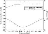
도 4는 본 발명의 일 실시예로서, 패치 방사유닛을 포함하는 글라스의 반사계수 및 효율을 도시하고 있다.
도 5는 본 발명의 일 실시예에 따른 접합 글라스 안테나 구조를 통한 방사패턴을 도시하고 있다.
도 6은 본 발명의 일 실시예에 따른 접합 글라스 안테나 구조의 패치 방사유닛의 배열에 따른 방사패턴을 도시하고 있다.1 is a cross-sectional view showing a laminated glass as an embodiment of the present invention.
2 is a perspective view of a laminated glass antenna structure as an embodiment of the present invention.
Figure 3 shows an enlarged view of a single patch radiation unit as an embodiment of the present invention.
Figure 4 shows the reflection coefficient and efficiency of the glass including the patch radiation unit as an embodiment of the present invention.
5 shows a radiation pattern through a laminated glass antenna structure according to an embodiment of the present invention.
6 shows a radiation pattern according to an arrangement of a patch radiation unit having a laminated glass antenna structure according to an embodiment of the present invention.
이하, 본 발명의 실시 예를 첨부된 도면들을 참조하여 더욱 상세하게 설명한다. 본 발명의 실시 예는 여러 가지 형태로 변형할 수 있으며, 본 발명의 범위가 아래의 실시 예들로 한정되는 것으로 해석되어서는 안 된다. 본 실시 예는 당업계에서 평균적인 지식을 가진 자에게 본 발명을 더욱 완전하게 설명하기 위해 제공되는 것이다.Hereinafter, an embodiment of the present invention will be described in more detail with reference to the accompanying drawings. Embodiments of the present invention may be modified in various forms, and the scope of the present invention should not be construed as being limited to the following embodiments. This embodiment is provided to more completely explain the present invention to those of ordinary skill in the art.
또한, 명세서에 기재된 "...라인", "...유닛", "...글라스" 등의 용어는 적어도 하나의 기능이나 동작을 처리하는 단위를 의미하며, 이는 하드웨어나 소프트웨어 또는 하드웨어 및 소프트웨어의 결합으로 구현될 수 있다.In addition, terms such as "... line", "... unit", "... glass", etc. described in the specification mean a unit that processes at least one function or operation, which is hardware or software or hardware and It can be implemented by a combination of software.
또한, 본 명세서에서 구성의 명칭을 제 1방향, 제 2방향 등으로 구분한 것은 그 구성의 명칭이 동일한 관계로 이를 구분하기 위한 것으로, 제 1방향과 제 2방향은 서로 상대적으로 반대 방향을 의미하는 것이다.In addition, in the present specification, the names of the components are divided into the first direction, the second direction, etc. to distinguish them because the names of the components are the same, and the first direction and the second direction mean relatively opposite directions to each other. will do
이하, 실시예를 첨부된 도면들을 참조하여 상세히 설명하기로 하며, 첨부 도면을 참조하여 설명함에 있어, 동일하거나 대응하는 구성 요소는 동일한 도면번호를 부여하고 이에 대해 중복되는 설명은 생략하기로 한다.Hereinafter, the embodiment will be described in detail with reference to the accompanying drawings, and in the description with reference to the accompanying drawings, the same or corresponding components are given the same reference numerals, and the overlapping description thereof will be omitted.
도 1은 본 발명의 접합 글라스 안테나 구조(10)를 포함하는 윈드실드 글라스의 측단면도를 도시하고 있다.1 shows a cross-sectional side view of a windshield glass including a laminated
도시된 바와 같이, 상단 글라스(100), 하단 글라스(200)를 포함하고, 상단 글라스(100)와 하단 글라스(200) 사이에는 패치 방사유닛(300)을 포함한다. 패치 방사유닛(300) 상면 또는 하면 중 적어도 한 면에 위치하는 PVB 필름(110)(폴리비닐 부티랄 필름)을 포함한다. 상단 글라스(100) 및 하단 글라스(200)는 소다 석회 유리로 제조될 수 있으며, 상단 글라스(100) 및 하단 글라스(200)는 동일한 두께 또는 상이한 두께를 갖도록 구성될 수 있다.As shown, it includes an
패치 방사유닛(300)은 상단 글라스(100)와 하단 글라스(200) 사이에 가장자리의 적어도 일부에 위치하도록 구성된다. 더 바람직하게, 본 발명의 일 실시예에서 윈드실드 글라스의 상단 또는 하단에 위치하도록 구성될 수 있다. 또한, 패치 방사유닛(300)은 하단 글라스(200) 배면에 위치하는 그라운드(400)와 통전되도록 구성될 수 있다.The
더욱이, 동축케이블(340)을 사용하여 패치 방사유닛(300)이 급전되도록 구성된다. 동축케이블(340)의 내부 전선이 스트립 라인(310)으로 연결되어 신호가 전달되며, 외부 전선은 하단 글라스(200) 배면에 위치하는 그라운드(400)를 구성된다.Moreover, the
본 발명의 일 실시예에서, 하단 글라스(200)와 상단 글라스(100) 사이에 위치하고, 트리 형상의 끝단에 다수의 사각형 패치 소자(330)를 포함하는 패치 방사유닛(300)은 동작 주파수인 28 GHz에서 공진하도록 설계되었다. 패치 방사유닛(300)의 패치 소자(330)는 가로, 세로 길이와 상단 글라스(100) 및 하단 글라스(200)의 유전율이 설계 변수로 작용하며, 패치 방사소자와 그라운드(400) 사이에서의 전류의 공진에 의해 다수의 패치 소자(330)들이 안테나로써 동작한다. 이때 해당 안테나의 패치 방사유닛(300)의 사이즈는 28 GHz에서 공진하면서 최대의 전면 방향이득을 갖도록 설계된다.In one embodiment of the present invention, the
더욱이, 본 발명의 패치 방사유닛(300)은 고이득 특성을 갖고 빔조향을 수행하기 위해 배열되는바, 단순히 이득 증가를 위해 패치 소자(330)를 위치하는 것이 아닌, 공진하는 전류의 위상 값이 상쇄되지 않도록 위치된다.Furthermore, the
더욱이, 스트립 라인(310)은 패치 소자(330)의 크기와 대비하여 결정되는 폭을 갖는바, 패치 방사유닛(300)이 전류의 위상 값과 공진하도록 구성된다.Furthermore, the
본 발명의 일 실시예에서, 접합 글라스 안테나 구조(10)는 다층 글라스 구조 사이에 패치 방사유닛(300)으로 구성되는 안테나가 적용되는 것을 고려하여, 안테나 방사면 위에 고유전율의 유전체를 얹어 안테나의 방사이득을 증가시키는 구조인 superstrate antenna의 원리를 적용하였다. 즉, Superstrate의 기능을 수행하는 상단 글라스(100)를 포함하여, 패치 방사유닛(300)에 유전율을 갖는 기판이 얹어지며, 패치 방사유닛(300)에서 방사되는 전파가 하단 글라스(200) 배면에 위치하는 그라운드(400)와 상단 글라스(100) 사이에서 한 번 더 반사되면서 동위상의 파면을 만들어 이득을 향상시킨다.In one embodiment of the present invention, in the laminated
즉, 본 발명의 일 실시예에서 패치 방사유닛(300)은 28 GHz에서 공진하도록 설계되는바, 상단 글라스(100) 및 하단 글라스(200)를 구성하는 물성은 비유전율(F/m)이 7을 갖도록 구성되는 경우 상단 글라스(100)의 두께는 1.5mm 내지 2.7mm 및 하단 글라스(200)의 두께가 두께가 0.3mm 내지 1.1mm를 갖도록 구성될 수 있다.That is, in an embodiment of the present invention, the
따라서, 상단 글라스(100)는 인쇄된 패치 방사유닛(300) 상면에 위치하는 고유전율의 기판으로써 superstrate 역할을 하여 이득을 더욱 증가시킬 수 있다. 상단 글라스(100) 두께는 위치되는 패치 방사유닛(300)의의 크기 및 공진주파수를 고려하여 superstrate의 특성이 나타날 수 있는 두께가 설정되도록 구성된다. 즉, 상단 글라스(100)는 superstrate 기능을 수행하는바, 패치 소자(330)에서 급전되는 전류가 상단 글라스(100)를 통해 패치 방사유닛(300)의 주파수와 동일한 주파수를 갖도록 구성되는바, 전면 방향 이득을 증가시킬 수 있다.Accordingly, the
인쇄되는 패치 방사유닛(300)은 PVB 필름과 하단 글라스(200) 사이의 적어도 일부에 위치하도록 구성되고 패치 방사유닛(300)의 그라운드(400)면은 하단 글라스(200) 최하단에 위치한다. 따라서 하단 글라스(200)는 패치 방사유닛(300)의 기판으로 동작하게 된다. 이때, 기판의 기능을 수행하는 하단 글라스(200)의 두께는 패치 방사소자와 마이크로 스트립 라인(310) 설계의 중요한 변수로 고려된다. 따라서. 하단 글라스(200)의 두께가 너무 두껍게 적용되는 경우에서는 스트립 라인(310), 연장라인(320) 및 연장라인(320) 끝단에 위치하는 패치 소자(330)가 안테나로서 동작하기 어려워, 차량용 글라스의 높은 유전율을 고려하여 기판으로 동작할 수 있도록 두께를 적용된다. 통상적으로 이 조건을 만족하기 위해 스트립 라인(310)의 폭(제 2방향 길이)/기판의 두께 비율은 1혹은 그 이상이 이상적이며 기판이 두께가 두꺼워져 비율이 0.5 이하로 현저하게 낮아지는 경우 전면방향 이득을 충분히 유지하기 어렵다.The printed
따라서, 본 발명의 일 실시예에서 스트립 라인(310)은 폭은 0.1mm 내지 0.9mm으로 구성되고, 하단 글라스(200)의 두께는 0.3mm 내지 1.1mm로 설정될 수 있다.Accordingly, in an embodiment of the present invention, the
차량에 적용되어 패치 방사유닛(300)을 급전하는 경우 패치 방사유닛(300)의 급전 포트의 급전 핀은 패치 방사유닛(300)의 마이크로 스트립 선로(스트립 라인(310) 또는/및 연장라인(320))에, 그라운드(400)는 패치 방사유닛(300)의 그라운드(400) 면과 납땜되어 연결된다. 또한, 본 발명의 일 실시예로서, 접합 글라스 안테나 구조(10)의 패치 방사유닛(300) 위치는 상단 글라스(100)와 직접적으로 연결되어 있지 않고 PVB 필름 하단에 위치하여 전면 방향이득이 최대가 되도록 결정된다.When applied to a vehicle to feed the
연장라인(320)은 순차적으로 배열되는 패치 소자(330)까지의 간격이 공진주파수의 약 반파장에 해당하는 길이를 갖도록 구성될 수 있다. 즉, 스트립 라인(310)을 기준으로 양측면에 위치하는 패치 소자(330)간의 거리는 송수신되는 5G mmWave(28GHz)의 한파장과 실질적으로 동일한 길이를 갖도록 구성된다. 이를 통해 전류의 위상과 동일한 좌우측에 서로 인접한 패치 소자(330)간의 거리를 통해 높은 방사 이득을 갖도록 구성된다.The
이처럼, 본 발명의 접합 글라스 안테나 구조(10)는 접합 글라스 사이에 위치하는 패치 방사유닛(300)을 안테나로 구성하고, 더욱이, 하단 글라스(200) 배면에 위치하는 그라운드(400) 및 상단 글라스(100)를 덮개(Superstrate)로 활용함으로써, 상단 글라스(100)를 투과하는 모든 전파가 동위상을 갖도록 구성되는 특징을 포함한다.As such, the laminated
도 2는 본 발명의 일 실시예로서, 접합 글라스 안테나 구조(10)를 포함하는 차량용 글라스의 사시도를 도시하고 있다.2 is a perspective view of a vehicle glass including a laminated
도시된 바와 같이, 글라스의 하단 일부에 위치하는 패치 방사유닛(300)을 포함하며, 패치 방사유닛(300)은 글라스의 폭방향으로 하나 이상 인접하여 위치하도록 구성된다.As shown, it includes a
패치 방사유닛(300)은 글라스 하단부로부터 높이 방향으로 연장되는 스트립 라인(310)을 구성하고, 상기 스트립 라인(310)의 측면으로 연장되는 연장라인(320)을 포함한다. 연장라인(320) 끝단에는 패치 소자(330)가 위치하도록 구성된다. 연장라인(320)은 스트립 라인(310)을 기준으로 좌우 측으로 높이에 따라 교차하여 위치된다. 더 바람직하게, 연장라인(320)은 우측으로 연장되는 제 1방향 연장라인(321a), 제 1방향 연장라인(320a)의 상단에 위치하고 스트립 라인(310)을 기준 좌측으로 연장되는 제 2방향 연장라인(322a)을 포함하며, 제 1방향 연장라인(321a)과 제 2방향 연장라인(322a)은 스트립 라인(310)의 높이를 따라 적어도 하나 이상으로 구성될 수 있다.The
본 발명의 일 실시예에서 제 1방향 연장라인(321a, 321b)은 높이를 따라 두 개로 구성되고, 제 2방향 연장라인(322a, 322b) 또한 높이를 따라 두 개가 위치하도록 구성된다. 더욱이, 제 1방향 연장라인(321a, 321b)과 제 2방향 연장라인(322a, 322b)은 순차적으로 위치하도록 구성되는바, 제 1방향 연장라인(321)과 제 2방향 연장라인(322)은 서로 동일한 수를 갖도록 스트립 라인(310)의 높이 방향을 따라 위치하도록 구성된다.In an embodiment of the present invention, the first
도시된 바와 같이, 4개의 패치 소자(330)를 포함하는 본 발명의 일 실시예에서는 하단 제 1방향 연장라인(321a)이 스트립 라인(310)의 하단과 인접하여 도면의 우측으로 연장되고, 하단 제 2방향 연장라인(322a)은 하단 제 1방향 연장라인(321a)과 비교하여 스트립 라인(310)의 높이 방향 상단에 소정의 간격을 갖도록 이격되어 단면상 좌측으로 연장되어 위치한다. 또한, 연장라인(320)들은 서로 동일한 길이를 갖도록 구성된다. 상단 제 2방향 연장라인(322b)은 상단 제 1방향 연장라인(321b) 상단을 기준으로 단면상 좌측으로 연장되도록 구성된다.As shown, in an embodiment of the present invention including four
좌우측으로 각각 2개의 패치 소자(330)를 포함하는 일 실시예에서, 하단 제 1방향 연장라인(321a), 상단 제 1방향 연장라인(321b), 하단 제 2방향 연장라인(322a) 및 상단 제 2방향 연장라인(322b)은 서로 동일한 높이 간격을 갖도록 구성되고, 서로 상이한 방향을 갖도록 스트립 라인(310)의 높이 방향으로 교차하여 위치되도록 구성된다. 더 바람직하게, 제 1방향 연장라인(321a, 321b)과 인접한 제 2방향 연장라인(322a, 322b)과의 높이 방향 거리는 각각 동일하도록 설정될 수 있다.In an embodiment including two
도 3은 본 발명의 일 실시예로서, 단일 패치 방사유닛(300)의 확대도를 도시하고 있다.3 shows an enlarged view of a single
도시된 바와 같이, 상단 글라스(100)와 하단 글라스(200) 사이에 위치하는 패치 방사유닛(300)은 높이 방향으로 위치하는 스트립 라인(310)을 기준으로 좌우측으로 연장되는 제 1방향 연장라인(320) 및 제 2방향 연장라인(320)을 포함한다. 더 바람직하게, 본 발명의 일 실시예에서는 각각 2개의 제 1방향 연장라인(320)과 제 2방향 연장라인(320)을 포함하고 있으며, 각각의 연장라인(320) 끝단에는 패치 소자(330)가 각각 위치하도록 구성될 수 있다.As shown, the
개시된 일 실시예에서 패치 소자(330)는 정사각형 단면을 갖도록 구성되며, 패치 소자(330)는 한변이 1.4mm 내지 2,6mm로 구성될 수 있다.In the disclosed embodiment, the
또한, 스트립 라인(310)의 높이 방향을 따라 위치하고 폭은 0.1mm 내지 0.9mm를 갖도록 구성되며, 연장라인(320)은 상기 스트립 라인(310)으로부터 폭방향을 따라 2.4mm 내지 3.6mm의 길이를 갖도록 구성될 수 있다.In addition, it is located along the height direction of the
더 바람직하게, Superstrate 안테나 구조를 제공하기 위해서 상단 글라스(100)는 6.8 내지 7.1의 비유전율을 갖도록 구성되며 상단 글라스(100)의 두께가 1.5mm 내지 2.7mm를 갖도록 구성된다. 더욱이, 하단 글라스(200)는 상단 글라스(100)와 동일한 비유전율을 갖도록 구성되며, 두께가 0.3mm 내지 1.1mm로 설정될 수 있다.More preferably, in order to provide a superstrate antenna structure, the
도 4는 본 발명의 일 실시예로서, 상단 글라스(100)가 2.1mm 이고, 하단 글라스(200)가 0.7mm 두께로 형성되며, 패치 소자(330)의 한변의 길이가 2mm이고, 스트립 라인(310)의 폭이 0.5mm이며, 연장라인(320)의 길이가 3.6mm이고, 패치 소자(330)간의 높이 방향 거리가 4.2mm만큼 이격된 패치 방사유닛(300)을 포함하는 글라스의 반사계수 및 효율을 측정한 데이터를 도시하고 있다.4 is an embodiment of the present invention, the
도시된 바와 같이, 반사계수는 급전 선로를 포함하는 시스템으로부터 안테나(패치 방사유닛(300))로 신호를 인가 할 때, 인가된 신호가 안테나에 전달되지 못하고 반사되어 되돌아오는 계수를 의미한다.As shown, the reflection coefficient refers to a coefficient that is reflected and returned when a signal is applied from a system including a feed line to the antenna (patch radiation unit 300), the applied signal is not transmitted to the antenna.
도 4에 도시된 dB 스케일 데이터로부터 -10 dB 이하의 반사계수는 시스템에서 전달한 전력의 90% 이상을 안테나에 전달함을 의미한다. 따라서 -10 dB 이하의 반사계수는 해당 주파수 대역에서 안테나의 성능이 우수함을 확인할 수 있다.A reflection coefficient of -10 dB or less from the dB scale data shown in FIG. 4 means that 90% or more of the power transmitted from the system is transmitted to the antenna. Therefore, it can be confirmed that the performance of the antenna is excellent in the corresponding frequency band with a reflection coefficient of -10 dB or less.
효율은 글라스가 갖는 재질적 특성, 혹은 안테나의 구조적 특성에 의해 안테나로 전달된 신호가 열 또는 기타에너지로 전환되지 않고 전자기파의 형태로 대기중으로 방사되는 비율을 의미한다. 효율이 0 (0%) 인 것은 대기중으로 방사되는 전자기파가 전혀 없음을 의미하고 효율이 1 (100%) 인 것은 안테나에 인가된 전력이 모두 전자기파의 형태로 대기중으로 방사됨을 의미한다.Efficiency refers to the rate at which the signal transmitted to the antenna is radiated into the atmosphere in the form of electromagnetic waves without being converted into heat or other energy due to the material characteristics of glass or the structural characteristics of the antenna. An efficiency of 0 (0%) means that there is no electromagnetic wave radiated to the atmosphere, and an efficiency of 1 (100%) means that all power applied to the antenna is radiated to the atmosphere in the form of electromagnetic waves.
상기 일 실시예로 제작된 접합 글라스 안테나 구조(10)는 차량용 다층 유리 안테나가 28 GHz 주파수에서 -17.9 dB 의 반사계수와 48.5 % 의 효율을 갖는 것을 알 수 있다. 이는 접합 글라스에 적용된 패치 방사유닛(300)(안테나)의 반사효율이 뛰어남을 나타내고 있다.It can be seen that the laminated
도 5는 본 발명의 일 실시예로서, 글라스 평면을 대상으로 안테나의 zx, zy 방향에 따른 방사패턴을 도시하고 있다. 차량용 접합 글라스에 적용된 패치 방사유닛(300)(안테나)는 패치 방사유닛(300)의 방사 방향을 원하는 방향으로 조향할 수 있도록 빔 폭이 좁게 나타난다. 따라서, 패치 방사유닛(300)의 방사 방향을 미리 정해진 방향으로 조향함으로써 통신에 효율적인 위치로 방사패턴을 집중시킬 수 있다. 패치 방사유닛(300)의 방사 방향은 도 1 내지 도 3에서 구현된 본 발명의 일 실시예를 통해 결정된다. 안테나의 이득은 dBi 단위로 표현되며 이는 이상적인 등방성 안테나 대비 특정 방향으로 전력을 어느 정도 배율의 세기로 전달함을 의미한다.5 illustrates a radiation pattern along zx and zy directions of an antenna with respect to a glass plane as an embodiment of the present invention. The patch radiation unit 300 (antenna) applied to the vehicle laminated glass has a narrow beam width so that the radiation direction of the
도 5에 도시된 바와 같이, 차량용 접합 글라스에 적용된 패치 방사유닛(300)은 28 GHz 주파수에서 전면 방향에 대해 7.7 dBi 의 이득을 갖는다. 이는 안테나의 평판에 수직한 방향으로 등방성 안테나 대비 최대 4배 이상 높은 전력을 전달함을 의미한다. 여기서 등방성 안테나란 모든 방향으로 동일한 전력을 방사하는 이상적인 안테나를 의미하며, 즉 모든 방향으로 0 dBi의 이득을 갖는 안테나를 의미한다.5, the
도 6은 본 발명의 일 실시예에 따른 다수의 트리형 패치 방사유닛(300)을 포함하는 접합 글라스 안테나 구조(10)의 전면방향 이득을 도시한 도면이다.6 is a view showing a front gain of a laminated
도시된 바와 같이, 트리구조를 갖고 4개의 열로 배치되는 패치 방사유닛(300) 안테나의 구성은 2열 또는 3열로 구성되는 패치 방사유닛(300)과 비교하여 전면 방향 이득값이 큰것을 도시하고 있다. 즉, 패치 방사유닛(300)의 열이 늘어날수록 따라 전면방향 이득은 증가하지만 빔폭은 좁아지게 된다. 따라서, 전면방향 이득이 증가되도록 다열의 패치 방사유닛(300)을 구성하고, 이를 특정 단말기로 수신하는 차량내 수신기를 구비할 경우 폭이 좁은 빔에 대한 이득은 증가할 수 있음을 알 수 있다.As shown, the antenna configuration of the
위의 상세한 설명은 본 발명을 예시하는 것이다. 또한 전술한 내용은 본 발명의 바람직한 실시 형태를 나타내어 설명하는 것이며, 본 발명은 다양한 다른 조합, 변경 및 환경에서 사용할 수 있다. 즉 본 명세서에 개시된 발명의 개념의 범위, 기술한 개시 내용과 균등한 범위 및/또는 당업계의 기술 또는 지식의 범위내에서 변경 또는 수정이 가능하다. 기술한 실시예는 본 발명의 기술적 사상을 구현하기 위한 최선의 상태를 설명하는 것이며, 본 발명의 구체적인 적용 분야 및 용도에서 요구되는 다양한 변경도 가능하다. 따라서 이상의 발명의 상세한 설명은 개시된 실시 상태로 본 발명을 제한하려는 의도가 아니다. 또한 첨부된 청구범위는 다른 실시 상태도 포함하는 것으로 해석되어야 한다.The above detailed description is illustrative of the present invention. In addition, the above description shows and describes preferred embodiments of the present invention, and the present invention can be used in various other combinations, modifications, and environments. That is, changes or modifications are possible within the scope of the concept of the invention disclosed herein, the scope equivalent to the described disclosure, and/or within the scope of skill or knowledge in the art. The described embodiment describes the best state for implementing the technical idea of the present invention, and various changes required in the specific application field and use of the present invention are possible. Accordingly, the detailed description of the present invention is not intended to limit the present invention to the disclosed embodiments. Also, the appended claims should be construed as including other embodiments.
10: 접합 글라스 안테나 구조
100: 상단 글라스
200: 하단 글라스
300: 패치 방사유닛
310: 스트립 라인
320: 연장라인
330: 패치 소자
340: 케이블
400: 그라운드10: laminated glass antenna structure
100: top glass
200: lower glass
300: patch radiation unit
310: strip line
320: extension line
330: patch element
340: cable
400: ground
Claims (8)
Translated fromKorean상기 상단 글라스 배면에 적어도 일부에 위치하는 패치 방사유닛; 및
상기 패치 방사유닛 배면에 위치하는 하단 글라스;를 포함하고,
상기 패치 방사유닛은,
높이 방향으로 위치하는 스트립 라인;
상기 스트립 라인의 측방향으로 연장되는 적어도 하나 이상의 연장라인; 및
상기 연장라인 끝단에 위치하는 패치 소자;를 포함하는 접합 글라스 안테나 구조.
a top glass positioned on the vehicle;
a patch radiating unit located at least in part on the upper surface of the glass; and
Including; a lower glass located on the rear surface of the patch radiation unit;
The patch radiation unit,
strip lines located in the height direction;
at least one extension line extending in a lateral direction of the strip line; and
A laminated glass antenna structure comprising a; patch element positioned at the end of the extension line.
상기 패치 소자는 한변이 1.4mm 내지 2.6mm를 갖도록 구성되는 사각형상으로 구성되는 접합 글라스 안테나 구조.
The method of claim 1,
The patch element is a laminated glass antenna structure configured in a rectangular shape configured to have one side of 1.4 mm to 2.6 mm.
상기 스트립 라인의 폭은 0.1mm 내지 0.9mm를 갖도록 구성되는 접합 글라스 안테나 구조.
The method of claim 1,
A laminated glass antenna structure configured to have a width of the strip line of 0.1 mm to 0.9 mm.
상기 연장라인은 상기 스트립 라인으로부터 2.4mm 내지 3.6mm의 길이를 갖도록 구성되는 접합 글라스 안테나 구조.
The method of claim 1,
The extended line is a laminated glass antenna structure configured to have a length of 2.4 mm to 3.6 mm from the strip line.
상기 하단 글라스 배면에는 그라운드;를 더 포함하는 접합 글라스 안테나 구조.
The method of claim 1,
A laminated glass antenna structure further comprising a ground on the lower surface of the glass.
상기 상단 글라스는 1.5mm 내지 2.7mm를 갖도록 구성되는 접합 글라스 안테나 구조.
The method of claim 1,
The upper glass is a laminated glass antenna structure configured to have a 1.5 mm to 2.7 mm.
상기 하단 글라스는 0.3mm 내지 1.1mm를 갖도록 구성되는 접합 글라스 안테나 구조.
The method of claim 1,
The bottom glass is a laminated glass antenna structure configured to have 0.3 mm to 1.1 mm.
상기 패치 방사유닛은 폭 방향으로 4개의 열을 갖도록 구성되는 접합 글라스 안테나 구조.
The method of claim 1,
The patch radiation unit is a laminated glass antenna structure configured to have four rows in the width direction.
Priority Applications (4)
| Application Number | Priority Date | Filing Date | Title |
|---|---|---|---|
| KR1020210021957AKR20220118163A (en) | 2021-02-18 | 2021-02-18 | Structure for Antenna of Adhere Glass |
| US17/673,050US20220263219A1 (en) | 2021-02-18 | 2022-02-16 | Laminated glass antenna structure |
| CN202210145073.4ACN114976610A (en) | 2021-02-18 | 2022-02-17 | Laminated glass antenna structure |
| DE102022201688.2ADE102022201688A1 (en) | 2021-02-18 | 2022-02-18 | LAMINATED GLASS ANTENNA STRUCTURE |
Applications Claiming Priority (1)
| Application Number | Priority Date | Filing Date | Title |
|---|---|---|---|
| KR1020210021957AKR20220118163A (en) | 2021-02-18 | 2021-02-18 | Structure for Antenna of Adhere Glass |
Publications (1)
| Publication Number | Publication Date |
|---|---|
| KR20220118163Atrue KR20220118163A (en) | 2022-08-25 |
Family
ID=82610619
Family Applications (1)
| Application Number | Title | Priority Date | Filing Date |
|---|---|---|---|
| KR1020210021957APendingKR20220118163A (en) | 2021-02-18 | 2021-02-18 | Structure for Antenna of Adhere Glass |
Country Status (4)
| Country | Link |
|---|---|
| US (1) | US20220263219A1 (en) |
| KR (1) | KR20220118163A (en) |
| CN (1) | CN114976610A (en) |
| DE (1) | DE102022201688A1 (en) |
Citations (1)
| Publication number | Priority date | Publication date | Assignee | Title |
|---|---|---|---|---|
| KR20110089827A (en) | 2010-02-01 | 2011-08-09 | 아사히 가라스 가부시키가이샤 | Glass antenna and vehicle window glass comprising the same |
Family Cites Families (6)
| Publication number | Priority date | Publication date | Assignee | Title |
|---|---|---|---|---|
| WO2008024993A2 (en)* | 2006-08-25 | 2008-02-28 | Rayspan Corporation | Antennas based on metamaterial structures |
| JP5091044B2 (en)* | 2008-07-31 | 2012-12-05 | 株式会社デンソー | Microstrip array antenna |
| HUE054039T2 (en)* | 2015-04-08 | 2021-08-30 | Saint Gobain | Vehicle antenna window pane |
| US10582608B2 (en)* | 2016-07-20 | 2020-03-03 | Hcl Technologies Limited | Interconnection between printed circuit boards |
| US20180241135A1 (en)* | 2017-02-23 | 2018-08-23 | Taoglas Group Holdings Limited | 27-28.5 GHz Ka BAND PHASED ARRAY FAN BEAM ANTENNAS AND METHODS |
| US20210159609A1 (en)* | 2019-11-21 | 2021-05-27 | Electronics And Telecommunications Research Institute | Capacitive-coupled comb-line microstrip array antenna |
- 2021
- 2021-02-18KRKR1020210021957Apatent/KR20220118163A/enactivePending
- 2022
- 2022-02-16USUS17/673,050patent/US20220263219A1/ennot_activeAbandoned
- 2022-02-17CNCN202210145073.4Apatent/CN114976610A/enactivePending
- 2022-02-18DEDE102022201688.2Apatent/DE102022201688A1/enactivePending
Patent Citations (1)
| Publication number | Priority date | Publication date | Assignee | Title |
|---|---|---|---|---|
| KR20110089827A (en) | 2010-02-01 | 2011-08-09 | 아사히 가라스 가부시키가이샤 | Glass antenna and vehicle window glass comprising the same |
Also Published As
| Publication number | Publication date |
|---|---|
| CN114976610A (en) | 2022-08-30 |
| DE102022201688A1 (en) | 2022-08-18 |
| US20220263219A1 (en) | 2022-08-18 |
Similar Documents
| Publication | Publication Date | Title |
|---|---|---|
| KR102725688B1 (en) | Antenna module placed on a vehicle | |
| US20210175628A1 (en) | Multilayer glass patch antenna | |
| EP4546563A1 (en) | Antenna module arranged in vehicle | |
| CN110247152A (en) | Vehicle integrated antenna with enhanced beam steering | |
| KR20240095268A (en) | Antenna module placed in vehicle | |
| WO2020260508A1 (en) | Vehicle antenna glazing | |
| EP4452632A1 (en) | A coated automotive glazing with integrated radar unit | |
| KR20220118163A (en) | Structure for Antenna of Adhere Glass | |
| KR102709419B1 (en) | Antenna module placed on a vehicle | |
| EP4554001A1 (en) | Antenna module arranged in vehicle | |
| KR20220118164A (en) | Antenna Structure for Glass | |
| EP4557514A1 (en) | Antenna module disposed in vehicle | |
| US12431608B2 (en) | Antenna module arranged in vehicle | |
| EP4564597A1 (en) | Antenna module arranged in vehicle | |
| KR20240020379A (en) | Antenna Structure for Glass | |
| EP4579950A1 (en) | Antenna module disposed in vehicle | |
| US12444828B2 (en) | Antenna module for placement in vehicle | |
| KR102707824B1 (en) | Antenna module placed on a vehicle | |
| Gallo et al. | Design and experimental validation of a windscreen patch array for C2C communications | |
| KR20250133644A (en) | Antenna module placed on a vehicle |
Legal Events
| Date | Code | Title | Description |
|---|---|---|---|
| PA0109 | Patent application | Patent event code:PA01091R01D Comment text:Patent Application Patent event date:20210218 | |
| PG1501 | Laying open of application | ||
| E902 | Notification of reason for refusal | ||
| PE0902 | Notice of grounds for rejection | Comment text:Notification of reason for refusal Patent event date:20250317 Patent event code:PE09021S01D |