KR20220115657A - Electric bus charging apparatus - Google Patents
Electric bus charging apparatusDownload PDFInfo
- Publication number
- KR20220115657A KR20220115657AKR1020210017438AKR20210017438AKR20220115657AKR 20220115657 AKR20220115657 AKR 20220115657AKR 1020210017438 AKR1020210017438 AKR 1020210017438AKR 20210017438 AKR20210017438 AKR 20210017438AKR 20220115657 AKR20220115657 AKR 20220115657A
- Authority
- KR
- South Korea
- Prior art keywords
- electric bus
- charger
- contact
- contact bar
- unit
- Prior art date
- Legal status (The legal status is an assumption and is not a legal conclusion. Google has not performed a legal analysis and makes no representation as to the accuracy of the status listed.)
- Granted
Links
- 238000012546transferMethods0.000claimsabstractdescription17
- 238000000034methodMethods0.000claimsdescription12
- 230000003028elevating effectEffects0.000claimsdescription6
- 238000010586diagramMethods0.000description6
- 238000004891communicationMethods0.000description4
- 238000012544monitoring processMethods0.000description4
- CURLTUGMZLYLDI-UHFFFAOYSA-NCarbon dioxideChemical compoundO=C=OCURLTUGMZLYLDI-UHFFFAOYSA-N0.000description2
- 239000002803fossil fuelSubstances0.000description2
- 229910002092carbon dioxideInorganic materials0.000description1
- 239000001569carbon dioxideSubstances0.000description1
- 238000010276constructionMethods0.000description1
- 238000005516engineering processMethods0.000description1
- 230000007613environmental effectEffects0.000description1
- 238000009434installationMethods0.000description1
- 238000012986modificationMethods0.000description1
- 230000004048modificationEffects0.000description1
- 238000005192partitionMethods0.000description1
- 229920001690polydopaminePolymers0.000description1
- 238000012545processingMethods0.000description1
- 238000010792warmingMethods0.000description1
Images


Classifications
- B—PERFORMING OPERATIONS; TRANSPORTING
- B60—VEHICLES IN GENERAL
- B60L—PROPULSION OF ELECTRICALLY-PROPELLED VEHICLES; SUPPLYING ELECTRIC POWER FOR AUXILIARY EQUIPMENT OF ELECTRICALLY-PROPELLED VEHICLES; ELECTRODYNAMIC BRAKE SYSTEMS FOR VEHICLES IN GENERAL; MAGNETIC SUSPENSION OR LEVITATION FOR VEHICLES; MONITORING OPERATING VARIABLES OF ELECTRICALLY-PROPELLED VEHICLES; ELECTRIC SAFETY DEVICES FOR ELECTRICALLY-PROPELLED VEHICLES
- B60L53/00—Methods of charging batteries, specially adapted for electric vehicles; Charging stations or on-board charging equipment therefor; Exchange of energy storage elements in electric vehicles
- B60L53/30—Constructional details of charging stations
- B60L53/35—Means for automatic or assisted adjustment of the relative position of charging devices and vehicles
- B—PERFORMING OPERATIONS; TRANSPORTING
- B60—VEHICLES IN GENERAL
- B60L—PROPULSION OF ELECTRICALLY-PROPELLED VEHICLES; SUPPLYING ELECTRIC POWER FOR AUXILIARY EQUIPMENT OF ELECTRICALLY-PROPELLED VEHICLES; ELECTRODYNAMIC BRAKE SYSTEMS FOR VEHICLES IN GENERAL; MAGNETIC SUSPENSION OR LEVITATION FOR VEHICLES; MONITORING OPERATING VARIABLES OF ELECTRICALLY-PROPELLED VEHICLES; ELECTRIC SAFETY DEVICES FOR ELECTRICALLY-PROPELLED VEHICLES
- B60L53/00—Methods of charging batteries, specially adapted for electric vehicles; Charging stations or on-board charging equipment therefor; Exchange of energy storage elements in electric vehicles
- B60L53/30—Constructional details of charging stations
- B60L53/31—Charging columns specially adapted for electric vehicles
- B—PERFORMING OPERATIONS; TRANSPORTING
- B60—VEHICLES IN GENERAL
- B60L—PROPULSION OF ELECTRICALLY-PROPELLED VEHICLES; SUPPLYING ELECTRIC POWER FOR AUXILIARY EQUIPMENT OF ELECTRICALLY-PROPELLED VEHICLES; ELECTRODYNAMIC BRAKE SYSTEMS FOR VEHICLES IN GENERAL; MAGNETIC SUSPENSION OR LEVITATION FOR VEHICLES; MONITORING OPERATING VARIABLES OF ELECTRICALLY-PROPELLED VEHICLES; ELECTRIC SAFETY DEVICES FOR ELECTRICALLY-PROPELLED VEHICLES
- B60L9/00—Electric propulsion with power supply external to the vehicle
- B—PERFORMING OPERATIONS; TRANSPORTING
- B60—VEHICLES IN GENERAL
- B60L—PROPULSION OF ELECTRICALLY-PROPELLED VEHICLES; SUPPLYING ELECTRIC POWER FOR AUXILIARY EQUIPMENT OF ELECTRICALLY-PROPELLED VEHICLES; ELECTRODYNAMIC BRAKE SYSTEMS FOR VEHICLES IN GENERAL; MAGNETIC SUSPENSION OR LEVITATION FOR VEHICLES; MONITORING OPERATING VARIABLES OF ELECTRICALLY-PROPELLED VEHICLES; ELECTRIC SAFETY DEVICES FOR ELECTRICALLY-PROPELLED VEHICLES
- B60L2200/00—Type of vehicles
- B60L2200/18—Buses
- B—PERFORMING OPERATIONS; TRANSPORTING
- B60—VEHICLES IN GENERAL
- B60Y—INDEXING SCHEME RELATING TO ASPECTS CROSS-CUTTING VEHICLE TECHNOLOGY
- B60Y2200/00—Type of vehicle
- B60Y2200/10—Road Vehicles
- B60Y2200/14—Trucks; Load vehicles, Busses
- B60Y2200/143—Busses
- B—PERFORMING OPERATIONS; TRANSPORTING
- B60—VEHICLES IN GENERAL
- B60Y—INDEXING SCHEME RELATING TO ASPECTS CROSS-CUTTING VEHICLE TECHNOLOGY
- B60Y2200/00—Type of vehicle
- B60Y2200/90—Vehicles comprising electric prime movers
- B60Y2200/91—Electric vehicles
- Y—GENERAL TAGGING OF NEW TECHNOLOGICAL DEVELOPMENTS; GENERAL TAGGING OF CROSS-SECTIONAL TECHNOLOGIES SPANNING OVER SEVERAL SECTIONS OF THE IPC; TECHNICAL SUBJECTS COVERED BY FORMER USPC CROSS-REFERENCE ART COLLECTIONS [XRACs] AND DIGESTS
- Y02—TECHNOLOGIES OR APPLICATIONS FOR MITIGATION OR ADAPTATION AGAINST CLIMATE CHANGE
- Y02T—CLIMATE CHANGE MITIGATION TECHNOLOGIES RELATED TO TRANSPORTATION
- Y02T90/00—Enabling technologies or technologies with a potential or indirect contribution to GHG emissions mitigation
- Y02T90/10—Technologies relating to charging of electric vehicles
- Y02T90/14—Plug-in electric vehicles
Landscapes
- Engineering & Computer Science (AREA)
- Power Engineering (AREA)
- Transportation (AREA)
- Mechanical Engineering (AREA)
- Life Sciences & Earth Sciences (AREA)
- Sustainable Development (AREA)
- Sustainable Energy (AREA)
- Charge And Discharge Circuits For Batteries Or The Like (AREA)
Abstract
Translated fromKoreanDescription
Translated fromKorean본 발명은 전기버스 충전 장치에 관한 것으로서, 더욱 상세하게는 전기버스의 상측에서 횡방향으로 이동하면서 전기버스를 충전시킴으로써 횡방향으로 나란하게 주차되어 있는 다수의 전기버스를 빠르고 손쉽게 충전하는 전기버스 충전 장치에 관한 것이다.The present invention relates to an electric bus charging device, and more particularly, an electric bus charging that quickly and easily charges a plurality of electric buses parked in parallel in the lateral direction by charging the electric bus while moving from the upper side of the electric bus in the lateral direction. It's about the device.
가솔린이나 경유 등의 화석 연료를 사용하는 자동차들의 경우 화석 연료의 고갈 및 지구 온난화 문제를 야기하고 있고, 그 결과 환경 보호를 위한 이산화탄소 및 배출가스의 규제가 강화되고 있다. 이에 대한 대안으로 전기차들이 서서히 보급되고 있으나, 한번 충전으로 운행할 수 있는 거리가 아직 충분하지 않고 충전 인프라의 구축도 더뎌 전기차의 보급에 장애물로 작용하고 있다.In the case of automobiles using fossil fuels such as gasoline or diesel, depletion of fossil fuels and global warming are caused, and as a result, regulations on carbon dioxide and exhaust gas for environmental protection are being strengthened. As an alternative to this, electric vehicles are gradually spreading, but the distance that can be driven by a single charge is not yet sufficient and the construction of charging infrastructure is slow, acting as an obstacle to the spread of electric vehicles.
한편, 정해진 노선을 주행하는 버스의 경우 한번 충전으로 노선을 충분히 운행할 수 있으므로 한번 충전으로 주행할 수 있는 거리의 제약이 상대적으로 낮고, 버스 차고지에 충전 시스템을 구비하면 되므로 충전 인프라의 구축도 상대적으로 용이하다. 따라서 정해진 노선을 운행하는 버스의 경우 전기자동차를 전환하기에 상대적으로 유리하다. 이에, 버스를 전기자동차로 전환하기 위한 노력이 계속되고 있다.On the other hand, in the case of a bus traveling on a fixed route, since a single charge can sufficiently drive the route, the limitation of the distance that can be driven on a single charge is relatively low. easy with Therefore, in the case of a bus running a fixed route, it is relatively advantageous to switch to an electric vehicle. Accordingly, efforts are being made to convert buses into electric vehicles.
그러나, 버스를 전기자동차와 전환하기 위해서는, 기존 운행 일정에 지장이 없는 심야시간 동안 전기버스 충전을 완료해야 하는데, 현재 확보된 충전 커넥터 체결 충전 방식으로는 차고지의 버스 주차 형태, 충전기 수요, 충전 관리자 확보, 충전 시간 등 즉각적인 적용이 불가한 상황이다.However, in order to convert a bus to an electric vehicle, it is necessary to complete the charging of the electric bus during late-night hours without any disruption to the existing operating schedule. Immediate application, such as securing and charging time, is not possible.
본 발명의 배경기술은 대한민국 공개특허공보 10-2018-0118873호(2018.11.01)의 '챔버형 전기버스 충전시스템'에 개시되어 있다.The background technology of the present invention is disclosed in 'chamber-type electric bus charging system' of Korean Patent Publication No. 10-2018-0118873 (2018.11.01).
본 발명은 전술한 문제점을 개선하기 위해 창안된 것으로서, 본 발명의 일 측면에 따른 목적은 전기버스의 상측에서 횡방향으로 이동하면서 전기버스를 충전시킴으로써 횡방향으로 나란하게 주차되어 있는 다수의 전기버스를 빠르고 손쉽게 충전하는 전기버스 충전 장치를 제공하는 데 있다.The present invention has been devised to improve the above problems, and an object according to one aspect of the present invention is to charge the electric bus while moving from the upper side of the electric bus in the transverse direction to a plurality of electric buses parked in parallel in the transverse direction. It is to provide an electric bus charging device that quickly and easily charges the
본 발명의 일 측면에 따른 전기버스 충전 장치는 전기버스의 횡방향으로 이동하면서 상기 전기버스의 전기버스 접촉바와 전기적으로 접촉되어 상기 전기버스에 전력을 공급하는 충전기; 및 상기 충전기가 상기 전기버스의 횡방향으로 이동될 수 있도록 가이드하는 이송 스테이션을 포함하는 것을 특징으로 한다.An electric bus charging device according to an aspect of the present invention includes: a charger for supplying power to the electric bus by being in electrical contact with the electric bus contact bar of the electric bus while moving in the lateral direction of the electric bus; and a transfer station for guiding the charger to be moved in the transverse direction of the electric bus.
본 발명의 상기 이송 스테이션은 상기 전기버스의 횡방향으로 설치되어 상기 충전기를 지지하는 수평 지지대; 상기 수평 지지대에 설치되어 상기 충전기가 상기 전기버스의 횡방향으로 이송되도록 하는 충전기 레일; 및 상기 전기버스의 횡방향으로 이격 설치되어 상기 수평 지지대의 양단을 각각 지지하는 수직 지지대를 포함하는 것을 특징으로 한다.The transfer station of the present invention is installed in the transverse direction of the electric bus horizontal support for supporting the charger; a charger rail installed on the horizontal support so that the charger is transported in the transverse direction of the electric bus; and vertical supports respectively installed to be spaced apart from each other in the transverse direction of the electric bus to support both ends of the horizontal support.
본 발명의 상기 전기버스 접촉바는 상기 전기버스의 지붕에 외부로 노출되게 설치되는 것을 특징으로 한다.The electric bus contact bar of the present invention is characterized in that it is installed to be exposed to the outside on the roof of the electric bus.
본 발명의 상기 전기버스 접촉바는 양극 단자와 음극 단자 각각이 2개씩 구비되어 상기 전기버스의 횡방향으로 나란하게 배치되는 것을 특징으로 한다.The electric bus contact bar of the present invention is provided with two each of a positive terminal and a negative terminal, characterized in that they are arranged side by side in the transverse direction of the electric bus.
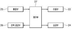
본 발명의 상기 충전기는 상기 전기버스 접촉바와 전기적으로 접촉되는 충전기 접촉바; 상기 충전기 접촉바를 통해 상기 전기버스 접촉바에 전력을 공급하는 전력 공급부; 상기 충전기 접촉바를 승하강시키는 승강부; 상기 충전기를 상기 이송 스테이션을 따라 상기 전기버스의 횡방향으로 이동시키는 이동부; 상기 전기버스 접촉바를 촬영하는 촬영부; 및 상기 이동부를 제어하여 상기 충전기를 이동시키면서 상기 촬영부를 통해 상기 전기버스 접촉바를 촬영하고, 상기 촬영부에 의해 촬영된 영상에 따라 상기 충전기를 전기버스 충전을 위한 위치로 이동시켜 상기 승강부를 하강시킨 후, 상기 충전기 접촉바를 상기 전기버스 접촉바와 전기적으로 접촉시켜 상기 전력 공급부를 통해 상기 전기버스 접촉바에 전력을 공급하는 제어부를 포함하는 것을 특징으로 한다.The charger of the present invention includes a charger contact bar in electrical contact with the electric bus contact bar; a power supply unit for supplying power to the electric bus contact bar through the charger contact bar; an elevating unit for elevating the charger contact bar; a moving unit for moving the charger in the transverse direction of the electric bus along the transfer station; a photographing unit for photographing the electric bus contact bar; and controlling the moving unit to move the charger while photographing the electric bus contact bar through the capturing unit, and moving the charger to a position for charging the electric bus according to the image captured by the capturing unit to lower the elevating unit Then, by electrically contacting the charger contact bar with the electric bus contact bar, characterized in that it comprises a control unit for supplying power to the electric bus contact bar through the power supply unit.
본 발명의 상기 충전기 접촉바는 양극 단자와 음극 단자 각각이 상기 충전기의 이동방향으로 나란하게 배치되는 것을 특징으로 한다.The charger contact bar of the present invention is characterized in that each of the positive terminal and the negative terminal are arranged side by side in the moving direction of the charger.
본 발명의 상기 제어부는 상기 촬영부를 통해 촬영된 영상에서 상기 전기버스 접촉바를 검출하고, 상기 전기버스 접촉바에 상기 충전기 접촉바가 정렬되도록 상기 이동부를 제어하여 것을 특징으로 한다.The control unit of the present invention detects the electric bus contact bar from the image captured by the photographing unit, and controls the moving unit so that the charger contact bar is aligned with the electric bus contact bar.
본 발명의 일 측면에 따른 전기버스 충전 장치는 전기버스의 상측에서 횡방향으로 이동하면서 전기버스를 충전시킴으로써 횡방향으로 나란하게 주차되어 있는 다수의 전기버스를 빠르고 손쉽게 충전한다.The electric bus charging device according to an aspect of the present invention quickly and easily charges a plurality of electric buses parked side by side in the lateral direction by charging the electric bus while moving from the upper side of the electric bus in the lateral direction.
본 발명의 다른 측면에 따른 전기버스 충전 장치는 기존 버스 차고지의 버스 주차 상황에 적합하여 전기버스 충전에 즉각적으로 이용될 수 있다.The electric bus charging device according to another aspect of the present invention is suitable for the bus parking situation of the existing bus depot and can be used immediately for charging the electric bus.
도 1 은 본 발명의 일 실시예에 따른 전기버스 충전 장치의 전체 구성도이다.
도 2 는 본 발명의 일 실시예에 따른 전기버스의 사시도이다.
도 3 는 본 발명의 일 실시예에 따른 전기버스 충전 장치의 이송 스테이션(10)의 사시도이다.
도 4 는 본 발명의 일 실시예에 따른 전기버스 충전 장치의 충전기의 사시도이다.
도 5 는 본 발명의 일 실시예에 따른 충전기 접촉단자의 승하강을 나타낸 도면이다.
도 6 은 본 발명의 일 실시예에 따른 충전기의 블럭 구성도이다.
도 7 내지 도 13 은 본 발명의 일 실시예에 따른 전기버스 충전 과정을 도시한 도면이다.1 is an overall configuration diagram of an electric bus charging device according to an embodiment of the present invention.
2 is a perspective view of an electric bus according to an embodiment of the present invention.
3 is a perspective view of the
4 is a perspective view of a charger of an electric bus charging device according to an embodiment of the present invention.
5 is a view showing the elevation of the contact terminal of the charger according to an embodiment of the present invention.
6 is a block diagram of a charger according to an embodiment of the present invention.
7 to 13 are diagrams illustrating an electric bus charging process according to an embodiment of the present invention.
이하에서는 본 발명의 일 실시예에 따른 전기버스 충전 장치를 첨부된 도면들을 참조하여 상세하게 설명한다. 이러한 과정에서 도면에 도시된 선들의 두께나 구성요소의 크기 등은 설명의 명료성과 편의상 과장되게 도시되어 있을 수 있다. 또한 후술되는 용어들은 본 발명에서의 기능을 고려하여 정의된 용어들로서, 이는 이용자, 운용자의 의도 또는 관례에 따라 달라질 수 있다. 그러므로 이러한 용어들에 대한 정의는 본 명세서 전반에 걸친 내용을 토대로 내려져야 할 것이다.Hereinafter, an electric bus charging device according to an embodiment of the present invention will be described in detail with reference to the accompanying drawings. In this process, the thickness of the lines or the size of the components shown in the drawings may be exaggerated for clarity and convenience of explanation. In addition, the terms to be described later are terms defined in consideration of functions in the present invention, which may vary according to intentions or customs of users and operators. Therefore, definitions of these terms should be made based on the content throughout this specification.
도 1 은 본 발명의 일 실시예에 따른 전기버스 충전 장치의 전체 구성도이고, 도 2 는 본 발명의 일 실시예에 따른 전기버스의 사시도이며, 도 3 는 본 발명의 일 실시예에 따른 전기버스 충전 장치의 이송 스테이션의 사시도이며, 도 4 는 본 발명의 일 실시예에 따른 전기버스 충전 장치의 충전기의 사시도이며, 도 5 는 본 발명의 일 실시예에 따른 충전기 접촉단자의 승하강을 나타낸 도면이며, 도 6 은 본 발명의 일 실시예에 따른 충전기의 블럭 구성도이다.1 is an overall configuration diagram of an electric bus charging device according to an embodiment of the present invention, FIG. 2 is a perspective view of an electric bus according to an embodiment of the present invention, and FIG. 3 is an electric bus according to an embodiment of the present invention A perspective view of a transfer station of a bus charging device, FIG. 4 is a perspective view of a charger of an electric bus charging device according to an embodiment of the present invention, and FIG. 6 is a block diagram of a charger according to an embodiment of the present invention.
도 1 을 참조하면, 본 발명의 일 실시예에 따른 전기버스 충전 장치는 전기버스(50)의 횡방향으로 이동하면서 전기버스(50)의 전기버스 접촉부(30)와 전기적으로 접촉되어 전기버스(50)에 전력을 공급하는 충전기(20), 충전기(20)가 전기버스(50)의 횡방향으로 이동될 수 있도록 가이드하는 이송 스테이션(10), 및 전기버스(50)에 설치되어 충전기(20)와 전기적으로 연결되는 전기버스 접촉부(30)를 포함한다.Referring to Figure 1, the electric bus charging device according to an embodiment of the present invention is in electrical contact with the
도 2 를 참조하면, 전기버스 접촉부(30)는 전기버스(50)의 지붕에 외부로 노출되게 설치되어 충전기(20)와 전기적으로 접속된다.Referring to FIG. 2 , the electric
전기버스 접촉부(30)는 양극 단자(32)와 음극 단자(31) 각각이 2개씩 구비하며, 양극 단자(32)와 음극 단자(310 각각은 전기버스(50)의 횡방향으로 나란하게 배치된다.The electric
전기버스 접촉부(30)의 양극 단자(32)는 각각 전기버스(50)의 OBC(On-Borad Charger)와 배터리팩 시스템(Battery Pack System)과 전기적 및 기계적으로 연결된다.The
본 실시예에서는 전기버스 접촉부(30)가 전기버스(50)의 지붕에 외부로 노출되게 설치되고, 양극 단자(32)와 음극 단자(31) 각각이 2개씩 구비되어 전기버스(50)의 횡방향으로 나란하게 배치 것을 예시로 설명하였으나, 전기버스 접촉부(30)의 설치 위치와 구조는 특별히 한정되는 것은 아니다.In this embodiment, the electric
이송 스테이션(10)은 전기버스(50)에 전력을 공급하는 충전기(20)가 전기버스(50)의 횡방향으로 이동될 수 있도록 가이드한다.The
통상적으로, 버스 차고지의 주차구역에는 다수 대의 전기버스(50)가 병렬 주차, 예를 들어 전기버스(50)의 횡방향으로 나란하게 주차될 수 있다. 이에 전기버스(50)에 대한 충전시간을 줄이고 효과적인 충전이 이루어질 수 있도록, 이송 스테이션(10)은 전기버스(50)의 충전구역에 설치될 수 있다.In general, in the parking area of the bus depot, a plurality of
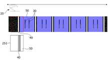
도 1 을 참조하면, 주차구역에 5대의 전기버스(50)를 주차할 수 있는 주차구획선(40)이 그어져 있는 경우, 이송 스테이션(10)은 충전기(20)가 주차구역내 주차된 전기버스(50)의 횡방향으로 이동할 수 있도록 설치된다.Referring to FIG. 1 , when a parking dividing
도 3 을 참조하면, 이송 스테이션(10)은 수평 지지대(12), 수직 지지대(11), 및 충전기 레일(13)을 포함한다.Referring to FIG. 3 , the
수평 지지대(12)는 주차구역의 양측, 즉 전기버스(50)의 횡방향으로 설치되어 충전기(20)가 전기버스(50)의 상부에서 전기버스(50)의 횡방향으로 이동할 수 있도록 지지한다.The
수직 지지대(11)는 2개가 구비되면, 이들은 전기버스(50)의 횡방향으로 이격 설치되어 수평 지지대(12)의 양단을 각각 지지한다. 이에 따라, 수직 지지대(11)가 전기버스(50)의 상부에 일정 거리 이격되게 위치하게 된다.When two
충전기 레일(13)은 수평 지지대(12)에 수평 지지대(12)의 길이 방향으로 설치되어 충전기(20)가 전기버스(50)의 횡방향으로 이송되도록 한다. 이에 따라, 도 2 의 화살표와 같이 충전기(20)가 이동될 수 있다.The
충전기(20)는 수직 지지대(11)의 충전기 레일(13)을 따라 전기버스(50)의 횡방향으로 이동하면서 전기버스(50)의 전기버스 접촉부(30)와 전기적으로 접촉되며 전기버스(50)에 전력을 공급한다.The
도 4 내지 도 6 을 참조하면, 충전기(20)는 충전기 접촉부(23), 전력 공급부(26), 승강부(24), 이동부(22), 촬영부(25), 및 제어부(27)를 포함한다.4 to 6 , the
이동부(22)는 충전기(20)를 이송 스테이션(10)을 따라 전기버스(50)의 횡방향으로 이동시킨다. 즉, 이동부(22)는 충전기(20)의 본체(21)에 설치되어 기계적으로 충전기 레일(13)과 연결되며, 제어부(27)의 제어신호에 따른 액추에이터 구동에 따라 충전기(20)를 충전기 레일(13)을 따라 이동시킨다.The moving
충전기 접촉부(23)는 전기버스 접촉부(30)와 전기적으로 접촉된다. 충전기 접촉부(23)는 양극 단자(232)와 음극 단자(231) 각각이 충전기(20)의 이동방향으로 나란하게 배치된다.The
충전기 접촉부(23)는 승강부(24)의 수직 방향으로 승하강될 수 있다. 충전기 접촉부(23)가 하강하는 경우, 충전기 접촉부(23)의 양극 단자(232)는 전기버스 접촉부(30)의 양극 단자(32)와 접촉되고, 충전기 접촉부(23)의 음극 단자(231)는 전기버스 접촉부(30)의 음극 단자(31)와 접촉된다.The
전력 공급부(26)는 상기한 바와 같이 충전기 접촉부(23)의 양극 단자(232)와 전기버스 접촉부(30)의 양극 단자(32)가 접촉되고 충전기 접촉부(23)의 음극 단자(231)와 전기버스 접촉부(30)의 음극 단자(31)와 접촉되는 경우, 제어부(27)의 제어신호에 따라 전력을 공급한다. 이에 따라, 전기버스(50)에 전력이 공급되어 전기버스(50)가 충전된다.As described above, the
전력 공급부(26)는 전기버스(50)를 충전시키기 위한 각종 충전 스테이션(미도시)과 연결된 급전선(미도시)을 통해 전력을 공급받을 수 있다. 급전선은 상기한 이송 스테이션(10)을 통해 충전 스테이션과 연결될 수 있다.The
전력 공급부(26)는 급전선을 통해 공급되는 전력을 단속하기 위한 적어도 하나의 스위칭 모듈(미도시), 전력상태를 모니터링하는 전력상태 모니터링 모듈(미도시), 전력 공급량을 모니터링하는 전력 공급량 모니터링 모듈(미도시), 및 전기버스(50)와 유무선 통신을 수행하는 통신 모듈(미도시) 등을 포함할 수 있다.The
전력 공급부(26)는 전기버스(50)와 충전기(20)가 전기적으로 접속되어 전력을 공급하여 전기버스(50)에 대한 충전을 수행하는 것은 특별히 한정되는 것은 아니며, 다양한 방식이 적용될 수 있다.The
승강부(24)는 충전기 접촉부(23)를 승하강시킨다. 승강부(24)는 일단이 본체(21)에 연결되고 타측에는 충전기 접촉부(23)가 설치되어 내부의 액추에이터 구동에 따라 충전기 접촉부(23)를 상승 또는 하강시킨다.The lifting
승강부(24)는 이동부(22)에 의해 충전기(20)가 전기버스(50)의 횡방향으로 이동하는 동안에는 충전기 접촉부(23)를 상승시키고, 충전기(20)가 충전에 적합한 위치에 도달하면 전력 공급을 위해 충전기 접촉부(23)를 하강시켜 전기버스 접촉부(30)와 접촉시킨다. 승강부(24)의 동작을 위한 액추에이터(미도시)는 상기한 본체(21) 내부에 구비될 수 있다.The lifting
촬영부(25)는 전기버스 접촉부(30)를 촬영하고, 촬영된 영상을 제어부(27)에 입력한다. 촬영부(25)는 본체(21)에 설치될 수 있으나 특별히 한정되는 것은 아니다.The photographing
제어부(27)는 이동부(22)를 제어하여 충전기(20)를 이동시키면서 촬영부(25)를 통해 전기버스 접촉부(30)를 촬영하고, 촬영부(25)에 의해 촬영된 영상에 따라 충전기(20)를 전기버스(50) 충전을 위한 위치로 이동시켜 승강부(24)를 하강시킨 후, 충전기 접촉부(23)를 전기버스 접촉부(30)와 전기적으로 접촉시켜 전력 공급부(26)를 통해 전기버스 접촉부(30)에 전력을 공급한다.The
좀 더 구체적으로 설명하면, 도 1 에 도시된 바와 주차구역 내 주차구획선(40)에 따라 다수 대의 전기버스(50)가 주차된 상태에서, 전기버스(50) 충전이 개시되면, 제어부(27)는 승강부(24)를 제어하여 충전기 접촉부(23)를 상승시키고 이동부(22)를 제어하여 충전기(20)를 이동시킨다. 이와 함께, 제어부(27)는 촬영부(25)를 제어하여 영상을 촬영한다.More specifically, when a plurality of
제어부(27)는 촬영부(25)에 의해 촬영된 영상을 분석하여 현재 충전기(20)의 위치가 충전에 적합한 위치를 확인한다. 즉, 제어부(27)는 촬영부(25)에 의해 촬영된 영상에서 전기버스 접촉부(30)를 검출하고, 검출된 전기버스 접촉부(30)가 영상 내 기 설정된 정렬 위치에 도달하는지를 판정한다.The
판정 결과 전기버스 접촉부(30)가 정렬 위치에 도달하면, 제어부(27)는 이동부(22)를 통해 충전기(20)를 정지시키고, 승강부(24)를 통해 충전기 접촉부(23)를 하강시킨다. 이에 따라, 충전기 접촉부(23)의 양극 단자(232)와 전기버스 접촉부(30)의 양극 단자(32)가 접촉되고, 충전기 접촉부(23)의 음극 단자(231)와 전기버스 접촉부(30)의 음극 단자(31)가 접촉된다.As a result of the determination, when the electric
상기한 바와 같이 충전기 접촉부(23)와 전기버스 접촉부(30)가 접촉됨에 따라, 제어부(27)는 전력 공급부(26)를 제어하여 전기버스(50)에 전력을 공급한다. 이에 따라 전기버스(50)가 충전된다.As described above, as the
즉, 제어부(27)는 촬영부(25)에 의해 촬영된 영상에서 전기버스 접촉부(30)를 검출하고 검출된 전기버스 접촉부(30)의 위치에 따라 이동부(22)를 통해 충전기 접촉부(23)에 대한 중심점 제어를 수행함으로써, 충전기 접촉부(23)가 충전에 적합한 위치에서 전기버스 접촉부(30)와 접촉될 수 있도록 한다.That is, the
제어부(27)는 수평 지지대(12)를 따라 충전기(20)를 이동시키면서 상기한 중심점 제어를 전기버스(50)마다 반복적으로 수행함으로써, 주차구역에 주차되어 있는 모든 전기버스(50)를 충전시킨다.The
이를 도 7 내지 도 13 을 참조하여 설명한다.This will be described with reference to FIGS. 7 to 13 .
도 7 내지 도 13 은 본 발명의 일 실시예에 따른 전기버스(50) 충전 과정을 도시한 도면이다.7 to 13 are diagrams illustrating a charging process of the
도 7 내지 도 13 에는 병렬 형태로 나란하게 주차되어 있는 5대의 전기버스(50)의 지붕과 주차구획선(40)으로 구성된 주차면 5면에 대한 탑-뷰(Top-view) 중 일부분으로서, 충전기(20)가 충전기 레일(13) 상에서 횡방향으로 이송 중 촬영부(25)에 의해 연속으로 촬영된 전기버스(50)의 지붕과 5개의 주차면에 대한 파노라마 이미지 영상(251)이 도시된다.7 to 13, as a part of the top-view of the five parking surfaces consisting of the roof and the
먼저, 도 7 에는 충전기(20)가 충전기 레일(13)을 따라 횡방향으로의 이송을 시작하고, 이때의 촬영부(25)에서 촬영된 이진화 처리 영상(251)이 도시되었다.First, in FIG. 7 , the
이 영상(251)에서 첫 번째 전기버스(50)의 주차구획선(40)과 첫 번째 전기버스(50)의 좌측 경계선이 순차적으로 인식된다.In this
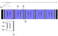
도 8 에는 충전기(20)가 충전기 레일(13)을 따라 횡방향으로의 이송하는 과정에서, 촬영부(25)에 의해 촬영된 이진화 처리 영상(251)이 도시되었다.In FIG. 8 , a
이 영상(251)에서 첫 번째 전기버스(50)의 주차구획선(40)과, 첫 번째 전기버스(50)의 좌측 경계선에 추가적으로 전기버스 접촉부(30)의 좌측 양극 단자(32)와 좌측 음극 단자(31)가 인식된다.In this
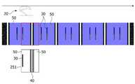
도 9 에는 충전기(20)가 충전기 레일(13)을 따라 횡방향으로의 이송하는 과정에서, 촬영부(25)에 의해 촬영된 이진화 처리 영상(251)이 도시되었다.9 shows a
이 영상(251)에서 전기버스 접촉부(30)의 좌우측 양극 단자(32)와 좌우측 음극 단자(31)가 모두 인식되고, 인식된 전기버스 접촉부(30)의 좌우측 양극 단자(32)와 좌우측 음극 단자(31)가 전기버스 접촉부(30)가 영상(251) 내 기 설정된 정렬 위치에 도달한 것으로 인식된다.In this
이때, 제어부(27)는 첫 번째 전기버스(50)의 전기버스 접촉부(32)의 양극 단자(32)와 음극 단자(31) 사이의 중심점을 기준으로, 이동부(22)를 통해 충전기 접촉부(23)를 횡방향 상에서 위치 제어한다.At this time, the
이후, 제어부(27)는 승강부(24)를 통해 충전기 접촉부(23)를 하강시켜 충전기 접촉부(23)와 전기버스 접촉부(30)를 접촉시키고, 전력 공급부(26)를 제어하여 전기버스(50)를 충전한다.Thereafter, the
충전이 완료되면, 제어부(27)는 승강부(24)를 제어하여 충전기 접촉부(23)를 상승시키고, 이동부(22)를 제어하여 충전기(20)를 이동시키면서 촬영부(25)를 통해 촬영한다.When charging is complete, the
이에 따라, 도 10 내지 도 13 에 도시된 바와 같이, 충전기(20)의 단계적인 이동에 따른 영상(251)을 촬영부(25)를 통해 획득하게 되고, 제어부(27)는 해당 영상(251)을 도 7 내지 도 9 에 도시된 바와 같이 분석하여 두 번째 전기버스(50)에 대한 충전을 수행한다. 이러한 과정은 주차구역에 주차되어 있는 전기버스(50)에 대해 반복적으로 수행한다.Accordingly, as shown in FIGS. 10 to 13 , the
이와 같이, 본 발명의 일 실시예에 따른 전기버스 충전 장치는 팬터그래프 방식으로 전기버스(50)의 상측에서 횡방향으로 이동하면서 전기버스(50)를 충전시킴으로써 횡방향으로 나란하게 주차되어 있는 다수의 전기버스(50)를 빠르고 손쉽게 충전한다.As such, the electric bus charging device according to an embodiment of the present invention is a pantograph method by charging the
또한, 본 발명의 일 실시예에 따른 전기버스 충전 장치는 버스 차고지의 버스 주차 상황에 적합하여 전기버스 충전에 즉각적으로 이용될 수 있다.In addition, the electric bus charging device according to an embodiment of the present invention can be used immediately to charge the electric bus suitable for the bus parking situation in the bus depot.
본 명세서에서 설명된 구현은, 예컨대, 방법 또는 프로세스, 장치, 소프트웨어 프로그램, 데이터 스트림 또는 신호로 구현될 수 있다. 단일 형태의 구현의 맥락에서만 논의(예컨대, 방법으로서만 논의)되었더라도, 논의된 특징의 구현은 또한 다른 형태(예컨대, 장치 또는 프로그램)로도 구현될 수 있다. 장치는 적절한 하드웨어, 소프트웨어 및 펌웨어 등으로 구현될 수 있다. 방법은, 예컨대, 컴퓨터, 마이크로프로세서, 집적 회로 또는 프로그래밍가능한 로직 디바이스 등을 포함하는 프로세싱 디바이스를 일반적으로 지칭하는 프로세서 등과 같은 장치에서 구현될 수 있다. 프로세서는 또한 최종-사용자 사이에 정보의 통신을 용이하게 하는 컴퓨터, 셀 폰, 휴대용/개인용 정보 단말기(personal digital assistant: "PDA") 및 다른 디바이스 등과 같은 통신 디바이스를 포함한다.Implementations described herein may be implemented in, for example, a method or process, an apparatus, a software program, a data stream, or a signal. Although discussed only in the context of a single form of implementation (eg, discussed only as a method), implementations of the discussed features may also be implemented in other forms (eg, as an apparatus or program). The apparatus may be implemented in suitable hardware, software and firmware, and the like. A method may be implemented in an apparatus such as, for example, a processor, which generally refers to a computer, a microprocessor, a processing device, including an integrated circuit or programmable logic device, or the like. Processors also include communication devices such as computers, cell phones, portable/personal digital assistants ("PDAs") and other devices that facilitate communication of information between end-users.
본 발명은 도면에 도시된 실시예를 참고로 하여 설명되었으나, 이는 예시적인 것에 불과하며 당해 기술이 속하는 기술분야에서 통상의 지식을 가진 자라면 이로부터 다양한 변형 및 균등한 타 실시예가 가능하다는 점을 이해할 것이다. 따라서, 본 발명의 진정한 기술적 보호범위는 아래의 특허청구범위에 의하여 정해져야할 것이다.Although the present invention has been described with reference to the embodiments shown in the drawings, this is merely exemplary and those skilled in the art to which the art pertains can make various modifications and equivalent other embodiments therefrom. will understand Accordingly, the true technical protection scope of the present invention should be defined by the following claims.
10: 이송 스테이션11: 수직 지지대
12: 수평 지지대13: 충전기 레일
20: 충전기21: 본체
22: 이동부23: 충전기 접촉부
24: 승강부25: 촬영부
26: 전력 공급부27: 제어부
30: 전기버스 접촉부40: 주차구획선
50: 전기버스10: transfer station 11: vertical support
12: horizontal support 13: charger rail
20: charger 21: body
22: moving part 23: charger contact part
24: lifting unit 25: photographing unit
26: power supply unit 27: control unit
30: electric bus contact 40: parking section line
50: electric bus
Claims (7)
Translated fromKorean상기 충전기가 상기 전기버스의 횡방향으로 이동될 수 있도록 가이드하는 이송 스테이션을 포함하는 전기버스 충전 장치.a charger for supplying power to the electric bus by being in electrical contact with the electric bus contact bar of the electric bus while moving in the lateral direction of the electric bus; and
Electric bus charging device including a transfer station for guiding the charger to be moved in the transverse direction of the electric bus.
상기 전기버스의 횡방향으로 설치되어 상기 충전기를 지지하는 수평 지지대;
상기 수평 지지대에 설치되어 상기 충전기가 상기 전기버스의 횡방향으로 이송되도록 하는 충전기 레일; 및
상기 전기버스의 횡방향으로 이격 설치되어 상기 수평 지지대의 양단을 각각 지지하는 수직 지지대를 포함하는 것을 특징으로 하는 전기버스 충전 장치.The method of claim 1, wherein the transfer station is
a horizontal support installed in the transverse direction of the electric bus to support the charger;
a charger rail installed on the horizontal support so that the charger is transported in the transverse direction of the electric bus; and
Electric bus charging device, characterized in that it is installed spaced apart in the transverse direction of the electric bus comprising a vertical support for supporting both ends of the horizontal support, respectively.
상기 전기버스 접촉바와 전기적으로 접촉되는 충전기 접촉바;
상기 충전기 접촉바를 통해 상기 전기버스 접촉바에 전력을 공급하는 전력 공급부;
상기 충전기 접촉바를 승하강시키는 승강부;
상기 충전기를 상기 이송 스테이션을 따라 상기 전기버스의 횡방향으로 이동시키는 이동부;
상기 전기버스 접촉바를 촬영하는 촬영부; 및
상기 이동부를 제어하여 상기 충전기를 이동시키면서 상기 촬영부를 통해 상기 전기버스 접촉바를 촬영하고, 상기 촬영부에 의해 촬영된 영상에 따라 상기 충전기를 전기버스 충전을 위한 위치로 이동시켜 상기 승강부를 하강시킨 후, 상기 충전기 접촉바를 상기 전기버스 접촉바와 전기적으로 접촉시켜 상기 전력 공급부를 통해 상기 전기버스 접촉바에 전력을 공급하는 제어부를 포함하는 것을 특징으로 하는 전기버스 충전 장치.According to claim 1, wherein the charger is
a charger contact bar in electrical contact with the electric bus contact bar;
a power supply unit for supplying power to the electric bus contact bar through the charger contact bar;
an elevating unit for elevating the charger contact bar;
a moving unit for moving the charger in the transverse direction of the electric bus along the transfer station;
a photographing unit for photographing the electric bus contact bar; and
After the electric bus contact bar is photographed through the photographing unit while moving the charger by controlling the moving unit, the charger is moved to a position for charging the electric bus according to the image photographed by the photographing unit, and the elevating unit is lowered , Electric bus charging device comprising a control unit for supplying power to the electric bus contact bar through the power supply unit by making the charger contact bar electrically contact the electric bus contact bar.
상기 촬영부를 통해 촬영된 영상에서 상기 전기버스 접촉바를 검출하고, 상기 전기버스 접촉바에 상기 충전기 접촉바가 정렬되도록 상기 이동부를 제어하여 것을 특징으로 하는 전기버스 충전 장치.The method of claim 5, wherein the control unit
The electric bus charging device, characterized in that detecting the electric bus contact bar from the image taken through the photographing unit, and controlling the moving unit so that the charger contact bar is aligned with the electric bus contact bar.
Priority Applications (1)
| Application Number | Priority Date | Filing Date | Title |
|---|---|---|---|
| KR1020210017438AKR102556306B1 (en) | 2021-02-08 | 2021-02-08 | Electric bus charging apparatus |
Applications Claiming Priority (1)
| Application Number | Priority Date | Filing Date | Title |
|---|---|---|---|
| KR1020210017438AKR102556306B1 (en) | 2021-02-08 | 2021-02-08 | Electric bus charging apparatus |
Publications (3)
| Publication Number | Publication Date |
|---|---|
| KR20220115657Atrue KR20220115657A (en) | 2022-08-18 |
| KR102556306B1 KR102556306B1 (en) | 2023-07-17 |
| KR102556306B9 KR102556306B9 (en) | 2023-09-07 |
Family
ID=83112099
Family Applications (1)
| Application Number | Title | Priority Date | Filing Date |
|---|---|---|---|
| KR1020210017438AActiveKR102556306B1 (en) | 2021-02-08 | 2021-02-08 | Electric bus charging apparatus |
Country Status (1)
| Country | Link |
|---|---|
| KR (1) | KR102556306B1 (en) |
Cited By (9)
| Publication number | Priority date | Publication date | Assignee | Title |
|---|---|---|---|---|
| CN115352308A (en)* | 2022-09-02 | 2022-11-18 | 四川玉狻猊科技有限公司 | Charging method of charging equipment |
| KR20240058660A (en)* | 2022-10-26 | 2024-05-07 | 한국철도기술연구원 | Automatic charging system and method using the bottom of electric bus |
| KR102673776B1 (en) | 2023-09-20 | 2024-06-10 | 주식회사 인스코비 | Charging system and method of aelectric bus control using directional antenna |
| KR102673780B1 (en) | 2023-10-23 | 2024-06-10 | 주식회사 인스코비 | Determining system of defined position for aelectric bus charging using antenna image analysys and controlling method thereof |
| KR20240102718A (en) | 2022-12-26 | 2024-07-03 | 주식회사 인스코비 | System and method for charging aelectric bus based on the wireless network |
| KR20240102723A (en) | 2022-12-26 | 2024-07-03 | 주식회사 인스코비 | Charging system and method of aelectric bus control having optimized wireless network function |
| KR102760984B1 (en)* | 2023-12-19 | 2025-02-03 | 주식회사 펌프킨 | Ground leveling device that improves the contact efficiency of the pantograph and contact bar |
| KR20250084438A (en) | 2023-12-04 | 2025-06-11 | 주식회사 인스코비 | Apparatus and method for controling hybrid communication for charging aelectric bus |
| KR20250084439A (en) | 2023-12-04 | 2025-06-11 | 주식회사 인스코비 | Controlling system for wireless communication with aelectric bus be charged and controlling method thereof |
Citations (3)
| Publication number | Priority date | Publication date | Assignee | Title |
|---|---|---|---|---|
| KR20110082120A (en)* | 2008-07-01 | 2011-07-18 | 프로테라 인크 | Electric car charging station |
| US20130088194A1 (en)* | 2011-08-16 | 2013-04-11 | Nucleus Scientific, Inc. | Overhead power transfer system |
| JP2014504493A (en)* | 2010-11-30 | 2014-02-20 | ディアロギカ ゲゼルシャフト フュア アンゲヴァンテ インフォルマーティク ミット ベシュレンクテル ハフツング | System for automatic landing and disconnection of overhead train line-type vehicles while traveling |
- 2021
- 2021-02-08KRKR1020210017438Apatent/KR102556306B1/enactiveActive
Patent Citations (3)
| Publication number | Priority date | Publication date | Assignee | Title |
|---|---|---|---|---|
| KR20110082120A (en)* | 2008-07-01 | 2011-07-18 | 프로테라 인크 | Electric car charging station |
| JP2014504493A (en)* | 2010-11-30 | 2014-02-20 | ディアロギカ ゲゼルシャフト フュア アンゲヴァンテ インフォルマーティク ミット ベシュレンクテル ハフツング | System for automatic landing and disconnection of overhead train line-type vehicles while traveling |
| US20130088194A1 (en)* | 2011-08-16 | 2013-04-11 | Nucleus Scientific, Inc. | Overhead power transfer system |
Cited By (9)
| Publication number | Priority date | Publication date | Assignee | Title |
|---|---|---|---|---|
| CN115352308A (en)* | 2022-09-02 | 2022-11-18 | 四川玉狻猊科技有限公司 | Charging method of charging equipment |
| KR20240058660A (en)* | 2022-10-26 | 2024-05-07 | 한국철도기술연구원 | Automatic charging system and method using the bottom of electric bus |
| KR20240102718A (en) | 2022-12-26 | 2024-07-03 | 주식회사 인스코비 | System and method for charging aelectric bus based on the wireless network |
| KR20240102723A (en) | 2022-12-26 | 2024-07-03 | 주식회사 인스코비 | Charging system and method of aelectric bus control having optimized wireless network function |
| KR102673776B1 (en) | 2023-09-20 | 2024-06-10 | 주식회사 인스코비 | Charging system and method of aelectric bus control using directional antenna |
| KR102673780B1 (en) | 2023-10-23 | 2024-06-10 | 주식회사 인스코비 | Determining system of defined position for aelectric bus charging using antenna image analysys and controlling method thereof |
| KR20250084438A (en) | 2023-12-04 | 2025-06-11 | 주식회사 인스코비 | Apparatus and method for controling hybrid communication for charging aelectric bus |
| KR20250084439A (en) | 2023-12-04 | 2025-06-11 | 주식회사 인스코비 | Controlling system for wireless communication with aelectric bus be charged and controlling method thereof |
| KR102760984B1 (en)* | 2023-12-19 | 2025-02-03 | 주식회사 펌프킨 | Ground leveling device that improves the contact efficiency of the pantograph and contact bar |
Also Published As
| Publication number | Publication date |
|---|---|
| KR102556306B9 (en) | 2023-09-07 |
| KR102556306B1 (en) | 2023-07-17 |
Similar Documents
| Publication | Publication Date | Title |
|---|---|---|
| KR102556306B1 (en) | Electric bus charging apparatus | |
| EP3256341B1 (en) | Contacting device and rapid charging system | |
| CN205004760U (en) | Electric automobile removes control system that charges | |
| KR20190096303A (en) | Electric vehicle charging system and operation method thereof | |
| CN106536266A (en) | Vehicle charging station with supply contact device mounted on cantilever | |
| CN206884780U (en) | overhead automatic charging system | |
| EP2848451B1 (en) | Connection system for charging batteries of a vehicle, particularly an electric bus | |
| KR102467861B1 (en) | Curved Movable Pantograph Automatic Charging Apparatus for Electric Vehicle Charging | |
| CN111497631A (en) | Charging road, underground power supply trolley, electric vehicle, charging system and method | |
| CN111267666B (en) | Centralized fully automatic top contact charging system and method for charging station | |
| CN204068362U (en) | A track-type autonomous mobile electric vehicle power supply device | |
| KR20180129121A (en) | Wireless charger for electric vehicle | |
| KR101269990B1 (en) | System for auto-exchanging of electric vehicle battery | |
| CN205135045U (en) | Stereo garage that can charge for car | |
| CN105332533A (en) | Chargeable mechanical stereoscopic garage | |
| JP2903505B2 (en) | Automatic guided vehicle equipment | |
| TW201206816A (en) | Crane system | |
| CN108995543A (en) | A kind of overhead automatic charging system | |
| US20210339643A1 (en) | Charging device and method for aligning charging device with vehicle for charging | |
| JP7511337B2 (en) | Mechanical parking lot | |
| CN218640692U (en) | Remove dock charging device suitable for new forms of energy electric automobile | |
| CN113829909B (en) | Rail vehicle charging control method, charging station and charging system | |
| CN105398918A (en) | Device for charging electric vehicle during elevator movement process | |
| CN113561813A (en) | Vehicle automatic charging device for parking lot, parking lot and charging method | |
| CN111204239A (en) | A charging device and method of using the same |
Legal Events
| Date | Code | Title | Description |
|---|---|---|---|
| PA0109 | Patent application | Patent event code:PA01091R01D Comment text:Patent Application Patent event date:20210208 | |
| PA0201 | Request for examination | Patent event code:PA02012R01D Patent event date:20210210 Comment text:Request for Examination of Application Patent event code:PA02011R01I Patent event date:20210208 Comment text:Patent Application | |
| PG1501 | Laying open of application | ||
| E902 | Notification of reason for refusal | ||
| PE0902 | Notice of grounds for rejection | Comment text:Notification of reason for refusal Patent event date:20230130 Patent event code:PE09021S01D | |
| E701 | Decision to grant or registration of patent right | ||
| PE0701 | Decision of registration | Patent event code:PE07011S01D Comment text:Decision to Grant Registration Patent event date:20230707 | |
| GRNT | Written decision to grant | ||
| PR0701 | Registration of establishment | Comment text:Registration of Establishment Patent event date:20230712 Patent event code:PR07011E01D | |
| PR1002 | Payment of registration fee | Payment date:20230712 End annual number:3 Start annual number:1 | |
| PG1601 | Publication of registration | ||
| G170 | Re-publication after modification of scope of protection [patent] | ||
| PG1701 | Publication of correction | Patent event code:PG17011E01I Patent event date:20230904 Comment text:Request for Publication of Correction Publication date:20230907 |