KR20220105589A - Ear-wearable device of measuring physiological signals and system for monitoring physiological signals in non-face-to-face - Google Patents
Ear-wearable device of measuring physiological signals and system for monitoring physiological signals in non-face-to-faceDownload PDFInfo
- Publication number
- KR20220105589A KR20220105589AKR1020210192694AKR20210192694AKR20220105589AKR 20220105589 AKR20220105589 AKR 20220105589AKR 1020210192694 AKR1020210192694 AKR 1020210192694AKR 20210192694 AKR20210192694 AKR 20210192694AKR 20220105589 AKR20220105589 AKR 20220105589A
- Authority
- KR
- South Korea
- Prior art keywords
- ear
- sensor
- thermometer
- oxygen saturation
- face
- Prior art date
- Legal status (The legal status is an assumption and is not a legal conclusion. Google has not performed a legal analysis and makes no representation as to the accuracy of the status listed.)
- Ceased
Links
Images


Classifications
- A—HUMAN NECESSITIES
- A61—MEDICAL OR VETERINARY SCIENCE; HYGIENE
- A61B—DIAGNOSIS; SURGERY; IDENTIFICATION
- A61B5/00—Measuring for diagnostic purposes; Identification of persons
- A61B5/68—Arrangements of detecting, measuring or recording means, e.g. sensors, in relation to patient
- A61B5/6801—Arrangements of detecting, measuring or recording means, e.g. sensors, in relation to patient specially adapted to be attached to or worn on the body surface
- A61B5/6813—Specially adapted to be attached to a specific body part
- A61B5/6814—Head
- A61B5/6815—Ear
- A—HUMAN NECESSITIES
- A61—MEDICAL OR VETERINARY SCIENCE; HYGIENE
- A61B—DIAGNOSIS; SURGERY; IDENTIFICATION
- A61B5/00—Measuring for diagnostic purposes; Identification of persons
- A61B5/0002—Remote monitoring of patients using telemetry, e.g. transmission of vital signals via a communication network
- A—HUMAN NECESSITIES
- A61—MEDICAL OR VETERINARY SCIENCE; HYGIENE
- A61B—DIAGNOSIS; SURGERY; IDENTIFICATION
- A61B5/00—Measuring for diagnostic purposes; Identification of persons
- A61B5/02—Detecting, measuring or recording for evaluating the cardiovascular system, e.g. pulse, heart rate, blood pressure or blood flow
- A61B5/0205—Simultaneously evaluating both cardiovascular conditions and different types of body conditions, e.g. heart and respiratory condition
- A61B5/02055—Simultaneously evaluating both cardiovascular condition and temperature
- A—HUMAN NECESSITIES
- A61—MEDICAL OR VETERINARY SCIENCE; HYGIENE
- A61B—DIAGNOSIS; SURGERY; IDENTIFICATION
- A61B5/00—Measuring for diagnostic purposes; Identification of persons
- A61B5/103—Measuring devices for testing the shape, pattern, colour, size or movement of the body or parts thereof, for diagnostic purposes
- A61B5/11—Measuring movement of the entire body or parts thereof, e.g. head or hand tremor or mobility of a limb
- A61B5/1112—Global tracking of patients, e.g. by using GPS
- A—HUMAN NECESSITIES
- A61—MEDICAL OR VETERINARY SCIENCE; HYGIENE
- A61B—DIAGNOSIS; SURGERY; IDENTIFICATION
- A61B5/00—Measuring for diagnostic purposes; Identification of persons
- A61B5/103—Measuring devices for testing the shape, pattern, colour, size or movement of the body or parts thereof, for diagnostic purposes
- A61B5/11—Measuring movement of the entire body or parts thereof, e.g. head or hand tremor or mobility of a limb
- A61B5/1116—Determining posture transitions
- A61B5/1117—Fall detection
- A—HUMAN NECESSITIES
- A61—MEDICAL OR VETERINARY SCIENCE; HYGIENE
- A61B—DIAGNOSIS; SURGERY; IDENTIFICATION
- A61B5/00—Measuring for diagnostic purposes; Identification of persons
- A61B5/74—Details of notification to user or communication with user or patient; User input means
- A61B5/7465—Arrangements for interactive communication between patient and care services, e.g. by using a telephone network
- A61B5/747—Arrangements for interactive communication between patient and care services, e.g. by using a telephone network in case of emergency, i.e. alerting emergency services
- G—PHYSICS
- G08—SIGNALLING
- G08B—SIGNALLING OR CALLING SYSTEMS; ORDER TELEGRAPHS; ALARM SYSTEMS
- G08B21/00—Alarms responsive to a single specified undesired or abnormal condition and not otherwise provided for
- G08B21/02—Alarms for ensuring the safety of persons
- G08B21/0202—Child monitoring systems using a transmitter-receiver system carried by the parent and the child
- G08B21/0205—Specific application combined with child monitoring using a transmitter-receiver system
- G08B21/0211—Combination with medical sensor, e.g. for measuring heart rate, temperature
- G—PHYSICS
- G16—INFORMATION AND COMMUNICATION TECHNOLOGY [ICT] SPECIALLY ADAPTED FOR SPECIFIC APPLICATION FIELDS
- G16H—HEALTHCARE INFORMATICS, i.e. INFORMATION AND COMMUNICATION TECHNOLOGY [ICT] SPECIALLY ADAPTED FOR THE HANDLING OR PROCESSING OF MEDICAL OR HEALTHCARE DATA
- G16H40/00—ICT specially adapted for the management or administration of healthcare resources or facilities; ICT specially adapted for the management or operation of medical equipment or devices
- G16H40/60—ICT specially adapted for the management or administration of healthcare resources or facilities; ICT specially adapted for the management or operation of medical equipment or devices for the operation of medical equipment or devices
- G16H40/67—ICT specially adapted for the management or administration of healthcare resources or facilities; ICT specially adapted for the management or operation of medical equipment or devices for the operation of medical equipment or devices for remote operation
- G—PHYSICS
- G16—INFORMATION AND COMMUNICATION TECHNOLOGY [ICT] SPECIALLY ADAPTED FOR SPECIFIC APPLICATION FIELDS
- G16H—HEALTHCARE INFORMATICS, i.e. INFORMATION AND COMMUNICATION TECHNOLOGY [ICT] SPECIALLY ADAPTED FOR THE HANDLING OR PROCESSING OF MEDICAL OR HEALTHCARE DATA
- G16H50/00—ICT specially adapted for medical diagnosis, medical simulation or medical data mining; ICT specially adapted for detecting, monitoring or modelling epidemics or pandemics
- G16H50/80—ICT specially adapted for medical diagnosis, medical simulation or medical data mining; ICT specially adapted for detecting, monitoring or modelling epidemics or pandemics for detecting, monitoring or modelling epidemics or pandemics, e.g. flu
- H—ELECTRICITY
- H04—ELECTRIC COMMUNICATION TECHNIQUE
- H04R—LOUDSPEAKERS, MICROPHONES, GRAMOPHONE PICK-UPS OR LIKE ACOUSTIC ELECTROMECHANICAL TRANSDUCERS; DEAF-AID SETS; PUBLIC ADDRESS SYSTEMS
- H04R25/00—Deaf-aid sets, i.e. electro-acoustic or electro-mechanical hearing aids; Electric tinnitus maskers providing an auditory perception
- H04R25/02—Deaf-aid sets, i.e. electro-acoustic or electro-mechanical hearing aids; Electric tinnitus maskers providing an auditory perception adapted to be supported entirely by ear
Landscapes
- Health & Medical Sciences (AREA)
- Life Sciences & Earth Sciences (AREA)
- Engineering & Computer Science (AREA)
- General Health & Medical Sciences (AREA)
- Public Health (AREA)
- Biomedical Technology (AREA)
- Medical Informatics (AREA)
- Physics & Mathematics (AREA)
- Pathology (AREA)
- Heart & Thoracic Surgery (AREA)
- Biophysics (AREA)
- Veterinary Medicine (AREA)
- Molecular Biology (AREA)
- Surgery (AREA)
- Animal Behavior & Ethology (AREA)
- Cardiology (AREA)
- Physiology (AREA)
- Business, Economics & Management (AREA)
- Oral & Maxillofacial Surgery (AREA)
- Dentistry (AREA)
- Primary Health Care (AREA)
- Otolaryngology (AREA)
- Child & Adolescent Psychology (AREA)
- Emergency Management (AREA)
- Epidemiology (AREA)
- Radar, Positioning & Navigation (AREA)
- Critical Care (AREA)
- Signal Processing (AREA)
- Neurosurgery (AREA)
- General Business, Economics & Management (AREA)
- General Physics & Mathematics (AREA)
- Computer Networks & Wireless Communication (AREA)
- Acoustics & Sound (AREA)
- Emergency Medicine (AREA)
- Nursing (AREA)
- Data Mining & Analysis (AREA)
- Databases & Information Systems (AREA)
- Pulmonology (AREA)
- Measuring Pulse, Heart Rate, Blood Pressure Or Blood Flow (AREA)
- Measuring And Recording Apparatus For Diagnosis (AREA)
Abstract
Description
Translated fromKorean본 발명은 사용자의 귀에 착용할 수 있는 비대면 생체 신호 측정 장치에 관한 것이다.The present invention relates to a non-face-to-face biosignal measuring device that can be worn on a user's ear.
원격 의료뿐 아니라, 최근 들어 심각해진 COVID-19과 같은 유행병은 의료 서비스의 비대면 제공을 더욱 강력하게 요구하고 있다. 의료 서비스를 제공하기 위해서, 의료진은 환자의 상태를 정확하게 알아야 한다. 생체 신호는 환자 상태를 판단하는데 있어서 가장 기본적이면서 중요한 정보이다. 체온, 산소포화도, 맥박 등의 생체 신호는 의료 시설에 구비된 정밀한 의료 장비를 이용하여 실시간 모니터링될 수 있다. 하지만 원격 의료 또는 비대면 진료로 진행해야 하는 경우에, 환자가 이러한 장치를 구비하기란 쉽지 않다.In addition to telemedicine, epidemics such as COVID-19, which have recently become serious, are increasingly demanding the non-face-to-face provision of medical services. In order to provide medical services, medical staff must accurately know the patient's condition. Biosignals are the most basic and important information for judging a patient's condition. Bio-signals such as body temperature, oxygen saturation, and pulse may be monitored in real time using precise medical equipment provided in medical facilities. However, when it is necessary to proceed with telemedicine or non-face-to-face treatment, it is not easy for a patient to have such a device.
스마트 워치 또는 스포츠용 이어셋은 산소 포화도에 기초하여 맥박을 측정할 수 있다. 그러나 산소 포화도와 같은 생체 신호는 동잡음(Motion artifacts)에 매우 민감하기 때문에 측정시 약간의 움직임에도 정맥 혈압파에 의한 신호보다 잡음이 더 높게 측정될 수 있다. 맥박을 정밀하게 측정할 수 있다는 점에서 이 장치들은 원격 진료나 비대면 건강 관리에 필요한 최소 정보를 제공할 수 있지만, 체온 등 다른 필수적인 생체 신호를 동시에 측정할 수 없다.A smart watch or sports earset can measure the pulse based on oxygen saturation. However, since a biological signal such as oxygen saturation is very sensitive to motion artifacts, even a slight movement during measurement may result in higher noise than a signal generated by a venous blood pressure wave. In terms of measuring the pulse precisely, these devices can provide the minimum information required for telemedicine or non-face-to-face health care, but cannot simultaneously measure other vital vital signs such as body temperature.
본 발명은 사용자의 생체 신호를 비대면으로 그리고 연속적으로 모니터링할 수 있는 귀 착용형 생체 신호 측정 장치를 제공하고자 한다.An object of the present invention is to provide an ear-wearable bio-signal measuring device capable of non-face-to-face and continuous monitoring of a user's bio-signal.
본 발명의 일측면에 따르면, 귀 착용형 생체 신호 측정 장치가 제공된다. 귀 착용형 생체 신호 측정 장치는 사용자의 귓등에 걸쳐지는 몸체, 일단이 몸체에 결합되며 귀 앞쪽에 배치되어 상기 몸체를 귀에 고정하는 이어 후크, 검출면이 상기 이어 후크의 타단 근처에 배치되도록 상기 몸체에 적어도 부분적으로 수용된 산소포화도 검출 센서, 연질 코드에 의해 상기 하우징에 연결된 귀 삽입형 체온계 및 상기 산소포화도 검출 센서 및 상기 귀 삽입형 체온계의 측정값을 무선으로 전송하는 무선 송수신기를 포함할 수 있다.According to one aspect of the present invention, there is provided an ear-wearable biosignal measuring device. An ear-wearable biosignal measuring device includes a body over the user's ear, one end coupled to the body and an ear hook disposed in front of the ear to fix the body to the ear, and the body so that a detection surface is disposed near the other end of the ear hook an oxygen saturation detecting sensor at least partially accommodated in the , an in-ear thermometer connected to the housing by a soft cord, and a wireless transceiver for wirelessly transmitting measurement values of the oxygen saturation detecting sensor and the in-ear thermometer.
일 실시예로, 상기 이어 후크는 상기 몸체로부터 연장된 S자 형상이며, 착용시 상기 산소포화도 검출 센서를 상기 귓등에 밀착시킬 수 있다.In one embodiment, the ear hook has an S-shape extending from the body, and when worn, the oxygen saturation detection sensor may be in close contact with the ear or the like.
일 실시예로, 상기 이어 후크는 상기 몸체에 회동 가능하게 결합될 수 있다.In one embodiment, the ear hook may be rotatably coupled to the body.
일 실시예로, 상기 귀 삽입형 체온계는, 상기 연질 코드에 연결된 체온계 하우징, 상기 체온계 하우징에 수용되며, 온도 보상 기능을 가진 센서 조립체 및 상기 체온계 하우징에 결합하여 상기 센서 조립체가 수용되는 내부 공간을 정의하는 보호 커버를 포함할 수 있다.In one embodiment, the ear implantable thermometer is accommodated in the thermometer housing connected to the soft cord and the thermometer housing, and is coupled to a sensor assembly having a temperature compensation function and the thermometer housing to define an internal space in which the sensor assembly is accommodated. It may include a protective cover.
일 실시예로, 상기 센서 조립체는 조립체 하우징, 상기 조립체 하우징에 수용되며 인체에서 방사된 적외선을 수광하여 제1 측정 신호 및 내부 온도를 측정하여 제2 측정 신호를 출력하는 온도 센서, 및 상기 내부 온도를 증가 또는 감소시키는 열전 소자를 포함할 수 있다.In an embodiment, the sensor assembly includes an assembly housing, a temperature sensor accommodated in the assembly housing and receiving infrared radiation emitted from a human body to measure a first measurement signal and an internal temperature to output a second measurement signal, and the internal temperature It may include a thermoelectric element that increases or decreases.
일 실시예로, 맥박은 상기 산소포화도 검출 센서의 검출값으로부터 산출될 수 있다.In an embodiment, the pulse may be calculated from a detection value of the oxygen saturation detection sensor.
본 발명의 다른 측면에 따르면, 연속적 비대면 모니터링 시스템이 제공된다. 연속적 비대면 모니터링 시스템은 복수의 사람 각각에 착용된 상태에서 생체 신호를 측정하여 생성한 측정값을 무선 통신을 통해 연속적으로 전송하는 복수의 귀 착용형 생체 신호 측정 장치 및 상기 복수의 귀 착용형 생체 신호 측정 장치로부터 상기 측정값을 수집하며, 수집한 측정값을 분석하여 비정상 생체 신호를 검출하는 생체 신호 수집 및 처리 장치를 포함하되, 상기 귀 착용형 생체 신호 측정 장치는 사용자의 귓등에 걸쳐지는 몸체, 일단이 몸체에 결합되며 귀 앞쪽에 배치되어 상기 몸체를 귀에 고정하는 이어 후크, 검출면이 상기 이어 후크의 타단 근처에 배치되도록 상기 몸체에 적어도 부분적으로 수용된 산소포화도 검출 센서;, 연질 코드에 의해 상기 하우징에 연결된 귀 삽입형 체온계 및 상기 산소포화도 검출 센서 및 상기 귀 삽입형 체온계의 측정값을 무선으로 전송하는 무선 송수신기를 포함할 수 있다.According to another aspect of the present invention, a continuous non-face-to-face monitoring system is provided. The continuous non-face-to-face monitoring system includes a plurality of ear-worn bio-signal measuring devices and the plurality of ear-wearable bio-signals that continuously transmit measurement values generated by measuring bio-signals while worn on each of a plurality of people through wireless communication. and a bio-signal collection and processing device for collecting the measured values from a signal measuring device and detecting an abnormal bio-signal by analyzing the collected measured values, wherein the ear-wearable bio-signal measuring device includes a body worn over the user's ear. , An ear hook having one end coupled to the body and disposed in front of the ear to fix the body to the ear, an oxygen saturation detection sensor at least partially accommodated in the body so that the detection surface is disposed near the other end of the ear hook; by a soft cord It may include an ear-type thermometer connected to the housing, and a wireless transceiver for wirelessly transmitting measurement values of the oxygen saturation detection sensor and the ear-type thermometer.
일 실시예로, 상기 이어 후크는 상기 몸체로부터 연장된 S자 형상이며, 착용시 상기 산소포화도 검출 센서를 상기 귓등에 밀착시킬 수 있다.In one embodiment, the ear hook has an S-shape extending from the body, and when worn, the oxygen saturation detection sensor may be in close contact with the ear or the like.
일 실시예로, 상기 이어 후크는 상기 몸체에 회동 가능하게 결합될 수 있다.In one embodiment, the ear hook may be rotatably coupled to the body.
일 실시예로, 상기 귀 삽입형 체온계는, 상기 연질 코드에 연결된 체온계 하우징, 상기 체온계 하우징에 수용되며, 온도 보상 기능을 가진 센서 조립체, 및 상기 체온계 하우징에 결합하여 상기 센서 조립체가 수용되는 내부 공간을 정의하는 보호 커버를 포함할 수 있다.In one embodiment, the ear implantable thermometer includes a thermometer housing connected to the soft cord, a sensor assembly accommodated in the thermometer housing, and having a temperature compensation function, and an internal space in which the sensor assembly is accommodated by being coupled to the thermometer housing. It may include a defining protective cover.
일 실시예로, 상기 센서 조립체는 조립체 하우징, 상기 조립체 하우징에 수용되며 인체에서 방사된 적외선을 수광하여 제1 측정 신호 및 내부 온도를 측정하여 제2 측정 신호를 출력하는 온도 센서 및 상기 내부 온도를 증가 또는 감소시키는 열전 소자를 포함할 수 있다.In one embodiment, the sensor assembly includes an assembly housing, a temperature sensor accommodated in the assembly housing and receiving infrared radiation emitted from a human body to measure a first measurement signal and an internal temperature to output a second measurement signal, and the internal temperature It may include a thermoelectric element that increases or decreases.
일 실시예로, 맥박은 상기 산소포화도 검출 센서의 검출값으로부터 산출될 수 있다.In an embodiment, the pulse may be calculated from a detection value of the oxygen saturation detection sensor.
본 발명에 따르면, 사용자의 생체 신호를 비대면으로 그리고 연속적으로 모니터링할 수 있게 된다.According to the present invention, it is possible to monitor the user's bio-signals non-face-to-face and continuously.
이하에서, 본 발명은 첨부된 도면에 도시된 실시예를 참조하여 설명된다. 이해를 돕기 위해, 첨부된 전체 도면에 걸쳐, 동일한 구성 요소에는 동일한 도면 부호가 할당되었다. 첨부된 도면에 도시된 구성은 본 발명을 설명하기 위해 예시적으로 구현된 실시예에 불과하며, 본 발명의 범위를 이에 한정하기 위한 것은 아니다. 특히, 첨부된 도면들은, 발명의 이해를 돕기 위해서, 일부 구성 요소를 다소 과장하여 표현하고 있다.
도 1은 귀 착용형 생체 신호 측정 장치를 예시적으로 도시한 도면이다.
도 2는 도 1에 예시된 귀 착용형 생체 신호 측정 장치를 착용하는 과정을 예시적으로 도시한 도면이다.
도 3은 도 1에 예시된 귀 착용형 생체 신호 측정 장치를 예시적으로 도시한 분해사시도이다.
도 4는 도 3에 예시된 비접촉식 온도 센서를 예시적으로 도시한 단면도이다.
도 5는 도 1에 예시된 귀 착용형 생체 신호 측정 장치의 클립과 본체간 결합 구조를 예시적으로 도시한 도면이다.
도 6은 도 1에 예시된 귀 착용형 생체 신호 측정 장치를 기능적으로 도시한 블록도이다.
도 7은 도 1에 예시된 귀 착용형 생체 신호 측정 장치를 이용한 연속적 비대면 모니터링 시스템을 예시적으로 도시한 도면이다.DETAILED DESCRIPTION OF THE PREFERRED EMBODIMENTS Hereinafter, the present invention is described with reference to the embodiments shown in the accompanying drawings. For ease of understanding, like elements have been assigned like reference numerals throughout the accompanying drawings. The configuration shown in the accompanying drawings is merely an exemplary embodiment for explaining the present invention, and is not intended to limit the scope of the present invention. In particular, the accompanying drawings, in order to help the understanding of the invention, some components are expressed somewhat exaggerated.
1 is a diagram exemplarily illustrating an ear-wearable biosignal measuring device.
FIG. 2 is a diagram exemplarily illustrating a process of wearing the ear-wearable biosignal measuring device illustrated in FIG. 1 .
FIG. 3 is an exploded perspective view exemplarily illustrating the ear-wearable biosignal measuring device illustrated in FIG. 1 .
FIG. 4 is a cross-sectional view illustrating the non-contact temperature sensor illustrated in FIG. 3 .
FIG. 5 is a diagram exemplarily illustrating a coupling structure between a clip and a main body of the ear-wearable biosignal measuring device illustrated in FIG. 1 .
FIG. 6 is a block diagram functionally illustrating the ear-wearable biosignal measuring device illustrated in FIG. 1 .
7 is a diagram exemplarily illustrating a continuous non-face-to-face monitoring system using the ear-wearable biosignal measuring device illustrated in FIG. 1 .
본 발명은 다양한 변경을 가할 수 있고 여러 가지 실시예를 가질 수 있는 바, 특정 실시예들을 도면에 예시하고 이를 상세한 설명을 통해 상세히 설명하고자 한다. 그러나, 이는 본 발명을 특정한 실시 형태에 대해 한정하려는 것이 아니며, 본 발명의 사상 및 기술 범위에 포함되는 모든 변경, 균등물 내지 대체물을 포함하는 것으로 이해되어야 한다. 특히, 이하에서 첨부된 도면을 참조하여 설명될 기능, 특징, 실시예들은, 단독으로 또는 다른 실시예와 결합하여 구현될 수 있다. 따라서 본 발명의 범위가 첨부된 도면에 도시된 형태에만 한정되는 것이 아님을 유의하여야 한다.Since the present invention can have various changes and can have various embodiments, specific embodiments are illustrated in the drawings and will be described in detail through the detailed description. However, this is not intended to limit the present invention to specific embodiments, and should be understood to include all modifications, equivalents and substitutes included in the spirit and scope of the present invention. In particular, functions, features, and embodiments to be described below with reference to the accompanying drawings may be implemented alone or in combination with other embodiments. Therefore, it should be noted that the scope of the present invention is not limited to the forms shown in the accompanying drawings.
어떤 구성요소가 다른 구성요소에 "연결되어" 있다거나 "접속되어" 있다고 언급된 때에는, 그 다른 구성요소에 직접적으로 연결되어 있거나 또는 접속되어 있을 수도 있지만, 중간에 다른 구성요소가 존재할 수도 있다고 이해되어야 할 것이다. 반면에, 어떤 구성요소가 다른 구성요소에 "직접 연결되어" 있다거나 "직접 접속되어" 있다고 언급된 때에는, 중간에 다른 구성요소가 존재하지 않는 것으로 이해되어야 할 것이다.When a component is referred to as being “connected” or “connected” to another component, it may be directly connected or connected to the other component, but it is understood that other components may exist in between. it should be On the other hand, when it is said that a certain element is "directly connected" or "directly connected" to another element, it should be understood that the other element does not exist in the middle.
제1, 제2 등의 용어는 다양한 구성요소들을 설명하는데 사용될 수 있지만, 상기 구성요소들은 상기 용어들에 의해 한정되어서는 안 된다. 상기 용어들은 하나의 구성요소를 다른 구성요소로부터 구별하는 목적으로만 사용된다.Terms such as first, second, etc. may be used to describe various elements, but the elements should not be limited by the terms. The above terms are used only for the purpose of distinguishing one component from another.
본 명세서에서 사용한 용어는 단지 특정한 실시예를 설명하기 위해 사용된 것으로, 본 발명을 한정하려는 의도가 아니다. 단수의 표현은 문맥상 명백하게 다르게 뜻하지 않는 한, 복수의 표현을 포함한다. 본 명세서에서, "포함하다" 또는 "가지다" 등의 용어는 명세서상에 기재된 특징, 숫자, 단계, 동작, 구성요소, 부품 또는 이들을 조합한 것이 존재함을 지정하려는 것이지, 하나 또는 그 이상의 다른 특징들이나 숫자, 단계, 동작, 구성요소, 부품 또는 이들을 조합한 것들의 존재 또는 부가 가능성을 미리 배제하지 않는 것으로 이해되어야 한다.The terms used herein are used only to describe specific embodiments, and are not intended to limit the present invention. The singular expression includes the plural expression unless the context clearly dictates otherwise. In the present specification, terms such as “comprise” or “have” are intended to designate that a feature, number, step, operation, component, part, or combination thereof described in the specification exists, but one or more other features It is to be understood that this does not preclude the possibility of the presence or addition of numbers, steps, operations, components, parts, or combinations thereof.
또한, 각 도면을 참조하여 설명하는 실시예의 구성 요소가 해당 실시예에만 제한적으로 적용되는 것은 아니며, 본 발명의 기술적 사상이 유지되는 범위 내에서 다른 실시예에 포함되도록 구현될 수 있으며, 또한 별도의 설명이 생략될지라도 복수의 실시예가 통합된 하나의 실시예로 다시 구현될 수도 있음은 당연하다.In addition, the components of the embodiment described with reference to each drawing are not limitedly applied only to the embodiment, and may be implemented to be included in other embodiments within the scope of maintaining the technical spirit of the present invention, and also Even if the description is omitted, it is natural that a plurality of embodiments may be re-implemented as a single integrated embodiment.
또한, 첨부 도면을 참조하여 설명함에 있어, 도면 부호에 관계없이 동일한 구성 요소는 동일하거나 관련된 참조부호를 부여하고 이에 대한 중복되는 설명은 생략하기로 한다. 본 발명을 설명함에 있어서 관련된 공지 기술에 대한 구체적인 설명이 본 발명의 요지를 불필요하게 흐릴 수 있다고 판단되는 경우 그 상세한 설명을 생략한다.In addition, in the description with reference to the accompanying drawings, the same components regardless of the reference numerals are given the same or related reference numerals, and the overlapping description thereof will be omitted. In describing the present invention, if it is determined that a detailed description of a related known technology may unnecessarily obscure the gist of the present invention, the detailed description thereof will be omitted.
또한, 명세서에 기재된 "…부", "…유닛", "…모듈", "…기" 등의 용어는 적어도 하나의 기능이나 동작을 처리하는 단위를 의미하며, 이는 하드웨어나 소프트웨어 또는 하드웨어 및 소프트웨어의 결합으로 구현될 수 있다.In addition, terms such as “…unit”, “…unit”, “…module”, “…group”, etc. described in the specification mean a unit that processes at least one function or operation, which is hardware or software or hardware and software. It can be implemented by combining
첨부된 도면 전체에 걸쳐서, 동일하거나 유사한 요소는 동일한 도면 부호를 사용하여 인용된다.Throughout the appended drawings, identical or similar elements are referenced using the same reference numerals.
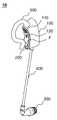
도 1은 귀 착용형 생체 신호 측정 장치를 예시적으로 도시한 도면이다.1 is a diagram exemplarily illustrating an ear-wearable biosignal measuring device.
귀 착용형 생체 신호 측정 장치(10)는 사용자의 기본적인 생체 신호를 측정할 수 있다. 여기서 귀 착용형 생체 신호 측정 장치(10)가 직접적으로 측정할 수 있는 생체 신호는 산소포화도 및 체온이며, 산소포화도를 이용하여 맥박이 산출될 수 있다. 산소포화도와 체온 이외에도 적절한 센서를 적용하여 다른 생체 신호도 측정할 수 있다.The ear-wearable
사용자는 귀 착용형 생체 신호 측정 장치(10)를 착용한 상태로 활동할 수 있다. 따라서 귀 착용형 생체 신호 측정 장치(10)는 생체 신호를 장기간에 걸쳐 연속적으로 측정할 수 있다. 여기서, '연속적'은 귀 착용형 생체 신호 측정 장치(10)를 계속해서 착용하고 있는 상태도 표현하기 위한 중의적인 표현이며, '주기적'으로 또는 '불규칙적'으로 측정해도 충분한 생체 신호도 '연속적'으로 측정된다고 표현하도록 한다. 예를 들어, 사용자는 일상 업무중일뿐 아니라, 수면 중에도 귀 착용형 생체 신호 측정 장치(10)를 착용할 수 있다. 따라서 체온 및/또는 맥박의 변화를 시간 단위부터 일 단위, 또는 주 단위로 모니터링 할 수 있게 된다.The user may be active while wearing the ear wearable
귀 착용형 생체 신호 측정 장치(10)와 같이, 귀에 착용할 수 있는 유형의 장치는 사용자의 자유로운 손 사용을 제한하지 않는다. 스마트 와치로 측정할 수 있는 산소포화도와 달리, 체온 측정은 체온계를 귀나 이마에 접촉한 상태 또는 일정 거리 이격시킨 상태에서 측정하여야 한다. 따라서 일 단위의 체온 모니터링이 필요한 경우에는, 사용자가 체온계를 휴대하면서 일정 시간마다 체온을 측정하여야 한다. 이에 반해, 귀 착용형 생체 신호 측정 장치(10)의 산소포화도 검출 센서(200)는 귓등에 밀착되며, 체온계(300)는 귀에 삽입된 상태가 유지되므로, 사용자의 불편함이 상당히 사라진다. 귀 착용형 생체 신호 측정 장치(10)는 생체 신호를 스스로 측정할 수 있는 사용자뿐 아니라 생체 신호를 스스로 측정할 수 없는 사용자에게도 적용할 수 있다. 특히, 귀 착용형 생체 신호 측정 장치(10)는 접촉시 감염 우려가 있는 유행증 환자를 연속적으로 모니터링하는데 효과적일 수 있다.An ear-worn type device, such as the ear-worn
도 1을 참조하면, 귀 착용형 생체 신호 측정 장치(10)는 몸체(100), 귀 삽입형 체온계(300), 연질 코드(400) 및 이어 후크(500)를 포함할 수 있다. 몸체(100)의 전면 F에는, 외부로 노출된 충전 단자(110), 스위치(120) 및 산소포화도 검출 센서(200)가 배치될 수 있다. 연질 코드(400)은 몸체(100)와 귀 삽입형 체온계(300)를 전기적으로 연결할 수 있다. 이어 후크(500)는 몸체(100), 특히, 산소포화도 검출 센서(200)를 귓등에 밀착시킬 수 있다. 산소포화도는 다른 생체 신호와 달리 동잡음에 취약할 뿐 아니라 피부에 밀착된 상태에서만 측정이 가능하다. 탄성 소재로 제조된 이어 후크(500)는 산소포화도 검출 센서(200)가 피부에 밀착되도록 할 뿐 아니라 밀착된 상태가 유지되도록 한다. 특히 귀는 움직임이 가장 적은 신체 기관이어서, 손이나 다리 등의 움직임에 의한 영향을 가장 적게 받는다.Referring to FIG. 1 , an ear-wearable
도 2는 도 1에 예시된 귀 착용형 생체 신호 측정 장치를 착용하는 과정을 예시적으로 도시한 도면이다.FIG. 2 is a diagram exemplarily illustrating a process of wearing the ear-wearable biosignal measuring device illustrated in FIG. 1 .
이어 후크(500)는 타단(520)이 몸체(100)의 전면 F으로부터 이격되도록 일단(510)으로부터 연장된다. 예를 들어, 이어 후크(500)는 일단(510)으로부터 반시계 방향으로 연장될 수 있다. 이어 후크(500)는 탄성 소재로 형성되어, 편리한 착용을 가능하게 하며, 특히, 착용한 상태에서는 본체(100)를 이어 후크(500) 방향으로 당겨서 산소포화도 검출 센서(200)와 피부와의 밀착을 유지할 수 있다. 일 실시예로, 편리한 착용을 위해, 이어 후크(500)의 타단(520)은 전면 F에서 멀어지는 방향으로 구부러져서, S자 형상을 가질 수 있다. 이로 인해 귀에 접촉하는 접촉 영역(525)은 타단(520) 근처에 위치하게 될 수 있다. 추가적으로, 이어 후크(500)의 일단(510)은 본체(100)의 상면 또는 전면 F에 결합될 수 있다.
귀 착용형 생체 신호 측정 장치(10)는 이어 후크(500)의 접촉 영역(525)과 몸체(100)의 전면 F 사이 틈에 귀바퀴를 삽입하여 착용할 수 있다. 이로 인해, 이어 후크(500)는 귀 앞쪽에 위치되며 몸체(100)는 귀 뒤쪽에 위치된다. 예시된 도면에서, 산소포화도 검출 센서(200)는 전면 F으로부터 부분적으로 돌출되어 귓등에 용이하게 밀착될 수 있다. 한편, 귓등과의 접촉 면적을 증가시키기 위해서, 전면 F의 적어도 일부 또는 전체는 오목한 곡면일 수 있다.The ear wearable
이어 후크(500)의 접촉 영역(525)에 접촉하는 귀 부위는 착용 상태에서 귓구멍으로부터 이격되어야 한다. 이어 후크(500)의 타단(520)부터 접촉 영역(525)까지 연장된 부분은 체온계(300)의 귀 삽입을 방해하지 말아야 한다. 접촉 영역(525) 또는 타단(520)이 산소포화도 검출 센서(200)에 가까우면, 더욱 견고하게 밀착될 수 있다. 따라서 접촉 영역(525) 또는 타단(520)의 위치는 산소포화도 검출 센서(200)의 위치에 따라 조정될 수 있다.The part of the ear that comes into contact with the
귓바퀴를 삽입한 후, 연질 코드(400)에 매달린 귀 삽입형 체온계(300)를 귓구멍에 삽입함으로써, 생체 신호 측정에 적합한 착용 과정이 완료될 수 있다. 연질 코드(400)의 길이는 귀에 삽입된 상태에서 귓볼이나 귓바퀴를 당기지 않도록 결정될 수 있다.After inserting the pinna, by inserting the ear-
도 3은 도 1에 예시된 귀 착용형 생체 신호 측정 장치를 예시적으로 도시한 분해사시도이다.FIG. 3 is an exploded perspective view exemplarily illustrating the ear-wearable biosignal measuring device illustrated in FIG. 1 .
몸체(100)는 몸체 하우징(101L, 101R)을 포함할 수 있다. 몸체 하우징(101L, 101R)의 전면 F에는, 충전 단자(110), 스위치(120) 및 산소포화도 검출 센서(200)에 대응하는 위치에 충전 단자 홀(102L, 102R), 스위치 홀(103L, 103R) 및 센서 홀(103L, 103R)이 형성될 수 있다. 몸체 하우징(101L, 101R)에 의해 내부 공간이 정의되며, 정의된 내부 공간에 귀 착용형 생체 신호 측정 장치(10)의 기능을 구현하는 구성 부품들 중 적어도 일부가 수용될 수 있다.The
충전 단자(110)는 충전 가능한 배터리(115)에 전기적으로 연결되며, 배터리(115)를 충전하는 전력을 외부로부터 공급받는다. 무선 충전기를 채택하면, 충전 단자(110) 및 충전 단자 홀(102L, 102R)은 생략될 수 있다.The charging
스위치(120)는 귀 착용형 생체 신호 측정 장치(10)의 구동을 제어한다. 스위치(120)에 의해 배터리(115)로부터 전력이 각 구성 부품에 공급될 수 있다. 스위치(120)가 전면 F에 배치됨으로써, 착용중에는 귀 착용형 생체 신호 측정 장치(10)를 턴오프시키 어려워진다. 따라서 귀 착용형 생체 신호 측정 장치(10)가 의도적인 조작 또는 실수에 의해 착용 중에 턴 오프되지 않을 수 있다.The
산소포화도 검출 센서(200)는 복수의 LED 및 수광 소자가 배치된 검출면을 가진다. LED는 적색 및 근적외선 LED를 포함할 수 있다. 산소포화도 검출 센서(200)의 검출면은 센서 홀(103L, 103R)을 통해 노출될 수 있다. 산소포화도 검출 센서(200)는 적색광과 근적외선광을 이용하여 동맥혈의 광흡수도를 측정한다. 산소포화도는 폐에서 결합한 산소를 조직까지 운반하는 기능성 헤모글로빈 HbO2와 산소를 운반하지 않는 부기능성 헤모글로빈 Hb을 이용하여 산출될 수 있다. HbO2와 Hb는 약 600nm 내지 약 1,000nm 사이의 광 대역에서 서로 다른 광학 특성, 즉, 상이한 흡광도를 나타낸다. 약 660nm 적색광에서, HbO2는 Hb보다 상대적으로 큰 흡광도를 가진다. 이를 이용하여, 적색광과 근적외선을 일정 간격으로 교번하여 조사하여 흡광도를 측정할 수 있다. 이로부터 산소포화도를 산출할 수 있으며, 산소포화도로부터 맥박을 산출할 수 있다.The oxygen
몸체 하우징(101L, 101R)은 배터리(115), 마이크로 프로세서(130), 무선 송수신기(140) 및 자이로 센서(150)를 수용할 수 있다. 배터리(115)로부터의 각 구성 부품까지의 전력 라인 및 센서(200, 330)와 마이크로 프로세서(130) 사이의 신호 라인은 인쇄 회로 기판(160)에 의해 제공될 수 있다. 충전 단자(110) 및 스위치(120)는 인쇄 회로 기판(160)에 고정될 수 있다.The body housings 101L and 101R may accommodate the
무선 송수신기(140)는 마이크로 프로세서(130)의 제어에 의해 하나 이상의 통신 방식에 따라 생체 신호를 송신하거나 수신한다. 여기서, 무선 송수신기(140)는 예를 들어 W-CDMA 같은 이동통신표준에 따른 기지국, LAN의 Wifi 라우터, 블루투스, 지그비, Wifi-Direct, NFC와 같은 근거리 무선 통신을 지원하는 장치(이하, 억세스 포인트로 총칭함) 등과 통신할 수 있다. 근거리 무선 통신만 가능한 경우, 무선 송수신기(140)는 예를 들어, 스마트 폰과 같은 이동 통신 단말을 통해 액세스 포인트에 연결될 수도 있다. 무선 송수신기(140)는 마이크로 프로세서(130) 또는 센서(200, 300)로부터 출력된 전기 신호를 무선 신호로 변환하여 액세스 포인트를 통해 외부 장치로 전송하며, 액세스 포인트를 통해 수신한 무선 신호를 전기 신호로 변환하여 마이크로 프로세서(130)에 입력한다.The
자이로 센서(150)는 귀 착용형 생체 신호 측정 장치(10)에 발생한 가속도를 측정한다. 귀 착용형 생체 신호 측정 장치(10)를 착용한 사용자가 움직임, 예를 들어, 걷기 또는 뛰기는 가속도 변화를 통해 감지할 수 있다. 사용자의 움직임 시간은 운동 시간으로 기록 관리될 수 있다. 한편, 사용자가 움직이는 동안에는 동잡음이 심해지므로, 산소포화도 측정이 잠시 정지될 수 있다. 자이로 센서(150)는 사용자가 쓰러지거나 떨어지면, 중력 방향으로 순간적으로 발생한 가속도를 측정할 수 있다.The
귀 삽입형 체온계(300)는 체온계 하우징(310), 보호 커버(320) 및 센서 조립체(330)를 포함할 수 있다. 체온계 하우징(310) 및 보호 커버(320)에 의해 정의되는 내부 공간에 센서 조립체(330)가 수용된다. 보호 커버(320)는 내이에서 방사된 적외선이 통과할 수 있도록, 개방되거나 광학적으로 투명한 매체를 적어도 부분적으로 포함할 수 있다.The ear
한편, 센서 조립체(330)는 온도 보상 기능을 가질 수 있다. 온도 보상 기능은 센서 자체의 온도를 정상 동작 범위로 유지시켜서 주변 온도 변화에 의한 측정 오차의 발생을 감소시킬 수 있다. 센서 조립체(330)의 다양한 실시예는 도 4를 참조하여 상세히 설명한다.Meanwhile, the
연질 코드(400)의 일단은 귀 삽입형 체온계(300)에 결합되며, 타단 부근은 결속 부재(410, Cord Strain Relief Bushing)에 결합된다. 결속 부재(410)는 몸체 하우징(101L, 101R)의 하부에 형성된 결속 부재 삽입홈(105L, 105R)에 삽입된다. 연질 코드(400)는 내부에 전기 전도체, 예를 들어, 전선을 포함할 수 있다. 둘 이상의 전선은 배터리(115) 및 마이크로 프로세서(130) 각각에 전기적으로 연결되어 귀 삽입형 체온계(300)에 전력을 공급하며 마이크로 프로세서(130)와 귀 삽입형 체온계(300)사이에서 제어 신호 및 측정 신호를 전달한다.One end of the
도 4는 도 3에 예시된 비접촉식 온도 센서를 예시적으로 도시한 단면도이다.FIG. 4 is a cross-sectional view illustrating the non-contact temperature sensor illustrated in FIG. 3 .
센서 조립체(330, 331, 332)는 온도 보상 기능을 가진다. 센서 조립체(330, 331, 332)는 조립체 하우징(340), 온도 센서(350) 및 열전 소자(Thermoelectric cooling, TEC)(360, 361, 362)를 포함할 수 있다. 온도 센서는 내이(內耳)로부터 방사된 적외선을 수광하는 적외선 센서, 적외선 센서의 수광면이 광축에 실질적으로 수직하게 배치되도록 적외선 센서를 고정하는 센서 하우징 및 적외선 센서 자체의 온도 또는 적외선 센서 주변의 온도(이하, '내부 온도'로 총칭함)를 측정하는 내부 센서를 포함할 수 있다. 조립체 하우징(340)은 온도 센서(350)의 광축상에 위치한 윈도우(345)를 포함할 수 있다. 센서 하우징은 일단이 개방되거나 광학적으로 투명한 매체에 의해 보호된 원통형 하우징일 수 있다. 센서 하우징은, 적외선 센서로부터 전기적으로 절연되되, 열 전도율이 높은 물질로 형성될 수 있다.The
온도 센서(350)은, 인체의 특정 부위에서 방사된 적외선을 수광하여 제1 측정 신호 및 내부 온도를 측정하여 제2 측정 신호를 출력한다. 온도 센서(350)은, 제1 측정 신호를 출력하는 적외선 센서 및 내부 온도를 측정하여 제2 측정 신호를 출력하는 내부 센서에 더 포함할 수 있다. 적외선 센서의 일 예로, 중국 Sunshine Technologies의 써모파일 센서 STP9CF55는, 제1 측정 신호를 출력하는 써모파일 센서와 제2 측정 신호를 출력하는 내부 센서, 예를 들어, 써미스터를 포함한다. 적외선 센서는, 수광한 적외선이 나타내는 온도가 상승할수록 저항값이 감소하는 NTC(Negative temperature coefficient) 센서이며, 내부 센서는, 내부 온도가 증가할수록 저항값이 증가하는 PTC(Positive temperature coefficient) 센서일 수 있다.The
온도 센서(350)는 열전 소자(360, 361, 362)에 열적으로 결합된다. 열전 소자(360, 361, 362)는 전기에 의해 구동되어 온도 센서(350)로부터 열을 제거(냉각)하거나 온도 센서(350)에 열을 전달(가열)할 수 다. 추가적으로, 센서 조립체(330, 331, 332)는 열전 소자(360, 361, 362)와 온도 센서(350)간 열 교환 효율을 증가시키기 위한 금속 부재(미도시)를 더 포함할 수 있다. 이하에서, 측정된 체온을 내부 온도를 이용하여 보정하는 종래 방식과, 본 발명에 의한 온도 보상 과정을 설명한다.The
적외선 센서의 일 예인 써모파일 센서는, 동작 온도에 따라, 동일한 온도를 나타내는 적외선을 수광하더라도 상이한 제1 측정 신호를 출력할 수 있다. 종래에, 제2 측정 신호를 통해 획득한 내부 온도는, 제1 측정 신호 자체 또는 제1 측정 신호로부터 연산된 체온을 보정하기 위해 이용되었다. 그러나 제1 측정 신호 및/또는 이로부터 연산된 체온을 보정하기 위해서는, 써모파일 센서별로 변환식 또는 변환표가 필요하다. 변환식 또는 변환표는, 필연적으로 일정 범위의 오차를 포함할 뿐 아니라, 동일 종류의 써모파일 센서도 PVT(Process, Voltage, Temperature) 등의 영향으로 인해, 적정 온도 범위를 벗어나면 상대적으로 큰 오차를 갖는 제1 측정 신호를 출력할 수 있다. 또한, 써모파일 센서별로 변환식 또는 변환표가 달라져야 한다.A thermopile sensor, which is an example of an infrared sensor, may output a different first measurement signal according to an operating temperature, even if infrared rays representing the same temperature are received. Conventionally, the internal temperature obtained through the second measurement signal is used to correct the first measurement signal itself or the body temperature calculated from the first measurement signal. However, in order to correct the first measurement signal and/or the body temperature calculated therefrom, a conversion formula or conversion table is required for each thermopile sensor. The conversion formula or conversion table inevitably includes an error within a certain range, and the same type of thermopile sensor also has a relatively large error if it is out of the appropriate temperature range due to the influence of PVT (Process, Voltage, Temperature), etc. It is possible to output a first measurement signal having a In addition, the conversion formula or conversion table should be different for each thermopile sensor.
센서 조립체(330, 331, 332)가 턴온 되면, 온도 센서(350)의 내부 온도 센서는, 현재 내부 온도 Tcurrent를 나타내는 제2 측정 신호를 출력한다. 마이크로 프로세서는, 미리 설정된 적정 내부 온도 Ttarget과 현재 내부 온도 Tcurrent를 비교하여 차이 Ttarget - Tcurrent를 산출한다. 차이가 양의 값이면, 내부 온도의 상승, 즉, 가열이 필요하며, 차이가 음의 값이면, 내부 온도의 하강, 즉, 냉각이 필요하다. 적정 내부 온도 Ttarget는, 섭씨 25도와 같은 상온일 수 있다. 상술한 바와 같이, 써모파일 센서는, 상온에서의 동작을 고려하여 제조되며, 다른 동작 온도에서보다 상대적으로 정밀한 제1 측정 신호를 출력할 수 있다.When the
마이크로 프로세서는 차이 Ttarget - Tcurrent에 따라 가열 또는 냉각 구동하도록 열전 소자(360, 361, 362)를 제어할 수 있다. 마이크로 프로세서는 온도 제어 명령에 따라, 열전 소자(360, 361, 362)에 공급하는 직류 전류의 방향, 크기 및 인가 시간을 조절하여, 열전 소자(360, 361, 362)의 양면 중 온도 센서(350)를 향하는 면을 가열 또는 냉각시킨다. 차이 Ttarget - Tcurrent가 크면, 상대적으로 큰 전류를 일정 시간 동안 인가하여 상대적으로 빠른 온도 상승을 유도한다. 열전 소자(360, 361, 362)에 의해 발생한 열은 온도 센서(350)로 전달되어, 내부 온도를 상승시킨다. 내부 온도 센서는, 상승한 내부 온도를 측정하여 제2 측정 신호를 출력하며, 마이크로 프로세서는 제2 측정 신호를 이용하여 산출된 현재 내부 온도 Tcurrent를 적정 내부 온도 Ttarget과 비교한다. 차이 Ttarget - Tcurrent가 감소하면, 열전 소자(360, 361, 362)에 인가되는 전류의 크기를 감소시켜, 온도 상승률이 제어될 수 있다. 냉각이 필요한 경우, 즉, 차이 Ttarget - Tcurrent가 음의 값이면, 마이크로 프로세서는, 열전 소자(360, 361, 362)에 인가하는 전류의 방향을 변경하여 열전 소자(360, 361, 362)의 양면 중 온도 센서(350)을 향하는 면을 냉각한다. 이를 통해 내부 온도가 하강한다.The microprocessor may control the
도 4의 (a)를 참조하면, 센서 조립체(330는 조립체 하우징(340)의 내측 바닥에 배치된 판재 형태의 열전 소자(360)를 포함할 수 있다. 열전 소자(360)는 온도 센서(350)와 접촉하거나 접촉하지 않을 수 있다. 온도 센서(350)의 타단과 접촉하도록 배치되면, 열전 소자(360)는 온도 센서(350)의 센서 하우징을 직접적으로 가열 또는 냉각할 수 있다. 온도 센서(350)의 타단으로부터 이격되도록 배치되면, 열전 소자(360)은 조립체 하우징(340)의 내부 공간(365)을 가열 또는 냉각함으로써, 적외선 센서 및/또는 센서 하우징을 간접적으로 가열 또는 냉각할 수 있다. 이를 통해, 내부 온도가 상승 또는 하강될 수 있다.4A , the
도 4의 (b) 및 (c)에서, 센서 조립체(331, 332)는 온도 센서(350)의 측면에 배치된 곡면으로 가공된 열전 소자(361, 362)를 포함할 수 있다. (b)에서, 열전 소자(361)는 온도 센서(350)의 하부 외측면에 접촉하여 온도 센서(350)의 센서 하우징을 직접적으로 가열 또는 냉각할 수 있다. (c)에서, 열전 소자(362')는 조립체 하우징(340)의 하부 내측면에 배치되어 조립체 하우징(340)의 내부 공간(365)을 가열 또는 냉각함으로써, 적외선 센서 및/또는 센서 하우징을 간접적으로 가열 또는 냉각할 수 있다. 이를 통해, 적외선 센서의 자체 온도 또는 주변 온도가 상승 또는 하강될 수 있다.4B and 4C , the
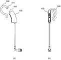
도 5는 도 1에 예시된 귀 착용형 생체 신호 측정 장치의 클립과 본체간 결합 구조를 예시적으로 도시한 도면이다.FIG. 5 is a diagram exemplarily illustrating a coupling structure between a clip and a main body of the ear-wearable biosignal measuring device illustrated in FIG. 1 .
도 5의 (a) 및 (b)를 함께 참조하면, 이어 후크(500)의 일단에 수용 소켓(511)이 형성되며, 수용 소켓(511)은 그 내부에 결합용 볼(106)을 수용한다. 결합용 볼은 몸체(100)의 상면에 배치될 수 있다. 수용 소켓과 결합용 볼(106L, 106R)은 볼 조인트를 구성하며, 이로 인해, 이어 후크(500)는 결합용 볼(106)이 상면으로부터 연장한 방향의 주위를 회전할 수 있다. 도 2에 예시된 착용 방식과 달리, 사용자는 이어 후크(500)를 시계 또는 반시계 방향으로 회전시키고 몸체(100)를 귓등에 배치한 후 이어 후크(500)를 반대 방향으로 회전시켜서 귀 착용형 생체 신호 측정 장치(10)를 착용할 수 있다.Referring to Figure 5 (a) and (b) together, the receiving
도 6은 도 1에 예시된 귀 착용형 생체 신호 측정 장치를 기능적으로 도시한 블록도이다.FIG. 6 is a block diagram functionally illustrating the ear-wearable biosignal measuring device illustrated in FIG. 1 .
도 6을 참조하면, 귀 착용형 생체 신호 측정 장치(10)는 마이크로 프로세서(130), 산소포화도 검출 센서(200), 귀 삽입형 체온계(300), 자이로 센서(150) 및 무선 송수신기(140)를 포함할 수 있다. 귀 착용형 생체 신호 측정 장치(10)의 구동은 스위치(120)에 의해 개시될 수 있다.Referring to FIG. 6 , the ear wearable
마이크로 프로세서(130)는 산소포화도 검출 센서(200), 귀 삽입형 체온계(300) 및 무선 송수신기(140)의 동작을 제어할 수 있다. 예를 들어, 마이크로 프로세서(130)는 일정 시간 간격으로 센서(200, 300)를 구동시켜서 생체 신호를 측정하도록 할 수 있다. 여기서, 산소포화도 검출 센서(200), 귀 삽입형 체온계(300)의 검출 간격은 동일하거나 상이할 수 있다. 시간 간격은 미리 지정된 간격이거나 외부에서 수신된 측정 제어 명령에 따라 설정된 간격일수 있다. 마이크로 프로세서(130)는 생체 신호 측정값이 설정된 정상 범위에 포함되는지 판단할 수 있다. 그리고 마이크로 프로세서(130)는 무선 송수신기(140)가 측정된 생체 신호를 외부로 전송하도록 할 수 있다.The
마이크로 프로세서(130)는 자이로 센서(150)를 통해 사용자의 움직임을 측정할 수 있다. 예를 들어, 마이크로 프로세서(130)는 자이로 센서(150)에 의해 측정되는 반복적인 가속도의 변화 패턴으로부터 사용자가 걷거나 뛰는 상태라고 판단할 수 있다. 이러한 사용자의 움직임은 일시적으로 저장된 후 외부로 전송될 수 있다. 다른 예를 들면, 마이크로 프로세서(130)는 사용자가 움직이는 동안에는 산소포화도 측정을 일시적으로 중지할 수 있다. 또 다른 예로, 마이크로 프로세서(130)는 중력 방향으로 순간적인 가속도가 측정되면, 사용자의 쓰러짐 또는 떨어짐으로 판단하여 무선 송수신부(140)와 통신하는 이동 통신 단말을 통해 외부로 응급 신호를 전송할 수 있다.The
추가적으로 또는 선택적으로, 마이크로 프로세서(130)는 귀 삽입형 체온계(300)의 센서 조립체(330)가 온도 보상 동작을 하도록 제어할 수 있다. 마이크로 프로세서(130)는 센서 조립체(330)로부터 내부 온도를 나타내는 제2 측정 신호를 수신하며, 제2 측정 신호가 설정된 정상 온도 범위를 벗어나지 않도록 열전 소자(360, 361, 362)를 구동한다.Additionally or alternatively, the
산소포화도 검출 센서(200)는 산소포화도를 측정하며 측정한 산소포화도를 이용하여 맥박을 산출할 수 있다. 한편, 산소포화도 검출 센서(200)는 산소포화도만 측정하며, 맥박은 마이크로 프로세서(130)가 산출할 수도 있다. 산소포화도 검출 센서(200)는 적색광 및 근적외선광이 조사되면 서로 다른 흡광율을 나타내는 헤모글로빈의 광학적 특성을 이용할 수 있다. 산소포화도 측정값은 AC 성분뿐 아니라 DC 성분도 포함될 수 있다. 실제 산소포화도를 나타내는 AC 성분과 달리, DC 잡음은 헤모글로빈을 제외한 다른 생체 조직에 의해 발생하며 이를 제거할 수 있는 다양한 방법, 예를 들어, Beer-Lambert, Peak and Valley, MASIMO 등의 방식이 적용될 수 있다.The oxygen
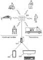
도 7은 도 1에 예시된 귀 착용형 생체 신호 측정 장치를 이용한 연속적 비대면 모니터링 시스템을 예시적으로 도시한 도면이다.7 is a diagram exemplarily illustrating a continuous non-face-to-face monitoring system using the ear-wearable biosignal measuring device illustrated in FIG. 1 .
영상으로 화재를 감시하는 시스템은 큰 건물이나 넓은 지역을 용이하게 관리할 수 있다. 이는 여러 곳의 영상을 한 곳에서 집중하여 모니터링할 수 있기 때문이다. 하지만, 병원에서 사용하는 의료 장비들은 주로 유선 통신 기능만 구현되어 있어서, 착용 후 이동을 제한하며, 따라서 자리를 벗어난 환자를 모니터링할 수 있는 방법을 제공하지 못했다. 특히, 의료진의 관리 범위를 벗어난 환자의 상태를 측정하기도 쉽지 않다.The video fire monitoring system can easily manage large buildings or large areas. This is because images from multiple locations can be centrally monitored in one place. However, medical equipment used in hospitals mainly implements only a wired communication function, restricting movement after wearing, and thus does not provide a method for monitoring a patient who has left the seat. In particular, it is not easy to measure the condition of a patient outside the scope of the medical staff.
귀 착용형 생체 신호 측정 장치(10)는 의료 시설에 수용중인 다수의 환자들에 대한 연속 및 비대면 모니터링을 가능하게 한다. 병원은 다수의 환자를 케어할 수 있는 의료진 및 의료 장비를 갖추고 있다. 하지만, 모든 환자의 생체 신호를 동시에 측정하여 상태를 모니터링하는 것은 실제로 불가능하다. 특히, 유행증 환자의 상태는 급격히 악화될 수 있어서 연속적인 모니터링이 필수적이다. 귀 착용형 생체 신호 측정 장치(10)는 의료 시설에 수용된 모든 환자마다 착용될 수 있으며, 측정된 생체 신호 중 비정상 생체 신호는 자동으로 검출되어 의료진에게 통지될 수 있다.The ear-worn
귀 착용형 생체 신호 측정 장치(10)는 의료 시설에 수용되지 않은 사람들에 대한 원격 의료 서비스의 제공을 가능하게 한다. 원격 의료 서비스는 꾸준한 관리가 필요한 질병을 가진 사람뿐 아니라 의료 시설로 이송중인 응급 환자에게도 제공될 수 있다. 일상 생활중에도, 생체 신호는 연속적으로 측정되어 상태 판단의 기초 정보로 이용될 수 있다.The ear-worn
도 7을 참조하면, 연속적 비대면 모니터링 시스템은 귀 착용형 생체 신호 측정 장치(10), 생체 신호 수집 및 처리 장치(610) 및 단말(620, 630)을 포함할 수 있다. 여기서, 단말은 의료진이 사용하는 개인용 컴퓨터, 노트북, 스마트폰, 패드 등과 같이 통신 기능을 가진 전자 정보 처리 장치일 수 있다. 귀 착용형 생체 신호 측정 장치(10)는 액세스 포인트(600)를 통해 생체 신호를 생체 신호 수집 및 처리 장치(610)로 전송한다. 한편, 생체 신호 수집 및 처리 장치(610)도 액세스 포인트(600)를 통해 측정 제어 명령을 귀 착용형 생체 신호 측정 장치(10)로 전송할 수 있다.Referring to FIG. 7 , the continuous non-face-to-face monitoring system may include an ear-wearable
생체 신호 수집 및 처리 장치(610)는 복수의 귀 착용형 생체 신호 측정 장치(10)로부터 하나 이상의 생체 신호를 수집한다. 수집된 생체 신호는 귀 착용형 생체 신호 측정 장치(10) 또는 이를 착용한 사람별로 구분되어 처리된다. 여기서 처리는 생체 신호를 분석하여 비정상 여부를 판단하는 과정뿐 아니라 처리 전 또는 처리 후 생체 신호를 저장하는 과정도 포함할 수 있다. 정상/비정상을 판단하는 수치 범위는 생체 신호별로 상이하게 설정될 수 있다.The biosignal collection and
전술한 본 발명의 설명은 예시를 위한 것이며, 본 발명이 속하는 기술분야의 통상의 지식을 가진 자는 본 발명의 기술적 사상이나 필수적인 특징을 변경하지 않고서 다른 구체적인 형태로 쉽게 변형이 가능하다는 것을 이해할 수 있을 것이다. 그러므로 이상에서 기술한 실시 예들은 모든 면에서 예시적인 것이며 한정적이 아닌 것으로 이해해야만 한다. 특히, 도면을 참조하여 설명된 본 발명의 특징은, 특정 도면에 도시된 구조에 한정되는 것이 아니며, 독립적으로 또는 다른 특징에 결합되어 구현될 수 있다.The above description of the present invention is for illustration, and those of ordinary skill in the art to which the present invention pertains can understand that it can be easily modified into other specific forms without changing the technical spirit or essential features of the present invention. will be. Therefore, it should be understood that the embodiments described above are illustrative in all respects and not restrictive. In particular, the features of the present invention described with reference to the drawings are not limited to the structures shown in the specific drawings, and may be implemented independently or in combination with other features.
본 발명의 범위는 상기 상세한 설명보다는 후술하는 특허청구범위에 의하여 나타나며, 특허청구범위의 의미 및 범위 그리고 그 균등 개념으로부터 도출되는 모든 변경 또는 변형된 형태가 본 발명의 범위에 포함되는 것으로 해석되어야 한다.The scope of the present invention is indicated by the following claims rather than the above detailed description, and all changes or modifications derived from the meaning and scope of the claims and their equivalent concepts should be construed as being included in the scope of the present invention. .
Claims (14)
Translated fromKorean일단이 몸체에 결합되며 귀 앞쪽에 배치되어 상기 몸체를 귀에 고정하는 이어 후크;
검출면이 상기 이어 후크의 타단 근처에 배치되도록 상기 몸체에 적어도 부분적으로 수용된 산소포화도 검출 센서;
연질 코드에 의해 상기 하우징에 연결된 귀 삽입형 체온계; 및
상기 산소포화도 검출 센서 및 상기 귀 삽입형 체온계의 측정값을 무선으로 전송하는 무선 송수신기를 포함하는 귀 착용형 생체 신호 측정 장치.a body that is hung over the user's ear;
an ear hook having one end coupled to the body and disposed in front of the ear to fix the body to the ear;
an oxygen saturation detection sensor at least partially accommodated in the body such that the detection surface is disposed near the other end of the ear hook;
an in-ear thermometer connected to the housing by a soft cord; and
and a wireless transceiver for wirelessly transmitting the measured values of the oxygen saturation detection sensor and the in-ear thermometer.
상기 이어 후크는 상기 몸체로부터 연장된 S자 형상이며, 착용시 상기 산소포화도 검출 센서를 상기 귓등에 밀착시키는 귀 착용형 생체 신호 측정 장치.The method according to claim 1,
The ear hook has an S-shape extending from the body, and when worn, the ear-wearable bio-signal measuring device closely adheres the oxygen saturation detection sensor to the back of the ear.
상기 이어 후크는 상기 몸체에 회동 가능하게 결합된 귀 착용형 생체 신호 측정 장치.The method according to claim 1,
The ear hook is an ear-wearable biosignal measuring device rotatably coupled to the body.
상기 연질 코드에 연결된 체온계 하우징;
상기 체온계 하우징에 수용되며, 온도 보상 기능을 가진 센서 조립체; 및
상기 체온계 하우징에 결합하여 상기 센서 조립체가 수용되는 내부 공간을 정의하는 보호 커버를 포함하는 귀 착용형 생체 신호 측정 장치.The method according to claim 1, The ear implantable thermometer,
a thermometer housing connected to the soft cord;
a sensor assembly accommodated in the thermometer housing and having a temperature compensation function; and
and a protective cover coupled to the thermometer housing and defining an inner space in which the sensor assembly is accommodated.
조립체 하우징;
상기 조립체 하우징에 수용되며 인체에서 방사된 적외선을 수광하여 제1 측정 신호 및 내부 온도를 측정하여 제2 측정 신호를 출력하는 온도 센서; 및
상기 내부 온도를 증가 또는 감소시키는 열전 소자를 포함하는 귀 착용형 생체 신호 측정 장치.The method according to claim 4, wherein the sensor assembly
assembly housing;
a temperature sensor accommodated in the assembly housing and receiving infrared radiation emitted from the human body to measure a first measurement signal and an internal temperature to output a second measurement signal; and
An ear-wearable biosignal measuring device including a thermoelectric element for increasing or decreasing the internal temperature.
상기 복수의 귀 착용형 생체 신호 측정 장치로부터 상기 측정값을 수집하며, 수집한 측정값을 분석하여 비정상 생체 신호를 검출하는 생체 신호 수집 및 처리 장치를 포함하되,
상기 귀 착용형 생체 신호 측정 장치는
사용자의 귓등에 걸쳐지는 몸체;
일단이 몸체에 결합되며 귀 앞쪽에 배치되어 상기 몸체를 귀에 고정하는 이어 후크;
검출면이 상기 이어 후크의 타단 근처에 배치되도록 상기 몸체에 적어도 부분적으로 수용된 산소포화도 검출 센서;
연질 코드에 의해 상기 하우징에 연결된 귀 삽입형 체온계; 및
상기 산소포화도 검출 센서 및 상기 귀 삽입형 체온계의 측정값을 무선으로 전송하는 무선 송수신기를 포함하는 연속적 비대면 모니터링 시스템.a plurality of ear-wearable bio-signal measuring devices for continuously transmitting the measured values generated by measuring bio-signals while worn by a plurality of people through wireless communication; and
a bio-signal collection and processing device that collects the measured values from the plurality of ear-worn bio-signal measuring devices and analyzes the collected measured values to detect abnormal bio-signals;
The ear wearable biosignal measuring device is
a body that is hung over the user's ear;
an ear hook having one end coupled to the body and disposed in front of the ear to fix the body to the ear;
an oxygen saturation detection sensor at least partially accommodated in the body such that the detection surface is disposed near the other end of the ear hook;
an in-ear thermometer connected to the housing by a soft cord; and
and a wireless transceiver for wirelessly transmitting the measured values of the oxygen saturation detection sensor and the ear-type thermometer.
상기 이어 후크는 상기 몸체로부터 연장된 S자 형상이며, 착용시 상기 산소포화도 검출 센서를 상기 귓등에 밀착시키는 연속적 비대면 모니터링 시스템.9. The method of claim 8,
The ear hook has an S-shape extending from the body, and a continuous non-face-to-face monitoring system for attaching the oxygen saturation detection sensor to the back of the ear when worn.
상기 이어 후크는 상기 몸체에 회동 가능하게 결합된 연속적 비대면 모니터링 시스템.9. The method of claim 8,
The ear hook is a continuous non-face-to-face monitoring system rotatably coupled to the body.
상기 연질 코드에 연결된 체온계 하우징;
상기 체온계 하우징에 수용되며, 온도 보상 기능을 가진 센서 조립체; 및
상기 체온계 하우징에 결합하여 상기 센서 조립체가 수용되는 내부 공간을 정의하는 보호 커버를 포함하는 연속적 비대면 모니터링 시스템.The method according to claim 8, wherein the ear implantable thermometer,
a thermometer housing connected to the soft cord;
a sensor assembly accommodated in the thermometer housing and having a temperature compensation function; and
and a protective cover coupled to the thermometer housing and defining an interior space in which the sensor assembly is accommodated.
조립체 하우징;
상기 조립체 하우징에 수용되며 인체에서 방사된 적외선을 수광하여 제1 측정 신호 및 내부 온도를 측정하여 제2 측정 신호를 출력하는 온도 센서; 및
상기 내부 온도를 증가 또는 감소시키는 열전 소자를 포함하는 연속적 비대면 모니터링 시스템.The method according to claim 11, wherein the sensor assembly
assembly housing;
a temperature sensor accommodated in the assembly housing and receiving infrared radiation emitted from the human body to measure a first measurement signal and an internal temperature to output a second measurement signal; and
A continuous non-face-to-face monitoring system comprising a thermoelectric element for increasing or decreasing the internal temperature.
Applications Claiming Priority (2)
| Application Number | Priority Date | Filing Date | Title |
|---|---|---|---|
| KR20210008088 | 2021-01-20 | ||
| KR1020210008088 | 2021-01-20 |
Publications (1)
| Publication Number | Publication Date |
|---|---|
| KR20220105589Atrue KR20220105589A (en) | 2022-07-27 |
Family
ID=82701048
Family Applications (1)
| Application Number | Title | Priority Date | Filing Date |
|---|---|---|---|
| KR1020210192694ACeasedKR20220105589A (en) | 2021-01-20 | 2021-12-30 | Ear-wearable device of measuring physiological signals and system for monitoring physiological signals in non-face-to-face |
Country Status (1)
| Country | Link |
|---|---|
| KR (1) | KR20220105589A (en) |
Citations (1)
| Publication number | Priority date | Publication date | Assignee | Title |
|---|---|---|---|---|
| KR20180060724A (en) | 2016-11-29 | 2018-06-07 | 삼성전자주식회사 | Bio signal processing apparatus, apparatus and method for living body information detecting |
- 2021
- 2021-12-30KRKR1020210192694Apatent/KR20220105589A/ennot_activeCeased
Patent Citations (1)
| Publication number | Priority date | Publication date | Assignee | Title |
|---|---|---|---|---|
| KR20180060724A (en) | 2016-11-29 | 2018-06-07 | 삼성전자주식회사 | Bio signal processing apparatus, apparatus and method for living body information detecting |
Similar Documents
| Publication | Publication Date | Title |
|---|---|---|
| US20240180456A1 (en) | Clip-on optical or ecg light based physiological measurement device | |
| CN109844473B (en) | Portable physiological monitor configured to measure tympanic temperature | |
| US11045092B2 (en) | Apparatus and method for measuring biologic parameters | |
| CN106999048B (en) | Portable Physiological Monitor | |
| US6929611B2 (en) | Device for measuring the body temperature | |
| HK1222524A1 (en) | Apparatus and method for measuring biologic parameters | |
| KR20220105589A (en) | Ear-wearable device of measuring physiological signals and system for monitoring physiological signals in non-face-to-face | |
| US20230190194A1 (en) | Ear-wearable device of measuring physiological signals and system for monitoring physiological signals in non-face-to-face | |
| KR102756875B1 (en) | Eye patch-type bio-signal measuring device and bio-signal monitoring method using the same | |
| KR102541914B1 (en) | In-ear type biological signal measuring instrument | |
| KR102621840B1 (en) | Biological signal monitoring system | |
| US20250255495A1 (en) | Physiological Strain Sensor | |
| KR20230100361A (en) | Surrounding environment control system using biological signal measuring device based on network and method thereof | |
| KR20230100359A (en) | Biological signal measurement system using biological signal measuring device and method thereof | |
| KR20230100365A (en) | Method, device and system for health management based on wearable device | |
| KR20230100363A (en) | Surrounding environment control system using biological signal measuring device based on network and method thereof | |
| KR20230100360A (en) | Remote health management system using biological signal measuring device based on network and method thereof | |
| TWM310726U (en) | Wrist protector with bio-electro signal detecting and warning function | |
| HK40008171A (en) | Portable physiology monitor configured to measure tympanic temperature | |
| HK1230058A1 (en) | Apparatus and method for measuring biologic parameters | |
| HK1228240A1 (en) | Apparatus and method for measuring biologic parameters |
Legal Events
| Date | Code | Title | Description |
|---|---|---|---|
| PA0109 | Patent application | Patent event code:PA01091R01D Comment text:Patent Application Patent event date:20211230 | |
| PA0201 | Request for examination | ||
| PG1501 | Laying open of application | ||
| E902 | Notification of reason for refusal | ||
| PE0902 | Notice of grounds for rejection | Comment text:Notification of reason for refusal Patent event date:20240221 Patent event code:PE09021S01D | |
| E601 | Decision to refuse application | ||
| PE0601 | Decision on rejection of patent | Patent event date:20240427 Comment text:Decision to Refuse Application Patent event code:PE06012S01D Patent event date:20240221 Comment text:Notification of reason for refusal Patent event code:PE06011S01I |