KR20220096561A - Clothes Treatment Apparatus - Google Patents
Clothes Treatment ApparatusDownload PDFInfo
- Publication number
- KR20220096561A KR20220096561AKR1020200189127AKR20200189127AKR20220096561AKR 20220096561 AKR20220096561 AKR 20220096561AKR 1020200189127 AKR1020200189127 AKR 1020200189127AKR 20200189127 AKR20200189127 AKR 20200189127AKR 20220096561 AKR20220096561 AKR 20220096561A
- Authority
- KR
- South Korea
- Prior art keywords
- unit
- door
- roller
- pants
- chamber
- Prior art date
- Legal status (The legal status is an assumption and is not a legal conclusion. Google has not performed a legal analysis and makes no representation as to the accuracy of the status listed.)
- Pending
Links
Images


Classifications
- D—TEXTILES; PAPER
- D06—TREATMENT OF TEXTILES OR THE LIKE; LAUNDERING; FLEXIBLE MATERIALS NOT OTHERWISE PROVIDED FOR
- D06F—LAUNDERING, DRYING, IRONING, PRESSING OR FOLDING TEXTILE ARTICLES
- D06F87/00—Apparatus for moistening or otherwise conditioning the article to be ironed or pressed
- D—TEXTILES; PAPER
- D06—TREATMENT OF TEXTILES OR THE LIKE; LAUNDERING; FLEXIBLE MATERIALS NOT OTHERWISE PROVIDED FOR
- D06F—LAUNDERING, DRYING, IRONING, PRESSING OR FOLDING TEXTILE ARTICLES
- D06F63/00—Ironing machines having a roller or rollers coacting with a fixed or moving flat bed or table
- D06F63/02—Ironing machines having a roller or rollers coacting with a fixed or moving flat bed or table with two or more rollers co-acting with a fixed or moving flat bed or table
- D—TEXTILES; PAPER
- D06—TREATMENT OF TEXTILES OR THE LIKE; LAUNDERING; FLEXIBLE MATERIALS NOT OTHERWISE PROVIDED FOR
- D06F—LAUNDERING, DRYING, IRONING, PRESSING OR FOLDING TEXTILE ARTICLES
- D06F63/00—Ironing machines having a roller or rollers coacting with a fixed or moving flat bed or table
- D—TEXTILES; PAPER
- D06—TREATMENT OF TEXTILES OR THE LIKE; LAUNDERING; FLEXIBLE MATERIALS NOT OTHERWISE PROVIDED FOR
- D06F—LAUNDERING, DRYING, IRONING, PRESSING OR FOLDING TEXTILE ARTICLES
- D06F67/00—Details of ironing machines provided for in groups D06F61/00, D06F63/00, or D06F65/00
- D06F67/005—Stands or cabinets
- D—TEXTILES; PAPER
- D06—TREATMENT OF TEXTILES OR THE LIKE; LAUNDERING; FLEXIBLE MATERIALS NOT OTHERWISE PROVIDED FOR
- D06F—LAUNDERING, DRYING, IRONING, PRESSING OR FOLDING TEXTILE ARTICLES
- D06F67/00—Details of ironing machines provided for in groups D06F61/00, D06F63/00, or D06F65/00
- D06F67/02—Rollers; Heating arrangements therefor
- D—TEXTILES; PAPER
- D06—TREATMENT OF TEXTILES OR THE LIKE; LAUNDERING; FLEXIBLE MATERIALS NOT OTHERWISE PROVIDED FOR
- D06F—LAUNDERING, DRYING, IRONING, PRESSING OR FOLDING TEXTILE ARTICLES
- D06F67/00—Details of ironing machines provided for in groups D06F61/00, D06F63/00, or D06F65/00
- D06F67/10—Driving arrangements
- D—TEXTILES; PAPER
- D06—TREATMENT OF TEXTILES OR THE LIKE; LAUNDERING; FLEXIBLE MATERIALS NOT OTHERWISE PROVIDED FOR
- D06F—LAUNDERING, DRYING, IRONING, PRESSING OR FOLDING TEXTILE ARTICLES
- D06F71/00—Apparatus for hot-pressing clothes, linen or other textile articles, i.e. wherein there is substantially no relative movement between pressing element and article while pressure is being applied to the article; Similar machines for cold-pressing clothes, linen or other textile articles
- D06F71/18—Apparatus for hot-pressing clothes, linen or other textile articles, i.e. wherein there is substantially no relative movement between pressing element and article while pressure is being applied to the article; Similar machines for cold-pressing clothes, linen or other textile articles specially adapted for pressing particular garments or parts thereof
- D06F71/28—Apparatus for hot-pressing clothes, linen or other textile articles, i.e. wherein there is substantially no relative movement between pressing element and article while pressure is being applied to the article; Similar machines for cold-pressing clothes, linen or other textile articles specially adapted for pressing particular garments or parts thereof for pressing sleeves, trousers, or other tubular garments or tubular parts of garments
- D06F71/29—Trousers
- D—TEXTILES; PAPER
- D06—TREATMENT OF TEXTILES OR THE LIKE; LAUNDERING; FLEXIBLE MATERIALS NOT OTHERWISE PROVIDED FOR
- D06F—LAUNDERING, DRYING, IRONING, PRESSING OR FOLDING TEXTILE ARTICLES
- D06F71/00—Apparatus for hot-pressing clothes, linen or other textile articles, i.e. wherein there is substantially no relative movement between pressing element and article while pressure is being applied to the article; Similar machines for cold-pressing clothes, linen or other textile articles
- D06F71/32—Details
- D06F71/34—Heating arrangements; Arrangements for supplying or removing steam or other gases
- D—TEXTILES; PAPER
- D06—TREATMENT OF TEXTILES OR THE LIKE; LAUNDERING; FLEXIBLE MATERIALS NOT OTHERWISE PROVIDED FOR
- D06F—LAUNDERING, DRYING, IRONING, PRESSING OR FOLDING TEXTILE ARTICLES
- D06F71/00—Apparatus for hot-pressing clothes, linen or other textile articles, i.e. wherein there is substantially no relative movement between pressing element and article while pressure is being applied to the article; Similar machines for cold-pressing clothes, linen or other textile articles
- D06F71/32—Details
- D06F71/36—Pressing elements
- D—TEXTILES; PAPER
- D06—TREATMENT OF TEXTILES OR THE LIKE; LAUNDERING; FLEXIBLE MATERIALS NOT OTHERWISE PROVIDED FOR
- D06F—LAUNDERING, DRYING, IRONING, PRESSING OR FOLDING TEXTILE ARTICLES
- D06F71/00—Apparatus for hot-pressing clothes, linen or other textile articles, i.e. wherein there is substantially no relative movement between pressing element and article while pressure is being applied to the article; Similar machines for cold-pressing clothes, linen or other textile articles
- D06F71/32—Details
- D06F71/38—Feeding arrangements
- D—TEXTILES; PAPER
- D06—TREATMENT OF TEXTILES OR THE LIKE; LAUNDERING; FLEXIBLE MATERIALS NOT OTHERWISE PROVIDED FOR
- D06F—LAUNDERING, DRYING, IRONING, PRESSING OR FOLDING TEXTILE ARTICLES
- D06F73/00—Apparatus for smoothing or removing creases from garments or other textile articles by formers, cores, stretchers, or internal frames, with the application of heat or steam
- D06F73/02—Apparatus for smoothing or removing creases from garments or other textile articles by formers, cores, stretchers, or internal frames, with the application of heat or steam having one or more treatment chambers
- D—TEXTILES; PAPER
- D06—TREATMENT OF TEXTILES OR THE LIKE; LAUNDERING; FLEXIBLE MATERIALS NOT OTHERWISE PROVIDED FOR
- D06F—LAUNDERING, DRYING, IRONING, PRESSING OR FOLDING TEXTILE ARTICLES
- D06F61/00—Ironing machines using two or more co-operating pressing rollers
- D06F61/02—Ironing machines using two or more co-operating pressing rollers with two rollers
Landscapes
- Engineering & Computer Science (AREA)
- Textile Engineering (AREA)
- Treatment Of Fiber Materials (AREA)
- Accessory Of Washing/Drying Machine, Commercial Washing/Drying Machine, Other Washing/Drying Machine (AREA)
- Main Body Construction Of Washing Machines And Laundry Dryers (AREA)
Abstract
Translated fromKoreanDescription
Translated fromKorean본 개시는 의류처리장치에 관한 것이다. 보다 구체적으로는 의류를 스팀에 노출시키면서 롤러를 통해 의류를 가압하여 의류의 주름을 제거하는 의류처리장치에 관한 것이다.The present disclosure relates to a laundry treatment apparatus. More particularly, it relates to a clothes treatment apparatus for removing wrinkles from clothes by pressing clothes through a roller while exposing them to steam.
의류처리장치는 가정 및 세탁소에서 의류를 세탁하고 건조하며, 의류에 생긴 주름을 제거하기 위해 개발된 장치를 말한다. 의류처리장치로 분류되는 것에는 의류를 세탁하는 세탁기, 의류를 건조하는 건조기, 세탁기능과 건조기능을 모두 갖는 세탁/건조기, 그리고, 의류를 리프레쉬(refresh)하는 의류관리기, 의류의 주름을 제거하는 스티머(steamer) 등을 포함하는 개념이다.A clothes treatment device refers to a device developed to wash and dry clothes at home and at laundry, and to remove wrinkles on clothes. Classified as clothes processing equipment, there is a washing machine for washing clothes, a dryer for drying clothes, a washing/drying machine having both washing and drying functions, a clothes management device for refreshing clothes, and a washing machine for removing wrinkles from clothes It is a concept including a steamer and the like.
스티머는 의류에 생긴 주름을 제거하기 위해 의류에 스팀을 공급하는 장치이다. 일반적인 다리미와 달리, 스티머는 의류에 직접적으로(예를 들어, 의류를 단단한 물체 와 접촉하는 방식으로) 열을 가하지 않고 대류를 통해 의류에 열을 가함으로써 주름을 제거하는 장치이다.A steamer is a device that supplies steam to clothes to remove wrinkles on clothes. Unlike a regular iron, a steamer is a device that removes wrinkles by applying heat to the garment through convection rather than directly (eg, by contacting the garment with a hard object) to the garment.
이에 반해 의류관리기는 의류를 쾌적하고 청정하게 유지할 수 있도록 해주는 장치이다. 의류관리기는 의류에 부착된 미세먼지를 털어내고, 냄새를 탈취하고, 의류를 건조시키며, 의류에 향기를 더할 수 있다. 또한, 정전기의 발생을 방지하고 제습된 공기 또는 스팀을 이용하여 의류에 생긴 주름을 제거할 수 있고, 의류를 살균소독할 수 있다.On the other hand, the clothes manager is a device that allows the clothes to be kept clean and comfortable. The clothes manager can remove fine dust attached to clothes, deodorize them, dry clothes, and add fragrance to clothes. In addition, it is possible to prevent the generation of static electricity, remove wrinkles on clothes using dehumidified air or steam, and sterilize clothes.
대한민국 등록특허공보 제10-1220579호에 따르면, 스팀을 분사하는 스팀공급장치가 도시되어 있으나, 스팀을 공급할 뿐, 의류에 인장력을 가하거나 압축력을 가하지 않아 주름제거에는 한계가 있다.According to Korean Patent Publication No. 10-1220579, a steam supply device for spraying steam is shown, but there is a limit to wrinkle removal because it only supplies steam and does not apply tensile or compressive force to clothes.
대한민국 등록특허공보 제10-2099179호에 따르면, 상기 의류처리장치는 캐비닛 내부의 수용공간에 의류를 거치한 상태에서, 캐비닛 하부에 위치한 공급부로 열풍을 공급하거나, 의류를 압박하여 탈취와 동시에 구김을 제거할 수 있다.According to Republic of Korea Patent Publication No. 10-2099179, the clothes processing apparatus supplies hot air to the supply unit located at the bottom of the cabinet while the clothes are placed in the receiving space inside the cabinet, or presses the clothes to deodorize and wrinkle them at the same time. can be removed
또한, 상기 의류처리장치는 의류가 캐비닛 내부에서 자중에 의해 펼쳐진 상태에서 열풍 또는 스팀이 공급되어 건조 및 탈취되거나 구김이 제거될 수 있었다. 그리고, 도어내면에 구비된 프레서 (presser)로 바지의 표면을 가압함으로써 바지의 구김이 효과적으로 제거되거나, 바지에 주름(crease)을 형성시키고, 세탁이나 건조가 완료된 후 다림질을 생략할 수 있는 효과도 도출하였다.In addition, in the clothes treatment apparatus, hot air or steam is supplied while clothes are unfolded by their own weight inside the cabinet, so that the clothes can be dried, deodorized, or wrinkled can be removed. In addition, by pressing the surface of the pants with a presser provided on the inner surface of the door, wrinkles are effectively removed or wrinkles are formed in the pants, and the ironing can be omitted after washing or drying is completed. was also derived.
특히, 스팀을 이용하여, 불필요한 주름(wrinkle)이나 구김(fold)을 제거하고, 바지에 기설정된 주름(crease 또는 pleat, 의류 디자인 단계부터 의도된 주름)을 잡아주는 프레서(presser) 또는 팬츠프레스(pants press)라는 바지관리부(또는 가압부)가 도어내면에 구비하고 있다.In particular, a presser or pant press that uses steam to remove unnecessary wrinkles or folds, and to hold preset wrinkles (crease or pleat, intended from the clothing design stage) on pants. The pants management part (or press part) called (pants press) is provided on the inner surface of the door.
그러나, 상기 프레서는 일측면에서 회전을 통해 바지를 가압하게 되어 있다. 따라서, 상기 의류의 일측면부터 가압하게 되므로, 상기 바지의 일측면부터 타측면까지 순차적으로 가압할 수 밖에 없다. 이 경우, 상기 바지 중 상기 프레서에 가까운 부분에는 상대적으로 많은 압력이 가해지고, 상기 압박부 중 멀리 구비된 부분에는 상대적으로 적은 압력이 가해짐으로써 상기 의류가 고르게 압박되지 않는 문제점이 있었다. 이는 결국 바지가 프레서에 의해 압박되는 과정에서, 상기 프레서에 밀려 바지의 형태가 틀어지거나 위치가 가변되는 문제점이 있었다.However, the presser is to press the pants through rotation from one side. Therefore, since one side of the clothes is pressed, there is no choice but to press sequentially from one side of the pants to the other side. In this case, a relatively large amount of pressure is applied to a portion of the pants close to the presser, and a relatively small pressure is applied to a portion of the pressing portion farther away, so that the clothes are not evenly compressed. In the end, in the process of the pants being pressed by the presser, there was a problem in that the shape of the pants was changed or the position was changed by being pushed by the presser.
또한, 종래 의류처리장치는 상기 의류의 주름이 더 많이 발생하거나, 의도한 방향과 전혀 다른 주름이 발생하는 문제가 발생하였다.In addition, the conventional clothes treatment apparatus has a problem in that more wrinkles of the clothes or wrinkles that are completely different from the intended direction are generated.
또한, 반드시 고내에서 스팀과 열풍을 공급받아야 하므로, 바지 한벌의 구김을 제거하기 위해 고내 전체에 스팀을 분사하고, 열풍을 공급하는 낭비가 발생할 수 있다. 그리고 스팀이 가압판으로 인해 의류로 침투되어 함습되는 양이 작을 수 있다.In addition, since steam and hot air must be supplied in the refrigerator, steam is sprayed throughout the interior of the refrigerator to remove wrinkles from a pair of trousers, and waste of supplying hot air may occur. In addition, the amount of steam permeated into the clothes due to the pressure plate may be small.
이러한 문제점을 해결하기 위해, 대한민국 공개특허 제10-2011-0048343호에는 도어내면에 바지를 팽팽하게 펼쳐 고정한 후, 스팀, 열풍 또는 열을 가할 수 있는 스캐너를 구비하고 있다. 상기 스캐너가 도어의 높이방향을 따라 상하로 이동하면서 거치된 바지에 스팀, 열풍, 또는 열을 가할 수 있다. 그러나, 베이스에 구비되는 레일로 인해, 바지를 베이스에 지지시키는 것이 아니라, 단순히 바지의 상단과 하단만을 클립으로 고정한 후 바지에 인장력을 가한 상태에서 바지와 베이스판 사이에 구비되는 스캐너를 이용하여 스팀, 열풍 또는 열을 가해 주름을 제거하게 된다. 따라서, 인장력을 이용하여 바지의 주름을 제거하므로, 반복해서 사용시 바지의 옷감이 늘어날 수 있다. 또한, 단순히 인장력을 이용하여 당기면서 다리미처럼 스캐너가 레일위를 미끄러지는 방식으로는 구김제거나 바지 앞주름과 같이 의도적으로 도드라지게 형성하는 주름(crease), 속칭 “칼주름 (clearly visible pants' leg crease)”, 을 만드는데 한계가 있다. 또한, 스캐너가 회전하는 구조가 아니므로, 스캐너가 상하방향으로 이동시 바지가 밀릴 수 있기 때문이다.In order to solve this problem, Korean Patent Laid-Open No. 10-2011-0048343 discloses a scanner capable of applying steam, hot air, or heat after the pants are stretched and fixed on the inner surface of the door. As the scanner moves up and down along the height direction of the door, steam, hot air, or heat may be applied to the mounted pants. However, due to the rail provided in the base, the pants are not supported on the base, but only the top and bottom of the pants are fixed with clips and then steam is applied using a scanner provided between the pants and the base plate while applying a tensile force to the pants. , hot air or heat is applied to remove wrinkles. Therefore, since the wrinkles of the pants are removed by using the tensile force, the fabric of the pants may be stretched when used repeatedly. In addition, in a way that the scanner slides on the rail like an iron while simply pulling using tensile force, a crease that removes wrinkles or intentionally creates a prominent wrinkle like the front of the pants, also known as “clearly visible pants' leg” crease)”, there is a limit to making it. In addition, since the scanner does not rotate, the pants may be pushed when the scanner moves in the vertical direction.
또한, 도어내면에 의류를 고정시킨 상태에서, 도어의 높이방향을 따라 위아래로 움직이며, 의류에 스팀 및/또는 열을 가하는 스캐너(scanner)가 도시되어 있다. 그러나, 스캐너와 의류가 맞닿는 면이 일정하여, 스캐너가 의류의 가운데에 위치할 수 있는 봉제선회피할 수 없는 문제점이 있다. 또한, 의류와 스캐너의 노즐사이에 스팀분사를 위한 이격공간이 없어 스팀분사가 충분히 이루어지지 않을 수 있다.Also, a scanner is shown that moves up and down along the height direction of the door in a state in which the clothes are fixed to the inner surface of the door, and applies steam and/or heat to the clothes. However, since the contact surface between the scanner and the clothing is constant, the scanner may be located in the center of the clothing and there is a problem in that it cannot be avoided. In addition, since there is no separation space for steam spraying between the clothes and the nozzle of the scanner, steam spraying may not be sufficiently performed.
한편, 대한민국 공개특허 제10-2018-0083740호는 베이스 위에 바지를 거치한 후, 바지를 가압하면서 이동가능한 롤러를 포함하는 의류처리장치를 개시하고 있다. 롤러는 도어의 상하방향으로 이동하는 이송부에 따라 피동적으로 회전하며, 스팀 또는 열풍은 베이스를 통해 분사하도록 되어 있다. 실제적으로 베이스판의 모든 영역에 바지가 거치되는 것은 아니므로, 바지가 막고 있는 부분 압력보다 바지가 막고 있지 않은 부분의 압력이 높아, 바지가 막고 있지 않은 영역에 위치한 스팀노즐로 더 많은 스팀이 분사되어 스팀과 열풍의 낭비가 있을 수 있다.Meanwhile, Korean Patent Laid-Open Publication No. 10-2018-0083740 discloses a laundry treatment apparatus including a roller that is movable while pressing the pants after mounting the pants on a base. The roller passively rotates according to the conveying part moving in the vertical direction of the door, and steam or hot air is sprayed through the base. Since the pants are not actually mounted on all areas of the base plate, the pressure in the part not blocked by the pants is higher than the partial pressure blocked by the pants, so more steam is sprayed with the steam nozzle located in the area not blocked by the pants There may be a waste of steam and hot air.
그리고, 일본 공개특허공보 1988-500354호는 자동다리미질 장치를 개시하고 있다. 단순히 이송부가 자동다리미질 장치의 길이방향으로 이동함에 따라, 의류의 앞뒤에 구비되는 양 롤러는 피동적으로 회전하며 의류를 압착하는 단순한 역할을 수행하게 된다. 또한, 롤러와 의류가 만나는 부분의 롤러단면이 일정하여 의류의 봉제선을 회피할 수 없는 문제점이 있다.In addition, Japanese Patent Laid-Open No. 1988-500354 discloses an automatic ironing apparatus. As the conveying unit simply moves in the longitudinal direction of the automatic ironing apparatus, both rollers provided at the front and back of the clothes passively rotate and perform a simple role of compressing the clothes. In addition, there is a problem in that the cross-section of the roller at a portion where the roller and the clothing meet is constant, so that the seam line of the clothing cannot be avoided.
그리고, 대한민국 공개특허공보 제10-2020-0081146호는 롤러가 상하로 움직이면서 바지를 감고, 스팀을 분사할 수 있는 의류처리장치를 개시하고 있다. 그러나, 롤러가 바지를 감을수록, 스팀이 빠져나가는 구멍이 차단되어, 충분한 스팀이 빠른시간안게 분사되기 어렵다. 또한, 바지의 봉제선과 같은 부분을 고려하지 않아 바지를 감을수록, 롤러서 바지가 계속 옆으로 미끄려져 감기는 현상이 발생하여 원하는 구김제거가 되지 않을 수 있다.In addition, Korean Patent Laid-Open Publication No. 10-2020-0081146 discloses a clothes treatment apparatus in which a roller moves up and down to wind up pants and spray steam. However, as the roller winds the pants, the hole through which the steam escapes is blocked, and it is difficult to spray sufficient steam in a short time. In addition, the more the trousers are wound because parts such as the seam of the trousers are not taken into account, the phenomenon that the trousers continue to slide sideways on the roller and are wound occurs, and desired wrinkle removal may not be possible.
본 개시는 한정된 공간에서 의류를 효과적으로 균일하게 가압하여 주름을 제거하는 것을 해결과제로 한다.An object of the present disclosure is to effectively and uniformly press clothes in a limited space to remove wrinkles.
본 개시는 의류가 수용되는 챔버 전체가 아니라, 주름을 제거할 의류에만 스팀을 분사한 후, 가열, 가압하는 것을 해결과제로 한다.An object of the present disclosure is to spray steam, and then heat and pressurize only the clothes to be wrinkled, not the entire chamber in which the clothes are accommodated.
본 개시는 의류를 균일하게 가압하여 이중주름을 최소화하는 것을 해결과제로 한다.The present disclosure aims to solve the problem of minimizing double wrinkles by uniformly pressing clothes.
본 개시는 의류의 두께에 무관하게 일정한 압력으로 가압하는 것을 해결과제로 한다.The present disclosure aims to solve the problem of pressing with a constant pressure regardless of the thickness of the clothing.
본 개시는 가압이 필요없는 부분에서는 의류를 가압되지 않는 것을 것을 해결과제로 한다.The present disclosure makes it a problem to solve the problem that clothes are not pressurized in parts that do not need pressurization.
본 개시는 주름을 제거할 의류에만 스팀을 분사하고 가열가압하여 기계실 전체의 구동없이 가압부만을 독립적으로 구동시키는 것을 것을 해결과제로 한다.The present disclosure aims to solve the problem of independently driving only the pressurizing unit without driving the entire machine room by spraying steam and heating and pressurizing only the clothes to be wrinkled.
본 개시는 도어를 개방한 상태에서도 가압부만을 독립적으로 구동시키는 것을 해결과제로 한다.An object of the present disclosure is to independently drive only the pressing unit even in an open state of the door.
본 개시는 롤러의 상하운동 시 전력을 공급하면서도, 전력공급부가 수분이나 습기에 노출되는 것을 최소화하는 것을 해결과제로 한다.The present disclosure provides a solution to minimizing exposure of the power supply unit to moisture or moisture while supplying power during vertical movement of the roller.
본 개시는 관리하고자 하는 바지에만 스팀을 분사하므로 스팀양을 최소화하는 것을 해결과제로 한다. 또한 관리하고자하는 바지만 가열하므로 에너지 사용을 최소화하는 것을 해결과제로 한다.Since the present disclosure sprays steam only to pants to be managed, it is a problem to minimize the amount of steam. In addition, since only the pants to be managed are heated, it is a task to minimize energy use.
본 개시는 스팀분사시 물공급유로나 스팀유로를 최소화하는 것을 해결과제로 한다.The present disclosure aims to solve the problem of minimizing a water supply flow path or a steam flow path during steam spraying.
본 개시는 롤러에 의해 의류의 봉제선이 눌려 구김이 생기는 것을 방지하는 것을 해결과제로 한다.An object of the present disclosure is to prevent wrinkles from being generated by pressing a seam of clothing by a roller.
본 개시는 바지관리부만을 구동시킬 수 있으므로, 에너지 효율을 향상시키고, 사용자 편의성을 증대시키는 것을 해결과제로 한다.Since the present disclosure can drive only the pants management unit, it is a problem to improve energy efficiency and increase user convenience.
이를 위해 롤러(roller)를 이용하여, 롤러의 회전시 바지를 가압함으로써, 바지의 의도된 주름(crease)을 필요한 길이만큼 형성할 수 있고, 구김이나 주름(wirinkels)을 제거할 수 있는 의류처리장치를 제공하는 것이다. 또한, 롤러는 도어의 높이방향을 따라 상하로 이동 가능하다. 바지를 가압한 상태로 이동시 바지가 밀릴 수 있기 때문에 이를 방지하기 위해 롤러부는 자체적으로 회전을 하면서 상하방향으로 이동할 수 있다. 바지의 봉제선을 회피하기 위해 롤러는 중심부가 함몰된 구조이며, 롤러의 양단을 지지하는 마운트가 도어내면에 구비되는 가이드홀 또는 가이드부을 따라 이동함으로써 롤러를 상하방향 운동을 가이드할 수 있다.To this end, by using a roller and pressing the pants when the roller rotates, it is possible to form the intended crease of the pants to a required length and to remove wrinkles or wrinkles. is to provide In addition, the roller is movable up and down along the height direction of the door. Since the pants may be pushed when the pants are moved in a pressurized state, in order to prevent this, the roller part can be moved up and down while rotating by itself. In order to avoid the seam of the trousers, the roller has a recessed center structure, and mounts supporting both ends of the roller can guide the vertical movement of the roller by moving along the guide hole or guide part provided on the inner surface of the door.
상술한 과제를 해결하기 위해, 일면에 투입구를 포함하는 캐비닛; 상기 캐비닛 내부에 위치하여 상기 투입구를 통해 의류를 수용하는 제1챔버; 상기 제1챔버의 하부에 위치하여 상기 제1챔버와 분리된 공간을 형성하는 제2챔버; 상기 캐비닛에 회전가능하게 결합하여 상기 투입구를 개폐하는 도어; 상기 도어의 일면 중 상기 제1챔버를 향하는 방향으로 위치하는 도어내면; 상기 도어내면에 구비되어 바지를 거치하는 의류거치부; 상기 도어내면에 결합하여 상기 의류거치부에 거치된 바지를 지지하는 베이스판; 상기 도어의 너비방향을 따라 구비된 회전축; 상기 회전축을 통해 회전하여 상기 바지를 가압하는 롤러부; 및 상기 회전축을 지지하고, 상기 롤러부의 회전에 따라 상기 도어의 높이방향으로 이동되는 이송부; 및 상기 롤러부 또는 상기 이송부에 구비되어 상기 롤러부를 회전시키는 구동부;를 포함하는 의류처리장치를 제공하는 것이다.In order to solve the above problems, a cabinet including an inlet on one side; a first chamber positioned inside the cabinet to receive clothes through the inlet; a second chamber positioned below the first chamber to form a space separated from the first chamber; a door rotatably coupled to the cabinet to open and close the inlet; an inner surface of the door positioned in a direction toward the first chamber among one surface of the door; a clothing holder provided on the inner surface of the door to hold pants; a base plate coupled to the inner surface of the door to support the pants mounted on the clothes holder; a rotation shaft provided along the width direction of the door; a roller unit rotating through the rotation shaft to press the pants; and a conveying unit supporting the rotating shaft and moving in the height direction of the door according to the rotation of the roller unit. and a driving unit provided in the roller unit or the conveying unit to rotate the roller unit.
상기 롤러부는 상기 롤러부의 일단에 가깝게 위치하여 상기 바지를 가압하는 원통형의 제1프레스부; 상기 롤러부의 타단에 가깝게 위치하는 상기 바지를 가압하고, 원통형의 제2프레스부; 및 상기 제1프레스바디와 상기 제2프레스바디 사이에 위치하여 상기 제1프레스부와 상기 제2프레스부를 연결하고, 상기 바지에 수분을 공급하는 원통형의 수분공급부;를 포함할 수 있다.The roller unit is located close to one end of the roller unit, a cylindrical first press unit for pressing the pants; Pressing the pants located close to the other end of the roller unit, a cylindrical second press unit; and a cylindrical moisture supply part positioned between the first press body and the second press body to connect the first press part and the second press part, and supply moisture to the pants.
상기 수분공급부의 지름은 상기 제1프레스부 및 상기 제2프레스부의 지름보다 작을 수 있다.A diameter of the moisture supply part may be smaller than a diameter of the first press part and the second press part.
상기 수분공급부는 상기 수분공급부의 내부에 위치하여 물을 저장하고 발생된 스팀을 배출하는 스팀발생탱크; 상기 스팀발생탱크의 내부에 위치하여 저장된 물을 가열하는 스팀가열부; 및 상기 스팀가열부에 의해 발생하여 상기 스팀발생탱크에서 배출된 스팀을 상기 바지를 향해 분사하기 위해 상기 수분공급부의 외주면을 따라 구비된 복수 개의 스팀분사홀;을 포함할 수 있다.The moisture supply unit is located inside the moisture supply unit, a steam generating tank for storing water and discharging the generated steam; a steam heating unit positioned inside the steam generating tank to heat the stored water; and a plurality of steam injection holes provided along an outer circumferential surface of the moisture supply unit to spray the steam generated by the steam heating unit and discharged from the steam generating tank toward the pants.
또한, 상기 롤러부는 상기 제1프레스부 및 상기 제2프레스부 중 어느 하나의 프레스부와 상기 수분공급부의 사이에는 상기 스팀발생탱크를 결합하거나 분리할 수 있는 탱크연결부;를 더 포함할 수 있다.In addition, the roller unit may further include a tank connection unit capable of coupling or separating the steam generating tank between the press unit of any one of the first press unit and the second press unit and the moisture supply unit.
상기 롤러부는 상기 제1프레스부의 내부에 상기 제1프레스부를 가열하기 위한 제1가열부; 및 상기 제2프레스부의 내부에 상기 제2프레스부를 가열하기 위한 제2가열부;를 더 포함할 수 있다.The roller unit includes a first heating unit for heating the first press unit inside the first press unit; and a second heating unit for heating the second press unit inside the second press unit.
그리고, 상기 제1가열부 및 상기 제2가열부는 각각상가 제1프레스부의 내주면 및 상기 제2프레스부의 내주면을 따라 구비될 수 있다.And, each of the first heating unit and the second heating unitIt may be provided along the inner peripheral surface of the first press unit and the inner peripheral surface of the second press unit.
한편, 상기 수분공급부는 상기 수분공급부의 외주면을 감싸는 파이프형태이며, 수분을 함유하는 다공성재질의 함습부를 포함하고, 상기 함습부의 외주면의 지름은 상기 제1프레스부 및 상기 제2프레스부의 지름과 같거나 클 수 있다.On the other hand, the moisture supply part is in the form of a pipe surrounding the outer peripheral surface of the moisture supply part, and includes a moisture-containing part of a porous material containing moisture, and the diameter of the outer peripheral surface of the moisture-containing part is the same as the diameter of the first press part and the second press part or it can be large.
한편, 상기 도어는 상기 도어내면을 관통하여 상기 도어의 높이방향을 따라 형성된 가이드홀부;을 더 포함하고 상기 이송부는 상기 롤러부의 회전시 상기 가이드홀부를 따라 상기 도어의 높이방향으로 이동할 수 있다.On the other hand, the door may further include a guide hole formed along the height direction of the door through the inner surface of the door, and the transfer unit may move along the guide hole in the height direction of the door when the roller part rotates.
상기 이송부는 상기 가이드홀부에 일부분이 삽입되어 상기 도어의 높이방향을 따라 이동하는 이동마운트부; 및 상기 이동마운트부에 결합하여 상기 회전축을 지지하는 이동지지부;를 포함할 수 있다.The transfer part is a movable mount part is inserted into the guide hole to move along the height direction of the door; and a moving support unit coupled to the moving mount unit to support the rotating shaft.
또한, 상기 이송부는 상기 도어의 너비방향과 나란하게 구비되어, 상기 이동마운트부의 일면 중 상기 가이드홀부에 삽입된 일면에 결합하는 휠부를 더 포함하고, 상기 휠부의 길이는 상기 가이드홀부의 너비방향 길이보다 커서 상기 이송부가 상기 가이드홀부에서 분리되는 것을 방지할 수 있다.In addition, the transfer unit is provided in parallel with the width direction of the door, further comprising a wheel portion coupled to one surface inserted into the guide hole portion among one surface of the movable mount portion, the length of the wheel portion is the width direction length of the guide hole portion It is larger and can prevent the transfer part from being separated from the guide hole part.
상기 이송부는 상기 이동지지부와 상기 이동마운트부 사이에 위치하여 상기 롤러가 상기 바지를 가압하기 위한 외력을 제공하는 탄성부재를 더 포함할 수 있다.The transfer unit may further include an elastic member positioned between the moving support unit and the moving mount unit to provide an external force for the roller to press the pants.
상기 이송부는 상기 롤러부의 제1회전방향으로 회전시, 상기 가이드홀부를 따라 윗방향 또는 아랫방향 중 일방향으로 움직이고, 상기 롤러부가 상기 제1회전방향의 반대방향인 제2회전방향으로 회전시, 상기 가이드홀부를 따라 상기 일방향과 반대방향으로 이동할 수 있다.When the conveying part rotates in the first rotational direction of the roller part, it moves in one of an upward or downward direction along the guide hole part, and when the roller part rotates in a second rotational direction opposite to the first rotational direction, the It can move in the one direction and the opposite direction along the guide hole part.
또한, 상기 롤러부가 정지시, 상기 이송부도 같이 정지할 수 있다.In addition, when the roller unit is stopped, the conveying unit may also be stopped.
한편, 상기 스팀가열부는 코일히터일 수 있다.Meanwhile, the steam heating unit may be a coil heater.
그리고, 상기 수분공급부는 상기 수분공급부의 내부에 상기 스팀발생탱크를 삽입하고 분리하기 위한 탱크투입구를 포함하는 제1수분공급바디; 상기 탱크투입구에 결합하는 제2수분공급바디;를 포함할 수 있다.In addition, the moisture supply unit includes: a first moisture supply body including a tank inlet for inserting and separating the steam generating tank inside the moisture supply unit; It may include; a second moisture supply body coupled to the tank inlet.
한편, 상기 도어를 개방시에도 상기 롤러부가 회전하면서, 상기 수분공급부를 통해 상기 바지에 스팀을 공급하면서 상기 바지를 가압할 수 있다. 즉, 상기 가압부는 상기 제1챔버(100)와 무관하게 독립적으로 구동할 수 있다.On the other hand, while the roller unit rotates even when the door is opened, the pants can be pressurized while supplying steam to the pants through the moisture supply unit. That is, the pressing unit may be independently driven regardless of the
또한, 상기 도어 또는 상기 도어내면에 회전가능하게 구비되어 상기 의류거치부, 상기 베이스판, 상기 회전축, 상기 롤러부 및 상기 이송부를 개폐하는 커버부를 더 포함할 수 있다.The door or the cover may further include a cover rotatably provided on the inner surface of the door to open and close the clothes holder, the base plate, the rotating shaft, the roller and the transfer unit.
한편, 상기 회전축은 상기 롤러부의 일단에 결합하는 제1회전축; 및 상기 롤러부의 타단에 결합하는 제2회전축을 포함할 수 있다.On the other hand, the rotation shaft is a first rotation shaft coupled to one end of the roller unit; and a second rotating shaft coupled to the other end of the roller unit.
또한, 상기 도어는 상기 도어내면을 관통하여 상기 도어의 높이방향을 따라 형성된 가이드홀부;을 더 포함하고 상기 이송부는 상기 제1회전축과 결합하는 제1운반부; 및 상기 제2회전축과 결합하는 제2운반부;를 포함하고, 상기 가이드홀부는 상기 베이스판의 일측면과 상기 베이스판의 일측면에 가깝게 위치하는 상기 도어의 일측면 사이에 구비되는 제1가이드홀; 및 상기 베이스판의 타측면과 상기 베이스판의 타측면에 가깝게 위치하는 상기 도어의 타측면 사이에 구비되는 제2가이드홀; 을 더 포함하여 상기 제1운반부는 상기 롤러부의 회전시 상기 제1가이드홀을 따라 상기 도어의 높이방향으로 이동가능하고, 상기 제2운반부는 상기 롤러부의 회전시 상기 제2가이드홀을 따라 상기 도어의 높이방향으로 이동가능할 수 있다.In addition, the door further includes a guide hole formed along the height direction of the door through the inner surface of the door; and a second carrying part coupled to the second rotating shaft, wherein the guide hole part is a first guide provided between one side of the base plate and one side of the door located close to one side of the base plate. hall; and a second guide hole provided between the other side of the base plate and the other side of the door located close to the other side of the base plate. The first carrying part is movable in the height direction of the door along the first guide hole when the roller part rotates, and the second carrying part is movable along the second guide hole when the roller part rotates. may be movable in the height direction of
한편, 상술한 과제를 해결하기 위해 일면에 투입구를 포함하는 캐비닛; 상기 캐비닛 내부에 위치하여 상기 투입구를 통해 의류를 수용하는 제1챔버; 상기 제1챔버의 하부에 위치하여 상기 제1챔버와 분리된 공간을 형성하는 제2챔버; 상기 캐비닛에 회전가능하게 결합하여 상기 투입구를 개폐하는 도어; 상기 도어의 일면 중 상기 제1챔버를 향하는 방향으로 위치하는 도어내면; 상기 도어내면에 구비되어 바지를 거치하는 의류거치부; 상기 도어내면에 결합하여 상기 의류거치부에 거치된 바지를 지지하는 베이스판; 상기 도어의 너비방향을 따라 구비된 회전축; 상기 회전축을 통해 회전하며, 상기 회전축 방향으로 소정길이에 해당하는 영역의 외주면의 지름은 양단의 지름보다 작도록 형성되어, 바지를 가압하는 롤러부; 상기 회전축을 지지하고, 상기 롤러부의 회전에 따라 상기 도어의 높이방향으로 이동되는 이송부; 및 상기 롤러부 또는 상기 이송부에 구비되어 상기 롤러부를 회전시키는 구동부;를 포함하는 의류처리장치를 제공하는 것이다.On the other hand, the cabinet including an inlet on one side in order to solve the above problems; a first chamber positioned inside the cabinet to receive clothes through the inlet; a second chamber positioned below the first chamber to form a space separated from the first chamber; a door rotatably coupled to the cabinet to open and close the inlet; an inner surface of the door positioned in a direction toward the first chamber among one surface of the door; a clothing holder provided on the inner surface of the door to hold pants; a base plate coupled to the inner surface of the door to support the pants mounted on the clothes holder; a rotation shaft provided along the width direction of the door; a roller part rotating through the rotation shaft, the diameter of the outer peripheral surface of the region corresponding to a predetermined length in the rotation shaft direction is smaller than the diameter of both ends, for pressing the pants; a conveying unit supporting the rotating shaft and moving in the height direction of the door according to the rotation of the roller unit; and a driving unit provided in the roller unit or the conveying unit to rotate the roller unit.
또는, 일면에 투입구를 포함하는 캐비닛; 상기 캐비닛 내부에 위치하여 상기 투입구를 통해 의류를 수용하는 제1챔버; 상기 제1챔버의 하부에 위치하여 상기 제1챔버와 분리된 공간을 형성하는 제2챔버; 상기 캐비닛에 회전가능하게 결합하여 상기 투입구를 개폐하는 도어; 상기 도어의 일면 중 상기 제1챔버를 향하는 방향으로 위치하는 도어내면; 상기 도어내면에 구비되어 바지를 거치하는 의류거치부; 상기 도어내면에 결합하여 상기 의류거치부에 거치된 바지를 지지하는 베이스판; 상기 도어의 너비방향을 따라 구비된 회전축; 상기 회전축을 통해 회전하여 상기 바지를 가압하는 롤러부; 상기 회전축을 지지하고, 상기 롤러부의 회전에 따라 상기 도어의 높이방향으로 이동되는 이송부; 및 상기 롤러부 또는 상기 이송부에 구비되어 상기 롤러부를 회전시키는 구동부;를 포함하는 의류처리장치를 제공하는 것이다.Alternatively, a cabinet including an inlet on one side; a first chamber positioned inside the cabinet to receive clothes through the inlet; a second chamber positioned below the first chamber to form a space separated from the first chamber; a door rotatably coupled to the cabinet to open and close the inlet; an inner surface of the door positioned in a direction toward the first chamber among one surface of the door; a clothing holder provided on the inner surface of the door to hold pants; a base plate coupled to the inner surface of the door to support the pants mounted on the clothes holder; a rotation shaft provided along the width direction of the door; a roller unit rotating through the rotation shaft to press the pants; a conveying unit supporting the rotating shaft and moving in the height direction of the door according to the rotation of the roller unit; and a driving unit provided in the roller unit or the conveying unit to rotate the roller unit.
한편, 상술한 과제를 해결하기 위해, 일면에 투입구를 포함하는 캐비닛; 상기 캐비닛 내부에 위치하여 상기 투입구를 통해 의류를 수용하는 제1챔버; 상기 제1챔버의 하부에 위치하여 상기 제1챔버와 분리된 공간을 형성하는 제2챔버; 상기 캐비닛에 회전가능하게 결합하여 상기 투입구를 개폐하는 도어; 상기 도어의 일면 중 상기 제1챔버를 향하는 방향으로 위치하는 도어내면; 상기 도어의 너비방향을 따라 구비된 회전축; 상기 회전축을 통해 회전하여 상기 바지를 가압하는 롤러부; 상기 도어내면에 결합하여 상기 회전축 및 상기 롤러부를 고정된 위치에서 지지하는 고정지지부; 및 상기 도어내면에 결합하여 상기 롤러부와의 사이에 위치하는 바지를 지지하는 베이스판;을 포함하는 의류처리장치를 제공하는 것이다.On the other hand, in order to solve the above problems, a cabinet including an inlet on one side; a first chamber positioned inside the cabinet to receive clothes through the inlet; a second chamber positioned below the first chamber to form a space separated from the first chamber; a door rotatably coupled to the cabinet to open and close the inlet; an inner surface of the door positioned in a direction toward the first chamber among one surface of the door; a rotation shaft provided along the width direction of the door; a roller unit rotating through the rotation shaft to press the pants; a fixed support unit coupled to the inner surface of the door to support the rotation shaft and the roller unit at a fixed position; and a base plate coupled to the inner surface of the door to support the pants positioned between the roller unit and the roller unit.
상기 롤러부는 상기 롤러부의 일단에 가깝게 위치하여 상기 바지를 가압하는 원통형의 제1프레스부; 상기 롤러부의 타단에 가깝게 위치하는 상기 바지를 가압하고, 원통형의 제2프레스부; 및 상기 제1프레스바디와 상기 제2프레스바디 사이에 위치하여 상기 제1프레스부와 상기 제2프레스부를 연결하고, 상기 바지에 수분을 공급하는 원통형의 수분공급부;를 포함할 수 있다.The roller unit is located close to one end of the roller unit, a cylindrical first press unit for pressing the pants; Pressing the pants located close to the other end of the roller unit, a cylindrical second press unit; and a cylindrical moisture supply part positioned between the first press body and the second press body to connect the first press part and the second press part, and supply moisture to the pants.
또한, 상기 수분공급부의 지름은 상기 제1프레스부 및 상기 제2프레스부의 지름보다 작을 수 있다.In addition, the diameter of the moisture supply part may be smaller than the diameter of the first press part and the second press part.
다른 한편으로, 상술한 과제를 해결하기 위해, 일면에 투입구를 포함하는 캐비닛; 상기 캐비닛 내부에 위치하여 상기 투입구를 통해 의류를 수용하는 제1챔버; 상기 제1챔버의 하부에 위치하여 상기 제1챔버와 분리된 공간을 형성하는 제2챔버; 상기 캐비닛에 회전가능하게 결합하여 상기 투입구를 개폐하는 도어; 상기 도어의 일면 중 상기 제1챔버를 향하는 방향으로 위치하는 도어내면; 상기 도어내면에 결합하여 바지를 지지하는 베이스판; 상기 도어의 너비방향을 따라 구비된 제1축; 상기 제1축을 통해 회전하는 제1롤러부; 상기 제1롤러부를 상기 도어의 높이방향으로 이동가능하게 지지하는 제1롤러지지부; 상기 도어의 너비방향을 따라 구비된 제2축; 상기 제1롤러부의 회전에 따라 상기 제2축을 통해 회전하여 상기 제1롤러부와 함께 상기 바지를 가압하는 제2롤러부; 상기 제2롤러부를 고정된 위치에서 지지하는 제2롤러지지부; 및 상기 제1롤러부가 상기 제2롤러부를 향해 움직이도록 상기 제1롤러지지부와 상기 제2롤러지지부 사이에 탄성력이 전달되도록 연결하는 탄성연결부;를 포함하는 의류처리장치를 제공하는 것이다.On the other hand, in order to solve the above-described problem, a cabinet including an inlet on one side; a first chamber positioned inside the cabinet to receive clothes through the inlet; a second chamber positioned below the first chamber to form a space separated from the first chamber; a door rotatably coupled to the cabinet to open and close the inlet; an inner surface of the door positioned in a direction toward the first chamber among one surface of the door; a base plate coupled to the inner surface of the door to support the pants; a first shaft provided along the width direction of the door; a first roller portion rotating through the first shaft; a first roller support part for movably supporting the first roller part in a height direction of the door; a second shaft provided along the width direction of the door; a second roller unit rotating through the second shaft according to the rotation of the first roller unit to press the pants together with the first roller unit; a second roller support part for supporting the second roller part in a fixed position; and an elastic connection part connecting the first roller support part to transmit an elastic force between the first roller support part and the second roller support part so that the first roller part moves toward the second roller part.
또는, 상술한 과제를 해결하기 위해, 일면에 투입구를 포함하는 캐비닛; 상기 캐비닛 내부에 위치하여 상기 투입구를 통해 의류를 수용하는 제1챔버; 상기 제1챔버의 하부에 위치하여 상기 제1챔버와 분리된 공간을 형성하는 제2챔버; 및 상기 캐비닛에 회전가능하게 결합하고 상기 투입구를 개폐하는 도어어셈블리를 포함하고, 상기 도어어셈블리는 일면에 도어연통구을 포함하며 상기 캐비닛에 회전가능하게 결합하여 상기 투입구를 개폐하는 제1도어바디; 상기 제1도어바디에 회전가능하게 결합하여, 상기 제1도어바디와 함께 상기 제1챔버와 분리되는, 바지가압공간을 형성하고, 상기 도어연통구를 개폐하는 제2도어바디; 상기 바지가압공간에서 어느 하나의 도어바디에 위치하여 바지를 거치하는 의류거치부; 상기 어느 하나의 도어바디에 결합하여 거치된 바지를 지지하는 베이스판; 상기 도어어셈블리의 너비방향을 따라 구비된 회전축; 상기 회전축을 통해 회전하여 상기 바지를 가압하는 롤러부; 상기 회전축을 지지하고, 상기 롤러부의 회전에 따라 상기 도어어셈블리의 높이방향으로 이동되는 이송부; 및 상기 롤러부 또는 상기 이송부에 구비되어 상기 롤러부를 회전시키는 구동부;를 포함하는 의류처리장치를 제공할 수 있다.Or, in order to solve the above problems, a cabinet including an inlet on one side; a first chamber positioned inside the cabinet to receive clothes through the inlet; a second chamber positioned below the first chamber to form a space separated from the first chamber; and a door assembly that is rotatably coupled to the cabinet and opens and closes the inlet, wherein the door assembly includes a door communicating hole on one surface and is rotatably coupled to the cabinet to open and close the inlet; a second door body rotatably coupled to the first door body and separated from the first chamber together with the first door body to form a trouser pressurizing space and to open and close the door communication port; a clothing holder positioned on any one of the door bodies in the pants pressing space to hold the pants; a base plate coupled to the one of the door bodies to support the mounted pants; a rotation shaft provided along the width direction of the door assembly; a roller unit rotating through the rotation shaft to press the pants; a conveying unit supporting the rotating shaft and moving in a height direction of the door assembly according to the rotation of the roller unit; and a driving unit provided in the roller unit or the conveying unit to rotate the roller unit.
또한, 상술한 과제를 해결하기 위해, 일면에 투입구를 포함하는 캐비닛; 상기 캐비닛 내부에 위치하여 상기 투입구를 통해 의류를 수용하는 제1챔버; 상기 제1챔버의 하부에 위치하여 상기 제1챔버와 분리된 공간을 형성하는 제2챔버; 상기 캐비닛에 회전가능하게 결합하여 상기 투입구를 개폐하는 도어; 및 상기 도어를 개방시, 상기 투입구를 통해 상기 제1챔버에서 인출가능하고, 일면에 보조투입구를 포함하며, 상기 제1챔버와 분리되어 바지가 수용되는 수용공간을 형성하는 이너챔버(inner chamber); 상기 이너챔버에 회전가능하게 결합하여 상기 보조투입구를 개폐하는 이너도어; 상기 수용공간을 형성하는 상기 이너챔버의 내부면 중 일면에 결합하여 바지를 거치하는 의류거치부; 상기 일면에 위치하여, 상기 의류거치부에 거치된 바지를 지지하는 베이스판; 상기 이너챔버의 너비방향을 따라 구비된 회전축; 상기 회전축을 통해 회전하여 상기 바지를 가압하는 롤러부; 상기 회전축을 지지하고, 상기 롤러부의 회전에 따라 상기 이너챔버의 높이방향으로 이동되는 이송부; 및 상기 롤러부 또는 상기 이송부에 구비되어 상기 롤러부를 회전시키는 구동부;를 포함하는 의류처리장치를 제공할 수 있다.In addition, in order to solve the above-described problem, a cabinet including an inlet on one side; a first chamber positioned inside the cabinet to receive clothes through the inlet; a second chamber positioned below the first chamber to form a space separated from the first chamber; a door rotatably coupled to the cabinet to open and close the inlet; and an inner chamber that can be withdrawn from the first chamber through the inlet when the door is opened, includes an auxiliary inlet on one surface, and is separated from the first chamber to form an accommodating space in which the trousers are accommodated. ; an inner door rotatably coupled to the inner chamber to open and close the auxiliary inlet; a clothing holder for holding pants by being coupled to one of the inner surfaces of the inner chamber forming the accommodating space; a base plate positioned on the one surface to support the pants mounted on the clothes holder; a rotation shaft provided along the width direction of the inner chamber; a roller unit rotating through the rotation shaft to press the pants; a conveying unit supporting the rotating shaft and moving in a height direction of the inner chamber according to the rotation of the roller unit; and a driving unit provided in the roller unit or the conveying unit to rotate the roller unit.
본 개시는 한정된 공간에서 의류를 효과적으로 균일하게 가압하여 주름을 제거할 수 있다.According to the present disclosure, wrinkles can be removed by effectively and uniformly pressing clothes in a limited space.
본 개시는 의류가 수용되는 챔버 전체가 아니라, 주름을 제거할 의류에만 스팀을 분사한 후, 가열, 가압할 수 있다.According to the present disclosure, steam may be sprayed on only the clothes to be wrinkled, not the entire chamber in which the clothes are accommodated, and then heated and pressurized.
본 개시는 의류를 균일하게 가압하여 이중주름을 최소화할 수 있다.The present disclosure can minimize double wrinkles by uniformly pressing clothes.
본 개시는 의류의 두께에 무관하게 일정한 압력으로 가압할 수 있다.The present disclosure may pressurize with a constant pressure regardless of the thickness of the clothing.
본 개시는 가압이 필요없는 부분에서는 의류가 가압되지 않도록 할 수 있다.The present disclosure may prevent the clothes from being pressurized in a portion that does not require pressurization.
본 개시는 주름을 제거할 의류에만 스팀을 분사하고 가열가압하여 기계실 전체의 구동없이 가압부만을 독립적으로 구동시킬 수 있다.According to the present disclosure, only the pressurizing unit can be independently driven without driving the entire machine room by spraying steam and heating and pressurizing only the clothes to be wrinkled.
본 개시는 도어를 개방한 상태에서도 가압부만을 독립적으로 구동시킬 수 있다.According to the present disclosure, only the pressing unit can be independently driven even in a state in which the door is opened.
본 개시는 롤러의 상하운동 시 전력을 공급하면서도, 전력공급부가 수분이나 습기에 노출되는 것을 최소화할 수 있다.The present disclosure can minimize exposure of the power supply unit to moisture or moisture while supplying power during vertical movement of the roller.
본 개시는 관리하고자 하는 바지에만 스팀을 분사하므로 스팀양을 최소화 할 수 있다. 또한 관리하고자하는 바지만 가열하므로 에너지 사용을 최소화할 수 있다.The present disclosure can minimize the amount of steam by spraying only the pants to be managed. In addition, energy consumption can be minimized by heating only the pants to be managed.
본 개시는 스팀분사시 물공급유로나 스팀유로를 최소화할 수 있다.The present disclosure can minimize a water supply passage or a steam passage when spraying steam.
본 개시는 롤러의 단면을 가변시켜 의류의 봉제선이 눌려 구김이 생기는 것을 방지하는 것을 해결과제로 한다.An object of the present disclosure is to change the cross-section of a roller to prevent wrinkling by pressing a seam of clothing.
본 개시는 바지관리부만을 구동시킬 수 있으므로, 에너지 효율을 향상시키고, 사용자 편의성을 증대시킬 수 있다.Since the present disclosure can drive only the pants management unit, it is possible to improve energy efficiency and increase user convenience.
도 1은 종래 의류처리장치의 일례를 도시한 것이다.
도 2는 제2챔버의 내부에 포함되는 기계장치의 일례를 도시한 것이다.
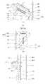
도 3은 본 개시의 특징인 가압부의 일례를 포함하고 있는 의류처리장치를 도시한 것이다.
도 4(a)는 가압부의 일례를 확대한 것이다. 도 4(b)는 도어내면에 결합하여 바지를 가압하는 가압부의 일례를 도시한 것이다. 도 4(c)는 가압부를 측면에서 바라본 모습이다.
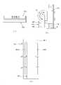
도 5(a)는 도어내면을 관통하는 가이드홀부에 삽입된 이송부를 바라본 모습이다. 도 5(b)는 삽입된 이송부를 일측면에서 바라본 모습이다.
도 6(a)는 도어내면의 반대면인 후방면에서 바라본 가이드홀부 및 전원연결상태를 나타낸 것이다. 도 6(b)와 도 6(c)는 후방면에서 바라본 양측에 구비된 이동마운트부 및 휠부를 확대한 것이다.
도 7은 가압부를 도시한 것이다.
도 8(a)는 롤러부의 내부에 구비되는 제1가열부, 제2가열부 및 스팀가열부의 일례를 나타낸 것이다. 도 8(b)는 롤러부의 내부에 구비되는 제1가열부, 제2가열부 및 스팀가열부의 다른 일례를 나타낸 것이다. 도 8(c)는 롤러부 내부에 구비되는 스팀발생탱크의 일례를 도시한 것이다.
도 9는 롤러부의 다른 일례를 도시한 것이다. 도 9(a)와 도 9(b)는 롤러부가 이동시 수분공급부가 롤러부에 앞서 이동하는 것을 도시한 것이다. 도 9(c)와 도 9(d)는 롤러부와 수분공급부를 정면에서 바라본 모습을 도시한 것이다.
도 10(a)은 롤러부의 무선구동을 위한 배터리를 장착한 일례를 도시하고 있다. 도 10(b)는 롤러부를 측면에서 바라본 모습을 도시하고 있다. 도 10(c)는 후방면에 구비되는 복수 개의 충전 지점을 도시하고 있다.
도 11(a)는 베이스판에 거치된 바지를 롤러부가 가압하는 모습을 측면에서 바라본 것이다. 도 11(b)는 이송부의 일 단면을 나타낸 것이다. 도 11(c)는 이동마운트부의 일 단면을 도시한 것이다.
도 12(a)와 도 12(b)는 베이스판과 가이드레일의 일례를 개략적으로 도시한 것이다.
도 13(a)와 도 13(b)는 베이스판과 가이드레일의 다른 일례를 개략적으로 도시한 것이다.
도 14는 이송부에 구비되는 탄성부재에 의해 바지두께에 무관하게 가압이 가능한 것을 도시한 것이다. 도 14(a)는 얇은 바지를 가압할 때를 도시한 것이고, 도 14(b)는 두꺼운 바지를 가압할 때를 도시한 것이다.
도 15(a)는 수분공급부에 스팀분사홀을 구비한 일례를 도시한 것이다. 도 15(b)는 스팀분사대신 수분을 함유한 함습부를 구비한 수분공급부의 일례를 나타낸 것이다.
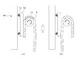
도 16(a)는 도어의 높이방향을 따라 움직이지 않고 고정된 위치에서 가압하는 롤러부를 도시한 것이다. 도 16(b)는 롤러부의 일 단면을 도시한 것이다.
도 17(a)는 롤러부의 회전에 따라 바지가 가압되는 초기 모습을 나타내고 있다. 도 17(b)는 롤러부의 회전으로 인해 바지가 가압되는 도중의 모습을 나타내고 있다.
도 18(a)는 2개의 롤러부 사이에서 바지를 가압하는 모습을 도시한 것이다. 도 18(b)는 2개의 롤러부의 일 단면을 나타낸 것이다.
도 19는 가압부를 가리는 커버부의 일례를 도시한 것이다.
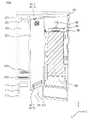
도 20은 도어의 내부에 바지를 가압할 수 있는 공간을 별도로 구비한 일례를 도시한 것이다.
도 21은 제1챔버의 내부에 바지를 가압할 수 있는 공간을 별도로 구비한 일례를 도시한 것이다.
도 22는 이너챔버와 이너도어를 연결하는 힌지구조를 도시한 것이다.1 shows an example of a conventional laundry treatment apparatus.
2 shows an example of a mechanical device included in the second chamber.
3 illustrates a laundry treatment apparatus including an example of a pressing unit, which is a feature of the present disclosure.
Fig. 4 (a) is an enlarged view of an example of the pressing unit. Figure 4 (b) shows an example of the pressing unit for pressing the pants coupled to the inner surface of the door. Figure 4 (c) is a view of the pressing part from the side.
5 (a) is a view of the transfer unit inserted into the guide hole penetrating the inner surface of the door. Figure 5 (b) is a view of the inserted transfer unit from one side.
Figure 6 (a) shows the guide hole portion and the power connection state as viewed from the rear surface, which is the opposite surface of the inner surface of the door. 6(b) and 6(c) are enlarged views of the movable mount unit and the wheel unit provided on both sides as viewed from the rear surface.
7 shows a pressing part.
8( a ) shows an example of a first heating unit, a second heating unit, and a steam heating unit provided inside the roller unit. 8 (b) shows another example of the first heating unit, the second heating unit, and the steam heating unit provided inside the roller unit. 8(c) shows an example of a steam generating tank provided inside the roller unit.
9 shows another example of the roller unit. 9(a) and 9(b) show that the moisture supply unit moves ahead of the roller unit when the roller unit moves. 9 ( c ) and 9 ( d ) are views showing the roller unit and the water supply unit as viewed from the front.
Figure 10 (a) shows an example in which a battery for wireless driving of the roller unit is mounted. Figure 10 (b) shows a state viewed from the side of the roller unit. 10( c ) shows a plurality of charging points provided on the rear surface.
Figure 11 (a) is a side view of the roller unit pressing the pants mounted on the base plate. Figure 11 (b) shows a cross-section of the transfer unit. Figure 11 (c) shows a cross-section of the movable mount part.
12(a) and 12(b) schematically show an example of a base plate and a guide rail.
13 (a) and 13 (b) schematically show another example of the base plate and the guide rail.
14 is a view showing that pressure is possible regardless of the thickness of the pants by the elastic member provided in the transfer unit. Figure 14 (a) shows when the thin pants are pressed, Figure 14 (b) shows when the thick pants are pressed.
15 (a) shows an example in which a steam spray hole is provided in the moisture supply unit. Fig. 15(b) shows an example of a moisture supply part having a moisture-containing part containing moisture instead of steam spraying.
Fig. 16 (a) shows the roller unit for pressing at a fixed position without moving along the height direction of the door. Figure 16 (b) shows a cross-section of the roller part.
Figure 17 (a) shows the initial state in which the pants are pressed according to the rotation of the roller unit. Figure 17 (b) shows a state in the middle of the pants are pressed due to the rotation of the roller.
Figure 18 (a) shows a state of pressing the pants between the two rollers. Figure 18 (b) shows a cross-section of the two roller parts.
19 shows an example of a cover part that covers the pressing part.
20 shows an example in which a space for pressing the pants is separately provided in the interior of the door.
21 shows an example in which a space for pressing the pants is separately provided in the interior of the first chamber.
22 illustrates a hinge structure connecting the inner chamber and the inner door.
이하에서는 첨부된 도면을 참고하여 본 개시의 바람직한 실시예를 상세하게 설명한다. 이하에 기술될 장치의 구성이나 제어방법은 본 개시의 실시예를 설명하기 위한 것일 뿐 본 개시의 권리범위를 한정하기 위함은 아니며, 명세서 전반에 걸쳐서 동일하게 사용된 참조번호들은 동일한 구성요소들을 나타낸다.Hereinafter, preferred embodiments of the present disclosure will be described in detail with reference to the accompanying drawings. The configuration or control method of the device to be described below is only for explaining the embodiment of the present disclosure and not for limiting the scope of the present disclosure, and the same reference numbers used throughout the specification indicate the same components .
본 명세서 중에서 사용되고 있는 특정한 용어는 단지 설명의 편의를 위한 것일 뿐으로 예시된 실시예의 한정으로 사용되고 있는 것은 아니다.Specific terminology used in the present specification is only for convenience of description and is not used as a limitation of the illustrated embodiment.
예를 들어, 「동일」 및 「동일하다」 등 표현은, 엄밀하게 동일한 상태를 나타낼 뿐만 아니라, 공차, 혹은, 같은 기능이 얻어지는 정도의 차가 존재하고 있는 상태도 나타낸다.For example, expressions such as "same" and "same as" not only indicate the strictly identical state, but also indicate a state in which a tolerance or a difference in the degree to which the same function is obtained exists.
예를 들어, 「어느 방향으로」, 「어느 방향을 따라」, 「나란하게」, 「수직하게」, 「중심으로」, 「동심」 혹은 「동축」등의 상대적 혹은 절대적인 배치를 나타내는 표현은, 엄밀하게 그러한 배치를 나타낼 뿐만 아니라, 공차, 혹은, 같은 기능이 얻어지는 정도의 각도나 거리를 가지고 상대적으로 변위하고 있는 상태도 나타낸다.For example, expressions indicating a relative or absolute arrangement such as "in any direction", "along a certain direction", "parallel", "vertically", "central", "concentric" or "coaxial", Not only strictly indicates such an arrangement, but also indicates a state in which the relative displacement is carried out with a tolerance or an angle or distance sufficient to obtain the same function.
본 명세서에서 주름이라 함은, 의류의 착용 후, 혹은 세탁이나 건조 후 생기는 의도치 않은 주름(Wrinkles 또는 구김)이나 접힘(fold)을 뜻하는 것이다. 즉, 디자인단계부터 디자인이나 기능을 위해 들어간 의도된 주름(pleat 또는 crease)이 아닌, 사용에 의해 옷감이 구겨지거나, 세탁이나 건조시 의도치 않게 생기는 주름 또는 구김을 뜻한다. 따라서, 의도된 주름과 같이 명시적으로 언급하지 않는 경우에는 의류의 착용, 세탁이나 건조 후 생기는 의도치 않은 주름(Wrinkles 또는 구김)이나 접힘(fold)을 뜻하는 것이다.As used herein, the term "wrinkle" refers to unintentional wrinkles (wrinkles or creases) or folds that occur after clothing is worn, washed or dried. In other words, it is not the intended pleat or crease entered for design or function from the design stage, but the wrinkle or crease that occurs unintentionally during washing or drying. Accordingly, unless explicitly stated, such as intended wrinkles, it refers to unintentional wrinkles (wrinkles or creases) or folds that occur after wearing, washing or drying clothing.
도 1은 종래 의류처리장치(2000)의 일례를 도시한 것이다. 상기 의류처리장치(2000)는 일면에 투입구(120)를 포함하는 캐비닛(150), 상기 캐비닛(150)의 내부에 위치하여 상기 투입구(120)를 통해 의류를 수용하는 제1챔버(100), 상기 제1챔버(100)의 하부에 위치하여 상기 제1챔버(100)와 분리된 공간을 형성하는 제2챔버(200), 상기 제2챔버(200)의 내부에 구비되어, 스팀을 생성하고 상기 제1챔버(100)에 공급하는 스팀유닛(250, 도 2 참조), 상기 캐비닛(150)에 회전가능하게 결합하여 상기 투입구(120)를 개폐하는 도어(400)를 포함하고 있다. 일반적인 사용자들의 사용방법을 고려하면, 바람직하게는 상기 투입구(120)는 상기 캐비닛(150)의 전면에 구비될 것이다.1 illustrates an example of a conventional
또한, 상기 의류처리장치(2000)는 상기 제2챔버(200)의 내부에 위치하여, 상기 제1챔버(100)의 공기를 흡입하는 송풍유닛(220, 도 2 참조) 및 상기 흡입된 공기를 제습하고 가열한 후 상기 제1챔버(100)로 배출하는 히트펌프유닛(230)을 더 포함할 수 있다.In addition, the
상기 캐비닛(150)은 금속재질로 구비될 수 있으며, 강도를 유지할 수 있다면 플라스틱 재질로 구비되어도 무방하다. 또한, 상기 제1챔버(100)는 플라스틱 사출성형에 의해 형성될 수 있다. 상기 제1챔버(100)는 프레임(미도시)에 의해 상기 캐비닛(150)에 결합될 수 있으나, 이와 달리, 캐비닛(150)과 제1챔버(100) 또는 캐비닛(150)과 제2챔버(200) 사이를 폴리우레탄(polyurethane)과 같은 발포플라스틱(foamed plastic)을 이용하여 충진하여도 무방하다.The
상의와 하의를 포함하는 의류는 상기 제1챔버(100)에 거치될 수 있으며, 상기 제2챔버(200)의 내부에 위치하는 송풍유닛(220, 도 2 참조), 히트펌프유닛(230, 도 2 참조) 및 스팀유닛(250, 도 2 참조)을 통해 의류를 리프레쉬하게 관리할 수 있다. 즉, 상기 제2챔버(200)의 내부에 위치하는 송풍유닛(220, 도 2 참조), 히트펌프유닛(230, 도 2 참조) 및 스팀유닛(250, 도 2 참조)을 통해 스팀 및/또는 가열공기를 이용하여 의류를 살균하고 탈취하며, 사용에 의해 형성된 구김을 제거하는 기능 등을 수행할 수 있다.The clothes including the top and bottom may be mounted in the
상기 제1챔버(100)는 상기 제1챔버(100) 내부의 상부에 의류를 거치하기 위한 의류지지부(190)를 포함할 수 있다. 상기 의류지지부(190)는 의류가 걸린 옷걸이를 수용할 수 있으며, 상기 의류지지부(190)를 좌우로 왕복운동시킬 수 있는 구동부(미도시)와 연결될 수 있다. 상기 의류지지부(190)의 운동은 의류를 흔들게 되고, 결국 의류에 부착된 미세먼지를 포함한 이물질을 분리할 수 있다. 또한, 상기 의류지지부(190)에 거치되는 의류를 흔드는 동안 제2챔버(200)에서 공급되는 스팀 혹은 수분(moisture)에 노출시켜 의류의 주름을 어느 정도 제거할 수 있다. 이러한 의류지지부(190)의 일례는 도 19에 도시된 무빙행어(moving hanger, 195)가 있다.The
즉, 상기 의류지지부(190)는 의류가 상기 제1챔버(100)의 내부에서 자중에 의해 펼쳐진 상태로 거치도리 수 있도록 하여, 상기 제2챔버(200)에서 공급되는 제습되고 가열된 공기 및/또는 스팀에 고르게 노출될 수 있도록 할 수 있다.That is, the
일반적으로 물은 대기압하에서 100 ℃ 에서 끓게 되는데 이때, 발생한 수증기를 스팀이라 할 수 있다. 수분은 이와 달리 상온에서 물을 1 mm 이하의 작은 물방울이 공기중에 부유한 형태를 말한다. 예를 들어, 안개와 비슷하다. 일반적으로 물을 가열하여 끓여서 발생한 스팀의 경우 수분보다 높은 온도로 인해 살균력이 수분보다 뛰어나고, 높은 온도에서 물분자가 더 활발히 움직이므로 의류의 침투성이 뛰어나 의류를 리프레쉬하는데 있어서 수분보다 스팀이 더 활용될 수 있다.In general, water boils at 100 °C under atmospheric pressure, and at this time, the generated water vapor can be called steam. Moisture, on the other hand, refers to a form in which water droplets of 1 mm or less are suspended in the air at room temperature. It's like fog, for example. In general, in the case of steam generated by heating and boiling water, it has superior sterilization power than water due to the higher temperature than water. can
상기 제1챔버(100)는 상기 의류지지부(190)의 구동부(미도시)가 상측에 위치하는 제1챔버 상부면(109), 바닥을 형성하는 제1챔버 바닥면(101), 상기 제1챔버 상부면(109)과 상기 제1챔버 바닥면(101)을 연결하는 상기 제1챔버의 좌우측면(105, 107)과 상기 제1챔버 후면(103)에 의해 형성된다. 만약 투입구(120)가 형성된 일면이 전면인 경우, 상기 제1챔버 후면(103)는 반대방향에 위치하게 될 것이다.The
상기 제1챔버 바닥면(101)은 상기 제2챔버(200)의 내부에서 스팀유닛(250)에 의해 생성된 스팀과 히트펌프유닛(230)에 의해 제습되고 가열된 공기를 제1챔버로 공급하기 위한 공기공급포트(1011)와 스팀공급포트(1012), 그리고, 송풍유닛(220)에 의해 상기 제1챔버(100)의 공기를 흡입하기 위한 공기흡입포트(1013)가 위치할 수 있다.The first
도 1에 도시된 바와 같이, 상기 공기공급포트(1011)와 스팀공급포트(1012)는 상기 제1챔버 바닥면(101)과 상기 제1챔버 후면(103)이 만나는 영역에 구비될 수 있다. 또한, 상기 제1챔버 바닥면(101)과 상기 제1챔버 후면(103)이 만나는 영역은 매끄럽게 경사진 형태일 수 있다. 상기 공기흡입포트(1013)는 상기 제1챔버 바닥면(101) 에서 투입구(120)에 가깝게 위치할 수 있다. 따라서, 상기 제1챔버(100) 내부의 공기는 상기 공기공급포트(1011)를 통해 토출되어 상기 공기흡입포트(1013)를 통해 흡입되어 순환하게 될 것이다. 스팀도 상기 스팀공급포트(1012)를 통해 배출된 뒤, 응축되어 상기 공기흡입포트(1013)를 통해 흡입된 후, 응축수를 저장하는 섬프(미도시)에 모이게 될 것이다.1 , the
상기 제1챔버(100)의 내부에서 응축되는 응축수를 보다 원활히 상기 공기흡입포트(1013)를 통해 상기 제2챔버(200)로 내부내기 위해 상기 제1챔버 바닥면(101)은 상기 제1챔버 후면(103)에서 투입구(120) 방향으로 하향경사질 수 있다In order to more smoothly introduce condensed water condensed inside the
도 1에 도시된 바와 같이 상기 의류처리장치(2000)는 스팀유닛(250)에 물을 공급하기 위한 급수탱크(310) 그리고, 섬프(미도시)에 집수된 응축수를 배출하여 저장하기 위한 배수탱크(330)가 상기 제2챔버(200)의 전방부에 구비될 수 있다. 또한, 상기 급수탱크(310) 및 상기 배수탱크(330)가 설치되는 탱크설치공간(미도시)을 형성하기 위한 탱크모듈프레임(미도시)이 구비되어, 상기 탱크설치공간(미도시)과 제2챔버(200)를 분리할 수 있다. 즉, 제1챔버(100)의 하부에는 탱크설치공간(351)과 제2챔버(200)가 위치하고, 상기 탱크설치공간은 상기 도어(400)에 가깝게 위치하고 상기 탱크설치공간의 뒤에 제2챔버(200)가 위치할 수 있다.As shown in FIG. 1 , the
상기 급수탱크(310)와 배수탱크(330)는 탱크모듈프레임(미도시)에서 각각 탈부착가능하도록 구비될 수 있다. 이와 달리, 급수탱크(310)와 배수탱크(330)가 하나로 결합되어 동시에 탈부착하게 구비되어도 무방하다.The
도어(400)는 상기 도어(400)를 닫는 경우, 상기 도어(400)의 후면 또는 상기 도어(400)에서 상기 제1챔버(100)를 향하는 방향으로 위치한 도어내면(401)을 포함할 수 있다. 상기 도어(400)는 힌지결합방식으로 캐비닛(150)에 회전가능하게 연결되어 투입구(120)를 개폐하게 될 것이다.When the
사용자가 도어(400)를 닫는 경우, 상기 급수탱크(310)의 전면과 상기 배수탱크(330)의 전면이 도어내면(401)을 마주보게 되고, 사용자가 도어(400)를 개방시에는 급수탱크(310)의 전면과 배수탱크(330)의 전면이 외부에 노출될 수 있다. 또한, 급수탱크(310)및 배수탱크(330)가 각각의 전면에 급수탱크윈도우(313) 및 배수탱크윈도우(333)를 포함하고 있어, 급수탱크(310) 및 배수탱크(330) 내부에 저장된 물의 수위를 바로 확인할 수 있다.When the user closes the
상기 급수탱크(310)의 전면과 상기 배수탱크(330)의 전면에서는 각각 급수탱크손잡이(315)와 배수탱크손잡이(335)를 포함할 수 있다. 사용자가 각각 상기 급수탱크손잡이(315)와 상기 배수탱크손잡이(335)를 잡아당기는 경우, 상기 급수탱크(310)와 상기 배수탱크(330)는 각각 상기 급수탱크의 전면말단과 상기 배수탱크의 전면말단을 중심으로 회전하여 상기 탱크모듈프레임(미도시)에서 분리될 수 있다. 또한, 상기 탱크모듈프레임(미도시)에 장착할 때도 마찬가지로 회전을 통해 상기 탱크모듈프레임(미도시)에 상기 급수탱크(310)와 상기 배수탱크(330)가 안착될 것이다.The front surface of the
종래의 의류처리장치(2000)의 경우, 상기 도어내면(401)또는 상기 제1챔버(100)의 내부에는 바지(P)를 거꾸로 의류걸이(403)에 거치시킨 후, 상기 의류걸이(403)를 매다는 의류거치부(405) 및 상기 의류거치부(405)및 상기 의류걸이(403)에 의해 고정된 바지(P)를 가압하는 프레서(50)가 위치할 수 있다.In the case of the conventional
상기 바지(P)를 거꾸로 즉 밑단(bottom hem)을 위로하여 매다는 이유는 상기 바지(P)의 허리부분 즉 바지(P)의 상단(pant waist)의 무게가, 바지(P)의 하단 즉, 바지통(pant leg) 부분보다 무거우므로 상기 바지(P)의 자중을 통해 상기 바지(P)에 인장력이 가해져 바지(P)를 골고루 펴지게 하기 위함이다.The reason that the pants P is hung upside down, that is, with the bottom hem upward, is that the weight of the waist of the pants P, that is, the top of the pants P, is the bottom of the pants P, that is, Because it is heavier than the pants (pant leg) portion, a tensile force is applied to the pants (P) through the weight of the pants (P) to evenly spread the pants (P).
상기 프레서(50)는 상기 도어내면(401)에 결합하여 상기 의류를 지지하는 지지판(51)과 상기 지지판(51)을 향해 회전하여 바지(P)를 가압하는 회전판(52)을 포함할 수 있다. 상기 회전판(52)이 상기 지지판(51)을 향해 회전하여 결합하게 되면 바지(P)를 가압할 수 있게 된다. 이 후 도어(400)을 닫아, 제1챔버(100)의 내부에서 스팀 및 제습되고 가열된 공기에 노출시켜 구김을 제거할 수 있다. 이때, 스팀이 바지(P)에 침투하는 것을 용이하게 하기 위해 상기 회전판(52)을 관통하는 회전판 관통홀(54)를 포함할 수 있으며, 바지(P)의 바지통의 길이방향을 따라 구비되는 솔기(seam)가 눌리는 것을 막기 위해 상기 회전판의 양면 중 바지(P)와 접촉하는 면에 함몰부(55)를 더 포함할 수 있다.The
도 2를 참조하면, 제2챔버(200)의 내부에는 상기 제1챔버(100)의 공기를 흡입하기 위한 송풍유닛(220), 상기 급수탱크(310)의 물을 공급받아 스팀을 발생시킨 후 상기 제1챔버(100)로 스팀을 공급하는 스팀유닛(250), 상기 송풍유닛(220)에 의해 흡입된 공기를 제습하고 가열한 후 상기 제1챔버(100)로 배출하는 히트펌프유닛(230)이 포함될 수 있다. 그리고, 상기 송풍유닛(220), 상기 스팀유닛(250), 및 상기 히트펌프유닛(230)을 제어하기 위한 제어부(미도시)가 위치할 수 있다.Referring to FIG. 2 , inside the second chamber 200 , the
상기 스팀유닛(220)은 상기 제1챔버(100)에 거치되는 의류를 살균, 탈취하고 구김을 제거하기 위해 구비되며, 상기 송풍유닛(220) 및 상기 히트펌프유닛(230)은 상기 제1챔버(100)의 공기를 순환시키고, 열교환을 통해 제습하기 위해 구비될 수 있다.The
상기 제어부는 이외에도 후술할 가압부(500)도 제어할 수 있다. 상기 제어부는 후술할 롤러부(530, 570, 670)의 회전을 제어할 수 있다. 또한, 상기 제어부는 의류지지부(190, 도 1참조)의 왕복운동도 제어할 수 있다.The control unit may also control the
제습되고 가열된 공기를 제1챔버(100)로 공급하기 위해서는 상기 제1챔버(100) 내부의 공기를 송풍팬(226)을 이용하여 흡입력을 발생시킨 후 인렛덕트(221)를 통해 흡입한다. 그리고, 히트펌프유닛(230)으로 이동시켜, 열교환시킨 후 다시 제1챔버(100)로 공급하게 된다.In order to supply the dehumidified and heated air to the
도 2를 참조하면, 상기 송풍유닛(220)은 송풍팬(226) 및 인렛덕트(221)를 포함할 수 있다. 투입구(120)가 위치하는 방향을 전방, 제1챔버의 후면이 위치하는 방향을 후방으로 칭하는 경우, 상기 인렛덕트(221)는 송풍팬(226)의 전방에 구비되고, 상기 인렛덕트(221)의 전방에는 탱크모듈프레임(미도시)이 구비될 수 있다. 따라서, 상기 탱크모듈프레임은 탱크설치공간(351)과 제2챔버(200)를 분리시킬 수 있다.Referring to FIG. 2 , the
상기 탱크모듈프레임(미도시)에 안착되는 급수탱크(310)와 배수탱크(330)는 캐비닛(150)의 양측면중 일측면에 가깝게 위치할 수 있다. 예컨대, 상기 급수탱크(310)는 탱크설치공간(미도시)에서 캐비닛(150)의 우측면이 캐비닛의 좌측면보다 가깝게 위치할 수 있고, 배수탱크(330)는 이와 반대로 상기 캐비닛(150)의 좌측면이 상기 캐비닛(150)의 우측면보다 가깝게 위치할 수 있다.The
상기 스팀유닛(250)도 상기 급수탱크(310)의 위치와 마찬가지로 상기 제2챔버(200)의 내부에서 상기 캐비닛(150)의 우측면이 상기 캐비닛(150)의 좌측면보다 가깝게 위치할 수 있다. 이는 상기 급수탱크(310)의 후방에 스팀유닛(250)을 배치하여, 급수탱크(310)에서 스팀유닛(250)으로 물이 이동하는 연결유로를 단순화시키기 위함이다.Similarly to the position of the
상기 스팀유닛(250)은 히터를 이용하여 상기 스팀유닛(250) 내부에 위치하는 물을 가열할 수 있으며, 발생된 스팀은 스팀유로(미도시)를 따라 상기 제1챔버 바닥면(101)에 구비되는 스팀공급포트(1012)와 연통될 수 있다.The
만약 급수탱크(310)가 캐비닛(150)의 우측면보다 캐비닛(150)의 좌측면에 가깝게 위치한다면, 이에 대응하여 스팀유닛의 위치도 캐비닛(150)의 우측면보다 캐비닛(150)의 좌측면에 가깝게 위치할 수 있다.If the
또한, 상기 인렛덕트(221)는 제1챔버 바닥면(101)에 구비되는 상기 공기흡입포트(1013)와 연통하여 상기 제1챔버(100)의 공기를 흡입하는 인렛덕트 입구(2213)를 포함할 수 있다. 또한, 상기 인렛덕트 입구(2213)는 경사진 유로를 형성할 수 있다. 이는 제1챔버(100) 및 도어(400)에 생긴 응축수가 제1챔버 바닥면(101)가 연통되는 인렛덕트 입구(2213)를 지나 경사진 유로를 타고 상기 인렛덕트(221)의 내측 하부에 구비되는 섬프(미도시)로 용이하게 이동시키기 위함이다.In addition, the
상기 송풍팬(226)의 전방에는 인렛덕트(221)가 위치하고, 상기 송풍팬(226)의 후방에는 스팀유닛(250) 및 히트펌프유닛(230) 이 배치될 수 있다. 또한, 상기 히트펌프유닛(230)은 서포터(265, supporter)에 의해 지지될 수 있다. 상기 서포터(265)는 상기 제2챔버(200)의 바닥을 형성하는 베이스부(210)에 구비될 수 있다. 따라서, 상기 서포터(265)는 상기 베이스부(210)와 상기 히트펌프유닛(230)사이에 소정의 이격된 거리를 형성하고, 상기 서포터(265)와 상기 베이스부(210)의 사이에 소정의 설치공간을 형성할 수 있다. 상기 설치공간에는 스팀유닛(250)이 위치하고, 상기 설치공간에서 상기 서포터(265)와 결합될 수 있다. 도 2에는 제어부(270)가 상기 서포터(265)의 설치공간에서 스팀유닛(250) 아래에 위치하는 일례를 도시하고 있으나, 이와 달리 상기 스팀유닛(250)의 후방등 상기 제2챔버(200)의 내부 어디에 설치되어도 무방하다.An
상기 히트펌프유닛(230)은 상기 제1열교환기(또는 증발기, 미도시) 및 상기 제2열교환기(또는 응축기, 미도시)를 내부에 포함하고 있는 하우징(231), 상기 하우징(231)에서 제습되고 가열되는 공기를 상기 제1챔버(100)로 배출시키기 위해 상기 제1챔버(100)에 구비되는 공기공급포트(1011)와 연통하는 공기토출구(2312)를 더 포함할 수 있다. 상기 서포터(265)의 외측에는 냉매를 순환시키기 위한 압축기(미도시) 및 팽창밸브(미도시)가 위치할 수 있다.The
도 2에 도시된 것과 달리 송풍유닛(220)이 상기 제1챔버의 공기를 순환시키고, 증발기, 응축기가 상기 송풍유닛에 의해 순환되는 공기를 이동시키는 덕트내부에 구비될 수도 있다. 즉, 송풍유닛이 인렛덕트(221), 송풍팬(226), 연결덕트(도 2의 하우징에 대응됨) 및 배기덕트(도 2의 공기토출구에 대응됨)로 구성되고, 히트펌프유닛은 상기 연결덕트 내부에 구비되는 증발기, 응축기, 그리고 상기 송풍유닛의 외부에 구비되는 압축기 및 팽창부를 포함할 수 도 있다.Unlike that shown in FIG. 2 , the
도 3을 참조하면, 도어(400)는 상기 도어(400)에서 제1챔버(100)를 향하는 방향으로 위치한 도어내면(401), 상기 도어내면(401)에 구비되어 캐비닛(150)의 가장자리와 밀착(tight contact)하여 상기 도어(400)와 상기 캐비닛(150)사이에 실링을 형성하기 위한 도어개스킷(486), 및 상기 도어(400)의 폐쇄시 상기 제1챔버(100)에서 생성되는 응축수를 상기 제1챔버 바닥면(101)으로 가이드하기 위해 도어내면(401)에 구비되는 도어라이너(482, 484)를 포함할 수 있다. 일부 실시예에서, 도어(400)는 제1챔버(100)와 탱크설치공간(351)을 동시에 개폐할 수 있는 구조를 구비하고 있다. 다른 실시예에서는 복수 개의 도어가 캐비닛(150)에 설치되어, 별개의 각 도어가 제1챔버(100)와 탱크설치공간(351)을 개폐할 수 있다. 도어라이너(482, 484)는 도어(400)를 닫는 경우 제1챔버(100)를 대향하도록 구비되며, 상부 도어라이너(482)와 하부 라이너파트(484)를 포함할 수 있다. 도어라이너(482, 484)는 상기 도어라이너(482, 484)의 표면에서 발생된 응축수를 제1챔버 바닥면(101)에 마련된 공기흡입포트(1013)을 통해 인렛덕트 하측에 구비되는 섬프(미도시)로 배출할 수 있다.Referring to FIG. 3 , the
도어개스킷(486)은 도어내면(401)을 둘러쌀 수 있도록 도어내면(401)에 장착될 수 있다. 도어(400)와 캐비닛(150)사이의 실링(sealing)은 도어개스킷(486)에 의해 이루어질 수 있다. 또한, 도어개스킷(486)은 개별적으로 제1챔버(100) 및 급수탱크(310) 및 배수탱크(330)가 설치되는 탱크설치공간(미도시)을 실링할 수도 있다.The
도 1에 도시된 프레서(50)의 일례를 참조하면, 회전판(52)이 바지(P)가 거치된 지지판(51)을 향해 회전하게 될 것이다. 상기 회전판(52)은 상기 회전판(52)의 양측면 중 일측면에 구비된 회전결합부(미도시), 예컨대 힌지,를 통해 회전하여 바지(P)를 가압할 수 있다. 이때, 상기 바지(P)는 상기 회전결합부가 위치하는 일측면부터 가압하게 될 것이다. 즉, 상기 회전결합부에 가까운 영역부터 가압하게 된다. 상기 회전결합부에 가까운 영역은 상기 회전판(52)이 완전히 회전하여 상기 지지판(51)을 마주보게 될 때까지, 즉, 상기 회전판(52)의 타측면이 상기 지지판(51)과 결합할 때까지 계속해서 가압하게 될 것이다.Referring to an example of the
따라서, 상기 회전판(52)이 회전하는 동안 상기 바지(P)에는 균일한 압력이 작용하지 않게 된다. 이 경우, 상기 바지(P)중 상기 회전결합부에 가까운 영역에는 상대적으로 많은 압력이 가해지고, 상기 상기 회전결합부에서 먼 영역에는 상대적으로 적은 압력이 가해짐으로써 상기 바지(P)가 고르게 압박되지 않는 문제점이 발생할 수 있다.Accordingly, a uniform pressure is not applied to the pants P while the
나아가, 상기 바지(P)가 상기 회전판(52)에 의해 가압되는 과정에서, 상기 회전판(52)에 의해 밀려 상기 의류의 고정된 형태가 틀어지거나 위치가 가변되는 문제점이 발생할 수 있다. 따라서, 종래 의류처리장치(2000)는, 주름이 더 많이 발생하거나, 의도한 방향과 전혀 다른 주름이 발생할 수 있는 문제점이 있다.Furthermore, while the trousers P are pressed by the rotating
또한, 상기 바지(P)를 거치하여도 단순히 이를 의류거치부(56, 도 1참조)에 매다는 것일 뿐, 고정할 수 없어 가압시 의류의 위치가 달라지는 것을 방지할 수 없는 문제점이 있다.In addition, even when the pants P are mounted, they are simply hung on the clothes holder 56 (refer to FIG. 1) and cannot be fixed, so there is a problem in that the position of the clothes cannot be prevented from being changed during pressurization.
그리고, 상기 바지(P를 접지 않고 전체 바지길이대로 상기 도어내면에 거치하는 경우, 상기 의류거치부(56, 도 1참조)의 높이가 높아 사용자에게 불편할 수 있다. 또한, 상기 도어내면(401) 대부분을 차지하여 도어내면(401)의 활용성이 떨어질 수 있는 문제점이 있다.In addition, when the pants (P) are mounted on the inner surface of the door along the length of the pants without folding the P, the height of the clothing holder 56 (refer to FIG. 1) is high, which may be inconvenient to the user. Also, the inner surface of the
또한, 상기 프레서(50)를 통해 바지(P)를 가압하고 주름(wrinkles)을 제거하며 의도되게 접힌 주름(crease)을 도드라지게 하기 위해서는 제2챔버(200)의 내부에 구비된 스팀유닛(250), 송풍유닛(220) 및 히트펌프유닛(230)을 구동시켜야 한다. 왜냐하면, 상기 프레서(50)를 위한 별도의 스팀발생장치는 공기가열장치를 구비하고 있지 않기 때문이다. 이는 상기 프레서(50)를 통해 바지(P)를 가압하기 위해서 반드시 의류처리장치(2000) 전체를 구동시켜야 한다는 것을 뜻한다. 또한, 상기 프레서(50)를 사용하기 전에 제1챔버(100)에 거치된 의류의 리프레쉬가 끝난 경우, 이미 리프레쉬된 의류를 상기 제1챔버(100)에서 꺼낸 후, 프레서(50)를 사용해야 하는 불편함이 있을 수 있다.In addition, in order to press the pants (P) through the presser (50), remove wrinkles, and to make intentionally folded creases stand out, a steam unit ( 250), the
또한, 사용자가 왼손잡이 또는 오른손잡이냐에 따라, 회전판(52)의 회전방향을 달리 설정할 수 있다. 이때마다 회전판을 분리 후 재조립해야하므로 설치시 번거로움이 따르게 된다.In addition, depending on whether the user is left-handed or right-handed, the rotation direction of the
도 3은 본 개시의 일 실시예인 의류처리장치(1000)를 나타낸 것으로, 종래 의류처리장치(2000)에서 바지(P)의 주름을 제거하기 위해 구비되는 프레서(50)와 다른 가압부(500)의 일례를 도시하고 있다. 본 개시의 특징은 전술할 문제점을 해결한 새로운 가압부를 제시하는 것이다.3 is a view showing a
즉, 상기 의류처리장치(1000)는 일면에 투입구(120)를 포함하는 캐비닛(150), 상기 캐비닛(150) 내부에 위치하여 상기 투입구(120)를 통해 의류를 수용하는 제1챔버(100), 상기 제1챔버(100)의 하부에 위치하여 상기 제1챔버(100)와 분리된 공간을 형성하는 제2챔버(200), 상기 캐비닛(150)에 회전가능하게 결합하여 상기 투입구(120)를 개폐하는 도어(400), 상기 도어(400)의 일면 중 상기 제1챔버를 향하는 방향으로 위치하는 도어내면(401), 상기 도어내면(401)에 구비되어 바지(P)를 거치하는 의류거치부(405), 상기 도어내면(401)에 결합하여 의류를 거치하고 가압하는 롤러방식의 가압부(500)를 포함한다.That is, the
상기 가압부(500)는 상기 의류거치부(405)에 거치된 바지(P)를 지지하는 베이스판(510), 상기 도어(400)의 너비방향을 따라 구비된 회전축(536), 상기 회전축(536)을 통해 회전하여 상기 바지(P)를 가압하는 롤러부(530) 및 상기 회전축(536)을 지지하고, 상기 회전축(536) 및 상기 롤러부(530)를 상기 도어(400)의 높이방향으로 이동시키는 이송부(550)를 포함할 수 있다.The
또한, 상기 의류처리장치(1000)는 상기 롤러부(530) 및 상기 이송부(550)에 구비되어 상기 롤러부(530)를 회전시키는 구동부(540, 도 5참조)를 포함할 수 있다.Also, the
종래 의류처리장치에서처럼 상기 롤러부(530)는 이송부(550)의 이송에 따라 수동적으로 회전하면서, 단순히 의류를 가압하는게 아니라, 상기 롤러부(530)가 구동부(540)에 의해 능동적으로 회전하면서 탄성에 의한 가압뿐만 아니라, 구동부(540)의 회전력에 의한 가압도 이루어질 수 있다. 즉, 상기 롤러부(530)는 베이스판위에 거치된 의류를 가압하면서 회전할 수 있다.As in the conventional laundry treatment apparatus, the
상기 롤러부(530)가 의류를 가압하면서 능동적으로 회전시, 상기 이송부(550)는 상기 롤러부(530)의 회전에 따라 수동적으로 이동하게 될 것이다. 즉, 상기 롤러부(530)를 회전시키는 구동부에 의해 상기 롤러부(530)의 회전 및 상기 이송부(550)의 이동이 동시에 이루어 질 수 있다.When the
그리고, 상기 롤러부(530)의 형상은 도어의 너비방향을 기준으로 상기 롤러부(530)의 가운데 부분의 지름이 상기 롤러부(530)의 양단의 지름보다 작을 수 있다. 이는 바지통에 일반적으로 구비되는 옷감보다 두터운 봉제선을 회피하기 위함이다. 그리고, 스팀이 분사될 수 있는 이격된 공간을 두어, 스팀을 옷감에 보다 골고루 빠르게 침투시키기 위함이다. 또한, 상기 롤러부(530)를 통해 의류를 향해 분사되어야 하는 쪽에 위치한 스팀분사홀(5331)의 압력이 반대쪽에 위치한 스팀분사홀(5331)의 압력보다 높아 스팀이 반대쪽으로만 분사되는 거을 방지하기 위함이다.In addition, in the shape of the
즉, 상기 롤러부(530)의 형상은 덤벨(dumbbell)형상과 유사하 형상일 수 있다. 즉, 롤러부(530)의 회전축(536) 방향 또는 도어(400)의 너비"??*으로 소정길이에 해당하는 영역의 외주면의 지름이 상기 롤러부(530)의 양단의 지름보다 작도록 형성될 수 있다. 거치된 바지의 중앙에 위치할 수 있는 봉제선을 회피하고 스팀을 분사할 수 있는 공간을 마련하기 위함이다.That is, the shape of the
또한, 도 2를 참조하면, 상기 제2챔버(200)의 내부에는 상기 제1챔버(100)의 공기를 흡입하기 위한 송풍유닛(220), 물을 공급받아 스팀을 발생시킨 후 상기 제1챔버(100)로 스팀을 공급하는 스팀유닛(250), 상기 송풍유닛(220)에 의해 흡입된 공기를 제습하고 가열한 후 상기 제1챔버(100)로 배출하는 히트펌프유닛(230)이 위치할 수 있다. 그리고, 상기 송풍유닛(220), 상기 스팀유닛(250), 및 상기 히트펌프유닛(230)을 제어하기 위한 제어부(미도시)가 위치할 수 있다.In addition, referring to FIG. 2 , a
상기 스팀유닛(220)은 상기 제1챔버(100)에 거치되는 의류를 살균, 탈취하고 구김을 제거하기 위해 구비되며, 상기 송풍유닛(220) 및 상기 히트펌프유닛(230)은 상기 제1챔버(100)의 공기를 순환시키고, 열교환을 통해 제습하기 위해 구비될 수 있다.The
상기 스팀유닛(250)은 제1챔버(100)의 내부에 거치되는 의류를 리프레쉬하기 위해 사용되는 것이며, 도 3에 도시된 가압부(500)는 상기 스팀유닛(250)과 별개로 동작하는 수분공급부(580, 도 5참조)를 포함할 수 있다. 또한, 상기 송풍유닛(220) 및 상기 히트펌프유닛(230)대신 바지(P)에 열을 가하기 위한 가열부(535, 도 8참조)를 포함할 수 있다. 따라서, 가압부(500)에 거치되는 바지(P)의 주름을 제거하기 위해 제1챔버(100) 전체에 스팀을 채우는 것보다 필요한 스팀의 양을 최소화할 수 있다. 또한, 제1챔버(100) 전체의 공기를 제습하고 가열하는 것보다 바지(P)에만 집중적으로 열을 가할 수 있으므로 에너지를 절약할 수 있다. 다시 말해, 상기 제2챔버(200)의 내부에 구비되는 상기 송풍유닛(220), 상기 스팀유닛(250), 및 상기 히트펌프유닛(230)을 구동시키지 않고, 상기 가압부(500)만을 이용하여 독립적으로 바지(P)를 리프레쉬할 수 있다.The
이 경우 사용자는 오직 가압부(500)에 거치된 바지(P)의 주름을 제거하고, 의도된 주름을 선명하게 할 수 있고, 의류처리장치(1000)는 이를 위한 별도의 관리코스를 제공하여 사용자가 선택할 수 있게 할 수 있다. 또한, 도어(400)가 개방된 상태에서도 상기 가압부(500)만을 동작시켜 거치된 바지(P)의 주름을 제거할 수 있다. 종래에는 프레서(50)에 거치된 바지(P)만을 가압하기 위해서는 이미 제1챔버(100)에서 리프레쉬된 의류들을 꺼낸 후, 오직 바지(P)만을 프레서(50)에 거치한 후 도어(400)를 닫은 후, 의류처리장치(2000)를 구동시켜야만 했다. 따라서, 본 개시는 이러한 불편함을 개선할 수 있다.In this case, the user can only remove the wrinkles of the trousers P mounted on the
또한, 종래 의류처리장치(2000)는 프레서(50)의 한쪽 측면을 기준으로 회전하여 가압하는 방식이므로 리버서블 설계(Reversible Design)를 위해서는 프레서(50)의 양 측면 중 어떠한 측면에 결합하여도 회전이 가능하게 설계되어야만 했다. 리버서블 설계란, 사용자가 왼손잡이 혹은 오른손잡이냐에 따라 회전방향을 달리 설정할 수 있도록 설계하는 것을 말한다. 그러나, 상기 가압부(500)는 도어(400)의 상하방향으로 이동하므로, 사용자가 사용하는 주된 손을 처음부터 고려할 필요가 없다.In addition, since the conventional
의류거치부(405)는 바지(P)를 의류걸이(403)에 고정시킨 후 상기 의류걸이(403)의 고리를 이용하여 거치할 수 있게 구비되어 있다. 상기 의류거치부(405)는 후크(hook)와 같은 고리가 도어내면(401)에서 제1챔버(100)를 향해 돌출되어 있어, 상기 돌출된 고리에 의류걸이(403)를 걸 수 있다. 상기 의류걸이(403)는 통상의 바지걸이나, 바지(P)의 양쪽 바지통을 접은 후 양 바지통의 밑단(hem)을 고정할 수 있다. 이때, 바지(P)는 선명하게 접힌 의도된 주름(clearly folded and intended crease), 예컨대 유니폼 하의나 양복하의의 앞주름, 을 요하는 부분이 측면에 위치하고, 바지통의 솔기(또는 봉제선)부분이 가운데 위치하도록 접은 상태에서 상기 의류걸이(403)를 이용해 바지(P)를 고정시킨 후, 상기 의류거치부(405)에 거치할 수 있다.The
따라서, 선명하게 접힌 의도된 주름(clearly folded and intended crease)은 롤러부(530)에 의해 가압하고, 바지통의 솔기는 가압하지 않도록, 롤러부(530)의 형태를 동일한 지름을 갖는 원통형이 아니라, 솔기에 대응되는 부분이 오목하게 함몰된 형태로 구비할 수 있다.Therefore, the shape of the
또한, 의류걸이(403)는 바지(P)의 밑단(hem)을 고정하게 되므로, 사용자는 바지(P)를 거꾸로 매달게 될 것이다. 이는 바지(P)에서 바지통을 제외한 허리부분, 예컨대 바지(P)의 허리선부터 엉덩이 부위 아래까지의 부분으로 라이즈(Rise)라 일컫는 부분, 의 무게가 더 무거우므로 전체적으로 바지(P)를 거꾸로 매달게 되는 경우 자중(self-weight)에 의해 바지(P) 자체에 인장력이 가해질 수 있기 때문이다. 바지(P)에 인장력이 가해지는 경우, 바지(P)가 도어(400)의 높이방향 또는 바지(P)의 길이방향을 따라 당겨지게 될 것이다.In addition, since the
도어(400)는 투입구(120)를 개폐하도록 캐비닛에 회전가능하게 결합될 수 있다. 이를 위해 도어(400)는 힌지유닛(미도시)과 같은 체결부재를 포함할 수 있다. 도어(400)는 하나의 플레이트으로 구성될 수도 있으나, 도 3에 개시된 도어(400)의 일실시예는 제1챔버(100)에서 멀어지는 방향에 구비된 도어(400)의 외부면을 포함하는 도어외면(4111), 상기 제1챔버(100)를 향하는 방향에 구비된 도어(400)의 내부면을 포함하는 도어내면(401), 상기 도어내면(401)과 상기 도어외면(4111)을 연결하는 측면부(4112)를 포함할 수 있다. 상기 도어(400)의 외부면은 사용자의 선택을 입력받고, 결과 및 정보를 출력하는 디스플레이부(미도시)를 포함할 수 있다. 또한, 상기 도어내면(401)과 상기 도어외면(4111)사이에는 전원연결 및 제어신호 전송을 위한 와이어(미도시)들이 위치할 수 있다. 그리고, 상기 도어내면(401)은 가압부(500)와 결합할 수 있다.The
상기 도어400)는 제1챔버(100) 방향을 향하는 도어내면(401), 상기 도어내면(401)의 양면 중 상기 투입구(120)에서 멀어지는 방향에 위치하는 후방면(4011)을 포함할 수 있다. 상기 도어내면(401)은 상기 도어(400)를 개방시 외부에 노출되나, 상기 후방면(4011)은 도어(400)의 내부공간을 형성하는 일면이므로 외부에 노출되지 않을 것이다. 또한, 상기 도어내면(401)는 상기 투입구(120)에서 멀어지는 방향에 위치하는 후방면(4011), 상기 투입구(120)에 가까운 방향에 위치하는 내부노출면을 포함할 수 있다.The
상기 도어내면(401)에는 캐비닛(150)의 가장자리와 밀착(tight contact)하여 상기 도어(400)와 상기 캐비닛(150)사이에 실링을 형성하기 위한 도어개스킷(486), 및 상기 도어(400)의 폐쇄시 상기 제1챔버(100)에서 생성되는 응축수를 상기 제1챔버 바닥면(101)으로 가이드하기 위해 도어내면(401)에 구비되는 도어라이너(482, 484)를 포함할 수 있다. 일부 실시예에서, 도어(400)는 제1챔버(100)와 탱크설치공간(351)을 동시에 개폐할 수 있는 구조를 구비하고 있다. 다른 실시예에서는 복수 개의 도어가 캐비닛(150)에 설치되어, 별개의 각 도어가 제1챔버(100)와 탱크설치공간(351)을 개폐할 수 있다. 도어라이너(482, 484)는 도어(400)를 닫는 경우 제1챔버(100)를 대향하도록 구비되며, 상부 도어라이너(482)와 하부 라이너파트(484)를 포함할 수 있다. 도어라이너(482, 484)는 상기 도어라이너(482, 484)의 표면에서 발생된 응축수를 제1챔버 바닥면(101)에 마련된 공기흡입포트(1013)을 통해 인렛덕트 하측에 구비되는 섬프(미도시)로 배출할 수 있다.The door
도어개스킷(486)은 도어내면(401)을 둘러쌀 수 있도록 도어내면(401)에 장착될 수 있다. 도어(400)와 캐비닛(150)사이의 실링(sealing)은 도어개스킷(486)에 의해 이루어질 수 있다. 또한, 도어개스킷(486)은 개별적으로 제1챔버(100) 및 급수탱크(310) 및 배수탱크(330)가 설치되는 탱크설치공간(미도시)을 실링할 수도 있다.The
베이스판(510)은 상기 도어내면(401)에 결합되어, 의류거치부(405)에 거치된 바지(P)를 지지할 수 있다. 상기 베이스판(510)은 상기 도어내면(401)에서 이격되어 결합될 수 있다. 그리고 이를 위해 상기 베이스판(510)과 상기 도어내면(401)사이에는 탄성력을 가진 탄성지지부(미도시)가 위치할 수 있다. 상기 롤러부(530)가 거치된 바지(P)를 상기 도어내면(401)을 향해 가압할 때, 상기 탄성지지부는 상기 베이스판(510)을 지지하고, 상기 바지(P)가 베이스판에 균일하게 밀착되게 할 수 있다.The
또한, 상기 베이스판(510)중 베이스판의 상부와 베이스판의 하부는 곡면형태로 구비될 수 있다. 상기 베이스판의 상부는 후술할 의류고정부(420)보다 의류거치부(405)에 가까운 상기 베이스판(510)의 일부분을 뜻하고, 베이스판의 하부는 의류거치부(405)보다 의류고정부(420)에 가깝운 상기 베이스판(510)의 일부분을 뜻한다. 상기 베이스판의 상부는 바지(P)의 밑단(hem)부분을 지지하는 반면, 상기 베이스판의 하부는 바지(P)의 허리부분을 지지하게 될 것이다.In addition, the upper part of the base plate and the lower part of the base plate among the
상기 베이스판(510)에 의해 지지되는 바지(P)에서 상기 롤러부(530)에 의해 가압되는 부분은 바지통부분이며, 허리부분은 지퍼, 허리주머니 등이 있으므로 롤러부(530)로 가압하기 어렵고, 가압할 필요가 없다. 따라서, 상기 의류고정부(420)는 상기 도어내면(401)의 하부에 결합하여 거꾸로 매단 바지(P)의 허리부분의 양측면을 고정하게 되므로, 바지통을 가압하는 상기 롤러부(530)와의 간섭은 일어나지 않을 것이다. 특히 상기 롤러부(530)는 스팀(steam) 또는 수분(moisture)을 이용하여 주름을 제거하고, 롤러부(530)를 가열하여 바지(P)를 가압함으로써, 주름이 도드러져야하는 부분, 예컨대 바지의 앞주름 등을 선명하게 형성할 수 있다.In the pants P supported by the
상기 베이스판(510)은 상기 베이스판의 상부와 상기 베이스판의 하부를 제외한 나머지 중간부분은 상기 도어내면(401)에 나란하게 구비될 것이다. 따라서, 상기 베이스판의 중간부분은 상기 베이스판(510)의 중간부분에 대응되는 도어내면(401)의 부분에 평행하고, 상기 베이스판의 상부와 상기 베이스판의 하부는 곡면의 형태로 상기 도어내면(401)에 가까워질 것이다.In the
만약, 상기 베이스판(510)을 측면에서 바라보면, 상기 도어내면(401)에서 수직한 방향으로 측정한 상기 베이스판(510)까지의 거리는 상기 베이스판 상부에서 상기 중간부분으로 갈수록 증가하게 될 것이다. 마찬가지로, 상기 도어내면(401)에서 수직한 방향으로 측정된 상기 베이스판(510)까지의 거리도 상기 베이스판의 하부에서 상기 중간부분으로 갈수록 증가하게 될 것이다. 이는 상기 바지(P)에 인장력을 더 효과적으로 인가하기 위함이다. 상기 의류거치부(405)는 도어내면(401)에 위치하고, 상기 의류거치부(405)에 거치된 바지(P)는 베이스판(510)을 따라 밑으로 인장력을 받게될 것이다. 따라서, 상기 베이스판(510)이 곡면인 경우가 상기 베이스판(510)이 평면인 경우보다, 상기 바지(P)와의 접촉길이가 길어지고, 상기 바지(P)와의 접촉면이 커지므로, 상기 바지(P)와 더 밀착하게 될 것이다. 결국 상기 바지에 인장력을 인가하는 효과를 증대시킬 수 있다.If the
상기 베이스판(510)중 중간부분이 가장 돌출된 형태이고 그 밑으로 내려갈수록 즉, 상기 베이스판(510)의 하부에 가까워질수록, 상기 도어내면(401)에서 상기 베이스판(510)까지의 수직거리가 감소하므로, 상기 바지(P)가 상기 베이스판(510)에서 떨어질 수 있다. 이를 방지하기 위해, 상기 도어(400)는 상기 도어내면(401)에 결합하여 거치된 바지(P)의 허리부분의 양 측면을 고정하는 의류고정부(420)를 더 포함할 수 있다. 상기 의류고정부(420)가 상기 바지(P)의 허리부분의 양 측면이 상기 베이스판(510)으로부터 이격되는 것을 방지하기 위해 상기 바지(P)를 잡아당기는 것과 마찬가지 효과를 주게 될 것이다. 따라서, 상기 바지(P)는 상기 의류고정부(420)로 인해 인장력을 받게 될 것이다.The middle part of the
상기 의류고정부(420)는 상기 거치된 바지(P)의 일측면을 고정하는 제1의류고정부(421) 및 상기 거치된 바지(P)의 타측면을 고정하는 제2의류고정부(422)를 포함할 수 있다. 여기서 바지(P)의 일측면 또는 타측면이라 함은 바지통의 솔기(또는 봉제선)부분이 가운데 위치하도록 접어 상기 의류걸이(403)를 이용해 바지(P)를 고정시킨 경우에 형성되는 양측면을 말한다.The
상기 의류고정부(420)가 상기 거치된 바지(P)의 양 측면을 고정하게 되므로 상기 바지(P)는 상기 베이스판(510)의 중간부분을 지나 상기 베이스판(510)의 하측에 가까워지더라도, 상기 베이스판(510)에 접촉하게 될 것이다. 상기 의류고정부(420)는 클램프(clamp)와 같은 형태로 구비되어 상기 바지(P)의 양 측면을 고정시킬 수 있다. 이와 달리, 도 3에서 도시된 의류고정부(420)의 일례는 각진 형태로 절곡된 빔(angled beam) 형태를 나타내고 있다. 상기 의류고정부(420)는 도어내면(401)에 결합하며, 상기 바지(P)가 삽입되어 느슨하게 상기 바지(P)의 양 측면을 고정하도록 구비될 수 있다. 즉, 상기 의류고정부(420)는 바지(P)가 베이스판(510)에 접촉하고, 좌우로 움직이는 것을 방지하기 위한 것이다.Since the
도 4(a)는 가압부(500)의 일례를 확대한 것이다. 상기 가압부(500)는 상기 의류거치부(405)에 거치된 바지(P)를 지지하는 베이스판(510), 상기 도어(400)의 너비방향을 따라 구비된 회전축(536), 상기 회전축(536)을 통해 회전하여 상기 바지(P)를 가압하는 롤러부(530) 및 상기 회전축(536)을 지지하고, 상기 회전축(536) 및 상기 롤러부(530)를 상기 도어(400)의 높이방향으로 이동시키는 이송부(550)를 포함할 수 있다.4 ( a ) is an enlarged view of an example of the
상기 롤러부(530)는 상기 롤러부(530)의 일단에 가깝게 위치하여 상기 바지(P)를 가압하는 원통형의 제1프레스부(531), 상기 롤러부(530)의 타단에 가깝게 위치하는 상기 바지(P)를 가압하고, 원통형의 제2프레스부(532) 및 상기 제1프레스부(531)와 상기 제2프레스부(532) 사이에 위치하여 상기 제1프레스부(531)와 상기 제2프레스부(532)를 연결하고, 상기 바지(P)에 수분을 공급하는 원통형의 수분공급부(533)를 포함할 수 있다.The
상기 롤러부(530)는 바지를 가압하는 제1프레스부(531)와 제2프레스부(532) 및 상기 바지(P)에 수분을 공급하는 수분공급부(533)가 일체로 형성될 수 있다. 따라서, 구동부(540, 도 5참조)가 롤러부(530)를 회전시 상기 제1프레스부(531)와 상기 제2프레스부(532) 및 상기 수분공급부(533)는 같이 회전할 수 있다.The
이때, 상기 롤러부(530)는 수분공급부(533)를 통해 수분을 공급받으면서 회전을 통해 상기 제1프레스부(531)와 상기 제2프레스부(532)를 이용하여 바지(P)를 당기면서 눌러줄 수 있으므로 주름제거 및 칼주름 형성에 효과적이다.At this time, the
상기 롤러부(530)는 금속재질, 나무재질 혹은 플라스틱 재질로 구비될 수 있으나, 바람직하게는 금속재질로 구비될 수 있다. 상기 롤러부(530)가 의류를 가압하고, 후술할 가열부를 통해 다리미와 마찬가지로 의류에 열을 가할 수 있기 위해서 경도(hardness)와 열전도율(thermal conductivity)을 고려할 때 금속재질이 바람직할 것이다.The
상기 롤러부(530)는 상기 롤러부(530)의 외형을 형성하는 롤러바디(5301), 상기 롤러바디(5301)의 양단 중 일단에 가깝게 위치한 제1프레스부(531), 상기 롤러바디의 양단중 타단에 가깝게 위치한 제2프레스부(532), 상기 제1프레스부(531)와 상기 제2프레스부(532) 사이에 위치하여 상기 제1프레스부(531)와 상기 제2프레스부(532)를 연결하고, 상기 바지(P)에 수분을 공급하는 원통형의 수분공급부(533)를 포함할 수 있다.The
상기 롤러부(530)는 도어의 너비방향을 따라 구비되는 회전축(536)을 통해 회전하며, 상기 롤러부(530)는 상기 도어의 길이방향을 따라 이동할 수 있도록 이송부(550)를 더 포함할 수 있다.The
상기 수분공급부(533)의 지름은 상기 제1프레스부(531) 및 상기 제2프레스부(532)의 지름보다 작을 수 있다. 도 4(a)에 도시된 상기 수분공급부(533)의 일례를 참조하면, 상기 수분공급부(533)의 외주면에는 스팀을 분사하기 위한 복수 개의 스팀분사홀(5331)을 포함할 수 있다.The diameter of the
상기 복수 개의 스팀분사홀(5331)을 통해 스팀을 분사하게 되면, 상기 롤러부(530)에 의해 가압되고 있는 바지에 스팀이 침투하게 될 것이다. 또한, 상기 가압부(500)가 상기 제1챔버의 수용되는 의류에 스팀을 분사하기 구비되는 스팀유닛(250)과 별도로 스팀을 공급하는 스팀발생탱크(580, 도 8 참조)를 상기 수분공급부(533)의 내부에 구비할 수 있으므로, 상기 가압부(500)는 상기 제1챔버(100)에 수용되어 스팀 및/또는 제습되고 가열된 공기를 공급하는 것과는 별개로 구동시킬 수 있다. 즉, 제2챔버(200) 내부에 수용되는 스팀유닛(250), 송풍유닛, 히트펌프유닛(230)의 구동없이, 상기 롤러부(530)만을 이동시키면서, 스팀을 분사하고, 거치된 바지에 열을 전달 할 수 있다. 예컨대, 상기 가압부는 사용자가 주름을 제거하기 위해 다리미판 위에서 스팀다리미를 사용하는 것과 같은 효과를 얻을 수 있다.When steam is sprayed through the plurality of
이때, 상기 수분공급부(533)의 지름이 상기 제1프레스부(531) 또는 상기 제2프레스부(532)의 지름과 동일하다면, 거치된 바지(P)를 상기 제1프레스부(531) 또는 상기 제2프레스부(532)와 마찬가지로 동일하게 가압하게 될 것이다. 이 경우, 상기 복수 개의 스팀분사홀(5331) 중 상기 바지와 접촉하고 있는 부분은 상기 바지에 의해 막히게 되므로 상기 바지와 접촉하지 않고 있는 반대쪽에 위치한 상기 복수 개의 스팀분사홀(5331) 중 일부의 스팀분사홀(5331)을 통해 스팀이 토출될 것이다. 이는 상기 바지(P)에 스팀을 분사하고자 하는 목적을 달성하지 못하게 되므로, 이를 방지하기 위해 상기 수분공급부(533)의 지름은 상기 제1프레스부(531) 또는 상기 제2프레스부(532)의 지름보다 작게 구비될 수 있다.At this time, if the diameter of the
또한, 상기 수분공급부(533)에 대응되는 바지의 영역은 바지 솔기또는 봉제선이 있을 수 있다. 이를 가압하게 되면 바지가 뒤틀리면서 이중주름이 생길 수 있다. 따라서, 이를 회피하기 위해서도 상기 수분공급부(533)의 지름은 상기 제1프레스부(531) 또는 상기 제2프레스부(532)의 지름보다 작게 구비될 수 있다.In addition, the area of the trousers corresponding to the
도 4(a)와 4(b)에 도시된 롤러부(530)의 일례를 참조하면, 상기 롤러부(530)의 양단은 회전축(536)에 의해 연결될 수 있다. 그리고 상기 양단에 구비된 회전축(536)은 상기 이송부(550)를 통해 상기 롤러부(530)를 지지할 수 있다.Referring to an example of the
구체적으로는 상기 회전축(536)은 상기 롤러부(530)의 일단에 결합하는 제1회전축(5361) 및 상기 롤러부(530)의 타단에 결합하는 제2회전축(5362)을 포함할 수 있다.Specifically, the
한편, 상기 도어(400)는 상기 도어내면(401)을 관통하여, 상기 도어(400)의 높이방향을 따라 형성된 가이드홀부(415)를 더 포함할 수 있다. 상기 이송부(550)는 상기 제1회전축(5361)과 결합하는 제1운반부(5501) 및 상기 제2회전축(5362)과 결합하는 제2운반부(5502)를 포함하고, 상기 가이드홀부(415)는 상기 베이스판(510)의 일측면과 상기 베이스판(510)의 일측면에 가깝게 위치하는 상기 도어(400)의 일측면 사이에 구비되는 제1가이드홀(4151) 및 상기 베이스판(510)의 타측면과 상기 베이스판(510)의 타측면에 가깝게 위치하는 상기 도어(400)의 타측면 사이에 구비되는 제2가이드홀(4152)을 더 포함할수 있다.Meanwhile, the
또한, 상기 제1운반부(5501)는 상기 롤러부(530)의 회전시 상기 제1가이드홀(4151)을 따라 상기 도어(400)의 높이방향으로 이동가능하고, 상기 제2운반부(5502)는 상기 롤러부(530)의 회전시 상기 제2가이드홀(4152)을 따라 상기 도어(400)의 높이방향(화살표 방향)으로 왕복이동할 수 있다.In addition, the first carrying
도 4(c)는 상기 가압부(500)의 일례를 일측면에서 바라본 모습을 나타내고 있다. 상기 도어(400)는 상기 도어내면(401), 상기 도어내면(401)의 양면중 상기 투입구(120)에서 멀어지는 방향에 위치하는 후방면(4011) 및 상기 후방면(4011)에 결합하여 설치공간(4115)을 형성하는 도어외면(4111)을 포함할 수 있다.FIG. 4(c) shows an example of the
즉, 상기 도어(400)는 하나의 플레이트로 구성된 것이 아니라, 여러 개의 패널이 결합한 어셈블리일 수 있다. 즉, 상기 투입구(120)를 마주보도록 구비되는 도어내면(401), 상기 도어내면(401)의 양면 중 상기 투입구(120)에서 더 멀어지는 방향에 위치한 도어외면(4111)을 포함하고, 상기 도어내면(401) 및 상기 도어외면(4111)은 상기 도어의 내부에 소정의 설치공간(4115)을 형성할 수 있다.That is, the
상기 설치공간(4115)에는 제어부(미도시)와 연결되어 제어신호를 송수신하거나 전원공급을 위한 전선이 구비될 수 있다. 상기 롤러부(530)의 회전을 위한 전력공급부(559, 도 6(a)참조)가 구비될 수 있다. 또한, 상기 가이드홀부를 따라 이동하는 상기 이송부(550)의 삽입깊이를 조절하여, 상기 롤러부(530)와 상기 이송부(550)사이의 거리를 조절할 수 있는 가이드부(440, 도 12(a) 참조)가 설치될 수 있다. 상기 전력공급부(559, 도 6(a)참조) 또는 상기 가이드부(440, 도 12(a) 참조)가 상기 설치공간(4115), 즉 상기 도어(400)의 내부공간에 구비되는 이유는 상기 제1챔버 또는 상기 롤러부(530)에 의한 스팀공급시 상기 전력공급부(559, 도 6(a)참조)가 수분에 노출되는 것을 최대한 방지하고, 상기 가이드부(440, 도 12(a) 참조)를 상기 도어의 설치공간(4115)에 설치하여, 외관상의 디자인을 깔끔하게 마무리할 수 있기 때문이다.The
도 4(c)를 참조하면, 상기 바지(P)를 가압하면서, 상기 롤러부(530)가 제1회전방향, 예컨대 시계방향, 으로 회전시, 상기 롤러부(530)는 위로 이동하게 될 것이다. 이를 위해 상기 롤러부를 회전지지하는 회전축(536), 상기 회전축을 지지하는 이송부(550)가 상기 롤러부(530)의 양단에 각각 구비될 수 있다. 상기 이송부(550)는 상기 가이드홀부(415)를 따라 상기 도어(400)의 높이방향으로 이동할 수 있다. 이 때, 상기 이송부의 일부는 상기 가이드홀부(415)에 삽입될 수 있다. 상기 이송부(550)는 삽입후 상기 이송부(550)가 상기 가이드홀부(415)에서 분리되는 것을 방지하기 위해, 상기 가이드홀부(415)의 너비보다 크게 상기 도어의 너비방향으로 구비되는 휠부(554)를 포함할 수 있다. 즉, 상기 휠부(554)는 상기 이송부(550)가 상기 가이드홀부(415)를 따라 이동가능하도록 작은 바퀴형상으로 구비될 수 있다. 따라서, 상기 이송부(550)는 상기 가이드홀부(415)를 따라 마찰을 줄여 부드럽게 상기 도어(400)의 높이방향으로 이동할 수 있다.Referring to Figure 4 (c), while pressing the pants (P), when the
상기 이송부(550)는 별도의 구동장치를 이용해 상기 가이드홀부(415)를 따라 이동할 수 있으나, 여기서는 상기 롤러부(530)의 회전에 따라, 수동적으로도 이동할 수있다. 즉, 별도의 구동장치없이 상기 롤러부(530)가 제1회전방향으로 회전시 위로 올라가고, 상기 롤러부(530)가 상기 제1회전방향의 반대방향인 제2회전방향으로 회전시 아래로 내려갈 수 있다.The conveying
이때, 상기 롤러부(530)는 상기 베이스판(510)상에서 상기 바지(P)를 가압하면서 회전할 것이고, 상기 롤러부(530)와 상기 이송부(550) 사이에는 탄성부재(552, 도 11참조)가 있어, 상기 롤러부(530)를 항상 상기 베이스판(510)을 향해 가압하도록 힘을 가할 수 있다. 따라서, 상기 롤러부(530)가 회전을 멈춘다고 하더라도, 상기 바지(P)에서 미끄러지는게 아니라, 상기 바지(P)를 가압한 채 현재 위치를 그대로 유지할 수 있다.At this time, the
즉, 상기 이송부(550)는 상기 롤러부(530)가 제1회전방향으로 회전시, 상기 가이드홀부(415)를 따라 위 또는 아래 방향중 중 일방향으로 움직이고, 상기 롤러부(530)가 상기 제1회전방향의 반대방향인 제2회전방향으로 회전시, 상기 가이드홀부(415)를 따라 상기 일방향과 반대방향으로 이동할 수 있다. 또한, 상기 롤러부(530)가 정지시, 상기 이송부(550)도 같이 정지할 수 있다.That is, when the
실제적으로 롤러부(530)의 회전으로 상기 도어의 높이방향을 따라 이동하게 되는 것이고 이송부(550)는 단순히 사이 가이드홀부(415)를 따라 이동할 수 있도록 가이드해주는 역할을 수행할 것이다.In fact, the rotation of the
도 4(c)를 참조하면, 전술한 바와 같이 상기 베이스판(510)은 상기 베이스판의 상부에서 중간부분으로 갈수록 상기 도어내면(401)에서 수직하게 상기 베이스판(510)에 이르는 거리인 D1이 증가할 수 있다. 상기 도어내면(401)의 구비되는 가이드홀부(415)를 따라 이동하는 이송부의 위치는 변화가 없으나, 상기 베이스판(510)상에서 이동하는 롤러부(530)의 위치는 변하게 될 것이다. 따라서, 상기 롤러부(530)와 상기 이송부(550) 사이의 거리는 상기 베이스판 상부에서 상기 베이스판의 중간부분으로 갈수록 증가하게 될 것이고, 상기 롤러부(530)와 상기 이송부(550)사이의 거리는 멀어지게 될 것이다. 이때, 상기 롤러부(530)와 상기 이송부(550)사이에 위치하는 탄성부재(552, 도 11참조)에 의해 상기 롤러부(530)는 상기 베이스판(510)을 향해 탄성력을 받으므로, 상기 바지(P)를 가압하게 될 것이다.Referring to FIG. 4( c ), as described above, the
도 5(a)는 도어내면(401)을 관통하는 상기 가이드홀부(415)에 삽입된 이송부(550)를 일측면에서 바라본 사시도이다. 도 5(b)는 상기 이송부(550)를 일측면에서 바라본 모습이다.5 (a) is a perspective view of the
도 5(a)를 참조하면, 도어(400)는 하나의 플레이트로 구성된 것이 아니라, 여러 개의 패널이 결합한 어셈블리일 수 있다. 도어(400)는 상기 투입구(120)를 마주보도록 구비되는 도어내면(401)을 포함할 수 있다. 또한, 상기 도어(400)는 상기 도어내면(401)의 양면중 상기 투입구(120)에서 멀어지는 방향에 위치하는 후방면(4011)을 포함할 수 있다.Referring to FIG. 5A , the
상기 가이드홀부(415)는 상기 도어내면(401)을 관통하여 형성되는데, 상기 가이드홀부(415)는 상기 도어(400)의 높이방향(화살표 방향)을 따라 높이방향이 너비방향보다 길게 형성될 수 있고, 형태는 직사각형 형태일 수 있다. 상기 이송부(550)는 상기 롤러부(530)의 회전시 상기 가이드홀부(415)를 따라 상기 도어(400)의 높이방향으로 이동할 수 있다. 또한, 상기 롤러부(530)가 회전을 멈추는 경우, 상기 롤러부(530)는 현재의 위치를 그대로 유지할 수 있다.The
상기 롤러부(530)가 상기 바지(P)를 가압하기 위해서, 상기 이송부(550)가 이동하는 가이드홀부(415)의 길이방향 크기는 상기 베이스판(510)의 길이와 비슷할 것이다. 그러나, 상기 의류고정부(420)가 바지(P)의 허리부분의 양측면을 고정하는 것을 감안하면, 상기 롤러부(530)가 상기 베이스판(510)의 전체길이를 이동할 수는 없으므로 상기 가이드홀부(415)의 길이는 상기 베이스판(510)의 길이보다 작을 수도 있다.In order for the
도 5(a)와 도 5(b)를 참조하면, 상기 이송부(550)는 상기 가이드홀부(415)에 일부분이 삽입되어 상기 도어(400)의 높이방향을 따라 이동하는 이동마운트부(553) 및 상기 이동마운트부(553)에 결합하여 상기 회전축(536)을 지지하는 이동지지부(551)를 포함할 수 있다.Referring to FIGS. 5A and 5B , the
또한, 상기 이송부(550)는 상기 도어(400)의 너비방향과 나란하게 구비되어, 상기 이동마운트부(553)의 일면 중 상기 가이드홀부(415)에 삽입된 일면에 결합하는 휠부(554)를 더 포함하고, 상기 휠부(554)의 길이는 상기 가이드홀부(415)의 너비방향 길이보다 커서 상기 이송부(550)가 상기 가이드홀부(415)에서 분리되는 것을 방지할 수 있다.In addition, the
또한, 상기 이송부(550)는 상기 이동지지부(551)와 상기 이동마운트부(553)의 사이에 위치하여 상기 롤러부(530)가 상기 바지(P)를 가압하기 위한 외력을 제공하는 탄성부재(552, 도 11참조)를 더 포함할 수 있다.In addition, the
상기 롤러부(530)는 상기 후방면(4011)에 구비되는 전력공급부(559, 도 6참조)를 통해 전력을 공급받을 수 있는데, 이는 상기 도어내면(401)의 습기에 노출되므로 상기 전력공급부(559, 도 6참조)가 습기에 노출되는 것을 방지하기 위해 후방면(4011)에 배치시킨 것이다.The
상기 전력공급부(559, 도 6참조)를 통한 전력을 공급받으면, 상기 롤러부(530)는 회전축(536)을 중심으로 회전할 수 있다. 상기 롤러부(530)를 회전시키기 위한 구동부(540)는 모터를 포함할 수 있다. 상기 구동부(540)는 상기 이동지지부(551)의 M1이나 상기 이동마운트부(553)의 M2의 위치에 구비할 수 있다. 상기 구동부(540)는 모터가 직접 롤러부(530)를 회전시킬수도 있다. 상기 구동부(540)는 또한 모터외에도 유성기어의 조합 또는 풀리의 조합을 더 포함할 수 있다. 이를 통해 상기 롤러부(530)를 적정 회전속도로 회전시킬 수 있으면 어떠한 것으로 구비되어도 무방하다. 또한, 상기 구동부(540)는 상기 롤러부(530)의 양단중 일단에만 구비될 수 있고, 상기 롤러부(530)의 양단에 구비되어도 무방하다. 다만, 상기 롤러부(530)의 양단에 구비되는 경우, 구동부(540)의 회전속도를 동기화시킬 필요가 있을 것이다. 상기 구동부(540)는 상기 의류처리장치(1000)에 구비되는 제어부(미도시)에 의해 제어될 수 있다.When power is supplied through the power supply unit 559 (refer to FIG. 6 ), the
상기 구동부(540)을 통해 상기 롤러부(530)가 능동적으로 회전하면서 탄성에 의한 가압뿐만 아니라, 구동부(540)의 회전력에 의한 가압도 이루어질 수 있다.As the
상기 휠부(554)는 상기 이동마운트부(553)의 일면 중 상기 가이드홀부에 삽입된 일면에 결합할 수 있다. 상기 휠부(554)는 상기 도어(400)의 너비방향과 나란하게 구비되는 휠축(5543), 상기 휠축(5543)에 결합하여 상기 이송부(550)가 상기 가이드홀부(415)를 따라 이동시 상기 후방면(4011)과의 마찰을 줄여 부드럽게 이동시키기 위한 휠회전부(5544)를 포함할 수 있다.The
상기 휠부(554)는 상기 이동마운트부(553)를 상기 후방면(4011)을 통해 안정적으로 지지하기 위해 상기 이동마운트부(553)의 상부와 하부에 각각 결합하는 상부휠(554a)과 하부휠(554b)을 포함할 수 있고, 상기 상부휠(554a)과 상기 하부휠(554b)은 각각 상기 휠축(5543)과 상기 휠회전부(5544)를 포함할 수 있다.The
도 6(a)내지 도 6(c)는 후방면(4011)에서 바라본 가이드홀부(415) 및 전력공급부(559)를 나타낸 것이다. 도 6(a)를 참조하면, 상기 회전축(536)이 상기 롤러부(530)의 일단에 결합하는 제1회전축(5361) 및 상기 롤러부(530)의 타단에 결합하는 제2회전축(5362)을 포함하는 경우, 상기 이송부(550)는 상기 제1회전축(5361)과 결합하는 제1운반부(5501) 및 상기 제2회전축(5362)과 결합하는 제2운반부(5502)를 포함하고, 상기 가이드홀부(415)는 상기 베이스판(510)의 일측면과 상기 베이스판(510)의 일측면에 가깝게 위치하는 상기 도어(400)의 일측면 사이에 구비되는 제1가이드홀(4151) 및 상기 베이스판(510)의 타측면과 상기 베이스판(510)의 타측면에 가깝게 위치하는 상기 도어(400)의 타측면 사이에 구비되는 제2가이드홀(4152) 을 더 포함할수 있다.6 (a) to 6 (c) shows the
상기 전력공급부(559)는 기계실(200)을 통해 전력을 공급받을 수 있다. 즉, 도어(400)의 내부에 구비되는 전력공급부(559)와 상기 기계시(200)은 도어(200)의 힌지부분 또는 도어(200)와 캐비닛(150)이 만나는 모서리의 구비되는 연통홀을 통해 전선으로 연결될 수 있다. 또한, 미감상, 도어(200)가 개방되더라도, 전선이 외부로 보이지 않도록 구비될 것이다.The
또한, 상기 제1운반부(5501)는 상기 롤러부(530)의 회전시 상기 제1가이드홀(4151)을 따라 상기 도어(400)의 높이방향으로 이동가능하고, 상기 제2운반부(5502)는 상기 롤러부(530)의 회전시 상기 제2가이드홀(4152)을 따라 상기 도어(400)의 높이방향(화살표 방향)으로 왕복이동할 수 있다.In addition, the first carrying
이 경우, 상기 휠부(554)는 상기 제1운반부(5501)와 결합하는 제1휠부(5541) 및 상기 제2운반부(5502)와 결합하는 제2휠부(5542)를 포함할 수 있다. 상기 제1휠부(5541) 및 상기 제2휠부(5542)는 각각 제1상부휠(5541a)과 제2하부휠(554b)을 포함할 수 있다. 상기 제1상부휠(5541a)과 상기 제2하부휠(554b)은 각각 상기 도어(400)의 너비방향과 나란하게 구비되는 휠축(5543), 상기 휠축(5543)에 결합하여 상기 이송부(550)가 상기 가이드홀부(415)를 따라 이동시 상기 후방면(4011)과의 마찰을 줄여 부드럽게 이동시키기 위한 휠회전부(5544)를 포함할 수 있다.In this case, the
상기 후방면(4011)에는 상기 롤러부(530)에 전력을 공급하기 위한 전력공급부(559)가 배치될 수 있다. 즉, 상기 도어의 내부인 설치공간(4115)을 통해 상기 롤러부(530)의 회전을 위한 전력을 공급할 수 있다.A
즉, 의류처리장치(1000)는 일면에 투입구(120)를 포함하는 캐비닛(150), 상기 캐비닛(150) 내부에 위치하여 상기 투입구(120)를 통해 의류를 수용하는 제1챔버(100), 상기 제1챔버(100)의 하부에 위치하여 상기 제1챔버(100)와 분리된 공간을 형성하는 제2챔버(200), 내부에 설치공간(4115)이 구비되고, 상기 캐비닛(150)에 회전가능하게 결합하여 상기 투입구(120)를 개폐하는 도어(400), 상기 투입구(120)를 향하는 도어내면(401), 상기 도어내면(401)에 구비되어 바지(P)를 거치하는 의류거치부(405), 상기 도어내면(401)에 결합하여 상기 의류거치부(405)에 거치된 바지(P)를 지지하는 베이스판(510), 상기 도어(400)의 높이방향을 따라 상기 베이스판(510)과 나란하게 구비되며, 상기 도어내면(401)을 상기 도어(400)의 높이방향 및 상기 도어(400)의 너비방향에 수직하게 관통하는 가이드홀부(415), 상기 도어(400)의 너비방향을 따라 나란하게 구비된 회전축(536), 상기 회전축(536)을 통해 회전하여 상기 바지를 가압하는 롤러부(530), 상기 회전축(536)을 지지하고, 상기 가이드홀부(415)를 따라 상기 회전축(536) 및 상기 롤러부(530)를 상기 도어(400)의 높이방향으로 이동시키는 이송부(550) 및 상기 설치공간(4115)에 수용되어 상기 롤러부(530)에 전력을 공급하는 전력공급부(559)를 포함할 수 있다.That is, the clothes treatment apparatus 1000 includes a cabinet 150 including an inlet 120 on one surface, a first chamber 100 positioned inside the cabinet 150 and accommodating clothes through the inlet 120 , A second chamber 200 positioned below the first chamber 100 to form a space separated from the first chamber 100, an installation space 4115 is provided therein, and the cabinet 150 A door 400 that is rotatably coupled to open and close the inlet 120 , an inner surface 401 of the door facing the inlet 120 , and a clothing holder provided on the inner surface 401 of the door to hold the pants P 405, a base plate 510 coupled to the door inner surface 401 to support the pants P mounted on the clothes holder 405, and the base plate along the height direction of the door 400 ( 510) and penetrating the inner surface 401 of the door vertically in the height direction of the door 400 and the width direction of the door 400, the guide hole 415, the width of the door 400 A rotating shaft 536 provided in parallel along the direction, a roller part 530 rotating through the rotating shaft 536 to press the pants, and supporting the rotating shaft 536, along the guide hole 415 A transfer unit 550 for moving the rotating shaft 536 and the roller unit 530 in the height direction of the door 400 and a power supply unit accommodated in the installation space 4115 to supply power to the roller unit 530 . (559) may be included.
도 6(a)에서 상기 제1운반부(5501)와 상기 제2운반부(5502)영역을 확대한 도 6(b)와 도 6(c)를 참조하면, 상기 전력공급부(559)는 상기 가이드홀부(415)를 따라 상기 도어(400)의 높이방향으로 배치되는 와이어부(5590)를 포함할 수 있다. 상기 가이드홀부(415)이 상기 롤러부(530)의 양단을 따라 제1가이드홀(4151)과 제2가이드홀(4152)을 포함하는 경우, 상기 와이어부(5590)는 상기 제1가이드홀(4151)과 상기 제2가이드홀(4152)을 따라 각각 배치된 제1와이어(5591) 및 제2와이어(5592)를 포함할 수 있다.Referring to FIGS. 6(b) and 6(c) in which the regions of the
예컨대, 상기 제1와이어(5591) 및 제2와이어(5592)는 각각 상기 제1가이드홀(4151)과 제2가이드홀(4152)을 따라 서로 평행하게 구비될 수 있다. 상기 제1와이어(5591)는 상기 제1가이드홀(4151)의 양 측면중 상기 제1가이드홀(4151)에 가까운 도어의 일측면에서 보다 멀리 위치한 상기 제1가이드홀(4151)의 일측면에 인접해서 상기 제1가이드홀(4151)의 높이방향을 따라 배치될 수 있다. 마찬가지로, 상기 제2와이어(5592)는 상기 제2가이드홀(41512의 양 측면중 상기 제2가이드홀(4151)에 가까운 도어의 타측면에서 보다 멀리 위치한 상기 제2가이드홀(4152)의 일측면에 인접해서 상기 제2가이드홀(4152)의 높이방향을 따라 배치될 수 있다.For example, the
즉, 상기 제1와이어(5591) 및 제2와이어(5592)는 각각 상기 제1가이드홀(4151)과 제2가이드홀(4152)을 따라 레일형태로 평행하게 구비될 수 있다.That is, the
따라서, 상기 전력공급부(559)는 상기 제1와이어(5591) 및 제2와이어(5592)를 통해 구동부(540)를 이용한 상기 롤러부(530)의 회전뿐만 아니라, 수분공급부(533)에서의 수분 및/또는 스팀 발생, 제1가열부(5351) 및 제2가열부(5352)를 통한 롤러부(530)의 외주면 가열에도 필요한 전력을 공급하게 될 것이다.Accordingly, the
한편, 상기 이동마운트부(553)는 상기 휠부(554)가 위치하는 상기 이동마운트의 일면인 마운트바디 하부면(5573)에 상기 와이어부(5590)와 연결되기 위한 이동접촉부(558)를 더 포함할 수 있다. 상기 이동접촉부(558)는 핀형태로 구비될 수 있고, 전기전도를 위해 알루미늄, 구리등과 같이 전기전도성이 우수한 재질 또는 그 합금으로 구비될 수 있다.On the other hand, the
상기 이동접촉부(558)는 상기 휠부(554)가 상부휠(554a)과 하부휠(554b)로 구비되는 경우에는 안정적인 접촉을 위해 상기 상부휠(554a)과 상기 하부휠(554b)사이에 위치할 수 있다. 상기 이동접촉부(558)를 통해 흐르는 전류는 상기 롤러부(530)의 회전을 위한 구동부(540)에 전달 될 것이다. 또한, 후술할 스팀생성 및 상기 롤러부(530)의 가열을 위해서도 사용될 것이다.The
상기 제1와이어(5591)와 상기 제2와이어(5592)를 통해 각각 마이너스 전류(음전류 또는 (-)전류)와 플러스 전류(양전류 또는 (+)전류)가 연결될 수 있다. 이와 달리, 상기 제1와이어(5591)와 상기 제2와이어(5592)는 각각 플러스 전류(양전류 또는 (+)전류)와 마이너스 전류(음전류 또는 (-)전류)가 연결되어도 무방하다. 상기 롤러부(530)는 상기 제1와이어(5591) 및 상기 제2와이어(5592)와 전기적으로 연결되어 하나의 회로를 이루며, 상기 회로에 직류(direct current)을 공급하는 것을 의미한다. 교류(Alternating)를 사용할 수도 있으나, 상기 롤러부의 지름을 고려한 구동부의 크기 및 필요한 토크를 감안하면 직류를 사용하는 것이 바람직할 것이다.A negative current (negative current or (-) current) and a positive current (positive current or (+) current) may be connected through the
상기 와이어부(5590)는 절연물질로 이루어진 피복부재로 감싸져 있으나, 상기 이동접촉부(558)와 접촉하는 일부분은 상기 도어의 높이방향을 따라 상기 피복부재가 벗겨져 구비될 수 있다.Although the wire part 5590 is covered with a covering member made of an insulating material, a portion in contact with the
도 6(a)는 상기 롤러부(530)가 상기 가이드홀부(415)의 상단에 위치한 것을 도시하고 있다. 이는 상기 롤러부(530)의 초기위치일 수 있다. 도어(400)의 전면에는 코스선택을 위한 입력부가 위치하여, 사용자는 상기 가압부(500)의 구동을 위한 코스를 선택할 수 있다. 상기 도어(400)의 전면은 상기 도어(400)가 상기 투입구(120)를 폐쇄하는 경우 외부로 노출되는 면을 말한다.FIG. 6( a ) shows that the
상기 가압부(500)를 구동하기에 앞서, 상기 롤러부(530)가 위치하는 곳을 초기위치라 할 수 있다. 상기 초기위치는 상기 가이드홀부(415)의 상단일 수 있다. 상기 바지통의 밑부분부터 가압하여, 상기 도어의 높이방향을 따라 왕복이동하는 것이, 상기 바지의 허리부분부터 가압하는 것보다 이중주름과 같이 잘못 형성되는 주름의 발생률이 적어지기 때문이다.Prior to driving the
또한, 사용자가 선택한 코스의 기 설정된 경과시간이 경과하는 경우, 상기 롤러부(530)는 상기 초기위치로 복귀하여 멈출 수 있다. 이는 사용 종료시 마다 최종 위치가 변화되어 매번 재사용할 때마다 우선적으로 초기위치로 상기 롤러부(530)를 재정렬해야할 필요성을 없애기 위함이다.Also, when a preset elapsed time of the course selected by the user has elapsed, the
도 6, 도 10 및 도 11을 참조하면, 동일한 기능을 하는 구성요소가 각각 도어의 일측과 타측에 가깝게 위치하고 있음을 알 수 있다. 즉, 가이드홀부(415)는 제1가이드홀(4151)과 제2가이드홀(4152)를 포함할 수 있다. 마찬가지로 와이어부(5590)는 제1와이어(5591)와 제2와이어(5592)를 각각 포함할 수 있다. 이와 마찬가지로, 이송부(550)도 제1운반부(5501)와 제2운반부(5502)를 포함하고, 각각의 가이드홀(4151, 4152)에 대응되어 구비될 수 있다. 마찬가지지로, 이동접촉부(558)는 제1접촉부(5581)와 제2접촉부(5582), 휠부(554)는 제1휠(5541)과 제2휠(5542), 이동마운트부(553)는 제1운반마운트부(5531)와 제2운반마운트부(5532), 이동마운트바디(557)는 제1운반마운트바디(5571)와 제2운반마운트바디(5572), 이동지지부(551)는 제1운반지지부(5511)와 제2운반지지부(5512)를 포함할 수 있다. 동일한 기능을 갖는 구성요소가 각기 대칭적으로 형성될 수 있다.6, 10, and 11 , it can be seen that components having the same function are located close to one side and the other side of the door, respectively. That is, the
그러므로 본 명세서에서는 가이드홀부(415), 와이어부(4490), 이송부(550), 이동접촉부(558), 휠부(554), 이동마운트부(553), 이동마운트바디(557) 및 이동지지부(551)의 명칭하에 하나만을 설명한 부분도 있으나, 나머지 하나는 동일한 기능요소를 갖고 대칭적으로 형성될 수 있다.Therefore, in the present specification, the
도 7은 상기 롤러부(530)를 위에서 바라본 모습을 도시하고 있다. 상기 롤러부(530)는 상기 롤러부(530)의 외형을 형성하는 롤러바디(5301), 상기 롤러바디(5301)의 양단 중 일단에 가깝게 위치한 제1프레스부(531), 상기 롤러바디의 양단중 타단에 가깝게 위치한 제2프레스부(532), 상기 제1프레스부(531)와 상기 제2프레스부(532) 사이에 위치하여 상기 제1프레스부(531)와 상기 제2프레스부(532)를 연결하고, 상기 바지(P)에 수분을 공급하는 원통형의 수분공급부(533)를 포함할 수 있다.7 shows the
상기 롤러부(530)는 도어의 너비방향을 따라 구비되는 회전축(536)을 통해 회전하며, 상기 롤러부(530)는 상기 도어의 길이방향을 따라 이동할 수 있도록 이송부(550)를 더 포함할 수 있다.The
도 7에 도시된 상기 수분공급부(533)의 일례를 참조하면, 상기 수분공급부(533)는 상기 수분공급부(533)의 외주면에 스팀을 분사하기 위한 복수 개의 스팀분사홀(5331)을 포함할 수 있다.Referring to an example of the
상기 복수 개의 스팀분사홀(5331)을 통해 스팀을 분사하게 되면, 상기 롤러부(530)에 의해 가압되고 있는 바지에 스팀이 침투하게 될 것이다. 또한, 상기 가압부(500)가 상기 제1챔버의 수용되는 의류에 스팀을 분사하기 구비되는 스팀유닛(250)과 별도로 스팀을 공급하는 스팀발생탱크(580, 도 8참조)를 상기 수분공급부(533)의 내부에 구비할 수 있으므로, 상기 가압부(500)는 상기 제1챔버(100)에 수용되어 스팀 및/또는 제습되고 가열된 공기를 공급하는 것과는 별개로 구동시킬 수 있다. 즉, 제2챔버(200) 내부에 수용되는 스팀유닛(250), 송풍유닛, 히트펌프유닛(230)의 구동없이, 상기 롤러부(530)만을 이동시키면서, 스팀을 분사하고, 거치된 바지에 열을 전달 할 수 있다. 예컨대, 상기 가압부는 사용자가 주름을 제거하기 위해 다리미판 위에서 스팀다리미를 사용하는 것과 같은 효과를 얻을 수 있다.When steam is sprayed through the plurality of
이때, 상기 수분공급부(533)의 지름이 상기 제1프레스부(531) 또는 상기 제2프레스부(532)의 지름과 동일하다면, 거치된 바지(P)를 상기 제1프레스부(531) 또는 상기 제2프레스부(532)와 마찬가지로 동일하게 가압하게 될 것이다. 이 경우, 상기 복수 개의 스팀분사홀(5331) 중 상기 바지와 접촉하고 있는 부분은 상기 바지에 의해 막히게 되므로 상기 바지와 접촉하지 않고 있는 반대쪽에 위치한 상기 복수 개의 스팀분사홀(5331) 중 일부의 스팀분사홀(5331)을 통해 스팀이 토출될 것이다. 이는 상기 바지(P)에 스팀을 분사하고자 하는 목적을 달성하지 못하게 되므로, 이를 방지하기 위해 상기 수분공급부(533)의 지름은 상기 제1프레스부(531) 또는 상기 제2프레스부(532)의 지름보다 작게 구비될 수 있다.At this time, if the diameter of the
또한, 상기 수분공급부(533)에 대응되는 바지의 영역은 바지 솔기또는 봉제선이 있을 수 있다. 이를 가압하게 되면 바지가 뒤틀리면서 이중주름이 생길 수 있다. 따라서, 이를 회피하기 위해서도 상기 수분공급부(533)의 지름은 상기 제1프레스부(531) 또는 상기 제2프레스부(532)의 지름보다 작게 구비될 수 있다.In addition, the area of the trousers corresponding to the
즉, 상기 롤러부(530)의 형상은 덤벨(dumbbell)형상과 유사하 형상일 수 있다. 즉, 롤러부(530)의 회전축(536) 방향 또는 도어(400)의 너비"??*으로 소정길이에 해당하는 영역의 외주면의 지름이 상기 롤러부(530)의 양단의 지름보다 작도록 형성될 수 있다. 거치된 바지의 중앙에 위치할 수 있는 봉제선을 회피하고 스팀을 분사할 수 있는 공간을 마련하기 위함이다.That is, the shape of the
상기 소정길이는 도 7에 Wr로 표시된 길이로, 상기 롤러부(530)는 상기 소정길이(Wr)에 대응되는 영역에 수분공급부(533)를 포함할 수 있다.The predetermined length is a length indicated by Wr in FIG. 7 , and the
그러나, 도 7에 도시된 롤러부(530)의 형상 및 수분공급부(533)의 형상은 일례일 뿐, 이와 다른 형상을 가져도 스팀을 분사할 수 있으면 어떤 형상이든 무방하다. 예를 들어, 상기 수분공급부(533)의 지름이 상기 제1프레스부(531) 또는 상기 제2프레스부(532)와 동일할 수도 있다. 대신, 동일한 지름을 갖는 상기 롤러부(530)의 외주면에 스팀분사홀(5331)이 상기 롤러부(530)의 반경방향을 따라 안쪽으로 함몰되어 형성될 수 있다. 이를 통해 상기 스팀이 분사될 수 있는 공간을 확보할 수 있다. 즉, 수분공급부(533)가 전체가 함몰되는 것이 아니라, 각각의 스팀분사홀(5331)의 영역만 함몰된 형상일 수 있다. 다만, 이 경우에도, 상기 롤러부(530)가 바지를 가압시 바지의 봉제선에 대응되는 영역에 해당하는 외주면은 봉제선과의 간섭을 방지하기 위해 회전축의 반경방향을 따라 안쪽으로 함몰되어 형성될 수 있다. 즉, 상기 롤러부(530)의 중심에 해당하는 영역의 외주면에는 봉제선과의 간섭을 방지하기 위헤 V자 혹은 U자형의 노치가 형성될 수 있다.However, the shape of the
상기 롤러부(530)를 구동하기 위한 구동부(540)는 상기 롤러부(530)의 일단에 구비될 수 있다. 그러나, 이와 달리 다른 곳에 위치한다고 하여도 상기 롤러부(530)를 회전시킬 수 있으면 어떠한 곳에 위치하여도 무방하다. 도 7에서는 상기 롤러부(530)의 양단에 제1운반부(5501) 및 제2운반부(5502)가 결합된 일례를 도시하고 있다. 상기 구동부는 상기 제1운반부(5501) 또는 상기 제2운반부(5502)의 내부에 위치할 수 있다. 예컨대 M1 또는 M2에 위치하여 상기 이동접촉부(558)를 통해 상기 전력공급부(559)로부터 공급받는 전력을 이용하여, 상기 롤러부(530)를 회전시킬 수 있는 회전력을 발생시킬 것이다.A driving
상기 수분공급부(533)는 제1수분공급바디(533a)와 제2수분공급바디(533b)로 결합된 형태일 수 있다. 또한, 필요시 상기 제1수분공급바디(533a) 또는 상기 제2수분공급바디(533b)중 적어도 하나는 상기 롤러부(530) 또는 상기 롤러바디(5301)에서 분리되거나 결합될 수 있다. 이는 상기 수분공급부(533) 내부에 위치할 수 있는 스팀발생탱크(580, 도 8참조)의 탈부착을 위함이다.The
다시 말해, 상기 수분공급부(533)는 상기 수분공급부(533)의 내부에 상기 스팀발생탱크(580)를 삽입하고 분리하기 위한 탱크투입구(120)를 포함하는 제1수분공급바디(533a), 상기 탱크투입구(120)에 결합하는 제2수분공급바디(533b)를 포함할 수 있다. 상기 제1수분공급바디(533a)와 상기 제2수분공급바디(533b)는 매끄럽게 결합되는 것이 바람직할 것이다.In other words, the
도 8(a)는 롤러부(530)의 내부에 구비되는 제1가열부(5351), 제2가열부(5352) 및 스팀가열부(5353)의 일례를 나타낸 것이다. 전술한 바와 같이 상기 롤러부(530)는 단순히 바지(P)를 가압하는 것이 아니다. 효과적인 주름제거 및 의도한 주름의 형성을 위해, 상기 롤러부(530)는 상기 바지(P)에 열을 전달하면서 스팀을 분사할 수 있다.8( a ) shows an example of the
우선 스팀의 분사를 위해, 상기 수분공급부(533)는 상기 수분공급부(533)의 내부에 위치하여 물을 저장하고 발생된 스팀을 배출하는 스팀발생탱크(580), 상기 스팀발생탱크(580)의 내부에 위치하여 저장된 물을 가열하는 스팀가열부(5353) 및 상기 스팀가열부(5353)에 의해 발생하여 상기 스팀발생탱크(580)에서 배출된 스팀을 상기 바지(P)를 향해 분사하기 위해 상기 수분공급부(533)의 외주면을 따라 구비된 복수 개의 스팀분사홀(5331, 도 7참조)을 포함할 수 있다.First, in order to spray steam, the
또한, 상기 롤러부(530)는 상기 제1프레스부(531) 및 상기 제2프레스부(532) 중 어느 하나의 프레스부와 상기 수분공급부(533)의 사이에 상기 스팀발생탱크(580)를 결합하거나 분리할 수 있는 탱크연결부(539)를 더 포함할수 있다.In addition, the
결국, 스팀발생탱크(580)으로부터 스팀분사홀(5331)까지의 거리가 짧고, 스팀발생탱크(580)를 카트리지(Cardtridge)와 같이 착탈가능하게 구비하여 롤러부(530) 내부에 수용할 수 있다. 따라서, 외부에 급수탱크나 보조탱크를 구비하여 물을 공급하는 것보다 유로를 단순화하고 최소화 할 수 있다. 그리고 오직 거치된 바지(P)만을 위한 스팀을 분사하게 되므로, 제1챔버(100) 전체에 스팀을 공급할 때와 비교하면, 필요한 스팀양을 줄일 수 있다.As a result, the distance from the
상기 롤러부(530)는 상기 제1프레스부(531)와 상기 수분공급부(533)의 사이 및 상기 제2프레스부(532)와 상기 수분공급부(533)사이에 스팀이 상기 복수 개의 스팀분사홀(5331, 도 7참조)로 토출되지 않고, 상기 제1프레스부(531) 및 상기 제2프레스부(532)의 내부로 누출되는 것을 막기 위한 차단부를 구비할 수 있다. 상기 제1프레스부(531)와 상기 수분공급부(533)의 사이에는 제1차단부(5371)가 위치하고, 상기 제2프레스부(532)와 상기 수분공급부(533)의 사이에는 제2차단부(5372)가 위치할 수 있다. 상기 제1차단부(5371) 및 상기 제2차단부(5372)는 금속막 또는 플라스틱 막으로 구비될 수 있다.The
상기 제1차단부(5371) 및 상기 제2차단부(5372) 중 하나의 차단부에는 상기 탱크연결부(539)가 구비되어 상기 스팀발생탱크(580)와의 결합하거나 분리될 수 있다.The
도 8(c)를 참조하면, 상기 스팀발생탱크(580)는 파이프 형태의 스팀발생탱크바디(583), 상기 스팀발생탱크바디(583)의 양단을 막는 제1커버(581) 및 제2커버(582)를 포함할 수 있다. 또한, 상기 스팀발생탱크(580)는 상기 제1커버(581) 및 상기 제2커버(582) 중 하나의 커버에 상기 탱크연결부와 전기적으로 연결되기 위한 제1단자(5851) 및 제2단자(5852)를 포함할 수 있다. 이는 마치 기다란 형광등에 구비되는 단자가 소켓에 끼워지는 것과 비슷한 형태일 수 있다. 상기 제1단자(5851) 및 상기 제2단자(5852)가 각각 이에 대응되는 소켓형태를 갖는 탱크연결부(539)에 연결되면 상기 스팀발생탱크는 전기적으로 연결되어 상기 스팀발생탱크(580)의 내부에 구비되는 스팀가열부(5353), 예컨대 히터, 를 동작시킬 수 있다.Referring to FIG. 8( c ), the
상기 스팀발생탱크(580)가 일종의 카트리지(Cartridge)처럼 상기 탱크연결부에 착탈가능한 것과 달리, 상기 스팀발생탱크(580)는 외부에 구비되는 급수탱크(310, 도 1참조)에서 물을 공급받는 급수파이프와 연결될 수도 있다. 이를 통해 제어부(미도시)는 상기 스팀발생탱크(580)에 물이 필요한 경우, 상기 급수파이프를 통해 물을 공급할 수 도 있다.Unlike the
상기 스팀가열부(5353)는 전기를 열로 변환하여 상기 스팀발생탱크(580) 내부에 저장된 물을 끓여 스팀을 발생시킬 수 있다. 발생된 스팀은 상기 제1커버 또는 상기 제2커버에 구비되는 스팀배출부(5811, 5812)를 통해 배출되고, 결국 상기 복수 개의 스팀분사홀(5331)을 통해 외부로 토출되어 상기 바지(P)에 분사되게 될 것이다.The
상기 히터는 바람직하게 코일히터(Coiled heater) 또는 쉬쓰히터(Sheath Heater)로 구비될 수 있다. 그러나 이와 다른 형태로 구비되어도 상기 스팀발생탱크(580)에 저장된 물을 가열할 수 만 있으면, 어떠한 가열장치여도 무방하다. 예컨대 인버터 방식의 코일을 구비할 수도 있다. 또한, 스팀발생탱크가 아닌 스팀발생파이프로 구비된 후, 외부의 구비되는 급수탱크(310, 도 1참조)에 연결되어 물이 스팀발생파이프를 이동 하는 중 가열되어 스팀이 발생하게 할 수도 있다.The heater may be preferably provided as a coiled heater or a sheath heater. However, even if provided in a different form, any heating device may be used as long as the water stored in the
상기 탱크연결부(539)는 상기 롤러부(530)의 회전방향과 반대방향으로 회전할 수 있다. 상기 스팀가열부(5353)가 상기 스팀발생탱크(580)에 저장된 물에 잠기게 하기 위함이다. 이는 여러 기어의 조합으로 구현될 수 있을 것이다. 또는, 상기 스팀발생탱크(580)는 롤러부(530)내부에서 자유롭게 회전할 수 있도록 구비될 수 있다. 이 경우 상기 스팀발생탱크(580)에 저장된 물의 자중에 의해 롤러부의 회전과 무관하게 중력방향을 향할 수 있다. 상기 그러나, 이와 달리 상기 스팀가열부(5353)가 상기 스팀발생탱크의 내주면에 구비되어 상기 스팀발생탱크(580)가 상기 롤러부(530)와 같이 회전하여도 무방할 수 있다.The
또한, 상기 스팀발생탱크580)에 저장된 물의 양도 상기 스팀가열부(5353)가 잠길정도의 양은 항상 남아 있을수 있도록 설계될 수 있다.In addition, the amount of water stored in the
상기 롤러부(530)는 바지에 열을 전달하여 가열하기 위한 가열부(535)를 더 포함할 수 있다. 상기 가열부(535)는 제1프레스부(531)를 가열하기 위한 제1가열부(5351), 상기 제2프레스부(532)를 가열하기 위한 제2가열부(5352)를 포함할 수 있다. 또한, 상기 가열부(535)는 상기 스팀가열부(5353)와 전기적으로 연결될 수 있다. 이는 상기 제1와이어(5591) 및 상기 제2와이어(5592)와 전기적으로 연결되기 위함이다.The
상기 제1가열부(5351)는 상기 제1프레스부(531)의 내주면을 따라 코일형태로 구비될 수 있다. 상기 제1가열부(5351)가 상기 제1프레스부(531)의 내주면에 접촉 시 가장 효율적으로 열을 전달할 수 있을 것이다. 이와 달리 상기 제1가열부(5351)가 상기 제1프레스부(531)의 내부에 위치하고, 상기 제1가열부(5351)에서 발열되는 열이 복사(thermal radiation)의 형태로 상기 제1프레스부(531)를 가열할 수 도 있다. 상기 제1프레스부(531)를 가열하여 가압하고 있는 바지(P)에 열이 전달될 수 있으면 어떠한 방식으로 가열하여도 무방하다.The
상기 제2가열부(5352)는 상기 제2프레스부(532)의 내주면을 따라 코일형태로 구비될 수 있다. 상기 제2가열부(5352)가 상기 제2프레스부(532)의 내주면에 접촉 시 가장 효율적으로 열을 전달할 수 있을 것이다. 이와 달리 상기 제2가열부(5352)가 상기 제2프레스부(532)의 내부에 위치하고, 상기 제2가열부(5352)에서 발열되는 열이 복사의 형태로 상기 제2프레스부(532)를 가열할 수 도 있다. 상기 제2프레스부(532)를 가열하여 가압하고 있는 바지(P)에 열이 전달될 수 있으면 어떠한 방식으로 가열하여도 무방하다.The
상기 제1프레스부(531) 및 상기 제2프레스부(532)가 가열될 것을 고려하면, 상기 롤러바디(5301)는 금속재질로 구비되는 것이 바람직할 것이다.Considering that the
한편, 도 8(a)를 참조하면, 상기 제1가열부(5351) 및 상기 제2가열부가 전기적으로 연결되고, 상기 스팀가열부(5353)는 별도로 상기 이송부를 통해 전력을 공급받을 수 있다. 그러나, 바람직하게는 경제성을 고려하면, 도 8(b)와 같이 상기 제1가열부(5351), 상기 제2가열부 및 상기 스팀가열부(5353)가 전기적으로 일체로 연결될 수 있다. 이는 일례일 뿐, 다른 방식으로 전기적으로 연결되어 상기 제1프레스부(531) 상기 제2프레스부(532)를 가열하고, 상기 수분공급부(533)를 통해 스팀을 배출할 수 있으면 무방하다.Meanwhile, referring to FIG. 8A , the
상기 수분공급부(533)는 스팀분사홀을 통해 스팀을 분사하는 대신, 상기 수분공급부(533)의 외주면을 감싸는 파이프형태로 구비되어, 수분을 함유하는 다공성재질의 함습부(5332, 도 15참조)를 포함할 수 있다. 상기 함습부(5332, 도 15참조)의 외주면의 지름은 상기 제1프레스부(531) 및 상기 제2프레스부(532)의 지름 이상으로 구비되어, 상기 롤러부(530)가 상기 바지(P)를 가압시, 함습부가 눌려(squeezed), 내부에 함습된 수분이 외부로 배출 될 수 있다.The
그러나, 스팀의 의류에 대한 침투력을 고려하면, 바지의 일부영역에만 스팀을 분사하여도 빠르게 전체바지로 침투하여 퍼질 수 있으므로, 함습부(5332, 도 15참조)보다는 스팀분사홀(5331) 및 스팀발생탱크(580)를 이용하여 스팀을 분사하는 것이 바람직할 것이다.However, considering the penetration of steam into clothing, even if steam is sprayed on only a portion of the pants, it can quickly penetrate and spread throughout the pants. It will be preferable to spray steam using the
도 8(a) 내지 도 8(c)는 상기 수분공급부(533)가 상기 가열부(535)와 함께, 상기 롤러부(530)의 내부에 위치하는 일례를 도시한 것이다. 이와 달리 도 9는 롤러부(530)가 상기 수분공급부(533)대신 상기 롤러부(530)의 외부에 스팀이동유닛(590)을 포함하는 일례를 도시한 것이다. 즉, 상기 롤러부(530)는 가열부(535)를 내부에 포함하고 있으나, 바지(P)에 스팀을 분사하기 위한 스팀이동유닛(590)을 상기 롤러부(530)의 외부에 구비할 수 있다. 스팀은 가열된 롤러부(530)가 바지를 가압하기 전에 미리 분사되어야 하므로, 상기 스팀이동유닛(590)은 상기 롤러부(530)의 회전방향에 따라 회전할 수 있도록, 상기 회전축(536)에 연결될 수 있다. 예컨대, 상기 롤러부(530)가 제1회전방향 또는 상기 제1회전방향에 반대방향인 제2회전방향으로 회전하여 도 9(a)와 같이 상기 도어(400)의 높이방향을 따라 하강하는 경우, 상기 스팀이동유닛(590)은 회전을 통해 상기 롤러부(530)가 하강하는 것보다 앞서서 위치하도록 할 수 있다. 따라서, 스팀이 분사된 후 가열된 롤러부(530)가 바지(P)를 가압하여 효과적으로 구김 또는 주름을 제거하고, 의도된 바지(P)의 주름, 예컨대 바지 앞주름,을 형성할 수 있다.8(a) to 8(c) show an example in which the
이와 반대로 도 9(b)를 참조하면, 상기 롤러부(530)가 도 9(a)와 반대방향으로 회전하여 상기 도어(400)의 높이방향을 따라 상승하는 경우, 상기 스팀이동유닛(590)은 회전을 통해 상기 롤러부(530)가 상기 도어(400)의 높이방향을 따라 상승하는 것보다 앞서도록 위치할 수 있다.Conversely, referring to FIG. 9(b), when the
이를 위해 상기 스팀이동유닛(590)은 스팀발생을 위한 증기탱크(591), 상기 증기탱크(591)를 상기 회전축(536)에 연결하여 회전지지하는 회전지지부(592), 상기 회전지지부와 결합하여, 상기 회전지지부가 상기 도어내면과 나란하게 배열되도록 지지하는 범퍼(593)를 포함할 수 있다.To this end, the
상기 범퍼(593)는 상기 증기탱크(591)가 상기 회전지지부를 통해 회전시, 소정 각도 이상으로 불필요하게 회전하는 것을 방지할 수 있다. 즉, 상기 증기탱크(591)는 상기 롤러부(530)에 앞서 상기 도어내면에 나란하게 구비될 때 까지만 회전할 수 있다. 또한, 상기 범퍼(593)는 상기 이동마운트부(553)에 결합하여 이동시 상기 스팀이동유닛을 이동시 안정적으로 지지할 수 있다.The
도 9(c)와 도 9(d)는 상기 롤러부(530)와 스팀이동유닛(590)을 정면에서 바라본 것을 도시하고 있다. 도시된 바와 같이, 상기 스팀이동유닛(590)은 상기 롤러부(530)의 이동방향에 앞서 스팀을 분사할 수 있다. 따라서, 효과적으로 구김을 제거하고, 의도된 주름(crease)를 형성할 수 있다.9(c) and 9(d) show the
도 10(a)는 롤러부(530)에 전력을 공급하기 위한 배터리를 포함하는 일례를 도시하고 있다. 도 10(b)는 롤러부(530)를 측면에서 바라본 모습을 도시하고 있다. 도 10(c)는 후방면(4011)에 구비되는 복수 개의 충전 지점을 도시하고 있다. 도 6은 가이드홀부(415)를 따라 배치된 와이어부(5590)를 이용하여 상기 롤러부(530)의 회전을 위한 전력을 공급하는 것을 도시하고 있다. 이와 달리, 도 10은 가이드홀부(415)를 따라 적어도 하나 이상의 충전부(561)를 구비하고 있는 것을 도시한 것이다. 안정적인 전력공급을 위해 배터리충전부(561)를 구비할 수 있다. 또는 전력공급을 통해 배터리충전부(561)를 충전시킨 후, 상기 배터리충전부(561)를 통해 롤러부(530)를 회전시키고, 수분공급부(533)에서 스팀을 발생시키고, 가열부(5351, 5352)를 통해 상기 롤러부(530)를 가열할 수 있다.10 ( a ) shows an example including a battery for supplying power to the
상기 롤러부(530)가 상기 도어의 높이방향을 따라 상기 가이드홀부(415)를 이동시, 상기 적어도 하나 이상의 충전부(561)에 도달하는 경우, 제어부(미도시)는 배터리(560)의 잔량을 체크한 후 필요시 상기 적어도 하나 이상의 충전부(561)를 통해 배터리(560)를 충전할 수 있다. 충전시에는 한 장소에만 일정시간 머무르게 되므로 상기 롤러부(530)는 회전을 멈출 수 있다.When the
도 10(a)는 상기 배터리가 상기 롤러부(530)의 외부에 구비되어 상기 이송부에 의해 지지되며, 상기 롤러부의 회전에 따라 같이 이동할 수 있는 일례를 도시하고 있다. 도 10(b)를 참조하면, 상기 배터리(560)는 상기 배터리(560)를 상기 이동지지부(551)에 연결하여 지지하는 충전지지부(562), 상기 충전지지부(562)가 소정각도 이상 회전하는 것을 방지하고, 상기 충전지지부(562)를 지지하는 충전부범퍼(593)를 더 포함할 수 있다.FIG. 10( a ) shows an example in which the battery is provided outside the
도 10(c)은 상기 후방면(4011)에 상기 가이드홀부(415)를 따라 적어도 하나 이상의 충전부(561)가 배치된 일례를 나타내고 있다. 최소 하나의 충전부(561)는 상기 가이드홀부(415)의 상단인 P1지점에 위치할 것이다. 이는 전술한 상기 롤러부(530)의 초기위치로, 상기 가압부(500)가 미사용시 상기 배터리(560)를 충전하기 위해 필요하다. 상기 적어도 하나 이상의 충전부(561)는 설치공간(4115)에 수용되는 와이어부(5590)와 연결될 수 있다.10( c ) shows an example in which at least one charging
상기 배터리충전부(561)는 상기 가이드홀부(415)를 따라, 적어도 하나 이상의 충전부를 포함할 수 있다. 즉, 상기 배터리충전부(561)은 상기 가이드홀부(415)의 상단, 즉 초기위치에, 제1충전부 및 상기 강홀부(415)의 하단 또는 중간위치에 제2충전부를 포함할 수 있다. 이와 달리, 도 10(c)처럼, 상기 충전부(561)는 상기 가이드홀부(415)를 따라, 중간지점인 P2과 P3지점에 충전부를 더 포함할 수 있다. 제어부(미도시)는 상기 롤러부(530)가 상기 충전부(561)에 도달시 상기 배터리(560)의 잔량을 체크하여, 현재 구동중인 코스의 남은시간을 고려하여 기 설정된 충전율에 도달할 때까지 기 설정된 충전시간동안 상기 배터리(560)를 충전할 수 있다.The
도 11은 이동지지부(551)와 이동마운트부(553)의 일례를 확대해서 나타낸 것이다. 이송부(550)는 상기 가이드홀부(415)에 일부분이 삽입되어 상기 도어(400)의 높이방향을 따라 이동하는 이동마운트부(553) 및 상기 이동마운트부(553)에 결합하여 상기 회전축을 지지하는 이동지지부(551)를 포함할 수 있다.11 is an enlarged view of an example of the
또한, 도 11(a)를 참조하면, 상기 이송부(550)는 상기 도어의 너비방향과 나란하게 구비되어, 상기 이동마운트부(553)의 일면 중 상기 가이드홀부(415)에 삽입된 일면인 마운트바디 하부면(5573)에 결합하는 휠부를 더 포함할 수 있다.In addition, referring to FIG. 11 ( a ), the
또한, 상기 이송부(550)는 상기 이동지지부(551)와 상기 이동마운트부(553)의 사이에 위치하여 상기 롤러바디(5301)가 상기 바지를 가압하기 위한 탄성력을 제공하는 탄성부재(552)를 더 포함할 수 있다.In addition, the
도 11(b)를 참조하면, 상기 이송부(550)는 상기 이동지지부(551)의 일부분을 내부에 수용하는 이동마운트바디(557), 상기 이동마운트바디(557)에서 상기 제1챔버(100)를 향하는 방향에 위치하여 상기 이동지지부(551)의 나머지부분을 외부로 돌출시키는 지지홀(5576)을 포함하고, 상기 탄성부재(552)는 상기 이동마운트바디(557)에 수용되어, 상기 이동지지부(551)의 일부분과 상기 이동마운트바디(557)를 탄성연결할 수 있다.Referring to FIG. 11( b ), the
예를 들어, 상기 베이스판(510)과 상기 가이드홀부(415)사이의 수직거리가 점점 증가하는 경우, 상기 롤러부(530)와 상기 이송부(550)사이의 거리가 멀어지게 될 것이다. 구체적으로 상기 롤러부(530)를 지지하는 이동지지부(551)와 이동마운트부(553)의 거리가 멀어지게 될 것이다. 상기 이동지지부(551)와 상기 이동마운트부(553)에는 이러한 거리의 변화에 대응할 수 있는 탄성부재(552)를 포함할 수 있다. 따라서, 상기 롤러부(530)와 상기 이송부(550)사이의 거리가 멀어지면, 탄성부재(552)에 의한 탄성력이 반대방향으로 작용하게 되므로, 상기 롤러부(530)는 베이스판(510)에 거치된 바지(P)를 가압할 수 있다.For example, when the vertical distance between the
반대로, 상기 베이스판(510)과 상기 가이드홀부(415)사이의 수직거리가 점점 감소하는 경우, 상기 롤러부(530)와 상기 이송부(550)사이의 거리가 가까워지게 될 것이다. 구체적으로 상기 롤러부(530)를 지지하는 이동지지부(551)와 이동마운트부(553)의 거리가 가까워지게 될 것이다. 따라서, 상기 롤러부(530)와 상기 이송부(550)사이의 거리가 가까워지면, 탄성부재(552)에 의한 탄성력이 반대방향으로 작용하게 되므로, 상기 롤러부(530)는 베이스판(510)에 거치된 바지(P)를 가압하지 않게 될 것이다.Conversely, when the vertical distance between the
이러한 원리를 이용하면, 베이스판(510)과 도어내면(401)사이의 거리, 베이스판(510)과 도어내면(401)에 구비된 가이드홀부(415) 사이의 거리 또는 후술할 가이드부(440)와 베이스판(510)의 거리를 조절하여, 상기 롤러부(530)가 상기 바지(P)를 가압하거나 가압하지 않게 만들 수 있다. 또한, 상기 베이스판(510)과 상기 도어내면(401)사이의 거리, 상기 베이스판(510)과 상기 도어내면(401)에 구비된 가이드홀부(415) 사이의 거리 또는 후술할 상기 가이드부(440)와 상기 베이스판(510)의 거리가 소정의 이격된 거리를 유지한채 나란한 경우, 상기 롤러부(530)는 상기 바지(P)를 일정한 힘으로 가압하게 될 것이다.Using this principle, the distance between the
도 11(c)를 참조하면, 상기 탄성부재(552)는 상기 이동마운트부(553)의 내부에 구비될 수 있다. 상기 이동마운트부(553)는 상기 이동마운트부(553)의 외형을 형성하는 이동마운트바디(557)를 포함하고, 상기 이동마운트바디(557)는 상기 가이드홀부에 삽입되는 마운트바디 하부면(5573), 상기 마운트바디의 반대방향에 위치하는 마운트바디 상부면(5574), 상기 마운트바디 상부면(5574)과 상기 마운트바디 하부면(5573)을 연결하여 내부공간을 형성하는 마운트바디 측면(5575)을 포함할 수 있다. 상기 마운트바디 측면(5575)은 상기 베이스판(510)과 상기 도어내면(401)사이의 거리, 상기 베이스판(510)과 상기 도어내면(401)에 구비된 가이드홀부(415) 사이의 거리 또는 후술할 상기 가이드부(440)와 상기 베이스판(510)의 거리에 따라 상기 가이드홀부에 일부나 전체가 삽입될 수 있다.Referring to FIG. 11( c ), the
상기 이동지지부(551)는 상기 이동마운트부(553)의 내부에 삽입되어 탄성부재(552)와 연결되는 제1지지바디(551a); 상기 제1지지바디(551a)에 연결되어 상기 회전축(536) 및 상기 롤러부(530)를 지지하는 제2지지바디(551b)를 포함할 수 있다.The
상기 마운트바디 상부면(5574)에는 상기 마운트바디 상부면(5574)을 관통하는 지지홀(5576)을 포함할 수 있다. 상기 지지홀(5576)을 통해 이동지지부(551)의 일부가 상기 이동마운트바디(557)의 내부에 수용되고, 나머지 부분은 상기 지지홀(5576)의 바깥으로 돌출되어 상기 회전축(536)와 연결될 것이다.The
상기 탄성부재(552)는 상기 이동지지부(551)중 상기 이동마운트바디(557)의 내부에 수용되는 일부분과 상기 마운트바디 상부면(5574)을 연결할 수 있다. 따라서, 상기 이동지지부(551)와 상기 이동마운트부(553)의 거리가 멀어지는 경우, 즉, 상기 이동지지부(551)중 상기 이동마운트바디(557)의 내부에 수용되는 일부분이 상기 지지홀(5576)을 통해 바깥으로 돌출되게 될 것이다. 따라서, 상기 탄성부재(552)는 압축이 되므로 상기 이동지지부(551)를 반대방향으로 밀게 되므로, 결국 상기 롤러부(530)가 상기 베이스판(510)에 거치된 바지를 가압할 수 있게 될 것이다.The
다시 말해, 제1지지바디(551a)가 상기 지지홀(5576)의 방향으로 이동하여, 상기 제2지지바디(551b)에 의해 상기 롤러부(530)가 상기 이송부(550)로부터 멀어지게 되는 경우, 상기 탄성부재(552)에 의한 탄성력으로 인해 상기 롤러부(530)는 상기 바지(P)를 가압할 수 있다.In other words, when the first support body 551a moves in the direction of the
이를 위해, 의류처리장치(1000)는 일면에 투입구(120)를 포함하는 캐비닛(150), 상기 캐비닛(150) 내부에 위치하여 상기 투입구(120)를 통해 의류를 수용하는 제1챔버(100), 상기 제1챔버의 하부에 위치하여 상기 제1챔버(100)와 분리된 공간을 형성하는 제2챔버(200), 상기 캐비닛(150)에 회전가능하게 결합하여 상기 투입구(120)를 개폐하는 도어(400), 상기 제1챔버(100)를 향하는 방향으로 위치하는 도어내면(401), 상기 도어내면(401)에 구비되어 바지(P)를 거치하는 의류거치부(405), 상기 도어내면(401)에 이격되게 결합하여 상기 의류거치부(405)에 거치되는 바지(P)를 지지하는 베이스판(510). 상기 도어(400)의 높이방향을 따라 상기 도어내면(401)을 상기 도어(400)의 높이방향 및 상기 도어(400)의 너비방향에 수직하게 관통하는 가이드홀부(415), 상기 도어(400)의 너비방향을 따라 나란하게 구비된 회전축(536), 상기 회전축(536)을 통해 회전하여 상기 바지(P)를 가압하는 롤러부(530), 상기 가이드홀부(415)에 삽입되어, 상기 롤러부(530)의 회전시 상기 가이드홀부(415)를 따라 상기 롤러부(530)를 이동시키는 이송부(550) 및 상기 이송부(550)에 위치하여, 상기 회전축(536)에 연결되어, 상기 롤러부(530)가 상기 베이스판(510)을 향해 상기 바지(P)를 가압하도록 탄성력을 인가하고, 상기 회전축(536)을 지지하는 탄성부재(552)를 포함할 수 있다.To this end, the
상기 탄성부재(552)의 위치를 도 11(c)를 이용하여 구체적으로 설명하면, 상기 이동지지부(551)는 상기 이동마운트부(553)의 내부에 수용되어 상기 탄성부재(552)와 연결되는 제1지지바디(551a), 및 상기 제1지지바디(551a)에 연결되어 상기 회전축(536)을 지지하는 제2지지바디(551b)를 포함할 수 있다. 상기 이동마운트부(553)는 상기 제1지지바디(551a)를 내부에 수용하는 이동마운트바디(557), 상기 이동마운트바디(557)의 일면 중 내부와 연통하기 위해, 상기 제1챔버를 향하는 방향에 위치한 마운트바디 상부면(5574), 및 상기 제1지지바디(551a)를 상기 이동마운트바디(557)의 외부로 돌출시키기 위해 상기 마운트바디 상부면(5574)을 관통하여 형성되는 지지홀(5576)을 포함할 수 있다. 이 때, 상기 탄성부재(552)는 상기 마운트바디 상부면(5574)과 상기 제1지지바디(551a) 사이에 위치 할 수 있다.When the position of the
상기 탄성부재(552)는 상기 이동지지부(551)와 상기 이동마운트부(553)를 탄성연결하면 어디에 위치하여도 무방하나, 상기 이동마운트부(553)의 내부에 위치시켜, 외관을 깔끔하게 보이게 하고, 습기에 노출되는 것을 최소화 시킬 수 있다.The
상기 베이스판(510)은 상기 도어내면(401)과 단순히 나란하게 구비되어, 항상 소정의 대향거리를 유지하도록 할 수 있다. 이 경우 상기 탄성부재(552)는 상기 롤러부(530)에 항상 탄성력을 인가하여 바지(P)를 가압하게 될 것이다.The
상기 대향거리는 상기 베이스판(510)은 상기 도어내면(401)사이의 거리를 뜻하고, 상기 도어내면(401)에서 수직하게 연장된 가상의 직선이 상기 베이스판(510)에 만날때까지의 거리를 뜻한다. 상기 베이스판(510)이 곡면을 포함한다면, 예를 들어, 베이스판의 중간부분은 상기 도어내면과 나란하게 구비된 평면으로 소정의 대향거리를 유지하는 반면, 상기 베이스판의 상부와 하부는 상기 도어내면을 향해 곡면형태로 구비되는 경우, 상기 베이스판(510)과 상기 도어내면(401) 사이의 대향거리를 변화시킬 수 있다. 즉, 상기 롤러부(530)는 상기 베이스판(510) 위에서 움직이고, 상기 이송부(550)는 상기 도어내면(401)에 구비되는 가이드홀부(415)를 따라 도어(400)의 높이방향으로 움직일 때, 상기 베이스판(510)과 상기 도어내면(401) 사이의 대향거리가 변화하므로, 상기 롤러부(530)와 상기 이송부(550)사이의 거리도 변할 것이다. 구체적으로는 상기 제1지지바디(551a)와 상기 마운트바디 상부면(5574) 사이의 거리가 변할 것이다. 따라서, 상기 제1지지바디(551a)와 상기 마운트바디 상부면(5574) 사이에 위치하는 탄성부재(552)의 길이가 변하게 될 것이다.The opposite distance is the distance between the
여기서 거리 또는 수직거리라 함은 도어의 높이방향 및 도어의 너비방향에 수직한 가상의 직선이 일 부재의 임의의 지점에서 출발하여 다른 부재를 만날 때까지의 거리를 뜻한다.Here, the distance or vertical distance refers to a distance from an arbitrary point of one member until an imaginary straight line perpendicular to the height direction of the door and the width direction of the door meets another member.
만약, 상기 탄성부재(552)의 길이가 원래 길이보다 길어지는 경우, 즉 상기 베이스판(510)과 상기 도어내면(401)사이의 거리가 증가하는 경우, 점차적으로 상기 롤러부(530)에 가해지는 탄성력이 증가하게 될 것이다. 따라서, 상기 베이스판 상부에서 상기 롤러부가 상기 베이스판의 중간부분을 향해 이동하는 경우, 점점 세게 바지를 가압하게 될 것이다. 상기 베이스판의 중간부분에서는 소정의 이격거리를 유지하므로, 상기 롤러부는 일정한 힘으로 상기 바지(P)를 가압하게 될 것이다. 상기 이격거리는 상기 베이스판(510)과 상기 도어내면(401)사이의 거리가 일정거리만큼 벌어져 상기 롤러부(530)가 탄성부재(552)에 의해 바지를 가압하는 기설정된 거리를 뜻한다. 따라서 상기 이격거리는 설계에 따라 달라질 수 있다.If the length of the
따라서, 상기 탄성부재(552)는 상기 마운트바디 상부면(5574)과 상기 제1지지바디(551a)에 사이에 위치하여, 상기 도어내면(401)과 상기 베이스판(510) 사이의 거리가 소정의 이격거리 이상이면, 상기 롤러부에 상기 베이스판을 향하는 방향으로 힘을 인가할 수 있다.Accordingly, the
상기 베이스판의 하부로 내려갈수록, 상기 베이스판(510)과 상기 도어내면(401)사이의 거리가 다시 줄어들게 되므로 상기 롤러부(530)는 점차적으로 상기 바지를 가압하는 힘이 약해지게 될 것이다. 상기 베이스판의 하부는 거꾸로 거치된 바지의 허리부분이므로 가압할 필요가 없기 때문이다.As the lower part of the base plate goes down, the distance between the
따라서, 상기 베이스판(510)을 곡면을 이용하여 설계하는 경우, 전술한 바와 같이 상기 바지(P)에 인장력을 효과적으로 가하면서, 상기 롤러부(530)가 바지(P)를 가압하는 힘을 조절할 수 있다.Therefore, when designing the
상기 베이스판(510)과 상기 가이드홀부(415)사이의 수직거리가 점점 증가하는 경우, 상기 롤러부(530)와 상기 이송부(550)사이의 거리가 멀어지게 될 것이다. 구체적으로 상기 롤러부(530)를 지지하는 이동지지부(551)와 이동마운트부(553)의 거리가 멀어지게 될 것이다. 상기 이동지지부(551)와 상기 이동마운트부(553)에는 이러한 거리의 변화에 대응할 수 있는 탄성부재(552)를 포함할 수 있다. 따라서, 상기 롤러부(530)와 상기 이송부(550)사이의 거리가 멀어지면, 탄성부재(552)에 의한 탄성력이 반대방향으로 작용하게 되므로, 상기 롤러부(530)는 베이스판(510)에 거치된 바지(P)를 가압할 수 있다.When the vertical distance between the
반대로, 상기 베이스판(510)과 상기 가이드홀부(415)사이의 수직거리가 점점 감소하는 경우, 상기 롤러부(530)와 상기 이송부(550)사이의 거리가 가까워지게 될 것이다. 구체적으로 상기 롤러부(530)를 지지하는 이동지지부(551)와 이동마운트부(553)의 거리가 가까워지게 될 것이다. 따라서, 상기 롤러부(530)와 상기 이송부(550)사이의 거리가 가까워지면, 탄성부재(552)에 의한 탄성력이 반대방향으로 작용하게 되므로, 상기 롤러부(530)는 베이스판(510)에 거치된 바지(P)를 가압하지 않게 될 것이다.Conversely, when the vertical distance between the
따라서, 이러한 메커니즘을 이용하여 상기 베이스판(510)을 곡면을 이용하여 설계하는 것이 바람직할 것이다. 도 12 내지 도 13은 곡면을 이용한 가이드부(440)의 여러가지 일례를 도시하고 있다. 또한, 상기 베이스판(510)이 곡면일 뿐만 아니라, 상기 가이드홀부(415)를 곡면형태로 설계하여도 유사한 효과를 얻게될 것이다.Therefore, it would be preferable to design the
도 12(a)와 도 12(b)를 참조하면, 상기 베이스판(510)의 양면 중 상기 도어내면(401)의 양면 중 제1챔버를 향하는 방향에 위치하여 상기 롤러부(530)와 마주보고, 바지를 지지하는 지지면(515)이 곡면으로 형성될 수 있다. 또한, 상기 가이드홀부(415)를 곡면형태로 만들기 위해 상기 후방면(4011)에 위치하여 상기 베이스판(510)과의 거리를 통해 상기 롤러부(530)와 상기 이송부(550) 사이의 거리를 조절하는 가이드부(440)를 포함할 수 있다. 상기 가이드부(440)에서 상기 휠부(554)와 접촉하는 면인 가이드면(4401)을 곡면으로 형성할 수 있다.12(a) and 12(b), among both surfaces of the
다시 말해, 상기 도어(400)는 상기 도어내면(401), 상기 도어내면(401)의 양면 중 상기 투입구(120)에서 멀어지는 방향에 위치하는 후방면(4011) 및 상기 후방면(4011)에 결합하여 설치공간(4115)을 형성하는 도어외면(4111) 및 상기 후방면(4011)에 위치하여, 상기 베이스판(510)과의 이격된 거리를 통해 상기 롤러부(530)와 상기 이송부(550) 사이의 거리를 조절하는 가이드부(440)를 포함할 수 있다.In other words, the
상기 베이스판(510)은 상기 바지(P)를 지지하는 지지면(515)을 포함하고, 상기 지지면(515)은 상기 지지면 중 상부에 위치하여 곡면형태로 이루어진 제1지지면(5151), 및 상기 제1지지면의 하측에서 상기 도어내면(401)에 나란하게 연장되는 제2지지면(5152)을 포함할 수 있다. 상기 가이드부(440)와 상기 제1지지면(5151) 사이의 거리는 상기 제2지지면(5152)에 접근할수록 증가할 수 있다. 또한, 상기 제2지지면(5152)은 상기 도어내면(401)과 상기 제1지지면(5151) 사이의 거리가 일정하게 유지할 수 있다. 이는 상기 도어내면(401)과 상기 제1지지면(5151)사이의 거리를 일정하게 유지한 채, 상기 롤러부(530)가 일정한 힘으로 바지(P)를 가압하게 하기 위함이다.The
상기 베이스판(510)은 상기 지지면(515) 중 하부에 위치하여 상기 제2지지면(5152)과 연결되며 곡면형태로 이루어진 제3지지면(5153)을 더 포함할 수 있다. 상기 도어내면(401)에서 상기 제3지지면(5153) 사이의 거리는 상기 제2지지면(5152)에서 멀어질수록 감소할 수 있다.The
즉, 상기 베이스판(510)과 상기 가이드부(440) 사이의 이격된 수직거리에 따라, 상기 롤러부(530)와 상기 이송부(550)사이의 거리를 조절하수 있다.That is, the distance between the
상기 제1지지면(5151)과 상기 제2지지면(5152)의 연결부위와 상기 제2지지면(5152)과 상기 제3지지면(5153)의 연결부위는 곡면과 평면을 매끄럽게 연결하기 위해 볼록한 형태의 곡면으로 형성될 수 있다.The connection portion of the
마찬가지로, 상기 가이드부(440)도 곡면형태로 구비될 수 있다. 또는, 상기 가이드부(440)중 상기 휠부(554)가 접촉해서 상기 휠부(554)를 안내하는 가이드면(4401)이 곡면형태로 구비될 수 있다. 상기 가이드부(440)는 이와 달리 레일(rail)과 같은 형태인 가이드레일로도 구비될 수 있는데, 이 경우는 상기 가이드레일에서 상기 휠부(554)와 접촉하는 가이드면(4401)이 곡면형태로 구비될 수 있다.Similarly, the
또한, 상기 가이드부(440)는 상기 후방면(4011)에 위치하여 상기 도어(400)의 내부공간에 구비되므로 외부로는 노출되지 않을 수 있다. 단지 가이드홀부(415)를 통해 이송부(550)가 삽입되는 깊이만이 조절되어 상기 이송부(550)와 상기 롤러부(530)사이의 거리를 조절할 수 있다. 상기 이송부(550)는 상기 휠부(554)를 통해 상기 가이드부(440)에 접촉하게 될 것이다.In addition, since the
상기 가이드부(440)는 상기 제1지지면(5151)에 대응되게 위치하여 상기 제1지지면(5151)과 나란하게 마주보는 제1가이드면(4411) 및 상기 제2지지면(5152)에 대응되게 위치하여 상기 제2지지면(5152)과 나란하게 마주보며 일단이 제1가이드면(4411)의 일단에 연결되는 제2가이드면(4412)을 포함할 수 있다. 또한, 상기 가이드부(440)는 상기 제3지지면(5153)에 대응되게 위치하고, 상기 제2가이드면(4412)에서 연장되어 상기 도어내면(401)에 나란하게 구비되는 제3가이드면(4413)을 더 포함할 수 있다.The
따라서, 상기 베이스판(510)은 상기 도어내면(401)을 기준으로 상부에서 하부까지, 곡면-평면-곡면으로 이루어진 제1지지면(5151)-제2지지면(5152)-제3지지면(5153)을 포함할 수 있다. 그리고 상기 가이드부(440)는 상기 도어내면(401)을 기준으로 상부에서 하부까지, 제1지지면(5151)-제2지지면(5152)-제3지지면(5153)에 대응되는 위치에 각각 제1가이드면(4411)-제2가이드면(4412)-제3가이드면(4413)을 포함할 수 있다. 상기 제3지지면(5153)은 곡면인 반면, 상기 제3가이드면(4413)은 평면으로 구비될 수 있다.Accordingly, the
제1지지면(5151)-제2지지면(5152)-제3지지면(5153)과 이에 대응되는 제1가이드면(4411)-제2가이드면(4412)-제3가이드면(4413)이 위치하는 영역을 각각 R1 - R2 - R3라고 하면, R1에서는 상기 제1지지면(5151)과 상기 제1가이드면(4411)이 곡면의 형태이나 서로 마주보고 동일한 나란하게 구비될 수 있다. 즉, 동일한 곡률로 구비되어, 상기 롤러부(530)와 상기 이송부(550)사이의 거리가 변하지 않을 수 있다. 만약 R1영역에서, 상기 제1지지면(5151)과 상기 제1가이드면(4411)의 수직거리(H1)가 상기 이격거리 이상인 경우, 상기 탄성부재(552)의 일정한 탄성력으로 인해 상기 롤러부(530)는 상기 바지(P)를 가압하게 될 것이다. 따라서, 상기 바지(P)는 R1영역에서 일정한 가압력으로 가압될 것이다.The first support surface 5151 - the second support surface 5152 - the
R2영역에서는 상기 제2지지면(5152)과 상기 제2가이드면(4412)의 거리가 일정한 채 평면을 유지할 수 있다. 이때, 제2가이드면(4412)은 상기 후반면의 일부일 수 있다. 즉, 평면인 후방면을 그대로 이용할 수 있다. 이때 상기 이격거리를 그대로 유지하므로 상기 롤러부(530)는 상기 바지(P)를 일정하게 가압하게 될 것이다.In the R2 region, a plane may be maintained while the distance between the
R3영역에서는 상기 제2지지면(5152)과 상기 제3가이드면(4413) 사이의 거리가 감소할 수 있다. 상기 제3가이드면(4413)은 평면인 반면, 상기 제2지지면(5152)은 곡면의 형태로 상기 도어내면(401)을 향하기 때문이다. 참고로, 상기 도어내면(401)은 상기 베이스판(510)과 상기 가이드부(440)사이에 위치할 것이다.In the R3 region, the distance between the
R3영역에서는 상기 롤러부(530)와 상기 이송부(550)사이의 거리가 줄어들게 되므로, 상기 탄성부재(552)는 상기 롤러부(530)를 상기 베이스판(510)을 향해 잡아당기는 것이 아니라 밀쳐내게 될 것이다. 따라서, 상기 바지의 허리부분에 해당하는 R3영역에서는 상기 바지를 가압하는 힘이 없거나 최소화할 수 있다. 상기 바지의 허리부분에는 지퍼, 단추, 주머니등 바지에서 돌출되어 있는 요소가 많기 때문에 상기 롤러부(530)가 지퍼, 단추, 주머니등을 가압하면, 깨지거나 원치 않는 이중주름이 생길 수 있기 때문이다.In the R3 region, since the distance between the
R3영역에서는 상기 롤러부(530)로 가압하는 대신, 스팀분사홀(5331)을 통해 스팀을 분사하여 바지에 스팀이 침습할 수 있도록 하여 주름을 제거할 수 있다.In the R3 region, instead of pressurizing with the
도 13(a)는 다른 곡면형태를 갖는 베이스판(510)과 가이드부(440)의 일례를 나타낸 것이다. 도 12에 도시된 베이스판(510)고 가이드부(440)와 달리, 상기 베이스판은 평면형태로 구비될 수 있다. 상기 가이드부(440)는 상부와 중간부분은 평면형태로 나란하게 구비되나, 하부에서는 상기 후방면을 향해 곡면형태로 형성될 수 있다. 참고로 후방면(4011)은 상기 베이스판(510)과 상기 가이드부(440)사이에 위치할 수 있다. 도 13에서는 상기 가이드부(440)의 상부와 중간부분(4414)에 해당하는 영역을 S1영역으로, 상기 가이드부(440)의 하부(4415)에 해당하는 영역을 S1영역으로 칭하고 있다. S1영역에서는 상기 가이드부(440)와 상기 베이스판(510)이 나란한게 평행하게 구비될 수 있다. 따라서 상기 가이드부(440)와 상기 베이스판(510) 사이의 수직거리가 소정의 이격거리 이상인 경우, 상기 롤러부(530)는 상기 바지를 일정하게 가압하게 될 것이다.13(a) shows an example of the
도 13(b)는 상기 롤러부(530)가 S2영역에 위치하고 있는 것을 개략적으로 나타낸 것이다. S2영역에서는 상기 베이스판(510)은 그대로 평면을 유지하고 있으나, 상기 가이드부(440)가 곡면형태로 휘어 상기 베이스판(510)과 상기 가이드부(440)사이의 거리는 점점 감소하게 될 것이다. 따라서, S영역에서는 상기 롤러부(530)와 상기 이송부(550)사이의 거리가 줄어들게 되므로, 상기 탄성부재(552)는 상기 롤러부(530)를 상기 베이스판(510)을 향해 잡아당기는 것이 아니라 밀쳐내게 될 것이다. 따라서, 상기 바지의 허리부분에 해당하는 R3영역에서는 상기 바지를 가압하는 힘이 없거나 최소화할 수 있다. 상기 바지의 허리부분에는 지퍼, 단추, 주머니등 바지에서 돌출되어 있는 요소가 많기 때문에 상기 롤러부(530)가 지퍼, 단추, 주머니등을 가압하면, 깨지거나 원치 않는 이중주름이 생길 수 있기 때문이다.13(b) schematically shows that the
S2영역에서는 상기 롤러부(530)로 가압하는 대신, 스팀분사홀(5331)을 통해 스팀을 분사하여 바지에 스팀이 침습할 수 있도록 하여 주름을 제거할 수 있다.In the S2 region, instead of pressurizing with the
도 12에 도시된 형상보다 도 13에 도시된 베이스판(510) 및 가이드부(440)의 형상이 단순하다는 장점은 있으나 바지의 이중주름 발생 빈도를 낮추는 관점에서는 도 12의 형상을 갖는 것이 바람직할 것이다.Although there is an advantage that the shape of the
만약, 회전축(536)이 상기 롤러부(530)의 양단에 구비되는 제1회전축(5361)과 제2회전축(5362)을 포함하는 경우라면, 이에 대응되어 상기 이송부(550)는 상기 롤러부(530)의 양단에 상기 제1회전축(5361) 및 상기 제2회전축(5362)과 결합하는 제1운반부(5501) 및 제2운반부(5502)를 포함할 수 있다. 상기 가이드홀부(415)는 상기 베이스판(510)의 양 측면에 상기 도어(400)의 높이방향을 따라 구비되어, 상기 제1운반부(5501)가 삽입되는 제1가이드홀(4151) 및 상기 제2운반부(5502)가 삽입되는 제2가이드홀(4152)을 포함할 수 있다. 또한, 상기 탄성부재(552)는 상기 제1운반부(5501)에 위치하여, 상기 롤러부(530)가 상기 베이스판(510)을 향해 상기 바지(P)를 가압하고 상기 회전축을 지지하는 제1탄성부재(5521) 및 상기 제2운반부(5502)에 위치하여, 상기 롤러부가 상기 베이스판을 향해 상기 바지(P)를 가압하고 상기 회전축을 지지하는 제2탄성부재(5522)를 포함할 수 있다.If the
이에 따라 상기 후방면(4011)에 위치하여 상기 제1가이드홀(4151)에 대응되는 위치에 구비되며, 상기 베이스판(510)과의 이격된 거리를 통해 상기 롤러부(530)와 상기 이송부(550) 사이의 거리를 조절하는 제1가이드부(441) 및 상기 후방면(4011)에 위치하여 상기 제2가이드홀(4152)에 대응되는 위치에 구비되며, 상기 제1가이드부(441)와 동일하게 상기 베이스판(510)과의 이격된 거리를 통해 상기 롤러부(530)와 상기 이송부(550) 사이의 거리를 조절하는 제2가이드부(442)를 포함할 수 있다. 상기 제1가이드부(441)와 상기 제2가이드부(442)는 가이드부(440)와 동일한 형상으로 구비될 것이다.Accordingly, it is located on the
상기 베이스판(510)은 전술한대로, 상기 바지(P)를 지지하는 지지면(515)을 포함할 수 있다. 상기 지지면(515)은 상부에 위치하여 곡면형태로 이루어진 제1지지면(5151), 상기 제1지지면(5151)의 하측에서 상기 도어내면(401)에 나란하게 연장되는 제2지지면(5152) 및 하부에 위치하여 상기 제2지지면(5152)에 연결되며 곡면형태로 이루어진 제3지지면(5153)을 포함할 수 있다.The
바람직하게는 상기 도어내면(401)에서 상기 제1지지면(5151) 사이의 수직거리는 상기 제2지지면(5152)에 가까워질수록 증가하고, 상기 도어내면(401)에서 상기 제2지지면(5152) 사이의 수직거리는 일정하고, 상기 도어내면(401)에서 상기 제3지지면(5153) 사이의 거리는 상기 제2지지면(5152)에서 멀어질수록 감소할 수 있다.Preferably, the vertical distance between the door
마찬가지로, 상기 제1가이드부(441)는 상기 제1지지면(5151)에 대응되게 위치하여 상기 제1지지면(5151)과 나란하게 마주보는 제1가이드면(4411), 상기 제2지지면(5152)에 대응되게 위치하여 상기 제2지지면(5152)과 나란하게 마주보며 일단이 제1가이드면(4411)의 일단에 연결되는 제2가이드면(4412), 상기 제3지지면(5153)에 대응되게 위치하고, 상기 제2가이드면(4412)에서 연장되어 상기 도어내면(401)에 나란하게 구비되는 제3가이드면(4413)을 포함할 수 있다.Similarly, the first guide part 441 is positioned to correspond to the
상기 제2가이드부(442)는 상기 제1지지면(5151)에 대응되게 위치하여 상기 제1지지면(5151)과 나란하게 마주보며 상기 제1가이드면(4411)과 동일한 형태를 갖는 제4가이드면(4421), 상기 제2지지면(5152)에 대응되게 위치하여 상기 제2지지면(5152)과 나란하게 마주보며 일단이 제4가이드면(4421)의 일단에 연결되고, 상기 제2가이드면(4412)과 동일한 형태를 갖는 제5가이드면(4422), 상기 제3지지면(5153)에 대응되게 위치하고, 상기 제5가이드면(4422)에서 연장되어 상기 도어내면(401)에 나란하게 구비되고, 상기 제5가이드면(4422)과 동일한 형태를 갖는 제6가이드면(4423)을 포함할 수 있다.The second guide part 442 is positioned to correspond to the
도 14는 이송부(550)에 구비되는 탄성부재(552)에 의해 바지두께에 무관하게 가압이 가능한 것을 도시한 것이다. 도 14(a)는 얇은 바지를 가압할 때를 도시한 것이고, 도 14(b)는 두꺼운 바지를 가압할 때를 도시한 것이다. 도 14에서 보듯이 바지두께에 따라, 상기 후방면(4011)에서 상기 베이스판(510)(또는 롤러부(530))까지의 수직거리 또는 상기 가이드면(4401)에서 상기 베이스판(510)(또는 롤러부(530))까지의 수직거리가 변할 수 있다.FIG. 14 shows that pressure is possible regardless of the thickness of the pants by the
상기 베이스판(510)과 상기 롤러부(530)사이에 바지를 끼우는 경우는 상기 의류거치부(405)에 거치된 바지를 상기 롤러부(530)를 잡아당긴 후 상기 베이스판(510)과 상기 롤러부(530)사이에 벌어진 틈에 삽입하여 끼울 수 있다. 또는 이와 달리 상기 롤러부(530)를 지지하는 제1운반지지부(5511) 또는 제2운반지지부(5512)중 어느 하나의 이동지지부에 상기 회전축(536)이 착탈가능하게 구비되고, 다른 하나의 이동지지부는 회전할 수 있게 힌지를 구비할 수 있다. 상기 힌지는 상기 도어의 높이방향을 따라 나란한 방향으로 구비되며 상기 힌지를 통해 상기 롤러바디(5301)를 회전시킨 후, 상기 바지를 상기 의류거치부(405)에 거치 시킨 후, 다시 상기 롤러바디(5301)를 회전시켜, 상기 어느 하나의 이동지지부에 다시 결합할 수 도 있다.When the trousers are sandwiched between the
도 15(a)는 수분공급부에 스팀분사홀을 구비한 일례를 도시한 것이다. 도 15(b)는 스팀분사대신 수분을 함유한 함습부를 구비한 수분공급부의 일례를 나타낸 것이다.15 (a) shows an example in which a steam spray hole is provided in the moisture supply unit. Fig. 15(b) shows an example of a moisture supply part having a moisture-containing part containing moisture instead of steam spraying.
상기 수분공급부(533)는 스팀분사홀을 통해 스팀을 분사하는 대신, 상기 수분공급부(533)의 외주면을 감싸는 파이프형태로 구비되어, 수분을 함유하는 다공성재질의 함습부(5332, 도 15참조)를 포함할 수 있다. 상기 함습부(5332, 도 15참조)의 외주면의 지름은 상기 제1프레스부(531) 및 상기 제2프레스부(532)의 지름 이상으로 구비되어, 상기 롤러부(530)가 상기 바지(P)를 가압시, 함습부가 눌려(squeezed), 내부에 함습된 수분이 외부로 배출 될 수 있다.The
그러나, 스팀의 의류에 대한 침투력을 고려하면, 바지의 일부영역에만 스팀을 분사하여도 빠르게 전체바지로 침투하여 퍼질 수 있으므로, 함습부(5332, 도 15참조)보다는 스팀분사홀(5331) 및 스팀발생탱크(580)를 이용하여 스팀을 분사하는 것이 바람직할 것이다.However, considering the penetration of steam into clothing, even if steam is sprayed on only a part of the pants, it can quickly penetrate and spread throughout the pants, so rather than the moisture-impregnating part 5332 (see FIG. 15 ), the
도 15는 상기 롤러부(530)가 상기 이송부(550)로 이동할 수 있는 상기 가이드홀부의 최상부에 위치하고 있는데 이때를 초기위치라 칭한다. 제어부(미도시)는 상기 롤러부(530)의 일정한 위치를 보장하기 위해 상기 가압부(500)의 구동을 종료할 때 항상 상기 롤러부(530)를 초기위치로 복귀시킬 수 있다.In FIG. 15 , the
전술한 바와 같이 상기 롤러부(530)는 스팀을 분사할 뿐만 아니라, 제1가열부(5351) 및 제2가열부(5352)를 통해 거치된 바지에 열을 전달 할 수 있다. 상온보다 높은 온도에서 섬유(fabric)의 주름이 더 잘 제거될 수 있기 때문이다. 또한, 스팀을 분사함으로써 더욱 효과적으로 주름을 제거할 수 있다.As described above, the
한편 상기 가압부(500)는 상기 롤러부(530)를 통해 스팀분사 및 바지에 열전달을 동시에 모두 할 수 있으므로, 굳이 제1챔버(100) 내부에 거치된 의류를 리프레쉬하기 위해, 스팀유닛(250) 및 히트펌프유닛(230)을 이용할 필요가 없다. 따라서, 바지 한벌읠 주름을 제거하기 위해, 제1챔버 내부에 거치된 옷을 모두 꺼낸 후 동작시킬 필요가 없다. 사용자는 바지관리에 관련된 코스를 선택하여 상기 가압부(500)만이 구동할 수 있도록 할 수 있다. 따라서, 사용자가 상기 바지관리에 대한 코스를 상기 제1챔버(100)에 거치된 옷을 관리하기 위한 코스들과 별도로 선택할 수 있도록 인터페이스를 제공 할 수 있다. 이를 통해 에너지 절약 및 사용자의 편의성을 증대시킬 수 있다.Meanwhile, since the
또한, 상기 도어가 개방된 경우에도 상기 가압부(500)만을 동작시킬 수 있을 것이다.Also, even when the door is opened, only the
도 16(a)은 롤러부(574)가 고정된 위치에서 회전만을 하는 가압부(500)의 일례를 도시하고 있다. 즉 상기 가압부(500)는 도어(400)의 일면 중 상기 제1챔버(100)를 향하는 방향으로 위치하는 도어내면(401), 상기 도어(400)의 너비방향을 따라 구비된 회전축(575), 상기 회전축(575)을 통해 회전하여 상기 바지를 가압하는 롤러부(574), 상기 도어내면(401)에 결합하여 상기 회전축(575) 및 상기 롤러부(574)를 고정된 위치에서 지지하는 고정지지부(573) 및 상기 도어내면(401)에 결합하여 상기 롤러부(574)와의 사이에 위치하는 바지를 지지하는 베이스판(510)을 포함할 수 있다.Fig. 16 (a) shows an example of the
고정된 위치에서 회전하는 롤러부(574)를 고정롤러부로 칭한다면, 상기 고정롤러부는 상기 고정롤러부의 외형을 형성하는 고정롤러바디, 상기 고정롤러바디를 회전시키는 고정롤러회전축, 상기 도어내면(401)의 고정된 위치에서 상기 고정롤러회전축을 지지하는 고정마운트부를 포함할 것이다.If the
상기 고정지지부(573)는 상기 도어내면(401)에서 고정된 위치에 결합될 수 있다. 따라서 상기 고정지지부(573, 또는 고정마운트부)에 의해 지지되는 회전축(575, 또는 고정롤러회전축)및 상기 회전축(575)을 통해 회전하는 롤러바디(5301)도 항상 고정된 위치에서 회전하게 될 것이다. 상기 롤러부(570, 또는 고정롤러부)는 탄성부재(미도시)를 이용하여 상기 베이스판(510)을 향해 바지(P)를 가압할 수 있다.The fixing
AA'를 따라 자른 단면을 나타내는 도 16(b)를 참조하면, 상기 롤러부(530)와 상기 베이스판(510) 사이에 삽입된 바지(P)는 상기 롤러부(530)의 회전에 따라 상대적으로 움직일 수 있다. 상기 롤러부(530)가 고정된 대신, 상기 롤러부(530)의 회전방향에 따라, 상기 바지가 대신 상기 도어의 높이방향을 따라 위아래로 움직일 수 있다. 이를 통해 상기 롤러부(530)는 바지의 일부 영역이 아닌 바지통 전체 영역을 가압할 수 있다.Referring to FIG. 16(b) showing a cross-section taken along AA', the pants P inserted between the
도 17은 고정된 롤러부(530)의 일 사용예를 개략적으로 도시한 것이다. 도 17(a)와 같이 베이스판(510)은 탄성지지부(511)에 의해 이격되어 상기 도어(400)에 결합될 수 있다. 이는 상기 베이스판(510)이 거치되는 바지(P)에 보다 잘 밀착될 수 있도록 하기 위함이다. 상기 베이스판(510)과 상기 롤러부(530)사이에는 바지의 일부분이 삽입되므로 별도의 의류거치부(405)를 필요로 하지 않을 것이다. 상기 베이스판(510)과 상기 롤러부(530) 사이에 위치한 바지(P)는 상기 롤러부(530)의 마찰력에 의해, 상기 롤러부(530)가 회전시 가압하면서, 상기 베이스판(510)의 안내를 받아 위나 아래로 움직이게 될 것이다. 도 17(b)는 상기 롤러부(530)가 일정시간 회전하여 상기 베이스판(510)과 상기 롤러부(530)에 삽입된 바지가 아래로 이동한 모습을 도시하고 있다. 만약 상기 롤러부(530)가 반대방향으로 회전하다면, 상기 베이스판(510)과 상기 롤러부(530)에 삽입된 바지가 위로 이동하여, 도 17(a)에 도시된 위치로 이동하게 될 것이다.17 schematically shows an example of use of the fixed
도 17에서는 상기 베이스판(510)과 상기 단일 롤러부(530)사이에서 바지(P)가 가압되는 일례를 도시한 반면, 도 18에서는 2개의 롤러부(671, 672) 사이에서 바지(P)가 가압되는 일례를 나타내고 있다. 공장의 롤링공정과 비슷하게 2개의 롤러부(671, 672)가 2개의 롤러부(671, 672)사이에 위치한 바지(P)를 가압하게 된다. 도 18(a)는 도어내면에 2개의 롤러부(671, 672)가 위치하여 바지(P)가 수직하게 이동하게 되어 있으나, 이와 달리, 도어내면에 수직한 방향으로 지지판을 구비하고, 상기 지지판위에 2개의 롤러부(671, 672)를 배치하여 바지(P)가 수평하게 이동하게 구비하여도 무방??.While FIG. 17 shows an example in which the trousers P are pressed between the
도 18(b)는 2개의 롤러부(671, 672)를 포함하는 가압부의 단면을 도시하고 있다. 상기 가압부(500)는 상기 도어내면(401)에 결합하여 바지(P)를 지지하는 베이스판(510), 상기 도어(400)의 너비방향을 따라 구비된 제1축(6711), 상기 제1축(6711)을 통해 회전하는 제1롤러부(671), 상기 제1롤러부(671)를 상기 도어(400)의 높이방향으로 이동가능하게 지지하는 제1롤러지지부(6714), 상기 도어(400)의 너비방향을 따라 구비된 제2축(6721), 상기 제1롤러부(671)의 회전에 따라 상기 제2축(6721)을 통해 회전하여 상기 제1롤러부(671)와 함께 상기 바지(P)를 가압하는 제2롤러부(672), 상기 제2롤러부(672)를 고정된 위치에서 지지하는 제2롤러지지부(6724), 및 상기 제1롤러부(671)가 상기 제2롤러부(672)를 향해 움직이도록 상기 제1롤러지지부(6714)와 상기 제2롤러지지부(6724) 사이에 탄성력이 전달되도록 연결하는 탄성연결부(6712)를 포함할 수 있다.FIG. 18(b) shows a cross-section of a pressing part including two
상기 제1롤러부(671)와 상기 제2롤러부(672) 중 어느 하나는 고정된 위치에서 회전할 수 있는데 도 18(ㅠ)에서는 제2롤러부가 고정된 위치에서 회전할 수 있도록 구비된 예를 도시하고 있다. 반면 제1롤러부(671)는 도어의 높이방향으로 어느 정도 이동할 수 있도록 구비될 수 있다. 이는 바지(P)의 두께에 따라 상기 제1롤러부(671)와 상기 제2롤러부(672)사이가 가변될 수 있게 하기 위함이다. 따라서, 상기 제1롤러부는 상기 도어내면을 따라 이동하기 위한 이동부(675)를 더 포함할 수 있다.Any one of the
상기 제1롤러부(671)와 상기 제2롤러부(672) 중 어느 하나의 롤러부에는 수분공급부(533) 및 가열부(535)를 포함할 수 있다. 이와 달리 상기 제1롤러부(671)에는 수분공급부(533)를 포함하고, 상기 제2롤러부(672)에는 가열부(535)를 포함할 수 있다. 또한 상기 제1롤러부(671)와 상기 제2롤러부(672)는 모두 바지(P)의 봉제선을 회피하기 위해 가운데 부분이 함몰된 형태일 수 있다. 즉, 상기 제1롤러부(671)와 상기 제2롤러부(672)의 중간 부분의 지름은 양 단부의 지름보다 작을 수 있다.Any one of the
도 19는 의류처리장치(1000)에 구비되는 가압부(500)를 보호하기 위한 커버부(430)의 일례를 도시한 것이다. 상기 가압부(500)는 상기 도어(400) 또는 상기 도어내면(401)에 회전가능하게 구비되어 상기 의류거치부(405), 상기 베이스판(510), 상기 회전축(536), 상기 롤러부(530) 및 상기 이송부(550)를 개폐하는 커버부(430)를 포함할 수 있다.19 illustrates an example of the
상기 커버부(430)는 상기 도어(400)를 폐쇄하고, 상기 제2챔버(200)에 구비되는 스팀유닛(250) 및 히트펌프유닛(230)을 구동시켜 스팀과 가열공기를 제1챔버(100)에 공급하는 경우, 상기 가압부(500)가 스팀 및 가열공기에 노출되는 것을 방지하기 위함이다.The
또한, 상기 커버부(430)를 구비함으로써, 상기 도어(400)를 개방한 경우에도, 상기 커버부(430)를 회전시켜 상기 가압부(500)를 덮은 후, 상기 가압부(500)만을 독립적으로 구동할 수 있다. 또는, 상기 제1챔버(100)에 거치된 의류를 리프레쉬하는 경우에도 상기 제1챔버(100)와 별개로 구동할 수 있다.In addition, by providing the
만약 커버부(430)에 의해서 상기 가압부(500)가 위치하는 공간이 폐쇄되면 상기 가압부(500)에서 배출하는 스팀, 스팀이 의류에 침습되어 수분으로 변화된 후, 가열부(535)에 의해 다시 가열되어 기화되는 증기, 가열된 공기가 빠져나가지 못할 수 있다. 이 경우, 기 설정된 경과시간 내에 상기 의류를 건조시킬 수 없을 것이다. 따라서, 이를 방지하기 위해, 상기 커버부(430)에는 상기 커버부(430)를 관통하는 제1연통홀(4311) 및 제2연통홀(4315)을 포함할 수 있다. 상기 제1연통홀(4311)에는 상기 커버부(430)가 폐쇄시키는 공간의 공기와 수분을 외부로 강제배출시키는 커버부환기팬(4313)이 설치될 수 있다. 또한, 상기 제2연통홀(4315)에는 상기 커버부(430)가 폐쇄시키는 공간의 공기와 수분을 외부와 교환할 수 있는 커버부환기커버(4317)가 설치될 수 있다. 상기 커버부환기커버(4317)는 루버(Louver)와 같은 형태로 구비될 수 있다.If the space in which the
만약 커버부환기팬(4313)이 상기 커버부(430)의 상부에 설치된다면, 상기 커버부환기커버(4317)는 외부의 공기가 내부로 들어오도록 가이드역할을 하게 될 것이다. 또한, 커버부환기팬(4313)과 커버부환기커버(4317)중 어느 하나만을 구비할 수도 있다.If the
도 20은 의류처리장치(4000)의 투입구를 열지 않고, 도어의 일부분만을 열어 바지를 거치한 후 주름을 제거할 수 있는 가압부의 일례를 도시하고 있다. 캐비닛의 투입구를 개폐하는 도어와 별도로 도어 내부에 가압부가 위치하고, 상기 가압부에 접근하기 위한 다른 도어가 구비될 수 있다. 이를 도어인도어(door in door)라 칭할 수 있다.20 illustrates an example of a pressing unit capable of removing wrinkles after the pants are mounted by opening only a part of the door without opening the inlet of the
즉, 상기 의류처리장치(4000)는 일면에 투입구(120)를 포함하는 캐비닛(150), 상기 캐비닛(150) 내부에 위치하여 상기 투입구(120)를 통해 의류를 수용하는 제1챔버(100), 상기 제1챔버(100)의 하부에 위치하여 상기 제1챔버(100)와 분리된 공간을 형성하는 제2챔버(200) 및 상기 캐비닛(150)에 회전가능하게 결합하고, 상기 투입구(120)를 개폐하는 도어어셈블리(450)를 포함할 수 있다.That is, the
상기 도어어셈블리(450)는 일면에 도어연통구(4511)를 포함하며 상기 캐비닛(150)에 회전가능하게 결합하여 상기 투입구(120)를 개폐하는 제1도어바디(451), 상기 제1도어바디(451)에 회전가능하게 결합하여, 상기 제1도어바디(451)와 함께 상기 제1챔버(100)와 분리되는 바지가압공간(4513)을 형성하고, 상기 도어연통구(4511)를 개폐하는 제2도어바디, 상기 바지가압공간(4513)에서 어느 하나의 도어바디에 위치하여 바지를 거치하는 의류거치부(405), 상기 어느 하나의 도어바디에 결합하여 거치된 바지(P)를 지지하는 베이스판(510), 상기 도어어셈블리(450)의 너비방향을 따라 구비된 회전축(536), 상기 회전축(536)을 통해 회전하여 상기 바지(P)를 가압하는 롤러부(530), 및 상기 회전축(536)을 지지하고, 상기 회전축(536) 및 상기 롤러부(530)를 상기 도어어셈블리(450)의 높이방향(Y축 방향)으로 이동시키는 이송부(550)를 포함할 수 있다.The
상기 제1도어바디(451)에는 상기 바지가압공간(4513)과 제1챔버(100)를 연통하여 상기 바지가압공간(4513)의 공기 및/또는 수분을 제1챔버(100)로 배출하거나 교환하는 인도어환기팬(4316) 또는 인도어환기커버(4318)를 구비할 수 있다. 또는, 인도어환기팬(4316)과 인도어환기커버(4318)중 어느 하나만을 구비할 수도 있다.The
또는 상기 제1도어바디(451)가 아닌 상기 제2도어바디(452)에 인도어환기팬(4316) 또는 인도어환기커버(4318)를 구비할 수 있다. 이 경우, 제1챔버로 공기를 배출하고 순환시키는 것과 달리, 외부로 공기 및/또는 스팀을 배출하고 순환시키게 될 것이다. 이는 상기 바지가압공간(4513)과 같이 폐쇄된 공간에서는 분사된 스팀 및 가열공기를 배출할 수가 없기 때문이다. 만약 인도어환기팬(4316) 또는 인도어환기커버(4318)가 없다면, 상기 가압부(500)의 구동이 종료된 후에도, 상기 바지가압공간(4513)에는 스팀, 수분, 가열공기가 그대로 잔류할 수 있기 때문이다.Alternatively, an
상기 도어어셈블리(450)를 포함하는 경우, 상기 도어(400)를 개방한 경우에도, 상기 가압부(500)만을 독립적으로 구동할 수 있다. 또는, 상기 제1챔버(100)에 거치된 의류를 리프레쉬하는 경우에도 상기 제1챔버(100)와 별개로 구동할 수 있다.When the
도 21은 제1챔버의 내부에 바지를 가압할 수 있는 공간을 별도로 구비한 일례를 도시한 것이다.21 shows an example in which a space for pressing the pants is separately provided in the interior of the first chamber.
즉, 상기 의류처리장치(5000)는 일면에 투입구(120)를 포함하는 캐비닛(150), 상기 캐비닛(150) 내부에 위치하여 상기 투입구(120)를 통해 의류를 수용하는 제1챔버(100), 상기 제1챔버(100)의 하부에 위치하여 상기 제1챔버(100)와 분리된 공간을 형성하는 제2챔버(200) 및 상기 캐비닛(150)에 회전가능하게 결합하고, 상기 투입구(120)를 개폐하는 도어(400), 상기 도어를 개방시, 상기 투입구를 통해 상기 제1챔버에서 인출가능한 이너챔버어셈블리(Inner chamber assembly, 130)를 포함할 수 있다. 또는 이너챔버어셈블리를 이너팬츠프레스(inner pants press)로 칭할 수 있다.That is, the
상기 이너챔버어셈블리(130)는 일면에 보조투입구(121)를 포함하고, 상기 제1챔버(100)와 분리되어 바지가 수용되는 수용공간(125)을 형성하는 이너챔버(inner chamber, 131), 상기 이너챔버(131)에 회전가능하게 결합하여 상기 보조투입구(121)를 개폐하는 이너도어(inner door, 132), 상기 수용공간(125)을 형성하는 상기 이너챔버(131)의 내부면 중 일면에 결합하여 바지(P)를 거치하는 의류거치부(405), 상기 일면에 위치하여, 상기 의류거치부(405)에 거치된 바지(P)를 지지하는 베이스판(510), 상기 이너챔버의 너비방향을 따라 구비된 회전축(536), 상기 회전축(536)을 통해 회전하여 상기 바지(P)를 가압하는 롤러부(530) 및 상기 회전축(536)을 지지하고, 상기 회전축(536) 및 상기 롤러부(530)를 상기 이너챔버(131)의 높이방향으로 이동시키는 이송부(550)를 포함할 수 있다.The
상기 이너도어(132)에는 상기 수용공간(125)과 제1챔버(100)를 연통하여 상기 수용공간(125)의 공기 및/또는 수분을 제1챔버(100)로 배출하거나 교환하는 이너환기팬(1358) 또는 이너환기커버(1359)를 구비할 수 있다. 또는, 이너환기팬(1358)과 이너환기커버(1359)중 어느 하나만을 구비할 수도 있다. 이는 상기 수용공간(125)과 같이 폐쇄된 공간에서는 분사된 스팀 및 가열공기를 배출할 수가 없기 때문이다. 만약 이너환기팬(1358) 또는 이너환기커버(1359)가 없다면, 상기 가압부(500)의 구동이 종료된 후에도, 상기 수용공간(125)에는 스팀, 수분, 가열공기가 그대로 잔류할 수 있기 때문이다.The
상기 이너도어어셈블리(450)를 포함하는 경우, 상기 도어(400)를 개방한 경우에도, 상기 가압부(500)만을 독립적으로 구동할 수 있다. 또는, 상기 제1챔버(100)에 거치된 의류를 리프레쉬하는 경우에도 상기 제1챔버(100)와 별개로 구동할 수 있다.When the
도 22는 이너도어(132)가 개방되어 상기 제1챔버(100)내부에 위치하고, 이너챔버(131)와 이너도어(132)를 연결하는 힌지구조를 도시한 것이다. 상기 이너도어어셈블리(450)는 평상시 제1챔버(100)의 내부에 위치하고 있다고 필요시 제1챔버(100)에서 인출가능하게 구비될 수 있다. 이를 위해 상기 이너도어어셈블리(450)는 상기 투입구(120)를 통해 밖으로 인출하기 위해 슬라이딩되도록 가이드하는 이너가이드(135)를 더 포함할 수 있다. 상기 이너가이드(135)를 통해 상기 이너도어어셈블리(450)를 슬라이딩시킴으로써 상기 제1챔버(100)에서 인출하거나 상기 제1챔버(100)에 삽입할 수 있다.22 illustrates a hinge structure in which the
F1과 F2로 표시된 인셋(inset)을 참조하면, 상기 이너도어(132)를 개방시 상기 수용공간(125)에 상기 가압부(500)가 위치할 수 있다. 상기 이너도어(132)는 상기 이너챔버(131)에 이너도어힌지(133)를 통해 힌지결합할 수 있다. 상기 이너도어힌지(133)는 바(bar) 형상으로 구비된 힌지바디(1331c), 상기 힌지바디(1331c)의 일단을 상기 이너챔버(131)에 회전 가능하게 결합시키는 힌지 제1회전축(1331a), 및 상기 힌지바디(1331c)의 타단을 상기 이너도어(132)에 회전 가능하게 결합시키는 힌지 제2회전축(1331b)을 포함하도록 구비된다. 상기 힌지바디(371)는 상기 힌지 제1회전축(1331a)과 힌지 제2회전축(1331b) 사이에 하나의 변곡점이 형성된 바 형상으로 구비될 수 있다. 이를 통해 좁은 공간에서 상기 가압부(500)에 거치된 바지(P)와 간섭없이 상기 이너도어(132)를 개폐할 수 있다.Referring to the insets indicated by F1 and F2, when the
본 개시는 다양한 형태로 변형되어 실시될 수 있을 것인바 상술한 실시예에 그 권리범위가 한정되지 않는다. 따라서, 변형된 실시예가 본 개시 특허청구범위의 구성요소를 포함하고 있다면 본 개시의 권리범위에 속하는 것으로 보아야 할 것이다.The present disclosure may be modified and implemented in various forms, but the scope of rights is not limited to the above-described embodiments. Accordingly, if the modified embodiment includes the elements of the claims of the present disclosure, it should be regarded as belonging to the scope of the present disclosure.
1000: 의류처리장치100: 제1챔버120: 투입구
200: 제2챔버150: 캐비닛210: 베이스부
400: 도어401: 도어내면415: 가이드홀부
420: 의류고정부430: 커버부440: 가이드부
450: 도어어셈블리500: 가압부510: 베이스판
530: 롤러부531: 제1프레스부532: 제2프레스부
533: 수분공급부535: 가열부536: 회전축
540: 구동부550: 이송부554: 휠부
558: 이동접촉부559: 전력공급부1000: clothes processing device 100: first chamber 120: inlet
200: second chamber 150: cabinet 210: base part
400: door 401: door inner surface 415: guide hole part
420: clothing fixing part 430: cover part 440: guide part
450: door assembly 500: pressing part 510: base plate
530: roller unit 531: first press unit 532: second press unit
533: moisture supply unit 535: heating unit 536: rotation shaft
540: driving unit 550: transfer unit 554: wheel unit
558: moving contact 559: power supply
Claims (28)
Translated fromKorean상기 캐비닛 내부에 위치하여 상기 투입구를 통해 의류를 수용하는 제1챔버;
상기 제1챔버의 하부에 위치하여 상기 제1챔버와 분리된 공간을 형성하는 제2챔버;
상기 캐비닛에 회전가능하게 결합하여 상기 투입구를 개폐하는 도어;
상기 도어의 일면 중 상기 제1챔버를 향하는 방향으로 위치하는 도어내면;
상기 도어내면에 구비되어 바지를 거치하는 의류거치부;
상기 도어내면에 결합하여 상기 의류거치부에 거치된 바지를 지지하는 베이스판;
상기 도어의 너비방향을 따라 구비된 회전축;
상기 회전축을 통해 회전하여 상기 바지를 가압하는 롤러부;
상기 회전축을 지지하고, 상기 롤러부의 회전에 따라 상기 도어의 높이방향으로 이동되는 이송부상기 회전축 및 상기 롤러부를 상기 도어의 높이방향으로 이동시키는 이송부; 및
상기 롤러부 또는 상기 이송부에 구비되어 상기 롤러부를 회전시키는 구동부;를 포함하는 의류처리장치.A cabinet including an inlet on one side;
a first chamber positioned inside the cabinet to receive clothes through the inlet;
a second chamber positioned below the first chamber to form a space separated from the first chamber;
a door rotatably coupled to the cabinet to open and close the inlet;
an inner surface of the door positioned in a direction toward the first chamber among one surface of the door;
a clothing holder provided on the inner surface of the door to hold pants;
a base plate coupled to the inner surface of the door to support the pants mounted on the clothes holder;
a rotation shaft provided along the width direction of the door;
a roller unit rotating through the rotation shaft to press the pants;
a conveying unit supporting the rotating shaft and moving in the height direction of the door according to the rotation of the roller unit; and
and a driving unit provided in the roller unit or the conveying unit to rotate the roller unit.
상기 롤러부는
상기 롤러부의 일단에 가깝게 위치하여 상기 바지를 가압하는 원통형의 제1프레스부;
상기 롤러부의 타단에 가깝게 위치하는 상기 바지를 가압하고, 원통형의 제2프레스부; 및
상기 제1프레스바디와 상기 제2프레스바디 사이에 위치하여 상기 제1프레스부와 상기 제2프레스부를 연결하고, 상기 바지에 수분을 공급하는 원통형의 수분공급부;를 포함하는 것을 특징으로 하는 의류처리장치.According to claim 1,
The roller part
a first cylindrical press unit positioned close to one end of the roller unit to press the pants;
Pressing the pants located close to the other end of the roller unit, a cylindrical second press unit; and
and a cylindrical moisture supply part positioned between the first press body and the second press body to connect the first press part and the second press part, and supply moisture to the pants; Device.
상기 수분공급부의 지름은 상기 제1프레스부 및 상기 제2프레스부의 지름보다 작은 것을 특징으로 하는 의류처리장치.3. The method of claim 2,
and a diameter of the moisture supply part is smaller than a diameter of the first press part and the second press part.
상기 수분공급부는
상기 수분공급부의 내부에 위치하여 물을 저장하고 발생된 스팀을 배출하는 스팀발생탱크;
상기 스팀발생탱크의 내부에 위치하여 저장된 물을 가열하는 스팀가열부; 및
상기 스팀가열부에 의해 발생하여 상기 스팀발생탱크에서 배출된 스팀을 상기 바지를 향해 분사하기 위해 상기 수분공급부의 외주면을 따라 구비된 복수 개의 스팀분사홀;을 포함하는 의류처리장치.4. The method of claim 3,
The moisture supply unit
a steam generating tank located inside the water supply unit to store water and discharge the generated steam;
a steam heating unit positioned inside the steam generating tank to heat the stored water; and
and a plurality of steam spray holes provided along an outer circumferential surface of the moisture supply unit to spray steam generated by the steam heating unit and discharged from the steam generating tank toward the pants.
상기 롤러부는
상기 제1프레스부 및 상기 제2프레스부 중 어느 하나의 프레스부와 상기 수분공급부의 사이에는 상기 스팀발생탱크를 결합하거나 분리할 수 있는 탱크연결부;를 더 포함하는 것을 특징으로 하는 의류처리장치.5. The method of claim 4,
The roller part
and a tank connection unit capable of coupling or separating the steam generating tank between the press unit of any one of the first press unit and the second press unit and the moisture supply unit.
상기 수분공급부는
상기 수분공급부의 외주면을 감싸는 파이프형태이며, 수분을 함유하는 다공성재질의 함습부를 포함하고,
상기 함습부의 외주면의 지름은 상기 제1프레스부 및 상기 제2프레스부의 지름 이상인 것을 특징으로 하는 의류처리장치.4. The method of claim 3,
The moisture supply unit
It is in the form of a pipe surrounding the outer peripheral surface of the moisture supply part, and includes a moisture-containing part of a porous material containing moisture,
The outer peripheral surface of the moisture-containing part has a diameter greater than or equal to the diameters of the first press part and the second press part.
상기 롤러부는
상기 제1프레스부의 내부에 상기 제1프레스부를 가열하기 위한 제1가열부; 및
상기 제2프레스부의 내부에 상기 제2프레스부를 가열하기 위한 제2가열부;를 더 포함하는 것을 특징으로 하는 의류처리장치.According to claim 1,
The roller part
a first heating unit for heating the first press unit inside the first press unit; and
and a second heating unit configured to heat the second press unit inside the second press unit.
상기 제1가열부 및 상기 제2가열부는 각각
상가 제1프레스부의 내주면 및 상기 제2프레스부의 내주면을 따라 구비된 것을 특징으로 하는 의류처리장치.8. The method of claim 7,
Each of the first heating unit and the second heating unit
The laundry treatment apparatus, characterized in that provided along the inner peripheral surface of the first press unit and the inner peripheral surface of the second press unit.
상기 도어는
상기 도어내면을 관통하여 상기 도어의 높이방향을 따라 형성된 가이드홀부;을 더 포함하고
상기 이송부는 상기 롤러부의 회전시 상기 가이드홀부를 따라 상기 도어의 높이방향으로 이동가능한 것을 특징으로 하는 의류처리장치.According to claim 1,
the door is
and a guide hole formed along the height direction of the door through the inner surface of the door.
The laundry treatment apparatus according to claim 1, wherein the conveying unit is movable along the guide hole in a height direction of the door when the roller unit rotates.
상기 이송부는
상기 가이드홀부에 일부분이 삽입되어 상기 도어의 높이방향을 따라 이동하는 이동마운트부; 및
상기 이동마운트부에 결합하여 상기 회전축을 지지하는 이동지지부;를 포함하는 것을 특징으로 하는 의류처리장치.10. The method of claim 9,
the transfer unit
a movable mount part having a portion inserted into the guide hole and moving along the height direction of the door; and
and a moving support unit coupled to the moving mount unit to support the rotation shaft.
상기 이송부는
상기 도어의 너비방향과 나란하게 구비되어, 상기 이동마운트부의 일면 중 상기 가이드홀부에 삽입된 일면에 결합하는 휠부를 더 포함하고,
상기 휠부의 길이는 상기 가이드홀부의 너비방향 길이보다 커서 상기 이송부가 상기 가이드홀부에서 분리되는 것을 방지하는 것을 특징으로 하는 의류처리장치.11. The method of claim 10,
the transfer unit
It is provided in parallel with the width direction of the door, further comprising a wheel portion coupled to one surface inserted into the guide hole portion of the one surface of the movable mount portion,
and a length of the wheel part is greater than a length of the guide hole part in a width direction to prevent the transfer part from being separated from the guide hole part.
상기 이송부는
상기 이동지지부와 상기 이동마운트부 사이에 위치하여 상기 롤러가 상기 바지를 가압하기 위한 외력을 제공하는 탄성부재를 더 포함하는 것을 특징으로 하는 의류처리장치.12. The method of claim 11,
the transfer unit
and an elastic member positioned between the movable support part and the movable mount part to provide an external force for the roller to press the pants.
상기 이송부는
상기 롤러부의 제1회전방향으로 회전시, 상기 가이드홀부를 따라 윗방향 또는 아랫방향 중 일방향으로 움직이고,
상기 롤러부가 상기 제1회전방향의 반대방향인 제2회전방향으로 회전시, 상기 가이드홀부를 따라 상기 일방향과 반대방향으로 이동하는 것을 특징으로 하는 의류처리장치.13. The method of claim 12,
the transfer unit
When the roller part rotates in the first rotational direction, it moves in one of the upward or downward directions along the guide hole part,
When the roller part rotates in a second rotational direction opposite to the first rotational direction, it moves along the guide hole in a direction opposite to the one direction.
상기 롤러부가 정지시, 상기 이송부도 같이 정지하는 것을 특징으로 하는 의류처리장치.14. The method of claim 13,
When the roller unit stops, the conveying unit also stops.
상기 스팀가열부는 코일히터인 것을 특징으로 하는 의류처리장치.5. The method of claim 4,
The steam heating unit is a laundry treatment apparatus, characterized in that the coil heater.
상기 수분공급부는
상기 수분공급부의 내부에 상기 스팀발생탱크를 삽입하고 분리하기 위한 탱크투입구를 포함하는 제1수분공급바디;
상기 탱크투입구에 결합하는 제2수분공급바디;를 포함하는 것을 특징으로 하는 의류처리장치.6. The method of claim 5,
The moisture supply unit
a first moisture supply body including a tank inlet for inserting and separating the steam generating tank into the moisture supply part;
and a second moisture supply body coupled to the tank inlet.
상기 도어를 개방시에도
상기 롤러부가 회전하면서, 상기 수분공급부를 통해 상기 바지에 스팀을 공급하면서 상기 바지를 가압할 수 있는 것을 특징으로 하는 의류처리장치.3. The method of claim 2,
Even when the door is opened
The clothes treatment apparatus according to claim 1, wherein the roller unit rotates while supplying steam to the trousers through the moisture supply unit to pressurize the trousers.
상기 도어 또는 상기 도어내면에 회전가능하게 구비되어 상기 의류거치부, 상기 베이스판, 상기 회전축, 상기 롤러부 및 상기 이송부를 개폐하는 커버부를 더 포함하는 것을 특징으로 하는 의류처리장치.According to claim 1,
and a cover part rotatably provided on the door or on the inner surface of the door to open and close the clothes holder, the base plate, the rotation shaft, the roller part, and the transfer part.
상기 회전축은
상기 롤러부의 일단에 결합하는 제1회전축; 및
상기 롤러부의 타단에 결합하는 제2회전축을 포함하는 것을 특징으로 하는 의류처리장치.According to claim 1,
The axis of rotation is
a first rotating shaft coupled to one end of the roller part; and
and a second rotation shaft coupled to the other end of the roller unit.
상기 도어는
상기 도어내면을 관통하여 상기 도어의 높이방향을 따라 형성된 가이드홀부;을 더 포함하고
상기 이송부는
상기 제1회전축과 결합하는 제1운반부; 및
상기 제2회전축과 결합하는 제2운반부;를 포함하고,
상기 가이드홀부는
상기 베이스판의 일측면과 상기 베이스판의 일측면에 가깝게 위치하는 상기 도어의 일측면 사이에 구비되는 제1가이드홀; 및
상기 베이스판의 타측면과 상기 베이스판의 타측면에 가깝게 위치하는 상기 도어의 타측면 사이에 구비되는 제2가이드홀; 을 더 포함하여
상기 제1운반부는
상기 롤러부의 회전시 상기 제1가이드홀을 따라 상기 도어의 높이방향으로 이동가능하고,
상기 제2운반부는
상기 롤러부의 회전시 상기 제2가이드홀을 따라 상기 도어의 높이방향으로 이동가능한 것을 특징으로 하는 의류처리장치.20. The method of claim 19,
the door is
and a guide hole formed along the height direction of the door through the inner surface of the door.
the transfer unit
a first carrying unit coupled to the first rotating shaft; and
Including; a second carrying unit coupled to the second rotation shaft;
The guide hole
a first guide hole provided between one side of the base plate and one side of the door positioned close to one side of the base plate; and
a second guide hole provided between the other side of the base plate and the other side of the door located close to the other side of the base plate; including more
The first transport unit
When the roller part rotates, it is movable in the height direction of the door along the first guide hole,
The second transport unit
The laundry treatment apparatus according to claim 1, wherein when the roller part rotates, it is movable along the second guide hole in a height direction of the door.
상기 캐비닛 내부에 위치하여 상기 투입구를 통해 의류를 수용하는 제1챔버;
상기 제1챔버의 하부에 위치하여 상기 제1챔버와 분리된 공간을 형성하는 제2챔버;
상기 캐비닛에 회전가능하게 결합하여 상기 투입구를 개폐하는 도어;
상기 도어의 일면 중 상기 제1챔버를 향하는 방향으로 위치하는 도어내면;
상기 도어내면에 구비되어 바지를 거치하는 의류거치부;
상기 도어내면에 결합하여 상기 의류거치부에 거치된 바지를 지지하는 베이스판;
상기 도어의 너비방향을 따라 구비된 회전축;
상기 회전축을 통해 회전하며, 상기 회전축 방향으로 소정길이에 해당하는 영역의 외주면의 지름은 양단의 지름보다 작도록 형성되어, 바지를 가압하는 롤러부;
상기 회전축을 지지하고, 상기 회전축 및 상기 롤러부를상기 롤러부의 회전에 따라 상기 도어의 높이방향으로 이동시키는이동되는 이송부; 및
상기 롤러부 또는 상기 이송부에 구비되어 상기 롤러부를 회전시키는 구동부;를 포함하는 의류처리장치.A cabinet including an inlet on one side;
a first chamber positioned inside the cabinet to receive clothes through the inlet;
a second chamber positioned below the first chamber to form a space separated from the first chamber;
a door rotatably coupled to the cabinet to open and close the inlet;
an inner surface of the door positioned in a direction toward the first chamber among one surface of the door;
a clothing holder provided on the inner surface of the door to hold pants;
a base plate coupled to the inner surface of the door to support the pants mounted on the clothes holder;
a rotation shaft provided along the width direction of the door;
a roller part rotating through the rotation shaft, the diameter of the outer peripheral surface of the region corresponding to the predetermined length in the rotation shaft direction being smaller than the diameter of both ends, for pressing the pants;
a conveying unit supporting the rotating shaft and moving the rotating shaft and the roller unit in a height direction of the door according to the rotation of the roller unit; and
and a driving unit provided in the roller unit or the conveying unit to rotate the roller unit.
상기 캐비닛 내부에 위치하여 상기 투입구를 통해 의류를 수용하는 제1챔버;
상기 제1챔버의 하부에 위치하여 상기 제1챔버와 분리된 공간을 형성하는 제2챔버;
상기 캐비닛에 회전가능하게 결합하여 상기 투입구를 개폐하는 도어;
상기 도어의 일면 중 상기 제1챔버를 향하는 방향으로 위치하는 도어내면;
상기 도어내면에 구비되어 바지를 거치하는 의류거치부;
상기 도어내면에 결합하여 상기 의류거치부에 거치된 바지를 지지하는 베이스판;
상기 도어의 너비방향을 따라 구비된 회전축;
상기 회전축을 통해 회전하여 상기 바지를 가압하는 롤러부; 및
상기 회전축을 지지하고, 상기 회전축 및 상기 롤러부를 상기 롤러부의 회전에 따라 상기 도어의 높이방향으로 이동되는 이송부상기 도어의 높이방향으로 이동시키는 이송부; 및
상기 롤러부 또는 상기 이송부에 구비되어 상기 롤러부를 회전시키는 구동부;를 포함하는 의류처리장치.A cabinet including an inlet on one side;
a first chamber positioned inside the cabinet to receive clothes through the inlet;
a second chamber positioned below the first chamber to form a space separated from the first chamber;
a door rotatably coupled to the cabinet to open and close the inlet;
an inner surface of the door positioned in a direction toward the first chamber among one surface of the door;
a clothing holder provided on the inner surface of the door to hold pants;
a base plate coupled to the inner surface of the door to support the pants mounted on the clothes holder;
a rotation shaft provided along the width direction of the door;
a roller unit rotating through the rotation shaft to press the pants; and
a transfer unit supporting the rotating shaft and moving the rotating shaft and the roller unit in a height direction of the door according to rotation of the roller unit; and
and a driving unit provided in the roller unit or the conveying unit to rotate the roller unit.
상기 캐비닛 내부에 위치하여 상기 투입구를 통해 의류를 수용하는 제1챔버;
상기 제1챔버의 하부에 위치하여 상기 제1챔버와 분리된 공간을 형성하는 제2챔버;
상기 캐비닛에 회전가능하게 결합하여 상기 투입구를 개폐하는 도어;
상기 도어의 일면 중 상기 제1챔버를 향하는 방향으로 위치하는 도어내면;
상기 도어의 너비방향을 따라 구비된 회전축;
상기 회전축을 통해 회전하여 상기 바지를 가압하는 롤러부;
상기 도어내면에 결합하여 상기 회전축 및 상기 롤러부를 고정된 위치에서 지지하는 고정지지부; 및
상기 도어내면에 결합하여 상기 롤러부와의 사이에 위치하는 바지를 지지하는 베이스판;을 포함하는 의류처리장치.A cabinet including an inlet on one side;
a first chamber positioned inside the cabinet to receive clothes through the inlet;
a second chamber positioned below the first chamber to form a space separated from the first chamber;
a door rotatably coupled to the cabinet to open and close the inlet;
an inner surface of the door positioned in a direction toward the first chamber among one surface of the door;
a rotation shaft provided along the width direction of the door;
a roller unit rotating through the rotation shaft to press the pants;
a fixed support unit coupled to the inner surface of the door to support the rotation shaft and the roller unit at a fixed position; and
and a base plate coupled to the inner surface of the door to support the pants positioned between the roller unit and the roller unit.
상기 롤러부는
상기 롤러부의 일단에 가깝게 위치하여 상기 바지를 가압하는 원통형의 제1프레스부;
상기 롤러부의 타단에 가깝게 위치하는 상기 바지를 가압하고, 원통형의 제2프레스부; 및
상기 제1프레스바디와 상기 제2프레스바디 사이에 위치하여 상기 제1프레스부와 상기 제2프레스부를 연결하고, 상기 바지에 수분을 공급하는 원통형의 수분공급부;를 포함하는 것을 특징으로 하는 의류처리장치.24. The method of claim 23,
The roller part
a first cylindrical press unit positioned close to one end of the roller unit to press the pants;
Pressing the pants located close to the other end of the roller unit, a cylindrical second press unit; and
and a cylindrical moisture supply part positioned between the first press body and the second press body to connect the first press part and the second press part, and supply moisture to the pants; Device.
상기 수분공급부의 지름은 상기 제1프레스부 및 상기 제2프레스부의 지름보다 작은 것을 특징으로 하는 의류처리장치.25. The method of claim 24,
and a diameter of the moisture supply part is smaller than a diameter of the first press part and the second press part.
상기 캐비닛 내부에 위치하여 상기 투입구를 통해 의류를 수용하는 제1챔버;
상기 제1챔버의 하부에 위치하여 상기 제1챔버와 분리된 공간을 형성하는 제2챔버;
상기 캐비닛에 회전가능하게 결합하여 상기 투입구를 개폐하는 도어;
상기 도어의 일면 중 상기 제1챔버를 향하는 방향으로 위치하는 도어내면;
상기 도어내면에 결합하여 바지를 지지하는 베이스판;
상기 도어의 너비방향을 따라 구비된 제1축;
상기 제1축을 통해 회전하는 제1롤러부;
상기 제1롤러부를 상기 도어의 높이방향으로 이동가능하게 지지하는 제1롤러지지부;
상기 도어의 너비방향을 따라 구비된 제2축;
상기 제1롤러부의 회전에 따라 상기 제2축을 통해 회전하여 상기 제1롤러부와 함께 상기 바지를 가압하는 제2롤러부;
상기 제2롤러부를 고정된 위치에서 지지하는 제2롤러지지부; 및
상기 제1롤러부가 상기 제2롤러부를 향해 움직이도록 상기 제1롤러지지부와 상기 제2롤러지지부 사이에 탄성력이 전달되도록 연결하는 탄성연결부;를 포함하는 의류처리장치.A cabinet including an inlet on one side;
a first chamber positioned inside the cabinet to receive clothes through the inlet;
a second chamber positioned below the first chamber to form a space separated from the first chamber;
a door rotatably coupled to the cabinet to open and close the inlet;
an inner surface of the door positioned in a direction toward the first chamber among one surface of the door;
a base plate coupled to the inner surface of the door to support the pants;
a first shaft provided along the width direction of the door;
a first roller portion rotating through the first shaft;
a first roller support part for movably supporting the first roller part in a height direction of the door;
a second shaft provided along the width direction of the door;
a second roller unit rotating through the second shaft according to the rotation of the first roller unit to press the pants together with the first roller unit;
a second roller support part for supporting the second roller part in a fixed position; and
and an elastic connector connecting the first roller support part and the second roller support part to transmit elastic force between the first roller support part and the second roller support part so that the first roller part moves toward the second roller part.
상기 캐비닛 내부에 위치하여 상기 투입구를 통해 의류를 수용하는 제1챔버;
상기 제1챔버의 하부에 위치하여 상기 제1챔버와 분리된 공간을 형성하는 제2챔버; 및
상기 캐비닛에 회전가능하게 결합하고 상기 투입구를 개폐하는 도어어셈블리를 포함하고,
상기 도어어셈블리는
일면에 도어연통구을 포함하며 상기 캐비닛에 회전가능하게 결합하여 상기 투입구를 개폐하는 제1도어바디;
상기 제1도어바디에 회전가능하게 결합하여, 상기 제1도어바디와 함께 상기 제1챔버와 분리되는, 바지가압공간을 형성하고, 상기 도어연통구를 개폐하는 제2도어바디;
상기 바지가압공간에서 어느 하나의 도어바디에 위치하여 바지를 거치하는 의류거치부;
상기 어느 하나의 도어바디에 결합하여 거치된 바지를 지지하는 베이스판;
상기 도어어셈블리의 너비방향을 따라 구비된 회전축;
상기 회전축을 통해 회전하여 상기 바지를 가압하는 롤러부; 및
상기 회전축을 지지하고, 상기 회전축 및 상기 롤러부를 상기 상기 롤러부의 회전에 따라 상기 도어어셈블리의 높이방향으로 이동시키는되는 이송부; 및
상기 롤러부 또는 상기 이송부에 구비되어 상기 롤러부를 회전시키는 구동부;를 포함하는 의류처리장치.A cabinet including an inlet on one side;
a first chamber positioned inside the cabinet to receive clothes through the inlet;
a second chamber positioned below the first chamber to form a space separated from the first chamber; and
and a door assembly rotatably coupled to the cabinet and opening and closing the inlet,
The door assembly is
a first door body including a door communication port on one surface and rotatably coupled to the cabinet to open and close the inlet;
a second door body rotatably coupled to the first door body and separated from the first chamber together with the first door body to form a trouser pressurizing space and to open and close the door communication port;
a clothing holder positioned on any one of the door bodies in the pants pressing space to hold the pants;
a base plate coupled to the one of the door bodies to support the mounted pants;
a rotation shaft provided along the width direction of the door assembly;
a roller unit rotating through the rotation shaft to press the pants; and
a conveying unit supporting the rotating shaft and moving the rotating shaft and the roller unit in a height direction of the door assembly according to the rotation of the roller unit; and
and a driving unit provided in the roller unit or the conveying unit to rotate the roller unit.
상기 캐비닛 내부에 위치하여 상기 투입구를 통해 의류를 수용하는 제1챔버;
상기 제1챔버의 하부에 위치하여 상기 제1챔버와 분리된 공간을 형성하는 제2챔버;
상기 캐비닛에 회전가능하게 결합하여 상기 투입구를 개폐하는 도어; 및
상기 도어를 개방시, 상기 투입구를 통해 상기 제1챔버에서 인출가능하고, 일면에 보조투입구를 포함하며, 상기 제1챔버와 분리되어 바지가 수용되는 수용공간을 형성하는 이너챔버(inner chamber);
상기 이너챔버에 회전가능하게 결합하여 상기 보조투입구를 개폐하는 이너도어;
상기 수용공간을 형성하는 상기 이너챔버의 내부면 중 일면에 결합하여 바지를 거치하는 의류거치부;
상기 일면에 위치하여, 상기 의류거치부에 거치된 바지를 지지하는 베이스판;
상기 이너챔버의 너비방향을 따라 구비된 회전축;
상기 회전축을 통해 회전하여 상기 바지를 가압하는 롤러부; 및
상기 회전축을 지지하고, 상기 롤러부의 회전에 따라 상기 회전축 및 상기 롤러부를 상기 이너챔버의 높이방향으로 이동시키는되는 이송부; 및
상기 롤러부 또는 상기 이송부에 구비되어 상기 롤러부를 회전시키는 구동부;를 포함하는 의류처리장치.A cabinet including an inlet on one side;
a first chamber positioned inside the cabinet to receive clothes through the inlet;
a second chamber positioned below the first chamber to form a space separated from the first chamber;
a door rotatably coupled to the cabinet to open and close the inlet; and
an inner chamber that is withdrawable from the first chamber through the inlet when the door is opened, includes an auxiliary inlet on one surface, and is separated from the first chamber to form an accommodating space in which the trousers are accommodated;
an inner door rotatably coupled to the inner chamber to open and close the auxiliary inlet;
a clothing holder for holding pants by being coupled to one of the inner surfaces of the inner chamber forming the accommodating space;
a base plate positioned on the one surface to support the pants mounted on the clothes holder;
a rotation shaft provided along the width direction of the inner chamber;
a roller unit rotating through the rotation shaft to press the pants; and
a conveying unit supporting the rotating shaft and moving the rotating shaft and the roller unit in a height direction of the inner chamber according to the rotation of the roller unit; and
and a driving unit provided in the roller unit or the conveying unit to rotate the roller unit.
Priority Applications (5)
| Application Number | Priority Date | Filing Date | Title |
|---|---|---|---|
| KR1020200189127AKR20220096561A (en) | 2020-12-31 | 2020-12-31 | Clothes Treatment Apparatus |
| CN202180088070.5ACN116670354A (en) | 2020-12-31 | 2021-12-30 | Clothes processing equipment |
| EP21915870.6AEP4271875A4 (en) | 2020-12-31 | 2021-12-30 | LAUNDRY TREATMENT DEVICE |
| PCT/KR2021/020272WO2022146073A1 (en) | 2020-12-31 | 2021-12-30 | Laundry treatment apparatus |
| US18/257,702US12270147B2 (en) | 2020-12-31 | 2021-12-30 | Laundry treatment apparatus |
Applications Claiming Priority (1)
| Application Number | Priority Date | Filing Date | Title |
|---|---|---|---|
| KR1020200189127AKR20220096561A (en) | 2020-12-31 | 2020-12-31 | Clothes Treatment Apparatus |
Publications (1)
| Publication Number | Publication Date |
|---|---|
| KR20220096561Atrue KR20220096561A (en) | 2022-07-07 |
Family
ID=82259503
Family Applications (1)
| Application Number | Title | Priority Date | Filing Date |
|---|---|---|---|
| KR1020200189127APendingKR20220096561A (en) | 2020-12-31 | 2020-12-31 | Clothes Treatment Apparatus |
Country Status (5)
| Country | Link |
|---|---|
| US (1) | US12270147B2 (en) |
| EP (1) | EP4271875A4 (en) |
| KR (1) | KR20220096561A (en) |
| CN (1) | CN116670354A (en) |
| WO (1) | WO2022146073A1 (en) |
Cited By (3)
| Publication number | Priority date | Publication date | Assignee | Title |
|---|---|---|---|---|
| WO2024039040A1 (en)* | 2022-08-17 | 2024-02-22 | 삼성전자주식회사 | Clothes care apparatus |
| KR102695984B1 (en)* | 2023-09-08 | 2024-08-19 | 주식회사 한울시스템 | Steam ironing apparatus for vehicle seat cover |
| KR20240149723A (en)* | 2023-04-06 | 2024-10-15 | 엘지전자 주식회사 | A press module and a laundry treating apparatus comprising the same |
Family Cites Families (13)
| Publication number | Priority date | Publication date | Assignee | Title |
|---|---|---|---|---|
| US3765580A (en)* | 1972-02-14 | 1973-10-16 | Automatic Steam Products Corp | Garment dewrinkling process and apparatus |
| DE3671055D1 (en)* | 1985-07-09 | 1990-06-13 | Aim Ind Australia | AUTOMATIC PAINTING DEVICE. |
| KR101220579B1 (en) | 2006-05-15 | 2013-01-10 | 엘지전자 주식회사 | Clothes refreshing apparatus |
| KR20110048343A (en) | 2009-11-02 | 2011-05-11 | 엘지전자 주식회사 | Clothing processing unit |
| US8595960B2 (en)* | 2011-03-01 | 2013-12-03 | Jonathan Grange | Garment roller press |
| US9469934B2 (en)* | 2013-02-11 | 2016-10-18 | Mohammed Salah Mohammed Alrefaei | Automated clothing steamer |
| KR102099175B1 (en) | 2013-07-17 | 2020-05-22 | 엘지전자 주식회사 | Laundry Treating Apparatus |
| KR102599103B1 (en) | 2016-11-11 | 2023-11-06 | 엘지전자 주식회사 | Laundry Treating Apparatus |
| KR102599102B1 (en) | 2016-11-11 | 2023-11-06 | 엘지전자 주식회사 | Laundry Treating Apparatus |
| KR20180083740A (en)* | 2017-01-13 | 2018-07-23 | 엘지전자 주식회사 | Fabric treating apparatus |
| RU2021129331A (en) | 2018-04-03 | 2021-11-12 | ЭлДжи ЭЛЕКТРОНИКС ИНК. | CLOTHING DEVICE |
| KR102799755B1 (en) | 2018-12-27 | 2025-04-25 | 코웨이 주식회사 | Multifunctional Storage System for Removal of Wrinkles of Clothing through Roller Pressure |
| KR102678318B1 (en) | 2018-12-27 | 2024-06-25 | 코웨이 주식회사 | Multifunctional storage system that can remove wrinkles by rolling clothes |
- 2020
- 2020-12-31KRKR1020200189127Apatent/KR20220096561A/enactivePending
- 2021
- 2021-12-30USUS18/257,702patent/US12270147B2/enactiveActive
- 2021-12-30WOPCT/KR2021/020272patent/WO2022146073A1/ennot_activeCeased
- 2021-12-30CNCN202180088070.5Apatent/CN116670354A/enactivePending
- 2021-12-30EPEP21915870.6Apatent/EP4271875A4/enactivePending
Cited By (3)
| Publication number | Priority date | Publication date | Assignee | Title |
|---|---|---|---|---|
| WO2024039040A1 (en)* | 2022-08-17 | 2024-02-22 | 삼성전자주식회사 | Clothes care apparatus |
| KR20240149723A (en)* | 2023-04-06 | 2024-10-15 | 엘지전자 주식회사 | A press module and a laundry treating apparatus comprising the same |
| KR102695984B1 (en)* | 2023-09-08 | 2024-08-19 | 주식회사 한울시스템 | Steam ironing apparatus for vehicle seat cover |
Also Published As
| Publication number | Publication date |
|---|---|
| EP4271875A4 (en) | 2025-02-05 |
| WO2022146073A1 (en) | 2022-07-07 |
| EP4271875A1 (en) | 2023-11-08 |
| CN116670354A (en) | 2023-08-29 |
| US12270147B2 (en) | 2025-04-08 |
| US20240052553A1 (en) | 2024-02-15 |
Similar Documents
| Publication | Publication Date | Title |
|---|---|---|
| USRE49678E1 (en) | Clothes treatment apparatus | |
| EP2389475B1 (en) | Fabric treating apparatus | |
| JP6656254B2 (en) | Aroma appliance and clothing processing apparatus including the same | |
| KR20220096561A (en) | Clothes Treatment Apparatus | |
| CN110552133B (en) | Clothes treating device | |
| KR20210124123A (en) | Laundry Treating Apparatus | |
| KR20090013947A (en) | Clothing processing device | |
| US12180644B2 (en) | Laundry treatment apparatus | |
| EP4249668B1 (en) | Clothing treatment apparatus | |
| KR20220096562A (en) | Clothes Treatment Apparatus and Controlling Method Thereof | |
| KR100845843B1 (en) | Refresh device | |
| KR20220096563A (en) | Clothes Treatment Apparatus | |
| US20250154714A1 (en) | Clothes care apparatus | |
| EP3929343A1 (en) | Laundry treatment apparatus | |
| AU2022204559B2 (en) | Laundry treating apparatus | |
| AU2022204625B2 (en) | Laundry treatment apparatus | |
| CN118489022A (en) | Clothes treating apparatus |
Legal Events
| Date | Code | Title | Description |
|---|---|---|---|
| PA0109 | Patent application | St.27 status event code:A-0-1-A10-A12-nap-PA0109 | |
| PG1501 | Laying open of application | St.27 status event code:A-1-1-Q10-Q12-nap-PG1501 | |
| PA0201 | Request for examination | St.27 status event code:A-1-2-D10-D11-exm-PA0201 | |
| D13-X000 | Search requested | St.27 status event code:A-1-2-D10-D13-srh-X000 | |
| E902 | Notification of reason for refusal | ||
| PE0902 | Notice of grounds for rejection | St.27 status event code:A-1-2-D10-D21-exm-PE0902 | |
| P11-X000 | Amendment of application requested | St.27 status event code:A-2-2-P10-P11-nap-X000 | |
| P13-X000 | Application amended | St.27 status event code:A-2-2-P10-P13-nap-X000 |