KR20220090319A - Crash sensor assembly for vehicle - Google Patents
Crash sensor assembly for vehicleDownload PDFInfo
- Publication number
- KR20220090319A KR20220090319AKR1020200181396AKR20200181396AKR20220090319AKR 20220090319 AKR20220090319 AKR 20220090319AKR 1020200181396 AKR1020200181396 AKR 1020200181396AKR 20200181396 AKR20200181396 AKR 20200181396AKR 20220090319 AKR20220090319 AKR 20220090319A
- Authority
- KR
- South Korea
- Prior art keywords
- substrate
- collision sensor
- vehicle
- potting material
- housing
- Prior art date
- Legal status (The legal status is an assumption and is not a legal conclusion. Google has not performed a legal analysis and makes no representation as to the accuracy of the status listed.)
- Ceased
Links
- 239000000758substrateSubstances0.000claimsabstractdescription47
- 239000000463materialSubstances0.000claimsabstractdescription37
- 238000004382pottingMethods0.000claimsabstractdescription37
- 238000007789sealingMethods0.000claimsabstractdescription6
- 238000003780insertionMethods0.000claimsdescription2
- 230000037431insertionEffects0.000claimsdescription2
- 238000000034methodMethods0.000claims7
- 230000001133accelerationEffects0.000description5
- 239000000853adhesiveSubstances0.000description4
- 230000001070adhesive effectEffects0.000description4
- 230000000694effectsEffects0.000description2
- 238000002347injectionMethods0.000description2
- 239000007924injectionSubstances0.000description2
- 230000007257malfunctionEffects0.000description2
- 239000000126substanceSubstances0.000description2
- RYGMFSIKBFXOCR-UHFFFAOYSA-NCopperChemical compound[Cu]RYGMFSIKBFXOCR-UHFFFAOYSA-N0.000description1
- 239000004593EpoxySubstances0.000description1
- 229910052802copperInorganic materials0.000description1
- 239000010949copperSubstances0.000description1
- 230000007423decreaseEffects0.000description1
- 238000005516engineering processMethods0.000description1
- 239000007788liquidSubstances0.000description1
- 238000004806packaging method and processMethods0.000description1
- 230000035939shockEffects0.000description1
Images


Classifications
- B—PERFORMING OPERATIONS; TRANSPORTING
- B60—VEHICLES IN GENERAL
- B60R—VEHICLES, VEHICLE FITTINGS, OR VEHICLE PARTS, NOT OTHERWISE PROVIDED FOR
- B60R21/00—Arrangements or fittings on vehicles for protecting or preventing injuries to occupants or pedestrians in case of accidents or other traffic risks
- B60R21/01—Electrical circuits for triggering passive safety arrangements, e.g. airbags, safety belt tighteners, in case of vehicle accidents or impending vehicle accidents
- B60R21/013—Electrical circuits for triggering passive safety arrangements, e.g. airbags, safety belt tighteners, in case of vehicle accidents or impending vehicle accidents including means for detecting collisions, impending collisions or roll-over
- B—PERFORMING OPERATIONS; TRANSPORTING
- B60—VEHICLES IN GENERAL
- B60R—VEHICLES, VEHICLE FITTINGS, OR VEHICLE PARTS, NOT OTHERWISE PROVIDED FOR
- B60R21/00—Arrangements or fittings on vehicles for protecting or preventing injuries to occupants or pedestrians in case of accidents or other traffic risks
- B60R21/01—Electrical circuits for triggering passive safety arrangements, e.g. airbags, safety belt tighteners, in case of vehicle accidents or impending vehicle accidents
- B60R2021/01013—Means for detecting collision, impending collision or roll-over
- B—PERFORMING OPERATIONS; TRANSPORTING
- B60—VEHICLES IN GENERAL
- B60R—VEHICLES, VEHICLE FITTINGS, OR VEHICLE PARTS, NOT OTHERWISE PROVIDED FOR
- B60R21/00—Arrangements or fittings on vehicles for protecting or preventing injuries to occupants or pedestrians in case of accidents or other traffic risks
- B60R21/01—Electrical circuits for triggering passive safety arrangements, e.g. airbags, safety belt tighteners, in case of vehicle accidents or impending vehicle accidents
- B60R2021/01204—Actuation parameters of safety arrangents
- B60R2021/01211—Expansion of air bags
- B—PERFORMING OPERATIONS; TRANSPORTING
- B60—VEHICLES IN GENERAL
- B60Y—INDEXING SCHEME RELATING TO ASPECTS CROSS-CUTTING VEHICLE TECHNOLOGY
- B60Y2400/00—Special features of vehicle units
- B60Y2400/30—Sensors
- B60Y2400/304—Acceleration sensors
- B60Y2400/3042—Collision sensors
Landscapes
- Engineering & Computer Science (AREA)
- Mechanical Engineering (AREA)
- Air Bags (AREA)
Abstract
Translated fromKoreanDescription
Translated fromKorean본 발명은 차량용 충돌 센서 조립체에 관한 것으로, 더욱 자세하게는 차량의 충돌을 감지하여 에어백 시스템의 제어부로 전달하는 차량용 충돌 센서 조립체에 관한 것이다.The present invention relates to a collision sensor assembly for a vehicle, and more particularly, to a collision sensor assembly for a vehicle that detects a vehicle collision and transmits it to a control unit of an airbag system.
차량용 에어백은 충돌 사고 시 발생하는 충격으로부터 탑승자를 보호하기 위한 장치로서, 스티어링 휠에 설치되는 운전자용 에어백(DAB), 크래쉬 패드에 설치되는 조수석용 에어백(PAB), 시트백의 외측 사이드에 설치되는 사이드 에어백, 루프 사이드 레일에 설치되는 커튼 에어백 등을 포함한다.A vehicle airbag is a device to protect occupants from impacts that occur in a crash accident. airbags, curtain airbags installed on the roof side rails, and the like.
차량용 에어백 시스템은 충돌 사고 시 전술한 에어백들의 전개 여부를 결정하기 위하여 차량에 장착된 각종 센서들에서 측정한 정보를 이용한다. 예를 들어, 차량의 에어백 제어 유닛에 포함된 가속도 센서, 차량의 전방에 장착된 전방 충돌 센서 및 차량의 측면에 장착된 측면 충돌 센서에서 측정된 감가속도 정보를 이용하여 충돌 여부와 충돌 세기를 판단한다.An airbag system for a vehicle uses information measured by various sensors mounted on a vehicle to determine whether to deploy the aforementioned airbags in a crash accident. For example, it is determined whether or not a collision exists and the collision intensity by using the deceleration information measured from the acceleration sensor included in the airbag control unit of the vehicle, the front collision sensor mounted on the front of the vehicle, and the side collision sensor mounted on the side of the vehicle do.
한편, 차량의 충돌을 감지하는 각종 센서들은 모듈화된 별도의 구성체로 이루어지며, 그 일례인 충돌 센서 어셈블리가 등록특허공보 제10-1296426호(2013.08.13.)에 개시되어 있다.On the other hand, various sensors for detecting a collision of a vehicle are made of a separate modular structure, and an example of the collision sensor assembly is disclosed in Korean Patent Publication No. 10-1296426 (2013.08.13.).
도 4에 도시된 바와 같이, 충돌 센서 어셈블리(1)는, 차량의 충격을 감지하는 센서(10)와, 충돌 센서(10)가 실장되는 기판(20)과, 충돌 센서(10)가 실장된 기판(20)을 수용하는 하우징(30)과, 기판(20)이 수용된 하우징(30)을 밀봉하는 포팅재(40)를 포함하여 구성된다.As shown in FIG. 4 , the
상술한 구조의 충돌 센서 어셈블리(10)는 온도의 변화가 심한 환경에서 사용되거나 장기간 사용될 경우 포팅재(40)의 접착력이 저하되는 문제가 있었다.The
또한, 포팅재(40)의 접착력이 저하되면 하우징(30)과의 사이에 틈새가 생기고, 이 틈새를 통해 수분 등의 이물질이 유입되어 충돌 센서(10) 또는/및 기판(20)이 오작동을 일으키는 문제가 있었다.In addition, when the adhesive force of the
또한, 종래의 충돌 센서 어셈블리(1)는 기판(20)의 하부 공간까지 포팅재(40)가 충전되는 바, 불필요한 사용으로 인한 포팅재(40)의 손실이 발생하는 문제가 있었다.In addition, in the conventional
본 발명은 전술한 종래 기술의 문제점을 해결하기 위한 것으로서, 하우징과 포팅재 사이의 접착력을 향상시켜 우수한 기밀성을 확보할 수 있는 차량용 충돌 센서 조립체를 제공하는데 그 목적이 있다.The present invention is to solve the problems of the prior art, and an object of the present invention is to provide a collision sensor assembly for a vehicle capable of securing excellent airtightness by improving adhesion between a housing and a potting material.
또한, 본 발명은 하우징의 구조를 개선하여 포팅재의 주입량을 줄여 손실을 최소화할 수 있는 차량용 충돌 센서 조립체의 제공을 목적으로 한다.Another object of the present invention is to provide a collision sensor assembly for a vehicle capable of minimizing a loss by reducing an injection amount of a potting material by improving the structure of the housing.
상기 목적을 달성하기 위한 본 발명에 의한 차량용 충돌 센서 조립체는, 차량의 충돌을 감지하는 충돌 센서와, 상기 충돌 센서가 실장되는 기판과, 상기 충돌 센서가 실장된 상기 기판이 수용되는 하우징과, 상기 기판이 수용된 상기 하우징을 밀봉하는 포팅재를 포함한다. 이때, 상기 하우징에는 상기 기판이 수용되며 상기 포팅재가 충전되는 장착홈이 형성되되, 상기 장착홈의 내벽에는 상기 포팅재와의 접촉 면적을 증대시켜 접착력을 향상시키기 위한 요철이 형성된다.A collision sensor assembly for a vehicle according to the present invention for achieving the above object includes a collision sensor for detecting a collision of a vehicle, a substrate on which the collision sensor is mounted, and a housing on which the substrate on which the collision sensor is mounted is accommodated; and a potting material sealing the housing in which the substrate is accommodated. At this time, a mounting groove is formed in the housing to accommodate the substrate and filled with the potting material, and irregularities are formed on the inner wall of the mounting groove to increase a contact area with the potting material to improve adhesion.
상술한 장착홈은, 상기 장착홈의 가장 위에 형성된 상단부와, 상기 장착홈의 가장 아래에 형성된 하단부와, 상기 상단부와 상기 하단부 사이에 형성된 중단부로 이루어지되, 상기 장착홈은 상부로 갈수록 확장되는 다단으로 형성된다. 이때, 상기 중단부와 상기 하단부 사이에는 상기 기판이 안착되는 단턱부가 형성되고, 상기 단턱부에는 상기 하우징과 상기 포팅재 사이로 유입된 수분이 저장되는 저장홈이 형성된다.The above-described mounting groove includes an upper end formed at the top of the mounting groove, a lower end formed at the bottom of the mounting groove, and a middle portion formed between the upper end and the lower end, wherein the mounting groove is multi-staged toward the upper side. is formed with At this time, a stepped portion on which the substrate is seated is formed between the middle portion and the lower portion, and a storage groove for storing moisture introduced between the housing and the potting material is formed in the stepped portion.
상술한 바와 같이 구성된 본 발명은, 장착홈의 내벽에 요철을 형성하여 포팅재와의 접촉 면적을 증대시킴으로써 하우징과 포팅재 사이의 접착력을 향상시킬 수 있다.According to the present invention configured as described above, the adhesion between the housing and the potting material can be improved by forming irregularities on the inner wall of the mounting groove to increase the contact area with the potting material.
또한, 본 발명은 하우징과 포팅재 사이의 접찰력이 향상됨에 따라 일정한 수준의 기밀성 또한 확보할 수 있다.In addition, the present invention can also secure a certain level of airtightness as the adhesive force between the housing and the potting material is improved.
또한, 본 발명은 기판이 장착홈의 단턱부에 안착되어 하우징과 밀착된 상태로 유지되므로, 포팅재가 장착홈의 하단부로 유입될 우려가 없는 바 포팅재의 주입량을 줄일 수 있어 손실을 최소화할 수 있다.In addition, according to the present invention, since the substrate is seated on the stepped portion of the mounting groove and maintained in close contact with the housing, it is possible to reduce the injection amount of the potting material without fear that the potting material will flow into the lower end of the mounting groove, thereby minimizing loss. .
또한, 본 발명은 기판이 안착되는 단턱부에 저장홈이 형성되므로 하우징과 포팅재 사이로 수분이 유입되더라도 터미널 측으로 유입되는 것을 차단할 수 있어 충돌 센서 또는/및 기판의 오작동을 방지할 수 있다.In addition, in the present invention, since a storage groove is formed in the stepped portion on which the substrate is seated, even if moisture is introduced between the housing and the potting material, it is possible to block the inflow to the terminal, thereby preventing malfunction of the collision sensor and/or the substrate.
도 1은 본 발명의 일 실시예에 따른 차량용 충돌 센서 조립체의 사시도.
도 2는 본 발명의 일 실시예에 따른 차량용 충돌 센서 조립체의 일부를 확대한 도면.
도 3은 본 발명의 일 실시예에 따른 차량용 충돌 센서 조립체의 단면도.
도 4는 종래 기술에 따른 차량용 충돌 센서 조립체의 단면도.1 is a perspective view of a collision sensor assembly for a vehicle according to an embodiment of the present invention;
2 is an enlarged view of a portion of a collision sensor assembly for a vehicle according to an embodiment of the present invention;
3 is a cross-sectional view of a collision sensor assembly for a vehicle according to an embodiment of the present invention;
4 is a cross-sectional view of a collision sensor assembly for a vehicle according to the prior art.
첨부된 도면을 참조하여 본 발명에 따른 바람직한 실시예를 상세히 설명하기로 한다. 여기서, 본 발명과 관련된 공지 기술에 대한 구체적인 설명이 본 발명의 요지를 불필요하게 흐릴 수 있다고 판단되는 경우에는 상세한 설명을 생략한다. 또한, 도면에서 동일한 참조부호는 동일 또는 유사한 구성요소를 가리키는 것으로 사용된다.A preferred embodiment according to the present invention will be described in detail with reference to the accompanying drawings. Here, when it is determined that the detailed description of the known technology related to the present invention may unnecessarily obscure the gist of the present invention, the detailed description will be omitted. Also, in the drawings, the same reference numerals are used to indicate the same or similar components.
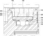
도 1 내지 도 3에 도시된 바와 같이, 본 발명의 일 실시예에 따른 차량용 충돌 센서 조립체(10)는, 차량의 충돌을 감지하는 충돌 센서(100)와, 충돌 센서(100)가 실장되는 기판(200)과, 충돌 센서(100)가 실장된 기판(200)이 수용되는 하우징(300)과, 기판(200)이 수용된 하우징(300)을 밀봉하는 포팅재(400)를 포함하여 구성된다.1 to 3 , the
이때, 하우징(300)에는 장착홈(310~330)이 형성되고, 장착홈(310~330)에는 센서(100)가 실장된 기판(200)이 설치되며, 기판(200)이 설치된 장착홈(310~330)에는 포팅재(400)가 주입된다.At this time,
상술한 차량용 충돌 센서 조립체(10)를 구성하는 각각의 구성요소에 대해 좀 더 상세히 살펴보도록 한다.Let's look at each of the components constituting the above-described vehicle
충돌 센서(100)는 차량의 충돌 사고 시 발생하는 충격을 감지하는 센서이다. 충돌 센서(100)로는 가속도 센서(acceleration sensor)가 주로 사용되는데, 이러한 가속도 센서는 외부에서 인가된 충격, 진동 등을 X축, Y축 및 Z축으로 구분하여 6축 방향의 가속도 값으로 출력함으로써 충돌 상황을 판단한다.The
기판(200)은 충돌 센서(100)에 전원 및 신호를 공급하거나 충돌 센서(100)에서 측정된 신호, 즉 가속도 값을 차량용 에어백 시스템으로 전달하는 역할을 한다.The
이러한 기판(200)은 회로, 저항 또는 센서 등의 전기적 부품들을 연결하기 위하여 구리 배선을 가늘게 인쇄한 통상의 인쇄회로기판(Printed Circuit Board; PCB)이다.The
본 실시예의 기판(200)은 얇은 두께를 가진 직사각형의 판재 형상이다. 기판(200)에는, 전원 및 신호 전달을 위한 단자홀(210)과, 기판(200)의 조립을 안내하기 위한 가이드홀(미도시)이 형성된다.The
또한, 기판(200)의 한쪽 모서리에는 오삽입을 방지하기 위한 챔퍼(chamfer, 230)가 형성된다. 이러한 챔퍼(230)는 기판(200)이 항상 일정한 방향으로 설치되도록 유도함으로써 조립 시 작업성을 향상시킬 수 있다.In addition, a
하우징(300)은 차량용 충돌 센서 조립체(10)의 외형을 형성하는 블록이다. 전술한 바와 같이, 하우징(300)에는 기판(200)의 설치를 위한 장착홈(310~330)이 형성된다.The
장착홈(310~330)은, 장착홈(310~330)의 입구를 형성하는 상단부(310)와, 상단부(310)의 하부에 차례로 형성된 중단부(320) 및 하단부(330)로 이루어진다. 이때, 상단부(310), 중단부(320) 및 하단부(330)로 이루어진 장착홈(310~330)은 상부로 갈수록 확장되는 다단으로 형성된다.The
장착홈(310~330)의 상단부(310)와 중단부(320)는 충돌 센서(100)가 실장된 기판(200)을 패키징하기 위한 포팅재(400)가 주입되는 부분으로, 상단부(310)와 중단부(330)의 내벽에는 포팅재(400)와의 접촉 면적을 증대시키기 위한 요철(340,350)이 형성된다.The
요철(340,350)은, 상단부(310)의 내벽에 형성된 제1요철(340)과, 중단부(320)의 내벽에 형성된 제2요철(350)로 이루어진다. 이때, 제1요철(340) 과 제2요철(350)은 볼록부(342,352)와 오목부(344,354)가 서로 엇갈리도록 배열된다.The concavities and
이와 같이, 상단부(310)와 중단부(330)의 내벽에 요철(340,350)을 형성하여 포팅재(400)와의 접촉 면적을 증대시킬 경우 포팅재(400)의 접착력을 향상시킬 수 있으며 충분한 밀봉성을 제공할 수 있다.As described above, when the contact area with the
장착홈(310~330)의 상단부(310)와 중단부(320) 사이에는 제1단턱부(360)가 형성되고, 중단부(320)와 하단부(330) 사이에는 기판(200)이 안착되는 제2단턱부(370)가 형성된다. 이때, 제1 단턱부(360)에는 충전홈(362)이 형성되고, 제2단턱부(370)에는 저장홈(372)이 형성된다.A first
충전홈(362)은 포팅재(400)가 충전되는 부분으로, 포팅재(400)와의 접촉 면적을 증대시켜 접착력을 향상시키는 역할을 한다. 또한, 저장홈(372)은 수분 등의 이물질이 저장되는 부분으로, 하우징(300)과 포팅재(400) 사이로 유입된 수분이 후술할 터미널(380) 측으로 유입되는 방지하는 역할을 한다.The
한편, 장착홈(310~330)의 중단부(320)에 형성된 제2요철(350)은 상부로 갈수록 확장되는 테이퍼 형상을 갖는다. 좀 더 상세하게는, 제2요철(350)의 볼록부(352)는 상부로 갈수록 확장되는 테이퍼 형상을 갖는데, 이는 기판(200)이 장착홈(310~330)에 쉽게 조립될 수 있도록 하기 위함이다.On the other hand, the second concavo-
다른 한편, 중단부(320)의 한쪽 모서리에는 기판(200)의 챔퍼(230)와 대응되는 돌기(322)가 형성된다. 돌기(322)는 챔퍼(230)와 함께 기판(200)이 항상 일정한 방향으로 설치되도록 유도함으로써 조립 시 작업성을 향상시킬 수 있다.On the other hand, a
장착홈(310~330)의 하단부(330)에는, 기판(200)에 전원 및 신호를 전달하기 위한 터미널(380)과, 기판(200)의 조립을 안내하기 위한 가이드(390)가 돌출된다. 이때, 터미널(380)과 가이드(390)는 장착홈(310~330)의 중단부(320)까지 연장되어, 기판(200)의 단자홀(210)과 가이드홀(미도시)에 각각 관통 결합된다.A
포팅재(400)는 기판(200)이 수용된 장착홈(310~330)에 주입되어 밀봉하는 역할을 한다. 즉, 기판(200)을 장착홈(310~330)에 조립한 상태에서 액상의 에폭시를 주입한 후 경화시킴으로써 충돌 센서(100)가 실장된 기판(200)을 고정한다.The
이상과 같이 본 발명에 대해서 예시한 도면을 참조로 하여 설명하였으나, 본 명세서에 개시된 실시 예와 도면에 의해 본 발명이 한정되는 것은 아니며, 본 발명의 기술사상의 범위 내에서 통상의 기술자에 의해 다양한 변형이 이루어질 수 있음은 자명하다. 아울러 앞서 본 발명의 실시 예를 설명하면서 본 발명의 구성에 따른 작용 효과를 명시적으로 기재하여 설명하지 않았을 지라도, 해당 구성에 의해 예측 가능한 효과 또한 인정되어야 함은 당연하다.As described above, the present invention has been described with reference to the illustrated drawings, but the present invention is not limited by the embodiments and drawings disclosed in the present specification. It is obvious that variations can be made. In addition, although the effects according to the configuration of the present invention have not been explicitly described and described while describing the embodiments of the present invention, it is natural that the effects predictable by the configuration should also be recognized.
10: 차량용 충돌 센서 조립체100: 충돌 센서
200: 기판300: 하우징
400: 포팅재10: collision sensor assembly for vehicle 100: collision sensor
200: substrate 300: housing
400: potting material
Claims (8)
Translated fromKorean상기 충돌 센서가 실장되는 기판;
상기 충돌 센서가 실장된 상기 기판이 수용되는 하우징; 및
상기 기판이 수용된 상기 하우징을 밀봉하는 포팅재를 포함하고,
상기 하우징에는 상기 기판이 수용되며 상기 포팅재가 충전되는 장착홈이 형성되되, 상기 장착홈의 내벽에는 상기 포팅재와의 접촉 면적을 증대시켜 접착력을 향상시키기 위한 요철이 형성된 것을 특징으로 하는 차량용 충돌 센서 조립체.
a collision sensor that detects a collision of a vehicle;
a board on which the collision sensor is mounted;
a housing in which the substrate on which the collision sensor is mounted is accommodated; and
and a potting material sealing the housing in which the substrate is accommodated,
The housing is provided with a mounting groove in which the substrate is accommodated and the potting material is filled, and an inner wall of the mounting groove is provided with concavities and convexities to increase a contact area with the potting material to improve adhesion. assembly.
상기 장착홈은, 상기 장착홈의 가장 위에 형성된 상단부와, 상기 장착홈의 가장 아래에 형성된 하단부와, 상기 상단부와 상기 하단부 사이에 형성된 중단부로 이루어지고,
상기 장착홈은 상부로 갈수록 확장되는 다단으로 형성된 것을 특징으로 하는 차량용 충돌 센서 조립체.
The method according to claim 1,
The mounting groove includes an upper end formed at the top of the mounting groove, a lower end formed at the bottom of the mounting groove, and a middle portion formed between the upper end and the lower end,
The vehicle collision sensor assembly, characterized in that the mounting groove is formed in multi-stage extending toward the upper portion.
상기 요철은, 상기 상단부의 내벽에 형성된 제1요철과, 상기 중단부의 내벽에 형성된 제2요철로 이루어진 것을 특징으로 하는 차량용 충돌 센서 조립체.
3. The method according to claim 2,
The bumpy portion includes a first unevenness formed on the inner wall of the upper end and a second unevenness formed on the inner wall of the middle portion.
상기 중단부의 내벽은 상부로 갈수록 확장되는 테이퍼 형상인 것을 특징을 하는 차량용 충돌 센서 조립체.
4. The method according to claim 3,
The collision sensor assembly for a vehicle, characterized in that the inner wall of the middle part has a tapered shape extending toward the top.
상기 상단부와 상기 중단부 사이에는 제1단턱부가 형성되고, 상기 제1단턱부에는 상기 포팅재가 유입되는 충전홈이 형성된 것을 특징으로 하는 차량용 충돌 센서 조립체.
5. The method according to any one of claims 2 to 4,
A first stepped portion is formed between the upper end and the middle portion, and a charging groove into which the potting material is introduced is formed in the first stepped portion.
상기 중단부와 상기 하단부 사이에는 상기 기판이 안착되는 제2단턱부가 형성되고,
상기 제2단턱부에는 상기 하우징과 상기 포팅재 사이로 유입된 수분이 저장되는 저장홈이 형성된 것을 특징으로 하는 차량용 충돌 센서 조립체.
6. The method of claim 5,
A second stepped portion on which the substrate is seated is formed between the middle portion and the lower portion,
The collision sensor assembly for a vehicle, characterized in that the storage groove for storing the moisture introduced between the housing and the potting material is formed in the second step portion.
상기 중단부의 일측에는 상기 기판의 오삽입을 방지하기 위한 돌기가 형성된 것을 특징으로 하는 차량용 충돌 센서 조립체.
7. The method of claim 6,
A collision sensor assembly for a vehicle, characterized in that a protrusion is formed on one side of the middle part to prevent erroneous insertion of the substrate.
상기 하단부에는 상기 기판에 전원 또는/및 신호를 전달하기 위한 터미널과, 상기 기판의 조립을 안내하기 위한 가이드가 돌출되고,
상기 터미널과 상기 가이드는 상기 중단부까지 연장된 것을 특징으로 하는 차량용 충돌 센서 조립체.8. The method of claim 7,
A terminal for transmitting power and / and a signal to the substrate and a guide for guiding the assembly of the substrate are protruded from the lower end,
The collision sensor assembly for a vehicle, characterized in that the terminal and the guide extend to the middle portion.
Priority Applications (1)
| Application Number | Priority Date | Filing Date | Title |
|---|---|---|---|
| KR1020200181396AKR20220090319A (en) | 2020-12-22 | 2020-12-22 | Crash sensor assembly for vehicle |
Applications Claiming Priority (1)
| Application Number | Priority Date | Filing Date | Title |
|---|---|---|---|
| KR1020200181396AKR20220090319A (en) | 2020-12-22 | 2020-12-22 | Crash sensor assembly for vehicle |
Publications (1)
| Publication Number | Publication Date |
|---|---|
| KR20220090319Atrue KR20220090319A (en) | 2022-06-29 |
Family
ID=82269993
Family Applications (1)
| Application Number | Title | Priority Date | Filing Date |
|---|---|---|---|
| KR1020200181396ACeasedKR20220090319A (en) | 2020-12-22 | 2020-12-22 | Crash sensor assembly for vehicle |
Country Status (1)
| Country | Link |
|---|---|
| KR (1) | KR20220090319A (en) |
Citations (1)
| Publication number | Priority date | Publication date | Assignee | Title |
|---|---|---|---|---|
| KR101296426B1 (en) | 2008-07-28 | 2013-08-13 | 티알더블유 오토모티브 유.에스. 엘엘씨 | Method and apparatus for packaging crash sensors |
- 2020
- 2020-12-22KRKR1020200181396Apatent/KR20220090319A/ennot_activeCeased
Patent Citations (1)
| Publication number | Priority date | Publication date | Assignee | Title |
|---|---|---|---|---|
| KR101296426B1 (en) | 2008-07-28 | 2013-08-13 | 티알더블유 오토모티브 유.에스. 엘엘씨 | Method and apparatus for packaging crash sensors |
Similar Documents
| Publication | Publication Date | Title |
|---|---|---|
| US7721603B2 (en) | Inertial sensor arrangement | |
| US7291023B1 (en) | Electric vehicle motion sensor | |
| KR102156579B1 (en) | Battery state detection device and method for manufacturing same | |
| JP6367475B2 (en) | Device for dry side installation of impact pressure sensor | |
| JP5685187B2 (en) | Method and apparatus for housing a vehicle collision sensor | |
| US7819004B2 (en) | Vehicle sensor | |
| US8693205B2 (en) | Control unit for personal protection device for a vehicle and method for assembling such a control unit | |
| US20070157699A1 (en) | Sensor module | |
| US20070010138A1 (en) | Sensor device | |
| CN107677299A (en) | Equipment for the installation shock sensor that is clasped | |
| KR20020080268A (en) | A vehicular electronic device | |
| US20070068276A1 (en) | Pressure sensor | |
| KR100378509B1 (en) | Sensor unit for controlling vehicle occupant protection | |
| US6362971B1 (en) | Control device for a vehicular occupant restraint system | |
| US11026340B2 (en) | Passenger protection control device | |
| KR20140027292A (en) | Rear windshield comprising electrics protection box | |
| JP4957454B2 (en) | Pressure sensor | |
| KR20220090319A (en) | Crash sensor assembly for vehicle | |
| US20140102225A1 (en) | Sensor device | |
| US11201421B2 (en) | Printed circuit board mounting arrangement | |
| JP2004294419A (en) | Sensor device | |
| JP4544107B2 (en) | Sensor device | |
| CN213043952U (en) | Electronic control device | |
| JP2019535020A (en) | Sensor devices for vehicles and automobiles | |
| JP6048291B2 (en) | Sensor device |
Legal Events
| Date | Code | Title | Description |
|---|---|---|---|
| PA0109 | Patent application | Patent event code:PA01091R01D Comment text:Patent Application Patent event date:20201222 | |
| PG1501 | Laying open of application | ||
| E902 | Notification of reason for refusal | ||
| PE0902 | Notice of grounds for rejection | Comment text:Notification of reason for refusal Patent event date:20250110 Patent event code:PE09021S01D | |
| E601 | Decision to refuse application | ||
| PE0601 | Decision on rejection of patent | Patent event date:20250320 Comment text:Decision to Refuse Application Patent event code:PE06012S01D |