KR20220086331A - Sheath device and endoscope system having the same - Google Patents
Sheath device and endoscope system having the sameDownload PDFInfo
- Publication number
- KR20220086331A KR20220086331AKR1020200176683AKR20200176683AKR20220086331AKR 20220086331 AKR20220086331 AKR 20220086331AKR 1020200176683 AKR1020200176683 AKR 1020200176683AKR 20200176683 AKR20200176683 AKR 20200176683AKR 20220086331 AKR20220086331 AKR 20220086331A
- Authority
- KR
- South Korea
- Prior art keywords
- guide body
- guide
- sheath device
- endoscope
- stopper
- Prior art date
- Legal status (The legal status is an assumption and is not a legal conclusion. Google has not performed a legal analysis and makes no representation as to the accuracy of the status listed.)
- Ceased
Links
- 238000011282treatmentMethods0.000claimsabstractdescription83
- 230000003287optical effectEffects0.000claimsabstractdescription38
- 238000000034methodMethods0.000claimsdescription24
- 239000012530fluidSubstances0.000description22
- 238000001356surgical procedureMethods0.000description15
- 238000002324minimally invasive surgeryMethods0.000description10
- 238000002357laparoscopic surgeryMethods0.000description5
- FAPWRFPIFSIZLT-UHFFFAOYSA-MSodium chlorideChemical compound[Na+].[Cl-]FAPWRFPIFSIZLT-UHFFFAOYSA-M0.000description4
- 210000001015abdomenAnatomy0.000description3
- 201000010099diseaseDiseases0.000description3
- 208000037265diseases, disorders, signs and symptomsDiseases0.000description3
- 238000003384imaging methodMethods0.000description3
- 238000003780insertionMethods0.000description3
- 230000037431insertionEffects0.000description3
- 238000012986modificationMethods0.000description3
- 230000004048modificationEffects0.000description3
- 210000000056organAnatomy0.000description3
- 239000000126substanceSubstances0.000description3
- 230000000740bleeding effectEffects0.000description2
- 239000008280bloodSubstances0.000description2
- 210000004369bloodAnatomy0.000description2
- 238000002674endoscopic surgeryMethods0.000description2
- 238000002682general surgeryMethods0.000description2
- 210000003734kidneyAnatomy0.000description2
- 238000002350laparotomyMethods0.000description2
- 238000011084recoveryMethods0.000description2
- 238000002432robotic surgeryMethods0.000description2
- 230000037390scarringEffects0.000description2
- 239000011780sodium chlorideSubstances0.000description2
- 210000001519tissueAnatomy0.000description2
- 206010000050Abdominal adhesionsDiseases0.000description1
- 208000032544CicatrixDiseases0.000description1
- 206010009944Colon cancerDiseases0.000description1
- 208000001333Colorectal NeoplasmsDiseases0.000description1
- 201000009273EndometriosisDiseases0.000description1
- 208000028389Nerve injuryDiseases0.000description1
- 206010033128Ovarian cancerDiseases0.000description1
- 206010061535Ovarian neoplasmDiseases0.000description1
- 208000029082Pelvic Inflammatory DiseaseDiseases0.000description1
- 208000007103SpondylolisthesisDiseases0.000description1
- 208000005718Stomach NeoplasmsDiseases0.000description1
- 206010044565TremorDiseases0.000description1
- 206010046543Urinary incontinenceDiseases0.000description1
- 208000002495Uterine NeoplasmsDiseases0.000description1
- 206010046814Uterine prolapseDiseases0.000description1
- 206010000210abortionDiseases0.000description1
- 231100000176abortionToxicity0.000description1
- 210000004100adrenal glandAnatomy0.000description1
- 210000000436anusAnatomy0.000description1
- 238000005452bendingMethods0.000description1
- 230000000903blocking effectEffects0.000description1
- 239000006227byproductSubstances0.000description1
- 238000002192cholecystectomyMethods0.000description1
- 230000001684chronic effectEffects0.000description1
- 238000004891communicationMethods0.000description1
- 238000012937correctionMethods0.000description1
- 230000003412degenerative effectEffects0.000description1
- 238000007599dischargingMethods0.000description1
- 238000002224dissectionMethods0.000description1
- 230000000694effectsEffects0.000description1
- 238000001839endoscopyMethods0.000description1
- 206010017758gastric cancerDiseases0.000description1
- 238000002647laser therapyMethods0.000description1
- 239000008141laxativeSubstances0.000description1
- 230000002475laxative effectEffects0.000description1
- 239000007788liquidSubstances0.000description1
- 230000002175menstrual effectEffects0.000description1
- 210000000214mouthAnatomy0.000description1
- 210000003205muscleAnatomy0.000description1
- 230000008764nerve damageEffects0.000description1
- 239000013307optical fiberSubstances0.000description1
- 210000003903pelvic floorAnatomy0.000description1
- 238000009420retrofittingMethods0.000description1
- 231100000241scarToxicity0.000description1
- 230000037387scarsEffects0.000description1
- 238000000926separation methodMethods0.000description1
- 238000009751slip formingMethods0.000description1
- 201000011549stomach cancerDiseases0.000description1
- 238000002560therapeutic procedureMethods0.000description1
- 238000012285ultrasound imagingMethods0.000description1
- 206010046766uterine cancerDiseases0.000description1
- 210000004291uterusAnatomy0.000description1
- XLYOFNOQVPJJNP-UHFFFAOYSA-NwaterSubstancesOXLYOFNOQVPJJNP-UHFFFAOYSA-N0.000description1
Images


Classifications
- A—HUMAN NECESSITIES
- A61—MEDICAL OR VETERINARY SCIENCE; HYGIENE
- A61B—DIAGNOSIS; SURGERY; IDENTIFICATION
- A61B1/00—Instruments for performing medical examinations of the interior of cavities or tubes of the body by visual or photographical inspection, e.g. endoscopes; Illuminating arrangements therefor
- A61B1/00131—Accessories for endoscopes
- A61B1/00135—Oversleeves mounted on the endoscope prior to insertion
- A—HUMAN NECESSITIES
- A61—MEDICAL OR VETERINARY SCIENCE; HYGIENE
- A61B—DIAGNOSIS; SURGERY; IDENTIFICATION
- A61B1/00—Instruments for performing medical examinations of the interior of cavities or tubes of the body by visual or photographical inspection, e.g. endoscopes; Illuminating arrangements therefor
- A61B1/00064—Constructional details of the endoscope body
- A61B1/00071—Insertion part of the endoscope body
- A61B1/0008—Insertion part of the endoscope body characterised by distal tip features
- A61B1/00087—Tools
- A—HUMAN NECESSITIES
- A61—MEDICAL OR VETERINARY SCIENCE; HYGIENE
- A61B—DIAGNOSIS; SURGERY; IDENTIFICATION
- A61B1/00—Instruments for performing medical examinations of the interior of cavities or tubes of the body by visual or photographical inspection, e.g. endoscopes; Illuminating arrangements therefor
- A61B1/00064—Constructional details of the endoscope body
- A61B1/00071—Insertion part of the endoscope body
- A61B1/0008—Insertion part of the endoscope body characterised by distal tip features
- A61B1/00094—Suction openings
- A—HUMAN NECESSITIES
- A61—MEDICAL OR VETERINARY SCIENCE; HYGIENE
- A61B—DIAGNOSIS; SURGERY; IDENTIFICATION
- A61B1/00—Instruments for performing medical examinations of the interior of cavities or tubes of the body by visual or photographical inspection, e.g. endoscopes; Illuminating arrangements therefor
- A61B1/00064—Constructional details of the endoscope body
- A61B1/00071—Insertion part of the endoscope body
- A61B1/0008—Insertion part of the endoscope body characterised by distal tip features
- A61B1/00096—Optical elements
- A—HUMAN NECESSITIES
- A61—MEDICAL OR VETERINARY SCIENCE; HYGIENE
- A61B—DIAGNOSIS; SURGERY; IDENTIFICATION
- A61B1/00—Instruments for performing medical examinations of the interior of cavities or tubes of the body by visual or photographical inspection, e.g. endoscopes; Illuminating arrangements therefor
- A61B1/00112—Connection or coupling means
- A61B1/00121—Connectors, fasteners and adapters, e.g. on the endoscope handle
- A61B1/00128—Connectors, fasteners and adapters, e.g. on the endoscope handle mechanical, e.g. for tubes or pipes
- A—HUMAN NECESSITIES
- A61—MEDICAL OR VETERINARY SCIENCE; HYGIENE
- A61B—DIAGNOSIS; SURGERY; IDENTIFICATION
- A61B1/00—Instruments for performing medical examinations of the interior of cavities or tubes of the body by visual or photographical inspection, e.g. endoscopes; Illuminating arrangements therefor
- A61B1/00131—Accessories for endoscopes
- A61B1/00137—End pieces at either end of the endoscope, e.g. caps, seals or forceps plugs
- A—HUMAN NECESSITIES
- A61—MEDICAL OR VETERINARY SCIENCE; HYGIENE
- A61B—DIAGNOSIS; SURGERY; IDENTIFICATION
- A61B1/00—Instruments for performing medical examinations of the interior of cavities or tubes of the body by visual or photographical inspection, e.g. endoscopes; Illuminating arrangements therefor
- A61B1/00147—Holding or positioning arrangements
- A61B1/00154—Holding or positioning arrangements using guiding arrangements for insertion
- A—HUMAN NECESSITIES
- A61—MEDICAL OR VETERINARY SCIENCE; HYGIENE
- A61B—DIAGNOSIS; SURGERY; IDENTIFICATION
- A61B1/00—Instruments for performing medical examinations of the interior of cavities or tubes of the body by visual or photographical inspection, e.g. endoscopes; Illuminating arrangements therefor
- A61B1/00163—Optical arrangements
- A61B1/00174—Optical arrangements characterised by the viewing angles
- A—HUMAN NECESSITIES
- A61—MEDICAL OR VETERINARY SCIENCE; HYGIENE
- A61B—DIAGNOSIS; SURGERY; IDENTIFICATION
- A61B17/00—Surgical instruments, devices or methods
- A61B17/00234—Surgical instruments, devices or methods for minimally invasive surgery
- A—HUMAN NECESSITIES
- A61—MEDICAL OR VETERINARY SCIENCE; HYGIENE
- A61B—DIAGNOSIS; SURGERY; IDENTIFICATION
- A61B17/00—Surgical instruments, devices or methods
- A61B17/34—Trocars; Puncturing needles
- A61B17/3417—Details of tips or shafts, e.g. grooves, expandable, bendable; Multiple coaxial sliding cannulas, e.g. for dilating
- A61B17/3421—Cannulas
- A—HUMAN NECESSITIES
- A61—MEDICAL OR VETERINARY SCIENCE; HYGIENE
- A61B—DIAGNOSIS; SURGERY; IDENTIFICATION
- A61B17/00—Surgical instruments, devices or methods
- A61B17/34—Trocars; Puncturing needles
- A61B17/3462—Trocars; Puncturing needles with means for changing the diameter or the orientation of the entrance port of the cannula, e.g. for use with different-sized instruments, reduction ports, adapter seals
Landscapes
- Health & Medical Sciences (AREA)
- Life Sciences & Earth Sciences (AREA)
- Surgery (AREA)
- Engineering & Computer Science (AREA)
- Animal Behavior & Ethology (AREA)
- General Health & Medical Sciences (AREA)
- Biomedical Technology (AREA)
- Heart & Thoracic Surgery (AREA)
- Medical Informatics (AREA)
- Molecular Biology (AREA)
- Veterinary Medicine (AREA)
- Nuclear Medicine, Radiotherapy & Molecular Imaging (AREA)
- Public Health (AREA)
- Pathology (AREA)
- Physics & Mathematics (AREA)
- Biophysics (AREA)
- Optics & Photonics (AREA)
- Radiology & Medical Imaging (AREA)
- Mechanical Engineering (AREA)
- Endoscopes (AREA)
Abstract
Translated fromKorean
Description
Translated fromKorean시스 장치 및 이를 구비하는 내시경 시스템이 개시된다. 구체적으로, 본 발명은 내시경 장치와 치료장치가 분리되도록 구성되고, 시스 장치를 구비하는 내시경 시스템에 관한 것이다.Disclosed are a sheath device and an endoscope system having the same. Specifically, the present invention relates to an endoscopic system configured to be separated from an endoscopic device and a treatment device, and including a sheath device.
내시경 시스템은 일반적으로 인체의 구강 또는 항문을 통해 장기를 검사하는 내시경 검사와 인체의 피부를 최소 절개하여 내시경을 삽입하는 최소 침습 시술로 구분될 수 있다.The endoscope system can be generally divided into an endoscopy for examining an organ through the oral cavity or anus of the human body and a minimally invasive procedure for inserting the endoscope through a minimal incision in the skin of the human body.
최소 침습 시술은 수술 시 절개부위를 줄여 인체에 상처를 최소한으로 남기는 수술 방법으로써, 그 예시로 복강경 수술이 있다. 전통적으로 복부에 큰 절개창을 열고 시행하는 개복 수술과 달리, 복강경 수술은 복부에 0.5~1.5cm의 작은 구멍을 여러 개 내고, 그 안으로 비디오 카메라 및 각종 기구들을 넣고 기구들을 움직여 수술을 수행하는 방법이다.Minimally invasive surgery is a surgical method that minimizes scarring on the human body by reducing the incision area during surgery, and an example of this is laparoscopic surgery. Unlike laparotomy, which is traditionally performed by opening a large incision in the abdomen, laparoscopic surgery is a method of performing surgery by making several small 0.5-1.5 cm holes in the abdomen, inserting a video camera and various instruments into them, and moving the instruments. .
더불어 로봇 수술도 최소 침습 수술 내에 속한다. 로봇 수술은 복강경 수술과 원리는 같으나, 의사가 로봇 팔을 조종하여 수술을 시행한다는 점에서 다르고, 보다 자유로운 움직임과 손 떨림을 방지하여 미세한 수술이 가능하다.Robotic surgery also falls under the category of minimally invasive surgery. Robotic surgery has the same principle as laparoscopic surgery, but it is different in that the doctor controls the robot arm to perform the surgery, and it allows for more free movement and prevents hand tremors for finer surgery.
이러한 최소 침습 시술은 칼로 인체를 절개하던 개복수술이 절개 부위가 크고, 흉터와 출혈이 많으며, 회복하는 데 시간이 오래 걸리는 단점을 보완할 목적으로 개발되었다.This minimally invasive procedure was developed for the purpose of compensating for the disadvantages of laparotomy, which used to cut the body with a knife, with a large incision, a lot of scars and bleeding, and a long recovery time.
구체적으로, 복강경 수술이나 관절경 수술을 예로 들어 설명하면, 복강경 수술이나 관절경 수술은 일자로 단단하게 형성되는 내시경을 인체 내로 삽입하여 수술장면 영상을 화면으로 보면서 인체 밖에서 기구를 조종하여 수술을 진행한다. 피부에 작은 구멍을 낸 후 기구들이 출입할 수 있는 시스를 삽입한다. 이 때, 대상부위 주변의 3~4 곳을 절개하고, 외부에서 몸 안을 관찰할 수 있도록 돕는 영상장치와 집게, 흡인기, 소작기, 절삭기 등을 삽입하여 세밀한 수술을 진행한다. 제거하는 조직은 확장기를 통해 몸 밖으로 꺼내게 된다.Specifically, if laparoscopic surgery or arthroscopic surgery is described as an example, laparoscopic surgery or arthroscopic surgery inserts an endoscope formed in a straight line into the human body and controls the instrument outside the human body while viewing the surgical scene image on the screen to perform the operation do. After making a small hole in the skin, a sheath is inserted through which the instruments can enter and exit. At this time, 3~4 places around the target site are incised, and an imaging device that helps to observe the inside of the body from the outside, forceps, aspirator, cauterizer, and cutting machine are inserted to perform detailed surgery. The tissue to be removed is taken out of the body through a dilator.
이러한 최소 침습 수술은 절개부위가 작고, 흉터와 출혈이 적으며, 회복 시간도 개복수술보다 훨씬 짧을 뿐 아니라, 수술 후 통증도 훨씬 덜한 것이 장점이다.The advantage of this minimally invasive surgery is that the incision site is small, scarring and bleeding are small, the recovery time is much shorter than that of open surgery, and the pain after surgery is much less.
최소 침습 수술이 적용되는 대표적인 질환은 산부인과, 신경외과, 일반외과, 비뇨기과 등이며, 특히 산부인과 질환에 많이 이용되는데, 주요 수술의 범위는 자궁외임신, 난관 및 난소 종양, 자궁근종 제거 및 자궁적출술, 자궁내막증, 만성 골반염, 요실금, 장유착 박리술, 월경제거술, 자궁후굴 교정, 자궁암, 난소암, 자궁탈출, 이완 골반저교정증 등이다.Typical diseases to which minimally invasive surgery is applied are obstetrics and gynecology, neurosurgery, general surgery, and urology. These include endometriosis, chronic pelvic inflammatory disease, urinary incontinence, intestinal adhesion dissection, menstrual abortion, retrofitting of the uterus, uterine cancer, ovarian cancer, uterine prolapse, and laxative pelvic floor correction.
신경외과 질환으로는 퇴행성 디스크 및 척추전방전위증을 들 수 있다. X선으로 위치를 확인하고 대상위치에 구멍을 낸 뒤, 레이저, 집게 등으로 질환을 제거한다. 근육조직에 손상이 없고, 수술로 인해 신경을 다치는 경우가 거의 없는 것이 장점이다.Neurosurgical diseases include degenerative discs and spondylolisthesis. After confirming the location with X-rays and making a hole in the target location, the disease is removed with a laser or tongs. The advantage is that there is no damage to the muscle tissue and there is almost no case of nerve damage due to surgery.
그 밖에는 위암과 대장암, 담낭절제술 등 일반외과와 신장 부신 등 배 뒤쪽 장기와 관련된 수술 등에도 최소 침습 시술이 행해지고 있다.In addition, minimally invasive procedures are being performed for general surgery such as gastric cancer, colorectal cancer, and cholecystectomy, as well as surgery related to organs in the back of the abdomen such as the kidneys and adrenal glands.
이러한 최소 침습 시술은 의료진의 입장에서 환부를 모니터로 확대해 보거나, 개복 수술에서는 보기 어려웠던 장기(예 : 신장)도 시야를 확보하며 수술할 수 있게 했다. 또한, 이러한 최소 침습 시술은 모니터 화면을 통해 수술 과정을 공유할 수 있어 젊은 의사들을 대상으로 교육효과를 줄 수도 있다.This minimally invasive procedure made it possible for medical staff to magnify the affected area with a monitor, or to operate an organ (eg kidney), which was difficult to see in open surgery, while securing a view. In addition, this minimally invasive procedure can share the surgical process through the monitor screen, so it can give educational effects to young doctors.
그러나, 종래의 이러한 최소 침습 시술을 위한 장치들은 수술용 기구들과 영상장치 및 기타 수술 보조 기구들의 사용을 위해 신체의 여러 군데에 절개를 해야 하는 문제점이 있었다.However, conventional devices for this minimally invasive procedure have a problem in that they have to make incisions in various places on the body for the use of surgical instruments, imaging devices, and other surgical auxiliary instruments.
이러한 문제점을 해결하기 위해, 내시경 장치와 치료 장치를 동시에 삽입하기 위한 기술들이 소개된 바 있다.In order to solve this problem, techniques for simultaneously inserting an endoscope device and a treatment device have been introduced.
한국공개특허문헌 제10-2011-0120476호는 일측 단부에 수술 도구가 구비된 로봇팔을 복수 개 구비한 내시경 수술용 로봇 장치를 개시한다.Korean Patent Publication No. 10-2011-0120476 discloses a robot device for endoscopic surgery having a plurality of robot arms equipped with surgical tools at one end.
그런데 이러한 유형의 내시경 수술용 로봇 장치는 로봇 팔 자체에 링크들로 이루어진 벤딩 관절이 구비되어야 하고, 별도의 가이드부 없이 로봇 팔을 제어하기 위한 동력이 공급되어야 하므로 구조가 복잡해지는 단점이 있다.However, this type of robot device for endoscopic surgery has disadvantages in that the robot arm itself has to be provided with a bending joint made of links, and power for controlling the robot arm without a separate guide unit must be supplied, thereby complicating the structure.
따라서, 이러한 복잡한 구조에 의하지 않고도, 보다 효과적으로 시술이나 수술을 할 수 있는 내시경 장치에 대한 방안이 착안될 수 있다.Therefore, a method for an endoscope apparatus capable of performing a procedure or surgery more effectively without relying on such a complicated structure can be devised.
일 실시예에 따른 목적은 신체의 한 부위에 구멍을 뚫는 것 만으로도 시술이 가능한 내시경 시스템을 제공하는 것이다.An object according to an embodiment is to provide an endoscope system that can be operated only by making a hole in one part of the body.
또한, 일 실시예에 따른 다른 목적은 다양한 치료를 수행할 수 있는 치료 장치를 내시경 장치와 함께 체내에 삽입할 수 있는 내시경 시스템을 제공하는 것이다.Another object according to an embodiment is to provide an endoscope system capable of inserting a treatment device capable of performing various treatments into the body together with the endoscope device.
또한, 일 실시예에 따른 다른 목적은 치료 과정에서 발생하는 이물질 등을 효과적으로 흡입하여 신체 외부로 배출할 수 있는 내시경 시스템을 제공하는 것이다.In addition, another object according to an embodiment is to provide an endoscope system capable of effectively sucking in a foreign substance generated during a treatment process and discharging it to the outside of the body.
또한, 일 실시예에 따른 다른 목적은 내시경 장치와 치료 장치를 함께 체내에 삽입하면서도 내시경의 시야확보가 용이한 내시경 시스템을 제공하는 것이다.Another object of the present invention is to provide an endoscope system that facilitates securing a field of view of an endoscope while inserting an endoscope device and a treatment device together into a body.
또한, 일 실시예에 따른 다른 목적은 치료 장치의 교체시 대상부위의 유체가 인출되는 것을 방지하는 구조를 구비하는 시스 장치 및 이를 구비하는 내시경 시스템을 제공하는 것이다.Another object according to one embodiment is to provide a sheath device having a structure that prevents fluid from being drawn out of a target site when the treatment device is replaced, and an endoscope system having the same.
또한, 일 실시예에 따른 다른 목적은 내시경 장치 및 치료 장치의 오삽입과 탈거를 방지하는 구조를 구비하는 시스 장치 및 이를 구비하는 내시경 시스템을 제공하는 것이다.In addition, another object according to an embodiment is to provide a sheath device having a structure for preventing erroneous insertion and removal of the endoscope device and the treatment device, and an endoscope system having the same.
상기 목적을 달성하기 위한 일 실시예에 따른 내시경 시스템은, 전방으로 연장되는 제1 가이드 바디와 제2 가이드 바디를 구비하는 시스 장치, 상기 시스 장치와 탈착되며, 광학부를 구비하는 내시경 장치, 및 상기 시스 장치와 탈착되며, 치료부를 구비하는 치료 장치를 포함할 수 있고, 상기 광학부는 일방향으로 연장되어서 상기 제1 가이드 바디 내에 인입될 수 있으며, 상기 치료부는 일방향으로 연장되어서 상기 제2 가이드 바디 내에 인입될 수 있고, 상기 제2 가이드 바디는 상기 제1 가이드 바디와 평행하게 상기 제1 가이드 바디의 상측에서 전방으로 연장되도록 배치될 수 있으며, 상기 광학부의 입사면은 전방 하방을 향하도록 경사진 것을 특징으로 할 수 있다.An endoscope system according to an embodiment for achieving the above object includes a sheath device having a first guide body and a second guide body extending forward, an endoscope device detachable from the sheath device, and having an optical unit, and the It may include a treatment device detachable from the sheath device and having a treatment unit, the optical unit extending in one direction to be retracted into the first guide body, and the treatment unit extending in one direction to be retracted into the second guide body and the second guide body may be arranged to extend forward from an upper side of the first guide body in parallel to the first guide body, and the incident surface of the optical unit is inclined forwardly downward. can be done with
상기 목적을 달성하기 위한 일 실시예에 따른 내시경 시스템의, 상기 제2 가이드 바디는 상기 제1 가이드 바디의 우상방 또는 좌상방에 위치될 수 있다.In the endoscope system according to an embodiment for achieving the above object, the second guide body may be located in the upper right or upper left of the first guide body.
상기 목적을 달성하기 위한 일 실시예에 따른 내시경 시스템의, 상기 치료부의 전방 단부는 상기 광학부의 전방 단부보다 전방 상방에 위치될 수 있다.In the endoscope system according to an embodiment for achieving the above object, the front end of the treatment unit may be located in an upper front than the front end of the optical unit.
상기 목적을 달성하기 위한 일 실시예에 따른 내시경 시스템은 상기 시스 장치는 상기 시스 장치의 외표면에 대응되는 형상으로 형성되는 제2 다이얼부를 포함할 수 있고, 상기 제2 다이얼부는 상기 시스 장치의 외표면 둘레를 따라서 회전할 수 있으며, 상기 제2 다이얼부는 상기 제2 다이얼부의 원형 단면의 중심 방향으로 돌출되는 스톱퍼를 포함할 수 있고, 상기 내시경 장치의 측면에는 상기 스톱퍼의 크기에 대응되는 가이드홈이 구비될 수 있으며, 상기 제2 다이얼부의 회전에 따라 상기 스톱퍼는 상기 가이드홈의 단부에 위치될 수 있다.In an endoscope system according to an embodiment for achieving the above object, the sheath device may include a second dial portion formed in a shape corresponding to an outer surface of the sheath device, and the second dial portion is outside the sheath device. It can rotate along the periphery of the surface, and the second dial part may include a stopper protruding in the center direction of the circular cross-section of the second dial part, and a guide groove corresponding to the size of the stopper is provided on the side surface of the endoscope device. It may be provided, and according to the rotation of the second dial part, the stopper may be located at the end of the guide groove.
상기 목적을 달성하기 위한 일 실시예에 따른 시스 장치는, 전방으로 연장되며 내부에 관로를 형성하는 제1 가이드 바디, 전방으로 연장되며 내부에 관로를 형성하는 제2 가이드 바디, 상기 제1 가이드 바디와 상기 제2 가이드 바디의 후방에 위치되는 몸체부, 및 상기 몸체부에 장착되는 마개부를 포함할 수 있고, 상기 제1 가이드 바디는 상기 제2 가이드 바디의 상측에 배치될 수 있으며, 상기 제1 가이드 바디와 상기 제2 가이드 바디는 서로 평행하게 배치될 수 있고, 상기 마개부는 상기 몸체부의 둘레를 따라 이동하여 상기 제2 가이드 바디의 관로를 개폐하도록 형성되는 것을 특징으로 할 수 있다.A sheath device according to an embodiment for achieving the above object, a first guide body extending forward and forming a conduit therein, a second guide body extending forward and forming a conduit therein, the first guide body and a body portion positioned at the rear of the second guide body, and a stopper mounted to the body portion, wherein the first guide body may be disposed above the second guide body, and the first The guide body and the second guide body may be disposed parallel to each other, and the stopper may be formed to move along a circumference of the body to open and close the conduit of the second guide body.
상기 목적을 달성하기 위한 일 실시예에 따른 상기 시스 장치는, 상기 몸체부의 외표면에 배치되어서, 상기 몸체부의 둘레를 따라서 회전하는 제1 다이얼부를 포함할 수 있고, 상기 마개부는 상기 제1 다이얼부의 내측에서 돌출되며, 상기 몸체부를 관통할 수 있으며, 상기 마개부는 상기 제1 다이얼부의 회전에 따라, 상기 제2 가이드 바디의 측면에 형성되는 인입홈으로 인입될 수 있다.The sheath device according to an embodiment for achieving the above object may include a first dial portion that is disposed on the outer surface of the body portion and rotates along the circumference of the body portion, and the stopper portion is the first dial portion It protrudes from the inside and may pass through the body, and the stopper may be introduced into an inlet groove formed on a side surface of the second guide body as the first dial portion rotates.
상기 목적을 달성하기 위한 일 실시예에 따른 시스 장치의, 상기 몸체부의 후면에는 상기 제1 가이드 바디와 연통 되는 제1 개구가 구비될 수 있고, 상기 몸체부의 후면에는 상기 제2 가이드 바디와 연통되는 제2 개구가 구비될 수 있으며, 상기 몸체부의 후면은 전방을 향하도록 깔때기 모양으로 형성되며, 상기 제1 개구는 상기 몸체부의 후면의 깔때기 모양의 전방 꼭지점 부분에 배치될 수 있고, 상기 목적을 달성하기 위한 일 실시예에 따른 상기 시스 장치는, 상기 몸체부의 측면에 배치되는 밸브 조립체부를 더 포함할 수 있으며, 상기 몸체부는 하우징 및 하우징의 측면에서 돌출되어서 상기 밸브 조립체와 연결되는 이동부재를 포함할 수 있고, 상기 이동부재는 상기 밸브 조립체부의 이동에 따라 상기 몸체부 상에서 이동될 수 있다.In the sheath device according to an embodiment for achieving the above object, a first opening communicating with the first guide body may be provided on the rear surface of the body part, and the rear surface of the body part communicating with the second guide body A second opening may be provided, the rear surface of the body part is formed in a funnel shape to face the front, and the first opening may be disposed in a funnel-shaped front vertex portion of the rear surface of the body part, and achieve the above object The sheath device according to an embodiment of the present invention may further include a valve assembly portion disposed on a side surface of the body portion, and the body portion may include a housing and a moving member protruding from the side surface of the housing and connected to the valve assembly. In addition, the moving member may be moved on the body part according to the movement of the valve assembly part.
상기 목적을 달성하기 위한 일 실시예에 따른 시스 장치의, 상기 하우징은 외측면에 가이드개구를 구비할 수 있고, 상기 이동부재는 서로 일체로 형성되는 돌출요소와 이동요소를 포함할 수 있으며, 상기 돌출요소는 상기 가이드개구를 통과하여 상기 하우징의 외측으로 돌출될 수 있고, 상기 이동요소는 상기 하우징의 내측면과 대응되도록 형성될 수 있으며, 상기 이동요소는 상기 가이드개구의 개방 크기보다 크게 형성될 수 있다.In the sheath device according to an embodiment for achieving the above object, the housing may have a guide opening on an outer surface, and the moving member may include a protruding element and a moving element integrally formed with each other, and the The protruding element may pass through the guide opening and protrude to the outside of the housing, the moving element may be formed to correspond to the inner surface of the housing, and the moving element may be formed to be larger than the opening size of the guide opening. can
상기 목적을 달성하기 위한 일 실시예에 따른 시스 장치의, 상기 제2 가이드 바디 내에는 입사면이 전방 하방을 향하는 내시경 장치의 광학부가 인입될 수 있고, 상기 제2 가이드 바디의 전방 단부는 상부가 하부보다 전방으로 길게 연장되도록, 상기 광학부의 상기 입사면과 대응되게 형성될 수 있다.Of the sheath device according to an embodiment for achieving the above object, the optical part of the endoscope device having an incident surface facing forward and downward may be introduced into the second guide body, and the front end of the second guide body has an upper portion It may be formed to correspond to the incident surface of the optical part so as to extend forward longer than the lower part.
일 실시예에 따른 내시경 시스템에 의하면, 내시경 장치와 치료 장치를 일체로 배치하는 시스 장치를 통하여, 신체의 한 부위에 내시경 장치와 치료 장치를 동시에 삽입할 수 있게 되었다. 이를 통하여 신체의 한 부위에만 구멍을 뚫어 내시경 장치 및 치료 장치를 동시에 대상 부위로 삽입하는 시술이 가능하다.According to the endoscope system according to an embodiment, it is possible to simultaneously insert the endoscope apparatus and the treatment apparatus into one part of the body through the sheath device for arranging the endoscope apparatus and the treatment apparatus integrally. Through this, it is possible to make a hole in only one part of the body and insert the endoscopic device and the treatment device into the target part at the same time.
또한, 일 실시예에 따른 내시경 시스템에 의하면, 치료 장치를 감싸는 관로를 구비하여 관로 내 치료 장치를 교체할 수 있는 시스 장치를 통하여, 수술이나 시술 중에 필요에 따라 관로로 적합한 치료 도구를 삽입 및 제거할 수 있게 되었다. 이를 통하여 환자의 환부에 무리를 주지 않고 다양한 치료를 용이하게 수행할 수 있다.In addition, according to the endoscope system according to an embodiment, a suitable treatment tool is inserted and removed into the conduit as needed during surgery or procedures through a sheath device that includes a conduit surrounding the treatment device and can replace the treatment device in the conduit. was able to do Through this, various treatments can be easily performed without burdening the affected part of the patient.
또한, 일 실시예에 따른 내시경 시스템에 의하면, 밸브들을 통하여, 수술 또는 시술을 위한 환부에 식염수를 공급하거나, 음압을 통해 환부의 유체를 배출할 수 있게 되었다. 이러한 식염수를 통해 환자의 환부에 공간을 확보하고, 환부의 유체를 외부로 배출하며 시야를 가리는 이물질을 제거하여 시야를 확보할 수 있다.In addition, according to the endoscope system according to an embodiment, it is possible to supply saline solution to the affected part for surgery or a procedure, or to discharge the fluid from the affected part through negative pressure through the valves. Through this saline solution, a space can be secured in the patient's affected area, the fluid from the affected area is discharged to the outside, and foreign substances blocking the field of view can be removed to secure the field of view.
또한, 일 실시예에 따른 내시경 시스템에 의하면, 내시경 장치와 치료 장치가 평행하게 부착되며, 내시경 장치는 치료 장치에 대향하는 방향으로 역경사지게 배치되어 내시경 장치를 비스듬하게 바라보게 되었다. 이를 통하여 환부와 내시경 장치를 보다 멀게 촬영하고 다른 조직의 방해 없이 촬영할 수 있다.In addition, according to the endoscope system according to an embodiment, the endoscope device and the treatment device are attached in parallel, and the endoscope device is disposed to be inclined in a direction opposite to the treatment device to obliquely look at the endoscope device. Through this, the affected part and the endoscope device can be photographed further away and photographed without interference from other tissues.
또한, 일 실시예에 따른 내시경 시스템에 의하면, 치료 장치가 탈착되는 시스 장치가 마개부를 구비하여 신체에 삽입된 채로 치료 장치를 탈거할 시, 치료 장치가 제거된 공간을 마개로 막을 수 있다. 이를 통하여, 치료 장치의 교체시 대상 부위 내의 유체가 외부로 인출되는 것을 방지할 수 있다.Further, according to the endoscope system according to an embodiment, when the sheath device from which the treatment device is detached has a stopper and the treatment device is removed while being inserted into the body, the space from which the treatment device is removed can be blocked with the stopper. Through this, it is possible to prevent the fluid in the target site from being drawn out when the treatment device is replaced.
또한, 일 실시예에 따른 내시경 시스템에 의하면, 시스 장치 외측에 체결구조가 구비되고 후방은 가이드 구조가 형성되어서, 내시경 장치가 가이드 구조를 따라 제1 가이드 바디로 인입되고 체결구조는 시스 장치와 내시경 장치를 고정결합시킬 수 있다. 이를 통하여, 시스 장치는 내시경 장치가 다른 개구로 오 삽입되는 문제와 시술 또는 수술도중 내시경 장치의 움직임 또는 탈거를 방지할 수 있다.In addition, according to the endoscope system according to an embodiment, a fastening structure is provided on the outside of the sheath device and a guide structure is formed on the rear side, so that the endoscope device is drawn into the first guide body along the guide structure and the fastening structure is the sheath device and the endoscope The device can be fixedly coupled. Through this, the sheath device can prevent the problem of erroneous insertion of the endoscope device into another opening and the movement or removal of the endoscope device during a procedure or operation.
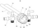
도 1은 일 실시예에 따른 내시경 시스템의 사시도이다.
도 2는 일 실시예에 따른 내시경 시스템의 정면 확대도이다.
도 3은 일 실시예에 따른 내시경 시스템의 전방을 확대한 확대도이다.
도 4는 일 실시예에 따른 시스 장치의 단면을 도시한다.
도 5는 일 실시예에 따른 시스 장치의 사시도이다.
도 6은 일 실시예에 따른 시스 장치의 단면도이다.
도 7은 일 실시예에 따른 시스 장치의 하부 사시도이다.1 is a perspective view of an endoscope system according to an embodiment;
2 is an enlarged front view of an endoscope system according to an embodiment.
3 is an enlarged view of the front of the endoscope system according to an embodiment.
4 shows a cross-section of a sheath device according to an embodiment.
5 is a perspective view of a sheath device according to an embodiment;
6 is a cross-sectional view of a sheath device according to an embodiment.
7 is a bottom perspective view of a sheath device according to an embodiment;
이하, 본 발명에 관련된 시스 장치 및 이를 구비하는 내시경 시스템에 대하여 도면을 참조하여 보다 상세하게 설명한다. 첨부된 도면은 본 명세서에 개시된 실시 예를 쉽게 이해할 수 있도록 하기 위한 것일 뿐, 첨부된 도면에 의해 본 명세서에 개시된 기술적 사상이 제한되지 않으며, 본 발명의 사상 및 기술 범위에 포함되는 모든 변경, 균등물 내지 대체물을 포함하는 것으로 이해되어야 한다.Hereinafter, a sheath device and an endoscope system having the same according to the present invention will be described in more detail with reference to the drawings. The accompanying drawings are only for easy understanding of the embodiments disclosed in the present specification, and the technical spirit disclosed in the present specification is not limited by the accompanying drawings, and all changes and equivalents included in the spirit and scope of the present invention It should be understood to include water or substitutes.
본 명세서에서 사용되는 단수의 표현은 문맥상 명백하게 다르게 뜻하지 않는 한, 복수의 표현을 포함한다.As used herein, the singular expression includes the plural expression unless the context clearly dictates otherwise.
본 명세서에서 어떤 구성요소가 다른 구성요소에 "연결되어" 있다거나 "접속되어" 있다고 언급된 때에는, 그 다른 구성요소에 직접적으로 연결되어 있거나 또는 접속되어 있을 수도 있지만, 중간에 다른 구성요소가 존재할 수도 있다고 이해되어야 할 것이다. 반면에, 어떤 구성요소가 다른 구성요소에 "직접 연결되어" 있다거나 "직접 접속되어" 있다고 언급된 때에는, 중간에 다른 구성요소가 존재하지 않는 것으로 이해되어야 할 것이다.When a component is referred to as being “connected” or “connected” to another component in the present specification, it may be directly connected to or connected to the other component, but other components may exist in between. It should be understood that there may be On the other hand, when it is said that a certain element is "directly connected" or "directly connected" to another element, it should be understood that the other element does not exist in the middle.
또한, "포함한다" 또는 "가지다" 등의 용어는 명세서상에 기재된 특징, 숫자, 단계, 동작, 구성요소, 부품 또는 이들을 조합한 것이 존재함을 지정하려는 것이지, 하나 또는 그 이상의 다른 특징들이나 숫자, 단계, 동작, 구성요소, 부품 또는 이들을 조합한 것들의 존재 또는 부가 가능성을 미리 배제하지 않는 것으로 이해되어야 한다.In addition, terms such as "comprises" or "have" are intended to designate that a feature, number, step, operation, component, part, or combination thereof described in the specification exists, and includes one or more other features or numbers. , it should be understood that it does not preclude the possibility of the presence or addition of steps, operations, components, parts, or combinations thereof.
또한, 실시예의 구성 요소를 설명하는 데 있어서, 제 1, 제 2, A, B, (a), (b) 등의 용어를 사용할 수 있다. 이러한 용어는 그 구성 요소를 다른 구성 요소와 구별하기 위한 것일 뿐, 그 용어에 의해 해당 구성 요소의 본질이나 차례 또는 순서 등이 한정되지 않는다. 어떤 구성 요소가 다른 구성요소에 "연결", "결합" 또는 "접속"된다고 기재된 경우, 그 구성 요소는 그 다른 구성요소에 직접적으로 연결되거나 접속될 수 있지만, 각 구성 요소 사이에 또 다른 구성 요소가 "연결", "결합" 또는 "접속"될 수도 있다고 이해되어야 할 것이다.In addition, in describing the components of the embodiment, terms such as first, second, A, B, (a), (b), etc. may be used. These terms are only for distinguishing the elements from other elements, and the essence, order, or order of the elements are not limited by the terms. When it is described that a component is "connected", "coupled" or "connected" to another component, the component may be directly connected or connected to the other component, but another component is between each component. It will be understood that may also be "connected", "coupled" or "connected".
어느 하나의 실시 예에 포함된 구성요소와, 공통적인 기능을 포함하는 구성요소는, 다른 실시 예에서 동일한 명칭을 사용하여 설명하기로 한다. 반대되는 기재가 없는 이상, 어느 하나의 실시 예에 기재한 설명은 다른 실시 예에도 적용될 수 있으며, 중복되는 범위에서 구체적인 설명은 생략하기로 한다.Components included in one embodiment and components having a common function will be described using the same names in other embodiments. Unless otherwise stated, descriptions described in one embodiment may be applied to other embodiments as well, and detailed descriptions within the overlapping range will be omitted.
도 1은 일 실시예에 따른 내시경 시스템의 사시도이고, 도 2는 일 실시예에 따른 내시경 시스템의 정면 확대도이며, 도 3은 일 실시예에 따른 내시경 시스템의 전방을 확대한 확대도이다.1 is a perspective view of an endoscope system according to an embodiment, FIG. 2 is an enlarged front view of the endoscope system according to an embodiment, and FIG. 3 is an enlarged front view of the endoscope system according to an embodiment.
도 1 내지 도 3를 참조하여 일 실시예에 따른 내시경 시스템은 시스 장치(100), 내시경 장치(200) 및 치료 장치(300)를 포함할 수 있다.1 to 3 , the endoscope system according to an embodiment may include a
시스 장치(100)는 내시경 장치(200)와 치료 장치(300)에서 돌출되는 부분을 감싸도록 형성되며, 이러한 시스 장치(100)는 인체의 대상부위(이하 환부) 표면에 구멍을 뚫은 후 인입될 수 있다. 시스 장치(100)가 인체의 환부에 인입되기 전 후로, 내시경 장치(200) 또는 치료 장치(300)는 시스 장치(100)와 결합되어, 시스 장치(100)를 따라 인체의 환부로 인입될 수 있다.The
또한, 치료 도중 내시경 장치(200) 또는 치료 장치(300)는 시스 장치(100)와 분리되어서 다른 기구들로 변경될 수도 있다.In addition, during treatment, the
이러한 시스 장치(100)는 제1 가이드 바디(110), 제2 가이드 바디(120), 몸체부(130)를 포함할 수 있고, 내시경 장치(200)는 광학부(210) 및 내시경 바디(220)를 포함할 수 있으며, 치료 장치(300)는 치료부(310) 및 치료도구바디(320)를 포함할 수 있다.The
시스 장치(100)는 광학부(210)와 치료부(310)를 감싸고, 광학부(210)는 인체 내에 삽입되어서 환부를 관찰할 수 있으며, 치료부(310)는 인체 내에 삽입되어서 환부를 관찰할 수 있다.The
구체적으로, 내시경 장치(200)는 시스 장치(100)에 탈착이 가능하며, 바람직하게 내시경 장치(200)의 광학부(210)는 시스 장치(100)의 제1 가이드 바디(110) 내에 인입되며, 시스 장치(100)의 몸체부(130)와 내시경 장치(200)의 내시경 바디(220)는 서로 고정되게 결합될 수 있다. 또한, 치료 장치(300)도 시스 장치(100) 또는 내시경 장치(200)에 탈착이 가능하고, 바람직하게 치료 장치(300)의 치료부(310)의 치료도구바디(320)는 시스 장치(100)의 제2 가이드 바디(120) 내에 인입되며, 시스 장치(100)의 몸체부(130) 또는 내시경 장치(200)의 내시경 바디(220)는 서로 고정되게 결합될 수 있다.Specifically, the
도 1을 참조하여, 제1 가이드 바디(110)와 제2 가이드 바디(120)는 전방으로 돌출될 수 있으며, 제2 가이드 바디(120)는 제1 가이드 바디(110)의 상측에 부착되어 배치될 수 있다. 이러한 제1 가이드 바디(110)와 제2 가이드 바디(120)는 서로 평행하게 배치되며, 따라서, 서로 같은 방향으로 연장될 수 있다.Referring to FIG. 1 , the
아래에서는 이러한 제1 가이드 바디(110)와 제2 가이드 바디(120)가 연장되는 방향을 전방으로 정의한다. 구체적으로, 제1 가이드 바디(110)와 제2 가이드 바디(120)의 길이 방향 일 단부에는 몸체부(130)가 배치될 수 있고, 제1 가이드 바디(110)와 제2 가이드(120) 바디를 기준으로, 몸체부(130)에서 제1 가이드 바디(110)과 제2 가이드 바디(120)가 돌출되는 방향은 전방으로 정의하고, 제1 가이드 바디(110)와 제2 가이드 바디(120)에서 몸체부(130)가 배치된 방향을 후방이라고 정의할 수 있다. 하방과 상방의 정의는 아래에서 광학부와 함께 설명된다.Below, the direction in which the
또한, 제1 가이드 바디(110)와 제2 가이드 바디(120)는 내부에 관로가 형성되어 광학부(210)와 치료부(310)가 인입될 수 있다. 바람직하게, 제1 가이드 바디(110)와 제2 가이드 바디(120)는 각각 두 단부가 개방된 원통형일 수 있으며, 이러한 원통의 개구를 통해 광학부(210)와 치료부(310)는 제1 가이드 바디(110)와 제2 가이드 바디(120)를 길이방향으로 관통할 수 있다. In addition, the
이를 위해, 도 1과 도 3를 참조하여, 광학부(210)는 광학연장부재(212)와 촬영부재(214)를 포함할 수 있고, 치료부(310)는 치료연장부재(312)와 치료부재(314)를 포함할 수 있다. 광학연장부재(212)와 치료연장부재(312)는 각각 제1 가이드 바디(110)와 제2 가이드 바디(120)의 형상에 대응되도록 일 방향으로 연장되게 형성되며, 광학연장부재(212)는 제1 가이드 바디(110)와 유사한 길이로 형성될 수 있다. 반면, 치료연장부재(312)는 제2 가이드 바디(120)보다 길게 형성될 수 있다.To this end, with reference to FIGS. 1 and 3 , the optical unit 210 may include an
따라서, 광학부(210)와 치료부(310)가 각각 제1 가이드 바디(110)와 제2 가이드 바디(120)에 인입되는 경우, 광학부(210)는 제1 가이드 바디(110)의 단부 근처에 배치될 수 있고, 치료부(310)는 제2 가이드 바디(120)의 전방으로 돌출될 수 있다.Accordingly, when the optical unit 210 and the
치료부재(314)는 치료연장부재(312)의 단부에 배치될 수 있고, 바람직하게 치료부재(314)는 환부의 절개 및 절단, 투약, 천공, 봉합 등의 환부의 치료를 위한 행위를 수행할 수 있는 버(burr), RF 치료기, 레이저 치료기 등의 임의의 장치일 수 있다. 이러한 치료 부재(314)는 내시경 장치(200)가 영상 정보를 취득 중인 환부에 대한 치료 과정을 수행할 수 있다. 이러한 치료부재(214)는 제2 가이드 바디(110)의 단부 개구를 통과하여 외측으로 돌출될 수 있다. 이렇게 돌출되는 치료부재(314)는 바람직하게 제1 가이드 바디(110) 보다도 전방에 위치될 수 있다.The
도 3를 다시 참조하여, 촬영부재(214)는 광학연장부재(212)의 단부에 배치될 수 있고, 바람직하게 촬영부재(214)는 영상장치의 렌즈 또는 렌즈 필터 등을 구비할 수 있다. 또한, 또 다른 실시예에서, 내시경 장치(200)는 별도의 보조 공들을 더 포함할 수 있으며, 이러한 보조 공들에는 필요에 따라 발광을 위한 광섬유, 영상 정보 획득을 위한 렌즈 등이 추가로 구비될 수 있다. 이러한 촬영부재(214)는 물체가 투영되는 입사면(2142)을 구비할 수 있으며, 입사면(2142)은 촬영부재(214)의 면을 지칭하며, 촬영부재(214)의 입사면(2142)은 전방 하방을 바라보도록 경사지게 형성될 수 있다. 이 때, 입사면(2142)이 향하는 방향을 참조하여, 하방은 입사면의 하측으로 정의될 수 있다.Referring back to FIG. 3 , the photographing
예를 들어, 상기 입사면(2142)는 역경사를 가지도록 이루어진다. 본 예시에서는, 상기 치료 장치(300)를 바라보는 방향으로 입사면이 배치되는 경사를 정경사라 정의하고, 반대의 경사를 역경사라 정의할 수 있다.For example, the
보다 상세하게, 상기 역경사를 형성하기 위하여, 광학연장부재(212)는 상방이 하방보다 길게 연장될 수 있다. 이에 따라 바람직하게 입사면(2142)은 광학연장부재(212)의 중심축을 기준으로 30도에서 90도 사이의 사잇각을 갖도록 기울어질 수 있다. 바람직하게 일반적으로 촬영부재(214)는 90도에서 120도 사이의 시야각을 가지고 있으며(만약, 촬영부재의 시야각이 120도 이상이라면, 입사면(2142)과 광학연장부재(212)의 중심축의 사잇각이 30도보다 낮을 수도 있다), 촬영부재(214)가 90도의 시야각을 갖는 경우 입사면(2142)은 광학연장부재(212)의 중심축을 기준으로 전방 하방을 바라보도록 45도 초과 90도 미만으로 기울어질 수 있다. 또한, 촬영부재(214)가 120도의 시야각을 갖는 경우 입사면(2142)은 광학연장부재(212)의 중심축을 기준으로 전방 하방을 바라보도록 30도 초과 90도 미만 기울어 질 수 있다.In more detail, in order to form the reverse inclination, the
더 바람직하게 이러한 촬영부재(214)의 입사면(2142)은 촬영부재(214)의 상측에 배치되는 치료부재(314)를 비스듬히 촬영할 수 있는 각도로 배치될 수 있다. 예를 들어 90도의 촬영부재(214)가 사용되는 경우 대략적으로 입사면(2142)과 광학연장부재(212)의 중심축의 사잇각은 바람직하게 80도 정도로 형성될 수 있다.More preferably, the
이에 따라 촬영부재(214)는 치료부재(314)를 비스듬하게 바라볼 수 있다. 촬영부재(214)는 외부 디스플레이 장치와 연결되어서 입사면(2142)으로 투영되는 물체는 외부 디스플레이 장치에서 디스플레이 될 수 있다. 이를 통해 입체감과 시야가 향상될 수 있고, 환부 주변을 확인할 수 있다.Accordingly, the photographing
상기 역경사에 의하면, 환부 주변이 보다 먼 거리에서 촬영될 수 있으며, 이는 시술자 또는 수술자의 시야 확보에 보다 도움이 될 수 있다.According to the reverse tilt, the periphery of the affected area can be photographed at a greater distance, which can be more helpful in securing the operator's or operator's field of vision.
이 때에, 상기 광학부(210)는 예를 들어, 카메라, 캠코더, 초음파 영상기기 중 적어도 하나를 포함한다.In this case, the optical unit 210 includes, for example, at least one of a camera, a camcorder, and an ultrasound imaging device.
상기 촬영부재(214)의 입사면(2142)과 대응하여 제1 가이드 바디(110)의 전방 단부도 입사면(2142)의 기울기와 동일하게 경사지게 형성될 수 있다. 구체적으로, 제1 가이드 바디(110)의 전방 단부도 입사면(2142)과 마찬가지로 제2 가이드 바디(120)에 대하여 역경사를 가지도록 이루어질 수 있으며, 즉, 제1 가이드 바디(110)의 전방 단부의 절단면은 전방 하방을 바라볼 수 있다.Corresponding to the
도 2를 참조하여, 입사면(2142)을 기준으로 촬영부재(214)는 우상방 또는 좌상방에 배치될 수 있다. 즉, 제2 가이드 바디(120)는 제1 가이드 바디(110)의 우상방 또는 좌상방에 배치될 수 있으며, 이에 따라 촬영부재(214)는 치료부재(314)를 비스듬하게 바라볼 수 있다. 바람직하게, 제2 가이드 바디(120)는 제1 가이드 바디(110)의 상측에서 우상방 또는 좌상방으로 35도 정도 기울어지게 배치될 수 있다.Referring to FIG. 2 , the photographing
이에 따라 사용자는 더 넓은 환부 범위를 관찰할 수 있다.Accordingly, the user can observe a wider area of the affected area.
도 4는 일 실시예에 따른 시스 장치(100)의 단면을 도시한다.4 shows a cross-section of the
도 4를 참조하여, 일 실시예에 다른 시스 장치(100)는 몸체부(130)에 장착되는 마개부(140)와 제1 다이얼부(150)를 포함할 수 있다.Referring to FIG. 4 , the
제1 다이얼부(150)는 몸체부(130)의 둘레의 모양에 대응되게 형성되어서 몸체부(130)의 외측면을 덮도록 배치될 수 있다. 바람직하게, 몸체부(130)는 원형 구간을 구비할 수 있으며, 제1 다이얼부(150)는 몸체부(130)의 원형 구간에 배치될 수 있다. 제1 다이얼부(150)는 링 형태일 수 있고, 외주면에는 바람직하게 돌기가 형성될 수 있다. 이러한 제1 다이얼부(150)는 사용자에 의해 몸체부(130) 상에서 둘레 방향으로 회전될 수 있으며, 외주면에 형성된 돌기는 사용자가 손으로 제1 다이얼부(150)를 회전시키기 용이하게 마찰을 보조할 수 있다.The
제1 다이얼부(150)의 내측에는 마개부(140)가 배치되고, 마개부(140)는 몸체부(130)를 관통하도록 배치될 수 있다. 몸체부(130)의 상측에는 몸체부(130)의 내측 공간과 연통되는, 몸체부(130)의 둘레를 따라 긴 개구가 형성될 수 있고, 마개부(140)는 개구를 통과하여 몸체부(130) 내측에 배치될 수 있다. 제1 다이얼부(150)의 회전에 의해, 마개부(140)는 몸체부(130)의 둘레에 형성되는 개구를 따라서 이동될 수 있다.The
바람직하게, 도 4를 다시 참조하여, 몸체부(130)의 개구와 마개부(140)는 몸체부(130)의 상측에 배치될 수 있고, 개구는 마개부(140)와 제1 다이얼부(150)가 몸체부(130)의 원형 단면의 중심을 회전중심으로 대략 70도 이동될 수 있는 길이로 형성될 수 있다.Preferably, referring again to FIG. 4 , the opening and the
내시경 시스템에서 치료 장치(300)가 교체 또는 제거를 위해 탈거되는 경우, 치료부(310)는 제2 가이드 바디(120)에서 분리되고, 분리된 후 제2 가이드 바디(120)의 내측 관로는 개방이 될 수 있다. 이에 따라, 시스 장치(100)가 환부에 인입되어 있는 경우, 제2 가이드 바디(120)를 통해서 환부의 혈액이나 식염 수 등 액체가 외부로 방출될 수 있다.When the
제2 가이드 바디(120)는 몸체부(130)를 관통하도록 형성될 수 있으며, 몸체부(130) 내에 위치한 제2 가이드 바디(120)의 일 측에는 인입홈(1202)이 형성될 수 있다.The
제1 다이얼(150)부의 회전에 의해 마개부(140)는 이동될 수 있으며, 마개부(140)는 제2 가이드 바디(120)에 형성되는 인입홈(1202)을 지나 제2 가이드 바디(120)에 인입될 수 있다. 이러한 마개부(140)가 제2 가이드 바디(120)에 인입됨에 따라 제2 가이드 바디(120)의 관로는 폐쇄될 수 있다.The
도 5는 일 실시예에 따른 시스 장치(200)의 후방 사시도이다.5 is a rear perspective view of the
도 5를 참조하여, 일 실시예에 따른 시스 장치(200)의 몸체부(130)의 후면에는 제1 가이드 바디(110)와 연통되는 제1 개구(1302) 및 제2 가이드 바디(120)와 연통되는 제2 개구(1304)가 구비될 수 있다. 제1 개구(1302)는 바람직하게 몸체부(130)의 단면 중앙부에 배치될 수 있고, 제2 개구(1304)는 바람직하게 몸체부(130)의 단면 중앙보다 상부 좌측 또는 우측에 배치될 수 있다.Referring to FIG. 5 , on the rear surface of the
이러한 몸체부(130)의 후면은 깔때기 모양으로 형성될 수 있다. 구체적으로, 몸체부(130)의 제1 개구(1302) 부분은 몸체부(130)의 후면 중 가장 전방에 위치될 수 있으며, 몸체부(130)의 다른 후면들은 제1 개구(1302) 보다 후방에 위치될 수 있다. 이에 따라, 제1 개구(1302)를 통해 제1 가이드 바디(110)로 인입되는 내시경 장치(200)의 광학부(210)는 몸체부(130) 후면에 형성되는 경사에 따라 광학부(210)의 전방 촬영부재(212)가 제1 개구(1302)를 향하도록 안내될 수 있다.The rear surface of the
이러한 내시경 장치(200)의 내시경 바디(220)의 후면에는 치료 장치(300)의 치료부(310)가 인입될 수 있는 개구가 형성될 수 있으며, 내시경 바디(220)의 개구와 제2 개구(1304) 및 제2 가이드 바디(120)는 연속되게 형성될 수 있다.An opening through which the
도 6은 일 실시예에 따른 내시경 시스템의 단면도이다.6 is a cross-sectional view of an endoscope system according to an embodiment.
도 6을 참조하여, 시스 장치(100)는 시스 장치(100)의 외표면에 대응되는 형상으로 형성되는 제2 다이얼부(160)를 더 포함할 수 있다.Referring to FIG. 6 , the
제2 다이얼부(160)는 제1 다이얼부(150)와 마찬가지로, 몸체부(130)의 둘레의 모양에 대응되게 형성되어서 몸체부(130)의 외측면을 덮도록 배치될 수 있다. 바람직하게, 몸체부(130)는 원형 구간을 구비할 수 있으며, 제2 다이얼부(160)는 몸체부(130)의 원형 구간에 배치될 수 있다. 또한, 제2 다이얼부(160)는 제1 다이얼부(150) 보다 후방에 배치될 수 있다. 제2 다이얼부(160)는 링 형태일 수 있고, 외주면에는 바람직하게 돌기가 형성될 수 있다. 이러한 제2 다이얼부(160)는 사용자에 의해 몸체부(130) 상에서 둘레 방향으로 회전될 수 있으며, 외주면에 형성될 된 돌기는 사용자가 손으로 제2 다이얼부(160)를 회전시키기 용이하게 마찰을 보조할 수 있다.Like the
제2 다이얼부(160)는 제2 다이얼부(160) 원형 단면의 중심 방향으로 돌출되는 스톱퍼(1602)를 포함할 수 있다.The
다시 도 6을 참조하여, 내시경 장치(200)의 내시경 바디(220)의 일부는 제2 다이얼부(160)의 내측면과 대응되도록 원형 단면을 갖게 형성될 수 있다. 제2 다이얼부(160)는 몸체부(130)의 후방에서 일부가 돌출되게 형성될 수 있으며, 내시경 바디(220)의 전방부분은 제2 다이얼부(160)의 내측에 배치될 수 있다.Referring back to FIG. 6 , a portion of the
이러한 내시경 바디(220)의 외측면에는 가이드홈(2202)이 형성될 수 있다. 이러한 가이드홈(2202)은 스톱퍼(1602)에 대응되는 크기와 형상으로 형성되어서, 가이드홈(2202)에 스톱퍼(1602)가 유입되고, 제2 다이얼부(160)는 회전되어서 스톱퍼(1602)는 가이드홈(2202)의 단부에 배치될 수 있다. 이에 따라, 시스 장치(100)와 내시경 장치(200)가 결합될 수 있다.A
바람직하게, 가이드홈(2202)은 나사산 또는 'ㄱ'자 형상 등으로 형성될 수 있으며, 스톱퍼(1602)는 가이드홈(2202)의 개방된 단부로 유입되어서, 제2 다이얼부(160)의 회전에 의해 가이드홈(2202)의 폐쇄된 단부로 안내될 수 있다.Preferably, the
본 발명에서 제2 다이얼부(160)는 시스 장치(100)에 형성되고 가이드홈(2202)은 내시경 장치(200)에 형성되는 것으로 도시되고 설명되었지만, 이에 한정되는 것은 아니다. 예를 들어, 제2 다이얼부와 유사한 구성이 내시경 장치에 형성되고 가이드 홈과 유사한 구성이 시스 장치에 형성될 수도 있다.In the present invention, the
도 7은 일 실시예에 따른 내시경 시스템의 하부 사시도이다.7 is a bottom perspective view of an endoscope system according to an embodiment.
도 2, 도 4 및 도 7을 참조하여, 일 실시예에 따른 내시경 시스템의 시스 장치(100)는 몸체부(130)의 측면에 배치될 수 있는 밸브 조립체부(170)를 더 포함할 수 있다.2, 4 and 7 , the
또한, 시스 장치(100)의 몸체부(130)는 하우징(132) 및 하우징(132)의 측면에서 돌출되어서 밸브 조립체부(170)와 연결되는 이동부재(134)를 더 포함할 수 있다.In addition, the
밸브 조립체부(170)는 바람직하게 몸체부(130)의 양쪽 측면에 하나씩 한 쌍이 배치되어 이동부재에 연결될 수 있지만 반드시 이에 한정되는 것은 아니다. 예를 들어, 상부측, 하부측에 배치될 수도 있고, 몸체부(130)의 후방에 배치될 수도 있다.A pair of
하우징(132)은 내부에 중공이 형성될 수 있다. 이러한 하우징 내부의 중공에는 밸브 조립체부(170)를 통해서 유입되는 유체가 유입될 수 있으며, 이러한 유체는 바람직하게 식염수일 수 있고, 하우징(132)의 내부에 유입되어서 제1 가이드 바디(110)를 통해 환부로 유출될 수 있다. 이러한 유체는 환부로 유출된 뒤 밸브 조립체부(170)를 통해 외부로 배출될 수 있으며, 이 때, 치료시 생성되는 찌꺼기나 부산물, 혈액 등을 함께 제거할 수 있다. 이에 따라 사용자는 시야를 용이하게 확보할 수 있으며, 즉 밸브 조립체부(170)는 바람직하게 유체 유입밸브와 유체 배출밸브 두 개를 모두 포함할 수 있다.The
이러한 밸브 조립체부(170)의 유체 유입밸브와 유체 배출밸브는 각각 이동부재(134)에 연결될 수 있다. 유체 유입밸브가 개방되는 경우, 유체는 이동부재(134)를 통해 하우징(132)의 중공으로 유입될 수 있고, 중공을 채운 유체는 제1 가이드 바디(110)를 통해 환부로 유출될 수 있다. 유체 유입밸브가 폐쇄되고 유체 배출밸브가 개방되는 경우, 하우징(132)의 중공에는 유체 배출밸브에 의해 음압이 형성될 수 있으며, 하우징(132)의 중공에 저류된 유체는 이동부재(134)를 통해 유체 배출밸브로 배출될 수 있다. 이와 동시에 하우징(132)의 중공에도 음압이 형성되어서 환부의 유체가 제1 가이드 바디(110)를 통해 하우징(132)의 중공으로 유입될 수 있다.The fluid inlet valve and the fluid outlet valve of the
도 7을 다시 참조하여, 하우징(132)은 외측면에 가이드개구(1322)를 구비할 수 있고, 이동부재(134)는 서로 일체형으로 형성되는 돌출요소(1344)와 이동요소(1342)를 포함할 수 있다.Referring back to FIG. 7 , the
이동요소(1342)는 하우징(132)의 내부에 위치할 수 있고, 돌출요소(1344)는 이동요소(1342)에서 돌출되어서 하우징(132)의 외측에 위치될 수 있다. 이러한 이동요소(1342)는 하우징(132)의 내측면과 대응되게 형성될 수 있으며, 이에 따라 하우징(132)의 내측면에 접촉되게 배치될 수 있다.The moving
구체적으로, 돌출요소(1344)는 가이드개구(1322)를 통과하여 하우징(132)의 외측으로 돌출될 수 있으며, 가이드개구(1342)는 돌출요소(1344)의 단면보다 크게 형성될 수 있다. 따라서, 돌출요소(1344)는 가이드개구(1342)를 내에서 이동될 수 있다. 즉, 돌출요소(1344)와 연결되는 밸브 조립체(170)는 가이드개구(1342)에서 돌출요소(1344)가 이동할 수 있는 만큼의 자유도를 가질 수 있다.Specifically, the protruding
이동요소(1342)는 돌출요소(1344)의 이동으로 인해 가이드개구(1342)가 개방되어 하우징(132)의 중공에 구비되는 유체들이 외부로 유출되는 것을 방지하도록, 가이드개구(1342)를 폐쇄할 수 있다.The moving
예를 들어, 하우징(132)의 단면은 원형일 수 있으며, 이동요소(1342)는 하우징(132)의 단면에 대응되도록 곡선형으로 형성될 수 있다, 이동요소(1342)는 바람직하게 하나로 형성되어 두 개 이상의 돌출요소(1344)와 연결될 수도 있다. 이동요소(1342)는 복수 개의 개구를 가져서, 두 개 이상의 돌출요소(1344)가 하우징(132) 내부의 중공과 연통하도록 개방될 수 있다.For example, the cross-section of the
이동요소(1342)는 돌출요소(1344)의 이동에도 가이드개구(1342)가 개방되는 것을 방지하도록 가이드개구(1342)보다 면적이 크도록 형성될 수 있다. 예를 들어, 가이드개구(1342)가 직선형으로 형성되고, 돌출요소(1344)가 가이드개구(1342)의 폐쇄된 일 단부에서 폐쇄된 타 단부로 이동할 수 있다. 이 때 이동요소(1342)의 길이는 돌출요소(1344)의 이동거리의 두 배 이상일 수 있다. 마찬가지로, 가이드 개구(1342)의 폭은 돌출요소(1344)의 단면보다 클 수 있으며, 돌출요소(1344)는 가이드개구(1342)의 폭 방향으로 이동될 수 있다. 이 때 이동요소(1342)의 폭은 돌출요소(1344)의 이동거리의 두 배 이상일 수 있으며, 이동요소(1342)를 중심으로 하여 이동요소(1342)의 이동거리보다 폭이 클 수 있다.The moving
위 설명된 시스 장치 및 이를 구비하는 내시경 시스템은 신체의 한 부위에 구멍을 뚫는 것만으로도 시술이 가능하고, 다양한 치료를 수행할 수 있는 치료 장치를 내시경 장치와 함께 체내에 삽입할 수 있다. 또한, 이러한 시스 장치 및 이를 구비하는 내시경 시스템은 치료 과정에서 발생하는 이물질 등을 효과적으로 흡입하여 신체 외부로 배출할 수 있고, 내시경 장치와 치료장치를 함께 체내에 삽입하면서도 내시경의 시야확보가 용이하며, 치료 장치의 교체시 대상부위의 유체가 인출되는 것을 방지하는 구조를 구비할 수 있다. 또한, 이러한 시스 장치 및 이를 구비하는 내시경 시스템은 내시경 장치 및 치료 장치의 오삽입과 탈거를 방지하는 구조를 구비할 수 있다.The above-described sheath device and the endoscope system having the same can be operated only by making a hole in one part of the body, and a treatment device capable of performing various treatments can be inserted into the body together with the endoscope device. In addition, such a sheath device and an endoscope system having the same can effectively suck in foreign substances generated during the treatment process and discharge them to the outside of the body, and it is easy to secure a field of view of the endoscope while inserting the endoscope device and the treatment device together into the body, It may be provided with a structure that prevents the fluid of the target site from being drawn out when the treatment device is replaced. In addition, such a sheath device and an endoscope system having the same may have a structure to prevent erroneous insertion and removal of the endoscope device and the treatment device.
이상에서 설명된 시스 장치 및 이를 구비하는 내시경 시스템은 상기 설명된 실시예들의 구성과 방법에 한정되는 것이 아니라, 상기 실시예들은 다양한 변형이 이루어질 수 있도록 각 실시예들의 전부 또는 일부가 선택적으로 조합되어 구성될 수도 있다.The sheath device and the endoscope system having the same described above are not limited to the configuration and method of the above-described embodiments, but all or part of each embodiment is selectively combined so that various modifications can be made. may be configured.
이상과 같이 본 발명의 실시예에서는 구체적인 구성 요소 등과 같은 특정 사항들과 한정된 실시예 및 도면에 의해 설명되었으나 이는 본 발명의 보다 전반적인 이해를 돕기 위해서 제공된 것일 뿐, 본 발명은 상기의 실시예에 한정되는 것은 아니며, 본 발명이 속하는 분야에서 통상적인 지식을 가진 자라면 이러한 기재로부터 다양한 수정 및 변형이 가능하다. 예를 들어, 설명된 기술들이 설명된 방법과 다른 순서로 수행되거나, 및/또는 설명된 구조, 장치 등의 구성요소들이 설명된 방법과 다른 형태로 결합 또는 조합되거나, 다른 구성요소 또는 균등물에 의하여 대치되거나 치환되더라도 적절한 결과가 달성될 수 있다. 따라서, 본 발명의 사상은 설명된 실시예에 국한되어 정해져서는 아니 되며, 후술하는 청구범위뿐 아니라 이 청구범위와 균등하거나 등가적 변형이 있는 모든 것들은 본 발명 사상의 범주에 속한다고 할 것이다.As described above, in the embodiments of the present invention, specific matters such as specific components, etc., and limited embodiments and drawings have been described, but these are only provided to help a more general understanding of the present invention, and the present invention is limited to the above embodiments Various modifications and variations are possible from these descriptions by those of ordinary skill in the art to which the present invention pertains. For example, the described techniques are performed in an order different from the described method, and/or the described components of structures, devices, etc. are combined or combined in a different form than the described method, or other components or equivalents. Appropriate results can be achieved even if substituted or substituted by Accordingly, the spirit of the present invention should not be limited to the described embodiments, and not only the claims described below, but also all of the claims and all equivalents or equivalent modifications will fall within the scope of the spirit of the present invention.
100 : 시스 장치
110 : 제1 가이드 바디
120 : 제2 가이드 바디
1202 : 인입홈
130 : 몸체부
1302 : 제1 개구
1304 : 제2 개구
132 : 하우징
1322 : 가이드개구
134 : 이동부재
1342 : 이동요소
1344 : 돌출요소
140 : 마개부
150 : 제1 다이얼부
160 : 제2 다이얼부
1602 : 스톱퍼
170 : 밸브 조립체부
200 : 내시경 장치
210 : 광학부
212 : 광학연장부재
214 : 촬영부재
2142 : 입사면
220 : 내시경 바디
2202 : 가이드홈
300 : 치료 장치
310 : 치료부
312 : 치료연장부재
314 : 치료부재
320 : 치료도구바디100: sheath device
110: first guide body
120: second guide body
1202: Inlet groove
130: body part
1302: first opening
1304: second opening
132: housing
1322: guide opening
134: movable member
1342: moving element
1344: protrusion element
140: stopper
150: first dial unit
160: second dial unit
1602: stopper
170: valve assembly part
200: endoscope device
210: optical unit
212: optical extension member
214: shooting member
2142: incident surface
220: endoscope body
2202: guide home
300: treatment device
310: treatment unit
312: absence of treatment extension
314: absence of treatment
320: treatment tool body
Claims (10)
Translated fromKorean상기 시스 장치와 탈착되며, 광학부를 구비하는 내시경 장치; 및
상기 시스 장치 또는 상기 내시경 장치와 탈착되며, 치료부를 구비하는 치료 장치;
를 포함하고,
상기 광학부는 일방향으로 연장되어서 상기 제1 가이드 바디 내에 인입되고,
상기 치료부는 일방향으로 연장되어서 상기 제2 가이드 바디 내에 인입되고,
상기 제2 가이드 바디는 상기 제1 가이드 바디와 평행하게 상기 제1 가이드 바디의 상측에서 전방으로 연장되도록 배치되며,
상기 광학부의 입사면은 전방 하방을 향하도록 경사진 것을 특징으로 하는, 내시경 시스템.
a sheath device having a first guide body and a second guide body extending forward;
an endoscope device detachable from the sheath device and having an optical unit; and
a treatment device detachable from the sheath device or the endoscope device and including a treatment unit;
including,
The optical unit extends in one direction and is introduced into the first guide body,
The treatment unit extends in one direction and is drawn into the second guide body,
The second guide body is arranged to extend forward from the upper side of the first guide body in parallel to the first guide body,
The endoscopic system, characterized in that the incident surface of the optical unit is inclined to face downward in the front.
상기 제2 가이드 바디는 상기 제1 가이드 바디의 우상방 또는 좌상방에 위치되는, 내시경 시스템.
The method of claim 1,
The second guide body is located in the upper right or upper left of the first guide body, the endoscope system.
상기 치료부의 전방 단부는 상기 광학부의 전방 단부보다 전방 상방에 위치되는, 내시경 시스템.
The method of claim 1,
The front end of the treatment unit is located anteriorly above the front end of the optic unit, the endoscopic system.
상기 시스 장치는 상기 시스 장치의 외표면에 대응되는 형상으로 형성되는 제2 다이얼부를 포함하고,
상기 제2 다이얼부는 상기 시스 장치의 외표면 둘레를 따라서 회전하며,
상기 제2 다이얼부는 상기 제2 다이얼부의 원형 단면의 중심 방향으로 돌출되는 스톱퍼를 포함하며,
상기 내시경 장치의 측면에는 상기 스톱퍼의 크기에 대응되는 가이드홈이 구비되고,
상기 제2 다이얼부의 회전에 따라 상기 스톱퍼는 상기 가이드홈의 단부에 위치되는, 내시경 시스템.
The method of claim 1,
The sheath device includes a second dial portion formed in a shape corresponding to the outer surface of the sheath device,
the second dial portion rotates around an outer surface of the sheath device;
The second dial portion includes a stopper protruding toward the center of the circular cross-section of the second dial portion,
A guide groove corresponding to the size of the stopper is provided on a side surface of the endoscope device,
According to the rotation of the second dial portion, the stopper is positioned at the end of the guide groove, the endoscope system.
전방으로 연장되며 내부에 관로를 형성하는 제2 가이드 바디;
상기 제1 가이드 바디와 상기 제2 가이드 바디의 후방에 위치되는 몸체부; 및
상기 몸체부에 장착되는 마개부;
를 포함하고,
상기 제1 가이드 바디는 상기 제2 가이드 바디의 상측에 배치되며,
상기 제1 가이드 바디와 상기 제2 가이드 바디는 서로 평행하게 배치되고,
상기 마개부는 상기 몸체부의 둘레를 따라 이동하여 상기 제2 가이드 바디의 관로를 개폐하도록 형성되는 것을 특징으로 하는, 시스 장치.
a first guide body extending forward and forming a conduit therein;
a second guide body extending forward and forming a conduit therein;
a body portion positioned at the rear of the first guide body and the second guide body; and
a stopper mounted on the body;
including,
The first guide body is disposed above the second guide body,
The first guide body and the second guide body are disposed parallel to each other,
The stopper, characterized in that formed to open and close the conduit of the second guide body by moving along the circumference of the body, the sheath device.
상기 시스 장치는 상기 몸체부의 외표면에 배치되어서, 상기 몸체부의 둘레를 따라서 회전하는 제1 다이얼부를 포함하고,
상기 마개부는 상기 제1 다이얼부의 내측에서 돌출되며, 상기 몸체부를 관통하고,
상기 마개부는 상기 제1 다이얼부의 회전에 따라, 상기 제2 가이드 바디의 측면에 형성되는 인입홈으로 인입되는, 시스 장치.
6. The method of claim 5,
The sheath device includes a first dial portion disposed on the outer surface of the body portion to rotate along the circumference of the body portion,
The stopper protrudes from the inside of the first dial part and penetrates the body part,
The stopper is introduced into the inlet groove formed on the side surface of the second guide body according to the rotation of the first dial portion, the sheath device.
상기 몸체부의 후면에는 상기 제1 가이드 바디와 연통 되는 제1 개구가 구비되고,
상기 몸체부의 후면에는 상기 제2 가이드 바디와 연통되는 제2 개구가 구비되며,
상기 몸체부의 후면은 전방을 향하도록 깔때기 모양으로 형성되며, 상기 제1 개구는 상기 몸체부의 후면의 깔때기 모양의 전방 꼭지점 부분에 배치되는, 시스 장치.
6. The method of claim 5,
A first opening communicating with the first guide body is provided on the rear surface of the body part,
A second opening communicating with the second guide body is provided on the rear surface of the body part,
The rear surface of the body part is formed in a funnel shape to face forward, and the first opening is disposed at a funnel-shaped front vertex portion of the rear surface of the body part.
상기 시스 장치는 상기 몸체부의 측면에 배치되는 밸브 조립체부를 더 포함하고,
상기 몸체부는 하우징 및 하우징의 측면에서 돌출되어서 상기 밸브 조립체와 연결되는 이동부재를 포함하며,
상기 이동부재는 상기 밸브 조립체부의 이동에 따라 상기 몸체부 상에서 이동되는, 시스 장치.
6. The method of claim 5,
The sheath device further includes a valve assembly portion disposed on a side surface of the body portion,
The body part includes a housing and a moving member protruding from the side of the housing and connected to the valve assembly,
wherein the moving member is moved on the body portion according to the movement of the valve assembly portion.
상기 하우징은 외측면에 가이드개구를 구비하고,
상기 이동부재는 서로 일체로 형성되는 돌출요소와 이동요소를 포함하며,
상기 돌출요소는 상기 가이드개구를 통과하여 상기 하우징의 외측으로 돌출되고,
상기 이동요소는 상기 하우징의 내측면과 대응되도록 형성되며,
상기 이동요소는 상기 가이드개구의 개방 크기보다 크게 형성되는, 시스 장치.
9. The method of claim 8,
The housing is provided with a guide opening on the outer surface,
The moving member includes a protruding element and a moving element integrally formed with each other,
The protruding element passes through the guide opening and protrudes to the outside of the housing,
The moving element is formed to correspond to the inner surface of the housing,
wherein the moving element is formed to be larger than an opening size of the guide opening.
상기 제2 가이드 바디 내에는 입사면이 전방 하방을 향하는 내시경 장치의 광학부가 인입되고,
상기 제2 가이드 바디의 전방 단부는 상부가 하부보다 전방으로 길게 연장되도록, 상기 광학부의 상기 입사면과 대응되게 형성되는, 시스 장치.
6. The method of claim 5,
In the second guide body, the optical part of the endoscope device with an incident surface facing forward and downward is introduced,
The front end of the second guide body is formed to correspond to the incident surface of the optical part so that the upper portion extends forward longer than the lower portion, the sheath device.
Priority Applications (1)
| Application Number | Priority Date | Filing Date | Title |
|---|---|---|---|
| KR1020200176683AKR20220086331A (en) | 2020-12-16 | 2020-12-16 | Sheath device and endoscope system having the same |
Applications Claiming Priority (1)
| Application Number | Priority Date | Filing Date | Title |
|---|---|---|---|
| KR1020200176683AKR20220086331A (en) | 2020-12-16 | 2020-12-16 | Sheath device and endoscope system having the same |
Publications (1)
| Publication Number | Publication Date |
|---|---|
| KR20220086331Atrue KR20220086331A (en) | 2022-06-23 |
Family
ID=82221817
Family Applications (1)
| Application Number | Title | Priority Date | Filing Date |
|---|---|---|---|
| KR1020200176683ACeasedKR20220086331A (en) | 2020-12-16 | 2020-12-16 | Sheath device and endoscope system having the same |
Country Status (1)
| Country | Link |
|---|---|
| KR (1) | KR20220086331A (en) |
- 2020
- 2020-12-16KRKR1020200176683Apatent/KR20220086331A/ennot_activeCeased
Similar Documents
| Publication | Publication Date | Title |
|---|---|---|
| US10869658B2 (en) | Devices for introducing multiple instruments and methods of use | |
| US11622753B2 (en) | Fully integrated endoscope with biopsy capabilities and methods of use | |
| US5533496A (en) | Endoscopic technique particularly suited for exploratory surgery | |
| US5448990A (en) | Endoscope viewing cannula and surgical techniques | |
| JP7026645B2 (en) | Clot drainage and visualization device and usage | |
| US6908427B2 (en) | Flexible endoscope capsule | |
| ES2487893T3 (en) | Apparatus for observing a visually obscured portion of a cavity | |
| US6832984B2 (en) | Minimally invasive surgery device | |
| CA2327268C (en) | Endoscopic instrumentation with working channel | |
| US7771384B2 (en) | Trocar with integral irrigation and suction tube | |
| JP3192239U (en) | Surgical endoscope | |
| US20110245602A1 (en) | Flexible endoscope with full-length lumen | |
| EP0497347A2 (en) | Laparoscope having means for removing image impeding material from a distal lens | |
| JP5604247B2 (en) | Endoscope device | |
| KR101656836B1 (en) | Endoscopic instrument comprising connectors and a cap connected thereto | |
| JP2012075658A (en) | Endoscope apparatus | |
| US20210298953A1 (en) | Miniature precision medical device | |
| CN210612102U (en) | Split type bladder renal pelvis broken stone cutting mirror | |
| KR20220086331A (en) | Sheath device and endoscope system having the same | |
| US20250040794A1 (en) | Endoscopic tubular minimally invasive surgical system | |
| JP3762508B2 (en) | Endoscope device | |
| JP3704103B2 (en) | Endoscope guide tube | |
| KR20230016323A (en) | Sheath apparatus and endoscope system having the same | |
| JP2021101801A (en) | Endoscope instrument for spinal endoscopic surgery | |
| JP2001198136A (en) | Energy treating system for operation |
Legal Events
| Date | Code | Title | Description |
|---|---|---|---|
| PA0109 | Patent application | Patent event code:PA01091R01D Comment text:Patent Application Patent event date:20201216 | |
| PA0201 | Request for examination | ||
| E902 | Notification of reason for refusal | ||
| PE0902 | Notice of grounds for rejection | Comment text:Notification of reason for refusal Patent event date:20220426 Patent event code:PE09021S01D | |
| PG1501 | Laying open of application | ||
| E601 | Decision to refuse application | ||
| PE0601 | Decision on rejection of patent | Patent event date:20220905 Comment text:Decision to Refuse Application Patent event code:PE06012S01D Patent event date:20220426 Comment text:Notification of reason for refusal Patent event code:PE06011S01I |