KR20220083666A - Constrained Mobility Mapping - Google Patents
Constrained Mobility MappingDownload PDFInfo
- Publication number
- KR20220083666A KR20220083666AKR1020227006639AKR20227006639AKR20220083666AKR 20220083666 AKR20220083666 AKR 20220083666AKR 1020227006639 AKR1020227006639 AKR 1020227006639AKR 20227006639 AKR20227006639 AKR 20227006639AKR 20220083666 AKR20220083666 AKR 20220083666A
- Authority
- KR
- South Korea
- Prior art keywords
- map
- robot
- obstacle
- voxel
- segment
- Prior art date
- Legal status (The legal status is an assumption and is not a legal conclusion. Google has not performed a legal analysis and makes no representation as to the accuracy of the status listed.)
- Granted
Links
Images


Classifications
- G—PHYSICS
- G05—CONTROLLING; REGULATING
- G05D—SYSTEMS FOR CONTROLLING OR REGULATING NON-ELECTRIC VARIABLES
- G05D1/00—Control of position, course, altitude or attitude of land, water, air or space vehicles, e.g. using automatic pilots
- G05D1/60—Intended control result
- G05D1/606—Compensating for or utilising external environmental conditions, e.g. wind or water currents
- G—PHYSICS
- G05—CONTROLLING; REGULATING
- G05D—SYSTEMS FOR CONTROLLING OR REGULATING NON-ELECTRIC VARIABLES
- G05D1/00—Control of position, course, altitude or attitude of land, water, air or space vehicles, e.g. using automatic pilots
- G05D1/02—Control of position or course in two dimensions
- G05D1/021—Control of position or course in two dimensions specially adapted to land vehicles
- G05D1/0268—Control of position or course in two dimensions specially adapted to land vehicles using internal positioning means
- G05D1/0274—Control of position or course in two dimensions specially adapted to land vehicles using internal positioning means using mapping information stored in a memory device
- B—PERFORMING OPERATIONS; TRANSPORTING
- B25—HAND TOOLS; PORTABLE POWER-DRIVEN TOOLS; MANIPULATORS
- B25J—MANIPULATORS; CHAMBERS PROVIDED WITH MANIPULATION DEVICES
- B25J9/00—Programme-controlled manipulators
- B25J9/16—Programme controls
- B25J9/1674—Programme controls characterised by safety, monitoring, diagnostic
- B25J9/1676—Avoiding collision or forbidden zones
- B—PERFORMING OPERATIONS; TRANSPORTING
- B25—HAND TOOLS; PORTABLE POWER-DRIVEN TOOLS; MANIPULATORS
- B25J—MANIPULATORS; CHAMBERS PROVIDED WITH MANIPULATION DEVICES
- B25J13/00—Controls for manipulators
- B25J13/08—Controls for manipulators by means of sensing devices, e.g. viewing or touching devices
- B25J13/088—Controls for manipulators by means of sensing devices, e.g. viewing or touching devices with position, velocity or acceleration sensors
- B25J13/089—Determining the position of the robot with reference to its environment
- B—PERFORMING OPERATIONS; TRANSPORTING
- B25—HAND TOOLS; PORTABLE POWER-DRIVEN TOOLS; MANIPULATORS
- B25J—MANIPULATORS; CHAMBERS PROVIDED WITH MANIPULATION DEVICES
- B25J9/00—Programme-controlled manipulators
- B25J9/16—Programme controls
- B25J9/1656—Programme controls characterised by programming, planning systems for manipulators
- B25J9/1664—Programme controls characterised by programming, planning systems for manipulators characterised by motion, path, trajectory planning
- B25J9/1666—Avoiding collision or forbidden zones
- B—PERFORMING OPERATIONS; TRANSPORTING
- B25—HAND TOOLS; PORTABLE POWER-DRIVEN TOOLS; MANIPULATORS
- B25J—MANIPULATORS; CHAMBERS PROVIDED WITH MANIPULATION DEVICES
- B25J9/00—Programme-controlled manipulators
- B25J9/16—Programme controls
- B25J9/1694—Programme controls characterised by use of sensors other than normal servo-feedback from position, speed or acceleration sensors, perception control, multi-sensor controlled systems, sensor fusion
- B25J9/1697—Vision controlled systems
- B—PERFORMING OPERATIONS; TRANSPORTING
- B62—LAND VEHICLES FOR TRAVELLING OTHERWISE THAN ON RAILS
- B62D—MOTOR VEHICLES; TRAILERS
- B62D57/00—Vehicles characterised by having other propulsion or other ground- engaging means than wheels or endless track, alone or in addition to wheels or endless track
- B62D57/02—Vehicles characterised by having other propulsion or other ground- engaging means than wheels or endless track, alone or in addition to wheels or endless track with ground-engaging propulsion means, e.g. walking members
- B62D57/032—Vehicles characterised by having other propulsion or other ground- engaging means than wheels or endless track, alone or in addition to wheels or endless track with ground-engaging propulsion means, e.g. walking members with alternately or sequentially lifted supporting base and legs; with alternately or sequentially lifted feet or skid
- G—PHYSICS
- G05—CONTROLLING; REGULATING
- G05D—SYSTEMS FOR CONTROLLING OR REGULATING NON-ELECTRIC VARIABLES
- G05D1/00—Control of position, course, altitude or attitude of land, water, air or space vehicles, e.g. using automatic pilots
- G05D1/02—Control of position or course in two dimensions
- G05D1/021—Control of position or course in two dimensions specially adapted to land vehicles
- G05D1/0212—Control of position or course in two dimensions specially adapted to land vehicles with means for defining a desired trajectory
- G05D1/0214—Control of position or course in two dimensions specially adapted to land vehicles with means for defining a desired trajectory in accordance with safety or protection criteria, e.g. avoiding hazardous areas
- G—PHYSICS
- G05—CONTROLLING; REGULATING
- G05D—SYSTEMS FOR CONTROLLING OR REGULATING NON-ELECTRIC VARIABLES
- G05D1/00—Control of position, course, altitude or attitude of land, water, air or space vehicles, e.g. using automatic pilots
- G05D1/02—Control of position or course in two dimensions
- G05D1/021—Control of position or course in two dimensions specially adapted to land vehicles
- G05D1/0212—Control of position or course in two dimensions specially adapted to land vehicles with means for defining a desired trajectory
- G05D1/0219—Control of position or course in two dimensions specially adapted to land vehicles with means for defining a desired trajectory ensuring the processing of the whole working surface
- G—PHYSICS
- G05—CONTROLLING; REGULATING
- G05D—SYSTEMS FOR CONTROLLING OR REGULATING NON-ELECTRIC VARIABLES
- G05D1/00—Control of position, course, altitude or attitude of land, water, air or space vehicles, e.g. using automatic pilots
- G05D1/02—Control of position or course in two dimensions
- G05D1/021—Control of position or course in two dimensions specially adapted to land vehicles
- G05D1/0231—Control of position or course in two dimensions specially adapted to land vehicles using optical position detecting means
- G05D1/0238—Control of position or course in two dimensions specially adapted to land vehicles using optical position detecting means using obstacle or wall sensors
- G—PHYSICS
- G05—CONTROLLING; REGULATING
- G05D—SYSTEMS FOR CONTROLLING OR REGULATING NON-ELECTRIC VARIABLES
- G05D1/00—Control of position, course, altitude or attitude of land, water, air or space vehicles, e.g. using automatic pilots
- G05D1/02—Control of position or course in two dimensions
- G05D1/021—Control of position or course in two dimensions specially adapted to land vehicles
- G05D1/0231—Control of position or course in two dimensions specially adapted to land vehicles using optical position detecting means
- G05D1/0246—Control of position or course in two dimensions specially adapted to land vehicles using optical position detecting means using a video camera in combination with image processing means
- G05D1/0251—Control of position or course in two dimensions specially adapted to land vehicles using optical position detecting means using a video camera in combination with image processing means extracting 3D information from a plurality of images taken from different locations, e.g. stereo vision
- G—PHYSICS
- G05—CONTROLLING; REGULATING
- G05D—SYSTEMS FOR CONTROLLING OR REGULATING NON-ELECTRIC VARIABLES
- G05D1/00—Control of position, course, altitude or attitude of land, water, air or space vehicles, e.g. using automatic pilots
- G05D1/02—Control of position or course in two dimensions
- G05D1/021—Control of position or course in two dimensions specially adapted to land vehicles
- G05D1/0231—Control of position or course in two dimensions specially adapted to land vehicles using optical position detecting means
- G05D1/0246—Control of position or course in two dimensions specially adapted to land vehicles using optical position detecting means using a video camera in combination with image processing means
- G05D1/0253—Control of position or course in two dimensions specially adapted to land vehicles using optical position detecting means using a video camera in combination with image processing means extracting relative motion information from a plurality of images taken successively, e.g. visual odometry, optical flow
- G—PHYSICS
- G05—CONTROLLING; REGULATING
- G05D—SYSTEMS FOR CONTROLLING OR REGULATING NON-ELECTRIC VARIABLES
- G05D1/00—Control of position, course, altitude or attitude of land, water, air or space vehicles, e.g. using automatic pilots
- G05D1/20—Control system inputs
- G05D1/24—Arrangements for determining position or orientation
- G05D1/242—Means based on the reflection of waves generated by the vehicle
- G—PHYSICS
- G05—CONTROLLING; REGULATING
- G05D—SYSTEMS FOR CONTROLLING OR REGULATING NON-ELECTRIC VARIABLES
- G05D1/00—Control of position, course, altitude or attitude of land, water, air or space vehicles, e.g. using automatic pilots
- G05D1/20—Control system inputs
- G05D1/24—Arrangements for determining position or orientation
- G05D1/246—Arrangements for determining position or orientation using environment maps, e.g. simultaneous localisation and mapping [SLAM]
- G05D1/2464—Arrangements for determining position or orientation using environment maps, e.g. simultaneous localisation and mapping [SLAM] using an occupancy grid
- G—PHYSICS
- G05—CONTROLLING; REGULATING
- G05D—SYSTEMS FOR CONTROLLING OR REGULATING NON-ELECTRIC VARIABLES
- G05D1/00—Control of position, course, altitude or attitude of land, water, air or space vehicles, e.g. using automatic pilots
- G05D1/20—Control system inputs
- G05D1/24—Arrangements for determining position or orientation
- G05D1/246—Arrangements for determining position or orientation using environment maps, e.g. simultaneous localisation and mapping [SLAM]
- G05D1/2465—Arrangements for determining position or orientation using environment maps, e.g. simultaneous localisation and mapping [SLAM] using a 3D model of the environment
- G—PHYSICS
- G05—CONTROLLING; REGULATING
- G05D—SYSTEMS FOR CONTROLLING OR REGULATING NON-ELECTRIC VARIABLES
- G05D1/00—Control of position, course, altitude or attitude of land, water, air or space vehicles, e.g. using automatic pilots
- G05D1/40—Control within particular dimensions
- G05D1/43—Control of position or course in two dimensions
- G05D1/435—Control of position or course in two dimensions resulting in a change of level, e.g. negotiating lifts or stairs
- G—PHYSICS
- G06—COMPUTING OR CALCULATING; COUNTING
- G06T—IMAGE DATA PROCESSING OR GENERATION, IN GENERAL
- G06T15/00—3D [Three Dimensional] image rendering
- G06T15/08—Volume rendering
- G—PHYSICS
- G06—COMPUTING OR CALCULATING; COUNTING
- G06T—IMAGE DATA PROCESSING OR GENERATION, IN GENERAL
- G06T7/00—Image analysis
- G06T7/50—Depth or shape recovery
- G06T7/55—Depth or shape recovery from multiple images
- G06T7/593—Depth or shape recovery from multiple images from stereo images
- G—PHYSICS
- G05—CONTROLLING; REGULATING
- G05D—SYSTEMS FOR CONTROLLING OR REGULATING NON-ELECTRIC VARIABLES
- G05D1/00—Control of position, course, altitude or attitude of land, water, air or space vehicles, e.g. using automatic pilots
- G05D1/20—Control system inputs
- G05D1/24—Arrangements for determining position or orientation
- G05D1/243—Means capturing signals occurring naturally from the environment, e.g. ambient optical, acoustic, gravitational or magnetic signals
- G05D1/2435—Extracting 3D information
- G—PHYSICS
- G05—CONTROLLING; REGULATING
- G05D—SYSTEMS FOR CONTROLLING OR REGULATING NON-ELECTRIC VARIABLES
- G05D1/00—Control of position, course, altitude or attitude of land, water, air or space vehicles, e.g. using automatic pilots
- G05D1/60—Intended control result
- G05D1/617—Safety or protection, e.g. defining protection zones around obstacles or avoiding hazards
- G05D1/622—Obstacle avoidance
- G—PHYSICS
- G05—CONTROLLING; REGULATING
- G05D—SYSTEMS FOR CONTROLLING OR REGULATING NON-ELECTRIC VARIABLES
- G05D2109/00—Types of controlled vehicles
- G05D2109/10—Land vehicles
- G05D2109/12—Land vehicles with legs
- G—PHYSICS
- G05—CONTROLLING; REGULATING
- G05D—SYSTEMS FOR CONTROLLING OR REGULATING NON-ELECTRIC VARIABLES
- G05D2111/00—Details of signals used for control of position, course, altitude or attitude of land, water, air or space vehicles
- G05D2111/60—Combination of two or more signals
- G05D2111/67—Sensor fusion
Landscapes
- Engineering & Computer Science (AREA)
- Mechanical Engineering (AREA)
- Physics & Mathematics (AREA)
- General Physics & Mathematics (AREA)
- Robotics (AREA)
- Radar, Positioning & Navigation (AREA)
- Remote Sensing (AREA)
- Automation & Control Theory (AREA)
- Aviation & Aerospace Engineering (AREA)
- Chemical & Material Sciences (AREA)
- Combustion & Propulsion (AREA)
- Transportation (AREA)
- Human Computer Interaction (AREA)
- Computer Vision & Pattern Recognition (AREA)
- Theoretical Computer Science (AREA)
- Computer Graphics (AREA)
- Electromagnetism (AREA)
- Control Of Position, Course, Altitude, Or Attitude Of Moving Bodies (AREA)
- Multimedia (AREA)
- Manipulator (AREA)
Abstract
Translated fromKoreanDescription
Translated fromKorean[0001] 본 개시는 제약된 이동성 매핑(constrained mobility mapping)에 관한 것이다.This disclosure relates to constrained mobility mapping.
[0002] 로봇 디바이스들(robot devices)은 다양한 작업들 또는 기능들을 수행하기 위해 제약되거나 다른 방식으로 어수선한 환경들에서 점점 더 많이 사용되고 있다. 이러한 로봇 디바이스들은 장애물들을 밟거나 장애물들과 부딪치지 않으면서 이러한 제약된 환경들을 항행(navigating)할 필요가 있을 수 있다. 이러한 로봇 디바이스들이 보다 보편화됨에 따라, 균형 및 속도를 유지하면서 장애물들과의 접촉을 회피하는 실시간 항행(real-time navigation) 및 스텝 계획에 대한 필요성이 존재한다.BACKGROUND Robot devices are increasingly used in constrained or otherwise cluttered environments to perform various tasks or functions. Such robotic devices may need to navigate these constrained environments without stepping on or bumping into them. As these robotic devices become more common, there is a need for real-time navigation and step planning that avoids contact with obstacles while maintaining balance and speed.
[0003] 본 개시의 일 양태는 제약된 이동성 매핑의 방법을 제공한다. 상기 방법은, 데이터 처리 하드웨어에서, 로봇의 적어도 하나의 센서로부터 센서 데이터의 적어도 하나의 원래 세트 및 센서 데이터의 현재 세트를 수신하는 단계를 포함한다. 여기서, 센서 데이터의 적어도 하나의 원래 세트 및 센서 데이터의 현재 세트 각각은 로봇 주위의 환경에 대응하고, 로봇은 몸체를 포함한다. 상기 방법은, 데이터 처리 하드웨어에 의해, 센서 데이터의 적어도 하나의 원래 세트에 기초하여 복수의 복셀들을 포함하는 복셀 맵을 생성하는 단계를 더 포함한다. 복수의 복셀들은 적어도 하나의 지면 복셀 및 적어도 하나의 장애물 복셀을 포함한다. 상기 방법은 또한, 데이터 처리 하드웨어에 의해, 센서 데이터의 현재 세트에 기초하여 구면 깊이 맵을 생성하는 단계, 및 데이터 처리 하드웨어에 의해, 복셀 맵과 구면 깊이 맵 사이의 비교에 기초하여 복셀 맵에 의해 표현된 장애물에 변화가 일어났다고 결정하는 단계를 포함한다. 상기 방법은, 데이터 처리 하드웨어에 의해, 환경 내의 장애물에 대한 변화를 반영하도록 복셀 맵을 업데이트하는 단계를 추가로 포함한다.One aspect of the present disclosure provides a method of constrained mobility mapping. The method includes receiving, in data processing hardware, at least one original set of sensor data and a current set of sensor data from at least one sensor of the robot. wherein each of the at least one original set of sensor data and the current set of sensor data corresponds to an environment around the robot, and the robot includes a body. The method further includes generating, by data processing hardware, a voxel map comprising a plurality of voxels based on the at least one original set of sensor data. The plurality of voxels includes at least one ground voxel and at least one obstacle voxel. The method also includes generating, by the data processing hardware, a spherical depth map based on the current set of sensor data, and by the data processing hardware by the voxel map based on a comparison between the voxel map and the spherical depth map. determining that a change has occurred in the represented obstacle. The method further includes updating, by the data processing hardware, the voxel map to reflect the change to the obstacle in the environment.
[0004] 본 개시의 구현예들은 하기의 선택적인 특징들 중 하나 이상을 포함할 수 있다. 일부 구현예들에서, 로봇은 4족 보행을 한정하는 4 개의 다리들을 포함한다. 일부 예에서, 복셀 맵을 생성하는 단계는, 로봇 주위의 공간의 3차원 유닛들이 점유되는지 여부를 결정하는 단계, 및 점유되는 각각의 3차원 유닛에 대해, 각각의 유닛을 지면, 장애물, 또는 지면도 장애물도 아닌 것 중 하나로 분류하는 단계를 포함한다. 일부 구성들에서, 구면 깊이 맵은 센서 데이터의 현재 세트의 구면 표현을 포함하며, 구면 표현은 센서 데이터의 현재 세트를 캡처하는 적어도 하나의 센서로부터의 거리 및 높이에서 센서 데이터의 포인트들에 의해 한정되는 직사각형 구조물들을 포함한다. 일부 구현예들에서, 환경 내의 장애물에 대한 변화를 반영하도록 복셀 맵을 업데이트하는 단계는 복셀 맵으로부터, 변화와 연관된 장애물에 대응하는 하나 이상의 복셀들을 제거하는 단계를 포함한다. 여기서, 하나 이상의 복셀들을 제거하는 단계는, 휴리스틱을 사용하여 환경 내의 물체에 대한 변화와 연관된 인근 복셀들을 식별하는 단계, 및 식별된 인근 복셀들을 제거하는 단계를 포함할 수 있다.[0004] Implementations of the present disclosure may include one or more of the following optional features. In some implementations, the robot includes four legs that define quadrupedal gait. In some examples, generating the voxel map includes determining whether three-dimensional units of space around the robot are occupied, and for each three-dimensional unit that is occupied, placing each unit on the ground, an obstacle, or the ground and classifying it as neither an obstacle nor an obstacle. In some configurations, the spherical depth map includes a spherical representation of a current set of sensor data, the spherical representation defined by points of sensor data at a distance and height from at least one sensor capturing the current set of sensor data. rectangular structures that become In some implementations, updating the voxel map to reflect the change to the obstacle in the environment includes removing, from the voxel map, one or more voxels corresponding to the obstacle associated with the change. Here, removing the one or more voxels may include identifying neighboring voxels associated with a change with respect to an object in the environment using a heuristic, and removing the identified neighboring voxels.
[0005] 일부 예들에서, 복셀 맵은 3차원 그리드를 포함하고, 상기 방법은, 복셀 맵의 3D 그리드의 각 셀에 대해, 데이터 처리 하드웨어에 의해, 각각의 수직 열의 연속 복셀들을 통합하여 세그먼트를 형성하는 단계를 더 포함한다. 여기서, 세그먼트는 높이 및 포인트 가중치를 포함하고, 포인트 가중치는 세그먼트를 형성하는 하나 이상의 복셀들이 센서 데이터의 적어도 하나의 원래 세트에 기초하여 점유된다는 확실성의 정도를 표시한다. 이러한 예들에서, 상기 방법은, 데이터 처리 하드웨어에 의해, 센서 데이터의 현재 세트가 각각의 세그먼트를 한정하는 센서 데이터를 포함하지 않는 경우에 각각의 세그먼트의 포인트 가중치를 감소시키는 단계를 더 포함할 수 있다. 추가적으로 또는 대안적으로, 이러한 예들에서, 상기 방법은 또한, 데이터 처리 하드웨어에 의해, 복셀 맵 내의 소정 위치에서의 세그먼트의 높이를 구면 깊이 맵 내의 각각의 위치에서의 열로부터의 높이 범위와 비교하는 단계를 포함할 수 있으며, 세그먼트의 위치 및 열의 각 위치는 로봇에 대한 동일한 위치에 대응한다. 이러한 예들에서, 환경 내의 장애물에 대한 변화를 반영하도록 복셀 맵을 업데이트하는 단계는 변화와 연관된 장애물에 대응하는 세그먼트를 트리밍하는 단계를 포함한다.[0005] In some examples, the voxel map comprises a three-dimensional grid, and the method comprises, for each cell of the 3D grid of the voxel map, by data processing hardware consolidating, by data processing hardware, successive voxels in each vertical column to form a segment further comprising the step of Here, the segment includes a height and a point weight, wherein the point weight indicates a degree of certainty that one or more voxels forming the segment are occupied based on at least one original set of sensor data. In such examples, the method may further include, by the data processing hardware, reducing, by the data processing hardware, the point weight of each segment if the current set of sensor data does not include sensor data defining the respective segment. . Additionally or alternatively, in these examples, the method also includes, by the data processing hardware, comparing, by the data processing hardware, the height of the segment at a given location in the voxel map to a range of heights from the column at each location in the spherical depth map. where each position of the segment and each position of the column corresponds to the same position relative to the robot. In such examples, updating the voxel map to reflect the change to the obstacle in the environment includes trimming the segment corresponding to the obstacle associated with the change.
[0006] 본 개시의 다른 양태는 또한 제약된 이동성 매핑의 방법을 제공한다. 상기 방법은, 데이터 처리 하드웨어에서, 로봇 주위의 환경에 대응하는 센서 데이터를 로봇의 적어도 하나의 센서로부터 수신하는 단계를 포함하며, 로봇은 몸체를 포함한다. 상기 방법은, 데이터 처리 하드웨어에 의해, 센서 데이터에 기초하여 복수의 복셀들을 포함하는 복셀 맵을 생성하는 단계를 더 포함한다. 여기서, 복수의 복셀들은 적어도 하나의 지면 복셀 및 적어도 하나의 장애물 복셀을 포함한다. 상기 방법은 또한, 복셀 맵에 기초하여, 데이터 처리 하드웨어에 의해, 로봇의 몸체가 환경 내의 장애물과 간섭 없이 이동할 수 있는 환경 내의 위치들을 표시하도록 구성된 몸체 장애물 맵을 생성하는 단계를 포함한다. 몸체 장애물 맵은 셀들로 분할되고, 복수의 셀들은 가장 가까운 장애물 경계의 표시를 포함하며, 가장 가까운 장애물 경계는 복셀 맵의 적어도 하나의 장애물 복셀로부터 도출된다. 상기 방법은 몸체 장애물 맵을 제어 시스템에 전달하는 단계를 더 포함하며, 제어 시스템은 환경에 대해 로봇을 이동시키도록 구성된다.Another aspect of the present disclosure also provides a method of constrained mobility mapping. The method includes receiving, in data processing hardware, sensor data corresponding to an environment around the robot from at least one sensor of the robot, the robot including a body. The method further includes generating, by the data processing hardware, a voxel map comprising a plurality of voxels based on the sensor data. Here, the plurality of voxels includes at least one ground voxel and at least one obstacle voxel. The method also includes generating, based on the voxel map, a body obstacle map configured to indicate, by the data processing hardware, positions in the environment through which the body of the robot can move without interference with the obstacle in the environment. The body obstacle map is divided into cells, the plurality of cells including an indication of a nearest obstacle boundary, the nearest obstacle boundary being derived from at least one obstacle voxel of the voxel map. The method further comprises communicating the body obstacle map to a control system, wherein the control system is configured to move the robot relative to the environment.
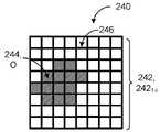
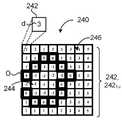
[0007] 이러한 양태는 하기의 선택적인 특징들 중 하나 이상을 포함할 수 있다. 일부 구현예들에서, 표시는 가장 가까운 장애물 경계까지의 거리 및 가장 가까운 장애물 경계까지의 방향의 추정치를 포함한다. 여기서, 몸체 장애물 맵을 생성하는 단계는 복수의 벡터들을 포함하는 벡터 필드를 생성하는 단계를 포함할 수 있으며, 복수의 벡터들의 각 벡터는 장애물 회피의 방향을 표시하고, 각각의 벡터는 가장 가까운 장애물 경계와 반대 방향인 벡터 방향을 포함한다. 일부 예들에서, 제어 시스템은 몸체 장애물 맵을 사용하여 로봇의 몸체의 수평 모션 및 로봇의 몸체의 요 회전을 제어하도록 구성된다. 복수의 셀들은 장애물의 경계에 대응하지 않을 수 있다.[0007] This aspect may include one or more of the following optional features. In some implementations, the indication includes an estimate of a distance to the nearest obstacle boundary and a direction to the nearest obstacle boundary. Here, generating the body obstacle map may include generating a vector field including a plurality of vectors, wherein each vector of the plurality of vectors indicates a direction of obstacle avoidance, and each vector is the nearest obstacle. Contains the vector direction opposite the boundary. In some examples, the control system is configured to control the horizontal motion of the body of the robot and yaw rotation of the body of the robot using the body obstacle map. The plurality of cells may not correspond to the boundary of the obstacle.
[0008] 일부 구성들에서, 상기 방법은 또한, 데이터 처리 하드웨어에 의해, 복수의 복셀들의 각 복셀과 연관된 포인트 가중치에 기초하여 복셀 맵의 복수의 복셀들을 필터링하는 단계를 포함할 수 있다. 여기서, 포인트 가중치는 각각의 복셀이 센서 데이터에 기초하여 점유된다는 확실성의 정도를 표시한다. 이러한 구성들에서, 복셀 맵에 기초하여 몸체 장애물 맵을 생성하는 단계는 포인트 가중치 임계치를 충족하고 장애물 복셀에 대응하는 필터링된 복수의 복셀들을 몸체 장애물 맵으로 변환하는 단계를 포함한다.In some configurations, the method may also include, by data processing hardware, filtering the plurality of voxels of the voxel map based on a point weight associated with each voxel of the plurality of voxels. Here, the point weight indicates the degree of certainty that each voxel is occupied based on the sensor data. In such configurations, generating the body obstacle map based on the voxel map includes converting a filtered plurality of voxels that meet a point weight threshold and corresponding to the obstacle voxel into a body obstacle map.
[0009] 본 개시의 제3 양태는 또한 제약된 이동성 매핑의 방법을 제공한다. 상기 방법은, 데이터 처리 하드웨어에서, 로봇 주위의 환경에 대응하는 센서 데이터를 로봇의 적어도 하나의 센서로부터 수신하는 단계를 포함하며, 로봇은 몸체 및 다리들을 포함하고, 각각의 다리는 원위 단부를 포함한다. 상기 방법은, 데이터 처리 하드웨어에 의해, 센서 데이터에 기초하여 복수의 세그먼트들을 포함하는 복셀 맵을 생성하는 단계를 더 포함하며, 복수의 세그먼트들의 각 세그먼트는 하나 이상의 복셀들에 의해 한정된 수직 열에 대응한다. 여기서, 복수의 세그먼트들은 적어도 하나의 지면 세그먼트 및 적어도 하나의 장애물 세그먼트를 포함한다. 복셀 맵에 기초하여, 상기 방법은 또한, 데이터 처리 하드웨어에 의해, 로봇이 환경에 대해 이동할 때 로봇의 각 다리의 원위 단부를 배치하기 위한 높이들을 표시하도록 구성된 지면 높이 맵을 생성하는 단계를 포함한다. 지면 높이 맵은 셀들로 분할되고, 적어도 하나의 셀은 각각의 지면 세그먼트에 대응하고, 각각의 지면 세그먼트에 기초하는 각각의 높이를 포함한다. 상기 방법은, 데이터 처리 하드웨어에 의해, 지면 높이 맵을 제어 시스템에 전달하는 단계를 더 포함하며, 제어 시스템은 지면 높이 맵에 기초하여 각각의 다리의 원위 단부를 환경 내의 배치 위치로 이동시키도록 구성된다.[0009] A third aspect of the present disclosure also provides a method of constrained mobility mapping. The method includes receiving, in data processing hardware, sensor data corresponding to an environment surrounding the robot from at least one sensor of the robot, the robot comprising a body and legs, each leg comprising a distal end do. The method further comprises, by data processing hardware, generating, based on the sensor data, a voxel map comprising a plurality of segments, each segment of the plurality of segments corresponding to a vertical column defined by one or more voxels . Here, the plurality of segments includes at least one ground segment and at least one obstacle segment. Based on the voxel map, the method also includes generating, by the data processing hardware, a ground height map configured to indicate heights for positioning the distal end of each leg of the robot as the robot moves relative to the environment. . The ground height map is partitioned into cells, wherein at least one cell corresponds to each ground segment and includes a respective height based on each ground segment. The method further comprises communicating, by data processing hardware, a ground height map to a control system, the control system configured to move a distal end of each leg to a deployment location in the environment based on the ground height map do.
[0010] 이러한 양태는 하기의 선택적인 특징들 중 하나 이상을 포함할 수 있다. 일부 구현예들에서, 지면 높이 맵을 생성하는 단계는 각각의 지면 세그먼트의 하나 이상의 복셀들에 대한 포인트 가중치가 높이 정확도 임계치를 충족한다고 결정하는 단계를 포함하며, 포인트 가중치는 각각의 복셀이 센서 데이터에 기초하여 점유된다는 확실성의 정도를 표시한다. 여기서, 높이 정확도 임계치는 각각의 지면 세그먼트에 의해 표현된 주어진 물체의 높이에 대한 정확도의 레벨을 표시한다. 이러한 구현예들에서, 각각의 지면 세그먼트의 하나 이상의 복셀들에 대한 포인트 가중치가 높이 정확도 임계치를 충족한다고 결정하는 단계는 각각의 지면 세그먼트의 가장 높은 높이로부터 각각의 지면 세그먼트의 가장 낮은 높이까지 각각의 지면 세그먼트를 한정하는 하나 이상의 복셀을 횡단하는 단계를 포함한다.[0010] This aspect may include one or more of the following optional features. In some implementations, generating the ground height map comprises determining that a point weight for one or more voxels of each ground segment meets a height accuracy threshold, wherein the point weight determines that each voxel corresponds to the sensor data It indicates the degree of certainty that it is occupied based on Here, the height accuracy threshold indicates the level of accuracy for the height of a given object represented by each ground segment. In such implementations, determining that the point weight for one or more voxels of each ground segment meets the height accuracy threshold comprises each ground segment from the highest height of each ground segment to the lowest height of each ground segment. traversing one or more voxels defining a ground segment.
[0011] 일부 예들에서, 상기 방법은 또한, 데이터 처리 하드웨어에 의해, 지면 높이 맵의 하나 이상의 셀들이 누락된 지형에 대응한다고 식별하는 단계; 데이터 처리 하드웨어에 의해, 누락된 지형이 센서 데이터의 오클루전에 대응하는지 여부를 결정하는 단계; 및 누락된 지형이 센서 데이터의 오클루전에 대응하는 경우, 데이터 처리 하드웨어에 의해, 누락된 지형을 편평한 지형으로 대체하는 단계를 더 포함한다. 누락된 지형이 센서 데이터의 오클루전에 대응하지 않는 경우, 상기 방법은 데이터 처리 하드웨어에 의해, 누락된 지형을 평활한 지형으로 대체하는 단계를 더 포함할 수 있다. 평활한 지형의 경우, 상기 방법은 지면 높이 맵의 후속 반복 동안에 지면 높이 맵에 평활한 지형을 존속시키지 않을 수 있다. 일부 구성들에서, 편평한 지형은 새로운 센서 데이터가 편평한 지형에 대응하는 실제 지형을 식별할 때까지 지면 높이 맵 내에 존속된다.[0011] In some examples, the method further includes: identifying, by data processing hardware, one or more cells of the ground height map corresponding to the missing terrain; determining, by the data processing hardware, whether the missing terrain corresponds to occlusion of the sensor data; and if the missing terrain corresponds to occlusion of the sensor data, replacing, by the data processing hardware, the missing terrain with a flat terrain. If the missing terrain does not correspond to occlusion of the sensor data, the method may further include, by data processing hardware, replacing the missing terrain with a smooth terrain. In the case of smooth terrain, the method may not persist the smooth terrain in the ground height map during subsequent iterations of the ground height map. In some configurations, the flat terrain persists within the ground height map until new sensor data identifies the actual terrain corresponding to the flat terrain.
[0012] 본 개시의 제4 양태는 또한 제약된 이동성 매핑의 방법을 제공한다. 상기 방법은, 데이터 처리 하드웨어에서, 로봇 주위의 환경에 대응하는 센서 데이터를 로봇의 적어도 하나의 센서로부터 수신하는 단계를 포함하며, 로봇은 몸체 및 다리들을 포함하고, 각각의 다리는 원위 단부를 포함한다. 상기 방법은, 데이터 처리 하드웨어에 의해, 센서 데이터에 기초하여 복수의 세그먼트들을 포함하는 복셀 맵을 생성하는 단계를 더 포함하며, 복수의 세그먼트들의 각 세그먼트는 하나 이상의 복셀들에 의해 한정된 수직 열에 대응한다. 여기서, 복수의 세그먼트들은 적어도 하나의 지면 세그먼트 및 적어도 하나의 장애물 세그먼트를 포함한다. 복셀 맵에 기초하여, 상기 방법은 또한, 데이터 처리 하드웨어에 의해, 로봇이 환경에 대해 이동할 때 로봇의 각 다리의 원위 단부를 배치하기 위한 높이들을 표시하도록 구성된 지면 높이 맵을 생성하는 단계를 포함한다. 지면 높이 맵에 기초하여, 상기 방법은, 데이터 처리 하드웨어에 의해, 하나 이상의 노스텝 영역들을 포함하는 노스텝 맵을 생성하는 단계를 더 포함하며, 각각의 노스텝 영역은 로봇이 환경에 대해 이동할 때 로봇의 각 다리의 원위 단부를 배치하지 않는 영역을 표시하도록 구성된다. 여기서, 노스텝 맵은 셀들로 분할되고, 각각의 셀은 거리 값 및 방향 벡터를 포함한다. 거리 값은 셀에 대한 가장 가까운 장애물의 경계까지의 거리를 표시한다. 방향 벡터는 셀에 대한 가장 가까운 장애물의 경계까지의 방향을 표시한다. 상기 방법은, 데이터 처리 하드웨어에 의해, 노스텝 맵을 제어 시스템에 전달하는 단계를 추가로 포함하며, 제어 시스템은 노스텝 맵에 기초하여 각각의 다리의 원위 단부를 환경 내의 배치 위치로 이동시키도록 구성된다.[0012] A fourth aspect of the present disclosure also provides a method of constrained mobility mapping. The method includes receiving, in data processing hardware, sensor data corresponding to an environment surrounding the robot from at least one sensor of the robot, the robot comprising a body and legs, each leg comprising a distal end do. The method further comprises, by data processing hardware, generating, based on the sensor data, a voxel map comprising a plurality of segments, each segment of the plurality of segments corresponding to a vertical column defined by one or more voxels . Here, the plurality of segments includes at least one ground segment and at least one obstacle segment. Based on the voxel map, the method also includes generating, by the data processing hardware, a ground height map configured to indicate heights for positioning the distal end of each leg of the robot as the robot moves relative to the environment. . Based on the ground height map, the method further comprises generating, by the data processing hardware, a nostep map comprising one or more nostep areas, each nostep area as the robot moves relative to the environment. configured to mark an area not disposing the distal end of each leg of the robot. Here, the nostep map is divided into cells, each cell containing a distance value and a direction vector. The distance value indicates the distance to the boundary of the nearest obstacle to the cell. The direction vector indicates the direction to the boundary of the nearest obstacle to the cell. The method further comprises communicating, by data processing hardware, a nostep map to a control system, the control system to move the distal end of each leg to a deployment location in the environment based on the nostep map. is composed
[0013] 이러한 양태는 하기의 선택적인 특징들 중 하나 이상을 포함할 수 있다. 가장 가까운 장애물의 경계까지의 거리는 셀이 가장 가까운 장애물 내부에 있는지 또는 가장 가까운 장애물 외부에 있는지를 식별하는 부호를 포함할 수 있다. 하나 이상의 노스텝 영역들 중 적어도 하나의 노스텝 영역은 로봇의 현재 포즈에 기초하여 로봇이 접근 가능하지 않는 영역을 식별할 수 있고, 이 영역은 현재 포즈와 상이한 대안 포즈로 로봇이 접근 가능하다. 일부 예들에서, 노스텝 맵을 생성하는 단계는 또한 로봇의 특정 다리에 대한 노스텝 맵을 생성하는 단계를 포함한다. 일부 구현예들에서, 상기 방법은 또한, 데이터 처리 하드웨어에 의해, 복셀 맵의 적어도 하나의 장애물 세그먼트에 기초하여 각각의 셀에 대한 가장 가까운 장애물을 결정하는 단계를 포함할 수 있다.[0013] This aspect may include one or more of the following optional features. The distance to the boundary of the nearest obstacle may include a code identifying whether the cell is inside the nearest obstacle or outside the nearest obstacle. At least one nostep area of the one or more nostep areas may identify an area inaccessible to the robot based on a current pose of the robot, wherein the area is accessible to the robot in an alternative pose different from the current pose. In some examples, generating the nostep map also includes generating the nostep map for a particular leg of the robot. In some implementations, the method may also include determining, by the data processing hardware, a nearest obstacle for each cell based on at least one obstacle segment of the voxel map.
[0014] 일부 구성들에서, 상기 방법은, 데이터 처리 하드웨어에 의해서, 지시된 속도를 달성하도록 다리에 대한 최소 경사를 결정하는 동작; 최소 경사에 기초하여 정강이 충돌 높이를 식별하는 동작; 및 노스텝 맵의 각 셀에 대해, 정강이 충돌 높이를 지면 높이 맵으로부터 수신된 각각의 셀에 대한 지면 높이와 비교하는 동작에 의해, 잠재적인 정강이 충돌에 대응하는 제1 노스텝 영역들을 결정하는 단계를 추가로 포함한다. 이러한 구성들에서, 상기 방법은 또한, 데이터 처리 하드웨어에 의해, 정강이 충돌 높이와 각각의 셀에 대한 지면 높이 사이의 차이가 정강이 충돌 임계치를 충족한다고 결정하는 단계를 포함할 수 있다.[0014] In some configurations, the method includes determining, by data processing hardware, a minimum inclination for a leg to achieve an indicated speed; identifying a shin impingement height based on the minimum inclination; and determining, for each cell of the nostep map, first nostep areas corresponding to a potential shin impact by comparing the shin impact height to the ground height for each cell received from the ground height map. further includes. In such configurations, the method may also include determining, by the data processing hardware, that the difference between the shin impingement height and the ground level height for each cell meets a shin impingement threshold.
[0015] 본 개시의 하나 이상의 구현예들의 세부사항들은 첨부 도면들 및 하기의 설명에 기재되어 있다. 다른 양태들, 특징들 및 이점들은 이 설명 및 도면들, 그리고 청구범위로부터 명백할 것이다.[0015] The details of one or more implementations of the disclosure are set forth in the accompanying drawings and the description below. Other aspects, features and advantages will be apparent from this description and drawings, and from the claims.
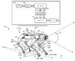
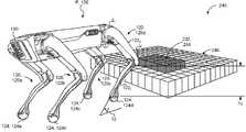
[0016] 도 1a는 환경 내의 예시적인 로봇의 개략도이다.
[0017] 도 1b는 도 1a의 로봇을 위한 예시적인 시스템들의 개략도이다.
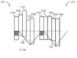
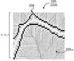
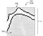
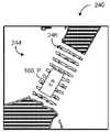
[0018] 도 2a 및 도 2b는 도 1a의 로봇에 대한 복셀 맵의 예시적인 투영의 사시도들이다.
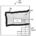
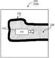
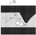
[0019] 도 2c는 도 1a의 로봇에 대한 예시적인 복셀 맵의 사시도이다.
[0020] 도 2d 및 도 2e는 복셀 분류의 예들의 개략도들이다.
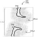
[0021] 도 2f 및 도 2g는 도 1a의 로봇의 위치에 기초하는 복셀 분류의 예들의 사시도들이다.
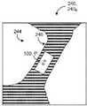
[0022] 도 2h는 네거티브 세그먼트들을 갖는 예시적인 복셀 맵의 사시도이다.
[0023] 도 2i 내지 도 2l은 복셀 맵에 대한 광선 추적의 예들의 사시도들이다.
[0024] 도 3a 내지 도 3f는 도 1a의 로봇에 의해 생성된 예시적인 몸체 장애물 맵들의 개략도들이다.
[0025] 도 3g 내지 도 3l은 도 1a의 로봇에 의한 몸체 장애물 맵 생성을 위한 예시적인 처리 기술들의 개략도들이다.
[0026] 도 4a는 도 1a의 로봇에 의한 지면 높이 맵 생성의 일 예의 개략도이다.
[0027] 도 4b는 도 1a의 로봇에 의해 생성된 지면 높이 맵의 일 예의 사시도이다.
[0028] 도 5a 내지 도 5c는 도 1a의 로봇에 의해 생성된 예시적인 노스텝 맵들의 개략도들이다.
[0029] 도 5d는 정강이 충돌들의 위험에 기초하는 예시적인 노스텝 맵의 사시도이다.
[0030] 도 5e는 도 1a의 로봇에 의해 생성된 예시적인 노스텝 맵의 개략도이다.
[0031] 도 5f 및 도 5g는 도 1a의 로봇의 하나 이상의 발들에 기초하는 예시적인 노스텝 맵의 사시도이다.
[0032] 도 5h 및 도 5i는 도 1a의 로봇에 의해 생성된 노스텝 맵들의 예들의 개략도들이다.
[0033] 도 6 내지 도 9는 로봇이 로봇 주위의 환경을 횡단하기 위한 맵을 생성하는 동작들의 예시적인 배열들이다.
[0034] 도 10은 본원에 설명된 시스템들 및 방법들을 구현하는 데 사용될 수 있는 예시적인 컴퓨팅 디바이스의 개략도이다.
[0035] 다양한 도면들에서 유사한 참조 부호들은 유사한 요소들을 나타낸다.1A is a schematic diagram of an example robot within an environment.
1B is a schematic diagram of example systems for the robot of FIG. 1A .
2A and 2B are perspective views of an example projection of a voxel map for the robot of FIG. 1A .
FIG. 2C is a perspective view of an example voxel map for the robot of FIG. 1A .
2D and 2E are schematic diagrams of examples of voxel classification.
2F and 2G are perspective views of examples of voxel classification based on the position of the robot of FIG. 1A ;
2H is a perspective view of an example voxel map with negative segments.
2I-2L are perspective views of examples of ray tracing for a voxel map.
3A-3F are schematic diagrams of example body obstacle maps generated by the robot of FIG. 1A ;
3G-3L are schematic diagrams of example processing techniques for generating a body obstacle map by the robot of FIG. 1A ;
[0026] FIG. 4A is a schematic diagram of an example of ground height map generation by the robot of FIG. 1A;
4B is a perspective view of an example of a ground height map generated by the robot of FIG. 1A ;
5A-5C are schematic diagrams of example nostep maps generated by the robot of FIG. 1A .
5D is a perspective view of an example nostep map based on risk of shin impacts.
[0030] FIG. 5E is a schematic diagram of an example nostep map generated by the robot of FIG. 1A;
5F and 5G are perspective views of an example nostep map based on one or more feet of the robot of FIG. 1A ;
5H and 5I are schematic diagrams of examples of nostep maps generated by the robot of FIG. 1A .
6-9 are example arrangements of operations for a robot to generate a map for traversing the environment around the robot.
10 is a schematic diagram of an example computing device that may be used to implement the systems and methods described herein.
[0035] Like reference signs in the various drawings indicate like elements.
[0036] 보행 로봇 디바이스들(legged robotic devices)("로봇들"로도 지칭됨)이 보다 보편화됨에 따라, 로봇들이 다수의 방식들로 제약된 환경들을 항행할 필요성이 증가하고 있다. 예를 들어, 로봇은 크고 작은 물체들이 바닥에 흩어져 있는 어수선한 방(room)을 횡단하거나 계단을 오르내릴 필요가 있을 수 있다. 전형적으로, 이러한 종류의 환경들을 항행하는 것은 느리고 힘든 과정이었으며, 이는 보행 로봇이 자주 정지하고, 물체들과 충돌하며, 그리고/또는 균형을 잃게 한다. 예를 들어, 물체와의 충돌 위험을 피하는 것조차도 로봇의 균형을 방해할 수 있다. 이러한 단점들 중 일부를 해결하기 위해, 로봇은 장애물들이 있는 환경에서의 로봇의 이동을 관리하는 것을 돕고 그리고/또는 안내하는 로봇에 대한 센서들에 기초하여 맵들(maps)을 구성한다. 이러한 맵들에 의해, 로봇은 실시간으로 이동 제약조건들을 고려하면서 지형을 횡단할 수 있으며, 그에 따라 보행 로봇 디바이스가 이동 유동성 및 균형을 유지하면서 제약된 환경을 신속하고 효율적으로 항행할 수 있게 한다.As legged robotic devices (also referred to as “robots”) become more common, there is an increasing need for robots to navigate constrained environments in multiple ways. For example, a robot may need to traverse a cluttered room with large and small objects scattered on the floor or climb up and down stairs. Typically, navigating these types of environments has been a slow and laborious process, which causes the walking robot to frequently stop, collide with objects, and/or lose balance. For example, even avoiding the risk of collision with an object can disturb the robot's balance. To address some of these shortcomings, the robot constructs maps based on sensors for the robot that help and/or guide the robot's movement in an environment with obstacles. These maps allow the robot to traverse the terrain while taking into account movement constraints in real time, thereby enabling the ambulatory robot device to navigate the constrained environment quickly and efficiently while maintaining mobility and balance.
[0037] 도 1a를 참조하면, 로봇(100)은 몸체(110)를 포함하며, 몸체(110)는 몸체(110)에 결합되고 로봇(100)이 환경(10)에 대해 이동할 수 있게 하는 로코모션-기반 구조물들(locomotion-based structures), 이를 테면 다리들(120a 내지 120d)을 갖는다. 일부 예들에서, 각각의 다리(120)는 하나 이상의 관절들(J)이 다리(120)의 부재들(122)이 이동하게 하도록 하는 관절연결형 구조물이다. 예를 들어, 각각의 다리(120)는 다리(120)의 상부 부재(122, 122U)를 몸체(110)에 결합하는 고관절(hip joint)(JH), 및 다리(120)의 상부 부재(122U)를 다리(120)의 하부 부재(122L)에 결합하는 무릎 관절(knee joint)(JK)을 포함한다. 도 1a는 4 개의 다리들(120a 내지 120d)을 갖는 4족 보행 로봇을 도시하지만, 로봇(100)은 환경(10) 내의 지형을 횡단하기 위한 수단을 제공하는 임의의 수의 다리들 또는 로코모션-기반 구조물들(예를 들어, 2 개의 다리들을 갖는 2족 보행 또는 인간형 로봇)을 포함할 수 있다.Referring to FIG. 1A , the
[0038] 지형을 횡단하기 위해, 각각의 다리(120)는 지형의 표면과 접촉하는 원위 단부(124)를 갖는다. 다시 말해서, 다리(120)의 원위 단부(124)는 로봇(100)의 이동 동안에 피봇하거나, 자리잡거나 또는 일반적으로 트랙션(traction)을 제공하기 위해 로봇(100)에 의해 사용되는 다리(120)의 단부이다. 예를 들어, 다리(120)의 원위 단부(124)는 로봇(100)의 발에 대응한다. 일부 예들에서, 도시되지는 않았지만, 다리(120)의 원위 단부(124)는 원위 단부(124)가 다리(120)의 하부 부재(122L)에 대해 관절연결 가능하도록 하는 발목 관절(ankle joint)(JA)을 포함한다.[0038] To traverse terrain, each
[0039] 로봇(100)은 중력 방향을 따른 수직 중력 축(예를 들어, Z-방향 축(AZ)으로 도시됨)과, 로봇(100)의 분포된 질량의 가중된 상대 포지션의 합이 0(zero)이 되는 포인트(point)인 질량 중심(CM)을 갖는다. 로봇(100)은 로봇(100)에 의해 취해지는 특정 자세(attitude) 또는 스탠스(stance)를 규정하기 위해 수직 중력 축(AZ)(즉, 중력에 대한 고정 기준 프레임(fixed reference frame))에 대한 CM에 기초하는 포즈(pose)(P)를 더 갖는다. 로봇(100)의 자세는 공간에서의 로봇(100)의 배향 또는 각도 포지션에 의해 규정될 수 있다. 몸체(110)에 대한 다리(120)의 이동들은 로봇(100)의 포즈(P)(즉, 로봇의 CM 포지션과 로봇(100)의 자세 또는 배향의 조합)를 변경한다. 여기서, 높이는 일반적으로 z-방향을 따른 거리를 지칭한다. 로봇(100)의 시상면(sagittal plane)은 y-방향 축(AY) 및 z-방향 축(AZ)의 방향들로 연장되는 Y-Z 평면에 대응한다. 일반적으로 시상면에 수직인 지면(횡방향 평면으로도 지칭됨)은 x-방향 축(AX) 및 y-방향 축(AY)의 방향들로 연장됨으로써 X-Y 평면에 걸쳐 있다. 지면은 로봇(100)의 다리들(120)의 원위 단부들(124)이 트랙션을 생성하여 로봇(100)이 환경(10)에 대해 이동하는 것을 도울 수 있는 지표면(12)을 지칭한다.[0039] The
[0040] 환경(10)에 대해 기동하기 위해, 로봇(100)은 하나 이상의 센서들(132, 132a 내지 132n)(예를 들어, 제1 센서(132, 132a) 및 제2 센서(132, 132b)로서 도시됨)을 갖는 센서 시스템(130)을 포함한다. 센서들(132)은 비전/이미지 센서들(vision/image sensors), 관성 센서들(예를 들어, 관성 측정 유닛(inertial measurement unit; IMU)), 힘 센서들, 및/또는 운동학적 센서들을 포함할 수 있다. 센서들(132)의 일부 예들은 스테레오 카메라와 같은 카메라, 스캐닝 광-검출 및 거리 측정(light-detection and ranging; LIDAR) 센서, 또는 스캐닝 레이저-검출 및 거리 측정(laser-detection and ranging; LADAR) 센서를 포함한다. 일부 예들에서, 센서(132)는 센서(132)에 대응하는 감지 범위 또는 영역을 한정하는 대응하는 시야(들)(FV)를 갖는다. 예를 들어, 도 1a는 로봇(100)에 대한 시야(FV)를 도시한다. 각각의 센서(132)는, 예를 들어 센서(132)가 하나 이상의 축(예를 들어, 지면과 관련하여 x-축, y-축, 또는 z-축)을 중심으로 시야(FV)를 변경할 수 있도록 피봇 가능 및/또는 회전 가능할 수 있다.To maneuver relative to the
[0041] 센서(132)로 시야(FV)를 조사할 때, 센서 시스템(130)은 시야(FV)에 대응하는 센서 데이터(134)(이미지 데이터로도 지칭됨)를 생성한다. 일부 예들에서, 센서 데이터(134)는 3차원 체적형 이미지 센서(132)에 의해 생성된 3차원 체적형 포인트 클라우드(three-dimensional volumetric point cloud)에 대응하는 데이터이다. 추가적으로 또는 대안적으로, 로봇(100)이 환경(10)에 대해 기동할 때, 센서 시스템(130)은 관성 측정 데이터(예를 들어, IMU에 의해 측정됨)를 포함하는 로봇(100)에 대한 포즈 데이터를 수집한다. 일부 예들에서, 포즈 데이터는 로봇(100)에 대한 운동학적 데이터 및/또는 배향 데이터를 포함한다. 센서 데이터(134)에 의해, 로봇(100)의 인식 시스템(200)은 환경(10) 주위의 지형에 대한 맵들(maps)(210, 220, 230, 240)을 생성할 수 있다.When illuminating the field of view FV with the sensor 132 , the
[0042] 로봇(100)이 환경(10)에 대해 기동하는 동안, 센서 시스템(130)은 환경(10)의 지형과 관련된 센서 데이터(134)를 수집한다. 예를 들어, 도 1a는 로봇(100)의 환경(10)으로서 방에 관한 센서 데이터(134)를 수집하는 센서 시스템(130)을 도시한다. 센서 시스템(130)이 센서 데이터(134)를 수집할 때, 컴퓨팅 시스템(140)은 센서 데이터(134)를 로봇(100)의 다양한 시스템들(예를 들어, 인식 시스템(200) 또는 제어 시스템(170))에 저장, 처리 및/또는 통신하도록 구성된다. 센서 데이터(134)와 관련된 컴퓨팅 작업들을 수행하기 위해, 로봇(100)의 컴퓨팅 시스템(140)은 데이터 처리 하드웨어(142) 및 메모리 하드웨어(144)를 포함한다. 데이터 처리 하드웨어(142)는 로봇(100)에 대한 활동들(예를 들어, 이동 및/또는 이동 기반 활동들)과 관련된 컴퓨팅 작업들을 수행하기 위해 메모리 하드웨어(144)에 저장된 명령들을 실행하도록 구성된다. 일반적으로 말하면, 컴퓨팅 시스템(140)은 데이터 처리 하드웨어(142) 및/또는 메모리 하드웨어(144)의 하나 이상의 위치들을 지칭한다. 일부 예들에서, 컴퓨팅 시스템(140)은 로봇(100) 상에 위치된 로컬 시스템이다. 로봇(100) 상에 위치되는 경우, 컴퓨팅 시스템(140)은 중앙 집중형(즉, 로봇(100) 상의 단일 위치/영역, 예를 들어 로봇(100)의 몸체(110)에 있음), 분산형(즉, 로봇(100) 주위의 다양한 위치들에 위치됨), 또는 이들 둘의 하이브리드 조합(예를 들어, 다수의 중앙 집중형 하드웨어 및 소수의 분산형 하드웨어의 경우)일 수 있다. 일부 차이점들을 예시하기 위해, 분산형 컴퓨팅 시스템(140)은 활동 위치(예를 들어, 다리(120)의 관절을 이동시키는 모터)에서 처리가 일어나게 할 수 있는 반면, 중앙 집중형 컴퓨팅 시스템(140)은 로봇(100) 상의 다양한 포지션들에 위치된 시스템들과 통신하는(예를 들어, 다리(120)의 관절을 이동시키는 모터와 통신하는) 중앙 처리 허브를 허용할 수 있다. 추가적으로 또는 대안적으로, 컴퓨팅 시스템(140)은 로봇(100)으로부터 원격으로 위치되는 컴퓨팅 리소스들(computing resources)을 포함한다. 예를 들어, 컴퓨팅 시스템(140)은 네트워크(150)를 통해 원격 시스템(160)(예를 들어, 원격 서버 또는 클라우드-기반 환경)과 통신한다. 컴퓨팅 시스템(140)과 매우 유사하게, 원격 시스템(160)은 원격 데이터 처리 하드웨어(162) 및 원격 메모리 하드웨어(164)와 같은 원격 컴퓨팅 리소스들을 포함한다. 여기서, 센서 데이터(134) 또는 다른 처리된 데이터(예를 들어, 컴퓨팅 시스템(140)에 의해 로컬로 처리되는 데이터)는 원격 시스템(160)에 저장될 수 있고, 컴퓨팅 시스템(140)에 액세스 가능할 수 있다. 일부 예들에서, 컴퓨팅 시스템(140)은 컴퓨팅 시스템(140)의 리소스들이 원격 시스템(160)의 리소스들에 상주할 수 있도록 컴퓨팅 리소스들(142, 144)의 확장들로서 원격 리소스들(162, 164)을 이용하도록 구성된다.While the
[0043] 일부 구현예들에서, 도 1a 및 도 1b에 도시된 바와 같이, 로봇(100)은 제어 시스템(170) 및 인식 시스템(200)을 포함한다. 인식 시스템(200)은 센서 시스템(130)으로부터 센서 데이터(134)를 수신하고 센서 데이터(134)를 맵들(210, 220, 230, 240)로 처리하도록 구성된다. 인식 시스템(200)에 의해 생성된 맵들(210, 220, 230, 240)에 의해, 인식 시스템(200)은 환경(10)에 대해 로봇(100)을 이동시키는 것과 같은 로봇(100)에 대한 제어된 동작들을 수행하기 위해 맵들(210, 220, 230, 240)을 제어 시스템(170)에 전달할 수 있다. 일부 예들에서, 인식 시스템(200)이 제어 시스템(170)과 분리되어 있지만 제어 시스템(170)과 통신함으로써, 제어 시스템(170)에 대한 처리는 로봇(100)을 제어하는 데 초점을 맞출 수 있는 반면, 인식 시스템(200)에 대한 처리는 센서 시스템(130)에 의해 수집된 센서 데이터(134)를 해석하는 데 초점을 맞추고 있다. 예를 들어, 이러한 시스템들(200, 170)은 환경(10)에서의 로봇(100)의 정확하고 부드러운 이동을 보장하기 위해 병렬로 처리를 실행한다.In some implementations, as shown in FIGS. 1A and 1B , the
[0044] 일부 예들에서, 제어 시스템(170)은 적어도 하나의 제어기(172), 경로 생성기(174), 스텝 로케이터(step locator)(176) 및 몸체 플래너(body planner)(178)를 포함한다. 제어 시스템(170)은 적어도 하나의 센서 시스템(130) 및 인식 시스템(200)과 통신하도록 구성된다. 제어 시스템(170)은 하드웨어(140)를 사용하여 동작들 및 다른 기능들을 수행한다. 제어기(172)는 로봇(100)의 시스템들(예를 들어, 제어 시스템(170) 및/또는 인식 시스템(200))로부터의 입력 또는 피드백에 기초하여 환경(10)에 대해 횡단하기 위해 로봇(100)의 이동을 제공하도록 구성된다. 이것은 로봇(100)의 포즈들 및/또는 거동들 사이의 이동을 포함할 수 있다. 예를 들어, 제어기(172)는 상이한 발자국 패턴들, 다리 패턴들, 몸체 이동 패턴들 또는 비전 시스템 감지 패턴들을 제어한다.In some examples, the
[0045] 일부 예들에서, 제어기(172)는 복수의 제어기들(172)을 포함하며, 제어기들(172) 각각은 고정 케이던스(fixed cadence)를 갖는다. 고정 케이던스는 다리(120)의 스텝 단계 또는 유각기에 대한 고정 타이밍을 지칭한다. 예를 들어, 제어기(172)는 로봇(100)이 특정 주파수(예를 들어, 250 밀리초, 350 밀리초 등마다의 스텝)로 다리들(120)을 이동시키도록(예를 들어, 스텝을 내디디도록) 명령한다. 각각의 제어기(172)가 고정 케이던스를 갖는 복수의 제어기들(172)의 경우, 로봇(100)은 제어기들(172)을 전환함으로써 가변 타이밍을 경험할 수 있다. 일부 구현예들에서, 로봇(100)이 환경(10)을 횡단할 때, 로봇(100)은 고정 케이던스 제어기들(172)을 연속적으로 전환/선택한다(예를 들어, 3 밀리초마다 제어기(170)를 재선택함).In some examples, controller 172 includes a plurality of controllers 172 , each of which has a fixed cadence. Fixed cadence refers to the fixed timing for the step phase or swing phase of the
[0046] 도 1b를 참조하면, 경로 생성기(174)는 로봇(100)에 대한 수평 모션을 결정하도록 구성된다. 예를 들어, 수평 모션은 로봇(100)의 병진(즉, X-Y 평면에서의 이동) 및/또는 요(yaw)(즉, Z-방향 축(AZ)을 중심으로 한 회전)를 지칭한다. 경로 생성기(174)는 센서 데이터(134)에 기초하여 로봇(100) 주위의 환경(10) 내의 장애물들을 결정한다. 경로 생성기(174)는 최적화를 위한 시작점으로서 명목상 충돌없는 경로를 스텝 로케이터(176)에 제공한다. 스텝 로케이터(176)는 또한 장애물들에 대한 정보를 수신하고, 그에 따라 스텝 로케이터(176)는 로봇(100)의 다리들(120)에 대한 발 위치들(예를 들어, 로봇(100)의 다리들(120)의 원위 단부들(124)을 배치하기 위한 위치들)을 식별할 수 있다. 스텝 로케이터(176)는 인식 시스템(200)으로부터의 입력들(예를 들어, 맵들(210, 220, 230, 240))을 사용하여 발 배치들(즉, 로봇(100)이 스텝을 내디뎌야 하는 위치들)을 생성한다. 몸체 플래너(178)는, 스텝 로케이터(176)와 매우 유사하게, 인식 시스템(200)으로부터 입력들(예를 들어, 맵들(210, 220, 230, 240))을 수신한다. 일반적으로 말하면, 몸체 플래너(178)는 환경(10)에 대해 성공적으로 이동하도록 로봇(100)의 몸체(110)의 역학(예를 들어, 회전, 예컨대 피치(pitch) 또는 요 및/또는 COM의 높이)을 조정하도록 구성된다.Referring to FIG. 1B , the path generator 174 is configured to determine a horizontal motion for the
[0047] 인식 시스템(200)은 다양한 장애물들을 갖는 지형에서 로봇(100)이 보다 정밀하게 이동하는 것을 돕는 로봇(100)의 시스템이다. 센서들(132)이 로봇(100) 주위의 공간(즉, 로봇의 환경(10))에 대한 센서 데이터(134)를 수집할 때, 인식 시스템(200)은 센서 데이터(134)를 사용하여 환경(10)에 대한 하나 이상의 맵들(210, 220, 230, 240)을 형성한다. 인식 시스템(200)이 맵(210, 220, 230, 240)을 생성하면, 인식 시스템(200)은 또한 (예를 들어, 센서 데이터(134)를 기존의 맵 상에 투영함으로써) 맵(210, 220, 230, 240)에 정보를 추가하고, 그리고/또는 (예를 들어, 현재 센서 데이터(134)에 기초하여 기존 맵을 광선 추적함으로써) 맵(210, 220, 230, 240)으로부터 정보를 제거하도록 구성된다. 맵들(210, 220, 230, 240)이 본원에서 별도로 설명되어 있지만, 그럼에도 불구하고, 인식 시스템(200)은 임의의 수의 맵(들)을 생성하여 각각의 맵에 대해 설명된 정보 및 특징들을 전달할 수 있다.[0047] The
[0048] 도 2a 내지 도 2l을 참조하면, 일부 구현예들에서, 인식 시스템(200)은 복셀 맵(voxel map)(210)을 생성한다. 인식 시스템(200)은 로봇(100)에 대한 세계 기준 프레임(world reference frame)과 로봇(100) 주위의 로컬 기준 프레임(local reference frame)의 조합에 기초하여 복셀 맵(210)을 생성한다. 여기서, 인식 시스템(200)은 세계 기준 프레임을 나타내기 위해 (예를 들어, 로봇(100)의 몸체(110)의 포지션 및/또는 속도에 의해) 로봇(100)의 위치를 한정하는 로봇(100)에 대한 오도메트리 정보(odometry information)를 수신하고, 로컬 기준 프레임을 나타내는 로봇(100) 근처의 영역으로서 센서(들)(132)의 범위 내의 영역을 한정하는 센서 데이터(134)를 수신한다. 오도메트리 정보 및 센서 데이터(134)에 의해서, 인식 시스템(200)은 로봇(100) 주위의 3차원 공간을 나타내기 위한 복셀 맵(210)을 생성한다. 일부 구현예들에서, 로봇(100)의 시스템들은 (예를 들어, 동시적 위치추정 및 매핑(simultaneous localization and mapping; SLAM)을 사용하여) 로봇(100)에 대한 현재 오도메트리 정보를 유지하기 위해 시간 경과에 따른 로봇의 상대 모션을 추적할 수 있다. 일부 예들에서, 복셀 맵(210)은 복셀 맵(210)이 소정 기간에 걸친 센서 데이터(134)의 다중 세트들을 포함하도록 인식 시스템(200)에 의한 센서 데이터(134)의 이력 수집을 나타내는 데이터 구조이다.2A-2L , in some implementations, the
[0049] 복셀 맵(210)은 일반적으로 복셀들(212)(즉, 픽셀(pixel)의 3차원 표현에 대응하는 그래픽 유닛)로서 3차원 공간을 나타낸다. 예를 들어, 도 2a는 복셀들(212, 2121-i)의 3차원(3D) 그리드(grid)를 도시한다. 일부 예들에서, 복셀 맵(210)의 각 복셀(212)은 3 센티미터 입방 영역을 나타낸다. 일부 구성들에서, 복셀 맵(210)은 복셀들(212)을 세그먼트들(214, 2141-i)로서 나타낸다(예를 들어, 도 2b에 도시된 바와 같음). 세그먼트들(214)은 수직 열로의 복셀들(212)의 통합을 지칭한다. 다시 말해서, 인식 시스템(200)은 3D 그리드의 동일한 수직 열 내의 복셀들(212)을 조합하여 적어도 하나의 세그먼트(214)를 형성한다. 예를 들어, 도 2c는 제1 세그먼트(214, 214a) 및 제2 세그먼트(214, 214b)를 갖는 셀들의 3D 그리드를 도시한다. 복셀들(212)을 세그먼트들(214)로서 나타냄으로써, 인식 시스템(200)은 로봇(100)의 환경(10) 내의 다양한 장애물들 또는 물체들의 분류를 단순화할 수 있다. 다시 말해서, 인식 시스템(200)은 수직 통합으로 인해 수천 개의 복셀들(212)이 아니라 수백 개의 세그먼트들(214)로 복셀 맵(210)을 처리한다.The
[0050] 일부 구현예들에서, 인식 시스템(200)은 세그먼트들(214)을 형성할 때 갭 임계치(gap threshold)를 갖도록 구성된다. 다시 말해서, 갭(Gp) 또는 복셀(들)(212)의 비연속 수직 열은 인식 시스템(200)이 갭(Gp) 이전의 복셀들(212)의 수직 열의 연속 부분을 나타내는 제1 세그먼트(214)를 종료하고, 갭(Gp) 이후의 복셀들(212)의 수직 열의 제2 연속 부분을 제2 세그먼트(214)로서 나타내게 할 수 있다. 예를 들어, 도 2c는 제2 세그먼트(214b)를 단일 세그먼트(214)(예를 들어, 동일한 회색 음영으로 지정됨)로서 도시하지만, 인식 시스템(200)은 도 2c에 도시된 갭(Gp)이 갭 임계치를 충족할 정도로 충분히 큰 경우에 제2 세그먼트(214b)를 다른 세그먼트(214)로 분할할 것이다. 따라서, 복셀들(212)의 수직 열은 열 내의 갭(들)의 크기가 갭 임계치를 충족하는지(예를 들어, 초과하는지) 여부에 따라 다수의 세그먼트들(214)을 포함할 수 있다. 반면에, 갭(Gp)의 크기가 임계치를 충족하지 못하는 경우(예를 들어, 도 2c에 도시된 바와 같음), 인식 시스템(200)은 갭(Gp)을 무시하고 갭(Gp)을 갖는 복셀들(212)의 전체 수직 열을 단일 세그먼트(214)로서 해석하도록 구성된다. 일부 예들에서, 갭 임계치는 30 센티미터이며, 그에 따라 30 센티미터보다 큰 임의의 수직 갭은 갭(Gp)의 일측에서 세그먼트(214)를 종료하고 갭(Gp)의 타측에서 새로운 세그먼트(214)의 형성을 유발할 것이다. 갭들(Gp)에서 세그먼트들(214)을 분리함으로써, 인식 시스템(200)은 동일한 세그먼트(214) 내의 모든 복셀들이 동일한 근원 물체에 대응한다고 추론하도록 구성될 수 있다.In some implementations, the
[0051] 계속해서 도 2c를 참조하면, 인식 시스템(200)은 지면(즉, 인식 시스템(200)이 로봇(100)이 스텝을 내디딜 수 있다고 해석하는 기하학적 영역), 장애물들(즉, 인식 시스템(200)이 로봇(100)의 이동을 방해할 수 있는 것으로 해석하는 기하학적 영역), 또는 지면도 장애물도 아닌 것(예를 들어, 무시될 수 있는 로봇(100) 위의 어떤 것)에 대응하는 부분들을 식별하기 위해 복셀 맵(210)을 분류하도록(예를 들어, 세그먼트들(214)을 분류하도록) 구성된다. 일부 구성들에서, 복셀 맵(210)은 열들의 조밀한 2차원 그리드를 포함하며, 여기서 열은 2차원 그리드의 각 특정 영역(즉, 셀) 내의 다수의 세그먼트들(214)의 수치적 표현이다. 추가적으로, 각각의 열은, 열이 열에 존재하는 다수의 복셀들(212)의 카운트를 포함하도록, 복셀들(212)의 희박한 리스트를 포함할 수 있다. 열은 2차원 그리드의 셀에서 수직 세그먼트(214)에 대응할 수 있기 때문에, 각각의 셀은 0 개 이상의 세그먼트들(214)을 가질 수 있다. 인식 시스템(200)이 복셀들(212)을 하나 이상의 세그먼트들(214)로 그룹화할 때, 인식 시스템(200)은 각각의 세그먼트(214)(또는 복셀(212))를 지면(214, 214G), 지하(214, 214UG), 장애물(214, 214OB) 또는 오버헤드(overhead)(214, 214OH)와 같은 대응하는 분류로 분류하도록 구성된다. 세그먼트(214)를 지면(214G)으로 분류함으로써, 인식 시스템(200)은 로봇(100)이 세그먼트(214)의 상단에 스텝을 내디딜 수 있음을 표시하고 있다. 인식 시스템(200)이 세그먼트(214)를 지하(214UG)로 분류하는 경우, 이러한 지하 분류는 인식 시스템(200) 또는 로봇(100)의 다른 시스템들의 추가 처리에 대해 무시될 수 있는 세그먼트(214)를 표시한다. 장애물들(214OB)로 분류된 세그먼트들(214)은 로봇(100)이 충돌할 수 있고 스텝을 내디딜 수 없는 물체들을 지칭한다. 여기서, 오버헤드(214OH)로 분류된 세그먼트(214)는 인식 시스템(200)이 로봇(100)이 그 아래로 횡단할 수 있다고 식별하는 세그먼트(214)를 지칭한다.[0051] With continued reference to FIG. 2C, the
[0052] 일반적으로 말하면, 본원에서의 언어는 때때로 지표면(12)(또는 지평면)을 지칭하면서 "지면"도 지칭한다. 지표면(12)은 세계 환경(10)의 피처(feature)를 지칭한다. 대조적으로, 지면(G)은 로봇(100)이 스텝을 내디딜 수 있는 영역(예를 들어, 복셀(212) 또는 세그먼트(214))에 대한 인식 시스템(200)에 의한 명칭을 지칭한다. 유사하게, 물체(14)는 세계 환경(10) 내의 물리적 구조 또는 피처인 반면, "장애물(O)"은 인식 시스템(200)에 의한 물체(14)(예를 들어, 점유된 복셀(212) 또는 장애물 세그먼트(214OB))에 대한 명칭이다. 다시 말해서, 센서 시스템(130)은 인식 시스템(200)이 장애물(O)로서 해석(즉, 인식)하는 환경(10)에서의 로봇(100) 근처의 물체(14)에 대한 센서 데이터(134)를 수집하며, 이는 물체(14)가 로봇(100)의 이동을 방해하거나 저지하는 영역이기 때문이다.[0052] Generally speaking, language herein sometimes refers to the earth's surface 12 (or to the horizon) while also referring to "the ground".
[0053] 일부 구현예들에서, 인식 시스템(200)은 볼록성 가정(convexity assumption)에 기초하여 분류를 수행하도록 구성된다. 볼록성 가정은 로봇(100)이 일반적으로 방향을 변경하지 않고 중심으로부터 외측으로 이동한다고 가정한다. 인식 시스템(200)의 관점에서, 볼록성 가정은 로봇(100)에 가장 가까운 분류 프로세스를 시작하고 외측으로 분류하도록 인식 시스템(200)에 명령한다. 볼록성 가정에 기초하는 인식 시스템(200)에 의한 분류 동안, 인식 시스템(200)은 결합 방식으로 셀들(또는 세그먼트들(214))을 분류할 수 있다. 다시 말해서, 셀의 분류는 인식 시스템(200)이 로봇(100)과 해당 셀 사이에서 인지한 셀들에 기초하고 있다.In some implementations, the
[0054] 로봇(100)이 감지하는 물체들을 분류할 때, 인식 시스템(200)은 다양한 문제들에 직면할 수 있다. 예를 들어, 인식 시스템(200)이 분류를 위해 1.5차원(1.5D) 분석을 사용하는 경우(즉, 1차원 라인이 해당 1D 라인 상의 각 포인트에 대해 높이 함수를 가짐), 인식 시스템(200)은 로봇(100)이 연속해서 여러 번 상향으로 횡단했는지 그리고 아마도 일정 지속시간 동안 상향 횡단을 계속해서는 안 되는지 여부를 식별하는 문제들에 직면할 위험이 있다. 다시 말해서, 로봇(100)은 지형을 오르고, 상대적으로 환경(10)의 가장 낮은 실제 표면을 따라 반드시 횡단할 필요는 없을 수 있다. 1.5D 분석에 대한 다른 잠재적인 문제는 일련의 셀들(예를 들어, 인접한 셀들)의 전체 기울기가 정량화하기 어려울 수 있으며; 그 결과 로봇(100)이 너무 가파른 경사를 갖는 셀들을 횡단하려고 시도한다는 것이다.When classifying objects that the
[0055] 이러한 단점들을 해결하기 위한 잠재적인 접근법은 인식 시스템(200)이 허용 가능한 높이 프로세스를 사용하는 것이다. 허용 가능한 높이 방법에서, 인식 시스템(200)은 로봇(100)이 스텝을 내디딜 수 없는 각 셀 근처(예를 들어, 인접)의 공간 영역을 한정한다. 로봇(100)이 인식 시스템(200)에 의해 인식된 모든 셀들 또는 셀들의 일부 클러스터에 대해 스텝을 내디딜 수 없는 공간 영역들의 경우, 인식 시스템(200)은 로봇(100)이 스텝을 내디딜 수 있는 곳을, 로봇(100)이 스텝을 내디딜 수 없는 영역으로 지정되지 않은 공간 영역들의 교차점으로 분류한다(즉, 지면 분류). 이러한 접근법은 1.5D 분류 접근법의 일부 결함들을 치유할 수 있지만, 환경(10)에 따라, 이러한 방법은 너무 제한적이어서 인식 시스템(200)이 로봇(100)이 스텝을 내디딜 수 있는 지면으로 충분한 셀들을 분류하지 못할 수 있다.[0055] A potential approach to address these shortcomings is for the
[0056] 도 2d와 같은 일부 구현예들에서, 인식 시스템(200)이 세그먼트들(214)을 효율적으로 및/또는 정확하게 분류할 수 있도록 허용 가능한 높이 프로세스를 보다 로버스트(robust)하게 만들기 위해, 인식 시스템(200)은 해당 특정 셀 이후에 허용 가능한 높이들의 트레이스(trace)로 셀에 대한 분류 프로세스를 시작한다. 여기서, 트레이스는 (예를 들어, 볼록성 가정을 고려할 때) 로봇(100)이 하나의 셀로부터 인접한 셀로 스텝을 내디딜 수 있는 높이들의 허용 가능한 범위를 지칭한다. 예를 들어, 도 2d 및 도 2e는 5 개의 세그먼트들(214, 214a 내지 214e) 및 각각의 시작 셀 위치(회색으로 나타냄)를 참조하여 트레이스 라인(216)을 도시한다. 인식 시스템(200)이 분류 동안에 셀들을 횡단할 때, 트레이스 라인(216)은 (예를 들어, 도 2d로부터 도 2e로) 시프팅(shifting)하고, 트레이스의 단부에 높이들의 허용 가능한 범위를 계속 추가한다. 시프팅 후에, 인식 시스템(200)은 트레이스에 대해 높이들의 현재 허용 가능한 범위를 처리하여; 작은 장애들(예를 들어, 높이 장애들)을 제거하고 허용 가능한 높이 범위를 단조롭도록 형상화한다. 일부 예들에서, 시프팅 이후의 처리는 분류 동안에 세그먼트들(214)에 대해 가산들 및 감산들 둘 모두가 일어나게 한다. 그러나, 도 2d 및 도 2e는 1차원 접근법에 대한 이러한 트레이스 분류 프로세스를 도시하지만, 인식 시스템(200)은 다른 차원(예를 들어, 2차원 또는 3차원)에서 유사한 프로세스를 수행할 수 있다.In some implementations, such as FIG. 2D , to make the allowable height process more robust so that the
[0057] 일부 예들에서, 인식 시스템(200)에 의한 분류는 정황(context) 의존적이다. 다시 말해서, 도 2f 및 도 2g에 도시된 바와 같이, 계단과 같은 물체(14)는, 로봇(100)이 장애물에 대해 제1 포즈(P, P1)로 있을 때, 로봇(100)에 대한 장애물이 될 수 있다. 그러나, 다른 포즈(P), 예를 들어 도 2g에 도시된 바와 같이, 계단 전방의 제2 포즈(P2)에서, 물체(14)는 로봇(100)에 대한 장애물이 아니라, 오히려 로봇(100)이 횡단할 수 있는 지면으로 간주되어야 한다. 따라서, 세그먼트(214)를 분류할 때, 인식 시스템(200)은 물체(14)에 대한 로봇(100)의 포지션 및/또는 포즈(P)를 고려한다.In some examples, classification by the
[0058] 일부 구성들에서, 복셀 점유의 엄격한 맵에 대응하기보다는, 복셀 맵(210)은 복셀 맵(210) 내의 각 복셀(212)에 대한 시각적 확실성(visual certainty)에 대응한다. 예를 들어, 인식 시스템(200)은 복셀 맵(210)의 각 복셀(212)에 대한 포인트 가중치(point weight)(Wp)(예를 들어, 도 2c에 도시된 바와 같음)를 포함하며, 여기서 포인트 가중치(Wp)는 인식 시스템(200)이 센서 데이터(134)에 기초하여 특정 복셀(212)의 점유를 인식(즉, 수신/처리)한 횟수를 나타낸다. 보다 구체적으로, 인식 시스템(200)은 특정 주파수로 센서 데이터(134)를 수신한다. 이러한 예들에서, 인식 시스템(200)이 인식 시스템(200)에 의해 점유된 것으로 이전에 식별된 복셀(212)에 대한 센서 데이터(134)를 수신할 때, 인식 시스템(200)은 이전에 식별된 복셀(212)의 점유에 대한 보다 큰 신뢰 레벨을 전하도록 포인트 가중치(Wp)를 조정한다. 일부 예들에서, 포인트 가중치(Wp)는 또한 복셀 점유를 식별하는 센서(132) 유형에 대한 팩터(factor)를 포함한다. 예를 들어, LIDAR 센서(132)는 스테레오 카메라 센서(132)보다 높은 정확도를 갖는다. 여기서, 인식 시스템(200)은 센서 데이터(134)를 수집하는 센서(132)의 정확도(예를 들어, LIDAR 센서(132)가 스테레오 카메라 센서(132)보다 정확함)를 나타내도록 포인트 가중치(Wp)를 조정한다. 다른 예에서, 포인트 가중치(Wp)는 식별된 복셀(212)의 거리에 기초하여 센서(132)의 유형을 고려한다. 예를 들어, 물체(14)로부터 더 멀리 떨어져 있을 때, 스테레오 카메라는 덜 정확하다(예를 들어, 보다 낮은 포인트 가중치를 수신할 것임). 대조적으로, LIDAR 센서(132)는 보다 먼 거리에서는 정확하지만, 물체(14)가 LIDAR 센서(132)에 근접하여 있을 때, 증가된 포인트 클라우드 밀도로 인해 훨씬 덜 정확하다. 따라서, 복셀(212)의 포인트 가중치(Wp)는 복셀 식별(예를 들어, 이전 식별, 거리, 센서(132)의 유형, 또는 이들의 임의의 조합)의 정확도에 영향을 미치는 하나 이상의 팩터들을 고려할 수 있다.In some configurations, rather than corresponding to a strict map of voxel occupancy, the
[0059] 일부 예들에서, 복셀에 대한 포인트 가중치(Wp)는 점유 임계치에 기초하여 존재한다(즉, 인식 시스템(200)에 의해 할당됨). 점유 임계치는 인식 시스템(200)이 센서 데이터(134)에 기초하여 복셀(212)이 점유되어 있다는 특정 신뢰를 갖는다는 것을 나타낸다. 예를 들어, 점유 임계치는 센서 데이터(134)에 기초하여 복셀(212)이 점유된 것으로 인식된 횟수의 카운트로 설정된다. 다시 말해서, 점유 임계치가 10의 값으로 설정되면, 인식 시스템(200)이 복셀(212)의 점유를 나타내는 센서 데이터(134)를 10 회 접하는 경우, 해당 복셀(212)에는 그 존재를 지정하는 포인트 가중치(Wp)가 주어진다. 일부 구현예들에서, 인식 시스템(200)은 센서 데이터(134)에 대한 특성(예를 들어, 거리, 센서(132)의 유형 등)에 기초하여 복셀(212)의 존재를 지정하는 포인트 가중치(Wp)를 감소시킨다.In some examples, the point weight (Wp ) for the voxel exists based on an occupancy threshold (ie, assigned by the recognition system 200 ). The occupancy threshold indicates that the
[0060] 다시 도 2c를 참조하면, 일부 구현예들에서, 복셀 맵(210)은 복셀 높이(212h)를 포함한다(예를 들어, 제3 세그먼트(214c)의 복셀(212)은 복셀 높이(212h)에서 보다 어두운 회색으로 음영처리된 것으로 도시됨). 복셀 높이(212h)는 인식 시스템(200)이 센서 데이터(134)에 기초하여 물체의 존재를 식별하는 복셀(212) 내의 포인트들의 평균 높이를 지칭한다. 각각의 복셀(212)에 대해 복셀 높이(212h)를 포함함으로써, 인식 시스템(200)의 복셀 맵(210)은 물체가 전체 복셀(212)을 점유한다고 가정하는 것보다 높은 레벨의 정확도를 포함한다. 예를 들어 복셀(212)이 3 입방 센티미터인 경우, 복셀 맵(210)은 3 입방 센티미터보다 큰 해상도로 복셀(212) 내의 물체들의 높이들을 식별한다. 이것은 인식 시스템(200)이 복셀(212)의 크기에 의해 이산화되는 대신에 물체들의 높이들(예를 들어, 지면 높이)에 대한 실제 값들을 반영할 수 있게 한다. 일부 예들에서, 복셀 맵(210)이 복셀 높이(212h)를 포함하는 경우, 인식 시스템(200)은 시간 경과에 따라 각각의 복셀(212)의 높이(212h)에 대한 변동을 추적한다.[0060] Referring back to FIG. 2C, in some implementations, the
[0061] 복셀(212)에 대한 복셀 높이(212h) 및 포인트 가중치(Wp)가 일반적으로 별도로 논의되었지만, 인식 시스템(200)은 이러한 특성들 중 하나 또는 일부 조합을 포함하는 복셀 맵(210)을 생성할 수 있다. 더욱이, 복셀 맵(210)에 대한 특성들에 관계없이, 인식 시스템(200)은 특정 기준들에 기초하여 센서 데이터(134)를 부적격화하도록 구성될 수 있다. 기준들의 일부 예들은 센서 데이터(134)가 너무 밝은 것, 너무 어두운 것, 감지된 물체에 너무 근접한 센서(132)로부터 인 것, 감지된 물체에서 너무 멀리 떨어져 있는 센서(132)로부터 인 것, 또는 로봇(100)의 구조물(예를 들어, 팔 또는 다리(120))에 너무 가까운 것을 포함한다. 예를 들어, 스테레오 카메라 센서(132)는 이러한 센서(132)에 대한 조건들이 이러한 기준들(예를 들어, 너무 밝은 것, 너무 어두운 것, 너무 가까운 것, 또는 너무 먼 것)을 충족할 때 제한된 정확도를 가질 수 있다. 부정확한 경향이 있는 센서 데이터(134)를 부적격화함으로써, 인식 시스템(200)은 환경(10) 주위를 이동하고 환경(10) 내에서 활동들을 수행하기 위해 로봇(100)에 의해서 제어 시스템(170)에 의해 사용될 수 있는 정확한 복셀 맵(210)을 보장한다. 그러한 정확도가 없으면, 로봇(100)은 환경(10)에서 기동하는 동안에 충돌들, 다른 유형들의 간섭, 또는 불필요한 회피의 위험이 있을 수 있다.Although the
[0062] 인식 시스템(200)은 복셀 맵(210)이 로봇(100)의 센서들(132)에 의해 캡처된 환경(10)의 일부 또는 모든 부분들에 걸쳐 있도록 시간 경과에 따라 복셀 맵(210)을 축적할 수 있다. 복셀 맵(210)은 상당히 클 수 있기 때문에, 로봇(100)의 바로 주위에 중심설정된 영역은 센서 시스템(130)에 의해 이전에 감지되고 인식 시스템(200)에 의해 인식된 영역보다 큰 정확도를 가질 수 있다. 이것은 로봇(100)이 오랜 지속시간 동안 복셀 맵(210)의 특정 영역으로부터 멀리 떨어져 있을 때 특히 사실일 수 있다.The
[0063] 일부 구현예들에서, 복셀 맵(210) 내의 복셀들(212)의 포인트 가중치(Wp)는 시간 경과에 따라 점진적으로 감쇠된다. 점진적 감쇠(gradual decay)는 최근에 인지된 물체들이 오랜 시간 전에 인지된 물체들보다 복셀 맵(210)에 더 큰 중요성을 갖도록 물체들(즉, 점유된 복셀들(212))이 시간적 성분을 가질 수 있게 한다. 예를 들어, 인식 시스템(200)은 현재 센서 데이터(134) 내에서 나타나지 않거나 정확하게 나타나지 않는(예를 들어, 부적격화되지 않는) 복셀(212)에 대한 점진적 감쇠 주파수에 기초하여 포인트 가중치(Wp)(즉, 포인트 가중치(Wp)의 값)를 감소시킨다(예를 들어, 3 초마다 일정 팩터(예를 들어, 일정 백분율)만큼 포인트 가중치(Wp)를 감소시킴). 점진적 감쇠는 점유된 복셀(212)의 포인트 가중치(Wp)가 특정 임계치 미만으로 감소될 수 없도록 구성될 수 있다. 여기서, 이러한 포인트 가중치 임계치는 점유 임계치 또는 자체의 독립적인 임계치의 다른 형태일 수 있다. 포인트 가중치 임계치를 사용함으로써, 인식 시스템(200)은 복셀(212)에 대응하는 공간이 점유되지만 최근에(즉, 주어진 기간에) 센서 데이터(134)에 나타나지 않았음을 인식한다.In some implementations, the point weight (Wp ) of the
[0064] 일부 예들에서, 복셀 맵(210)의 일부분들은 로봇(100)의 컴퓨팅 시스템(140) 내에, 그리고/또는 컴퓨팅 시스템(140)과 통신하는 원격 시스템(160) 내에 저장된다. 예를 들어, 인식 시스템(200)은 인식 시스템(200)에 대한 잠재적인 처리를 감소시키기 위해 특정 포인트 가중치(Wp)(예를 들어, 포인트 가중치 저장 임계치에 기초함)를 갖는 복셀 맵(210)의 부분들을 스토리지(storage)로 전송한다. 다른 예들에서, 인식 시스템(200)은 포인트 가중치 제거 임계치(예를 들어, 포인트 가중치 제거 임계치 미만)와 같은 특정 포인트 가중치(Wp)를 충족하는 복셀 맵(210)의 부분들을 제거하거나 소거한다. 예를 들어, 인식 시스템(200)이 복셀(212)에 대한 포인트 가중치(Wp)를 거의 0(또는 본질적으로 0)으로 감소시키면, 인식 시스템(200)은 복셀 맵(210)으로부터 복셀(212)을 소거한다.In some examples, portions of
[0065] 각각의 복셀(212)에 대한 포인트 가중치들(Wp)에 의해서, 인식 시스템(200)은 포인트 가중치들(Wp)에 기초하여 세그먼트들(214)을 생성할 수 있다. 다시 말해서, 일부 구성들에서, 인식 시스템(200)은 세그먼트 생성 임계치를 포함하며, 세그먼트 생성 임계치는 세그먼트 생성 동안 세그먼트 생성 임계치 미만의 포인트 가중치(Wp)를 갖는 복셀들(212)을 무시하도록 표시한다. 따라서, 인식 시스템(200)은 세그먼트 생성 임계치 미만의 포인트 가중치(Wp)를 갖는 복셀(212)에서 세그먼트(214)를 생성하지 않는다.With the point weights Wp for each
[0066] 도 2h를 참조하면, 일부 예들에서, 인식 시스템(200)은 네거티브 세그먼트들(negative segments)(214, 214N)(예를 들어, 제1 네거티브 세그먼트(214Na) 및 제2 네거티브 세그먼트(214Nb))을 생성하도록 구성된다. 네거티브 세그먼트들(214, 214N)은 알려진 빈 공간인 복셀 맵(210) 내의 영역들의 표현들이다. 네거티브 세그먼트들(214N)은 아무것도 없는 것으로 확인된 복셀 맵(210) 내의 영역들과 알려지지 않은 영역들 사이의 구별을 허용한다. 다시 말해서, 네거티브 세그먼트들(214N)은 (예를 들어, 센서 시스템(130)에 의해) 로봇(100)이 인지한 장소와 인지하지 못한 장소를 인식 시스템(200)이 구별할 수 있게 한다. 일부 예들에서, 네거티브 세그먼트들(214N)이 복셀들(212)로 추가로 분할(즉, 처리)되지 않기 때문에, 네거티브 세그먼트들(214N)은 인식 시스템(200)을 위한 처리 리소스들을 보존한다. 이것은 인식 시스템(200)이 알려진 빈 공간의 임의의 추가 처리에 전념하는 것을 방지한다. 일부 구현예들에서, 인식 시스템(200)에 의해 생성된 네거티브 세그먼트들(214N)은 (예를 들어, 감쇠와 유사하게) 로봇(100)이 네거티브 세그먼트(214N)와 연관된 위치로부터 멀리 이동함에 따라 축소된다. 여기서, 인식 시스템(200)이 네거티브 세그먼트들(214N)을 축소하는 속도는 로봇(100)에 대한 추정된 오도메트리 드리프트(odometry drift)(즉, 오도메트리 정보에 의해 입증된 포지션의 변화)에 기초할 수 있다.Referring to FIG. 2H , in some examples, the
[0067] 네거티브 세그먼트들(214N)은 지면이 인식되지 않은 장소들에 있을 수 있는 곳의 추정치를 제공함으로써 감지 시스템(200)이 세그먼트들을 지면 대 장애물로 분류하는 것을 도울 수 있다. 예를 들어, 인식 시스템(200)이 지면을 식별하지 않았지만(예를 들어, 지면을 분류함), 인식 시스템(200)이 복셀 맵(210)의 특정 범위에 네거티브 세그먼트들(214N)이 있다고 식별한 경우, 인식 시스템(200)은 센서 시스템(130)이 네거티브 세그먼트 범위 아래의 영역을 인지하지 못한(즉, 감지하지 못한) 경우에도 지면이 네거티브 세그먼트 범위 아래의 어딘가에 있다고 가정할 수 있다. 달리 말하면, 네거티브 세그먼트들(214N)은 복셀 맵(210)의 비인지 영역들에 상한을 배치할 수 있으며, 이는 인식 시스템(200)이 비인지 영역들의 상한 위에 네거티브 세그먼트들(214N)(즉, 알려진 빈 공간)을 생성할 수 있기 때문이다. 예를 들어, 인식 시스템(200)이 제1 네거티브 세그먼트(214Na)와 제2 네거티브 세그먼트(214Nb) 둘 모두를 감지했지만, 각각의 네거티브 세그먼트(214Na, 214Nb) 아래의 지면 세그먼트들(214G)을 감지하지 못한 경우, 인식 시스템(200)은 지면 세그먼트들(214G)이 인식된 네거티브 세그먼트들(214Na, 214Nb) 아래에 존재한다고 가정할 수 있다. 추가적으로 또는 대안적으로, 네거티브 세그먼트들(214N)은 인식 시스템(200)이 인식 시스템(200)에 의해 생성된 근거리 맵(220)에 대한 비인지 지형의 높이를 추론할 수 있게 한다.
[0068] 일부 예들에서, 인식 시스템(200)은 광선 추적(ray tracing)의 개념을 이용하여 복셀 맵(210)으로부터 데이터를 제거한다. 전통적으로, 광선 추적은 센서 데이터(134)(예를 들어, 포인트 클라우드)와 센서 데이터(132)를 생성하는 센서(132) 사이의 라인을 추적하는 기술을 지칭한다. 이러한 기술에 기초하여, 센서(132)가 일정 거리에서 물체를 감지하는 경우, 물체와 센서(132) 사이의 라인이 방해받지 않는 것으로 추정될 수 있다. 따라서, 물체와 센서(132) 사이의 라인을 추적함으로써, 광선 추적 기술은 해당 라인 상에 어떤 것이 존재하는지 확인한다. 광선 추적은 로봇(100)의 환경(10) 내에서 물체가 물리적으로 이동할 수 있기 때문에 유리할 수 있다. 물리적으로 이동하는 물체의 경우, 인식 시스템(200)은 이동하는 물체가 현재 점유하지 않은 공간을 이동하는 물체가 점유한 것으로 복셀 맵(210)을 생성할 수 있고; 따라서 잠재적으로 로봇(100)에 거짓 장애물들을 도입할 수 있다. 광선 추적에 기초하는 기술을 사용함으로써, 인식 시스템(200)은 일반적으로, 인식 시스템(200)이 이전에 물체(예를 들어, 하나 이상의 복셀들(212))를 인식한 환경(10)의 부분을 센서 시스템(130)이 현재 인지할 수 있는 경우(예를 들어, 포인트 클라우드가 이제 주어진 공간에 대한 원래 포인트 클라우드의 범위를 넘어서 확장됨) 이전에 인식된 물체에 대응하는 복셀 맵(210)의 원래 부분이 제거되거나 적어도 부분적으로 수정되어야 하는 처리 전략을 적용한다. 다시 말해서, 센서 데이터(134)의 현재 세트(예를 들어, 이미지 데이터)는 센서 데이터(134)의 이전 세트(예를 들어, 원래 센서 데이터(134))로부터 인식된 물체가 복셀 맵(210)에 의해 더 이상 정확하게 묘사되지 않는다는 것을 표시한다. 추가적으로 또는 대안적으로, 광선 추적에 기초하는 기술은 오도메트리 드리프트가 있는 경우 또는 센서 노이즈로 인해 복셀 맵(210)에 거짓 물체들이 나타나는 경우에 도움이 될 수 있다.In some examples, the
[0069] 도 2i 내지 도 2l을 참조하면, 일부 예들에서, 인식 시스템(200)은 광선 추적에 대한 수정된 접근법을 수행하도록 구성된다. 센서(132)와 센서 데이터(134) 사이의 라인을 추적하는 대신에, 인식 시스템(200)은 센서 데이터(134)(예를 들어, 인식 시스템(200)이 수신하는 센서 데이터(134)의 가장 최근 세트)에 대한 구면 깊이 맵(spherical depth map)(218)을 구성한다. 센서 데이터(134)의 구면 깊이 맵(218)의 경우, 인식 시스템(200)은 구면 깊이 맵(218)을 인식 시스템(200)이 지금까지 생성한 복셀 맵(210)과 비교한다. 일부 예들에서, 인식 시스템(200)은 세그먼트 레벨의 비교를 수행하여, 인식 시스템(200)이 복셀 맵(210)의 기존 세그먼트들(214)을 구면 깊이 맵(218)과 비교한다. 구면 깊이 맵(218)을 복셀 맵(210)과 비교함으로써, 인식 시스템(200)에 대한 처리는 전통적인 광선 추적 접근법보다 계산상 더 효율적이다. 하기의 수학식들 (1) 및 (2)는 수학식 (1)의 전통적인 광선 추적 기술과 수학식 (2)의 수정된 광선 추적 접근법 사이의 계산 비용을 나타낸다.2I-2L , in some examples, the

여기서,O(f(N))은 환경(10) 내의 N 개의 물체들의 세트이다. 여기서, 전통적인 광선 추적의 계산 비용은 수학식 (1)에 나타낸 바와 같이, R에 의해 스케일링된 포인트들(즉, 센서 데이터(134)에 대응하는 포인트들)의 수 Np의 팩터이며, 여기서 R은 광선(즉, 트레이스 라인)이 평균적으로 통과하는 복셀들(212)의 수를 나타낸다. 대조적으로, 수정된 광선 추적 접근법의 계산 비용은 수학식 (2)에 나타낸 바와 같이, 비교에 포함된 포인트들의 수 Np와 세그먼트들(214)의 수 Ns의 합계의 팩터이다. 기존 광선 추적의 계산 비용은 세그먼트들의 수 Ns를 포함하는 합계가 아니라 R에 의해 스케일링되기 때문에, 기존 광선 추적은 일반적으로 수정된 광선 추적 접근법보다 계산 비용이 더 많이 드는 몇몇 팩터들이 있다.whereO (f(N) ) is the set of N objects in
[0070] 일부 구현예들에서, 인식 시스템(200)은 열들 사이의 비교를 수행함으로써 기존의 복셀 맵(210)을 구면 깊이 맵(218)과 비교한다. 다시 말해서, 복셀 맵(210)의 각 열(즉, 수직면 또는 z-평면)은 구면 깊이 맵(218)의 열에 대응한다. 열 내의 각 세그먼트(214)에 대해, 인식 시스템(200)은 구면 깊이 맵(218)의 대응하는 열의 높이 범위를 확인하여, 구면 깊이 맵(218)을 형성하는 센서 데이터(134)가 세그먼트(214)보다 더 멀리 감지했는지 여부를 결정한다. 다시 말해서, 인식 시스템(200)이 구면 깊이 맵(218) 내의 동일한 위치에 있는 열의 높이 범위와 일치하는 복셀 맵(210)의 열 내의 세그먼트(214)를 만나는 경우, 인식 시스템(200)은 세그먼트(214)를 제거함으로써 복셀 맵(210)을 업데이트하지 않는다(즉, 구면 깊이 맵(218)을 형성하는 센서 데이터(134)는 복셀 맵(210) 내의 세그먼트(214)의 존재를 검증함). 반면에, 인식 시스템(200)이 구면 깊이 맵(218) 내의 동일한 위치에 있는 열의 높이 범위와 일치하지 않는 복셀 맵(210)의 열 내의 세그먼트(214)를 만나는 경우, 인식 시스템(200)은 세그먼트(214)를 제거함으로써 복셀 맵(210)을 업데이트한다(즉, 구면 깊이 맵(218)을 형성하는 센서 데이터(134)는 복셀 맵(210) 내의 세그먼트(214)가 더 이상 존재하지 않음을 검증함). 일부 예들에서, 높이 범위가 변하는 경우(예를 들어, 아래에 있는 물체가 약간 이동하는 경우), 인식 시스템(200)은 복셀 맵(210)의 대응하는 세그먼트(214)를 완전히 제거하는 대신에 수정한다. 복셀 관점에서, 비교 프로세스는 구면 깊이 맵(218)을 형성하는 센서 데이터(134)를 사용하여, 인식 시스템(200)이 세그먼트(214)를 제거하거나 수정한 위치를 복셀(212)이 더 이상 점유하지 않는다는 것을 확인한다. 여기서, 구면 깊이 맵(218)을 형성하는 센서 데이터(134)는 복셀 맵(210)을 형성하는 원래의 센서 데이터(134) 이후에 얻어진 센서 데이터(134)의 현재 세트(예를 들어, 이미지 데이터)를 포함한다.In some implementations, the
[0071] 도 2i 및 도 2j에 도시된 바와 같이, 일부 구성들에서, 구면 깊이 맵(218)은 센서 데이터(134)의 구면 표현이다. 구면 표현으로서, 인식 시스템(200)은 로봇(100)에 대한 센서 데이터(134)를 생성하는 각각의 센서(132)로부터 (예를 들어, x-y 평면에서) 거리 및 (예를 들어, z 평면에서) 높이에 직사각형 구조물들을 형성함으로써 구면 깊이 맵(218)을 구성할 수 있다. 예를 들어, 도 2i는 센서 데이터(134)의 포인트들에 의해 한정된 직사각형 구조물들을 도시한다. 도 2j는 센서 데이터(134)(도 2i에 도시됨) 및 복셀 맵(210)의 현재 세그먼트들(2141-i) 상에 오버레이된 구면 깊이 맵(218)을 도시한다. 여기서, 물체(14)(예를 들어, 사람의 하부 부분)는 로봇(100) 근처의 장애물 세그먼트(214OB)로서 도시된다. 달리 말하면, 로봇(100)은 센서들(132)의 범위에 기초하여 반경방향으로 연장되는 구(또는 3차원 형상)의 중심에 있다. 일부 예들에서, 로봇(100)(예를 들어, 인식 시스템(200))은 이러한 구를 웨지들(wedges) 또는 피라미드형 섹션들로 분할하며, 여기서 섹션의 정점은 로봇(100)에 대응한다. 섹션의 크기는 인식 시스템(200)의 구성에 따라 달라질 수 있다. 일부 예들에서, 이러한 섹션 접근법의 경우, 피라미드형 섹션의 베이스는 구면 깊이 맵(218)의 직사각형 구조물들을 형성한다.2I and 2J , in some configurations, the spherical depth map 218 is a spherical representation of the
[0072] 도 2k 및 도 2l을 참조하면, 로봇(100)과 환경(10) 내의 물체(14)(예를 들어, 도 2i 및 도 2j에 도시된 사람) 둘 모두가 이동하는 경우, 변화하는 시야(FV)와의 상호작용이 존재한다. 예를 들어, 센서 시스템(130)은 로봇(100)이 사람으로부터 특정 거리에 있을 때의 위치에서 전체 사람을 인지할 수 있다. 예를 들어, 도 2k 내의 세그먼트(214)는 사람에 대응한다. 그러나, 도 2l에 도시된 바와 같이 로봇(100)이 사람에게 접근하는 경우, 센서 시스템(130)은 사람 전체보다 덜 감지한다(예를 들어, 센서 데이터(134)는 무릎들로부터 히프들까지의 사람을 캡처함). 이러한 시나리오들에서, 사람이 해당 위치로부터 멀리 이동하는 경우, 인식 시스템(200)은 수정된 광선 추적에 기초하여 무릎들로부터 히프들까지의 사람이 더 이상 존재하지 않는다고 인식하지만, 무릎들 아래 및 히프들 위의 사람에 대응하는 다른 세그먼트들(214)(예를 들어, 제2 세그먼트(214b) 및 제3 세그먼트(214c)로 도시됨)도 더 이상 존재하지 않는 것으로 연관시키는 것이 가능하지 않을 수 있다. 다시 말해서, 로봇(100)은 인식 시스템(200)에 의한 제거 또는 수정 동안에 세그먼트들(214)을 연관시키는 방식이 부족하여; 사람의 아티팩트들(artifacts)이 복셀 맵(210)에 부정확하게 존재하게 한다. 이러한 문제에 대응하기 위해, 인식 시스템(200)이 수정된 광선 추적 접근법에 의해 복셀들(212) 및/또는 세그먼트들(214)을 제거하는 경우, 인식 시스템(200)은 휴리스틱(heuristics)을 사용하여 동일한 근원 물체의 일부일 가능성이 있는 주변의 모호한 복셀들(212am)을 식별하고 제거한다.2K and 2L , when both the
[0073] 일부 예들에서, 복셀 맵(210)은 복셀들(212) 및/또는 세그먼트들(214)에 대한 색상 시각화(color visualization)를 포함한다. 예를 들어, 인식 시스템(200)은 색상 시각화를 갖는 복셀 맵(210)을 로봇(100)의 디버깅 프로그램(debugging program)에 전달하여, 조작자가 로봇(100)에 대한 지형 문제들을 시각적으로 이해하게 할 수 있다. 다른 예에서, 인식 시스템(200)은 로봇(100)의 이동을 제어하는 로봇(100)의 조작자에게 시각화를 갖는 복셀 맵(210)을 전달하여, 조작자가 로봇(100)의 주변을 이해할 수 있게 한다. 수동 조작자는, 특히 조작자가 로봇(100) 주변의 일부 또는 전부를 시각화하는 조작자로부터의 거리에 로봇(100)이 있을 때, 시각화를 선호할 수 있다.In some examples,
[0074] 도 3a 내지 도 3l을 참조하면, 복셀 맵(210)에 기초하여, 인식 시스템(200)은 하나 이상의 몸체 장애물 맵들(body obstacle maps)(220)을 생성하도록 구성된다. 몸체 장애물 맵(220)은 일반적으로 로봇(100)의 몸체(110)가 로봇(100)에 대한 X-Y 평면 내의 위치와 중첩될 수 있는지 여부를 결정한다. 다시 말해서, 몸체 장애물 맵(220)은 로봇(100)에 대한 장애물들을 식별하여, 로봇(100)이 환경(10) 내의 소정 위치에서 중첩됨으로써, 동일한 위치 또는 그 근처에 있는 장애물들과 충돌 또는 잠재적인 손상의 위험이 있는지 여부를 표시한다. 로봇(100)의 몸체(110)에 대한 장애물들의 맵으로, 로봇(100)의 시스템들(예를 들어, 제어 시스템(170))은 몸체 장애물 맵(220)을 사용하여, 로봇(100)에 인접하거나 가장 가까운 경계들을 식별할 뿐만 아니라, 장애물들을 회피하도록 로봇(100)을 이동시키는 방향들(예를 들어, 최적 방향)을 식별할 수 있다. 일부 예들에서, 다른 맵들(210, 230, 240)과 매우 유사하게, 인식 시스템(200)은 셀들(222)의 그리드(예를 들어, X-Y 평면의 그리드)에 따라 몸체 장애물 맵(220)을 생성한다. 여기서, 몸체 장애물 맵(220) 내의 각 셀(222)은 장애물로부터의 거리(d)와 장애물(즉, 장애물의 경계)인 최근접 셀(222)을 가리키는 벡터(v)를 포함한다. 예를 들어, 전체 몸체 장애물 맵(220)이 셀들(222)(예를 들어, 3 센티미터 셀들의 128 x 128 그리드)로 분할될 수 있지만, 도 3a는 장애물의 가장 가까운 경계까지의 거리(d) 및 벡터(v)를 각각 포함하는 6 개의 셀들(222, 222a 내지 222f)을 도시한다.3A-3L , based on the
[0075] 도 3a 및 도 3b를 참조하면, 일부 예들에서, 인식 시스템(200)은 복셀 맵(210)으로부터 2 개의 몸체 장애물 맵들(220a, 220b), 즉 제1 몸체 장애물 맵(220, 220a) 및 제2 몸체 장애물 맵(220, 220b)을 도출한다. 도 3a에 도시된 바와 같이, 인식 시스템(200)에 의해 생성된 제1 몸체 장애물 맵(220a)(표준 장애물 맵(220a)으로도 지칭됨)은 제어 시스템(170)의 스텝 로케이터(176)가 로봇(100)에 대한 발 배치 위치들을 식별하는 스텝 계획을 생성할 수 있게 한다. 도 3b에서, 인식 시스템(200)에 의해 생성된 제2 몸체 장애물 맵(220b)(확장 장애물 맵(220b)으로도 지칭됨)은 제어 시스템(170)의 몸체 경로 생성기(174)가 로봇(100)의 몸체(110)에 대한 거친 궤적(예를 들어, 몸체(110)의 병진 및 요 회전과 같은 수평 모션)을 한정할 수 있게 한다. 일반적으로 말하면, 표준 장애물 맵(220a)은 확장 장애물 맵(220b)보다 덜 처리된 맵(220)이며, 따라서 환경(10) 내의 실제 물리적 장애물들의 보다 진정한 표현으로 간주될 수 있다. 더 처리된 맵(220)으로서, 확장 장애물 맵(220b)은 환경(10) 내의 장애물들에 대한 퍼텐셜 필드 표현(potential field representation)을 포함한다.Referring to FIGS. 3A and 3B , in some examples, the
[0076] 계속해서 도 3a 및 도 3b를 참조하면, 각각의 맵(220)은 몸체 장애물 영역들(224)(예를 들어, 흑색으로 도시됨) 및 무-몸체 장애물 영역들(no body obstacle areas)(226)(예를 들어, 대각선 크로스-해칭 패턴으로 도시됨)을 포함한다. 몸체 장애물 영역들(224)은 인식 시스템(200)이 복셀 맵(210)에 기초하여 장애물을 식별하는 몸체 장애물 맵(220)의 영역들(예를 들어, 하나 이상의 셀들(222))을 지칭한다. 예를 들어, 몸체 장애물 영역들(224)은 물체의 경계에 위치된 셀들(222)(즉, 물체의 경계를 공간적으로 나타내는 셀들)과, 인식 시스템(200)이 복셀/세그먼트 분류 동안에 장애물로서 지정한 셀들(222)에 대응한다. 대조적으로, 무-몸체 장애물 영역들(226)은 인식 시스템(200)이 복셀 맵(210)에 기초하여 장애물을 식별하지 않은 몸체 장애물 맵(220)의 영역들(예를 들어, 하나 이상의 셀(222))을 지칭한다. 일부 구현예들에서, 이러한 영역들(224, 226)은 (예를 들어, 영역들(224, 226)을 수정하기 위해) 인식 시스템(200)에 의해 추가로 처리될 수 있다. 예를 들어, 인식 시스템(200)은 도 3a의 표준 몸체 장애물 맵(220a)과 비교할 때 도 3b의 확장 몸체 장애물 맵(220b)에서 로봇(100)에 대한 주행 방향(DT)으로의 몸체 장애물 영역(224)을 더 좁게 수정하고 있다.[0076] With continued reference to FIGS. 3A and 3B , each
[0077] 일부 구성들에서, 초기에, 인식 시스템(200)은 유사한 처리 방식으로 몸체 장애물 맵들(220a, 220b) 둘 모두를 생성한다. 복셀 맵(210)은 복셀 맵(210)의 특정 위치(예를 들어, 복셀 맵(210)의 셀)에 장애물이 존재하는지 존재하지 않는지에 대한 분류들을 포함하기 때문에, 인식 시스템(200)은 이러한 장애물/무-장애물 지정을 몸체 장애물 맵들(220)의 대응하는 각 위치로 변환한다. 장애물들 또는 이들의 결여가 (예를 들어, 영역들(224, 226)로서) 몸체 장애물 맵들(220) 내에 나타나면, 인식 시스템(200)은 각각의 몸체 장애물 맵(220)을 필터링하여 낮은 가중치를 갖는 작은 영역들(예를 들어, 불량 센서 데이터(134))을 제거한다. 일부 예들에서, 인식 시스템(200)에 의한 필터링 프로세스는 팽창(dilation), 낮은 가중치 영역들의 제거, 및/또는 침식(erosion)에 의해 복셀 맵(210)으로부터 변환된 정보를 수정한다. 여기서, 낮은 가중치 영역은 복셀 맵(210)에 의해 식별되는 세그먼트(214)의 높이와 해당 세그먼트(214)에 대한 포인트 가중치의 일정 조합을 갖는 영역을 지칭한다. 다시 말해서, 필터링 동안, 인식 시스템(200)은 몸체 장애물 맵들(220a, 220b)의 영역으로부터 세그먼트들(214)을 제거하는 시기를 지정하기 위해 세그먼트(214)의 높이 및/또는 세그먼트(214)의 포인트 가중치에 대한 하나 이상의 임계치들을 포함할 수 있다. 이러한 제거는 실제 물리적 물체들의 표현들을 보존하면서 센서 노이즈(즉, 불량 센서 데이터)를 제거하는 것을 목표로 한다. 추가적으로 또는 대안적으로, 몸체 장애물 맵들(220)을 형성할 때, 인식 시스템(200)은 로봇의 현재 포즈(P) 아래 영역을 마킹하고, 새로운 장애물들이 해당 영역에 마킹되는 것을 방지한다.In some configurations, initially, the
[0078] 도 3c 및 도 3d를 참조하면, 일부 구성들에서, 인식 시스템(200)은 장애물 섀도우들(obstacle shadows)을 포함하도록 표준 몸체 맵(220a)을 추가로 처리한다. 장애물 섀도우들은 스텝 로케이터(176)가 제약 추출을 보다 효과적으로 수행할 수 있게 하는 장애물들(예를 들어, 몸체 장애물 영역들(224))의 확장들이다. 장애물 섀도우들이 없으면, 스텝 로케이터(176)는 몸체 장애물 맵(220)에 의해 표현된 벽들과 같은 얇은 장애물들에 대한 제약 추출에 어려움이 있을 수 있다. 예를 들어, 도 3c는 인식 시스템(200)이 도 3d에 두꺼워진 피처들(즉, 보다 큰 몸체 장애물 영역들(224))로 도시된 바와 같이 장애물 섀도우들을 포함하도록 몸체 장애물 영역(224)을 확장하기 전에 몸체 장애물 맵(220) 내의 몸체 장애물 영역들(224)에 대한 얇은 피처들(예를 들어, 얇은 벽들)을 도시한다. 여기서, 두꺼워진 피처들은 인식 시스템(200)이 동일한 해당 몸체 장애물 영역(224)의 일부로서 몸체 장애물 영역(224)의 셀들에 하나 이상의 인접한 셀들을 지정함으로써 발생한다. 일부 예들에서, 장애물 섀도우들은 맵의 에지까지 장애물 뒤의 영역을 충전한다. 이러한 접근법은 벽이 전면(즉, 로봇(100)과 대면함)에서는 로봇(100)까지의 실제 거리를 갖지만, 후면(즉, 로봇(100)과 대면하지 않는 측면)에서만 장애물 섀도우로 두꺼워지도록, 섀도우들을 방향성있게 생성한다.3C and 3D , in some configurations, the
[0079] 도 3e 내지 도 3l을 참조하면, 확장 몸체 장애물 맵(220b)은 사용자-규정 영역들(228UR)(도 3e 내지 도 3g), 갭-충전 영역(228GF)(도 3h), 및/또는 벡터 필드들(vector fields)(228VF)(도 3i 내지 도 3l)과 같은 하나 이상의 장애물-기반 피처들(228)을 포함한다. 일부 예들에서, 로봇(100)의 조작자는 확장 몸체 장애물 맵(220b)에 사용자-규정 영역들(228UR)을 포함한다. 사용자-규정 영역들(228UR)은 조작자가 장애물(즉, 몸체 장애물 영역(224)을 형성 및/또는 수정하는 가상 장애물)을 생성하기 위해 확장 몸체 장애물 맵(220b)에 삽입하는 형상들(예를 들어, 다각형들)을 지칭한다. 예를 들어, 조작자는 로봇(100)이 코스를 벗어날 수 있는 정도를 제한한다. 조작자는 인터페이스(예를 들어, 응용 프로그램 인터페이스(application programming interface; API))와 상호작용하여 확장 몸체 장애물 맵(220b) 내에 삽입할 형상을 그리거나 선택할 수 있다. 예를 들어, 인터페이스는 제어기(예를 들어, 리모콘) 또는 일부 유형의 터미널(예를 들어, 컴퓨터의 디스플레이)이다. 일부 구현예들에서, 조작자에 의해 생성된 사용자-규정 영역(228UR)에 기초하여, 인식 시스템(200)은 사용자-규정 영역(228UR)을 확장 몸체 장애물 맵(220b) 상의 몸체 장애물 영역들(224)로 변환한다. 이러한 사용자-규정 영역들(228UR)은, 확장 몸체 장애물 맵(220b)의 일부분들로서, 로봇(100)의 주행 경로에 대한 추가 제한을 야기할 수 있다. 예를 들어, 도 3e는 제1 사용자-규정 영역(228URa)의 정사각형 형상에 기초하여 도 3f에 도시된 몸체 장애물 영역(224)을 수정하는 2 개의 사용자-규정 영역들(228UR, 228URa, 228URb)을 도시한다. 여기서, 사용자-규정 영역(228URa)은 인식 시스템(200)이 몸체 장애물 영역(224)과 교차하는 사용자-규정 영역(228URa)의 일부를 몸체 장애물 영역(224)에 통합하도록 가상 장애물을 표시하도록 구성된다. 사용자-규정 영역(228UR)은 (예를 들어, 하나 이상의 몸체 장애물 영역들(224)과 통합하기 위해) 몸체 장애물로 지정되거나, (예를 들어, 하나 이상의 무-몸체 장애물 영역들(226)과 통합하기 위해) 장애물이 아닌 것으로 지정될 수 있다. 사용자-규정 영역들(228UR)은 로봇(100)에 대한 몸체 궤적에 영향을 미칠 수 있지만, 사용자-규정 영역들(228UR)은 스텝 로케이터(176)가 가짜 장애물들(즉, 가상 물체들)에 반응하는 것을 회피하기 위해 스텝 로케이터(176)에 입력되지 않는다.3E-3L , extended body obstacle map 220b includes user-defined areas 228UR ( FIGS. 3E-3G ), gap-fill area 228GF ( FIG. 3H ), and/or one or more obstacle-based features 228 such as vector fields 228VF ( FIGS. 3I-L ). In some examples, the operator of the
[0080] 도 3g 및 도 3h를 참조하면, 일부 구성들에서, 확장 몸체 장애물 맵(220b)은 갭-충전 영역(들)(228GF)을 형성하는 갭 필러(gap filler)를 포함한다. 갭 충전은 좁은 갭들을 충전함으로써 갭-충전 영역들(228GF)을 형성하는 인식 시스템(200)의 갭 필러에 의한 처리 기술이다. 예를 들어, 인식 시스템(200)은 로봇(100)의 폭과 동일하거나 거의 동일한 좁은 갭들을 충전함으로써 갭-충전 영역들(228GF)을 형성한다. 갭 필러에 의해서, 인식 시스템(200)은 로봇(100)이 통과할 수 있는 크기의 통로들에 대한 명확한 구별을 하기 위해 갭-충전 영역들(228GF)을 형성하도록 구성된다. 일부 예들에서, 갭 필러는 각각의 셀(222)에 포함된 가장 가까운 장애물 경계까지의 거리(d) 및 벡터(v)에 따라 셀 단위로 갭-충전 영역들(228GF)을 형성한다. 주어진 셀(222)에 대해, 갭 필러는 셀의 가장 가까운 장애물 경계와 적어도 2 개의 이웃하는 셀의 가장 가까운 장애물 경계들을 식별한다. 3 개의 식별된 장애물 경계들 중 2 개가 거리 충전 임계치(예를 들어, 사전결정된 거리 범위)를 충족하는 거리만큼 분리된 경우, 갭 필러는 해당 거리에 걸쳐 있는 셀들을 충전하여(즉, 갭들을 충전하여) 갭-충전 영역(228GF)을 형성한다. 갭 충전에 의해, 갭 필러는 로봇(100)이 좁고 잠재적으로 통과 불가능한 통로 내로 자신을 강제하는 것을 회피하는 것을 보장한다. 이것은, 특히 복셀 맵(210) 및 확장 몸체 장애물 맵(220)이 센서 시스템(130)(예를 들어, 센서 데이터(134)의 지속적인 수신)에 기초하여 변경 또는 업데이트될 수 있는 경우, 로봇(100)이 좁은 통로에 끼이거나 재밍(jamming)되는 것을 방지하고자 한다. 사용자-규정 영역들(228UR)과 매우 유사하게, 인식 시스템(200)은 갭-충전 영역들(228GF)을 스텝 로케이터(176)에 전달하지 않는다. 스텝 로케이터(176)는 (예를 들어, 슬립(slip) 또는 트립(trip)으로부터) 균형을 유지하기 위해 갭-충전 영역(들)(228GF)을 이용할 필요가 있을 수 있다.3G and 3H , in some configurations, the expanded body obstacle map 220b includes a gap filler that forms gap-filling area(s) 228GF . Gap filling is a processing technique by the gap filler of
[0081] 예를 들어, 도 3g는 각 영역(224) 사이에 갭을 갖는 2 개의 몸체 장애물 영역들(224a, 224b)을 도시한다. 도시된 바와 같이, 인식 시스템(200)은 셀들(222)(A, B 및 C로 표시됨)을 식별하고, 각 셀(222)에 대한 가장 가까운 장애물 경계(예를 들어, 벡터들(v1 내지 v3)로서 도시됨)를 결정한다. 여기서, 인식 시스템(200)은 (예를 들어, 갭 필러에 의해) 셀 A 및 셀 B가 상이한 가장 가까운 장애물 경계들을 식별하고 이들 식별된 가장 가까운 장애물 경계들 사이의 거리가 거리 충전 임계치보다 작다고 결정한다. 이러한 결정에 기초하여, 갭 필러는 크로스-해칭된 셀들(222)을 충전하여 도 3h에 도시된 바와 같이 크로스-해칭된 셀들에 걸쳐 있는 갭-충전 영역(224GF)을 형성한다. 도 3h는 이러한 프로세스가 2 개의 몸체 장애물 영역들(224a, 224b)(도 3g)을 브리징(bridging)하여 갭-충전 영역(228GF)을 포함하는 단일 몸체 장애물 영역(224)을 형성하는 것을 도시한다.For example, FIG. 3G shows two
[0082] 도 3i 내지 도 3l을 참조하면, 일부 예들에서, 확장 몸체 장애물 맵(220b)은 장애물-기반 피처(228)로서 벡터 필드들(228VF)을 포함한다. 벡터 필드들(228VF)에 의해서, 확장 몸체 장애물 맵(220b)은 퍼텐셜 필드-기반 장애물 회피를 허용할 수 있다. 다시 말해서, (예를 들어, 몸체 궤적 생성 동안) 제어 시스템(170)은 퍼텐셜 필드(potential field)를 형성하는 벡터들(v, v1-i)의 방향들을 따름으로써 장애물들을 회피할 수 있다. 여기서, 벡터 필드(228VF)의 벡터(v)의 방향은 몸체 장애물 맵(220)의 각 셀(222)에 포함된 가장 가까운 장애물 경계로 방향을 반전시킴으로써 각각의 셀(222)에 대해 한정된다. 불행하게도 벡터 필드(228VF)에 대한 필드 방향들(즉, 집합적 방향들)의 추가 처리 없이는, 가장 가까운 경계 벡터(v)로부터 도출된 원시 필드 방향은 매끄럽지 않고 종종 제어 시스템이 궤적 채터(trajectory chatter)를 겪게 하기 때문에, 벡터(v)의 방향은 셀(222)로부터 셀(222)(예를 들어, 인접한 셀들)로 급격하게 변화할 수 있다. 이러한 상태로 두면, 필드 방향들은 (예를 들어, 급격한 제어 기동들에 의해) 퍼텐셜 필드-기반 장애물 회피를 방해할 가능성이 있을 것이다. 예를 들어, 도 3i는 전체 벡터 필드(228VF)가 들쭉날쭉하게 보이고 그에 따라 전체 파괴적 퍼텐셜 필드를 초래하게 하는 급격한 방향 변화들을 갖는 원시 벡터 필드(228VF)를 도시한다.3I-3L , in some examples, the expanded body obstacle map 220b includes vector fields 228VF as the obstacle-based feature 228 . With the vector fields 228VF , the extended body obstacle map 220b may allow for potential field-based obstacle avoidance. In other words, (eg, during body trajectory generation)
[0083] 도 3j에 도시된 바와 같이, 퍼텐셜 필드-기반 장애물 회피에 대한 방해를 방지하기 위해, 인식 시스템(200)은 의미있는 벡터 필드(228VF)가 로봇(100)의 몸체 궤적에 사용될 수 있도록 원시 벡터 필드(228VF)를 평활화하기 위한 추가 처리를 수행한다. 일부 예들에서, 인식 시스템(200)은 평활화 커널(smoothing kernel)에 의해 원시 벡터 필드(228VF)를 평활화한다. 예를 들어, 평활화 커널은 셀들(222)의 정사각형 영역에 대한 평균 필터(averaging filter)이다. 평활화 커널은 벡터들(v)을 원시 벡터 형태로 정규화할 수 있는 이미지 처리 기술이다. 확장 몸체 장애물 맵(220b)의 경우, 평활화는 다수의 장애물들이 중첩 영향 영역들을 갖는 경우에 특히 중요할 수 있으며; 이는 인근 장애물들이 서로의 벡터 필드(228VF)에 영향을 줄 수 있음을 의미한다. 도 3k 및 도 3l을 참조하면, 2 개의 인근 L자형 장애물들은 제1 몸체 장애물 영역들(224a) 및 제2 몸체 장애물 영역들(224b)에 의해 표현된다. 각각의 몸체 장애물 영역(224a, 224b)은 제1 몸체 장애물 영역(224a)과 연관된 제1 벡터 필드(228VFa) 및 제2 몸체 장애물 영역(224b)과 연관된 제2 벡터 필드(228VFb)에 의해 도시된 바와 같이 원시 벡터 필드(228VF)에 기여한다. 이러한 장애물들의 인접성으로 인해, 도 3k는 장애물들의 원시 퍼텐셜 필드가 원시 벡터 필드(228VF)에서 날카로운 골(sharp valley)을 형성하는 중첩 영향 영역을 포함하는 것을 도시한다. 로봇(100)의 제어 시스템(170)이 이러한 원시 포텐셜 필드(228VF)의 날카로운 골에서 포텐셜 필드-기반 장애물 회피를 작동하려고 시도한다면, 로봇(100)은 원시 퍼텐셜 필드에 대한 벡터들(v)의 방향과 크기에 기초하여 많은 좌우로의 채터링(예를 들어, 전후로의 바운싱(bouncing))에 직면할 것이다. 여기서, 벡터 필드(228VF)를 갖는 벡터들(v)의 크기들을 로봇(100)에 대한 횡단 가능한 경로(PT)로 조정하기 위해 인식 시스템(200)에 의해 평활화하는 처리 기술이 도 3l에 도시되어 있다. 다시 말해서, 평활화는 이러한 2 개의 장애물들의 중간 사이에 각 장애물의 포텐셜 필드(228VF)의 중첩 소거 효과에 의해 형성된 횡단 가능한 경로(PT)가 있다고 식별한다.As shown in FIG. 3J , in order to prevent interference with potential field-based obstacle avoidance, the
[0084] 일부 예들에서, 인식 시스템(200)에 의한 평활화 기술은 가장 가까운 경계로의 벡터(v)의 방향의 변경들을 야기한다. 예시하자면, 좁은 갭에 대해, 평활화 기술은 로봇(100)이 좁은 갭 내로 진입하는 것을 방지하거나 로봇(100)을 좁은 갭의 단부에서 밀어내는 퍼텐셜 필드를 갖는 벡터 필드(228VF)를 형성할 수 있다. 가장 가까운 경계로의 벡터(v)의 방향의 변경들을 수정하기 위해, 인식 시스템(200)은 평활화 후에 벡터들(v) 사이의 거리를 재스케일링한다. 벡터들(v) 사이의 거리들을 재스케일링하기 위해, 인식 시스템은 벡터 방향이 평활화 기술에 의해 급격하게 변경된 위치들(예를 들어, 셀들(222))을 식별한다. 예를 들어, 인식 시스템(200)은 평활화 기술 이전의 벡터 필드들(228VF)(예를 들어, 가장 가까운 경계에 대한 벡터에 기초한 원시 필드 벡터)을 저장하고, 특히 벡터 필드들(228VF)의 벡터들(v)의 방향들에 대해, 이러한 벡터 필드들(228VF)을 평활화 기술에 의해 형성된 벡터 필드들(228VF)과 비교한다. 이러한 비교에 기초하여, 인식 시스템(200)은 평활화 기술로부터의 새로운 방향에 기초하여 장애물(들)까지의 거리를 재평가하고, 재평가된 거리들에 따라 새로운 방향으로의 벡터들(v)의 크기들을 조정한다. 예를 들어, 평활화 기술로부터의 새로운 방향을 따라 장애물이 없는 경우, 인식 시스템(200)은 벡터(v)의 크기를 0으로 스케일링한다. 일부 예들에서, 평활화 기술 전후의 벡터 필드들(228VF) 사이의 비교는 인식 시스템(200)이 재평가하는 벡터들(v)의 수를 감소시키기 위해 특정 방향 변경 임계치를 충족하는 벡터들(v)을 식별한다.In some examples, the smoothing technique by the
[0085] 도 4a 및 도 4b를 참조하면, 인식 시스템(200)은 복셀 맵(210)에 기초하여 지면 높이 맵(ground height map)(230)을 생성한다. 일부 구현예들에서, 지면 높이 맵(230)은, 각각의 X-Y 위치(예를 들어, 지면 높이 맵(230)의 셀로서 지정됨)에서, 지면 높이 맵(230)이 높이(232)를 특정하도록 기능한다. 다시 말해서, 지면 높이 맵(230)은 수평면의 특정 X-Y 위치에서 로봇(100)이 특정 높이로 스텝을 내디뎌야 함을 전달한다. 예를 들어, 지면 높이 맵(230)은 2.5차원(2.5D) 맵이다. 실제 예시를 위해, 테이블의 일부 및 지면의 일부가 X-Y 위치에 존재하는 경우, 지면 높이 맵(230)은 테이블을 무시하면서 지면(즉, 로봇(100)이 스텝을 내디뎌야 하는 위치)의 높이(232)를 전달한다.4A and 4B , the
[0086] 일부 예들에서, 인식 시스템(200)은 복셀 맵(220)에서 지면(G)으로 분류된 세그먼트들(214)(즉, 지면 세그먼트들(214G))을 지면 높이 맵(230)으로 변환함으로써 지면 높이 맵(230)을 형성한다. 예를 들어, 지면 높이 맵(230)과 복셀 맵(210)은 동일한 그리드 시스템을 사용하여 복셀 맵(210) 내의 특정 위치에서의 지면 분류가 지면 높이 맵(230) 내의 동일한 위치로 직접 옮겨질 수 있다. 일부 구현예들에서, 복셀 맵(210)이 지면으로 분류된 세그먼트를 포함하지 않는 셀들에서, 인식 시스템(200)은 지면 높이 맵(230)에서 장애물로 분류된 세그먼트(즉, 장애물 세그먼트들(214OB))를 생성한다.In some examples,
[0087] 지면으로 분류된 복셀 맵(210)의 각 세그먼트(214)에 대한 높이를 지면 높이 맵(230)으로 변환할 때, 인식 시스템(200)은 지면 정확도를 보장하기 위해 세그먼트(214) 높이의 정확한 표현을 전달하려고 시도한다. 정확도를 보장하기 위해, 일부 예들에서, 지면으로 분류된 각 세그먼트(214)에 대해, 인식 시스템(200)은 세그먼트(214)의 상단(즉, 세그먼트(214) 상의 가장 높은 z-포인트)에서 시작하여 세그먼트(214)를 분석하고, 세그먼트(214)(예를 들어, 세그먼트(214)에 대응하는 복셀들(212))를 따라 아래로 내려간다. 예를 들어, 도 4a는 지면 세그먼트(214G)의 가장 높은 z-높이에서 각각의 복셀(212a 내지 212n)에 대한 분석의 시작을 표시하는 화살표를 갖는 지면 세그먼트(214G)를 도시한다. 이러한 분석 동안, 인식 시스템(200)은 포인트들의 특정 포인트 가중치(Wp) 가치가 높이 정확도 임계치(232TH)를 충족하는지 여부를 결정한다. 여기서, 높이 정확도 임계치(232TH)는 물체의 높이(232)에서의 정확도의 레벨을 나타낸다. 포인트 가중치(Wp)는 포인트 가중치(Wp)가 클수록 복셀 및/또는 세그먼트의 표현이 근원 물체의 존재에 관해서 더 신뢰하도록 구성되기 때문에, 높이 정확도 임계치(232TH)는 복셀 맵(210)이 정확한 높이(232)를 지면으로 분류된 세그먼트들(214)에 대한 지면 높이 맵(230)으로 변환한다는 신뢰를 보장하는 것을 돕는다. 일부 예들에서, 인식 시스템(200)이 포인트들의 충분한 포인트 가중치들(Wp) 가치가 높이 정확도 임계치(232TH)를 충족한다고(예를 들어, 높이 정확도 임계치를 초과한다고) 결정하는 경우, 인식 시스템(200)은 포인트들의 평균 높이를 분류된 지면 세그먼트(214G)의 높이(232)로서 지면 높이 맵(230)에 전달한다. 높이 정확도 임계치(232TH)에 의한 이러한 하향식(top-down) 접근법을 사용함으로써, 높이(232)는 세그먼트(214)가 많은 데이터를 포함하든지 희박한 데이터(134)를 포함하든지 간에 대체로 정확하다. 일부 구현예들에서, 포인트 가중치들을 사용하는 기술보다 덜 정확하지만, 인식 시스템(200)은 지면으로 분류된 세그먼트(214)의 상단에 대응하는 높이를 지면 높이 맵(230)에 전달한다. 이러한 접근법은 지면 높이 맵(230)에 대해 더 적은 정확도가 허용되는 경우에 사용될 수 있다.[0087] When converting the height for each
[0088] 일부 예들에서, 인식 시스템(200)은 복셀 맵(210)으로부터의 세그먼트들(214)이 지면(즉, 지면 세그먼트(214G)) 또는 장애물(즉, 장애물 세그먼트(214OB))로 분류되지 않은 경우에 (예를 들어, 갭들을 충전함으로써) 지면 높이 맵(230) 내의 누락된 지형에 대한 추론들(234)을 생성하도록 구성된다. 일반적으로, 인식 시스템(200)은 2 개의 주요 전략들, 즉 오클루전-기반 접근법(occlusion-based approach) 및/또는 평활화-기반 접근법을 사용하여 추론들(234)을 생성한다. 인식 시스템(200)이 지면 높이 맵(230)을 생성할 때, 인식 시스템(200)은 센서 데이터(134)(예를 들어, 깊이 센서 데이터(134))에서 불연속부들을 식별한다. 불연속부들은 센서 데이터(134)가 먼 물체에 인접하게 가까운 물체를 표시하는 경우를 지칭한다. 인식 시스템(200)이 불연속부를 만나는 경우, 인식 시스템(200)은 이러한 원근 콘트라스트(near-far contrast)가 환경(10) 내의 센서 시스템(130)에 대한 오클루전(234O)(도 4b)으로 인해 일어난다고 가정한다. 인식 시스템(200)이 오클루전(234O)이 일어난다고 가정하는 경우, 인식 시스템(200)은 이러한 갭들을 편평한 지형(234FT)으로서 매핑함으로써 센서 데이터(134)의 갭들을 충전한다. 예를 들어, 도 4b는 로봇(100)이 센서 데이터(134)에 기초하여 계단들의 수직판들(risers)에 오클루전들을 갖는 계단들을 횡단하는 것을 도시한다. 이러한 오클루전들에 기초하여, 도 4b는 계단들의 디딤판(tread) 부분들 사이의 오클루전들(234O)이 인식 시스템(200)에 의해 제1 계단용 디딤판의 후방 부분을 제1 계단 위의 제2 계단용 디딤판의 전방 부분에 브리징하는 편평한 지형(234FT)으로서 충전되는 것을 도시한다. 여기서, 브리지들은 이미지 공간에서는 인접하지만 3차원 세계에서는 멀리 떨어져 있는 2 개의 포인트들을 연결하는 선분으로 도시되어 있다.In some examples, the
[0089] 대조적으로, 센서 데이터(134)가 원근 콘트라스트(즉, 오클루전)를 표시하지 않는 경우, 인식 시스템(200)은 누락된 센서 데이터(134)가 센서 시스템(130)에 의한 불량한 시력으로 인한 것으로 가정하고 누락된 센서 데이터(134)를 평활한 지형(234ST)으로서 매핑한다. 다시 말해서, 인식 시스템(200)은 센서 데이터(134)가 누락되고 센서 데이터(134)가 원근 콘트라스트를 표시하지 않는 경우에 평활화 기술을 사용한다. 일부 예들에서, 인식 시스템(200)에 의해 사용되는 평활화 기술은 반복적인 평균 플러드-필 알고리즘(averaging flood-fill algorithm)이다. 여기서, 이러한 알고리즘은 실제 센서 데이터(134) 및 오클루전(234O)으로부터의 데이터로부터 내삽 및/또는 외삽하도록 구성될 수 있다. 일부 구현예들에서, 인식 시스템(200)은 네거티브 세그먼트들(214N)이 인식 시스템(200)에 의한 추론들(234)(즉, 평활한 지형(234ST)을 인식하게 하는 추론들(234))에 대한 경계들을 제공하도록 네거티브 세그먼트(들)(214N)를 고려하여 평활화 기술을 수행한다. 일부 구성들에서, 인식 시스템(200)은 갭들을 충전하는 것과 관련되기 때문에, 인식 시스템(200)은, 내삽 및 외삽 모두를 수행하는 경우에도, 외삽된 부분들을 제거한다.In contrast, if the
[0090] 인식 시스템(200)에 의해 이루어진 추론(234)에 따라, 인식 시스템(200)은 추론된 지형(예를 들어, 편평한 지형(234FT) 또는 평활한 지형(234ST))을 존속시키거나(즉, 유지하거나) 제거한다. 예를 들어, 인식 시스템(200)은 특정 주파수(예를 들어, 센서(들)(132)가 센서 데이터(134)를 생성하는 주파수 또는 주파수의 일부 간격)로 센서 데이터(134)를 해석하도록 구성된다. 다시 말해서, 인식 시스템(200)은 설정된 시간 간격들로 수신된 센서 데이터(134)로 반복 처리를 수행할 수 있다. 도 4a를 다시 참조하면, 인식 시스템(200)이 새로운 센서 데이터(134)를 수신하는 경우, 인식 시스템(200)은 추론들(234)을 존속시킬지 여부를 결정한다. 인식 시스템(200)에 의한 이전 처리 반복이 센서 데이터(134)를 오클루전(234O)으로 해석한 경우(즉, 편평한 지형(234FT)을 초래함), 인식 시스템(200)에 의한 센서 데이터(134)의 후속 처리 반복은 센서 시스템(130)이 실제로 오클루전 영역에 대한 센서 데이터(134)를 인식 시스템(200)에 제공하지 않는 한 이전의 편평한 지형 추론(234FT)을 유지한다. 대조적으로, 인식 시스템(200)에 의한 이전 처리 반복이 누락된 센서 데이터(134)를 평활한 지형(234ST)으로 추론한 경우, 인식 시스템(200)은 센서 데이터(134)의 후속 처리 반복 동안에 추론(234)을 소거(즉, 제거)한다. 보다 구체적으로, 인식 시스템(200)은 인식 시스템(200)의 반복마다 이러한 유형들의 추론들(234)(즉, 비-오클루전)을 재계산하도록 구성된다. 따라서, 추론(234)이 존속되는지 여부는 로봇(100)에 대한 정황에 기초한다. 예를 들어, 오클루전들(234O)은 로봇(100)의 특정 포즈에서만 볼 수 있고 다른 포즈에서는 볼 수 없기 때문에, 오클루전들(234O)이 존속하지 않는다면, 오클루전(234O)이 나중에 인식되지 않을 위험이 있다. 따라서, 인식 시스템(200)은 오클루전들(234O)을 존속시킨다. 대조적으로, 평활한 지형(234ST)은 로봇(100)의 상태에 의존하지 않고, 오히려 매핑된 상태에 의존한다. 다시 말해서, 평활한 지형(234ST)에는 추가적인 상태 정보가 포함되어 있지 않기 때문에, 평활한 지형(234ST)의 제거는 로봇(100)에 어떠한 위험도 제공하지 않는다. 따라서, 인식 시스템(200)은 이후의 반복에서 평활한 지형(234ST)을 간단히 재구성할 수 있다.[0090] According to the
[0091] 일부 구현예들에서, 후속 반복들 동안, 인식 시스템(200)은 오클루전-기반 추론들(234O)이 실제 센서 데이터(134)에 여전히 인접한지(예를 들어, 센서 데이터(134)의 실제 포인트들을 편평한 지형(234FT)과 함께 브리징하는지) 여부를 평가한다. 여기서, 인식 시스템(200)에 대한 일반적인 규칙은 오클루전-기반 추론들(234O)을 유지하는 것이지만, 오클루전-기반 추론들(234O)의 평가가 오클루전-기반 추론들(234O)이 어떠한 현재 센서 데이터(134)에도 더 이상 인접하지 않는다고 식별하는 경우, 인식 시스템(200)은 이러한 비부착의 오클루전-기반 추론들(234O)을 제거한다.In some implementations, during subsequent iterations, the
[0092] 지면 높이 맵(230)의 생성 동안, 인식 시스템(200)은 센서 데이터(134) 내에서 생기는 좁거나 작은 피트들(pits)(236)(도 4b)을 충전하도록 구성될 수 있다. 일반적으로, 피트(236)는 센서 데이터(134) 내의 보이드(void)(예를 들어, 구멍 또는 공동)를 지칭한다. 이러한 피트들(236)이 생기는 경우, 이러한 피트들(236)은 실제 지형 불규칙부들보다는 불량 센서 데이터(134)와 관련될 가능성이 있다. 일부 구성들에서, 인식 시스템(200)은 로봇(100)의 다리(120)의 원위 단부(124)(예를 들어, 발)보다 작은 피트들(236)을 충전하도록 구성된다. 다시 말해서, 인식 시스템(200)은 로봇(100)의 발의 지면 결합면 면적보다 작은 값으로 설정된 피트-충전 임계치를 포함할 수 있다. 로봇(100)이 다족 보행형이고 다리(120)마다 발의 지면 결합면 면적이 상이한 경우, 피트-충전 임계치는 로봇(100)의 모든 발들 중 가장 작은 지면 결합면 면적으로 설정될 수 있다. 일부 예들에서, 인식 시스템(200)은 형태학적 팽창에 이어서 형태학적 침식을 사용하여 피트들(236)을 충전하며, 여기서 인식 시스템(200)은 불(Boolean) 값들 대신에 오히려 실제 값들을 사용한다.During generation of the
[0093] 일부 구현예들에서, 인식 시스템(200)은 장애물들(O)을 확장하기(예를 들어, 장애물의 크기를 증가시키기) 위한 추가 처리로 지면 높이 맵(230)을 생성한다. 장애물들(O)을 확장함으로써, 지면 높이 맵(230)은 로봇(100)(예를 들어, 환경(10) 주위를 기동하는 동안 로봇(100)의 스윙 다리(swing leg)(120))에 대한 지형 회피를 돕는다. 다시 말해서, 장애물들(O)을 확장함으로써 인식 시스템(200)은 지면 높이 맵(230)이 맵(230) 상의 장애물(O)의 위치와 장애물(O)의 실제 위치 사이의 버퍼(buffer)를 가질 수 있게 한다. 이러한 버퍼는, 로봇(100)의 일부가 실제 장애물(O)과 충돌하기 전에 이동 오차에 대한 마진(margin)이 있도록, 로봇(100)의 구성요소들, 예컨대 로봇(100)의 무릎들, 발들 또는 다른 관절들(J)이 추가로 제약될 수 있게 한다. 예를 들어, 지면 높이 맵(230) 내의 벽은 물체 회피를 위한 버퍼를 제공하기 위해 벽에 인접한 공간 내로 약 6 센티미터로 확장(예를 들어, 오프셋)될 수 있다.In some implementations, the
[0094] 일부 예들에서, 지면 높이 맵(230)은, 맵(230)의 각 셀에 대해, 지면 높이 추정치(232est) 및 지면 높이 정확도 추정치(232Acc) 둘 모두를 포함한다. 여기서, 인식 시스템(200)은 지면 높이(232)의 정확도를 표시하기 위해 지면 높이 정확도 추정치(232Acc)를 생성한다. 일부 구현예들에서, 지면 높이 정확도(232Acc)는 인식 시스템(200)이 센서 데이터(134) 및 로봇(100)의 오도메트리 드리프트로부터 지면을 얼마나 최근에 인식했는지를 고려한다. 예를 들어, 인식 시스템(200)이 약 3 초 내에 특정 셀에 대한 지면(G)을 시각화하는 센서 데이터(134)를 수신하지 않았고 로봇(100)의 오도메트리가 약 1 센티미터/초를 드리프팅하고 있는 경우, 인식 시스템(200)은 ±3 센티미터의 지면 높이 정확도(232Acc)를 지면 높이(232)와 연관시킨다(예를 들어, ±3 센티미터의 지면 높이 정확도(232Acc)를 포함하도록 지면 높이(232)를 부가하거나 기존의 지면 높이 정확도(232Acc)를 수정함). 이러한 접근법은 로봇의 제어 시스템(170)이 지면 높이 추정치(232est)를 신뢰할 수 있는(예를 들어, 주어진 지면 높이 추정치(232est)에 따라 작동할 수 있는) 상황들을 결정하는 데 사용될 수 있다.In some examples, the
[0095] 도 5a 내지 도 5i를 참조하면, 일부 구현예들에서, 인식 시스템(200)은 노스텝 맵(240)을 생성하도록 구성된다. 노스텝 맵(240)은 일반적으로 로봇(100)이 특정 수평 위치(즉, X-Y 평면 내의 위치)로 스텝을 내디딜 수 있는 경우에 로봇(100)에게 알려주기 위해 로봇(100)이 스텝을 내딛도록 허용되지 않는 영역들을 한정하는 맵을 의미한다. 일부 예들에서, 몸체 장애물 맵(220) 및 지면 높이 맵(230)과 매우 유사하게, 노스텝 맵(240)은 셀(242, 2421-i)의 그리드로 구획되며, 여기서 각각의 셀(242)은 로봇(100) 주위의 환경(10)의 특정 영역을 나타낸다. 예를 들어, 각각의 셀(242)은 3 센티미터 정사각형이다. 설명의 편의를 위해, 각각의 셀(242)은 환경(10) 내에서의 X-Y 평면 내에 존재한다. 인식 시스템(200)이 노스텝 맵(240)을 생성할 때, 인식 시스템(200)은, 예를 들어 도 5a에 도시된 바와 같이, 불 값 맵을 생성할 수 있으며, 여기서 불 값 맵은 노스텝 영역들(244)(예를 들어, 회색 셀들로 도시됨) 및 스텝 영역들(246)(예를 들어, 백색 셀들로 도시됨)을 식별한다. 노스텝 영역(244)은 장애물(O)이 존재하는 하나 이상의 셀들(242)의 영역을 지칭하는 반면, 스텝 영역(246)은 장애물(O)이 존재하는 것으로 인식되지 않는 하나 이상의 셀들(242)의 영역을 지칭한다.5A-5I , in some implementations, the
[0096] 도 5b 및 도 5c와 같은 일부 구성들에서, 인식 시스템(200)은 노스텝 맵(240)이 부호있는 거리 필드(signed-distance field)를 포함하도록 불 값 맵을 추가로 처리한다. 여기서, 노스텝 맵(240)에 대한 부호있는 거리 필드는 장애물(O)의 경계까지의 거리(d)(예를 들어, 노스텝 영역(244)의 경계까지의 거리(d)) 및 장애물(O)의 경계까지의 벡터(v)(예를 들어, 노스텝 영역(244)의 경계까지의 가장 가까운 방향을 한정함)를 포함한다. 부호있는 거리 필드는 셀(242)이 장애물(O)의 경계까지의 거리(d) 및 벡터(v) 둘 모두를 포함하도록 조합될 수 있지만, 도 5b 및 도 5c는 설명의 편의를 위해 각각의 성분을 별도로 나타낸다(즉, 도 5b는 거리들(d)을 나타내고, 도 5c는 벡터들(v)을 나타냄). 부호있는 거리 필드에서, 값의 부호는 셀(242)이 장애물(O)의 경계 내에 있는지(예를 들어, 거리의 부호가 음수임) 또는 장애물(O)의 경계 밖에 있는지(예를 들어, 거리의 부호가 양수임)를 표시한다. 다시 말해서, 셀(242)이 경계로부터 멀어질수록, (예를 들어, 경계 내부든 또는 경계 외부든 간에) 셀(242)에 대한 거리 값이 더 커진다. 일부 예들에서, 노스텝 맵(240)은 특정 셀(242)과 장애물(O)의 경계 사이의 셀들(242)의 수의 카운트로서 특정 셀(242)에 대한 장애물(O)의 경계까지의 거리(d)를 나타낸다. 다른 예들에서, 노스텝 맵(240)이 환경(10)에 대해 기동하는 로봇(100)에 대해 물체들(14)에 대한 보다 큰 입도(granularity)(예를 들어, 셀 카운트보다 큼) 및 그에 따라 정확도를 제공하도록, 노스텝 맵(240)은 실제 거리로서 장애물(O)의 경계까지의 거리(d)를 나타낸다. 예를 들어, 셀(242)이 장애물(O)의 경계 상에 있는 경우, 인식 시스템(200)은 거리(d)를 부호 없이 0으로서 나타낸다. 장애물(O)의 경계까지의 거리(d)와 장애물(O)의 가장 가까운 경계까지의 벡터(v)에 의해서, 노스텝 맵(240)은 스텝을 내디딜 곳 및 스텝을 내딛지 못할 곳뿐만 아니라, 스텝을 내디딜 (예를 들어, 스텝 영역(246) 내의) 잠재적인 장소를 (예를 들어, 로봇(100)의 제어 시스템(170)에) 전달할 수 있다. 예시하자면, 로봇(100)에 대한 정상적인 보행 패턴은 로봇(100)의 발이 노스텝 영역(244)에 배치될 것임을 나타낼 수 있다. 제어 시스템(170)은 노스텝 맵(240)을 이용하기 때문에, 이러한 예에서, 제어 시스템(170)은 제어 시스템(170)이 원래 계획된 대로 발을 노스텝 영역(244)에 배치하지 않고 대신에 스텝 영역(246)(예를 들어, 원래 계획된 발 배치에 가장 가까운 셀들의 그룹(242)) 내에 발을 배치해야 한다고 식별할 수 있다. 일부 예들에서, 노스텝 맵(240) 내의 셀(242)에 대한 벡터들(v) 및 거리들(d)을 해석함으로써, 제어 시스템(170)은 로봇(100)의 보행 패턴에 대한 방해를 최소화할 수 있다(예를 들어, 균형을 유지하기 위해 보행 조정들 동안에 슬립 없이 스텝을 내딛는 것을 도움).In some configurations, such as FIGS. 5B and 5C , the
[0097] 노스텝 맵(240)을 생성할 때, 인식 시스템(200)은 몇몇의 상이한 이유들로 노스텝 영역(244) 및/또는 스텝 영역(246)을 식별할 수 있다. 이유들 중 일부는 영역 내의 경사, 영역 내의 정강이 충돌들의 잠재적인 위험, 영역 내의 피트들의 존재, 영역 내의 비-스윙 섀도우들(no swing shadows)의 존재, 및/또는 영역 내의 로봇(100)에 대한 자체-충돌들의 가능성을 포함한다. 일부 예들에서, 인식 시스템(200)은 센서 데이터(134)에 대한 2 개의 상이한 스케일 필터들(예를 들어, 소벨 필터들(Sobel filters))을 사용함으로써 영역 내의 경사를 계산한다. 2 개의 상이한 스케일들을 사용하면, 제1 필터는 소-스케일 경사들을 검출할 수 있는 반면, 제2 필터는 대-스케일 경사들을 검출할 수 있다. 인식 시스템(200)은 소-스케일 경사가 높고(즉, 제1 조건) 소-스케일 경사가 대-스케일 경사보다 큰 경우(즉, 제2 조건) 노스텝 영역(244)으로 영역을 지정한다. 예를 들어, 인식 시스템(200)은, 소-스케일 경사의 값이 경사 임계치를 충족하는 경우(예를 들어, 경사 임계치보다 큰 경우), 인식 시스템(200)이 소-스케일 경사를 높은 것으로 지정하도록(즉, 제1 조건을 충족함) 하는 경사 임계치를 갖도록 구성된다. 동일한 경사 임계치 또는 다른 경사 임계치는 소-스케일 경사 값과 대-스케일 경사 값 사이의 임계 차이를 표시하도록 구성될 수 있다. 여기서, 소-스케일 경사 값과 대-스케일 경사 값 사이의 차이가 임계 차이를 충족하는 경우(예를 들어, 임계 차이를 초과하는 경우), 인식 시스템(200)은 소-스케일 경사를 대-스케일 경사보다 큰 것으로(즉, 제2 조건을 충족함) 식별한다. 주어진 영역에 대해 제1 조건 및 제2 조건 모두가 충족되는 경우, 인식 시스템(200)은 해당 영역을 노스텝 영역(244)으로 지정한다. 다시 말해서, 언덕은 (예를 들어, 소-스케일 경사 및 대-스케일 경사 모두가 크기 때문에) 로봇(100)에 의해 항행 가능할 수 있는 반면, 계단의 에지는 (예를 들어, 소-스케일 경사가 높고 대-스케일 경사가 소-스케일 경사보다 작기 때문에) 항행 가능하지 않다. 보다 일반적으로, 인식 시스템(200)은 경사가 주변 영역보다 가파르고, 또한 충분히 가파른(예를 들어, 로봇(100)이 이동 동안에 균형을 유지하는 데 문제가 있을 정도로 가파른) 영역들을 식별하고자 하고 있다.When generating the
[0098] 도 5d를 참조하면, 이전에 언급된 바와 같이, 인식 시스템(200)은 정강이 충돌들을 회피하기 위해 노스텝 영역(244)으로 영역을 식별할 수 있다. 일반적으로, 로봇(100)의 다리(120)의 구조에 기초하여, 다리(120)의 정강이(122L)는 지표면(12)에 대해 특정 경사(s)를 갖는다. 일부 구현예들에서, 로봇(100)의 하나 이상의 다리들(120)은 다리(120)를 몸체(110)에 연결하는 관절(즉, 고관절(JH))이 로봇(100)의 몸체(110)의 시상면에서 무릎 관절(JK)의 전방에 있도록 구성된다. 여기서, 무릎 관절(JK)은 다리(120)의 상부 부재(122, 122U)를 원위 단부(124)를 포함하는 다리(120)의 하부 부재(122, 122L)(즉, 정강이)에 연결하는 관절을 지칭한다. 이러한 구성에 기초하여, 로봇(100)이 보다 빠르게 이동하는 경우, 원위 단부(124)는 고관절(JH)로부터 더 멀리(즉, 시상면에서 더 전방으로) 스텝을 내디디며; 그 결과 다리(120)의 하부 부재(122L)(즉, 정강이)가 보다 느린 속도들(또는 정지 상태)보다, 보다 빠른 속도들에서 지표면(12)에 대해 더 수평이 된다. 여기서, 로봇(100)이 (예를 들어, 제어 시스템(170)으로부터) 특정 속도에 대한 이동 지시들(commands)을 실행할 때, 지시된 속도는 하부 부재(122L)와 지표면(12) 사이의 최소 경사(즉, 최소 정강이 경사)를 요구한다. 로봇(100)의 이러한 구조적인 해부학적 구조로 인해, 인식 시스템(200)은 로봇(100)이 원하는 속도로 환경(10)을 통해 이동할 때 지면 높이 맵(230)의 지면 높이들(232)이 하부 부재(122L)와 충돌할지 여부를 결정한다. 인식 시스템(200)이 셀(242)에 대한 지면 높이(232)가 충돌을 일으킬 가능성이 있다고 결정하는 경우, 인식 시스템(200)은 해당 셀(242)을 노스텝 영역(244)으로 지정한다. 예를 들어, 다리(120)의 해부학적 구조(즉, 다리(120)의 알려진 치수) 및 로봇(100)의 모션 동안의 최소 정강이 경사(s)에 기초하여, 인식 시스템(200)은 로봇(100)의 다리(120)에 대한 충돌 높이(hC)를 결정하고, 이러한 충돌 높이(hC)를 지면 높이 맵(230)의 지면 높이(232)와 비교한다. 일부 구성들에서, 충돌 높이(hC)와 지면 높이(232)를 비교할 때, 인식 시스템(200)은 충돌 높이(hC)보다 크거나 동일한 지면 높이(232)를 갖는 임의의 셀을 노스텝 맵(240)에 대한 노스텝 영역(244)으로 식별한다.Referring to FIG. 5D , as previously mentioned, the
[0099] 일부 예들에서, 각각의 셀(242)에 대해, 인식 시스템(200)은 하부 부재(122L)의 방향을 따라 인근 또는 인접 셀들(242)을 샘플링한다. 다시 말해서, 인식 시스템(200)은, 로봇(100)의 발이 (예를 들어, 로봇(100)에 대한 고정된 요에 기초하여) 위치되거나 이론적으로 위치될 것인 셀(242)(여기서는 발자국 셀(footstep cell)로 지칭됨)에 기초하여, 하부 부재(122L) 아래에 있는 셀들(242)을 식별한다. 식별된 셀들(242)에 의해서, 인식 시스템(200)은 다리(120)의 보폭의 과정(즉, 최소 정강이 경사(s))에 걸쳐 하부 부재(122L)의 가장 낮은 예상 높이로서 충돌 높이(hC)를 결정하고, 최소 정강이 경사(s)와 간섭하는 이러한 셀들(242) 중 임의의 셀들(즉, 다리(120) 아래에 있는 셀들)을 식별한다. 셀들(242) 중 임의의 셀들이 간섭을 유발하는 경우, 인식 시스템(200)은 이 발자국 셀을 스텝을 내딛기에 부적절한 장소(즉, 노스텝 셀/영역)로 식별한다.In some examples, for each
[00100] 최소 정강이 경사(s)는 로봇(100)의 속도가 변함에 따라 변할 수 있기 때문에, 인식 시스템(200)은 제어 시스템(170)이 실행하거나 로봇(100)(예를 들어, 로봇(100)의 다리(120))에 대한 속도를 수정할 때마다, 또는 제어 시스템(170)에 의해 입력된 속도 후에 일정 주파수 간격으로 노스텝 맵(240)을 조정할 수 있다. 일부 예들에서, 인식 시스템(200)은 로봇(100)의 다리(120)에 대해 충돌이 일어날 것인지 여부를 결정할 때 로봇(100)의 몸체(110)의 현재 요(즉, z-축을 중심으로 한 회전) 및/또는 로봇(100)에 대한 모션 방향을 추가로 고려한다. 다시 말해서, 로봇(100)의 측면에 있는 벽은 로봇(100)이 벽과 평행하게 이동할 때에는 로봇(100)과 충돌할 위험이 없지만, 벽은 로봇(100)이 벽과 수직으로 이동할 때에는 충돌할 위험이 있을 것이다.[00100] Because the minimum shin inclination (s) can change as the speed of the
[00101] 계단들과 같은 특정 지형(예를 들어, 도 5h 및 도 5i에 도시됨)의 경우, 인식 시스템(200)이 정강이 충돌 회피 및 경사 회피를 조합하여 노스텝 맵(240)을 생성하는 경우, 인식 시스템(200)은 노스텝 맵(240)의 노스텝 영역들(244)을 지정할 때 지나치게 포괄적으로 될 위험이 있다. 인식 시스템(200)이 지나치게 포괄적으로 되는 것을 방지하고 이에 의해 로봇(100)이 계단들을 횡단하는 것을 방지하기 위해, 일부 구현예들에서, 인식 시스템(200)은 검출된 층계의 각 계단에 스텝 영역(246)(예를 들어, 적어도 하나의 셀 폭의 계단 영역(246))이 있는 것을 보장하도록 구성된다. 일부 예들에서, 인식 시스템(200)은 최소로 위험한 노스텝 조건을 결정함으로써 각 계단에 스텝 영역(246)을 형성한다. 일부 구현예들에서, 계단들에 대해, 최소로 위험한 노스텝 조건은 정강이 충돌들이다. 이러한 구현예들에서, 인식 시스템(200)은 지면 높이 맵(230)의 계단 영역 내에서 잠재적인 정강이 충돌들을 무시한다. 예를 들어, 인식 시스템(200)은 정강이 충돌 임계치를 충족하지 못하는 잠재적인 정강이 충돌들을 무시한다. 여기서, 정강이 충돌 임계치는 높은 정강이 충돌 위험(예를 들어, 벽) 및 낮은 정강이 충돌 위험(예를 들어, 계단의 수직판)을 표시해야 하는, 정강이 충돌 높이(hC)와 지면 높이(232) 사이의 차이를 구분한다. 계단당 적어도 하나의 셀 폭의 스텝 영역(246)을 보장하기 위해, 정강이 충돌 임계치는 층계들에 대한 건물 표준 치수들에 기초하여 구성될 수 있다. 일부 예들에서, 정강이 충돌이 가정된 각도에 기초하기 때문에 정강이 충돌들은 최소로 위험한 노스텝 충돌이지만, 제어 시스템(170)은 로봇(100)의 다리들(120)에 대해 로봇(100)의 몸체(110)를 변경함으로써 정강이들의 각도를 조정할 수 있다.For certain terrain, such as stairs (eg, shown in FIGS. 5H and 5I ), the
[00102] 선택적으로, 인식 시스템(200)은 노스텝 맵(240)을 생성할 때 좁은 피트(236) 또는 트렌치(trench)를 표시하는 센서 데이터(134)의 영역들을 노스텝 영역들(244)로 지정하도록 구성된다. 일반적으로 말하면, 인식 시스템(200)은 지면 높이 맵(230)을 생성할 때 좁은 피트(236)를 제거하거나 충전하여야 한다. 일부 예들에서, 인식 시스템(200)은 지면 높이 맵(230)에 기초하여 노스텝 맵(240)을 생성하기 때문에, 잔여의 좁은 피트(236)는 로봇(100)에 문제가 될 수 있다. 이러한 예들에서, 인식 시스템(200)은 좁은 피트들(236)을 노스텝 영역(244)으로 지정함으로써 노스텝 맵(240)을 생성할 때 인식되는 좁은 피트들(236)을 회피한다. 인식 시스템(200)이 지면 높이 맵(230)의 생성 동안에 좁은 피트(236)를 충전하도록 구성되지만(즉, 처리 기술들에 의해 이러한 피트들(236)을 제거함), 좁은 피트들(236)을 노스텝 영역(244)으로 지정함으로써, 노스텝 맵(240)은 로봇(100)이 환경(10)에 대해 이동할 때 잠재적인 불량 데이터 영역들이 로봇(100)에 문제들을 유발하지 않는 것을 보장한다.Optionally, when generating the
[00103] 도 5e와 같은 일부 예들에서, 인식 시스템(200)은 노스텝 맵(240) 내에 비-스윙 영역들(248R) 및 비-스윙 섀도우들(248S)을 포함한다. 비-스윙 영역들(248R)은 로봇(100)이 이를 통해 주행할 수 없는 장애물(즉, 몸체 장애물)을 갖는 영역을 지칭한다. 예를 들어, 환경(10) 내에서는 지표면(12)에 물체(14)(예를 들어, 통나무―도시되지는 않음)가 있지만, 로봇(100)은 물체 위로 그리고/또는 물체 주위로 하나 이상의 다리들(120)을 옮길 수 없다(예를 들어, 물체(14)를 횡단하기에 충분히 높게 다리(120)를 들어올릴 수 없음). 물체(14)의 타측에 편평한 지면이 있는 경우에도, 로봇(100)의 현재 위치에 기초하여 로봇(100)이 타측으로 스텝을 내디딜 방법은 없다. 여기서, 인식 시스템(200)은 로봇(100)이 물체(14)의 타측의 영역에 진입할 수 없기 때문에 물체(14)를 비-스윙 영역(248R)으로 식별하고 물체(14)의 타측을 비-스윙 섀도우(248S)로 식별한다. 다시 말해서, 비-스윙 섀도우(248S)는 로봇(100)이 장애물로 인해 현재 포지션 및/또는 회전(예를 들어, 요)에 기초하여 물리적으로 진입할 수 없는 영역(즉, 로봇(100)의 현재 포즈(P)에 기초해서는 로봇(100)이 접근 가능하지 않지만 상이한 포즈(P)로는 로봇(100)이 접근 가능한 영역)을 지정한다. 예를 들어, 도 5e는 로봇(100)이 하나의 다리(120)를 다른 다리(120)를 통해 이동시켜야 하기 때문에 로봇(100)의 뒷다리들(120c, 120d)에 인접한 영역들이 비-스윙 영역(248R) 및 비-스윙 섀도우(248S)를 포함하는 것을 나타낸다. 여기서, 도 5e의 색상 패턴들은 하기를 나타낸다: 스텝 영역들(246)은 백색 또는 크로스-해칭된 백색(예를 들어, 계단들 상에 있음)이고; 노스텝 영역들(244)(즉, 비-스윙 또는 비-스윙 섀도우들이 있는 것 이외의 이유들로 노스텝인 영역들)은 밝은 회색이고; 비-스윙 영역(248R)은 짙은 회색이며; 비-스윙 섀도우들(248s)은 백색 대각선들을 갖는 흑색이다. 일부 구현예들에서, 인식 시스템(200)은 로봇(100)의 다리들(120)의 원위 단부들(124)의 볼록 껍질(convex hull)에서 발산하는 플러드-필 알고리즘을 사용하여 비-스윙 섀도우(248S)를 형성한다.In some examples, such as FIG. 5E , the
[00104] 도 5f 및 도 5g를 참조하면, 추가적으로 또는 대안적으로, 인식 시스템(200)은 로봇(100)의 현재 스텝 포지션에서 로봇(100)의 하나 이상의 개별 다리들(120)에 대한 노스텝 맵(240)을 생성한다. 통상적으로, 노스텝 맵(240)은 포괄적으로 로봇(100)의 모든 다리들(120)에 대해 유효하다. 예를 들어, 도 5f는 3 개의 스텝 영역(246, 246a 내지 246c)을 나타내는 크로스-해칭된 백색 영역을 갖는 모든 다리들(120)에 대한 노스텝 맵(240)을 도시한다. 보다 상세하게는, 제1 스텝 영역(246, 246a)은 다리들(120)이 계단들 이전의 바닥의 넓은 영역에 스텝을 내디딜 수 있음을 표시한다. 그러나, 제어 시스템(170)이 다리들(120) 사이의 충돌들(자체-충돌들로도 지칭됨)과 관련된 일부 구성들이 있을 수 있다. 도 5f와 도 5g를 비교하면, 도 5g는 특히 로봇(100)의 우측 앞다리(120)에 대한 노스텝 맵(240)을 도시한다. 이러한 특정한 노스텝 맵(240)에서, 인식 시스템(200)은, 로봇(100)의 우측 앞다리(120)가 해당 영역에 스텝을 내디딘 경우, 이러한 영역에 대한 우측 앞다리(120)의 이동이 다리들(120) 사이의 충돌을 유발하는 영역을 추가로 식별하기 위해 노스텝 영역들(244)(흑색으로 도시됨)을 생성한다. 예를 들어, 인식 시스템(200)은 좌측 앞다리(120) 근처 및 좌측 앞다리(120)의 좌측에 제1 노스텝 영역(244, 244a)을 생성한다. 일부 구현예들에서, 인식 시스템(200)은 비-스윙 섀도우들(248s)과 유사한 기술을 사용하여 이러한 노스텝 영역들(244)을 생성한다. 일부 구성들에서, 인식 시스템(200)은 비-스윙 섀도우들(248S)과 유사한 기술보다 더 신속하게 계산하는 사전규정된 형상을 사용하여 이러한 노스텝 영역들(244)을 생성한다.5F and 5G , additionally or alternatively, the
[00105] 도 5h 및 도 5i를 참조하면, 일부 구현예들에서, 인식 시스템(200)은 로봇(100)이 이동할 수 있는 위치들과 로봇(100)이 이동할 수 없는 위치들 사이의 구별을 표시하기 위해 노스텝 맵(240)을 추가로 처리한다. 보다 상세하게는, 노스텝 맵(240)은 로봇(100)이 맵(240)의 스텝 영역(246)으로 이동하기 위해 위로 스텝을 내디뎌야 할 수 있는 노스텝 영역(244)을 표시한다. 예를 들어, 도 5h는 로봇(100)이 노스텝 영역(244)(예를 들어, 백색 영역으로 도시됨)을 갖는 각 계단의 부분들을 갖는 층계를 횡단하고, 그에 따라 로봇(100)의 다리(120)가 다리(120)의 원위 단부(124)를 스텝 영역(246)(예를 들어, 흑백 대각선 패턴 영역들로 도시됨) 내에 배치하기 위해 이러한 노스텝 영역들(244) 위로 스텝을 내딛는 것을 도시한다. 이러한 노스텝 영역들(244)이 일부 기능(예를 들어, 이동 계획)을 위해 제어 시스템(170)에 의해 사용될 수 있지만, 로봇(100) 및/또는 제어 시스템(170)의 다른 양태들은 그러한 입도를 필요로 하지 않을 수 있다. 다시 말해서, 제어 시스템(170)의 하나 이상의 제어기들은 맵(240)의 섹션이 로봇(100)에 의해 항행 가능한지 여부를 보다 포괄적으로 아는 것을 선호할 수 있다. 따라서, 일부 예들에서, 인식 시스템(200)은 영역의 일부 부분들이 노스텝 영역들(244)을 갖지 않을 수 있다고 하더라도 맵(240)의 영역이 항행 가능한지 여부를 표시하는 대규모-영역들 노스텝 맵(240, 240B)을 생성한다. 대규모-영역들 노스텝 맵(240B)을 생성하기 위해, 인식 시스템(200)은 먼저 노스텝 맵(240)에 대한 형태학적 침식을 수행한 후에 후속적으로 형태학적 팽창을 수행한다. 일반적으로 말하면, 침식 기술이 영역의 경계들을 벗겨내고(예를 들어, 작은 노스텝 영역(244)을 제거함), 다음에 팽창 기술이 보다 지배적인 스텝 영역(246)을 확장하며; 그 결과, 영역이 로봇(100)에 대해 항행 가능한지 여부의 보다 포괄적인 구별을 생성한다(예를 들어, 도 5i에 도시된 바와 같음). 다시 말해서, 기술들은 큰 영역을 변경하지 않고 작은 영역들을 제거하고자 한다. 일부 구성들에서, 로봇(100)은 다른 맵들(210, 220, 230)과 함께 대규모-영역들 노스텝 맵(240B)을 사용하여, 제어 시스템(170)의 부분들에 상이한 정보를 전달한다.5H and 5I , in some implementations, the
[00106] 도 6은 복셀 맵(210)을 생성하는 방법(600)의 일 예이다. 동작(602)에서, 방법(600)은 센서 데이터(134)의 적어도 하나의 원래 세트 및 센서 데이터(134)의 현재 세트를 수신한다. 센서 데이터(134)의 적어도 하나의 원래 세트 및 센서 데이터(134)의 현재 세트 각각은 적어도 하나의 센서(132)로부터의 로봇(100) 주위의 환경(10)에 대응한다. 여기서, 로봇(100)은 몸체(110) 및 다리들(120)을 포함한다. 동작(604)에서, 방법(600)은 센서 데이터(134)의 적어도 하나의 원래 세트에 기초하여 복수의 복셀들(212)을 포함하는 복셀 맵(210)을 생성하는 단계를 포함한다. 복수의 복셀들(212)은 적어도 하나의 지면 복셀(212) 및 적어도 하나의 장애물 복셀(212)을 포함한다. 동작(606)에서, 방법(600)은 센서 데이터(134)의 현재 세트에 기초하여 구면 깊이 맵을 생성한다. 동작(608)에서, 방법(600)은 복셀 맵(210)과 구면 깊이 맵 사이의 비교에 기초하여 복셀 맵(210)에 의해 표현된 장애물에 변화가 일어났다고 결정하는 단계를 포함한다. 동작(610)에서, 방법(600)은 환경(10) 내의 장애물에 대한 변화를 반영하도록 복셀 맵(210)을 업데이트하는 단계를 포함한다.6 is an example of a
[00107] 도 7은 몸체 장애물 맵(220)을 생성하는 방법(700)의 일 예이다. 동작(702)에서, 방법(700)은 적어도 하나의 센서(132)로부터 로봇(100) 주위의 환경(10)에 대응하는 센서 데이터(134)를 수신한다. 여기서, 로봇(100)은 몸체(110) 및 다리들(120)을 포함한다. 동작(704)에서, 방법(700)은 센서 데이터(134)에 기초하여 복수의 복셀들(212)을 포함하는 복셀 맵(210)을 생성하며, 복수의 복셀들(212)은 적어도 하나의 지면 복셀(212G) 및 적어도 하나의 장애물 복셀(212OB)을 포함한다. 동작(706)에서, 복셀 맵(210)에 기초하여, 방법(700)은 로봇(100)의 몸체(110)가 환경(10) 내의 장애물과의 간섭 없이 이동할 수 있는 환경(10) 내의 위치들을 표시하도록 구성된 몸체 장애물 맵(220)을 생성한다. 몸체 장애물 맵(220)은 셀들(222)로 분할하며, 복수의 셀들(222)은 가장 가까운 장애물(O)의 표시를 포함한다. 여기서, 가장 가까운 장애물(O)은 복셀 맵(210)의 적어도 하나의 장애물(O)로부터 도출된다. 동작(708)에서, 방법(700)은 몸체 장애물 맵(220)을 로봇(100)의 제어 시스템(170)에 전달한다. 제어 시스템(170)은 환경(10)에 대해 로봇(100)을 이동시키도록 구성된다.7 is an example of a
[00108] 도 8은 지면 높이 맵(230)을 생성하는 방법(800)의 일 예이다. 동작(802)에서, 방법(800)은 적어도 하나의 센서(132)로부터 로봇(100) 주위의 환경(10)에 대응하는 센서 데이터(134)를 수신한다. 여기서, 로봇(100)은 몸체(110) 및 다리들(120)을 포함하며, 각각의 다리(120)는 원위 단부(124)를 포함한다. 동작(804)에서, 방법(800)은 센서 데이터(134)에 기초하여 복수의 세그먼트들(214)을 포함하는 복셀 맵(210)을 생성하며, 복수의 세그먼트들(214)은 적어도 하나의 지면 세그먼트(214G) 및 적어도 하나의 장애물 세그먼트(214OB)를 포함한다. 복수의 세그먼트들(214)의 각 세그먼트(214)는 하나 이상의 복셀들(212)에 의해 한정된 수직 열에 대응한다. 동작(806)에서, 복셀 맵(210)에 기초하여, 방법(800)은 로봇(100)이 환경(10)에 대해 이동할 때 로봇(100)의 각 다리(120)의 원위 단부(124)를 배치하기 위한 높이들을 표시하도록 구성된 지면 높이 맵(230)을 생성한다. 여기서, 지면 높이 맵(230)은 셀들로 분할되며, 적어도 하나의 셀은 각각의 지면 세그먼트(214G)에 대응하고, 각각의 지면 세그먼트(214G)에 기초하는 각각의 높이(232)를 포함한다. 동작(808)에서, 방법(800)은 지면 높이 맵(230)을 로봇(100)의 제어 시스템(170)에 전달하며, 제어 시스템(170)은 지면 높이 맵(230)에 기초하여 각각의 다리(120)의 원위 단부(124)를 환경(10) 내의 배치 위치로 이동시키도록 구성된다.8 is an example of a
[00109] 도 9는 노스텝 맵(240)을 생성하는 방법(900)의 일 예이다. 동작(902)에서, 방법(900)은 적어도 하나의 센서(132)로부터 로봇(100) 주위의 환경(10)에 대응하는 센서 데이터(134)를 수신한다. 로봇은 몸체(110) 및 다리들(120)을 포함하며, 각각의 다리(120)는 원위 단부(124)를 포함한다. 동작(904)에서, 방법(900)은 센서 데이터(134)에 기초하여 복수의 세그먼트들(214)을 포함하는 복셀 맵(210)을 생성하며, 복수의 세그먼트들(214)은 적어도 하나의 지면 세그먼트(214G) 및 적어도 하나의 장애물 세그먼트(214OB)를 포함한다. 복수의 세그먼트들(214)의 각 세그먼트(214)는 하나 이상의 복셀들(212)에 의해 한정된 수직 열에 대응한다. 동작(906)에서, 복셀 맵(210)에 기초하여, 방법(900)은 로봇(100)이 환경(10)에 대해 이동할 때 로봇(100)의 각 다리(120)의 원위 단부(124)를 배치하기 위한 높이들을 표시하도록 구성된 지면 높이 맵(230)을 생성한다. 동작(908)에서, 지면 높이 맵(230)에 기초하여, 방법(900)은 하나 이상의 노스텝 영역들(244)을 포함하는 노스텝 맵(240)을 생성한다. 각각의 노스텝 영역(244)은 로봇(100)이 환경(10)에 대해 이동할 때 로봇(100)의 각 다리(120)의 원위 단부(124)를 배치하지 않는 영역을 표시하도록 구성된다. 여기서, 노스텝 맵은 셀들(242)로 분할되며, 각각 셀(242)은 거리 값 및 방향 벡터(v)를 포함한다. 거리 값은 셀(242)에 대한 가장 가까운 장애물의 경계까지의 거리를 표시하고, 방향 벡터(v)는 셀(242)에 대한 가장 가까운 장애물의 경계까지의 방향을 표시한다. 동작(910)에서, 방법(900)은 노스텝 맵(240)을 제어 시스템(170)에 전달하며, 제어 시스템(170)은 노스텝 맵(240)에 기초하여 각각의 다리(120)의 원위 단부(124)를 환경(10) 내의 배치 위치로 이동시키도록 구성된다.9 is an example of a
[00110] 도 10은 본 명세서에 설명된 시스템들(예를 들어, 센서 시스템(130), 제어 시스템(170), 인식 시스템(200) 등) 및 방법들(예를 들어, 방법들(600, 700, 800, 900))을 구현하는 데 사용될 수 있는 예시적인 컴퓨팅 디바이스(1000)의 개략도이다. 컴퓨팅 디바이스(1000)는 랩탑들, 데스크탑들, 워크스테이션들, 개인용 정보 단말기들, 서버들, 블레이드 서버들(blade servers), 메인프레임들(mainframes) 및 다른 적절한 컴퓨터들과 같은 다양한 형태들의 디지털 컴퓨터들을 나타내도록 의도된다. 본원에 나타낸 구성요소들, 이들의 연결들 및 관계들, 및 이들의 기능들은 단지 예시적인 것이며, 본 명세서에서 설명 및/또는 청구된 발명들의 구현예들을 제한하려는 것은 아니다.10 illustrates systems (eg,
[00111] 컴퓨팅 디바이스(1000)는 프로세서(1010)(예를 들어, 데이터 처리 하드웨어(142, 162)), 메모리(1020)(예를 들어, 메모리 하드웨어(144, 164)), 저장 디바이스(1030), 메모리(1020) 및 고속 확장 포트들(1050)에 연결되는 고속 인터페이스/제어기(1040), 저속 버스(1070) 및 저장 디바이스(1030)에 연결되는 저속 인터페이스/제어기(1060)를 포함한다. 구성요소들(1010, 1020, 1030, 1040, 1050 및 1060) 각각은 다양한 버스들을 사용하여 상호 연결되며, 공통 마더보드 상에 장착되거나 적절하게 다른 방식들로 장착될 수 있다. 프로세서(1010)는, 고속 인터페이스(1040)에 연결된 디스플레이(1080)와 같은 외부 입/출력 디바이스 상에 그래픽 사용자 인터페이스(GUI)를 위한 그래픽 정보를 표시하기 위해, 메모리(1020) 또는 저장 디바이스(1030)에 저장된 명령들을 포함하여, 컴퓨팅 디바이스(1000) 내에서 실행하기 위한 명령들을 처리할 수 있다. 다른 구현예들에서, 다수의 프로세서들 및/또는 다수의 버스들이 다수의 메모리들 및 메모리 유형들과 함께 적절하게 사용될 수 있다. 또한, 다수의 컴퓨팅 디바이스들(1000)이 연결될 수 있으며, 각각의 디바이스는 (예를 들어, 서버 뱅크(server bank), 블레이드 서버들의 그룹, 또는 다중 프로세서 시스템으로서) 필요한 동작들의 일부들을 제공한다.The
[00112] 메모리(1020)는 컴퓨팅 디바이스(1000) 내에 비일시적으로 정보를 저장한다. 메모리(1020)는 컴퓨터 판독 가능 매체, 휘발성 메모리 유닛(들) 또는 비휘발성 메모리 유닛(들)일 수 있다. 비일시적 메모리(1020)는 컴퓨팅 디바이스(1000)에 의한 사용을 위해 임시적 또는 영구적으로 프로그램들(예를 들어, 명령들의 시퀀스들) 또는 데이터(예를 들어, 프로그램 상태 정보)를 저장하는 데 사용되는 물리적 디바이스들일 수 있다. 비휘발성 메모리의 예들은 플래시 메모리 및 판독 전용 메모리(ROM)/프로그램 가능 판독 전용 메모리(PROM)/소거 가능한 프로그램 가능 판독 전용 메모리(EPROM)/전자적으로 소거 가능한 프로그램 가능 판독 전용 메모리(EEPROM)(예를 들어, 전형적으로 부팅 프로그램들과 같은 펌웨어에 사용됨)를 포함하지만 이에 제한되지 않는다. 휘발성 메모리의 예들은 랜덤 액세스 메모리(RAM), 동적 랜덤 액세스 메모리(DRAM), 정적 랜덤 액세스 메모리(SRAM), 상변화 메모리(PCM)뿐만 아니라, 디스크들 또는 테이프들을 포함하지만 이에 제한되지 않는다.The
[00113] 저장 디바이스(1030)는 컴퓨팅 디바이스(1000)를 위한 대용량 스토리지를 제공할 수 있다. 일부 구현예들에서, 저장 디바이스(1030)는 컴퓨터 판독 가능 매체이다. 다양한 상이한 구현예들에서, 저장 디바이스(1030)는, 스토리지 영역 네트워크(storage area network) 내의 디바이스들 또는 다른 구성들을 포함하는, 플로피 디스크 디바이스, 하드 디스크 디바이스, 광 디스크 디바이스, 또는 테이프 디바이스, 플래시 메모리 또는 다른 유사한 솔리드 스테이트 메모리 디바이스, 또는 디바이스들의 어레이일 수 있다. 추가 구현예들에서, 컴퓨터 프로그램 제품은 정보 캐리어(information carrier)에 유형적으로 구현된다. 컴퓨터 프로그램 제품은 실행될 때 전술한 것들과 같은 하나 이상의 방법들을 수행하는 명령들을 포함한다. 정보 캐리어는 메모리(1020), 저장 디바이스(1030), 또는 프로세서(1010) 상의 메모리와 같은 컴퓨터 또는 기계 판독 가능 매체이다.The
[00114] 고속 제어기(1040)는 컴퓨팅 디바이스(1000)에 대한 대역폭 집약적 동작들(bandwidth-intensive operations)을 관리하는 한편, 저속 제어기(1060)는 보다 낮은 대역폭 집약적 동작들을 관리한다. 임무들(duties)의 그러한 할당은 단지 예시적인 것일 뿐이다. 일부 구현예들에서, 고속 제어기(1040)는 메모리(1020)에, (예를 들어, 그래픽 프로세서 또는 가속기를 통해) 디스플레이(1080)에, 그리고 다양한 확장 카드들(도시되지 않음)을 수용할 수 있는 고속 확장 포트들(1050)에 연결된다. 일부 구현예들에서, 저속 제어기(1060)는 저장 디바이스(1030) 및 저속 확장 포트(1090)에 결합된다. 다양한 통신 포트들(예를 들어, USB, 블루투스, 이더넷, 무선 이더넷)을 포함할 수 있는 저속 확장 포트(1090)는 하나 이상의 입/출력 디바이스들, 예컨대 키보드, 포인팅 디바이스, 스캐너, 또는, 예를 들어 네트워크 어댑터를 통해, 스위치 또는 라우터(router)와 같은 네트워킹 디바이스에 결합될 수 있다.The high-
[00115] 컴퓨팅 디바이스(1000)는 도면에 도시된 바와 같이 다수의 상이한 형태들로 구현될 수 있다. 예를 들어, 컴퓨팅 디바이스(1000)는 표준 서버(1000a)로서 또는 그러한 서버들(1000a)의 그룹에 여러 번 구현되거나, 랩톱 컴퓨터(1000b)로서, 랙 서버 시스템(rack server system)(500c)의 일부로서, 또는 로봇(100)의 일부로서 구현될 수 있다.The
[00116] 본원에 설명된 시스템들 및 기술들의 다양한 구현예들은 디지털 전자 및/또는 광 회로, 집적 회로, 특수 설계된 ASIC들(application specific integrated circuits), 컴퓨터 하드웨어, 펌웨어, 소프트웨어, 및/또는 이들의 조합들로 실현될 수 있다. 이러한 다양한 구현예들은, 저장 시스템, 적어도 하나의 입력 디바이스 및 적어도 하나의 출력 디바이스로부터 데이터 및 명령들을 수신하고 이들로부터 데이터 및 명령들을 송신하도록 결합된, 특수 목적 또는 범용일 수 있는 적어도 하나의 프로그램 가능한 프로세서를 포함하는 프로그램 가능한 시스템에서 실행 가능 및/또는 해석 가능한 하나 이상의 컴퓨터 프로그램에서의 구현예를 포함할 수 있다.[00116] Various implementations of the systems and techniques described herein may include digital electronic and/or optical circuitry, integrated circuits, specially designed application specific integrated circuits (ASICs), computer hardware, firmware, software, and/or combinations can be realized. These various implementations provide at least one programmable, which may be special purpose or general purpose, coupled to receive data and instructions from, and transmit data and instructions therefrom, a storage system, at least one input device, and at least one output device. It may include implementations in one or more computer programs executable and/or interpretable in a programmable system including a processor.
[00117] 이러한 컴퓨터 프로그램들(프로그램, 소프트웨어, 소프트웨어 애플리케이션 또는 코드로도 알려짐)은 프로그램 가능한 프로세서에 대한 기계 명령들을 포함하고, 고급 절차 및/또는 객체 지향 프로그래밍 언어, 및/또는 어셈블리/기계 언어로 구현될 수 있다. 본원에 사용된 바와 같이, 용어 "기계 판독 가능 매체" 및 "컴퓨터 판독 가능 매체"는 기계 판독 가능 신호로서 기계 명령들을 수신하는 기계 판독 가능 매체를 포함하는 프로그램 가능 프로세서에 기계 명령들 및/또는 데이터를 제공하는 데 사용되는 임의의 컴퓨터 프로그램 제품, 비일시적 컴퓨터 판독 가능 매체, 장치 및/또는 디바이스(예를 들어, 자기 디스크들, 광 디스크들, 메모리, 프로그램 가능 논리 디바이스들(PLDs))를 지칭한다. 용어 "기계 판독 가능 신호"는 기계 명령들 및/또는 데이터를 프로그램 가능한 프로세서에 제공하는 데 사용되는 임의의 신호를 지칭한다.[00117] Such computer programs (also known as programs, software, software applications, or code) include machine instructions for a programmable processor, and may be written in a high-level procedural and/or object-oriented programming language, and/or assembly/machine language. can be implemented. As used herein, the terms "machine readable medium" and "computer readable medium" refer to machine instructions and/or data to a programmable processor including a machine readable medium that receives the machine instructions as a machine readable signal. refers to any computer program product, non-transitory computer-readable medium, apparatus, and/or device (eg, magnetic disks, optical disks, memory, programmable logic devices (PLDs)) used to provide do. The term “machine readable signal” refers to any signal used to provide machine instructions and/or data to a programmable processor.
[00118] 본 명세서에 설명된 프로세스들 및 논리 흐름들은 입력 데이터에 대해 동작하고 출력을 생성함으로써 기능들을 수행하기 위해 하나 이상의 컴퓨터 프로그램들을 실행하는 하나 이상의 프로그램 가능한 프로세서들에 의해 수행될 수 있다. 프로세스들 및 논리 흐름들은 또한 특수 목적 논리 회로, 예를 들어 FPGA(field programmable gate array) 또는 ASIC(application specific integrated circuit)에 의해 수행될 수도 있다. 컴퓨터 프로그램의 실행에 적합한 프로세서들은, 예로서, 범용 및 특수 목적 마이크로프로세서, 및 임의의 종류의 디지털 컴퓨터의 임의의 하나 이상의 프로세서들 모두를 포함한다. 일반적으로, 프로세서는 판독 전용 메모리나 랜덤 액세스 메모리 또는 둘 모두로부터 명령들 및 데이터를 수신할 것이다. 컴퓨터의 필수 요소들은 명령들을 수행하기 위한 프로세서, 및 명령들 및 데이터를 저장하기 위한 하나 이상의 메모리 디바이스들이다. 일반적으로, 컴퓨터는 또한 데이터를 저장하기 위한 하나 이상의 대용량 저장 디바이스들, 예를 들어 자기 디스크들, 광자기 디스크들 또는 광 디스크들을 포함하거나, 또는 이들로부터 데이터를 수신하거나 이들에 데이터를 전송하거나, 또는 둘 모두를 수행하도록 작동적으로 결합된다. 그러나, 컴퓨터가 그러한 디바이스들을 가질 필요는 없다. 컴퓨터 프로그램 명령들 및 데이터를 저장하기에 적합한 컴퓨터 판독 가능 매체들은, 예로서, 반도체 메모리 디바이스들, 예를 들어 EPROM, EEPROM 및 플래시 메모리 디바이스들; 자기 디스크들, 예를 들어 내부 하드 디스크들 또는 이동식 디스크들; 광자기 디스크들; 및 CD ROM 및 DVD-ROM 디스크들을 포함하여, 모든 형태들의 비휘발성 메모리, 매체들 및 메모리 디바이스를 포함한다. 프로세서 및 메모리는 특수 목적 논리 회로에 의해 보완되거나 그에 통합될 수 있다.[00118] The processes and logic flows described herein may be performed by one or more programmable processors executing one or more computer programs to perform functions by operating on input data and generating output. The processes and logic flows may also be performed by a special purpose logic circuit, for example a field programmable gate array (FPGA) or application specific integrated circuit (ASIC). Processors suitable for the execution of a computer program include, by way of example, both general and special purpose microprocessors, and any one or more processors of any kind of digital computer. In general, a processor will receive instructions and data from read only memory or random access memory or both. The essential elements of a computer are a processor for performing instructions, and one or more memory devices for storing instructions and data. In general, a computer also includes one or more mass storage devices for storing data, such as magnetic disks, magneto-optical disks or optical disks, for receiving data from, or sending data to, or operatively coupled to perform both. However, the computer need not have such devices. Computer-readable media suitable for storing computer program instructions and data include, by way of example, semiconductor memory devices such as EPROM, EEPROM and flash memory devices; magnetic disks, such as internal hard disks or removable disks; magneto-optical disks; and all forms of non-volatile memory, media and memory devices, including CD ROM and DVD-ROM disks. The processor and memory may be supplemented by or integrated with special purpose logic circuitry.
[00119] 사용자와의 상호 작용을 제공하기 위해, 본 개시의 하나 이상의 양태들은 디스플레이 디바이스, 예를 들어, CRT(cathode ray tube), LCD(liquid crystal display) 모니터, 또는 정보를 사용자에게 표시하기 위한 터치 스크린, 및 선택적으로, 사용자가 컴퓨터에 입력을 제공할 수 있는 키보드 및 포인팅 디바이스, 예를 들어 마우스 또는 트랙볼(trackball)을 갖는 컴퓨터에서 구현될 수 있다. 사용자와 상호 작용을 또한 제공하기 위해 다른 종류들의 디바이스들이 사용될 수 있으며; 예를 들어, 사용자에게 제공되는 피드백은 임의의 형태의 감각적 피드백, 예를 들어 시각적 피드백, 청각적 피드백 또는 촉각적 피드백일 수 있고; 사용자로부터의 입력은 음향, 음성(speech) 또는 촉각 입력을 포함하여, 임의의 형태로 수신될 수 있다. 또한, 컴퓨터는, 사용자가 사용하는 디바이스로 문서들을 전송하고 디바이스로부터 문서를 수신함으로써; 예를 들어, 웹 브라우저로부터 수신된 요청들에 응답하여 사용자 클라이언트 디바이스 상의 웹 브라우저에 웹 페이지들을 전송함으로써, 사용자와 상호 작용할 수 있다.[00119] To provide interaction with a user, one or more aspects of the present disclosure may include a display device, eg, a cathode ray tube (CRT), a liquid crystal display (LCD) monitor, or a method for displaying information to a user. It may be implemented in a computer with a touch screen, and optionally a keyboard and pointing device, such as a mouse or trackball, through which a user can provide input to the computer. Other types of devices may be used to also provide interaction with the user; For example, the feedback provided to the user may be any form of sensory feedback, such as visual feedback, auditory feedback, or tactile feedback; The input from the user may be received in any form, including acoustic, speech, or tactile input. In addition, the computer can be configured by sending documents to and receiving documents from the device used by the user; Interact with the user, for example, by sending web pages to a web browser on the user's client device in response to requests received from the web browser.
[00120] 다수의 구현예들이 설명되었다. 그럼에도 불구하고, 본 개시의 사상 및 범위로부터 벗어남이 없이 다양한 변형들이 이루어질 수 있다는 것이 이해될 것이다.[00120] A number of implementations have been described. Nevertheless, it will be understood that various modifications may be made without departing from the spirit and scope of the present disclosure.
Claims (28)
Translated fromKorean데이터 처리 하드웨어(data processing hardware)(142)에서, 로봇(100)의 적어도 하나의 센서(132)로부터 센서 데이터(134)의 적어도 하나의 원래 세트 및 센서 데이터(134)의 현재 세트를 수신하는 단계―상기 센서 데이터(134)의 적어도 하나의 원래 세트 및 상기 센서 데이터(134)의 현재 세트 각각은 상기 로봇(100) 주위의 환경(10)에 대응하고, 상기 로봇(100)은 몸체(110)를 포함함―;
상기 데이터 처리 하드웨어(142)에 의해, 상기 센서 데이터(134)의 적어도 하나의 원래 세트에 기초하여 복수의 복셀들(voxels)(212)을 포함하는 복셀 맵(voxel map)(210)을 생성하는 단계―상기 복수의 복셀들(212)은 적어도 하나의 지면 복셀(ground voxel)(212) 및 적어도 하나의 장애물 복셀(obstacle voxel)(212)을 포함함―;
상기 데이터 처리 하드웨어(142)에 의해, 상기 센서 데이터(134)의 현재 세트에 기초하여 구면 깊이 맵(spherical depth map)(218)을 생성하는 단계;
상기 데이터 처리 하드웨어(142)에 의해, 상기 복셀 맵(210)과 상기 구면 깊이 맵(218) 사이의 비교에 기초하여 장애물로서 상기 복셀 맵(210)에 의해 표현된 물체(14)에 변화가 일어났다고 결정하는 단계; 및
상기 데이터 처리 하드웨어(142)에 의해, 상기 환경(10) 내의 물체(14)에 대한 변화를 반영하도록 상기 복셀 맵(210)을 업데이트하는 단계를 포함하는,
방법(600).A method (600) comprising:
receiving, in data processing hardware 142 , at least one original set of sensor data 134 and a current set of sensor data 134 from at least one sensor 132 of the robot 100 . - the at least one original set of sensor data 134 and the current set of sensor data 134 each correspond to an environment 10 surrounding the robot 100 , wherein the robot 100 has a body 110 . including-;
generating, by the data processing hardware 142 , a voxel map 210 comprising a plurality of voxels 212 based on the at least one original set of sensor data 134 . step, wherein the plurality of voxels (212) include at least one ground voxel (212) and at least one obstacle voxel (212);
generating, by the data processing hardware (142), a spherical depth map (218) based on the current set of sensor data (134);
By the data processing hardware 142, a change occurred in the object 14 represented by the voxel map 210 as an obstacle based on a comparison between the voxel map 210 and the spherical depth map 218. determining that; and
updating, by the data processing hardware (142), the voxel map (210) to reflect changes to the object (14) in the environment (10);
Method 600.
상기 로봇(100)은 4족 보행(quadruped)을 한정하는 4 개의 다리들(120)을 포함하는,
방법(600).According to claim 1,
The robot (100) comprises four legs (120) defining a quadruped,
Method 600.
상기 복셀 맵(210)을 생성하는 단계는,
상기 로봇(100) 주위의 공간의 3차원 유닛들(three-dimensional units)이 점유되는지 여부를 결정하는 단계; 및
점유되는 각각의 3차원 유닛에 대해, 각각의 유닛을 지면, 장애물, 또는 지면도 장애물도 아닌 것 중 하나로 분류하는 단계를 포함하는,
방법(600).3. The method according to claim 1 or 2,
The generating of the voxel map 210 includes:
determining whether three-dimensional units of space around the robot (100) are occupied; and
for each three-dimensional unit occupied, classifying each unit as either a ground, an obstacle, or neither a ground nor an obstacle;
Method 600.
상기 복셀 맵(210)은 3차원(3D) 그리드(grid)를 포함하고, 상기 방법(600)은, 상기 복셀 맵(210)의 3D 그리드의 각 셀(cell)에 대해, 상기 데이터 처리 하드웨어(142)에 의해, 각각의 수직 열(vertical column)의 연속 복셀들(212)을 통합하여 세그먼트(segment)(214)를 형성하는 단계를 더 포함하며, 상기 세그먼트(214)는 높이 및 포인트 가중치(point weight)(Wp)를 포함하고, 상기 포인트 가중치(Wp)는 상기 세그먼트(214)를 형성하는 하나 이상의 복셀들(212)이 상기 센서 데이터(134)의 적어도 하나의 원래 세트에 기초하여 점유된다는 확실성(certainty)의 정도를 표시하는,
방법(600).4. The method according to any one of claims 1 to 3,
The voxel map 210 includes a three-dimensional (3D) grid, and the method 600 includes, for each cell of the 3D grid of the voxel map 210, the data processing hardware ( 142) by consolidating successive voxels 212 of each vertical column to form a segment 214, wherein the segment 214 has a height and a point weight ( point weight (Wp ), wherein the point weight (Wp ) is based on which one or more voxels 212 forming the segment 214 are based on at least one original set of sensor data 134 . indicating the degree of certainty of being occupied,
Method 600.
상기 데이터 처리 하드웨어(142)에 의해, 상기 센서 데이터(134)의 현재 세트가 각각의 세그먼트(214)를 한정하는 센서 데이터(134)를 포함하지 않는 경우에 상기 각각의 세그먼트(214)의 포인트 가중치(Wp)를 감소시키는 단계를 더 포함하는,
방법(600).5. The method of claim 4,
by the data processing hardware 142 , the point weight of each segment 214 if the current set of sensor data 134 does not include the sensor data 134 defining the respective segment 214 . further comprising reducing (Wp ),
Method 600.
상기 데이터 처리 하드웨어(142)에 의해, 상기 복셀 맵(210) 내의 소정 위치에서의 상기 세그먼트(214)의 높이를 상기 구면 깊이 맵(218) 내의 각각의 위치에서의 열로부터의 높이 범위와 비교하는 단계―상기 세그먼트(214)의 위치 및 상기 열의 각 위치는 상기 로봇(100)에 대한 동일한 위치에 대응함―; 및
상기 데이터 처리 하드웨어(142)에 의해, 상기 세그먼트(214)의 높이와 상기 열로부터의 높이 범위가 일치하지 않는다고 결정하는 단계를 더 포함하는,
방법(600).6. The method according to claim 4 or 5,
comparing, by the data processing hardware 142 , the height of the segment 214 at a given location in the voxel map 210 to a range of heights from a column at each location in the spherical depth map 218 . step, wherein the position of the segment (214) and each position of the column correspond to the same position relative to the robot (100); and
determining, by the data processing hardware (142), that the height of the segment (214) and the height range from the column do not match.
Method 600.
상기 구면 깊이 맵(218)은 상기 센서 데이터(134)의 현재 세트의 구면 표현을 포함하며, 상기 구면 표현은 상기 센서 데이터(134)의 현재 세트를 캡처하는 상기 적어도 하나의 센서(132)로부터의 거리 및 높이에서 상기 센서 데이터(134)의 포인트들에 의해 한정되는 직사각형 구조물들을 포함하는,
방법(600).7. The method according to any one of claims 1 to 6,
The spherical depth map 218 includes a spherical representation of the current set of sensor data 134 , the spherical representation from the at least one sensor 132 capturing the current set of sensor data 134 . rectangular structures defined by the points of the sensor data (134) in distance and height;
Method 600.
상기 환경(10) 내의 물체(14)에 대한 변화를 반영하도록 상기 복셀 맵(210)을 업데이트하는 단계는 상기 복셀 맵(210)으로부터, 상기 변화와 연관된 상기 장애물에 대응하는 하나 이상의 복셀들(212)을 제거하는 단계를 포함하는,
방법(600).8. The method according to any one of claims 1 to 7,
Updating the voxel map 210 to reflect a change to the object 14 in the environment 10 includes, from the voxel map 210, one or more voxels 212 corresponding to the obstacle associated with the change. ) comprising the step of removing
Method 600.
상기 하나 이상의 복셀들(212)을 제거하는 단계는,
휴리스틱(heuristics)을 사용하여 상기 환경(10) 내의 물체(14)에 대한 변화와 연관된 인근 복셀들(212)을 식별하는 단계; 및
식별된 인근 복셀들(212)을 제거하는 단계를 포함하는,
방법(600).9. The method of claim 8,
The step of removing the one or more voxels 212 includes:
identifying nearby voxels (212) associated with changes to the object (14) in the environment (10) using heuristics; and
removing the identified nearby voxels (212);
Method 600.
상기 환경(10) 내의 물체(14)에 대한 변화를 반영하도록 상기 복셀 맵(210)을 업데이트하는 단계는 상기 변화와 연관된 상기 장애물(214OB)에 대응하는 세그먼트(214)를 트리밍(trimming)하는 단계를 포함하는,
방법(600).7. The method according to any one of claims 4 to 6,
Updating the voxel map 210 to reflect a change to an object 14 in the environment 10 includes trimming a segment 214 corresponding to the obstacle 214OB associated with the change. comprising steps,
Method 600.
데이터 처리 하드웨어(142)에서, 로봇(100) 주위의 환경(10)에 대응하는 센서 데이터(134)를 상기 로봇(100)의 적어도 하나의 센서(132)로부터 수신하는 단계―상기 로봇(100)은 몸체(110)를 포함함―;
상기 데이터 처리 하드웨어(142)에 의해, 상기 센서 데이터(134)에 기초하여 복수의 복셀들(212)을 포함하는 복셀 맵(210)을 생성하는 단계―상기 복수의 복셀들(212)은 적어도 하나의 지면 복셀(212) 및 적어도 하나의 장애물 복셀(212)을 포함함―;
상기 복셀 맵(210)에 기초하여, 상기 데이터 처리 하드웨어(142)에 의해, 상기 로봇(100)의 몸체(110)가 상기 환경(10) 내의 장애물과 간섭 없이 이동할 수 있는 상기 환경(10) 내의 위치들을 표시하도록 구성된 몸체 장애물 맵(body obstacle map)(220)을 생성하는 단계―상기 몸체 장애물 맵(220)은 셀들(222)로 분할되고, 복수의 상기 셀들(222)은 가장 가까운 장애물 경계의 표시를 포함하며, 상기 가장 가까운 장애물 경계는 상기 복셀 맵(210)의 적어도 하나의 장애물 복셀(212)로부터 도출됨―; 및
상기 데이터 처리 하드웨어(142)에 의해, 상기 몸체 장애물 맵(220)을 상기 제어 시스템(170)에 전달하는 단계―상기 제어 시스템(170)은 상기 환경(10)에 대해 상기 로봇(100)을 이동시키도록 구성됨―;를 포함하는,
방법(700).A method 700 comprising:
receiving, in data processing hardware (142), sensor data (134) corresponding to an environment (10) around the robot (100) from at least one sensor (132) of the robot (100) - the robot (100) includes a silver body 110 ;
generating, by the data processing hardware (142), a voxel map (210) including a plurality of voxels (212) based on the sensor data (134), wherein the plurality of voxels (212) is at least one comprising a ground voxel 212 and at least one obstacle voxel 212 of ;
Based on the voxel map 210 , by the data processing hardware 142 , the body 110 of the robot 100 can move within the environment 10 without interference with obstacles within the environment 10 . generating a body obstacle map 220 configured to indicate positions, wherein the body obstacle map 220 is divided into cells 222, a plurality of the cells 222 of the nearest obstacle boundary an indication, wherein the nearest obstacle boundary is derived from at least one obstacle voxel (212) of the voxel map (210); and
passing, by the data processing hardware 142 , the body obstacle map 220 to the control system 170 , the control system 170 moving the robot 100 relative to the environment 10 . configured to do—including;
Method 700.
상기 표시는 상기 가장 가까운 장애물 경계까지의 거리 및 상기 가장 가까운 장애물 경계까지의 방향의 추정치(estimate)를 포함하는,
방법(700).12. The method of claim 11,
wherein the indication comprises an estimate of a distance to the nearest obstacle boundary and a direction to the nearest obstacle boundary;
Method 700.
상기 몸체 장애물 맵(220)을 생성하는 단계는 복수의 벡터들(vectors)을 포함하는 벡터 필드(vector field)(228VF)를 생성하는 단계를 포함하며, 상기 복수의 벡터들의 각 벡터는 장애물 회피의 방향을 표시하고, 각각의 벡터는 상기 가장 가까운 장애물 경계와 반대 방향인 벡터 방향을 포함하는,
방법(700).13. The method of claim 12,
Generating the body obstacle map 220 includes generating a vector field 228VF comprising a plurality of vectors, each vector of the plurality of vectors being obstacle avoidance. indicating the direction of , and each vector includes a vector direction opposite to the nearest obstacle boundary.
Method 700.
상기 제어 시스템(170)은 상기 몸체 장애물 맵(220)을 사용하여 상기 로봇(100)의 몸체(110)의 수평 모션(horizontal motion) 및 상기 로봇(100)의 몸체(110)의 요 회전(yaw rotation)을 제어하도록 구성되는,
방법(700).14. The method according to any one of claims 11 to 13,
The control system 170 uses the body obstacle map 220 to perform a horizontal motion of the body 110 of the robot 100 and a yaw rotation of the body 110 of the robot 100 . rotation) configured to control
Method 700.
상기 데이터 처리 하드웨어(142)에 의해, 상기 복수의 복셀들(212)의 각 복셀(212)과 연관된 포인트 가중치에 기초하여 상기 복셀 맵(210)의 복수의 복셀들(212)을 필터링하는 단계를 더 포함하며, 상기 포인트 가중치는 각각의 복셀(212)이 상기 센서 데이터(134)에 기초하여 점유된다는 확실성의 정도를 표시하고,
상기 복셀 맵(210)에 기초하여 상기 몸체 장애물 맵(220)을 생성하는 단계는 포인트 가중치 임계치(point weight threshold)를 충족하고 장애물 복셀(212)에 대응하는 필터링된 복수의 복셀들(212)을 상기 몸체 장애물 맵(220)으로 변환하는 단계를 포함하는,
방법(700).15. The method according to any one of claims 11 to 14,
filtering, by the data processing hardware 142 , the plurality of voxels 212 of the voxel map 210 based on a point weight associated with each voxel 212 of the plurality of voxels 212 . further comprising, wherein the point weight indicates a degree of certainty that each voxel (212) is occupied based on the sensor data (134);
The generating of the body obstacle map 220 based on the voxel map 210 includes filtering a plurality of voxels 212 that satisfy a point weight threshold and correspond to the obstacle voxel 212 . Including the step of converting the body obstacle map (220),
Method 700.
데이터 처리 하드웨어(142)에서, 로봇(100) 주위의 환경(10)에 대응하는 센서 데이터(134)를 상기 로봇(100)의 적어도 하나의 센서(132)로부터 수신하는 단계―상기 로봇(100)은 몸체(110) 및 다리들(120)을 포함하고, 각각의 다리(120)는 원위 단부(124)를 포함함―;
상기 데이터 처리 하드웨어(142)에 의해, 상기 센서 데이터(134)에 기초하여 복수의 세그먼트들(214)을 포함하는 복셀 맵(210)을 생성하는 단계―상기 복수의 세그먼트들(214)의 각 세그먼트(214)는 하나 이상의 복셀들(212)에 의해 한정된 수직 열에 대응하고, 상기 복수의 세그먼트들(214)은 적어도 하나의 지면 세그먼트(214G) 및 적어도 하나의 장애물 세그먼트(214OB)를 포함함―;
상기 복셀 맵(210)에 기초하여, 상기 데이터 처리 하드웨어(142)에 의해, 상기 로봇(100)이 상기 환경(10)에 대해 이동할 때 상기 로봇(100)의 각 다리(120)의 원위 단부(124)를 배치하기 위한 높이들을 표시하도록 구성된 지면 높이 맵(ground height map)(230)을 생성하는 단계―상기 지면 높이 맵(230)은 셀들로 분할되고, 적어도 하나의 셀은 각각의 지면 세그먼트(214G)에 대응하고, 상기 각각의 지면 세그먼트(214G)에 기초하는 각각의 높이(232)를 포함함―; 및
상기 데이터 처리 하드웨어(142)에 의해, 상기 지면 높이 맵(230)을 제어 시스템(170)에 전달하는 단계―상기 제어 시스템(170)은 상기 지면 높이 맵(230)에 기초하여 상기 각각의 다리(120)의 원위 단부(124)를 상기 환경(10) 내의 배치 위치로 이동시키도록 구성됨―;를 포함하는,
방법(800).A method 800, comprising:
receiving, in data processing hardware (142), sensor data (134) corresponding to an environment (10) around the robot (100) from at least one sensor (132) of the robot (100) - the robot (100) comprises a body 110 and legs 120 , each leg 120 comprising a distal end 124 ;
generating, by the data processing hardware (142), a voxel map (210) comprising a plurality of segments (214) based on the sensor data (134) - each segment of the plurality of segments (214) 214 corresponds to a vertical column defined by one or more voxels 212 , wherein the plurality of segments 214 include at least one ground segment 214G and at least one obstacle segment 214OB . —;
Based on the voxel map 210 , by the data processing hardware 142 , the distal end of each leg 120 of the robot 100 as it moves relative to the environment 10 ( generating a ground height map 230 configured to indicate heights for placing 124 - the ground height map 230 is divided into cells, wherein at least one cell is corresponding to 214G , including a respective height 232 based on the respective ground segment 214G ; and
passing, by the data processing hardware 142 , the ground height map 230 to a control system 170 , the control system 170 , based on the ground height map 230 , for each of the legs ( configured to move the distal end (124) of 120) to a deployment location within the environment (10);
Method (800).
상기 지면 높이 맵(230)을 생성하는 단계는 상기 각각의 지면 세그먼트(214G)의 하나 이상의 복셀들(212)에 대한 포인트 가중치(Wp)가 높이 정확도 임계치(232TH)를 충족한다고 결정하는 단계를 포함하며, 상기 포인트 가중치(Wp)는 각각의 복셀(212)이 센서 데이터(134)에 기초하여 점유된다는 확실성의 정도를 표시하고, 상기 높이 정확도 임계치(232TH)는 상기 각각의 지면 세그먼트(214G)에 의해 표현된 주어진 물체(14)의 높이(232)에 대한 정확도의 레벨을 표시하는,
방법(800).17. The method of claim 16,
The generating the ground height map 230 comprises determining that a point weight Wp for one or more voxels 212 of each ground segment 214G meets a height accuracy threshold 232TH . wherein the point weight (Wp ) indicates a degree of certainty that each voxel ( 212 ) is occupied based on sensor data ( 134 ), and wherein the height accuracy threshold ( 232TH ) is indicating a level of accuracy for a height 232 of a given object 14 represented by segment 214G ,
Method (800).
상기 각각의 지면 세그먼트(214G)의 하나 이상의 복셀들(212)에 대한 포인트 가중치(Wp)가 높이 정확도 임계치(232TH)를 충족한다고 결정하는 단계는 상기 각각의 지면 세그먼트(214G)의 가장 높은 높이(232)로부터 상기 각각의 지면 세그먼트(214G)의 가장 낮은 높이(232)까지 상기 각각의 지면 세그먼트(214G)를 한정하는 상기 하나 이상의 복셀(212)을 횡단하는 단계를 포함하는,
방법(800).18. The method of claim 17,
Determining that the point weight Wp for one or more voxels 212 of each ground segment 214G meets the height accuracy threshold 232TH of each ground segment 214G traversing the one or more voxels (212) defining each ground segment (214G ) from a highest height (232) to a lowest height (232) of each ground segment (214G ) ,
Method (800).
상기 데이터 처리 하드웨어(142)에 의해, 상기 지면 높이 맵(230)의 하나 이상의 셀들이 누락된 지형에 대응한다고 식별하는 단계;
상기 데이터 처리 하드웨어(142)에 의해, 상기 누락된 지형이 상기 센서 데이터(134)의 오클루전(occlusion)(234O)에 대응하는지 여부를 결정하는 단계; 및
상기 누락된 지형이 상기 센서 데이터(134)의 오클루전(234O)에 대응하는 경우, 상기 데이터 처리 하드웨어(142)에 의해, 상기 누락된 지형을 편평한 지형(234FT)으로 대체하는 단계를 더 포함하는,
방법(800).19. The method according to any one of claims 16 to 18,
identifying, by the data processing hardware (142), one or more cells of the ground height map (230) corresponding to a missing terrain;
determining, by the data processing hardware (142), whether the missing terrain corresponds to an occlusion (234O ) of the sensor data (134); and
if the missing terrain corresponds to the occlusion 234O of the sensor data 134 , then replacing, by the data processing hardware 142 , the missing terrain with a flat terrain 234FT . more containing,
Method (800).
상기 누락된 지형이 상기 센서 데이터(134)의 오클루전(234O)에 대응하지 않는 경우, 상기 데이터 처리 하드웨어(142)에 의해, 상기 누락된 지형을 평활한 지형(234ST)으로 대체하는 단계를 더 포함하는,
방법(800).20. The method of claim 19,
If the missing terrain does not correspond to the occlusion 234O of the sensor data 134 , replacing the missing terrain with a smooth terrain 234ST by the data processing hardware 142 . further comprising steps,
Method (800).
상기 편평한 지형(234FT)은 새로운 센서 데이터(134)가 상기 편평한 지형(234FT)에 대응하는 실제 지형을 식별할 때까지 상기 지면 높이 맵(230) 내에 존속되는,
방법(800).21. The method of claim 19 or 20,
the flat terrain (234FT ) persists in the ground height map (230) until new sensor data (134) identifies the actual terrain corresponding to the flat terrain (234FT );
Method (800).
상기 평활한 지형(234ST)은 상기 지면 높이 맵(230)의 후속 반복 동안에 상기 지면 높이 맵(230)에 존속되지 않는,
방법(800).21. The method of claim 20,
the smooth terrain (234ST ) does not persist in the ground height map (230) during subsequent iterations of the ground height map (230);
Method (800).
데이터 처리 하드웨어(142)에서, 로봇(100) 주위의 환경(10)에 대응하는 센서 데이터(134)를 상기 로봇(100)의 적어도 하나의 센서(132)로부터 수신하는 단계―상기 로봇(100)은 몸체(110) 및 다리들(120)을 포함하고, 각각의 다리(120)는 원위 단부(124)를 포함함―;
상기 데이터 처리 하드웨어(142)에 의해, 상기 센서 데이터(134)에 기초하여 복수의 세그먼트들(214)을 포함하는 복셀 맵(210)을 생성하는 단계―상기 복수의 세그먼트들(214)의 각 세그먼트(214)는 하나 이상의 복셀들(212)에 의해 한정된 수직 열에 대응하고, 상기 복수의 세그먼트들(214)은 적어도 하나의 지면 세그먼트(214G) 및 적어도 하나의 장애물 세그먼트(214OB)를 포함함―;
상기 복셀 맵(210)에 기초하여, 상기 데이터 처리 하드웨어(140)(142)에 의해, 상기 로봇(100)이 상기 환경(10)에 대해 이동할 때 상기 로봇(100)의 각 다리(120)의 원위 단부(124)를 배치하기 위한 높이들을 표시하도록 구성된 지면 높이 맵(230)을 생성하는 단계;
상기 지면 높이 맵(230)에 기초하여, 상기 데이터 처리 하드웨어(142)에 의해, 하나 이상의 노스텝 영역(no step region)(244)을 포함하는 노스텝 맵(no step map)(240)을 생성하는 단계―각각의 노스텝 영역(244)은 상기 로봇(100)이 상기 환경(10)에 대해 이동할 때 상기 로봇(100)의 각 다리(120)의 원위 단부(124)를 배치하지 않는 영역을 표시하도록 구성되고, 상기 노스텝 맵(240)은 셀들(242)로 분할되고, 각각의 셀(242)은 거리 값 및 방향 벡터를 포함하고, 상기 거리 값은 셀(242)에 대한 가장 가까운 장애물(O)의 경계까지의 거리를 표시하고, 상기 방향 벡터는 상기 셀(242)에 대한 상기 가장 가까운 장애물(O)의 경계까지의 방향을 표시함―; 및
상기 데이터 처리 하드웨어(142)에 의해, 상기 노스텝 맵(240)을 제어 시스템(170)에 전달하는 단계―상기 제어 시스템(170)은 상기 노스텝 맵(240)에 기초하여 상기 각각의 다리(120)의 원위 단부(124)를 상기 환경(10) 내의 배치 위치로 이동시키도록 구성됨―;를 포함하는,
방법(900).A method (900) comprising:
receiving, in data processing hardware (142), sensor data (134) corresponding to an environment (10) around the robot (100) from at least one sensor (132) of the robot (100) - the robot (100) comprises a body 110 and legs 120 , each leg 120 comprising a distal end 124 ;
generating, by the data processing hardware (142), a voxel map (210) comprising a plurality of segments (214) based on the sensor data (134) - each segment of the plurality of segments (214) 214 corresponds to a vertical column defined by one or more voxels 212 , wherein the plurality of segments 214 include at least one ground segment 214G and at least one obstacle segment 214OB . —;
Based on the voxel map 210 , by the data processing hardware 140 , 142 , the movement of each leg 120 of the robot 100 as the robot 100 moves relative to the environment 10 . generating a ground height map (230) configured to indicate heights for disposing the distal end (124);
Generate, by the data processing hardware 142 , based on the ground height map 230 , a no step map 240 comprising one or more no step regions 244 . each nostep area 244 defines an area that does not dispose the distal end 124 of each leg 120 of the robot 100 as the robot 100 moves relative to the environment 10 . and wherein the nostep map 240 is divided into cells 242 , each cell 242 comprising a distance value and a direction vector, wherein the distance value is the nearest obstacle to the cell 242 . indicate the distance to the boundary of (O), and the direction vector indicates the direction to the boundary of the nearest obstacle (O) with respect to the cell (242); and
passing, by the data processing hardware 142 , the nostep map 240 to a control system 170 , the control system 170 based on the nostep map 240 for each leg ( configured to move the distal end (124) of 120) to a deployment location within the environment (10);
Method 900.
상기 가장 가까운 장애물(O)의 경계까지의 거리는 상기 셀(242)이 상기 가장 가까운 장애물(O) 내부에 있는지 또는 상기 가장 가까운 장애물(O) 외부에 있는지를 식별하는 부호(sign)를 포함하는,
방법(900).24. The method of claim 23,
The distance to the boundary of the nearest obstacle O includes a sign identifying whether the cell 242 is inside the nearest obstacle O or outside the nearest obstacle O,
Method 900.
상기 데이터 처리 하드웨어(142)에 의해,
지시된 속도를 달성하도록 다리(120)에 대한 최소 경사를 결정하는 것;
상기 최소 경사(들)에 기초하여 정강이 충돌 높이(shin collision height)(hC)를 식별하는 것; 및
상기 노스텝 맵(240)의 각 셀(242)에 대해, 상기 정강이 충돌 높이(hC)를 상기 지면 높이 맵(230)으로부터 수신된 각각의 셀(242)에 대한 지면 높이(232)와 비교하는 것에 의해,
잠재적인 정강이 충돌에 대응하는 제1 노스텝 영역들(244)을 결정하는 단계를 더 포함하는,
방법(900).25. The method of claim 23 or 24,
by the data processing hardware 142,
determining a minimum inclination for the leg 120 to achieve the indicated speed;
identifying a shin collision height (hC ) based on the minimum inclination(s); and
For each cell 242 of the nostep map 240 , compare the shin impact height hC with the ground height 232 for each cell 242 received from the ground height map 230 . by doing
further comprising determining first nostep regions (244) corresponding to potential shin impingement;
Method 900.
상기 데이터 처리 하드웨어(142)에 의해, 상기 정강이 충돌 높이(hC)와 상기 각각의 셀(242)에 대한 지면 높이(232) 사이의 차이가 정강이 충돌 임계치를 충족한다고 결정하는 단계를 더 포함하는,
방법(900).26. The method of claim 25,
determining, by the data processing hardware (142), that the difference between the shin impact height (hC ) and the ground height (232) for each of the cells (242) meets a shin impact threshold; ,
Method 900.
상기 하나 이상의 노스텝 영역들(244) 중 적어도 하나의 노스텝 영역(244)은 상기 로봇(100)의 현재 포즈에 기초하여 상기 로봇(100)이 접근 가능하지 않는 영역을 식별하고, 상기 영역은 상기 현재 포즈와 상이한 대안 포즈로 상기 로봇(100)이 접근 가능한,
방법(900).27. The method according to any one of claims 23 to 26,
At least one no-step area 244 of the one or more no-step areas 244 identifies an area inaccessible to the robot 100 based on a current pose of the robot 100, the area comprising: The robot 100 is accessible in an alternative pose different from the current pose,
Method 900.
상기 노스텝 맵(240)을 생성하는 단계는 상기 로봇(100)의 특정 다리(120)에 대한 상기 노스텝 맵(240)을 생성하는 단계를 포함하는,
방법(900).28. The method according to any one of claims 23 to 27,
Generating the no-step map 240 includes generating the no-step map 240 for a specific leg 120 of the robot 100,
Method 900.
Applications Claiming Priority (5)
| Application Number | Priority Date | Filing Date | Title |
|---|---|---|---|
| US201962883310P | 2019-08-06 | 2019-08-06 | |
| US62/883,310 | 2019-08-06 | ||
| US16/573,284 | 2019-09-17 | ||
| US16/573,284US11416003B2 (en) | 2019-08-06 | 2019-09-17 | Constrained mobility mapping |
| PCT/US2019/051511WO2021025708A1 (en) | 2019-08-06 | 2019-09-17 | Constrained mobility mapping |
Publications (2)
| Publication Number | Publication Date |
|---|---|
| KR20220083666Atrue KR20220083666A (en) | 2022-06-20 |
| KR102762233B1 KR102762233B1 (en) | 2025-02-04 |
Family
ID=74498868
Family Applications (1)
| Application Number | Title | Priority Date | Filing Date |
|---|---|---|---|
| KR1020227006639AActiveKR102762233B1 (en) | 2019-08-06 | 2019-09-17 | Constrained mobility mapping |
Country Status (6)
| Country | Link |
|---|---|
| US (2) | US11416003B2 (en) |
| EP (1) | EP4010773B1 (en) |
| JP (1) | JP7425854B2 (en) |
| KR (1) | KR102762233B1 (en) |
| CN (1) | CN114503043B (en) |
| WO (1) | WO2021025708A1 (en) |
Cited By (7)
| Publication number | Priority date | Publication date | Assignee | Title |
|---|---|---|---|---|
| KR102524995B1 (en)* | 2023-02-02 | 2023-04-25 | 국방과학연구소 | Map generating method of electronic apparatus |
| US12222723B2 (en) | 2021-06-04 | 2025-02-11 | Boston Dynamics, Inc. | Directed exploration for navigation in dynamic environments |
| US12235652B2 (en) | 2018-10-12 | 2025-02-25 | Boston Dynamics, Inc. | Terrain aware step planning system |
| US12304082B2 (en) | 2021-06-04 | 2025-05-20 | Boston Dynamics, Inc. | Alternate route finding for waypoint-based navigation maps |
| KR102815179B1 (en)* | 2025-04-28 | 2025-06-02 | 모비어스 주식회사 | Three-dimensional lidar slam system with dynamic object removal and dynamic object filtering method in dynamic environments |
| US12372982B2 (en) | 2019-08-06 | 2025-07-29 | Boston Dynamics, Inc. | Constrained mobility mapping |
| US12442640B2 (en) | 2023-08-25 | 2025-10-14 | Boston Dynamics, Inc. | Intermediate waypoint generator |
Families Citing this family (24)
| Publication number | Priority date | Publication date | Assignee | Title |
|---|---|---|---|---|
| US9594377B1 (en)* | 2015-05-12 | 2017-03-14 | Google Inc. | Auto-height swing adjustment |
| US11599128B2 (en) | 2020-04-22 | 2023-03-07 | Boston Dynamics, Inc. | Perception and fitting for a stair tracker |
| US11548151B2 (en)* | 2019-04-12 | 2023-01-10 | Boston Dynamics, Inc. | Robotically negotiating stairs |
| FR3099753B1 (en)* | 2019-08-07 | 2021-09-03 | Safran Aircraft Engines | SURVEILLANCE PROCESS, COMPUTER PROGRAM PRODUCT, ASSOCIATED SURVEILLANCE SYSTEM AND AIRCRAFT |
| AU2020366385A1 (en)* | 2019-10-15 | 2022-05-12 | Alarm.Com Incorporated | Navigation using selected visual landmarks |
| US11797016B2 (en) | 2020-04-13 | 2023-10-24 | Boston Dynamics, Inc. | Online authoring of robot autonomy applications |
| US12094195B2 (en) | 2020-04-20 | 2024-09-17 | Boston Dynamics, Inc. | Identifying stairs from footfalls |
| US12077229B2 (en) | 2020-04-22 | 2024-09-03 | Boston Dynamics, Inc. | Stair tracking for modeled and perceived terrain |
| US11597089B2 (en)* | 2020-11-06 | 2023-03-07 | Bear Robotics, Inc. | Method, system, and non-transitory computer-readable recording medium for controlling a destination of a robot |
| US20220390952A1 (en)* | 2021-06-04 | 2022-12-08 | Boston Dynamics, Inc. | Detecting negative obstacles |
| KR102543745B1 (en)* | 2021-06-09 | 2023-06-14 | 주식회사 버넥트 | Method and system for collecting that field operation situation and facility information |
| US11753045B2 (en)* | 2021-06-22 | 2023-09-12 | Waymo Llc | Modeling positional uncertainty of moving objects using precomputed polygons |
| WO2023085183A1 (en)* | 2021-11-10 | 2023-05-19 | ソニーグループ株式会社 | Information processing device, information processing method, and mobile object |
| DE102021131129A1 (en) | 2021-11-26 | 2023-06-01 | Navvis Gmbh | MOBILE DEVICE AND METHOD FOR DETECTING AN OBJECT SPACE |
| CN114529701A (en)* | 2022-02-11 | 2022-05-24 | 深圳市杉川机器人有限公司 | Three-dimensional map processing method and device, electronic equipment and medium |
| US20240053761A1 (en)* | 2022-08-09 | 2024-02-15 | Ghost Robotics Corporation | Method to Use Depth Sensors on the Bottom of Legged Robot for Stair Climbing |
| CN115709471B (en)* | 2023-01-10 | 2023-05-30 | 深圳鹏行智能研究有限公司 | Robot state value adjusting method and robot |
| US12365094B2 (en) | 2023-04-17 | 2025-07-22 | Figure Ai Inc. | Head and neck assembly for a humanoid robot |
| US12403611B2 (en) | 2023-04-17 | 2025-09-02 | Figure Ai Inc. | Head and neck assembly for a humanoid robot |
| US12019448B1 (en)* | 2023-05-09 | 2024-06-25 | Plusai, Inc. | Mapping and detection for safe navigation |
| US12420434B1 (en) | 2024-01-04 | 2025-09-23 | Figure Ai Inc. | Kinematics of a mechanical end effector |
| CN118376227A (en)* | 2024-03-12 | 2024-07-23 | 北京石头创新科技有限公司 | Map reconstruction method, device, storage medium and electronic device |
| KR102743382B1 (en)* | 2024-04-01 | 2024-12-16 | 국방과학연구소 | Method and apparatus terrain recognition |
| CN118898838B (en)* | 2024-09-30 | 2025-01-24 | 苏州元脑智能科技有限公司 | Method, device, medium and vehicle for determining three-dimensional shape information of road obstacles |
Citations (11)
| Publication number | Priority date | Publication date | Assignee | Title |
|---|---|---|---|---|
| JP2006011880A (en)* | 2004-06-25 | 2006-01-12 | Sony Corp | Environmental map creation method and device, and mobile robot device |
| JP2007041656A (en)* | 2005-07-29 | 2007-02-15 | Sony Corp | Moving body control method, and moving body |
| KR20090114786A (en)* | 2008-04-30 | 2009-11-04 | 삼성전자주식회사 | Robots and how to map them |
| KR20120019893A (en)* | 2010-08-27 | 2012-03-07 | 한국과학기술원 | Footstep planning method for bipedal robot |
| KR20130002834A (en)* | 2011-06-29 | 2013-01-08 | 엘지전자 주식회사 | Method for autonomous movement and apparatus thereof |
| KR20180004151A (en)* | 2015-04-10 | 2018-01-10 | 더 유럽피안 애토믹 에너지 커뮤니티(이유알에이티오엠), 리프레젠티드 바이 더 유럽피안 커미션 | Apparatus and method for real-time mapping and localization |
| US9975245B1 (en)* | 2015-12-30 | 2018-05-22 | Boston Dynamics, Inc. | Methods and systems for planning a body position of a robotic device |
| US10081098B1 (en)* | 2014-08-25 | 2018-09-25 | Boston Dynamics, Inc. | Generalized coordinate surrogates for integrated estimation and control |
| WO2018231616A1 (en)* | 2017-06-14 | 2018-12-20 | Zoox, Inc. | Voxel based ground plane estimation and object segmentation |
| US20190138029A1 (en)* | 2018-12-27 | 2019-05-09 | Intel Corporation | Collision avoidance system, depth imaging system, vehicle, map generator and methods thereof |
| US20190213896A1 (en)* | 2015-08-11 | 2019-07-11 | Gopro, Inc. | Systems and methods for vehicle guidance |
Family Cites Families (121)
| Publication number | Priority date | Publication date | Assignee | Title |
|---|---|---|---|---|
| JPH08370B2 (en)* | 1988-11-07 | 1996-01-10 | 工業技術院長 | Walking leg control device for walking machine |
| US5111401A (en) | 1990-05-19 | 1992-05-05 | The United States Of America As Represented By The Secretary Of The Navy | Navigational control system for an autonomous vehicle |
| US5307271A (en) | 1990-09-28 | 1994-04-26 | The United States Of America As Represented By The Secretary Of The Navy | Reflexive teleoperated control system for a remotely controlled vehicle |
| JP3176701B2 (en) | 1992-04-15 | 2001-06-18 | 本田技研工業株式会社 | Mobile object current position recognition processor |
| JP3467136B2 (en) | 1995-11-07 | 2003-11-17 | 富士重工業株式会社 | Travel control device for autonomous vehicles |
| JP4583098B2 (en) | 2003-08-11 | 2010-11-17 | 学校法人早稲田大学 | Robot motion pattern creation program, motion pattern creation device, and robot using the same. |
| JP3994950B2 (en) | 2003-09-19 | 2007-10-24 | ソニー株式会社 | Environment recognition apparatus and method, path planning apparatus and method, and robot apparatus |
| US20050216182A1 (en) | 2004-03-24 | 2005-09-29 | Hussain Talib S | Vehicle routing and path planning |
| CN101068662B (en) | 2004-12-14 | 2012-03-28 | 本田技研工业株式会社 | Legged mobile robot and control method thereof |
| US7444237B2 (en) | 2005-01-26 | 2008-10-28 | Fujitsu Limited | Planning a journey that includes waypoints |
| JP2006239844A (en) | 2005-03-04 | 2006-09-14 | Sony Corp | Obstacle avoiding device, obstacle avoiding method, obstacle avoiding program and mobile robot device |
| WO2007051972A1 (en) | 2005-10-31 | 2007-05-10 | Qinetiq Limited | Navigation system |
| US20070282564A1 (en) | 2005-12-06 | 2007-12-06 | Microvision, Inc. | Spatially aware mobile projection |
| US8326469B2 (en) | 2006-07-14 | 2012-12-04 | Irobot Corporation | Autonomous behaviors for a remote vehicle |
| US7584020B2 (en) | 2006-07-05 | 2009-09-01 | Battelle Energy Alliance, Llc | Occupancy change detection system and method |
| US7211980B1 (en) | 2006-07-05 | 2007-05-01 | Battelle Energy Alliance, Llc | Robotic follow system and method |
| US20100066587A1 (en) | 2006-07-14 | 2010-03-18 | Brian Masao Yamauchi | Method and System for Controlling a Remote Vehicle |
| US8843244B2 (en) | 2006-10-06 | 2014-09-23 | Irobot Corporation | Autonomous behaviors for a remove vehicle |
| GB0616688D0 (en)* | 2006-08-23 | 2006-10-04 | Qinetiq Ltd | Target orientation |
| CA2602879A1 (en) | 2006-09-14 | 2008-03-14 | University Of South Florida | System and method for real-time travel path prediction and automatic incident alerts |
| JP2008072963A (en) | 2006-09-21 | 2008-04-03 | Yanmar Co Ltd | Agricultural working vehicle |
| US8346391B1 (en) | 2006-12-28 | 2013-01-01 | Science Applications International Corporation | Methods and systems for an autonomous robotic platform |
| JP5067215B2 (en) | 2008-03-17 | 2012-11-07 | トヨタ自動車株式会社 | Mobile robot and environmental map generation method |
| US8930058B1 (en) | 2008-10-20 | 2015-01-06 | The United States Of America As Represented By The Secretary Of The Navy | System and method for controlling a vehicle traveling along a path |
| KR101581197B1 (en) | 2009-01-06 | 2015-12-30 | 삼성전자주식회사 | Robot and control method thereof |
| JP4998506B2 (en) | 2009-04-22 | 2012-08-15 | トヨタ自動車株式会社 | Robot control device, robot control method, and legged robot |
| IL200921A (en) | 2009-09-14 | 2016-05-31 | Israel Aerospace Ind Ltd | Infantry robotic porter system and methods useful in conjunction therewith |
| US8918209B2 (en) | 2010-05-20 | 2014-12-23 | Irobot Corporation | Mobile human interface robot |
| US9014848B2 (en) | 2010-05-20 | 2015-04-21 | Irobot Corporation | Mobile robot system |
| KR101772977B1 (en) | 2010-10-07 | 2017-08-31 | 삼성전자주식회사 | Moving robot and map-building method thereof |
| US9146558B2 (en) | 2010-11-30 | 2015-09-29 | Irobot Corporation | Mobile robot and method of operating thereof |
| CA2928262C (en)* | 2010-12-30 | 2018-06-26 | Irobot Corporation | Mobile robot system |
| US9323250B2 (en) | 2011-01-28 | 2016-04-26 | Intouch Technologies, Inc. | Time-dependent navigation of telepresence robots |
| WO2013074899A1 (en) | 2011-11-16 | 2013-05-23 | Flextronics Ap, Llc | Configurable dash display |
| US9463574B2 (en) | 2012-03-01 | 2016-10-11 | Irobot Corporation | Mobile inspection robot |
| JP2013250795A (en) | 2012-05-31 | 2013-12-12 | Aisin Seiki Co Ltd | Movable body guiding device and movable body guiding method |
| JP5886502B2 (en) | 2012-12-20 | 2016-03-16 | トヨタ自動車株式会社 | MOBILE BODY CONTROL DEVICE, MOBILE BODY CONTROL METHOD, AND CONTROL PROGRAM |
| US9483055B2 (en) | 2012-12-28 | 2016-11-01 | Irobot Corporation | Autonomous coverage robot |
| JP6015474B2 (en) | 2013-02-05 | 2016-10-26 | トヨタ自動車株式会社 | Control method for legged robot and legged robot |
| JP6132659B2 (en) | 2013-02-27 | 2017-05-24 | シャープ株式会社 | Ambient environment recognition device, autonomous mobile system using the same, and ambient environment recognition method |
| US8849494B1 (en) | 2013-03-15 | 2014-09-30 | Google Inc. | Data selection by an autonomous vehicle for trajectory modification |
| CN203371557U (en) | 2013-07-19 | 2014-01-01 | 上海化学工业区公共管廊有限公司 | Robot video system |
| CN103413313B (en) | 2013-08-19 | 2016-08-10 | 国家电网公司 | The binocular vision navigation system of electrically-based robot and method |
| US9989967B2 (en) | 2014-03-04 | 2018-06-05 | Cybernet Systems Corporation | All weather autonomously driven vehicles |
| EP2933604B1 (en) | 2014-04-14 | 2016-11-30 | Softbank Robotics Europe | A method for localizing a robot in a localization plane |
| ES2675363T3 (en) | 2014-06-05 | 2018-07-10 | Softbank Robotics Europe | Procedure for constructing a probability map between the absence and the presence of obstacles for an autonomous robot |
| US9395726B1 (en) | 2014-07-24 | 2016-07-19 | Google Inc. | Methods and devices for bound and gallop gaits |
| JP2016081404A (en) | 2014-10-21 | 2016-05-16 | 株式会社日立製作所 | Autonomous mobile device |
| US9352470B1 (en) | 2014-11-11 | 2016-05-31 | Google Inc. | Yaw slip handling in a robotic device |
| JP6481347B2 (en) | 2014-11-28 | 2019-03-13 | 村田機械株式会社 | Travel amount estimation device, autonomous mobile body, and travel amount estimation method |
| US9704043B2 (en)* | 2014-12-16 | 2017-07-11 | Irobot Corporation | Systems and methods for capturing images and annotating the captured images with information |
| US9717387B1 (en) | 2015-02-26 | 2017-08-01 | Brain Corporation | Apparatus and methods for programming and training of robotic household appliances |
| US9594377B1 (en)* | 2015-05-12 | 2017-03-14 | Google Inc. | Auto-height swing adjustment |
| US9561592B1 (en) | 2015-05-15 | 2017-02-07 | Google Inc. | Ground plane compensation for legged robots |
| US9586316B1 (en) | 2015-09-15 | 2017-03-07 | Google Inc. | Determination of robotic step path |
| US9789607B1 (en) | 2015-11-03 | 2017-10-17 | Google Inc. | Achieving a target gait in a legged robot based on steering commands |
| US10017218B1 (en) | 2015-11-11 | 2018-07-10 | Boston Dynamics, Inc. | Achieving a target gait behavior in a legged robot |
| WO2017090108A1 (en) | 2015-11-25 | 2017-06-01 | 株式会社日立製作所 | Shelf arrangement system, conveyance robot, and shelf arrangement method |
| US10705528B2 (en)* | 2015-12-15 | 2020-07-07 | Qualcomm Incorporated | Autonomous visual navigation |
| US9946259B2 (en) | 2015-12-18 | 2018-04-17 | Raytheon Company | Negative obstacle detector |
| US10471611B2 (en) | 2016-01-15 | 2019-11-12 | Irobot Corporation | Autonomous monitoring robot systems |
| CN105652873B (en)* | 2016-03-04 | 2018-10-09 | 中山大学 | A kind of moving robot obstacle avoiding method based on Kinect |
| US10196104B1 (en) | 2016-05-04 | 2019-02-05 | Schaft Inc. | Terrain Evaluation for robot locomotion |
| GB2550347A (en)* | 2016-05-13 | 2017-11-22 | The Imp College Of Science Tech & Medicine | Real-Time Height Mapping |
| US10059392B1 (en) | 2016-06-27 | 2018-08-28 | Boston Dynamics, Inc. | Control of robotic devices with non-constant body pitch |
| US9996944B2 (en)* | 2016-07-06 | 2018-06-12 | Qualcomm Incorporated | Systems and methods for mapping an environment |
| US11314262B2 (en) | 2016-08-29 | 2022-04-26 | Trifo, Inc. | Autonomous platform guidance systems with task planning and obstacle avoidance |
| US9933781B1 (en) | 2016-11-23 | 2018-04-03 | Denso International America, Inc. | Data-driven planning for automated driving |
| US10296012B2 (en) | 2016-12-21 | 2019-05-21 | X Development Llc | Pre-computation of kinematically feasible roadmaps |
| US10089750B2 (en)* | 2017-02-02 | 2018-10-02 | Intel Corporation | Method and system of automatic object dimension measurement by using image processing |
| CN107169986B (en)* | 2017-05-23 | 2019-09-17 | 北京理工大学 | A kind of obstacle detection method and system |
| WO2018213931A1 (en) | 2017-05-25 | 2018-11-29 | Clearpath Robotics Inc. | Systems and methods for process tending with a robot arm |
| CN107515606A (en)* | 2017-07-20 | 2017-12-26 | 北京格灵深瞳信息技术有限公司 | Robot implementation method, control method and robot, electronic equipment |
| DE102017214746A1 (en) | 2017-08-23 | 2019-02-28 | Neusoft Technology Solutions Gmbh | Method for generating alternative route suggestions |
| US10754339B2 (en) | 2017-09-11 | 2020-08-25 | Baidu Usa Llc | Dynamic programming and quadratic programming based decision and planning for autonomous driving vehicles |
| US20190100306A1 (en)* | 2017-09-29 | 2019-04-04 | Intel IP Corporation | Propeller contact avoidance in an unmanned aerial vehicle |
| WO2019098082A1 (en) | 2017-11-20 | 2019-05-23 | ソニー株式会社 | Control device, control method, program, and moving body |
| CA3000134C (en)* | 2017-11-27 | 2019-07-02 | Cae Inc. | Method and system for simulating a radar image |
| US10572775B2 (en)* | 2017-12-05 | 2020-02-25 | X Development Llc | Learning and applying empirical knowledge of environments by robots |
| CN108052103B (en) | 2017-12-13 | 2020-12-04 | 中国矿业大学 | Simultaneous localization and map construction method of inspection robot in underground space based on deep inertial odometry |
| CN112004645B (en) | 2017-12-19 | 2024-10-15 | 卡内基梅隆大学 | Intelligent cleaning robot |
| US10606269B2 (en) | 2017-12-19 | 2020-03-31 | X Development Llc | Semantic obstacle recognition for path planning |
| US11157527B2 (en)* | 2018-02-20 | 2021-10-26 | Zoox, Inc. | Creating clean maps including semantic information |
| KR102466940B1 (en) | 2018-04-05 | 2022-11-14 | 한국전자통신연구원 | Topological map generation apparatus for traveling robot and method thereof |
| WO2019200053A1 (en) | 2018-04-12 | 2019-10-17 | Uber Technologies, Inc. | Autonomous vehicle control using service pools across different service entities |
| DE102018205879A1 (en)* | 2018-04-18 | 2019-10-24 | Volkswagen Aktiengesellschaft | Method, apparatus and computer readable storage medium with instructions for processing sensor data |
| US11287826B2 (en) | 2018-10-12 | 2022-03-29 | Boston Dynamics, Inc. | Terrain aware step planning system |
| US11747825B2 (en) | 2018-10-12 | 2023-09-05 | Boston Dynamics, Inc. | Autonomous map traversal with waypoint matching |
| US11175664B1 (en) | 2019-01-15 | 2021-11-16 | Amazon Technologies, Inc. | Navigation directly from perception data without pre-mapping |
| US12038752B1 (en) | 2019-01-17 | 2024-07-16 | Renu Robotics Corp. | Autonomous vehicle navigational fallover |
| DE102019202702B3 (en) | 2019-02-28 | 2020-08-13 | Kuka Deutschland Gmbh | Driving along a predetermined arrangement of paths with a mobile robot |
| US11548151B2 (en) | 2019-04-12 | 2023-01-10 | Boston Dynamics, Inc. | Robotically negotiating stairs |
| US11599128B2 (en) | 2020-04-22 | 2023-03-07 | Boston Dynamics, Inc. | Perception and fitting for a stair tracker |
| JP7502409B2 (en) | 2019-08-06 | 2024-06-18 | ボストン ダイナミクス,インコーポレイテッド | Intermediate Waypoint Generator |
| US11416003B2 (en)* | 2019-08-06 | 2022-08-16 | Boston Dynamics, Inc. | Constrained mobility mapping |
| KR102692977B1 (en) | 2019-08-06 | 2024-08-07 | 보스턴 다이나믹스, 인크. | Footstep contact detection |
| US11447195B2 (en) | 2019-08-06 | 2022-09-20 | Boston Dynamics, Inc. | Leg swing trajectories |
| DE102019212614A1 (en) | 2019-08-22 | 2021-02-25 | Carl Zeiss Smt Gmbh | Method for calibrating a measuring device |
| US11465281B2 (en) | 2019-10-14 | 2022-10-11 | Boston Dynamics, Inc. | Dynamic planning controller |
| US11691292B2 (en) | 2019-10-14 | 2023-07-04 | Boston Dynamics, Inc. | Robot choreographer |
| US11712802B2 (en) | 2020-04-20 | 2023-08-01 | Boston Dynamics, Inc. | Construction constrained motion primitives from robot maps |
| US11927961B2 (en) | 2020-04-20 | 2024-03-12 | Boston Dynamics, Inc. | Constrained robot autonomy language |
| US12077229B2 (en) | 2020-04-22 | 2024-09-03 | Boston Dynamics, Inc. | Stair tracking for modeled and perceived terrain |
| CN211956515U (en) | 2020-04-30 | 2020-11-17 | 上海允登信息科技有限公司 | Intelligent asset checking system of data center IT equipment |
| CN111604916B (en) | 2020-04-30 | 2024-04-02 | 杭州优云科技有限公司 | Machine room IT equipment fault cabinet U-position positioning system and method |
| US11931900B2 (en) | 2020-07-24 | 2024-03-19 | Samsung Electronics Co., Ltd. | Method of predicting occupancy of unseen areas for path planning, associated device, and network training method |
| US20220083062A1 (en) | 2020-09-11 | 2022-03-17 | Locus Robotics Corp. | Robot navigation management between zones in an environment |
| CN112034861A (en) | 2020-09-15 | 2020-12-04 | 航天科工智能机器人有限责任公司 | Bionic autonomous robot autonomous obstacle avoidance system and obstacle avoidance method thereof |
| US12325131B2 (en) | 2020-12-21 | 2025-06-10 | Boston Dynamics, Inc. | Constrained manipulation of objects |
| US12172537B2 (en) | 2020-12-22 | 2024-12-24 | Boston Dynamics, Inc. | Robust docking of robots with imperfect sensing |
| KR20220138438A (en) | 2021-02-26 | 2022-10-13 | 현대자동차주식회사 | Apparatus for generating multi path of moving robot and method thereof |
| US11940800B2 (en) | 2021-04-23 | 2024-03-26 | Irobot Corporation | Navigational control of autonomous cleaning robots |
| US12304082B2 (en) | 2021-06-04 | 2025-05-20 | Boston Dynamics, Inc. | Alternate route finding for waypoint-based navigation maps |
| EP4348380A1 (en) | 2021-06-04 | 2024-04-10 | Boston Dynamics, Inc. | Directed exploration for navigation in dynamic environments |
| US20220390952A1 (en) | 2021-06-04 | 2022-12-08 | Boston Dynamics, Inc. | Detecting negative obstacles |
| US20220390954A1 (en) | 2021-06-04 | 2022-12-08 | Boston Dynamics, Inc. | Topology Processing for Waypoint-based Navigation Maps |
| CN113633219B (en) | 2021-07-23 | 2022-12-20 | 美智纵横科技有限责任公司 | Recharge path determination method, device, equipment and computer readable storage medium |
| CN114234967B (en) | 2021-12-16 | 2023-10-20 | 浙江大学 | Six-foot robot positioning method based on multi-sensor fusion |
| EP4466120A1 (en) | 2022-01-21 | 2024-11-27 | Boston Dynamics, Inc. | Systems and methods of coordinated body motion of robotic devices |
| CN114499733A (en) | 2022-02-16 | 2022-05-13 | 东南大学 | Four-legged robot-mounted SLAM device and sensor time synchronization method |
| US20230415343A1 (en) | 2022-06-23 | 2023-12-28 | Boston Dynamics, Inc. | Automatically trasitioning a robot to an operational mode optimized for particular terrain |
- 2019
- 2019-09-17USUS16/573,284patent/US11416003B2/enactiveActive
- 2019-09-17KRKR1020227006639Apatent/KR102762233B1/enactiveActive
- 2019-09-17JPJP2022502057Apatent/JP7425854B2/enactiveActive
- 2019-09-17WOPCT/US2019/051511patent/WO2021025708A1/ennot_activeCeased
- 2019-09-17EPEP19782821.3Apatent/EP4010773B1/enactiveActive
- 2019-09-17CNCN201980100707.0Apatent/CN114503043B/enactiveActive
- 2022
- 2022-07-11USUS17/811,840patent/US12372982B2/enactiveActive
Patent Citations (11)
| Publication number | Priority date | Publication date | Assignee | Title |
|---|---|---|---|---|
| JP2006011880A (en)* | 2004-06-25 | 2006-01-12 | Sony Corp | Environmental map creation method and device, and mobile robot device |
| JP2007041656A (en)* | 2005-07-29 | 2007-02-15 | Sony Corp | Moving body control method, and moving body |
| KR20090114786A (en)* | 2008-04-30 | 2009-11-04 | 삼성전자주식회사 | Robots and how to map them |
| KR20120019893A (en)* | 2010-08-27 | 2012-03-07 | 한국과학기술원 | Footstep planning method for bipedal robot |
| KR20130002834A (en)* | 2011-06-29 | 2013-01-08 | 엘지전자 주식회사 | Method for autonomous movement and apparatus thereof |
| US10081098B1 (en)* | 2014-08-25 | 2018-09-25 | Boston Dynamics, Inc. | Generalized coordinate surrogates for integrated estimation and control |
| KR20180004151A (en)* | 2015-04-10 | 2018-01-10 | 더 유럽피안 애토믹 에너지 커뮤니티(이유알에이티오엠), 리프레젠티드 바이 더 유럽피안 커미션 | Apparatus and method for real-time mapping and localization |
| US20190213896A1 (en)* | 2015-08-11 | 2019-07-11 | Gopro, Inc. | Systems and methods for vehicle guidance |
| US9975245B1 (en)* | 2015-12-30 | 2018-05-22 | Boston Dynamics, Inc. | Methods and systems for planning a body position of a robotic device |
| WO2018231616A1 (en)* | 2017-06-14 | 2018-12-20 | Zoox, Inc. | Voxel based ground plane estimation and object segmentation |
| US20190138029A1 (en)* | 2018-12-27 | 2019-05-09 | Intel Corporation | Collision avoidance system, depth imaging system, vehicle, map generator and methods thereof |
Cited By (8)
| Publication number | Priority date | Publication date | Assignee | Title |
|---|---|---|---|---|
| US12235652B2 (en) | 2018-10-12 | 2025-02-25 | Boston Dynamics, Inc. | Terrain aware step planning system |
| US12372982B2 (en) | 2019-08-06 | 2025-07-29 | Boston Dynamics, Inc. | Constrained mobility mapping |
| US12222723B2 (en) | 2021-06-04 | 2025-02-11 | Boston Dynamics, Inc. | Directed exploration for navigation in dynamic environments |
| US12304082B2 (en) | 2021-06-04 | 2025-05-20 | Boston Dynamics, Inc. | Alternate route finding for waypoint-based navigation maps |
| KR102524995B1 (en)* | 2023-02-02 | 2023-04-25 | 국방과학연구소 | Map generating method of electronic apparatus |
| US12019161B1 (en) | 2023-02-02 | 2024-06-25 | Agency For Defense Development | Map generating method of electronic apparatus |
| US12442640B2 (en) | 2023-08-25 | 2025-10-14 | Boston Dynamics, Inc. | Intermediate waypoint generator |
| KR102815179B1 (en)* | 2025-04-28 | 2025-06-02 | 모비어스 주식회사 | Three-dimensional lidar slam system with dynamic object removal and dynamic object filtering method in dynamic environments |
Also Published As
| Publication number | Publication date |
|---|---|
| KR102762233B1 (en) | 2025-02-04 |
| CN114503043B (en) | 2025-04-01 |
| US20210041887A1 (en) | 2021-02-11 |
| CN114503043A (en) | 2022-05-13 |
| JP7425854B2 (en) | 2024-01-31 |
| US20220374024A1 (en) | 2022-11-24 |
| EP4010773A1 (en) | 2022-06-15 |
| EP4010773B1 (en) | 2024-05-29 |
| JP2022543997A (en) | 2022-10-17 |
| US12372982B2 (en) | 2025-07-29 |
| WO2021025708A1 (en) | 2021-02-11 |
| US11416003B2 (en) | 2022-08-16 |
Similar Documents
| Publication | Publication Date | Title |
|---|---|---|
| KR102762233B1 (en) | Constrained mobility mapping | |
| US11660752B2 (en) | Perception and fitting for a stair tracker | |
| US20240174310A1 (en) | Stair Tracking for Modeled and Perceived Terrain | |
| US11599128B2 (en) | Perception and fitting for a stair tracker | |
| JP7219812B2 (en) | Terrain-aware step planning system | |
| CN115667061A (en) | Identifying steps from footsteps | |
| CN115718500B (en) | Foot landing control method and system for legged robot with automatic gait switching | |
| CN118809622A (en) | Humanoid robot visual recognition and motion control method based on machine learning | |
| US20250321586A1 (en) | Constrained Mobility Mapping | |
| Castejón et al. | Compact modeling technique for outdoor navigation | |
| CN120063292B (en) | Path planning method for self-mobile device, self-mobile device and readable storage medium | |
| CN117629219A (en) | Charging positioning guiding method and automatic charging robot | |
| CN119312997A (en) | A planning method for automatic coal raking action of excavator | |
| Castejón Sisamón et al. | Compact Modeling Technique for Outdoor Navigation |
Legal Events
| Date | Code | Title | Description |
|---|---|---|---|
| PA0105 | International application | Patent event date:20220225 Patent event code:PA01051R01D Comment text:International Patent Application | |
| PA0201 | Request for examination | ||
| PG1501 | Laying open of application | ||
| E902 | Notification of reason for refusal | ||
| PE0902 | Notice of grounds for rejection | Comment text:Notification of reason for refusal Patent event date:20240406 Patent event code:PE09021S01D | |
| E701 | Decision to grant or registration of patent right | ||
| PE0701 | Decision of registration | Patent event code:PE07011S01D Comment text:Decision to Grant Registration Patent event date:20241119 | |
| GRNT | Written decision to grant | ||
| PR0701 | Registration of establishment | Comment text:Registration of Establishment Patent event date:20250124 Patent event code:PR07011E01D | |
| PR1002 | Payment of registration fee | Payment date:20250124 End annual number:3 Start annual number:1 | |
| PG1601 | Publication of registration |