KR20220073944A - Self-Powered Wireless Sensor - Google Patents
Self-Powered Wireless SensorDownload PDFInfo
- Publication number
- KR20220073944A KR20220073944AKR1020200161899AKR20200161899AKR20220073944AKR 20220073944 AKR20220073944 AKR 20220073944AKR 1020200161899 AKR1020200161899 AKR 1020200161899AKR 20200161899 AKR20200161899 AKR 20200161899AKR 20220073944 AKR20220073944 AKR 20220073944A
- Authority
- KR
- South Korea
- Prior art keywords
- sensor
- self
- wireless sensor
- solar
- energy
- Prior art date
- Legal status (The legal status is an assumption and is not a legal conclusion. Google has not performed a legal analysis and makes no representation as to the accuracy of the status listed.)
- Ceased
Links
- 238000001514detection methodMethods0.000claimsabstractdescription34
- 208000033999Device damageDiseases0.000claimsabstractdescription7
- 230000005494condensationEffects0.000claimsabstractdescription7
- 238000009833condensationMethods0.000claimsabstractdescription7
- 238000013021overheatingMethods0.000claimsabstractdescription7
- 230000002265preventionEffects0.000claimsabstractdescription7
- 238000003306harvestingMethods0.000claimsdescription41
- 238000004891communicationMethods0.000claimsdescription19
- 238000000034methodMethods0.000claimsdescription7
- 239000003990capacitorSubstances0.000claimsdescription3
- 230000035939shockEffects0.000abstractdescription4
- 230000006870functionEffects0.000description38
- 238000005516engineering processMethods0.000description21
- 238000007726management methodMethods0.000description19
- 238000001803electron scatteringMethods0.000description18
- 238000012544monitoring processMethods0.000description11
- 238000010586diagramMethods0.000description9
- 239000000047productSubstances0.000description8
- 239000007789gasSubstances0.000description5
- 239000000463materialSubstances0.000description5
- 230000005540biological transmissionEffects0.000description4
- 238000013480data collectionMethods0.000description4
- 238000013461designMethods0.000description4
- 238000011161developmentMethods0.000description4
- 239000000779smokeSubstances0.000description4
- 238000004458analytical methodMethods0.000description3
- 238000006243chemical reactionMethods0.000description3
- 238000007405data analysisMethods0.000description3
- 230000007613environmental effectEffects0.000description3
- 238000010801machine learningMethods0.000description3
- 238000013135deep learningMethods0.000description2
- 238000010438heat treatmentMethods0.000description2
- 238000010248power generationMethods0.000description2
- 241000283690Bos taurusSpecies0.000description1
- 229910052779NeodymiumInorganic materials0.000description1
- 238000013473artificial intelligenceMethods0.000description1
- 238000010219correlation analysisMethods0.000description1
- 238000013500data storageMethods0.000description1
- 238000013502data validationMethods0.000description1
- 238000013079data visualisationMethods0.000description1
- 238000003745diagnosisMethods0.000description1
- 230000000694effectsEffects0.000description1
- 238000009434installationMethods0.000description1
- 230000007774longtermEffects0.000description1
- 238000012986modificationMethods0.000description1
- 230000004048modificationEffects0.000description1
- QEFYFXOXNSNQGX-UHFFFAOYSA-Nneodymium atomChemical compound[Nd]QEFYFXOXNSNQGX-UHFFFAOYSA-N0.000description1
- 230000000737periodic effectEffects0.000description1
- 238000005381potential energyMethods0.000description1
- 238000012545processingMethods0.000description1
- 239000013589supplementSubstances0.000description1
- 239000010409thin filmSubstances0.000description1
- 238000012546transferMethods0.000description1
- 238000010200validation analysisMethods0.000description1
- 239000002918waste heatSubstances0.000description1
Images


Classifications
- G—PHYSICS
- G01—MEASURING; TESTING
- G01D—MEASURING NOT SPECIALLY ADAPTED FOR A SPECIFIC VARIABLE; ARRANGEMENTS FOR MEASURING TWO OR MORE VARIABLES NOT COVERED IN A SINGLE OTHER SUBCLASS; TARIFF METERING APPARATUS; MEASURING OR TESTING NOT OTHERWISE PROVIDED FOR
- G01D21/00—Measuring or testing not otherwise provided for
- G01D21/02—Measuring two or more variables by means not covered by a single other subclass
- H—ELECTRICITY
- H02—GENERATION; CONVERSION OR DISTRIBUTION OF ELECTRIC POWER
- H02S—GENERATION OF ELECTRIC POWER BY CONVERSION OF INFRARED RADIATION, VISIBLE LIGHT OR ULTRAVIOLET LIGHT, e.g. USING PHOTOVOLTAIC [PV] MODULES
- H02S40/00—Components or accessories in combination with PV modules, not provided for in groups H02S10/00 - H02S30/00
- H02S40/20—Optical components
- H02S40/22—Light-reflecting or light-concentrating means
- H—ELECTRICITY
- H02—GENERATION; CONVERSION OR DISTRIBUTION OF ELECTRIC POWER
- H02S—GENERATION OF ELECTRIC POWER BY CONVERSION OF INFRARED RADIATION, VISIBLE LIGHT OR ULTRAVIOLET LIGHT, e.g. USING PHOTOVOLTAIC [PV] MODULES
- H02S40/00—Components or accessories in combination with PV modules, not provided for in groups H02S10/00 - H02S30/00
- H02S40/30—Electrical components
- H02S40/38—Energy storage means, e.g. batteries, structurally associated with PV modules
- Y—GENERAL TAGGING OF NEW TECHNOLOGICAL DEVELOPMENTS; GENERAL TAGGING OF CROSS-SECTIONAL TECHNOLOGIES SPANNING OVER SEVERAL SECTIONS OF THE IPC; TECHNICAL SUBJECTS COVERED BY FORMER USPC CROSS-REFERENCE ART COLLECTIONS [XRACs] AND DIGESTS
- Y02—TECHNOLOGIES OR APPLICATIONS FOR MITIGATION OR ADAPTATION AGAINST CLIMATE CHANGE
- Y02E—REDUCTION OF GREENHOUSE GAS [GHG] EMISSIONS, RELATED TO ENERGY GENERATION, TRANSMISSION OR DISTRIBUTION
- Y02E10/00—Energy generation through renewable energy sources
- Y02E10/50—Photovoltaic [PV] energy
- Y—GENERAL TAGGING OF NEW TECHNOLOGICAL DEVELOPMENTS; GENERAL TAGGING OF CROSS-SECTIONAL TECHNOLOGIES SPANNING OVER SEVERAL SECTIONS OF THE IPC; TECHNICAL SUBJECTS COVERED BY FORMER USPC CROSS-REFERENCE ART COLLECTIONS [XRACs] AND DIGESTS
- Y02—TECHNOLOGIES OR APPLICATIONS FOR MITIGATION OR ADAPTATION AGAINST CLIMATE CHANGE
- Y02E—REDUCTION OF GREENHOUSE GAS [GHG] EMISSIONS, RELATED TO ENERGY GENERATION, TRANSMISSION OR DISTRIBUTION
- Y02E70/00—Other energy conversion or management systems reducing GHG emissions
- Y02E70/30—Systems combining energy storage with energy generation of non-fossil origin
Landscapes
- Physics & Mathematics (AREA)
- General Physics & Mathematics (AREA)
- Alarm Systems (AREA)
- Fire Alarms (AREA)
- Arrangements For Transmission Of Measured Signals (AREA)
Abstract
Translated fromKoreanDescription
Translated fromKorean본 발명은 자가 발전 무선 센서에 관한 것으로서, 보다 상세하게는 배터리 과열 및 화재 예방을 위한 온도 감지 센서, 결로 발생 예방을 위한 습도 감지 센서, 화재 발생 예방을 위한 감지 센서, 물리적 충격으로 인한 기기파손 사전 감지 센서로 이용될 수 있는 자가 발전 무선 센서에 관한 것이다.The present invention relates to a self-powered wireless sensor, and more particularly, a temperature sensor for battery overheating and fire prevention, a humidity detection sensor for preventing condensation, a detection sensor for preventing fire, and advance device damage due to physical shock It relates to a self-powered wireless sensor that can be used as a detection sensor.
에너지 하베스팅 기술은 태양광, 진동, 열, 풍력 등과 같이 자연적인 에너지원으로부터 발생하는 에너지를 미세하게 수확하여 축적한 후 필요할 때 사용하기 위해 생성된 에너지를 저장하는 일련의 과정을 일컫는다.Energy harvesting technology refers to a series of processes of finely harvesting and accumulating energy generated from natural energy sources such as sunlight, vibration, heat, and wind power, and then storing the generated energy for use when needed.
이러한 에너지 하베스팅 기술은 21세기 들어, 전 세계적으로 에너지 위기의식이 급격히 고조되고 친환경 기술이 이슈화되면서 새로운 그린에너지 기술로서 많은 관심을 받아오고 있다.Such energy harvesting technology has been receiving a lot of attention as a new green energy technology as awareness of energy crisis has rapidly increased around the world in the 21st century and eco-friendly technology has become an issue.
미세하지만 소모되어 버려지는 많은 에너지들은 그림처럼 태양에서 발생하는 태양광에너지와 태양열에너지, 교량에서 발생하는 진동, 통신용 타워에서 전송되는 전자기에너지와 진동에너지, 생명체에서 지속적으로 발생하는 열과 이동 시 생성되는 진동, 빗방울의 위치에너지, 가정에서 사용하는 각종 전자제품에서 발생하는 열과 진동, 차량의 열과 진동 등 무수히 많으며, 이러한 미소한 에너지 자원들을 에너지 변환 소재를 활용하여 유용한 전기에너지로 변환, 활용이 가능하다.As shown in the figure, a lot of energy that is consumed and wasted is generated from solar energy and solar thermal energy from the sun, vibration from bridges, electromagnetic energy and vibration energy transmitted from communication towers, and heat generated continuously from living things and generated during movement. Vibration, potential energy of raindrops, heat and vibration generated by various electronic products used at home, heat and vibration of vehicles, etc. are numerous, and these minute energy resources can be converted into useful electrical energy by using energy conversion materials. .
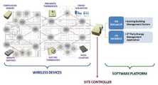
최근 에너지 하베스팅 기술이 수십-수백 mW 수준의 비교적 저전력을 요구하는 무선 센서 네트워크 (WSN: Wireless Sensor Network)용 센서 노드에 적용이 가능해지면서 기존 센서 노드의 전력을 공급하던 배터리를 대체하기 위한 기술 개발이 활발히 진행되고 있다. 산업 자동화, 빌딩 자동화, 구조물 진단, 상태 모니터링을 위하여 적은 전력으로 작동이 가능한 무선센서노드의 효율적인 운영을 위해서 에너지 하베스팅 기술의 중요성은 더욱 부각되고 있다.Recently, as energy harvesting technology can be applied to sensor nodes for wireless sensor networks (WSN) that require relatively low power of tens to hundreds of mW, technology development to replace the battery that supplies power to the existing sensor nodes This is actively going on. For the efficient operation of wireless sensor nodes that can operate with low power for industrial automation, building automation, structure diagnosis, and condition monitoring, the importance of energy harvesting technology is becoming more prominent.
산업 자동화를 위한 제어 시스템 분야에서 에너지 하베스팅 기술의 적용은 유럽에서 처음 시작되었지만, 홈오토메이션 (Home automation) 및 관련 제어 기술이 부가되면서 북미 시장으로 전파되었다.The application of energy harvesting technology in the field of control systems for industrial automation was first started in Europe, but spread to the North American market as home automation and related control technology were added.
사물과 사람, 하드웨어와 소프트웨어, 아날로그와 디지털의 융합기술이 고도화되면서 유비쿼터스 환경에서 필수불가결한 각종 센서의 전원 공급과 초저전력형 휴대기기의 효율적 활용을 위한 전원의 확보가 필수적이나 현재의 전원기술은 주로 배터리를 이용하기 때문에 시스템 수명의 한계와 지속적인 전원 공급을 위한 주기적인 배터리 교체/관리로 인한 부가적인 비용 발생 문제가 심각하였다.As the convergence technology of things and people, hardware and software, and analog and digital is advanced, it is essential to supply power to various sensors, which are indispensable in a ubiquitous environment, and to secure power for efficient use of ultra-low-power portable devices. Since the battery is mainly used, the system lifespan is limited and the additional cost caused by periodic battery replacement/management for continuous power supply was serious.
따라서 제어 시스템 관리의 자동화가 요구되거나 배터리 사용이 제한되고 문제시되는 곳에는 무선 센서 네트워크 기술과 에너지 하베스팅 기술의 접목을 통해 문제 해결의 실마리를 찾게 되었다.Therefore, where automation of control system management is required or battery use is limited and problematic, a clue to solving the problem has been found through the grafting of wireless sensor network technology and energy harvesting technology.
나아가 에너지 효율을 개선하기 위한 스마트 그리드, 에너지 하베스팅 전원 관리 솔루션, 저전력 박막 전지 기술의 향상은 에너지 하베스팅 기술의 토털 솔루션을 발전시키는데 크게 기여하였다.Furthermore, the improvement of smart grid, energy harvesting power management solution, and low-power thin film cell technology to improve energy efficiency greatly contributed to the development of total solution of energy harvesting technology.
현재 무선 센서 네트워크 시장은 에너지 하베스팅 기술을 이용한 제품의 신규 시장을 형성하는데 중요한 역할을 하고 있으며, 산불, 홍수와 같은 환경 재난 관리, 빌딩, 교량과 같은 대형 구조물 상태관리, 화물 관리, 홈 네트워크, 수산 생태 환경 관리 등 관련 제품의 상용화를 가속시킬 다양한 응용 분야에서의 기술이 소개되고 있다.Currently, the wireless sensor network market is playing an important role in forming a new market for products using energy harvesting technology. Technologies in various application fields that will accelerate the commercialization of related products such as aquatic ecosystem management are being introduced.
무선센서노드를 구성하는 각 요소별 전력을 소비하는 비율은 노드 설계에 따라 다소 차이가 있지만 대체적으로 감지 대상의 물리적 환경 정보를 감지하는 센서계통 시스템이 약 15% 수준을 차지하며, 감지 신호를 처리/제어하는 회로부인 제어계통 시스템이 약 25% 가까이 소모하며, 나머지 통신계통 시스템이 60% 수준으로 가장 많은 전력을 소비하게 된다.Although the ratio of power consumption for each element constituting a wireless sensor node varies slightly depending on the node design, in general, the sensor system that detects the physical environment information of the detection target accounts for about 15% and processes the detection signal. / The control system, which is the circuit part that controls, consumes about 25%, and the rest of the communication system consumes the most power at the level of 60%.
무선센서노드의 각 구성 요소별 전력 소비에 영향을 미치는 요인으로는 배터리의 경우, 방전율, 배터리 크기, DC/DC 변환 효율 등이 있으며 센서부에서는 신호처리 손실, 신호 상태 등이, 마이크로프로세서에서는 동작 주파수와 전압, 온도 등이 영향을 미치며, 통신부에서는 데이터 속도, 전송량, 사용률 (Duty cycle) 등이 주요 전력 소비원이 될 수 있다 (표 1).Factors affecting the power consumption of each component of the wireless sensor node include the discharge rate, battery size, and DC/DC conversion efficiency in the case of a battery. Frequency, voltage, and temperature have an effect, and in the communication department, data rate, transmission amount, duty cycle, etc. can be major power consumption sources (Table 1).
기존의 무선 센서 네트워크를 구성하는 센서 노드는 대부분 건전지로 동작을 하였으며, 지속적인 모니터링을 위해 오랜 시간 동안 작동해야 하는 센서 네트워크의 특성 때문에 센서 노드의 운용에 가장 큰 제약 요소인 소형 AA 또는 AAA급 건전지로 무선 센서 네트워크의 원활한 작동은 기대하기 어려웠으며, 무엇보다 지속적인 에너지의 공급과 발생된 에너지의 손실을 최소화하기 위한 효율적인 에너지의 활용이 요구되었다.Most of the sensor nodes constituting the existing wireless sensor network were operated with batteries, and due to the characteristics of the sensor network that needs to be operated for a long time for continuous monitoring, small AA or AAA batteries, which are the biggest constraint on the operation of the sensor node, are used. It was difficult to expect a smooth operation of the wireless sensor network, and above all, continuous energy supply and efficient energy utilization were required to minimize the loss of generated energy.
최근 태양광, 열전, 압전, RF 등 다양한 에너지 하베스팅 기술이 급격히 발전하면서 여러 환경 에너지원으로부터 무선 센서 네트워크에 적용하기 위한 전원 공급 기술이 가능하게 되었다.With the rapid development of various energy harvesting technologies such as solar, thermoelectric, piezoelectric, and RF in recent years, power supply technology for application to wireless sensor networks from various environmental energy sources has become possible.
태양광 발전의 경우 단위 면적당 수십 밀리와트의 전력 생산이 가능하여 무선 센서 노드의 전원으로 사용하기 위한 다양한 노력들이 이루어졌지만 날씨의 변화에 민감한 특성 상 지속적이 발전을 하기에는 적합하지 않았으며 실내와 실외에서의 태양광 공급 에너지 밀도의 차이가 심각하여 무선 센서 네트워크 분야에 응용하기에는 다소 제한적이었다.In the case of solar power generation, it is possible to produce tens of milliwatts of power per unit area, so various efforts have been made to use it as a power source for wireless sensor nodes, but it is not suitable for continuous power generation due to its sensitive nature to changes in the weather. The difference in the energy density of solar energy was severe, so it was somewhat limited to be applied to the wireless sensor network field.
하지만 압전, 열전 하베스팅 기술은 기존에 인식되어 왔던 나노ㅇ마이크로 와트 수준의 비교적 낮은 출력 전력 성능을 극복하고 소재, 구조, 회로, 전력관리 등 단기간의 요소 기술의 성장에 따른 출력 성능의 극대화에 대한 많은 응용 연구가 필요한 실정이다.However, piezoelectric and thermoelectric harvesting technologies overcome the relatively low output power performance of nano and micro watt levels that have been recognized in the past, and are focused on maximizing output performance according to the short-term growth of element technologies such as materials, structures, circuits, and power management. Many applied studies are needed.
본 발명은 상기와 같은 문제점을 해결하기 위해 이루어진 것으로서, IC 구조, 회로, 전력관리 기능 등의 요소 기술 개발에 따른 출력 성능이 극대화된 자가 발전 무선 센서를 제공하는 데 목적이 있다.The present invention has been made to solve the above problems, and an object of the present invention is to provide a self-powered wireless sensor that maximizes output performance according to the development of element technologies such as an IC structure, a circuit, and a power management function.
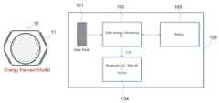
상기 과제를 해결하기 위하여 본 발명은 본체; 태양열을 흡수하여 집열시키는 Solar Panel; 상기 Solar Panel로부터 에너지를 미세하게 수확하여 축적한 후 필요할 때 사용하기 위해 생성된 에너지를 저장하도록 제어하는 Solar energy Harvesting IC;를 포함한다.In order to solve the above problems, the present invention provides a main body; Solar Panel that absorbs and collects solar heat; It includes; Solar energy Harvesting IC that controls to store the energy generated to be used when necessary after harvesting and accumulating energy finely from the Solar Panel.
상기 Solar Panel은, 상기 본체의 외면을 감싼다.The Solar Panel surrounds the outer surface of the main body.
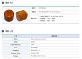
상기 본체는, 단면이 육각형 형상이고, 상기 Solar Panel은, 상기 본체의 육각형 형상의 외면을 감싼다.The main body has a hexagonal cross section, and the Solar Panel surrounds the hexagonal outer surface of the main body.
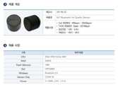
상기 Solar energy Harvesting IC는 블루투스 통신 기능을 갖는 Bluetooth SoC With RF; 및 센서;에 전력을 공급한다.The Solar energy Harvesting IC includes a Bluetooth SoC With RF having a Bluetooth communication function; and the sensor;
본 발명은 배터리를 충전하도록 하고, 배터리의 SOC(State Of Charge)가 목표 충전 레벨에 도달한 후에는 소모전류를 일정하게 분배한다.According to the present invention, the battery is charged, and after the state of charge (SOC) of the battery reaches a target charging level, the consumption current is uniformly distributed.
상기 Solar energy Harvesting IC에 배터리 과열 및 화재 예방을 위한 온도 감지 센서, 결로 발생 예방을 위한 습도 감지 센서, 화재 발생 예방을 위한 감지 센서, 및 물리적 충격으로 인한 기기파손 사전 감지 센서 중 하나가 결합되어 전력을 공급받는다.The solar energy harvesting IC is combined with one of a temperature sensor for battery overheating and fire prevention, a humidity sensor for preventing condensation, a detection sensor for preventing fire, and a pre-detection sensor for device damage due to physical impact. are supplied with
상기 Solar energy Harvesting IC는, 디지털 입력신호(IN)를 인가받아 레벨 시프팅(level shifting) 하여 디지털 출력신호(OUT)를 출력한다.The solar energy harvesting IC receives a digital input signal IN and level-shifts it to output a digital output signal OUT.
상기 Solar energy Harvesting IC는, 빛 에너지를 전기 에너지로 변환하는 복수개의 PV cell; 상기 PV cell에 연결되어 임시 충전 기능을 갖는 Super capacitor; 상기 PV cell에서 출력되는 전기신호를 입력받고 입력받은 전기신호의 레벨을 조절하여 출력하는 Level shifter; 상기 각 구성을 제어하는 Micro controller;와 연결된다.The solar energy harvesting IC, a plurality of PV cells for converting light energy into electrical energy; a super capacitor connected to the PV cell and having a temporary charging function; a level shifter that receives an electrical signal output from the PV cell and adjusts the level of the received electrical signal to output; It is connected with a micro controller that controls each of the components.
상기와 같이 이루어지는 본 발명은배터리 과열 및 화재 예방을 위한 온도 감지 센서, 결로 발생 예방을 위한 습도 감지 센서, 화재 발생 예방을 위한 감지 센서, 물리적 충격으로 인한 기기파손 사전 감지 센서 등의 출력 성능을 극대화할 수 있다.The present invention made as described aboveIt is possible to maximize the output performance of a temperature sensor to prevent overheating of the battery and fire, a humidity sensor to prevent dew condensation, a detection sensor to prevent fire, and a sensor to detect device damage in advance due to physical impact.
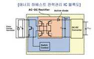
도 1은 종래 발명에 따른 에너지 전력 관리 IC에 대한 개념도이다.
도 2는 본 발명의 일실시예에 따른 자가 발전 무선 센서의 구성을 보여주는 도면이다.
도 3은 본 발명의 일실시예에 따른 자가 발전 무선 센서의 세부적인 구성을 보여주는 도면이다.
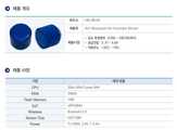
도 4는 본 발명의 다른 실시예에 따른 자가 발전 무선 센서의 실제 제품 구성을 보여주는 도면이다.
도 5는 본 발명의 다른 실시예에 따른 배터리 과열 및 화재 예방을 위한 온도 감지 센서를 보여주는 도면이다.
도 6은 도 5에 도시된 제품의 성능을 보여주는 도면이다.
도 7은 본 발명의 또 다른 실시예에 따른 결로 발생 예방을 위한 습도 감지 센서를 보여주는 도면이다.
도 8은 도 7에 도시된 제품의 성능을 보여주는 도면이다.
도 9는 본 발명의 또 다른 실시예에 따른 화재 발생 예방을 위한 감지 센서를 보여주는 도면이다.
도 10은 도 9에 도시된 제품의 성능을 보여주는 도면이다.
도 11은 본 발명의 또 다른 실시예에 따른 물리적 충격으로 인한 기기파손 사전 감지 센서를 보여주는 도면이다.
도 12는 도 11에 도시된 제품의 성능을 보여주는 도면이다.
도 13은 본 발명의 다른 실시예에 따른 자가 발전 무선 센서를 적용하는 시스템에 대한 개략적인 구성을 보여주는 도면이다.
도 14는 본 발명의 다른 실시예에 따른 자가 발전 무선 센서를 적용하는 시스템에 대한 개략적인 구성을 보여주는 도면이다.
도 15은 본 발명에 따른 클라우드 기반 ESS 통합 안전관리시스템 개념도를 보여주는 도면이다.
도 16은 본 발명의 일실시예에 따른 ESS 화재 예방 시스템의 Ai Edge Controller를 구체적으로 보여주는 도면이다.
도 17는 본 발명의 일 실시예에 따른 BLE 5.0 기반 초소형 무선 센서 모듈들을 보여주는 도면이다.
도 18는 본 발명의 다른 실시예에 따른 배터리 랙/룸의 모니터링 센서 부착 위치를 보여주는 도면이다.
도 19는 본 발명의 일 실시예에 따른 Ai Edge Controller SW Block을 보여주는 도면이다.1 is a conceptual diagram of an energy power management IC according to the related art.
2 is a diagram showing the configuration of a self-powered wireless sensor according to an embodiment of the present invention.
3 is a diagram showing a detailed configuration of a self-powered wireless sensor according to an embodiment of the present invention.
4 is a diagram showing an actual product configuration of a self-powered wireless sensor according to another embodiment of the present invention.
5 is a view showing a temperature sensor for preventing overheating and fire of a battery according to another embodiment of the present invention.
6 is a view showing the performance of the product shown in FIG.
7 is a view showing a humidity sensor for preventing the occurrence of condensation according to another embodiment of the present invention.
8 is a view showing the performance of the product shown in FIG.
9 is a view showing a detection sensor for preventing fire according to another embodiment of the present invention.
10 is a view showing the performance of the product shown in FIG.
11 is a view showing a device damage pre-detection sensor due to a physical impact according to another embodiment of the present invention.
12 is a view showing the performance of the product shown in FIG.
13 is a diagram showing a schematic configuration of a system to which a self-powered wireless sensor according to another embodiment of the present invention is applied.
14 is a diagram showing a schematic configuration of a system to which a self-powered wireless sensor according to another embodiment of the present invention is applied.
15 is a view showing a conceptual diagram of a cloud-based ESS integrated safety management system according to the present invention.
16 is a view specifically showing the Ai Edge Controller of the ESS fire prevention system according to an embodiment of the present invention.
17 is a diagram showing BLE 5.0-based ultra-small wireless sensor modules according to an embodiment of the present invention.
18 is a view showing a monitoring sensor attachment position of a battery rack / room according to another embodiment of the present invention.
19 is a view showing an Ai Edge Controller SW Block according to an embodiment of the present invention.
본 발명을 충분히 이해하기 위해서 본 발명의 바람직한 실시예를 첨부 도면을 참조하여 설명한다. 본 발명의 실시예는 여러 가지 형태로 변형될 수 있으며, 본 발명의 범위가 아래에서 상세히 설명하는 실시예로 한정되는 것으로 해석되어서는 안 된다. 본 실시예는 당업계에서 평균적인 지식을 가진 자에게 본 발명을 보다 완전하게 설명하기 위하여 제공되는 것이다. 따라서 도면에서의 요소의 형상 등은 보다 명확한 설명을 강조하기 위해서 과장되어 표현될 수 있다. 각 도면에서 동일한 부재는 동일한 참조부호로 도시한 경우가 있음을 유의하여야 한다. 또한, 본 발명의 요지를 불필요하게 흐릴 수 있다고 판단되는 공지 기능 및 구성에 대한 상세한 기술은 생략된다.In order to fully understand the present invention, preferred embodiments of the present invention will be described with reference to the accompanying drawings. Embodiments of the present invention may be modified in various forms, and the scope of the present invention should not be construed as being limited to the embodiments described in detail below. This example is provided to more completely explain the present invention to those of ordinary skill in the art. Accordingly, the shape of elements in the drawings may be exaggerated to emphasize a clearer description. It should be noted that in each drawing, the same member is shown with the same reference numerals in some cases. In addition, detailed descriptions of well-known functions and configurations determined to unnecessarily obscure the gist of the present invention will be omitted.
도 2 내지 도 4에 도시된 바와 같이 본 발명은 본체(10); 태양열을 흡수하여 집열시키는 Solar Panel(101); 상기 Solar Panel(101)로부터 에너지를 미세하게 수확하여 축적한 후 필요할 때 사용하기 위해 생성된 에너지를 저장하도록 제어하는 Solar energy Harvesting IC(102);를 포함한다.2 to 4, the present invention is a
상기 Solar Panel(101)로 이루어진 Solar Panel부(11)는, 상기 본체(10)의 외면을 감싼다.The
상기 본체는(10), 단면이 육각형 형상이고, 상기 Solar Panel부(11)는 상기 본체의 육각형 형상의 외면을 감싼다.The
상기 Solar energy Harvesting IC(102)는 블루투스 통신 기능을 갖는 Bluetooth SoC With RF; 및 센서(104);에 전력을 공급한다.The Solar
본 발명은 배터리(103)를 충전하도록 하고, 배터리의 SOC(State Of Charge)가 목표 충전 레벨에 도달한 후에는 소모전류를 일정하게 분배한다.According to the present invention, the
상기 Solar energy Harvesting IC에 배터리 과열 및 화재 예방을 위한 온도 감지 센서, 결로 발생 예방을 위한 습도 감지 센서, 화재 발생 예방을 위한 감지 센서, 및 물리적 충격으로 인한 기기파손 사전 감지 센서 중 하나가 결합되어 전력을 공급받는다.The solar energy harvesting IC is combined with one of a temperature sensor for battery overheating and fire prevention, a humidity sensor for preventing condensation, a detection sensor for preventing fire, and a pre-detection sensor for device damage due to physical impact. are supplied with
상기 Solar energy Harvesting IC는, 디지털 입력신호(IN)를 인가받아 레벨 시프팅(level shifting) 하여 디지털 출력신호(OUT)를 출력한다.The solar energy harvesting IC receives a digital input signal IN and level-shifts it to output a digital output signal OUT.
상기 Solar energy Harvesting IC(102)는, 빛 에너지를 전기 에너지로 변환하는 복수개의 PV cell; 상기 PV cell에 연결되어 임시 충전 기능을 갖는 Super capacitor; 상기 PV cell에서 출력되는 전기신호를 입력받고 입력받은 전기신호의 레벨을 조절하여 출력하는 Level shifter; 상기 각 구성을 제어하는 Micro controller;와 연결된다.The Solar
도 5 내지 도 10에 도시된 바와 같이 본 발명에 따른 자가 발전 무선 센서의 하베스팅 에너지(Harvesting energy)로서 태양광 발전(Photovoltaic)을 사용하고, 복수개의 다양한 광원 소스(Harvesting energy from various light sources: sun, bulbs, natural indoor light, ..)로부터 에너지를 얻는다.As shown in Figs. 5 to 10, using solar power (Photovoltaic) as harvesting energy of the self-powered wireless sensor according to the present invention, a plurality of various light sources (Harvesting energy from various light sources: It gets its energy from the sun, bulbs, natural indoor light, ..).
실시예1Example 1
하베스팅 에너지로 열(Thermal)을 이용하고, 하베스팅 에너지는 복수개의 다양한 열원(Thermal sources: waste heat, human heat, motor, ..)으로부터 에너지를 얻는다.Heat (Thermal) is used as harvesting energy, and harvesting energy obtains energy from a plurality of various heat sources (thermal sources: waste heat, human heat, motor, ..).
예를 들어 본 발명에서 사용되는 TEGs(TEG, thermoelectric generator)는 20ㅅW에서 10mW를 생산할 수 있다.For example, TEGs (TEG, thermoelectric generator) used in the present invention can produce 10 mW at 20 μW.
TEG로부터 얻을 수 있는 하베스팅 에너지는 3ㅅW 에서 550mW 임이 바람직하다.The harvesting energy obtainable from the TEG is preferably 3 μW to 550 mW.
실시예2Example 2
하베스팅 에너지로 진동(Vibration)이 사용되면, 하베스팅 에너지는 복수개의 다양한 진동 소스(vibration sources: motors, railroads, cattle, ..)로부터 얻는다.When vibration is used as harvesting energy, harvesting energy is obtained from a plurality of various vibration sources (vibration sources: motors, railroads, cattle, ..).
상기 진동 소스로 부터 3ㅅW 에서 550mW를 생산할 수 있다.From the vibration source, 3 μW to 550 mW can be produced.
실시예3Example 3
하베스팅 에너지로 알에프 소스(RF)가 이용되며, 하베스팅 에너지는 복수개의 다양한 알에프 소스(RF sources : wi-fi, GSM900, 3G, ..)로부터 얻을 수 있다.An RF source (RF) is used as harvesting energy, and harvesting energy can be obtained from a plurality of various RF sources (RF sources: wi-fi, GSM900, 3G, ..).
상기 알에프 소스로부터 얻을 수 있는 하베스팅 에너지는 -19dBm 에서 10dBm 임이 바람직하다.The harvesting energy obtainable from the RF source is preferably -19dBm to 10dBm.
이하 도 13 내지 도 19를 참고하여 자가 발전 무선 센서를 적용하는 시스템에 대하여 자세히 설명한다.Hereinafter, a system to which a self-powered wireless sensor is applied will be described in detail with reference to FIGS. 13 to 19 .
실시예4 - 클라우드 기반 ESS 통합 안전관리시스템Example 4 - Cloud-based ESS Integrated Safety Management System
도 15에서 (a) 클라우드 기반 ESS 통합 안전관리시스템 개념도를 보면, 본 발명은 ESS 통합 안전관리시스템 요구사항 분석에 따라 이를 반영하여 시스템 아키텍쳐(system Architecture)를 설계하고 보완한다.Referring to (a) a conceptual diagram of a cloud-based ESS integrated safety management system in FIG. 15 , the present invention designs and supplements the system architecture by reflecting the ESS integrated safety management system requirements analysis.
ESS 통합 관리를 위한 다양한 ESS Type 설정 기능 및 데이터 맵(Data Map)을 설계하고, 원거리 다수의 ESS 통합 관리를 위한 장치 개체(디바이스 오브젝트; Device-Object) 구조를 제공한다.It designs various ESS type setting functions and data maps for integrated management of ESS, and provides a device object (Device-Object) structure for integrated management of multiple ESSs from a distance.
또한 ESS Type 지원 통신 인터페이스, 실시간 ESS 통합 관리를 위한 상세 기능 정의 및 클라우드 기반 통합 DB를 구현한다.In addition, it implements ESS Type support communication interface, detailed function definition for real-time ESS integrated management, and cloud-based integrated DB.
도 15의 (b) Safety ESS 통합 안전관리시스템 Data 흐름도를 보면 사용자 WEB을 통해 ESS ID, 이름, Type, Device ID, 이름, Type 등을 포함하는 ESS 정보를 생성하여 EMS 서버에 전달하면 EMS 서버가 각 정보를 저장하고, 디바이스 모드버스 맵(Device Modbus Map)을 설정한다.15 (b) of the Safety ESS integrated safety management system data flow chart, when ESS information including ESS ID, name, Type, Device ID, name, Type, etc. is generated and delivered to the EMS server through the user WEB, the EMS server Each information is saved and the Device Modbus Map is set.
예를 들어 본 발명에서 사용되는 REST(REpresentational State Transfer) API(Application Programming Interface) 방식은 ESS ID, Device ID(1개), Object(N개), isControl 명령을 포함하여 전송하고, MQTT(Message Queuing Telemetry Transport) 방식은 Topic으로 (ACQ)Control/ESS ID/Device ID, Data로 ESS ID, Device ID, Object(N개)를 포함한다.For example, the REST (REpresentational State Transfer) API (Application Programming Interface) method used in the present invention transmits including ESS ID, Device ID (1), Object (N), isControl commands, and MQTT (Message Queuing) Telemetry Transport) method includes (ACQ)Control/ESS ID/Device ID as Topic, ESS ID, Device ID, and Object (N) as Data.
도 16에 도시된 바와 같이 BLE 5.0 통신 게이트웨이 메인보드를 Safety Watchdog System 내장을 위해 소형화 설계하고, 통신 게이트웨이 펌웨어도 추가한다.As shown in Fig. 16, the BLE 5.0 communication gateway main board is designed to be miniaturized to embed the Safety Watchdog System, and communication gateway firmware is also added.
상기 디바이스의 등록, 관리 및 서비스 구현, 정보 보고 기능을 위한 Register, Update, Read, Write, Execute, Discover 등의 기본 동작을 설계한다.Design basic operations such as Register, Update, Read, Write, Execute, and Discover for the device registration, management and service implementation, and information reporting functions.
추가적으로 이기종 설비 및 외부 플랫폼 연동 지원을 위한 다중 통신 인터페이스, 통신 장치 Failure Tolerant 연동 기능, 임베디드 Logging 기능, 데이터 스트림 Transaction 실시간 처리 기능을 갖는다.In addition, it has multiple communication interfaces to support interworking with heterogeneous facilities and external platforms, communication device failure tolerance interworking function, embedded logging function, and data stream transaction real-time processing function.
본 발명은 Edge 다비이스 보안 인증 및 서버 연동 통신 보안 기능 구현을 위한 PKI 알고리즘 보안 칩셋 적용 보드를 더 포함한다.The present invention further includes a PKI algorithm security chipset application board for implementing edge device security authentication and server interworking communication security functions.
또한 본 발명은 화재 발생 인자 센서 데이터 딥러닝 분석을 위한 인공지능 모듈을 적용한다.In addition, the present invention applies an artificial intelligence module for deep learning analysis of fire occurrence factor sensor data.
예를 들어 본 발명은 AI Edge 컨트롤러 임베디드 SW를 제공할 수 있으며 화재 발생 인자를 구분하고 센서 데이터를 전달받아 딥러닝 분석을 심층적으로 할 수 있다.For example, the present invention can provide AI Edge controller embedded SW, classify fire factors and receive sensor data to perform deep learning analysis in depth.
실시예 5 - BLE 5.0 기반 초소형 무선 센서 모듈Example 5 - BLE 5.0 based ultra-small wireless sensor module
도 17에 도시된 바와 같이 본 발명은 BLE 5.0 기반 초소형 무선센서 모듈(5종)을 포함한다.As shown in FIG. 17, the present invention includes a BLE 5.0-based ultra-small wireless sensor module (5 types).
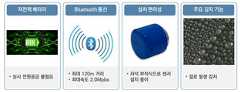
일 실시예로서 본 발명은 화재 발생 유발 인자 사전 감지를 위한 온도, 습도, 연기, 진동, 오프가스 센서부를 포함한다.As an embodiment, the present invention includes a temperature, humidity, smoke, vibration, and off-gas sensor unit for prior detection of a fire triggering factor.
상기 무선센서들은 설치가 용이하고, 화재 발생시 일정시간(5분 이상) 통신 및 센싱 기능 수행이 가능토록 불연소재를 이용한 자석(Neodymium) 부착식 센서 케이스를 포함한다.The wireless sensors are easy to install and include a magnet (Neodymium) attached sensor case using non-combustible materials to enable communication and sensing functions for a certain period of time (more than 5 minutes) in case of a fire.
상기 무선센서들에는 장기간 배터리 교체 주기 확보를 위한 저전력 무선통신방식 적용 BLE 5.0 통신 모듈을 포함한다.The wireless sensors include a low-power wireless communication method applied BLE 5.0 communication module for securing a long-term battery replacement cycle.
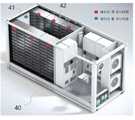
도 18에 도시된 바와 같이 본 발명에 따른 초소형 무선 센서 모듈의 설치 장소는 배터리 룸 모니터링 센서(41), 배터리 랙 모니터링 센서(42) 등으로 구성된다.As shown in FIG. 18 , the installation site of the miniature wireless sensor module according to the present invention consists of a battery
상기 배터리 룸 모니터링 센서(41)는 배터리 룸을 모니터링하기 위해 천정 부분에 부착되어 배터리 룸 내부의 온도, 습도 등을 감지한다.The battery
상기 배터리 랙 모니터링 센서(42)는 배터리 랙을 모니터링하기 위해 배터리 랙 상측부 또는 측면부에 부착되며 배터리 랙의 병렬 배치 숫자에 따라 증가되게 부착된다.The battery
도 19에 도시된 바와 같이 Ai Edge Controller SW Block(50)은 SUPPORT SERVICES부(51), CORE SERVICES부(52), DEVICE SERVICES부(53)로 구성된다.As shown in FIG. 19 , the Ai Edge
다시 SUPPORT SERVICES부(51)는 ML모듈, off-gas supervisory모듈, Vibration supervisory모듈, Temperature Supervisory모듈, Device Auth. & Setting모듈, Database모듈, Rule Engine모듈, VEE모듈, Logging모듈, Alert&Notification모듈, Control모듈, Aggregator모듈, 3rd Party Interface모듈 등으로 나뉘어 진다.Again, the
또한 CORE SERVICES부(52)는 CORE DATA모듈, COMMAND모듈, META DATA모듈, REGISTRY&CONFIG모듈 등으로 나뉘어 진다.In addition, the
DEVICE SERVICES부(53)는 REST모듈, MODBUS모듈, MQTT모듈, ADDITIONAL DEVICES모듈 등으로 나뉘어 진다.The
상기 SUPPRT SERVICES부(51)는 지원서비스로서 1) ML(Machine Learning) - 센서 데이터 상관관계 분석을 통한 ESS 화재 예측 및 감지 알고리즘, 2) off-gas supervisory- off-gas 감지기능 : 열폭주 / 착화 / 전선류 피복 발열 사전 감지, 3) Vibration supervisory - 진동 감지기능 : 물리적 충격 / 지진 감지, 4) Temperature supervisory - 온도 감지기능 : 발열,누전환경 사전감지 / 열폭주 현상 감지, 5) Humidity supervisory - 습도 감지기능 : 누전 / 발화조건 사전감지, 6) smoke supervisory - 연기(Co2, tvoc) 감지기능 : 열 폭주 현상 / 착화 전 가연성 물질 분출 감지, 7) Device Auth & Setting - 장치 권한 및 설정 등록 및 수정 기능, 8) Database - 설비, 장치 등록 정보 경보 설정정보, 9) Rule Engine - SUPPRT SERVICES 기능 명령 및 관리, - 센서데이터를 감시하여 Control, Alert & Notification, - Aggregator, supervisory, Logging 관리, 10) VEE - 센서 데이터 유효성 검증(Validation, Estimation, Editing), 11) Logging - 로그 등록 : 수집데이터, 경보감지, 통신, 에러 데이터 수집, 12) Alert & Notification - 사용자 알림 : 경보에 따른 알람 및 SMS 전송, 13) Control - 경보 Level에 따라 MC(Magnetic Contactor)제어, 14) Aggregator - 데이터 수집 및 변환 기능, 15) Third Party Interface - Third party Application 지원 기능 등을 가지고 있다.The SUPPRT SERVICES unit 51 provides support services as follows: 1) ML (Machine Learning) - ESS fire prediction and detection algorithm through sensor data correlation analysis, 2) off-gas supervisory- off-gas detection function: thermal runaway / ignition / Pre-detection of heating of electrical wire sheathing, 3) Vibration supervisory - Vibration detection function: Physical shock / earthquake detection, 4) Temperature supervisory - Temperature detection function: Pre-detection of heat and leakage environment / Thermal runaway detection, 5) Humidity supervisory - Humidity supervisory Detection function: short circuit / pre-ignition condition detection, 6) smoke supervisory - Smoke (Co2, tvoc) detection function: thermal runaway phenomenon / flammable material ejection detection before ignition, 7) Device Auth & Setting - Device permission and setting registration and modification function , 8) Database - Facility, device registration information, alarm setting information, 9) Rule Engine - SUPPRT SERVICES function command and management, - Control, Alert & Notification by monitoring sensor data, - Aggregator, supervisory, Logging management, 10) VEE - Sensor data validation (Validation, Estimation, Editing), 11) Logging - Log registration: Collected data, alarm detection, communication, error data collection, 12) Alert & Notification - User notification: Alarm and SMS transmission according to the alarm, 13) Control - It has MC (Magnetic Contactor) control according to the alarm level, 14) Aggregator - Data collection and conversion function, 15) Third Party Interface - Third party application support function, etc.
CORE SERVICES부(52)는 핵심 데이터 저장 및 분석을 통한 META DATA 생성 시스템 구성 및 설정하는 장치로서, 1) CORE DATA - 설비 및 환경센서 수집 데이터, 2) COMMAND - ESS Safety Watchdog System 명령, 3) META DATA - CORE DATA 분석 후 생산된 데이터 분석 및 관리 용도, 4) REGISTRY & CONFIG - 시스템 구성 및 설정 정보 등록 기능 등을 가지고 있다.The
DEVICE SERVICES부(53)는 데이터 수집 및 변환 후 EMS Server로 전송, 장치 관리하는 장치로서, 1) REST - 데이터 수집 및 EMS Server 데이터 전송 (HTTP Protocol), 2) MODBUS - 설비 데이터 수집 (PCS, BMS, PowerMeter), 3) MQTT - EMS Server로 전송, 4) ADDITIONAL DEVICES - 장치 추가 (설비 및 환경센서) 기능 등을 가지고 있다.The
구체적으로 살펴보면, Ai Edge Controller(20)는 (1) Safety ESS Watchdog System 자동 운전 스케줄러 기능, (2) Event and alarm logging and management 기능, (3) Con■gure system setpoints(최적화된 설정치) 설정 기능, (4) Real time and historic data visualization 기능, (5) Monitor, Forecast, and Dispatch; generation, demand, and storage 기능, (6) Real-Time Stream Data 분석 기능 등을 포함한다.Specifically, the
일실시예로서 특정 발전소의 설비 통신 상태를 통신 / 통신두절로 표출하고, 상기 발전소에서 발생한 금일 경보 현황들을 표출하며, 금일 발전량 및 충/방전량을 시간별 차트로 표출한다.As an embodiment, the facility communication state of a specific power plant is expressed as communication / communication interruption, the current alarm status generated in the power plant is expressed, and the current generation amount and charge/discharge amount are expressed in an hourly chart.
이 때, 사용자가 복수의 발전소를 모니터링 시 해당 버튼을 통해 다른 발전소로 바로 이동할 수도 있다.In this case, when a user monitors a plurality of power plants, the user may move directly to another power plant through a corresponding button.
일 실시예로서 본 발명의 센서별 화재발생환경 및 화재발생 감지 모드에서 열폭주현상 전 / 착화 전 / 착화 이후 화재확산을 사전감지 및 예측, 긴급조치를 통해 화재 예방 및 피해를 최소화할 수 있다.As an embodiment of the present invention, fire prevention and damage can be minimized through pre-detection and prediction of fire spread before thermal runaway/pre-ignition/after ignition in the fire occurrence environment and fire detection mode for each sensor of the present invention, and emergency measures.
예를 들어 온도센서는 발열, 누전환경 사전감지 / 열폭주 현상 감지 기능이 있고, 진동센서는 물리적 충격 / 지진 감지 기능이 있으며, 습도센서는 누전 / 발화조건 사전감지 기능이 있고, Off가스센서는 열 폭주 현상 / 착화 전 가연성 물질 분출 감지 기능이 있으며, 연기센서는 열폭주/ 착화 / 전선류 피복 발열 사전 감지 기능이 있다.For example, the temperature sensor has a function to detect heat and electric leakage environment in advance / thermal runaway phenomenon, the vibration sensor has a physical shock / earthquake detection function, the humidity sensor has a function to detect electric leakage / ignition condition in advance, and the off gas sensor has a function There is a function to detect thermal runaway/inflammable material ejection before ignition, and the smoke sensor has a function to detect thermal runaway/ignition/heating of electrical wires in advance.
10 : 본체
11 : Solar Panel부
20 : Ai Edge Controller
22 : VEE 기능부
25 : 알람 통지 및 제어부
27 : 고속 Edge Rules Engine Service부
40 : 모니터링 센서
41 : 배터리 룸 모니터링 센서
42 : 배터리 랙 모니터링 센서
50 : Ai Edge Controller SW Block
51 : SUPPORT SERVICES부
52 : CORE SERVICES부
53 : DEVICE SERVICES부
101 : Solar Panel
102 : Solar energy Harvesting IC
103 : 배터리
104 : Bluetooth SoC With RF 및 센서10: body
11: Solar Panel part
20 : Ai Edge Controller
22: with VEE function
25: alarm notification and control
27: High-speed Edge Rules Engine Service part
40: monitoring sensor
41 : battery room monitoring sensor
42: battery rack monitoring sensor
50: Ai Edge Controller SW Block
51: SUPPORT SERVICES
52: CORE SERVICES part
53: DEVICE SERVICES part
101: Solar Panel
102: Solar energy Harvesting IC
103: battery
104 : Bluetooth SoC With RF and Sensor
Claims (8)
Translated fromKorean상기 본체 외면에 부착되어 태양열을 흡수하여 집열시키는 Solar Panel을 포함하는 Solar Panel부;
상기 Solar Panel로부터 에너지를 미세하게 수확하여 축적한 후 필요할 때 사용하기 위해 생성된 에너지를 저장하도록 제어하는 Solar energy Harvesting IC;
상기 Solar energy Harvesting IC의 제어를 받아 상기 Solar Panel로부터 생성된 에너지를 저장하는 배터리;를 포함하는 자가 발전 무선 센서.main body;
A Solar Panel unit including a Solar Panel attached to the outer surface of the main body to absorb and collect solar heat;
Solar energy Harvesting IC that controls to store the energy generated to be used when necessary after harvesting and accumulating energy from the Solar Panel finely;
Self-generated wireless sensor comprising a; battery for storing energy generated from the Solar Panel under the control of the Solar energy Harvesting IC.
상기 Solar Panel부는,
상기 본체의 외면을 감싸는 것을 특징으로 하는 자가 발전 무선 센서.According to claim 1,
The Solar Panel unit,
Self-powered wireless sensor, characterized in that surrounding the outer surface of the body.
상기 본체는,
단면이 육각형 형상이고,
상기 Solar Panel부는,
상기 본체의 육각형 형상의 외면을 감싸는 것을 특징으로 하는 자가 발전 무선 센서.3. The method of claim 1 or 2,
The body is
The cross section is hexagonal,
The Solar Panel unit,
Self-powered wireless sensor, characterized in that it wraps around the outer surface of the hexagonal shape of the body.
상기 Solar energy Harvesting IC는 블루투스 통신 기능을 갖는 Bluetooth SoC With RF; 및 센서;에 전력을 공급하는 것을 특징으로 하는 자가 발전 무선 센서.According to claim 1,
The Solar energy Harvesting IC includes a Bluetooth SoC With RF having a Bluetooth communication function; and a sensor; a self-powered wireless sensor for supplying power to the sensor.
상기 Solar energy Harvesting IC는 상기 배터리의 SOC(State Of Charge)가 목표 충전 레벨에 도달한 후에는 소모전류를 일정하게 외부 분배하는 것을 특징으로 하는 자가 발전 무선 센서.According to claim 1,
The Solar Energy Harvesting IC is a self-powered wireless sensor, characterized in that it constantly distributes the consumption current to the outside after the SOC (State Of Charge) of the battery reaches a target charge level.
상기 Solar energy Harvesting IC에 배터리 과열 및 화재 예방을 위한 온도 감지 센서, 결로 발생 예방을 위한 습도 감지 센서, 화재 발생 예방을 위한 감지 센서, 및 물리적 충격으로 인한 기기파손 사전 감지 센서 중 하나가 결합되어 전력을 공급받는 것을 특징으로 하는 자가 발전 무선 센서.According to claim 1,
The solar energy harvesting IC is combined with one of a temperature sensor for battery overheating and fire prevention, a humidity sensor for preventing condensation, a detection sensor for preventing fire, and a pre-detection sensor for device damage due to physical impact. Self-generation wireless sensor, characterized in that it is supplied.
상기 Solar energy Harvesting IC는,
상기 Solar Panel부의 복수개의 전압 상태에 따른 디지털 입력신호(IN)를 인가받아 레벨 시프팅(level shifting)하여 복수개의 디지털 출력신호(OUT)를 출력하는 것을 특징으로 하는 자가 발전 무선 센서.3. The method of claim 2,
The Solar energy Harvesting IC is,
A self-powered wireless sensor, characterized in that it receives a digital input signal (IN) according to a plurality of voltage states of the Solar Panel unit and outputs a plurality of digital output signals (OUT) by level shifting.
상기 Solar energy Harvesting IC는,
빛 에너지를 전기 에너지로 변환하는 복수개의 PV cell;
상기 PV cell에 연결되어 임시 충전 기능을 갖는 Super capacitor;
상기 PV cell에서 출력되는 전기신호를 입력받고 입력받은 전기신호의 레벨을 조절하여 출력하는 Level shifter;
상기 각 구성을 제어하는 Micro controller;와 연결되는 것을 특징으로 하는 자가 발전 무선 센서.According to claim 1,
The Solar energy Harvesting IC is,
a plurality of PV cells that convert light energy into electrical energy;
a super capacitor connected to the PV cell and having a temporary charging function;
a level shifter that receives an electrical signal output from the PV cell and adjusts the level of the received electrical signal to output;
Self-generated wireless sensor, characterized in that connected to; Micro controller for controlling each of the components.
Priority Applications (1)
| Application Number | Priority Date | Filing Date | Title |
|---|---|---|---|
| KR1020200161899AKR20220073944A (en) | 2020-11-27 | 2020-11-27 | Self-Powered Wireless Sensor |
Applications Claiming Priority (1)
| Application Number | Priority Date | Filing Date | Title |
|---|---|---|---|
| KR1020200161899AKR20220073944A (en) | 2020-11-27 | 2020-11-27 | Self-Powered Wireless Sensor |
Publications (1)
| Publication Number | Publication Date |
|---|---|
| KR20220073944Atrue KR20220073944A (en) | 2022-06-03 |
Family
ID=81983595
Family Applications (1)
| Application Number | Title | Priority Date | Filing Date |
|---|---|---|---|
| KR1020200161899ACeasedKR20220073944A (en) | 2020-11-27 | 2020-11-27 | Self-Powered Wireless Sensor |
Country Status (1)
| Country | Link |
|---|---|
| KR (1) | KR20220073944A (en) |
Cited By (1)
| Publication number | Priority date | Publication date | Assignee | Title |
|---|---|---|---|---|
| CN115790829A (en)* | 2022-11-30 | 2023-03-14 | 中铁二院工程集团有限责任公司 | Double-energy-supply type sensor for monitoring passive protective net |
Citations (3)
| Publication number | Priority date | Publication date | Assignee | Title |
|---|---|---|---|---|
| KR101039133B1 (en) | 2010-08-30 | 2011-06-07 | 중앙대학교 산학협력단 | Gas and fire information display system based on wireless sensor network |
| KR102045489B1 (en) | 2019-05-09 | 2019-11-18 | 풍성에너지 (주) | Device for prevention of fires in energy storage system, and method thereof |
| KR102045871B1 (en) | 2019-06-07 | 2019-11-18 | 주식회사 창성에이스산업 | System For Detecting Fire Based on Artificial Intelligence And Method For Detecting Fire Based on Artificial Intelligence |
- 2020
- 2020-11-27KRKR1020200161899Apatent/KR20220073944A/ennot_activeCeased
Patent Citations (3)
| Publication number | Priority date | Publication date | Assignee | Title |
|---|---|---|---|---|
| KR101039133B1 (en) | 2010-08-30 | 2011-06-07 | 중앙대학교 산학협력단 | Gas and fire information display system based on wireless sensor network |
| KR102045489B1 (en) | 2019-05-09 | 2019-11-18 | 풍성에너지 (주) | Device for prevention of fires in energy storage system, and method thereof |
| KR102045871B1 (en) | 2019-06-07 | 2019-11-18 | 주식회사 창성에이스산업 | System For Detecting Fire Based on Artificial Intelligence And Method For Detecting Fire Based on Artificial Intelligence |
Cited By (1)
| Publication number | Priority date | Publication date | Assignee | Title |
|---|---|---|---|---|
| CN115790829A (en)* | 2022-11-30 | 2023-03-14 | 中铁二院工程集团有限责任公司 | Double-energy-supply type sensor for monitoring passive protective net |
Similar Documents
| Publication | Publication Date | Title |
|---|---|---|
| Adu-Manu et al. | Energy-harvesting wireless sensor networks (EH-WSNs) A review | |
| Akan et al. | Internet of hybrid energy harvesting things | |
| Nishimoto et al. | Prototype implementation of ambient RF energy harvesting wireless sensor networks | |
| JP5174105B2 (en) | Power distribution system and power distribution control method | |
| JP5816545B2 (en) | Wireless sensor system | |
| KR20130067678A (en) | Micro-grid simulation apparatus and power management system | |
| CN103634572B (en) | A kind of intelligent transmission line patrol communication system based on video surveillance | |
| Tan et al. | Mine fire detection system based on wireless sensor network | |
| CN211790906U (en) | High-power off-grid energy management system | |
| Weddell et al. | Energy harvesting for smart city applications | |
| KR20220073944A (en) | Self-Powered Wireless Sensor | |
| JP5057287B2 (en) | Communication system, center device and terminal device used in the communication system | |
| Krejcar et al. | Optimized solar energy power supply for remote wireless sensors based on IEEE 802.15. 4 standard | |
| KR20160049446A (en) | Apparatus and Method for Selective Delivery of Distributed Energy Resources Information from Multiple Slave Devices in Smart Grid Environment | |
| CN107290999A (en) | A kind of substation equipment monitoring system based on Internet of Things | |
| CN107482619A (en) | It is a kind of that the system and method being scheduled and for electricity consumption are reported based on power | |
| KR101008202B1 (en) | Photovoltaic device monitoring system and monitoring method including transformer | |
| Abdul-Qawy | Energy-Harvesting for IoT-based wireless nodes: A progress study | |
| Li et al. | Supply and demand oriented energy management in the internet of things | |
| Stolojescu-Crisan et al. | A home energy management system | |
| Chethan et al. | Sustainable forest management techniques | |
| Alsharif et al. | Green IoT: A Review and Future Research Directions. Symmetry 2023, 15, 757 | |
| Bdiri et al. | Wireless sensor nodes using energy harvesting and B-Mac protocol | |
| KR20150074526A (en) | Weather intelligence measurement and gathering method and system | |
| Popa et al. | A classification of solutions for the energy limitation in wireless sensor networks |
Legal Events
| Date | Code | Title | Description |
|---|---|---|---|
| PA0109 | Patent application | Patent event code:PA01091R01D Comment text:Patent Application Patent event date:20201127 | |
| PA0201 | Request for examination | ||
| PG1501 | Laying open of application | ||
| E902 | Notification of reason for refusal | ||
| PE0902 | Notice of grounds for rejection | Comment text:Notification of reason for refusal Patent event date:20220930 Patent event code:PE09021S01D | |
| E90F | Notification of reason for final refusal | ||
| PE0902 | Notice of grounds for rejection | Comment text:Final Notice of Reason for Refusal Patent event date:20230322 Patent event code:PE09021S02D | |
| E601 | Decision to refuse application | ||
| E801 | Decision on dismissal of amendment | ||
| PE0601 | Decision on rejection of patent | Patent event date:20230927 Comment text:Decision to Refuse Application Patent event code:PE06012S01D Patent event date:20230322 Comment text:Final Notice of Reason for Refusal Patent event code:PE06011S02I Patent event date:20220930 Comment text:Notification of reason for refusal Patent event code:PE06011S01I | |
| PE0801 | Dismissal of amendment | Patent event code:PE08012E01D Comment text:Decision on Dismissal of Amendment Patent event date:20230927 Patent event code:PE08011R01I Comment text:Amendment to Specification, etc. Patent event date:20230515 Patent event code:PE08011R01I Comment text:Amendment to Specification, etc. Patent event date:20221111 Patent event code:PE08011R01I Comment text:Amendment to Specification, etc. Patent event date:20221018 |