KR20220073311A - Exercise machine - Google Patents
Exercise machineDownload PDFInfo
- Publication number
- KR20220073311A KR20220073311AKR1020200161259AKR20200161259AKR20220073311AKR 20220073311 AKR20220073311 AKR 20220073311AKR 1020200161259 AKR1020200161259 AKR 1020200161259AKR 20200161259 AKR20200161259 AKR 20200161259AKR 20220073311 AKR20220073311 AKR 20220073311A
- Authority
- KR
- South Korea
- Prior art keywords
- fixing
- handle
- bar
- block
- fixed
- Prior art date
- Legal status (The legal status is an assumption and is not a legal conclusion. Google has not performed a legal analysis and makes no representation as to the accuracy of the status listed.)
- Pending
Links
Images


Classifications
- A—HUMAN NECESSITIES
- A63—SPORTS; GAMES; AMUSEMENTS
- A63B—APPARATUS FOR PHYSICAL TRAINING, GYMNASTICS, SWIMMING, CLIMBING, OR FENCING; BALL GAMES; TRAINING EQUIPMENT
- A63B21/00—Exercising apparatus for developing or strengthening the muscles or joints of the body by working against a counterforce, with or without measuring devices
- A63B21/16—Supports for anchoring force-resisters
- A63B21/169—Supports for anchoring force-resisters for anchoring on or against a wall
- A—HUMAN NECESSITIES
- A63—SPORTS; GAMES; AMUSEMENTS
- A63B—APPARATUS FOR PHYSICAL TRAINING, GYMNASTICS, SWIMMING, CLIMBING, OR FENCING; BALL GAMES; TRAINING EQUIPMENT
- A63B21/00—Exercising apparatus for developing or strengthening the muscles or joints of the body by working against a counterforce, with or without measuring devices
- A63B21/16—Supports for anchoring force-resisters
- A—HUMAN NECESSITIES
- A63—SPORTS; GAMES; AMUSEMENTS
- A63B—APPARATUS FOR PHYSICAL TRAINING, GYMNASTICS, SWIMMING, CLIMBING, OR FENCING; BALL GAMES; TRAINING EQUIPMENT
- A63B2210/00—Space saving
- A63B2210/50—Size reducing arrangements for stowing or transport
- A—HUMAN NECESSITIES
- A63—SPORTS; GAMES; AMUSEMENTS
- A63B—APPARATUS FOR PHYSICAL TRAINING, GYMNASTICS, SWIMMING, CLIMBING, OR FENCING; BALL GAMES; TRAINING EQUIPMENT
- A63B2225/00—Miscellaneous features of sport apparatus, devices or equipment
- A63B2225/05—Miscellaneous features of sport apparatus, devices or equipment with suction cups
- A63B2225/055—Miscellaneous features of sport apparatus, devices or equipment with suction cups used for fixing
- A—HUMAN NECESSITIES
- A63—SPORTS; GAMES; AMUSEMENTS
- A63B—APPARATUS FOR PHYSICAL TRAINING, GYMNASTICS, SWIMMING, CLIMBING, OR FENCING; BALL GAMES; TRAINING EQUIPMENT
- A63B2225/00—Miscellaneous features of sport apparatus, devices or equipment
- A63B2225/09—Adjustable dimensions
Landscapes
- Health & Medical Sciences (AREA)
- Life Sciences & Earth Sciences (AREA)
- Biophysics (AREA)
- Orthopedic Medicine & Surgery (AREA)
- General Health & Medical Sciences (AREA)
- Physical Education & Sports Medicine (AREA)
- Rehabilitation Tools (AREA)
Abstract
Translated fromKoreanDescription
Translated fromKorean본 발명은 운동기구에 관한 것으로, 더욱 상세하게는 일부가 회전하면서 형태가 가변될 수 있는 운동기구에 관한 것이다.The present invention relates to an exercise device, and more particularly, to an exercise device whose shape can be changed while a part is rotated.
일반적으로, 근력운동을 위해 사용되는 기구는 정해진 단위의 무게를 가진 중량추와 연결된 레버를 밀거나 당기면서 근육의 이완 및 수축을 반복하도록 되어 있다. 이러한 근력 운동을 위한 기구 중에는, 이두근 운동을 위한 암컬(ARM CURL)기구, 대흉근 등 가슴운동을 위한 체스트 프레스(CHEST PRESS) 또는 버터플라이(BUTTERFLY)기구, 등 근육의 운동을 위한 풀업(PULL UP)기구 다양한 운동기구가 존재한다.In general, a device used for strength exercise is designed to repeat muscle relaxation and contraction while pushing or pulling a lever connected to a weight having a predetermined unit weight. Among the devices for strength training, ARM CURL device for biceps exercise, chest press or butterfly device for chest exercise such as pectoralis major, and pull-up for back muscle exercise Equipment There are various types of exercise equipment.
특히, 최근에는 사용자들이 휘트니스 센터를 방문하지 않고 가정에서 운동할 수 있도록 하는 홈 트레이닝 기구들이 널리 사용되고 있다. 그런데, 앞서 예시한 근력 운동을 위한 기구들은 부피가 매우 커서 설치공간을 많이 필요로 하기 때문에 홈 트레이닝 기구로 활용되기 어려운 문제가 있다.In particular, recently, home training devices that allow users to exercise at home without visiting a fitness center have been widely used. However, there is a problem in that it is difficult to be used as a home training device because the previously exemplified devices for strength training have a very large volume and require a lot of installation space.
이를 해결하기 위해서, 운동기구의 일부를 접거나 회전시켜 사용하지 않을 때는 운동기구의 부피를 줄이는 기술들이 개발되고 있다. 예를 들어, 미국 공개특허 US2020/0047027(선행특허1)과, US2019/0262652(선행특허2)에는 운동기구의 일부를 회전시켜 사용하지 않을 때는 접을 수 있는 구조가 공개되어 있다.In order to solve this, technologies for reducing the volume of the exercise equipment when not in use by folding or rotating a part of the exercise equipment are being developed. For example, US Patent Publication US2020/0047027 (Prior Patent 1) and US2019/0262652 (Prior Patent 2) disclose a structure that can be folded when not in use by rotating a part of the exercise device.
그러나, 운동기구의 일부가 회전가능하게 구성되는 경우에는, 운동중에 강한 하중이 회전부위에 가해질 경우에 운동기구가 파손될 수 있고, 또한 운동기구의 일부가 고정된 상태로부터 해제되어 사용자가 다칠 우려가 있다.However, if a part of the exercise equipment is configured to be rotatable, the exercise equipment may be damaged when a strong load is applied to the rotating part during exercise, and there is a risk of injury to the user by releasing a part of the exercise equipment from the fixed state. have.
한편, 가변형태의 운동기구를 사용할 때는 먼저 운동기구 전체를 견고하게 고정한 후에, 부피를 줄이기 위해 회전구조를 적용한 부분, 예를 들어 핸들 부분이 회전되지 않도록 고정할 필요가 있다. 따라서 운동기구를 고정하기 위한 절차가 복잡하고 불편한 단점이 있다.On the other hand, when using a variable type exercise equipment, it is necessary to first fix the entire exercise equipment firmly and then fix the portion to which the rotation structure is applied to reduce the volume, for example, the handle portion so that it does not rotate. Therefore, there is a disadvantage that the procedure for fixing the exercise equipment is complicated and inconvenient.
본 발명은 상기한 바와 같은 종래기술의 문제점을 해결하기 위한 것으로, 본 발명의 목적은 운동기구의 일부를 회전가능하게 하되, 운동시에는 고정된 상태가 견고하게 유지될 수 있게 하는 것이다.The present invention is to solve the problems of the prior art as described above, and an object of the present invention is to make a part of the exercise device rotatable, and to be able to maintain a fixed state firmly during exercise.
본 발명의 다른 목적은 운동기구의 사이드프레임 전체를 고정하는 작업과, 사이드프레임에 연결된 핸들장치를 고정하는 작업이 하나의 동작으로 동시에 이루어질 수 있도록 하는 것이다.Another object of the present invention is to enable the operation of fixing the entire side frame of the exercise device and the operation of fixing the handle device connected to the side frame to be simultaneously performed in one operation.
본 발명의 또 다른 목적은 사이드프레임을 고정하기 위한 제1고정모듈과 제2고정모듈이 서로 반대방향으로 동작하여, 사이드프레임의 안쪽에 고정위치가 형성되도록 하는 것이다.Another object of the present invention is to operate the first fixing module and the second fixing module for fixing the side frame in opposite directions to form a fixing position inside the side frame.
상기한 바와 같은 목적을 달성하기 위한 본 발명의 특징에 따르면, 본 발명은 사이드프레임이 메인프레임에 수납되거나 인출되도록 구비되고, 인출된 상태에서 상기 메인프레임에 대해 회전가능하다. 그리고, 상기 사이드프레임에는 핸들설치바가 회전가능하게 구비될 수 있다. 상기 사이드프레임에는 프레임고정장치가 설치되어 상기 사이드프레임의 회전을 방지할 수 있고, 상기 핸들설치바에는 핸들고정장치가 설치되어 상기 핸들설치바의 회전을 방지해줄 수 있다. 이때, 상기 핸들고정장치는 상기 프레임고정장치에 연동 연동하여 상기 사이드프레임의 상부 및 하부에 각각 고정될 수 있다. 이처럼 상기 사이드프레임과 상기 핸들설치바는 각각 프레임고정장치와 핸들고정장치에 의해 견고하게 고정된 상태를 유지할 수 있다. 특히, 사용자가 하나의 조작만 하면 사이드프레임과 핸들설치바를 모두 고정할 수 있다.According to a feature of the present invention for achieving the above object, the present invention is provided such that the side frame is accommodated in or withdrawn from the main frame, and is rotatable with respect to the main frame in the drawn out state. In addition, a handle installation bar may be rotatably provided on the side frame. A frame fixing device may be installed on the side frame to prevent rotation of the side frame, and a handle fixing device may be installed on the handle installation bar to prevent rotation of the handle installation bar. In this case, the handle fixing device may be fixed to the upper and lower portions of the side frame by interlocking with the frame fixing device, respectively. In this way, the side frame and the handle installation bar can be maintained firmly fixed by the frame fixing device and the handle fixing device, respectively. In particular, both the side frame and the handle installation bar can be fixed if the user only operates one.
그리고, 상기 핸들고정장치에는 제1고정모듈과 제2고정모듈이 구비될 수 있다. 이때 상기 제1고정모듈과 상기 제2고정모듈은 서로 반대방향으로 이동하여 상기 사이드프레임의 하부와 상부에 각각 고정될 수 있다. 따라서, 상기 제1고정모듈과 제2고정모듈은 각각 핸들설치바의 하단과 상단을 사이드프레임에 고정해줄 수 있다.In addition, the handle fixing device may include a first fixing module and a second fixing module. In this case, the first fixing module and the second fixing module may move in opposite directions to be fixed to a lower portion and an upper portion of the side frame, respectively. Accordingly, the first fixing module and the second fixing module may each fix the lower end and the upper end of the handle installation bar to the side frame.
또한, 상기 핸들고정장치에는 상기 안착레그에 연동하는 연동바가 포함될 수 있다. 상기 연동바는 상기 핸들설치바의 내부에서 승강될 수 있고, 상기 연동바의 양단에는 각각 상기 제1고정모듈과 상기 제2고정모듈이 구비될 수 있다. 이렇게 되면, 상기 연동바는 외부로 노출되지 않고, 내부공간에서 승강될 수 있다.In addition, the handle fixing device may include an interlocking bar interlocking with the seating leg. The interlocking bar may be lifted from the inside of the handle installation bar, and the first fixing module and the second fixing module may be provided at both ends of the interlocking bar, respectively. In this way, the interlocking bar is not exposed to the outside, and can be raised and lowered in the inner space.
그리고, 상기 핸들고정장치는 제1고정모듈과 제2고정모듈을 포함하고, 제1고정모듈과 제2고정모듈은 연동바에 의해 서로 연결되어 함께 동작될 수 있다. 여기서 상기 제1고정모듈은 상기 안착레그에 연동하여 승강되고, 하강하면 적어도 일부가 상기 사이드프레임의 제1고정서포트에 걸려 고정될 수 있다. 상기 제2고정모듈은 상기 핸들설치바를 따라 승강되고, 상승하면 적어도 일부가 상기 사이드프레임의 제2고정서포트에 걸려 고정될 수 있다. 따라서, 상기 제1고정모듈과 제2고정모듈은 서로 연동하되, 반대방향으로 동작되어 각각 사이드프레임의 안쪽에 고정될 수 있다.In addition, the handle fixing device includes a first fixing module and a second fixing module, and the first fixing module and the second fixing module are connected to each other by an interlocking bar to operate together. Here, the first fixing module may be raised and lowered by interlocking with the seating leg, and at least a portion thereof may be fixedly caught by the first fixing support of the side frame when descending. The second fixing module may be raised and lowered along the handle installation bar, and when it rises, at least a portion may be fixed by being caught by the second fixing support of the side frame. Accordingly, the first fixing module and the second fixing module are interlocked with each other, but may be operated in opposite directions to be fixed to the inside of the side frame, respectively.
상기 안착레그에는 상기 제1고정모듈의 승강실린더와 간섭되어 상기 승강실린더를 승강시키는 연동턱이 돌출될 수 있다. 특히, 상기 안착레그에는 클램프가 결합되고, 상기 클램프에는 상기 승강실린더의 표면을 향해 상기 연동턱이 돌출될 수 있다. 따라서, 상기 프레임고정장치와 상기 핸들고정장치는 자연스럽게 서로 연동할 수 있다.Interlocking jaws for elevating the elevating cylinder by interference with the elevating cylinder of the first fixing module may protrude from the seating leg. In particular, a clamp may be coupled to the seating leg, and the interlocking jaw may protrude toward the surface of the elevating cylinder to the clamp. Accordingly, the frame fixing device and the handle fixing device can naturally interwork with each other.
그리고, 상기 프레임고정장치는 상기 사이드프레임에 고정되는 브라켓과, 상기 브라켓과 변환링크를 통해 회전가능하게 연결되는 고정레버를 포함할 수 있다. 상기 안착레그는 상기 변환링크에 의해 상기 고정레버와 연동하여 승강되고, 상기 제1고정모듈의 승강실린더를 걸어 승강시킬 수 있다.In addition, the frame fixing device may include a bracket fixed to the side frame, and a fixing lever rotatably connected to the bracket through a conversion link. The seating leg may be raised and lowered by interlocking with the fixed lever by the conversion link, and may be raised and lowered by hanging the elevating cylinder of the first fixed module.
또한, 상기 제1고정모듈은 상기 핸들설치바를 둘러싸고, 상기 연동턱에 간섭되는 연동리브가 구비되는 승강실린더를 포함할 수 있다. 상기 승강실린더에는 제1고정블록이 결합되어 상기 승강실린더와 함께 승강될 수 있다. 상기 제1고정블록은 상기 연동바의 일단과 결합되며, 상기 승강실린더와 함께 하강하면 상기 제1고정서포트의 제1고정홈에 끼워질 수 있다.In addition, the first fixing module may include a lifting cylinder that surrounds the handle installation bar and is provided with an interlocking rib that interferes with the interlocking jaw. A first fixing block is coupled to the elevating cylinder to be elevated together with the elevating cylinder. The first fixing block is coupled to one end of the interlocking bar, and when it descends together with the elevating cylinder, it may be fitted into the first fixing groove of the first fixing support.
그리고, 상기 제1고정서포트에는 상기 핸들설치바의 회전경로를 따라 다수개의 상기 제1고정홈이 형성될 수 있다. 상기 제1고정블록은 회전을 통해 다수개의 상기 제1고정홈 중 어느 하나의 고정홈에 끼워져 상기 핸들설치바의 회전을 방지할 수 있다. 따라서 상기 핸들설치바는 다양한 각도로 고정될 수 있다.In addition, a plurality of first fixing grooves may be formed in the first fixing support along a rotation path of the handle installation bar. The first fixing block may be inserted into any one of the plurality of first fixing grooves through rotation to prevent rotation of the handle installation bar. Accordingly, the handle installation bar may be fixed at various angles.
또한, 상기 핸들설치바에는 상기 핸들설치바가 세워지는 방향을 따라 개구부가 개방될 수 있다. 상기 제1고정모듈의 상기 제1고정블록과 상기 제2고정모듈의 제2고정블록은 각각 상기 개구부에 끼워져 상기 제1고정모듈 및 상기 제2고정모듈은 상기 핸들설치바와 함께 회전될 수 있다. 따라서, 별도의 체결구 없이도 상기 제1고정모듈 및 상기 제2고정모듈은 상기 핸들설치바와 함께 회전될 수 있다.In addition, an opening may be opened in the handle installation bar along a direction in which the handle installation bar is erected. The first fixing block of the first fixing module and the second fixing block of the second fixing module are fitted in the opening, respectively, so that the first fixing module and the second fixing module can be rotated together with the handle installation bar. Accordingly, the first fixing module and the second fixing module may be rotated together with the handle installation bar without a separate fastener.
그리고, 상기 승강실린더 또는 상기 제1고정블록에는 보조블록이 결합될 수 있다. 상기 보조블록은 다수개의 상기 제1고정홈 중에서 상기 승강실린더가 끼워지는 제1고정홈과 이웃한 다른 제1고정홈에 끼워질 수 있다. 따라서 상기 제1고정모듈 및 이에 연결된 부품에 가해지는 외력을 분산시킬 수 있고, 이를 통해 운동기구의 내구성을 더욱 높일 수 있다.In addition, an auxiliary block may be coupled to the elevating cylinder or the first fixed block. The auxiliary block may be fitted into another first fixing groove adjacent to the first fixing groove into which the elevating cylinder is fitted among the plurality of first fixing grooves. Therefore, it is possible to disperse the external force applied to the first fixing module and the parts connected thereto, thereby further increasing the durability of the exercise equipment.
또한, 상기 제2고정모듈은 상기 핸들설치바의 내부에 승강가능하도록 설치되고, 상기 연동바의 타단과 결합되는 가이드블록을 포함할 수 있다. 제2고정블록은 상기 핸들설치바를 따라 승강하면서 상기 제2고정서포트에 걸릴 수 있다. 이때, 상기 핸들설치바에 고정된 회전축을 중심으로 회전되는 링크부가 구비될 수 있다. 상기 링크부는 그 양단부가 각각 상기 가이드블록 및 상기 제2고정블록에 연결되어 상기 가이드블록와 상기 제2고정블록을 서로 반대방향으로 동작시킬 수 있다.In addition, the second fixing module may include a guide block that is installed so as to be liftable inside the handle installation bar and is coupled to the other end of the interlocking bar. The second fixed block may be caught by the second fixed support while ascending and descending along the handle installation bar. In this case, a link portion rotating about a rotation shaft fixed to the handle installation bar may be provided. Both ends of the link unit may be respectively connected to the guide block and the second fixing block to operate the guide block and the second fixing block in opposite directions.
그리고, 상기 가이드블록에는 상기 연동바의 타단에 결합되는 가이드몸체가 포함될 수 있다. 상기 가이드몸체에는 상기 링크부가 회전가능하게 연결되며, 상기 핸들설치바의 내부공간에 수납될 수 있다. 지지암은 상기 가이드몸체에서 상기 가이드블록의 승강방향을 따라 돌출될 수 있고, 상기 지지암은 상기 제2고정서포트의 중심홀에 접할 수 있다. 따라서, 상기 가이드블록은 상기 제2고정모듈의 승강방향이 일정하게 되도록 안내할 수 있고, 상기 지지암은 상기 제2고정모듈의 회전경로가 일정하게 이루어지도록 안내할 수 있다.In addition, the guide block may include a guide body coupled to the other end of the interlocking bar. The link portion is rotatably connected to the guide body, and may be accommodated in an inner space of the handle installation bar. The support arm may protrude from the guide body in the elevating direction of the guide block, and the support arm may be in contact with the center hole of the second fixed support. Accordingly, the guide block may guide the elevating direction of the second fixing module to be constant, and the support arm may guide the rotation path of the second fixing module to be constant.
또한, 상기 제2고정서포트에는 상기 개구부와 연결되는 제2고정홈이 형성되고, 상기 제2고정블록은 상기 제2고정홈에 끼워져 상기 핸들설치바의 회전을 방지할 수 있다. 이때, 상기 제2고정홈은 상기 핸들설치바의 회전방향을 기준으로 좌우 양쪽 중 어느 한 쪽으로 개방되어, 상기 제2고정블록의 회전방향을 제한할 수도 있다.In addition, a second fixing groove connected to the opening may be formed in the second fixing support, and the second fixing block may be fitted into the second fixing groove to prevent rotation of the handle installation bar. In this case, the second fixing groove may be opened to either one of the left and right sides based on the rotation direction of the handle installation bar, thereby limiting the rotation direction of the second fixing block.
그리고, 상기 제2고정서포트에는 상기 제1고정서포트 방향으로 플랜지가 돌출될 수 있다. 상기 플랜지의 중심에 형성된 중심홀의 내면에는 상기 가이드블록의 일부가 밀착되며, 상기 플랜지의 외주면에는 상기 핸들설치바의 내주면이 밀착될 수 있다.A flange may protrude from the second fixed support in the direction of the first fixed support. A portion of the guide block may be in close contact with an inner surface of the central hole formed at the center of the flange, and an inner circumferential surface of the handle installation bar may be in close contact with an outer circumferential surface of the flange.
위에서 살핀 바와 같은 본 발명에 의한 운동기구에는 다음과 같은 효과가 있다.The exercise device according to the present invention as salvaged above has the following effects.
본 발명의 운동기구를 구성하는 사이드프레임과 사이드프레임에 설치된 핸들설치바는 각각 독립적으로 회전될 수 있어, 사용자에게 다양한 운동각도를 제공해줄 수 있다. 이때, 사이드프레임과 핸들설치바는 각각 프레임고정장치와 핸들고정장치에 의해 견고하게 고정된 상태를 유지할 수 있으므로, 운동기구의 안정성이 향상되는 효과가 있다.The side frame constituting the exercise device of the present invention and the handle installation bar installed on the side frame can each be rotated independently, thereby providing various angles of movement to the user. At this time, since the side frame and the handle installation bar can maintain a firmly fixed state by the frame fixing device and the handle fixing device, respectively, there is an effect of improving the stability of the exercise equipment.
그리고, 사용자가 프레임고정장치를 조작하면 핸들고정장치가 이에 연동되어 함께 동작할 수 있다. 따라서 사용자가 하나의 조작만 하면 사이드프레임과 핸들설치바를 모두 고정할 수 있어서 사용편의성이 향상되는 효과가 있다.And, when the user manipulates the frame fixing device, the handle fixing device is linked thereto to operate together. Therefore, the user can fix both the side frame and the handle installation bar with only one operation, thereby improving the convenience of use.
또한, 핸들고정장치를 구성하는 제1고정모듈과 제2고정모듈은 각각 핸들설치바의 하단과 상단을 사이드프레임에 고정해줄 수 있다. 핸들설치바의 하단과 상단이 모두 고정되면 핸들설치바에 보다 큰 외력(토크)이 가해지더라도 핸들설치바가 흔들리거나 회전되지 않고, 고정된 상태를 안정적으로 유지할 수 있다.In addition, the first fixing module and the second fixing module constituting the handle fixing device may fix the lower end and the upper end of the handle installation bar to the side frame, respectively. When both the lower and upper ends of the handle installation bar are fixed, even if a greater external force (torque) is applied to the handle installation bar, the handle installation bar does not shake or rotate, and the fixed state can be stably maintained.
그리고, 핸들고정장치를 구성하는 제1고정모듈과 제2고정모듈은 서로 연동하되, 반대방향으로 동작되어 각각 사이드프레임의 안쪽에 고정된다. 즉, 핸들고정장치의 고정위치가 사이드프레임의 안쪽에 형성되는 것이다. 이에 따라 핸들고정장치는 사이드프레임에서 연결된 부품이 아니라, 사이드프레임에 직접 걸려 고정될 수 있어 보다 안정적인 고정이 가능하다.In addition, the first fixing module and the second fixing module constituting the handle fixing device interlock with each other, but operate in opposite directions and are respectively fixed to the inside of the side frame. That is, the fixing position of the handle fixing device is formed inside the side frame. Accordingly, the handle fixing device is not a part connected to the side frame, but can be directly hooked and fixed to the side frame, enabling more stable fixing.
특히, 핸들고정장치의 고정위치가 사이드프레임의 안쪽에 형성되면, 핸들고정장치를 잠그기 위한 부품이 사이드프레임의 바깥쪽으로 돌출되지 않을 수 있고, 따라서 운동기구의 미감이 향상되는 효과도 있다.In particular, if the fixing position of the handle fixing device is formed on the inside of the side frame, the parts for locking the handle fixing device may not protrude out of the side frame, and thus the aesthetics of the exercise device is improved.
또한, 제1고정모듈과 제2고정모듈은 핸들설치바의 양 끝단을 각각 고정해줄 수 있고, 핸들장치의 설치 높이에 관계없이 핸들설치바의 전체높이구간에 걸쳐 고른 고정력을 제공해 줄 수 있다. 따라서 핸들설치바의 어느 한쪽에 과도한 토크가 걸리는 것이 방지되고, 운동기구의 내구성이 향상되는 효과가 있다.In addition, the first fixing module and the second fixing module may fix both ends of the handle installation bar, respectively, and provide an even fixing force over the entire height section of the handle installation bar regardless of the installation height of the handle device. Accordingly, excessive torque is prevented from being applied to either side of the handle installation bar, and the durability of the exercise equipment is improved.
그리고, 본 발명에서 제1고정모듈에는 제1고정블록과 보조블록이 서로 다른 방향으로 돌출되고, 제1고정블록과 보조블록은 각각 사이드프레임에 고정될 수 있다. 따라서 제1고정모듈 및 이에 연결된 부품에 가해지는 외력을 분산시킬 수 있고, 이를 통해 운동기구의 내구성을 더욱 높일 수 있다.In addition, in the present invention, the first fixed block and the auxiliary block protrude in different directions from the first fixed module, and the first fixed block and the auxiliary block may be fixed to the side frame, respectively. Therefore, it is possible to disperse the external force applied to the first fixing module and the parts connected thereto, thereby further increasing the durability of the exercise equipment.
또한, 본 발명에서 제2고정모듈에는 가이드블록이 구비되고, 가이드블록은 핸들설치바의 내부공간에 수납된 상태로 승강될 수 있다. 가이드블록은 그 표면이 내부공간에 밀착된 상태로 승강되므로, 제2고정모듈도 가이드블록에 안내되어 뒤틀림 없이 일정한 방향으로 승강될 수 있다. 따라서 핸들설치바의 잠금동작이 안정적으로 이루어질 수 있다.In addition, in the present invention, the second fixing module is provided with a guide block, and the guide block can be lifted up and down while being accommodated in the inner space of the handle installation bar. Since the guide block is raised and lowered with its surface in close contact with the inner space, the second fixing module can also be guided to the guide block and lifted in a certain direction without distortion. Therefore, the locking operation of the handle installation bar can be performed stably.
도 1은 본 발명에 의한 운동기구의 일실시례를 보인 사시도.
도 2는 도 1의 실시례를 구성하는 사이드프레임이 전방으로 인출된 상태를 보인 사시도.
도 3은 본 발명의 일실시례를 구성하는 프레임고정장치 및 제1고정모듈의 구조를 보인 사시도.
도 4는 본 발명의 일실시례를 구성하는 프레임고정장치 및 제1고정모듈의 구조를 보인 단면도.
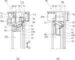
도 5(a) 및 도 5(b)는 본 발명에 의한 프레임고정장치의 풀림상태 및 잠김상태를 각각 보인 측면도.
도 6은 본 발명의 일실시례를 구성하는 제1고정모듈의 구조를 보인 사시도.
도 7은 본 발명의 일실시례를 구성하는 제1고정모듈의 구조를 보인 단면도.
도 8은 본 발명의 일실시례를 구성하는 제2고정모듈의 구조를 보인 사시도.
도 9(a) 및 도 9(b)는 본 발명에 의한 제2고정모듈의 풀림상태 및 잠김상태를 각각 보인 측면도.
도 10은 핸들설치바를 생략하고, 본 발명의 일실시례를 구성하는 제2고정모듈의 구조를 보인 측면도.
도 11은 핸들설치바를 생략하고, 본 발명의 일실시례를 구성하는 제2고정모듈의 구조를 보인 정면도.
도 12는 본 발명에 의한 운동기구의 일실시례를 구성하는 사이드프레임과 핸들설치바를 고정하는 과정을 순차적으로 보인 동작순서도.1 is a perspective view showing an embodiment of an exercise device according to the present invention.
Figure 2 is a perspective view showing a state in which the side frame constituting the embodiment of Figure 1 is drawn forward.
Figure 3 is a perspective view showing the structure of the frame fixing device and the first fixing module constituting an embodiment of the present invention.
Figure 4 is a cross-sectional view showing the structure of the frame fixing device and the first fixing module constituting an embodiment of the present invention.
5 (a) and 5 (b) are side views respectively showing the unlocked state and the locked state of the frame fixing device according to the present invention.
Figure 6 is a perspective view showing the structure of the first fixing module constituting an embodiment of the present invention.
7 is a cross-sectional view showing the structure of the first fixing module constituting an embodiment of the present invention.
8 is a perspective view showing the structure of a second fixing module constituting an embodiment of the present invention.
9 (a) and 9 (b) are side views respectively showing the unlocked state and the locked state of the second fixing module according to the present invention.
Figure 10 is a side view showing the structure of the second fixing module constituting an embodiment of the present invention, omitting the handle installation bar.
11 is a front view showing the structure of the second fixing module constituting an embodiment of the present invention, omitting the handle installation bar.
12 is an operation flowchart sequentially showing the process of fixing the side frame and the handle installation bar constituting an embodiment of the exercise device according to the present invention.
이하, 본 발명의 일부 실시례들을 예시적인 도면을 통해 상세하게 설명한다. 각 도면의 구성요소들에 참조부호를 부가함에 있어서, 동일한 구성요소들에 대해서는 비록 다른 도면상에 표시되더라도 가능한 한 동일한 부호를 가지도록 하고 있음에 유의해야 한다. 또한, 본 발명의 실시례를 설명함에 있어, 관련된 공지구성 또는 기능에 대한 구체적인 설명이 본 발명의 실시례에 대한 이해를 방해한다고 판단되는 경우에는 그 상세한 설명은 생략한다.Hereinafter, some embodiments of the present invention will be described in detail with reference to exemplary drawings. In adding reference numerals to the components of each drawing, it should be noted that the same components are given the same reference numerals as much as possible even though they are indicated on different drawings. In addition, in describing the embodiment of the present invention, if it is determined that a detailed description of a related known configuration or function interferes with the understanding of the embodiment of the present invention, the detailed description thereof will be omitted.
또한, 본 발명의 실시례의 구성 요소를 설명하는 데 있어서, 제 1, 제 2, A, B, (a), (b) 등의 용어를 사용할 수 있다. 이러한 용어는 그 구성 요소를 다른 구성 요소와 구별하기 위한 것일 뿐, 그 용어에 의해 해당 구성 요소의 본질이나 차례 또는 순서 등이 한정되지 않는다. 어떤 구성 요소가 다른 구성요소에 "연결", "결합" 또는 "접속"된다고 기재된 경우, 그 구성 요소는 그 다른 구성요소에 직접적으로 연결되거나 접속될 수 있지만, 각 구성 요소 사이에 또 다른 구성 요소가 "연결", "결합" 또는 "접속"될 수도 있다고 이해되어야 할 것이다.In addition, in describing the components of the embodiment of the present invention, terms such as first, second, A, B, (a), (b), etc. may be used. These terms are only for distinguishing the elements from other elements, and the essence, order, or order of the elements are not limited by the terms. When it is described that a component is "connected", "coupled" or "connected" to another component, the component may be directly connected or connected to the other component, but another component is between each component. It will be understood that may also be "connected", "coupled" or "connected".
본 발명은 운동기구에 관한 것으로, 본 발명은 다수의 부품이 가변될 수 있는 형태의 운동기구에 관한 것이다. 여기서 가변이란, 일부 부품이 회전되거나 슬라이딩 동작되면서 운동기구의 전체 형태가 변하는 것을 의미할 수 있다. 이러한 가변구조를 통해서 사용자는 운동기구를 접어서 보관할 수 있고, 다양한 각도, 길이 또는 높이에서 운동기구를 사용할 수도 있다.The present invention relates to an exercise device, and the present invention relates to a type of exercise device in which a plurality of parts can be varied. Here, variable may mean that the overall shape of the exercise device is changed while some parts are rotated or slidably operated. Through this variable structure, the user can fold and store the exercise equipment, and can use the exercise equipment at various angles, lengths or heights.
이와 같이, 본 발명의 운동기구는 가변구조이므로, 어떠한 형태에서도 운동기구가 견고하게 고정될 필요가 있다. 이하에서는 운동기구의 고정구조를 중심으로 하여 본 발명의 구조를 설명하기로 한다.As described above, since the exercise device of the present invention has a variable structure, it is necessary to firmly fix the exercise device in any shape. Hereinafter, the structure of the present invention will be described with a focus on the fixing structure of the exercise device.
도 1과 도 2에는 본 발명에 의한 운동기구의 일실시례가 도시되어 있다. 도 1에는 운동기구를 구성하는 사이드프레임(30A,30B)이 메인프레임(10)에 수납된 상태가 도시되어 있고, 도 2에는 사이드프레임(30A,30B)이 메인프레임(10)에서 인출된 상태가 도시되어 있다.1 and 2 show an embodiment of an exercise device according to the present invention. 1 shows a state in which the side frames 30A and 30B constituting the exercise equipment are accommodated in the
상기 메인프레임(10)은 설치장소에 고정된 것이고, 상기 사이드프레임(30A,30B)은 상기 메인프레임(10)에서 직선이동하여 인출될 수 있다. 또한, 상기 사이드프레임(30A,30B)은 상기 메인프레임(10)에서 인출된 상태에서 회전할 수도 있다. 따라서 사용자가 운동기구를 사용할 때에는 (i) 상기 사이드프레임(30A,30B)은 상기 메인프레임(10)에 수납되는 방향으로 직선이동하지 않도록 고정되어야 하고, 또한 (ii) 상기 사이드프레임(30A,30B)이 상기 메인프레임(10)에 대해 회전하지 않도록 고정되어야 한다. 상기 사이드프레임(30A,30B)의 회전동작은 아래에서 설명될 프레임고정장치(50)가 잠글 수 있다.The
참고로, 이하에서 '잠김'은 사이드프레임(30A,30B) 또는 핸들설치바(32)가 회전하지 않도록 고정된 것을 의미하고, '풀림'은 사이드프레임(30A,30B) 또는 핸들설치바(32)가 회전할 수 있는 상태가 되는 것을 의미한다.For reference, 'locked' means that the side frames 30A, 30B or the
상기 메인프레임(10)은 벽체(W)에 고정될 수 있다. 도 1에는 벽체(W)의 모서리 부분에 메인프레임(10)이 설치된 모습을 볼 수 있다. 상기 메인프레임(10)의 상부 및 하부에는 각각 상부플레이트(11)와 하부플레이트(13)가 배치될 수 있다. 상기 상부플레이트(11)와 상기 하부플레이트(13)는 판상구조이고, 그 사이에는 전면플레이트(12)가 구비될 수 있다.The
여기서, 상기 전면플레이트(12)는 사용자가 마주보게 되는 부분으로, 거울로 구성되거나 상기 전면플레이트(12)에 디스플레이(17)가 설치될 수도 있다. 본 실시례에서 상기 전면플레이트(12)의 상부에는 디스플레이(17)가 구비되어 사용자에게 다양한 화면을 제공할 수 있다.Here, the
본 실시례에서 상기 메인프레임(10)은 내부에 설치공간을 갖는 다각기둥 형상일 수 있다. 예를 들어 도 1과 도 2에 도시된 바와 같이, 상기 메인프레임(10)은 직각 이등변 삼각형 형태의 단면을 갖는 삼각 기둥 형상일 수 있다. 상기 메인프레임(10)은 직각 이등변 삼각형에서 직각을 이루는 부분이 후방에 위치하도록 배치될 수 있다. 실내 공간에 운동기구를 배치할 때, 설치장소의 모서리 부분에 상기 메인프레임(10)의 후면이 위치하도록 배치하면, 공간의 활용도를 높일 수 있다.In this embodiment, the
상기 메인프레임(10)의 설치공간에는 다양한 부품을 내장할 수 있다. 따라서 상기 메인프레임(10)프레임을 운동기구의 본체부로 볼 수도 있다. 상기 설치공간에는 무거운 부품이 내장되어, 상기 메인프레임(10)은 운동기구가 전도(顚倒)하지 않도록 무게중심 역할을 수행할 수도 있다. 예를 들어 상기 메인프레임(10)의 내부에는 운동 부하를 발생시키는 구동부(미도시)를 포함할 수 있다. 구동부는 예를 들어 모터, 감속기 및 구동부의 운동부하를 전달하기 위한 풀리 등과 같은 부품을 포함할 수 있다. 모터, 감속기 및 풀리는 주로 금속으로 형성되어 비교적 중량이 있는 부품이므로 상기 메인프레임(10)의 내부에 배치하여 무게중심 역할을 하도록 할 수 있다.Various parts may be embedded in the installation space of the
상기 메인프레임(10)의 하부에는 고정풋(14)이 구비될 수 있다. 상기 고정풋(14)은 상기 하부플레이트(13)에서 아래쪽, 즉 설치면을 향해 돌출될 수 있다. 따라서 상기 고정풋(14)이 상기 운동기구를 지지해줄 수 있다. 상기 고정풋(14)은 레벨러로 구성되어, 상기 고정풋(14)이 상기 설치면으로 돌출되는 높이를 조절할 수도 있다.A fixed
상기 메인프레임(10)에는 사이드프레임(30A,30B)이 설치될 수 있다. 상기 사이드프레임(30A,30B)은 상기 메인프레임(10)에서 인출되거나 수납될 수 있다. 상기 사이드프레임(30A,30B)이 상기 메인프레임(10)에 수납되면 운동기구의 전체 부피가 줄어들어, 운동기구를 사용하지 않을 때 운동기구가 차지하는 부피를 줄일 수 있다. 반대로, 상기 사이드프레임(30A,30B)이 상기 메인프레임(10)으로부터 인출되면 사이드프레임(30A,30B)에 결합된 핸들장치(33)가 돌출되는 길이가 길어져 사용자는 보다 다양한 운동기능을 활용할 수 있다.Side frames 30A and 30B may be installed on the
본 실시례에서 상기 사이드프레임(30A,30B)은 한 쌍으로 구성될 수 있다. 즉, 상기 사이드프레임(30A,30B)은 제1사이드프레임(30A)과 제2사이드프레임(30B)으로 구성될 수 있다. 구분을 위해서 도면을 기준으로, 좌측의 사이드프레임(30A,30B)을 제1사이드프레임(30A)으로 칭하고 우측의 사이드프레임(30A,30B)을 제2사이드프레임(30B)으로 칭하기로 한다.In this embodiment, the side frames 30A and 30B may be configured as a pair. That is, the side frames 30A and 30B may include a
상기 제1사이드프레임(30A) 및 제2사이드프레임(30B)은 메인프레임(10)에서 수납되거나 인출되도록 배치될 수 있다. 상기 제1사이드프레임(30A)과 상기 제2사이드프레임(30B)은 메인프레임(10)를 중심으로 양측에 대칭되도록 배치될 수 있다. 이와 같이 상기 제1사이드프레임(30A)과 상기 제2사이드프레임(30B)은 실질적으로 동일한 구성에 해당하므로, 이하에서는 제1사이드프레임(30A)을 중심으로 설명하기로 한다.The
상기 제1사이드프레임(30A)은 상기 메인프레임(10)의 좌측면을 따라 슬라이드 이동하며 수납되거나 돌출될 수 있다. 예를 들어 도 1과 같이 메인프레임(10)의 설치공간에 제1사이드프레임(30A)은 수납되어 있을 수 있다. 반대로 도 2와 같이 상기 메인프레임(10) 정면의 좌측에서 대각선 방향으로 상기 제1사이드프레임(30A)이 돌출될 수 있다. 도시되지는 않았으나, 상기 메인프레임(10)의 내부에 설치된 LM가이드를 따라 상기 제1사이드프레임(30A)이 슬라이딩될 수 있다.The
본 실시례에서, 상기 제1사이드프레임(30A)과 상기 제2사이드프레임(30B)은 메인프레임(10)에서 돌출된 후 상기 메인프레임(10)의 상하방향을 회전축으로 하여 회전할 수 있다. 예를 들어 도 2에 도시된 바와 같이 상기 메인프레임(10)로부터 돌출된 제1사이드프레임(30A)과 제2사이드프레임(30B)은 서로 가까워지도록 회전할 수 있다. 그리고 상기 제1사이드프레임(30A)이 제2사이드프레임(30B)과 가까워지도록 회전함으로써, 사용자는 자신의 신체 구조에 맞추어 제1사이드프레임(30A)의 핸들장치(33)와 상기 제2사이드프레임(30B)의 핸들장치(33)가 서로 가까워지도록 할 수 있다.In this embodiment, the
상기 제1사이드프레임(30A)의 구조를 보면, 상기 제1사이드프레임(30A)의 상부에는 상부바디(31a)가 배치되고, 하부에는 하부바디(31b)가 배치될 수 있다. 상기 상부바디(31a)와 하부바디(31b)는 서로 높이를 달리하여 나란하게 돌출될 수 있다. 이때 상기 상부바디(31a)는 사용자가 풀업(Pull Up)과 같은 운동을 할 수 있는 풀업바의 일부가 될 수도 있다.Looking at the structure of the
상기 상부바디(31a)와 상기 하부바디(31b)의 사이는 연결되어 상기 제1사이드프레임(30A)은 대략 사각형상이 될 수 있다. 여기서 상기 상부바디(31a)와 상기 하부바디(31b)의 앞단 사이는 아래에서 설명될 핸들설치바(32)로 연결될 수 있고, 후단 사이는 상기 제1사이드프레임(30A)의 회전축이 되는 축부(미도시)에 의해 연결될 수 있다. 그리고, 상기 상부바디(31a)와 상기 하부바디(31b)의 사이에는 거울 등이 설치되는 설치플레이트(35, 도 3참조) 등이 설치될 수도 있다.The
도시되지는 않았으나, 본 발명의 일 실시예에는 잠금장치가 구비되어, 상기 제1사이드프레임(30A)이 다시 상기 메인프레임(10)의 안쪽으로 슬라이드 이동하는 것을 방지할 수 있다. 예를 들어 상기 잠금장치는 상기 제1사이드프레임(30A)에 상하방향으로 슬라이드 이동하는 걸쇠로 구성되어 상기 제1사이드프레임(30A)의 슬라이드 이동을 방지할 수 있다. 이와 달리, 상기 잠금장치가 생략되고, 아래에서 설명될 프레임고정장치(50)가 상기 제1사이드프레임(30A)의 회전 뿐 아니라 슬라이딩 이동까지 제한 할 수도 있다.Although not shown, a locking device is provided in one embodiment of the present invention to prevent the
상기 제1사이드프레임(30A)과 상기 제2사이드프레임(30B)에는 각각 핸들장치(33)가 설치될 수 있다. 상기 핸들장치(33)는 사용자가 운동을 할 때 사용자를 향해 돌출되는 부분이 될 수 있다. 상기 핸들장치(33)는 상기 핸들장치(33)를 상기 제1사이드프레임(30A)에 고정하기 위한 고정수단(33a)과, 상기 고정수단(33a)에 의해 상기 제1사이드프레임(30A)에 고정되는 핸들바(33b)로 구성될 수 있다.A
상기 고정수단(33a)은 상기 핸들바(33b)가 상기 제1사이드프레임(30A)에 고정되도록 함과 동시에, 상기 핸들바(33b)의 높이를 조절하는 역할을 할 수 있다. 예를 들어 상기 고정수단(33a)과 상기 제1사이드프레임(30A)을 연속으로 통과한 조절핀(미도시)을 분리한 후에 상기 고정수단(33a)의 높이를 조절하고 상기 조절핀을 꼽아 상기 고정수단(33a) 및 핸들바(33b)의 높이를 조절할 수도 있다. 이러한 높이조절을 위한 고정수단(33a)의 형태는 다양한 변형이 가능하다.The fixing means 33a may serve to fix the
상기 핸들바(33b)의 내부에는 와이어(미도시)가 내장되고, 와이어의 한쪽 끝 부분에는 파지부(미도시)가 연결될 수 있다. 사용자가 상기 파지부를 당기면, 상기 파지부에 연결된 와이어가 상기 핸들바(33b)의 내부로부터 외부로 연장되고, 사용자가 파지부를 당기는 힘을 제거하면 상기 파지부와 와이어는 다시 상기 핸들바(33b)의 끝 부분으로 돌아갈 수 있다.A wire (not shown) may be embedded in the
이러한 와이어의 복귀는 상기 메인프레임(10)에 설치된 부하공급부에 의해 이루어질 수 있다. 상기 부하공급부는 모터 및 감속기 등으로 구성되고, 상기 와이어가 원위치, 즉 상기 핸들바(33b)의 안쪽으로 삽입되는 방향으로 상기 와이어에 부하를 공급해줄 수 있다.The return of the wire may be made by a load supply unit installed in the
그리고, 상기 와이어는 상기 메인프레임(10), 상기 제1사이드프레임(30A) 및 상기 핸들바(33b) 내부를 연속적으로 통과하되, 한쪽 끝은 파지부에 연결되고 반대쪽 끝은 상기 부하공급부에 감길 수 있다. 이때, 상기 메인프레임(10), 상기 제1사이드프레임(30A) 및 상기 핸들바(33b) 내부에는 다수개의 풀리(미도시)가 배치되어 와이어가 안정적으로 풀리거나 감길 수 있도록 할 수 있다. 이와 달리, 상기 와이어의 전부 또는 일부는 운동기구의 바깥쪽으로 노출되게 설치될 수도 있다.Then, the wire continuously passes through the
상기 제1사이드프레임(30A)의 하부에는 프레임고정장치(50)가 설치될 수 있다. 상기 프레임고정장치(50)는 상기 제1사이드프레임(30A)이 회전하지 않도록 상기 제1사이드프레임(30A)를 잠김상태로 만들거나, 반대로 회전할 수 있는 풀림상태로 만들 수 있다. 상기 프레임고정장치(50)는 상기 제1사이드프레임(30A)의 하부에 설치되는데, 도 2에서 보듯이 상기 제1사이드프레임(30A)의 가장 돌출된 전단의 하부에 구비될 수 있다.A
도 3과 도 4에는 상기 프레임고정장치(50)의 구조가 잘 도시되어 있다. 여기서 도 3은 도 2의 A부분을 확대하여 도시한 것이다. 이에 보듯이, 상기 프레임고정장치(50)는 고정레버(53)의 회전에 연동된 안착레그(55)가 직선이동하면서 설치면(지면)에 밀착되는 구조를 가질 수 있다. 상기 안착레그(55)가 설치면에 밀착되면, 상기 제1사이드프레임(30A)과 설치면 사이의 이격된 공간이 없어지고, 상기 제1사이드프레임(30A)은 설치면에 강하게 고정될 수 있다. 상기 제1사이드프레임(30A)이 상기 프레임고정장치(50)에 의해 설치면에 고정되면, 상기 제1사이드프레임(30A)은 회전되지 못하는 잠김상태가 될 수 있다.3 and 4 show the structure of the
여기서, 상기 고정레버(53)는 회전운동을 하고, 상기 안착레그(55)는 상기 고정레버(53)에 연동하여 상하방향으로 직선이동할 수 있다. 상기 고정레버(53)와 안착레그(55) 사이에는 회전운동을 직선운동으로 변환시켜주는 변환링크(52,54)가 있다.Here, the fixing
상기 프레임고정장치(50)의 구조를 자세히 보면, 상기 프레임고정장치(50)에는 브라켓(51)이 구비될 수 있다. 상기 브라켓(51)은 상기 하부바디(31b)에서 절곡된 형상의 설치부(31c)에 고정될 수 있다. 상기 설치부(31c)는 안착레그(55)가 승강되는 상하방향으로 구비되고, 그 표면에 상기 브라켓(51)이 고정될 수 있는 것이다. 상기 브라켓(51)은 평판구조이고, 상기 설치부(31c)에 고정되어 움직이지 않는 부분이다.Looking at the structure of the
상기 브라켓(51)에는 고정레버(53)가 연결될 수 있다. 상기 고정레버(53)는 사용자가 파지하고 회전시키는 부분으로, 도 4를 기준으로 반시계방향(화살표①방향)으로 회전하면 상기 제1사이드프레임(30A)을 잠김 상태로 만들 수 있고, 시계방향(화살표①'방향)으로 회전하면 상기 제1사이드프레임(30A)을 풀림 상태로 만들 수 있다. 도 3과 도 4에는 모두 상기 고정레버(53)가 잠김 방향으로 회전되어 있는 상태가 도시되어 있다.A fixing
참고로, 도면부호 31d는 스토핑부로, 상기 고정레버(53)가 풀림방향으로 회전할 때 최대회전각을 제한하는 부분이 될 수 있다. 즉, 상기 고정레버(53)가 상기 스토핑부(31d)에 닿으면 더 이상 풀림방향(도 4의 화살표 ①' 방향)으로 회전될 수 없게 된다.For reference,
상기 고정레버(53)와 상기 브라켓(51)의 사이에는 변환링크(52,54)가 구비될 수 있다. 상기 변환링크(52,54)는 상기 고정레버(53)의 회전운동을 안착레그(55)의 직선운동으로 바꾸어주는 것이다. 이를 위해서 상기 변환링크(52,54)에는 상기 브라켓(51)과 고정레버(53) 뿐 아니라, 상기 안착레그(55)도 연결될 수 있다.Conversion links 52 and 54 may be provided between the fixing
상기 변환링크(52,54)는 제1링크(52)와 제2링크(54)를 포함할 수 있다. 상기 제1링크(52)는 상기 브라켓(51)에 제1축(H1)으로 회전가능하게 고정되고, 또한 상기 제1링크(52)에는 상기 고정레버(53)가 고정형태로 조립될 수 있다. 상기 고정레버(53)는 체결구(53a)로 고정될 수 있다. 따라서 상기 고정레버(53)를 회전시키면 상기 제1링크(52)가 함께 회전하게 된다. 도 3에서 보듯이, 상기 제1링크(52)는 한 쌍으로 구성되고, 한 쌍의 제1링크(52) 사이에 상기 제2링크(54)가 배치될 수 있다.The conversion links 52 and 54 may include a
상기 제1링크(52)에는 상기 제2링크(54)가 연결될 수 있다. 상기 제2링크(54)는 상기 제1링크(52)에 회전가능하게 연결되는데, 도 4에서 보듯이 상기 제2링크(54)는 제2축(H2)으로 상기 제1링크(52)에 회전가능하게 조립될 수 있다. 그리고 상기 제2링크(54)에는 안착레그(55)가 제3축(H3)으로 연결되어 상기 제2링크(54)가 회전할 때 승강될 수 있다.The
이때, 상기 제1링크(52)는 고정된 제1축(H1)을 회전축으로 회전되지만, 상기 제2링크(54)의 회전축인 제2축(H2)은 회전되는 몸체인 제1링크(52)에 고정되어 있으므로 상기 제2링크(54)의 회전축은 제1링크(52)의 회전에 따라 함께 움직이는 축이 될 수 있다.At this time, the
상기 안착레그(55)는 상기 고정레버(53)의 회전에 연동하여서 상기 제2링크(54)를 따라 승강될 수 있다. 상기 안착레그(55)가 하강하면 설치면에 안착되어 상기 제1사이드프레임(30A)이 회전되지 않도록 지지할 수 있다. 상기 안착레그(55)의 하단에는 안착풋(55a)이 구비될 수 있다. 상기 안착풋(55a)은 상기 안착레그(55) 보다 큰 폭을 갖는데, 본 실시례에서 상기 안착풋(55a)은 원기둥형이다. 상기 안착풋(55a) 전체 또는 상기 안착풋(55a)의 표면은 고무재질과 같이 마찰력이 높은 재질로 만들어져 상기 안착레그(55) 전체가 미끌어지지 않도록 할 수 있다.The
도 4를 보면, 상기 안착레그(55)에는 클램프(56)가 연결되어 있다. 상기 클램프(56)는 상기 안착레그(55)와 함께 승강되는 부품일 수 있다. 상기 클램프(56)는 상기 안착레그(55)와 결합하여 상기 안착레그(55)와 함께 승강함과 동시에, 승강실린더(60)를 동작시키는 역할을 할 수 있다.Referring to FIG. 4 , a
상기 클램프(56)의 일부는 상기 안착레그(55)를 감싸 고정하고, 나머지 일부는 상기 설치부(31c)의 안쪽에 마련된 승강홈(31b')에 안내될 수 있다. 그리고 상기 승강홈(31b')에 안내되는 클램프(56)의 일부에는 연동턱(56a)이 돌출될 수 있다. 상기 연동턱(56a)은 승강실린더(60)의 연동리브(62a,62b)를 걸어 상기 승강실린더(60)를 위쪽으로 밀어 올리거나, 아래쪽으로 당겨 내릴 수 있다.A part of the
참고로 도 5(a)에는 상기 연동턱(56a)이 상기 연동리브(62a,62b) 중 제1리브(62a)를 걸어 상기 승강실린더(60)를 위쪽으로 밀어 올린 상태가 도시되어 있고, 도 5(b)에는 상기 연동턱(56a)이 상기 연동리브(62a,62b) 중 제2리브(62b)를 걸어 상기 승강실린더(60)를 아래쪽으로 당겨 내린 모습이 도시되어 있다.For reference, Fig. 5 (a) shows a state in which the interlocking
이처럼, 상기 클램프(56)는 연동턱(56a)을 이용해서 상기 승강실린더(60)를 작동시키게 되고, 상기 승강실린더(60)는 승강되면서 아래에서 설명될 연동바(67)를 승강시킬 수 있다. 본 실시례에서 상기 연동턱(56a)은 상기 클램프(56)에 구비되지만, 상기 연동턱(56a)은 상기 안착레그(55)에 구비될 수도 있다. 또한, 상기 클램프(56)는 상기 안착레그(55)의 일부이거나 상기 클램프(56)가 생략되고 안착레그(55)만 존재할 수도 있다.As such, the
다음으로, 상기 프레임고정장치(50)와 연동되는 핸들고정장치를 설명하기로 한다. 상기 핸들고정장치는 상기 핸들설치바(32)를 잠김상태로 만드는 역할을 할 수 있다. 상기 핸들고정장치가 작동하면 상기 핸들설치바(32)는 회전하지 못하고 고정된 상태가 되는 것이다. 본 실시례에서 상기 핸들고정장치는 아래에서 설명될 바와 같이 상기 프레임고정장치(50)와 연동하여 동시에 동작될 수 있다.Next, a handle fixing device interlocked with the
도 2를 보면, 상기 핸들설치바(32)는 상기 제1사이드프레임(30A)과 제2사이드프레임(30B)의 전단에 상하방향으로 세워지고, 상기 핸들설치바(32)에는 앞서 설명한 핸들장치(33)가 설치될 수 있다. 즉, 상기 핸들장치(33)의 고정수단(33a)이 상기 핸들설치바(32)에 결합되는데, 상기 고정수단(33a)이 상기 핸들설치바(32)를 따라 승강되면 상기 핸들장치(33)의 높이가 가변될 수 있다.Referring to FIG. 2 , the
먼저 상기 핸들설치바(32)의 구조를 보면, 상기 핸들설치바(32)는 속이 빈 파이프 형태일 수 있다. 상기 핸들설치바(32)의 내부공간(32a)에는 앞서 설명한 와이어가 수납될 수 있고, 또한 연동바(67)와 아래에서 설명될 가이드블록(80)이 내장될 수 있다. 상기 핸들설치바(32)의 전방 일부는 개구되어 개구부(32b)가 형성될 수 있는데, 상기 개구부(32b)는 상기 핸들설치바(32)의 높이 방향을 따라 연속적으로 형성될 수 있다.First, looking at the structure of the
제1사이드프레임(30A)에 설치된 핸들설치바(32)를 보면, 상기 핸들설치바(32)는 상단 및 하단이 각각 상기 제1사이드프레임(30A)의 상부바디(31a)와 하부바디(31b)에 각각 고정되는데, 회전가능한 상태가 될 수 있다. 따라서 상기 핸들설치바(32)는 세워진 방향, 즉 높이방향으로 형성된 회전축으로 하여 회전될 수 있다. 여기서 높이방향은 도면을 기준으로 보았을 때 상하방향이 될 수 있다.Looking at the
상기 핸들설치바(32)가 회전하면, 상기 핸들설치바(32)에 설치된 상기 핸들장치(33)도 함께 회전하면서 다양한 운동각도를 만들어낼 수 있다. 다만, 상기 핸들장치(33)가 사용자가 원하는 운동각도로 회전된 후에는 잠김 필요가 있는데, 이러한 잠김은 핸들고정장치에 의해 이루어질 수 있다.When the
상기 핸들고정장치의 구조를 보면, 상기 핸들고정장치는 크게 제1고정모듈(K1), 제2고정모듈(K2) 및 연동바(67)를 포함할 수 있다. 상기 제1고정모듈(K1)과 상기 제2고정모듈(K2)은 각각 상기 핸들설치바(32)의 하단과 상단을 고정하는 역할을 할 수 있다. 그리고 상기 연동바(67)는 상기 제1고정모듈(K1)과 상기 제2고정모듈(K2)이 서로 연동해서 함께 동작되도록 할 수 있다.Looking at the structure of the handle fixing device, the handle fixing device may largely include a first fixing module (K1), a second fixing module (K2) and an interlocking bar (67). The first fixing module K1 and the second fixing module K2 may serve to fix the lower end and the upper end of the
본 실시례에서 상기 제1고정모듈(K1)과 상기 제2고정모듈(K2)은 서로 반대방향으로 이동하여 상기 제1사이드프레임(30A)의 상부와 하부에 각각 고정되고, 이를 통해 상기 핸들설치바(32)가 잠김상태가 되도록 할 수 있다. 이에 대한 구체적이 내용은 아래에서 다시 설명하기로 한다.In this embodiment, the first fixing module K1 and the second fixing module K2 move in opposite directions to be fixed to the upper and lower portions of the
도 6 및 도 7에는 제1고정모듈(K1)의 구조가 도시되어 있다. 상기 제1고정모듈(K1)은 상기 연동바(67)의 하단부(67a)에 설치될 수 있다. 그리고 상기 제1고정모듈(K1)의 적어도 일부는 상기 제1사이드프레임(30A)의 하부바디(31b)에 배치된 제1고정서포트(36)에 걸려 고정될 수 있다. 즉, 상기 제1고정모듈(K1)의 일부가 상기 제1고정서포트(36)에 끼워지면 잠김상태가 되고, 제1고정서포트(36)로부터 빠져나오면 풀림상태가 되는 것이다.6 and 7 show the structure of the first fixing module K1. The first fixing module K1 may be installed at the
참고로, 도 6에서는 상기 핸들설치바(32)의 내부공간(32a)에 수납되어 있는 제1고정서포트(36)와 제1고정모듈(K1)의 구조가 잘 보이도록 상기 핸들설치바(32)를 위쪽으로 분리한 모습이 도시되어 있다. 실제로는 상기 핸들설치바(32)가 아래쪽으로 내려와 핸들설치바(32)의 내부공간(32a) 안에 상기 제1고정서포트(36)와 제1고정모듈(K1)이 모두 가려진 상태가 된다.For reference, in FIG. 6, the
상기 제1고정서포트(36)의 구조를 먼저 살펴보면, 상기 제1고정서포트(36)는 상기 하부바디(31b)에 설치되고, 대략 원통형상일 수 있다. 상기 제1고정서포트(36)는 전부 또는 일부가 상기 핸들설치바(32)의 내부공간(32a) 안으로 삽입될 수 있고, 내부공간(32a)에 삽입된 부분이 상기 제1고정모듈(K1)의 제1고정블록(65)과 간섭될 수 있다.Looking at the structure of the first fixed
상기 제1고정서포트(36)의 상부에는 제1고정홈(36a,36b,36c)이 함몰된 형태로 구비될 수 있다. 상기 제1고정홈(36a,36b,36c)은 상기 제1고정서포트(36)의 위쪽으로 개방되어 있고, 상기 제1고정홈(36a,36b,36c)의 안쪽으로 제1고정블록(65)이 삽입되어 끼워질 수 있다. 도 6에는 상기 제1고정블록(65)이 상기 제1고정홈(36a,36b,36c)으로부터 분리된 상태로 도시되어 있다. 이 상태에서 제1고정블록(65)이 하강하면, 상기 제1고정블록(65)은 상기 제1고정홈(36a,36b,36c)에 끼워질 수 있고, 이와 같은 상태는 도 4에 표현되어 있다.The
상기 제1고정홈(36a,36b,36c)은 상기 제1고정서포트(36)에 다수개가 형성될 수도 있다. 상기 제1고정홈(36a,36b,36c)은 상기 핸들설치바(32)의 회전경로를 따라 다수개가 형성될 수 있는 것이다. 그리고, 상기 제1고정블록(65)은 회전을 통해 다수개의 상기 제1고정홈(36a,36b,36c) 중 어느 하나의 고정홈에 끼워질 수 있다. 이렇게 되면 상기 핸들설치바(32)의 각도가 다양하게 설정될 수 있다.A plurality of the
도 7을 보면, 상기 제1고정서포트(36)에는 다수개의 제1고정홈(36a,36b,36c)이 형성된 것을 볼 수 있다. 본 실시례에서 상기 제1고정홈(36a,36b,36c)은 총 3개로 구성되고, 각각의 고정홈은 90도 간격으로 배치되어 있다. 물론, 이것은 하나의 예시에 불과하고, 상기 제1고정홈(36a,36b,36c)의 개수 및 제1고정홈(36a,36b,36c)들 사이의 각도는 변경될 수 있는 것이다.Referring to FIG. 7 , it can be seen that a plurality of first fixing
다시 상기 제1고정모듈(K1)을 보면, 상기 제1고정모듈(K1)에는 승강실린더(60)가 포함될 수 있다. 상기 제1고정모듈(K1)은 상기 승강실린더(60)와 함께 상기 제1고정블록(65)을 포함할 수 있다. 이들 승강실린더(60)와 제1고정블록(65)은 함께 승강될 뿐 아니라 함께 회전할 수 있다. 그리고 상기 승강실린더(60)와 상기 제1고정블록(65)의 승강동작과 회전동작은 연동바(67)에 전달되어 연동바(67)도 함께 승강되거나 회전될 수 있다.Referring to the first fixing module K1 again, the first fixing module K1 may include an elevating
이때, 상기 제1고정모듈(K1)의 승강동작은 앞서 설명한 상기 프레임고정장치(50)에 연동하여 이루어질 수 있고, 제1고정모듈(K1)의 회전동작은 상기 핸들설치바(32)와 연동하여 이루어질 수 있다. 상기 제1고정모듈(K1)의 제1고정블록(65)이 상기 핸들설치바(32)의 개구부(32b)에 걸린 상태(도 7참조)이므로, 상기 핸들설치바(32)가 회전하면 상기 제1고정모듈(K1) 전체가 함께 회전될 수 있다.In this case, the lifting operation of the first fixing module K1 may be performed in conjunction with the
상기 승강실린더(60)는 상기 핸들설치바(32)를 둘러싸는 형태로 배치되는데, 본 실시례에서 상기 승강실린더(60)는 상기 핸들설치바(32)의 하단에 위치한다. 상기 승강실린더(60)는 대략 원통형상으로, 그 내부의 실린더공간(61)에는 상기 핸들설치바(32)의 하단 일부가 위치하고, 상기 제1고정블록(65)도 상기 실린더공간(61) 안에 설치될 수 있다.The lifting
상기 승강실린더(60)는 상기 제1고정블록(65)을 매개로 하여 상기 연동바(67)에 결합되므로, 상기 승강실린더(60)가 승강되면, 상기 제1고정블록(65) 및 상기 연동바(67)도 함께 승강될 수 있다.Since the elevating
상기 승강실린더(60)에는 연동리브(62a,62b)가 구비될 수 있다. 상기 연동리브(62a,62b)는 상기 클램프(56)의 연동턱(56a)에 간섭되는 것으로, 상기 승강실린더(60)의 표면에서 돌출된 구조일 수 있다. 본 실시례에서 상기 연동리브(62a,62b)는 상기 승강실린더(60)의 외주면을 둘러 대략 링형상이 되는데, 이에 따라 상기 승강실린더(60)가 어떠한 각도로 회전하더라도 항상 연동턱(56a)과 간섭될 수 있다.The elevating
상기 연동리브(62a,62b)는 제1리브(62a)와 제2리브(62b)를 포함할 수 있다. 상기 제1리브(62a)와 상기 제2리브(62b)는 서로 높이를 달리하여 상기 승강실린더(60)의 외주면에 각각 구비될 수 있다. 상대적으로 상부에 위치한 제1리브(62a)는 상기 클램프(56)가 상승할 때 상기 연동턱(56a)에 걸려 상기 승강실린더(60)가 딸려 올라가게 하는 부분이다. 그리고 상대적으로 하부에 위치한 제2리브(62b)는 클램프(56)가 하강할 때 상기 연동턱(56a)에 걸려 상기 승강실린더(60)가 딸려 내려가게 하는 부분이다.The interlocking
즉, 상기 클램프(56)의 연동턱(56a)은 상기 제1리브(62a)와 상기 제2리브(62b) 사이에 위치하고, 승강과정에서 상기 제1리브(62a) 및 제2리브(62b)와 간섭될 수 있다. 이때 상기 제1리브(62a)와 상기 제2리브(62b) 사이가 이격된 높이는 상기 연동턱(56a)의 두께 보다 크기 때문에, 상기 연동턱(56a)은 어느 정도 상승한 후에 제1리브(62a)에 걸리거나, 어느 정도 하강한 후에 제2리브(62b)에 걸릴 수 있다. 이와 달리, 상기 연동리브(62a,62b)는 하나로 구성되고, 상기 연동턱(56a)이 상기 연동리브(62a,62b)에 항상 물려 있는 형태가 될 수도 있다.That is, the interlocking
상기 승강실린더(60)의 실린더공간(61)에는 제1고정블록(65)이 결합될 수 있다. 상기 제1고정블록(65)은 상기 제1고정모듈(K1)을 구성하는 부품으로 대략 육면체형상일 수 있다. 상기 제1고정블록(65)은 도 6에서 보듯이 좌우폭 보다 높이가 더 높은 형태일 수 있다. 상기 제1고정블록(65)은 상기 연동바(67)의 하단부(67a)에 결합될 수 있다.A
상기 제1고정블록(65)은 상기 연동바(67)와 결합됨과 동시에, 승강실린더(60)와도 결합될 수 있다. 이에 따라 상기 승강실린더(60)가 상기 클램프(56)에 의해 승강되면, 상기 제1고정블록(65) 및 상기 연동바(67)도 함께 승강될 수 있다. 상기 제1고정블록(65)과 상기 연동바(67) 사이의 결합과, 상기 제1고정블록(65)과 상기 승강실린더(60)의 결합은 각각 별도의 체결구에 의해 이루어지거나 용접 등의 방식으로 이루어질 수도 있다.The
상기 제1고정블록(65)에는 보조블록(66)이 더 결합될 수도 있다. 상기 보조블록(66)은 상기 제1고정블록(65)과 함께 상기 제1고정홈(36a,36b,36c)에 끼워져 상기 핸들설치바(32)의 잠김상태를 더욱 견고하게 유지해주는 역할을 할 수 있다. 상기 보조블록(66) 다수개의 상기 제1고정홈(36a,36b,36c) 중에서 상기 승강실린더(60)가 끼워지는 제1고정홈(36a)과 이웃한 다른 제1고정홈(36b)에 끼워질 수 있다.An
본 실시례에서 상기 보조블록(66)은 상기 제1고정블록(65)의 측면에서 상기 제1고정블록(65)이 상기 연동바(67)로부터 돌출된 방향과 직교한 방향으로 돌출될 수 있다. 이에 따라 상기 보조블록(66)은 상기 제1고정블록(65)과 90도 각도를 이루게 되고, 서로 다른 방향으로 고정력을 가질 수 있다.In this embodiment, the
상기 승강실린더(60)와 상기 제1고정블록(65)은 하나의 제1고정모듈(K1)을 구성할 수 있고, 상기 제1고정모듈(K1)은 앞서 설명한 프레임고정장치(50)와 연동할 수 있다. 상기 프레임고정장치(50)의 클램프(56)가 하강하면 상기 클램프(56)는 상기 승강실린더(60)와 제1고정블록(65)을 끌고 내려와서, 상기 제1고정모듈(K1)을 상기 제1고정서포트(36)에 고정시킨다. 따라서 상기 핸들설치바(32)는 잠김상태가 되어 회전할 수 없는 상태가 된다.The elevating
보다 정확하게는, 도 6과 도 7을 보면, 상기 제1고정블록(65)의 일부는 상기 핸들설치바(32)의 개구부(32b)에 끼워진 상태가 될 수 있다. 따라서 상기 제1고정블록(65)이 고정되면, 상기 핸들설치바(32)도 고정되어 회전될 수 없는 상태가 되는 것이다. 그리고 사용자가 핸들장치(33)를 사용하는 과정에서 발생하는 토크는 상기 제1고정블록(65)에 전달되는데, 상기 제1고정블록(65)에 전달되는 토크는 상기 보조블록(66)으로 분산되고, 특히 보조블록(66)은 제1고정블록(65)과 직교한 방향으로 연장되기 때문에 여러 방향으로 힘이 분산될 수 있다.More precisely, referring to FIGS. 6 and 7 , a part of the
이와 반대로, 상기 제1고정모듈(K1)이 상기 제1고정서포트(36)에서 벗어나면, 상기 제1고정모듈(K1)은 상기 핸들설치바(32)와 함께 회전될 수 있다. 이러한 동작도 상기 제1고정블록(65)의 일부가 상기 핸들설치바(32)의 개구부(32b)에 끼워진 상태이기 때문에 자연스럽게 이루어지는 것이다.Conversely, when the first fixing module K1 deviates from the first fixing
한편, 상기 제1고정모듈(K1)은 연동바(67)에 결합되어 있으므로, 상기 제1고정모듈(K1)의 동작은 상기 연동바(67)의 승강으로 이어질 수 있다. 그리고 상기 연동바(67)는 제2고정모듈(K2)가 연결되어 있으므로, 상기 제2고정모듈(K2)도 함께 동작하면서 상기 핸들설치바(32)의 상단을 잠김상태로 만들어주게 된다.Meanwhile, since the first fixing module K1 is coupled to the interlocking
상기 제2고정모듈(K2)의 설명에 앞서 상기 연동바(67)를 먼저 살펴보면, 상기 연동바(67)는 일방향으로 길게 연장되는 막대형상이다. 상기 연동바(67)는 상기 핸들설치바(32)의 내부공간(32a)에 수납되어, 상기 내부공간(32a) 안에서 승강될 수 있다. 도 7에서 보듯이, 본 실시례에서 상기 연동바(67)는 사각형상의 횡단면을 갖는데, 반드시 이에 한정될 필요는 없다.Looking at the interlocking
상기 연동바(67)의 하단부(67a)에 상기 제1고정모듈(K1)이 결합될 수 있고, 상단부(67b)에는 제2고정모듈(K2)이 결합될 수 있다. 상기 제1고정모듈(K1)과 상기 제2고정모듈(K2)은 상기 연동바(67)를 매개로 하여 서로 동시에 동작될 수 있다. 보다 정확하게는, 상기 연동바(67)의 하단부(67a)은 상기 제1고정모듈(K1)의 제1고정블록(65)에 결합되고, 상기 연동바(67)의 상단부(67b)은 제2고정모듈(K2)의 가이드블록(80)에 결합된다.The first fixing module K1 may be coupled to the
본 실시례에서 상기 연동바(67)의 외면은 상기 내부공간(32a)의 내면에 지지되고 있지는 않지만, 제2고정모듈(K2)의 가이드블록(80)에 결합되어 상기 가이드블록(80)에 지지될 수 있다. 상기 가이드블록(80)은 아래에서 설명될 바와 같이 상기 내부공간(32a)에 대응하는 형상을 가지므로, 상기 연동바(67)는 상기 내부공간(32a)에서 흔들리지 않고 승강될 수 있다.In this embodiment, the outer surface of the interlocking
상기 연동바(67)의 상단부(67b)에는 제2고정모듈(K2)이 결합된다. 상기 제2고정모듈(K2)은 상기 핸들설치바(32)의 길이방향을 따라 승강되고, 상승하면 적어도 일부가 상기 사이드프레임(30A,30B)의 제2고정서포트(71)에 걸려 고정될 수 있다. 상기 제2고정모듈(K2)이 제2고정서포트(71)에 걸리면 상기 핸들설치바(32)의 상단이 잠김상태가 될 수 있다.A second fixing module K2 is coupled to the
도 8 내지 도 11에는 상기 제2고정모듈(K2)의 구조가 도시되어 있다. 여기서 도 8은 도 2의 B부분을 확대하여 도시한 것이다. 이에 보듯이, 상기 제2고정모듈(K2)은 상기 가이드블록(80), 제2고정블록(85) 및 링크부(75)를 포함할 수 있다. 상기 가이드블록(80), 제2고정블록(85) 및 링크부(75)는 전체가 함께 승강되고, 또한 상기 연동바(67)가 회전할 때 함께 회전할 수 있다.8 to 11 show the structure of the second fixing module K2. Here, FIG. 8 is an enlarged view of part B of FIG. 2 . As can be seen, the second fixing module K2 may include the
상기 제2고정모듈(K2)의 승강은 상기 연동바(67)에 연동하여 이루어지는 것이므로 결국 상기 프레임고정장치(50)에 연동하여 승강되는 것으로 볼 수 있다. 그리고 상기 제2고정모듈(K2)의 회전은 상기 연동바(67)가 상기 핸들설치바(32)와 함께 회전되기 때문에 이루어지기도 하지만, 도 8에서 보듯이, 상기 제2고정모듈(K2)의 제2고정블록(85)이 상기 핸들설치바(32)의 개구부(32b)에 걸린 상태이기 때문에 함께 회전된다고 볼 수도 있다.Since the lifting and lowering of the second fixing module K2 is performed in conjunction with the interlocking
상기 제2고정모듈(K2)의 설명에 앞서 제2고정서포트(71)의 구조를 보면, 도 9(a)에서 보듯이 상기 제2고정서포트(71)는 상기 핸들설치바(32)의 상단부에 연결될 수 있다. 상기 핸들설치바(32)는 상기 제1사이드프레임(30A)의 상부바디(31a)에 고정되는 부품이고, 상기 핸들설치바(32)의 상단부는 상기 제2고정서포트(71)에 맞물려 회전될 수 있는 상태이다.Looking at the structure of the second fixed
상기 제2고정서포트(71)의 중심에는 플랜지(71a)가 구비될 수 있다. 상기 플랜지(71a)는 아래쪽으로 돌출된 구조이고, 그 중심에는 회전홀(71b)이 관통되게 형성될 수 있다. 상기 회전홀(71b)의 내면에는 아래에서 설명될 가이드블록(80)의 지지암(81')이 밀착될 수 있고, 따라서 상기 회전홀(71b)은 상기 가이드블록(80)의 회전을 안내할 수 있다.A
상기 플랜지(71a)에는 상기 핸들설치바(32)의 상단 일부가 맞물릴 수 있다. 보다 정확하게는 상기 핸들설치바(32)의 상단 일부가 상기 플랜지(71a)의 바깥쪽 면을 둘러 쌀 수 있다. 이에 따라 상기 플랜지(71a)는 상기 핸들설치바(32)의 회전을 안내하는 역할도 할 수 있다.An upper portion of the
상기 제2고정서포트(71)에는 제2고정홈(73)이 형성될 수 있다. 상기 제2고정홈(73)은 상기 플랜지(71a)의 바깥쪽에 형성된 함몰구조이고, 여기에는 상기 제2고정모듈(K2)의 제2고정블록(85)이 끼워질 수 있다. 보다 정확하게는, 상기 제2고정서포트(71)에는 한 쌍의 고정암(72)이 있고, 상기 한 쌍의 고정암(72) 사이에 상기 고정홈이 형성될 수 있다. 상기 제2고정블록(85)이 상기 제2고정홈(73)에 끼워지면, 상기 제2고정블록(85)은 회전되지 못하고, 따라서 상기 제2고정블록(85)과 연결된 핸들설치바(32) 전체가 회전되지 못하는 잠김상태가 된다.A
이때, 상기 제2고정홈(73)은 상기 제2고정서포트(71)의 전체 높이 구간에 형성되는 것이 아니라, 일부 구간에만 형성될 수 있다. 보다 정확하게는, 상기 제2고정홈(73)은 상기 제2고정서포트(71)의 상부에만 형성될 수 있다. 이에 따라 상기 제2고정블록(85)이 상승하면 제2고정홈(73)에 걸려 잠김상태가 되지만, 하강하면 제2고정홈(73)에서 벗어나 풀림상태가 된다. 이러한 구조는 아래에서 다시 설명하기로 한다.At this time, the
상기 제2고정모듈(K2)의 구조 중에서 먼저 링크부(75)를 보면, 상기 링크부(75)는 상기 핸들설치바(32)에 고정된 회전축인 링크축(76)을 중심으로 회전될 수 있다. 상기 링크축(76)은 상기 핸들설치바(32)에 고정되게 설치되어 있지만 상기 핸들설치바(32) 전체가 회전될 수 있기 때문에, 상기 링크부(75) 역시 링크축(76)을 중심으로 회전됨과 동시에, 상기 핸들설치바(32)의 회전에 따라 회전될 수 있다.First, looking at the
상기 링크부(75)는 그 양단부가 각각 상기 가이드블록(80) 및 상기 제2고정블록(85)에 연결되어 상기 가이드블록(80)와 상기 제2고정블록(85)을 서로 반대방향으로 동작시키는 역할을 할 수 있다. 보다 정확하게는, 도 8을 보면, 상기 링크부(75)이 우측단(L1)은 상기 가이드블록(80)에 링크되어 있고, 상기 링크축(76)을 기준으로 상기 우측단(L1)의 반대편인 좌측단(L2)은 제2고정블록(85)에 링크되어 있다. 따라서, 상기 링크부(75)가 링크축(76)을 중심으로 회전되면 상기 가이드블록(80)와 상기 제2고정블록(85)은 서로 반대방향으로 승강될 수 있다.The
도 9(a)를 보면, 상기 링크부(75)의 우측단(L1)이 상승하여 상기 가이드블록(80)도 상승한 상태지만 상기 제2고정블록(85)은 아래쪽으로 하강한 상태가 표현되어 있고, 도 9(b)는 이와 반대로 상기 제2고정블록(85)은 상승하되 상기 가이드블록(80)은 하강한 상태를 표현한 것이다.Referring to Figure 9 (a), the right end (L1) of the
도 9(a)에서 화살표③'방향으로 상기 연동바(67)가 상승하면, 상기 연동바(67)에 결합된 가이드블록(80)이 상승하면서 상기 링크부(75)가 화살표④방향으로 회전될 수 있다. 그리고 상기 링크부(75)에 연결된 제2고정블록(85)은 화살표⑤방향으로 상승될 수 있다. 물론, 상기 연동바(67)가 화살표③방향으로 하강하면, 각 부품들은 이와 반대로 동작된다.When the interlocking
상기 링크부(75)에는 가이드블록(80)이 연결될 수 있다. 상기 가이드블록(80)의 골격을 형성하는 가이드몸체(81)는 대략 원기둥형상일 수 있다. 보다 정확하게는 상기 핸들설치바(32)의 내부공간(32a)은 원형의 횡단면형상이고, 상기 가이드몸체(81)는 상기 내부공간(32a)에 접하는 원통형상인 것이다. 이렇게 되면 상기 가이드블록(80)이 상기 내부공간(32a)에 채워진 상태가 되므로, 상기 가이드블록(80)은 상기 내부공간(32a)에서 틀어지거나 흔들리지 않을 수 있다. 그리고 상기 가이드블록(80)에 결합된 상기 연동바(67) 역시 안정적으로 승강될 수 있다.A
상기 가이드블록(80)에는 바결합부(82)가 구비될 수 있다. 상기 바결합부(82)는 상기 가이드블록(80)의 한쪽에 길게 연장될 수 있고, 여기에 상기 연동바(67)의 상단부(67b)이 고정될 수 있다. 상기 바결합부(82)에는 상기 연동바(67)가 볼트와 같은 체결구로 고정될 수 있다.The
상기 바결합부(82)의 반대편에는 블록승강홈(83)이 개구될 수 있다. 상기 블록승강홈(83)은 상기 가이드블록(80)의 전방으로 개방된 부분이고, 상기 블록승강홈(83)에는 상기 제2고정블록(85)의 적어도 일부가 위치할 수 있다. 상기 제2고정블록(85)의 일부는 상기 블록승강홈(83)에 끼워진 상태로 상하방향으로 이동할 수 있다.A
상기 가이드블록(80)에는 축회피홈(81'')이 형성될 수 있다. 상기 축회피홈(81'')은 상기 링크축(76)이 상기 핸들설치바(32)에 고정될 때 상기 가이드블록(80)과 간섭되지 않도록 상기 가이드블록(80)의 일부가 아래쪽으로 함몰된 구조일 수 있다.A
한편, 상기 가이드몸체(81)에는 지지암(81')이 돌출될 수 있다. 상기 지지암(81')은 상기 가이드몸체(81)에서 위쪽으로 길게 연장된 구조로, 보다 정확하게는 상기 지지암(81')은 상기 가이드몸체(81)에서 상기 가이드블록(80)의 승강방향을 따라 돌출될 수 있다. 상기 지지암(81')은 상기 제2고정서포트(71)의 중심홀인 회전홀(71b)의 내면에 접할 수 있다. 그리고 상기 지지암(81')은 상기 회전홀(71b)의 내면에 접한 상태로 회전되므로, 상기 가이드블록(80) 전체가 보다 안정적인 회전이 이루어질 수 있다.Meanwhile, a
참고로 도 9(a)는 상기 지지암(81')이 상기 회전홀(71b)의 내부로 삽입된 상태이고, 도 9(b)는 상기 지지암(81')이 상대적으로 하강했으나 상단일부가 상기 회전홀(71b)의 내부에 여전히 위치된 것을 볼 수 있다.For reference, FIG. 9(a) shows the state in which the support arm 81' is inserted into the
이와 같이, 상기 가이드블록(80)은 상기 내부공간(32a) 안에서 일정한 방향으로 승강될 수 있어서, 상기 가이드블록(85)에 결합된 상기 연동바(67)도 일정한 방향으로 안정되게 승강될 수 있다. 또한, 상기 가이드블록(80)의 상기 지지암(81')이 상기 회전홀(71b)에 접한 상태이므로 상기 가이드블록(80)의 회전도 정확하게 안내될 수 있다.In this way, the
상기 가이드블록(80)에는 승강단(84)이 돌출될 수 있다. 상기 승강단(84)은 상기 제2고정블록(85)의 하부에서 전방, 즉 상기 개구부(32b)에 끼워지는 방향으로 돌출될 수 있다. 상기 승강단(84)은 상기 핸들설치바(32)의 개구부(32b)에 끼워져 상기 개구부(32b)를 따라 승강될 수 있고, 풀림상태(도 9(a))에서 상기 승강단(84)에는 상기 제2고정블록(85)이 안착될 수 있다.A lifting
상기 제2고정모듈(K2)에는 제2고정블록(85)이 포함될 수 있다. 상기 제2고정블록(85)은 상기 제2고정서포트(71)의 상기 제2고정홈(73)에 끼워지는 부분으로, 상기 링크부(75)에 연결된 상태일 수 있다. 상기 제2블록의 적어도 일부가 상기 제2고정홈(73)에 끼워지면, 상기 제2고정블록(85)을 비롯한 상기 링크부(75) 및 가이드블록(80), 그리고 상기 연동바(67) 역시 회전될 수 없게 되는 잠김상태가 된다.The second fixing module K2 may include a
이때, 상기 제2고정블록(85)은 상기 핸들설치바(32)에 형성된 상기 개구부(32b)에 일부가 끼워진 상태일 수 있다. 이에 따라 상기 제2고정블록(85)이 상기 제2고정홈(73)에 끼워지면, 상기 핸들설치바(32)의 상단도 함께 회전할 수 없는 잠김상태가 될 수 있다. 즉, 상기 핸들설치바(32)는 상기 제2고정블록(85)에 걸려 회전될 수 없는 것이다. 물론 풀림상태가 되면 상기 제2고정블록(85)은 상기 핸들설치바(32)와 함께 회전될 수 있다.In this case, the
도 8을 보면, 상기 제2고정블록(85)의 블록전방부(85a)가 상기 개구부(32b)에 끼워진 상태가 도시되어 있다. 이에 보듯이 상기 제2고정블록(85)이 상기 개구부(32b)에 끼워져 있어서 상기 제2고정블록(85)과 상기 핸들설치바(32)는 항상 함께 회전하므로, 상기 제2고정블록(85)이 상기 제2고정서포트(71)에 걸리지 않은 상태에서만 상기 핸들설치바(32)도 회전될 수 있다.Referring to FIG. 8 , a state in which the block
앞서 설명한 바와 같이, 상기 제2고정서포트(71)의 제2고정홈(73)은 상기 제2고정서포트(71)의 상부에만 마련되어 있으므로 상기 제2고정블록(85)이 하강하면 상기 제2고정홈(73)에 끼워진 상태(잠김상테)로부터 해제되어 풀림상태가 될 수 있다.As described above, since the
이와 같이, 본 실시례에서 상기 제2고정블록(85)은 상승하여 걸림상태를 만들 수 있다. 특히, 상기 제2고정블록(85)이 상승하면 상기 핸들설치바(32)의 상단을 잡고 있는 상기 제2고정서포트(71)에 걸려 고정되는데, 상기 제2고정서포트(71)는 상기 상부바디(31a)에 고정된 부품이다. 따라서 상기 핸들고정장치의 상단 고정위치가 제1사이드프레임(30A)의 안쪽에 형성될 수 있다. 이렇게 되면, 상기 핸들고정장치는 제1사이드프레임(30A)에서 아래쪽으로 연장된 부품이 아니라, 제1사이드프레임(30A)에 직접 걸려 고정되는 형태가 되고, 결국 상기 핸들설치바(32)의 상단부는 보다 안정적인 고정이 가능하다.As such, in the present embodiment, the
이때, 도 11에서 보듯이, 상기 제2고정홈(73)을 만드는 한 쌍의 고정암(72)은 상기 제2고정블록(85)을 좌우 양쪽에서 잡아 고정할 수 있는데, 하나의 고정암(72)만 더 짧게 형성될 수도 있다. 이렇게 되면, 상기 하나의 고정암(72)은 상기 제2고정블록(85)을 항상 걸어 주지만 나머지 하나의 고정암(72)은 상기 제2고정블록(85)이 하강하면 걸지 않게 될 수 있다. 결과적으로 상기 제2고정블록(85)은 시계방향 또는 반시계방향 중 어느 한쪽 방향으로만 회전될 수 있다.At this time, as shown in FIG. 11 , a pair of fixing
상기 제1고정모듈(K1)과 상기 제2고정모듈(K2)은 상기 연동바(67)를 통해 서로 연동되어 함께 동작될 수 있다. 또한 상기 핸들고정장치는 상기 프레임고정장치(50)에 연동된다. 이들은 실제로는 동시에 동작되지만, 힘이 전달되는 순서를 보면, 고정레버(53)-변환링크(52,54)-안착레그(55)-클램프(56)-승강실린더(60)-제1고정블록(65)-연동바(67)-가이드블록(80)-링크부(75)-제2고정블록(85) 순서로 힘이 전달되어 동시에 동작될 수 있다.The first fixing module K1 and the second fixing module K2 may be interlocked with each other through the interlocking
상기 핸들설치바(32)가 풀림상태에서 잠김상태로 변환되는 과정을 보다 구체적으로 보기로 한다. 먼저 상기 제1고정모듈(K1)에 의해 상기 핸들설치바(32)의 하단부가 잠김상태로 변환되는 과정을 보면, 사용자가 도 5(a)의 화살표①방향으로 상기 고정레버(53)를 회전시키면, 상기 고정레버(53)는 회전하면서 상기 변환링크(52,54)를 회전시키게 된다. 그리고 상기 변환링크(52,54)는 회전과 동시에 상기 안착레그(55)를 아래쪽으로 내릴 수 있다.A process in which the
상기 안착레그(55)가 아래쪽으로 내려갈 때, 상기 안착레그(55)에 결합된 상기 클램프(56)도 함께 하강하게 된다. 그리고 상기 클램프(56)의 연동턱(56a)이 상기 승강실린더(60)의 연동리브(62a,62b) 중 제2리브(62b)를 걸어 아래쪽으로 당김에 따라, 상기 승강실린더(60)도 하강할 수 있다.When the
이때, 상기 승강실린더(60)에는 제1고정블록(65)이 결합되어 있으므로 상기 제1고정블록(65)도 하강하면서 상기 제1고정홈(36a,36b,36c)에 끼워지게 된다. 이렇게 되면 제1고정블록(65)은 상기 제1고정서포트(36)에 걸려 회전되지 못하게 되는데, 상기 제1고정블록(65)은 상기 핸들설치바(32)의 개구부(32b)에 끼워진 상태이므로 상기 핸들설치바(32)의 하단부도 역시 회전하지 못하게 된다. 이와 같은 상태가 도 4에 도시되어 있다.At this time, since the
다음으로, 상기 핸들설치바(32)의 상단부가 잠김상태로 변환되는 과정을 보면, 상기 핸들설치바(32)의 상단부는 상기 제1고정모듈(K1)에 연동된 제2고정모듈(K2)에 의해 잠김상태가 될 수 있다. 구체적으로 보면, 상기 제1고정블록(65)에 결합된 상기 연동바(67)가 제1고정블록(65)과 함께 하강하면, 상기 연동바(67)에 연결된 제2고정모듈(K2)의 가이드블록(80)도 함께 하강할 수 있다.Next, looking at the process in which the upper end of the
도 9(a)에서 보듯이, 상기 가이드블록(80)은 상승한 상태이고, 상기 제2고정블록(85)은 하강한 상태에 있으나, 상기 가이드블록(80)이 하강하면 상기 제2고정블록(85)은 상승하게 된다. 즉, 링크부(75)의 동작에 의해 상기 제2고정블록(85)이 상승하는 것이다.As shown in Fig. 9(a), the
도 9(b)를 보면, 상기 제2고정블록(85)이 상승하여 상기 제2고정서포트(71)의 제2고정홈(73)에 끼워진 상태를 볼 수 있다. 상기 제2고정블록(85)이 상기 제2고정홈(73)에 끼워지면 상기 제2고정블록(85)은 회전되지 못하고 잠김상태가 되고, 제2고정모듈(K2) 전체가 회전할 수 없는 상태가 된다.Referring to FIG. 9( b ), it can be seen that the
이때, 상기 제2고정블록(85)의 블록전방부(85a)는 상기 핸들설치바(32)의 개구부(32b)에 끼워진 상태이므로, 상기 핸들설치바(32)도 상기 제2고정블록(85)와 함께 잠김상태가 될 수 있다. 즉, 상기 핸들설치바(32)의 상단부도 고정되는 것이다.At this time, since the block
이처럼 상기 핸들설치바(32)의 하단과 상단이 모두 고정되면 핸들설치바(32)에 보다 큰 외력(토크)이 가해지더라도 핸들설치바(32)가 흔들리거나 회전되지 않고, 고정된 상태를 안정적으로 유지할 수 있다.As such, when both the lower and upper ends of the
다음으로, 도 12를 참조하여 본 발명에 의한 운동기구를 사용하는 과정을 설명하기로 한다.Next, a process of using the exercise device according to the present invention will be described with reference to FIG. 12 .
사용자는 먼저 상기 제1사이드프레임(30A)을 상기 메인프레임(10)으로부터 인출하고, 상기 핸들설치바(32)를 회전시킬 수 있다. 운동기구가 수납상태일 때, 상기 핸들설치바(32)에 구비된 상기 핸들장치(33)는 상기 메인프레임(10)의 안쪽을 향해 있어서 상기 메인프레임(10)의 내부에 수납될 수 있다. 따라서 사용자는 상기 제1사이드프레임(30A)을 꺼낸 후에 상기 핸들설치바(32)를 회전시켜서 상기 핸들장치(33)가 전방을 향하도록 할 수 있다. 이와 같은 모습이 도 12(a)에 도시되어 있다.The user may first withdraw the
만약 사용자가 상기 핸들장치(33)의 사용각도를 조절하고자 한다면, 먼저 상기 고정레버(53)를 화살표 ①'방향으로 들어올려 상기 핸들설치바(32)를 풀림상태로 만들어야 한다. 이와 같은 상태가 도 12(b)에 도시되어 있다.If the user wants to adjust the angle of use of the
사용자가 상기 고정레버(53)를 들어올리면, 상기 고정레버(53)는 회전하면서 상기 변환링크(52,54)를 회전시키게 된다. 그리고 상기 변환링크(52,54)는 회전과 동시에 상기 안착레그(55)를 위쪽으로 올릴 수 있다.When the user lifts the fixing
상기 안착레그(55)가 상승할 때, 상기 안착레그(55)에 결합된 상기 클램프(56)도 함께 상승하게 된다. 그리고 상기 클램프(56)의 연동턱(56a)이 상기 승강실린더(60)의 연동리브(62a,62b) 중 제1리브(62a)를 걸어 위쪽으로 당김에 따라, 상기 승강실린더(60)도 상승할 수 있다.When the
이때, 상기 승강실린더(60)에는 제1고정블록(65)이 결합되어 있으므로 상기 제1고정블록(65)도 상승하면서 상기 제1고정홈(36a,36b,36c)에서 벗어나게 된다. 이렇게 되면 제1고정블록(65)은 상기 제1고정서포트(36)에 걸리지 않고 회전될 수 있는데, 상기 제1고정블록(65)은 상기 핸들설치바(32)의 개구부(32b)에 끼워진 상태이므로 상기 핸들설치바(32)의 하단부도 풀림상태가 되어 회전될 수 있는 것이다. 이와 같은 상태가 도 5(a)에 도시되어 있다.At this time, since the
한편, 이와 동시에 상기 핸들설치바(32)의 상단부도 풀림상태가 될 수 있다. 상기 핸들설치바(32)의 상단부는 상기 제1고정모듈(K1)에 연동된 제2고정모듈(K2)에 의해 풀림상태가 되는 것이다. 즉, 상기 제1고정블록(65)에 결합된 상기 연동바(67)가 제1고정블록(65)과 함께 상승하면, 상기 연동바(67)에 연결된 제2고정모듈(K2)의 가이드블록(80)도 함께 상승할 수 있다.Meanwhile, at the same time, the upper end of the
도 9(b)를 참조하면, 잠김상태 일 때 상기 가이드블록(80)은 하강한 상태이고, 상기 제2고정블록(85)은 상승한 상태이므로, 상기 제2고정모듈(K2)에 의해 상기 핸들설치바(32)의 상단부가 잠김상태에 있다.Referring to FIG. 9(b), when the
이때, 상기 연동바(67)가 상기 제1고정모듈(K1)을 따라 상승하면, 상기 가이드블록(80)도 함께 상승하고, 상기 제2고정블록(85)은 반대로 하강하게 된다. 즉, 링크부(75)의 동작에 의해 상기 제2고정블록(85)이 하강하는 것이다.At this time, when the interlocking
도 9(a)를 보면, 상기 제2고정블록(85)이 하강하여 상기 제2고정서포트(71)의 제2고정홈(73)에서 벗어난 상태를 볼 수 있다. 상기 제2고정블록(85)이 상기 제2고정홈(73)에서 벗어나면 상기 제2고정블록(85)은 회전될 수 있는 풀림상태가 되고, 제2고정모듈(K2) 전체가 회전할 수 있는 상태가 된다.Referring to FIG. 9( a ), it can be seen that the
이때, 상기 제2고정블록(85)의 블록전방부(85a)는 상기 핸들설치바(32)의 개구부(32b)에 끼워진 상태이므로, 상기 핸들설치바(32)도 상기 제2고정블록(85)와 함께 풀림상태가 될 수 있다. 즉, 상기 핸들설치바(32)의 상단부도 풀림상태가 되는 것이다.At this time, since the block
이처럼, 사용자가 고정레버(53)만 회전시키면, 핸들고정장치를 구성하는 제1고정모듈(K1)과 제2고정모듈(K2)은 각각 핸들설치바(32)의 하단과 상단을 사이드프레임(30A,30B)에 고정해줄 수 있다.In this way, when the user rotates only the fixing
이어서 사용자는 도 12(b)의 화살표 X방향으로 상기 핸들설치바(32)를 회전시켜 원하는 각도를 만든 후에, 다시 도 12(c)의 화살표 ①방향으로 고정레버(53)를 회전시키면 상기 핸들설치바(32)가 잠김상태가 되어 회전될 수 없다. 상기 핸들설치바(32)가 잠기는 과정은 앞서 설명했으므로 자세한 설명을 생략하기로 한다.Next, the user rotates the
한편, 상기 고정레버(53)가 회전하면, 상기 핸들설치바(32)가 잠김과 동시에, 상기 제1사이드프레임(30A)의 회전도 방지될 수 있다. 풀림상태, 즉 도 12(b)의 상태에서는 상기 프레임고정장치(50)가 상승하여 상기 안착레그(55)가 설치면으로부터 이격되므로 상기 제1사이드프레임(30A)도 회전될 수 있는 상태에 놓인다.On the other hand, when the fixing
그런데, 상기 고정레버(53)를 화살표 ①방향으로 회전시키면 상기 안착레그(55)가 하강하여 설치면에 지지되므로, 결국 프레임고정장치(50)가 상기 제1사이드프레임(30A)의 회전도 잠그게 되는 것이다.However, when the fixing
이처럼, 사용자가 고정레버(53)만 회전시키면 프레임고정장치(50)와 핸들고정장치가 함께 동작할 수 있다. 따라서 사용자가 하나의 조작만 하면 제1사이드프레임(30A)과 핸들설치바(32)를 모두 고정할 수 있다.As such, when the user rotates only the fixing
이상에서, 본 발명에 따른 실시례를 구성하는 모든 구성 요소들이 하나로 결합하거나 결합하여 동작하는 것으로 설명되었다고 해서, 본 발명이 반드시 이러한 실시례에 한정되는 것은 아니다. 즉, 본 발명의 목적 범위 안에서라면, 그 모든 구성 요소들이 하나 이상으로 선택적으로 결합하여 동작할 수도 있다. 또한, 이상에서 기재된 "포함하다", "구성하다" 또는 "가지다" 등의 용어는, 특별히 반대되는 기재가 없는 한, 해당 구성 요소가 내재할 수 있음을 의미하는 것이므로, 다른 구성 요소를 제외하는 것이 아니라 다른 구성 요소를 더 포함할 수 있는 것으로 해석되어야 한다. 기술적이거나 과학적인 용어를 포함한 모든 용어들은, 다르게 정의되지 않는 한, 본 발명이 속하는 기술 분야에서 통상의 지식을 가진 자에 의해 일반적으로 이해되는 것과 동일한 의미가 있다. 사전에 정의된 용어와 같이 일반적으로 사용되는 용어들은 관련 기술의 문맥상의 의미와 일치하는 것으로 해석되어야 하며, 본 발명에서 명백하게 정의하지 않는 한, 이상적이거나 과도하게 형식적인 의미로 해석되지 않는다.In the above, even though it has been described that all components constituting the embodiment according to the present invention operate in combination or combined into one, the present invention is not necessarily limited to this embodiment. That is, within the scope of the object of the present invention, all the components may operate by selectively combining one or more. In addition, terms such as "comprises", "comprises" or "have" described above mean that the corresponding component may be inherent, unless otherwise specified, excluding other components. Rather, it should be construed as being able to further include other components. All terms, including technical or scientific terms, have the same meaning as commonly understood by one of ordinary skill in the art to which the present invention belongs, unless otherwise defined. Terms commonly used, such as those defined in the dictionary, should be construed as being consistent with the contextual meaning of the related art, and should not be construed in an ideal or excessively formal sense unless explicitly defined in the present invention.
10: 메인프레임11: 상부플레이트
13: 하부플레이트17: 디스플레이
30A: 제1사이드프레임30B: 제2사이드프레임
32: 핸들설치바32a: 내부공간
32b: 개구부33: 핸들장치
36: 제1고정서포트36a,36b,36c: 제1고정홈
50: 프레임고정장치60: 승강실린더
65: 제1고정블록67: 연동바
71: 제2고정서포트75: 링크부
80: 가이드블록85: 제2고정블록
K1: 제1고정모듈K2: 제2고정모듈10: mainframe 11: upper plate
13: lower plate 17: display
30A:
32: handle
32b: opening 33: handle device
36: first
50: frame fixing device 60: elevating cylinder
65: first fixing block 67: interlocking bar
71: second fixed support 75: link unit
80: guide block 85: second fixed block
K1: first fixed module K2: second fixed module
Claims (20)
Translated fromKorean상기 메인프레임에 수납되거나 인출되도록 구비되고, 상기 메인프레임에서 인출된 상태에서 상기 메인프레임에 대해 회전가능한 사이드프레임;
상기 사이드프레임에 설치되고, 핸들장치가 구비되며, 높이 방향으로 연장된 회전축을 중심으로 회전가능한 핸들설치바;
상기 사이드프레임을 따라 승강되는 안착레그가 구비되고, 상기 안착레그가 설치면에 안착되도록 하는 고정레버가 회전가능하게 구비되는 프레임고정장치;와
상기 핸들설치바와 함께 회전하고, 상기 고정레버의 회전에 연동하여 상기 사이드프레임의 상부 및 하부에 각각 고정되는 핸들고정장치;를 포함하는 운동기구.
a main frame provided with a driving unit for generating an exercise load therein;
a side frame provided to be accommodated in or withdrawn from the main frame and rotatable with respect to the main frame in a state with which the main frame is withdrawn;
a handle installation bar installed on the side frame, provided with a handle device, and rotatable about a rotation shaft extending in a height direction;
A frame fixing device provided with a seating leg elevating along the side frame and rotatably provided with a fixing lever for seating the seating leg on an installation surface; and
and a handle fixing device which rotates together with the handle installation bar and is respectively fixed to the upper and lower portions of the side frame in association with the rotation of the fixing lever.
The method according to claim 1, The handle fixing device is provided with a first fixing module and a second fixing module, the first fixing module and the second fixing module moving in opposite directions to each other on the lower portion and upper portion of the side frame, respectively fixed exercise equipment.
The method according to claim 1, wherein the handle fixing device includes an interlocking bar interlocking with the seating leg, the interlocking bar is raised and lowered inside the handle installation bar, and both ends of the interlocking bar have the first fixing module and the first fixing module, respectively. 2 Exercise equipment equipped with a fixed module.
상기 안착레그에 연동하여 승강되고, 하강하면 적어도 일부가 상기 사이드프레임의 제1고정서포트에 걸려 고정되는 제1고정모듈;
상기 핸들설치바를 따라 승강되고, 상승하면 적어도 일부가 상기 사이드프레임의 제2고정서포트에 걸려 고정되는 제2고정모듈;과
상기 핸들설치바에 내장되고, 양단부가 각각 상기 제1고정모듈 및 상기 제2고정모듈에 연결되어 상기 제1고정모듈 및 상기 제2고정모듈이 서로 연동되게 하는 연동바;를 포함하는 운동기구.
The method according to claim 1, The handle fixing device
a first fixing module that is raised and lowered by interlocking with the seating leg, and at least part of which is fixed by being caught by the first fixing support of the side frame when descending;
A second fixing module elevating along the handle installation bar, and at least part of which is fixed by being caught by the second fixing support of the side frame when it rises; and
and an interlocking bar embedded in the handle installation bar and having both ends connected to the first and second fixing modules, respectively, so that the first fixing module and the second fixing module are interlocked with each other.
The exercise device according to claim 1, wherein when the fixing lever rotates in the first direction, the seating leg connected to the fixing lever by a conversion link descends and is seated on the installation surface.
The exercise device according to claim 4, wherein an interlocking jaw for elevating the elevating cylinder by interfering with the elevating cylinder of the first fixing module protrudes from the seating leg.
The exercise device according to claim 6, wherein a clamp is coupled to the seating leg, and the interlocking jaw protrudes toward the surface of the elevating cylinder to the clamp.
상기 사이드프레임에 고정되는 브라켓;
상기 브라켓과 변환링크를 통해 회전가능하게 연결되는 상기 고정레버;와
상기 변환링크에 의해 상기 고정레버와 연동하여 승강되고, 상기 제1고정모듈의 승강실린더를 걸어 승강시키는 안착레그;를 포함하는 운동기구.
The method according to claim 1, wherein the frame fixing device
a bracket fixed to the side frame;
The fixing lever is rotatably connected to the bracket through the conversion link; And
and a seating leg that is lifted and lowered by interlocking with the fixed lever by the conversion link, and elevating by hanging the elevating cylinder of the first fixed module.
상기 핸들설치바를 둘러싸고, 상기 연동턱에 간섭되는 연동리브가 구비되는 승강실린더;와
상기 승강실린더에 결합되어 상기 승강실린더와 함께 승강되고, 상기 연동바의 일단과 결합되며, 상기 승강실린더와 함께 하강하면 상기 제1고정서포트의 제1고정홈에 끼워지는 제1고정블록;을 포함하는 운동기구.
The method according to claim 6, wherein the first fixing module
A lifting cylinder surrounding the handle installation bar and provided with an interlocking rib interfering with the interlocking jaw; and
A first fixing block coupled to the elevating cylinder and elevating together with the elevating cylinder, coupled with one end of the interlocking bar, and fitted into the first fixed groove of the first fixed support when descending with the elevating cylinder; includes; exercise equipment.
The method according to claim 4, The first fixed support is formed with a plurality of first fixing grooves along a rotation path of the handle installation bar, the first fixing block is any one of the plurality of first fixing grooves through rotation. An exercise device inserted into the fixing groove of the handle to prevent rotation of the handle installation bar.
The method according to claim 4, The handle installation bar has an opening in a direction in which the handle installation bar is erected, and the first fixing block of the first fixing module and the second fixing block of the second fixing module are respectively the openings. The exercise device is inserted into the first fixed module and the second fixed module is rotated together with the handle installation bar.
The method according to claim 6, wherein an auxiliary block is coupled to the lifting cylinder or the first fixing block, the auxiliary block is another first fixing groove adjacent to the first fixing groove in which the lifting cylinder is fitted among the plurality of first fixing grooves. An exercise device that fits into the groove.
상기 핸들설치바의 내부에 승강가능하도록 설치되고, 상기 연동바의 타단과 결합되는 가이드블록;
상기 핸들설치바를 따라 승강하면서 상기 제2고정서포트에 걸리는 제2고정블록;과
상기 핸들설치바에 고정된 회전축을 중심으로 회전되고, 양단부가 각각 상기 가이드블록 및 상기 제2고정블록에 연결되어 상기 가이드블록와 상기 제2고정블록을 서로 반대방향으로 동작시키는 링크부;를 포함하는 운동기구.
The method according to claim 4, wherein the second fixing module
a guide block installed to be liftable inside the handle installation bar and coupled to the other end of the interlocking bar;
A second fixed block caught on the second fixed support while ascending and descending along the handle installation bar; and
A link portion that rotates about a rotation shaft fixed to the handle installation bar, and both ends are connected to the guide block and the second fixed block, respectively, to operate the guide block and the second fixed block in opposite directions. machine.
상기 연동바의 타단에 결합되고, 상기 링크부가 회전가능하게 연결되며, 상기 핸들설치바의 내부공간에 수납되는 가이드몸체;와
상기 가이드몸체에서 상기 가이드블록의 승강방향을 따라 돌출되고, 상기 제2고정서포트의 중심홀에 접하는 지지암;을 포함하는 운동기구.
The method according to claim 13, The guide block
A guide body coupled to the other end of the interlocking bar, the link part is rotatably connected, and accommodated in the inner space of the handle installation bar; and
and a support arm protruding from the guide body in the elevating direction of the guide block and in contact with the center hole of the second fixed support.
The exercise device according to claim 14, wherein the inner space has a circular cross-sectional shape, and the guide body has a cylindrical shape in contact with the inner space.
The exercise device according to claim 13, wherein a lifting end supporting a lower portion of the second fixing block protrudes from the guide block, and the lifting end is inserted into an opening of the handle installation bar and lifted along the opening.
The exercise device according to claim 13, wherein a second fixing groove connected to the opening is formed in the second fixing support, and the second fixing block is fitted into the second fixing groove to prevent rotation of the handle installation bar.
The exercise device according to claim 17, wherein the second fixing groove is opened to either one of the left and right sides based on the rotation direction of the handle installation bar, thereby limiting the rotation direction of the second fixing block.
The method according to claim 13, The second fixed support, the flange protrudes in the direction of the first fixed support, a portion of the guide block is in close contact with the inner surface of the center hole formed in the center of the flange, the handle is installed on the outer peripheral surface of the flange An exercise device in which the inner circumferential surface of the bar is in close contact.
상기 본체부에 수납되거나 인출되도록 구비되고, 상기 본체부에서 인출된 상태에서 상기 본체부에 대해 회전가능한 사이드프레임;
핸들장치가 구비되고, 상하 방향으로 연장된 회전축을 중심으로 회전가능하도록 상기 사이드프레임에 설치되는 핸들설치바;
고정레버의 회전에 의해 승강되고, 설치면에 안착되면 상기 사이드프레임의 회전을 방지하는 안착레그,
상기 핸들설치바와 함께 회전하고, 상기 안착레그에 연동하여 상기 사이드프레임의 제1고정서포트에 걸리는 제1고정모듈;
상기 핸들설치바와 함께 회전하고, 상기 안착레그에 연동하여 상기 사이드프레임의 제2고정서포트에 걸리는 제2고정모듈;과
상기 안착레그에 연동하여 상기 핸들설치바에서 승강되고, 양단에는 각각 상기 제1고정모듈과 상기 제2고정모듈이 결합되어 상기 제1고정모듈과 상기 제2고정모듈이 상기 안착레그에 연동되게 하는 연결바;를 포함하는 운동기구.
a main body provided with a driving unit for generating an exercise load therein;
a side frame provided to be accommodated in or withdrawn from the main body and rotatable with respect to the main body in a state drawn out from the main body;
a handle installation bar provided with a handle device and installed on the side frame so as to be rotatable about a rotation axis extending in the vertical direction;
A seating leg that is lifted by the rotation of the fixing lever and prevents rotation of the side frame when it is seated on the installation surface;
a first fixing module that rotates together with the handle installation bar and is engaged with the first fixing support of the side frame by interlocking with the seating leg;
a second fixing module that rotates together with the handle installation bar and is engaged with the second fixing support of the side frame by interlocking with the seating leg; and
The first fixing module and the second fixing module are coupled to each other at both ends of the handle installation bar by interlocking with the seating leg so that the first fixing module and the second fixing module are interlocked with the seating leg. Connection bar; Exercise equipment including.
Priority Applications (2)
| Application Number | Priority Date | Filing Date | Title |
|---|---|---|---|
| KR1020200161259AKR20220073311A (en) | 2020-11-26 | 2020-11-26 | Exercise machine |
| PCT/KR2021/013449WO2022114496A1 (en) | 2020-11-26 | 2021-09-30 | Sporting apparatus |
Applications Claiming Priority (1)
| Application Number | Priority Date | Filing Date | Title |
|---|---|---|---|
| KR1020200161259AKR20220073311A (en) | 2020-11-26 | 2020-11-26 | Exercise machine |
Publications (1)
| Publication Number | Publication Date |
|---|---|
| KR20220073311Atrue KR20220073311A (en) | 2022-06-03 |
Family
ID=81754710
Family Applications (1)
| Application Number | Title | Priority Date | Filing Date |
|---|---|---|---|
| KR1020200161259APendingKR20220073311A (en) | 2020-11-26 | 2020-11-26 | Exercise machine |
Country Status (2)
| Country | Link |
|---|---|
| KR (1) | KR20220073311A (en) |
| WO (1) | WO2022114496A1 (en) |
Families Citing this family (2)
| Publication number | Priority date | Publication date | Assignee | Title |
|---|---|---|---|---|
| CN117379751A (en)* | 2022-07-04 | 2024-01-12 | 北京觅淘智联科技有限公司 | Swing arm connecting structure, body building equipment and height position self-adjusting method |
| CN117379752A (en)* | 2022-07-04 | 2024-01-12 | 北京觅淘智联科技有限公司 | Swing arm connection structure of body-building equipment and body-building equipment with same |
Citations (2)
| Publication number | Priority date | Publication date | Assignee | Title |
|---|---|---|---|---|
| US20190262652A1 (en) | 2017-10-02 | 2019-08-29 | Tonal Systems, Inc. | Exercise machine with pancake motor |
| US20200047027A1 (en) | 2018-08-07 | 2020-02-13 | Interactive Strength, Inc. | User interface system for an interactive exercise machine |
Family Cites Families (5)
| Publication number | Priority date | Publication date | Assignee | Title |
|---|---|---|---|---|
| US6547704B2 (en)* | 2000-02-16 | 2003-04-15 | John Parrillo | Muscle stretching apparatus |
| KR101394117B1 (en)* | 2012-10-09 | 2014-05-14 | 한국생산기술연구원 | Cable crossover training machine |
| US9011298B2 (en)* | 2012-11-05 | 2015-04-21 | Rhiannon Corp. | Exercise apparatus having spring assemblies capable of engaging a slidable weight bar assembly for enhanced concentric and eccentric working of muscle |
| US11097148B2 (en)* | 2017-07-13 | 2021-08-24 | Flexline Fitness, Inc. | Fitness machine |
| KR102053685B1 (en)* | 2017-11-27 | 2019-12-09 | 주식회사 론픽 | Complex fitness machine for motor control type |
- 2020
- 2020-11-26KRKR1020200161259Apatent/KR20220073311A/enactivePending
- 2021
- 2021-09-30WOPCT/KR2021/013449patent/WO2022114496A1/ennot_activeCeased
Patent Citations (2)
| Publication number | Priority date | Publication date | Assignee | Title |
|---|---|---|---|---|
| US20190262652A1 (en) | 2017-10-02 | 2019-08-29 | Tonal Systems, Inc. | Exercise machine with pancake motor |
| US20200047027A1 (en) | 2018-08-07 | 2020-02-13 | Interactive Strength, Inc. | User interface system for an interactive exercise machine |
Also Published As
| Publication number | Publication date |
|---|---|
| WO2022114496A1 (en) | 2022-06-02 |
Similar Documents
| Publication | Publication Date | Title |
|---|---|---|
| US4542899A (en) | Exercise device | |
| US6183401B1 (en) | Method and apparatus for adjusting resistance to exercise | |
| KR20220073311A (en) | Exercise machine | |
| EP1212122B1 (en) | Cable crossover exercise apparatus | |
| EP0466438A1 (en) | Carrier device for heavy load | |
| US11998787B2 (en) | Exercise bar carriage locking mechanism | |
| TWM646737U (en) | Foldable crib | |
| CN109380830A (en) | A kind of Combined hand pushes away folding suspended umbrella | |
| CN112704838A (en) | Force training equipment capable of realizing interconversion between Smith machine and flying bird trainer | |
| KR20220126115A (en) | Exercise machine | |
| CN101799105B (en) | Collapsible and lockable support frame | |
| CN117404580A (en) | Tripod | |
| CN214286482U (en) | Body-building apparatus | |
| KR20220157702A (en) | Exercise machine | |
| JP5130089B2 (en) | Interlocking lifting parallel bar | |
| JPH101282A (en) | Container spreader | |
| US20220193476A1 (en) | Serpentine climbing cord exercise climber | |
| CN215837472U (en) | Anti-lifting deformation strengthening mechanism for draw-bar box | |
| CN215520746U (en) | Linkage unlocking device for inner ladder and multifunctional ladder comprising same | |
| CN221801150U (en) | Rotatable support display mechanism | |
| CN119333001B (en) | Tent support structure and tent | |
| CN119288273B (en) | Tent support structure and tent | |
| CN221752190U (en) | Pull rope chest expander | |
| JP3373500B1 (en) | awning | |
| JP2508207Y2 (en) | Drop bar device |
Legal Events
| Date | Code | Title | Description |
|---|---|---|---|
| PA0109 | Patent application | Patent event code:PA01091R01D Comment text:Patent Application Patent event date:20201126 | |
| PG1501 | Laying open of application | ||
| E902 | Notification of reason for refusal | ||
| PE0902 | Notice of grounds for rejection | Comment text:Notification of reason for refusal Patent event date:20250325 Patent event code:PE09021S01D |