KR20220071148A - Measurement management method and device, communication device - Google Patents
Measurement management method and device, communication deviceDownload PDFInfo
- Publication number
- KR20220071148A KR20220071148AKR1020217033543AKR20217033543AKR20220071148AKR 20220071148 AKR20220071148 AKR 20220071148AKR 1020217033543 AKR1020217033543 AKR 1020217033543AKR 20217033543 AKR20217033543 AKR 20217033543AKR 20220071148 AKR20220071148 AKR 20220071148A
- Authority
- KR
- South Korea
- Prior art keywords
- measurement
- serving cell
- terminal device
- state
- bwp
- Prior art date
- Legal status (The legal status is an assumption and is not a legal conclusion. Google has not performed a legal analysis and makes no representation as to the accuracy of the status listed.)
- Pending
Links
Images


Classifications
- H—ELECTRICITY
- H04—ELECTRIC COMMUNICATION TECHNIQUE
- H04W—WIRELESS COMMUNICATION NETWORKS
- H04W24/00—Supervisory, monitoring or testing arrangements
- H04W24/10—Scheduling measurement reports ; Arrangements for measurement reports
- H—ELECTRICITY
- H04—ELECTRIC COMMUNICATION TECHNIQUE
- H04L—TRANSMISSION OF DIGITAL INFORMATION, e.g. TELEGRAPHIC COMMUNICATION
- H04L5/00—Arrangements affording multiple use of the transmission path
- H04L5/0001—Arrangements for dividing the transmission path
- H04L5/0003—Two-dimensional division
- H04L5/0005—Time-frequency
- H04L5/0007—Time-frequency the frequencies being orthogonal, e.g. OFDM(A) or DMT
- H04L5/001—Time-frequency the frequencies being orthogonal, e.g. OFDM(A) or DMT the frequencies being arranged in component carriers
- H—ELECTRICITY
- H04—ELECTRIC COMMUNICATION TECHNIQUE
- H04L—TRANSMISSION OF DIGITAL INFORMATION, e.g. TELEGRAPHIC COMMUNICATION
- H04L5/00—Arrangements affording multiple use of the transmission path
- H04L5/0001—Arrangements for dividing the transmission path
- H04L5/0014—Three-dimensional division
- H04L5/0023—Time-frequency-space
- H04L5/0025—Spatial division following the spatial signature of the channel
- H—ELECTRICITY
- H04—ELECTRIC COMMUNICATION TECHNIQUE
- H04L—TRANSMISSION OF DIGITAL INFORMATION, e.g. TELEGRAPHIC COMMUNICATION
- H04L5/00—Arrangements affording multiple use of the transmission path
- H04L5/003—Arrangements for allocating sub-channels of the transmission path
- H04L5/0058—Allocation criteria
- H04L5/0064—Rate requirement of the data, e.g. scalable bandwidth, data priority
- H—ELECTRICITY
- H04—ELECTRIC COMMUNICATION TECHNIQUE
- H04L—TRANSMISSION OF DIGITAL INFORMATION, e.g. TELEGRAPHIC COMMUNICATION
- H04L5/00—Arrangements affording multiple use of the transmission path
- H04L5/0091—Signalling for the administration of the divided path, e.g. signalling of configuration information
- H04L5/0096—Indication of changes in allocation
- H04L5/0098—Signalling of the activation or deactivation of component carriers, subcarriers or frequency bands
- H—ELECTRICITY
- H04—ELECTRIC COMMUNICATION TECHNIQUE
- H04W—WIRELESS COMMUNICATION NETWORKS
- H04W24/00—Supervisory, monitoring or testing arrangements
- H04W24/08—Testing, supervising or monitoring using real traffic
- H—ELECTRICITY
- H04—ELECTRIC COMMUNICATION TECHNIQUE
- H04W—WIRELESS COMMUNICATION NETWORKS
- H04W52/00—Power management, e.g. Transmission Power Control [TPC] or power classes
- H04W52/02—Power saving arrangements
- H04W52/0209—Power saving arrangements in terminal devices
- H04W52/0225—Power saving arrangements in terminal devices using monitoring of external events, e.g. the presence of a signal
- H04W52/0229—Power saving arrangements in terminal devices using monitoring of external events, e.g. the presence of a signal where the received signal is a wanted signal
- H04W72/0413—
- H04W72/042—
- H—ELECTRICITY
- H04—ELECTRIC COMMUNICATION TECHNIQUE
- H04W—WIRELESS COMMUNICATION NETWORKS
- H04W72/00—Local resource management
- H04W72/04—Wireless resource allocation
- H04W72/044—Wireless resource allocation based on the type of the allocated resource
- H04W72/0453—Resources in frequency domain, e.g. a carrier in FDMA
- H—ELECTRICITY
- H04—ELECTRIC COMMUNICATION TECHNIQUE
- H04W—WIRELESS COMMUNICATION NETWORKS
- H04W72/00—Local resource management
- H04W72/04—Wireless resource allocation
- H04W72/044—Wireless resource allocation based on the type of the allocated resource
- H04W72/0457—Variable allocation of band or rate
- H—ELECTRICITY
- H04—ELECTRIC COMMUNICATION TECHNIQUE
- H04W—WIRELESS COMMUNICATION NETWORKS
- H04W72/00—Local resource management
- H04W72/20—Control channels or signalling for resource management
- H04W72/21—Control channels or signalling for resource management in the uplink direction of a wireless link, i.e. towards the network
- H—ELECTRICITY
- H04—ELECTRIC COMMUNICATION TECHNIQUE
- H04W—WIRELESS COMMUNICATION NETWORKS
- H04W72/00—Local resource management
- H04W72/20—Control channels or signalling for resource management
- H04W72/23—Control channels or signalling for resource management in the downlink direction of a wireless link, i.e. towards a terminal
- H04W72/231—Control channels or signalling for resource management in the downlink direction of a wireless link, i.e. towards a terminal the control data signalling from the layers above the physical layer, e.g. RRC or MAC-CE signalling
- H—ELECTRICITY
- H04—ELECTRIC COMMUNICATION TECHNIQUE
- H04L—TRANSMISSION OF DIGITAL INFORMATION, e.g. TELEGRAPHIC COMMUNICATION
- H04L5/00—Arrangements affording multiple use of the transmission path
- H04L5/003—Arrangements for allocating sub-channels of the transmission path
- H04L5/0053—Allocation of signalling, i.e. of overhead other than pilot signals
- H—ELECTRICITY
- H04—ELECTRIC COMMUNICATION TECHNIQUE
- H04W—WIRELESS COMMUNICATION NETWORKS
- H04W48/00—Access restriction; Network selection; Access point selection
- H04W48/16—Discovering, processing access restriction or access information
- Y—GENERAL TAGGING OF NEW TECHNOLOGICAL DEVELOPMENTS; GENERAL TAGGING OF CROSS-SECTIONAL TECHNOLOGIES SPANNING OVER SEVERAL SECTIONS OF THE IPC; TECHNICAL SUBJECTS COVERED BY FORMER USPC CROSS-REFERENCE ART COLLECTIONS [XRACs] AND DIGESTS
- Y02—TECHNOLOGIES OR APPLICATIONS FOR MITIGATION OR ADAPTATION AGAINST CLIMATE CHANGE
- Y02D—CLIMATE CHANGE MITIGATION TECHNOLOGIES IN INFORMATION AND COMMUNICATION TECHNOLOGIES [ICT], I.E. INFORMATION AND COMMUNICATION TECHNOLOGIES AIMING AT THE REDUCTION OF THEIR OWN ENERGY USE
- Y02D30/00—Reducing energy consumption in communication networks
- Y02D30/70—Reducing energy consumption in communication networks in wireless communication networks
Landscapes
- Engineering & Computer Science (AREA)
- Signal Processing (AREA)
- Computer Networks & Wireless Communication (AREA)
- Mobile Radio Communication Systems (AREA)
Abstract
Translated fromKoreanDescription
Translated fromKorean본 발명은 이동 통신 기술 분야에 관한 것으로, 보다 구체적으로 측정 관리 방법 및 장치, 통신 장치에 관한 것이다.The present invention relates to the field of mobile communication technology, and more particularly, to a measurement management method and apparatus, and a communication device.
LTE(Long Term Evolution) 시스템에는 BWP(Bandwidth Part) 개념과 BM(Beam Management) 개념이 없으므로 BM 측정과 관련된 메커니즘도 없다. 새로운 무선(NR) 시스템에서는 BWP 개념과 BM 개념이 도입되었으며, BM 측정과 관련된 메커니즘을 명확히 해야 한다.Since the LTE (Long Term Evolution) system does not have a BWP (Bandwidth Part) concept and a BM (Beam Management) concept, there is also no mechanism related to BM measurement. In the new radio (NR) system, the BWP concept and the BM concept have been introduced, and the mechanisms related to BM measurement should be clarified.
본 출원의 실시예는 측정 관리 방법 및 장치, 통신 장치를 제공한다.An embodiment of the present application provides a measurement management method and apparatus, and a communication apparatus.
본 출원의 실시예에 따른 측정 관리 방법은 단말 장치의 제 1 서빙 셀이 제 1 상태에 있는 경우에 단말 장치는 제 1 BWP를 확정하고, 제 1 서빙 셀에 대한 빔 관리(BM) 측정은 제 1 BWP에서 수행되는 것을 포함하고, 제 1 상태는 휴면 상태 또는 휴면 동작이 있는 활성화 상태를 포함한다.In the measurement management method according to an embodiment of the present application, when the first serving cell of the terminal device is in the first state, the terminal device determines the first BWP, and beam management (BM) measurement for the first serving cell is performed in the first state. 1 includes being performed in BWP, wherein the first state includes a dormant state or an active state with dormant actions.
본 출원의 실시예에 따른 측정 관리 장치는 제 1 확정 유닛을 포함하고, 제 1 확정 유닛은 단말 장치의 제 1 서빙 셀이 제 1 상태에 있는 경우에 제 1 BWP를 확정하는 데에 사용되며, 제 1 서빙 셀에 대한 BM 측정은 제 1 BWP에서 수행되고, 제 1 상태는 휴면 상태 또는 휴면 동작이 있는 활성화 상태를 포함한다.A measurement management apparatus according to an embodiment of the present application includes a first determining unit, wherein the first determining unit is used to determine a first BWP when a first serving cell of the terminal device is in a first state, The BM measurement for the first serving cell is performed in the first BWP, and the first state includes a dormant state or an active state with dormant operation.
본 출원의 실시예에 따른 단말 장치는 프로세서와 메모리를 포함한다. 메모리는 컴퓨터 프로그램을 저장하는 데에 사용되고, 프로세서는 메모리에 저장된 컴퓨터 프로그램을 호출하여 실행함으로써, 상기 측정 관리 방법을 실행하는 데에 사용된다.A terminal device according to an embodiment of the present application includes a processor and a memory. The memory is used to store the computer program, and the processor is used to execute the measurement management method by calling and executing the computer program stored in the memory.
본 출원의 실시예에 따른 네트워크 장치는 프로세서와 메모리를 포함한다. 메모리는 컴퓨터 프로그램을 저장하는 데에 사용되고, 프로세서는 메모리에 저장된 컴퓨터 프로그램을 호출하여 실행함으로써, 상기 측정 관리 방법을 실행하는 데에 사용된다.A network device according to an embodiment of the present application includes a processor and a memory. The memory is used to store the computer program, and the processor is used to execute the measurement management method by calling and executing the computer program stored in the memory.
본 출원의 실시예에 따른 칩은 상기 측정 관리 방법을 실행하는 데에 사용된다.A chip according to an embodiment of the present application is used to execute the measurement management method.
구체적으로, 칩은 프로세서를 포함한다. 프로세서는 메모리에서 컴퓨터 프로그램을 호출하여 실행함으로써, 상기 칩이 장착된 장치가 상기 측정 관리 방법을 실행하도록 하는 데에 사용된다.Specifically, the chip includes a processor. The processor is used to execute the measurement management method by calling and executing a computer program in the memory, so that the device in which the chip is mounted executes the measurement management method.
본 출원의 실시예에 따른 컴퓨터 판독 가능한 저장 매체는 컴퓨터 프로그램을 저장하는 데에 사용된다. 컴퓨터 프로그램은 컴퓨터가 상기 측정 관리 방법을 수행하도록 한다.A computer-readable storage medium according to an embodiment of the present application is used to store a computer program. The computer program causes the computer to perform the measurement management method.
본 출원의 실시예에 따른 컴퓨터 프로그램 제품은 컴퓨터 프로그램 명령을 포함한다. 컴퓨터 프로그램 명령은 컴퓨터가 상기 측정 관리 방법을 수행하도록 한다.A computer program product according to an embodiment of the present application includes computer program instructions. The computer program instructions cause the computer to perform the measurement management method.
본 출원의 실시예에 따른 컴퓨터 프로그램이 컴퓨터에서 실행될 때, 컴퓨터가 상기 측정 관리 방법을 수행하도록 한다.When the computer program according to the embodiment of the present application is executed in the computer, the computer performs the measurement management method.
상술한 기술 방안을 통해 NR(new radio)에서의 서빙 셀의 휴면 동작을 명확히 한다. 휴면 동작을 갖는 제 1 서빙 셀에 대하여 단말 장치에 의해 수행되는 BM 측정 메커니즘 및 BM 측정 결과 보고 메커니즘을 제공하며, 따라서 단말 장치의 절전 목표를 달성할 수 있다.The dormant operation of the serving cell in NR (new radio) is clarified through the above-described technical method. A BM measurement mechanism performed by the terminal device and a BM measurement result reporting mechanism are provided for the first serving cell having a dormant operation, thus achieving the power saving goal of the terminal device.
여기에 설명된 도면은 본 출원을 추가로 이해하는 데에 사용되며, 본 출원의 일부분이다. 본 출원의 예시적인 실시예 및 그 설명은 본 출원을 설명하는 데에 사용되며, 본 출원을 한정하고자 하는 것은 아니다.
도 1은 본 출원의 실시예에 따른 통신 시스템의 아키텍처를 나타내는 개략도이다.
도 2a는 본 출원의 실시예에 따른 BWP를 나타내는 개략도 1이다.
도 2b는 본 출원의 실시예에 따른 BWP를 나타내는 개략도 2이다.
도 2c는 본 출원의 실시예에 따른 BWP를 나타내는 개략도 3이다.
도 3은 본 출원의 실시예에 따른 측정 관리 방법의 흐름도이다.
도 4는 본 출원의 실시예에 따른 측정 관리 장치의 구조를 나타내는 개략도이다.
도 5는 본 출원의 실시예에 따른 통신 장치의 구조를 나타내는 개략도이다.
도 6은 본 출원의 실시예에 따른 관련된 칩의 구조를 나타내는 개략도이다.
도 7은 본 출원의 실시예에 따른 통신 시스템의 예시적인 블록도이다.The drawings described herein are used to further understand the present application and are a part of the present application. Exemplary embodiments and descriptions of the present application are used to describe the present application, and are not intended to limit the present application.
1 is a schematic diagram illustrating an architecture of a communication system according to an embodiment of the present application.
2A is a schematic diagram 1 showing a BWP according to an embodiment of the present application.
Figure 2b is a schematic diagram showing the BWP according to an embodiment of the present application.
Figure 2c is a schematic diagram 3 showing the BWP according to an embodiment of the present application.
3 is a flowchart of a measurement management method according to an embodiment of the present application.
4 is a schematic diagram illustrating a structure of a measurement management apparatus according to an embodiment of the present application.
5 is a schematic diagram illustrating a structure of a communication device according to an embodiment of the present application.
6 is a schematic diagram illustrating a structure of a related chip according to an embodiment of the present application.
7 is an exemplary block diagram of a communication system according to an embodiment of the present application.
이하, 본 출원의 실시예에 첨부된 도면을 참조하면서 본 출원의 실시예에 따른 기술 해결책을 보다 명확하게 설명한다. 설명되는 실시예는 단지 본 발명의 일부 실시예일 뿐이고, 모든 실시예가 아니다는 점이 자명하다. 본 명세서에 기재된 실시예에 따라 당업자가 창조적인 노력없이 얻을 수 있는 모든 다른 실시예는 모두 본 출원의 보호범위에 속한다.Hereinafter, a technical solution according to an embodiment of the present application will be more clearly described with reference to the accompanying drawings in the embodiment of the present application. It is apparent that the described embodiments are merely some and not all embodiments of the present invention. All other embodiments that can be obtained without creative efforts by those skilled in the art according to the embodiments described herein fall within the protection scope of the present application.
본 출원의 실시예의 기술 방안은 다양한 통신 시스템에 응용될 수 있다. 예를 들어, 장기 진화(Long Term Evolution, LTE) 시스템, LTE 주파수 분할 듀플렉스(Frequency Division Duplex, FDD) 시스템, LTE 시분할 듀플렉스(Time Division Duplex, TDD) 시스템, 5G(5-Generation) 통신 시스템 또는 미래의 통신 시스템 등이다.The technical solution of the embodiment of the present application may be applied to various communication systems. For example, Long Term Evolution (LTE) system, LTE Frequency Division Duplex (FDD) system, LTE Time Division Duplex (TDD) system, 5G (5-Generation) communication system or future of communication systems, etc.
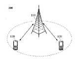
예시적으로, 본 출원의 실시예에 적용되는 통신 시스템(100)은 도 1에 도시된 바와 같다. 통신 시스템(100)은 네트워크 장치(110)를 포함할 수 있으며, 네트워크 장치(110)는 단말 장치(120)(또는 통신 단말기, 단말기라고도 함)와 통신하는 장치일 수 있다. 네트워크 장치(110)는 특정된 지리적 영역에 통신 커버리지를 제공하고, 또한 상기 커버리지 영역 내의 단말 장치와 통신할 수 있다. 선택적으로, 네트워크 장치(110)는 LTE 시스템에 있어서의 eNB 또는 eNodeB(evolutional Node B)일 수 있고, 또는 클라우드 무선 액세스 네트워크(Cloud Radio Access Network, CRAN)의 무선 컨트롤러일 수도 있다. 또는 네트워크 장치는 모바일 스위칭 센터(Mobile Switching Center), 릴레이 스테이션(relay station), 액세스 포인트, 차량 탑재 장치, 웨어러블 장치, 허브(hub), 스위치(switch), 네트워크 브리지, 라우터(router), 5G 네트워크의 네트워크측 장치 또는 미래 통신 시스템의 네트워크 장치 등일 수 있다.Illustratively, the
통신 시스템(100)은 네트워크 장치(110)의 커버리지 영역 내의 적어도 하나의 단말 장치(120)를 더 포함한다. 본 명세서에서 사용되는 ‘단말 장치’는 유선 선로 및/또는 다른 데이터 연결/네트워크 및/또는 무선 인터페이스를 통해 연결되는 장치, 및/또는 통신 신호를 송수신하는 다른 단말 장치, 및/또는 IoT(Internet of Things, IoT) 장치일 수 있지만, 이것에 한정되는 것은 아니다. 유선 선로는, 예를 들어, 공중 교환 전화망(public switched telephone network, PSTN), 디지털 가입자 회선(digital subscriber line, DSL), 디지털 케이블, 직접 연결 케이블일 수 있다. 무선 인터페이스는, 예를 들어, 셀룰러 네트워크, 무선 근거리 네트워크(wireless local area network, WLAN), 디지털 비디오 방송 핸드 헬드(digital video broadcasting handheld, DVB-H) 네트워크와 같은 디지털 TV 네트워크, 위성 네트워크, 진폭 변조 주파수 변조(amplitude modulation-frequency modulation, AM-FM) 방송 송신기일 수 있다. 무선 인터페이스를 통해 통신하도록 구성된 단말 장치는 ‘무선 통신 단말기’, ‘무선 단말기’또는 ‘모바일 단말기’라고 부를 수 있다. 모바일 단말기의 예시로는 위성 또는 셀룰러 전화; 셀룰러 무선 전화와 데이터 처리, 팩스 및 데이터 통신 능력을 결합할 수 있는 개인 통신 시스템(personal communication system, PCS) 단말기; 무선 전화(radio telephone), 무선 호출기(pager), 인터넷/인트라넷 액세스(Internet/Intranet access), 웹 브라우징(web browsing), 노트북(notebook), 캘린더(calendar) 및/또는 글로벌 포지셔닝 시스템(global positioning system, GPS) 수신기를 포함할 수 있는 개인 디지털 보조(Personal Digital Assistant, PDA); 및 일반 노트북 및/또는 휴대용 수신기 또는 무선 전화 기능을 갖춘 다른 전자 장치를 포함할 수 있지만, 이것에 한정되는 것은 아니다. 단말 장치는 액세스 단말기, 사용자 장비(UE), 사용자 유닛, 사용자 스테이션, 모바일 스테이션, 이동국, 원격 스테이션, 원격 단말기, 모바일 장치, 사용자 단말기, 단말기, 무선 통신 장치, 사용자 에이전트, 또는 사용자 장치를 가리킬 수 있다. 액세스 단말기는 셀룰러 전화, 무선 전화, SIP(Session Initiation Protocol) 전화, WLL(Wireless Local Loop) 스테이션, PDA, 무선 통신 기능을 갖는 핸드 헬드 장치, 컴퓨팅 장치 또는 무선 모뎀에 연결된 다른 처리 장치, 차량 탑재 장치, 웨어러블 장치, 5G 네트워크의 단말 장치 또는 미래 진화의 PLMN 내의 단말 장치 등일 수 있다.The
선택적으로, 단말 장치(120) 사이는 D2D(Device to Device) 통신을 수행할 수 있다.Optionally, device to device (D2D) communication may be performed between the
선택적으로, 5G 시스템 또는 5G 네트워크는 NR 시스템 또는 NR 네트워크라고 할 수 있다.Optionally, the 5G system or 5G network may be referred to as an NR system or an NR network.
도 1은 하나의 네트워크 장치 및 2개의 단말 장치를 나타내고 있다. 선택적으로, 통신 시스템(100)은 여러 네트워크 장치를 포함할 수 있으며, 또한 각 네트워크 장치의 커버리지 영역 내에 다른 수량의 단말 장치가 있을 수 있으며, 본 출원의 실시예는 이것에 대하여 한정하지 않는다.1 shows one network device and two terminal devices. Optionally, the
선택적으로, 통신 시스템(100)은 네트워크 컨트롤러, 이동 관리 엔티티(mobility management entity, MME) 등과 같은 다른 네트워크 엔티티를 더 포함할 수 있으며, 본 출원의 실시예는 이것에 대하여 한정하지 않는다.Optionally, the
본 출원의 실시예에 있어서, 네트워크/시스템에 있어서의 통신 기능을 갖는 장치는 통신 장치라고 부를 수 있다. 예를 들어, 도 1에 도시된 통신 시스템(100)에 있어서, 통신 장치는 통신 기능을 갖는 네트워크 장치(110) 및 단말 장치(120)를 포함할 수 있다. 네트워크 장치(110) 및 단말 장치(120)는 상술한 구체적인 장치일 수 있으며, 여기서 반복하지 않는다. 통신 장치는 통신 시스템(100) 내의 다른 장치를 더 포함할 수 있으며, 예를 들어, 네트워크 컨트롤러, MME 등 다른 네트워크 엔티티이며, 본 출원의 실시예는 이것에 대하여 구체적으로 한정하지 않는다.In the embodiments of the present application, a device having a communication function in a network/system may be referred to as a communication device. For example, in the
본 명세서의 ‘시스템’ 및 ‘네트워크’라는 용어는 본 명세서에서 서로 바꾸어 사용될 수 있다. 본 명세서의 ‘및/또는’이라는 용어는 단지 관련 대상의 연관 관계를 설명하고, 세가지 관계가 존재할 수 있으며, 예를 들어, ‘A 및/또는 B’는 ‘A만 존재한다’, ‘A와 B가 동시에 존재한다’, ‘B 만 존재한다’라는 세가지 상황을 나타낼 수 있다. 또한, 본 명세서의 부호 ‘/’는 일반적으로 전후 관련 대상이 ‘또는’이라는 관계에 있음을 나타낸다.In this specification, the terms 'system' and 'network' may be used interchangeably in this specification. The term 'and/or' in the present specification merely describes a relation of a related object, and three relations may exist, for example, 'A and/or B' is 'only A exists', 'A and It can represent three situations: 'B exists at the same time' and 'Only B exists'. In addition, the symbol '/' in the present specification generally indicates that the subject related before and after is in a relationship of 'or'.
본 출원의 실시예의 기술 방안을 편리하게 이해하기 위하여, 이하, 본 출원의 실시예에 관련된 기술 방안을 상세하게 설명한다.In order to conveniently understand the technical solutions of the embodiments of the present application, the technical schemes related to the embodiments of the present application will be described in detail below.
본 출원의 실시예의 기술 방안을 더 잘 이해하기 위하여, 이하, 본 출원의 실시예에 관련된 기술 방안을 설명한다. 이하 관련 기술과 본 출원의 실시예의 기술 방안의 임의의 조합은 모두 본 출원의 실시예의 보호 범위에 속한다.In order to better understand the technical solutions of the embodiments of the present application, the technical schemes related to the embodiments of the present application will be described below. Any combination of the following related technologies and the technical solutions of the embodiments of the present application all fall within the protection scope of the embodiments of the present application.
사람들이 속도, 지연, 빠른 이동성, 에너지 효율에 대한 추구와 미래의 삶에 있어서의 서비스의 다양성, 복잡성에 따라 제 3 세대 파트너십 프로젝트(The 3rd Generation Partnership Project, 3GPP) 국제 표준화 조직은 5G(5-Generation)의 개발을 시작하였다. 5G의 주요한 응용 시나리오는 eMBB(Enhance Mobile Broadband), URLLC(Ultra-Reliable Low-Latency Communications), mMTC(massive Machine-Type Communications)이다.According to people's pursuit of speed, delay, fast mobility, energy efficiency, and diversity and complexity of services in the future life, the 3rd Generation Partnership Project (3GPP) international standardization organization is 5G (5- Generation) began to develop. The main application scenarios of 5G are eMBB (Enhance Mobile Broadband), URLLC (Ultra-Reliable Low-Latency Communications), and mMTC (Massive Machine-Type Communications).
한편, eMBB는 여전히 사용자가 멀티미디어 콘텐츠, 서비스 및 데이터를 획득하는 것을 목표로 하고, 그 수요는 매우 빠르게 증가되고 있다. 다른 한편, eMBB는 실내, 도시, 농촌 등 다양한 시나리오에 배치될 수 있고, 그 기능과 요구사항의 차이도 비교적 크기 때문에, 일률적으로 논할 수 없으며, 구체적인 배치 시나리오(deployment scenarios)에 따라 자세하게 분석하여야만 한다. URLLC의 전형적인 애플리케이션은 산업 자동화, 전력 자동화, 원격 의료 작업(수술), 교통 안전 보장 등을 포함한다. mMTC의 전형적인 특징은 높은 연결 밀도, 적은 양의 데이터, 지연에 민감하지 않은 서비스, 낮은 모듈 비용 및 긴 서비스 수명 등을 포함한다.On the other hand, eMBB still aims for users to acquire multimedia content, services and data, and the demand is increasing very rapidly. On the other hand, since eMBB can be deployed in various scenarios such as indoor, urban, and rural areas, and the difference in functions and requirements is also relatively large, it cannot be discussed uniformly, and it must be analyzed in detail according to specific deployment scenarios. . Typical applications of URLLC include industrial automation, power automation, telemedicine operations (surgery), and traffic safety assurance. Typical characteristics of mMTC include high connection density, small amount of data, latency-insensitive service, low module cost and long service life.
NR의 초기 배치에서는 완전한 NR 커버리지를 실현하기 어려우므로, 일반적인 네트워크 커버리지 모드는 광역의 LTE 커버리지 모드 및 NR의 아일랜드 커버리지(island coverage) 모드이다. 또한 6GHz(gigahertz) 미만의 LTE가 대량으로 배치되어 있기 때문에, 5G에 사용할 수 있는 6GHz 미만의 스펙트럼은 매우 적다. 따라서, NR는 반드시 6GHz 이상의 스펙트럼의 응용을 연구하여야만 한다. 하지만 고주파 대역은 커버리지가 제한되어 있고, 신호 페이딩이 빠르다. 또한 LTE에 대한 이동 통신 사업자의 초기 투자를 보호하기 위하여, LTE와 NR 사이를 긴밀한 결합시키는 (tight interworking) 모드가 제안되었다.Since it is difficult to realize complete NR coverage in the initial deployment of NR, general network coverage modes are wide area LTE coverage mode and NR island coverage mode. Also, due to the massive deployment of LTE below 6 GHz (gigahertz), there is very little spectrum below 6 GHz available for 5G. Therefore, NR must study the application of spectrum above 6GHz. However, the high-frequency band has limited coverage, and signal fading is fast. In addition, in order to protect the initial investment of mobile operators in LTE, a tight interworking mode between LTE and NR has been proposed.
3GPP는 첫번째 5G 버전, 즉 EN-DC(Evolved universal terrestrial radio access-NR(E-UTRA-NR) Dual Connectivity)를 완성하였다. EN-DC에서 LTE 기지국은 마스터 노드(Master Node, MN)이고, NR 기지국은 보조 노드(Secondary Node, SN)이다. MN은 주로 무선 자원 제어(Radio Resource Control, RRC) 제어 기능과 코어 네트워크(Core Network, CN)로 이어지는 제어면을 담당한다. SN은 예를 들어, 데이터 전송 기능을 제공하는 시그널링 무선 베어러(Signaling Radio Bearer, SRB) 3과 같은 보조 시그널링을 구성할 수 있다. 이중 연결(Dual Connection, DC)은 EN-DC에 한정되지 않고, NE-DC(NR Evolved universal terrestrial radio access (NR-E-UTRA) Dual Connectivity), 5GC-EN-DC(5G core network-EN-DC), NR DC 등일 수 있다.3GPP has completed the first 5G version, EN-DC (Evolved universal terrestrial radio access-NR (E-UTRA-NR) Dual Connectivity). In EN-DC, the LTE base station is a Master Node (MN), and the NR base station is a Secondary Node (SN). The MN is mainly responsible for a radio resource control (RRC) control function and a control surface leading to a core network (CN). The SN may configure auxiliary signaling, for example, a Signaling Radio Bearer (SRB) 3 that provides a data transmission function. Dual Connection (DC) is not limited to EN-DC, NE-DC (NR Evolved universal terrestrial radio access (NR-E-UTRA) Dual Connectivity), 5GC-EN-DC (5G core network-EN- DC), NR DC, and the like.
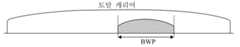
5G에서 최대 채널 대역폭(광대역 캐리어(wideband carrier)라고도 함)은 400MHZ(megahertz)일 수 있다. LTE에서의 최대 20M의 대역폭과 비교하면, 광대역 캐리어의 대역폭이 매우 크다. 단말 장치가 광대역 캐리어에서 계속 작동하는 경우, 단말 장치의 소비 전력이 매우 크므로, 단말 장치의 무선 주파수(Radio Frequency, RF) 대역폭은 단말 장치의 실제 처리량에 따라 조정하는 것이 바람직하다. 따라서 BWP 개념이 도입된다. BWP는 단말 장치의 전력 소비를 최적화하기 위한 것이다. 예를 들어, 단말 장치의 속도에 대한 요구 사항이 낮은 경우, 단말 장치는 작은 BWP로 구성될 수 있다(도 2a에 도시된 바와 같다). 단말 장치의 속도에 대한 요구 사항이 높은 경우, 단말 장치는 큰 BWP로 구성될 수 있다(도 2b에 도시된 바와 같다). 단말 장치는 고속을 지원하거나 또는 캐리어 어그리게이션(Carrier Aggregation, CA) 모드에서 작동하는 경우, 단말 장치는 다중 BWP로 구성될 수 있다(도 2c에 도시된 바와 같다). BWP의 또 다른 목적은 하나의 셀에서 여러 매개 변수 세트(numerology)의 공존을 트리거하는 것이다. 도 2c에 도시된 바와 같이, BWP1는 numerology1에 대응하고, BWP2는 numerology2에 대응한다.In 5G, the maximum channel bandwidth (also called wideband carrier) may be 400 megahertz (MHZ). Compared with the maximum bandwidth of 20M in LTE, the bandwidth of the broadband carrier is very large. When the terminal device continues to operate on a broadband carrier, power consumption of the terminal device is very large, so it is preferable to adjust the radio frequency (RF) bandwidth of the terminal device according to the actual throughput of the terminal device. Thus, the BWP concept is introduced. The BWP is for optimizing the power consumption of the terminal device. For example, when the speed requirement of the terminal device is low, the terminal device may be configured with a small BWP (as shown in FIG. 2A ). When the speed requirement of the terminal device is high, the terminal device may be configured with a large BWP (as shown in FIG. 2B ). When the terminal device supports high speed or operates in a carrier aggregation (CA) mode, the terminal device may be configured with multiple BWPs (as shown in FIG. 2C ). Another purpose of BWP is to trigger the coexistence of multiple parameter sets (numerology) in one cell. As shown in FIG. 2C , BWP1 corresponds to numerology1, and BWP2 corresponds to numerology2.
RRC 전용 시그널링을 통해 단말 장치는 가장 많게는 4개의 업 링크 BWP와 가장 많게는 4개의 다운 링크 BWP로 구성될 수 있다. 하지만 동시에 하나의 업 링크 BWP와 하나의 다운 링크 BWP만 활성화될 수 있다. RRC 전용 시그널링에 있어서, 구성된 BWP 중 첫번째로 활성화된 BWP(초기에 활성화된 BWP)를 지시할 수 있다. 또한, 단말 장치가 연결 상태에 있는 동안, 다운 링크 제어 정보(Downlink Control Information, DCI)를 통해 서로 다른 BWP 사이에서 전환될 수 있다.Through RRC dedicated signaling, a terminal device may be configured with a maximum of four uplink BWPs and a maximum of four downlink BWPs. However, only one uplink BWP and one downlink BWP can be active at the same time. In RRC-only signaling, it is possible to indicate the first activated BWP (the initially activated BWP) among the configured BWPs. Also, while the terminal device is in a connected state, it may be switched between different BWPs through downlink control information (DCI).
단말 장치는 활성화된 BWP에서만 무선 링크 모니터링(Radio Link Monitoring, RLM)을 수행하고 활성화되지 않은 BWP에서는 RLM을 수행하지 않는다. 단말 장치가 서로 다른 BWP를 전환할 때, RLM 관련 타이머와 카운터를 재설정할 필요가 없다. 무선 자원 관리(Radio Resource Management, RRM) 측정에 관하여, 단말 장치가 어느 활성화된 BWP에서 데이터를 송수신하느냐에 관계없이 모두 RRM 측정에 영향을 끼치지 않는다. 채널 품질 지시(Channel Quality Indication, CQI) 측정에 관하여, 단말 장치는 활성화된 BWP에서만 CQI 측정을 수행한다.The terminal device performs radio link monitoring (Radio Link Monitoring, RLM) only in the activated BWP and does not perform RLM in the non-activated BWP. When the terminal device switches between different BWPs, there is no need to reset the RLM-related timers and counters. With respect to radio resource management (RRM) measurement, regardless of which activated BWP the terminal device transmits/receives data, it does not affect RRM measurement. With respect to channel quality indication (CQI) measurement, the terminal device performs CQI measurement only in the activated BWP.
NR에서 CQI는 주로 셀의 다운 링크 채널의 품질을 평가하는 데에 사용된다. 셀의 다운 링크 채널의 품질은 단말 장치가 측정하고 보고한다. 단말 장치는 상위 계층의 지시에 따라 대응하는 파일럿 신호(참조 신호라고도 함)를 측정하고, CQI 측정 결과(CQI 측정보고라고도 함)를 보고한다. 네트워크 측은 단말 장치에 의해 보고되는 CQI 측정 결과에 따라, 또한 현재 네트워크 리소스 상황에 따라 단말 장치의 변조 모드, 자원 할당, MIMO(Multiple-Input Multiple-Output)의 관련 구성에 대하여 조정을 실시할지 여부를 결정한다.In NR, CQI is mainly used to evaluate the quality of a cell's downlink channel. The quality of the downlink channel of the cell is measured and reported by the terminal device. The terminal device measures a corresponding pilot signal (also referred to as a reference signal) according to an instruction from a higher layer, and reports a CQI measurement result (also referred to as a CQI measurement report). According to the CQI measurement result reported by the terminal device, the network side adjusts the modulation mode, resource allocation, and related configuration of the MIMO (Multiple-Input Multiple-Output) of the terminal device according to the current network resource situation whether or not to perform adjustments. decide
NR에서 CQI 측정을 나타내는 신호는 네트워크 측에 의해 단말 장치를 위해 구성된 채널 상태 지시 참조 신호(Channel Status Indicator Reference Signal, CSI-RS)이다. 네트워크 측은 미디어 액세스 제어 제어 요소(Media Access Control Control Element, MAC CE)에 의해 CQI 측정을 수행할지 여부를 제어한다(네트워크 측이 수행하지 않는다고 통지하는 경우, 네트워크 측은 CSI-RS를 전송하지 않는다).A signal indicating CQI measurement in NR is a Channel Status Indicator Reference Signal (CSI-RS) configured for a terminal device by the network side. The network side controls whether or not to perform CQI measurement by a Media Access Control Control Element (MAC CE) (if the network side notifies that it does not perform, the network side does not transmit CSI-RS).
CQI 보고 모드는 주기적 CQI 보고 및 비 주기적 CQI 보고로 나눌 수 있다. 주기적 CQI 보고에 대하여, 네트워크 측에서 보고 주기를 구성한다. 비 주기적 CQI 보고는 DCI에 의해 지시된다. DCI에 의해 지시되는 CQI 보고는 주기적인 보고일 수도 있으며, 그 주기는 RRC 시그널링에서 구성된다.The CQI reporting mode can be divided into periodic CQI reporting and non-periodic CQI reporting. For periodic CQI reporting, the network side configures a reporting period. Aperiodic CQI reporting is indicated by DCI. The CQI report indicated by DCI may be a periodic report, and the period is configured in RRC signaling.
CQI 전송 채널은 물리적 업 링크 공유 채널(Physical Uplink SharedChannel, PUSCH)과 물리적 업 링크 제어 채널(Physical Uplink Control Channel, PUCCH)로 나눌 수 있다. PUSCH가 할당되지 않은 서브 프레임에 대하여, 주기적인 CQI 보고/ PMI(Precoding Matrix Indicator) 보고/RI(Rank Indication) 보고는 PUCCH를 통해 전송된다. PUSCH가 할당된 서브 프레임에 대하여, 주기적인 보고는 CAS(channel-associated signaling) 방식으로 PUSCH를 통해 전송된다. 주기적인 보고와 비주기적인 보고가 동일한 서브 프레임에서 발생하면, 단말기는 상기 서브 프레임에서 우선 비주기적인 보고를 전송한다.The CQI transport channel can be divided into a physical uplink shared channel (Physical Uplink SharedChannel, PUSCH) and a physical uplink control channel (PUCCH). For a subframe to which a PUSCH is not allocated, a periodic CQI report/Precoding Matrix Indicator (PMI) report/Rank Indication (RI) report is transmitted through the PUCCH. For a subframe to which the PUSCH is allocated, a periodic report is transmitted through the PUSCH in a channel-associated signaling (CAS) scheme. If the periodic report and the aperiodic report occur in the same subframe, the terminal first transmits the aperiodic report in the subframe.
고속 요구를 충족하기 위하여 5G도 CA(Carrier Aggregation) 기술을 지원한다. CA에서는 여러 구성 요소 캐리어(Component Carrier, CC)의 리소스를 공동으로 스케줄링하고 사용함으로써, NR 시스템은 더 큰 대역폭을 지원할 수 있기 때문에, 더 높은 시스템 피크 속도를 실현할 수 있다. 스펙트럼에 있어서의 집합 캐리어(aggregated carrier)의 연속성에 따라 연속 CA와 비 연속 CA로 나눌 수 있다. 집합 캐리어가 동일한 밴드(band)에 있는지 여부에 따라 인트라 밴드(intra-band) CA와 인터 밴드(inter-band) CA로 나눌 수 있다.To meet the high-speed demand, 5G also supports CA (Carrier Aggregation) technology. In CA, by jointly scheduling and using the resources of several component carriers (CC), the NR system can support a larger bandwidth, so that a higher system peak rate can be realized. According to the continuity of aggregated carriers in the spectrum, it can be divided into continuous CA and non-contiguous CA. According to whether the aggregate carrier is in the same band, it may be divided into an intra-band CA and an inter-band CA.
CA에는 단지 하나의 PCC(Primary Cell Component) 밖에 없다. PCC는 RRC 시그널링 연결, 비 액세스 계층(Non-Access Stratum, NAS) 기능, 안전 등을 제공한다. PUCCH는 PCC에 존재하고 또한 오직 PCC에 존재한다. CA에는 하나 이상의 SCC(Secondary Cell Component)가 있을 수 있다. SCC는 추가 무선 자원만 제공한다. PCC와 SCC는 모두 서빙 셀(serving cell)이라고 한다. PCC의 셀은 프라이머리 셀(primary cell, Pcell)이고, SCC의 셀은 보조 셀(secondary cell, Scell)이다. 또한, 표준은 최대 5개의 캐리어가 집합된다고 규정하며, 즉, 집합 후의 최대 대역폭은 100MHZ이고, 집합 캐리어는 동일한 기지국에 속한다. 모든 집합 캐리어는 동일한 셀 무선 네트워크 임시 식별자(Cell-Radio Network Temporary Identifier, C-RNTI)를 사용하며, 기지국은 각 캐리어가 위치하는 셀에서 C-RNTI에 충돌이 없음을 확보한다. 비대칭(asymmetric) CA와 대칭(symmetric) CA를 지원하므로 집합 캐리어에는 꼭 다운 링크 캐리어가 있으며, 업 링크 캐리어는 없어도 된다. PCC 셀에 대하여 반드시 해당 셀의 물리적 다운 링크 제어 채널(Physical Downlink Control Channel, PDCCH)와 PUCCH가 있다. 또한 PCC 셀만 PUCCH가 있고, 다른 SCC 셀은 PDCCH가 있을 수 있다.CA has only one Primary Cell Component (PCC). PCC provides RRC signaling connectivity, Non-Access Stratum (NAS) functions, safety, and the like. PUCCH is present in PCC and also only present in PCC. A CA may have one or more Secondary Cell Components (SCCs). SCC only provides additional radio resources. Both PCC and SCC are referred to as serving cells. A cell of the PCC is a primary cell (Pcell), and a cell of the SCC is a secondary cell (Scell). In addition, the standard stipulates that a maximum of 5 carriers are aggregated, that is, the maximum bandwidth after aggregation is 100 MHZ, and the aggregated carriers belong to the same base station. All aggregate carriers use the same Cell-Radio Network Temporary Identifier (C-RNTI), and the base station ensures that there is no collision in the C-RNTI in the cell in which each carrier is located. Since asymmetric CA and symmetric CA are supported, the aggregate carrier must have a downlink carrier, and there is no need for an uplink carrier. For a PCC cell, there must be a Physical Downlink Control Channel (PDCCH) and a PUCCH of the corresponding cell. Also, only a PCC cell may have a PUCCH, and other SCC cells may have a PDCCH.
CA에 있어서, 스케줄링에 사용되는 PDCCH 리소스가 위치한 캐리어에 관하여, 캐리어 스케줄링은 동일 캐리어 스케줄링(same-carrier scheduling)과 크로스 캐리어 스케줄링(cross-carrier scheduling)을 포함한다. 동일 캐리어 스케줄링은 캐리어 스케줄링 정보를 해당 캐리어 PDCCH에 배치하여 스케줄링하는 것을 의미한다. 크로스 캐리어 스케줄링은 캐리어 스케줄링 정보를 다른 캐리어에 배치하여 스케줄링하는 것을 의미한다. 크로스 캐리어 스케줄링의 도입은 이종 네트워크(heterogeneous network)의 간섭 회피를 목적으로 한다.In CA, with respect to a carrier in which a PDCCH resource used for scheduling is located, carrier scheduling includes same-carrier scheduling and cross-carrier scheduling. Same-carrier scheduling means scheduling by arranging carrier scheduling information on a corresponding carrier PDCCH. Cross-carrier scheduling means scheduling by disposing carrier scheduling information to another carrier. Introduction of cross-carrier scheduling aims to avoid interference of heterogeneous networks.
크로스 캐리어 스케줄링에서 서로 다른 캐리어 간의 스케줄링 정보는 DCI의 캐리어 지시 필드(Carrier Indicator Field, CIF)에 의해 구분된다. CIF는 캐리어의 일련 번호 (serial number)를 지시하는 데에 사용된다. CIF는 3 비트를 고정 점용하고, CIF 값의 범위는 0~7이다. PCC의 CIF는 0으로 고정되어 있다. PDCCH가 존재하는 캐리어는 여러개 있을 수 있지만, PCC는 꼭 자신의 PDCCH가 있다. 상위 계층은 현재 SCC가 어느 캐리어의 PDCCH를 사용하여 스케줄링하느냐를 확정한다.In cross-carrier scheduling, scheduling information between different carriers is distinguished by a carrier indicator field (CIF) of DCI. CIF is used to indicate the serial number of the carrier. CIF uses 3 bits fixedly, and the range of CIF values is 0-7. The CIF of PCC is fixed to 0. There may be multiple carriers in which the PDCCH exists, but the PCC must have its own PDCCH. The upper layer determines which carrier's PDCCH is used for scheduling by the current SCC.
Scell는 RRC 전용 시그널링에 의해 구성된다. 초기 구성 상태는 비활성 상태이며, 비활성 상태에서는 데이터를 송수신할 수 없다. MAC CE에 의해 Scell가 활성화된 후에만 데이터를 송수신할 수 있다. Scell 구성 및 활성화 지연 각도로부터 보면, 상기 아키텍처는 가장 바람직한 아키텍처가 아니다. 이러한 지연은 특히 소규모 셀 배치 시나리오에서 CA의 사용 효율 및 무선 자원의 효율을 저하시킨다. 조밀한 소규모 셀 배치 시나리오에서 특히 각 Scell을 별도로 구성할 필요가 있는 경우에 각 Scell의 시그널링 로드도 매우 크다. 따라서 이러한 CA 아키텍처는 지연이 추가되고, CA의 사용이 제한되며, CA 로드 공유(load sharing)의 이득(gain)이 저하된다.Scell is configured by RRC dedicated signaling. The initial configuration state is an inactive state, and data cannot be transmitted/received in an inactive state. Data can be transmitted/received only after Scell is activated by the MAC CE. From the Scell configuration and activation delay angle, the above architecture is not the most desirable architecture. This delay degrades the efficiency of use of the CA and the efficiency of radio resources, especially in a small cell deployment scenario. In a dense small cell deployment scenario, the signaling load of each Scell is also very large, especially when it is necessary to configure each Scell separately. Therefore, this CA architecture adds delay, limits the use of CA, and reduces the gain of CA load sharing.
이를 위해 LTE R15는 CA를 최적화하였다. 최적화된 주요 기능은 아래와 같다.For this purpose, LTE R15 has optimized CA. The main optimized functions are as follows.
휴면 Scell 상태(Dormant Scell state): Scell의 상태는 활성화 상태 및 비활성화 상태로 나눌 수 있다. 셀을 빨리 회복하기 위하여, 새로운 셀 상태, 즉 휴면(dormant) 상태가 정의된다. 휴면 상태에서 단말 장치는 PDCCH를 디코딩하지 않고, CQI 측정/RRM 측정을 수행하며, CQI 측정 결과/RRM 측정 결과를 보고한다. 동시에 휴면 상태 전환을 제어하기 위하여 새로운 MAC CE가 정의된다. 구체적으로, 새로운 MAC CE는 활성화 상태와 휴면 상태 사이의 전환을 제어하는 데에 사용된다. 새로운 MAC CE에서 1 비트는 하나의 Scell에 대응하고, 비트 값이 1로 설정되는 경우, Scell이 휴면 상태로 들어감을 의미하며, 비트의 값이 0으로 설정되는 경우, Scell이 활성화 상태로 들어감을 의미한다.Dormant Scell state: The state of the Scell can be divided into an activated state and an inactive state. In order to quickly recover the cell, a new cell state, ie, a dormant state, is defined. In the sleep state, the terminal device does not decode the PDCCH, performs CQI measurement/RRM measurement, and reports the CQI measurement result/RRM measurement result. At the same time, a new MAC CE is defined to control dormant state transition. Specifically, the new MAC CE is used to control the transition between the active state and the dormant state. In the new MAC CE, 1 bit corresponds to one Scell, and when the bit value is set to 1, it means that the Scell enters the dormant state, and when the bit value is set to 0, the Scell enters the active state. it means.
직접 Scell 상태 구성(Direct Scell state configuration): RRC 시그널링에서 Scell의 상태는 활성화 상태 또는 휴면 상태로 구성된다. Scell 상태는 비활성 상태이다고 묵인한다.Direct Scell state configuration: In RRC signaling, the state of the Scell is configured as an active state or a dormant state. The Scell state is tolerated as being inactive.
NR에 빔 스위핑(beam sweeping) 프로세스가 도입되었다. BM을 수행하기 위하여 네트워크 측에서는 각 셀에 BM 관련 측정 RS(측정 RS는 빔과 관련됨)를 구성하고, BM 관련 측정 RS를 단말 장치에 통지한다. 단말 장치는 PUCCH에서 이러한 BM 관련 측정 RS의 측정 결과를 네트워크 측에 보고한다. 네트워크 측은 측정 결과에 따라 MAC CE를 통해 품질이 좋은 빔 세트를 지시하고, 동시에 DCI를 통해 품질이 좋은 빔 세트 중 어느 빔이 사용되고 있는지를 지시한다.A beam sweeping process was introduced in NR. In order to perform BM, the network side configures a BM-related measurement RS (measurement RS is related to a beam) in each cell, and notifies the BM-related measurement RS to the terminal device. The terminal device reports the measurement result of the BM-related measurement RS to the network side in the PUCCH. The network side instructs a high-quality beam set through MAC CE according to the measurement result, and at the same time indicates which beam among the high-quality beam sets is used through DCI.
LTE에서 Scell는 휴면 상태의 개념이 도입되었다. 본 출원의 실시예의 기술 방안에 따르면, NR에서는 Scell에 대하여 휴면 상태의 개념이 도입되지 않고 휴면 동작의 개념이 도입되었다. 즉, Scell은 휴면 동작이 있을 수 있다. 본 출원의 실시예에서는 셀이 휴면 동작을 수행하는 상태를 제 1 상태라고 한다. 본 출원의 실시예의 제 1 상태와 LTE에서의 휴면 상태는 다르다. NR은 BWP의 개념이 도입되었기 때문에, 휴면 동작을 갖는 셀의 단말 장치가 BM 측정을 실행하는 경우, 셀의 모든 BWP에서 BW 측정을 수행할 필요없이 하나의 BWP에서 BW 측정을 수행하면 된다. 이하, 본 출원의 실시예의 기술 방안에 대하여 상세하게 설명한다.In LTE, the concept of the dormant state of Scell was introduced. According to the technical method of the embodiment of the present application, in NR, the concept of the dormant state is not introduced with respect to the Scell, but the concept of the dormant operation. That is, the Scell may have a dormant operation. In the embodiment of the present application, a state in which the cell performs a dormant operation is referred to as a first state. The first state of the embodiment of the present application and the dormant state in LTE are different. Since the concept of BWP is introduced for NR, when a terminal device of a cell having a dormant operation performs BM measurement, BW measurement may be performed in one BWP without the need to perform BW measurement in all BWPs of the cell. Hereinafter, the technical method of the embodiment of the present application will be described in detail.
도 3은 본 출원의 실시예에 따른 측정 관리 방법의 흐름도이다. 도 3에 도시된 바와 같이, 측정 관리 방법은 아래 내용을 포함한다.3 is a flowchart of a measurement management method according to an embodiment of the present application. As shown in FIG. 3 , the measurement management method includes the following contents.
단계 301: 단말 장치의 제 1 서빙 셀이 제 1 상태에 있는 경우, 단말 장치는 제 1 BWP를 확정하고, 제 1 서빙 셀에 대한 빔 관리(BM) 측정은 제 1 BWP에서 수행되고, 제 1 상태는 휴면 상태 또는 휴면 동작이 있는 활성화 상태를 포함한다.Step 301: when the first serving cell of the terminal device is in the first state, the terminal device determines the first BWP, and beam management (BM) measurement for the first serving cell is performed in the first BWP, and the first States include dormant states or active states with dormant actions.
본 출원의 실시예에 있어서, 제 1 서빙 셀은 단말 장치에 서비스를 제공하는 셀이다. 선택적으로, 제 1 서빙 셀은 Scell이다.In an embodiment of the present application, the first serving cell is a cell that provides a service to a terminal device. Optionally, the first serving cell is an Scell.
본 출원의 실시예에 있어서, 서빙 셀에 대하여 '휴면 동작'이라는 개념을 도입하였으며, 본 출원의 실시예는 '서빙 셀이 휴면 동작을 수행한다'는 상태를 제 1 상태라고 한다. 휴면 동작은 서빙 셀에 대하여 정의되어 있지만, 휴면 동작은 단말 장치의 동작이다. 구체적으로, 휴면 동작은 셀을 입도(granularity)로 하며, '서빙 셀 1이 제 1 상태로 들어간다'는 것은 단말 장치가 서빙 셀 1에서 휴면 동작을 수행하는 것으로 이해될 수 있다. '서빙 셀 2이 제 1 상태로 들어간다'는 것은 단말 장치가 서빙 셀 2에서 휴면 동작을 수행하는 것으로 이해될 수 있다.In the embodiment of the present application, the concept of 'a dormant operation' is introduced with respect to a serving cell, and in the embodiment of the present application, a state that 'the serving cell performs a dormant operation' is referred to as a first state. The dormant operation is defined for the serving cell, but the dormant operation is an operation of the terminal device. Specifically, the dormant operation sets the cell to granularity, and 'the serving
본 출원의 일부 선택 가능한 실시예에 있어서, 제 1 상태에 있는 제 1 서빙 셀에서의 단말 장치의 동작은 RRM 측정 및/또는 CQI 측정 및/또는 BM 측정을 수행하는 것과, RRM 측정 결과 및/또는 CQI 측정 결과 및/또는 BM 측정 결과를 보고하는 것과, PDCCH의 모니터링을 중지하는 것과, PUCCH 및/또는 물리적 업 링크 공유 채널(PUSCH) 및/또는 사운딩 참조 신호(sounding reference signal, SRS)의 전송을 중지하는 것과, 물리적 다운 링크 공유 채널(PDSCH)의 수신을 중지하는 것 중 적어도 하나를 포함한다.In some selectable embodiments of the present application, the operation of the terminal device in the first serving cell in the first state includes performing RRM measurement and/or CQI measurement and/or BM measurement, RRM measurement result and/or Reporting the CQI measurement result and / or BM measurement result, stopping monitoring of the PDCCH, and transmitting the PUCCH and / or a physical uplink shared channel (PUSCH) and / or a sounding reference signal (SRS) It includes at least one of stopping and stopping reception of a physical downlink shared channel (PDSCH).
본 출원의 실시예에 있어서, 단말 장치는 아래 임의의 하나의 방식에 의해 제 1 서빙 셀이 제 1 상태로 들어간다는 것을 확정할 수 있다.In an embodiment of the present application, the terminal device may determine that the first serving cell enters the first state by any one of the following methods.
(1) 방식 1(1)
단말 장치는 네트워크 장치가 보내는 제 1 지시 정보를 수신한다. 제 1 지시 정보는 제 1 서빙 셀이 제 1 상태로 들어간다는 것을 지시하는 데에 사용된다. 단말 장치는 제 1 지시 정보에 따라 제 1 서빙 셀이 제 1 상태로 들어간다고 확정한다.The terminal device receives the first indication information sent by the network device. The first indication information is used to indicate that the first serving cell enters the first state. The terminal device determines that the first serving cell enters the first state according to the first indication information.
일부 선택 가능한 실시예에 있어서, 제 1 지시 정보는 RRC 시그널링, MAC CE, PDCCH 중 적어도 하나가 휴대한다.In some selectable embodiments, the first indication information is carried by at least one of RRC signaling, MAC CE, and PDCCH.
(2) 방식 2(2)
제 1 타이머가 만료되는 경우, 단말 장치는 제 1 서빙 셀이 제 1 상태로 들어간다고 확정한다.When the first timer expires, the terminal device determines that the first serving cell enters the first state.
일부 선택 가능한 실시예에 있어서, 제 1 타이머의 구성 정보는 RRC 시그널링, MAC CE, PDCCH 중 적어도 하나가 휴대한다.In some selectable embodiments, the configuration information of the first timer is carried by at least one of RRC signaling, MAC CE, and PDCCH.
본 출원의 실시예에 있어서, 제 1 BWP은 단말 장치가 제 1 상태로 들어가는 제 1 서빙 셀에서 BW 측정을 수행하는 BWP를 가리킨다. 구체적으로, 제 1 상태로 들어가는 제 1 서빙 셀에 대하여, 단말 장치는 제 1 서빙 셀의 모든 BWP에서 BW 측정을 수행할 필요가 없고, 하나의 BWP(즉, 제 1 BWP)에서 BW 측정을 수행하면 된다.In the embodiment of the present application, the first BWP refers to a BWP in which the terminal device performs BW measurement in the first serving cell entering the first state. Specifically, for the first serving cell entering the first state, the terminal device does not need to perform BW measurement in all BWPs of the first serving cell, and performs BW measurement in one BWP (ie, the first BWP). Do it.
본 출원의 실시예에 있어서, 단말 장치는 아래 임의의 하나의 방식에 의해 BM 측정을 수행할 필요가 있는 제1 BWP를 확정할 수 있다.In an embodiment of the present application, the terminal device may determine the first BWP required to perform BM measurement by any one of the following methods.
(A) 방식 1(A)
단말 장치는 네트워크 장치에서 보내는 제 2 지시 정보를 수신하고, 제 2 지시 정보는 제 1 BWP의 ID(identity)를 지시하는 데에 사용된다. 단말 장치는 제 1 BWP의 ID를 기반으로 제 1 BWP을 확정한다.The terminal device receives the second indication information sent from the network device, and the second indication information is used to indicate the ID (identity) of the first BWP. The terminal device determines the first BWP based on the ID of the first BWP.
일부 선택 가능한 실시예에 있어서, 제 2 지시 정보는 RRC 시그널링, MAC CE, PDCCH 중 적어도 하나가 휴대한다.In some selectable embodiments, the second indication information is carried by at least one of RRC signaling, MAC CE, and PDCCH.
네트워크 장치는 제 2 지시 정보를 통해 구성된 하나의 BWP의 ID (즉, 제 1 BWP의 ID)를 명시적으로 지시할 수 있다. 단말 장치는 제 2 지시 정보에 따라 BWP의 ID에 대응하는 BWP(즉, 제 1 BWP)을 확정할 수 있다.The network device may explicitly indicate the ID of one configured BWP (ie, the ID of the first BWP) through the second indication information. The terminal device may determine the BWP (ie, the first BWP) corresponding to the ID of the BWP according to the second indication information.
(B) 방식 2(B)
단말 장치는 제 1 구성 정보 중 구성된 초기 활성화된 BWP를 제 1 BWP로 사용한다. 제 1 구성 정보는 RRC 시그널링이 휴대한다.The terminal device uses the initially activated BWP configured among the first configuration information as the first BWP. The first configuration information is carried by RRC signaling.
네트워크 장치는 RRC 시그널링을 통해 단말 장치에 한 그룹의 BWP (예를 들어, 4개의 업 링크 BWP와 4개의 다운 링크 BWP)을 구성하고, 초기 활성화된 BWP를 지시할 수 있다. RRC 시그널링의 구성 정보는 제 1 구성 정보라고 한다. 제 1 구성 정보는 적어도 초기 활성화된 BWP를 구성하는 데에 사용된다. 단말 장치는 상기 초기 활성화된 BWP를 휴면 동작 하에서 BM 측정을 수행하는 BWP(즉, 제 1 BWP)로 한다.The network device may configure a group of BWPs (eg, 4 uplink BWPs and 4 downlink BWPs) to the terminal device through RRC signaling, and may indicate an initially activated BWP. The configuration information of RRC signaling is referred to as first configuration information. The first configuration information is used to configure at least an initially activated BWP. The terminal device sets the initially activated BWP as the BWP (ie, the first BWP) for performing BM measurement under the dormant operation.
(C) 방식 3(C) Method 3
단말 장치는 제 1 지시 정보를 휴대하는 활성화된 BWP를 제 1 BWP로 사용하며, 제 1 지시 정보는 제 1 서빙 셀이 제 1 상태로 들어간다는 것을 지시하는 데에 사용된다.The terminal device uses the activated BWP carrying the first indication information as the first BWP, and the first indication information is used to indicate that the first serving cell enters the first state.
단말 장치는 수신된 휴면 동작을 지시하는 지시 정보(즉, 제 1 지시 정보)를 휴대하는 활성화된 BWP를 휴면 동작 하에서 BM 측정을 수행하는 BWP(즉, 제 1 BWP)로 한다.The terminal device sets the activated BWP carrying the received indication information indicating the dormant operation (ie, the first indication information) as the BWP (ie, the first BWP) for performing BM measurement under the dormant operation.
본 출원의 실시예의 기술 방안은 BM 측정 보고 메커니즘을 제공한다. 이하, 구체적으로 설명한다.The technical solution of the embodiment of the present application provides a BM measurement reporting mechanism. Hereinafter, it demonstrates concretely.
(Ⅰ) BM 측정 보고 메커니즘 1(Ⅰ) BM
단말 장치의 하나 이상의 서빙 셀에 대하여, 서빙 셀에 PUCCH가 구성되어 있는 경우, 서빙 셀은 제 1 상태로 들어갈 수 없다(즉, 휴면 동작을 수행할 수 없다.)For one or more serving cells of the terminal device, when the PUCCH is configured in the serving cell, the serving cell cannot enter the first state (ie, it cannot perform a dormant operation).
PUCCH가 구성되어 있는 서빙 셀은 휴면 동작을 수행할 수 없다고 프로토콜에 규정할 수 있다.It may be specified in the protocol that the serving cell in which the PUCCH is configured cannot perform a dormant operation.
(Ⅱ) BM 측정 보고 메커니즘 2(Ⅱ) BM
단말 장치의 하나 이상의 서빙 셀에 대하여, 서빙 셀에 PUCCH가 구성되어 있는 경우, 서빙 셀은 제 1 상태로 들어갈 수 있다(즉, 휴면 동작을 수행할 수 있다). 서빙 셀의 BM 측정 결과는 목표 셀의 PUCCH를 통해 전송된다. 일부 선택 가능한 실시예에 있어서, 목표 셀은 PCell이거나, 또는 목표 셀은 네트워크 장치가 지시하는 셀이다.For one or more serving cells of the terminal device, when the PUCCH is configured in the serving cell, the serving cell may enter the first state (ie, perform a dormant operation). The BM measurement result of the serving cell is transmitted through the PUCCH of the target cell. In some selectable embodiments, the target cell is a PCell, or the target cell is a cell indicated by a network device.
PUCCH가 구성되어 있는 서빙 셀은 휴면 동작을 수행할 수 있다고 프로토콜에 규정할 수 있다. 그러나 상기 PUCCH에 대응하는 서빙 셀 그룹의 모든 서빙 셀의 BM 측정 결과는 PCell의 PUCCH를 통해 보고하거나 네트워크 측에 의해 명시적으로 구성된 하나의 서빙 셀의 PUCCH에 의해 보고한다.The serving cell in which the PUCCH is configured may specify in the protocol that it can perform a dormant operation. However, the BM measurement results of all serving cells of the serving cell group corresponding to the PUCCH are reported through the PUCCH of the PCell or reported by the PUCCH of one serving cell explicitly configured by the network side.
본 출원의 실시예의 기술 방안에 있어서, PUCCH가 구성되어 있는 셀이 제 1 상태에 있는 경우, BM 측정 결과를 어떻게 보고하느냐를 명확히 할 필요가 있다. 따라서 BM 메커니즘을 제안하며, BM 메커니즘에 대하여 구체적으로 설명한다.In the technical solution of the embodiment of the present application, when the cell in which the PUCCH is configured is in the first state, it is necessary to clarify how to report the BM measurement result. Therefore, the BM mechanism is proposed and the BM mechanism will be described in detail.
(a) BM 메커니즘 1(a)
휴면 동작을 수행하는 서빙 셀에 대하여, 좋은 빔의 유지 보수를 위해 네트워크 측은 전송 구성 지시(Transmission configuration indicator, TCI) 상태 활성화/비 활성화를 발송하지 않는다. 단말 장치의 빔 측정 결과가 모두 좋지 않은 경우, 또는 좋지 않은 빔의 개수가 일정한 문턱값보다 적은 경우, 네트워크 측은 RRC 시그널링을 통해 BM RS 세트를 재구성한다.For a serving cell performing a dormant operation, the network side does not send a transmission configuration indicator (TCI) state activation/deactivation for good beam maintenance. When all beam measurement results of the terminal device are not good, or the number of bad beams is less than a certain threshold, the network side reconfigures the BM RS set through RRC signaling.
(b) BM 메커니즘 2(b)
단말 장치는 제 1 BWP에서 제 1 서빙 셀의 BM 측정을 수행하여 M개의 참조 신호(reference signals, RS)에 대응하는 측정 결과를 획득한다. M은 1보다 큰 양의 정수이다. 단말 장치는 M개의 RS에 대응하는 측정 결과에 따라 BM 측정 결과를 보고할지 여부 및/또는 네트워크 장치에 제 3 지시 정보를 전송할지 여부를 확정한다. 제 3 지시 정보는 네트워크 장치에 BM RS 세트를 재구성하도록 지시하는 데에 사용된다.The terminal device performs BM measurement of the first serving cell in the first BWP to obtain measurement results corresponding to M reference signals (RS). M is a positive integer greater than 1. The terminal device determines whether to report the BM measurement result and/or whether to transmit the third indication information to the network device according to the measurement result corresponding to the M RSs. The third indication information is used to instruct the network device to reconfigure the BM RS set.
또한, 일부 선택 가능한 실시예에 있어서, 단말 장치는 M개의 RS에 대응하는 측정 결과에서 제 1 측정 문턱값보다 작은 N개의 RS에 대응하는 측정 결과를 확정한다. 1≤N≤M, 또한 N은 양의 정수이다. N의 값이 제 1 문턱값보다 작거나 같은 경우, 단말 장치는 BM 측정 결과를 보고하고, 및/또는 네트워크 장치에 제 3 지시 정보를 전송한다.Also, in some selectable embodiments, the terminal device determines measurement results corresponding to N RSs smaller than the first measurement threshold from the measurement results corresponding to the M RSs. 1≤N≤M, and N is a positive integer. When the value of N is less than or equal to the first threshold, the terminal device reports the BM measurement result, and/or transmits third indication information to the network device.
단말 장치는 네트워크 장치에 BM 측정 결과를 항상 보고하지 않는다. 단말 장치는 오직 측정 결과가 제 1 측정 문턱값보다 작은 RS 개수가 제 1 문턱값보다 적은 경우에만 BM 측정 결과를 보고한다.The terminal device does not always report the BM measurement result to the network device. The terminal device reports the BM measurement result only when the number of RSs for which the measurement result is smaller than the first measurement threshold is less than the first threshold.
또한, 일부 선택 가능한 실시예에 있어서, 단말 장치는 M개의 RS에 대응하는 측정 결과가 모두 제 1 측정 문턱값보다 작은 것으로 확정된 경우, 단말 장치는 BM 측정 결과를 보고하고, 및/또는 네트워크 장치에 제 3 지시 정보를 전송한다.In addition, in some selectable embodiments, when it is determined that the measurement results corresponding to the M RSs are all smaller than the first measurement threshold, the terminal device reports the BM measurement result, and/or the network device to transmit the third instruction information.
상술한 방안에서, 제 1 문턱값은 네트워크 장치에 의해 구성되거나 프로토콜에 규정된다.In the above-described scheme, the first threshold is configured by the network device or specified in the protocol.
상술한 방안에서, 제 1 측정 문턱값은 네트워크 장치에 의해 구성되거나 프로토콜에 규정된다.In the above-described scheme, the first measurement threshold is configured by the network device or specified in the protocol.
상술한 방안에서, 제 1 측정 문턱값은 RSRP(Reference Signal Received Power) 문턱값, RSRQ(Reference Signal Received Quality) 문턱값, SINR(Signal to Interference plus Noise Ratio) 문턱값 중 적어도 하나를 포함한다. 따라서 RS에 대응하는 측정 결과는 RSRP 측정 결과, RSRQ 측정 결과, SINR 측정 결과 중 적어도 하나를 포함한다.In the above-described method, the first measurement threshold includes at least one of a reference signal received power (RSRP) threshold, a reference signal received quality (RSRQ) threshold, and a signal to interference plus noise ratio (SINR) threshold. Accordingly, the measurement result corresponding to the RS includes at least one of an RSRP measurement result, an RSRQ measurement result, and an SINR measurement result.
본 출원의 일부 선택 가능한 실시예에 있어서, 단말 장치는 네트워크 장치에서 보내는 제 2 구성 정보를 수신한다. 제 2 구성 정보는 제 1 측정 보고 주기를 확정하는 데에 사용된다. 제 1 측정 보고 주기는 단말 장치가 제 1 유형의 BM 측정 결과를 보고하는 데에 사용된다. 제 1 유형의 BM 측정 결과는 제 1 상태로 들어간 서빙 셀에 대하여 BM 측정을 실시하여 획득한 BM 측정 결과이다. 또한, 선택적으로, 제 1 측정 보고 주기는 제 2 측정 보고 주기보다 길다. 제 2 측정 보고 주기는 단말 장치가 제 2 유형의 BM 측정 결과를 보고하는 데에 사용된다. 제 2 유형의 BM 측정 결과는 활성화 상태로 들어간 서빙 셀에 대하여 BM 측정을 실시하여 획득한 BM 측정 결과이다.In some selectable embodiments of the present application, the terminal device receives the second configuration information sent from the network device. The second configuration information is used to determine the first measurement reporting period. The first measurement reporting period is used for the terminal device to report the first type of BM measurement result. The first type of BM measurement result is a BM measurement result obtained by performing BM measurement on the serving cell that has entered the first state. Further, optionally, the first measurement reporting period is longer than the second measurement reporting period. The second measurement reporting period is used for the terminal device to report the second type of BM measurement result. The second type of BM measurement result is a BM measurement result obtained by performing BM measurement on a serving cell that has entered an activated state.
휴면 동작을 수행하는 서빙 셀에 대하여 네트워크 측은 활성화 상태에 있는 서빙 셀에 대응하는 제 2 측정 보고 주기보다 긴 제 1 측정 보고 주기를 구성한다. 제 1 측정 보고 주기는 서빙 셀이 휴면 동작을 수행할 때에 BM 측정 결과를 보고하는 데에 사용된다.For the serving cell performing the dormant operation, the network side configures a first measurement reporting period longer than the second measurement reporting period corresponding to the serving cell in the active state. The first measurement reporting period is used to report the BM measurement result when the serving cell performs a dormant operation.
본 출원의 일부 선택 가능한 실시예에 있어서, 단말 장치가 BM 측정 결과를 보고한 다음에, 및/또는 네트워크 장치에 제 3 지시 정보를 전송한 다음에 네트워크는 단말 장치를 위해 구성된 BM RS 세트를 재구성한다. 단말 장치는 네트워크 장치에서 보내는 제 3 구성 정보를 수신한다. 제 3 구성 정보는 BM RS 세트를 재구성하는 데에 사용된다.In some selectable embodiments of the present application, after the terminal device reports the BM measurement result and/or after sending the third indication information to the network device, the network reconfigures the BM RS set configured for the terminal device do. The terminal device receives the third configuration information sent from the network device. The third configuration information is used to reconfigure the BM RS set.
본 출원의 실시예의 기술 방안은 서빙 셀이 제 1 상태와 활성화 상태 간의 전환 메커니즘을 제공한다. 이하, 구체적으로 설명한다.The technical solution of the embodiment of the present application provides a mechanism for the serving cell to switch between the first state and the active state. Hereinafter, it demonstrates concretely.
모든 서빙 셀은 서로 다른 서빙 셀 그룹으로 나눠진다. 각 서빙 셀 그룹은 그룹 ID를 가지며, 서빙 셀 그룹 내의 각 서빙 셀은 인덱스 번호가 갖는다. 본 출원의 실시예에 따른 서빙 셀은 Scell일 수 있다.All serving cells are divided into different serving cell groups. Each serving cell group has a group ID, and each serving cell in the serving cell group has an index number. The serving cell according to the embodiment of the present application may be an Scell.
단말 장치는 제 1 PDCCH를 수신하고, 제 1 PDCCH는 제 1 서빙 셀 그룹의 ID 및 제 1 서빙 셀 그룹에 대응하는 제 1 비트 맵(bitmap)을 포함한다. 제 1 비트 맵의 각 비트는 각각 제 1 서빙 셀 그룹 내의 하나의 서빙 셀에 대응된다. 비트의 값은 해당 비트에 대응하는 서빙 셀이 활성화 상태로 들어가는지 여부 또는 제 1 상태로 들어가는지 여부를 지시하는 데에 사용된다.The terminal device receives the first PDCCH, and the first PDCCH includes an ID of the first serving cell group and a first bitmap corresponding to the first serving cell group. Each bit of the first bit map corresponds to one serving cell in the first serving cell group, respectively. The value of the bit is used to indicate whether the serving cell corresponding to the bit enters the activated state or enters the first state.
예를 들면, 비트의 값이 1(또는 0)인 경우, 해당 비트에 대응하는 서빙 셀이 제 1 상태로 들어감(또는 제 1 상태로 들어가지 않음)을 나타낸다. 또 다른 예를 들면, 비트의 값이 1(또는 0)인 경우, 해당 비트에 대응하는 서빙 셀이 제 1 상태로 들어감(또는 활성화 상태로 들어감)을 나타낸다.For example, when the value of the bit is 1 (or 0), it indicates that the serving cell corresponding to the bit enters the first state (or does not enter the first state). As another example, when the value of the bit is 1 (or 0), it indicates that the serving cell corresponding to the bit enters the first state (or enters the activated state).
단말 장치는 제 1 PDCCH를 수신하고, 제 1 PDCCH는 제 1 서빙 셀 그룹의 ID, 제 1 CIF 및 제 1 비트를 포함한다. 제 1 CIF는 제 1 서빙 셀 그룹 내의 하나의 서빙 셀을 지시하는 데에 사용된다. 제 1 비트의 값은 하나의 서빙 셀이 활성화 상태로 들어가는지 여부 또는 제 1 상태로 들어가는지 여부를 지시하는 데에 사용된다.The terminal device receives the first PDCCH, and the first PDCCH includes the ID of the first serving cell group, the first CIF, and the first bit. The first CIF is used to indicate one serving cell in the first serving cell group. The value of the first bit is used to indicate whether one serving cell enters the activated state or enters the first state.
예를 들면, 비트의 값이 1(또는 0)인 경우, 서빙 셀이 제 1 상태로 들어감(또는 제 1 상태로 들어가지 않음)을 나타낸다. 또 다른 예를 들면, 비트의 값이 1(또는 0)인 경우, 서빙 셀이 제 1 상태로 들어감(또는 활성화 상태로 들어감)을 나타낸다.For example, if the value of the bit is 1 (or 0), it indicates that the serving cell enters the first state (or does not enter the first state). As another example, when the value of the bit is 1 (or 0), it indicates that the serving cell enters the first state (or enters the activated state).
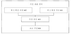
도 4는 본 출원의 실시예에 따른 측정 관리 장치의 구조를 나타내는 개략도이다. 도 4에 도시된 바와 같이, 측정 관리 장치는 제 1 확정 유닛(401)을 포함한다. 제 1 확정 유닛(401)은 단말 장치의 제 1 서빙 셀이 제 1 상태에 있는 경우에 제 1 BWP를 확정하는 데에 사용된다. 제 1 서빙 셀에 대한 BM 측정은 제 1 BWP에서 수행되고, 제 1 상태는 휴면 상태 또는 휴면 동작이 있는 활성화 상태를 포함한다.4 is a schematic diagram illustrating a structure of a measurement management apparatus according to an embodiment of the present application. As shown in FIG. 4 , the measurement management device includes a first determining unit 401 . The first determining unit 401 is used to determine the first BWP when the first serving cell of the terminal device is in the first state. The BM measurement for the first serving cell is performed in the first BWP, and the first state includes a dormant state or an active state with dormant operation.
일부 선택 가능한 실시예에 있어서, 측정 관리 장치는 제 2 확정 유닛(402)을 더 포함한다. 제 2 확정 유닛(402) 네트워크 장치가 보내는 제 1 지시 정보를 수신하고, 제 1 지시 정보에 따라 제 1 서빙 셀이 제 1 상태로 들어간다고 확정하는 데에 사용된다. 제 1 지시 정보는 제 1 서빙 셀이 제 1 상태로 들어간다는 것을 지시하는 데에 사용된다.In some selectable embodiments, the measurement management device further comprises a second determining unit 402 . The second determining unit 402 is used to receive the first indication information sent by the network device, and to determine that the first serving cell enters the first state according to the first indication information. The first indication information is used to indicate that the first serving cell enters the first state.
일부 선택 가능한 실시예에 있어서, 제 1 지시 정보는 RRC 시그널링, MAC CE, PDCCH 중 적어도 하나가 휴대한다.In some selectable embodiments, the first indication information is carried by at least one of RRC signaling, MAC CE, and PDCCH.
일부 선택 가능한 실시예에 있어서, 측정 관리 장치는 제 2 확정 유닛(402)을 더 포함한다. 제 2 확정 유닛(402)은 제 1 타이머가 만료되는 경우, 제 1 서빙 셀이 제 1 상태로 들어간다고 확정하는 데에 사용된다.In some selectable embodiments, the measurement management device further comprises a second determining unit 402 . The second determining unit 402 is used for determining that the first serving cell enters the first state when the first timer expires.
일부 선택 가능한 실시예에 있어서, 제 1 타이머의 구성 정보는 RRC 시그널링, MAC CE, PDCCH 중 적어도 하나가 휴대한다.In some selectable embodiments, the configuration information of the first timer is carried by at least one of RRC signaling, MAC CE, and PDCCH.
일부 선택 가능한 실시예에 있어서, 제 1 확정 유닛(401)은 네트워크 장치에서 보내는 제 2 지시 정보를 수신하는 데에 사용된다. 제 2 지시 정보는 제 1 BWP의 ID를 지시하는 데에 사용된다. 제 1 확정 유닛(401)은 제 1 BWP의 ID를 기반으로 제 1 BWP을 확정한다.In some selectable embodiments, the first determining unit 401 is used to receive the second indication information sent from the network device. The second indication information is used to indicate the ID of the first BWP. The first determining unit 401 determines the first BWP based on the ID of the first BWP.
일부 선택 가능한 실시예에 있어서, 제 2 지시 정보는 RRC 시그널링, MAC CE, PDCCH 중 적어도 하나가 휴대한다.In some selectable embodiments, the second indication information is carried by at least one of RRC signaling, MAC CE, and PDCCH.
일부 선택 가능한 실시예에 있어서, 제 1 확정 유닛(401)은 제 1 구성 정보 중 구성된 초기 활성화된 BWP를 제 1 BWP로 사용한다.In some selectable embodiments, the first determining unit 401 uses the initially activated BWP configured in the first configuration information as the first BWP.
일부 선택 가능한 실시예에 있어서, 제 1 구성 정보는 RRC 시그널링이 휴대한다.In some selectable embodiments, the first configuration information is carried by RRC signaling.
일부 선택 가능한 실시예에 있어서, 제 1 확정 유닛(401)은 제 1 지시 정보를 휴대하는 활성화된 BWP를 제 1 BWP로 사용하는 데에 사용되며, 제 1 지시 정보는 제 1 서빙 셀이 제 1 상태로 들어감을 지시하는 데에 사용된다.In some selectable embodiments, the first determining unit 401 is used to use the activated BWP carrying the first indication information as the first BWP, wherein the first indication information is determined by the first serving cell Used to indicate entry into a state.
일부 선택 가능한 실시예에 있어서, 단말 장치의 하나 이상의 서빙 셀에 대하여, 서빙 셀에 PUCCH가 구성되어 있는 경우, 서빙 셀은 제 1 상태로 들어갈 수 없다.In some selectable embodiments, when PUCCH is configured in one or more serving cells of the terminal device, the serving cell cannot enter the first state.
일부 선택 가능한 실시예에 있어서, 단말 장치의 하나 이상의 서빙 셀에 대하여, 서빙 셀에 PUCCH가 구성되어 있는 경우, 서빙 셀은 제 1 상태로 들어갈 수 있다. 서빙 셀의 BM 측정 결과는 목표 셀의 PUCCH를 통해 전송된다.In some selectable embodiments, with respect to one or more serving cells of the terminal device, when PUCCH is configured in the serving cell, the serving cell may enter the first state. The BM measurement result of the serving cell is transmitted through the PUCCH of the target cell.
일부 선택 가능한 실시예에 있어서, 목표 셀은 PCell(primary cell)이거나, 또는 목표 셀은 네트워크 장치가 지시하는 셀이다.In some selectable embodiments, the target cell is a primary cell (PCell), or the target cell is a cell indicated by a network device.
일부 선택 가능한 실시예에 있어서, 측정 관리 장치는 측정 유닛(403) 및 보고 유닛(404)을 더 포함한다. 측정 유닛(403)은 제 1 BWP에서 제 1 서빙 셀의 BM 측정을 수행하여 M개의 RS에 대응하는 측정 결과를 획득하는 데에 사용된다. M은 1보다 큰 양의 정수이다. 보고 유닛(404)은 M개의 RS에 대응하는 측정 결과에 따라 BM 측정 결과를 보고할지 여부 및/또는 네트워크 장치에 제 3 지시 정보를 전송할지 여부를 확정한다. 제 3 지시 정보는 네트워크 장치에 BM RS 세트를 재구성하도록 지시하는 데에 사용된다.In some selectable embodiments, the measurement management device further includes a measurement unit 403 and a reporting unit 404 . The measurement unit 403 is used to perform BM measurement of the first serving cell in the first BWP to obtain measurement results corresponding to the M RSs. M is a positive integer greater than 1. The reporting unit 404 determines, according to the measurement results corresponding to the M RSs, whether to report the BM measurement result and/or whether to transmit the third indication information to the network device. The third indication information is used to instruct the network device to reconfigure the BM RS set.
일부 선택 가능한 실시예에 있어서, 보고 유닛(404)은 M개의 RS에 대응하는 측정 결과에서 제 1 측정 문턱값보다 작은 N개의 RS에 대응하는 측정 결과를 확정하는 데에 사용된다. 1≤N≤M, 또한 N은 양의 정수이다. N의 값이 제 1 문턱값보다 작거나 같은 경우, 보고 유닛(404)은 BM 측정 결과를 보고하고, 및/또는 네트워크 장치에 제 3 지시 정보를 전송한다.In some selectable embodiments, the reporting unit 404 is used to ascertain measurement results corresponding to N RSs smaller than the first measurement threshold in the measurement results corresponding to the M RSs. 1≤N≤M, and N is a positive integer. If the value of N is less than or equal to the first threshold, the reporting unit 404 reports the BM measurement result, and/or sends the third indication information to the network device.
일부 선택 가능한 실시예에 있어서, 보고 유닛(404)은 단말 장치가 M개의 RS에 대응하는 측정 결과들이 모두 제 1 측정 문턱값보다 작은 것으로 확정된 경우에 BM 측정 결과를 보고하고, 및/또는 네트워크 장치에 제 3 지시 정보를 전송하는 데에 사용된다.In some selectable embodiments, the reporting unit 404 reports the BM measurement result when the terminal device determines that the measurement results corresponding to the M RSs are all smaller than the first measurement threshold, and/or the network Used to transmit third indication information to the device.
일부 선택 가능한 실시예에 있어서, 제 1 문턱값은 네트워크 장치에 의해 구성되거나 프로토콜에 규정된다.In some selectable embodiments, the first threshold is configured by the network device or defined in a protocol.
일부 선택 가능한 실시예에 있어서, 제 1 측정 문턱값은 네트워크 장치에 의해 구성되거나 프로토콜에 규정된다.In some selectable embodiments, the first measurement threshold is configured by the network device or defined in a protocol.
일부 선택 가능한 실시예에 있어서, 측정 관리 장치는 수신 유닛(도시되지 않음)을 더 포함한다. 수신 유닛은 네트워크 장치에서 보내는 제 2 구성 정보를 수신하는 데에 사용된다. 제 2 구성 정보는 제 1 측정 보고 주기를 확정하는 데에 사용된다. 제 1 측정 보고 주기는 단말 장치가 제 1 유형의 BM 측정 결과를 보고하는 데에 사용된다. 제 1 유형의 BM 측정 결과는 제 1 상태로 들어간 서빙 셀에 대하여 BM 측정을 실시하여 획득한 BM 측정 결과이다.In some selectable embodiments, the measurement management device further comprises a receiving unit (not shown). The receiving unit is used to receive the second configuration information sent from the network device. The second configuration information is used to determine the first measurement reporting period. The first measurement reporting period is used for the terminal device to report the first type of BM measurement result. The first type of BM measurement result is a BM measurement result obtained by performing BM measurement on the serving cell that has entered the first state.
일부 선택 가능한 실시예에 있어서, 제 1 측정 보고 주기는 제 2 측정 보고 주기보다 길다. 제 2 측정 보고 주기는 단말 장치가 제 2 유형의 BM 측정 결과를 보고하는 데에 사용된다. 제 2 유형의 BM 측정 결과는 활성화 상태로 들어간 서빙 셀에 대하여 BM 측정을 실시하여 획득한 BM 측정 결과이다.In some selectable embodiments, the first measurement reporting period is longer than the second measurement reporting period. The second measurement reporting period is used for the terminal device to report the second type of BM measurement result. The second type of BM measurement result is a BM measurement result obtained by performing BM measurement on a serving cell that has entered an activated state.
일부 선택 가능한 실시예에 있어서, 측정 관리 장치는 수신 유닛을 더 포함한다. 수신 유닛은 네트워크 장치에서 보내는 제 3 구성 정보를 수신하는 데에 사용된다. 제 3 구성 정보는 BM RS 세트를 재구성하는 데에 사용된다.In some selectable embodiments, the measurement management device further comprises a receiving unit. The receiving unit is used to receive the third configuration information sent from the network device. The third configuration information is used to reconfigure the BM RS set.
일부 선택 가능한 실시예에 있어서, 측정 관리 장치는 수신 유닛을 더 포함한다. 수신 유닛은 제 1 PDCCH를 수신하는 데에 사용된다. 제 1 PDCCH는 제 1 서빙 셀 그룹의 ID 및 제 1 서빙 셀 그룹에 대응하는 제 1 비트 맵(bitmap)을 포함한다. 제 1 비트 맵의 각 비트는 각각 제 1 서빙 셀 그룹 내의 하나의 서빙 셀에 대응된다. 비트의 값은 해당 비트에 대응하는 서빙 셀이 활성화 상태로 들어가는지 여부 또는 제 1 상태로 들어가는지 여부를 지시하는 데에 사용된다.In some selectable embodiments, the measurement management device further comprises a receiving unit. The receiving unit is used to receive the first PDCCH. The first PDCCH includes an ID of the first serving cell group and a first bitmap corresponding to the first serving cell group. Each bit of the first bit map corresponds to one serving cell in the first serving cell group, respectively. The value of the bit is used to indicate whether the serving cell corresponding to the bit enters the activated state or enters the first state.
일부 선택 가능한 실시예에 있어서, 측정 관리 장치는 수신 유닛을 더 포함한다. 수신 유닛은 제 1 PDCCH를 수신하는 데에 사용된다. 제 1 PDCCH는 제 1 서빙 셀 그룹의 ID, 제 1 CIF 및 제 1 비트를 포함한다. 제 1 CIF는 제 1 서빙 셀 그룹 내의 하나의 서빙 셀을 지시하는 데에 사용된다. 제 1 비트의 값은 하나의 서빙 셀이 활성화 상태로 들어가는지 여부 또는 제 1 상태로 들어가는지 여부를 지시하는 데에 사용된다.In some selectable embodiments, the measurement management device further comprises a receiving unit. The receiving unit is used to receive the first PDCCH. The first PDCCH includes the ID of the first serving cell group, the first CIF, and the first bit. The first CIF is used to indicate one serving cell in the first serving cell group. The value of the first bit is used to indicate whether one serving cell enters the activated state or enters the first state.
일부 선택 가능한 실시예에 있어서, 제 1 상태에 있는 제 1 서빙 셀에서의 단말 장치의 동작은 RRM 측정 및/또는 CQI 측정 및/또는 BM 측정을 수행하는 것과, RRM 측정 결과 및/또는 CQI 측정 결과 및/또는 BM 측정 결과를 보고하는 것과, PDCCH의 모니터링을 중지하는 것과, PUCCH 및/또는 PUSCH 및/또는 SRS의 전송을 중지하는 것과, PDSCH의 수신을 중지하는 것 중 적어도 하나를 포함한다.In some selectable embodiments, the operation of the terminal device in the first serving cell in the first state includes performing RRM measurement and/or CQI measurement and/or BM measurement, and RRM measurement result and/or CQI measurement result and/or reporting the BM measurement result, stopping monitoring of the PDCCH, stopping transmission of PUCCH and/or PUSCH and/or SRS, and stopping reception of PDSCH.
당업자라면 본 출원의 실시예에 따른 상기 측정 관리 시스템의 관련 설명은 본 출원의 실시예에 따른 측정 관리 방법의 관련 설명을 참조할 수 있다는 것을 이해할 수 있다.Those skilled in the art can understand that the related description of the measurement management system according to the embodiment of the present application may refer to the related description of the measurement management method according to the embodiment of the present application.
도 5는 본 출원의 실시예에 따른 통신 장치(500)의 구조를 나타내는 개략도이다. 통신 장치는 단말 또는 네트워크 장치일 수 있다. 도 5에 도시된 바와 같이, 통신 장치(500)는 프로세서(510)를 포함한다. 프로세서(510)는 메모리에 저장된 컴퓨터 프로그램을 호출하여 실행함으로써, 본 출원의 실시예에 따른 방법을 실현할 수 있다.5 is a schematic diagram illustrating a structure of a communication device 500 according to an embodiment of the present application. The communication device may be a terminal or a network device. As shown in FIG. 5 , the communication device 500 includes a
선택적으로, 도 5에 도시된 바와 같이, 통신 장치(500)는 메모리(520)를 더 포함할 수 있다. 프로세서(510)는 메모리(520)에 저장된 컴퓨터 프로그램을 호출하여 실행함으로써 본 출원의 실시예에 따른 방법을 실행할 수 있다.Optionally, as shown in FIG. 5 , the communication device 500 may further include a
메모리(520)는 프로세서(510)와 독립적인 별도의 장치이거나 또는 프로세서(510)에 통합될 수 있다.The
선택적으로, 도 5에 도시된 바와 같이, 통신 장치(500)는 트랜시버(530)를 더 포함할 수 있다. 프로세서(510)는 트랜시버(530)와 다른 장치가 통신하도록 제어할 수 있으며, 구체적으로 다른 장치에 정보 또는 데이터를 전송하거나 또는 다른 장치에서 전송된 정보 또는 데이터를 수신할 수 있다.Optionally, as shown in FIG. 5 , the communication device 500 may further include a
트랜시버(530)는 송신기 및 수신기를 포함할 수 있다. 트랜시버(530)는 안테나를 더 포함할 수 있다. 안테나의 수량은 하나 또는 여러개일 수 있다.The
선택적으로, 통신 장치(500)는 구체적으로 본 출원의 실시예에 따른 네트워크 장치일 수 있고, 통신 장치(500)는 본 출원의 방법 실시예에서 설명된 네트워크 장치에 의해 수행되는 대응하는 과정을 실시할 수 있으며, 간결함을 위해, 여기서는 반복하지 않는다.Optionally, the communication device 500 may specifically be a network device according to an embodiment of the present application, and the communication device 500 performs a corresponding process performed by the network device described in the method embodiment of the present application , and for the sake of brevity, it is not repeated here.
선택적으로, 통신 장치(500)는 구체적으로 본 출원의 실시예에 따른 이동 단말기/단말 장치일 수 있고, 통신 장치(500)는 본 출원의 방법 실시예에서 설명된 이동 단말기/단말 장치에 의해 수행되는 대응하는 과정을 실현할 수 있으며, 간결함을 위해, 여기서는 반복하지 않는다.Optionally, the communication device 500 may specifically be a mobile terminal/terminal device according to an embodiment of the present application, and the communication device 500 is performed by the mobile terminal/terminal device described in the method embodiment of the present application The corresponding process can be realized, and for the sake of brevity, it is not repeated here.
도 6은 본 출원의 실시예에 따른 칩의 구조를 나타내는 블록도이다. 도 6에 도시된 칩(600)은 프로세서(610)를 포함하고, 프로세서(610)는 메모리에서 컴퓨터 프로그램을 호출하여 실행함으로써 본 출원의 실시예의 방법을 실현할 수 있다.6 is a block diagram illustrating a structure of a chip according to an embodiment of the present application. The chip 600 shown in FIG. 6 includes a
선택적으로, 도 6에 도시된 바와 같이, 칩(600)은 메모리(620)를 더 포함할 수 있다. 프로세서(610)는 메모리(620)에서 컴퓨터 프로그램을 호출하여 실행함으로써 본 출원의 실시예의 방법을 실현할 수 있다.Optionally, as shown in FIG. 6 , the chip 600 may further include a
메모리(620)는 프로세서(610)와 독립적인 별도의 장치이거나 또는 프로세서(610)에 통합될 수 있다.The
선택적으로, 칩(600)은 입력 인터페이스(630)를 더 포함할 수 있다. 프로세서(610)는 입력 인터페이스(630)와 다른 장치 또는 칩이 통신하도록 제어할 수 있으며, 구체적으로 다른 장치 또는 칩에서 송신된 정보 또는 데이터를 획득할 수 있다.Optionally, the chip 600 may further include an
선택적으로, 칩(600)은 출력 인터페이스(640)를 더 포함할 수 있다. 프로세서(610)는 출력 인터페이스(640)와 다른 장치 또는 칩이 통신하도록 제어할 수 있으며, 구체적으로 다른 장치 또는 칩에 정보 또는 데이터를 출력할 수 있다.Optionally, the chip 600 may further include an
선택적으로, 칩은 본 출원의 실시예에 따른 네트워크 장치에 적용될 수 있으며, 칩은 본 출원의 방법 실시예에서 설명한 네트워크 장치에 의해 수행되는 대응하는 과정을 실현할 수 있으며, 간결함을 위해, 여기서는 반복하지 않는다.Optionally, the chip may be applied to the network device according to the embodiment of the present application, and the chip may realize the corresponding process performed by the network device described in the method embodiment of the present application, and for the sake of brevity, not repeated here does not
선택적으로, 칩은 본 출원의 실시예에 따른 이동 단말기/단말 장치에 적용될 수 있으며, 칩은 본 출원의 방법 실시예에서 설명한 이동 단말기/단말 장치에 의해 수행되는 대응하는 과정을 실현할 수 있으며, 간결함을 위해, 여기서는 반복하지 않는다.Optionally, the chip may be applied to the mobile terminal/terminal device according to the embodiment of the present application, and the chip may realize the corresponding process performed by the mobile terminal/terminal device described in the method embodiment of the present application, concise For this reason, it is not repeated here.
본 출원의 실시예에 언급된 칩은 시스템 레벨 칩, 시스템 칩, 칩 시스템 또는 시스템 온 칩이라고도 한다는 것을 이해하기 바란다.It should be understood that the chip mentioned in the embodiments of the present application is also referred to as a system level chip, a system chip, a chip system, or a system on a chip.
도 7은 본 발명의 실시예에 따른 통신 시스템(700)의 구조를 나타내는 블록도이다. 도 7에 도시된 바와 같이, 통신 시스템(700)은 단말 장치(710) 및 네트워크 장치(720)를 포함한다.7 is a block diagram showing the structure of a communication system 700 according to an embodiment of the present invention. As shown in FIG. 7 , the communication system 700 includes a
단말 장치(710)는 상술한 방법 실시예에서 설명된 단말 장치의 기능을 구현할 수 있고, 네트워크 장치(720)는 상술한 방법 실시예에서 설명된 네트워크 장치의 기능을 구현할 수 있으며, 간결함을 위해, 여기서는 반복하지 않는다.The
본 출원의 실시예의 프로세서는 신호 처리 능력을 갖는 집적 회로 칩일 수 있다. 실시 과정에서 상술한 방법 실시예의 각 단계는 프로세서의 하드웨어 형태의 집적 논리 회로(integrated logic circuit) 또는 소프트웨어 형태의 명령에 의해 완성될 수 있다. 프로세서는 범용 프로세서, 디지털 신호 프로세서(Digital Signal Processor, DSP), 주문형 집적 회로(Application Specific Integrated Circuit, ASIC), 필드 프로그래머블 게이트 어레이(Field Programmable Gate Array, FPGA) 또는 다른 프로그래머블 로직 디바이스, 이산 게이트 또는 트랜지스터 논리 장치, 개별 하드웨어 구성 요소일 수 있다. 프로세서는 본 발명의 실시예에 개시된 방법, 단계 및 논리 블록도를 실현 또는 실행할 수 있다. 범용 프로세서는 마이크로 프로세서 또는 임의의 통상적인 프로세서 등일 수 있다. 본 발명의 실시예에서 개시된 방법의 단계는 직접 하드웨어 디코딩 프로세서에 의해 실행 및 완성될 수 있거나, 또는 디코딩 프로세서의 하드웨어 및 소프트웨어 모듈의 조합에 의해 실행 및 완성될 수 있다. 소프트웨어 모듈은 랜덤 액세스 메모리(random access memory, RAM), 플래시 메모리, 읽기 전용 메모리(read only memory, ROM), 프로그래머블 읽기 전용 메모리(programmable ROM, PROM) 또는 전기적으로 지울 수 있는 프로그래머블 메모리, 레지스터 등 본 기술 분야의 성숙한 저장 매체에 있을 수 있다. 저장 매체는 메모리에 있다. 프로세서는 메모리의 정보를 읽고 프로세서의 하드웨어를 사용하여 상술한 방법의 단계를 완성한다.The processor of the embodiment of the present application may be an integrated circuit chip having signal processing capability. In the course of implementation, each step of the above-described method embodiments may be completed by an integrated logic circuit in the form of hardware of a processor or instructions in the form of software. A processor is a general purpose processor, digital signal processor (DSP), application specific integrated circuit (ASIC), field programmable gate array (FPGA) or other programmable logic device, discrete gate or transistor. It can be a logical unit, a discrete hardware component. A processor may realize or execute the methods, steps, and logical block diagrams disclosed in the embodiments of the present invention. A general purpose processor may be a microprocessor or any conventional processor or the like. The steps of the method disclosed in the embodiment of the present invention may be directly executed and completed by a hardware decoding processor, or may be executed and completed by a combination of hardware and software modules of the decoding processor. A software module consists of random access memory (RAM), flash memory, read only memory (ROM), programmable read-only memory (PROM), or electrically erasable programmable memory, registers, etc. It can be in the mature storage media of the technology sector. The storage medium is in memory. The processor reads the information in the memory and uses the processor's hardware to complete the steps of the method described above.
본 출원의 실시예의 메모리는 휘발성 메모리 또는 비 휘발성 메모리일 수 있으며, 또는 휘발성 메모리 및 비 휘발성 메모리 양자를 포함할 수 있다. 비 휘발성 메모리는 읽기 전용 메모리(Read-Only Memory, ROM), 프로그램 가능 읽기 전용 메모리(Programmable Read-Only Memory, PROM), 삭제 가능 프로그램 가능 읽기 전용 메모리(Erasable Programmable Read-Only Memory, EPROM), 전기적 삭제 가능 프로그램 가능 읽기 전용 메모리(Electrically Erasable Programmable Read-Only Memory, EEPROM) 또는 플래시 메모리(Flash Memory)일 수 있다. 휘발성 메모리는 외부 고속 캐시로 사용되는 랜덤 액세스 메모리(Random Access Memory, RAM)일 수 있다. 예시적이지만 한정적이지 않은 예를 들어, 다양한 형태의 RAM을 사용할 수 있으며, 예를 들어, 정적 랜덤 액세스 메모리(Static RAM, SRAM), 동적 랜덤 액세스 메모리(Dynamic Random Access Memory, DRAM), 동기 동적 랜덤 액세스 메모리(Synchronous Dynamic Random Access Memory, SDRAM), 더블 데이터 레이트 동기 동적 랜덤 액세스 메모리(Double Data Rate Synchronous Dynamic Random Access Memory, DDR SDRAM), 확장 동기 동적 랜덤 액세스 메모리(Enhanced Synchronous Dynamic Random Access Memory, ESDRAM), 동기 연결 동적 랜덤 액세스 메모리(Synch-link Dynamic Random Access Memory, SLDRAM) 및 직접 램바스 랜덤 액세스 메모리(Direct Rambus Random Access Memory, DRRAM)이다. 본 명세서에 기재된 시스템과 방법의 메모리는 이들과 다른 임의의 적절한 유형의 메모리를 포함하지만, 이것에 한정되지 않는다.The memory of the embodiment of the present application may be a volatile memory or a non-volatile memory, or may include both a volatile memory and a non-volatile memory. Non-volatile memory includes read-only memory (ROM), programmable read-only memory (PROM), erasable programmable read-only memory (EPROM), electrical It can be either Electrically Erasable Programmable Read-Only Memory (EEPROM) or Flash Memory. The volatile memory may be a random access memory (RAM) used as an external high-speed cache. By way of example, but not limitation, various types of RAM may be used, such as static random access memory (SRAM), dynamic random access memory (DRAM), synchronous dynamic random Synchronous Dynamic Random Access Memory (SDRAM), Double Data Rate Synchronous Dynamic Random Access Memory (DDR SDRAM), Enhanced Synchronous Dynamic Random Access Memory (ESDRAM) , Synchro-link Dynamic Random Access Memory (SLDRAM) and Direct Rambus Random Access Memory (DRRAM). Memory of the systems and methods described herein includes, but is not limited to, these and any other suitable type of memory.
상술한 메모리는 예시적이지만 한정적이지 아니라는 것을 이해하기 바란다. 예를 들어, 본 출원의 실시예의 메모리는 정적 랜덤 액세스 메모리(Static RAM, SRAM), 동적 랜덤 액세스 메모리(Dynamic Random Access Memory, DRAM), 동기 동적 랜덤 액세스 메모리(Synchronous Dynamic Random Access Memory, SDRAM), 더블 데이터 레이트 동기 동적 랜덤 액세스 메모리(Double Data Rate Synchronous Dynamic Random Access Memory, DDR SDRAM), 확장 동기 동적 랜덤 액세스 메모리(Enhanced Synchronous Dynamic Random Access Memory, ESDRAM), 동기 연결 동적 랜덤 액세스 메모리(Synch-link Dynamic Random Access Memory, SLDRAM) 및 직접 램바스 랜덤 액세스 메모리(Direct Rambus Random Access Memory, DRRAM)일 수도 있다. 즉, 본 출원의 실시예의 메모리는 이들과 다른 임의의 적절한 유형의 메모리를 포함하지만, 이것에 한정되지 않는다.It should be understood that the above-described memory is exemplary, but not limiting. For example, the memory of the embodiment of the present application includes a static random access memory (SRAM), a dynamic random access memory (DRAM), a synchronous dynamic random access memory (SDRAM), Double Data Rate Synchronous Dynamic Random Access Memory (DDR SDRAM), Enhanced Synchronous Dynamic Random Access Memory (ESDRAM), Synchronous Dynamic Random Access Memory (Synch-link Dynamic) Random Access Memory (SLDRAM) and Direct Rambus Random Access Memory (DRRAM). That is, the memory of the embodiments of the present application includes, but is not limited to, any suitable type of memory other than these.
본 출원의 실시예는 또한 컴퓨터 프로그램을 저장하는 데에 사용되는 컴퓨터 판독 가능한 기억 매체를 제공한다.An embodiment of the present application also provides a computer-readable storage medium used to store a computer program.
선택적으로, 컴퓨터 판독 가능한 저장 매체는 본 출원의 실시예에 따른 네트워크 장치에 적용될 수 있으며, 컴퓨터 프로그램은 컴퓨터에서 본 출원의 실시예에 따른 다양한 방법에 있어서의 네트워크 장치에 의해 실현되는 대응하는 단계를 실행하도록 하며, 간결함을 위해, 여기서는 반복하지 않는다.Optionally, the computer-readable storage medium may be applied to the network device according to the embodiment of the present application, and the computer program may perform the corresponding steps realized by the network device in various methods according to the embodiment of the present application in the computer. implementation, and for the sake of brevity, it is not repeated here.
선택적으로, 컴퓨터 판독 가능한 저장 매체는 본 출원의 실시예에 따른 이동 단말기/단말 장치에 적용될 수 있으며, 컴퓨터 프로그램은 컴퓨터에서 본 출원의 실시예에 따른 다양한 방법에 있어서의 이동 단말기/단말 장치에 의해 실현되는 대응하는 단계를 실행하도록 하며, 간결함을 위해, 여기서는 반복하지 않는다.Optionally, the computer-readable storage medium may be applied to the mobile terminal/terminal device according to the embodiment of the present application, and the computer program is executed in the computer by the mobile terminal/terminal device in various methods according to the embodiment of the present application. The corresponding steps to be realized are executed, and for the sake of brevity, they are not repeated here.
본 출원의 실시예는 또한 컴퓨터 프로그램 명령을 포함하는 컴퓨터 프로그램 제품을 제공한다.Embodiments of the present application also provide a computer program product comprising computer program instructions.
선택적으로, 컴퓨터 프로그램 제품은 본 출원의 실시예에 따른 네트워크 장치에 적용될 수 있으며, 컴퓨터 프로그램 명령은 컴퓨터에서 본 출원의 실시예에 따른 다양한 방법에 있어서의 네트워크 장치에 의해 실현되는 대응하는 단계를 실행하도록 하며, 간결함을 위해, 여기서는 반복하지 않는다.Optionally, the computer program product may be applied to the network device according to the embodiments of the present application, and the computer program instructions execute corresponding steps realized by the network devices in various methods according to the embodiments of the present application in the computer. and, for the sake of brevity, it is not repeated here.
선택적으로, 컴퓨터 프로그램 제품은 본 출원의 실시예에 따른 이동 단말기/단말 장치에 적용될 수 있으며, 컴퓨터 프로그램 명령은 컴퓨터에서 본 출원의 실시예에 따른 다양한 방법에 있어서의 이동 단말기/단말 장치에 의해 실현되는 대응하는 단계를 실행하도록 하며, 간결함을 위해, 여기서는 반복하지 않는다.Optionally, the computer program product may be applied to the mobile terminal/terminal device according to the embodiment of the present application, and the computer program instructions are realized by the mobile terminal/terminal device in various methods according to the embodiment of the present application in the computer The corresponding steps are executed, and for the sake of brevity, they are not repeated here.
본 출원의 실시예는 또한 컴퓨터 프로그램을 제공한다.Embodiments of the present application also provide a computer program.
선택적으로, 컴퓨터 프로그램은 본 출원의 실시예에 따른 네트워크 장치에 적용될 수 있다. 컴퓨터에서 컴퓨터 프로그램을 실행하면, 컴퓨터에서 본 출원의 실시예에 따른 다양한 방법에 있어서의 네트워크 장치에 의해 실현되는 대응하는 단계를 실행하도록 하며, 간결함을 위해, 여기서는 반복하지 않는다.Optionally, the computer program may be applied to the network device according to the embodiment of the present application. Executing the computer program on the computer causes the computer to execute corresponding steps realized by the network devices in various methods according to the embodiments of the present application, and for the sake of brevity, they are not repeated here.
선택적으로, 컴퓨터 프로그램은 본 출원의 실시예에 따른 이동 단말기/단말 장치에 적용될 수 있다. 컴퓨터에서 컴퓨터 프로그램을 실행하면, 컴퓨터에서 본 출원의 실시예에 따른 다양한 방법에 있어서의 이동 단말기/단말 장치에 의해 실현되는 대응하는 단계를 실행하도록 하며, 간결함을 위해, 여기서는 반복하지 않는다.Optionally, the computer program may be applied to a mobile terminal/terminal device according to an embodiment of the present application. Executing the computer program on the computer causes the computer to execute the corresponding steps realized by the mobile terminal/terminal device in various methods according to the embodiments of the present application, and for the sake of brevity, it is not repeated here.
본 영역의 일반 기술자라면 본문에서 공개된 실시예에서 설명된 각 예시의 유닛과 알고리즘 절차가 전자 하드웨어, 또는 컴퓨터 소프트웨어와 전자 하드웨어의 결합에 의해 구현될 수 있다는 것을 인식할 수 있다. 이러한 기능이 하드웨어 또는 소프트웨어로 실행되는지는 기술 방안의 특정 애플리케이션과 설계 제약 조건에 의해 결정된다. 전문 기술자라면, 기술된 기능을 구현하기 위해, 각 애플리케이션에 대해 상이한 방법을 사용할 수 있지만, 이러한 구현은 본 발명의 범위를 벗어난 것으로 간주되어서는 안된다.A person skilled in the art may recognize that each example unit and algorithm procedure described in the embodiments disclosed herein may be implemented by electronic hardware, or a combination of computer software and electronic hardware. Whether these functions are implemented as hardware or software depends on the specific application of the technical solution and design constraints. A person skilled in the art may use different methods for each application to implement the described functions, but such implementation should not be considered as departing from the scope of the present invention.
당업자라면 편리하게 간결하게 설명하기 위하여 상술한 시스템, 장치 및 유닛의 구체적인 작동 과정은 상술한 방법 실시예의 대응하는 프로세스를 참조할 수 있다는 것을 이해할 수 있으며, 여기서는 반복하지 않는다.Those skilled in the art can understand that for the purpose of convenient and concise description, the specific operating procedures of the above-described systems, apparatuses and units may refer to the corresponding processes of the above-described method embodiments, which are not repeated herein.
본 출원에서 제공되는 몇몇 실시예에서, 개시된 시스템, 장치 및 방법은 다른 방식으로 구현할 수 있다는 것을 이해할 수 있다. 예를 들어, 상기 설명된 장치의 실시예는 단지 예시적인 것이며, 예를 들어, 상기 유닛의 분할은 단지 논리적인 기능 분할일 뿐, 실제 구현에서는 다른 분할 방식이 있을 수 있으며, 예들 들어, 여러개의 유닛 또는 컴포넌트가 결합되거나 다른 시스템에 통합될 수 있고, 또는 일부 기능은 무시되거나 실행되지 않을 수 있다. 또한, 표시되거나 논의된 결합 또는 직접 결합 또는 통신 연결은 일부 인터페이스, 장치 또는 유닛을 통한 간접적 결합 또는 통신 연결일 수 있으며, 전기적, 기계적 또는 다른 형태일 수 있다.In some embodiments provided in this application, it is to be understood that the disclosed systems, apparatuses, and methods may be implemented in other ways. For example, the above-described embodiment of the device is merely exemplary, for example, the division of the unit is only a logical division of functions, and in actual implementation, there may be other division methods, for example, several Units or components may be combined or integrated into other systems, or some functions may be ignored or not executed. Further, the coupling or direct coupling or communication connection shown or discussed may be an indirect coupling or communication connection through some interface, device or unit, and may be in an electrical, mechanical, or other form.
분리된 구성 요소로 설명된 유닛은 물리적으로 분리되거나 분리되지 않을 수도 있고, 유닛으로 표시되는 구성 요소는 물리적 유닛일 수 있고 아닐 수도 있으며, 한 위치에 배치되거나 여러 네트워크 유닛에 분포되어 있을 수도 있다. 본 실시예 방안의 목적을 달성하기 위해 실제 요구에 따라 그 중의 일부 또는 모든 유닛을 선택할 수 있다.A unit described as a separate component may or may not be physically separated, and a component represented as a unit may or may not be a physical unit, and may be located in one location or distributed in several network units. In order to achieve the purpose of this embodiment, some or all units may be selected according to actual needs.
또한, 본 발명의 각 실시예에서의 각 기능 유닛은 하나의 처리 유닛에 통합될 수 있고, 또는 각각의 유닛이 물리적으로 별도로 존재할 수도 있고, 또는 2개 이상의 유닛이 하나의 유닛에 통합될 수도 있다.In addition, each functional unit in each embodiment of the present invention may be integrated into one processing unit, or each unit may exist physically separately, or two or more units may be integrated into one unit. .
상기 기능은 소프트웨어 기능 유닛 형태로 구현되어 별도의 제품으로 판매되거나 사용되는 경우, 컴퓨터 판독 가능 저장 매체에 저장될 수 있다. 이러한 이해를 기초로 하여 본 발명의 기술방안의 본질, 혹은 기술 분야에 기여하는 부분 또는 기술적 방안의 일부를 소프트웨어 제품의 형태로 구현될 수 있다. 해당 컴퓨터 소프트웨어는 하나의 저장 매체에 저장되며, 컴퓨터 장치(개인용 컴퓨터, 서버 또는 네트워크 장치일 수 있음)가 본 발명의 각 실시예에 따른 방법의 전부 또는 일부를 실행할 수 있도록 하는 다수의 명령어를 포함한다. 전술한 저장 매체는 USB, 외장 하드, 읽기 전용 기억 장치(ROM, Read-Only Memory), 랜덤 액세스 메모리(RAM, Random Access Memory), 디스크 또는 광 디스크 등과 같은 프로그램 코드를 저장할 수 있는 다양한 매체를 포함한다.When the function is implemented in the form of a software function unit and sold or used as a separate product, it may be stored in a computer-readable storage medium. Based on this understanding, the essence of the technical solution of the present invention, a part contributing to the technical field, or a part of the technical solution may be implemented in the form of a software product. The computer software is stored in a single storage medium, and includes a plurality of instructions that enable a computer device (which may be a personal computer, a server, or a network device) to execute all or part of the method according to each embodiment of the present invention. do. The aforementioned storage medium includes various media capable of storing a program code, such as a USB, external hard drive, read-only memory (ROM), random access memory (RAM), disk or optical disk, etc. do.
상술한 것은 단지 본 발명의 구체적인 실시예이며, 본 발명의 보호 범위는 이것에 한정되는 것은 아니다. 당업자라면 본 발명에 개시된 기술 범위 내에서 변경 또는 교체를 쉽게 도출할 수 있으며, 이러한 변경 또는 교체는 모두 본 발명의 범위 내에 포함되어야 한다. 따라서 본 출원의 보호 범위는 특허 청구 범위에 의해 결정된다.The above are only specific embodiments of the present invention, and the protection scope of the present invention is not limited thereto. Those skilled in the art can easily derive changes or replacements within the technical scope disclosed in the present invention, and all such changes or replacements should be included within the scope of the present invention. Accordingly, the protection scope of the present application is determined by the claims.
Claims (53)
Translated fromKorean단말 장치의 제 1 서빙 셀이 제 1 상태에 있는 경우, 상기 단말 장치는 제 1 BWP를 확정하고, 상기 제 1 서빙 셀에 대한 빔 관리(BM) 측정은 제 1 BWP에서 수행되는 것 - 상기 제 1 상태는 휴면 상태 또는 휴면 동작이 있는 활성화 상태를 포함함 - 을 포함하는 것을 특징으로 하는 측정 관리 방법.A measurement management method comprising:
When the first serving cell of the terminal device is in the first state, the terminal device determines the first BWP, and beam management (BM) measurement for the first serving cell is performed in the first BWP - the first 1 state comprises a dormant state or an active state with a dormant action.
상기 방법은,
상기 단말 장치는 네트워크 장치가 보내는 제 1 지시 정보를 수신하는 것 - 상기 제 1 지시 정보는 상기 제 1 서빙 셀이 상기 제 1 상태로 들어간다는 것을 지시하는 데에 사용됨 - 과,
상기 단말 장치는 상기 제 1 지시 정보에 따라 상기 제 1 서빙 셀이 상기 제 1 상태로 들어간다고 확정하는 것을 더 포함하는 것을 특징으로 하는 방법.The method of claim 1,
The method is
the terminal device receives first indication information sent by a network device, wherein the first indication information is used to indicate that the first serving cell enters the first state;
The method further comprising: determining, by the terminal device, that the first serving cell enters the first state according to the first indication information.
상기 제 1 지시 정보는 무선 리소스 제어(RRC) 시그널링, 미디어 액세스 제어 제어 요소(MAC CE), 물리적 다운링크 제어 채널(PDCCH) 중 적어도 하나가 휴대하는 것을 특징으로 하는 방법.3. The method of claim 2,
The first indication information is carried by at least one of radio resource control (RRC) signaling, media access control control element (MAC CE), and physical downlink control channel (PDCCH).
상기 방법은,
제 1 타이머가 만료되는 경우, 상기 단말 장치는 상기 제 1 서빙 셀이 상기 제 1 상태로 들어간다고 확정하는 것을 더 포함하는 것을 특징으로 하는 방법.The method of claim 1,
The method is
The method further comprising: when the first timer expires, the terminal device determines that the first serving cell enters the first state.
상기 제 1 타이머의 구성 정보는 RRC 시그널링, MAC CE, PDCCH 중 적어도 하나가 휴대하는 것을 특징으로 하는 방법.5. The method of claim 4,
The configuration information of the first timer is characterized in that at least one of RRC signaling, MAC CE, and PDCCH is carried.
상기 단말 장치는 제 1 BWP를 확정한다는 것은,
상기 단말 장치는 네트워크 장치에서 보내는 제 2 지시 정보를 수신하는 것 - 상기 제 2 지시 정보는 제 1 BWP의 ID를 지시하는 데에 사용됨 - 과,
상기 단말 장치는 상기 제 1 BWP의 ID를 기반으로 상기 제 1 BWP을 확정하는 것을 포함하는 것을 특징으로 하는 방법.6. The method according to any one of claims 1 to 5,
That the terminal device determines the first BWP,
the terminal device receives second indication information sent from the network device, wherein the second indication information is used to indicate the ID of the first BWP; and
The method, characterized in that the terminal device comprises determining the first BWP based on the ID of the first BWP.
상기 제 2 지시 정보는 RRC 시그널링, MAC CE, PDCCH 중 적어도 하나가 휴대하는 것을 특징으로 하는 방법.7. The method of claim 6,
The second indication information is characterized in that at least one of RRC signaling, MAC CE, and PDCCH is carried.
상기 단말 장치는 제 1 BWP를 확정한다는 것은,
상기 단말 장치는 제 1 구성 정보 중 구성된 초기 활성화된 BWP를 제 1 BWP로 사용하는 것을 포함하는 것을 특징으로 하는 방법.6. The method according to any one of claims 1 to 5,
That the terminal device determines the first BWP,
The method, characterized in that the terminal device includes using the initially activated BWP configured among the first configuration information as the first BWP.
상기 제 1 구성 정보는 RRC 시그널링이 휴대하는 것을 특징으로 하는 방법.9. The method of claim 8,
The first configuration information is a method, characterized in that the RRC signaling carried.
상기 단말 장치는 제 1 BWP를 확정한다는 것은,
상기 단말 장치는 제 1 지시 정보를 휴대하는 활성화된 BWP를 상기 제 1 BWP로 사용하는 것을 포함하며,
상기 제 1 지시 정보는 상기 제 1 서빙 셀이 제 1 상태로 들어간다는 것을 지시하는 데에 사용되는 것을 특징으로 하는 방법.6. The method according to any one of claims 1 to 5,
That the terminal device determines the first BWP,
The terminal device includes using the activated BWP carrying the first indication information as the first BWP,
The method of claim 1, wherein the first indication information is used to indicate that the first serving cell enters a first state.
상기 단말 장치의 하나 이상의 서빙 셀에 대하여, 상기 서빙 셀에 PUCCH가 구성되어 있는 경우, 상기 서빙 셀은 상기 제 1 상태로 들어갈 수 없는 것을 특징으로 하는 방법.11. The method according to any one of claims 1 to 10,
For one or more serving cells of the terminal device, when PUCCH is configured in the serving cell, the serving cell cannot enter the first state.
상기 단말 장치의 하나 이상의 서빙 셀에 대하여, 상기 서빙 셀에 PUCCH가 구성되어 있는 경우, 상기 서빙 셀은 상기 제 1 상태로 들어갈 수 있으며, 상기 서빙 셀의 BM 측정 결과는 목표 셀의 PUCCH를 통해 전송되는 것을 특징으로 하는 방법.11. The method according to any one of claims 1 to 10,
For one or more serving cells of the terminal device, when PUCCH is configured in the serving cell, the serving cell may enter the first state, and the BM measurement result of the serving cell is transmitted through the PUCCH of the target cell A method characterized by being.
상기 목표 셀은 PCell이거나, 또는 상기 목표 셀은 네트워크 장치가 지시하는 셀인 것을 특징으로 하는 방법.13. The method of claim 12,
The target cell is a PCell, or the target cell is a cell indicated by a network device.
상기 제 1 BWP에서 상기 제 1 서빙 셀의 BM 측정을 수행한다는 것은,
상기 단말 장치는 상기 제 1 BWP에서 상기 제 1 서빙 셀의 BM 측정을 수행하여 M개의 참조 신호(RS)에 대응하는 측정 결과를 획득하는 것 - M은 1보다 큰 양의 정수임 - 을 포함하고,
상기 방법은,
상기 단말 장치는 상기 M개의 RS에 대응하는 측정 결과에 따라 BM 측정 결과를 보고할지 여부 및/또는 네트워크 장치에 제 3 지시 정보를 전송할지 여부를 확정하는 것 - 상기 제 3 지시 정보는 상기 네트워크 장치에 BM RS 세트를 재구성하도록 지시하는 데에 사용됨 - 을 더 포함하는 것을 특징으로 하는 방법.14. The method according to any one of claims 1 to 13,
Performing the BM measurement of the first serving cell in the first BWP means,
The terminal device performs BM measurement of the first serving cell in the first BWP to obtain measurement results corresponding to M reference signals (RS), where M is a positive integer greater than 1 - including,
The method is
The terminal device determines whether to report the BM measurement result and/or whether to transmit third indication information to the network device according to the measurement results corresponding to the M RSs - the third indication information is the network device used to instruct to reconfigure the BM RS set.
상기 단말 장치는 상기 M개의 RS에 대응하는 측정 결과에 따라 BM 측정 결과를 보고할지 여부를 확정하는 것은,
상기 단말 장치는 상기 M개의 RS에 대응하는 측정 결과에서 제 1 측정 문턱값보다 작은 N개의 RS에 대응하는 측정 결과를 확정하는 것 - 1≤N≤M, 또한 N은 양의 정수임 - 과,
상기 N의 값이 제 1 문턱값보다 작거나 같은 경우, 상기 단말 장치는 BM 측정 결과를 보고하고, 및/또는 네트워크 장치에 제 3 지시 정보를 전송하는 것을 포함하는 것을 특징으로 하는 방법.15. The method of claim 14,
The terminal device determines whether to report the BM measurement result according to the measurement result corresponding to the M RSs,
The terminal device determines, from the measurement results corresponding to the M RSs, measurement results corresponding to N RSs smaller than a first measurement threshold - 1≤N≤M, and N is a positive integer;
When the value of N is less than or equal to the first threshold, the terminal device reports a BM measurement result, and/or transmits third indication information to the network device.
상기 단말 장치는 상기 M개의 RS에 대응하는 측정 결과에 따라 BM 측정 결과를 보고할지 여부를 확정하는 것은,
상기 단말 장치는 상기 M개의 RS에 대응하는 측정 결과가 모두 제 1 측정 문턱값보다 작은 것으로 확정된 경우, 상기 단말 장치는 BM 측정 결과를 보고하고, 및/또는 네트워크 장치에 제 3 지시 정보를 전송하는 것을 포함하 는 것을 특징으로 하는 방법.15. The method of claim 14,
The terminal device determines whether to report the BM measurement result according to the measurement result corresponding to the M RSs,
When the terminal device determines that all measurement results corresponding to the M RSs are smaller than the first measurement threshold, the terminal device reports the BM measurement result and/or transmits third indication information to the network device A method comprising:
상기 제 1 문턱값은 네트워크 장치에 의해 구성되거나 프로토콜에 규정되는 것을 특징으로 하는 방법.16. The method of claim 15,
The method of claim 1, wherein the first threshold is configured by a network device or specified in a protocol.
상기 제 1 측정 문턱값은 네트워크 장치에 의해 구성되거나 프로토콜에 규정되는 것을 특징으로 하는 방법.17. The method according to claim 15 or 16,
The method of claim 1, wherein the first measurement threshold is configured by a network device or specified in a protocol.
상기 방법은,
상기 단말 장치는 네트워크 장치에서 보내는 제 2 구성 정보를 수신하는 것을 더 포함하고,
상기 제 2 구성 정보는 제 1 측정 보고 주기를 확정하는 데에 사용되고, 상기 제 1 측정 보고 주기는 상기 단말 장치가 제 1 유형의 BM 측정 결과를 보고하는 데에 사용되며, 상기 제 1 유형의 BM 측정 결과는 제 1 상태로 들어간 서빙 셀에 대하여 BM 측정을 실시하여 획득한 BM 측정 결과인 것을 특징으로 하는 방법.19. The method according to any one of claims 14 to 18,
The method is
The terminal device further comprises receiving second configuration information sent from the network device,
The second configuration information is used to determine a first measurement report period, the first measurement report period is used for the terminal device to report a measurement result of the first type of BM, and the BM of the first type The measurement result is a BM measurement result obtained by performing BM measurement on the serving cell entering the first state.
상기 제 1 측정 보고 주기는 상기 제 2 측정 보고 주기보다 길고, 상기 제 2 측정 보고 주기는 상기 단말 장치가 제 2 유형의 BM 측정 결과를 보고하는 데에 사용되며, 상기 제 2 유형의 BM 측정 결과는 활성화 상태로 들어간 서빙 셀에 대하여 BM 측정을 실시하여 획득한 BM 측정 결과인 것을 특징으로 하는 방법.20. The method of claim 19,
The first measurement report period is longer than the second measurement report period, and the second measurement report period is used for the terminal device to report the BM measurement result of the second type, and the BM measurement result of the second type is a BM measurement result obtained by performing BM measurement on a serving cell that has entered an activated state.
상기 방법은,
상기 단말 장치는 네트워크 장치에서 보내는 제 3 구성 정보를 수신하는 것을 더 포함하고,
상기 제 3 구성 정보는 BM RS 세트를 재구성하는 데에 사용되는 것을 특징으로 하는 방법.21. The method according to any one of claims 14 to 20,
The method is
The terminal device further comprises receiving third configuration information sent from the network device,
The third configuration information is used for reconfiguring the BM RS set.
상기 방법은,
상기 단말 장치는 제 1 PDCCH를 수신하는 것 - 상기 제 1 PDCCH는 제 1 서빙 셀 그룹의 ID 및 상기 제 1 서빙 셀 그룹에 대응하는 제 1 비트 맵을 포함하고, 상기 제 1 비트 맵의 각 비트는 각각 상기 제 1 서빙 셀 그룹 내의 하나의 서빙 셀에 대응되며, 상기 비트의 값은 해당 비트에 대응하는 서빙 셀이 활성화 상태로 들어가는지 여부 또는 제 1 상태로 들어가는지 여부를 지시하는 데에 사용됨 - 을 더 포함하는 것을 특징으로 하는 방법.22. The method according to any one of claims 1 to 21,
The method is
the terminal device receives a first PDCCH, wherein the first PDCCH includes an ID of a first serving cell group and a first bitmap corresponding to the first serving cell group, each bit of the first bitmap each corresponds to one serving cell in the first serving cell group, and the value of the bit is used to indicate whether the serving cell corresponding to the bit enters the activated state or enters the first state. - Method characterized in that it further comprises.
상기 단말 장치는 제 1 PDCCH를 수신하는 것 - 상기 제 1 PDCCH는 제 1 서빙 셀 그룹의 ID, 제 1 CIF 및 제 1 비트를 포함하고, 상기 제 1 CIF는 상기 제 1 서빙 셀 그룹 내의 하나의 서빙 셀을 지시하는 데에 사용되며, 상기 제 1 비트의 값은 상기 하나의 서빙 셀이 활성화 상태로 들어가는지 여부 또는 제 1 상태로 들어가는지 여부를 지시하는 데에 사용됨 - 을 더 포함하는 것을 특징으로 하는 방법.22. The method according to any one of claims 1 to 21,
the terminal device receives a first PDCCH, wherein the first PDCCH includes an ID of a first serving cell group, a first CIF and a first bit, and the first CIF is one of the first serving cell groups in the first serving cell group. used to indicate a serving cell, wherein the value of the first bit is used to indicate whether the one serving cell enters an activated state or enters a first state. how to do it with
상기 제 1 상태에 있는 상기 제 1 서빙 셀에서의 상기 단말 장치의 동작은 RRM 측정 및/또는 CQI 측정 및/또는 BM 측정을 수행하는 것과, RRM 측정 결과 및/또는 CQI 측정 결과 및/또는 BM 측정 결과를 보고하는 것과, 물리적 다운 링크 제어 채널(PDCCH)의 모니터링을 중지하는 것과, 물리적 업 링크 제어 채널(PUCCH) 및/또는 물리적 업 링크 공유 채널(PUSCH) 및/또는 사운딩 참조 신호(SRS)의 전송을 중지하는 것과, 물리적 다운 링크 공유 채널(PDSCH)의 수신을 중지하는 것 중 적어도 하나를 포함하는 것을 특징으로 하는 방법.24. The method according to any one of claims 1 to 23,
The operation of the terminal device in the first serving cell in the first state includes performing RRM measurement and/or CQI measurement and/or BM measurement, and RRM measurement result and/or CQI measurement result and/or BM measurement reporting the result, stopping monitoring of the physical downlink control channel (PDCCH), and the physical uplink control channel (PUCCH) and/or the physical uplink shared channel (PUSCH) and/or the sounding reference signal (SRS) A method, comprising at least one of stopping the transmission of and stopping the reception of a physical downlink shared channel (PDSCH).
제 1 확정 유닛을 포함하고,
상기 제 1 확정 유닛은 단말 장치의 제 1 서빙 셀이 제 1 상태에 있는 경우에 제 1 BWP를 확정하는 데에 사용되며, 상기 제 1 서빙 셀에 대한 BM 측정은 상기 제 1 BWP에서 수행되고, 상기 제 1 상태는 휴면 상태 또는 휴면 동작이 있는 활성화 상태를 포함하는 것을 특징으로 하는 측정 관리 장치.A measurement management device comprising:
a first determining unit;
the first determining unit is used to determine the first BWP when the first serving cell of the terminal device is in the first state, and the BM measurement for the first serving cell is performed in the first BWP, wherein the first state includes a dormant state or an active state with dormant operation.
상기 측정 관리 장치는 제 2 확정 유닛을 더 포함하고,
상기 제 2 확정 유닛은 네트워크 장치가 보내는 제 1 지시 정보를 수신하고, 상기 제 1 지시 정보에 따라 상기 제 1 서빙 셀이 상기 제 1 상태로 들어간다고 확정하는 데에 사용되며, 상기 제 1 지시 정보는 상기 제 1 서빙 셀이 상기 제 1 상태로 들어간다는 것을 지시하는 데에 사용되는 것을 특징으로 하는 장치.26. The method of claim 25,
The measurement management device further includes a second determining unit,
The second determining unit is used to receive the first indication information sent by the network device, and to determine according to the first indication information that the first serving cell enters the first state, the first indication information is and used to indicate that the first serving cell enters the first state.
상기 제 1 지시 정보는 RRC 시그널링, MAC CE, PDCCH 중 적어도 하나가 휴대하는 것을 특징으로 하는 장치.27. The method of claim 26,
At least one of RRC signaling, MAC CE, and PDCCH carries the first indication information.
상기 측정 관리 장치는 제 2 확정 유닛을 더 포함하고,
상기 제 2 확정 유닛은 제 1 타이머가 만료되는 경우, 상기 제 1 서빙 셀이 상기 제 1 상태로 들어간다고 확정하는 데에 사용되는 것을 특징으로 하는 장치.26. The method of claim 25,
The measurement management device further includes a second determining unit,
and the second determining unit is used for determining that the first serving cell enters the first state when the first timer expires.
상기 제 1 타이머의 구성 정보는 RRC 시그널링, MAC CE, PDCCH 중 적어도 하나가 휴대하는 것을 특징으로 하는 장치.29. The method of claim 28,
The configuration information of the first timer is characterized in that at least one of RRC signaling, MAC CE, and PDCCH is carried.
상기 제 1 확정 유닛은 네트워크 장치에서 보내는 제 2 지시 정보를 수신하는 데에 사용되고, 상기 제 2 지시 정보는 제 1 BWP의 ID를 지시하는 데에 사용되며,
상기 제 1 확정 유닛은 상기 제 1 BWP의 ID를 기반으로 상기 제 1 BWP을 확정하는 것을 특징으로 하는 장치.30. The method according to any one of claims 25 to 29,
the first determining unit is used to receive second indication information sent from the network device, the second indication information is used to indicate the ID of the first BWP;
The first determining unit is configured to determine the first BWP based on the ID of the first BWP.
상기 제 2 지시 정보는 RRC 시그널링, MAC CE, PDCCH 중 적어도 하나가 휴대하는 것을 특징으로 하는 장치.31. The method of claim 30,
At least one of RRC signaling, MAC CE, and PDCCH carries the second indication information.
상기 제 1 확정 유닛은 제 1 구성 정보 중 구성된 초기 활성화된 BWP를 제 1 BWP로 사용하는 것을 특징으로 하는 장치.30. The method according to any one of claims 25 to 29,
The first determining unit uses the initially activated BWP configured among the first configuration information as the first BWP.
상기 제 1 구성 정보는 RRC 시그널링이 휴대하는 것을 특징으로 하는 장치.33. The method of claim 32,
The first configuration information is an apparatus, characterized in that the RRC signaling carried.
상기 제 1 확정 유닛은 제 1 지시 정보를 휴대하는 활성화된 BWP를 제 1 BWP로 사용하며, 상기 제 1 지시 정보는 상기 제 1 서빙 셀이 제 1 상태로 들어감을 지시하는 데에 사용되는 것을 특징으로 하는 장치.30. The method according to any one of claims 25 to 29,
wherein the first determining unit uses an activated BWP carrying first indication information as a first BWP, wherein the first indication information is used to indicate that the first serving cell enters a first state device to do.
단말 장치의 하나 이상의 서빙 셀에 대하여, 상기 서빙 셀에 PUCCH가 구성되어 있는 경우, 상기 서빙 셀은 상기 제 1 상태로 들어갈 수 없는 것을 특징으로 하는 장치.35. The method according to any one of claims 25 to 34,
With respect to one or more serving cells of a terminal device, when PUCCH is configured in the serving cell, the serving cell cannot enter the first state.
단말 장치의 하나 이상의 서빙 셀에 대하여, 상기 서빙 셀에 PUCCH가 구성되어 있는 경우, 상기 서빙 셀은 제 1 상태로 들어갈 수 있으며, 상기 서빙 셀의 BM 측정 결과는 목표 셀의 PUCCH를 통해 전송되는 것을 특징으로 하는 장치.35. The method according to any one of claims 25 to 34,
For one or more serving cells of the terminal device, when PUCCH is configured in the serving cell, the serving cell may enter the first state, and the BM measurement result of the serving cell is transmitted through the PUCCH of the target cell. device characterized.
상기 목표 셀은 PCell이거나, 또는 상기 목표 셀은 네트워크 장치가 지시하는 셀인 것을 특징으로 하는 장치.37. The method of claim 36,
The target cell is a PCell, or the target cell is a cell indicated by a network device.
상기 측정 관리 장치는 측정 유닛 및 보고 유닛을 더 포함하고,
상기 측정 유닛은 상기 제 1 BWP에서 상기 제 1 서빙 셀의 BM 측정을 수행하여 M개의 RS에 대응하는 측정 결과를 획득하는 데에 사용되고, M은 1보다 큰 양의 정수이며,
상기 보고 유닛은 상기 M개의 RS에 대응하는 측정 결과에 따라 BM 측정 결과를 보고할지 여부 및/또는 네트워크 장치에 제 3 지시 정보를 전송할지 여부를 확정하는 데에 사용되며, 상기 제 3 지시 정보는 상기 네트워크 장치에 BM RS 세트를 재구성하도록 지시하는 데에 사용되는 것을 특징으로 하는 장치.38. The method according to any one of claims 25 to 37,
The measurement management device further includes a measurement unit and a reporting unit,
the measurement unit is used to perform BM measurement of the first serving cell in the first BWP to obtain measurement results corresponding to M RSs, where M is a positive integer greater than 1;
The reporting unit is used to determine whether to report the BM measurement result and/or to transmit third indication information to the network device according to the measurement results corresponding to the M RSs, the third indication information and used to instruct the network device to reconfigure a BM RS set.
상기 보고 유닛은 상기 M개의 RS에 대응하는 측정 결과에서 제 1 측정 문턱값보다 작은 N개의 RS에 대응하는 측정 결과를 확정하는 데에 사용되고, 1≤N≤M, 또한 N은 양의 정수이며,
상기 N의 값이 제 1 문턱값보다 작거나 같은 경우, 상기 보고 유닛은 BM 측정 결과를 보고하고, 및/또는 네트워크 장치에 상기 제 3 지시 정보를 전송하는 것을 특징으로 하는 장치.39. The method of claim 38,
the reporting unit is used to determine, in the measurement results corresponding to the M RSs, measurement results corresponding to N RSs smaller than a first measurement threshold, 1≤N≤M, and N is a positive integer;
When the value of N is less than or equal to the first threshold, the reporting unit reports a BM measurement result, and/or sends the third indication information to the network device.
상기 보고 유닛은 상기 단말 장치가 M개의 RS에 대응하는 측정 결과들이 모두 제 1 측정 문턱값보다 작은 것으로 확정된 경우에 BM 측정 결과를 보고하고, 및/또는 네트워크 장치에 제 3 지시 정보를 전송하는 데에 사용되는 것을 특징으로 하는 장치.39. The method of claim 38,
The reporting unit reports the BM measurement result when the terminal device determines that all measurement results corresponding to the M RSs are smaller than the first measurement threshold, and/or transmits third indication information to the network device A device characterized in that it is used for
상기 제 1 문턱값은 네트워크 장치에 의해 구성되거나 프로토콜에 규정되는 것을 특징으로 하는 장치.38. The method of claim 37,
wherein the first threshold is configured by a network device or specified in a protocol.
제 1 측정 문턱값은 네트워크 장치에 의해 구성되거나 프로토콜에 규정되는 것을 특징으로 하는 장치.39. The method of claim 37 or 38,
and the first measurement threshold is configured by the network device or specified in a protocol.
상기 측정 관리 장치는 수신 유닛을 더 포함하고,
상기 수신 유닛은 네트워크 장치에서 보내는 제 2 구성 정보를 수신하는 데에 사용되며, 상기 제 2 구성 정보는 제 1 측정 보고 주기를 확정하는 데에 사용되고, 상기 제 1 측정 보고 주기는 상기 단말 장치가 제 1 유형의 BM 측정 결과를 보고하는 데에 사용되며, 상기 제 1 유형의 BM 측정 결과는 제 1 상태로 들어간 서빙 셀에 대하여 BM 측정을 실시하여 획득한 BM 측정 결과인 것을 특징으로 하는 장치.41. The method according to any one of claims 36 to 40,
The measurement management device further comprises a receiving unit,
The receiving unit is used to receive second configuration information sent from the network device, the second configuration information is used to determine a first measurement report period, and the first measurement report period is the first measurement report period by the terminal device. used to report a BM measurement result of a type 1, wherein the measurement result of the BM of the first type is a BM measurement result obtained by performing BM measurement on a serving cell that has entered the first state.
상기 제 1 측정 보고 주기는 제 2 측정 보고 주기보다 길고, 상기 제 2 측정 보고 주기는 상기 단말 장치가 제 2 유형의 BM 측정 결과를 보고하는 데에 사용되며, 상기 제 2 유형의 BM 측정 결과는 활성화 상태로 들어간 서빙 셀에 대하여 BM 측정을 실시하여 획득한 BM 측정 결과인 것을 특징으로 하는 장치.44. The method of claim 43,
The first measurement reporting period is longer than the second measurement reporting period, the second measurement reporting period is used for the terminal device to report a second type of BM measurement result, and the second type of BM measurement result is An apparatus, characterized in that it is a BM measurement result obtained by performing BM measurement on a serving cell that has entered an activated state.
상기 측정 관리 장치는 수신 유닛을 더 포함하고,
상기 수신 유닛은 네트워크 장치에서 보내는 제 3 구성 정보를 수신하는 데에 사용되며, 상기 제 3 구성 정보는 BM RS 세트를 재구성하는 데에 사용되는 것을 특징으로 하는 장치.45. The method according to any one of claims 38 to 44,
The measurement management device further comprises a receiving unit,
The receiving unit is used to receive third configuration information sent from the network device, wherein the third configuration information is used to reconfigure the BM RS set.
상기 측정 관리 장치는 수신 유닛을 더 포함하고,
상기 수신 유닛은 제 1 PDCCH를 수신하는 데에 사용되며, 상기 제 1 PDCCH는 제 1 서빙 셀 그룹의 ID 및 상기 제 1 서빙 셀 그룹에 대응하는 제 1 비트 맵을 포함하고, 상기 제 1 비트 맵의 각 비트는 각각 상기 제 1 서빙 셀 그룹 내의 하나의 서빙 셀에 대응되고, 상기 비트의 값은 해당 비트에 대응하는 서빙 셀이 활성화 상태로 들어가는지 여부 또는 제 1 상태로 들어가는지 여부를 지시하는 데에 사용되는 것을 특징으로 하는 장치.46. The method according to any one of claims 25 to 45,
The measurement management device further comprises a receiving unit,
The receiving unit is used to receive a first PDCCH, wherein the first PDCCH includes an ID of a first serving cell group and a first bit map corresponding to the first serving cell group, the first bit map Each bit of each corresponds to one serving cell in the first serving cell group, and the value of the bit indicates whether the serving cell corresponding to the bit enters the activated state or enters the first state. A device characterized in that it is used for
상기 측정 관리 장치는 수신 유닛을 더 포함하고,
상기 수신 유닛은 제 1 PDCCH를 수신하는 데에 사용되고, 상기 제 1 PDCCH는 제 1 서빙 셀 그룹의 ID, 제 1 CIF 및 제 1 비트를 포함하고, 상기 제 1 CIF는 상기 제 1 서빙 셀 그룹 내의 하나의 서빙 셀을 지시하는 데에 사용되며, 상기 제 1 비트의 값은 상기 하나의 서빙 셀이 활성화 상태로 들어가는지 여부 또는 제 1 상태로 들어가는지 여부를 지시하는 데에 사용되는 것을 특징으로 하는 장치.46. The method according to any one of claims 25 to 45,
The measurement management device further comprises a receiving unit,
the receiving unit is used to receive a first PDCCH, wherein the first PDCCH includes an ID of a first serving cell group, a first CIF and a first bit, wherein the first CIF is within the first serving cell group It is used to indicate one serving cell, and the value of the first bit is used to indicate whether the one serving cell enters the activated state or enters the first state. Device.
상기 제 1 상태에 있는 상기 제 1 서빙 셀에서의 단말 장치의 동작은 RRM 측정 및/또는 CQI 측정 및/또는 BM 측정을 수행하는 것과, RRM 측정 결과 및/또는 CQI 측정 결과 및/또는 BM 측정 결과를 보고하는 것과, 물리적 다운 링크 제어 채널(PDCCH)의 모니터링을 중지하는 것과, 물리적 업 링크 제어 채널(PUCCH) 및/또는 물리적 업 링크 공유 채널(PUSCH) 및/또는 사운딩 참조 신호(SRS)의 전송을 중지하는 것과, 물리적 다운 링크 공유 채널(PDSCH)의 수신을 중지하는 것 중 적어도 하나를 포함하는 것을 특징으로 하는 장치.48. The method according to any one of claims 25 to 47,
The operation of the terminal device in the first serving cell in the first state includes performing RRM measurement and/or CQI measurement and/or BM measurement, and RRM measurement result and/or CQI measurement result and/or BM measurement result to report, and to stop monitoring of the physical downlink control channel (PDCCH), and the physical uplink control channel (PUCCH) and/or the physical uplink shared channel (PUSCH) and/or the sounding reference signal (SRS). An apparatus comprising at least one of stopping transmission and stopping reception of a physical downlink shared channel (PDSCH).
프로세서와 메모리를 포함하고,
상기 메모리는 컴퓨터 프로그램을 저장하는 데에 사용되고,
상기 프로세서는 상기 메모리에 저장된 컴퓨터 프로그램을 호출하여 실행함으로써, 제 1 항 내지 제 24 항 중 어느 한 항에 기재된 방법을 실행하는 데에 사용되는 것을 특징으로 하는 통신 장치.A communication device comprising:
including a processor and memory;
The memory is used to store a computer program,
25. A communication device, characterized in that the processor is used to execute the method according to any one of claims 1 to 24 by calling and executing the computer program stored in the memory.
상기 프로세서는 메모리에서 컴퓨터 프로그램을 호출하여 실행함으로써, 상기 칩이 장착된 장치가 제 1 항 내지 제 24 항 중 어느 한 항에 기재된 방법을 실행하도록 하는 데에 사용되는 것을 특징으로 하는 칩.A chip comprising a processor, comprising:
25. A chip, characterized in that the processor is used to call and execute a computer program in a memory, thereby causing a device on which the chip is mounted to execute the method according to any one of claims 1 to 24.
상기 컴퓨터 프로그램은 컴퓨터가 제 1 항 내지 제 24 항 중 어느 한 항에 기재된 방법을 수행하도록 하는 것을 특징으로 하는 컴퓨터 판독 가능한 저장 매체.A computer-readable storage medium used for storing a computer program, comprising:
The computer program is a computer readable storage medium, characterized in that it causes a computer to perform the method according to any one of claims 1 to 24.
상기 컴퓨터 프로그램 명령은 컴퓨터가 제 1 항 내지 제 24 항 중 어느 한 항에 기재된 방법을 수행하도록 하는 것을 특징으로 하는 컴퓨터 프로그램 제품.A computer program product comprising computer program instructions, comprising:
25. A computer program product, characterized in that the computer program instructions cause a computer to perform the method according to any one of claims 1 to 24.
컴퓨터가 제 1 항 내지 제 24 항 중 어느 한 항에 기재된 방법을 수행하도록 하는 것을 특징으로 하는 컴퓨터 프로그램.A computer program comprising:
A computer program, characterized in that it causes a computer to perform the method according to any one of claims 1 to 24.
Applications Claiming Priority (1)
| Application Number | Priority Date | Filing Date | Title |
|---|---|---|---|
| PCT/CN2019/108700WO2021056460A1 (en) | 2019-09-27 | 2019-09-27 | Measurement management method and apparatus, and communication device |
Publications (1)
| Publication Number | Publication Date |
|---|---|
| KR20220071148Atrue KR20220071148A (en) | 2022-05-31 |
Family
ID=75165314
Family Applications (1)
| Application Number | Title | Priority Date | Filing Date |
|---|---|---|---|
| KR1020217033543APendingKR20220071148A (en) | 2019-09-27 | 2019-09-27 | Measurement management method and device, communication device |
Country Status (8)
| Country | Link |
|---|---|
| US (1) | US11877167B2 (en) |
| EP (1) | EP3923622B1 (en) |
| JP (1) | JP7429242B2 (en) |
| KR (1) | KR20220071148A (en) |
| CN (2) | CN113365307B (en) |
| BR (1) | BR112021023148A2 (en) |
| CA (1) | CA3137981A1 (en) |
| WO (1) | WO2021056460A1 (en) |
Families Citing this family (5)
| Publication number | Priority date | Publication date | Assignee | Title |
|---|---|---|---|---|
| KR20220016065A (en) | 2019-05-30 | 2022-02-08 | 광동 오포 모바일 텔레커뮤니케이션즈 코포레이션 리미티드 | BWP management method, device, and terminal |
| KR20220066135A (en)* | 2019-10-03 | 2022-05-23 | 에프쥐 이노베이션 컴퍼니 리미티드 | Methods and apparatuses for power saving operations |
| CN113079713A (en) | 2019-11-04 | 2021-07-06 | Oppo广东移动通信有限公司 | Cell state management method and device, terminal equipment and network equipment |
| CN115529113B (en)* | 2021-06-25 | 2025-08-22 | 维沃移动通信有限公司 | Reference signal transmission method and device |
| CN117280777A (en)* | 2023-08-08 | 2023-12-22 | 北京小米移动软件有限公司 | Information transmission method and device, communication equipment, communication system and storage medium |
Family Cites Families (13)
| Publication number | Priority date | Publication date | Assignee | Title |
|---|---|---|---|---|
| CN103069907B (en)* | 2010-06-30 | 2017-05-17 | 诺基亚通信公司 | Scheduling of user terminals in communication network |
| US9967076B2 (en)* | 2015-04-16 | 2018-05-08 | Ofinno Technologies, Llc | Control signaling in a wireless device and wireless network |
| US10367677B2 (en)* | 2016-05-13 | 2019-07-30 | Telefonaktiebolaget Lm Ericsson (Publ) | Network architecture, methods, and devices for a wireless communications network |
| WO2019028850A1 (en)* | 2017-08-11 | 2019-02-14 | Mediatek Singapore Pte. Ltd. | Methods of multiple ss block transmissions and rrm measurement in a wideband carrier |
| US11133912B2 (en)* | 2017-10-02 | 2021-09-28 | Qualcomm Incorporated | Bandwidth part activation, deactivation, and switching in wireless communications |
| US11576085B2 (en)* | 2017-10-25 | 2023-02-07 | Qualcomm Incorporated | Secondary cell activation and deactivation enhancements in new radio |
| US10567145B2 (en)* | 2018-01-05 | 2020-02-18 | Ofinno, Llc | Beam reports with multiple cells |
| US11297674B2 (en)* | 2018-02-14 | 2022-04-05 | Samsung Electronics Co., Ltd. | Method and apparatus for power savings at a user equipment |
| KR102629306B1 (en)* | 2018-05-21 | 2024-01-25 | 삼성전자 주식회사 | A method and apparatus of processing by classifying sdap control pdu in a mobile communication system |
| EP3598806A1 (en)* | 2018-07-19 | 2020-01-22 | Comcast Cable Communications LLC | Resource management for wireless communications using a power saving state |
| US11558814B2 (en)* | 2019-01-11 | 2023-01-17 | Qualcomm Incorporated | Secondary cell dormancy for new radio carrier aggregation |
| WO2020155160A1 (en)* | 2019-02-02 | 2020-08-06 | Zte Corporation | Serving cell state management |
| US11272445B2 (en)* | 2019-03-27 | 2022-03-08 | Ofinno, Llc | Power state transition in the presence of uplink traffic |
- 2019
- 2019-09-27BRBR112021023148Apatent/BR112021023148A2/enunknown
- 2019-09-27WOPCT/CN2019/108700patent/WO2021056460A1/ennot_activeCeased
- 2019-09-27KRKR1020217033543Apatent/KR20220071148A/enactivePending
- 2019-09-27CNCN202110615168.3Apatent/CN113365307B/enactiveActive
- 2019-09-27JPJP2021562017Apatent/JP7429242B2/enactiveActive
- 2019-09-27CACA3137981Apatent/CA3137981A1/ennot_activeAbandoned
- 2019-09-27CNCN201980069248.4Apatent/CN112889309A/enactivePending
- 2019-09-27EPEP19946464.5Apatent/EP3923622B1/enactiveActive
- 2021
- 2021-09-09USUS17/470,681patent/US11877167B2/enactiveActive
Also Published As
| Publication number | Publication date |
|---|---|
| CN113365307A (en) | 2021-09-07 |
| BR112021023148A2 (en) | 2022-01-04 |
| CA3137981A1 (en) | 2021-04-01 |
| EP3923622A1 (en) | 2021-12-15 |
| US20220007221A1 (en) | 2022-01-06 |
| WO2021056460A1 (en) | 2021-04-01 |
| EP3923622A4 (en) | 2022-05-18 |
| JP7429242B2 (en) | 2024-02-07 |
| JP2022553586A (en) | 2022-12-26 |
| EP3923622B1 (en) | 2023-10-25 |
| US11877167B2 (en) | 2024-01-16 |
| CN112889309A (en) | 2021-06-01 |
| CN113365307B (en) | 2023-03-21 |
Similar Documents
| Publication | Publication Date | Title |
|---|---|---|
| US12323368B2 (en) | Method and device for managing band width part | |
| US11751278B2 (en) | Cell state management method and apparatus, terminal device, and network device | |
| US12213013B2 (en) | Cell configuration method and apparatus, terminal device, and network device | |
| US11877167B2 (en) | Measurement management method and terminal device | |
| EP3849225B1 (en) | Function control method for terminal device, terminal device and network device | |
| US11825322B2 (en) | Measurement control method, terminal, and non-transitory computer-readable storage medium | |
| KR102853693B1 (en) | Wireless communication method, terminal device and network device | |
| US11991735B2 (en) | Measurement control method, terminal device, and network device | |
| US12302143B2 (en) | Measurement method, terminal device and non-transitory computer-readable storage medium for a master cell group and a secondary cell group | |
| EP4236148B1 (en) | Method and apparatus for reporting dc location, and terminal device and network device | |
| WO2020061804A1 (en) | Carrier processing method, terminal, network device and storage medium | |
| CN114600511B (en) | Method and device for controlling cell state, terminal equipment and network equipment | |
| US12225546B2 (en) | Feedback method and apparatus, terminal device, and network device |
Legal Events
| Date | Code | Title | Description |
|---|---|---|---|
| PA0105 | International application | St.27 status event code:A-0-1-A10-A15-nap-PA0105 | |
| PG1501 | Laying open of application | St.27 status event code:A-1-1-Q10-Q12-nap-PG1501 | |
| A201 | Request for examination | ||
| E13-X000 | Pre-grant limitation requested | St.27 status event code:A-2-3-E10-E13-lim-X000 | |
| P11-X000 | Amendment of application requested | St.27 status event code:A-2-2-P10-P11-nap-X000 | |
| P13-X000 | Application amended | St.27 status event code:A-2-2-P10-P13-nap-X000 | |
| PA0201 | Request for examination | St.27 status event code:A-1-2-D10-D11-exm-PA0201 | |
| P22-X000 | Classification modified | St.27 status event code:A-2-2-P10-P22-nap-X000 | |
| P22-X000 | Classification modified | St.27 status event code:A-2-2-P10-P22-nap-X000 | |
| P22-X000 | Classification modified | St.27 status event code:A-2-2-P10-P22-nap-X000 | |
| E902 | Notification of reason for refusal | ||
| PE0902 | Notice of grounds for rejection | St.27 status event code:A-1-2-D10-D21-exm-PE0902 | |
| E13-X000 | Pre-grant limitation requested | St.27 status event code:A-2-3-E10-E13-lim-X000 | |
| P11-X000 | Amendment of application requested | St.27 status event code:A-2-2-P10-P11-nap-X000 | |
| P13-X000 | Application amended | St.27 status event code:A-2-2-P10-P13-nap-X000 |