KR20220061695A - A speaker and electronic device including the speaker - Google Patents
A speaker and electronic device including the speakerDownload PDFInfo
- Publication number
- KR20220061695A KR20220061695AKR1020200147971AKR20200147971AKR20220061695AKR 20220061695 AKR20220061695 AKR 20220061695AKR 1020200147971 AKR1020200147971 AKR 1020200147971AKR 20200147971 AKR20200147971 AKR 20200147971AKR 20220061695 AKR20220061695 AKR 20220061695A
- Authority
- KR
- South Korea
- Prior art keywords
- actuator
- attachment interface
- diaphragm
- control
- speaker device
- Prior art date
- Legal status (The legal status is an assumption and is not a legal conclusion. Google has not performed a legal analysis and makes no representation as to the accuracy of the status listed.)
- Granted
Links
Images


Classifications
- H—ELECTRICITY
- H04—ELECTRIC COMMUNICATION TECHNIQUE
- H04R—LOUDSPEAKERS, MICROPHONES, GRAMOPHONE PICK-UPS OR LIKE ACOUSTIC ELECTROMECHANICAL TRANSDUCERS; DEAF-AID SETS; PUBLIC ADDRESS SYSTEMS
- H04R7/00—Diaphragms for electromechanical transducers; Cones
- H04R7/02—Diaphragms for electromechanical transducers; Cones characterised by the construction
- H—ELECTRICITY
- H04—ELECTRIC COMMUNICATION TECHNIQUE
- H04R—LOUDSPEAKERS, MICROPHONES, GRAMOPHONE PICK-UPS OR LIKE ACOUSTIC ELECTROMECHANICAL TRANSDUCERS; DEAF-AID SETS; PUBLIC ADDRESS SYSTEMS
- H04R3/00—Circuits for transducers, loudspeakers or microphones
- H04R3/02—Circuits for transducers, loudspeakers or microphones for preventing acoustic reaction, i.e. acoustic oscillatory feedback
- H—ELECTRICITY
- H04—ELECTRIC COMMUNICATION TECHNIQUE
- H04R—LOUDSPEAKERS, MICROPHONES, GRAMOPHONE PICK-UPS OR LIKE ACOUSTIC ELECTROMECHANICAL TRANSDUCERS; DEAF-AID SETS; PUBLIC ADDRESS SYSTEMS
- H04R2205/00—Details of stereophonic arrangements covered by H04R5/00 but not provided for in any of its subgroups
- H04R2205/026—Single (sub)woofer with two or more satellite loudspeakers for mid- and high-frequency band reproduction driven via the (sub)woofer
- H—ELECTRICITY
- H04—ELECTRIC COMMUNICATION TECHNIQUE
- H04R—LOUDSPEAKERS, MICROPHONES, GRAMOPHONE PICK-UPS OR LIKE ACOUSTIC ELECTROMECHANICAL TRANSDUCERS; DEAF-AID SETS; PUBLIC ADDRESS SYSTEMS
- H04R2499/00—Aspects covered by H04R or H04S not otherwise provided for in their subgroups
- H04R2499/10—General applications
- H04R2499/15—Transducers incorporated in visual displaying devices, e.g. televisions, computer displays, laptops
Landscapes
- Engineering & Computer Science (AREA)
- Physics & Mathematics (AREA)
- Acoustics & Sound (AREA)
- Signal Processing (AREA)
- Health & Medical Sciences (AREA)
- General Health & Medical Sciences (AREA)
- Otolaryngology (AREA)
- Multimedia (AREA)
- Circuit For Audible Band Transducer (AREA)
- Diaphragms For Electromechanical Transducers (AREA)
Abstract
Description
Translated fromKorean본 개시는 스피커 장치 및 이를 포함하는 전자 장치에 관한 것으로, 더욱 상세하게는 액츄에이터에 의해 진동되어 음을 방사하는 진동판을 포함하는 스피커 장치 및 이를 포함하는 전자 장치에 관한 것이다.The present disclosure relates to a speaker device and an electronic device including the same, and more particularly, to a speaker device including a diaphragm that is vibrated by an actuator to radiate sound, and an electronic device including the same.
근래에는 전자 장치가 소형화된 크기 및 얇은 두께의 외관이 되도록 설계되고 있다. 이러한 설계 방향에 맞추어, 영상 정보와 더불어 가장 중요한 요소인 오디오 정보의 전달에 필요한 스피커 장치 또한 전자 장치의 소형화에 맞추어 면적과 부피가 감소되어야 한다.In recent years, electronic devices are being designed to have a miniaturized size and thin appearance. In accordance with this design direction, the area and volume of a speaker device necessary for transmitting audio information, which is the most important element along with image information, should also be reduced in accordance with the miniaturization of the electronic device.
그러나, 음을 방사하기 위한 진동판의 크기가 작아지게 되면, 진동판에서 방사된 음의 유효 주파수 범위가 고주파수 대역으로 국한되고, 스피커의 구동부인 자석과 코일의 부피도 작아지며 면적이 줄기 때문에 출력이 감소되는 문제를 가진다.However, when the size of the diaphragm for emitting sound is reduced, the effective frequency range of the sound emitted from the diaphragm is limited to a high frequency band, and the volume of the magnet and coil, which are the driving parts of the speaker, is also reduced and the output is reduced because the area is reduced. have the problem of being
TV와 같은 전자 장치의 경우에는 제공되는 컨텐츠의 종류가 영화, 드라마, 뉴스, 토론, 교육, 다큐멘터리, 음악, 스포츠 등 매우 다양하므로, 컨텐츠에서 제공되는 오디오 정보도 그 특성이 매우 다양하다. 따라서, 넓은 주파수 대역의 음을 방사하기 위하여 스피커 장치를 외부에 설치하도록 별도로 구비되거나, 패널 내부에 설치될 경우 스피커 장치의 설치 공간 확보를 위해서 후면 커버의 형상이 수정되어야 한다. 단순히 설치에 대한 문제뿐만이 아니라, 저주파수로 갈수록 인간의 청감이 둔해지는 특성을 고려하면, 시청자의 청감을 만족시키기 위해서는 중-고주파수 대역 보다 저주파수의 음을 더 크게 방사 시킬 수 있는 능력을 지닌 고성능의 스피커 장치, 즉, 진동판의 크기가 크고 진폭이 큰 스피커 장치가 필요하다.In the case of an electronic device such as a TV, since the types of contents provided are very diverse, such as movies, dramas, news, discussions, education, documentaries, music, sports, etc., audio information provided from the contents also has very various characteristics. Therefore, when the speaker device is separately provided to be installed outside in order to radiate sound of a wide frequency band or installed inside a panel, the shape of the rear cover must be modified to secure an installation space for the speaker device. Considering not only the installation problem, but also the characteristic that human hearing becomes dull as the frequency goes down, a high-performance speaker with the ability to radiate low-frequency sounds louder than the mid-high-frequency band in order to satisfy the audience's hearing A device, that is, a loudspeaker device having a large diaphragm and a large amplitude is required.
근래에는 이러한 문제를 해결하기 위하여, 압전 스피커나 평판 스피커 등과 같은 다양한 스피커 장치가 개발되고 있다. 그러나, 이러한 스피커 장치들 역시 고품질의 오디오를 제공하기에는 큰 공간이 필요한 한계가 존재한다.In recent years, in order to solve this problem, various speaker devices such as a piezoelectric speaker or a flat speaker have been developed. However, these speaker devices also have a limitation in that a large space is required to provide high-quality audio.
본 개시는 상술한 문제점을 해결하기 위해 안출된 것으로, 본 발명의 목적은 보(beam) 형태의 진동판 및 진동판에 구비된 메인 액츄에이터와 복수의 제어 액츄에이터를 이용하여 오디오를 제공하는 스피커 장치 및 이를 포함하는 전자 장치를 제공함에 있다.The present disclosure has been made to solve the above problems, and an object of the present invention is to provide a speaker device for providing audio using a beam-shaped diaphragm, a main actuator provided on the diaphragm and a plurality of control actuators, and including the same To provide an electronic device that
본 개시의 일 실시예에 따른, 스피커 장치는, 진동을 발생하기 위한 보(beam) 형태의 진동판; 입력 신호에 따라 상기 진동판을 진동시켜 음을 발생시키기 위해 상기 진동판의 중앙 영역에 배치되는 메인 액츄에이터; 및 상기 메인 액츄에이터와 상기 진동부의 부착 경계면 사이에 배치되며, 입력 신호에 따라 상기 진동판을 진동시켜 상기 메인 액츄에이터에서 발생하는 진행파를 증폭하고 상기 부착 경계면으로부터 반사되는 반사파를 제거하기 위한 복수의 제어 액츄에이터;를 포함한다.According to an embodiment of the present disclosure, a speaker device includes: a diaphragm in the form of a beam for generating vibration; a main actuator disposed in a central region of the diaphragm to vibrate the diaphragm according to an input signal to generate a sound; and a plurality of control actuators disposed between the attachment interface of the main actuator and the vibrating unit, and configured to vibrate the diaphragm according to an input signal to amplify a traveling wave generated from the main actuator and remove a reflected wave reflected from the attachment interface. includes
또한, 상기 복수의 제어 액츄에이터는, 상기 메인 액츄에이터와 제1 부착 경계면 사이에 배치되는 제1 제어 액츄에이터 및 상기 메인 액츄에이터와 상기 제1 부착 경계면의 반대편에 위치한 제2 부착 경계면 사이에 배치되는 제2 제어 액츄에이터를 포함할 수 있다.In addition, the plurality of control actuators may include a first control actuator disposed between the main actuator and a first attachment interface and a second control actuator disposed between the main actuator and a second attachment interface disposed opposite the first attachment interface. It may include an actuator.
그리고, 상기 스피커 장치가 저주파 대역의 음을 출력하는 스피커 장치인 경우, 상기 제1 제어 액츄에이터는 상기 메인 액츄에이터와 상기 제1 부착 경계면 사이의 중앙 영역에 위치하며, 상기 제2 제어 액츄에이터는 상기 메인 액츄에이터와 상기 제2 부착 경계면 사이의 중앙 영역에 위치할 수 있다.And, when the speaker device is a speaker device that outputs a sound of a low frequency band, the first control actuator is located in a central region between the main actuator and the first attachment interface, and the second control actuator is the main actuator. and a central region between the second attachment interface.
또한, 상기 제1 및 제2 제어 액츄에이터에 입력되는 입력 신호와 상기 진동판 상의 복수의 측정점에서 측정된 진동 속도를 이용하여 획득된 전달 함수를 바탕으로 상기 제1 및 제2 제어 액츄에이터에 대한 입력 신호를 획득하는 제어부;를 포함할 수 있다.In addition, based on a transfer function obtained using the input signals input to the first and second control actuators and the vibration velocities measured at a plurality of measurement points on the diaphragm, the input signals to the first and second control actuators It may include; a control unit to obtain.
그리고, 상기 스피커 장치가 고주파 대역의 음을 출력하는 스피커 장치인 경우, 상기 제1 제어 액츄에이터는 상기 메인 액츄에이터와 상기 제1 부착 경계면 사이에서 상기 제1 부착 경계면에 가까운 영역에 위치하며, 상기 제2 제어 액츄에이터는 상기 메인 액츄에이터와 상기 제2 부착 경계면 사이에서 상기 제2 부착 경계면에 가까운 영역에 위치할 수 있다.And, when the speaker device is a speaker device that outputs a sound of a high frequency band, the first control actuator is located between the main actuator and the first attachment interface in a region close to the first attachment interface, and the second The control actuator may be located in a region close to the second attachment interface between the main actuator and the second attachment interface.
또한, 상기 제1 및 제2 제어 액츄에이터에 입력되는 입력 신호와 상기 진동판에 의해 발생되는 복수의 진행파 성분을 이용하여 획득된 전달 함수를 바탕으로 상기 제1 및 제2 제어 액츄에이터에 대한 입력 신호를 획득하는 제어부;를 포함할 수 있다.In addition, based on a transfer function obtained using an input signal input to the first and second control actuators and a plurality of traveling wave components generated by the diaphragm, input signals to the first and second control actuators are obtained It may include a control unit;
그리고, 상기 제1 및 상기 제2 제어 액츄에이터를 이동시키기 위한 액츄에이터 이동부를 더 포함하고, 상기 이동부는, 상기 스피커 장치가 저주파의 음을 출력하는 경우, 상기 제1 제어 액츄에이터를 상기 메인 액츄에이터와 상기 제1 부착 경계면 사이의 영역 중 중앙 영역으로 이동시키며, 상기 제2 제어 액츄에이터를 상기 메인 액츄에이터와 상기 제2 부착 경계면 사이의 영역 중 중앙 영역으로 이동시키며, 상기 스피커 장치가 고주파의 음을 출력하는 경우, 상기 제1 제어 액츄에이터를 상기 메인 액츄에이터와 상기 제1 부착 경계면 사이의 영역 중 상기 제1 부착 경계면에 가까운 영역으로 이동시키며, 상기 제2 제어 액츄에이터를 상기 메인 액츄에이터와 상기 제2 부착 경계면 사이의 영역 중 상기 제2 부착 경계면에 가까운 영역으로 이동시킬 수 있다.and an actuator moving unit for moving the first and second control actuators, wherein the moving unit connects the first control actuator to the main actuator and the second control actuator when the speaker device outputs a low-frequency sound When moving the second control actuator to a central region among the regions between the first attachment interfaces, and moving the second control actuator to a central region among the regions between the main actuator and the second attachment interface, the speaker device outputs a high-frequency sound, move the first control actuator to an area between the main actuator and the first attachment interface near the first attachment interface, and move the second control actuator to an area between the main actuator and the second attachment interface It can be moved to a region close to the second attachment interface.
또한, 상기 진동판의 폭은 상기 진동판의 길이의 15% 이하일 수 있다.In addition, the width of the diaphragm may be 15% or less of the length of the diaphragm.
그리고, 상기 진동판 측면에 간극이 형성되며, 상기 간극의 크기는 상기 진동판의 길이의 5% 이하일 수 있다.A gap may be formed on a side surface of the diaphragm, and the size of the gap may be 5% or less of a length of the diaphragm.
또한, 상기 진동판 후면에 배치되어 상기 진동판에서 후면 방향으로 방사하는 음을 감소시키기 위한 흡음층;을 포함할 수 있다.The diaphragm may further include a sound absorbing layer disposed on the rear surface of the diaphragm to reduce a sound radiated from the diaphragm toward the rear surface.
그리고, 상기 진동판를 상기 진동판을 지지하기 위한 상기 스피커 장치의 본체에 고정하기 위한 고정부를 더 포함하며, 상기 고정부는, 상기 진동판에서 발생하는 진동이 다른 구조에 전달되지 않도록 방진구 및 상기 지지부와 직접 접촉되지 않도록 형성된 고정용 볼트를 포함할 수 있다.and a fixing part for fixing the diaphragm to the main body of the speaker device for supporting the diaphragm, wherein the fixing part is directly connected to the vibration isolator and the support so that the vibration generated in the diaphragm is not transmitted to other structures It may include a fixing bolt formed so as not to contact.
본 개시의 일 실시예에 따른 전자 장치는, 컨텐츠를 획득하는 컨텐츠 획득부; 상기 획득된 컨텐츠의 오디오를 출력하기 위한 스피커 장치; 및 상기 획득된 컨텐츠의 오디오를 출력하기 위해 상기 스피커 장치에 입력 신호를 제공하는 제어부;를 포함하고, 상기 스피커 장치는, 진동을 발생하기 위한 보(beam) 형태의 진동판; 상기 제어부에 의해 제공된 입력 신호에 따라 상기 진동판을 진동시켜 음을 발생시키기 위해 상기 진동판의 중앙 영역에 배치되는 메인 액츄에이터; 및 상기 메인 액츄에이터와 상기 진동부의 부착 경계면 사이에 배치되며, 상기 제어부에 의해 제공된 입력 신호에 따라 상기 진동판을 진동시켜 상기 메인 액츄에이터에서 발생하는 진행파를 증폭하고 상기 부착 경계면으로부터 반사되는 반사파를 제거하기 위한 복수의 제어 액츄에이터;를 포함한다.According to an embodiment of the present disclosure, an electronic device includes: a content acquisition unit configured to acquire content; a speaker device for outputting audio of the obtained content; and a control unit configured to provide an input signal to the speaker device to output audio of the obtained content, wherein the speaker device includes: a diaphragm in the form of a beam for generating vibration; a main actuator disposed in a central region of the diaphragm to vibrate the diaphragm according to an input signal provided by the controller to generate a sound; and an attachment interface between the main actuator and the vibrating part, and vibrates the diaphragm according to an input signal provided by the controller to amplify a traveling wave generated from the main actuator and remove a reflected wave reflected from the attachment interface. It includes; a plurality of control actuators.
그리고, 상기 복수의 제어 액츄에이터는, 상기 메인 액츄에이터와 제1 부착 경계면 사이에 배치되는 제1 제어 액츄에이터 및 상기 메인 액츄에이터와 상기 제1 부착 경계면의 반대편에 위치한 제2 부착 경계면 사이에 배치되는 제2 제어 액츄에이터를 포함할 수 있다.and the plurality of control actuators include a first control actuator disposed between the main actuator and a first attachment interface and a second control disposed between the main actuator and a second attachment interface disposed opposite the first attachment interface. It may include an actuator.
또한, 상기 스피커 장치가 저주파 대역의 음을 출력하는 우퍼 스피커 장치인 경우, 상기 제1 제어 액츄에이터는 상기 메인 액츄에이터와 상기 제1 부착 경계면 사이의 중앙 영역에 위치하며, 상기 제2 제어 액츄에이터는 상기 메인 액츄에이터와 상기 제2 부착 경계면 사이의 중앙 영역에 위치할 수 있다.In addition, when the speaker device is a woofer speaker device that outputs a sound of a low frequency band, the first control actuator is located in a central region between the main actuator and the first attachment interface, and the second control actuator is the main It may be located in a central region between the actuator and the second attachment interface.
그리고, 상기 제어부는, 상기 제1 및 제2 제어 액츄에이터에 입력되는 입력 신호와 상기 진동판 상의 복수의 측정점에서 측정된 진동 속도를 이용하여 획득된 전달 함수를 바탕으로 상기 제1 및 제2 제어 액츄에이터에 대한 입력 신호를 획득할 수 있다.And, the control unit, the first and second control actuators based on a transfer function obtained using the input signal input to the first and second control actuators and vibration velocities measured at a plurality of measurement points on the diaphragm It is possible to obtain an input signal for
그리고, 상기 스피커 장치가 고주파 대역의 음을 출력하는 트위터 스피커 장치인 경우, 상기 제1 제어 액츄에이터는 상기 메인 액츄에이터와 상기 제1 부착 경계면 사이에서 상기 제1 부착 경계면에 가까운 영역에 위치하며, 상기 제2 제어 액츄에이터는 상기 메인 액츄에이터와 상기 제2 부착 경계면 사이에서 상기 제2 부착 경계면에 가까운 영역에 위치할 수 있다.And, when the speaker device is a tweeter speaker device that outputs a sound of a high frequency band, the first control actuator is located between the main actuator and the first attachment interface and is located in a region close to the first attachment interface, The second control actuator may be located in a region close to the second attachment interface between the main actuator and the second attachment interface.
또한, 상기 제어부는, 상기 제1 및 제2 제어 액츄에이터에 입력되는 입력 신호와 상기 진동판에 의해 발생되는 복수의 진행파 성분을 이용하여 획득된 전달 함수를 바탕으로 상기 제1 및 제2 제어 액츄에이터에 대한 입력 신호를 획득할 수 있다.In addition, the control unit, the first and second control actuators based on a transfer function obtained using an input signal input to the first and second control actuators and a plurality of traveling wave components generated by the diaphragm An input signal can be obtained.
상술한 바와 같은 본 개시의 다양한 실시예에 따라, 전자 장치 내부의 좁은 가용 공간에도 설치가 가능하며 보 구조의 진동 특성이 방사음에 반영되지 않는 좁은 폭을 가진 보 구조의 스피커 장치가 제공될 수 있다. 이를 통해, 음 방사 성능의 저하없이 기존 스피커 장치보다 작은 부피를 차지하는 스피커 장치를 제공할 수 있게 된다.According to various embodiments of the present disclosure as described above, a speaker device having a beam structure can be provided that can be installed even in a narrow available space inside an electronic device and has a narrow width in which the vibration characteristics of the beam structure are not reflected in radiated sound. there is. Through this, it is possible to provide a speaker device that occupies a smaller volume than a conventional speaker device without degrading sound emission performance.
도 1a는 본 개시의 일 실시예에 따른, 저주파 대역의 음을 방사하기 위한 보 구조의 스피커 장치,
도 1b는 본 개시의 일 실시예에 따른, 고주파 대역의 음을 방사하기 위한 보 구조의 스피커 장치,
도 2는 본 개시의 일 실시예에 따른, 보 구조의 스피커 장치에 의해 형성되는 진행파 성분을 도시한 도면,
도 3은 본 개시의 일 실시예에 따른, 전달 함수를 획득하기 위한 구성을 도시한 도면,
도 4는 본 개시의 일 실시예에 따른, 보 구조의 스피커 장치가 오디오를 제공하기 위한 구성을 도시한 도면,
도 5는 다양한 실시예에 따른, 보 구조의 스피커 장치에서 방사된 음의 주파수 응답을 설명하기 위한 도면,
도 6은 본 개시의 일 실시예에 따른, 간극의 크기, 주파수 및 종횡비에 따라 보구조 스피커 장치의 축 방향 측정점에 측정된 방사 음압의 변화를 나타내는 도면,
도 7은 본 개시의 일 실시예에 따른, 보 구조의 스피커 장치의 후면 공간과 흡음재의 유무에 따른 방사 음향 파워 스펙트럼의 변화를 나타내는 도면, 그리고,
도 8은 본 개시의 일 실시예에 따른, 스피커 장치를 포함하는 전자 장치의 구성을 설명하기 위한 블록도이다.1A is a speaker device having a beam structure for emitting a sound of a low frequency band, according to an embodiment of the present disclosure;
1B is a speaker device having a beam structure for emitting sound in a high-frequency band, according to an embodiment of the present disclosure;
2 is a view showing a traveling wave component formed by a speaker device having a beam structure according to an embodiment of the present disclosure;
3 is a diagram illustrating a configuration for obtaining a transfer function, according to an embodiment of the present disclosure;
4 is a diagram illustrating a configuration for a speaker device having a beam structure to provide audio according to an embodiment of the present disclosure;
5 is a view for explaining a frequency response of sound emitted from a speaker device having a beam structure, according to various embodiments;
6 is a view illustrating a change in radiated sound pressure measured at a measurement point in an axial direction of the auxiliary structure speaker device according to the size, frequency, and aspect ratio of the gap, according to an embodiment of the present disclosure;
7 is a view showing a change in the radiated acoustic power spectrum according to the presence or absence of a rear space and a sound absorbing material of a speaker device having a beam structure, according to an embodiment of the present disclosure;
8 is a block diagram illustrating a configuration of an electronic device including a speaker device according to an embodiment of the present disclosure.
본 실시 예들은 다양한 변환을 가할 수 있고 여러 가지 실시 예를 가질 수 있는바, 특정 실시 예들을 도면에 예시하고 상세한 설명에 상세하게 설명하고자 한다. 그러나 이는 특정한 실시 형태에 대해 범위를 한정하려는 것이 아니며, 본 개시의 실시 예의 다양한 변경(modifications), 균등물(equivalents), 및/또는 대체물(alternatives)을 포함하는 것으로 이해되어야 한다. 도면의 설명과 관련하여, 유사한 구성요소에 대해서는 유사한 참조 부호가 사용될 수 있다.Since the present embodiments can apply various transformations and can have various embodiments, specific embodiments are illustrated in the drawings and described in detail in the detailed description. However, this is not intended to limit the scope of the specific embodiments, and should be understood to include various modifications, equivalents, and/or alternatives of the embodiments of the present disclosure. In connection with the description of the drawings, like reference numerals may be used for like components.
본 개시를 설명함에 있어서, 관련된 공지 기능 혹은 구성에 대한 구체적인 설명이 본 개시의 요지를 불필요하게 흐릴 수 있다고 판단되는 경우 그에 대한 상세한 설명은 생략한다.In describing the present disclosure, if it is determined that a detailed description of a related known function or configuration may unnecessarily obscure the subject matter of the present disclosure, a detailed description thereof will be omitted.
덧붙여, 하기 실시 예는 여러 가지 다른 형태로 변형될 수 있으며, 본 개시의 기술적 사상의 범위가 하기 실시 예에 한정되는 것은 아니다. 오히려, 이들 실시 예는 본 개시를 더욱 충실하고 완전하게 하고, 당업자에게 본 개시의 기술적 사상을 완전하게 전달하기 위하여 제공되는 것이다.In addition, the following examples may be modified in various other forms, and the scope of the technical spirit of the present disclosure is not limited to the following examples. Rather, these embodiments are provided to more fully and complete the present disclosure, and to fully convey the technical spirit of the present disclosure to those skilled in the art.
본 개시에서 사용한 용어는 단지 특정한 실시 예를 설명하기 위해 사용된 것으로, 권리범위를 한정하려는 의도가 아니다. 단수의 표현은 문맥상 명백하게 다르게 뜻하지 않는 한, 복수의 표현을 포함한다.The terms used in the present disclosure are used only to describe specific embodiments, and are not intended to limit the scope of rights. The singular expression includes the plural expression unless the context clearly dictates otherwise.
본 개시에서, "가진다," "가질 수 있다," "포함한다," 또는 "포함할 수 있다" 등의 표현은 해당 특징(예: 수치, 기능, 동작, 또는 부품 등의 구성요소)의 존재를 가리키며, 추가적인 특징의 존재를 배제하지 않는다.In the present disclosure, expressions such as “have,” “may have,” “include,” or “may include” indicate the presence of a corresponding characteristic (eg, a numerical value, function, operation, or component such as a part). and does not exclude the presence of additional features.
본 개시에서, "A 또는 B," "A 또는/및 B 중 적어도 하나," 또는 "A 또는/및 B 중 하나 또는 그 이상"등의 표현은 함께 나열된 항목들의 모든 가능한 조합을 포함할 수 있다. 예를 들면, "A 또는 B," "A 및 B 중 적어도 하나," 또는 "A 또는 B 중 적어도 하나"는, (1) 적어도 하나의 A를 포함, (2) 적어도 하나의 B를 포함, 또는 (3) 적어도 하나의 A 및 적어도 하나의 B 모두를 포함하는 경우를 모두 지칭할 수 있다.In this disclosure, expressions such as "A or B," "at least one of A and/and B," or "one or more of A or/and B" may include all possible combinations of the items listed together. . For example, "A or B," "at least one of A and B," or "at least one of A or B" means (1) includes at least one A, (2) includes at least one B; Or (3) it may refer to all cases including both at least one A and at least one B.
본 개시에서 사용된 "제1," "제2," "첫째," 또는 "둘째,"등의 표현들은 다양한 구성요소들을, 순서 및/또는 중요도에 상관없이 수식할 수 있고, 한 구성요소를 다른 구성요소와 구분하기 위해 사용될 뿐 해당 구성요소들을 한정하지 않는다.As used in the present disclosure, expressions such as “first,” “second,” “first,” or “second,” may modify various elements, regardless of order and/or importance, and refer to one element. It is used only to distinguish it from other components, and does not limit the components.
어떤 구성요소(예: 제1 구성요소)가 다른 구성요소(예: 제2 구성요소)에 "(기능적으로 또는 통신적으로) 연결되어((operatively or communicatively) coupled with/to)" 있다거나 "접속되어(connected to)" 있다고 언급된 때에는, 상기 어떤 구성요소가 상기 다른 구성요소에 직접적으로 연결되거나, 다른 구성요소(예: 제3 구성요소)를 통하여 연결될 수 있다고 이해되어야 할 것이다.A component (eg, a first component) is "coupled with/to (operatively or communicatively)" to another component (eg, a second component); When referring to "connected to", it will be understood that the certain element may be directly connected to the other element or may be connected through another element (eg, a third element).
반면에, 어떤 구성요소(예: 제1 구성요소)가 다른 구성요소(예: 제2 구성요소)에 "직접 연결되어" 있다거나 "직접 접속되어" 있다고 언급된 때에는, 상기 어떤 구성요소와 상기 다른 구성요소 사이에 다른 구성요소(예: 제3 구성요소)가 존재하지 않는 것으로 이해될 수 있다.On the other hand, when it is said that a component (eg, a first component) is "directly connected" or "directly connected" to another component (eg, a second component), the component and the It may be understood that other components (eg, a third component) do not exist between other components.
본 개시에서 사용된 표현 "~하도록 구성된(또는 설정된)(configured to)"은 상황에 따라, 예를 들면, "~에 적합한(suitable for)," "~하는 능력을 가지는(having the capacity to)," "~하도록 설계된(designed to)," "~하도록 변경된(adapted to)," "~하도록 만들어진(made to)," 또는 "~를 할 수 있는(capable of)"과 바꾸어 사용될 수 있다. 용어 "~하도록 구성된(또는 설정된)"은 하드웨어적으로 "특별히 설계된(specifically designed to)" 것만을 반드시 의미하지 않을 수 있다.The expression “configured to (or configured to)” as used in this disclosure, depending on the context, for example, “suitable for,” “having the capacity to” ," "designed to," "adapted to," "made to," or "capable of." The term “configured (or configured to)” may not necessarily mean only “specifically designed to” in hardware.
대신, 어떤 상황에서는, "~하도록 구성된 장치"라는 표현은, 그 장치가 다른 장치 또는 부품들과 함께 "~할 수 있는" 것을 의미할 수 있다. 예를 들면, 문구 "A, B, 및 C를 수행하도록 구성된(또는 설정된) 프로세서"는 해당 동작을 수행하기 위한 전용 프로세서(예: 임베디드 프로세서), 또는 메모리 장치에 저장된 하나 이상의 소프트웨어 프로그램들을 실행함으로써, 해당 동작들을 수행할 수 있는 범용 프로세서(generic-purpose processor)(예: CPU 또는 application processor)를 의미할 수 있다.Instead, in some circumstances, the expression “a device configured to” may mean that the device is “capable of” with other devices or parts. For example, the phrase "a processor configured (or configured to perform) A, B, and C" refers to a dedicated processor (eg, an embedded processor) for performing the corresponding operations, or by executing one or more software programs stored in a memory device. , may mean a generic-purpose processor (eg, a CPU or an application processor) capable of performing corresponding operations.
실시 예에 있어서 '모듈' 혹은 '부'는 적어도 하나의 기능이나 동작을 수행하며, 하드웨어 또는 소프트웨어로 구현되거나 하드웨어와 소프트웨어의 결합으로 구현될 수 있다. 또한, 복수의 '모듈' 혹은 복수의 '부'는 특정한 하드웨어로 구현될 필요가 있는 '모듈' 혹은 '부'를 제외하고는 적어도 하나의 모듈로 일체화되어 적어도 하나의 프로세서로 구현될 수 있다.In an embodiment, a 'module' or 'unit' performs at least one function or operation, and may be implemented as hardware or software, or a combination of hardware and software. In addition, a plurality of 'modules' or a plurality of 'units' may be integrated into at least one module and implemented with at least one processor, except for 'modules' or 'units' that need to be implemented with specific hardware.
한편, 도면에서의 다양한 요소와 영역은 개략적으로 그려진 것이다. 따라서, 본 발명의 기술적 사상은 첨부한 도면에 그려진 상대적인 크기나 간격에 의해 제한되지 않는다.Meanwhile, various elements and regions in the drawings are schematically drawn. Accordingly, the technical spirit of the present invention is not limited by the relative size or spacing drawn in the accompanying drawings.
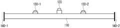
이하에서는 도면을 참조하여 본 개시의 다양한 실시예에 대해 설명하기로 한다. 우선, 본 개시에 따른, 스피커 장치(100)는 보(beam) 구조의 진동판(110), 진동판(110) 상에 위치하는 메인 액츄에이터(120)와 복수의 제어 액츄에이터(130-1,130-2)를 포함할 수 있다.Hereinafter, various embodiments of the present disclosure will be described with reference to the drawings. First, according to the present disclosure, the speaker device 100 includes a
진동판(110)은 메인 액츄에이터(110) 및 복수의 제어 액츄에이터(130-1,130-2)에 의해 발생된 진동에 따라 음을 방사할 수 있다. 특히, 진동판(110)은 얇은 두께를 가지는 전자 장치의 내부 공간에 삽입될 수 있도록 얇은 두께와 폭을 가지는 보(beam) 구조일 수 있다. 이때, 보 구조라 함은, 짧은 폭을 가지며, 길이는 폭보다 상대적으로 넓은 긴 평판의 일부(plate strip) 구조로서, 폭 방향의 진동 특성이 무시될 수 있는 1차원라 가정할 수 있다.The
특히, 보 구조는 2차원 평판 구조보다 진동 제어의 난이도가 낮고, 제어에 필요한 제어 액츄에이터의 개수 또한 작아지게 된다. 보의 폭은 목표로 하는 방사음의 주파수 대역에 따라 다르게 할 수 있으며, 물론 방사 파워를 크게 하기 위해서는 그 폭을 가능한 크게 만들 수 있다. 보의 길이도 폭의 경우와 마찬가지로 목표로 하는 방사음의 주파수 대역에 따라 다르게 할 수 있으며, 물론 방사 파워를 크게 하기 위해서는 그 길이를 가능한 크게 만들 수 있다. 보의 종횡비, 즉 길이와 폭의 비율은 폭 방향의 진동 모드를 무시하여 1차원 보로 가정할 수 있어야 한다. 보의 폭 방향, 길이 방향에 대한 1차 공진 주파수의 관계는 아래의 수학식 1과 같이 표현된다:In particular, the beam structure is less difficult to control vibration than the two-dimensional flat structure, and the number of control actuators required for control is also reduced. The width of the beam can be varied according to the frequency band of the target radiation, and of course, the width can be made as large as possible in order to increase the radiation power. Like the width, the length of the beam can be varied according to the frequency band of the target radiation. Of course, the length can be made as large as possible in order to increase the radiation power. The aspect ratio of the beam, that is, the ratio of length and width, should be able to be assumed as a one-dimensional beam by ignoring the vibration mode in the width direction. The relationship between the primary resonant frequency with respect to the width and length directions of the beam is expressed as

여기서,


메인 액츄에이터(120)는 입력된 오디오 신호를 바탕으로 생성된 입력 신호에 따라 진동판(110)을 진동시켜 음을 발생시킬 수 있다. 이때, 메인 액츄에이터(120)는 진동판(110)의 중앙 영역에 배치될 수 있다.The
복수의 제어 액츄에이터(130-1,130-2)는 입력된 오디오 신호 및 전달 함수를 바탕으로 생성된 입력 신호에 따라 진동판을 진동시켜 메인 액츄에이터에서 발생하는 진행파를 증폭하고 부착 경계면으로부터 반사되는 반사파를 제거할 수 있다. 이때, 복수의 제어 액츄에이터(130-1,130-2)는 메인 액츄에이터(120)와 진동부(110)의 부착 경계면 사이에 배치될 수 있다. 일 예로, 복수의 제어 액츄에이터는 메인 액츄에이터(120)와 제1 부착 경계면(140-1) 사이에 배치되는 제1 제어 액츄에이터(130-1) 및 메인 액츄에이터(120)와 제1 부착 경계면(140-1)의 반대편에 위치한 제2 부착 경계면(140-2) 사이에 배치되는 제2 제어 액츄에이터(130-2)를 포함할 수 있다.The plurality of control actuators 130-1 and 130-2 vibrate the diaphragm according to the input audio signal and the input signal generated based on the transfer function to amplify the traveling wave generated from the main actuator and remove the reflected wave reflected from the attachment interface. can In this case, the plurality of control actuators 130 - 1 and 130 - 2 may be disposed between the
특히, 복수의 제어 액츄에이터(130-1,130-2)는 스피커 장치의 유형에 따라 상이한 위치에 배치될 수 있다.In particular, the plurality of control actuators 130 - 1 and 130 - 2 may be arranged at different positions depending on the type of speaker device.
본 개시의 일 실시예로, 스피커 장치(100)가 저주파 대역의 음을 출력하는 스피커 장치(예로, 우퍼 스피커)인 경우, 도 1a에 도시된 바와 같이, 제1 제어 액츄에이터(130-1)는 메인 액츄에이터(120)와 제1 부착 경계면(140-1) 사이의 중앙 영역에 위치하며, 제2 제어 액츄에이터(130-2)는 메인 액츄에이터(120)와 제2 부착 경계면(140-2) 사이의 중앙 영역에 위치할 수 있다.In an embodiment of the present disclosure, when the speaker device 100 is a speaker device (eg, a woofer speaker) that outputs a sound of a low frequency band, as shown in FIG. 1A , the first control actuator 130-1 is It is located in the central region between the
이때, 스피커 장치(100)는 제1 제어법(예로, 모드 제어법(nodal control))을 이용하여 제1 및 제2 제어 액츄에이터(130-1,130-2)에 대한 입력 신호를 획득할 수 있다. 제1 제어법은 제1 및 제2 제어 액츄에이터(130-1, 130-2)에 입력되는 입력 신호와 진동판(140) 상의 복수의 측정점에서 측정된 진동 속도을 이용하여 획득된 전달 함수를 바탕으로 제1 및 제2 제어 액츄에이터(130-1,130-2)에 대한 입력 신호를 획득하는 방법이다.In this case, the speaker apparatus 100 may obtain input signals to the first and second control actuators 130 - 1 and 130 - 2 using a first control method (eg, nodal control). The first control method is a first control method based on a transfer function obtained using input signals input to the first and second control actuators 130-1 and 130-2 and vibration velocities measured at a plurality of measurement points on the diaphragm 140. and a method of obtaining an input signal to the second control actuators 130-1 and 130-2.
제1 제어법은 액츄에이터에 입력되는 신호와 보 구조의 진동판(110) 위 측정점에서 얻어진 진동 속도 간 전달 함수(transfer function)를 이용하며, 아래의 수학식 2와 같이 표현할 수 있다.The first control method uses a transfer function between the signal input to the actuator and the vibration velocity obtained at a measurement point on the

복수의 액츄에이터와 측정점에 대해 얻어지는 전달 함수와 전달 함수를 통해 구성되는 전달 행렬(transfer matrix)의 관계식은 아래의 수학식 3과 같이, 표현할 수 있다.A relational expression between a transfer function obtained for a plurality of actuators and measurement points and a transfer matrix formed through the transfer function may be expressed as in Equation 3 below.

여기서G는 전달 함수,vm은m번째 측정점에서의 진동 속도,en은n번째 액츄에이터의 입력 전압 신호이다. 수학식 3에 있어서, 설계자가 원하는 진동장이 미리 정의되었을 경우, 원하는 진동장을 구현하기 위한 액츄에이터들의 입력 신호를 역문제(inverse problem) 기법에 의해 아래의 수학식 4와 같이 얻어낼 수 있다.whereG is the transfer function,vm is the vibration velocity at them -th measurement point, anden is the input voltage signal of then -th actuator. In Equation 3, when a desired vibration field is predefined by a designer, input signals of actuators for realizing the desired vibration field can be obtained as in Equation 4 below by an inverse problem technique.

여기서,

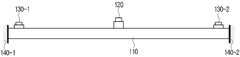
본 개시의 일 실시예로, 스피커 장치(100)가 고주파 대역의 음을 출력하는 스피커 장치(예로, 트위터 스피커)인 경우, 도 1b에 도시된 바와 같이, 제1 제어 액츄에이터(130-1)는 메인 액츄에이터(120)와 제1 부착 경계면(140-1) 사이에서 제1 부착 경계면(140-1)에 가까운 영역에 위치하며, 제2 제어 액츄에이터(130-2)는 메인 액츄에이터(120)와 제2 부착 경계면(140-2) 사이에서 제2 부착 경계면(140-2)에 가까운 영역에 위치할 수 있다.In an embodiment of the present disclosure, when the speaker device 100 is a speaker device (eg, a tweeter speaker) that outputs a sound of a high frequency band, as shown in FIG. 1B , the first control actuator 130-1 is It is located in a region close to the first attachment interface 140-1 between the
이때, 스피커 장치(100)는 제2 제어법(예로, 진행파 제어법(traveling wave control))을 이용하여 제1 및 제2 제어 액츄에이터(130-1,130-2)에 대한 입력 신호를 획득할 수 있다. 제2 제어법은 제1 및 제2 제어 액츄에이터(130-1, 130-2)에 입력되는 입력 신호와 진동판(140)에 의해 발생되는 복수의 진행파 성분을 이용하여 획득된 전달 함수를 바탕으로 제1 및 제2 제어 액츄에이터(130-1,130-2)에 대한 입력 신호를 획득하는 방법이다.In this case, the speaker apparatus 100 may obtain input signals to the first and second control actuators 130-1 and 130-2 using a second control method (eg, traveling wave control). The second control method is a first control method based on a transfer function obtained using input signals input to the first and second control actuators 130-1 and 130-2 and a plurality of traveling wave components generated by the diaphragm 140. and a method of obtaining an input signal to the second control actuators 130-1 and 130-2.
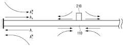
제2 제어법은 제1 제어법과 달리 액츄에이터의 입력 신호와 각 진행파 성분들이 가지는 크기 간의 전달 함수를 이용한다. 액츄에이터(220)의 진동에 의해 보구조에 형성되는 굽힘파 진동장은 도 2에 도시된 바와 같이, 4개의 진행파 성분(


여기서,v는 진동 속도,x는 측정 위치,t는 시간,k는 파수(wave number,


여기서,T는 행렬의 전치(transpose), Cn은n번째 액츄에이터의 파동 전달 계수 (wave transfer coefficient)로 이루어진 벡터(vector)이다. 위와 같이 정의된 액츄에이터의 입력 신호와 진행파 성분들의 크기에 대한 관계를 이용하면, 원하는 진행파의 크기를 형성할 수 있는 액츄에이터의 입력 신호를 구할 수 있다. 스피커 장치(100)에 복수의 액츄에이터들이 존재할 경우에는 아래의 수학식 7과 같은 행렬식이 유도될 수 있다.Here,T is the transpose of the matrix, and Cn is a vector consisting of the wave transfer coefficient of then -th actuator. Using the relationship between the actuator input signal and the magnitude of the traveling wave components defined above, the actuator input signal capable of forming a desired magnitude of the traveling wave can be obtained. When a plurality of actuators exist in the speaker device 100, a determinant of Equation 7 below may be derived.

여기서, 행렬 K는 복수의 액츄에이터들의 파동 전달 벡터로 구성된 전달 행렬이며, At는 스피커 장치(100)에서 구현하고자 하는 진행파 성분들의 크기를 의미한다. 따라서, 수학식 7을 수학식 3과 동일한 역문제 기법을 이용하여 풀이하게 되면, 원하는 진동장을 구현하기 위한 액츄에이터들의 입력 신호를 아래의 수학식 8과 같이 구할 수 있다.Here, the matrix K is a transfer matrix composed of wave transfer vectors of a plurality of actuators, and At refers to the size of traveling wave components to be implemented in the speaker device 100 . Therefore, if Equation 7 is solved using the same inverse problem technique as Equation 3, input signals of actuators for realizing a desired vibration field can be obtained as

특히, 제1 제어법의 경우에는 1차 진동 모드를 발현해야 하기 때문에, 제어 액츄에이터(130-1,130-2)가 도 1a에 도시된 바와 같이, 진동 마디선(nodal line)을 회피하며 보 구조의 중앙 영역(메인 액츄에이터(120)가 위치한 영역)과 경계 부착면(140-1,140-2)의 중앙 영역에 위치하는 것이 유리할 수 있다. 제2 제어법의 경우에는 보 구조의 경계 부착면(140-1,140-2)에서 형성된 반사파를 제거하기 위해, 제어 액츄에이터(130-1,130-1)가 도 1b에 도시된 바와 같이, 보 구조의 양 끝단에 가까운 곳에 제어 액츄에이터를 위치시키는 것이 유리할 수 있다.In particular, in the case of the first control method, since it is necessary to express the primary vibration mode, the control actuators 130-1 and 130-2 avoid the vibration nodal line as shown in FIG. 1A and avoid the center of the beam structure. It may be advantageous to be located in the central region of the region (the region in which the
또한, 본 개시의 일 실시예에 따른, 스피커 장치(100)는 제1 및 제2 제어 액츄에이터(130-1,130-2))를 진동판 상에서 이동시키기 위한 액츄에이터 이동부(미도시)를 더 포함할 수 있다. 스피커 장치(100)가 저주파 대역의 음을 출력하는 경우, 액츄에이터 이동부는 도 1a에 도시된 바와 같이, 제1 제어 액츄에이터(130-1)를 메인 액츄에이터(120)와 제1 부착 경계면(140-1) 사이의 영역 중 중앙 영역으로 이동시키며, 제2 제어 액츄에이터(130-2)를 메인 액츄에이터(120)와 제2 부착 경계면(140-2) 사이의 영역 중 중앙 영역으로 이동시킬 수 있다. 스피커 장치(100)가 고주파 대역의 음을 출력하는 경우, 액츄에이터 이동부는 도 1b에 도시된 바와 같이, 제1 제어 액츄에이터(130-1)를 메인 액츄에이터(120)와 제1 부착 경계면(140-1) 사이의 영역 중 제1 부착 경계면(140-1)에 가까운 영역으로 이동시키며, 제2 제어 액츄에이터(130-2)를 메인 액츄에이터(120)와 제2 부착 경계면(140-2) 사이의 영역 중 제2 부착 경계면(140-2)에 가까운 영역으로 이동시킬 수 있다. 즉, 출력되는 음의 주파수 대역에 따라 액츄에이터 이동부를 통해 제어 액츄에이터의 위치가 변경될 수 있다.In addition, according to an embodiment of the present disclosure, the speaker device 100 may further include an actuator moving unit (not shown) for moving the first and second control actuators 130-1 and 130-2) on the diaphragm. there is. When the speaker device 100 outputs a sound of a low frequency band, the actuator moving unit connects the first control actuator 130-1 to the
또한, 스피커 장치(100)의 진동판(110) 측면에는 간극이 형성될 수 있다. 이때, 간극은 진동판(110)과 스피커 장치(100)의 구조물 사이의 간격을 말할 수 있다. 구체적으로, 보 구조의 진동판(110)를 가진하여 음을 방사하면, 진동부(110)의 전면부 뿐만 아니라 후면부에서도 위상이 반대인 음이 방사된다. 따라서, 위상이 반대인 음에 대한 처리를 하지 않으면 전면부로 방사되는 음과 후면부로 방사되는 음이 상쇄되어 음향 방사효율이 매우 나빠지게 된다. 따라서, 보 구조 스피커 장치(100)는 고정부를 제외한 길이 방향의 측면에 매우 작은 간극을 포함할 수 있다. 이때, 형성된 간극은 진동판(110)의 진동을 방해하지 않게 하지만 후면부로 방사된 음이 전면부로 빠져 나오는 것을 막을 수 있다. 이때, 간극의 크기는 진동판(110)의 길이의 5% 이하일 수 있다.Also, a gap may be formed on the side of the
또한, 스피커 장치(100)는 진동판(110) 후면에 배치되어 진동판(110)에서 후면 방향으로 방사하는 음을 감소시키기 위한 흡음층을 포함할 수 있다. 이때, 흡음층은 진동판(110)의 후면 방향으로 방사되는 음의 크기를 줄이고, 반사에 따른 진동판(110)의 진동의 영향을 최소화 시킬 수 있다.Also, the speaker device 100 may include a sound absorbing layer disposed on the rear surface of the
또한, 스피커 장치(100)는 진동판(110)를 진동판(110)을 지지하는 스피커 장치(100)의 본체에 고정하기 위한 고정부를 더 포함할 수 있다. 이때, 고정부는 진동판(110)에서 발생하는 진동이 다른 구조에 전달되지 않도록 방진구 및 지지부와 직접 접촉되지 않도록 형성된 고정용 볼트를 포함할 수 있다. 구체적으로, 고정부는 진동 절연이 필수적이므로, 절연 요소의 공진 주파수를 가능한 낮추기 위해 유연한 소재의 방진구를 경계 부착면에 삽입할 수 있다.Also, the speaker device 100 may further include a fixing unit for fixing the
스피커 장치(100)가 전달 함수를 산출하기 위한 방법은 도 3을 참조하여 설명하기로 한다. 스피커 장치(100)는 전달 함수를 산출하기 위하여, 속도 센서(310), 메모리(320), 제어부(330), 증폭부(340)를 포함할 수 있다.A method for the speaker device 100 to calculate the transfer function will be described with reference to FIG. 3 . The speaker device 100 may include a
메인 액츄에이터(120) 및 제어 액츄에이터(130-1,130-2)에 의해 진동판(110)이 진동하는 경우, 속도 센서(310)는 진동판(110)의 복수의 측정점에서 진동속도를 감지할 수 있다. 예로, 속도 센서(310)는 메인 액츄에이터(120)와 부착 경계면(140-1,140-2) 사이의 10 등분한 지점 각각에 진동속도를 감지할 수 있다.When the
메모리(320)는 속도 센서(310)에 의해 감지된 복수의 측정점에 대한 진동 속도를 저장할 수 있다.The
증폭부(340)는 제어부(330)에 의해 생성된 특정 입력 신호에 따라 제어 액츄에이터(130-1,130-2)를 가진시킬 수 있다.The amplifying
제어부(330)는 제어 액츄에이터(130-1,130-2)를 가진하기 위한 특정 입력 신호를 생성하고, 생성된 신호를 증폭부(340)로 출력할 수 있다. 또한, 제어부(330)는 제어 액츄에이터(130-1,130-2)를 가진하기 위한 특정 입력 신호와 메모리(320)에 저장된 복수의 측정점 간의 진동 속도를 이용하여 복수의 측정점에 대한 전달함수를 획득할 수 있다.The
이때, 전달함수를 산출하기 위한 시스템은 스피커 장치(100)의 설계 단계에 적용되어 제품 출하 전에 전달함수가 산출될 수 있으나, 이는 일 실시예에 불과할 뿐, 전달함수를 산출하기 위한 시스템은 보 구조의 스피커 장치(100)에 내장되어 실시간으로 전달 함수를 산출할 수 있다.At this time, the system for calculating the transfer function is applied to the design stage of the speaker device 100 so that the transfer function can be calculated before product shipment, but this is only an example, and the system for calculating the transfer function is a beam structure It is built into the speaker device 100 of the , and can calculate the transfer function in real time.
스피커 장치(100)가 입력된 오디오 신호 및 산출된 전달 함수를 바탕으로 음을 방사하는 방법은 도 4을 참조하여 설명하기로 한다. 스피커 장치(100)는 오디오 신호 입력부(410), 메모리(420), 제어부(430) 및 증폭부(440)를 포함할 수 있다.A method for the speaker device 100 to emit a sound based on the input audio signal and the calculated transfer function will be described with reference to FIG. 4 . The speaker device 100 may include an audio
오디오 신호 입력부(410)는 외부로부터 오디오 신호를 입력받을 수 있다. 이때, 오디오 신호는 다양한 컨텐츠 데이터로부터 획득된 신호일 수 있다. 이때, 입력된 오디오 신호를 바탕으로 메인 액츄에이터(120)가 가진될 수 있다.The audio
메모리(420)는 오디오 신호 입력부(410)에서 입력된 오디오 신호 및 도 3에서 산출된 전달 함수를 저장할 수 있다. 이때, 메모리(420)는 버퍼(buffer)와 같은 휘발성 메모리로 구현될 수 있으나, 이는 일 실시예에 불과할 뿐, 다른 메모리로 구현될 수 있다.The
제어부(430)는 오디오 신호 입력부(410)에서 입력된 오디오 신호 및 도 3에서 산출된 전달 함수를 바탕으로 제어 액츄에이터(130-1,130-2)를 가진하기 위한 입력 신호를 생성할 수 있다.The
이때, 제어부(430)는 스피커 장치(100)의 종류 또는 입력되는 주파수 대역에 따라 상이한 제어법을 통해 입력 신호를 생성할 수 있다. 예를 들어, 스피커 장치(430)가 우퍼 스피커 이거나, 저주파 대역의 오디오 신호가 입력된 경우, 제어부(430)는 제1 제어법을 통해 입력 신호를 생성할 수 있다. 즉, 제어부(430)는 입력된 오디오 신호 및 진동판(110) 상의 복수의 측정점에서 측정된 진동 속도을 이용하여 획득된 전달 함수를 바탕으로 제1 및 제2 제어 액츄에이터(130-1,130-2)에 대한 입력 신호를 획득할 수 있다. 또 다른 예로, 스피커 장치(430)가 트위터 스피커이거나, 고주파 대역의 오디오 신호가 입력된 경우, 제어부(430)는 제2 제어법을 통해 입력 신호를 생성할 수 있다. 즉, 제어부(430)는 입력된 오디오 신호 및 진동판(140)에 의해 발생되는 복수의 진행파 성분을 이용하여 획득된 전달 함수를 바탕으로 제1 및 제2 제어 액츄에이터(130-1,130-2)에 대한 입력 신호를 생성할 수 있다.In this case, the
증폭부(440)는 획득된 입력 신호를 바탕으로 제어 액츄에이터(130-1,130-2)를 가진시켜 메인 액츄이터에(120)에서 방사되는 음을 증폭할 수 있다.The
도 5는 다양한 실시예에 따른, 보 구조의 스피커 장치에서 방사된 음의 주파수 응답을 설명하기 위한 도면이다. 특히, 도 5는 실험을 통해 얻어진 보 구조의 스피커 장치(100)로부터 방사된 음의 주파수 응답을 나타내는다. 이때, 실험에 사용된 보구조의 스피커 장치(100)의 진동판(110)은 315 x 40 x 2 mm3크기의 알루미늄이며, 모드 제어법의 경우, 제어 액츄에이터는 메인 액츄에이터로부터 80 mm 떨어져 있으며, 진행파 제어법의 경우 진동판(110)의 양 끝단으로부터 30 mm 떨어진 위치에 배치될 수 있다. 관심 주파수 대역은 중주파수 대역의 스피커를 고려하여 300-2000 Hz으로 정의될 수 있다.5 is a view for explaining a frequency response of sound emitted from a speaker device having a beam structure, according to various embodiments of the present disclosure; In particular, FIG. 5 shows a frequency response of a sound emitted from the speaker device 100 having a beam structure obtained through an experiment. At this time, the
진동장 제어없이(즉, 전달 함수를 바탕으로 오디오 신호에 대응되는 입력 신호를 생성하지 않고) 메인 액츄에이터 또는 제어 액츄에이터만 가진될 경우, 보 구조의 스피커 장치(100)에서 방사음 스펙트럼에 심한 변동 및 가파른 응답이 발생하여 음질이 저하되는 결과를 보여준다. 이와 달리 진동장을 제어할 경우, 진동의 영향이 상당량 감소하는 것을 알 수 있으며, 이에 따라 보다 평탄한 방사음의 주파수 응답이 구현되는 것을 알 수 있다. 이때, 모드 제어법의 경우 진행파 제어법보다 관심 주파수 대역에서 보다 평탄한 주파수 응답을 가지나 스펙트럼의 골(trough)이 보구조의 스피커 장치(100)의 진동 모드에 따라 발생한다. 진행파 제어법은 보 구조에 진행파 진동장이 형성됨에 따라 체적 속도(volume velocity)가 감소되어 응답이 높지 않은 주파수 대역이 존재하나, 모드 제어법보다 고주파수 대역에서 골의 발생과 같은 스펙트럼의 변동이 작은 특성을 가진다.When only the main actuator or the control actuator is excited without vibration field control (that is, without generating an input signal corresponding to an audio signal based on a transfer function), severe fluctuations in the radiation sound spectrum in the speaker device 100 of the beam structure and A steep response occurs, which results in deterioration of sound quality. On the other hand, when the vibration field is controlled, it can be seen that the effect of vibration is significantly reduced, and accordingly, it can be seen that a more flat frequency response of the radiated sound is realized. In this case, the mode control method has a flatter frequency response in the frequency band of interest than the traveling wave control method, but a trough of the spectrum occurs according to the vibration mode of the speaker device 100 having the beam structure. In the traveling wave control method, as a traveling wave oscillation field is formed in the beam structure, there is a frequency band where the response is not high because the volume velocity is reduced, but there is a characteristic that the spectrum fluctuation such as the generation of a bone is smaller than the mode control method in the high frequency band. .
즉, 진동판(110)의 중심부에서 메인 액츄에이터(120)로 가진되어 작동하는 보구조 스피커 장치(100)에서 원하는 주파수 응답을 얻기 위해서는, 이와 같이 추가적인 제어 액츄에이터(130-1,130-2)를 이용한 진동장 제어가 필요함을 알 수 있다.That is, in order to obtain a desired frequency response in the auxiliary structure speaker device 100 that is excited by the
도 6은 본 개시의 일 실시예에 따른, 간극의 크기, 주파수 및 종횡비에 따라 보구조 스피커 장치의 축 방향 측정점에 측정된 방사 음압의 변화를 나타내는 도면이다. 도 6의 상단에 도시된 도면의 종횡비는 1이고, 중앙에 도시된 도면의 종회비는 20이고, 하단에 도시된 도면의 종횡비는 50이다. 평판의 종횡비, 주파수 및 간극의 크기에 따른 방사 음압 레벨의 변화량.Ra= la/lb,Rg= d/la로 정의되며, 여기서la, lb는 각각 평판의 장변과 단변,d는 간극의 크기이다6 is a diagram illustrating a change in radiated sound pressure measured at a measurement point in an axial direction of the auxiliary structure speaker device according to the size, frequency, and aspect ratio of the gap, according to an embodiment of the present disclosure. The aspect ratio of the drawing shown in the upper part of FIG. 6 is 1, the aspect ratio of the figure shown in the center is 20, and the aspect ratio of the figure shown in the lower part is 50. The amount of change in the radiated sound pressure level with the aspect ratio of the plate, the frequency, and the size of the gap. It is defined asRa= la/lb ,Rg= d/la , wherelaand lbare the long and short sides of the plate, respectively, andd is the size of the gap.
도 6에 도시된 바와 같이, 간극에 의해 변화하는 방사 음압의 경향은 종횡비에 따라 상이하나, 간극의 크기가 평판 길이의 5 % 이하일 경우, 방사 음압 레벨의 변화는 0.3 dB 이하이다. 이는 사람이 감지할 수 없을 만큼 충분히 작은 값이기에, 이를 기준으로 실제 보구조 스피커(100)를 설계할 때 간극의 크기를 결정할 수 있다.As shown in FIG. 6 , the tendency of the radiated sound pressure changed by the gap is different depending on the aspect ratio, but when the size of the gap is 5% or less of the plate length, the change in the radiated sound pressure level is 0.3 dB or less. Since this value is sufficiently small that a human cannot detect it, the size of the gap can be determined when designing the actual auxiliary structure speaker 100 based on this value.
도 7은 본 개시의 일 실시예에 따른, 보 구조의 스피커 장치의 후면 공간과 흡음재의 유무에 따른 방사 음향 파워 스펙트럼의 변화를 나타내는 도면이다.7 is a view illustrating a change in a radiated acoustic power spectrum according to a rear space of a speaker device having a beam structure and the presence or absence of a sound absorbing material, according to an embodiment of the present disclosure.
도 7에 도시된 바와 같이, 후면 공간이 존재할 시 진동판(110)과의 음향-진동 상호작용으로 인해 진동판(110)의 진동 모드와 후면 공간의 음향 모드에 의한 영향이 존재함을 알 수 있다. 이때 흡음재를 부착하게 되면 해당 주파수에서 음향 및 진동 모드에 의한 영향을 대폭 감소시킬 수 있다. 즉, 스피커 장치(100) 설치 시, 스피커 장치(100)의 후면에 흡음재를 부착할 경우, 후면 방사되는 소리를 감소시키고 후면 공간의 영향을 최소화시킬 수 있어 보다 향상된 음질의 음을 방사할 수 있게 된다.As shown in FIG. 7 , when the rear space exists, it can be seen that the vibration mode of the
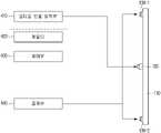
도 8은 본 개시의 일 실시예에 따른, 스피커 장치를 포함하는 전자 장치의 구성을 설명하기 위한 블록도이다. 도 8에 도시된 바와 같이, 전자 장치(100)는 컨텐츠 획득부(810), 메모리(820), 스피커 장치(830), 디스플레이(840) 및 제어부(850)를 포함할 수 있다. 이때, 스피커 장치(830)는 도 1 내지 도 7에서 설명한 스피커 장치(100)와 동일하므로, 중복되는 설명은 생략하기로 한다. 또한, 메모리(820) 및 제어부(850)는 도 3 및 도 4에서 설명한 메모리 및 제어부와 동일하므로, 중복되는 설명은 생략하기로 한다.8 is a block diagram illustrating a configuration of an electronic device including a speaker device according to an embodiment of the present disclosure. As shown in FIG. 8 , the electronic device 100 may include a
본 개시의 다양한 실시 예에 따른 전자 장치는 예를 들면, TV, 스마트 폰, 태블릿 PC, 데스크탑 PC, 랩탑 PC 또는 웨어러블 장치 중 적어도 하나를 포함할 수 있다. 어떤 실시 예들에서, 전자 장치는 예를 들면, DVD(digital video disk) 플레이어, 오디오, 냉장고, 에어컨, 청소기, 오븐, 전자레인지, 세탁기, 공기 청정기, 셋톱 박스, 홈 오토매이션 컨트롤 패널, 보안 컨트롤 패널, 미디어 박스(예: 삼성 HomeSyncTM, 애플TVTM, 또는 구글 TVTM), 게임 콘솔(예: XboxTM, PlayStationTM), 전자 사전, 전자 키, 캠코더, 또는 전자 액자 중 적어도 하나를 포함할 수 있다.The electronic device according to various embodiments of the present disclosure may include, for example, at least one of a TV, a smart phone, a tablet PC, a desktop PC, a laptop PC, and a wearable device. In some embodiments, the electronic device is, for example, a digital video disk (DVD) player, audio, refrigerator, air conditioner, vacuum cleaner, oven, microwave oven, washing machine, air purifier, set-top box, home automation control panel, security control panel, media box (eg Samsung HomeSyncTM , Apple TVTM , or Google TVTM ), game console (eg XboxTM , PlayStationTM ), electronic dictionary, electronic key, camcorder, or electronic picture frame. can
다른 실시예에서, 전자 장치는 각종 의료기기(예: 각종 휴대용 의료측정기기(혈당 측정기, 심박 측정기, 혈압 측정기, 또는 체온 측정기 등), MRA(magnetic resonance angiography), MRI(magnetic resonance imaging), CT(computed tomography), 촬영기, 또는 초음파기 등), 네비게이션 장치, 위성 항법 시스템(GNSS(global navigation satellite system)), EDR(event data recorder), FDR(flight data recorder), 자동차 인포테인먼트 장치, 선박용 전자 장비(예: 선박용 항법 장치, 자이로 콤파스 등), 항공 전자기기(avionics), 보안 기기, 차량용 헤드 유닛(head unit), 산업용 또는 가정용 로봇, 드론(drone), 금융 기관의 ATM, 상점의 POS(point of sales), 또는 사물 인터넷 장치 (예: 전구, 각종 센서, 스프링클러 장치, 화재 경보기, 온도조절기, 가로등, 토스터, 운동기구, 온수탱크, 히터, 보일러 등) 중 적어도 하나를 포함할 수 있다.In another embodiment, the electronic device includes various medical devices (eg, various portable medical devices (eg, a blood glucose meter, a heart rate monitor, a blood pressure monitor, or a body temperature monitor), magnetic resonance angiography (MRA), magnetic resonance imaging (MRI), or CT. (computed tomography, camera, or ultrasound machine, etc.), navigation devices, global navigation satellite system (GNSS), event data recorder (EDR), flight data recorder (FDR), automotive infotainment devices, marine electronic equipment ( Examples: navigation devices for ships, gyro compasses, etc.), avionics, security devices, head units for vehicles, industrial or household robots, drones, ATMs in financial institutions, point of sale (POS) in stores sales), or Internet of Things devices (eg, light bulbs, various sensors, sprinkler devices, fire alarms, thermostats, street lights, toasters, exercise equipment, hot water tanks, heaters, boilers, etc.).
컨텐츠 획득부(810)는 외부로부터 컨텐츠를 획득할 수 있다. 이때, 컨텐츠 획득부(810)는 방송 컨텐츠를 획득하기 위해 튜너로 구현될 수 있으나, 이는 일 실시예에 불과할 뿐, 통신 인터페이스(예로, LTE(Long Term Evolution), LTE-A(LTE Advanced), 4G(4th Generation), 5G(5th Generation), WiFi 등), 입출력 인터페이스(HDMI(High Definition Multimedia Interface), MHL (Mobile High-Definition Link), USB (Universal Serial Bus) 등)으로 구현될 수 있다.The
메모리(820)는 제어부(850))에 포함된 롬(ROM)(예를 들어, EEPROM(electrically erasable programmable read-only memory)), 램(RAM) 등의 내부 메모리로 구현되거나, 제어부(850)와 별도의 메모리로 구현될 수도 있다. 이 경우, 메모리(820)는 데이터 저장 용도에 따라 전자 장치(600)에 임베디드된 메모리 형태로 구현되거나, 전자 장치(800)에 탈부착이 가능한 메모리 형태로 구현될 수도 있다. 예를 들어, 전자 장치(800)의 구동을 위한 데이터의 경우 전자 장치(800)에 임베디드된 메모리에 저장되고, 전자 장치(800)의 확장 기능을 위한 데이터의 경우 전자 장치(800)에 탈부착이 가능한 메모리에 저장될 수 있다.The
한편, 전자 장치(800)에 임베디드된 메모리의 경우 휘발성 메모리(예: DRAM(dynamic RAM), SRAM(static RAM), 또는 SDRAM(synchronous dynamic RAM) 등), 비휘발성 메모리(non-volatile Memory)(예: OTPROM(one time programmable ROM), PROM(programmable ROM), EPROM(erasable and programmable ROM), EEPROM(electrically erasable and programmable ROM), mask ROM, flash ROM, 플래시 메모리(예: NAND flash 또는 NOR flash 등), 하드 드라이브, 또는 솔리드 스테이트 드라이브(solid state drive(SSD)) 중 적어도 하나로 구현되고, 전자 장치(800)에 탈부착이 가능한 메모리의 경우 메모리 카드(예를 들어, CF(compact flash), SD(secure digital), Micro-SD(micro secure digital), Mini-SD(mini secure digital), xD(extreme digital), MMC(multi-media card) 등), USB 포트에 연결 가능한 외부 메모리(예를 들어, USB 메모리) 등과 같은 형태로 구현될 수 있다.Meanwhile, in the case of a memory embedded in the
디스플레이(840)는 LCD(Liquid Crystal Display), OLED(Organic Light Emitting Diodes) 디스플레이, PDP(Plasma Display Panel) 등과 같은 다양한 형태의 디스플레이로 구현될 수 있다. 디스플레이(110)내에는 a-si TFT, LTPS(low temperature poly silicon) TFT, OTFT(organic TFT) 등과 같은 형태로 구현될 수 있는 구동 회로, 백라이트 유닛 등도 함께 포함될 수 있다. 한편, 디스플레이(840)는 터치 센서와 결합된 터치 스크린, 플렉시블 디스플레이(flexible display), 3차원 디스플레이(3D display) 등으로 구현될 수 있다.The display 840 may be implemented as various types of displays, such as a liquid crystal display (LCD), an organic light emitting diode (OLED) display, a plasma display panel (PDP), and the like. The
또한, 본 개시의 일 실시 예에 따른, 디스플레이(840)는 외부로부터 수신되는 다양한 영상 컨텐츠(예로, 방송 컨텐츠 등)를 디스플레이할 수 있다.Also, according to an embodiment of the present disclosure, the display 840 may display various image contents (eg, broadcast contents, etc.) received from the outside.
제어부(850)는 전자 장치(800)의 전반적인 제어 동작을 수행할 수 있다. 구체적으로, 제어부(850)는 전자 장치(800)의 전반적인 동작을 제어하는 기능을 한다.The
제어부(850)는 디지털 신호를 처리하는 디지털 시그널 프로세서(digital signal processor(DSP), 마이크로 프로세서(microprocessor), TCON(Time controller)으로 구현될 수 있다. 다만, 이에 한정되는 것은 아니며, 중앙처리장치(central processing unit(CPU)), MCU(Micro Controller Unit), MPU(micro processing unit), 어플리케이션 프로세서(application processor(AP)), GPU(graphics-processing unit) 또는 커뮤니케이션 프로세서(communication processor(CP)), ARM 프로세서 중 하나 또는 그 이상을 포함하거나, 해당 용어로 정의될 수 있다. 또한, 제어부(850)는 프로세싱 알고리즘이 내장된 SoC(System on Chip), LSI(large scale integration)로 구현될 수도 있고, FPGA(Field Programmable gate array) 형태로 구현될 수도 있다. 또한, 제어부(850)는 메모리에 저장된 컴퓨터 실행가능 명령어(computer executable instructions)를 실행함으로써 다양한 기능을 수행할 수 있다.The
또한, 상술한 다양한 실시 예들에 따른 구성 요소(예: 모듈 또는 프로그램) 각각은 단수 또는 복수의 개체로 구성될 수 있으며, 전술한 해당 서브 구성 요소들 중 일부 서브 구성 요소가 생략되거나, 또는 다른 서브 구성 요소가 다양한 실시 예에 더 포함될 수 있다. 대체적으로 또는 추가적으로, 일부 구성 요소들(예: 모듈 또는 프로그램)은 하나의 개체로 통합되어, 통합되기 이전의 각각의 해당 구성 요소에 의해 수행되는 기능을 동일 또는 유사하게 수행할 수 있다. 다양한 실시 예들에 따른, 모듈, 프로그램 또는 다른 구성 요소에 의해 수행되는 동작들은 순차적, 병렬적, 반복적 또는 휴리스틱하게 실행되거나, 적어도 일부 동작이 다른 순서로 실행되거나, 생략되거나, 또는 다른 동작이 추가될 수 있다.In addition, each of the components (eg, a module or a program) according to the above-described various embodiments may be composed of a single or a plurality of entities, and some sub-components of the aforementioned sub-components may be omitted, or other sub-components may be omitted. Components may be further included in various embodiments. Alternatively or additionally, some components (eg, a module or a program) may be integrated into a single entity to perform the same or similar functions performed by each corresponding component prior to integration. According to various embodiments, operations performed by a module, program, or other component may be sequentially, parallel, repetitively or heuristically executed, or at least some operations may be executed in a different order, omitted, or other operations may be added. can
이상에서는 본 개시의 바람직한 실시 예에 대하여 도시하고 설명하였지만, 본 개시는 상술한 특정의 실시 예에 한정되지 아니하며, 청구범위에서 청구하는 본 개시의 요지를 벗어남이 없이 당해 개시에 속하는 기술분야에서 통상의 지식을 가진 자에 의해 다양한 변형 실시가 가능한 것은 물론이고, 이러한 변형실시들은 본 개시의 기술적 사상이나 전망으로부터 개별적으로 이해되어져서는 안될 것이다.In the above, preferred embodiments of the present disclosure have been illustrated and described, but the present disclosure is not limited to the specific embodiments described above, and it is common in the technical field pertaining to the present disclosure without departing from the gist of the present disclosure as claimed in the claims. Various modifications may be made by those having the knowledge of
110: 진동판120: 메인 액츄에이터
130-1: 제1 제어 액츄에이터130-2: 제2 제어 액츄에이터
140-1: 제1 부착 경계면140-2: 제2 부착 경계면110: diaphragm 120: main actuator
130-1: first control actuator 130-2: second control actuator
140-1: first attachment interface 140-2: second attachment interface
Claims (17)
Translated fromKorean진동을 발생하기 위한 보(beam) 형태의 진동판;
입력 신호에 따라 상기 진동판을 진동시켜 음을 발생시키기 위해 상기 진동판의 중앙 영역에 배치되는 메인 액츄에이터; 및
상기 메인 액츄에이터와 상기 진동부의 부착 경계면 사이에 배치되며, 입력 신호에 따라 상기 진동판을 진동시켜 상기 메인 액츄에이터에서 발생하는 진행파를 증폭하고 상기 부착 경계면으로부터 반사되는 반사파를 제거하기 위한 복수의 제어 액츄에이터;를 포함하는 스피커 장치.A speaker device comprising:
a diaphragm in the form of a beam for generating vibration;
a main actuator disposed in a central region of the diaphragm to vibrate the diaphragm according to an input signal to generate a sound; and
a plurality of control actuators disposed between the attachment interface of the main actuator and the vibrating part, and configured to vibrate the diaphragm according to an input signal to amplify a traveling wave generated from the main actuator and remove a reflected wave reflected from the attachment interface; speaker unit included.
상기 복수의 제어 액츄에이터는,
상기 메인 액츄에이터와 제1 부착 경계면 사이에 배치되는 제1 제어 액츄에이터 및 상기 메인 액츄에이터와 상기 제1 부착 경계면의 반대편에 위치한 제2 부착 경계면 사이에 배치되는 제2 제어 액츄에이터를 포함하는 스피커 장치.According to claim 1,
The plurality of control actuators,
and a first control actuator disposed between the main actuator and a first attachment interface and a second control actuator disposed between the main actuator and a second attachment interface opposite the first attachment interface.
상기 스피커 장치가 저주파 대역의 음을 출력하는 스피커 장치인 경우,
상기 제1 제어 액츄에이터는 상기 메인 액츄에이터와 상기 제1 부착 경계면 사이의 중앙 영역에 위치하며, 상기 제2 제어 액츄에이터는 상기 메인 액츄에이터와 상기 제2 부착 경계면 사이의 중앙 영역에 위치하는 스피커 장치.3. The method of claim 2,
When the speaker device is a speaker device that outputs a sound of a low frequency band,
The first control actuator is located in a central region between the main actuator and the first attachment interface, and the second control actuator is located in a central region between the main actuator and the second attachment interface.
상기 제1 및 제2 제어 액츄에이터에 입력되는 입력 신호와 상기 진동판 상의 복수의 측정점에서 측정된 진동 속도를 이용하여 획득된 전달 함수를 바탕으로 상기 제1 및 제2 제어 액츄에이터에 대한 입력 신호를 획득하는 제어부;를 포함하는 스피커 장치.4. The method of claim 3,
Obtaining input signals for the first and second control actuators based on a transfer function obtained using the input signals input to the first and second control actuators and the vibration velocities measured at a plurality of measurement points on the diaphragm A speaker device comprising a control unit.
상기 스피커 장치가 고주파 대역의 음을 출력하는 스피커 장치인 경우,
상기 제1 제어 액츄에이터는 상기 메인 액츄에이터와 상기 제1 부착 경계면 사이에서 상기 제1 부착 경계면에 가까운 영역에 위치하며, 상기 제2 제어 액츄에이터는 상기 메인 액츄에이터와 상기 제2 부착 경계면 사이에서 상기 제2 부착 경계면에 가까운 영역에 위치하는 스피커 장치.3. The method of claim 2,
When the speaker device is a speaker device that outputs a sound in a high-frequency band,
the first control actuator is located between the main actuator and the first attachment interface in a region proximal to the first attachment interface, and wherein the second control actuator is located between the main actuator and the second attachment interface and the second attachment interface is between the main actuator and the second attachment interface. A speaker unit located in an area close to the boundary surface.
상기 제1 및 제2 제어 액츄에이터에 입력되는 입력 신호와 상기 진동판에 의해 발생되는 복수의 진행파 성분을 이용하여 획득된 전달 함수를 바탕으로 상기 제1 및 제2 제어 액츄에이터에 대한 입력 신호를 획득하는 제어부;를 포함하는 스피커 장치.6. The method of claim 5,
A control unit for obtaining input signals to the first and second control actuators based on a transfer function obtained using an input signal input to the first and second control actuators and a plurality of traveling wave components generated by the diaphragm A speaker device comprising ;
상기 제1 및 상기 제2 제어 액츄에이터를 이동시키기 위한 액츄에이터 이동부를 더 포함하고,
상기 이동부는,
상기 스피커 장치가 저주파의 음을 출력하는 경우, 상기 제1 제어 액츄에이터를 상기 메인 액츄에이터와 상기 제1 부착 경계면 사이의 영역 중 중앙 영역으로 이동시키며, 상기 제2 제어 액츄에이터를 상기 메인 액츄에이터와 상기 제2 부착 경계면 사이의 영역 중 중앙 영역으로 이동시키며,
상기 스피커 장치가 고주파의 음을 출력하는 경우, 상기 제1 제어 액츄에이터를 상기 메인 액츄에이터와 상기 제1 부착 경계면 사이의 영역 중 상기 제1 부착 경계면에 가까운 영역으로 이동시키며, 상기 제2 제어 액츄에이터를 상기 메인 액츄에이터와 상기 제2 부착 경계면 사이의 영역 중 상기 제2 부착 경계면에 가까운 영역으로 이동시키는 스피커 장치.3. The method of claim 2,
Further comprising an actuator moving unit for moving the first and second control actuators,
The moving unit,
When the speaker device outputs a low-frequency sound, the first control actuator is moved to a central region among regions between the main actuator and the first attachment interface, and the second control actuator is moved between the main actuator and the second It moves to the central area among the areas between the attachment interfaces,
When the speaker device outputs a high-frequency sound, the first control actuator is moved to a region between the main actuator and the first attachment interface that is closer to the first attachment interface, and the second control actuator is moved to the A speaker device for moving the main actuator to an area close to the second attachment interface among the areas between the main actuator and the second attachment interface.
상기 진동판의 폭은 상기 진동판의 길이의 15% 이하인 것을 특징으로 하는 스피커 장치.According to claim 1,
A width of the diaphragm is 15% or less of a length of the diaphragm.
상기 진동판 측면에 간극이 형성되며,
상기 간극의 크기는 상기 진동판의 길이의 5% 이하인 것을 특징으로 하는 스피커 장치.According to claim 1,
A gap is formed on the side of the diaphragm,
The size of the gap is 5% or less of the length of the diaphragm speaker device.
상기 진동판 후면에 배치되어 상기 진동판에서 후면 방향으로 방사하는 음을 감소시키기 위한 흡음층;을 포함하는 스피커 장치.According to claim 1,
and a sound absorbing layer disposed on a rear surface of the diaphragm to reduce a sound radiated from the diaphragm in a rear direction.
상기 진동판를 상기 진동판을 지지하기 위한 상기 스피커 장치의 본체에 고정하기 위한 고정부를 더 포함하며,
상기 고정부는,
상기 진동판에서 발생하는 진동이 다른 구조에 전달되지 않도록 방진구 및 상기 지지부와 직접 접촉되지 않도록 형성된 고정용 볼트를 포함하는 스피커 장치.According to claim 1,
Further comprising a fixing part for fixing the diaphragm to the main body of the speaker device for supporting the diaphragm,
The fixing part,
and a vibration isolator so that the vibration generated from the diaphragm is not transmitted to other structures and a fixing bolt formed not to come into direct contact with the support part.
컨텐츠를 획득하는 컨텐츠 획득부;
상기 획득된 컨텐츠의 오디오를 출력하기 위한 스피커 장치; 및
상기 획득된 컨텐츠의 오디오를 출력하기 위해 상기 스피커 장치에 입력 신호를 제공하는 제어부;를 포함하고,
상기 스피커 장치는,
진동을 발생하기 위한 보(beam) 형태의 진동판;
상기 제어부에 의해 제공된 입력 신호에 따라 상기 진동판을 진동시켜 음을 발생시키기 위해 상기 진동판의 중앙 영역에 배치되는 메인 액츄에이터; 및
상기 메인 액츄에이터와 상기 진동부의 부착 경계면 사이에 배치되며, 상기 제어부에 의해 제공된 입력 신호에 따라 상기 진동판을 진동시켜 상기 메인 액츄에이터에서 발생하는 진행파를 증폭하고 상기 부착 경계면으로부터 반사되는 반사파를 제거하기 위한 복수의 제어 액츄에이터;를 포함하는 디스플레이 장치.In an electronic device,
a content acquisition unit for acquiring content;
a speaker device for outputting audio of the obtained content; and
Including; a control unit that provides an input signal to the speaker device to output the audio of the obtained content;
The speaker device,
a diaphragm in the form of a beam for generating vibration;
a main actuator disposed in a central region of the diaphragm to vibrate the diaphragm according to an input signal provided by the controller to generate a sound; and
It is disposed between the attachment interface of the main actuator and the vibrating part, and vibrates the diaphragm according to an input signal provided by the controller to amplify a traveling wave generated from the main actuator and remove a reflected wave reflected from the attachment interface. Control actuator of; Display device comprising a.
상기 복수의 제어 액츄에이터는,
상기 메인 액츄에이터와 제1 부착 경계면 사이에 배치되는 제1 제어 액츄에이터 및 상기 메인 액츄에이터와 상기 제1 부착 경계면의 반대편에 위치한 제2 부착 경계면 사이에 배치되는 제2 제어 액츄에이터를 포함하는 디스플레이 장치.13. The method of claim 12,
The plurality of control actuators,
A display device comprising: a first control actuator disposed between the main actuator and a first attachment interface; and a second control actuator disposed between the main actuator and a second attachment interface opposite the first attachment interface.
상기 스피커 장치가 저주파 대역의 음을 출력하는 우퍼 스피커 장치인 경우,
상기 제1 제어 액츄에이터는 상기 메인 액츄에이터와 상기 제1 부착 경계면 사이의 중앙 영역에 위치하며, 상기 제2 제어 액츄에이터는 상기 메인 액츄에이터와 상기 제2 부착 경계면 사이의 중앙 영역에 위치하는 디스플레이 장치.14. The method of claim 13,
When the speaker device is a woofer speaker device that outputs a sound in a low frequency band,
The first control actuator is positioned in a central region between the main actuator and the first attachment interface, and the second control actuator is positioned in a central region between the main actuator and the second attachment interface.
상기 제어부는,
상기 제1 및 제2 제어 액츄에이터에 입력되는 입력 신호와 상기 진동판 상의 복수의 측정점에서 측정된 진동 속도를 이용하여 획득된 전달 함수를 바탕으로 상기 제1 및 제2 제어 액츄에이터에 대한 입력 신호를 획득하는 디스플레이 장치.15. The method of claim 14,
The control unit is
Obtaining input signals for the first and second control actuators based on a transfer function obtained using the input signals input to the first and second control actuators and the vibration velocities measured at a plurality of measurement points on the diaphragm display device.
상기 스피커 장치가 고주파 대역의 음을 출력하는 트위터 스피커 장치인 경우,
상기 제1 제어 액츄에이터는 상기 메인 액츄에이터와 상기 제1 부착 경계면 사이에서 상기 제1 부착 경계면에 가까운 영역에 위치하며, 상기 제2 제어 액츄에이터는 상기 메인 액츄에이터와 상기 제2 부착 경계면 사이에서 상기 제2 부착 경계면에 가까운 영역에 위치하는 디스플레이 장치.14. The method of claim 13,
When the speaker device is a tweeter speaker device that outputs a sound in a high-frequency band,
the first control actuator is located between the main actuator and the first attachment interface in a region proximal to the first attachment interface, and wherein the second control actuator is located between the main actuator and the second attachment interface and the second attachment interface is between the main actuator and the second attachment interface. A display device located in an area close to the boundary surface.
상기 제어부는,
상기 제1 및 제2 제어 액츄에이터에 입력되는 입력 신호와 상기 진동판에 의해 발생되는 복수의 진행파 성분을 이용하여 획득된 전달 함수를 바탕으로 상기 제1 및 제2 제어 액츄에이터에 대한 입력 신호를 획득하는 디스플레이 장치.17. The method of claim 16,
The control unit is
A display for obtaining input signals to the first and second control actuators based on a transfer function obtained using an input signal input to the first and second control actuators and a plurality of traveling wave components generated by the diaphragm Device.
Priority Applications (2)
| Application Number | Priority Date | Filing Date | Title |
|---|---|---|---|
| KR1020200147971AKR102833739B1 (en) | 2020-11-06 | 2020-11-06 | A speaker and electronic device including the speaker |
| PCT/KR2021/014455WO2022097961A1 (en) | 2020-11-06 | 2021-10-18 | Speaker device and electronic device including same |
Applications Claiming Priority (1)
| Application Number | Priority Date | Filing Date | Title |
|---|---|---|---|
| KR1020200147971AKR102833739B1 (en) | 2020-11-06 | 2020-11-06 | A speaker and electronic device including the speaker |
Publications (2)
| Publication Number | Publication Date |
|---|---|
| KR20220061695Atrue KR20220061695A (en) | 2022-05-13 |
| KR102833739B1 KR102833739B1 (en) | 2025-07-18 |
Family
ID=81457202
Family Applications (1)
| Application Number | Title | Priority Date | Filing Date |
|---|---|---|---|
| KR1020200147971AActiveKR102833739B1 (en) | 2020-11-06 | 2020-11-06 | A speaker and electronic device including the speaker |
Country Status (2)
| Country | Link |
|---|---|
| KR (1) | KR102833739B1 (en) |
| WO (1) | WO2022097961A1 (en) |
Citations (5)
| Publication number | Priority date | Publication date | Assignee | Title |
|---|---|---|---|---|
| US20040189151A1 (en)* | 2000-01-07 | 2004-09-30 | Lewis Athanas | Mechanical-to-acoustical transformer and multi-media flat film speaker |
| KR20160127635A (en)* | 2015-04-27 | 2016-11-04 | 주식회사 동운아나텍 | Apparatus for driving voice coil actuator of camera and method thereof |
| KR101817102B1 (en)* | 2016-11-30 | 2018-01-10 | 엘지디스플레이 주식회사 | Display device for generating sound by panel vibration type |
| US20190200139A1 (en)* | 2017-12-22 | 2019-06-27 | Nvf Tech Ltd. | Two-dimensional distributed mode actuator |
| US20200136489A1 (en)* | 2018-10-24 | 2020-04-30 | Mplus Co., Ltd. | Sound vibration actuator |
Family Cites Families (3)
| Publication number | Priority date | Publication date | Assignee | Title |
|---|---|---|---|---|
| EP2202619A1 (en)* | 2008-12-23 | 2010-06-30 | Research In Motion Limited | Portable electronic device including tactile touch-sensitive input device and method of controlling same |
| KR101095128B1 (en)* | 2009-11-30 | 2011-12-16 | 삼성전기주식회사 | Touch screen device |
| KR102445686B1 (en)* | 2017-12-11 | 2022-09-20 | 엘지디스플레이 주식회사 | display device |
- 2020
- 2020-11-06KRKR1020200147971Apatent/KR102833739B1/enactiveActive
- 2021
- 2021-10-18WOPCT/KR2021/014455patent/WO2022097961A1/ennot_activeCeased
Patent Citations (5)
| Publication number | Priority date | Publication date | Assignee | Title |
|---|---|---|---|---|
| US20040189151A1 (en)* | 2000-01-07 | 2004-09-30 | Lewis Athanas | Mechanical-to-acoustical transformer and multi-media flat film speaker |
| KR20160127635A (en)* | 2015-04-27 | 2016-11-04 | 주식회사 동운아나텍 | Apparatus for driving voice coil actuator of camera and method thereof |
| KR101817102B1 (en)* | 2016-11-30 | 2018-01-10 | 엘지디스플레이 주식회사 | Display device for generating sound by panel vibration type |
| US20190200139A1 (en)* | 2017-12-22 | 2019-06-27 | Nvf Tech Ltd. | Two-dimensional distributed mode actuator |
| US20200136489A1 (en)* | 2018-10-24 | 2020-04-30 | Mplus Co., Ltd. | Sound vibration actuator |
Also Published As
| Publication number | Publication date |
|---|---|
| WO2022097961A1 (en) | 2022-05-12 |
| KR102833739B1 (en) | 2025-07-18 |
Similar Documents
| Publication | Publication Date | Title |
|---|---|---|
| EP2204688B1 (en) | Liquid crystal display device having sound output function and the like and an electronic device using the same | |
| CN106293047B (en) | Reducing power consumption of mobile devices by dynamic resolution scaling | |
| US8666197B2 (en) | Method of generating image, apparatus for performing the same, diagnosis system, and medical image system | |
| KR102630805B1 (en) | Display apparatus | |
| CN115104322B (en) | Head-mounted device dipole audio components | |
| US9261586B2 (en) | Method and apparatus for generating diagnosis image, diagnosis system, and medical image system for performing the method | |
| CN111669689B (en) | A screen sounding device, screen sounding method, computer equipment and medium | |
| CN114154520B (en) | Training method of machine translation model, machine translation method, device and equipment | |
| CN102998638A (en) | Magnetic resonance apparatus | |
| KR102706777B1 (en) | Display apparatus | |
| CN109451146A (en) | A kind of vibration processing method and terminal | |
| Červenka et al. | An algebraic correction for the Westervelt equation to account for the local nonlinear effects in parametric acoustic array | |
| CN117717371A (en) | Ultrasound imaging methods, devices, computer equipment, media and computer products | |
| KR102833739B1 (en) | A speaker and electronic device including the speaker | |
| CN108712706A (en) | Sound production method, sound production device, electronic device and storage medium | |
| CN114364979A (en) | Non-contact non-destructive inspection system, signal processing device, and non-contact non-destructive inspection method | |
| CN102868957B (en) | Ultra-thin speaker system | |
| US10517573B2 (en) | Method, apparatus, and system for adjusting brightness of ultrasound image by using prestored gradation data and images | |
| US20240236556A1 (en) | Speaker with Single Driver Force Cancellation | |
| US20240292136A1 (en) | Speaker with Single Driver Force Cancellation | |
| US20240284096A1 (en) | Force Canceling Speaker | |
| Ma et al. | Differential Volterra filter: A two-stage decoupling method for audible sounds generated by parametric array loudspeakers based on Westervelt equation | |
| CN108986733B (en) | display device | |
| CN202231854U (en) | Ultra-thin speaker system | |
| JP6168555B2 (en) | Ultrasonic diagnostic apparatus and ultrasonic system |
Legal Events
| Date | Code | Title | Description |
|---|---|---|---|
| PA0109 | Patent application | St.27 status event code:A-0-1-A10-A12-nap-PA0109 | |
| P11-X000 | Amendment of application requested | St.27 status event code:A-2-2-P10-P11-nap-X000 | |
| P13-X000 | Application amended | St.27 status event code:A-2-2-P10-P13-nap-X000 | |
| P11-X000 | Amendment of application requested | St.27 status event code:A-2-2-P10-P11-nap-X000 | |
| P13-X000 | Application amended | St.27 status event code:A-2-2-P10-P13-nap-X000 | |
| R15-X000 | Change to inventor requested | St.27 status event code:A-3-3-R10-R15-oth-X000 | |
| R16-X000 | Change to inventor recorded | St.27 status event code:A-3-3-R10-R16-oth-X000 | |
| PG1501 | Laying open of application | St.27 status event code:A-1-1-Q10-Q12-nap-PG1501 | |
| R18-X000 | Changes to party contact information recorded | St.27 status event code:A-3-3-R10-R18-oth-X000 | |
| R18-X000 | Changes to party contact information recorded | St.27 status event code:A-3-3-R10-R18-oth-X000 | |
| A201 | Request for examination | ||
| PA0201 | Request for examination | St.27 status event code:A-1-2-D10-D11-exm-PA0201 | |
| D13-X000 | Search requested | St.27 status event code:A-1-2-D10-D13-srh-X000 | |
| E902 | Notification of reason for refusal | ||
| PE0902 | Notice of grounds for rejection | St.27 status event code:A-1-2-D10-D21-exm-PE0902 | |
| E13-X000 | Pre-grant limitation requested | St.27 status event code:A-2-3-E10-E13-lim-X000 | |
| P11-X000 | Amendment of application requested | St.27 status event code:A-2-2-P10-P11-nap-X000 | |
| E701 | Decision to grant or registration of patent right | ||
| PE0701 | Decision of registration | St.27 status event code:A-1-2-D10-D22-exm-PE0701 | |
| PR0701 | Registration of establishment | St.27 status event code:A-2-4-F10-F11-exm-PR0701 | |
| PR1002 | Payment of registration fee | St.27 status event code:A-2-2-U10-U11-oth-PR1002 Fee payment year number:1 | |
| PG1601 | Publication of registration | St.27 status event code:A-4-4-Q10-Q13-nap-PG1601 |