KR20220048501A - System and method for guiding expected speed of vehicle - Google Patents
System and method for guiding expected speed of vehicleDownload PDFInfo
- Publication number
- KR20220048501A KR20220048501AKR1020200130951AKR20200130951AKR20220048501AKR 20220048501 AKR20220048501 AKR 20220048501AKR 1020200130951 AKR1020200130951 AKR 1020200130951AKR 20200130951 AKR20200130951 AKR 20200130951AKR 20220048501 AKR20220048501 AKR 20220048501A
- Authority
- KR
- South Korea
- Prior art keywords
- vehicle
- speed
- deceleration event
- information
- predicted
- Prior art date
- Legal status (The legal status is an assumption and is not a legal conclusion. Google has not performed a legal analysis and makes no representation as to the accuracy of the status listed.)
- Pending
Links
Images


Classifications
- B—PERFORMING OPERATIONS; TRANSPORTING
- B60—VEHICLES IN GENERAL
- B60W—CONJOINT CONTROL OF VEHICLE SUB-UNITS OF DIFFERENT TYPE OR DIFFERENT FUNCTION; CONTROL SYSTEMS SPECIALLY ADAPTED FOR HYBRID VEHICLES; ROAD VEHICLE DRIVE CONTROL SYSTEMS FOR PURPOSES NOT RELATED TO THE CONTROL OF A PARTICULAR SUB-UNIT
- B60W50/00—Details of control systems for road vehicle drive control not related to the control of a particular sub-unit, e.g. process diagnostic or vehicle driver interfaces
- B60W50/08—Interaction between the driver and the control system
- B60W50/14—Means for informing the driver, warning the driver or prompting a driver intervention
- B—PERFORMING OPERATIONS; TRANSPORTING
- B60—VEHICLES IN GENERAL
- B60K—ARRANGEMENT OR MOUNTING OF PROPULSION UNITS OR OF TRANSMISSIONS IN VEHICLES; ARRANGEMENT OR MOUNTING OF PLURAL DIVERSE PRIME-MOVERS IN VEHICLES; AUXILIARY DRIVES FOR VEHICLES; INSTRUMENTATION OR DASHBOARDS FOR VEHICLES; ARRANGEMENTS IN CONNECTION WITH COOLING, AIR INTAKE, GAS EXHAUST OR FUEL SUPPLY OF PROPULSION UNITS IN VEHICLES
- B60K35/00—Instruments specially adapted for vehicles; Arrangement of instruments in or on vehicles
- B60K35/10—Input arrangements, i.e. from user to vehicle, associated with vehicle functions or specially adapted therefor
- B—PERFORMING OPERATIONS; TRANSPORTING
- B60—VEHICLES IN GENERAL
- B60K—ARRANGEMENT OR MOUNTING OF PROPULSION UNITS OR OF TRANSMISSIONS IN VEHICLES; ARRANGEMENT OR MOUNTING OF PLURAL DIVERSE PRIME-MOVERS IN VEHICLES; AUXILIARY DRIVES FOR VEHICLES; INSTRUMENTATION OR DASHBOARDS FOR VEHICLES; ARRANGEMENTS IN CONNECTION WITH COOLING, AIR INTAKE, GAS EXHAUST OR FUEL SUPPLY OF PROPULSION UNITS IN VEHICLES
- B60K35/00—Instruments specially adapted for vehicles; Arrangement of instruments in or on vehicles
- B60K35/20—Output arrangements, i.e. from vehicle to user, associated with vehicle functions or specially adapted therefor
- B60K35/21—Output arrangements, i.e. from vehicle to user, associated with vehicle functions or specially adapted therefor using visual output, e.g. blinking lights or matrix displays
- B60K35/22—Display screens
- B—PERFORMING OPERATIONS; TRANSPORTING
- B60—VEHICLES IN GENERAL
- B60K—ARRANGEMENT OR MOUNTING OF PROPULSION UNITS OR OF TRANSMISSIONS IN VEHICLES; ARRANGEMENT OR MOUNTING OF PLURAL DIVERSE PRIME-MOVERS IN VEHICLES; AUXILIARY DRIVES FOR VEHICLES; INSTRUMENTATION OR DASHBOARDS FOR VEHICLES; ARRANGEMENTS IN CONNECTION WITH COOLING, AIR INTAKE, GAS EXHAUST OR FUEL SUPPLY OF PROPULSION UNITS IN VEHICLES
- B60K35/00—Instruments specially adapted for vehicles; Arrangement of instruments in or on vehicles
- B60K35/20—Output arrangements, i.e. from vehicle to user, associated with vehicle functions or specially adapted therefor
- B60K35/21—Output arrangements, i.e. from vehicle to user, associated with vehicle functions or specially adapted therefor using visual output, e.g. blinking lights or matrix displays
- B60K35/23—Head-up displays [HUD]
- B60K35/231—Head-up displays [HUD] characterised by their arrangement or structure for integration into vehicles
- B—PERFORMING OPERATIONS; TRANSPORTING
- B60—VEHICLES IN GENERAL
- B60K—ARRANGEMENT OR MOUNTING OF PROPULSION UNITS OR OF TRANSMISSIONS IN VEHICLES; ARRANGEMENT OR MOUNTING OF PLURAL DIVERSE PRIME-MOVERS IN VEHICLES; AUXILIARY DRIVES FOR VEHICLES; INSTRUMENTATION OR DASHBOARDS FOR VEHICLES; ARRANGEMENTS IN CONNECTION WITH COOLING, AIR INTAKE, GAS EXHAUST OR FUEL SUPPLY OF PROPULSION UNITS IN VEHICLES
- B60K35/00—Instruments specially adapted for vehicles; Arrangement of instruments in or on vehicles
- B60K35/20—Output arrangements, i.e. from vehicle to user, associated with vehicle functions or specially adapted therefor
- B60K35/28—Output arrangements, i.e. from vehicle to user, associated with vehicle functions or specially adapted therefor characterised by the type of the output information, e.g. video entertainment or vehicle dynamics information; characterised by the purpose of the output information, e.g. for attracting the attention of the driver
- B—PERFORMING OPERATIONS; TRANSPORTING
- B60—VEHICLES IN GENERAL
- B60K—ARRANGEMENT OR MOUNTING OF PROPULSION UNITS OR OF TRANSMISSIONS IN VEHICLES; ARRANGEMENT OR MOUNTING OF PLURAL DIVERSE PRIME-MOVERS IN VEHICLES; AUXILIARY DRIVES FOR VEHICLES; INSTRUMENTATION OR DASHBOARDS FOR VEHICLES; ARRANGEMENTS IN CONNECTION WITH COOLING, AIR INTAKE, GAS EXHAUST OR FUEL SUPPLY OF PROPULSION UNITS IN VEHICLES
- B60K35/00—Instruments specially adapted for vehicles; Arrangement of instruments in or on vehicles
- B60K35/60—Instruments characterised by their location or relative disposition in or on vehicles
- B—PERFORMING OPERATIONS; TRANSPORTING
- B60—VEHICLES IN GENERAL
- B60K—ARRANGEMENT OR MOUNTING OF PROPULSION UNITS OR OF TRANSMISSIONS IN VEHICLES; ARRANGEMENT OR MOUNTING OF PLURAL DIVERSE PRIME-MOVERS IN VEHICLES; AUXILIARY DRIVES FOR VEHICLES; INSTRUMENTATION OR DASHBOARDS FOR VEHICLES; ARRANGEMENTS IN CONNECTION WITH COOLING, AIR INTAKE, GAS EXHAUST OR FUEL SUPPLY OF PROPULSION UNITS IN VEHICLES
- B60K35/00—Instruments specially adapted for vehicles; Arrangement of instruments in or on vehicles
- B60K35/80—Arrangements for controlling instruments
- B60K35/81—Arrangements for controlling instruments for controlling displays
- B—PERFORMING OPERATIONS; TRANSPORTING
- B60—VEHICLES IN GENERAL
- B60R—VEHICLES, VEHICLE FITTINGS, OR VEHICLE PARTS, NOT OTHERWISE PROVIDED FOR
- B60R1/00—Optical viewing arrangements; Real-time viewing arrangements for drivers or passengers using optical image capturing systems, e.g. cameras or video systems specially adapted for use in or on vehicles
- B—PERFORMING OPERATIONS; TRANSPORTING
- B60—VEHICLES IN GENERAL
- B60W—CONJOINT CONTROL OF VEHICLE SUB-UNITS OF DIFFERENT TYPE OR DIFFERENT FUNCTION; CONTROL SYSTEMS SPECIALLY ADAPTED FOR HYBRID VEHICLES; ROAD VEHICLE DRIVE CONTROL SYSTEMS FOR PURPOSES NOT RELATED TO THE CONTROL OF A PARTICULAR SUB-UNIT
- B60W30/00—Purposes of road vehicle drive control systems not related to the control of a particular sub-unit, e.g. of systems using conjoint control of vehicle sub-units
- B60W30/14—Adaptive cruise control
- B—PERFORMING OPERATIONS; TRANSPORTING
- B60—VEHICLES IN GENERAL
- B60W—CONJOINT CONTROL OF VEHICLE SUB-UNITS OF DIFFERENT TYPE OR DIFFERENT FUNCTION; CONTROL SYSTEMS SPECIALLY ADAPTED FOR HYBRID VEHICLES; ROAD VEHICLE DRIVE CONTROL SYSTEMS FOR PURPOSES NOT RELATED TO THE CONTROL OF A PARTICULAR SUB-UNIT
- B60W40/00—Estimation or calculation of non-directly measurable driving parameters for road vehicle drive control systems not related to the control of a particular sub unit, e.g. by using mathematical models
- B60W40/02—Estimation or calculation of non-directly measurable driving parameters for road vehicle drive control systems not related to the control of a particular sub unit, e.g. by using mathematical models related to ambient conditions
- B—PERFORMING OPERATIONS; TRANSPORTING
- B60—VEHICLES IN GENERAL
- B60W—CONJOINT CONTROL OF VEHICLE SUB-UNITS OF DIFFERENT TYPE OR DIFFERENT FUNCTION; CONTROL SYSTEMS SPECIALLY ADAPTED FOR HYBRID VEHICLES; ROAD VEHICLE DRIVE CONTROL SYSTEMS FOR PURPOSES NOT RELATED TO THE CONTROL OF A PARTICULAR SUB-UNIT
- B60W40/00—Estimation or calculation of non-directly measurable driving parameters for road vehicle drive control systems not related to the control of a particular sub unit, e.g. by using mathematical models
- B60W40/10—Estimation or calculation of non-directly measurable driving parameters for road vehicle drive control systems not related to the control of a particular sub unit, e.g. by using mathematical models related to vehicle motion
- B60W40/105—Speed
- B—PERFORMING OPERATIONS; TRANSPORTING
- B60—VEHICLES IN GENERAL
- B60W—CONJOINT CONTROL OF VEHICLE SUB-UNITS OF DIFFERENT TYPE OR DIFFERENT FUNCTION; CONTROL SYSTEMS SPECIALLY ADAPTED FOR HYBRID VEHICLES; ROAD VEHICLE DRIVE CONTROL SYSTEMS FOR PURPOSES NOT RELATED TO THE CONTROL OF A PARTICULAR SUB-UNIT
- B60W40/00—Estimation or calculation of non-directly measurable driving parameters for road vehicle drive control systems not related to the control of a particular sub unit, e.g. by using mathematical models
- B60W40/10—Estimation or calculation of non-directly measurable driving parameters for road vehicle drive control systems not related to the control of a particular sub unit, e.g. by using mathematical models related to vehicle motion
- B60W40/107—Longitudinal acceleration
- G—PHYSICS
- G08—SIGNALLING
- G08G—TRAFFIC CONTROL SYSTEMS
- G08G1/00—Traffic control systems for road vehicles
- G08G1/01—Detecting movement of traffic to be counted or controlled
- G08G1/04—Detecting movement of traffic to be counted or controlled using optical or ultrasonic detectors
- G—PHYSICS
- G08—SIGNALLING
- G08G—TRAFFIC CONTROL SYSTEMS
- G08G1/00—Traffic control systems for road vehicles
- G08G1/01—Detecting movement of traffic to be counted or controlled
- G08G1/052—Detecting movement of traffic to be counted or controlled with provision for determining speed or overspeed
- G08G1/054—Detecting movement of traffic to be counted or controlled with provision for determining speed or overspeed photographing overspeeding vehicles
- G—PHYSICS
- G08—SIGNALLING
- G08G—TRAFFIC CONTROL SYSTEMS
- G08G1/00—Traffic control systems for road vehicles
- G08G1/09—Arrangements for giving variable traffic instructions
- G08G1/095—Traffic lights
- G—PHYSICS
- G08—SIGNALLING
- G08G—TRAFFIC CONTROL SYSTEMS
- G08G1/00—Traffic control systems for road vehicles
- G08G1/09—Arrangements for giving variable traffic instructions
- G08G1/0962—Arrangements for giving variable traffic instructions having an indicator mounted inside the vehicle, e.g. giving voice messages
- G08G1/0967—Systems involving transmission of highway information, e.g. weather, speed limits
- G08G1/096766—Systems involving transmission of highway information, e.g. weather, speed limits where the system is characterised by the origin of the information transmission
- G08G1/096783—Systems involving transmission of highway information, e.g. weather, speed limits where the system is characterised by the origin of the information transmission where the origin of the information is a roadside individual element
- B—PERFORMING OPERATIONS; TRANSPORTING
- B60—VEHICLES IN GENERAL
- B60K—ARRANGEMENT OR MOUNTING OF PROPULSION UNITS OR OF TRANSMISSIONS IN VEHICLES; ARRANGEMENT OR MOUNTING OF PLURAL DIVERSE PRIME-MOVERS IN VEHICLES; AUXILIARY DRIVES FOR VEHICLES; INSTRUMENTATION OR DASHBOARDS FOR VEHICLES; ARRANGEMENTS IN CONNECTION WITH COOLING, AIR INTAKE, GAS EXHAUST OR FUEL SUPPLY OF PROPULSION UNITS IN VEHICLES
- B60K2360/00—Indexing scheme associated with groups B60K35/00 or B60K37/00 relating to details of instruments or dashboards
- B60K2360/16—Type of output information
- B60K2360/167—Vehicle dynamics information
- B—PERFORMING OPERATIONS; TRANSPORTING
- B60—VEHICLES IN GENERAL
- B60K—ARRANGEMENT OR MOUNTING OF PROPULSION UNITS OR OF TRANSMISSIONS IN VEHICLES; ARRANGEMENT OR MOUNTING OF PLURAL DIVERSE PRIME-MOVERS IN VEHICLES; AUXILIARY DRIVES FOR VEHICLES; INSTRUMENTATION OR DASHBOARDS FOR VEHICLES; ARRANGEMENTS IN CONNECTION WITH COOLING, AIR INTAKE, GAS EXHAUST OR FUEL SUPPLY OF PROPULSION UNITS IN VEHICLES
- B60K2360/00—Indexing scheme associated with groups B60K35/00 or B60K37/00 relating to details of instruments or dashboards
- B60K2360/16—Type of output information
- B60K2360/168—Target or limit values
- B—PERFORMING OPERATIONS; TRANSPORTING
- B60—VEHICLES IN GENERAL
- B60K—ARRANGEMENT OR MOUNTING OF PROPULSION UNITS OR OF TRANSMISSIONS IN VEHICLES; ARRANGEMENT OR MOUNTING OF PLURAL DIVERSE PRIME-MOVERS IN VEHICLES; AUXILIARY DRIVES FOR VEHICLES; INSTRUMENTATION OR DASHBOARDS FOR VEHICLES; ARRANGEMENTS IN CONNECTION WITH COOLING, AIR INTAKE, GAS EXHAUST OR FUEL SUPPLY OF PROPULSION UNITS IN VEHICLES
- B60K2360/00—Indexing scheme associated with groups B60K35/00 or B60K37/00 relating to details of instruments or dashboards
- B60K2360/16—Type of output information
- B60K2360/177—Augmented reality
- B—PERFORMING OPERATIONS; TRANSPORTING
- B60—VEHICLES IN GENERAL
- B60K—ARRANGEMENT OR MOUNTING OF PROPULSION UNITS OR OF TRANSMISSIONS IN VEHICLES; ARRANGEMENT OR MOUNTING OF PLURAL DIVERSE PRIME-MOVERS IN VEHICLES; AUXILIARY DRIVES FOR VEHICLES; INSTRUMENTATION OR DASHBOARDS FOR VEHICLES; ARRANGEMENTS IN CONNECTION WITH COOLING, AIR INTAKE, GAS EXHAUST OR FUEL SUPPLY OF PROPULSION UNITS IN VEHICLES
- B60K2360/00—Indexing scheme associated with groups B60K35/00 or B60K37/00 relating to details of instruments or dashboards
- B60K2360/16—Type of output information
- B60K2360/178—Warnings
- B—PERFORMING OPERATIONS; TRANSPORTING
- B60—VEHICLES IN GENERAL
- B60K—ARRANGEMENT OR MOUNTING OF PROPULSION UNITS OR OF TRANSMISSIONS IN VEHICLES; ARRANGEMENT OR MOUNTING OF PLURAL DIVERSE PRIME-MOVERS IN VEHICLES; AUXILIARY DRIVES FOR VEHICLES; INSTRUMENTATION OR DASHBOARDS FOR VEHICLES; ARRANGEMENTS IN CONNECTION WITH COOLING, AIR INTAKE, GAS EXHAUST OR FUEL SUPPLY OF PROPULSION UNITS IN VEHICLES
- B60K2360/00—Indexing scheme associated with groups B60K35/00 or B60K37/00 relating to details of instruments or dashboards
- B60K2360/16—Type of output information
- B60K2360/179—Distances to obstacles or vehicles
- B—PERFORMING OPERATIONS; TRANSPORTING
- B60—VEHICLES IN GENERAL
- B60K—ARRANGEMENT OR MOUNTING OF PROPULSION UNITS OR OF TRANSMISSIONS IN VEHICLES; ARRANGEMENT OR MOUNTING OF PLURAL DIVERSE PRIME-MOVERS IN VEHICLES; AUXILIARY DRIVES FOR VEHICLES; INSTRUMENTATION OR DASHBOARDS FOR VEHICLES; ARRANGEMENTS IN CONNECTION WITH COOLING, AIR INTAKE, GAS EXHAUST OR FUEL SUPPLY OF PROPULSION UNITS IN VEHICLES
- B60K2360/00—Indexing scheme associated with groups B60K35/00 or B60K37/00 relating to details of instruments or dashboards
- B60K2360/20—Optical features of instruments
- B60K2360/21—Optical features of instruments using cameras
- B—PERFORMING OPERATIONS; TRANSPORTING
- B60—VEHICLES IN GENERAL
- B60K—ARRANGEMENT OR MOUNTING OF PROPULSION UNITS OR OF TRANSMISSIONS IN VEHICLES; ARRANGEMENT OR MOUNTING OF PLURAL DIVERSE PRIME-MOVERS IN VEHICLES; AUXILIARY DRIVES FOR VEHICLES; INSTRUMENTATION OR DASHBOARDS FOR VEHICLES; ARRANGEMENTS IN CONNECTION WITH COOLING, AIR INTAKE, GAS EXHAUST OR FUEL SUPPLY OF PROPULSION UNITS IN VEHICLES
- B60K2360/00—Indexing scheme associated with groups B60K35/00 or B60K37/00 relating to details of instruments or dashboards
- B60K2360/20—Optical features of instruments
- B60K2360/33—Illumination features
- B60K2360/334—Projection means
- B—PERFORMING OPERATIONS; TRANSPORTING
- B60—VEHICLES IN GENERAL
- B60R—VEHICLES, VEHICLE FITTINGS, OR VEHICLE PARTS, NOT OTHERWISE PROVIDED FOR
- B60R2300/00—Details of viewing arrangements using cameras and displays, specially adapted for use in a vehicle
- B60R2300/10—Details of viewing arrangements using cameras and displays, specially adapted for use in a vehicle characterised by the type of camera system used
- B—PERFORMING OPERATIONS; TRANSPORTING
- B60—VEHICLES IN GENERAL
- B60R—VEHICLES, VEHICLE FITTINGS, OR VEHICLE PARTS, NOT OTHERWISE PROVIDED FOR
- B60R2300/00—Details of viewing arrangements using cameras and displays, specially adapted for use in a vehicle
- B60R2300/20—Details of viewing arrangements using cameras and displays, specially adapted for use in a vehicle characterised by the type of display used
- B—PERFORMING OPERATIONS; TRANSPORTING
- B60—VEHICLES IN GENERAL
- B60W—CONJOINT CONTROL OF VEHICLE SUB-UNITS OF DIFFERENT TYPE OR DIFFERENT FUNCTION; CONTROL SYSTEMS SPECIALLY ADAPTED FOR HYBRID VEHICLES; ROAD VEHICLE DRIVE CONTROL SYSTEMS FOR PURPOSES NOT RELATED TO THE CONTROL OF A PARTICULAR SUB-UNIT
- B60W50/00—Details of control systems for road vehicle drive control not related to the control of a particular sub-unit, e.g. process diagnostic or vehicle driver interfaces
- B60W50/08—Interaction between the driver and the control system
- B60W50/14—Means for informing the driver, warning the driver or prompting a driver intervention
- B60W2050/146—Display means
- B—PERFORMING OPERATIONS; TRANSPORTING
- B60—VEHICLES IN GENERAL
- B60W—CONJOINT CONTROL OF VEHICLE SUB-UNITS OF DIFFERENT TYPE OR DIFFERENT FUNCTION; CONTROL SYSTEMS SPECIALLY ADAPTED FOR HYBRID VEHICLES; ROAD VEHICLE DRIVE CONTROL SYSTEMS FOR PURPOSES NOT RELATED TO THE CONTROL OF A PARTICULAR SUB-UNIT
- B60W2420/00—Indexing codes relating to the type of sensors based on the principle of their operation
- B60W2420/40—Photo, light or radio wave sensitive means, e.g. infrared sensors
- B60W2420/403—Image sensing, e.g. optical camera
- B—PERFORMING OPERATIONS; TRANSPORTING
- B60—VEHICLES IN GENERAL
- B60W—CONJOINT CONTROL OF VEHICLE SUB-UNITS OF DIFFERENT TYPE OR DIFFERENT FUNCTION; CONTROL SYSTEMS SPECIALLY ADAPTED FOR HYBRID VEHICLES; ROAD VEHICLE DRIVE CONTROL SYSTEMS FOR PURPOSES NOT RELATED TO THE CONTROL OF A PARTICULAR SUB-UNIT
- B60W2520/00—Input parameters relating to overall vehicle dynamics
- B60W2520/10—Longitudinal speed
- B—PERFORMING OPERATIONS; TRANSPORTING
- B60—VEHICLES IN GENERAL
- B60W—CONJOINT CONTROL OF VEHICLE SUB-UNITS OF DIFFERENT TYPE OR DIFFERENT FUNCTION; CONTROL SYSTEMS SPECIALLY ADAPTED FOR HYBRID VEHICLES; ROAD VEHICLE DRIVE CONTROL SYSTEMS FOR PURPOSES NOT RELATED TO THE CONTROL OF A PARTICULAR SUB-UNIT
- B60W2555/00—Input parameters relating to exterior conditions, not covered by groups B60W2552/00, B60W2554/00
- B60W2555/60—Traffic rules, e.g. speed limits or right of way
- B—PERFORMING OPERATIONS; TRANSPORTING
- B60—VEHICLES IN GENERAL
- B60W—CONJOINT CONTROL OF VEHICLE SUB-UNITS OF DIFFERENT TYPE OR DIFFERENT FUNCTION; CONTROL SYSTEMS SPECIALLY ADAPTED FOR HYBRID VEHICLES; ROAD VEHICLE DRIVE CONTROL SYSTEMS FOR PURPOSES NOT RELATED TO THE CONTROL OF A PARTICULAR SUB-UNIT
- B60W2556/00—Input parameters relating to data
- B60W2556/45—External transmission of data to or from the vehicle
- B60W2556/50—External transmission of data to or from the vehicle of positioning data, e.g. GPS [Global Positioning System] data
- B—PERFORMING OPERATIONS; TRANSPORTING
- B60—VEHICLES IN GENERAL
- B60W—CONJOINT CONTROL OF VEHICLE SUB-UNITS OF DIFFERENT TYPE OR DIFFERENT FUNCTION; CONTROL SYSTEMS SPECIALLY ADAPTED FOR HYBRID VEHICLES; ROAD VEHICLE DRIVE CONTROL SYSTEMS FOR PURPOSES NOT RELATED TO THE CONTROL OF A PARTICULAR SUB-UNIT
- B60W2720/00—Output or target parameters relating to overall vehicle dynamics
- B60W2720/10—Longitudinal speed
- B—PERFORMING OPERATIONS; TRANSPORTING
- B60—VEHICLES IN GENERAL
- B60Y—INDEXING SCHEME RELATING TO ASPECTS CROSS-CUTTING VEHICLE TECHNOLOGY
- B60Y2300/00—Purposes or special features of road vehicle drive control systems
- B60Y2300/14—Cruise control
- G—PHYSICS
- G08—SIGNALLING
- G08G—TRAFFIC CONTROL SYSTEMS
- G08G1/00—Traffic control systems for road vehicles
- G08G1/16—Anti-collision systems
- G08G1/164—Centralised systems, e.g. external to vehicles
Landscapes
- Engineering & Computer Science (AREA)
- Mechanical Engineering (AREA)
- Transportation (AREA)
- Chemical & Material Sciences (AREA)
- Combustion & Propulsion (AREA)
- Physics & Mathematics (AREA)
- General Physics & Mathematics (AREA)
- Automation & Control Theory (AREA)
- Life Sciences & Earth Sciences (AREA)
- Atmospheric Sciences (AREA)
- Mathematical Physics (AREA)
- Human Computer Interaction (AREA)
- Multimedia (AREA)
- Traffic Control Systems (AREA)
- Instrument Panels (AREA)
- Navigation (AREA)
Abstract
Translated fromKoreanDescription
Translated fromKorean본 발명은 차량의 예측 속도 안내 장치 및 안내 방법에 관한 것으로서, 더욱 상세하게는 차량 주행 중 감속 이벤트 지점에서 예상되는 차량 속도 정보를 디스플레이를 통해 표시하는 차량의 예측 속도 안내 장치 및 안내 방법에 관한 것이다.The present invention relates to an apparatus and method for guiding a predicted speed of a vehicle, and more particularly, to an apparatus and method for guiding a predicted speed of a vehicle for displaying information on vehicle speed expected at a deceleration event point during vehicle driving through a display .
오늘날 자동차는 여러 첨단 기술이 적용되면서 기동성과 유용성, 편의성, 안전성 등이 크게 향상되고 있다. 일례로, 자동차에서 운전자의 눈에 정보를 투영하는 헤드업 디스플레이(HUD, HeadUp Display)의 이용이 늘고 있다.Today's automobiles are greatly improved in mobility, usability, convenience, and safety as various advanced technologies are applied. For example, the use of a head-up display (HUD) that projects information to the driver's eyes in a vehicle is increasing.
헤드업 디스플레이 유닛은 차량의 운행 정보를 윈드쉴드 글라스(windshield glass)에 표시하도록 구비된 전방 표시장치이다. 처음에는 비행기에서 조종사의 전방 시야를 확보하기 위해 헤드업 디스플레이 유닛이 도입되었으나, 최근 들어 차량에서도 주행 정보나 정보를 전달하기 위해 적용되고 있다.The head-up display unit is a front display device provided to display driving information of a vehicle on windshield glass. In the beginning, a head-up display unit was introduced to secure a pilot's forward view in an airplane, but recently, it has been applied to deliver driving information or information in a vehicle as well.
차량에서 헤드업 디스플레이 유닛은 기존 클러스터에 표시되던 속도나 연료량, 방향, 온도, 경고 등의 정보를 운전자가 인식할 수 있도록 윈드쉴드 글라스에 가상 이미지를 형성하여 표시한다. 또한, 헤드업 디스플레이 유닛은 기존 클러스터 정보뿐만 아니라 야간에 전방의 물체를 식별할 수 있도록 하는 나이트비전의 기능을 제공하기도 한다.In a vehicle, the head-up display unit forms and displays a virtual image on the windshield glass so that the driver can recognize information such as speed, fuel amount, direction, temperature, and warning displayed on the existing cluster. In addition, the head-up display unit provides not only the existing cluster information, but also the function of night vision to identify objects in front at night.
이와 같은 헤드업 디스플레이 유닛을 이용할 경우, 전방에 대한 운전자의 집중력이 높아지므로 사고 발생의 위험이 감소할 수 있고, 운전자가 운전 중 클러스터 정보를 확인하기 위해 고개를 숙이면서 발생하는 사고를 예방할 수 있다. 더 부연하면, 헤드업 디스플레이 유닛은 차량의 내부 동작 정보와 주행 정보의 영상을 윈드쉴드 글라스에 표시하여 운전자의 시선 이동을 최소화하고 운전자의 전방 주의가 분산되지 않도록 한다.When such a head-up display unit is used, the risk of an accident can be reduced because the driver's concentration on the front is increased, and accidents that occur when the driver bows his head to check the cluster information while driving can be prevented. . In more detail, the head-up display unit displays images of the vehicle's internal operation information and driving information on the windshield glass to minimize the driver's gaze movement and prevent the driver's forward attention from being dispersed.
장치 구성에 있어, 헤드업 디스플레이 유닛은 영상을 생성하는 LCD(Liquid Crystal Display)와 같은 영상 소스(image source), 영상 소스로부터 생성되어 투사되는 영상이 윈드쉴드 글라스의 적정 거리 및 유효 초점거리에 상을 맺도록 하는 광학계, 그리고 운전자 조작을 위한 인터페이스 등으로 구성될 수 있다.In the configuration of the device, the head-up display unit is an image source such as a liquid crystal display (LCD) that generates an image, and an image generated from the image source and projected is imaged at an appropriate distance and effective focal length of the windshield glass. It may be composed of an optical system that connects the
최근 증강 현실(AR, Augmented Reality) 기술이 발전함에 따라 차량 분야에도 증강 현실 기술을 활용하려는 연구가 활발히 진행되고 있다. 예를 들어, 기존 헤드업 디스플레이에 증강 현실 기술을 적용하여 증강 현실 헤드업 디스플레이에 대한 연구가 진행되고 있다.Recently, as augmented reality (AR) technology develops, research to utilize augmented reality technology in the vehicle field is being actively conducted. For example, research on the augmented reality head-up display is being conducted by applying the augmented reality technology to the existing head-up display.
기존 헤드업 디스플레이의 경우 차량의 윈드쉴드 글라스에 차량 운행 및 전방 시야에 방해되지 않는 범위에서 최소한의 정보를 표시하여 운전 편의성을 증대시킨다. 반면, 증강 현실 헤드업 디스플레이는 윈드쉴드 글라스에 보이는 주변 지형지물에 대한 정보와 차량의 정보를 융합하여 표시함으로써 편의성을 극대화할 수 있다.In the case of the existing head-up display, the minimum information is displayed on the windshield glass of the vehicle in a range that does not interfere with vehicle operation and front view to increase driving convenience. On the other hand, the augmented reality head-up display can maximize convenience by fusing and displaying information on surrounding features and vehicle information shown on the windshield glass.
한편, 전술한 헤드업 디스플레이의 기능과 더불어, 차량에 적용되고 있는 첨단 기술 중 하나로서 내비게이션 기반 스마트 크루즈 제어(Navigation-based Smart Cruise Control, 이하 'NSCC'라 칭함) 기능이 알려져 있다. NSCC는 내비게이션의 지도 정보를 이용하여 제한속도와 도로 곡률 등에 따라 차량 속도를 제어하는 기능이며, 그 밖에 과속 카메라 위치에 맞게 속도를 감속시키는 기능을 포함한다.Meanwhile, in addition to the aforementioned head-up display function, a navigation-based smart cruise control (hereinafter referred to as 'NSCC') function is known as one of the advanced technologies applied to a vehicle. NSCC is a function to control the vehicle speed according to the speed limit and curvature of the road using map information from the navigation system.
일반적인 운전 상황에서 전방에 과속 카메라가 존재할 경우 운전자는 가속 페달과 브레이크 페달을 조작하여 차량이 제한속도 이하로 주행하도록 운전한다. 그러나 이러한 운전 조작이 운전자의 감으로 이루어지기 때문에 과다한 페달 조작과 과감속, 과속 등이 발생할 수 있는 문제가 있다.In a normal driving situation, if there is a speed camera in front of the vehicle, the driver operates the accelerator and brake pedals to drive the vehicle below the speed limit. However, there is a problem in that excessive pedal operation, excessive speed, overspeed, etc. may occur because such driving operation is performed by the driver's sense.
반면, NSCC 기능을 이용할 경우에는 전방에 과속 카메라가 존재할 때 차량이 스스로 속도를 제어하기 때문에 상기와 같은 과다한 페달 조작이나 과감속, 과속 등이 발생하는 문제가 개선될 수 있다. 하지만, NSCC 기능의 사용 중 차량에서 자체적으로 속도 제어를 실행하지만 운전자가 NSCC 작동 알람 외에는 어떠한 정보도 제공받지 못하므로 운전자가 항상 불안감을 느낄 수 있다.On the other hand, in the case of using the NSCC function, since the vehicle controls the speed by itself when there is a speed camera in front, the problem of excessive pedal operation, overspeeding, overspeeding, etc. as described above can be improved. However, while the NSCC function is in use, the vehicle itself performs speed control, but the driver does not receive any information other than the NSCC operation alarm, so the driver may feel anxious all the time.
따라서, 본 발명은 상기와 같은 문제점을 해결하기 위하여 창출한 것으로서,주행 중 차량에서 수집되는 정보를 이용하여 차량 전방에 과속 카메라와 같은 감속 이벤트가 존재할 경우 감속 이벤트 지점에서 예상되는 차량 속도를 계산하고, 그 결과를 디스플레이를 통해 표시하는 차량의 예측 속도 안내 장치 및 안내 방법을 제공하는데 그 목적이 있다.Therefore, the present invention was created to solve the above problems, and when there is a deceleration event such as a speed camera in front of the vehicle using information collected from the vehicle while driving, the vehicle speed expected at the deceleration event point is calculated and , an object of the present invention is to provide an apparatus for guiding the predicted speed of a vehicle and a guiding method for displaying the result through a display.
본 발명의 목적은 이상에서 언급된 목적으로 제한되지 않으며, 언급되지 않은 다른 목적들은 아래의 기재로부터 본 발명이 속하는 기술분야에서 통상의 지식을 가진 자(이하 '통상의 기술자')에게 명확하게 이해될 수 있을 것이다.The object of the present invention is not limited to the object mentioned above, and other objects not mentioned are clearly understood by those of ordinary skill in the art from the description below (hereinafter referred to as 'person of ordinary skill') it could be
상기한 목적을 달성하기 위하여, 본 발명의 일 양태에 따르면, 차량 주행 동안 감속 이벤트 지점에서의 차량 예측 속도를 결정하는데 필요한 차량 운전 정보와 감속 이벤트 정보를 제공하는 정보제공부; 상기 정보제공부에서 제공되는 차량 운전 정보와 감속 이벤트 정보를 기초로 주행 경로 상의 감속 이벤트를 감지하고 상기 감지된 감속 이벤트 지점에서의 차량 예측 속도를 결정하는 제어기; 및 상기 제어기로부터 감속 이벤트 정보와 함께 감속 이벤트 지점에서의 차량 예측 속도를 나타내는 신호를 수신하여 상기 수신된 차량 예측 속도를 감속 이벤트의 위치와 함께 미리 정해진 형태의 증강 현실 이미지로 윈드쉴드 글라스에 표시하는 디스플레이 유닛을 포함하는 차량의 예측 속도 안내 장치를 제공한다.In order to achieve the above object, according to an aspect of the present invention, there is provided an information providing unit for providing vehicle driving information and deceleration event information necessary to determine a vehicle predicted speed at a deceleration event point during vehicle driving; a controller for detecting a deceleration event on a driving path based on the vehicle driving information and deceleration event information provided from the information providing unit and determining a vehicle prediction speed at the detected deceleration event point; and receiving a signal indicating the vehicle prediction speed at the deceleration event point together with the deceleration event information from the controller, and displaying the received vehicle prediction speed as an augmented reality image in a predetermined form along with the location of the deceleration event on the windshield glass Provided is an apparatus for guiding a predicted speed of a vehicle including a display unit.
그리고 본 발명의 다른 양태에 따르면, 차량 주행 동안 제어기가 감속 이벤트에서의 차량 예측 속도를 결정하는데 필요한 차량 운전 정보와 감속 이벤트 정보를 정보제공부로부터 제공받는 단계; 제어기가 정보제공부에서 제공되는 차량 운전 정보와 감속 이벤트 정보를 기초로 주행 경로 상의 감속 이벤트를 감지하고 상기 감지된 감속 이벤트 지점에서의 차량 예측 속도를 결정하는 단계; 및 디스플레이 유닛이 제어기로부터 감속 이벤트 정보와 함께 감속 이벤트 지점에서의 차량 예측 속도를 나타내는 신호를 수신하여 상기 수신된 차량 예측 속도를 감속 이벤트의 위치와 함께 미리 정해진 형태의 증강 현실 이미지로 윈드쉴드 글라스에 표시하는 단계를 포함하는 차량의 예측 속도 안내 방법을 제공한다.And according to another aspect of the present invention, the method comprising: receiving, by the controller, vehicle driving information and deceleration event information necessary for determining a vehicle predicted speed in a deceleration event during vehicle driving, from an information providing unit; detecting, by a controller, a deceleration event on a driving route based on the vehicle driving information and deceleration event information provided from the information providing unit, and determining a vehicle prediction speed at the detected deceleration event point; and the display unit receives a signal indicating the vehicle prediction speed at the deceleration event point along with the deceleration event information from the controller, and displays the received vehicle prediction speed as an augmented reality image in a predetermined form along with the location of the deceleration event on the windshield glass. It provides a method of guiding a predicted speed of a vehicle, comprising the step of displaying.
이로써, 본 발명에 따른 차량의 예측 속도 안내 장치 및 안내 방법에 의하면, 주행 중 차량에서 수집되는 정보를 이용하여 차량 전방에 제한속도가 규정된 감속 이벤트(예, 과속 카메라나 속도제한 구간)가 존재할 경우 감속 이벤트 지점에서 예상되는 차량 속도를 계산하고, 그 결과를 증강 현실(Augmented Reality) 이미지로 윈드쉴드 글라스에 표시하여 운전자에게 시각적으로 안내할 수 있다.Accordingly, according to the apparatus and method for guiding the predicted speed of a vehicle according to the present invention, there is a deceleration event (eg, a speed camera or a speed limit section) in which the speed limit is defined in front of the vehicle using information collected from the vehicle while driving. In this case, it is possible to calculate the vehicle speed expected at the deceleration event point, and display the result as an augmented reality image on the windshield glass to visually guide the driver.
이로써, 감속 이벤트 지점을 통과할 때의 속도 규정 미준수 우려에 따른 운전자의 불안감이 해소될 수 있고, 감속 이벤트 지점에서의 제한속도 준수에 대한 확실성을 운전자에게 제공할 수 있게 된다.Accordingly, the driver's anxiety due to concerns about non-compliance with the speed regulation when passing the deceleration event point can be resolved, and it is possible to provide the driver with certainty about observing the speed limit at the deceleration event point.
또한, 본 발명에 따른 예측 속도 안내 장치 및 안내 방법이 적용된다면, NSCC(Navigation-based Smart Cruise Control) 기능을 이용할 때, 차량 전방의 과속 카메라 존재시 운전자가 느낄 수 있는 속도 규정 미준수의 염려와 불안감이 해소될 수 있게 된다.In addition, if the predictive speed guidance device and the guidance method according to the present invention are applied, when using the NSCC (Navigation-based Smart Cruise Control) function, the driver may feel concerned and anxious about non-compliance with the speed regulation when there is a speed camera in front of the vehicle. this can be resolved.
도 1은 본 발명의 실시예에 따른 차량의 예측 속도 안내 장치의 구성을 나타내는 블록도이다.
도 2는 본 발명의 실시예에서 차량 예측 속도가 결정되는 방법을 설명하기 위한 도면이다.
도 3은 본 발명의 실시예에서 과속 카메라의 위치 및 과속 카메라에서의 도로상 차량 영역을 표시한 예를 보여주는 도면이다.
도 4는 본 발명의 실시예에서 과속 예측시 표시 상태를 예시한 도면이다.
도 5는 본 발명의 실시예에 따른 차량의 예측 속도 안내 과정을 나타내는 순서도이다.1 is a block diagram illustrating a configuration of an apparatus for guiding a predicted speed of a vehicle according to an embodiment of the present invention.
2 is a diagram for explaining a method for determining a vehicle prediction speed in an embodiment of the present invention.
3 is a view showing an example of displaying a position of a speed camera and a vehicle area on a road in the speed camera according to an embodiment of the present invention.
4 is a diagram illustrating a display state when predicting overspeed according to an embodiment of the present invention.
5 is a flowchart illustrating a process of guiding a predicted speed of a vehicle according to an embodiment of the present invention.
발명의 실시예에서 제시되는 특정한 구조 내지 기능적 설명들은 단지 본 발명의 개념에 따른 실시예를 설명하기 위한 목적으로 예시된 것으로, 본 발명의 개념에 따른 실시예들은 다양한 형태로 실시될 수 있다. 또한, 본 명세서에 설명된 실시예들에 한정되는 것으로 해석되어서는 아니 되며, 본 발명의 사상 및 기술 범위에 포함되는 모든 변경물, 균등물 내지 대체물을 포함하는 것으로 이해되어야 한다.Specific structural or functional descriptions presented in the embodiments of the present invention are only exemplified for the purpose of explaining the embodiments according to the concept of the present invention, and the embodiments according to the concept of the present invention may be implemented in various forms. In addition, it should not be construed as being limited to the embodiments described herein, and it should be understood to include all modifications, equivalents and substitutes included in the spirit and scope of the present invention.
한편, 본 발명에서 제1 및/또는 제2 등의 용어는 다양한 구성 요소들을 설명하는데 사용될 수 있지만, 상기 구성 요소들은 상기 용어들에 한정되지는 않는다. 상기 용어들은 하나의 구성요소를 다른 구성요소들과 구별하는 목적으로만, 예컨대 본 발명의 개념에 따른 권리 범위로부터 벗어나지 않는 범위 내에서, 제1구성요소는 제2구성요소로 명명될 수 있고, 유사하게 제2구성요소는 제1구성요소로도 명명될 수 있다.Meanwhile, in the present invention, terms such as first and/or second may be used to describe various components, but the components are not limited to the terms. The above terms are used only for the purpose of distinguishing one component from other components, for example, within the scope not departing from the scope of the rights according to the concept of the present invention, the first component may be named as the second component, Similarly, the second component may also be referred to as a first component.
어떠한 구성요소가 다른 구성요소에 "연결되어" 있다거나 "접속되어" 있다고 언급된 때에는, 그 다른 구성요소에 직접적으로 연결되어 있거나 접속되어 있을 수도 있지만, 중간에 다른 구성요소가 존재할 수도 있다고 이해되어야 할 것이다. 반면에, 어떠한 구성요소가 다른 구성요소에 "직접 연결되어" 있다거나 또는 "직접 접촉되어" 있다고 언급된 때에는, 중간에 다른 구성요소가 존재하지 않는 것으로 이해되어야 할 것이다. 구성요소들 간의 관계를 설명하기 위한 다른 표현들, 즉 "~사이에"와 "바로 ~사이에" 또는 "~에 인접하는"과 "~에 직접 인접하는" 등의 표현도 마찬가지로 해석되어야 한다.When a component is referred to as being “connected” or “connected” to another component, it should be understood that it may be directly connected or connected to the other component, but other components may exist in between. something to do. On the other hand, when an element is referred to as being “directly connected” or “in direct contact with” another element, it should be understood that no other element is present in the middle. Other expressions for describing the relationship between elements, that is, expressions such as "between" and "immediately between" or "adjacent to" and "directly adjacent to", should be interpreted similarly.
명세서 전체에 걸쳐서 동일한 참조번호들은 동일한 구성요소들을 나타낸다. 또한, 본 명세서에서 사용된 용어는 실시 예들을 설명하기 위한 것이며, 본 발명을 제한하고자 하는 것은 아니다. 본 명세서에서 단수형은 문구에서 특별히 언급되지 않는 한 복수형도 포함된다. 명세서에서 사용되는 "포함한다(comprises)" 및/또는 "포함하는(comprising)"은 언급된 구성요소, 단계, 동작 및/또는 소자가 하나 이상의 다른 구성요소, 단계, 동작 및/또는 소자의 존재 또는 추가를 배제하지 않는다.Like reference numerals refer to like elements throughout. In addition, the terminology used herein is for the purpose of describing the embodiments, and is not intended to limit the present invention. As used herein, the singular includes the plural unless specifically stated in the context. As used herein, “comprises” and/or “comprising” means that the stated component, step, operation and/or element is the presence of one or more other components, steps, operations and/or elements. or addition is not excluded.
이하에서는 첨부된 도면을 참조하여 본 발명의 실시예에 대해 상세히 설명한다.Hereinafter, embodiments of the present invention will be described in detail with reference to the accompanying drawings.
본 발명은 주행 중 차량에서 수집되는 정보를 이용하여 차량 전방에 과속 카메라와 같은 감속 이벤트가 존재할 경우 감속 이벤트 지점에서 예상되는 차량 속도를 계산하고, 그 결과를 디스플레이를 통해 표시하는 차량의 예측 속도 안내 장치 및 방법을 제공하고자 하는 것이다. 여기서, 디스플레이는 헤드업 디스플레이가 될 수 있다.The present invention calculates the vehicle speed expected at the deceleration event point when there is a deceleration event such as a speed camera in front of the vehicle using information collected from the vehicle while driving, and displays the result on the display. It is intended to provide an apparatus and method. Here, the display may be a heads-up display.
즉, 본 발명에서는 전방 감속 이벤트 지점에서 예상되는 차량 속도를 디스플레이 유닛을 이용하여 표시(표출) 및 안내하며, 이때 디스플레이 유닛은 헤드업 디스플레이 유닛이 될 수 있다. 더 구체적으로는, 상기 디스플레이 유닛은 차량 예측 속도를 증강 현실(AR, Augmented Reality)의 이미지로 윈드쉴드 글라스에 표시하는 증강 현실 헤드업 디스플레이(AR HUD) 유닛일 수 있다.That is, in the present invention, the vehicle speed expected at the point of the forward deceleration event is displayed (expressed) and guided using the display unit, and in this case, the display unit may be a head-up display unit. More specifically, the display unit may be an augmented reality head-up display (AR HUD) unit that displays the vehicle prediction speed as an augmented reality (AR) image on the windshield glass.
도 1은 본 발명의 실시예에 따른 차량의 예측 속도 안내 장치의 구성을 나타내는 블록도이다.1 is a block diagram illustrating a configuration of an apparatus for guiding a predicted speed of a vehicle according to an exemplary embodiment of the present invention.
도시된 바와 같이, 본 발명의 실시예에 따른 차량의 예측 속도 안내 장치는, 차량 전방에 위치한 감속 이벤트에서의 차량 예측 속도 결정을 위한 정보를 제공하는 정보제공부(10), 상기 정보제공부(10)에서 제공되는 정보를 기초로 상기 감속 이벤트에서의 차량 예측 속도를 연산 및 결정하는 제어기(20), 및 상기 결정된 차량 예측 속도를 나타내는 신호를 제어기(20)로부터 수신하여 감속 이벤트에서의 차량 예측 속도를 미리 정해진 형태의 증강 현실 이미지로 윈드쉴드 글라스에 표시하는 디스플레이 유닛(30)을 포함하여 구성된다.As shown, the apparatus for guiding the predicted speed of a vehicle according to an embodiment of the present invention includes an
여기서, 정보제공부(10)는 차량 운전 정보를 검출하여 제공하는 운전정보 검출부(11), 및 주행 경로에서 차량 전방의 감속 이벤트 정보를 제공하는 내비게이션 장치(18)를 포함할 수 있다. 본 발명의 예측 속도 안내 장치가 설치된 차량에서, 상기 운전정보 검출부(11)는 차량 주행 동안 감속 이벤트 지점에서의 차량 속도를 예측하는데 필요한 차량 운전 정보를 검출하기 위한 것이다.Here, the
본 발명의 실시예에서, 운전정보 검출부(11)에 의해 검출되는 차량 운전 정보는 차량 속도와 차량 가감속도 정보를 포함할 수 있다. 이때, 운전정보 검출부(11)는 차량의 주행 차속(차량 속도)을 실시간으로 검출하는 차속 검출부(12)를 포함할 수 있다. 본 발명의 실시예에서, 차속 검출부(12)에 의해 검출되는 실시간 주행 차속은 차량 가감속도 정보를 취득하는데 이용될 수 있다. 즉, 제어기(20)가 차속 검출부(12)로부터 수신되는 차속 신호를 미분하여 차량 가감속도 정보를 취득할 수 있는 것이다.In an embodiment of the present invention, the vehicle driving information detected by the driving
이에 제어기(20)가 차속 검출부(12)를 통해 얻어지는 차량 속도(차속) 정보와 차량 가감속도 정보를 이용하여 차량 전방 감속 이벤트 지점에서의 속도를 예측할 수 있다. 제어기(20)가 감속 이벤트 지점에서의 차량 예측 속도를 연산 및 결정하는 것에 대해서는 후술하기로 한다.Accordingly, the
본 발명의 실시예에서, 차속 검출부(12)는 휠속 센서를 포함하는 구성이 될 수 있다. 즉, 차량 속도를 실시간으로 검출하기 위해 구동륜의 회전속도(이하 '휠속'이라 칭함)를 검출하는 휠속 센서의 신호가 이용될 수 있고, 이러한 휠속 센서의 신호를 후처리하여 실시간 차속 정보가 얻어지는 것은 공지되어 있다. 또한, 휠속 센서의 신호를 후처리하여 얻어지는 차속 신호를 미분하여 차량의 가감속도가 취득될 수 있다.In an embodiment of the present invention, the vehicle
그 밖에, 본 발명의 실시예에서, 차량 가감속도 정보는, 차속 신호를 미분하여 얻어지는 것이 아닌, 실제 차량에 설치된 가속도 센서(13)를 통해 취득될 수도 있다. 이 경우 운전정보 검출부(11)는 차속 검출부(12)와 함께 차량의 종방향 가속도를 검출하는 가속도 센서(13)를 포함하는 것이 될 수 있고, 이때 가속도 센서(13)는 차량에 설치된 G-센서가 될 수 있다. G-센서에 의하면, 양(+)의 가속도뿐만 아니라 음(-)의 감속도 정보도 얻어질 수 있다.In addition, in an embodiment of the present invention, the vehicle acceleration/deceleration information may be obtained through the
그 밖에, 차량 가감속도 정보는 차량 구동계 속도 신호를 후처리하여 얻어질 수도 있다. 여기서, 구동계 속도는 차량을 구동하는 구동장치인 엔진의 회전속도(이하 '엔진 속도'라 칭함), 또는 차량을 구동하는 구동장치인 구동모터의 회전속도(이하 '모터 속도'라 칭함)일 수 있다.In addition, the vehicle acceleration/deceleration information may be obtained by post-processing the vehicle driveline speed signal. Here, the driveline speed may be the rotational speed of the engine, which is a driving device for driving the vehicle (hereinafter referred to as 'engine speed'), or the rotational speed of the driving motor, which is a driving device for driving the vehicle (hereinafter, referred to as 'motor speed'). there is.
이 경우, 운전정보 검출부(11)는 차량 구동계 속도를 검출하기 위한 속도 검출부(14)를 포함하는 것일 수 있다. 여기서, 속도 검출부(14)는 엔진 자동차에 구비되는 엔진 회전수 센서이거나, 전기자동차에서 구동모터에 설치되는 레졸버일 수 있다.In this case, the driving
예를 들면, 전기자동차에서 레졸버에 의해 검출되는 모터 속도와 종감속 기어비를 이용하여 차속이 얻어질 수 있고, 이 차속을 미분하면 가감속도 정보가 얻어질 수 있다. 또는 엔진 회전수 센서에 의해 검출되는 엔진 속도와 엔진에서 구동륜까지의 기어비(변속기 기어비 및 종감속 기어비) 정보를 이용하여 차속이 얻어질 수 있고, 이 차속을 미분하면 가감속도 정보가 얻어질 수 있다.For example, in an electric vehicle, a vehicle speed may be obtained using a motor speed and final reduction gear ratio detected by a resolver, and acceleration/deceleration information may be obtained by differentiating the vehicle speed. Alternatively, the vehicle speed may be obtained by using the engine speed detected by the engine speed sensor and the gear ratio (transmission gear ratio and final reduction gear ratio) information from the engine to the driving wheels, and if the vehicle speed is differentiated, acceleration/deceleration information may be obtained. .
또한, 구동장치의 토크(구동 토크 및 회생 토크) 등을 기반으로 차량의 가감속도를 연산할 수도 있으며, 여기서 토크는 구동장치에 대한 토크 지령(엔진 토크 지령, 모터 구동 토크 지령, 모터 회생 토크 지령)이 될 수 있다. 이는 제어기(20)에서 차량 운전 정보를 기초로 결정될 수 있는 것으로서, 제어기(20)에서 차량 운전 정보를 기초로 구동 토크 지령 및 회생 토크 지령 등이 결정되는 것에 대해서는 공지의 기술 사항이므로 본 명세서에서 상세한 설명을 생략하기로 한다.In addition, it is also possible to calculate the acceleration/deceleration of the vehicle based on the torque (driving torque and regenerative torque) of the driving device, where the torque is a torque command to the driving device (engine torque command, motor driving torque command, motor regenerative torque command). ) can be This may be determined based on the vehicle driving information in the
한편, 본 발명의 실시예에서, 정보제공부(10)의 운전정보 검출부(11)는, 차량 가감속도 정보를 취득할 목적 외에, 제어기(20)가 차량의 주행 상태를 판단할 수 있도록 하기 위해, 차속 검출부(12)를 포함할 수 있고, 그 밖에 운전자의 운전 입력 정보를 검출하는 운전 입력 검출부와, 전방 차량(preceding vehicle) 정보를 검출하기 위한 전방 차량 검출부(17)를 더 포함하여 구성될 수 있다.On the other hand, in the embodiment of the present invention, the driving
상기 운전 입력 검출부는 차량 주행 중 운전자가 운전 조작을 행함에 따라 입력되는 운전 입력 정보를 검출하기 위한 것으로, 운전자 페달 입력값을 검출하기 위한 검출부, 즉 운전자의 가속페달 입력값(APS 값)을 검출하는 가속페달 검출부(15)와, 운전자의 브레이크 페달 입력값(BPS 값)을 검출하는 브레이크 페달 검출부(16)를 포함할 수 있다. 상기 가속페달 검출부(15)는 통상의 차량에 구비되는 가속페달 센서(APS, Accelerator Position Sensor)일 수 있고, 브레이크 페달 검출부(16)는 브레이크 페달 센서(BPS, Brake pedal Positon Sensor)일 수 있다.The driving input detection unit detects driving input information input as the driver performs a driving operation while driving the vehicle. It may include an accelerator
또한, 전방 차량 검출부(17)는 본 발명에 따른 예측 속도 안내가 이루어지는 차량의 앞에서 주행하고 있는 전방 차량(동일 차선에서 주행하는 선행 차량)에 대한 정보를 검출할 수 있는 차량 내 센서를 포함하는 구성이 될 수 있다. 구체적으로는, 차량 전방 검출부(17)는 차량에 설치된 RADAR(RAdio Detection And Ranging) 센서 또는 LADAR(LAser Detection And Ranging) 센서를 포함하는 구성이 될 수 있다. 상기 전방 차량 검출부(17)에 의해 얻어질 수 있는 전방 차량 정보는, 본 발명에 따른 예측 속도 안내가 이루어지는 차량(ego-vehicle)과 전방 차량(preceding vehicle) 간의 상대거리 또는 상대속도 정보를 포함하는 것이 될 수 있다.In addition, the front
이에 따라, 본 발명의 실시예에서, 운전정보 검출부(11)에 의해 검출되는 차량 운전 정보는, 상기한 차량 속도 및 가감속도 정보 외에, 가속페달 입력값과 브레이크 페달 입력값, 그리고 전방 차량 정보를 더 포함하는 것이 될 수 있다.Accordingly, in the embodiment of the present invention, the vehicle driving information detected by the driving
그리고 내비게이션 장치(18)는 운전자가 목적지를 설정하여 목적지까지의 주행 경로가 생성된 상태로 차량이 주행하는 동안 차량의 현재 위치 정보와 함께 차량 전방의 감속 이벤트 정보를 제공한다. 여기서, 감속 이벤트 정보는 주행 경로 상 차량 전방의 속도제한 구간 및 과속 카메라의 위치 정보와 규정된 제한속도, 그리고 현재의 차량 위치로부터 감속 이벤트(속도제한 구간이나 과속 카메라) 위치까지의 잔여 거리 정보를 포함할 수 있다.In addition, the
한편, 제어기(20)는 운전정보 검출부(11)에 의해 검출되는 차량 운전 정보와, 내비게이션 장치(18)에서 제공되는 감속 이벤트 정보를 기초로 감속 이벤트 지점에서의 차량 예측 속도를 결정하고, 차량 예측 속도를 안내하기 위한 제어를 수행한다. 여기서, 감속 이벤트는 전술한 바와 같이 제한속도가 규정된 감속 이벤트, 즉 주행 경로 상에 존재하는 속도제한 구간이나 과속 카메라가 될 수 있다. 이 중에서 차량 예측 속도가 구해지는 속도제한 구간의 위치는 구간 시작을 알리는 구간시작 표지판이 설치된 위치일 수 있다.Meanwhile, the
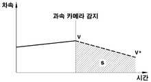
도 2는 본 발명의 실시예에서 차량 예측 속도가 결정되는 방법을 설명하기 위한 도면으로서, 제어기(20)에서는 운전정보 검출부(11)에 의해 취득되는 차량 속도 정보와 차량 가감속도 정보, 내비게이션 장치(18)에서 제공되는 감속 이벤트(속도제한 구간, 과속 카메라 등) 지점까지의 잔여 거리 정보를 이용하여 하기 식 (1)과 같이 결정될 수 있다.2 is a diagram for explaining a method for determining a vehicle predicted speed in an embodiment of the present invention. In the

여기서, v*는 감속 이벤트 지점에서의 차량 예측 속도이고, v는 감속 이벤트 감지 후 차량 주행 동안 검출되는 실시간 차량 속도(차량 실제 속도)이며, a는 차량 가감속도를, s는 현재 차량 위치에서 전방 감속 이벤트 지점까지의 잔여 거리(업데이트되는 잔여 거리임)를 각각 나타낸다.where v* is the vehicle predicted speed at the deceleration event point, v is the real-time vehicle speed (vehicle actual speed) detected while the vehicle is driving after detecting the deceleration event, a is the vehicle acceleration/deceleration, and s is the forward speed from the current vehicle position. Represents the remaining distance (which is the updated residual distance) to the point of the deceleration event, respectively.
본 발명의 실시예에서, 제어기(20)는 내비게이션 장치(18)로부터 제한속도가 규정된 속도제한 구간이나 과속 카메라 위치까지의 잔여 거리 정보와 상기 규정된 제한속도 정보를 수신하고, 상기 잔여 거리를 수신한 시점에서 차량 실제 속도 및 차량 이동 거리(도 2에서 속도 적산 값 s)를 계산하여 잔여 거리를 업데이트한다.In the embodiment of the present invention, the
이때, 제어기(20)는 차량이 감속 이벤트 감지 후 감속 이벤트 지점을 향해 주행하는 동안 잔여 거리를 계속해서 업데이트하게 된다. 여기서, 업데이트되는 잔여 거리는 감속 이벤트 감지 후 최초 수신된 잔여 거리에서 차량이 이동한 거리를 뺀 값으로 구해질 수 있다. 이와 같이 실시간으로 업데이트되는 잔여 거리가 식 (1)에서 차량 예측 속도를 계산하는데 이용되는 잔여 거리 s가 된다.At this time, the
다음으로, 본 발명의 실시예에서, 디스플레이 유닛(30)은 감속 이벤트 지점에서 예상되는 차량 속도, 즉 제어기(20)에서 실시간으로 결정되는 차량 예측 속도를 표시하여 운전자에게 안내한다. 상기 디스플레이 유닛(30)은 헤드업 디스플레이 유닛이 될 수 있다. 더 구체적으로는, 상기 디스플레이 유닛은 차량 예측 속도를 증강 현실(Augmented Reality) 이미지로 윈드쉴드 글라스에 표시하는 증강 현실 헤드업 디스플레이(AR HUD) 유닛일 수 있다.Next, in the embodiment of the present invention, the
본 발명의 실시예에서, 디스플레이 유닛(30)은, 제어기(20)로부터 감속 이벤트의 위치와 규정된 제한속도, 그리고 감속 이벤트 지점에서의 차량 예측 속도를 나타내는 신호를 수신하여 증강 현실 이미지로 표시하기 위한 일련의 제어를 수행하는 디스플레이 제어기(31)와, 차량 전방의 영상을 촬영하는 카메라(32)와, 상기 촬영된 영상 정보를 이용하여 감속 이벤트의 위치와 차량 예측 속도를 표시한 증강 현실 이미지가 윈드쉴드 글라스에 표시되도록 하기 위한 프로젝터(33)를 포함하여 구성된다.In an embodiment of the present invention, the
이러한 구성에서, 디스플레이 제어기(31)는 카메라(32)로부터 촬영된 차량 전방의 영상 신호를 수신하고, 촬영된 차량 전방의 영상에서 속도제한 구간의 구간 시작 표지판이나 과속 카메라와 같은 전방 감속 이벤트를 식별하여 전방 감속 이벤트의 위치를 결정한다. 또한, 디스플레이 제어기(31)는 상기 결정된 전방 감속 이벤트의 위치에 기초하여 차량 전방의 영상에서 차량이 전방 감속 이벤트 지점에 도달하였을 때 위치하게 될 도로상의 차량 영역을 결정한다.In this configuration, the
또한, 디스플레이 제어기(31)는 카메라(32)에 의해 촬영된 영상을 이용하여 전방 감속 이벤트 위치와 상기 도로상의 차량 영역, 그리고 차량 예측 속도를 표시한 증강 현실 이미지를 프로젝터(33)에 전달하고, 동시에 윈드쉴드 글라스에 조사하라는 명령신호를 프로젝터(33)에 전달한다.In addition, the
이로써, 전방 감속 이벤트 위치, 전방 감속 이벤트 지점에서의 도로상 차량 영역, 그리고 전방 감속 이벤트 지점에서의 차량 예측 속도를 나타내는 증강 현실 이미지가 윈드쉴드 글라스를 통해 표시되며, 이에 운전자가 시각적으로 차량 예측 속도를 안내받을 수 있게 된다.Thereby, an augmented reality image representing the location of the forward deceleration event, the vehicle area on the road at the point of the forward deceleration event, and the vehicle predicted speed at the point of the forward deceleration event is displayed through the windshield glass, so that the driver can visually see the predicted vehicle speed can be guided.
이와 같이 본 발명에서는 주행 중 차량에서 수집되는 정보를 이용하여 차량 전방에 제한속도가 규정된 감속 이벤트(예, 과속 카메라 또는 속도제한 구간의 제한속도 표지판)가 존재할 경우 감속 이벤트 지점에서 예상되는 차량 속도를 계산하고, 그 결과를 차량 내 디스플레이(예, 헤드업 디스플레이)에 증강 현실(Augmented Reality) 이미지로 표시하여 운전자에게 시각적으로 안내할 수 있게 된다.As described above, in the present invention, when there is a deceleration event with a prescribed speed limit in front of the vehicle (eg, a speed camera or a speed limit sign in the speed limit section) using information collected from the vehicle while driving, the vehicle speed expected at the deceleration event point is calculated, and the result is displayed as an augmented reality image on an in-vehicle display (eg, a heads-up display) to visually guide the driver.
이로써, 감속 이벤트 지점을 통과할 때의 속도 규정 미준수에 따른 운전자의 불안감이 해소될 수 있고, 감속 이벤트 지점에서의 제한속도 준수에 대한 확실성을 운전자에게 제공할 수 있게 된다.Accordingly, the driver's anxiety due to non-compliance with the speed regulation when passing the deceleration event point can be resolved, and it is possible to provide the driver with certainty about observing the speed limit at the deceleration event point.
또한, 본 발명에 따른 예측 속도 안내 장치 및 안내 방법이 적용된다면, NSCC(Navigation-based Smart Cruise Control) 기능을 이용할 때, 차량 전방의 과속 카메라 존재시 운전자가 느낄 수 있는 속도 규정 미준수의 염려 및 불안감이 해소될 수 있게 된다.In addition, if the predictive speed guidance device and the guidance method according to the present invention are applied, when using the NSCC (Navigation-based Smart Cruise Control) function, when a speed camera is present in front of the vehicle, the driver may feel the fear and anxiety of non-compliance with the speed regulation this can be resolved.
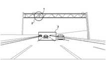
도 3은 본 발명의 실시예에서 카메라(32)에 의해 촬영되는 영상에 과속 카메라 위치 및 차량이 과속 카메라 위치에 도달했을 때의 차량 영역을 표시한 예를 보여주는 도면이다. 또한, 도 4는 본 발명의 실시예에서 과속 예측시 표시 상태를 예시한 도면이다.3 is a view showing an example of displaying a speed camera position and a vehicle area when the vehicle reaches the speed camera position on an image captured by the
본 발명의 실시예에 따른 예측 속도 안내 장치에서는 과속 카메라가 감지된 경우 도 3에 나타낸 바와 같이 과속 카메라(1)의 위치를 나타내는 증강 현실 이미지를 윈드쉴드 글라스를 통해 표시하여 운전자에게 안내한다. 도 3을 참조하면, 영상 내에서 과속 카메라 위치는 원(2)으로 표시되고 있으며, 과속 카메라가 위치한 곳의 바로 아래에 차량이 위치하게 될 도로상의 차량 영역(3)이 사각형으로 표시되고 있음을 볼 수 있다.In the predictive speed guidance device according to an embodiment of the present invention, when a speed camera is detected, an augmented reality image indicating the location of the
또한, 디스플레이 제어기(31)는 차량 예측 속도와 제한속도를 비교하여 전방 감속 이벤트(과속 카메라) 위치에서 차량 과속이 예측될 경우 도 4에 나타낸 바와 같이 감속 이벤트(과속 카메라) 및 도로상 차량 영역의 표시 색상을 설정된 색상으로 변화시키거나 표시 부분에 깜박임 등의 효과를 주어 운전자에게 경고한다.In addition, the
예를 들면, 제한속도가 80km/h인 도로에서 차량이 시속 100km/h의 속도로 주행하다가, 과속 카메라 500m 앞에서 과속 카메라 정보를 수신하여 차량 감속을 실시할 때, 500m 후 과속 카메라 지점에서의 차량 예측 속도가 95km/h로 결정되었다면 과속 카메라 위치에서 과속 상태인 것으로 예측한다. 이 경우 도 4에 나타낸 바와 같이 과속 카메라와 도로상 차량 영역의 표시 색상을 변화시키거나 표시 부분에 깜박임 등의 효과를 주어 경고한다.For example, when a vehicle is traveling at a speed of 100 km/h on a road with a speed limit of 80 km/h and decelerates by receiving information from the speed camera 500 m in front of the speed camera, the vehicle at the speed camera point after 500 m If the predicted speed is determined to be 95 km/h, it is predicted to be in a speeding state at the speed camera position. In this case, as shown in FIG. 4 , a warning is given by changing the display color of the speed camera and the vehicle area on the road or applying an effect such as blinking to the display part.
반면, 동일한 상황에서 과속 카메라를 향해 이동하는 동안 차량이 적절히 감속되어 과속 카메라 100m 앞에서 과속 카메라 지점에서의 차량 예측 속도가 80km/h인 것으로 다시 계산되었다면 과속 상태인 것으로 예측하지 않으며, 과속 예측 상태가 해제되므로 상기와 같은 경고 표시 작동을 위한 제어가 수행되지 않는다.On the other hand, if the vehicle is properly decelerated while moving towards the speed camera under the same circumstances and the predicted vehicle speed at the speed camera point is 80 km/h in front of the speed camera 100 m, it is not predicted to be over-speeding, and the over-speeding condition is not predicted. Since it is released, the control for the warning display operation as described above is not performed.
이하, 본 발명의 실시예에 따른 차량 예측 속도 안내 방법을 도 5를 참조하여 설명하기로 한다.Hereinafter, a vehicle prediction speed guidance method according to an embodiment of the present invention will be described with reference to FIG. 5 .
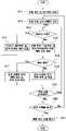
먼저, 차량 주행 동안 제어기(20)에는 운전정보 검출부(11)에 의해 실시간으로 차량 속도 및 차량 가감속도 정보가 얻어진다(S11).First, vehicle speed and vehicle acceleration/deceleration information are obtained in real time by the driving
이어 내비게이션 장치(18)가 제공하는 감속 이벤트 정보로부터 제어기(20)가 주행 경로 상 차량 전방의 감속 이벤트를 감지하게 되면(S12), 현재 NSCC 기능이 작동 상태인지를 판단한다(S13).Next, when the
여기서, 제어기(20)는 NSCC 기능이 작동 상태인 것으로 판단한 경우, NSCC 제어속도와 감속 이벤트(과속 카메라) 정보를 디스플레이 유닛(30)으로 전달하여 NSCC 제어속도와 감속 이벤트 위치가 표시되도록 한다(S14).Here, when the
반면, 제어기(20)가 NSCC 기능이 미작동 상태인 것으로 판단한 경우, 차량 속도 및 가감속도, 내비게이션 장치(18)로부터 수신된 감속 이벤트까지의 잔여 거리 정보로부터 감속 이벤트에서의 차량 예측 속도를 결정한다(S15).On the other hand, when the
이어 제어기(20)는 감지된 감속 이벤트의 위치와 종류, 규정된 제한속도 등의 감속 이벤트 정보와 함께 상기 결정된 감속 이벤트에서의 차량 예측 속도를 나타내는 신호를 디스플레이 유닛(30)의 디스플레이 제어기(31)로 전달한다.Then, the
이에 디스플레이 제어기(31)에서는 감속 이벤트에서의 차량 예측 속도를 감속 이벤트에 규정된 제한속도와 비교하여 감속 이벤트에서의 과속 예측 상태인지를 판단한다(S16).Accordingly, the
여기서, 과속 예측 상태인 것으로 판단한 경우, 디스플레이 제어기(31)는 감속 이벤트 위치 및 차량 예측 속도를 윈드쉴드 글라스에 표출(표시)하면서 과속 예측 상태를 표출하기 위한 제어를 실시한다(S17).Here, when it is determined that the overspeed prediction state is present, the
반면, 과속 예측 상태가 아닌 것으로 판단한 경우, 디스플레이 제어기(31)는 감속 이벤트 위치 및 차량 예측 속도를 윈드쉴드 글라스에 표출하기 위한 제어를 실시하고(S18), 이때 과속 예측 상태의 표출을 위한 제어는 실시하지 않는다On the other hand, when it is determined that the overspeed prediction state is not, the
이어 제어기(20)는 수집되는 정보를 이용하여 감속 이벤트까지의 잔여 거리 등 주행 상황이 실시간으로 업데이트 되었다면(S19 단계), 이후 차량이 감속 이벤트를 통과할 때까지 S13 ~ S19 단계를 반복한다.Then, if the driving conditions such as the remaining distance to the deceleration event are updated in real time using the collected information (step S19), the
이후 차량이 감속 이벤트를 통과한 것으로 판단한 경우, 제어기(20)는 디스플레이 유닛(30)을 통한 차량 예측 속도 표시 작동 및 그 제어를 중지한다(S20,S21).Thereafter, when it is determined that the vehicle has passed the deceleration event, the
이상으로 본 발명의 실시예에 대하여 상세하게 설명하였지만, 본 발명의 권리범위가 이에 한정되는 것은 아니며, 다음의 특허청구범위에서 정의하고 있는 본 발명의 기본 개념을 이용한 당 업자의 여러 변형 및 개량 형태 또한 본 발명의 권리범위에 포함된다.Although the embodiment of the present invention has been described in detail above, the scope of the present invention is not limited thereto, and various modifications and improvements made by those skilled in the art using the basic concept of the present invention as defined in the following claims Also included in the scope of the present invention.
10 : 정보제공부
11 : 운전정보 검출부
12 : 차속 검출부
13 : 가속도 센서
14 : 속도 검출부
15 : 가속페달 검출부
16 : 브레이크 페달 검출부
17 : 전방 차량 검출부
18 : 내비게이션 장치
20 : 제어기
30 : 디스플레이 유닛
31 : 디스플레이 제어기
32 : 카메라
33 : 프로젝터10: information provision department
11: driving information detection unit
12: vehicle speed detection unit
13: acceleration sensor
14: speed detection unit
15: accelerator pedal detection unit
16: brake pedal detection unit
17: front vehicle detection unit
18: navigation device
20: controller
30: display unit
31: display controller
32 : camera
33: projector
Claims (20)
Translated fromKorean상기 정보제공부에서 제공되는 차량 운전 정보와 감속 이벤트 정보를 기초로 주행 경로 상의 감속 이벤트를 감지하고 상기 감지된 감속 이벤트 지점에서의 차량 예측 속도를 결정하는 제어기; 및
상기 제어기로부터 감속 이벤트 정보와 함께 감속 이벤트 지점에서의 차량 예측 속도를 나타내는 신호를 수신하여 상기 수신된 차량 예측 속도를 감속 이벤트의 위치와 함께 미리 정해진 형태의 증강 현실 이미지로 윈드쉴드 글라스에 표시하는 디스플레이 유닛을 포함하는 차량의 예측 속도 안내 장치.
an information providing unit that provides vehicle driving information and deceleration event information necessary to determine a vehicle predicted speed at a deceleration event point during vehicle driving;
a controller for detecting a deceleration event on a driving path based on the vehicle driving information and deceleration event information provided by the information providing unit and determining a vehicle prediction speed at the detected deceleration event point; and
A display for receiving a signal indicating the vehicle prediction speed at the deceleration event point together with the deceleration event information from the controller and displaying the received vehicle prediction speed as an augmented reality image in a predetermined form along with the location of the deceleration event on the windshield glass A predictive speed guidance device for a vehicle including a unit.
상기 정보제공부는
차량 운전 정보를 검출하여 제공하는 운전정보 검출부; 및
주행 경로에서 차량 전방의 감속 이벤트 정보를 제공하는 내비게이션 장치를 포함하는 것을 특징으로 하는 차량의 예측 속도 안내 장치.
The method according to claim 1,
The information provider
a driving information detection unit that detects and provides vehicle driving information; and
A device for guiding a predicted speed of a vehicle, comprising a navigation device that provides information on a deceleration event in front of the vehicle on a driving route.
상기 차량 운전 정보는 차량 속도와 차량 가감속도를 포함하고,
상기 감속 이벤트 정보는 감속 이벤트의 위치 및 규정된 제한속도, 차량 현재 위치에서 감속 이벤트까지의 잔여 거리를 포함하는 것을 특징으로 하는 차량의 예측 속도 안내 장치.
3. The method according to claim 2,
The vehicle driving information includes vehicle speed and vehicle acceleration/deceleration,
The deceleration event information includes a position of the deceleration event, a prescribed speed limit, and a residual distance from the current position of the vehicle to the deceleration event.
상기 제어기는 감속 이벤트 감지 후 차량이 감속 이벤트를 향해 주행하는 동안의 실시간 차량 속도 및 차량 가감속도 정보와 상기 잔여 거리 정보를 이용하여 상기 감속 이벤트 지점에서의 차량 예측 속도를 결정하는 것을 특징으로 하는 차량의 예측 속도 안내 장치.
4. The method according to claim 3,
The controller determines the predicted vehicle speed at the deceleration event point by using real-time vehicle speed and vehicle acceleration/deceleration information and the residual distance information while the vehicle is driving toward the deceleration event after detecting the deceleration event of predictive speed guide device.
상기 제어기는 상기 차량 속도(v)와 차량 가감속도(a), 상기 잔여 거리(s)로부터 아래의 식 E1을 이용하여 감속 이벤트 지점에서의 차량 예측 속도를 계산하는 것을 특징으로 하는 차량의 예측 속도 안내 장치.
E1 :

5. The method according to claim 4,
The controller calculates the predicted vehicle speed at the deceleration event point from the vehicle speed (v), the vehicle acceleration/deceleration (a), and the residual distance (s) using the following equation E1. guidance device.
E1:
상기 디스플레이 유닛은
차량 전방의 영상을 촬영하는 카메라;
상기 수신된 차량 예측 속도를 증강 현실 이미지로 표시하기 위한 제어를 수행하는 디스플레이 제어기; 및
상기 디스플레이 제어기의 명령신호에 따라 상기 카메라에 의해 촬영된 차량 전방의 영상 정보를 이용하여 감속 이벤트의 위치와 차량 예측 속도를 표시한 증강 현실 이미지가 윈드쉴드 글라스에 표시되도록 하는 프로젝터를 포함하는 것을 특징으로 하는 차량의 예측 속도 안내 장치.
The method according to claim 1,
the display unit
A camera for taking an image of the front of the vehicle;
a display controller performing control to display the received vehicle prediction speed as an augmented reality image; and
and a projector to display on the windshield glass an augmented reality image indicating the location of the deceleration event and the predicted vehicle speed by using the image information in front of the vehicle photographed by the camera according to the command signal of the display controller A device for predicting vehicle speed.
상기 디스플레이 제어기는
상기 카메라에 의해 촬영된 차량 전방의 영상에서 감속 이벤트를 식별하여 감속 이벤트의 위치를 결정하고,
상기 결정된 감속 이벤트의 위치에 기초하여 상기 차량 전방의 영상에서 차량이 전방 감속 이벤트 지점에 도달하였을 때 위치하게 될 도로상의 차량 영역을 결정하며,
상기 결정된 도로상의 차량 영역이 프로젝터를 통해 윈드쉴드 글라스에 더 표시되도록 제어하는 것을 특징으로 하는 차량의 예측 속도 안내 장치.
7. The method of claim 6,
the display controller
Determine the location of the deceleration event by identifying the deceleration event in the image in front of the vehicle taken by the camera,
determining a vehicle area on the road to be located when the vehicle reaches a forward deceleration event point in the image in front of the vehicle based on the determined position of the deceleration event,
The predicted vehicle speed guide apparatus, characterized in that the determined vehicle area on the road is controlled to be further displayed on the windshield glass through a projector.
상기 디스플레이 제어기는
상기 제어기에서 수신된 감속 이벤트 지점에서의 차량 예측 속도와 감속 이벤트 정보의 제한속도를 비교하여, 상기 감속 이벤트 지점에서 차량 과속 상태가 예측되는 경우, 상기 프로젝터를 통해 윈드쉴드 글라스에 경고 표시가 이루어지도록 제어하는 것을 특징으로 하는 차량의 예측 속도 안내 장치.
7. The method of claim 6,
the display controller
By comparing the vehicle predicted speed at the deceleration event point received from the controller and the limit speed of the deceleration event information, when the vehicle overspeed condition is predicted at the deceleration event point, a warning display is made on the windshield glass through the projector Predicted speed guidance device of a vehicle, characterized in that the control.
상기 감속 이벤트는 제한속도가 규정된 과속 카메라 또는 속도제한 구간인 것을 특징으로 하는 차량의 예측 속도 안내 장치.
The method according to claim 1,
The deceleration event is an apparatus for predicting speed of a vehicle, characterized in that the speed limit is a prescribed speed camera or a speed limit section.
제어기가 정보제공부에서 제공되는 차량 운전 정보와 감속 이벤트 정보를 기초로 주행 경로 상의 감속 이벤트를 감지하고 상기 감지된 감속 이벤트 지점에서의 차량 예측 속도를 결정하는 단계; 및
디스플레이 유닛이 제어기로부터 감속 이벤트 정보와 함께 감속 이벤트 지점에서의 차량 예측 속도를 나타내는 신호를 수신하여 상기 수신된 차량 예측 속도를 감속 이벤트의 위치와 함께 미리 정해진 형태의 증강 현실 이미지로 윈드쉴드 글라스에 표시하는 단계를 포함하는 차량의 예측 속도 안내 방법.
receiving, from an information providing unit, vehicle driving information and deceleration event information necessary for a controller to determine a vehicle predicted speed in a deceleration event during vehicle driving;
detecting, by a controller, a deceleration event on a driving route based on vehicle driving information and deceleration event information provided from the information providing unit, and determining a vehicle prediction speed at the detected deceleration event point; and
The display unit receives a signal indicating the vehicle predicted speed at the deceleration event point along with the deceleration event information from the controller, and displays the received vehicle predicted speed along with the location of the deceleration event as an augmented reality image in a predetermined form on the windshield glass A method of guiding a predicted speed of a vehicle comprising the step of:
상기 정보제공부는
차량 운전 정보를 검출하여 제공하는 운전정보 검출부; 및
주행 경로에서 차량 전방의 감속 이벤트 정보를 제공하는 내비게이션 장치를 포함하는 것을 특징으로 하는 차량의 예측 속도 안내 방법.
11. The method of claim 10,
The information provider
a driving information detection unit that detects and provides vehicle driving information; and
A method for guiding a predicted speed of a vehicle, comprising a navigation device that provides information on a deceleration event in front of the vehicle on a driving route.
상기 차량 운전 정보는 차량 속도와 차량 가감속도를 포함하고,
상기 감속 이벤트 정보는 감속 이벤트의 위치 및 규정된 제한속도, 차량 현재 위치에서 감속 이벤트까지의 잔여 거리를 포함하는 것을 특징으로 하는 차량의 예측 속도 안내 방법.
12. The method of claim 11,
The vehicle driving information includes vehicle speed and vehicle acceleration/deceleration,
The deceleration event information includes a position of the deceleration event, a prescribed speed limit, and a residual distance from the current vehicle position to the deceleration event.
상기 제어기는 감속 이벤트 감지 후 차량이 감속 이벤트를 향해 주행하는 동안의 실시간 차량 속도 및 차량 가감속도 정보와 상기 잔여 거리 정보를 이용하여 상기 감속 이벤트 지점에서의 차량 예측 속도를 결정하는 것을 특징으로 하는 차량의 예측 속도 안내 방법.
13. The method of claim 12,
The controller determines the predicted vehicle speed at the deceleration event point by using real-time vehicle speed and vehicle acceleration/deceleration information and the residual distance information while the vehicle is driving toward the deceleration event after detecting the deceleration event of the predicted speed guide method.
상기 제어기는
상기 내비게이션 장치로부터 상기 잔여 거리 정보를 수신한 시점의 차량 속도와 상기 차량 속도를 적산하여 계산한 차량 이동 거리를 이용하여 상기 잔여 거리를 업데이트하고,
상기 업데이트되는 잔여 거리 정보를 상기 감속 이벤트 지점에서의 차량 예측 속도를 결정하는데 이용하는 것을 특징으로 하는 차량의 예측 속도 안내 방법.14. The method of claim 13,
the controller
updating the remaining distance by using the vehicle moving distance calculated by integrating the vehicle speed and the vehicle speed at the time when the remaining distance information is received from the navigation device;
and using the updated residual distance information to determine the predicted vehicle speed at the deceleration event point.
상기 제어기는 상기 차량 속도(v)와 차량 가감속도(a), 상기 잔여 거리(s)로부터 아래의 식 E1을 이용하여 감속 이벤트 지점에서의 차량 예측 속도를 계산하는 것을 특징으로 하는 차량의 예측 속도 안내 방법.
E1 :

14. The method of claim 13,
The controller calculates the predicted vehicle speed at the deceleration event point from the vehicle speed (v), the vehicle acceleration/deceleration (a), and the residual distance (s) using the following equation E1. How to guide.
E1:
상기 제어기는 감속 이벤트 감지 후 내비게이션 기반 스마트 크루즈 제어(Navigation-based Smart Cruise Control) 기능의 작동 여부를 확인하여 상기 스마트 크루즈 제어 기능의 작동 중이면 스마트 크루즈 제어 시 제어속도 값을 상기 감속 이벤트 지점에서의 차량 예측 속도로 결정하는 것을 특징으로 하는 차량의 예측 속도 안내 방법.
11. The method of claim 10,
After detecting a deceleration event, the controller checks whether a navigation-based smart cruise control function is operating, and if the smart cruise control function is in operation, the controller sets the control speed value at the deceleration event point during smart cruise control. A method of guiding the predicted speed of a vehicle, characterized in that it is determined by the vehicle predicted speed.
상기 디스플레이 유닛은
차량 전방의 영상을 촬영하는 카메라;
상기 수신된 차량 예측 속도를 증강 현실 이미지로 표시하기 위한 제어를 수행하는 디스플레이 제어기; 및
상기 디스플레이 제어기의 명령신호에 따라 상기 카메라에 의해 촬영된 차량 전방의 영상 정보를 이용하여 감속 이벤트의 위치와 차량 예측 속도를 표시한 증강 현실 이미지가 윈드쉴드 글라스에 표시되도록 하는 프로젝터를 포함하는 것을 특징으로 하는 차량의 예측 속도 안내 방법.
11. The method of claim 10,
the display unit
A camera for taking an image of the front of the vehicle;
a display controller performing control to display the received vehicle prediction speed as an augmented reality image; and
and a projector to display on the windshield glass an augmented reality image indicating the location of the deceleration event and the predicted vehicle speed by using the image information in front of the vehicle photographed by the camera according to the command signal of the display controller A method of guiding the predicted speed of a vehicle.
상기 디스플레이 제어기는
상기 카메라에 의해 촬영된 차량 전방의 영상에서 감속 이벤트를 식별하여 감속 이벤트의 위치를 결정하고,
상기 결정된 감속 이벤트의 위치에 기초하여 상기 차량 전방의 영상에서 차량이 전방 감속 이벤트 지점에 도달하였을 때 위치하게 될 도로상의 차량 영역을 결정하며,
상기 결정된 도로상의 차량 영역이 프로젝터를 통해 윈드쉴드 글라스에 더 표시되도록 제어하는 것을 특징으로 하는 차량의 예측 속도 안내 방법.
18. The method of claim 17,
the display controller
Determine the location of the deceleration event by identifying the deceleration event in the image in front of the vehicle taken by the camera,
determining a vehicle area on the road to be located when the vehicle reaches a forward deceleration event point in the image in front of the vehicle based on the determined position of the deceleration event,
The predicted speed guidance method of a vehicle, characterized in that controlling the determined vehicle area on the road to be further displayed on the windshield glass through a projector.
상기 디스플레이 제어기는
상기 제어기에서 수신된 감속 이벤트 지점에서의 차량 예측 속도와 감속 이벤트 정보의 제한속도를 비교하여, 상기 감속 이벤트 지점에서 차량 과속 상태가 예측되는 경우, 상기 프로젝터를 통해 윈드쉴드 글라스에 경고 표시가 이루어지도록 제어하는 것을 특징으로 하는 차량의 예측 속도 안내 방법.
18. The method of claim 17,
the display controller
By comparing the vehicle predicted speed at the deceleration event point received from the controller and the limit speed of the deceleration event information, when the vehicle overspeed condition is predicted at the deceleration event point, a warning display is made on the windshield glass through the projector A method of guiding the predicted speed of a vehicle, characterized in that it controls.
상기 감속 이벤트는 제한속도가 규정된 과속 카메라 또는 속도제한 구간인 것을 특징으로 하는 차량의 예측 속도 안내 방법.11. The method of claim 10,
The deceleration event is a predicted speed guidance method of a vehicle, characterized in that the speed limit is a prescribed speed camera or a speed limit section.
Priority Applications (4)
| Application Number | Priority Date | Filing Date | Title |
|---|---|---|---|
| KR1020200130951AKR20220048501A (en) | 2020-10-12 | 2020-10-12 | System and method for guiding expected speed of vehicle |
| US17/376,948US11640762B2 (en) | 2020-10-12 | 2021-07-15 | Apparatus and method of indicating expected speed of vehicle |
| DE102021207859.1ADE102021207859A1 (en) | 2020-10-12 | 2021-07-22 | Apparatus and method for displaying an expected speed of a vehicle |
| CN202110850326.3ACN114348013A (en) | 2020-10-12 | 2021-07-27 | Apparatus and method for indicating expected speed of vehicle |
Applications Claiming Priority (1)
| Application Number | Priority Date | Filing Date | Title |
|---|---|---|---|
| KR1020200130951AKR20220048501A (en) | 2020-10-12 | 2020-10-12 | System and method for guiding expected speed of vehicle |
Publications (1)
| Publication Number | Publication Date |
|---|---|
| KR20220048501Atrue KR20220048501A (en) | 2022-04-20 |
Family
ID=80818249
Family Applications (1)
| Application Number | Title | Priority Date | Filing Date |
|---|---|---|---|
| KR1020200130951APendingKR20220048501A (en) | 2020-10-12 | 2020-10-12 | System and method for guiding expected speed of vehicle |
Country Status (4)
| Country | Link |
|---|---|
| US (1) | US11640762B2 (en) |
| KR (1) | KR20220048501A (en) |
| CN (1) | CN114348013A (en) |
| DE (1) | DE102021207859A1 (en) |
Cited By (2)
| Publication number | Priority date | Publication date | Assignee | Title |
|---|---|---|---|---|
| KR20250003121A (en) | 2023-06-30 | 2025-01-07 | 주식회사 라이노스 | Head-Up Display Device And A Control Method Thereof |
| KR102773108B1 (en) | 2023-11-03 | 2025-02-26 | 주식회사 라이노스 | Apparatus for predicting and warning of speeding and method of thereof |
Families Citing this family (2)
| Publication number | Priority date | Publication date | Assignee | Title |
|---|---|---|---|---|
| JP2024040694A (en)* | 2022-09-13 | 2024-03-26 | トヨタ自動車株式会社 | Display control device, display control method and program |
| CN117162777B (en)* | 2023-11-03 | 2024-02-20 | 西安信飞特信息科技有限公司 | Content presentation method, device, equipment and storage medium |
Family Cites Families (31)
| Publication number | Priority date | Publication date | Assignee | Title |
|---|---|---|---|---|
| US5381155A (en)* | 1993-12-08 | 1995-01-10 | Gerber; Eliot S. | Vehicle speeding detection and identification |
| JP2006199264A (en)* | 2004-12-24 | 2006-08-03 | Nissan Motor Co Ltd | Merge support device and merge support method |
| JP4737519B2 (en)* | 2005-06-28 | 2011-08-03 | アイシン・エィ・ダブリュ株式会社 | Vehicle control auxiliary device and vehicle control auxiliary method |
| US9520061B2 (en)* | 2008-06-20 | 2016-12-13 | Tk Holdings Inc. | Vehicle driver messaging system and method |
| KR100920265B1 (en)* | 2007-12-12 | 2009-10-05 | 한국전자통신연구원 | Section speed warning device and system |
| KR101649643B1 (en)* | 2010-02-01 | 2016-08-19 | 엘지전자 주식회사 | Information display apparatus and method thereof |
| JP6163033B2 (en)* | 2013-07-10 | 2017-07-12 | 矢崎総業株式会社 | Head-up display device and display unit |
| US10272780B2 (en)* | 2013-09-13 | 2019-04-30 | Maxell, Ltd. | Information display system and information display device |
| KR101500164B1 (en)* | 2013-10-10 | 2015-03-06 | 현대자동차주식회사 | Apparatus for controlling speed in speed enforcement section and method thereof |
| WO2015072030A1 (en)* | 2013-11-18 | 2015-05-21 | 三菱電機株式会社 | Driving support device and driving support method |
| DE102015217391B4 (en)* | 2014-09-12 | 2021-09-30 | Yazaki Corporation | In-vehicle display device |
| JP6314067B2 (en)* | 2014-09-12 | 2018-04-18 | 矢崎総業株式会社 | In-vehicle display device |
| GB201420988D0 (en)* | 2014-11-26 | 2015-01-07 | Tomtom Telematics Bv | Apparatus and method for vehicle economy improvement |
| JPWO2016103938A1 (en)* | 2014-12-22 | 2017-09-21 | 富士フイルム株式会社 | Projection display device, electronic device, driver visual image sharing method, and driver visual image sharing program |
| JP6319187B2 (en)* | 2015-05-26 | 2018-05-09 | トヨタ自動車株式会社 | Vehicle speed limit system |
| JP6304126B2 (en)* | 2015-05-26 | 2018-04-04 | トヨタ自動車株式会社 | Vehicle control system |
| KR101750159B1 (en)* | 2015-07-01 | 2017-06-22 | 엘지전자 주식회사 | Assistance Apparatus for Driving of a Vehicle, Method thereof, and Vehicle having the same |
| KR101678095B1 (en)* | 2015-07-10 | 2016-12-06 | 현대자동차주식회사 | Vehicle, and method for controlling thereof |
| JP6414567B2 (en)* | 2016-06-02 | 2018-10-31 | トヨタ自動車株式会社 | Speed limit display device for vehicle |
| FR3053804B1 (en)* | 2016-07-05 | 2018-08-17 | Valeo Comfort & Driving Assistance | HEAD-UP DISPLAY AND METHOD FOR CONTROLLING A DEVICE FOR GENERATING IMAGES OF A HEAD-UP DISPLAY |
| KR102751064B1 (en)* | 2016-12-15 | 2025-01-08 | 현대자동차주식회사 | Vehicle and method for controlling the same |
| KR102331025B1 (en)* | 2017-02-23 | 2021-11-25 | 현대자동차주식회사 | Image information acquisition device, vehicle and method for controlling thereof |
| KR101908309B1 (en)* | 2017-04-12 | 2018-10-16 | 엘지전자 주식회사 | Lamp for Vehicle |
| KR20190023550A (en)* | 2017-08-29 | 2019-03-08 | 현대자동차주식회사 | Driving assist system using navigation information and operating method thereof |
| JP2019081473A (en)* | 2017-10-31 | 2019-05-30 | ダイハツ工業株式会社 | Driving support device |
| KR102547823B1 (en)* | 2017-12-13 | 2023-06-26 | 삼성전자주식회사 | Method and device to visualize content |
| JP7195879B2 (en)* | 2018-11-05 | 2022-12-26 | 京セラ株式会社 | Display device, 3D display device, head-up display and vehicle |
| US11823568B2 (en)* | 2019-05-02 | 2023-11-21 | Toyota Motor North America, Inc. | Dynamic speed limit for vehicles and autonomous vehicles |
| JP7298566B2 (en)* | 2020-08-07 | 2023-06-27 | トヨタ自動車株式会社 | Electric car |
| US20220055659A1 (en)* | 2020-08-20 | 2022-02-24 | Denso International America, Inc. | Mode selection according to system conditions |
| KR102195881B1 (en)* | 2020-09-28 | 2020-12-29 | 김병준 | Apparatus for providing information on blind spot for safe driving |
- 2020
- 2020-10-12KRKR1020200130951Apatent/KR20220048501A/enactivePending
- 2021
- 2021-07-15USUS17/376,948patent/US11640762B2/enactiveActive
- 2021-07-22DEDE102021207859.1Apatent/DE102021207859A1/enactivePending
- 2021-07-27CNCN202110850326.3Apatent/CN114348013A/enactivePending
Cited By (2)
| Publication number | Priority date | Publication date | Assignee | Title |
|---|---|---|---|---|
| KR20250003121A (en) | 2023-06-30 | 2025-01-07 | 주식회사 라이노스 | Head-Up Display Device And A Control Method Thereof |
| KR102773108B1 (en) | 2023-11-03 | 2025-02-26 | 주식회사 라이노스 | Apparatus for predicting and warning of speeding and method of thereof |
Also Published As
| Publication number | Publication date |
|---|---|
| DE102021207859A1 (en) | 2022-04-14 |
| US20220114889A1 (en) | 2022-04-14 |
| US11640762B2 (en) | 2023-05-02 |
| CN114348013A (en) | 2022-04-15 |
Similar Documents
| Publication | Publication Date | Title |
|---|---|---|
| KR20220048501A (en) | System and method for guiding expected speed of vehicle | |
| JP7416176B2 (en) | display device | |
| US11220274B2 (en) | Vehicle display control device | |
| US11008016B2 (en) | Display system, display method, and storage medium | |
| US11225248B2 (en) | Vehicle control apparatus | |
| JP7307558B2 (en) | Vehicle driving control system | |
| US20220234607A1 (en) | Driving Assistance Method and Driving Assistance System | |
| US20200215917A1 (en) | Method for operating a driver assistance system of a transportation vehicle and transportation vehicle | |
| JP2019138773A (en) | Display device | |
| JP5599848B2 (en) | Display device and vehicle | |
| US20170240183A1 (en) | Autonomous driving apparatus | |
| JP7384126B2 (en) | Vehicle congestion determination device and vehicle display control device | |
| JP5988785B2 (en) | Driving assistance device | |
| CN109844842A (en) | Driving mode transition controller, system, method and program | |
| CN114103981B (en) | Vehicle-mounted display device, vehicle-mounted display method, and computer-readable storage medium | |
| JP2019160081A (en) | Transport equipment and traveling control method for the same | |
| CN109501804B (en) | Method and device for displaying acceleration of vehicle running in front in vehicle | |
| WO2018186012A1 (en) | Vehicle control device | |
| US20240294188A1 (en) | Vehicle control device | |
| WO2019053928A1 (en) | Projection control device for vehicle and head-up display device | |
| JP2023072773A (en) | Driving assistance device | |
| CN119183428A (en) | Method and device for automatically starting a vehicle at a signal unit | |
| JP6990221B2 (en) | Vehicle and its control device and control method | |
| JP2021051489A (en) | Driving auxiliary system | |
| JP2016224553A (en) | Vehicle traffic information display system |
Legal Events
| Date | Code | Title | Description |
|---|---|---|---|
| PA0109 | Patent application | St.27 status event code:A-0-1-A10-A12-nap-PA0109 | |
| PN2301 | Change of applicant | St.27 status event code:A-3-3-R10-R13-asn-PN2301 St.27 status event code:A-3-3-R10-R11-asn-PN2301 | |
| P11-X000 | Amendment of application requested | St.27 status event code:A-2-2-P10-P11-nap-X000 | |
| P13-X000 | Application amended | St.27 status event code:A-2-2-P10-P13-nap-X000 | |
| PG1501 | Laying open of application | St.27 status event code:A-1-1-Q10-Q12-nap-PG1501 | |
| A201 | Request for examination | ||
| PA0201 | Request for examination | St.27 status event code:A-1-2-D10-D11-exm-PA0201 | |
| P22-X000 | Classification modified | St.27 status event code:A-2-2-P10-P22-nap-X000 | |
| P22-X000 | Classification modified | St.27 status event code:A-2-2-P10-P22-nap-X000 | |
| PE0902 | Notice of grounds for rejection | St.27 status event code:A-1-2-D10-D21-exm-PE0902 |