KR20220045717A - Cleaning system and docking device having the same - Google Patents
Cleaning system and docking device having the sameDownload PDFInfo
- Publication number
- KR20220045717A KR20220045717AKR1020200128669AKR20200128669AKR20220045717AKR 20220045717 AKR20220045717 AKR 20220045717AKR 1020200128669 AKR1020200128669 AKR 1020200128669AKR 20200128669 AKR20200128669 AKR 20200128669AKR 20220045717 AKR20220045717 AKR 20220045717A
- Authority
- KR
- South Korea
- Prior art keywords
- suction
- fan motor
- cleaning
- dust collector
- docking device
- Prior art date
- Legal status (The legal status is an assumption and is not a legal conclusion. Google has not performed a legal analysis and makes no representation as to the accuracy of the status listed.)
- Pending
Links
Images


Classifications
- A—HUMAN NECESSITIES
- A47—FURNITURE; DOMESTIC ARTICLES OR APPLIANCES; COFFEE MILLS; SPICE MILLS; SUCTION CLEANERS IN GENERAL
- A47L—DOMESTIC WASHING OR CLEANING; SUCTION CLEANERS IN GENERAL
- A47L9/00—Details or accessories of suction cleaners, e.g. mechanical means for controlling the suction or for effecting pulsating action; Storing devices specially adapted to suction cleaners or parts thereof; Carrying-vehicles specially adapted for suction cleaners
- A47L9/28—Installation of the electric equipment, e.g. adaptation or attachment to the suction cleaner; Controlling suction cleaners by electric means
- A47L9/2868—Arrangements for power supply of vacuum cleaners or the accessories thereof
- A47L9/2873—Docking units or charging stations
- A—HUMAN NECESSITIES
- A47—FURNITURE; DOMESTIC ARTICLES OR APPLIANCES; COFFEE MILLS; SPICE MILLS; SUCTION CLEANERS IN GENERAL
- A47L—DOMESTIC WASHING OR CLEANING; SUCTION CLEANERS IN GENERAL
- A47L9/00—Details or accessories of suction cleaners, e.g. mechanical means for controlling the suction or for effecting pulsating action; Storing devices specially adapted to suction cleaners or parts thereof; Carrying-vehicles specially adapted for suction cleaners
- A47L9/10—Filters; Dust separators; Dust removal; Automatic exchange of filters
- A47L9/106—Dust removal
- A—HUMAN NECESSITIES
- A47—FURNITURE; DOMESTIC ARTICLES OR APPLIANCES; COFFEE MILLS; SPICE MILLS; SUCTION CLEANERS IN GENERAL
- A47L—DOMESTIC WASHING OR CLEANING; SUCTION CLEANERS IN GENERAL
- A47L9/00—Details or accessories of suction cleaners, e.g. mechanical means for controlling the suction or for effecting pulsating action; Storing devices specially adapted to suction cleaners or parts thereof; Carrying-vehicles specially adapted for suction cleaners
- A47L9/10—Filters; Dust separators; Dust removal; Automatic exchange of filters
- A47L9/16—Arrangement or disposition of cyclones or other devices with centrifugal action
- A—HUMAN NECESSITIES
- A47—FURNITURE; DOMESTIC ARTICLES OR APPLIANCES; COFFEE MILLS; SPICE MILLS; SUCTION CLEANERS IN GENERAL
- A47L—DOMESTIC WASHING OR CLEANING; SUCTION CLEANERS IN GENERAL
- A47L9/00—Details or accessories of suction cleaners, e.g. mechanical means for controlling the suction or for effecting pulsating action; Storing devices specially adapted to suction cleaners or parts thereof; Carrying-vehicles specially adapted for suction cleaners
- A47L9/22—Mountings for motor fan assemblies
- A—HUMAN NECESSITIES
- A47—FURNITURE; DOMESTIC ARTICLES OR APPLIANCES; COFFEE MILLS; SPICE MILLS; SUCTION CLEANERS IN GENERAL
- A47L—DOMESTIC WASHING OR CLEANING; SUCTION CLEANERS IN GENERAL
- A47L9/00—Details or accessories of suction cleaners, e.g. mechanical means for controlling the suction or for effecting pulsating action; Storing devices specially adapted to suction cleaners or parts thereof; Carrying-vehicles specially adapted for suction cleaners
- A47L9/28—Installation of the electric equipment, e.g. adaptation or attachment to the suction cleaner; Controlling suction cleaners by electric means
Landscapes
- Engineering & Computer Science (AREA)
- Mechanical Engineering (AREA)
- Robotics (AREA)
- Cleaning In General (AREA)
Abstract
Description
Translated fromKorean본 발명은 청소장치의 도킹장치에 관한 것으로, 보다 상세하게는 구조를 개선하여 사용성이 개선된 도킹장치 및 이를 갖는 청소 시스템에 관한 것이다.The present invention relates to a docking device for a cleaning device, and more particularly, to a docking device having improved usability by improving the structure and a cleaning system having the same.
일반적으로 청소기는 청소기 본체의 내부에 장착되는 모터에 의해 발생되는 진공압을 이용하여 먼지 등과 같은 이물질이 포함된 공기를 흡입한 후 본체의 내부에서 이물질을 걸러내는 가전제품이다.BACKGROUND ART In general, a vacuum cleaner is a home appliance that uses vacuum pressure generated by a motor mounted inside a cleaner body to suck in air containing foreign substances such as dust, and then filter the foreign substances from the inside of the main body.
청소기는 흡입압을 발생시키는 모터와, 모터로부터 발생되는 흡입압을 통해 피청소면의 이물질을 흡입하는 흡입유닛을 포함할 수 있다. 청소기는 그 형태에 따라, 캐니스터 타입의 청소기, 업라이트 타입의 청소기, 핸디형 청소기, 스틱형 청소기 등으로 구분될 수 있다.The vacuum cleaner may include a motor for generating a suction pressure and a suction unit for sucking foreign substances on the surface to be cleaned through the suction pressure generated from the motor. The vacuum cleaner may be classified into a canister-type cleaner, an upright-type cleaner, a handy-type cleaner, a stick-type cleaner, and the like according to the shape thereof.
최근에는 사용성이 편리한 무선 청소기의 선호도가 높아지고 있다.Recently, the preference for a cordless vacuum cleaner that is convenient to use is increasing.
무선 청소기를 포함하는 청소장치는, 청소기와, 청소기의 사용이 끝난 때 청소기를 보관 및 충전하도록 마련된 청소기 거치장치를 포함할 수 있다.A cleaning device including a wireless cleaner may include a cleaner and a cleaner holder provided to store and charge the cleaner when use of the cleaner is finished.
이러한, 무선 청소기를 포함하는 청소기는 이물질을 집진하는 먼지통을 포함하고, 사용자는 주기적으로 먼지통에 집진된 이물질을 먼지통으로부터 배출시켜야 한다. 소비자는 먼지통만 가져가 비우거나, 스틱 청소기의 경우 세트 전체를 가져가 이물질을 비워야 하므로 먼지통에 쌓여 있던 일부 먼지가 배출과정에서 다시 비산되는 문제가 있다.Such a vacuum cleaner including a cordless vacuum cleaner includes a dust container for collecting foreign substances, and a user must periodically discharge the foreign substances collected in the dust container from the dust container. Consumers have to take only the dust bin to empty it or, in the case of a stick vacuum cleaner, take the whole set to empty the foreign substances, so there is a problem in that some dust accumulated in the dust bin is scattered again during the discharge process.
또한, 먼지통의 이물질을 비우기 위한 별도의 장치는 이물질의 배출을 위한 흡입력을 유발시키는 별도의 모터와 그에 따른 구성부품이 요구되는 문제가 있다.In addition, a separate device for emptying the foreign substances in the dust bin has a problem in that a separate motor for generating a suction force for discharging the foreign substances and corresponding components are required.
본 발명의 일 측면은 구조를 개선하여 사용성이 개선된 도킹장치 및 이를 갖는 청소 시스템을 제공한다.One aspect of the present invention provides a docking device having improved usability by improving the structure and a cleaning system having the same.
본 발명의 다른 측면은 먼지통의 이물질을 비우기 위한 도킹장치에 별도의 자동배출장치 및 모터/배기부를 구성하지 않고 청소장치를 이용함으로써 제품의 사용성 및 편의성을 향상시킬 수 있는 도킹장치 및 이를 갖는 청소 시스템을 제공한다.Another aspect of the present invention is a docking device capable of improving usability and convenience of a product by using a cleaning device without configuring a separate automatic discharge device and a motor/exhaust unit in a docking device for emptying foreign substances in a dust bin, and a cleaning system having the same provides
본 발명의 사상에 따른 청소 시스템은, 흡입부에 흡입력을 발생시키도록 마련되는 팬모터와, 흡입력에 의해 흡입된 이물질이 집진되는 집진통을 포함하는 청소장치와, 상기 집진통이 도킹하도록 마련되고, 상기 집진통에 집진된 이물질이 전달되어 수용되는 먼지통을 포함하는 도킹장치;를 포함하고, 상기 팬모터는 상기 흡입부의 위치를 변경 가능하도록 상기 청소장치로부터 회전 가능하게 마련되고, 상기 도킹장치는, 상기 청소장치로부터 회전 이동 된 상기 흡입부와 상기 집진통 사이에 흡입유로를 형성하도록 상기 팬모터가 연결되는 흡입덕트를 포함한다.A cleaning system according to the spirit of the present invention includes a cleaning device including a fan motor provided to generate a suction force in the suction unit, and a dust collector for collecting foreign substances sucked by the suction force, and the dust collector is provided to dock, , a docking device including a dust bin in which foreign substances collected in the dust bin are delivered and accommodated, wherein the fan motor is rotatably provided from the cleaning device to change the position of the suction part, and the docking device includes and a suction duct to which the fan motor is connected so as to form a suction passage between the suction unit rotated from the cleaning device and the dust collector.
또한, 상기 청소장치는, 상하 방향으로 연장되는 장축을 가지는 청소기본체와, 상기 청소기본체의 장축 상에 배치되는 상기 집진통 내부의 이물질이 원심 회전 분리되도록 마련되는 사이클론을 포함한다.In addition, the cleaning apparatus includes a cleaning main body having a long axis extending in a vertical direction, and a cyclone provided to centrifugally separate foreign substances in the dust collecting bin disposed on the long axis of the cleaning main body.
또한, 상기 청소장치는, 상기 팬모터를 수용하며, 상기 흡입구와 토출구가 마련되는 팬모터 하우징과, 상기 팬모터 하우징을 상기 청소기본체로부터 회전 이동 가능하도록 마련되는 회전장치를 더 포함한다.The cleaning device may further include a fan motor housing accommodating the fan motor, provided with the suction port and the discharge port, and a rotating device provided to rotate and move the fan motor housing from the cleaning main body.
또한, 상기 흡입덕트는, 상기 청소기본체의 장축으로부터 이격되어 배치되고, 상기 청소기본체로부터 회전 이동된 상기 팬모터가 결합되는 팬모터 결합부를 포함한다.In addition, the suction duct includes a fan motor coupling part disposed to be spaced apart from the long axis of the cleaning main body, and to which the fan motor rotated from the cleaning main body is coupled.
또한, 상기 집진통이 상기 도킹장치와 도킹 시, 상기 팬모터의 모터축은 상기 사이클론의 장축으로부터 회전 이동되어 위치된다.In addition, when the dust collector is docked with the docking device, the motor shaft of the fan motor is rotated from the long axis of the cyclone to be positioned.
또한, 상기 회전장치는, 회전축과, 상기 회전축이 회전 가능하게 지지되도록 상기 청소기본체와 상기 팬모터 하우징에 각각 마련되는 회전축 지지부를 포함한다.In addition, the rotating device includes a rotating shaft, and rotating shaft support portions respectively provided in the cleaning main body and the fan motor housing so that the rotating shaft is rotatably supported.
또한, 상기 도킹장치는, 일 방향으로 연장되는 장축을 가지는 도킹장치 본체와, 상기 집진통이 안착되도록 상기 도킹장치 본체의 장축 방향으로 상측이 개방되어 마련되는 안착부와, 상기 도킹장치 본체의 하측에 마련되는 공기 배출부를 더 포함한다.In addition, the docking device, a docking device body having a long axis extending in one direction, a seating portion provided with an upper side open in the long axis direction of the docking device body so that the dust collector is seated, and a lower side of the docking device body It further includes an air outlet provided in the.
또한, 상기 도킹장치는, 상기 토출구를 통해 배출되는 배기 중 일부를 상기 흡입유로로 환류시키도록 상기 토출구와 상기 도킹장치 본체 사이를 연결하는 환류덕트를 더 포함한다.In addition, the docking device further includes a reflux duct connecting the outlet and the docking device main body to return a portion of the exhaust discharged through the outlet to the suction passage.
또한, 상기 환류덕트는, 상기 토출구와 상기 집진통 사이를 연결한다.In addition, the reflux duct connects between the discharge port and the dust collector.
또한, 상기 흡입덕트는, 상기 공기 배출부에 연결되는 연결부와, 상기 도킹장치 본체의 장축 방향을 통해 유입된 공기의 유동방향을 전환하도록 형성되는 방향전환부를 더 포함한다.In addition, the suction duct further includes a connection part connected to the air discharge part, and a direction change part formed to change the flow direction of the air introduced through the long axis direction of the docking device body.
또한, 상기 흡입유로는, 상기 집진통 주위로부터 외기가 유입되는 제1흡입경로와 상기 팬모터 하우징의 상기 토출구로부터 배출되는 공기가 유입되는 제2흡입경로를 더 포함한다.The suction flow path further includes a first suction path through which outside air is introduced from around the dust collector and a second suction path through which air discharged from the outlet of the fan motor housing is introduced.
또한, 상기 청소장치는, 상기 청소기본체에 분리 가능하게 결합되는 연장관과, 상기 연장관에 분리 가능하게 결합되는 흡입헤드를 포함하고, 상기 흡입유로는 상기 흡입헤드와 상기 연장관을 통해 공기가 유입되는 제3흡입경로를 더 포함한다.In addition, the cleaning device includes an extension pipe detachably coupled to the cleaning main body, and a suction head detachably coupled to the extension pipe, and the suction flow path includes a first inlet through which air is introduced through the suction head and the extension pipe. 3 It further includes a suction path.
또한, 상기 흡입유로는 상기 제1흡입경로와 상기 제2흡입경로 그리고 제3흡입경로를 통해 유입되는 공기가 상기 집진통을 통해 상기 도킹장치 본체 내부를 이동하도록 마련되는 제1흡입유로와, 상기 제1흡입유로에 연결되며, 상기 흡입덕트를 이동하여 상기 토출구를 통해 배출되도록 마련되는 제2흡입유로를 더 포함한다.In addition, the suction flow path is a first suction path provided so that air introduced through the first suction path, the second suction path, and the third suction path moves inside the docking device body through the dust collector; It further includes a second suction passage connected to the first suction passage and provided to be discharged through the outlet by moving the suction duct.
또한, 상기 도킹장치는, 상기 흡입유로 상에 마련되는 필터를 더 포함하고, 상기 필터는 상기 도킹장치 본체의 장축 방향을 기준으로 상기 먼지통의 하측에 배치된다.In addition, the docking device may further include a filter provided on the suction passage, and the filter is disposed below the dust container with respect to a long axis direction of the docking device body.
본 발명의 다른 측면에 따른 팬모터의 흡입력에 의해 흡입된 먼지를 집진하는 집진통을 포함하는 청소기본체; 및 상기 집진통이 도킹하도록 마련되고, 상기 집진통에 집진된 이물질이 전달되어 수용되는 먼지통을 포함하는 도킹장치;를 포함하고, 상기 팬모터는 상기 청소기본체로부터 회전 가능하게 마련되고, 상기 도킹장치는, 상기 팬모터에 의해 형성된 흡입 기류에 의해 상기 팬모터와 상기 집진통과의 사이에 흡입유로 형성하도록 마련되는 흡입덕트를 포함하며, 상기 흡입덕트는 상기 청소기본체로부터 회전 이동된 상기 팬모터가 결합되도록 상기 도킹장치로부터 이격되어 배치되는 팬모터 결합부를 포함한다.In accordance with another aspect of the present invention, there is provided a cleaning apparatus comprising: a cleaning main body including a dust collector for collecting dust sucked by a suction force of a fan motor; and a docking device including a dust bin provided to dock the dust collecting bin and receiving foreign substances collected in the dust collecting bin, wherein the fan motor is rotatably provided from the cleaning main body, and the docking device includes a suction duct provided to form a suction flow path between the fan motor and the dust collecting tube by the suction airflow formed by the fan motor, wherein the suction duct is coupled to the fan motor rotated from the cleaning main body It includes a fan motor coupling portion disposed so as to be spaced apart from the docking device.
또한, 상기 청소기 본체는, 상기 팬모터를 수용하며, 상기 흡입구와 토출구가 마련되는 팬모터 하우징과, 상기 팬모터 하우징을 상기 청소기본체로부터 회전 이동 가능하게 하도록 마련되는 회전장치를 더 포함한다.The cleaner body may further include a fan motor housing accommodating the fan motor, provided with the suction port and the discharge port, and a rotating device provided to enable the fan motor housing to rotate from the cleaning body.
또한, 상기 흡입유로는, 상기 집진통 주위로부터 외기가 유입되는 제1흡입경로와 상기 토출구로부터 배출되는 공기가 유입되는 제2흡입경로를 더 포함한다.In addition, the suction flow path further includes a first suction path through which outside air is introduced from around the dust collector and a second suction path through which air discharged from the outlet is introduced.
또한, 상기 도킹장치는, 도킹장치 본체와, 상기 집진통이 안착되도록 상기 도킹장치 본체에 마련되는 안착부와, 상기 도킹장치 본체의 하측에 마련되는 공기 배출부를 포함한다.In addition, the docking device includes a docking device body, a seating portion provided on the docking device body to seat the dust collector, and an air outlet provided under the docking device body.
또한, 상기 도킹장치는, 상기 토출구를 통해 배출되는 공기 중 일부를 상기 흡입유로로 환류시키도록 상기 토출구와 상기 도킹장치 본체 사이를 연결하는 환류덕트를 더 포함한다.In addition, the docking device further includes a reflux duct connecting the outlet and the docking device body to reflux a portion of the air discharged through the outlet to the suction passage.
또한, 상기 환류덕트는 상기 토출구와 상기 흡입유로 사이를 연결한다.In addition, the reflux duct connects between the discharge port and the suction passage.
본 발명의 도킹장치는 집진통의 이물질을 비우기 위한 도킹장치에 별도의 자동배출장치 및 모터/배기부를 구성하지 않고 청소장치를 이용함으로써 제품의 사용성 및 편의성을 향상시킬 수 있는 효과가 있다.The docking device of the present invention has the effect of improving the usability and convenience of the product by using a cleaning device without configuring a separate automatic discharge device and a motor/exhaust unit in the docking device for emptying foreign substances in the dust collector.
또한, 집진통을 도킹장치에 직접 연결하여 자동으로 배출함으로써, 집진통 내부의 먼지 제거율을 향상 시킬 수 있고, 미세먼지 등의 비산을 완벽하게 방지할 수 있다.In addition, by directly connecting the dust collector to the docking device and discharging it automatically, the dust removal rate inside the dust collector can be improved and scattering of fine dust can be completely prevented.
또한, 일반적으로 집진통 먼지의 자동 배출을 위해 구성되는 모터/배기부의 부품들이 불필요하여 도킹장치를 작고 가볍게 구성할 수 있고, 도킹장치 내부에 마련되는 먼지통의 용량을 증대시킬 수 있는 효과가 있다.In addition, in general, parts of the motor/exhaust unit configured for automatic discharge of dust from the dust collector are unnecessary, so that the docking device can be configured to be small and light, and the capacity of the dust container provided inside the docking device can be increased.
도 1 은 본 발명의 일실시예에 따른 청소장치의 집진통이 도킹장치에 도킹된 상태를 나타내는 사시도,
도 2 는 본 발명의 일실시예에 따른 청소장치와 도킹장치를 나타내는 사시도,
도 3 은 본 발명의 일실시예에 따른 집진통이 도킹된 도킹장치의 측단면도,
도 4 는 본 발명의 일실시예에 따른 청소장치로부터 회전 이동된 팬모터 하우징을 나타내는 사시도,
도 5 는 본 발명의 일실시예에 따른 팬모터 하우징이 도킹장치의 흡입덕트에 연결된 상태를 나타내는 도면,
도 6 은 본 발명의 일실시예에 따른 흡입유로와 환류덕트의 공기흐름을 나타내는 도면,
도 7 은 본 발명의 일실시예에 따른 흡입유로의 제3흡입경로를 나타내는 도면,
도 8 은 본 발명의 일실시예에 따른 흡입유로의 공기 흐름을 나타내는 도면,
도 9 는 본 발명의 다른 실시예에 따른 청소장치와 도킹장치를 개략적으로 나타내는 도면,
도 10 은 본 발명의 또 다른 실시예에 따른 청소장치와 도킹장치를 개략적으로 나타내는 도면이다.1 is a perspective view showing a state in which a dust collector of a cleaning device according to an embodiment of the present invention is docked in a docking device;
2 is a perspective view showing a cleaning device and a docking device according to an embodiment of the present invention;
3 is a side cross-sectional view of a docking device to which a dust collector is docked according to an embodiment of the present invention;
4 is a perspective view showing a fan motor housing rotationally moved from a cleaning device according to an embodiment of the present invention;
5 is a view showing a state in which the fan motor housing is connected to the suction duct of the docking device according to an embodiment of the present invention;
6 is a view showing the air flow of the suction passage and the reflux duct according to an embodiment of the present invention;
7 is a view showing a third suction path of the suction flow path according to an embodiment of the present invention;
8 is a view showing an air flow in a suction passage according to an embodiment of the present invention;
9 is a view schematically showing a cleaning device and a docking device according to another embodiment of the present invention;
10 is a view schematically showing a cleaning apparatus and a docking apparatus according to another embodiment of the present invention.
본 명세서에 기재된 실시예와 도면에 도시된 구성은 개시된 발명의 바람직한 일 예에 불과할 뿐이며, 본 출원의 출원시점에 있어서 본 명세서의 실시예와 도면을 대체할 수 있는 다양한 변형 예들이 있을 수 있다.The configuration shown in the embodiments and drawings described in this specification is only a preferred example of the disclosed invention, and there may be various modifications that can be substituted for the embodiments and drawings of the present specification at the time of filing of the present application.
또한, 본 명세서의 각 도면에서 제시된 동일한 참조번호 또는 부호는 실질적으로 동일한 기능을 수행하는 부품 또는 구성요소를 나타낸다.In addition, the same reference numerals or reference numerals in each drawing of the present specification indicate parts or components that perform substantially the same functions.
또한, 본 명세서에서 사용한 용어는 실시예를 설명하기 위해 사용된 것으로, 개시된 발명을 제한 및/또는 한정하려는 의도가 아니다. 단수의 표현은 문맥상 명백하게 다르게 뜻하지 않는 한, 복수의 표현을 포함한다. 본 명세서에서, "포함하다" 또는 "가지다" 등의 용어는 명세서상에 기재된 특징, 숫자, 단계, 동작, 구성요소, 부품 또는 이들을 조합한 것이 존재함을 지정하려는 것이지, 하나 또는 그 이상의 다른 특징들이나 숫자, 단계, 동작, 구성요소, 부품 또는 이들을 조합한 것들의 존재 또는 부가 가능성을 미리 배제하지 않는다.In addition, the terminology used herein is used to describe the embodiments, and is not intended to limit and/or limit the disclosed invention. The singular expression includes the plural expression unless the context clearly dictates otherwise. In the present specification, terms such as “comprise” or “have” are intended to designate that a feature, number, step, operation, component, part, or combination thereof described in the specification exists, but one or more other features It does not preclude the possibility of the presence or addition of numbers, steps, operations, components, parts, or combinations thereof.
또한, 본 명세서에서 사용한 “제1”, “제2” 등과 같이 서수를 포함하는 용어는 다양한 구성요소들을 설명하는데 사용될 수 있지만, 상기 구성요소들은 상기 용어들에 의해 한정되지는 않으며, 상기 용어들은 하나의 구성요소를 다른 구성요소로부터 구별하는 목적으로만 사용된다. 예를 들어, 본 발명의 권리 범위를 벗어나지 않으면서 제1 구성요소는 제2 구성요소로 명명될 수 있고, 유사하게 제2 구성요소도 제1 구성요소로 명명될 수 있다. “및/또는” 이라는 용어는 복수의 관련된 기재된 항목들의 조합 또는 복수의 관련된 기재된 항목들 중의 어느 항목을 포함한다.In addition, terms including ordinal numbers such as “first” and “second” used in this specification may be used to describe various components, but the components are not limited by the terms, and the terms are It is used only for the purpose of distinguishing one component from another. For example, without departing from the scope of the present invention, a first component may be referred to as a second component, and similarly, a second component may also be referred to as a first component. The term “and/or” includes any combination of a plurality of related listed items or any of a plurality of related listed items.
또한 하기의 설명에서 사용된 용어 "선단", "후단", "상부", "하부", "상단" 및 하단" 등은 도면을 기준으로 정의한 것이며, 이 용어에 의하여 각 구성요소의 형상 및 위치가 제한되는 것은 아니다.In addition, the terms "tip", "rear end", "upper", "lower", "upper" and lower" used in the following description are defined based on the drawings, and the shape and position of each component by this term is not limited.
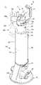
도 1 은 본 발명의 일실시예에 따른 청소장치의 집진통이 도킹장치에 도킹된 상태를 나타내는 사시도이고, 도 2 는 본 발명의 일실시예에 따른 청소장치와 도킹장치를 나타내는 사시도이며, 도 3 은 본 발명의 일실시예에 따른 집진통이 도킹된 도킹장치의 측단면도이다.1 is a perspective view illustrating a state in which a dust collector of a cleaning device according to an embodiment of the present invention is docked in a docking device, and FIG. 2 is a perspective view showing a cleaning device and a docking device according to an embodiment of the present invention, FIG. 3 is a side cross-sectional view of the docking device to which the dust collector is docked according to an embodiment of the present invention.
도 1 내지 도 3 에 도시된 바와 같이, 청소 시스템(1)은 청소장치(10)와 도킹장치(100)를 포함한다.1 to 3 , the
청소장치(10)는 도킹장치(100)에 도킹하도록 마련될 수 있다. 청소장치(10)는 여러가지 상황에서 도킹장치(100)에 도킹할 수 있다. 예를 들어, 청소장치(10)의 배터리(15)를 충전하는 경우 또는 청소장치(10)의 집진통(20)에 이물질이 가득 찬 경우 소비자가 직접 도킹시켜 먼지를 제거하는 경우 등이 있을 수 있다.The
청소장치(10)는 청소기본체(11)와, 청소기본체(11)에 분리 가능하게 결합되는 연장관(50)과, 연장관(50)에 분리 가능하게 결합되는 흡입헤드(40)를 포함할 수 있다. The
청소장치(10)는 피청소면 상의 이물질을 흡입하는데 필요한 흡입력을 발생시키는 팬모터(33)와, 피청소면으로부터 흡입된 이물질이 수용되는 집진통(20)을 포함할 수 있다.The
집진통(20)은 흡입헤드(40)를 통해 유입된 공기중의 먼지나 오물들을 걸러 내어 모아지도록 구성될 수 있다. 집진통(20)은 청소기본체(11)로부터 분리 가능하게 마련될 수 있다.The
청소장치(10)는 팬모터 하우징(30)을 포함할 수 있다. 팬모터 하우징(30)은 내부에 팬모터(33)를 포함할 수 있다. 팬모터 하우징(30)은 원통 형상으로 형성될 수 있다. 팬모터 하우징(30)은 필터(미도시)를 더 포함할 수 있다. 필터는 대략 도넛 형상으로 마련되어 팬모터 하우징(30)의 내부에 마련될 수 있다. 필터의 종류에는 제한이 없으나, 일례로, 헤파 필터(Hepa Filter)가 팬모터 하우징(30)의 내부에 배치될 수 있다. 필터는 집진통(20)에서 걸러지지 않은 초미세먼지 등을 필터링 할 수 있다. 필터는 팬모터 하우징(30)의 내부 외측에 배치되고, 그 중심에 팬모터(33)가 배치될 수 있다.The
청소기본체(11)는 사용자가 파지하여 청소장치(10)를 조작할 수 있도록 핸들(16)이 마련될 수 있다. 사용자는 핸들(16)을 잡고 청소장치(10)를 전후로 이동시켜 청소할 수 있다.The cleaning
청소기본체(11)는 조작부(12)를 포함할 수 있다. 사용자는 조작부(12)에 마련된 전원버튼 등을 보작하여 청소장치(10)를 온/오프 시키거나 흡입강도를 조작할 수 있다.The cleaning
흡입헤드(40)는 피청소면과 접촉하도록 구성될 수 있다. 흡입헤드(40)는 피청소면에 접촉하여 피청소면에 존재하는 먼지 등의 이물질을 흡입하도록 마련될 수 있다.The
흡입헤드(40)와 청소기본체(11)는 연장관(50)에 의해 연결될 수 있다. 연장관(50)은 일단은 흡입헤드(40)에 피봇 연결되어 흡입헤드(40)가 연장관(50)에 대해 관절 운동할 수 있도록 마련될 수 있다.The
청소기본체(11)의 연장관(50)은 연장관 연결부(51)를 포함할 수 있다. 연장관 연결부(51)는 연장관(50)을 청소기본체(11)로부터 분리하거나 결합할 수 있도록 마련된다. 연장관(50)은 연장관 분리버튼(51a)을 포함할 수 있다. 연장관 분리버튼(51a)은 연장관 연결부(51)에 마련될 수 있다. 사용자는 연장관 분리버튼(51a)을 눌러 연장관(50)을 청소기본체(11)로부터 분리할 수 있다.The
청소기본체(11)의 연장관(50)은 흡입헤드 연결부(52)를 더 포함할 수 있다. 흡입헤드 연결부(52)는 흡입헤드(40)를 청소기본체(11)로부터 분리하거나 청소기본체(11)에 결합하도록 마련될 수 있다.The
청소기본체(11)는 집진통(20)과 연장관(50) 및 흡입헤드(40)를 연결시켜 집진통(20)으로 이물질을 가이드 하는 집진 가이드(18)를 포함할 수 있다.The cleaning
집진 가이드(18)는 상술한 바와 같이 이물질을 집진통(20)으로 가이드하면서 연장관(50)과 결합될 수 있다. 집진 가이드(18)는 연장관(50) 외 흡입헤드(40)와 직접 연결되거나 보조 흡입 유닛과 같은 다른 구성들과 결합 가능하게 마련될 수 있다.The
사용자는 청소 상황에 따라 다양한 구성을 청소기본체(11)의 집진 가이드(18)에 연결시켜 청소의 편의성을 향상시킬 수 있다.The user may improve the convenience of cleaning by connecting various components to the dust collection guide 18 of the cleaning
청소기본체(11)는 배터리(15)를 더 포함할 수 있다. 배터리(15)는 청소기본체(11)에 분리 가능하게 장착될 수 있다.The cleaning
또한, 배터리(15)는 도시되지는 않았지만 청소기 도킹장치 또는 도킹 스테이션 등에 마련된 충전단자와 전기적으로 연결될 수 있다. 배터리(15)는 충전단자로부터 전력을 공급받아 충전될 수 있다.Also, although not shown, the
도킹장치(100)는 청소장치(10)가 보관 또는 거치될 수 있도록 마련될 수 있다.The
도킹장치(100)는 외관을 형성하는 도킹장치본체(110, 이하, '도킹하우징'이라 함)를 포함할 수 있다. 도킹하우징(110)은 청소장치(10)의 집진통(20)이 도킹되도록 마련될 수 있다.The
도킹장치(100)는 청소장치(10)의 집진통(20)에 공급되는 흡입기류를 변화시켜 포집물이 자동으로 배출되도록 마련될 수 있다.The
도킹하우징(110)은 일 방향으로 연장되는 장축을 가지도록 마련될 수 있다. 장축은 바람직하게는 상하방향으로 연장될 수 있다. 이에 따라 도킹하우징(110)은 대략 상하방향으로 연장되는 원통 형상으로 마련될 수 있다. 본 발명의 실시예에서 도킹장치 및 도킹하우징은 상하 방향으로 연장되는 원통 형상인 것을 예를 들어 도시하였으나, 본 발명의 사상은 이에 한정되지 않는다. 예를 들어 도킹장치 및 도킹하우징은 상하 방향으로 연장되는 박스 형상으로 형성될 수도 있다.The
도킹장치(100)는 베이스(101)와, 베이스(101)와 도킹하우징(110) 사이를 연결하는 연결브라켓(102)을 더 포함할 수 있다. 베이스(101)에는 청소장치(10)의 흡입헤드(40)가 지지되도록 마련되는 흡입헤드 지지부(103)가 마련될 수 있다.The
도킹하우징(110)은 적어도 일부가 분리 가능하게 마련될 수 있다. 도킹하우징(110)의 적어도 일부가 분리되면서 사용자는 도킹하우징(110) 내부에 배치되는 먼지통(130)을 용이하게 교체할 수 있다.At least a part of the
도킹하우징(110)에는 청소장치(10)의 집진통(20)이 안착되는 안착부(120)가 마련될 수 있다. 안착부(120)는 도킹하우징(110)의 장축을 기준으로 상측을 향해 개방되도록 마련될 수 있다. 안착부(120)는 도킹하우징(110)의 상단에 위치될 수 있다. 안착부(120)는 도킹하우징(110)에서 외부로 개방되는 공간으로 청소장치(10)의 집진통(20)이 상하방향으로 삽입되어 안착될 수 있도록 마련될 수 있다.The
청소장치(10)의 집진통(20)은 도킹장치(100)에 도킹될 때, 도킹하우징(110)의 장축과 집진통(20)의 장축은 대략 대응되는 방향으로 향하도록 마련될 수 있다.When the
집진통(20)은 원통 형상으로 형성될 수 있다. 집진통(20)이 안착되도록 마련되는 도킹하우징(110)의 안착부(120)는 원통 형상으로 형성될 수 있다. 집진통(20)의 하단에는 개구(20a)가 형성되고, 개구(20a)를 개폐시키는 커버(23)가 장착될 수 있다.The
청소장치(10)의 집진통(20)은 일 방향으로 연장되는 장축을 가지는 원통 형상을 포함할 수 있다. 집진통(20)은 그 내부로 유입되는 이물질을 원심 회전을 통해 분리하도록 마련될 수 있다. 집진통(20)의 내부에는 멀티 사이클론(22)이 배치될 수 있다. 집진통(20)은 멀티 사이클론(22)의 하측으로 이물질이 포집되도록 마련될 수 있다. 집진통(20)은 1차적으로 포집되고 상대적으로 큰 이물질이 집진되는 제1집진부(22a)와, 멀티 사이클론(22)에 의해 포집되고 상대적으로 작은 이물질이 집진되는 제2집진부(22b)를 포함할 수 있다.The
제1집진부(22a)와 제2집진부(22b)는 모두 집진통(20)의 커버(23)에 의해 개방될 수 있다. 제1집진부(22a)와 제2집진부(22b)는 커버(23)의 개방 시 집진통(20)에 포집된 이물질이 도킹장치(100)의 안착부(120)로 배출될 수 있도록 마련된다.Both the first
안착부(120)는 도킹하우징(110) 내부에 배치되는 안착 가이드(121)를 포함할 수 있다. 안착 가이드(121)는 집진통(20)이 안착부(120)에 안착 시 집진통(20)에 집진된 이물질이 가이드될 수 있도록 마련된다. 안착 가이드(121)는 먼지통(130)에 연결될 수 있다.The
도킹하우징(110)에는 청소장치(10)의 집진통(20)으로부터 배출되는 이물질이 먼지통(130)으로 흡입되도록 마련되는 흡입유로(200)가 마련될 수 있다. 흡입유로(200)는 도킹하우징(110)의 안착부(120)에 연결되도록 마련될 수 있다. 집진통(20)의 커버(23)는 집진통(20)이 안착부(120)에 안착 시, 자동으로 오픈될 수 있도록 마련될 수 있다. 안착 가이드(121)는 집진통(20)의 커버(23)의 개방을 가이드할 수도 있다.The
도킹하우징(110)은 내부에 흡입유로(200)가 형성될 수 있다. 도킹하우징(110)은 집진통(20)이 안착부(120)에 안착 시, 집진통(20) 내부에 집진된 이물질이 집진통(20) 외부로 배출되도록 마련되는 흡입유로(200)를 포함할 수 있다.The
흡입유로(200)는 청소장치(10)의 팬모터(33)에 의해 발생하는 기류의 흐름을 집진통(20)으로 전달하도록 마련될 수 있다. 도킹하우징(110)의 흡입유로(200)는 청소장치(10)의 팬모터(33)에 의해 발생하는 기류의 흐름을 집진통(20)으로 전달하도록 마련될 수 있다. 즉, 청소장치(10)의 팬모터(33)에 의해 발생하는 흡입기류가 흡입유로(200)를 따라 집진통(20) 내부로 전달되고 흡입 기류에 의해 집진통(20) 내부의 이물질이 기류의 흐름에 따라 집진통(20) 외부로 배출될 수 있다. 집진통(20)의 이물질은 기류의 흐름에 따라 안착부(120)와 안착 가이드(121)로 배출된 후 먼지통(130)에 포집될 수 있다.The
도킹하우징(110)의 먼지통(130)은 공기는 투과되고 이물질은 투과되지 않은 재질로 마련되어 흡입유로(200)를 통해 집진통(20)에서 먼지통(130)으로 유입된 이물질이 포집될 수 있도록 마련된다.The
기존 도킹하우징(110)의 내부에는 먼지 배출을 위한 배출장치 및 흡입기류를 형성하기 위한 흡입장치의 구성이 별도로 구성되어야 하는데, 청소장치(10)의 팬모터(33)의 흡입력을 이용하므로 별도의 먼지 배출을 위한 구성을 요구되지 않아 도킹하우징(110)의 구조를 작고 가볍게 구성할 수 있으며, 먼지통(130)의 용량을 크게 할 수 있어 청소 효율을 향상시킬 수 있다.In the existing
흡입유로(200)의 일단은 집진통(20)에 연결되고, 흡입유로(200)의 타단은 청소장치(10)의 팬모터(33)에 연결될 수 있다.One end of the
도킹장치(100)는 흡입유로(200)를 형성하도록 마련되는 흡입덕트(210)를 더 포함할 수 있다. 흡입덕트(210)는 청소장치(10)의 팬모터(33)가 연결되도록 마련될 수 있다. 흡입덕트(210)는 도킹하우징(110)의 일측에 배치될 수 있다. 흡입덕트(210)는 도킹하우징(110)으로부터 연장되어 형성될 수 있다. 흡입덕트(210)는 도킹하우징(110)의 장축으로부터 일측으로 이격되어 배치될 수 있다. 흡입덕트(210)는 팬모터(33)가 연결되도록 마련되는 팬모터 결합부(220)를 포함할 수 있다. 팬모터 결합부(220)는 흡입덕트(210)의 일측 단부에 마련될 수 있다. 흡입덕트(210)의 팬모터 결합부(220)는 청소장치(10)의 팬모터(33)가 청소기본체(11)로부터 회전 이동되어 결합될 수 있도록, 도킹하우징(110)의 일측에 이격되어 배치될 수 있다.The
도킹하우징(110)의 하부에는 흡입덕트(210)가 연결되도록 마련되는 공기 배출부(111)가 마련될 수 있다. 공기 배출부(111)는 도킹하우징(110)의 하단에 배치될 수 있다. 공기 배출부(111)는 흡입덕트(210)에 연결되어 흡입유로(200)를 형성하도록 마련된다. 공기 배출부(111)에는 먼지통(130)을 관통하여 배출되는 공기를 필터링 하기 위한 필터(150)가 장착될 수 있다. 필터(150)는 도킹하우징(110)의 흡입유로(200) 상에 배치될 수 있다. 본 발명의 실시예에서 필터는 도킹하우징에 설치되는 것을 예를 들어 도시하였으나, 본 발명의 사상은 이에 한정되지 않는다. 예를 들어 필터는 흡입유로가 형성되는 도킹하우징과 흡입덕트 중 적어도 한 곳에 배치될 수 있다.An
도킹장치(100)의 도킹하우징(110)에는 팬모터(33)로부터 배출되는 배기 중 일부를 흡입유로(200)로 환류시키도록 마련되는 환류덕트(300)가 설치될 수 있다.In the
청소장치(10)의 팬모터(33)는 팬모터 하우징(30) 내부에 장착될 수 있다. 팬모터(33)는 팬모터(33)의 회전에 의해 흡입력이 발생되는 흡입부(33a)를 포함할 수 있다. 흡입부(33a)는 팬모터(33)의 하부에 형성될 수 있다.The
팬모터 하우징(30)은 청소기본체(11) 및 집진통(20)에 대응되도록 원통 형상으로 형성될 수 있다. 팬모터 하우징(30)은 팬모터(33)의 흡입부(33a)에 대응되도록 하면 중 적어도 일부가 개구되어 형성되는 흡입구(30a)를 포함할 수 있다. 팬모터 하우징(30)은 그 외주면에 형성되는 토출구(30b)를 포함할 수 있다. 토출구(30b)는 복수개의 홀을 포함할 수 있다. 본 발명의 실시예에서 팬모터 하우징(30)의 토출구(30b)는 복수의 홀인 것을 예를 들어 도시하였으나, 본 발명의 사상은 이에 한정되지 않는다. 예를 들어 토출구는 복수의 슬릿을 포함할 수 있다.The
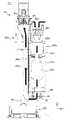
도 4 는 본 발명의 일실시예에 따른 청소장치로부터 회전 이동된 팬모터 하우징을 나타내는 사시도이고, 도 5 는 본 발명의 일실시예에 따른 팬모터 하우징이 도킹장치의 흡입덕트에 연결된 상태를 나타내는 도면이다.4 is a perspective view illustrating the fan motor housing rotationally moved from the cleaning device according to an embodiment of the present invention, and FIG. 5 is a state in which the fan motor housing according to an embodiment of the present invention is connected to the suction duct of the docking device It is a drawing.
도 4 내지 도 5 에 도시된 바와 같이, 청소장치(10)는 청소기본체(11)에 회전 가능하게 마련되는 팬모터 하우징(30)을 포함할 수 있다.4 to 5 , the
팬모터 하우징(30)은 내부에 팬모터(33)가 수용되어 흡입력을 발생하도록 마련된다. 팬모터 하우징(30)은 청소장치(10)로부터 회전 가능하게 마련될 수 있다. 팬모터 하우징(30)은 청소기본체(11)로부터 회전 가능하게 마련될 수 있다. 팬모터 하우징(30)은 청소기본체(11)로부터 수평 방향으로 회전 이동 가능하게 설치될 수 있다. 팬모터 하우징(30)은 청소기본체(11)의 장축 방향에 대응되는 제1위치(P1)에서 수평 방향으로 회전 이동된 제2위치(P2)로 이동될 수 있다. 팬모터 하우징(30)은 팬모터(33)의 흡입부(33a)의 위치를 변경 가능하도록 청소기본체(11)로부터 회전 이동될 수 있다. 팬모터 하우징(30)은 팬모터(33)의 흡입부(33a) 위치를 청소기본체(11)의 장축 방향 중심위치(P1)로부터 일측으로 이동된 제2위치(P2)로 회전 시켜 이동할 수 있다.The
팬모터 하우징(30)은 흡입구(30a)의 위치를 변경 가능하도록 청소기본체(11)로부터 회전 이동될 수 있다. 팬모터 하우징(30)은 팬모터(33)의 흡입부(33a)의 위치를 변경 가능하도록 청소기본체(11)로부터 회전 가능하게 마련될 수 있다.The
청소장치(10)는 팬모터 하우징(30)을 청소기본체(11)로부터 회전 이동 가능하도록 회전장치(70)를 더 포함할 수 있다.The
회전장치(70)는 청소기본체(11)와 팬모터 하우징(30) 사이에 마련되어, 팬모터(33)의 위치를 청소기본체(11)로부터 이동 가능하게 마련된다. 회전장치(70)는 회전축(71)과, 회전축(71)이 회전 가능하게 지지되도록 청소기본체(11)와 팬모터 하우징(30)에 마련되는 회전축 지지부(72)를 포함할 수 있다. 회전축 지지부(72)는 청소기본체(11)에 마련되는 제1회전축지지부(72a)와, 팬모터 하우징(30)에 마련되는 제2회전축지지부(72b)를 포함할 수 있다.The
청소장치(10)의 집진통(20)이 도킹장치(100)의 안착부(120)에 안착되면, 팬모터(33) 즉, 팬모터 하우징(30)은 청소기본체(11)의 장축 방향에 대응되는 제1위치(P1)에서 회전 이동되어 청소기본체(11)의 장축 방향으로부터 이격되어 위치되는 제2위치(P2)로 이동하게 된다. 본 발명의 실시예에서 팬모터 하우징(30)은 청소기본체(11)로부터 회전축을 중심으로 사용자가 수동으로 이동시키는 것을 예를 들어 도시하였으나, 본 발명의 사상은 이에 한정되지 않는다. 청소기본체와 팬모터 하우징의 회전 동작은 별도의 장치를 통해 자동으로 구동되도록 할 수도 있다.When the
또, 도시되지는 않았지만 회전축(71)과 회전축 지지부(72) 사이를 탄성 지지하기 위한 텐션 부재(미도시)를 더 포함할 수도 있다. 텐션 부재에 의해 팬모터 하우징(30)은 청소기본체(11)에 자동으로 복귀될 수 있다.In addition, although not shown, a tension member (not shown) for elastically supporting between the
청소기본체(11)의 제1위치(P1)에서 제2위치(P2)로 이동된 팬모터 하우징(30)은 도킹장치(100)의 흡입덕트(210)에 연결될 수 있다.The
흡입덕트(210)의 일단은 도킹하우징(110)에 연결될 수 있다. 흡입덕트(210)의 타단은 팬모터 하우징(30)에 연결될 수 있다. 흡입덕트(210)의 일단은 도킹하우징(110)의 흡입유로(200)에 연결될 수 있다. 흡입덕트(210)의 타단은 팬모터(33)의 흡입부(33a)에 연결될 수 있다.One end of the
흡입덕트(210)는 청소장치(10)의 팬모터 하우징(30)이 연결되기 위한 팬모터 결합부(220)를 포함할 수 있다. 팬모터 결합부(220)는 흡입덕트(210)의 상단에 마련될 수 있다. 팬모터 결합부(220)는 팬모터 하우징(30)의 회전 이동에 의해 연결될 수 있도록 대응되는 위치에 마련될 수 있다. 팬모터 결합부(220)는 팬모터 하우징(30)의 흡입구(30a)에 대응되는 개구(220a)를 포함할 수 있다. 팬모터 결합부(220)는 흡입덕트(210)의 상단에 형성될 수 있다. 개구(220a)는 흡입덕트(210)의 상단에 형성될 수 있다.The
흡입덕트(210)의 하단은 도킹하우징(110)의 하부에 연결되어 도킹하우징(110) 내부의 흡입유로(200)에 연결될 수 있다. 흡입덕트(210)의 하단은 도킹하우징(110)의 공기 배출부(111)에 연결될 수 있다. 흡입덕트(210)는 공기 배출부(111)에 연결되기 위한 연결부(211)와, 도킹하우징(110)의 장축 방향을 통해 유입된 공기의 유동 방향을 전환하도록 형성되는 방향 전환부(212)를 더 포함할 수 있다. 방향 전환부(212)는 도킹하우징(110)의 장축 방향으로 유입된 공기를 흡입덕트(210)의 장축 방향으로 전환시키도록 마련될 수 있다. 도킹하우징(110)의 장축 방향으로 유입된 공기는 방향 전환부(212)를 따라 방향을 전환하여 흡입덕트(210)의 장축 방향으로 이동할 수 있다.The lower end of the
도 6 은 본 발명의 일실시예에 따른 흡입유로와 환류덕트의 공기흐름을 나타내는 도면이고, 도 7 은 본 발명의 일실시예에 따른 흡입유로의 제3흡입경로를 나타내는 도면이며, 도 8 은 본 발명의 일실시예에 따른 흡입유로의 공기 흐름을 나타내는 도면이다.6 is a view showing the air flow of the suction flow path and the reflux duct according to an embodiment of the present invention, FIG. 7 is a view showing the third suction path of the suction flow path according to an embodiment of the present invention, FIG. 8 is It is a view showing an air flow in a suction passage according to an embodiment of the present invention.
도 6 내지 도 8 에 도시된 바와 같이, 흡입유로(200)는 청소장치(10)의 팬모터(33)에서 발생한 흡입력을 통해 발생하는 흡입기류에 의해 형성된다.6 to 8 , the
흡입유로(200)는 도킹하우징(110) 내부에 형성되는 제1흡입유로(200a)와, 흡입덕트(210) 내부에 형성되는 제2흡입유로(200b)를 포함할 수 있다. 제1흡입유로(200a)와 제2흡입유로(200b)는 서로 연결되어 형성될 수 있다. 제1흡입유로(200a)와 제2흡입유로(200b)는 팬모터(33)에 의해 발생되는 흡입 기류에 의해 형성될 수 있다. 제1흡입유로(200a)와 제2흡입유로(200b)는 팬모터(33)에 의해 발생하는 기류의 흐름을 집진통(20)으로 전달하도록 형성될 수 있다. 팬모터(33)에 의해 발생하는 흡입 기류는 흡입덕트(210)의 제2흡입유로(200b) 및 도킹하우징(110)의 제1흡입유로(200a)를 따라 집진통(20) 내부로 전달되고, 흡입기류에 의해 집진통(20) 내부의 이물질이 기류 흐름에 의해 도킹하우징(110) 내부의 먼지통(130)으로 포집되도록 한다.The
흡입유로(200)는 집진통(20)의 주위로부터 외기가 유입되는 제1흡입경로(Q1)와, 팬모터 하우징(30)의 토출구(30b)로부터 배출되는 공기 중 일부가 유입되는 제2흡입경로(Q2)와, 청소장치(10)의 흡입헤드(40)와 연장관(50)을 통해 공기가 유입되는 제3흡입경로(Q3)를 포함할 수 있다.The
흡입유로(200)의 제1흡입경로(Q1)는 집진통(20)의 상부로부터 외기가 유입되어 집진통(20)을 통과하면서 형성될 수 있다. 청소장치(10)의 도킹 시, 청소기본체(11)로부터 회전 이동된 팬모터 하우징(30)에 의해 집진통(20) 상부가 개방된다. 개방된 집진통(20) 상단은 외부에 노출되고 팬모터(33)에서 흡입력이 발생되면 팬모터(33)의 흡입력에 의해 집진통(20)의 노출된 상부 주위의 외기는 집진통(20) 내부로 유입되어 제1흡입유로(200a)를 따라 이동하게 된다.The first suction path Q1 of the
흡입유로(200)의 제2흡입경로(Q2)는 팬모터 하우징(30)의 토출구(30b)를 통해 토출되는 배기 중 일부가 집진통(20)으로 재 유입되어 형성될 수 있다. 이때, 제2흡입경로(Q2)의 공기는 제1흡입경로(Q1)의 공기와 섞여 집진통(20) 내부로 이동하게 된다.The second suction path Q2 of the
흡입유로(200)의 제3흡입경로(Q3)는 청소장치(10)의 흡입헤드(40)와 연장관(50)을 통해 유입되는 공기에 의해 형성될 수 있다. 팬모터(33)의 흡입력에 의해 흡입헤드(40)를 통해 유입되는 공기는 연장관(50)을 통해 청소기본체(11)의 집진 가이드(18)로 유입되고 집진 가이드(18)에 연결된 집진통(20) 내부로 유입되게 된다.The third suction path Q3 of the
집진 가이드(18)와 집진통(20)은 연결홀(19)을 통해 연결될 수 있다. 제3흡입경로(Q3)의 공기는 집진통(20) 내부에서 제1흡입경로(Q1)의 공기와 제2흡입경로(Q2)의 공기와 섞여 집진통(20) 외부로 이동하게 된다.The
제1흡입경로(Q1)와 제2흡입경로(Q2), 그리고 제3흡입경로(Q3)를 통해 집진통(20) 내부로 이동하는 공기는 도킹하우징(110) 내부에 형성되는 제1흡입유로(200a)를 통해 안착 가이드(121)와 먼지통(130)을 거쳐 흡입덕트(210)의 제2흡입유로(200b)로 이동한다.Air moving into the
이러한 제1흡입경로(Q1)와 제2흡입경로(Q2), 그리고 제3흡입경로(Q3)를 통한 공기의 유량 변화는 흡입유로에 플러스 효과를 가해 먼지 배출 성능을 향상시킬 수 있다.The change in the flow rate of air through the first suction path Q1, the second suction path Q2, and the third suction path Q3 may have a positive effect on the suction path and improve the dust discharge performance.
흡입유로(200) 내에는 필터(150)가 마련될 수 있다. 필터(150)는 흡입유로(200)가 형성되는 흡입덕트(210)와 도킹하우징(110) 중 적어도 하나에 배치될 수 있다. 필터(150)는 도킹하우징(110)의 장축 방향을 기분으로 먼지통(130)의 하부에 배치되는 것이 바람직하다. 흡입유로(200) 상에 필터(150)를 장착함으로써 필터링 효율을 향상시킬 수 있다.A
도킹장치(100)는 팬모터 하우징(30)의 토출구(30b)를 통해 배출되는 배기 중 일부가 흡입유로(200)로 환류되도록 형성되는 환류덕트(300)를 더 포함할 수 있다.(도 6 참고)The
환류덕트(300)는 팬모터 하우징(30)의 토출구(30b)와 흡입유로(200) 사이를 연결하도록 마련될 수 있다. 환류덕트(300)의 일측은 팬모터 하우징(30)의 토출구(30b)에 연결되게 마련되고, 타측은 도킹하우징(110)에 연결되게 마련될 수 있다. 환류덕트(300)는 팬모터 하우징(30)의 토출구(30b)에 대응되게 마련되는 제1단부(310)와, 도킹하우징(110) 내부에 형성되는 제1흡입유로(200a)에 연결되도록 마련되는 제2단부(320)를 포함할 수 있다. 환류덕트(300)의 제1단부(310)는 환류덕트(300)의 상단에 위치될 수 있다. 환류덕트(300)의 제1단부(310)는 팬모터 하우징(30)의 토출구(30b)를 통해 배출되는 공기가 유입되도록 형성될 수 있다. 환류덕트(300)의 제2단부(320)는 도킹하우징(110)에 연결될 수 있다. 제2단부(320)는 제1단부(310)를 통해 유입된 공기가 흡입유로(200)로 이동할 수 있도록 제1흡입유로(200a)에 연결될 수 있다. 제2단부(320)는 도킹하우징(110)의 안착 가이드(121)에 연결될 수 있다. 본 발명의 실시예에서 환류덕트(300)의 제2단부(320)는 도킹하우징(110)의 안착 가이드(121)에 연결되는 것을 예를 들어 도시하였으나, 본 발명의 사상은 이에 한정되지 않는다. 예를 들어 환류덕트의 제2단부는 먼지통 또는 흡입덕트에 연결될 수도 있다.The
이처럼 팬모터(33)에 의해 배출되는 공기의 일부를 환류덕트(300)로 환류시켜 배출 효율을 높일 뿐만 아니라 소음을 저감시키고 냄새를 줄일 수 있다.As such, a part of the air discharged by the
본 발명의 도킹장치(100)에 의한 청소장치(10) 집진통(20)의 먼지 배출을 위한 동작을 간략하게 설명하면 다음과 같다.An operation for discharging dust of the
청소장치(10)의 집진통(20)이 도킹장치(100)의 안착부(120)에 안착되면, 청소기본체(11)로부터 팬모터 하우징(30)이 회전되어 이동된다.When the
청소기본체(11)로부터 회전 이동된 팬모터 하우징(30)은 흡입덕트(210)의 팬모터 결합부(220)에 결합된다.The
청소장치(10)의 팬모터(33)가 동작하면 흡입력에 의한 흡입기류가 형성된다.When the
팬모터(33)에 의한 배출흡입은 약 20~30초의 한 사이클로 진행되며, 추가 동작을 원할 경우 청소장치(10)의 조작부(12)를 활용할 수 있다.The exhaust suction by the
한 사이클이 진행되는 동안 팬모터(33)는 온오프(ON/OFF)를 반복할 수 있다. 집진통(20)의 멀티 사이클론(22) 내부의 기류에 맥동을 주어 먼지 및 이물질이 기류를 따라 이동되는 효과를 높일 수 있다.During one cycle, the
집진통(20)의 커버(23)는 도킹하우징(110)의 안착부(120)에 안착 시 자동으로 개방되며, 동시에 도시되지는 않았지만 유량조절모터(미도시)가 동작할 수 있다.The
집진통(20)의 커버(23)가 개방되어 집진통()이 오픈되면 도킹하우징(110) 내부의 흡입유로(200)에 공기 흐름이 형성된다.When the
유량조절모터의 사용 시에는 유량조절모터는 회전하면서 메인 모터(미도시) 의 유로를 20초간 열고 닫아, 이를 통해 청소기본체(11) 내부의 유로에 유량을 변화시켜 집진통(20) 내부의 먼지를 배출할 수 있다.When the flow control motor is used, the flow control motor opens and closes the flow path of the main motor (not shown) for 20 seconds while rotating, thereby changing the flow rate in the flow path inside the cleaning
또한, 환류덕트(300)를 통해 배출되는 공기를 바로 외부로 보내지 않고 흡입유로(200)에 재순환시킴으로 혹시나 발생될 수 있는 냄새 또는 소음을 저감 시킬 수 있다.In addition, by recirculating the air discharged through the
도 9 는 본 발명의 다른 실시예에 따른 청소장치와 도킹장치를 개략적으로 나타내는 도면이다. 미도시된 도번은 도 1 내지 도 8을 참조한다.9 is a view schematically showing a cleaning apparatus and a docking apparatus according to another embodiment of the present invention. For unillustrated drawings, refer to FIGS. 1 to 8 .
도 9 에 도시된 바와 같이, 청소 시스템(1A)은 청소장치(10B)와 도킹장치(100A)를 포함할 수 있다.As shown in FIG. 9 , the
청소장치(10A)는 청소기본체(11A)와, 청소기본체(11A)에 분리 가능하게 연결되는 연장관(50A)과, 연장관(50A)에 분리 가능하게 결합되는 흡입헤드(40A)를 포함할 수 있다.The cleaning device 10A may include a cleaning
청소기본체(11A)는 피청소면 상의 이물질을 흡입하는데 필요한 흡입력을 발생시키는 팬모터(33A)를 포함할 수 있다. 팬모터(33A)는 팬모터 하우징(30A)에 설치될 수 있다.The cleaning
청소장치(10A)는 청소기본체(11A)에 분리 및 회전 가능하게 결합되는 집진통(20A)을 포함할 수 있다.The cleaning device 10A may include a
집진통(20A)은 청소기본체(11A)에 회전 가능하게 결합될 수 있다. 집진통(20A)은 청소기본체(11A)의 팬모터 하우징(30A)에 회전 가능하게 결합될 수 있다.The
청소기본체(11A)는 일방향으로 연장되는 장축(X)을 가지도록 마련될 수 있다. 청소기본체(11A)의 장축(X)은 바람직하게 상하 방향으로 연장될 수 있다. 팬모터 하우징(30A)은 청소기본체(11A)에 대응되는 장축(X) 상에 위치될 수 있다.The cleaning
도킹장치(100A)는 청소장치(10A)가 도킹되도록 마련될 수 있다. 도킹장치(100A)는 상하 방향으로 연장되는 장축(X)을 가지는 도킹하우징(110A)과 도킹하우징(110A)으로부터 연장되어 장축(X) 방향으로 나란하게 배치되는 흡입덕트(210A)를 포함할 수 있다. 흡입덕트(210A)는 일측은 도킹하우징(110A)에 연결되고 타측은 청소장치(10A)의 팬모터 하우징(30A)이 연결되도록 마련될 수 있다.The
흡입덕트(210A)는 도킹하우징(110A)의 장축(X)이 위치된 제1축(C1) 으로부터 이격된 제2축(C2)에 배치될 수 있다.The
청소장치(10A)의 집진통(20A)은 청소기본체(11A)로부터 회전 가능하게 마련될 수 있다. 집진통(20A)은 청소기본체(11A)의 팬모터 하우징(30A)으로부터 회전 가능하게 마련될 수 있다. 진진통(20A)은 청소기본체(11A)와 회전장치(70A)에 의해 회전 가능하게 연결될 수 있다.The
따라서, 집진통(20A)은 청소장치(10A)의 도킹 시, 청소기본체(11A)로부터 회전 이동되어 도킹하우징(110A)의 안착부(120A)에 안착될 수 있다.Accordingly, the
집진통(20A)이 안착되도록 마련되는 도킹하우징(110A)은 상단에 개구되어 형성되는 안착부(120A)를 포함할 수 있다. 도킹하우징(110A)은 안착부(120A)에 연결되는 안착 가이드(121A)와 인착 가이드(121A)에 연결되는 먼지통(130A)을 포함할 수 있다.The
청소장치(10A)의 팬모터 하우징(30A)은 흡입덕트(210A)에 연결될 수 있다. 흡입덕트(210A)에 연결된 팬모터 하우징(30A)은 내부의 팬모터(33A)에 의해 흡입력을 발생시켜 흡입덕트(210A) 내의 흡입유로(200A)로 흡입기류를 발생시킬 수 있다. 팬모터(33A)의 흡입력에 의해 발생되는 흡입기류는 도킹하우징(110A)에 안착된 집진통(20A)으로 전달되고, 집진통(20A)에 집진된 이물질은 흡입기류에 의해 먼지통(130A)으로 전달될 수 있다.The
한편, 도킹하우징(110A)은 팬모터 하우징(30A)의 토출구(30b)를 통해 토출되는 공기 중 일부를 흡입유로(200A)로 환류시키도록 마련된 환류덕트(210A)를 더 포함할 수 있다.Meanwhile, the
환류덕트(210A)는 일단은 팬모터 하우징(30A)의 토출구(30b)에 연결되고 타단은 도킹하우징(110A)의 흡입유로(200A)에 연결되도록 마련될 수 있다. 이처럼 팬모터(33A)에 의해 배출되는 공기의 일부를 환류덕트(300A)로 환류시켜 배출 효율을 높일 뿐만 아니라 소음을 저감시키고 냄새를 줄일 수 있다.The
도 10 은 본 발명의 또 다른 실시예에 따른 청소장치와 도킹장치를 개략적으로 나타내는 도면이다. 미도시된 도번은 도 1 내지 도 8을 참조한다.10 is a view schematically showing a cleaning apparatus and a docking apparatus according to another embodiment of the present invention. For unillustrated drawings, refer to FIGS. 1 to 8 .
도 10 에 도시된 바와 같이, 청소 시스템(1B)은 청소장치(10B)와 도킹장치(100B)를 포함할 수 있다.As shown in FIG. 10 , the
청소장치(10B)는 청소기본체(11B)와 청소기본체(11B)에 연결되는 집진통(20B)을 포함할 수 있다. 청소기본체(11B)는 피청소면 상의 이물질을 흡입하는데 필요한 흡입력을 발생시키는 팬모터(33)를 포함할 수 있다. 팬모터(33)는 팬모터 하우징(30B)에 설치될 수 있다. 청소장치(10B)는 청소기본체(11B)에 회전 가능하게 결합되는 팬모터 하우징(30B)을 포함할 수 있다.The
청소장치(10B)는 청소기본체(11B)에 분리 가능하게 결합되는 연장관(50B)과, 연장관(50B)에 분리 가능하게 결합되는 흡입헤드(40B)를 포함할 수 있다.The
청소기본체(11B)는 집진통(20B)과 연장과(50B) 및 흡입헤드(40B)를 연결시켜 집진통(20B)으로 이물질을 가이드 하는 집진 가이드(18B)를 포함할 수 있다.The cleaning
청소장치(10B)의 연장관(50B)은 일 방향으로 연장되는 장축(X)을 가지도록 연장될 수 있다. 집진통(20B)은 연장관(50B)의 장축(X)이 연장되는 방향과 대략 직교되는 방향으로 연장되는 연장축(Y)을 가지는 원통 형상으로 마련될 수 있다.The
집진통(20B)은 원심 회전 분리를 통해 이물질이 집진되도록 마련될 수 있다. 집진통(20B)은 이물질을 원심 회전 분리로 집진하도록 멀티 사이클론을 더 포함할 수 있다.The
집진통(20B)이 도킹하도록 마련되는 도킹장치(100B)는 일방향으로 연장되는 장축을 가지도록 마련되는 도킹하우징(110B)을 포함할 수 있다. 도킹하우징(110B)은 상하방향으로 연장되는 박스 형상을 포함할 수 있다.The
청소장치(10B)는 도킹하우징(110B)의 연장 방향인 제1방향(A)에 대해 대략 직교되는 방향인 제2방향(B)으로 도킹될 수 있다. 집진통(20B)은 도킹하우징(110B)의 연장 방향인 제1방향(A)에 대해 대략 직교되는 방향인 제2방향(B)으로 도킹될 수 있다.The
도킹하우징(110B)에는 집진통(20B)이 안착되도록 마련되는 안착부(120B)가 마련될 수 있다. 안착부(120B)는 도킹하우징(110B)의 연장 방향인 제1방향(A)에 대해 대략 직교되는 방향인 제2방향(B)으로 형성될 수 있다. 도킹하우징(110B)에는 안착부(120B)에 연결되는 안착 가이드(121B)와 먼지통(130B)이 마련될 수 있다.The docking housing (110B) may be provided with a seating portion (120B) provided so that the dust collector (20B) is seated. The
도킹하우징(110B)의 안착부(120B)에 도킹되는 집진통(20B)으로부터 배출되는 이물질은 안착부(120B)와 안착 가이드(121B)를 통해 먼지통(130B)으로 집진될 수 있다.Foreign substances discharged from the
청소장치(10B)의 집진통(20B)과 도킹하우징(110B)의 안착부(120B)는 제2방향(B)에 대해 동일한 제1축(C1)을 가지도록 위치된다.The
청소장치(10B)의 팬모터 하우징(30B)은 도킹하우징(110B)에 연결되어 마련되는 흡입덕트(210B)에 연결된다. 팬모터 하우징(30B)은 청소기본체(11B)로부터 회전 이동되어 흡입덕트(210B)에 연결될 수 있다.The
이때, 청소장치(10B)의 팬모터 하우징(30B)은 청소기본체(11B)로부터 회전 이동되어 제2방향(B)에 대해 제1축(C1)으로부터 이격되어 위치되는 제2축(C2)에 위치된다.At this time, the
청소장치(10B)의 팬모터(33) 즉, 팬모터 하우징(30B)은 도킹하우징(110B)으로부터 이격되어 배치된 흡입덕트(210B)에 연결되어 흡입유로(200B)를 형성한다.The
이처럼 청소장치(10B)의 집진통(20B)에 집진된 이물질을 제거하도록 청소장치(10B)의 팬모터(33)를 이용하여 흡입유로(200B)를 형성하면 도킹하우징(110B) 내부에 별도의 흡입기류를 형성하기 위한 배출장치 및 구성이 요구되지 않아 구조적, 공간적 활용도를 높일 수 있다.In this way, when the
또, 청소기본체(11B)의 집진통(20B)과 이격되어 위치되는 팬모터(33)에 의해 형성되는 흡입유로(200B)는 청소기본체(11B) 내부의 유량 변화를 가해 배출 성능을 향상시킬 수 있다.In addition, the
이상과 같이 본 발명의 이해를 위해 그 실시예를 기술하였으나, 당업자라면 알 수 있듯이 본 발명은 본 명세서에 기술된 특정 실시예를 한정하는 것이 아니라, 본 발명의 범주를 벗어나지 않는 범위에서 다양하게 변형, 변경 및 대체될 수 있다.Although the embodiments have been described for the purpose of understanding the present invention as described above, the present invention is not limited to the specific embodiments described herein, as will be understood by those skilled in the art, but various modifications are made without departing from the scope of the present invention. , subject to change and substitution.
1 : 청소 시스템10 :청소 장치
20 : 집진통30 : 팬모터 하우징
40 : 흡입헤드50 : 연장관
100 : 도킹장치110 : 도킹하우징
120 : 안착부200 : 흡입유로
210 : 흡입덕트300 : 환류덕트1: cleaning system 10: cleaning device
20: dust collector 30: fan motor housing
40: suction head 50: extension tube
100: docking device 110: docking housing
120: seating part 200: suction flow path
210: suction duct 300: reflux duct
Claims (20)
Translated fromKorean상기 집진통이 도킹하도록 마련되고, 상기 집진통에 집진된 이물질이 전달되어 수용되는 먼지통을 포함하는 도킹장치를 포함하고,
상기 팬모터는 상기 흡입부의 위치를 변경 가능하도록 상기 청소장치로부터 회전 가능하게 마련되고,
상기 도킹장치는,
상기 청소장치로부터 회전 이동 된 상기 흡입부와 상기 집진통 사이에 흡입유로를 형성하도록 상기 팬모터가 연결되는 흡입덕트를 포함하는 청소 시스템.A cleaning device comprising: a fan motor provided to generate a suction force in the suction unit; and a dust collector for collecting foreign substances sucked by the suction force;
and a docking device including a dust container provided to dock the dust collector and receiving foreign substances collected in the dust collector,
The fan motor is provided rotatably from the cleaning device to change the position of the suction unit,
The docking device,
and a suction duct to which the fan motor is connected to form a suction flow path between the suction unit rotated from the cleaning device and the dust collector.
상기 청소장치는,
상하 방향으로 연장되는 장축을 가지는 청소기본체와,
상기 청소기본체의 장축 상에 배치되는 상기 집진통 내부의 이물질이 원심 회전 분리되도록 마련되는 사이클론을 포함하는 청소 시스템.The method of claim 1,
The cleaning device is
A cleaning main body having a long axis extending in the vertical direction,
A cleaning system including a cyclone provided to centrifuge the foreign substances inside the dust collecting bin disposed on the long axis of the cleaning main body.
상기 청소장치는,
상기 팬모터를 수용하며, 상기 흡입구와 토출구가 마련되는 팬모터 하우징과,
상기 팬모터 하우징을 상기 청소기본체로부터 회전 이동 가능하도록 마련되는 회전장치를 더 포함하는 청소 시스템.3. The method of claim 2,
The cleaning device is
a fan motor housing accommodating the fan motor and provided with the inlet and outlet;
The cleaning system further comprising a rotating device provided to rotate the fan motor housing from the cleaning main body.
상기 흡입덕트는,
상기 청소기본체의 장축으로부터 이격되어 배치되고, 상기 청소기본체로부터 회전 이동된 상기 팬모터가 결합되는 팬모터 결합부를 포함하는 청소 시스템.4. The method of claim 3,
The suction duct is
A cleaning system comprising a fan motor coupling part disposed to be spaced apart from the long axis of the cleaning main body, and to which the fan motor rotated from the cleaning main body is coupled.
상기 집진통이 상기 도킹장치와 도킹 시, 상기 팬모터의 모터축은 상기 사이클론의 장축으로부터 회전 이동되어 위치되는 청소 시스템.4. The method of claim 3,
When the dust collector is docked with the docking device, the motor shaft of the fan motor is rotated from the long shaft of the cyclone and positioned.
상기 회전장치는,
회전축과,
상기 회전축이 회전 가능하게 지지되도록 상기 청소기본체와 상기 팬모터 하우징에 각각 마련되는 회전축 지지부를 포함하는 청소 시스템.4. The method of claim 3,
The rotating device is
rotating shaft,
The cleaning system including rotating shaft support parts respectively provided in the cleaning main body and the fan motor housing so that the rotating shaft is rotatably supported.
상기 도킹장치는,
일 방향으로 연장되는 장축을 가지는 도킹장치 본체와,
상기 집진통이 안착되도록 상기 도킹장치 본체의 장축 방향으로 상측이 개방되어 마련되는 안착부와,
상기 도킹장치 본체의 하측에 마련되는 공기 배출부를 더 포함하는 청소 시스템.4. The method of claim 3,
The docking device,
A docking device body having a long axis extending in one direction;
a seating portion provided with an upper side open in the long axis direction of the docking device body so that the dust collector is seated;
The cleaning system further comprising an air outlet provided on the lower side of the docking device body.
상기 도킹장치는,
상기 토출구를 통해 배출되는 배기 중 일부를 상기 흡입유로로 환류시키도록 상기 토출구와 상기 도킹장치 본체 사이를 연결하는 환류덕트를 더 포함하는 청소 시스템.8. The method of claim 7,
The docking device,
The cleaning system further comprising a reflux duct connecting the discharge port and the docking device body to return a portion of the exhaust discharged through the discharge port to the suction passage.
상기 환류덕트는,
상기 토출구와 상기 흡입유로 사이를 연결하는 청소 시스템.9. The method of claim 8,
The reflux duct is
A cleaning system connecting the discharge port and the suction passage.
상기 흡입덕트는,
상기 공기 배출부에 연결되는 연결부와,
상기 도킹장치 본체의 장축 방향을 통해 유입된 공기의 유동방향을 전환하도록 형성되는 방향전환부를 더 포함하는 청소 시스템.8. The method of claim 7,
The suction duct is
a connection part connected to the air outlet;
The cleaning system further comprising a direction changer formed to change the flow direction of the air introduced through the long axis direction of the docking device body.
상기 흡입유로는,
상기 집진통 주위로부터 외기가 유입되는 제1흡입경로와
상기 팬모터 하우징의 상기 토출구로부터 배출되는 공기가 유입되는 제2흡입경로를 더 포함하는 청소 시스템.11. The method of claim 10,
The suction flow is
A first suction path through which outside air is introduced from around the dust collector and
The cleaning system further comprising a second suction path through which the air discharged from the outlet of the fan motor housing is introduced.
상기 청소장치는,
상기 청소기본체에 분리 가능하게 결합되는 연장관과,
상기 연장관에 분리 가능하게 결합되는 흡입헤드를 포함하고,
상기 흡입유로는 상기 흡입헤드와 상기 연장관을 통해 공기가 유입되는 제3흡입경로를 더 포함하는 청소 시스템.12. The method of claim 11,
The cleaning device is
an extension pipe detachably coupled to the cleaning body;
and a suction head detachably coupled to the extension tube,
The suction flow path further includes a third suction path through which air is introduced through the suction head and the extension pipe.
상기 흡입유로는
상기 제1흡입경로와 상기 제2흡입경로 그리고 제3흡입경로를 통해 유입되는 공기가 상기 집진통을 통해 상기 도킹장치 본체 내부를 이동하도록 마련되는 제1흡입유로와,
상기 제1흡입유로에 연결되며, 상기 흡입덕트를 이동하여 상기 토출구를 통해 배출되도록 마련되는 제2흡입유로를 더 포함하는 청소 시스템.13. The method of claim 12,
The suction flow
a first suction path provided to allow air introduced through the first suction path, the second suction path, and the third suction path to move inside the docking device body through the dust collector;
The cleaning system further comprising a second suction flow path connected to the first suction flow path and provided to be discharged through the discharge port by moving the suction duct.
상기 도킹장치는,
상기 흡입유로 상에 마련되는 필터를 더 포함하고,
상기 필터는 상기 도킹장치 본체의 장축 방향을 기준으로 상기 먼지통의 하측에 배치되는 청소 시스템.8. The method of claim 7,
The docking device,
Further comprising a filter provided on the suction passage,
The filter is a cleaning system disposed below the dust container with respect to the long axis direction of the docking device body.
상기 집진통이 도킹하도록 마련되고, 상기 집진통에 집진된 이물질이 전달되어 수용되는 먼지통을 포함하는 도킹장치;를 포함하고,
상기 팬모터는 상기 청소기본체로부터 회전 가능하게 마련되고,
상기 도킹장치는,
상기 팬모터에 의해 형성된 흡입 기류에 의해 상기 팬모터와 상기 집진통과의 사이에 흡입유로 형성하도록 마련되는 흡입덕트를 포함하며,
상기 흡입덕트는 상기 청소기본체로부터 회전 이동된 상기 팬모터가 결합되도록 상기 도킹장치로부터 이격되어 배치되는 팬모터 결합부를 포함하는 청소 시스템.a cleaning main body including a dust collector for collecting dust sucked by the suction force of the fan motor; and
a docking device provided to dock the dust collector, and including a dust container in which foreign substances collected in the dust collector are delivered and accommodated; and
The fan motor is provided rotatably from the cleaning body,
The docking device,
and a suction duct provided to form a suction flow path between the fan motor and the dust collecting tube by the suction airflow formed by the fan motor,
The suction duct includes a fan motor coupling part disposed to be spaced apart from the docking device so that the fan motor rotationally moved from the cleaning body is coupled.
상기 청소기 본체는,
상기 팬모터를 수용하며, 상기 흡입구와 토출구가 마련되는 팬모터 하우징과,
상기 팬모터 하우징을 상기 청소기본체로부터 회전 이동 가능하게 하도록 마련되는 회전장치를 더 포함하는 청소 시스템.16. The method of claim 15,
The vacuum cleaner body,
a fan motor housing accommodating the fan motor and provided with the inlet and outlet;
The cleaning system further comprising a rotating device provided to allow the fan motor housing to be rotatably moved from the cleaning main body.
상기 흡입유로는,
상기 집진통 주위로부터 외기가 유입되는 제1흡입경로와
상기 토출구로부터 배출되는 공기가 유입되는 제2흡입경로를 더 포함하는 청소 시스템.17. The method of claim 16,
The suction flow is
A first suction path through which outside air is introduced from around the dust collector and
The cleaning system further comprising a second suction path through which the air discharged from the outlet is introduced.
상기 도킹장치는,
도킹장치 본체와,
상기 집진통이 안착되도록 상기 도킹장치 본체에 마련되는 안착부와,
상기 도킹장치 본체의 하측에 마련되는 공기 배출부를 포함하는 청소 시스템.17. The method of claim 16,
The docking device,
a docking device body;
a seating portion provided on the docking device body so that the dust collector is seated;
A cleaning system including an air outlet provided on a lower side of the docking device body.
상기 도킹장치는,
상기 토출구를 통해 배출되는 공기 중 일부를 상기 흡입유로로 환류시키도록 상기 토출구와 상기 도킹장치 본체 사이를 연결하는 환류덕트를 더 포함하는 청소 시스템.19. The method of claim 18,
The docking device,
The cleaning system further comprising a reflux duct connecting the discharge port and the docking device body to reflux a portion of the air discharged through the discharge port to the suction passage.
상기 환류덕트는 상기 토출구와 상기 집진통 사이를 연결하는 청소 시스템.20. The method of claim 19,
The reflux duct is a cleaning system for connecting between the outlet and the dust collector.
Priority Applications (2)
| Application Number | Priority Date | Filing Date | Title |
|---|---|---|---|
| KR1020200128669AKR20220045717A (en) | 2020-10-06 | 2020-10-06 | Cleaning system and docking device having the same |
| PCT/KR2021/010627WO2022075570A1 (en) | 2020-10-06 | 2021-08-11 | Cleaning system and docking apparatus |
Applications Claiming Priority (1)
| Application Number | Priority Date | Filing Date | Title |
|---|---|---|---|
| KR1020200128669AKR20220045717A (en) | 2020-10-06 | 2020-10-06 | Cleaning system and docking device having the same |
Publications (1)
| Publication Number | Publication Date |
|---|---|
| KR20220045717Atrue KR20220045717A (en) | 2022-04-13 |
Family
ID=81125848
Family Applications (1)
| Application Number | Title | Priority Date | Filing Date |
|---|---|---|---|
| KR1020200128669APendingKR20220045717A (en) | 2020-10-06 | 2020-10-06 | Cleaning system and docking device having the same |
Country Status (2)
| Country | Link |
|---|---|
| KR (1) | KR20220045717A (en) |
| WO (1) | WO2022075570A1 (en) |
Cited By (7)
| Publication number | Priority date | Publication date | Assignee | Title |
|---|---|---|---|---|
| CN115227134A (en)* | 2022-07-11 | 2022-10-25 | 苏州简单有为科技有限公司 | Cleaning system |
| WO2024085349A1 (en)* | 2022-10-17 | 2024-04-25 | 삼성전자주식회사 | Cleaner |
| WO2024117852A1 (en)* | 2022-12-02 | 2024-06-06 | 엘지전자 주식회사 | Vacuum cleaner station |
| WO2024207646A1 (en)* | 2023-04-06 | 2024-10-10 | 无锡小天鹅电器有限公司 | Robot vacuum cleaner base station, robot vacuum cleaner system, and cleaning apparatus |
| WO2024244113A1 (en)* | 2023-06-02 | 2024-12-05 | 苏州松木科技有限公司 | Dust collector and cleaning device |
| WO2025124576A1 (en)* | 2023-12-13 | 2025-06-19 | 广东德尔玛健康科技有限公司 | Cleaning device, base station and cleaning system |
| WO2025143927A1 (en)* | 2023-12-28 | 2025-07-03 | 엘지전자 주식회사 | Cleaner, cleaner station, and cleaner system |
Families Citing this family (2)
| Publication number | Priority date | Publication date | Assignee | Title |
|---|---|---|---|---|
| CN115381333B (en)* | 2022-07-11 | 2024-01-02 | 苏州简单有为科技有限公司 | Cleaning system |
| CN116725422A (en)* | 2023-06-02 | 2023-09-12 | 深圳市晨北科技有限公司 | Cleaning host, dust collection base station and cleaning system |
Family Cites Families (5)
| Publication number | Priority date | Publication date | Assignee | Title |
|---|---|---|---|---|
| KR100437365B1 (en)* | 2000-10-31 | 2004-06-25 | 삼성광주전자 주식회사 | A cyclone dust-collecting apparatus of vacuum cleaner |
| KR101496913B1 (en)* | 2010-11-03 | 2015-03-02 | 삼성전자 주식회사 | Robot cleaner, automatic exhaust station and robot cleaner system having the same |
| KR102277145B1 (en)* | 2014-09-03 | 2021-07-14 | 삼성전자주식회사 | Vacuum cleaner |
| KR101985314B1 (en)* | 2018-10-29 | 2019-09-03 | 김정욱 | Robot cleaning apparatus automatically |
| KR20200073966A (en)* | 2018-12-14 | 2020-06-24 | 삼성전자주식회사 | Cleaning device having vacuum cleaner and docking station |
- 2020
- 2020-10-06KRKR1020200128669Apatent/KR20220045717A/enactivePending
- 2021
- 2021-08-11WOPCT/KR2021/010627patent/WO2022075570A1/ennot_activeCeased
Cited By (8)
| Publication number | Priority date | Publication date | Assignee | Title |
|---|---|---|---|---|
| CN115227134A (en)* | 2022-07-11 | 2022-10-25 | 苏州简单有为科技有限公司 | Cleaning system |
| CN115227134B (en)* | 2022-07-11 | 2023-05-09 | 苏州简单有为科技有限公司 | cleaning system |
| WO2024085349A1 (en)* | 2022-10-17 | 2024-04-25 | 삼성전자주식회사 | Cleaner |
| WO2024117852A1 (en)* | 2022-12-02 | 2024-06-06 | 엘지전자 주식회사 | Vacuum cleaner station |
| WO2024207646A1 (en)* | 2023-04-06 | 2024-10-10 | 无锡小天鹅电器有限公司 | Robot vacuum cleaner base station, robot vacuum cleaner system, and cleaning apparatus |
| WO2024244113A1 (en)* | 2023-06-02 | 2024-12-05 | 苏州松木科技有限公司 | Dust collector and cleaning device |
| WO2025124576A1 (en)* | 2023-12-13 | 2025-06-19 | 广东德尔玛健康科技有限公司 | Cleaning device, base station and cleaning system |
| WO2025143927A1 (en)* | 2023-12-28 | 2025-07-03 | 엘지전자 주식회사 | Cleaner, cleaner station, and cleaner system |
Also Published As
| Publication number | Publication date |
|---|---|
| WO2022075570A1 (en) | 2022-04-14 |
Similar Documents
| Publication | Publication Date | Title |
|---|---|---|
| KR20220045717A (en) | Cleaning system and docking device having the same | |
| KR102566393B1 (en) | Cleaning device having vacuum cleaner and docking station | |
| KR102609722B1 (en) | Cleaner | |
| US7222392B2 (en) | Airflow system for bagless vacuum cleaner | |
| US7749294B2 (en) | Compact robot vacuum cleaner | |
| EP0868140B1 (en) | A cleaner | |
| USRE43804E1 (en) | Hand-holdable vacuum cleaners | |
| US6532620B2 (en) | Cyclone dust collecting chamber for a vacuum cleaner | |
| CA2445242C (en) | Vacuum cleaner equipped with dirt cup and separate filter drawer | |
| KR101248722B1 (en) | Dust Collector and Vacuum Cleaner Having the Same | |
| EP1857032A2 (en) | Vacuum cleaner having primary and secondary cyclone units | |
| CA2428429A1 (en) | Cyclonic vacuum cleaner with filter and filter sweeper | |
| EP1733671B1 (en) | Vacuum cleaner | |
| CN111655104A (en) | Cleaning device | |
| KR20220087200A (en) | cleaner | |
| EP4260784A1 (en) | Cleaner | |
| KR20220050527A (en) | Cleaner | |
| JP7538758B2 (en) | Cleaning system | |
| EP4230104A1 (en) | Vacuum cleaner | |
| KR101199662B1 (en) | Dust and dirt collecting unit for vacuum cleaner | |
| KR20220099037A (en) | cleaner | |
| GB2406044A (en) | Bagless vacuum cleaner having rotary agitator with integral motor | |
| KR20230101706A (en) | Cleaner system and coupling assembly for cleaner system | |
| KR20240164025A (en) | Station for cleaner and cleaning device having the same | |
| CN118829384A (en) | Vacuum cleaner base station |
Legal Events
| Date | Code | Title | Description |
|---|---|---|---|
| PA0109 | Patent application | Patent event code:PA01091R01D Comment text:Patent Application Patent event date:20201006 | |
| PG1501 | Laying open of application |