KR20220032380A - Patient-specific rapid maxillary expanders - Google Patents
Patient-specific rapid maxillary expandersDownload PDFInfo
- Publication number
- KR20220032380A KR20220032380AKR1020200114086AKR20200114086AKR20220032380AKR 20220032380 AKR20220032380 AKR 20220032380AKR 1020200114086 AKR1020200114086 AKR 1020200114086AKR 20200114086 AKR20200114086 AKR 20200114086AKR 20220032380 AKR20220032380 AKR 20220032380A
- Authority
- KR
- South Korea
- Prior art keywords
- extension
- main body
- tooth
- teeth
- pair
- Prior art date
- Legal status (The legal status is an assumption and is not a legal conclusion. Google has not performed a legal analysis and makes no representation as to the accuracy of the status listed.)
- Ceased
Links
- 238000003825pressingMethods0.000claimsabstractdescription51
- 210000002050maxillaAnatomy0.000claimsdescription13
- 2380000101463D printingMethods0.000claimsdescription5
- 229920000299Nylon 12Polymers0.000claimsdescription5
- 210000000214mouthAnatomy0.000claimsdescription5
- 239000011347resinSubstances0.000claimsdescription3
- 229920005989resinPolymers0.000claimsdescription3
- 229920001483poly(ethyl methacrylate) polymerPolymers0.000claimsdescription2
- 239000002861polymer materialSubstances0.000claimsdescription2
- 238000000034methodMethods0.000claims4
- 229920003229poly(methyl methacrylate)Polymers0.000claims1
- 239000004926polymethyl methacrylateSubstances0.000claims1
- 206010061549Sensation of foreign bodyDiseases0.000abstractdescription5
- 210000004373mandibleAnatomy0.000description7
- 206010061274MalocclusionDiseases0.000description3
- 238000010586diagramMethods0.000description2
- 230000000694effectsEffects0.000description2
- 238000004519manufacturing processMethods0.000description2
- 239000000463materialSubstances0.000description2
- 230000000149penetrating effectEffects0.000description2
- 229920000642polymerPolymers0.000description2
- 238000012986modificationMethods0.000description1
- 230000004048modificationEffects0.000description1
- 210000001738temporomandibular jointAnatomy0.000description1
Images


Classifications
- B—PERFORMING OPERATIONS; TRANSPORTING
- B33—ADDITIVE MANUFACTURING TECHNOLOGY
- B33Y—ADDITIVE MANUFACTURING, i.e. MANUFACTURING OF THREE-DIMENSIONAL [3-D] OBJECTS BY ADDITIVE DEPOSITION, ADDITIVE AGGLOMERATION OR ADDITIVE LAYERING, e.g. BY 3-D PRINTING, STEREOLITHOGRAPHY OR SELECTIVE LASER SINTERING
- B33Y80/00—Products made by additive manufacturing
- A—HUMAN NECESSITIES
- A61—MEDICAL OR VETERINARY SCIENCE; HYGIENE
- A61B—DIAGNOSIS; SURGERY; IDENTIFICATION
- A61B17/00—Surgical instruments, devices or methods
- A61B17/56—Surgical instruments or methods for treatment of bones or joints; Devices specially adapted therefor
- A61B17/58—Surgical instruments or methods for treatment of bones or joints; Devices specially adapted therefor for osteosynthesis, e.g. bone plates, screws or setting implements
- A61B17/60—Surgical instruments or methods for treatment of bones or joints; Devices specially adapted therefor for osteosynthesis, e.g. bone plates, screws or setting implements for external osteosynthesis, e.g. distractors, contractors
- A61B17/66—Alignment, compression or distraction mechanisms
- A61B17/663—Alignment, compression or distraction mechanisms for jaw bones, e.g. subcutaneous distractors with external access
- A—HUMAN NECESSITIES
- A61—MEDICAL OR VETERINARY SCIENCE; HYGIENE
- A61B—DIAGNOSIS; SURGERY; IDENTIFICATION
- A61B17/00—Surgical instruments, devices or methods
- A61B17/56—Surgical instruments or methods for treatment of bones or joints; Devices specially adapted therefor
- A61B17/58—Surgical instruments or methods for treatment of bones or joints; Devices specially adapted therefor for osteosynthesis, e.g. bone plates, screws or setting implements
- A61B17/68—Internal fixation devices, including fasteners and spinal fixators, even if a part thereof projects from the skin
- A61B17/80—Cortical plates, i.e. bone plates; Instruments for holding or positioning cortical plates, or for compressing bones attached to cortical plates
- A61B17/8004—Cortical plates, i.e. bone plates; Instruments for holding or positioning cortical plates, or for compressing bones attached to cortical plates with means for distracting or compressing the bone or bones
- A—HUMAN NECESSITIES
- A61—MEDICAL OR VETERINARY SCIENCE; HYGIENE
- A61C—DENTISTRY; APPARATUS OR METHODS FOR ORAL OR DENTAL HYGIENE
- A61C7/00—Orthodontics, i.e. obtaining or maintaining the desired position of teeth, e.g. by straightening, evening, regulating, separating, or by correcting malocclusions
- A61C7/002—Orthodontic computer assisted systems
- A—HUMAN NECESSITIES
- A61—MEDICAL OR VETERINARY SCIENCE; HYGIENE
- A61C—DENTISTRY; APPARATUS OR METHODS FOR ORAL OR DENTAL HYGIENE
- A61C7/00—Orthodontics, i.e. obtaining or maintaining the desired position of teeth, e.g. by straightening, evening, regulating, separating, or by correcting malocclusions
- A61C7/10—Devices having means to apply outwardly directed force, e.g. expanders
Landscapes
- Health & Medical Sciences (AREA)
- Orthopedic Medicine & Surgery (AREA)
- Life Sciences & Earth Sciences (AREA)
- Animal Behavior & Ethology (AREA)
- Veterinary Medicine (AREA)
- Public Health (AREA)
- General Health & Medical Sciences (AREA)
- Surgery (AREA)
- Engineering & Computer Science (AREA)
- Oral & Maxillofacial Surgery (AREA)
- Dentistry (AREA)
- Epidemiology (AREA)
- Medical Informatics (AREA)
- Nuclear Medicine, Radiotherapy & Molecular Imaging (AREA)
- Molecular Biology (AREA)
- Biomedical Technology (AREA)
- Heart & Thoracic Surgery (AREA)
- Neurology (AREA)
- General Engineering & Computer Science (AREA)
- Materials Engineering (AREA)
- Manufacturing & Machinery (AREA)
- Chemical & Material Sciences (AREA)
- Dental Tools And Instruments Or Auxiliary Dental Instruments (AREA)
Abstract
Translated fromKoreanDescription
Translated fromKorean본 발명은 급속 상악 확장기에 관한 것으로, 보다 구체적으로는 치아 가압부가 치아 전체 및 잇몸을 둘러싸는 구조가 아닌, 치아의 내측면을 외측 방향으로 가압하는 구조로 마련됨으로써, 시술 용이성을 증대시킬 수 있고, 착용자의 이물감을 개선시킬 수 있으며, 치아 가압부들이 치아 외부로 노출되지 않으므로, 착용자의 심미감을 증대시킬 수 있는 급속 상악 확장기에 관한 것이다.The present invention relates to a rapid maxillary expander, and more specifically, by providing a structure in which the tooth pressing part presses the inner surface of the tooth in the outward direction rather than the structure surrounding the entire tooth and gums, the ease of operation can be increased. , it is possible to improve the feeling of foreign body of the wearer, and since the tooth pressing parts are not exposed to the outside of the teeth, it relates to a rapid maxillary dilator that can increase the aesthetic feeling of the wearer.
악골은 상악골과 하악골로 이루어지며, 상측 및 하측에 각각 상악골 및 하악골과 연결된 상부 치아 및 하부 치아가 형성되고, 턱관절 운동에 따라 상부 및 하부 치아가 서로 교합되면서 음식물을 씹을 수 있는 구조로 이루어져 있다.The mandible consists of the maxilla and the mandible, and the upper and lower teeth connected to the maxilla and mandible are formed on the upper and lower sides, respectively, and the upper and lower teeth occlude with each other according to the temporomandibular joint movement. .
일반적으로 정상인은 상악골이 하악골 보다 전방으로 더 돌출되도록 형성되어 있다. 그러나 종종 상악골이 하악골보다 작아서 상악골과 하악골이 반대로 물리는 부정 교합이 발생하는 경우가 있다.In general, a normal person is formed so that the maxilla protrudes more forward than the mandible. However, sometimes the maxilla is smaller than the mandible, resulting in malocclusion in which the maxilla and mandible are oppositely bitten.
부정 교합이 발생하는 경우에는 상악골을 전방으로 빼냄과 아울러 상악골의 상부 치아를 확장시키는 교정 치료를 수행하며, 악궁 확장 장치는 상악골이 하악골에 비해 덜 발달한 부정 교합 환자의 교정 치료에 이용되는 장치로 상악골을 확장시켜 교정 치료를 용이하게 하기 위한 장치이다.In the case of malocclusion, the maxilla is pulled forward and orthodontic treatment is performed to expand the upper teeth of the maxilla. It is a device for facilitating orthodontic treatment by expanding the maxilla.
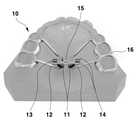
도 1은 종래의 악궁 확장 장치(10)를 도시한 도면이다.1 is a view showing a conventional arch extension device (10).
종래의 악궁 확장 장치(10)는 상악궁에 고정되는 장치로, 한 쌍의 본체(11), 본체(11)에 고정된 암(12), 한 쌍의 본체(11) 사이의 간격을 조절하는 확장 스크류(13), 본체(11)의 간격 조절 시 본체(11)의 움직임을 안내하기 위한 가이드 레일(14), 확장 스크류(13)에 형성되며 회전용 키를 삽입하여 회전시킴으로써 확장 스크류(13)가 회전되게 하는 키 홀(15) 및 암(12)과 결합하며 환자의 치아에 고정되는 치아 가압부(16)를 포함하여 이루어지며, 키 홀(15)에 키를 꽂고, 확장 스크류(13)를 회전시켜줌으로써, 본체(11)가 양 측의 치아 방향으로 이동하면서 본체(11) 사이의 간격이 벌어지며, 악궁 확장 장치가 고정된 상악을 확장시켜준다.The conventional maxillary
하지만 종래의 악궁 확장 장치(10)는 치아 가압부(16)가 치아 전체 및 잇몸을 둘러싸는 구조로 이루어지므로, 착용자로 하여금 이물감을 발생시키고, 악궁 확장 장치의 고정부가 치아 외부로 노출됨으로써 심미감을 저하시키며, 제작 과정이 복잡하고, 제작에 많은 시간이 소요되는 문제점이 있었다.However, since the conventional
본 발명은 이러한 문제점을 해결하기 위해 안출된 것으로, 본 발명의 목적은 치아 가압부가 치아 전체 및 잇몸을 둘러싸는 구조가 아닌, 치아의 내측면을 외측 방향으로 가압하는 구조로 마련됨으로써, 착용자의 이물감을 개선시킬 수 있으며, 치아 가압부들이 치아 외부로 노출되지 않으므로, 착용자의 심미감을 증대시킬 수 있는 급속 상악 확장기를 제공하기 위한 것이다.The present invention has been devised to solve this problem, and an object of the present invention is to provide a structure for pressing the inner surface of the tooth in the outward direction, not the structure in which the tooth pressing part surrounds the entire tooth and the gums, so that the wearer's feeling of foreign body This is to provide a rapid maxillary expander that can improve the aesthetics of the wearer, since the tooth pressing parts are not exposed to the outside of the teeth.
본 발명의 목적들은 이상에서 언급한 목적들로 제한되지 않으며, 언급되지 않은 또 다른 목적들은 아래의 기재로부터 당업자에게 명확하게 이해될 수 있을 것이다.Objects of the present invention are not limited to the objects mentioned above, and other objects not mentioned will be clearly understood by those skilled in the art from the following description.
상기의 목적을 달성하기 위하여 본 발명은 상악골을 확장시키기 위한 급속 상악 확장기로서, 제1 확장부 본체 및 제2 확장부 본체를 포함하는 한 쌍의 확장부 본체; 일측은 상기 제1 확장부 본체에 체결되고, 타측은 제2 확장부 본체에 체결되며, 중앙부에는 키홀이 형성되고, 회전됨에 따라 상기 제1 확장부 본체와 상기 제2 확장부 본체의 간격을 조절하는 확장 스크류; 일측은 상기 제1 확장부 본체에 끼워져 구비되고, 타측은 상기 제2 확장부 본체의 외부로 노출되도록 구비되어 상기 제2 확장부 본체의 측방향 이동을 가이드하는 제1 가이드 로드 및 일측은 상기 제2 확장부 본체에 끼워져 구비되고, 타측은 상기 제1 확장부 본체의 외부로 노출되도록 구비되어 상기 제1 확장부 본체의 측방향 이동을 가이드 하는 제2 가이드 로드를 포함하는 한 쌍의 가이드 로드; 일단은 상기 제1 확장부 본체에 연결되고, 타단은 치아를 향해 뻗어져 구비되는 제1 연결부 및 일단은 상기 제2 확장부 본체에 연결되고, 타단은 치아를 향해 뻗어져 구비되는 제2 연결부를 포함하는 한 쌍의 연결부; 및 상기 제1 연결부의 타단과 연결되고 치아를 가압하는 제1 치아 가압부 및 상기 제2 연결부의 타단과 연결되고 치아를 가압하는 제2 치아 가압부를 포함하는 한 쌍의 치아 가압부;를 포함하고, 상기 치아 가압부들의 일측면은 치아의 내측면과 대응되는 형상으로 마련되며, 다수개의 치아 내측면을 외측 방향으로 가압하는 것을 특징으로 하는 급속 상악 확장기를 제공한다.In order to achieve the above object, the present invention provides a rapid maxillary expander for expanding the maxilla, comprising: a pair of extension parts including a first extension body and a second extension body; One side is fastened to the first extension main body, the other end is fastened to the second extension main body, a key hole is formed in the central part, and as it rotates, the distance between the first extension main body and the second extension main body is adjusted. expansion screw; A first guide rod having one side fitted into the first extension body and the other side being exposed to the outside of the second extension main body to guide the lateral movement of the second extension main body, and one side being the first guide rod a pair of guide rods fitted into the second extension body and including a second guide rod having the other end exposed to the outside of the first extension main body to guide the lateral movement of the first extension main body; One end is connected to the body of the first extension, the other end is provided extending toward the teeth, the first connecting portion and one end connected to the second extension main body, the other end is provided extending toward the second connecting portion extending toward the teeth a pair of connecting portions including; and a pair of tooth pressing parts connected to the other end of the first connection part and including a second tooth pressing part connected to the other end of the first tooth pressing part and the other end of the second connection part pressing the teeth and pressing the teeth. , One side of the tooth pressing parts is provided in a shape corresponding to the inner surface of the tooth, and provides a rapid maxillary dilator, characterized in that it presses the inner surface of a plurality of teeth in an outward direction.
바람직한 실시예에 있어서, 상기 치아 가압부들은 상기 각 연결부와 착탈 가능하도록 구비된다.In a preferred embodiment, the tooth pressing parts are provided to be detachable from each of the connecting parts.
바람직한 실시예에 있어서, 상기 연결부들은 상기 각 확장부 본체와 착탈 가능하도록 구비되In a preferred embodiment, the connection parts are provided so as to be detachable from the main body of each extension.
바람직한 실시예에 있어서, 상기 치아 가압부들은 구강 내부의 3D 형상 데이터에 기반하여 3D 프린팅하거나 CAD/CAM을 이용하여 제작된다.In a preferred embodiment, the tooth pressing parts are manufactured using 3D printing or CAD/CAM based on 3D shape data of the inside of the oral cavity.
바람직한 실시예에 있어서, 상기 치아 가압부들은 PMMA(polyethylmethacrylate), 폴리아미드12(PA12) 또는 폴리머 재질로 마련되며, 레진에 의해 치아에 부착된다.In a preferred embodiment, the tooth pressing parts are made of PMMA (polyethylmethacrylate), polyamide 12 (PA12) or a polymer material, and are attached to the tooth by a resin.
본 발명은 다음과 같은 우수한 효과를 가진다.The present invention has the following excellent effects.
본 발명의 급속 상악 확장기에 의하면, 치아 가압부가 치아 전체 및 잇몸을 둘러싸는 구조가 아닌, 치아의 내측면을 외측 방향으로 가압하는 구조로 마련됨으로써, 시술 용이성을 증대시킬 수 있고, 착용자의 이물감을 개선시킬 수 있으며, 치아 가압부들이 치아 외부로 노출되지 않으므로, 착용자의 심미감을 증대시킬 수 있는 효과가 있다.According to the rapid maxillary expander of the present invention, the tooth pressing unit is provided in a structure that presses the inner surface of the tooth in the outward direction, not the structure that surrounds the entire tooth and the gums, so that the ease of operation can be increased, and the wearer's feeling of foreign body It can be improved, and since the tooth pressing parts are not exposed to the outside of the teeth, there is an effect that can increase the aesthetic feeling of the wearer.
또한, 본 발명의 급속 상악 확장기에 의하면, 치아 가압부가 연결부에서 분리 가능한 구조로 마련되거나, 연결부가 확장부 본체에서 분리 가능한 구조로 마련됨으로써, 치아 가압부의 변형 등의 제품 훼손이 발생하였을 경우, 제품 전체를 교체하지 않고, 치아 가압부 또는 연결부만을 선택적으로 교체하여 사용할 수 있는 장점을 지닌다.In addition, according to the rapid maxillary expander of the present invention, when the tooth pressing part is provided in a structure detachable from the connection part or the connection part is provided in a structure detachable from the extension part main body, when product damage such as deformation of the tooth pressing part occurs, the product Without replacing the whole, it has the advantage of being able to selectively replace only the tooth pressing part or the connection part.
또한, 본 발명의 급속 상악 확장기에 의하면, 치아 가압부는 구강 내부의 3D 형상 데이터에 기반하여 3D 프린팅하거나 CAD/CAM을 이용하여 제작되므로, 착용자의 치아, 잇몸 형상에 맞춤형 구조로 용이하게 제작될 수 있고, 폴리아미드12 재질로 제작되어, 치아에 용이하게 접착시킬 수 있는 이점을 지닌다.In addition, according to the rapid maxillary expander of the present invention, since the tooth pressing part is manufactured using 3D printing or CAD/CAM based on 3D shape data inside the oral cavity, it can be easily manufactured with a structure customized to the shape of the wearer's teeth and gums. It is made of
도 1은 종래의 악궁 확장 장치를 설명하기 위한 도면이다.
도 2는 본 발명의 일 실시예에 따른 급속 상악 확장기의 사용 상태도이다.
도 3은 본 발명의 일 실시예에 따른 급속 상악 확장기를 설명하기 위한 분해 사시도이다.
도 4는 본 발명의 다른 일 실시예에 따른 급속 상악 확장기의 연결부를 설명하기 위한 도면이다.1 is a view for explaining a conventional arch extension device.
Figure 2 is a state diagram of use of the rapid maxillary expander according to an embodiment of the present invention.
3 is an exploded perspective view for explaining a rapid maxillary dilator according to an embodiment of the present invention.
4 is a view for explaining the connection part of the rapid maxillary expander according to another embodiment of the present invention.
본 발명에서 사용되는 용어는 가능한 현재 널리 사용되는 일반적인 용어를 선택하였으나, 특정한 경우는 출원인이 임의로 선정한 용어도 있는데 이 경우에는 단순한 용어의 명칭이 아닌 발명의 상세한 설명 부분에 기재되거나 사용된 의미를 고려하여 그 의미가 파악되어야 할 것이다.As for the terms used in the present invention, general terms that are currently widely used are selected as possible, but in certain cases, there are also terms arbitrarily selected by the applicant. So the meaning should be understood.
이하, 첨부한 도면에 도시된 바람직한 실시예들을 참조하여 본 발명의 기술적 구성을 상세하게 설명한다.Hereinafter, the technical configuration of the present invention will be described in detail with reference to preferred embodiments shown in the accompanying drawings.
그러나, 본 발명은 여기서 설명되는 실시예에 한정되지 않고 다른 형태로 구체화 될 수도 있다. 명세서 전체에 걸쳐 동일한 참조번호는 동일한 구성요소를 나타낸다.However, the present invention is not limited to the embodiments described herein and may be embodied in other forms. Like reference numerals refer to like elements throughout.
도 2는 본 발명의 일 실시예에 따른 급속 상악 확장기의 사용 상태도이고, 도 3은 본 발명의 일 실시예에 따른 급속 상악 확장기의 분해사시도이다.2 is a state diagram of the use of a rapid maxillary expander according to an embodiment of the present invention, and FIG. 3 is an exploded perspective view of the rapid maxillary expander according to an embodiment of the present invention.
도 2 및 도 3을 참조하면, 본 발명의 일 실시예에 따른 급속 상악 확장기(100)는 상악골이 하악골에 비해 덜 발달한 부정 교합 환자의 교정 치료에 이용되며, 상악골을 확장시켜 교정 치료를 용이하게 하기 위한 장치로, 확장부 본체(110), 확장 스크류(120), 가이드 로드(130), 연결부(140), 치아 가압부(150)를 포함하여 이루어진다.2 and 3, the rapid maxillary expander 100 according to an embodiment of the present invention is used for orthodontic treatment of a malocclusion patient whose maxilla is less developed than the mandible, and it expands the maxilla to facilitate orthodontic treatment As a device for doing this, it comprises an
상기 확장부 본체(110)는 제1 확장부 본체(111)와 제2 확장부 본체(112)를 포함하여 한 쌍으로 구비되며, 중앙부 측방향으로 관통하는 확장 스크류 홀이 형성된다.The
또한, 상기 확장부 본체(110)는 상기 확장 스크류 홀의 양측에 제1 가이드 로드 홀과 제2 가이드 로드 홀이 각각 형성되며, 상기 확장 스크류 홀의 양측 최외측에는 제1 연결부 홀과 제2 연결부 홀이 각각 형성될 수 있다.In addition, in the
상기 확장 스크류(120)는 중앙부에 상하 방향으로 관통하는 키홀(120a)이 형성되고, 일측은 상기 제1 확장부 본체(111)에 체결되고, 타측은 상기 제2 확장부 본체(112)에 체결된다.The
이에 따라, 상기 확장 스크류(120)가 회전될 경우, 상기 제1 확장부 본체(111)와 상기 제2 확장부 본체(112)의 간격이 점진적으로 이격되는 형태로 구동된다.Accordingly, when the
상기 가이드 로드(130)는 제1 가이드 로드(131) 및 제2 가이드 로드(132)를 포함하여 한 쌍으로 구비된다.The
여기서, 상기 제1 가이드 로드(131)의 일측은 상기 제1 확장부 본체(111)에 끼워져 구비되고, 타측은 상기 제2 확장부 본체(112)의 외부로 노출되도록 구비되어, 상기 제2 확장부 본체(112)의 측방향 이동을 가이드하는 역할을 한다.Here, one side of the
또한, 상기 제2 가이드 로드(132)의 일측은 상기 제2 확장부 본체(112)에 끼워져 구비되고, 타측은 상기 제1 확장부 본체(111)의 외부로 노출되도록 구비되어, 상기 제1 확장부 본체(111)의 측방향 이동을 가이드하는 역할을 한다.In addition, one side of the
상기 연결부(140)는 제1 연결부(141) 및 제2 연결부(142)를 포함하여 한 쌍으로 구비된다.The
여기서, 상기 제1 연결부(141)는 일단이 상기 제1 확장부 본체(111)에 연결되고, 타단은 치아를 향해 뻗어져 구비된다.Here, the first connecting
예를 들면, 상기 제1 연결부(141)는 한 쌍의 제1 바 부재(141a), 한 쌍의 제2 바 부재(141b), 한 쌍의 제3 바 부재(141c)를 포함하여 이루어질 수 있다.For example, the
여기서, 상기 제1 바 부재(141a)는 상기 제1 확장부 본체(111)와 평행하도록 일단이 제1 확장부 본체(111)에 끼워져 구비된다.Here, the
또한, 상기 제2 바 부재(141b)는 일단이 상기 제1 바 부재(141a)의 타단과 일체로 연결되며, 타단은 치아를 향해 뻗어지도록 구비되며, 상기 제1 바 부재(141a)와 소정 각도를 이루도록 구비된다.In addition, one end of the
또한, 상기 제3 바 부재(141c)는 일단이 상기 제1 바 부재(141a)의 중앙부와 일체로 연결되고, 타단은 상기 제2 바 부재(141b)의 중앙부와 일체로 연결되어, 연결부의 강도를 보강하는 역할을 한다.In addition, the
또한, 상기 제2 연결부(142)는 일단이 상기 제2 확장부 본체(112)에 연결되고, 타단은 치아를 향해 뻗어져 구비된다.In addition, the
또한, 상기 제2 연결부(142)는 상기 제1 연결부(141)와 마찬가지로, 한 쌍의 제1 바 부재(142a), 한 쌍의 제2 바 부재(142b), 한 쌍의 제3 바 부재(142c)를 포함하여 이루어지며, 상기 바 부재들(142a, 142b, 142c)은 상기 제1 연결부(141)의 바 부재들(141a, 141b, 141c)과 서로 대응되는 구성이므로, 중복되는 설명은 생략하기로 한다.In addition, the
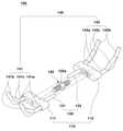
도 4는 본 발명의 다른 일 실시예에 따른 급속 상악 확장기의 연결부를 설명하기 위한 도면이다.4 is a view for explaining the connection part of the rapid maxillary expander according to another embodiment of the present invention.
도 4를 참조하면, 상기 연결부(140)는 한 쌍의 제1 연결부(141)와 제2 연결부(142)를 포함하여 이루어지며, 상기 제1 연결부(141)는 한 쌍의 제1 바 부재(141a), 한 쌍의 제2 바 부재(141b), 한 쌍의 제3 바 부재(141c), 제4 바 부재(141d), 제5 바 부재(141e), 제6 바 부재(141f)를 포함하여 이루어질 수 있다.Referring to FIG. 4 , the
한편, 제1 바 부재(141a), 한 쌍의 제2 바 부재(141b), 한 쌍의 제3 바 부재(141c)는 전술한 바와 동일한 구성이므로, 중복되는 설명은 생략하기로 한다.Meanwhile, since the
상기 제4 바 부재(141d)는 한 쌍의 제1 바부재(141a)들을 연결하고, 상기 제5 바부재(141e)는 한 쌍으로 구비되어 "X"자 형상을 이루도록 서로 대칭되는 위치의 제1 바부재(141a)와 제2 바부재(141b)들을 각각 연결하며, 제6 바 부재(141f)는 한 쌍의 제2 바부재(142b)들을 연결하여, 보다 연결부의 강도를 보강하는 역할을 한다.The
또한, 상기 제2 연결부(142)는 한 쌍의 제1 바 부재(142a), 한 쌍의 제2 바 부재(142b), 한 쌍의 제3 바 부재(142c), 제4 바 부재(142d), 제5 바 부재(142e), 제6 바 부재(142f)를 포함하여 이루어지며, 상기 제1 연결부(141)와 서로 대응되는 구성이므로, 각 바 부재들에 대한 중복되는 설명은 생략하기로 한다.In addition, the
또한, 상기 연결부들(141,142)은 상기 각 확장부 본체(111,112)와 착탈 가능하도록 구비될 수 있다.In addition, the connecting
다시 말하면, 상기 제1 연결부(141)는 상기 제1 확장부 본체(111)로부터 분리 가능하도록 구비되고, 상기 제2 연결부(132)는 상기 제2 확장부 본체(112)로부터 분리 가능하도록 구비되는 것이다.In other words, the
이는 치아 가압부의 변형 또는 연결부의 훼손이 발생될 경우, 제품 전체를 교체하지 않고, 연결부만을 선택적으로 교체하여 사용할 수 있게 하기 위함이다.This is to enable the use of selectively replacing only the connection part without replacing the entire product when deformation of the tooth pressing part or damage to the connection part occurs.
상기 치아 가압부(150)는 한 쌍의 제1 치아 가압부(151)와 제2 치아 가압부(152)를 포함하여 이루어진다.The
여기서, 상기 제1 치아 가압부(151)는 상기 제1 연결부(141)의 타단과 연결되어, 일측 치아들을 가압하고, 상기 제2 치아 가압부(152)는 상기 제2 연결부(142)의 타단과 타측 치아들을 가압한다.Here, the first
또한, 상기 제1 치아 가압부(151) 및 상기 제2 치아 가압부(152)의 일측면은 서로 대응되는 위치의 치아들의 내측면과, 각각 대응되는 형상으로 마련되며, 다수개의 치아 내측면을 내측에서 외측 방향으로 가압한다.In addition, one side of the first
즉, 상기 치아 가압부(150)는 치아 전체 및 잇몸을 둘러싸는 구조가 아닌, 치아의 내측면과 면접하여 외측 방향으로 가압하는 구조로 마련됨으로써, 착용자의 이물감을 개선시킬 수 있으며, 치아 가압부들이 치아 외부로 노출되지 않으므로, 착용자의 심미감을 증대시킬 수 있는 것이다.That is, the
또한, 상기 치아 가압부(150)들은 상기 각 연결부(141, 142)와 착탈 가능하도록 구비될 수 있다.In addition, the
이는 상기 치아 가압부(150)가 변형 등 훼손이 발생하였을 경우, 제품 전체를 교체하지 않고, 치아 가압부만을 선택적으로 교체하여 사용할 수 있는 장점을 지니게 한다.This gives the advantage of being able to selectively replace only the tooth pressing unit without replacing the entire product when the
또한, 상기 치아 가압부(150)는 구강 내부의 3D 형상 데이터에 기반하여 3D 프린팅하거나 CAD/CAM 가공으로 제작될 수 있으며, PMMA(polymethylmetharcrylate)나 폴리아미드12(PA12) 및 기타 폴리머등의 재질로 제조되며, 레진에 의해 치아에 부착될 수 있다.In addition, the
즉, 상기 치아 가압부(150)는 구강 내부의 3D 형상 데이터에 기반하여 3D 프린팅하거나 CAD/CAM 가공으로 제작되므로, 착용자의 치아, 잇몸 형상에 맞춤형 구조로 용이하게 제작될 수 있고, PMMA(polymethylmetharcrylate)나 폴리아미드12(PA12) 및 기타 폴리머등으로 제작되어, 치아에 용이하게 접착시킬 수 있는 이점을 지닌다.That is, since the
이상에서 살펴본 바와 같이 본 발명은 바람직한 실시예를 들어 도시하고 설명하였으나, 상기한 실시예에 한정되지 아니하며 본 발명의 정신을 벗어나지 않는 범위 내에서 당해 발명이 속하는 기술분야에서 통상의 지식을 가진 자에 의해 다양한 변경과 수정이 가능할 것이다.As described above, the present invention has been illustrated and described with reference to preferred embodiments, but it is not limited to the above-described embodiments, and those of ordinary skill in the art to which the present invention pertains within the scope not departing from the spirit of the present invention Various changes and modifications will be possible.
110 : 확장부 본체111 : 제1 확장부 본체
112 : 제2 확장부 본체120 : 확장 스크류
130 : 가이드 로드131 : 제1 가이드 로드
132 : 제2 가이드 로드140 : 연결부
141 : 제1 연결부142 : 제2 연결부
150 : 치아 가압부151 : 제1 치아 가압부
152 : 제2 치아 가압부110: extended unit body 111: first extended unit body
112: second extension body 120: expansion screw
130: guide rod 131: first guide rod
132: second guide rod 140: connection part
141: first connection part 142: second connection part
150: tooth pressing unit 151: first tooth pressing unit
152: second tooth pressing part
Claims (5)
Translated fromKorean제1 확장부 본체 및 제2 확장부 본체를 포함하는 한 쌍의 확장부 본체;
일측은 상기 제1 확장부 본체에 체결되고, 타측은 제2 확장부 본체에 체결되며, 중앙부에는 키홀이 형성되고, 회전됨에 따라 상기 제1 확장부 본체와 상기 제2 확장부 본체의 간격을 조절하는 확장 스크류;
일측은 상기 제1 확장부 본체에 끼워져 구비되고, 타측은 상기 제2 확장부 본체의 외부로 노출되도록 구비되어 상기 제2 확장부 본체의 측방향 이동을 가이드하는 제1 가이드 로드 및 일측은 상기 제2 확장부 본체에 끼워져 구비되고, 타측은 상기 제1 확장부 본체의 외부로 노출되도록 구비되어 상기 제1 확장부 본체의 측방향 이동을 가이드 하는 제2 가이드 로드를 포함하는 한 쌍의 가이드 로드;
일단은 상기 제1 확장부 본체에 연결되고, 타단은 치아를 향해 뻗어져 구비되는 제1 연결부 및 일단은 상기 제2 확장부 본체에 연결되고, 타단은 치아를 향해 뻗어져 구비되는 제2 연결부를 포함하는 한 쌍의 연결부; 및
상기 제1 연결부의 타단과 연결되고 치아를 가압하는 제1 치아 가압부 및 상기 제2 연결부의 타단과 연결되고 치아를 가압하는 제2 치아 가압부를 포함하는 한 쌍의 치아 가압부;를 포함하고,
상기 치아 가압부들의 일측면은 치아의 내측면과 대응되는 형상으로 마련되며, 다수개의 치아 내측면을 외측 방향으로 가압하는 것을 특징으로 하는 급속 상악 확장기.
A rapid maxillary dilator for expanding the maxilla, comprising:
a pair of extension body including a first extension body and a second extension body;
One side is fastened to the first extension main body, the other end is fastened to the second extension main body, a key hole is formed in the central part, and as it rotates, the distance between the first extension main body and the second extension main body is adjusted. expansion screw;
A first guide rod having one side fitted into the first extension body and the other side being exposed to the outside of the second extension main body to guide the lateral movement of the second extension main body, and one side being the first guide rod a pair of guide rods fitted into the second extension body and including a second guide rod having the other end exposed to the outside of the first extension main body to guide the lateral movement of the first extension main body;
One end is connected to the body of the first extension, the other end is provided extending toward the teeth, the first connecting portion and one end connected to the second extension main body, the other end is provided extending toward the second connecting portion extending toward the teeth a pair of connecting portions including; and
A pair of tooth pressing parts including a first tooth pressing part connected to the other end of the first connection part and pressing the teeth and a second tooth pressing part connected to the other end of the second connection part and pressing the teeth;
One side of the tooth pressing parts is provided in a shape corresponding to the inner surface of the tooth, and the rapid maxillary dilator, characterized in that the inner surface of the plurality of teeth is pressed in the outward direction.
상기 치아 가압부들은
상기 각 연결부와 착탈 가능하도록 구비되는 것을 특징으로 하는 급속 상악 확장기.
The method of claim 1,
The tooth pressing parts are
Rapid maxillary dilator, characterized in that it is provided so as to be detachable from each of the connection parts.
상기 연결부들은 상기 각 확장부 본체와 착탈 가능하도록 구비되는 것을 특징으로 하는 급속 상악 확장기.
The method of claim 1,
The rapid maxillary dilator, characterized in that the connection parts are provided so as to be detachable from the main body of each of the extensions.
상기 치아 가압부들은 구강 내부의 3D 형상 데이터에 기반하여 3D 프린팅하거나 CAD/CAM을 이용하여 제작되는 것을 특징으로 하는 급속 상악 확장기.
The method of claim 1,
The tooth pressurizing portion is a rapid maxillary expander, characterized in that it is manufactured using 3D printing or CAD / CAM based on 3D shape data inside the oral cavity.
상기 치아 가압부들은 PMMA(polyethylmethacrylate), 폴리아미드12(PA12) 또는 폴리머 재질로 마련되며, 레진에 의해 치아에 부착되는 것을 특징으로 하는 급속 상악 확장기.The method of claim 1,
The tooth pressing parts are made of PMMA (polyethylmethacrylate), polyamide 12 (PA12) or a polymer material, and the rapid maxillary dilator, characterized in that it is attached to the tooth by a resin.
Priority Applications (3)
| Application Number | Priority Date | Filing Date | Title |
|---|---|---|---|
| KR1020200114086AKR20220032380A (en) | 2020-09-07 | 2020-09-07 | Patient-specific rapid maxillary expanders |
| PCT/KR2020/014200WO2022050482A1 (en) | 2020-09-07 | 2020-10-16 | Patient-customized rapid maxillary expander |
| US17/056,122US20220304777A1 (en) | 2020-09-07 | 2020-10-16 | Patient-specific rapid maxillary expander |
Applications Claiming Priority (1)
| Application Number | Priority Date | Filing Date | Title |
|---|---|---|---|
| KR1020200114086AKR20220032380A (en) | 2020-09-07 | 2020-09-07 | Patient-specific rapid maxillary expanders |
Publications (1)
| Publication Number | Publication Date |
|---|---|
| KR20220032380Atrue KR20220032380A (en) | 2022-03-15 |
Family
ID=80491138
Family Applications (1)
| Application Number | Title | Priority Date | Filing Date |
|---|---|---|---|
| KR1020200114086ACeasedKR20220032380A (en) | 2020-09-07 | 2020-09-07 | Patient-specific rapid maxillary expanders |
Country Status (3)
| Country | Link |
|---|---|
| US (1) | US20220304777A1 (en) |
| KR (1) | KR20220032380A (en) |
| WO (1) | WO2022050482A1 (en) |
Cited By (1)
| Publication number | Priority date | Publication date | Assignee | Title |
|---|---|---|---|---|
| KR102781804B1 (en)* | 2024-12-04 | 2025-03-18 | 시경근 | Palatal expansion appliance |
Families Citing this family (1)
| Publication number | Priority date | Publication date | Assignee | Title |
|---|---|---|---|---|
| BE1031335B1 (en)* | 2023-02-09 | 2024-09-17 | Mandible Guide B V | Palatal expansion system |
Family Cites Families (10)
| Publication number | Priority date | Publication date | Assignee | Title |
|---|---|---|---|---|
| GB0821366D0 (en)* | 2008-11-21 | 2008-12-31 | Ortho Pro Teknica Ltd | Orthodontic teeth positioning appliances |
| AR075488A1 (en)* | 2009-12-11 | 2011-04-06 | Villalba Raul Horacio | DENTAL DEVICE FOR THE CORRECTION OF THE TRANSVERSAL MICROGNATISM OF THE SUPERIOR MAXILAR IN ADULT PATIENTS AND PROCEDURE FOR THE CONSTRUCTION OF THE DEVICE AND A SURGICAL GUIDE |
| KR101111976B1 (en)* | 2010-05-17 | 2012-02-14 | 경희대학교 산학협력단 | Maxillary dental arch width correction device |
| US20130252195A1 (en)* | 2012-03-26 | 2013-09-26 | President And Fellows Of Harvard College | Orthodontic expander system and method |
| EP3383309B1 (en)* | 2015-12-06 | 2023-08-30 | Brius Technologies, Inc. | Teeth repositioning system and method of producing the same |
| US20170281315A1 (en)* | 2016-03-29 | 2017-10-05 | Tayside Health Board | Removable rapid maxillary expander |
| US20170354482A1 (en)* | 2016-06-01 | 2017-12-14 | Paul Kim | Maxillary skeletal expander device and method |
| CN207605023U (en)* | 2017-05-23 | 2018-07-13 | 重庆医科大学附属口腔医院 | Tongue side, which is fixed, expands bow device |
| KR101949445B1 (en)* | 2017-05-29 | 2019-04-29 | 문성철 | Customized palatal expander and method of manufacturing the same |
| CN209404980U (en)* | 2018-09-11 | 2019-09-20 | 佛山市佛冠义齿有限公司 | A kind of orthodontic expansion bow device |
- 2020
- 2020-09-07KRKR1020200114086Apatent/KR20220032380A/ennot_activeCeased
- 2020-10-16USUS17/056,122patent/US20220304777A1/ennot_activeAbandoned
- 2020-10-16WOPCT/KR2020/014200patent/WO2022050482A1/ennot_activeCeased
Cited By (1)
| Publication number | Priority date | Publication date | Assignee | Title |
|---|---|---|---|---|
| KR102781804B1 (en)* | 2024-12-04 | 2025-03-18 | 시경근 | Palatal expansion appliance |
Also Published As
| Publication number | Publication date |
|---|---|
| WO2022050482A1 (en) | 2022-03-10 |
| US20220304777A1 (en) | 2022-09-29 |
Similar Documents
| Publication | Publication Date | Title |
|---|---|---|
| CN111295153B (en) | Dental appliance with selective bite loading and controlled tip staggering | |
| JP6873323B2 (en) | Oral device for mandibular adjustment | |
| KR101111976B1 (en) | Maxillary dental arch width correction device | |
| KR101510857B1 (en) | Transparent orthodontic device | |
| KR20220032380A (en) | Patient-specific rapid maxillary expanders | |
| CN113412098B (en) | Digital three-dimensional tooth model dental system | |
| JPS6053139A (en) | Mouth mounting type dental correcting tool used in correcting second grade irregular occulusion | |
| KR101482727B1 (en) | Method of manufacturing device for curing snore and sleep apnea syndrome using 3d printing | |
| US10172692B2 (en) | Rapid palatal expander and method for the making thereof | |
| CN102078223A (en) | Reasonable arrangement inducing device for teeth of children and manufacturing method thereof | |
| CN211633659U (en) | Shell-shaped tooth orthodontic appliance | |
| JP2007325917A (en) | Mouthpiece | |
| WO2020250975A1 (en) | Mouthpiece and mouthpiece manufacturing method | |
| CN205683156U (en) | There is the invisible orthotic device without bracket of tongue thorn | |
| KR102659743B1 (en) | Invisalign | |
| CN115551441A (en) | Dental appliance, device and method for manufacturing dental appliance | |
| KR20060086753A (en) | Device for lateral enlargement of maxilla by fixing directly to the skeleton | |
| CN210673464U (en) | Tooth appliance with occlusion guiding function | |
| EP3937830B1 (en) | Dental splint and method for producing same | |
| KR102005925B1 (en) | Dental system with baseline to allow positional merging od digital three-dimensional tooth model | |
| IT201900001019A1 (en) | Orthodontic appliance. | |
| DE212020000762U1 (en) | Dental instrument for adjusting a positional relationship between the upper and lower jaw | |
| CN221904122U (en) | Tooth socket for stabilizing jaw position | |
| CN223287257U (en) | A squeeze-type transparent appliance | |
| CN221672057U (en) | Shell dental instrument, shell dental instrument system and kit |
Legal Events
| Date | Code | Title | Description |
|---|---|---|---|
| PA0109 | Patent application | Patent event code:PA01091R01D Comment text:Patent Application Patent event date:20200907 | |
| PA0201 | Request for examination | ||
| PE0902 | Notice of grounds for rejection | Comment text:Notification of reason for refusal Patent event date:20211213 Patent event code:PE09021S01D | |
| PG1501 | Laying open of application | ||
| E601 | Decision to refuse application | ||
| PE0601 | Decision on rejection of patent | Patent event date:20220914 Comment text:Decision to Refuse Application Patent event code:PE06012S01D Patent event date:20211213 Comment text:Notification of reason for refusal Patent event code:PE06011S01I |