KR20220031900A - Systems and Methods for Controlled Manufacturing - Google Patents
Systems and Methods for Controlled ManufacturingDownload PDFInfo
- Publication number
- KR20220031900A KR20220031900AKR1020227002109AKR20227002109AKR20220031900AKR 20220031900 AKR20220031900 AKR 20220031900AKR 1020227002109 AKR1020227002109 AKR 1020227002109AKR 20227002109 AKR20227002109 AKR 20227002109AKR 20220031900 AKR20220031900 AKR 20220031900A
- Authority
- KR
- South Korea
- Prior art keywords
- control
- manufacturing
- parameters
- effector
- laser beam
- Prior art date
- Legal status (The legal status is an assumption and is not a legal conclusion. Google has not performed a legal analysis and makes no representation as to the accuracy of the status listed.)
- Withdrawn
Links
Images


Classifications
- B—PERFORMING OPERATIONS; TRANSPORTING
- B22—CASTING; POWDER METALLURGY
- B22F—WORKING METALLIC POWDER; MANUFACTURE OF ARTICLES FROM METALLIC POWDER; MAKING METALLIC POWDER; APPARATUS OR DEVICES SPECIALLY ADAPTED FOR METALLIC POWDER
- B22F10/00—Additive manufacturing of workpieces or articles from metallic powder
- B22F10/20—Direct sintering or melting
- B—PERFORMING OPERATIONS; TRANSPORTING
- B29—WORKING OF PLASTICS; WORKING OF SUBSTANCES IN A PLASTIC STATE IN GENERAL
- B29C—SHAPING OR JOINING OF PLASTICS; SHAPING OF MATERIAL IN A PLASTIC STATE, NOT OTHERWISE PROVIDED FOR; AFTER-TREATMENT OF THE SHAPED PRODUCTS, e.g. REPAIRING
- B29C64/00—Additive manufacturing, i.e. manufacturing of three-dimensional [3D] objects by additive deposition, additive agglomeration or additive layering, e.g. by 3D printing, stereolithography or selective laser sintering
- B29C64/30—Auxiliary operations or equipment
- B29C64/386—Data acquisition or data processing for additive manufacturing
- B29C64/393—Data acquisition or data processing for additive manufacturing for controlling or regulating additive manufacturing processes
- B—PERFORMING OPERATIONS; TRANSPORTING
- B22—CASTING; POWDER METALLURGY
- B22F—WORKING METALLIC POWDER; MANUFACTURE OF ARTICLES FROM METALLIC POWDER; MAKING METALLIC POWDER; APPARATUS OR DEVICES SPECIALLY ADAPTED FOR METALLIC POWDER
- B22F12/00—Apparatus or devices specially adapted for additive manufacturing; Auxiliary means for additive manufacturing; Combinations of additive manufacturing apparatus or devices with other processing apparatus or devices
- B22F12/40—Radiation means
- B22F12/41—Radiation means characterised by the type, e.g. laser or electron beam
- B—PERFORMING OPERATIONS; TRANSPORTING
- B22—CASTING; POWDER METALLURGY
- B22F—WORKING METALLIC POWDER; MANUFACTURE OF ARTICLES FROM METALLIC POWDER; MAKING METALLIC POWDER; APPARATUS OR DEVICES SPECIALLY ADAPTED FOR METALLIC POWDER
- B22F10/00—Additive manufacturing of workpieces or articles from metallic powder
- B22F10/20—Direct sintering or melting
- B22F10/22—Direct deposition of molten metal
- B—PERFORMING OPERATIONS; TRANSPORTING
- B22—CASTING; POWDER METALLURGY
- B22F—WORKING METALLIC POWDER; MANUFACTURE OF ARTICLES FROM METALLIC POWDER; MAKING METALLIC POWDER; APPARATUS OR DEVICES SPECIALLY ADAPTED FOR METALLIC POWDER
- B22F10/00—Additive manufacturing of workpieces or articles from metallic powder
- B22F10/20—Direct sintering or melting
- B22F10/25—Direct deposition of metal particles, e.g. direct metal deposition [DMD] or laser engineered net shaping [LENS]
- B—PERFORMING OPERATIONS; TRANSPORTING
- B22—CASTING; POWDER METALLURGY
- B22F—WORKING METALLIC POWDER; MANUFACTURE OF ARTICLES FROM METALLIC POWDER; MAKING METALLIC POWDER; APPARATUS OR DEVICES SPECIALLY ADAPTED FOR METALLIC POWDER
- B22F10/00—Additive manufacturing of workpieces or articles from metallic powder
- B22F10/20—Direct sintering or melting
- B22F10/28—Powder bed fusion, e.g. selective laser melting [SLM] or electron beam melting [EBM]
- B—PERFORMING OPERATIONS; TRANSPORTING
- B22—CASTING; POWDER METALLURGY
- B22F—WORKING METALLIC POWDER; MANUFACTURE OF ARTICLES FROM METALLIC POWDER; MAKING METALLIC POWDER; APPARATUS OR DEVICES SPECIALLY ADAPTED FOR METALLIC POWDER
- B22F10/00—Additive manufacturing of workpieces or articles from metallic powder
- B22F10/30—Process control
- B22F10/38—Process control to achieve specific product aspects, e.g. surface smoothness, density, porosity or hollow structures
- B—PERFORMING OPERATIONS; TRANSPORTING
- B22—CASTING; POWDER METALLURGY
- B22F—WORKING METALLIC POWDER; MANUFACTURE OF ARTICLES FROM METALLIC POWDER; MAKING METALLIC POWDER; APPARATUS OR DEVICES SPECIALLY ADAPTED FOR METALLIC POWDER
- B22F10/00—Additive manufacturing of workpieces or articles from metallic powder
- B22F10/80—Data acquisition or data processing
- B22F10/85—Data acquisition or data processing for controlling or regulating additive manufacturing processes
- B—PERFORMING OPERATIONS; TRANSPORTING
- B23—MACHINE TOOLS; METAL-WORKING NOT OTHERWISE PROVIDED FOR
- B23K—SOLDERING OR UNSOLDERING; WELDING; CLADDING OR PLATING BY SOLDERING OR WELDING; CUTTING BY APPLYING HEAT LOCALLY, e.g. FLAME CUTTING; WORKING BY LASER BEAM
- B23K26/00—Working by laser beam, e.g. welding, cutting or boring
- B23K26/02—Positioning or observing the workpiece, e.g. with respect to the point of impact; Aligning, aiming or focusing the laser beam
- B23K26/03—Observing, e.g. monitoring, the workpiece
- B23K26/034—Observing the temperature of the workpiece
- B—PERFORMING OPERATIONS; TRANSPORTING
- B29—WORKING OF PLASTICS; WORKING OF SUBSTANCES IN A PLASTIC STATE IN GENERAL
- B29C—SHAPING OR JOINING OF PLASTICS; SHAPING OF MATERIAL IN A PLASTIC STATE, NOT OTHERWISE PROVIDED FOR; AFTER-TREATMENT OF THE SHAPED PRODUCTS, e.g. REPAIRING
- B29C64/00—Additive manufacturing, i.e. manufacturing of three-dimensional [3D] objects by additive deposition, additive agglomeration or additive layering, e.g. by 3D printing, stereolithography or selective laser sintering
- B29C64/10—Processes of additive manufacturing
- B29C64/141—Processes of additive manufacturing using only solid materials
- B29C64/153—Processes of additive manufacturing using only solid materials using layers of powder being selectively joined, e.g. by selective laser sintering or melting
- B—PERFORMING OPERATIONS; TRANSPORTING
- B33—ADDITIVE MANUFACTURING TECHNOLOGY
- B33Y—ADDITIVE MANUFACTURING, i.e. MANUFACTURING OF THREE-DIMENSIONAL [3-D] OBJECTS BY ADDITIVE DEPOSITION, ADDITIVE AGGLOMERATION OR ADDITIVE LAYERING, e.g. BY 3-D PRINTING, STEREOLITHOGRAPHY OR SELECTIVE LASER SINTERING
- B33Y10/00—Processes of additive manufacturing
- B—PERFORMING OPERATIONS; TRANSPORTING
- B33—ADDITIVE MANUFACTURING TECHNOLOGY
- B33Y—ADDITIVE MANUFACTURING, i.e. MANUFACTURING OF THREE-DIMENSIONAL [3-D] OBJECTS BY ADDITIVE DEPOSITION, ADDITIVE AGGLOMERATION OR ADDITIVE LAYERING, e.g. BY 3-D PRINTING, STEREOLITHOGRAPHY OR SELECTIVE LASER SINTERING
- B33Y30/00—Apparatus for additive manufacturing; Details thereof or accessories therefor
- B—PERFORMING OPERATIONS; TRANSPORTING
- B33—ADDITIVE MANUFACTURING TECHNOLOGY
- B33Y—ADDITIVE MANUFACTURING, i.e. MANUFACTURING OF THREE-DIMENSIONAL [3-D] OBJECTS BY ADDITIVE DEPOSITION, ADDITIVE AGGLOMERATION OR ADDITIVE LAYERING, e.g. BY 3-D PRINTING, STEREOLITHOGRAPHY OR SELECTIVE LASER SINTERING
- B33Y50/00—Data acquisition or data processing for additive manufacturing
- B33Y50/02—Data acquisition or data processing for additive manufacturing for controlling or regulating additive manufacturing processes
- G—PHYSICS
- G01—MEASURING; TESTING
- G01N—INVESTIGATING OR ANALYSING MATERIALS BY DETERMINING THEIR CHEMICAL OR PHYSICAL PROPERTIES
- G01N29/00—Investigating or analysing materials by the use of ultrasonic, sonic or infrasonic waves; Visualisation of the interior of objects by transmitting ultrasonic or sonic waves through the object
- G01N29/04—Analysing solids
- G01N29/06—Visualisation of the interior, e.g. acoustic microscopy
- G01N29/0654—Imaging
- G01N29/069—Defect imaging, localisation and sizing using, e.g. time of flight diffraction [TOFD], synthetic aperture focusing technique [SAFT], Amplituden-Laufzeit-Ortskurven [ALOK] technique
- G—PHYSICS
- G01—MEASURING; TESTING
- G01N—INVESTIGATING OR ANALYSING MATERIALS BY DETERMINING THEIR CHEMICAL OR PHYSICAL PROPERTIES
- G01N29/00—Investigating or analysing materials by the use of ultrasonic, sonic or infrasonic waves; Visualisation of the interior of objects by transmitting ultrasonic or sonic waves through the object
- G01N29/22—Details, e.g. general constructional or apparatus details
- G01N29/225—Supports, positioning or alignment in moving situation
- G—PHYSICS
- G01—MEASURING; TESTING
- G01N—INVESTIGATING OR ANALYSING MATERIALS BY DETERMINING THEIR CHEMICAL OR PHYSICAL PROPERTIES
- G01N29/00—Investigating or analysing materials by the use of ultrasonic, sonic or infrasonic waves; Visualisation of the interior of objects by transmitting ultrasonic or sonic waves through the object
- G01N29/22—Details, e.g. general constructional or apparatus details
- G01N29/24—Probes
- G01N29/2418—Probes using optoacoustic interaction with the material, e.g. laser radiation, photoacoustics
- G—PHYSICS
- G01—MEASURING; TESTING
- G01N—INVESTIGATING OR ANALYSING MATERIALS BY DETERMINING THEIR CHEMICAL OR PHYSICAL PROPERTIES
- G01N29/00—Investigating or analysing materials by the use of ultrasonic, sonic or infrasonic waves; Visualisation of the interior of objects by transmitting ultrasonic or sonic waves through the object
- G01N29/22—Details, e.g. general constructional or apparatus details
- G01N29/26—Arrangements for orientation or scanning by relative movement of the head and the sensor
- G01N29/265—Arrangements for orientation or scanning by relative movement of the head and the sensor by moving the sensor relative to a stationary material
- G—PHYSICS
- G01—MEASURING; TESTING
- G01N—INVESTIGATING OR ANALYSING MATERIALS BY DETERMINING THEIR CHEMICAL OR PHYSICAL PROPERTIES
- G01N29/00—Investigating or analysing materials by the use of ultrasonic, sonic or infrasonic waves; Visualisation of the interior of objects by transmitting ultrasonic or sonic waves through the object
- G01N29/22—Details, e.g. general constructional or apparatus details
- G01N29/32—Arrangements for suppressing undesired influences, e.g. temperature or pressure variations, compensating for signal noise
- G01N29/326—Arrangements for suppressing undesired influences, e.g. temperature or pressure variations, compensating for signal noise compensating for temperature variations
- G—PHYSICS
- G05—CONTROLLING; REGULATING
- G05B—CONTROL OR REGULATING SYSTEMS IN GENERAL; FUNCTIONAL ELEMENTS OF SUCH SYSTEMS; MONITORING OR TESTING ARRANGEMENTS FOR SUCH SYSTEMS OR ELEMENTS
- G05B19/00—Programme-control systems
- G05B19/02—Programme-control systems electric
- G05B19/18—Numerical control [NC], i.e. automatically operating machines, in particular machine tools, e.g. in a manufacturing environment, so as to execute positioning, movement or co-ordinated operations by means of programme data in numerical form
- G05B19/4097—Numerical control [NC], i.e. automatically operating machines, in particular machine tools, e.g. in a manufacturing environment, so as to execute positioning, movement or co-ordinated operations by means of programme data in numerical form characterised by using design data to control NC machines, e.g. CAD/CAM
- G05B19/4099—Surface or curve machining, making 3D objects, e.g. desktop manufacturing
- B—PERFORMING OPERATIONS; TRANSPORTING
- B22—CASTING; POWDER METALLURGY
- B22F—WORKING METALLIC POWDER; MANUFACTURE OF ARTICLES FROM METALLIC POWDER; MAKING METALLIC POWDER; APPARATUS OR DEVICES SPECIALLY ADAPTED FOR METALLIC POWDER
- B22F12/00—Apparatus or devices specially adapted for additive manufacturing; Auxiliary means for additive manufacturing; Combinations of additive manufacturing apparatus or devices with other processing apparatus or devices
- B22F12/40—Radiation means
- B22F12/44—Radiation means characterised by the configuration of the radiation means
- B22F12/45—Two or more
- B—PERFORMING OPERATIONS; TRANSPORTING
- B22—CASTING; POWDER METALLURGY
- B22F—WORKING METALLIC POWDER; MANUFACTURE OF ARTICLES FROM METALLIC POWDER; MAKING METALLIC POWDER; APPARATUS OR DEVICES SPECIALLY ADAPTED FOR METALLIC POWDER
- B22F12/00—Apparatus or devices specially adapted for additive manufacturing; Auxiliary means for additive manufacturing; Combinations of additive manufacturing apparatus or devices with other processing apparatus or devices
- B22F12/90—Means for process control, e.g. cameras or sensors
- B—PERFORMING OPERATIONS; TRANSPORTING
- B23—MACHINE TOOLS; METAL-WORKING NOT OTHERWISE PROVIDED FOR
- B23K—SOLDERING OR UNSOLDERING; WELDING; CLADDING OR PLATING BY SOLDERING OR WELDING; CUTTING BY APPLYING HEAT LOCALLY, e.g. FLAME CUTTING; WORKING BY LASER BEAM
- B23K26/00—Working by laser beam, e.g. welding, cutting or boring
- B23K26/34—Laser welding for purposes other than joining
- B23K26/342—Build-up welding
- B—PERFORMING OPERATIONS; TRANSPORTING
- B23—MACHINE TOOLS; METAL-WORKING NOT OTHERWISE PROVIDED FOR
- B23K—SOLDERING OR UNSOLDERING; WELDING; CLADDING OR PLATING BY SOLDERING OR WELDING; CUTTING BY APPLYING HEAT LOCALLY, e.g. FLAME CUTTING; WORKING BY LASER BEAM
- B23K9/00—Arc welding or cutting
- B23K9/04—Welding for other purposes than joining, e.g. built-up welding
- B23K9/044—Built-up welding on three-dimensional surfaces
- Y—GENERAL TAGGING OF NEW TECHNOLOGICAL DEVELOPMENTS; GENERAL TAGGING OF CROSS-SECTIONAL TECHNOLOGIES SPANNING OVER SEVERAL SECTIONS OF THE IPC; TECHNICAL SUBJECTS COVERED BY FORMER USPC CROSS-REFERENCE ART COLLECTIONS [XRACs] AND DIGESTS
- Y02—TECHNOLOGIES OR APPLICATIONS FOR MITIGATION OR ADAPTATION AGAINST CLIMATE CHANGE
- Y02P—CLIMATE CHANGE MITIGATION TECHNOLOGIES IN THE PRODUCTION OR PROCESSING OF GOODS
- Y02P10/00—Technologies related to metal processing
- Y02P10/25—Process efficiency
Landscapes
- Engineering & Computer Science (AREA)
- Chemical & Material Sciences (AREA)
- Materials Engineering (AREA)
- Manufacturing & Machinery (AREA)
- Physics & Mathematics (AREA)
- Health & Medical Sciences (AREA)
- General Health & Medical Sciences (AREA)
- Analytical Chemistry (AREA)
- General Physics & Mathematics (AREA)
- Life Sciences & Earth Sciences (AREA)
- Pathology (AREA)
- Biochemistry (AREA)
- Immunology (AREA)
- Optics & Photonics (AREA)
- Automation & Control Theory (AREA)
- Plasma & Fusion (AREA)
- Toxicology (AREA)
- Mechanical Engineering (AREA)
- Acoustics & Sound (AREA)
- Human Computer Interaction (AREA)
- Powder Metallurgy (AREA)
- Investigating Or Analyzing Materials By The Use Of Ultrasonic Waves (AREA)
- Laser Beam Processing (AREA)
Abstract
Translated fromKoreanDescription
Translated fromKorean본 발명은 적층 제조 분야, 더 구체적으로 지향형 에너지 침착(DED, directed energy deposition)을 위한 방법의 카테고리, 및 보다 더 구체적으로 DED 적층 제조 방법에 의해서 제조, 수리 또는 표면 처리(resurface)하기 위해서 관련 부품을 제어 제조하기 위한 시스템 및 방법에 관한 것이다.The present invention relates to the field of additive manufacturing, more specifically a category of methods for directed energy deposition (DED), and even more specifically related parts for manufacturing, repair or resurfacing by means of a DED additive manufacturing method. It relates to a system and method for controlling manufacturing.
적층 제조는 재료의 적층에 의해서 제조하기 위한 방법의 세트를 지칭한다. 재료를 투사하거나 재료를 침착(DED)하기 위한 방법이 제조 구역의 레벨에서 (특히 분말, 와이어 또는 필라멘트 형태로) 재료를 적층하는 것에 의해서 정의된다. 활성화 공급원이 발산형의, 일반적으로 레이저, 전자 빔 또는 전기 아크일 수 있으나, 비제한적으로, 플라즈마 공급원 또는 선행 공급원들의 조합과 같은, 다른 형태의 에너지가 고려될 수 있다.Additive manufacturing refers to a set of methods for manufacturing by the deposition of materials. A method for projecting or depositing a material (DED) is defined by depositing the material (especially in powder, wire or filament form) at the level of the manufacturing zone. The activation source may be a divergent, typically laser, electron beam, or electric arc, although other forms of energy are contemplated, such as, but not limited to, a plasma source or a combination of preceding sources.
최근에, 적층 제조에 의해서 생산되는 부품의 제어는, 상기 부품의 제조 후에 및/또는 제조 방법의 제어를 위한 방법에 의해서 실행된다.In recent years, the control of a part produced by additive manufacturing is carried out by a method for controlling the manufacturing method and/or after the manufacturing of the part.
따라서, 비-파괴적 제어 방법 및 파괴적 제어 방법이 존재한다.Accordingly, non-destructive control methods and destructive control methods exist.
비-파괴적 제어 방법에는 특히 방사선 촬영, 단층 촬영, 통상적인 초음파, 푸코 전류(Foucault current), 열 촬영, 전단 촬영이 포함된다.Non-destructive control methods include, inter alia, radiography, tomography, conventional ultrasound, Foucault current, thermal imaging, shear imaging.
파괴적 제어 방법은 특히 기계적 테스트를 포함하고, 최종 부품에서 실행된다. 따라서, 이러한 방법들은 부품의 제조 중에 결함을 검출할 수 없다. 또한, 이러한 방법들은, 결함이 검출되자 마자 제조 중단을 위한 또는 특정 매개변수를 수정하기 위한 피드백 루프를 제 위치에서 제공하지 못한다. 마지막으로, 관련 부품들이 복잡한 최종 기하형태를 가질 때, 이러한 파괴적 제어 방법은 효율적이지 못하다.Destructive control methods include in particular mechanical testing and are implemented on the final part. Accordingly, these methods cannot detect defects during manufacture of the part. Also, these methods do not provide in place a feedback loop for stopping manufacturing or correcting certain parameters as soon as a defect is detected. Finally, when the involved parts have complex final geometries, this destructive control method is inefficient.
핫 멜트(hot melt)의 제어, 가시광선 또는 적외선 카메라에 의한 제어와 같은, 제조 중의 제어 방법이 또한 존재한다. 그러나, 이러한 방법은 국소적인 제어, 표면 제어, 또는 심지어 표면 아래의 피상적인 제어만을 가능하게 한다. 이러한 유형의 방법은, 상기 부품이 제조 방법 중에 나타난 매립된 결함을 포함할 때 또는 결함, 예를 들어 균열이 제조 노즐로부터 멀리에서 나타날 때, 부품의 무결성을 보장하지 못한다.Control methods during manufacturing also exist, such as control of the hot melt, control by means of a visible or infrared camera. However, this method allows only local control, surface control, or even superficial control below the surface. This type of method does not guarantee the integrity of the part when the part contains embedded defects that appeared during the manufacturing process or when defects, eg cracks, appear away from the manufacturing nozzle.
DED 적층 제조 방법에서의 제어 방법의 구현이 종래 기술에서 설명되어 있다. 이러한 방법들 중 하나는 레이저 초음파에 의한 제어 방법이다.Implementation of a control method in a DED additive manufacturing method has been described in the prior art. One of these methods is a control method by laser ultrasound.
레이저 초음파에 의한 제어 방법은 생성 레이저 및 검출 레이저로 구성된 제어 장치를 기초로 한다. 제어를 위한 부품 상으로의 펄스형 생성 레이저로부터의 레이저 빔의 방출은, 광열 효과(열탄성 체제) 또는 삭마(ablation)에 의해서, 탄성 파동의 전파를 발생시킨다. 초음파 파동은 제어를 위한 부품 내로 전파된다. 결함의 존재 시에, 다채널 디지털 제어 디렉터가 상기 결함과 상호 작용한다. 따라서, 이러한 기계적 파동은 부분적으로 반사 또는 회절되고, 검출 지점의 레벨에서 시그니처(signature)를 생성하면서 감쇠된다. 광학 간섭계에 커플링된 검출 레이저는, 제어를 위한 부품의 표면에 법선으로 또는 접선방향으로 변위를 측정할 수 있게 한다.The control method by laser ultrasound is based on a control device composed of a generating laser and a detection laser. The emission of a laser beam from a pulsed generating laser onto the part for control generates propagation of an elastic wave, either by the photothermal effect (thermoelastic regime) or by ablation. Ultrasonic waves propagate into the component for control. In the presence of a defect, a multi-channel digital control director interacts with the defect. Thus, these mechanical waves are partially reflected or diffracted and attenuated creating a signature at the level of the detection point. A detection laser coupled to the optical interferometer makes it possible to measure the displacement normal to or tangential to the surface of the part for control.
종래 기술은, 제조 중의 매우 드문 실시형태를 포함하여, 적층 제조 중에 제어를 위해서 초음파를 사용하는 것과 관련된 다양한 작업을 포함한다.The prior art includes various operations related to the use of ultrasound for control during additive manufacturing, including very rare embodiments during manufacturing.
실험실에서만 실행된 이러한 연구의 대부분에서, 2개의 제어 레이저가 고정되고, 이는, 기하형태와 관련하여, 제조 중의 부품의 검사를 불가능하게 하거나 적어도 매우 제한되게 한다. 따라서, 검사는 레이저에 대면되어 배치된 부품의 구역에만 관련된다. 따라서, 이들은 매우 단순한 기하형태를 갖는 부품이다. Palermo에서 실행되고 문헌 [1]에서 개시된 테스트는, 제어 레이저가 제조 노즐의 운동역학적 조립체와 일체가 된다는 점에서 구별된다. 이러한 장치는 특정 조건에서 상부 비드만을 제어할 수 있게 하고: 한편으로 제어는, 획득을 가능하게 하기 위해서 충분히 느린 노즐 이동으로 제한되고, 다른 한편으로, 제어는, 현저한 곡률이 없는, 매우 단순한 기하형태 및 궤적으로 제한된다. 다음에, 기계 구조물을 기준으로 하는 프레임에 대한 부품의 가능한 이동이 제한되고 심지어 불가능하며, 그러한 이동이 없는 경우에 제어 레이저는 더 이상 제어를 위한 구역에 대해서 직각이 되지 못한다. 또한, 방금 용융된 제어되는 구역의 높은 온도는 초음파 전파에 영향을 미치고, 결과적으로 신호의 분석 및 결함의 검출을 복잡하게 한다. 이러한 결함을 극복하기 위해서, 하나의 기술적 해결책은 센서를 수반하는 산업용 로봇의 이용이다.In most of these studies, carried out only in the laboratory, two controlled lasers are fixed, which makes inspection of the part during manufacture impossible or at least very limited with respect to geometry. Thus, the inspection is only concerned with the area of the part that is placed facing the laser. Thus, they are parts with very simple geometries. The test carried out at Palermo and disclosed in [1] is distinguished in that the control laser is integrated with the kinematic assembly of the manufacturing nozzle. Such a device makes it possible to control only the upper bead under certain conditions: on the one hand, the control is limited to a sufficiently slow nozzle movement to enable acquisition, and on the other hand, the control is of a very simple geometry, without significant curvature. and trajectory. The possible movement of the part relative to the frame relative to the machine structure is then limited and even impossible, in the absence of such movement the control laser is no longer orthogonal to the area for control. In addition, the high temperature of the just-melted controlled zone affects the ultrasonic propagation, which in turn complicates the analysis of the signal and the detection of defects. To overcome these deficiencies, one technical solution is the use of industrial robots accompanied by sensors.
통상적으로, 산업용 로봇은 많은 수의 축을 관리하기 위해서 제어 랙(control rack)을 이용하나, 축의 개수는, 전형적으로 랙 당 6개 내지 8개로 급격하게 제한된다. 더 많은 수의 이동 방향을 위해서, 몇 개의 랙이 서로 동기화된다. 이러한 랙은 선택적으로 디지털 제어부에 의해서 감독될 수 있다. 이는 디지털 제어부와 랙 사이의 통신 지연 및 언어 변환 문제를 초래한다. 빠른 현상을 위한 실시간 동기화가 제한될 수 있다. 또한, 랙의 이용은 일반적으로, 예를 들어 저크(jerk)의 시작과 같은, 이동의 안정성을 개선하는데 있어서 유용할 수 있는, 모터 제어기 변수(지속시간 및 가속 속력, 감속 등)에 대한 접근을 방지한다. 따라서, 제조 및 실시간 제어의 복합적인 관리는 랙의 이용에 의해서 저하된 방식으로만 실현될 수 있다. 또한, 몇 개의 랙의 이용은, 각각의 기계적 시스템의 궤적을 독립적으로 프로그래밍할 것을 요구하고, 랙들 사이의 통신이 제한된다.Typically, industrial robots use control racks to manage a large number of axes, but the number of axes is sharply limited, typically 6 to 8 per rack. For a larger number of travel directions, several racks are synchronized with each other. These racks can optionally be overseen by a digital control. This causes communication delay and language conversion problems between the digital control unit and the rack. Real-time synchronization for fast development may be limited. In addition, the use of racks generally provides access to motor controller variables (duration and acceleration speed, deceleration, etc.) prevent. Therefore, the complex management of manufacturing and real-time control can only be realized in a degraded manner by the use of racks. In addition, the use of several racks requires programming the trajectory of each mechanical system independently, and communication between racks is limited.
또한, 집고 배치하는 것을 수행하기 위해서, 즉 물체를 지점(A)으로부터 취하고 이를 지점(B)으로 가능한 한 신속하게 가져가는 작용을 수행하기 위해서, 다관절형 로봇이 주로 이용된다. A와 B 사이에서 발생되는 것에 대한 제약은 매우 제한된다. 제어 랙은 이러한 목적을 위해서 설계되었다. 부품을 제 위치에서 제어하기 위해서, 로봇은 주어진 속력으로 정확한 궤적을 수행할 필요가 있다.Also, to perform picking and placing, that is, to perform the action of taking an object from point A and bringing it to point B as quickly as possible, articulated robots are mainly used. The restrictions on what happens between A and B are very limited. The control rack is designed for this purpose. In order to control a part in place, the robot needs to follow a precise trajectory at a given speed.
제어 랙의 사용에 대한 대안은, 디지털 제어 디렉터(DCD, digital control director)를 사용하는 것이고, 다시 말해서 작동기에 작용하는 명령어를 해석하면서 상이한 이동 가능 부재들의 변위를 디지털 제어하는 장치를 이용하는 것이다. 다채널 DCD는, 2개의 독립적인 작용을 관리하기 위해서 일반적으로 사용되는, 몇 개의 출력을 갖는다. 디지털 제어부를 갖춘 기계 도구는 특징적인 예를 제공한다. 통상적으로, 다채널 디지털 제어 디렉터를 이용하는 시스템은 2개의 단계를 수행하기 위해서 이러한 접근 방식을 이용한다. 예를 들어, 다채널 디지털 제어 디렉터의 전형적인 이용은, 2개의 도구 기계가 회전 부품을 가공하는, 트윈 터렛 선반(twin turret lathe)과 관련된다. 각각의 도구는 그 가공 프로그램을 가지며, 2개의 도구들 사이에서는 통신이 이루어지지 않는다. 다른 도구가 동작을 수행하는 것을 대기하는 동안에만 도구에 대한 프로그램이 일시 중지된다.An alternative to the use of a control rack is to use a digital control director (DCD), ie a device that digitally controls the displacement of different movable members while interpreting commands acting on the actuator. A multi-channel DCD has several outputs, which are commonly used to manage two independent operations. A machine tool with a digital control provides a characteristic example. Typically, a system using a multi-channel digital control director uses this approach to perform two steps. For example, a typical use of a multi-channel digitally controlled director involves a twin turret lathe, where two tool machines machine rotating parts. Each tool has its own machining program, and there is no communication between the two tools. The program for a tool is paused only while waiting for another tool to perform an action.
본 발명은, 산업적 제조 중에 레이저 초음파에 의한 검사를 가능하게 하기 위해서, 제조 중에 부품의 기하형태적 복잡성 및 궤적 복잡성을 고려할 수 있게 하는 시스템 및 방법을 제시한다.SUMMARY OF THE INVENTION The present invention provides a system and method that allows to take into account the geometrical and trajectory complexity of a part during manufacturing, in order to enable inspection by laser ultrasound during industrial manufacturing.
본 발명의 청구 대상은, 농축 에너지 하의 재료의 침착에 의해서 부품을 제조, 수리 또는 표면 처리하기 위한 방법을 제어하는데 적합한 제어 제조 시스템에 관한 것이고, 상기 제어 제조 시스템은:The subject matter of the present invention relates to a controlled manufacturing system suitable for controlling a method for manufacturing, repairing or surface treatment of a part by deposition of material under concentrated energy, said controlled manufacturing system comprising:
- 부품의 3-차원적인 디지털 모델을 획득하기 위한 수단;- means for obtaining a three-dimensional digital model of the part;
- 적층 제조 기계의 제조 매개변수를 규정하기 위해서, 상기 부품의 3-차원적인 디지털 모델을 기초로, 부품에 대한 제조 파일을 생성하기 위한 수단으로서, 상기 제조 매개변수는 제조 명령어와 연관되는, 수단;- means for generating a manufacturing file for a part, on the basis of a three-dimensional digital model of the part, for defining manufacturing parameters of an additive manufacturing machine, the manufacturing parameters being associated with manufacturing instructions ;
- 제어 이펙터(control effector)의 제어 매개변수를 규정하기 위해서 부품에 대한 제어 파일을 생성하기 위한 수단으로서, 상기 제어 매개변수는 제어 명령어와 연관되는, 수단;- means for generating a control file for a part for defining control parameters of a control effector, said control parameters being associated with a control command;
- 적층 제조 기계에 대한 제조 매개변수의 그리고 제어 이펙터에 대한 제어 매개변수의 동시 적용 중에 제조 매개변수 및 제어 매개변수가 공존할 수 있는지의 여부를 결정하기 위해서, 제조 파일 및 제어 파일의 분석을 실행하는 분석 수단;- conducting an analysis of the manufacturing file and the control file to determine whether the manufacturing parameters and the control parameters can coexist during the simultaneous application of the manufacturing parameters to the additive manufacturing machine and the control parameters to the control effector; analysis means;
- 제어 모듈로서, 적층 제조 기계 및 제어 이펙터를 동시에 관리하기 위해서, 적층 제조 기계를 지원하는데 적합한 다관절 제조 시스템에 대한 제조 명령어의 수신 및 송신을 위한 적어도 하나의 통신 채널, 및 제어 이펙터를 지원하는데 적합한 다관절 제어 시스템에 대한 제어 명령어를 수신 및 송신하기 위한 적어도 하나의 통신 채널을 포함하는, 제어 모듈을 포함한다.- a control module, supporting the control effector, and at least one communication channel for receiving and transmitting manufacturing instructions to an articulated manufacturing system suitable for supporting the additive manufacturing machine, for concurrently managing the additive manufacturing machine and the control effector; and a control module comprising at least one communication channel for receiving and transmitting control commands to a suitable articulated control system.
바람직한 방식에서, 제어 제조 시스템은 초기 생성 레이저 빔을 방출할 수 있는 생성 레이저, 및 레이저 초음파 방법에 따라 부품에 제어를 실행하기 위한 초기 검출 레이저 빔을 방출할 수 있는 검출 레이저를 포함한다.In a preferred manner, the controlled manufacturing system comprises a generating laser capable of emitting an initially produced laser beam, and a detection laser capable of emitting an initial detection laser beam for effecting control on a part according to a laser ultrasound method.
바람직한 방식에서, 제어 이펙터는 생성 레이저 빔을 생성하기 위해서 초기 생성 레이저 빔을 성형하기 위한 장치, 및 검출 레이저 빔을 생성하기 위해서 초기 검출 레이저 빔을 성형하기 위한 장치를 포함한다.In a preferred manner, the control effector comprises an apparatus for shaping the initial production laser beam to produce a production laser beam, and an apparatus for shaping the initial detection laser beam to produce a detection laser beam.
바람직한 방식에서, 제어 이펙터는, 생성 레이저 빔과 검출 레이저 빔 사이의 거리를 고정하기 위해서 레이저-간 거리를 조정하기 위한 장치를 포함한다.In a preferred manner, the control effector comprises a device for adjusting the inter-laser distance in order to fix the distance between the generating laser beam and the detecting laser beam.
바람직한 방식에서, 제어 모듈은 다채널 디지털 제어 디렉터이다.In a preferred manner, the control module is a multi-channel digital control director.
바람직한 방식에서, 제어 이펙터는 부품의 제어 구역 부근의 무접촉 온도 측정 탐침을 포함한다.In a preferred manner, the control effector comprises a contactless temperature measuring probe in the vicinity of the control zone of the part.
바람직한 방식에서, 제어 이펙터는, 적층 제조 기계 내의 부품의 결함을 검출하거나 심지어 위치 결정하기(locating) 위해서 제어 이펙터에 선택적으로 포함되는, 하나 이상의 다른 제어 수단과 조합된다.In a preferred manner, the control effector is combined with one or more other control means, optionally included in the control effector, for detecting or even locating defects of a part in the additive manufacturing machine.
본 발명의 제2 양태에 따라, 본 발명은, 농축 에너지 하의 재료 침착에 의해서, 부품을 제조, 수리 또는 표면 처리하기 위한 방법에 적합한 제어 제조 방법에 관한 것이고, 그러한 방법은:According to a second aspect of the present invention, the present invention relates to a controlled manufacturing method suitable for a method for manufacturing, repairing or surface treatment of a part by deposition of material under concentrated energy, said method comprising:
- 상기 부품을 모델링하기 위해서, 제조, 수리 또는 표면 처리하기 위한 부품의 3-차원적인 디지털 모델을 생성하는 단계;- to model said part, generating a three-dimensional digital model of the part for manufacturing, repair or surface treatment;
- 적층 제조 기계의 제조 매개변수를 규정하기 위해서, 상기 부품의 3-차원적인 디지털 모델을 기초로, 부품에 대한 제조 파일을 생성하는 단계로서, 상기 제조 매개변수는 제조 명령어와 연관되는, 단계;- generating a manufacturing file for a part, on the basis of a three-dimensional digital model of the part, for defining manufacturing parameters of the additive manufacturing machine, the manufacturing parameters being associated with manufacturing instructions;
- 제어 장치의 제어 매개변수를 규정하기 위해서 제어 파일을 생성하는 단계로서, 상기 제어 매개변수는 제어 명령어와 연관되는, 단계;- generating a control file for defining control parameters of the control device, said control parameters being associated with control commands;
- 적층 제조 기계에 대한 제조 매개변수의 그리고 제어 이펙터에 대한 제어 매개변수의 동시 적용 중에 제조 매개변수 및 제어 매개변수가 공존할 수 있는지의 여부를 결정하기 위해서, 제조 파일 및 제어 파일을 분석하는 단계;- analyzing the manufacturing file and the control file to determine whether the manufacturing parameters and the control parameters can coexist during the simultaneous application of the manufacturing parameters to the additive manufacturing machine and the control parameters to the control effector; ;
- 제조 매개변수 및 제어 매개변수가 공존할 수 있는 경우에, 부품을 제조, 수리 또는 표면 처리하기 위해서 적층 제조 기계 및 제어 이펙터를 동시적 관리하는 단계로서, 상기 동시적 관리는 제조 명령어 및 제어 명령어를 기초로 하는, 단계를 포함한다.- simultaneous management of an additive manufacturing machine and a control effector for manufacturing, repairing or surface treatment of a part when the manufacturing parameter and the control parameter can coexist, wherein the simultaneous management comprises the manufacturing command and the control command based on the steps.
바람직한 방식에서, 제어 제조를 위한 방법은:In a preferred manner, the method for controlled manufacturing comprises:
- 제조 매개변수 및 제어 매개변수가 공존할 수 없는 경우에:- When manufacturing parameters and control parameters cannot coexist:
- 적층 제조 기계의 제조 매개변수를 규정하기 위해서, 상기 부품의 3-차원적인 디지털 모델을 기초로, 부품에 대한 제조 파일을 생성하는 단계로서, 상기 제조 매개변수는 제조 명령어와 연관되는, 단계; 및/또는- generating a manufacturing file for a part, on the basis of a three-dimensional digital model of the part, for defining manufacturing parameters of the additive manufacturing machine, the manufacturing parameters being associated with manufacturing instructions; and/or
- 제어 이펙터의 제어 매개변수를 규정하기 위해서 제어 파일을 생성하는 단계로서, 상기 제어 매개변수는 제어 명령어와 연관되는, 단계를 포함한다.- generating a control file for defining control parameters of the control effector, said control parameters being associated with control commands.
바람직한 방식에서, 농축 에너지 하의 재료 침착에 의해서 부품을 제조, 수리 또는 표면 처리하기 위한 방법은, 레이저에 의해서 금속 분말을 용융시키기 위한, 레이저에 의해서 금속 와이어를 용융시키기 위한, 또는 전기 아크에 의해서 금속 와이어를 용융시키기 위한 방법이다.In a preferred manner, the method for manufacturing, repairing or surface treatment of a part by material deposition under concentrated energy comprises: for melting metal powder by means of a laser, for melting a metal wire by means of a laser, or by means of an electric arc. A method for melting the wire.
바람직한 방식에서, 제어 명령어는 결함 출현 가능성이 높은 부품의 영역을 표적으로 한다.In a preferred manner, the control commands target areas of the part where the occurrence of defects is high.
바람직한 방식에서, 결함의 검출은 제조의 중단을 초래한다.In a preferred manner, the detection of the defect results in the interruption of manufacturing.
바람직한 방식에서, 결함의 검출은, 부품의 결함 구역의 용융 또는 가공과 같은 교정 작용의 실행으로 이어진다.In a preferred manner, the detection of the defect leads to the execution of a corrective action, such as melting or machining of the defective area of the part.
본 발명의 목적, 청구 대상 및 특징이, 도면을 참조한 이하의 설명으로부터 명확해질 것이다.
도 1은 본 발명의 실시형태에 따른 제어 제조 시스템을 도시한다.
도 2는 제조, 수리 또는 표면 처리를 위한 부품의 제어 중의 생성 및 검출 레이저 빔들의 배열에 관한 도면을 도시한다.
도 3은 굽힘부를 포함하는 부품, 및 굽힘부 이전의 생성 및 검출 레이저 빔들의 배열에 관한 도면을 도시한다.
도 4는 굽힘부를 포함하는 부품, 및 굽힘부 이후의 생성 및 검출 레이저 빔들의 배열에 관한 도면을 도시한다.
도 5는 본 발명에 따른 제어 제조 방법의 동작에 관한 도면을 도시한다.
도 6은 제조, 수리 또는 표면 처리를 위한 부품의 제어 제조 방법의 제1 단계를 예시하기 위해서, 상면도에 따른 본 발명에 따른 시스템을 도시한다.
도 7은 제조, 수리 또는 표면 처리를 위한 부품의 제어 제조 방법의 제2 단계를 예시하기 위해서, 상면도에 따른 본 발명에 따른 시스템을 도시한다.
도 8은 제조, 수리 또는 표면 처리를 위한 부품의 제어 제조 방법의 제3 단계를 예시하기 위해서, 상면도에 따른 본 발명에 따른 시스템을 도시한다.
도 9는 제조, 수리 또는 표면 처리를 위한 부품의 제어 제조 방법의 제4 단계를 예시하기 위해서, 상면도에 따른 본 발명에 따른 시스템을 도시한다.The object, claimed subject matter and features of the present invention will become apparent from the following description with reference to the drawings.
1 illustrates a controlled manufacturing system according to an embodiment of the present invention.
2 shows a diagram of an arrangement of generating and detecting laser beams during control of a part for manufacturing, repair or surface treatment;
3 shows a diagram of a component comprising a bend and an arrangement of the generating and detecting laser beams before the bend;
4 shows a diagram of a component comprising a bend, and an arrangement of the generating and detecting laser beams after the bend;
5 shows a diagram of the operation of the control manufacturing method according to the present invention.
6 shows a system according to the invention according to a top view, to illustrate a first step of a method for the controlled manufacturing of a part for manufacturing, repair or surface treatment, FIG.
7 shows the system according to the invention according to a top view, in order to illustrate a second step of the method for the controlled manufacturing of a part for manufacturing, repair or surface treatment, FIG.
8 shows a system according to the invention according to a top view, in order to illustrate a third step of the method for the controlled manufacturing of a part for manufacturing, repair or surface treatment, FIG.
9 shows a system according to the invention according to a top view, in order to illustrate a fourth step of the method for the controlled manufacturing of a part for manufacturing, repair or surface treatment, FIG.
도 1은 본 발명에 따른 제어 제조 시스템(100)을 도시한다.1 shows a controlled manufacturing system 100 according to the present invention.
제어 제조를 위한 시스템Systems for Controlled Manufacturing
다관절 제조 시스템 및 제조 기계Articulated Manufacturing Systems and Manufacturing Machines
제어 제조 시스템(100)은 재료의 투사 또는 침착에 의한 적층 제조 분야에서 적어도 하나의 다관절 제조 시스템(138)을 포함한다. 다관절 제조 시스템(138)은 적층 제조 기계의 구성요소 중 하나이고, 상기 기계는 또한 부품 홀더 트레이, 연속적인 레이저, 전자원 또는 전기 아크와 같은 에너지원, 및 원료를 단위 시간 당 제어된 양으로 공급하기 위한 시스템을 포함한다. 원료는 일반적으로 분말 또는 금속 와이어의 형태이다. 전형적으로, 분말의 침착의 경우에, 다관절 제조 시스템(138)은 한편으로 제조 노즐을 이동시키는 부-시스템, 예를 들어 제조 노즐의 변위를 가능하게 하는 x-y-z(3 축) 데카르트 병진운동 시스템, 그리고 다른 한편으로 부품 홀더 트레이를 예를 들어 2개의 회전 축을 따라서 이동시키는 부-시스템으로 구성된다. 제조 노즐은 분말 및 에너지 입력을 함께 그룹화한다.Controlled manufacturing system 100 includes at least one articulated manufacturing system 138 in the field of additive manufacturing by projection or deposition of material. Articulated manufacturing system 138 is one of the components of an additive manufacturing machine, which machine also dispenses a part holder tray, a continuous laser, an energy source such as an electron source or an electric arc, and raw material in controlled amounts per unit time. system for supplying. The raw material is usually in the form of powder or metal wire. Typically, in the case of powder deposition, the articulated manufacturing system 138 is, on the one hand, a sub-system for moving the manufacturing nozzle, for example an xyz (3-axis) Cartesian translation system that allows displacement of the manufacturing nozzle; And on the other hand it consists of a sub-system for moving the part holder tray along, for example, two axes of rotation. The manufacturing nozzle groups the powder and energy inputs together.
제어 시스템 및 제어 이펙터Control systems and control effectors
제어 제조 시스템(100)은 적어도 하나의 제어 시스템(102)을 포함한다. 제어 시스템(102)은, 이하에서 구체적으로 설명되는, 생성 레이저(114), 검출 레이저(120), 생성 레이저(114)로부터 도입되는 초기 생성 레이저 빔(116)을 성형하기 위한 장치(118), 검출 레이저(120)로부터 도입되는 초기 검출 레이저 빔(122)을 성형하기 위한 장치(124), 레이저-간 거리(DADI)를 조정하기 위한 장치(128), 간섭계(126)를 포함한다. 성형 장치(118, 124) 및 DADI(128)는 구체적으로 후술되는 광학 헤드 또는 제어 이펙터(130)와 함께 그룹화된다.The controlled manufacturing system 100 includes at least one control system 102 . The control system 102 includes a
제어 시스템(102)은 또한, 제어 이펙터(130)를 지원하는데 적합한 다관절 제어 시스템(132)을 포함한다. 선택적으로, 하나 이상의 다관절 제어 시스템(132)은, 가시광선 카메라 또는 적외선 카메라 및/또는 가공, 표면 처리 또는 열처리 이펙터와 같이 제조 중에 부품을 국소적으로 처리하기 위한 몇 개의 이펙터와 같은, 상이한 성질의 하나 이상의 제어 이펙터(130)를 포함할 수 있다.Control system 102 also includes an articulated control system 132 suitable for supporting
바람직한 방식에서, 생성 레이저(114)는, 나노초 단위의 지속시간을 가지고 제어하기 위한 재료에 의해서 흡수되도록 선택된 파장을 가지는, 펄스 레이저를 포함한다. 따라서, 금속의 경우에, 선택된 레이저는 우선적으로 1064 nm 또는 532 nm YAG 레이저이다. 생성 레이저(114)는 광섬유에 의해서 제어 이펙터(130)로 전달되는 초기 생성 레이저 빔(116)을 방출하고, 생성 레이저 빔(116)은, 성형된 레이저 빔(134)이 제조, 표면 처리 또는 구축을 위해서 부품(140)의 방향으로 방출되기 전에, 성형 장치(118)에 의해서 성형된다.In a preferred manner, the generating
따라서, 제어 이펙터(130)는 생성 레이저(114)의 출력부와 제어하기 위한 부품(140) 사이에 배치되는 생성 레이저 빔(116)을 광학적으로 성형하기 위한 장치(118)를 포함한다. 이러한 광학 성형 장치(118)는 성형된 레이저 빔(134)을 획득하기 위해서 초기 생성 레이저 빔(116)을 성형하도록, 그리고 0.2 내지 5 mm의 직경 또는 0.2 mm 폭 및 2 내지 10 mm 길이의 공급원 라인(source line)의 디스크에 따라 부품에 충돌시키도록 설계된다. 따라서, 더 넓은 통과 대역 및 공급원 라인에 직각인 초음파의 전파 방향을 획득하고, 이는 레일리 파동(Rayleigh wave) 생성을 최적화하는, 그에 따라 DED 적층 제조의 결함 검출에 유리한 효과(f > 10 MHz, 즉 λ < 0.2 mm)를 갖는다. 이러한 광학 성형 장치(118)는 광학 렌즈의 조립체로 구성된다.Accordingly, the
생성 레이저 빔(116)을 성형하기 위한 광학 장치(118)의 출력부는 다관절 제어 시스템(132)을 통해서, 1 mm 내지 1 m의, 제어하기 위한 부품(140)의 표면으로부터의 거리에, 적절한 경우에, 바람직하게 5 mm 내지 300 mm의, 적층 제조 기계의 제조 외장(미도시)(존재할 때) 내의 제어 이펙터(130) 및 다관절 제어 시스템(132)의 통합을 가능하게 하는 최대 거리에 배치된다.The output of the
제어 시스템(102)은 검출 레이저(120), 우선적으로 긴 펄스 유형 또는 연속적인 유형의 레이저를 포함한다. 초기 검출 레이저 빔(122)이 광학 성형 장치(124)에 의해서 성형되어, 성형된 검출 레이저 빔(136)을 형성한다. 부품(140)의 벽 상에서의 이러한 검출 레이저 빔(136)의 반사가 간섭계(126)에 의해서 측정된다.The control system 102 comprises a
제어 시스템(102)은 또한 간섭계(126), 예컨대, 공초점 Fabry-Perot 유형의 간섭계, 광굴절 AsGa 결정을 이용하는 2개의 파동의 혼합, 다중 검출기 기술을 갖는 호모다인(homodyne), 또는 적외선(1550 nm) 도플러 효과 진동계를 포함한다. 간섭계는 검출 레이저(120)에 커플링된다. 우선적으로, 제어 시스템(102)에 포함되는 간섭계(126)는 다관절 제어 시스템(132)에 수반되지 않는다. 선택적으로, 그러나 비-우선적인 방식으로, 구성 광학 요소의 안정성이 보장되는 경우에, 간섭계(126)는 제어 이펙터(130) 내에 포함될 수 있다.Control system 102 may also include
도 2에 도시된 바와 같이, 생성 레이저 빔(134) 및 검출 레이저 빔(136)은 부품의 표면의 법선에 대해서 경사진다.As shown in Fig. 2, the generating
생성 레이저 빔(134)은 생성 지점에서 부품의 표면의 법선(144)에 대해서 80도(°) 내지 0°의, 그리고 보다 우선적으로 50° 내지 0 °의, 그리고 보다 더 우선적으로 0°의(즉, 충돌 지점에 부품(140)의 표면에 법선인) 각도(A)만큼 경사진다.The
검출 레이저 빔(136)은 검출 지점에서 부품의 표면의 법선(146)에 대해서 0° 내지 60°의 각도(B)만큼 경사진다. 수렴 각도(B)는 우선적으로 평면(uz) 내의 또는 평면(uz)을 벗어나는, 즉 부품의 표면에 법선 또는 평행한, 그리고 각각 중심점(epicentre)에서의 또는 중심점을 벗어나는 변위의 측정을 분리하도록 선택될 것이다. 스팟 레이저 대칭성은 중심점에서 0의 평행 변위를 부여한다. 법선 변위의 측정을 위해서, 각도(B)는 우선적으로 0° 내지 5°, 그리고 더 우선적으로 0°, 즉 부품의 표면에 대해서 법선으로 선택될 것이다. 횡방향 변위의 측정을 위해서, 수렴 각도(B)는 우선적으로 5° 내지 60°로 취해질 것이다. 감도의 관점으로부터, 최적 각도는 표면 확산 특성에 따라 달라진다. 확산 강도는 약 45°의 각도까지 약간 감소되고, 신호 대 노이즈 비율은 사인 B에 따라 달라진다. 수렴 각도는 유리하게 B > 10°로 선택된다. 30° 내지 45°의 입사 각도(B)가 디페이징(dephasing), 감도, 및 정밀도의 관점으로부터 우선적으로 선택될 것이다. uz/ux 진폭 비율은 수렴 각도(B) 및 재료의 푸아송 계수(Poisson coefficient)에 따라 직접적으로 달라진다. 각도(B)의 선택은 또한 사용되는 간섭계(Mach-Zehnder, confocal Fabry-Perot, Doppler vibrometer), 또는 광-굴절 결정 및 큰 구경의 광학기기(상이한 입사각들에 대한 검사 표면에 의한 후방 산란 광의 수집)를 이용하여 2개의 파동을 혼합하기 위한 간섭계의 유형 및 성능을 고려한다.The
제어 이펙터(130)는 우선적으로 도 1에 도시된 레이저-간 거리를 조정하기 위한 장치(DADI)(128)를 포함하고, 이는 생성 레이저 빔(134)과 검출 레이저 빔(136) 사이의 도 2에 도시된 이중 화살표(152)에 의해서 표시된 간격 또는 거리를 조정할 수 있게 한다. 부품(140)의 표면의 레벨에서, 이러한 거리는 0 mm(즉, 생성 레이저 빔(134) 및 검출 레이저 빔(136)이 병합된다) 내지 150 mm, 우선적으로 5 mm 내지 100 mm로 구성된다. DADI(128)는, 제어 중에 생성 레이저 빔(134) 및 검출 레이저 빔(136)을 멀리 또는 가깝게 이동시킬 수 있다.The
도 2에서, 생성 레이저 빔을 성형하기 위한 장치(118)와 부품(140) 사이의 거리가 이중 화살표(142)에 의해서 표시된다.In FIG. 2 , the distance between the
따라서, 생성 레이저 빔(134)과 검출 레이저 빔(136)의 분리 거리는, 부품(140)의 기하형태에 그리고 상기 부품(140)의 제조에 의해서 유도되는 이동에 맞춰 구성하기 위해서, 후술되는 다채널 디지털 제어 디렉터에 의해서 관리될 수 있다.Thus, the separation distance of the generating
생성 레이저 빔(134)과 검출 레이저 빔(136) 사이의 거리의 조정은 2개의 실시형태에 따라 제공된다.Adjustment of the distance between the generating
제1의 소위 "오프-라인" 실시형태에서, 즉 제조 방법을 벗어난 실시형태에서, 조정은 부품(140)에 대한, 후술되는, 제어 파일의 생성으로서 이루어진다. 사실상, 부품 상의 각각의 제어 지점에서, 후술되는 제어 설계 소프트웨어(110)는 부품(140)의 곡률을 계산하고 그로부터 최적의 레이저-간 거리를 추정한다. 이어서, 소프트웨어(110)는, 각각의 제어 지점에 대해서, 생성 레이저 빔(134)과 검출 레이저 빔(136) 사이의 거리를 제어 파일 내에 기록할 수 있다. 디지털 제어부(112)는 추후의 제어 지점에 대해서 주어진 값에 따라 장치 DADI(128)를 관리할 것이다.In a first so-called "off-line" embodiment, ie in an embodiment outside the manufacturing method, the adjustment is made as a creation of a control file, described below, for the
제2의 소위 "온-라인" 실시형태에서, 즉 제조 방법 중의 실시형태에서, 조정은 디지털 제어부에 의해서 이루어진다. 디지털 제어부는 공급된 프로그램에 따라 이동 명령을 모터에 제공한다. 디지털 제어부는 프로그램을 판독하고 명령어를 모터 및 다른 요소, 예를 들어 레이저에 관한 설정점으로 변환한다. 디지털 제어부는 제어 파일을 미리 그리고 각각의 제어 지점에 대해서 판독하고, 그에 따라 다음 제어 지점을 알고 있다. 제어 지점들이 서로 근접하는 경우에 그리고 곡률의 변동이 심하지 않은 경우에, 디지털 제어부는, 사용자의 개입이 없이, DADI(128)에 의해서 생성 레이저 빔(134)과 검출 레이저 빔(136) 사이의 거리를 구성한다.In a second so-called “on-line” embodiment, ie in an embodiment in the manufacturing method, the adjustment is made by means of a digital control unit. The digital control unit provides a movement command to the motor according to the supplied program. The digital control reads the program and converts the commands into set points for motors and other elements, such as lasers. The digital control reads the control file in advance and for each control point, and knows the next control point accordingly. In the case where the control points are close to each other and the variation of the curvature is not severe, the digital controller controls the distance between the generating
도 3에 도시된 굽힘부(158)가 부품(140)의 표면 상에 존재할 때, 제어 궤적의 관리가 2개의 스테이지로 이루어진다.When the
도 3은 화살표(154)에 의해서 도시된 변위의 방향에 따른 제어 궤적의 관리를 도시한다. 굽힘부(158) 이전에, 생성 레이저 빔(134)과 검출 레이저 빔(136) 사이의 결정된 또는 공칭 거리(152)는, 2개의 생성 빔(134)과 검출 빔(136)이 중첩될 때까지, 증분적인 방식으로 감소된다.3 shows the management of the control trajectory according to the direction of displacement indicated by
도 4는 화살표(160)에 의해서 도시된 변위의 방향에 따른 제어 궤적의 관리를 도시한다. 굽힘부(158) 이후에, 생성 레이저 빔(134)과 검출 레이저 빔(136) 사이의 거리는, 2개의 생성 빔(134) 및 검출 빔(136)이 결정된 거리(152)만큼 분리될 때까지, 증가된다. 이러한 실시형태는 굽힘부의 존재 하에서 제어를 보장할 수 있게 한다. 사실상, 제어 이펙터(130)가 굽힘부에 근접하는 동안 거리(152)가 유지되는 경우에, 검출 레이저(136)는 부품(140)을 벗어날 것이다.4 shows the management of the control trajectory according to the direction of displacement indicated by the
제어 이펙터(130)는 또한 부품(140)의 제어 구역(174) 부근의 무접촉 온도 측정 탐침(미도시)을 포함할 수 있다. 이러한 온도 측정 탐침은 초음파 전파 측정의 보다 정확한 프로세싱을 위해서 사용된다. 우선적으로, 거동의 보정, 즉 온도에 따른 초음파의 전파 속력의 보정이 미리 실행될 수 있다. 온도 측정 탐침은 예를 들어 적외선 온도 측정법에 의한 측정일 수 있다.
제어 이펙터(130)는 또한, 성형 장치(118, 124), DADI(128), 온도 측정 탐침(미도시), 그리고 선택적으로 간섭 측정 장치(126)를 수용할 수 있게 하는, 보호 하우징을 포함한다.The
바람직한 방식으로, 렌즈와 같은 광학 요소 상의 분진의 침착을 방지하기 위해서, 제어 이펙터(130)의 보호 하우징이 가압된다. 더 우선적으로, 보호 하우징의 외측으로의 기체 유동의 존재는, 적층 제조 방법과 관련된 분진, 연기 또는 재료의 사출물에 의한 광학 요소의 임의의 오염을 방지한다. 또한, 이펙터(130)의 레이저(134 및 136)의 출력 오리피스는, 사용되는 레이저의 파장에 투명한 윈도우에 의해서 보호된다. 제어 이펙터(130)의 제어 하우징은 다관절 제어 시스템(132)에 고정된다.In a preferred manner, the protective housing of the
바람직한 방식에서, 생성 레이저(114) 및 검출 레이저(120)는 제어 이펙터(130)의 보호 하우징 내에 포함되지 않고, 다관절 제어 시스템(132)과 통합되지 않는다. 바람직하게, 생성 레이저(114) 및 검출 레이저(120)는, 빠져 나갈 때, 적층 제조 기계의 제조 챔버의 외측으로 이동되고, 초기 생성 레이저 빔(116) 및 검출 레이저 빔(122)은 광섬유에 의해서 성형 장치(118, 124)로 전달된다.In a preferred manner, the
컴퓨터 지원 설계/컴퓨터 지원 드래프팅 소프트웨어Computer-aided design/computer-aided drafting software
제어 제조 시스템(100)은 또한 부품(140)의 3-차원적인 디지털 모델을 획득하기 위한 수단(104)을 포함한다. 예를 들어, 제어 제조 시스템(100)은, 제조, 수리 또는 표면 처리하기 위한 부품(11)의 3-차원적인 디지털 모델에 대한 파일, 예를 들어 STP 파일을 생성할 수 있게 하는, 컴퓨터 지원 드래프팅 또는 컴퓨터 지원 설계 소프트웨어를 포함한다. 이러한 파일은 부품의 기하형태, 즉 부품의 전체 부피 또는 단순히 그 표면을 규정한다. 이러한 파일은 또한 다른 소프트웨어로부터 얻어질 수 있다. 이러한 파일은 컴퓨터 지원 제조 소프트웨어(108)에 그리고 후술되는 제어 설계 소프트웨어(110)에 전달되도록 의도된다.The controlled manufacturing system 100 also comprises means 104 for obtaining a three-dimensional digital model of the
컴퓨터 지원 제조 소프트웨어computer aided manufacturing software
제어 제조 시스템(100)은 제조, 수리 또는 표면 처리하기 위한 부품에 대한 제조 파일을 생성하기 위한 수단(108)을 포함한다. 예를 들어, 제어 시스템은, 적층 제조 기계에 의한 제조에 필요한 매개변수를 규정하는 제조 파일을 생성할 수 있게 하는 컴퓨터 지원 제조 소프트웨어(108)를 포함한다. 이러한 제조 매개변수는, 시간에 걸쳐 그리고 예를 들어 3개의 축 또는 자유도를 따라서, 또는 최대 6개의 축을 따라서 부-다관절 제조 시스템(138)에 의해서 실행되는 헤드 또는 제조 노즐의 변위를 포함한다. 이러한 제조 매개변수는 또한 일반적으로 2개의 축을 따른 운동역학 조립체, 즉, 부품 홀더 트레이 및 부품(140)의 시간에 걸친 변위를 포함한다. 마지막으로, 제조 매개변수는 에너지원의 파워, 제조 헤드의 유형 및 특성, 재료의 유량, 기체 대기와 같은 프린팅 매개변수를 포함한다.Controlled manufacturing system 100 includes means 108 for generating manufacturing files for parts for manufacturing, repair or surface treatment. For example, the control system includes computer-aided manufacturing software 108 that makes it possible to create a manufacturing file defining parameters necessary for manufacturing by the additive manufacturing machine. These manufacturing parameters include displacements of the head or manufacturing nozzles effected by the sub-articulated manufacturing system 138 over time and along, for example, three axes or degrees of freedom, or along up to six axes. These manufacturing parameters also include the displacement over time of the kinematic assembly, the part holder tray and the
제어의 설계 소프트웨어control design software
제어 제조 시스템(100)은 제어 파일을 생성하기 위한 수단을 포함한다. 예를 들어, 제어 제조 시스템(100)은 제어 매개변수를 포함하는 제어 파일을 생성하는 제어를 위한 설계 소프트웨어(110)를 포함한다. 이러한 제어 매개변수는 부품(140)의 제어 구역에서의 상대적인 위치들의 규정을 포함하고, 상기 구역은 2개의 생성 레이저 빔(134) 및 검출 레이저 빔(136) 충돌 지점 및 순간 그리고 제어의 지속시간에 의해서 규정된다. 이러한 제어 매개변수는 또한 시간에 걸친 다관절 제어 시스템의 위치 및 2개의 빔들 사이의 거리(152)를 포함한다. 선택적으로, 이러한 제어 매개변수는 생성 레이저 빔(134) 및 검출 레이저 빔(136)의 배향을 포함한다. 마지막으로, 제어 매개변수는, 파워, 샷의 비율(rate of shot), 및 샷의 수와 같은, 생성 레이저(114) 및 검출 레이저(120)를 구현하기 위한 매개변수를 포함한다.Control manufacturing system 100 includes means for generating a control file. For example, the control manufacturing system 100 includes design software 110 for control that generates a control file containing control parameters. These control parameters include the definition of the relative positions in the control zone of the
분석 수단analysis tool
따라서, 제어 제조 시스템(100)은 또한, 제조 매개변수 및 제어 매개변수가 공존할 수 있는지의 여부, 즉 이들이 양립 가능한지의 여부를 결정하기 위해서, 제조 파일 및 제어 파일의 비교 분석을 실행하기 위한 분석 수단(106)을 포함한다.Accordingly, the control manufacturing system 100 also analyzes to perform a comparative analysis of the manufacturing file and the control file to determine whether the manufacturing parameter and the control parameter can coexist, i.e., whether they are compatible. means 106 .
제조 파일 및 제어 파일의 규정 또는 생성은 구분된 방식으로, 즉 상이한 디지털 도구들에서 이루어질 수 있다. 그러나, 이러한 제조 및 제어 파일은 함께 생성되어야 한다.The definition or creation of the manufacturing file and the control file can be done in a separate manner, ie in different digital tools. However, these manufacturing and control files must be created together.
사실상, 제어 매개변수의 규정은 제조 매개변수를 고려하여야 한다. 예를 들어, 부품(140)의 제어 구역의 제어부의 프로그래밍은 제조 중의 부품의 변위를 고려하여야 하고, 상기 변위는 제조 매개변수로서 규정된다.In fact, the definition of control parameters must take into account manufacturing parameters. For example, programming of the control section of the control zone of the
또한, 제조 매개변수의 규정은 부품(140)의 제어를 가능하게 하도록 이루어져야 하고, 즉 다관절 제조 시스템(138)의 요소의 이동은, 다관절 제어 시스템(132) 또는 구축되는 부품(140)에 대한 충격 또는 손상이 없이, 제조 구역 부근에서의 다관절 제어 시스템(132)의 통합을 가능하게 하여야 한다.In addition, the definition of manufacturing parameters must be made to enable control of the
바람직한 방식으로, 제조 매개변수의 규정은 부품(140)의 상기 제어에 유리하도록 실행되어야 하고, 즉 제어를 돕는 해결책은 예를 들어 다관절 제어 시스템(132)의 이동을 제한하도록 선택된다.In a preferred manner, the definition of the manufacturing parameters should be implemented in favor of said control of the
이러한 제어 및 제조의 통합은 사용자에 의해서 또는, 예를 들어 궤적 시뮬레이션 소프트웨어, 또는 심지어 초음파 전파의 시뮬레이션을 포함하거나 포함하지 않는 시스템의 디지털 트윈과 같은, 시뮬레이션 도구에 의해서 디지털적으로 이루어질 수 있다.This integration of control and manufacturing can be done digitally by the user or by simulation tools, such as, for example, trajectory simulation software, or even a digital twin of the system with or without simulation of ultrasonic propagation.
다채널 디지털 제어 디렉터Multi-Channel Digital Control Director
제어 제조 시스템(100)은, 커플링 방식으로, 전술한 적어도 하나의 다관절 제어 시스템(132) 및 전술한 적어도 하나의 다관절 적층 제조 시스템(138)을 관리하고 그에 따라 제조 파일의 매개변수 및 제어 파일의 매개변수에 따라 관리하는 제어 모듈 또는 다채널 디지털 제어 디렉터(DCD)(112)를 포함한다. 다채널 제어 디렉터(112)는 다채널 모드의 디지털 제어부일 수 있다. 다채널 제어 디렉터(112)는, 제조 명령어를 다관절 제조 시스템에 송신하기 위한 적어도 하나의 채널 및 제어 명령어를 다관절 제어 시스템에 송신하기 위한 적어도 하나의 채널을 포함하는, 적어도 2개의 구분된 채널들을 사용한다. 이러한 특성의 기술적 효과는, 복수의 축 또는 자유도의 동기화 관리에 관한 문제를 해결하기 위한 것이다. 따라서, 본 발명에 따른 다채널 제어 디렉터(112)는, 동기화된 방식으로 그리고 동시적으로, 다관절 제조 시스템(138)을 위한 복수의 축 - 3개 이상, 전형적으로 5개 -, 및 전형적으로 7개인 다관절 제어 시스템(132)을 위한 복수의 축을 관리할 수 있다.The controlled manufacturing system 100, in a coupling manner, manages the aforementioned at least one articulated control system 132 and the aforementioned at least one articulated additive manufacturing system 138 and accordingly the parameters of the manufacturing file and It includes a control module or multi-channel digital control director (DCD) 112 that manages according to the parameters of the control file. The multi-channel control director 112 may be a digital controller in a multi-channel mode. The multi-channel control director 112 includes at least two distinct channels, including at least one channel for transmitting manufacturing instructions to the articulated manufacturing system and at least one channel for transmitting control commands to the articulated control system. use them The technical effect of this characteristic is to solve the problem of synchronization management of a plurality of axes or degrees of freedom. Thus, the multi-channel control director 112 in accordance with the present invention provides, in a synchronized manner and simultaneously, a plurality of axes - three or more, typically five -, and typically for the articulated manufacturing system 138 . It is possible to manage a plurality of axes for the seven joint control system 132 .
다관절 제어 시스템(들)(132)의 축의 이동은 다관절 제조 시스템(138)의 축의 이동과 동기화되고, 그에 따라 제조 방법 중에 부품의 궤적 및 배향에 맞춰 구성된 제어를 가능하게 한다.The movement of the axis of the articulated control system(s) 132 is synchronized with the movement of the axis of the articulated manufacturing system 138 , thereby enabling control tailored to the trajectory and orientation of the part during the manufacturing method.
선택적으로, 시스템의 디지털 트윈으로 지칭되는 디지털 시스템은, 특히 어떠한 충돌도 방지하는 것에 의해서 그리고 제어 지점의 효율적인 관리를 보장하는 것에 의해서, 계산된 이동의 실행 가능성을 보장하게 할 수 있다.Optionally, a digital system, referred to as a digital twin of the system, can make it possible to ensure the feasibility of the calculated movements, in particular by avoiding any collisions and by ensuring efficient management of control points.
다채널 디지털 제어 디렉터(112)는 또한 생성 레이저(114) 및 검출 레이저(120)를 제어하여, 트리거링 신호에 의해서 초기 생성 레이저 빔(116) 및 검출 레이저 빔(122)의 방출을 유발한다.The multi-channel digital control director 112 also controls the
제어 제조를 위한 방법Methods for Controlled Manufacturing
제어 제조 시스템은, 도 5에 도시된 이하의 단계를 포함하는 제어 제조 방법에 따라 동작한다.The controlled manufacturing system operates according to a controlled manufacturing method including the following steps shown in FIG. 5 .
단계(162)에서, 컴퓨터 지원 도면 작성 또는 컴퓨터 지원 설계 소프트웨어(104)는, 적층 제조 기계(미도시)에 의해서 제조하기 위한 부품(140)을 모델링하기 위해서, 제조, 수리 또는 표면 처리하기 위한 부품(140)의 3-차원적인 디지털 모델을 생성한다.In
단계(164)에서, 컴퓨터 지원 제조 소프트웨어(108)는, 제조 매개변수를 규정하기 위해서, 제조하기 위한 부품(140)에 대한 제조 파일을 생성한다.At
단계(166)에서, 제어 설계 소프트웨어(110)는 제어 매개변수를 규정하기 위한 제어 파일을 생성한다.In
단계(164 및 166)를 동시에 그리고 단계(164)와 단계(166) 사이의 연속적인 반복으로 실행하여, 제조 파일 내의 제조 프로그램과 양립 가능한 제어 파일 내의 제어 프로그램을 규정하고, 그 반대의 경우도 마찬가지이다.Executing
단계(168)에서, 제조 및 제어 파일은, 제어 매개변수가 제조 매개변수를 고려하도록 그리고 제조 매개변수가 제어를 가능하게 하거나 심지어 제어에 유리하도록, 사용자 또는 분석 모듈과 같은, 분석 수단(106)에 의해서 분석된다. 이러한 단계(168)는, 제어 매개변수가 제조 매개변수와 간섭하지 않는다는 것을 검증할 수 있게 한다. 다시 말해서, 단계(168)는, 제어 매개변수가 제조 매개변수와 공존할 수 있다는 것을 검증할 수 있게 한다. 제어 및 제조 프로그램들이 양립 가능하지 않은 경우에, 제어 제조 방법은 단계(162) 이후에 재개된다.In
단계(170)에서, 다채널 디지털 제어 디렉터(112)는, 제조 명령어 및 제어 명령어를 기초로, 다관절 제어 시스템(132) 및 다관절 제조 시스템(138)을 동시에 관리한다.In
제어 전략control strategy
본 발명에 의해서 설명되는 제어는 재료의 투사 또는 침착에 의해서 기계 또는 적층 제조 설비 내에서 실행된다. 전술한 바와 같이, 상기 제어는 우선적으로 제조 중에, 즉 재료의 침착 또는 투사와 동시에 실행된다. 상기 제어는 또한 제조 전에(예를 들어, 수리 또는 부가 기능의 경우) 또는 제조 후에 실행될 수 있다.The control described by the present invention is implemented within a machine or additive manufacturing facility by projection or deposition of material. As mentioned above, the control is preferentially performed during manufacturing, ie simultaneously with the deposition or projection of the material. The control may also be performed prior to manufacturing (eg, in the case of a repair or add-on) or after manufacturing.
레이저 초음파 방법에 의한 제어는 적층 제조 기계 내의 부품의 비이상부 또는 결함을 검출하는 것을 목적으로 한다. 표적화되는 비이상부는 주로: 두께 변동, 국소적인 결함(들), 예를 들어 다공성 또는 개재물, 균열과 같은 연장된 결함, 및/또는 재료의 구조의 변동(재료의 밀도 상실, 미세조직 이방성, 탄성 특성의 변경)이다. 조도에 관한 정보가 또한 얻어질 수 있다. 개별적으로 검출된 부피 결함의 특징적인 치수는 50 ㎛ 초과, 우선적으로 100 ㎛ 초과, 보다 더 우선적으로 300 ㎛ 초과 이어야 한다.Control by means of a laser ultrasonic method aims to detect anomalies or defects in a part in an additive manufacturing machine. Targeted anomalies are primarily: thickness variations, local defect(s), e.g. porosity or inclusions, elongated defects such as cracks, and/or variations in the structure of the material (loss of density of the material, microstructure anisotropy, elasticity) change in characteristics). Information regarding illuminance can also be obtained. The characteristic dimensions of the individually detected volumetric defects should be greater than 50 μm, preferentially greater than 100 μm and even more preferentially greater than 300 μm.
초음파의 생성은 생성 레이저가 접근할 수 있는 부품의 면 상에서만 이루어질 수 있다. 초음파의 검출은 검출 레이저가 접근할 수 있는 부품의 면 상에서만 이루어질 수 있다. 2개의 레이저 충격 지점들 사이에서, 초음파 전파는 부피 내에서 그리고 표면 상에서 2개의 레이저들 사이에 위치된 제어 구역을 탐지할 수 있게 한다.The generation of ultrasound can only take place on the side of the part that the generating laser can access. The detection of ultrasound can only take place on the side of the part to which the detection laser can access. Between the two laser impact points, ultrasonic propagation makes it possible to detect a control zone located between the two lasers in the volume and on the surface.
제어 구역은 전체 부품을 덮을 수 있거나, 무작위적일 수 있거나, 우선적으로, 다음과 같은, 관심 표적 영역(ROI)(즉, 결함 출현 가능성이 높은 영역)을 덮을 수 있다:The control region may cover the entire part, it may be random, or it may preferentially cover the target region of interest (ROI) (ie, the region with a high probability of the appearance of a defect), such as:
- 당업자에게 알려지거나 열기계적 분석에 의해서, 특히 유한 요소에 의한 시뮬레이션에 의해서 결정된 응력 집중 구역;- the zone of stress concentration known to the person skilled in the art or determined by thermomechanical analysis, in particular by simulation with finite elements;
- 비드 커버리지 구역(bead coverage zone), 특히 윤곽과 충진 비드 사이의 계면;- the bead coverage zone, in particular the interface between the contour and the filling bead;
- 노즐이 궤적의 급격한 변동을 가지는 구역과 같은 기하형태적 특이점.- A geometrical singularity, such as an area where the nozzle has a sharp change in trajectory.
레이저 초음파 방법에 의한 제어는, 예를 들어 이하와 같이, 제조되는 부품을 제어하는 다른 수단 또는 제조 방법과 조합될 수 있다:Control by means of a laser ultrasonic method may be combined with other means or manufacturing methods for controlling the part being manufactured, for example as follows:
- 예상되는 기하형태적 변동, 결함 의심부, 또는 부품의 열을 검출할 수 있게 하는 가시광선 또는 적외선 영역 내의 카메라;- a camera in the visible or infrared region that allows detection of expected geometric variations, suspected defects, or heat of the part;
- 결함을 생성할 수 있게 하는 해당 용융 구역의 불안정성에 대한 접근을 제공하는 용융 구역의 동축적인 검사;- coaxial inspection of the molten zone to provide access to the instability of that molten zone allowing the creation of defects;
- 예를 들어 열전쌍 또는 가스 검출기와 같은, 제조 외장을 탐지하는 센서;- sensors that detect manufacturing enclosures, such as, for example, thermocouples or gas detectors;
- 레이저 파워, 모터의 변위, 분말의 유량, 플라즈마에 의해서 유도된 복사선의 분석과 같은, 제조 방법으로부터의 이탈을 나타낼 수 있는 기계 데이터.- Machine data that may indicate deviations from the manufacturing method, such as analysis of laser power, displacement of motors, flow rate of powder, and radiation induced by plasma.
하나 이상의 제어 수단의 이러한 조합은 적절한 제어 구역을 식별할 수 있게 한다. 또한, 불확실한 표시의 경우에, 제어 수단의 이러한 조합은 결정적인 결함, 즉 사양 및 요건 문턱값을 초과하는 결함의 존재를 확인할 수 있게 한다. 몇 개의 제어 수단의 데이터를 조합하는 것에 의한 것을 포함하는, 통계 학습 또는 특히 기계 학습 유형의 인공 지능 접근 방식은 레이저 초음파의 비정상적인 허용 기준을 개선하게 할 수 있다.This combination of one or more control means makes it possible to identify an appropriate control zone. Furthermore, in case of an uncertain indication, this combination of control means makes it possible to ascertain the presence of a critical defect, ie a defect that exceeds specification and requirement thresholds. Artificial intelligence approaches, particularly of the type of statistical learning or machine learning, including by combining data from several control means, may lead to improving the abnormal acceptance criteria of laser ultrasound.
부품의 임계성 및 허용 가능한 결함에 따라 규정되는 제어 전략의 선택은 단계(166) 중에 이루어지고 단계(168) 중에 검증된다. 방법 중의 제어 구역의 식별의 경우에서도, 평균 제어 표시의 검출 또는 부가적인 감시에 의해서, 원리가 동일하게 유지된다: 가능한 제어 구역이 단계(166) 중에 참조되었고, 단계(168)에서 검증되었고, 제어부 트리거링은 결함 의심부의 검출에 대해서만 컨디셔닝된다.The selection of a control strategy defined according to the criticality and allowable defects of the part is made during
제정(SANCTION)SANCTION
결함이 "온-라인" 제어 중에, 즉 제조 방법의 과정에서 제어 제조 시스템(100)에 의해서 검출될 때, 2개의 작용 레벨(도면에 미표시)이 가능하다.When a defect is detected by the controlled manufacturing system 100 during "on-line" control, ie in the course of the manufacturing method, two levels of action (not shown) are possible.
제1 작용 레벨에서, 결함 존재에 관한 진단이 확인된다. 이어서, 자동적인 또는 (사용자에 의한) 수동적인 제어가 부품의 제조를 중단시킨다. 이러한 작용은, 비-준수 부품의 나머지를 생산하는데 필요한 원료의 양 및 남은 기계가공 횟수로 인한 손실을 제한할 수 있게 한다.At a first level of action, a diagnosis regarding the presence of a defect is confirmed. Then, automatic or manual control (by the user) stops manufacturing the part. This action makes it possible to limit the amount of raw material needed to produce the remainder of the non-compliant part and the loss due to the number of machining remaining.
제2 레벨에서, 우선적으로 사용자의 작용 하에서 그리고 결함의 성질에 따라, 결함 구역이 제조 기계의 단일 레이저 빔의 작용에 의해서 또는 레이저 빔과 제조 기계의 분말(재료의 부족이 존재하는 경우)의 조합된 작용에 의해서 재용융될 수 있다. 정상 구역 상에서 제조를 다시 한번 실행하기 위해서, 원인이 되는 구역을 또한 가공할 수 있다.In a second level, preferentially under the action of the user and depending on the nature of the defect, the defect area is created by the action of a single laser beam of the manufacturing machine or a combination of the laser beam and the powder of the manufacturing machine (if there is a shortage of material). It can be remelted by the action. In order to run the production once again on the normal zone, the causative zone can also be machined.
실시예Example
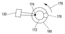
예시적인 실시형태가, 전술한 4개의 단계에 따라 원통형 부품을 생산하는 것을 도시하는 도 6 내지 도 9에 도시되어 있다. 원통형 부품(172)을 생산하기 위해서, 제조 노즐(176)이 나선 궤적을 기술하거나, 제조 기계의 트레이(180)가 회전되고 제조 노즐(176)이 제조 축을 따라서 상승하는, 2개의 해결책이 가능하다. 부품의 관점으로부터 결과적인 궤적은 동일하다. 그러나, 화살표(178)를 따라 회전되는 트레이(180)를 갖는 해결책은 제어를 단순화할 수 있게 하고, 그에 따라 이러한 해결책이 바람직하다. 이러한 경우에, 제조 파일과 제어 파일 사이의 단계(168)에 따른 상호 작용은 제조를 단순화하는 제조 전략을 선택할 수 있게 한다.An exemplary embodiment is shown in Figures 6-9 which illustrate the production of a cylindrical part according to the four steps described above. To produce the
도 6에서, 제어 이펙터(130)는 대기 위치에 있다. 제조 노즐(176)은 재료 침착 과정에 있다. 다관절 제어 시스템(132)은 이동 가능하지 않고, 제어 구역(174)이 제어 이펙터(130)의 전방을 통과하는 동안, 대기한다.6 , the
도 7에서, 제어 구역(174)은 제어 이펙터(130)의 전방을 통과한다. 생성 레이저(114) 및 검출 레이저(120)가 활성화되어 제어 구역(174)을 제어하고, 성형된 생성 레이저 빔(134) 및 성형된 검출 레이저 빔(136)을 각각 방출한다.In FIG. 7 , the
도 8에서, 제어 이펙터(130)를 지지하는 다관절 제어 시스템(132)은, 제어 구역(174)을 모니터링하기 위해서 화살표(178)의 방향에 따라 변위된다. 이러한 이동은 프로그래밍되지 않고, 따라서 다관절 제어 시스템(132)과 부품(172)의 결합의 결과이다. 그에 따라, 다관절 제어 시스템(132)은 화살표(178)의 방향에 따라 제어 이펙터(130)의 하우징을 변위시키는 것에 의해서 부품(172)의 제어부(174) 상에서 제어 이펙터(130)를 부동적으로 유지하고, 다채널 디지털 제어 디렉터(112)는, 다관절 제조 시스템(132)의 속력 및 궤적이 제어 이펙터(130)를 제어 구역(174)에 대해서 부동적으로 유지할 수 있게 하는 것을 보장한다.In FIG. 8 , the articulated control system 132 supporting the
도 9에서, 제어 구역(174)의 제어가 종료되었을 때, 다관절 제어 시스템(132)은 제조 기계의 트레이(180)로부터 분리되고 제어 이펙터(130)를 대기 위치로 복귀시킨다. 이어서, 구역(174)은 "제어됨"으로 표기되고, 다관절 제어 시스템(132)은 제어를 위한 다른 구역의 통과를 대기한다. 모든 구역(174)이 제어되었을 때, 다관절 제어 시스템(132)은 제어 이펙터(130)의 하우징의 높이를 증가시키고, 부품(172)의 다음 스테이지의 제어를 실행한다. 동일 제어 스테이지 상의 2개의 지점들 사이의 간격은 전형적으로 몇 밀리미터의 단위이고, 2개의 제어 스테이지들 사이의 거리는 전형적으로 몇 밀리미터의 단위이다.In FIG. 9 , when control of the
이러한 상황에서, 제어 파일은 스캔하기 위한 각도 값 및 구축 방향의 증분에 관한 표를 포함한다. 제어 파일은 또한 제어 지속시간 및 트레이(180)의 회전 속력에 관한 값을 포함한다. 다관절 제조 시스템(138)의 모든 궤적은, 다채널 DCD(112)의 사용으로 DCD에 의해서 자동적으로 계산된다.In this situation, the control file contains a table of increments of angle values and construction directions to scan. The control file also contains values relating to the control duration and rotational speed of the
따라서, 본 발명에 따른 제어 시스템 및 방법은, 검출 레이저 빔(134)과 생성 레이저 빔(136) 사이의 간격의 동적 조정으로 인해서, 비드의 복잡한 기하형태를 제어할 수 있게 한다.Thus, the control system and method according to the present invention makes it possible to control the complex geometry of the bead, due to the dynamic adjustment of the spacing between the
본 발명에 따른 제어 시스템 및 방법은 생성 레이저 빔(134) 및 검출 레이저 빔(136)의 이동을 제조 노즐(176)의 이동으로부터 분리한다. 따라서, 제어는 위상 지연을 가지고 이루어질 수 있고, 이는 비드 냉각 시간을 제공하고 이는 큰 열 구배의 존재 하에서의 제어를 방지할 수 있게 한다.A control system and method in accordance with the present invention separates the movement of the
본 발명에 따른 제어 시스템 및 방법은, 부품의 구축, 그 표면 처리, 그 수리의 과정 중에 부품의 모니터링을 보장할 수 있게 한다. 따라서, 본 발명에 따른 제어 시스템 및 방법은 제조 중에 결함을 검출할 수 있게 하고, 제조 방법을 중단시키기 위한 피드백 루프를 가능하게 할 수 있고, 또는 결함이 검출되자 마자 제조 방법의 특정 매개변수를 수정하게 할 수 있다. 본 발명에 따른 제어 시스템 및 방법은 또한 부품을 층별로 제어하게 할 수 있다.The control system and method according to the invention make it possible to ensure the monitoring of the part during the course of its construction, its surface treatment and its repair. Thus, the control system and method according to the present invention may enable the detection of defects during manufacturing, a feedback loop for stopping the manufacturing method, or correcting certain parameters of the manufacturing method as soon as the defect is detected. can do it The control system and method according to the invention can also allow for layer-by-layer control of components.
본 발명에 따른 제어 시스템 및 방법은, 다관절 제조 시스템을 위한 5개의 축 및 다관절 제어 시스템을 위한 7개의 축과 같은, 많은 수의 축의 동기화를 관리하는 문제를 해결할 수 있게 한다. 종래 기술에서, 그러한 많은 수의 축의 관리는, 컴퓨팅 파워와 관련하여 매우 고비용적이거나 심지어 불가능하다. 또한, 종래 기술의 시스템에서, 모든 축 이동은 단일 프로그램으로 프로그래밍되어야 하고, 이는 그 기록을 매우 복잡하게 한다.The control system and method according to the present invention makes it possible to solve the problem of managing the synchronization of a large number of axes, such as five axes for articulated manufacturing systems and seven axes for articulated control systems. In the prior art, the management of such a large number of axes is very expensive or even impossible in terms of computing power. Also, in prior art systems, all axis movements have to be programmed with a single program, which makes the recording very complicated.
또한, 본 발명에 따른 방법 및 시스템은 적층 제조 기계의 동적 거동, 그리고 특히 침착 속도를 연속적으로 측정할 수 있게 하고, 그에 따라 제어 이펙터의 동역학, 특히 가속도를 적응시킬 수 있게 하고, 적층 제조 기계 및 제어 이펙터를 동기화시킬 수 있게 한다. 따라서, 제어 이펙터의 진동이 방지된다.In addition, the method and system according to the invention make it possible to continuously measure the dynamic behavior of an additive manufacturing machine, and in particular the deposition rate, and thus make it possible to adapt the dynamics, in particular the acceleration, of the control effector, the additive manufacturing machine and Allows the control effector to be synchronized. Thus, vibration of the control effector is prevented.
따라서, 본 발명에 따른 방법은 특히 2개의 중요 단계를 포함한다. 제1 단계는, 장비의 안전을 보장하면서, 생산 과정에서 관심 구역의 제어 가능성을 보장하기 위해서, 제어 프로그램 및 제조 프로그램을 함께 규정하는 것으로 구성된다. 제2 단계는, 많은 수의 축, 전형적으로: 다관절 제어 시스템(132)을 위한 6개의 축, 다관절 제조 시스템(138)을 위한 5개의 축, 및 DADI(128)를 위한 하나의 축인, 12개의 축의 동기화된 관리를 보장하기 위한 다채널 디지털 제어 디렉터의 이용이다. 따라서, 본 발명에 따른 방법은, 제조 프로그램 및 제어 프로그램을 분리하는 것에 의해서, 많은 수의 축의 동시적 관리에 관한 문제를 해결한다.The process according to the invention thus comprises in particular two important steps. The first step consists in defining the control program and the manufacturing program together in order to ensure the controllability of the area of interest in the production process, while ensuring the safety of the equipment. The second stage is a number of axes, typically: six axes for the articulated control system 132 , five axes for the articulated manufacturing system 138 , and one axis for the DADI 128 . The use of a multi-channel digital control director to ensure synchronized management of 12 axes. The method according to the invention thus solves the problem of simultaneous management of a large number of axes by separating the manufacturing program and the control program.
디지털 제어의 다채널 양태는, 종래 기술의 시스템에 존재하지 않는, 상호 작용 및 상호 연결을 가지고 이용된다.The multi-channel aspect of digital control is used with interactivity and interconnection that does not exist in prior art systems.
참조 문헌References
[1] CERNIGLIA D., SCAFIDI M., PANTANO A. and RUDLIN J. "Inspection of additive-manufactured layered components", Ultrasonics, (Sept. 2015), Vol. 62, Pages 292-298.[1] CERNIGLIA D., SCAFIDI M., PANTANO A. and RUDLIN J. “Inspection of additive-manufactured layered components”, Ultrasonics, (Sept. 2015), Vol. 62, Pages 292-298.
Claims (13)
Translated fromKorean- 부품(140, 172)의 3-차원적인 디지털 모델을 획득하기 위한 수단(104);
- 적층 제조 기계의 제조 매개변수를 규정하기 위해서, 상기 부품(140, 172)의 3-차원적인 디지털 모델을 기초로, 부품(140, 172)에 대한 제조 파일을 생성하기 위한 수단(108)으로서, 상기 제조 매개변수는 제조 명령어와 연관되는, 수단(108);
- 제어 이펙터(130)의 제어 매개변수를 규정하기 위해서 부품(140, 172)에 대한 제어 파일을 생성하기 위한 수단(110)으로서, 상기 제어 매개변수는 제어 명령어와 연관되는, 수단(110);
- 적층 제조 기계에 대한 제조 매개변수의 그리고 제어 이펙터(130)에 대한 제어 매개변수의 동시 적용 중에 제조 매개변수 및 제어 매개변수가 공존할 수 있는지의 여부를 결정하기 위해서, 제조 파일 및 제어 파일의 분석을 실행하는 분석 수단(106);
- 제어 모듈(112)로서, 적층 제조 기계 및 제어 이펙터(130)를 동시에 관리하기 위해서, 적층 제조 기계를 지원하는데 적합한 다관절 제조 시스템(138)에 대한 제조 명령어의 수신 및 송신을 위한 적어도 하나의 통신 채널, 및 제어 이펙터(130)를 지원하는데 적합한 다관절 제어 시스템(132)에 대한 제어 명령어를 수신 및 송신하기 위한 적어도 하나의 통신 채널을 포함하는, 제어 모듈을 포함하는, 제어 제조 시스템(100).A controlled manufacturing system (100) suitable for controlling a method for manufacturing, repairing or surface treatment of a part (140, 172) by deposition of material under concentrated energy, said controlled manufacturing system comprising:
- means (104) for obtaining a three-dimensional digital model of the part (140, 172);
- means (108) for generating manufacturing files for parts (140, 172), based on a three-dimensional digital model of said parts (140, 172), for defining manufacturing parameters of an additive manufacturing machine; means (108), wherein the manufacturing parameter is associated with a manufacturing instruction;
- means (110) for generating a control file for the part (140, 172) for defining control parameters of the control effector (130), the control parameters being associated with a control command;
- in order to determine whether the manufacturing parameters and control parameters can coexist during simultaneous application of the manufacturing parameters to the additive manufacturing machine and the control parameters to the control effector 130; analysis means 106 for performing the analysis;
- at least one control module 112 for receiving and transmitting manufacturing instructions to an articulated manufacturing system 138 suitable for supporting the additive manufacturing machine, to simultaneously manage the additive manufacturing machine and the control effector 130 A control manufacturing system (100), including a control module, comprising a communication channel and at least one communication channel for receiving and transmitting control commands for an articulated control system (132) suitable for supporting a control effector (130) ).
초기 생성 레이저 빔(116)을 방출할 수 있는 생성 레이저(114), 및 레이저 초음파 방법에 따라 부품(140, 172)에 제어를 실행하기 위한 초기 검출 레이저 빔(122)을 방출할 수 있는 검출 레이저(120)를 포함하는, 제어 제조 시스템(100).According to claim 1,
A generating laser 114 capable of emitting an initial generating laser beam 116 , and a detecting laser capable of emitting an initial detecting laser beam 122 for effecting control on the parts 140 , 172 according to a laser ultrasound method. A controlled manufacturing system (100) comprising (120).
제어 이펙터(130)는 생성 레이저 빔(134)을 생성하기 위해서 초기 생성 레이저 빔(116)을 성형하기 위한 장치(118), 및 검출 레이저 빔(136)을 생성하기 위해서 초기 검출 레이저 빔(122)을 성형하기 위한 장치(124)를 포함하는, 제어 제조 시스템(100).3. The method of claim 2,
The control effector 130 includes an apparatus 118 for shaping the initial production laser beam 116 to generate a production laser beam 134 , and an initial detection laser beam 122 to generate a detection laser beam 136 . A controlled manufacturing system (100) comprising an apparatus (124) for forming
제어 이펙터(130)는, 생성 레이저 빔(134)과 검출 레이저 빔(136) 사이의 거리를 고정하기 위해서 레이저-간 거리를 조정하기 위한 장치(128)를 포함하는, 제어 제조 시스템(100).4. The method of claim 3,
The control effector (130) comprises a device (128) for adjusting the inter-laser distance to fix a distance between the production laser beam (134) and the detection laser beam (136).
제어 모듈(112)이 다채널 디지털 제어 디렉터인, 제어 제조 시스템(100).5. The method according to any one of claims 1 to 4,
The control manufacturing system (100), wherein the control module (112) is a multi-channel digital control director.
제어 이펙터(130)는 부품(140, 172)의 제어 구역(174) 부근의 무접촉 온도 측정 탐침을 포함하는, 제어 제조 시스템(100).6. The method according to any one of claims 1 to 5,
The controlled manufacturing system (100), wherein the controlled effector (130) comprises a contactless temperature measurement probe proximate the control zone (174) of the component (140, 172).
제어 이펙터(130)는, 상기 적층 제조 기계 내의 부품(140, 172)의 결함을 검출하거나 심지어 위치 결정하기 위해서 제어 이펙터(130)에 선택적으로 포함되는, 하나 이상의 다른 제어 수단과 조합되는, 제어 제조 시스템(100).7. The method according to any one of claims 1 to 6,
The control effector 130 is combined with one or more other control means, optionally included in the control effector 130 for detecting or even locating defects of the parts 140 , 172 within the additive manufacturing machine. system 100.
- 상기 부품(140, 172)을 모델링하기 위해서, 제조, 수리 또는 표면 처리하기 위한 부품(140, 172)의 3-차원적인 디지털 모델을 생성하는 단계(162);
- 적층 제조 기계의 제조 매개변수를 규정하기 위해서, 부품의 3-차원적인 디지털 모델을 기초로, 부품에 대한 제조 파일을 생성하는 단계(164)로서, 상기 제조 매개변수는 제조 명령어와 연관되는, 단계(164);
- 제어 장치의 제어 매개변수를 규정하기 위해서 제어 파일을 생성하는 단계(166)로서, 상기 제어 매개변수는 제어 명령어와 연관되는, 단계(166);
- 적층 제조 기계에 대한 제조 매개변수의 그리고 제어 이펙터(130)에 대한 제어 매개변수의 동시 적용 중에 제조 매개변수 및 제어 매개변수가 공존할 수 있는지의 여부를 결정하기 위해서, 제조 파일 및 제어 파일을 분석하는 단계(168);
- 제조 매개변수 및 제어 매개변수가 공존할 수 있는 경우에, 부품(140, 172)을 제조, 수리 또는 표면 처리하기 위해서 적층 제조 기계 및 제어 이펙터(130)를 동시적 관리하는 단계(170)로서, 상기 동시적 관리는 제조 명령어 및 제어 명령어를 기초로 하는, 단계(170)를 포함하는, 방법.It is a controlled manufacturing method suitable for a method for manufacturing, repairing or surface treatment of a part, by material deposition under concentrated energy:
- generating (162) a three-dimensional digital model of the part (140, 172) for manufacturing, repair or surface treatment, in order to model the part (140, 172);
- generating (164) a manufacturing file for a part on the basis of a three-dimensional digital model of the part, in order to define manufacturing parameters of the additive manufacturing machine, the manufacturing parameters being associated with manufacturing instructions; step 164;
- generating (166) a control file for defining control parameters of the control device, said control parameters being associated with a control command (166);
- to determine whether the manufacturing parameters and control parameters can coexist during simultaneous application of the manufacturing parameters to the additive manufacturing machine and the control parameters to the control effector 130; analyzing 168;
- concurrently managing (170) the additive manufacturing machine and the control effector (130) for manufacturing, repairing or surface treatment of the part (140, 172), where the manufacturing parameters and the control parameters can coexist; , wherein the concurrent management is based on manufacturing instructions and control instructions.
- 제조 매개변수 및 제어 매개변수가 공존할 수 없는 경우에:
- 적층 제조 기계의 제조 매개변수를 규정하기 위해서, 부품(140, 172)의 3-차원적인 디지털 모델을 기초로, 부품(140, 172)에 대한 제조 파일을 생성하는 단계(164)로서, 상기 제조 매개변수는 제조 명령어와 연관되는, 단계(164); 및/또는
- 제어 이펙터(130)의 제어 매개변수를 규정하기 위해서 제어 파일을 생성하는 단계(166)로서, 상기 제어 매개변수는 제어 명령어와 연관되는, 단계(166)를 포함하는, 방법.9. The method of claim 8,
- When manufacturing parameters and control parameters cannot coexist:
- generating (164) a manufacturing file for the part (140, 172) on the basis of the three-dimensional digital model of the part (140, 172), in order to define the manufacturing parameters of the additive manufacturing machine, said manufacturing parameters are associated with manufacturing instructions, step 164; and/or
- generating (166) a control file for defining control parameters of a control effector (130), said control parameters being associated with a control command;
농축 에너지 하의 재료 침착에 의해서 부품(140, 172)을 제조, 수리 또는 표면 처리하기 위한 방법은, 레이저에 의해서 금속 분말을 용융시키기 위한, 레이저에 의해서 금속 와이어를 용융시키기 위한, 또는 전기 아크에 의해서 금속 와이어를 용융시키기 위한 방법인, 방법.10. The method according to claim 8 or 9,
Methods for manufacturing, repairing, or surface treatment of parts 140 , 172 by material deposition under concentrated energy include melting metal powder by a laser, melting a metal wire by a laser, or by an electric arc. A method for melting a metal wire.
제어 명령어는 결함 출현 가능성이 높은 부품(140, 172)의 영역을 표적으로 하는, 방법.11. The method according to any one of claims 8 to 10,
The method of claim 1, wherein the control instructions target an area of the component (140, 172) that has a high probability of the appearance of a defect.
결함의 검출이 제조의 중단을 초래하는, 방법.12. The method according to any one of claims 8 to 11,
A method, wherein detection of the defect results in discontinuation of manufacturing.
결함의 검출이, 부품(140, 172)의 결함 구역의 용융 또는 가공과 같은 교정 작용의 실행을 초래하는, 방법.12. The method according to any one of claims 8 to 11,
A method, wherein detection of a defect results in execution of a corrective action, such as melting or machining of a defective area of a part (140, 172).
Applications Claiming Priority (3)
| Application Number | Priority Date | Filing Date | Title |
|---|---|---|---|
| FR1906669AFR3097463B1 (en) | 2019-06-20 | 2019-06-20 | CONTROLLED MANUFACTURING SYSTEM AND PROCESS |
| FRFR1906669 | 2019-06-20 | ||
| PCT/FR2020/050864WO2020254738A1 (en) | 2019-06-20 | 2020-05-25 | System and method for controlled manufacturing |
Publications (1)
| Publication Number | Publication Date |
|---|---|
| KR20220031900Atrue KR20220031900A (en) | 2022-03-14 |
Family
ID=68072745
Family Applications (1)
| Application Number | Title | Priority Date | Filing Date |
|---|---|---|---|
| KR1020227002109AWithdrawnKR20220031900A (en) | 2019-06-20 | 2020-05-25 | Systems and Methods for Controlled Manufacturing |
Country Status (7)
| Country | Link |
|---|---|
| US (1) | US20220347754A1 (en) |
| EP (1) | EP3986646A1 (en) |
| JP (1) | JP2022537449A (en) |
| KR (1) | KR20220031900A (en) |
| CN (1) | CN114258344A (en) |
| FR (1) | FR3097463B1 (en) |
| WO (1) | WO2020254738A1 (en) |
Families Citing this family (4)
| Publication number | Priority date | Publication date | Assignee | Title |
|---|---|---|---|---|
| CN113588566B (en)* | 2021-08-23 | 2022-06-21 | 南京大学 | Device and method for quality inspection of laser spot welding micro-solder spot based on laser ultrasonic |
| JP7695673B2 (en)* | 2022-01-21 | 2025-06-19 | 株式会社ダイヘン | Defect Judgment Device |
| CN118385614B (en)* | 2024-07-01 | 2024-10-18 | 创材深造(苏州)科技有限公司上海分公司 | Method, device, equipment and storage medium for additive manufacturing of multi-mode powder parts |
| CN119534619A (en)* | 2024-11-13 | 2025-02-28 | 上海航天设备制造总厂有限公司 | Metal additive manufacturing online detection method and system |
Family Cites Families (6)
| Publication number | Priority date | Publication date | Assignee | Title |
|---|---|---|---|---|
| US10352911B2 (en)* | 2008-09-12 | 2019-07-16 | Balthasar Fischer | Airborne ultrasound testing system for a test object |
| JP2018536560A (en)* | 2015-11-16 | 2018-12-13 | レニショウ パブリック リミテッド カンパニーRenishaw Public Limited Company | Machine control for additive manufacturing processes and equipment |
| US10611091B2 (en)* | 2016-09-01 | 2020-04-07 | 3D Systems, Inc. | Additive manufacturing of a three-dimensional object |
| US10953647B2 (en)* | 2017-01-06 | 2021-03-23 | International Business Machines Corporation | Methods and systems for detecting and rectifying faults in 3D printing processes |
| CN108333219A (en)* | 2018-03-19 | 2018-07-27 | 长沙理工大学 | A kind of online lossless detection method for band large-scale metal component laser gain material manufacturing process |
| CN109387568A (en)* | 2018-12-21 | 2019-02-26 | 西安增材制造国家研究院有限公司 | A kind of laser ultrasonic detection device and increasing material manufacturing, detection integrated equipment |
- 2019
- 2019-06-20FRFR1906669Apatent/FR3097463B1/enactiveActive
- 2020
- 2020-05-25USUS17/621,072patent/US20220347754A1/ennot_activeAbandoned
- 2020-05-25WOPCT/FR2020/050864patent/WO2020254738A1/ennot_activeCeased
- 2020-05-25CNCN202080058587.5Apatent/CN114258344A/enactivePending
- 2020-05-25KRKR1020227002109Apatent/KR20220031900A/ennot_activeWithdrawn
- 2020-05-25JPJP2021576242Apatent/JP2022537449A/enactivePending
- 2020-05-25EPEP20739748.0Apatent/EP3986646A1/enactivePending
Also Published As
| Publication number | Publication date |
|---|---|
| JP2022537449A (en) | 2022-08-25 |
| FR3097463A1 (en) | 2020-12-25 |
| CN114258344A (en) | 2022-03-29 |
| FR3097463B1 (en) | 2022-09-23 |
| EP3986646A1 (en) | 2022-04-27 |
| WO2020254738A1 (en) | 2020-12-24 |
| US20220347754A1 (en) | 2022-11-03 |
Similar Documents
| Publication | Publication Date | Title |
|---|---|---|
| KR20220031900A (en) | Systems and Methods for Controlled Manufacturing | |
| CN111198538B (en) | Processing condition setting device and three-dimensional laser processing system | |
| CN110869149B (en) | Apparatus and method for additive manufacturing | |
| JP6645960B2 (en) | Method of measuring depth of penetration of laser beam into workpiece and laser processing device | |
| JP6560678B2 (en) | Laser beam, laser tool, laser machine, workpiece machining method using machine controller | |
| JP7317427B2 (en) | Metal Additive Manufacturing Synchronous Detection System and Method by Cooperating with Laser Ultrasound and Galvo Scanner | |
| WO2002074482A1 (en) | Apparatus and method for focal point control for laser machining | |
| WO2001001064A2 (en) | Topographer for real time ablation feedback | |
| JP2648401B2 (en) | Equipment for monitoring material processing by laser | |
| EP3304054B1 (en) | Real-time inspection of automated ribbon placement | |
| JPH03151180A (en) | Joint chasing type precision laser welding system | |
| CN113874141A (en) | Method and apparatus for additive manufacturing of workpieces | |
| CN114450584A (en) | Laminated shape system | |
| JP2022160992A (en) | Ultrasound inspection system and method | |
| US20160151114A1 (en) | Wall thickness compensation during laser orifice drilling | |
| WO2019234994A1 (en) | Measurement system, measurement method, and measurement program | |
| Mewes et al. | The correction of the nozzle-bed-distance in robotic fused deposition modeling | |
| JP4202305B2 (en) | 3D laser processing machine | |
| WO2022162893A1 (en) | Machine tool, optical systems, and measuring device | |
| WO2021220456A1 (en) | Processing system | |
| Steen | Laser automation and in-process sensing | |
| JP6456205B2 (en) | Method for measuring cross-sectional shape of measurement object | |
| JPH01218784A (en) | Laser beam processing method | |
| JP2010099679A (en) | Laser machining apparatus and position detecting method of the same | |
| Steen | Laser process automation |
Legal Events
| Date | Code | Title | Description |
|---|---|---|---|
| PA0105 | International application | St.27 status event code:A-0-1-A10-A15-nap-PA0105 | |
| P11-X000 | Amendment of application requested | St.27 status event code:A-2-2-P10-P11-nap-X000 | |
| P13-X000 | Application amended | St.27 status event code:A-2-2-P10-P13-nap-X000 | |
| PG1501 | Laying open of application | St.27 status event code:A-1-1-Q10-Q12-nap-PG1501 | |
| PC1203 | Withdrawal of no request for examination | St.27 status event code:N-1-6-B10-B12-nap-PC1203 | |
| P22-X000 | Classification modified | St.27 status event code:A-2-2-P10-P22-nap-X000 |