KR20220025887A - Robot motion planning method, path planning method, gripping method and device therefor - Google Patents
Robot motion planning method, path planning method, gripping method and device thereforDownload PDFInfo
- Publication number
- KR20220025887A KR20220025887AKR1020227003435AKR20227003435AKR20220025887AKR 20220025887 AKR20220025887 AKR 20220025887AKR 1020227003435 AKR1020227003435 AKR 1020227003435AKR 20227003435 AKR20227003435 AKR 20227003435AKR 20220025887 AKR20220025887 AKR 20220025887A
- Authority
- KR
- South Korea
- Prior art keywords
- robot
- collision
- degree
- gripping
- detection
- Prior art date
- Legal status (The legal status is an assumption and is not a legal conclusion. Google has not performed a legal analysis and makes no representation as to the accuracy of the status listed.)
- Granted
Links
Images


Classifications
- G—PHYSICS
- G01—MEASURING; TESTING
- G01C—MEASURING DISTANCES, LEVELS OR BEARINGS; SURVEYING; NAVIGATION; GYROSCOPIC INSTRUMENTS; PHOTOGRAMMETRY OR VIDEOGRAMMETRY
- G01C21/00—Navigation; Navigational instruments not provided for in groups G01C1/00 - G01C19/00
- G01C21/20—Instruments for performing navigational calculations
- B—PERFORMING OPERATIONS; TRANSPORTING
- B25—HAND TOOLS; PORTABLE POWER-DRIVEN TOOLS; MANIPULATORS
- B25J—MANIPULATORS; CHAMBERS PROVIDED WITH MANIPULATION DEVICES
- B25J9/00—Programme-controlled manipulators
- B25J9/16—Programme controls
- B25J9/1656—Programme controls characterised by programming, planning systems for manipulators
- B25J9/1664—Programme controls characterised by programming, planning systems for manipulators characterised by motion, path, trajectory planning
- B25J9/1666—Avoiding collision or forbidden zones
- B—PERFORMING OPERATIONS; TRANSPORTING
- B25—HAND TOOLS; PORTABLE POWER-DRIVEN TOOLS; MANIPULATORS
- B25J—MANIPULATORS; CHAMBERS PROVIDED WITH MANIPULATION DEVICES
- B25J15/00—Gripping heads and other end effectors
- B25J15/06—Gripping heads and other end effectors with vacuum or magnetic holding means
- B25J15/0616—Gripping heads and other end effectors with vacuum or magnetic holding means with vacuum
- B25J15/0683—Details of suction cup structure, e.g. grooves or ridges
- B—PERFORMING OPERATIONS; TRANSPORTING
- B25—HAND TOOLS; PORTABLE POWER-DRIVEN TOOLS; MANIPULATORS
- B25J—MANIPULATORS; CHAMBERS PROVIDED WITH MANIPULATION DEVICES
- B25J9/00—Programme-controlled manipulators
- B25J9/16—Programme controls
- B25J9/1612—Programme controls characterised by the hand, wrist, grip control
- B—PERFORMING OPERATIONS; TRANSPORTING
- B25—HAND TOOLS; PORTABLE POWER-DRIVEN TOOLS; MANIPULATORS
- B25J—MANIPULATORS; CHAMBERS PROVIDED WITH MANIPULATION DEVICES
- B25J9/00—Programme-controlled manipulators
- B25J9/16—Programme controls
- B25J9/1628—Programme controls characterised by the control loop
- B25J9/1653—Programme controls characterised by the control loop parameters identification, estimation, stiffness, accuracy, error analysis
- B—PERFORMING OPERATIONS; TRANSPORTING
- B25—HAND TOOLS; PORTABLE POWER-DRIVEN TOOLS; MANIPULATORS
- B25J—MANIPULATORS; CHAMBERS PROVIDED WITH MANIPULATION DEVICES
- B25J9/00—Programme-controlled manipulators
- B25J9/16—Programme controls
- B25J9/1656—Programme controls characterised by programming, planning systems for manipulators
- B25J9/1669—Programme controls characterised by programming, planning systems for manipulators characterised by special application, e.g. multi-arm co-operation, assembly, grasping
- G—PHYSICS
- G01—MEASURING; TESTING
- G01C—MEASURING DISTANCES, LEVELS OR BEARINGS; SURVEYING; NAVIGATION; GYROSCOPIC INSTRUMENTS; PHOTOGRAMMETRY OR VIDEOGRAMMETRY
- G01C21/00—Navigation; Navigational instruments not provided for in groups G01C1/00 - G01C19/00
- G01C21/26—Navigation; Navigational instruments not provided for in groups G01C1/00 - G01C19/00 specially adapted for navigation in a road network
- G01C21/34—Route searching; Route guidance
- G—PHYSICS
- G05—CONTROLLING; REGULATING
- G05B—CONTROL OR REGULATING SYSTEMS IN GENERAL; FUNCTIONAL ELEMENTS OF SUCH SYSTEMS; MONITORING OR TESTING ARRANGEMENTS FOR SUCH SYSTEMS OR ELEMENTS
- G05B2219/00—Program-control systems
- G05B2219/30—Nc systems
- G05B2219/39—Robotics, robotics to robotics hand
- G05B2219/39536—Planning of hand motion, grasping
- G—PHYSICS
- G05—CONTROLLING; REGULATING
- G05B—CONTROL OR REGULATING SYSTEMS IN GENERAL; FUNCTIONAL ELEMENTS OF SUCH SYSTEMS; MONITORING OR TESTING ARRANGEMENTS FOR SUCH SYSTEMS OR ELEMENTS
- G05B2219/00—Program-control systems
- G05B2219/30—Nc systems
- G05B2219/40—Robotics, robotics mapping to robotics vision
- G05B2219/40137—Force sensation feedback from simulated tool
- G—PHYSICS
- G05—CONTROLLING; REGULATING
- G05B—CONTROL OR REGULATING SYSTEMS IN GENERAL; FUNCTIONAL ELEMENTS OF SUCH SYSTEMS; MONITORING OR TESTING ARRANGEMENTS FOR SUCH SYSTEMS OR ELEMENTS
- G05B2219/00—Program-control systems
- G05B2219/30—Nc systems
- G05B2219/40—Robotics, robotics mapping to robotics vision
- G05B2219/40318—Simulation of reaction force and moment, force simulation
- G—PHYSICS
- G05—CONTROLLING; REGULATING
- G05B—CONTROL OR REGULATING SYSTEMS IN GENERAL; FUNCTIONAL ELEMENTS OF SUCH SYSTEMS; MONITORING OR TESTING ARRANGEMENTS FOR SUCH SYSTEMS OR ELEMENTS
- G05B2219/00—Program-control systems
- G05B2219/30—Nc systems
- G05B2219/40—Robotics, robotics mapping to robotics vision
- G05B2219/40319—Simulate contact of object and obstacle, reduce to pairs with only one contact
- G—PHYSICS
- G05—CONTROLLING; REGULATING
- G05B—CONTROL OR REGULATING SYSTEMS IN GENERAL; FUNCTIONAL ELEMENTS OF SUCH SYSTEMS; MONITORING OR TESTING ARRANGEMENTS FOR SUCH SYSTEMS OR ELEMENTS
- G05B2219/00—Program-control systems
- G05B2219/30—Nc systems
- G05B2219/40—Robotics, robotics mapping to robotics vision
- G05B2219/40442—Voxel map, 3-D grid map
Landscapes
- Engineering & Computer Science (AREA)
- Robotics (AREA)
- Mechanical Engineering (AREA)
- Radar, Positioning & Navigation (AREA)
- Remote Sensing (AREA)
- Automation & Control Theory (AREA)
- Physics & Mathematics (AREA)
- General Physics & Mathematics (AREA)
- Health & Medical Sciences (AREA)
- General Health & Medical Sciences (AREA)
- Orthopedic Medicine & Surgery (AREA)
- Manipulator (AREA)
Abstract
Translated fromKoreanDescription
Translated fromKorean본 출원은 컴퓨터 기술분야에 관한 것으로서, 특히 로봇 운동 계획 방법, 경로 계획 방법, 그립핑 방법 및 그 장치에 관한 것이다.The present application relates to the field of computer technology, and more particularly, to a robot motion planning method, a path planning method, a gripping method, and an apparatus thereof.
관련 출원들과의 상호 인용Cross-Citation with Related Applications
본 출원은 2020년 05월 22일 출원한 출원번호가 202010440673.4이고, 발명의 명칭이 "로봇 운동 계획 방법, 경로 계획 방법, 그립핑 방법 및 그 장치"인 중국 특허 출원의 우선권을 주장하며, 그 모든 내용은 인용을 통해 본 출원에 결합된다.This application claims the priority of the Chinese patent application filed on May 22, 2020 with the application number 202010440673.4, and the title of the invention is "Robot motion planning method, path planning method, gripping method and device therefor", and all The content is incorporated into this application by reference.
공업 지능화의 발전에 따라, 로봇으로 인간을 대체하여 물체(예를 들어, 공업 부품, 공업 컨테이너)를 조작(예를 들어, 그립핑, 이동, 배치 등)하는 상황이 점점 보급되고 있다. 로봇 조작 시, 일반적으로 물체를 일 상태에서 다른 상태로 변경하여야 하며, 이러한 과정은 로봇에 의해 그립핑된 물체와 다른 물체 사이에 충돌의 발생을 방지하고, 로봇의 운동이 효율적으로 원활하게 이루어지도록 하여, 위험이 발생하는 것을 방지하여야 한다.With the development of industrial intelligence, the situation of manipulating (eg, gripping, moving, placing, etc.) objects (eg, industrial parts, industrial containers) by replacing humans with robots is becoming more and more prevalent. When operating a robot, it is generally necessary to change an object from one state to another. This process prevents the occurrence of a collision between the object gripped by the robot and another object, and makes the robot movement efficiently Thus, it is necessary to prevent a risk from occurring.
관련 기술에 따르면, 실체 로봇 암에 센서를 설치하는 방식으로 충돌 검출을 실시간으로 수행한다. 하지만, 이러한 방식은 로봇 운동 끊김 현상을 초래하기 쉬우므로, 공업 자동화를 달성하는데 영향을 미친다.According to the related art, collision detection is performed in real time by installing a sensor on an actual robot arm. However, this method is easy to cause the robot movement interruption, which affects the achievement of industrial automation.
본 출원은 상술한 기술문제 중 하나를 적어도 어느 정도 해결하는 것을 목적으로 한다.An object of the present application is to solve at least one of the above technical problems to some extent.
이를 위해, 본 출원의 제1 목적은 로봇 운동 계획 방법을 개시하는 것이다.To this end, a first object of the present application is to disclose a robot motion planning method.
본 출원의 제2 목적은 충돌 정도 검출을 기반으로 하는 로봇 경로 계획 방법을 개시하는 것이다.A second object of the present application is to disclose a robot path planning method based on collision degree detection.
본 출원의 제3 목적은 충돌 정도 검출을 기반으로 하는 로봇 그립핑 방법을 개시하는 것이다.A third object of the present application is to disclose a robot gripping method based on collision degree detection.
본 출원의 제4 목적은 로봇 운동 계획 장치를 개시하는 것이다.A fourth object of the present application is to disclose a robot motion planning device.
본 출원의 제5 목적은 충돌 정도 검출을 기반으로 하는 로봇 경로 계획 장치를 개시하는 것이다.A fifth object of the present application is to disclose a robot path planning device based on collision degree detection.
본 출원의 제6 목적은 충돌 정도 검출을 기반으로 하는 로봇 그립핑 장치를 개시하는 것이다.A sixth object of the present application is to disclose a robot gripping device based on collision degree detection.
본 출원의 제7 목적은 전자기기를 개시하는 것이다.A seventh object of the present application is to disclose an electronic device.
본 출원의 제8 목적은 컴퓨터 판독 가능 저장매체를 개시하는 것이다.An eighth object of the present application is to disclose a computer-readable storage medium.
상술한 목적을 달성하기 위하여, 본 출원의 제1 측면의 실시예는, 물체에 대해 충돌 정도 검출을 수행하며, 상기 방법은, 상기 물체가 위치한 현실 시나리오의 공간 모델을 로딩하는 단계; 상기 물체와 상기 공간 모델 내의 충돌 대상에 대해 충돌 검출을 수행하는 단계; 상기 물체의 충돌 민감도, 충돌 대상의 충돌 민감도를 기초로 상응한 충돌 검출의 결과에 대응되는 로봇이 상기 물체를 조작하여 형성되는 상기 로봇의 운동 계획 방안을 결정하는 단계를 포함하는 로봇 운동 계획 방법을 개시한다.In order to achieve the above object, an embodiment of the first aspect of the present application is to perform collision degree detection for an object, the method comprising: loading a spatial model of a real scenario in which the object is located; performing collision detection on the object and a collision object in the spatial model; Based on the collision sensitivity of the object and the collision sensitivity of the collision object, a robot motion planning method comprising the step of determining a motion planning method of the robot, which is formed by manipulating the object by the robot corresponding to the result of the corresponding collision detection start
본 출원의 일 실시예에서, 상기 물체와 상기 공간 모델 내의 충돌 대상에 대해 충돌 검출을 수행하는 단계는, 상기 물체의 충돌 모델과 충돌 대상의 대상 모델의 오버랩 정도를 결정하는 단계; 오버랩 정도 및 상기 공간 모델 내의 각 모델 해상도를 기초로 상응한 충돌 대상의 충돌 정도를 결정하는 단계를 포함한다.In an embodiment of the present application, the performing collision detection with respect to the object and the collision target in the spatial model may include: determining an overlap between the collision model of the object and the target model of the collision target; and determining the degree of collision of the corresponding collision object based on the degree of overlap and the resolution of each model in the spatial model.
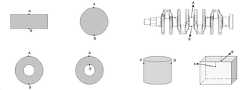
본 출원의 일 실시예에서, 상기 충돌 모델은 상기 공간 모델에서 제1 해상도로 상기 물체가 차지하는 공간을 분할하여 형성된 작은 큐브 집합을 포함하고, 대상 모델은 상기 공간 모델에서 제2 해상도로 상응한 충돌 대상이 차지하는 공간을 분할하여 형성된 작은 큐브 집합을 포함한다.In an embodiment of the present application, the collision model includes a small cube set formed by dividing the space occupied by the object at a first resolution in the spatial model, and the target model includes a collision corresponding to the second resolution in the spatial model. It contains a set of small cubes formed by dividing the space occupied by the object.
본 출원의 일 실시예에서, 상기 오버랩 정도 및 상기 공간 모델 내의 각 모델 해상도를 기초로 충돌 대상의 충돌 정도를 결정하는 단계는, 상기 충돌 모델과 대상 모델 사이의 오버랩 큐브 집합을 결정하는 단계; 상응한 오버랩 큐브 집합 중 각 작은 큐브로부터 상응한 모델 표면까지의 거리를 기초로 각 작은 큐브의 깊이 가중치를 결정하고, 오버랩 정도를 결합하여 상기 충돌 모델과 대상 모델의 충돌 정도를 결정하고, 여기서, 오버랩 정도는 상응한 오버랩 큐브 집합 내의 작은 큐브 수량인 단계를 포함한다.In an embodiment of the present application, determining the degree of collision of the collision object based on the degree of overlap and the resolution of each model in the spatial model may include: determining a set of overlapping cubes between the collision model and the target model; Determining the depth weight of each small cube based on the distance from each small cube of the set of corresponding overlapping cubes to the corresponding model surface, combining the overlap degree to determine the collision degree of the collision model and the target model, wherein, The degree of overlap includes a step in which the amount of small cubes in the corresponding set of overlapping cubes is a step.
본 출원의 일 실시예에서, 충돌 대상은 운동 계획 방안 중 상기 로봇이 상기 물체에 대해 그립핑 조작을 완성한 후로부터 배치 조작 전까지의 각 이동 경로 상의 상기 물체가 차지하는 공간과 오버랩되는 복수의 대상을 포함하는 것; 및/또는 충돌 대상은 상기 물체에 대해 그립핑 조작을 수행하는 과정에서의 상기 로봇의 조작 말단의 그리퍼를 포함하는 것; 및/또는 충돌 대상은 상기 로봇이 배치 조작을 과정하는 과정에서 상기 물체가 배치되는 접촉 물체를 포함한다.In one embodiment of the present application, the collision object includes a plurality of objects overlapping the space occupied by the object on each movement path from after the robot completes the gripping operation on the object to before the placement operation in the motion planning method to do; and/or the collision target includes a gripper at the operating end of the robot in the process of performing a gripping operation on the object; and/or the collision target includes a contact object on which the object is placed while the robot performs a placement operation.
본 출원의 실시예의 로봇 운동 계획 방법은, 로봇이 조작될 물체에 대해 조작할 때, 물체가 위치한 현실 시나리오의 공간 모델을 결합하여, 물체와 상기 공간 모델 내의 충돌 대상에 대해 충돌 검출을 수행하고, 물체의 충돌 민감도, 충돌 대상의 충돌 민감도를 기초로 상응한 충돌 검출의 결과에 대응되는 로봇이 물체를 조작하여 형성되는 로봇의 운동 계획 방안을 결정하여, 로봇이 대응되는 물체에 대해 조작할 때, 상기 운동 계획 방안을 기반으로 운동할 수 있도록 하여, 로봇이 상기 물체를 조작하는 과정에서, 로봇이 운동하는 과정에서 끊김 현상이 발생하는 것을 방지하고, 로봇의 운동을 원활하게 하며, 로봇 산업 조작의 지능화 정도를 향상시킨다.The robot motion planning method of the embodiment of the present application performs collision detection with respect to the object and the collision object in the spatial model by combining the spatial model of the real scenario in which the object is located when the robot operates on the object to be manipulated, Based on the collision sensitivity of the object and the collision sensitivity of the collision object, the robot corresponding to the result of the corresponding collision detection determines the motion planning method of the robot formed by manipulating the object, and when the robot operates on the corresponding object, By making it possible to exercise based on the motion planning method, in the process of the robot manipulating the object, the interruption phenomenon is prevented from occurring in the process of the robot moving, and the movement of the robot is smoothed, and the operation of the robot industry Increase the level of intelligence.
상술한 목적을 달성하기 위하여, 본 출원의 제2 측면의 실시예는, 충돌 정도 검출을 기반으로 하는 로봇 경로 계획 방법을 개시하며, 상기 방법은, 상기 로봇이 물체에 대한 그립핑 조작을 완성하였을 때, 충돌 정도 검출을 기반으로 상기 로봇에 대해 이동 경로 계획을 수행하고, 이동 경로 계획 결과에 대응되는 이동 경로를 이산화하며, 동시에 이산화 후의 각 이산 궤적 포인트를 발송하여 상기 로봇이 이동하도록 하는 단계; 상기 로봇의 이동 속도를 기초로 각 이산 궤적 포인트에 대응되는 로봇 주행 시점을 결정하고, 각 주행 시점에 상기 물체에 대해 충돌 검출을 수행하는 단계; 어느 시점의 충돌 정도가 상기 물체의 충돌 민감도보다 높으면 상기 로봇의 이동을 중지하여, 위험이 발생하는 것을 방지하는 단계를 포함한다.In order to achieve the above object, an embodiment of the second aspect of the present application discloses a robot path planning method based on collision degree detection, wherein the method includes the robot completing a gripping operation on an object. performing movement path planning for the robot based on the collision degree detection, discretizing the movement path corresponding to the movement path planning result, and simultaneously sending each discrete trajectory point after the discretization to cause the robot to move; determining a robot running time corresponding to each discrete trajectory point based on the moving speed of the robot, and performing collision detection with respect to the object at each running time point; and stopping the movement of the robot when the collision degree at a certain point in time is higher than the collision sensitivity of the object to prevent a danger from occurring.
본 출원의 일 실시예에서, 상기 각 주행 시점에 상기 물체에 대해 충돌 검출을 수행하는 단계는, 각 주행 시점에 상기 물체와 상기 물체가 위치한 현실 시나리오에 대응되는 공간 모델 내의 충돌 대상에 대해 충돌 검출을 수행하고, 여기서, 상기 공간 모델은 각 주행 시점의 상응한 시점의 현실 시나리오 상황과 대응되는 단계를 포함하고; 상기 어느 시점의 충돌 정도가 상기 물체의 충돌 민감도보다 높으면 상기 로봇의 이동을 중지하는 단계는, 어느 시점의 충돌 정도가 상기 물체의 충돌 민감도 또는 충돌 대상의 충돌 민감도보다 높으면 상기 로봇의 이동을 중지하는 단계를 포함한다.In an embodiment of the present application, the performing collision detection with respect to the object at each driving time may include detecting collision with respect to a collision object in a spatial model corresponding to a real scenario in which the object and the object are located at each driving time. , wherein the spatial model includes a step corresponding to a real scenario situation at a corresponding time of each driving time; The step of stopping the movement of the robot when the collision degree at a certain point in time is higher than the collision sensitivity of the object, stopping the movement of the robot when the collision degree at a certain point in time is higher than the collision sensitivity of the object or the collision sensitivity of the collision target. includes steps.
본 출원의 실시예의 충돌 정도 검출을 기반으로 하는 로봇 경로 계획 방법은, 로봇이 물체에 대한 그립핑 조작을 완성하였을 때, 충돌 정도 검출을 기반으로 로봇에 대해 이동 경로 계획을 수행하고, 이동 경로 계획 결과에 대응되는 이동 경로를 이산화하며, 동시에 이산화 후의 각 이산 궤적 포인트를 발송하여 로봇이 이동하도록 하고; 로봇의 이동 속도를 기초로 각 이산 궤적 포인트에 대응되는 로봇 주행 시점을 결정하고, 각 주행 시점에 물체에 대해 충돌 검출을 수행하고; 만약 어느 시점의 충돌 정도가 물체의 충돌 민감도보다 높으면 로봇 이동을 중지하여, 위험이 발생하는 것을 방지한다.In the robot path planning method based on the collision degree detection of the embodiment of the present application, when the robot completes the gripping operation on the object, the moving path planning is performed for the robot based on the collision degree detection, and the moving path planning is performed discretize the moving path corresponding to the result, and at the same time send each discrete trajectory point after discretization so that the robot moves; determining a robot running time corresponding to each discrete trajectory point based on the moving speed of the robot, and performing collision detection on an object at each running time point; If the collision degree at any point in time is higher than the collision sensitivity of the object, the robot stops moving to prevent danger.
이에 따라, 로봇 운동의 원활성을 확보하고, 충돌 정도 검출을 기반으로 하는 방식으로 로봇의 각각의 주행 시점에 물체에 대해 충돌 검출을 수행하고, 대응되는 주행 시점에 대응되는 충돌 정도가 물체의 충돌 민감도보다 높은 것으로 결정될 때, 로봇이 이동을 중지하도록 제어하여, 로봇 조작의 안전 및 조작되는 물체의 온전성을 확보하여, 로봇 운동의 원활성을 확보하고, 로봇의 지능화 정도를 더욱 향상시킨다.Accordingly, the smoothness of robot movement is ensured, and collision detection is performed on the object at each driving time of the robot in a manner based on collision degree detection, and the collision degree corresponding to the corresponding driving time is determined by the collision of the object. When it is determined that the sensitivity is higher than the sensitivity, the robot is controlled to stop moving, thereby ensuring the safety of robot operation and the integrity of the manipulated object, ensuring smoothness of robot movement, and further improving the degree of intelligence of the robot.
상술한 목적을 달성하기 위하여, 본 출원의 제3측면의 실시예는 충돌 정도 검출을 기반으로 하는 로봇 그립핑 방법을 개시하며, 상기 방법은, 상기 로봇의 조작 말단의 그리퍼, 및 그립핑될 물체를 기초로, 상기 로봇이 상기 물체를 그립핑하는 모든 그립핑 위치 자세를 연산하는 단계; 상기 물체의 제1 대칭 정도, 및 상기 그리퍼와 상기 물체의 접촉점 집합의 제2 대칭 정도를 기초로, 그립핑 위치 자세에서 상기 로봇의 현재 위치 자세에 비해 변환 정도가 가장 작은 목표 위치 자세를 결정하는 단계; 상기 그리퍼에 대해 충돌 정도 검출을 수행하여 현재 위치 자세로부터 상기 목표 위치 자세까지의 이동 경로를 결정하고, 상기 이동 경로를 이산화한 후의 각 궤적 포인트를 상기 로봇으로 발송하여 그립핑 조작을 완성하는 단계를 포함한다.In order to achieve the above object, an embodiment of the third aspect of the present application discloses a robot gripping method based on collision degree detection, the method comprising: a gripper at the manipulating end of the robot, and an object to be gripped calculating all gripping positions and postures at which the robot grips the object based on ; Based on the first degree of symmetry of the object and the second degree of symmetry of a set of contact points between the gripper and the object, determining a target position and posture with the smallest degree of transformation compared to the current position and posture of the robot in the gripping position and posture step; determining the movement path from the current position and posture to the target position and posture by performing collision degree detection for the gripper, and sending each trajectory point after discretizing the movement path to the robot to complete the gripping operation include
본 출원의 일 실시예에서, 상기 대칭 정도는 각도값이고, 상기 물체가 상기 제1 대칭 정도에 상응한 각도값에 따라 회전한 후 회전 전과 오버랩되고, 상기 접촉점 집합이 상기 제2 대칭 정도에 대응되는 각도값을 따라 회전한 후 회전 전과 오버랩된다.In an embodiment of the present application, the degree of symmetry is an angular value, and after the object rotates according to an angle value corresponding to the first degree of symmetry, it overlaps with before rotation, and the set of contact points corresponds to the second degree of symmetry After rotating according to the angle value, it overlaps with before rotation.
본 출원의 일 실시예에서, 상기 그리퍼는 서커를 포함하고, 상기 물체는 컨테이너를 포함하고, 상기 서커의 면적이 상기 컨테이너의 그립핑될 면의 면적과 다르면, 상기 로봇의 조작 말단의 그리퍼, 및 그립핑될 물체를 기초로, 상기 로봇이 상기 물체를 그립핑하는 모든 그립핑 위치 자세를 연산하는 단계는, 상기 서커의 중심을 상기 그립핑될 면의 중심에 맞추어 상기 그립핑될 면 상에서 흡착 영역을 결정하는 단계; 또는 상기 서커의 정각을 상기 그립핑될 면의 정각에 맞추어 상기 그립핑될 면 상에서 흡착 영역을 결정하는 단계; 또는 상기 서커의 긴 변을 상기 그립핑될 면의 긴 변에 맞추어 상기 그립핑될 면 상에서 흡착 영역을 결정하는 단계; 또는 상기 서커의 짧은 변을 상기 그립핑될 면의 짧은 변에 맞추어 상기 그립핑될 면 상에서 흡착 영역을 결정하는 단계; 결정된 흡착 영역을 기초로 상기 로봇의 모든 그립핑 위치 자세를 연산하되, 여기서, 흡착 영역은 상기 그립핑될 면 상에서의 상기 컨테이너의 질량 중심의 직교 투영점을 포함하는 단계를 포함한다.In an embodiment of the present application, the gripper includes a sucker, the object includes a container, and when the area of the sucker is different from the area of the gripping surface of the container, a gripper at the operating end of the robot, and Calculating all gripping positions and postures at which the robot grips the object, based on the object to be gripped, may include aligning the center of the sucker with the center of the surface to be gripped and a suction area on the surface to be gripped. determining; or determining an adsorption area on the surface to be gripped by matching the right angle of the sucker with the square angle of the surface to be gripped; or determining an adsorption area on the gripping surface by matching the long side of the sucker with the long side of the gripping surface; or determining an adsorption area on the gripping surface by matching the short side of the sucker with the short side of the gripping surface; calculating all gripping positions and postures of the robot based on the determined adsorption area, wherein the adsorption area comprises an orthogonal projection of the center of mass of the container on the surface to be gripped.
본 출원의 일 실시예에서, 상기 목표 위치 자세는 상기 그리퍼의 위치 및 자세를 포함하고, 상기 자세는 상기 그리퍼의 상기 물체를 향한 그립핑 방향을 포함하고; 상기 그립핑 위치 자세에서 상기 로봇의 현재 위치 자세에 비해 변환 정도가 가장 작은 목표 위치 자세를 결정하는 단계 후에, 상기 그리퍼의 변형 능력을 기반으로 상기 그립핑 방향을 조정하여, 상기 그립핑 방향과 상기 그리퍼의 현재 방향 사이의 차이를 감소시키는 단계를 더 포함한다.In an embodiment of the present application, the target position and posture includes a position and an attitude of the gripper, and the posture includes a gripping direction of the gripper toward the object; After determining the target position and posture having the smallest degree of transformation compared to the current position and posture of the robot in the gripping position and posture, the gripping direction is adjusted based on the deformability of the gripper, so that the gripping direction and the reducing the difference between the current orientations of the grippers.
본 출원의 실시예의 충돌 정도 검출을 기반으로 하는 로봇 그립핑 방법은, 로봇이 그립핑될 물체를 그립핑할 때, 로봇의 조작 말단의 그리퍼, 및 그립핑될 물체를 결합하여, 로봇이 물체를 그립핑하는 모든 그립핑 위치 자세를 연산하고, 물체의 제1 대칭 정도, 및 그리퍼와 물체의 접촉점 집합의 제2 대칭 정도를 결합하여, 그립핑 위치 자세에서 로봇의 현재 위치 자세에 비해 변환 정도가 가장 작은 목표 위치 자세를 결정하고, 및 그리퍼에 대해 충돌 정도 검출을 수행하여 현재 위치 자세로부터 목표 위치 자세까지의 이동 경로를 결정하고, 나아가 이동 경로를 이산화한 후의 각 궤적 포인트를 로봇으로 발송하여 그립핑 조작을 완성한다. 이에 따라, 충돌 정도 검출을 기반으로 로봇의 그립핑 경로에 대한 계획을 구현하고, 충돌의 발생을 방지하는 동시에, 로봇이 획득한 그립핑 경로를 따라 물체에 대한 그립핑을 원활하게 완성할 수 있도록 하므로, 로봇의 지능화 정도를 더욱 향상시킨다.The robot gripping method based on the collision degree detection of the embodiment of the present application, when the robot grips the object to be gripped, combines the gripper of the operating end of the robot and the object to be gripped, so that the robot grips the object All gripping positions and postures are calculated, and by combining the first degree of symmetry of the object and the second degree of symmetry of the set of contact points between the gripper and the object, the degree of transformation in the gripping position and posture is lower than that of the robot’s current position and posture. Determine the smallest target position and attitude, and perform collision degree detection for the gripper to determine the movement path from the current position and attitude to the target position and attitude, further discretize the movement path, and then send each trajectory point to the robot to grip Complete the ping operation. Accordingly, it is possible to implement a plan for the robot's gripping path based on the collision degree detection, prevent the occurrence of a collision, and at the same time ensure that the robot smoothly completes the gripping of the object along the acquired gripping path. Therefore, the degree of intelligence of the robot is further improved.
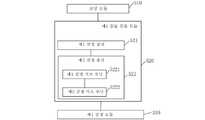
상술한 목적을 달성하기 위하여, 본 출원의 제4 측면의 실시예는 로봇 운동 계획 장치를 개시하며, 물체에 대해 충돌 정도 검출을 수행하고, 상기 장치는, 상기 물체가 위치한 현실 시나리오의 공간 모델을 로딩하는 로딩 모듈; 상기 물체와 상기 공간 모델 내의 충돌 대상에 대해 충돌 검출을 수행하는 제1 충돌 검출 모듈; 상기 물체의 충돌 민감도, 충돌 대상의 충돌 민감도를 기초로 상응한 충돌 검출의 결과에 대응되는 로봇이 상기 물체를 조작하여 형성되는 상기 로봇의 운동 계획 방안을 결정하는 제1 결정 모듈을 포함한다.In order to achieve the above object, an embodiment of the fourth aspect of the present application discloses a robot motion planning apparatus, performing collision degree detection for an object, the apparatus is configured to generate a spatial model of a real scenario in which the object is located a loading module to load; a first collision detection module configured to perform collision detection between the object and a collision object in the spatial model; and a first determination module configured to determine a motion planning method of the robot, which is formed by manipulating the object by the robot corresponding to the result of the corresponding collision detection based on the collision sensitivity of the object and the collision sensitivity of the collision object.
본 출원의 일 실시예에서, 상기 제1 충돌 검출 모듈은, 상기 물체의 충돌 모델과 충돌 대상의 대상 모델의 오버랩 정도를 결정하는 제1 결정 유닛; 오버랩 정도 및 상기 공간 모델 내의 각 모델 해상도를 기초로 상응한 충돌 대상의 충돌 정도를 결정하는 제2 결정 유닛을 포함한다.In an embodiment of the present application, the first collision detection module may include: a first determining unit configured to determine a degree of overlap between the collision model of the object and the target model of the collision target; and a second determining unit, configured to determine a collision degree of the corresponding collision object based on the overlap degree and each model resolution in the spatial model.
본 출원의 일 실시예에서, 상기 충돌 모델은 상기 공간 모델에서 제1 해상도로 상기 물체가 차지하는 공간을 분할하여 형성된 작은 큐브 집합을 포함하고, 대상 모델은 상기 공간 모델에서 제2 해상도로 상응한 충돌 대상이 차지하는 공간을 분할하여 형성된 작은 큐브 집합을 포함한다.In an embodiment of the present application, the collision model includes a small cube set formed by dividing the space occupied by the object at a first resolution in the spatial model, and the target model includes a collision corresponding to the second resolution in the spatial model. It contains a set of small cubes formed by dividing the space occupied by the object.
본 출원의 일 실시예에서, 상기 제2 결정 유닛은, 상기 충돌 모델과 대상 모델 사이의 오버랩 큐브 집합을 결정하는 제1 결정 서브 유닛; 상응한 오버랩 큐브 집합 중 각 작은 큐브로부터 상응한 모델 표면까지의 거리를 기초로 각 작은 큐브의 깊이 가중치를 결정하고, 나아가 오버랩 정도를 결합하여 상기 충돌 모델과 대상 모델의 충돌 정도를 결정하고, 여기서, 오버랩 정도는 상응한 오버랩 큐브 집합 내의 작은 큐브 수량인 제2 결정 서브 유닛을 포함한다.In an embodiment of the present application, the second determining unit includes: a first determining sub-unit for determining a set of overlapping cubes between the collision model and the target model; Determine the depth weight of each small cube based on the distance from each small cube in the set of corresponding overlapping cubes to the corresponding model surface, and further determine the degree of collision between the collision model and the target model by combining the degree of overlap, wherein , the degree of overlap includes a second determining sub-unit, which is a small cube quantity in the corresponding set of overlapping cubes.
본 출원의 일 실시예에서, 충돌 대상은 운동 계획 방안 중 상기 로봇이 상기 물체에 대해 그립핑 조작을 완성한 후로부터 배치 조작 전까지의 각 이동 경로 상의 상기 물체가 차지하는 공간과 오버랩되는 복수의 대상을 포함하고; 및/또는 충돌 대상은 상기 물체에 대해 그립핑 조작을 수행하는 과정에서의 상기 로봇의 조작 말단의 그리퍼를 포함하고; 및/또는 충돌 대상은 상기 로봇이 배치 조작을 수행하는 과정하는 과정에서 상기 물체가 배치되는 접촉 물체를 포함한다.In one embodiment of the present application, the collision object includes a plurality of objects overlapping the space occupied by the object on each movement path from after the robot completes the gripping operation on the object to before the placement operation in the motion planning method and; and/or the collision target includes a gripper at an operating end of the robot in the process of performing a gripping operation on the object; and/or the collision target includes a contact object on which the object is placed while the robot performs a placement operation.
본 출원의 실시예의 로봇 운동 계획 장치는, 로봇이 조작될 물체에 대해 조작할 때, 물체가 위치한 현실 시나리오의 공간 모델을 결합하여, 물체와 상기 공간 모델 내의 충돌 대상에 대해 충돌 검출을 수행하고, 물체의 충돌 민감도, 충돌 대상의 충돌 민감도를 기초로 상응한 충돌 검출의 결과에 대응되는 로봇이 물체를 조작하여 형성되는 로봇의 운동 계획 방안을 결정하여, 로봇이 대응되는 물체에 대해 조작할 때, 상기 운동 계획 방안을 기반으로 운동할 수 있도록 하여, 로봇이 상기 물체를 조작하는 과정에서, 로봇이 운동하는 과정에서 끊김 현상이 발생하는 것을 방지하고, 로봇의 운동을 원활하게 하며, 로봇 산업 조작의 지능화 정도를 향상시킨다.The robot motion planning apparatus of the embodiment of the present application, when the robot operates on the object to be manipulated, combines the spatial model of the real scenario in which the object is located, and performs collision detection on the object and the collision object in the spatial model, Based on the collision sensitivity of the object and the collision sensitivity of the collision object, the robot corresponding to the result of the corresponding collision detection determines the motion planning method of the robot formed by manipulating the object, and when the robot operates on the corresponding object, By making it possible to exercise based on the motion planning method, in the process of the robot manipulating the object, the interruption phenomenon is prevented from occurring in the process of the robot moving, and the movement of the robot is smoothed, and the operation of the robot industry Increase the level of intelligence.
상술한 목적을 달성하기 위하여, 본 출원의 제5 측면의 실시예는 충돌 정도 검출을 기반으로 하는 로봇 경로 계획 장치를 개시하며, 상기 장치는, 상기 로봇이 물체에 대한 그립핑 조작을 완성하였을 때, 충돌 정도 검출을 기반으로 상기 로봇에 대해 이동 경로 계획을 수행하고, 이동 경로 계획 결과에 대응되는 이동 경로를 이산화하며, 동시에 이산화 후의 각 이산 궤적 포인트를 발송하여 상기 로봇이 이동하도록 하는 제1 제어 모듈; 상기 로봇의 이동 속도를 기초로 각 이산 궤적 포인트에 대응되는 로봇 주행 시점을 결정하고, 각 주행 시점에 상기 물체에 대해 충돌 검출을 수행하는 제2 충돌 검출 모듈; 어느 시점의 충돌 정도가 상기 물체의 충돌 민감도보다 높으면 상기 로봇의 이동을 중지하여, 위험이 발생하는 것을 방지하는 제2 제어 모듈을 포함한다.In order to achieve the above object, an embodiment of the fifth aspect of the present application discloses a robot path planning device based on collision degree detection, wherein the device is configured to: when the robot completes a gripping operation on an object , a first control for performing movement path planning for the robot based on the collision degree detection, discretizing the movement path corresponding to the movement path planning result, and simultaneously sending each discrete trajectory point after discretization so that the robot moves module; a second collision detection module that determines a robot traveling time point corresponding to each discrete trajectory point based on the moving speed of the robot, and performs collision detection on the object at each traveling time point; and a second control module for stopping the movement of the robot when the collision degree at a certain point in time is higher than the collision sensitivity of the object to prevent a danger from occurring.
본 출원의 일 실시예에서, 상기 제2 충돌 검출 모듈은 구체적으로, 각 주행 시점에 상기 물체와 상기 물체가 위치한 현실 시나리오에 대응되는 공간 모델 내의 충돌 대상에 대해 충돌 검출을 수행하기 위한 것이며, 여기서, 상기 공간 모델과 각 주행 시점의 상응한 시점의 현실 시나리오 상황은 서로 대응되고; 상기 제2 제어 모듈은 구체적으로, 어느 시점의 충돌 정도가 상기 물체의 충돌 민감도 또는 충돌 대상의 충돌 민감도보다 높으면 상기 로봇의 이동을 중지한다.In an embodiment of the present application, the second collision detection module is specifically configured to perform collision detection for the object and a collision object in a spatial model corresponding to a real scenario in which the object is located at each driving time, wherein , the spatial model and the real scenario situation of the corresponding time of each driving time correspond to each other; Specifically, the second control module stops the movement of the robot when the collision degree at a certain point in time is higher than the collision sensitivity of the object or the collision sensitivity of the collision target.
본 출원의 실시예의 충돌 정도 검출을 기반으로 하는 로봇 경로 계획 장치는, 로봇이 물체에 대한 그립핑 조작을 완성하였을 때, 충돌 정도 검출을 기반으로 로봇에 대해 이동 경로 계획을 수행하고, 이동 경로 계획 결과에 대응되는 이동 경로를 이산화하며, 동시에 이산화 후의 각 이산 궤적 포인트를 발송하여 로봇이 이동하도록 하고; 로봇의 이동 속도를 기초로 각 이산 궤적 포인트에 대응되는 로봇의 주행 시점을 결정하고, 각 주행 시점에 물체에 대해 충돌 검출을 수행하고; 만약 어느 시점의 충돌 정도가 물체의 충돌 민감도보다 높으면 로봇 이동을 중지하여, 위험이 발생하는 것을 방지한다.이에 따라, 로봇 운동의 원활성을 확보하고, 충돌 정도 검출을 기반으로 하는 방식으로 로봇의 각각의 주행 시점에 물체에 대해 충돌 검출을 수행하고, 대응되는 주행 시점에 대응되는 충돌 정도가 물체의 충돌 민감도보다 높은 것으로 결정될 때, 로봇이 이동을 중지하도록 제어하여, 로봇 조작의 안전성 및 조작되는 물체의 온전성을 확보함으로써, 로봇 운동의 원활성을 확보하고, 로봇의 지능화 정도를 더욱 향상시킨다.The robot path planning apparatus based on the collision degree detection of the embodiment of the present application, when the robot completes the gripping operation on the object, performs the movement path planning for the robot based on the collision degree detection, and the movement path planning discretize the moving path corresponding to the result, and at the same time send each discrete trajectory point after discretization so that the robot moves; determining a traveling time of the robot corresponding to each discrete trajectory point based on the moving speed of the robot, and performing collision detection on the object at each traveling time; If the collision degree at any point in time is higher than the collision sensitivity of the object, the robot stops moving to prevent danger. Accordingly, the smoothness of robot movement is ensured, and the robot The collision detection is performed on the object at each driving time point, and when it is determined that the collision degree corresponding to the corresponding driving time point is higher than the collision sensitivity of the object, the robot is controlled to stop moving, so that the safety and operation of the robot are controlled. By ensuring the integrity of the object, the smoothness of the robot movement is ensured, and the degree of intelligence of the robot is further improved.
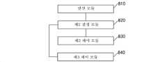
상술한 목적을 달성하기 위하여, 본 출원의 제6 측면의 실시예는 충돌 정도 검출을 기반으로 하는 로봇 그립핑 장치를 개시하며, 상기 장치는, 상기 로봇의 조작 말단의 그리퍼, 및 그립핑될 물체를 기초로, 상기 로봇이 상기 물체를 그립핑하는 모든 그립핑 위치 자세를 연산하는 연산 모듈; 상기 물체의 제1 대칭 정도, 및 상기 그리퍼와 상기 물체의 접촉점 집합의 제2 대칭 정도를 기초로, 그립핑 위치 자세에서 상기 로봇의 현재 위치 자세에 비해 변환 정도가 가장 작은 목표 위치 자세를 결정하는 제2 결정 모듈; 상기 그리퍼에 대해 충돌 정도 검출을 수행하여 현재 위치 자세로부터 상기 목표 위치 자세까지의 이동 경로를 결정하고, 상기 이동 경로를 이산화한 후의 각 궤적 포인트를 상기 로봇으로 발송하여 그립핑 조작을 완성하는 제3 제어 모듈을 포함한다.In order to achieve the above object, an embodiment of the sixth aspect of the present application discloses a robot gripping device based on collision degree detection, the device comprising: a gripper at the operating end of the robot, and an object to be gripped a calculation module for calculating all gripping positions and postures at which the robot grips the object based on ; Based on the first degree of symmetry of the object and the second degree of symmetry of a set of contact points between the gripper and the object, determining a target position and posture with the smallest degree of transformation compared to the current position and posture of the robot in the gripping position and posture a second determining module; A third method of determining a movement path from a current position and attitude to the target position and attitude by performing collision degree detection with respect to the gripper, and sending each trajectory point after discretizing the movement path to the robot to complete a gripping operation Includes control module.
본 출원의 일 실시예에서, 상기 대칭 정도는 각도값이고, 상기 물체가 상기 제1 대칭 정도에 상응한 각도값에 따라 회전한 후 회전 전과 오버랩되고, 상기 접촉점 집합이 상기 제2 대칭 정도에 대응되는 각도값을 따라 회전한 후 회전 전과 오버랩된다.In an embodiment of the present application, the degree of symmetry is an angular value, and after the object rotates according to an angle value corresponding to the first degree of symmetry, it overlaps with before rotation, and the set of contact points corresponds to the second degree of symmetry After rotating according to the angle value, it overlaps with before rotation.
본 출원의 일 실시예에서, 상기 그리퍼는 서커를 포함하고, 상기 물체는 컨테이너를 포함하고, 상기 서커의 면적이 상기 컨테이너의 그립핑될 면의 면적과 다르면, 상기 연산 모듈은 구체적으로, 상기 서커의 중심을 상기 그립핑될 면의 중심에 맞추어 상기 그립핑될 면 상에서 흡착 영역을 결정하는 것; 또는 상기 서커의 정각을 상기 그립핑될 면의 정각에 맞추어 상기 그립핑될 면 상에서 흡착 영역을 결정하는 것; 또는 상기 서커의 긴 변을 상기 그립핑될 면의 긴 변에 맞추어 상기 그립핑될 면 상에서 흡착 영역을 결정하는 것; 또는 상기 서커의 짧은 변을 상기 그립핑될 면의 짧은 변에 맞추어 상기 그립핑될 면 상에서 흡착 영역을 결정하는 것; 결정된 흡착 영역을 기초로 상기 로봇의 모든 그립핑 위치 자세를 연산하되, 여기서, 흡착 영역은 상기 그립핑될 면 상에서의 상기 컨테이너의 질량 중심의 직교 투영점을 포함한다.In an embodiment of the present application, when the gripper includes a sucker, the object includes a container, and the area of the sucker is different from the area of the gripped surface of the container, the calculation module is specifically configured to: determining an adsorption area on the gripped surface by aligning the center of the with the center of the gripped surface; or determining an adsorption area on the surface to be gripped by matching the right angle of the sucker to the right angle of the surface to be gripped; or aligning the long side of the sucker with the long side of the gripping surface to determine an adsorption area on the gripping surface; or determining an adsorption area on the gripping surface by matching the short side of the sucker with the short side of the gripping surface; Calculate all gripping positions and postures of the robot based on the determined adsorption area, wherein the adsorption area includes an orthogonal projection of the center of mass of the container on the surface to be gripped.
본 출원의 일 실시예에서, 상기 목표 위치 자세는 상기 그리퍼의 위치 및 자세를 포함하고, 상기 자세는 상기 그리퍼의 상기 물체를 향한 그립핑 방향을 포함하고; 상기 장치는, 상기 제2 결정 모듈이 그립핑 위치 자세에서 상기 로봇의 현재 위치 자세에 비해 변환 정도가 가장 작은 목표 위치 자세를 결정한 후, 상기 그리퍼의 변형 능력을 기초로 상기 그립핑 방향을 조정하여, 상기 그립핑 방향과 상기 그리퍼의 현재 방향 사이의 차이를 감소시키는 조정 모듈을 더 포함한다.In an embodiment of the present application, the target position and posture includes a position and an attitude of the gripper, and the posture includes a gripping direction of the gripper toward the object; The device, after the second determining module determines the target position and posture with the smallest degree of transformation compared to the current position and posture of the robot in the gripping position and posture, adjusts the gripping direction based on the deformability of the gripper, , further comprising an adjustment module for reducing a difference between the gripping direction and a current direction of the gripper.
본 출원의 실시예의 충돌 정도 검출을 기반으로 하는 로봇 그립핑 장치는, 로봇이 그립핑될 물체를 그립핑할 때, 로봇의 조작 말단의 그리퍼, 및 그립핑될 물체를 결합하여, 로봇이 물체를 그립핑하는 모든 그립핑 위치 자세를 연산하고, 물체의 제1 대칭 정도, 및 그리퍼와 물체의 접촉점 집합의 제2 대칭 정도를 결합하여, 그립핑 위치 자세에서 로봇의 현재 위치 자세에 비해 변환 정도가 가장 작은 목표 위치 자세를 결정하고, 및 그리퍼에 대해 충돌 정도 검출을 수행하여 현재 위치 자세로부터 목표 위치 자세까지의 이동 경로를 결정하고, 나아가 이동 경로를 이산화한 후의 각 궤적 포인트를 로봇으로 발송하여 그립핑 조작을 완성한다. 이에 따라, 충돌 정도 검출을 기반으로 로봇의 그립핑 경로의 계획을 구현하고, 충돌이 발생하는 것을 방지하는 동시에, 로봇이 획득한 그립핑 경로를 따라 물체에 대한 그립핑을 원활하게 수행할 수 있도록 함으로써, 로봇의 지능화 정도를 향상시킨다.The robot gripping device based on the collision degree detection of the embodiment of the present application combines the gripper of the operating end of the robot and the object to be gripped when the robot grips the object to be gripped, so that the robot grips the object All gripping positions and postures are calculated, and by combining the first degree of symmetry of the object and the second degree of symmetry of the set of contact points between the gripper and the object, the degree of transformation in the gripping position and posture is lower than that of the robot’s current position and posture. Determine the smallest target position and attitude, and perform collision degree detection for the gripper to determine the movement path from the current position and attitude to the target position and attitude, further discretize the movement path, and then send each trajectory point to the robot to grip Complete the ping operation. Accordingly, it is possible to implement the planning of the robot's gripping path based on the detection of the collision degree, prevent collisions from occurring, and at the same time enable the robot to smoothly grip objects along the acquired gripping path. By doing so, the degree of intelligence of the robot is improved.
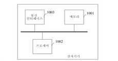
상술한 목적을 달성하기 위하여, 본 출원의 제7 측면의 실시예는 전자기기를 개시하며, 메모리, 프로세서 및 상기 메모리 상에 저장되며 상기 프로세서 상에서 실행 가능한 컴퓨터 프로그램을 포함하고, 상기 프로세서는 상기 컴퓨터 프로그램을 실행할 때 상술한 로봇 운동 계획 방법, 또는, 상술한 충돌 정도 검출을 기반으로 하는 로봇 경로 계획 방법, 또는, 상술한 충돌 정도 검출을 기반으로 하는 로봇 그립핑 방법을 구현한다.In order to achieve the above object, an embodiment of the seventh aspect of the present application discloses an electronic device, comprising a memory, a processor, and a computer program stored on the memory and executable on the processor, the processor comprising the computer When executing the program, the above-described robot motion planning method, or the robot path planning method based on the collision degree detection described above, or the robot gripping method based on the collision degree detection method described above is implemented.
상술한 목적을 달성하기 위하여, 본 출원의 제8측면의 실시예는 컴퓨터 판독 가능 저장매체를 개시하며, 컴퓨터 프로그램이 저장되어 있고, 상기 컴퓨터 프로그램은 프로세서에 의해 실행될 때 상술한 로봇 운동 계획 방법, 또는, 상술한 충돌 정도 검출을 기반으로 하는 로봇 경로 계획 방법, 또는, 상술한 충돌 정도 검출을 기반으로 하는 로봇 그립핑 방법을 구현한다.In order to achieve the above object, an embodiment of the eighth aspect of the present application discloses a computer readable storage medium, in which a computer program is stored, wherein the computer program is executed by a processor, the robot motion planning method described above; Alternatively, the robot path planning method based on the collision degree detection described above, or the robot gripping method based on the collision degree detection method described above is implemented.
본 출원의 추가적인 측면과 이점은 아래의 기재에 개시되며, 일부는 아래의 기재로부터 명확해지거나, 본 출원을 실시함으로써 파악할 수 있다.Additional aspects and advantages of the present application are disclosed in the description below, some of which will become apparent from the description below, or may be acquired by practicing the present application.
아래에서 첨부 도면을 결합하여 기재되는 실시예에 대한 설명으로부터 본 출원의 상술한 및/또는 추가적인 측면 및 이점을 더욱 명확하고 쉽게 이해할 수 있다. 여기서,
도 1a는 본 출원의 실시예에 따른 로봇 운동 계획 방법의 흐름도이다.
도 1b는 본 출원의 실시예의 이동 경로의 예시도이다.
도 1c는 본 출원의 실시예의 로봇을 나타내는 도면이다.
도 2는 물체와 공간 모델 내의 충돌 대상에 대해 충돌 검출을 수행하는 구체적인 흐름도이다.
도 3은 본 출원의 실시예에 따른 충돌 정도 검출을 기반으로 하는 로봇 경로 계획 방법의 흐름도이다.
도 4a는 본 출원의 실시예에 따른 충돌 정도 검출을 기반으로 하는 로봇 그립핑 방법의 흐름도이다.
도 4b는 간할적 접촉점 집합을 나타내는 예시도이다.
도 4c는 연속적 접촉점 집합을 나타내는 예시도이다.
도 4d는 접촉점 집합의 회전 기준점의 예시도 1이다.
도 4e는 접촉점 집합의 회전 기준점의 예시도 2이다.
도 4f는 그립핑 죠의 그립핑 위치 자세를 나타내는 예시도이다.
도 4g는 흡착 영역이 접촉점 집합을 포함하는 것을 나타내는 예시도이다.
도 5는 본 출원의 실시예에 따른 로봇 운동 계획 장치의 구성도이다.
도 6은 본 출원의 실시예에 따른 다른 로봇 운동 계획 장치의 구성도이다.
도 7은 본 출원의 실시예에 따른 충돌 정도 검출을 기반으로 하는 로봇 경로 계획 장치의 구성도이다.
도 8은 본 출원의 실시예에 따른 충돌 정도 검출을 기반으로 하는 로봇 그립핑 장치의 구성도이다.
도 9는 본 출원의 실시예에 따른 다른 충돌 정도 검출을 기반으로 하는 로봇 그립핑 장치의 구성도이다.
도 10은 본 출원의 실시예에 따른 전자기기의 구성도이다.The above and/or additional aspects and advantages of the present application may be more clearly and easily understood from the description of the embodiments described below in conjunction with the accompanying drawings. here,
1A is a flowchart of a robot motion planning method according to an embodiment of the present application.
1B is an exemplary diagram of a movement path according to an embodiment of the present application.
1C is a diagram illustrating a robot according to an embodiment of the present application.
2 is a detailed flowchart of performing collision detection on an object and a collision target in a space model.
3 is a flowchart of a robot path planning method based on collision degree detection according to an embodiment of the present application.
4A is a flowchart of a robot gripping method based on collision degree detection according to an embodiment of the present application.
4B is an exemplary diagram illustrating a set of intermittent contact points.
4C is an exemplary diagram illustrating a continuous set of contact points.
4D is an exemplary diagram 1 of a rotation reference point of a contact point set.
4E is an exemplary diagram 2 of a rotation reference point of a contact point set.
4F is an exemplary view showing the gripping position and posture of the gripping jaw.
4G is an exemplary view showing that the adsorption region includes a set of contact points.
5 is a block diagram of a robot motion planning apparatus according to an embodiment of the present application.
6 is a block diagram of another robot motion planning apparatus according to an embodiment of the present application.
7 is a block diagram of a robot path planning apparatus based on collision degree detection according to an embodiment of the present application.
8 is a block diagram of a robot gripping apparatus based on collision degree detection according to an embodiment of the present application.
9 is a block diagram of a robot gripping device based on another collision degree detection according to an embodiment of the present application.
10 is a block diagram of an electronic device according to an embodiment of the present application.
아래에서는 본 출원의 실시예에 대해 상세하게 기재하며, 상기 실시예의 예시는 첨부 도면에 나타내어지고, 여기서 동일하거나 유사한 부호는 항상 동일하거나 유사한 소자 또는 동일하거나 유사한 기능을 구비하는 요소를 나타낸다. 아래에서 첨부 도면을 참조하여 기재되는 실시예는 예시적인 것으로서, 본 출원을 해석하기 위한 것인 바, 본 출원에 대한 한정으로 이해하여서는 안된다.DETAILED DESCRIPTION OF THE PREFERRED EMBODIMENTS Embodiments of the present application will be described in detail below, examples of which are shown in the accompanying drawings, wherein the same or similar reference numerals always denote the same or similar elements or elements having the same or similar functions. The embodiments described below with reference to the accompanying drawings are illustrative and are for interpreting the present application, and should not be construed as limitations on the present application.
아래에서는 첨부 도면을 참조하여 본 출원의 실시예의 로봇 운동 계획 방법, 장치, 전자기기 및 저장매체에 대해 기재한다.Hereinafter, with reference to the accompanying drawings, a robot motion planning method, an apparatus, an electronic device and a storage medium of an embodiment of the present application will be described.
제1 측면에서는 본 출원의 로봇 운동 계획 방법에 대해 소개한다.In the first aspect, the robot motion planning method of the present application is introduced.
일부 실시예에서, 로봇 운동 계획은 충돌 정도 검출을 기반으로 하며, 충돌 정도 검출은 로봇에 의해 조작될 물체(또는 로봇의 어느 부위)에 대해 수행되는, 해당 물체가 위치한 공간 모델 내의 충돌 대상과의 충돌 검출로 정의되며, 충돌 정도 검출은, 로봇이 물체에 대해 수행하는 다양한 유형의 조작에 대응되는 로봇 운동의 기준으로서 사용되는, 물체, 충돌 대상 사이의 충돌 정도를 출력한다. 일부 실시예에서, 충돌 정도 검출은 가상 시나리오에서의 모의 시뮬레이션을 기반으로 수행할 수 있다.In some embodiments, the robot motion planning is based on collision degree detection, wherein the collision degree detection is performed on an object to be manipulated by the robot (or any part of the robot) with a collision object in a spatial model in which the object is located. It is defined as collision detection, and the collision degree detection outputs the degree of collision between an object and a collision target, which is used as a reference for robot motion corresponding to various types of manipulations performed by the robot on the object. In some embodiments, the collision degree detection may be performed based on a simulated simulation in a hypothetical scenario.
도 1은 본 출원의 실시예에 따른 로봇 운동 계획 방법의 흐름도이다. 여기서, 설명해야 할 점은, 본 실시예의 로봇 운동 계획 방법의 수행 주체는 로봇 운동 계획 장치이고, 상기 로봇 운동 계획 장치는 전자기기에 배치되고, 상기 전자기기는 로봇과 통신을 수행하여 로봇에 의해 조작될 물체(또는 로봇 자체)에 대해 충돌 정도 검출을 수행하고, 충돌 검출 결과를 기초로 로봇에 대해 운동 계획을 수행하기 위한 것이다. 여기서, 전자기기는 단말기, 서버 등을 포함할 수 있지만 이에 한정되지 않고, 본 출원은 이에 대해 한정하지 않는다. 또한, 일부 실시예에서, 로봇은 선택적으로 로봇 암과 관련되며, 로봇 암의 형태에 대해 구체적으로 한정하지 않고, 6축 로봇, 4축 로봇, 및 본 출원에 언급되지 않은 로봇 암 등에 의해 수행되는 본 출원의 관련 조작은 모두 본 발명의 보호 범위에 속한다.1 is a flowchart of a robot motion planning method according to an embodiment of the present application. Here, the point to be described is that the performing subject of the robot motion planning method of this embodiment is a robot motion planning device, the robot motion planning device is disposed in an electronic device, and the electronic device communicates with the robot by the robot. This is for performing collision degree detection on the object to be manipulated (or the robot itself), and performing motion planning for the robot based on the collision detection result. Here, the electronic device may include, but is not limited to, a terminal, a server, and the like, and the present application is not limited thereto. Further, in some embodiments, the robot is optionally associated with a robot arm, and is not specifically limited to the shape of the robot arm, but is performed by a 6-axis robot, a 4-axis robot, and a robot arm not mentioned in this application, etc. All related operations of the present application belong to the protection scope of the present invention.
선택적으로, 도 1a에 도시된 바와 같이, 상기 로봇 운동 계획 방법은 아래의 단계들을 포함할 수 있다.Optionally, as shown in FIG. 1A , the robot motion planning method may include the following steps.
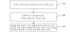
단계(101), 물체가 위치한 현실 시나리오의 공간 모델을 로딩한다.
로봇을 제어하여 물체에 대해 조작할 때, 조작될 물체와 로봇의 조작 말단을 고정시키고, 전자기기를 통해 로봇에 대해 운동 계획을 수행하여, 로봇의 운동 계획 방안을 얻을 수 있다. 계획은 전자기기 상에 장착된 로봇 운동 모의 시뮬레이션 플랫폼을 통해 수행할 수 있다. 일부 실시예에서, 운동 계획 방안은 그립핑 방안, 이동 경로 계획 방안, 배치 방안을 포함하고, 부분 실시예에서 이동 경로 계획 방안은 도 1b에 도시된 복수의 이동 경로의 선택 방안을 포함하고, 부분 실시예에서 이동 경로 계획 방안은 도 1c에 도시된 로봇 조작 과정에서의 로봇 자세 설정 방안을 포함한다.When the robot is controlled and manipulated on an object, the object to be manipulated and the manipulation end of the robot are fixed, and a motion plan is performed on the robot through an electronic device, so that a motion planning plan of the robot can be obtained. Planning can be performed through a simulation platform for simulating robot motion mounted on an electronic device. In some embodiments, the movement planning method includes a gripping method, a movement path planning method, and a placement method, and in partial embodiments, the movement path planning method includes a selection method of a plurality of movement paths shown in FIG. 1B , and in part In the embodiment, the moving path planning method includes a robot posture setting method in the robot manipulation process shown in FIG. 1C .
일부 관련 실시예에서, 물체에 대해 수행하는 로봇의 조작은 물체에 대한 그립핑 조작을 포함할 수 있고, 다른 일부 관련 실시예에서 조작은 이동 조작을 포함할 수 있고, 또 다른 관련 실시예에서 조작은 배치 조작을 포함할 수 있고; 또는, 다른 일부 실시예에서, 조작은 그립핑, 이동, 배치의 임의의 조합을 포함한다.In some related embodiments, the manipulation of the robot performed on the object may include a gripping manipulation on the object, and in some other related embodiments the manipulation may comprise a movement manipulation, and in still other related embodiments the manipulation may include a manipulation manipulation. may include batch manipulation; Or, in some other embodiments, the manipulation includes any combination of gripping, moving, and positioning.
관련 조작을 수행하기 전에, 구체적으로, 조작될 물체가 위치한 현실 시나리오의 공간 모델을 로딩할 수 있다. 일부 실시예에서, 공간 모델은 구체적으로 관련 전자기기 상의 가상 시나리오 내에서의 현실 시나리오의 구현 형태로서, 이는 현실 공간 상황을 나타낸다. 일부 선택적인 실시예에서, 공간 모델의 구체적인 형태는 특정 데이터 유형일 수 있고; 또는, 일부 선택적인 실시예에서, 공간 모델은 전자기기가 특정 데이터 유형을 렌더링하여 효과를 표시하는 것으로 구현될 수 있다. 부분 실시예에서, 공간 모델은 센서에서 수집한 현실 시나리오의 데이터를 기초로 구축된다.Before performing the relevant manipulation, specifically, the spatial model of the real scenario in which the object to be manipulated is located may be loaded. In some embodiments, the spatial model is specifically an implementation form of a real scenario in a virtual scenario on an associated electronic device, which represents a real space situation. In some optional embodiments, the specific shape of the spatial model may be a specific data type; Alternatively, in some alternative embodiments, the spatial model may be implemented as an electronic device rendering a specific data type to display the effect. In a partial embodiment, the spatial model is built based on data of real-world scenarios collected from sensors.
일부 실시예에서, 공간 모델은 현실 시나리오 상황과 고도의 대응을 유지할 수 있다. 예를 들어, 현실 시나리오에 조작 스테이지, 부재, 로봇이 포함되면, 공간 모델도 조작 스테이지, 부재, 로봇이 포함되고; 만약 현실 시나리오에 컨베이어, 부재, 물료 공급 스테이지, 로봇이 포함되면, 공간 모델도 컨베이어, 부재, 물료 공급 스테이지, 로봇이 포함하고; 만약 현실 시나리오에 컨베이어, 팔렛트, 컨테이너, 로봇이 포함되면, 공간 모델도 컨베이어, 팔렛트, 컨테이너, 로봇이 포함되고; 만약 현실 시나리오에 물료 박스, 소형 물체, 컨베이어, 로봇이 포함되면, 공간 모델도 물료 박스, 소형 물체, 컨베이어, 로봇이 포함되고; 만약 현실 시나리오가 컨베이어, 소포가 포함되면, 공간 모델도 컨베이어, 소포가 포함되며, 이와 같은 여러가지가 있다. 만약 현실 시나리오의 상황이 변경되면, 공간 모델 내의 상응한 상황도 이에 따라 변경된다. 일부 실시예에서, 변경되는 상황은 위치 변경, 자세 변경, 자체 형상 변경 등의 기타 열거되지 않은 상황을 포함할 수 있다. 일부 실시예에서, 단계(101)의 공간 모델은 로봇, 조작될 물체를 포함할 수 있다.In some embodiments, the spatial model may maintain a high degree of correspondence with real-world scenario situations. For example, if the real scenario includes the manipulation stage, member, and robot, the spatial model also includes the manipulation stage, member, and robot; If the real scenario includes a conveyor, a member, a material supply stage, and a robot, the spatial model also includes a conveyor, a member, a material supply stage, and a robot; If the real scenario includes conveyors, pallets, containers, and robots, the spatial model also includes conveyors, pallets, containers and robots; If the real scenario includes a material box, a small object, a conveyor, and a robot, the spatial model also includes a material box, a small object, a conveyor, and a robot; If the real scenario includes conveyors and parcels, the spatial model also includes conveyors and parcels, and so on. If the situation in the real scenario changes, the corresponding situation in the spatial model also changes accordingly. In some embodiments, the circumstances to be changed may include other unlisted circumstances, such as a change of location, change of posture, change of its own shape, and the like. In some embodiments, the spatial model of
선택적으로, 조작될 물체는 로봇이 조작할 수 있는 임의의 물체, 예컨대, 컨테이너, 공업 부품, 물류 소형 실체, 물류 소포, 탐지기, 글루건, 커팅 툴 등일 수 있으며, 관련 물체에 대해 충돌 검출을 수행한다. 물체는 심지어 로봇 자체의 부위일 수 있으며, 이에 따라 로봇의 각 부위에 대해 충돌 검출을 수행하여 충돌을 방지하고, 본 출원은 조작될 물체에 대해 구체적으로 한정하지 않는다.Optionally, the object to be manipulated may be any object that the robot can manipulate, such as containers, industrial parts, logistics small entities, logistics parcels, detectors, glue guns, cutting tools, etc., and performs collision detection on the relevant objects . The object may even be a part of the robot itself, and accordingly, collision detection is performed for each part of the robot to prevent collision, and the present application does not specifically limit the object to be manipulated.
일부 실시예에서, 공간 모델은 2차원 평면 모델일 수 있고, 예를 들어 현실 중 톱 뷰 각도의 평면일 수 있고, 또는 현실 중 사이드 뷰 각도의 평면일 수 있다. 대응되는 2차원의 차원은 데카르트 좌표계의 두 축으로 설명할 수 있으며, 두 축으로 예컨대 XOY, YOZ, XOZ 평면과 같은 평면을 형성한다.In some embodiments, the spatial model may be a two-dimensional planar model, for example a plane with a top view angle in reality, or a plane at a side view angle in reality. The corresponding two-dimensional dimension can be described by two axes of the Cartesian coordinate system, and the two axes form a plane such as the XOY, YOZ, and XOZ planes.
일부 경우, 공간 모델은 2차원 평면 모델의 기초 상에서 시간에 따라 변경될 수 있으며, 일부 경우 변경 내용이 상응한 시야각의 현실 시나리오 변경 내용과 서로 매칭 대응되고, 일부 경우 변경 내용이 상응한 시야각의 현실 시나리오 변경 내용 중 일부 내용과 서로 매칭 대응된다.In some cases, the spatial model may change over time on the basis of a two-dimensional planar model, in some cases the changes match and correspond to the real scenario changes of the corresponding viewing angles, and in some cases the changes correspond to the reality of the corresponding viewing angles. Some of the scenario changes are matched with each other.
일부 실시예에서, 공간 모델은 3차원 입체 모델일 수 있고, 3차원 입체 모델은 데카르트 좌표계를 통해 임의의 실제 공간점을 기준으로 하여 설명할 수 있다.In some embodiments, the spatial model may be a three-dimensional three-dimensional model, and the three-dimensional three-dimensional model may be described with reference to an arbitrary real space point through a Cartesian coordinate system.
일부 경우, 공간 모델은 3차원 입체 모델의 기초 상에서 시간에 따라 변경될 수 있고, 일부 경우 변경 내용은 현실 시나리오의 변경 내용과 서로 매칭 대응될 수 있고, 일부 경우 변경 내용은 현실 시나리오 변경 내용 중 일부 내용과 서로 매칭 대응된다.In some cases, the spatial model may change over time on the basis of the three-dimensional three-dimensional model, and in some cases, the changes may match and correspond to the changes in the real scenario, and in some cases, the changes may be part of the changes in the real scenario. The content matches each other.
선택적으로, 조작될 물체가 위치한 현실 시나리오의 공간 모델은 물체가 위치한 현실 시나리오의 시나리오 이미지를 기반으로 미리 구축된 것이다.Optionally, the spatial model of the real scenario in which the object to be manipulated is located is pre-built based on the scenario image of the real scenario in which the object is located.
여기서, 물체가 위치한 현실 시나리오의 시나리오 이미지를 기반으로 구축하는 예시적 구현 형태에 따르면, 비전 센서(예를 들어, 3차원 산업용 카메라, 지능형 산업용 카메라, 고정밀 산업용 카메라)를 사용하여 상기 현실 시나리오에 대해 이미지를 수집하고, 수집한 시나리오 이미지를 기초로, 상기 현실 시나리오의 공간 모델을 획득할 수 있다.Here, according to an exemplary implementation form for building based on a scenario image of a real scenario in which an object is located, a vision sensor (eg, a three-dimensional industrial camera, an intelligent industrial camera, a high-precision industrial camera) is used for the real scenario. Images may be collected, and a spatial model of the real scenario may be obtained based on the collected scenario images.
선택적으로, 비전 센서를 기초로 상기 현실 시나리오에 대해 이미지를 수집하고, 수집한 시나리오 이미지를 기초로, 상기 현실 시나리오의 포인트 클라우드 데이터를 획득할 수 있으며, 상기 현실 시나리오의 포인트 클라우드 데이터를 기초로, 상기 현실 시나리오의 3차원 공간 모델을 획득할 수 있다.Optionally, an image may be collected for the real scenario based on a vision sensor, and point cloud data of the real scenario may be obtained based on the collected scenario image, and based on the point cloud data of the real scenario, A three-dimensional space model of the real scenario may be obtained.
단계(102), 물체와 공간 모델 내의 충돌 대상에 대해 충돌 검출을 수행한다.In
일부 실시예에서, 충돌 대상은 물체와 충돌할 수 있는 임의의 기타 물체를 포함한다.In some embodiments, the colliding object includes any other object capable of colliding with the object.
일부 실시예에서, 충돌 검출은 물체와 충돌 대상의 거리를 기반으로 수행한다.In some embodiments, collision detection is performed based on a distance between the object and the collision target.
일부 실시예에서, 충돌 검출은 가상 시나리오 내의 모의 시뮬레이션되는 물체와 충돌 대상의 거리를 기초로 수행한다.In some embodiments, collision detection is performed based on the distance between the simulated object and the collision target in the hypothetical scenario.
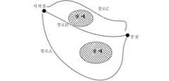
일부 실시예에서, 충돌 검출은 로봇의 복수의 운동 계획 방안을 기반으로 수행한다. 설명하면, 운동 계획 방안은 이동 방안을 포함한다. 예시적 실시예는 도 1b에 도시된 바와 같이, 만약 로봇이 물체를 그립핑하여 시작점으로부터 종점까지 이동하여야 하면, 경로 A, 경로 B, 경로 C가 운동 계획 방안의 모든 결과라고 가정하면, 물체가 경로 A를 따라 이동할 때의 방안, 물체가 경로 B를 따라 이동할 때의 방안, 물체가 경로 C를 따라 이동할 때의 방안을 기반으로, 물체와 이미지 중 장애물과의 충돌 검출을 수행하여, 각 충돌 검출 결과를 획득함으로써, 충돌 정도 검출을 완성한다. 설명해야 할 점은, 본 실시예는 가장 간단한 경우를 열거할 뿐, 실제 경우 시작점으로부터 종점까지 더 많은 운동 계획 방안이 존재할 수 있다. 다른 일부 예시적 실시예에서, 운동 계획 방안은 로봇이 일 경로를 따라 이동하는 과정에서의 각 조인트, 각 부분 기계암 및 기타 부분의 자세 변경 방안을 포함하며, 예시적으로, 부분 실시예에서 로봇은 물체를 일 시작점(또는 초기 시작점)으로부터 목표점(또는 종점)까지 이동시키고, 로봇 각 조인트의 서로 다른 회전 상태의 조합을 통해 구현할 수 있고, 로봇의 구성도는 도 1c에 도시된 바와 같을 수 있으며, 각 조인트는 주위에 표기된 화살표의 방향을 따라 회전할 수 있으며, 하나의 조합에서 각 조인트는 각각 하나의 각도에 대응되어, 조인트 간의 기계암이 일 자세를 유지하도록 하고, 복수의 조합은 복수의 자세에 대응되고, 주위에 장애물이 존재할 경우 부분 조합의 자세는 장애물과 충돌이 발생할 수 있다.In some embodiments, collision detection is performed based on a plurality of motion planning schemes of the robot. To explain, the exercise planning method includes a movement plan. An exemplary embodiment is as shown in Fig. 1b, if the robot has to grip the object and move from the start point to the end point, assuming that the paths A, B, and C are all the results of the motion planning scheme, the object is Based on the method when moving along the path A, the method when the object moves along the path B, and the method when the object moves along the path C, collision detection between the object and the obstacle in the image is performed, and each collision is detected By obtaining the result, the collision degree detection is completed. It should be noted that this embodiment only enumerates the simplest case, and in an actual case, there may be more exercise planning methods from the starting point to the ending point. In some other exemplary embodiments, the motion planning method includes a method of changing the posture of each joint, each part mechanical arm and other parts in the process of the robot moving along a path, illustratively, in the partial embodiment, the robot moves the object from one starting point (or initial starting point) to a target point (or ending point), and can be implemented through a combination of different rotational states of each joint of the robot, and the configuration diagram of the robot may be as shown in FIG. , each joint can be rotated along the direction of the arrow marked around it, and in one combination, each joint corresponds to one angle, so that the mechanical arm between the joints maintains one posture, and a plurality of combinations are Corresponds to the posture, and when there is an obstacle around, the posture of the partial combination may collide with the obstacle.
일부 실시예에서, 충돌 대상은 물체 이동 시의 임의의 장애이거나, 또는 로봇 자세 변경 과정에서의 임의의 장애일 수 있다.In some embodiments, the collision target may be any obstacle in moving the object, or any obstacle in the process of changing the robot posture.
설명적으로, 운동 계획 방안은 그립핑 방안을 포함한다. 실제 조작에서, 로봇은 서로 다른 그립핑 힘으로 물체의 각 위치에서 그립핑 또는 흡착하는 등의 방식으로 그립핑 조작을 수행하고, 서로 다른 그립핑 방안에 대응된다. 따라서, 그립핑 힘이 다른 각 그립핑 방안을 기반으로 물체와 로봇 사이의 충돌 검출을 수행하여, 각 방안의 충돌 검출 결과를 획득하여, 충돌 정도 검출을 완성한다.Illustratively, the exercise planning scheme includes a gripping scheme. In actual operation, the robot performs the gripping operation in a manner such as gripping or sucking the object at each position with different gripping forces, and corresponds to different gripping methods. Accordingly, collision detection between the object and the robot is performed based on each gripping method having a different gripping force, and a collision detection result of each method is obtained, thereby completing the collision degree detection.
설명적으로, 운동 계획 방안은 배치 방안을 포함한다. 일부 실시예에서, 로봇은 서로 다른 속도 또는 서로 다른 높이, 자세로 물체를 배치하고, 이에 따라 물체와 이에 접촉되는 물체 사이의 충돌을 초래하고, 서로 다른 배치 방안에 대응되며, 각 배치 방안을 기반으로 물체와 배치면 사이의 충돌 검출을 수행하여, 각 충돌 검출 결과를 획득함으로써, 충돌 정도 검출을 완성한다.Illustratively, an exercise planning scheme includes a deployment scheme. In some embodiments, the robot deploys objects at different speeds or at different heights and postures, thus causing collisions between the objects and objects in contact with them, corresponding to different placement schemes, and based on the respective placement schemes. The collision detection is completed by performing collision detection between the object and the placement surface and obtaining each collision detection result.
일부 실시예에서, 충돌 검출의 결과는 물체와 충돌 대상 사이의 충돌 여부로 표시될 수 있고; 또는 일부 실시예에서, 충돌 검출 결과는 물체와 충돌 대상 사이의 충돌 정도로 표시될 수 있으며, 부분 실시예는 충돌 정도가 0인 경우를 포함할 수 있다.In some embodiments, the result of collision detection may be displayed as whether or not there is a collision between the object and the collision object; Alternatively, in some embodiments, the collision detection result may be displayed as a collision degree between an object and a collision target, and partial embodiments may include a case in which the collision degree is 0.
일부 실시예에서, 물체와 충돌 대상 사이의 충돌 정도는 물체와 충돌 대상 사이의 충격력으로 표시될 수 있다; 일부 실시예에서, 물체와 충돌 대상 사이의 충돌 정도는 공간 모델 내의 물체와 충돌 대상 사이의 오버랩 정도 등으로 표시될 수 있고, 부분 실시예에서 오버랩 정도는 오버랩 면적으로 표시되고, 다른 일부 실시예에서 오버랩 정도는 오버랩 체적으로 표시된다.In some embodiments, the degree of collision between the object and the collision target may be expressed as an impact force between the object and the collision target; In some embodiments, the degree of collision between the object and the collision target may be expressed as a degree of overlap between the object and the collision target in the spatial model, etc., in partial embodiments, the degree of overlap is expressed as an overlap area, and in some other embodiments The degree of overlap is expressed by the overlap volume.
단계(103), 물체의 충돌 민감도, 충돌 대상의 충돌 민감도를 기초로 상응한 충돌 검출의 결과에 대응되는 로봇이 상기 물체를 조작하여 형성되는 로봇의 운동 계획 방안을 결정한다.In
일부 실시예에서, 충돌 민감도는 대응되는 물체 또는 충돌 대상의 충돌에 대한 견딜 수 있는 정도를 평가하기 위한 것이다.In some embodiments, the collision sensitivity is for assessing the tolerance of a corresponding object or collision object to collide.
일부 실시예에서, 충돌 민감도가 높으면 충돌에 대한 견딜 수 있는 정도가 낮으므로, 가급적으로 충돌이 없는 운동 계획 방안을 선택하여야 한다는 것을 의미하고; 충돌 민감도가 낮으면 충돌에 대한 견딜 수 있는 정도가 높으므로, 일정한 충돌이 있는 운동 계획 방안을 선택할 수 있다는 것을 의미한다. 일부 실시예에서, 충돌 민감도가 고와 저 사이인 상태이면, 상응한 견딜 수 있는 운동 방안에서, 실제 상황을 참조하여 기타 리듬, 안정도, 운동 원활도, 안전도 등의 측면에 대한 요구를 결합하여 바람직안 상응 방안을 선택할 수 있다.In some embodiments, high collision sensitivity means low collision tolerance, so preferably collision-free motion planning should be selected; Low collision sensitivity means high collision tolerance, which means that motion planning with constant collision can be selected. In some embodiments, when the collision sensitivity is between high and low, in a corresponding tolerable exercise plan, combining the requirements of other aspects of rhythm, stability, movement smoothness, safety, etc. with reference to the actual situation, It is possible to choose a preferred response plan.
일부 실시예에서, 충돌 민감도는 서로 대응되는 물체의 내충격력 임계값으로 표기할 수 있고; 일부 실시예에서, 충돌 민감도는 서로 대응되는 물체의 허용 가능한 오버랩 정도 임계값 등으로 표시되고, 부분 실시예에서 오버랩 정도 임계값은 오버랩 면적으로 표시되고, 다른 일부 실시예에서 오버랩 정도는 오버랩 체적으로 표시된다.In some embodiments, the collision sensitivity may be expressed as an impact resistance threshold value of objects corresponding to each other; In some embodiments, the collision sensitivity is expressed as an allowable degree of overlap threshold of objects corresponding to each other, etc., in partial embodiments, the degree of overlap threshold is expressed as an overlap area, and in some other embodiments, the degree of overlap is expressed as an overlap volume is displayed
일부 실시예에서, 운동 계획 방안은 로봇이 상기 물체를 조작하는 이동 궤적 정보, 이동 속도 정보, 그립핑 힘 정보, 배치 자세 정보, 및 이러한 실시예에 열거되지 않은 기타 로봇 운동학 관련 정보 등, 및 상술한 정보의 임의의 조합을 포함할 수 있다. 또는, 운동 계획 방안은 로봇이 관련 조작을 수행하는 과정에서의 각 부위 각도의 결정, 또는 그 자세의 결정을 포함할 수 있다.In some embodiments, the motion planning method may include movement trajectory information, movement speed information, gripping force information, positioning posture information, and other robot kinematics-related information not listed in these embodiments, etc., in which the robot manipulates the object, and the above It may include any combination of one information. Alternatively, the motion planning method may include the determination of the angle of each part in the process of the robot performing the related manipulation, or the determination of its posture.
본 출원의 실시예의 로봇 운동 계획 방법은, 로봇이 조작될 물체에 대해 조작할 때, 물체가 위치한 현실 시나리오의 공간 모델을 결합하여, 물체와 상기 공간 모델 내의 충돌 대상에 대해 충돌 검출을 수행하고, 물체의 충돌 민감도, 충돌 대상의 충돌 민감도를 기초로 상응한 충돌 검출의 결과에 대응되는 로봇이 물체를 조작하여 형성되는 로봇의 운동 계획 방안을 결정하여, 로봇이 대응되는 물체에 대해 조작할 때, 상기 운동 계획 방안을 기반으로 운동할 수 있도록 하여, 로봇이 상기 물체를 조작하는 과정에서, 로봇이 운동하는 과정에서 끊김 현상이 발생하는 것을 방지하고, 로봇의 운동을 원활하게 하며, 로봇 산업 조작의 지능화 정도를 향상시킨다.The robot motion planning method of the embodiment of the present application performs collision detection with respect to the object and the collision object in the spatial model by combining the spatial model of the real scenario in which the object is located when the robot operates on the object to be manipulated, Based on the collision sensitivity of the object and the collision sensitivity of the collision object, the robot corresponding to the result of the corresponding collision detection determines the motion planning method of the robot formed by manipulating the object, and when the robot operates on the corresponding object, By making it possible to exercise based on the motion planning method, in the process of the robot manipulating the object, the interruption phenomenon is prevented from occurring in the process of the robot moving, and the movement of the robot is smoothed, and the operation of the robot industry Increase the level of intelligence.
본 출원의 일부 실시예에서, 물체의 충돌 모델과 충돌 대상의 대상 모델을 기바능로 충돌 검출을 수행할 수 있으며, 본 출원의 일부 실시예에 포함되는 충돌 검출의 구체적인 구현형태는 예시적으로 도 2에 도시된 단계와 같이 수행할 수 있으며, 이래의 단계들을 포함할 수 있다.In some embodiments of the present application, collision detection may be performed using a function of a collision model of an object and a target model of a collision target, and specific implementations of collision detection included in some embodiments of the present application are illustrated by way of example. It may be performed as in the step shown in 2, and may include the following steps.
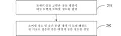
단계(201), 물체의 충돌 모델과 충돌 대상의 대상 모델의 오버랩 정도를 결정한다.In
일부 실시예에서, 충돌 모델(및/또는 대상 모델)은 전자기기 중 가상 시나리오 내에서의 물체의 구현 형태로서, 물체(및/또는 충돌 대상)의 상응한 상황을 나타낼 수 있으며, 일부 실시예에서 충돌 모델(및/또는 대상 모델)은 물체(및/또는 충돌 대상)의 형상, 위치, 자세, 운동 상태 등의 가타 물체 정보 중 어느 하나 또는 이들의 임의의 조합을 나타낼 수 있다.In some embodiments, the collision model (and/or target model) is an implementation form of an object in a virtual scenario among electronic devices, and may represent a corresponding situation of the object (and/or collision target), in some embodiments The collision model (and/or object model) may represent any one or any combination of other object information such as shape, position, posture, and motion state of the object (and/or object to be collided with).
일부 실시예에서, 충돌 모델(및/또는 대상 모델)의 구체적인 형태는 어느 일 데이터 유형일 수 있고; 또는, 일부 선택적인 실시예에서, 충돌 모델(및/또는 대상 모델)은 전자기기가 특정 데이터 유형을 렌더링하여 효과를 표시하는 것으로 구현될 수 있다.In some embodiments, the specific form of the collision model (and/or target model) may be any one data type; Alternatively, in some alternative embodiments, the collision model (and/or target model) may be implemented as an electronic device rendering a particular data type to indicate the effect.
부분 실시예에서, 충돌 모델(및/또는 대상 모델)은 센서가 수집한 현실 시나리오의 데이터를 기초로 구축된다.In some embodiments, the collision model (and/or target model) is built based on data of real-world scenarios collected by sensors.
일부 실시예에서, 충돌 모델(및/또는 대상 모델)은 2차원 평면 모델일 수 있고, 예를 들어 현실 중 톱뷰 각도의 평면일 수 있고, 또는 현실 중 사이드 뷰 각도의 평면일 수 있다. 대응되는 2차원의 차원은 데카르트 좌표계의 두 축으로 설명할 수 있으며, 두 축으로 예를 들어 XOY, YOZ, XOZ 평면과 같은 평면을 형성한다.In some embodiments, the collision model (and/or target model) may be a two-dimensional planar model, for example a real-world top view plane, or a real-world side view plane. The corresponding two-dimensional dimension can be described by two axes of the Cartesian coordinate system, and the two axes form a plane, for example, the XOY, YOZ, and XOZ planes.
일부 경우, 충돌 모델(및/또는 대상 모델)은 2차원 평면 모델의 기초 상에서 시간에 따라 변경될 수 있으며, 일부 경우 변경 내용이 상응한 시야각으로 하는 물체(및/또는 충돌 대상)의 변경 내용과 서로 매칭 대응되고, 일부 경우 변경 내용이 상응한 시야각으로 하는 물체(및/또는 충돌 대상)의 변경 내용 중 일부 내용과 서로 매칭 대응된다.In some cases, the collision model (and/or the target model) may change over time on the basis of a two-dimensional planar model, and in some cases the changes may correspond to changes in the object (and/or the collision target) with corresponding viewing angles. They match each other, and in some cases, the changes match and correspond to some of the changes of the object (and/or collision target) with the corresponding viewing angle.
일부 실시예에서, 충돌 모델(및/또는 대상 모델)은 3차원 입체 모델일 수 있고, 3차원 입체 모델은 데카르트 좌표계를 통해 물체(및/또는 충돌 대상) 상의 임의의 실제 포인트를 기준으로 하여 설명할 수 있다.In some embodiments, the collision model (and/or object model) may be a three-dimensional model, wherein the three-dimensional model is described with reference to any real point on the object (and/or object of collision) via a Cartesian coordinate system. can do.
일부 경우, 충돌 모델(및/또는 대상 모델)은 3차원 입체 모델의 기초 상에서 시간에 따라 변경될 수 있고, 일부 경우 변경 내용은 모델(및/또는 대상 모델)의 변경 내용과 서로 매칭 대응될 수 있고, 일부 경우 변경 내용은 모델(및/또는 대상 모델)의 변경 내용 중 일부 내용과 서로 매칭 대응될 수 있다.In some cases, the collision model (and/or target model) may change over time on the basis of the three-dimensional stereoscopic model, and in some cases the changes may match and correspond to changes in the model (and/or target model). And, in some cases, the change content may match and correspond to some content of the change content of the model (and/or the target model).
본 출원의 일부 실시예에서, 충돌 모델(및/또는 대상 모델)이 기하학적 모델, 삼각 패치 모델을 포함할 때, 물체의 충돌 모델과 충돌 대상의 대상 모델 표면으로 둘러싸인 공간 차지 상황을 검출함으로써, 오버랩 정도를 결정할 수 있다. 선택적으로, 공간 차지 상황은 오버랩 영역의 면적 또는 체적일 수 있다.In some embodiments of the present application, when the collision model (and/or the target model) includes a geometric model, a triangular patch model, by detecting a space occupancy situation surrounded by the collision model of the object and the target model surface of the collision target, the overlap degree can be determined. Optionally, the space occupancy situation may be the area or volume of the overlap region.
일부 실시예에서, 물체의 충돌 모델(및/또는 대상 모델)은 옥트리 모델 등의 가타 서로 유사한 데이터 형태일 수 있으며, 나아가 일부 구현형태에서 충돌 모델과 대상 모델 표면으로 둘러싸인 공간 차지 상황을 검출하여, 오버랩 정도를 연산할 수 있다.In some embodiments, the collision model (and/or target model) of the object may be in the form of other similar data such as an octree model, and further, in some implementations, by detecting a space occupancy situation surrounded by the collision model and the target model surface, The degree of overlap can be calculated.
여기서, 물체와 충돌 대상이 공간적으로 서로 많이 차지할수록, 그 대응되는 오버랩 정도가 더욱 높다.Here, the more the object and the collision target occupy each other spatially, the higher the corresponding overlapping degree.
본 출원의 일부 실시예에서, 충돌 모델은 공간 모델 중 조작될 물체 상황과 서로 매칭되는 작은 큐브 집합을 포함하고, 대상 모델은 공간 모델 중 충돌 대상 상황과 서로 매칭되는 작은 큐브 집합을 포함한다.In some embodiments of the present application, the collision model includes a small cube set matching the object situation to be manipulated in the spatial model, and the target model includes a small cube set matching the collision target situation in the spatial model.
일부 실시예에서, 오버랩 정도의 구체적은 결정 형태는, 상기 물체의 작은 큐브 집합 중의 각각의 작은 큐브에 대하여, 충돌 대상의 작은 큐브 집합에 상기 작은 큐브와 공간적으로 적어도 하나의 점이 사귀는 상응한 작은 큐브가 존재하는지 여부를 판단하고, 만약 존재하면, 상기 물체의 작은 큐브 집합 중의 상기 작은 큐브와 충돌 대상의 작은 큐브 집합 중의 상응한 작은 큐브가 충돌하는 것으로 결정하고, 물체와 충돌 대상 사이에 충돌이 발생하는 작은 큐브 수량을 통계하고, 작은 큐브 수량을 기초로, 둘 사이의 오버랩 정도를 결정하는 것을 포함한다.In some embodiments, the specific crystalline form of the degree of overlap is, for each small cube of the set of small cubes of the object, a corresponding small cube in which the small cube and at least one point spatially mate in the small cube set of the object of collision. determine whether or not exists, and if it exists, it is determined that the small cube in the small cube set of the object collides with the corresponding small cube in the small cube set of the collision target, and a collision occurs between the object and the collision target stating the small cube quantity, and determining the degree of overlap between the two based on the small cube quantity.
단계(202), 오버랩 정도 및 공간 모델 내의 각 모델 해상도를 기초로 상응한 충돌 대상의 충돌 정도를 결정한다.In
일부 실시예에서, 충돌 모델은 공간 모델에서 특정 해상도로 물체가 차지한 공간을 분할하여 형성된 화소 집합을 포함하고, 대상 모델은 공간 모델에서 다른 해상도로 상응한 충돌 대상이 차지하는 공간을 분할하여 형성된 화소 집합을 포함한다.In some embodiments, the collision model includes a set of pixels formed by partitioning a space occupied by an object at a particular resolution in a spatial model, and the target model includes a set of pixels formed by partitioning a space occupied by a corresponding collision object at a different resolution in the spatial model includes
일부 실시에서, 충돌 정도의 구체적인 결정 형태에 따르면, 충돌 모델과 대상 모델 사이의 오버랩 화소 집합을 결정하고; 상응한 오버랩 화소 집합 중 각 화소와 상응한 모델 표면의 거리를 기초로 각 화소의 깊이 가중치를 결정하고, 나아가 오버랩 정도를 결합하여 충돌 모델과 대상 모델의 충돌 정도를 결정하고, 여기서, 오버랩 정도는 상응한 오버랩 화소 집합 내의 화소 수량이다.In some implementations, according to the specific form of determining the degree of collision, a set of overlapping pixels between the collision model and the target model is determined; The depth weight of each pixel is determined based on the distance between each pixel and the corresponding model surface among the set of corresponding overlapping pixels, and further the degree of overlap is combined to determine the degree of collision between the collision model and the target model, where the degree of overlap is The number of pixels in the corresponding set of overlapping pixels.
일부 실시에서, 충돌 모델은 공간 모델에서 제1 해상도로 물체가 차지한 공간을 분할하여 형성된 작은 큐브 집합을 포함하고, 대상 모델은 공간 모델에서 제2 해상도로 상응한 충돌 대상이 차지한 공간을 분할하여 형성된 작은 큐브 집합을 포함한다.In some implementations, the collision model comprises a set of small cubes formed by partitioning the space occupied by the object at a first resolution in the spatial model, wherein the target model is formed by partitioning the space occupied by the corresponding collision object at a second resolution in the spatial model. Contains a small set of cubes.
일부 실시에서, 충돌 정도의 구체적인 구현 형태에 따르면, 충돌 모델과 대상 모델 사이의 오버랩 큐브 집합을 결정하고; 상응한 오버랩 큐브 집합 중 각 작은 큐브와 상응한 모델 표면의 거리를 기초로 각 작은 큐브의 깊이 가중치를 결정하고, 나아가 오버랩 정도를 결합하여 충돌 모델과 대상 모델의 충돌 정도를 결정하고, 여기서, 오버랩 정도는 상응한 오버랩 큐브 집합 내의 작은 큐브 수량이다.In some implementations, according to a specific implementation form of the degree of collision, a set of overlapping cubes between the collision model and the target model is determined; Determine the depth weight of each small cube based on the distance between each small cube and the corresponding model surface among the set of corresponding overlapping cubes, and further combine the overlap degree to determine the collision degree between the collision model and the target model, where the overlap The degree is the number of small cubes in the corresponding set of overlapping cubes.
여기서, 서로 다른 응용 시나리오에서, 로봇이 물체에 대해 서로 다른 조작을 수행할 수 있으며, 서로 다른 조작 시 대응되는 충돌 대상은 일반적으로 서로 다르다는 점을 이해할 수 있다. 본 출원의 일부 실시예에서, 로봇이 물체에 대해 수행하는 조작이 이동 조작을 포함할 때, 상술한 충돌 대상은 운동 계획 방안 중 로봇이 물체에 대해 그립핑 조작을 완성한 후로부터 배치 조작 전까지의 각 이동 경로 상의 물체가 차지하는 공간과 오버랩되는 복수의 대상을 포함할 수 있다.Here, it can be understood that in different application scenarios, the robot may perform different manipulations on the object, and the corresponding collision targets are generally different in the different manipulations. In some embodiments of the present application, when the operation performed by the robot on the object includes the movement operation, the above-described collision target is the angle from after the robot completes the gripping operation on the object to the placement operation during the motion planning method. It may include a plurality of objects overlapping the space occupied by the object on the movement path.
본 출원의 선택적인 실시예에서, 로봇이 물체에 대해 수행하는 조작이 그립핑 조작을 더 포함할 때, 상술한 충돌 대상은 물체에 대해 그립핑 조작을 수행하는 과정에서의 로봇의 조작 말단의 그리퍼를 더 포함할 수 있다.In an optional embodiment of the present application, when the operation performed by the robot on the object further includes a gripping operation, the above-described collision target is a gripper at the operation end of the robot in the process of performing the gripping operation on the object may further include.
본 출원의 선택적인 실시예에서, 로봇이 물체에 대해 수행하는 조작이 배치 조작을 더 포함할 때, 상술한 충돌 대상은 로봇이 배치 조작을 수행하는 과정에서 물체가 배치되는 접촉 물체를 더 포함할 수 있고, 부분 실시예에서 접촉 물체는 물체가 배치되는 순간에 접촉되는 사물, 예를 들어, 로봇이 이번 조작 전에 배치한, 이번에 배치되는 물체의 하부 또는 측부에 위치한 다른 물체, 또는 로봇에 의해 배치된 것이 아닌, 이번에 배치되는 물체의 하부 또는 측부에 위치하는 다른 물체이거나, 또는 물체가 배치되는 플랫폼 등을 포함한다.In an optional embodiment of the present application, when the operation performed by the robot on the object further includes a placement operation, the above-described collision target may further include a contact object on which the object is placed while the robot performs the placement operation. In some embodiments, the contact object is an object being touched at the moment the object is placed, eg, another object placed by the robot before this operation, located below or next to the object placed at this time, or placed by the robot It is another object that is located below or on the side of the object to be placed this time, or a platform on which the object is placed.
또는, 충돌 대상은 운동 계획 방안 중 로봇이 관련 조작을 수행할 때 로봇 자체 자세 변환 과정에서 로봇의 임의의 부위가 차지하는 공간과 오버랩되는 복수의 대상을 포함할 수 있다.Alternatively, the collision target may include a plurality of targets overlapping with a space occupied by an arbitrary part of the robot in the process of transforming the robot's own posture when the robot performs related manipulations in the motion planning method.
제2 측면에서는 본 출원의 충돌 정도 검출을 기반으로 하는 로봇 경로 계획 방법에 대해 소개한다.In the second aspect, the robot path planning method based on the collision degree detection of the present application is introduced.
도 3은 본 출원의 실시예에 따른 충돌 정도 검출을 기반으로 하는 로봇 경로 계획 방법의 흐름도이다. 여기서, 설명해야 할 점은, 본 실시예의 충돌 정도 검출을 기반으로 하는 로봇 경로 계획 방법의 수행 주체는 로봇 경로 계획 장치이고, 일부 실시예에서 상기 로봇 경로 계획 장치는 전자기기에 배치되고, 상기 전자기기는 로봇과 통신을 수행하여 로봇에 대해 이동 경로 계획을 수행하기 위한 것이다.3 is a flowchart of a robot path planning method based on collision degree detection according to an embodiment of the present application. Here, it should be explained that the subject of the robot path planning method based on the collision degree detection of this embodiment is a robot path planning device, and in some embodiments, the robot path planning device is disposed in an electronic device, and the electronic The device is for performing communication with the robot to perform movement path planning for the robot.
도 3에 도시된 바와 같이, 상기 로봇 이동 경로 계획 방법은 아래의 단계들을 포함할 수 있다.As shown in FIG. 3 , the method for planning the robot movement path may include the following steps.
단계(301), 로봇이 물체에 대한 그립핑 조작을 완성하였을 때, 충돌 정도 검출을 기반으로 로봇에 대해 이동 경로 계획을 수행하고, 이동 경로 계획 결과에 대응되는 이동 경로를 이산화하며, 동시에 이산화 후의 각 이산 궤적 포인트를 발송하여 로봇이 이동하도록 한다.In
본 출원의 선택적인 실시예에서, 로봇이 물체에 대한 그립핑 조작을 완성하였을 때, 충돌 정도 검출을 기반으로 로봇에 대해 이동 경로 계획을 수행하여 로봇의 이동 경로 계획 결과를 획득한 후, 이동 경로 계획 결과에 대응되는 이동 경로에 대해 이산화 처리를 수행하여, 각각의 이산 궤적 포인트를 획득할 수 있다.In an optional embodiment of the present application, when the robot completes the gripping operation on the object, the movement path planning is performed on the robot based on the collision degree detection to obtain the movement path planning result of the robot, and then the movement path Each discrete trajectory point may be obtained by performing discretization processing on the movement path corresponding to the planning result.
이동 경로 계획은 이동 방안 계획을 포함할 수 있다. 예시적 실시예는 도 1b에 도시된 바와 같이, 만약 로봇이 물체를 그립핑하여 시작점으로부터 종점까지 이동하여야 하면, 경로 A, 경로 B, 경로 C가 운동 계획 방안의 모든 결과라고 가정한다. 이때 부분 실시예에서, 충돌 정도 검출을 기반으로 로봇에 대해 이동 경로 계획을 수행하는 구체적인 과정은, 물체가 경로 A를 따라 이동할 때의 방안, 및 물체가 경로 B를 따라 이동할 때의 방안, 및 물체가 경로 C를 따라 이동할 때의 방안을 기반으로, 물체와 이동 과정에서의 충돌 대상, 예컨대 도 1b 중 장애와의 충돌 검출을 수행하여 각 충돌 정도를 획득함으로써, 충돌 정도 검출을 완성하는 것을 포함한다. 설명해야 할 점은, 본 실시예는 가장 간단한 하나의 경우를 열거할 뿐, 실제 경우 시작점으로부터 종점까지 더 많은 운동 계획 방안이 존재할 수 있다.The movement route plan may include a movement plan plan. The exemplary embodiment assumes that, as shown in FIG. 1B , if the robot has to grip an object to move from a starting point to an end point, path A, path B, and path C are all results of the motion planning scheme. At this time, in a partial embodiment, the specific process of performing the movement path planning for the robot based on the collision degree detection is a method when the object moves along the path A, and a method when the object moves along the path B, and the object based on the method when moving along the path C, performing collision detection with an object and a collision object in the moving process, for example, an obstacle in FIG. 1B to obtain each collision degree, thereby completing the collision degree detection . It should be noted that this embodiment only lists one simplest case, and in actual cases, there may be many more exercise planning methods from the starting point to the ending point.
다른 일부 예시적 실시예에서, 이동 경로 계획은 로봇이 일 경로를 따라 이동하는 과정에서의 각 조인트, 각 부분 기계 암 및 기타 부분 자세 변경 방안을 포함할 수 있으며, 예시적으로, 부분 실시예에서 로봇이 물체를 일 시작점(또는 초기 시작점)으로부터 목표점(또는 종점)까지 이동하며, 로봇의 각 조인트의 서로 다른 회전 상태의 조합을 통해 구현할 수 있고, 로봇의 구조도는 도 1c에 도시된 바와 같으며, 각 조인트는 주위에 표기된 화살표의 방향에 따라 회전할 수 있으며, 하나의 조합에서 각 조인트는 각각 하나의 각도에 대응되며, 이로써 조인트 간의 기계암이 일 자세를 유지하도록 하고, 복수의 조합은 복수의 자세에 대응된다. 이때 부분 실시예에서, 복수의 조합 중 로봇의 서로 다른 자세를 기반으로, 로봇의 각 부위, 예를 들어 제1 조인트, 제2 조인트, 또는 제5 조인트, 제6 조인트, 또는 각 조인트 사이의 기계암에 대해 자세 변화 이동 과정에서의 충돌 대상과의 충돌 검출을 수행하여 각 충돌 정도를 획득함으로써, 충돌 정도 검출을 완성한다.In some other exemplary embodiments, the movement path planning may include each joint, each partial machine arm and other partial posture change measures in the process of the robot moving along one path, illustratively, in the partial embodiment The robot moves an object from one starting point (or initial starting point) to a target point (or ending point), and it can be implemented through a combination of different rotational states of each joint of the robot. , each joint can be rotated according to the direction of the arrow marked around it, and in one combination, each joint corresponds to one angle, so that the mechanical arm between the joints maintains one posture, and a plurality of combinations corresponding to the posture of In this case, in a partial embodiment, based on the different postures of the robot among the plurality of combinations, each part of the robot, for example, the first joint, the second joint, or the fifth joint, the sixth joint, or a machine between each joint The collision degree detection is completed by performing collision detection with the collision target in the process of moving the arm to change the posture and obtaining each collision degree.
구체적인 충돌 검출 방법은 제1 측면에 따른 로봇 운동 계획 방법 실시예의 관련 기재를 참조할 수 있으며, 여기서는 반복되는 설명을 생략한다.For a specific collision detection method, reference may be made to the related description of the embodiment of the robot motion planning method according to the first aspect, and repeated description will be omitted herein.
구체적인 경로 이산화 과정에서 이산하는 이산 포인트는 경로의 특징점을 선택하고, 종래 기술에 따른 로봇 운동학 관련 이산화 방식을 사용하여 구현할 수 있으며, 본 출원에서는 반복되는 설명을 생략한다.In a specific path discretization process, discrete points may be implemented by selecting feature points of a path and using a discretization method related to robot kinematics according to the prior art, and repeated description will be omitted in the present application.
단계(302), 로봇의 이동 속도를 기초로 각 이산 궤적 포인트에 대응되는 로봇의 주행 시점을 결정하고, 각 주행 시점에 물체에 대해 충돌 검출을 수행한다.In
일부 실시예에서, 각 주행 시점에 물체와 물체가 위치한 현실 시나리오에 대응되는 공간 모델 내의 충돌 대상에 대해 충돌 검출을 수행하고, 여기서, 공간 모델과 각 주행 시점의 상응한 시점의 현실 시나리오 상황은 서로 대응된다.In some embodiments, collision detection is performed on the object and the collision object in the spatial model corresponding to the real scenario in which the object is located at each driving time, wherein the spatial model and the real scenario situation at the corresponding time of each driving time are mutually corresponds to
부분 실시예에서, 물체와 공간 모델 중의 충돌 대상에 대해 충돌 검출을 수행하는 관련 기재는 제1 측면의 로봇 운동 계획 방법 실시예의 관련 기재를 참조할 수 있으며, 여기서는 반복되는 설명을 생략한다.In a partial embodiment, the related description of performing collision detection on the object and the collision object in the space model may refer to the related description of the robot motion planning method embodiment of the first aspect, and repeated description is omitted herein.
여기서, 상술한 공간 모델의 구축 과정은 제1 측면의 로봇 운동 계획 방법 실시예의 관련 기재를 참조할 수 있으며, 여기서는 반복되는 설명을 생략한다.Here, for the above-described construction process of the spatial model, reference may be made to the related description of the embodiment of the robot motion planning method of the first aspect, and repeated description will be omitted here.
단계(303), 만약 어느 시점의 충돌 정도가 물체의 충돌 민감도보다 높으면 로봇의 이동을 중지하여, 위험이 발생하는 것을 방지한다.In
일부 실시예에서, 만약 어느 시점의 충돌 정도가 물체의 충돌 민감도 또는 충돌 대상의 충돌 민감도보다 높으면 로봇의 이동을 중지한다.In some embodiments, if the collision degree at a point in time is higher than the collision sensitivity of the object or the collision sensitivity of the collision target, the robot stops moving.
설명해야 할 점은, 관련 실시예에서, 충돌 정도가 충돌 민감도가 높다는 것은예시적으로 현재 충돌 정도에 대하여, 상응한 충돌 민감도의 사물이 받아들일 수 없는 것으로 이해할 수 있으며, 이에 따라 상응한 물체의 온전, 안전을 확보하기 위하여, 로봇의 이동을 중지한다.It should be explained, that in a related embodiment, that the collision degree is high in collision sensitivity can be understood as illustratively that an object of a corresponding collision sensitivity is unacceptable with respect to the current collision degree, and accordingly, In order to ensure integrity and safety, the movement of the robot is stopped.
충돌 민감도의 관련 기재는 제1 측면의 로봇 운동 계획 방법 실시예의 관련 기재를 참조할 수 있으며, 여기서는 반복되는 설명을 생략한다.For the related description of the collision sensitivity, reference may be made to the related description of the embodiment of the robot motion planning method of the first aspect, and repeated description is omitted herein.
다시 말하면, 본 실시예에서, 로봇이 물체에 대해 이동 조작을 수행하는 과정에서, 로봇의 각 주행 시점에 대하여, 각 주행 시점에 물체에 대해 충돌 검출을 수행하고, 충돌 검출 결과를 기초로 로봇의 이동 조작 과정에 대해 제어하여, 상기 충돌 과정을 기반으로 로봇에 대해 이동 경로 계획을 수행하는 방법을 제공하여, 로봇의 지능화 정도를 향상시킨다.In other words, in the present embodiment, in the process of the robot performing a movement operation on the object, for each traveling time of the robot, collision detection is performed for the object at each traveling time, and based on the collision detection result, the robot By controlling the movement manipulation process and providing a method of performing movement path planning for the robot based on the collision process, the degree of intelligence of the robot is improved.
본 출원의 실시예의 충돌 정도 검출을 기반으로 하는 로봇 경로 계획 방법은, 로봇이 물체에 대한 그립핑 조작을 완성하였을 때, 충돌 정도 검출을 기반으로 로봇에 대해 이동 경로 계획을 수행하고, 이동 경로 계획 결과에 대응되는 이동 경로를 이산화하며, 동시에 이산화 후의 각 이산 궤적 포인트를 발송하여 로봇이 이동하도록 하고; 로봇의 이동 속도를 기초로 각 이산 궤적 포인트에 대응되는 로봇 주행 시점을 결정하고, 각 주행 시점에 물체에 대해 충돌 검출을 수행하고; 만약 어느 시점의 충돌 정도가 물체의 충돌 민감도보다 높으면 로봇 이동을 중지하여, 위험이 발생하는 것을 방지한다. 이에 따라, 로봇 운동의 원활성을 확보하고, 충돌 정도 검출을 기반으로 하는 방식으로 로봇의 각각의 주행 시점에 물체에 대해 충돌 검출을 수행하고, 대응되는 주행 시점에 대응되는 충돌 정도가 물체의 충돌 민감도보다 높은 것으로 결정될 때, 로봇이 이동을 중지하도록 제어하여, 로봇 조작의 안전 및 조작되는 물체의 온전성을 확보하여, 로봇 운동의 원활성을 확보하고, 로봇의 지능화 정도를 더욱 향상시킨다.In the robot path planning method based on the collision degree detection of the embodiment of the present application, when the robot completes the gripping operation on the object, the moving path planning is performed for the robot based on the collision degree detection, and the moving path planning is performed discretize the moving path corresponding to the result, and at the same time send each discrete trajectory point after discretization so that the robot moves; determining a robot running time corresponding to each discrete trajectory point based on the moving speed of the robot, and performing collision detection on an object at each running time point; If the collision degree at any point in time is higher than the collision sensitivity of the object, the robot stops moving to prevent danger. Accordingly, the smoothness of robot movement is ensured, and collision detection is performed on the object at each driving time point of the robot in a manner based on collision degree detection, and the collision degree corresponding to the corresponding driving time point is determined by the collision of the object. When it is determined that the sensitivity is higher than the sensitivity, the robot is controlled to stop moving, thereby ensuring the safety of robot operation and the integrity of the manipulated object, ensuring smoothness of robot movement, and further improving the degree of intelligence of the robot.
제3 측면에서는 본 출원의 충돌 정도 검출을 기반으로 하는 로봇 그립핑 방법에 대해 소개한다.In the third aspect, a robot gripping method based on the collision degree detection of the present application will be introduced.
도 4a는 본 출원의 실시예에 따른 충돌 정도 검출을 기반으로 하는 로봇 그립핑 방법의 흐름도이다. 여기서, 설명해야 할 점은, 본 실시예의 충돌 정도 검출을 기반으로 하는 로봇 그립핑 방법의 수행 주체는 충돌 정도 검출을 기반으로 하는 로봇 그립핑 장치이고, 상기 충돌 정도 검출을 기반으로 하는 로봇 그립핑 장치는 전자기기에 배치되고, 상기 전자기기는 로봇과 통신을 수행하여 로봇에 대해 그립핑 방안 계획을 수행하기 위한 것이다.4A is a flowchart of a robot gripping method based on collision degree detection according to an embodiment of the present application. Here, it should be explained that the subject performing the robot gripping method based on the collision degree detection of this embodiment is a robot gripping device based on the collision degree detection, and robot gripping based on the collision degree detection The device is disposed in an electronic device, and the electronic device is configured to communicate with the robot to perform a gripping plan plan for the robot.
도 4a에 도시된 바와 같이, 상기 충돌 정도 검출을 기반으로 하는 로봇 그립핑 방법은 아래의 단계들을 포함할 수 있다.As shown in FIG. 4A , the robot gripping method based on the collision degree detection may include the following steps.
단계(401), 로봇의 조작 말단의 그리퍼, 및 그립핑될 물체를 기초로, 로봇이 물체를 그립핑하는 모든 그립핑 위치 자세를 연산한다.Based on the
설명적으로, 실제 응용에서 로봇이 그립핑 조작을 수행하여야 하고, 로봇 조작 말단(즉, 로봇 조작 단의 조인트각)은 그리퍼와 고정되고, 그리퍼는 물체를 그립핑하기 위한 것이다.Illustratively, in actual application, the robot should perform a gripping operation, and the robot operating end (ie, the joint angle of the robot operating end) is fixed with the gripper, and the gripper is for gripping the object.
일부 실시예에서, 상술한 그리퍼는 핑거, 클램프, 또는 서커, 또는 그 조합 등을 포함할 수 있으며, 물체를 획득하여, 물체가 로봇을 따라 관련 이동을 수행하거나, 관련 조작을 수행하도록 하기 위한 것이다.In some embodiments, the gripper described above may include a finger, clamp, or sucker, or a combination thereof, etc., for acquiring an object, such that the object performs a relevant movement along the robot, or performs an associated manipulation .
일부 구체적인 실시예에서, 물체 실제 형상, 실제 사이즈, 실제 중량을 참고하여 그립핑 포인트(및/또는 그립핑 힘)을 결정하고, 상응한 그리퍼 중류를 매칭시킨다.In some specific embodiments, the gripping point (and/or gripping force) is determined with reference to the actual shape, actual size, and actual weight of the object, and the corresponding gripper midstream is matched.
일부 실시예에서, 물체 위치 자세, 및 그리퍼 종류를 기초로 모든 그립핑 위치 자세를 결정할 수 있다. 그립핑 위치 자세는 바로 그립핑 위치 및 자세이다.In some embodiments, all gripping positions and postures may be determined based on the object position and posture, and the gripper type. The gripping position and posture is the gripping position and posture.
단계(402), 물체의 제1 대칭 정도, 및 그리퍼와 물체의 접촉점 집합의 제2 대칭 정도를 기초로, 그립핑 위치 자세에서 로봇의 현재 위치 자세에 비해 변환 정도가 가장 작은 목표 위치 자세를 결정한다.In
부분 실시예에서, 물체(및/또는 접촉점 집합)는 대칭성을 구비하므로, 로봇의 모든 그립핑 위치 자세에 포함된 서로 다른 그립핑 위치 자세는 동일한 그립핑 효과를 달성할 수 있다. 예시적 실시예는 도 4f에 도시된 바와 같이, 그립핑 죠의 두 그립핑 위치 자세는, 즉 그립핑 핑거의 좌우 순서가 상이하며, 모두 두 그립핑 핑거가 그립핑 접촉점 A, B 상에 닿도록 하여, 동일한 그립핑 효과를 달성할 수 있다. 부분 보다 바람직한 실시예에서, 대칭 정도를 기초로, 그립핑 죠의 복수의 그립핑 위치 자세로부터 현재 위치 자세와 유사하거나, 또는 이동이 더욱 원활한 목표 위치 자세를 선택하여 그립핑 조작을 수행함으로써, 로봇 운동의 원활성에 유리하고, 로봇 지능화 정도를 향상시킨다.In a partial embodiment, the object (and/or set of contact points) has symmetry, so that different gripping positions and postures included in all gripping positions and postures of the robot can achieve the same gripping effect. In the exemplary embodiment, as shown in FIG. 4F , the two gripping positions and postures of the gripping jaws, that is, the left and right order of the gripping fingers are different, and both gripping fingers touch the gripping contact points A and B. to achieve the same gripping effect. In a more preferred embodiment, on the basis of the degree of symmetry, the robot performs a gripping operation by selecting a target position and posture similar to the current position and posture from a plurality of gripping positions and postures of the gripping jaw, or a target position and posture in which movement is smoother. It is beneficial to the smoothness of movement and improves the degree of robot intelligence.
일부 실시예에서, 대칭 정도는 대칭성의 정도를 포함하고, 만약 하나의 사물 본체가 이에 의해 구획된 범위 내를 관통하는 어느 방향 벡터를 따라 미러 이미지를 형성하면 이는 대칭성을 구비한다고 지칭하며; 만약 하나의 대칭성 사물 본체가 이에 의해 구획된 범위 내를 관통하는 복수의 방향 벡터를 따라 모두 미러 이미지를 형성할 수 있으면 그 대칭 정도가 높다고 하며, 간단한 예시적 예를 들면 예컨대 원형, 구형을 들 수 있고; 만약 하나의 대칭성 사물 본체가 개별 벡터를 따라 미러 이미지를 형성할 수 있으면 그 대칭 정도가 낮다고 하며, 간단 예시적 예를 들면 예컨대 직사각형, 직육면체를 들 수 있으며; 한편, 예컨대 정삼각형, 정사각형, 정육각형 등의 각 변이 동일한 다각형은, 그 본체가 미러 이미지를 형성함에 있어서 참고할 수 있는 방향 벡터 수량을 기초로 상응하게 그 대칭 정도를 결정한다.In some embodiments, the degree of symmetry includes a degree of symmetry, and if an object body forms a mirror image along a certain direction vector passing through a range defined by it, it is said to have symmetry; If a single symmetrical object body can form mirror images all along a plurality of direction vectors passing through the range partitioned by this, the degree of symmetry is said to be high. there is; If a single symmetrical object body can form a mirror image along an individual vector, the degree of symmetry is said to be low, and simple illustrative examples include, for example, a rectangle and a rectangular parallelepiped; On the other hand, for example, a polygon having the same sides, such as an equilateral triangle, a square, and a regular hexagon, correspondingly determines the degree of symmetry based on the quantity of direction vectors that the body can refer to when forming a mirror image.
일부 실시예에서, 대칭 정도는 대칭성의 정도를 포함하고, 만약 하나의 사물 본체가 이에 의해 구획된 범위 내의 어느 하나의 회전 기준점을 따라 0°, 또는 360° 회전하여야 회전 전과 오버랩될 수 있으면, 그 대칭 정도가 낮다고 하고; 만약 어느 하나의 사물 본체가 이에 의해 구획된 범위 내의 어느 일 회전 기준점을 따라 임의의 각도만큼 회전하여도 회전 전과 오버랩될 수 있으면, 그 대칭 정도가 높다고 하고; 만약 어느 하나의 사물 본체가 이에 의해 구획된 어느 하나의 회전 기준점을 따라 회전하는 각도가 작을수록(0° 제외) 회전 전과 오버랩될 수 있으면, 그 대칭 정도가 더욱 높다고 한다. 보다 바람직한 실시예에서, 회전 기준점은 상응한 범위 내의 중심점을 포함하고, 선택적으로 질량 중심을 포함할 수 있다. 부분 실시예에서, 회전 기준점은 상응한 범위의 관찰 시야각의 평면 중심점인 바, 예시적으로 구체의 톱뷰 시야각에 대응되는 원의원심, 링 축방향 시야각 중심 등을 들 수 있으며; 부분 실시예에서, 회전점은 물체 3차원 입체 구조의 중심점인 바, 예를 들어 구체의 중심점, 직육면체 중심점을 들 수 있다.In some embodiments, the degree of symmetry includes a degree of symmetry, if one object body must rotate 0° or 360° along any one rotation reference point within the range partitioned thereby to overlap with before rotation, the The degree of symmetry is said to be low; If any one object body rotates by an arbitrary angle along any one rotation reference point within the range partitioned thereby and overlaps with that before rotation, it is said that the degree of symmetry is high; If the rotation angle of any one object body along any one rotation reference point partitioned thereby is small (except 0°), and overlaps with the previous rotation, the degree of symmetry is said to be higher. In a more preferred embodiment, the rotation reference point includes a center point within a corresponding range, and may optionally include a center of mass. In a partial embodiment, the rotation reference point is the plane center point of the viewing angle of the corresponding range, for example, a distal centrifugal, ring axial viewing angle center, etc. corresponding to the top view viewing angle of the sphere; In a partial embodiment, the rotation point is the center point of the three-dimensional structure of the object, for example, a center point of a sphere or a center point of a cuboid.
일부 실시예에서, 상술한 대칭 정도는 각도값으로 표시되고, 이에 따라 물체는 제1 대칭 정도에 상응한 각도값을 따라 회전한 후 회전 전과 오버랩되고, 접촉점 집합은 제2 대칭 정도에 상응한 각도값에 따라 회전한 후 회전 전과 오버랩된다.In some embodiments, the aforementioned degree of symmetry is expressed as an angular value, whereby the object rotates along an angle value corresponding to the first degree of symmetry and overlaps with before rotation, and the set of contact points is an angle corresponding to the second degree of symmetry After rotation according to the value, it overlaps with before rotation.
여기서, 상술한 위치 자세는 위치 및 자세를 포함한다.Here, the position and posture described above includes a position and a posture.
부분 실시예에서, 물체 대칭성은 그 질량 분포 대칭성을 포함하고, 다른 일부 실시예에서, 물체 대칭성은 물체 형태 대칭성을 포함한다.In partial embodiments, the object symmetry includes its mass distribution symmetry, and in some other embodiments, the object symmetry includes an object shape symmetry.
부분 실시예에서의 접촉점 집합은 연속적인 것일 수 있고; 또는, 다른 일부 실시예에서의 접촉점 집합은 간헐적인 것일 수 있다. 간단한 예시적 실시예를 들면 아래와 같이, 간할적 접촉점 집합의 예시적 실시예는 도 4b 중 각종 물체 각각의 상응한 포인트 A, 포인트 B로 구성된 경우를 참조할 수 있다. 연속적 접촉점 집합의 예시적 실시예는 도 4c 중 각 물체 상의 짙은 음영으로 표기된 부분을 참조할 수 있다.The set of contact points in partial embodiments may be continuous; Alternatively, the contact point set in some other embodiments may be intermittent. For a simple exemplary embodiment, as follows, an exemplary embodiment of a set of intermittent contact points may refer to a case in which the corresponding points A and B of various objects are configured in FIG. 4B . An exemplary embodiment of a set of continuous contact points may refer to a portion indicated by a dark shade on each object in FIG. 4C .
부분 실시예에서, 접촉점 집합의 대칭 정도는 도 4d - 도 4e에 도시된 바와 같을 수 있다. 도 4 중 접촉점 집합이 회전 기준점을 따라 90° 회전하면 회전 전과 오버랩될 수 있으며, 도 4e 중 접촉점 집합이 회전 기준점을 따라 180° 회전하면 회전 전과 오버랩될 수 있으며, 상대적으로 말하면, 도 4d에 도시된 접촉점 집합 대칭 정도가 도 4e에 도시된 접촉점 집합 대칭 정도보다 크다.In a partial embodiment, the degree of symmetry of the set of contact points may be as shown in FIGS. 4D-4E . When the set of contact points in FIG. 4 rotates 90° along the rotation reference point, it may overlap with the previous rotation, and when the contact point set in FIG. 4e rotates 180° along the rotation reference point, it may overlap with before rotation, relatively speaking, as shown in FIG. 4D The degree of symmetry of the contact point set is greater than the degree of symmetry of the contact point set shown in FIG. 4E .
일부 실시예에서, 물체를 그립핑하는 과정에서, 로봇 각 조인트각이 최소로 회전하도록 하기 위하여, 로봇이 물체를 그립핑하는 모든 그립핑 위치 자세를 획득한 후, 물체의 제1 대칭 정도, 및 그리퍼와 물체의 접촉점 집합의 제2 대칭 정도를 결합하여, 모든 그립핑 위치 자세에서, 로봇의 현재 위치 자세에 비해 변환 정도가 가장 작은 목표 위치 자세를 결정할 수 있다.In some embodiments, in the process of gripping the object, the first degree of symmetry of the object, after the robot acquires all the gripping position postures for gripping the object, so as to minimize the rotation of each joint angle of the robot, and By combining the second degree of symmetry of the set of contact points between the gripper and the object, it is possible to determine a target position and posture having the smallest degree of transformation compared to the current position and posture of the robot in all gripping positions and postures.
단계(403), 그리퍼에 대해 충돌 정도 검출을 수행하여 현재 위치 자세로부터 목표 위치 자세까지의 이동 경로를 결정하고, 나아가 이동 경로를 이산화한 후의 각 궤적 포인트를 로봇으로 발송하여 그립핑 조작을 완성한다.In
본 출원의 상응한 실시예에서, 충돌 정도 검출을 기반으로 로봇 그립핑 방안을 결정하며, 로봇의 현재 위치 자세와 목표 위치 자세를 획득한 후, 그리퍼에 대해 충돌 정도 검출을 수행하여 허용 가능한 충돌 정도 내에서 그립핑 방안을 선택함으로써, 선택 가능한 방안 수량을 증가하고, 선택 가능한 방안에 원활한 구현 가능한 그립핑 방안이 포함될 가능성이 향상되도록 하고, 로봇 이동의 원활성을 어느 정도 향상시켜 특이점 발생 활률을 낮추며 이에 따라 로봇의 지능화 정도를 향상시킨다. 또한, 상술한 목표 위치 자세는 대칭 정도를 기반으로 결정되며, 이는 선택 가능한 방안의 수량을 더욱 증가시켜, 원활한 이동에 상대적으로 유리한 목표 위치 자세를 결정하도록 로봇을 보조하여, 그립핑 조작에 사용함으로써, 로봇 이동의 원활 정도를 더욱 향상시키고, 로봇의 지능화 정도를 더욱 향상시킨다.In a corresponding embodiment of the present application, the robot gripping method is determined based on the collision degree detection, and after acquiring the robot's current position and target position and posture, the collision degree detection is performed on the gripper to allow the collision degree to be tolerated By selecting a gripping method within Accordingly, the degree of intelligence of the robot is improved. In addition, the above-described target position and posture is determined based on the degree of symmetry, which further increases the number of selectable measures, assisting the robot to determine a target position and posture relatively advantageous for smooth movement, and using it for gripping operation. , further improve the smoothness of robot movement, and further improve the degree of intelligence of the robot.
여기서, 공간 모델은 그리퍼가 위치한 현실 시나리오에 대응되는 공간 모델이다.Here, the space model is a space model corresponding to the real scenario in which the gripper is located.
부분 실시예에서, 그리퍼에 대해 충돌 정도 검출을 수행하여 현재 위치 자세로부터 목표 위치 자세까지의 이동 경로를 결정하는 구체적인 구현 형태에 따르면, 로봇의 현재 위치 자세로부터 목표 위치 자세까지의 복수의 후보 이동 경로를 획득하고, 각각의 후보 이동 경로에 대하여, 그리퍼에 대해 충돌 정도 검출을 수행하여, 각각의 후보 이동 경로에 대응되는 충돌 검출 결과를 획득하고, 충돌 검출 결과 중 그립핑 죠(및/또는 충돌 대상)가 견딜 수 있는 충돌 정도에 대응되는 후보 이동 경로를 현재 위치 자세로부터 목표 위치 자세까지의 이동 경로로서 선택하고, 상기 이동 경로를 로봇으로 발송하여 그립핑 조작을 완성한다.In a partial embodiment, according to a specific implementation form for determining the movement path from the current position and posture by performing collision degree detection on the gripper, a plurality of candidate movement paths from the current position and posture of the robot to the target position and posture , and for each candidate movement path, collision degree detection is performed on the gripper to obtain a collision detection result corresponding to each candidate movement path, and among the collision detection results, the gripping jaw (and/or collision target) ) is selected as a movement path from the current position and posture to the target position and posture, and the moving path is sent to the robot to complete the gripping operation.
본 출원의 부분 실시예에서, 상술한 그리퍼는 서커를 포함하고, 상술한 물체는 컨테이너를 포함한다.In a partial embodiment of the present application, the aforementioned gripper comprises a sucker and the aforementioned object comprises a container.
부분 실시예에서, 서커는 어레이 형태로 배열되어, 작사각형 면적의 서커를 형성한다.In a partial embodiment, the suckers are arranged in an array, forming a sucker of rectangular area.
부분 실시예에서, 서커의 면적과 컨테이너의 그립핑될 면의 면적이 동일한 지 여부를 판단하고, 만약 서커 면적이 컨테이너의 그립핑될 면의 면적과 다르면, 상술한 로봇의 그립핑 위치 자세는 후술하는 방식으로 결정할 수 있다.In a partial embodiment, it is determined whether the area of the sucker and the area of the gripping surface of the container are the same, and if the sucker area is different from the area of the gripping surface of the container, the gripping position and posture of the robot described above will be described later. you can decide how
방식 1: 서커의 중심을 그립핑될 면의 중심에 맞추어 그립핑될 면 상에서 흡착 영역을 결정한다; 또는 방식 2: 서커의 정각을 그립핑될 면의 정각에 맞추어 그립핑될 면 상에서 흡착 영역을 결정한다; 또는 방식 3: 서커의 긴 변을 그립핑될 면의 긴 변에 맞추어 그립핑될 면 상에서 흡착 영역을 결정한다; 또는 방식 4: 서커의 짧은 변을 그립핑될 면의 짧은 변에 맞추어 그립핑될 면 상에서 흡착 영역을 결정한다. 상술한 방식을 기초로 흡착 영역을 결정한 후, 결정된 흡착 영역을 기초로 로봇의 모든 그립핑 위치 자세를 연산하며, 여기서, 흡착 영역은 그립핑될 면 상에서의 컨테이너의 질량 중심의 직교 투영점을 포함한다.Method 1: Align the center of the sucker with the center of the face to be gripped to determine the suction area on the face to be gripped; or method 2: determine the suction area on the gripping surface by matching the right angle of the sucker with the right angle of the gripping surface; or Method 3: Matching the long side of the sucker with the long side of the surface to be gripped to determine the suction area on the surface to be gripped; or Method 4: Match the short side of the sucker with the short side of the side to be gripped to determine the suction area on the side to be gripped. After determining the adsorption area based on the above-described method, all gripping positions and postures of the robot are calculated based on the determined adsorption area, wherein the adsorption area includes an orthogonal projection point of the center of mass of the container on the surface to be gripped do.
부분 실시예에서, 그립핑될 면은 컨테이너의 톱뷰 면을 포함하거나, 또는 다른 일부 실시예에서, 그립핑될 면은 컨테이너의 사이드뷰 면을 포함한다.In partial embodiments, the face to be gripped comprises a top view face of the container, or in some other embodiments the face to be gripped comprises a side view face of the container.
부분 실시예에서, 흡착 영역은 접촉점 집합을 포함하고, 예시적으로 도 4g에 도시된 바와 같다.In a partial embodiment, the adsorption zone comprises a set of contact points, illustratively as shown in FIG. 4G .
부분 실시예에서, 서커는 어레이 형태로 배열되어, 직사각형 면적 서커를 형성하고, 서커의 정각은 직사각형 면적 서커의 정각을 포함하고, 부분 실시예에서 서커의 긴 변은 직사각형 면적 서커의 긴 변을 포함하고, 부분 실시예에서 서커의 짧은 변은 직사각형 면적 서커의 짧은 변을 포함한다.In a partial embodiment, the suckers are arranged in an array to form a rectangular area sucker, the regular angle of the sucker comprises a regular angle of the rectangular area sucker, and in partial embodiments the long side of the sucker comprises the long side of the rectangular area sucker and, in partial embodiments, the short side of the sucker comprises the short side of the rectangular area sucker.
부분 실시예에서, 서커는 어레이 형태로 배열되어, 직사각형 면적 서커를 형성하고, 서커의 면적은 그립핑될 면보다 크며, 이때 서커의 긴 변은 직사각형 면적 서커의, 직사각형 면적 서커 내부를 향해 평행 이동하여 한 줄의 서커를 가로지르는 긴 변을 포함하고; 서커의 짧은 변은 직사각형 면적 서커의, 직사각형 면적 서커 내부를 향해 평행 이동하여 한 줄의 서커를 가로지르는 짧은 변을 포함하고; 서커의 정각은 평행 이동 후 긴 변과 짧은 변으로 형성되는 정각을 포함한다. 물론 부분 실시예에서, 서커 어레이 범위 내에서 평행 이동하여 두 줄, 심지어 복수의 줄의 서커를 가로지를 수 있다. 부분 실시예에서, 긴 변, 짧은 변이 가로지르는 줄 수량은 서로 다를 수 있다.In a partial embodiment, the suckers are arranged in an array to form a rectangular area sucker, the area of the sucker being greater than the face to be gripped, wherein the long side of the sucker moves in parallel towards the interior of the rectangular area sucker of the rectangular area sucker including a long side that crosses a row of suckers; the short side of the sucker comprises a short side of the rectangular area sucker that crosses a row of the sucker by translating into the interior of the rectangular area sucker; Sucker's regular angle includes a regular angle formed by a long side and a short side after translation. Of course, in some embodiments, it is possible to traverse two or even multiple rows of suckers by translating within the range of the sucker array. In partial embodiments, the number of lines crossed by the long side and the short side may be different from each other.
부분 실시예에서, 상술한 목표 위치 자세는 그리퍼의 위치 및 자세를 포함할 수 있으며, 상술한 자세는 그리퍼가 물체를 향하는 그립핑 방향을 포함하고, 본 출원의 부분 실시예에서, 그리퍼는 정방향으로 물체를 향하여 그립핑 조작을 완성하며, 구체적으로 그리퍼는 그립핑될 물체의 그립핑될 면의 법선 방향을 따라 물체를 그립핑하고; 또는 일부 실시예에서, 로봇의 그리퍼가 그립핑될 물체를 쉽게 그립핑할 수 있도록 하기 위하여, 그리퍼가 그립핑될 물체의 그립핑될 면의 법선 방향과 편향되도록 할 수 있으며, 구체적으로 그립핑 위치 자세에서 로봇의 현재 위치 자세에 비해 변환 정도가 가장 작은 목표 위치 자세를 결정한 후, 그리퍼의 형상 변형 능력을 기초로 그립핑 방향을 조정하여, 그립핑 방향과 그리퍼의 현재 방향 사이의 차이를 더욱 줄임으로써, 원활한 이동에 더욱 유리한 목표 위치 자세를 결정하도록 로봇을 보조하여, 그립핑 조작에 사용함으로써, 로봇 이동의 원활 정도를 더욱 향상시키고, 로봇의 지능화 정도를 더욱 향상시킬 수 있다.In a partial embodiment, the above-described target position and posture may include the position and posture of the gripper, the above-described posture includes a gripping direction in which the gripper faces the object, and in a partial embodiment of the present application, the gripper is positioned in the forward direction to complete the gripping operation toward the object, specifically, the gripper grips the object along the normal direction of the gripped surface of the object to be gripped; Alternatively, in some embodiments, in order for the gripper of the robot to easily grip the object to be gripped, the gripper may be deflected from the normal direction of the gripped surface of the object to be gripped, specifically the gripping position After determining the target position and posture with the smallest degree of transformation compared to the robot’s current position and posture, the gripping direction is adjusted based on the shape deformation ability of the gripper to further reduce the difference between the gripping direction and the current direction of the gripper Thus, by assisting the robot to determine a target position and posture more advantageous for smooth movement and using it for gripping operation, it is possible to further improve the degree of smooth movement of the robot and further improve the degree of intelligence of the robot.
본 출원의 부분 실시예에서, 변형 능력을 기반으로 하는 그리퍼를 통해 그립핑될 물체에 대해 그립핑 조작을 수행함으로써, 로봇이 그리퍼를 통해 그립핑될 물체를 그립핑할 때, 로봇의 그리퍼의 방향이 그립핑 표면의 법선 방향에 잘 맞춰질 필요가 없도록 하여, 목표 위치 자세가 초기 위치 자세에 더욱 유사하도록 하므로, 로봇의 지능화 정도를 더욱 향상시킨다.In a partial embodiment of the present application, when the robot grips the object to be gripped through the gripper by performing a gripping operation on the object to be gripped through the gripper based on the deformability, when the robot grips the object to be gripped through the gripper, the direction of the gripper of the robot It does not need to be well aligned with the normal direction of the gripping surface, so that the target position and posture is more similar to the initial position and posture, which further improves the degree of intelligence of the robot.
본 출원의 실시예의 충돌 정도 검출을 기반으로 하는 로봇 그립핑 방법은, 로봇이 그립핑될 물체를 그립핑할 때, 로봇의 조작 말단의 그리퍼, 및 그립핑될 물체를 결합하여, 로봇이 물체를 그립핑하는 모든 그립핑 위치 자세를 연산하고, 물체의 제1 대칭 정도, 및 그리퍼와 물체의 접촉점 집합의 제2 대칭 정도를 결합하여, 그립핑 위치 자세에서 로봇의 현재 위치 자세에 비해 변환 정도가 가장 작은 목표 위치 자세를 결정하고, 및 그리퍼에 대해 충돌 정도 검출을 수행하여 현재 위치 자세로부터 목표 위치 자세까지의 이동 경로를 결정하고, 나아가 이동 경로를 이산화한 후의 각 궤적 포인트를 로봇으로 발송하여 그립핑 조작을 완성한다. 이에 따라, 충돌 정도 검출을 기반으로 로봇의 그립핑 경로에 대한 계획을 구현하고, 충돌의 발생을 방지하는 동시에, 로봇이 획득한 그립핑 경로를 따라 물체에 대한 그립핑을 원활하게 완성할 수 있도록 하므로, 로봇의 지능화 정도를 더욱 향상시킨다.The robot gripping method based on the collision degree detection of the embodiment of the present application, when the robot grips the object to be gripped, combines the gripper of the operating end of the robot and the object to be gripped, so that the robot grips the object All gripping positions and postures are calculated, and by combining the first degree of symmetry of the object and the second degree of symmetry of the set of contact points between the gripper and the object, the degree of transformation in the gripping position and posture is lower than that of the robot’s current position and posture. Determine the smallest target position and attitude, and perform collision degree detection for the gripper to determine the movement path from the current position and attitude to the target position and attitude, further discretize the movement path, and then send each trajectory point to the robot to grip Complete the ping operation. Accordingly, it is possible to implement a plan for the robot's gripping path based on the collision degree detection, prevent the occurrence of a collision, and at the same time ensure that the robot smoothly completes the gripping of the object along the acquired gripping path. Therefore, the degree of intelligence of the robot is further improved.
도 5는 본 출원의 실시예에 따른 로봇 운동 계획 장치의 구성도이다.5 is a block diagram of a robot motion planning apparatus according to an embodiment of the present application.
도 5에 도시된 바와 같이, 상기 로봇 운동 계획 장치는 물체에 대해 충돌 정도 검출을 수행하고, 상기 장치는 로딩 모듈(510), 제1 충돌 검출 모듈(520) 및 제1 결정 모듈(530)을 포함할 수 있으며, 여기서,As shown in Figure 5, the robot motion planning device performs collision degree detection for the object, the device is a
로딩 모듈(510)은 물체가 위치한 현실 시나리오의 공간 모델을 로딩하기 위한 것이다.The
제1 충돌 검출 모듈(520)은 물체와 공간 모델 내의 충돌 대상에 대해 충돌 검출을 수행하기 위한 것이다.The first
제1 결정 모듈(530)은 물체의 충돌 민감도, 충돌 대상의 충돌 민감도를 기초로 상응한 충돌 검출의 결과에 대응되는 로봇이 물체를 조작하여 형성되는 로봇의 운동 계획 방안을 결정한다.The
여기서, 설명해야 할 점은, 상술한 로봇 운동 계획 방법 실시예에 대한 해석설명은 상기 실시예의 로봇 운동 계획 장치에도 적용되며, 여기서는 반복되는 설명을 생략한다.Here, the point to be described is that the above-described interpretation of the robot motion planning method embodiment is also applied to the robot motion planning device of the embodiment, and repeated description is omitted here.
본 출원의 실시예의 로봇 운동 계획 장치는, 로봇이 조작될 물체에 대해 조작할 때, 물체가 위치한 현실 시나리오의 공간 모델을 결합하여, 물체와 상기 공간 모델 내의 충돌 대상에 대해 충돌 검출을 수행하고, 물체의 충돌 민감도, 충돌 대상의 충돌 민감도를 기초로 상응한 충돌 검출의 결과에 대응되는 로봇이 물체를 조작하여 형성되는 로봇의 운동 계획 방안을 결정함으로써, 로봇이 대응되는 물체에 대해 조작할 때, 상기 운동 계획 방안을 기초로 운동하도록 할 수 있으므로, 로봇이 상기 물체를 조작하는 과정에서, 로봇 운동 과정에 끊김 현상이 발생하는 것을 방지하고, 로봇의 운동을 원활하게 하고, 로봇 산업 조작의 지능화 정도를 향상시킨다.The robot motion planning apparatus of the embodiment of the present application, when the robot operates on the object to be manipulated, combines the spatial model of the real scenario in which the object is located, and performs collision detection on the object and the collision object in the spatial model, Based on the collision sensitivity of the object and the collision sensitivity of the collision object, the robot corresponding to the result of the corresponding collision detection determines the motion planning method of the robot formed by manipulating the object, so that when the robot operates on the corresponding object, Since it can be made to exercise based on the motion planning method, in the process of the robot manipulating the object, it prevents the interruption phenomenon from occurring in the robot motion process, facilitates the robot's movement, and the degree of intelligence of robot industrial operation to improve
본 출원의 일 실시예에서, 도 5에 도시된 장치 실시예의 기초 상에서, 도 6에 도시된 바와 같이, 상술한 제1 충돌 검출 모듈(520)은,In one embodiment of the present application, on the basis of the device embodiment shown in Fig. 5, as shown in Fig. 6, the above-described first
물체의 충돌 모델과 충돌 대상의 대상 모델의 오버랩 정도를 결정하는 제1 결정 유닛(521);a first determining
오버랩 정도 및 공간 모델 내의 각 모델 해상도를 기초로 상응한 충돌 대상의 충돌 정도를 결정하는 제2 결정 유닛(522);을 포함한다.and a second determining
본 출원의 일 실시예에서, 충돌 모델은 공간 모델에서 제1 해상도로 물체가 차지하는 공간을 분할하여 형성된 작은 큐브 집합을 포함하고, 대상 모델은 공간 모델에서 제2 해상도로 상응한 충돌 대상이 차지하는 공간을 분할하여 형성된 작은 큐브 집합을 포함한다.In an embodiment of the present application, the collision model includes a set of small cubes formed by dividing a space occupied by an object at a first resolution in a spatial model, and the target model includes a space occupied by a corresponding collision target at a second resolution in the spatial model It contains a set of small cubes formed by dividing
본 출원의 일 실시예에서, 상술한 제2 결정 유닛(522)은,In one embodiment of the present application, the above-described second determining
충돌 모델과 대상 모델 사이의 오버랩 큐브 집합을 결정하는 제1 결정 서브 유닛(5221);a first determining sub-unit 5221 for determining a set of overlapping cubes between the collision model and the target model;
상응한 오버랩 큐브 집합 중 각 작은 큐브로부터 상응한 모델 표면까지의 거리를 기초로 각 작은 큐브의 깊이 가중치를 결정하고, 나아가 오버랩 정도를 결합하여 충돌 모델과 대상 모델의 충돌 정도를 결정하고, 여기서, 오버랩 정도는 상응한 오버랩 큐브 집합 내의 작은 큐브 수량인 제2 결정 서브 유닛(5222)을 포함할 수 있다.Determine the depth weight of each small cube based on the distance from each small cube of the set of corresponding overlapping cubes to the corresponding model surface, and further determine the degree of collision between the collision model and the target model by combining the degree of overlap, wherein, The degree of overlap may include a second determining sub-unit 5222 that is a small cube quantity in the corresponding set of overlapping cubes.
본 출원의 일 실시예에서, 상술한 충돌 대상은 로봇이 물체에 대해 그립핑 조작을 완성한 후로부터 배치 조작 전 까지의 각 이동 경로 상의 물체가 차지하는 공간과 오버랩되는 복수의 대상을 포함한다. 및/또는 충돌 대상은 물체에 대해 그립핑 조작을 수행하는 과정에서의 로봇의 조작 말단의 그리퍼를 포함한다. 및/또는 충돌 대상은 로봇이 배치 조작을 수행하는 과정에서 물체가 배치되는 접촉 물체를 포함한다.In one embodiment of the present application, the above-described collision target includes a plurality of objects overlapping with the space occupied by the object on each movement path from after the robot completes the gripping operation on the object to before the placement operation. and/or the collision target includes a gripper at the operating end of the robot in the process of performing a gripping operation on the object. and/or the collision target includes a contact object on which the object is placed while the robot performs a placement operation.
도 7은 본 출원의 실시예에 따른 충돌 정도 검출을 기반으로 하는 로봇 경로 계획 장치의 구성도이다.7 is a block diagram of a robot path planning apparatus based on collision degree detection according to an embodiment of the present application.
도 7에 도시된 바와 같이, 상기 충돌 정도 검출을 기반으로 하는 로봇 경로 계획 장치는 제1 제어 모듈(710), 제2 충돌 검출 모듈(720) 및 제2 제어 모듈(730)을 포함할 수 있으며, 여기서,7, the robot path planning apparatus based on the collision degree detection may include a
제1 제어 모듈(710)은 로봇이 물체에 대한 그립핑 조작을 완성하였을 때, 충돌 정도 검출을 기반으로 로봇에 대해 이동 경로 계획을 수행하고, 이동 경로 계획 결과에 대응되는 이동 경로를 이산화하며, 동시에 이산화 후의 각 이산 궤적 포인트를 발송하여 로봇이 이동하도록 하기 위한 것이다.When the robot completes the gripping operation on the object, the
제2 충돌 검출 모듈(720)은 로봇의 이동 속도를 기초로 각 이산 궤적 포인트에 대응되는 로봇 주행 시점을 결정하고, 각 주행 시점에 물체에 대해 충돌 검출을 수행하기 위한 것이다.The second
제2 제어 모듈(730)은 어느 시점에 충돌 정도가 물체의 충돌 민감도보다 높으면 로봇 이동을 중지하여, 위험이 발생하는 것을 방지하기 위한 것이다.The
본 출원의 일 실시예에서, 상술한 제2 충돌 검출 모듈(720)은 구체적으로, 각 주행 시점에 물체와 물체가 위치한 현실 시나리오에 대응되는 공간 모델 내의 충돌 대상에 대해 충돌 검출을 수행하기 위한 것이며, 여기서, 공간 모델과 각 주행 시점의 상응한 시점의 현실 시나리오 상황은 서로 대응된다.In an embodiment of the present application, the above-described second
제2 제어 모듈(730)은 구체적으로, 어느 시점의 충돌 정도가 물체의 충돌 민감도 또는 충돌 대상의 충돌 민감도보다 높으면 로봇 이동을 중지하기 위한 것이다.The
여기서, 설명해야 할 점은, 상술한 충돌 정도 검출을 기반으로 하는 로봇 경로 계획 방법 실시예에 대한 해석 설명은 상기 실시예의 충돌 정도 검출을 기반으로 하는 로봇 경로 계획 장치에도 적용되며, 여기서는 반복되는 설명을 생략한다.Here, it should be explained that the interpretation description of the embodiment of the robot path planning method based on the collision degree detection described above also applies to the robot path planning device based on the collision degree detection of the above embodiment, and here the description is repeated omit
본 출원의 실시예의 충돌 정도 검출을 기반으로 하는 로봇 경로 계획 장치는, 로봇이 물체에 대한 그립핑 조작을 완성하였을 때, 충돌 정도 검출을 기반으로 로봇에 대해 이동 경로 계획을 수행하고, 이동 경로 계획 결과에 대응되는 이동 경로를 이산화하며, 동시에 이산화 후의 각 이산 궤적 포인트를 발송하여 로봇이 이동하도록 하고; 로봇의 이동 속도를 기초로 각 이산 궤적 포인트에 대응되는 로봇의 주행 시점을 결정하고, 각 주행 시점에 물체에 대해 충돌 검출을 수행하고; 만약 어느 시점의 충돌 정도가 물체의 충돌 민감도보다 높으면 로봇 이동을 중지하여, 위험이 발생하는 것을 방지한다.이에 따라, 로봇 운동의 원활성을 확보하고, 충돌 정도 검출을 기반으로 하는 방식으로 로봇의 각각의 주행 시점에 물체에 대해 충돌 검출을 수행하고, 대응되는 주행 시점에 대응되는 충돌 정도가 물체의 충돌 민감도보다 높은 것으로 결정될 때, 로봇이 이동을 중지하도록 제어하여, 로봇 조작의 안전성 및 조작되는 물체의 온전성을 확보함으로써, 로봇 운동의 원활성을 확보하고, 로봇의 지능화 정도를 더욱 향상시킨다.The robot path planning apparatus based on the collision degree detection of the embodiment of the present application, when the robot completes the gripping operation on the object, performs the movement path planning for the robot based on the collision degree detection, and the movement path planning discretize the moving path corresponding to the result, and at the same time send each discrete trajectory point after discretization so that the robot moves; determining a traveling time of the robot corresponding to each discrete trajectory point based on the moving speed of the robot, and performing collision detection on the object at each traveling time; If the collision degree at any point in time is higher than the collision sensitivity of the object, the robot stops moving to prevent danger. Accordingly, the smoothness of robot movement is ensured, and the robot The collision detection is performed on the object at each driving time point, and when it is determined that the collision degree corresponding to the corresponding driving time point is higher than the collision sensitivity of the object, the robot is controlled to stop moving, so that the safety and operation of the robot are controlled. By ensuring the integrity of the object, the smoothness of the robot movement is ensured, and the degree of intelligence of the robot is further improved.
도 8은 본 출원의 실시예에 따른 충돌 정도 검출을 기반으로 하는 로봇 그립핑 장치의 구성도이다.8 is a block diagram of a robot gripping apparatus based on collision degree detection according to an embodiment of the present application.
도 8에 도시된 바와 같이, 상기 충돌 정도 검출을 기반으로 하는 로봇 그립핑 장치는 연산 모듈(810), 제2 결정 모듈(820) 및 제3 제어 모듈(830)을 포함할 수 있으며, 여기서,As shown in FIG. 8 , the robot gripping apparatus based on the collision degree detection may include an
연산 모듈(810)은 로봇의 조작 말단의 그리퍼, 및 그립핑될 물체를 기초로, 로봇이 물체를 그립핑하는 모든 그립핑 위치 자세를 연산하기 위한 것이다.The
제2 결정 모듈(820)은 물체의 제1 대칭 정도, 및 그리퍼와 물체의 접촉점 집합의 제2 대칭 정도를 기초로, 그립핑 위치 자세에서 로봇의 현재 위치 자세에 비해 변환 정도가 가장 작은 목표 위치 자세를 결정하기 위한 것이다.The
제3 제어 모듈(830)은 그리퍼에 대해 충돌 정도 검출을 수행하여 현재 위치 자세로부터 목표 위치 자세까지의 이동 경로를 결정하고, 나아가 이동 경로를 이산화한 후의 각 궤적 포인트를 로봇으로 발송하여 그립핑 조작을 완성하기 위한 것이다.The
본 출원의 일 실시예에서, 대칭 정도는 각도값이고, 물체가 제1 대칭 정도에 상응한 각도값을 따라 회전한 후 회전 전과 오버랩되고, 접촉점 집합이 제2 대칭 정도에 상응한 각도값에 따라 회전한 후 회전 전과 오버랩된다.In an embodiment of the present application, the degree of symmetry is an angular value, and after the object rotates along the angular value corresponding to the first degree of symmetry, it overlaps with before rotation, and the set of contact points according to the angular value corresponding to the second degree of symmetry After rotation, it overlaps with before rotation.
본 출원의 일 실시예에서, 그리퍼는 서커를 포함하고, 물체는 컨테이너를 포함하며, 만약 서커 면적과 컨테이너의 그립핑될 면의 면적이 다르면, 연산 모듈(810)은 구체적으로, 서커의 중심을 그립핑될 면의 중심에 맞추어 그립핑될 면 상에서 흡착 영역을 결정한다. 또는 서커의 정각을 그립핑될 면의 정각에 맞추어 그립핑될 면 상에서 흡착 영역을 결정한다. 또는 서커의 긴 변을 그립핑될 면의 긴 변에 맞추어 그립핑될 면 상에서 흡착 영역을 결정한다. 또는 서커의 짧은 변을 그립핑될 면의 짧은 변에 맞추어 그립핑될 면 상에서 흡착 영역을 결정한다. 결정된 흡착 영역을 기초로 로봇의 모든 그립핑 위치 자세를 연산하며, 여기서, 흡착 영역은 그립핑될 면 상에서의 컨테이너의 질량 중심의 직교 투영점을 포함한다.In an embodiment of the present application, the gripper includes a sucker, the object includes a container, and if the sucker area and the area of the gripped surface of the container are different, the
본 출원의 일 실시예에서, 목표 위치 자세는 그리퍼의 위치 및 자세를 포함하고, 자세는 그리퍼가 물체를 향하는 그립핑 방향을 포함하고, 도 8에 도시된 실시예의 기초 상에서, 도 9에 도시된 바와 같이, 상기 장치는,In an embodiment of the present application, the target position and attitude includes the position and attitude of the gripper, and the attitude includes a gripping direction in which the gripper faces the object, and on the basis of the embodiment shown in FIG. 8 , shown in FIG. As can be seen, the device comprises:
제2 결정 모듈(820)이 그립핑 위치 자세에서 로봇의 현재 위치 자세에 비해 변환 정도가 가장 작은 목표 위치 자세를 결정한 후, 그리퍼의 변형 능력을 기초로 그립핑 방향을 조정하여, 그립핑 방향과 그리퍼의 현재 방향 사이의 차이를 감소시키는 조정 모듈(840)을 더 포함할 수 있다.After the
여기서, 설명해야 할 점은, 상술한 충돌 정도 검출을 기반으로 하는 로봇 그립핑 방법 실시예에 대한 해석 설명은 상기 실시예의 충돌 정도 검출을 기반으로 하는 로봇 그립핑 장치에도 적용되며, 여기서는 반복되는 설명을 생략한다.Here, it should be noted that the description of the interpretation of the embodiment of the robot gripping method based on the detection of the degree of collision is also applied to the robot gripping apparatus based on the detection of the degree of collision of the above embodiment, and the description is repeated here omit
본 출원의 실시예의 충돌 정도 검출을 기반으로 하는 로봇 그립핑 장치는, 로봇이 그립핑될 물체를 그립핑할 때, 로봇의 조작 말단의 그리퍼, 및 그립핑될 물체를 결합하여, 로봇이 물체를 그립핑하는 모든 그립핑 위치 자세를 연산하고, 물체의 제1 대칭 정도, 및 그리퍼와 물체의 접촉점 집합의 제2 대칭 정도를 결합하여, 그립핑 위치 자세에서 로봇의 현재 위치 자세에 비해 변환 정도가 가장 작은 목표 위치 자세를 결정하고, 및 그리퍼에 대해 충돌 정도 검출을 수행하여 현재 위치 자세로부터 목표 위치 자세까지의 이동 경로를 결정하고, 나아가 이동 경로를 이산화한 후의 각 궤적 포인트를 로봇으로 발송하여 그립핑 조작을 완성한다. 이에 따라, 충돌 정도 검출을 기반으로 로봇의 그립핑 경로의 계획을 구현하고, 충돌이 발생하는 것을 방지하는 동시에, 로봇이 획득한 그립핑 경로를 따라 물체에 대한 그립핑을 원활하게 수행할 수 있도록 함으로써, 로봇의 지능화 정도를 향상시킨다.The robot gripping device based on the collision degree detection of the embodiment of the present application combines the gripper of the operating end of the robot and the object to be gripped when the robot grips the object to be gripped, so that the robot grips the object All gripping positions and postures are calculated, and by combining the first degree of symmetry of the object and the second degree of symmetry of the set of contact points between the gripper and the object, the degree of transformation in the gripping position and posture is lower than that of the robot’s current position and posture. Determine the smallest target position and attitude, and perform collision degree detection for the gripper to determine the movement path from the current position and attitude to the target position and attitude, further discretize the movement path, and then send each trajectory point to the robot to grip Complete the ping operation. Accordingly, it is possible to implement the planning of the robot's gripping path based on the detection of the collision degree, prevent collisions from occurring, and at the same time enable the robot to smoothly grip objects along the acquired gripping path. By doing so, the degree of intelligence of the robot is improved.
도 10은 본 출원의 실시예에 따른 전자기기의 구성도이다. 상기 전자기기는 메모리(1001), 프로세서(1002) 및 메모리(1001)에 저장되며 프로세서(1002) 상에서 실행 가능한 컴퓨터 프로그램을 포함할 수 있다.10 is a block diagram of an electronic device according to an embodiment of the present application. The electronic device may include a
프로세서(1002)는 프로그램을 실행할 때 상술한 실시예에 따른 로봇 운동 계획 방법을 구현한다.The
본 출원의 일 실시예에서, 상술한 프로세서(1002)가 프로그램을 실행할 때 상술한 실시예에 따른 충돌 정도 검출을 기반으로 하는 로봇 경로 계획 방법을 구현한다.In one embodiment of the present application, when the above-described
본 출원의 일 실시예에서, 상술한 프로세서(1002)가 프로그램을 실행할 때 상술한 실시예에 따른 충돌 정도 검출을 기반으로 하는 로봇 그립핑 방법을 구현한다.In an embodiment of the present application, when the above-described
나아가, 전자기기는, 메모리(1001)와 프로세서(1002) 사이의 통신을 위한 통신 인터페이스(1003)를 더 포함한다.Furthermore, the electronic device further includes a
메모리(1001)는 프로세서(1002)에서 실행될 수 있는 컴퓨터 프로그램을 저장하기 위한 것이다.The
메모리(1001)는 고속 RAM 메모리를 포함할 수 있고, 비휘발성 메모리(non-volatile memory), 에컨대 적어도 하나의 자기 디스크 메모리를 더 포함할 수도 있다.The
프로세서(1002)는 프로그램을 실행할 때 상술한 실시예의 접착제 스프레이 궤적 정보 결정 방법을 구현하기 위한 것이다.The
만약 메모리(1001), 프로세서(1002)및 통신 인터페이스(1003)가 별도로 구현되면, 통신 인터페이스(1003), 메모리(1001) 및 프로세서(1002)는 버스를 통해 서로 연결되고 서로 사이의 통신을 완성할 수 있다. 버스는 산업 표준 체계 구조(Industry Standard Architecture, ISA로 약칭) 버스, 외부 기기 상호 연결(Peripheral Component, PCI로 약칭) 버스 또는 확장 산업 표준 체계 구조(Extended Industry Standard Architecture, EISA로 약칭) 버스 등일 수 있다. 버스는 어드레스 버스, 데이터 버스, 제어 버스 등으로 구분될 수 있다. 표시의 편의성을 위하여, 도 10에서는 단지 하나의 굵은 선으로 표시하였으나, 하나의 버스만 존재하거나 일 종류의 버스만 존재하는 것을 나타내는 것은 아니다.If the
선택적으로, 구체적으로 구현할 때, 만약 메모리(1001), 프로세서(1002) 및 통신 인터페이스(1003)가 하나의 칩에 집적되어 구현되면, 메모리(1001), 프로세서(1002) 및 통신 인터페이스(1003)는 내부 인터페이스를 통해 서로 사이의 통신을 완성할 수 있다.Optionally, in concrete implementation, if the
프로세서(1002)는 하나의 중앙 프로세서(Central Processing Unit, CPU로 약칭)일 수 있고, 또는 특정 집적 회로(Application Specific Integrated Circuit, ASIC로 약칭)일 수 있고, 또는 본 출원의 실시예를 실시하도록 구성된 하나 또는 복수의 집적회로일 수 있다.The
본 실시예는 컴퓨터 판독 가능 저장매체를 더 제공하며, 여기에는 컴퓨터 프로그램이 저장되어 있고, 상기 프로그램은 프로세서에 의해 실행될 때 상술한 로봇 운동 계획 방법, 또는, 충돌 정도 검출을 기반으로 하는 로봇 경로 계획 방법, 또는, 충돌 정도 검출을 기반으로 하는 로봇 그립핑 방법을 구현한다.This embodiment further provides a computer-readable storage medium, in which a computer program is stored, wherein the program is executed by a processor for the above-described robot motion planning method, or robot path planning based on collision degree detection method, or a robot gripping method based on collision degree detection is implemented.
본 출원의 기재에서, 이해하여야 할 점은, 용어 "제1", "제2"는 단지 기재의 목적으로 사용되며, 상대적 중요성을 지시 또는 암시하거나 또는 지시되는 기술특징의 수량을 간접적으로 지시하는 것으로 이해하여서는 안된다. 이에 따라, "제1", "제2"로 한정되어 있는 특징은 적어도 하나의 상기 특징을 명시적으로 또는 은닉적으로 포함할 수 있다. 본 출원의 기재에서, "복수"는 별도의 명확한 구체적 한정이 없는 한, 적어도 두 개를 의미하며, 예를 들어 두 개, 세 개 등일 수 있다.In the description of the present application, it should be understood that the terms "first" and "second" are used only for the purpose of description, and indicate or imply relative importance or indirectly indicate the quantity of the indicated technical feature. should not be understood as Accordingly, a feature defined as “first” or “second” may explicitly or implicitly include at least one of the aforementioned features. In the description of the present application, "plurality" means at least two, for example, two, three, etc., unless there is a clear specific limitation.
본 명세서의 기재에서, 참고적 용어 "일 실시예", "일부 실시예", "예시", "구체적 예시", 또는 "일부 예시" 등의 기재는 상기 실시예 또는 예시를 결합하여 기재되는 구체적 특징, 구조, 재료 또는 특성이 본 출원의 적어도 하나의 실시예 또는 예시에 포함된다는 점을 기재하기 위한 것이다. 본 명세서에서, 상술한 용어에 대한 예시적 표현은 반드시 동일한 실시예 또는 예시에 한정될 필요는 없다. 또한, 기재되는 구체적 특징, 구조, 재료 또는 특성은 어느 하나 또는 복수의 실시예 또는 예시에서 적합한 방식으로 결합될 수 있다. 한편, 서로 모순되지 않는 상황에서, 본 분야의 기술자라면 본 명세서에 기재된 서로 다른 실시예 또는 예시 및 서로 다른 실시예 또는 예시의 특징에 대해 결합 및 조합할 수 있다.In the description of the present specification, the reference terms “one embodiment”, “some embodiments”, “examples”, “specific examples”, or “some examples” refer to specific examples described by combining the above embodiments or examples. It is intended to describe that a feature, structure, material, or characteristic is included in at least one embodiment or illustration of the present application. In the present specification, exemplary expressions for the above-described terms are not necessarily limited to the same embodiment or example. In addition, the specific features, structures, materials, or properties described may be combined in any suitable manner in any one or plurality of embodiments or examples. On the other hand, in situations that do not contradict each other, those skilled in the art may combine and combine different embodiments or examples and features of different embodiments or examples described in this specification.
흐름도 또는 그 외의 기타 방식으로 기재되는 임의의 과정 또는 방법에 대한 기재는 하나 또는 복수의 특정 논리 기능 또는 과정의 단계를 구현하기 위한 실행 가능 명령의 코드를 포함하는 모듈, 세그먼트 또는 부분을 나타내며, 본 출원의 바람직한 실시형태의 범위는 별도의 구현을 포함하며, 여기서 도시된 또는 논의되는 순서에 따를 필요는 없으며, 관련된 기능을 기초로 기본적으로 동시의 방식 또는 반대되는 순서를 포함하여 기능을 수행하는 것을 포함하며, 본 출원의 실시예가 속하는 기술분야의 기술자라면 이에 대해 이해하여야 한다.A description of any process or method, whether described in a flowchart or otherwise, represents a module, segment, or portion comprising code of executable instructions for implementing one or a plurality of specific logical functions or steps of a process, and The scope of the preferred embodiments of the application include separate implementations, which need not follow the order shown or discussed, but which perform functions in a fundamentally contemporaneous manner or in a reverse order based on the functions involved. Including, those skilled in the art to which the embodiment of the present application pertains should understand this.
흐름도 또는 그 외의 기타 방식으로 기재되는 논리 및/또는 단계는, 예를 들어, 논리 기능을 구현하기 위한 실행 가능한 명령의 특정 순서 리스트로 간주할 수 있으며, 구체적으로 임의의 컴퓨터 판독 가능 매체에서 구현되어, 명령 실행 시스템, 장치 또는 기기(컴퓨터를 기반으로 하는 시스템, 프로세서를 포함하는 시스템 또는 명령 실행 시스템, 장치 또는 기로부터 명령을 획득하여 명령을 실행할 수 있는 기타 시스템)에 사용될 수 있으며, 또는 이러한 명령 실행 시스템, 장치 또는 기기를 결합하여 사용할 수 있다. 본 명세서의 경우, "컴퓨터 판독 가능 매체"는 프로그램을 포함, 저장, 통신, 전파 또는 전송하여, 명령 실행 시스템, 장치 또는 기기 또는 이러한 명령 실행 시스템, 장치 또는 기기가 결합되어 사용할 수 있도록 하는 장치일 수 있다. 컴퓨터 판독 가능 매체의 더욱 구체적인 예시(비충분한 리스트)는, 하나 또는 복수의 배선을 구비하는 전기적 연결부(전자장치), 휴대식 컴퓨터 디스크 박스(자기 장치), 램덤 액세스 메모리(RAM), 판독 전용 메모리(ROM), 삭제 가능 및 프로그래머블 읽기 전용 메모리(EPROM 또는 플래쉬 메모리), 광섬유 장치, 및 휴대식 광 디스크 판독 전용 메모리(CDROM)를 포함한다. 한편, 컴퓨터 판독 가능 매체는 심지어 해당 컴퓨터 판독 가능 매체에 프로그램을 프린팅할 수 있는 종이 또는 기타 적절한 매체일 수 있으며, 왜냐 하면 예를 들어 종이 또는 기타 매체에 대해 광학 스캐닝을 수행하고, 이어서 편집, 해석하거나 수요에 따라 기타 적당한 방식으로 처리하여 전자 방식으로 프로그램을 획득한 후, 이를 컴퓨터 메모리에 저장할 수 있기 때문이다.Logic and/or steps described in flow diagrams or otherwise may, for example, be regarded as a specific ordered list of executable instructions for implementing logical functions, and are specifically embodied in any computer-readable medium. , an instruction execution system, device, or device (a system based on a computer, a system including a processor, or other system that can obtain instructions from an instruction execution system, device, or device to execute an instruction), or such an instruction Any combination of execution systems, devices or devices may be used. As used herein, a "computer-readable medium" is a device that contains, stores, communicates, propagates, or transmits a program, so that an instruction execution system, apparatus, or apparatus or such an instruction execution system, apparatus or apparatus can be combined and used. can More specific examples (not an exhaustive list) of computer readable media include electrical connections having one or more wires (electronic devices), portable computer disk boxes (magnetic devices), random access memory (RAM), read-only memory ( ROM), erasable and programmable read-only memory (EPROM or Flash memory), fiber optic devices, and portable optical disk read-only memory (CDROM). On the other hand, the computer readable medium may even be paper or other suitable medium capable of printing a program on the computer readable medium, since for example performing optical scanning on the paper or other medium followed by editing, interpretation This is because the program can be obtained electronically by processing it in a suitable way or other suitable method according to demand, and then stored in the computer memory.
본 출원의 각 부분은 하드웨어, 소프트웨어, 펌웨어 또는 이들의 조합으로 구현될 수 있다는 점을 이해하여야 한다. 상술한 실시형태에서, 복수의 단계 또는 방법은 메모리에 저장되어 있으며 적합한 명령 실행 시스템에 의해 실행 가능한 소프트웨어 또는 펌웨어로 구현할 수 있다. 예를 들어, 만약 하드웨어를 사용하여 다른 실시형태에서와 동일하게 구현하면, 본 분야의 공지된, 데이터 신호에 대해 논리 기능을 구현하기 위한 논리 게이트 회로를 구비하는 이산 논리 회로, 적합한 조합 논리 게이트 회로를 구비하는 전용 집적 회로, 프로그래머블 게이트 어레이(PGA), 필드 프로그래머블 게이트 어레이(FPGA) 등 중 어느 하나 또는 이들의 조합으로 구현할 수 있다.It should be understood that each part of the present application may be implemented in hardware, software, firmware, or a combination thereof. In the embodiments described above, the plurality of steps or methods may be implemented in software or firmware stored in a memory and executable by a suitable instruction execution system. For example, a discrete logic circuit having a logic gate circuit for implementing a logic function for a data signal, a suitable combinational logic gate circuit, known in the art, if implemented identically as in the other embodiments using hardware. It can be implemented as any one of a dedicated integrated circuit, a programmable gate array (PGA), a field programmable gate array (FPGA), etc. or a combination thereof.
본 기술분야의 일반 기술자들은 상술한 실시예의 방법에 휴대된 모든 또는 부분 단계는 프로그램을 통해 관련 하드웨어에 명령하여 완성할 수 있으며, 프로그램은 컴퓨터 판독 가능 저장매체에 저장될 수 있고, 상기 프로그램이 실행될 때, 방법 실시예의 단계 중 하나 또는 그 조합을 포함한다.Those skilled in the art can complete all or partial steps carried in the method of the above-described embodiment by instructing the relevant hardware through a program, the program can be stored in a computer-readable storage medium, and the program can be executed when including one or a combination of the steps of the method embodiment.
또한, 본 출원의 각각의 실시예에 따른 각 기능 유닛은 하나의 처리 모듈에 집적될 수 있고, 각각의 유닛이 물리적으로 별도로 존재할 수도 있고, 둘 또는 둘 이상이 하나의 모듈에 집적될 수도 있다. 상술한 집적된 모듈은 하드웨어 형태로 구현될 수 있고, 소프트웨어 기능 모듈의 형태로 구현될 수도 있다. 집적된 모듈이 만약 소프트웨어 기능 모듈의 형태로 구현되고 별도의 제품으로서 판매 또는 사용될 때, 하나의 컴퓨터 판독 가능 저장매체에 저장될 수도 있다.In addition, each functional unit according to each embodiment of the present application may be integrated in one processing module, each unit may exist physically separately, or two or two or more may be integrated in one module. The above-described integrated module may be implemented in the form of hardware or may be implemented in the form of a software function module. When the integrated module is implemented in the form of a software function module and sold or used as a separate product, it may be stored in one computer-readable storage medium.
위에서 언급한 저장매체는 판독 전용 메모리, 자기 디스크 또는 광 디스크 등일 수 있다. 비록 위에서 본 출원의 실시예를 도시 및 기재하였으나, 상술한 실시예는 예시적인 것일 뿐, 본 출원에 대한 한정으로 이해하여서는 안되며, 본 분야의 일반 기술자라면 본 출원의 범위 내에서 상술한 실시예에 대해 변경, 수정, 치환 및 변형을 가할 수 있다.The above-mentioned storage medium may be a read-only memory, a magnetic disk, an optical disk, or the like. Although the embodiments of the present application have been illustrated and described above, the above-described embodiments are merely exemplary, and should not be construed as limitations on the present application, and those skilled in the art may use the above-described embodiments within the scope of the present application. Changes, modifications, substitutions and variations may be made to the
Claims (16)
Translated fromKorean상기 물체가 위치한 현실 시나리오의 공간 모델을 로딩하는 단계;
상기 물체와 상기 공간 모델 내의 충돌 대상에 대해 충돌 검출을 수행하는 단계;
상기 물체의 충돌 민감도, 충돌 대상의 충돌 민감도를 기초로 상응한 충돌 검출의 결과에 대응되는 로봇이 상기 물체를 조작하여 형성되는 상기 로봇의 운동 계획 방안을 결정하는 단계를 포함하는 것을 특징으로 하는 로봇 운동 계획 방법.In the robot motion planning method, the collision degree detection is performed on an object, the method comprising:
loading a spatial model of a real scenario in which the object is located;
performing collision detection on the object and a collision object in the spatial model;
A robot corresponding to a result of the corresponding collision detection based on the collision sensitivity of the object and the collision sensitivity of the collision object, comprising the step of determining a motion planning method of the robot formed by manipulating the object How to plan your workout.
상기 물체와 상기 공간 모델 내의 충돌 대상에 대해 충돌 검출을 수행하는 단계는,
상기 물체의 충돌 모델과 충돌 대상의 대상 모델의 오버랩 정도를 결정하는 단계;
오버랩 정도 및 상기 공간 모델 내의 각 모델 해상도를 기초로 상응한 충돌 대상의 충돌 정도를 결정하는 단계를 포함하는 것을 특징으로 하는 방법.According to claim 1,
The step of performing collision detection with respect to the object and the collision object in the spatial model,
determining the degree of overlap between the collision model of the object and the target model of the collision target;
and determining the degree of collision of the corresponding collision object based on the degree of overlap and the resolution of each model in the spatial model.
상기 충돌 모델은 상기 공간 모델에서 제1 해상도로 상기 물체가 차지하는 공간을 분할하여 형성된 작은 큐브 집합을 포함하고, 대상 모델은 상기 공간 모델에서 제2 해상도로 상응한 충돌 대상이 차지하는 공간을 분할하여 형성된 작은 큐브 집합을 포함하는 것을 특징으로 하는 방법.3. The method of claim 2,
The collision model includes a set of small cubes formed by dividing the space occupied by the object at a first resolution in the spatial model, and the target model is formed by dividing the space occupied by the corresponding collision object at a second resolution in the spatial model. A method comprising a small set of cubes.
상기 오버랩 정도 및 상기 공간 모델 내의 각 모델 해상도를 기초로 충돌 대상의 충돌 정도를 결정하는 단계는,
상기 충돌 모델과 대상 모델 사이의 오버랩 큐브 집합을 결정하는 단계;
상응한 오버랩 큐브 집합 중 각 작은 큐브로부터 상응한 모델 표면까지의 거리를 기초로 각 작은 큐브의 깊이 가중치를 결정하고, 오버랩 정도를 결합하여 상기 충돌 모델과 대상 모델의 충돌 정도를 결정하고, 여기서, 오버랩 정도는 상응한 오버랩 큐브 집합 내의 작은 큐브 수량인 단계를 포함하는 것을 특징으로 하는 방법.4. The method of claim 3,
The step of determining the degree of collision of the collision target based on the degree of overlap and the resolution of each model in the spatial model,
determining a set of overlapping cubes between the collision model and the target model;
Determine the depth weight of each small cube based on the distance from each small cube in the set of corresponding overlapping cubes to the corresponding model surface, and determine the degree of collision between the collision model and the target model by combining the degree of overlap, wherein, and the degree of overlap is a small cube quantity in a corresponding set of overlapping cubes.
충돌 대상은 운동 계획 방안 중 상기 로봇이 상기 물체에 대해 그립핑 조작을 완성한 후로부터 배치 조작 전까지의 각 이동 경로 상의 상기 물체가 차지하는 공간과 오버랩되는 복수의 대상을 포함하는 것; 및/또는
충돌 대상은 상기 물체에 대해 그립핑 조작을 수행하는 과정에서의 상기 로봇의 조작 말단의 그리퍼를 포함하는 것; 및/또는
충돌 대상은 상기 로봇이 배치 조작을 과정하는 과정에서 상기 물체가 배치되는 접촉 물체를 포함하는 것을 특징으로 하는 방법.5. The method according to any one of claims 1 to 4,
The collision object includes a plurality of objects overlapping the space occupied by the object on each movement path from after the robot completes the gripping operation on the object to before the placement operation in the motion planning method; and/or
The collision target includes a gripper at the operating end of the robot in the process of performing a gripping operation on the object; and/or
The collision target includes a contact object on which the object is placed while the robot performs a placement operation.
상기 로봇이 물체에 대한 그립핑 조작을 완성하였을 때, 충돌 정도 검출을 기반으로 상기 로봇에 대해 이동 경로 계획을 수행하고, 이동 경로 계획 결과에 대응되는 이동 경로를 이산화하며, 동시에 이산화 후의 각 이산 궤적 포인트를 발송하여 상기 로봇이 이동하도록 하는 단계;
상기 로봇의 이동 속도를 기초로 각 이산 궤적 포인트에 대응되는 로봇 주행 시점을 결정하고, 각 주행 시점에 상기 물체에 대해 충돌 검출을 수행하는 단계;
어느 시점의 충돌 정도가 상기 물체의 충돌 민감도보다 높으면 상기 로봇의 이동을 중지하여, 위험이 발생하는 것을 방지하는 단계를 포함하는 것을 특징으로 하는 로봇 경로 계획 방법.In the robot path planning method based on collision degree detection, the method comprises:
When the robot completes the gripping operation on the object, a movement path planning is performed for the robot based on the collision degree detection, and the movement path corresponding to the movement path planning result is discretized, and at the same time, each discrete trajectory after the discretization sending points so that the robot moves;
determining a robot running time corresponding to each discrete trajectory point based on the moving speed of the robot, and performing collision detection with respect to the object at each running time point;
When the collision degree at a certain point in time is higher than the collision sensitivity of the object, stopping the movement of the robot, and preventing a danger from occurring.
상기 각 주행 시점에 상기 물체에 대해 충돌 검출을 수행하는 단계는,
각 주행 시점에 상기 물체와 상기 물체가 위치한 현실 시나리오에 대응되는 공간 모델 내의 충돌 대상에 대해 충돌 검출을 수행하고, 여기서, 상기 공간 모델은 각 주행 시점의 상응한 시점의 현실 시나리오 상황과 대응되는 단계를 포함하고;
상기 어느 시점의 충돌 정도가 상기 물체의 충돌 민감도보다 높으면 상기 로봇의 이동을 중지하는 단계는,
어느 시점의 충돌 정도가 상기 물체의 충돌 민감도 또는 충돌 대상의 충돌 민감도보다 높으면 상기 로봇의 이동을 중지하는 단계를 포함하는 것을 특징으로 하는 방법.7. The method of claim 6,
The step of performing collision detection on the object at each driving time point includes:
performing collision detection for the object and a collision object in a spatial model corresponding to a real scenario in which the object is located at each driving time, wherein the spatial model corresponds to a real scenario situation at a corresponding time of each driving time comprising;
The step of stopping the movement of the robot when the collision degree at the certain point in time is higher than the collision sensitivity of the object,
and stopping the movement of the robot when the collision degree at a certain point in time is higher than the collision sensitivity of the object or the collision sensitivity of the collision target.
상기 로봇의 조작 말단의 그리퍼, 및 그립핑될 물체를 기초로, 상기 로봇이 상기 물체를 그립핑하는 모든 그립핑 위치 자세를 연산하는 단계;
상기 물체의 제1 대칭 정도, 및 상기 그리퍼와 상기 물체의 접촉점 집합의 제2 대칭 정도를 기초로, 그립핑 위치 자세에서 상기 로봇의 현재 위치 자세에 비해 변환 정도가 가장 작은 목표 위치 자세를 결정하는 단계;
상기 그리퍼에 대해 충돌 정도 검출을 수행하여 현재 위치 자세로부터 상기 목표 위치 자세까지의 이동 경로를 결정하고, 상기 이동 경로를 이산화한 후의 각 궤적 포인트를 상기 로봇으로 발송하여 그립핑 조작을 완성하는 단계를 포함하는 것을 특징으로 하는 로봇 그립핑 방법.In the robot gripping method based on collision degree detection, the method comprises:
calculating, based on the gripper of the operating end of the robot and the object to be gripped, all gripping positions and postures at which the robot grips the object;
Based on the first degree of symmetry of the object and the second degree of symmetry of a set of contact points between the gripper and the object, determining a target position and posture with the smallest degree of transformation compared to the current position and posture of the robot in the gripping position and posture step;
determining the movement path from the current position and posture to the target position and posture by performing collision degree detection for the gripper, and sending each trajectory point after discretizing the movement path to the robot to complete the gripping operation; Robot gripping method comprising the.
상기 대칭 정도는 각도값이고, 상기 물체가 상기 제1 대칭 정도에 상응한 각도값에 따라 회전한 후 회전 전과 오버랩되고, 상기 접촉점 집합이 상기 제2 대칭 정도에 대응되는 각도값을 따라 회전한 후 회전 전과 오버랩되는 것을 특징으로 하는 방법.9. The method of claim 8,
The degree of symmetry is an angular value, after the object rotates according to an angle value corresponding to the first degree of symmetry and overlaps with before rotation, after the set of contact points rotates according to an angle value corresponding to the second degree of symmetry Method, characterized in that it overlaps with before rotation.
상기 그리퍼는 서커를 포함하고, 상기 물체는 컨테이너를 포함하고, 상기 서커의 면적이 상기 컨테이너의 그립핑될 면의 면적과 다르면, 상기 로봇의 조작 말단의 그리퍼, 및 그립핑될 물체를 기초로, 상기 로봇이 상기 물체를 그립핑하는 모든 그립핑 위치 자세를 연산하는 단계는,
상기 서커의 중심을 상기 그립핑될 면의 중심에 맞추어 상기 그립핑될 면 상에서 흡착 영역을 결정하는 단계; 또는
상기 서커의 정각을 상기 그립핑될 면의 정각에 맞추어 상기 그립핑될 면 상에서 흡착 영역을 결정하는 단계; 또는
상기 서커의 긴 변을 상기 그립핑될 면의 긴 변에 맞추어 상기 그립핑될 면 상에서 흡착 영역을 결정하는 단계; 또는
상기 서커의 짧은 변을 상기 그립핑될 면의 짧은 변에 맞추어 상기 그립핑될 면 상에서 흡착 영역을 결정하는 단계;
결정된 흡착 영역을 기초로 상기 로봇의 모든 그립핑 위치 자세를 연산하되, 여기서, 흡착 영역은 상기 그립핑될 면 상에서의 상기 컨테이너의 질량 중심의 직교 투영점을 포함하는 단계를 포함하는 것을 특징으로 하는 방법.10. The method according to claim 8 or 9,
the gripper includes a sucker, the object includes a container, and if the area of the sucker is different from the area of the gripping surface of the container, based on the gripper of the operating end of the robot, and the object to be gripped, Calculating all gripping positions and postures at which the robot grips the object includes:
determining an adsorption area on the surface to be gripped by aligning the center of the sucker with the center of the surface to be gripped; or
determining an adsorption area on the surface to be gripped by matching the right angle of the sucker with the square angle of the surface to be gripped; or
determining an adsorption area on the gripping surface by matching the long side of the sucker with the long side of the gripping surface; or
determining an adsorption area on the gripping surface by matching the short side of the sucker with the short side of the gripping surface;
Calculate all gripping positions and postures of the robot based on the determined adsorption area, wherein the adsorption area comprises an orthogonal projection point of the center of mass of the container on the surface to be gripped. method.
상기 목표 위치 자세는 상기 그리퍼의 위치 및 자세를 포함하고, 상기 자세는 상기 그리퍼의 상기 물체를 향한 그립핑 방향을 포함하고; 상기 그립핑 위치 자세에서 상기 로봇의 현재 위치 자세에 비해 변환 정도가 가장 작은 목표 위치 자세를 결정하는 단계 후에,
상기 그리퍼의 변형 능력을 기반으로 상기 그립핑 방향을 조정하여, 상기 그립핑 방향과 상기 그리퍼의 현재 방향 사이의 차이를 감소시키는 단계를 더 포함하는 것을 특징으로 하는 방법.10. The method according to claim 8 or 9,
the target position and posture includes a position and an attitude of the gripper, and the attitude includes a gripping direction of the gripper toward the object; After the step of determining the target position and posture with the smallest degree of transformation compared to the current position and posture of the robot in the gripping position and posture,
Adjusting the gripping direction based on the deformability of the gripper to reduce a difference between the gripping direction and the current direction of the gripper.
상기 물체가 위치한 현실 시나리오의 공간 모델을 로딩하는 로딩 모듈;
상기 물체와 상기 공간 모델 내의 충돌 대상에 대해 충돌 검출을 수행하는 제1 충돌 검출 모듈;
상기 물체의 충돌 민감도, 충돌 대상의 충돌 민감도를 기초로 상응한 충돌 검출의 결과에 대응되는 로봇이 상기 물체를 조작하여 형성되는 상기 로봇의 운동 계획 방안을 결정하는 제1 결정 모듈을 포함하는 것을 특징으로 하는 로봇 운동 계획 장치.In the robot motion planning device, for performing collision degree detection for an object, the device comprising:
a loading module for loading a spatial model of a real scenario in which the object is located;
a first collision detection module configured to perform collision detection between the object and a collision target in the spatial model;
and a first determination module for determining a motion planning method of the robot, which is formed by manipulating the object by the robot corresponding to the result of the corresponding collision detection based on the collision sensitivity of the object and the collision sensitivity of the collision object Robot motion planning device.
상기 로봇이 물체에 대한 그립핑 조작을 완성하였을 때, 충돌 정도 검출을 기반으로 상기 로봇에 대해 이동 경로 계획을 수행하고, 이동 경로 계획 결과에 대응되는 이동 경로를 이산화하며, 동시에 이산화 후의 각 이산 궤적 포인트를 발송하여 상기 로봇이 이동하도록 하는 제1 제어 모듈;
상기 로봇의 이동 속도를 기초로 각 이산 궤적 포인트에 대응되는 로봇 주행 시점을 결정하고, 각 주행 시점에 상기 물체에 대해 충돌 검출을 수행하는 제2 충돌 검출 모듈;
어느 시점의 충돌 정도가 상기 물체의 충돌 민감도보다 높으면 상기 로봇의 이동을 중지하여, 위험이 발생하는 것을 방지하는 제2 제어 모듈을 포함하는 것을 특징으로 하는 로봇 경로 계획 장치.In the robot path planning device based on the collision degree detection, the device,
When the robot completes the gripping operation on the object, a movement path planning is performed for the robot based on the collision degree detection, and the movement path corresponding to the movement path planning result is discretized, and at the same time, each discrete trajectory after the discretization a first control module that sends a point so that the robot moves;
a second collision detection module that determines a robot traveling time point corresponding to each discrete trajectory point based on the moving speed of the robot and performs collision detection on the object at each traveling time point;
When the collision degree at a certain point in time is higher than the collision sensitivity of the object, the robot path planning apparatus comprising a second control module to stop the movement of the robot to prevent a danger from occurring.
상기 로봇의 조작 말단의 그리퍼, 및 그립핑될 물체를 기초로, 상기 로봇이 상기 물체를 그립핑하는 모든 그립핑 위치 자세를 연산하는 연산 모듈;
상기 물체의 제1 대칭 정도, 및 상기 그리퍼와 상기 물체의 접촉점 집합의 제2 대칭 정도를 기초로, 그립핑 위치 자세에서 상기 로봇의 현재 위치 자세에 비해 변환 정도가 가장 작은 목표 위치 자세를 결정하는 제2 결정 모듈;
상기 그리퍼에 대해 충돌 정도 검출을 수행하여 현재 위치 자세로부터 상기 목표 위치 자세까지의 이동 경로를 결정하고, 상기 이동 경로를 이산화한 후의 각 궤적 포인트를 상기 로봇으로 발송하여 그립핑 조작을 완성하는 제3 제어 모듈을 포함하는 것을 특징으로 하는 로봇 그립핑 장치.In the robot gripping device based on collision degree detection, the device comprises:
a calculation module for calculating all gripping positions and postures at which the robot grips the object based on the gripper at the operating end of the robot and the object to be gripped;
Based on the first degree of symmetry of the object and the second degree of symmetry of a set of contact points between the gripper and the object, determining a target position and posture with the smallest degree of transformation compared to the current position and posture of the robot in the gripping position and posture a second determining module;
A third method of determining a movement path from a current position and attitude to the target position and attitude by performing collision degree detection for the gripper, and sending each trajectory point after discretizing the movement path to the robot to complete a gripping operation Robot gripping device comprising a control module.
Applications Claiming Priority (3)
| Application Number | Priority Date | Filing Date | Title |
|---|---|---|---|
| CN202010440673.4ACN111504328B (en) | 2020-05-22 | 2020-05-22 | Robot motion planning method, path planning method, grasping method and device thereof |
| CN202010440673.4 | 2020-05-22 | ||
| PCT/CN2020/122219WO2021232669A1 (en) | 2020-05-22 | 2020-10-20 | Robot motion planning method, path planning method, grabbing method and devices thereof |
Publications (2)
| Publication Number | Publication Date |
|---|---|
| KR20220025887Atrue KR20220025887A (en) | 2022-03-03 |
| KR102695304B1 KR102695304B1 (en) | 2024-08-13 |
Family
ID=71878547
Family Applications (1)
| Application Number | Title | Priority Date | Filing Date |
|---|---|---|---|
| KR1020227003435AActiveKR102695304B1 (en) | 2020-05-22 | 2020-10-20 | Robot motion planning method, path planning method, gripping method and device thereof |
Country Status (6)
| Country | Link |
|---|---|
| US (1) | US12109710B2 (en) |
| EP (1) | EP4155675A4 (en) |
| JP (1) | JP7410270B2 (en) |
| KR (1) | KR102695304B1 (en) |
| CN (2) | CN111504328B (en) |
| WO (1) | WO2021232669A1 (en) |
Cited By (1)
| Publication number | Priority date | Publication date | Assignee | Title |
|---|---|---|---|---|
| KR102650464B1 (en)* | 2022-10-31 | 2024-03-25 | 한국철도기술연구원 | Method for updating map based on image deep learning using autonomous mobile robot and system for monitoring driving using the method |
Families Citing this family (25)
| Publication number | Priority date | Publication date | Assignee | Title |
|---|---|---|---|---|
| CN111504328B (en)* | 2020-05-22 | 2022-07-08 | 梅卡曼德(北京)机器人科技有限公司 | Robot motion planning method, path planning method, grasping method and device thereof |
| CN112025701B (en)* | 2020-08-11 | 2022-02-18 | 浙江大华技术股份有限公司 | Method, device, computing equipment and storage medium for grabbing object |
| CN112258576A (en)* | 2020-10-16 | 2021-01-22 | 青岛滨海学院 | Image processing-based overlapped thin wire grabbing system and method |
| CN112464410B (en)* | 2020-12-02 | 2021-11-16 | 熵智科技(深圳)有限公司 | Method and device for determining workpiece grabbing sequence, computer equipment and medium |
| CN116745074B (en)* | 2021-01-12 | 2025-08-19 | 川崎重工业株式会社 | Path generation device, path generation method, and path generation program |
| CN112802093B (en)* | 2021-02-05 | 2023-09-12 | 梅卡曼德(北京)机器人科技有限公司 | Object grabbing method and device |
| US12275158B2 (en)* | 2021-03-26 | 2025-04-15 | Intel Corporation | Generation of three-dimensional representation of object surface from structured point-cloud |
| CN113246143A (en)* | 2021-06-25 | 2021-08-13 | 视比特(长沙)机器人科技有限公司 | Mechanical arm dynamic obstacle avoidance trajectory planning method and device |
| CN115213882A (en)* | 2021-06-29 | 2022-10-21 | 达闼机器人股份有限公司 | Robot control method, device, medium and equipment |
| CN115213883A (en)* | 2021-06-29 | 2022-10-21 | 达闼机器人股份有限公司 | Robot control method, device, medium and equipment |
| CN113741454B (en)* | 2021-08-31 | 2023-06-23 | 浙江大学 | A search-based multi-agent path planning method and system |
| US12390923B2 (en)* | 2021-09-07 | 2025-08-19 | Mujin, Inc. | Robotic gripper assemblies for openable object(s) and methods for picking objects |
| CN113954073B (en)* | 2021-11-08 | 2024-03-22 | 北京华航唯实机器人科技股份有限公司 | Track analysis method and device for movable part of robot and robot equipment |
| CN114129263B (en)* | 2021-11-29 | 2023-07-25 | 武汉联影智融医疗科技有限公司 | Surgical robot path planning method, system, equipment and storage medium |
| CN114310892B (en)* | 2021-12-31 | 2024-05-03 | 梅卡曼德(北京)机器人科技有限公司 | Object grasping method, device and equipment based on point cloud data collision detection |
| CN114872043B (en)* | 2022-05-09 | 2023-11-17 | 苏州艾利特机器人有限公司 | Robot collision detection method, storage medium and electronic equipment |
| JP2024034216A (en)* | 2022-08-31 | 2024-03-13 | オムロン株式会社 | Apparatus, method and program for generating a robot motion path |
| CN115576332B (en)* | 2022-12-07 | 2023-03-24 | 广东省科学院智能制造研究所 | A task-level multi-robot cooperative motion planning system and method |
| CN115849006B (en)* | 2022-12-16 | 2025-03-11 | 梅卡曼德(北京)机器人科技有限公司 | Grabbing method and device for steel plate workpiece, electronic equipment and storage medium |
| CN116412776B (en)* | 2023-03-17 | 2025-06-10 | 电子科技大学 | Robot path planning type automatic three-dimensional scanning measurement method |
| CN116664672A (en)* | 2023-06-15 | 2023-08-29 | 佛山显扬科技有限公司 | Method, device, computer equipment and storage medium for determining workpiece grasping pose |
| CN117444989B (en)* | 2023-12-25 | 2024-03-22 | 常州微亿智造科技有限公司 | Collision detection method and device for path planning |
| CN117562661B (en)* | 2024-01-15 | 2024-03-22 | 深圳惟德精准医疗科技有限公司 | Method for detecting collision of mechanical arm and related product |
| CN119610103B (en)* | 2024-12-13 | 2025-09-30 | 上海华元创信软件有限公司 | Welding path planning method, system and medium based on robot kinematics |
| CN119845285B (en)* | 2025-03-20 | 2025-07-08 | 盛视科技股份有限公司 | A narrow road path planning method for intelligent robots |
Citations (4)
| Publication number | Priority date | Publication date | Assignee | Title |
|---|---|---|---|---|
| JP2013504447A (en)* | 2009-09-15 | 2013-02-07 | ハリス コーポレイション | Robot apparatus for implementing collision avoidance scheme and related method |
| CN104850699A (en)* | 2015-05-19 | 2015-08-19 | 天津市天锻压力机有限公司 | Anti-collision control method of transfer robots of stamping production line |
| US20190054620A1 (en)* | 2016-02-26 | 2019-02-21 | Intuitive Surgical Operations, Inc. | System and method for collision avoidance using virtual boundaries |
| JP6704157B1 (en)* | 2019-05-31 | 2020-06-03 | 株式会社Mujin | Robot system with dynamic packing mechanism |
Family Cites Families (35)
| Publication number | Priority date | Publication date | Assignee | Title |
|---|---|---|---|---|
| JPH103308A (en)* | 1996-06-18 | 1998-01-06 | Fanuc Ltd | Interference avoiding method for industrial robot |
| EP1901150B1 (en)* | 2006-09-14 | 2008-10-29 | Abb Research Ltd. | A method and device for avoiding collisions between an industrial robot and an object |
| CN102773858B (en)* | 2012-07-17 | 2015-06-03 | 北京航空航天大学 | Obstacle avoidance method of robot palletizer |
| DE112014000700B4 (en)* | 2013-02-06 | 2023-03-02 | Mitsubishi Electric Corporation | Interference Checker |
| DE102013019450A1 (en)* | 2013-11-21 | 2015-05-21 | Daimler Ag | A method for avoiding a collision of a robot with an object |
| WO2016103308A1 (en)* | 2014-12-26 | 2016-06-30 | 川崎重工業株式会社 | Robot system |
| EP3250347B1 (en)* | 2015-01-26 | 2023-11-08 | Duke University | Specialized robot motion planning hardware and methods of making and using same |
| CN105598965B (en)* | 2015-11-26 | 2018-03-16 | 哈尔滨工业大学 | The autonomous grasping means of robot drive lacking hand based on stereoscopic vision |
| JP6597408B2 (en)* | 2016-03-04 | 2019-10-30 | 株式会社デンソー | Collision mitigation control device |
| CN105945942A (en)* | 2016-04-05 | 2016-09-21 | 广东工业大学 | Robot off line programming system and method |
| CN106166749B (en)* | 2016-06-29 | 2018-09-18 | 北京控制工程研究所 | A kind of motion track planing method of space movement multi-arm robot |
| CN106166750B (en)* | 2016-09-27 | 2019-06-04 | 北京邮电大学 | An Improved D* Robotic Arm Dynamic Obstacle Avoidance Path Planning Method |
| CN107253180B (en)* | 2017-01-22 | 2023-06-16 | 梅卡曼德(北京)机器人科技有限公司 | An object attitude adjustment device and attitude adjustment method based on an industrial robot |
| CN106695802A (en)* | 2017-03-19 | 2017-05-24 | 北京工业大学 | Improved RRT<*> obstacle avoidance motion planning method based on multi-degree-of-freedom mechanical arm |
| JP6598814B2 (en)* | 2017-04-05 | 2019-10-30 | キヤノン株式会社 | Information processing apparatus, information processing method, program, system, and article manufacturing method |
| WO2018193130A1 (en)* | 2017-04-21 | 2018-10-25 | Roboception Gmbh | Method for creating a database of gripper poses, method for controlling a robot, computer-readable storage medium and materials handling system |
| CN109311604B (en)* | 2017-05-27 | 2021-01-08 | 深圳配天智能技术研究院有限公司 | Robot and method for adjusting posture of robot |
| CN107803831B (en)* | 2017-09-27 | 2019-12-31 | 杭州新松机器人自动化有限公司 | AOAAE hierarchical bounding box collision detection method |
| JP6883903B2 (en)* | 2017-10-31 | 2021-06-09 | ユニバーシティ インダストリー コオペレイション グループ オブ キョンヒ ユニバーシティ | Robot safety improvement method and safety evaluation method |
| CN108196453B (en)* | 2018-01-24 | 2020-11-20 | 中南大学 | A swarm intelligent computing method for robotic arm motion planning |
| US20190299409A1 (en)* | 2018-03-29 | 2019-10-03 | Siemens Industry Software Ltd. | Method, system and computer program product for determining tuned robotic motion instructions |
| CN110411446B (en)* | 2018-04-28 | 2023-09-08 | 深圳果力智能科技有限公司 | Path planning method for robot |
| JP7165951B2 (en) | 2018-05-10 | 2022-11-07 | パナソニックIpマネジメント株式会社 | Robot control method |
| WO2020040979A1 (en)* | 2018-08-23 | 2020-02-27 | Realtime Robotics, Inc. | Collision detection useful in motion planning for robotics |
| US11312014B2 (en)* | 2018-09-10 | 2022-04-26 | Kindred Systems Inc. | System and method for robotic gripping utilizing dynamic collision modeling for vacuum suction and finger control |
| US20200086497A1 (en)* | 2018-09-13 | 2020-03-19 | The Charles Stark Draper Laboratory, Inc. | Stopping Robot Motion Based On Sound Cues |
| US11215997B2 (en)* | 2018-11-30 | 2022-01-04 | Zoox, Inc. | Probabilistic risk assessment for trajectory evaluation |
| CN109816730B (en)* | 2018-12-20 | 2021-08-17 | 先临三维科技股份有限公司 | Workpiece grasping method, device, computer equipment and storage medium |
| US10456915B1 (en)* | 2019-01-25 | 2019-10-29 | Mujin, Inc. | Robotic system with enhanced scanning mechanism |
| CN109986560B (en)* | 2019-03-19 | 2023-02-14 | 埃夫特智能装备股份有限公司 | Mechanical arm self-adaptive grabbing method for multiple target types |
| CN110340890A (en)* | 2019-06-27 | 2019-10-18 | 北京控制工程研究所 | A Global Collision-Free Trajectory Planning System for Space Manipulator |
| JP2021016908A (en)* | 2019-07-18 | 2021-02-15 | 京セラドキュメントソリューションズ株式会社 | Learning device, robot control system and learning control method |
| EP3819088B1 (en)* | 2019-11-07 | 2022-04-06 | Siemens Aktiengesellschaft | Method for determining a safety area and for routing robots |
| CN111015655B (en)* | 2019-12-18 | 2022-02-22 | 深圳市优必选科技股份有限公司 | Mechanical arm grabbing method and device, computer readable storage medium and robot |
| CN111504328B (en)* | 2020-05-22 | 2022-07-08 | 梅卡曼德(北京)机器人科技有限公司 | Robot motion planning method, path planning method, grasping method and device thereof |
- 2020
- 2020-05-22CNCN202010440673.4Apatent/CN111504328B/enactiveActive
- 2020-05-22CNCN202110866359.7Apatent/CN114061580B/enactiveActive
- 2020-10-20WOPCT/CN2020/122219patent/WO2021232669A1/ennot_activeCeased
- 2020-10-20JPJP2022506756Apatent/JP7410270B2/enactiveActive
- 2020-10-20KRKR1020227003435Apatent/KR102695304B1/enactiveActive
- 2020-10-20EPEP20936812.5Apatent/EP4155675A4/enactivePending
- 2022
- 2022-01-13USUS17/574,798patent/US12109710B2/enactiveActive
Patent Citations (4)
| Publication number | Priority date | Publication date | Assignee | Title |
|---|---|---|---|---|
| JP2013504447A (en)* | 2009-09-15 | 2013-02-07 | ハリス コーポレイション | Robot apparatus for implementing collision avoidance scheme and related method |
| CN104850699A (en)* | 2015-05-19 | 2015-08-19 | 天津市天锻压力机有限公司 | Anti-collision control method of transfer robots of stamping production line |
| US20190054620A1 (en)* | 2016-02-26 | 2019-02-21 | Intuitive Surgical Operations, Inc. | System and method for collision avoidance using virtual boundaries |
| JP6704157B1 (en)* | 2019-05-31 | 2020-06-03 | 株式会社Mujin | Robot system with dynamic packing mechanism |
Cited By (1)
| Publication number | Priority date | Publication date | Assignee | Title |
|---|---|---|---|---|
| KR102650464B1 (en)* | 2022-10-31 | 2024-03-25 | 한국철도기술연구원 | Method for updating map based on image deep learning using autonomous mobile robot and system for monitoring driving using the method |
Also Published As
| Publication number | Publication date |
|---|---|
| CN111504328A (en) | 2020-08-07 |
| CN111504328B (en) | 2022-07-08 |
| US12109710B2 (en) | 2024-10-08 |
| EP4155675A1 (en) | 2023-03-29 |
| US20220134559A1 (en) | 2022-05-05 |
| JP7410270B2 (en) | 2024-01-09 |
| CN114061580A (en) | 2022-02-18 |
| WO2021232669A1 (en) | 2021-11-25 |
| EP4155675A4 (en) | 2024-11-27 |
| JP2022543115A (en) | 2022-10-07 |
| KR102695304B1 (en) | 2024-08-13 |
| CN114061580B (en) | 2023-12-29 |
Similar Documents
| Publication | Publication Date | Title |
|---|---|---|
| KR20220025887A (en) | Robot motion planning method, path planning method, gripping method and device therefor | |
| US11559894B2 (en) | Object handling control device, object handling device, object handling method, and computer program product | |
| US10894324B2 (en) | Information processing apparatus, measuring apparatus, system, interference determination method, and article manufacturing method | |
| CN108495738B (en) | System and method for providing a dynamic robot control system | |
| US8483878B2 (en) | Method and apparatus for predicting interference between target section of robot and peripheral object | |
| US8306661B2 (en) | Method and system for establishing no-entry zone for robot | |
| JP5778311B1 (en) | Picking apparatus and picking method | |
| WO2018092860A1 (en) | Interference avoidance device | |
| US8948904B2 (en) | Work picking system | |
| Kaldestad et al. | Collision avoidance with potential fields based on parallel processing of 3D-point cloud data on the GPU | |
| JP2023524607A (en) | ROBOT MULTI-SPECIFIED GRIPPER ASSEMBLY AND METHOD OF OPERATION THEREOF | |
| Ullmann et al. | Intuitive virtual grasping for non haptic environments | |
| CN110461550B (en) | Robot program generation device and generation method | |
| EP3822048B1 (en) | Gripping attitude evaluating device, and gripping attitude evaluating program | |
| US11433538B2 (en) | Trajectory generation system and trajectory generating method | |
| JP4211701B2 (en) | Robot hand gripping control device | |
| JP2011093015A (en) | Control device of hand-eye bin picking robot | |
| CN114643581B (en) | Double-mechanical-arm collision avoidance track planning method and system based on improved artificial potential field method | |
| JP7708840B2 (en) | Robot device for detecting interference between robot components | |
| US20250196361A1 (en) | Controlling a robotic manipulator for packing an object | |
| Garcia et al. | Autonomous 4DOF robotic manipulator prototype for industrial environment and human cooperation | |
| WO2023013740A1 (en) | Robot control device, robot control system, and robot control method | |
| JP7259487B2 (en) | Control method and robot system | |
| JP7522381B1 (en) | Robot System | |
| WO2024075394A1 (en) | Control device, and control method |
Legal Events
| Date | Code | Title | Description |
|---|---|---|---|
| PA0105 | International application | St.27 status event code:A-0-1-A10-A15-nap-PA0105 | |
| PA0201 | Request for examination | St.27 status event code:A-1-2-D10-D11-exm-PA0201 | |
| PG1501 | Laying open of application | St.27 status event code:A-1-1-Q10-Q12-nap-PG1501 | |
| PN2301 | Change of applicant | St.27 status event code:A-3-3-R10-R13-asn-PN2301 St.27 status event code:A-3-3-R10-R11-asn-PN2301 | |
| E902 | Notification of reason for refusal | ||
| PE0902 | Notice of grounds for rejection | St.27 status event code:A-1-2-D10-D21-exm-PE0902 | |
| E13-X000 | Pre-grant limitation requested | St.27 status event code:A-2-3-E10-E13-lim-X000 | |
| P11-X000 | Amendment of application requested | St.27 status event code:A-2-2-P10-P11-nap-X000 | |
| P13-X000 | Application amended | St.27 status event code:A-2-2-P10-P13-nap-X000 | |
| E701 | Decision to grant or registration of patent right | ||
| PE0701 | Decision of registration | St.27 status event code:A-1-2-D10-D22-exm-PE0701 | |
| GRNT | Written decision to grant | ||
| PR0701 | Registration of establishment | St.27 status event code:A-2-4-F10-F11-exm-PR0701 | |
| PR1002 | Payment of registration fee | St.27 status event code:A-2-2-U10-U12-oth-PR1002 Fee payment year number:1 | |
| PG1601 | Publication of registration | St.27 status event code:A-4-4-Q10-Q13-nap-PG1601 | |
| R17-X000 | Change to representative recorded | St.27 status event code:A-5-5-R10-R17-oth-X000 | |
| R18-X000 | Changes to party contact information recorded | St.27 status event code:A-5-5-R10-R18-oth-X000 |