KR20220010863A - Electronic device and controlling method thereof - Google Patents
Electronic device and controlling method thereofDownload PDFInfo
- Publication number
- KR20220010863A KR20220010863AKR1020200089518AKR20200089518AKR20220010863AKR 20220010863 AKR20220010863 AKR 20220010863AKR 1020200089518 AKR1020200089518 AKR 1020200089518AKR 20200089518 AKR20200089518 AKR 20200089518AKR 20220010863 AKR20220010863 AKR 20220010863A
- Authority
- KR
- South Korea
- Prior art keywords
- voltage
- electronic device
- terminal
- active
- active terminals
- Prior art date
- Legal status (The legal status is an assumption and is not a legal conclusion. Google has not performed a legal analysis and makes no representation as to the accuracy of the status listed.)
- Pending
Links
Images


Classifications
- G—PHYSICS
- G01—MEASURING; TESTING
- G01R—MEASURING ELECTRIC VARIABLES; MEASURING MAGNETIC VARIABLES
- G01R19/00—Arrangements for measuring currents or voltages or for indicating presence or sign thereof
- G01R19/165—Indicating that current or voltage is either above or below a predetermined value or within or outside a predetermined range of values
- G01R19/16533—Indicating that current or voltage is either above or below a predetermined value or within or outside a predetermined range of values characterised by the application
- G01R19/16538—Indicating that current or voltage is either above or below a predetermined value or within or outside a predetermined range of values characterised by the application in AC or DC supplies
- H—ELECTRICITY
- H02—GENERATION; CONVERSION OR DISTRIBUTION OF ELECTRIC POWER
- H02H—EMERGENCY PROTECTIVE CIRCUIT ARRANGEMENTS
- H02H3/00—Emergency protective circuit arrangements for automatic disconnection directly responsive to an undesired change from normal electric working condition with or without subsequent reconnection ; integrated protection
- H02H3/08—Emergency protective circuit arrangements for automatic disconnection directly responsive to an undesired change from normal electric working condition with or without subsequent reconnection ; integrated protection responsive to excess current
- H02H3/10—Emergency protective circuit arrangements for automatic disconnection directly responsive to an undesired change from normal electric working condition with or without subsequent reconnection ; integrated protection responsive to excess current additionally responsive to some other abnormal electrical conditions
- H02H3/105—Emergency protective circuit arrangements for automatic disconnection directly responsive to an undesired change from normal electric working condition with or without subsequent reconnection ; integrated protection responsive to excess current additionally responsive to some other abnormal electrical conditions responsive to excess current and fault current to earth
- G—PHYSICS
- G01—MEASURING; TESTING
- G01R—MEASURING ELECTRIC VARIABLES; MEASURING MAGNETIC VARIABLES
- G01R19/00—Arrangements for measuring currents or voltages or for indicating presence or sign thereof
- G01R19/0084—Arrangements for measuring currents or voltages or for indicating presence or sign thereof measuring voltage only
- G—PHYSICS
- G01—MEASURING; TESTING
- G01R—MEASURING ELECTRIC VARIABLES; MEASURING MAGNETIC VARIABLES
- G01R19/00—Arrangements for measuring currents or voltages or for indicating presence or sign thereof
- G01R19/165—Indicating that current or voltage is either above or below a predetermined value or within or outside a predetermined range of values
- G01R19/16566—Circuits and arrangements for comparing voltage or current with one or several thresholds and for indicating the result not covered by subgroups G01R19/16504, G01R19/16528, G01R19/16533
- G01R19/16576—Circuits and arrangements for comparing voltage or current with one or several thresholds and for indicating the result not covered by subgroups G01R19/16504, G01R19/16528, G01R19/16533 comparing DC or AC voltage with one threshold
- G—PHYSICS
- G01—MEASURING; TESTING
- G01R—MEASURING ELECTRIC VARIABLES; MEASURING MAGNETIC VARIABLES
- G01R19/00—Arrangements for measuring currents or voltages or for indicating presence or sign thereof
- G01R19/165—Indicating that current or voltage is either above or below a predetermined value or within or outside a predetermined range of values
- G01R19/16566—Circuits and arrangements for comparing voltage or current with one or several thresholds and for indicating the result not covered by subgroups G01R19/16504, G01R19/16528, G01R19/16533
- G01R19/1659—Circuits and arrangements for comparing voltage or current with one or several thresholds and for indicating the result not covered by subgroups G01R19/16504, G01R19/16528, G01R19/16533 to indicate that the value is within or outside a predetermined range of values (window)
- G—PHYSICS
- G06—COMPUTING OR CALCULATING; COUNTING
- G06F—ELECTRIC DIGITAL DATA PROCESSING
- G06F1/00—Details not covered by groups G06F3/00 - G06F13/00 and G06F21/00
- G06F1/26—Power supply means, e.g. regulation thereof
- G—PHYSICS
- G06—COMPUTING OR CALCULATING; COUNTING
- G06F—ELECTRIC DIGITAL DATA PROCESSING
- G06F3/00—Input arrangements for transferring data to be processed into a form capable of being handled by the computer; Output arrangements for transferring data from processing unit to output unit, e.g. interface arrangements
- G06F3/14—Digital output to display device ; Cooperation and interconnection of the display device with other functional units
- G—PHYSICS
- G08—SIGNALLING
- G08B—SIGNALLING OR CALLING SYSTEMS; ORDER TELEGRAPHS; ALARM SYSTEMS
- G08B21/00—Alarms responsive to a single specified undesired or abnormal condition and not otherwise provided for
- G08B21/18—Status alarms
- G—PHYSICS
- G08—SIGNALLING
- G08B—SIGNALLING OR CALLING SYSTEMS; ORDER TELEGRAPHS; ALARM SYSTEMS
- G08B21/00—Alarms responsive to a single specified undesired or abnormal condition and not otherwise provided for
- G08B21/18—Status alarms
- G08B21/185—Electrical failure alarms
- G—PHYSICS
- G08—SIGNALLING
- G08B—SIGNALLING OR CALLING SYSTEMS; ORDER TELEGRAPHS; ALARM SYSTEMS
- G08B3/00—Audible signalling systems; Audible personal calling systems
- G08B3/10—Audible signalling systems; Audible personal calling systems using electric transmission; using electromagnetic transmission
- H—ELECTRICITY
- H01—ELECTRIC ELEMENTS
- H01H—ELECTRIC SWITCHES; RELAYS; SELECTORS; EMERGENCY PROTECTIVE DEVICES
- H01H47/00—Circuit arrangements not adapted to a particular application of the relay and designed to obtain desired operating characteristics or to provide energising current
- H—ELECTRICITY
- H01—ELECTRIC ELEMENTS
- H01H—ELECTRIC SWITCHES; RELAYS; SELECTORS; EMERGENCY PROTECTIVE DEVICES
- H01H47/00—Circuit arrangements not adapted to a particular application of the relay and designed to obtain desired operating characteristics or to provide energising current
- H01H47/002—Monitoring or fail-safe circuits
- H—ELECTRICITY
- H01—ELECTRIC ELEMENTS
- H01R—ELECTRICALLY-CONDUCTIVE CONNECTIONS; STRUCTURAL ASSOCIATIONS OF A PLURALITY OF MUTUALLY-INSULATED ELECTRICAL CONNECTING ELEMENTS; COUPLING DEVICES; CURRENT COLLECTORS
- H01R4/00—Electrically-conductive connections between two or more conductive members in direct contact, i.e. touching one another; Means for effecting or maintaining such contact; Electrically-conductive connections having two or more spaced connecting locations for conductors and using contact members penetrating insulation
- H01R4/28—Clamped connections, spring connections
- H01R4/30—Clamped connections, spring connections utilising a screw or nut clamping member
- H—ELECTRICITY
- H02—GENERATION; CONVERSION OR DISTRIBUTION OF ELECTRIC POWER
- H02H—EMERGENCY PROTECTIVE CIRCUIT ARRANGEMENTS
- H02H3/00—Emergency protective circuit arrangements for automatic disconnection directly responsive to an undesired change from normal electric working condition with or without subsequent reconnection ; integrated protection
- H02H3/08—Emergency protective circuit arrangements for automatic disconnection directly responsive to an undesired change from normal electric working condition with or without subsequent reconnection ; integrated protection responsive to excess current
- H02H3/10—Emergency protective circuit arrangements for automatic disconnection directly responsive to an undesired change from normal electric working condition with or without subsequent reconnection ; integrated protection responsive to excess current additionally responsive to some other abnormal electrical conditions
- G—PHYSICS
- G01—MEASURING; TESTING
- G01R—MEASURING ELECTRIC VARIABLES; MEASURING MAGNETIC VARIABLES
- G01R31/00—Arrangements for testing electric properties; Arrangements for locating electric faults; Arrangements for electrical testing characterised by what is being tested not provided for elsewhere
- G01R31/50—Testing of electric apparatus, lines, cables or components for short-circuits, continuity, leakage current or incorrect line connections
- G01R31/54—Testing for continuity
Landscapes
- Physics & Mathematics (AREA)
- Engineering & Computer Science (AREA)
- General Physics & Mathematics (AREA)
- Theoretical Computer Science (AREA)
- General Engineering & Computer Science (AREA)
- Power Engineering (AREA)
- Human Computer Interaction (AREA)
- Electromagnetism (AREA)
- Business, Economics & Management (AREA)
- Emergency Management (AREA)
- Measurement Of Current Or Voltage (AREA)
- Direct Current Feeding And Distribution (AREA)
Abstract
Translated fromKoreanDescription
Translated fromKorean본 발명은 복수의 활성 단자(live terminal) 및 중성 단자(neutral terminal)를 전원 입력 단자로 갖는 전자 장치 및 그 제어 방법에 관한 것이다.The present invention relates to an electronic device having a plurality of live terminals and a neutral terminal as power input terminals, and a method for controlling the same.
3선 또는 4선 연결식 전원 사양의 전자 장치의 경우에는 전원 와이어를 제품의 단자(terminal)에 결선하여 전원을 공급할 수 있다. 전자 장치 내에는 120V가 정격 전압인 전장물(예: 모터, 램프, 펌프)과 240V가 정격 전압인 전장물(예: 히터)을 포함하고 있으므로, 전원 와이어가 단자에 잘못 연결될 경우, 120V가 정격 전압인 전장물에 240V가 인가되어 소손 및 발화가 발생하거나, 240V가 정격 전압인 전장물에 정격 전압이 인가되지 않아 기능 불량이 발생할 수 있다.In the case of an electronic device with a 3-wire or 4-wire connection type power specification, power can be supplied by connecting the power wire to the terminal of the product. Since the electronic device contains electrical components with a rated voltage of 120V (eg motors, lamps, pumps) and electrical components with a rated voltage of 240V (eg heaters), if the power wire is incorrectly connected to the terminal, 120V is rated If 240V is applied to an electrical device, which is a voltage, burnout or ignition may occur, or a malfunction may occur because the rated voltage is not applied to an electrical device having a rated voltage of 240V.
기존에는 전장물의 전원 사양에 비하여 과전압이 인가될 때의 전장물 소손을 방지하기 위하여, 전자 장치에 과전압 감지 회로를 부가하였다. 다만, 과전압 감지 회로는, 전원 와이어의 오결선으로 인한 과전압을 감지할 수 있었지만, 전원 와이어의 미결선이나, 콘센트에서 전원이 공급되지 않는 것을 감지할 수 없는 한계가 있었다.Conventionally, an overvoltage detection circuit is added to an electronic device in order to prevent damage to the electronic device when an overvoltage is applied compared to the power specification of the electronic device. However, the overvoltage detection circuit was able to detect overvoltage due to miswiring of the power wire, but had a limitation in not being able to detect unconnected power wire or no power from the outlet.
복수의 활성 단자(live terminal) 사이의 전압을 감지함으로써, 전원 입력 단자를 통한 전원 공급에 오류가 있는지 여부를 결정하여 동작을 제어하는 전자 장치 및 그 제어 방법을 제공한다.Provided are an electronic device and a method for controlling the same for determining whether there is an error in power supply through a power input terminal by sensing a voltage between a plurality of live terminals to control an operation thereof.
일 실시예에 따른 전자 장치는, 복수의 활성 단자(live terminal) 및 중성 단자(neutral terminal)를 포함하는 전원 입력 단자; 상기 복수의 활성 단자 사이에 연결되어 상기 복수의 활성 단자 사이의 전압을 감지하는 전압 감지 회로; 및 상기 복수의 활성 단자 사이의 전압의 크기가 임계 값 미만이면, 상기 전자 장치의 동작이 차단되도록 제어하는 제어부;를 포함한다.An electronic device according to an embodiment includes a power input terminal including a plurality of live terminals and a neutral terminal; a voltage sensing circuit connected between the plurality of active terminals to sense a voltage between the plurality of active terminals; and a control unit controlling the operation of the electronic device to be blocked when the magnitude of the voltage between the plurality of active terminals is less than a threshold value.
상기 전압 감지 회로는, 상기 복수의 활성 단자 사이의 전압의 크기가 임계 값 이상이면, 상기 전압을 반파 정류하여 구형파를 출력할 수 있다.The voltage sensing circuit may output a square wave by half-wave rectifying the voltage when the magnitude of the voltage between the plurality of active terminals is equal to or greater than a threshold value.
상기 제어부는, 상기 전압 감지 회로가 구형파를 출력하는 경우 상기 전자 장치가 동작되도록 제어할 수 있다.The controller may control the electronic device to operate when the voltage sensing circuit outputs a square wave.
상기 제어부는, 상기 전압 감지 회로가 구형파를 출력하지 않는 경우 상기 전자 장치의 동작이 차단되도록 제어할 수 있다.The controller may control the operation of the electronic device to be blocked when the voltage sensing circuit does not output a square wave.
상기 전자 장치는, 상기 복수의 활성 단자 사이에 연결되는 제1 전장물; 상기 복수의 활성 단자의 제1 활성 단자 및 상기 중성 단자 사이에 연결되는 제2 전장물; 상기 제1 전장물과 직렬로 연결되는 제1 릴레이; 및 상기 제2 전장물과 직렬로 연결되는 제2 릴레이;를 더 포함하고, 상기 제어부는, 상기 복수의 활성 단자 사이의 전압의 크기가 임계 값 미만이면, 상기 제1 릴레이 및 상기 제2 릴레이가 오프되도록 제어할 수 있다.The electronic device may include: a first electronic device connected between the plurality of active terminals; a second electrical device connected between the first active terminal and the neutral terminal of the plurality of active terminals; a first relay connected in series with the first electronic device; and a second relay connected in series with the second electrical device, wherein the controller includes, when the magnitude of the voltage between the plurality of active terminals is less than a threshold value, the first relay and the second relay It can be controlled to be turned off.
상기 임계 값은, 전원 와이어의 정상 결선 시 상기 복수의 활성 단자 사이의 전압의 오차 범위와 상기 전원 와이어의 정상 결선 시 상기 복수의 활성 단자의 제1 활성 단자 및 상기 중성 단자 사이의 전압의 오차 범위 사이의 값으로 결정될 수 있다.The threshold value is an error range of the voltage between the plurality of active terminals when the power wire is normally connected and the error range of the voltage between the first active terminal and the neutral terminal of the plurality of active terminals when the power wire is normally connected. It can be determined as a value between
상기 전자 장치는, 디스플레이;를 더 포함하고, 상기 제어부는, 상기 복수의 활성 단자 사이의 전압의 크기가 임계 값 미만이면, 상기 전원 입력 단자를 통한 전원 공급에 오류가 있음을 나타내는 메시지를 표시하도록 상기 디스플레이를 제어할 수 있다.The electronic device may further include a display, wherein the control unit displays a message indicating that there is an error in power supply through the power input terminal when the magnitude of the voltage between the plurality of active terminals is less than a threshold value. The display can be controlled.
상기 전자 장치는, 스피커;를 더 포함하고, 상기 제어부는, 상기 복수의 활성 단자 사이의 전압의 크기가 임계 값 미만이면, 상기 전원 입력 단자를 통한 전원 공급에 오류가 있음을 나타내는 알림음을 출력하도록 상기 스피커를 제어할 수 있다.The electronic device may further include a speaker, and the controller outputs a notification sound indicating that there is an error in power supply through the power input terminal when the magnitude of the voltage between the plurality of active terminals is less than a threshold value. The speaker can be controlled to do so.
복수의 활성 단자(live terminal) 및 중성 단자(neutral terminal)를 포함하는 전원 입력 단자를 포함하는 일 실시예에 따른 전자 장치의 제어 방법은, 상기 복수의 활성 단자 사이에 연결되어 상기 복수의 활성 단자 사이의 전압을 감지하는 전압 감지 회로의 출력에 기초하여 상기 복수의 활성 단자 사이의 전압의 크기와 임계 값을 비교하고; 상기 복수의 활성 단자 사이의 전압의 크기가 상기 임계 값 미만이면, 상기 전자 장치의 동작이 차단되도록 제어하는 것;을 포함한다.The control method of an electronic device according to an embodiment including a power input terminal including a plurality of live terminals and a neutral terminal is connected between the plurality of active terminals and the plurality of active terminals comparing magnitudes and thresholds of voltages between the plurality of active terminals based on an output of a voltage sensing circuit sensing a voltage therebetween; and controlling the operation of the electronic device to be blocked when the magnitude of the voltage between the plurality of active terminals is less than the threshold value.
상기 전압 감지 회로는, 상기 복수의 활성 단자 사이의 전압의 크기가 임계 값 이상이면, 상기 전압을 반파 정류하여 구형파를 출력할 수 있다.The voltage sensing circuit may output a square wave by half-wave rectifying the voltage when the magnitude of the voltage between the plurality of active terminals is equal to or greater than a threshold value.
상기 전자 장치의 제어 방법은, 상기 전압 감지 회로가 구형파를 출력하는 경우 상기 전자 장치가 동작되도록 제어하는 것;을 더 포함할 수 있다.The method of controlling the electronic device may further include controlling the electronic device to operate when the voltage sensing circuit outputs a square wave.
상기 전자 장치의 동작이 차단되도록 제어하는 것은, 상기 전압 감지 회로가 구형파를 출력하지 않는 경우 상기 전자 장치의 동작이 차단되도록 제어하는 것;을 포함할 수 있다.The controlling to block the operation of the electronic device may include controlling to block the operation of the electronic device when the voltage sensing circuit does not output a square wave.
상기 전자 장치는, 상기 복수의 활성 단자 사이에 연결되는 제1 전장물; 상기 복수의 활성 단자의 제1 활성 단자 및 상기 중성 단자 사이에 연결되는 제2 전장물; 상기 제1 전장물과 직렬로 연결되는 제1 릴레이; 및 상기 제2 전장물과 직렬로 연결되는 제2 릴레이;를 더 포함하고, 상기 전자 장치의 동작이 차단되도록 제어하는 것은, 상기 복수의 활성 단자 사이의 전압의 크기가 임계 값 미만이면, 상기 제1 릴레이 및 상기 제2 릴레이가 오프되도록 제어하는 것;을 포함할 수 있다.The electronic device may include: a first electronic device connected between the plurality of active terminals; a second electrical device connected between the first active terminal of the plurality of active terminals and the neutral terminal; a first relay connected in series with the first electronic device; and a second relay connected in series with the second electrical device, wherein the controlling to block the operation of the electronic device includes, when the magnitude of the voltage between the plurality of active terminals is less than a threshold value, the second relay and controlling the
상기 임계 값은, 전원 와이어의 정상 결선 시 상기 복수의 활성 단자 사이의 전압의 오차 범위와 상기 전원 와이어의 정상 결선 시 상기 복수의 활성 단자의 제1 활성 단자 및 상기 중성 단자 사이의 전압의 오차 범위 사이의 값으로 결정될 수 있다.The threshold value is an error range of the voltage between the plurality of active terminals when the power wire is normally connected and the error range of the voltage between the first active terminal and the neutral terminal of the plurality of active terminals when the power wire is normally connected. It can be determined as a value between
상기 전자 장치는, 디스플레이;를 더 포함하고, 상기 전자 장치의 제어 방법은, 상기 복수의 활성 단자 사이의 전압의 크기가 임계 값 미만이면, 상기 전원 입력 단자를 통한 전원 공급에 오류가 있음을 나타내는 메시지를 표시하도록 상기 디스플레이를 제어하는 것;을 더 포함할 수 있다.The electronic device further includes a display, wherein, in the method for controlling the electronic device, when the magnitude of the voltage between the plurality of active terminals is less than a threshold value, indicating that there is an error in power supply through the power input terminal It may further include; controlling the display to display a message.
상기 전자 장치는, 스피커;를 더 포함하고, 상기 복수의 활성 단자 사이의 전압의 크기가 임계 값 미만이면, 상기 전원 입력 단자를 통한 전원 공급에 오류가 있음을 나타내는 알림음을 출력하도록 상기 스피커를 제어하는 것;을 더 포함할 수 있다.The electronic device further includes a speaker, and when the magnitude of the voltage between the plurality of active terminals is less than a threshold value, the speaker is configured to output a notification sound indicating that there is an error in power supply through the power input terminal. Controlling; may further include.
일 실시예에 따른 전자 장치 및 그 제어 방법에 의하면, 복수의 활성 단자(live terminal) 사이의 전압을 감지하여 전원 와이어의 전원 입력 단자를 통한 전원 공급에 오류가 있는지 여부를 결정함으로써, 전장물의 소손 및 발화나 전장물의 기능 불량을 방지할 수 있다.According to an electronic device and a control method thereof according to an embodiment, by detecting a voltage between a plurality of live terminals and determining whether there is an error in power supply through a power input terminal of a power wire, damage to an electrical device And it is possible to prevent ignition or malfunction of electric devices.
도 1은 일 실시예에 따른 전자 장치에 마련되는 전원 입력 단자를 도시한 도면이다.
도 2는 일 실시예에 따른 전자 장치에서의 전장물과 전원 입력 단자 사이의 연결 관계를 설명하기 위한 도면이다.
도 3은 일 실시예에 따른 전자 장치의 제어 블록도이다.
도 4는 일 실시예에 따른 전자 장치의 회로도이다.
도 5는 일 실시예에 따른 전압 감지 회로의 회로도이다.
도 6은 일 실시예에 따른 전압 감지 회로의 임계 값을 설명하기 위한 도면이다.
도 7 및 도 8은 일 실시예에 따른 전압 감지 회로의 출력을 설명하기 위한 도면이다.
도 9는 일 실시예에 따른 전자 장치가 메시지를 표시하는 경우를 설명하기 위한 도면이다.
도 10은 일 실시예에 따른 전자 장치의 제어 방법 중 전원 입력 단자를 통한 전원 공급의 오류를 감지하는 경우의 순서도이다.1 is a diagram illustrating a power input terminal provided in an electronic device according to an exemplary embodiment.
FIG. 2 is a diagram for describing a connection relationship between an electronic device and a power input terminal in an electronic device according to an exemplary embodiment.
3 is a control block diagram of an electronic device according to an exemplary embodiment.
4 is a circuit diagram of an electronic device according to an exemplary embodiment.
5 is a circuit diagram of a voltage sensing circuit according to an exemplary embodiment.
6 is a diagram for describing a threshold value of a voltage sensing circuit according to an exemplary embodiment.
7 and 8 are diagrams for explaining an output of a voltage sensing circuit according to an exemplary embodiment.
9 is a diagram for explaining a case in which an electronic device displays a message according to an exemplary embodiment.
10 is a flowchart illustrating a case in which an error in power supply through a power input terminal is detected in a method of controlling an electronic device according to an exemplary embodiment.
본 명세서에 기재된 실시예와 도면에 도시된 구성은 개시된 발명의 바람직한 일 예에 불과할 뿐이며, 본 출원의 출원시점에 있어서 본 명세서의 실시예와 도면을 대체할 수 있는 다양한 변형 예들이 있을 수 있다.The configuration shown in the embodiments and drawings described in this specification is only a preferred example of the disclosed invention, and there may be various modifications that can replace the embodiments and drawings of the present specification at the time of filing of the present application.
본 명세서 전체에서, 어떤 부분이 다른 부분과 "연결"되어 있다고 할 때, 이는 직접적으로 연결되어 있는 경우뿐 아니라, 간접적으로 연결되어 있는 경우를 포함하고, 간접적인 연결은 무선 통신망을 통해 연결되는 것을 포함한다.Throughout this specification, when a part is "connected" with another part, this includes not only a case in which it is directly connected but also a case in which it is indirectly connected, and the indirect connection refers to being connected through a wireless communication network. include
또한, 본 명세서에서 사용한 용어는 실시예를 설명하기 위해 사용된 것으로, 개시된 발명을 제한 및/또는 한정하려는 의도가 아니다. 단수의 표현은 문맥상 명백하게 다르게 뜻하지 않는 한, 복수의 표현을 포함한다. 본 명세서에서, "포함하다" 또는 "가지다" 등의 용어는 명세서상에 기재된 특징, 숫자, 단계, 동작, 구성요소, 부품 또는 이들을 조합한 것이 존재함을 지정하려는 것이지, 하나 또는 그 이상의 다른 특징들이나 숫자, 단계, 동작, 구성요소, 부품 또는 이들을 조합한 것들의 존재 또는 부가 가능성을 미리 배제하지 않는다.In addition, the terminology used herein is used to describe the embodiments, and is not intended to limit and/or limit the disclosed invention. The singular expression includes the plural expression unless the context clearly dictates otherwise. In the present specification, terms such as “comprise” or “have” are intended to designate that a feature, number, step, operation, component, part, or combination thereof described in the specification exists, but one or more other features It does not preclude the possibility of the presence or addition of numbers, steps, operations, components, parts, or combinations thereof.
또한, 본 명세서에서 사용한 "제1", "제2" 등과 같이 서수를 포함하는 용어는 다양한 구성요소들을 설명하는데 사용될 수 있지만, 상기 구성요소들은 상기 용어들에 의해 한정되지는 않으며, 상기 용어들은 하나의 구성요소를 다른 구성요소로부터 구별하는 목적으로만 사용된다. 예를 들어, 본 발명의 권리 범위를 벗어나지 않으면서 제1 구성요소는 제2 구성요소로 명명될 수 있고, 유사하게 제2 구성요소도 제1 구성요소로 명명될 수 있다.In addition, terms including an ordinal number, such as "first", "second", etc. used herein may be used to describe various elements, but the elements are not limited by the terms, and the terms are It is used only for the purpose of distinguishing one component from another. For example, without departing from the scope of the present invention, a first component may be referred to as a second component, and similarly, a second component may also be referred to as a first component.
또한, "~부", "~기", "~블록", "~부재", "~모듈" 등의 용어는 적어도 하나의 기능이나 동작을 처리하는 단위를 의미할 수 있다. 예를 들어, 상기 용어들은 FPGA(field-programmable gate array) / ASIC(application specific integrated circuit) 등 적어도 하나의 하드웨어, 메모리에 저장된 적어도 하나의 소프트웨어 또는 프로세서에 의하여 처리되는 적어도 하나의 프로세스를 의미할 수 있다.In addition, terms such as "~ part", "~ group", "~ block", "~ member", and "~ module" may mean a unit for processing at least one function or operation. For example, the terms may mean at least one process processed by at least one hardware such as a field-programmable gate array (FPGA) / application specific integrated circuit (ASIC), at least one software stored in a memory, or a processor. have.
각 단계들에 붙여지는 부호는 각 단계들을 식별하기 위해 사용되는 것으로 이들 부호는 각 단계들 상호 간의 순서를 나타내는 것이 아니며, 각 단계들은 문맥상 명백하게 특정 순서를 기재하지 않는 이상 명기된 순서와 다르게 실시될 수 있다.The signs attached to each step are used to identify each step, and these signs do not indicate the order between the steps, and each step is performed differently from the stated order unless the context clearly indicates a specific order. can be
이하에서는 본 발명에 따른 실시예를 첨부된 도면을 참조하여 상세히 설명한다.Hereinafter, an embodiment according to the present invention will be described in detail with reference to the accompanying drawings.
도 1은 일 실시예에 따른 전자 장치에 마련되는 전원 입력 단자를 도시한 도면이고, 도 2는 일 실시예에 따른 전자 장치에서의 전장물과 전원 입력 단자 사이의 연결 관계를 설명하기 위한 도면이다.1 is a diagram illustrating a power input terminal provided in an electronic device according to an embodiment, and FIG. 2 is a diagram for explaining a connection relationship between an electrical device and a power input terminal in the electronic device according to an embodiment .
도 1 및 도 2를 참조하면, 일 실시예에 따른 전자 장치(1)는, 전원 와이어(20)가 연결되는 전원 입력 단자(10)를 포함할 수 있다. 즉, 전자 장치(1)는, 전원 와이어(20)와 연결되는 전원 입력 단자(10)를 통하여 외부 전원(미도시)으로부터 전력을 공급받을 수 있다. 다시 말해, 전원 와이어(20)는, 콘센트(미도시) 및 전원 입력 단자(10)를 연결할 수 있다.1 and 2 , the
전원 입력 단자(10)는, 전자 장치(1)의 하우징 내부에 배치될 수 있으며, 복수의 활성 단자(live terminal)(10a, 10c)와, 중성 단자(neutral terminal)(10b)를 포함할 수 있다. 구체적으로, 전원 입력 단자(10)는, 제1 활성 단자(L1 단자)(10a), 중성 단자(N 단자)(10b) 및 제2 활성 단자(L2 단자)(10c)를 포함할 수 있다.The
일반적으로 복수의 활성 단자(10a, 10c)에는 120V의 전압이 입력되는 전원 와이어(20a, 20c)가 연결될 수 있으며, 중성 단자(10b)에는 중성선(neutral line)(20b)이 연결될 수 있다. 이때, 제1 활성 단자(10a)에 연결되는 제1 전원 와이어(20a)로부터 입력되는 전압은, 제2 활성 단자(10b)에 연결되는 제2 전원 와이어(20c)로부터 입력되는 전압과 180도의 위상 차이를 가진다. 이를 통해, 활성 단자(10a, 10c) 및 중성 단자(10b) 사이에는 120V의 교류 전압이 인가될 수 있으며, 복수의 활성 단자(10a, 10c) 사이에는 240V의 교류 전압이 인가될 수 있다.In general,
이때, 전자 장치(1)의 제1 전장물(30)은, 제1 활성 단자(10a) 및 제2 활성 단자(10c) 사이에 마련되어, 제1 활성 단자(10a) 및 제2 활성 단자(10c) 사이의 전압을 인가받을 수 있으며, 제2 전장물(40)은, 제1 활성 단자(10a) 및 중선 단자(10b) 사이의 전압을 인가받을 수 있다.In this case, the first
즉, 제1 전장물(30)의 정격 전압은 240V이며, 제2 전장물(40)의 정격 전압은 120V일 수 있다. 따라서, 제1 활성 단자(10a) 및 제2 활성 단자(10c)에는 120V의 교류 전압이 입력되는 전원 와이어(20a, 20c)가 연결되고, 중성 단자(10b)에 중성선(20b)이 연결되어, 제1 전장물(30) 및 제2 전장물(40) 각각으로 정격 전압이 인가될 수 있다.That is, the rated voltage of the first
예를 들어, 전자 장치(1)는, 건조기일 수 있으며, 제1 전장물(30)은, 240V를 정격 전압으로 하는 히터일 수 있으며, 제2 전장물(40)은, 120V를 정격 전압으로 하는 모터, 램프, 펌프 등일 수 있다.For example, the
또한, 전자 장치(1)는, 조리 기기일 수 있으며, 제1 전장물(30)은, 240V를 정격 전압으로 하는 히터일 수 있으며, 제2 전장물(40)은, 120V를 정격 전압으로 하는 모터, 램프 등일 수 있다.In addition, the
전자 장치(1)의 유형은, 상기 예에 한정되는 것은 아니며, 240V를 정격 전압으로 하는 전장물과 120V를 정격 전압으로 하는 전장물을 포함하고, 활성 단자 및 중성 단자를 통하여 전원을 입력받는 전자 장치이면, 제한 없이 전자 장치(1)의 유형에 포함될 수 있다.The type of the
이처럼, 전원 입력 단자(10)와 전원 와이어(20)가 오류 없이 결선되는 경우에는, 제1 전장물(30) 및 제2 전장물(40) 각각으로 정격 전압이 인가될 수 있다.As such, when the
다만, 전원 입력 단자(10)와 전원 와이어(20) 사이의 결선이 잘못되는 경우 제1 전장물(30) 및 제2 전장물(40) 각각으로 정격 전압이 아닌 정격 전압이 인가되거나, 전압이 인가되지 않을 수 있다.However, if the connection between the
즉, 중성선(20b)이 중성 단자(10b)가 아닌 다른 단자에 연결될 경우, 제1 전장물 (30) 및 제2 전장물(40) 중 적어도 하나는 정격 전압이 인가되지 않아 소손되거나 출력이 저하될 수 있다.That is, when the
예를 들어, 제2 활성 단자(10c)에 제2 전원 와이어(20c)가 연결되지 않거나(미결선), 제2 활성 단자(10c)에 제2 전원 와이어(20c)가 아닌 중성선(20b)이 연결되는 경우(오결선), 제1 전장물 (30)로 정격 전압이 인가되지 않아 제1 전장물(30)의 출력이 저하될 수 있으며, 제1 전장물(30)에 의한 기능(예: 건조 행정)에 불량이 발생할 수 있다.For example, the
또한, 제2 활성 단자(10c)에 제2 전원 와이어(20c)가 연결되는 경우에도, 전자 장치(1)의 설치 장소에서의 옥내배선이 2선식으로 240V의 전압을 공급하지 못하는 경우, 제1 전장물 (30)로 전압이 인가되지 않아 제1 전장물(30)이 동작하지 않으므로, 제1 전장물(30)에 의한 기능(예: 건조 행정)에 불량이 발생할 수 있다.In addition, even when the
따라서, 일 실시예에 따른 전자 장치(1)는, 복수의 활성 단자(10a, 10c) 사이의 전압을 감지함으로써, 전원 입력 단자(10)를 통한 전원 공급의 오류를 결정하여, 전장물(30, 40)의 소손 및 발화나 전장물(30, 40)의 기능 불량을 방지하도록 한다. 이하에서는, 전원 입력 단자(10)를 통한 전원 공급의 오류를 결정하는 것에 대하여 자세히 설명하도록 한다.Accordingly, the
도 3은 일 실시예에 따른 전자 장치(1)의 제어 블록도이고, 도 4는 일 실시예에 따른 전자 장치(1)의 회로도이다.3 is a control block diagram of the
도 3 및 도4를 참조하면, 일 실시예에 따른 전자 장치(1)는, 복수의 활성 단자(10a, 10c) 사이의 전압을 감지하는 전압 감지 회로(110)와, 제어에 필요한 각종 정보를 저장하는 저장부(120)와, 사용자로부터 입력을 수신하는 입력부(130)와, 복수의 활성 단자(10a, 10c) 사이의 전압에 기초하여 전원 와이어(20)의 결선 오류를 결정하여 전자 장치(1)의 동작을 제어하는 제어부(140)와, 제1 전장물(30)으로의 전압 공급을 제어하는 제1 릴레이(150)와, 제2 전장물(40)으로의 전압 공급을 제어하는 제2 릴레이(160)와, 전원 공급 오류를 표시하는 디스플레이(170)와, 전원 공급 오류에 대응하는 알림음을 출력하는 스피커(180)를 포함한다.3 and 4 , the
도 3에 도시된 전자 장치(1)의 구성 요소들의 성능에 대응하여 적어도 하나의 구성요소가 추가되거나 삭제될 수 있다. 또한, 구성 요소들의 상호 위치는 시스템의 성능 또는 구조에 대응하여 변경될 수 있다는 것은 당해 기술 분야에서 통상의 지식을 가진 자에게 용이하게 이해될 것이다.At least one component may be added or deleted according to the performance of the components of the
일 실시예에 따른 전압 감지 회로(110)는, 복수의 활성 단자(10a, 10c) 사이의 전압을 감지하기 위한 회로이다. 이를 위해, 전압 감지 회로(110)는, 제1 활성 단자(10a) 및 제2 활성 단자(10c) 각각과 연결될 수 있다.The
구체적으로, 전압 감지 회로(110)는 제1 활성 단자(10a) 및 제2 활성 단자(10c) 사이의 전압(L1-L2 전압)을 반파 정류하여 전압의 구형파를 출력할 수 있다. 이후, 전압 감지 회로(110)는 절연 소자를 통하여 전기적 신호의 구형파를 제어부(140)에 전송할 수 있다.Specifically, the
이때, 전압 감지 회로(110)는, 제1 활성 단자(10a) 및 제2 활성 단자(10c) 사이의 전압이 임계 값 이상이면, 전압의 구형파를 출력할 수 있다. 반면, 전압 감지 회로(110)는, 제1 활성 단자(10a) 및 제2 활성 단자(10c) 사이의 전압이 임계 값 미만이면, 전압의 구형파를 출력하지 않을 수 있다.In this case, when the voltage between the first
임계 값은, 제1 활성 단자(10a) 및 제2 활성 단자(10c) 각각에 제1 전원 와이어(20a) 및 제2 전원 와이어(20c)가 연결되고 각각의 전원 와이어(20a, 20c)로 전압이 인가되는 경우를 식별하기 위한 것으로, 전원 와이어(20)의 정상 결선 시 제1 활성 단자(10a) 및 제2 활성 단자(10c) 사이의 전압의 오차 범위(예: ±15%)와 전원 와이어(20)의 정상 결선 시 제1 활성 단자(10a) 및 중성 단자(10b) 사이의 전압의 오차 범위(예: ±30%) 사이의 값으로 결정될 수 있다.The threshold value is the
예를 들어, 전압 감지 회로(110)는, 제1 활성 단자(10a) 및 제2 활성 단자(10c) 사이의 전압이 제1 전장물(30)의 정격 전압에 해당하는 240V인 경우 전압의 구형파를 출력할 수 있으며, 제1 활성 단자(10a) 및 제2 활성 단자(10c) 사이의 전압이 제1 전장물(30)의 정격 전압에 못 미치는 120V인 경우 전압의 구형파를 출력하지 않을 수 있다.For example, the
전압 감지 회로(110)의 구체적인 구성 및 동작은 도 5를 참조하여 설명하도록 한다.A detailed configuration and operation of the
일 실시예에 따른 저장부(120)는, 제어에 필요한 각종 정보를 저장할 수 있으며, 기 공지된 유형의 저장 매체로 마련될 수 있다.The
예를 들어, 저장부(120)는, 전압 감지 회로(110)의 출력과 릴레이(150, 160)의 동작 사이의 상관 관계에 대한 정보, 전압 감지 회로(110)의 출력과 디스플레이(170)의 동작 사이의 상관 관계에 대한 정보 및 전압 감지 회로(110)의 출력과 스피커(180)의 동작 사이의 상관 관계에 대한 정보 등을 저장할 수 있다.For example, the
일 실시예에 따른 입력부(130)는, 사용자로부터 전자 장치(1)의 동작과 관련된 사용자 입력을 수신하고, 수신된 사용자 입력에 대응하는 전기적 신호(전압 또는 전류)를 제어부(140)로 출력할 수 있다.The
입력부(130)는 하우징 상에 마련된 복수의 버튼들을 포함할 수 있다. 예를 들어, 입력부(130)는 전자 장치(1)의 전원을 온시키는 전원 버튼과, 동작 모드를 선택하기 위한 모드 선택 버튼과, 동작의 개시 및 정지를 명령하기 위한 동작 개시/정지 버튼과, 동작의 옵션을 선택하기 위한 옵션 선택 버튼 등을 포함할 수 있다.The
복수의 버튼들은 사용자가 누르는 것에 의하여 작동되는 푸시 스위치(push switch)와 멤브레인 스위치(membrane switch), 또는 사용자의 신체 일부의 접촉에 의하여 작동되는 터치 스위치(touch switch) 등을 포함할 수 있다.The plurality of buttons may include a push switch and a membrane switch operated by the user's pressing, or a touch switch operated by the user's body part contact.
입력부(130)는 전자 장치(1)와 별도 마련된 원격 제어기와 원격 제어기로부터 무선 신호를 수신하는 수신기를 포함할 수 있다. 원격 제어기는 하우징과 마찬가지로 복수의 버튼들을 포함할 수 있다.The
일 실시예에 따른 제어부(140)는, 전압 감지 회로(110)의 출력에 기초하여 복수의 활성 단자(10a, 10c) 사이의 전압의 크기를 식별할 수 있다. 구체적으로, 제어부(140)는, 전압 감지 회로(110)가 구형파를 출력하는 경우 복수의 활성 단자(10a, 10c) 사이의 전압이 임계 값 이상인 것으로 결정할 수 있다. 또한, 제어부(140)는, 전압 감지 회로(110)가 구형파를 출력하지 않는 경우 복수의 활성 단자(10a, 10c) 사이의 전압이 임계 값 미만인 것으로 결정할 수 있다.The
일 실시예에 따른 제어부(140)는, 전압 감지 회로(110)가 구형파를 출력하는 경우 복수의 활성 단자(10a, 10c) 사이의 전압의 크기가 임계 값 이상인 것으로 결정하여, 전자 장치(1)가 동작하도록 제어할 수 있다. 예를 들어, 제어부(140)는, 제1 릴레이(150) 및 제2 릴레이(160)가 온되도록 제어하여, 제1 전장물(30) 및 제2 전장물(40)으로 전압이 공급되도록 할 수 있다.When the
일 실시예에 따른 제어부(140)는, 복수의 활성 단자(10a, 10c) 사이의 전압의 크기가 임계 값 미만이면, 전자 장치(1)의 동작이 차단되도록 제어할 수 있다.The
구체적으로, 제어부(140)는, 전압 감지 회로(110)가 구형파를 출력하지 않는 경우 복수의 활성 단자(10a, 10c) 사이의 전압의 크기가 임계 값 미만인 것으로 결정하여, 전자 장치(1)의 동작을 차단할 수 있다. 예를 들어, 제어부(140)는, 제1 릴레이(150) 및 제2 릴레이(160)가 오프되도록 제어하여, 제1 전장물(30) 및 제2 전장물(40)으로 전압이 공급되지 않도록 할 수 있다.Specifically, when the
일 실시예에 따른 제어부(140)는, 복수의 활성 단자(10a, 10c) 사이의 전압의 크기가 임계 값 미만이면, 전원 입력 단자(10)를 통한 전원 공급에 오류가 있음을 나타내는 메시지를 표시하도록 디스플레이(170)를 제어할 수 있다.The
일 실시예에 따른 제어부(140)는, 복수의 활성 단자(10a, 10c) 사이의 전압의 크기가 임계 값 미만이면, 전원 입력 단자(10)를 통한 전원 공급에 오류가 있음을 나타내는 알림음을 출력하도록 스피커(180)를 제어할 수 있다.The
제어부(140)는 전술한 동작 및 후술하는 동작을 수행하는 프로그램이 저장된 적어도 하나의 메모리 및 저장된 프로그램을 실행시키는 적어도 하나의 프로세서를 포함할 수 있다. 메모리와 프로세서가 복수인 경우에, 이들이 하나의 칩에 집적되는 것도 가능하고, 물리적으로 분리된 위치에 마련되는 것도 가능하다.The
일 실시예에 따른 제1 릴레이(150)는, 제1 활성 단자(10a) 및 제2 활성 단자(10c) 사이에 마련되어, 제1 전장물(30)과 직렬로 연결될 수 있다. 이를 통해, 제1 릴레이(150)는, 온 또는 오프됨으로써, 제1 전장물(30)으로 제1 활성 단자(10a) 및 제2 활성 단자(10c) 사이의 전압의 공급을 제어할 수 있다.The
즉, 제1 릴레이(150)가 온이 되는 경우, 제1 전장물(30)으로 제1 활성 단자(10a) 및 제2 활성 단자(10c) 사이의 전압이 공급될 수 있으며, 제1 릴레이(150)가 오프가 되는 경우, 제1 전장물(30)으로 제1 활성 단자(10a) 및 제2 활성 단자(10c) 사이의 전압의 공급이 차단될 수 있다.That is, when the
일 실시예에 따른 제2 릴레이(160)는, 제1 활성 단자(10a) 및 중성 단자(10b) 사이에 마련되어, 제2 전장물(40)과 직렬로 연결될 수 있다. 이를 통해, 제2 릴레이(160)는, 온 또는 오프됨으로써, 제2 전장물(40)으로 제1 활성 단자(10a) 및 중성 단자(10b) 사이의 전압의 공급을 제어할 수 있다.The
즉, 제2 릴레이(160)가 온이 되는 경우, 제2 전장물(40)으로 제2 활성 단자(10a) 및 중성 단자(10b) 사이의 전압이 공급될 수 있으며, 제2 릴레이(160)가 오프가 되는 경우, 제2 전장물(40)으로 제1 활성 단자(10a) 및 중성 단자(10b) 사이의 전압의 공급이 차단될 수 있다.That is, when the
일 실시예에 따른 디스플레이(170)는, 제어부(140)의 제어에 따라, 복수의 활성 단자(10a, 10c) 사이의 전압이 임계 값 미만인 경우, 전원 입력 단자(10)를 통한 전원 공급에 오류가 있음을 나타내는 메시지를 표시할 수 있다.In the
이를 위해, 디스플레이(170)는, 기 공지된 유형의 디스플레이 패널을 포함할 수 있으며, 하우징의 전면에 마련될 수 있다.To this end, the
일 실시예에 따른 스피커(180)는, 제어부(140)의 제어에 따라, 복수의 활성 단자(10a, 10c) 사이의 전압이 임계 값 미만인 경우, 전원 입력 단자(10)를 통한 전원 공급에 오류가 있음을 나타내는 알림음을 출력할 수 있다.The
이 때, 전압 감지 회로(110), 저장부(120), 제어부(140), 제1 릴레이(150) 및 제2 릴레이(160)는, 도 4에 도시된 바와 같이, 하나의 인쇄 회로 기판(400)에 마련될 수 있다. 다만, 실시예에 따라, 전압 감지 회로(110), 저장부(120), 제어부(140), 제1 릴레이(150) 및 제2 릴레이(160)가, 복수의 인쇄 회로 기판에 나뉘어 마련되고, 복수의 인쇄 회로 기판 각각이 전기적으로 연결되는 것 역시 가능하다.At this time, the
또한, 전압 감지 회로(110)는, 제1 활성 단자(L1 단자)(10a) 및 제2 활성 단자(L2 단자)(10c) 각각에 연결될 수 있다. 또한, 제1 릴레이(150)는, 제1 활성 단자(L1 단자)(10a) 및 제2 활성 단자(L2 단자)(10c) 사이에 마련될 수 있으며, 제1 전장물(30)과 직렬로 연결될 수 있다. 또한, 제2 릴레이(160)는, 제1 활성 단자(L1 단자)(10a) 및 중성 단자(N 단자)(10b) 사이에 마련될 수 있으며, 제2 전장물(4s0)과 직렬로 연결될 수 있다.Also, the
이상에서는, 전자 장치(1)의 제어 구성 및 회로 구성에 대하여 설명하였다. 이하에서는, 전압 감지 장치(110)가 복수의 활성 단자(10a, 10c) 사이의 전압을 감지하는 것에 대하여 자세히 설명하도록 한다.In the above, the control configuration and circuit configuration of the
도 5는 일 실시예에 따른 전압 감지 회로(110)의 회로도이고, 도 6은 일 실시예에 따른 전압 감지 회로(110)의 임계 값을 설명하기 위한 도면이고, 도 7 및 도 8은 일 실시예에 따른 전압 감지 회로(110)의 출력을 설명하기 위한 도면이다.5 is a circuit diagram of the
도 5를 참조하면, 일 실시예에 따른 전압 감지 회로(110)는, 제1 활성 단자(L1 단자)(10a)와 연결되는 제1 연결 커넥터(510)와, 제2 활성 단자(L2 단자)(10c)와 연결되는 제2 연결 커넥터(520)를 포함할 수 있다. 이를 통해, 전압 감지 회로(110)는, 제1 활성 단자(10a)와 연결된 전원 와이어(20)로부터 입력된 전압과, 제2 활성 단자(10c)와 연결된 전원 와이어(20)로부터 입력된 전압을 인가받을 수 있다.Referring to FIG. 5 , the
또한, 전압 감지 회로(110)는, 입력된 전원의 전기적 신호의 전류 및 전압 값을 기 설정된 값만큼 감소시키는 입력 저항(530)을 포함할 수 있다.Also, the
또한, 전압 감지 회로(110)는, 포토 커플러(540)를 포함하며, 포터 커플러(540)는, 전원의 전기적 신호를 빛으로 전달 시킬 수 있는 소자이며 발광 다이오드와 트랜지스터로 구현할 수 있다. 그리고, 발광 다이오드와 트랜지스터 사이에는 절연 물질을 포함할 수 있다. 포토 커플러(540)는 전원의 전기적 신호를 반파 정류하여 구형파(Vout)를 출력할 수 있다.In addition, the
또한, 전압 감지 회로(110)는, 실시예에 따라, 구형파의 고주파 부분의 신호를 제거할 수 있는 저주파 통과 필터(low pass filter)(550)를 더 포함할 수 있다.In addition, the
도 5에 도시된 전압 감지 회로(110)를 구성하는 소자의 종류 및 소자의 수치는 일 실시 예에 불과하며 다양하게 구현될 수 있음은 물론이다.It goes without saying that the types and numerical values of elements constituting the
이처럼, 전압 감지 회로(110)는, 제1 활성 단자(L1 단자)(10a)의 전압과, 제2 활성 단자(L2 단자)(10c)의 전압을 인가받을 수 있으며, 입력 저항(530)에 의해 감압된 제1 활성 단자(10a) 및 제2 활성 단자(10c) 사이의 전압(L1-L2 전압)이 포토 커플러(540)로 인가될 수 있다.As such, the
이때, 입력 저항(530)에 의해 감압된 제1 활성 단자(10a) 및 제2 활성 단자(10c) 사이의 전압(L1-L2 전압)이 포토 커플러(540)의 발광 다이오드의 문턱 전압 이상인 경우에만, 포토 커플러(540)의 발광 다이오드에서 광이 방출되어 트랜지스터가 온이 되며, 구형파가 출력될 수 있다. 즉, 입력 저항(530)에 의해 감압된 제1 활성 단자(10a) 및 제2 활성 단자(10c) 사이의 전압(L1-L2 전압)이 포토 커플러(540)의 발광 다이오드의 문턱 전압 미만인 경우에는, 포토 커플러(540)의 발광 다이오드에서 광이 방출되지 않아, 구형파가 출력되지 않는다.At this time, only when the voltage (voltage L1-L2) between the first
전압 감지 회로(110)가 제1 활성 단자(10a) 및 제2 활성 단자(10c) 사이의 전압(L1-L2 전압)이 정상 결선인 경우일 때의 전압에 대응한 경우에만 구형파를 출력할 수 있도록, 포토 커플러(540)의 발광 다이오드의 문턱 전압에 기초하여 입력 저항(530)의 저항 값이 설정될 수 있다.The
다시 말해, 제1 활성 단자(10a) 및 제2 활성 단자(10c) 사이의 전압(L1-L2 전압)이 임계 값 이상일 때 포터 커플러(540)의 발광 다이오드가 발광할 수 있도록, 입력 저항(530)의 저항 값이 설정될 수 있다.In other words, when the voltage (voltage L1-L2) between the first
임계 값은, 제1 활성 단자(10a) 및 제2 활성 단자(10c) 각각에 제1 전원 와이어(20a) 및 제2 전원 와이어(20c)가 연결되고 각각의 전원 와이어(20a, 20c)로 전압이 인가되는 경우를 식별하기 위한 것입니다.The threshold value is the
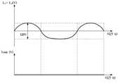
이를 위해, 임계 값은, 도 6에 도시된 바와 같이, 전원 와이어(20)의 정상 결선 시 제1 활성 단자(10a) 및 중성 단자(10b) 사이의 전압의 오차 범위(V1 ~ V2)와, 전원 와이어(20)의 정상 결선 시 제1 활성 단자(10a) 및 제2 활성 단자(10c) 사이의 전압의 오차 범위(V3 ~ V4) 사이의 값(Vc)으로 결정될 수 있다. 다시 말해, 전원 와이어(20)의 정상 결선 시 제1 활성 단자(10a) 및 중성 단자(10b) 사이의 전압의 오차 범위(V1 ~ V2) 중 높은 값(V2)과, 전원 와이어(20)의 정상 결선 시 제1 활성 단자(10a) 및 제2 활성 단자(10c) 사이의 전압의 오차 범위(V3 ~ V4) 중 낮은 값(V3) 사이의 값(Vc)을 임계 값으로 결정할 수 있다.To this end, the threshold is, as shown in FIG. 6, an error range (V1 to V2) of the voltage between the first
구체적으로, 임계 값은, 전원 와이어(20)의 정상 결선 시 제1 활성 단자(10a) 및 중성 단자(10b) 사이의 전압(120V)의 오차 범위(예: 84V ~ 156V)와, 전원 와이어(20)의 정상 결선 시 제1 활성 단자(10a) 및 제2 활성 단자(10c) 사이의 전압(240V)의 오차 범위(예: 204V ~ 276V) 사이의 값(예: 180V)으로 결정될 수 있다.Specifically, the threshold value is the error range (eg, 84V to 156V) of the voltage (120V) between the first
이를 통해, 전원 감지 회로(110)는, 제1 활성 단자(10a) 및 제2 활성 단자(10c) 각각에 제1 전원 와이어(20a) 및 제2 전원 와이어(20c)가 연결되고 각각의 전원 와이어(20a, 20c)로 전압이 인가되어, 제1 활성 단자(10a) 및 제2 활성 단자(10c) 사이의 전압(L1-L2 전압)(예: 240V)이 임계 값 이상이 되는 경우, 도 7에 도시된 바와 같이, 전압의 전기적 신호를 반파 정류하여 구형파(Vout)를 출력할 수 있다.Through this, the
이와 반대로, 전원 감지 회로(110)는, 제2 활성 단자(10c)에 제2 전원 와이어(20c)가 연결되지 않아, 제1 활성 단자(10a) 및 제2 활성 단자(10c) 사이의 전압(L1-L2 전압)(예: 120V)이 임계 값 미만이 되는 경우, 도 8에 도시된 바와 같이, 구형파(Vout)가 출력되지 않을 수 있다.On the contrary, the
일 실시예에 따른 제어부(140)는, 전압 감지 회로(110)가 구형파를 출력하는 경우 복수의 활성 단자(10a, 10c) 사이의 전압의 크기가 임계 값 이상인 것으로 결정하여, 전자 장치(1)가 동작하도록 제어할 수 있다. 예를 들어, 제어부(140)는, 제1 릴레이(150) 및 제2 릴레이(160)가 온되도록 제어하여, 제1 전장물(30) 및 제2 전장물(40)으로 전압이 공급되도록 할 수 있다.When the
일 실시예에 따른 제어부(140)는, 복수의 활성 단자(10a, 10c) 사이의 전압의 크기가 임계 값 미만이면, 전자 장치(1)의 동작이 차단되도록 제어할 수 있다.The
구체적으로, 제어부(140)는, 전압 감지 회로(110)가 구형파를 출력하지 않는 경우 복수의 활성 단자(10a, 10c) 사이의 전압의 크기가 임계 값 미만인 것으로 결정하여, 전자 장치(1)의 동작을 차단할 수 있다. 예를 들어, 제어부(140)는, 제1 릴레이(150) 및 제2 릴레이(160)가 오프되도록 제어하여, 제1 전장물(30) 및 제2 전장물(40)으로 전압이 공급되지 않도록 할 수 있다.Specifically, when the
이처럼, 전자 장치(1)는, 제1 활성 단자(10a) 및 제2 활성 단자(10c) 각각에 제1 전원 와이어(20a) 및 제2 전원 와이어(20c)가 연결되고 각각의 전원 와이어(20a, 20c)에 서로 반대 위상을 갖는 전압(120V)이 인가되는 경우에만 전자 장치(1)가 동작되도록 제어한다.As such, in the
이를 통해, 전자 장치(1)는, 전원 입력 단자(10) 및 전원 와이어(20) 사이의 결선의 오류에 따라 발생할 수 있는 전장물(30, 40)의 소손 및 발화나 전장물(30, 40)의 기능 불량을 방지할 수 있다.Through this, the
또한, 사용자는, 전자 장치(1)의 전원이 온됨에도 불구하고, 전자 장치(1)가 동작하지 않는 경우, 전원 입력 단자(10)를 통한 전원 공급에 오류가 있음을 인식할 수 있다.Also, when the
이 경우, 사용자는, 제2 활성 단자(10c)에 제2 전원 와이어(20c)가 연결되지 않거나(미결선), 제2 활성 단자(10c)에 제2 전원 와이어(20c)가 아닌 중성선(20b)이 연결되는 경우(오결선), 제2 활성 단자(10c)에 제2 전원 와이어(20c)를 연결함으로써, 전원 입력 단자(10)를 통해 전원 공급이 수행될 수 있도록 한다.In this case, the user, the
또한, 사용자는, 제 2 활성 단자(10c)에 제2 전원 와이어(20c)가 연결됨에도 불구하고, 전자 장치(1)가 동작하지 않는 경우, 전자 장치(1)의 설치 장소에서의 옥내배선이 2선식으로 240V의 전압을 공급하지 못하는 것을 인식할 수 있으며, 옥내 배선에 대한 배선 작업을 통하여 콘센트에서 240V의 전압이 공급될 수 있도록 함으로써, 전원 입력 단자(10)를 통해 전원 공급이 수행될 수 있도록 한다.In addition, when the
또한, 사용자는, 전원 버튼의 입력에도 불구하고, 전자 장치(1)의 전원이 온이 되지 않는 경우, 제1 활성 단자(10a) 및 중성 단자(10b) 중 적어도 하나에서의 배선에 오류가 있음을 인식할 수 있으며, 제1 활성 단자(10a)에 제1 전원 와이어(20a)를 연결하고 중성 단자(10b)에 중성선(20b)을 연결함으로써, 전원 입력 단자(10)를 통해 전원 공급이 수행될 수 있도록 한다.In addition, when the user does not turn on the power of the
도 9는 일 실시예에 따른 전자 장치(1)가 메시지를 표시하는 경우를 설명하기 위한 도면이다.9 is a diagram for explaining a case in which the
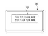
도 9를 참조하면, 일 실시예에 따른 전자 장치(1)는, 복수의 활성 단자(10a, 10c) 사이의 전압의 크기가 임계 값 미만이면, 전원 입력 단자(10)를 통한 전원 공급에 오류가 있음을 나타내는 메시지(900)를 표시할 수 있다.Referring to FIG. 9 , in the
구체적으로, 제어부(140)는, 실시예에 따라, 전압 감지 회로(110)가 구형파를 출력하지 않는 경우 복수의 활성 단자(10a, 10c) 사이의 전압의 크기가 임계 값 미만인 것으로 결정하여, 전자 장치(1)의 동작을 차단하는 동시에 전원 입력 단자(10)를 통한 전원 공급에 오류가 있음을 나타내는 메시지(900)(예: 전원 입력 단자를 통한 전원 공급에 오류 발생)를 표시하도록 디스플레이(170)를 제어할 수 있다.Specifically, according to the embodiment, when the
또한, 제어부(140)는, 실시예에 따라, 전압 감지 회로(110)가 구형파를 출력하지 않는 경우 복수의 활성 단자(10a, 10c) 사이의 전압의 크기가 임계 값 미만인 것으로 결정하여, 전자 장치(1)의 동작을 차단하는 동시에 전원 입력 단자(10)를 통한 전원 공급에 오류가 있음을 나타내는 알림음을 출력하도록 스피커(190)를 제어할 수 있다.In addition, according to an embodiment, when the
이때, 알림음는 "전원 입력 단자를 통한 전원 공급에 오류 발생"이라는 메시지에 대응되는 음성에 대응하거나, 기 설정된 음향에 대응할 수 있다.In this case, the notification sound may correspond to a voice corresponding to the message “Error in supplying power through the power input terminal” or may correspond to a preset sound.
사용자는, 메시지(900) 또는 알림음 중 적어도 하나에 기초하여 전원 입력 단자(10)를 통한 전원 공급에의 오류 발생을 인식할 수 있다. 사용자는, 전원 입력 단자(10) 및 전원 와이어(20) 사이의 결선을 정성화 하거나, 옥내 배선에 대한 배선 작업을 통하여 콘센트에서 240V의 전압이 공급될 수 있도록 함으로써, 전원 입력 단자(10)를 통해 전원 공급이 수행될 수 있도록 한다.The user may recognize the occurrence of an error in power supply through the
이하, 일 측면에 따른 전자 장치(1)의 제어 방법에 관한 실시예를 설명하기로 한다. 전자 장치(1)의 제어 방법에는 전술한 실시예에 따른 전자 장치(1)가 사용될 수 있다. 따라서, 앞서 도 1 내지 도 9를 참조하여 설명한 내용은 전자 장치(1)의 제어 방법에도 동일하게 적용될 수 있다.Hereinafter, an embodiment of a method for controlling the
도 10은 일 실시예에 따른 전자 장치(1)의 제어 방법 중 전원 입력 단자(10)를 통한 전원 공급의 오류를 감지하는 경우의 순서도이다.10 is a flowchart illustrating a case in which an error in power supply through the
일 실시예에 따른 전자 장치(1)는, 전원 버튼이 입력되는 경우(1010의 예), 복수의 활성 단자 사이의 전압을 감지할 수 있다(1020).The
이때, 제어부(140)는, 전압 감지 회로(110)의 출력에 기초하여 복수의 활성 단자(10a, 10c) 사이의 전압의 크기를 식별할 수 있다. 구체적으로, 제어부(140)는, 전압 감지 회로(110)가 구형파를 출력하는 경우 복수의 활성 단자(10a, 10c) 사이의 전압이 임계 값 이상인 것으로 결정할 수 있다. 또한, 제어부(140)는, 전압 감지 회로(110)가 구형파를 출력하지 않는 경우 복수의 활성 단자(10a, 10c) 사이의 전압이 임계 값 미만인 것으로 결정할 수 있다.In this case, the
일 실시예에 따른 전자 장치(1)는, 감지된 전압이 임계 값 이상인 경우(1030의 예), 전자 장치(1)가 동작되도록 제어할 수 있다(1040).The
즉, 제어부(140)는, 전압 감지 회로(110)가 구형파를 출력하는 경우 복수의 활성 단자(10a, 10c) 사이의 전압의 크기가 임계 값 이상인 것으로 결정하여, 전자 장치(1)가 동작하도록 제어할 수 있다. 예를 들어, 제어부(140)는, 제1 릴레이(150) 및 제2 릴레이(160)가 온되도록 제어하여, 제1 전장물(30) 및 제2 전장물(40)으로 전압이 공급되도록 할 수 있다.That is, when the
일 실시예에 따른 전자 장치(1)는, 감지된 전압이 임계 값 미만인 경우(1030의 아니오), 전자 장치(1)의 동작이 차단되도록 제어할 수 있다(1050).When the sensed voltage is less than the threshold value (NO in 1030 ), the
구체적으로, 제어부(140)는, 전압 감지 회로(110)가 구형파를 출력하지 않는 경우 복수의 활성 단자(10a, 10c) 사이의 전압의 크기가 임계 값 미만인 것으로 결정하여, 전자 장치(1)의 동작을 차단할 수 있다. 예를 들어, 제어부(140)는, 제1 릴레이(150) 및 제2 릴레이(160)가 오프되도록 제어하여, 제1 전장물(30) 및 제2 전장물(40)으로 전압이 공급되지 않도록 할 수 있다.Specifically, when the
이처럼, 전자 장치(1)는, 제1 활성 단자(10a) 및 제2 활성 단자(10c) 각각에 제1 전원 와이어(20a) 및 제2 전원 와이어(20c)가 연결되고 각각의 전원 와이어(20a, 20c)에 서로 반대 위상을 갖는 전압(120V)이 인가되는 경우에만 전자 장치(1)가 동작되도록 제어한다.As such, in the
이를 통해, 전자 장치(1)는, 전원 입력 단자(10) 및 전원 와이어(20) 사이의 결선의 오류에 따라 발생할 수 있는 전장물(30, 40)의 소손 및 발화나 전장물(30, 40)의 기능 불량을 방지할 수 있다.Through this, the
또한, 사용자는, 전자 장치(1)의 전원이 온됨에도 불구하고, 전자 장치(1)가 동작하지 않는 경우, 전원 입력 단자(10)를 통한 전원 공급에 오류가 있음을 인식할 수 있다.Also, when the
이 경우, 사용자는, 제2 활성 단자(10c)에 제2 전원 와이어(20c)가 연결되지 않거나(미결선), 제2 활성 단자(10c)에 제2 전원 와이어(20c)가 아닌 중성선(20b)이 연결되는 경우(오결선), 제2 활성 단자(10c)에 제2 전원 와이어(20c)를 연결함으로써, 전원 입력 단자(10)를 통해 전원 공급이 수행될 수 있도록 한다.In this case, the user, the
또한, 사용자는, 제 2 활성 단자(10c)에 제2 전원 와이어(20c)가 연결됨에도 불구하고, 전자 장치(1)가 동작하지 않는 경우, 전자 장치(1)의 설치 장소에서의 옥내배선이 2선식으로 240V의 전압을 공급하지 못하는 것을 인식할 수 있으며, 옥내 배선에 대한 배선 작업을 통하여 콘센트에서 240V의 전압이 공급될 수 있도록 함으로써, 전원 입력 단자(10)를 통해 전원 공급이 수행될 수 있도록 한다.In addition, when the
또한, 사용자는, 전원 버튼의 입력에도 불구하고, 전자 장치(1)의 전원이 온이 되지 않는 경우, 제1 활성 단자(10a) 및 중성 단자(10b) 중 적어도 하나에서의 배선에 오류가 있음을 인식할 수 있으며, 제1 활성 단자(10a)에 제1 전원 와이어(20a)를 연결하고 중성 단자(10b)에 중성선(20b)을 연결함으로써, 전원 입력 단자(10)를 통해 전원 공급이 수행될 수 있도록 한다.In addition, when the user does not turn on the power of the
또한, 일 실시예에 따른 전자 장치(1)는, 전원 입력 단자(10)를 통한 전원 공급에 오류가 있음을 나타내는 메시지를 표시할 수 있다(1060).Also, the
구체적으로, 제어부(140)는, 실시예에 따라, 전압 감지 회로(110)가 구형파를 출력하지 않는 경우 복수의 활성 단자(10a, 10c) 사이의 전압의 크기가 임계 값 미만인 것으로 결정하여, 전자 장치(1)의 동작을 차단하는 동시에 전원 입력 단자(10)를 통한 전원 공급에 오류가 있음을 나타내는 메시지(900)(예: 전원 입력 단자를 통한 전원 공급에 오류 발생)를 표시하도록 디스플레이(170)를 제어할 수 있다.Specifically, according to the embodiment, when the
또한, 제어부(140)는, 실시예에 따라, 전압 감지 회로(110)가 구형파를 출력하지 않는 경우 복수의 활성 단자(10a, 10c) 사이의 전압의 크기가 임계 값 미만인 것으로 결정하여, 전자 장치(1)의 동작을 차단하는 동시에 전원 입력 단자(10)를 통한 전원 공급에 오류가 있음을 나타내는 알림음을 출력하도록 스피커(190)를 제어할 수 있다.In addition, according to an embodiment, when the
사용자는, 메시지(900) 또는 알림음 중 적어도 하나에 기초하여 전원 입력 단자(10)를 통한 전원 공급에의 오류 발생을 인식할 수 있다. 사용자는, 전원 입력 단자(10) 및 전원 와이어(20) 사이의 결선을 정성화 하거나, 옥내 배선에 대한 배선 작업을 통하여 콘센트에서 240V의 전압이 공급될 수 있도록 함으로써, 전원 입력 단자(10)를 통해 전원 공급이 수행될 수 있도록 한다.The user may recognize the occurrence of an error in power supply through the
한편, 개시된 실시예들은 컴퓨터에 의해 실행 가능한 명령어를 저장하는 기록매체의 형태로 구현될 수 있다. 명령어는 프로그램 코드의 형태로 저장될 수 있으며, 프로세서에 의해 실행되었을 때, 프로그램 모듈을 생성하여 개시된 실시예들의 동작을 수행할 수 있다. 기록매체는 컴퓨터로 읽을 수 있는 기록매체로 구현될 수 있다.Meanwhile, the disclosed embodiments may be implemented in the form of a recording medium storing instructions executable by a computer. Instructions may be stored in the form of program code, and when executed by a processor, may create a program module to perform the operations of the disclosed embodiments. The recording medium may be implemented as a computer-readable recording medium.
컴퓨터가 읽을 수 있는 기록매체로는 컴퓨터에 의하여 해독될 수 있는 명령어가 저장된 모든 종류의 기록 매체를 포함한다. 예를 들어, ROM(read only memory), RAM(random access memory), 자기 테이프, 자기 디스크, 플래쉬 메모리, 광 데이터 저장장치 등이 있을 수 있다.The computer-readable recording medium includes any type of recording medium in which instructions readable by the computer are stored. For example, there may be read only memory (ROM), random access memory (RAM), magnetic tape, magnetic disk, flash memory, optical data storage, and the like.
이상에서와 같이 첨부된 도면을 참조하여 개시된 실시예들을 설명하였다. 본 발명이 속하는 기술분야에서 통상의 지식을 가진 자는 본 발명의 기술적 사상이나 필수적인 특징을 변경하지 않고도, 개시된 실시예들과 다른 형태로 본 발명이 실시될 수 있음을 이해할 것이다. 개시된 실시예들은 예시적인 것이며, 한정적으로 해석되어서는 안 된다.The disclosed embodiments have been described with reference to the accompanying drawings as described above. Those of ordinary skill in the art to which the present invention pertains will understand that the present invention may be practiced in other forms than the disclosed embodiments without changing the technical spirit or essential features of the present invention. The disclosed embodiments are illustrative and should not be construed as limiting.
1: 전자 장치10: 전원 입력 단자
10a: 제1 활성 단자10b: 중성 단자
10c: 제2 활성 단자20: 전원 와이어
20a: 제1 전원 와이어20b: 중성선
20c: 제2 전원 와이어30: 제1 전장물
40: 제2 전장물110: 전압 감지 회로
120: 저장부130: 입력부
140: 제어부150: 제1 릴레이
160: 제2 릴레이170: 디스플레이
180: 스피커1: electronic device 10: power input terminal
10a: first
10c: second active terminal 20: power wire
20a:
20c: second power wire 30: first electronic device
40: second electronic device 110: voltage sensing circuit
120: storage unit 130: input unit
140: control unit 150: first relay
160: second relay 170: display
180: speaker
Claims (16)
Translated fromKorean복수의 활성 단자(live terminal) 및 중성 단자(neutral terminal)를 포함하는 전원 입력 단자;
상기 복수의 활성 단자 사이에 연결되어 상기 복수의 활성 단자 사이의 전압을 감지하는 전압 감지 회로; 및
상기 복수의 활성 단자 사이의 전압의 크기가 임계 값 미만이면, 상기 전자 장치의 동작이 차단되도록 제어하는 제어부;를 포함하는 전자 장치.In an electronic device,
a power input terminal comprising a plurality of live terminals and a neutral terminal;
a voltage sensing circuit connected between the plurality of active terminals to sense a voltage between the plurality of active terminals; and
The electronic device comprising a; when the magnitude of the voltage between the plurality of active terminals is less than a threshold value, a control unit controlling the operation of the electronic device to be blocked.
상기 전압 감지 회로는,
상기 복수의 활성 단자 사이의 전압의 크기가 임계 값 이상이면, 상기 전압을 반파 정류하여 구형파를 출력하는 전자 장치.According to claim 1,
The voltage sensing circuit comprises:
When the magnitude of the voltage between the plurality of active terminals is greater than or equal to a threshold value, the electronic device outputs a square wave by half-wave rectifying the voltage.
상기 제어부는,
상기 전압 감지 회로가 구형파를 출력하는 경우 상기 전자 장치가 동작되도록 제어하는 전자 장치.3. The method of claim 2,
The control unit is
An electronic device for controlling the electronic device to operate when the voltage sensing circuit outputs a square wave.
상기 제어부는,
상기 전압 감지 회로가 구형파를 출력하지 않는 경우 상기 전자 장치의 동작이 차단되도록 제어하는 전자 장치.3. The method of claim 2,
The control unit is
An electronic device for controlling the operation of the electronic device to be blocked when the voltage sensing circuit does not output a square wave.
상기 전자 장치는,
상기 복수의 활성 단자 사이에 연결되는 제1 전장물;
상기 복수의 활성 단자의 제1 활성 단자 및 상기 중성 단자 사이에 연결되는 제2 전장물;
상기 제1 전장물과 직렬로 연결되는 제1 릴레이; 및
상기 제2 전장물과 직렬로 연결되는 제2 릴레이;를 더 포함하고,
상기 제어부는,
상기 복수의 활성 단자 사이의 전압의 크기가 임계 값 미만이면, 상기 제1 릴레이 및 상기 제2 릴레이가 오프되도록 제어하는 전자 장치.According to claim 1,
The electronic device is
a first electrical device connected between the plurality of active terminals;
a second electrical device connected between the first active terminal and the neutral terminal of the plurality of active terminals;
a first relay connected in series with the first electronic device; and
It further includes; a second relay connected in series with the second electronic device;
The control unit is
When the magnitude of the voltage between the plurality of active terminals is less than a threshold value, the electronic device controls to turn off the first relay and the second relay.
상기 임계 값은,
전원 와이어의 정상 결선 시 상기 복수의 활성 단자 사이의 전압의 오차 범위와 상기 전원 와이어의 정상 결선 시 상기 복수의 활성 단자의 제1 활성 단자 및 상기 중성 단자 사이의 전압의 오차 범위 사이의 값으로 결정되는 전자 장치.According to claim 1,
The threshold is
It is determined as a value between the error range of the voltage between the plurality of active terminals when the power wire is normally connected and the error range of the voltage between the first active terminal and the neutral terminal of the plurality of active terminals when the power wire is normally connected becoming an electronic device.
상기 전자 장치는,
디스플레이;를 더 포함하고,
상기 제어부는,
상기 복수의 활성 단자 사이의 전압의 크기가 임계 값 미만이면, 상기 전원 입력 단자를 통한 전원 공급에 오류가 있음을 나타내는 메시지를 표시하도록 상기 디스플레이를 제어하는 전자 장치.According to claim 1,
The electronic device is
Display; further comprising,
The control unit is
When the magnitude of the voltage between the plurality of active terminals is less than a threshold value, the electronic device controls the display to display a message indicating that there is an error in power supply through the power input terminal.
상기 전자 장치는,
스피커;를 더 포함하고,
상기 제어부는,
상기 복수의 활성 단자 사이의 전압의 크기가 임계 값 미만이면, 상기 전원 입력 단자를 통한 전원 공급에 오류가 있음을 나타내는 알림음을 출력하도록 상기 스피커를 제어하는 전자 장치.According to claim 1,
The electronic device is
speaker; further comprising,
The control unit is
When the magnitude of the voltage between the plurality of active terminals is less than a threshold value, the electronic device of controlling the speaker to output a notification sound indicating that there is an error in power supply through the power input terminal.
상기 복수의 활성 단자 사이에 연결되어 상기 복수의 활성 단자 사이의 전압을 감지하는 전압 감지 회로의 출력에 기초하여 상기 복수의 활성 단자 사이의 전압의 크기와 임계 값을 비교하고;
상기 복수의 활성 단자 사이의 전압의 크기가 상기 임계 값 미만이면, 상기 전자 장치의 동작이 차단되도록 제어하는 것;을 포함하는 전자 장치의 제어 방법.In the control method of an electronic device comprising a power input terminal comprising a plurality of active terminals (live terminal) and a neutral terminal (neutral terminal),
comparing a magnitude and a threshold value of a voltage between the plurality of active terminals based on an output of a voltage sensing circuit coupled between the plurality of active terminals to sense a voltage between the plurality of active terminals;
and controlling the operation of the electronic device to be blocked when the magnitude of the voltage between the plurality of active terminals is less than the threshold value.
상기 전압 감지 회로는,
상기 복수의 활성 단자 사이의 전압의 크기가 임계 값 이상이면, 상기 전압을 반파 정류하여 구형파를 출력하는 전자 장치의 제어 방법.10. The method of claim 9,
The voltage sensing circuit comprises:
When the magnitude of the voltage between the plurality of active terminals is greater than or equal to a threshold value, the control method of the electronic device for outputting a square wave by half-wave rectifying the voltage.
상기 전압 감지 회로가 구형파를 출력하는 경우 상기 전자 장치가 동작되도록 제어하는 것;을 더 포함하는 전자 장치의 제어 방법.11. The method of claim 10,
and controlling the electronic device to operate when the voltage sensing circuit outputs a square wave.
상기 전자 장치의 동작이 차단되도록 제어하는 것은,
상기 전압 감지 회로가 구형파를 출력하지 않는 경우 상기 전자 장치의 동작이 차단되도록 제어하는 것;을 포함하는 전자 장치의 제어 방법.11. The method of claim 10,
Controlling the operation of the electronic device to be blocked is,
and controlling the operation of the electronic device to be blocked when the voltage sensing circuit does not output a square wave.
상기 전자 장치는,
상기 복수의 활성 단자 사이에 연결되는 제1 전장물;
상기 복수의 활성 단자의 제1 활성 단자 및 상기 중성 단자 사이에 연결되는 제2 전장물;
상기 제1 전장물과 직렬로 연결되는 제1 릴레이; 및
상기 제2 전장물과 직렬로 연결되는 제2 릴레이;를 더 포함하고,
상기 전자 장치의 동작이 차단되도록 제어하는 것은,
상기 복수의 활성 단자 사이의 전압의 크기가 임계 값 미만이면, 상기 제1 릴레이 및 상기 제2 릴레이가 오프되도록 제어하는 것;을 포함하는 전자 장치의 제어 방법.10. The method of claim 9,
The electronic device is
a first electrical device connected between the plurality of active terminals;
a second electrical device connected between the first active terminal and the neutral terminal of the plurality of active terminals;
a first relay connected in series with the first electronic device; and
It further includes; a second relay connected in series with the second electronic device;
Controlling the operation of the electronic device to be blocked is,
and controlling the first relay and the second relay to be turned off when the magnitude of the voltage between the plurality of active terminals is less than a threshold value.
상기 임계 값은,
전원 와이어의 정상 결선 시 상기 복수의 활성 단자 사이의 전압의 오차 범위와 상기 전원 와이어의 정상 결선 시 상기 복수의 활성 단자의 제1 활성 단자 및 상기 중성 단자 사이의 전압의 오차 범위 사이의 값으로 결정되는 전자 장치의 제어 방법.10. The method of claim 9,
The threshold is
It is determined as a value between the error range of the voltage between the plurality of active terminals when the power wire is normally connected and the error range of the voltage between the first active terminal and the neutral terminal of the plurality of active terminals when the power wire is normally connected A method of controlling an electronic device.
상기 전자 장치는,
디스플레이;를 더 포함하고,
상기 복수의 활성 단자 사이의 전압의 크기가 임계 값 미만이면, 상기 전원 입력 단자를 통한 전원 공급에 오류가 있음을 나타내는 메시지를 표시하도록 상기 디스플레이를 제어하는 것;을 더 포함하는 전자 장치의 제어 방법.10. The method of claim 9,
The electronic device is
Display; further comprising,
When the magnitude of the voltage between the plurality of active terminals is less than a threshold value, controlling the display to display a message indicating that there is an error in power supply through the power input terminal; .
상기 전자 장치는,
스피커;를 더 포함하고,
상기 복수의 활성 단자 사이의 전압의 크기가 임계 값 미만이면, 상기 전원 입력 단자를 통한 전원 공급에 오류가 있음을 나타내는 알림음을 출력하도록 상기 스피커를 제어하는 것;을 더 포함하는 전자 장치의 제어 방법.10. The method of claim 9,
The electronic device is
speaker; further comprising,
Controlling the electronic device further comprising: when the magnitude of the voltage between the plurality of active terminals is less than a threshold value, controlling the speaker to output a notification sound indicating that there is an error in power supply through the power input terminal Way.
Priority Applications (3)
| Application Number | Priority Date | Filing Date | Title |
|---|---|---|---|
| KR1020200089518AKR20220010863A (en) | 2020-07-20 | 2020-07-20 | Electronic device and controlling method thereof |
| PCT/KR2021/006440WO2022019460A1 (en) | 2020-07-20 | 2021-05-24 | Electronic device and controlling method thereof |
| US18/089,176US12392806B2 (en) | 2020-07-20 | 2022-12-27 | Electronic device and controlling method thereof |
Applications Claiming Priority (1)
| Application Number | Priority Date | Filing Date | Title |
|---|---|---|---|
| KR1020200089518AKR20220010863A (en) | 2020-07-20 | 2020-07-20 | Electronic device and controlling method thereof |
Publications (1)
| Publication Number | Publication Date |
|---|---|
| KR20220010863Atrue KR20220010863A (en) | 2022-01-27 |
Family
ID=79728823
Family Applications (1)
| Application Number | Title | Priority Date | Filing Date |
|---|---|---|---|
| KR1020200089518APendingKR20220010863A (en) | 2020-07-20 | 2020-07-20 | Electronic device and controlling method thereof |
Country Status (3)
| Country | Link |
|---|---|
| US (1) | US12392806B2 (en) |
| KR (1) | KR20220010863A (en) |
| WO (1) | WO2022019460A1 (en) |
Family Cites Families (21)
| Publication number | Priority date | Publication date | Assignee | Title |
|---|---|---|---|---|
| JP3839857B2 (en) | 1994-09-20 | 2006-11-01 | 塩野義製薬株式会社 | Method for producing ether type thiophospholipid compound |
| KR100202080B1 (en) | 1996-06-29 | 1999-06-15 | 윤종용 | Low voltage protection circuit |
| KR100259517B1 (en) | 1996-11-15 | 2000-06-15 | 정몽규 | Mounting of Front Suspension of Vehicle |
| KR100348249B1 (en) | 1999-10-08 | 2002-08-09 | 엘지전자 주식회사 | Data architecture of VCT and method for transmit/receiving service information |
| US6671150B2 (en) | 2001-11-07 | 2003-12-30 | Eaton Corporation | Circuit breaker for detecting an excessive voltage and tripping responsive thereto |
| JP4110510B2 (en)* | 2002-03-08 | 2008-07-02 | 三菱電機株式会社 | Air conditioner miswiring detector |
| KR101498624B1 (en)* | 2008-08-07 | 2015-03-11 | 엘지전자 주식회사 | Clothes dryer and clothes dryer control method |
| US20100140062A1 (en) | 2008-12-09 | 2010-06-10 | Stmicroelectronics, Inc. | Protective circuit for an apparatus |
| KR100912645B1 (en)* | 2009-03-20 | 2009-08-17 | 주식회사 대륙 | Single-phase 2-wire circuit breaker with tripping function even when neutral wire is missing |
| KR101607891B1 (en) | 2009-07-31 | 2016-04-11 | 엘지전자 주식회사 | Diagnostic system and method for home appliance |
| US8441248B2 (en) | 2010-10-21 | 2013-05-14 | Whirlpool Corporation | Laundry treating appliance with voltage detection |
| KR101028786B1 (en)* | 2010-12-21 | 2011-04-14 | 이수미 | Distribution board with integrated image harmonic filter |
| KR101257094B1 (en) | 2011-02-11 | 2013-04-19 | 엘지전자 주식회사 | Apparatus for detecting wrong connection of power line and air conditioner having the same |
| US8093858B1 (en)* | 2011-03-01 | 2012-01-10 | International Controls And Measurements Corp. | AC line voltage conditioner and controller |
| KR101536111B1 (en) | 2013-12-20 | 2015-07-13 | 동부대우전자 주식회사 | Apparatus and method for detecting over voltage or low voltage |
| KR101780653B1 (en) | 2015-10-27 | 2017-09-21 | 김영리 | Integrally formed mold apparatus for synthetic resin floating and method for manufacturing integrally formed floating using the same |
| KR101891117B1 (en) | 2017-02-08 | 2018-08-23 | 엘지전자 주식회사 | Wrong wiring detection device and air conditioner including the same |
| KR102460253B1 (en) | 2017-04-14 | 2022-10-27 | 엘지전자 주식회사 | Laundry treatment machine |
| KR101957168B1 (en) | 2017-07-27 | 2019-03-12 | 엘지전자 주식회사 | Air conditioner |
| JP2019154215A (en) | 2018-03-06 | 2019-09-12 | ブラザー工業株式会社 | Switching power supply |
| KR102642560B1 (en) | 2018-09-21 | 2024-02-28 | 엘지전자 주식회사 | An electronic device having single-phase three-wire type wiring structure |
- 2020
- 2020-07-20KRKR1020200089518Apatent/KR20220010863A/enactivePending
- 2021
- 2021-05-24WOPCT/KR2021/006440patent/WO2022019460A1/ennot_activeCeased
- 2022
- 2022-12-27USUS18/089,176patent/US12392806B2/enactiveActive
Also Published As
| Publication number | Publication date |
|---|---|
| US20230135862A1 (en) | 2023-05-04 |
| US12392806B2 (en) | 2025-08-19 |
| WO2022019460A1 (en) | 2022-01-27 |
Similar Documents
| Publication | Publication Date | Title |
|---|---|---|
| US7193335B2 (en) | Sensing socket assembly | |
| US8954628B2 (en) | Portable device and peripheral extension dock | |
| JP6580249B2 (en) | Relay board and sensor device | |
| WO1999034152A1 (en) | Indoor-outdoor communication device in air conditioner | |
| JP3557335B2 (en) | Interface circuit | |
| KR20220010863A (en) | Electronic device and controlling method thereof | |
| KR100880914B1 (en) | Wireless multi-outlet circuit | |
| CN117792042B (en) | Load type identification circuit, driving circuit and method for automatically identifying load type | |
| CN211557585U (en) | Double-control switch and double-control system | |
| KR100373452B1 (en) | Power supply cutoff apparatus | |
| KR100996834B1 (en) | Outlet with standby power / continuous power selection | |
| JP2009044826A (en) | Power supply device | |
| CN112534667A (en) | System and method for identifying arcing in electrical wiring | |
| CN112421314B (en) | A plug-and-play power protection device and socket electrical appliance | |
| US20170207049A1 (en) | System for actively detecting alternating current load | |
| JP6197608B2 (en) | Power supply / reception device and control method | |
| JP3910321B2 (en) | Inrush current suppression device and power supply device | |
| KR102727516B1 (en) | Plug recptacle apparatus based on sunburst chart display | |
| KR102280726B1 (en) | Electromagnetic switch including dry contact type protective circuit, and control system of power device using the same | |
| CN107978139B (en) | Wireless remote control switch device and wireless remote control electric appliance | |
| KR101370530B1 (en) | Electronic socket | |
| KR100600439B1 (en) | Automatic Power Off Device | |
| CN119535304A (en) | Measuring device, measuring system and procedure | |
| CN109976491A (en) | Power supply circuit and electronic device including the power supply circuit | |
| KR20220152850A (en) | Electronic device controlling application of power and method for operating thereof |
Legal Events
| Date | Code | Title | Description |
|---|---|---|---|
| PA0109 | Patent application | Patent event code:PA01091R01D Comment text:Patent Application Patent event date:20200720 | |
| PG1501 | Laying open of application | ||
| E902 | Notification of reason for refusal | ||
| PE0902 | Notice of grounds for rejection | Comment text:Notification of reason for refusal Patent event date:20250323 Patent event code:PE09021S01D |