KR20220001976A - Battery management system and communication method thereof - Google Patents
Battery management system and communication method thereofDownload PDFInfo
- Publication number
- KR20220001976A KR20220001976AKR1020200080556AKR20200080556AKR20220001976AKR 20220001976 AKR20220001976 AKR 20220001976AKR 1020200080556 AKR1020200080556 AKR 1020200080556AKR 20200080556 AKR20200080556 AKR 20200080556AKR 20220001976 AKR20220001976 AKR 20220001976A
- Authority
- KR
- South Korea
- Prior art keywords
- battery management
- management system
- slave
- slave battery
- master
- Prior art date
- Legal status (The legal status is an assumption and is not a legal conclusion. Google has not performed a legal analysis and makes no representation as to the accuracy of the status listed.)
- Pending
Links
Images


Classifications
- H—ELECTRICITY
- H01—ELECTRIC ELEMENTS
- H01M—PROCESSES OR MEANS, e.g. BATTERIES, FOR THE DIRECT CONVERSION OF CHEMICAL ENERGY INTO ELECTRICAL ENERGY
- H01M10/00—Secondary cells; Manufacture thereof
- H01M10/42—Methods or arrangements for servicing or maintenance of secondary cells or secondary half-cells
- H01M10/425—Structural combination with electronic components, e.g. electronic circuits integrated to the outside of the casing
- H—ELECTRICITY
- H01—ELECTRIC ELEMENTS
- H01M—PROCESSES OR MEANS, e.g. BATTERIES, FOR THE DIRECT CONVERSION OF CHEMICAL ENERGY INTO ELECTRICAL ENERGY
- H01M10/00—Secondary cells; Manufacture thereof
- H01M10/42—Methods or arrangements for servicing or maintenance of secondary cells or secondary half-cells
- H01M10/4207—Methods or arrangements for servicing or maintenance of secondary cells or secondary half-cells for several batteries or cells simultaneously or sequentially
- H—ELECTRICITY
- H01—ELECTRIC ELEMENTS
- H01M—PROCESSES OR MEANS, e.g. BATTERIES, FOR THE DIRECT CONVERSION OF CHEMICAL ENERGY INTO ELECTRICAL ENERGY
- H01M10/00—Secondary cells; Manufacture thereof
- H01M10/42—Methods or arrangements for servicing or maintenance of secondary cells or secondary half-cells
- H01M10/48—Accumulators combined with arrangements for measuring, testing or indicating the condition of cells, e.g. the level or density of the electrolyte
- H01M10/482—Accumulators combined with arrangements for measuring, testing or indicating the condition of cells, e.g. the level or density of the electrolyte for several batteries or cells simultaneously or sequentially
- H—ELECTRICITY
- H01—ELECTRIC ELEMENTS
- H01M—PROCESSES OR MEANS, e.g. BATTERIES, FOR THE DIRECT CONVERSION OF CHEMICAL ENERGY INTO ELECTRICAL ENERGY
- H01M10/00—Secondary cells; Manufacture thereof
- H01M10/42—Methods or arrangements for servicing or maintenance of secondary cells or secondary half-cells
- H01M10/425—Structural combination with electronic components, e.g. electronic circuits integrated to the outside of the casing
- H01M2010/4271—Battery management systems including electronic circuits, e.g. control of current or voltage to keep battery in healthy state, cell balancing
- H—ELECTRICITY
- H01—ELECTRIC ELEMENTS
- H01M—PROCESSES OR MEANS, e.g. BATTERIES, FOR THE DIRECT CONVERSION OF CHEMICAL ENERGY INTO ELECTRICAL ENERGY
- H01M10/00—Secondary cells; Manufacture thereof
- H01M10/42—Methods or arrangements for servicing or maintenance of secondary cells or secondary half-cells
- H01M10/425—Structural combination with electronic components, e.g. electronic circuits integrated to the outside of the casing
- H01M2010/4278—Systems for data transfer from batteries, e.g. transfer of battery parameters to a controller, data transferred between battery controller and main controller
- H—ELECTRICITY
- H01—ELECTRIC ELEMENTS
- H01M—PROCESSES OR MEANS, e.g. BATTERIES, FOR THE DIRECT CONVERSION OF CHEMICAL ENERGY INTO ELECTRICAL ENERGY
- H01M2220/00—Batteries for particular applications
- H01M2220/20—Batteries in motive systems, e.g. vehicle, ship, plane
- Y—GENERAL TAGGING OF NEW TECHNOLOGICAL DEVELOPMENTS; GENERAL TAGGING OF CROSS-SECTIONAL TECHNOLOGIES SPANNING OVER SEVERAL SECTIONS OF THE IPC; TECHNICAL SUBJECTS COVERED BY FORMER USPC CROSS-REFERENCE ART COLLECTIONS [XRACs] AND DIGESTS
- Y02—TECHNOLOGIES OR APPLICATIONS FOR MITIGATION OR ADAPTATION AGAINST CLIMATE CHANGE
- Y02E—REDUCTION OF GREENHOUSE GAS [GHG] EMISSIONS, RELATED TO ENERGY GENERATION, TRANSMISSION OR DISTRIBUTION
- Y02E60/00—Enabling technologies; Technologies with a potential or indirect contribution to GHG emissions mitigation
- Y02E60/10—Energy storage using batteries
Landscapes
- Engineering & Computer Science (AREA)
- Manufacturing & Machinery (AREA)
- Chemical & Material Sciences (AREA)
- Chemical Kinetics & Catalysis (AREA)
- Electrochemistry (AREA)
- General Chemical & Material Sciences (AREA)
- Microelectronics & Electronic Packaging (AREA)
- Charge And Discharge Circuits For Batteries Or The Like (AREA)
- Secondary Cells (AREA)
- Remote Monitoring And Control Of Power-Distribution Networks (AREA)
Abstract
Translated fromKoreanDescription
Translated fromKorean본 발명은 무선 통신을 수행하는 배터리 관리 시스템 및 배터리 관리 시스템 간의 무선 통신 방법에 관한 것이다.The present invention relates to a battery management system for performing wireless communication and a wireless communication method between the battery management system.
일반적으로 차량이 주차되어 있는 경우, 무선 통신을 수행하는 배터리 관리 시스템의 마스터 배터리 관리 시스템은 전원이 꺼져 있으며 배터리 모듈에 장착되어 상시 전원을 공급받는 슬레이브 배터리 관리 시스템만이 전원이 켜져 있게 된다.In general, when the vehicle is parked, the power of the master battery management system of the battery management system performing wireless communication is turned off, and only the slave battery management system that is mounted on the battery module and receives constant power is turned on.
만약, 사용자가 차량의 시동을 걸고 마스터 배터리 관리 시스템에 전원이 들어오게 되면, 슬레이브 배터리 관리 시스템들은 현재 배터리 모듈의 상태 정보를 마스터 배터리 관리 시스템으로 전달한다. 그러나, 슬레이브 배터리 관리 시스템은 언제 마스터 배터리 관리 시스템에 전원이 들어올지 예측하기가 어려우므로 주기적으로 웨이크업되어 수신기를 동작시키고 마스터 배터리 관리 시스템으로부터 전송되는 신호가 있는지 확인한다.If the user starts the vehicle and power is turned on to the master battery management system, the slave battery management systems transmit current state information of the battery module to the master battery management system. However, since it is difficult to predict when the master battery management system will be powered on, the slave battery management system periodically wakes up to operate the receiver and checks whether there is a signal transmitted from the master battery management system.
이러한 마스터 배터리 관리 시스템의 웨이크업 신호는 무작위로 송신되므로, 슬레이브 배터리 관리 시스템이 마스터 배터리 관리 시스템의 신호를 신속하게 인지하려면 자주 수신기를 동작시키면 된다. 그러나, 수신기를 자주 동작시킬 경우 배터리 모듈의 전원을 사용하는 슬레이브 배터리 관리 시스템의 소모 전류가 커져 차량의 주차시 배터리 모듈이 방전될 위험이 높아진다.Since the wake-up signal of the master battery management system is randomly transmitted, the slave battery management system needs to operate the receiver frequently to quickly recognize the signal of the master battery management system. However, when the receiver is frequently operated, the consumption current of the slave battery management system using the power of the battery module increases, so that the risk of the battery module being discharged when the vehicle is parked increases.
이처럼, 차량의 시동이 켜진 이후 슬레이브 배터리 관리 시스템이 마스터 배터리 관리 시스템에서 전송된 신호를 인지하여 전체 배터리 시스템이 정상 동작으로 돌아오는 시간(wake-up time)과 슬레이브 배터리 관리 시스템이 차량이 주차된 동안 소모하는 전류(sleep current)는 서로 트레이드 오프(trade-off) 관계에 있다. 통상적으로 슬레이브 배터리 관리 시스템이 하드웨어적으로 소모 전류가 개선되지 않는 이상, 배터리 관리 시스템에서 요구되는 웨이크업 시간에 따라 시스템의 소모 전류가 정해지게 된다.In this way, after the vehicle is started, the slave battery management system recognizes the signal transmitted from the master battery management system, and the entire battery system returns to normal operation (wake-up time) and the slave battery management system determines when the vehicle is parked. The current consumed during the sleep current has a trade-off relationship with each other. In general, unless the current consumption of the slave battery management system is improved by hardware, the current consumption of the system is determined according to a wakeup time required by the battery management system.
본 발명은 상기와 같은 과제를 해결하기 위해 고안된 것으로서, 슬레이브 배터리 관리 시스템이 마스터 배터리 관리 시스템에 웨이크업 신호를 요청하기 위한 요청 신호를 전송한 후 슬레이브 배터리 관리 시스템의 수신 주기를 동기화함으로써, 배터리 모듈의 소모 전류를 감소시켜 전력을 효율적으로 사용할 수 있고 배터리 관리 시스템의 웨이크업 시간을 단축할 수 있는 배터리 관리 시스템 및 이들의 통신 방법을 제공하는 것을 목적으로 한다.The present invention is devised to solve the above problems, and by synchronizing the reception period of the slave battery management system after the slave battery management system transmits a request signal for requesting a wakeup signal to the master battery management system, the battery module An object of the present invention is to provide a battery management system capable of efficiently using power by reducing current consumption of a battery and shortening a wake-up time of the battery management system, and a communication method thereof.
본 발명의 일 실시 예에 따른 배터리 관리 시스템은 복수의 슬레이브 배터리 관리 시스템(Battery Management System, BMS)에 웨이크업(wake-up) 신호를 송신하는 마스터 배터리 관리 시스템 및 상기 마스터 배터리 관리 시스템으로부터 상기 웨이크업 신호를 수신하면, 배터리 모듈의 상태 정보를 상기 마스터 배터리 관리 시스템에 송신하는 복수의 슬레이브 배터리 관리 시스템을 포함하고, 상기 복수의 슬레이브 배터리 관리 시스템 중 적어도 하나의 슬레이브 배터리 관리 시스템은 상기 마스터 배터리 관리 시스템에 요청 신호를 전송하고, 상기 요청 신호에 기초하여 상기 복수의 슬레이브 배터리 관리 시스템이 상기 마스터 배터리 관리 시스템으로부터 상기 웨이크업 신호를 수신하는 수신 주기를 동기화할 수 있다.A battery management system according to an embodiment of the present invention includes a master battery management system that transmits a wake-up signal to a plurality of slave battery management systems (BMS) and the wake from the master battery management system. and a plurality of slave battery management systems for transmitting state information of a battery module to the master battery management system upon receiving an up signal, wherein at least one slave battery management system among the plurality of slave battery management systems is configured to manage the master battery A request signal may be transmitted to the system, and a reception period in which the plurality of slave battery management systems receive the wakeup signal from the master battery management system may be synchronized based on the request signal.
본 발명의 일 실시 예에 따른 배터리 관리 시스템의 통신 방법은 복수의 슬레이브 배터리 관리 시스템 중 적어도 하나의 슬레이브 배터리 관리 시스템에서 마스터 배터리 관리 시스템으로 요청 신호를 전송하는 단계, 상기 요청 신호에 기초하여 상기 복수의 슬레이브 배터리 관리 시스템이 상기 마스터 배터리 관리 시스템으로부터 웨이크업 신호를 수신하는 수신 주기를 동기화하는 단계, 상기 마스터 배터리 관리 시스템에서 상기 복수의 슬레이브 배터리 관리 시스템으로 상기 웨이크업 신호를 송신하는 단계 및 상기 복수의 슬레이브 배터리 관리 시스템이 상기 마스터 배터리 관리 시스템으로부터 상기 웨이크업 신호를 수신하면, 배터리 모듈의 상태 정보를 상기 마스터 배터리 관리 시스템에 송신하는 단계를 포함할 수 있다.The communication method of a battery management system according to an embodiment of the present invention includes transmitting a request signal from at least one slave battery management system among a plurality of slave battery management systems to a master battery management system, and based on the request signal, the plurality of synchronizing, by a slave battery management system of a receiving cycle for receiving a wakeup signal from the master battery management system, transmitting the wakeup signal from the master battery management system to the plurality of slave battery management systems, and the plurality of When the slave battery management system of the receives the wake-up signal from the master battery management system, it may include the step of transmitting the state information of the battery module to the master battery management system.
본 발명의 배터리 관리 시스템 및 이들의 통신 방법에 따르면, 슬레이브 배터리 관리 시스템이 마스터 배터리 관리 시스템에 웨이크업 신호를 요청하기 위한 요청 신호를 전송한 후 슬레이브 배터리 관리 시스템의 수신 주기를 동기화함으로써, 배터리 모듈의 소모 전류를 감소시켜 전력을 효율적으로 사용할 수 있고 배터리 관리 시스템의 웨이크업 시간을 단축할 수 있다.According to the battery management system and their communication method of the present invention, the slave battery management system transmits a request signal for requesting a wake-up signal to the master battery management system and then synchronizes the reception period of the slave battery management system, whereby the battery module By reducing the current consumption of the battery, power can be used efficiently and the wake-up time of the battery management system can be shortened.
도 1은 마스터 및 슬레이브 배터리 관리 시스템의 동작을 나타내는 도면이다.
도 2a는 종래의 배터리 관리 시스템의 통신 동작을 나타내는 도면이고, 도 2b는 본 발명의 일 실시 예에 따른 배터리 관리 시스템의 통신 동작을 나타내는 도면이다.
도 3a 및 3b는 종래의 배터리 관리 시스템과 본 발명의 일 실시 예에 따른 배터리 관리 시스템의 전력 효율을 비교하기 위한 도면이다.
도 4a는 종래의 배터리 관리 시스템의 통신 동작을 나타내는 도면이고, 도 4b는 본 발명의 다른 실시 예에 따른 배터리 관리 시스템의 통신 동작을 나타내는 도면이다.
도 5는 본 발명의 일 실시 예에 따른 배터리 관리 시스템의 통신 방법을 나타내는 흐름도이다.
도 6은 본 발명의 다른 실시 예에 따른 배터리 관리 시스템의 통신 방법을 나타내는 흐름도이다.
도 7은 본 발명의 일 실시 예에 따른 배터리 관리 시스템의 하드웨어 구성을 나타내는 블록도이다.1 is a diagram illustrating the operation of a master and slave battery management system.
2A is a diagram illustrating a communication operation of a conventional battery management system, and FIG. 2B is a diagram illustrating a communication operation of a battery management system according to an embodiment of the present invention.
3A and 3B are diagrams for comparing the power efficiency of a conventional battery management system and a battery management system according to an embodiment of the present invention.
4A is a diagram illustrating a communication operation of a conventional battery management system, and FIG. 4B is a diagram illustrating a communication operation of a battery management system according to another embodiment of the present invention.
5 is a flowchart illustrating a communication method of a battery management system according to an embodiment of the present invention.
6 is a flowchart illustrating a communication method of a battery management system according to another embodiment of the present invention.
7 is a block diagram illustrating a hardware configuration of a battery management system according to an embodiment of the present invention.
이하, 첨부한 도면을 참조하여 본 발명의 다양한 실시 예들에 대해 상세히 설명하고자 한다. 본 문서에서 도면상의 동일한 구성 요소에 대해서는 동일한 참조 부호를 사용하고 동일한 구성요소에 대해서 중복된 설명은 생략한다.Hereinafter, various embodiments of the present invention will be described in detail with reference to the accompanying drawings. In this document, the same reference numerals are used for the same components in the drawings, and duplicate descriptions of the same components are omitted.
본 문서에 개시되어 있는 본 발명의 다양한 실시 예들에 대해서, 특정한 구조적 내지 기능적 설명들은 단지 본 발명의 실시 예를 설명하기 위한 목적으로 예시된 것으로, 본 발명의 다양한 실시 예들은 여러 가지 형태로 실시될 수 있으며 본 문서에 설명된 실시 예들에 한정되는 것으로 해석되어서는 아니 된다.For various embodiments of the present invention disclosed in this document, specific structural or functional descriptions are only exemplified for the purpose of describing the embodiments of the present invention, and various embodiments of the present invention may be implemented in various forms. and should not be construed as being limited to the embodiments described in this document.
다양한 실시 예에서 사용된 "제1", "제2", "첫째", 또는 "둘째" 등의 표현들은 다양한 구성요소들을, 순서 및/또는 중요도에 상관없이 수식할 수 있고, 해당 구성 요소들을 한정하지 않는다. 예를 들면, 본 발명의 권리 범위를 벗어나지 않으면서 제1 구성 요소는 제2 구성 요소로 명명될 수 있고, 유사하게 제2 구성요소도 제1 구성 요소로 바꾸어 명명될 수 있다.Expressions such as "first", "second", "first", or "second" used in various embodiments may modify various components regardless of order and/or importance, do not limit For example, without departing from the scope of the present invention, a first component may be referred to as a second component, and similarly, the second component may also be renamed as a first component.
본 문서에서 사용된 용어들은 단지 특정한 실시 예를 설명하기 위해 사용된 것으로, 다른 실시 예의 범위를 한정하려는 의도가 아닐 수 있다. 단수의 표현은 문맥상 명백하게 다르게 뜻하지 않는 한, 복수의 표현을 포함할 수 있다.Terms used in this document are only used to describe specific embodiments, and may not be intended to limit the scope of other embodiments. The singular expression may include the plural expression unless the context clearly dictates otherwise.
기술적이거나 과학적인 용어를 포함해서 여기서 사용되는 모든 용어들은 본 발명의 기술 분야에서 통상의 지식을 가진 자에 의해 일반적으로 이해되는 것과 동일한 의미를 가질 수 있다. 일반적으로 사용되는 사전에 정의된 용어들은 관련 기술의 문맥 상 가지는 의미와 동일 또는 유사한 의미를 가지는 것으로 해석될 수 있으며, 본 문서에서 명백하게 정의되지 않는 한, 이상적이거나 과도하게 형식적인 의미로 해석되지 않는다. 경우에 따라서, 본 문서에서 정의된 용어일지라도 본 발명의 실시 예들을 배제하도록 해석될 수 없다.All terms used herein, including technical or scientific terms, may have the same meaning as commonly understood by one of ordinary skill in the art of the present invention. Terms defined in general used in the dictionary can be interpreted as having the same or similar meaning as the meaning in the context of the related art, and unless explicitly defined in this document, it is not interpreted in an ideal or excessively formal meaning. . In some cases, even terms defined in this document cannot be construed to exclude embodiments of the present invention.
도 1은 마스터 및 슬레이브 배터리 관리 시스템의 동작을 나타내는 도면이다.1 is a diagram illustrating operations of a master and slave battery management system.
배터리 팩(1)에는 복수의 배터리 모듈(2, 4, 6)이 직렬 또는 병렬로 연결되어 있다. 각각의 배터리 모듈(2, 4, 6)에는 복수의 배터리 셀이 포함되어 있고, 슬레이브 배터리 관리 시스템(12, 14, 16)이 각각 배치된다. 각각의 슬레이브 배터리 관리 시스템(12, 14, 16)은 복수의 배터리 모듈(2, 4, 6)의 온도, 전압 또는 전류 등의 상태를 측정하여 모니터링하고, 모니터링 한 정보를 상위 시스템으로 전송하고, 상위 시스템에서 배터리 셀의 제어 명령을 수신하여 연결된 배터리 셀을 제어한다.A plurality of
복수의 배터리 모듈(2, 4, 6)은 직렬 또는 병렬로 연결되어 배터리 팩(1)을 형성한다. 배터리 팩(1)에는 마스터 배터리 관리 시스템(10)이 배치된다. 또한, 마스터 배터리 관리 시스템(10)은 배터리 모듈(2, 4, 6)에 각각 배치되어 있는 슬레이브 배터리 관리 시스템(12, 14, 16)으로부터 각각의 배터리 셀의 모니터링 정보를 수신하여, 상위 시스템으로 전송하고, 상위 시스템으로부터 각종 명령을 수신하여 해당 슬레이브 배터리 관리 시스템(12, 14, 16)으로 전송한다.A plurality of battery modules (2, 4, 6) are connected in series or parallel to form a battery pack (1). A master
한편, 본 발명의 일 실시 예에 따른 배터리 관리 시스템 중 마스터 배터리 관리 시스템(10)은 구동시 복수의 슬레이브 배터리 관리 시스템(12, 14, 16)에 웨이크업(wake-up) 신호를 송신할 수 있다. 구체적으로, 마스터 배터리 관리 시스템(10)은 복수의 슬레이브 배터리 관리 시스템(12, 14, 16) 중 어느 하나의 슬레이브 배터리 관리 시스템으로부터 요청 신호를 수신하면 웨이크업 신호를 복수의 슬레이브 배터리 관리 시스템(12, 14, 16)으로 전송할 수 있다.Meanwhile, in the battery management system according to an embodiment of the present invention, the master
그리고 복수의 슬레이브 배터리 관리 시스템(12, 14, 16)은 마스터 배터리 관리 시스템(10)으로부터 웨이크업 신호를 수신하면, 배터리 모듈의 상태 정보를 마스터 배터리 관리 시스템(10)으로 송신할 수 있다. 또한, 복수의 슬레이브 배터리 관리 시스템(12, 14, 16) 중 적어도 하나의 슬레이브 배터리 관리 시스템은, 예를 들면, 대표 슬레이브 배터리 관리 시스템으로서 마스터 배터리 관리 시스템(10)에 요청 신호를 전송하고, 해당 요청 신호에 기초하여 복수의 슬레이브 배터리 관리 시스템(12, 14, 16)이 마스터 배터리 관리 시스템(10)으로부터 웨이크업 신호를 수신하는 수신 주기를 동기화할 수 있다.In addition, when the plurality of slave
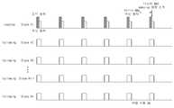
도 2a는 종래의 배터리 관리 시스템의 통신 동작을 나타내는 도면이고, 도 2b는 본 발명의 일 실시 예에 따른 배터리 관리 시스템의 통신 동작을 나타내는 도면이다.2A is a diagram illustrating a communication operation of a conventional battery management system, and FIG. 2B is a diagram illustrating a communication operation of a battery management system according to an embodiment of the present invention.
종래의 배터리 관리 시스템에서는 차량이 주차되어 있는 경우, 도 2a에 나타낸 것과 같이, 슬레이브 배터리 관리 시스템은 주기적으로 수신 동작을 수행하면서 마스터 배터리 관리 시스템으로부터 신호가 전송되는지 여부를 확인한다. 이 때, 마스터 배터리 관리 시스템의 웨이크업 신호는 랜덤으로 송신되므로, 슬레이브 배터리 관리 시스템의 수신 시간이 짧거나 수신 주기가 길면 슬레이브 배터리 관리 시스템이 마스터 배터리 관리 시스템으로부터 신호를 성공적으로 수신할 확률이 낮아진다. 예를 들어, 슬레이브 배터리 관리 시스템의 수신 시간은 최소한 마스터 배터리 관리 시스템의 신호를 2회 이상 수신할 수 있는 시간인 것이 바람직하다.In the conventional battery management system, when the vehicle is parked, as shown in FIG. 2A , the slave battery management system periodically performs a reception operation and checks whether a signal is transmitted from the master battery management system. At this time, since the wake-up signal of the master battery management system is transmitted randomly, if the reception time of the slave battery management system is short or the reception period is long, the probability that the slave battery management system successfully receives the signal from the master battery management system is low. . For example, it is preferable that the reception time of the slave battery management system is a time during which the signal of the master battery management system can be received at least twice or more.
또한, 종래에는 슬레이브 배터리 관리 시스템 각각에 대해 구비된 내부 RTC(real time clock)를 이용하여 수신 주기를 계산하기 때문에 슬레이브 배터리 관리 시스템들의 수신 시간의 동기화가 이루어지기 어렵다. 따라서, 모든 슬레이브 배터리 관리 시스템에서 마스터 배터리 관리 시스템의 신호를 성공적으로 수신하기 위해서는 최소한 한 주기 동안 마스터 배터리 관리 시스템에서 웨이크업 명령 신호를 송신할 필요가 있다.Also, in the related art, since the reception period is calculated using an internal real time clock (RTC) provided for each of the slave battery management systems, it is difficult to synchronize the reception times of the slave battery management systems. Therefore, in order to successfully receive the signal of the master battery management system in all the slave battery management systems, it is necessary to transmit the wakeup command signal from the master battery management system for at least one cycle.
한편, 도 2b를 참조하면, 본 발명의 일 실시 예에 따른 배터리 관리 시스템은 복수의 슬레이브 배터리 관리 시스템 중 하나가 대표 슬레이브 배터리 관리 시스템(제1 슬레이브 배터리 관리 시스템)으로서 매 수신 주기의 시작 시점에 마스터 배터리 관리 시스템으로 요청 신호를 보낼 수 있다. 이 경우, 나머지 슬레이브 배터리 관리 시스템들(제2 슬레이브 배터리 관리 시스템)은 요청 신호를 기준으로 수신 주기의 동기화를 할 수 있다. 또한, 대표 슬레이브 배터리 관리 시스템은 요청 신호의 전송이 끝난 후 일정 시간 내에 웨이크업 신호에 대한 수신 동작을 수행할 수 있다.Meanwhile, referring to FIG. 2B , in the battery management system according to an embodiment of the present invention, one of a plurality of slave battery management systems is a representative slave battery management system (first slave battery management system) at the start of each reception cycle. A request signal can be sent to the master battery management system. In this case, the remaining slave battery management systems (the second slave battery management system) may synchronize the reception period based on the request signal. In addition, the representative slave battery management system may perform a reception operation for the wakeup signal within a predetermined time after the transmission of the request signal is finished.
마스터 배터리 관리 시스템의 경우, 차량의 시동이 걸리면 일단 수신 동작을 수행하여 대표로 선정된 슬레이브 배터리 관리 시스템의 요청 신호를 수신할 때까지 대기하였다가 수신에 성공하면 웨이크업 명령 신호를 슬레이브 배터리 관리 시스템들로 송신할 수 있다.In the case of the master battery management system, once the vehicle is started, it performs a reception operation and waits until it receives a request signal from the slave battery management system selected as a representative. can be sent to
이처럼, 본 발명의 일 실시 예에 따른 배터리 관리 시스템에 의하면, 마스터배터리 관리 시스템이 요청 신호를 수신한 후에 슬레이브 배터리 관리 시스템으로 웨이크업 신호를 전송하므로, 슬레이브 배터리 관리 시스템들은 웨이크업 신호의 송신 시간을 예측할 수 있고, 슬레이브 배터리 관리 시스템들의 수신 주기가 동기화되므로 마스터 배터리 관리 시스템으로부터의 웨이크업 신호를 한번에 성공적으로 수신할 수 있다.As such, according to the battery management system according to an embodiment of the present invention, since the master battery management system transmits a wakeup signal to the slave battery management system after receiving the request signal, the slave battery management systems transmit the wakeup signal transmission time can be predicted, and since the reception periods of the slave battery management systems are synchronized, the wakeup signal from the master battery management system can be successfully received at once.
도 2b에서와 같이, 본 발명의 일 실시 예에 따른 배터리 관리 시스템에서 마스터와 슬레이브 배터리 관리 시스템 모두 웨이크업이 완료되면, 슬레이브 배터리 관리 시스템은 배터리 모듈의 상태(배터리 모듈 전압, 온도 등) 등에 관한 데이터를 마스터 배터리 관리 시스템으로 송신할 수 있고, 마스터 배터리 관리 시스템은 수신된 상태 정보에 기초하여 각종 명령(예를 들면, 상태 모니터링 명령, 셀 밸런싱 명령, 이상 진단을 위한 임계치 지정 명령 등)을 슬레이브 배터리 관리 시스템으로 송신할 수 있다.As shown in FIG. 2B , in the battery management system according to an embodiment of the present invention, when the wake-up of both the master and slave battery management systems is completed, the slave battery management system relates to the state (battery module voltage, temperature, etc.) of the battery module. data may be transmitted to the master battery management system, and the master battery management system may issue various commands (eg, status monitoring command, cell balancing command, threshold value designation command for abnormal diagnosis, etc.) to the slave based on the received status information. can be sent to the battery management system.
한편, 도 2b에서는 본 발명의 일 실시 예에 따른 배터리 관리 시스템에서 하나의 슬레이브 배터리 관리 시스템을 대표로 선정하는 것으로 나타내었으나, 대표 슬레이브 배터리 관리 시스템은 필요에 따라 복수의 슬레이브 배터리 관리 시스템으로 선정될 수 있다. 또한, 도 2b에서는 하나의 대표 슬레이브 배터리 관리 시스템이 계속해서 송신 동작을 수행하는 것으로 나타내었으나, 복수의 대표 슬레이브 배터리 관리 시스템이 선정된 경우, 복수의 대표 슬레이브 배터리 관리 시스템 각각이 교대로 송신 동작을 수행할 수도 있다.Meanwhile, although FIG. 2B shows that one slave battery management system is selected as a representative in the battery management system according to an embodiment of the present invention, the representative slave battery management system may be selected as a plurality of slave battery management systems if necessary. can In addition, although it is shown that one representative slave battery management system continuously performs a transmission operation in FIG. 2B , when a plurality of representative slave battery management systems are selected, each of the plurality of representative slave battery management systems alternately performs a transmission operation can also be done
그리고, 대표로 선정된 슬레이브 배터리 관리 시스템은 차량의 시동이 꺼짐에 따라 마스터 배터리 관리 시스템이 오프되기 전에 배터리 모듈의 SoC 잔량에 기초하여 대표 슬레이브 배터리 관리 시스템의 대상이 되는 순서를 정하여 나머지 슬레이브 배터리 관리 시스템으로 전달할 수 있다. 따라서, 각 슬레이브 배터리 관리 시스템은 SoC 잔량에 의해 정해진 순서와 횟수에 따라 대표 슬레이브 배터리 관리 시스템으로서의 역할을 수행할 수 있다.In addition, the slave battery management system selected as a representative determines the order to be the target of the representative slave battery management system based on the SoC remaining amount of the battery module before the master battery management system is turned off as the vehicle is turned off to manage the remaining slave batteries. can be passed to the system. Accordingly, each slave battery management system may serve as a representative slave battery management system according to the order and number of times determined by the remaining SoC amount.
그러나, 본 발명에 따른 대표 슬레이브 배터리 관리 시스템이 SoC에 의해서만 결정되는 것은 아니며, 사용자에 의해 직접 설정되거나, 배터리 모듈 순서에 의해 순차적으로 선정되는 등 다양한 방법으로 결정될 수 있다. 또한, 대표 슬레이브 배터리 관리 시스템을 대신하여 마스터 배터리 관리 시스템이 전원이 오프되기 전 복수의 슬레이브 배터리 관리 시스템 중 적어도 하나의 슬레이브 배터리 관리 시스템을 대표 슬레이브 배터리 관리 시스템으로 선정할 수 있다.However, the representative slave battery management system according to the present invention is not determined only by the SoC, and may be determined in various ways, such as directly set by the user or sequentially selected by the battery module order. Also, instead of the representative slave battery management system, before the master battery management system is powered off, at least one slave battery management system among a plurality of slave battery management systems may be selected as the representative slave battery management system.
도 3a 및 3b는 종래의 배터리 관리 시스템과 본 발명의 일 실시 예에 따른 배터리 관리 시스템의 전력 효율을 비교하기 위한 도면이다.3A and 3B are diagrams for comparing the power efficiency of a conventional battery management system and a battery management system according to an embodiment of the present invention.
도 3a 및 3b에서는 마스터 배터리 관리 시스템의 웨이크업 신호 송신 주기를 1ms로 설정하고, 12개의 슬레이브 배터리 관리 시스템에 대해 수신 주기를 100ms로 설정하였다. 또한, 배터리 관리 시스템의 RF 송신(Tx) 전류 및 RF 수신(Rx) 전류는 각각 30mA, 15mA로 하고, 슬레이브 배터리 관리 시스템이 차량의 시동이 꺼져 있는 동안 소모하는 전류를 50μA로 하였다. 그러나, 도 3a 및 3b에 나타낸 사양들은 예시적인 것일 뿐, 본 발명이 이에 제한되는 것은 아니다.3A and 3B, the wakeup signal transmission period of the master battery management system is set to 1 ms, and the reception period is set to 100 ms for the 12 slave battery management systems. In addition, the RF transmit (Tx) current and RF receive (Rx) current of the battery management system were set to 30mA and 15mA, respectively, and the current consumed by the slave battery management system while the vehicle's ignition was turned off was set to 50μA. However, the specifications shown in FIGS. 3A and 3B are exemplary only, and the present invention is not limited thereto.
도 3a에 나타낸 것과 같이, 종래의 배터리 관리 시스템의 통신 방법에서는 마스터 배터리 관리 시스템의 웨이크업 신호를 최소 2번 이상 수신하기 위해 슬레이브 배터리 관리 시스템의 수신 시간을 3ms로 설정하였다. 이 경우, 주기당 배터리 관리 시스템의 소모 전류는 59.82mAh이며, 따라서 400V/90kWh/SoC 30%의 사양을 갖는 배터리 팩을 기준으로 주차 가능 일수는 47일이 된다.As shown in FIG. 3A , in the conventional communication method of the battery management system, the reception time of the slave battery management system is set to 3ms in order to receive the wakeup signal of the master battery management system at least twice or more. In this case, the consumption current of the battery management system per cycle is 59.82 mAh, so the number of days that can be parked is 47 days based on a battery pack having a specification of 400V/90kWh/SoC 30%.
한편, 도 3b에 나타낸 본 발명의 일 실시 예에 따른 배터리 관리 시스템에서는 대표(#1) 슬레이브 배터리 관리 시스템의 수신 시간 및 송신 시간을 각각 1ms로 설정하고, 나머지 슬레이브 배터리 관리 시스템의 수신 시간은 2ms로 설정하였다. 이 경우, 주기당 배터리 관리 시스템의 소모 전류는 44.37mAh이며, 따라서 400V/90kWh/SoC 30%의 사양을 갖는 배터리 팩을 기준으로 주차 가능 일수는 64.8일이 된다. 즉, 본 발명의 일 실시 예에 따른 배터리 관리 시스템은 종래에 비해 주기당 소모 전류를 27.5% 개선할 수 있고, 주차 가능 일수를 17.8일 더 증가시킬 수 있다.Meanwhile, in the battery management system according to an embodiment of the present invention shown in FIG. 3B , the reception time and the transmission time of the representative (#1) slave battery management system are set to 1 ms, respectively, and the reception time of the remaining slave battery management systems is 2 ms. was set to In this case, the consumption current of the battery management system per cycle is 44.37mAh, so the number of days that can be parked is 64.8 days based on a battery pack having a specification of 400V/90kWh/SoC 30%. That is, the battery management system according to an embodiment of the present invention can improve the current consumption per cycle by 27.5% and increase the number of days available for parking by 17.8 days compared to the conventional one.
이와 같이, 본 발명의 일 실시 예에 따른 배터리 관리 시스템에 따르면, 슬레이브 배터리 관리 시스템이 마스터 배터리 관리 시스템에 웨이크업 신호를 요청하기 위한 요청 신호를 전송한 후 슬레이브 배터리 관리 시스템의 수신 주기를 동기화함으로써, 배터리 모듈의 소모 전류를 감소시켜 전력을 효율적으로 사용할 수 있고 배터리 관리 시스템의 웨이크업 시간을 단축할 수 있다.As such, according to the battery management system according to an embodiment of the present invention, after the slave battery management system transmits a request signal for requesting a wakeup signal to the master battery management system, by synchronizing the reception period of the slave battery management system , it is possible to efficiently use power by reducing the current consumption of the battery module and shorten the wake-up time of the battery management system.
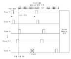
도 4a는 종래의 배터리 관리 시스템의 통신 동작을 나타내는 도면이고, 도 4b는 본 발명의 다른 실시 예에 따른 배터리 관리 시스템의 통신 동작을 나타내는 도면이다. 도 4a 및 4b는 배터리 관리 시스템의 소모 전류를 감소시키기 위해 수신 주기를 늘리는 경우(예를 들면, 도 3a 및 3b의 2배)에 관하여 설명하기 위한 것이다.4A is a diagram illustrating a communication operation of a conventional battery management system, and FIG. 4B is a diagram illustrating a communication operation of a battery management system according to another embodiment of the present invention. 4A and 4B are for explaining a case in which a reception period is increased (eg, twice that of FIGS. 3A and 3B ) in order to reduce current consumption of the battery management system.
도 4a를 참조하면, 종래의 배터리 관리 시스템에서 슬레이브 배터리 관리 시스템의 수신 주기가 200ms인 경우, 도 3a에 비해 평균 소모 전류는 16.45mAh로 감소하는 효과가 있으나, 마스터 배터리 관리 시스템으로부터 신호를 수신하여 웨이크업하기 위해 소요되는 시간은 최소한 수신 주기보다 작아질 수는 없다. 또한, 만약 특정(#n) 슬레이브 배터리 관리 시스템이 노이즈 등의 신호 불량에 의해 마스터 배터리 관리 시스템의 웨이크업 신호를 한번이라도 놓치게 된다면 배터리 관리 시스템의 총 웨이크업 소요 시간이 확률적으로 최대 수신 주기의 2배가 될 수 있다.Referring to FIG. 4A , when the reception period of the slave battery management system in the conventional battery management system is 200 ms, the average current consumption is reduced to 16.45 mAh compared to FIG. 3A, but by receiving a signal from the master battery management system, The time required for waking up cannot be less than at least the reception period. In addition, if the specific (#n) slave battery management system misses the wakeup signal of the master battery management system even once due to signal failure such as noise, the total wakeup time of the battery management system is probabilistically lower than that of the maximum reception period. can be doubled.
반면, 본 발명의 일 실시 예에 따른 배터리 관리 시스템은, 도 4b에 나타낸 것과 같이, 대표로 선정된 슬레이브 배터리 관리 시스템에서 요청 신호의 송신 주기를 1/2로 감소시켜 마스터 배터리 관리 시스템으로 요청 신호를 더 전송함으로써, 마스터 배터리 관리 시스템이 대표 슬레이브 배터리 관리 시스템의 요청 신호를 수신할 기회를 늘리고 있다.On the other hand, in the battery management system according to an embodiment of the present invention, as shown in FIG. 4B , the request signal to the master battery management system by reducing the transmission period of the request signal in the representative slave battery management system by 1/2 By further transmitting , the master battery management system increases the chance of receiving a request signal from the representative slave battery management system.
만약, 1/2 주기로 송수신 동작을 수행하는 대표 슬레이브 배터리 관리 시스템이 마스터 배터리 관리 시스템으로부터 웨이크업 신호를 수신한 경우, 대표 슬레이브 배터리 관리 시스템은 먼저 수신된 웨이크업 신호를 요청 신호에 복사하여 나머지 슬레이브 배터리 관리 시스템으로 전달할 수 있다.If the representative slave battery management system that performs transmission/reception operation in 1/2 cycle receives a wakeup signal from the master battery management system, the representative slave battery management system first copies the received wakeup signal to the request signal and then copies the received wakeup signal to the remaining slaves. It can be passed to the battery management system.
또한, 대표 슬레이브 배터리 관리 시스템은 나머지 배터리 관리 시스템의 수신 주기를 감소시킬 수 있다. 예를 들면, 나머지 슬레이브 배터리 관리 시스템의 수신 주기는 마스터 배터리 관리 시스템이 슬레이브 배터리 관리 시스템으로부터 데이터를 수집할 수 있는 최소 프레임 단위로 감소될 수 있다. 이와 같이 하여, 만약 웨이크업 신호를 수신하는데 실패한 슬레이브 배터리 관리 시스템이 있더라도 빠른 시간 내에 수신에 성공할 수 있도록 할 수 있다.In addition, the representative slave battery management system may reduce the reception period of the remaining battery management systems. For example, the reception period of the remaining slave battery management system may be reduced to a minimum frame unit in which the master battery management system can collect data from the slave battery management system. In this way, even if there is a slave battery management system that fails to receive the wake-up signal, it is possible to successfully receive the wake-up signal within a short time.
이처럼, 도 4b의 배터리 관리 시스템에 따르면, 소모 전류는 15.96mAh로 감소할 수 있으며, 일부 슬레이브 배터리 관리 시스템에서 웨이크업 신호를 놓치게 되더라도 배터리 관리 시스템의 총 웨이크업 소요 시간은 수신 주기+α로서 종래의 배터리 관리 시스템에 비해 웨이크업 시간을 단축시킬 수 있다.As such, according to the battery management system of FIG. 4B, the consumption current may be reduced to 15.96mAh, and even if the wakeup signal is missed in some slave battery management systems, the total wakeup time of the battery management system is the reception period + α. It can shorten the wake-up time compared to the battery management system of
도 5는 본 발명의 일 실시 예에 따른 배터리 관리 시스템의 통신 방법을 나타내는 흐름도이다.5 is a flowchart illustrating a communication method of a battery management system according to an embodiment of the present invention.
도 5를 참조하면, 먼저 복수의 슬레이브 배터리 관리 시스템 중 대표로 선정된 배터리 관리 시스템(제1 슬레이브 배터리 관리 시스템)이 마스터 배터리 관리 시스템에 미리 설정된 송신 주기로 요청 신호를 전송한다(S110). 이 때, 대표 슬레이브 배터리 관리 시스템은 전술한 것처럼 배터리 모듈의 SoC 잔량에 기초하여 마스터 배터리 관리 시스템의 구동 전에 결정될 수 있다. 또한, 대표 슬레이브 배터리 관리 시스템은 송신 동작을 수행한 후, 마스터 배터리 관리 시스템으로부터 웨이크업 신호를 수신하기 위해 일정 시간 내에 수신 동작으로 전환할 수 있다.Referring to FIG. 5 , first, a battery management system (a first slave battery management system) selected as a representative among a plurality of slave battery management systems transmits a request signal to the master battery management system in a preset transmission cycle ( S110 ). In this case, the representative slave battery management system may be determined before the master battery management system is driven based on the SoC remaining amount of the battery module as described above. In addition, after the representative slave battery management system performs the transmission operation, in order to receive the wake-up signal from the master battery management system, the representative slave battery management system may switch to the reception operation within a predetermined time.
그리고, 대표 슬레이브 배터리 관리 시스템의 요청 신호에 기초하여 나머지 슬레이브 배터리 관리 시스템(제2 슬레이브 배터리 관리 시스템)의 수신 주기를 동기화한다(S120). 이에 따라, 마스터 배터리 관리 시스템으로부터 웨이크업 신호를 수신하기 위한 모든 슬레이브 배터리 관리 시스템의 수신 주기가 동일하게 될 수 있다.Then, the reception period of the remaining slave battery management system (the second slave battery management system) is synchronized based on the request signal of the representative slave battery management system (S120). Accordingly, the reception period of all the slave battery management systems for receiving the wakeup signal from the master battery management system may be the same.
마스터 배터리 관리 시스템이 구동되면 대표 슬레이브 배터리 관리 시스템의 요청 신호에 대한 수신 동작을 시작한다(S130). 이 때, 단계 S130은 단계 S110 이전에 수행될 수 있다. 즉, 마스터 배터리 관리 시스템이 구동되어 수신 동작을 시작한 이후, 대표 슬레이브 배터리 관리 시스템이 마스터 배터리 관리 시스템으로 요청 신호를 전송하여 슬레이브 배터리 관리 시스템의 수신 주기를 동기화할 수 있다.When the master battery management system is driven, the reception operation for the request signal of the representative slave battery management system is started (S130). In this case, step S130 may be performed before step S110. That is, after the master battery management system is driven and the reception operation is started, the representative slave battery management system may transmit a request signal to the master battery management system to synchronize the reception period of the slave battery management system.
만약, 마스터 배터리 관리 시스템이 대표 슬레이브 배터리 관리 시스템의 요청 신호를 수신하지 못하면(S140)(NO), 마스터 배터리 관리 시스템에서는 요청 신호를 수신할 때까지 지속적으로 수신 동작을 수행한다. 한편, 마스터 배터리 관리 시스템이 대표 슬레이브 배터리 관리 시스템의 요청 신호를 수신하면(YES), 마스터 배터리 관리 시스템이 복수의 슬레이브 배터리 관리 시스템으로 웨이크업 신호를 송신한다(S150).If the master battery management system does not receive the request signal of the representative slave battery management system (S140) (NO), the master battery management system continuously performs the reception operation until it receives the request signal. On the other hand, when the master battery management system receives the request signal of the representative slave battery management system (YES), the master battery management system transmits a wakeup signal to the plurality of slave battery management systems (S150).
이처럼, 본 발명의 일 실시 예에 따른 배터리 관리 시스템에서 마스터와 슬레이브 배터리 관리 시스템 모두 웨이크업이 완료되면, 슬레이브 배터리 관리 시스템은 배터리 모듈의 상태(배터리 모듈 전압, 온도 등) 등에 관한 데이터를 마스터 배터리 관리 시스템으로 송신할 수 있고, 마스터 배터리 관리 시스템은 수신된 상태 정보에 기초하여 각종 명령(예를 들면, 상태 모니터링 명령, 셀 밸런싱 명령, 이상 진단을 위한 임계치 지정 명령 등)을 슬레이브 배터리 관리 시스템으로 송신할 수 있다.As such, when the wake-up of both the master and slave battery management systems in the battery management system according to an embodiment of the present invention is completed, the slave battery management system transmits data related to the state (battery module voltage, temperature, etc.) of the battery module to the master battery. can be sent to the management system, and the master battery management system sends various commands (eg, status monitoring command, cell balancing command, threshold designation command for abnormal diagnosis, etc.) to the slave battery management system based on the received status information. can send
이와 같이, 본 발명의 일 실시 예에 따른 배터리 관리 시스템의 통신 방법에 의하면, 대표 슬레이브 배터리 관리 시스템에서 마스터 배터리 관리 시스템으로 요청 신호를 전송하고, 이러한 요청 신호에 기초하여 마스터 배터리 관리 시스템이 웨이크업 신호를 전송하므로 마스터 배터리 관리 시스템이 웨이크업 신호를 송신하는 시간을 예측할 수 있다. 또한, 대표 슬레이브 배터리 관리 시스템의 요청 신호에 따라 나머지 슬레이브 배터리 관리 시스템의 수신 주기를 동기화함으로써 모든 슬레이브 배터리 관리 시스템이 마스터 배터리 관리 시스템으로부터 동시에 웨이크업 신호를 수신할 수 있다.As described above, according to the communication method of the battery management system according to an embodiment of the present invention, the representative slave battery management system transmits a request signal to the master battery management system, and the master battery management system wakes up based on the request signal. By sending a signal, it is possible to predict when the master battery management system will send a wake-up signal. In addition, by synchronizing the reception period of the remaining slave battery management systems according to the request signal of the representative slave battery management system, all the slave battery management systems can simultaneously receive the wakeup signal from the master battery management system.
도 6은 본 발명의 다른 실시 예에 따른 배터리 관리 시스템의 통신 방법을 나타내는 흐름도이다. 도 6에서 단계 S250 내지 S290은 도 5의 단계 S110 내지 S150과 실질적으로 동일하므로, 구체적인 설명은 생략한다.6 is a flowchart illustrating a communication method of a battery management system according to another embodiment of the present invention. Steps S250 to S290 in FIG. 6 are substantially the same as steps S110 to S150 in FIG. 5 , and thus a detailed description thereof will be omitted.
도 6을 참조하면, 본 발명의 다른 실시 예에 따른 배터리 관리 시스템에서는 먼저, 슬레이브 배터리 관리 시스템의 수신 주기가 기준치 이상인지 여부를 판단한다. 이 때, 수신 주기의 기준치는, 예를 들어, 200ms일 수 있다. 이 때, 슬레이브 배터리 관리 시스템의 수신 주기가 기준치 미만이라면(NO), 단계 S250으로 진행하여 도 5와 마찬가지의 동작을 수행할 수 있다.Referring to FIG. 6 , in the battery management system according to another embodiment of the present invention, first, it is determined whether the reception period of the slave battery management system is equal to or greater than a reference value. In this case, the reference value of the reception period may be, for example, 200 ms. At this time, if the reception period of the slave battery management system is less than the reference value (NO), the process proceeds to step S250 and the same operation as in FIG. 5 may be performed.
만약, 슬레이브 배터리 관리 시스템의 수신 주기가 기준치 이상인 경우(YES), 대표 슬레이브 배터리 관리 시스템(제1 슬레이브 배터리 관리 시스템)은 요청 신호의 송신 주기를 감소시킬 수 있다(S220). 예를 들어, 대표 슬레이브 배터리 관리 시스템은 송신 주기를 1/2 이하로 감소시켜 마스터 배터리 관리 시스템이 대표 슬레이브 배터리 관리 시스템으로부터 요청 신호를 수신할 확률을 높일 수 있다.If the reception period of the slave battery management system is equal to or greater than the reference value (YES), the representative slave battery management system (the first slave battery management system) may reduce the transmission period of the request signal ( S220 ). For example, the representative slave battery management system may reduce the transmission period to 1/2 or less, thereby increasing the probability that the master battery management system receives a request signal from the representative slave battery management system.
다음으로, 대표 슬레이브 배터리 관리 시스템이 마스터 배터리 관리 시스템으로부터 웨이크업 신호를 성공적으로 수신하면 해당 웨이크업 신호를 복사하여 나머지 배터리 관리 시스템(제2 슬레이브 배터리 관리 시스템)으로 전달할 수 있다(S230).Next, when the representative slave battery management system successfully receives the wakeup signal from the master battery management system, it can copy the wakeup signal and transmit it to the remaining battery management system (the second slave battery management system) (S230).
또한, 대표 슬레이브 배터리 관리 시스템은 나머지 슬레이브 배터리 관리 시스템의 수신 주기를 감소시킬 수 있다(S240). 이 경우, 나머지 슬레이브 배터리 관리 시스템의 수신 주기는 마스터 배터리 관리 시스템이 슬레이브 배터리 관리 시스템으로부터 데이터를 수집할 수 있는 최소 프레임 단위로 감소될 수 있다.Also, the representative slave battery management system may reduce the reception period of the remaining slave battery management systems (S240). In this case, the reception period of the remaining slave battery management systems may be reduced to a minimum frame unit in which the master battery management system can collect data from the slave battery management system.
이처럼, 본 발명의 일 실시 예에 따른 배터리 관리 시스템에서는 단계 S230 및 단계 S240의 동작을 통해 나머지 슬레이브 배터리 관리 시스템이 마스터 배터리 관리 시스템의 웨이크업 신호를 수신할 가능성을 높일 수 있다. 따라서, 슬레이브 배터리 관리 시스템들 중 노이즈 등 통신 불량에 의해 웨이크업 신호의 수신에 실패하는 경우가 있더라도 수신 시간을 최대로 단축할 수 있다.As such, in the battery management system according to an embodiment of the present invention, the possibility that the remaining slave battery management systems receive the wakeup signal of the master battery management system may be increased through the operations of steps S230 and S240. Accordingly, even if there is a case in which reception of the wake-up signal fails due to communication failure such as noise among slave battery management systems, the reception time can be shortened to the maximum.
이와 같이, 본 발명의 일 실시 예에 따른 배터리 관리 시스템의 통신 방법에 따르면, 슬레이브 배터리 관리 시스템이 마스터 배터리 관리 시스템에 웨이크업 신호를 요청하기 위한 요청 신호를 전송한 후 슬레이브 배터리 관리 시스템의 수신 주기를 동기화함으로써, 배터리 모듈의 소모 전류를 감소시켜 전력을 효율적으로 사용할 수 있고 배터리 관리 시스템의 웨이크업 시간을 단축할 수 있다.As described above, according to the communication method of the battery management system according to an embodiment of the present invention, after the slave battery management system transmits a request signal for requesting a wakeup signal to the master battery management system, the reception period of the slave battery management system By synchronizing the , the current consumption of the battery module can be reduced, power can be used efficiently, and the wake-up time of the battery management system can be shortened.
도 7은 본 발명의 일 실시 예에 따른 배터리 관리 시스템의 하드웨어 구성을 나타내는 블록도이다.7 is a block diagram illustrating a hardware configuration of a battery management system according to an embodiment of the present invention.
도 7을 참조하면, 배터리 관리 시스템(700)은, 각종 처리 및 각 구성을 제어하는 마이크로컨트롤러(MCU; 710)와, 운영체제 프로그램 및 각종 프로그램(예로서, 배터리 상태 측정 프로그램, 신호 생성 프로그램, 수신 동기화 프로그램 등) 등이 기록되는 메모리(720)와, 배터리 셀 모듈 및/또는 반도체 스위칭 소자와의 사이에서 입력 인터페이스 및 출력 인터페이스를 제공하는 입출력 인터페이스(730)와, 유무선 통신망을 통해 외부와 통신 가능한 통신 인터페이스(740)를 구비할 수 있다. 이와 같이, 본 발명에 따른 컴퓨터 프로그램은 메모리(720)에 기록되고, 마이크로 컨트롤러(710)에 의해 처리됨으로써, 예를 들면 도 2b 및 4b 등에서 설명한 각종 기능들을 수행하는 모듈로서 구현될 수 있다.Referring to FIG. 7 , the
이상에서, 본 발명의 실시예를 구성하는 모든 구성 요소들이 하나로 결합하거나 결합하여 동작하는 것으로 설명되었다고 해서, 본 발명이 반드시 이러한 실시예에 한정되는 것은 아니다. 즉, 본 발명의 목적 범위 안에서라면, 그 모든 구성 요소들이 하나 이상으로 선택적으로 결합하여 동작할 수도 있다.In the above, even though it has been described that all components constituting the embodiment of the present invention operate by being combined or combined into one, the present invention is not necessarily limited to this embodiment. That is, within the scope of the object of the present invention, all the components may operate by selectively combining one or more.
또한, 이상에서 기재된 "포함하다", "구성하다" 또는 "가지다" 등의 용어는, 특별히 반대되는 기재가 없는 한, 해당 구성 요소가 내재할 수 있음을 의미하는 것이므로, 다른 구성 요소를 제외하는 것이 아니라 다른 구성 요소를 더 포함할 수 있는 것으로 해석되어야 한다. 기술적이거나 과학적인 용어를 포함한 모든 용어들은, 다르게 정의되지 않는 한, 본 발명이 속하는 기술 분야에서 통상의 지식을 가진 자에 의해 일반적으로 이해되는 것과 동일한 의미가 있다. 사전에 정의된 용어와 같이 일반적으로 사용되는 용어들은 관련 기술의 문맥상의 의미와 일치하는 것으로 해석되어야 하며, 본 발명에서 명백하게 정의하지 않는 한, 이상적이거나 과도하게 형식적인 의미로 해석되지 않는다.In addition, terms such as "comprises", "comprises" or "have" described above mean that the corresponding component may be inherent, unless otherwise specified, excluding other components. Rather, it should be construed as being able to further include other components. All terms, including technical or scientific terms, have the same meaning as commonly understood by one of ordinary skill in the art to which the present invention belongs, unless otherwise defined. Terms commonly used, such as those defined in the dictionary, should be interpreted as being consistent with the contextual meaning of the related art, and are not interpreted in an ideal or excessively formal meaning unless explicitly defined in the present invention.
이상의 설명은 본 발명의 기술 사상을 예시적으로 설명한 것에 불과한 것으로서, 본 발명이 속하는 기술 분야에서 통상의 지식을 가진 자라면 본 발명의 본질적인 특성에서 벗어나지 않는 범위에서 다양한 수정 및 변형이 가능할 것이다. 따라서, 본 발명에 개시된 실시예들은 본 발명의 기술 사상을 한정하기 위한 것이 아니라 설명하기 위한 것이고, 이러한 실시예에 의하여 본 발명의 기술 사상의 범위가 한정되는 것은 아니다. 본 발명의 보호 범위는 아래의 청구 범위에 의하여 해석되어야 하며, 그와 동등한 범위 내에 있는 모든 기술 사상은 본 발명의 권리 범위에 포함되는 것으로 해석되어야 할 것이다.The above description is merely illustrative of the technical spirit of the present invention, and various modifications and variations will be possible without departing from the essential characteristics of the present invention by those skilled in the art to which the present invention pertains. Accordingly, the embodiments disclosed in the present invention are not intended to limit the technical spirit of the present invention, but to explain, and the scope of the technical spirit of the present invention is not limited by these embodiments. The protection scope of the present invention should be construed by the following claims, and all technical ideas within the scope equivalent thereto should be construed as being included in the scope of the present invention.
1: 배터리 팩2, 4, 6: 배터리 모듈
10: 마스터 BMS12, 14, 16: 슬레이브 BMS
700: 배터리 관리 시스템710: MCU
720: 메모리730: 입출력 I/F
740: 통신 I/F1:
10:
700: battery management system 710: MCU
720: memory 730: input/output I/F
740: communication I/F
Claims (14)
Translated fromKorean상기 마스터 배터리 관리 시스템으로부터 상기 웨이크업 신호를 수신하면, 배터리 모듈의 상태 정보를 상기 마스터 배터리 관리 시스템에 송신하는 복수의 슬레이브 배터리 관리 시스템을 포함하고,
상기 복수의 슬레이브 배터리 관리 시스템 중 적어도 하나의 슬레이브 배터리 관리 시스템은 상기 마스터 배터리 관리 시스템에 요청 신호를 전송하고, 상기 요청 신호에 기초하여 상기 복수의 슬레이브 배터리 관리 시스템이 상기 마스터 배터리 관리 시스템으로부터 상기 웨이크업 신호를 수신하는 수신 주기를 동기화하는 배터리 관리 시스템.a master battery management system for transmitting a wake-up signal to a plurality of slave battery management systems (BMS); and
When receiving the wakeup signal from the master battery management system, including a plurality of slave battery management system for transmitting the state information of the battery module to the master battery management system,
At least one slave battery management system among the plurality of slave battery management systems transmits a request signal to the master battery management system, and based on the request signal, the plurality of slave battery management systems wake from the master battery management system A battery management system that synchronizes the receive cycle to receive the up signal.
상기 복수의 슬레이브 배터리 관리 시스템은,
상기 마스터 배터리 관리 시스템에 미리 설정된 송신 주기로 요청 신호를 전송하는 제1 슬레이브 배터리 관리 시스템; 및
상기 제1 슬레이브 배터리 관리 시스템의 요청 신호에 기초하여 상기 수신 주기를 동기화하는 제2 슬레이브 배터리 관리 시스템을 포함하는 배터리 관리 시스템.The method according to claim 1,
The plurality of slave battery management systems,
a first slave battery management system for transmitting a request signal to the master battery management system in a preset transmission period; and
and a second slave battery management system that synchronizes the reception period based on a request signal of the first slave battery management system.
상기 마스터 배터리 관리 시스템은 상기 요청 신호를 수신하면 상기 복수의 슬레이브 배터리 관리 시스템으로 상기 웨이크업 신호를 송신하는 배터리 관리 시스템.The method according to claim 1 or 2,
When the master battery management system receives the request signal, the battery management system transmits the wakeup signal to the plurality of slave battery management systems.
상기 제1 슬레이브 배터리 관리 시스템은 상기 요청 신호의 전송이 끝난 후 일정 시간 내에 상기 웨이크업 신호에 대한 수신 동작을 수행하는 배터리 관리 시스템.3. The method according to claim 2,
The first slave battery management system performs a reception operation on the wakeup signal within a predetermined time after the transmission of the request signal is finished.
상기 제1 슬레이브 배터리 관리 시스템은 상기 복수의 슬레이브 배터리 관리 시스템의 수신 주기가 미리 설정된 기준치 이상인 경우, 상기 요청 신호의 송신 주기를 감소시키는 배터리 관리 시스템.3. The method according to claim 2,
The first slave battery management system decreases the transmission period of the request signal when the reception period of the plurality of slave battery management systems is equal to or greater than a preset reference value.
상기 제1 슬레이브 배터리 관리 시스템은 상기 마스터 배터리 관리 시스템으로부터 상기 웨이크업 신호를 수신한 경우, 상기 웨이크업 신호를 상기 제2 슬레이브 배터리 관리 시스템으로 전달하는 배터리 관리 시스템.6. The method of claim 5,
When the first slave battery management system receives the wakeup signal from the master battery management system, the battery management system transmits the wakeup signal to the second slave battery management system.
상기 제1 슬레이브 배터리 관리 시스템은 상기 마스터 배터리 관리 시스템으로부터 상기 웨이크업 신호를 수신한 경우, 상기 제2 슬레이브 배터리 관리 시스템의 수신 주기를 감소시키는 배터리 관리 시스템.6. The method of claim 5,
When the first slave battery management system receives the wakeup signal from the master battery management system, the battery management system reduces a reception period of the second slave battery management system.
상기 제1 슬레이브 배터리 관리 시스템은 복수의 슬레이브 배터리 관리 시스템으로 결정되고,
상기 제1 슬레이브 배터리 관리 시스템은 교대로 상기 마스터 배터리 관리 시스템에 상기 요청 신호를 전송하는 배터리 관리 시스템.3. The method according to claim 2,
The first slave battery management system is determined as a plurality of slave battery management systems,
The first slave battery management system alternately transmits the request signal to the master battery management system.
상기 마스터 배터리 관리 시스템 또는 상기 제1 슬레이브 배터리 관리 시스템은, 상기 마스터 배터리 관리 시스템이 오프되기 전에 상기 복수의 슬레이브 배터리 관리 시스템 중 적어도 하나를 상기 제1 슬레이브 배터리 관리 시스템으로 결정하는 배터리 관리 시스템.3. The method according to claim 2,
The master battery management system or the first slave battery management system determines at least one of the plurality of slave battery management systems as the first slave battery management system before the master battery management system is turned off.
상기 복수의 슬레이브 배터리 관리 시스템은 상기 배터리 모듈의 SOC에 기초하여 상기 제1 슬레이브 배터리 관리 시스템으로 결정되는 배터리 관리 시스템.10. The method of claim 9,
The plurality of slave battery management systems is determined as the first slave battery management system based on the SOC of the battery module.
상기 요청 신호에 기초하여 상기 복수의 슬레이브 배터리 관리 시스템이 상기 마스터 배터리 관리 시스템으로부터 웨이크업 신호를 수신하는 수신 주기를 동기화하는 단계;
상기 마스터 배터리 관리 시스템에서 상기 요청 신호를 수신하는 것에 대응하여 상기 복수의 슬레이브 배터리 관리 시스템으로 상기 웨이크업 신호를 송신하는 단계; 및
상기 복수의 슬레이브 배터리 관리 시스템이 상기 마스터 배터리 관리 시스템으로부터 상기 웨이크업 신호를 수신하면, 배터리 모듈의 상태 정보를 상기 마스터 배터리 관리 시스템에 송신하는 단계를 포함하는 배터리 관리 시스템의 통신 방법.transmitting a request signal from at least one slave battery management system among a plurality of slave battery management systems to a master battery management system;
synchronizing a reception period in which the plurality of slave battery management systems receive a wakeup signal from the master battery management system based on the request signal;
transmitting the wake-up signal to the plurality of slave battery management systems in response to receiving the request signal from the master battery management system; and
When the plurality of slave battery management systems receive the wakeup signal from the master battery management system, the communication method of the battery management system comprising the step of transmitting the state information of the battery module to the master battery management system.
상기 복수의 슬레이브 배터리 관리 시스템은,
상기 마스터 배터리 관리 시스템에 미리 설정된 송신 주기로 요청 신호를 전송하는 제1 슬레이브 배터리 관리 시스템; 및
상기 제1 슬레이브 배터리 관리 시스템의 요청 신호에 기초하여 상기 수신 주기를 동기화하는 제2 슬레이브 배터리 관리 시스템을 포함하는 배터리 관리 시스템의 통신 방법.12. The method of claim 11,
The plurality of slave battery management systems,
a first slave battery management system for transmitting a request signal to the master battery management system in a preset transmission period; and
and a second slave battery management system that synchronizes the reception period based on a request signal of the first slave battery management system.
상기 제1 슬레이브 배터리 관리 시스템은 상기 요청 신호의 전송이 끝난 후 일정 시간 내에 상기 웨이크업 신호에 대한 수신 동작을 수행하는 단계를 더 포함하는 배터리 관리 시스템의 통신 방법.13. The method of claim 12,
and performing, by the first slave battery management system, a reception operation on the wakeup signal within a predetermined time after the transmission of the request signal is finished.
상기 제1 슬레이브 배터리 관리 시스템은 상기 복수의 슬레이브 배터리 관리 시스템의 수신 주기가 미리 설정된 기준치 이상인 경우, 상기 요청 신호의 송신 주기를 감소시키는 단계를 더 포함하는 배터리 관리 시스템의 통신 방법.13. The method of claim 12,
The communication method of the battery management system further comprising the step of reducing, by the first slave battery management system, the transmission period of the request signal when the reception period of the plurality of slave battery management systems is equal to or greater than a preset reference value.
Priority Applications (6)
| Application Number | Priority Date | Filing Date | Title |
|---|---|---|---|
| KR1020200080556AKR20220001976A (en) | 2020-06-30 | 2020-06-30 | Battery management system and communication method thereof |
| PCT/KR2021/008201WO2022005176A1 (en) | 2020-06-30 | 2021-06-29 | Battery management systems and communication method thereof |
| US17/801,579US20230128767A1 (en) | 2020-06-30 | 2021-06-29 | Battery management system and communication method thereof |
| CN202180016773.7ACN115176374B (en) | 2020-06-30 | 2021-06-29 | Battery management system and communication method thereof |
| JP2022548529AJP7456573B2 (en) | 2020-06-30 | 2021-06-29 | Battery management systems and their communication methods |
| EP21832716.1AEP4145584A4 (en) | 2020-06-30 | 2021-06-29 | BATTERY MANAGEMENT SYSTEMS AND COMMUNICATION METHODS THEREOF |
Applications Claiming Priority (1)
| Application Number | Priority Date | Filing Date | Title |
|---|---|---|---|
| KR1020200080556AKR20220001976A (en) | 2020-06-30 | 2020-06-30 | Battery management system and communication method thereof |
Publications (1)
| Publication Number | Publication Date |
|---|---|
| KR20220001976Atrue KR20220001976A (en) | 2022-01-06 |
Family
ID=79316617
Family Applications (1)
| Application Number | Title | Priority Date | Filing Date |
|---|---|---|---|
| KR1020200080556APendingKR20220001976A (en) | 2020-06-30 | 2020-06-30 | Battery management system and communication method thereof |
Country Status (6)
| Country | Link |
|---|---|
| US (1) | US20230128767A1 (en) |
| EP (1) | EP4145584A4 (en) |
| JP (1) | JP7456573B2 (en) |
| KR (1) | KR20220001976A (en) |
| CN (1) | CN115176374B (en) |
| WO (1) | WO2022005176A1 (en) |
Cited By (2)
| Publication number | Priority date | Publication date | Assignee | Title |
|---|---|---|---|---|
| WO2025089622A1 (en)* | 2023-10-26 | 2025-05-01 | 주식회사 엘지에너지솔루션 | Battery diagnosis apparatus and operation method thereof |
| WO2025100674A1 (en)* | 2023-11-06 | 2025-05-15 | 주식회사 엘지에너지솔루션 | Battery system, battery pack using the same and battery pack monitoring method |
Families Citing this family (1)
| Publication number | Priority date | Publication date | Assignee | Title |
|---|---|---|---|---|
| KR20240038902A (en)* | 2022-09-16 | 2024-03-26 | 주식회사 엘지에너지솔루션 | Battery pack for generating synchronization signal and vehicle including the same |
Family Cites Families (13)
| Publication number | Priority date | Publication date | Assignee | Title |
|---|---|---|---|---|
| JP2005039632A (en)* | 2003-07-16 | 2005-02-10 | Nippon Telegr & Teleph Corp <Ntt> | Wireless data communication method, parent device and child device |
| KR101245279B1 (en) | 2010-10-11 | 2013-03-19 | 주식회사 엘지화학 | Method and System for setting up sequent ID of multi-slave in battery pack |
| KR101631064B1 (en)* | 2012-08-06 | 2016-06-16 | 삼성에스디아이 주식회사 | Battery pack, voltage measuring method of the same, and energy storage system including the battery pack |
| KR101768251B1 (en)* | 2013-04-05 | 2017-08-30 | 삼성에스디아이 주식회사 | Battery Pack Providing Confirmation For Normal Connection Of Battery Module |
| KR101640888B1 (en) | 2013-10-16 | 2016-07-19 | 주식회사 엘지화학 | Communication system having synchronised units and synchronising method thereof |
| WO2015092846A1 (en)* | 2013-12-16 | 2015-06-25 | 株式会社日立製作所 | Battery system and battery cell management device |
| KR101779655B1 (en)* | 2015-02-26 | 2017-09-18 | 엘에스산전 주식회사 | Method of synchronization of energy storage system |
| KR102157882B1 (en)* | 2017-07-19 | 2020-09-18 | 주식회사 엘지화학 | Wireless battery manamement system and a battery pack including the same |
| KR102203247B1 (en)* | 2017-10-10 | 2021-01-13 | 주식회사 엘지화학 | Wireless battery management apparatus and battery pack including the same |
| CN207925612U (en)* | 2018-01-18 | 2018-09-28 | 宁波吉利汽车研究开发有限公司 | A kind of distributed battery management system |
| US11569553B2 (en)* | 2018-06-06 | 2023-01-31 | Samsung Sdi Co., Ltd. | Battery system configured to detect abnormal battery system conditions and method of the same |
| KR20200031931A (en)* | 2018-09-17 | 2020-03-25 | 주식회사 엘지화학 | System and method for recognition of BMS |
| KR102701084B1 (en)* | 2018-11-06 | 2024-08-30 | 삼성에스디아이 주식회사 | Battery Module System |
- 2020
- 2020-06-30KRKR1020200080556Apatent/KR20220001976A/enactivePending
- 2021
- 2021-06-29EPEP21832716.1Apatent/EP4145584A4/enactivePending
- 2021-06-29CNCN202180016773.7Apatent/CN115176374B/enactiveActive
- 2021-06-29USUS17/801,579patent/US20230128767A1/enactivePending
- 2021-06-29JPJP2022548529Apatent/JP7456573B2/enactiveActive
- 2021-06-29WOPCT/KR2021/008201patent/WO2022005176A1/ennot_activeCeased
Cited By (2)
| Publication number | Priority date | Publication date | Assignee | Title |
|---|---|---|---|---|
| WO2025089622A1 (en)* | 2023-10-26 | 2025-05-01 | 주식회사 엘지에너지솔루션 | Battery diagnosis apparatus and operation method thereof |
| WO2025100674A1 (en)* | 2023-11-06 | 2025-05-15 | 주식회사 엘지에너지솔루션 | Battery system, battery pack using the same and battery pack monitoring method |
Also Published As
| Publication number | Publication date |
|---|---|
| CN115176374B (en) | 2025-07-04 |
| CN115176374A (en) | 2022-10-11 |
| US20230128767A1 (en) | 2023-04-27 |
| WO2022005176A1 (en) | 2022-01-06 |
| EP4145584A1 (en) | 2023-03-08 |
| JP7456573B2 (en) | 2024-03-27 |
| EP4145584A4 (en) | 2024-02-07 |
| JP2023515357A (en) | 2023-04-13 |
Similar Documents
| Publication | Publication Date | Title |
|---|---|---|
| US10131246B2 (en) | Communication system for battery management systems in electric or hybrid vehicles | |
| JP7456573B2 (en) | Battery management systems and their communication methods | |
| CN211223102U (en) | Bidirectional wake-up circuit of battery management system, battery management system and electric vehicle | |
| KR102157882B1 (en) | Wireless battery manamement system and a battery pack including the same | |
| KR102007835B1 (en) | Power supply of Battery Management System | |
| CN207972546U (en) | A kind of BMS systems dormancy awakening circuit | |
| JP2001526875A (en) | Data transmission system | |
| CN109041188B (en) | Wireless terminal, wireless terminal power saving method and device | |
| CN108900313A (en) | A kind of CAN bus based network management and system | |
| CN114834254A (en) | Control method and device of power management system, storage medium and processor | |
| CN112042044B (en) | Power storage system, sensor module, and control method for power storage system | |
| CN108777862B (en) | Bluetooth transmission method, Bluetooth controller and Bluetooth device | |
| KR20200031931A (en) | System and method for recognition of BMS | |
| US20020183092A1 (en) | Master-slave communication system and electronic apparatus utilizing such system | |
| CN104850109A (en) | Vehicle electronic system constant-electric node state switching method, network and vehicle | |
| CN113923695A (en) | Awakening fault detection method and device and message sending method and device | |
| CN113253644B (en) | Equipment working mode switching method, micro-control device and ship positioning system | |
| US12328025B2 (en) | Battery management system | |
| WO2025077761A1 (en) | Data interaction method for battery management system, and battery management system | |
| CN104916103A (en) | Intelligent instrument wireless communication and control method | |
| US20220124626A1 (en) | Power saving for a multi-connection wireless device | |
| CN117841677A (en) | Communication state control method, battery management system, vehicle, and storage medium | |
| CN114655069B (en) | Power battery control method and device, battery management system and electric automobile | |
| CN115460037A (en) | CAN network management method, device, management equipment, vehicle and storage medium | |
| CN113515071A (en) | Vehicle controller power management method, storage medium and system |
Legal Events
| Date | Code | Title | Description |
|---|---|---|---|
| PA0109 | Patent application | Patent event code:PA01091R01D Comment text:Patent Application Patent event date:20200630 | |
| PN2301 | Change of applicant | Patent event date:20210602 Comment text:Notification of Change of Applicant Patent event code:PN23011R01D | |
| PG1501 | Laying open of application | ||
| A201 | Request for examination | ||
| PA0201 | Request for examination | Patent event code:PA02012R01D Patent event date:20230104 Comment text:Request for Examination of Application Patent event code:PA02011R01I Patent event date:20200630 Comment text:Patent Application | |
| E902 | Notification of reason for refusal | ||
| PE0902 | Notice of grounds for rejection | Comment text:Notification of reason for refusal Patent event date:20250305 Patent event code:PE09021S01D |