KR20210154825A - Glass laminate with definite stress profile and method for manufacturing the same - Google Patents
Glass laminate with definite stress profile and method for manufacturing the sameDownload PDFInfo
- Publication number
- KR20210154825A KR20210154825AKR1020217037446AKR20217037446AKR20210154825AKR 20210154825 AKR20210154825 AKR 20210154825AKR 1020217037446 AKR1020217037446 AKR 1020217037446AKR 20217037446 AKR20217037446 AKR 20217037446AKR 20210154825 AKR20210154825 AKR 20210154825A
- Authority
- KR
- South Korea
- Prior art keywords
- glass article
- layer
- clad
- core
- laminated glass
- Prior art date
- Legal status (The legal status is an assumption and is not a legal conclusion. Google has not performed a legal analysis and makes no representation as to the accuracy of the status listed.)
- Withdrawn
Links
- 239000005340laminated glassSubstances0.000titleclaimsabstractdescription76
- 238000000034methodMethods0.000titleclaimsabstractdescription55
- 238000004519manufacturing processMethods0.000titleclaimsdescription10
- 239000011521glassSubstances0.000claimsabstractdescription298
- 239000010410layerSubstances0.000claimsabstractdescription207
- 239000012792core layerSubstances0.000claimsabstractdescription107
- 239000000203mixtureSubstances0.000claimsabstractdescription70
- 230000006835compressionEffects0.000claimsabstractdescription40
- 238000007906compressionMethods0.000claimsabstractdescription40
- 230000007704transitionEffects0.000claimsabstractdescription19
- 238000005253claddingMethods0.000claimsabstractdescription16
- 150000002500ionsChemical class0.000claimsdescription50
- 238000005342ion exchangeMethods0.000claimsdescription48
- 230000007423decreaseEffects0.000claimsdescription14
- 230000009477glass transitionEffects0.000claimsdescription8
- 238000010791quenchingMethods0.000claimsdescription8
- 230000000171quenching effectEffects0.000claimsdescription8
- 238000010438heat treatmentMethods0.000claimsdescription5
- 238000010030laminatingMethods0.000claimsdescription4
- 229910001414potassium ionInorganic materials0.000claimsdescription4
- 229910001415sodium ionInorganic materials0.000claimsdescription4
- 230000000087stabilizing effectEffects0.000claimsdescription2
- 230000035882stressEffects0.000description220
- 230000014759maintenance of locationEffects0.000description50
- 238000003426chemical strengthening reactionMethods0.000description15
- 238000005728strengtheningMethods0.000description15
- 238000005496temperingMethods0.000description12
- 230000000052comparative effectEffects0.000description10
- 238000012360testing methodMethods0.000description10
- 230000006870functionEffects0.000description8
- 238000007373indentationMethods0.000description8
- 230000000717retained effectEffects0.000description8
- 239000000126substanceSubstances0.000description7
- 239000000463materialSubstances0.000description6
- 150000003839saltsChemical class0.000description6
- 239000002356single layerSubstances0.000description6
- 229910052799carbonInorganic materials0.000description5
- 239000006059cover glassSubstances0.000description5
- 238000010586diagramMethods0.000description5
- 238000007679ring-on-ring testMethods0.000description5
- 238000004088simulationMethods0.000description5
- 230000015572biosynthetic processEffects0.000description4
- 238000005259measurementMethods0.000description4
- 230000003763resistance to breakageEffects0.000description4
- 238000007545Vickers hardness testMethods0.000description3
- 150000001768cationsChemical class0.000description3
- 230000008859changeEffects0.000description3
- 238000009792diffusion processMethods0.000description3
- 230000009977dual effectEffects0.000description3
- -1for exampleSubstances0.000description3
- 238000003286fusion draw glass processMethods0.000description3
- 239000011159matrix materialSubstances0.000description3
- 102100027446Acetylserotonin O-methyltransferaseHuman genes0.000description2
- 101000936718Homo sapiens Acetylserotonin O-methyltransferaseProteins0.000description2
- 229910052783alkali metalInorganic materials0.000description2
- 239000005328architectural glassSubstances0.000description2
- 230000008901benefitEffects0.000description2
- 229910001423beryllium ionInorganic materials0.000description2
- 238000005336crackingMethods0.000description2
- 230000006378damageEffects0.000description2
- 229910003460diamondInorganic materials0.000description2
- 239000010432diamondSubstances0.000description2
- 230000004927fusionEffects0.000description2
- 230000006872improvementEffects0.000description2
- 238000003475laminationMethods0.000description2
- 238000012986modificationMethods0.000description2
- 230000004048modificationEffects0.000description2
- 238000000465mouldingMethods0.000description2
- 238000013001point bendingMethods0.000description2
- 230000008569processEffects0.000description2
- 230000004044responseEffects0.000description2
- 239000011734sodiumSubstances0.000description2
- 238000007655standard test methodMethods0.000description2
- 239000006058strengthened glassSubstances0.000description2
- 230000002459sustained effectEffects0.000description2
- 238000010998test methodMethods0.000description2
- UTPYTEWRMXITIN-YDWXAUTNSA-N1-methyl-3-[(e)-[(3e)-3-(methylcarbamothioylhydrazinylidene)butan-2-ylidene]amino]thioureaChemical compoundCNC(=S)N\N=C(/C)\C(\C)=N\NC(=S)NCUTPYTEWRMXITIN-YDWXAUTNSA-N0.000description1
- 229910000760Hardened steelInorganic materials0.000description1
- 238000005848Knoop reactionMethods0.000description1
- 238000006124Pilkington processMethods0.000description1
- 238000005299abrasionMethods0.000description1
- 239000000853adhesiveSubstances0.000description1
- 230000001070adhesive effectEffects0.000description1
- 239000005358alkali aluminosilicate glassSubstances0.000description1
- 239000005359alkaline earth aluminosilicate glassSubstances0.000description1
- 238000004458analytical methodMethods0.000description1
- 238000013459approachMethods0.000description1
- 239000010426asphaltSubstances0.000description1
- 238000007678ball-on-ring testMethods0.000description1
- 238000005452bendingMethods0.000description1
- 239000000919ceramicSubstances0.000description1
- 229910010293ceramic materialInorganic materials0.000description1
- 239000005345chemically strengthened glassSubstances0.000description1
- 150000001805chlorine compoundsChemical class0.000description1
- 238000000576coating methodMethods0.000description1
- 238000004737colorimetric analysisMethods0.000description1
- 238000010276constructionMethods0.000description1
- 238000001816coolingMethods0.000description1
- 238000007405data analysisMethods0.000description1
- 230000003247decreasing effectEffects0.000description1
- 230000007547defectEffects0.000description1
- 230000001419dependent effectEffects0.000description1
- 238000013461designMethods0.000description1
- 238000011161developmentMethods0.000description1
- 230000009429distressEffects0.000description1
- 238000009826distributionMethods0.000description1
- 230000001747exhibiting effectEffects0.000description1
- 239000005357flat glassSubstances0.000description1
- 230000014509gene expressionEffects0.000description1
- 239000006112glass ceramic compositionSubstances0.000description1
- 230000005484gravityEffects0.000description1
- 238000007654immersionMethods0.000description1
- 230000000977initiatory effectEffects0.000description1
- 238000003698laser cuttingMethods0.000description1
- 230000000670limiting effectEffects0.000description1
- 238000000691measurement methodMethods0.000description1
- 230000007246mechanismEffects0.000description1
- 150000002823nitratesChemical class0.000description1
- 230000008520organizationEffects0.000description1
- 230000036961partial effectEffects0.000description1
- 239000002245particleSubstances0.000description1
- 230000000704physical effectEffects0.000description1
- 230000001902propagating effectEffects0.000description1
- 230000002829reductive effectEffects0.000description1
- 230000002787reinforcementEffects0.000description1
- 239000012266salt solutionSubstances0.000description1
- 238000006748scratchingMethods0.000description1
- 230000002393scratching effectEffects0.000description1
- 239000004065semiconductorSubstances0.000description1
- 230000035939shockEffects0.000description1
- HBMJWWWQQXIZIP-UHFFFAOYSA-Nsilicon carbideChemical compound[Si+]#[C-]HBMJWWWQQXIZIP-UHFFFAOYSA-N0.000description1
- 238000003283slot draw processMethods0.000description1
- 239000007787solidSubstances0.000description1
- 239000000243solutionSubstances0.000description1
- 150000003467sulfuric acid derivativesChemical class0.000description1
- 239000002344surface layerSubstances0.000description1
- 238000012956testing procedureMethods0.000description1
- 238000007669thermal treatmentMethods0.000description1
- 238000012546transferMethods0.000description1
- 235000012431wafersNutrition0.000description1
Images


Classifications
- C—CHEMISTRY; METALLURGY
- C03—GLASS; MINERAL OR SLAG WOOL
- C03B—MANUFACTURE, SHAPING, OR SUPPLEMENTARY PROCESSES
- C03B17/00—Forming molten glass by flowing-out, pushing-out, extruding or drawing downwardly or laterally from forming slits or by overflowing over lips
- C03B17/02—Forming molten glass coated with coloured layers; Forming molten glass of different compositions or layers; Forming molten glass comprising reinforcements or inserts
- B—PERFORMING OPERATIONS; TRANSPORTING
- B32—LAYERED PRODUCTS
- B32B—LAYERED PRODUCTS, i.e. PRODUCTS BUILT-UP OF STRATA OF FLAT OR NON-FLAT, e.g. CELLULAR OR HONEYCOMB, FORM
- B32B17/00—Layered products essentially comprising sheet glass, or glass, slag, or like fibres
- B32B17/06—Layered products essentially comprising sheet glass, or glass, slag, or like fibres comprising glass as the main or only constituent of a layer, next to another layer of a specific material
- C—CHEMISTRY; METALLURGY
- C03—GLASS; MINERAL OR SLAG WOOL
- C03B—MANUFACTURE, SHAPING, OR SUPPLEMENTARY PROCESSES
- C03B17/00—Forming molten glass by flowing-out, pushing-out, extruding or drawing downwardly or laterally from forming slits or by overflowing over lips
- C03B17/06—Forming glass sheets
- C03B17/064—Forming glass sheets by the overflow downdraw fusion process; Isopipes therefor
- C—CHEMISTRY; METALLURGY
- C03—GLASS; MINERAL OR SLAG WOOL
- C03B—MANUFACTURE, SHAPING, OR SUPPLEMENTARY PROCESSES
- C03B27/00—Tempering or quenching glass products
- C03B27/04—Tempering or quenching glass products using gas
- C03B27/0413—Stresses, e.g. patterns, values or formulae for flat or bent glass sheets
- C—CHEMISTRY; METALLURGY
- C03—GLASS; MINERAL OR SLAG WOOL
- C03B—MANUFACTURE, SHAPING, OR SUPPLEMENTARY PROCESSES
- C03B27/00—Tempering or quenching glass products
- C03B27/04—Tempering or quenching glass products using gas
- C03B27/052—Tempering or quenching glass products using gas for flat or bent glass sheets being in a vertical position
- C03B27/0526—Stresses, e.g. patterns, values or formulae
- C—CHEMISTRY; METALLURGY
- C03—GLASS; MINERAL OR SLAG WOOL
- C03C—CHEMICAL COMPOSITION OF GLASSES, GLAZES OR VITREOUS ENAMELS; SURFACE TREATMENT OF GLASS; SURFACE TREATMENT OF FIBRES OR FILAMENTS MADE FROM GLASS, MINERALS OR SLAGS; JOINING GLASS TO GLASS OR OTHER MATERIALS
- C03C21/00—Treatment of glass, not in the form of fibres or filaments, by diffusing ions or metals in the surface
- C03C21/001—Treatment of glass, not in the form of fibres or filaments, by diffusing ions or metals in the surface in liquid phase, e.g. molten salts, solutions
- C03C21/002—Treatment of glass, not in the form of fibres or filaments, by diffusing ions or metals in the surface in liquid phase, e.g. molten salts, solutions to perform ion-exchange between alkali ions
- C—CHEMISTRY; METALLURGY
- C03—GLASS; MINERAL OR SLAG WOOL
- C03C—CHEMICAL COMPOSITION OF GLASSES, GLAZES OR VITREOUS ENAMELS; SURFACE TREATMENT OF GLASS; SURFACE TREATMENT OF FIBRES OR FILAMENTS MADE FROM GLASS, MINERALS OR SLAGS; JOINING GLASS TO GLASS OR OTHER MATERIALS
- C03C23/00—Other surface treatment of glass not in the form of fibres or filaments
- C03C23/007—Other surface treatment of glass not in the form of fibres or filaments by thermal treatment
- B—PERFORMING OPERATIONS; TRANSPORTING
- B32—LAYERED PRODUCTS
- B32B—LAYERED PRODUCTS, i.e. PRODUCTS BUILT-UP OF STRATA OF FLAT OR NON-FLAT, e.g. CELLULAR OR HONEYCOMB, FORM
- B32B2307/00—Properties of the layers or laminate
- B32B2307/50—Properties of the layers or laminate having particular mechanical properties
- B—PERFORMING OPERATIONS; TRANSPORTING
- B32—LAYERED PRODUCTS
- B32B—LAYERED PRODUCTS, i.e. PRODUCTS BUILT-UP OF STRATA OF FLAT OR NON-FLAT, e.g. CELLULAR OR HONEYCOMB, FORM
- B32B7/00—Layered products characterised by the relation between layers; Layered products characterised by the relative orientation of features between layers, or by the relative values of a measurable parameter between layers, i.e. products comprising layers having different physical, chemical or physicochemical properties; Layered products characterised by the interconnection of layers
- B32B7/02—Physical, chemical or physicochemical properties
- B32B7/027—Thermal properties
- C—CHEMISTRY; METALLURGY
- C03—GLASS; MINERAL OR SLAG WOOL
- C03C—CHEMICAL COMPOSITION OF GLASSES, GLAZES OR VITREOUS ENAMELS; SURFACE TREATMENT OF GLASS; SURFACE TREATMENT OF FIBRES OR FILAMENTS MADE FROM GLASS, MINERALS OR SLAGS; JOINING GLASS TO GLASS OR OTHER MATERIALS
- C03C2203/00—Production processes
- C03C2203/50—After-treatment
Landscapes
- Chemical & Material Sciences (AREA)
- Organic Chemistry (AREA)
- Engineering & Computer Science (AREA)
- Materials Engineering (AREA)
- Physics & Mathematics (AREA)
- Thermal Sciences (AREA)
- Life Sciences & Earth Sciences (AREA)
- Chemical Kinetics & Catalysis (AREA)
- General Chemical & Material Sciences (AREA)
- Geochemistry & Mineralogy (AREA)
- Mathematical Physics (AREA)
- Surface Treatment Of Glass (AREA)
- Laminated Bodies (AREA)
Abstract
Translated fromKoreanDescription
Translated fromKorean본 출원은 35 U.S.C. § 119 하에 2019년 4월 23일에 출원된 미국 가출원번호 제62/837411호의 우선권을 청구하며, 그 내용은 전체가 참고로서 본원에서 인용되고 혼입된다.This application is filed under 35 U.S.C. Priority is claimed under U.S. Provisional Application No. 62/837411, filed on April 23, 2019 under § 119, the contents of which are incorporated herein by reference in their entirety.
본 기재는 유리 물품에 관한 것으로, 좀 더 구체적으로는 복수의 유리층을 포함하는 라미네이트된 유리 물품 및 그 제조방법에 관한 것이다.The present disclosure relates to a glass article, and more particularly, to a laminated glass article including a plurality of glass layers and a method of manufacturing the same.
유리 물품은 자동차-유리, 건축 패널, 가전기구, 및 커버 유리(예를 들어, 스마트폰과 같은 터치-스크린 소자, 테블릿, 랩톱 컴퓨터, 및 모니터)를 포함하는 다양한 제품에 널리 사용될 수 있다. 상대적으로 큰 흠이 사용 동안 유리 물품의 표면 내에 도입될 수 있다. 예를 들어, 스마트폰이 거친 표면, 가령 아스팔트 상에 떨어질 때, 거친 표면의 예리한 피쳐와의 접촉에 의해 야기된 국부적인 압입은 커버 유리의 표면 내에 약 300 ㎛ 만큼 깊은 흠을 야기할 수 있다.Glass articles can be widely used in a variety of products, including automotive-glass, architectural panels, household appliances, and cover glass (eg, touch-screen devices such as smartphones, tablets, laptop computers, and monitors). Relatively large blemishes may be introduced into the surface of the glass article during use. For example, when a smartphone is dropped on a rough surface, such as asphalt, the local indentation caused by contact with sharp features of the rough surface can cause a flaw as deep as about 300 μm in the surface of the cover glass.
따라서, 깊은 흠에 의해 야기된 파손(breakage)에 대한 개선된 저항성, 개선된 기계적 신뢰성 및 개선된 낙하 성능을 갖는 유리 물품에 대한 요구가 존재한다.Accordingly, there is a need for glass articles having improved resistance to breakage caused by deep flaws, improved mechanical reliability, and improved drop performance.
본 기재의 다양한 관점에 따르면, 라미네이트된 유리 물품은 평균 코어 열팽창계수 (CTEcore)를 갖는 코어 유리 조성물을 포함하는 코어층; 및 상기 코어층에 직접 인접하며, 클래드층이 압축에 있고 코어층이 인장에 있도록 CTEcore미만인 평균 클래드 열팽창계수 (CTEclad)를 갖는 클래드 유리 조성물을 포함하는 클래드층을 포함한다. 상기 클래드층의 압축 응력은 클래드층의 외표면으로부터 거리 증가에 따라 증가하며, 코어층 및 클래드층 사이의 계면 영역에서 계단형-변화(step-chnage)로서 최대 인장 응력으로 전이하며, 인장 응력의 규모는 코어층 내에서 계단형-변화로부터 최대 인장 응력까지 연속적으로 증가한다.According to various aspects of the present disclosure, a laminated glass article comprises a core layer comprising a core glass composition having anaverage core coefficient of thermal expansion (CTE core );and a CTE core directly adjacent the core layer, such that the clad layer is in compression and the core layer is in tension.and a clad layer comprising a clad glass composition having an average clad coefficient of thermal expansion (CTEclad ) that is less than. The compressive stress of the cladding layer increases with increasing distance from the outer surface of the clad layer, and transitions to the maximum tensile stress as a step-chnage in the interface region between the core layer and the clad layer, The scale increases continuously from step-change to maximum tensile stress in the core layer.
또 다른 관점은 전술한 관점의 라미네이트된 유리 물품을 포함하며, 여기서상기 클래드층의 표면 압축 응력은 적어도 200 MPa이다.Another aspect includes the laminated glass article of the preceding aspect, wherein the surface compressive stress of the clad layer is at least 200 MPa.
또 다른 관점은 전술한 관점 중 어느 하나의 라미네이트된 유리 물품을 포함하며, 여기서 상기 클래드층의 표면 압축 응력은 적어도 250 MPa이다.Another aspect includes the laminated glass article of any one of the preceding aspects, wherein the surface compressive stress of the clad layer is at least 250 MPa.
또 다른 관점은 전술한 관점 중 어느 하나의 라미네이트된 유리 물품을 포함하며, 여기서 상기 라미네이트된 유리 물품은 50 ㎛ 까지의 압축의 깊이를 포함한다.Another aspect includes the laminated glass article of any one of the preceding aspects, wherein the laminated glass article comprises a depth of compression of up to 50 μm.
본 기재의 다른 관점에 따르면, 유리 물품의 제조방법은, 적어도 하나의 코어층 및 적어도 하나의 클래드층을 라미네이트하여 라미네이트된 유리 물품을 형성하는 단계, 상기 적어도 하나의 코어층은 평균 코어 열팽창계수 (CTEcore)를 갖는 코어 유리 조성물을 포함하며, 상기 적어도 하나의 클래드층은 적어도 하나의 클래드층이 압축에 있고 적어도 하나의 코어층이 인장에 있도록 CTEcore미만인 평균 클래드 열팽창계수 (CTEclad)를 갖는 클래드 유리 조성물을 포함함; 상기 라미네이트된 유리 물품의 유리 전이 온도 Tg보다 50 ℃ 내지 200 ℃ 더 큰 제1의 온도로 라미네이트된 유리 물품을 가열하는 단계; 상기 라미네이트된 유리 물품을 제1의 온도에서 미리결정된 기간 동안 안정시키는(equilibrating) 단계; 및 상기 라미네이트된 유리 물품을 라미네이트된 유리 물품의 변형점 아래의 제2의 온도로 급냉시키는(quenching) 단계를 포함한다.According to another aspect of the present disclosure, a method of manufacturing a glass article comprises the steps of laminating at least one core layer and at least one clad layer to form a laminated glass article, wherein the at least one core layer has an average core coefficient of thermal expansion ( CTEcore) having a core comprising a glass composition, wherein the at least one clad layer CTEcore at least one clad layer is in compression so that the at least one core layer has a tensilecomprising a clad glass composition having an average clad coefficient of thermal expansion (CTEclad ) that is less than; heating the laminated glass article to a first temperature that is 50° C. to 200° C. greater than the glass transition temperature Tg of the laminated glass article; equilibrating the laminated glass article at a first temperature for a predetermined period of time; and quenching the laminated glass article to a second temperature below the strain point of the laminated glass article.
또 다른 관점은 전술한 방법을 포함하며, 여기서 상기 제1의 온도는 750 ℃ 이상 및 900 ℃ 이하이다.Another aspect includes the method described above, wherein the first temperature is greater than or equal to 750°C and less than or equal to 900°C.
또 다른 관점은 전술한 관점 중 어느 하나의 방법을 포함하며, 여기서 상기 제2의 온도는 25 ℃ ± 10 ℃이다.Another aspect includes the method of any one of the preceding aspects, wherein said second temperature is 25 °C ± 10 °C.
또 다른 관점은 전술한 관점 중 어느 하나의 방법을 포함하며, 여기서 상기 라미네이트된 유리 물품을 이온 교환 처리에 투입하는 단계를 더욱 포함한다.Another aspect includes the method of any one of the preceding aspects, wherein the method further comprises subjecting the laminated glass article to an ion exchange treatment.
또 다른 관점은 전술한 관점 중 어느 하나의 방법을 포함하며, 여기서 급냉 후, 상기 클래드층의 압축 응력은 클래드층의 외표면으로부터 거리가 증가함에 따라 증가하며, 코어층 및 클래드층 사이의 계면 영역에서 계단형-변화로서 최대 인장 응력으로 전이하며, 인장 응력의 규모는 코어층 내에서 계단형-변화로부터 최대 인장 응력까지 연속적으로 증가한다.Another aspect includes the method of any one of the preceding aspects, wherein after quenching, the compressive stress of the clad layer increases with increasing distance from the outer surface of the clad layer, wherein the interfacial region between the core layer and the clad layer transitions to the maximum tensile stress as a step-change in , and the magnitude of the tensile stress increases continuously from the step-change to the maximum tensile stress in the core layer.
또 다른 관점은 전술한 관점 중 어느 하나의 방법을 포함하며, 여기서 급냉 후, 상기 클래드층의 표면 압축 응력은 적어도 200 MPa이다.Another aspect includes the method of any one of the preceding aspects, wherein, after quenching, the surface compressive stress of the clad layer is at least 200 MPa.
본 기재의 관점에 따르면, 라미네이트된 유리 물품은, 평균 코어 열팽창계수 (CTEcore)를 갖는 코어 유리 조성물을 포함하는 코어층; 상기 코어층에 직접 인접하며, 클래드층이 압축에 있고 코어층이 인장에 있도록 CTEcore 미만인 평균 클래드 열팽창계수 (CTEclad)를 갖는 클래드 유리 조성물을 포함하는 클래드층을 포함한다. 상기 클래드층의 압축 응력은 클래드층의 외표면으로부터 거리가 증가함에 따라 감소하며, 코어층 및 클래드층 사이의 계면 영역에서 계단형-변화로서 최대 인장 응력으로 전이하며, 인장 응력은 상기 계단형-변화로부터 코어층 내의 최대 인장 응력까지 연속적으로 증가한다.According to aspects of the present disclosure, a laminated glass article comprises: a core layer comprising a core glass composition having anaverage core coefficient of thermal expansion (CTE core ); and a clad layer directly adjacent the core layer and comprising a clad glass composition having an average coefficient of clad thermal expansion (CTEclad) that is less than the CTE core such that the clad layer is in compression and the core layer is in tension. The compressive stress of the clad layer decreases with increasing distance from the outer surface of the clad layer, and transitions to the maximum tensile stress as a step-change in the interface region between the core layer and the clad layer, and the tensile stress is the step- It increases continuously from the change to the maximum tensile stress in the core layer.
또 다른 관점은 전술한 관점의 유리 물품을 포함하며, 여기서 상기 클래드층의 표면 압축 응력은 적어도 500 MPa이다.Another aspect includes the glass article of the preceding aspect, wherein the surface compressive stress of the clad layer is at least 500 MPa.
또 다른 관점은 전술한 2개의 관점 중 어느 하나의 유리 물품을 포함하며, 여기서 상기 최대 인장 응력은 적어도 50 MPa이다.Another aspect includes the glass article of any one of the two aspects described above, wherein the maximum tensile stress is at least 50 MPa.
또 다른 관점은 전술한 3개의 관점 중 어느 하나의 유리 물품을 포함하며, 여기서 상기 압축 응력은 비-선형 관계에 따라 클래드층의 외표면으로부터 거리가 증가함에 따라 감소한다.Another aspect includes the glass article of any of the three aspects described above, wherein the compressive stress decreases with increasing distance from the outer surface of the clad layer according to a non-linear relationship.
또 다른 관점은 전술한 4개의 관점 중 어느 하나의 유리 물품을 포함하며, 여기서 상기 인장 응력은 비-선형 관계에 따라 최대 인장 응력으로 증가한다.Another aspect includes the glass article of any of the four aspects described above, wherein the tensile stress increases to a maximum tensile stress according to a non-linear relationship.
본 기재의 다른 관점에 따르면, 유리 물품의 제조방법은, 적어도 하나의 코어층 및 적어도 하나의 클래드층을 라미네이트하여 라미네이트된 유리 물품을 형성하는 단계, 상기 적어도 하나의 코어층은 평균 코어 열팽창계수 (CTEcore)를 갖는 이온-교환가능한 코어 유리 조성물을 포함하며, 상기 적어도 하나의 클래드층은 적어도 하나의 클래드층이 압축에 있고 적어도 하나의 코어층이 인장에 있도록 CTEcore 미만의 평균 클래드 열팽창계수 (CTEclad)를 갖는 이온-교환가능한 클래드 유리 조성물을 포함함; 및 상기 라미네이트된 유리 물품을 제1의 이온 소스 및 제2의 이온 소스를 포함하는 이온 교환 욕과 접촉시키는 단계를 포함한다. 상기 접촉 후, 라미네이트된 유리 물품은 50 ㎛ 이상의 압축의 깊이를 갖는다.According to another aspect of the present disclosure, a method of manufacturing a glass article comprises the steps of laminating at least one core layer and at least one clad layer to form a laminated glass article, wherein the at least one core layer has an average core coefficient of thermal expansion ( Anion-exchangeable core glass composition having a CTE core , wherein the at least one clad layer has an average clad thermal expansion coefficient of less than theCTE core such that the at least one clad layer is in compression and the at least one core layer is in tension. CTEclad ) comprising an ion-exchangeable clad glass composition; and contacting the laminated glass article with an ion exchange bath comprising a first ion source and a second ion source. After said contacting, the laminated glass article has a depth of compression of at least 50 μm.
또 다른 관점은 전술한 관점의 방법을 포함하며, 여기서 상기 접촉 후, 라미네이트된 유리 물품은 70 ㎛ 이상의 DOC를 갖는다.Another aspect includes the method of the preceding aspect, wherein after said contacting, the laminated glass article has a DOC of at least 70 μm.
또 다른 관점은 전술한 2개의 관점 중 어느 하나의 방법을 포함하며, 여기서 상기 접촉 후, 라미네이트된 유리 물품은 100 ㎛ 이상의 DOC를 갖는다.Another aspect includes the method of any one of the two aspects described above, wherein after said contacting, the laminated glass article has a DOC of at least 100 μm.
또 다른 관점은 3개의 전술한 관점 중 어느 하나의 방법을 포함하며, 여기서 상기 접촉 후, 라미네이트된 유리 물품은 200 ㎛ 이상의 DOC를 갖는다.Another aspect includes the method of any one of the three aforementioned aspects, wherein after said contacting, the laminated glass article has a DOC of at least 200 μm.
또 다른 관점은 전술한 4개의 관점 중 어느 하나의 방법을 포함하며, 여기서 상기 이온 교환 욕은 제1의 이온 교환 욕이며, 상기 방법은 적어도 하나의 부가적인 이온 소스를 포함하는 제2의 이온 교환 욕과 라미네이트된 유리 물품을 접촉시키는 단계를 더욱 포함한다. 대안적으로, 상기 관점은 전술한 4개의 관점 중 어느 하나의 방법을 포함할 수 있으며, 여기서 상기 라미네이트된 유리 물품을 이온 교환 욕과 접촉시키는 단계는 제1의 이온 소스를 포함하는 제1의 이온 교환 욕과 라미테이트된 유리 물품을 접촉시키고 연이어 상기 라미네이트된 유리 물품을 제2의 이온 소스를 포함하는 제2의 이온 교환 욕과 접촉시키는 단계를 포함한다.Another aspect includes the method of any one of the four aspects described above, wherein the ion exchange bath is a first ion exchange bath, and wherein the method comprises a second ion exchange bath comprising at least one additional ion source. and contacting the bath with the laminated glass article. Alternatively, the aspect may include a method of any one of the four aspects described above, wherein the step of contacting the laminated glass article with an ion exchange bath comprises a first ion source comprising a first ion source. contacting the exchange bath with the laminated glass article and subsequently contacting the laminated glass article with a second ion exchange bath comprising a second ion source.
또 다른 관점은 전술한 5개의 관점 중 어느 하나의 방법을 포함하며, 여기서 상기 제1의 이온 소스는 나트륨 이온의 소스를 포함하며, 상기 제2의 이온 소스는 칼륨 이온의 소스를 포함한다.Another aspect includes the method of any one of the above five aspects, wherein the first ion source comprises a source of sodium ions and the second ion source comprises a source of potassium ions.
또 다른 관점은 전술한 7개의 관점 중 어느 하나의 방법을 포함하며, 여기서 상기 라미네이트된 유리 물품을 이온 교환 욕과 접촉시키기 전에, 상기 라미네이트된 유리 물품을 라미네이트된 유리 물품의 유리 전이 온도보다 50 ℃ 내지 200 ℃ 더 큰 제1의 온도로 가열하는 단계; 상기 라미네이트된 유리 물품을 제1의 온도에서 미리결정된 기간 동안 안정시키는 단계; 및 상기 라미네이트된 유리 물품을 제2의 온도로 급냉하는 단계를 더욱 포함한다.Another aspect includes the method of any one of the preceding seven aspects, wherein prior to contacting the laminated glass article with an ion exchange bath, the laminated glass article is subjected to a glass transition temperature of 50° C. above the glass transition temperature of the laminated glass article. heating to a first temperature greater than or equal to 200 °C; stabilizing the laminated glass article at a first temperature for a predetermined period of time; and quenching the laminated glass article to a second temperature.
부가적인 특징 및 이점은 다음의 상세한 설명에서 서술될 것이며, 부분적으로는 본 설명으로부터 당업자에게 쉽게 명백해지거나 또는 상세한 설명에 이어지는 청구항 및 첨부된 도면을 포함하여 본원에 기재된 구현예를 실시함으로써 인식될 것이다.Additional features and advantages will be set forth in the detailed description that follows, and will be readily apparent to those skilled in the art from this description, or recognized by practicing the embodiments described herein, including the claims following the detailed description and the appended drawings. .
전술한 일반적인 설명 및 다음의 상세한 설명 모두는 다양한 구현예를 기재하며, 청구된 주제의 성질 및 특성을 이해하기 위한 개관 또는 틀을 제공하도록 의도된다는 점이 이해되어야 한다. 첨부된 도면은 다양한 구현예의 추가적인 이해를 제공하기 위하여 포함되며, 본 명세서에 혼입되어 일부를 구성한다. 본 도면은 청구된 주제의 원리 및 작동을 설명하기 위한 설명과 함께 본원에 기재된 다양한 구현예를 예시한다.It is to be understood that both the foregoing general description and the following detailed description set forth various embodiments and are intended to provide an overview or framework for understanding the nature and nature of the claimed subject matter. The accompanying drawings are included to provide a further understanding of various embodiments, and are incorporated in and constitute a part of this specification. The drawings illustrate various implementations described herein, together with a description to explain the principles and operation of the claimed subject matter.
도 1은 본원에 기재되고 예시된 하나 이상의 구현예에 따른 유리 물품의 단면도이며;
도 2는 본원에 기재되고 예시된 하나 이상의 구현예에 따른 유리 물품을 형성하는데 사용될 수 있는 오버플로우 배급기의 단면도이며;
도 3은 유리 물품 내의 깊이가 x-축 상에 도시되고 응력이 y-축 상에 도시된 실시예 및 비교예의 응력 프로파일을 나타낸 도면이며;
도 4는 보유 강도가 y-축 상에 도시되고 흠 크기가 x-축 상에 도시된 실시예 및 비교예의 보유 강도 프로파일을 나타낸 도면이며;
도 5는 잔류 응력이 y-축 상에 도시되고 깊이가 x-축 상에 도시된 실시예 및 3개의 비교예의 잔류 응력을 나타낸 도면이며;
도 6은 링-온-링 장치의 개략적인 단면도이며;
도 7은 실시예 1 및 비교예 A, B, D, 및 I에 대해서 마모된 링-온-링 시험의 결과를 나타낸 것으로서, 고장 하중이 y-축 상에 도시되고, 마모 압력이 x-축 상에 도시되며;
도 8은 화학적으로 강화된 유리의 단일 층의 잔류 응력 및 유리 물품의 층들 사이의 CTE 불일치를 갖는 라미네이트된 유리 물품의 잔류 응력을 나타내며, 여기서 잔류 응력은 y-축 상에 도시되며, 깊이는 x-축 상에 도시되며;
도 9는 화학적 강화로부터 형성된 응력 프로파일 및 기계적 강화 및 화학적 강화의 조합으로부터 형성된 조합된 응력 프로파일의 다양한 예를 나타내며, 여기서 잔류 응력은 y-축 상에 도시되며 깊이는 x-축 상에 도시되며;
도 10은 화학적 강화로부터 형성된 보유 강도 프로파일 및 기계적 강화 및 화학적 강화의 조합으로부터 형성된 조합된 보유 강도 프로파일의 다양한 예를 나타내며, 여기서 상기 보유 강도는 y-축 상에 도시되며, 깊이는 x-축 상에 도시되며;
도 11은 다양한 실시예 및 비교예의 잔류 응력을 나타낸 도면며, 여기서 상기 잔류 응력은 y-축 상에 도시되며, 깊이는 x-축 상에 도시되며; 그리고
도 12는 다양한 실시예 및 비교예의 보유 강도를 나타낸 도면이며, 여기서 보유 강도는 y-축 상에 도시되며, 깊이는 x-축 상에 도시된다.1 is a cross-sectional view of a glass article according to one or more embodiments described and illustrated herein;
2 is a cross-sectional view of an overflow distributor that may be used to form a glass article according to one or more embodiments described and illustrated herein;
3 is a diagram showing the stress profiles of Examples and Comparative Examples in which the depth in the glass article is plotted on the x-axis and the stress is plotted on the y-axis;
4 is a diagram showing the retention strength profiles of Examples and Comparative Examples in which retention strength is plotted on the y-axis and flaw size is plotted on the x-axis;
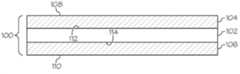
Fig. 5 is a diagram showing the residual stresses of the example and three comparative examples in which the residual stress is plotted on the y-axis and the depth is plotted on the x-axis;
6 is a schematic cross-sectional view of a ring-on-ring device;
7 shows the results of a worn ring-on-ring test for Example 1 and Comparative Examples A, B, D, and I, where the failure load is plotted on the y-axis and the wear pressure is on the x-axis; shown above;
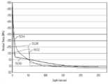
8 shows the residual stress of a single layer of chemically strengthened glass and the residual stress of a laminated glass article with a CTE mismatch between the layers of the glass article, where the residual stress is plotted on the y-axis and the depth is x -shown on the axis;
9 shows various examples of stress profiles formed from chemical strengthening and combined stress profiles formed from a combination of mechanical and chemical strengthening, where residual stress is plotted on the y-axis and depth is plotted on the x-axis;
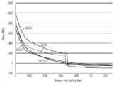
10 shows various examples of retention strength profiles formed from chemical strengthening and combined retention strength profiles formed from a combination of mechanical strengthening and chemical strengthening, wherein the retention strength is plotted on the y-axis and depth is on the x-axis. is shown in;
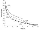
11 is a diagram illustrating residual stresses of various examples and comparative examples, wherein the residual stress is plotted on the y-axis and depth plotted on the x-axis; and
12 is a diagram illustrating retention strength of various examples and comparative examples, wherein retention strength is plotted on the y-axis and depth is plotted on the x-axis.
다양한 구현예에 대하여 참조가 상세히 이루어질 것이며, 실시예가 첨부된 도면에서 예시된다. 가능한 한, 동일하거나 또는 유사한 부분을 언급하기 위하여 도면을 걸쳐 동일한 참조 부호가 사용될 것이다.Reference will be made in detail to various embodiments, the embodiments of which are illustrated in the accompanying drawings. Wherever possible, the same reference numbers will be used throughout the drawings to refer to the same or like parts.
다르게 명시되지 않는 한, 본원에 서술된 어느 방법이 특정 순서로 단계들이 수행되거나, 또는 특정 배향의 어느 장치를 요구하도록 고려되는 것으로 의도되지 않는다. 따라서, 방법 청구항이 단계에 이어지도록 순서를 명시적으로 기재하지 않거나, 또는 어느 장치 청구항이 개별적인 성분의 배향 또는 순서를 명시적으로 기재하지 않거나, 또는 단계가 특정 순서로 한정되는 것으로 청구항 또는 설명에서 구체적으로 명시되지 않거나, 또는 장치의 구성에 대한 특정 순서 또는 배향이 기재되지 않은 경우, 순서 또는 배향이 어느 관점에서 고려되는 것으로 의도되지 않는다. 이는 다음을 포함하여 해석을 위한 어느 가능한 비-표현적 기초에 대해 유지된다: 단계, 작동 흐름, 구성성분의 순서 또는 구성성분의 배향의 배열과 관련한 논리상의 문제; 문법 조직 또는 구두법으로터 유래된 명백한 의미, 및; 명세서에 기재된 구현예의 수 또는 유형.Unless otherwise specified, it is not intended that any method described herein be contemplated as requiring the steps to be performed in a particular order, or to require any device in a particular orientation. Accordingly, a method claim does not explicitly recite an order to be followed by steps, or an apparatus claim does not explicitly recite an orientation or order of individual components, or steps are limited to a specific order in the claims or descriptions. No order or orientation is intended to be considered in any respect unless specifically indicated, or unless a specific order or orientation for the construction of devices is disclosed. This holds for any possible non-representative basis for interpretation, including: logical issues relating to the arrangement of steps, operational flows, order of components or orientation of components; explicit meaning derived from grammatical organization or punctuation; and; The number or type of embodiments described in the specification.
본원에서 사용되는 바와 같이, 단수 형태는 맥락적으로 다르게 명시되지 않는 한, 복수의 참조를 포함한다. 따라서, 예를 들어, "하나의" 성분에 대한 참조는 맥락적으로 다르게 명시되지 않는 한, 2 이상의 이러한 성분들을 갖는 관점을 포함한다. 또한, 단어 "또는"은 선행사 "중 어느 하나"(또는 "또는"이 배제적으로 비균등한 것을 가리키는 다른 유사 용어 - 예를 들어, x 또는 y 중 단지 하나, 등) 없이 사용되는 경우, 포괄적으로 해석되어야 한다(예를 들어, "x 또는 y"는 x 또는 y 둘 모두 또는 하나를 의미한다).As used herein, the singular forms include plural references unless the context dictates otherwise. Thus, for example, reference to "a" component includes aspects having two or more such components, unless the context dictates otherwise. Also, the word "or" is inclusive when used without the antecedent "any of" (or other similar terms indicating that "or" is exclusively unequal - eg, only one of x or y, etc.) (eg, "x or y" means either or both x or y).
용어 "및/또는"은 또한 포괄적으로 해석되어야 한다(예를 들어, "x 및/또는 y"는 x 또는 y 모두 또는 하나를 의미한다). "및/또는" 또는 "또는"이 3 이상의 항목의 군에 대해서 접속사로 사용되는 경우, 상기 군은 하나의 항목 단독, 이들 모두의 항목을 함께, 또는 어느 조합 또는 수의 이들 항목을 포함하는 것으로 이해되어야 한다. 또한, "갖는다, 갖는, 포함한다 및 포함하는과 같은 명세서 및 청구항에서 사용된 용어들은 용어 포함하다 및 포함하는과 동의어로 고려되어야 한다.The term “and/or” should also be interpreted inclusively (eg, “x and/or y” means either or both x or y). When “and/or” or “or” is used as a conjunction with respect to a group of three or more items, the group is intended to include one item alone, all of these items together, or any combination or number of these items. should be understood Also, terms used in the specification and claims, such as "has, has, includes, and includes," should be considered synonymous with the terms includes and including.
다르게 명시되지 않는 한, 본 명세서(또는 청구항 외)에서 사용되는, 모든 수치 또는 표현, 가령 디멘전, 물리적 특성 및 그 유사 사항은 용어 "대략"에 의해 모든 경우에서 변형되는 것으로 이해된다. 적어도, 본 청구항의 균등물의 적용을 제한하지 않으려는 시도로, 용어 "대략"에 의해 변형된 본 명세서 또는 청구항 내에 기재된 각 수치 파라미터는 기재된 유효 숫자 자리수의 수의 관점에서 그리고 보통의 반올림 기술을 적용하여 고려되어야 한다.Unless otherwise specified, all numbers or expressions used herein (or outside the claims), such as dimensions, physical properties and the like, are understood to be modified in all instances by the term "approximately". At the very least, in an attempt not to limit the application of equivalents of this claim, each numerical parameter recited herein or in a claim modified by the term "approximately" in light of the number of recited significant digits and applying ordinary rounding techniques should be considered.
모든 언급된 범위들은 어느 및 모든 범위 또는 각각의 범위에 의해 포함된 어느 및 모든 개별적인 값을 기재하는 청구항에 대한 뒷받침을 제공하며 포함하는 것으로 이해되어야 한다. 예를 들어, 1 내지 10의 언급된 범위는 최소값 1 및 최대값 10을 포함하거나 및/또는 그 사이의 어느 및 모든 서브범위 또는 개별 값을 기재하는 청구항에 대한 뒷받침을 제공하며 이를 포함하는 것으로 고려되어야 한다; 즉, 1 이상의 최소 값으로 시작하고 10 이하의 최대 값으로 끝나는 모든 서브 범위들(예를 들어, 5.5 내지 10, 2.34 내지 3.56, 및 등) 또는 1에서 10까지의 어느 값(예를 들어, 3, 5.8, 9.9994, 및 등).All recited ranges are to be understood as including and providing support for any and all ranges or claims reciting any and every individual value encompassed by each range. For example, a stated range of 1 to 10 provides support for and is considered to include the minimum value of 1 and the maximum value of 10 and/or providing support for claims reciting any and all subranges or individual values therebetween. should be; That is, all subranges starting with a minimum value of 1 or greater and ending with a maximum value of 10 or less (eg, 5.5 to 10, 2.34 to 3.56, and etc.) or any value from 1 to 10 (eg, 3 , 5.8, 9.9994, and so on).
기재된 모든 수치는 어느 하나의 방향으로 0-100% 가변적인 것으로 이해되어야 하며, 따라서 이러한 값에 의해 형성될 수 있는 이러한 값 또는 어느 및 모든 범위 또는 서브 범위를 기재하는 청구항에 대한 뒷받침을 제공한다. 예를 들어, 8의 기재된 수치는 0 내지 16(어느 하나의 방향으로 100%)으로 변하며, 상기 범위 그 자체(예를 들어, 0 내지 16), 상기 범위 내의 어느 서브범위(예를 들어, 2 내지 12.5) 또는 상기 범위 내의 개별적인 값(예를 들어, 15.2)을 기재하는 청구항에 대한 뒷받침을 제공한다는 점이 이해되어야 한다.All numerical values recited are to be understood as varying from 0-100% in either direction, thus providing support for claims reciting such values or any and all ranges or subranges that may be formed by such values. For example, a stated numerical value of 8 varies from 0 to 16 (100% in either direction), the range itself (eg, 0 to 16), any subrange within the range (eg, 2 to 12.5) or individual values within the range (eg, 15.2), it is to be understood as providing support for claims.
도면은 크기 대로 도시되지 않은 하나 이상의 구현예 및/또는 크기 대로 도시된 하나 이상의 구현예를 예시하는 것으로 해석되어야 한다. 이는 예를 들어, 도면이 다음과 같이 나타내는 것으로 해석될 수 있다: (a) 모든 것이 크기대로 도시됨, (b) 어떤 것도 크기 대로 도시되지 않음, 또는 (c) 하나 이상의 피쳐가 크기 대로 도시되고 하나 이상의 피쳐가 크기 대로 도시되지 않음. 따라서, 도면은 서로에 대해서 또는 단독으로 중 어느 하나로 어느 도시된 피쳐의 크기, 비례 및/또는 기타 치수를 기재하는 뒷받침을 제공하도록 기능할 수 있다. 또한, 모든 이러한 크기, 비례 및/또는 기타 치수는 어느 하나의 방향으로 0-100% 가변적인 것으로 이해되어야 하므로, 이러한 값에 의해 형성될 수 있는 이러한 값 또는 어느 및 모든 범위 또는 서브 범위를 기재하는 청구항에 대한 뒷받침을 제공한다.The drawings should be interpreted as illustrating one or more implementations not drawn to scale and/or one or more implementations not drawn to scale. This may be construed as, for example, that the drawings represent: (a) everything is drawn to scale, (b) nothing is drawn to scale, or (c) one or more features are drawn to scale and One or more features not drawn to scale. Accordingly, the drawings may serve to provide a backing describing the sizes, proportions and/or other dimensions of any depicted features, either relative to each other or alone. Further, all such sizes, proportions and/or other dimensions are to be understood as varying from 0-100% in either direction, and therefore it is to be understood that such values or any and all ranges or subranges that may be formed by such values are described. Provide support for the claim.
청구항에서 기재된 용어는 다음의 예외에만 속하는 청구항 용어(예를 들어, 조합된 항목의 가장 넓은 의미를 제공하도록 2 이상의 관련 사전 항목이 조합되어야 하는)에 이들 소스의 어느 하나 또는 조합에 의해 부여되는 가장 넓은 의미가 주어져야 하는 것으로 이해되어, 당업자에 의해 공통적으로 이해되는 의미, 관련 기술 사전 및/또는 일반 사전에서 널리 사용되는 관련 항목을 참조로 하여 결정되는 바에 따라 평범하고 관례적인 의미로 주어져야 한다: (a) 용어가 평범하고 관례적인 의미보다 더 광대한 방식으로 사용되는 경우, 상기 용어는 평범하고 관례적인 의미에 덧붙여 부가적인 광대한 의미로 주어져야 하거나, 또는 (b) 용어가 "본 문헌에서 얕은 의미로 사용되는 바와 같은" 어구 또는 유사한 언어(예를 들어, "이 용어는 의미한다", "이 용어는 바와 같이 정의된다, "본 기재의 목적을 위하여 본 용어는 의미되어야 한다", 등)에 의해 이어지는 기재에 의해 다른 의미를 갖도록 명시적으로 정의되는 경우. 구체적인 예의 참조, 단어 "발명"의 사용, "즉"의 사용 등은 예외 (b)를 일의키는 것을 의미하지 않거나 또는 기재된 청구항 용어들의 범위를 다르게 제한하지 않는다. 본 문헌에 함유되지 않은 어떤 것, 예외 (b)가 적용되는 기타 상황은 청구 범위의 부인 또는 부정으로 고려되어야 한다.The terms recited in the claims are the most conferred by any one or combination of these sources on claim terms (eg, two or more related dictionary entries must be combined to provide the broadest meaning of the combined entry) subject to the following exceptions only. It is to be understood that a broad meaning is to be given, as determined by reference to a meaning commonly understood by those skilled in the art, a related technical dictionary and/or a related item widely used in a general dictionary: ( a) where a term is used in a manner broader than its ordinary and customary meaning, the term shall be given in an additional broad sense in addition to its ordinary and customary meaning, or (b) if the term has a "shallow meaning in this document" in a phrase or similar language (eg, "this term means", "this term is defined as" Where explicitly defined to have a different meaning by the description that follows by reference to a specific example, use of the word "invention", use of "i.e.", etc., does not imply that exception (b) is unique or claimed without otherwise limiting the scope of the terms, anything not contained herein, or any other circumstance to which exception (b) applies, shall be considered a denial or negation of the claims.
본원에서 사용되는 바와 같이, 용어 "평균 열팽창계수" 또는 "평균 CTE"는 0 ℃ 내지 300 ℃ 사이의 주어진 물질 또는 층의 선형 열팽창계수의 평균을 나타낸다. 본원에서 사용되는 바와 같이, 용어 "열팽창계수" 또는 "CTE"는 다르게 명시되지 않는 한 평균 열팽창계수를 나타낸다.As used herein, the term “average coefficient of thermal expansion” or “average CTE” refers to the average of the linear thermal expansion coefficients of a given material or layer between 0°C and 300°C. As used herein, the term "coefficient of thermal expansion" or "CTE" refers to the average coefficient of thermal expansion unless otherwise specified.
다양한 구현예에서, 상기 유리 물품의 하나 이상의 성질은 후-형성 가상 공정(fictivation process)의 사용에 의해 개선된다. 본원에서 사용되는 바와 같이, "가상"은 적절한 열 처리를 통해서 유리 상에 열적 이력 또는 특정의 가상 온도를 부여하는 것을 나타낸다. 본원에서 사용되는 바와 같이, 용어 "가상 온도(fictive temperature)"는 유리의 엔탈피에 대한 구조적 기여를 반영하는 온도를 나타낸다. 유리의 가상 온도는 "Unified approach for determining the enthalpic fictive temperature of glasses with arbitrary thermal history," (Journal of Non-Crystalline Solids 357 (2011) pp. 3230-3236)에서 Xiaoju Guo 등에 의해 기술되는 바와 같은 비색분석법에 의해 결정될 수 있으며, 그 내용은 전체가 참고로서 본원에 혼입된다. 본원에 기재된 유리에서, 상기 가상 온도는 유리 물품의 유리 전이 온도(Tg)보다 50 ℃ 내지 200 ℃ 만큼 더욱 크다.In various embodiments, one or more properties of the glass article are improved by use of a post-forming fictivation process. As used herein, “virtual” refers to imparting a thermal history or a particular fictive temperature on glass through appropriate thermal treatment. As used herein, the term “fictive temperature” refers to a temperature that reflects the structural contribution to the enthalpy of a glass. The fictive temperature of the glass is a colorimetric method as described by Xiaoju Guo et al. in "Unified approach for determining the enthalpic fictive temperature of glasses with arbitrary thermal history," (Journal of Non-Crystalline Solids 357 (2011) pp. 3230-3236). may be determined by, the contents of which are incorporated herein by reference in their entirety. In the glasses described herein, the fictive temperature is greater than the glass transition temperature (Tg) of the glass article by 50°C to 200°C.
유리 라미네이트glass laminate
다양한 구현예에서, 유리 물품은 적어도 제1의 층 및 제2의 층을 포함한다. 예를 들어, 상기 제1의 층은 코어층을 포함하며, 제2의 층은 코어층에 인접한 하나 이상의 클래드층을 포함한다. 상기 제1의 층 및/또는 제2의 층은 유리 물질, 세라믹 물질, 유리-세라믹 물질, 또는 이들의 조합을 포함하는 유리층이다.In various embodiments, the glass article includes at least a first layer and a second layer. For example, the first layer includes a core layer and the second layer includes one or more cladding layers adjacent the core layer. The first layer and/or the second layer is a glass layer comprising a glass material, a ceramic material, a glass-ceramic material, or a combination thereof.
일부 구현예에서, 상기 제1의 층 및/또는 제2의 층은 투명한 유리층이다.In some embodiments, the first layer and/or the second layer is a transparent glass layer.
상기 코어층은 평균 코어 CTE (코어 CTE 또는 CTEcore)를 가지며, 상기 클래드층은 평균 클래드 CTE (클래드 CTE 또는 CTEclad)를 갖는다. 예를 들어, 상기 코어층은 코어 CTE를 갖는 제1의 유리 조성물로부터 형성되며, 상기 클래드층은 클래드 CTE를 갖는 제2의 유리 조성물로부터 형성된다. 상기 코어 CTE는 어느 열 처리 또는 이온 교환 전에, 코어층이 인장에 있고 클래드층이 압축에 있도록 클래드 CTE보다 크다. 일부 구현예에서, 유리 라미네이트의 응력 프로파일은 클래드층 내에 배치된 압축 응력 피크를 포함한다(예를 들어, 클래드층의 외표면 및 클래드층의 내표면 사이). 부가적으로 또는 대안적으로, 상기 유리 라미네이트의 응력 프로파일은 클래드층 내에 배치된 연속적으로 증가하는 영역을 포함할 수 있다(예를 들어, 어느 압축 응력 스파이크를 배제한, 클래드층의 외표면 및 압축의 깊이 사이에서 압축 응력이 증가한다). 일부 구현예에서, 클래드층의 압축 응력은 클래드층 및 코어층의 계면까지 유리 물품 내의 증가하는 깊이로 증가한다. 또 다른 구현예에서, 상기 유리 라미네이트의 응력 프로파일은 클래드층 및 코어층 사이의 계면까지 유리 물품 내의 깊이 증가로 연속적으로 감소하는 압축 응력 및 유리 라미네이트의 표면에서의 압축 응력 피크를 포함한다.The core layer has an average core CTE (core CTE or CTEcore ), and the clad layer has an average clad CTE (clad CTE or CTEclad ). For example, the core layer is formed from a first glass composition having a core CTE and the clad layer is formed from a second glass composition having a clad CTE. The core CTE is greater than the clad CTE so that, prior to any heat treatment or ion exchange, the core layer is in tension and the clad layer is in compression. In some embodiments, the stress profile of the glass laminate includes compressive stress peaks disposed within the clad layer (eg, between an outer surface of the clad layer and an inner surface of the clad layer). Additionally or alternatively, the stress profile of the glass laminate may include continuously increasing regions disposed within the cladding layer (eg, the outer surface of the clad layer, excluding any compressive stress spikes, and of compression). compressive stress increases between depths). In some embodiments, the compressive stress of the clad layer increases with increasing depth within the glass article up to the interface of the clad layer and the core layer. In another embodiment, the stress profile of the glass laminate comprises a compressive stress that continuously decreases with increasing depth in the glass article up to the interface between the clad layer and the core layer and a compressive stress peak at the surface of the glass laminate.
도 1은 유리 물품(100)의 일 구현예의 단면도이다. 상기 유리 물품(100)은 복수의 유리층을 포함하는 라미네이트된 시트이다. 구현예에서, 상기 라미네이트된 시트는 도 1에 나타낸 바와 같이 실질적으로 평면일 수 있거나, 또는 상기 라미네이트된 시트는 비-평면일 수 있다. 상기 유리 물품(100)은 제1의 클래드층(104) 및 제2의 클래드층(106) 사이에 배치된 코어층(102)을 포함한다. 일부 구현예에서, 상기 제1의 클래드층(104) 및 제2의 클래드층(106)은 도 1에 나타낸 바와 같이, 코어층(102)에 대해서 외층이다. 예를 들어, 상기 제1의 클래드층(104)의 외표면(108)은 유리 물품(100)의 외표면이거나, 및/또는 상기 제2의 클래드층(106)의 외표면(100)은 상기 유리 물품(100)의 외표면이다. 다른 구현예에서, 상기 제1의 클래드층(104) 및/또는 제2의 클래드층(106)은 코어층(102) 및 외부층(미도시) 사이에 배치된 중간층이다.1 is a cross-sectional view of one embodiment of a
상기 코어층(102)은 제1의 주표면 및 제1의 주표면에 대향하는 제2의 주표면을 포함한다. 일부 구현예에서, 상기 제1의 클래드층(104)은 상기 코어층(102)의 제1의 주표면에 용융된다. 부가적으로 또는 대안적으로, 상기 제2의 클래드층(106)은 상기 코어층(102)의 제2의 주표면에 용융된다. 이러한 구현예에서, 제1의 클래드층(104) 및 코어층(102) 사이의 계면(112) 및/또는 제2의 클래드층(106) 및 코어층(102) 사이의 계면(114)은 코어층에 각각의 클래드층을 부착하기 위하여 부가되거나 또는 구성된, 어느 결합 물질, 가령, 예를 들어, 접착제, 코팅층 또는 어느 비-유리 물질을 함유하지 않는다. 따라서, 상기 제1의 클래드층(104) 및/또는 제2의 클래드층(106)은 코어층(102)에 직접 용융되거나 및/또는 코어층(102)에 직접 인접한다. 일부 구현예에서, 상기 유리 물품(100)은 코어층 및 제1의 클래드층 사이 및/또는 코어층 및 제2의 클래드층 사이에 배치된 하나 이상의 중간층을 포함한다. 예를 들어, 상기 중간층은 코어층 및 클래드층의 계면에 형성된 확산층 및/또는 중간 유리층을 포함할 수 있다. 상기 확산층은 확산층에 인접한 각 층의 성분을 포함하는 블렌드된 영역(예를 들어, 2개의 직접 인접한 유리층들 사이의 블렌드된 영역)을 포함할 수 있다. 일부 구현예에서, 상기 유리 물품(100)은 직접 인접한 유리층들 사이의 계면이 유리-유리 계면인 유리-유리 라미네이트를 포함한다.The
일부 구현예에서,상기 코어층(102)은 제1의 유리 조성물을 포함하며, 제1 및/또는 제2의 클래드층(104, 106)은 상기 제1의 유리 조성물과 다른 제2의 유리 조성물을 포함한다. 상기 제1의 유리 조성물 및 제2의 유리 조성물은 본원에 기재된 바와 같이 유리 물품(100)을 화학적으로 강화하기 전에 서로 다르다. 예를 들어, 도 1에 나타낸 구현예에서, 상기 코어층(102)은 제1의 유리 조성물을 포함하며, 상기 제1의 클래드층(104) 및 제2의 클래드층(106) 각각은 제2의 유리 조성물을 포함한다. 다른 구현예에서, 상기 제1의 클래드층은 제2의 유리 조성물을 포함하며, 상기 제2의 클래드층은 상기 제1의 유리 조성물 및/또는 제2의 유리 조성물과 다른 제3의 유리 조성물을 포함한다.In some embodiments, the
상기 유리 물품은 적합한 공정, 가령, 예를 들어, 퓨전 인발, 하향 인발, 슬롯 인발, 상향 인발 또는 플로우트 공정을 사용하여 형성될 수 있다. 일부 구현예에서, 상기 유리 물품(100)은 퓨전 인발 공정을 사용하여 형성된다. 도 2는 유리 물품, 가령, 예를 들어 유리 물품(100)을 형성하는데 사용될 수 있는 오버플로우 배급기(200)의 실시예의 단면도이다.The glass article may be formed using a suitable process, such as, for example, a fusion draw, down draw, slot draw, up draw or float process. In some embodiments, the
상기 오버플로우 배급기(200)는 미국특허번호 제4,214,886호에 기재된 바와 같이 구성될 수 있으며, 상기 문헌은 그 전체가 참고로서 혼입된다. 예를 들어, 퓨전 인발 장치(200)는 하부 오버플로우 배급기(220) 및 하부 오버플로우 배급기(220) 위에 위치된 상부 오버플로우 배급기(240)를 포함한다. 상기 하부 오버플로우 배급기(220)는 트로프(222)를 포함한다. 제1의 유리 조성물(224)이 용융되어 점성 상태로 트로프(222) 내로 공급된다. 상기 제1의 유리 조성물(224)은 이하에서 더욱 설명되는 바와 같이 유리 물품(100)의 코어층(102)을 형성한다. 상기 상부 오버플로우 배급기(240)는 트로프(242)를 포함한다. 제2의 유리 조성물(244)이 용융되어 점성 상태로 트로프(242) 내로 공급된다. 상기 제2의 유리 조성물(244)은 이하에서 더욱 설명되는 바와 같이 유리 물품(100)의 제1 및 제2의 클래드층(104, 106)을 형성한다.The
상기 제1의 유리 조성물(224)은 트로프(222)를 흘러넘쳐 하부 오버플로우 배급기(220)의 대향하는 외부 형성 표면(226 및 228) 아래로 흐른다. 상기 외부 형성 표면(226 및 228)은 인발 라인(230)에서 수렴한다. 상기 하부 오버플로우 배급기(220)의 각각의 외부 형성 표면(226 및 228) 아래로 흐르는 제1의 유리 조성물(224)의 개별적인 스트림은 상기 인발 라인(230)에서 수렴하며, 여기서 이들은 함께 용융되어 유리 물품(100)의 코어층(102)을 형성한다.The
상기 제2의 유리 조성물(224)은 트로프(242)를 흘러넘쳐 상부 오버플로우 배급기(240)의 대향하는 외부 형성 표면(246 및 248) 아래로 흐른다. 상기 제2의 유리 조성물(244)은 상기 제2의 유리 조성물(224)이 하부 오버플로우 배급기(220) 주위로 흘러 상기 하부 오버플로우 배급기(220)의 외부 형성 표면(226 및 228) 위로 흐르는 제1의 유리 조성물(224)과 접촉하도록 상부 오버플로우 배급기(240)에 의해 바깥으로 방향이 바꿔진다. 상기 제2의 유리 조성물(244)의 개별적인 스트림은 하부 오버플로우 배급기(220)의 각각의 외부 형성 표면(226 및 288) 아래로 흐르는 제1의 유리 조성물(224)의 각각의 개별적인 스트림에 용융된다. 인발 라인(230)에서 제1의 유리 조성물(224)의 스트림의 수렴 시, 상기 제2의 유리 조성물(244)은 상기 유리 물품(100)의 제1 및 제2의 클래드층(104, 106)을 형성한다.The
일부 구현예에서,점성 상태의 상기 코어층(102)의 제1의 유리 조성물(224)은 점성 상태의 제1 및 제2의 클래드층(104, 106)의 제2의 유리 조성물(244)과 접촉되어 라미네이트된 시트를 형성한다. 이러한 구현예의 일부에서, 상기 라미네이트된 시트는 도 2에 나타낸 바와 같이, 하부 오버플로우 배급기(220)의 인발 라인(230)으로부터 떨어져 이동하는 유리 리본의 부분이다. 상기 유리 리본은 예를 들어, 중력 및/또는 풀링 롤러를 포함하는 적합한 수단에 의해 하부 오버플로우 배급기(220)로부터 떨어져 인발될 수 있다. 상기 유리 리본은 하부 오버플로우 배급기(220)로부터 떨어져 이동함에 따라 냉각된다. 상기 유리 리본은 라미네이트된 시트를 이들로부터 분리하기 위하여 끊어진다. 따라서, 라미네이트된 시트는 유리 리본으로부터 커팅된다. 상기 유리 리본은 적합한 기술, 가령, 예를 들어, 스코링, 벤딩, 열충격, 및/또는 레이저 커팅을 사용하여 끊어질 수 있다. 일부 구현예에서, 상기 유리 물품(100)은 도 1에 나타낸 바와 같은 라미네이트된 시트를 포함한다. 다른 구현예에서, 상기 라미네이트된 시트는 더욱 공정되어(예를 들어, 커팅 또는 몰딩) 유리 물품을 형성할 수 있다.In some embodiments, the
상기 유리 물품(100)은 3개의 층을 포함하는 것으로 도 1에 나타내지만, 다른 구현예가 고려된다. 예를 들어, 상기 유리 물품은 2, 4 또는 그 이상의 층을 가질 수 있다. 2개의 층을 포함하는 유리 물품은 2개의 층이 결합되는 한편 오버플로우 배급기의 각각의 인발 라인으로부터 떨어져 이동하도록 위치된 2개의 오버플로우 배급기를 사용하거나, 또는 2개의 유리 조성물이 오버플로우 배급기의 대향하는 외부 형성 표면 위로 흘러 오버플로우 배급기의 인발 라인에서 수렴하도록 나누어진 트로프를 갖는 단일 오버플로우 배급기를 사용함으로써 형성될 수 있다. 4개의 층을 포함하는 유리 물품은 부가적인 오버플로우 배급기 및/또는 나누어진 트로프를 갖는 오버플로우 배급기를 사용하여 형성될 수 있다. 따라서, 미리결정된 수의 층을 갖는 유리 물품은 오버플로우 배급기를 그에 따라 변형함으로써 형성될 수 있다.Although the
상기 유리 물품(100)은 라미네이트된 시트를 포함하는 것으로 도 1에 나타나나, 다른 형태가 고려된다. 예를 들어, 상기 유리 물품은 복수의 관형 층(예를 들어, 하나 이상의 환형 오리피스)를 포함하는 라미네이트된 튜브의 형태일 수 있으며, 상기 라미네이트된 튜브의 부분적인 단면은 도 1에 나타낸 것과 유사한 라미네이트된 구조를 가질 수 있다. 다른 구현예에서, 상기 유리 물품은 성형된 유리 물품일 수 있으며, 가령 라미네이트된 시트를 성형하거나 몰딩함으로써 형성될 수 있다.The
일부 구현예에서,상기 유리 물품(100)은 적어도 약 0.05 mm, 적어도 약 0.1 mm, 적어도 약 0.2 mm, 또는 적어도 약 0.3 mm의 두께를 갖는다. 부가적으로 또는 대안적으로, 상기 유리 물품(100)은 약 3 mm 미만, 약 2 mm 미만, 약 1.5 mm 미만, 약 1 mm 미만, 약 0.7 mm 미만, 또는 약 0.6 mm 미만의 두께를 갖는다. 일부 구현예에서, 상기 유리 물품의 두께에 대한 코어층(102)의 두께의 비는 적어도 약 0.5, 적어도 약 0.7, 적어도 약 0.8, 적어도 약 0.85, 적어도 약 0.9, 또는 적어도 약 0.95이다. 부가적으로 또는 대안적으로, 상기 유리 물품의 두께에 대한 코어층의 두께의 비는 약 0.95 미만, 약 0.93 미만, 약 0.9 미만, 약 0.87 미만, 또는 약 0.85 미만이다. 일부 구현예에서, 상기 제2의 층의 두께(예를 들어, 각각의 제1의 클래드층(104) 및 제2의 클래드층(106))는 약 0.01 mm 내지 약 0.6 mm이다.In some embodiments, the
일부 구현예에서,상기 제1의 유리 조성물 및/또는 제2의 유리 조성물은 본원에 기재된 바와 같은 퓨전 인발 공정을 사용하여 유리 물품(100)을 형성하는데 적합한 액상 점도를 갖는다. 예를 들어, 상기 코어층(102)의 제1의 유리 조성물은 적어도 약 100 kP, 적어도 약 200 kP, 또는 적어도 약 300 kP의 액상 점도를 가질 수 있다. 부가적으로 또는 대안적으로, 상기 제1의 유리 조성물은 약 3000 kP 미만, 약 2500 kP 미만, 약 1000 kP 미만, 또는 약 800 kP 미만의 액상 점도를 포함한다. 상기 제1 및/또는 제2의 클래드층(104 및 106)의 제2의 유리 조성물은 적어도 약 50 kP, 적어도 약 100 kP, 또는 적어도 약 200 kP의 액상 점도를 가질 수 있다. 부가적으로 또는 대안적으로, 상기 제2의 유리 조성물은 약 3000 kP 미만, 약 2500 kP 미만, 약 1000 kP 미만, 또는 약 800 kP 미만의 액상 점도를 포함한다. 상기 제1의 유리 조성물은 제2의 층을 형성하기 위하여 상기 오버플로우 배급기 위로 제2의 유리 조성물을 운반하는데 도움을 줄 수 있다. 따라서, 상기 제2의 유리 조성물은 퓨전 인발 공정을 사용하여 단일 층 시트를 형성하는데 적합한 것으로 일반적으로 고려되는 것보다 낮은 액상 점도를 가질 수 있다.In some embodiments, the first glass composition and/or the second glass composition have a liquidus viscosity suitable for forming the
본원에 기재된 다양한 구현예에서, 상기 유리 물품(100)은 기계적 강화 및 열적 템퍼링, 또는 가상, 및/또는 이온 교환의 조합에 의해 강화된다. 예를 들어, 상기 유리 물품(100)은 본원에 기재된 바와 같은 CTE 불일치를 가질 수 있으며, 열적으로 템퍼링되거나 또는 가상되어 깊은 흠에 대하여 응력 프로파일을 더욱 개선하고 누프 및 비커스 스크래치 성능을 개선할 수 있다. 또 다른 예로서, 상기 유리 물품(100)은 본원에 기재된 바와 같은 CTE 불일치를 가질 수 있으며, 이온 교환되어 깊은 흠에 대한 응력 프로파일을 개선할 수 있다.In various embodiments described herein, the
기계적 강화mechanical reinforcement
다양한 구현예에서, 상기 유리 물품(100)은 기계적으로 강화된다. 예를 들어, 상기 제1 및/또는 제2의 클래드층(104, 106)을 형성하는 제2의 유리 조성물은 상기 코어층(102)을 형성하는 제1의 유리 조성물과 다른 CTE를 가질 수 있다. 특히, 일부 구현예에서, 상기 제1 및 제2의 클래드층(104, 106)은 상기 코어층(102)의 유리 조성물보다 낮은 CTE를 갖는 유리 조성물로부터 형성될 수 있다. CTE 불일치(즉, 상기 제1 및 제2의 클래드층(104, 106) 및 코어층(102)의 CTE 사이의 차이)는 유리 물품(100)의 냉각 시 코어층 내의 인장 응력 및 클래드층 내의 압축 응력의 형성으로 귀결된다. 다양한 구현예에서, 각각의 상기 제1 및 제2의 클래드층은 독립적으로 코어층보다 높은 CTE, 낮은 CTE 또는 실질적으로 동일한 CTE를 가질 수 있다. 표면 압축 응력은 존재하는 표면 흠이 균열로 발전하는 것을 억제하는 경향을 갖는다. 좀 더 높은 CTE 불일치는 클래드층에서 좀 더 높은 표면 압축으로 귀결된다. 부가적으로, 좀 더 두꺼운 클래드층은 좀 더 깊은 압축의 깊이 (DOC)로 귀결된다. 그러나, 이러한 좀 더 높은 표면 압축 응력 및 좀 더 깊은 DOC는 또한 코어층 내의 인장 응력 증가로 귀결된다. 따라서, 다양한 인자가 본원에 기재된 바와 같이 서로 균형을 맞추어야 한다.In various embodiments, the
구현예에서, 상기 코어층(102)의 CTE 및 제1 및/또는 제2의 클래드층(104, 106)의 CTE는 적어도 약 5 x 10⁻⁷℃-1, 적어도 약 15 x 10-7℃-1, 적어도 약 25 x 10-7℃-1, 또는 적어도 약 30 x 10-7℃-1 만큼 다르다. 부가적으로 또는 대안적으로, 상기 코어층(102)의 CTE 및 제1 및/또는 제2의 클래드층(104, 106)의 CTE는 약 100 x 10-7℃-1 미만, 약 75 x 10-7℃-1미만, 약 50 x 10-7℃-1 미만, 약 40 x 10-7℃-1 미만, 약 30 x 10-7℃-1 미만, 약 20 x 10-7℃-1 미만, 또는 약 10 x 10-7℃-1 미만 만큼 다르다. 예를 들어, 일부 구현예에서, 상기 코어층의 CTE 및 제1 및/또는 제2의 클래드층의 CTE는 약 5 x 10⁻⁷℃-1 내지 약 30 x 10-7℃-1, 또는 약 5 x 10⁻⁷℃-1 내지 약 20 x 10-7℃-1 만큼 다르다. 일부 구현예에서, 상기 제1 및/또는 제2의 클래드층의 제2의 유리 조성물은 약 66 x 10-7℃-1 미만, 약 55 x 10-7℃-1 미만, 약 50 x 10-7℃-1 미만, 약 40 x 10-7℃-1 미만, 또는 약 35 x 10-7℃-1 미만의 CTE를 갖는다. 부가적으로 또는 대안적으로, 상기 제1 및/또는 제2의 클래드층의 제2의 유리 조성물은 적어도 약 10 x 10-7℃-1, 적어도 약 15 x 10-7℃-1, 적어도 약 25 x 10-7℃-1, 또는 적어도 약 30 x 10-7℃-1의 CTE를 갖는다. 상기 코어층의 제1의 유리 조성물은 적어도 약 40 x 10-7℃-1, 적어도 약 50 x 10-7℃-1, 적어도 약 55 x 10-7℃-1, 적어도 약 65 x 10-7℃-1, 적어도 약 70 x 10-7℃-1, 적어도 약 80 x 10-7℃-1, 또는 적어도 약 90 x 10-7℃-1의 CTE를 가질 수 있다. 부가적으로 또는 대안적으로, 상기 코어층의 제1의 유리 조성물은 약 120 x 10-7℃-1 미만, 약 110 x 10-7℃-1 미만, 약 100 x 10-7℃-1 미만, 약 90 x 10-7℃-1 미만, 약 75 x 10-7℃-1 미만, 또는 약 70 x 10-7℃-1 미만의 CTE를 가질 수 있다.In an embodiment, the CTE of the core layer 102 and the CTE of the first and/or second clad layers 104 , 106 are at least about 5 x 10⁻⁷ °C-1 , at least about 15 x 10-7 °C-1 , at least about 25 x 10-7 °C-1 , or at least about 30 x 10-7 °C-1 . Additionally or alternatively, the CTE of the core layer 102 and the CTE of the first and/or second clad layers 104 , 106 areless than about 100 x 10 -7 °C-1 , about 75 x 10Less than -7 ℃-1, less than about 50 x 10-7 ℃-1, less than about 40 x 10-7 ℃-1, less than about 30 x 10-7 ℃-1, less than about 20 x 10-7 ℃-1 , or by less than about 10 x 10-7 °C-1. For example, in some embodiments, the CTE of the core layer and the CTE of the first and/or second clad layers are from about 5 x 10⁻⁷ °C-1 to about 30 x 10-7 °C-1 , or about 5 x 10⁻⁷ °C-1 to about 20 x 10-7 °C-1 . In some embodiments, the second glass composition of the first and/or second clad layer isless than about 66 x 10 -7 °C-1 , less than about 55 x 10-7 °C-1 , less than about 50 x 10- has a CTE of lessthan 7 °C-1 , less than about 40 x 10-7 °C-1 , or less than about 35 x 10-7 °C-1 . Additionally or alternatively, the second glass composition of the first and/or second clad layer may be at least about 10 x 10-7 °C-1 , at least about 15 x 10-7 °C-1 , at least about 25 x 10-7 °C-1 , or a CTE of at least about 30 x 10-7 °C-1 . The first glass composition of the core layer is at least about 40 x 10-7 °C-1 , at least about 50 x 10-7 °C-1 , at least about 55 x 10-7 °C-1 , at least about 65 x 10-7 CTE of °C-1 , at least about 70 x 10-7 °C-1 , at least about 80 x 10-7 °C-1 , or at least about 90 x 10-7 °C-1 . Additionally or alternatively, the first glass composition of the core layer isless than about 120 x 10 -7 °C-1 , less than about 110 x 10-7 °C-1 , less than about 100 x 10-7 °C-1 , less than about 90 x 10-7 °C-1 , less than about 75 x 10-7 °C-1 , or less than about 70 x 10-7 °C-1 .
열적thermal템퍼링tempering
본원에 기재된 다양한 구현예에서, 상기 유리 물품(100)은 열적으로 템퍼링되거나 또는 가상된다. 구현예에서, 상기 유리 물품(100)은 상기 클래드층의 유리 전이 온도(Tg)보다 50 ℃ 내지 200 ℃ 더 큰 제1의 온도로 가열된 후, 미리결정된 기간 동안 제1의 온도에서 상기 유리 물품을 안정시키며, 다음으로 상기 유리 물품을 상기 코어층 또는 클래드층의 좀 더 낮은 변형점 아래의 제2의 온도까지 급냉시킨다. 일부 구현예에서, 상기 유리 물품은 상기 클래드층의 유리 전이 온도(Tg)보다 50 ℃ 내지 200 ℃ 더 큰 제1의 온도로 가열되고, 이어서 제1의 온도에서 안정된 다음, 상기 클래드층 또는 코어층의 더 낮은 변형점 아래의 제2의 온도로 급냉된다. 상기 제1 및 제2의 클래드층(104, 106)이 다른 Tg를 갖는 구현예에서, 상기 제1의 온도는 좀 더 높은 Tg보다 크다. 일부 구현예에서, 상기 제1의 온도는 상기 클래드층의 Tg보다 높고, 상기 코어층의 Tg 미만이다. 다른 구현예에서, 상기 제1의 온도는 클래드층의 Tg 및 코어층의 Tg보다 높다. 일부 구현예에서, 상기 제1의 온도는 상기 클래드층 및 코어층의 두께 중량 평균 Tg보다 높다. 일부 구현예에서, 상기 유리 물품은 750 ℃ 이상 및 900 ℃ 이하, 또는 775 ℃ 이상 및 875 ℃ 이하, 또는 790 ℃ 이상 및 860 ℃ 이하의 제1의 온도로 가열된다. 일부 구현예에서, 상기 제2의 온도는 상기 클래드층의 변형점 미만이고 상기 코어층의 변형점 미만이다. 다른 구현예에서, 상기 제2의 온도는 상기 클래드층의 변형점 미만이고 코어층의 변형점을 초과한다. 일부 구현예에서, 상기 제2의 온도는 상기 클래드층 및 코어층의 두께 중량 평균 변형점 미만이다. 일부 구현예에서, 상기 유리는 제1의 온도로부터 약 실온(25 ℃ ± 10 ℃)인 제2의 온도까지 빠르게 냉각된다.In various embodiments described herein, the
도 3은 열 템퍼링 및 CTE 불일치에 의해 생성된 예시적인 조합된 열적 기계적 응력 프로파일(304) 및 CTE 불일치 단독에 의해 생성된 예시적인 기계적 응력 프로파일(302)을 포함하는 그래프이다. 도 3에 나타낸 바와 같이, 양의 응력은 압축 응력에 대응하는 한편, 음의 응력은 인장 응력에 대응한다. 기계적 응력 프로파일(302) 및 조합된 열적 기계적 응력 프로파일(304)에 대해서, 상기 열 전달 계수는 0.03이었다. 각 유리 물품은 4.0의 코어/클래드 비 및 55 ㎛의 클래드 두께로 라미네이트되었다. 상기 응력 프로파일은 유리 물품(100) 내의 깊이의 함수로서 응력에 의해 나타낸다. 유리 물품(100)의 외표면으로부터 거리로서 주어진, 유리 물품(100) 내의 깊이는 x-축 상에 도시되며, 응력은 y-축 상에 도시된다.3 is a graph including an exemplary combined thermal
상기 유리 물품의 응력 프로파일은 예를 들어, 복굴절 기반 측정 기술 또는 굴절 근-장(RNF) 기술을 사용하는 것을 포함하는 어느 적합한 기술을 사용하여 측정될 수 있다. 예를 들어, 응력 측정은 ASTM C1422 및 ATSM C1279에 따라 수행될 수 있다. 상기 응력 프로파일은 유리 물품 내의 깊이의 함수로서 유리 물품(100) 내의 응력을 포함한다. 상기 유리 물품의 외표면으로부터 거리로서 주어진, 유리 물품(100) 내의 깊이는 x-축 상에 도시되며, 응력은 y-축 상에 도시된다. 상기 유리 물품 내의 깊이는 압축의 깊이(DOC)로서 본원에서 언급될 수 있다. 압축 응력은 양의 x-축 상에 도시되며, 인장 응력은 음의 y-축 상에 도시된다. 그러나, 본원에 기재된 압축 및 인장 응력의 값은 응력의 절대 값을 나타내거나, 또는 응력의 크기를 나타낸다. 따라서, 인장 응력은 음의 값과 반대로 양의 값으로서 본원에서 제공된다.The stress profile of the glass article may be measured using any suitable technique including, for example, using a birefringence based measurement technique or a refractive near-field (RNF) technique. For example, stress measurements can be performed according to ASTM C1422 and ATSM C1279. The stress profile includes stress within the
기계적 응력 프로파일(302)을 참조하면, 상기 압축 영역(예를 들어, 클래드층)은 약 50 ㎛의 두께 및 약 150 MPa의 제1의 압축 응력을 갖는다. 기계적 응력(302)은 계단 함수이다. 따라서, 상기 압축 응력은 압축 영역을 통해서 상기 표면 압축 응력으로부터 연속적으로 증가하며, 상기 응력은 클래드층 및 코어층 사이의 계면 영역에서 계단형-변화로서 최대 인장 응력으로 전이한다.Referring to
조합된 열적 기계적 응력 프로파일(304)을 참조하면, 상기 압축 영역은 약 50 ㎛의 층의 깊이(DOL)까지 연장하며, 적어도 200 MPa의 표면 압축 응력을 갖는다. 다양한 구현예에서, 상기 표면 압축 응력은 250 MPa를 초과한다. 상기 압축 응력은 상기 클래드층을 통해서 상기 표면 압축 응력으로부터 클래드층의 외표면으로부터 거리 증가에 따라 연속적으로 증가하며, 코어층 및 클래드층 사이의 계면 영역에서 계단형-변화로서 최대 인장 응력으로 전이하며, 인장 응력의 규모는 상기 계단형-변화로부터 코어층 내의 최대 인장 응력가지 연속적으로 증가한다. 따라서, 기계적 응력 프로파일(302)과 반대로, 상기 조합된 역적 기계적 응력 프로파일(304)은 상기 코어층의 중간-지점까지 코어층 내의 연속적으로 증가하는 인장 응력의 영역을 갖는다.Referring to the combined thermal
나아가, 조합된 열적 기계적 응력 프로파일(304)에서 볼 수 있는 바와 같이, 상기 열적 템퍼링은, 특히 코어층 내의, 상기 프로파일에 포물선 형상을 도입하며, 이는 종종 인장 영역으로서 나타낼 수 있다. 응력 프로파일 내의 이러한 형상은 코어층 내로 연장하는 흠이 유리 물품의 깊이 내로 더욱 깊어질 때까지 피크가되지 않을 것임을 나타낸다.Furthermore, as can be seen in the combined thermal
도 3은 유리 물품(예를 들어, 하나의 클래드층 및 코어층의 부분을 통해서)의 두께의 부분을 통해서 응력 프로파일 각각의 부분만을 예시한다는 점이 인식될 것이다. 대칭적인 유리 물품에 대해서, 유리 물품의 두께의 남은 부분을 통한 응력 프로파일은 도 3의 응력 프로파일의 예시된 부분의 거울 이미지이다.It will be appreciated that FIG. 3 illustrates only a portion of each of the stress profiles through a portion of the thickness of the glass article (eg, through a portion of one clad layer and a core layer). For a symmetrical glass article, the stress profile through the remainder of the thickness of the glass article is a mirror image of the illustrated portion of the stress profile of FIG. 3 .
유리 물품의 보유 강도는 유리 물품의 응력 프로파일에 기반하여 결정될 수 있다. 예를 들어, 상기 보유 강도는 상기 유리 물품의 표면으로부터 특정된 깊이까지 연장하는 흠을 형성하는 단계 및 흠의 형성 후 상기 유리 물품의 강도를 결정하는 단계에 의해 결정된다. 상기 강도는 예를 들어, 링-온-링 시험 방법(예를 들어, ASTM C1499-09에 기재된 바에 따라), 볼-온-링 시험 방법, 3-점 굽힘 시험 방법, 4-점 굽힘 시험 방법, 또는 또 다른 적합한 방법 또는 기술을 사용하여 결정된 유리 물품의 굴곡 강도이다. 이러한 보유 강도 결정은 상기 유리 물품의 응력 프로파일에 기반한 파괴 역학 모사(fracture mechanics simulation)를 사용하여 수행될 수 있다.The retention strength of the glass article may be determined based on a stress profile of the glass article. For example, the retention strength is determined by forming a flaw extending from a surface of the glass article to a specified depth and determining the strength of the glass article after formation of the flaw. The strength can be determined, for example, by a ring-on-ring test method (eg, as described in ASTM C1499-09), a ball-on-ring test method, a three-point bending test method, a four-point bending test method. , or the flexural strength of the glass article as determined using another suitable method or technique. Such retained strength determination can be performed using fracture mechanics simulation based on the stress profile of the glass article.
도 4는 기계적 강화 단독, 열적 템퍼링 단독, 및 기계적 강화 및 열적 템퍼링의 조합에 의해 발생된 응력 프로파일에 대응하는 실시예 보유 강도 프로파일을 비교하는 그래프이다. 상기 보유 강도 프로파일은 흠 크기의 함수로서 보유 강도에 의해 나타낸다. 유리 물품의 외표면으로부터 흠이 연장되는 지점까지의 거리로서 주어진, 흠 크기는 x-축 상에 도시되며, 보유 강도는 y-축 상에 도시된다.4 is a graph comparing Example retained strength profiles corresponding to stress profiles generated by mechanical strengthening alone, thermal tempering alone, and a combination of mechanical strengthening and thermal tempering. The retention strength profile is represented by retention strength as a function of flaw size. Flaw size, given as the distance from the outer surface of the glass article to the point at which the flaw extends, is plotted on the x-axis and retention strength is plotted on the y-axis.
상기 보유 강도 프로파일(402, 404, 406 및 408)은 파괴 역학 모사를 사용하여 발생되었다. 상기 기계적 보유 강도 프로파일(402)은 CTE 불일치(예를 들어, 기계적으로 강화된)를 포함하는 라미네이트된 유리 물품에 기반하였다. 상기 열적 보유 강도 유리 프로파일(404 및 406)은 열적 템퍼링(예를 들어, 열적으로 템퍼링된)에 투입된 단일 층 유리 물품에 기반하였다. 상기 조합된 보유 강도 프로파일(408)은 열적 템퍼링에 투입된(예를 들어 기계적으로 강화되고 열적으로 템퍼링된) CTE 불일치를 갖는 라미네이트된 유리 물품에 기반하였다.The retention strength profiles 402, 404, 406 and 408 were generated using fracture mechanics simulations. The mechanical
도 4에 나타낸 바와 같이, 각각의 강도 프로파일은 유리 물품의 외표면 부근에서 상대적으로 높은 보유 강도(예를 들어, 적어도 약 250 MPa)를 가지며, 이는 상대적으로 얕은 낙하(예를 들어, 약 10 ㎛ 미만)의 결과로서 유리 물품의 파손을 피하는 것을 도울 수 있다. 그러나, 조합된 보유 강도 프로파일(408)은 유리 물품 내로 더욱 깊게(예를 들어, 클래드층의 표면으로부터 먼 거리로) 기계적 보유 강도 프로파일(402)보다 높은 보유 강도를 유지한다. 예를 들어, 조합된 보유 강도 프로파일(408)의 보유 강도는 약 5 ㎛ 내지 약 140 ㎛의 흠 크기에 대해서 기계적 보유 강도 프로파일(402)보다 높으며, 이는 상대적으로 깊은 흠의 결과로서 유리 물품의 파손을 피하는 것을 도울 수 있다. 나아가, 상기 조합된 보유 강도 프로파일(408)의 보유 강도는 약 25 ㎛ 내지 약 40 ㎛의 흠 크기에 대한 강도에서의 상당한 개선으로, 약 40 ㎛을 초과하는 흠 크기에 대해서 열적인 보유 강도 유리 프로파일(404 및 406)과 대적할 만한 것으로 남는다. 따라서, 이러한 흠 크기로부터 귀결되는 파손에 대한 개선된 저항성은 조합된 보유 강도 프로파일(408)과 유사한 보유 강도 프로파일을 갖는 커버 유리에 대해서 개선된 낙하 성능으로 전이된다.As shown in FIG. 4 , each strength profile has a relatively high retention strength (eg, at least about 250 MPa) near the outer surface of the glass article, which results in a relatively shallow drop (eg, about 10 μm). less) as a result of which may help avoid breakage of the glass article. However, the combined
도 5는 도 4에 도시된 프로파일에 대한 잔류 응력 모델을 도시한다. 상기 잔류 응력 프로파일(502, 504, 506 및 508)은 파괴 역학 모사를 사용하여 발생되었다. 상기 기계적 잔류 응력 프로파일(502)은 CTE 불일치를 포함하는 라미네이트된 유리 물품에 기반하였다. 상기 열적 잔류 응력 유리 프로파일(504 및 506)은 열적 템퍼링에 투입되는 단일 층 유리 물품에 기반하였다. 조합된 잔류 응력 프로파일(508)은 열적 템퍼링에 투입되는 CTE 불일치를 갖는 라미네이트된 유리 물품에 기반하였다.Fig. 5 shows a residual stress model for the profile shown in Fig. 4; The residual stress profiles 502, 504, 506 and 508 were generated using fracture mechanics simulations. The mechanical
도 5에 나타낸 바와 같이, 조합된 잔류 응력 프로파일(508)은 약 50 ㎛ 까지의 압축의 깊이 (DOC)에 대해서 압축 응력의 상대적으로 일정한 양을 가지며, 이는 클래드층 및 코어층 사이의 계면 영역에 대응한다. 상기 조합된 잔류 응력 프로파일(508) 내의 압축 응력은 적어도 25 ㎛ 내지 50 ㎛의 깊이에 대해서 대적할만한 잔류 응력 프로파일 내의 잔류 압축 응력보다 상당히 크다. 부가적으로, 상기 압축 응력은 DOC를 통해서 계면 영역까지 상대적으로 일정하게 남으며, 이는 표면 흠이 균열로 전개되는 것을 방지할 수 있다. 클래드층 및 코어층 사이의 계면 영역에서, 상기 응력은 계단형-변화의 압축 응력으로부터 최대 인장 응력까지 전이하며, 이는 코어층을 통해서 계단형-변화로부터 매끄럽게 그리고 연속적으로 증가한다.5, the combined
개선된 강도 및 응력 프로파일을 제공하는 것에 덧붙여, 다양한 구현예에서, 상기 유리 물품의 조합된 기계 그리고 가상은 비커스 스크래치 임계값 및 압입 시험 성능 및 누프 스크래치 시험 성능에 의해 증명되는 바와 같이, 예리한 접촉 손상 사건에 대한 개선된 저항성을 제공할 수 있다.In addition to providing an improved strength and stress profile, in various embodiments, the combined mechanical and virtual of the glass article is subjected to sharp contact damage, as evidenced by Vickers scratch threshold and indentation test performance and Knoop scratch test performance. may provide improved resistance to events.
본원에 기재된 비커스 압입 임계값 측정은 0.2 mm/min의 속도에서 유리 표면에 압입 하중을 적용한 후 제거함으로써 수행된다. 최대 압입 하중은 10초 동안 유지된다. 압입 임계값은 10중 50%가 인덴트 임프레션의 코너로부터 나오는 방사상/중앙(radial/median) 균열의 어떤 수를 나타내는 압입 하중에서 정의된다. 최대 하중은 상기 임계값이 주어진 유리 조성물에 대해서 충족될 때까지 증가된다. 모든 압입 측정은 50% 상대 습도에서 실온에서 수행된다.The Vickers indentation threshold measurement described herein is performed by applying and then removing an indentation load to the glass surface at a rate of 0.2 mm/min. The maximum indentation load is held for 10 s. The indentation threshold is defined at the indentation load in which 50% out of 10 represents a certain number of radial/median cracks emerging from the corners of the indent impression. The maximum load is increased until the above threshold is met for a given glass composition. All indentation measurements are performed at room temperature at 50% relative humidity.
비커스 스크래치 임계값은 증가하는 하중에서 비커스 인덴터로 유리 물품의 표면을 스크래치하는 것에 반응으로 유리 물품에서 측면 균열이 먼저 발견되는 하중을 나타낸다. 시험 과정은 비커스 인덴터가 누프 다이아몬드로 치환되는 것을 제외하고는, 누프 스크래치 임계값을 결정하는데 사용되는 것과 유사하다. 측면 균열은 비커스 인덴터에 의해 형성된 원래 스크래치 또는 그루브의 폭의 2배를 초과하는 유리 물품 내의 지속된 균열에 의해 증명된다.The Vickers scratch threshold represents a load at which a lateral crack is first found in a glass article in response to scratching the surface of the glass article with a Vickers indenter at increasing loads. The testing procedure is similar to that used to determine the Knoop scratch threshold, except that the Vickers indenter is replaced with a Knoop diamond. Lateral cracking is evidenced by sustained cracking in the glass article exceeding twice the width of the original scratch or groove formed by the Vickers indenter.
본원에 기재된 누프 스크래치 임계값(KST)은 누프 다이아몬드 인덴터를 사용하여 결정된다. 상기 스크래치 임계값은 측면 균열 개시에 대해서 하중 범위를 먼저 확인함으로써 결정된다. 하중 범위가 확인되면, 하중 당 3 이상의 스크래치를 갖는 증가하는 일정한 하중 하에 일련의 5 mm 길이 스크래치가 누프 스크래치 임계값을 확인하기 위하여 4 mm/s의 속도에서 발생된다. 측면 균열은 그루브의 폭을 2배보다 큰 지속된 균열로서 정의된다.The Knoop Scratch Threshold (KST) described herein is determined using a Knoop Diamond Indenter. The scratch threshold is determined by first checking the load range for lateral crack initiation. Once the load range was identified, a series of 5 mm long scratches under increasing constant load with 3 or more scratches per load were generated at a rate of 4 mm/s to confirm the Knoop scratch threshold. A side crack is defined as a sustained crack that is greater than twice the width of the groove.
표 1은 기계적으로 강화된 동일한 유리 물품에 비해서 기계적 그리고 열적으로 템퍼링된(실시예 1) 0.55 mm의 두께를 갖는 실시예 유리 물품에 대해서 최소 및 최대 비커스 스크래치 임계값, 비커스 압입 임계값, 및 누프 스크래치 임계값에서의 변화(△)를 제공한다.Table 1 shows the minimum and maximum Vickers scratch thresholds, Vickers indentation thresholds, and knoops for an example glass article having a thickness of 0.55 mm that was mechanically and thermally tempered (Example 1) compared to the same mechanically strengthened glass article. It gives the change in scratch threshold (Δ).

표 1에 제공된 데이터에 의해 나타낸 바와 같이, 유리 물품의 열적 템퍼링 및 기계적 강화의 조합은 증가된 최소 스크래치/압입 파괴 저항성 뿐만 아니라 비커스 스크래치 및 비커스 압입 값 모두의 증가된 최대값으로 귀결될 수 있다.As indicated by the data provided in Table 1, the combination of thermal tempering and mechanical strengthening of the glass article can result in increased minimum scratch/indentation fracture resistance as well as increased maximum values of both Vickers scratch and Vickers indentation values.
하나 이상의 구현예에서, 본원에 기재된 유리 물품은 마모된 링-온-링(AROR) 시험에 투입되는 경우 개선된 표면 강도를 더욱 나타낸다. 물질의 강도는 파괴가 일어나는 응력으로 정의된다. 상기 AROR 시험은 평평한 유리 시료의 시험을 위한 표면 강도 측정이며, "Standard Test Method for Monotonic Equibiaxial Flexural Strength of Advanced Ceramics at Ambient Temperature" 명칭의 ASTM C1499-09(2013)가 본원에 기재된 AROR 시험 방법론에 대한 기본으로서 기능한다. ASMT C1499-09의 내용은 그 전체가 참고로서 본원에 혼입된다. 구현예에서, 상기 유리 시료는 "Standard Test Methods for Strength of Glass by Flexure (Determination of Modulus of Rupture) 명칭의 ASMT C158-02(2012)의 "Abrasion Procedures" 명칭의 Annex A2에 기재된 방법 및 장치를 사용하여 유리 샘플에 전달된 90 그릿 실리콘 카바이드(SiC) 입자로 링-온-링 시험하기 전에 마모된다. 상기 ASTM C158-02의 내용 및 Annex 2의 내용은 특히 그 전체가 참고로서 본원에 혼입된다.In one or more embodiments, the glass articles described herein further exhibit improved surface strength when subjected to an abraded ring-on-ring (AROR) test. The strength of a material is defined as the stress at which failure occurs. The AROR test is a surface strength measurement for the testing of flat glass samples, and ASTM C1499-09 (2013) entitled “Standard Test Method for Monotonic Equibiaxial Flexural Strength of Advanced Ceramics at Ambient Temperature” is a method for the AROR test methodology described herein. serves as the basis. The content of ASMT C1499-09 is incorporated herein by reference in its entirety. In an embodiment, the glass sample is prepared using the methods and apparatus described in Annex A2 entitled "Abrasion Procedures" of ASMT C158-02 (2012) entitled "Standard Test Methods for Strength of Glass by Flexure (Determination of Modulus of Rupture)" and abraded prior to ring-on-ring testing with 90 grit silicon carbide (SiC) particles transferred to glass samples.The content of ASTM C158-02 and Annex 2 above are specifically incorporated herein by reference in their entirety.
링-온-링 시험 전에, 유리 물품의 표면은 ASTM C158-02, Annex 2에 기술된 바에 따라 마모되어 ASTM C158-02의 도 A2.1에 도시된 장치를 사용하여 샘플의 표면 결함 조건을 표준화하거나 및/또는 제어한다. 상기 연마재는 미리결정된 압력에서 유리 물품의 표면 상에서 샌드블라스트된다. 공기 흐름이 확립된 후, 5 cm3의 연마재가 깔때기 내로 덤프되며, 상기 샘플은 연마재의 도입 후 5초 동안 샌드블라스트된다.Prior to the ring-on-ring test, the surface of the glass article was abraded as described in ASTM C158-02, Annex 2 to standardize the surface defect conditions of the sample using the apparatus shown in Figure A2.1 of ASTM C158-02. and/or control. The abrasive is sandblasted onto the surface of the glass article at a predetermined pressure. After the air flow is established, 5 cm3 of abrasive is dumped into the funnel, and the sample is sandblasted for 5 seconds after introduction of the abrasive.
링-온-링 시험에 대해서, 적어도 하나의 마모된 표면을 갖는 유리 물품은 도 6에 나타낸 바와 같이 다른 크기의 2개의 동심 링 사이에 위치되어 양축굴곡 강도를 결정한다(즉, 2개의 동심 링 사이에 굴곡이 주어지는 경우 물질이 지속될 수 있는 최대 응력). 상기 마모된 링-온-링 구조(600)에서, 상기 마모된 유리 물품(610)은 직경 D2를 갖는 지지 링(620)에 의해 지지된다. 힘(F)은 하중 셀(미도시)에 의해 직경 D1을 갖는 하중 링(630)에 의해 유리 물품의 표면에 적용된다.For the ring-on-ring test, a glass article having at least one worn surface is placed between two concentric rings of different sizes as shown in FIG. 6 to determine the biaxial strength (i.e., the two concentric rings The maximum stress that a material can sustain if given a flex between them). In the worn ring-on-
하중 링 및 지지 링의 직경의 비 D1/D2는 약 0.2 내지 약 0.5의 범위일 수 있다. 일부 구현예에서, D1/D2는 약 0.5이다. 하중 및 지지 링(630, 620)은 지지 링 직경(D2)의 0.5% 이내로 동심으로 정렬되어야 한다. 시험에 사용되는 하중 셀은 선택된 범위 내의 어느 하중에서 ±1% 이내로 정확해야 한다. 일부 구현예에서, 시험은 23±2 ℃의 온도 및 40±10%의 상대 습도에서 수행된다.The ratio D1/D2 of the diameters of the load ring and the support ring may range from about 0.2 to about 0.5. In some embodiments, D1/D2 is about 0.5. The load and support rings 630 and 620 should be concentrically aligned to within 0.5% of the support ring diameter D2. The load cell used for the test shall be accurate to within ±1% of any load within the selected range. In some embodiments, the test is performed at a temperature of 23±2° C. and a relative humidity of 40±10%.
고정 디자인에 대해서, 하중 링(630)의 생산 표면의 직경 r은 h/2≤r≤3h/2이며, 여기서 h는 유리 물품(610)의 두께이다. 하중 및 지지 링(630, 620)은 경도 HRc > 40를 갖는 경화강으로 전형적으로 이루어진다. ROR 고정은 상업적으로 입수 가능하다.For the stationary design, the diameter r of the production surface of the
상기 ROR 시험에 대한 의도된 고장 메커니즘(failure mechanism)은 하중 링(630) 내의 표면(630a)으로부터 기원하는 유리 물품(610)의 파괴를 관찰하기 위한 것이다. 상기 영역 밖에서 일어나는 고장, 즉, 하중 링(630)과 지지 링(620) 사이에서 일어나는 고장은 데이터 분석에서 생략된다. 그러나, 유리 물품(610)의 두께 및 고 강도에 기인하여, 시료 두께 h의 1/2를 초과하는 큰 편향(deflection)으 종종 관찰된다. 따라서, 하중 링(630) 아래로부터 유래된 고장의 높은 %를 관찰하는 것은 흔하다. 응력은 각 시료 내의 고장의 기원 및 링의 내부 및 아래 모두에서 응력 전개의 인지(변형 게이지 분석을 통해서 수집된) 없이 정확하게 계산될 수 없다. 따라서 AROR 시험은 측정된 반응에 따라 고장에서의 피크 하중에 초점을 맞춘다.The intended failure mechanism for the ROR test is to observe the failure of the
상기 유리 물품의 강도는 표면 흠의 존재에 좌우된다. 그러나, 주어진 크기의 흠이 존재할 가능성은 유리의 강도가 본래 통계적이므로 정확하게 예측할 수 없다. 확률 분포는 따라서 얻어진 데이터의 통계적 대표로서 일반적으로 사용될 수 있다.The strength of the glass article is dependent on the presence of surface flaws. However, the probability of the presence of a flaw of a given size cannot be accurately predicted since the strength of the glass is inherently statistical. Probability distributions can therefore be used generally as a statistical representation of the data obtained.
도 7은 실시예 1 및 비교예 A, B, C, 및 D에 대한 마모 압력(x-축 상)의 함수로서 고장에 대한 하중(y-축)의 그래프를 나타낸다. 표 2는 실시예 1 및 비교예 A-D의 설명을 제공한다.7 shows a graph of load to failure (y-axis) as a function of wear pressure (on x-axis) for Example 1 and Comparative Examples A, B, C, and D. FIG. Table 2 provides a description of Example 1 and Comparative Examples A-D.

도 7에 나타낸 바와 같이, 약 5 psi 초과의 압력에 대해서, 실시예 1은 약 35 psi까지 실질적으로 일정한 보유 강도를 나타낸다. 따라서, 기계적으로 그리고 열적으로 강화된 상기 유리 물품은 손상의 깊이에 대해서 상대적으로 덜민감한 반면, 비교예는 동일한 수준에 걸쳐 강도에서 큰 변화를 나타낸다. 도 7은 또한 가상 라미네이트가 비교예 D보다 25 psi에서 거의 2배의 보유 강도를 나타내는, 우수한 성능을 가졌다는 점을 증명한다.7 , for pressures greater than about 5 psi, Example 1 exhibits a substantially constant retention strength up to about 35 psi. Thus, the mechanically and thermally strengthened glass articles are relatively insensitive to the depth of damage, while the comparative example shows a large change in strength over the same level. 7 also demonstrates that the virtual laminate had superior performance, exhibiting nearly twice the retention strength at 25 psi than Comparative Example D.
다양한 구현예에서, 상기 제2의 층(예를 들어, 제1의 클래드층(104) 및/또는 제2의 클래드층(106))은 상대적으로 낮은 CTE, 이온-교환가능한 유리 조성물을 포함하며, 상기 제1의 층(예를 들어, 코어층(102))은 상대적으로 높은 CTE 이온-교환가능한 유리 조성물을 포함한다. 제2의 층에 사용하기에 적합할 수 있는 예시적인 유리 조성물은 미국 특허출원 공개번호 제2014/00141217호 및 미국 특허출원 공개번호 제2015/0030827에 기재된 것을 포함하며, 이들 각각은 그 전체가 참고로서 본원에 혼입된다. 제1의 층으로 사용하기에 적합할 수 있는 예시적인 유리 조성물은 미국 특허출원 공개번호 제2014/00141217호 및 미국 특허출원 공개번호 제2015/0037552에 기재된 것을 포함하며, 이들 각각은 그 전체가 참고로서 본원에 혼입된다.In various embodiments, the second layer (eg, first clad
화학적 강화chemical strengthening
본원에 기재된 다양한 구현예에서, 상기 유리 물품(100)은 열적 템퍼링의 대안으로 또는 이에 덧붙여 기계적 강화 및 화학적 강화의 조합에 의해 강화될 수 있다. 예를 들어, 상기 유리 물품(100)은 본원에 기재된 바와 같은 CTE 불일치를 가질 수 있으며, 화학적으로 강화되어 라미네이션 또는 CTE 불일치 단독에 비해서 적어도 클래드층을 통해서 압축 응력을 더욱 증가시킬 수 있다.In various embodiments described herein, the
본원에 기재된 다양한 구현예에서, 상술한 바와 같이 기계적으로 강화된 후, 상기 유리 물품(100)은 화학적으로 강화된다. 예를 들어, 상기 유리 물품(100)은 2중의 이온 교환 처리되어 유리 물품의 외표면(예를 들어, 클래드층의 바깥 부분)에서 유리 물품의 영역 내에 압축 응력을 증가시킬 수 있다. 일부 구현예에서, 상기 이온 교환 처리는 유리 물품(100)의 하나 이상의 표면에 이온 교환 매체를 적용하는 단계 또는 그렇지 않으면 이온 교환 매체(예를 들어, 이온 교환 욕)와 라미네이트된 유리 물품(100)을 접촉시키는 단계를 포함한다. 상기 이온 교환 매체는 용액, 페이스트, 겔 또는 유리 네트워크(예를 들어, 제2의 층의 유리 네트워크) 내의 좀 더 작은 이온과 교환될 하나 이상의 이온 소스 또는 좀 더 큰 이온의 소스를 포함하는 또 다른 적합한 매체일 수 있다. 용어 "좀 더 큰 이온" 및 "좀 더 작은 이온"은 상대적인 용어로서, 좀 더 큰 이온은 좀 더 작은 이온에 비해서 상대적으로 크며, 좀 더 작은 이온은 좀 더 큰 이온에 비해서 상대적으로 작다는 것을 의미한다. 따라서, 좀 더 큰 이온은 좀 더 작은 이온보다 좀 더 큰 이온 반경을 가지며, 좀 더 작은 이온은 좀 더 큰 이온보다 좀 더 작은 이온 반경을 갖는다. 일부 구현예에서, 상기 유리 물품(100)의 제2의 층은 알칼리 알루미노실리케이트 유리를 포함한다. 따라서, 상기 유리의 표면 층 내의 좀 더 작은 이온 및 이온 교환 매체 내의 좀 더 큰 이온은 1가의 알칼리 금속 양이온(예를 들어, Li+, Na+, 및/또는 K+)일 수 있다. 대안저으로, 상기 유리 물품(100) 내의 1가의 양이온은 알칼리 금속 양이온 외의 1가 양이온(예를 들어, Ag+또는그 유사물)으로 대체될 수 있다. 일부 구현예에서, 상기 유리 물품(100)의 제2의 층은 알칼리 토 알루미노실리케이트 유리를 포함한다. 일부 구현예에서, 상기 이온 교환 매체는 용융 염 용액을 포함하며, 상기 이온 교환 처리는 유리 매트릭스 내의 좀 더 작은 이온(예를 들어, Na+, Li+, Ca2+, 및/또는 Mg2+)으로 이온교환될 좀 더 큰 이온을 포함하는 용융 염 욕 내에 라미네이트된 유리 물품을 침지시키는 단계를 포함한다. 일부 구현예에서, 상기 용융 염 욕은 좀 더 큰 이온의 염(예를 들어, 질산염, 황산염 및/또는 염화물)을 포함한다. 예를 들어, 용융 염 욕은 용융 KNO3, 용융 NaNO3, 또는 이들의 조합을 포함할 수 있다. 부가적으로 또는 대안적으로, 용융 염 욕의 온도는 약 380 ℃ 내지 약 450 ℃일 수 있으며, 침지 시간은 약 2 시간 내지 약 16 시간이다.In various embodiments described herein, after being mechanically strengthened as described above, the
본원에 기재된 다양한 구현예에서, 상기 이온 교환 매체는 적어도 2의 이온 소스(예를 들어, 적어도 2개의 양이온)을 포함한다. 일부 구현예에서, 단일 이온 교환 매체는 이온 소스 둘 모두를 포함할 수 있는 한편, 다른 구현예에서, 제1의 이온 교환 매체는 제1의 이온 소스를 포함할 수 있는 한편, 제2의 이온 교환 매체는 제2의 이온 소스를 포함할 수 있다. 예를 들어, 일부 구현예에서, 상기 이온 교환 매체는 Na+ 및 K+ 이온(또는 이들의 염)을 포함할 수 있는 한편, 이는 응력 프로파일의 다른 지점에서 응력을 조절하는데 사용될 수 있다. 다른 구현예에서, 상기 유리 물품은 Na+ 이온을 포함하는 제1의 이온 교환 매체와 접촉될 수 있으며, 다음으로 K+ 이온을 포함하는 제2의 이온 교환 매채와 접촉될 수 있다. 유리 물품(100)의 표면에서 좀 더 큰 이온을 갖는 유리 매트릭스 내에 좀 더 작은 이온을 대체함으로써, 상기 제2의 층의 압축 응력은 상기 유리 물품의 외표면에서 증가된다. 예를 들어, 상기 이온 교환 처리 동안, 이온 교환 매체로부터의 좀 더 큰 이온은 유리 물품(100)의 제2의 층의 바깥 부분 내로 확산하며, 상기 유리 매트릭스로부터의 좀 더 작은 이온은 상기 유리 물품의 제2의 층의 바깥 부분 밖으로 확산한다. 따라서, 상기 제2의 층의 바깥 부분은 유리 물품의 교환된 영역을 포함한다. 상기 이온 교환된 영역 내의 좀 더 큰 이온의 증가된 농도는 유리 네트워크의 과밀을 야기하고 상기 이온 교환된 영역 내의 유리 물품(100)의 압축 응력을 증가시킨다. 일부 구현예에서, 이온 교환 처리에 유리 물품(100)을 투입하는 것은 상기 유리 물품의 외표면에서의 표면 압축 응력(예를 들어, CTE 불일치에 의해 발생된 초기 표면 압축 응력으로부터)을 최종 압축 응력 값까지 증가시킨다. 예를 들어, 상기 최종 압축 응력 값은 적어도 약 200 MPa, 적어도 약 300 MPa, 적어도 약 400 MPa, 적어도 약 500 MPa, 적어도 약 600 MPa, 적어도 약 700 MPa, 적어도 약 800 MPa, 적어도 약 900 MPa, 또는 적어도 약 1,000 MPa이다. 부가적으로 또는 대안적으로, 상기 최종 압축 응력 값은 약 1300 MPa 미만, 약 1200 MPa 미만, 약 1000 MPa 미만, 약 900 MPa 미만, 또는 약 800 MPa 미만이다.In various embodiments described herein, the ion exchange medium comprises at least two ion sources (eg, at least two cations). In some embodiments, a single ion exchange medium may include both ion sources, while in other embodiments, a first ion exchange medium may include a first ion source while a second ion exchange medium The medium may include a second ion source. For example, in some embodiments, the ion exchange medium may include Na+ and K+ ions (or salts thereof), while they may be used to modulate stress at different points in the stress profile. In another embodiment, the glass article may be contacted with a first ion exchange medium comprising Na+ ions, and then contacted with a second ion exchange medium comprising K+ ions. By replacing smaller ions in the glass matrix with larger ions at the surface of the
나아가, 다양한 구현예에서, 상기 유리 물품은 50 ㎛ 이상의 압축의 깊이 (DOC)를 가질 수 있다. 예를 들어, 상기 유리 물품은 70 ㎛ 이상, 100 ㎛ 이상, 또는 200 ㎛ 이상의 DOC를 가질 수 있다. 상기 DOC는 상기 클래드층의 두께를 증가시키는 것에 덧붙여 이온 교환에 의해 달성될 수 있다.Furthermore, in various embodiments, the glass article can have a depth of compression (DOC) of 50 μm or greater. For example, the glass article may have a DOC of at least 70 μm, at least 100 μm, or at least 200 μm. The DOC may be achieved by ion exchange in addition to increasing the thickness of the cladding layer.
도 8은 화학적 강화 단독에 의해 발생된 실시예의 화학적 응력 프로파일(804) 및 CTE 불일치 단독에 의해 발생된 실시예의 기계적 응력 프로파일(802)을 포함하는 예시적인 그래프이다. 상기 응력 프로파일은 유리 물품(100) 내의 깊이의 함수로서 응력에 의해 표시된다. 유리 물품(100)의 외표면으로부터 거리로서 주어진 유리 물품(100) 내의 깊이가 x-축 상에 도시되며, 응력이 y-축 상에 도시된다.8 is an exemplary graph including a
기계적 응력 프로파일(802)을 참조하면, 상기 압축 응력(예를 들어, 클래드층)은 약 50 ㎛의 두께(예를 들어, DOC) 및 약 150 MPa의 제1의 압축 응력을 갖는다. 기계적 응력(302)은 계단형 함수이다. 따라서, 상기 압축 응력은 상기 클래드층을 통해서 표면으로부터 실질적으로 일정하게 남으며, 클래드층 및 코어층 사이의 계면 영역에서 계단형-변화로서 최대 인장 응력으로 전이된다.Referring to
화학적 응력 프로파일(804)을 참조하면, 압축 영역은 약 80 ㎛의 압축의 깊이 (DOC)까지 연장하며, 약 900 MPa의 표면 압축 응력을 갖는다. 상기 압축은 압축 영역의 외표면에서 표면 압축 응력으로부터 인장 영역 내의 최대 인장 응력까지 연속적으로 전이한다. 따라서, 기계적 응력 프로파일(802)과 반대로, 상기 화학적 응력 프로파일(804)은 압축 응력 영역 및 인장 영역 사이에 일정한 압축 응력 또는 계단형-변화의 영역을 갖지 않는다.Referring to
다양한 구현예에서, 상기 유리 물품(100)은 기계적 강화 및 화학적 강화의 조합에 의해 강화된다. 예를 들어, 본원에 기재된 바와 같은 CTE 불일치를 갖는 유리 물품(100)(예를 들어, 유리 라미네이트)은 화학적으로 강화되어 압축 층의 외표면에서 압축을 더욱 증가시킨다. 도 9는 기계적 강화 및 화학적 강화의 조합으로부터 형성된 조합된 응력 프로파일 및 화학적 강화로부터 형성된 응력 프로파일의 다양한 예를 나타내는 그래프이다.In various embodiments, the
도 9는 유리 물품의 두께의 부분을 통한(예를 들어, 하나의 클래드층 및 코어층의 부분을 통한) 각각의 응력 프로파일의 부분만을 예시하는 것임이 인식될 것이다. 대칭형 유리 물품에 대해서(예를 들어, 동일한 두께 및 유리 조성물을 갖는 2개의 클래드층 사이에 위치된 코어층), 상기 유리 물품의 두께의 잔여 부분을 통한 응력 프로파일은 도 9 내의 응력 프로파일의 예시된 부분의 거울 이미지이다. 도 9에 나타낸 실시예에서, 상기 응력 프로파일(902) 및 응력 프로파일(904)은 본원에 기재된 바와 같은 2중의 이온 교환 처리를 사용하여 화학적으로 강화되었다. 상기 응력 프로파일(906) 및 응력 프로파일(908)은 2중 이온 교환 처리를 사용하여 기계적으로 강화되고 화학적으로 강화된 유리 물품에 대한 응력 프로파일이다. 특히, 상기 응력 프로파일(908)을 갖는 유리 물품은 이온 교환 및 계단형 변화에 대해서 좀 더 얕은 층의 깊이, 라미네이트 층들 사이에 좀 더 낮은 CTE 차이, 및 좀 더 낮은 피크 CS를 갖는다. 응력 프로파일(902)은 응력 프로파일(906)의 유리 라미네이트에 사용된 2중 이온 교환에 대응되며, 응력 프로파일(904)은 응력 프로파일(908)의 유리 라미네이트에 대해 사용된 2중 이온 교환에 대응한다.It will be appreciated that FIG. 9 only illustrates a portion of each stress profile through a portion of the thickness of the glass article (eg, through a portion of one clad layer and a core layer). For a symmetrical glass article (eg, a core layer positioned between two clad layers having the same thickness and glass composition), the stress profile through the remainder of the thickness of the glass article is an illustration of the stress profile in FIG. It is a mirror image of a part. In the embodiment shown in FIG. 9 , the
각각의 응력 프로파일(906 및 908)에서의 압축 응력은 클래드층의 외표면으로부터 거리 증가에 따라 각각 약 1000 MPa 및 800 MPa의 제1의 압축 응력으로부터 연속적으로 감소하며, 다음으로 코어층 및 클래드층 사이의 계면 영역에서 계단형-변화로서 최대 인장 응력으로 전이한다. 인장 응력의 규모는 상기 계단형-변화로부터 상기 코어층 내의 최대 인장 응력까지 연속적으로 증가한다. 반대로, 각각의 응력 프로파일(902 및 904) 내의 압축 응력은 클래드의 외표면으로부터 거리 증가에 따라 연속적으로 감소하며, 코어층 내의 최대 인장 응력으로 매끄럽게 전이한다.The compressive stress in each of the stress profiles 906 and 908 successively decreases from the first compressive stress of about 1000 MPa and 800 MPa, respectively, with increasing distance from the outer surface of the clad layer, followed by the core layer and the clad layer. The transition to maximum tensile stress as a step-change in the interfacial region between The magnitude of the tensile stress increases continuously from the step-change to the maximum tensile stress in the core layer. Conversely, the compressive stress in each of the stress profiles 902 and 904 decreases continuously with increasing distance from the outer surface of the clad, and smoothly transitions to the maximum tensile stress in the core layer.
일부 구현예에서,상기 유리 물품(100)은 화학적으로 강화되어 클래드층을 통해서 압축 응력을 증가시킨다. 따라서, 상기 화학적 강화는 클래드층의 거의 전체 두께가 화학적으로 강화되고 응력이 동일한 이온 교환 처리에 노출된 비-라미네이티드 유리에 비해서 압축 층을 통해서 증가하도록 수행된다.In some embodiments, the
유리 물품의 보유 강도는 유리 물품의 응력 프로파일에 기반하여 결정될 수 있다. 예를 들어, 상기 보유 강도는 유리 물품의 표면으로부터 특정 깊이까지 연장하는 흠을 형성하는 단계 및 흠 형성 후 상기 유리 물품의 강도를 결정하는 단계에 의해 결정된다.The retention strength of the glass article may be determined based on a stress profile of the glass article. For example, the retention strength is determined by forming a flaw extending from the surface of the glass article to a specified depth and determining the strength of the glass article after flaw formation.
도 10은 화학적 강화 단독에 의해 그리고 기계적 강화 및 화학적 강화의 조합에 의해 발생된 응력 프로파일에 대응하는 실시예의 보유 강도 프로파일을 비교하는 그래프이다. 상기 보유 강도 프로파일은 흠 크기의 함수로서 보유 강도에 의해 나타낸다. 유리 물품의 외표면으로부터 흠이 연장하는 지점까지의 거리로서 주어진, 흠 크기가 x-축 상에 도시되고, 보유 강도가 y-축 상에 도시된다.10 is a graph comparing the retained strength profiles of examples corresponding to stress profiles generated by chemical strengthening alone and by a combination of mechanical and chemical strengthening. The retention strength profile is represented by retention strength as a function of flaw size. Flaw size, given as the distance from the outer surface of the glass article to the point at which the flaw extends, is plotted on the x-axis and retention strength is plotted on the y-axis.
화학적 보유 강도 프로파일(1002 및 1004)은 각각 도 9에 도시된 화학적 응력 프로파일(902 및 904)에 기반한 파괴 역학 모사를 사용하여 발생되었다. 조합된 보유 강도 프로파일(1006 및 1008)은 각각 도 9에 도시된 조합된 응력 프로파일(906 및 908)에 기반한 파괴 역학 모사를 사용하여 발생되었다.Chemical retained
도 10에 나타낸 바와 같이, 각각의 프로파일 강도는 유리 물품의 외표면 부근에서 상대적으로 높은 보유 강도(예를 들어, 적어도 약 200 MPa)를 가지며, 이는 상대적으로 얕은 낙하(예를 들어, 약 10 ㎛ 미만)의 결과로서 유리 물품의 파손을 피하는데 도움이 될 수 있다. 그러나, 조합된 보유 강도 프로파일(1006 및 1008)은 유리 물품 내로 더욱 깊게 화학적 보유 강도 프로파일(1002 및 1004)보다 높은 보유 강도를 유지한다. 예를 들어, 상기 조합된 보유 강도 프로파일(1006 및 1008)의 보유 강도는 약 5 ㎛ 내지 약 90 ㎛의 흠 크기에 대해서 화학적 보유 강도 프로파일(1002 및 1003)보다 높으며, 이는 상대적으로 깊은 흠의 결과로서 유리 물품의 파손을 피하는데 도움이 될 수 있다. 따라서, 이러한 흠 크기로부터 귀결되는 파손에 대한 개선된 저항성은 조합된 보유 강도 프로파일(1006) 및/또는 조합된 보유 강도 프로파일(1008)과 유사한 보유 강도 프로파일을 갖는 커버 유리에 대해서 개선된 낙하 성능으로 전이된다. 나아가, 큰 흠으로부터 귀결되는 파손에 대한 개선된 저항성은 보유 강도 프로파일(1002) 및/또는 보유 강도 프로파일(1004)과 비교하여 인장 영역의 최대 인장 응력을 실질적으로 증가시키지 않고 조합된 보유 강도 프로파일(1006) 및/또는 조합된 보유 강도 프로파일(1008)에 의해 달성될 수 있다. 예를 들어, 압축 영역 내로 상대적으로 깊게 압축 응력을 증가시키는 것(예를 들어, DOC를 증가시키는 것과 같은)은 응력 프로파일 곡선의 압축 부분 아래의 영역을 유지시키는 것을 도울 수 있으며, 이는 상대적으로 낮은, 인장 영역 내의 최대 인장 응력에 비례하는 한편 또한 상대적으로 깊은 흠에 의해 야기되는 파손에 대한 보호를 제공한다. 따라서, 상기 최대 인장 응력은 취성 한계 아래로 유지될 수 있다. 부가적으로 또는 대안적으로, 상기 압축 영역의 두께는 상기 최대 인장 응력을 수용불가능한 수준(예를 들어, 취성 한계를 초과하여)으로 증가시키지 않고 유리 물품 내로 상대적으로 높은 압축 응력 깊이를 유지하기에(예를 들어, 큰 흠으로부터 귀결되는 파손에 대한 개선된 저항성을 달성하기에) 충분히 크다. 상기 취성 한계는 예를 들어, 미국 특허출원 공개번호 제2010/0035038호에 기재되어 있는 바에 따라 결정될 수 있으며, 상기 문헌은 그 전체가 참고로서 본원에 혼입된다.As shown in FIG. 10 , each profile strength has a relatively high retention strength (eg, at least about 200 MPa) near the outer surface of the glass article, which results in a relatively shallow drop (eg, about 10 μm). less) can help to avoid breakage of the glass article as a result. However, the combined
높은 표면 압축은 유리 물품의 깊이 내로 흠이 전파하는 것을 방지하는 것을 도울 수 있다. 부가적으로, 연속된 높은 압축 응력은, 증가하는 깊이로 감소하나, 본원에 기재된 유리 물품의 좀 더 큰 깊이를 통해서 흠을 충족시킨다. 이러한 압축 응력에서 증가는 흠의 전파를 막는 것을 도울 수 있다. 따라서, 상기 증가된 압축은 기계적 강화 단독에 의해 강화된 유리 물품에 비해서 흠 전파에 대한 개선된 저항성을 제공할 수 있다. 또한, 상기 클래드층은 어느 화학적 강화 전에 CTE 불일치로부터 압축 응력 하에 있기 때문에, 상기 유리 물품은 이온 교환 단독에 의해 강화된 유리 물품에 비해서 좀 더 높은 표면 압축 응력을 가질 수 있다. 따라서, 기계적 강화 및 2중 이온 교환을 조합함으로써, 압축 피크의 이점은 표면 흠의 형성을 방지하는 것을 도울 수 있는 상대적으로 높은 표면 압축 응력을 희생시키지 않고 달성될 수 있다.High surface compression can help prevent flaws from propagating into the depth of the glass article. Additionally, the continuous high compressive stress decreases with increasing depth, but fills the flaw through the greater depth of the glass articles described herein. This increase in compressive stress can help prevent flaw propagation. Thus, the increased compression can provide improved resistance to fault propagation as compared to glass articles strengthened by mechanical strengthening alone. Also, because the cladding layer is under compressive stress from CTE mismatch prior to any chemical strengthening, the glass article may have a higher surface compressive stress compared to a glass article strengthened by ion exchange alone. Thus, by combining mechanical strengthening and double ion exchange, the benefits of compressive peaks can be achieved without sacrificing the relatively high surface compressive stress that can help prevent the formation of surface flaws.
흠이 표면을 초과하여 전파하는 경우, 유리 물품 내로 상대적으로 깊게 연장하는 압축 응력은 흠의 결과로서 유리 물품의 고장을 방지하는 것을 도울 수 있다(예를 들어, 흠이 장력에 있는 코어층에 다다르는 것을 방지함으로써). 따라서, 유리 물품의 좀 더 깊은 깊이를 통한 증가된 압축(예를 들어, 기계적 강화에 의해 제공된)은 화학적 강화 단독에 의해 강화되며 유리 물품 내로 더욱 깊게 빠르게 감소하는 압축 응력을 갖는 유리 물품에 비해서 개선된 저항성을 제공할 수 있다. 따라서, 본원에 기재된 2중 교환 강화 및 기계적 강화의 조합에 의해 발생된 응력 프로파일은 종래의 강화 기술에 비해서 유리 물품의 개선된 성능을 가능하게 할 수 있다.When the flaw propagates beyond the surface, compressive stresses extending relatively deep into the glass article can help prevent failure of the glass article as a result of the flaw (eg, when the flaw reaches the core layer in tension). by preventing it). Thus, increased compression through a greater depth of the glass article (eg, provided by mechanical strengthening) is an improvement over a glass article that is strengthened by chemical strengthening alone and has a compressive stress that rapidly decreases deeper into the glass article. resistance can be provided. Accordingly, the stress profile generated by the combination of double exchange strengthening and mechanical strengthening described herein may enable improved performance of glass articles over conventional strengthening techniques.
일부 구현예에서,상기 압축 피크의 위치는 특정 적용에 대해 적응된 확정 응력 프로파일을 갖는 유리 물품을 형성하기 위하여 테일러될 수 있다. 예를 들어, 상기 이온 교환 영역에 대한 시간 및/또는 온도는 제2의 층의 이온 교환된 영역이 유리 물품 내로 더욱 깊게 연장하도록 증가될 수 있다. 따라서, 상기 압축 피크의 위치는 유리 물품 내로 더욱 깊게 시프트될 수 있다. 대안적으로, 상기 이온 교환 처리의 시간 및/또는 온도는 상기 제2의 층의 이온 교환된 영역이 유리 물품 내로 더욱 얕게 연장하도록 감소될 수 있다. 따라서, 상기 압축 피크의 위치는 유리 물품 내로 더욱 얕게 시프트될 수 있다. 상기 유리 물품 내로 더욱 깊게 압축 피크를 위치시키는 것은 동일한 중심 인장에 대해서 유리 물품 내에 좀 더 깊게 압축 피크를 위치시키는 것에 비해서 보유 강도에 의해 나타나는 유리 물품의 신뢰성을 개선시키는 것을 도울 수 있다. 그러나, 상기 유리 물품 내로 좀 더 얕게 압축 피크를 위치시키는 것은 동일한 중심 인장에 대해서 유리 물품 내에 좀 더 깊게 압축 피크를 위치시키는 것에 비해서 유리 물품의 강도를 개선시키는 것을 도울 수 있다. 따라서, 압축 피크는 강도 및 신뢰성의 균형을 맞추기 위하여 위치될 수 있다.In some embodiments, the location of the compression peak can be tailored to form a glass article with a definite stress profile adapted for a particular application. For example, the time and/or temperature for the ion exchanged region may be increased such that the ion exchanged region of the second layer extends deeper into the glass article. Accordingly, the position of the compression peak can be shifted deeper into the glass article. Alternatively, the time and/or temperature of the ion exchange treatment may be reduced such that the ion exchanged regions of the second layer extend more shallowly into the glass article. Accordingly, the position of the compression peak can be shifted more shallowly into the glass article. Positioning the compression peak deeper into the glass article can help improve the reliability of the glass article exhibited by the retention strength compared to positioning the compression peak deeper into the glass article for the same central tension. However, positioning the compression peak more shallowly into the glass article can help improve the strength of the glass article compared to positioning the compression peak more deeply in the glass article for the same central tension. Accordingly, compression peaks can be positioned to balance strength and reliability.
또한, 다양한 구현예에서, 상기 클래드층의 두께는 다양한 범위의 흠에 대해서 개선된 보유 강도 뿐 아니라 변하는 압축의 깊이(DOC)를 제공하기 위하여 조절될 수 있다. 도 11은 압축의 다양한 깊이를 제공하기 위하여 조절되는 다양한 응력 프로파일을 도시한다. 도 11에서, 응력 프로파일(1102)은 이온 교환되는 단일 유리 시트에 대응한다. 따라서, 응력 프로파일(1102)은 표면에서 압축 응력 스파이크 및 포물선 형상을 갖는다. 다시 말해서, 상기 압축 응력은 유리 물품의 표면에서 피크이고 연속적으로 감소되며 압축에서부터 인장으로 그리고 유리 물품의 중간에서 최대 인장으로 매끄럽게 전이한다. 응력 프로파일(1104 및 1106)은 각각 200 ㎛ 및 250 ㎛ 두께 클래드층을 갖는 라미네이트된 유리 물품에 대응된다. 각각의 유리 물품은 이온 교환되었다. 따라서, 각각의 응력 프로파일은 유리 물품의 표면에서 압축 응력 스파이크를 가지며, 표면으로부터 거리 증가에 따라 연속적으로 감소하며, 다음으로 코어층 및 클래드층 사이의 계면 영역에서 계단형-변화로서 최대 인장 응력으로 전이하며, 인장 응력의 규모는 계단형-변화로부터 최대 인장 응력까지 계속적으로 증가한다. 응력 프로파일(1104)를 응력 프로파일(1106)에 비교함으로써, 클래드층의 증가된 두께는 압축의 깊이를 약 200 ㎛로부터 약 250 ㎛까지 증가시킴을 볼 수 있다.Further, in various embodiments, the thickness of the clad layer can be adjusted to provide varying depth of compression (DOC) as well as improved retention strength for a wide range of flaws. 11 shows various stress profiles that are adjusted to provide different depths of compression. In FIG. 11 , the
응력 프로파일(1108 및 1110)은 이온-교환된 단일 층 유리 물품에 대응한다. 도 11에 나타낸 바와 같이, 응력 프로파일(1108)은 형상에서 포물선이고, 클래드층의 외표면으로부터 거리 증가에 따라 감소하는 압축 응력을 가지며, 인장 응력으로 매끄럽게 전이한다. 반면, 응력 프로파일(1110)은 클래드층의 외표면에서 압축 응력 스파이크를 포함하며, 압축 응력은 클래드층의 외표면으로부터 거리 증가에 따라 연속적으로 감소하며, 인장 응력으로 매끄럽게 전이한다. 응력 프로파일(1112)은 300 ㎛의 두께를 갖는 클래드층을 갖는 유리 라미네이트에 대응하며, 이는 유리의 두께 내로 더욱 깊게 압축의 깊이를 이끈다. 부가적으로, 응력 프로파일(1104 및 1106)과 반대로, 응력 프로파일(1112)은 클래드층의 표면에서 압축 응력 스파이크를 갖지 않는다. 따라서, 압축 응력은 클래드층의 외표면에서부터 거리 증가에 따라 감소하며, 코어층 및 클래드층 사이의 계면 영역에서 계단형-변화로서 최대 인장 응력으로 전이하며, 인장 응력의 규모는 계단형-변화로부터 코어층 내의 최대 인장 응력까지 연속적으로 증가한다.
도 12는 도 11에 도시된 응력 프로파일에 대응하는 보유 강도 프로파일을 나타낸다. 볼 수 있는 바와 같이, 이온-교환 처리와 결합된 유리 물품의 라미네이션은 대부분의 흠 크기에 대해서 강도를 증가시키며, 압축의 깊이를 증가시키는 것은 유리 물품 내로 더욱 깊게 강도를 추가로 증가시킨다. 특히, 강도 프로파일(1212)은 300 MPa 초과의 보유 강도에서 거의 275 ㎛의 흠 크기를 나타내는 한편, 강도 프로파일(1204 및 1206)은 각각 약 200 ㎛ 및 250 ㎛의 흠 크기로 유사한 강도를 나타낸다. 단일 층 유리 시트에 대해서, 상기 강도 프로파일(1202, 1208, 및 1210)은 200 ㎛의 깊이에서 또는 그 전에 약 200 MPa 아래로 낙하하는 연속적으로 감소하는 강도를 갖는다. 따라서, 상기 보유 강도는 다양한 크기의 흠을 고려하기 위하여 DOC를 조절함으로써 조절될 수 있다.12 shows a retained strength profile corresponding to the stress profile shown in FIG. 11 . As can be seen, lamination of the glass article combined with an ion-exchange treatment increases strength for most flaw sizes, and increasing the depth of compression further increases strength deeper into the glass article. In particular,
본원에 기재된 유리 물품은 예를 들어, LCD 또는 LED 디스플레이, 컴퓨터 모니터, 및 현금 자동 입출금기(ATMs)를 포함하는 소비자 또는 상업적 전자 소자에서의 예를 들어, 커버 유리 또는 유리 뒤판 적용을 위한; 예를 들어, 휴대폰, 개인 미디어 플레이터, 테블릿 컴퓨터를 포함하는 휴대용 전자 장치를 위한, 터치 스크린 또는 터치 센서 적용을 위한; 예를 들어, 반도체 웨이퍼를 포함하는 집적 회로 적용을 위한; 광전지 적용을 위한; 건축 유리 적용을 위한; 자동차 또는 차량 유리 적용을 위한; 또는 상업적 또는 가정 전기제품 적용을 위한 것을 포함하는 다양한 적용을 위하여 사용될 수 있다. 다양한 구현예에서, 소비자 전자 소자(예를 들어, 스마트폰, 테블릿 컴퓨터, 퍼스널 컴퓨터, 울트라북, 텔레비젼, 및 카메라), 건축용 유리 및/또는 자동차 유리는 본원에 기재된 유리 물품을 포함한다.The glass articles described herein are useful, for example, for cover glass or glass backing applications in consumer or commercial electronic devices including, for example, LCD or LED displays, computer monitors, and automated teller machines (ATMs); for portable electronic devices including, for example, cell phones, personal media players, tablet computers, for touch screen or touch sensor applications; for integrated circuit applications including, for example, semiconductor wafers; for photovoltaic applications; for architectural glass applications; for automotive or vehicle glass applications; or for a variety of applications including those for commercial or home appliance applications. In various embodiments, consumer electronic devices (eg, smartphones, tablet computers, personal computers, ultrabooks, televisions, and cameras), architectural glass, and/or automotive glass include glass articles described herein.
당업자에게 본 청구된 주제의 사상 및 범위를 벗어나지 않고 본원에 기재된 구현예에 다양한 변형 및 변화가 이루어질 수 있음이 명백할 것이다. 따라서, 첨부된 청구항 및 그 동등물의 범위 내에 이러한 변형 및 변화가 있다면 본 명세서는 본워에 기재된 다양한 구현예의 변형 및 변화를 커버하는 것으로 의도된다.It will be apparent to those skilled in the art that various modifications and changes can be made in the embodiments described herein without departing from the spirit and scope of the claimed subject matter. Accordingly, this specification is intended to cover the modifications and variations of the various embodiments described herein provided they come within the scope of the appended claims and their equivalents.
Claims (23)
Translated fromKorean평균 코어 열팽창계수 (CTEcore)를 갖는 코어 유리 조성물을 포함하는 코어층; 및
상기 코어층에 직접 인접하며, 클래드층이 압축에 있고 코어층이 인장에 있도록 CTEcore미만인 평균 클래드 열팽창계수 (CTEclad)를 갖는 클래드 유리 조성물을 포함하는 클래드층을 포함하며;
여기서, 상기 클래드층의 압축 응력은 클래드층의 외표면으로부터 거리 증가에 따라 증가하며, 코어층 및 클래드층 사이의 계면 영역에서 계단형-변화(step-chnage)로서 최대 인장 응력으로 전이하며, 인장 응력의 규모는 코어층 내에서 계단형-변화로부터 최대 인장 응력까지 연속적으로 증가하는, 라미네이트된 유리 물품.A laminated glass article comprising:
a core layer comprising a core glass composition having an average core coefficient of thermal expansion (CTEcore ); and
A CTE core directly adjacent to the core layer such that the clad layer is in compression and the core layer is in tension.a clad layer comprising a clad glass composition having an average clad coefficient of thermal expansion (CTEclad ) of less than;
Here, the compressive stress of the clad layer increases with increasing distance from the outer surface of the clad layer, and transitions to the maximum tensile stress as a step-chnage in the interface region between the core layer and the clad layer, wherein the magnitude of the stress increases continuously from a step-change to a maximum tensile stress in the core layer.
상기 클래드층의 표면 압축 응력은 적어도 200 MPa인, 라미네이트된 유리 물품.The method according to claim 1,
wherein the surface compressive stress of the clad layer is at least 200 MPa.
상기 클래드층의 표면 압축 응력은 적어도 250 MPa인, 라미네이트된 유리 물품.The method according to claim 1,
wherein the surface compressive stress of the clad layer is at least 250 MPa.
상기 라미네이트된 유리 물품은 50 ㎛ 까지의 압축의 깊이를 포함하는, 라미네이트된 유리 물품.4. The method according to any one of claims 1 to 3,
wherein the laminated glass article comprises a depth of compression of up to 50 μm.
적어도 하나의 코어층 및 적어도 하나의 클래드층을 라미네이트하여 라미네이트된 유리 물품을 형성하는 단계, 상기 적어도 하나의 코어층은 평균 코어 열팽창계수 (CTEcore)를 갖는 코어 유리 조성물을 포함하며, 상기 적어도 하나의 클래드층은 적어도 하나의 클래드층이 압축에 있고 적어도 하나의 코어층이 인장에 있도록 CTEcore미만인 평균 클래드 열팽창계수 (CTEclad)를 갖는 클래드 유리 조성물을 포함함;
상기 라미네이트된 유리 물품의 유리 전이 온도 Tg보다 50 ℃ 내지 200 ℃ 더 큰 제1의 온도로 라미네이트된 유리 물품을 가열하는 단계;
상기 라미네이트된 유리 물품을 제1의 온도에서 미리결정된 기간 동안 안정시키는(equilibrating) 단계; 및
상기 라미네이트된 유리 물품을 라미네이트된 유리 물품의 변형점 아래의 제2의 온도로 급냉시키는(quenching) 단계를 포함하는, 유리 물품의 제조방법.A method for manufacturing a glass article, comprising:
laminating at least one core layer and at least one clad layer to form a laminated glass article, wherein the at least one core layer comprises a core glass composition having anaverage core coefficient of thermal expansion (CTE core ), the at least oneThe cladding layer of the CTE core is such that at least one cladding layer is in compression and at least one core layer is in tension.comprising a clad glass composition having an average clad coefficient of thermal expansion (CTEclad ) that is less than;
heating the laminated glass article to a first temperature that is 50° C. to 200° C. greater than the glass transition temperature Tg of the laminated glass article;
equilibrating the laminated glass article at a first temperature for a predetermined period of time; and
and quenching the laminated glass article to a second temperature below the strain point of the laminated glass article.
상기 제1의 온도는 750 ℃ 이상 및 900 ℃ 이하인, 유리 물품의 제조방법.6. The method of claim 5,
The first temperature is 750 ℃ or more and 900 ℃ or less, the method of manufacturing a glass article.
상기 제2의 온도는 25 ℃ ± 10 ℃인, 유리 물품의 제조방법.7. The method of claim 5 or 6,
The second temperature is 25 ℃ ± 10 ℃, the method of manufacturing a glass article.
상기 라미네이트된 유리 물품을 이온 교환 처리에 투입하는 단계를 더욱 포함하는, 유리 물품의 제조방법.6. The method of claim 5,
and subjecting the laminated glass article to an ion exchange treatment.
급냉 후, 상기 클래드층의 압축 응력은 클래드층의 외표면으로부터 거리가 증가함에 따라 증가하며, 코어층 및 클래드층 사이의 계면 영역에서 계단형-변화로서 최대 인장 응력으로 전이하며, 인장 응력의 규모는 코어층 내에서 계단형-변화로부터 최대 인장 응력까지 연속적으로 증가하는, 유리 물품의 제조방법.9. The method according to any one of claims 5 to 8,
After quenching, the compressive stress of the clad layer increases with increasing distance from the outer surface of the clad layer, and transitions to the maximum tensile stress as a step-change in the interface region between the core layer and the clad layer, and the magnitude of the tensile stress increases continuously from step-change to maximum tensile stress in the core layer.
급냉 후, 상기 클래드층의 표면 압축 응력은 적어도 200 MPa인, 유리 물품의 제조방법.9. The method according to any one of claims 5 to 8,
After quenching, the surface compressive stress of the clad layer is at least 200 MPa.
평균 코어 열팽창계수 (CTEcore)를 갖는 코어 유리 조성물을 포함하는 코어층;
상기 코어층에 직접 인접하며, 클래드층이 압축에 있고 코어층이 인장에 있도록 CTEcore 미만인 평균 클래드 열팽창계수 (CTEclad)를 갖는 클래드 유리 조성물을 포함하는 클래드층을 포함하며;
여기서 상기 클래드층의 압축 응력은 클래드층의 외표면으로부터 거리가 증가함에 따라 감소하며, 코어층 및 클래드층 사이의 계면 영역에서 계단형-변화로서 최대 인장 응력으로 전이하며, 인장 응력의 규모는 상기 코어층 내에서 계단형-변화로부터 최대 인장 응력까지 연속적으로 증가하는, 라미네이트된 유리 물품.A laminated glass article comprising:
a core layer comprising a core glass composition having an average core coefficient of thermal expansion (CTEcore );
a clad layer directly adjacent the core layer and comprising a clad glass composition having a mean clad coefficient of thermal expansion (CTEclad) less than the CTE core such that the clad layer is in compression and the core layer is in tension;
wherein the compressive stress of the cladding layer decreases with increasing distance from the outer surface of the clad layer, and transitions to the maximum tensile stress as a step-change in the interface region between the core layer and the clad layer, and the magnitude of the tensile stress is A laminated glass article that continuously increases from a step-change to a maximum tensile stress in the core layer.
상기 클래드층의 표면 압축 응력은 적어도 500 MPa인, 라미네이트된 유리 물품.12. The method of claim 11,
wherein the surface compressive stress of the clad layer is at least 500 MPa.
상기 최대 인장 응력은 적어도 50 MPa인, 라미네이트된 유리 물품.13. The method of claim 11 or 12,
wherein the maximum tensile stress is at least 50 MPa.
상기 압축 응력은 비-선형 관계에 따라 클래드층의 외표면으로부터 거리가 증가함에 따라 감소하는, 라미네이트된 유리 물품.14. The method according to any one of claims 11 to 13,
wherein the compressive stress decreases with increasing distance from the outer surface of the clad layer according to a non-linear relationship.
상기 인장 응력은 비-선형 관계에 따라 최대 인장 응력으로 증가하는, 라미네이트된 유리 물품.15. The method according to any one of claims 11 to 14,
wherein the tensile stress increases to a maximum tensile stress according to a non-linear relationship.
적어도 하나의 코어층 및 적어도 하나의 클래드층을 라미네이트하여 라미네이트된 유리 물품을 형성하는 단계, 상기 적어도 하나의 코어층은 평균 코어 열팽창계수 (CTEcore)를 갖는 이온-교환가능한 코어 유리 조성물을 포함하며, 상기 적어도 하나의 클래드층은 적어도 하나의 클래드층이 압축에 있고 적어도 하나의 코어층이 인장에 있도록 CTEcore 미만의 평균 클래드 열팽창계수 (CTEclad)를 갖는 이온-교환가능한 클래드 유리 조성물을 포함함; 및
상기 라미네이트된 유리 물품을 제1의 이온 소스 및 제2의 이온 소스를 포함하는 이온 교환 욕과 접촉시키는 단계를 포함하며;
상기 접촉 후, 라미네이트된 유리 물품은 50 ㎛ 이상의 압축의 깊이(DOC)를 갖는, 유리 물품의 제조방법.A method for manufacturing a glass article, comprising:
laminating at least one core layer and at least one clad layer to form a laminated glass article, wherein the at least one core layer comprises an ion-exchangeable core glass composition having anaverage core coefficient of thermal expansion (CTE core ) wherein the at least one clad layer comprises an ion-exchangeable clad glass composition having an average coefficient of clad thermal expansion (CTEclad) less than a CTE core such that at least one clad layer is in compression and at least one core layer is in tension. ; and
contacting the laminated glass article with an ion exchange bath comprising a first ion source and a second ion source;
After said contacting, the laminated glass article has a depth of compression (DOC) of at least 50 μm.
상기 접촉 후, 라미네이트된 유리 물품은 70 ㎛ 이상의 DOC를 갖는, 유리 물품의 제조방법.17. The method of claim 16,
After said contacting, the laminated glass article has a DOC of at least 70 μm.
상기 접촉 후, 라미네이트된 유리 물품은 100 ㎛ 이상의 DOC를 갖는, 유리 물품의 제조방법.17. The method of claim 16,
After said contacting, the laminated glass article has a DOC of at least 100 μm.
상기 접촉 후, 라미네이트된 유리 물품은 200 ㎛ 이상의 DOC를 갖는, 유리 물품의 제조방법.17. The method of claim 16,
after said contacting, the laminated glass article has a DOC of at least 200 μm.
상기 이온 교환 욕은 제1의 이온 교환 욕이며, 상기 방법은 적어도 하나의 부가적인 이온 소스를 포함하는 제2의 이온 교환 욕과 라미네이트된 유리 물품을 접촉시키는 단계를 더욱 포함하는, 유리 물품의 제조방법.17. The method of claim 16,
wherein the ion exchange bath is a first ion exchange bath, the method further comprising contacting the laminated glass article with a second ion exchange bath comprising at least one additional ion source Way.
상기 제1의 이온 소스는 나트륨 이온의 소스를 포함하며, 상기 제2의 이온 소스는 칼륨 이온의 소스를 포함하는, 유리 물품의 제조방법.21. The method according to any one of claims 16 to 20,
wherein the first ion source comprises a source of sodium ions and the second ion source comprises a source of potassium ions.
상기 라미네이트된 유리 물품을 이온 교환 욕과 접촉시키는 단계는 라미네이트된 유리 물품을 제1의 이온 소스를 포함하는 제1의 이온 교환 욕과 접촉시키는 단계 및 연이어 라미네이트된 유리 물품을 제2의 이온 소스를 포함하는 제2의 이온 교환 욕과 접촉시키는 단계를 포함하는, 유리 물품의 제조방법.17. The method of claim 16,
Contacting the laminated glass article with the ion exchange bath comprises contacting the laminated glass article with a first ion exchange bath comprising a first ion source and subsequently contacting the laminated glass article with a second ion source. A method of making a glass article comprising the step of contacting with a second ion exchange bath comprising:
상기 라미네이트된 유리 물품을 이온 교환 욕과 접촉시키기 전에,
상기 라미네이트된 유리 물품을 라미네이트된 유리 물품의 유리 전이 온도 Tg 보다 50 ℃ 내지 200 ℃ 더 큰 제1의 온도로 가열하는 단계;
상기 라미네이트된 유리 물품을 제1의 온도에서 미리결정된 기간 동안 안정시키는 단계; 및
상기 라미네이트된 유리 물품을 제2의 온도로 급냉하는 단계를 더욱 포함하는, 유리 물품의 제조방법.17. The method of claim 16,
prior to contacting the laminated glass article with an ion exchange bath,
heating the laminated glass article to a first temperature that is 50° C. to 200° C. greater than the glass transition temperature Tg of the laminated glass article;
stabilizing the laminated glass article at a first temperature for a predetermined period of time; and
and quenching the laminated glass article to a second temperature.
Applications Claiming Priority (3)
| Application Number | Priority Date | Filing Date | Title |
|---|---|---|---|
| US201962837411P | 2019-04-23 | 2019-04-23 | |
| US62/837,411 | 2019-04-23 | ||
| PCT/US2020/027913WO2020219290A1 (en) | 2019-04-23 | 2020-04-13 | Glass laminates having determined stress profiles and methods of making the same |
Publications (1)
| Publication Number | Publication Date |
|---|---|
| KR20210154825Atrue KR20210154825A (en) | 2021-12-21 |
Family
ID=70617202
Family Applications (1)
| Application Number | Title | Priority Date | Filing Date |
|---|---|---|---|
| KR1020217037446AWithdrawnKR20210154825A (en) | 2019-04-23 | 2020-04-13 | Glass laminate with definite stress profile and method for manufacturing the same |
Country Status (5)
| Country | Link |
|---|---|
| US (2) | US12064938B2 (en) |
| KR (1) | KR20210154825A (en) |
| CN (1) | CN113727954A (en) |
| TW (1) | TW202043036A (en) |
| WO (1) | WO2020219290A1 (en) |
Families Citing this family (5)
| Publication number | Priority date | Publication date | Assignee | Title |
|---|---|---|---|---|
| CN114631136B (en) | 2019-08-29 | 2024-11-26 | 康宁股份有限公司 | Foldable device, strip and method of manufacturing the same |
| CN118401367A (en)* | 2021-11-30 | 2024-07-26 | 康宁股份有限公司 | Glass-based products with reduced risk of delayed failure and high stored strain energy |
| GB2622269A (en)* | 2022-09-09 | 2024-03-13 | Corning Inc | Glass laminate articles |
| CN120303220A (en)* | 2022-12-09 | 2025-07-11 | 康宁股份有限公司 | Strengthened glass-based products |
| CN118084323A (en)* | 2024-02-27 | 2024-05-28 | 福耀玻璃工业集团股份有限公司 | Glass, preparation method thereof, glass assembly and vehicle |
Family Cites Families (469)
| Publication number | Priority date | Publication date | Assignee | Title |
|---|---|---|---|---|
| US1951950A (en) | 1933-05-29 | 1934-03-20 | Corning Glass Works | Method and apparatus for cooling glass articles |
| US2145119A (en) | 1935-04-17 | 1939-01-24 | Corning Glass Works | Tempering glass articles |
| US2177336A (en) | 1935-07-01 | 1939-10-24 | Corning Glass Works | Glass vessel |
| BE524291A (en) | 1951-04-21 | |||
| US3169900A (en) | 1955-01-31 | 1965-02-16 | Libbey Owens Ford Glass Co | Stress pattern tempered glass sheet and method of making the same |
| FR1271096A (en) | 1960-07-15 | 1961-09-08 | Tempering process for glass sheets and resulting products | |
| US3223501A (en) | 1962-05-18 | 1965-12-14 | Pittsburgh Plate Glass Co | Method and apparatus for treating glass on a pressurized fluid bed |
| GB1112781A (en) | 1961-09-22 | 1968-05-08 | Pittsburgh Plate Glass Co | Method and apparatus for bending a glass sheet |
| US3293015A (en) | 1961-09-22 | 1966-12-20 | Pittsburgh Plate Glass Co | Method and apparatus for tempering glass sheets on a gas support bed |
| US3409422A (en) | 1961-09-22 | 1968-11-05 | Ppg Industries Inc | Method and apparatus for forming a compound bend in a glass sheet on a gas support bed |
| US3223499A (en) | 1962-06-04 | 1965-12-14 | Pittsburgh Plate Glass Co | Method of treating and conveying glass sheets |
| NL298724A (en) | 1962-10-04 | |||
| US3225349A (en) | 1962-12-17 | 1965-12-21 | Gen Electric | Moving target indicating radar system |
| US3279906A (en) | 1963-02-27 | 1966-10-18 | Ford Motor Co | Apparatus for press forming and tempering of glass |
| GB1026770A (en) | 1963-09-09 | 1966-04-20 | Corning Glass Works | Glass article and method of treatment |
| US3332759A (en) | 1963-11-29 | 1967-07-25 | Permaglass | Method of and apparatus for manufacturing glass sheets on a gas support bed |
| NO116133B (en) | 1964-03-13 | 1969-02-03 | Ppg Industries Inc | |
| NL137693C (en) | 1964-03-25 | |||
| US3223549A (en) | 1964-11-09 | 1965-12-14 | Pittsburgh Plate Glass Co | Coating of glass sheet while deformable and supported on gas |
| US3374078A (en) | 1964-12-24 | 1968-03-19 | Pittsburgh Plate Glass Co | Apparatus for supporting and heating glass sheets on a gas bed |
| US3423198A (en) | 1965-06-14 | 1969-01-21 | Permaglass | Method for tempering glass utilizing an organic polymer gaseous suspension |
| US3445316A (en) | 1966-04-14 | 1969-05-20 | Corning Glass Works | Method of differential chemical tempering glass and article |
| GB1190372A (en) | 1966-04-25 | 1970-05-06 | Pilkington Brothers Ltd | Improvements in or relating to the Treatment of Glass Sheets |
| US3637453A (en) | 1966-06-17 | 1972-01-25 | Owens Illinois Inc | Glass-ceramic articles having an integral compressive stress surface layer |
| SU254731A1 (en) | 1966-07-12 | 2013-03-10 | И.А. Богуславский | METHOD OF STRENGTHENING GLASSES AND GLASS-CRYSTALLINE MATERIALS |
| GB1160284A (en) | 1966-11-17 | 1969-08-06 | Libbey Owens Ford Company Form | Tempering |
| DE1596712B2 (en) | 1966-12-28 | 1971-10-28 | Wartenberg, Erwin W., Dr., 7000 Stuttgart | PROCESS FOR MANUFACTURING TENSIONED GLASSES |
| US3556757A (en) | 1968-02-05 | 1971-01-19 | Corning Glass Works | Alkali metal salt bath with alkali metal acetate additive for treatment of glasses and glass-ceramics |
| US3890128A (en) | 1968-02-27 | 1975-06-17 | Pilkington Brothers Ltd | Method of toughening glass |
| GB1253681A (en) | 1968-02-27 | 1971-11-17 | Pilkington Brothers Ltd | Improvements in or relating to the toughening of glass |
| US3497340A (en) | 1968-07-29 | 1970-02-24 | Ppg Industries Inc | Method of tempering and reshaping glass sheets |
| US3607169A (en) | 1968-11-07 | 1971-09-21 | Exxon Research Engineering Co | Method for producing evacuated glass microspheres |
| BE743569A (en) | 1968-12-24 | 1970-06-22 | ||
| GB1282720A (en) | 1969-01-08 | 1972-07-26 | Triplex Safety Glass Co | Improvements in or relating to the toughening of glass |
| IL33620A (en) | 1969-01-08 | 1974-06-30 | Pilkington Brothers Ltd | Method of toughening glass by quenching in oil and products obtained thereby |
| US3558415A (en) | 1969-01-13 | 1971-01-26 | Ppg Industries Inc | Glass window having a compressively stressed outer glass sheet |
| US3753674A (en) | 1970-02-11 | 1973-08-21 | Ppg Industries Inc | Thermal tempering of glass having short strain point-to-softening point interval |
| US3673049A (en)* | 1970-10-07 | 1972-06-27 | Corning Glass Works | Glass laminated bodies comprising a tensilely stressed core and a compressively stressed surface layer fused thereto |
| US3830540A (en) | 1971-01-21 | 1974-08-20 | Ppg Industries Inc | Treating glass sheets |
| GB1359885A (en) | 1971-03-01 | 1974-07-17 | Wartenberg E W | Thermally treating glass |
| US3744921A (en) | 1971-05-07 | 1973-07-10 | Cooper Ind Inc | Glue gun construction |
| BE787880A (en) | 1971-08-24 | 1973-02-23 | Ppg Industries Inc | COOLING MODULE |
| US3931438A (en) | 1971-11-08 | 1976-01-06 | Corning Glass Works | Differential densification strengthening of glass-ceramics |
| GB1411140A (en) | 1972-08-14 | 1975-10-22 | Mcmaster H A | Fluid-flow nozzle assembly for glass-tempering blastheads and a blasthead including such an assembly |
| SU443845A1 (en) | 1972-12-02 | 1974-09-25 | Саратовский Филиал Государственного Научно-Исследовательского Института Стекла | Gas cushion making device |
| US3850679A (en) | 1972-12-15 | 1974-11-26 | Ppg Industries Inc | Chemical vapor deposition of coatings |
| US3794476A (en) | 1972-12-26 | 1974-02-26 | Ppg Industries Inc | Method for thermally tempering glass sheet by liquid quenching |
| GB1442320A (en) | 1973-07-20 | 1976-07-14 | Pilkington Brothers Ltd | Apparatus and method for toughening glass |
| US3883339A (en) | 1974-05-07 | 1975-05-13 | Ppg Industries Inc | Method of two stage tempering of glass |
| US3929442A (en) | 1974-05-07 | 1975-12-30 | Ppg Industries Inc | Tempering glass sheets by heat of sublimation |
| US3988628A (en) | 1974-06-13 | 1976-10-26 | General Electric Company | Metal halide lamp with titania-silicate barrier zone in fused silica envelope |
| JPS51103920A (en) | 1975-03-07 | 1976-09-14 | Libbey Owens Ford Co | MAGESHORISARETAUSUDENOKYOKAITAGARASUNOSEIZOHOHOTO SORENISHOSURUSOCHI |
| US3973943A (en) | 1975-03-12 | 1976-08-10 | Ppg Industries, Inc. | Apparatus for supporting shaped glass sheets for tempering |
| SU537960A1 (en) | 1975-05-30 | 1976-12-05 | Государственный научно-исследовательский институт стекла | The method of tempering glass sheets |
| US3994711A (en) | 1975-09-15 | 1976-11-30 | Mcmaster Harold | Glass tempering system including oscillating roller furnace |
| SU548188A1 (en) | 1975-09-19 | 1982-09-07 | Саратовский Филиал Государственного Научно-Исследовательского Института Стекла | Method for making sheet glass from glass melt |
| GB1512163A (en) | 1976-03-05 | 1978-05-24 | Triplex Safety Glass Co | Toughened glass sheets |
| JPS52134622A (en) | 1976-05-07 | 1977-11-11 | Asahi Glass Co Ltd | Process for tempering glass article |
| US4107460A (en) | 1976-12-06 | 1978-08-15 | Threshold Technology, Inc. | Apparatus for recognizing words from among continuous speech |
| IE47093B1 (en) | 1977-06-23 | 1983-12-14 | Triplex Safety Glass Co | Improvements in or relating to toughened glass sheets and method for their production |
| IE47350B1 (en) | 1977-09-29 | 1984-02-22 | Pilkington Brothers Ltd | Fluidised beds |
| LU80019A1 (en) | 1978-07-21 | 1980-02-14 | Bfg Glassgroup | PROCESS AND DEVICE FOR HEAT TREATING GLASS AND PRODUCT OBTAINED |
| US4372774A (en) | 1978-08-17 | 1983-02-08 | Pilkington Brothers Limited | Thermal treatment of glass |
| NZ191307A (en) | 1978-08-17 | 1981-11-19 | Pilkington Brothers Ltd | Thermally toughening glass in fluidised bed |
| US4204845A (en) | 1978-09-25 | 1980-05-27 | Ppg Industries, Inc. | Method of heat treating moving glass sheets on modified gas bed |
| JPS5919050B2 (en) | 1979-01-29 | 1984-05-02 | 旭硝子株式会社 | Tempered glass plate, method and apparatus for manufacturing the tempered glass plate |
| US4214886A (en) | 1979-04-05 | 1980-07-29 | Corning Glass Works | Forming laminated sheet glass |
| IE50357B1 (en) | 1979-10-23 | 1986-04-02 | Pilkington Brothers Ltd | Treating articles with particulate material |
| US4286052A (en) | 1980-01-10 | 1981-08-25 | Ppg Industries, Inc. | Method for making stained glass photomasks using stabilized glass |
| DE3001944C2 (en) | 1980-01-21 | 1982-04-29 | Schott Glaswerke, 6500 Mainz | Process for the thermal toughening of glass |
| JPS56155030A (en) | 1980-04-30 | 1981-12-01 | Ishizuka Glass Ltd | Quenched tempered glass container |
| JPS56155031A (en) | 1980-04-30 | 1981-12-01 | Ishizuka Glass Ltd | Quenched tempered glass container |
| US4314836A (en) | 1980-08-04 | 1982-02-09 | Ppg Industries, Inc. | Glass sheet tempering apparatus with nozzle arrangement providing fluid escape paths and method of tempering glass sheets |
| US4319907A (en) | 1980-09-15 | 1982-03-16 | Ppg Industries, Inc. | Method for bending and tempering an apertured glass sheet |
| JPS5767036A (en) | 1980-10-07 | 1982-04-23 | Ishizuka Glass Ltd | Tempered glass container |
| JPS5767035A (en) | 1980-10-07 | 1982-04-23 | Ishizuka Glass Ltd | Tempered glass container and its manufacture |
| FR2515635B1 (en) | 1981-10-29 | 1986-03-14 | Ceraver | METHOD FOR MANUFACTURING A TEMPERED GLASS DIELECTRIC FOR ELECTRICAL INSULATOR AND INSULATOR THEREFROM |
| JPS5888132A (en) | 1981-11-18 | 1983-05-26 | Nippon Sheet Glass Co Ltd | Method and apparatus for manufacture of tempered glass |
| JPS5891042A (en) | 1981-11-26 | 1983-05-30 | Nippon Sheet Glass Co Ltd | Tempered glass |
| NL8300160A (en) | 1982-02-01 | 1983-09-01 | Pilkington Brothers Plc | THERMAL TIGHTENING OF GLASS. |
| JPS598626A (en) | 1982-07-02 | 1984-01-17 | Asahi Glass Co Ltd | Heat treated glass plate and its manufacturing method |
| JPS598627A (en) | 1982-07-02 | 1984-01-17 | Asahi Glass Co Ltd | Heat treated glass plate and its manufacturing method |
| JPS598630A (en) | 1982-07-06 | 1984-01-17 | Asahi Glass Co Ltd | Method for heat-treating glass plate |
| JPS5925736B2 (en) | 1982-07-06 | 1984-06-20 | 旭硝子株式会社 | Improved method for manufacturing heat-treated glass plates |
| JPS5925734B2 (en) | 1982-07-06 | 1984-06-20 | 旭硝子株式会社 | Glass plate heat treatment method |
| JPS5925735B2 (en) | 1982-07-06 | 1984-06-20 | 旭硝子株式会社 | Manufacturing method of heat treated glass plate |
| JPS5957923A (en) | 1982-09-29 | 1984-04-03 | Nippon Sheet Glass Co Ltd | Apparatus for manufacturing tempered bent glass |
| SU1098916A1 (en) | 1982-12-16 | 1984-06-23 | Борский Ордена Ленина Стекольный Завод Им.М.Горького | Apparatus for creating fluidized bed in tempering glass |
| US4470838A (en) | 1983-02-28 | 1984-09-11 | Glasstech, Inc. | Composite blasthead for quench station of glass sheet tempering system |
| FR2547575B1 (en) | 1983-06-14 | 1985-10-04 | Saint Gobain Vitrage | GLASS TEMPERING IMPROVEMENT |
| US5285517A (en) | 1983-06-24 | 1994-02-08 | Canyon Materials, Inc. | High energy beam sensitive glasses |
| GB2149777B (en) | 1983-11-16 | 1987-06-24 | Central Glass Co Ltd | Method of toughening glass sheet by quenching |
| JPS6172637A (en) | 1984-09-17 | 1986-04-14 | Central Glass Co Ltd | Tempering of flag glass |
| JPS60171245A (en) | 1984-02-17 | 1985-09-04 | Asahi Glass Co Ltd | Film coated glass plate |
| JPS6158827A (en) | 1984-08-31 | 1986-03-26 | Kawamura Kogyo Kk | Preparation of tempered glass cover |
| JPS61141756A (en) | 1984-12-12 | 1986-06-28 | Hitachi Chem Co Ltd | Polyimide precursor resin composition |
| JPS6236030A (en) | 1985-08-08 | 1987-02-17 | Sasaki Glass Kk | Method and apparatus for tempering mouth part of glass ware by air cooling |
| SU1655920A1 (en) | 1986-01-21 | 1991-06-15 | Предприятие П/Я А-7840 | Glass hardening device |
| US4690871A (en) | 1986-03-10 | 1987-09-01 | Gordon Roy G | Protective overcoat of titanium nitride films |
| SE448252B (en) | 1986-03-18 | 1987-02-02 | Skf Ab | GAS STORAGE WITH A STORAGE AREA ORGANIZED ON A GAS TRANSFERABLE ELEMENT AS WELL AS TO MAKE A SUCH STOCK |
| US4985275A (en) | 1986-06-05 | 1991-01-15 | Ushio Denki Kabushiki Kaisha | Method for producing a fused silica envelope for discharge lamp |
| JPS63270330A (en) | 1987-04-24 | 1988-11-08 | Ishizuka Glass Ltd | How to improve the heat resistance of soda lime glass containers |
| GB8717959D0 (en) | 1987-07-29 | 1987-09-03 | Pilkington Brothers Plc | Coated glass |
| US5057375A (en) | 1988-04-15 | 1991-10-15 | Gordon Roy G | Titanium silicide-coated glass windows |
| US4913720A (en) | 1988-09-29 | 1990-04-03 | Glasstech, Inc. | Glass sheet modulated quenching |
| US4973163A (en) | 1988-10-08 | 1990-11-27 | Kanzaki Paper Manufacturing Co., Ltd. | Method for measuring birefringence |
| JP2791479B2 (en) | 1988-10-08 | 1998-08-27 | 王子製紙株式会社 | Retardation measurement method |
| JPH0649586B2 (en) | 1988-12-28 | 1994-06-29 | 旭硝子株式会社 | Heat-treated glass plate and its manufacturing method |
| JPH0623068B2 (en) | 1989-04-05 | 1994-03-30 | セントラル硝子株式会社 | How to strengthen flat glass |
| JPH0629148B2 (en) | 1989-05-31 | 1994-04-20 | セントラル硝子株式会社 | Heat treatment method for glass plate |
| JPH0653585B2 (en) | 1989-07-12 | 1994-07-20 | 旭硝子株式会社 | Heat treatment method for glass plate |
| US5071796A (en) | 1989-08-14 | 1991-12-10 | Ppg Industries, Inc. | Flat glass composition with improved melting and tempering properties |
| US5121329A (en) | 1989-10-30 | 1992-06-09 | Stratasys, Inc. | Apparatus and method for creating three-dimensional objects |
| JPH0624994B2 (en) | 1990-03-19 | 1994-04-06 | セントラル硝子株式会社 | Heat treatment method for glass plate |
| FI86055C (en) | 1990-07-04 | 1992-07-10 | Tamglass Oy | ANORDNING FOER VAERMEHAERDNING AV GLASSKIVOR. |
| JPH0598626A (en) | 1991-04-08 | 1993-04-20 | Tatsumi Kogyo Kk | Effluent oil recovering method and device used therefor |
| US5213440A (en) | 1991-09-26 | 1993-05-25 | Yeh Jien Wei | Method of making yellow transparent tempered glass and glass product |
| JPH0598628A (en) | 1991-10-04 | 1993-04-20 | Toa Harbor Works Co Ltd | Anchor for drain material |
| JP2947647B2 (en) | 1991-10-07 | 1999-09-13 | ライト工業株式会社 | Prevention device for clogging of pressure feed line |
| JPH0598629A (en) | 1991-10-07 | 1993-04-20 | Teruhiko Yamazaki | Moisture dehydrating method for colloid-incorporating muddy material and device thereof |
| JPH0598627A (en) | 1991-10-08 | 1993-04-20 | Taisei Corp | Improving method for soft ground |
| JP2794356B2 (en) | 1991-10-11 | 1998-09-03 | 不動建設株式会社 | Deep mixing method and apparatus |
| JP3118789B2 (en) | 1992-06-04 | 2000-12-18 | 日本電気硝子株式会社 | Slow cooling method for glass plate |
| FI91247C (en) | 1992-06-15 | 1994-06-10 | Aulis Bertin | Procedure for the pre-treatment of coated glass for heat treatment |
| US5795659A (en) | 1992-09-05 | 1998-08-18 | International Inc. | Aluminide-silicide coatings coated products |
| US5500287A (en) | 1992-10-30 | 1996-03-19 | Innovation Associates, Inc. | Thermal insulating material and method of manufacturing same |
| JPH06236030A (en) | 1993-02-10 | 1994-08-23 | Sumitomo Chem Co Ltd | Positive type resist composition |
| JPH06336533A (en) | 1993-05-27 | 1994-12-06 | Kanegafuchi Chem Ind Co Ltd | Polyimide film of improved adhesiveness |
| JP3598538B2 (en) | 1993-07-30 | 2004-12-08 | 旭硝子株式会社 | Method and apparatus for quenching and strengthening glass plate |
| US5735923A (en) | 1993-07-30 | 1998-04-07 | Asahi Glass Company Ltd. | Method of and apparatus for cooling and tempering a glass plate |
| JP3505755B2 (en) | 1993-12-09 | 2004-03-15 | 旭硝子株式会社 | Glass plate heat treatment equipment |
| JPH07267664A (en) | 1994-03-23 | 1995-10-17 | Asahi Glass Co Ltd | Blow-out fluid temperature and pressure control method in the production of heat-treated glass. |
| CH686304A5 (en) | 1994-07-08 | 1996-02-29 | Vetrotech Ag | A method for manufacturing flat or curved glass plates. |
| US5654057A (en) | 1994-12-28 | 1997-08-05 | Hoya Corporation | Sheet glass flattening method, method of manufacturing glass substrate for an information recording disk using flattened glass, method of manufacturing a magnetic recording disk using glass substrate, and magnetic recording medium |
| US5643649A (en) | 1995-07-31 | 1997-07-01 | International Business Machines Corporation | Method for improving the flatness of glass disk substrates |
| JP2003040635A (en) | 1995-10-16 | 2003-02-13 | Central Glass Co Ltd | Production method for fireproof glass |
| JPH09183626A (en) | 1995-12-28 | 1997-07-15 | Central Glass Co Ltd | Reinforced thin glass plate |
| JP3804115B2 (en) | 1996-01-24 | 2006-08-02 | 旭硝子株式会社 | Glass substrate |
| TR199701411T1 (en) | 1996-03-21 | 1998-06-22 | Lisec Peter | Process and plant for hardening glass sheets. |
| WO1997037947A1 (en) | 1996-04-11 | 1997-10-16 | Nippon Sheet Glass Co., Ltd. | Thermally tempered flat glass and method of finishing edge portions of the same |
| JP3238322B2 (en) | 1996-04-15 | 2001-12-10 | 日本板硝子株式会社 | Heat strengthened flat glass |
| US6183565B1 (en) | 1997-07-08 | 2001-02-06 | Asm International N.V | Method and apparatus for supporting a semiconductor wafer during processing |
| US6532134B1 (en) | 1996-07-26 | 2003-03-11 | International Business Machines Corporation | Silicon coating on air bearing surface for magnetic thin film heads |
| US5938810A (en) | 1996-10-23 | 1999-08-17 | Donnelly Corporation | Apparatus for tempering and bending glass |
| JPH10158020A (en) | 1996-11-25 | 1998-06-16 | Fuji Photo Optical Co Ltd | Nozzle for injection molding of glass |
| KR100218143B1 (en) | 1997-04-08 | 1999-09-01 | 유병섭 | Tempered Glass Manufacturing Equipment |
| US6079227A (en) | 1997-06-05 | 2000-06-27 | Nippon Sheet Glass Co., Ltd. | Method for manufacturing bent and tempered glass sheet and apparatus for manufacturing the same |
| US6180237B1 (en) | 1997-06-13 | 2001-01-30 | Asahi Glass Company Ltd. | Tempered glass |
| JPH11199257A (en) | 1997-06-13 | 1999-07-27 | Asahi Glass Co Ltd | Tempered glass plate, cooling method and cooling device for glass plate |
| JP3414205B2 (en) | 1997-06-27 | 2003-06-09 | 日本板硝子株式会社 | Laminated glass |
| CN1091313C (en) | 1997-08-12 | 2002-09-18 | 鸿海精密工业股份有限公司 | Electrical connector with shielding housing |
| FR2768142B1 (en) | 1997-09-11 | 1999-11-05 | Saint Gobain Vitrage | DEVICE FOR COOLING BOMBED GLASS SHEETS |
| US6353283B1 (en) | 1997-10-20 | 2002-03-05 | Corning Incorporated | Implosion-resistant cathode ray tube envelope |
| FR2775476B1 (en) | 1998-03-02 | 2000-04-14 | Saint Gobain Vitrage | GLASS SHEET FOR THERMALLY TEMPERED |
| JPH11310430A (en) | 1998-04-27 | 1999-11-09 | Asahi Glass Co Ltd | Glass composition for use as a substrate |
| US6200665B1 (en) | 1998-06-08 | 2001-03-13 | Asahi Glass Company Ltd. | Stepped glass sheet |
| JP4438126B2 (en) | 1998-06-08 | 2010-03-24 | 旭硝子株式会社 | Stepped glass plate |
| US5938808A (en) | 1998-07-31 | 1999-08-17 | Glasstech, Inc. | Process for cryogenically quenching glass sheets |
| US5931981A (en) | 1998-07-31 | 1999-08-03 | Glasstech, Inc. | Process for quenching glass sheets with a cryogenic liquid and pressurized air |
| US6336775B1 (en) | 1998-08-20 | 2002-01-08 | Matsushita Electric Industrial Co., Ltd. | Gas floating apparatus, gas floating-transporting apparatus, and thermal treatment apparatus |
| JP2000072463A (en) | 1998-08-21 | 2000-03-07 | Asahi Glass Co Ltd | Method and apparatus for strengthening glass sheet |
| JP2000103632A (en) | 1998-09-30 | 2000-04-11 | Asahi Glass Co Ltd | Tempered glass, method and apparatus for manufacturing tempered glass |
| EP1124765B1 (en) | 1998-10-21 | 2013-04-03 | Glasstech, Inc. | Uniform distribution quenching of formed glass sheets |
| RU2151750C1 (en) | 1998-11-11 | 2000-06-27 | Шутов Александр Иванович | Glass quenching method |
| JP2000172202A (en) | 1998-12-09 | 2000-06-23 | Canon Inc | Flat panel image display device and method of manufacturing the same |
| NL1012004C2 (en) | 1999-05-07 | 2000-11-13 | Asm Int | Method for moving wafers as well as ring. |
| JP2000327355A (en) | 1999-05-13 | 2000-11-28 | Asahi Glass Co Ltd | Glass plate support ring |
| JP4069400B2 (en) | 1999-06-17 | 2008-04-02 | 旭硝子株式会社 | Glass plate air cooling strengthening device |
| DE60044233D1 (en) | 1999-06-17 | 2010-06-02 | Asahi Glass Co Ltd | DEVICE AND METHOD FOR AIR-COOLED REINFORCEMENT OF GLASS CHEESES |
| JP2001026434A (en) | 1999-07-13 | 2001-01-30 | Nippon Sheet Glass Co Ltd | Device for rapidly cooling glass |
| PL194385B1 (en) | 1999-09-01 | 2007-05-31 | Pilkington Plc | Improvements in or relating to tempered glazings, and glass for use therein |
| US6713180B1 (en) | 1999-09-01 | 2004-03-30 | Pilkington Plc | Improvements in or relating to tempered glazings and glass for use therein |
| FI109292B (en) | 1999-11-01 | 2002-06-28 | Uniglass Engineering Oy | Method and apparatus for heating glass |
| WO2001034531A1 (en) | 1999-11-11 | 2001-05-17 | Nippon Sheet Glass Co., Ltd. | Flat glass to be tempered |
| JP2001180967A (en) | 1999-12-21 | 2001-07-03 | Central Glass Co Ltd | Manufacturing method of glass composition |
| US20010007723A1 (en) | 1999-12-24 | 2001-07-12 | Takahiro Tokumoto | Glass substrate for magnetic recording medium, manufacturing method thereof, and magnetic recording medium incorporating the glass substrate |
| NL1013984C2 (en) | 1999-12-29 | 2001-07-02 | Asm Int | Method and device for treating substrates. |
| NL1013989C2 (en) | 1999-12-29 | 2001-07-02 | Asm Int | Method and device for treating a wafer. |
| JP2001348245A (en) | 2000-06-02 | 2001-12-18 | Hoya Corp | Reinforced glass, method for manufacturing the same and glass for display |
| KR100942738B1 (en) | 2000-03-16 | 2010-02-17 | 더 칠드런스 호스피탈 오브 필라델피아 | Method of regulating capsular polysaccharide production of pneumococcal |
| DE10017698B9 (en) | 2000-04-08 | 2007-11-29 | Schott Ag | Cleaning-friendly glass ceramic body |
| JP2001307662A (en) | 2000-04-18 | 2001-11-02 | Asahi Glass Co Ltd | Glass panel for cathode ray tube |
| US6442017B1 (en) | 2000-08-09 | 2002-08-27 | Server Technology, Inc. | Battery-power distribution panel for network equipment |
| GB0020471D0 (en) | 2000-08-19 | 2000-10-11 | Pilkington Plc | Glass compositions |
| DE10045479A1 (en) | 2000-09-14 | 2002-04-04 | Schott Glas | Method and device for contactless storage and transportation of flat glass |
| JP3726664B2 (en) | 2000-09-18 | 2005-12-14 | 日本板硝子株式会社 | Filter substrate for display and display device |
| EP1215039B1 (en) | 2000-12-06 | 2012-06-06 | Asahi Glass Company, Limited | Laminated glass and glass plate used for producing laminated glass |
| US20040107733A1 (en) | 2001-01-18 | 2004-06-10 | Hideo Yashizawa | Method and apparatus for forcedly cooling sheet glass and tempered sheet glass |
| US20030037569A1 (en) | 2001-03-20 | 2003-02-27 | Mehran Arbab | Method and apparatus for forming patterned and/or textured glass and glass articles formed thereby |
| EP1245545B1 (en) | 2001-03-30 | 2011-08-10 | Asahi Glass Company Ltd. | Glass plate and method for tempering a glass plate |
| JP5334005B2 (en) | 2001-04-27 | 2013-11-06 | 旭硝子株式会社 | Tempered glass plate |
| GB0110846D0 (en) | 2001-05-02 | 2001-06-27 | Phoqus Ltd | Tablets with coloured patterns |
| RU2199496C2 (en) | 2001-06-27 | 2003-02-27 | Белгородская государственная технологическая академия строительных материалов | Sheet glass hardening unit |
| ATE297365T1 (en) | 2001-08-09 | 2005-06-15 | Isg Interver Special Glass Ltd | METHOD AND DEVICE FOR PRODUCING A TEMPERED GLASS SHEET |
| US6826929B2 (en) | 2001-09-19 | 2004-12-07 | Premakaran T. Boaz | Method for simultaneously heating and cooling glass to produce tempered glass |
| JP2003137603A (en) | 2001-10-25 | 2003-05-14 | Sun Tec Corp Kk | Thermally tempered glass formed body having photocatalyst layer and method of manufacturing the same |
| TWI222423B (en) | 2001-12-27 | 2004-10-21 | Orbotech Ltd | System and methods for conveying and transporting levitated articles |
| JP2003261344A (en) | 2002-03-08 | 2003-09-16 | Nippon Sheet Glass Co Ltd | Method for manufacturing thermally tempered glass article and manufacturing apparatus used for the same |
| JP3875130B2 (en) | 2002-03-26 | 2007-01-31 | 株式会社東芝 | Display device and manufacturing method thereof |
| JP4109491B2 (en) | 2002-05-07 | 2008-07-02 | 日本板硝子株式会社 | Translucent glass panel |
| JP2003342030A (en) | 2002-05-27 | 2003-12-03 | Asahi Glass Co Ltd | Cooling reinforcement method of glass plate |
| JP4722371B2 (en) | 2002-06-11 | 2011-07-13 | 旭硝子株式会社 | Method and apparatus for producing tempered glass |
| KR20020061567A (en) | 2002-06-19 | 2002-07-24 | 유병섭 | A cooling device of strengthened glass manufacture system |
| JP4539037B2 (en) | 2002-07-10 | 2010-09-08 | 旭硝子株式会社 | Tempered glass plate, manufacturing method thereof and manufacturing apparatus |
| EP1380550B1 (en) | 2002-07-10 | 2011-09-21 | Asahi Glass Co., Ltd. | Tempered glass sheet having a central zone of higher compressive stress, process and apparatus therefor |
| JP4397196B2 (en) | 2002-09-04 | 2010-01-13 | セントラル硝子株式会社 | Thermally tempered glass and manufacturing method and apparatus thereof |
| US7694532B1 (en) | 2002-09-19 | 2010-04-13 | Boaz Premakaran T | System and method for tempering glass containers |
| RU2237621C1 (en) | 2003-01-27 | 2004-10-10 | Белгородская государственная технологическая академия строительных материалов | Glass hardening process |
| EP1462420A1 (en) | 2003-03-28 | 2004-09-29 | Pilkington Plc | Apparatus and Method for Tempering Bent Glass Sheets |
| US7022627B2 (en) | 2003-10-31 | 2006-04-04 | Asm International N.V. | Method for the heat treatment of substrates |
| US7566673B2 (en) | 2003-10-31 | 2009-07-28 | Konica Minolta Opto, Inc. | Glass substrate for an information recording medium and information recording medium employing it |
| US7410355B2 (en) | 2003-10-31 | 2008-08-12 | Asm International N.V. | Method for the heat treatment of substrates |
| US7362422B2 (en) | 2003-11-10 | 2008-04-22 | Baker Hughes Incorporated | Method and apparatus for a downhole spectrometer based on electronically tunable optical filters |
| DE10354411A1 (en) | 2003-11-21 | 2005-06-23 | Linde Ag | Burner control for fire polishing glass |
| DE102004022629B9 (en) | 2004-05-07 | 2008-09-04 | Schott Ag | Flooded lithium aluminosilicate flat glass with high temperature resistance, which can be preloaded chemically and thermally and its use |
| JP4557606B2 (en) | 2004-06-01 | 2010-10-06 | 日本板硝子株式会社 | Folded glass plate |
| JP4059238B2 (en) | 2004-09-16 | 2008-03-12 | ソニー株式会社 | Digital signal processing apparatus and digital signal processing method |
| US7908885B2 (en) | 2004-11-08 | 2011-03-22 | New Way Machine Components, Inc. | Non-contact porous air bearing and glass flattening device |
| MXGT04000019A (en) | 2004-12-10 | 2005-06-08 | Luis Rendon Granados Juan | Chemical process for an anti-reflective glass by immersion in an acid solution for simultaneously and continuously producing one or several pieces and/or sheets of glass, the same having standard and variable dimensions. |
| US20070271957A1 (en) | 2004-12-27 | 2007-11-29 | The Furukawa Electric Co., Ltd. | Process for Producing Glass Strip, Glass Strip and Glass Substrate |
| SG158175A1 (en) | 2004-12-27 | 2010-01-29 | Silence Therapeutics Ag | Lipid complexes coated with peg and their use |
| US20060179722A1 (en) | 2005-02-02 | 2006-08-17 | Spindler Robert G | Edge treatment for glass panes |
| KR200388025Y1 (en) | 2005-03-08 | 2005-06-30 | 주식회사 태평양 | Mascara Brush |
| WO2006110145A1 (en) | 2005-04-11 | 2006-10-19 | Ppg Industries Ohio, Inc. | Method of and apparatus for strengthening edges of one or more glass sheets |
| JP2006298691A (en) | 2005-04-20 | 2006-11-02 | Hitachi Ltd | Flat image display device |
| DE102005033908B3 (en) | 2005-07-15 | 2006-05-18 | Schott Ag | Cooling process to manufacture plate glass capable of conversion to ceramic condition |
| RU2299184C1 (en) | 2005-11-14 | 2007-05-20 | Открытое акционерное общество "Саратовский институт стекла" | Device for strengthening lower surface of float-glass band |
| US8234883B2 (en) | 2005-11-29 | 2012-08-07 | Ppg Industries Ohio, Inc. | Apparatus and method for tempering glass sheets |
| JP4811647B2 (en) | 2006-01-17 | 2011-11-09 | 独立行政法人産業技術総合研究所 | Manufacturing method of glass molded product |
| JP4889337B2 (en) | 2006-03-28 | 2012-03-07 | コバレントマテリアル株式会社 | Glass round bar spiral processing equipment |
| US7465687B2 (en) | 2006-05-31 | 2008-12-16 | Corning Incorporated | Tough cordierite glass-ceramics |
| KR100690381B1 (en) | 2006-06-08 | 2007-03-12 | 케미테크산업 주식회사 | Manufacturing method of reinforced safety mirror |
| KR20140135846A (en) | 2006-08-14 | 2014-11-26 | 아사히 가라스 가부시키가이샤 | Heat-resistant tempered glass and process for producing the same |
| US8074473B2 (en) | 2006-12-01 | 2011-12-13 | Glasstech, Inc. | Method for quenching formed glass sheets |
| CN101426648A (en) | 2006-12-30 | 2009-05-06 | Mogem有限公司 | Window for display device, manufacturing method thereof and wireless terminal unit comprising the same |
| US8776548B2 (en) | 2007-01-30 | 2014-07-15 | Corning Incorporated | Ultra thin glass drawing and blowing |
| JP5429949B2 (en) | 2007-05-08 | 2014-02-26 | 日本電気硝子株式会社 | Glass substrate for thin film compound solar cell and method for producing the same |
| US7666511B2 (en) | 2007-05-18 | 2010-02-23 | Corning Incorporated | Down-drawable, chemically strengthened glass for cover plate |
| KR20100022491A (en) | 2007-05-25 | 2010-03-02 | 코닝 인코포레이티드 | Apparatus for handling a glass sheet |
| EP2164347B1 (en) | 2007-07-10 | 2016-06-29 | DSM IP Assets B.V. | Yeast autolysates |
| US7867932B2 (en) | 2007-08-28 | 2011-01-11 | Corning Incorporated | Refractory glass ceramics |
| JP5743125B2 (en) | 2007-09-27 | 2015-07-01 | 日本電気硝子株式会社 | Tempered glass and tempered glass substrate |
| KR100918577B1 (en) | 2007-11-29 | 2009-09-24 | 주식회사 신성씨앤씨 | Tempered Glass and Manufacturing Method |
| EP2236547A4 (en) | 2008-01-24 | 2013-01-23 | Sumitomo Chemical Co | SURFACE-TREATED FIBER, RESIN COMPOSITION AND MOLDED ARTICLE OF THE COMPOSITION |
| US8233433B2 (en) | 2008-02-26 | 2012-07-31 | Kyocera Corporation | Apparatus, system and method for initiating WLAN service using beacon signals |
| US8232218B2 (en) | 2008-02-29 | 2012-07-31 | Corning Incorporated | Ion exchanged, fast cooled glasses |
| KR100937889B1 (en) | 2008-04-21 | 2010-01-21 | (주)국제안전유리 | Manufacturing Process of Tempered Glass |
| JP5867953B2 (en) | 2008-06-27 | 2016-02-24 | 日本電気硝子株式会社 | Tempered glass and tempered glass |
| FR2934588B1 (en) | 2008-07-30 | 2011-07-22 | Fives Stein | METHOD AND DEVICE FOR MAKING A STRUCTURE ON ONE OF THE FACES OF A GLASS RIBBON |
| JP5614607B2 (en) | 2008-08-04 | 2014-10-29 | 日本電気硝子株式会社 | Tempered glass and method for producing the same |
| CN103043900A (en) | 2008-08-08 | 2013-04-17 | 康宁股份有限公司 | Strengthened glass articles and methods of making |
| US8445394B2 (en) | 2008-10-06 | 2013-05-21 | Corning Incorporated | Intermediate thermal expansion coefficient glass |
| FR2936794A1 (en) | 2008-10-08 | 2010-04-09 | Saint Gobain | Composition, useful as glass substrate, comprises silicon dioxide, aluminum oxide, boric oxide, calcium oxide, potassium oxide, sodium oxide, potassium oxide and sodium oxide, zirconium oxide, fluorine, and magnesium oxide |
| US8821999B2 (en) | 2008-11-05 | 2014-09-02 | Corning Incorporated | Vacuum-insulated glass windows with glass-bump spacers |
| US8713967B2 (en) | 2008-11-21 | 2014-05-06 | Corning Incorporated | Stable glass sheet and method for making same |
| KR20100058109A (en) | 2008-11-24 | 2010-06-03 | 삼성전자주식회사 | A method and apparatus of displaying background image of portable terminal using position information |
| WO2010076903A1 (en) | 2008-12-29 | 2010-07-08 | Dug-Kyu Kim | Touch screen window for applying to display panel such as lcd panel and method for preparing the same |
| US20100162761A1 (en) | 2008-12-30 | 2010-07-01 | Stephen Carney | Flame polishing of flat glass |
| JP5622069B2 (en) | 2009-01-21 | 2014-11-12 | 日本電気硝子株式会社 | Tempered glass, tempered glass and method for producing tempered glass |
| CN201407444Y (en) | 2009-03-31 | 2010-02-17 | 深圳永合科技化工有限公司 | Rotary joint adopting graphite and hard alloy sealing components |
| US20100279067A1 (en) | 2009-04-30 | 2010-11-04 | Robert Sabia | Glass sheet having enhanced edge strength |
| US20100279068A1 (en) | 2009-05-04 | 2010-11-04 | Glen Bennett Cook | Embossed glass articles for anti-fingerprinting applications and methods of making |
| KR20120030412A (en) | 2009-05-08 | 2012-03-28 | 코닝 인코포레이티드 | Glass articles with polymer overmolds and methods for forming the same |
| US8568849B2 (en) | 2009-05-20 | 2013-10-29 | Ming Kun Shi | Surface treated film and/or laminate |
| CN201404365Y (en) | 2009-05-21 | 2010-02-17 | 王金生 | Functional facial mask cloth |
| US9637408B2 (en) | 2009-05-29 | 2017-05-02 | Corsam Technologies Llc | Fusion formable sodium containing glass |
| US9371247B2 (en) | 2009-05-29 | 2016-06-21 | Corsam Technologies Llc | Fusion formable sodium free glass |
| EP2440967B1 (en) | 2009-06-11 | 2018-03-21 | Switch Materials, Inc. | Variable transmittance optical filter and uses thereof |
| CN102471133B (en) | 2009-08-10 | 2014-10-15 | Hoya株式会社 | Glass for magnetic recording medium substrate, magnetic recording medium substrate and method for producing same, and magnetic recording medium |
| US8802581B2 (en) | 2009-08-21 | 2014-08-12 | Corning Incorporated | Zircon compatible glasses for down draw |
| KR101173072B1 (en) | 2009-08-27 | 2012-08-13 | 한국산업기술대학교산학협력단 | High Quality Non-polar/Semi-polar Semiconductor Device on Tilted Substrate and Manufacturing Method thereof |
| CN101671112B (en) | 2009-09-18 | 2012-11-21 | 信义超薄玻璃(东莞)有限公司 | Glass air cushion bed device with enhanced heat treatment |
| NL2003836C2 (en) | 2009-11-19 | 2011-05-23 | Levitech B V | Floating wafer track with lateral stabilization mechanism. |
| JP5267436B2 (en) | 2009-11-20 | 2013-08-21 | 旭硝子株式会社 | Glass substrate for information recording medium and magnetic disk |
| KR101093947B1 (en) | 2009-12-29 | 2011-12-13 | 김한곤 | Thin Glass Reinforced Heat Treatment Equipment Using Trolley Conveyor |
| JP2013516387A (en) | 2010-01-07 | 2013-05-13 | コーニング インコーポレイテッド | Shock-resistant glass plate |
| FI126760B (en) | 2010-01-11 | 2017-05-15 | Glaston Services Ltd Oy | Method and apparatus for supporting glass sheets and heating them with hot gas pad |
| KR20110087774A (en) | 2010-01-27 | 2011-08-03 | 삼성코닝정밀소재 주식회사 | Tempered Glass Manufacturing System |
| NL2004177C2 (en) | 2010-02-01 | 2011-08-03 | Levitech B V | Dynamic fluid valve and method for establishing the same. |
| AU2011212982B9 (en)* | 2010-02-02 | 2014-10-02 | Apple Inc. | Enhanced chemical strengthening glass of covers for portable electronic devices |
| JP5644129B2 (en)* | 2010-02-12 | 2014-12-24 | 日本電気硝子株式会社 | Tempered plate glass and manufacturing method thereof |
| WO2011103143A1 (en) | 2010-02-16 | 2011-08-25 | The University Of North Carolina At Chapel Hill | Array of micromolded structures for sorting adherent cells |
| JP4803304B2 (en) | 2010-02-22 | 2011-10-26 | カシオ計算機株式会社 | Image processing apparatus and program |
| KR101149306B1 (en) | 2010-03-23 | 2012-05-24 | 삼성코닝정밀소재 주식회사 | Apparatus for manufacturing a tempered glass |
| JP5821841B2 (en) | 2010-03-30 | 2015-11-24 | 旭硝子株式会社 | Method and apparatus for strengthening glass plate |
| KR20110112503A (en) | 2010-04-07 | 2011-10-13 | 허성관 | Plate glass strengthening device |
| US9302937B2 (en) | 2010-05-14 | 2016-04-05 | Corning Incorporated | Damage-resistant glass articles and method |
| KR20130100235A (en) | 2010-05-20 | 2013-09-10 | 쌩-고벵 글래스 프랑스 | Glass substrates for high temperature applications |
| US8650908B2 (en) | 2010-05-25 | 2014-02-18 | Emhart Glass S.A. | Post-manufacture glass container thermal strengthening on a conveyor |
| US8839644B2 (en) | 2010-05-25 | 2014-09-23 | Emhart Glass S.A. | Post-manufacture glass container thermal strengthening method |
| US8759238B2 (en) | 2010-05-27 | 2014-06-24 | Corning Incorporated | Ion exchangeable glasses |
| KR101000677B1 (en) | 2010-06-18 | 2010-12-10 | 정숙자 | Laminated Glass Tempered Heat Treatment Equipment |
| JP5844361B2 (en)* | 2010-06-29 | 2016-01-13 | コーニング インコーポレイテッド | Multi-layer glass plate manufactured by co-stretching using overflow, downdraw and fusion methods |
| JP4993046B2 (en) | 2010-06-29 | 2012-08-08 | コニカミノルタアドバンストレイヤー株式会社 | Manufacturing method of glass substrate for information recording medium |
| JP2013177253A (en) | 2010-06-30 | 2013-09-09 | Asahi Glass Co Ltd | Method of improving strength of glass substrate for front face plate of display device |
| NL2005049C2 (en) | 2010-07-07 | 2012-01-10 | Levitech B V | Method and apparatus for contactlessly advancing substrates. |
| KR101032825B1 (en) | 2010-07-28 | 2011-05-06 | 김한곤 | Curved heat treatment device for thin glass |
| US20120052271A1 (en) | 2010-08-26 | 2012-03-01 | Sinue Gomez | Two-step method for strengthening glass |
| CN103201230B (en) | 2010-09-14 | 2016-07-13 | 康宁股份有限公司 | Electric pallet and its installation |
| KR101218224B1 (en) | 2010-11-12 | 2013-01-03 | 삼성코닝정밀소재 주식회사 | Apparatus for manufacturing a tempered glass |
| CA2812161A1 (en) | 2010-12-13 | 2012-06-21 | Cardinal Fg Company | System and method for producing patterned heat-strengthened glass |
| JP4975186B1 (en) | 2010-12-16 | 2012-07-11 | 日東電工株式会社 | Manufacturing method of polarizing film |
| KR20120070450A (en) | 2010-12-21 | 2012-06-29 | 엘지이노텍 주식회사 | Tempered glass substrate and method for manufacturing the same |
| KR101248380B1 (en) | 2010-12-30 | 2013-03-28 | 삼성코닝정밀소재 주식회사 | Apparatus and method for manufacturing a patterned and tempered glass |
| WO2012096053A1 (en) | 2011-01-11 | 2012-07-19 | 旭硝子株式会社 | Method for cutting reinforced glass plate |
| WO2012099385A2 (en) | 2011-01-18 | 2012-07-26 | 성균관대학교산학협력단 | Method for transferring graphene using a hot press |
| RU2464243C1 (en) | 2011-02-22 | 2012-10-20 | Открытое акционерное общество "Обнинское научно-производственное предприятие "Технология" | Method of hardening glass articles |
| KR20140018227A (en)* | 2011-02-28 | 2014-02-12 | 아사히 가라스 가부시키가이샤 | Tempered glass plate |
| KR101286131B1 (en) | 2011-03-14 | 2013-07-15 | 포항공과대학교 산학협력단 | fabrication method of silicate glass including Lead sulfide quantum dots containing silver nano-particle |
| US9725359B2 (en) | 2011-03-16 | 2017-08-08 | Apple Inc. | Electronic device having selectively strengthened glass |
| CN106673458B (en) | 2011-03-16 | 2019-07-02 | 苹果公司 | The controlled chemistry of thin glass is strengthened |
| US8679599B2 (en) | 2011-03-29 | 2014-03-25 | Corning Incorporated | Light-weight strengthened, low-emittance vacuum insulated glass (VIG) windows |
| US8460755B2 (en) | 2011-04-07 | 2013-06-11 | Stratasys, Inc. | Extrusion-based additive manufacturing process with part annealing |
| TWI525052B (en) | 2011-04-18 | 2016-03-11 | 康寧公司 | Methods and apparatus for convective heat treatment of thin glass sheets |
| AT510416B1 (en) | 2011-04-18 | 2012-04-15 | Inova Lisec Technologiezentrum | METHOD AND DEVICE FOR HARDENING GLASS |
| JP2012232882A (en) | 2011-04-18 | 2012-11-29 | Asahi Glass Co Ltd | Method for producing chemically tempered glass, and glass for chemical tempering |
| CA2833614C (en) | 2011-04-20 | 2021-08-03 | National Research Council Of Canada | Locally-active anticoagulants and anti-inflammatory agents |
| WO2012166761A1 (en) | 2011-05-31 | 2012-12-06 | Corning Incorporated | Precision glass roll forming process and apparatus |
| US9003835B2 (en) | 2011-05-31 | 2015-04-14 | Corning Incorporated | Precision roll forming of textured sheet glass |
| US10035331B2 (en) | 2011-06-24 | 2018-07-31 | Corning Incorporated | Light-weight hybrid glass laminates |
| WO2013001841A1 (en) | 2011-06-30 | 2013-01-03 | Hoya株式会社 | Glass substrate for magnetic disk and method for manufacturing same |
| CN102863146A (en) | 2011-07-06 | 2013-01-09 | 常州亚玛顿股份有限公司 | Physical toughened glass, solar cell panel and manufacture methods of physical toughened glass and solar cell panel |
| TWI497732B (en) | 2011-07-06 | 2015-08-21 | Changzhou Almaden Stock Co Ltd | Physical tempered glass, solar cell top cover, solar cell backplane structure and solar panel |
| NL2007114C2 (en) | 2011-07-14 | 2013-01-15 | Levitech B V | Floating substrate monitoring and control device, and method for the same. |
| TWI572480B (en)* | 2011-07-25 | 2017-03-01 | 康寧公司 | Laminated and ion-exchanged strengthened glass laminates |
| KR101379061B1 (en) | 2011-08-11 | 2014-03-28 | (주)엘지하우시스 | Heat strengthened vacuum glass |
| JP5790303B2 (en) | 2011-08-21 | 2015-10-07 | 日本電気硝子株式会社 | Method for producing tempered glass sheet |
| AU2011101310A4 (en) | 2011-08-26 | 2011-11-10 | Sterlite Technologies Limited | Glass composition for strengthened cover glass |
| KR20130024484A (en) | 2011-08-31 | 2013-03-08 | 삼성코닝정밀소재 주식회사 | Manufacture method for tempered glass and manufacture apparatus for tempered glass |
| CN103827051A (en) | 2011-09-22 | 2014-05-28 | 旭硝子株式会社 | Glass plate for tempering |
| KR101120262B1 (en) | 2011-09-23 | 2012-03-16 | 주식회사 도우인시스 | Furnace apparatus for manufacturing of tempered glass |
| CN102503103A (en) | 2011-10-18 | 2012-06-20 | 玻石机械(天津)有限公司 | Heat treatment method and equipment for heat-strengthened glass plate |
| US9850162B2 (en) | 2012-02-29 | 2017-12-26 | Corning Incorporated | Glass packaging ensuring container integrity |
| CN109704566B (en) | 2011-10-25 | 2022-08-26 | 康宁股份有限公司 | Alkaline earth aluminosilicate glass compositions having improved chemical and mechanical durability |
| KR101292643B1 (en) | 2011-10-26 | 2013-08-02 | 성균관대학교산학협력단 | Electromagnetic noise suppressing film comprising graphene and electronic device comprising the same |
| EP2771185B1 (en) | 2011-10-28 | 2018-11-28 | Corning Incorporated | Glass articles with infrared reflectivity and methods for making the same |
| WO2013074779A1 (en) | 2011-11-16 | 2013-05-23 | Corning Incorporated | Ion exchangeable glass with high crack initiation threshold |
| US10106457B2 (en) | 2011-11-23 | 2018-10-23 | Corning Incorporated | Vapor deposition systems and processes for the protection of glass sheets |
| US8776550B2 (en) | 2011-11-23 | 2014-07-15 | Corning Incorporated | Method and system for making glass articles |
| US20130127202A1 (en) | 2011-11-23 | 2013-05-23 | Shandon Dee Hart | Strengthened Glass and Glass Laminates Having Asymmetric Impact Resistance |
| US20130133366A1 (en) | 2011-11-28 | 2013-05-30 | Gregory Scott Glaesemann | Methods of Improving Strength of Glass Articles |
| CN103253857A (en) | 2012-02-20 | 2013-08-21 | 王世忠 | Thermal tempering production method and equipment for thin glass |
| US9039886B2 (en) | 2012-02-24 | 2015-05-26 | Cheil Industries, Inc. | Method of transferring graphene |
| US9162919B2 (en) | 2012-02-28 | 2015-10-20 | Corning Incorporated | High strain point aluminosilicate glasses |
| TWI564262B (en) | 2012-02-29 | 2017-01-01 | 康寧公司 | High cte potassium borosilicate core glasses and glass articles comprising the same |
| WO2013130665A2 (en) | 2012-02-29 | 2013-09-06 | Corning Incorporated | Low cte, ion-exchangeable glass compositions and glass articles comprising the same |
| US9359251B2 (en)* | 2012-02-29 | 2016-06-07 | Corning Incorporated | Ion exchanged glasses via non-error function compressive stress profiles |
| US8907871B2 (en) | 2012-03-15 | 2014-12-09 | Corning Incorporated | Touch screen assemblies for electronic devices |
| US20130255314A1 (en) | 2012-03-27 | 2013-10-03 | Douglas C. Allan | Method for fusion drawing ion-exchangeable glass |
| CN103359934B (en) | 2012-03-31 | 2018-02-13 | 肖特玻璃科技(苏州)有限公司 | Resistance to deformation high yield strength zirconium Boroalumino silicate glasses in light weight |
| CN102659305A (en) | 2012-04-18 | 2012-09-12 | 无锡海达安全玻璃有限公司 | Novel semi-tempering process for back plate glass of thin-film solar cells |
| TWI593644B (en) | 2012-05-09 | 2017-08-01 | 康寧公司 | Method of manufacturing cover glass |
| US9365446B2 (en) | 2012-05-14 | 2016-06-14 | Richard Green | Systems and methods for altering stress profiles of glass |
| US9512029B2 (en) | 2012-05-31 | 2016-12-06 | Corning Incorporated | Cover glass article |
| US9517967B2 (en) | 2012-05-31 | 2016-12-13 | Corning Incorporated | Ion exchangeable glass with high damage resistance |
| EP3919454B1 (en) | 2012-05-31 | 2023-11-01 | Corning Incorporated | Zircon compatible, ion exchangeable glass with high damage resistance |
| KR101629779B1 (en) | 2012-06-08 | 2016-06-13 | 니폰 덴키 가라스 가부시키가이샤 | Tempered glass, tempered glass plate, and glass for tempering |
| KR101681931B1 (en) | 2012-06-12 | 2016-12-02 | 코닝정밀소재 주식회사 | Cutting method and cutting apparatus of tempered glass |
| JP6168288B2 (en) | 2012-06-13 | 2017-07-26 | 日本電気硝子株式会社 | Tempered glass and tempered glass plate |
| JP5924489B2 (en) | 2012-06-21 | 2016-05-25 | 日本電気硝子株式会社 | Method for producing tempered glass |
| JP2014037343A (en) | 2012-07-18 | 2014-02-27 | Nippon Electric Glass Co Ltd | Glass for medicine container and glass tube using the same |
| AU2013202793B2 (en) | 2012-07-31 | 2014-09-18 | Gen-Probe Incorporated | System, method and apparatus for automated incubation |
| WO2014022663A1 (en) | 2012-08-03 | 2014-02-06 | Corning Incorporated | Multi-layer transparent light-weight safety glazings |
| JP2014031865A (en) | 2012-08-06 | 2014-02-20 | Oiles Ind Co Ltd | Air bearing device and application apparatus |
| US20140050911A1 (en) | 2012-08-17 | 2014-02-20 | Corning Incorporated | Ultra-thin strengthened glasses |
| JPWO2014030682A1 (en)* | 2012-08-24 | 2016-07-28 | 旭硝子株式会社 | Tempered glass |
| US20140065401A1 (en) | 2012-08-31 | 2014-03-06 | Corning Incorporated | Glass articles with high flexural strength and method of making |
| US20150218045A1 (en) | 2012-08-31 | 2015-08-06 | Corning Incorporated | Edge treating a cut edge of a glass piece |
| CN104619664A (en) | 2012-09-14 | 2015-05-13 | 旭硝子株式会社 | Glass for chemical toughening, chemically toughened glass and method for producing glass for chemical toughening |
| US9796621B2 (en) | 2012-10-15 | 2017-10-24 | Saxon Glass Technologies, Inc. | Strengthened glass and methods for making using heat treatment |
| DE102012020609B4 (en) | 2012-10-19 | 2014-11-27 | Audi Ag | Operating element for a motor vehicle and method for producing a control element |
| US8854623B2 (en) | 2012-10-25 | 2014-10-07 | Corning Incorporated | Systems and methods for measuring a profile characteristic of a glass sample |
| US9925714B2 (en) | 2012-11-21 | 2018-03-27 | Stratasys, Inc. | Method for printing three-dimensional items wtih semi-crystalline build materials |
| JP6079166B2 (en) | 2012-11-26 | 2017-02-15 | ソニー株式会社 | Manufacturing method of laminated structure |
| JP2015061808A (en) | 2012-12-21 | 2015-04-02 | 日本電気硝子株式会社 | Strengthened glass, strengthened glass plate, strengthened glass container, and glass for strengthening |
| KR101467082B1 (en) | 2013-03-07 | 2014-12-01 | 김한곤 | Heat treat apparatus for tempering a thin glass |
| US20140272346A1 (en) | 2013-03-15 | 2014-09-18 | Rubicon Technology, Inc. | Method of growing aluminum oxide onto substrates by use of an aluminum source in an oxygen environment to create transparent, scratch resistant windows |
| KR101825276B1 (en) | 2013-03-15 | 2018-02-02 | 쇼오트 글라스 테크놀로지스 (쑤저우) 코퍼레이션 리미티드. | Chemically toughened flexible ultrathin glass |
| NL2010471C2 (en) | 2013-03-18 | 2014-09-24 | Levitech B V | Substrate processing apparatus. |
| CN105408109A (en) | 2013-04-22 | 2016-03-16 | 康宁股份有限公司 | Laminated glass structures having high glass to polymer interlayer adhesion |
| TWI631049B (en) | 2013-05-07 | 2018-08-01 | 康寧公司 | Method of making 3d glass covers and computer-implemented methods for estimating the shape thereof |
| US9527767B2 (en)* | 2013-05-09 | 2016-12-27 | Corning Incorporated | Alkali-free phosphoborosilicate glass |
| JP6333961B2 (en) | 2013-05-10 | 2018-05-30 | コーニング インコーポレイテッド | Laser welding of transparent glass sheet using low melting point glass or absorbing thin film |
| US20140356605A1 (en) | 2013-05-31 | 2014-12-04 | Corning Incorporated | Antimicrobial Articles and Methods of Making and Using Same |
| TWI642643B (en) | 2013-06-14 | 2018-12-01 | 康寧公司 | Laminated sealing foil |
| US10131574B2 (en) | 2013-06-17 | 2018-11-20 | Corning Incorporated | Antimicrobial glass articles and methods of making and using same |
| US9512035B2 (en) | 2013-06-17 | 2016-12-06 | Corning Incorporated | Antimicrobial glass articles with improved strength and methods of making and using same |
| JP2015006650A (en) | 2013-06-26 | 2015-01-15 | 須知 晃一 | Method of manufacturing composite bodies of system configuration structure cell and component material |
| CN103319082B (en) | 2013-06-27 | 2015-09-16 | 长治市晟龙实业有限公司 | The manufacture method of ultra-thin thermal reinforced glass |
| JP6394110B2 (en) | 2013-07-08 | 2018-09-26 | 日本電気硝子株式会社 | Method for producing tempered glass |
| JP6490684B2 (en) | 2013-07-25 | 2019-03-27 | コーニング インコーポレイテッド | Method and apparatus for forming glass ribbon |
| US11079309B2 (en) | 2013-07-26 | 2021-08-03 | Corning Incorporated | Strengthened glass articles having improved survivability |
| KR102255630B1 (en)* | 2013-08-15 | 2021-05-25 | 코닝 인코포레이티드 | Intermediate to high cte glasses and glass articles comprising the same |
| WO2015031148A1 (en) | 2013-08-26 | 2015-03-05 | Corning Incorporated | Methods for localized annealing of chemically strengthened glass |
| EP3038827A2 (en) | 2013-08-29 | 2016-07-06 | Corning Incorporated | Thin glass laminate structures |
| WO2015033562A1 (en) | 2013-09-09 | 2015-03-12 | 日本板硝子株式会社 | Glass composition and strengthened glass sheet |
| JP2015054790A (en) | 2013-09-11 | 2015-03-23 | 日本電気硝子株式会社 | Antibacterial function-fitted strengthened glass and method for producing the same |
| FI126763B (en) | 2013-09-25 | 2017-05-15 | Glaston Finland Oy | Method and apparatus for curing glass sheets |
| FI126983B (en) | 2013-10-03 | 2017-09-15 | Glaston Finland Oy | Method of transporting a glass plate on an air-carrying table in a heating oven |
| WO2015054112A1 (en) | 2013-10-07 | 2015-04-16 | Corning Incorporated | Glass laminate structures having improved edge strength |
| US9356603B2 (en)* | 2013-10-11 | 2016-05-31 | Palo Alto Research Center Incorporated | Thermally tempered glass substrate using CTE mismatched layers and paste mixtures for transient electronic systems |
| KR102302163B1 (en) | 2013-10-14 | 2021-09-15 | 코닝 인코포레이티드 | Ion Exchange Processes and Chemically Strengthened Glass Substrates Resulting Therefrom |
| WO2015057886A1 (en) | 2013-10-15 | 2015-04-23 | Wolf And Associates, Inc. | Three-dimensional printer systems and methods |
| IL229012A (en) | 2013-10-21 | 2016-06-30 | Micron 3Dp Ltd | Detachable filament guide and nozzle module for 3d printers |
| JP2015086080A (en) | 2013-10-28 | 2015-05-07 | 旭硝子株式会社 | Physically tempered glass and method for producing physically tempered glass |
| KR101609649B1 (en) | 2013-11-01 | 2016-04-06 | 한국에너지기술연구원 | Inorganic fiber reinforced organic-inorganic hybrid ion exchange membrane with high dimensional stability and high thermal resistance and method for manufacturing the same |
| WO2015084268A1 (en) | 2013-12-05 | 2015-06-11 | National University Of Singapore | Graphene tape |
| US20150158275A1 (en) | 2013-12-10 | 2015-06-11 | Corning Incorporated | Non-yellowing glass laminate structure |
| JP2015112929A (en) | 2013-12-10 | 2015-06-22 | 須知 晃一 | Manufacturing method and components of flying body for individual's aerial work |
| JP6135773B2 (en) | 2013-12-13 | 2017-05-31 | 旭硝子株式会社 | Chemically strengthened glass, chemically strengthened glass, and method for producing chemically strengthened glass |
| US9552836B2 (en) | 2013-12-23 | 2017-01-24 | Seagate Technology Llc | Slider including one or more fluid pathways, and related apparatuses and methods |
| KR101413626B1 (en) | 2013-12-31 | 2014-08-06 | 김호권 | Manufacturing Apparatus and Process of Glass Plate using Chemical Reinforcement |
| JP6300177B2 (en) | 2014-02-19 | 2018-03-28 | 日本電気硝子株式会社 | Method for producing tempered glass |
| SG10201501340QA (en) | 2014-02-26 | 2015-09-29 | Univ Singapore | Method and apparatus for transferring graphene to a polymeric substrate |
| US20150251377A1 (en) | 2014-03-07 | 2015-09-10 | Corning Incorporated | Glass laminate structures for head-up display system |
| KR102421511B1 (en)* | 2014-03-27 | 2022-07-15 | 코닝 인코포레이티드 | Glass Article |
| WO2015156262A1 (en) | 2014-04-09 | 2015-10-15 | 旭硝子株式会社 | Manufacturing method for chemically strengthened glass |
| US20150307385A1 (en) | 2014-04-25 | 2015-10-29 | Massachusetts Institute Of Technology | Methods and apparatus for additive manufacturing of glass |
| US10144198B2 (en) | 2014-05-02 | 2018-12-04 | Corning Incorporated | Strengthened glass and compositions therefor |
| US9868254B2 (en) | 2014-05-30 | 2018-01-16 | Apple Inc. | Method and apparatus for three dimensional printing of colored objects |
| WO2015191527A2 (en) | 2014-06-12 | 2015-12-17 | Corning Incorporated | Laminating thin glass structures |
| WO2015195419A2 (en) | 2014-06-19 | 2015-12-23 | Corning Incorporated | Strengthened glass with deep depth of compression |
| WO2016002888A1 (en) | 2014-07-04 | 2016-01-07 | 旭硝子株式会社 | Glass for chemical strengthening, and chemically strengthened glass |
| CN104103385B (en) | 2014-07-21 | 2017-02-15 | 国家电网公司 | Overhung composite insulator string and method for printing same by using 3D |
| US11097974B2 (en) | 2014-07-31 | 2021-08-24 | Corning Incorporated | Thermally strengthened consumer electronic glass and related systems and methods |
| WO2017019837A1 (en) | 2015-07-30 | 2017-02-02 | Corning Incorporated | Thermally strengthened architectural glass and related systems and methods |
| MX2017001386A (en) | 2014-07-31 | 2017-08-21 | Corning Inc | Thermally tempered glass and methods and apparatuses for thermal tempering of glass. |
| CN104211288B (en) | 2014-08-25 | 2017-05-03 | 中国南玻集团股份有限公司 | Glass tempering processing system and glass air cushion heating device thereof |
| CN104355530A (en) | 2014-09-03 | 2015-02-18 | 宁波市合鑫玻璃科技有限公司 | Production process for flat tempered glass |
| DE102014013528B4 (en) | 2014-09-12 | 2022-06-23 | Schott Ag | Coated glass or glass-ceramic substrate with stable multifunctional surface properties, method for its production and its use |
| CN104295448A (en) | 2014-09-23 | 2015-01-21 | 熊凌云 | All-weather clean energy comprehensive electricity generating and energy saving method and facility manufacturing method thereof |
| CN104260569A (en) | 2014-09-26 | 2015-01-07 | 惠州市颂誉玻璃有限公司 | 3D (three dimensional) printing method on glass surface |
| CN115504681A (en) | 2014-10-07 | 2022-12-23 | 康宁股份有限公司 | Glass article with defined stress distribution and method for its production |
| CN104310773A (en) | 2014-10-15 | 2015-01-28 | 芜湖新利德玻璃制品有限公司 | Cesium-potassium salt masking liquid, cesium-potassium glass and preparation method of cesium-potassium salt masking liquid and cesium-potassium glass |
| KR20170088953A (en)* | 2014-11-26 | 2017-08-02 | 코닝 인코포레이티드 | Thin glass sheet and system and method for forming the same |
| WO2016094282A1 (en)* | 2014-12-08 | 2016-06-16 | Corning Incorporated | Laminated glass article with low compaction and method for forming the same |
| KR102618609B1 (en) | 2014-12-11 | 2023-12-27 | 코닝 인코포레이티드 | X-Ray Induced Coloration In Glass Or Glass-Ceramic Articles |
| CN104479282B (en) | 2014-12-11 | 2018-04-27 | 四川威玻股份有限公司 | A kind of glass fiber compound material for 3D printing and preparation method thereof |
| JP6324632B2 (en) | 2015-01-06 | 2018-05-16 | フィリップス ライティング ホールディング ビー ヴィ | Printer head for 3D printing |
| CN107531135A (en) | 2015-02-26 | 2018-01-02 | 康宁股份有限公司 | The thin layer stack structure of acoustical behavior with reinforcing |
| US10379265B2 (en) | 2015-05-11 | 2019-08-13 | Corning Incorporated | Surface display units with opaque screen |
| MX2018000350A (en) | 2015-07-10 | 2018-11-12 | Corning Inc | Cold formed laminates. |
| US20170022100A1 (en) | 2015-07-24 | 2017-01-26 | Corning Incorporated | Glass bumps on glass articles and methods of laser-induced growth |
| WO2017020041A1 (en) | 2015-07-30 | 2017-02-02 | Corning Incorporated | Thermally strengthened glass and related systems and methods |
| US11167528B2 (en)* | 2015-10-14 | 2021-11-09 | Corning Incorporated | Laminated glass article with determined stress profile and method for forming the same |
| GB201519082D0 (en) | 2015-10-28 | 2015-12-09 | Vlyte Innovations Ltd | An autonomous vehicle that minimizes human reactions |
| US10253550B1 (en) | 2015-10-30 | 2019-04-09 | Corning Incorporated | Vacuum insulated glass units and methodology for manufacturing the same |
| TW201718258A (en) | 2015-11-05 | 2017-06-01 | 康寧公司 | Laminated glass article with determined modulus contrast and method for forming the same |
| US20170158543A1 (en) | 2015-12-05 | 2017-06-08 | Spiral Arts, Inc. | Method and Apparatus For Additive Manufacturing of Objects Using Droplets of Molten Glass |
| JP2019501101A (en)* | 2015-12-08 | 2019-01-17 | コーニング インコーポレイテッド | S-shaped stress profile and generation method |
| CN205275454U (en) | 2016-01-12 | 2016-06-01 | 中建材衢州金格兰石英有限公司 | Automatic flame polish device of quartz glass stick |
| KR101952085B1 (en) | 2016-01-12 | 2019-05-21 | 코닝 인코포레이티드 | Thin, thermally and chemically tempered glass-based products |
| JP2019507090A (en)* | 2016-01-29 | 2019-03-14 | コーニング インコーポレイテッド | Heat-enhanced photochromic glass and related systems and methods |
| WO2017139552A1 (en) | 2016-02-10 | 2017-08-17 | Corning Incorporated | Composite light guide plate |
| WO2017184414A1 (en)* | 2016-04-18 | 2017-10-26 | Corning Incorporated | Method of thermally tempering glass laminates using selective microwave heating and active cooling |
| US11059744B2 (en)* | 2016-06-14 | 2021-07-13 | Corning Incorporated | Glasses having improved drop performance |
| CN106045283B (en) | 2016-07-31 | 2018-12-18 | 中国科学院宁波材料技术与工程研究所 | A kind of glass melting extrusion 3D printing device |
| GB201614208D0 (en) | 2016-08-19 | 2016-10-05 | Pilkington Group Ltd | Switchable glazing unit |
| US11565506B2 (en) | 2016-09-23 | 2023-01-31 | Apple Inc. | Thermoformed cover glass for an electronic device |
| US10800141B2 (en) | 2016-09-23 | 2020-10-13 | Apple Inc. | Electronic device having a glass component with crack hindering internal stress regions |
| WO2018089562A1 (en) | 2016-11-09 | 2018-05-17 | Corning Incorporated | Dimmable window pane with reduced bow and insulated glazing unit comprising the same |
| EP3571044B1 (en) | 2017-01-18 | 2023-08-16 | Corning Incorporated | Glass-based articles with engineered stress profiles and methods of manufacture |
| CN110446691B (en) | 2017-01-18 | 2022-07-08 | 康宁股份有限公司 | Coated glass-based articles with engineered stress profiles and methods of manufacture |
| TWI749160B (en)* | 2017-01-31 | 2021-12-11 | 美商康寧公司 | Coated glass-based articles with engineered stress profiles and a consumer electonic product comprising the same |
| JP6794866B2 (en)* | 2017-02-15 | 2020-12-02 | Agc株式会社 | Chemically tempered glass and its manufacturing method |
| EP3594725A4 (en) | 2017-03-07 | 2020-12-16 | Nippon Sheet Glass Company, Limited | Optical component and method for producing optical component |
| US20190030861A1 (en)* | 2017-07-27 | 2019-01-31 | Corning Incorporated | Composite laminate with high depth of compression |
| US11214515B2 (en) | 2017-11-30 | 2022-01-04 | Corning Incorporated | Glass-based articles having stress profiles with high stored energy and methods of manufacture |
| US11697617B2 (en)* | 2019-08-06 | 2023-07-11 | Corning Incorporated | Glass laminate with buried stress spikes to arrest cracks and methods of making the same |
- 2020
- 2020-04-13KRKR1020217037446Apatent/KR20210154825A/ennot_activeWithdrawn
- 2020-04-13USUS17/605,103patent/US12064938B2/enactiveActive
- 2020-04-13WOPCT/US2020/027913patent/WO2020219290A1/ennot_activeCeased
- 2020-04-13CNCN202080031366.9Apatent/CN113727954A/enactivePending
- 2020-04-15TWTW109112574Apatent/TW202043036A/enunknown
- 2024
- 2024-07-02USUS18/761,977patent/US20240351312A1/enactivePending
Also Published As
| Publication number | Publication date |
|---|---|
| TW202043036A (en) | 2020-12-01 |
| WO2020219290A1 (en) | 2020-10-29 |
| US20220212446A1 (en) | 2022-07-07 |
| US20240351312A1 (en) | 2024-10-24 |
| CN113727954A (en) | 2021-11-30 |
| US12064938B2 (en) | 2024-08-20 |
Similar Documents
| Publication | Publication Date | Title |
|---|---|---|
| EP3402762B1 (en) | Thin thermally and chemically strengthened glass-based articles | |
| KR20210154825A (en) | Glass laminate with definite stress profile and method for manufacturing the same | |
| US11123959B2 (en) | Glass article with determined stress profile and method of producing the same | |
| US11167528B2 (en) | Laminated glass article with determined stress profile and method for forming the same | |
| CN206580739U (en) | Glass based articles | |
| KR102711362B1 (en) | Glass with improved drop performance | |
| KR102421511B1 (en) | Glass Article | |
| TWI750298B (en) | Glass-based articles with engineered stress profiles and methods of manufacture | |
| EP3519368B1 (en) | Glass-based articles with engineered stress profiles and methods of manufacture | |
| TWI839488B (en) | Scratch and damage resistant laminated glass articles | |
| US12384718B2 (en) | Glass laminate articles | |
| US12384719B2 (en) | Glass compositions and strengthened glass laminate articles comprising the same | |
| Lapinsuo | Thin Film Coatings by Atomic Layer Deposition for Improvement of the Flexural Strength of Glass | |
| Lapinsuo | Atomikerroskasvatuksella valmistettujen ohutkalvopinnoitteiden käyttö lasin taivutuslujuuden parantamisessa |
Legal Events
| Date | Code | Title | Description |
|---|---|---|---|
| PA0105 | International application | Patent event date:20211116 Patent event code:PA01051R01D Comment text:International Patent Application | |
| PG1501 | Laying open of application | ||
| PC1202 | Submission of document of withdrawal before decision of registration | Comment text:[Withdrawal of Procedure relating to Patent, etc.] Withdrawal (Abandonment) Patent event code:PC12021R01D Patent event date:20240305 | |
| WITB | Written withdrawal of application |