KR20210151079A - Printing Machine With Rotatable Extruder Module to Make 3D Integrated Composite Structures - Google Patents
Printing Machine With Rotatable Extruder Module to Make 3D Integrated Composite StructuresDownload PDFInfo
- Publication number
- KR20210151079A KR20210151079AKR1020217031200AKR20217031200AKR20210151079AKR 20210151079 AKR20210151079 AKR 20210151079AKR 1020217031200 AKR1020217031200 AKR 1020217031200AKR 20217031200 AKR20217031200 AKR 20217031200AKR 20210151079 AKR20210151079 AKR 20210151079A
- Authority
- KR
- South Korea
- Prior art keywords
- printing machine
- effector
- extruder
- rotatable
- nozzle assembly
- Prior art date
- Legal status (The legal status is an assumption and is not a legal conclusion. Google has not performed a legal analysis and makes no representation as to the accuracy of the status listed.)
- Ceased
Links
Images


Classifications
- B—PERFORMING OPERATIONS; TRANSPORTING
- B29—WORKING OF PLASTICS; WORKING OF SUBSTANCES IN A PLASTIC STATE IN GENERAL
- B29C—SHAPING OR JOINING OF PLASTICS; SHAPING OF MATERIAL IN A PLASTIC STATE, NOT OTHERWISE PROVIDED FOR; AFTER-TREATMENT OF THE SHAPED PRODUCTS, e.g. REPAIRING
- B29C64/00—Additive manufacturing, i.e. manufacturing of three-dimensional [3D] objects by additive deposition, additive agglomeration or additive layering, e.g. by 3D printing, stereolithography or selective laser sintering
- B29C64/20—Apparatus for additive manufacturing; Details thereof or accessories therefor
- B—PERFORMING OPERATIONS; TRANSPORTING
- B25—HAND TOOLS; PORTABLE POWER-DRIVEN TOOLS; MANIPULATORS
- B25J—MANIPULATORS; CHAMBERS PROVIDED WITH MANIPULATION DEVICES
- B25J18/00—Arms
- B25J18/007—Arms the end effector rotating around a fixed point
- B—PERFORMING OPERATIONS; TRANSPORTING
- B29—WORKING OF PLASTICS; WORKING OF SUBSTANCES IN A PLASTIC STATE IN GENERAL
- B29C—SHAPING OR JOINING OF PLASTICS; SHAPING OF MATERIAL IN A PLASTIC STATE, NOT OTHERWISE PROVIDED FOR; AFTER-TREATMENT OF THE SHAPED PRODUCTS, e.g. REPAIRING
- B29C35/00—Heating, cooling or curing, e.g. crosslinking or vulcanising; Apparatus therefor
- B29C35/02—Heating or curing, e.g. crosslinking or vulcanizing during moulding, e.g. in a mould
- B29C35/08—Heating or curing, e.g. crosslinking or vulcanizing during moulding, e.g. in a mould by wave energy or particle radiation
- B—PERFORMING OPERATIONS; TRANSPORTING
- B29—WORKING OF PLASTICS; WORKING OF SUBSTANCES IN A PLASTIC STATE IN GENERAL
- B29C—SHAPING OR JOINING OF PLASTICS; SHAPING OF MATERIAL IN A PLASTIC STATE, NOT OTHERWISE PROVIDED FOR; AFTER-TREATMENT OF THE SHAPED PRODUCTS, e.g. REPAIRING
- B29C64/00—Additive manufacturing, i.e. manufacturing of three-dimensional [3D] objects by additive deposition, additive agglomeration or additive layering, e.g. by 3D printing, stereolithography or selective laser sintering
- B29C64/10—Processes of additive manufacturing
- B29C64/106—Processes of additive manufacturing using only liquids or viscous materials, e.g. depositing a continuous bead of viscous material
- B29C64/118—Processes of additive manufacturing using only liquids or viscous materials, e.g. depositing a continuous bead of viscous material using filamentary material being melted, e.g. fused deposition modelling [FDM]
- B—PERFORMING OPERATIONS; TRANSPORTING
- B29—WORKING OF PLASTICS; WORKING OF SUBSTANCES IN A PLASTIC STATE IN GENERAL
- B29C—SHAPING OR JOINING OF PLASTICS; SHAPING OF MATERIAL IN A PLASTIC STATE, NOT OTHERWISE PROVIDED FOR; AFTER-TREATMENT OF THE SHAPED PRODUCTS, e.g. REPAIRING
- B29C64/00—Additive manufacturing, i.e. manufacturing of three-dimensional [3D] objects by additive deposition, additive agglomeration or additive layering, e.g. by 3D printing, stereolithography or selective laser sintering
- B29C64/20—Apparatus for additive manufacturing; Details thereof or accessories therefor
- B29C64/205—Means for applying layers
- B29C64/209—Heads; Nozzles
- B—PERFORMING OPERATIONS; TRANSPORTING
- B29—WORKING OF PLASTICS; WORKING OF SUBSTANCES IN A PLASTIC STATE IN GENERAL
- B29C—SHAPING OR JOINING OF PLASTICS; SHAPING OF MATERIAL IN A PLASTIC STATE, NOT OTHERWISE PROVIDED FOR; AFTER-TREATMENT OF THE SHAPED PRODUCTS, e.g. REPAIRING
- B29C64/00—Additive manufacturing, i.e. manufacturing of three-dimensional [3D] objects by additive deposition, additive agglomeration or additive layering, e.g. by 3D printing, stereolithography or selective laser sintering
- B29C64/20—Apparatus for additive manufacturing; Details thereof or accessories therefor
- B29C64/227—Driving means
- B29C64/241—Driving means for rotary motion
- B—PERFORMING OPERATIONS; TRANSPORTING
- B29—WORKING OF PLASTICS; WORKING OF SUBSTANCES IN A PLASTIC STATE IN GENERAL
- B29C—SHAPING OR JOINING OF PLASTICS; SHAPING OF MATERIAL IN A PLASTIC STATE, NOT OTHERWISE PROVIDED FOR; AFTER-TREATMENT OF THE SHAPED PRODUCTS, e.g. REPAIRING
- B29C64/00—Additive manufacturing, i.e. manufacturing of three-dimensional [3D] objects by additive deposition, additive agglomeration or additive layering, e.g. by 3D printing, stereolithography or selective laser sintering
- B29C64/20—Apparatus for additive manufacturing; Details thereof or accessories therefor
- B29C64/295—Heating elements
- B—PERFORMING OPERATIONS; TRANSPORTING
- B29—WORKING OF PLASTICS; WORKING OF SUBSTANCES IN A PLASTIC STATE IN GENERAL
- B29C—SHAPING OR JOINING OF PLASTICS; SHAPING OF MATERIAL IN A PLASTIC STATE, NOT OTHERWISE PROVIDED FOR; AFTER-TREATMENT OF THE SHAPED PRODUCTS, e.g. REPAIRING
- B29C64/00—Additive manufacturing, i.e. manufacturing of three-dimensional [3D] objects by additive deposition, additive agglomeration or additive layering, e.g. by 3D printing, stereolithography or selective laser sintering
- B29C64/30—Auxiliary operations or equipment
- B29C64/307—Handling of material to be used in additive manufacturing
- B29C64/321—Feeding
- B29C64/336—Feeding of two or more materials
- B—PERFORMING OPERATIONS; TRANSPORTING
- B33—ADDITIVE MANUFACTURING TECHNOLOGY
- B33Y—ADDITIVE MANUFACTURING, i.e. MANUFACTURING OF THREE-DIMENSIONAL [3-D] OBJECTS BY ADDITIVE DEPOSITION, ADDITIVE AGGLOMERATION OR ADDITIVE LAYERING, e.g. BY 3-D PRINTING, STEREOLITHOGRAPHY OR SELECTIVE LASER SINTERING
- B33Y10/00—Processes of additive manufacturing
- B—PERFORMING OPERATIONS; TRANSPORTING
- B33—ADDITIVE MANUFACTURING TECHNOLOGY
- B33Y—ADDITIVE MANUFACTURING, i.e. MANUFACTURING OF THREE-DIMENSIONAL [3-D] OBJECTS BY ADDITIVE DEPOSITION, ADDITIVE AGGLOMERATION OR ADDITIVE LAYERING, e.g. BY 3-D PRINTING, STEREOLITHOGRAPHY OR SELECTIVE LASER SINTERING
- B33Y30/00—Apparatus for additive manufacturing; Details thereof or accessories therefor
- B—PERFORMING OPERATIONS; TRANSPORTING
- B33—ADDITIVE MANUFACTURING TECHNOLOGY
- B33Y—ADDITIVE MANUFACTURING, i.e. MANUFACTURING OF THREE-DIMENSIONAL [3-D] OBJECTS BY ADDITIVE DEPOSITION, ADDITIVE AGGLOMERATION OR ADDITIVE LAYERING, e.g. BY 3-D PRINTING, STEREOLITHOGRAPHY OR SELECTIVE LASER SINTERING
- B33Y40/00—Auxiliary operations or equipment, e.g. for material handling
- B—PERFORMING OPERATIONS; TRANSPORTING
- B29—WORKING OF PLASTICS; WORKING OF SUBSTANCES IN A PLASTIC STATE IN GENERAL
- B29C—SHAPING OR JOINING OF PLASTICS; SHAPING OF MATERIAL IN A PLASTIC STATE, NOT OTHERWISE PROVIDED FOR; AFTER-TREATMENT OF THE SHAPED PRODUCTS, e.g. REPAIRING
- B29C35/00—Heating, cooling or curing, e.g. crosslinking or vulcanising; Apparatus therefor
- B29C35/02—Heating or curing, e.g. crosslinking or vulcanizing during moulding, e.g. in a mould
- B29C35/08—Heating or curing, e.g. crosslinking or vulcanizing during moulding, e.g. in a mould by wave energy or particle radiation
- B29C35/0805—Heating or curing, e.g. crosslinking or vulcanizing during moulding, e.g. in a mould by wave energy or particle radiation using electromagnetic radiation
- B29C2035/0838—Heating or curing, e.g. crosslinking or vulcanizing during moulding, e.g. in a mould by wave energy or particle radiation using electromagnetic radiation using laser
- B—PERFORMING OPERATIONS; TRANSPORTING
- B29—WORKING OF PLASTICS; WORKING OF SUBSTANCES IN A PLASTIC STATE IN GENERAL
- B29C—SHAPING OR JOINING OF PLASTICS; SHAPING OF MATERIAL IN A PLASTIC STATE, NOT OTHERWISE PROVIDED FOR; AFTER-TREATMENT OF THE SHAPED PRODUCTS, e.g. REPAIRING
- B29C64/00—Additive manufacturing, i.e. manufacturing of three-dimensional [3D] objects by additive deposition, additive agglomeration or additive layering, e.g. by 3D printing, stereolithography or selective laser sintering
- B29C64/20—Apparatus for additive manufacturing; Details thereof or accessories therefor
- B29C64/264—Arrangements for irradiation
- B29C64/268—Arrangements for irradiation using laser beams; using electron beams [EB]
Landscapes
- Engineering & Computer Science (AREA)
- Chemical & Material Sciences (AREA)
- Materials Engineering (AREA)
- Manufacturing & Machinery (AREA)
- Physics & Mathematics (AREA)
- Mechanical Engineering (AREA)
- Optics & Photonics (AREA)
- Health & Medical Sciences (AREA)
- Robotics (AREA)
- Toxicology (AREA)
- Oral & Maxillofacial Surgery (AREA)
- Thermal Sciences (AREA)
Abstract
Translated fromKoreanDescription
Translated fromKorean본 개시내용은 일반적으로 고성능 3D 집적 복합 구조체를 제조하기 위한 프린팅 기계에 관한 것으로, 보다 상세하게 고성능 3D 집적 복합 구조체를 제조하기 위한 용융 필라멘트 제조(FFF) 프린팅 기계로서, 상기 기계는 상기 구조체에 대해 노즐 조립체를 회전시키도록 회전가능한 로터리 조립체에 장착된 압출기 모듈을 구비하는, 용융 필라멘트 제조(FFF) 프린팅 기계에 관한 것이다.FIELD OF THE INVENTION The present disclosure relates generally to a printing machine for manufacturing high-performance 3D integrated composite structures, and more particularly, to a molten filament manufacturing (FFF) printing machine for manufacturing high-performance 3D integrated composite structures, wherein the machine comprises: A molten filament manufacturing (FFF) printing machine having an extruder module mounted to a rotary assembly rotatable to rotate a nozzle assembly.
용융 필라멘트 제조(fused filament fabrication: FFF)는 첨가제 제조(additive manufacturing: AM) 기술이며, 3D 프린팅에 사용되는 기술이다. 보다 구체적으로, FFF 공정은 가열된 노즐에 스톡 재료를 제공하는데, 이러한 재료는 그로부터 층별로 놓여 압출됨으로써 원하는 제품을 구축하고, 용융된 폴리머 또는 섬유 강화 폴리머 재료는 일단 노즐로부터 압출되면 즉시 경화되기 시작한다. 용융 재료는 예비 성형된 필라멘트 또는 펠렛과 같은 상이한 공급원료로부터 생성될 수 있다.Fused filament fabrication (FFF) is an additive manufacturing (AM) technique, a technique used in 3D printing. More specifically, the FFF process provides stock material to a heated nozzle from which it is laid layer by layer and extruded to build the desired product, and the molten polymer or fiber reinforced polymer material immediately begins to cure once extruded from the nozzle. do. The molten material may be produced from different feedstocks such as preformed filaments or pellets.
폴리에테르에테르케톤(PEEK), 폴리에테르케톤케톤(PEKK), 폴리페닐설폰(PPSF 또는 PPSU), 폴리에테르이미드(PEI) 및 폴리페닐렌(PPS)을 포함하는 고성능 비정질 또는 반결정성 열가소성 물질과 같은 각종 물질이 FFF용으로 사용될 수 있다. FFF에 적합할 수 있는 다른 물질은 아크릴로니트릴 부타디엔 스티렌(ABS), 폴리락트산(PLA), 폴리카보네이트(PC), 폴리아미드(PA), 폴리스티렌(PS), 리그닌, 고무, 탄소 섬유, 유리 섬유, 석영 섬유, 케블라 섬유, 초고분자량 폴리에틸렌(UHMWPE), 다이네마, 고충격 폴리스티렌(HIPS), 나일론, 고밀도 폴리에틸렌(HDPE) 공융물, 플라스티신, 실온 가황(RTV) 실리콘 등을 포함한다.high performance amorphous or semicrystalline thermoplastics including polyetheretherketone (PEEK), polyetherketoneketone (PEKK), polyphenylsulfone (PPSF or PPSU), polyetherimide (PEI) and polyphenylene (PPS) A variety of materials can be used for the FFF. Other materials that may be suitable for FFF include acrylonitrile butadiene styrene (ABS), polylactic acid (PLA), polycarbonate (PC), polyamide (PA), polystyrene (PS), lignin, rubber, carbon fiber, glass fiber. , quartz fiber, Kevlar fiber, ultra high molecular weight polyethylene (UHMWPE), dynema, high impact polystyrene (HIPS), nylon, high density polyethylene (HDPE) eutectic, plasticine, room temperature vulcanization (RTV) silicone, and the like.
오토클레이브 경화 핸드 레이 업(autoclave cured hand lay-up), 자동화된 섬유 배치(automated fiber placement), 테이프 배치(tape placement) 등과 같은 종래의 복잡한 복합 제조 방법은 노동 집약적이고, 비싸고, 긴-리드(long-lead) 및 고가의 툴링을 필요로 하며, 전형적으로 유능한 제조 기술자를 필요로 한다. 공지된 복합 첨가제 제조 방법은 비교적 낮은 섬유 부피, 높은 공극률 및 낮은 구조적 성능을 제공할 수 있다. 공지된 첨가제 제조 또는 3D 프린팅 기술은 실제로 2.5D 이며, 여기서 기계는 x-y 평면에서 층을 구축한 다음,, 기계는 정지하여 빌드 플랫폼을 z-방향으로 이동시키며, x-y 평면에 또 다른 층을 형성하므로, 평면 공정이다. 실제의 3D 제조 공정은 x, y 및 z 방향으로 동시에 형성될 것이다. 그러나, 진정한 3D 방식으로 복합체를 구축할 수 있는 통합된 첨가제 제조 제조 시스템이 없기 때문에, 현재의 프린팅 능력의 값에 대한 상당한 제한들이 존재하며, 이들 시스템은 섬유가 일반적으로 부품 상의 가장 높은 응력의 방향과 정렬되지 않기 때문에 높은 성능 구조적 요건을 달성하지 않을 것이다.Conventional complex composite manufacturing methods such as autoclave cured hand lay-up, automated fiber placement, tape placement, etc. are labor-intensive, expensive, and long-lead ( It requires long-lead and expensive tooling, and typically requires skilled manufacturing technicians. Known methods of making composite additives can provide relatively low fiber volume, high porosity and low structural performance. A known additive manufacturing or 3D printing technique is actually 2.5D, where the machine builds a layer in the xy plane, then the machine stops to move the build platform in the z-direction, forming another layer in the xy plane, so , is a flat process. The actual 3D manufacturing process will be formed simultaneously in the x, y and z directions. However, since there are no integrated additive manufacturing manufacturing systems capable of building composites in a true 3D manner, there are significant limitations on the value of current printability, and these systems ensure that the fibers are usually in the direction of the highest stress on the part. It will not achieve high performance structural requirements because it is not aligned with
공지된 첨가제 제조 3D 프린팅 기계는 종종 x-y 평면에 첨가제 물질을 내리는 엔드-이펙터를 갖는 갠트리 스타일 접근법을 사용한다. 그러나, 갠트리 스타일 기계(gantry style machine)는 제작되는 부품의 크기 및 요구되는 갠트리 기계의 크기 간의 직접적인 상관관계가 있기 때문에 제조 셀에 대한 도전에서 확장성(scalability), 감당할 수 있는 비용(scalability) 및 유연성(flexibility)를 가능하게 하며, 갠트리 기계는 한번에 단일 작동일 수 있다. 매우 큰 부품은 매우 큰 기계들을 요구하므로, 요구되는 풋프린트 및 기계 비용을 강요한다. 로봇 접근법은 더 큰 유연성 및 더 쉬운 스케일-업을 제공한다. 예를 들어, 복수의 로봇은 동일한 셀 내에서 작동할 수 있다. 또한, 각각의 로봇은 셀 내 또는 그 주위의 상이한 위치에서 재배치를 가능하게 하는 이동가능한 베이스에 장착될 수 있다. 로봇 접근법은 복수의 작업을 수행하는 복수의 로봇을 통해 다수의 자유도, 3D에서 제조하는 능력, 및 제조 유연성을 증가시키는 추가적인 로봇 포즈(robot poses)를 허용한다.Known additive manufacturing 3D printing machines often use a gantry style approach with an end-effector that unloads additive material in an x-y plane. However, gantry style machines pose a challenge to manufacturing cells because there is a direct correlation between the size of the part being fabricated and the size of the gantry machine required. Allowing for flexibility, the gantry machine can be a single operation at a time. Very large parts require very large machines, thus imposing a required footprint and machine cost. The robotic approach provides greater flexibility and easier scale-up. For example, multiple robots may operate within the same cell. Additionally, each robot can be mounted on a movable base that allows repositioning at different locations within or around the cell. The robotic approach allows for additional robot poses that increase multiple degrees of freedom, the ability to manufacture in 3D, and manufacturing flexibility with multiple robots performing multiple tasks.
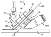
도 1은 로봇, 상기 로봇에 장착되며 수직 배향으로 위치된 엔드-이펙터, 및 회전가능한 압출기 모듈을 구비하는 3D 프린팅 기계의 등각도이다.
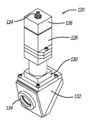
도 2는 도 1에 도시된 엔드-이펙터에 사용될 수 있는 연속 섬유 압출기 모듈의 등각도이다.
도 3은 도 2에 도시된 압출기 모듈 내의 노즐 조립체의 등각도이다.
도 4는 빌드-플레이트에 대한 도 3에 도시된 노즐 조립체의 단면도이다.
도 5는 도 1에 도시된 3D 프린팅 기계의 등각도로서, 엔드-이펙터가 수직 바향으로 위치된 도면이다.
도 6은 도 1에 도시된 바와 같은 배향으로 3D 프린팅 기계의 분해 등각도로서, 노즐 조립체가 일 배향으로 회전된 도면이다.
도 7은 도 1에 도시된 바와 같은 배향으로 3D 프린팅 기계의 분해 등각도로서, 노즐 조립체가 90°배향으로 회전된 도면이다.
도 8은 도 1에 도시된 3D 프린팅 기계의 엔드-이펙터 내에 장착될 수 있는 듀얼-헤드 압출기 모듈의 분해 측면도이다.
도 9는 도 1에 도시된 3D 프린팅 기계와 함께 사용될 수 있고 집적된 레이저 옵틱 및 IR 카메라를 구비하는 엔드-이펙터의 등각도이다.
도 10은 엔드-이펙터로부터 분리된 도 9에 도시된 레이저 옵틱의 등각도이다.1 is an isometric view of a 3D printing machine having a robot, an end-effector mounted to the robot and positioned in a vertical orientation, and a rotatable extruder module;
FIG. 2 is an isometric view of a continuous fiber extruder module that may be used in the end-effector shown in FIG. 1 ;
3 is an isometric view of a nozzle assembly within the extruder module shown in FIG. 2 ;
FIG. 4 is a cross-sectional view of the nozzle assembly shown in FIG. 3 with respect to the build-plate;
Fig. 5 is an isometric view of the 3D printing machine shown in Fig. 1, in which the end-effector is positioned in a vertical direction;
FIG. 6 is an exploded isometric view of the 3D printing machine in the orientation as shown in FIG. 1 , with the nozzle assembly rotated to one orientation; FIG.
FIG. 7 is an exploded isometric view of the 3D printing machine in the orientation as shown in FIG. 1 , with the nozzle assembly rotated to the 90° orientation; FIG.
FIG. 8 is an exploded side view of a dual-head extruder module that may be mounted within the end-effector of the 3D printing machine shown in FIG. 1 ;
FIG. 9 is an isometric view of an end-effector that may be used with the 3D printing machine shown in FIG. 1 and having integrated laser optics and an IR camera;
Fig. 10 is an isometric view of the laser optic shown in Fig. 9 separated from the end-effector;
고성능 3D 집적 복합 구조체를 제조하기 위한 프린팅 기계에 관한 본 개시내용의 실시예들의 하기의 논의는 단지 예시적인 것일 뿐이며, 본 개시내용 또는 그 적용 또는 용도를 제한하도록 의도되지 않는다.The following discussion of embodiments of the present disclosure with respect to a printing machine for manufacturing high performance 3D integrated composite structures is illustrative only and is not intended to limit the disclosure or its application or use.
도 1은 베이스 부분(14), 로터리 및 피봇 조인트(18)에 의해 베이스 부분(14)에 결합된 연장 아암(16), 및 엘보우 피봇 조인트(22)에 의해 베이스 부분(14)에 대향하는 연장 아암(16)에 결합된 작동 아암(20)을 갖는 로봇(12)을 구비하는 3D 프린팅 기계(10)의 등각도이다. 엔드-이펙터(26)는 결합 메커니즘(30)을 갖는 피봇 조인트(28)에 의해 조인트(22)에 대향된 각도로 작동 아암(20)에 결합된다. 로봇(12)은 엔드-이펙터(26)를 위한 임의의 적절한 위치설정 장치를 나타내는 것으로 의도된다. 엔드-이펙터(26)는 본 명세서에 기술된 바와 같이 복잡한 복합 구조체를 구축하기 위한 용융 섬유, 필라멘트 등을 매설하기 위한 프린트-헤드 조립체로서 동작한다. 소정의 방식으로 작동하며, 소정의 특싱을 갖는 다양한 엔드-이펙터가 본 명세서에서 논의될 것이며, 이는 로봇(12)에 부착될 수 있다. 작동 동안, 기계(10)는 프린팅 공정의 온도 및 부품을 둘러싸는 주변 온도가 제어되도록 오븐(도시되지 않음) 내에 위치되거나 위치되지 않을 수 있다.1 shows a
엔드-이펙터(26)는 외부 하우징(34)과, 결합 메커니즘(30)에 해제가능하게 그리고 회전가능하게 연결되는 회전가능한 커넥터(36)를 구비하며, 하우징(34)은 그 내에 다양한 구성요소를 도시하기 위해 투명한 것으로 도시되어 있다. 이들 구성요소는 다양한 재료의 복수의 필라멘트(42)가 권취되는 복수의, 여기서 3개의 스풀(40), 스풀(40)로부터 필라멘트(42)를 선택적으로 그리고 독립적으로 인출하는 모터(44), 샤프트(56)에 의해 필라멘트 공급 조립체(48)에 결합된 직각 기어 박스(32), 인덱싱 모터(58)에 의해 회전되고 필라멘트(42)가 인출되어 용융되는 배럴(46)을 갖는 로터리 조립체(38), 배럴(46)의 일단부에 장착된 단부 플레이트(54), 및 플레이트(54)를 통해 연장되고 압출기 모듈의 일부인 노즐 조립체(50)를 포함한다. 스풀(40)은 도시된 바와 같이 엔드-이펙터(26)에 장착되거나, 또는 튜브(도시되지 않음)를 통해 엔드-이펙터(26)에 공급되는 재료와 이격되게 장착될 수 있다. 대안적으로, 스톡 재료는 필라멘트(42)를 사용하는 대신에 펠렛에 의해 제공될 수 있다.The end-
도 2는 엔드-이펙터(26) 내에 제공될 수 있고 로터리 조립체(38)에 의해 회전되는 압출기 모듈의 유형의 하나의 비제한적인 예인 연속 섬유 압출기 모듈(140)의 등각도이며, 모듈(140)은 엔드-이펙터(26)에 부착될 수 있게 하는 장착 브래킷(142)으로 피팅된다. 모듈(140)은 필라멘트 가이드 튜브(144)를 통해 필라멘트(138)(도 4 참조)를 수용하고, 필라멘트(138)는 필라멘트 가이드 튜브 장착 브래킷(146)을 통과한 다음, 공급 롤러(148)와 클램프 롤러(150) 사이에서 통과한다. 공급 롤러(148)는 파워 커넥터(154) 및 인코더(156)를 갖는 공급 모터(152)에 결합되어, 모듈(140)을 통해 필라멘트(138)를 공급하도록 구동력을 제공한다. 클램프 롤러(150)는 필라멘트(138)에 대해 클램프 롤러(150)를 가압하는 클램프 롤러 액추에이터(158)에 결합되어, 공급 롤러(148)와 클램프 롤러(150) 사이의 필라멘트를 선택된 양의 힘으로 핀치함으로써, 필라멘트(138)가 미끄러짐 없이 공급될 수 있도록 공급 롤러(148)와 필라멘트(138) 사이에 충분한 견인력이 생성되도록 보장한다.2 is an isometric view of a continuous
그 다음, 필라멘트(138)는 필라멘트 가이드(184)를 통해 그리고 노즐 조립체(16) 내로 통과한다. 도 3은 등각도이고, 도 4는 모듈(140)로부터 분리된 노즐 조립체(162)의 단면도이다. 노즐 조립체(162)는 필라멘트 입구(164) 및 노즐(166)을 포함하며, 그 주위에 냉각 블록(168)과 가열 블록(170)이 클램핑되고, 냉각 블록(168)은 냉각제 호스 커넥터(172)의 세트를 통해 액체 냉각제를 수용한다. 가열 블록(170)은 가열 요소(174)에 의해 가열되고, 그 온도는 열전쌍, 서미스터, 저항 온도 검출기(RTD), 또는 유사한 유형의 온도 센서일 수 있는 온도 센서(176)에 의해 모니터링된다. 이러한 배열은 필라멘트(138)가 노즐(166)의 노즐 팁(180)에 도달할 때까지 그 폴리머 성분의 용융점보다 낮은 온도로 유지되는 것을 보장한다. 그 다음, 필라멘트(138)는 노즐(166)의 단부에서 가열되어, 필라멘트(138)가 노즐 팁(180)으로부터 나올 때 필라멘트(138)가 빌드 표면(190)에 결합되도록 폴리머를 용융시킨다.The
커터(182)는 커터 액추에이터(186)에 의해 이동되는 필라멘트 가이드(184)와 노즐 조립체(162) 사이에 제공되어, 커터 가이드(188)에 의해 구속된다. 커터 액추에이터(186)가 작동될 때, 커터(182)를 필라멘트 공급방향에 수직인 방향으로 필라멘트(138) 쪽으로 이동시키고, 필라멘트 가이드(184)의 하측부에 대해 필라멘트(138)를 전단하고 전체 필라멘트(138)를 통해 절단한다. 이는 필라멘트(138)가 프린트될 때 적절한 길이로 자동적으로 절단될 수 있게 한다. 필라멘트(138)는 노즐(166)로부터 일 방향으로 압출되기 때문에, 노즐(166)은 필라멘트(138)를 상이한 방향으로 압출할 수 있도록 상이한 방향으로 회전되어야 한다. 이는 노즐(166)의 회전에 민감하지 않고 인쇄 방향이 노즐(166)의 축에 수직인 한 임의의 방향으로 프린팅할 수 있는 종래의 3D 프린팅 노즐 설계와 상이하다.The
연속적인 섬유-강화 3D 프린팅 공정은 노즐 조립체(50)의 배향에 민감하다. 기계는 노즐 조립체(50)를 회전가능하게 함으로써 이러한 민감도의 일부를 극복한다. 또한, 엔드-이펙터(26)의 나머지 부분에 대해 노즐 조립체(50)를 회전가능하게 함으로써, 엔드-이펙터(26)로부터 압출되는 필라멘트(42)의 방향은 전체 엔드-이펙터(26)를 회전시킬 필요없이 제어될 수 있다. 엔드-이펙터(26)는 로터리 조립체(38)에 비해 상대적으로 크고 폭넓지 않을 수 있어, 엔드-이펙터(26)의 배향과 독립적으로 압출기 모듈의 배향을 제어할 수 있으므로, 기계(10)의 기민성을 상당히 개선시킨다.The continuous fiber-reinforced 3D printing process is sensitive to the orientation of the
상술한 바와 같이, 프린팅 공정에 의해 구축되는 부품은 빌드 플랫폼 상에 형성된다. 기계(10)의 설계에서, 프린딩 또는 제조되는 부품(72)이 도시되어 있는 로터리 원형 테이블(70)이 사용된다. 선택적인 라이저(74)는 테이블(70)의 중심에 제공되고, 부품(72)은 라이저(74) 상에 위치된다. 그러나, 일부 설계들에서, 라이저(74)는 필요하지 않을 수 있다. 엔드-이펙터(26)는 부품(72)에 인접하게 위치되어 수평 배향에 있다. 부품(72)이 놓이는 라이저(74)를 제공함으로써, 부품(72)은 작은 직경의 부품을 효과적으로 프린팅하기 위해 바람직한 엔드-이펙터(26)와 테이블(70) 사이에 간극을 제공하도록 테이블(70)의 상부 표면(76)으로부터 소정의 적절한 거리로 분리된다. 일 실시예에서, 라이저(74)는 부품(72)으로의 열전달을 개선하고 라이저(74)의 표면으로 부품(72)의 열적 안정성 및 부착을 유지하기 위해 구리와 같은 높은 열전도성 재료로 제조된다. 라이저(74)는 넓은 범위의 기하학적 구조를 갖는 부품의 제조에 더 효과적일 수 있도록 상이한 형상, 크기 및 높이로 제공될 수 있다. 테이블(70)의 측면은 테이블(70)이 회전되도록 하고 라이저(74)가 가열되도록 하는 적절한 구성요소(78)를 내부에 도시하기 위해 투명한 것으로 도시되어 있다.As described above, the part built by the printing process is formed on the build platform. In the design of the
엔드-이펙터(26)는 각진 벽(52) 상에 각진 배향으로 결합 메커니즘(30)에 결합되고, 엔드-이펙터(26)는 도 1의 주로 수평 배향으로 도시되어, 노즐 조립체(50)는 빌드 플랫폼에 평행하게 지향되고, 이는 필라멘트(42)가 빌드 표면의 측면 상에 놓이도록 한다. 도 5는 엔드-이펙터(26)의 배향이 주로 수직 배향으로 변경되도록 커넥터(36)가 회전되어 필라멘트(42)가 빌드 표면의 상부에 놓이도록 하는 3D 프린팅 기계(10)의 등각도이다. 주로 수평 배향과 주로 수직 배향 사이의 중간 배향도 가능하다. 이러한 방식으로 엔드-이펙터(26)를 회전시키는 능력은 노즐 조립체(50)가 빌드 표면, 즉 빌드 플레이트 또는 부품(72)에 수직으로 배향되는 것을 허용하며, 이는 요구되는 로봇 포즈들의 개수를 감소시키는 동안에 훨씬 더 많은 수의 시나리오를 허용한다. 보다 구체적으로, 표준 접근법은 특정 구성요소 빌드를 위한 광범위한 로봇 포즈를 프로그램하는 것이다. 그러나, 엔드-이펙터(26)가 각진 벽(52) 상에서 각진 배향으로 회전가능한 커넥터(36)를 사용하여 회전가능한 본 명세서에 기술된 접근법은 경로 프로그래밍을 단순화하면서 반복성을 향상시킨다. 이는 도 1 및 5의 로봇(12)의 포즈가 거의 동일하다는 점에 의해 예시된다. 또한, 이러한 특징은 로봇 이동을 최소화함으로써 맞춤형 로봇 툴링에 대한 마모 및 인열을 최소화한다.The end-
연속적인 섬유 강화 3D 프린팅 공정은 노즐 조립체(50)의 배향에 민감하다. 압출기 모듈이 엔드-이펙터(26)의 나머지 부분에 대해 회전가능하게 함으로써, 노즐 조립체(50)로부터 압출되는 필라멘트(42)의 방향은 전체 엔드-이펙터(26)를 회전시킬 필요성이 없이 제어될 수 있다. 엔드-이펙터(26)는 압출기 모듈에 비해 상대적으로 크고 폭이 넓지 않을 수 있으므로, 엔드-이펙터(26)의 배향과 독립적으로 압출기 모듈의 배향을 제어할 수 있어, 3D 프린팅 기계(10)의 기민성을 크게 향상시킨다.The continuous fiber reinforced 3D printing process is sensitive to the orientation of the
도 6은 하나의 배향으로 로터리 조립체(38)에 의해 회전되는 노즐 조립체(50)와 함께 수평 방향으로 배향된 3D 프린팅 기계(10)의 분해 등각도이다. 이러한 도시는 노즐 조립체(50)가 어느 한 방향으로 프린트하는 능력을 도시한다.6 is an exploded isometric view of
도 7은 또 다른 배향으로 로터리 조립체(38)에 의해 90° 회전된 노즐 조립체(50)와 함께 수평 방향으로 배향된 3D 프린팅 기계(10)의 분해 등각도이다. 이러한 도시는 도 6과 상당히 다른 방식으로 프린트하도록 노즐 조립체(50)의 능력을 도시하지만, 도 1과 실질적으로 동일한 포즈로 배향된 로봇(12)을 갖는다.7 is an exploded isometric view of
도 8은 엔드-이펙터(26) 내에 장착되도록 설계되고 로터리 조립체(38)에 의해 회전되는 압출기 모듈(80)의 분해 측면도이다. 모듈(80)은 제1 압출기 모듈(86) 및 제2 압출기 모듈(88)을 갖는 일체형 이중 압출기 조립체(84)를 둘러싸는 외부 하우징(82)을 구비한다. 이러한 실시예에서, 압출기 모듈(86)은 냉각 블록(98) 및 하나의 다양한 폴리머 또는 세절된-섬유-충전된 폴리머(도시되지 않음)를 압출하는 노즐(92) 주위에 클램핑된 히터 블록(90)을 구비하고, 압출기 모듈(88)은 냉각 블록(100) 및 또 다른 다양한 폴리머 또는 세절된-섬유-충전된 폴리머(도시되지 않음)를 압출하는 노즐(104) 주위에 클램핑된 히터 블록(102)을 구비한다. 노즐(92)은 액추에이터(94)에 의해 하우징(82) 외부로 연장되고 하우징(82) 내로 다시 후퇴되고, 노즐(104)은 액추에이터(96)에 의해 하우징(82) 외부로 연장되고 하우징(82) 내로 다시 후퇴된다. 필라멘트는 단지 폴리머, 또 다른 강호 재료의 짧은 거리의 섬유 또는 입자로 강화된 폴리머 또는 연속 섬유로 강화된 폴리머일 수 있다.8 is an exploded side view of an extruder module 80 designed to be mounted within an end-
도 9는 3D 프린팅 기계(10)와 함께 사용될 수 있는 엔드-이펙터(110)의 등각도이다. 엔드-이펙터(110)는 그로부터 연장되는 노즐(108)을 구비한다. 브래킷(116)은 하우징(114)에 장착되고, IR 카메라(118) 또는 고온계 및 레이저 포커싱 광학 조립체(120)는 브래킷(116)에 연결된다. 레이저 포커싱 광학 조립체(120)는 압출된 재료를 가열하고 노즐(108)의 바로 근처의 영역을 예열하는데 사용되는 레이저 빔(122)을 포커싱하고, 카메라(118)는 프린팅 공정의 신뢰성을 향상시키기 위해 그 영역의 온도를 측정한다. 국부화된 레이저 가열으로부터 추가적인 폴리머 흐름은 다공성을 감소시키고, 증가된 연속적인 탄소 섬유 체적을 허용하여, 복합 구조체의 성능을 향상시킨다. 또한, 레이저 포커싱 광학 조립체(120) 및 IR 카메라(118)는 하우징(114)내에 장착될 수 있고, 유리 또는 유사한 투명 재료로 제조된 윈도우(도시되지 않음)를 통해 작동할 수 있다.9 is an isometric view of an end-
도 10은 엔드-이펙터(110)로부터 분리된 레이저 포커싱 광학 조립체(120)의 등각도이다. 레이저 광학 조립체(120)는 광섬유(124), 레이저 빔(122)을 시준하기 위한 시준 및 빔 성형 광학계(126, 128), 레이저 빔(122)을 포커싱하기 위한 포커싱 렌즈(130), 레이저 빔(122)을 구부리기 위한 폴딩 광학계(132) 및 레이저 빔(122)이 레이저 포커싱 광학 조립체(120)를 빠져나가는 유리 하우징 커버(134)에 레이저 포커싱 광학 조립체(120)를 연결하기 위한 커넥터를 구비한다.10 is an isometric view of the laser focusing
대안적인 실시예에서, 기계(10)는 다양한 프린터 모듈의 툴 포인트 선명도를 자동으로 교정하기 위한 머신 비전 시스템을 구비할 수 있다. 또한, 기계(10)는 기계(10)가 고온 오븐 내의 부품을 제조하게 하는 맞춤형 냉각 슈트를 구비할 수 있으며, 이는 고온 및 고성능 열가소성 플라스틱과 함께 높은 인성 및 내화학성 복합 구조체 제조를 가능하게 한다.In an alternative embodiment, the
전술한 논의는 단지 본 발명의 예시적인 실시예들을 개시하고 설명한다. 당해 업계에서의 통상의 기술자는 이러한 논의로부터 그리고 첨부된 도면과 청구범위로부터 다양한 변경, 수정 및 변동이 이어지는 청구범위에서 정의된 본 발명의 사상과 범위로부터 벗어나지 않으면서 이루어질 수 있다는 것을 쉽게 인식할 것이다.The foregoing discussion discloses and describes merely exemplary embodiments of the present invention. Those skilled in the art will readily recognize from this discussion and from the appended drawings and claims that various changes, modifications and variations can be made therein without departing from the spirit and scope of the invention as defined in the appended claims. .
Claims (20)
Translated fromKorean베이스 부분, 로봇 암 및 상기 베이스 부분에 대향하는 상기 암에 고정된 단부 조인트를 구비하는 로봇;
압출가능한 재료의 적어도 하나의 공급원; 및
상기 단부 조인트에 장착되는 엔드-이펙터(end-effector)로서, 상기 엔드-이펙터는 상기 압출가능한 재료를 압출하기 위한 적어도 하나의 압출기 모듈 및 로터리 조립체를 구비하고, 상기 적어도 하나의 압출기 모듈은 상기 엔드-이펙터 외부로 가열된 재료를 압출하기 위한 노즐 조립체를 구비하며, 상기 적어도 하나의 압출기 모듈은 상기 로터리 조립체에 장착되고, 상기 로터리 조립체는 회전가능하여 상기 엔드-이펙터를 회전시키지 않고서 상기 부품에 대해 상기 노즐 조립체를 회전시키는, 상기 엔드-이펙터
를 포함하는,
3D 프린팅 기계.
A 3D printing machine for manufacturing a composite part, comprising:
a robot having a base portion, a robot arm and an end joint secured to the arm opposite the base portion;
at least one source of extrudable material; and
an end-effector mounted to said end joint, said end-effector having at least one extruder module and a rotary assembly for extruding said extrudable material, said at least one extruder module comprising said end - a nozzle assembly for extruding heated material out of an effector, said at least one extruder module being mounted to said rotary assembly, said rotary assembly being rotatable for said part without rotating said end-effector rotating the nozzle assembly, the end-effector
containing,
3D printing machine.
상기 단부 조인트는 회전가능한 커넥터를 구비하고,
상기 엔드-이펙터는 상기 회전가능한 커넥터에 의해 상기 부품에 대해 회전가능하여 상기 노즐 조립체는 상기 로봇의 포즈를 크게 변경하지 않고서 상이한 배향으로 상기 부품에 수직으로 배향될 수 있는,
3D 프린팅 기계.
According to claim 1,
the end joint has a rotatable connector;
wherein the end-effector is rotatable relative to the part by the rotatable connector such that the nozzle assembly can be oriented perpendicular to the part in different orientations without significantly changing the pose of the robot.
3D printing machine.
상기 엔드-이펙터는 각진 코너 벽을 갖는 외부 하우징을 가지며, 상기 회전가능한 커넥터는 상기 각진 코너 벽에 고정되는,
3D 프린팅 기계.
According to claim 1,
wherein the end-effector has an outer housing having angled corner walls, and wherein the rotatable connector is secured to the angled corner walls.
3D printing machine.
상기 적어도 하나의 압출기 모듈은 별개의 노즐 조립체를 각각 구비하는 제1 압출기 및 제2 압출기를 갖는 다중-압출기 모듈이고,
상기 압출가능한 재료의 적어도 하나의 공급원은, 상기 제1 압출기가 하나의 압출가능한 재료를 수용하고 상기 제2 압출기가 다른 압출가능한 재료를 수용하는 압출가능한 재료의 복수의 공급원인,
3D 프린팅 기계.
According to claim 1,
wherein the at least one extruder module is a multi-extruder module having a first extruder and a second extruder each having separate nozzle assemblies;
wherein the at least one source of extrudable material is a plurality of sources of extrudable material, wherein the first extruder receives one extrudable material and the second extruder receives another extrudable material;
3D printing machine.
상기 제1 압출기는 외부 하우징 내외로 상기 노즐 조립체를 후퇴 및 연장하기 위한 제1 액추에이터를 구비하고, 상기 제2 압출기는 상기 외부 하우징 내외로 상기 노즐 조립체를 후퇴 및 연장하기 위한 제2 액추에이터를 구비하는,
3D 프린팅 기계.
5. The method of claim 4,
wherein the first extruder has a first actuator for retracting and extending the nozzle assembly into and out of an outer housing and the second extruder has a second actuator for retracting and extending the nozzle assembly into and out of the outer housing ,
3D printing machine.
상기 엔드-이펙터에 대해 위치된 테이블을 더 포함하고, 상기 부품은 상기 테이블 상에 제조되고, 상기 테이블은 회전가능한,
3D 프린팅 기계.
According to claim 1,
further comprising a table positioned relative to the end-effector, wherein the part is fabricated on the table, the table being rotatable;
3D printing machine.
상기 테이블 상에 위치되는 라이저(riser)를 더 포함하고, 상기 부품은 상기 테이블로부터 이격되도록 상기 라이저 상에 제조되는,
3D 프린팅 기계.
7. The method of claim 6,
further comprising a riser positioned on the table, wherein the part is fabricated on the riser to be spaced from the table;
3D printing machine.
상기 테이블은 상기 테이블 및 상기 라이저를 가열하기 위한 열원을 구비하는,
3D 프린팅 기계.
8. The method of claim 7,
wherein the table has a heat source for heating the table and the riser;
3D printing machine.
상기 엔드-이펙터는 압출된 재료와, 상기 노즐 조립체의 바로 근방에 있는 영역을 가열하기 위한 레이저 빔을 생성하는 레이저를 더 구비하는,
3D 프린팅 기계.
According to claim 1,
wherein the end-effector further comprises a laser for generating a laser beam for heating the extruded material and an area in the immediate vicinity of the nozzle assembly;
3D printing machine.
상기 엔드-이펙터는 레이저 빔에 의해 가열된 영역의 온도를 측정하는 카메라 또는 고온계를 더 구비하는,
3D 프린팅 기계.
9. The method of claim 8,
The end-effector further comprises a camera or a pyrometer for measuring the temperature of the area heated by the laser beam,
3D printing machine.
상기 압출가능한 재료의 적어도 하나의 공급원은 상기 엔드-이펙터 내에 있는,
3D 프린팅 기계.
According to claim 1,
wherein the at least one source of extrudable material is within the end-effector;
3D printing machine.
상기 압출가능한 재료의 적어도 하나의 공급원은 적어도 하나의 스풀이고, 상기 압출가능한 재료는 필라멘트인,
3D 프린팅 기계.
12. The method of claim 11,
wherein the at least one source of extrudable material is at least one spool, and wherein the extrudable material is a filament.
3D printing machine.
상기 압출가능한 재료의 적어도 하나의 공급원은 상이하게 권취된 필라멘트를 각각 보유하는 복수의 스풀인,
3D 프린팅 기계.
13. The method of claim 12,
wherein the at least one source of extrudable material is a plurality of spools each holding differently wound filaments;
3D printing machine.
다양한 프린트 모듈의 툴 포인트 선명도(tool point definitions)를 자동으로 교정하기 위한 머신 비전 시스템(machine vision system)을 더 포함하는,
3D 프린팅 기계.
According to claim 1,
a machine vision system for automatically correcting tool point definitions of various print modules;
3D printing machine.
맞춤형 냉각 슈트(customized cooling suit)를 더 포함하는,
3D 프린팅 기계.
According to claim 1,
Further comprising a customized cooling suit,
3D printing machine.
베이스 부분, 로봇 암 및 상기 베이스 부분에 대향하는 상기 암에 고정된 단부 조인트를 구비하는 로봇; 및
상기 단부 조인트에 장착되는 엔드-이펙터(end-effector)로서, 상기 엔드-이펙터는 상이하게 권취된 필라멘트를 각각 보유하는 복수의 스풀, 상기 필라멘트를 압출하기 위한 복수의 압출기 모듈 및 회전가능한 조립체를 구비하고, 각각의 압출기 모듈은 상기 엔드-이펙터 외부로 가열된 재료를 압출하기 위한 노즐 조립체를 구비하며, 상기 압출기 모듈은 상기 회전가능한 조립체에 장착되고, 상기 회전가능한 조립체는 회전가능하여 상기 엔드-이펙터를 회전시키지 않고서 상기 부품에 대해 상기 노즐 조립체를 회전시키는, 상기 엔드-이펙터
를 포함하는,
3D 프린팅 기계.
A 3D printing machine for manufacturing a composite part, comprising:
a robot having a base portion, a robot arm and an end joint secured to the arm opposite the base portion; and
an end-effector mounted to the end joint, the end-effector having a plurality of spools each holding differently wound filaments, a plurality of extruder modules for extruding the filaments, and a rotatable assembly wherein each extruder module has a nozzle assembly for extruding heated material out of the end-effector, the extruder module being mounted to the rotatable assembly, the rotatable assembly being rotatable to the end-effector rotating the nozzle assembly relative to the part without rotating the
containing,
3D printing machine.
상기 복수의 압출기 모듈은 별개의 노즐 조립체를 각각 구비하는 제1 압출기 및 제2 압출기를 구비하는,
3D 프린팅 기계.
17. The method of claim 16,
wherein the plurality of extruder modules have a first extruder and a second extruder each having separate nozzle assemblies;
3D printing machine.
상기 제1 압출기는 외부 하우징 내외로 상기 노즐 조립체를 후퇴 및 연장하기 위한 제1 액추에이터를 구비하고, 상기 제2 압출기는 상기 외부 하우징 내외로 상기 노즐 조립체를 후퇴 및 연장하기 위한 제2 액추에이터를 구비하는,
3D 프린팅 기계.
18. The method of claim 17,
wherein the first extruder has a first actuator for retracting and extending the nozzle assembly into and out of an outer housing and the second extruder has a second actuator for retracting and extending the nozzle assembly into and out of the outer housing ,
3D printing machine.
상기 단부 조인트는 회전가능한 커넥터를 구비하고,
상기 엔드-이펙터는 상기 회전가능한 커넥터에 의해 상기 부품에 대해 회전가능하여, 상기 노즐 조립체는 상기 로봇의 포즈를 크게 변경하지 않고서 상이한 배향으로 상기 부품에 수직으로 배향될 수 있는,
3D 프린팅 기계.
17. The method of claim 16,
the end joint has a rotatable connector;
the end-effector is rotatable relative to the part by the rotatable connector such that the nozzle assembly can be oriented perpendicular to the part in different orientations without significantly changing the pose of the robot.
3D printing machine.
상기 엔드-이펙터는 각진 코너 벽을 갖는 외부 하우징을 가지며, 상기 회전가능한 커넥터는 상기 각진 코너 벽에 고정되는,
3D 프린팅 기계.
20. The method of claim 19,
wherein the end-effector has an outer housing having angled corner walls, and wherein the rotatable connector is secured to the angled corner walls.
3D printing machine.
Applications Claiming Priority (3)
| Application Number | Priority Date | Filing Date | Title |
|---|---|---|---|
| US16/380,328US11167484B2 (en) | 2019-04-10 | 2019-04-10 | Printing machine for fabricating 3D integrated composite structures and having a rotatable extruder module |
| US16/380,328 | 2019-04-10 | ||
| PCT/US2020/025294WO2020210054A1 (en) | 2019-04-10 | 2020-03-27 | Printing machine for fabricating 3d integrated composite structures and having a rotatable extruder module |
Publications (1)
| Publication Number | Publication Date |
|---|---|
| KR20210151079Atrue KR20210151079A (en) | 2021-12-13 |
Family
ID=70296142
Family Applications (1)
| Application Number | Title | Priority Date | Filing Date |
|---|---|---|---|
| KR1020217031200ACeasedKR20210151079A (en) | 2019-04-10 | 2020-03-27 | Printing Machine With Rotatable Extruder Module to Make 3D Integrated Composite Structures |
Country Status (4)
| Country | Link |
|---|---|
| US (1) | US11167484B2 (en) |
| EP (1) | EP3953151B1 (en) |
| KR (1) | KR20210151079A (en) |
| WO (1) | WO2020210054A1 (en) |
Families Citing this family (12)
| Publication number | Priority date | Publication date | Assignee | Title |
|---|---|---|---|---|
| US11097484B1 (en)* | 2018-02-13 | 2021-08-24 | Made In Space, Inc. | System and method for hybrid additive and subtractive manufacturing with part movement |
| US11167483B2 (en)* | 2019-04-10 | 2021-11-09 | Northrop Grumman Systems Corporation | Methods and apparatus for fabrication of 3D integrated composite structures |
| US11117319B2 (en)* | 2019-04-10 | 2021-09-14 | Northrop Grumman Systems Corporation | Printing machine for fabricating 3D integrated composite structures and having a multiple extruder module |
| US11413806B2 (en)* | 2019-04-10 | 2022-08-16 | Northrop Grumman Systems Corporation | Method for fabricating a 3D composite structure including smoothing of support structures |
| US11814324B2 (en) | 2019-07-18 | 2023-11-14 | Northrop Grumman Systems Corporation | Additive manufacturing methods for forming high-temperature composite structures and related structures |
| US11964432B2 (en) | 2021-08-12 | 2024-04-23 | Northrop Grumman Systems Corporation | Ultrasonic material placement and compaction device with material passing through the ultrasonic horn element |
| US11911965B2 (en) | 2021-08-12 | 2024-02-27 | Northrop Grumman Systems Corporation | Ultrasonic consolidation of continuous filament materials for additive manufacturing |
| US11958241B2 (en) | 2021-08-12 | 2024-04-16 | Northrop Grumman Systems Corporation | Ultrasonic device for compaction allowing coordinated actuation and motion of multiple ultrasonic compaction horns |
| US11872761B2 (en) | 2021-08-12 | 2024-01-16 | Northrop Grumman Systems Corporation | Ultrasonic compaction device using reciprocating disk horns |
| CN115091757B (en)* | 2022-06-21 | 2024-01-05 | 深圳市创想三维科技股份有限公司 | Automatic material switching device for 3D printing and 3D printer |
| CN115214137B (en)* | 2022-07-13 | 2023-08-01 | 深圳市创想三维科技股份有限公司 | Switching device and 3D printing equipment |
| US12391010B2 (en) | 2023-01-13 | 2025-08-19 | Rtx Corporation | Methods of manufacture for composite blades |
Family Cites Families (58)
| Publication number | Priority date | Publication date | Assignee | Title |
|---|---|---|---|---|
| US4750960A (en)* | 1984-09-10 | 1988-06-14 | Rensselaer Polytechnic Institute | Robotic winding system and method |
| US5653925A (en) | 1995-09-26 | 1997-08-05 | Stratasys, Inc. | Method for controlled porosity three-dimensional modeling |
| US6471800B2 (en) | 2000-11-29 | 2002-10-29 | Nanotek Instruments, Inc. | Layer-additive method and apparatus for freeform fabrication of 3-D objects |
| US6817553B2 (en)* | 2003-02-04 | 2004-11-16 | Efc Systems, Inc. | Powder paint spray coating apparatus having selectable, modular spray applicators |
| JP4615398B2 (en) | 2005-08-26 | 2011-01-19 | 本田技研工業株式会社 | Carbon fiber composite material molded body |
| WO2009015850A2 (en)* | 2007-08-02 | 2009-02-05 | Kuka Systems Gmbh | Rotary coupling |
| ITVI20080109A1 (en) | 2008-05-14 | 2009-11-15 | Ettore Maurizio Costabeber | METHOD OF PRODUCTION OF THREE-DIMENSIONAL OBJECTS AND MACHINE USING THIS METHOD |
| EP2329935A1 (en)* | 2009-12-04 | 2011-06-08 | Günther Battenberg | Modelling device |
| US20120073726A1 (en) | 2010-09-24 | 2012-03-29 | General Electric Company | Resin Delivery, Application and Infusion System and Integrated Layup System and Method of Use |
| US9776376B2 (en) | 2011-08-29 | 2017-10-03 | Impossible Objects, LLC | Methods and apparatus for three-dimensional printed composites based on flattened substrate sheets |
| US9511543B2 (en) | 2012-08-29 | 2016-12-06 | Cc3D Llc | Method and apparatus for continuous composite three-dimensional printing |
| DE102012017538A1 (en)* | 2012-09-05 | 2014-03-06 | Heidelberger Druckmaschinen Ag | Process for imaging and / or varnishing the surface of objects |
| TWI509119B (en) | 2012-12-03 | 2015-11-21 | Ind Tech Res Inst | Carbon fiber composite and manufacturing method thereof |
| US20140232035A1 (en) | 2013-02-19 | 2014-08-21 | Hemant Bheda | Reinforced fused-deposition modeling |
| US9579851B2 (en) | 2013-03-22 | 2017-02-28 | Markforged, Inc. | Apparatus for fiber reinforced additive manufacturing |
| US9126367B1 (en) | 2013-03-22 | 2015-09-08 | Markforged, Inc. | Three dimensional printer for fiber reinforced composite filament fabrication |
| US9956725B2 (en) | 2013-03-22 | 2018-05-01 | Markforged, Inc. | Three dimensional printer for fiber reinforced composite filament fabrication |
| CN107187022B (en) | 2013-03-22 | 2020-08-11 | 格雷戈里·托马斯·马克 | Three-dimensional printing |
| US9149988B2 (en) | 2013-03-22 | 2015-10-06 | Markforged, Inc. | Three dimensional printing |
| US9156205B2 (en) | 2013-03-22 | 2015-10-13 | Markforged, Inc. | Three dimensional printer with composite filament fabrication |
| US20170173868A1 (en) | 2013-03-22 | 2017-06-22 | Markforged, Inc. | Continuous and random reinforcement in a 3d printed part |
| US9694544B2 (en) | 2013-03-22 | 2017-07-04 | Markforged, Inc. | Methods for fiber reinforced additive manufacturing |
| US9688028B2 (en) | 2013-03-22 | 2017-06-27 | Markforged, Inc. | Multilayer fiber reinforcement design for 3D printing |
| US9815268B2 (en) | 2013-03-22 | 2017-11-14 | Markforged, Inc. | Multiaxis fiber reinforcement for 3D printing |
| EP3130444B1 (en) | 2013-06-05 | 2020-04-01 | Markforged, Inc. | Method for fiber reinforced additive manufacturing |
| US9908291B2 (en) | 2013-09-30 | 2018-03-06 | Adobe Systems Incorporated | Smooth 3D printing using multi-stage filaments |
| US9440397B1 (en) | 2014-01-30 | 2016-09-13 | David E. Fly | Layered 3D printing with lower viscosity fluid fill |
| US20170198104A1 (en) | 2014-03-12 | 2017-07-13 | Arevo, Inc. | Compositions for use in fused filament 3d fabrication and method for manufacturing same |
| US10449731B2 (en) | 2014-04-30 | 2019-10-22 | Magna International Inc. | Apparatus and process for forming three-dimensional objects |
| US9796140B2 (en) | 2014-06-19 | 2017-10-24 | Autodesk, Inc. | Automated systems for composite part fabrication |
| US9808991B2 (en) | 2014-07-29 | 2017-11-07 | Cc3D Llc. | Method and apparatus for additive mechanical growth of tubular structures |
| US10059053B2 (en) | 2014-11-04 | 2018-08-28 | Stratasys, Inc. | Break-away support material for additive manufacturing |
| TWI611909B (en) | 2014-11-29 | 2018-01-21 | National Tsing Hua University | High speed flexible 3d freeform techniques |
| US9592660B2 (en) | 2014-12-17 | 2017-03-14 | Arevo Inc. | Heated build platform and system for three dimensional printing methods |
| US9908978B2 (en) | 2015-04-08 | 2018-03-06 | Arevo Inc. | Method to manufacture polymer composite materials with nano-fillers for use in additive manufacturing to improve material properties |
| US20160332372A1 (en) | 2015-05-13 | 2016-11-17 | Honeywell International Inc. | Carbon fiber preforms |
| US10035305B2 (en) | 2015-06-30 | 2018-07-31 | Honeywell International Inc. | Method of making carbon fiber preforms |
| ITUB20153684A1 (en)* | 2015-07-24 | 2017-01-24 | Univ Degli Studi Di Trieste | Additive manufacturing device for making a three-dimensional object. |
| US10022890B2 (en) | 2015-09-15 | 2018-07-17 | Honeywell International Inc. | In situ carbonization of a resin to form a carbon-carbon composite |
| US10207426B2 (en) | 2015-10-14 | 2019-02-19 | Northrop Grumman Systems Corporation | Continuous fiber filament for fused deposition modeling (FDM) additive manufactured (AM) structures |
| US10173410B2 (en) | 2015-12-08 | 2019-01-08 | Northrop Grumman Systems Corporation | Device and method for 3D printing with long-fiber reinforcement |
| KR101785703B1 (en)* | 2016-01-14 | 2017-10-17 | 주식회사 키스타 | Head unit and head supply unit for controlling discharge of raw material made of plastic formable materials |
| US10052813B2 (en) | 2016-03-28 | 2018-08-21 | Arevo, Inc. | Method for additive manufacturing using filament shaping |
| US11192297B2 (en) | 2016-05-24 | 2021-12-07 | University Of South Carolina | Composite continuous filament for additive manufacturing |
| US12269211B2 (en) | 2016-05-26 | 2025-04-08 | Wisconsin Alumni Research Foundation | Additive manufacturing process continuous reinforcement fibers and high fiber volume content |
| KR102184682B1 (en)* | 2016-08-22 | 2020-12-01 | 스트래터시스,인코포레이티드 | Multi-axis robot additive manufacturing system and method |
| CN106264796B (en)* | 2016-10-19 | 2018-04-06 | 泉州装备制造研究所 | A kind of 3D printing system based on multi-shaft interlocked control and machine vision metrology |
| US10457033B2 (en) | 2016-11-07 | 2019-10-29 | The Boeing Company | Systems and methods for additively manufacturing composite parts |
| JP2018103458A (en)* | 2016-12-26 | 2018-07-05 | 株式会社リコー | Manufacturing method, position adjustment method, and three-dimensional modeling apparatus of three-dimensional structure |
| US11911958B2 (en) | 2017-05-04 | 2024-02-27 | Stratasys, Inc. | Method and apparatus for additive manufacturing with preheat |
| US10875244B2 (en)* | 2017-05-17 | 2020-12-29 | Slice Engineering LLC | Adaptable high-performance extrusion head for fused filament fabrication systems |
| TWI615267B (en)* | 2017-09-20 | 2018-02-21 | 東友科技股份有限公司 | Dual printhead assembly and 3d printing apparatus using the same |
| US11485078B2 (en)* | 2018-02-09 | 2022-11-01 | Motherson Innovations Company Limited | Robot-mounted 3D printing apparatus |
| US11465335B2 (en)* | 2018-06-29 | 2022-10-11 | Arevo, Inc. | Filament cutter |
| CN109177149A (en)* | 2018-07-28 | 2019-01-11 | 华中科技大学 | A kind of more material high flexibility laser gain material manufacture systems of polymer and its method |
| DE102019202660A1 (en)* | 2019-02-27 | 2020-08-27 | Airbus Operations Gmbh | 3D printing device |
| US11117319B2 (en)* | 2019-04-10 | 2021-09-14 | Northrop Grumman Systems Corporation | Printing machine for fabricating 3D integrated composite structures and having a multiple extruder module |
| US11167483B2 (en)* | 2019-04-10 | 2021-11-09 | Northrop Grumman Systems Corporation | Methods and apparatus for fabrication of 3D integrated composite structures |
- 2019
- 2019-04-10USUS16/380,328patent/US11167484B2/enactiveActive
- 2020
- 2020-03-27WOPCT/US2020/025294patent/WO2020210054A1/ennot_activeCeased
- 2020-03-27EPEP20720287.0Apatent/EP3953151B1/enactiveActive
- 2020-03-27KRKR1020217031200Apatent/KR20210151079A/ennot_activeCeased
Also Published As
| Publication number | Publication date |
|---|---|
| EP3953151B1 (en) | 2024-01-24 |
| US20200324472A1 (en) | 2020-10-15 |
| US11167484B2 (en) | 2021-11-09 |
| EP3953151A1 (en) | 2022-02-16 |
| WO2020210054A1 (en) | 2020-10-15 |
Similar Documents
| Publication | Publication Date | Title |
|---|---|---|
| US11167483B2 (en) | Methods and apparatus for fabrication of 3D integrated composite structures | |
| EP3953151B1 (en) | Printing machine for fabricating 3d integrated composite structures and having a rotatable extruder module | |
| US11117319B2 (en) | Printing machine for fabricating 3D integrated composite structures and having a multiple extruder module | |
| US11413806B2 (en) | Method for fabricating a 3D composite structure including smoothing of support structures | |
| US11173654B2 (en) | Method for fabricating multi-material structure for 3D integrated composite structures | |
| US11565464B2 (en) | System for deposition and fabrication of 3D integrated composite structures | |
| US10582619B2 (en) | Apparatus for wire handling and embedding on and within 3D printed parts | |
| JP6902812B2 (en) | Printhead for additional manufacturing of goods | |
| CN117279767A (en) | Three-dimensional printhead with adjustable print angle | |
| CN119768264A (en) | Heating unit for composite printing of articles | |
| US20180070453A1 (en) | Wire embedding system with a curved delivery path | |
| US20230321904A1 (en) | Extruder, Print Head And Apparatus For Additive Manufacturing | |
| US20230048983A1 (en) | Ultrasonic consolidation of continuous filament materials for additive manufacturing | |
| CN111873424A (en) | Extruder for additive manufacturing machine tool |
Legal Events
| Date | Code | Title | Description |
|---|---|---|---|
| PA0105 | International application | St.27 status event code:A-0-1-A10-A15-nap-PA0105 | |
| PG1501 | Laying open of application | St.27 status event code:A-1-1-Q10-Q12-nap-PG1501 | |
| PA0201 | Request for examination | St.27 status event code:A-1-2-D10-D11-exm-PA0201 | |
| E902 | Notification of reason for refusal | ||
| PE0902 | Notice of grounds for rejection | St.27 status event code:A-1-2-D10-D21-exm-PE0902 | |
| E13-X000 | Pre-grant limitation requested | St.27 status event code:A-2-3-E10-E13-lim-X000 | |
| P11-X000 | Amendment of application requested | St.27 status event code:A-2-2-P10-P11-nap-X000 | |
| PE0601 | Decision on rejection of patent | St.27 status event code:N-2-6-B10-B15-exm-PE0601 |