KR20210143936A - Methods and systems for identifying bond boundaries between normal and weak bonds in multilayer articles - Google Patents
Methods and systems for identifying bond boundaries between normal and weak bonds in multilayer articlesDownload PDFInfo
- Publication number
- KR20210143936A KR20210143936AKR1020217037595AKR20217037595AKR20210143936AKR 20210143936 AKR20210143936 AKR 20210143936AKR 1020217037595 AKR1020217037595 AKR 1020217037595AKR 20217037595 AKR20217037595 AKR 20217037595AKR 20210143936 AKR20210143936 AKR 20210143936A
- Authority
- KR
- South Korea
- Prior art keywords
- waveform
- location
- boundary
- article
- ridges
- Prior art date
- Legal status (The legal status is an assumption and is not a legal conclusion. Google has not performed a legal analysis and makes no representation as to the accuracy of the status listed.)
- Ceased
Links
- 238000000034methodMethods0.000titleclaimsabstractdescription93
- 230000008878couplingEffects0.000claimsabstractdescription35
- 238000010168coupling processMethods0.000claimsabstractdescription35
- 238000005859coupling reactionMethods0.000claimsabstractdescription35
- 230000004044responseEffects0.000claimsabstractdescription18
- 238000003860storageMethods0.000claimsdescription31
- 238000002604ultrasonographyMethods0.000claimsdescription26
- 239000000463materialSubstances0.000claimsdescription20
- 229910052751metalInorganic materials0.000claimsdescription14
- 239000002184metalSubstances0.000claimsdescription14
- 239000007787solidSubstances0.000claimsdescription10
- 230000001902propagating effectEffects0.000claimsdescription3
- 230000000644propagated effectEffects0.000claims4
- 229910001092metal group alloyInorganic materials0.000claims2
- 238000003466weldingMethods0.000description21
- 238000012360testing methodMethods0.000description13
- 238000000879optical micrographMethods0.000description10
- 238000010586diagramMethods0.000description9
- 230000008569processEffects0.000description9
- 238000001878scanning electron micrographMethods0.000description8
- 238000004891communicationMethods0.000description5
- 238000005253claddingMethods0.000description4
- 230000002950deficientEffects0.000description4
- 238000005516engineering processMethods0.000description4
- 238000004880explosionMethods0.000description4
- 210000000988bone and boneAnatomy0.000description3
- 230000008859changeEffects0.000description3
- 230000001427coherent effectEffects0.000description3
- 230000006870functionEffects0.000description3
- 230000014509gene expressionEffects0.000description3
- 150000002739metalsChemical class0.000description3
- PXHVJJICTQNCMI-UHFFFAOYSA-NNickelChemical compound[Ni]PXHVJJICTQNCMI-UHFFFAOYSA-N0.000description2
- RTAQQCXQSZGOHL-UHFFFAOYSA-NTitaniumChemical compound[Ti]RTAQQCXQSZGOHL-UHFFFAOYSA-N0.000description2
- 229910045601alloyInorganic materials0.000description2
- 239000000956alloySubstances0.000description2
- 229910052782aluminiumInorganic materials0.000description2
- XAGFODPZIPBFFR-UHFFFAOYSA-NaluminiumChemical compound[Al]XAGFODPZIPBFFR-UHFFFAOYSA-N0.000description2
- 230000008901benefitEffects0.000description2
- 210000001185bone marrowAnatomy0.000description2
- 230000007547defectEffects0.000description2
- 238000009792diffusion processMethods0.000description2
- 238000004519manufacturing processMethods0.000description2
- 238000001000micrographMethods0.000description2
- 238000009659non-destructive testingMethods0.000description2
- 230000003287optical effectEffects0.000description2
- 239000006223plastic coatingSubstances0.000description2
- 239000010935stainless steelSubstances0.000description2
- 229910001220stainless steelInorganic materials0.000description2
- 239000010936titaniumSubstances0.000description2
- 229910052719titaniumInorganic materials0.000description2
- 230000007704transitionEffects0.000description2
- 229910000975Carbon steelInorganic materials0.000description1
- RYGMFSIKBFXOCR-UHFFFAOYSA-NCopperChemical compound[Cu]RYGMFSIKBFXOCR-UHFFFAOYSA-N0.000description1
- BQCADISMDOOEFD-UHFFFAOYSA-NSilverChemical compound[Ag]BQCADISMDOOEFD-UHFFFAOYSA-N0.000description1
- 229910000831SteelInorganic materials0.000description1
- QCWXUUIWCKQGHC-UHFFFAOYSA-NZirconiumChemical compound[Zr]QCWXUUIWCKQGHC-UHFFFAOYSA-N0.000description1
- 238000005219brazingMethods0.000description1
- 238000004364calculation methodMethods0.000description1
- 239000010962carbon steelSubstances0.000description1
- 238000010073coating (rubber)Methods0.000description1
- 239000011248coating agentSubstances0.000description1
- 238000000576coating methodMethods0.000description1
- 229910052802copperInorganic materials0.000description1
- 239000010949copperSubstances0.000description1
- 230000009977dual effectEffects0.000description1
- 229920006334epoxy coatingPolymers0.000description1
- 239000002360explosiveSubstances0.000description1
- 239000000945fillerSubstances0.000description1
- 238000005242forgingMethods0.000description1
- 239000011521glassSubstances0.000description1
- 238000007654immersionMethods0.000description1
- 238000007689inspectionMethods0.000description1
- 238000005304joiningMethods0.000description1
- 239000007791liquid phaseSubstances0.000description1
- 238000003754machiningMethods0.000description1
- 238000012423maintenanceMethods0.000description1
- 238000002844meltingMethods0.000description1
- 230000008018meltingEffects0.000description1
- 230000005055memory storageEffects0.000description1
- 229910052759nickelInorganic materials0.000description1
- 229920003229poly(methyl methacrylate)Polymers0.000description1
- 239000004926polymethyl methacrylateSubstances0.000description1
- 238000012545processingMethods0.000description1
- 238000003908quality control methodMethods0.000description1
- 229910052709silverInorganic materials0.000description1
- 239000004332silverSubstances0.000description1
- 239000007790solid phaseSubstances0.000description1
- 239000010959steelSubstances0.000description1
- 239000000126substanceSubstances0.000description1
- 229910052715tantalumInorganic materials0.000description1
- GUVRBAGPIYLISA-UHFFFAOYSA-Ntantalum atomChemical compound[Ta]GUVRBAGPIYLISA-UHFFFAOYSA-N0.000description1
- 230000007723transport mechanismEffects0.000description1
- 239000012808vapor phaseSubstances0.000description1
- XLYOFNOQVPJJNP-UHFFFAOYSA-NwaterSubstancesOXLYOFNOQVPJJNP-UHFFFAOYSA-N0.000description1
- 229910052726zirconiumInorganic materials0.000description1
Images


Classifications
- G—PHYSICS
- G01—MEASURING; TESTING
- G01N—INVESTIGATING OR ANALYSING MATERIALS BY DETERMINING THEIR CHEMICAL OR PHYSICAL PROPERTIES
- G01N29/00—Investigating or analysing materials by the use of ultrasonic, sonic or infrasonic waves; Visualisation of the interior of objects by transmitting ultrasonic or sonic waves through the object
- G01N29/04—Analysing solids
- G01N29/06—Visualisation of the interior, e.g. acoustic microscopy
- G01N29/0654—Imaging
- G01N29/069—Defect imaging, localisation and sizing using, e.g. time of flight diffraction [TOFD], synthetic aperture focusing technique [SAFT], Amplituden-Laufzeit-Ortskurven [ALOK] technique
- G—PHYSICS
- G01—MEASURING; TESTING
- G01N—INVESTIGATING OR ANALYSING MATERIALS BY DETERMINING THEIR CHEMICAL OR PHYSICAL PROPERTIES
- G01N29/00—Investigating or analysing materials by the use of ultrasonic, sonic or infrasonic waves; Visualisation of the interior of objects by transmitting ultrasonic or sonic waves through the object
- G01N29/04—Analysing solids
- G01N29/06—Visualisation of the interior, e.g. acoustic microscopy
- G01N29/0654—Imaging
- G—PHYSICS
- G01—MEASURING; TESTING
- G01N—INVESTIGATING OR ANALYSING MATERIALS BY DETERMINING THEIR CHEMICAL OR PHYSICAL PROPERTIES
- G01N29/00—Investigating or analysing materials by the use of ultrasonic, sonic or infrasonic waves; Visualisation of the interior of objects by transmitting ultrasonic or sonic waves through the object
- G01N29/04—Analysing solids
- G01N29/043—Analysing solids in the interior, e.g. by shear waves
- B—PERFORMING OPERATIONS; TRANSPORTING
- B23—MACHINE TOOLS; METAL-WORKING NOT OTHERWISE PROVIDED FOR
- B23K—SOLDERING OR UNSOLDERING; WELDING; CLADDING OR PLATING BY SOLDERING OR WELDING; CUTTING BY APPLYING HEAT LOCALLY, e.g. FLAME CUTTING; WORKING BY LASER BEAM
- B23K20/00—Non-electric welding by applying impact or other pressure, with or without the application of heat, e.g. cladding or plating
- B23K20/06—Non-electric welding by applying impact or other pressure, with or without the application of heat, e.g. cladding or plating by means of high energy impulses, e.g. magnetic energy
- B23K20/08—Explosive welding
- B—PERFORMING OPERATIONS; TRANSPORTING
- B23—MACHINE TOOLS; METAL-WORKING NOT OTHERWISE PROVIDED FOR
- B23K—SOLDERING OR UNSOLDERING; WELDING; CLADDING OR PLATING BY SOLDERING OR WELDING; CUTTING BY APPLYING HEAT LOCALLY, e.g. FLAME CUTTING; WORKING BY LASER BEAM
- B23K31/00—Processes relevant to this subclass, specially adapted for particular articles or purposes, but not covered by only one of the preceding main groups
- B23K31/12—Processes relevant to this subclass, specially adapted for particular articles or purposes, but not covered by only one of the preceding main groups relating to investigating the properties, e.g. the weldability, of materials
- B23K31/125—Weld quality monitoring
- G—PHYSICS
- G01—MEASURING; TESTING
- G01N—INVESTIGATING OR ANALYSING MATERIALS BY DETERMINING THEIR CHEMICAL OR PHYSICAL PROPERTIES
- G01N29/00—Investigating or analysing materials by the use of ultrasonic, sonic or infrasonic waves; Visualisation of the interior of objects by transmitting ultrasonic or sonic waves through the object
- G01N29/04—Analysing solids
- G01N29/048—Marking the faulty objects
- G—PHYSICS
- G01—MEASURING; TESTING
- G01N—INVESTIGATING OR ANALYSING MATERIALS BY DETERMINING THEIR CHEMICAL OR PHYSICAL PROPERTIES
- G01N29/00—Investigating or analysing materials by the use of ultrasonic, sonic or infrasonic waves; Visualisation of the interior of objects by transmitting ultrasonic or sonic waves through the object
- G01N29/04—Analysing solids
- G01N29/07—Analysing solids by measuring propagation velocity or propagation time of acoustic waves
- G—PHYSICS
- G01—MEASURING; TESTING
- G01N—INVESTIGATING OR ANALYSING MATERIALS BY DETERMINING THEIR CHEMICAL OR PHYSICAL PROPERTIES
- G01N29/00—Investigating or analysing materials by the use of ultrasonic, sonic or infrasonic waves; Visualisation of the interior of objects by transmitting ultrasonic or sonic waves through the object
- G01N29/22—Details, e.g. general constructional or apparatus details
- G01N29/24—Probes
- G—PHYSICS
- G01—MEASURING; TESTING
- G01N—INVESTIGATING OR ANALYSING MATERIALS BY DETERMINING THEIR CHEMICAL OR PHYSICAL PROPERTIES
- G01N29/00—Investigating or analysing materials by the use of ultrasonic, sonic or infrasonic waves; Visualisation of the interior of objects by transmitting ultrasonic or sonic waves through the object
- G01N29/22—Details, e.g. general constructional or apparatus details
- G01N29/26—Arrangements for orientation or scanning by relative movement of the head and the sensor
- G01N29/265—Arrangements for orientation or scanning by relative movement of the head and the sensor by moving the sensor relative to a stationary material
- G—PHYSICS
- G01—MEASURING; TESTING
- G01N—INVESTIGATING OR ANALYSING MATERIALS BY DETERMINING THEIR CHEMICAL OR PHYSICAL PROPERTIES
- G01N29/00—Investigating or analysing materials by the use of ultrasonic, sonic or infrasonic waves; Visualisation of the interior of objects by transmitting ultrasonic or sonic waves through the object
- G01N29/44—Processing the detected response signal, e.g. electronic circuits specially adapted therefor
- G01N29/4409—Processing the detected response signal, e.g. electronic circuits specially adapted therefor by comparison
- G01N29/4436—Processing the detected response signal, e.g. electronic circuits specially adapted therefor by comparison with a reference signal
- G—PHYSICS
- G01—MEASURING; TESTING
- G01N—INVESTIGATING OR ANALYSING MATERIALS BY DETERMINING THEIR CHEMICAL OR PHYSICAL PROPERTIES
- G01N29/00—Investigating or analysing materials by the use of ultrasonic, sonic or infrasonic waves; Visualisation of the interior of objects by transmitting ultrasonic or sonic waves through the object
- G01N29/44—Processing the detected response signal, e.g. electronic circuits specially adapted therefor
- G01N29/46—Processing the detected response signal, e.g. electronic circuits specially adapted therefor by spectral analysis, e.g. Fourier analysis or wavelet analysis
- G—PHYSICS
- G01—MEASURING; TESTING
- G01N—INVESTIGATING OR ANALYSING MATERIALS BY DETERMINING THEIR CHEMICAL OR PHYSICAL PROPERTIES
- G01N2291/00—Indexing codes associated with group G01N29/00
- G01N2291/02—Indexing codes associated with the analysed material
- G01N2291/023—Solids
- G01N2291/0231—Composite or layered materials
- G—PHYSICS
- G01—MEASURING; TESTING
- G01N—INVESTIGATING OR ANALYSING MATERIALS BY DETERMINING THEIR CHEMICAL OR PHYSICAL PROPERTIES
- G01N2291/00—Indexing codes associated with group G01N29/00
- G01N2291/02—Indexing codes associated with the analysed material
- G01N2291/028—Material parameters
- G01N2291/0289—Internal structure, e.g. defects, grain size, texture
- G—PHYSICS
- G01—MEASURING; TESTING
- G01N—INVESTIGATING OR ANALYSING MATERIALS BY DETERMINING THEIR CHEMICAL OR PHYSICAL PROPERTIES
- G01N2291/00—Indexing codes associated with group G01N29/00
- G01N2291/04—Wave modes and trajectories
- G01N2291/044—Internal reflections (echoes), e.g. on walls or defects
- G—PHYSICS
- G01—MEASURING; TESTING
- G01N—INVESTIGATING OR ANALYSING MATERIALS BY DETERMINING THEIR CHEMICAL OR PHYSICAL PROPERTIES
- G01N2291/00—Indexing codes associated with group G01N29/00
- G01N2291/26—Scanned objects
- G01N2291/267—Welds
Landscapes
- Physics & Mathematics (AREA)
- General Physics & Mathematics (AREA)
- Pathology (AREA)
- Life Sciences & Earth Sciences (AREA)
- Chemical & Material Sciences (AREA)
- Analytical Chemistry (AREA)
- Biochemistry (AREA)
- General Health & Medical Sciences (AREA)
- Immunology (AREA)
- Health & Medical Sciences (AREA)
- Engineering & Computer Science (AREA)
- Acoustics & Sound (AREA)
- Signal Processing (AREA)
- Mechanical Engineering (AREA)
- Quality & Reliability (AREA)
- Mathematical Physics (AREA)
- Spectroscopy & Molecular Physics (AREA)
- Investigating Or Analyzing Materials By The Use Of Ultrasonic Waves (AREA)
Abstract
Translated fromKoreanDescription
Translated fromKorean관련 출원에 대한 상호 참조CROSS-REFERENCE TO RELATED APPLICATIONS
본 출원은 2019년 4월 17일에 출원된 미국 가출원 62/834,987의 이익을 주장하며, 그 전체 내용은 여기에 참조로 포함된다.This application claims the benefit of US Provisional Application No. 62/834,987, filed on April 17, 2019, the entire contents of which are incorporated herein by reference.
산업 및 상업에서 사용되는 많은 물품들에는 금속 상의 플라스틱 코팅, 금속 상의 고무 코팅, 금속 상의 에폭시 코팅, 유리 상의 플라스틱 코팅, 또는 클래드된(또는, 피복된)(cladded) 금속 부품과 같은 다층 부품 또는 재료가 포함될 수 있다. 다층 부품 또는 재료의 품질에서 중요한 고려 사항은 다층 부품 또는 재료의 층들 간의 결합(또는, 접착) 강도(bond strength)이다. 예를 들어, 폭발적으로 용접된 금속과 같은 피복된 금속 물품들(또는, 제품들)(cladded metal articles)의 분야에서 한 가지 일반적인 표준은 용접된 물품이 제곱인치당 최소 20 킬로파운드(kilopounds per square inch, ksi)의 전단 강도(shear strength)를 가져야 한다는 것이다.Many articles used in industry and commerce include multilayer parts or materials such as plastic coatings on metal, rubber coatings on metal, epoxy coatings on metal, plastic coatings on glass, or cladded (or cladded) metal parts. may be included. An important consideration in the quality of a multilayer part or material is the bond strength between the layers of the multilayer part or material. For example, in the field of cladded metal articles, such as explosively welded metal, one general standard is that the welded article must be at least 20 kilopounds per square inch. , ksi).
결합(또는, 접착) 실패, 즉, 층들 간의 결합 부족, 또는 층들 간의 약한 결합은 다층 부품 또는 재료로 만들어진 물품의 안전성이나 유용성에 영향을 줄 수 있다. 예를 들어, 결합들이 약하거나 결함이 있으면 부품이 더 빨리 마모되어 사용자의 유지 보수 및 교체 비용이 증가할 수 있다. 또한, 다층 부품이나 물품의 결합이 약하거나 결함이 있으면 기계에 손상을 입히거나 사용자에게 부상을 입히는 치명적인 고장이 발생할 수 있다.Bonding (or adhesion) failure, ie, lack of bonding between layers, or weak bonding between layers, can affect the safety or usefulness of articles made of multilayer parts or materials. For example, weak or defective joints can cause parts to wear faster, increasing maintenance and replacement costs for the user. In addition, weak or defective bonding of multi-layered parts or articles can lead to catastrophic failures that damage the machine or injure the user.
따라서, 다층 부품이나 재료를 사용하기 전에 결합의 품질을 테스트하는 것이 도움이 된다. 초음파 검사와 같은 비파괴 검사 방법은 다층 부품 또는 재료 제조의 품질 관리에 사용될 수 있다. 초음파 검사의 파형을 분석하여 정상적인 결합 영역들(sound bond regions)과 결함이 있는 결합 영역들 사이의 경계들을 식별하고 표시할 수 있다. 결함이 있는 결합 영역들은 가능한 경우 수리되거나 물품에서 절제되어 폐기될 수 있다.Therefore, it is helpful to test the quality of the bond before using a multilayer part or material. Non-destructive testing methods such as ultrasonic testing can be used for quality control in the manufacture of multilayer parts or materials. By analyzing the waveform of the ultrasound examination, the boundaries between sound bond regions and defective bond regions can be identified and marked. Defective bonding areas can be repaired if possible or removed from the article and discarded.
기존의 비파괴 검사 기술들은 결합 실패 영역들 또는 층들 간의 결합 부족을 식별할 수 있지만, 기존 기술들은 약한 결합 영역들을 식별하는 데 어려움이 있다. 따라서, 다층 물품에서 정상적인 결합과 약한 결합 사이의 결합 경계를 보다 확실하게 식별할 수 있는 방법 및 시스템을 개발하는 것이 바람직할 수 있다.Existing non-destructive testing techniques can identify areas of bonding failure or lack of bonding between layers, but existing techniques have difficulty identifying areas of weak bonding. Accordingly, it may be desirable to develop methods and systems that can more reliably identify the bond boundary between normal and weak bonds in multilayer articles.
본 발명의 특정 실시예들의 목적은 다층 물품에서 정상적인 결합과 약한 결합 사이의 결합 경계를 보다 확실하게 식별할 수 있는 방법 및 시스템을 제공하는 것이다.It is an object of certain embodiments of the present invention to provide a method and system that can more reliably identify the bond boundary between normal and weak bonds in multilayer articles.
제1 층 및 제2 층을 갖는 물품에서 정상적인 결합과 약한 결합 사이의 결합 경계를 식별하는 방법의 예시적인 실시예는 상기 물품의 표면 상의 복수의 위치들을 결정하는 단계를 포함할 수 있다. 상기 방법은 상기 복수의 위치들의 각 위치에 대해, 상기 물품으로부터 반사된 초음파의 전파, 시간 도메인 파형을 획득하는 단계를 더 포함할 수 있다. 상기 방법은, 상기 복수의 위치들 중 인접한 위치들의 각 쌍에 대해, 제1 위치에서 생성된 제1 파형의 파형 특성과 제2 위치에서 생성된 제2 파형의 파형 특성의 비교에 기초하여 상기 인접한 위치들의 쌍의 상기 제1 위치와 상기 인접한 위치들의 쌍의 상기 제2 위치 사이에 결합 경계가 있는지 여부를 결정하는 단계를 더 포함할 수 있다. 상기 방법은, 상기 복수의 위치들 중 인접한 위치들의 각 쌍에 대해, 그리고 상기 제1 위치와 상기 제2 위치 사이에 결합 경계가 있다는 결정에 응답하여, 상기 제1 위치 및 상기 제2 위치 중 하나 또는 모두에 기초하여 경계 위치를 결정하고 상기 경계 위치를 기억하는(memorializing) 단계를 더 포함할 수 있다.An exemplary embodiment of a method of identifying a bond boundary between a normal bond and a weak bond in an article having a first layer and a second layer can include determining a plurality of locations on a surface of the article. The method may further include acquiring, for each location of the plurality of locations, a propagation, time domain waveform of the ultrasonic wave reflected from the article. The method includes: for each pair of adjacent locations of the plurality of locations, based on a comparison of a waveform characteristic of a first waveform generated at a first location and a waveform characteristic of a second waveform generated at a second location The method may further include determining whether there is a coupling boundary between the first location of the pair of locations and the second location of the adjacent pair of locations. The method includes: for each pair of adjacent locations of the plurality of locations, and in response to determining that there is a coupling boundary between the first location and the second location, one of the first location and the second location or determining a boundary position based on all of the boundary positions, and memorializing the boundary positions.
제1 층과 제2 층을 갖는 물품에서 정상적인 결합과 약한 결합 사이의 결합 경계를 식별하기 위한 시스템의 예시적인 실시예는 툴 헤드(tool head), 고정된 위치에서 상기 툴 헤드에 장착된 초음파 변환기, 상기 툴 헤드에 작동 가능하게(operably) 결합되고 상기 물품의 표면에 평행한 2차원 평면을 따라 상기 툴 헤드를 이동시키도록 구조화된 모터 시스템, 상기 툴 헤드의 위치를 나타내는 위치 신호를 출력하도록 구성된 위치 센서, 및 상기 초음파 변환기, 상기 모터 시스템, 및 상기 위치 센서에 작동 가능하게 결합된 컨트롤러를 포함할 수 있다. 상기 컨트롤러는 상기 변환기를 상기 물품의 표면을 따라 복수의 위치들로 이동시키도록 상기 모터 시스템을 제어하도록 구성될 수 있다. 상기 컨트롤러는 상기 복수의 위치들의 각 위치에 대해, 상기 위치 신호에 기초하여 상기 위치의 좌표를 식별하고, 상기 물품을 통해 초음파를 전송하도록 상기 변환기를 제어하고, 상기 변환기에 의해 수신된 반사된 초음파에 기초하여 전파, 시간 도메인 파형을 생성하도록 더 구성될 수 있다. 상기 컨트롤러는 상기 복수의 위치들 중 인접한 위치들의 각 쌍에 대해, 제1 위치에서 생성된 제1 파형의 파형 특성과 제2 위치에서 생성된 제1 파형의 파형 특성의 비교에 기초하여 상기 인접한 위치들의 쌍의 상기 제1 위치와 상기 인접한 위치들의 쌍의 상기 제2 위치 사이에 결합 경계가 있는지 여부를 결정하도록 더 구성될 수 있다. 상기 컨트롤러는 상기 복수의 위치들 중 인접한 위치들의 각 쌍에 대해, 결합 경계가 있다는 결정에 응답하여, 상기 제1 위치 및 상기 제2 위치 중 하나 또는 모두에 기초하여 경계 좌표를 결정하도록 더 구성될 수 있다.An exemplary embodiment of a system for identifying a bond boundary between a normal bond and a weak bond in an article having a first layer and a second layer is a tool head, an ultrasonic transducer mounted to the tool head in a fixed position. , a motor system operably coupled to the tool head and structured to move the tool head along a two-dimensional plane parallel to the surface of the article, configured to output a position signal indicative of a position of the tool head a position sensor, and a controller operatively coupled to the ultrasonic transducer, the motor system, and the position sensor. The controller may be configured to control the motor system to move the transducer to a plurality of positions along the surface of the article. the controller identifies, for each position of the plurality of positions, a coordinate of the position based on the position signal, controls the transducer to transmit ultrasound through the article, and the reflected ultrasound received by the transducer and may be further configured to generate a propagation, time domain waveform based on The controller is configured to: for each pair of adjacent locations of the plurality of locations, based on a comparison of the waveform properties of the first waveform generated at the first location and the waveform properties of the first waveform generated at the second location, the adjacent location and determine whether there is a coupling boundary between the first location of the pair of pairs and the second location of the adjacent pair of locations. wherein the controller is further configured to, for each pair of adjacent locations of the plurality of locations, in response to determining that there is a binding boundary, determine a boundary coordinate based on one or both of the first location and the second location. can
비일시적 컴퓨터 판독 가능 저장 매체의 예시적인 실시예는 컴퓨터에 의해 실행될 때, 상기 컴퓨터로 하여금 제1 층 및 제2 층을 포함하는 물품의 표면 상의 제1 위치와 관련된 제1 파형을 획득하게 하는 컴퓨터 실행 가능 명령어를 포함할 수 있다. 상기 제1 파형은 변환기를 통해 상기 물품을 통해 초음파를 전송하고 상기 변환기에서 수신된 반사된 초음파에 기초하여 전파, 시간 도메인 파형을 생성함으로써 생성될 수 있다. 상기 컴퓨터 실행 가능 명령어는 상기 컴퓨터로 하여금 상기 물품의 상기 표면 상의 제2 위치와 관련된 제2 파형을 획득하게 할 수 있다. 상기 제2 파형은 변환기를 통해 상기 물품을 통해 초음파를 전송하고 상기 변환기에서 수신된 반사된 초음파에 기초하여 전파, 시간 도메인 파형을 생성함으로써 생성될 수 있다. 상기 컴퓨터 실행 가능 명령어는 상기 컴퓨터로 하여금 제1 위치에서 생성된 제1 파형의 파형 특성과 제2 위치에서 생성된 제2 파형의 파형 특성의 비교에 기초하여 인접한 위치들의 쌍의 상기 제1 위치와 인접한 위치들의 쌍의 상기 제2 위치 사이에 결합 경계가 있는지 여부를 결정하고, 상기 제1 위치와 상기 제2 위치 사이에 결합 경계가 있다는 결정에 응답하여, 상기 제1 위치 및 상기 제2 위치 중 하나 또는 모두에 기초하여 경계 위치를 결정하고 상기 경계 위치를 기억하게 할 수 있다.An exemplary embodiment of a non-transitory computer readable storage medium, when executed by a computer, causes the computer to acquire a first waveform associated with a first location on a surface of an article comprising a first layer and a second layer It may contain executable instructions. The first waveform may be generated by transmitting ultrasound waves through the article through a transducer and generating a propagating, time domain waveform based on reflected ultrasound waves received at the transducer. The computer-executable instructions may cause the computer to obtain a second waveform associated with a second location on the surface of the article. The second waveform may be generated by transmitting ultrasound waves through the article through a transducer and generating a propagating, time domain waveform based on reflected ultrasound waves received at the transducer. The computer-executable instructions cause the computer to determine the first location of a pair of adjacent locations based on a comparison of a waveform property of a first waveform generated at a first location and a waveform property of a second waveform generated at a second location. determine whether there is a coupling boundary between the second location of the pair of adjacent locations, and in response to determining that there is a coupling boundary between the first location and the second location, one of the first location and the second location The boundary position may be determined based on one or both and the boundary position may be memorized.
본 명세서에 설명된 실시예들에 따르면, 다층 물품에서 정상적인 결합과 약한 결합 사이의 결합 경계를 보다 확실하게 식별할 수 있는 방법 및 시스템을 제공할 수 있다.According to the embodiments described herein, it is possible to provide a method and system capable of more reliably identifying a bond boundary between a normal bond and a weak bond in a multi-layer article.
첨부된 도면에 도시된 예시적인 실시예를 참조하여 보다 구체적인 설명이 제공될 것이다. 이들 도면은 예시적인 실시예를 도시하고 본 개시의 범위를 제한하지 않는다는 것을 이해하고, 예시적인 실시예는 다음과 같은 첨부 도면의 사용을 통해 추가적인 구체성(specificity)과 상세성(detail)으로 묘사되고 설명될 것이다:
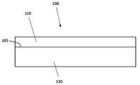
도 1은 예시적인 실시예에 따른 다층 물품의 개략도이다.
도 2는 예시적인 실시예에 따른 다층 물품의 분해 개략도이다.
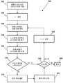
도 3은 예시적인 실시예에 따른 정상적인 결합과 약한 결합 사이의 결합 경계를 식별하는 방법의 흐름도이다.
도 4는 예시적인 실시예에 따른 정상적인 결합과 약한 결합 사이의 결합 경계를 식별하는 방법의 흐름도이다.
도 5는 예시적인 실시예에 따른 파형의 특성을 비교하여 두 지점 사이에 결합 경계가 존재하는지 여부를 판단하는 방법의 흐름도이다.
도 6은 예시적인 실시예에 따른 파형의 특성을 비교하여 두 지점 사이에 결합 경계가 존재하는지 여부를 판단하는 방법의 흐름도이다.
도 7은 예시적인 실시예에 따른 다층 물품의 표면의 개략도이다.
도 8은 예시적인 실시예에 따른 다층 물품의 초음파 파형의 개략도이다.
도 9는 예시적인 실시예에 따른 다층 물품의 초음파 파형의 개략도이다.
도 10은 예시적인 실시예에 따른 다층 물품의 표면의 개략도이다.
도 11은 예시적인 실시예에 따른 다층 물품에서 정상적인 결합과 약한 결합 사이의 결합 경계를 식별하기 위한 시스템의 개략도이다.
도 12는 예시적인 실시예에 따른 다층 물품에서 정상적인 결합과 약한 결합 사이의 결합 경계를 식별하기 위한 시스템의 개략적인 블록도이다.
도 13은 예시적인 실시예에 따른 다층 물품의 표면의 개략도이다.
도 14는 예시적인 실시예에 따른 클래드된(또는, 피복된)(cladded) 물품의 클래드층(clad layer)의 결합면(또는, 접합면)의 저배율 광학 현미경사진(low magnification light optical micrograph)이다.
도 15는 예시적인 실시예에 따른 클래드된 물품의 베이스층의 결합면의 저배율 광학 현미경사진이다.
도 16은 예시적인 실시예에 따른 클래드된 물품의 클래드층의 결합면의 저배율 광학 현미경사진이다.
도 17은 예시적인 실시예에 따른 클래드된 물품의 베이스층의 결합면의 저배율 광학 현미경사진이다.
도 18은 예시적인 실시예에 따른 클래드된 물품의 클래드층의 결합면의 고배율 광학 현미경사진(high magnification light optical micrograph)이다.
도 19는 예시적인 실시예에 따른 클래드된 물품의 베이스층의 결합면의 고배율 광학 현미경사진이다.
도 20은 예시적인 실시예에 따른 클래드된 물품의 클래드층의 결합면의 고배율 광학 현미경사진이다.
도 21은 예시적인 실시예에 따른 클래드된 물품의 베이스층의 결합면의 고배율 광학 현미경사진이다.
도 22는 예시적인 실시예에 따른 클래드된 물품의 클래드층의 결합면의 주사 전자 현미경 현미경사진(scanning electron microscope micrograph)이다.
도 23은 예시적인 실시예에 따른 클래드된 물품의 클래드층의 결합면의 주사 전자 현미경 현미경사진이다.
도 24는 예시적인 실시예에 따른 클래드된 물품의 클래드층의 결합면의 주사 전자 현미경 현미경사진이다.
도 25는 예시적인 실시예에 따른 클래드된 물품의 클래드층의 결합면의 주사 전자 현미경 현미경사진이다.
도 26은 예시적인 실시예에 따른 클래드된 물품의 클래드층의 결합면의 주사 전자 현미경 현미경사진이다.
도 27은 예시적인 실시예에 따른 클래드된 물품의 클래드층의 결합면의 주사 전자 현미경 현미경사진이다.
도 28은 예시적인 실시예에 따른 클래드된 물품의 클래드층의 결합면의 주사 전자 현미경 현미경사진이다.
도 29는 예시적인 실시예에 따른 클래드된 물품의 클래드층의 결합면의 주사 전자 현미경 현미경사진이다.
도 30은 예시적인 실시예에 따른 파형의 특성을 비교하여 두 지점 사이에 결합 경계가 존재하는지 여부를 판단하는 방법의 흐름도이다.
도 31은 예시적인 실시예에 따른 클래드된 물품의 초음파 파형의 고속 푸리에 변환을 비교한 그래프이다.
예시적인 실시예의 다양한 특징, 측면 및 이점은 도면 및 상세한 설명 전체에 걸쳐 동일한 참조 부호가 동일한 구성 요소를 나타내는 첨부 도면과 함께 이하의 상세한 설명으로부터 더욱 명백해질 것이다. 다양한 설명된 특징은 도면에서 반드시 축척(scale)에 맞게 그려지지는 않지만 일부 실시예와 관련된 특정 특징을 강조하기 위해 그려진다.
여기에서 사용된 표제는 조직적 목적만을 위한 것이며 본 개시 또는 청구범위의 범위를 제한하기 위한 것이 아니다. 이해를 용이하게 하기 위해, 가능한 경우 도면에 공통적인 유사한 요소를 지정하기 위해 참조 번호가 사용되었다.A more specific description will be provided with reference to exemplary embodiments shown in the accompanying drawings. It is understood that these drawings illustrate exemplary embodiments and do not limit the scope of the present disclosure, which exemplary embodiments are depicted with additional specificity and detail through use of the accompanying drawings, which follows It will be explained:
1 is a schematic diagram of a multilayer article according to an exemplary embodiment;
2 is an exploded schematic diagram of a multilayer article according to an exemplary embodiment.
Fig. 3 is a flow chart of a method for identifying a bond boundary between a normal bond and a weak bond according to an exemplary embodiment.
Fig. 4 is a flowchart of a method for identifying a bond boundary between a normal bond and a weak bond according to an exemplary embodiment.
5 is a flowchart of a method of determining whether a coupling boundary exists between two points by comparing characteristics of a waveform according to an exemplary embodiment.
6 is a flowchart of a method of determining whether a coupling boundary exists between two points by comparing characteristics of a waveform according to an exemplary embodiment.
7 is a schematic view of a surface of a multilayer article according to an exemplary embodiment.
8 is a schematic diagram of an ultrasound waveform of a multilayer article according to an exemplary embodiment.
9 is a schematic diagram of an ultrasound waveform of a multilayer article according to an exemplary embodiment.
10 is a schematic diagram of a surface of a multilayer article according to an exemplary embodiment.
11 is a schematic diagram of a system for identifying a bond boundary between a normal bond and a weak bond in a multilayer article according to an exemplary embodiment.
12 is a schematic block diagram of a system for identifying a bond boundary between a normal bond and a weak bond in a multilayer article according to an exemplary embodiment.
13 is a schematic view of a surface of a multilayer article according to an exemplary embodiment.
14 is a low magnification light optical micrograph of the bonding surface (or bonding surface) of a clad layer of a clad (or clad) article according to an exemplary embodiment. .
15 is a low magnification optical micrograph of a bonding surface of a base layer of a clad article according to an exemplary embodiment.
16 is a low magnification optical micrograph of a bonding surface of a clad layer of a clad article according to an exemplary embodiment.
17 is a low magnification optical micrograph of a bonding surface of a base layer of a clad article according to an exemplary embodiment.
18 is a high magnification light optical micrograph of a bonding surface of a clad layer of a clad article according to an exemplary embodiment.
19 is a high magnification optical micrograph of a bonding surface of a base layer of a clad article according to an exemplary embodiment.
20 is a high magnification optical micrograph of a bonding surface of a clad layer of a clad article according to an exemplary embodiment.
21 is a high magnification optical micrograph of a bonding surface of a base layer of a clad article according to an exemplary embodiment.
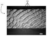
22 is a scanning electron microscope micrograph of a bonding surface of a clad layer of a clad article according to an exemplary embodiment.
23 is a scanning electron micrograph of a bonding surface of a clad layer of a clad article according to an exemplary embodiment.
24 is a scanning electron micrograph of a bonding surface of a clad layer of a clad article according to an exemplary embodiment.
25 is a scanning electron micrograph of a bonding surface of a clad layer of a clad article according to an exemplary embodiment.
26 is a scanning electron micrograph of a bonding surface of a clad layer of a clad article according to an exemplary embodiment.
27 is a scanning electron micrograph of a bonding surface of a clad layer of a clad article according to an exemplary embodiment.
28 is a scanning electron micrograph of a bonding surface of a clad layer of a clad article according to an exemplary embodiment.
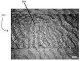
29 is a scanning electron micrograph of a bonding surface of a clad layer of a clad article according to an exemplary embodiment.
30 is a flowchart of a method of determining whether a coupling boundary exists between two points by comparing characteristics of a waveform according to an exemplary embodiment.
31 is a graph comparing fast Fourier transforms of ultrasonic waveforms of clad articles according to an exemplary embodiment.
Various features, aspects and advantages of exemplary embodiments will become more apparent from the following detailed description, taken in conjunction with the accompanying drawings in which like reference numerals refer to like elements throughout the drawings and detailed description. Various described features are not necessarily drawn to scale in the drawings, but are drawn to emphasize specific features associated with some embodiments.
The headings used herein are for organizational purposes only and are not intended to limit the scope of the present disclosure or claims. To facilitate understanding, reference numbers have been used, where possible, to designate like elements common to the drawings.
이제 다양한 실시예를 상세히 참조할 것이다. 각 예는 설명을 위해 제공되며 제한을 의미하지 않으며 모든 가능한 실시예의 정의를 구성하지 않는다.Reference will now be made in detail to various embodiments. Each example is provided by way of illustration and is not meant to be limiting and does not constitute a definition of all possible embodiments.
도 1은 복수의 층들을 갖는 물품(100)의 예시적인 실시예를 도시한다. 물품(100)은 베이스층(base layer)(110) 및 베이스층(110)에 결합되는(또는, 접합되는) 클래드층(clad layer)(120)을 포함할 수 있다. 물품은 베이스층(110)과 클래드층(120) 사이의 계면(interface)(105)을 포함할 수 있으며, 이는 베이스층(110)과 클래드층(120) 사이의 결합(또는, 접합)(bond)에 대응할 수 있다.1 shows an exemplary embodiment of an
예시적인 실시예에서, 물품(100)은 클래드된 금속 물품(cladded metal article)일 수 있다. 베이스층(110)은 스테인리스강, 탄소강, 티타늄, 니켈, 알루미늄 또는 이들 물질을 포함하는 합금과 같은 물질로 형성될 수 있다. 예시적인 실시예에서, 클래드층(120)은 알루미늄, 강철, 티타늄, 지르코늄, 구리, 은, 탄탈륨과 같은 물질, 또는 이들 물질 중 임의의 것을 포함하는 합금으로 형성될 수 있다. 그러나, 베이스층(110) 및 클래드층(120)은 이들 물질에 한정되지 않고, 특정 응용의 요구 사항에 따라 다른 물질이 사용될 수 있음이 이해될 것이다. 클래드층(120)은 베이스층(110)에 고체 상태 용접 방식(solid-state welding method)으로 접합될 수 있고, 클래드층(120)과 베이스층(110) 사이에 계면(105)을 형성할 수 있다. 계면(105)은 클래드층(120)과 베이스층(110) 사이의 영역일 수 있으며, 클래드층(120)과 베이스층(110) 각각의 원자들은 서로 확산된다.In an exemplary embodiment,
고체 상태 용접은 브레이징 용가재(brazing filler metal)를 추가하지 않고 연결되는 베이스 물질의 융점(melting point) 미만의 온도에서 구조적 요소들 사이의 접합/용접을 생산하는 용접 공정 그룹을 포함할 수 있다. 예시적인 실시예에서, 고체 상태 용접은 (i) 액체 또는 증기 상을 통해 구조적 요소들의 일부를 넣지 않고, (ii) 압력을 사용하고, (iii) 온도의 도움을 받거나 받지 않는 접합/용접 공정으로 설명될 수 있다. 고체 상태 용접은 베이스 물질의 상당한 변형(appreciable deformation) 및 고체 상태 확산과 함께 광범위한 압력 및 온도에서 수행된다. 고체 상태 용접 공정에는 냉간 용접, 확산 용접, 폭발 용접, 단조 용접, 마찰 용접, 열간 압력 용접, 롤 용접 및 초음파 용접을 포함한다.Solid state welding may include a group of welding processes that produce a bond/weld between structural elements at a temperature below the melting point of the base material being joined without the addition of brazing filler metal. In an exemplary embodiment, solid state welding is a joining/welding process that (i) does not put some of the structural elements through a liquid or vapor phase, (ii) uses pressure, and (iii) does not assist with or without temperature. can be explained. Solid state welding is performed over a wide range of pressures and temperatures with solid state diffusion and appreciable deformation of the base material. Solid state welding processes include cold welding, diffusion welding, blast welding, forging welding, friction welding, hot pressure welding, roll welding and ultrasonic welding.
예시적인 실시예에서, 베이스층(110)과 클래드층(120) 사이의 고체 상태 용접은 폭발 용접일 수 있다. 폭발 용접(explosion welding, "EXW")은 제어된 폭발을 사용하여 이종 금속들(dissimilar metals)을 고품질의 야금학적 접합 조인트(metallurgically bonded joint)에 강제로 적용하는 고체 상태 용접 기술이다. 이종 금속들 사이의 전이 조인트(transition joint)는 기계적 강도가 높고, 초고진공 타이트(ultra-high vacuum tight)이며 급격한 열 변동(drastic thermal excursions)을 견딜 수 있다. EXW는 폭발물을 사용하여 구성 요소들 중 하나를 매우 빠른 속도로 가속하여 수행된 두 금속을 함께 용접하거나 클래딩하는(또는, 피복하는) 고체상 공정이다. 두 구성 요소들이 항상 고체 상태의 물질이기 때문에 이 공정은 고체상이다.In an exemplary embodiment, the solid state welding between the
물품(100)이 고체 상태 용접된 물품, 보다 구체적으로 폭발적으로 용접된 물품으로서 위에서 설명되었지만, 본 명세서에서 기술된 실시예는 또한 전통적으로 용접된 금속, 금속층 및 비금속층을 갖는 물품들, 및 2개의 비금속층들을 갖는 물품들과 같은 다른 유형의 물품들에 적용될 수 있음이 이해될 것이다.Although
도 2는 물품(100)의 분해도를 도시한다. 도 2를 참조하면, 베이스층(110)은 베이스층 결합면(또는, 베이스층 접합면)(112) 및 베이스층 외면(114)을 포함할 수 있다. 또한, 클래드층(120)은 클래드층 결합면(또는, 클래드층 접합면)(122) 및 클래드층 외면(124)을 포함할 수 있다. 베이스층(110) 및 클래드층(120)이 함께 접합될 때, 베이스층 외면(114) 및 클래드층 외면(124) 중 어느 하나는 본 명세서에 설명된 실시예의 목적을 위해 물품(100)의 표면으로 간주될 수 있다.2 shows an exploded view of the
도 3은 도 1 및 도 2에 도시된 바와 같이 물품(100)에서 베이스층(110)과 클래드층(120) 사이의 정상적인 결합과 베이스층(110)과 클래드층(120) 사이의 약한 결합 사이의 경계를 식별하는 방법(300)의 예시적인 실시예를 도시한다. "경계(boundary)"라는 용어는 x-y 평면(도 7 참조)에서 클래드층(120)과 베이스층(110) 사이의 계면이 정상적인 결합에서 약한 결합으로 전이되는 위치를 의미할 수 있다. 블록(302)에서, 총 n개의 위치들이 물품(100)의 표면 상에서 식별되며, n은 2 이상의 정수이다. 도 7은 복수의 위치들(162)이 물품(100)의 클래드층 외면(124) 상의 테스트 영역(160) 내에서 식별된 예시적인 실시예를 도시한다. 도 7은 클래드층 외면(124) 상에 배열된 위치들(162)을 도시하지만, 위치들(162)은 대안적인 예시적인 실시예에서 베이스층 외면(114) 상에서 식별될 수 있다. 위치들(162)은 각 위치(162) 사이에 일정한 간격으로 배열될 수 있거나, 위치(162) 사이에 가변 간격(varying interval)이 있을 수 있다. 추가로, 예시적인 실시예에서, 물품(100)의 서브세트(subset)를 테스트할 필요만 있을 수 있고, 위치들(162)은 도 7에 도시된 바와 같이 테스트 영역(160)에서만 식별될 수 있다. 다른 예시적인 실시예에서, 물품(100)의 전체를 테스트하는 것이 바람직할 수 있고, 위치들(162)은 전체 클래드층 외면(124)에 걸쳐 식별될 수 있다.3 is a diagram between the normal bond between the
도 3으로 돌아가서, 블록(304)에서, 파라미터 i는 1과 동일하게 설정된다. 블록(306)에서, 복수의 위치들(162) 중 i번째 위치(162)에 대응하는 i번째 파형이 획득된다. i번째 파형은 i번째 위치에서 반사된 초음파의 세기(intensity)의 시간 도메인 파형(time domain waveform)일 수 있다. 예시적인 실시예에서, i번째 파형은 전파 파형일 수 있다. 전파 파형은 반사된 초음파의 정류되지 않은 파형으로, 양의 진폭과 음의 진폭을 모두 보여준다. 도 8에 도시된 제1 파형(700) 및 도 9에 도시된 제2 파형(800)은 전파, 시간 도메인 파형의 예시적인 실시예이다. i번째 파형을 획득하는 것은 디지털 스토리지로부터 파형을 검색하거나 초음파 변환기를 사용하여 실시간 파형(real-time waveform)을 획득하는 것을 포함할 수 있다. 변환기(transducer)는 휴대형일 수도 있고 자동화 시스템에 장착될 수도 있다. 아래의 표 1은 사용될 수 있는 변환기들의 유형들의 예시적인 실시예뿐만 아니라 변환기들과 관련된 파라미터들의 예시적인 실시예를 식별한다.3, at
풀 웨이브0.5” single transducer,
full wave
변환기,
0.415'' 폴리메틸메타크릴레이트0.25” delay tip
converter,
0.415'' polymethyl methacrylate
표 1에 열거된 변환기들 및 파라미터들은 예시일 뿐이며, 다른 유형들의 변환기들 및/또는 언급된 파라미터들에 대한 값들이 사용될 수 있음이 이해될 것이다.It will be understood that the transducers and parameters listed in Table 1 are exemplary only, and that other types of transducers and/or values for the noted parameters may be used.
도 3의 블록(308)에서, (i+1)번째 파형이 획득된다(또는, 얻어진다). i번째 파형과 유사하게, (i+1)번째 파형을 획득하는 것은 디지털 스토리지로부터 파형을 검색하거나 초음파 변환기를 사용하여 라이브 파형(live waveform)을 획득하는 것을 포함할 수 있다. 예시적인 실시예에서, i번째 파형과 (i+1)번째 파형은 동일한 변환기를 사용하여 획득될 수 있다. 예를 들어, 변환기는 i번째 위치로 이동하여 i번째 파형을 얻은 다음, (i+1)번째 위치로 이동하여 (i+1)번째 파형을 얻을 수 있다. 변환기는 각 위치로 이산적으로(discretely) 이동되거나 각 위치를 통해(또는, 관통하여) 연속적으로 이동하고 이동하는 동안 파형을 얻을 수 있다.At
블록(310)에서, i번째 파형은 (i+1)번째 파형과 비교되고, 블록(312)에서, 블록(310)에서 수행된 비교가 베이스층(110)과 클래드층(120) 사이의 정상적인 결합과, 베이스층(110)과 클래드층(120) 사이의 약한 결합 사이의 경계를 나타내는지 여부가 결정된다(도 1-2 참조). 블록(310)에서의 비교 및 블록(312)에서의 결정에 관한 추가 세부사항은 여기에서 상세히 설명될 것이다. 비교가 결합 경계를 나타내면(즉, 블록(312)에서 "예"), 방법(300)은 블록(314)으로 진행한다. 비교가 결합 경계를 나타내지 않으면(즉, 블록(312)에서 "아니오"), 방법(300)은 블록(316)으로 진행한다.At
블록(314)에서, 결합 경계의 위치는 i번째 위치 및 (i+1)번째 위치 중 하나 또는 모두에 기초하여 결정된다. 예를 들어, 도 10은 좌표 x1, y1를 갖는 제1 위치(170) 및 좌표 x2, y2를 갖는 제2 위치(172)의 예를 도시한다. 제1 위치(170)와 제2 위치(172) 사이의 경계 위치(174)는 좌표 xb, yb를 가질 수 있다. 경계 위치(174)의 x-좌표 xb는 [x1, x2] 범위(끝점 포함)에 속할 수 있고, 경계 위치(174)의 y-좌표 yb는 [y1, y2] 범위(끝점 포함)에 속할 수 있다. 예시적인 실시예에서, 경계 위치(174)의 좌표는 제1 위치(170)와 제2 위치(172) 사이의 중간점으로 설정될 수 있다. 대안적으로, 사용자의 선호도 및 요구에 따라, 경계 위치(174)의 좌표는 제1 위치(170)와 제2 위치(172) 사이 및 이를 포함하는 임의의 위치에 설정될 수 있다.At
블록(315)에서, 경계 위치가 기억된다. 예시적인 실시예에서, 기억(memorialization)은 수동(manual)일 수 있다. 예를 들어, 변환기로 물품(100)(도 1-2 참조)을 검사하는 사용자는 파형의 비교가 결합 경계를 나타낼 때 필기 도구, 휴대용 표면 프린터 또는 다른 적절한 마킹 툴(marking tool)로 클래드층 외면(124)을 표시할 수 있다. 대안적으로, 자동화 시스템이 사용되는 경우, 시스템은 필기 도구, 표면 프린터, 레이저 에칭기, 또는 물품(100)의 경계 위치를 물리적으로 마킹하기 위한 다른 적절한 마킹 툴을 포함할 수 있다. 대안적으로, 경계 위치의 기억은 경계 위치의 좌표를 저장 매체에 데이터로서 전자적으로 저장하는 것을 포함할 수 있다.At
블록(316)에서, 파라미터 i가 값 n-1과 동일한지 여부가 결정된다. i가 n-1이면(블록(316)에서 "예"), 방법(300)은 방법이 종료되는 블록(320)으로 진행한다. i가 n-1과 같지 않으면(블록(316)에서 "아니오"), 방법(300)은 i가 1만큼 증가하는 블록(318)으로 진행한다. 그 다음, 방법(300)은 블록(306)으로 돌아간다.At
도 4는 도 1 및 도 2에 도시된 바와 같이 물품(100)에서 베이스층(110)과 클래드층(120) 사이의 정상적인 결합과 베이스층(110)과 클래드층(120) 사이의 약한 결합 사이의 경계를 식별하는 방법(400)의 다른 예시적인 실시예를 도시한다. 본 명세서에서 상세하게 설명되는 바와 같이, 방법(400)은 모든 위치들(162)에서 파형을 획득한 다음, 파형을 순환하여 비교한다. 이것은 경계 위치들이 나중에 계산될 수 있고 테스트 중인 물품의 식별 정보(일련 번호(serial number) 또는 배치 번호(batch number)와 같은)에 연결될 수 있기 때문에, 저장 매체에 파형을 전자적으로 저장할 수 있는 자동화 시스템을 사용할 때 유용할 수 있다. 이것은 파형을 비교하고 물품의 경계 위치들을 물리적으로 표시하는 데 필요한 시간을 제거함으로써 자동화 시스템의 더 높은 처리량을 용이하게 한다.4 is a diagram between the normal bond between the
블록(402)에서, 총 n개의 위치들이 물품(100)의 표면 상에서 식별되며, n은 2 이상의 정수이다. 블록(404)에서, 파라미터 i는 1과 동일하게 설정된다. 블록(406)에서, 표 1에 기술된 변환기들 중 하나 또는 다른 적절한 변환기와 같은 변환기는 n개의 위치들의 i번째 위치로 이동된다. 블록(408)에서, 초음파는 변환기를 통해(via) 물품(100)을 통해(through) 전송된다. 블록(410)에서, 반사된 초음파는 i번째 위치의 변환기에서 수신된다. 블록(412)에서, i번째 위치에 대응하는 i번째 파형이 획득된다. i번째 파형은 i번째 위치에서 반사된 초음파의 세기(intensity)의 시간 도메인 파형(time domain waveform)일 수 있다. 블록(412)에서 i번째 파형을 생성하는 것의 일부로서, i번째 파형은 저장 매체에 데이터로서 전자적으로 저장될 수 있다.At
블록(414)에서, 파라미터 i가 n과 동일한지 여부가 결정된다. 파라미터 i가 n과 동일하지 않은 경우(블록(414)에서 "아니오"), 방법(400)은 블록(416)으로 진행한다. 블록(416)에서, 파라미터 i는 1만큼 증가하고, 방법(400)은 블록(406)으로 돌아간다. 파라미터 i가 n과 같으면(블록(414)에서 "예"), 방법(400)은 블록(418)으로 진행한다.At
블록(418)에서, 파라미터 i는 1로 재설정된다. 블록(420)에서, i번째 파형은 (i+1)번째 파형과 비교된다. 블록(420)의 일부로서, i번째 파형 및 (i+1)번째 파형은 전자식 스토리지(electronic storage)로부터 검색될 필요가 있을 수 있다. 블록(422)에서, 블록(420)에서 수행된 비교가 결합 경계를 나타내는지 여부가 결정된다. 블록(420)에서의 비교 및 블록(422)에서의 결정에 관한 추가 세부사항은 여기에서 상세히 설명될 것이다. 비교가 결합 경계를 나타내면(즉, 블록(422)에서 "예"), 방법(400)은 블록(424)으로 진행한다. 비교가 결합 경계를 나타내지 않으면(즉, 블록(422)에서 "아니오"), 방법(400)은 블록(426)으로 진행한다.At
블록(424)에서 결합 경계의 경계 위치가 결정된다. 결합 경계의 결정은 도 3의 블록(314)과 관련하여 위에서 설명된 바와 같은 방법과 유사하다. 블록(425)에서, 경계 위치가 기억된다. 결합 경계의 기억은 도 3의 블록(315)과 관련하여 위에서 설명된 바와 같은 방법과 유사하다.At
블록(426)에서, 파라미터 i가 값 n-1과 동일한지 여부가 결정된다. i가 n-1과 같으면(블록(426)에서 "예"), 방법(400)은 방법(400)이 종료되는 블록(430)으로 진행한다. i가 n-1과 같지 않으면(블록(426)에서 "아니오"), 방법(400)은 i가 1만큼 증가하는 블록(428)로 진행한다. 방법(400)은 다음 파형 쌍(next pair of waveforms)이 비교되는 블록(420)으로 돌아간다.At
도 5는 파형의 특성을 비교하고 두 지점 사이에 결합 경계가 존재하는지 여부를 결정하는 방법(500)의 예시적인 실시예를 도시한다. 방법(500)은 도 3의 블록(310 및 312) 또는 도 4의 블록(420) 및 블록(422)에 대응하는 요소들을 포함할 수 있다. 방법(500)을 설명함에 있어서, 도 8에 예시된 제1 파형(700) 및 도 9에 예시된 제2 파형(800)도 참조될 것이다.5 depicts an exemplary embodiment of a
도 5로 돌아가서, 블록(502)에서 제1 파형(700)이 획득된다. 제1 파형(700)은 상술한 바와 같이 초음파 변환기를 이용하여 획득될 수 있다. 대안적으로, 제1 파형(700)은 전자적 데이터로서 저장 매체로부터 검색될 수 있다.Returning to FIG. 5 , a
블록(504)에서, 제1 파형(700)(즉, 도 8에 도시된 마루들(710))에서 제1 마루 수(p1)가 카운트된다. 예시적인 실시예에서, 제1 마루 수(p1)는 제1 파형(700)의 x-축을 따른 값들의 기 결정된 범위(706)에 대응하는 제1 파형(700)의 서브세트(subset)에서 카운트될 수 있다. 기 결정된 범위(706)는 클래드층(120)과 베이스층(110) 사이의 계면으로부터 반사된 초음파를 볼 것으로 예상되는 시간 도메인의 값에 대응할 수 있다. 예를 들어, 예시적인 실시예에서, 변환기는 클래드층(120) 상에 위치하는 것으로 가정할 수 있다. 클래드층(120)의 두께와 클래드층(120)의 물질의 음속을 알면, 초음파가 변환기로부터 클래드층(120)과 베이스층(110) 사이의 계면으로 이동하고 다시 변환기로 이동하는 데 걸리는 시간이 계산될 수 있다. 이 기간은 기 결정된 범위(706)의 중간점을 계산하는 데 사용될 수 있다. 기 결정된 범위(706)의 폭은 클래드층(120)의 두께 및/또는 클래드층(120)과 베이스층(110) 사이의 계면의 추정된 두께의 제조 공차(manufacturing tolerances)에 기초하여 계산될 수 있고, 그 다음 이러한 거리 값들을 클래드층(120)의 물질의 음속에 기초하여 파형의 시간 도메인에서 대응하는 값들로 변환할 수 있다. 기 결정된 범위의 중간점 및/또는 너비 계산에 영향을 미칠 수 있는 기타 요인에는 사용 중인 변환기의 유형(즉, 단일 요소, 이중 요소, 딜레이 팁(delay tip) 등) 및/또는 이용되는 초음파의 스타일(즉, 접촉, 침지(immersion), 수주(water column) 등)이 포함될 수 있다. 대안적으로 또는 추가로, 사용자는 기 결정된 범위(706)에 대한 적절한 값을 결정하거나 확인하기 위해, 테스트 중인 물품 또는 알려진 샘플에 대해 테스팅(testing) 전에 보정 절차를 수행할 수 있다. 예를 들어, 클래드층(120)과 베이스층(110) 사이의 계면은 기 결정된 범위(706)를 설정하기 위해 초음파 파형 상에서 시각적으로 식별될 수 있다. 기 결정된 범위(706)를 이용하여, 도 8은 제1 파형(700)에 대해 제1 마루 수(first number of peaks)(p1)(도 8에서 710으로 표시됨)가 2와 동일한 것을 도시한다.At block 504 , the first number of ridges p 1 in the first waveform 700 (ie,
다른 실시예에서, 제1 마루 수(p1)는 제1 파형(700)의 y-값에 대응하는 기 결정된 제1 임계값(predetermined first threshold)(702)보다 높은 마루들의 수일 수 있다. 기 결정된 제1 임계값(702)은 사용되는 변환기의 전력 레벨, 베이스층(110) 및 클래드층(120)(도 1-2 참조)을 형성하는 특정 재료, 베이스층(110) 및 클래드층(120)의 두께, 및/또는 초음파의 전파에 영향을 미칠 수 있는 다른 인자에 기초하여 결정될 수 있다. 예시적인 실시예에서, 사용자는 제1 임계값(702)에 대한 적절한 레벨을 결정하기 위해, 테스트되는 물품 또는 알려진 샘플에 대해 테스팅 전에 보정(또는, 교정) 절차를 수행할 수 있다. 제1 임계값(702)을 사용하여, 도 8은 제1 파형(700)에 대해 제1 마루 수(p1)가 2와 동일한 것을 도시한다.In another embodiment, the first number of ridges p1 may be a number of ridges higher than a predetermined
도 5로 돌아가서, 블록(506)에서, 제1 파형(700)(도 8에서 712로 표시됨)에서 제1 골 수(first number of troughs)(t1)가 카운트된다. 예시적인 실시예에서, 제1 골 수(t1)는 제1 파형(700)의 x-축을 따른 값들의 기 결정된 범위(706)에 대응하는 제1 파형(700)의 서브세트에서 카운트될 수 있다. 기 결정된 범위(706)를 사용하여, 도 8은 제1 골 수(t1)(도 8에서 712로 표시됨)가 제1 파형(700)에 대해 1과 동일한 것을 도시한다. 대안적으로, 제1 골 수(t1)는 기 결정된 제2 임계값(704)보다 작은 골의 수일 수 있다. 예시적인 실시예에서, 제2 임계값(704)은 제1 임계값(702)의 음의 값일 수 있다. 대안적으로, 제2 임계값(704)은 사용되는 변환기의 전력 레벨, 베이스층(110) 및 클래드층(120)(도 1-2 참조)을 형성하는 특정 재료, 베이스층(110) 및 클래드층(120)의 두께, 및/또는 초음파의 전파에 영향을 미칠 수 있는 다른 인자에 기초하여 결정될 수 있다. 예시적인 실시예에서, 사용자는 제2 임계값(704)에 대한 적절한 레벨을 결정하기 위해, 테스트되는 물품 또는 알려진 샘플에 대해 테스팅 전에 보정 절차를 수행할 수 있다. 제2 임계값(704)을 사용하여, 도 8은 제1 파형(700)에 대한 제1 골 수(t1)가 1과 동일한 것을 도시한다.Returning to FIG. 5 , at
블록(508)에서, 블록(502)에서와 유사한 방식(similar fashion)으로 상이한 위치에 대응하는 제2 파형(800)이 획득된다. 블록(510)에서, 블록(504)에서와 유사한 방식으로 제2 파형(800)에 대해 제2 마루 수(p2)(도 9에서 810으로 표시된 마루들)가 카운트된다. 제2 마루 수(p2)를 카운트할 때, 제1 마루 수(p1)를 카운트하는 데 사용되는 제1 임계값(702) 또는 기 결정된 범위(706)가 사용될 수 있다. 블록(512)에서, 제2 골 수(t2)(도 9에서 812로 표시된 골들)은 블록(506)에서와 유사한 방식으로 제2 파형(800)에 대해 카운트된다. 제2 골 수(t2)를 카운트할 때, 제1 골 수(t1)를 카운트하는 데 사용되는 제2 임계값(704) 또는 기 결정된 범위(706)가 사용될 수 있다.At
블록(514)에서, 제1 마루 수(p1)가 제2 마루 수(p2)와 동일한지 여부 및 제1 골 수(t1)가 제2 골 수(t2)와 동일한지 여부가 결정된다. 두 동등성(both equalities)이 참이면(블록(514)에서 "예"), 방법(500)은 결합 경계가 존재하지 않는 것으로 결정되는 블록(516)으로 진행한다. 어느 하나의 동등성이 참이 아니면(블록(514)에서 "아니오"), 방법(500)은 결합 경계가 존재한다고 결정되는 블록(518)로 진행한다.At
도 6은 파형의 특성을 비교하고 두 지점 사이에 결합 경계가 존재하는지 여부를 결정하는 방법(600)의 예시적인 실시예를 도시한다. 도 6에서, 블록들(602 내지 612)은 도 5의 블록들(502 내지 512)와 동일하다. 도 6의 블록(614)에서, 제1 마루 수(p1)와 제1 골 수(t1)의 제1 합이 제2 마루 수(p2)와 제2 골 수(t2)의 제2 합과 동일한지 여부가 결정된다. 블록(614)의 동등성이 참이면(블록(614)에서 "예"), 방법(600)은 블록(616)으로 진행하고, 여기서 결합 경계가 존재하지 않는 것으로 결정된다. 블록(614)의 동등성이 참이 아닌 경우(블록(614)에서 "아니오"), 방법(600)은 블록(618)으로 진행하고, 여기서 결합 경계가 존재한다고 결정된다.6 shows an exemplary embodiment of a
도 30은 파형의 특성을 비교하고 두 지점 사이에 결합 경계가 존재하는지 여부를 결정하는 방법(900)의 예시적인 실시예를 도시한다. 전술한 방법(500) 및 방법(600)에서, 파형(700) 및 파형(800)의 특성은 마루들 및 골들의 수였다. 대조적으로, 도 30에 도시된 방법(900)에서 비교된 특성은 고속 푸리에 변환(fast Fourier transform, FFT)에 의해 결정된 파형의 성분 주파수이다.30 depicts an exemplary embodiment of a
블록(902)에서, 제1 파형(700)이 획득된다. 블록(902)에서 제1 파형(700)의 획득은 도 5의 블록(502) 또는 도 6의 블록(602)에서와 유사한 방식으로 달성될 수 있다. 블록(904)에서, 제1 파형(700)의 제1 파형 FFT(750)가 도 31의 실선 곡선(solid line curve)에 의해 도시된 바와 같이 계산된다. 제1 파형 FFT(750)는 공지된 FFT 알고리즘에 의해 생성될 수 있다.At
블록(906)에서, 제1 피크 값(또는, 제1 마루 값)(a1)이 식별된다. 제1 피크 값(a1)은 제1 파형 FFT(750)의 제1 최대 피크(또는, 제1 최대 마루)(752)에서의 크기에 대응할 수 있다(도 31 참조). 도 31은 제1 파형 FFT(750)에 대한 2개의 최대 피크를 나타내는 것처럼 보일 수 있지만, 복소수 데이터 세트에 대해 동작하는 것과 대조적으로 실수 데이터 세트에 대해 동작할 때 많은 FFT 알고리즘들이 대칭 곡선을 생성한다는 것이 이해될 것이다. 따라서, 제1 파형 FFT(750)의 단일 제1 최대 피크(752)만을 식별하는 것으로 충분할 수 있다. 도 31에 도시된 구체적인 예에서, 제1 최대 피크(752)의 제1 피크 값(a1)은 9.04로 계산되었다.At
블록(908)에서, 제2 파형(800)이 획득된다. 블록(908)에서 제2 파형(800)의 획득은 도 5의 블록(508) 또는 도 6의 블록(602)에서와 유사한 방식으로 달성될 수 있다. 블록(910)에서, 제2 파형(800)의 제2 파형 FFT(850)가 도 31의 파선 곡선(broken line curve)에 의해 도시된 바와 같이 계산된다. 제2 파형 FFT(850)는 공지된 FFT 알고리즘에 의해 생성될 수 있다.At
블록(912)에서, 제2 피크 값(또는, 제2 마루 값)(a2)이 식별된다. 제2 피크 값(a2)은 제2 파형 FFT(850)의 제2 최대 피크(또는, 제2 최대 마루)(852)에서의 크기에 대응할 수 있다(도 31 참조). 도 31에 도시된 구체적인 예에서, 제2 최대 피크(852)의 제2 피크 값(a2)은 14.08로 계산되었다.At
블록(914)에서, 제1 피크 값(a1)과 제2 피크 값(a2) 사이의 차이(b)가 기 결정된 FFT 임계값보다 큰지 여부가 결정된다. 기 결정된 FFT 임계값은 알려진 정상적인 결합 샘플에서 마루 값의 평균 변화에 기초할 수 있다. 예를 들어, 보정 과정(calibration process)에서 알려진 정상적인 결합 샘플이 5%의 FFT 마루 값 변동을 갖는 것으로 결정하면, 기 결정된 FFT 임계값은 이의 배수일 수 있다. 예를 들어, 예시적인 실시예에서, 기 결정된 FFT 임계값은 피크 값의 10%, 15% 또는 20% 이상일 수 있다. 예시적인 실시예에서, 차이(b)는 방정식 (1)에 의해 주어진 바와 같이 제1 피크 값(a1)과 제2 피크 값(a2) 사이의 단순한 차이로서 계산될 수 있다:At
b = | a1 - a2| (1)b = | a1 - a2 | (One)
다른 예시적인 실시예에서, 차이(b)는 제1 피크 값(a1) 또는 제2 피크 값(a2)을 기준으로 하는 백분율 차이로 표현될 수 있다. 예를 들어, 차이(b)는 방정식 (2)로 주어질 수 있다.In another exemplary embodiment, the difference (b) may be expressed as a percentage difference based onthe first peak value (a 1 ) or the second peak value (a2 ). For example, the difference (b) can be given by equation (2).
b = | a1 - a2| / a1(2)b = | a1 - a2 | /a1 (2)
방정식 (2)의 분모는 제2 피크 값(a2) 또는 대안적으로 제1 피크 값(a1) 및 제2 피크 값(a2)의 평균값으로 대체될 수 있음을 주목해야 한다.It should be noted that the denominator of equation (2)can be replaced by the second peak value (a 2 ) or alternatively the average value of the first peak value (a1 ) and the second peak value (a2 ).
블록(914)으로 돌아가서, 제1 피크 값(a1)과 제2 피크 값(a2) 사이의 차이(b )가 기 결정된 FFT 임계값보다 큰 것으로 결정되면(블록(914)에서 "예"), 방법(900)은 결합 경계가 존재하는 것으로 결정되는 블록(918)으로 진행한다. 차이(b )가 기 결정된 FFT 임계값보다 크지 않다고 결정되면(블록(914)에서 "아니오"), 방법(900)은 결합 경계가 존재하지 않는 것으로 결정되는 블록(916)으로 진행한다. 도 31에 도시된 구체적인 예에서, 차이(b)는 5.04, 즉 제1 피크값(a1)의 55.8%이다. 20%의 기 결정된 FFT 임계값을 가정하면, 이는 제1 파형(700)에 대응하는 위치와 제2 파형(800)에 대응하는 위치 사이에 결합 경계가 있음을 나타낸다.Returning to block 914 , if itis determined that the difference b between the first peak value a 1 and the second peak value a2 is greater than the predetermined FFT threshold (“Yes” at block 914 ). ), the
전술한 방법(900)에서, FFT 파형의 피크 값들이 비교된다. 그러나, FFT 파형의 다른 특성도 비교할 수 있음을 이해해야 한다. 예를 들어, 예시적인 실시예에서, FFT 파형의 기 결정된 빈(predetermined bin)에서의 값들은 피크에서의 값 대신에 비교될 수 있다. 또는, 예시적인 실시예에서, FFT 파형의 피크들(또는, 마루들)의 x-축 값들(즉, 피크 위치들)을 비교할 수 있다. 두 FFT 파형의 피크 위치들이 기 결정된 빈 수 이상으로 변하는 경우, 두 FFT 파형에 대응하는 지점들 사이에 결합 경계가 존재한다고 판단될 수 있다.In the
도 11 및 도 12는 제1 층 및 제2 층을 갖는 물품(100)에서 정상적인 결합과 약한 결합 사이의 결합 경계를 식별하기 위한 시스템(200)의 예시적인 실시예를 도시한다. 도 11에 도시된 바와 같이, 시스템(200)은 제1 레일들(210), 제1 레일 마운트들(first rail mounts)(212), 제2 레일(220), 툴 헤드(tool head)(222), 초음파 변환기(232), 및 컨트롤러(240)를 포함할 수 있다. 예시적인 실시예에서, 시스템(200)은 마킹 장치(marking device)(234)를 더 포함할 수 있다.11-12 show an exemplary embodiment of a
제2 레일(220)은 제1 레일 마운트들(212)을 통해 제1 레일들(210)에 장착될 수 있다. 시스템(200)은 y-방향으로 제 1 레일들(210)을 따라 제 1 레일 마운트들(212)을 이동시키도록 구성된 하나 이상의 제 1 레일 마운트 모터들(214)(도 12 참조)를 더 포함할 수 있으며, 제2 레일(220)이 제1 레일 마운트들(212)을 통해 제1 레일들(210)에 장착되기 때문에 제2 레일(220)을 y-방향으로 이동 시킨다. 시스템(200)은 제1 레일 마운트 모터(214)에 작동 가능하게 결합된 제1 레일 마운트 인코더들(first rail mount encoders)(216)(도 12 참조)와 같은 하나 이상의 위치 센서들을 더 포함할 수 있다. 제1 레일 마운트 인코더(216)는 제1 레일들(210)을 따라 제1 레일 마운트들(212)의 y-방향에서의 위치를 나타내는 인코더 신호를 출력하도록 구성될 수 있다.The
시스템(200)은 x-방향으로 제2 레일(220)을 따라 툴 헤드(222)를 이동시키도록 구성된 툴 헤드 모터(tool head motor)(224)(도 12 참조)를 더 포함할 수 있다. 시스템(200)은 툴 헤드 모터(224)에 작동 가능하게 결합된 툴 헤드 인코더(226)(도 12 참조)와 같은 위치 센서를 더 포함할 수 있다. 툴 헤드 인코더(226)는 제2 레일(220)을 따라 툴 헤드(222)의 x-방향에서의 위치를 나타내는 인코더 신호를 출력하도록 구성될 수 있다.The
다른 말로, 제1 레일 마운트 모터(214) 및 툴 헤드 모터(224)는 툴 헤드(222)에 작동 가능하게 결합되고 툴 헤드(222)를 물품(100)의 표면에 평행한 2차원 평면을 따라 이동시키도록 구성된 모터 시스템의 일부일 수 있다. 제1 레일 마운트 인코더(216) 및 툴 헤드 인코더(226)는 모터 시스템에 작동 가능하게 결합되고 툴 헤드(222)의 위치를 나타내는 인코더 신호들을 출력하도록 구성된 인코더들의 예시적인 실시예이다.In other words, the first
초음파 변환기(232)는 툴 헤드(222)에 대해 고정된 위치에서 툴 헤드(222)에 장착될 수 있다. 따라서, 초음파 변환기(232)의 위치는 인코더 신호들로부터 계산된 툴 헤드(222)의 위치에 기초하여 계산될 수 있다. 추가적으로, 마킹 장치(234)는 툴 헤드(222)에 대해 고정된 위치에서 툴 헤드(222) 상에 장착될 수 있다. 따라서, 마킹 장치(234)의 위치는 인코더 신호들로부터 계산된 툴 헤드(222)의 위치에 기초하여 계산될 수 있다. 마킹 장치(234)는 테스트되는 물품의 표면을 마킹하기에 적합한 임의의 장치일 수 있다. 마킹 장치(234)의 비제한적인 예는 펜, 표면 프린터, 레이저 에칭기, 또는 물품(100) 상의 경계 위치를 물리적으로 마크하기 위한 다른 적절한 마킹 툴을 포함할 수 있다.The
도 12에 도시된 바와 같이, 컨트롤러(240)는 버스(bus)(250)를 통해 초음파 변환기(232), 제1 레일 마운트 모터(214), 제1 레일 마운트 인코더(216), 툴 헤드 모터(214), 툴 헤드 인코더(226), 및 마킹 장치(234)에 작동 가능하게 결합될 수 있다. 대안적으로, 컨트롤러(240)는 무선 신호들(radio signals), 블루투스(Bluetooth), 무선 LAN 또는 기타 적절한 무선 통신 방법들을 통해 초음파 변환기(232), 제1 레일 마운트 모터(214), 제1 레일 마운트 인코더(216), 툴 헤드 모터(214), 툴 헤드 인코더(226), 및 마킹 장치(234)와 무선으로 통신하도록 구성될 수 있다.As shown in FIG. 12 , the
도 12에서 추가로 볼 수 있는 바와 같이, 컨트롤러(240)는 프로세서(240a) 및 메모리(240b)를 포함할 수 있다. 컨트롤러(240)는 추가로 외부 저장 매체(242)에 작동 가능하게 연결될 수 있다. 추가적으로, 본 개시의 목적을 위해, 컨트롤러(240)는 또한 메모리(240b)에 작동 가능하게 결합되는 것으로 간주될 수 있다. 메모리(240b) 및 외부 저장 매체(242)는 컴퓨터가 읽을 수 있는 비일시적 저장 매체(non-transitory computer-readable storage media)일 수 있다. 컨트롤러(240)의 프로세서(240a)는 메모리(240b) 및/또는 외부 저장 매체(242) 중 어느 하나에 저장된 컴퓨터 실행가능 명령어(computer-executable instructions)를 실행하도록 구성될 수 있다.12 , the
메모리(240b) 및 외부 저장 매체(242)는 컴퓨터가 읽을 수 있는 매체의 예이다. 컴퓨터 판독 가능 매체는 컴퓨터에서 액세스할 수 있는 모든 사용 가능한 매체일 수 있으며, 휘발성(volatile) 및 비휘발성(nonvolatile) 매체, 이동식(removable) 및 비이동식(non-removable) 매체를 모두 포함한다. 예로서, 컴퓨터 판독 가능 매체는 컴퓨터 저장 매체 및 통신 매체를 포함할 수 있지만 이에 제한되지는 않는다. 컴퓨터 저장 매체는 컴퓨터 판독 가능 명령어, 데이터 구조, 프로그램 모듈 또는 기타 데이터와 같은 정보의 저장을 위한 임의의 방법 또는 기술로 구현된 휘발성 및 비휘발성, 이동식 및 비이동식 매체를 모두 포함할 수 있다. 컴퓨터 저장 매체에는 RAM(Random Access Memory), ROM(Read-Only Memory), EEPROM(Electrically Erasable Read-Only Memory), 플래시 메모리 또는 기타 메모리 기술, CD-ROM(Compact Disk Read-Only Optical Memory), DVD(digital versatile disks) 또는 기타 광 디스크 저장 장치(other optical disk storage), 자기 카세트(magnetic cassettes), 자기 테이프(magnetic tape), 자기 디스크 저장 장치(magnetic disk storage) 또는 기타 자기 저장 장치, 또는 원하는 정보를 저장하는 데 사용될 수 있고 컴퓨터에 의해 액세스될 수 있는 기타 모든 매체가 포함되지만 이에 제한되지는 않는다. 통신 매체는 컴퓨터 판독 가능 명령어, 데이터 구조, 프로그램 모듈 등, 및/또는 반송파(carrier wave) 또는 기타 전송 메커니즘과 같은 변조된 데이터 신호의 기타 데이터 중 하나 이상을 구현하고, 본 개시와 일치하는 임의의 알려진 정보 전달 매체를 포함할 수 있다. "변조된 데이터 신호(modulated data signal)"라는 용어는 신호의 정보를 인코딩하는 방식으로 설정되거나 변경된 특성 중 하나 이상을 갖는 신호를 의미한다. 예로서, 통신 매체는 유선 네트워크 또는 직접 유선 연결과 같은 유선 매체, 및 음향(acoustic), 무선 주파수(radio frequency, RF), 적외선 및 기타 무선 매체와 같은 무선 매체를 포함하지만 이에 제한되지 않는다. 위의 모든 것의 조합도 컴퓨터 판독 가능 매체의 범위에 포함되어야 한다.The
예시적인 실시예에서, 컨트롤러(240)는 제1 레일 마운트 모터(214) 및 툴 헤드 모터(224)를 제어하여 변환기(232)를 물품(100)의 표면을 따라 복수의 위치들(162)(도 7 참조)로 이동시키도록 구성될 수 있다. 도 11은 변환기(232)가 물품(100)의 외부 클래드층 표면(124)을 따라 이동되는 것을 도시하지만, 변환기(232)가 물품(100)의 베이스층 외면(114)을 따라 이동될 수 있다는 것도 이해될 것이다.In the exemplary embodiment, the
컨트롤러(240)는 복수의 위치들(162) 중 각 위치(162)에 대해, 변환기(232)와 툴 헤드(222) 사이의 고정된 관계에 기초하여 제1 레일 마운트 인코더(216)로부터의 인코더 신호 및 툴 헤드 인코더(226)로부터의 인코더 신호에 기초하여 위치의 좌표를 식별하도록 추가로 구성될 수 있다. 예시적인 실시예에서, 좌표는 시스템(200) 고유의 좌표 시스템(coordinate system native)에 대해 계산될 수 있다. 다른 예시적인 실시예에서, 컨트롤러(240)는 물품(100)의 표면에 제공된 인덱스 마크(190)에 대한 좌표를 계산하도록 구성될 수 있다.The
컨트롤러(240)는 물품(100)을 통해(또는, 관통하여) 초음파를 전송하도록 변환기(232)를 제어하도록 추가로 구성될 수 있다. 변환기(232)는 클래드층 외면(124)으로부터 반사된 파, 클래드층(120)과 베이스층(110) 사이의 계면에서 반사된 파, 및/또는 베이스층 외면(114)(즉, 후면벽(backwall))으로부터 반사된 파와 같은 반사된 초음파를 수신하도록 구성될 수 있다. 컨트롤러(240)는 도 8에 도시된 제1 파형(700) 또는 도 9에 도시된 제2 파형(800)과 같은 변환기(232)에 의해 수신된 반사된 초음파에 기초하여 전파(full-wave), 시간 도메인 파형(time domain waveform)을 생성하도록 추가로 구성될 수 있다. 예시적인 실시예에서, 컨트롤러(240)는 파형이 기록된 물품(100)의 표면 상의 위치와 관련된 파형 데이터로서 메모리(240b) 또는 저장 매체(242)에 파형을 저장할 수 있다.The
컨트롤러(240)는 복수의 위치들(162) 중 인접한 위치들의 각 쌍에 대해, 쌍의 제1 위치와 쌍의 제2 위치 사이에 결합 경계가 있는지 여부를 판단하도록 추가로 구성될 수 있다. 예를 들어, 도 10은 제1 위치(170) 및 제2 위치(172)를 포함하는 한 쌍의 인접한 위치들의 예시적인 실시예를 도시하고, 컨트롤러(240)는 제1 위치(170)와 제2 위치(172) 사이에 결합 경계가 있는지 여부를 판단하도록 구성될 수 있다. 컨트롤러(240)는 제1 위치(170)에 기록된 제1 파형(700)의 파형 특성과 제2 위치(172)에 기록된 제2 파형(800)의 파형 특성을 비교하여 이를 수행할 수 있다. 예시적인 실시예에서, 컨트롤러(240)는 도 5에 설명된 방법(500), 도 6에 설명된 방법(600), 또는 도 30에 설명된 방법(900) 중 임의의 것을 구현함으로써 제1 위치(170)와 제2 위치(172) 사이에 결합 경계가 있는지 여부를 결정할 수 있다.The
컨트롤러(240)는 제1 위치(170)와 제2 위치(172) 사이에 결합 경계가 있다는 결정에 응답하여, 제1 위치(170) 및 제2 위치(172) 중 하나 또는 모두에 기초하여 경계 좌표를 결정하도록 추가로 구성될 수 있다. 예를 들어, 컨트롤러(240)는 경계 위치의 좌표를 제1 위치(170)의 좌표, 제2 위치(172)의 좌표, 또는 제1 위치(170)와 제2 위치(172) 모두로부터 계산된 좌표로 설정할 수 있다. 예를 들어, 도 10에 도시된 예시적인 실시예에서, 경계 위치(174)의 좌표는 제1 위치(170)와 제2 위치(172) 사이의 중간점으로 계산된다.In response to determining that there is a coupling boundary between the
예시적인 실시예에서, 경계 위치(174)의 좌표가 컨트롤러(240)에 의해 결정되면, 사용자는 테스트되는 물품(100)의 표면 상에 경계 위치(174)의 좌표를 수동으로 마크할 수 있다. 경계 위치(174)의 좌표를 둘러싼 영역은 물품(100)에서 약한 결합 영역의 전체 범위를 결정하기 위해 손으로(by hand) 더 자세히 테스트될 수 있다. 대안적으로, 예시적인 실시예에서, 컨트롤러(240)는 경계 위치(174)의 좌표를 기억하도록 구성될 수 있다. 예를 들어, 컨트롤러(240)는 경계 좌표에 대응하는 지점(또는, 포인트)에서 물품(100)의 표면을 마크하도록 마킹 툴(234)을 제어하도록 구성될 수 있다. 마킹이 사용자에 의해 수동으로 이루어지든 마킹 툴(234)을 통해 시스템(200)에 의해 자동으로 이루어지든, 일단 테스트가 완료되면, 마킹들(125)의 집합적 세트는 약한 결합 영역들을 나타낼 수 있다(도 13 참조). 예시적인 실시예에서, 마킹들(125)에 의해 설정된(set off) 더 작은 영역들은 약한 결합 영역들일 수 있고, 더 큰 나머지 영역들은 정상적인 결합에 대응하는 것으로 추정될 수 있다.In an exemplary embodiment, once the coordinates of the
예시적인 실시예에서, 물품(100)을 마킹하는 것에 대한 대안으로서 또는 마킹에 추가하여, 컨트롤러(240)는 경계 좌표를 메모리(240b) 또는 저장 매체(242)에 전자 데이터로서 저장함으로써 경계 좌표를 기억하도록 구성될 수 있다. 저장된 경계 좌표는 물품의 나중 기계 가공에 사용될 수 있으며, 예를 들어, 경계 좌표에 의해 정의된 물품(100)의 부분을 절단하도록 공작 기계(machine tool)가 프로그램될 수 있고, 이에 의해 약한 결합 영역들을 절단할 수 있다. 또한, 경계 좌표를 전자 데이터로 저장하는 것은 경계 위치가 컴퓨터 디스플레이 상의 물품(100)의 이미지에 매핑되는 것을 허용할 수 있다. 다른 예시적인 실시예에서, 약한 결합을 갖는 것으로 확인된 물품(100)의 영역은 가능한 경우 수리될 수 있다.In an exemplary embodiment, as an alternative to or in addition to marking the
시스템(200)이 제1 레일 인코더(216) 및 툴 헤드 인코더(226)를 사용하는 것으로 위에서 설명되었지만, 시스템(200)은 툴 헤드(222)의 위치를 결정하기 위한 인코더로 제한되지 않는다는 것이 이해될 것이다. 예를 들어, 사진 측량 센서 또는 레이저 센서와 같은 다른 위치 감지 센서가 사용될 수 있다. 대안적으로, 역반사체(retroreflector)는 레이저 계측 시스템(laser metrology system)과 함께 사용하기 위해 툴 헤드(222) 상에 위치될 수 있다.Although the
추가로, 시스템(200)은 제1 레일(220) 및 제2 레일(220)을 따라 이동되는 툴 헤드(222)를 참조하여 위에서 설명되었다. 그러나, 시스템(200)은 이 실시예에 한정되지 않는다. 예를 들어, 대안적인 실시예에서, 툴 헤드(222)는 툴 헤드를 물품(100)의 표면 상의 요구되는 위치들의 각각에 이동시키기 위해 다중 자유도(multiple degrees of freedom)를 갖는 관절식 암(articulated arm)에 장착될 수 있다.Additionally,
도 14 내지 도 29는 전술한 방법(300), 방법(400), 방법(500), 방법(600) 및 방법(900) 중 하나 이상을 사용하여 정상적인 결합으로 식별된 클래드된 물품의 부분 및 약한 결합으로 식별된 부분을 보여주는 이미지들이다. 도 14 내지 도 29에서, 물품(100)은 스테인리스 스틸(stainless steel)로 구성된 베이스층(110) 및 배빗(babbitt)으로 구성된 클래드층(120)을 갖는다. 클래드층(120)은 베이스층(110)에 폭발 용접을 통해 접합되었다.14-29 illustrate portions and weak portions of a clad article identified as normal bonding using one or more of
도 14 내지 도 17은 베이스층 결합면(또는, 베이스층 접합면)(112) 및 클래드층 결합면(또는, 클래드층 접합면)(122)의 저배율 광학 현미경 사진들이다. 도 14는 정상적인 결합 영역에서 클래드층 결합면(122)에 대응하는 일관성 있는(또는, 간섭성) 클래드층 결합파(coherent clad layer bond waves)(126)를 도시한다. 유사하게, 도 15는 정상적인 결합 영역에서 베이스층 결합면(112)에 대응하는 일관성 있는 베이스층 결합파(coherent base layer bond waves)(116)를 도시한다. 이에 반해, 도 16은 약한 결합 영역의 클래드층 결합면(122)에 대응하는 일관성이 없는(또는, 비간섭성) 클래드층 결합파(incoherent clad layer bond waves)(128)를 도시하고, 도 17은 약한 결합 영역의 베이스층 결합면(112)에 대응하는 일관성이 없는 베이스층 결합파(incoherent base layer bond waves)(118)를 도시한다. 일관성이 없는 결합파들(118, 128)은 약한 결합 영역을 나타낸다.14 to 17 are low magnification optical micrographs of the base layer bonding surface (or the base layer bonding surface) 112 and the cladding layer bonding surface (or the cladding layer bonding surface) 122 . FIG. 14 shows coherent (or coherent) clad layer bond waves 126 corresponding to the clad
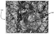
도 18 내지 도 21은 베이스층 결합면(112) 및 클래드층 결합면(122)의 고배율 광학 현미경 사진들이다. 도 18에서, 정상적인 결합 영역에서 클래드층 결합면(122)에 대응하고, 도 19에서, 정상적인 결합 영역에서 베이스층 결합면(112)에 대응하는 가시적인 결함이 없다. 이에 반해, 도 20에서, 약한 결합 영역에서 클래드층 결합면(122)에 대응하고, 도 21에서, 약한 결합 영역에서 베이스층 결합면(112)에 대응하는, 약한 결합 영역을 나타내는 원형 결함(130)을 보여준다.18 to 21 are high-magnification optical micrographs of the base
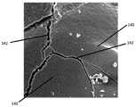
도 22 내지 도 25는 정상적인 결합 영역에서 클래드층 결합면(122)의 영역들의 주사 전자 현미경(scanning electron microscope, SEM) 현미경 사진들이다. 도 22 내지 도 25에서 표면의 얼룩진 외관 및 제한된 미세균열은 정상적인 결합을 나타낸다. 이에 반해, 도 26 내지 도 29는 약한 결합 영역에서 클래드층 결합면(112)의 영역들의 SEM 현미경 사진들이다. 공극(voids)(140), 현저한 균열(142), 둥근 및/또는 타원형 구조(144), 및 심한 각진 특징부(severe angular features)(146)에 의해 표시된 상당한 미소 가공도(microporosity)가 있음을 도 26 내지 도 29에서 알 수 있으며, 이들 모두는 약한 결합 영역을 나타낸다.22 to 25 are scanning electron microscope (SEM) micrographs of regions of the clad
따라서, 도 14 내지 도 29를 보면, 여기에 설명된 방법들은 정상적인 결합 영역에서 약한 결합 영역을 비파괴적으로 식별하는 데 성공했으며, 이는 결합 표면의 상세한 검사를 통해 후속적으로 확인되었다.Accordingly, referring to FIGS. 14 to 29 , the methods described herein succeeded in non-destructively identifying weak bonding regions in normal bonding regions, which was subsequently confirmed through detailed inspection of the bonding surfaces.
다양한 실시예, 구성 및 양태에서, 본 개시는 다양한 실시예, 하위 조합, 및 이들의 서브세트를 포함하여 본 명세서에 도시되고 설명된 바와 같은 구성요소, 방법, 프로세스, 시스템 및/또는 장치를 포함한다. 본 개시는 다양한 실시예, 구성 및 양태에서, 예를 들어, 본 명세서에 도시 및/또는 설명되지는 않았지만 본 개시와 일관되고 당업계에 잘 알려져 있거나 이해될 수 있는 구성 요소 또는 프로세스의 실제 또는 선택적인 사용 또는 포함을 고려한다.In various embodiments, configurations and aspects, the present disclosure includes components, methods, processes, systems and/or apparatus as shown and described herein, including various embodiments, sub-combinations, and subsets thereof. do. The present disclosure relates to various embodiments, configurations and aspects, for example, the actual or selection of components or processes not shown and/or described herein that are consistent with the present disclosure and that may be well known or understood in the art. Consider the use or inclusion of
본 개시의 실시예는 다수의 다른 범용 또는 특수 목적 컴퓨팅 시스템 환경 또는 구성과 함께 동작한다. 여기에 설명된 시스템 및 방법과 함께 사용하기에 적합할 수 있는 컴퓨팅 시스템, 환경 및/또는 구성의 예에는 개인용 컴퓨터, 서버 컴퓨터, 핸드-헬드(hand-held) 또는 랩톱 장치, 멀티프로세서 시스템, 마이크로프로세서-기반 시스템, 셋톱 박스, 프로그래밍 가능한 소비자 전자 제품, 네트워크 PC, 미니컴퓨터, 메인프레임 컴퓨터, 상기 시스템 또는 장치 중 임의의 것을 포함하는 분산 컴퓨팅 환경 등일 수 있으며, 이에 제한되지 않는다.Embodiments of the present disclosure operate with many other general-purpose or special-purpose computing system environments or configurations. Examples of computing systems, environments, and/or configurations that may be suitable for use with the systems and methods described herein include personal computers, server computers, hand-held or laptop devices, multiprocessor systems, micro It can be, but is not limited to, a processor-based system, a set-top box, a programmable consumer electronic product, a network PC, a minicomputer, a mainframe computer, a distributed computing environment including any of the above systems or devices, and the like.
본 개시의 실시예는 컴퓨터에 의해 실행되는 프로그램 모듈과 같은 컴퓨터 실행가능 명령어의 일반적인 맥락에서 설명될 수 있다. 일반적으로, 프로그램 모듈은 특정 작업을 수행하거나 특정 추상 데이터 유형을 구현하는 루틴, 프로그램, 개체, 구성 요소, 데이터 구조 등을 포함할 수 있다. 여기에 설명된 시스템 및 방법은 또한 작업이 통신 네트워크를 통해 연결된 원격 처리 장치에 의해 수행되는 분산 컴퓨팅 환경에서 실행될 수 있다. 분산 컴퓨팅 환경에서, 프로그램 모듈은 메모리 저장 장치를 포함하는 로컬 및 원격 컴퓨터 저장 매체 모두에 위치될 수 있다. 프로그램과 모듈이 수행하는 작업은 아래 그림과 함께 설명되어 있다. 당업자는 예시적인 실시예를 프로세서 실행 가능 명령어로서 구현할 수 있으며, 이는 본 개시에 따른 대응하는 컴퓨팅 환경에서 컴퓨터 판독 가능 매체의 임의의 형태에 기록될 수 있다.Embodiments of the present disclosure may be described in the general context of computer-executable instructions, such as program modules, being executed by a computer. Generally, program modules may include routines, programs, objects, components, data structures, etc. that perform particular tasks or implement particular abstract data types. The systems and methods described herein may also be practiced in distributed computing environments where tasks are performed by remote processing devices that are linked through a communications network. In a distributed computing environment, program modules may be located in both local and remote computer storage media including memory storage devices. The tasks performed by programs and modules are described with the figure below. Skilled artisans may implement the example embodiments as processor-executable instructions, which may be recorded on any form of computer-readable medium in a corresponding computing environment in accordance with the present disclosure.
"적어도 하나", "하나 이상", 및 "및/또는"이라는 문구는 작동 시 결합(또는, 접속)(conjunctive) 및 분리(disjunctive) 둘 다인 개방형 표현이다. 예를 들어, "A, B 및 C 중 적어도 하나"라는 표현은 각각 "A, B 또는 C 중 적어도 하나", "A, B 및 C 중 하나 이상", "A, B 또는 C 중 하나 이상", 및 "A, B 및/또는 C"는 A 혼자, B 혼자, C 혼자, A와 B 함께, A와 C 함께, B와 C 함께, 또는 A, B와 C 함께를 의미한다.The phrases "at least one", "one or more", and "and/or" are open-ended expressions that are both conjunctive and disjunctive in operation. For example, the expression "at least one of A, B and C" means "at least one of A, B, or C", "at least one of A, B and C", "at least one of A, B or C", respectively. , and "A, B and/or C" means A alone, B alone, C alone, A and B together, A and C together, B and C together, or A, B and C together.
본 명세서 및 뒤따르는 청구범위에서, 하기 의미를 갖는 다수의 용어가 참조될 것이다. "a"(또는, "an") 및 "the"라는 용어는 문맥에서 달리 명시하지 않는 한 복수의 지시 대상을 포함하는 해당 개체의 하나 이상을 나타냅니다. 이와 같이, 용어 "a"(또는, "an"), "하나 이상(one or more)" 및 "적어도 하나(at least one)"는 본 명세서에서 상호 교환적으로 사용될 수 있다. 또한, "일 실시예(one embodiment)", "일부 실시예(some embodiments)", "일 실시예(an embodiment)" 등에 대한 참조는 인용된 특징을 또한 포함하는 추가 실시예의 존재를 배제하는 것으로 해석되도록 의도되지 않는다. 명세서 및 청구범위 전반에 걸쳐 본 명세서에서 사용되는 근사 언어는 관련된 기본 기능의 변경을 초래하지 않고 허용 가능하게 변할 수 있는 임의의 정량적 표현을 수정하는 데 적용될 수 있다. 따라서, "약(about)"과 같은 용어에 의해 완화된 값은 명시된 정확한 값으로 제한되지 않는다. 어떤 경우에는 근사 언어가 값을 측정하는 기구의 정밀도에 해당할 수 있다. "제1(또는, 첫 번째)(first)", "제2(또는, 두 번째)(second)", "위쪽(upper)", "아래쪽(lower)" 등과 같은 용어는 한 요소를 다른 요소와 식별하는 데 사용되며, 달리 지정되지 않는 한 요소의 특정 순서나 수를 나타내는 것은 아니다.In this specification and in the claims that follow, reference will be made to a number of terms having the following meanings. The terms "a" (or "an") and "the" refer to one or more of those objects, including plural referents, unless the context dictates otherwise. As such, the terms “a” (or “an”), “one or more”, and “at least one” may be used interchangeably herein. Further, reference to “one embodiment,” “some embodiments,” “an embodiment,” etc., is intended to exclude the existence of additional embodiments that also include the recited features. It is not intended to be interpreted. Throughout the specification and claims, the approximation language used herein may be applied to modify any quantitative expression that may be permissibly varied without resulting in a change in the basic function involved. Accordingly, a value relaxed by a term such as "about" is not limited to the exact value specified. In some cases, the approximation language may correspond to the precision of the instrument for measuring the value. Terms such as "first (or first)", "second (or second)", "upper", "lower", etc. refer to one element as another. is used to identify and does not indicate a specific order or number of elements unless otherwise specified.
본 명세서에 사용된 용어 "~일 수 있다(may)" 및 "~있을 수 있다(may be)"는 일련의 상황 내에서 발생할 가능성을 나타내며, 특정 재산, 특성 또는 기능의 소유, 및/또는 한정된 동사와 관련된 능력(ability), 역량(capability) 또는 가능성 중 하나 이상을 표현함으로써 다른 동사를 한정한다(qualify). 따라서, "~일 수 있다(may)" 및 "~있을 수 있다(may be)"의 사용은 수정된 용어가 표시된 용량, 기능 또는 사용에 명백히 적절하거나, 가능하거나 적합하다는 것을 나타내지만, 일부 상황에서는 수정된 용어가 때때로 적절하거나, 가능하거나 적합하지 않을 수 있음을 고려한다. 예를 들어, 어떤 상황에서는 사건이나 능력이 예상될 수 있지만 다른 상황에서는 사건이나 능력이 발생할 수 없다. 이러한 구별은 "~일 수 있다(may)" 및 "~있을 수 있다(may be)"이라는 용어로 포착된다.As used herein, the terms "may" and "may be" refer to the possibility of occurring within a set of circumstances, the possession of a particular property, characteristic or function, and/or limited Qualify another verb by expressing one or more of the ability, capability, or possibility associated with the verb. Thus, the use of "may" and "may be" indicates that the modified term is clearly appropriate, possible, or suitable for the indicated dose, function, or use, although in some circumstances considers that amended terms may at times be appropriate, possible or inappropriate. For example, in some situations an event or ability may be expected, but in another situation the event or ability cannot occur. This distinction is captured by the terms "may" and "may be".
청구범위에 사용된 바와 같이, "포함한다(comprises)"라는 단어 및 그 문법적 변형은 논리적으로 또한 예를 들어, "본질적으로 구성되는(consisting essentially of)" 및 "구성되는(consisting of)"과 같이 다양하고 상이한 정도의 구를 포함한다. 필요한 경우 범위가 제공되었으며 해당 범위에는 그 사이의 모든 하위 범위가 포함된다. 첨부된 청구범위는 본 개시내용이 특정 실시양태에서 특정 범위의 사용을 명확히 하는 경우를 제외하고는 범위의 변형을 포함해야 함을 예상해야 한다.As used in the claims, the word "comprises" and grammatical variations thereof are logically and also, for example, "consisting essentially of" and "consisting of" and It includes spheres of varying and different degrees as well. Scopes have been provided where necessary, including all subranges in between. It is to be expected that the appended claims should cover variations of ranges except where the present disclosure makes clear the use of specific ranges in specific embodiments.
본 명세서에서 사용된 용어 "결정하다(determine)", "계산하다(calculate)", "계산하다(compute)" 및 이들의 변형은 상호 교환가능하게 사용되며 임의의 유형의 방법론, 프로세스, 수학적 연산 또는 기술을 포함한다.As used herein, the terms “determine,” “calculate,” “compute,” and variations thereof, are used interchangeably and are used interchangeably with any type of methodology, process, mathematical operation. or technology.
이 개시 내용은 예시 및 설명의 목적으로 제공된다. 본 개시는 여기에 개시된 형태 또는 형태들로 제한되지 않는다. 본 개시의 상세한 설명에서, 예를 들어, 일부 예시적인 실시예의 다양한 특징은 함께 그룹화되어 이들 및 다른 고려되는 실시예, 구성 및 양태(또는, 측면)를 대표적으로 설명하는데, 본 개시에 모든 잠재적인 실시예, 변형 및 특징의 조합에 대한 설명을 포함하는 것이 실현 가능하지 않다. 따라서, 개시된 실시예, 구성 및 측면의 특징은 위에서 명시적으로 논의되지 않은 대안의 실시예, 구성 및 측면에서 조합될 수 있다. 예를 들어, 다음 청구범위에 인용된 특징은 단일의 개시된 실시예, 구성 또는 측면의 모든 특징보다 적다. 따라서, 다음 청구범위는 본 명세서에 포함되며, 각 청구범위는 본 개시내용의 별도의 실시예로서 그 자체로 존재한다.This disclosure is provided for purposes of illustration and description. The present disclosure is not limited to the form or forms disclosed herein. In the detailed description of the present disclosure, for example, various features of some illustrative embodiments are grouped together to representatively describe these and other contemplated embodiments, configurations, and aspects (or aspects); It is not feasible to include descriptions of embodiments, variations, and combinations of features. Accordingly, features of the disclosed embodiments, configurations, and aspects may be combined in alternative embodiments, configurations, and aspects not explicitly discussed above. For example, features recited in the following claims are less than all features of a single disclosed embodiment, configuration or aspect. Accordingly, the following claims are hereby incorporated by reference, with each claim standing on its own as a separate embodiment of the present disclosure.
과학 및 기술의 발전은 비록 청구범위가 이러한 변형을 반드시 배제하지는 않을지라도 본 개시의 용어로 반드시 표현되지 않는 변형을 제공할 수 있다.Advances in science and technology may provide for variations that are not necessarily expressed in the terms of this disclosure, although the claims do not necessarily exclude such variations.
100: 물품
110: 베이스층
120: 클래드층
105: 계면
200: 시스템
210: 제1 레일
212: 제1 레일 마운트
220: 제2 레일
222: 툴 헤드
232: 초음파 변환기
240: 컨트롤러
234: 마킹 장치100: Goods
110: base layer
120: clad layer
105: interface
200: system
210: first rail
212: first rail mount
220: second rail
222: tool head
232: ultrasonic transducer
240: controller
234: marking device
Claims (20)
Translated fromKorean상기 물품의 표면 상의 복수의 위치들을 결정하는 단계;
상기 복수의 위치들의 각 위치에 대해, 상기 물품으로부터 반사된 초음파의 전파(full-wave), 시간 도메인 파형(time domain waveform)을 획득하는 단계;
상기 복수의 위치들 중 인접한 위치들의 각 쌍에 대해:
제1 위치에서 생성된 제1 파형의 파형 특성과 제2 위치에서 생성된 제2 파형의 파형 특성의 비교에 기초하여 상기 인접한 위치들의 쌍의 상기 제1 위치와 상기 인접한 위치들의 쌍의 상기 제2 위치 사이에 결합 경계가 있는지 여부를 결정하는 단계; 및
상기 제1 위치와 상기 제2 위치 사이에 결합 경계가 있다는 결정에 응답하여, 상기 제1 위치 및 상기 제2 위치 중 하나 또는 모두에 기초하여 경계 위치를 결정하고 상기 경계 위치를 기억하는(memorializing) 단계를 포함하는 방법.A method for identifying a bond boundary between a sound bond and a weak bond in an article having a first layer and a second layer, the method comprising:
determining a plurality of locations on the surface of the article;
obtaining, for each position of the plurality of positions, a full-wave, time domain waveform of the ultrasonic wave reflected from the article;
For each pair of adjacent ones of the plurality of locations:
the first position of the pair of adjacent locations and the second of the pair of adjacent locations based on a comparison of the waveform characteristic of the first waveform generated at the first location and the waveform characteristic of the second waveform generated at the second location determining whether there is a binding boundary between the locations; and
in response to determining that there is a coupling boundary between the first location and the second location, determining a boundary location based on one or both of the first location and the second location and remembering the boundary location A method comprising steps.
전파, 시간 도메인 파형을 획득하는 단계는,
변환기를 통해(via) 상기 물품을 통해(through) 초음파를 전송하는 단계;
상기 변환기로 반사된 초음파를 수신하는 단계; 및
상기 반사된 초음파에 기초하여 상기 전파, 시간 도메인 파형을 생성하는 단계를 포함하는 방법.According to claim 1,
Acquiring a propagation, time domain waveform comprises:
transmitting ultrasound through the article via a transducer;
receiving the reflected ultrasound with the transducer; and
and generating the propagated, time domain waveform based on the reflected ultrasound.
전파, 시간 도메인 파형을 획득하는 단계는,
저장 매체로부터 상기 전파, 시간 도메인 파형에 대응하는 파형 데이터를 획득하는 단계를 포함하는 방법.According to claim 1,
Acquiring a propagation, time domain waveform comprises:
and acquiring waveform data corresponding to the propagated, time domain waveform from a storage medium.
상기 파형 특성은 상기 제1 파형 및 상기 제2 파형에 대해 기 결정된 x-축 범위에 대해 평가되고,
상기 기 결정된 x-축 범위는 상기 제1 층의 물질을 관통하는 음파의 속도 및 상기 제1 층의 두께에 기초하는 방법.According to claim 1,
the waveform characteristic is evaluated for a predetermined x-axis range for the first waveform and the second waveform;
wherein the predetermined x-axis range is based on the thickness of the first layer and the velocity of the sound wave passing through the material of the first layer.
상기 제1 위치와 상기 제2 위치 사이에 결합 경계가 있는지 결정하는 단계는,
상기 제1 파형의 마루들(peaks)의 제1 마루 수를 카운팅하는 단계;
상기 제1 파형의 골들(troughs)의 제1 골 수를 카운팅하는 단계;
상기 제2 파형의 마루들의 제2 마루 수를 카운팅하는 단계;
상기 제2 파형의 골들의 제2 골 수를 카운팅하는 단계;
상기 제1 마루 수가 상기 제2 마루 수와 같고 상기 제1 골 수가 상기 제2 골 수와 동일한 것에 응답하여, 상기 제1 위치와 상기 제2 위치 사이에 결합 경계가 없다고 결정하는 단계; 및
상기 제1 마루 수가 상기 제2 마루 수와 같지 않거나 상기 제1 골 수가 상기 제2 골 수와 동일하지 않은 것에 응답하여, 상기 제1 위치와 상기 제2 위치 사이에 결합 경계가 있다고 결정하는 단계를 포함하는 방법.According to claim 1,
Determining whether there is a coupling boundary between the first location and the second location comprises:
counting a first number of peaks of the first waveform;
counting a first number of troughs of the first waveform;
counting a second number of ridges of the ridges of the second waveform;
counting a second number of troughs of the troughs of the second waveform;
in response to the first number of ridges being equal to the second number of ridges and the first number of troughs being equal to the second number of ridges, determining that there is no coupling boundary between the first location and the second location; and
determining that there is a coupling boundary between the first location and the second location in response to the first number of ridges being equal to or not equal to the second number of ridges How to include.
상기 제1 위치와 상기 제2 위치 사이에 결합 경계가 있는지 결정하는 단계는,
상기 제1 파형의 마루들(peaks)의 제1 마루 수를 카운팅하는 단계;
상기 제1 파형의 골들(troughs)의 제1 골 수를 카운팅하는 단계;
상기 제2 파형의 마루들의 제2 마루 수를 카운팅하는 단계;
상기 제2 파형의 골들의 제2 골 수를 카운팅하는 단계;
상기 제1 마루 수와 상기 제1 골 수의 제1 합이 상기 제2 마루 수와 상기 제2 골 수의 제2 합과 동일한 것에 응답하여, 상기 제1 위치와 상기 제2 위치 사이에 결합 경계가 없다고 결정하는 단계; 및
상기 제1 합이 상기 제2 합과 동일하지 않은 것에 응답하여, 상기 제1 위치와 상기 제2 위치 사이에 결합 경계가 있다고 결정하는 단계를 포함하는 방법.According to claim 1,
Determining whether there is a coupling boundary between the first location and the second location comprises:
counting a first number of peaks of the first waveform;
counting a first number of troughs of the first waveform;
counting a second number of ridges of the ridges of the second waveform;
counting a second number of troughs of the troughs of the second waveform;
a coupling boundary between the first location and the second location in response to the first sum of the number of ridges and the first number of troughs being equal to the second sum of the second number of ridges and the second number of troughs; determining that there is no; and
and in response to the first sum being not equal to the second sum, determining that there is a coupling boundary between the first location and the second location.
상기 경계 위치를 기억하는 단계는 상기 경계 위치에 대응하는 위치에 상기 물품의 표면을 표시하는 단계를 포함하는 방법.According to claim 1,
The step of storing the boundary position includes marking the surface of the article at a position corresponding to the boundary position.
상기 경계 위치를 기억하는 단계는 상기 경계 위치의 좌표를 저장 매체에 저장하는 단계를 포함하는 방법.According to claim 1,
The storing of the boundary position includes storing the coordinates of the boundary position in a storage medium.
상기 제1 파형의 상기 파형 특성은 상기 제1 파형의 고속 푸리에 변환(fast Fourier transform, FFT)의 특성이고, 상기 제2 파형의 상기 파형 특성은 상기 제2 파형의 FFT의 특성인 방법.According to claim 1,
The waveform characteristic of the first waveform is a characteristic of a fast Fourier transform (FFT) of the first waveform, and the waveform characteristic of the second waveform is a characteristic of an FFT of the second waveform.
상기 물품은 클래드된 물품(cladded article)이고,
상기 제1 층은 제1 금속 또는 제1 금속 합금을 포함하고,
상기 제2 층은 제2 금속 또는 제2 금속 합금을 포함하는 방법.According to claim 1,
the article is a cladded article,
the first layer comprises a first metal or a first metal alloy;
wherein the second layer comprises a second metal or a second metal alloy.
상기 제1 층은 상기 제2 층에 고체 상태로 용접되는 방법.11. The method of claim 10,
wherein the first layer is welded in a solid state to the second layer.
상기 제1 층은 상기 제2 층에 폭발적으로(explosively) 용접되는 방법.12. The method of claim 11,
wherein the first layer is explosively welded to the second layer.
툴 헤드(tool head);
상기 툴 헤드에 대해 고정된 위치에서 상기 툴 헤드에 장착된 초음파 변환기;
상기 툴 헤드에 작동 가능하게(operably) 결합되고 상기 물품의 표면에 평행한 2차원 평면을 따라 상기 툴 헤드를 이동시키도록 된 모터 시스템;
상기 툴 헤드의 위치를 나타내는 위치 신호를 출력하도록 된 위치 센서; 및
상기 초음파 변환기, 상기 모터 시스템, 및 상기 위치 센서에 작동 가능하게 결합된 컨트롤러를 포함하고,
상기 컨트롤러는,
상기 변환기를 상기 물품의 표면을 따라 복수의 위치들로 이동시키도록 상기 모터 시스템을 제어하는 단계;
상기 복수의 위치들의 각 위치에 대해:
상기 위치 신호에 기초하여 상기 위치의 좌표를 식별하는 단계;
상기 물품을 통해(through) 초음파를 전송하도록 상기 변환기를 제어하는 단계; 및
상기 변환기에 의해 수신된 반사된 초음파에 기초하여 전파, 시간 도메인 파형을 생성하는 단계;
상기 복수의 위치들 중 인접한 위치들의 각 쌍에 대해:
제1 위치에서 생성된 제1 파형의 파형 특성과 제2 위치에서 생성된 제1 파형의 파형 특성의 비교에 기초하여 상기 인접한 위치들의 쌍의 상기 제1 위치와 상기 인접한 위치들의 쌍의 상기 제2 위치 사이에 결합 경계가 있는지 여부를 결정하는 단계; 및
결합 경계가 있다는 결정에 응답하여, 상기 제1 위치 및 상기 제2 위치 중 하나 또는 모두에 기초하여 경계 좌표를 결정하는 단계를 수행하도록 구성되는 시스템.A system for identifying a bond boundary between a normal bond and a weak bond in an article having a first layer and a second layer, the system comprising:
tool head;
an ultrasonic transducer mounted to the tool head in a fixed position relative to the tool head;
a motor system operably coupled to the tool head and adapted to move the tool head along a two-dimensional plane parallel to the surface of the article;
a position sensor configured to output a position signal indicating the position of the tool head; and
a controller operatively coupled to the ultrasonic transducer, the motor system, and the position sensor;
The controller is
controlling the motor system to move the transducer to a plurality of positions along the surface of the article;
For each location of the plurality of locations:
identifying coordinates of the location based on the location signal;
controlling the transducer to transmit ultrasound through the article; and
generating a propagated, time domain waveform based on the reflected ultrasound received by the transducer;
For each pair of adjacent ones of the plurality of locations:
The first location of the pair of adjacent locations and the second of the pair of adjacent locations based on a comparison of the waveform characteristic of the first waveform generated at the first location and the waveform characteristic of the first waveform generated at the second location determining whether there is a binding boundary between the locations; and
and in response to determining that there is a combined boundary, determining boundary coordinates based on one or both of the first location and the second location.
상기 컨트롤러에 작동 가능하게 결합된 저장 매체를 더 포함하고,
상기 컨트롤러는 결합 경계가 있다는 결정에 응답하여, 상기 경계 좌표를 상기 저장 매체에 저장함으로써 상기 경계 좌표를 기억하도록 구성되는 시스템.14. The method of claim 13,
a storage medium operatively coupled to the controller;
and the controller is configured to, in response to determining that there is a binding boundary, store the boundary coordinates by storing the boundary coordinates in the storage medium.
상기 툴 헤드에 장착되고 상기 컨트롤러에 작동 가능하게 결합된 마킹 툴(marking tool)을 더 포함하고,
상기 컨트롤러는 결합 경계가 있다는 결정에 응답하여, 상기 경계 좌표에서 상기 물품의 상기 표면을 표시하도록 상기 마킹 툴을 제어함으로써 상기 경계 좌표를 기억하도록 구성되는 시스템.14. The method of claim 13,
a marking tool mounted to the tool head and operatively coupled to the controller;
wherein the controller is configured to, in response to determining that there is an engagement boundary, store the boundary coordinates by controlling the marking tool to mark the surface of the article at the boundary coordinates.
상기 컨트롤러는 상기 파형 특성이 상기 제1 파형 및 상기 제2 파형에 대해 기 결정된 x-축 범위에 대해 평가되도록 구성되고,
상기 기 결정된 x-축 범위는 상기 제1 층의 물질을 관통하는 음파의 속도 및 상기 제1 층의 두께에 기초하는 시스템.14. The method of claim 13,
wherein the controller is configured such that the waveform characteristic is evaluated for a predetermined x-axis range for the first waveform and the second waveform;
wherein the predetermined x-axis range is based on the thickness of the first layer and the velocity of the sound wave passing through the material of the first layer.
상기 컨트롤러는 상기 제1 위치 및 상기 제2 위치 사이에 결합 경계가 있는지 여부를 결정하도록,
상기 제1 파형의 마루들(peaks)의 제1 마루 수를 카운팅하는 단계;
상기 제1 파형의 골들(troughs)의 제1 골 수를 카운팅하는 단계;
상기 제2 파형의 마루들의 제2 마루 수를 카운팅하는 단계;
상기 제2 파형의 골들의 제2 골 수를 카운팅하는 단계;
상기 제1 마루 수가 상기 제2 마루 수와 같고 상기 제1 골 수가 상기 제2 골 수와 동일한 것에 응답하여, 상기 제1 위치와 상기 제2 위치 사이에 결합 경계가 없다고 결정하는 단계; 및
상기 제1 마루 수가 상기 제2 마루 수와 같지 않거나 상기 제1 골 수가 상기 제2 골 수와 동일하지 않은 것에 응답하여, 상기 제1 위치와 상기 제2 위치 사이에 결합 경계가 있다고 결정하는 단계를 포함하도록 구성되는 시스템.14. The method of claim 13,
wherein the controller determines whether there is a coupling boundary between the first location and the second location;
counting a first number of peaks of the first waveform;
counting a first number of troughs of the first waveform;
counting a second number of ridges of the ridges of the second waveform;
counting a second number of troughs of the troughs of the second waveform;
in response to the first number of ridges being equal to the second number of ridges and the first number of troughs being equal to the second number of ridges, determining that there is no coupling boundary between the first location and the second location; and
determining that there is a coupling boundary between the first location and the second location in response to the first number of ridges being equal to or not equal to the second number of ridges A system configured to contain.
상기 컨트롤러는 상기 제1 위치 및 상기 제2 위치 사이에 결합 경계가 있는지 여부를 결정하도록,
상기 제1 파형의 마루들(peaks)의 제1 마루 수를 카운팅하는 단계;
상기 제1 파형의 골들(troughs)의 제1 골 수를 카운팅하는 단계;
상기 제2 파형의 마루들의 제2 마루 수를 카운팅하는 단계;
상기 제2 파형의 골들의 제2 골 수를 카운팅하는 단계;
상기 제1 마루 수와 상기 제1 골 수의 제1 합이 상기 제2 마루 수와 상기 제2 골 수의 제2 합과 동일한 것에 응답하여, 상기 제1 위치와 상기 제2 위치 사이에 결합 경계가 없다고 결정하는 단계; 및
상기 제1 합이 상기 제2 합과 동일하지 않은 것에 응답하여, 상기 제1 위치와 상기 제2 위치 사이에 결합 경계가 있다고 결정하는 단계를 포함하도록 구성되는 시스템.14. The method of claim 13,
wherein the controller determines whether there is a coupling boundary between the first location and the second location;
counting a first number of peaks of the first waveform;
counting a first number of troughs of the first waveform;
counting a second number of ridges of the ridges of the second waveform;
counting a second number of troughs of the troughs of the second waveform;
a coupling boundary between the first location and the second location in response to the first sum of the number of ridges and the first number of troughs being equal to the second sum of the second number of ridges and the second number of troughs; determining that there is no; and
and in response to the first sum being not equal to the second sum, determining that there is a coupling boundary between the first location and the second location.
상기 제1 파형의 상기 파형 특성은 상기 제1 파형의 고속 푸리에 변환(fast Fourier transform, FFT)의 특성이고, 상기 제2 파형의 상기 파형 특성은 상기 제2 파형의 FFT의 특성인 시스템.14. The method of claim 13,
The waveform characteristic of the first waveform is a characteristic of a fast Fourier transform (FFT) of the first waveform, and the waveform characteristic of the second waveform is a characteristic of an FFT of the second waveform.
컴퓨터에 의해 실행될 때, 상기 명령어는 상기 컴퓨터가
제1 층과 제2 층을 포함하는 물품의 표면 상의 제1 위치와 관련된 제1 파형을 획득하는 단계로서, 상기 제1 파형은 변환기를 통해(via) 상기 물품을 통해(through) 초음파를 전송하고 상기 변환기에서 수신된 반사된 초음파에 기초하여 전파, 시간 도메인 파형을 생성함으로써 생성되는 단계;
상기 물품의 상기 표면 상의 제2 위치와 관련된 제2 파형을 획득하는 단계로서, 상기 제2 파형은 변환기를 통해 상기 물품을 관통하는 초음파를 전송하고 상기 변환기에서 수신된 반사된 초음파에 기초하여 전파, 시간 도메인 파형을 생성함으로써 생성되는 단계;
제1 위치에서 생성된 제1 파형의 파형 특성과 제2 위치에서 생성된 제2 파형의 파형 특성의 비교에 기초하여 인접한 위치들의 쌍의 상기 제1 위치와 인접한 위치들의 쌍의 상기 제2 위치 사이에 결합 경계가 있는지 여부를 결정하는 단계; 및
상기 제1 위치와 상기 제2 위치 사이에 결합 경계가 있다는 결정에 응답하여, 상기 제1 위치 및 상기 제2 위치 중 하나 또는 모두에 기초하여 경계 위치를 결정하고 상기 경계 위치를 기억하는(memorializing) 단계를 수행하도록 하는 비일시적 컴퓨터 판독 가능 저장 매체.A non-transitory computer-readable storage medium comprising computer-executable instructions, the non-transitory computer-readable storage medium comprising:
When executed by a computer, the instructions cause the computer to
obtaining a first waveform associated with a first location on a surface of an article comprising a first layer and a second layer, the first waveform transmitting ultrasound through a transducer and through the article; generated by generating a propagated, time-domain waveform based on the reflected ultrasound received at the transducer;
acquiring a second waveform associated with a second location on the surface of the article, the second waveform transmitting an ultrasonic wave passing through the article through a transducer and propagating based on the reflected ultrasonic wave received at the transducer; generated by generating a time domain waveform;
between the first position of the pair of adjacent positions and the second position of the pair of adjacent positions based on a comparison of the waveform characteristic of the first waveform generated at the first location and the waveform characteristic of the second waveform generated at the second location determining whether there is a binding boundary on ; and
in response to determining that there is a coupling boundary between the first location and the second location, determining a boundary location based on one or both of the first location and the second location and remembering the boundary location A non-transitory computer-readable storage medium that causes steps to be performed.
Applications Claiming Priority (3)
| Application Number | Priority Date | Filing Date | Title |
|---|---|---|---|
| US201962834987P | 2019-04-17 | 2019-04-17 | |
| US62/834,987 | 2019-04-17 | ||
| PCT/US2020/028713WO2020214926A1 (en) | 2019-04-17 | 2020-04-17 | Method and system of identifying a bond boundary between a sound bond and a weak bond in a multilayer article |
Publications (1)
| Publication Number | Publication Date |
|---|---|
| KR20210143936Atrue KR20210143936A (en) | 2021-11-29 |
Family
ID=72837937
Family Applications (1)
| Application Number | Title | Priority Date | Filing Date |
|---|---|---|---|
| KR1020217037595ACeasedKR20210143936A (en) | 2019-04-17 | 2020-04-17 | Methods and systems for identifying bond boundaries between normal and weak bonds in multilayer articles |
Country Status (7)
| Country | Link |
|---|---|
| US (2) | US12111290B2 (en) |
| EP (1) | EP3956658A4 (en) |
| JP (1) | JP2022526837A (en) |
| KR (1) | KR20210143936A (en) |
| CN (2) | CN113728227B (en) |
| CA (1) | CA3136934A1 (en) |
| WO (1) | WO2020214926A1 (en) |
Cited By (1)
| Publication number | Priority date | Publication date | Assignee | Title |
|---|---|---|---|---|
| US12111290B2 (en) | 2019-04-17 | 2024-10-08 | Dmc Global Inc. | Method and system of identifying a bond boundary between a sound bond and a weak bond in a multilayer article |
Family Cites Families (50)
| Publication number | Priority date | Publication date | Assignee | Title |
|---|---|---|---|---|
| GB1592601A (en) | 1977-02-19 | 1981-07-08 | Rolls Royce | Apparatus for ultrasonic examination |
| US4570487A (en) | 1980-04-21 | 1986-02-18 | Southwest Research Institute | Multibeam satellite-pulse observation technique for characterizing cracks in bimetallic coarse-grained component |
| US5108693A (en) | 1988-09-28 | 1992-04-28 | General Electric Company | Non-destructive dimensional and flaw inspection of thin wall tube weldments |
| JP2642459B2 (en)* | 1988-12-07 | 1997-08-20 | 東京電力株式会社 | Ultrasonic inspection image processing equipment |
| US5063780A (en) | 1990-02-15 | 1991-11-12 | General Electric Company | Ultrasonic dimensional and flaw inspection of thin-walled tubular elements |
| DE4213212A1 (en) | 1992-04-22 | 1993-10-28 | Krautkraemer Gmbh | Process for the ultrasonic testing of spot welded joints in sheet metal |
| NO179926C (en)* | 1993-04-02 | 1998-03-11 | Red Band As | Procedures for automatic condition checking, inspection, cleaning and / or surface treatment of structures, in particular thickness measurement of plate structures and pipes |
| JPH095305A (en)* | 1995-06-16 | 1997-01-10 | Daido Steel Co Ltd | Defect inspection method and device |
| US5631424A (en)* | 1995-07-31 | 1997-05-20 | General Electric Company | Method for ultrasonic evaluation of materials using time of flight measurements |
| US5661241A (en) | 1995-09-11 | 1997-08-26 | The Babcock & Wilcox Company | Ultrasonic technique for measuring the thickness of cladding on the inside surface of vessels from the outside diameter surface |
| JPH09159657A (en)* | 1995-12-07 | 1997-06-20 | Komatsu Ltd | Ultrasonic flaw detector |
| JPH11183446A (en) | 1997-12-25 | 1999-07-09 | Nkk Corp | Ultrasonic flaw detection method and apparatus for welds |
| US6397680B1 (en)* | 2000-07-24 | 2002-06-04 | National Research Council Of Canada | Ultrasonic spectroscopy apparatus for determining thickness and other properties of multilayer structures |
| US7774917B2 (en) | 2003-07-17 | 2010-08-17 | Tubefuse Applications B.V. | Forge welding tubulars |
| US7220966B2 (en)* | 2003-07-29 | 2007-05-22 | Toyota Motor Manufacturing North America, Inc. | Systems and methods for inspecting coatings, surfaces and interfaces |
| KR101079436B1 (en)* | 2006-04-11 | 2011-11-02 | 가와사키 쥬코교 가부시키가이샤 | Method and device for inspecting object formed by friction stir joining |
| JP4886564B2 (en)* | 2007-03-23 | 2012-02-29 | 公益財団法人鉄道総合技術研究所 | Ultrasonic flaw detection method and apparatus |
| CN101542279B (en)* | 2007-03-29 | 2013-03-13 | 松下电器产业株式会社 | Ultrasonic measurement method and device |
| JP5259175B2 (en) | 2007-12-26 | 2013-08-07 | 株式会社東芝 | Ultrasonic diagnostic apparatus, ultrasonic image processing apparatus, and ultrasonic image processing program |
| US8469889B2 (en)* | 2008-03-27 | 2013-06-25 | Panasonic Corporation | Ultrasonograph that chooses tracking waveforms for attribute value calculations |
| WO2009152143A1 (en) | 2008-06-09 | 2009-12-17 | Materials And Sensors Technologies, Inc. | Differential ultrasonic waveguide cure monitoring probe |
| US8166821B2 (en) | 2008-07-14 | 2012-05-01 | Eaton Corporation | Non-destructive test evaluation of welded claddings on rods of hydraulic cylinders used for saltwater, brackish and freshwater applications |
| NZ592250A (en) | 2008-09-26 | 2012-11-30 | Lilly Co Eli | Modified animal erythropoietin polypeptides and their uses |
| JP2010085380A (en)* | 2008-10-03 | 2010-04-15 | Hitachi Constr Mach Co Ltd | Ultrasonic inspection device, ultrasonic inspection method, and ultrasonic inspection program |
| JP5075850B2 (en)* | 2009-01-30 | 2012-11-21 | 株式会社日立エンジニアリング・アンド・サービス | Ultrasonic inspection apparatus and ultrasonic inspection method |
| GB0903232D0 (en) | 2009-02-25 | 2009-04-08 | Saipem Spa | A method for testing pipeline welds |
| US8256296B2 (en) | 2009-08-03 | 2012-09-04 | Georgia Tech Research Corporation | Methods and systems for detecting defects in welded structures utilizing pattern matching |
| JP5618529B2 (en)* | 2009-12-04 | 2014-11-05 | 株式会社東芝 | 3D ultrasonic inspection equipment |
| CN101846655B (en) | 2010-05-28 | 2011-09-21 | 北京工业大学 | Ultrasonic Measurement Method of Interface Stiffness in Adhesive Structures |
| US9146205B2 (en) | 2011-05-10 | 2015-09-29 | Areva Inc. | Vibrothermographic weld inspections |
| CN103194747B (en) | 2012-01-09 | 2015-03-18 | 沈阳大陆激光成套设备有限公司 | Method for laser cladding manufacturing or remanufacturing of wear and corrosion resistant wind power generator shaft |
| WO2014030615A1 (en)* | 2012-08-21 | 2014-02-27 | 株式会社Ihi | Method and device for inspecting interface of composite structure |
| CN103615995B (en) | 2013-11-18 | 2016-05-04 | 江苏科技大学 | A kind of thin cladding layer thickness lossless detection method based on ultrasonic surface wave |
| JP6251025B2 (en) | 2013-11-28 | 2017-12-20 | 日立Geニュークリア・エナジー株式会社 | Reactor pressure vessel nozzle maintenance device and maintenance method thereof |
| CN104975288B (en) | 2015-06-17 | 2017-08-11 | 燕山大学 | A kind of quick reproducing method of pulling-straightening roller |
| CN105388212B (en) | 2015-10-23 | 2018-08-10 | 北京大学 | The supersonic detection method of defect in a kind of thick walled composite tubular shape structure |
| CN105424804B (en) | 2015-12-03 | 2018-09-07 | 北京工商大学 | One kind remanufacturing composite part defect supersonic detection method |
| CN105441856B (en) | 2015-12-31 | 2018-04-13 | 安徽昱工机电科技有限公司 | A kind of red copper water jacket of laser deposited nickel-base alloy |
| JP6805445B2 (en)* | 2016-05-12 | 2020-12-23 | 株式会社フジタ | Condition evaluation device for inspection objects |
| CN105965212B (en) | 2016-06-24 | 2018-04-20 | 河北宇鹏重工管道装备制造有限公司 | A kind of bimetallic clad steel plate threeway method of manufacturing technology |
| CN106048599B (en) | 2016-07-07 | 2018-07-27 | 绵阳高新区三阳塑胶有限责任公司 | A kind of micro- cladding preparation method of metal or alloy matrix surface |
| CN105935769B (en) | 2016-07-07 | 2017-11-28 | 四川三阳激光增材制造技术有限公司 | A kind of laser melting coating for 3D printing drip molding etches preparation method |
| US10495609B2 (en) | 2016-10-18 | 2019-12-03 | The Aerospace Corporation | Ultrasonic inspection technique to assess bond quality in composite structures |
| US11631653B2 (en)* | 2017-02-03 | 2023-04-18 | Mitsubishi Electric Corporation | Ultrasonic bonding apparatus, ultrasonic bonding inspection method and ultrasonically-bonded portion fabrication method |
| US20180340858A1 (en) | 2017-05-23 | 2018-11-29 | The Boeing Company | Application of Ultrasonic Guided Waves for Structural Health Monitoring of Bonded Joints |
| JP6990046B2 (en)* | 2017-05-31 | 2022-01-12 | 三菱重工業株式会社 | Detection method and detection device for internal defects of inspection objects |
| KR101845882B1 (en)* | 2017-11-06 | 2018-05-18 | 나우 주식회사 | Method for contactless detecting bad bonding |
| BE1026211B1 (en)* | 2018-04-16 | 2019-11-18 | Flexible Robotic Solutions Bvba | ROBOT SYSTEM AND METHOD FOR NON-DESTRUCTIVE TESTING |
| CN108593772B (en)* | 2018-05-16 | 2020-12-15 | 中国科学院声学研究所 | Ultrasonic detection method and system for low/high acoustic impedance bonding interface |
| CN113728227B (en) | 2019-04-17 | 2025-01-10 | Dmc全球公司 | Method and system for identifying bond boundaries between strong bonds and weak bonds in a multi-layer article |
- 2020
- 2020-04-17CNCN202080029656.XApatent/CN113728227B/enactiveActive
- 2020-04-17EPEP20791575.2Apatent/EP3956658A4/ennot_activeWithdrawn
- 2020-04-17CACA3136934Apatent/CA3136934A1/ennot_activeAbandoned
- 2020-04-17WOPCT/US2020/028713patent/WO2020214926A1/ennot_activeCeased
- 2020-04-17USUS17/604,241patent/US12111290B2/enactiveActive
- 2020-04-17CNCN202411894062.1Apatent/CN119438383A/enactivePending
- 2020-04-17KRKR1020217037595Apatent/KR20210143936A/ennot_activeCeased
- 2020-04-17JPJP2021559919Apatent/JP2022526837A/enactivePending
- 2024
- 2024-09-04USUS18/824,419patent/US20240426784A1/enactivePending
Cited By (1)
| Publication number | Priority date | Publication date | Assignee | Title |
|---|---|---|---|---|
| US12111290B2 (en) | 2019-04-17 | 2024-10-08 | Dmc Global Inc. | Method and system of identifying a bond boundary between a sound bond and a weak bond in a multilayer article |
Also Published As
| Publication number | Publication date |
|---|---|
| EP3956658A1 (en) | 2022-02-23 |
| US12111290B2 (en) | 2024-10-08 |
| EP3956658A4 (en) | 2022-12-21 |
| CN113728227B (en) | 2025-01-10 |
| CN119438383A (en) | 2025-02-14 |
| US20220196604A1 (en) | 2022-06-23 |
| US20240426784A1 (en) | 2024-12-26 |
| CN113728227A (en) | 2021-11-30 |
| JP2022526837A (en) | 2022-05-26 |
| CA3136934A1 (en) | 2020-10-22 |
| WO2020214926A1 (en) | 2020-10-22 |
Similar Documents
| Publication | Publication Date | Title |
|---|---|---|
| Hosseinzadeh et al. | Towards good practice guidelines for the contour method of residual stress measurement | |
| Lévesque et al. | Inspection of additive manufactured parts using laser ultrasonics | |
| Papavasileiou et al. | Quality control in manufacturing–review and challenges on robotic applications | |
| US20240426784A1 (en) | Method and system of identifying a bond boundary between a sound bond and a weak bond in a multilayer article | |
| Alvarez Bestard et al. | Measurement and estimation of the weld bead geometry in arc welding processes: the last 50 years of development | |
| Mi et al. | Real-time weld penetration depth monitoring with laser ultrasonic sensing system | |
| Na et al. | Nondestructive evaluation method for standardization of fused filament fabrication based additive manufacturing | |
| Vasilev et al. | Feed forward control of welding process parameters through on-line ultrasonic thickness measurement | |
| Santospirito et al. | Defect detection in laser powder deposition components by laser thermography and laser ultrasonic inspections | |
| JP5256450B2 (en) | Surface roughness evaluation method | |
| Pivkin et al. | Image processing of advance milling cutters to automate the measurement of the geometric parameters of the cutting edge on optical measuring systems | |
| Li et al. | Nondestructive detection of laser-cladding coating interface defects: a deep learning-enhanced laser ultrasonics approach | |
| Ahmad et al. | Nondestructive Evaluation of Materials | |
| Bakre et al. | In-situ laser ultrasound-based Rayleigh wave process monitoring of DED-AM metals | |
| Park et al. | Nondestructive inspection of cylindrical components repaired via directed energy deposition using scanning acoustic microscopy with metal lubricants | |
| Jia et al. | Nondestructive testing of ultrasonic welding joints using shearography technique | |
| Tallafuss et al. | A feasibility study on different NDT techniques used for testing bond quality in cold roll bonded Al-Sn alloy/steel bimetal strips | |
| Nakao et al. | Adhesive bond imaging by noncontact measurements with single-sided access | |
| CN117129475A (en) | Terahertz nondestructive testing method for defects of non-metal pipeline hot-melt joint | |
| Stoesslein et al. | On-the-fly laser machining: A case study for in situ balancing of rotative parts | |
| Song et al. | FEA study of non-linear effect of coupling media to sonic infrared imaging | |
| Olsson et al. | Normal vector distribution as a classification tool for convoluted rough surfaces with overhanging features | |
| Fakih et al. | Detection and assessment of flaws in friction stir welded metallic plates | |
| Radha et al. | Density-based dynamically self-parameterized clustering for material inspection | |
| Ye et al. | Comprehensive detection method of weld based on line structured light and weak magnetic detection |
Legal Events
| Date | Code | Title | Description |
|---|---|---|---|
| PA0105 | International application | Patent event date:20211117 Patent event code:PA01051R01D Comment text:International Patent Application | |
| PA0201 | Request for examination | ||
| PG1501 | Laying open of application | ||
| E902 | Notification of reason for refusal | ||
| PE0902 | Notice of grounds for rejection | Comment text:Notification of reason for refusal Patent event date:20230923 Patent event code:PE09021S01D | |
| E601 | Decision to refuse application | ||
| PE0601 | Decision on rejection of patent | Patent event date:20231128 Comment text:Decision to Refuse Application Patent event code:PE06012S01D Patent event date:20230923 Comment text:Notification of reason for refusal Patent event code:PE06011S01I |