KR20210137308A - Driver assistance system and method therof - Google Patents
Driver assistance system and method therofDownload PDFInfo
- Publication number
- KR20210137308A KR20210137308AKR1020200054907AKR20200054907AKR20210137308AKR 20210137308 AKR20210137308 AKR 20210137308AKR 1020200054907 AKR1020200054907 AKR 1020200054907AKR 20200054907 AKR20200054907 AKR 20200054907AKR 20210137308 AKR20210137308 AKR 20210137308A
- Authority
- KR
- South Korea
- Prior art keywords
- vehicle
- seat
- collision
- driver assistance
- image data
- Prior art date
- Legal status (The legal status is an assumption and is not a legal conclusion. Google has not performed a legal analysis and makes no representation as to the accuracy of the status listed.)
- Pending
Links
Images


Classifications
- B—PERFORMING OPERATIONS; TRANSPORTING
- B60—VEHICLES IN GENERAL
- B60W—CONJOINT CONTROL OF VEHICLE SUB-UNITS OF DIFFERENT TYPE OR DIFFERENT FUNCTION; CONTROL SYSTEMS SPECIALLY ADAPTED FOR HYBRID VEHICLES; ROAD VEHICLE DRIVE CONTROL SYSTEMS FOR PURPOSES NOT RELATED TO THE CONTROL OF A PARTICULAR SUB-UNIT
- B60W30/00—Purposes of road vehicle drive control systems not related to the control of a particular sub-unit, e.g. of systems using conjoint control of vehicle sub-units
- B60W30/08—Active safety systems predicting or avoiding probable or impending collision or attempting to minimise its consequences
- B—PERFORMING OPERATIONS; TRANSPORTING
- B60—VEHICLES IN GENERAL
- B60K—ARRANGEMENT OR MOUNTING OF PROPULSION UNITS OR OF TRANSMISSIONS IN VEHICLES; ARRANGEMENT OR MOUNTING OF PLURAL DIVERSE PRIME-MOVERS IN VEHICLES; AUXILIARY DRIVES FOR VEHICLES; INSTRUMENTATION OR DASHBOARDS FOR VEHICLES; ARRANGEMENTS IN CONNECTION WITH COOLING, AIR INTAKE, GAS EXHAUST OR FUEL SUPPLY OF PROPULSION UNITS IN VEHICLES
- B60K28/00—Safety devices for propulsion-unit control, specially adapted for, or arranged in, vehicles, e.g. preventing fuel supply or ignition in the event of potentially dangerous conditions
- B60K28/10—Safety devices for propulsion-unit control, specially adapted for, or arranged in, vehicles, e.g. preventing fuel supply or ignition in the event of potentially dangerous conditions responsive to conditions relating to the vehicle
- B60K28/12—Safety devices for propulsion-unit control, specially adapted for, or arranged in, vehicles, e.g. preventing fuel supply or ignition in the event of potentially dangerous conditions responsive to conditions relating to the vehicle responsive to conditions relating to doors or doors locks, e.g. open door
- B—PERFORMING OPERATIONS; TRANSPORTING
- B60—VEHICLES IN GENERAL
- B60K—ARRANGEMENT OR MOUNTING OF PROPULSION UNITS OR OF TRANSMISSIONS IN VEHICLES; ARRANGEMENT OR MOUNTING OF PLURAL DIVERSE PRIME-MOVERS IN VEHICLES; AUXILIARY DRIVES FOR VEHICLES; INSTRUMENTATION OR DASHBOARDS FOR VEHICLES; ARRANGEMENTS IN CONNECTION WITH COOLING, AIR INTAKE, GAS EXHAUST OR FUEL SUPPLY OF PROPULSION UNITS IN VEHICLES
- B60K35/00—Instruments specially adapted for vehicles; Arrangement of instruments in or on vehicles
- B60K35/10—Input arrangements, i.e. from user to vehicle, associated with vehicle functions or specially adapted therefor
- B—PERFORMING OPERATIONS; TRANSPORTING
- B60—VEHICLES IN GENERAL
- B60K—ARRANGEMENT OR MOUNTING OF PROPULSION UNITS OR OF TRANSMISSIONS IN VEHICLES; ARRANGEMENT OR MOUNTING OF PLURAL DIVERSE PRIME-MOVERS IN VEHICLES; AUXILIARY DRIVES FOR VEHICLES; INSTRUMENTATION OR DASHBOARDS FOR VEHICLES; ARRANGEMENTS IN CONNECTION WITH COOLING, AIR INTAKE, GAS EXHAUST OR FUEL SUPPLY OF PROPULSION UNITS IN VEHICLES
- B60K35/00—Instruments specially adapted for vehicles; Arrangement of instruments in or on vehicles
- B60K35/20—Output arrangements, i.e. from vehicle to user, associated with vehicle functions or specially adapted therefor
- B60K35/28—Output arrangements, i.e. from vehicle to user, associated with vehicle functions or specially adapted therefor characterised by the type of the output information, e.g. video entertainment or vehicle dynamics information; characterised by the purpose of the output information, e.g. for attracting the attention of the driver
- B—PERFORMING OPERATIONS; TRANSPORTING
- B60—VEHICLES IN GENERAL
- B60N—SEATS SPECIALLY ADAPTED FOR VEHICLES; VEHICLE PASSENGER ACCOMMODATION NOT OTHERWISE PROVIDED FOR
- B60N2/00—Seats specially adapted for vehicles; Arrangement or mounting of seats in vehicles
- B60N2/24—Seats specially adapted for vehicles; Arrangement or mounting of seats in vehicles for particular purposes or particular vehicles
- B60N2/42—Seats specially adapted for vehicles; Arrangement or mounting of seats in vehicles for particular purposes or particular vehicles the seat constructed to protect the occupant from the effect of abnormal g-forces, e.g. crash or safety seats
- B60N2/4207—Seats specially adapted for vehicles; Arrangement or mounting of seats in vehicles for particular purposes or particular vehicles the seat constructed to protect the occupant from the effect of abnormal g-forces, e.g. crash or safety seats characterised by the direction of the g-forces
- B60N2/4214—Seats specially adapted for vehicles; Arrangement or mounting of seats in vehicles for particular purposes or particular vehicles the seat constructed to protect the occupant from the effect of abnormal g-forces, e.g. crash or safety seats characterised by the direction of the g-forces longitudinal
- B60N2/4228—Seats specially adapted for vehicles; Arrangement or mounting of seats in vehicles for particular purposes or particular vehicles the seat constructed to protect the occupant from the effect of abnormal g-forces, e.g. crash or safety seats characterised by the direction of the g-forces longitudinal due to impact coming from the rear
- B—PERFORMING OPERATIONS; TRANSPORTING
- B60—VEHICLES IN GENERAL
- B60N—SEATS SPECIALLY ADAPTED FOR VEHICLES; VEHICLE PASSENGER ACCOMMODATION NOT OTHERWISE PROVIDED FOR
- B60N2/00—Seats specially adapted for vehicles; Arrangement or mounting of seats in vehicles
- B60N2/24—Seats specially adapted for vehicles; Arrangement or mounting of seats in vehicles for particular purposes or particular vehicles
- B60N2/42—Seats specially adapted for vehicles; Arrangement or mounting of seats in vehicles for particular purposes or particular vehicles the seat constructed to protect the occupant from the effect of abnormal g-forces, e.g. crash or safety seats
- B60N2/427—Seats or parts thereof displaced during a crash
- B—PERFORMING OPERATIONS; TRANSPORTING
- B60—VEHICLES IN GENERAL
- B60R—VEHICLES, VEHICLE FITTINGS, OR VEHICLE PARTS, NOT OTHERWISE PROVIDED FOR
- B60R21/00—Arrangements or fittings on vehicles for protecting or preventing injuries to occupants or pedestrians in case of accidents or other traffic risks
- B60R21/01—Electrical circuits for triggering passive safety arrangements, e.g. airbags, safety belt tighteners, in case of vehicle accidents or impending vehicle accidents
- B60R21/013—Electrical circuits for triggering passive safety arrangements, e.g. airbags, safety belt tighteners, in case of vehicle accidents or impending vehicle accidents including means for detecting collisions, impending collisions or roll-over
- B60R21/0134—Electrical circuits for triggering passive safety arrangements, e.g. airbags, safety belt tighteners, in case of vehicle accidents or impending vehicle accidents including means for detecting collisions, impending collisions or roll-over responsive to imminent contact with an obstacle, e.g. using radar systems
- B—PERFORMING OPERATIONS; TRANSPORTING
- B60—VEHICLES IN GENERAL
- B60W—CONJOINT CONTROL OF VEHICLE SUB-UNITS OF DIFFERENT TYPE OR DIFFERENT FUNCTION; CONTROL SYSTEMS SPECIALLY ADAPTED FOR HYBRID VEHICLES; ROAD VEHICLE DRIVE CONTROL SYSTEMS FOR PURPOSES NOT RELATED TO THE CONTROL OF A PARTICULAR SUB-UNIT
- B60W10/00—Conjoint control of vehicle sub-units of different type or different function
- B60W10/30—Conjoint control of vehicle sub-units of different type or different function including control of auxiliary equipment, e.g. air-conditioning compressors or oil pumps
- B—PERFORMING OPERATIONS; TRANSPORTING
- B60—VEHICLES IN GENERAL
- B60W—CONJOINT CONTROL OF VEHICLE SUB-UNITS OF DIFFERENT TYPE OR DIFFERENT FUNCTION; CONTROL SYSTEMS SPECIALLY ADAPTED FOR HYBRID VEHICLES; ROAD VEHICLE DRIVE CONTROL SYSTEMS FOR PURPOSES NOT RELATED TO THE CONTROL OF A PARTICULAR SUB-UNIT
- B60W40/00—Estimation or calculation of non-directly measurable driving parameters for road vehicle drive control systems not related to the control of a particular sub unit, e.g. by using mathematical models
- B60W40/02—Estimation or calculation of non-directly measurable driving parameters for road vehicle drive control systems not related to the control of a particular sub unit, e.g. by using mathematical models related to ambient conditions
- B—PERFORMING OPERATIONS; TRANSPORTING
- B60—VEHICLES IN GENERAL
- B60W—CONJOINT CONTROL OF VEHICLE SUB-UNITS OF DIFFERENT TYPE OR DIFFERENT FUNCTION; CONTROL SYSTEMS SPECIALLY ADAPTED FOR HYBRID VEHICLES; ROAD VEHICLE DRIVE CONTROL SYSTEMS FOR PURPOSES NOT RELATED TO THE CONTROL OF A PARTICULAR SUB-UNIT
- B60W50/00—Details of control systems for road vehicle drive control not related to the control of a particular sub-unit, e.g. process diagnostic or vehicle driver interfaces
- B60W50/08—Interaction between the driver and the control system
- B60W50/14—Means for informing the driver, warning the driver or prompting a driver intervention
- G—PHYSICS
- G01—MEASURING; TESTING
- G01S—RADIO DIRECTION-FINDING; RADIO NAVIGATION; DETERMINING DISTANCE OR VELOCITY BY USE OF RADIO WAVES; LOCATING OR PRESENCE-DETECTING BY USE OF THE REFLECTION OR RERADIATION OF RADIO WAVES; ANALOGOUS ARRANGEMENTS USING OTHER WAVES
- G01S13/00—Systems using the reflection or reradiation of radio waves, e.g. radar systems; Analogous systems using reflection or reradiation of waves whose nature or wavelength is irrelevant or unspecified
- G01S13/88—Radar or analogous systems specially adapted for specific applications
- G01S13/93—Radar or analogous systems specially adapted for specific applications for anti-collision purposes
- G01S13/931—Radar or analogous systems specially adapted for specific applications for anti-collision purposes of land vehicles
- G—PHYSICS
- G01—MEASURING; TESTING
- G01S—RADIO DIRECTION-FINDING; RADIO NAVIGATION; DETERMINING DISTANCE OR VELOCITY BY USE OF RADIO WAVES; LOCATING OR PRESENCE-DETECTING BY USE OF THE REFLECTION OR RERADIATION OF RADIO WAVES; ANALOGOUS ARRANGEMENTS USING OTHER WAVES
- G01S17/00—Systems using the reflection or reradiation of electromagnetic waves other than radio waves, e.g. lidar systems
- G01S17/88—Lidar systems specially adapted for specific applications
- G01S17/93—Lidar systems specially adapted for specific applications for anti-collision purposes
- G01S17/931—Lidar systems specially adapted for specific applications for anti-collision purposes of land vehicles
- B—PERFORMING OPERATIONS; TRANSPORTING
- B60—VEHICLES IN GENERAL
- B60R—VEHICLES, VEHICLE FITTINGS, OR VEHICLE PARTS, NOT OTHERWISE PROVIDED FOR
- B60R21/00—Arrangements or fittings on vehicles for protecting or preventing injuries to occupants or pedestrians in case of accidents or other traffic risks
- B60R2021/0002—Type of accident
- B60R2021/0011—Rear collision or recoiling bounce after frontal collision
- B—PERFORMING OPERATIONS; TRANSPORTING
- B60—VEHICLES IN GENERAL
- B60R—VEHICLES, VEHICLE FITTINGS, OR VEHICLE PARTS, NOT OTHERWISE PROVIDED FOR
- B60R21/00—Arrangements or fittings on vehicles for protecting or preventing injuries to occupants or pedestrians in case of accidents or other traffic risks
- B60R21/01—Electrical circuits for triggering passive safety arrangements, e.g. airbags, safety belt tighteners, in case of vehicle accidents or impending vehicle accidents
- B60R2021/01013—Means for detecting collision, impending collision or roll-over
- B—PERFORMING OPERATIONS; TRANSPORTING
- B60—VEHICLES IN GENERAL
- B60W—CONJOINT CONTROL OF VEHICLE SUB-UNITS OF DIFFERENT TYPE OR DIFFERENT FUNCTION; CONTROL SYSTEMS SPECIALLY ADAPTED FOR HYBRID VEHICLES; ROAD VEHICLE DRIVE CONTROL SYSTEMS FOR PURPOSES NOT RELATED TO THE CONTROL OF A PARTICULAR SUB-UNIT
- B60W2420/00—Indexing codes relating to the type of sensors based on the principle of their operation
- B60W2420/40—Photo, light or radio wave sensitive means, e.g. infrared sensors
- B60W2420/403—Image sensing, e.g. optical camera
- B—PERFORMING OPERATIONS; TRANSPORTING
- B60—VEHICLES IN GENERAL
- B60W—CONJOINT CONTROL OF VEHICLE SUB-UNITS OF DIFFERENT TYPE OR DIFFERENT FUNCTION; CONTROL SYSTEMS SPECIALLY ADAPTED FOR HYBRID VEHICLES; ROAD VEHICLE DRIVE CONTROL SYSTEMS FOR PURPOSES NOT RELATED TO THE CONTROL OF A PARTICULAR SUB-UNIT
- B60W2420/00—Indexing codes relating to the type of sensors based on the principle of their operation
- B60W2420/40—Photo, light or radio wave sensitive means, e.g. infrared sensors
- B60W2420/408—Radar; Laser, e.g. lidar
- B60W2420/42—
- B—PERFORMING OPERATIONS; TRANSPORTING
- B60—VEHICLES IN GENERAL
- B60W—CONJOINT CONTROL OF VEHICLE SUB-UNITS OF DIFFERENT TYPE OR DIFFERENT FUNCTION; CONTROL SYSTEMS SPECIALLY ADAPTED FOR HYBRID VEHICLES; ROAD VEHICLE DRIVE CONTROL SYSTEMS FOR PURPOSES NOT RELATED TO THE CONTROL OF A PARTICULAR SUB-UNIT
- B60W2554/00—Input parameters relating to objects
- B60W2554/80—Spatial relation or speed relative to objects
- B—PERFORMING OPERATIONS; TRANSPORTING
- B60—VEHICLES IN GENERAL
- B60Y—INDEXING SCHEME RELATING TO ASPECTS CROSS-CUTTING VEHICLE TECHNOLOGY
- B60Y2300/00—Purposes or special features of road vehicle drive control systems
- B60Y2300/08—Predicting or avoiding probable or impending collision
Landscapes
- Engineering & Computer Science (AREA)
- Mechanical Engineering (AREA)
- Transportation (AREA)
- Automation & Control Theory (AREA)
- Chemical & Material Sciences (AREA)
- Combustion & Propulsion (AREA)
- Radar, Positioning & Navigation (AREA)
- Physics & Mathematics (AREA)
- Remote Sensing (AREA)
- Human Computer Interaction (AREA)
- Electromagnetism (AREA)
- Aviation & Aerospace Engineering (AREA)
- Computer Networks & Wireless Communication (AREA)
- General Physics & Mathematics (AREA)
- Mathematical Physics (AREA)
- Traffic Control Systems (AREA)
- Control Of Driving Devices And Active Controlling Of Vehicle (AREA)
Abstract
Translated fromKoreanDescription
Translated fromKorean운전자 보조 시스템 및 그의 방법에 관한 것으로, 보다 상세하게는 후방 차량의 추돌 가능성을 판단하여 추돌 시의 피해를 최소화할 수 있는 운전자 보조 시스템 및 그의 방법에 관한 것이다.To a driver assistance system and a method therefor, and more particularly, to a driver assistance system capable of minimizing damage in a collision by determining a collision possibility of a rear vehicle and a method thereof.
차량은 도로나 선로를 주행하면서 사람이나 물건을 목적지까지 운반할 수 있는 장치를 의미한다. 차량은 주로 차체에 설치된 하나 이상의 차륜을 이용하여 여러 위치로 이동할 수 있다. 이와 같은 차량으로는 삼륜 또는 사륜 자동차나, 모터사이클 등의 이륜 자동차나, 건설 기계, 자전거 및 선로 상에 배치된 레일 위에서 주행하는 열차 등이 있을 수 있다.A vehicle refers to a device capable of transporting people or goods to a destination while traveling on a road or track. The vehicle may be moved to various positions mainly by using one or more wheels installed on the vehicle body. Such a vehicle may include a three-wheeled or four-wheeled vehicle, a two-wheeled vehicle such as a motorcycle, a construction machine, a bicycle, and a train running on rails disposed on a track.
최근에는 운전자의 부담을 경감시켜주고 편의를 증진시켜주기 위하여 차량 상태, 운전자 상태, 및 주변 환경에 대한 정보를 능동적으로 제공하는 첨단 운전자 보조 시스템(Advanced Driver Assist System; ADAS)이 탑재된 차량에 대한 연구가 활발히 진행되고 있다.Recently, in order to reduce the burden on the driver and improve convenience, there is a need for a vehicle equipped with an Advanced Driver Assist System (ADAS) that actively provides information on the vehicle status, the driver status, and the surrounding environment. Research is actively underway.
차량에 탑재되는 첨단 운전자 보조 시스템의 일 예로, 차량에 탑재되는 첨단 운전자 지원 시스템의 일 예로, 스마트 크루즈 컨트롤 시스템(Smart Cruise Control System), 차선 유지 보조 시스템(Lane Keeping Assist System), 차로 유지 보조 시스템(Lane Following Assist), 차선 이탈 경보 시스템(Lane Departure Warning System), 전방충돌방지 보조 시스템(Forward Collision Avoidance; FCA) 등이 있다.As an example of an advanced driver assistance system mounted on a vehicle, an example of an advanced driver assistance system mounted on a vehicle, a smart cruise control system, a lane keeping assist system, and a lane keeping assistance system (Lane Following Assist), Lane Departure Warning System (Lane Departure Warning System), Forward Collision Avoidance (FCA), etc.
이에 반해, 후방 차량의 추돌에 대비하여 운전자를 보호할 수 있는 방법 및 장치의 개발이 더딘 실정이다.On the other hand, development of a method and an apparatus capable of protecting a driver in preparation for a rear-vehicle collision has been slow.
본 개시의 일 측면은 후방 객체의 추돌 가능성을 판단하고 시트를 조절하거나 운전자를 차량 밖으로 탈출시킴으로써 추돌로부터 운전자를 보호할 수 있는 운전자 보조 시스템 및 운전자 보조 방법을 제공한다.One aspect of the present disclosure provides a driver assistance system and a driver assistance method capable of protecting a driver from a collision by determining a collision possibility of a rear object and adjusting a seat or escaping the driver out of a vehicle.
상술한 목적을 달성하기 위한 일 실시예에 따른 운전자 보조 시스템은, 차량에 설치되어, 상기 차량의 후방 시야를 가지며, 후방 영상 데이터를 획득하는 제1 센서; 레이더 센서와 라이다 센서로 구성된 그룹에서 선택되어, 상기 차량에 설치되며, 상기 차량의 후방의 감지 시야를 가지고, 후방 감지 데이터를 획득하는 제2 센서; 및 상기 후방 영상 데이터와 상기 후방 감지 데이터를 처리하는 프로세서를 포함하는 제어부;를 포함하고, 상기 제어부는, 상기 후방 영상 데이터와 상기 후방 감지 데이터를 처리한 것에 응답하여 상기 차량의 후방에 위치하는 후방 객체의 추돌 가능성을 판단하고, 상기 후방 객체의 추돌이 예상되면 상기 차량의 시트를 미리 설정된 위치로 조절할 수 있다.According to an exemplary embodiment, a driver assistance system includes: a first sensor installed in a vehicle, having a rear view of the vehicle, and acquiring rear image data; a second sensor selected from the group consisting of a radar sensor and a lidar sensor, installed in the vehicle, having a detection field of the rear of the vehicle, and acquiring rear detection data; and a control unit including a processor for processing the rear image data and the rear detection data, wherein the control unit is located at the rear of the vehicle in response to processing the rear image data and the rear detection data. It is possible to determine the collision possibility of the object, and when the collision of the rear object is expected, the seat of the vehicle may be adjusted to a preset position.
또한, 상기 미리 설정된 위치는, 상기 차량의 운전자가 상기 시트에 밀착되도록 설정될 수 있다.In addition, the preset position may be set so that the driver of the vehicle is in close contact with the seat.
또한, 상기 제어부는, 상기 후방 객체의 속도 및 크기에 기초하여 상기 후방 객체의 추돌에 의한 예상 충격량을 결정하고, 상기 예상 충격량이 미리 설정된 값 이하이면 상기 차량의 시트를 상기 미리 설정된 위치로 조절할 수 있다.In addition, the control unit may determine an expected impact amount due to the collision of the rear object based on the speed and size of the rear object, and if the expected impact amount is less than or equal to a preset value, adjust the seat of the vehicle to the preset position have.
또한, 상기 제어부는, 상기 예상 충격량이 상기 미리 설정된 값보다 크면 상기 차량의 도어를 오픈하고, 상기 시트를 상기 차량과 분리시키고 상기 분리된 시트를 상기 오픈된 도어를 통해 상기 차량의 외부로 탈출시킬 수 있다.In addition, when the expected impact amount is greater than the preset value, the door of the vehicle is opened, the seat is separated from the vehicle, and the separated seat escapes to the outside of the vehicle through the opened door. can
또한, 상기 제어부는, 상기 차량의 도어를 90도 이상으로 오픈할 수 있다.In addition, the control unit may open the door of the vehicle by 90 degrees or more.
또한, 상기 제어부는, 상기 분리된 시트를 상기 오픈된 도어를 통해 상기 차량의 외부로 탈출시킬 때 상기 시트에 설치된 에어백을 동작시킬 수 있다.In addition, the controller may operate the airbag installed on the seat when the separated seat is evacuated to the outside of the vehicle through the open door.
또한, 상기 제어부는, 상기 후방 감지 데이터를 처리한 것에 응답하여 상기 후방 객체의 속도를 결정하고, 상기 후방 영상 데이터를 처리한 것에 응답하여 상기 후방 객체의 크기를 결정할 수 있다.Also, the controller may determine the speed of the rear object in response to processing the rear detection data, and determine the size of the rear object in response to processing the rear image data.
또한, 상기 제어부는, 상기 후방 객체의 추돌이 예상되면 상기 차량의 사용자 인터페이스를 제어하여 운전자에게 추돌을 경고할 수 있다.Also, when a collision of the rear object is expected, the controller may control a user interface of the vehicle to warn the driver of the collision.
또한, 상기 운전자 보조 시스템은, 상기 차량에 설치되어, 상기 차량의 전방 시야를 가지며, 전방 영상 데이터를 획득하는 제3 센서; 레이더 센서와 라이다 센서로 구성된 그룹에서 선택되어, 상기 차량에 설치되며, 상기 차량의 전방의 감지 시야를 가지고, 전방 감지 데이터를 획득하는 제4 센서; 및 레이더 센서와 라이다 센서로 구성된 그룹에서 선택되어, 상기 차량에 설치되며, 상기 차량의 측방의 감지 시야를 가지고, 측방 감지 데이터를 획득하는 제5 센서;를 더 포함하고, 상기 제어부는, 상기 전방 영상 데이터와 상기 전방 감지 데이터와 상기 측방 감지 데이터를 처리한 것에 응답하여 상기 후방 객체의 추돌을 회피하기 위한 회피 공간을 탐색하고, 상기 차량이 상기 회피 공간으로 이동하도록 상기 차량을 제어할 수 있다.The driver assistance system may include: a third sensor installed in the vehicle, having a front view of the vehicle, and acquiring front image data; a fourth sensor selected from the group consisting of a radar sensor and a lidar sensor, installed in the vehicle, having a detection field of view in front of the vehicle, and acquiring forward detection data; and a fifth sensor selected from the group consisting of a radar sensor and a lidar sensor, installed in the vehicle, having a side detection field of the vehicle, and acquiring side detection data; In response to processing the front image data, the forward detection data, and the side detection data, an avoidance space for avoiding a collision of the rear object may be searched, and the vehicle may be controlled to move the vehicle to the avoidance space .
상술한 목적을 달성하기 위한 일 실시예에 따른 운전자 보조 방법은, 차량의 후방 영상 데이터와 후방 감지 데이터를 획득하고; 상기 후방 영상 데이터와 상기 후방 감지 데이터를 처리하고; 상기 후방 영상 데이터와 상기 후방 감지 데이터를 처리한 것에 응답하여 상기 차량의 후방에 위치하는 후방 객체의 추돌 가능성을 판단하고; 상기 후방 객체의 추돌이 예상되면 상기 차량의 시트를 미리 설정된 위치로 조절하는 것;을 포함할 수 있다.A driver assistance method according to an embodiment for achieving the above object includes: acquiring rear image data and rear detection data of a vehicle; process the rear image data and the rear detection data; determining a collision possibility of a rear object located at the rear of the vehicle in response to processing the rear image data and the rear detection data; Adjusting the seat of the vehicle to a preset position when the collision of the rear object is expected; may include.
또한, 상기 미리 설정된 위치는, 상기 차량의 운전자가 상기 시트에 밀착되도록 설정될 수 있다.In addition, the preset position may be set so that the driver of the vehicle is in close contact with the seat.
또한, 상기 후방 객체의 추돌이 예상되면 상기 차량의 시트를 미리 설정된 위치로 조절하는 것은, 상기 후방 객체의 속도 및 크기에 기초하여 상기 후방 객체의 추돌에 의한 예상 충격량을 결정하고, 상기 예상 충격량이 미리 설정된 값 이하이면 상기 차량의 시트를 상기 미리 설정된 위치로 조절하는 것;을 포함할 수 있다.In addition, when the collision of the rear object is expected, adjusting the seat of the vehicle to a preset position determines the expected impact amount due to the collision of the rear object based on the speed and size of the rear object, and the expected impact amount and adjusting the seat of the vehicle to the preset position when it is less than or equal to a preset value.
또한, 상기 예상 충격량이 상기 미리 설정된 값보다 크면, 상기 차량의 도어를 오픈하고 상기 시트를 상기 차량과 분리시키고 상기 분리된 시트를 상기 오픈된 도어를 통해 상기 차량의 외부로 탈출시키는 것;을 더 포함할 수 있다.In addition, if the expected impact amount is greater than the preset value, opening the door of the vehicle, separating the seat from the vehicle, and escaping the separated seat to the outside of the vehicle through the opened door; further may include
또한, 상기 차량의 도어를 오픈하는 것은, 상기 차량의 도어를 90도 이상으로 오픈하는 것;을 포함할 수 있다.Also, the opening of the door of the vehicle may include opening the door of the vehicle by 90 degrees or more.
또한, 상기 분리된 시트를 상기 오픈된 도어를 통해 상기 차량의 외부로 탈출시킬 때 상기 시트에 설치된 에어백을 동작시키는 것;을 더 포함할 수 있다.The method may further include operating an airbag installed on the seat when the separated seat is evacuated to the outside of the vehicle through the open door.
또한, 상기 후방 객체의 속도 및 크기에 기초하여 상기 후방 객체의 추돌에 의한 예상 충격량을 결정하는 것은, 상기 후방 감지 데이터를 처리한 것에 응답하여 상기 후방 객체의 속도를 결정하고; 상기 후방 영상 데이터를 처리한 것에 응답하여 상기 후방 객체의 크기를 결정하는 것;을 포함할 수 있다.In addition, determining the expected impact amount due to the collision of the rear object based on the speed and size of the rear object may include: determining the speed of the rear object in response to processing the rear detection data; and determining the size of the rear object in response to processing the rear image data.
또한, 상기 후방 객체의 추돌이 예상되면 상기 차량의 사용자 인터페이스를 제어하여 운전자에게 추돌을 경고하는 것;을 더 포함할 수 있다.In addition, when the collision of the rear object is expected, controlling the user interface of the vehicle to warn the driver of the collision; may further include.
또한, 상기 차량의 전방 영상 데이터, 전방 감지 데이터 및 측방 감지 데이터를 획득하고; 상기 전방 영상 데이터와 상기 전방 감지 데이터와 상기 측방 감지 데이터를 처리한 것에 응답하여 상기 후방 객체의 추돌을 회피하기 위한 회피 공간을 탐색하고; 상기 차량이 상기 회피 공간으로 이동하도록 상기 차량을 제어하는 것;을 더 포함할 수 있다.In addition, acquiring front image data, forward detection data, and side detection data of the vehicle; searching for an avoidance space for avoiding the collision of the rear object in response to processing the front image data, the front detection data, and the side detection data; It may further include; controlling the vehicle so that the vehicle moves to the avoidance space.
본 개시의 일 측면에 따르면, 후방 객체의 추돌에 의한 피해를 최소화시킬 수 있으며, 후방 객체의 추돌로부터 운전자를 효율적으로 보호할 수 있다.According to an aspect of the present disclosure, it is possible to minimize damage caused by the collision of the rear object, and it is possible to effectively protect the driver from the collision of the rear object.
도 1은 일 실시예에 따른 차량의 구성을 도시한다.
도 2은 일 실시예에 따른 운전자 보조 시스템의 구성을 도시한다.
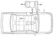
도 3은 일 실시예에 따른 운전자 보조 시스템에 포함된 카메라 및 레이더를 도시한다.
도 4는 일 실시예에 따른 운전자 보조 방법의 순서도이다.
도 5는 회피 공간이 존재하는 경우 차량의 주행 경로를 도시한 도면이다.
도 6은 회피 공간이 존재하지 않는 상황을 도시한 도면이다.
도 7은 회피 공간이 존재하지 않는 경우 시트의 위치 변화를 나타낸 도면이다.
도 8은 회피 공간이 존재하지 않는 경우 시트의 탈출 과정을 나타낸 도면이다.1 shows a configuration of a vehicle according to an embodiment.
2 illustrates a configuration of a driver assistance system according to an exemplary embodiment.
3 illustrates a camera and a radar included in a driver assistance system according to an exemplary embodiment.
4 is a flowchart of a driver assistance method according to an exemplary embodiment.
5 is a diagram illustrating a driving path of a vehicle when an avoidance space exists.
6 is a diagram illustrating a situation in which an avoidance space does not exist.
7 is a view showing a change in the position of the seat when there is no avoidance space.
8 is a view showing an escape process of the seat when there is no avoidance space.
명세서 전체에 걸쳐 동일 참조 부호는 동일 구성요소를 지칭한다. 본 명세서가 실시예들의 모든 요소들을 설명하는 것은 아니며, 본 발명이 속하는 기술분야에서 일반적인 내용 또는 실시예들 간에 중복되는 내용은 생략한다. 명세서에서 사용되는 '부, 모듈, 부재, 블록'이라는 용어는 소프트웨어 또는 하드웨어로 구현될 수 있으며, 실시예들에 따라 복수의 '부, 모듈, 부재, 블록'이 하나의 구성요소로 구현되거나, 하나의 '부, 모듈, 부재, 블록'이 복수의 구성요소들을 포함하는 것도 가능하다.Like reference numerals refer to like elements throughout. This specification does not describe all elements of the embodiments, and general content in the technical field to which the present invention pertains or content that overlaps among the embodiments is omitted. The term 'part, module, member, block' used in the specification may be implemented in software or hardware, and according to embodiments, a plurality of 'part, module, member, block' may be implemented as one component, It is also possible for one 'part, module, member, block' to include a plurality of components.
명세서 전체에서, 어떤 부분이 다른 부분과 "연결"되어 있다고 할 때, 이는 직접적으로 연결되어 있는 경우뿐 아니라, 간접적으로 연결되어 있는 경우를 포함하고, 간접적인 연결은 무선 통신망을 통해 연결되는 것을 포함한다.Throughout the specification, when a part is "connected" with another part, it includes not only direct connection but also indirect connection, and indirect connection includes connection through a wireless communication network. do.
또한 어떤 부분이 어떤 구성요소를 "포함"한다고 할 때, 이는 특별히 반대되는 기재가 없는 한 다른 구성요소를 제외하는 것이 아니라 다른 구성요소를 더 포함할 수 있는 것을 의미한다.In addition, when a part "includes" a certain component, this means that other components may be further included, rather than excluding other components, unless otherwise stated.
제 1, 제 2 등의 용어는 하나의 구성요소를 다른 구성요소로부터 구별하기 위해 사용되는 것으로, 구성요소가 전술된 용어들에 의해 제한되는 것은 아니다.Terms such as 1st, 2nd, etc. are used to distinguish one component from another component, and the component is not limited by the above-mentioned terms.
단수의 표현은 문맥상 명백하게 예외가 있지 않는 한, 복수의 표현을 포함한다.The singular expression includes the plural expression unless the context clearly dictates otherwise.
각 단계들에 있어 식별부호는 설명의 편의를 위하여 사용되는 것으로 식별부호는 각 단계들의 순서를 설명하는 것이 아니며, 각 단계들은 문맥상 명백하게 특정 순서를 기재하지 않는 이상 명기된 순서와 다르게 실시될 수 있다.In each step, the identification code is used for convenience of description, and the identification code does not describe the order of each step, and each step may be performed differently from the specified order unless the specific order is clearly stated in the context. have.
또한, 본 개시에서의 '후방 객체'는 차량(1)과의 추돌 가능성이 있는 모든 대상체를 의미하며, 다른 차량을 포함할 수 있다.In addition, the 'rear object' in the present disclosure means any object that is likely to collide with the
이하 첨부된 도면들을 참고하여 본 발명의 작용 원리 및 실시예들에 대해 설명한다.Hereinafter, the working principle and embodiments of the present invention will be described with reference to the accompanying drawings.
도 1은 일 실시예에 의한 차량의 구성을 도시한다.1 shows a configuration of a vehicle according to an embodiment.
도 1에 도시된 바와 같이, 차량(1)은 엔진(10)과, 변속기(20)와, 제동 장치(30)와, 조향 장치(40)를 포함한다. 엔진(10)은 실린더와 피스톤을 포함하며, 차량(1)이 주행하기 위한 동력을 생성할 수 있다. 변속기(20)는 복수의 기어들을 포함하며, 엔진(10)에 의하여 생성된 동력을 차륜까지 전달할 수 있다. 제동 장치(30)는 차륜과의 마찰을 통하여 차량(1)을 감속시키거나 차량(1)을 정지시킬 수 있다. 조향 장치(40)는 차량(1)의 주행 방향을 변경시킬 수 있다.As shown in FIG. 1 , a
차량(1)은 복수의 전장 부품들을 포함할 수 있다. 예를 들어, 차량(1)은 엔진 관리 시스템(Engine Management System, EMS) (11)과, 변속기 제어 유닛(Transmission Control Unit, TCU) (21)과, 전자식 제동 제어 모듈(Electronic Brake Control Module) (31)과, 전자식 조향 장치(Electronic Power Steering, EPS) (41)과, 바디 컨트롤 모듈(Body Control Module, BCM)과, 운전자 보조 시스템(100)(Driver Assistance System, DAS)과, 사용자 인터페이스(200)와, 시트(300)와, 도어(400)를 포함할 수 있다.The
엔진 관리 시스템(11)은 가속 페달을 통한 운전자의 가속 의지 또는 운전자 보조 시스템(100)의 요청에 응답하여 엔진(10)을 제어할 수 있다. 예를 들어, 엔진 관리 시스템(11)은 엔진(10)의 토크를 제어할 수 있다.The
변속기 제어 유닛(21)은 변속 레버를 통한 운전자의 변속 명령 및/또는 차량(1)의 주행 속도에 응답하여 변속기(20)를 제어할 수 있다. 예를 들어, 변속기 제어 유닛(21)은 엔진(10)으로부터 차륜까지의 변속 비율을 조절할 수 있다.The
전자식 제동 제어 모듈(31)은 제동 페달을 통한 운전자의 제동 의지 및/또는 차륜들의 슬립(slip)에 응답하여 제동 장치(30)를 제어할 수 있다. 예를 들어, 전자식 제동 제어 모듈(31)은 차량(1)의 제동 시에 감지되는 차륜의 슬립에 응답하여 차륜의 제동을 일시적으로 해제할 수 있다(Anti-lock Braking Systems, ABS). 전자식 제동 제어 모듈(31)은 차량(1)의 조향 시에 감지되는 오버스티어링(oversteering) 및/또는 언더스티어링(understeering)에 응답하여 차륜의 제동을 선택적으로 해제할 수 있다(Electronic stability control, ESC). 또한, 전자식 제동 제어 모듈(31)은 차량(1)의 구동 시에 감지되는 차륜의 슬립에 응답하여 차륜을 일시적으로 제동할 수 있다(Traction Control System, TCS).The electronic
전자식 조향 장치(41)는 스티어링 휠을 통한 운전자의 조향 의지에 응답하여 운전자가 쉽게 스티어링 휠을 조작할 수 있도록 조향 장치(40)의 동작을 보조할 수 있다. 예를 들어, 전자식 조향 장치(41)는 저속 주행 또는 주차 시에는 조향력을 감소시키고 고속 주행 시에는 조향력을 증가시키도록 조향 장치(40)의 동작을 보조할 수 있다.The
바디 컨트롤 모듈(51)은 운전자에게 편의를 제공하거나 운전자의 안전을 보장하는 전장 부품들의 동작을 제어할 수 있다. 예를 들어, 바디 컨트롤 모듈(51)은 헤드 램프, 와이퍼, 클러스터, 다기능 스위치 및 방향 지시 램프 등을 제어할 수 있다.The
사용자 인터페이스(200)는 차량(1)의 운전자에게 다양한 정보를 다양한 방법으로 제공할 수 있다.The
일 예로, 사용자 인터페이스(200)는 다양한 정보를 시각적, 청각적, 촉각적 수단을 이용하여 운전자에게 전달할 수 있다.For example, the
시트(seat; 300)는 차량(1)의 운전자를 포함한 탑승자가 앉을 수 있도록 차량(1) 내부에 마련될 수 있다.The
이러한 시트(300)는 전동 펌프에 의한 유압 또는 전기 모터 등을 이용해 위아래 또는 앞뒤로 조절할 수 있도록 설계된 파워 시트(300)를 의미할 수 있다.The
시트(300)는 운전자 시트(300), 동승자 시트(300), 후석 시트(300)를 모두 포함할 수 있지만, 설명의 편의를 위하여 시트(300)를 운전자 시트(300)로 가정하여 설명한다.The
시트(300)는 바디 컨트롤 모듈(51)에 의해 제어되거나 운전자 보조 시스템(100)에 의해 제어될 수 있으며, 바디 컨트롤 모듈(51)은 운전자 보조 시스템(100)으로부터 수신한 제어 신호에 기초하여 시트(300)의 위치를 조절할 수 있다.The
도어(400)는 전동 펌프에 의한 유압 또는 전기 모터 등을 이용해 자동으로 열리거나 닫힐 수 있도록 설계된 자동 도어(400)를 의미할 수 있다.The
도어(400)는 운전자 쪽 도어(400), 동승자 쪽 도어(400), 후석 도어(400)를 모두 포함할 수 있지만, 설명의 편의를 위하여 도어(400)를 운전자 쪽 도어(400)로 가정하여 설명한다.The
도어(400)는 바디 컨트롤 모듈(51)에 의해 제어되거나 운전자 보조 시스템(100)에 의해 제어될 수 있으며, 바디 컨트롤 모듈(51)은 운전자 보조 시스템(100)으로부터 수신한 제어 신호에 기초하여 도어(400)를 오픈할 수 있다.The
운전자 보조 시스템(100)은 운전자가 차량(1)을 조작(구동, 제동, 조향)하는 것을 보조할 수 있다. 예를 들어, 운전자 보조 시스템(100)은 차량(1)이 주행 중인 도로의 환경(예를 들어, 다른 차량, 보행자, 사이클리스트(cyclist), 차선, 도로 표지판 등)을 감지하고, 감지된 환경에 응답하여 차량(1)의 구동 및/또는 제동 및/또는 조향을 제어할 수 있다.The
또한, 운전자 보조 시스템(100)은 차량(1)이 주행 중인 도로의 환경에 응답하여 차량(1)의 시트(300) 및/또는 도어(400)를 제어할 수 있다.Also, the
운전자 보조 시스템(100)은 운전자에게 다양한 기능을 제공할 수 있다. 예를 들어, 운전자 보조 시스템(100)은 차선 이탈 경고(Lane Departure Warning, LDW)와, 차선 유지 보조(Lane Keeping Assist, LKA)와, 상향등 보조(High Beam Assist, HBA)와, 자동 긴급 제동(Autonomous Emergency Braking, AEB)과, 교통 표지판 인식(Traffic Sign Recognition, TSR)과, 스마트 크루즈 컨트롤(Smart Cruise Control, SCC)과, 사각지대 감지(Blind Spot Detection, BSD)를 제공할 수 있다.The
운전자 보조 시스템(100)은 차량(1) 주변의 영상 데이터를 획득하는 카메라 모듈(101)과, 차량(1) 주변의 객체 데이터를 획득하는 레이더 모듈(102)을 포함한다. 카메라 모듈(101)은 카메라(101a)와 제어기(Electronic Control Unit, ECU) (101b)를 포함하며, 차량(1)의 전방을 촬영하고 다른 차량, 보행자, 사이클리스트, 차선, 도로 표지판, 신호등 등을 인식할 수 있다. 레이더 모듈(102)은 레이더(102a)와 제어기(102b)를 포함하며, 차량(1) 주변의 객체(예를 들어, 다른 차량, 보행자, 사이클리스트 등)의 상대 위치, 상대 속도 등을 획득할 수 있다.The
즉, 운전자 보조 시스템(100)은 카메라 모듈(101)에서 획득한 영상 데이터와 레이더 모듈(102)에서 획득한 감지 데이터(레이더 데이터)를 처리하고, 영상 데이터와 레이더 데이터를 처리한 것에 응답하여 차량(1)이 주행 중인 도로의 환경, 차량(1)의 전방에 위치하는 전방 객체, 차량(1)의 후방에 위치하는 후방 객체 및 차량(1)의 측방에 위치하는 측방 객체를 감지할 수 있다.That is, the
운전자 보조 시스템(100)은 도 1에 도시된 바에 한정되지 아니하며, 차량(1) 주변을 스캔하며 객체를 감지하는 라이다(lidar)를 더 포함할 수 있다.The
이상의 전자 부품들은 차량용 통신 네트워크(NT)를 통하여 서로 통신할 수 있다. 예를 들어, 전장 부품들은 이더넷(Ethernet), 모스트(MOST, Media Oriented Systems Transport), 플렉스레이(Flexray), 캔(CAN, Controller Area Network), 린(LIN, Local Interconnect Network) 등을 통하여 데이터를 주고 받을 수 있다. 예를 들어, 운전자 보조 시스템(100)은 엔진 관리 시스템(11), 전자식 제동 제어 모듈(31), 전자식 조향 장치(41)에 각각 차량용 통신 네트워크(NT)를 통하여 구동 제어 신호, 제동 신호 및 조향 신호를 전송할 수 있다.The above electronic components may communicate with each other through the vehicle communication network NT. For example, electronic components transmit data through Ethernet, MOST (Media Oriented Systems Transport), Flexray, CAN (Controller Area Network), and LIN (Local Interconnect Network). can give and receive For example, the
또 다른 예로, 운전자 보조 시스템(100)은 바디 컨트롤 모듈(51), 사용자 인터페이스(200), 시트(300), 도어(400)에 각각 차량용 통신 네트워크(NT)를 통하여 시트(300) 및 도어(400) 제어 신호, 정보 출력 신호, 시트(300) 제어 신호, 도어(400) 제어 신호를 전송할 수 있다.As another example, the
도 2는 일 실시예에 의한 운전자 보조 시스템의 구성을 도시한다. 도 3은 일 실시예에 의한 운전자 보조 시스템에 포함된 카메라 및 레이더를 도시한다.2 illustrates a configuration of a driver assistance system according to an exemplary embodiment. 3 illustrates a camera and a radar included in a driver assistance system according to an exemplary embodiment.
도 2에 도시된 바와 같이, 차량(1)은 제동 시스템(32)과, 조향 시스템(42)과, 운전자 보조 시스템(100)과, 사용자 인터페이스와, 시트(300)와 도어(400)를 포함할 수 있다.As shown in FIG. 2 , a
제동 시스템(32)은 도 1과 함께 설명된 전자식 제동 제어 모듈(31, 도 1 참조)과 제동 장치(30, 도 1 참조)를 포함하며, 조향 시스템(42)은 전자식 조향 장치(41, 도 1 참조)와 조향 장치(40, 도 1 참조)를 포함할 수 있다.The
사용자 인터페이스(200)는 운전자 보조 시스템(100)의 제어 신호에 기초하여 차량(1)의 운전자에게 관성 주행의 시작 시점을 안내하기 위한 정보를 출력할 수 있다. 이를 위한 사용자 인터페이스(200)는 운전자에게 청각적 정보를 전달하는 스피커(220) 및/또는 운전자에게 시각적 정보를 전달하는 디스플레이(210)를 포함할 수 있다.The
일 실시예에 따른 디스플레이(210)는 운전자 보조 시스템(100)의 제어 신호에 기초하여 운전자에게 추돌을 경고하는 영상을 출력할 수 있다. 예를 들어, 디스플레이(210)는 추돌을 경고하는 메시지를 출력할 수 있다.The
이를 위한 디스플레이(210)는 차량(1)의 내부에 마련될 수 있으며, 패널을 포함할 수 있다. 예를 들어, 디스플레이(210)는 차량(1)의 클러스터에 마련될 수 있으며, 클러스터 및 센터페시아를 가로질러 마련될 수도 있으며, 차량(1) 내부의 천장에 마련될 수도 있으며, 차량(1) 내부의 도어(400)에 마련될 수도 있다.The
패널은 음극선관(Cathode Ray Tube, CRT) 패널, 액정 디스플레이(Liquid Crystal Display, LCD) 패널, 발광 다이오드(Light Emitting Diode, LED) 패널, 유기 발광 다이오드(Organic Light Emitting Diode, OLED) 패널, 플라즈마 디스플레이 패널(Plasma Display Panel, PDP), 전계 방출 디스플레이(Field Emission Display, FED) 패널 중 어느 하나일 수 있다.Panels include a cathode ray tube (CRT) panel, a liquid crystal display (LCD) panel, a light emitting diode (LED) panel, an organic light emitting diode (OLED) panel, and a plasma display. It may be any one of a plasma display panel (PDP) and a field emission display (FED) panel.
디스플레이(210)가 마련되는 위치 및 개수는, 차량(1)의 운전자에게 정보를 시각적으로 전달할 수 있는 위치 및 개수이면 제한 없이 포함될 수 있다.The position and number of the
일 실시예에 따른 스피커(220)는 운전자 보조 시스템(100)의 제어 신호에 기초하여 추돌을 경고하기 위한 사운드를 출력할 수 있다. 예를 들어, 스피커(220)는 긴급 경고 알람을 출력할 수 있다.The
이를 위한 스피커(220)는 차량(1)의 내부에 마련될 수 있으며, 차량(1)의 운전자가 출력되는 사운드를 청취할 수 있는 위치이면 제한 없이 마련될 수 있다.For this purpose, the
시트(300)는 도어(400) 쪽에 마련된 에어백(310)을 포함할 수 있다.The
시트(300)가 좌측에 존재하는 경우, 에어백(310)은 시트(300) 내부에서 좌측에 마련될 수 있다.When the
시트(300)는 운전자의 머리를 편하게 받쳐 주며, 추돌 사고 시 순간적으로 목이 뒤로 꺾여 목뼈가 손상되는 것을 미리 방지해 주기 위한 헤드 레스트(320)를 포함할 수 있으며, 운전자가 등을 기댈 수 있는 등받이(330)를 포함할 수 있다.The
헤드 레스트(320)의 위치 및 등받이(330)의 위치는 운전자 보조 시스템(100) 및/또는 바디 컨트롤 모듈(51)에 의해 각각 독립적으로 제어될 수 있다.The position of the
운전자 보조 시스템(100)은 전방 카메라(110)와, 후방 카메라(115)와, 전방 레이더(120)와, 후방 레이더(125)와, 복수의 코너 레이더들(130)을 포함할 수 있다.The
전방 카메라(110)는 도 3에 도시된 바와 같이 차량(1)의 전방을 향하는 시야(field of view) (110a)를 가질 수 있다. 전방 카메라(110)는 예를 들어 차량(1)의 프론트 윈드 쉴드에 설치될 수 있으나, 차량(1)의 전방을 향하는 시야를 갖는다면 어느 위치든지 제한 없이 마련될 수 있다.The
전방 카메라(110)는 차량(1)의 전방을 촬영하고, 차량(1) 전방의 영상 데이터를 획득할 수 있다. 차량(1) 전방의 영상 데이터는 차량(1) 전방에 위치하는 다른 차량 및/또는 차선에 관한 정보를 포함할 수 있다.The
후방 카메라(115)는 도 3에 도시된 바와 같이 차량(1)의 후방을 향하는 시야(field of view) (115a)를 가질 수 있다. 후방 카메라(115)는 예를 들어 차량(1)의 리어 윈드 쉴드에 설치될 수 있으나, 차량(1)의 후방을 향하는 시야를 갖는다면 어느 위치든지 제한 없이 마련될 수 있다.The
후방 카메라(115)는 차량(1)의 후방을 촬영하고, 차량(1) 후방의 영상 데이터를 획득할 수 있다. 차량(1) 후방의 영상 데이터는 차량(1) 후방에 위치하는 다른 차량 및/또는 차선에 관한 정보를 포함할 수 있다.The
전방 카메라(110) 및 후방 카메라(115)는 복수의 렌즈들 및 이미지 센서를 포함할 수 있다. 이미지 센서는 광을 전기 신호로 변환하는 복수의 포토 다이오드들을 포함할 수 있으며, 복수의 포토 다이오드들이 2차원 매트릭스로 배치될 수 있다.The
전방 카메라(110) 및 후방 카메라(115)는 제어부(140)와 전기적으로 연결될 수 있다. 예를 들어, 전방 카메라(110) 및 후방 카메라(115)는 차량용 통신 네트워크(NT)를 통하여 제어부(140)와 연결되거나, 하드 와이어(hard wire)를 통하여 제어부(140)와 연결되거나, 인쇄 회로 기판(Printed Circuit Board, PCB)을 통하여 제어부(140)와 연결될 수 있다.The
전방 카메라(110)는 차량(1) 전방의 영상 데이터를 제어부(140)로 전달할 수 있으며, 후방 카메라(115)는 차량(1) 후방의 영상 데이터를 제어부(140)로 전달할 수 있다.The
전방 레이더(120)는 도 3에 도시된 바와 같이 차량(1)의 전방을 향하는 감지 시야(field of sensing) (120a)을 가질 수 있다. 전방 레이더(120)는 예를 들어 차량(1)의 그릴(grille) 또는 프론트 범퍼(bumper)에 설치될 수 있다.The
후방 레이더(125)는 도 3에 도시된 바와 같이 차량(1)의 후방을 향하는 감지 시야(field of sensing) (125a)을 가질 수 있다. 후방 레이더(125)는 예를 들어 차량(1)의 리어 범퍼에 설치될 수 있다.The
전방 레이더(120) 및 후방 레이더(125)는 차량(1)의 전방, 후방을 향하여 송신 전파를 방사하는 송신 안테나(또는 송신 안테나 어레이)와, 객체에 반사된 반사 전파를 수신하는 수신 안테나(또는 수신 안테나 어레이)를 포함할 수 있다. 전방 레이더(120) 및 후방 레이더(125)는 송신 안테나에 의한 송신된 송신 전파와 수신 안테나에 의하여 수신된 반사 전파로부터 전방 레이더 데이터 및 후방 레이더 데이터를 획득할 수 있다. 전방 레이더 데이터 및 후방 레이더 데이터는 차량(1)의 전방 및 후방에 위치하는 다른 차량 또는 보행자 또는 사이클리스트에 관한 거리 정보 및 속도 정도를 포함할 수 있다. 전방 레이더(120) 및 후방 레이더(125)는 송신 전파와 반사 전파 사이의 위상 차이(또는 시간 차이)에 기초하여 객체까지의 상태 거리를 산출하고, 송신 전파와 반사 전파 사이의 주파수 차이에 기초하여 객체의 상대 속도를 산출할 수 있다.The
전방 레이더(120) 및 후방 레이더(125)는 예를 들어 차량용 통신 네트워크(NT) 또는 하드 와이어 또는 인쇄 회로 기판을 통하여 제어부(140)와 연결될 수 있다. 전방 레이더(120) 및 후방 레이더(125)는 전방 레이더 데이터 및 후방 레이더 데이터를 제어부(140)로 전달할 수 있다.The
복수의 코너 레이더들(130)은 차량(1)의 전방 우측에 설치되는 제1 코너 레이더(131)와, 차량(1)의 전방 좌측에 설치되는 제2 코너 레이더(132)와, 차량(1)의 후방 우측에 설치되는 제3 코너 레이더(133)와, 차량(1)의 후방 좌측에 설치되는 제4 코너 레이더(134)를 포함한다.The plurality of
제1 코너 레이더(131)는 도 3에 도시된 바와 같이 차량(1)의 전방 우측을 향하는 감지 시야(131a)를 가질 수 있다. 전방 레이더(120)는 예를 들어 차량(1)의 전방 범퍼의 우측에 설치될 수 있다. 제2 코너 레이더(132)는 차량(1)의 전방 좌측을 향하는 감지 시야(132a)를 가질 수 있으며, 예를 들어 차량(1)의 전방 범퍼의 좌측에 설치될 수 있다. 제3 코너 레이더(133)는 차량(1)의 후방 우측을 향하는 감지 시야(133a)를 가질 수 있으며, 예를 들어 차량(1)의 후방 범퍼의 우측에 설치될 수 있다. 제4 코너 레이더(134)는 차량(1)의 후방 좌측을 향하는 감지 시야(134a)를 가질 수 있으며, 예를 들어 차량(1)의 후방 범퍼의 좌측에 설치될 수 있다.The
제1, 제2, 제3 및 제4 코너 레이더들(131, 132, 133, 134) 각각은 송신 안테나와 수신 안테나를 포함할 수 있다. 제1, 제2, 제3 및 제4 코너 레이더들(131, 132, 133, 134)은 각각 제1 코너 레이더 데이터와 제2 코너 레이더 데이터와 제3 코너 레이더 데이터와 제4 코너 레이더 데이터를 획득할 수 있다. 제1 코너 레이더 데이터는 차량(1) 전방 우측에 위치하는 다른 차량 또는 보행자 또는 사이클리스트(이하 "객체"라 한다)에 관한 거리 정보 및 속도 정도를 포함할 수 있다. 제2 코너 레이더 데이터는 차량(1) 전방 좌측에 위치하는 객체의 거리 정보 및 속도 정도를 포함할 수 있다. 제3 및 제4 코너 레이더 데이터는 차량(1) 후방 우측 및 차량(1) 후방 좌측에 위치하는 객체의 거리 정보 및 상대 속도를 포함할 수 있다.Each of the first, second, third, and
제1, 제2, 제3 및 제4 코너 레이더들(131, 132, 133, 134) 각각은 예를 들어 차량용 통신 네트워크(NT) 또는 하드 와이어 또는 인쇄 회로 기판을 통하여 제어부(140)와 연결될 수 있다. 제1, 제2, 제3 및 제4 코너 레이더들(131, 132, 133, 134)은 각각 제1, 제2, 제3 및 제4 코너 레이더 데이터를 제어부(140)로 전달할 수 있다.Each of the first, second, third and
제어부(140)는 카메라 모듈(101, 도 1 참조)의 제어기(101b, 도 1 참조) 및/또는 레이더 모듈(102, 도 1 참조)의 제어기(102b, 도 1 참조) 및/또는 별도의 통합 제어기를 포함할 수 있다.The
제어부(140)는 프로세서(141)와 메모리(142)를 포함할 수 있다.The
프로세서(141)는 후방 카메라(115)의 후방 영상 데이터와 후방 레이더(125)의 후방 레이더 데이터를 처리하여, 차량(1)의 후방에 위치하는 후방 객체의 추돌 가능성을 판단할 수 있다. 또한, 프로세서(141)는 후방 카메라(115)의 후방 영상 데이터와 후방 레이더(125)의 후방 레이더 데이터를 처리한 것에 응답하여 시트(300) 및/또는 도어(400)를 제어하기 위한 제어 신호를 생성할 수 있다.The
또한, 프로세서(141)는 후방 카메라(115)의 후방 영상 데이터와 후방 레이더(125)의 후방 레이더 데이터를 처리한 것에 응답하여 차량(1)을 이동시키기 위한 구동 신호, 제동 신호 및 조향 신호를 생성할 수 있다.In addition, the
또한, 프로세서(141)는 후방 카메라(115)의 후방 영상 데이터와 후방 레이더(125)의 후방 레이더 데이터를 처리한 것에 응답하여 사용자 인터페이스(200)를 제어하기 위한 제어 신호를 생성할 수 있다.In addition, the
예를 들어, 프로세서(141)는 카메라들(110, 115)의 영상 데이터를 처리하는 이미지 프로세서 및/또는 레이더들(120, 125, 130)의 레이더 데이터를 처리하는 디지털 시그널 프로세서 및/또는 구동 신호, 제동 신호, 조향 신호, 및 사용자 인터페이스(200), 시트(300), 도어(400)를 제어하기 위한 제어 신호를 생성하는 마이크로 컨트롤 유닛(Micro Control Unit, MCU) 또는 통합 제어 유닛(Domain Control Unit; DCU)을 포함할 수 있다.For example, the
프로세서(141)는 후방 카메라(115)의 후방 영상 데이터와 후방 레이더(125)의 후방 레이더 데이터에 기초하여 차량(1) 후방의 객체들(예를 들어, 다른 차량)을 감지할 수 있다.The
구체적으로, 프로세서(141)는 후방 레이더(125)가 획득한 후방 레이더 데이터에 기초하여 차량(1) 후방의 객체들의 위치(거리 및 방향) 및 상대 속도를 획득할 수 있다. 프로세서(141)는 후방 카메라(115)의 후방 영상 데이터에 기초하여 차량(1) 후방의 객체들의 위치(방향) 및 유형 정보(예를 들어, 후방 객체가 트럭인지, 승용차인지)를 획득할 수 있다. 또한, 프로세서(141)는 후방 영상 데이터에 의하여 감지된 객체들을 후방 레이더 데이터에 의한 감지된 객체에 매칭하고, 매칭 결과에 기초하여 차량(1)의 후방 객체들의 유형 정보와 위치와 상대 속도를 획득할 수 있다.Specifically, the
또한, 후술하여 설명할 바와 같이 프로세서(141)는 차량(1)이 후방 객체의 추돌 가능성을 판단하고, 후방 객체의 추돌에 의한 예상 충격량을 결정할 수 있다.In addition, as will be described later, the
마찬가지로, 프로세서(141)는 전방 카메라(110)의 전방 영상 데이터와 전방 레이더(120)의 전방 레이더 데이터, 측방 레이더(130)의 측방 레이더 데이터를 처리하고, 차량(1) 주변의 환경을 감지할 수 있다.Similarly, the
메모리(142)는 프로세서(141)가 영상 데이터를 처리하기 위한 프로그램 및/또는 데이터와, 레이더 데이터를 처리하기 위한 프로그램 및/또는 데이터와, 프로세서(141)가 제동 신호 및/또는 조향 신호 및/또는 제어 신호를 생성하기 위한 프로그램 및/또는 데이터를 저장할 수 있다.The
메모리(142)는 카메라들(110, 115)로부터 수신된 영상 데이터 및/또는 레이더들(120, 125, 130)로부터 수신된 레이더 데이터를 임시로 기억하고, 프로세서(141)의 영상 데이터 및/또는 레이더 데이터의 처리 결과를 임시로 기억할 수 있다.The
이를 위한 메모리(142)는 S램(S-RAM), D램(D-RAM) 등의 휘발성 메모리뿐만 아니라 플래시 메모리, 롬(Read Only Memory, ROM), 이피롬(Erasable Programmable Read Only Memory: EPROM) 등의 비휘발성 메모리를 포함할 수 있다.The
운전자 보조 시스템(100)은 도 2에 도시된 바에 한정되지 아니하며, 차량(1) 주변을 스캔하며 객체를 감지하는 라이다(lidar)를 더 포함할 수 있다.The
이하 도 4 내지 도 8을 참조하여 제어부(140)가 추돌에 따른 피해를 방지할 수 있는 프로세스를 자세하게 설명한다.Hereinafter, a process by which the
도 4는 일 실시예에 따른 운전자 보조 방법의 순서도이고, 도 5는 회피 공간이 존재하는 경우 차량의 주행 경로를 도시한 도면이고, 도 6은 회피 공간이 존재하지 않는 상황을 도시한 도면이고, 도 7은 회피 공간이 존재하지 않는 경우 시트(300)의 위치 변화를 나타낸 도면이고, 도 8은 회피 공간이 존재하지 않는 경우 시트(300)의 탈출 과정을 나타낸 도면이다.4 is a flowchart of a driver assistance method according to an embodiment, FIG. 5 is a diagram illustrating a driving route of a vehicle when an avoidance space exists, and FIG. 7 is a view showing a change in the position of the
도 4를 참조하면, 제어부(140)는 후방 영상 데이터와 후방 레이더 데이터(이하 후방 감지 데이터)를 처리하고, 후방 영상 데이터와 후방 감지 데이터를 처리한 것에 응답하여 차량(1)의 후방에 위치하는 후방 객체(2)의 추돌 가능성을 판단할 수 있다(1000).Referring to FIG. 4 , the
제어부(140)는 후방 객체(2)의 추돌이 예상되면 후방 객체(2)의 추돌을 회피하기 위한 회피 공간을 탐색할 수 있다(1100).When the collision of the
구체적으로, 제어부(140)는 전방 영상 데이터와 전방 레이더 데이터(이하 전방 감지 데이터)와 측방 레이더 데이터(이하 측방 감지 데이터)를 처리한 것에 응답하여 후방 객체(2)의 추돌을 회피하기 위한 회피 공간을 탐색할 수 있다.Specifically, the
도 5를 참조하면, 제어부(140)는 후방 차량(2)의 추돌이 예상되면, 전방 영상 데이터와 전방 감지 데이터와 측방 감지 데이터에 기초하여 차량(1)의 전방 및 측방에 위치하는 다른 차량들(3)의 위치 및 상대 속도를 결정할 수 있으며, 다른 차량들(3)의 위치 및 상대 속도에 기초하여 회피 공간을 탐색할 수 있다.Referring to FIG. 5 , when a collision of the
제어부(140)는 회피 공간이 존재하는 경우(1100의 예) 차량(1)이 회피 공간으로 이동하도록 차량(1)을 제어할 수 있다(1150).When the avoidance space exists (Yes in 1100 ), the
즉, 제어부(140)는 회피 공간이 존재하면 차량(1)이 회피 공간으로 이동할 수 있도록 하는 구동 신호, 조향 신호 및 제동 신호를 생성할 수 있다.That is, when the avoidance space exists, the
위와 같이, 일 실시예에 따른 운전자 보조 시스템(100)이 탑재된 차량(1)은 회피 공간이 존재하는 경우 회피 공간으로 이동함으로써 후방 객체(2)와의 추돌을 방지할 수 있다.As described above, the
도 6을 참조하면, 차량(1)이 다른 차량들(3)로 둘러싸여 있어서 후방 차량(2)의 추돌을 회피할 공간이 없다. 도 6에 도시된 바와 같이, 회피 공간이 존재하지 않으면(1100의 아니오), 제어부(140)는 후방 영상 데이터 및 후방 감지 데이터를 처리한 것에 기초하여 후방 객체(2)의 추돌에 의한 예상 충격량을 결정할 수 있다(1200).Referring to FIG. 6 , since the
구체적으로, 제어부(140)는 후방 감지 데이터를 처리한 것에 응답하여 후방 객체(2)의 속도를 결정하고, 후방 영상 데이터를 처리한 것에 응답하여 후방 객체(2)의 크기를 결정하고, 후방 객체(2)의 속도 및 크기에 기초하여 후방 객체(2)의 추돌에 의한 예상 충격량을 결정할 수 있다.Specifically, the
위와 같이 제어부(140)가 후방 객체(2)의 크기를 고려함으로써, 후방 객체(2)가 동일한 속도로 접근하고 있더라도 후방 객체(2)가 승용차인 경우와 덤프 트럭인 경우의 예상 충격량이 다르게 산출될 수 있다.As described above, by considering the size of the
제어부(140)는 후방 객체(2)의 추돌에 의한 예상 충격량이 미리 설정된 값 이하이면(1200의 아니오) 차량(1)의 시트(300)를 미리 설정된 위치로 조절할 수 있다(1250).If the expected impact amount due to the collision of the
이 때, 미리 설정된 값은 운전자가 심한 부상을 입을 것이라고 추측될 수 있는 정도의 충격량으로 설정될 수 있다.In this case, the preset value may be set to an amount of impact that can be estimated that the driver will be seriously injured.
또한, 제어부(140)는 차량(1)의 운전자가 시트(300)에 밀착되도록 시트(300)를 미리 설정된 위치로 조절할 수 있다. 즉, 미리 설정된 위치는 차량(1)의 운전자가 시트(300)에 밀착되도록 설정될 수 있다.Also, the
도 7을 참조하면, 미리 설정된 위치는 시트(300)의 헤드 레스트(320)가 전방으로 회전 이동된 위치, 시트(300)의 등받이(330)가 전방으로 회전 이동된 위치를 의미할 수 있다.Referring to FIG. 7 , the preset position may refer to a position in which the
즉, 제어부(140)는 후방 객체(2)의 추돌에 의한 예상 충격량이 미리 설정된 값 이하이면 시트(300)의 헤드 레스트(320)를 전방으로 회전 이동시키고, 시트(300)의 등받이(330)를 전방으로 회전 이동시킬 수 있다.That is, if the expected impact amount due to the collision of the
위와 같이, 경미한 사고가 예상되는 경우 시트(300)를 조절함으로써 운전자와 시트(300)를 밀착시키고 운전자의 부상을 방지할 수 있다.As described above, when a minor accident is expected, by adjusting the
도 8을 참조하면, 제어부(140)는 후방 객체(2)의 추돌에 의한 예상 충격량이 미리 설정된 값보다 크면(1200의 예) 차량(1)의 도어(400)를 오픈하고 시트(300)를 전방으로 이동시키고, 시트(300)를 차량(1)과 분리시키고(1300) 분리된 시트(300)를 오픈된 도어(400)를 통해 차량(1)의 외부로 탈출시킬 수 있다(1350).Referring to FIG. 8 , the
추돌에 의한 예상 충격량이 미리 설정된 값보다 크면 운전자가 심각한 부상을 입을 수 있으므로, 운전자를 차량(1)의 외부로 탈출시키기 위함이다.If the expected impact amount due to the collision is greater than the preset value, the driver may be seriously injured, so that the driver may escape to the outside of the
이 때, 제어부(140)는 차량(1)의 도어(400)를 90도 이상으로 오픈할 수 있다. 도어(400)가 90도보다 작은 각도로 오픈되면 시트(300)가 차량(1)의 외부로 탈출되는데 어려움이 있기 때문이다.In this case, the
또한, 제어부(140)는 분리된 시트(300)를 오픈된 도어(400)를 통해 차량(1)의 외부로 탈출시킬 때 시트(300)에 설치된 에어백(310)을 동작시킴으로써 시트(300)의 낙하에 의한 운전자의 부상을 방지할 수 있다.In addition, the
위와 같이, 추돌에 의해 운전자의 심각한 부상이 예상되는 경우에는 운전자를 차량(1)으로부터 탈출시킴으로써 운전자의 심각한 부상을 방지할 수 있다.As described above, when serious injury to the driver is expected due to a collision, serious injury to the driver may be prevented by escaping the driver from the
또한, 제어부(140)는 후방 객체(2)의 추돌이 예상되면 사용자 인터페이스(200)를 제어하여 운전자에게 추돌을 경고할 수 있다.Also, when a collision of the
예를 들어, 제어부(140)는 디스플레이(210)를 제어하여 운전자에게 추돌을 경고하는 영상을 출력할 수 있으며, 스피커(220)를 제어하여 추돌을 경고하기 위한 사운드를 출력할 수 있다.For example, the
개시된 실시예들에 따르면 추돌 시 발생할 수 있는 운전자의 피해를 최소화 할 수 있다.According to the disclosed embodiments, it is possible to minimize damage to the driver that may occur during a collision.
한편, 개시된 실시예들은 컴퓨터에 의해 실행 가능한 명령어를 저장하는 기록매체의 형태로 구현될 수 있다. 명령어는 프로그램 코드의 형태로 저장될 수 있으며, 프로세서에 의해 실행되었을 때, 프로그램 모듈을 생성하여 개시된 실시예들의 동작을 수행할 수 있다. 기록매체는 컴퓨터로 읽을 수 있는 기록매체로 구현될 수 있다.Meanwhile, the disclosed embodiments may be implemented in the form of a recording medium storing instructions executable by a computer. Instructions may be stored in the form of program code, and when executed by a processor, may generate program modules to perform operations of the disclosed embodiments. The recording medium may be implemented as a computer-readable recording medium.
컴퓨터가 읽을 수 있는 기록매체로는 컴퓨터에 의하여 해독될 수 있는 명령어가 저장된 모든 종류의 기록 매체를 포함한다. 예를 들어, ROM(Read Only Memory), RAM(Random Access Memory), 자기 테이프, 자기 디스크, 플래쉬 메모리, 광 데이터 저장장치 등이 있을 수 있다.The computer-readable recording medium includes any type of recording medium in which instructions readable by the computer are stored. For example, there may be a read only memory (ROM), a random access memory (RAM), a magnetic tape, a magnetic disk, a flash memory, an optical data storage device, and the like.
이상에서와 같이 첨부된 도면을 참조하여 개시된 실시예들을 설명하였다. 본 발명이 속하는 기술분야에서 통상의 지식을 가진 자는 본 발명의 기술적 사상이나 필수적인 특징을 변경하지 않고도, 개시된 실시예들과 다른 형태로 본 발명이 실시될 수 있음을 이해할 것이다. 개시된 실시예들은 예시적인 것이며, 한정적으로 해석되어서는 안 된다.The disclosed embodiments have been described with reference to the accompanying drawings as described above. Those of ordinary skill in the art to which the present invention pertains will understand that the present invention may be practiced in other forms than the disclosed embodiments without changing the technical spirit or essential features of the present invention. The disclosed embodiments are illustrative and should not be construed as limiting.
1: 차량100: 운전자 보조 시스템
110: 전방 카메라120: 전방 레이더
130: 복수의 코너 레이더들131: 제1 코너 레이더
132: 제2 코너 레이더133: 제3 코너 레이더
134: 제4 코너 레이더140: 제어부
200: 사용자 인터페이스300: 시트
310: 에어백400: 도어1: Vehicle 100: Driver assistance system
110: front camera 120: front radar
130: plurality of corner radars 131: first corner radar
132: second corner radar 133: third corner radar
134: fourth corner radar 140: control unit
200: user interface 300: sheet
310: airbag 400: door
Claims (18)
Translated fromKorean레이더 센서와 라이다 센서로 구성된 그룹에서 선택되어, 상기 차량에 설치되며, 상기 차량의 후방의 감지 시야를 가지고, 후방 감지 데이터를 획득하는 제2 센서; 및
상기 후방 영상 데이터와 상기 후방 감지 데이터를 처리하는 프로세서를 포함하는 제어부;를 포함하고,
상기 제어부는,
상기 후방 영상 데이터와 상기 후방 감지 데이터를 처리한 것에 응답하여 상기 차량의 후방에 위치하는 후방 객체의 추돌 가능성을 판단하고,
상기 후방 객체의 추돌이 예상되면 상기 차량의 시트를 미리 설정된 위치로 조절하는 운전자 보조 시스템.a first sensor installed in a vehicle, having a rear view of the vehicle, and acquiring rear image data;
a second sensor selected from the group consisting of a radar sensor and a lidar sensor, installed in the vehicle, having a detection field of the rear of the vehicle, and acquiring rear detection data; and
a control unit including a processor for processing the rear image data and the rear detection data;
The control unit is
In response to processing the rear image data and the rear detection data, determining the possibility of collision of a rear object located at the rear of the vehicle,
A driver assistance system that adjusts the seat of the vehicle to a preset position when a collision of the rear object is expected.
상기 미리 설정된 위치는,
상기 차량의 운전자가 상기 시트에 밀착되도록 설정되는 운전자 보조 시스템.According to claim 1,
The preset location is
A driver assistance system that is set so that the driver of the vehicle is in close contact with the seat.
상기 제어부는,
상기 후방 객체의 속도 및 크기에 기초하여 상기 후방 객체의 추돌에 의한 예상 충격량을 결정하고,
상기 예상 충격량이 미리 설정된 값 이하이면 상기 차량의 시트를 상기 미리 설정된 위치로 조절하는 운전자 보조 시스템.According to claim 1,
The control unit is
Determine the expected impact amount due to the collision of the rear object based on the speed and size of the rear object,
A driver assistance system that adjusts the seat of the vehicle to the preset position when the expected impact amount is less than or equal to a preset value.
상기 제어부는,
상기 예상 충격량이 상기 미리 설정된 값보다 크면 상기 차량의 도어를 오픈하고, 상기 시트를 상기 차량과 분리시키고 상기 분리된 시트를 상기 오픈된 도어를 통해 상기 차량의 외부로 탈출시키는 운전자 보조 시스템.4. The method of claim 3,
The control unit is
When the expected impact amount is greater than the preset value, the driver assistance system opens a door of the vehicle, separates the seat from the vehicle, and allows the separated seat to escape to the outside of the vehicle through the open door.
상기 제어부는,
상기 차량의 도어를 90도 이상으로 오픈하는 운전자 보조 시스템.5. The method of claim 4,
The control unit is
A driver assistance system that opens the door of the vehicle by more than 90 degrees.
상기 제어부는,
상기 분리된 시트를 상기 오픈된 도어를 통해 상기 차량의 외부로 탈출시킬 때 상기 시트에 설치된 에어백을 동작시키는 운전자 보조 시스템.5. The method of claim 4,
The control unit is
A driver assistance system for operating an airbag installed on the seat when the separated seat is evacuated to the outside of the vehicle through the open door.
상기 제어부는,
상기 후방 감지 데이터를 처리한 것에 응답하여 상기 후방 객체의 속도를 결정하고, 상기 후방 영상 데이터를 처리한 것에 응답하여 상기 후방 객체의 크기를 결정하는 운전자 보조 시스템.4. The method of claim 3,
The control unit is
A driver assistance system that determines a speed of the rear object in response to processing the rear detection data, and determines a size of the rear object in response to processing the rear image data.
상기 제어부는,
상기 후방 객체의 추돌이 예상되면 상기 차량의 사용자 인터페이스를 제어하여 운전자에게 추돌을 경고하는 운전자 보조 시스템.According to claim 1,
The control unit is
When a collision of the rear object is expected, the driver assistance system controls a user interface of the vehicle to warn the driver of the collision.
상기 차량에 설치되어, 상기 차량의 전방 시야를 가지며, 전방 영상 데이터를 획득하는 제3 센서;
레이더 센서와 라이다 센서로 구성된 그룹에서 선택되어, 상기 차량에 설치되며, 상기 차량의 전방의 감지 시야를 가지고, 전방 감지 데이터를 획득하는 제4 센서; 및
레이더 센서와 라이다 센서로 구성된 그룹에서 선택되어, 상기 차량에 설치되며, 상기 차량의 측방의 감지 시야를 가지고, 측방 감지 데이터를 획득하는 제5 센서;를 더 포함하고,
상기 제어부는,
상기 전방 영상 데이터와 상기 전방 감지 데이터와 상기 측방 감지 데이터를 처리한 것에 응답하여 상기 후방 객체의 추돌을 회피하기 위한 회피 공간을 탐색하고,
상기 차량이 상기 회피 공간으로 이동하도록 상기 차량을 제어하는 운전자 보조 시스템.According to claim 1,
a third sensor installed in the vehicle, having a front view of the vehicle, and acquiring front image data;
a fourth sensor selected from the group consisting of a radar sensor and a lidar sensor, installed in the vehicle, having a detection field of view in front of the vehicle, and acquiring forward detection data; and
A fifth sensor selected from the group consisting of a radar sensor and a lidar sensor, installed in the vehicle, has a side detection field of the vehicle, and acquires side detection data; further comprising,
The control unit is
Searching for an avoidance space for avoiding collision of the rear object in response to processing the front image data, the front detection data, and the side detection data,
A driver assistance system for controlling the vehicle to move the vehicle to the avoidance space.
상기 후방 영상 데이터와 상기 후방 감지 데이터를 처리하고;
상기 후방 영상 데이터와 상기 후방 감지 데이터를 처리한 것에 응답하여 상기 차량의 후방에 위치하는 후방 객체의 추돌 가능성을 판단하고;
상기 후방 객체의 추돌이 예상되면 상기 차량의 시트를 미리 설정된 위치로 조절하는 것;을 포함하는 운전자 보조 방법.acquiring rear image data and rear detection data of the vehicle;
process the rear image data and the rear detection data;
determining a collision possibility of a rear object located at the rear of the vehicle in response to processing the rear image data and the rear detection data;
and adjusting the seat of the vehicle to a preset position when the collision of the rear object is expected.
상기 미리 설정된 위치는,
상기 차량의 운전자가 상기 시트에 밀착되도록 설정되는 운전자 보조 방법.11. The method of claim 10,
The preset location is
A driver assistance method in which the driver of the vehicle is set to be in close contact with the seat.
상기 후방 객체의 추돌이 예상되면 상기 차량의 시트를 미리 설정된 위치로 조절하는 것은,
상기 후방 객체의 속도 및 크기에 기초하여 상기 후방 객체의 추돌에 의한 예상 충격량을 결정하고,
상기 예상 충격량이 미리 설정된 값 이하이면 상기 차량의 시트를 상기 미리 설정된 위치로 조절하는 것;을 포함하는 운전자 보조 방법.11. The method of claim 10,
Adjusting the seat of the vehicle to a preset position when the collision of the rear object is expected,
Determine the expected impact amount due to the collision of the rear object based on the speed and size of the rear object,
and adjusting the seat of the vehicle to the preset position when the expected impact amount is less than or equal to a preset value.
상기 예상 충격량이 상기 미리 설정된 값보다 크면, 상기 차량의 도어를 오픈하고 상기 시트를 상기 차량과 분리시키고 상기 분리된 시트를 상기 오픈된 도어를 통해 상기 차량의 외부로 탈출시키는 것;을 더 포함하는 운전자 보조 방법.13. The method of claim 12,
When the expected impact amount is greater than the preset value, opening the door of the vehicle, separating the seat from the vehicle, and escaping the separated seat to the outside of the vehicle through the opened door; further comprising Driver assistance method.
상기 차량의 도어를 오픈하는 것은,
상기 차량의 도어를 90도 이상으로 오픈하는 것;을 포함하는 운전자 보조 방법.14. The method of claim 13,
To open the door of the vehicle,
A driver assistance method comprising; opening the door of the vehicle by 90 degrees or more.
상기 분리된 시트를 상기 오픈된 도어를 통해 상기 차량의 외부로 탈출시킬 때 상기 시트에 설치된 에어백을 동작시키는 것;을 더 포함하는 운전자 보조 방법.14. The method of claim 13,
and operating an airbag installed on the seat when the separated seat is evacuated to the outside of the vehicle through the open door.
상기 후방 객체의 속도 및 크기에 기초하여 상기 후방 객체의 추돌에 의한 예상 충격량을 결정하는 것은,
상기 후방 감지 데이터를 처리한 것에 응답하여 상기 후방 객체의 속도를 결정하고;
상기 후방 영상 데이터를 처리한 것에 응답하여 상기 후방 객체의 크기를 결정하는 것;을 포함하는 운전자 보조 방법.13. The method of claim 12,
Determining the expected impact amount due to the collision of the rear object based on the speed and size of the rear object,
determine a velocity of the back object in response to processing the back sensed data;
and determining the size of the rear object in response to processing the rear image data.
상기 후방 객체의 추돌이 예상되면 상기 차량의 사용자 인터페이스를 제어하여 운전자에게 추돌을 경고하는 것;을 더 포함하는 운전자 보조 방법.11. The method of claim 10,
When the collision of the rear object is expected, controlling the user interface of the vehicle to warn the driver of the collision; the driver assistance method further comprising.
상기 차량의 전방 영상 데이터, 전방 감지 데이터 및 측방 감지 데이터를 획득하고;
상기 전방 영상 데이터와 상기 전방 감지 데이터와 상기 측방 감지 데이터를 처리한 것에 응답하여 상기 후방 객체의 추돌을 회피하기 위한 회피 공간을 탐색하고;
상기 차량이 상기 회피 공간으로 이동하도록 상기 차량을 제어하는 것;을 더 포함하는 운전자 보조 방법.11. The method of claim 10,
acquiring front image data, forward detection data, and side detection data of the vehicle;
searching for an avoidance space for avoiding a collision of the rear object in response to processing the front image data, the front detection data, and the side detection data;
and controlling the vehicle so that the vehicle moves to the avoidance space.
Priority Applications (2)
| Application Number | Priority Date | Filing Date | Title |
|---|---|---|---|
| KR1020200054907AKR20210137308A (en) | 2020-05-08 | 2020-05-08 | Driver assistance system and method therof |
| US17/315,663US11780427B2 (en) | 2020-05-08 | 2021-05-10 | Apparatus for assisting driving and method thereof |
Applications Claiming Priority (1)
| Application Number | Priority Date | Filing Date | Title |
|---|---|---|---|
| KR1020200054907AKR20210137308A (en) | 2020-05-08 | 2020-05-08 | Driver assistance system and method therof |
Publications (1)
| Publication Number | Publication Date |
|---|---|
| KR20210137308Atrue KR20210137308A (en) | 2021-11-17 |
Family
ID=78411668
Family Applications (1)
| Application Number | Title | Priority Date | Filing Date |
|---|---|---|---|
| KR1020200054907APendingKR20210137308A (en) | 2020-05-08 | 2020-05-08 | Driver assistance system and method therof |
Country Status (2)
| Country | Link |
|---|---|
| US (1) | US11780427B2 (en) |
| KR (1) | KR20210137308A (en) |
Families Citing this family (1)
| Publication number | Priority date | Publication date | Assignee | Title |
|---|---|---|---|---|
| CN118928278B (en)* | 2024-08-26 | 2025-09-30 | 奇瑞新能源汽车股份有限公司 | Vehicle control system, method, equipment, medium and product based on collision detection |
Family Cites Families (18)
| Publication number | Priority date | Publication date | Assignee | Title |
|---|---|---|---|---|
| US6629575B2 (en)* | 2002-04-24 | 2003-10-07 | Dimitar Nikolov | Vehicle occupant emergency system |
| JP2006007833A (en)* | 2004-06-22 | 2006-01-12 | Aisin Seiki Co Ltd | Vehicle occupant protection device |
| JP5257655B2 (en)* | 2008-03-25 | 2013-08-07 | アイシン精機株式会社 | Sheet device |
| US20140310075A1 (en)* | 2013-04-15 | 2014-10-16 | Flextronics Ap, Llc | Automatic Payment of Fees Based on Vehicle Location and User Detection |
| US9327693B2 (en)* | 2013-04-10 | 2016-05-03 | Magna Electronics Inc. | Rear collision avoidance system for vehicle |
| US9381915B1 (en)* | 2015-01-20 | 2016-07-05 | Ford Global Technologies, Llc | Vehicle side impact control |
| US10279770B2 (en)* | 2017-02-01 | 2019-05-07 | Ford Global Technologies, Llc | Vehicle impact absorbing system including chest load reduction |
| US10011194B1 (en)* | 2017-03-08 | 2018-07-03 | Lear Corporation | System and method for positioning a vehicle seat |
| JP6543650B2 (en)* | 2017-03-31 | 2019-07-10 | 株式会社Subaru | Vehicle occupant protection device |
| KR102014268B1 (en) | 2018-01-18 | 2019-08-26 | 창원대학교 산학협력단 | Apparatus and Method for Reducing Rear-end Impact of a Vehicle |
| KR20190109850A (en) | 2018-03-19 | 2019-09-27 | 현대자동차주식회사 | Vehicle and control method for the same |
| US11485254B2 (en)* | 2018-04-09 | 2022-11-01 | State Farm Mutual Automobile Insurance Company | System and method for adjusting an interior configuration of a vehicle in response to a vehicular accident |
| KR102563478B1 (en)* | 2018-05-08 | 2023-08-04 | 현대자동차주식회사 | Method of Passenger Occupancy Detection using Interconnecting Sensor and Passenger Occupancy Detection System thereof |
| US11077816B1 (en)* | 2019-06-26 | 2021-08-03 | Zoox, Inc. | Restraint surface adjustment safety system |
| JP7280138B2 (en)* | 2019-07-22 | 2023-05-23 | 株式会社Subaru | passenger protection device |
| US11643073B2 (en)* | 2019-10-24 | 2023-05-09 | Zoox, Inc. | Trajectory modifications based on a collision zone |
| US11148673B2 (en)* | 2020-01-13 | 2021-10-19 | Pony Ai Inc. | Vehicle operator awareness detection |
| US11254272B2 (en)* | 2020-05-04 | 2022-02-22 | Ho Keung Tse | Vehicle safety |
- 2020
- 2020-05-08KRKR1020200054907Apatent/KR20210137308A/enactivePending
- 2021
- 2021-05-10USUS17/315,663patent/US11780427B2/enactiveActive
Also Published As
| Publication number | Publication date |
|---|---|
| US11780427B2 (en) | 2023-10-10 |
| US20210347354A1 (en) | 2021-11-11 |
Similar Documents
| Publication | Publication Date | Title |
|---|---|---|
| KR102715606B1 (en) | Advanced Driver Assistance System, Vehicle having the same and method for controlling the vehicle | |
| KR102673147B1 (en) | Driver assistance system and controlling method thereof | |
| KR102352464B1 (en) | Driver assistance system and control method for the same | |
| CN112706763A (en) | Vehicle and method of controlling the same | |
| KR102695891B1 (en) | driver assistance apparatus | |
| CN113060141A (en) | Advanced driver assistance system, vehicle having the same, and method of controlling the vehicle | |
| KR102440255B1 (en) | Driver assistance system and its control method | |
| KR20200051085A (en) | Vehicle and control method for the same | |
| KR20210083459A (en) | Advanced Driver Assistance System, Vehicle having the same and method for controlling the vehicle | |
| KR20210130297A (en) | Driver assistance apparatus | |
| US12091000B2 (en) | Driver assistance system and control method thereof | |
| KR20200058642A (en) | Vehicle and method for controlling thereof | |
| KR20210079946A (en) | Vehicle and control method thereof | |
| KR20210080713A (en) | Driver assistance system and controlling method thereof | |
| KR20220106875A (en) | Driver assistance system and method therof | |
| US11634120B2 (en) | Driver assistance system and driver assistance method | |
| KR20210084713A (en) | Driver assistance system and driver assistance method | |
| KR102367959B1 (en) | Driver Assistance Display Device, Vehicle having the same and method for controlling the same | |
| KR102440265B1 (en) | driver assistance system | |
| KR20220166119A (en) | Driver assistance system and method thereof | |
| KR20210154296A (en) | driver assistance apparatus | |
| KR102700168B1 (en) | Driver assistance apparatus | |
| KR20210088117A (en) | Driver assistance system and method therof | |
| KR20210079964A (en) | Vehicle and control method thereof | |
| KR20200094629A (en) | Driver assistance system, and control method for the same |
Legal Events
| Date | Code | Title | Description |
|---|---|---|---|
| PA0109 | Patent application | St.27 status event code:A-0-1-A10-A12-nap-PA0109 | |
| PN2301 | Change of applicant | St.27 status event code:A-3-3-R10-R13-asn-PN2301 St.27 status event code:A-3-3-R10-R11-asn-PN2301 | |
| PN2301 | Change of applicant | St.27 status event code:A-3-3-R10-R13-asn-PN2301 St.27 status event code:A-3-3-R10-R11-asn-PN2301 | |
| N231 | Notification of change of applicant | ||
| PN2301 | Change of applicant | St.27 status event code:A-3-3-R10-R13-asn-PN2301 St.27 status event code:A-3-3-R10-R11-asn-PN2301 | |
| PG1501 | Laying open of application | St.27 status event code:A-1-1-Q10-Q12-nap-PG1501 | |
| PN2301 | Change of applicant | St.27 status event code:A-3-3-R10-R11-asn-PN2301 | |
| R19-X000 | Request for party data change rejected | St.27 status event code:A-3-3-R10-R19-oth-X000 | |
| PN2301 | Change of applicant | St.27 status event code:A-3-3-R10-R13-asn-PN2301 St.27 status event code:A-3-3-R10-R11-asn-PN2301 | |
| R17-X000 | Change to representative recorded | St.27 status event code:A-3-3-R10-R17-oth-X000 | |
| PA0201 | Request for examination | St.27 status event code:A-1-2-D10-D11-exm-PA0201 | |
| P22-X000 | Classification modified | St.27 status event code:A-2-2-P10-P22-nap-X000 | |
| E902 | Notification of reason for refusal | ||
| PE0902 | Notice of grounds for rejection | St.27 status event code:A-1-2-D10-D21-exm-PE0902 | |
| E13-X000 | Pre-grant limitation requested | St.27 status event code:A-2-3-E10-E13-lim-X000 | |
| P11-X000 | Amendment of application requested | St.27 status event code:A-2-2-P10-P11-nap-X000 |