KR20210130731A - Hemostatic Clip Short System - Google Patents
Hemostatic Clip Short SystemDownload PDFInfo
- Publication number
- KR20210130731A KR20210130731AKR1020217027744AKR20217027744AKR20210130731AKR 20210130731 AKR20210130731 AKR 20210130731AKR 1020217027744 AKR1020217027744 AKR 1020217027744AKR 20217027744 AKR20217027744 AKR 20217027744AKR 20210130731 AKR20210130731 AKR 20210130731A
- Authority
- KR
- South Korea
- Prior art keywords
- tension member
- clip
- capsule
- yoke
- locking
- Prior art date
- Legal status (The legal status is an assumption and is not a legal conclusion. Google has not performed a legal analysis and makes no representation as to the accuracy of the status listed.)
- Granted
Links
Images


Classifications
- A—HUMAN NECESSITIES
- A61—MEDICAL OR VETERINARY SCIENCE; HYGIENE
- A61B—DIAGNOSIS; SURGERY; IDENTIFICATION
- A61B17/00—Surgical instruments, devices or methods
- A61B17/12—Surgical instruments, devices or methods for ligaturing or otherwise compressing tubular parts of the body, e.g. blood vessels or umbilical cord
- A61B17/122—Clamps or clips, e.g. for the umbilical cord
- A61B17/1227—Spring clips
- A—HUMAN NECESSITIES
- A61—MEDICAL OR VETERINARY SCIENCE; HYGIENE
- A61B—DIAGNOSIS; SURGERY; IDENTIFICATION
- A61B17/00—Surgical instruments, devices or methods
- A61B17/0057—Implements for plugging an opening in the wall of a hollow or tubular organ, e.g. for sealing a vessel puncture or closing a cardiac septal defect
- A—HUMAN NECESSITIES
- A61—MEDICAL OR VETERINARY SCIENCE; HYGIENE
- A61B—DIAGNOSIS; SURGERY; IDENTIFICATION
- A61B17/00—Surgical instruments, devices or methods
- A61B17/08—Wound clamps or clips, i.e. not or only partly penetrating the tissue ; Devices for bringing together the edges of a wound
- A61B17/083—Clips, e.g. resilient
- A—HUMAN NECESSITIES
- A61—MEDICAL OR VETERINARY SCIENCE; HYGIENE
- A61B—DIAGNOSIS; SURGERY; IDENTIFICATION
- A61B17/00—Surgical instruments, devices or methods
- A61B17/12—Surgical instruments, devices or methods for ligaturing or otherwise compressing tubular parts of the body, e.g. blood vessels or umbilical cord
- A61B17/128—Surgical instruments, devices or methods for ligaturing or otherwise compressing tubular parts of the body, e.g. blood vessels or umbilical cord for applying or removing clamps or clips
- A61B17/1285—Surgical instruments, devices or methods for ligaturing or otherwise compressing tubular parts of the body, e.g. blood vessels or umbilical cord for applying or removing clamps or clips for minimally invasive surgery
- A—HUMAN NECESSITIES
- A61—MEDICAL OR VETERINARY SCIENCE; HYGIENE
- A61B—DIAGNOSIS; SURGERY; IDENTIFICATION
- A61B17/00—Surgical instruments, devices or methods
- A61B2017/0046—Surgical instruments, devices or methods with a releasable handle; with handle and operating part separable
- A61B2017/00473—Distal part, e.g. tip or head
- A—HUMAN NECESSITIES
- A61—MEDICAL OR VETERINARY SCIENCE; HYGIENE
- A61B—DIAGNOSIS; SURGERY; IDENTIFICATION
- A61B17/00—Surgical instruments, devices or methods
- A61B17/0057—Implements for plugging an opening in the wall of a hollow or tubular organ, e.g. for sealing a vessel puncture or closing a cardiac septal defect
- A61B2017/00575—Implements for plugging an opening in the wall of a hollow or tubular organ, e.g. for sealing a vessel puncture or closing a cardiac septal defect for closure at remote site, e.g. closing atrial septum defects
- A61B2017/00584—Clips
- A—HUMAN NECESSITIES
- A61—MEDICAL OR VETERINARY SCIENCE; HYGIENE
- A61B—DIAGNOSIS; SURGERY; IDENTIFICATION
- A61B17/00—Surgical instruments, devices or methods
- A61B2017/00743—Type of operation; Specification of treatment sites
- A61B2017/00818—Treatment of the gastro-intestinal system
- A—HUMAN NECESSITIES
- A61—MEDICAL OR VETERINARY SCIENCE; HYGIENE
- A61B—DIAGNOSIS; SURGERY; IDENTIFICATION
- A61B17/00—Surgical instruments, devices or methods
- A61B17/12—Surgical instruments, devices or methods for ligaturing or otherwise compressing tubular parts of the body, e.g. blood vessels or umbilical cord
- A61B2017/12004—Surgical instruments, devices or methods for ligaturing or otherwise compressing tubular parts of the body, e.g. blood vessels or umbilical cord for haemostasis, for prevention of bleeding
- A—HUMAN NECESSITIES
- A61—MEDICAL OR VETERINARY SCIENCE; HYGIENE
- A61B—DIAGNOSIS; SURGERY; IDENTIFICATION
- A61B90/00—Instruments, implements or accessories specially adapted for surgery or diagnosis and not covered by any of the groups A61B1/00 - A61B50/00, e.g. for luxation treatment or for protecting wound edges
- A61B90/03—Automatic limiting or abutting means, e.g. for safety
- A61B2090/037—Automatic limiting or abutting means, e.g. for safety with a frangible part, e.g. by reduced diameter
- A—HUMAN NECESSITIES
- A61—MEDICAL OR VETERINARY SCIENCE; HYGIENE
- A61B—DIAGNOSIS; SURGERY; IDENTIFICATION
- A61B90/00—Instruments, implements or accessories specially adapted for surgery or diagnosis and not covered by any of the groups A61B1/00 - A61B50/00, e.g. for luxation treatment or for protecting wound edges
- A61B90/03—Automatic limiting or abutting means, e.g. for safety
Landscapes
- Health & Medical Sciences (AREA)
- Surgery (AREA)
- Life Sciences & Earth Sciences (AREA)
- Heart & Thoracic Surgery (AREA)
- Molecular Biology (AREA)
- Veterinary Medicine (AREA)
- Engineering & Computer Science (AREA)
- Biomedical Technology (AREA)
- Public Health (AREA)
- Medical Informatics (AREA)
- Nuclear Medicine, Radiotherapy & Molecular Imaging (AREA)
- Animal Behavior & Ethology (AREA)
- General Health & Medical Sciences (AREA)
- Reproductive Health (AREA)
- Vascular Medicine (AREA)
- Cardiology (AREA)
- Surgical Instruments (AREA)
- Oral & Maxillofacial Surgery (AREA)
- Pathology (AREA)
Abstract
Translated fromKoreanDescription
Translated fromKorean본 개시는 2019년 6월 19일자로 출원된 미국 가 특허 출원 번호 62/863,320호에 대한 우선권을 주장하고; 그 개시는 원용에 의해 본 명세서에 포함된다.This disclosure claims priority to U.S. Provisional Patent Application No. 62/863,320, filed June 19, 2019; The disclosure is incorporated herein by reference.
본 개시는 내시경 장치에 관한 것으로, 특히 위장관을 따라 조직을 치료하기 위한 내시경 클리핑 장치(clipping device)에 관한 것이다.The present disclosure relates to an endoscopic device, and more particularly to an endoscopic clipping device for treating tissue along the gastrointestinal tract.
내시경 위장관(GI) 수술 동안, 환자는 GI 관 벽의 천공 위험에 처할 수 있거나 수술의 일부로서 GI 관 벽의 폐쇄를 요구할 수 있다. 지혈 클립은 예를 들어, 관강 천공의 폐쇄와 함께 점막/점막하 결함, 출혈성 궤양, 동맥, 폴립(polyp), 게실(diverticula)의 지혈에 사용될 수 있다. 결함의 크기에 따라서, 다중 클립이 요구될 수 있다.During endoscopic gastrointestinal (GI) surgery, the patient may be at risk of perforation of the GI tract wall or may require occlusion of the GI tract wall as part of the surgery. Hemostatic clips can be used, for example, for hemostasis of mucosal/submucosal defects, hemorrhagic ulcers, arteries, polyps, diverticulas with occlusion of luminal perforations. Depending on the size of the defect, multiple clips may be required.
본 개시는 조직 치료 장치에 관한 것으로서, 상기 장치는 제 1 및 제 2 클립 아암(clip arm)과 함께, 근위 단부로부터 원위 단부까지 종 방향으로 연장하고 이를 통해 연장하는 채널을 포함하는 캡슐을 포함한다. 제 1 및 제 2 클립 아암이 개방 구성과 폐쇄 구성 사이에서 서로에 대해 이동 가능하도록 근위 단부가 채널 내에 수용된다. 전개 기구는 제 1 및 제 2 클립 아암의 근위 단부에 연결된 인장 부재(tension member), 및 인장 부재에 해제 가능하게 커플링되고(coupled) 캡슐에 대해 종 방향으로 이동 가능하여 개방 구성과 폐쇄 구성 사이에서 제 1 및 제 2 클립 아암을 이동시키는 요크(yoke)를 포함한다. 인장 부재 및 요크는 인장 부재에 대한 미리 결정된 근위 방향 힘에 응답하여, 그 근위 부분으로부터 장치를 해제하기 위해서 서로 분리되도록 구성된다. 잠금 기구는 전개 기구에 커플링되고 요크가 인장 부재로부터 분리될 때 폐쇄 구성에서 제 1 및 제 2 클립 아암을 잠그도록 캡슐의 대응하는 잠금 특징부와 맞물리도록 구성된 한 쌍의 잠금 핑거(locking finger)를 포함한다.The present disclosure relates to a tissue treatment device comprising a capsule comprising, together with first and second clip arms, a channel extending longitudinally from a proximal end to a distal end and extending therethrough. . A proximal end is received within the channel such that the first and second clip arms are movable relative to each other between an open configuration and a closed configuration. The deployment mechanism includes a tension member connected to the proximal ends of the first and second clip arms, and releasably coupled to the tension member and movable longitudinally relative to the capsule between an open configuration and a closed configuration. and a yoke for moving the first and second clip arms in the . The tension member and the yoke are configured to disengage from one another to release the device from the proximal portion thereof in response to a predetermined proximal force on the tension member. The locking mechanism includes a pair of locking fingers coupled to the deployment mechanism and configured to engage corresponding locking features of the capsule to lock the first and second clip arms in a closed configuration when the yoke is disengaged from the tension member. includes
실시예에서, 제 1 및 제 2 클립 아암은 제 1 단부로부터 제 2 단부로 연장하고 그 일부분을 따르는 굽힘부(bend)를 포함하는 단일체 클리핑 요소(one-piece clipping element)를 통해 규정될 수 있으며, 굽힘부는 단일체 클리핑 요소의 중간점(midpoint)을 따라 연장되어 제 1 및 제 2 클립 아암의 길이가 실질적으로 상응한다.In an embodiment, the first and second clip arms may be defined through a one-piece clipping element extending from the first end to the second end and including a bend along a portion thereof and , the bend extends along a midpoint of the monolithic clipping element such that the lengths of the first and second clip arms substantially correspond.
실시예에서, 인장 부재의 원위 단부는 인장 부재의 원위 단부를 가로질러 직경 방향으로 연장하는 핀을 통해 그리고 클립 아암의 근위 단부에 형성된 실질적으로 라운드 공간(rounded space)을 통해 단일체 클리핑 요소를 따르는 굽힘부를 통해 클립 아암의 근위 단부에 연결될 수 있다.In an embodiment, the distal end of the tension member is bent along the monolithic clipping element through a pin extending diametrically across the distal end of the tension member and through a substantially rounded space formed at the proximal end of the clip arm. may be connected to the proximal end of the clip arm through the portion.
실시예에서, 잠금 기구는 핀을 통해 인장 부재의 원위 단부에 커플링된 링(ring)을 포함할 수 있으며, 한 쌍의 잠금 핑거는 링으로부터 근위 방향으로 연장한다.In embodiments, the locking mechanism may include a ring coupled to the distal end of the tension member via a pin, the pair of locking fingers extending proximally from the ring.
실시예에서, 잠금 핑거는 반경 방향 외측으로 편향되고 그 근위 단부로부터 연장하는 잠금 구조물을 포함할 수 있다.In embodiments, the locking finger may include a locking structure biased radially outwardly and extending from a proximal end thereof.
실시예에서, 요크는 요크에 대해 잠금 핑거의 근위 단부를 구속하고 요크가 인장 부재로부터 분리될 때까지 잠금 구조물이 캡슐의 잠금 특징부에 맞물리는 것을 방지하는 한 쌍의 오버행(overhang)을 포함할 수 있다.In an embodiment, the yoke may include a pair of overhangs that restrain the proximal end of the locking finger relative to the yoke and prevent the locking structure from engaging the locking feature of the capsule until the yoke is disengaged from the tension member. can
실시예에서, 캡슐은 약 7.5 mm 내지 8.5 mm 범위의 길이를 가질 수 있다.In embodiments, the capsule may have a length ranging from about 7.5 mm to 8.5 mm.
실시예에서, 제 1 및 제 2 클립 아암은 개방 구성을 향해 편향될 수 있어서, 제 1 및 제 2 클립 아암이 캡슐 내로 근위 방향으로 당겨질 때 제 1 및 제 2 클립 아암이 폐쇄 구성을 향해 구속되고, 제 1 및 제 2 클립 아암이 캡슐 밖으로 원위 방향으로 이동될 때 제 1 및 제 2 클립 아암이 그 편향된 개방 구성으로 복귀하게 한다.In an embodiment, the first and second clip arms may be biased toward an open configuration such that when the first and second clip arms are pulled proximally into the capsule, the first and second clip arms are constrained toward the closed configuration and , causing the first and second clip arms to return to their biased open configuration when the first and second clip arms are moved distally out of the capsule.
본 개시는 또한, 클리핑 장치에 관한 것으로서, 상기 장치는 근위 단부로부터 원위 단부까지 종 방향으로 연장하고 이를 통해 연장하는 채널을 포함하는 캡슐을 포함하는 클립을 포함한다. 제 1 및 제 2 클립 아암의 근위 단부는 개방 구성과 폐쇄 구성 사이에서 서로에 대해 제 1 및 제 2 클립 아암을 이동시키기 위해서 캡슐의 채널 내에 활주 가능하게 수용된다. 전개 기구는 제 1 및 제 2 클립 아암의 근위 단부에 연결된 인장 부재를 포함한다. 요크는 인장 부재에 해제 가능하게 커플링되고 캡슐에 대해 이동 가능하여 개방 구성과 폐쇄 구성 사이에서 제 1 및 제 2 클립 아암을 이동시키는 제어 부재에 커플링될 수 있다. 인장 부재 및 요크는 인장 부재에 대한 미리 결정된 근위 방향 힘에 응답하여 분리되도록 구성된다. 잠금 기구는 전개 기구에 커플링되고 요크가 인장 부재로부터 분리될 때 폐쇄 구성에서 제 1 및 제 2 클립 아암을 잠그도록 캡슐의 대응하는 잠금 특징부와 맞물리도록 구성된 한 쌍의 잠금 핑거를 포함한다. 근위 부분은 캡슐의 근위 단부에 해제 가능하게 커플링되어 인장 부재로부터 요크가 분리될 때 클립이 근위 부분으로부터 해제되고 표적 조직 위의 신체 내에서 전개된다.The present disclosure also relates to a clipping device comprising a clip comprising a capsule extending longitudinally from a proximal end to a distal end and comprising a channel extending therethrough. The proximal ends of the first and second clip arms are slidably received within the channel of the capsule to move the first and second clip arms relative to each other between an open configuration and a closed configuration. The deployment mechanism includes a tension member connected to the proximal ends of the first and second clip arms. The yoke is releasably coupled to the tension member and can be coupled to a control member movable relative to the capsule to move the first and second clip arms between an open configuration and a closed configuration. The tension member and the yoke are configured to disengage in response to a predetermined proximal force on the tension member. The locking mechanism includes a pair of locking fingers coupled to the deployment mechanism and configured to engage corresponding locking features of the capsule to lock the first and second clip arms in a closed configuration when the yoke is disengaged from the tension member. The proximal portion is releasably coupled to the proximal end of the capsule such that the clip is released from the proximal portion and deployed within the body over the target tissue when the yoke is disengaged from the tension member.
실시예에서, 제 1 및 제 2 클립 아암은 제 1 단부로부터 제 2 단부로 연장하고 그 일부분을 따르는 굽힘부를 포함하는 단일체 클리핑 요소를 통해 규정될 수 있으며, 굽힘부는 단일체 클리핑 요소의 중간점을 따라 연장되어 제 1 및 제 2 클립 아암의 길이가 실질적으로 대응한다.In an embodiment, the first and second clip arms may be defined through a monolithic clipping element extending from the first end to the second end and comprising a bend along a portion thereof, the bend along a midpoint of the monolithic clipping element. extended so that the lengths of the first and second clip arms substantially correspond.
실시예에서, 인장 부재의 원위 단부는 인장 부재의 원위 단부를 가로질러 직경 방향으로 연장하는 핀을 통해 그리고 클립 아암의 근위 단부에 형성된 실질적으로 라운드 공간을 통해 단일체 클리핑 요소를 따르는 굽힘부를 통해 클립 아암의 근위 단부에 연결될 수 있다.In an embodiment, the distal end of the tension member is through a pin extending diametrically across the distal end of the tension member and through a bend along the monolithic clipping element through a substantially round space formed at the proximal end of the clip arm. may be connected to the proximal end of
실시예에서, 잠금 기구는 핀을 통해 인장 부재의 원위 단부에 커플링된 링을 포함할 수 있으며, 한 쌍의 잠금 핑거는 링으로부터 근위 방향으로 연장한다.In embodiments, the locking mechanism may include a ring coupled to the distal end of the tension member via a pin, the pair of locking fingers extending proximally from the ring.
실시예에서, 잠금 핑거는 반경 방향 외측으로 편향되고 그 근위 단부로부터 연장하는 잠금 구조물을 포함할 수 있다.In embodiments, the locking finger may include a locking structure biased radially outwardly and extending from a proximal end thereof.
실시예에서, 요크는 요크에 대해 잠금 핑거의 근위 단부를 구속하고 요크가 인장 부재로부터 분리될 때까지 잠금 구조물이 캡슐의 잠금 특징부에 맞물리는 것을 방지하는 한 쌍의 오버행을 포함할 수 있다.In embodiments, the yoke may include a pair of overhangs that constrain the proximal end of the locking finger relative to the yoke and prevent the locking structure from engaging the locking feature of the capsule until the yoke is disengaged from the tension member.
실시예에서, 캡슐은 약 7.5 mm 내지 8.5 mm 범위의 길이를 가질 수 있다.In embodiments, the capsule may have a length ranging from about 7.5 mm to 8.5 mm.
본 개시는 또한, 표적 조직을 치료하는 방법에 관한 것이다. 클립 장치의 클립이 작업 채널의 원위 단부를 지나 원위 방향으로 연장할 때까지 클립 장치는 내시경의 작업 채널을 통해 신체 내의 표적 부위에 삽입된다. 클립 장치는 캡슐 및 한 쌍의 클립 아암을 포함하며, 그 근위 단부는 캡슐 내에서 활주 가능하게 수용된다. 클립 장치는 선택된 표적 조직이 단일체 클리핑 요소의 제 1 단부와 제 2 단부 사이에 파지될 때까지 개방 구성과 폐쇄 구성 사이에서 이동되며, 제 1 및 제 2 클립 아암은 제 1 및 제 2 클립 아암에 연결된 인장 부재에 해제 가능하게 커플링되는 요크에 커플링된 제어 와이어를 통해 개방 구성과 폐쇄 구성 사이에서 이동된다. 클립 장치는 제어 부재를 따라 미리 결정된 근위 방향 힘을 가하여 인장 부재로부터 요크를 분리하여, 잠금 기구의 잠금 핑거가 캡슐의 대응 잠금 기능과 맞물리게 허용함으로써, 표적 조직이 원하는 대로 파지되면 폐쇄 구성으로 잠긴다.The present disclosure also relates to a method of treating a target tissue. The clip device is inserted through the working channel of the endoscope into the target site in the body until the clip of the clip device extends distally past the distal end of the working channel. The clip device includes a capsule and a pair of clip arms, a proximal end of which is slidably received within the capsule. The clip device is moved between an open configuration and a closed configuration until a selected target tissue is gripped between the first and second ends of the monolithic clipping element, the first and second clip arms being attached to the first and second clip arms. It is moved between an open configuration and a closed configuration via a control wire coupled to a yoke that is releasably coupled to a connected tension member. The clip device applies a predetermined proximal force along the control member to disengage the yoke from the tension member, allowing the locking fingers of the locking mechanism to engage the corresponding locking function of the capsule, thereby locking into a closed configuration when the target tissue is gripped as desired.
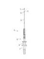
도 1은 본 개시의 예시적인 실시예에 따른 장치의 종 방향 측면도를 도시한다.
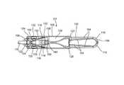
도 2는 도 1의 장치에 따른 클립의 부분적으로 투명한 종 방향 측면도를 도시한다.
도 3은 개방 구성에서 도 2의 클립의 다른 부분적으로 투명한 종 방향 측면도를 도시한다.
도 4는 도 2의 클립의 종축을 중심으로 90도 회전된 개방 구성에서 부분적으로 투명한 다른 종 방향 측면도를 도시한다.
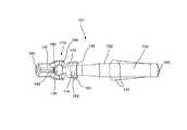
도 5는 도 2의 클립의 전개 기구, 잠금 기구 및 클립 아암의 사시도를 도시한다.
도 6은 도 2의 클립의 전개 기구 및 잠금 기구의 사시도를 도시한다.
도 7은 도 2의 클립의 전개 기구 및 클립 아암의 종 방향 측면도를 도시한다.1 shows a longitudinal side view of a device according to an exemplary embodiment of the present disclosure;
FIG. 2 shows a partially transparent longitudinal side view of a clip according to the device of FIG. 1 ;
3 shows another partially transparent longitudinal side view of the clip of FIG. 2 in an open configuration;
FIG. 4 shows another longitudinal side view partially transparent in an open configuration rotated 90 degrees about the longitudinal axis of the clip of FIG. 2 ;
FIG. 5 shows a perspective view of a deployment mechanism, a locking mechanism and a clip arm of the clip of FIG. 2 ;
Fig. 6 shows a perspective view of the deployment mechanism and locking mechanism of the clip of Fig. 2;
Fig. 7 shows a longitudinal side view of the clip arm and the deployment mechanism of the clip of Fig. 2;
본 개시는 다음의 설명 및 첨부 도면을 참조하여 추가로 이해될 수 있으며, 여기서 동일한 요소는 동일한 참조 부호로 지칭된다. 본 개시는 내부 조직 천공, 결함 및/또는 출혈을 치료하기 위한 내시경 클리핑 장치에 관한 것이다. 몇몇 실시예에서, 표적 부위의 시각화를 개선하고 다중 클립을 배치할 때 더 양호한 조작성을 허용하기 위해서 더 짧은 전개 클립이 선호될 수 있다. 본 개시의 예시적인 실시예는 원하는 대로 표적 조직을 클리핑하기 위해서 개방 구성과 폐쇄 구성 사이에서 클립을 이동시키도록 캡슐 내에서 활주 가능한 단일체 요소를 통해 규정된 클립 아암을 포함하는 클립을 설명한다. 단일체 요소는 캡슐을 포함하는 다른 종래의 클립 디자인에 비해 전개된 클립의 길이를 줄이기 위해서 별도의 전개 기구 및 잠금 기구에 연결된다. 본 명세서에 사용된 바와 같은 용어 근위 및 원위는 각각, 장치의 사용자를 향하는 방향 및 사용자로부터 멀어지는 방향을 지칭하는 것으로 의도된다는 것이 당업자에 의해 이해될 것이다.BRIEF DESCRIPTION OF THE DRAWINGS The present disclosure may be further understood with reference to the following description and accompanying drawings, wherein like elements are referred to by like reference numerals. The present disclosure relates to an endoscopic clipping device for treating internal tissue perforation, defect and/or bleeding. In some embodiments, shorter deployment clips may be preferred to improve visualization of the target site and to allow better maneuverability when placing multiple clips. Exemplary embodiments of the present disclosure describe a clip comprising a clip arm defined through a monolithic element slidable within a capsule to move the clip between an open configuration and a closed configuration to clip target tissue as desired. The monolithic element is connected to a separate deployment mechanism and locking mechanism to reduce the length of the deployed clip compared to other conventional clip designs including capsules. It will be understood by those skilled in the art that the terms proximal and distal as used herein are intended to refer to a direction toward and away from the user of the device, respectively, respectively.
도 1 내지 도 7에 도시된 바와 같이, 본 개시의 예시적인 실시예에 따른 클립 장치(100)는 클립 아암(104)의 원위 단부(108)가 서로 분리되는 개방 구성과 원위 단부(108)가 조직을 파지하기 위해서 서로를 향해 당겨지는 폐쇄 구성 사이에서 클립 아암(104)을 이동시키도록 캡슐(106) 내에 수용된 한 쌍의 클립 아암(104)을 규정하는 단일체 요소(102)를 포함하는 클립(101)을 포함한다. 실시예에서, 단일체 요소(102)는 제 1 단부(110)로부터 제 2 단부(112)로 연장하고, 예를 들어 클립 아암(104)을 규정하기 위해서 조인트 또는 중간점(114)에서 구부러진다. 중간점(114)은 인장 부재(118) 및 요크(120)를 포함하는 전개 기구(116)에 연결되며, 이는 캡슐(106) 내에 활주 가능하게 수용되어 클립 아암(104)을 개방 구성과 폐쇄 구성 사이에서 이동시킨다.1 to 7 , the
잠금 기구(122)는 단일체 요소(102) 및 전개 기구(116)에 커플링되어, 클립(101)이 신체의 표적 조직 위에 전개될 때, 클립(101)은 폐쇄 구성으로 잠겨진다. 일 실시예에서, 도 1에 도시된 바와 같이, 클립(101)은 근위 단부가 사용자에게 접근 가능한 신체 외부에 남아 있는 동안 내시경의 작업 채널을 통해 신체 내의 표적 부위에 클립(101)의 삽입을 용이하게 하는 크기인 장치(100)의 세장형 근위 부분(160)에 해제 가능하게 커플링된다. 근위 부분(160)은 예를 들어, 사용자가 클립(101)의 이동 및 전개를 제어할 수 있게 하는 작동기(164)를 포함하는 핸들 부재(162) 및 핸들 부재(162)로부터 클립(101)으로 원위 방향으로 연장하는 가요성 샤프트(166)를 포함할 수 있으며, 가요성 샤프트(166)의 원위 단부(168)는 예를 들어, 부싱(172)을 통해 클립(101)에 해제 가능하게 커플링된다. 사용자는 작동기(164)를 조작하여 클립 아암(104)에 연결되도록 가요성 샤프트(166)를 통해서 핸들 부재(162)로부터 연장하는 제어 부재(170)를 이동시킴으로써, 개방 구성과 폐쇄 구성 사이에서 클립 아암(104)의 이동을 제어한다.The
캡슐(106)은 근위 단부(124)로부터 원위 단부(126)로 연장하고 이를 통해 연장하는 채널(128)을 포함한다. 일 실시예에서, 근위 단부(124)는 캡슐(106)의 근위 단부(124)에서 탭(130)을 통해 장치의 근위 부분에 해제 가능하게 커플링되도록 구성되며, 이는 근위 부분의 대응 부분과 맞물리도록 반경 방향 내측으로 크림핑될 수 있다. 캡슐(106)은 또한, 예를 들어 아래에서 더 상세히 설명되는 바와 같이, 잠금 기구(122)의 일부분과 맞물리기 위해 캡슐 벽을 통해 측 방향으로 연장하는 잠금 창(132)과 같은 캡슐 벽에 형성된 잠금 특징부를 포함한다.The
일 실시예에서, 캡슐(106)은 7.5 mm 내지 8.55 mm 범위의 길이를 가질 수 있다. 이러한 실시예의 캡슐(106)은 12.5 mm 내지 13.5 mm 범위의 길이를 가질 수 있는 몇몇 종래 클립의 캡슐 길이보다 실질적으로 더 짧다. 아래에서 더 자세히 설명될 클립 아암(104)과 별도의 잠금 기구(122)의 단일체 설계는 클립 아암(104)의 개방 폭을 희생함이 없이 캡슐(106)이 몇몇 기존 클립에 비해 더 짧은 길이를 갖게 한다는 것을 당업자는 이해할 것이다.In one embodiment, the
전술한 바와 같이, 클립 아암(104)은 제 1 단부(110)로부터 제 2 단부(112)까지의 길이를 따라 연장하고 예를 들어, 클립 아암(104)이 중간점(114)의 대향 측면, 예를 들어 제 1 및 제 2 단부(110, 112)의 근위부로부터 연장하는 길이의 일부분을 따라 연장하도록 중간점(114)에서 구부러지는 단일체 요소(102)로 형성된다. 따라서, 단일체 요소(102)의 제 1 및 제 2 단부(110, 112)는 클립 아암(104)의 원위 단부(108)에 대응한다. 중간점(114)은 클립 아암(104)이 개방 구성과 폐쇄 구성 사이에서 이동할 수 있도록 캡슐(106)의 채널(128) 내에 활주 가능하게 수용되는 전개 기구(116)에 연결된다.As noted above, the
일 실시예에서, 클립 아암(104)은 캡슐(106)의 원위 방향으로 전진할 때 클립 아암(104)이 그 자연스런 편향 하에서 개방 구조로 서로 이격되도록 개방 구성을 향해 편향된다. 아암(104)이 캡슐(106) 내로 근위 방향으로 당겨질 때, 클립 아암(104)은 캡슐(106)의 벽에 의해 구속되고 원위 단부(108)가 서로 인접한 폐쇄 위치로 함께 당겨진다. 당업자는 클립 아암(104)을 개폐하기 위한 임의의 수의 다른 기구가 사용될 수 있음을 이해할 것이다. 예시적인 실시예가 클립 아암(104)을 형성하기 위해 굽힘부를 포함하는 단일체 요소(102)를 도시하고 설명하지만, 대안적인 실시예에서 근위 단부가 인장 부재(118)에 연결될 수 있도록 클립 아암의 근위 단부가 서로에 부착될 수 있다는 것이 또한, 당업자에 의해 이해될 것이다.In one embodiment, the
이 실시예의 클립 아암(104)은 또한, 그로부터 연장하고 캡슐(106)의 일부분과 맞물리도록 구성된 맞물림 특징부(134)를 포함하여 맞물림 특징부(134)가 캡슐(106)과 맞물릴 때, 클립 아암(104)은 캡슐(106) 내로 근위 방향으로 추가로 이동되는 것이 방지된다. 일 실시예에서, 맞물림 특징부(134)는 맞물림 특징부(134)의 원위에 있는 클립 아암(104)의 부분이 맞물림 특징부(134)의 근위에 있는 클립 아암(104)의 부분보다 더 큰 폭을 갖도록 클립 아암(104)의 부분으로부터 측 방향 외측으로 연장한다. 맞물림 특징부(134)의 근위 방향으로 연장하는 클립 아암(104)의 부분은 클립 아암(104)의 이들 부분이 캡슐(106) 내로 근위 방향으로 당겨되게 하는 크기이다.The
클립 아암(104)의 근위 부분이 캡슐(106) 내로 근위 방향으로 당겨질 때, 맞물림 특징부(134)는 클립 아암(104)이 캡슐(106) 내로 근위 방향으로 추가로 당겨지는 것을 방지하는 캡슐(106)의 원위 면(127)의 일부분과 접한다. 맞물림 특징부(134)는 클립 아암(104)의 길이를 따라 위치 설정되어 맞물림 특징부(134)가 캡슐(106)과 맞물린 지점에서 클립 아암(104)이 폐쇄 구성으로 함께 클립 아암(104)을 당기기 위해 캡슐(106) 내로 충분히 근위 방향으로 당겨진다. 일 예에서, 맞물림 특징부(134)는 클립 아암(104)의 종 방향 에지로부터 측 방향으로 연장하는 날개로서 구성된다.When the proximal portion of the
인장 부재(118)는 요크(120)에 해제 가능하게 커플링되도록 구성된 근위 단부(136)로부터 예를 들어, 핀(140)을 통해 단일체 요소(102)의 중간점(114)에 부착된 원위 단부(138)로 연장한다. 일 실시예에서, 원위 단부(138)는 원위 단부(138)를 가로질러 직경 방향으로 연장하는 핀(140)이 중간점(114)에서 단일체 요소(102)의 굽힘부에 의해 규정되는 클립 아암(104)의 근위 단부(158)에서 실질적으로 라운드 공간 내에 수용되도록 중간점(114) 위로 연장한다. 환언하면, 핀(140)은 중간점(114)의 굽힘부를 따라서 단일체 요소(102)의 내부 표면을 따라 한 쌍의 아암(104) 사이에서 연장하도록 핀(140)이 중간점(114)의 바로 원위 방향으로 연장한다. 인장 부재(118) 및 핀(140)은 캡슐(106)에 대한 인장 부재(118)의 종 방향 이동이 캡슐(106)에 대한 클립 아암(104)을 대응하게 이동시키도록 단일체 요소(102)에 연결된다. 인장 부재(118)의 근위 단부(136)는 요크(120)의 대응하는 크기 및 형상 부분에 맞물리는 크기 및 형상을 가진다. 일 실시예에서, 근위 단부(136)는 실질적으로 C-형상 돌출부를 포함한다.
요크(120)는 예를 들어, 당김 와이어와 같은 제어 부재에 연결되도록 구성된 근위 단부(142)로부터 인장 부재(118)의 근위 단부(136)에 해제 가능하게 맞물리도록 구성된 원위 단부(144)로 연장한다. 일 실시예에서, 원위 단부(144)는 근위 단부(136)의 C-형상 돌출부를 수용하도록 크기와 형상을 갖는 실질적으로 C-형상 오목부(146)를 포함한다. 인장 부재(118)의 근위 단부(136)와 요크(120)의 원위 단부(144)는 아래에서 더 상세히 설명되는 바와 같이 미리 결정된 힘을 받을 때 서로 분리되도록 구성된다.The
일 실시예에서, 요크(120)의 적어도 일부분을 따르는 폭은 캡슐(106)의 채널(128)의 폭(예를 들어, 직경)에 실질적으로 대응하여, 요크(120)가 갭슐(106)의 근위 단부(124) 내에 위치될 때 요크(120)는 탭(130)과 맞물려 탭(130)을 장치의 근위 부분과 맞물리지 않게 반경 방향 외측으로 이동시킨다. 요크(120)는 또한, 그 일부분으로부터 원위 방향으로 연장하는 한 쌍의 오버행(148)를 포함한다. 아래에서 더 상세히 설명되는 바와 같이, 오버행(148)은 잠금 기구(122)의 잠금 아암(152)의 근위 단부(154)를 구속하도록 구성되어 클립(101)이 표적 조직 위에 전개될 때까지 잠금 아암(154)이 캡슐(106)의 잠금 특징부(134)에 맞물리는 것이 방지된다.In one embodiment, the width along at least a portion of the
잠금 기구(122)는 인장 부재(118)에 부착되고, 전술한 바와 같이 클립(101)이 전개될 때까지 요크(120)에 의해 구속되는 잠금 아암(152)을 포함한다. 일 실시예에서, 잠금 기구(122)는 링(150) 및 링(150)으로부터 근위 방향으로 연장하는 한 쌍의 잠금 아암(152)을 포함한다. 링(150)은 인장 부재(118)를 클립 아암(104)에 연결하는 동일한 핀(140)을 통해 인장 부재(118)에 부착된다. 특히, 핀(140)은 링(150)이 인장 부재(118)의 원위 단부(138)와 클립 아암(104)의 근위 단부(158) 모두에 대해 연장하도록 링(150)을 가로질러 직경 방향으로 연장한다.The
잠금 아암(152)은 링(150)의 대향 측부로부터 근위 단부(154)까지 근위 방향으로 연장하고, 일 실시예에서 반경방향 외측으로 편향된다. 링(150)은 로킹 아암(152)이 요크(120)의 오버행(148)을 통해 구속되게 인장 부재(118)의 대향 측면을 따라 연장하도록 인장 부재(118)에 연결된다. 잠금 아암(152)의 근위 단부(154)는 근위 단부(154)가 그 편향 구성으로 복귀하도록 허용될 때, 잠금 구조(156)가 캡슐(106)의 잠금 특징부(132)와 맞물리도록 그로부터 연장하는 잠금 구조물(156)을 포함한다. 일 실시예에서, 잠금 구조물(156)은 근위 단부(154)가 오버행(148)으로부터 해제될 때, 캡슐(106)의 잠금 창(132)과 맞물리도록 근위 단부(154)로부터 연장하는 잠금 탭으로서 구성된다. 아래에서 더 상세히 설명되는 바와 같이, 근위 단부(154)는 미리 결정된 힘이 인장 부재(118)로부터 요크(120)를 분리하기 위해 요크(120)에 가해질 때 그 반경 방향 외측으로 편향된 구성으로 복귀하도록 해제되고 허용된다.Locking
예시적인 방법에 따르면, 클립 장치(100)의 클립(101)은 예를 들어, 내시경의 작동 채널을 통해 신체 내의 표적 부위에 삽입된다. 클립(101)은 폐쇄 구성에서 작업 채널을 통해 삽입되어 클립 아암(104)이 작업 채널의 내부에서 손상되지 않게 한다. 클립(101)이 표적 부위에 도달하면, 클립 아암(104)은 캡슐(106)에 대해 원위 방향으로 이동되어 클립 아암(104)의 원위 부분이 캡슐(106) 밖으로 연장하고 클립 아암(104)이 그 자연스런 편향 하에서 개방 구성을 향해 자유로이 이동함으로써 표적 조직이 클립 아암(104) 사이에 수용될 수 있다. 클립(101)은 조직의 표적 부분이 원하는 대로 클립 아암(104) 사이에 위치될 때까지 개방 구성과 폐쇄 구성 사이에서 반복적으로 이동될 수 있다. 그런 다음 사용자는 클립 아암(104)을 캡슐(106) 내로 근위 방향으로 당겨서 클립 아암(104)이 캡슐(106) 내로 당겨짐에 따라서 클립 아암(104)이 클립 아암(104)의 원위 단부(108) 사이의 표적 조직을 파지하기 위해 서로를 향해 당겨진다. 전술한 바와 같이, 클립(101)은 예를 들어, 요크(120)에 커플링된 제어 부재(170)의 이동을 통해 개방 구성과 폐쇄 구성 사이에서 이동될 수 있다.According to the exemplary method, the
클립(101)이 표적 조직을 파지하는 원하는 위치에 있다고 사용자가 만족할 때, 사용자는 미리 결정된 힘이 요크(120)를 인장 부재(118)로부터 근위 방향으로 당겨서 이들이 서로 분리될 때까지, 맞물림 특징부(134)가 전술된 바와 같이 캡슐(106)과 맞물린 후에 제어 부재(170)에 증가하는 근위 방향 힘을 가한다. 요크(120)가 인장 부재(118)로부터 분리됨에 따라서, 클립 아암(104)의 잠금 기구(122)의 근위 단부(154)는 요크(120)의 오버행(148)로부터 해제되어, 잠금 탭(156)이 캡슐(106)의 잠금 창(132)과 맞물릴 때까지 근위 단부(154)가 그 반경 방향 외측으로 편향된 구성을 향해 스프링 해제됨으로써 클립(101)을 폐쇄 구성으로 잠근다.When the user is satisfied that the
그 다음, 요크(120)는 캡슐(106)의 채널(128)에 대응하는 폭을 갖는 요크(120)의 일부분이 캡슐(106)의 근위 단부(124) 내에 위치될 때까지 캡슐(106)에 대해 (예를 들어, 그에 연결된 제어 부재를 통해)근위 방향으로 추가로 당겨질 수 있어서, 예를 들어 장치(100)의 근위 부분(160)의 부싱(172)과 맞물리지 않게 반경 방향 내측으로 크림핑된 탭(130)을 반경 방향 외측으로 압박하고 근위 부분(160)으로부터 클립(101)을 분리한다. 따라서, 근위 부분(160)이 신체로부터 제거될 수 있는 동안 클립(101)은 표적 조직 위에 클립된 채로 유지된다. 일 실시예에서, 클립(101)이 근위 부분(160)으로부터 분리될 때, 탭(130)은 그 반경 방향 내측으로 크림핑된 구성으로 복귀하여 인장 부재(118)로부터 분리되었지만 요크(120)는 캡슐(106)의 근위 단부(124)에 부착된 상태를 유지한다.The
이러한 실시예에서, 제어 부재(170)에 가해진 추가의 근위 방향 힘은 요크(120)로부터 제어 부재를 분리하고, 신체에 클립(101)을 남기고 제어 부재(170)를 포함하는 장치(100)의 근위 부분(160)이 그로부터 제거되게 한다. 다른 실시예에 따르면, 근위 부분(160)으로부터 캡슐(106)의 분리시, 요크(120)는 근위 부분(160) 및 요크(120)가 신체로부터 제거될 수 있는 동안 클립(101)이 신체 내에 유지되도록 캡슐(106) 밖으로 근위 방향으로 당겨질 수 있다.In such an embodiment, the additional proximal force applied to the
본 개시의 범주를 벗어남이 없이 다양한 변형이 본 개시에서 이루어질 수 있음은 당업자에게 자명할 것이다.It will be apparent to those skilled in the art that various modifications may be made in the present disclosure without departing from the scope thereof.
Claims (15)
Translated fromKorean근위 단부로부터 원위 단부까지 종 방향으로 연장하고 이를 통해 연장하는 채널을 포함하는 캡슐;
제 1 및 제 2 클립 아암(clip arm)으로서, 제 1 및 제 2 클립 아암이 개방 구성과 폐쇄 구성 사이에서 서로에 대해 이동 가능하도록 그 근위 단부가 채널 내에 수용되는 제 1 및 제 2 클립 아암;
제 1 및 제 2 클립 아암의 근위 단부에 연결된 인장 부재(tension member), 및 인장 부재에 해제 가능하게 커플링되고(coupled) 캡슐에 대해 종 방향으로 이동 가능하여 개방 구성과 폐쇄 구성 사이에서 제 1 및 제 2 클립 아암을 이동시키는 요크(yoke)를 포함하는 전개 기구로서, 인장 부재 및 요크는 인장 부재에 대한 미리 결정된 근위 방향 힘에 응답하여, 그 근위 부분으로부터 장치를 해제하기 위해서 서로 분리되도록 구성되는 전개 기구; 및
전개 기구에 커플링되고 요크가 인장 부재로부터 분리될 때, 폐쇄 구성에서 제 1 및 제 2 클립 아암을 잠그도록 캡슐의 대응하는 잠금 특징부와 맞물리도록 구성되는 한 쌍의 잠금 핑거(locking finger)를 포함하는 잠금 기구를 포함하는,
조직 치료 장치.A tissue treatment device comprising:
a capsule extending longitudinally from the proximal end to the distal end and comprising a channel extending therethrough;
first and second clip arms, the proximal ends of which are received within the channel such that the first and second clip arms are movable relative to each other between an open configuration and a closed configuration;
a tension member connected to the proximal ends of the first and second clip arms, and a tension member releasably coupled to the tension member and movable in a longitudinal direction relative to the capsule to allow a first change between an open configuration and a closed configuration. and a yoke for moving the second clip arm, wherein the tension member and the yoke are configured to disengage from each other to release the device from the proximal portion in response to a predetermined proximal force on the tension member. becoming a deployment mechanism; and
a pair of locking fingers coupled to the deployment mechanism and configured to engage corresponding locking features of the capsule to lock the first and second clip arms in a closed configuration when the yoke is disengaged from the tension member; a locking mechanism comprising:
tissue therapy device.
제 1 및 제 2 클립 아암은 제 1 단부로부터 제 2 단부로 연장하고 그 일부분을 따르는 굽힘부(bend)를 포함하는 단일체 클리핑 요소(one-piece clipping element)를 통해 규정되며, 굽힘부는 단일체 클리핑 요소의 중간점(midpoint)을 따라 연장되어 제 1 및 제 2 클립 아암의 길이가 실질적으로 상응하는,
조직 치료 장치.The method of claim 1,
The first and second clip arms are defined through a one-piece clipping element extending from the first end to the second end and including a bend along a portion thereof, the bend being the one-piece clipping element. extending along the midpoint of the first and second clip arms to substantially correspond in length;
tissue therapy device.
인장 부재의 원위 단부는 인장 부재의 원위 단부를 가로질러 직경 방향으로 연장하는 핀을 통해 그리고 클립 아암의 근위 단부에 형성된 실질적으로 라운드 공간(rounded space)을 통해 단일체 클리핑 요소를 따르는 굽힘부를 통해 클립 아암의 근위 단부에 연결되는,
조직 치료 장치.3. The method of claim 2,
The distal end of the tension member passes through a pin extending diametrically across the distal end of the tension member and through a bend along the monolithic clipping element through a substantially rounded space formed at the proximal end of the clip arm. connected to the proximal end of
tissue therapy device.
잠금 기구는 핀을 통해 인장 부재의 원위 단부에 커플링된 링(ring)을 포함하며, 한 쌍의 잠금 핑거는 링으로부터 근위 방향으로 연장하는,
조직 치료 장치.4. The method of claim 3,
The locking mechanism includes a ring coupled to the distal end of the tension member via a pin, the pair of locking fingers extending proximally from the ring;
tissue therapy device.
잠금 핑거는 반경 방향 외측으로 편향되고 그 근위 단부로부터 연장하는 잠금 구조물을 포함하는,
조직 치료 장치.5. The method according to any one of claims 1 to 4,
the locking finger comprising a locking structure biased radially outwardly and extending from a proximal end thereof;
tissue therapy device.
요크는, 요크에 대해 잠금 핑거의 근위 단부를 구속하고 요크가 인장 부재로부터 분리될 때까지 잠금 구조물이 캡슐의 잠금 특징부에 맞물리는 것을 방지하는 한 쌍의 오버행(overhang)을 포함하는,
조직 치료 장치.6. The method of claim 5,
wherein the yoke includes a pair of overhangs that restrain the proximal end of the locking finger relative to the yoke and prevent the locking structure from engaging the locking feature of the capsule until the yoke is disengaged from the tension member.
tissue therapy device.
캡슐은 약 7.5 mm 내지 8.5 mm 범위의 길이를 가지는,
조직 치료 장치.7. The method according to any one of claims 1 to 6,
The capsule has a length in the range of about 7.5 mm to 8.5 mm,
tissue therapy device.
제 1 및 제 2 클립 아암은 개방 구성을 향해 편향되어, 제 1 및 제 2 클립 아암이 캡슐 내로 근위 방향으로 당겨질 때, 제 1 및 제 2 클립 아암이 폐쇄 구성을 향해 구속되고, 제 1 및 제 2 클립 아암이 캡슐 밖으로 원위 방향으로 이동될 때, 제 1 및 제 2 클립 아암이 그 편향된 개방 구성으로 복귀하게 하는,
조직 치료 장치.8. The method according to any one of claims 1 to 7,
The first and second clip arms are biased toward an open configuration such that when the first and second clip arms are pulled proximally into the capsule, the first and second clip arms are constrained toward the closed configuration, and the first and second clip arms are constrained toward the closed configuration. 2 causing the first and second clip arms to return to their biased open configuration when moved distally out of the capsule;
tissue therapy device.
근위 단부로부터 원위 단부로 종 방향으로 연장하고 이를 통해 연장하는 채널을 포함하는 캡슐을 포함하는 클립으로서, 제 1 및 제 2 클립 아암의 근위 단부는 개방 구성과 폐쇄 구성 사이에서 서로에 대해 제 1 및 제 2 클립 아암을 이동시키기 위해서 캡슐의 채널 내에 활주 가능하게 수용되는, 클립;
제 1 및 제 2 클립 아암의 근위 단부에 연결되는 인장 부재, 인장 부재에 해제 가능하게 커플링되고 캡슐에 대해 이동 가능하여 개방 구성과 폐쇄 구성 사이에서 제 1 및 제 2 클립 아암을 이동시키는 제어 부재에 커플링 가능한 요크를 포함하는 전개 기구로서, 인장 부재 및 요크는 인장 부재에 대한 미리 결정된 근위 방향 힘에 응답하여 분리되도록 구성되는, 전개 기구;
전개 기구에 커플링되고 요크가 인장 부재로부터 분리될 때, 폐쇄 구성에서 제 1 및 제 2 클립 아암을 잠그도록 캡슐의 대응하는 잠금 특징부와 맞물리도록 구성되는 한 쌍의 잠금 핑거(locking finger)를 포함하는, 잠금 기구; 및
캡슐의 근위 단부에 해제 가능하게 커플링되어, 인장 부재로부터 요크가 분리될 때, 클립이 근위 부분으로부터 해제되고 표적 조직 위의 신체 내에서 전개되는, 근위 부분을 포함하는,
클리핑 장치.A clipping device comprising:
A clip comprising a capsule extending longitudinally from a proximal end to a distal end and comprising a channel extending therethrough, wherein the proximal ends of the first and second clip arms are first and relative to each other between an open configuration and a closed configuration. a clip slidably received within the channel of the capsule for moving the second clip arm;
a tension member connected to the proximal ends of the first and second clip arms, a control member releasably coupled to the tension member and movable relative to the capsule to move the first and second clip arms between an open configuration and a closed configuration a deployment instrument comprising a yoke coupleable to the deployment instrument, wherein the tension member and the yoke are configured to disengage in response to a predetermined proximal force on the tension member;
a pair of locking fingers coupled to the deployment mechanism and configured to engage corresponding locking features of the capsule to lock the first and second clip arms in a closed configuration when the yoke is disengaged from the tension member; a locking mechanism comprising; and
a proximal portion releasably coupled to the proximal end of the capsule, wherein when the yoke is disengaged from the tension member, the clip releases from the proximal portion and deploys within the body over the target tissue;
clipping device.
제 1 및 제 2 클립 아암은 제 1 단부로부터 제 2 단부로 연장하고 그 일부분을 따르는 굽힘부를 포함하는 단일체 클리핑 요소를 통해 규정되며, 굽힘부는 단일체 클리핑 요소의 중간점을 따라 연장되어 제 1 및 제 2 클립 아암의 길이가 실질적으로 상응하는,
클리핑 장치.10. The method of claim 9,
The first and second clip arms are defined through a monolithic clipping element extending from the first end to the second end and including a bend along a portion thereof, the bend extending along a midpoint of the monolithic clipping element to extend the first and second ends. 2 the length of the clip arm substantially corresponding,
clipping device.
인장 부재의 원위 단부는 인장 부재의 원위 단부를 가로질러 직경 방향으로 연장하는 핀을 통해 그리고 클립 아암의 근위 단부에 형성된 실질적으로 라운드 공간을 통해 단일체 클리핑 요소를 따르는 굽힘부를 통해 클립 아암의 근위 단부에 연결되는,
클리핑 장치.11. The method of claim 10,
The distal end of the tension member is connected to the proximal end of the clip arm through a pin extending diametrically across the distal end of the tension member and through a bend along the monolithic clipping element through a substantially round space formed at the proximal end of the clip arm. connected,
clipping device.
잠금 기구는 핀을 통해 인장 부재의 원위 단부에 커플링된 링을 포함하며, 한 쌍의 잠금 핑거는 링으로부터 근위 방향으로 연장하는,
클리핑 장치.12. The method of claim 11,
the locking mechanism includes a ring coupled to the distal end of the tension member via a pin, the pair of locking fingers extending proximally from the ring;
clipping device.
잠금 핑거는 반경 방향 외측으로 편향되고 그 근위 단부로부터 연장하는 잠금 구조물을 포함하는,
클리핑 장치.12. The method according to any one of claims 9 to 11,
the locking finger comprising a locking structure biased radially outwardly and extending from a proximal end thereof;
clipping device.
요크는, 요크에 대해 잠금 핑거의 근위 단부를 구속하고 요크가 인장 부재로부터 분리될 때까지 잠금 구조물이 캡슐의 잠금 특징부에 맞물리는 것을 방지하는 한 쌍의 오버행을 포함하는,
클리핑 장치.14. The method of claim 13,
wherein the yoke includes a pair of overhangs that restrain the proximal end of the locking finger relative to the yoke and prevent the locking structure from engaging the locking feature of the capsule until the yoke is disengaged from the tension member.
clipping device.
캡슐은 약 7.5 mm 내지 8.5 mm 범위의 길이를 가지는,
클리핑 장치.15. The method according to any one of claims 9 to 14,
The capsule has a length in the range of about 7.5 mm to 8.5 mm,
clipping device.
Priority Applications (1)
| Application Number | Priority Date | Filing Date | Title |
|---|---|---|---|
| KR1020247022622AKR102814683B1 (en) | 2019-06-18 | 2020-06-10 | Hemostasis clip short system |
Applications Claiming Priority (3)
| Application Number | Priority Date | Filing Date | Title |
|---|---|---|---|
| US201962863016P | 2019-06-18 | 2019-06-18 | |
| US62/863,016 | 2019-06-18 | ||
| PCT/US2020/037037WO2020257024A1 (en) | 2019-06-18 | 2020-06-10 | Hemostasis clip short system |
Related Child Applications (1)
| Application Number | Title | Priority Date | Filing Date |
|---|---|---|---|
| KR1020247022622ADivisionKR102814683B1 (en) | 2019-06-18 | 2020-06-10 | Hemostasis clip short system |
Publications (2)
| Publication Number | Publication Date |
|---|---|
| KR20210130731Atrue KR20210130731A (en) | 2021-11-01 |
| KR102683750B1 KR102683750B1 (en) | 2024-07-10 |
Family
ID=71948708
Family Applications (3)
| Application Number | Title | Priority Date | Filing Date |
|---|---|---|---|
| KR1020217027744AActiveKR102683750B1 (en) | 2019-06-18 | 2020-06-10 | Hemostatic clip device shortening system for tissue |
| KR1020257017357APendingKR20250085837A (en) | 2019-06-18 | 2020-06-10 | Hemostasis clip short system |
| KR1020247022622AActiveKR102814683B1 (en) | 2019-06-18 | 2020-06-10 | Hemostasis clip short system |
Family Applications After (2)
| Application Number | Title | Priority Date | Filing Date |
|---|---|---|---|
| KR1020257017357APendingKR20250085837A (en) | 2019-06-18 | 2020-06-10 | Hemostasis clip short system |
| KR1020247022622AActiveKR102814683B1 (en) | 2019-06-18 | 2020-06-10 | Hemostasis clip short system |
Country Status (8)
| Country | Link |
|---|---|
| US (3) | US11484314B2 (en) |
| EP (2) | EP3905970B1 (en) |
| JP (3) | JP7368487B2 (en) |
| KR (3) | KR102683750B1 (en) |
| CN (2) | CN119655819A (en) |
| AU (1) | AU2020295355B2 (en) |
| CA (1) | CA3129467A1 (en) |
| WO (1) | WO2020257024A1 (en) |
Families Citing this family (3)
| Publication number | Priority date | Publication date | Assignee | Title |
|---|---|---|---|---|
| CA3129467A1 (en)* | 2019-06-18 | 2020-12-24 | Boston Scientific Scimed, Inc. | Hemostasis clip short system |
| CN118632664A (en)* | 2022-02-09 | 2024-09-10 | 波士顿科学国际有限公司 | Locking feature for hemostatic clips |
| JP2025517539A (en)* | 2022-09-27 | 2025-06-05 | ボストン サイエンティフィック サイムド,インコーポレイテッド | Locking mechanism for hemostatic clips |
Citations (3)
| Publication number | Priority date | Publication date | Assignee | Title |
|---|---|---|---|---|
| WO2004017839A1 (en)* | 2002-08-21 | 2004-03-04 | Olympus Corporation | Ligating device for biological tissue |
| WO2009155286A1 (en)* | 2008-06-19 | 2009-12-23 | Boston Scientific Scimed, Inc. | Hemostatic clipping devices and methods |
| US20100217294A1 (en)* | 2002-08-21 | 2010-08-26 | Olympus Corporation | Living tissue ligation device |
Family Cites Families (20)
| Publication number | Priority date | Publication date | Assignee | Title |
|---|---|---|---|---|
| DE4319829C1 (en)* | 1993-06-16 | 1994-08-25 | Lerch Karl Dieter | Set for treating vascular deformities |
| JP4472217B2 (en) | 2000-10-16 | 2010-06-02 | オリンパス株式会社 | Biological tissue clip device |
| US6991634B2 (en)* | 2001-05-23 | 2006-01-31 | Pentax Corporation | Clip device of endoscope |
| US7094245B2 (en)* | 2001-10-05 | 2006-08-22 | Scimed Life Systems, Inc. | Device and method for through the scope endoscopic hemostatic clipping |
| WO2003053256A1 (en)* | 2001-12-13 | 2003-07-03 | Sumitomo Bakelite Company Limited | Clip device for endoscope and clip for endoscope for use therein |
| JP4242614B2 (en) | 2002-08-21 | 2009-03-25 | オリンパス株式会社 | Biological tissue ligation device |
| EP1670365B1 (en)* | 2003-09-30 | 2018-12-05 | Boston Scientific Scimed, Inc. | Apparatus for deployment of a hemostatic clip |
| US7494461B2 (en) | 2003-09-30 | 2009-02-24 | Boston Scientific Scimed, Inc. | Through the scope tension member release clip |
| JP4758173B2 (en)* | 2004-12-24 | 2011-08-24 | オリンパス株式会社 | Ligation device |
| JP5244816B2 (en) | 2006-12-05 | 2013-07-24 | クック メディカル テクノロジーズ エルエルシー | Combination therapy hemostatic clip |
| JP5006753B2 (en) | 2007-10-17 | 2012-08-22 | Hoya株式会社 | Endoscopic clip device |
| JP5588711B2 (en)* | 2010-03-30 | 2014-09-10 | 富士フイルム株式会社 | Ligation device |
| JP2013027458A (en) | 2011-07-27 | 2013-02-07 | Sony Corp | Information processing apparatus, information processing method, and program |
| JP5343113B2 (en)* | 2011-09-15 | 2013-11-13 | 富士フイルム株式会社 | Clip unit and ligating apparatus using the same |
| US9138234B2 (en) | 2011-11-14 | 2015-09-22 | Anrei Medical (Hz) Co., Ltd. | Clip apparatus for ligature of living tissue |
| US20140088616A1 (en)* | 2012-09-24 | 2014-03-27 | Boston Scientific Scimed, Inc. | Release mechanism for hemostatic clip |
| EP3487422B1 (en)* | 2016-08-22 | 2021-11-03 | Boston Scientific Limited | Hemostasis reloadable clipping device with sleeve engagement |
| CA3031692C (en)* | 2016-11-22 | 2021-01-19 | Boston Scientific Limited | Hemostasis reloadable clip release mechanism |
| WO2018106710A1 (en)* | 2016-12-06 | 2018-06-14 | Boston Scientific Scimed, Inc. | Compressive coupler for reloadable hemostasis clipping device |
| CA3129467A1 (en)* | 2019-06-18 | 2020-12-24 | Boston Scientific Scimed, Inc. | Hemostasis clip short system |
- 2020
- 2020-06-10CACA3129467Apatent/CA3129467A1/enactivePending
- 2020-06-10EPEP20751372.2Apatent/EP3905970B1/enactiveActive
- 2020-06-10EPEP21217039.3Apatent/EP4032485B1/enactiveActive
- 2020-06-10KRKR1020217027744Apatent/KR102683750B1/enactiveActive
- 2020-06-10KRKR1020257017357Apatent/KR20250085837A/enactivePending
- 2020-06-10CNCN202510094311.7Apatent/CN119655819A/enactivePending
- 2020-06-10KRKR1020247022622Apatent/KR102814683B1/enactiveActive
- 2020-06-10AUAU2020295355Apatent/AU2020295355B2/enactiveActive
- 2020-06-10WOPCT/US2020/037037patent/WO2020257024A1/ennot_activeCeased
- 2020-06-10JPJP2021551836Apatent/JP7368487B2/enactiveActive
- 2020-06-10USUS16/898,130patent/US11484314B2/enactiveActive
- 2020-06-10CNCN202080042308.6Apatent/CN113924051B/enactiveActive
- 2022
- 2022-09-29USUS17/936,726patent/US12076015B2/enactiveActive
- 2023
- 2023-08-04JPJP2023127658Apatent/JP7635313B2/enactiveActive
- 2024
- 2024-07-31USUS18/790,650patent/US20240390005A1/enactivePending
- 2025
- 2025-02-12JPJP2025020420Apatent/JP2025072594A/enactivePending
Patent Citations (4)
| Publication number | Priority date | Publication date | Assignee | Title |
|---|---|---|---|---|
| WO2004017839A1 (en)* | 2002-08-21 | 2004-03-04 | Olympus Corporation | Ligating device for biological tissue |
| US20100217294A1 (en)* | 2002-08-21 | 2010-08-26 | Olympus Corporation | Living tissue ligation device |
| EP2455009A2 (en)* | 2002-08-21 | 2012-05-23 | Olympus Corporation | Ligating device for biological tissue |
| WO2009155286A1 (en)* | 2008-06-19 | 2009-12-23 | Boston Scientific Scimed, Inc. | Hemostatic clipping devices and methods |
Also Published As
| Publication number | Publication date |
|---|---|
| KR20240110115A (en) | 2024-07-12 |
| EP3905970B1 (en) | 2022-12-14 |
| EP4032485A1 (en) | 2022-07-27 |
| KR102814683B1 (en) | 2025-05-29 |
| CA3129467A1 (en) | 2020-12-24 |
| US20230014853A1 (en) | 2023-01-19 |
| JP2025072594A (en) | 2025-05-09 |
| JP2023162219A (en) | 2023-11-08 |
| WO2020257024A1 (en) | 2020-12-24 |
| CN113924051A (en) | 2022-01-11 |
| CN113924051B (en) | 2025-02-11 |
| JP2022522496A (en) | 2022-04-19 |
| US11484314B2 (en) | 2022-11-01 |
| AU2020295355B2 (en) | 2022-12-15 |
| US20240390005A1 (en) | 2024-11-28 |
| AU2020295355A1 (en) | 2021-08-12 |
| JP7368487B2 (en) | 2023-10-24 |
| US12076015B2 (en) | 2024-09-03 |
| US20200397436A1 (en) | 2020-12-24 |
| KR102683750B1 (en) | 2024-07-10 |
| CN119655819A (en) | 2025-03-21 |
| JP7635313B2 (en) | 2025-02-25 |
| KR20250085837A (en) | 2025-06-12 |
| EP3905970A1 (en) | 2021-11-10 |
| EP4032485B1 (en) | 2025-05-07 |
Similar Documents
| Publication | Publication Date | Title |
|---|---|---|
| JP7477548B2 (en) | Hemostatic clip | |
| JP7230229B2 (en) | Deployment of hemostatic clips | |
| JP7635313B2 (en) | Hemostatic Clip Shortening System | |
| KR102688538B1 (en) | Clipping device having a deployment mechanism to shorten the length of the deployed clip | |
| KR102798107B1 (en) | Hemostasis clip to eliminate shed parts | |
| JP7153806B2 (en) | Hemostatic clip with compressible capsule |
Legal Events
| Date | Code | Title | Description |
|---|---|---|---|
| PA0105 | International application | St.27 status event code:A-0-1-A10-A15-nap-PA0105 | |
| PA0201 | Request for examination | St.27 status event code:A-1-2-D10-D11-exm-PA0201 | |
| P11-X000 | Amendment of application requested | St.27 status event code:A-2-2-P10-P11-nap-X000 | |
| P13-X000 | Application amended | St.27 status event code:A-2-2-P10-P13-nap-X000 | |
| PG1501 | Laying open of application | St.27 status event code:A-1-1-Q10-Q12-nap-PG1501 | |
| E902 | Notification of reason for refusal | ||
| PE0902 | Notice of grounds for rejection | St.27 status event code:A-1-2-D10-D21-exm-PE0902 | |
| P11-X000 | Amendment of application requested | St.27 status event code:A-2-2-P10-P11-nap-X000 | |
| P13-X000 | Application amended | St.27 status event code:A-2-2-P10-P13-nap-X000 | |
| E701 | Decision to grant or registration of patent right | ||
| PE0701 | Decision of registration | St.27 status event code:A-1-2-D10-D22-exm-PE0701 | |
| PA0104 | Divisional application for international application | St.27 status event code:A-0-1-A10-A18-div-PA0104 St.27 status event code:A-0-1-A10-A16-div-PA0104 | |
| PR0701 | Registration of establishment | St.27 status event code:A-2-4-F10-F11-exm-PR0701 | |
| PR1002 | Payment of registration fee | St.27 status event code:A-2-2-U10-U12-oth-PR1002 Fee payment year number:1 | |
| PG1601 | Publication of registration | St.27 status event code:A-4-4-Q10-Q13-nap-PG1601 |