KR20210127805A - Automated storage and retrieval system - Google Patents
Automated storage and retrieval systemDownload PDFInfo
- Publication number
- KR20210127805A KR20210127805AKR1020217032922AKR20217032922AKR20210127805AKR 20210127805 AKR20210127805 AKR 20210127805AKR 1020217032922 AKR1020217032922 AKR 1020217032922AKR 20217032922 AKR20217032922 AKR 20217032922AKR 20210127805 AKR20210127805 AKR 20210127805A
- Authority
- KR
- South Korea
- Prior art keywords
- payload
- pickface
- frame
- extension
- arms
- Prior art date
- Legal status (The legal status is an assumption and is not a legal conclusion. Google has not performed a legal analysis and makes no representation as to the accuracy of the status listed.)
- Granted
Links
- 230000000694effectsEffects0.000claimsabstractdescription23
- 230000033001locomotionEffects0.000claimsdescription59
- 238000000034methodMethods0.000claimsdescription33
- 238000009966trimmingMethods0.000claimsdescription30
- 241001061260Emmelichthys struhsakeriSpecies0.000description79
- 239000012636effectorSubstances0.000description77
- 230000008878couplingEffects0.000description18
- 238000010168coupling processMethods0.000description18
- 238000005859coupling reactionMethods0.000description18
- 230000005540biological transmissionEffects0.000description14
- 230000014759maintenance of locationEffects0.000description9
- 241001061257EmmelichthyidaeSpecies0.000description6
- 230000008602contractionEffects0.000description6
- 230000001419dependent effectEffects0.000description3
- 238000010586diagramMethods0.000description3
- 238000012546transferMethods0.000description3
- XAGFODPZIPBFFR-UHFFFAOYSA-NaluminiumChemical compound[Al]XAGFODPZIPBFFR-UHFFFAOYSA-N0.000description2
- 229910052782aluminiumInorganic materials0.000description2
- 230000000712assemblyEffects0.000description2
- 238000000429assemblyMethods0.000description2
- 230000008901benefitEffects0.000description2
- 238000004891communicationMethods0.000description2
- 239000000463materialSubstances0.000description2
- 238000012986modificationMethods0.000description2
- 230000004048modificationEffects0.000description2
- 230000009467reductionEffects0.000description2
- OAICVXFJPJFONN-UHFFFAOYSA-NPhosphorusChemical compound[P]OAICVXFJPJFONN-UHFFFAOYSA-N0.000description1
- 239000000853adhesiveSubstances0.000description1
- 230000001070adhesive effectEffects0.000description1
- 238000012790confirmationMethods0.000description1
- 238000001514detection methodMethods0.000description1
- 238000007667floatingMethods0.000description1
- 230000001939inductive effectEffects0.000description1
- 238000007726management methodMethods0.000description1
- 229910052698phosphorusInorganic materials0.000description1
- 239000011574phosphorusSubstances0.000description1
- 230000008569processEffects0.000description1
- 238000007665saggingMethods0.000description1
- 230000000087stabilizing effectEffects0.000description1
- 230000003068static effectEffects0.000description1
- 238000010415tidyingMethods0.000description1
- 238000003466weldingMethods0.000description1
Images


Classifications
- B—PERFORMING OPERATIONS; TRANSPORTING
- B65—CONVEYING; PACKING; STORING; HANDLING THIN OR FILAMENTARY MATERIAL
- B65G—TRANSPORT OR STORAGE DEVICES, e.g. CONVEYORS FOR LOADING OR TIPPING, SHOP CONVEYOR SYSTEMS OR PNEUMATIC TUBE CONVEYORS
- B65G1/00—Storing articles, individually or in orderly arrangement, in warehouses or magazines
- B65G1/02—Storage devices
- B65G1/04—Storage devices mechanical
- B65G1/0492—Storage devices mechanical with cars adapted to travel in storage aisles
- B—PERFORMING OPERATIONS; TRANSPORTING
- B65—CONVEYING; PACKING; STORING; HANDLING THIN OR FILAMENTARY MATERIAL
- B65G—TRANSPORT OR STORAGE DEVICES, e.g. CONVEYORS FOR LOADING OR TIPPING, SHOP CONVEYOR SYSTEMS OR PNEUMATIC TUBE CONVEYORS
- B65G1/00—Storing articles, individually or in orderly arrangement, in warehouses or magazines
- B65G1/02—Storage devices
- B65G1/04—Storage devices mechanical
- B65G1/0407—Storage devices mechanical using stacker cranes
- B65G1/0414—Storage devices mechanical using stacker cranes provided with satellite cars adapted to travel in storage racks
- B—PERFORMING OPERATIONS; TRANSPORTING
- B65—CONVEYING; PACKING; STORING; HANDLING THIN OR FILAMENTARY MATERIAL
- B65G—TRANSPORT OR STORAGE DEVICES, e.g. CONVEYORS FOR LOADING OR TIPPING, SHOP CONVEYOR SYSTEMS OR PNEUMATIC TUBE CONVEYORS
- B65G1/00—Storing articles, individually or in orderly arrangement, in warehouses or magazines
- B65G1/02—Storage devices
- B65G1/04—Storage devices mechanical
- B65G1/0407—Storage devices mechanical using stacker cranes
- B65G1/0435—Storage devices mechanical using stacker cranes with pulling or pushing means on either stacking crane or stacking area
- B—PERFORMING OPERATIONS; TRANSPORTING
- B65—CONVEYING; PACKING; STORING; HANDLING THIN OR FILAMENTARY MATERIAL
- B65G—TRANSPORT OR STORAGE DEVICES, e.g. CONVEYORS FOR LOADING OR TIPPING, SHOP CONVEYOR SYSTEMS OR PNEUMATIC TUBE CONVEYORS
- B65G1/00—Storing articles, individually or in orderly arrangement, in warehouses or magazines
- B65G1/02—Storage devices
- B65G1/04—Storage devices mechanical
- B65G1/06—Storage devices mechanical with means for presenting articles for removal at predetermined position or level
- B65G1/065—Storage devices mechanical with means for presenting articles for removal at predetermined position or level with self propelled cars
- B—PERFORMING OPERATIONS; TRANSPORTING
- B65—CONVEYING; PACKING; STORING; HANDLING THIN OR FILAMENTARY MATERIAL
- B65G—TRANSPORT OR STORAGE DEVICES, e.g. CONVEYORS FOR LOADING OR TIPPING, SHOP CONVEYOR SYSTEMS OR PNEUMATIC TUBE CONVEYORS
- B65G1/00—Storing articles, individually or in orderly arrangement, in warehouses or magazines
- B65G1/02—Storage devices
- B65G1/04—Storage devices mechanical
- B65G1/137—Storage devices mechanical with arrangements or automatic control means for selecting which articles are to be removed
- B65G1/1373—Storage devices mechanical with arrangements or automatic control means for selecting which articles are to be removed for fulfilling orders in warehouses
- B65G1/1378—Storage devices mechanical with arrangements or automatic control means for selecting which articles are to be removed for fulfilling orders in warehouses the orders being assembled on fixed commissioning areas remote from the storage areas
Landscapes
- Engineering & Computer Science (AREA)
- Mechanical Engineering (AREA)
- Warehouses Or Storage Devices (AREA)
- Manipulator (AREA)
Abstract
Translated fromKoreanDescription
Translated fromKorean관련된 출원들 상호 참조CROSS-REFERENCE TO RELATED APPLICATIONS
본원은 2013년 9월 13일에 출원된 미국 임시 특허 출원 번호 61/877,614의 정규 출원이며 상기 출원에 대한 우선권을 주장하며, 상기 출원에서 개시된 것은 그 전체가 본원에 참조로 편입된다.This application is a regular application and claims priority to U.S. Provisional Patent Application No. 61/877,614, filed on September 13, 2013, the disclosure of which is incorporated herein by reference in its entirety.
기술분야technical field
본원의 예시적인 실시예들은 물체 처리 시스템들에 관한 것이며, 더 상세하게는, 물체 처리 시스템들 내에 아이템들의 운송 및 저장에 관한 것이다.Exemplary embodiments herein relate to object handling systems, and more particularly, to the transportation and storage of items within object handling systems.
예를 들면, 창고 내에 아이템들을 저장하는 것은 관련된 풋프린트를 가진 큰 빌딩이나 저장 구조 공간을 필요로 한다. 이 창고들에서 저장소에 아이템들을 위치시키고 그리고 그 저장소로부터 아이템을 옮기는데 있어서 자율 차량들 또는 로봇들이 사용될 수 있다.For example, storing items in a warehouse requires space in a large building or storage structure with an associated footprint. In these warehouses, autonomous vehicles or robots may be used in placing items in and moving items from the storage.
저장 구조로부터의 이동을 위해 아이템들을 효과적으로 잡을 수 있는 자율 차량을 구비하는 것이 유리할 것이다. 다중의 저장 레벨들에 액세스할 수 있어서 상기기 저장 구조의 저장 밀도가 증가될 수 있도록 하는 자율 차량을 구비하는 것이 또한 유리할 것이다.It would be advantageous to have an autonomous vehicle capable of effectively grabbing items for movement from a storage structure. It would also be advantageous to have an autonomous vehicle capable of accessing multiple storage levels so that the storage density of the storage structure can be increased.
본 발명은 상기와 같은 유리함들을 제공할 수 있는 자율 저장 및 인출 시스템을 제공하려고 한다.The present invention seeks to provide an autonomous storage and retrieval system that can provide the above advantages.
본 발명은 자율 가이드 자율 운송 차량을 제공한다. 이 자율 가이드 자율 운송 차량은:The present invention provides an autonomous guided autonomous transport vehicle. This self-guided autonomous transport vehicle is:
피크페이스 (pickface) 지지 평면을 가진 페이로드 (payload) 베이를 구비한 페이로드 영역을 형성하는 프레임;a frame defining a payload region having a payload bay having a pickface support plane;
상기 프레임에 직립한 적어도 2개의 리프트 매스트들로 상기 프레임에 장착된 적어도 하나의 리프팅 어셈블리로, 상기 적어도 2개의 리프트 매스트들은 상기 프레임의 페이로드 영역에 장착되어 상기 페이로드 베이와 함께 상기 프레임의 페이로드 영역을 형성하는, 적어도 하나의 리프팅 어셈블리; 그리고at least one lifting assembly mounted to the frame with at least two lift masts upright in the frame, the at least two lift masts being mounted in a payload area of the frame to provide the frame with the payload bay at least one lifting assembly defining a payload region of and
적어도 수직 방향에서의 이동을 위해 상기 적어도 2개의 리프트 매스트들에 움직일 수 있게 장착된 확장 암(extension arm)들을 포함하며,extension arms movably mounted to said at least two lift masts for movement in at least a vertical direction;
각 확장 암은 상기 페이로드 영역으로 그리고 페이로드 영역으로부터 적어도 하나의 피크페이스를 운반하는 것을 실행하기 위해 확장 축을 따라 상기 프레임에 대해 확장 및 수축하도록 구성되며,each extension arm is configured to extend and retract relative to the frame along an axis of extension to effect carrying at least one pickface to and from the payload region;
상기 페이로드 영역은, 상기 확장 축을 가로지르는 적어도 하나의 방향에서 상기 프레임의 페이로드 영역에 대해 움직일 수 있는 페이로드 정돈 횡단 부재를 구비한다.The payload region includes a payload trimming transverse member movable relative to the payload region of the frame in at least one direction transverse to the axis of extension.
본 발명은 저장 및 인출 시스템을 제공하며, 상기 저장 및 인출 시스템은:The present invention provides a storage and retrieval system, said storage and retrieval system comprising:
적어도 하나의 자율 가이드 자율 운송 차량으로,with at least one autonomous guided autonomous transport vehicle,
피크페이스 지지 평면을 가진 페이로드 베이를 구비한 페이로드 영역을 형성하는 프레임;a frame defining a payload region having a payload bay having a pickface support plane;
상기 프레임에 직립한 적어도 2개의 리프트 매스트들로 상기 프레임에 장착된 적어도 하나의 리프팅 어셈블리로, 상기 적어도 2개의 리프트 매스트들은 상기 프레임의 페이로드 영역에 장착되어 상기 페이로드 베이와 함께 상기 프레임의 페이로드 영역을 형성하는, 적어도 하나의 리프팅 어셈블리; 그리고at least one lifting assembly mounted to the frame with at least two lift masts upright in the frame, the at least two lift masts being mounted in a payload area of the frame to provide the frame with the payload bay at least one lifting assembly defining a payload region of and
적어도 수직 방향에서의 이동을 위해 상기 적어도 2개의 리프트 매스트들에 움직일 수 있게 장착된 확장 암들을 포함하며, 각 확장 암은 확장 축을 따라 상기 프레임에 대해 확장 및 수축하도록 구성되며,expansion arms movably mounted to said at least two lift masts for movement in at least a vertical direction, each expansion arm configured to expand and retract relative to said frame along an expansion axis;
상기 페이로드 영역은, 상기 확장 축을 가로지르는 적어도 하나의 방향에서 상기 프레임의 페이로드 영역에 대해 움직일 수 있는 페이로드 정돈 횡단 부재를 구비한, 적어도 하나의 자율 가이드 자율 운송 차량;the payload region comprising: at least one autonomous guided autonomous transport vehicle having a payload trimming transverse member movable relative to the payload region of the frame in at least one direction transverse to the axis of extension;
적어도 하나의 피킹 (picking) 통로로, 상기 적어도 하나의 자율 가이드 자율 운송 차량의 상기 적어도 하나의 피킹 통로를 통한 이동을 허용하도록 구성된 적어도 하나의 피킹 통로; 그리고at least one picking aisle configured to allow movement of the at least one autonomous guided autonomous transport vehicle through the at least one picking aisle; and
상기 적어도 하나의 피킹 통로에 인접하여 위치한 적어도 하나의 저장 선반을 포함하며,at least one storage shelf positioned adjacent the at least one picking aisle;
상기 확장 암들의 확장 및 수축은 상기 적어도 하나의 저장 선반 및 상기 페이로드 영역 사이에서 적어도 하나의 피크페이스를 운반하는 것을 실행한다.Expansion and retraction of the expansion arms effect carrying at least one pickface between the at least one storage shelf and the payload area.
본 발명은, 적어도 하나의 자율 가이드 자율 운송 차량, 적어도 하나의 하나의 피킹 (picking) 통로로, 상기 적어도 하나의 자율 가이드 자율 운송 차량이 상기 피킹 통로를 따라 이동하도록 허용하도록 구성된 피킹 통로 데크를 구비한 적어도 하나의 피킹 통로 그리고 상기 적어도 하나의 피킹 통로에 인접하여 배치된 적어도 하나의 저장 선반을 포함하는 저장 및 인출 시스템 내에서 피크페이스들을 운반하기 위한 방법을 제공하며, 상기 방법은:The present invention comprises at least one autonomous guided autonomous transport vehicle, at least one picking aisle, and a picking aisle deck configured to allow the at least one autonomous guided autonomous transport vehicle to move along the picking aisle. A method for transporting pickfaces in a storage and retrieval system comprising at least one picking aisle and at least one storage shelf disposed adjacent the at least one picking aisle, the method comprising:
상기 적어도 하나의 자율 가이드 자율 운송 차량의 확장 암들을 상기 적어도 하나의 자율 가이드 자율 운송 차량의 프레임의 페이로드 영역에 대한 적어도 하나의 축을 따라 배치하여, 상기 확장 암들이 상기 적어도 하나의 저장 선반의 미리 정해진 로케이션에 대응하는 위치에 배치되도록 하는 단계로서, 상기 확장 암들은, 상기 프레임에 직립한 적어도 2개의 리프트 매스트들로 상기 프레임에 장착되고 상기 프레임의 페이로드 베이와 함께 상기 프레임의 페이로드 영역을 형성하는 적어도 하나의 리프팅 어셈블리를 따라 수직으로 배치되는, 단계disposing the expansion arms of the at least one autonomous guided autonomous transport vehicle along at least one axis relative to a payload area of a frame of the at least one autonomous guided autonomous transport vehicle, such that the expansion arms are positioned in advance of the at least one storage shelf. placing the extension arms in a position corresponding to a given location, wherein the extension arms are mounted to the frame with at least two lift masts upright in the frame and include a payload area of the frame together with a payload bay of the frame. disposed vertically along at least one lifting assembly forming a
상기 확장 암들이 피크페이스의 반대 측면들에 걸터 있도록 상기 확장 암들을 확장하는 단계;extending the extension arms so that the extension arms span opposite sides of the pickface;
상기 피크페이스를 상기 확장 암의 수축을 통해 상기 적어도 하나의 자율 가이드 자율 운송 차량의 페이로드 영역으로 운반하는 단계; 그리고conveying the pickface to a payload area of the at least one autonomous guided autonomous transport vehicle through retraction of the expansion arm; and
상기 페이로드 영역의 페이로드 정돈 횡단 부재를 상기 프레임의 페이로드 영역에 대한 다른 축을 따라, 상기 다른 축을 가로지르는 적어도 하나의 방향으로 이동시키는 단계를 포함한다.moving the payload trimming transverse member of the payload region along another axis relative to the payload region of the frame in at least one direction transverse to the other axis.
본 발명은 자율 가이드 자율 운송 차량을 제공하며, 상기 자율 가이드 자율 운송 차량은:The present invention provides an autonomous guided autonomous transport vehicle, the autonomous guided autonomous transport vehicle comprising:
피크페이스 지지 평면을 가진 페이로드 베이를 구비한 페이로드 영역을 형성하는 프레임;a frame defining a payload region having a payload bay having a pickface support plane;
상기 프레임에 직립한 적어도 2개의 리프트 매스트들로 상기 프레임에 장착된 적어도 하나의 리프팅 어셈블리로, 상기 적어도 2개의 리프트 매스트들은 상기 프레임의 페이로드 영역에 장착되어 상기 페이로드 베이와 함께 상기 프레임의 페이로드 영역을 형성하는, 적어도 하나의 리프팅 어셈블리; 그리고at least one lifting assembly mounted to the frame with at least two lift masts upright in the frame, the at least two lift masts being mounted in a payload area of the frame to provide the frame with the payload bay at least one lifting assembly defining a payload region of and
적어도 수직 방향에서의 이동을 위해 상기 적어도 2개의 리프트 매스트들에 움직일 수 있게 장착된 확장 암들을 포함하며,expansion arms movably mounted to said at least two lift masts for movement in at least a vertical direction;
각 확장 암은 상기 페이로드 영역으로 그리고 페이로드 영역으로부터 적어도 하나의 피크페이스를 운반하는 것을 실행하기 위해 확장 축을 따라 상기 프레임에 대해 확장 및 수축하도록 구성되며,each extension arm is configured to extend and retract relative to the frame along an axis of extension to effect carrying at least one pickface to and from the payload region;
상기 페이로드 영역은, 상기 확장 축을 가로지르는 적어도 하나의 방향에서 상기 프레임에 대해 움직일 수 있는 페이로드 정돈 횡단 부재를 구비하며,the payload region comprises a payload trimming transverse member movable relative to the frame in at least one direction transverse to the axis of extension;
상기 페이로드 정돈 횡단 부재는 상기 확장 암들의 확장 및 수축에 독립적으로 상기 확장 축을 가로지르는 방향에서 상기 적어도 하나의 피크페이스의 정돈을 실행한다.The payload trimming transverse member effectuates trimming of the at least one pickface in a direction transverse to the extension axis independently of extension and retraction of the extension arms.
본 발명의 효과는 본 명세서의 해당되는 부분들에 개별적으로 명시되어 있다.The effects of the present invention are individually indicated in the corresponding parts of the specification.
상기 개시된 실시예들의 전술한 모습들 및 다른 특징들은 첨부한 도면들과 함께 다음의 상세한 설명에서 설명된다.
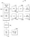
도 1은 개시된 실시예의 모습들에 따른 자율 저장 및 인출 시스템의 개략적인 예시이다.
도 2a - 도 2e는 개시된 실시예의 모습들에 따른 도 1의 자율 저장 및 인출 시스템의 일부의 개략적인 예시들이다.
도 3a - 도 3c는 개시된 실시예의 모습들에 따른 자율 운송 차량의 부분들의 개략적인 예시이다.
도 4는 개시된 실시예의 모습들에 따른 자율 운송 차량의 일부의 개략적인 예시이다.
도 5a - 도 5c는 개시된 실시예의 모습들에 따른 자율 운송 차량의 부분들의 개략적인 예시이다.
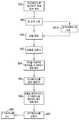
도 5d는 개시된 실시예의 모습들에 따른 피크페이스 운반 동작의 흐름도이다.
도 6은 개시된 실시예의 모습들에 따른 자율 운송 차량의 일부의 개략적인 예시이다.
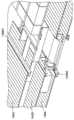
도 7a - 도 7c는 개시된 실시예의 모습들에 따른 도 1의 자율 저장 및 인출 시스템의 일부의 개략적인 예시들이다.
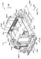
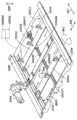
도 8은 개시된 실시예의 모습들에 따른 자율 운송 차량의 개략적인 예시이다.
도 9-11, 11a, 12a, 12b, 13, 13a, 13b, 14a 및 14b는 개시된 실시예의 모습들에 따른 자율 운송 차량의 부분들의 개략적인 예시들이다.
도 15 및 도 16은 개시된 실시예의 모습들에 따른 피크페이스 운반 동작의 흐름도들이다.
도 17 및 도 18은 개시된 실시예의 모습들에 따른 피크페이스 구축 동작의 흐름도들이다.The foregoing aspects and other features of the disclosed embodiments are set forth in the following detailed description in conjunction with the accompanying drawings.
1 is a schematic illustration of an autonomous storage and retrieval system in accordance with aspects of a disclosed embodiment;
2A-2E are schematic illustrations of a portion of the autonomous storage and retrieval system of FIG. 1 in accordance with aspects of the disclosed embodiment.
3A-3C are schematic illustrations of portions of an autonomous transport vehicle in accordance with aspects of the disclosed embodiment;
4 is a schematic illustration of a portion of an autonomous transport vehicle in accordance with aspects of the disclosed embodiment.
5A-5C are schematic illustrations of portions of an autonomous transport vehicle in accordance with aspects of the disclosed embodiment.
5D is a flow diagram of a pickface transport operation in accordance with aspects of the disclosed embodiment.
6 is a schematic illustration of a portion of an autonomous transport vehicle in accordance with aspects of the disclosed embodiment.
7A-7C are schematic illustrations of a portion of the autonomous storage and retrieval system of FIG. 1 in accordance with aspects of the disclosed embodiment.
8 is a schematic illustration of an autonomous transport vehicle in accordance with aspects of the disclosed embodiment.
9-11, 11a, 12a, 12b, 13, 13a, 13b, 14a and 14b are schematic illustrations of portions of an autonomous transport vehicle in accordance with aspects of the disclosed embodiment.
15 and 16 are flow diagrams of a pickface transport operation in accordance with aspects of the disclosed embodiment.
17 and 18 are flow diagrams of a pickface building operation in accordance with aspects of the disclosed embodiment.
도 1은 개시된 실시예의 모습에 따른 저장 및 인출 시스템을 걔략적으로 예시한다. 상기 개시된 실시예의 모습들이 상기 도면들을 참조하여 설명될 것이지만, 상기 개시된 실시예의 모습들은 많은 대안의 모습들로 구체화될 수 있다는 것이 이해되어야 한다. 추가로, 어떤 적합한 크기, 형상 및 유형의 요소들 또는 재질들도 사용될 수 있을 것이다.1 schematically illustrates a storage and retrieval system in accordance with aspects of a disclosed embodiment. While aspects of the disclosed embodiment will be described with reference to the drawings, it should be understood that the aspects of the disclosed embodiment may be embodied in many alternative aspects. Additionally, any suitable size, shape and type of elements or materials may be used.
개시된 실시예의 모습들에 따라, 상기 저장 및 인출 시스템 (100)은 2011년 12월 15일에 출원된 미국 특허 출원 번호 13/326,674 및 2010년 4월 12일에 출원된 PCT 특허 출원 PCT/US10/30669인 제목 "Storage and Retrieval System" (WO 공개. 2010/118412)의 출원들에서 설명된 것들과 같은 케이스 유닛들을 위해, 예를 들면, 소매상들로부터 수신된 주문들을 충족시키기 위해 소매 유통 센터 또는 창고에서, 예를 들면, 작동하며, 상기 출원들에서 개시된 내용들은 그 전체가 본원에 참조로 편입된다.In accordance with aspects of the disclosed embodiment, the storage and
상기 저장 및 인출 시스템 (100)은 인피드 (in-feed) 및 아웃-피드 (out-feed) 운반 스테이션들 (170, 160), 입고 및 출고 수직 리프트 (LIFT)들 (150A, 150B) (보통은 리프트들 (150)로 언급됨), 저장 구조 (130), 그리고 여러 자율 로버들 또는 자율 운송 차량 (110) (이것은 또한 봇 (bot)들로 언급될 수 있음)을 포함할 수 있다. 상기 저장 구조 (130)은, 예를 들면, 다중 레벨의 저장 래크 (rack) 모듈들을 포함하여, 그 래크 모듈에서 각 레벨은 각자의 저장 또는 피킹 통로들 (130A), 그리고 상기 저장 구조 (130)의 저장 영역들 중 어느 하나와 상기 리프트들 (150)의 한 선반 (shelf) 사이에서 케이스 유닛들을 운반하기 위한 운반 데크들 (130B)을 포함한다. 상기 저장 통로들 (130A) 그리고 운반 데크들 (130B)은 케이스 유닛들을 피킹 스톡 (picking stock)으로 배치하고 그리고 주문받은 케이스 유닛들을 인출하기 위해서 상기 로버들 (110)이 상기 저장 통로들 (130A) 및 운반 데크들 (130B)을 횡단하는 것을 허용하도록 또한 구성된다.The storage and
상기 로버들 (110)은, 예를 들면, 상기 저장 및 인출 시스템 (100)을 통해 케이스 유닛들을 나르고 운반할 수 있는 임의의 적합한 자율 차량들이다. 상기 로버들 (110)은 위에서 설명된 소매 상품과 같은 케이스 유닛들을 상기 저장 구조 (130)의 하나 또는 그 이상의 레벨들 내의 피킹 스톡으로 배치하고 그리고 그 후에 주문받은 케이스 유닛들을, 예를 들면, 가게 또는 다른 적합한 로케이션으로 운송하기 위해서 그 주문받은 케이스 유닛들을 선택적으로 인출하도록 구성된다.The
상기 로버들 (110) 및 상기 저장 및 인출 시스템 (100)의 다른 적합한 특징들은, 예를 들면, 하나 또는 그 이상의 중앙 시스템 제어 컴퓨터 (예를 들면, 제어 서버) (120)에 의해, 예를 들면, 어떤 적합한 네트워크 (180)를 통해서 제어된다. 한 모습에서, 상기 네트워크 (180)는 어떤 적합한 유형 및/또는 개수의 통신 프로토콜들을 이용한 유선 네트워크, 무선 네트워크 또는 유선 및 무선 네트워크의 결합이다. 한 모습에서, 상기 제어 서버 (120)는 모든 활성 시스템 컴포넌트들의 활동들을 제어하고, 스케줄링하며, 그리고 모니터하고, 창고 및 피크페이스들을 관리하며, 그리고 창고 관리 시스템 (2500)과 인터페이스하는 것을 예시적인 목적들만을 위해서 포함하여 상기 저장 및 인출 시스템 (100)을 관리하도록 구성된 실질적으로 동시에 동작하는 프로그램들의 컬렉션을 포함한다.The
이제 도 2를 참조하면, 상기 로버 (110)는 제1 말단 (110E1) 그리고 그 제1 말단 (110E1)과 길이 방향으로 이격된 제2 말단 (110E2)을 구비한 프레임 (110F)을 포함한다. 상기 프레임 (110F)은 페이로드 베드 (200)를 형성하며, 이 페이로드 베드는 어떤 적합한 방식으로 페이로드 베드 (200) 내 피크페이스 (210)를 지지 (support)하도록 구성된다. 한 모습에서, 측면으로 배치된 롤러들 (도시되지 않음)이 상기 피크페이스를 지지하며 그리고 피크페이스 (210)가 상기 페이로드 베드 내 길이 방향에서 움직이도록 허용하며, 반면에 다른 모습들에서는, 상기 페이로드 베드는 여기에서 설명되었던 것처럼 상기 페이로드 베드 내에서 상기 피크페이스 (210)를 지지하기 위한 어떤 적합한 지지 표면(들)을 구비한다. 또 다른 모습들에서, 엔드 이펙터 (end effector) (200E)는 페이로드 베드 (200) 내에서 피크페이스 (210)를 지지한다. 상기 로버 (110)는 상기 저장 및 인출 시스템을 통한 상기 로버 (110)의 움직임을 제어하기 위해 로버 (110)의 하나 또는 그 이상의 구동 섹션들에 연결된 어떤 적합한 제어기 (110C) (도 1), 상기 엔드 이펙터 (200E) 그리고 상기 로버의 어떤 다른 적합한 움직일 수 있는 컴포넌트들을 포함한다. 여기에서 사용되는 피크페이스는, 예를 들면, 앞뒤로, 나란히, 또는 그것들의 조합으로 배치된 하나 또는 그 이상의 상품 케이스 유닛들이라는 것에 유의한다. 상기 개시된 실시예의 모습들을 통합할 수 있는 로버들 (110)의 적합한 예들은 미국 특허 번호 8,425,173; "Automated Storage and Retrieval System" 제목의 2014년 3월 17일에 출원된 미국 특허 출원 번호 14/215,310; 2011년 12월 12일에 출원된 미국 특허 출원 번호 13/236,423 (공개 번호 2012/0189409); 2011년 12월 15일에 출원된 미국 특허 출원 번호 13/327,040 (공개 번호 2012/0197431); 2011년 12월 15일에 출원된 미국 특허 출원 번호 13/326,952 (공개 번호 2012/0189416); 2011년 12월 15일에 출원된 미국 특허 출원 번호 13/326,993 (공개 번호 2012/0185082); 2011년 12월 15일에 출원된 미국 특허 출원 번호 13/326,447 (공개 번호 2012/0185122); 2011년 12월 15일에 출원된 미국 특허 출원 번호 13/326,505 (공개 번호 2012/0195724)에서 설명된 것들이며, 이 출원들에서 개시된 것은 그 전체가 본원에 참조로 편입된다.Referring now to FIG. 2 , the
도 2a, 도 2b 그리고 또한 도 3a를 참조하면, 상기 로버 (110)는 상기 페이로드 베드 (200)로 그리고 페이로드 베드로부터 피크페이스 (210)를 운반하기 위해 상기 프레임 (110F)에 움직일 수 있게 연결된 임의의 적합한 엔드 이펙터 (200E)를 포함한다. 한 모습에서 상기 엔드 이펙터는 신축식 (telescoping) 암들 (220A, 220B)을 포함하며, 이 신축식 암들은 피크페이스들 (210)의 반대편 측면들에 걸터있으며 (straddle) 그리고 적적한 개수의 핑커들 또는 피크페이스 지지 부재들 (250)을 이용하여, 예를 들면, 자신의 기저에 의해 (예를 들면, 밑으로부터) 각 피크페이스를 들어올리고 지지함으로써 피크페이스들 (210)을 처리하도록 구성된다. 아래에서 설명될, 한 모습에서 상기 핑거들 (250)은 자신들 각자의 암들 (220A, 220B)에 대해 정적이며 (예를 들면, 고정됨), 반면에 (아래에서 설명될) 다른 모습들에서는, 상기 핑거들 (250)은 자신들 각자의 암들 (220A, 220B)에 대해 작동된다 (예를 들면, 움직일 수 있다). 각 암은 상기 저장 선반들의 저장 공간으로 상기 말단 이벡터 (220E)를 적절하게 확장하거나 도달하게 하는 것을 제공하기 위한 적절한 개수의 신축식 부재들을 구비한다. 예를 들면, 적어도 신축식 부재 (300)는 상기 엔드 이펙터의 각 암 (220A, 220B)의 신축식 확장 및 수축을 위해 상기 엔드 이펙터의 확장의 축 (299)을 따라 다른 신축식 부재 (301)에 활주식으로 연결된다. 각 암은 적합한 방식으로 상기 프레임 (110F)에 적합하게 설치된다. 예를 들면, 한 모습에서 레일들이나 트랙들과 같은 적절한 개수의 가이드들 (310)이 적합한 방식으로 프레임 (110F)에 설치된다. 상기 레일들은 페이로드 베드 (200)의 각 길이방향 측면에 또는 그 측면에 인접하게 설치되며, 그래서 각 가이드 (310)가 상기 프레임 (110F)에 대해 측면으로 연장하도록 한다. 하나 또는 그 이상의 신축식 부재들 (300, 301)이 상기 가이드 (310)에 활주식으로 설치되며, 그래서 상기 페이로드 베드 (200)로 그리고 페이로드 베드로부터 피크페이스들 (210)을 운반하기 위해 하나 또는 그 이상의 신축식 부재들 (300, 301)이 화살표의 방향 (299)에서 측면으로 연장하도록 한다. 엔드 이펙터 (200E)가 상기 로버 (110)의 한 측면으로부터만 확장하는 것으로 예시되지만, 다른 모습에서는 상기 엔드 이펙터 (200E)는 상기 로버의 어느 하나의 측면 (110S1, 110S2) (도 6)으로부터 확장하도록 구성된다는 것에 유의한다. 한 모습에서 첫 번째 신축식 부재 (300)는, 예를 들면, 적합한 트랙들을 가이드 (310)에 맞물리게 하는 가이드 롤러들이나 슬라이더들을 이용하는 것과 같은 적합한 방식으로 가이드 (310)에 활주식으로 설치된다. 상기 암들 (220A, 220B)의 첫 번째 신축식 부재 (300)는 가이드 (310)에 관하여 위에서 설명된 것과 실질적으로 유사한 방식으로 상기 첫 번째 신축식 부재 (300)에 두 번째 신축식 부재 (301)를 가동성 있게 설치하기 위한 가이드 (311)를 포함한다. 비록 두 개의 신축식 부재들이 상기 도면들에서 예시되었지만, 다른 모습들에서 어떤 적합한 개수의 신축식 부재들이 위에서 설명된 것과 실질적으로 유사한 방식인 확장 및 수축을 위해, 예를 들어, 서로에게 직렬로 설치된다는 것이 이해되어야 한다. 실감될 수 있을 것처럼, (예를 들면, 각 암 (220A, 220B)이 상기 프레임 (110F)에 가장 가까운 최근접 말단 (proximate end) 그리고 상기 프레임 (110F)으로부터 가장 멀리에 있는 최원 말단 (distal end))을 가질 때에) 각 암 (220A, 220B)의 가장 먼 말단의 직렬로 설치된 신축식 부재는 이 경우에는 두 번째 신축식 부재 (301)이며, 상기 핑거들 (250)을 포함하며, 반면에 다른 모습들에서는 상기 압의 어떤 적합한 신축식 부재는 핑거들 (250)을 포함한다.2A , 2B and also referring to FIG. 3A , the
상기 신축식 부재들 (300, 301) 각각은 적합한 횡단면을 구비하여, 상기 신축식 부재들 (300, 301) 중 적어도 하나가 저장 선반 (240) 상에 배치된 인접한 피크페이스들 (210) 사이에서의 공간 (SP) (도 2c)에서 확장할 수 있도록 한다. 한 모습에서 (예를 들면, 확장될 때에 상기 암들의 늘어짐을 최소화하기 위해 그리고 상기 암들의 더 큰 페이로드 용량을 허용하기 위해) 상기 암 (220A, 220B)을 보강하기 위해서 각 신축식 부재 (300, 301) 각각의 높이 (H)는 상기 신축식 부재의 폭 (W)보다 실질적으로 더 클 수 있으며, 이는, 예를 들면, (예컨데, 하나 또는 그 이상의 상품 케이스 유닛들이 다른 것 뒤에 배치되는 경우인) 깊은 저장 (deep storage)을 또한 용이하게 한다. 이중-슬라이드 피킹이 또한 가능하며, 이는 피크페이스들의 반대 측면들에 걸터 있도록 하기 위해서, 상기 암들 (220A, 220B)이 상기 페이로드 베드 (200)의 앞 (200F) 그리고 뒤 (200R)에 위치하기 때문이다 (앞 그리고 뒤는 여기에서는 예시의 목적들만을 위해 사용된 것이며 그리고 다른 모습들에서는 상기 페이로드 베드 (200)의 길이방향 측면들을 인용하기 위해 어떤 적합한 공간적인 식별자들이 사용될 수 있을 것이라는 것에 유의한다).Each of the
이제 도 3a를 참조하면, 각 암 (220A, 220B)의 가장 먼 말단의 신축식 부재는 이 모습에서는 두 번째 신축식 부재 (301)이며, 표면 (301S)을 구비하여, 핑거들 (250)이 상기 표면 (301S)으로부터 상기 페이로드 베드 (200)의 중심선 (CL)을 향하여 연장하도록 한다. 실감될 수 있을 것처럼, 각 암의 상기 핑거들 (250)은 서로에게 대향하여, 피크페이스 아래에서 연장하도록 한다. 실감될 수 있을 것처럼, 상기 핑거들 (250)은 적합한 길이 L을 구비하여, 적어도 하나의 신축식 부재 (300, 301) 그리고 상기 핑거들 (250)이 피크페이스들 (210) 사이에서의 공간 (도 2c)에서 확장될 수 있도록 한다. 이 모습에서 상기 핑거들 (250)은 가장 먼 말단의 신축식 부재에 대해 고정된다 (예를 들면, 상기 핑거들은 상기 두 번째 신축식 부재에 대해서 움직일 수 없다). 그러나, 다른 모습들에서는, 도 3b 및 도 3c에서 볼 수 있는 것처럼, 상기 핑거들 (250', 250'')은 예를 들면 가장 먼 말단의 신축식 부재(301')에 대해 움직일 수 있다. 예를 들면, 한 모습에서 핑거들 (250')은 상기 가장 먼 말단의 신축식 부재 (301')에 회전 가능하게 설치되며, 그래서 그 핑거들이 수축된 위치 그리고 확장된 위치 사이에서 움직이도록 한다. 수축된 위치에서, 상기 핑거들 (250')은, 예를 들면, 상기 표면 (301S)과 실질적으로 평행하며, 반면에 확장된 위치에서 상기 핑거들 (250')은, 예를 들면, 하나 또는 그 이상의 피크페이스들 (210) 아래로 확장하기 위해 상기 표면 (301S)에 실질적으로 수직이다 (또는 상기 표면에 대해 어떤 다른 적합한 각도로 배치된다). 이 모습에서 상기 핑거들 (250') 각각은, 상기 엔드 이펙터 (200E)의 확장 및 수축의 방향 (299) (도 2a)에 실질적으로 수직으로 확장하는 각자의 회전축들 (363) 주위로 회전 가능하다. 다른 모습에서, 상기 핑거들 (250'')은, 예를 들면, 상기 엔드 이펙터 (200E)의 확장 및 수축의 방향 (299)에 실질적으로 평행인 회전의 축 (364) 주위에서 회전가능하다. 예를 들면, 도 3b에서 볼 수 있는 것처럼, 상기 핑거들 (250'')은 수축된 위치 및 확장된 위치 사이에서 움직일 수 있다. 수축된 위치에서, 상기 표면 (301S)과 실질적으로 평행하기 위해서, 상기 핑거들 (250'')은 상기 표면 (301S)으로 또는 상기 표면에 인접하게 접혀진다. 확장된 위치에서, 하나 또는 그 이상의 피크페이스들 (210) 아래로 확장하기 위해 상기 표면 (301S)에 실질적으로 수직이기 위해서, 상기 핑거들 (250'')은 펼쳐진다. 또 다른 모습들에서, 상기 핑거들은 수축된 위치 및 확장된 위치 사이에서 움직이기 위해서, 어떤 적합한 방식으로 상기 가장 먼 말단의 신축 부재에 대해서 움직일 수 있다.Referring now to FIG. 3A , the telescoping member at the furthest end of each
이제 도 2c 및 도 2d를 참조하면, 상기 핑거들 (250)의 대향하는 배치는, 예를 들면, 상기 암들 (220A, 220B)이 상기 저장 선반 (140) 내로 확장될 때에, 상기 핑거들이 상기 저장 선반 (140)의 지지 표면들 (140S) 사이에 위치하도록 한다. 예를 들면, 한 모습에서 상기 저장 선반 (140)는, 상기 엔드 이펙터 (200E)의 확장 및 수축의 방향 (299)에 실질적으로 수직인 (예를 들면, 횡단하는) 방향 (297) (도 2a)으로 확장하는 이격하여 위치한 지지 표면들 (140S)을 포함한다. 예를 들면, 지지 표면들 (140S) 사이의 피치 (P1) (도 2a)는, 예를 들면, 상기 핑거들 (250) 사이의 피치 (P2)(도 3a)와 실질적으로 유사하며, 그래서 저장 선반 (140) 내부로 삽입될 때에 상기 핑거들 (250)이 상기 엔드 이펙터 (200E)의 확장 축을 횡단하는 방향 (299)에서 상기 선반 구조 (예를 들면, 상기 지지 표면들 (140S))와 인터리브되도록 하며, 반면에 다른 모습들에서 상기 핑거들 사이의 이격은 상기 핑거들이 상기 지지 표면들 사이의 개방부들을 통해서 통과하는 것을 허용하기에 적합한 이격이다.Referring now to FIGS. 2C and 2D , the opposing arrangement of the
도 2a를 다시 참조하면, 상기 로버 (110)는 어떤 적합한 개수의 드라이브들을 포함하는 구동 섹션 (260)을 구비한다. 예를 들면, 상기 구동 섹션 (260)은 하나 또는 그 이상의 엔드 이펙터 드라이브들 (260A, 260B, 260C)을 포함하며, 이 말단 이벡터 드라이브들은 축 (299)을 따른 확장/수축에서 상기 엔드 이펙터를 이동시키도록 구성되고, 하나 또는 그 이상의 암들 (220A, 220B)을 이동시키도록 구성되어 상기 암들이 상기 페이로드 베드 센터라인 (CL)을 향하여 그리고 페이로드 베드 센터라인으로부터 화살표의 방향 (297)의 방향에서 함께 그리고 떨어져서 움직이도록 하며 (도 5a 또한 참조), 상기 암들을 이동시키도록 구성되어 (예를 들면, 상기 페이로드 베드 (200) 및/또는 저장 영역에 대한 피크페이스들 (210)의 정돈 (justification)을 위해) 상기 암들 (220A, 220B)이 상기 페이로드 베드 센터라인 (CL)에 대해 화살표의 방향 (297)에서 한 유닛으로서 함께 움직이도록 하며 그리고 상기 엔드 이펙터 (200E)의 확장 및 수축의 축 (예를 들면, 방향) (299)에 실질적으로 수직인 방향 (298)에서 상기 암들을 올리고/낮추게 하도록 구성된다. 한 모습에서, 각 운반 암 (220A, 220B)의 횡단은 상기 페이로드 베드/영역의 피크페이스 지지 평면과 실질적으로 평행한 평면에서이며, 이는 적어도 하나의 피크페이스의 크기에 독립적으로 그 적어도 하나의 피크페이스의 전체 페이로드 영역 정돈 (예를 들면, 상기 암들 (220A, 220B)에 의해 액세스 가능한 저장 선반 영역 내 어디에서라도 그리고 상기 페이로드 베드 내 어디에서라도 상기 페이로드의 정돈)을 실행하기 위한 것이다. 도 4를 또한 참조하면, 한 모습에서 (예를 들면, 화살표 방향 (299)에서 상기 암들 (220A, 220B)을 이동시키는) 엔드 이펙터 확장/수축 드라이브 (260A)는 상기 로버 (110)의 각 암 (220A, 220B)을 확장시키고 수축시키기 위한 적합한 벨트 트랜스미션 (400)을 포함한다. 각 신축식 부재 (300, 301) (또한 도 3a 참조)는 각자의 신축식 부재 (300, 301)를 일렬로 확장하도록 구성된 적합한 벨트 및 도르래 설비 (400P1, 400P2, 400P3, 400B1, 400B2)를 포함한다 (예를 들면, 신축식 부재 (300, 301) 중 하나는 첫 번째 단계의 확장에서 미리 정해진 거리/범위로 확장하며 그리고 그 후에 상기 신축식 부재 중 다른 것이 두 번째 단계의 확장에서 미리 정해진 거리/범위로 확장하며, 그래서 상기 신축식 부재들 (300, 301)이 상기 첫 번째 단계의 확장에서 하나의 유닛으로서 움직이도록 하며 그리고 상기 신축식 부재들 (300, 301) 중 단 하나만이 상기 두 번째 단계의 확장에서 움직이도록 한다). 다른 모습들에서, 상기 벨트 및 도르래 설비 (400P1, 400P2, 400P3, 400B1, 400B2)는, 예를 들면, 자신들 각자의 신축식 부재들 (300, 301)을 실질적으로 동일하게 확장하도록 구성된다 (예를 들면, 참조번호 300의 신축식 부재가 미리 정해진 거리/범위로 확장하면 참조번호 301의 신축식 부재 또한 대응하는 미리 정해진 거리/범위로 확장하며, 그래서 참조번호 300의 신축식 부재가 상기 페이로드 베드 (200)에 대해 움직이고 그리고 참조번호 301의 신축식 부재가 참조번호 300의 신축식 부재 및 페이로드 베드 (200) 둘 모두에 대해 움직이도록 한다). 실감될 수 있을 것처럼, 상기 암들 (220A, 220B)의 수축은 위에서 설명된 것과 실질적으로 반대의 방식으로 발생한다. 다른 모습들에서, 상기 암들 (220A, 220B)을 확장하고 수축하기 위해서, 예를 들면, 볼 및 나사 배열들, 체인들, 수력 또는 공압식 액튜에이터들, 전기 액튜에이터들, 자기 드라이브들 등과 같은 어떤 적합한 구동 결합이 사용된다. 유사하게, (예를 들면, 참조번호 297의 방향에서 하나 또는 그 이상의 암들을 움직이는) 암 그립 (gripping) 드라이브 (260B) 그리고 (예를 들면, 참조번호 298의 화살표 방향에서 상기 암들 (220A, 220B)을 움직이는) 엔드 이펙터 리프트 드라이브 (260C)는 어떤 적합한 구성을 가지며 그리고 위에서 설명된 그런 트랜스미션들처럼 상기 암들을 구동하기 위한 어떤 적합한 트랜스미션들을 포함한다. 실감할 수 있을 것처럼, 한 모습에서 상기 암 그립 드라이브 (260B)는 본원에서 설명된 상기 암들 (220A, 220B) 중 하나 또는 그 이상을 움직이게 하기 위한 하나 또는 그 이상의 드라이브들 (260B1, 260B2)을 포함한다. 한 모습에서, 하나의 암 (220A, 220B)을 다른 암 (220A, 220B)에 대해 움직이게 하기 위해서 상기 그립 드라이브 (260B)는 상기 암들 (220A, 220B) 중 하나 또는 둘 모두에 연결된 단일의 드라이브 모터 (260B1)를 포함한다 (예를 들면, 상기 암들 (220A, 220B) 중 하나는 고정되어 있으며, 반면에 다른 암 (220A, 220B)은 움직이며 또는 두 암들 모두가 움직여서, 아래에서 설명되는 방식과 유사한 방식으로 공통의 드라이브 모터에 의해 서로를 향하여 그리고 서로로부터 멀리 구동되도록 하기 위해서 한 암의 움직임이 다른 암의 움직임에 연결되도록 한다). 다른 모습들에서, 상기 그립 드라이브 (260B)는 적어도 두 개의 드라이브들 (260B1, 260B2)을 포함하며, 여기에서 다른 암 (220A, 220B)에 독립적으로 움직이기 위해서 각 암 (220A, 220B)은 각자의 드라이브 모터 (260B1, 260B2)에 의해 구동된다. 실감될 수 있을 것처럼, 각 암의 독립적인 움직임은 피크페이스들 (210)을 그립하는 허용하는 것만이 아니라, 예를 들면, 저장 공간 또는 다른 피크페이스 보유 로케이션 (holding location)에 대해 참조번호 297의 화살표의 방향에서 상기 피크페이스 (210)의 정돈을 실행하기 위해 참조번호 297의 화살표 방향에서 상기 피크페이스 (210)의 움직임을 허용한다. 또 다른 모습들에서 상기 암들 (220A, 220B)은 어떤 적합한 개수의 드라이브 모터들에 의해 적합한 방식으로 참조번호 297의 방향에서 움직일 수 있다.Referring again to FIG. 2A , the
위에서 논의된 것처럼, 상기 저장 선반들 (140)은, 예를 들면, 상기 암들 (220A, 220B)의 핑거들 (250)이 상기 선반들 (140)을 통해 지나가는 것을 가능하게 하도로 구성되며, 그래서 상기 핑거들 (250)이 상기 선반들 (140)의 지지 표면들 (140S) 아래에 위치하도록 한다. 한 모습에서 상기 저장 선반 (140)는 와이어 선반여서 상기 지지 표면들 (140S)이 그 선반의 와이어들에 의해 형성되도록 한다. 상기 와이어 선반들 (140)은 와이어 메시 구성과 같은 적합한 구성을 가지며, 그 구성에서 상기 와이어 선반들의 상단 부재들은 상기 지지 표면들 (140S)을 형성하며 그리고 상기 피크페이스들이 상기 선반들 (140)로 그리고 그 선반들로부터 이동되는 방향 (299)에 실질적으로 횡단하는 방향 (297)으로 향하고 정렬된다. 상기 와이어 선반들 (140)은 어떤 적합한 방식으로 (예를 들면, 수평 지지들 (282)과 같은) 상기 저장 래크 구조 및/또는 상기 피킹 통로 데크/레일들에 고착된다. 한 모습에서 상기 와이어 선반들 (140)은 상기 저장 래크 구조 및/또는 상기 피킹 통로 데크/레일들 주위를 둘러싸며, 그래서 파스너 (fastener)들 또는 다른 고정 방법들 (예를 들면, 접착제들, 용접 등)을 실질적으로 사용하지 않고 상기 와이어 선반들 (140)이 상기 저장 래크 구조 및/또는 상기 피킹 통로 데크/레일들에 움직일 수 있게 고정되도록 한다. 다른 모습들에서 어떤 제거 가능한 파스너들을 이용하여 상기 와이어 선반들 (140)은 상기 저장 래크 구조 및/또는 상기 피킹 통로 데크/레일들에 움직일 수 있게 고정된다. 다른 모습들에서 상기 선반들 (140)은 이동할 수 없을 수 있다.As discussed above, the
다른 모습들에서 상기 저장 선반 (140')는 2010년 4월 9일에 출원된 미국 특허 출원 12/757,381에서 설명된 것과 실질적으로 유사하며, 상기 출원에서 개시된 것은 그 전체가 본원에 참조로서 편입된다. 예를 들면, 도 2e를 참조하면 각 저장 선반 (140')는, 예를 들면, 상기 저장 선반 (140')의 수평 지지 (282)로부터 확장하는 하나 또는 그 이상의 지지 레그들 (280L1, 280L2)을 포함한다. 상기 지지 레그들 (280L1, 280L2)은 어떤 적합한 구성을 구비하며 그리고 실질적으로 U-형상의 채널 (280)의 일부일 수 있으며, 그래서 상기 레그들이 채널부 (280B)를 통해 서로에게 연결되도록 한다. 상기 채널부 (280B)는 상기 채널 (280) 및 하나 또는 그 이상의 수평 지지들 (282) 사이에서의 접착 포인트를 제공한다. 다른 모습들에서, 각 지지 레그 (280L1, 280L2)는 개별적으로 상기 수평 지지들 (282)에 설치되도록 구성된다. 이 모습에서, 각 지지 레그 (280L1, 280L2)는 상기 선반 (140') 상에 제공된 피크페이스들을 지지하도록 구성된 적합한 지지 표면 (140S) 영역을 구비한 구부러진 부분 (280H1, 280H2)을 포함한다. 상기 구부러진 부분 (280H1, 280H2)은, 예를 들면, 상기 선반 상에 저장된 피크페이스들의 변형을 실질적으로 방지하도록 구성된다. 다른 모습들에서 상기 레그 부분들 (280H1, 280H2)은 적합한 두께를 가지며 또는 상기 선반들 상에 저장된 케이스 유닛들을 지지하기 위한 어떤 다른 적합한 형상 및/또는 구성을 가진다. 도 2e에서 볼 수 있는 것처럼 상기 지지 레그들 (280L1, 280L2) 또는 채널들 (280)은 박판이 덧대어진 (slatted) 또는 주름잡힌 (corrugated) 선반 구조를 형성할 수 있으며, 그 선반 구조에서, 예를 들면, 상기 지지 레그들 (280L1, 280L2) 사이의 공간들 (SP2)은 아래에서 설명될 것처럼 상기 선반로 그리고 상기 선반로부터 피크페이스들을 운반하기 위해 상기 엔드 이펙터 (200E)의 핑거들이 상기 선반에 도달하는 것을 가능하게 한다.In other aspects the storage shelf 140' is substantially similar to that described in U.S. Patent Application 12/757,381, filed April 9, 2010, the disclosure of which is incorporated herein by reference in its entirety. . For example, referring to FIG. 2E , each
실감될 수 있을 것처럼 여기에서 설명된 저장 선반들은 한 모습에서는 상기 저장 및 인출 시스템 (100)의 구조적인 비용들을 줄이면서도, 실질적으로 평평하여, 상기 저장 및 인출 시스템 (100)의 증가된 저장 밀도를 가능하게 한다.As will be realized, the storage shelves described herein are substantially flat, reducing the structural costs of the storage and
위에서 설명된 것처럼, (실질적으로 상기 저장 선반들 (140, 140')과 실질적으로 유사한) 저장 선반들 (140A, 140B, 140C)은 도 7a - 도 7c에서 보이는 것처럼 다른 것 위에 쌓여질 수 있으며, 그래서 다중의 저장 선반들이 단일의 피킹 통로 데크 (130AD)로부터 액세스될 수 있도록 한다. 여기에서, 다른 것 위에 쌓여질 수 있으며 단일의 피킹 통로 데크 (130AD)로부터 액세스될 수 있는 두 개의 저장 선반들 (140A, 140B)이 존재한다. 다른 모습들에서는, 단일의 피킹 통로 데크 (130AD)로부터 액세스될 수 있는 둘 보다 많은 저장 선반들이 존재한다. 한 모습에서, 상기 엔드 이펙터 리프트 드라이브 (206C)는 상기 저장 및 인출 시스템의 다중의 저장 레벨들 사이에서의 상기 엔드 이펙터의 이동을 제공하도록 구성된다. 예를 들면, 도 7a, 도 7b 및 도 7c를 참조하면, 상기 저장 선반들 (140)은 피킹 통로들 (130A) (도 1)의 개수에 있어서의 감소를 허용하며, 이는 피킹 통로 데크 (130AD) 당 다중-레벨 저장을 제공함에 의해서 줄어든 운반 데크들 (130B) (도 1) 크기, 그리고 줄어든 데크 (예를 들면, 운반 데크 (130B) 그리고 피킹 통로 데크 (130AD) 둘 모두)를 가능하게 할 것이다. 상기 선반들 (140)의 구성은 또한 수평 및 수직의 케이스 밀도에서의 증가를 또한 가능하게 하며, 상기 암들 (220A, 220B)을 이용하여 상기 케이스 유닛들 또는 피크페이스들을 배치하고/등록하는 것은 상기 피크페이스들을 더 가깝게 함께 이동시키는 것을 가능하게 한다 (예를 들면, 위에서 설명된 것처럼 피크페이스에 간격을 두는 것을 줄어들게 한다). 위에서 언급된 것처럼, 상기 케이스 유닛들 또는 피크페이스들 사이에 간격을 두는 것은 상기 저장 선반 (140)으로 그리고 저장 선반으로부터 상기 케이스 유닛(들) 또는 피크페이스를 운반하기 위해서 상기 암들 (220A, 220B)을 위한 간격이 인접한 케이스 유닛들이나 피크페이스들 사이에 삽입되도록 허용한다.As described above,
계속 도 7a - 도 7c를 참조하면, 그리고 위에서 언급된 것처럼, 상기 로버 (110A)는 쌓여진 저장 선반들 (140A, 140B)에 단일의 피킹 통로 데크 (130AD)로부터 액세스하도록 구성될 수 있을 것이다. 예시적인 목적들만을 위해서, 이 모습에서 각 피킹 통로 데크 (130AD)는 두 개 레벨의 저장 (140A, 140B)으로의 액세스를 제공하지만 다른 모습들에서 각 피킹 통로는 둘 보다 많은 레벨의 저장으로의 액세스를 제공할 수 있을 것이다. 각 피킹 통로에 의해 액세스되는 저장의 레벨은 한 피킹 통로 데크로부터 다른 피킹 통로 데크로 변할 수 있을 것이라는 것에 유의한다 (예를 들면, 한 데크는 제1 개수의 저장 레벨들로의 액세스를 제공하지만, 다른 데크는 상기 제1 개수와 상이한 제2 개수의 저장 레벨들로의 액세스를 제공할 수 있을 것이다). 위에서 논의된 것처럼, 상기 로버 (110)는, 여기에서 설명된 것과 실질적으로 유사한 방식으로 케이스 유닛이나 피크페이스가 붙잡아지거나 또는 배치될 저장 레벨에 대응하는 미리 정해진 높이로 상기 암들 (220A, 220B)을 들어 올리거나 낮추는 엔드 이펙터 리프트 드라이브 (260C) (도 2a)를 포함할 수 있을 것이다. 상기 엔드 이펙터 리프트 드라이브 (260C)는, 예를 들면, 선형 액튜에이터, 스크루 드라이브, 씨저 리프트 (scissor lift) (도 7a), 자기 드라이브 등과 같이 상기 암들 (220A, 220B)을 높이고 낮추도록 구성된 임의의 적합한 구동 섹션이다.With continued reference to FIGS. 7A-7C , and as noted above, the rover 110A may be configured to access stacked
이제 도 2b, 도 2d, 및 도 5a - 도 5d를 참조하여, 피크페이스 (210) 피킹 동작이 설명될 것이다. 상기 로버 (110)는, 예를 들면, 피크페이스를 운반하기 위해서 제어 서버 (120) (도 1)와 같은 어떤 적합한 제어기로부터 명령을 수신한다. 상기 로버는 상기 운반 데크 (130B)를 따라 미리 정해진 피킹 통로 (130A)로 이동한다. 상기 로버 (110)는 상기 피킹 통로 (130A)에 진입하며 그리고 미리 정해진 저장 로케이션에서 멈춘다 (도 5d, 블록 500). 위에서 논의된 것처럼, 상기 로버 (110)는 암들 (220A, 220B)을 구비한 엔드 이펙터 (200E)를 포함하며, 이 암들은 상기 피크페이스 (210)의 반대 측면들 (210S1, 210S2)에 걸터 있으며 그리고 반대 측면들을 잇도록 구성되며 그리고 상기 피크페이스 (210)를 상기 페이로드 베드 (200)로 그리고 그 페이로드 베드로부터 운반하도록 구성된다. 실감될 것처럼, 상기 암들 (220A, 220B)이 상기 페이로드 베드 (200) 내에서 수축되고 그리고 상기 로버 (100)가 피크페이스를 운반하지 않을 때에, 상기 암들 (220A, 220B)은 거리 D1만큼 분리되며, 이 거리 D1은 상기 로버가 운반할 수 있는 가장 넓은 피크페이스의 폭 W보다 실질적으로 더 크며 그리고/또는 상기 저장 및 인출 시스템 (100) 내에 저장되었다. 상기 로버 제어기 (110C)는 상기 엔드 이펙터 드라이브 섹션 (260)을 동작시켜서 상기 암들 (220A, 220B) 중 하나 또는 그 이상을 길이 방향으로 이동시켜 상기 암들 (220A, 220B)을, 예를 들면, 상기 피크페이스 (210) (도 2b)의 폭 W에 따라 상기 저장 공간과 정렬시킨다. 한 모습에서, 상기 로버 (110)는 상기 로버가 상기 피킹 통로(들) (130A) (도 1)를 따라 이동할 때에 상기 저장 선반들 (140) 상에 위치한 피크페이스(들)의 측면들 (210S1, 210S2)을 탐지하도록 구성된 (아래에서 설명될 것과 같은) 어떤 적합한 센서들을 포함한다. 다른 모습들에서 상기 피크페이스들 (210)은 상기 저장 선반들의 미리 정해진 특징들에 대해 상기 저장 선반들 상에 배치되며, 그래서 상기 센서들이 상기 피크페이스 (그리고 상기 피크페이스 측면들)의 위치를 판별하기 위해 상기 저장 선반들의 상기 미리 정해진 특징들을 탐지할 수 있도록 한다. 한 모습에서, 케이스 센서들은 2011년 12월 15일에 출원된 미국 특허 출원 13/327,035 (공개 번호 2012/0189410) 및 2012년 9월 10일에 출원된 "Storage and Retrieval System Case Unit Detection"제목의 미국 출원 13/608,877에서 설명된 것들과 실질적으로 유사하며, 이 출원들에서 개시된 내용들은 그 전체가 본원에 참조로서 편입된다. 상기 로버 (110)는 상기 암들 (220A, 220B) 중 하나 또는 그 이상을 이동시켜서 상기 암들 (220A, 220B) 사이에서의 거리 D1을 조절하도록 하며, 그래서 확장되었을 때에 상기 암들 (220A, 220B)이 상기 페이로드 베드 (200)로 운반될 피크페이스 (210)의 다른 측면 상에서 상기 공간들 SP (도 2c) 내에 배치되도록 한다. 위에서 설명된 것처럼, 한 모습에서 상기 로버 (110)는 화살표 방향 (297)에서의 정돈을 포함하며, 상기 로버의 신축식 암들은 상기 화살표 방향 (297)에서 한 유닛으로서 이동되어, 보유 로케이션으로부터 상기 피크페이스를 집으면 상기 암들을 상기 피크페이스와 더 정렬시키며 (또는 보유 로케이션에 상기 피크페이스를 배치하면 상기 피크페이스를 보유 로케이션과 정렬시킨다), 이는 예를 들면, 피크페이스 보유 로케이션에 대해 상기 신축식 암들의 정밀 배치이다 (도 5d. 상기 로버 (110) 제어기 (110C) (도 1)는 상기 드라이브들 (260A, 260C)에게 명령하여 상기 암들 (220A, 220B)을 상기 피크페이스 보유 로케이션의 상기 지지 표면 (140S)과 실질적으로 동일한 레벨 또는 상기 지지 표면 위의 레벨로 올리도록 하고 그리고 상기 암들 (220A, 220B)을 상기 저장 선반 (140)으로 미리 정해진 거리만큼 확장시키도록 하며, 그래서 상기 핑거들 (250)이 상기 피크페이스(들) (210)과 실질적으로 정렬되도록 하며 그리고 상기 핑거들이 상기 선반 지지 표면들 (140S) 사이의 공간들 (SP2) 사이에 배치되도록 한다 (도 5d, 블록 502). 한 모습에서 상기 암들 (220A, 220B)은 상기 페이로드 베드 (200)의 지지 표면에 독립적인 방향 (298)에서 이동되며, 반면에 다른 모습들에서 상기 페이로드 베드의 지지 표면은 또한 참조번호 298의 방향에서 (상기 드라이브 (260C)에 의해 또는 페이로드 베드 리프트 드라이브를 이용하여) 이동하도록 구성되며, 그래서 상기 페이로드 베드 지지 표면이 상기 지지 표면 (140S)에 인접하도록 하며, 이전에 그 전체가 본원에 참조로서 편입된 미국 임시 특허 출원 61/790,801에서 설명된 것과 실질적으로 유사한 방식으로 상기 지지 표면 (140S)으로부터 상기 피크페이스가 운반된다. 한 모습에서, 상기 암들 (220A, 220B)이 상기 저장 로케이션으로 얼마나 깊게 확장되어야 하는지를 결정하고 그리고 (상기 암들 (220A, 220B)의 확장의 방향에 관하여) 상기 피크페이스의 앞부분 및 뒷부분 가장자리 경계들을 결정하기 위해 (상기 피크페이스의 정돈에 관하여 아래에서 설명됨), 어떤 적합한 센서 (257)가 상기 제어기 (110C)에게 피드백을 제공한다. 상기 암들 (220A, 220B)은 드라이브 (260C)를 이용하여 낮추어지며, 그래서 상기 핑거들이 상기 선반 지지 표면 (140S) 아래의 미리 정해진 거리 (D2)에 배치되도록 한다 (도 5d, 블록 503). 드라이브 (260B)를 이용하여 상기 암들 (220A, 220B) 중 하나 또는 그 이상은 화살표 방향 (297)에서 상기 피크페이스 (210)의 측면들 (210S1, 210S2)을 향하여 이동되며, 그래서, 예를 들면, 신축식 부재 (301)의 표면 (301S)이 상기 피크페이스를 가볍게 잡고 (예를 들면, 이 경우 가볍게 잡는다는 것은 상기 피크페이스의 정렬을 위해 상기 피크페이스를 터치하며, 그 터치하는 것이 상기 피크페이스를 저장 선반으로부터 들어올리기 위해 상기 피크페이스를 잡기에 충분한 그립을 제공하지는 않는다는 것을 의미한다) 그리고 상기 핑거들 (250)은 상기 피크페이스 (210) 아래에 위치하도록 한다 (도 5d, 블록 504). 다른 모습들에서 상기 표면들 (301S)은 상기 피크페이스를 들어올리기 위한 충분한 그립을 제공할 수 있을 것이다. 드라이브 (260C)를 이용하여 상기 암들 (220A, 220B)을 들어올림으로써 상기 피크페이스 (210)는 화살표 방향 (298)에서 상기 저장 선반 (140)으로부터 적절한 거리 D3만큼 들어올려지며, 그래서 상기 피크페이스의 하중을 지지하기 위해 상기 피크페이스의 접촉 바닥 (210B) (도 2a)까지 상기 핑거들 (250)이 올려지도록 한다 (예를 들면, 상기 피크페이스는 상기 표면 (310S)을 따라서 슬라이드되어 상기 핑커들 (250) 및 상기 피크페이스의 바닥 (210B) 사이에서의 접촉을 허용한다) (도 5d, 블록 505). 상기 암들 (220A, 220B)은 화살표 방향 (299)에서 수축될 수 있으며, 그래서 상기 피크페이스가 상기 페이로드 베드 (200)의 위에 위치하도록 하며 (도 5d, 블록 506) 그리고 상기 피크페이스 (210)는 화살표 방향 (298)에서 상기 페이로드 베드 (200)로 향하여 낮추어질 수 있다 (도 5d, 블록 507). 상기 페이로드 베드 내에 위치할 때에 상기 피크페이스 (210)는 한 실시예에서 상기 핑거들에 의해 그리고/또는 상기 페이로드 베드 (200)의 적합한 지지 표면에 의해 지지된다. 실감될 수 있듯이, 상기 피크페이스의 정돈을 위해 하나 또는 그 이상의 암들 (220A, 220B)이 화살표의 방향 (297)에서 이동되는 경우인 아래에서 설명되는 것과 같이 어떤 적절한 방식으로 상기 페이로드 베드 내에서 상기 피크페이스를 정돈하기 위해 (예를 들면, 상기 페이로드 베드의 하나 또는 그 이상의 기준들에 대해 미리 정해진 위치에 상기 피크페이스를 위치시킨다), 일 실시예에서, 상기 표면들 (301S)이 사용된다 (도 5d, 블록 508).Referring now to FIGS. 2B, 2D, and 5A-5D, the
피크페이스 (210)의 운송 동안에, 상기 피크페이스는 일 실시예에서 상기 암들 (220A, 220B)의 표면들 (301S) 또는 상기 로버의 어떤 다른 적합한 정렬/그리핑 표면들에 의해 클램프 고정되거나 유지된다. 상기 피크페이스 (210)를 어떤 적합한 피크페이스 보유 로케이션 내부에 배치하기 위해서 상기 로버 (110)는 상기 피크 페이스 보유 로케이션에 대해 미리 정해진 로케이션에 배치될 수 있다. 한 모습에서, 상기 피크페이스 (210)가 정돈되는 경우, 상기 피크페이스 (210)는 상기 페이로드 베드 (200) 내에서 화살표의 방향 (297)에서 상기 암들 (220A, 220B)에 의해 움직져서, 상기 피크페이스 (210)를 상기 피크페이스 보유 로케이션과 정렬시킨다. 다른 모습들에서 상기 로버 (110)를 배치하는 것은 상기 피크페이스 (210)를 상기 피크페이스 보유 로케이션과 정렬하는 것을 실행한다. 상기 암들 (220A, 220B)은 상기 피크페이스를 상기 피크페이스 보유 로케이션의 지지 표면 (140S)과 실질적으로 동일한 또는 그 위의 레벨로 올리며 그리고 상기 피크페이스를 상기 페이로드 베드 (200) 상으로 운반하기 위해 위에서 설명된 것과 실질적으로 반대의 방식으로 상기 암들은 상기 피크페이스 (210)를 상기 피크페이스 보유 로케이션의 상기 지지 표면 (140S) 상으로 운반한다. 실감할 수 있을 것처럼, 페이로드를 상기 로버 (110)로 그리고 상기 로버로부터 운반하는 것이 피크페이스 (210)에 관하여 설명되었지만, 우에서의 섦여은 개별 케이스 유닛들을 상기 로버 (110)로 그리고 그 로버로부터 운반하는 것에도 또한 적용될 수 있다는 것이 이해되어야 한다. 추가로, 저장 선반 (140, 140', 140A, 140B)에 대해 참조하였지만, 상기 로버는 케이스 유닛 및/또는 케이스 유닛들로 형성된 피크페이스를 상기 저장 선반 (140, 140', 140A, 140B), 리프트 (150A, 150B)의 선반 또는 어떤 다른 적합한 로케이션과 같은 어떤 적합한 피크페이스 보유 로케이션으로도 운반할 수 있을 것이라는 것을 이해하여야 한다.During transport of the
도 2b, 도 2d 및 도 5a-5d를 다시 참조하여, 상기 로버 (110)의 예시적인 프크페이스 구축 동작이 설명될 것이다. 위에서 설명된 것과 실질적으로 유사한 방식으로 상기 로버 (110)는 하나 또는 그 이상의 피크페이스들 (210)을 선반으로부터 로버 (110)로 운반하도록 배치된다 (도 17, 블록 8000). 도 2C에서 예시된 것처럼 상기 암들 (220A, 220B) 사이의 간격 D1은 화살표의 방향 (297)에서 조절되어, (인접한 케이스 유닛들/피크페이스들 사이의 공간 SP에 맞게 하기 위해서) 상기 암들 (220A, 220B)을 하나 또는 그 이상의 제1 피크페이스들 (210)과 정렬시킨다 (도 17, 블록 8001). 위에서 설명되었듯이, 한 모습에서 상기 로버 (110)는 화살표의 방향 (297)에서의 정돈을 포함하며, 상기 로버의 신축식 암들은 화살표 방향 (297)에서 하나의 유닛으로서 움직여져서 상기 신축식 암들 (220A, 220B)을 하나 또는 그 이상의 제1 피크페이스들 (210)과 더 정렬시키며, 예를 들면, 피크페이스 보유 로케이션에 대한 상기 신축식 암들의 미세 배치한다 (도 17, 블록 8001A). 상기 신축식 암들 (220A, 220B)은 도 5d의 참조번호 502 - 508의 블록들에 관하여 위에서 설명된 방식으로 상기 페이로드 베이로 하나 또는 그 이상의 제1 피크페이스들 (210)을 운반하기 위해 화살표들의 방향 (299A, 299B)에서 확장되고 수축된다 (도 17, 블록 8003). 일단 하나 또는 그 이상의 제1 피크페이스들 (210)이 페이로드 베드 (200) 내에 배치되면 상기 로버 (110)는 상기 피킹 구조를 횡단하며 그리고 하나 또는 그 이상의 제2 피크페이스 (210X) (도 2c)를 상기 페이로드 베이 (200)로 운반하기 위해 다른 피크페이스 보유 로케이션에 대해서 배치된다 (도 17, 블록 8000). 상기 페이로드 베이 내 하나 또는 그 이상의 피크페이스들 (210)은 클램프 고정된 것이 풀리며 (unclamped) 그리고 상기 수축식 암들 (220A, 220B) 사이의 간격은 조절되고 (도 17, 블록 8001) 그리고/또는 정돈되어 (도 17, 블록 8001A) 상기 신축식 암들 (220A, 220B)을 다른 피크페이스 보유 로케이션 내 하나 또는 그 이상의 제2 피크페이스들 (210X)와 정렬시킨다. 실감될 수 있을 것처럼, 상기 페이로드 베드 (200) 상에 이미 보유된 상기 하나 또는 그 이상의 제1 피크페이스들 (210)은 상기 신축식 암들이 정돈될 때에 화살표 방향 (297)에서 상기 신축식 암들 (220A, 220B)를 이용하여 이동된다. 상기 신축식 암들 (220A, 220B)은 도 5d의 참조번호 502 - 508의 블록들에 관하여 위에서 설명된 방식으로 상기 페이로드 베이로 하나 또는 그 이상의 제2 피크페이스들 (210X)을 운반하기 위해 화살표들의 방향 (299A, 299B)에서 확장되고 수축된다 (도 17, 블록 8003). 실감될 수 있듯이, 상기 하나 또는 그 이상의 제2 피크페이스들을 상기 페이로드 베이 (200)로 운반하는 동안에 상기 신축식 암들 (220A, 220B)은 상기 하나 또는 그 이상의 제1 피크페이스 (210)의 측면들로부터 이격될 수 있을 것이며, 그래서 상기 핑거들 (250)이 상기 페이로드 베이 (200) 내 상기 하나 또는 그 이상의 제1 피크페이스들에 접촉하지 않도록 한다 (그리고/또는 도 3b 및 도 3c를 참조하면, 상기 페이로드 베이 (200) 내 상기 피크페이스 (210)와 접촉하지 않기 위해서 상기 핑거들 (250', 250'') 중 하나 또는 그 이상이 배치되며, 예를 들면, 수축된다). 다른 모습들에서 상기 암들 (220A, 220B)의 자유 단들 (free ends) FE (도 2d)로부터 가장 멀리에 있는 핑거들 (250)은 상기 자유 단들 FE에 인접한 핑거들 (250)보다 더 길며, 그래서 하나 또는 그 이상의 제2 피크페이스들 (210X)을 피킹하는 동안에 상기 하나 또는 그 이상의 제1 피크페이스들 (210)이 상기 암들 (220A, 220B)에 의해 보유되도록 하며, 상기 암들 (220A, 220B)이 상기 보유 로케이션으로 확장될 때에 접촉하지 않으면서 하나 또는 그 이상의 제2 피크페이스들 (210X)에 걸터 있기 위해서 상기 암들 (220A, 220B)이 이격되도록 여전히 허용한다. 상기 하나 또는 그 이상의 제1 피크페이스들 및 제2 피크페이스들 (210, 210X)은 로버 (110)에 의해서 하나의 유닛으로서 운반되며 그리고 상기 피크페이스들 (210, 210X)을 페이로드 베드 (200)로 운반하는 것에 관하여 위에서 설명된 것과 실질적으로 반대의 방식으로 피크페이스 보유 로케이션에 하나의 유닛으로서 (또는 하나보다 많은 피크페이스 보유 로케이션에서 분리하여) 배치된다.Referring back to FIGS. 2B , 2D and 5A-5D , an exemplary fockface building operation of the
한 모습에서, 위에서 언급된 것처럼, 상기 로버 (110)는 이전에 그 전체가 본원에 참조로서 편입된 "Automated Storage and Retrieval System" 제목의 2014년 3월 17일에 출원된 미국 임시 특허 출원 번호 14/215,310에서 설명된 것들과 같은 정돈 특징들을 포함한다. 예를 들면, 한 모습에서, 상기 로버 (110)는 능동 사이드 정돈을 포함한다 (여기에서, 위에서 언급된 것처럼, 하나의 암 (220A, 220B)은 고정되고 그리고 다른 암 (220A, 220B)은 참조번호 297의 방향에서 움직일 수 있으며 또는 이 경우 두 암들 (220A, 220B) 모두가 참조번호 297의 방향에서 움직일 수 있다). 케이스 경계들의 물리적인 확정을 위한 적합한 센서들 (257)이 상기 페이로드 베드 (200)에 인접하여 또는 상기 페이로드 베드 내에 그리고/또는 하나 또는 그 이상의 암들 (220A, 220B) 위에 또한 배치될 수 있을 것이다. 한 모습에서 상기 센서들(257)은 상기 로버의 암들 (220A, 220B) 상에 배치된 커튼 센서들 또는 빔 라인 센서들이다. 상기 센서들 (257)은 피크페이스들을 배치할 때에 상기 로버가 빈 공간 그리고 적당한 공간이, 예를 들면, 피크페이스를 위한 저장 선반 (140, 140', 140A, 140B)과 같은 어떤 적합한 피크페이스 보유 로케이션 상에 존재한다는 것을 확인하고 그리고 상기 피크페이스가 올바른 단벽 (setback) (예를 들면, 피크페이스가 피크페이스 보유 로케이션의 피킹 통로 가장자리 또는 어떤 다른 적합한 레퍼런스 기준로부터 위치한 거리)을 두고 배치된다는 것을 확인하는 것을 가능하게 한다. 저장 로케이션으로부터 피크페이스들 (210)을 피킹하면, 상기 센서들 (257)은 케이스 목적지 결정 그리고 상기 암들 (220A, 220B)이 상기 저장 로케이션으로 확장되는 깊이에 대한 확인을 허용한다. 상기 암들 (220A, 220B)은, 한 모습에서, (예를 들면, 저장 선반 (140)의 가장자리로부터 떨어져있는 저장 로케이션에서) 깊은 저장 로케이션들 내에 배치되고 있는 피크페이스들을 위한 안내를 또한 제공한다.In one aspect, as noted above, the
상기 피크페이스들에 대한 정돈이 제공되는 경우에, 상기 로버 (110)의 페이로드 베드 (200)는, 한 모습에서, 상기 피크페이스 (210) (그리고 그 피크페이스를 형성하는 케이스 유닛들)의 다중의 자유도를 가진, 상기 페이로드 베드 (200)의 표면에 따르는 슬라이딩 이동을 가능하게 하도록 구성된다. 한 모습에서 상기 페이로드 베드는 낮은 마찰 계수를 가진 적합한 물질로 구축된 실질적으로 평평한 표면이며, 반면에 다른 모습들에서 상기 페이로드 베드는 피크페이스가 올려있는 복수의 볼 베어링들을 포함하며, 또 다른 모습들에서 상기 페이로드 베드 (200)는 상기 피크페이스 (210) (그리고 그 피크페이스를 형성하는 케이스 유닛들)의 다중의 자유도를 가진, 상기 페이로드 베드 (200)의 표면에 따른 슬라이딩 이동을 가능하게 하는 위에서 설명된 것과 같은 어떤 적합한 구조를 가진다. 다른 모습들에서, 상기 핑거들 (250)에 의해 상기 페이로드 베드 표면 위에서 유지되면서도 상기 피크페이스는 정돈된다.In the event that tidying up of the pickfaces is provided, the
위에서 언급된 것처럼, 도 6을 참조하면, 한 모습에서, 상기 로버 (110)는 저장 선반들 (140) 위에 위치한 피크페이스(들) (210)의 위치를 탐지하기 위한 적합한 센서들을 포함한다. 개시된 실시예의 한 모습에서, 상기 로버는 하나 또는 그 이상의 빔 센서들 (600, 601) 그리고/또는 근접 센서들 (602, 603)을 포함하며, 이 센서들은 상기 저장 선반 (140)의 수평 지지들 (282) 상에 또는 내에 배치된 미리 정해진 지형들이나 타겟들 (611, 612, 613) (예를 들면, 슬롯들, 돌기부들 등)을 감지하기 위해 상기 페이로드 베드 (200) 아래의 상기 로브 (110)의 프레임 (110F) 상에 배치될 수 있을 것이다. 예를 들면, 상기 센서들 (600, 601, 602, 603)은, 예를 들면, 수평 지지들 (282) 상의 타겟들 (611, 612, 613)을 감지하기 위해 배치되며, 그래서 각 타겟 (611, 612, 613)이 각자의 센서 (600, 601, 602, 603)에 의해 감지되면 그 센서가 미국 임시 특허 출원 번호 61/790,801에서 설명된 것과 실질적으로 유사한 방식으로 상기 로버의 위치를 판별하기 위한 온/오프 신호를 생성하도록 한다. 실감될 수 있듯이, 상기 로버는 상기 로버의 양 측면들 (110S1, 110S2) 상에 센서들 (700, 701)을 가지며, 그래서 피킹 통로 (130A) 내 단 하나의 수평 지지 (282) 상에 타겟들 (611, 612, 613)이 위치하는 경우에 상기 로버의 이동 방위에 무관하게 상기 센서들 (600, 601, 602, 603)이 상기 타겟들 (611, 612, 613)을 검출할 수 있도록 한다. 실감될 수 있을 것처럼, 상기 센서들이 상기 타겟들이 아니라 상기 저장 선반 (140) 상에 위치한 피크페이스들 (210)을 탐지할 수 있는 경우에, 상기 센서들은 피크페이스들 (210)을 탐지하기 위해 상기 로버 위에 어떤 적합한 높이에 위치한다. 한 모습에서 상기 빔 센서들 (600, 601) 그리고 하나 또는 그 이상이 근접 센서들 (602, 603)은 상기 저장 구조 내에서 상기 로버의 위치를 판별하기 위해 서로 결합하여 사용된다. 한 모습에서 상기 근접 센서들 (602, 603)은 상기 피킹 통로 (130A) 내에서 상기 로버의 위치를 판별하기 위해 사용되며, 반면에 상기 로버 (110)와 상기 저장 선반 (140) 사이에서 피크페이스들 (210)을 운반하기 위해 상기 피크페이스들 (210) 사이의 공간들 (SP)에 상기 로버 (110)의 암들 (220A, 220B)을 정렬시키기 위해서 상기 타겟들 (611, 612, 613) 사이의 영역에서 상기 로버의 위치를 판별하기 위해 상기 빔 센서들 (600, 601)이 사용되며, 반면에 다른 모습들에서 상기 빔 센서들 (600, 601) 그리고 근접 센서들 (602, 603)은 저장 구조 내에서 상기 로버의 위치를 판별하고 그리고 상기 로버 (110)와 상기 저장 선반들 (140) 사이에서 피크페이스들을 운반하기 위해 적합한 방식으로 사용된다.As mentioned above, with reference to FIG. 6 , in one aspect, the
이제 도 8을 참조하면, 개시된 실시예의 모습에 따라 로버 (110)가 예시된다. 상기 로버 (110)는 논의된 경우를 제외하면 위에서 설명된 것과 실질적으로 유사하다. 여기에서 상기 로버 (110)는 제1 말단 (110E1) 그리고 그 제1 말단 (110E1)으로부터 길이 방향으로 이격된 제2 말단 (110E2)을 구비한 프레임 (110F)을 포함한다. 상기 프레임 (110F)은 페이로드 영역 (200A)을 형성하며, 그 영역에 데카르트 신축식 매니퓰레이터 (800E)가 설치된다. 상기 매니퓰레이터 (800E)는 아래에서 설명될 것처럼 가변의 길이 및 폭을 가진 피크페이스들 (210) (도 2a)을, 예를 들어 어떤 적합한 저장 선반과 상기 로버 (110)의 페이로드 베이 사이에서 상기 피크페이스들 (210)을 밀거나 당김으로써, 처리하도록 구성된다. 한 모습에서 상기 저장 선반은 위에서 설명된 저장 선반 (140) (도 2a)과 실질적으로 유사할 수 있으며, 다른 모습들에서 상기 저장 선반은 와이어 래크 피크페이스 지지 표면이 아니라 실질적으로 평평한 피크페이스 지지 표면 또는 박판이 덧대어진 피크페이스 지지 표면을 포함할 수 있을 것이다.Referring now to FIG. 8 , a
이 모습에서 상기 매니퓰레이터 (800E)는 (아래에서 설명될) 적어도 3 자유도 드라이브 (three degree of freedom drive)를 구비한 드라이브 섹션, 하나 또는 그 이상의 신축식 암들 (802A, 802B) (예를 들면, 일반적으로 엔드 이펙터 (802)), 페이로드 베이 (200) 그리고 적어도 하나의 매스트 어셈블리 (mast assembly) 또는 부재 (801A, 801B)를 포함한다. 한 모습에서 상기 페이로드 베이 (200)는 프레임 (110F)의 페이로드 영역 (200A)에 설치된 두 개의 매스트 어셈블리들 또는 부재들 (801A, 801B) 사이에 매달리며, 반면에 다른 모습들에서 상기 페이로드 베이 (200)는 (매스트 부재들 (801A, 801B) 중 하나와 같은) 단일의 매스트 부재로부터 캔틸레버 (cantilever)될 수 있을 것이다. 아래에서 아주 상세하게 설명된 것인 상기 매스트 부재들 (801A, 801B)은 화살표의 방향 (298)에서 상기 페이로드 베이 (200)의 (예를 들면, 상기 로버가 이동하는 표면에 대해 수직으로의) 움직임을 실행하기 위한 가이드들을 포함한다. 상기 엔드 이펙터 (802)는 페이로드 베이 (200)와 선반 (140) 사이에서 피크페이스들 (210)을 운반하기 위해 페이로드 베이 (200)의 외부에 도달하고/확장하기 위해서 화살표 방향 (299)에서 확장하고 수축하기 위해 페이로드 베이 (200) 내에 적어도 부분적으로 설치된다. 여기에서, 엔드 이펙터 (802)는 상기 페이로드 베이 (200)의 (예를 들면, 화살표의 방향 (297)에서) 반대편 측면들에 실질적으로 배치된 두 개의 신축식 암들 (802A, 802B)을 포함한다. 상기 신축식 암들 (802A, 802B)은 화살표의 방향 (297)에서 상기 페이로드 베이 내에서 서로를 향하여 그리고 서로로부터 멀리 움직일 수 있도록 하기 위해 상기 페이로드 베이 (200) 내에 적어도 부분적으로 설치된다. 실감될 수 있듯이, 상기 페이로드 (200)는 실질적으로 평평한 표면 또는 플레이트 (200S) 상에서와 같은 어떤 적합한 방식으로 상기 페이로드 베드 (200) 내에서 피크페이스 (210)을 지지하도록 구성된다.In this aspect the
이제 도 9를 참조하면, 한 모습에서 (일반적으로 매스트 부재 (801)로 언급되는) 상기 매스트 부재들 (801A, 801B)은 실질적으로 동일한 구성을 가지며, 반면에 다른 모습들에서는 상기 매스트 부재들 (801A, 801B)은 각각 어떤 적합한 구성을 가질 수 있다. 여기에서 각 매스트 부재 (801)는 프레임 (801F), 캐리지 (803) 그리고 드라이브 (810) (예를 들면, 수직 드라이브)을 포함한다. 상기 프레임 (801F)은 상기 프레임 (801F)의 반대편 수직 측면들 상에 배치된 두 개의 반대편 채널들 (801C)을 형성한다. 상기 캐리지 (803)는 화살표의 방향 (298)에서 수직으로 움직이기 위해서 상기 채널들 (801C) 사이로 확장하며 그리고 상기 채널들 내에 설치된다. 예를 들면, 도 10을 참조하면, 상기 캐리지 (803)는 상기 캐리지 (803)의 반대편 말단들 (803E1, 803E2)에 설치된 가이드 휠 부재들 또는 어셈블리들 (803G)을 포함한다. 각 가이드 휠 부재는 하나 또는 그 이상의 가이드 휠들 (803R1A, 803R1B, 803R2)을 포함하여, 이 가이드 휠들은 각자의 채널 (801C)의 하나 또는 그 이상의 측면들과 맞물린다. 예를 들어, 각 가이드 부재 (803G)는 하나 또는 그 이상의 방향들 (297, 299)에서 상기 캐리지를 안정시키는 가이드 휠들 (803R1A, 803R1B, 803R2)을 포함한다. 여기에서, 도 9a에서 볼 수 있는 것처럼, 각 가이드 부재 (803G)는 하나 또는 그 이상의 가이드 휠들 (803R1A, 803R1B)을 포함하며, 화살표 방향 (297)에서 상기 캐리지 (803)의 움직임을 안정시키기 위해서 그 가이드 휠들은 공통 채널 (801C)의 반대편 측면들 (801CS1, 803CS2)에 맞물리며 (예를 들면, 참조번호 803R1A의 휠은 참조번호 803CS2 측면과 맞물리며 참조번호 803R1B의 휠은 참조번호 803CS1 측면과 맞물리며 또는 그 반대) 그리고 하나 또는 그 이상의 가이드 휠들 (803R2)을 포함하며, 화살표 방향 (299)에서 상기 캐리지 (803)의 움직임을 안정시키기 위해서 그 가이드 휠은 (반대 측면들 사이에 걸치는) 상기 채널 (801C)의 다른 측면과 맞물린다. 실감될 수 있을 것처럼, 상기 가이드 휠 부재들 (803G)은 서로에게 거울 이미지들이며, 그래서 예를 들면, 화살표의 수직 방향 (298)에서) 가장 위의 휠들 (803R1A (803E2의 말단에서), 803R1B (803E1의 말단에서))은 각자의 채널들의 반대편 측면들에 맞물리며 그리고 가장 밑의 휠들 (803R1B (803E2의 말단에서), 803R1A (803E1의 말단에서))은 각자의 채널의 반대편 측면들에 맞물리며, 이는 화살표 방향 (299)에서 확장하는 축 주위의 상기 채널들 (801C) 내에서 상기 캐리지의 비틀리는 움직임 TM1을 제거하기 위한 것이다. 화살표 방향 (297)으로 확장하는 축 주위의 상기 캐리지 (803)의 비틀리는 움직임 TM2는 와이어들 (803W1, 803W2) 및 도르래들 (803P1, 803P2)을 포함하는 와이어 로프 리빙 (wire rope reeving)을 이용하여 실질적으로 제거되며, 여기에서 상기 도르래들 (803P1, 803P2)은 캐리지 (803)에 설치되며 그리고 와이어들 (803W1, 803W2)의 말단들 (803WE)은, 예를 들면, 각자의 매스트 부재에 앵커 (anchor)된다. 도 10에서 볼 수 있는 것처럼, 상기 와이러 로프 리빙은 와이어 로프 (802W1, 803W2)가 상기 도르래들을 통해서 지나가게 하도록 배치되며, 이는 상기 프레임 (803F)의 반대편 측면 및/또는 말단에서 상기 리빙을 가로질러 떠나기 위한 것이다. 예를 들어, 와이어 로프 (803W1)는 말단 (803E2)에서 상기 프레임에 진입하며, 도르래 (803P1)에 맞물리며, 상기 프레임의 길이를 따라서 이동하며, 도르래 (803P2)에 맞물리고 그리고 그 후에 반대편 말단 (803E1)에서 반대편 측면으로부터 상기 프레임에서 나간다. 유사하게, 와이어 로프 (803W2)는 말단 (803E1)에서 상기 프레임에 진입하며, 도르래 (803P2)에 맞물리며, 와이어 로프 (803W1)를 가로지르면서 상기 프레임의 길이를 따라서 이동하며, 도르래 (803P1)에 맞물리고 그리고 그 후에 반대편 말단 (803E2)에서 반대편 측면으로부터 상기 프레임에서 나간다. 이 교차하는 리빙 배치는 상기 매스트 (801)를 따르는 이동을 대해 미리 정해진 방위 (예를 들면, 수평으로)에서 상기 캐리지를 속박한다.Referring now to FIG. 9 , in one aspect the
상기 캐리지 (803)는, 벨트와 도르래 드라이브 시스템을 포함하지만 다른 모습들에서는 화살표 방향 (298)에서 상기 캐리지를 구동하는 리드 스크루 드라이버 또는 다른 선형 액튜에이터를 포함하는 드라이브 (810) (예를 들면, 수직 드라이브)에 의한 것처럼 어떤 적합한 방식으로 화살표 방향 (298)에서 구동된다. 상기 드라이브 (810)는 상기 매스트 (801)에 설치된 프레임 (801F)을 포함한다. 드라이브 모터 (260C)의 출력 샤프트에 설치된 도르래 (810P2)로 벨트 (810B)를 구동하기 위해서 상기 드라이브 모터 (260C)가 상기 프레임 (810F)에 설치된다. 상기 벨트 (810B)는 상기 프레임 (810F)에 설치된 하나 또는 그 이상의 도르래들 (801P1, 801P3, 801P2)에 의해 주변에 감져지고 가이드된다. 상기 벨트 (810B)는 상기 캐리지 (803)의 마운트 (803B)를 경유하여 상기 캐리지에 고정되며, 그래서 상기 벨트 (810B)가 움직이면 상기 캐리지 (803)가 화살표의 방향 (298)에서 상기 벨트 (810B)와 함께 움직이도록 한다. 실감할 수 있듯이, 각 매스트 부재 (801A, 801B)가 각자의 수직 드라이브를 포함하므로, 상기 드라이브들 (810)은 제어기 (110C) (도 1)와 같은 마스터-슬레이브 제어 시스템에 의해 구동되며, 그래서 상기 매스트 부재들 (801A, 801B) 사이에 매달린 상기 페이로드 베이 (200)가 레벨을 유지하도록 한다. 예를 들면, 적어도 상기 매스트 부재 (801)에 의해 한정된 이동의 한계들 내에서 상기 페이로드 베이 (200)의 수직 배치는 무한정이다. 실감될 수 있을 것처럼, 상기 채널 (801C)의 높이 그리고 상기 프레임 (801F)의 폭 (예를 들면, 반대편 채널들 (801C) 사이의 거리)은 상기 페이로드 베이 (200)의 이동 높이 H 및/또는 깊이 D에 종속하여 적합하게 크기가 정해진다. 도 9에서 볼 수 있는 것처럼, 각 매스트 부재 (801)는 채널들 (801A)을 포함하며, 그래서 상기 캐리지 (803) 및 상기 페이로드 베이 (200)가 서로 결합될 수 있으며, 그래서 상기 캐리지(들) (803)가 상기 페이로드 베이 (200)를 지지하거나 그렇지 않다면 운반하도록 한다 (예를 들면, 상기 페이로드 베이는 상기 캐리지(들) (803)에 매달려 있다).The
이제 도 8 및 도 11을 참조하면, 상기 페이로드 베이 (200)는 프레임 (200F) 그리고 상기 프레임 (200F)에 설치된 피크 페이스 지지 표면 (200S) (도 11에는 도시되지 않음)을 포함한다. 상기 프레임 (200F)은 반대편의 채널들 (200C1, 200C2)을 한정하며, 화살표 방향 (297)에서 이동하기 위해서 이 채널들에 두 개의 이펙터 캐리지들 (200G1, 200G2)이 설치된다. 도 12a 및 도 12b를 또한 참조하면, 각 이펙터 캐리지 (일반적으로 이펙터 캐리지 (200G))는 프레임 (200GF)을 포함하며, 이 프레임은 반대편 말단들 (200GE1, 200GE2)에 배치된 가이드 휠 캐리지들 (200RC)을 구비한다. 각 가이드 휠 캐리지 (200RC)는 하나 또는 그 이상의 가이드 휠들 (200GP1A-200GP1D)을 포함하며, 이 가이드 휠들은 상기 이펙터 캐리지 (200G)의 움직임을 화살표의 방향들 (298, 299)에서의 움직임으로부터 안정하게 하기 위해 상기 채널 (200C)의 하나 또는 그 이상의 벽들에 맞물리도록 구성된다. 예를 들면, 도 11a를 참조하면, 각 가이드 휠 캐리지 (200RC)는 하나 또는 그 이상의 가이드 휠들을 포함하며, (참조번호 200의 방향과 실질적으로 평행한 축 주위에서 상기 이펙터 캐리지 (200G)의 비틀림 움직임 TM3를 실질적으로 제거하는 것은 물론이며) 화살표 방향 (298)에서 상기 이펙터 캐리지 (200G)의 움직임을 안정하게 하기 위해 이 가이드 휠은 각자의 채널 (200C)의 반대편 측면들 (200CS1, 200CS2)에 맞물리며, 그리고 하나 또는 그 이상의 가이드 휠들을 포함하며, 화살표 방향 (299)에서 상기 이펙터 캐리지 (200G)의 움직임을 안정하게 하기 위해 이 가이드 휠들은 각자의 채널 (200C)의 다른 벽 (200CS3)에 맞물린다. 참조번호 298의 화살표 방향과 실질적으로 평행한 축 주위에서 상기 이펙터 캐리지 (200G)의 비틀림 움직임 TM4은 캐리지 (803)에 관하여 위에서 설명된 것과 실질적으로 유사한 방식으로 (위에서 설명된 것과 유사한) 와이어 로프 리빙에 의해 실질적으로 제거되며, 여기에서 상기 와이어 로프 리빙은 와이어들 (200W1, 200W2) 그리고 프레임 (200GF)에 설치된 도르래들 (200P1-200P4)을 포함하며, 상기 와이어들 (200W1, 200W2)의 말단들 (200WE)은 예를 들면 상기 페이로드 베드의 프레임 (200F)이나 상기 로버 (110)의 어떤 다른 적합한 부분에 고착되거나 또는 그렇지 않다면 고정된다. 각 이펙터 캐리지는 각자의 이펙터 캐리지 (200G)를 드라이브 벨트 (260DB)에 고정하기 위한 드라이브 벨트 커플링 부재 (200GBA)를 또한 포함한다. 상기 프레임 (200F)에 고정된 모터 (260D)는 (도르래들 (260DP1, 260DP2)로 상기 프레임 (200F)에 설치된) 드라이브 벨트 (260DB)를 구동하여 상기 이펙터 캐리지들 (200G1, 200G2)을 서로를 향하여 그리고 서로로부터 멀어지도록 움직이게 하며, 여기에서 하나의 이펙터 캐리지 (200G1)는 (도르래들 (260DP1, 260DP2) 주위에 고리를 이룬) 상기 드라이브 벨트 (260DB)의 제일 위 (260DBT)에 부착되며 그리고 다른 이펙터 캐리지 (200G2)는 상기 드라이브 벨트 (260DP) 루프의 바닥 (260DBB)에 부착된다. 상기 이펙터 캐리지 (200G1, 200G2) 위치들은 자신들의 이동의 한계들 사이에서 무한정이다. 이펙터 캐리지들 (200G1, 200G2)가 다양한 크기의 피크페이스들을 수용하기 위해 조절될 때에 상기 페이로드 베이 (200)의 길이 및 폭은 적절한 길이 및 폭을 가진 피크페이스를 지지하기 위해 크기가 조절될 수 있다. 실감될 수 있듯이, 하나 또는 그 이상의 암 마운트들 (200M)은 각 이펙터 캐리지 (200G1, 200G2)에 첨부되며, 그래서 상기 신축식 암들 (802A, 802B)이 상기 캐리지들 (200G1, 200G2) 중 각자의 하나의 캐리지에 설치되도록 한다. 피크페이스 지지 표면 (200S) 내에 형성된 슬롯들이나 어퍼처들 (200SA) 내에서 이동하기 위해서 상기 암 마운트들 (200M)은 상기 페이로드 베이 (200)의 피크페이스 지지 표면 (200S)을 통해 확장된다. 다른 모습에서, 각 이펙터 캐리지 (200G1, 200G2)는 위에서 설명된 것과 유사한 방식으로 다른 이펙터 캐리지에 독립적으로 움직일 수 있으며, 그래서 피크페이스(들)가 상기 프레임 (110F) 및/또는 피크페이스 보유 로케이션에 대해 참조번호 297의 화살표 방향에서 정돈되도록 한다. 예를 들면, 이 모습에서 상기 이펙터 캐리지들 (200G1, 200G2) 중 하나는 모터 (260D)에 의해 참조번호 297의 화살표 방향에서의 이동을 위해 드라이브 벨트 (260DB)에 연결된다. 다른 이펙터 캐리지 (200G1, 200G2)는 제2 모터 (260D2) (모터 (260D)와 실질적으로 유사함)에 의해 참조번호 297의 화살표 방향에서의 이동을 위해 (위에서 설명된 것과 실질적으로 유사한 방식으로) 제2 드라이브 벨트 (260DB2)에 연결된다. 여기에서 각 이펙터 캐리지, 그리고 각 신축식 암 (802A, 802B)은 독립적으로 움직일 수 있으며 그리고 함께 움직일 수 있어서, 상기 신축식 암들 (802A, 802B) 중 하나 또는 그 이상을 움직여서 피크페이스가 참조번호 297의 화살표 방향에서 정돈될 수 있도록 한다.Referring now to FIGS. 8 and 11 , the
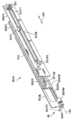
이제 도 13, 도 14a 및 도 14b를 참조하면, 상기 신축식 암들 (802A, 802B) 각각은 세 개의 링크들 (802FL, 802CL, 802IL)을 포함하지만, 다른 모습들에서 각 신축식 암 (802A, 802B)은 둘 보다 더 많거나 더 작은 개수의 링크들과 같은, 어떤 적합한 개수의 링크들을 포함한다. 여기에서 각 신축식 암은 상기 암 마운트들 (200M)에 설치된 고정 링크 (802FL), 중심 링크 (802CL), 그리고 내부 링크 (802IL)를 포함한다. 상기 중심 링크 (802CL)는 참조번호 299의 화살표 방향에서 상기 고정 링크 (802FL)에 대해 움직일 수 있도록 하기 위해 어떤 적합한 선형 슬라이드 (802CR) 또는 다른 선형으로 움직일 수 있는 조인트를 통해 상기 고정 링크 (802FL)에 설치된다. 상기 내부 링크 (802IL)는 참조번호 299의 화살표 방향에서 상기 중심 링크 (802CL)에 대해 움직일 수 있도록 하기 위해 어떤 적합한 선형 슬라이드 (802IR) 또는 다른 선형으로 움직일 수 있는 조인트를 통해 상기 중심 링크 (802CL)에 설치된다. 드라이브 벨트 (501B)가 도르래들 (501P1, 501P2)을 통해 상기 고정 링크 (802FL)에 설치되며, 여기에서 도르래 (501P1)는 드라이브 커플링 (501)을 구비한 구동 도르래이다. 드라이브 모터 (260A)는 상기 프레임 (200F)에 설치되며 그리고, 예를 들면, 벨트 및 도르래 트랜스미션, 기어 구동 트랜스미션, 체인 구동 트랜스미션 또는 어떤 다른 구동 커플링과 같은 어떤 적합한 트랜스미션 (260AT)을 통해 하나 또는 그 이상의 샤프트들 (500A, 500B)에 작동 가능하게 연결된다 (도면들에서는 두 개의 드라이브 샤프트들이 보이지만 다른 모습들에서는 둘 보다 더 많거나 더 작은 드라이브 샤프트들이 사용된다). 상기 도르래 (501P1)를 구동시키고 그리고 그렇게 해서 상기 벨트 (501B)를 구동시키 위해, 상기 하나 또는 그 이상의 샤프트들 (500A, 500B)은 상기 모터를 상기 드라이브 커플링 (501)에 연결시킨다. 상기 중심 링크 (8012CL)는 커플링 (501C)으로 벨트 (501B)에 결합되며, 그래서 상기 벨트 (501B)가 움직이면 상기 중심 링크 (802CL)가 참조번호 299의 화살표 방향에서 상기 벨트 (501B)와 함께 움직이도록 한다. 다른 드라이브 벨트 (501B2)가, 벨트 (501B)에 관해 위에서 설명된 것과 유사한 방식으로 상기 중심 링크 (802CL) 상에 도르래들과 함께 설치된다. 상기 벨트 (501B2)는 상기 고정 링크 (802FL) 그리고 상기 내부 링크 (802IL) 둘 모두에 고정되며, 그래서 상기 중심 링크 (802CL)가 화살표 299의 방향에서 구동되면, 상기 벨트 (501B2)의 슬레이브적인 속성이 상기 내부 링크 (802IL) 및 상기 중심 링크 (802CL) 사이에서의 상대적인 움직임을 초래하게 하며, 그래서 상기 내부 링크 (802IL)이 참조번호 299의 화살표의 방향에서 또한 움직이게 하며 그리고 상기 링크들 (802FL, 802CL, 802IL)이 신축식 방식으로 확장하도록 한다.Referring now to FIGS. 13 , 14A and 14B , each of the
한 모습에서, 피크페이스 맞물림 또는 푸셔 부재 (pusher member) (900T)가 상기 내부 링크 (802IL)에 설치되며, 이는 참조번호 299의 화살표 방향에서 움직일 수 있도록 하기 위한 것이다. 다른 피크페이스 맞물림 또는 핑커 부재 (900F)가 축 FAX 주위에서 회전가능하도록 하기 위해 내부 링크 (802IL)에 또한 설치되며, 이것은 참조번호 299의 방향과 실질적으로 평행하며, 이것은 배치된 위치 (도 14b 참조) 그리고 수축된 위치 (도 14a 참조) 사이에서 회전되도록 하기 위한 것이다. 상기 푸셔 부재 (900T)는 상기 내부 링크 (802IL)의 어퍼처 (900TA) 내에서 참조번호 299의 방향에서 왕복하기 위해 선형 드라이브 또는 액튜에이터 (900TM)에 의해 구동된다. 상기 푸셔 부재 (900T)는, 참조번호 299A의 화살표 방향에서 이동할 때에 미리 정해진 선반 (140) 상으로 피크페이스를 밀기 위해 상기 페이로드 베이 (200)의 중심선 PBCL을 향하여 참조번호 297의 화살표 방향에서 확장하는 피크페이스 맞물림 표면 (900TS)을 포함한다. 한 모습에서 상기 푸셔 부재 (900T)는 참조번호 299의 화살표 방향에서, 피크페이스 보유 로케이션으로 배치되고 있을 때에, 예를 들면, 피크페이스 크기, 저장 래크 구조 (예를 들면, 상기 피크페이스 보유 로케이션) 및 상기 신축식 암들 (802A, 802B)의 확장/수축 중 하나 또는 그 이상에 독립적으로 피크페이스(들)의 정돈을 실행한다. 다른 말로 하면, 참조번호 299의 방향에서 상기 푸셔 부재의 이동은 상기 신축식 암들 (802A, 802B)의 확장/수축에 독립적으로 그리고 저장 래크 (피크페이스 보유 로케이션)를 가로지르는 확장 및 수축의 방향을 따른 피크페이스의 독립적으로 다양한 정돈을 실행한다. 실감될 수 있듯이, 한 모습에서, 참조번호 299, 297의 화살표들 중 하나 또는 그 이상의 화살표의 방향에서 상기 암들 (802A, 802B)의 움직임에 따라 참조번호 299의 화살표 방햐에서 하나 또는 그 이상의 푸셔 부재 (900T)의 이동은 적어도 하나의 피크페이스의 크기에 독립적인 적어도 하나의 피크페이스의 전체 페이로드 영역 정돈 (예를 들면, 위에서 언급된 것처럼, 상기 암들 (220A, 220B)에 의해 액세스 가능한 저장 선반 영역 내 임의의 장소 그리고 상기 페이로드 베드 내 임의 장소에서의 페이로드의 정돈)을 실행하기 위해 페이로드 베드/영역의 피크페이스 지지 평면과 실질적으로 평행한 평면 내에서이다.In one aspect, a pickface engagement or
상기 핑거 부재 (900F)는 회전 모터 (900FM)와 같은 어떤 적합한 드라이브를 통해 상기 내부 링크 (802IL) 상에 회전 가능하게 설치된다. 도 13a를 또한 참조하면, 상기 핑거 부재 (900F)는 수축된 위치 내에 배치되어 상기 피크페이스 (210)가The
선반 (140) 상으로 밀릴 때에 또는 상기 엔드 이펙터의 확장 동안에 상기 자유 말단 FE을 지나서 선반 (140) 상의 피크페이스 저장 로케이션으로 이동하는 것을 허용하며, 예를 들면, 그래서 각 신축식 암이 인접한 피크페이스들 사이에서 확장되도록 하며, 이는 선반 (140) 상에 위치한 피크페이스들과 간섭하지 않으면서, 집혀진 피크페이스에 걸터있게 하기 위한 것이다. 상기 핑거 부재 (900F)는 피크페이스 맞물림 표면 (900FS)을 포함하며, 이 피크페이스 맞물림 표면은 미리 정해진 피크페이스에 맞물려서, 상기 신축식 암들 (802A, 802B)이 상기 선반들 밖으로 이동하고 그리고 상기 피크페이스를 상기 페이로드 베이 (200)로 운송할 때에 상기 선반 (140)으로부터 상기 피크페이스를 당기기 위한 것이다. 도 13, 도 14a, 도 14b에서 볼 수 있듯이, 상기 핑거 부재 (900F)는 상기 내부 링크 (802IL)의 자유 말단 FE에 위치하며 그리고 축 FAX 주위에서 회전한다. 동작 시에, 수축식 암들 (802A, 802B)이 피크페이스 (210)를 집기 위해 선반 (140) 내로 확장될 때에, 상기 핑거 부재 (900F)는 상기 피크페이스 (210)의 말단 (210E)을 지나서 배치되며 그리고 그 후에 상기 배치된 위치로 회전되어, 상기 피크페이스 맞물림 표면 (900FS)이 상기 피크페이스 (210) 뒤에 배치되도록 한다. 상기 엔드 이펙터 (802)가 참조번호 299B의 화살표 방향에서 수축되면 상기 핑거들 (900F)의 피크페이스 맞물림 표면들 (900FS)은 상기 피크페이스 (210)에 맞물리며 그리고 상기 피크페이스 (210)를 상기 페이로드 베이 (200)로 당긴다.Allows movement past the free end FE to a pickface storage location on the
실감될 수 있듯이, 상기 푸셔 부재 (900T)는 상기 핑거 부재 (900F)를 향하여 그리고 그 핑거 부재로부터 멀어지는 참조번호 299의 방향에서 움직일 수 있다. 상기 핑거 부재 (900F)에 대한 상기 푸셔 부재 (900T)의 이 왕복하는 운동의 움직임은 상기 핑거 부재들 (900F)와 상기 푸셔 부재들 (900T) 사이에서 상기 피크페이스들 (예를 들면, 변하는 깊이들/크기들 DP를 구비한 피크페이스들)을 움켜잡고 (예를 들면, 캡쳐) 그리고 릴리즈하는 것을 실행한다. 상기 푸셔 부재들 (900T) 및 핑거 부재들 (900F) 사이에서의 상대적인 이동은 상기 신축식 암들 (802A, 802B) (예를 들면, 상기 엔드 이펙터 (802))의 자유 말단 FE에서 피크페이스의 정돈을 또한 실행하며, 그래서 상기 피크페이스가 상기 엔드 이펙터 (802)의, 예를 들면, 확장 길이에 종속한 무한대 개수의 미리 정해진 위치들에서 선반 상으로 밀려지도록 한다.As can be realized, the
한 모습에서, 하나 또는 그 이상의 신축식 암들 (802A, 802B)은 상기 암들 (802A, 802B) 중 각자 또는 둘 모두의 푸셔 부재 모터 (900TM) 및 핑거 모터 (900FM)를 제어하기 위한 무선 제어 모듈 (910)을 포함한다. 실감될 수 있듯이, 한 모습에서 각 신축식 암 (802A, 802B)은 각자의 모터들 (900TM, 900FM)을 제어하기 위한 각자의 무선 제어 모듈 (910)을 포함하며, 반면에 다른 모습들에서 공통의 무선 제어 모듈 (910)이 신축식 암들 (802A, 802B) 둘 모두에 있는 모터들 (900TM, 900FM)을 제어할 수 있다. 상기 무선 제어 모듈(들) (910)은 각 신축식 암 (802A, 802B)의 내부 링크 (802IL)에 설치되며, 다른 모습들에서 상기 무선 제어 모듈 (910)은 각 신축식 암 (802A, 802B)의 어떤 적합한 위치에도 설치된다. 상기 무선 제어 모듈 (910)은, 예를 들면, 블루투스, 적외산, 라디오 주파수 또는 어떤 다른 모습의 무선 통신과 같은 어떤 적합한 방식으로, 예를 들면, 상기 로버 제어기 (110C) (도 1)와 무선 통신하도록 구성된다. 상기 무선 제어 모듈 (910)은 상기 모터들 (900TM, 900FM)에게 전력을 공급하기 위한 배터리 (910B) 그리고 상기 배터리 (910B)를 충전하기 위한 접점들 (910C)을 포함한다. 예를 들어, 신축식 암들 (802A, 802B)이 도 8 및 도 13에서 도시된 것처럼 자신들의 원래의 또는 완전하게 수축된 구성/위치에 있을 때에, 상기 접점들 (910C)은 페이로드 베이 (200)의 접점들 (200CT)과 맞물리며, 그래서 상기 배터리들이 재충전되도록 한다. 여기에서 상기 접점들은 기계적인 접점들인 것으로 도시되었지만, 다른 모습들에서 상기 배터리 (910B)를 재충전시키는 것은 유도성과 같은 비접촉식 충전을 통해 실행될 수 있을 것이다. 실감될 수 있듯이, 상기 푸셔 부재 모터 (900TM) 및 핑거 모터 (900FM)는, 예를 들면, 많은 공간을 차지할 수 있으며 그리고 신뢰성의 문제점일 수 있는 페이로드 베이 (200) 및 상기 신축식 암들 (802A, 802B)의 각 링크 사이에서의 플렉싱 와이어들을 실질적으로 제거한다.In one aspect, one or
한 모습에서 참조번호 260A와 같은 단일의 모터는 도 13에서 최선으로 예시된 신축식 암들 둘 모두를 구동한다. 위에서 설명된 것처럼, 상기 모터 (260A)는, 예를 들면, 상기 페이로드 베이 (200)의 중간 후위에 있는 페이로드 베이 (200)의 프레임 (200F)에 설치되지만, 다른 모습들에서 상기 모터 (260A)는 상기 페이로드 베이 (200)에 대한 어떤 적합한 위치에도 설치될 수 있을 것이다. 상기 모터 (260A)는 벨트 및 도르래 트랜스미션 (260AT), 체인 구동 트랜스미션, 기어 드라이브 트랜스미션 또는 어떤 다른 트랜스미션과 같은 어떤 적합한 트랜스미션에 연결된다. 상기 트랜스미션 (260AT)은 상기 모터 (260A)의 출력 샤프트를, 예를 들면, 드라이브 샤프트들 (500A, 500B)과 연결시키며, 이 드라이브 샤프트들은, 예를 들면, 상기 트랜스미션 (260AT)으로부터의 어느 한 방향에서 확장하기 위해 상기 신축식 암 (802A, 802B)에 실질적으로 수직인 방위이다. 두 개의 드라이브 샤프트들 (500A, 500B)이 예시되었지만, 다른 모습들에서는 단일의 드라이브가 사용된다. 상기 드라이브 샤프트들 (500A, 500B)은, 아래에서 설명될 것과 같이 상기 샤프트들 (500A, 500B)을 트랜스미션 (260AT) 및 도르래들 (501P1)에 결합시키기 위한 스플라인 (spline) 커플링, 헥스 (hex) 커플링, 플랜지 (flange) 커플링, 빔 (beam) 커플링, 고정 커플링 (rigid coupling) 또는 어떤 다른 커플링과 같은 적합한 커플링이나 적합한 드라이브 맞물림을 포함하는 어떤 적합한 샤프트들일 수 있다. 예를 들면, 위에서 설명된 것처럼, 도르래 (501P1)는 드라이브 커플링 (501)을 포함하며, 이는 상기 드라이브 샤프트들 (500A, 500B) 중 각자의 하나의 드라이브 커플링과 짝을 이룬다. 한 모습에서, 상기 샤프트들 (500A, 500B) 그리고 상기 도르래 (501P10 사이에서의 커플링은 부상식 (floating) 커플링이어서, 상기 드라이브 샤프트들 (500A, 500B)이 고정된 암 링크들 (802FL)에 배치된 도르래들 (501PS)의 드라이브 커플링 (501)에 의해 지지되도록 하며, 이는, 예를 들면, 잘못된 정렬로부터 묶이는 것을 피하기 위한 것이다. 각 도르래 (501P1)가 각자의 드라이브 샤프트 (500A, 500B)에 의해 구동되면, 암들 (802A, 802B)의 신축식 모션에 전력을 공급하거나 그렇지 않다면 그 신축식 모션을 구동하기 위해서 각 도르래 (501P1)는 각 암 (802A, 802B)의 고정된 암 링크 (802FL) 상의 벨트 (501B)를 결국 구동한다. 한 모습에서 상기 드라이브 샤프트 (500A, 500B)는 상기 드라이브 커플링이 상기 드라이브 샤프트 (500A, 500B)의 길이를 따라서 확장하도록 구성되어, 상기 도르래 (501P1)가 드라이브 샤프트 (500A, 500B)와의 구동 맞물림은 유지하면서 각 드라이브 샤프트 (500A, 500B)의 길이를 따라서 미끄러질 수 있도록 한다. 예를 들면, 상기 암들 (802A, 802B)이 참조번호 297의 화살표 방향에서 서로를 향하여 또는 서로로부터 멀어지게 이동되면, 각 도르래 (501P1)의 커플링 (501)은 상기 드라이브 샤프트 (500A, 500B)를 따라서 미끄러져서, 상기 암들이 참조번호 297의 화살표 방향을 따라 제한된 이동 범위 내 무한 개수의 위치들에서 확장되고 수축되는 것을 가능하게 한다.In one aspect, a single motor, such as 260A, drives both telescoping arms best illustrated in FIG. 13 . As described above, the
실감될 수 있듯이, 부하들이 상기 매니퓰레이터 (800E) 내에 분산되는 방식으로 인해서, (여기에서 설명되는) 상기 매니퓰레이터 (800E)의 구조는 극도로 가벼운 무게일 수 있다. 예를 들어, 상기 매스트들 (801A, 802B), 페이러드 베이 (200) 그리고 그것들에 있는 컴포넌트들 (예를 들면, 참조번호 298, 297의 화살표들 방향들에서 상기 신축식 암들 (802A, 802B)을 구동하기 위한 컴포넌트들)은 표준의 알루미늄 채널 및 높은 강도의 점착성을 함께 보유하는 알루미늄 스킨들을 사용한다. 이런 유형의 구조는, 처리될 피크페이스들의 변이에 종속하는 큰 또는 작은 페이로드들을 위해 개별적인 프레임들 (200F, 200GF, 801F, 803F)이 구성되는 것을 가능하게 한다. 상기 신축식 암들 (802A, 802B)은 변하는 이동 깊이들을 위해 또한 쉽게 구성된다.As can be realized, due to the way loads are distributed within the
도 8을 다시 참조하여, 상기 매니퓰레이터 (800E)의 예시적인 동작이 설명될 것이다. 상기 로버 (110)는 위에서 설명된 것과 실질적으로 유사한 방식으로 피크페이스를 선반으로부터 로버 (110)로 운반하기 위해 배치된다 (도 15, 블록 5000). 상기 암들 (802A, 802B)을 도 13a에서 도시된 것처럼 (인접한 피크페이스들 사이에 공간 SP에 맞추기 위해서) 피크페이스에 정렬시키기 위해 참조번호 297의 화살표 방향에서 상기 암들 (802A, 802B) 사이의 간격 D1'이 조절된다 (도 15, 블록 5001). 위에서 설명된 것처럼, 한 모습에서 상기 로버 (110)는 참조번호 297의 화살표 방향에서의 정돈을 포함하며, 상기 로버의 신축식 암들은 참조번호 297의 방향에서 하나의 유닛으로서 움직여서 상기 피크페이스를 보유 로케이션에 더 정렬시키며 (또는 상기 암들을 상기 피크페이스에 정렬시키며), 예를 들면, 피크페이스 보유 로케이션에 대해 상기 신축식 암들을 정밀하게 배치한다 (도 15, 블록 5001A). 상기 페이로드 베이 (200)는 참조번호 298의 화살표 방향에서 이동되어 상기 페이로드 베이 (200)의 피크페이스 지지 표면 (200S)을 선반 (140)의 지지 표면 (또는 평면) (140SPL)에 실질적으로 정렬시킨다 (도 15, 블록 5002). 상기 신축식 암들 (802A, 802B)은 참조번호 299A의 방향에서 확장되어 (예를 들면, 핑거들 (900F)은 수축된 위치에서 있으며), 상기 핑거들 (900F)이 도 13a에 도시된 것처럼 피크페이스 (210)의 말단 (210E) 뒤에 또는 그 말단을 지나서 위치하도록 한다 (도 15, 블록 5003). 상기 핑거들 (900F)은 (도 13a 및 도 14b에 도시된 것처럼) 전개된 위치로 회전되며 (도 15, 블록 5004) 그리고 상기 수축식 암들 (802A, 802B)은 참조번호 299B의 화살표 방향에서 수축되어, 상기 핑거들 (900F)이 상기 피크페이스 (210)에 맞물리도록 하며 그리고 상기 피크페이스를 상기 선반 (140)으로부터 상기 페이로드 베이 (200)의 피크페이스 지지 표면 (200S)으로 끌어당기도록한다 (예를 들면, 미끄러지도록 한다) (도 15, 블록 5005). 실감될 수 있을 것처럼, 상기 내부 암 링크들 (802IL) 및 상기 피크페이스 (210) 사이에 적합한 제거가 제공되어, 상기 내부 링크들 (802IL) 사이에서 피크페이스가 제거되는 것을 가능하게 하지만, 한 모습에서 상기 제거는 최소이어서, 상기 내부 암 링크들 (802IL)이 상기 페이로드 베이 내에서 상기 피크페이스의 (참조번호 297의 화살표 방향에서의) 이동 및 정돈을 가이드하도록 한다는 것이 이해되어야 한다. 다른 모습들에서 상기 피크페이스는 상기 페이로드 베이 (200) 내 참조번호 297의 화살표 방향에서, 예를 들면, 상기 페이로드 베이 (200)의 중심라인 CL (도 13)을 따라서 정돈되며, 이 경우에 상기 페이로드 베이 (200)의 상기 중심라인 (CL)을 따라서 상기 피크페이스의 중심라인을 배치하기 위해 상기 신축식 암들 (802A, 802B)은 참조번호 297의 화살표 방향 내 다른 쪽을 향하여 이동된다. 예를 들면 피크페이스의 운송을 허용하기 위해 상기 핑거(들) (900F) 및 상기 푸셔 부재(들) (900T) 사이에 상기 피크페이스 (210)를 클램프 고정하거나 잡기 위해서 상기 핑거들 (900F)에 대하여 상기 피크페이스 (210)를 이동시키기 위해 상기 푸셔 부재 (900T)는 참조번호 299A의 화살표 방향에서 작동된다. 실감할 수 있듯이, 상기 핑거(들) (900F) 및 상기 푸셔 부재(들) (900T) 사이에 상기 피크페이스 (210)를 클램프 고정하는 것은 참조번호 299의 방향에서 상기 피크페이스 (210)를 또한 정돈시키며, 그래서 상기 피크페이스가 미리 정해진 선반 (140) 또는 다른 보유 로케이션 상의 어떤 적합한 깊이에서 배치될 수 있도록 한다 (도 15, 블록 5008). 다른 모습들에서, 상기 핑거들 (900F)은 상기 피크페이스로부터 맞물림이 해제되며 그리고 참조번호 299의 화살표 방향에서 의 상기 푸셔 부재(들) (900T) 단독의 움직임은 참조번호 299의 화살표 방향에서 상기 피크페이스 (210)의 정돈을 수행하며, 그래서 상기 피크페이스가 미리 정해진 선반 (140) 또는 다른 보유 로케이션 상의 어떤 적합한 깊이에서 배치될 수 있도록 한다. 실감될 수 있듯이, 위에서 설명된 집는 (picking) 프로세스는 상기 페이로드 베이 (200) 내에서 참조번호 200의 방향을 따라 여러 피크페이들이 배열되도록 반복될 수 있다.Referring again to FIG. 8 , an exemplary operation of the
피크페이스 (210)를 배치하기 위해 상기 로버 (110)는 위에서 설명된 것과 실질적으로 유사한 방식으로 선반으로부터 상기 로버 (110)로 피크페이스를 운반하기 위해 위치가 정해진다. 위에서 설명된 것처럼, 한 모습에서 상기 로버 (110)는 참조번호 297의 화살표 방향에서의 정돈을 포함하며, 상기 로버의 신축식 암들은 참조번호 297의 방향에서 하나의 유닛으로서 움직여서 상기 피크페이스를 보유 로케이션에 맞추어 더 정렬시키며 (또는 상기 암들을 상기 피크페이스에 맞추어 정렬시키며), 예를 들면, 피크페이스 보유 로케이션에 대해 상기 신축식 암들을 정밀하게 배치한다 (도 16, 블록 6001A). 상기 페이로드 베이 (200)는 참조번호 298의 화살표 방향에서 이동되어 도 13b에 도시된 것처럼 상기 페이로드 베이 (200)의 피크페이스 지지 표면 (200S)을 선반 (140)의 지지 표면 (또는 평면) (140SPL)에 실질적으로 정렬시킨다 (도 16, 블록 6002). 상기 핑거들 (900F)은, 예를 들면, 14a에서 보이는 수축된 위치로 회전된다 (실감될 수 있듯이 상기 푸셔 부재(들) (900T) 및 상기 핑거(들) (900F) 사이에서 상기 피크페이스를 잡는 것은 상기 핑거(들) (900F)의 움직임을 허용하기 위해 충분하게 릴리즈될 수 있을 것이다) (도 16, 블록 6003). 상기 신축식 암들 (802A, 802B)은 참조번호 299A의 화살표의 방향에서 확장되며, 그래서 상기 푸셔 부재들 (900T)이 상기 피크페이스 (210)를 상기 페이로드 베이의 피크페이스 지지 표면 (200S)으로부터 상기 선반 (140) 또는 다른 피크페이스 보유 위치의 지지 표면 (140SPL)으로 밀거나 미끄러지게 하도록 한다 (도 16, 블록 6004). 한 모습에서 참조번호 299A의 방향에서 상기 피크페이스를 추가로 배치하기 위해서 상기 신축식 암들 (802A, 802B)의 확장 동안에 그리고/또는 그 이후에 상기 푸셔 부재들 (900T)은 참조번호 299A의 방향에서 이동된다. 도 8을 다시 참조하여, 로버 (110)의 예시적인 피크페이스 구축 동작이 설명될 것이다. 상기 로버 (110)는 위에서 설명된 것과 실질적으로 유사한 방식으로 하나 또는 그 이상의 제1 피크페이스들 (210) (도 2c)을 선반으로부터 상기 로버 (110)로 운반하기 위해 배치된다 (도 18, 블록 7000). 도 13a에서 도시된 것처럼 (인접한 케이스 유닛들/피크페이스들 사이의 공간 (SP)에 맞추기 위해서) 상기 암들 (802A, 802B)을 하나 또는 그 이상의 제1 피크페이스들 (210)에 정렬시키기 위해 참조번호 297의 화살표 방향에서 상기 암들 (802A, 802B) 사이의 간격 D1'이 조절된다 (도 18, 블록 7001). 위에서 설명된 것처럼, 한 모습에서 상기 로버 (110)는 참조번호 297의 화살표 방향에서의 정돈을 포함하며, 상기 로버의 신축식 암들은 참조번호 297의 방향에서 하나의 유닛으로서 움직여서 상기 신축식 암들 (802A, 802B)을 하나 또는 그 이상의 제1 피크페이스들 (210)에 더 정렬시키며, 예를 들면, 피크페이스 보유 로케이션에 대해 상기 신축식 암들을 정밀하게 배치한다 (도 18, 블록 7001A). 상기 페이로드 베이 (200)는 참조번호 298의 화살표 방향에서 이동되어 상기 페이로드 베이 (200)의 피크페이스 지지 표면 (200S)을 도 13b에 도시된 것처럼 선반 (140)의 지지 표면 (또는 평면) (140SPL)에 실질적으로 정렬시킨다 (도 18, 블록 7002). 상기 신축식 암들 (802A, 802B)은 참조번호 299A, 299B의 화살표들의 방향에서 확장되고 수축하여, 도 15의 블록들 5003 - 5007에 관해서 위에서 설명된 방식으로 하나 또는 그 이상의 제1 피크페이스들 (210)을 상기 페이로드 베이로 운반한다 (도 18, 블록 7003). 일단 하나 또는 그 이상의 제1 피크페이스들 (2100이 상기 페이로드 베드 (200) 내에 배치되면 상기 로버 (110)는 상기 피킹 구조를 횡단하고 그리고 하나 또는 그 이상의 제2 피크페이스들 (210X) (도 2c)을 상기 페이로드 베이 (200)로 운반하기 위해서 다른 피크페이스 보유 로케이션에 대해 위치가 정해진다 (도 18, 블록 7000). 상기 페이로드 베이 내 하나 또는 그 이상의 피크페이스들 (210)이 클램프 고정 해제되고 그리고 상기 신축식 암들 (801A, 801B)을 다른 피크페이스 보유 로케이션 내 하나 또는 그 이상의 제2 피크페이스들 (210X)에 정렬시키기 위해서 상기 신축식 암들 (802A, 802B) 사이의 간격이 조절되고 (도 18, 블록 7001) 그리고/또는 정돈된다 (도 18, 블록 7001A). 실감될 수 있듯이, 상기 페이로드 베드 (200) 상에 이미 보유된 하나 또는 그 이상의 제1 피크페이스들 (210)은 상기 신축식 암들이 정돈될 때에 참조번호 297의 화살표 방향에서 상기 신축식 암들를 이용하여 이동된다. 페이로드 베이 (200)의 피크페이스 지지 표면 (200S)을 도 13b에 도시된 것처럼 선반 (140)의 지지 표면 (또는 평면) (140SPL)에 실질적으로 정렬하기 위해 상기 페이로드 베이 (200)는 참조번호 298의 방향에서 이동된다 (도 18, 블록 7002). 상기 신축식 암들 (802A, 802B)은 도 15의 참조번호 5003 - 5007의 블록들에 관하여 위에서 설명된 방식으로 상기 페이로드 베이로 하나 또는 그 이상의 제2 피크페이스들 (210X)을 운반하기 위해 참조번호 299A, 299B의 화살표들의 방향에서 확장되고 수축된다 (도 18, 블록 7003). 실감될 수 있듯이, 상기 하나 또는 그 이상의 제2 피크페이스들 (210X)을 상기 페이로드 베이 (200)로 운반하는 동안에 상기 신축식 암들 (802A, 802B)은 상기 하나 또는 그 이상의 제1 피크페이스들의 측면들로부터 이격될 수 있을 것이며, 그래서 상기 푸셔 부재들 (900T)이 상기 페이로드 베이 (200) 내 상기 하나 또는 그 이상의 제1 피크페이스들 (2100에 접촉하지 않도록 한다 (그리고/또는 상기 페이로드 베이 (200) 내 상기 피크페이스와 접촉하지 않기 위해서 상기 푸셔 부재들 (900T)이 배치된다). 하나 또는 그 이상의 피크페이스들 (210X)이 상기 페이로드 베드 (200) 내에 위치할 때에, 참조번호 299A, 299B의 화살표들의 방향에서 상기 하나 또는 그 이상의 제1 피크페이스들 및 제2 피크페이스들을 함께 편안하게 보관하기 위해 상기 푸셔 부재들 (900T) 그리고/또는 핑거들 (900F)이 사용된다. 피크페이스들 (210, 210X)을 페이로드 베드로 운반하는 것에 관하여 위에서 설명된 것과 실질적으로 반대의 방식으로 상기 하나 또는 그 이상의 제1 피크페이스들 및 제2 피크페이스들 (210, 210X)은 상기 로버에 의해서 하나의 유닛으로서 운반되며 그리고 피크페이스 보유 로케이션에 하나의 유닛으로서 배치된다.For positioning the
개시된 실시예의 하나 또는 그 이상의 모습들에 따라서 자율 운송 차량이 제공된다. 상기 자율 운송 차량은 페이로드 베드 그리고 상기 페이로드 베드 내에 배치되며 그리고 상기 페이로드 베드로 그리고 페이로드 베드로부터 피크페이스를 운반하기 위해 제1 축을 따라 확장하도록 구성된 엔드 이펙터를 포함하며, 상기 엔드 이팩터는 적어도 하나의 운반 암 그리고 상기 제1 축에 실질적으로 수직인 제2 축을 따라서 상기 적어도 하나의 암을 확장시키는 핑거들 (fingers)을 포함하며, 상기 핑거들은 상기 피크페이스 밑으로부터 상기 피크페이스를 지지하도록 구성된다.An autonomous transport vehicle is provided in accordance with one or more aspects of a disclosed embodiment. The autonomous transport vehicle includes a payload bed and an end effector disposed within the payload bed and configured to extend along a first axis for carrying a pickface to and from the payload bed, the end effector comprising at least a carrying arm and fingers extending the at least one arm along a second axis substantially perpendicular to the first axis, the fingers configured to support the pickface from below the pickface do.
개시된 실시예의 하나 또는 그 이상의 모습들에 따라서, 상기 적어도 하나의 운반 암은 상기 피크페이스의 반대편 측면들에 걸치도록 (straddle) 구성된 두 개의 운반 암들을 포함한다.In accordance with one or more aspects of the disclosed embodiment, the at least one transport arm includes two transport arms configured to straddle opposite sides of the pickface.
개시된 실시예의 하나 또는 그 이상의 모습들에 따라서, 상기 적어도 하나의 운반 암은 신축식 운반 암 (telescoping transfer arm)이다.In accordance with one or more aspects of the disclosed embodiment, the at least one transfer arm is a telescoping transfer arm.
개시된 실시예의 하나 또는 그 이상의 모습들에 따라 상기 적어도 하나의 운반 암 각각은 상기 적어도 하나의 운반 암의 확장 및 수축을 실행하도록 구성된 벨트 드라이브를 포함한다.In accordance with one or more aspects of the disclosed embodiment each of the at least one transport arm includes a belt drive configured to effect extension and retraction of the at least one transport arm.
개시된 실시예의 하나 또는 그 이상의 모습들에 따라서, 상기 핑거들은 피크페이스 지지 선반의 지지 표면들 사이의 피치에 대응하는 미리 정해진 피치만큼 이격하여 위치하여, 상기 핑거들이 상기 지지 표면들 사이에 위치한 공간들을 통해 지나가도록 한다.In accordance with one or more aspects of the disclosed embodiment, the fingers are spaced apart by a predetermined pitch corresponding to the pitch between the support surfaces of the pickface support shelf, such that the fingers are spaced apart from the spaces located between the support surfaces. let it pass through
개시된 실시예의 하나 또는 그 이상의 모습들에 따라서, 상기 자율 운송 차량은 상기 자율 운송 차량의 길이 방향 축을 따라 상기 적어도 하나의 운반 암을 움직이게 하도록 구성된 드라이브 섹션을 포함한다.In accordance with one or more aspects of the disclosed embodiment, the autonomous transport vehicle includes a drive section configured to move the at least one transport arm along a longitudinal axis of the autonomous transport vehicle.
개시된 실시예의 하나 또는 그 이상의 모습들에 따라서, 상기 자율 운송 차량은 상기 자율 운송 차량의 길이 방향 축을 따른 상기 적어도 하나의 운반 암 각각을 상기 적어도 하나의 운반 암 중 다른 하나와 독립적으로 움직이게 하도록 구성된 드라이브 섹션을 포함한다.In accordance with one or more aspects of the disclosed embodiment, the autonomous transport vehicle is a drive configured to move each of the at least one transport arm along a longitudinal axis of the autonomous transport vehicle independently of the other of the at least one transport arm. contains sections.
개시된 실시예의 하나 또는 그 이상의 모습들에 따라서, 상기 자율 운송 차량은 상기 엔드 이펙터들 상기 제1 축에 실질적으로 수직인 방향에서 움직이게 하도록 구성된 드라이브 섹션을 포함한다.In accordance with one or more aspects of the disclosed embodiment, the autonomous transport vehicle includes a drive section configured to cause the end effectors to move in a direction substantially perpendicular to the first axis.
개시된 실시예의 하나 또는 그 이상의 모습들에 따라서, 상기 드라이브 섹션은 상기 제1 축에 실질적으로 수직인 방향에서 상기 엔드 이펙터를 움직이게 하도록 구성되어, 상기 자율 운송 차량이 다중 레벨의 쌓여진 저장 선반들에 액세스하는 것을 가능하게 한다.In accordance with one or more aspects of the disclosed embodiment, the drive section is configured to move the end effector in a direction substantially perpendicular to the first axis, such that the autonomous transport vehicle accesses multi-level stacked storage shelves. make it possible to do
개시된 실시예의 하나 또는 그 이상의 모습들에 따라서, 상기 핑거들은 상기 적어도 하나의 운반 암에 고정되어 설치된다.In accordance with one or more aspects of the disclosed embodiment, the fingers are fixedly mounted to the at least one transport arm.
개시된 실시예의 하나 또는 그 이상의 모습들에 따라서, 상기 핑거들은 확장된 위치와 수축된 위치 사이에서의 움직임을 위해 상기 적어도 하나의 운반 암에 움직일 수 있게 장착되며, 이 경우에 상기 확장된 위치에 있을 때에 상기 핑거들은 상기 제2 축을 따라 상기 적어도 하나의 운반 암으로부터 확장한다.In accordance with one or more aspects of the disclosed embodiment, the fingers are movably mounted to the at least one carrying arm for movement between an extended position and a retracted position, in which case in the extended position. when the fingers extend from the at least one carrying arm along the second axis.
개시된 실시예의 하나 또는 그 이상의 모습들에 따라서, 저장 및 인출 시스템이 제공된다. 상기 저장 및 인출 시스템은 적어도 하나의 자율 운송 차량을 포함하며, 이 자율 운송 차량은 페이로드 베드 그리고 상기 페이로드 베드 내에 배치되며 그리고 상기 페이로드 베드로 그리고 페이로드 베드로부터 피크페이스를 운반하기 위해 제1 축을 따라 확장하도록 구성된 엔드 이펙터를 포함하며, 상기 저장 및 인출 시스템은 적어도 하나의 피킹 (picking) 통로로, 상기 적어도 하나의 자율 운송 차량의 상기 피킹 통로를 통한 이동을 허용하도록 구성된 적어도 하나의 피킹 통로; 그리고 상기 적어도 하나의 피킹 통로에 인접하여 위치한 적어도 하나의 저장 선반을 포함하며, 상기 적어도 하나의 저장 선반은 제2 축을 따라 확장하는 이격되어 이치한 피크페이스 지지 표면들을 구비하며, 이 경우 상기 제2 축은 상기 제1 축에 실질적으로 수직이며 그리고 상기 엔드 이펙터는 핑거들을 포함하며, 이 핑거들은 상기 제2 축을 따라 연장하며 그리고 상기 핑거들과 상기 피크페이스 지지 표면들과의 인터리빙을 허용하도록 구성된다.In accordance with one or more aspects of the disclosed embodiment, a storage and retrieval system is provided. The storage and retrieval system includes at least one autonomous transport vehicle, the autonomous transport vehicle disposed within the payload bed and a first payload bed for transporting a pickface to and from the payload bed. an end effector configured to extend along an axis, wherein the storage and retrieval system comprises at least one picking aisle configured to permit movement of the at least one autonomous transport vehicle through the picking aisle; ; and at least one storage shelf positioned adjacent the at least one picking aisle, the at least one storage shelf having spaced apart pickface support surfaces extending along a second axis, in this case the second An axis is substantially perpendicular to the first axis and the end effector includes fingers extending along the second axis and configured to allow interleaving of the fingers with the pickface support surfaces.
개시된 실시예의 하나 또는 그 이상의 모습들에 따라서, 상기 엔드 이펙터 (end effector)는 적어도 하나의 운반 암 그리고 그 적어도 하나의 운반 암으로부터 확장하는 핑거들을 포함한다.In accordance with one or more aspects of the disclosed embodiment, the end effector includes at least one conveying arm and fingers extending from the at least one conveying arm.
개시된 실시예의 하나 또는 그 이상의 모습들에 따라서, 상기 적어도 하나의 운반 암은 상기 피크페이스의 반대편 측면들에 걸치도록 (straddle) 구성된 두 개의 운반 암들을 포함한다.In accordance with one or more aspects of the disclosed embodiment, the at least one transport arm includes two transport arms configured to straddle opposite sides of the pickface.
개시된 실시예의 하나 또는 그 이상의 모습들에 따라서, 상기 자율 운송 차량은 상기 자율 운송 차량의 길이 방향 축을 따라 상기 적어도 하나의 운반 암을 움직이게 하도록 구성된 드라이브 섹션을 포함한다.In accordance with one or more aspects of the disclosed embodiment, the autonomous transport vehicle includes a drive section configured to move the at least one transport arm along a longitudinal axis of the autonomous transport vehicle.
개시된 실시예의 하나 또는 그 이상의 모습들에 따라서, 상기 자율 운송 차량은 상기 자율 운송 차량의 길이 방향 축을 따른 상기 적어도 하나의 운반 암 각각을 상기 적어도 하나의 운반 암 중 다른 하나와 독립적으로 움직이게 하도록 구성된 드라이브 섹션을 포함한다.In accordance with one or more aspects of the disclosed embodiment, the autonomous transport vehicle is a drive configured to move each of the at least one transport arm along a longitudinal axis of the autonomous transport vehicle independently of the other of the at least one transport arm. contains sections.
개시된 실시예의 하나 또는 그 이상의 모습들에 따라서, 상기 엔드 이펙터는 신축식 엔드 이펙터이다.In accordance with one or more aspects of the disclosed embodiment, the end effector is a telescoping end effector.
개시된 실시예의 하나 또는 그 이상의 모습들에 따라서, 상기 엔드 이펙터는 적어도 하나의 운반 함을 포함하며 그리고 그 적어도 하나의 운반 암 각각은 상기 엔드 이펙터의 확장 및 수축을 실행하도록 구성된 벨트 드라이브를 포함한다.In accordance with one or more aspects of the disclosed embodiment, the end effector includes at least one transport box and each of the at least one transport arm includes a belt drive configured to effect extension and retraction of the end effector.
개시된 실시예의 하나 또는 그 이상의 모습들에 따라서, 상기 핑거들은 피크페이스 지지 선반의 지지 표면들 사이의 피치에 대응하는 미리 정해진 피치만큼 이격하여 위치하여, 상기 핑거들이 상기 지지 표면들 사이에 위치한 공간들을 통해 지나가도록 한다.In accordance with one or more aspects of the disclosed embodiment, the fingers are spaced apart by a predetermined pitch corresponding to the pitch between the support surfaces of the pickface support shelf, such that the fingers are spaced apart from the spaces located between the support surfaces. let it pass through
개시된 실시예의 하나 또는 그 이상의 모습들에 따라서, 상기 자율 운송 차량은 상기 제1 축에 실질적으로 수직인 방향에서 상기 엔드 이펙터를 움직이게 하도록 구성된 드라이브 섹션을 포함한다.In accordance with one or more aspects of the disclosed embodiment, the autonomous transport vehicle includes a drive section configured to move the end effector in a direction substantially perpendicular to the first axis.
개시된 실시예의 하나 또는 그 이상의 모습들에 따라서, 상기 드라이브 섹션은 상기 제1 축에 실질적으로 수직인 방향에서 상기 엔드 이펙터를 움직이게 하도록 구성되어, 상기 적어도 하나의 자율 운송 차량이 다중 레벨의 쌓여진 저장 선반들에 액세스하는 것을 가능하게 한다.In accordance with one or more aspects of the disclosed embodiment, the drive section is configured to move the end effector in a direction substantially perpendicular to the first axis, such that the at least one autonomous transport vehicle is a multi-level stacked storage shelf. make it possible to access them.
개시된 실시예의 하나 또는 그 이상의 모습들에 따라서, 상기 핑거들은 상기 엔드 이펙터에 고정되어 장착된다.In accordance with one or more aspects of the disclosed embodiment, the fingers are fixedly mounted to the end effector.
개시된 실시예의 하나 또는 그 이상의 모습들에 따라서, 상기 핑거들은 확장된 위치와 수축된 위치 사이에서의 움직임을 위해 상기 엔드 이펙터에 움직일 수 있게 장착되며, 이 경우에 상기 확장된 위치에 있을 때에 상기 핑거들은 상기 제2 축을 따라 상기 엔드 이펙터로부터 확장한다.In accordance with one or more aspects of the disclosed embodiment, the fingers are movably mounted to the end effector for movement between an extended position and a retracted position, in which case the finger when in the extended position. They extend from the end effector along the second axis.
개시된 실시예의 하나 또는 그 이상의 모습들에 따라서, 저장 및 인출 시스템 내에서 피크페이스들을 운반하기 위한 방법을 제공하며, 여기에서 상기 저장 및 인출 시스템은 적어도 하나의 자율 운송 차량, 적어도 하나의 하나의 피킹 (picking) 통로로, 상기 적어도 하나의 자율 운송 차량이 상기 피킹 통로를 따라 이동하도록 허용하도록 구성된 피킹 통로 데크를 구비한 적어도 하나의 피킹 통로 그리고 상기 적어도 하나의 피킹 통로에 인접하여 배치된 적어도 하나의 저장 선반을 포함한다. 상기 방법은 상기 적어도 하나의 자율 운송 차량의 엔드 이펙터를 적어도 하나의 저장 선반으로 미리 정해진 거리만큼 연장하여, 상기 엔드 이펙터의 암들이 피크페이스 반대 측면들에 걸터있도록 하는 단계, 상기 엔드 이펙터를 낮추어서 상기 엔드 이펙터의 확장의 축에 실질적으로 수직인 방향에서 상기 엔드 이펙터의 핑거들이 적어도 하나의 저장 선반의 피커페이스 지지 표면들과 그리고 그 지지 표면 아래에서 인터리빙되도록 하는 단계, 상기 피크페이스 밑에 상기 핑거들을 배치하는 단계, 그리고 상기 피크페이스를 상기 핑거들이 상기 피크페이스의 하중을 지지하는 곳인 상기 적어도 하나의 저장 선반으로부터 들어올리는 단계를 포함한다.In accordance with one or more aspects of the disclosed embodiment, there is provided a method for transporting pickfaces within a storage and retrieval system, wherein the storage and retrieval system comprises at least one autonomous transport vehicle, at least one picking at least one picking aisle having a picking aisle deck configured to allow the at least one autonomous transport vehicle to move along the picking aisle and at least one picking aisle disposed adjacent the at least one picking aisle Includes storage shelves. The method includes extending an end effector of the at least one autonomous transport vehicle to at least one storage shelf a predetermined distance such that the arms of the end effector straddle opposite sides of the pickface, lowering the end effector to the causing the fingers of the end effector to interleave with and below the pickerface support surfaces of at least one storage shelf in a direction substantially perpendicular to the axis of extension of the end effector, disposing the fingers under the pickface and lifting the pickface from the at least one storage shelf where the fingers support the load on the pickface.
개시된 실시예의 하나 또는 그 이상의 모습들에 따라서, 상기 피크페이스 밑에 상기 핑거들을 배치하는 단계는 상기 엔드 이펙터의 하나 또는 그 이상의 암들을 상기 피크페이스의 각자의 측면으로 향하여 움직이게 하는 단계를 포함한다.In accordance with one or more aspects of the disclosed embodiment, placing the fingers under the pickface includes moving one or more arms of the end effector towards a respective side of the pickface.
개시된 실시예의 하나 또는 그 이상의 모습들에 따라서, 상기 엔드 이펙터는 암들을 포함하며 그리고 상기 방법은 상기 암들 사이의 간격을 조절하는 단계를 더 포함하여, 상기 암들이 상기 피크페이스의 반대의 측면들을 따라 배치된 선반 공간들로 접촉하지 않고 삽입되도록 한다.In accordance with one or more aspects of the disclosed embodiment, the end effector comprises arms and the method further comprises adjusting a spacing between the arms, wherein the arms follow opposite sides of the pickface. Allows to be inserted without contact with the arranged shelf spaces.
개시된 실시예의 하나 또는 그 이상의 모습들에 따라서, 상기 저장 선반은 쌓여진 저장 선반들을 포함하며 그리고 상기 방법은 상기 엔드 이펙터들을 상기 쌓여진 저장 선반들 중 하나의 레벨로 높이거나 낮추는 단계를 더 포함한다.In accordance with one or more aspects of the disclosed embodiment, the storage shelf includes stacked storage shelves and the method further includes raising or lowering the end effectors to a level of one of the stacked storage shelves.
개시된 실시예의 하나 또는 그 이상의 모습들에 따라서, 다중의 쌓여진 저장 선반들은 공통의 피킹 통로 데크로부터 상기 적어도 하나의 자율 운송 차량에 의해 액세스 가능한다.In accordance with one or more aspects of the disclosed embodiment, multiple stacked storage shelves are accessible by the at least one autonomous transport vehicle from a common picking aisle deck.
개시된 실시예의 하나 또는 그 이상의 모습들에 따라서, 자율 운송 차량이 제공되며, 상기 자율 운송 차량은, 페이로드 (payload) 영역을 형성하는 프레임; 상기 프레임에 장착된 신축식 암 (telescoping arm)들로, 각 신축식 암들은, 상기 페이로드 영역으로 그리고 페이로드 영역으로부터 적어도 하나의 피크페이스 (pickface)를 운반하는 것을 실행하기 위해 확장 축을 따라 상기 프레임에 대해 확장 및 수축하며, 그리고 상기 확장 축과 각을 이룬 적어도 하나의 방향에서 상기 프레임에 대해 횡단하도록 구성된, 신축식 암들; 그리고 각 신축식 암으로부터 확장하는 적어도 하나의 탭을 포함하며, 상기 적어도 하나의 탭은 확장 및 수축의 방향을 횡단하는 방향에서 확장하며, 그리고 상기 신축식 암들 중 하나의 신축식 암 상의 상기 적어도 하나의 탭은 상기 신축식 암들 중 다른 신축식 암 상의 적어도 하나의 탭과 맞대어 있다.In accordance with one or more aspects of the disclosed embodiment, an autonomous transport vehicle is provided, the autonomous transport vehicle comprising: a frame defining a payload area; telescoping arms mounted to the frame, each telescoping arms along the axis of extension to effect carrying at least one pickface to and from the payload region. telescoping arms configured to extend and retract relative to the frame and transverse to the frame in at least one direction angled with the axis of extension; and at least one tab extending from each telescoping arm, the at least one tab extending in a direction transverse to the direction of expansion and retraction, and wherein the at least one tab on the telescoping arm of one of the telescoping arms is included. A tab of the abuts at least one tab on the other of the telescoping arms.
개시된 실시예의 하나 또는 그 이상의 모습들에 따라서, 상기 적어도 하나의 방향은 수직 방향 및 수평 방향 중 하나 이상이다.In accordance with one or more aspects of the disclosed embodiment, the at least one direction is one or more of a vertical direction and a horizontal direction.
개시된 실시예의 하나 또는 그 이상의 모습들에 따라서, 상기 자율식 운송 차량은 상기 신축식 암들의 횡단 그리고 상기 신축식 암들의 확장 및 수축을 실행하기 위해 상기 신축식 암들에 연결된 3 자유도 드라이브를 더 포함한다.In accordance with one or more aspects of the disclosed embodiment, the autonomous transport vehicle further comprises a three degree of freedom drive coupled to the telescoping arms to effect traversing the telescoping arms and extending and retracting the telescoping arms. do.
개시된 실시예의 하나 또는 그 이상의 모습들에 따라서, 신축식 암들 사이의 거리는 가변의 거리여서, 각 신축식 암이 확장 및 수축의 가변 로케이션을 가지도록 한다.In accordance with one or more aspects of the disclosed embodiment, the distance between the telescoping arms is a variable distance, such that each telescoping arm has a variable location of extension and retraction.
개시된 실시예의 하나 또는 그 이상의 모습들에 따라서, 각 신축식 암은 자유 말단 및 그 자유 말단에 장착된 회전가능 핑거 (finger)를 포함하며, 상기 회전가능 핑거는, 상기 적어도 하나의 피크페이스에 접촉하지 않기 위해 수축된 위치 그리고 상기 적어도 하나의 피크페이스의 수직 측면에 맞물리게 하며 그리고 상기 적어도 하나의 피크페이스를 상기 페이로드 영역으로 운반하는 것으로 적어도 실행하기 위해 배치된 위치 사이에서 움직일 수 있다.In accordance with one or more aspects of the disclosed embodiment, each telescoping arm includes a free end and a rotatable finger mounted to the free end, the rotatable finger contacting the at least one pickface. It is movable between a retracted position and a position arranged to at least effect engaging the vertical side of the at least one pickface and conveying the at least one pickface to the payload area.
개시된 실시예의 하나 또는 그 이상의 모습들에 따라서, 각 신축식 암은 적어도 하나의 각자의 핑거의 작동을 실행하기 위한 무선 제어 모듈을 포함한다.In accordance with one or more aspects of the disclosed embodiment, each telescoping arm includes a wireless control module for effecting actuation of at least one respective finger.
개시된 실시예의 하나 또는 그 이상의 모습들에 따라서, 각 신축식 암은 상기 핑거와 맞닿은 움직일 수 있는 푸셔 부재 (pusher member)를 포함하며, 상기 푸셔 부재는 상기 핑거를 향하여 그리고 그 핑거로부터 적어도 하나의 클램프까지 선형으로 움직이고 그리고 상기 움직일 수 있는 푸셔 부재와 핑거 사이에서 상기 피크페이스를 릴리즈하도록 구성된다.In accordance with one or more aspects of the disclosed embodiment, each telescoping arm includes a moveable pusher member abutting the finger, the pusher member comprising at least one clamp toward and from the finger. and to release the pickface between the movable pusher member and a finger.
개시된 실시예의 하나 또는 그 이상의 모습들에 따라서, 각 신축식 암은 적어도 하나의 움직일 수 있는 푸셔 부재의 작동을 실행하기 위한 무선 제어 모듈을 포함한다.In accordance with one or more aspects of the disclosed embodiment, each telescoping arm includes a wireless control module for effecting actuation of at least one movable pusher member.
개시된 실시예의 하나 또는 그 이상의 모습들에 따라서, 상기 적어도 하나의 피크페이스의 크기에 독립적으로 상기 적어도 하나의 피크페이스의 전체 (full) 페이로드 영역 정돈 (justification)을 실행하기 위해, 각 운반 암이 횡단하는 것은 상기 페이로드 영역의 피크페이스 지지 평면과 실질적으로 평행한 평면 내에서이다.In accordance with one or more aspects of the disclosed embodiment, in order to effect a full payload area justification of the at least one pickface independent of the size of the at least one pickface, each transport arm is configured to: Transverse is in a plane substantially parallel to the pickface support plane of the payload region.
개시된 실시예의 하나 또는 그 이상의 모습들에 따라서, 각 신축식 암은 핑거들을 포함하며, 상기 확장 축에 실질적으로 수직인 제2 축을 따라 상기 핑거들은 상기 신축식 암으로부터 확장하며, 상기 핑거들은 상기 적어도 하나의 피크페이스 아래로부터 상기 적어도 하나의 피크페이스를 지지하도록 구성된다.In accordance with one or more aspects of the disclosed embodiment, each telescoping arm comprises fingers, the fingers extending from the telescoping arm along a second axis substantially perpendicular to the axis of extension, the fingers comprising the at least and support the at least one pickface from below.
개시된 실시예의 하나 또는 그 이상의 모습들에 따라서, 상기 핑거들은 피크페이스 지지 선반의 지지 표면들 사이의 피치에 대응하는 미리 정해진 피치만큼 이격하여 위치하며, 그래서 상기 핑거들이 상기 지지 표면들 사이에 위치한 공간들을 통해서 지나갈 수 있도록 한다.In accordance with one or more aspects of the disclosed embodiment, the fingers are spaced apart by a predetermined pitch corresponding to a pitch between the support surfaces of the pickface support shelf, such that the space between the support surfaces in which the fingers are located to pass through them.
개시된 실시예의 하나 또는 그 이상의 모습들에 따라서, 상기 핑거들은 상기 적어도 하나의 운송 암에 고정하여 장착된다.In accordance with one or more aspects of the disclosed embodiment, the fingers are fixedly mounted to the at least one transport arm.
개시된 실시예의 하나 또는 그 이상의 모습들에 따라서, 상기 핑거들은 확장된 위치 및 수축된 위치 사이에서의 움직임을 위해 상기 적어도 하나의 운반 암에 움직일 수 있게 장착되며, 상기 확장된 위치에 있을 때에 상기 핑거들은 상기 제2 축을 따라 상기 적어도 하나의 운반 암으로부터 확장된다.In accordance with one or more aspects of the disclosed embodiment, the fingers are movably mounted to the at least one carrying arm for movement between an extended position and a retracted position, wherein when in the extended position the finger They extend from the at least one transport arm along the second axis.
개시된 실시예의 하나 또는 그 이상의 모습들에 따라서, 상기 적어도 하나의 탭은 상기 신축식 암들의 수직 움직임을 통해 피크페이스에 맞물린다.In accordance with one or more aspects of the disclosed embodiment, the at least one tab engages the pickface through vertical movement of the telescoping arms.
개시된 실시예의 하나 또는 그 이상의 모습들에 따라서, 저장 및 인출 시스템이 제공되며, 이 저장 및 인출 시스템은 적어도 하나의 자율 운송 차량으로, 페이로드 영역을 형성하는 프레임, 그리고 상기 프레임에 장착된 신축식 암으로, 각 신축식 암들은, 확장 축을 따라 상기 프레임에 대해 확장 및 수축하며, 그리고 상기 확장 축과 각을 이룬 적어도 하나의 방향에서 상기 프레임에 대해 횡단하도록 구성된, 신축식 암들을 포함하는, 적어도 하나의 자율 운송 차량; 적어도 하나의 피킹 (picking) 통로로, 상기 적어도 하나의 자율 운송 차량의 상기 피킹 통로를 통한 이동을 허용하도록 구성된 적어도 하나의 피킹 통로; 그리고 상기 적어도 하나의 피킹 통로에 인접하여 위치한 적어도 하나의 저장 선반을 포함하며, 상기 신축식 암의 확장 및 수축은 상기 적어도 하나의 저장 선반 및 상기 페이로드 영역 사이에서 적어도 하나의 피크페이스를 운반하는 것을 실행하기 위한 것이다.In accordance with one or more aspects of the disclosed embodiment, a storage and retrieval system is provided, the storage and retrieval system comprising at least one autonomous transport vehicle, a frame defining a payload area, andtelescoping arms mounted to the frame, each telescoping arms extending and retracting relative to the frame along an axis of extension, andat least one autonomous transport vehicle comprising telescoping arms configured to transverse to the frame in at least one direction angled with the axis of extension; at least one picking aisle, at least one picking aisle configured to allow movement of the at least one autonomous transport vehicle through the picking aisle; and at least one storage shelf positioned adjacent to the at least one picking passage, wherein expansion and retraction of the telescoping arm carries at least one pickface between the at least one storage shelf and the payload area. to run things
개시된 실시예의 하나 또는 그 이상의 모습들에 따라서, 상기 적어도 하나의 저장 선반은 상기 적어도 하나의 피킹 통로의 공통 이동 표면으로부터 액세스 가능한 하나보다 많은, 쌓여진 저장 선반을 포함한다.In accordance with one or more aspects of the disclosed embodiment, the at least one storage shelf includes more than one stacked storage shelf accessible from a common moving surface of the at least one picking aisle.
개시된 실시예의 하나 또는 그 이상의 모습들에 따라서, 상기 적어도 하나의 방향은 수직 및 수평 방향 중 하나 이상이다.In accordance with one or more aspects of the disclosed embodiment, the at least one direction is one or more of a vertical and a horizontal direction.
개시된 실시예의 하나 또는 그 이상의 모습들에 따라서, 상기 적어도 하나의 자율 운송 차량은 상기 신축식 암들의 횡단 그리고 상기 신축식 암들의 확장 및 수축을 실행하기 위해 상기 신축식 암들에 연결된 3 자유도 (three degree of freedom) 드라이브를 포함한다.In accordance with one or more aspects of the disclosed embodiment, the at least one autonomous transport vehicle has three degrees of freedom coupled to the telescoping arms to effect traversal of the telescoping arms and extension and retraction of the telescoping arms. degree of freedom) drive.
개시된 실시예의 하나 또는 그 이상의 모습들에 따라서, 신축식 암들 사이의 거리는 가변의 거리여서, 각 신축식 암이 확장 및 수축의 가변 로케이션 (location)을 가지도록 한다.In accordance with one or more aspects of the disclosed embodiment, the distance between the telescoping arms is a variable distance, such that each telescoping arm has a variable location of extension and retraction.
개시된 실시예의 하나 또는 그 이상의 모습들에 따라서, 각 신축식 암은 핑거들을 포함하며, 상기 확장 축에 실질적으로 수직인 제2 축을 따라 상기 핑거들은 상기 신축식 암으로부터 확장하며, 상기 핑거들은 상기 적어도 하나의 피크페이스 아래로부터 상기 적어도 하나의 피크페이스를 지지하도록 구성된다.In accordance with one or more aspects of the disclosed embodiment, each telescoping arm comprises fingers, the fingers extending from the telescoping arm along a second axis substantially perpendicular to the axis of extension, the fingers comprising the at least and support the at least one pickface from below.
개시된 실시예의 하나 또는 그 이상의 모습들에 따라서, 적어도 하나의 자율 운송 차량, 적어도 하나의 하나의 피킹 (picking) 통로로, 상기 적어도 하나의 자율 운송 차량이 상기 피킹 통로를 따라 이동하도록 허용하도록 구성된 피킹 통로 데크를 구비한 적어도 하나의 피킹 통로 그리고 상기 적어도 하나의 피킹 통로에 인접하여 배치된 적어도 하나의 저장 선반을 포함하는 저장 및 인출 시스템 내에서 피크페이스들을 운반하기 위한 방법이 제공되며, 상기 방법은, 상기 적어도 하나의 자율 운송 차량의 신축식 암들을 상기 적어도 하나의 자율 운송 차량의 프레임에 대한 적어도 하나의 축을 따라 배치하여, 상기 신축식 암들이 상기 적어도 하나의 저장 선반의 미리 정해진 로케이션에 대응하는 위치에 배치되도록 하는 단계; 상기 신축식 암들을 상기 프레임에 대한 다른 축을 따라 확장하여, 상기 적어도 하나의 축이 상기 다른 축에 대해 각도를 이루는 곳인 피크페이스의 반대 측면들에 상기 신축식 암들이 걸터 있도록 하는 단계; 그리고 상기 다른 축을 따른 상기 신축식 암들의 수축을 통해 상기 피크페이스를 상기 적어도 하나의 자율 운송 차량의 페이로드 영역으로 운반하는 단계를 포함한다.In accordance with one or more aspects of the disclosed embodiment, picking with at least one autonomous transport vehicle, at least one picking aisle, configured to allow the at least one autonomous transport vehicle to move along the picking aisle. A method is provided for transporting pickfaces in a storage and retrieval system comprising at least one picking aisle having an aisle deck and at least one storage shelf disposed adjacent the at least one picking aisle, the method comprising: , positioning the telescoping arms of the at least one autonomous transport vehicle along at least one axis relative to a frame of the at least one autonomous transport vehicle, such that the telescoping arms correspond to a predetermined location of the at least one storage shelf. to be placed in position; extending the telescoping arms along another axis relative to the frame so that the telescoping arms straddle opposite sides of the pickface where the at least one axis is angled relative to the other axis; and conveying the pickface to a payload area of the at least one autonomous transport vehicle via retraction of the telescoping arms along the other axis.
개시된 실시예의 하나 또는 그 이상의 모습들에 따라서, 상기 피크페이스를 상기 페이로드 영역으로 운반하는 단계는 상기 신축식 암들에 장착된 회전 가능한 핑거들을 이용하여 상기 페이로드 영역으로 상기 피크페이스를 끌어당기는 단계를 포함한다.In accordance with one or more aspects of the disclosed embodiment, the step of transporting the pickface to the payload region comprises drawing the pickface into the payload region using rotatable fingers mounted on the telescoping arms. includes
개시된 실시예의 하나 또는 그 이상의 모습들에 따라서, 상기 방법은 상기 신축식 암들 상에 배치된 움직일 수 있는 푸셔 부재들을 이용하여 상기 피크페이스를 상기 핑거들에 대해 클램프 고정하는 단계를 더 포함한다.In accordance with one or more aspects of the disclosed embodiment, the method further comprises clamping the pickface to the fingers using moveable pusher members disposed on the telescoping arms.
개시된 실시예의 하나 또는 그 이상의 모습들에 따라서, 상기 방법은 상기 적어도 하나의 회전 가능 핑거들의 작동을 무선으로 실행하는 단계를 더 포함한다.In accordance with one or more aspects of the disclosed embodiment, the method further comprises wirelessly effecting actuation of the at least one rotatable fingers.
개시된 실시예의 하나 또는 그 이상의 모습들에 따라서, 상기 신축식 암들을 배치하는 것은 두 축을 따라 상기 신축식 암들을 배치하는 것을 포함하며, 여기에서 상기 두 축들은 서로에게 실질적으로 직교한다.In accordance with one or more aspects of the disclosed embodiment, disposing the telescoping arms includes disposing the telescoping arms along two axes, wherein the two axes are substantially orthogonal to one another.
개시된 실시예의 하나 또는 그 이상의 모습들에 따라서, 자율 운송 차량은 페이로드 영역을 형성하는 프레임; 상기 프레임에 장착된 신축식 암들로, 각 신축식 암들은, 상기 페이로드 영역으로 그리고 페이로드 영역으로부터 적어도 하나의 피크페이스를 운반하는 것을 실행하기 위해 확장 축을 따라 상기 프레임에 대해 확장 및 수축하며, 그리고 상기 확장 축과 각을 이룬 적어도 하나의 방향에서 상기 프레임에 대해 횡단하도록 구성된, 신축식 암들; 그리고 각 신축식 암으로부터 확장하는 적어도 하나의 탭을 포함하며, 상기 신축식 암들의 확장 및 수축에 독립적으로 확장 및 수축의 방향에서 상기 적어도 하나의 피크페이스의 정돈 (justification)을 실행하기 위해 상기 신축식 암들의 확장 및 수축의 방향에서 움직일 수 있도록 하기 위해서 상기 적어도 하나의 탭은 각자의 신축식 암에 장착되어 있다.In accordance with one or more aspects of the disclosed embodiment, an autonomous transport vehicle includes a frame defining a payload region; telescoping arms mounted to the frame, each telescoping arm comprising:expands and contracts relative to the frame along an axis of extension to effect conveying at least one pickface to and from the payload region, and to the frame in at least one direction angled with the axis of extension. telescoping arms configured to traverse to; and at least one tab extending from each telescoping arm, wherein the telescoping arm is configured to effect justification of the at least one pickface in a direction of expansion and contraction independently of the expansion and contraction of the telescoping arms. The at least one tab is mounted to a respective telescoping arm to enable movement in the direction of extension and retraction of the telescoping arms.
개시된 실시예의 하나 또는 그 이상의 모습들에 따라서, 상기 적어도 하나의 탭은 확장 및 수축의 방향을 횡단하는 방향에서 확장하며, 그리고 상기 신축식 암들 중 하나의 신축식 암 상의 상기 적어도 하나의 탭은 상기 신축식 암들 중 다른 신축식 암 상의 적어도 하나의 탭과 맞대어 있다.In accordance with one or more aspects of the disclosed embodiment, the at least one tab extends in a direction transverse to a direction of extension and retraction, and wherein the at least one tab on one of the telescoping arms comprises the abuts at least one tab on the other of the telescoping arms.
전술한 설명은 개시된 실시예의 모습들을 단지 예시하는 것이라는 것이 이해되어야만 한다. 당야한 대안들 및 수정들이 개시된 실시예의 모습들로부터 벗어나지 않으면서 본 발명이 속한 기술 분야에서의 통상의 지식을 가진 자들에 의해 고안될 수 있다. 따라서, 개시된 실시예의 상기 모습들은 첨부된 청구항들의 범위 내에 포함되는 그런 대안들, 수정들 및 변형들 모두를 포함하는 것으로 의도된 것이다. 또한, 상이한 특징들이 서로 상이한 종속항 또는 독립항에 열거되었다는 단순한 사실은 그런 특징들이 조합이 유리하게 사용될 수 없다는 것을 표시하지 않으며, 그런 조합은 본 발명의 모습들의 범위 내에 남아 있는 것이다.It should be understood that the foregoing description is merely illustrative of aspects of the disclosed embodiment. Pertinent alternatives and modifications may be devised by those of ordinary skill in the art to which the present invention pertains without departing from the aspects of the disclosed embodiment. Accordingly, the above aspects of the disclosed embodiment are intended to cover all such alternatives, modifications and variations that fall within the scope of the appended claims. Furthermore, the mere fact that different features are recited in mutually different dependent or independent claims does not indicate that a combination of such features cannot be used to advantage, which combination remains within the scope of the aspects of the invention.
Claims (28)
Translated fromKorean피크페이스 (pickface) 지지 평면을 가진 페이로드 (payload) 베이를 구비한 페이로드 영역을 형성하는 프레임;
상기 프레임에 직립한 적어도 2개의 리프트 매스트들로 상기 프레임에 장착된 적어도 하나의 리프팅 어셈블리로, 상기 적어도 2개의 리프트 매스트들은 상기 프레임의 페이로드 영역에 장착되어 상기 페이로드 베이와 함께 상기 프레임의 페이로드 영역을 형성하는, 적어도 하나의 리프팅 어셈블리; 그리고
적어도 수직 방향에서의 이동을 위해 상기 적어도 2개의 리프트 매스트들에 움직일 수 있게 장착된 확장 암(extension arm)들을 포함하며,
각 확장 암은 상기 페이로드 영역으로 그리고 페이로드 영역으로부터 적어도 하나의 피크페이스를 운반하는 것을 실행하기 위해 확장 축을 따라 상기 프레임에 대해 확장 및 수축하도록 구성되며,
상기 페이로드 영역은, 상기 확장 축을 가로지르는 적어도 하나의 방향에서 상기 프레임의 페이로드 영역에 대해 움직일 수 있는 페이로드 정돈 횡단 부재를 구비한, 자율 가이드 자율 운송 차량.As an autonomous guided autonomous transport vehicle:
a frame defining a payload region having a payload bay having a pickface support plane;
at least one lifting assembly mounted to the frame with at least two lift masts upright in the frame, the at least two lift masts being mounted in a payload area of the frame to provide the frame with the payload bay at least one lifting assembly defining a payload region of and
extension arms movably mounted to said at least two lift masts for movement in at least a vertical direction;
each extension arm is configured to extend and retract relative to the frame along an axis of extension to effect carrying at least one pickface to and from the payload region;
wherein the payload region has a payload trimming transverse member movable relative to the payload region of the frame in at least one direction transverse to the axis of extension.
상기 적어도 하나의 방향은 수직 방향 및 수평 방향 중 하나 이상인, 자율 가이드 자율 가이드 자율 운송 차량.According to claim 1,
and the at least one direction is at least one of a vertical direction and a horizontal direction.
상기 확장 암들에 연결되어 상기 페이로드 정돈 횡단 부재의 횡단 그리고 상기 확장 암들의 확장 및 수축을 실행하는 3 자유도 드라이브를 더 포함하는, 자율 가이드 자율 운송 차량.According to claim 1,
and a three degree of freedom drive coupled to the expansion arms to effect traversing of the payload trimming traversing member and expanding and retracting the expansion arms.
상기 페이로드 정돈 횡단 부재 및 적어도 하나의 확장 암 사이의 거리는 가변 거리여서, 상기 페이로드 정돈 횡단 부재가 상기 적어도 하나의 확장 암의 확장 및 수축에 대해 가변 로케이션을 가지도록 하는, 자율 가이드 자율 운송 차량.According to claim 1,
The distance between the payload trimming cross member and the at least one extension arm is a variable distance, such that the payload trimming cross member has a variable location with respect to the extension and retraction of the at least one extension arm. .
상기 적어도 하나의 피크페이스의 크기에 독립적으로 상기 적어도 하나의 피크페이스의 전체 페이로드 영역 정돈을 실행하기 위해서, 상기 페이로드 정돈 횡단 부재의 횡단은 상기 페이로드 영역의 피크페이스 지지 평면과 실질적으로 평행인 평면 내에서인, 자율 가이드 자율 운송 차량.According to claim 1,
In order to effect the overall payload area trimming of the at least one pickface independently of the size of the at least one pickface, the traversing of the payload trimming transverse member is substantially parallel to the pickface support plane of the payload area. A self-guided autonomous transport vehicle that is in-plane.
상기 확장 암들이 상기 프레임의 페이로드 영역에 대해 리프트 축을 따라 높아지고 낮아지도록 상기 적어도 2개의 리프트 매스트들이 배열된, 자율 가이드 자율 운송 차량.According to claim 1,
wherein the at least two lift masts are arranged such that the extension arms are raised and lowered along a lift axis relative to a payload area of the frame.
상기 확장 암들의 확장 축이 상기 프레임의 페이로드 영역에 대해 상기 리프트 축을 따라 높아지고 낮아지도록 상기 적어도 2개의 리프트 매스트들이 배열된, 자율 가이드 자율 운송 차량.7. The method of claim 6,
wherein the at least two lift masts are arranged such that the extension axis of the extension arms is raised and lowered along the lift axis with respect to the payload area of the frame.
상기 확장 축은 상기 리프트 축을 따라 높아지고 낮아져서, 상기 확장 암들의 확장 및 수축이 상기 페이로드 영역의 피크페이스 지지 평면 위의 저장 선반들 내에 있도록 하는, 자율 가이드 자율 운송 차량.8. The method of claim 7,
and the extension axis is raised and lowered along the lift axis such that extension and retraction of the extension arms are within storage shelves above the pickface support plane of the payload area.
상기 저장 선반들은 상기 피크페이스 지지 평면 위에 쌓여진, 자율 가이드 자율 운송 차량.9. The method of claim 8,
and the storage shelves are stacked above the pickface support plane.
적어도 하나의 자율 가이드 자율 운송 차량으로,
피크페이스 지지 평면을 가진 페이로드 베이를 구비한 페이로드 영역을 형성하는 프레임;
상기 프레임에 직립한 적어도 2개의 리프트 매스트들로 상기 프레임에 장착된 적어도 하나의 리프팅 어셈블리로, 상기 적어도 2개의 리프트 매스트들은 상기 프레임의 페이로드 영역에 장착되어 상기 페이로드 베이와 함께 상기 프레임의 페이로드 영역을 형성하는, 적어도 하나의 리프팅 어셈블리; 그리고
적어도 수직 방향에서의 이동을 위해 상기 적어도 2개의 리프트 매스트들에 움직일 수 있게 장착된 확장 암들을 포함하며, 각 확장 암은 확장 축을 따라 상기 프레임에 대해 확장 및 수축하도록 구성되며,
상기 페이로드 영역은, 상기 확장 축을 가로지르는 적어도 하나의 방향에서 상기 프레임의 페이로드 영역에 대해 움직일 수 있는 페이로드 정돈 횡단 부재를 구비한, 적어도 하나의 자율 가이드 자율 운송 차량;
적어도 하나의 피킹 (picking) 통로로, 상기 적어도 하나의 자율 가이드 자율 운송 차량의 상기 적어도 하나의 피킹 통로를 통한 이동을 허용하도록 구성된 적어도 하나의 피킹 통로; 그리고
상기 적어도 하나의 피킹 통로에 인접하여 위치한 적어도 하나의 저장 선반을 포함하며,
상기 확장 암들의 확장 및 수축은 상기 적어도 하나의 저장 선반 및 상기 페이로드 영역 사이에서 적어도 하나의 피크페이스를 운반하는 것을 실행하는, 저장 및 인출 시스템.As a storage and retrieval system:
with at least one autonomous guided autonomous transport vehicle,
a frame defining a payload region having a payload bay having a pickface support plane;
at least one lifting assembly mounted to the frame with at least two lift masts upright in the frame, the at least two lift masts being mounted in a payload area of the frame to provide the frame with the payload bay at least one lifting assembly defining a payload region of and
expansion arms movably mounted to said at least two lift masts for movement in at least a vertical direction, each expansion arm configured to expand and retract relative to said frame along an expansion axis;
the payload region comprising: at least one autonomous guided autonomous transport vehicle having a payload trimming transverse member movable relative to the payload region of the frame in at least one direction transverse to the axis of extension;
at least one picking aisle configured to allow movement of the at least one autonomous guided autonomous transport vehicle through the at least one picking aisle; and
at least one storage shelf positioned adjacent the at least one picking aisle;
The expansion and retraction of the expansion arms effectuates carrying at least one pickface between the at least one storage shelf and the payload area.
상기 적어도 하나의 저장 선반은 상기 적어도 하나의 피킹 통로의 공통 이동 표면으로부터 액세스 가능한 하나보다 많은, 쌓여진 저장 선반을 포함하는, 저장 및 인출 시스템.11. The method of claim 10,
wherein the at least one storage shelf comprises more than one stacked storage shelf accessible from a common moving surface of the at least one picking aisle.
상기 적어도 하나의 방향은 수직 및 수평 방향 중 하나 이상인, 저장 및 인출 시스템.11. The method of claim 10,
wherein the at least one direction is at least one of a vertical and a horizontal direction.
상기 적어도 하나의 자율 가이드 자율 운송 차량은,
상기 확장 암들에 연결되어 상기 페이로드 정돈 횡단 부재의 횡단 그리고 상기 확장 암들의 확장 및 수축을 실행하는 3 자유도 드라이브를 포함하는, 저장 및 인출 시스템.11. The method of claim 10,
the at least one autonomous guided autonomous transport vehicle,
and a three degree of freedom drive coupled to the expansion arms to effect traversing of the payload trimming cross member and expansion and retraction of the expansion arms.
상기 페이로드 정돈 횡단 부재 및 적어도 하나의 확장 암 사이의 거리는 가변 거리여서, 상기 페이로드 정돈 횡단 부재가 상기 적어도 하나의 확장 암의 확장 및 수축에 대해 가변 로케이션을 가지도록 하는, 저장 및 인출 시스템.11. The method of claim 10,
The distance between the payload trimming cross member and the at least one extension arm is a variable distance, such that the payload trimming cross member has a variable location with respect to the extension and retraction of the at least one extension arm.
상기 확장 암들이 상기 프레임의 페이로드 영역에 대해 리프트 축을 따라 높아지고 낮아지도록 상기 적어도 2개의 리프트 매스트들이 배열된, 저장 및 인출 시스템.11. The method of claim 10,
wherein the at least two lift masts are arranged such that the expansion arms are raised and lowered along a lift axis relative to a payload area of the frame.
상기 확장 암들의 확장 축이 상기 프레임의 페이로드 영역에 대해 상기 리프트 축을 따라 높아지고 낮아지도록 상기 적어도 2개의 리프트 매스트들이 배열된, 저장 및 인출 시스템.16. The method of claim 15,
wherein the at least two lift masts are arranged such that the extension axis of the extension arms is raised and lowered along the lift axis relative to the payload area of the frame.
상기 확장 축은 상기 리프트 축을 따라 높아지고 낮아져서, 상기 확장 암들의 확장 및 수축이 상기 페이로드 영역의 피크페이스 지지 평면 위의 저장 선반들 내에 있도록 하는, 저장 및 인출 시스템.17. The method of claim 16,
and the extension axis is raised and lowered along the lift axis such that extension and retraction of the extension arms are within storage shelves above the pickface support plane of the payload area.
상기 저장 선반들은 상기 피크페이스 지지 평면 위에 쌓여진, 저장 및 인출 시스템.18. The method of claim 17,
wherein the storage shelves are stacked above the pickface support plane.
상기 적어도 하나의 자율 가이드 자율 운송 차량의 확장 암들을 상기 적어도 하나의 자율 가이드 자율 운송 차량의 프레임의 페이로드 영역에 대한 적어도 하나의 축을 따라 배치하여, 상기 확장 암들이 상기 적어도 하나의 저장 선반의 미리 정해진 로케이션에 대응하는 위치에 배치되도록 하는 단계로서, 상기 확장 암들은, 상기 프레임에 직립한 적어도 2개의 리프트 매스트들로 상기 프레임에 장착되고 상기 프레임의 페이로드 베이와 함께 상기 프레임의 페이로드 영역을 형성하는 적어도 하나의 리프팅 어셈블리를 따라 수직으로 배치되는, 단계
상기 확장 암들이 피크페이스의 반대 측면들에 걸터 있도록 상기 확장 암들을 확장하는 단계;
상기 피크페이스를 상기 확장 암의 수축을 통해 상기 적어도 하나의 자율 가이드 자율 운송 차량의 페이로드 영역으로 운반하는 단계; 그리고
상기 페이로드 영역의 페이로드 정돈 횡단 부재를 상기 프레임의 페이로드 영역에 대한 다른 축을 따라, 상기 다른 축을 가로지르는 적어도 하나의 방향으로 이동시키는 단계를 포함하는, 방법.At least one autonomous guided autonomous transport vehicle, at least one picking aisle, with at least one picking aisle deck, the at least one autonomous guided autonomous transport vehicle having a picking aisle deck configured to allow the at least one autonomous guided autonomous transport vehicle to move along the picking aisle A method for transporting pickfaces in a storage and retrieval system comprising a picking aisle and at least one storage shelf disposed adjacent the at least one picking aisle, the method comprising:
disposing the expansion arms of the at least one autonomous guided autonomous transport vehicle along at least one axis with respect to a payload area of a frame of the at least one autonomous guided autonomous transport vehicle, such that the expansion arms are positioned in advance of the at least one storage shelf. placing the extension arms in a position corresponding to a given location, wherein the extension arms are mounted to the frame with at least two lift masts upright in the frame and include a payload area of the frame together with a payload bay of the frame. disposed vertically along at least one lifting assembly forming a
extending the extension arms so that the extension arms straddle opposite sides of the pickface;
conveying the pickface to a payload area of the at least one autonomous guided autonomous transport vehicle through retraction of the expansion arm; and
moving the payload trimming transverse member of the payload region along another axis relative to the payload region of the frame in at least one direction transverse to the other axis.
상기 확장 암들이 상기 프레임의 페이로드 영역에 대해 리프트 축을 따라 높아지자고 낮아지도록 상기 적어도 2개의 리프트 매스트들이 배열되는, 방법.20. The method of claim 19,
wherein the at least two lift masts are arranged such that the extension arms are raised and lowered along a lift axis relative to a payload area of the frame.
상기 확장 암들의 확장 축이 상기 프레임의 페이로드 영역에 대해 상기 리프트 축을 따라 높아지자고 낮아지도록 상기 적어도 2개의 리프트 매스트들이 배열되는, 방법.21. The method of claim 20,
wherein the at least two lift masts are arranged such that the extension axis of the extension arms is raised and lowered along the lift axis relative to the payload area of the frame.
상기 확장 축은 상기 리프트 축을 따라 높아지고 낮아져서, 상기 확장 암들의 확장 및 수축이 상기 페이로드 영역의 피크페이스 지지 평면 위의 저장 선반들 내에 있도록 하는, 방법.22. The method of claim 21,
and the extension axis is raised and lowered along the lift axis such that extension and retraction of the extension arms are within storage shelves above the pickface support plane of the payload area.
상기 저장 선반들은 상기 피크페이스 지지 평면 위에 쌓여진, 방법.23. The method of claim 22,
wherein the storage shelves are stacked above the pickface support plane.
피크페이스 지지 평면을 가진 페이로드 베이를 구비한 페이로드 영역을 형성하는 프레임;
상기 프레임에 직립한 적어도 2개의 리프트 매스트들로 상기 프레임에 장착된 적어도 하나의 리프팅 어셈블리로, 상기 적어도 2개의 리프트 매스트들은 상기 프레임의 페이로드 영역에 장착되어 상기 페이로드 베이와 함께 상기 프레임의 페이로드 영역을 형성하는, 적어도 하나의 리프팅 어셈블리; 그리고
적어도 수직 방향에서의 이동을 위해 상기 적어도 2개의 리프트 매스트들에 움직일 수 있게 장착된 확장 암들을 포함하며,
각 확장 암은 상기 페이로드 영역으로 그리고 페이로드 영역으로부터 적어도 하나의 피크페이스를 운반하는 것을 실행하기 위해 확장 축을 따라 상기 프레임에 대해 확장 및 수축하도록 구성되며,
상기 페이로드 영역은, 상기 확장 축을 가로지르는 적어도 하나의 방향에서 상기 프레임에 대해 움직일 수 있는 페이로드 정돈 횡단 부재를 구비하며,
상기 페이로드 정돈 횡단 부재는 상기 확장 암들의 확장 및 수축에 독립적으로 상기 확장 축을 가로지르는 방향에서 상기 적어도 하나의 피크페이스의 정돈을 실행하는, 자율 가이드 자율 운송 차량.As an autonomous guided autonomous transport vehicle:
a frame defining a payload region having a payload bay having a pickface support plane;
at least one lifting assembly mounted to the frame with at least two lift masts upright in the frame, the at least two lift masts being mounted in a payload area of the frame to provide the frame with the payload bay at least one lifting assembly defining a payload region of and
expansion arms movably mounted to said at least two lift masts for movement in at least a vertical direction;
each extension arm is configured to extend and retract relative to the frame along an axis of extension to effect carrying at least one pickface to and from the payload region;
the payload region comprises a payload trimming transverse member movable relative to the frame in at least one direction transverse to the axis of extension;
and the payload trimming cross member effectuates trimming of the at least one pickface in a direction transverse to the axis of extension independently of extension and retraction of the extension arms.
상기 확장 암들이 상기 프레임의 페이로드 영역에 대해 리프트 축을 따라 높아지자고 낮아지도록 상기 적어도 2개의 리프트 매스트들이 배열되는, 자율 가이드 자율 운송 차량.25. The method of claim 24,
wherein the at least two lift masts are arranged such that the extension arms are raised and lowered along a lift axis relative to a payload area of the frame.
상기 확장 암들의 확장 축이 상기 프레임의 페이로드 영역에 대해 상기 리프트 축을 따라 높아지자고 낮아지도록 상기 적어도 2개의 리프트 매스트들이 배열되는, 자율 가이드 자율 운송 차량.26. The method of claim 25,
wherein the at least two lift masts are arranged such that the extension axis of the extension arms is raised and lowered along the lift axis with respect to the payload area of the frame.
상기 확장 축은 상기 리프트 축을 따라 높아지고 낮아져서, 상기 확장 암들의 확장 및 수축이 상기 페이로드 영역의 피크페이스 지지 평면 위의 저장 선반들 내에 있도록 하는, 자율 가이드 자율 운송 차량.27. The method of claim 26,
and the extension axis is raised and lowered along the lift axis such that extension and retraction of the extension arms are within storage shelves above the pickface support plane of the payload area.
상기 저장 선반들은 상기 피크페이스 지지 평면 위에 쌓여진, 자율 가이드 자율 운송 차량.28. The method of claim 27,
and the storage shelves are stacked above the pickface support plane.
Priority Applications (1)
| Application Number | Priority Date | Filing Date | Title |
|---|---|---|---|
| KR1020227042005AKR102740419B1 (en) | 2013-09-13 | 2014-09-15 | Automated storage and retrieval system |
Applications Claiming Priority (6)
| Application Number | Priority Date | Filing Date | Title |
|---|---|---|---|
| US201361877614P | 2013-09-13 | 2013-09-13 | |
| US61/877,614 | 2013-09-13 | ||
| US14/486,008US10894663B2 (en) | 2013-09-13 | 2014-09-15 | Automated storage and retrieval system |
| KR1020167009735AKR102314503B1 (en) | 2013-09-13 | 2014-09-15 | Automated storage and retrieval system |
| US14/486,008 | 2014-09-15 | ||
| PCT/US2014/055563WO2015038999A2 (en) | 2013-09-13 | 2014-09-15 | Automated storage and retrieval system |
Related Parent Applications (1)
| Application Number | Title | Priority Date | Filing Date |
|---|---|---|---|
| KR1020167009735ADivisionKR102314503B1 (en) | 2013-09-13 | 2014-09-15 | Automated storage and retrieval system |
Related Child Applications (1)
| Application Number | Title | Priority Date | Filing Date |
|---|---|---|---|
| KR1020227042005ADivisionKR102740419B1 (en) | 2013-09-13 | 2014-09-15 | Automated storage and retrieval system |
Publications (2)
| Publication Number | Publication Date |
|---|---|
| KR20210127805Atrue KR20210127805A (en) | 2021-10-22 |
| KR102473726B1 KR102473726B1 (en) | 2022-12-02 |
Family
ID=52666526
Family Applications (3)
| Application Number | Title | Priority Date | Filing Date |
|---|---|---|---|
| KR1020217032922AActiveKR102473726B1 (en) | 2013-09-13 | 2014-09-15 | Automated storage and retrieval system |
| KR1020167009735AActiveKR102314503B1 (en) | 2013-09-13 | 2014-09-15 | Automated storage and retrieval system |
| KR1020227042005AActiveKR102740419B1 (en) | 2013-09-13 | 2014-09-15 | Automated storage and retrieval system |
Family Applications After (2)
| Application Number | Title | Priority Date | Filing Date |
|---|---|---|---|
| KR1020167009735AActiveKR102314503B1 (en) | 2013-09-13 | 2014-09-15 | Automated storage and retrieval system |
| KR1020227042005AActiveKR102740419B1 (en) | 2013-09-13 | 2014-09-15 | Automated storage and retrieval system |
Country Status (5)
| Country | Link |
|---|---|
| US (3) | US10894663B2 (en) |
| JP (3) | JP6523296B2 (en) |
| KR (3) | KR102473726B1 (en) |
| CN (1) | CN105705441B (en) |
| WO (1) | WO2015038999A2 (en) |
Families Citing this family (78)
| Publication number | Priority date | Publication date | Assignee | Title |
|---|---|---|---|---|
| TWI680928B (en) | 2009-04-10 | 2020-01-01 | 美商辛波提克有限責任公司 | Vertical lift system and method for transferring uncontained case unit to and from a multilevel storage structure |
| US9321591B2 (en) | 2009-04-10 | 2016-04-26 | Symbotic, LLC | Autonomous transports for storage and retrieval systems |
| US8696010B2 (en)* | 2010-12-15 | 2014-04-15 | Symbotic, LLC | Suspension system for autonomous transports |
| US8965619B2 (en) | 2010-12-15 | 2015-02-24 | Symbotic, LLC | Bot having high speed stability |
| US9561905B2 (en) | 2010-12-15 | 2017-02-07 | Symbotic, LLC | Autonomous transport vehicle |
| US9187244B2 (en) | 2010-12-15 | 2015-11-17 | Symbotic, LLC | BOT payload alignment and sensing |
| US9499338B2 (en) | 2010-12-15 | 2016-11-22 | Symbotic, LLC | Automated bot transfer arm drive system |
| US11078017B2 (en) | 2010-12-15 | 2021-08-03 | Symbotic Llc | Automated bot with transfer arm |
| CN105705441B (en) | 2013-09-13 | 2018-04-10 | 西姆伯蒂克有限责任公司 | Autonomous transport car, the method for storing and fetching system and selection face being transmitted in the system |
| US9505556B2 (en)* | 2014-09-03 | 2016-11-29 | Ottos Consultants Ltd. | Storage system using lifting mechanism for collecting containers in desired sequence |
| US10214354B2 (en)* | 2014-12-18 | 2019-02-26 | Nextshift Robotics, Inc. | Method and system for automated transport of items |
| EP3192616B1 (en) | 2016-01-14 | 2024-09-25 | Jungheinrich AG | Robot to pick up and transport objects and method using such a robot |
| US9827669B2 (en)* | 2016-04-21 | 2017-11-28 | Fetch Robotics, Inc. | Robotic torso sensing system and method |
| US10138060B1 (en)* | 2016-06-22 | 2018-11-27 | Amazon Technologies, Inc. | Modular, multi-function robotic positioning system |
| EP3272679B1 (en)* | 2016-07-19 | 2020-10-21 | Dematic GmbH | Automatically centring load support for shuttle vehicles having a variable receiving width |
| FR3056565B1 (en)* | 2016-09-27 | 2021-01-08 | Savoye | DEVICE FOR GRIPPING LOADS OF VARIABLE SIZES AND PROCESS FOR ADAPTING THE CORRESPONDING GRIP WIDTH |
| CN106364831B (en)* | 2016-09-29 | 2018-06-19 | 三峡大学 | A kind of high position cargo fetching device |
| AT519098B1 (en)* | 2017-05-08 | 2018-04-15 | TELESCOPIC WITH ROLLING FINGER FOR LASER SUPPLEMENT | |
| AT519089B1 (en)* | 2017-05-08 | 2018-04-15 | Karl Dipl Ing Angleitner | TELESCOPIC LASER RECEIPT |
| DE102017122704A1 (en)* | 2017-09-29 | 2019-04-04 | Lr Intralogistik Gmbh | Device for load transfer |
| CN107720066A (en)* | 2017-09-30 | 2018-02-23 | 山东兰剑物流科技股份有限公司 | Cellular system and hopper storage radio frequency |
| FR3072371A1 (en)* | 2017-10-12 | 2019-04-19 | Exotec Solutions | SYSTEM FOR STORING AND TRANSPORTING OBJECTS STORED IN WAREHOUSE STORAGE |
| DE102017219432A1 (en)* | 2017-10-30 | 2019-05-02 | FB Industry Automation GmbH | Shelving system with shuttle vehicle |
| DE102017219431A1 (en)* | 2017-10-30 | 2019-05-02 | FB Industry Automation GmbH | Shelving system with shuttle vehicle |
| WO2019089923A1 (en)* | 2017-11-03 | 2019-05-09 | Labrador Systems, Inc. | Autonomous domestic robotic systems for item retrieval and transport |
| US12006143B2 (en)* | 2017-11-14 | 2024-06-11 | Hai Robotics Co., Ltd. | Handling robot |
| US12103771B2 (en) | 2017-11-14 | 2024-10-01 | Hai Robotics Co., Ltd. | Handling robot |
| US11396424B2 (en) | 2017-11-14 | 2022-07-26 | Hai Robotics Co., Ltd. | Handling robot |
| US11465840B2 (en) | 2017-11-14 | 2022-10-11 | Hai Robotics Co., Ltd. | Handling robot |
| MY188417A (en) | 2017-11-14 | 2021-12-08 | Hai Robotics Co Ltd | Automated guided vehicle designed for warehouse |
| US12330870B2 (en) | 2017-11-14 | 2025-06-17 | Hai Robotics Co., Ltd. | Handling robot |
| WO2019133944A1 (en)* | 2017-12-29 | 2019-07-04 | Avar Robotics Inc. | Robotic item retrieval and distribution system |
| JP6841262B2 (en)* | 2018-04-24 | 2021-03-10 | 株式会社ダイフク | Goods carrier |
| US11590997B1 (en) | 2018-08-07 | 2023-02-28 | Staples, Inc. | Autonomous shopping cart |
| US11630447B1 (en)* | 2018-08-10 | 2023-04-18 | Staples, Inc. | Automated guided vehicle for transporting objects |
| CN209160601U (en)* | 2018-09-07 | 2019-07-26 | 深圳市海柔创新科技有限公司 | a handling robot |
| US10435252B1 (en) | 2018-10-08 | 2019-10-08 | Becton Dickinson Rowa Germany Gmbh | Operating device for placing or retrieving bottle-like piece goods |
| EP3636565B1 (en)* | 2018-10-08 | 2024-02-21 | Becton Dickinson Rowa Germany GmbH | Operator's device for the storing and retrieving of bottle-like piece goods |
| US11597598B2 (en) | 2019-02-01 | 2023-03-07 | Hai Robotics Co., Ltd. | Handling robot |
| US11542135B2 (en) | 2019-02-01 | 2023-01-03 | Hai Robotics Co., Ltd. | Handling robot |
| DE102019104051A1 (en)* | 2019-02-18 | 2020-08-20 | A&A Logistik-Equipment GmbH & Co. KG | Driverless transport vehicle |
| JP7063295B2 (en)* | 2019-03-22 | 2022-05-09 | 株式会社ダイフク | Goods carrier |
| DE102019204762B4 (en)* | 2019-04-03 | 2024-11-07 | Audi Ag | load handling device for an automated warehouse |
| CN110203603A (en)* | 2019-07-01 | 2019-09-06 | 无锡凯乐士科技有限公司 | A kind of telescopic fork mechanism and shuttle |
| CN110255042A (en)* | 2019-07-22 | 2019-09-20 | 浙江凯乐士科技有限公司 | A kind of cargo fetching device, goods handling apparatus and system |
| CN111776559B (en) | 2019-09-09 | 2021-10-15 | 北京京东乾石科技有限公司 | warehouse shuttle |
| US11807451B2 (en) | 2019-09-17 | 2023-11-07 | Hai Robotics Co., Ltd. | Fork and carrying robot |
| CN211056639U (en)* | 2019-09-17 | 2020-07-21 | 深圳市海柔创新科技有限公司 | Fork and handling robot |
| KR102336620B1 (en) | 2019-09-23 | 2021-12-09 | 주식회사 티에스피지 | Telescopic fork Device for moving cart |
| JP7429289B2 (en)* | 2019-10-23 | 2024-02-07 | シャンハイ クイックトロン インテリジェント テクノロジー カンパニー リミテッド | Expanding/contracting device and transfer robot |
| IT201900019802A1 (en)* | 2019-10-25 | 2020-01-25 | Lhd S P A | Automated container handling system |
| US11407587B1 (en)* | 2019-11-04 | 2022-08-09 | Amazon Technologies, Inc. | Automated container retrieval and delivery systems |
| CN110844440A (en)* | 2019-12-19 | 2020-02-28 | 上海欣巴自动化科技有限公司 | Material taking mechanism of material box vehicle |
| CN110893969B (en)* | 2019-12-20 | 2020-10-30 | 上海企享企业服务股份有限公司 | A freight picks up floor truck for intelligent warehouse |
| US11697556B2 (en)* | 2020-02-07 | 2023-07-11 | Packsize Llc | Dynamic conveyor system for custom sized packaging |
| IT202000005632A1 (en)* | 2020-03-17 | 2021-09-17 | Automha S P A | Device for picking up and / or depositing items for automatic warehouses. |
| JP7332038B2 (en)* | 2020-04-30 | 2023-08-23 | 村田機械株式会社 | Traveling trolley and automated warehouse |
| CN113917894B (en)* | 2020-07-09 | 2024-04-19 | 讯芯电子科技(中山)有限公司 | Intelligent carrier and intelligent material storage management system |
| CN212711034U (en)* | 2020-07-30 | 2021-03-16 | 深圳市海柔创新科技有限公司 | Goods taking mechanism and carrying device |
| JP7444014B2 (en)* | 2020-10-02 | 2024-03-06 | トヨタ自動車株式会社 | Transportation system and transportation method |
| JP2023549279A (en)* | 2020-11-18 | 2023-11-22 | ザ ルービック テクノロジーズ インコーポレイテッド | Robotic devices, systems and methods for moving goods |
| JP7415963B2 (en)* | 2021-01-21 | 2024-01-17 | 株式会社ダイフク | stacker crane control system |
| DE102021101200A1 (en)* | 2021-01-21 | 2022-07-21 | Gebr. Willach Gmbh | Manipulator, as well as warehouse with manipulator |
| FR3122174B1 (en)* | 2021-04-22 | 2023-10-27 | Arteion | Support conveying system for biological sample containers, and biological sample processing system comprising such a conveying system |
| JP7400769B2 (en)* | 2021-05-13 | 2023-12-19 | 株式会社ダイフク | Transfer equipment |
| US11939170B2 (en)* | 2021-06-30 | 2024-03-26 | Intelligrated Headquarters, Llc | Devices, systems, and methods for article retrieval |
| US12115666B2 (en)* | 2021-07-01 | 2024-10-15 | Intelligrated Headquarters, Llc | Methods, apparatuses, and systems for dynamically retrieving objects |
| US20230011746A1 (en)* | 2021-07-06 | 2023-01-12 | Intelligrated Headquarters, Llc | Modular autonomous vehicle |
| US11897546B2 (en) | 2021-09-24 | 2024-02-13 | Ford Global Technologies, Llc | Retention assembly for a delivery vehicle |
| TWI838909B (en) | 2021-10-12 | 2024-04-11 | 美商靈巧公司 | Modular stack mover system, kitting system, method for controlling a robotic modular pusher system, and computer program product embodied in a non-transitory computer readable medium |
| US20230114393A1 (en)* | 2021-10-12 | 2023-04-13 | Dexterity, Inc. | Stack pusher |
| US12024363B2 (en)* | 2021-12-13 | 2024-07-02 | Intelligrated Headquarters, Llc | Automated shuttle apparatus and methods of using the same |
| WO2023225642A1 (en)* | 2022-05-20 | 2023-11-23 | Symbotic Llc | Autonomous transport vehicle |
| DE102022002935B4 (en)* | 2022-08-11 | 2025-08-21 | Advastore Se | Shuttle and shelving system |
| KR20250103677A (en)* | 2022-10-28 | 2025-07-07 | 심보틱 엘엘씨 | Autonomous transport vehicles and soundness assessment methods therefor |
| CN116675155A (en)* | 2023-04-27 | 2023-09-01 | 北京极智嘉科技股份有限公司 | Get and put subassembly and transfer robot |
| DE102023111918A1 (en)* | 2023-05-08 | 2024-11-14 | Nedcon B.V. | shelf arrangement |
| EP4570708A1 (en) | 2023-12-15 | 2025-06-18 | Cleveron AS | An unmanned shuttle and a method for load handling in a warehouse |
Citations (2)
| Publication number | Priority date | Publication date | Assignee | Title |
|---|---|---|---|---|
| JPH0948507A (en)* | 1995-08-04 | 1997-02-18 | Itoki Crebio Corp | Carrying-in/out device of moving truck in automated warehouse |
| WO2012083057A1 (en)* | 2010-12-15 | 2012-06-21 | Casepick Systems, Llc | Bot payload alignment and sensing |
Family Cites Families (624)
| Publication number | Priority date | Publication date | Assignee | Title |
|---|---|---|---|---|
| US2673689A (en) | 1954-03-30 | Toy railroad track | ||
| US1887667A (en) | 1929-04-02 | 1932-11-15 | Mechanical Transfer Car Corp | Means of parking cars in garages |
| US1845962A (en) | 1930-10-18 | 1932-02-16 | George W Dorr | Toy railway |
| US2606508A (en) | 1950-02-24 | 1952-08-12 | Nicolas John Van Nes | Means for handling freight |
| US2656995A (en) | 1951-05-09 | 1953-10-27 | Goodyear Aircraft Corp | Multiposition caster lock for airplane cross-wind main landing wheels |
| US2923421A (en) | 1955-04-13 | 1960-02-02 | Roumefort Francois De Senig De | Improvements in mechanized garages |
| US2840248A (en) | 1955-05-27 | 1958-06-24 | Donald E Grove | Self-propelled traverse for mechanical car parking systems |
| US2792234A (en) | 1955-08-23 | 1957-05-14 | Truckstell Mfg Company | Swivel connection for vehicle frames |
| US2877575A (en) | 1956-01-25 | 1959-03-17 | Harry C Stedt | Boom-suspension buckets and the like |
| US2945604A (en) | 1958-02-10 | 1960-07-19 | Speed Park Inc | Transferring apparatus |
| US3016154A (en) | 1958-03-14 | 1962-01-09 | Viale | Garage |
| US2996621A (en) | 1958-04-01 | 1961-08-15 | Jr Arthur M Barrett | Electronic steering for industrial trucks |
| GB1023991A (en) | 1961-08-01 | 1966-03-30 | King Ltd Geo W | Improvements in or relating to the parking or storage of vehicles |
| GB1007276A (en) | 1962-03-15 | 1965-10-13 | Peter Vincent Doeson | Improvements in and relating to trucks |
| US3162459A (en) | 1962-11-15 | 1964-12-22 | Green Giant Company | Folding frame for farm implements |
| US3512625A (en)* | 1964-12-11 | 1970-05-19 | Rex Chainbelt Inc | Material handling system |
| US3370492A (en) | 1965-04-02 | 1968-02-27 | Smithe Machine Co Inc F L | Die cutting presses |
| US3746189A (en) | 1966-04-18 | 1973-07-17 | Clark Equipment Co | Automatic control system for storage systems transfer cart |
| US3369648A (en) | 1966-09-09 | 1968-02-20 | Aerojet General Co | Vertical sorting system |
| US3519149A (en) | 1968-03-07 | 1970-07-07 | Triax Co | Over height load protection for automatic storage system |
| US3581915A (en) | 1968-09-19 | 1971-06-01 | Triax Co | Stacker crane position control system with an auxillary verifying means |
| US3554390A (en) | 1968-12-16 | 1971-01-12 | Triax Co | Warehouse system with automatic means to selectively transfer a single or plurality of articles |
| NL6915003A (en) | 1969-07-05 | 1971-01-07 | ||
| US3677421A (en) | 1969-08-20 | 1972-07-18 | Cutler Hammer Inc | Storage courier boundary control system |
| US3636586A (en) | 1969-12-11 | 1972-01-25 | American Hospital Supply Corp | Caster and swivel lock assembly |
| CH518209A (en) | 1970-03-17 | 1972-01-31 | Wanner Maurice | Railway installation, comprising vehicles able to travel on tracks with different gauges |
| US3738506A (en) | 1970-11-06 | 1973-06-12 | A Cornford | Automatic storage system |
| US3737056A (en) | 1971-04-19 | 1973-06-05 | Conco Inc | Plural number control system for an automatic warehouse |
| DE2150500A1 (en) | 1971-10-09 | 1973-04-12 | Ferag Ag | LIFT CONVEYOR |
| US3744945A (en) | 1971-11-30 | 1973-07-10 | C Metrailer | Apparatus for modular concrete constructions |
| US3904216A (en) | 1971-11-30 | 1975-09-09 | Charles E Metrailer | Variable height transport carriage |
| US3774543A (en) | 1971-12-08 | 1973-11-27 | Pullman Inc | Passenger vehicle static switching apparatus |
| US3782565A (en) | 1971-12-23 | 1974-01-01 | J Doran | Automated handling system for container held material |
| US4307988A (en) | 1971-12-28 | 1981-12-29 | Page Peter H | Storage system |
| US3751758A (en) | 1972-07-05 | 1973-08-14 | American Hospital Supply Corp | Caster and swivel lock assembly |
| US4007843A (en) | 1972-07-17 | 1977-02-15 | Rapistan, Incorporated | Multi-aisle warehouse system with mobile lift having control means for an article transfer vehicle |
| US3845715A (en) | 1972-07-27 | 1974-11-05 | Oehler Wyhlen Lagertechnik Ag | System for positioning a vehicle |
| US3789765A (en) | 1972-10-26 | 1974-02-05 | A Schultz | Switching system |
| US3811383A (en) | 1972-11-14 | 1974-05-21 | Rexnord Inc | Car switching system |
| US3802580A (en) | 1973-02-22 | 1974-04-09 | Supreme Equip & Syst | Means for selectively removing a preselected number of articles from an inventory storage means |
| US3876095A (en) | 1973-03-05 | 1975-04-08 | Harry C Stedt | Material handling apparatus |
| CA1020330A (en) | 1973-04-12 | 1977-11-08 | Charles E. Metrailer | Apparatus and method for modular concrete constructions |
| JPS539368B2 (en) | 1973-04-23 | 1978-04-05 | ||
| US3876087A (en) | 1973-05-22 | 1975-04-08 | Francesco Osta | Removable cylinder carrying carriage, for rotary machines for the treatment of band material |
| US3822647A (en) | 1973-07-09 | 1974-07-09 | Rohr Industries Inc | Passive switching system |
| US3850111A (en) | 1973-10-23 | 1974-11-26 | Clark Equipment Co | Vehicle mounted plate having guide rollers |
| SE440733B (en) | 1973-12-07 | 1985-08-19 | Sten Ove Hammarstrand | AXEL SWITCHING SYSTEM FOR TERRAIN VEHICLES |
| US3970840A (en) | 1974-07-16 | 1976-07-20 | Lear Siegler, Inc. | Control circuitry for vehicle guidance mechanism |
| US3896955A (en) | 1974-10-03 | 1975-07-29 | California Inst Of Techn | Automated multi-level vehicle parking system |
| US3984012A (en) | 1975-04-16 | 1976-10-05 | Lyman Ennis F | Automatic storage and retrieval system for motor vehicles and the like |
| JPS51146072A (en)* | 1975-06-11 | 1976-12-15 | Hitachi Ltd | Underground automatic warehouse |
| JPS5225319A (en) | 1975-08-15 | 1977-02-25 | Mazda Motor Corp | Asymmetrical rear suspension of automobiles |
| US4026365A (en) | 1975-11-10 | 1977-05-31 | International Harvester Company | Caster wheel supported agricultural implement with self-locking caster wheel |
| US4057019A (en) | 1976-01-19 | 1977-11-08 | Caterpillar Tractor Co. | Self-contained steering guidance means |
| US4064986A (en) | 1976-04-30 | 1977-12-27 | Westinghouse Electric Corporation | Escalator having guide wheels and guide track with cooperative non-flat surfaces |
| US4072203A (en) | 1976-05-14 | 1978-02-07 | Pierson Neil W | Small, personal, all terrain vehicle |
| DE2627523C2 (en) | 1976-06-18 | 1985-04-04 | Daimler-Benz Ag, 7000 Stuttgart | Traffic system with fairway and mechanically transversely guided road vehicles |
| DE2813437A1 (en) | 1978-03-29 | 1979-10-11 | Daimler Benz Ag | TRACK-DRIVING VEHICLE IN PARTICULAR FOR PUBLIC PERSONAL TRAFFIC WITH SWIVELING REAR AXLE AND LONGITUDINAL ARM FOR SUCH AN AXLE |
| US4079955A (en) | 1976-08-09 | 1978-03-21 | The United States Of America As Represented By The Secretary Of The Army | Locking device |
| US4037291A (en) | 1976-08-19 | 1977-07-26 | American Hospital Supply Corporation | Caster and swivel lock assembly |
| DE2710239A1 (en) | 1977-03-09 | 1978-09-14 | Zettelmeyer Maschf | CONSTRUCTION MACHINE OR WHEELED CONSTRUCTION VEHICLE ON WHEELS |
| JPS6010967B2 (en) | 1977-03-15 | 1985-03-22 | 株式会社伊藤喜工作所 | Automatic individual removal and storage device for file folders |
| DE2721071C2 (en) | 1977-05-11 | 1986-04-24 | Daimler-Benz Ag, 7000 Stuttgart | Traffic system for track-guided vehicles with steerable wheels |
| DE2725789C2 (en) | 1977-06-08 | 1983-01-13 | Adolf 5758 Fröndenberg Theobald | Storage facility for pallets, in particular pallets for rod material |
| DE2743316C3 (en) | 1977-09-27 | 1980-03-20 | Waggonfabrik Uerdingen Ag, 4150 Krefeld | Switch for two-lane overhead monorail vehicles |
| US4395181A (en) | 1978-07-17 | 1983-07-26 | Litton Systems, Inc. | Robot vehicle |
| US4372219A (en) | 1978-09-22 | 1983-02-08 | Gibbs-Ryder Materials Handling Systems, Inc. | Material handling system |
| FR2449017A2 (en) | 1978-10-13 | 1980-09-12 | Daimler Benz Ag | ROAD VEHICLE MECHANICALLY GUIDED ON A TRACK |
| US4273234A (en) | 1979-02-02 | 1981-06-16 | Bourgeois Ronald D | Conveyor storage system |
| US4223611A (en) | 1979-04-11 | 1980-09-23 | The Boeing Company | Vehicle steering apparatus |
| DE2925469C2 (en) | 1979-06-23 | 1982-07-08 | Stolzer-Lagertechnik GmbH, 7590 Achern | Device for the storage of rod-shaped material and for the automatic, program-controlled supply of a cutting machine with this material |
| US4268207A (en)* | 1979-07-06 | 1981-05-19 | Eaton Corporation | Load support and shuttle |
| IT1166132B (en) | 1979-07-16 | 1987-04-29 | Camerini Mario | METHOD SYSTEM SYSTEM FOR STORING CONTAINERS (STANDARDIZED METAL CONTAINERS) THAT ALLOWS AT THE SAME TIME ECONOMY OF SPACE, TIME AND IMMEDIATE AVAILABILITY OF EACH SINGLE CONTAINER, ALL MANUALLY CONTROLLED AND / OR AUTOMATED AND / OR SELECTED AND / OR SELECTED AND / OR SELECTED |
| CH632466A5 (en) | 1979-08-21 | 1982-10-15 | Sibonne Sa | STORAGE INSTALLATION. |
| US4505630A (en) | 1979-12-17 | 1985-03-19 | Besser Company | Article transfer apparatus |
| JPS5931297B2 (en) | 1980-04-24 | 1984-08-01 | エンタック株式会社 | Manufacturing method and device for wire wheels for electric motors |
| US4353572A (en) | 1980-06-02 | 1982-10-12 | The United States Of America As Represented By The Secretary Of The Army | Articulation joint roll stabilizer |
| US4349937A (en) | 1980-07-11 | 1982-09-21 | Stewart-Warner Corporation | Caster assembly with swivel lock and brake |
| US4349938A (en) | 1980-07-11 | 1982-09-21 | Stewart-Warner Corporation | Caster assembly with swivel lock |
| US4406570A (en) | 1980-09-30 | 1983-09-27 | Burlington Industries, Inc. | Materials handling system |
| US4415975A (en) | 1980-12-31 | 1983-11-15 | Mid-West Conveyor Company, Inc. | Apparatus and method for rough positioning a vehicle at a storage bin in an automatic storage and retrieval system |
| US4428708A (en) | 1980-12-31 | 1984-01-31 | Midwest Conveyor Co., Inc. | Apparatus and method for fine positioning a vehicle at a storage bin in an automatic storage and retrieval system |
| DE3102094C1 (en) | 1981-01-23 | 1982-10-28 | Daimler-Benz Ag, 7000 Stuttgart | Trackable motor vehicle |
| IT1136819B (en) | 1981-03-13 | 1986-09-03 | Finsider Costr Metall Cmf | CONVEYOR DEVICE FOR A STORAGE SYSTEM |
| JPS57194861A (en) | 1981-05-25 | 1982-11-30 | Murata Mach Ltd | Automatic transfer system of workpiece in machine shop |
| US4492504A (en) | 1981-12-07 | 1985-01-08 | Bell & Howell Company | Materials handling system |
| US4502586A (en) | 1982-03-31 | 1985-03-05 | Artos Engineering Company | Belt type conveyor for conveying wire segments |
| US4527486A (en) | 1983-06-10 | 1985-07-09 | Saturn Machine & Welding Co., Inc. | Vehicle with selectively useable wheel sets |
| DE3322906A1 (en) | 1983-06-25 | 1985-03-14 | Vdo Adolf Schindling Ag, 6000 Frankfurt | CONTAINER WITH A DEVICE FOR ELECTRICALLY MEASURING THE LEVEL OF A LIQUID CONTAINING IT |
| US4862807A (en) | 1983-07-12 | 1989-09-05 | Cimarron Technology Ltd. | Passive railway switching system |
| DE3480916D1 (en) | 1983-10-03 | 1990-02-08 | Hans Sieber | STORAGE FACILITIES. |
| EP0152602B1 (en) | 1983-12-16 | 1987-07-22 | Robert Bosch Gmbh | Procedure for determining an optimum slip value |
| JPS60153309A (en) | 1984-01-21 | 1985-08-12 | Ikegami Tsushinki Co Ltd | Device for inserting electronic part into print circuit board |
| JPS60183405A (en) | 1984-02-28 | 1985-09-18 | Ishikawajima Harima Heavy Ind Co Ltd | Location control device for crane in automated warehousing |
| DE3408081A1 (en) | 1984-03-05 | 1985-09-19 | Siemens AG, 1000 Berlin und 8000 München | PICKING DEVICE |
| DK184585A (en) | 1984-05-09 | 1985-11-10 | Flyda Mordaunt Ltd | DEVICE FOR HANDLING CONTAINERS |
| US4716530A (en) | 1984-05-21 | 1987-12-29 | Kabushiki Kaisha Meidensha | System for automatically controlling movement of unmanned vehicle and method therefor |
| JPS6194905A (en) | 1984-10-12 | 1986-05-13 | Hitachi Ltd | Adaptive travel control system for stacker cranes |
| US5282712A (en) | 1985-05-13 | 1994-02-01 | Computer Aided Systems, Inc. | Organizer system and method for a rotatable storage structure |
| US5472309A (en) | 1985-05-13 | 1995-12-05 | Computer Aided Systems, Inc. | System for delivery |
| JPS6241705A (en) | 1985-08-16 | 1987-02-23 | Denki Kagaku Kogyo Kk | Production of carbonaceous material coated with glassy carbon |
| US4909697A (en) | 1986-01-02 | 1990-03-20 | Computer Aided Systems, Inc. | Automated work station |
| US5273392A (en) | 1986-01-02 | 1993-12-28 | Computer Aided Systems, Inc. | Automated work center and method |
| EP0235488B1 (en) | 1986-09-19 | 1990-01-24 | REDOUTE CATALOGUE Société Anonyme: | Robotic handling system |
| US4773807A (en) | 1986-04-30 | 1988-09-27 | Harnischfeger Engineers, Inc. | High-speed automatic storage and retrieval system and apparatus therefor |
| US4786229A (en) | 1986-04-30 | 1988-11-22 | Henderson Thomas R | Document storage and retrieval apparatus and method |
| US4733740A (en) | 1986-05-06 | 1988-03-29 | Custom Technologies, Inc. | Automated guided vehicle system |
| US4777416A (en) | 1986-05-16 | 1988-10-11 | Denning Mobile Robotics, Inc. | Recharge docking system for mobile robot |
| US4726725A (en) | 1986-06-10 | 1988-02-23 | Harnischfeger Corporation | Load grasping apparatus for narrow aisle stacker crane |
| US5380139A (en) | 1986-06-30 | 1995-01-10 | Kone Oy | Load handling method and system |
| JPS6337007U (en) | 1986-08-26 | 1988-03-10 | ||
| US4812985A (en) | 1986-09-15 | 1989-03-14 | Ja-Pac, Inc | Article storage and retrieval system |
| US5219264A (en) | 1986-09-19 | 1993-06-15 | Texas Instruments Incorporated | Mobile robot on-board vision system |
| JPS63160204A (en) | 1986-12-23 | 1988-07-04 | 田中貴金属工業株式会社 | Slide contactor |
| US5002449A (en) | 1986-12-25 | 1991-03-26 | Kabushikikaisha Itoki Kosakusho | Automatic storage/retrieval apparatus for articles |
| US4811229A (en) | 1987-01-05 | 1989-03-07 | Hewlett-Packard Company | Control system for automatic guided vehicles |
| US4856263A (en) | 1987-06-15 | 1989-08-15 | Advanced Pulver Systems, Inc. | System for loading patterns of articles into containers |
| US4856956A (en) | 1987-06-18 | 1989-08-15 | Supac Systems, Inc. | Container extraction and transfer mechanism for an automated storage and retrieval system |
| US4905783A (en) | 1987-06-26 | 1990-03-06 | Ford Motor Company | Vehicular controller with differential wheel speed input |
| JPH061309Y2 (en) | 1987-06-29 | 1994-01-12 | 本田技研工業株式会社 | Valve hole processing equipment |
| US5004399A (en) | 1987-09-04 | 1991-04-02 | Texas Instruments Incorporated | Robot slice aligning end effector |
| JP2525828B2 (en) | 1987-09-12 | 1996-08-21 | 株式会社ニッコー | Tracing change device for racing toys |
| US4887016A (en) | 1987-09-21 | 1989-12-12 | Viking Systems International, Inc. | Portable robot with automatic set-up |
| US5286157A (en) | 1987-11-12 | 1994-02-15 | Frans Vainio | Method and apparatus for storing paper rolls in a storage shelving |
| JPH01179321A (en) | 1988-01-04 | 1989-07-17 | Toshiba Corp | Resist coating equipment |
| JPH01242302A (en) | 1988-03-23 | 1989-09-27 | Motoda Electron Co Ltd | In-house providing type automatic warehouse |
| JPH081553Y2 (en) | 1988-03-29 | 1996-01-17 | 株式会社ノリタケカンパニーリミテド | CRT heating device |
| US4936738A (en) | 1988-04-26 | 1990-06-26 | Food Plant Engineering, Inc. | Alternating push back selective rack storage system |
| US5213463A (en) | 1988-07-06 | 1993-05-25 | Michel Rothlisberger | Mechanized storage system |
| DE3825570A1 (en) | 1988-07-28 | 1990-02-01 | Tepora Transportsysteme Entwic | DEVICE FOR THE STORAGE OF LONG GOODS |
| US4966242A (en) | 1988-08-22 | 1990-10-30 | Les Entreprises Bernard Baillargeon Inc. | All-terrain vehicle |
| US4883401A (en) | 1988-10-21 | 1989-11-28 | Jervis B. Webb Company | Article handling apparatus for the storage and delivery of plural types of articles |
| US4967370A (en) | 1988-10-21 | 1990-10-30 | Robotic Vision Systems, Inc. | Robot and sensor error determination system |
| US4987992A (en) | 1989-01-09 | 1991-01-29 | Pflow Industries Inc. | Material transfer apparatus |
| US5163001A (en) | 1989-02-17 | 1992-11-10 | Luke Jr Walter | Interactive display for use on an automatic guided vehicle |
| US4942826A (en) | 1989-04-12 | 1990-07-24 | Trackmobile, Inc. | Vehicle having variable gauge rail wheels |
| US5179329A (en) | 1989-04-25 | 1993-01-12 | Shinko Electric Co., Ltd. | Travel control method, travel control device, and mobile robot for mobile robot systems |
| DE8905526U1 (en) | 1989-05-02 | 1989-06-29 | Copla Förder- und Lagertechnik Gesellschaft für Anlagenbau mbH, 1000 Berlin | High-bay warehouse for storing and retrieving roll-shaped goods, especially paper rolls |
| US5140787A (en) | 1989-07-10 | 1992-08-25 | John Corcoran | High density storage facility |
| US5015145A (en) | 1989-10-06 | 1991-05-14 | R. J. Reynolds Tobacco Company | Automated cargo loading system |
| CA2027319C (en) | 1989-10-13 | 1998-08-18 | Shigeyoshi Fujita | Self-propelled platform car type conveying system |
| DE3938565A1 (en) | 1989-11-21 | 1991-05-23 | Behringwerke Ag | INCUBATIONAL DEVICE FOR MICROTITRATION PLATES |
| US5548516A (en) | 1989-12-11 | 1996-08-20 | Caterpillar Inc. | Multi-tasked navigation system and method for an autonomous land based vehicle |
| US5069592A (en) | 1990-03-13 | 1991-12-03 | Lev Galperin | Automated multistorey parking building |
| JP2679346B2 (en) | 1990-03-28 | 1997-11-19 | 神鋼電機株式会社 | Charging control method for mobile robot system |
| US5226782A (en) | 1990-05-07 | 1993-07-13 | Stanley-Vidmar, Inc. | Automatic storage and retrieval system |
| US5187664A (en) | 1990-11-27 | 1993-02-16 | Eaton-Kenway, Inc. | Proportional position-sensing system for an automatic guided vehicle |
| US5650703B1 (en) | 1990-06-28 | 1999-03-02 | Hk Systems Inc | Downward compatible agv system and methods |
| US5281901A (en) | 1990-12-03 | 1994-01-25 | Eaton-Kenway, Inc. | Downward compatible AGV system and methods |
| ES2060255T5 (en) | 1990-07-10 | 1998-02-01 | Daifuku Kk | CONTROL SYSTEM FOR AN AUTOMATIC STORAGE EQUIPMENT. |
| CA2042133C (en) | 1990-07-10 | 1997-09-09 | Hiroaki Kita | Equipment for transporting a load |
| US5199840A (en) | 1990-08-01 | 1993-04-06 | John Castaldi | Automated storage and retrieval system |
| US5165838A (en) | 1990-09-06 | 1992-11-24 | Teledyne Industries, Inc. | Vehicle for transporting loads |
| TW200605B (en) | 1990-09-13 | 1993-02-21 | Daihuku Co Ltd | |
| US5668724A (en) | 1990-09-28 | 1997-09-16 | Robert Bosch Gmbh | Method for improving the controllabilty of motor vehicles |
| FR2670237B1 (en) | 1990-12-10 | 1993-02-12 | Ebstein Simon | MECHANIZED INSTALLATION WITH FULLY AUTOMATED MANAGEMENT FOR THE STORAGE OF OBJECTS, ESPECIALLY MOTOR VEHICLES. |
| US5377851A (en) | 1991-01-28 | 1995-01-03 | Daifuku Co., Ltd. | Rack assembly |
| DE4104527A1 (en) | 1991-02-14 | 1992-08-20 | Knapp Logistik Automation | DEVICE AND METHOD FOR PICKING PIECE |
| GB2257966B (en) | 1991-04-26 | 1994-08-31 | Daifuku Kk | Rack arrangement |
| JPH04338006A (en) | 1991-05-13 | 1992-11-25 | Daifuku Co Ltd | Load transferring device |
| KR960005533B1 (en) | 1991-05-22 | 1996-04-26 | 가부시끼가이샤 다이후꾸 | Load transport system for automated warehousing |
| DE9107229U1 (en) | 1991-06-12 | 1991-07-25 | Copla Förder- und Lagertechnik Gesellschaft für Anlagenbau mbH, 1000 Berlin | Rail for warehouses, especially high-bay warehouses, for roll-shaped storage goods, especially paper rolls |
| US5238100A (en) | 1991-06-13 | 1993-08-24 | Ford Motor Company | Method and apparatus for handling glass sheets |
| EP0520736B1 (en) | 1991-06-28 | 1996-09-11 | Kao Corporation | Method for warehousing of articles |
| US5168815A (en) | 1991-07-31 | 1992-12-08 | Stewart & Stevenson Services, Inc. | Railroad car moving vehicle |
| FR2681449B1 (en) | 1991-09-12 | 1993-12-10 | Giat Industries | METHOD AND DEVICE FOR CONTROLLING THE TURNING OF A CRAWLER VEHICLE OR WITH NON-STEERING WHEELS. |
| US5265944A (en) | 1991-09-23 | 1993-11-30 | Allied-Signal, Inc. | Wheel speed verification system |
| US5350270A (en) | 1991-10-09 | 1994-09-27 | Qube, Inc. | Pickface conveyor |
| US5156639A (en) | 1991-11-18 | 1992-10-20 | Deere & Company | Railway maintenance vehicle |
| FR2685306B1 (en) | 1991-12-24 | 1996-06-21 | Etude Mecanisation Automatisat | AUTOMATED STORAGE STORE AND NEW TYPE OF TROLLEY ALLOWING THE PLACEMENT OR EXTRACTION OF PRODUCTS WITHIN THE STORAGE AREAS. |
| JPH05179321A (en) | 1992-01-08 | 1993-07-20 | Kawasaki Steel Corp | Coke grain size segregation strengthening method in the radial direction of blast furnace |
| US5421685A (en) | 1992-01-10 | 1995-06-06 | Stanley-Vidmar, Inc. | Vacuum-type gripping apparatus |
| DE59302002D1 (en) | 1992-02-17 | 1996-05-02 | Inventio Ag | People conveyor system |
| US5397212A (en) | 1992-02-21 | 1995-03-14 | Ebara Corporation | Robot with dust-free and maintenance-free actuators |
| US5395206A (en) | 1992-03-17 | 1995-03-07 | Cerny, Jr.; Louis J. | Method and apparatus for filling orders in a warehouse |
| US5218909A (en) | 1992-04-21 | 1993-06-15 | Ng Cody K M | Slot track racing apparatus |
| US5271703A (en) | 1992-05-08 | 1993-12-21 | Si Handling System, Inc. | Automatic order selection system capable of responding to simultaneous order requests |
| US5385243A (en) | 1992-05-20 | 1995-01-31 | Harnischfeger Engineers, Inc. | Modular system for automatically staging letters in connection with a letter sorting machine |
| WO1993024343A1 (en) | 1992-05-22 | 1993-12-09 | Daifuku Co., Ltd. | Apparatus for supplying electric power to moving object without contact |
| DE9207669U1 (en) | 1992-06-05 | 1993-02-18 | Siemens AG, 8000 München | Storage container with a gripping area for a handling device |
| US5379229A (en) | 1992-06-18 | 1995-01-03 | Communications Test Design, Inc. | Automated storage and retrieval system |
| DE4224168C2 (en) | 1992-07-22 | 1996-11-07 | Zueblin Systemtechnik | Device for handling roller pallets, especially in rack storage |
| US5434490A (en) | 1992-07-31 | 1995-07-18 | Daifuku Co., Ltd. | Article transport system |
| US5328316A (en) | 1992-08-04 | 1994-07-12 | Hoffmann Christopher J | Automatic storage and retrieval system having an extendible bin extraction mechanism with pop-up tabs |
| FR2694734B1 (en) | 1992-08-11 | 1994-11-18 | Techlam | Orientation device for vehicle bogie fitted with pneumatic wheels. |
| EP0588455B1 (en) | 1992-09-17 | 1997-03-26 | MANNESMANN Aktiengesellschaft | Conveyor system with an industrial truck guided by guide rails |
| KR100191130B1 (en) | 1992-10-01 | 1999-06-15 | 이도 스스므 | Article transportation system |
| ES2160099T3 (en) | 1992-10-21 | 2001-11-01 | Kawasaki Heavy Ind Ltd | METHOD FOR CHANGING THE ROAD WIDTH OF A RAILWAY VEHICLE, RAILWAY VEHICLE WITH VARIABLE VIA WIDTH, AND CORRESPONDING FIXED INSTALLATION. |
| EP0628124B1 (en) | 1992-11-12 | 2001-02-21 | FM Patentverwertung KG | Device for storing objects in a storage block |
| US5418732A (en) | 1992-11-25 | 1995-05-23 | Odetics, Inc. | Laser targeting system |
| US5377910A (en) | 1993-02-18 | 1995-01-03 | Newton; Alan R. | Railroad system |
| US5421697A (en) | 1993-03-02 | 1995-06-06 | Storage Technology Corporation | Telescopic pick-and-place robotic mechanism |
| JP3386507B2 (en) | 1993-03-30 | 2003-03-17 | 富士通株式会社 | Three-dimensional installation equipment for information processing equipment |
| US5509538A (en) | 1993-06-03 | 1996-04-23 | Amphion Inc. | Paperless order picking system |
| SE501477C2 (en) | 1993-07-22 | 1995-02-27 | Apogeum Ab | Procedure and device for controlling AGV for choice of road when switching between separate, non-fixed work areas |
| US5337880A (en) | 1993-07-23 | 1994-08-16 | Automated Systems, Inc. | Article storage carousel with automatic conveyor loading and unloading |
| FR2710092B1 (en) | 1993-09-15 | 1995-10-13 | Ebstein Simon | Mechanized automatic installation for storing objects, especially cars. |
| KR0183454B1 (en) | 1993-10-07 | 1999-04-15 | 마스다 쇼오이치로오 | Conveying equipment |
| ATE170489T1 (en) | 1993-11-24 | 1998-09-15 | Schenck Handling Systems Gmbh | DEVICE FOR STORAGE IN OR OUT OF STORAGE OR RESTORING OF CARRIERS FOR CONVEYED GOODS |
| JP3323957B2 (en) | 1993-12-10 | 2002-09-09 | 株式会社岡村製作所 | Load transfer position control device for automatic warehouse |
| JP3102245B2 (en) | 1993-12-27 | 2000-10-23 | 株式会社イトーキクレビオ | Transfer equipment in automatic warehouse |
| JP3189545B2 (en) | 1993-12-27 | 2001-07-16 | 株式会社イトーキクレビオ | Two-way transfer equipment in automatic warehouse |
| US5559696A (en) | 1994-02-14 | 1996-09-24 | The Regents Of The University Of Michigan | Mobile robot internal position error correction system |
| US5588796A (en) | 1994-04-18 | 1996-12-31 | Atg Cygnet Inc. | Apparatus and method for handling information storage media |
| US5626362A (en) | 1994-06-07 | 1997-05-06 | Interactive Driving Systems, Inc. | Simulator for teaching vehicle speed control and skid recovery techniques |
| US6024381A (en) | 1994-06-07 | 2000-02-15 | Mottola; Frederik R. | Simulator for teaching vehicle speed control and skid recovery techniques |
| WO1995034491A1 (en) | 1994-06-16 | 1995-12-21 | Macgregor (Fin) Oy | Four-chain paternoster cargo handling system |
| US5460476A (en) | 1994-06-21 | 1995-10-24 | International Business Machines Corporation | Dual gripper picker assembly for an automated storage system |
| US6021367A (en) | 1994-08-24 | 2000-02-01 | Ford Global Technologies, Inc. | Vehicle steering system and method for controlling vehicle direction through differential braking of left and right road wheels |
| JPH0891795A (en) | 1994-09-29 | 1996-04-09 | Aichi Corp | Boom work vehicle safety device |
| JP3337570B2 (en) | 1994-10-14 | 2002-10-21 | 株式会社イトーキクレビオ | Moving trolley in automated warehouse |
| JP3218158B2 (en) | 1994-11-04 | 2001-10-15 | 株式会社イトーキクレビオ | Automatic warehouse removal control method |
| US5525884A (en) | 1995-02-10 | 1996-06-11 | Yazaki Industrial Chemical Co., Ltd. | Automatically guided vehicle |
| FR2730715B1 (en) | 1995-02-22 | 1997-04-04 | Gec Alsthom Syst Et Serv | SELF-PROPELLED TROLLEY AND STORAGE STORE SERVED BY SUCH TROLLEYS |
| US5611422A (en) | 1995-03-01 | 1997-03-18 | Fab-Tech Industries, Inc. | Materials carrying apparatus |
| EP0733563A1 (en) | 1995-03-22 | 1996-09-25 | Toyokanetsu Kabushiki Kaisha | Merchandise handling equipment and merchandise storage equipment |
| JPH08258763A (en) | 1995-03-23 | 1996-10-08 | Daifuku Co Ltd | Article conveying vehicle |
| FR2732958B1 (en) | 1995-04-11 | 1997-05-09 | Gec Alsthom Syst Et Serv | SELF-PROPELLED TROLLEY WITH TELESCOPIC FORKS FOR SERVING A LOAD STORAGE STORE ON PALLETS AND STORAGE STORE |
| US5667230A (en) | 1995-06-02 | 1997-09-16 | Dsc Communications Corporation | Rack lift assembly |
| US7769513B2 (en) | 2002-09-03 | 2010-08-03 | Automotive Technologies International, Inc. | Image processing for vehicular applications applying edge detection technique |
| US5529165A (en) | 1995-07-27 | 1996-06-25 | St. Onge Company | Carousel storage conveyor |
| US5725063A (en) | 1995-08-14 | 1998-03-10 | Case Corporation | Articulated work vehicle |
| CA2157265C (en) | 1995-08-30 | 1999-02-02 | Donald Gauvin | Articulated vehicle |
| US5798920A (en) | 1995-11-17 | 1998-08-25 | Hk Systems, Inc. | Storage and retrieval machine control system having an encoder and an optical distance meter |
| US5829096A (en) | 1996-01-29 | 1998-11-03 | Perry; Eugene D. | Locking caster |
| US5764014A (en) | 1996-02-01 | 1998-06-09 | Mannesmann Dematic Rapistan Corp. | Automated guided vehicle having ground track sensor |
| US5806870A (en) | 1996-02-05 | 1998-09-15 | Hull; Harold L. | Utility vehicle having two pivotable chassis |
| US5718322A (en) | 1996-03-21 | 1998-02-17 | The United States Of America As Represented By The Secretary Of The Navy | Conveyor safety tray |
| WO1997037864A1 (en) | 1996-04-10 | 1997-10-16 | Neway Anchorlok International, Inc. | Anti-creep device for a trailer with air springs |
| US5810540A (en) | 1996-04-30 | 1998-09-22 | Castaldi; John | Automated storage and retrieval system and bin insertion/extraction mechanism therefor |
| JP3867866B2 (en) | 1996-05-28 | 2007-01-17 | 株式会社日立プラントテクノロジー | Automated guided vehicle |
| US6036427A (en) | 1996-05-29 | 2000-03-14 | Daifuku Co., Ltd. | Guided vehicle system for transporting loads |
| US5928058A (en) | 1996-06-07 | 1999-07-27 | Francis; Geoffrey V. | Slot car and mechanism for guiding same |
| US5866469A (en) | 1996-06-13 | 1999-02-02 | Boeing North American, Inc. | Method of anodic wafer bonding |
| US6645355B2 (en) | 1996-07-15 | 2003-11-11 | Semitool, Inc. | Semiconductor processing apparatus having lift and tilt mechanism |
| US6091498A (en) | 1996-07-15 | 2000-07-18 | Semitool, Inc. | Semiconductor processing apparatus having lift and tilt mechanism |
| WO1998009910A1 (en) | 1996-09-09 | 1998-03-12 | Crown Equipment Corporation | Personnel carrying vehicle |
| US5847537A (en) | 1996-10-19 | 1998-12-08 | Parmley, Sr.; Daniel W. | Electric vehicle charging station system |
| US5927926A (en) | 1996-10-21 | 1999-07-27 | Itoki Crebio Corporation | Carriage for storage-retrieval system with locking-engaging members |
| ATE380226T1 (en) | 1996-11-01 | 2007-12-15 | Choisy Ltee Lab | COATING OR SEALING COMPOSITION |
| US5974348A (en) | 1996-12-13 | 1999-10-26 | Rocks; James K. | System and method for performing mobile robotic work operations |
| US5857413A (en) | 1997-01-16 | 1999-01-12 | Ward; Glen N. | Method and apparatus for automated powered pallet |
| US6135697A (en)* | 1997-01-30 | 2000-10-24 | Siemens Electrocom, L.P. | Transfer of cartridges containing flat articles |
| JPH10240343A (en) | 1997-02-27 | 1998-09-11 | Minolta Co Ltd | Autonomously traveling vehicle |
| US5833431A (en) | 1997-03-04 | 1998-11-10 | Rosse, Iii; Sammy A. | Warehouse truck attachment and method for the transportation and storage of compressible items |
| US5802980A (en) | 1997-04-07 | 1998-09-08 | Dfm Enterprises, Inc. | Vehicle drive system for road and railroad track |
| US5918951A (en) | 1997-05-09 | 1999-07-06 | The B.F. Goodrich Company | Antiskid brake control system using kalman filtering |
| US6220676B1 (en) | 1997-05-09 | 2001-04-24 | The B. F. Goodrich Company | Antiskid control of multi-wheel vehicles using coupled and decoupled Kalman filtering incorporating pitch weight transfer |
| JP2875235B2 (en) | 1997-05-26 | 1999-03-31 | 株式会社朝日コーポレーション | Self-propelled toy intersection device and traveling toy configured using the intersection device |
| DE19722915A1 (en) | 1997-05-31 | 1998-12-03 | Alsthom Cge Alcatel | Digital decoder of a transmission system |
| US6061607A (en) | 1997-07-18 | 2000-05-09 | St. Onge Company | Order pick system |
| US7682122B2 (en) | 1997-07-22 | 2010-03-23 | Maynard Michael D | Article retrieving and positioning system and apparatus for articles, layers, cases, and pallets |
| IT1294287B1 (en) | 1997-07-30 | 1999-03-24 | Fata Automation | CELL WAREHOUSE WITH HYDROPNEUMATIC HANDLING TRANSPORT WAGONS |
| US5988306A (en) | 1997-08-29 | 1999-11-23 | Yazaki Industrial Chemical Co., Ltd. | Automatically guided vehicle |
| JP3887904B2 (en) | 1997-09-10 | 2007-02-28 | 株式会社豊田自動織機 | Control device for transfer device for stacker crane |
| JP3340656B2 (en) | 1997-10-21 | 2002-11-05 | 本田技研工業株式会社 | Transfer equipment |
| US7979172B2 (en) | 1997-10-22 | 2011-07-12 | Intelligent Technologies International, Inc. | Autonomous vehicle travel control systems and methods |
| US6390756B1 (en) | 1997-10-29 | 2002-05-21 | Siemens Dematic Postal Automation, L.P. | Transfer of cartridges containing flat articles |
| US6158566A (en) | 1997-11-12 | 2000-12-12 | Dillin Engineered Systems Corporation | Transfer system for a conveyor |
| JP3433662B2 (en) | 1997-12-24 | 2003-08-04 | 東海ゴム工業株式会社 | Operation control method of unmanned traveling vehicle and unmanned traveling vehicle |
| US6289260B1 (en) | 1998-02-05 | 2001-09-11 | St. Onge Company | Automated order pick process |
| US6272406B2 (en) | 1998-03-09 | 2001-08-07 | Jervis B. Webb Company | Guidance system for an automated guided-vehicle |
| ES2195451T3 (en) | 1998-03-19 | 2003-12-01 | Fameccanica Data Spa | MACHINE TO GROUP PRODUCTS THAT ARRIVE IN A SINGLE LINE IN PARALLEL ROWS. |
| DE19821969A1 (en) | 1998-05-18 | 1999-11-25 | Focke & Co | Device for packaging groups of (single) packs |
| US6213704B1 (en) | 1998-05-20 | 2001-04-10 | Applied Komatsu Technology, Inc. | Method and apparatus for substrate transfer and processing |
| US6257826B1 (en) | 1998-09-18 | 2001-07-10 | Kisters Kayat, Inc. | Package handling apparatus and method |
| US6116842A (en) | 1998-10-02 | 2000-09-12 | Harris; Richard D. | Transfer car for a conveyor system |
| JP2000122720A (en) | 1998-10-19 | 2000-04-28 | Ishikawajima Harima Heavy Ind Co Ltd | Inspection and transport method for unmanned guided vehicles |
| JP2000118615A (en) | 1998-10-19 | 2000-04-25 | Ishikawajima Harima Heavy Ind Co Ltd | Transfer equipment and automatic warehouse equipped with it |
| JP3538554B2 (en) | 1998-10-19 | 2004-06-14 | 株式会社イトーキクレビオ | Automatic warehouse |
| US6397990B1 (en) | 1998-10-20 | 2002-06-04 | Pri Automation, Inc. | Materials transport system having inductive power transfer |
| JP2000128357A (en) | 1998-10-21 | 2000-05-09 | Fuji Yusoki Kogyo Co Ltd | Row unit cargo loading device |
| DE19857886A1 (en) | 1998-12-15 | 2000-06-29 | Johann W Grond | Method and storage system for storing and retrieving loads |
| US6341269B1 (en) | 1999-01-26 | 2002-01-22 | Mercani Technologies, Inc. | System, method and article of manufacture to optimize inventory and merchandising shelf space utilization |
| JP2000298518A (en) | 1999-04-15 | 2000-10-24 | Murata Mach Ltd | Automated guided vehicle |
| AU4839300A (en) | 1999-05-11 | 2000-11-21 | Webvan Group, Inc. | Electronic commerce enabled delivery system and method |
| JP2001044695A (en) | 1999-07-26 | 2001-02-16 | Fuji Mach Mfg Co Ltd | Substrate transporting method and substrate conveyor |
| US6851921B2 (en) | 1999-07-30 | 2005-02-08 | Gerhard Haag | Automated parking garage |
| US20070276535A1 (en) | 1999-07-30 | 2007-11-29 | Gerhard Haag | Automated warehouse facility |
| JP2001052398A (en) | 1999-08-04 | 2001-02-23 | Fujitsu Ltd | Loading device |
| US6508102B1 (en) | 1999-08-26 | 2003-01-21 | Aisin Seiki Co., Ltd. | Near real-time friction estimation for pre-emptive vehicle control |
| US6360673B1 (en) | 1999-09-01 | 2002-03-26 | Siemens Electrocom, L.P. | Trolley chassis |
| JP2001121461A (en) | 1999-10-26 | 2001-05-08 | Denso Corp | Robot system |
| JP4207336B2 (en) | 1999-10-29 | 2009-01-14 | ソニー株式会社 | Charging system for mobile robot, method for searching for charging station, mobile robot, connector, and electrical connection structure |
| US6374155B1 (en) | 1999-11-24 | 2002-04-16 | Personal Robotics, Inc. | Autonomous multi-platform robot system |
| US6325586B1 (en) | 1999-12-08 | 2001-12-04 | Protosight, Inc. | Automated storage and retrieval system |
| US6439955B1 (en) | 1999-12-21 | 2002-08-27 | The Marketing Store Worldwide L.P. | Toy vehicle and track system |
| US7155308B2 (en) | 2000-01-24 | 2006-12-26 | Irobot Corporation | Robot obstacle detection system |
| US6563128B2 (en) | 2001-03-09 | 2003-05-13 | Cymer, Inc. | Base stabilization system |
| US6554119B2 (en) | 2000-02-07 | 2003-04-29 | Progressive Tool & Industries Co. | Flexible automotive assembly line and method |
| AU2001250027A1 (en) | 2000-03-06 | 2001-09-17 | Jervis B. Webb Company | Apparatus for transport and delivery of articles |
| US6295922B1 (en) | 2000-03-09 | 2001-10-02 | Nu-Tech Printing Machinery, Inc. | In-line finishing stacker with unloading pusher apparatus |
| US6324994B1 (en) | 2000-03-09 | 2001-12-04 | Charles A. Glenn | Hybrid transit system |
| JP4377515B2 (en) | 2000-03-24 | 2009-12-02 | 株式会社レンタルのニッケン | Driving mechanism for track vehicles |
| US6345217B1 (en) | 2000-03-31 | 2002-02-05 | Rapistan Systems Advertising Corp. | Automated guided vehicle (AGV) with bipolar magnet sensing |
| AU2001253279A1 (en) | 2000-04-09 | 2001-10-23 | Robert D. Lichti Sr. | Moving crank mechanism |
| US6409451B1 (en)* | 2000-04-13 | 2002-06-25 | Ibp, Inc. | Item handler and method for flow through storage |
| DE10023977C2 (en) | 2000-05-16 | 2002-03-14 | Wilfried Strothmann Gmbh & Co | Trolleys for rail systems |
| JP2003533394A (en) | 2000-05-17 | 2003-11-11 | ザ・ボウラー・カンパニー | Truck suspension with asymmetric leaf springs |
| JP2001344020A (en) | 2000-05-31 | 2001-12-14 | Nippon Yusoki Co Ltd | Controller and control method for automated guided vehicle |
| DE20011661U1 (en) | 2000-07-05 | 2000-12-21 | Wagner, Rudolf M., Dipl.-Ing., 53539 Kelberg | Device for unsorted storage of goods or other objects of different dimensions |
| US6394260B1 (en) | 2000-07-17 | 2002-05-28 | Pflow Industries, Inc. | Conveyor system including roller-guided carriage assemblies |
| US6652213B1 (en) | 2000-09-08 | 2003-11-25 | California Natural Products | Automated warehousing system and method |
| US6629502B2 (en) | 2000-09-14 | 2003-10-07 | Daifuku Co., Ltd. | Conveyance system |
| IT1318932B1 (en) | 2000-09-27 | 2003-09-19 | Fata Handling S P A | CELL WAREHOUSE WITH FACILITATED HANDLING OF LOADING UNIT. |
| US6503043B1 (en) | 2000-10-17 | 2003-01-07 | Lebleu Corporation | Multiple level loading apparatus and method |
| KR100642072B1 (en) | 2000-11-22 | 2006-11-10 | 삼성광주전자 주식회사 | Mobile robot system using RF module |
| SE0004465D0 (en) | 2000-12-04 | 2000-12-04 | Abb Ab | Robot system |
| US6600418B2 (en) | 2000-12-12 | 2003-07-29 | 3M Innovative Properties Company | Object tracking and management system and method using radio-frequency identification tags |
| TW506936B (en) | 2000-12-15 | 2002-10-21 | Yazaki Ind Chem Co Ltd | Under-cart type guided tractor |
| US7571511B2 (en) | 2002-01-03 | 2009-08-11 | Irobot Corporation | Autonomous floor-cleaning robot |
| WO2002059021A1 (en) | 2001-01-26 | 2002-08-01 | Bakvertisi Limited | Method and apparatus for container storage and container retrieval |
| US20020102149A1 (en) | 2001-01-26 | 2002-08-01 | Tekcel, Inc. | Random access storage and retrieval system for microplates, microplate transport and micorplate conveyor |
| JP4048029B2 (en) | 2001-02-02 | 2008-02-13 | 株式会社ダイフク | Method for controlling merging of articles |
| US6928336B2 (en) | 2001-02-12 | 2005-08-09 | The Stanley Works | System and architecture for providing a modular intelligent assist system |
| US20020124389A1 (en) | 2001-03-07 | 2002-09-12 | Matson Kenneth D. | Order-filling distribution system and method |
| US7653457B2 (en) | 2001-03-16 | 2010-01-26 | Breakthrough Logistics Corporation | Method and system for efficient package delivery and storage |
| DE10115754C2 (en) | 2001-03-23 | 2003-04-24 | Bellheimer Metallwerk Gmbh | storage lift |
| JP4551584B2 (en) | 2001-03-30 | 2010-09-29 | 株式会社湯山製作所 | Infusion bottle supply device |
| US20050149226A1 (en) | 2002-04-09 | 2005-07-07 | Ebox, Inc. | Warehousing system and method |
| GB0109336D0 (en) | 2001-04-17 | 2001-05-30 | Secr Defence | Drive configuration for a skid steered vehicle |
| US6439131B1 (en) | 2001-04-27 | 2002-08-27 | Joseph M. Higgins | Convertible highway and rail freight vehicle |
| DE10142395C5 (en) | 2001-05-03 | 2009-07-30 | Dematic Gmbh & Co. Kg | Storage and transport system in modular design |
| US6721638B2 (en) | 2001-05-07 | 2004-04-13 | Rapistan Systems Advertising Corp. | AGV position and heading controller |
| US6695328B2 (en) | 2001-05-16 | 2004-02-24 | Calvin Keith Cope | Vehicle frame assembly and split-frame vehicle |
| US20030033217A1 (en) | 2001-05-18 | 2003-02-13 | International Business Machines Corporation | Method and system for mapping shelf space |
| JP4815067B2 (en) | 2001-05-31 | 2011-11-16 | 株式会社イトーキ | Automatic warehouse |
| AU2002345013A1 (en) | 2001-06-07 | 2002-12-16 | Siemens Aktiengesellschaft | Tiered control architecture for material handling |
| JP4011307B2 (en) | 2001-06-29 | 2007-11-21 | 株式会社イトーキ | Automatic warehouse entry / exit control device |
| US6556887B2 (en) | 2001-07-12 | 2003-04-29 | Applied Materials, Inc. | Method for determining a position of a robot |
| JP2003063610A (en) | 2001-08-23 | 2003-03-05 | Sumitomo Metal Mining Co Ltd | Ejecting position deciding method and device for short thin product |
| JP3832292B2 (en) | 2001-08-31 | 2006-10-11 | 株式会社ダイフク | Load storage equipment |
| KR100412674B1 (en) | 2001-09-11 | 2003-12-31 | 현대자동차주식회사 | The method for estimating the friction coefficient between tires and road surfaces for calculating flexible safe following distance of the vehicle |
| US6618660B2 (en) | 2001-10-15 | 2003-09-09 | General Motors Corporation | Anti-lock brake yaw control method |
| US6631321B1 (en) | 2001-10-29 | 2003-10-07 | Navigation Technologies Corp. | Vehicle heading change determination using compensated differential wheel speed |
| US6864489B2 (en) | 2001-10-30 | 2005-03-08 | 3M Innovative Properties Company | Method of detecting wear on a substrate using a fluorescent indicator |
| JP3864803B2 (en) | 2002-02-25 | 2007-01-10 | 株式会社ダイフク | Containment equipment |
| US6729836B2 (en) | 2002-03-13 | 2004-05-04 | Stingel, Iii Frederick J. | Automated container storage and delivery system |
| US7184855B2 (en) | 2002-03-13 | 2007-02-27 | Stingel Iii Frederick J | Automated container storage and delivery system |
| JP2004001162A (en) | 2002-03-28 | 2004-01-08 | Fuji Photo Film Co Ltd | Pet robot charging system, receiving arrangement, robot, and robot system |
| US6923612B2 (en)* | 2002-03-29 | 2005-08-02 | TGW Transportgeräte GmbH & Co. KG | Load-handling system and telescopic arm therefor |
| US6655297B2 (en) | 2002-04-19 | 2003-12-02 | Daifuku Co., Ltd. | Transfer system using movable bodies |
| US7734495B2 (en) | 2002-04-23 | 2010-06-08 | Kimberly-Clark Worldwide, Inc. | Methods and system for allocating shelf space |
| JP3940792B2 (en) | 2002-04-23 | 2007-07-04 | グリーンボーイ株式会社 | Golf cart retreat control device |
| US7058866B2 (en) | 2002-04-24 | 2006-06-06 | International Business Machines Corporation | Method and system for an on-chip AC self-test controller |
| JP2003321102A (en) | 2002-05-02 | 2003-11-11 | Tokyo Electron Ltd | System for automatic guided vehicle |
| US6836701B2 (en) | 2002-05-10 | 2004-12-28 | Royal Appliance Mfg. Co. | Autonomous multi-platform robotic system |
| AU2003231430B8 (en) | 2002-05-13 | 2009-07-30 | Bakvertisi Limited | Apparatus for transporting containers |
| SE520032C2 (en) | 2002-05-24 | 2003-05-13 | Sjoelanders Smides Och Mek Ver | Vehicles for driving on both road and railroad tracks |
| US7002772B2 (en) | 2002-07-03 | 2006-02-21 | International Business Machines Corporation | Gripper mechanism for tape cartridges |
| JP2004043109A (en) | 2002-07-11 | 2004-02-12 | Itoki Crebio Corp | Transfer mechanism and automatic warehouse system with the same |
| US6950722B2 (en) | 2002-07-15 | 2005-09-27 | Distrobot Systems, Inc. | Material handling system and method using mobile autonomous inventory trays and peer-to-peer communications |
| US6895301B2 (en) | 2002-07-15 | 2005-05-17 | Distrobot Systems, Inc. | Material handling system using autonomous mobile drive units and movable inventory trays |
| US6748292B2 (en) | 2002-07-15 | 2004-06-08 | Distrobot Systems, Inc. | Material handling method using autonomous mobile drive units and movable inventory trays |
| US7695235B1 (en) | 2002-07-19 | 2010-04-13 | Rallis John H | Automated warehousing and cargo loading system |
| KR101028065B1 (en) | 2002-07-22 | 2011-04-08 | 브룩스 오토메이션 인코퍼레이티드 | Substrate processing apparatus |
| US7959395B2 (en) | 2002-07-22 | 2011-06-14 | Brooks Automation, Inc. | Substrate processing apparatus |
| US7988398B2 (en) | 2002-07-22 | 2011-08-02 | Brooks Automation, Inc. | Linear substrate transport apparatus |
| US6922632B2 (en) | 2002-08-09 | 2005-07-26 | Intersense, Inc. | Tracking, auto-calibration, and map-building system |
| JP2004083249A (en) | 2002-08-28 | 2004-03-18 | Nippon Yusoki Co Ltd | Transfer device |
| EP1587725B1 (en) | 2002-08-30 | 2013-12-25 | Aethon, Inc. | Robotic cart pulling vehicle |
| KR100418328B1 (en) | 2002-09-04 | 2004-02-14 | 이완영 | Palletless loading structure for storage system |
| US7054716B2 (en) | 2002-09-06 | 2006-05-30 | Royal Appliance Mfg. Co. | Sentry robot system |
| US6861154B2 (en) | 2002-09-26 | 2005-03-01 | Ecolab, Inc. | Coating wear indicator |
| JP3910129B2 (en) | 2002-09-30 | 2007-04-25 | 株式会社イトーキ | Automatic warehouse |
| WO2004030943A2 (en) | 2002-10-02 | 2004-04-15 | Harlan Silverstein | Pneumatic locking swivel caster |
| US20040238326A1 (en) | 2002-10-08 | 2004-12-02 | Wayne Lichti | Method and apparatus for material handling and storage |
| US6871116B2 (en) | 2002-10-17 | 2005-03-22 | Vertique, Inc. | Determining pallet case configurations for placement by a robot |
| US7293801B2 (en) | 2003-08-18 | 2007-11-13 | Invacare Corporation | Self-stabilizing suspension for wheeled vehicles |
| US7069124B1 (en) | 2002-10-28 | 2006-06-27 | Workhorse Technologies, Llc | Robotic modeling of voids |
| CA2446484C (en) | 2002-10-28 | 2007-09-04 | Brandt Road Rail Corporation | Rail car mover apparatus for loader vehicle |
| KR100468107B1 (en) | 2002-10-31 | 2005-01-26 | 삼성광주전자 주식회사 | Robot cleaner system having external charging apparatus and method for docking with the same apparatus |
| US6763767B2 (en) | 2002-11-15 | 2004-07-20 | Central Manufacturing | Railcar mover having negative cambered rail wheels |
| US7162338B2 (en) | 2002-12-17 | 2007-01-09 | Evolution Robotics, Inc. | Systems and methods for computing a relative pose for global localization in a visual simultaneous localization and mapping system |
| TW588712U (en) | 2002-12-23 | 2004-05-21 | Grand Hall Entpr Co Ltd | Improvement of fabricating structure for operation platform frame |
| US7536283B2 (en) | 2003-01-03 | 2009-05-19 | L&P Property Management Company | Storage optimization system and method |
| US8924049B2 (en) | 2003-01-06 | 2014-12-30 | General Electric Company | System and method for controlling movement of vehicles |
| US7263357B2 (en) | 2003-01-14 | 2007-08-28 | Samsung Electronics Co., Ltd. | Method for fast roaming in a wireless network |
| US7140830B2 (en) | 2003-01-14 | 2006-11-28 | Cnh America Llc | Electronic control system for skid steer loader controls |
| DE10305028B4 (en) | 2003-02-07 | 2007-04-05 | Airbus Deutschland Gmbh | Vertical conveyor for the transport of food in an airplane with at least two decks arranged one above the other |
| DE10304916A1 (en) | 2003-02-07 | 2004-08-26 | O&K Orenstein & Koppel Ag | Method and device for camber adjustment |
| JP4200785B2 (en) | 2003-02-21 | 2008-12-24 | いすゞ自動車株式会社 | Automated guided vehicle |
| CA2424605A1 (en) | 2003-04-04 | 2004-10-04 | M.C.Healthcare Products Inc. | Directional lock |
| US7101139B1 (en) | 2003-05-06 | 2006-09-05 | Benedict Charles E | Automated material handling system with motorized transfer vehicles |
| US7931431B2 (en) | 2003-05-06 | 2011-04-26 | Bec Companies, Inc. | Automated material handling system with load transfer vehicles |
| AT500228B1 (en)* | 2003-05-20 | 2007-07-15 | Tgw Transportgeraete Gmbh | TELESKOPSCHUBARM, ESPECIALLY FOR A LASTEUFNAHMEVORRICHTUNG |
| US7110855B2 (en) | 2003-05-30 | 2006-09-19 | Sk Daifuku Corporation | Order processing system using pick and pass process and method of processing orders using the system |
| US20050131645A1 (en) | 2003-06-09 | 2005-06-16 | Panopoulos Peter J. | Machine having automatic transport with scanning and GPS functions |
| US20100145507A1 (en) | 2008-12-04 | 2010-06-10 | Donald Blust | Automated business system and method of vending and returning a consumer product |
| US7133746B2 (en) | 2003-07-11 | 2006-11-07 | F Robotics Acquistions, Ltd. | Autonomous machine for docking with a docking station and method for docking |
| WO2005009324A2 (en) | 2003-07-22 | 2005-02-03 | Scriptpro Llc | Fork based transport storage system |
| US7991505B2 (en)* | 2003-08-29 | 2011-08-02 | Casepick Systems, Llc | Materials-handling system using autonomous transfer and transport vehicles |
| US7591630B2 (en) | 2003-08-29 | 2009-09-22 | Casepick Systems, Llc | Materials-handling system using autonomous transfer and transport vehicles |
| US20070061041A1 (en) | 2003-09-02 | 2007-03-15 | Zweig Stephen E | Mobile robot with wireless location sensing apparatus |
| JP4658463B2 (en) | 2003-09-09 | 2011-03-23 | 株式会社アイチコーポレーション | Control equipment for aerial work platforms |
| WO2005030563A2 (en) | 2003-10-01 | 2005-04-07 | Technology Investments Limited | Articulated dump truck |
| US7425829B2 (en) | 2003-10-14 | 2008-09-16 | Merlin Technology, Inc. | Tracking positions of personnel, vehicles, and inanimate objects |
| JP4414194B2 (en) | 2003-11-06 | 2010-02-10 | 株式会社岡村製作所 | Goods receipt method in automatic warehouse |
| US7792350B2 (en) | 2003-11-10 | 2010-09-07 | Brooks Automation, Inc. | Wafer center finding |
| US7376487B2 (en) | 2003-11-25 | 2008-05-20 | International Business Machines Corporation | Nesting negotiation for self-mobile devices |
| DE10356563A1 (en) | 2003-12-04 | 2005-06-30 | Maschinenbau U. Konstruktion Gmbh Elmshorn | Palleting device for cardboard sheet stacks has reception surface at reception station provided with vertically displaced support pins lifting cardboard sheet stacks for insertion of handling robot grippers |
| JP3102245U (en) | 2003-12-12 | 2004-07-02 | ジェイ建築システム株式会社 | Construction structure of building members using fiber sheet |
| US7460462B2 (en) | 2003-12-17 | 2008-12-02 | Hewlett-Packard Development Company, L.P. | Contact probe storage fet sensor and write heater arrangements |
| US7672677B2 (en) | 2004-01-16 | 2010-03-02 | Compasscom Software Corporation | Method and system to transfer and to display location information about an object |
| JP2005206259A (en) | 2004-01-19 | 2005-08-04 | Bridgestone Corp | Pallet less automatic warehouse |
| US7332890B2 (en) | 2004-01-21 | 2008-02-19 | Irobot Corporation | Autonomous robot auto-docking and energy management systems and methods |
| WO2005071597A1 (en) | 2004-01-22 | 2005-08-04 | University Of Florida Research Foundation, Inc. | Location determination and navigation using arrays of passive rfid tags |
| US7729801B2 (en) | 2004-02-03 | 2010-06-01 | F Robotics Acquisitions Ltd. | Robot docking station and robot for use therewith |
| US7119982B2 (en) | 2004-03-05 | 2006-10-10 | Spectra Logic Corporation | Data cartridge library operable with a multipiece magazine, drive bay, user interface, an entry/exit port, and universal electronics bay |
| US7102848B2 (en) | 2004-03-05 | 2006-09-05 | Spectra Logic Corporation | Modular robotics system for a data cartridge library |
| US7145747B2 (en) | 2004-03-05 | 2006-12-05 | Spectra Logic Corporation | Data cartridge library including a magazine, a picker, an elevator, and a grasper |
| GB0405014D0 (en) | 2004-03-05 | 2004-04-07 | Qinetiq Ltd | Movement control system |
| US7085097B2 (en) | 2004-03-05 | 2006-08-01 | Spectra Logic Corporation | Entry/exit port magazine for a data cartridge library |
| JP2005270430A (en) | 2004-03-25 | 2005-10-06 | Funai Electric Co Ltd | Station for mobile robot |
| US20050217532A1 (en) | 2004-03-30 | 2005-10-06 | Conneally Martin C | Tight curve high rail vehicle |
| US7640863B2 (en) | 2004-04-02 | 2010-01-05 | Minges Marcus C | System for storage and retrieval of warehousable objects |
| FI117862B (en) | 2004-04-02 | 2007-03-30 | Fastems Oy Ab | Systems and methods for manipulating cassettes using cassettes by means of a transfer device |
| US7266422B1 (en) | 2004-04-09 | 2007-09-04 | Fanuc Robotics America, Inc. | Automated palletizing cases having mixed sizes and shapes |
| JP4264824B2 (en) | 2004-04-13 | 2009-05-20 | トヨタ自動車株式会社 | Trolley truck |
| DE102004019922A1 (en) | 2004-04-21 | 2004-11-18 | Bär, Ralf, Dipl.-Ing. | Conveyor for palletized workpieces has guide profile with carriages to receive pallets and with form locking couplings to control attachment to drive |
| US6966734B2 (en) | 2004-04-23 | 2005-11-22 | Toteff Thomas S | Dual purpose track for holding wheel chocks and strap clips to tie down dirt bikes to trailers |
| US20050238465A1 (en) | 2004-04-27 | 2005-10-27 | Razumov Sergey N | Robotic retail facility |
| US7871234B2 (en) | 2004-04-30 | 2011-01-18 | Yuyama Mfg. Co., Ltd. | Cart transport apparatus |
| EP1598291B1 (en) | 2004-05-21 | 2008-02-20 | KHT Kommissionier- und Handhabungstechnik GmbH | Apparatus and method for automatically storing articles |
| AT501062B1 (en) | 2004-06-04 | 2007-06-15 | Katt Transp Gmbh | METHOD FOR PROMOTING GOODS AND PLANT FOR IMPLEMENTING THE PROCESS |
| US20060216137A1 (en) | 2004-07-02 | 2006-09-28 | Katsunori Sakata | Carrying apparatus and carrying control method for sheet-like substrate |
| US7706917B1 (en) | 2004-07-07 | 2010-04-27 | Irobot Corporation | Celestial navigation system for an autonomous robot |
| US20060018996A1 (en) | 2004-07-09 | 2006-01-26 | Pollock Paul W | Automatic discovery of a storage configuration method and apparatus |
| DE102004035220A1 (en) | 2004-07-21 | 2006-02-16 | Tente Gmbh & Co. Kg | Swivel castor with an impeller |
| US7433759B2 (en) | 2004-07-22 | 2008-10-07 | Applied Materials, Inc. | Apparatus and methods for positioning wafers |
| JP4376150B2 (en) | 2004-08-06 | 2009-12-02 | 株式会社デンソー | Rotation angle detector |
| SE0402030L (en) | 2004-08-16 | 2006-02-17 | Moving Ab | Stock management system and procedure |
| WO2006024035A2 (en) | 2004-08-24 | 2006-03-02 | Brooks Automation, Inc. | Transportation system |
| US7671293B2 (en) | 2004-09-08 | 2010-03-02 | Lockheed Martin Corporation | System and method for dynamic allocation for bin assignment |
| US20060058921A1 (en) | 2004-09-13 | 2006-03-16 | Tamao Okamoto | Mobile robot |
| US7720570B2 (en) | 2004-10-01 | 2010-05-18 | Redzone Robotics, Inc. | Network architecture for remote robot with interchangeable tools |
| US7402018B2 (en) | 2004-10-14 | 2008-07-22 | Kiva Systems, Inc. | Inventory system with mobile drive unit and inventory holder |
| US8007221B1 (en) | 2004-10-22 | 2011-08-30 | Irobot Corporation | Lifting apparatus for remote controlled robotic device |
| JP2006137577A (en)* | 2004-11-12 | 2006-06-01 | Ishikawajima Harima Heavy Ind Co Ltd | Automatic warehouse and transfer equipment |
| JP2006143363A (en) | 2004-11-17 | 2006-06-08 | Daifuku Co Ltd | Article storage facility |
| US7584812B2 (en) | 2004-11-29 | 2009-09-08 | Deere & Company | Articulated dozer with suspension and suspension lockout |
| US7192034B2 (en) | 2004-11-29 | 2007-03-20 | Deere & Company | Load based suspension motion limiting |
| US20060113136A1 (en) | 2004-11-30 | 2006-06-01 | Coot2 Inc. | Off road vehicle apparatus and method |
| TW200619112A (en) | 2004-12-02 | 2006-06-16 | Murata Machinery Ltd | Storing system |
| KR100615281B1 (en)* | 2004-12-04 | 2006-08-25 | 주식회사 파이컴 | Cantilever Panel Feeder |
| CN2752234Y (en) | 2004-12-10 | 2006-01-18 | 中国兵器工业第五五研究所 | Semi-automatic trackless transportion vehicle |
| US7381022B1 (en) | 2004-12-18 | 2008-06-03 | Rodney Joe King | Automated 3-dimensional multitasking, stocking, storage, and distribution system |
| US7783383B2 (en) | 2004-12-22 | 2010-08-24 | Intelligent Hospital Systems Ltd. | Automated pharmacy admixture system (APAS) |
| WO2006069601A2 (en) | 2004-12-29 | 2006-07-06 | Sap Aktiengesellschaft | Optimizing vehicle loading operations |
| WO2006078873A2 (en) | 2005-01-18 | 2006-07-27 | Redzone Robotics, Inc. | Autonomous inspector mobile platform |
| KR101240732B1 (en) | 2005-02-18 | 2013-03-07 | 아이로보트 코퍼레이션 | Autonomous surface cleaning robot for wet and dry cleaning |
| DE102005009695A1 (en) | 2005-02-28 | 2006-08-31 | Keuro Besitz Gmbh & Co Edv-Dienstleistungs Kg | Shelf storage and method for relocating stored goods in a shelf warehouse |
| FR2882694B1 (en) | 2005-03-02 | 2007-05-11 | Manitou Bf Sa | LATERAL STABILIZATION DEVICE FOR TROLLEY HAVING AN OSCILLATING BRIDGE |
| US20060201376A1 (en) | 2005-03-04 | 2006-09-14 | Georges Brigham | Transportation system with increased capacity |
| FI126245B (en) | 2005-03-09 | 2016-08-31 | Konecranes Finland Oy | Procedure for placing a palletless goods package on a warehouse shelf and handing it over therefrom and administering the package logistics and equipment for carrying out the procedure |
| US7751928B1 (en) | 2005-03-11 | 2010-07-06 | Amazon Technologies, Inc. | Method and system for agent exchange-based materials handling |
| CA2601572A1 (en) | 2005-03-18 | 2006-09-28 | Gatekeeper Systems, Inc. | Power generation systems and methods for wheeled objects |
| US7100294B1 (en) | 2005-03-24 | 2006-09-05 | Spectron Glass And Electronics, Inc | Method of sensing tilt, tilt sensor, and method of manufacturing same |
| US8930023B2 (en) | 2009-11-06 | 2015-01-06 | Irobot Corporation | Localization by learning of wave-signal distributions |
| US7506545B1 (en) | 2005-05-05 | 2009-03-24 | Ologic, Inc. | Balancing device |
| US7591366B2 (en) | 2005-06-07 | 2009-09-22 | Hytrol Conveyor Company, Inc. | Conveyor system and method for accumulating packages of varying lengths |
| TWI382949B (en) | 2005-06-15 | 2013-01-21 | Daifuku Kk | Item handling device |
| US8028822B2 (en) | 2005-06-27 | 2011-10-04 | Braunstein Zachary L | Automatic distributed vending system |
| US7825543B2 (en) | 2005-07-12 | 2010-11-02 | Massachusetts Institute Of Technology | Wireless energy transfer |
| US20070071585A1 (en) | 2005-07-15 | 2007-03-29 | Claus Henkel | Shuttles for transporting goods |
| US8483869B2 (en) | 2005-07-19 | 2013-07-09 | Amazon Technologies, Inc. | Method and system for fulfilling requests in an inventory system |
| EP1920396A4 (en) | 2005-07-19 | 2010-05-26 | Kiva Sys Inc | Method and system for storing inventory holders |
| US7894933B2 (en) | 2005-07-19 | 2011-02-22 | Kiva Systems, Inc. | Method and system for retrieving inventory items |
| US7386379B2 (en) | 2005-07-22 | 2008-06-10 | Gm Global Technology Operations, Inc. | Method and apparatus to control coordinated wheel motors |
| US7456596B2 (en) | 2005-08-19 | 2008-11-25 | Cisco Technology, Inc. | Automatic radio site survey using a robot |
| US7689318B2 (en) | 2005-08-19 | 2010-03-30 | Lonnie Draper | Inventory control and prescription dispensing system |
| US20070045018A1 (en) | 2005-08-25 | 2007-03-01 | Carter Scott J | Systems and methods for controlling powered vehicles near a restricted region |
| US20070065259A1 (en) | 2005-08-30 | 2007-03-22 | Talley Paul A | Automated self storage system |
| JP4577568B2 (en) | 2005-09-09 | 2010-11-10 | 株式会社ダイフク | Article conveying device in article storage facility |
| JP4232112B2 (en) | 2005-09-29 | 2009-03-04 | 株式会社ダイフク | Goods transport equipment |
| EP1772400A1 (en) | 2005-10-06 | 2007-04-11 | Stöcklin Logistik AG | Load carrying device having telescopic booms and adjustable pushers |
| KR100766435B1 (en) | 2005-10-27 | 2007-10-15 | 엘지전자 주식회사 | Mobile robot charging station return system |
| KR100692897B1 (en) | 2005-10-28 | 2007-03-12 | 엘지전자 주식회사 | Mobile robot |
| US8267634B2 (en) | 2005-11-07 | 2012-09-18 | Brooks Automation, Inc. | Reduced capacity carrier, transport, load port, buffer system |
| US7826926B2 (en) | 2005-11-07 | 2010-11-02 | Samsung Electronics Co., Ltd. | Robot and method of localizing the same |
| JP2007131383A (en) | 2005-11-09 | 2007-05-31 | Toyota Industries Corp | Automated warehouse |
| US20100044124A1 (en) | 2005-11-23 | 2010-02-25 | Radke Daniel D | Articulated Dozer With Suspension And Suspension Lockout |
| DE102005058478A1 (en) | 2005-12-07 | 2007-06-14 | Walter Winkler | Display shelf for e.g. fruit, has shelf board with conveyor belt provided above storage surface on upper side of shelf board and transported in endless loop via end face, where belt is provided with drive |
| US7686560B2 (en) | 2005-12-08 | 2010-03-30 | Conestoga Cold Storage | Rack, conveyor and shuttle automated pick system |
| WO2008013568A2 (en) | 2005-12-30 | 2008-01-31 | Irobot Corporation | Autonomous mobile robot |
| WO2007079346A2 (en) | 2005-12-30 | 2007-07-12 | Olsen Christopher J | Articulated wheel assemblies and vehicles therewith |
| US7641014B2 (en) | 2006-01-31 | 2010-01-05 | Robert Bosch Gmbh | Traction control system and method |
| JP4735387B2 (en) | 2006-04-18 | 2011-07-27 | パナソニック株式会社 | Surface mount type current fuse |
| JP4353956B2 (en) | 2006-04-19 | 2009-10-28 | 株式会社Kks | Suspension device for automatic guided vehicle |
| PT2345576E (en) | 2006-04-26 | 2013-11-18 | Vectrix Internat Ltd | Vehicle with lockable tilt system |
| US8108092B2 (en) | 2006-07-14 | 2012-01-31 | Irobot Corporation | Autonomous behaviors for a remote vehicle |
| MX2008014501A (en) | 2006-05-12 | 2009-01-27 | John D Moore | Sortation conveyor apparatus and methods. |
| US8417383B2 (en) | 2006-05-31 | 2013-04-09 | Irobot Corporation | Detecting robot stasis |
| US7826919B2 (en) | 2006-06-09 | 2010-11-02 | Kiva Systems, Inc. | Method and system for transporting inventory items |
| WO2007147005A2 (en) | 2006-06-13 | 2007-12-21 | Arrowhead Conveyor Corporation, Inc. | Conveyor apparatus |
| US7912574B2 (en) | 2006-06-19 | 2011-03-22 | Kiva Systems, Inc. | System and method for transporting inventory items |
| US7873469B2 (en) | 2006-06-19 | 2011-01-18 | Kiva Systems, Inc. | System and method for managing mobile drive units |
| US8220710B2 (en) | 2006-06-19 | 2012-07-17 | Kiva Systems, Inc. | System and method for positioning a mobile drive unit |
| US8649899B2 (en) | 2006-06-19 | 2014-02-11 | Amazon Technologies, Inc. | System and method for maneuvering a mobile drive unit |
| JP2008009765A (en) | 2006-06-29 | 2008-01-17 | Ricoh Co Ltd | Automated guided vehicle, automated guided vehicle driving system, control method thereof, recording medium, software, block pattern and wide area pattern |
| US7974738B2 (en) | 2006-07-05 | 2011-07-05 | Battelle Energy Alliance, Llc | Robotics virtual rail system and method |
| US7587260B2 (en) | 2006-07-05 | 2009-09-08 | Battelle Energy Alliance, Llc | Autonomous navigation system and method |
| US7668621B2 (en) | 2006-07-05 | 2010-02-23 | The United States Of America As Represented By The United States Department Of Energy | Robotic guarded motion system and method |
| US7620477B2 (en) | 2006-07-05 | 2009-11-17 | Battelle Energy Alliance, Llc | Robotic intelligence kernel |
| US7801644B2 (en) | 2006-07-05 | 2010-09-21 | Battelle Energy Alliance, Llc | Generic robot architecture |
| JP4868964B2 (en) | 2006-07-13 | 2012-02-01 | 三菱ふそうトラック・バス株式会社 | Running state determination device |
| JP4739137B2 (en) | 2006-07-20 | 2011-08-03 | 富士通株式会社 | Luggage transfer robot |
| US7909562B2 (en) | 2006-08-08 | 2011-03-22 | C&S Wholesale Grocers, Inc. | Material handling apparatus |
| JP4756367B2 (en) | 2006-08-17 | 2011-08-24 | 株式会社ダイフク | Goods storage equipment |
| US7499155B2 (en) | 2006-08-23 | 2009-03-03 | Bryan Cappelletti | Local positioning navigation system |
| US7495561B2 (en) | 2006-08-25 | 2009-02-24 | International Business Machines Corporation | Item position indicator and optimized item retrieval for a sensor equipped storage unit |
| US7885750B2 (en) | 2006-08-30 | 2011-02-08 | Ford Global Technologies | Integrated control system for stability control of yaw, roll and lateral motion of a driving vehicle using an integrated sensing system to determine a sideslip angle |
| US8970363B2 (en) | 2006-09-14 | 2015-03-03 | Crown Equipment Corporation | Wrist/arm/hand mounted device for remotely controlling a materials handling vehicle |
| US8072309B2 (en) | 2006-09-14 | 2011-12-06 | Crown Equipment Corporation | Systems and methods of remotely controlling a materials handling vehicle |
| US7693757B2 (en) | 2006-09-21 | 2010-04-06 | International Business Machines Corporation | System and method for performing inventory using a mobile inventory robot |
| KR100966875B1 (en) | 2006-09-26 | 2010-06-29 | 삼성전자주식회사 | Robot positioning using omnidirectional image |
| WO2008038393A1 (en) | 2006-09-28 | 2008-04-03 | Hirata Corporation | Automatic warehouse |
| US8046103B2 (en) | 2006-09-29 | 2011-10-25 | F Robotics Acquisitions Ltd. | System and method for determining the location of a machine |
| KR101033200B1 (en) | 2006-10-20 | 2011-05-06 | 주식회사 케이티 | Mobile Positioning Service System and Method Using RFI and Communication Network |
| JP4883777B2 (en) | 2006-10-20 | 2012-02-22 | 日本輸送機株式会社 | Consignment structure |
| EP2088097B1 (en) | 2006-11-16 | 2013-04-03 | Hirata Corporation | Storage system and storage method |
| US8000835B2 (en) | 2006-12-01 | 2011-08-16 | Lockheed Martin Corporation | Center of gravity sensing and adjusting load bar, program product, and related methods |
| KR100843096B1 (en) | 2006-12-21 | 2008-07-02 | 삼성전자주식회사 | Apparatus and method for determining driving status of mobile robot |
| KR20080060535A (en) | 2006-12-27 | 2008-07-02 | 주식회사 유진로봇 | Automatic charging device of autonomous mobile robot and automatic charging method using the same |
| US7850413B2 (en) | 2007-01-05 | 2010-12-14 | Kiva Systems, Inc. | System and method for transporting inventory items |
| EP2121204B1 (en) | 2007-01-12 | 2015-10-14 | Opex Corporation | Method and apparatus for sorting items |
| DE102007005561B4 (en) | 2007-01-24 | 2009-11-26 | SSI Schäfer Noell GmbH Lager- und Systemtechnik | Picking system with shelf transport unit and method for operating such a system |
| JP4895022B2 (en) | 2007-01-30 | 2012-03-14 | 株式会社ダイフク | Carriage transfer device |
| US20080215180A1 (en) | 2007-03-02 | 2008-09-04 | Rao Kota | Arrangement for dynamic lean replenishment and methods therefor |
| JP5229442B2 (en) | 2007-03-27 | 2013-07-03 | いすゞ自動車株式会社 | Automated guided vehicle body |
| DE102007016662C5 (en) | 2007-04-04 | 2022-09-15 | Kuka Deutschland Gmbh | Omnidirectional vehicle and mobile industrial robot |
| WO2008130560A1 (en)* | 2007-04-19 | 2008-10-30 | Nikon Corporation | Three degree of movement mover and method for controlling the same |
| US8260499B2 (en) | 2007-05-01 | 2012-09-04 | Deere & Company | Automatic steering system and method for a work vehicle with feedback gain dependent on a sensed payload |
| US8136650B2 (en) | 2007-05-03 | 2012-03-20 | Bibliotheca ITG LLC | Apparatus and methods for book handling |
| FR2915977B1 (en) | 2007-05-11 | 2009-12-11 | Savoye | SHUTTLE WITH TRAY FOR STORAGE WAREHOUSE AND / OR LOGISTIC PREPARATION. |
| CN100453972C (en) | 2007-06-01 | 2009-01-21 | 北京沃尔康科技有限责任公司 | Gas pendulum inertia sensor |
| US7648002B2 (en) | 2007-06-08 | 2010-01-19 | Deere & Company | Vehicle with coordinated Ackerman and differential steering |
| US8222892B2 (en) | 2007-06-27 | 2012-07-17 | Brooks Automation, Inc. | Sensor for simultaneous position and gap measurement |
| KR101660894B1 (en) | 2007-06-27 | 2016-10-10 | 브룩스 오토메이션 인코퍼레이티드 | Multiple dimension position sensor |
| US7941244B2 (en) | 2007-09-25 | 2011-05-10 | Amazon Technologies, Inc. | Stow and sortation system |
| US20090085741A1 (en) | 2007-09-27 | 2009-04-02 | Symbol Technologies, Inc. | Methods and apparatus for locating an rfid reader using rfid tags |
| US20090148259A1 (en) | 2007-10-09 | 2009-06-11 | Haim Shani | Automated Vehicle Parking Garage with Catwalk Installation |
| US8452628B2 (en) | 2007-10-10 | 2013-05-28 | Sap Ag | System and method of facilitating interaction between members of supply chain |
| US8286984B2 (en) | 2007-12-18 | 2012-10-16 | Dillon Ben N | Articulated combine with unloading and rear bogey steering architecture |
| AT506284A1 (en)* | 2007-12-21 | 2009-07-15 | Tgw Mechanics Gmbh | METHOD FOR STORING LOADING TOOLS AND TRANSPORT DEVICE |
| AT506221B1 (en)* | 2008-01-11 | 2009-07-15 | Tgw Mechanics Gmbh | METHOD AND TRANSPORT DEVICE FOR POSITIONING LOADING TOOLS BEFORE DELIVERY INTO A SHELF COMPARTMENT |
| ITMO20080036A1 (en) | 2008-02-04 | 2009-08-05 | S I T I Di Basso S R L | LOADING AND UNLOADING DEVICE FOR A TRASLOELEVATORE APPARATUS |
| ES2353770B1 (en) | 2008-02-26 | 2012-01-16 | Administrador De Infraestructuras Ferroviarias (Adif) | DUAL WIDTH CHANGING DEVICE IN SINGLE PLATFORM. |
| US8047756B2 (en) | 2008-04-04 | 2011-11-01 | Savant Automation, Inc. | Automatic load transfer device and method for automated material handling systems |
| US8961695B2 (en) | 2008-04-24 | 2015-02-24 | Irobot Corporation | Mobile robot for cleaning |
| US7967354B2 (en) | 2008-05-06 | 2011-06-28 | Fanuc Robotics America, Inc. | Mixed size product handling end of arm tool |
| US7926145B2 (en) | 2008-05-07 | 2011-04-19 | Chaokuo Liao | Selectively lockable caster |
| US20090284369A1 (en) | 2008-05-13 | 2009-11-19 | Qualcomm Incorporated | Transmit power control for a wireless charging system |
| AT506887A1 (en) | 2008-05-26 | 2009-12-15 | Tgw Mechanics Gmbh | STORAGE SYSTEM AND METHOD FOR OPERATING THE SAME |
| KR101464125B1 (en) | 2008-06-05 | 2014-12-04 | 삼성전자주식회사 | Walking Robot |
| CN101607399A (en) | 2008-06-19 | 2009-12-23 | 鸿富锦精密工业(深圳)有限公司 | Charging device |
| US8024064B1 (en) | 2008-06-30 | 2011-09-20 | Amazon Technologies, Inc. | Placement of inventory in a materials handling facility |
| JP2010013260A (en) | 2008-07-04 | 2010-01-21 | Murata Mach Ltd | Conveyance system, and traveling vehicle |
| US7972102B2 (en) | 2008-07-24 | 2011-07-05 | Marine Terminals Corporation | Automated marine container terminal and system |
| JP2010049987A (en) | 2008-08-22 | 2010-03-04 | Rohm Co Ltd | Manufacturing system using photoresist, and its lighting source |
| JP5097650B2 (en) | 2008-08-29 | 2012-12-12 | 株式会社日立産機システム | Robot system |
| US8772973B2 (en) | 2008-09-27 | 2014-07-08 | Witricity Corporation | Integrated resonator-shield structures |
| US20100277121A1 (en) | 2008-09-27 | 2010-11-04 | Hall Katherine L | Wireless energy transfer between a source and a vehicle |
| US8613582B2 (en) | 2008-10-06 | 2013-12-24 | Unitronics Parking Solutions Ltd | Shuttle cars for use in automated parking |
| NL1036081C (en) | 2008-10-16 | 2010-04-19 | Lely Patent Nv | UNMANNED VEHICLE WITH SECURITY DEVICE. |
| US8041456B1 (en) | 2008-10-22 | 2011-10-18 | Anybots, Inc. | Self-balancing robot including an ultracapacitor power source |
| US8790061B2 (en)* | 2008-10-27 | 2014-07-29 | Dematic Accounting Services Gmbh | Transferring shuttle for three dimensional automated warehouse |
| US9464450B2 (en)* | 2008-11-07 | 2016-10-11 | Safe Parking Limited | Automatic parking structure |
| US8760520B2 (en) | 2008-11-10 | 2014-06-24 | Eduard Levin | System and method for tracking and monitoring personnel and equipment |
| US20100131182A1 (en) | 2008-11-21 | 2010-05-27 | Michael Deegan | Systems and methods for measuring weight and weight distribution of a payload |
| JP2010132370A (en) | 2008-12-02 | 2010-06-17 | Murata Machinery Ltd | Carrying vehicle system |
| US8948914B2 (en) | 2008-12-05 | 2015-02-03 | Aethon, Inc. | System and method for securely transporting an item |
| US8031086B2 (en) | 2008-12-10 | 2011-10-04 | Deere & Company | Method and system for determining a position of a vehicle |
| WO2010080539A1 (en) | 2008-12-18 | 2010-07-15 | Payge Marie Hamby | Shelving deck |
| US7963384B2 (en) | 2008-12-19 | 2011-06-21 | 3584925 Canada Inc. | Automated order sequencing method and system |
| JP5404063B2 (en) | 2009-01-07 | 2014-01-29 | 三菱重工業株式会社 | Transportation vehicle guidance device |
| US7866671B2 (en) | 2009-01-12 | 2011-01-11 | Herman Madler | Automatic leveling vehicle |
| SG196831A1 (en) | 2009-01-17 | 2014-02-13 | Boomerang Systems Inc | Automated storage system and transport vehicle |
| JP5310055B2 (en) | 2009-02-12 | 2013-10-09 | トヨタ自動車株式会社 | Hybrid vehicle |
| TWI680928B (en)* | 2009-04-10 | 2020-01-01 | 美商辛波提克有限責任公司 | Vertical lift system and method for transferring uncontained case unit to and from a multilevel storage structure |
| US7988403B2 (en) | 2009-05-18 | 2011-08-02 | Cnh America Llc | Bulk materials cart having dual unload capability |
| US8473187B2 (en) | 2009-06-01 | 2013-06-25 | Robert Bosch Gmbh | Method and apparatus for combining three-dimensional position and two-dimensional intensity mapping for localization |
| JP4934167B2 (en) | 2009-06-18 | 2012-05-16 | クラリオン株式会社 | Position detection apparatus and position detection program |
| US8364309B1 (en) | 2009-07-14 | 2013-01-29 | Bailey Bendrix L | User-assisted robot navigation system |
| US9020639B2 (en) | 2009-08-06 | 2015-04-28 | The Regents Of The University Of California | Multimodal dynamic robotic systems |
| US8602706B2 (en) | 2009-08-17 | 2013-12-10 | Brooks Automation, Inc. | Substrate processing apparatus |
| DE102009026386A1 (en) | 2009-08-17 | 2011-02-24 | Walter Winkler | Semi-automatic picking system |
| US8797141B2 (en) | 2009-08-20 | 2014-08-05 | Trimble Navigation Limited | Reverse RFID location system |
| GB2473436B (en) | 2009-09-09 | 2016-02-17 | Gm Global Tech Operations Inc | Method and apparatus for road surface friction estimation based on the self aligning torque |
| US8094035B2 (en) | 2009-09-24 | 2012-01-10 | Autoliv Asp, Inc. | Storage rack safety device |
| DE102009058327B4 (en) | 2009-10-21 | 2018-07-19 | Airbus Operations Gmbh | System and method for storage in an aircraft galley |
| JP5010664B2 (en) | 2009-10-30 | 2012-08-29 | セイコーインスツル株式会社 | Information display system and management device |
| US8212533B2 (en) | 2009-12-23 | 2012-07-03 | Toyota Motor Engineering & Manufacturing North America, Inc. | Robot battery charging apparatuses and methods |
| US8632290B2 (en) | 2010-01-21 | 2014-01-21 | Auto Parkit, Llc | Automated parking system |
| US8508590B2 (en) | 2010-03-02 | 2013-08-13 | Crown Equipment Limited | Method and apparatus for simulating a physical environment to facilitate vehicle operation and task completion |
| EP2544971B1 (en) | 2010-03-12 | 2020-12-16 | Symbotic LLC | Replenishment and order fulfillment system |
| US8706298B2 (en) | 2010-03-17 | 2014-04-22 | Raytheon Company | Temporal tracking robot control system |
| US10343535B2 (en) | 2010-04-08 | 2019-07-09 | Witricity Corporation | Wireless power antenna alignment adjustment system for vehicles |
| KR101760632B1 (en) | 2010-05-19 | 2017-07-21 | 퀄컴 인코포레이티드 | Adaptive wireless energy transfer system |
| US8515575B2 (en) | 2010-07-19 | 2013-08-20 | Paragon Technologies, Inc. | Mobile automatic order selection system capable of responding to simultaneous order requests |
| JP5310686B2 (en) | 2010-09-28 | 2013-10-09 | 村田機械株式会社 | Article conveying device |
| US9522781B2 (en)* | 2010-09-30 | 2016-12-20 | Dematic Systems Gmbh | Shuttle for automated warehouse |
| US8696010B2 (en) | 2010-12-15 | 2014-04-15 | Symbotic, LLC | Suspension system for autonomous transports |
| US11078017B2 (en) | 2010-12-15 | 2021-08-03 | Symbotic Llc | Automated bot with transfer arm |
| US9561905B2 (en) | 2010-12-15 | 2017-02-07 | Symbotic, LLC | Autonomous transport vehicle |
| US8965619B2 (en) | 2010-12-15 | 2015-02-24 | Symbotic, LLC | Bot having high speed stability |
| US8998554B2 (en)* | 2010-12-15 | 2015-04-07 | Symbotic Llc | Multilevel vertical conveyor platform guides |
| DE102011012950B4 (en) | 2011-03-03 | 2021-05-12 | Grenzebach Maschinenbau Gmbh | Device and method for the defined intermediate storage and picking of produced goods of the same type but different sizes |
| US9150355B2 (en)* | 2011-04-04 | 2015-10-06 | Dematic Systems GbmH | Telescoping mechanism and method of extending and retracting a telescoping mechanism |
| GB2494447B (en) | 2011-09-09 | 2014-02-26 | Dyson Technology Ltd | Autonomous surface treating appliance |
| DE102011084551A1 (en)* | 2011-10-14 | 2013-04-18 | Krones Aktiengesellschaft | Storage and retrieval unit and picking warehouse |
| CN202321418U (en)* | 2011-11-30 | 2012-07-11 | 云南昆船设计研究院 | Automatic storage equipment of cigarette stick-shaped charging tray |
| AT512339B1 (en) | 2011-12-21 | 2015-10-15 | Tgw Logistics Group Gmbh | REGULAR STORAGE SYSTEM AND METHOD FOR OPERATING THE SAME |
| WO2013112907A1 (en) | 2012-01-25 | 2013-08-01 | Adept Technology, Inc. | Autonomous mobile robot for handling job assignments in a physical environment inhabited by stationary and non-stationary obstacles |
| EP2745869A1 (en) | 2012-12-21 | 2014-06-25 | ECP Entwicklungsgesellschaft mbH | Sluice assembly for the introduction of a cord-like body, in particular of a catheter, into a patient |
| GB201301578D0 (en) | 2013-01-29 | 2013-03-13 | Dyson Technology Ltd | Mobile robot |
| AU2014270078B2 (en) | 2013-05-23 | 2019-02-28 | Q-Bot Limited | Method of covering a surface of a building and robot therefor |
| CN105705441B (en) | 2013-09-13 | 2018-04-10 | 西姆伯蒂克有限责任公司 | Autonomous transport car, the method for storing and fetching system and selection face being transmitted in the system |
| CN103475972B (en) | 2013-09-24 | 2017-01-25 | 小米科技有限责任公司 | Connecting part for headset plug, headset plug and terminal |
| US9480380B2 (en) | 2013-12-04 | 2016-11-01 | Samsung Electronics Co., Ltd. | Cleaning robot and control method thereof |
| US9776330B2 (en) | 2014-04-30 | 2017-10-03 | The Boeing Company | Crawler robot and supporting platform |
| US9850079B2 (en) | 2015-01-23 | 2017-12-26 | Symbotic, LLC | Storage and retrieval system transport vehicle |
| US10328836B2 (en) | 2015-09-23 | 2019-06-25 | Amazon Technologies, Inc. | Actively balanced mobile drive unit |
| US10435075B2 (en) | 2016-05-06 | 2019-10-08 | Arvinmeritor Technology, Llc | Suspension module having a subframe assembly |
- 2014
- 2014-09-15CNCN201480062272.2Apatent/CN105705441B/ennot_activeExpired - Fee Related
- 2014-09-15KRKR1020217032922Apatent/KR102473726B1/enactiveActive
- 2014-09-15KRKR1020167009735Apatent/KR102314503B1/enactiveActive
- 2014-09-15JPJP2016542846Apatent/JP6523296B2/enactiveActive
- 2014-09-15USUS14/486,008patent/US10894663B2/enactiveActive
- 2014-09-15KRKR1020227042005Apatent/KR102740419B1/enactiveActive
- 2014-09-15WOPCT/US2014/055563patent/WO2015038999A2/enactiveApplication Filing
- 2019
- 2019-04-25JPJP2019084735Apatent/JP6812491B2/enactiveActive
- 2020
- 2020-12-16JPJP2020208823Apatent/JP7266571B2/enactiveActive
- 2021
- 2021-01-19USUS17/152,358patent/US11708218B2/enactiveActive
- 2023
- 2023-07-25USUS18/358,453patent/US20230399174A1/enactivePending
Patent Citations (2)
| Publication number | Priority date | Publication date | Assignee | Title |
|---|---|---|---|---|
| JPH0948507A (en)* | 1995-08-04 | 1997-02-18 | Itoki Crebio Corp | Carrying-in/out device of moving truck in automated warehouse |
| WO2012083057A1 (en)* | 2010-12-15 | 2012-06-21 | Casepick Systems, Llc | Bot payload alignment and sensing |
Also Published As
| Publication number | Publication date |
|---|---|
| JP6812491B2 (en) | 2021-01-13 |
| CN105705441B (en) | 2018-04-10 |
| CN105705441A (en) | 2016-06-22 |
| US11708218B2 (en) | 2023-07-25 |
| WO2015038999A2 (en) | 2015-03-19 |
| KR20160054599A (en) | 2016-05-16 |
| US10894663B2 (en) | 2021-01-19 |
| KR102740419B1 (en) | 2024-12-10 |
| US20150081089A1 (en) | 2015-03-19 |
| JP2021050098A (en) | 2021-04-01 |
| JP2016531060A (en) | 2016-10-06 |
| US20230399174A1 (en) | 2023-12-14 |
| KR102473726B1 (en) | 2022-12-02 |
| JP2019142723A (en) | 2019-08-29 |
| KR20220166370A (en) | 2022-12-16 |
| JP7266571B2 (en) | 2023-04-28 |
| KR102314503B1 (en) | 2021-10-19 |
| US20210139240A1 (en) | 2021-05-13 |
| JP6523296B2 (en) | 2019-05-29 |
| WO2015038999A3 (en) | 2015-06-18 |
Similar Documents
| Publication | Publication Date | Title |
|---|---|---|
| KR102314503B1 (en) | Automated storage and retrieval system | |
| JP6765404B2 (en) | Automatic storage and retrieval system | |
| EP3044127B1 (en) | Automated storage and retrieval system |
Legal Events
| Date | Code | Title | Description |
|---|---|---|---|
| A107 | Divisional application of patent | ||
| PA0104 | Divisional application for international application | Comment text:Divisional Application for International Patent Patent event code:PA01041R01D Patent event date:20211013 Application number text:1020167009735 Filing date:20160412 | |
| PG1501 | Laying open of application | ||
| PA0201 | Request for examination | Patent event code:PA02012R01D Patent event date:20211110 Comment text:Request for Examination of Application | |
| E902 | Notification of reason for refusal | ||
| PE0902 | Notice of grounds for rejection | Comment text:Notification of reason for refusal Patent event date:20220120 Patent event code:PE09021S01D | |
| E701 | Decision to grant or registration of patent right | ||
| PE0701 | Decision of registration | Patent event code:PE07011S01D Comment text:Decision to Grant Registration Patent event date:20220829 | |
| GRNT | Written decision to grant | ||
| PA0104 | Divisional application for international application | Comment text:Divisional Application for International Patent Patent event code:PA01041R01D Patent event date:20221129 Application number text:1020167009735 Filing date:20160412 | |
| PR0701 | Registration of establishment | Comment text:Registration of Establishment Patent event date:20221129 Patent event code:PR07011E01D | |
| PR1002 | Payment of registration fee | Payment date:20221130 End annual number:3 Start annual number:1 | |
| PG1601 | Publication of registration |