KR20210127264A - robot - Google Patents
robotDownload PDFInfo
- Publication number
- KR20210127264A KR20210127264AKR1020197024608AKR20197024608AKR20210127264AKR 20210127264 AKR20210127264 AKR 20210127264AKR 1020197024608 AKR1020197024608 AKR 1020197024608AKR 20197024608 AKR20197024608 AKR 20197024608AKR 20210127264 AKR20210127264 AKR 20210127264A
- Authority
- KR
- South Korea
- Prior art keywords
- cover
- robot
- spin
- outer body
- pin
- Prior art date
- Legal status (The legal status is an assumption and is not a legal conclusion. Google has not performed a legal analysis and makes no representation as to the accuracy of the status listed.)
- Granted
Links
Images


Classifications
- H—ELECTRICITY
- H05—ELECTRIC TECHNIQUES NOT OTHERWISE PROVIDED FOR
- H05K—PRINTED CIRCUITS; CASINGS OR CONSTRUCTIONAL DETAILS OF ELECTRIC APPARATUS; MANUFACTURE OF ASSEMBLAGES OF ELECTRICAL COMPONENTS
- H05K7/00—Constructional details common to different types of electric apparatus
- H05K7/14—Mounting supporting structure in casing or on frame or rack
- H05K7/1422—Printed circuit boards receptacles, e.g. stacked structures, electronic circuit modules or box like frames
- H05K7/1427—Housings
- B—PERFORMING OPERATIONS; TRANSPORTING
- B25—HAND TOOLS; PORTABLE POWER-DRIVEN TOOLS; MANIPULATORS
- B25J—MANIPULATORS; CHAMBERS PROVIDED WITH MANIPULATION DEVICES
- B25J11/00—Manipulators not otherwise provided for
- B—PERFORMING OPERATIONS; TRANSPORTING
- B25—HAND TOOLS; PORTABLE POWER-DRIVEN TOOLS; MANIPULATORS
- B25J—MANIPULATORS; CHAMBERS PROVIDED WITH MANIPULATION DEVICES
- B25J11/00—Manipulators not otherwise provided for
- B25J11/008—Manipulators for service tasks
- B—PERFORMING OPERATIONS; TRANSPORTING
- B25—HAND TOOLS; PORTABLE POWER-DRIVEN TOOLS; MANIPULATORS
- B25J—MANIPULATORS; CHAMBERS PROVIDED WITH MANIPULATION DEVICES
- B25J19/00—Accessories fitted to manipulators, e.g. for monitoring, for viewing; Safety devices combined with or specially adapted for use in connection with manipulators
- B25J19/0075—Means for protecting the manipulator from its environment or vice versa
- B—PERFORMING OPERATIONS; TRANSPORTING
- B25—HAND TOOLS; PORTABLE POWER-DRIVEN TOOLS; MANIPULATORS
- B25J—MANIPULATORS; CHAMBERS PROVIDED WITH MANIPULATION DEVICES
- B25J9/00—Programme-controlled manipulators
- B25J9/0009—Constructional details, e.g. manipulator supports, bases
- B—PERFORMING OPERATIONS; TRANSPORTING
- B25—HAND TOOLS; PORTABLE POWER-DRIVEN TOOLS; MANIPULATORS
- B25J—MANIPULATORS; CHAMBERS PROVIDED WITH MANIPULATION DEVICES
- B25J9/00—Programme-controlled manipulators
- B25J9/10—Programme-controlled manipulators characterised by positioning means for manipulator elements
- B25J9/1005—Programme-controlled manipulators characterised by positioning means for manipulator elements comprising adjusting means
- B25J9/101—Programme-controlled manipulators characterised by positioning means for manipulator elements comprising adjusting means using limit-switches, -stops
- F—MECHANICAL ENGINEERING; LIGHTING; HEATING; WEAPONS; BLASTING
- F16—ENGINEERING ELEMENTS AND UNITS; GENERAL MEASURES FOR PRODUCING AND MAINTAINING EFFECTIVE FUNCTIONING OF MACHINES OR INSTALLATIONS; THERMAL INSULATION IN GENERAL
- F16M—FRAMES, CASINGS OR BEDS OF ENGINES, MACHINES OR APPARATUS, NOT SPECIFIC TO ENGINES, MACHINES OR APPARATUS PROVIDED FOR ELSEWHERE; STANDS; SUPPORTS
- F16M11/00—Stands or trestles as supports for apparatus or articles placed thereon ; Stands for scientific apparatus such as gravitational force meters
- F16M11/20—Undercarriages with or without wheels
- F16M11/22—Undercarriages with or without wheels with approximately constant height, e.g. with constant length of column or of legs
- H—ELECTRICITY
- H05—ELECTRIC TECHNIQUES NOT OTHERWISE PROVIDED FOR
- H05K—PRINTED CIRCUITS; CASINGS OR CONSTRUCTIONAL DETAILS OF ELECTRIC APPARATUS; MANUFACTURE OF ASSEMBLAGES OF ELECTRICAL COMPONENTS
- H05K1/00—Printed circuits
- H05K1/18—Printed circuits structurally associated with non-printed electric components
- H05K1/181—Printed circuits structurally associated with non-printed electric components associated with surface mounted components
- H—ELECTRICITY
- H05—ELECTRIC TECHNIQUES NOT OTHERWISE PROVIDED FOR
- H05K—PRINTED CIRCUITS; CASINGS OR CONSTRUCTIONAL DETAILS OF ELECTRIC APPARATUS; MANUFACTURE OF ASSEMBLAGES OF ELECTRICAL COMPONENTS
- H05K5/00—Casings, cabinets or drawers for electric apparatus
- H05K5/02—Details
- H05K5/03—Covers
- H—ELECTRICITY
- H01—ELECTRIC ELEMENTS
- H01H—ELECTRIC SWITCHES; RELAYS; SELECTORS; EMERGENCY PROTECTIVE DEVICES
- H01H13/00—Switches having rectilinearly-movable operating part or parts adapted for pushing or pulling in one direction only, e.g. push-button switch
- H01H13/02—Details
- H01H13/04—Cases; Covers
- H—ELECTRICITY
- H05—ELECTRIC TECHNIQUES NOT OTHERWISE PROVIDED FOR
- H05K—PRINTED CIRCUITS; CASINGS OR CONSTRUCTIONAL DETAILS OF ELECTRIC APPARATUS; MANUFACTURE OF ASSEMBLAGES OF ELECTRICAL COMPONENTS
- H05K2201/00—Indexing scheme relating to printed circuits covered by H05K1/00
- H05K2201/10—Details of components or other objects attached to or integrated in a printed circuit board
- H05K2201/10007—Types of components
- H05K2201/10053—Switch
Landscapes
- Engineering & Computer Science (AREA)
- Mechanical Engineering (AREA)
- Robotics (AREA)
- Microelectronics & Electronic Packaging (AREA)
- General Engineering & Computer Science (AREA)
- Toys (AREA)
- Manipulator (AREA)
Abstract
Translated fromKoreanDescription
Translated fromKorean본 발명은 로봇에 관한 것이다.The present invention relates to a robot.
로봇은 스스로 보유한 능력에 의해 주어진 일을 자동으로 처리하거나 작동하는 기계로서, 로봇의 응용분야는 대체로, 산업용, 의료용, 우주용, 해저용 등으로 분류되고, 최근에는 음성이나 몸짓에 의해 인간과 커뮤니케이션을 행할 수 있는 커뮤니케이션 로봇이 증가되는 추세이다.A robot is a machine that automatically processes or operates a given task based on its own ability. The application fields of robots are generally classified into industrial, medical, space, and submarine applications, and recently, communicate with humans through voice or gesture. There is an increasing trend of communication robots that can do this.
로봇은 인간에게 시각적 정보나 청각적 정보를 사용자에게 제공하기 위한 디스플레이 등의 인터페이스를 포함할 수 있다.The robot may include an interface such as a display for providing visual information or auditory information to a user.
이러한 로봇은 그 외관을 형성하는 아우터 바디를 포함할 수 있고, 아우터 바디는 특정 모션으로 스핀되거나 틸팅될 수 있다.Such a robot may include an outer body that forms its appearance, and the outer body may be spun or tilted in a specific motion.
상기 로봇은 스크류 등의 체결부재나 각종 부품이 외부에서 최대한 보이지 않게 구성되는 것이 바람직하고, 특히 외관을 고급화하기 위한 별도의 커버를 포함할 수 있으며, 이 경우 로봇 외관의 고급화가 가능할 수 있다.The robot is preferably configured such that fastening members such as screws or various parts are not visible from the outside as much as possible, and in particular, may include a separate cover for enhancing the appearance, in this case, the appearance of the robot may be improved.
본 발명은 아우터 바디의 변형이나 파손을 최소화할 수 있고 로봇를 제공하는데 그 목적이 있다.An object of the present invention is to provide a robot that can minimize the deformation or damage of the outer body.
본 발명의 다른 목적은 외관의 고급화가 가능하는 데 있다.Another object of the present invention is to make it possible to improve the appearance.
본 발명의 또 다른 목적은 부품의 분실이 최소화하는 데 있다.Another object of the present invention is to minimize the loss of parts.
본 발명의 실시 예에 따른 로봇은 핀 관통공이 형성된 아우터 바디와; 상기 핀 관통공을 관통하는 핀이 돌출되고 상기 핀의 일측에 돌출부가 형성된 커버와; 상기 핀의 외둘레에 배치되는 스토퍼를 포함하고, 상기 스토퍼는 상기 돌출부에 접촉되어 걸리는 돌출부 접촉면과 상기 아우터 바디의 내부에서 상기 핀 관통공 주변에 접촉되어 걸리는 아우터 바디 접촉면을 포함할 수 있다.A robot according to an embodiment of the present invention includes an outer body having a pin through hole formed therein; a cover in which a pin passing through the pin through hole protrudes and a protrusion is formed on one side of the pin; and a stopper disposed on the outer periphery of the pin, wherein the stopper may include a protrusion contact surface applied by contact with the protrusion portion and an outer body contact surface caught in contact with the periphery of the pin through hole in the inner body of the outer body.
상기 로봇은 상기 아우터 바디에 체결부재로 체결된 이너 프레임를 더 포함할 수 있다.The robot may further include an inner frame fastened to the outer body by a fastening member.
상기 체결부재는 상기 커버 중 상기 핀이 돌출된 면을 향할 수 있다. 상기 커버는 상기 체결부재를 가릴 수 있다.The fastening member may face the protruding surface of the pin of the cover. The cover may cover the fastening member.
상기 로봇은 상기 아우터 바디에 체결된 피시비와; 상기 피시비에 설치된 스위칭 소자와; 상기 스위칭 소자를 스위칭시키는 버튼을 더 포함할 수 있다.The robot may include a PCB coupled to the outer body; a switching element installed on the PCB; A button for switching the switching element may be further included.
상기 커버는 상기 버튼의 외둘레를 둘러싸는 버튼 홀이 형성될 수 있다.The cover may have a button hole surrounding the outer periphery of the button.
상기 피시비는 상기 핀을 회피하는 회피공이 형성될 수 있다.The PCB may be formed with a hole for avoiding the pin.
상기 아우터 바디는 상기 버튼이 수용되는 버튼 수용부가 형성될 수 있다. 상기 버튼 수용부는 상기 커버 중 상기 핀이 돌출된 면을 향할 수 있다. 상기 커버는 상기 버튼 수용부를 가릴 수 있다.The outer body may be formed with a button receiving portion in which the button is accommodated. The button accommodating part may face the protruding surface of the pin of the cover. The cover may cover the button receiving part.
상기 로봇은 상기 피시비에 접속된 케이블 단자를 더 포함할 수 있다.The robot may further include a cable terminal connected to the PCB.
상기 케이블 단자는 상기 커버 중 상기 핀이 돌출된 면을 향할 수 있다. 상기 커버는 상기 케이블 단자를 가릴 수 있다.The cable terminal may face a surface in which the pin protrudes from the cover. The cover may cover the cable terminal.
상기 스토퍼는 고리 형상일 수 있다.The stopper may have a ring shape.
상기 스토퍼의 내경은 상기 돌출부의 외경보다 작을 수 있다.An inner diameter of the stopper may be smaller than an outer diameter of the protrusion.
상기 커버는 상기 핀이 일면에 돌출된 이너 커버와; 상기 이너 커버 중 상기 핀이 돌출된 면의 반대면을 덮는 아우터 커버를 포함할 수 있다.The cover may include an inner cover in which the pins protrude from one surface; The inner cover may include an outer cover that covers a surface opposite to the protruding surface of the pin.
상기 이너 커버는 탄성 재질일 수 있다. 상기 스토퍼는 금속 재질일 수 있다.The inner cover may be made of an elastic material. The stopper may be made of a metal material.
본 발명의 실시 예에 따르면, 사용자나 작업자가 커버의 일부를 외부로 인출하면, 스토퍼가 핀 관통부 주변에 구속됨에 따라 핀의 일부 및 스토퍼가 아우터 바디의 내부에 남게 되며, 커버 전체가 아우터 바디에서 완전 분리될 경우 발생될 수 있는 커버의 분실을 최소화할 수 있다.According to an embodiment of the present invention, when a user or an operator withdraws a part of the cover to the outside, as the stopper is constrained around the pin penetrating part, a part of the pin and the stopper remain inside the outer body, and the entire cover is the outer body. It is possible to minimize the loss of the cover that may occur when it is completely separated from the
도 1은 본 발명의 실시 예에 따른 로봇이 적용된 네트워크 시스템 일예가 도시된 도,
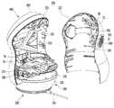
도 2는 본 발명의 실시 예에 따른 로봇이 도시된 사시도,
도 3은 본 발명의 실시 예에 따른 로봇의 제어 블록도,
도 4는 본 발명의 실시 예에 따른 로봇이 도시된 정면도,
도 5는 본 발명의 실시 예에 따른 아우터 바디가 전방으로 틸팅되었을 때의 측면도,
도 6는 본 발명의 실시 예에 따른 아우터 바디가 후방으로 틸팅되었을 때의 측면도,
도 7은 본 발명의 실시 예에 따른 로봇의 분해 사시도,
도 8은 도 4의 A-A'선 단면도,
도 9는 본 발명의 실시 예에 따른 아우터 바디가 분해되었을 때의 사시도,
도 10은 본 발명의 실시 예에 따른 로봇의 배면도,
도 11은 도 10에 도시된 커버가 장착되지 않을 경우의 로봇 배면도,
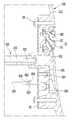
도 12는 도 10에 도시된 B-B'선 단면도,
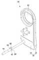
도 13은 본 발명의 실시 예에 따른 커버의 일부가 후방으로 인출되고 커버가 스토퍼가 아우터 바디에 걸릴 때의 단면도,
도 14는 본 발명의 실시 예에 따른 커버의 사시도이다.1 is a diagram showing an example of a network system to which a robot according to an embodiment of the present invention is applied;
2 is a perspective view showing a robot according to an embodiment of the present invention;
3 is a control block diagram of a robot according to an embodiment of the present invention;
4 is a front view showing a robot according to an embodiment of the present invention;
5 is a side view when the outer body is tilted forward according to an embodiment of the present invention;
6 is a side view when the outer body is tilted rearward according to an embodiment of the present invention;
7 is an exploded perspective view of a robot according to an embodiment of the present invention;
8 is a cross-sectional view taken along line A-A' of FIG. 4;
9 is a perspective view when the outer body according to the embodiment of the present invention is disassembled;
10 is a rear view of a robot according to an embodiment of the present invention;
11 is a rear view of the robot when the cover shown in FIG. 10 is not mounted;
12 is a cross-sectional view taken along line B-B' shown in FIG. 10;
13 is a cross-sectional view when a part of the cover according to an embodiment of the present invention is drawn out to the rear and the cover is caught by the stopper on the outer body;
14 is a perspective view of a cover according to an embodiment of the present invention.
이하에서는 본 발명의 구체적인 실시 예를 도면과 함께 상세히 설명하도록 한다.Hereinafter, specific embodiments of the present invention will be described in detail with drawings.
도 1은 본 발명의 실시 예에 따른 로봇이 적용된 네트워크 시스템 일예가 도시된 도이다.1 is a diagram illustrating an example of a network system to which a robot according to an embodiment of the present invention is applied.
로봇이 적용된 네트워크 시스템은 도 1에 도시된 바와 같이, 유선 네트워크 또는 무선 네트워크를 통해 상호 간에 정보를 전송하는 로봇(robot, 1), 액세서리(accessary, 2, 3a, 3b), 게이트웨이(gateway, 4), 단말기(6), 공유기(Access Point, 7) 및 서버(8)을 포함할 수 있다.As shown in FIG. 1, the network system to which the robot is applied includes a robot (robot, 1), an accessory (accessary, 2, 3a, 3b), and a gateway (gateway, 4) that transmit information to each other through a wired network or a wireless network. ), the
네트워크는 와이파이(wi-fi), 이더넷(ethernet), 직비(zigbee), 지-웨이브(z-wave), 블루투스(bluetooth) 등의 기술을 기반으로 하여 구축될 수 있다. 로봇(1), 액세서리(2, 3a, 3b), 게이트웨이(4) 및 공유기(7)는 정해진 통신규약(protocol)에 따라 네트워크와 접속 가능한 통신 모듈을 구비할 수 있다.The network may be built based on technologies such as Wi-Fi, Ethernet, zigbee, z-wave, and Bluetooth. The
네트워크의 구성에 따라, 네트워크 시스템을 구성하는 각 장치들(1, 2, 3a, 3b, 4, 7)에 구비된 통신 모듈이 정해질 수 있고, 각 장치와 네트워크, 또는 장치 상호간의 통신 방식에 따라 장치에는 다수개의 통신 모듈이 구비될 수 있다.According to the configuration of the network, the communication module provided in each of the
로봇(1)은 공유기(7)와 유선(예를 들어, 이더넷) 또는 무선(예를 들어, wi-fi) 통신을 통해 연결될 수 있다. 게이트웨이(4) 및 공유기(7)를 매개로 로봇(1)과 액세서리(2, 3b) 상호 간의 통신이 이루어질 수 있고, 다른 예로 공유기(7)를 매개로 로봇(1)와 액세서리(3a) 또는 기타 기기(5) 상호 간의 통신이 이루어질 수 있다.The
구체적으로, 액세서리(2, 3b)로부터 송신된 신호가 게이트웨이(4)와 공유기(7)를 차례로 경유하여 로봇(1)으로 전송될 수 있고, 로봇(1)으로부터 송신된 신호가 공유기(7)와 게이트웨이(4)를 차례로 경유하여 액세서리(2, 3b)로 전송될 수 있다. 다른 예로, 액세서리(3a) 또는 기타 기기(5)로부터 송신된 신호가 공유기(7)를 경유하여 로봇(1)로 전송될 수 있고, 로봇(1)로부터 송신된 신호가 공유기(7)를 경유하여 액세서리(3a) 또는 기타 기기(5)로 전송될 수 있다.Specifically, the signal transmitted from the
예를 들어, 액세서리(2, 3a, 3b)의 센서 모듈에 의해 획득된 정보는 네트워크를 통해 서버(8), 단말기(6) 또는 로봇(1)으로 전송될 수 있다. 또한, 서버(8), 로봇(1) 또는 단말기(6)로부터 상기 센서 모듈, 제어모듈, 또는 리모트 콘트롤 모듈의 제어를 위한 신호가 액세서리(2)로 전송되는 것도 가능하다. 이러한 신호의 전송은 게이트웨이(4) 및/또는 공유기(7)를 거쳐서 이루어진다.For example, information acquired by the sensor module of the
액세서리(2, 3a, 3b)와 로봇(1) 간의 통신은, 게이트웨이(4)와 공유기(7)만으로도 가능하다. 예를 들어, 홈 네트워크가 인터넷 등의 외부 통신망과 단절된 경우에도 액세서리(2, 3a, 3b)와 로봇(1)간의 통신이 가능하다.Communication between the
로봇(1)이 공유기(7)를 통해 서버(8)와 연결되는 경우에는, 로봇(1)이나 액세서리(2)로부터 송신된 정보가 서버(8)에 저장될 수 있다. 서버(8)에 저장된 정보들은 서버(8)와 접속된 단말기(6)가 수신할 수 있다.When the
또한, 단말기(6)로부터 전송된 정보는 서버(8)를 경유하여 로봇(1)이나 액세서리(2)로 전송될 수 있다. 최근에 널리 이용되고 있는 단말기인 스마트폰(smart phone)은 그래픽 기반의 편리한 UI를 제공하기 때문에, 상기 UI를 통해 로봇(1) 및/또는 액세서리(2)를 제어하거나, 로봇(1) 및/또는 액세서리(2)로부터 수신한 정보를 가공하여 표시하는 것이 가능하다. 또한, 스마트폰에 탑재된 어플리케이션(application)을 업데이트함으로써, 로봇(1) 및/또는 액세서리(2)를 통해 구현 가능한 기능을 확장할 수도 있다.Also, the information transmitted from the
한편, 서버(8)와 무관하게 단말기(6)와 로봇(1)이 직접 서로 통신할 수 있도록 구현할 수 있다. 예를 들면, Blue-Tooth 방식을 이용하여 로봇(1)와 단말기(6)가 서로 직접 통신할 수 있다.On the other hand, it can be implemented so that the
한편, 단말기(6)를 활용하지 않고도, 로봇(1) 만으로도 액세서리(2)를 제어하거나 액세서리(2)로부터 수신한 정보를 가공하여 표시하는 것도 가능하다.On the other hand, without using the
네트워크 시스템은 게이트웨이(4) 없이 구성될 수 있고, 로봇(1)이 게이트웨이(4)가 수행하던 기능을 겸하는 것도 가능함은 물론이다.The network system may be configured without the gateway 4 , and it is of course also possible for the
액세서리(2, 3a, 3b)는 네트워크와의 접속을 위한 적어도 하나의 통신 모듈을 포함한다. 통신 모듈은 소정의 네트워크와 통신한다.The
액세서리(2,3a,3b)는 소정의 주변 상황을 감지하는 센서 모듈을 포함할 수 있다. 액세서리(2,3a,3b)는 주변 환경에 영향을 미치는 특정 기능을 발휘하는 제어 모듈을 포함할 수 있다. 액세서리(2,3a,3b)는 소정의 주변 기기를 제어하는 광 신호(예를 들어, 적외선 신호)를 송신하는 리모트 컨트롤 모듈을 포함할 수 있다.The
센서 모듈을 구비한 액세서리(2,3a,3b)는, 기압 센서, 습도 센서, 온도 센서, 방사능 감지 센서, 열 감지 센서, 가스 감지 센서, 공기질 센서, 전자 코 센서, 헬스케어 센서, 생체 인식 센서, 수면 센서(예를 들어 사용자의 잠옷이나 속옷에 부착하고 사용자가 잠을 자는 동안 코콜이, 무호흡, 뒤척임 등을 감지), 근접센서, 조도센서, 가속도센서, 자기센서, 중력센서, 자이로스코프센서, 모션센서, RGB센서, 적외선센서(IR 센서 : infrared sensor), 초음파센서, 원격감지센서, SAR, 레이더, 광센서(예를 들어, 영상센서, 이미지센서) 등을 구비한 장치를 예로 들 수 있다.Accessories (2, 3a, 3b) equipped with a sensor module include a barometric pressure sensor, a humidity sensor, a temperature sensor, a radiation sensor, a heat sensor, a gas sensor, an air quality sensor, an electronic nose sensor, a healthcare sensor, and a biometric sensor. , sleep sensor (e.g., attached to the user's pajamas or underwear to detect snoring, apnea, toss and turn while the user is sleeping), proximity sensor, light sensor, accelerometer, magnetic sensor, gravity sensor, gyroscope sensor, For example, a device equipped with a motion sensor, RGB sensor, infrared sensor (IR sensor), ultrasonic sensor, remote sensing sensor, SAR, radar, optical sensor (eg, image sensor, image sensor), etc. may be exemplified. .
제어모듈을 구비한 액세서리(2,3a,3b)는, 조명을 제어하는 스마트 라이팅, 전원의 인가 및 정도를 조절하는 스마트 플러그, 보일러 또는 공기조화기의 작동 여부 및 강도 등을 조절하는 스마트 온도 조절기, 가스의 차단 여부를 제어하는 스마트 가스락 등을 예로 들 수 있다.Accessories (2, 3a, 3b) with control modules are smart lighting to control lighting, smart plugs to control the application and degree of power, and smart thermostats to control whether or not the boiler or air conditioner operates and its strength, etc. , a smart gas lock that controls whether to shut off gas, etc. are examples.
리모트 콘트롤 모듈을 구비한 액세서리(2,3a,3b)는, 원격 제어 가능한 가전기기 등에 적외선(IR) 신호를 발신하는 적외선 LED 등을 구비한 장치를 예로 들 수 있다.The
액세서리(예를 들어, 3a,3b)는 소정의 성능을 발휘하기 위하여 정하여진 용도만으로 설치될 수 있다. 예를 들어, 액세서리(3a)는 영상 카메라이고, 액세서리(3b)는 스마트 플러그이다.Accessories (eg, 3a, 3b) may be installed only for a predetermined purpose in order to exhibit a predetermined performance. For example, the accessory 3a is a video camera, and the accessory 3b is a smart plug.
본 발명의 일 실시예에 따른 액세서리(2)는 사용자가 원하는 임의의 위치에 설치가 가능하도록 구비될 수 있다. 또한, 다양한 용도로 활용 가능하도록 구비될 수 있다. 예를 들어, 액세서리(2)는 가전기기, 도어, 창문 또는 벽체 등 외부의 물체에 부착될 수 있다.The
게이트웨이(4)는 하나 이상의 액세서리(2, 3b)와 공유기(7) 간의 통신을 매개한다. 게이트웨이(4)는 무선으로 액세서리(2)와 통신할 수 있다. 게이트웨이(4)는 유선 또는 무선으로 공유기(7)와 통신한다. 예를 들어, 게이트웨이(4)와 공유기(7) 간의 통신은 이더넷(Ethernet) 또는 와이파이(wi-fi)를 기반으로 할 수 있다.The gateway 4 mediates communication between one or
공유기(7)는 유선 또는 무선 통신을 통해 서버(8)와 연결될 수 있다. 서버(8)는 인터넷을 통해 접속이 가능하다. 인터넷에 접속된 각종 단말기(6)로 서버(8)와 통신할 수 있다. 단말기(6)는 PC(personal computer), 스마트 폰(smart phone) 등의 이동 단말기(mobile terminal)를 예로 들 수 있다.The router 7 may be connected to the
액세서리(2, 3b)는 게이트웨이(4)와 통신하도록 구비될 수 있다. 다른 예로, 액세서리(3a)는 게이트웨이(4)를 거치지 않고 공유기(7)와 직접 통신하도록 구비될 수 있다.
공유기(7)는 게이트웨이(4)를 거치지 않고 상기 액세서리(3a) 또는 통신 모듈을 탑재한 기타 기기(5)와 직접 통신하도록 구비될 수도 있다. 이러한 기기들(5, 3a)은 바람직하게는 와이파이 통신 모듈을 구비하고 있어, 게이트웨이(4)를 경유하지 않고도 공유기(7)와 직접 통신이 가능하다.The router 7 may be provided to communicate directly with the accessory 3a or
도 2는 본 발명의 실시예에 따른 로봇이 도시된 사시도이고, 도 3은 본 발명의 실시예에 따른 로봇의 제어 블록도이며, 도 4는 본 발명의 실시예에 따른 로봇이 도시된 정면도이고, 도 5는 본 발명의 실시예에 따른 아우터 바디가 전방으로 틸팅되었을 때의 측면도이며, 도 6는 본 발명의 실시예에 따른 아우터 바디가 후방으로 틸팅되었을 때의 측면도이다.Figure 2 is a perspective view showing a robot according to an embodiment of the present invention, Figure 3 is a control block diagram of the robot according to an embodiment of the present invention, Figure 4 is a front view showing the robot according to an embodiment of the present invention , Figure 5 is a side view when the outer body is tilted forward according to an embodiment of the present invention, Figure 6 is a side view when the outer body is tilted rearward according to an embodiment of the present invention.
로봇은 베이스(100)와, 아우터 바디(300)를 포함할 수 있다. 로봇은 로봇의 모션을 수행하는 구동부(60)을 포함할 수 있다. 구동부(60)는 아우터 바디(300)에 연결되어 아우터 바디(300)의 3차원 모션을 수행할 수 있다.The robot may include a
구동부(60)는 베이스(100)에 배치되어 베이스(100)에 지지될 수 있다. 구동부(60)는 아우터 바디(300)를 회전 및 틸팅시킬 수 있다. 구동부(60)는 아우터 바디(300)를 회전시키는 것이 가능하고, 아우터 바디(300)를 틸팅시키는 것이 가능하며, 아W터 바디(300)를 회전시키면서 틸팅시키는 것이 가능하다.The driving
구동부(60)는 베이스(100) 위에 스핀 가능하게 배치된 스핀 바디(200)와, 스핀 바디(200)를 회전시키는 스핀 기구(250)와, 스핀 바디(200)에 배치되고 아우터 바디(300)에 연결되어 아우터 바디(300)를 틸팅시키는 틸팅 기구(350)을 포함할 수 있다.The driving
스핀 기구(250)와 틸팅 기구(350)은 독립적으로 구동될 수도 있고, 동시에 구동될 수 있고, 동시 구동시 아우터 바디(300)가 복합적인 모션을 수행하게 할 수 있다.The
스핀기구(250)는 스핀 바디(200)가 베이스(100)를 중심으로 회전되게 할 수 있다. 스핀 바디(200)는 상하 방향으로 연장된 회전축(OS)을 중심으로 회전하게 배치될 수 있고, 스핀 기구(250)는 스핀 바디(200)를 회전축(OS)을 중심으로 회전시킬 수 있다.The
틸팅 기구(350)는 틸팅축(OT)을 중심으로 아우터 바디(300)를 틸팅시킬 수 있다. 아우터 바디(300)는 수평 방향으로 연장된 틸팅축(OT)를 중심으로 틸팅되게 배치될 수 있고, 틸팅 기구(350)는 아우터 바디(300)가 스핀 바디(200)에 대해 일측으로 기울어지게 아우터 바디(300)를 틸팅시킬 수 있다.The
틸팅 기구(350)는 스핀 바디(200)에 장착될 수 있고, 스핀 기구(250)에 의해 스핀 바디(200)가 회전되면, 틸팅 기구(350) 및 아우터 바디(300)는 스핀 바디(200)와 함께 회전될 수 있다.The
로봇은 스핀 바디(200)와 아우터 바디(300) 중 적어도 하나에 설치된 적어도 하나의 인터페이스(42,44,54,56)를 포함할 수 있다.The robot may include at least one
로봇(1)은 로봇(1)을 제어하는 제어부(20)를 포함할 수 있다. 제어부(20)는 서버(8) 또는 단말기(6)에 구비되어 네트워크를 통해 로봇(1)을 제어하는 것도 가능하다.The
로봇(1)은 네트워크와 통신하는 통신 모듈(22)을 포함할 수 있다. 통신 모듈(22)은 와이파이 모듈, 블루투스 모듈, 직비 모듈, 지웨이브 모듈 등을 포함할 수 있다. 통신 모듈(22)은 직접 통신하고자 하는 장치의 통신방식에 따라 달라질 수 있다.The
통신 모듈(22)은 네트워크 시스템을 구성하는 공유기(7), 게이트웨이(4), 액세서리(2, 3a, 3b), 서버(8) 및 단말기(6) 중 적어도 어느 하나와 통신할 수 있다.The
통신 모듈(22)을 통해 입력부(50)로부터 획득된 정보를 네트워크 상으로 전송할 수 있다. 통신 모듈(22)을 통해 네트워크 상에서 로봇(1)으로 정보가 수신될 수 있고, 제어부(20)는 수신된 정보를 근거로 출력부(40) 또는 구동부(60)를 제어할 수 있다.Information obtained from the
로봇(1)은 구동 감지부(70)를 통해 획득한 정보가 저장되는 저장부(24)를 더 포함할 수 있다. 저장부(24)에는 통신 모듈(22)을 통해 네트워크으로부터 수신한 정보가 저장될 수 있다. 저장부(24)에는 입력부(50)로 입력된 지시가 저장될 수 있다.The
로봇(1)는 로봇(1)의 각 구성들에게 전원을 공급하는 전원 장치(30)를 포함한다. 전원 장치(30)는 외부의 유선 전원 케이블을 연결할 수 있는 전원 연결부(32)를 포함할 수 있다. 전원 연결부(32)는 소켓으로 구현될 수 있다. 전원 장치(30)는 배터리(34)를 포함할 수 있다. 배터리(34)는 충전용으로 구비될 수 있다. 전원 장치(30)는 배터리(34)를 충전시킬 수 있는 충전 모듈 예를 들면, 무선 충전 모듈(36)을 더 포함할 수 있다.The
로봇(1)은 출력부(40)를 포함할 수 있다. 출력부(40)는 정보를 시각적으로 또는 청각적으로 외부로 출력할 수 있다.The
출력부(40)는 정보를 시각적으로 출력하는 디스플레이(42)를 포함한다. 출력부(40)는 정보를 청각적으로 출력하는 스피커(44)를 포함할 수 있다.The
로봇(1)는 입력부(50)를 포함할 수 있다. 입력부(50)는 로봇(1)의 제어를 위한 명령을 수신할 수 있다. 입력부(50)는 사용자가 통신 모듈(22)을 통하지 않고 직접 명령 등을 입력할 수 있게 구성되는 것이 가능하다. 입력부(50)는 액세서리(2)의 제어를 위한 명령을 수신할 수도 있다.The
입력부(50)는 스위치(52)를 포함할 수 있다. 스위치(52)는 로봇(1)의 전원을 ON/OFF하는 전원 스위치를 포함할 수 있다. 스위치(52)는 로봇(1)의 기능의 설정, 소정의 네트워크와 페어링(pairing), 또는 단말기(6)와의 페어링 등을 위한 기능 스위치를 포함할 수 있다. 상기 기능 스위치의 누름 시간 및/또는 연속 누름 횟수 등의 조합을 통해, 로봇(1)에 다양한 명령이 내려지도록 기 설정할 수 있다. 스위치(52)는 로봇(1)의 기 설정된 세팅을 리셋 시킬 수 있는 리셋 스위치를 포함할 수 있다. 스위치(52)는 로봇(1)을 절전 상태 또는 미출력 상태로 전환시키는 슬립(Sleep) 스위치를 포함할 수 있다.The
입력부(50)는 외부의 시각적 이미지를 센싱하는 센서 예를 들면, 카메라(54)를 포함할 수 있다. 카메라(54)는 사용자를 인식하기 위한 이미지를 획득할 수 있다. 카메라(54)는 사용자의 방향을 인식하기 위한 이미지를 획득할 수 있다. 카메라(54)에서 획득한 이미지 정보는 저장부(24)에 저장될 수 있다.The
입력부(50)는 터치형 디스플레이를 포함할 수 있다.The
입력부(50)는 외부의 소리를 센싱하는 마이크(56)를 포함한다. 로봇(1)에 마이크(56)가 구비된 경우, 로봇(1)의 제어부(20)는 마이크(56)를 통해 입력된 사용자의 음성을 인식하여 명령을 추출할 수 있다. 음원의 위치를 인식하기 위하여, 입력부(50)는 복수의 마이크(56)를 포함할 수 있다. 마이크(56)에서 획득한 소리 정보 또는 사용자의 위치 정보는 저장부(24)에 저장될 수 있다.The
로봇(1)은 로봇(1)에 대한 사용자의 방향을 감지하기 위한 방향 감지 센서를 포함할 수 있다. 방향 감지 센서는 카메라(54) 및/또는 복수의 마이크(56)를 포함할 수 있다.The
로봇(1)은 로봇(1)의 디스플레이(42)의 출력 내용 또는 스피커(44)의 출력 내용과 함께 로봇(1)이 모션을 수행함으로써, 살아있는 생명체와 같은 느낌을 줄 수 있다. 사람과 사람의 커뮤니케이션에 있어서 제스쳐(모션) 또는 아이 컨택트(eye contact)의 역할이 큰 것처럼, 구동부(60)에 의한 로봇(1)의 모션은 출력부(40)의 출력 내용을 사용자에게 효율적으로 인지시킬 수 있다. 구동부(60)에 의한 로봇(1)의 모션은 사용자와 로봇(1) 사이의 커뮤니케이션 과정에서 감성적 요소를 더 할 수 있다.The
로봇(1)은 구동부(60)에 의한 현재의 모션 상태를 감지할 수 있는 구동 감지부(70)를 포함한다. 구동 감지부(70)는 스핀 바디(200)가 회전축(OS)을 중심으로 회전한 각도를 감지하는 스핀각 감지부(72)를 포함한다. 로봇이 아우터 바디(300) 및 틸팅 기구(350)를 더 포함할 경우, 구동 감지부(70)는 틸팅축(OT)을 중심으로 아우터 바디(300)가 스핀 바디(200)에 대해 회전한 각도(기울어진 각도)를 감지하는 틸팅각 감지부(76)를 포함할 수 있다.The
제어부(20)는 입력부(50)로부터 받은 제어 정보에 근거하여 통신 모듈(22)을 제어할 수 있다. 제어부(20)는 통신 모듈(22)이 네트워크부터 수신한 정보를 저장부(24)에 저장하도록 제어할 수 있다. 제어부(20)는 저장부(24)에 저장된 정보를 통신 모듈(22)을 통해 네트워크로 송신할 수 있도록 제어할 수 있다.The
제어부(20)는 입력부(50)로부터 제어 정보를 입력 받을 수 있다. 제어부(20)는 출력부(40)가 소정의 정보를 출력하도록 제어할 수 있다. 제어부(20)는 출력부(40)의 정보 출력과 함께 구동부(60)가 동작하도록 제어할 수 있다.The
일 예로, 제어부(20)는 카메라(54)에서 획득한 이미지를 기초로 사용자가 누구인지 인식하고, 이를 근거로 출력부(40) 및 구동부(60)를 작동시킬 수 있다. 제어부(20)는 인식한 사용자가 기 설정된 사용자와 일치하면, 디스플레이(42)에서 웃는 이미지를 표시하고, 틸팅 기구(350)를 작동시켜 아우터 바디(300)가 상하 방향 또는 좌우 방향으로 기울이게 동작시킬 수 있다.For example, the
다른 예로, 제어부(20)는 방향 감지 센서를 기초로 사용자의 얼굴 위치를 인식하고, 이를 근거로 출력부(40) 및 구동부(60)를 작동시킬 수 있다. 제어부(20)는 디스플레이(42)에 소정의 정보를 표시하고, 스핀 기구(250)를 작동시켜 디스플레이(42)가 사용자의 얼굴을 향하게 동작시킬 수 있다. 제어부(20)는, 인터페이스 모듈(400)의 화상 출력 방향을 방향 감지 센서에서 감지된 사용자의 방향으로 전환하기 위해, 스핀 바디(200)가 회전되게 제어할 수 있다.As another example, the
제어부(20)는 통신 모듈(22)을 통해 네트워크로부터 수신한 제어 정보에 근거하여 구동부(60)의 작동 여부 등을 제어할 수 있다. 제어부(20)는 입력부(50)로부터 받은 제어 정보에 근거하여 구동부(60)를 제어할 수 있다. 제어부(20)는 저장부(24)에 저장된 제어 정보에 근거하여 구동부(60)를 제어할 수 있다.The
로봇(1)은 리모트 컨트롤 모듈(80)을 포함할 수 있다. 리모트 컨트롤 모듈(80)는 소정의 주변 기기를 제어하는 광 신호(예를 들어, 적외선 신호)를 송신할 수 있다. 소정의 주변 기기는 리모트 컨트롤이 가능한 주변의 기기를 의미할 수 있다. 예를 들어, 리모트 콘트롤러로 제어가 가능한 세탁기, 냉장고, 공기조화기, 로봇청소기, 티브이 등이 상기 소정의 주변 기기가 된다. 리모트 컨트롤 모듈(80)은 소정의 주변 기기를 제어하는 소정의 광 신호를 조사(emitting)하는 발광부를 포함할 수 있다. 예를 들어, 발광부는 적외선을 조사하는 LED일 수 있다. 리모트 컨트롤 모듈(80)이 광 신호를 조사하는 방향은 로봇(1)의 동작에 따라 변경될 수 있다. 이를 통해 원거리 제어가 필요한 특정 기기의 방향으로 리모트 컨트롤 모듈(80)의 광 신호 조사 방향을 변경하여, 상기 특정 기기를 광 신호로 제어할 수 있다.The
로봇(1)을 구성하는 디스플레이(42)과, 스피커(44)와, 카메라(54)과, 마이크(56) 등은 인간과 로봇(1)의 커뮤니케이션을 돕는 인터페이스들일 수 있고, 이러한 인터페이스들은 스핀 바디(200)에 장착되어 스핀 바디(200)의 회전시 스핀 바디(200)와 함께 회전되는 것이 가능하고, 아우터 바디(300)에 장착되어 아우터 바디(300)의 틸팅시 아우터 바디(300)와 함께 틸팅되는 것이 가능하다.The
커뮤니이션 로봇(1)은 디스플레이(42)과, 스피커(44)와, 카메라(54)과, 마이크(56) 등의 인터페이스들이 스핀 바디(200)와 아우터 바디(300)에 분산되어 배치되는 것이 가능하다.In the
로봇(1)은 디스플레이(42)과, 스피커(44)와, 카메라(54)과, 마이크(56) 등의 인터페이스들 중 적어도 하나를 포함하는 인터페이스 모듈(400)을 포함할 수 있고, 이러한 인터페이스 모듈(400)은 아우터 바디(300)에 장착되어 스핀 바디(200)의 회전시 아우터 바디(300)와 함께 스핀될 수 있고, 아우터 바디(300)의 틸팅시 아우터 바디(300)와 함께 틸팅될 수 있다.The
한편, 배터리(34)와, 디스플레이(42)과, 스피커(44)와, 카메라(54)과, 마이크(56)과, 스핀 기구(250) 및 틸팅 기구(350) 등은 그 각각의 무게나 크기 등을 고려하여 스핀 바디(200)나 아우터 바디(300)에 지지되는 것이 바람직하고, 로봇(1)의 전체 무게 중심을 최대한 낮출 수 있게 배치되는 것이 바람직하다.On the other hand, the
도 7은 본 발명의 실시 예에 따른 로봇의 분해 사시도이고, 도 8은 도 4의 A-A'선 단면도이다.7 is an exploded perspective view of a robot according to an embodiment of the present invention, and FIG. 8 is a cross-sectional view taken along line A-A' of FIG. 4 .
베이스(100)은 스핀 바디(200)를 회전 가능하게 지지할 수 있고, 스핀 바디(200)로부터 전달되는 하중을 지지할 수 있다. 로봇이 아우터 바디(300) 및 인터페이스들을 더 포함할 경우, 아우터 바디(300), 인터페이스들의 하중은 스핀 바디(200)를 통해 베이스(100)로 전달될 수 있다.The base 100 may rotatably support the
이하, 베이스(100)에 대해 도 7 및 도 8을 참조하여 상세히 설명한다.Hereinafter, the
베이스(100)는 복수개 부재의 결합체로 구성될 수 있다. 베이스(100)는 로어 베이스(101)와, 로어 베이스(101)의 상부에 배치된 어퍼 베이스(102)를 포함할 수 있다.The base 100 may be composed of a combination of a plurality of members. The base 100 may include a
베이스(100)의 내부에는 베이스 피시비(103)가 수용될 수 있는 피시비 수용공간(S1)이 형성될 수 있다. 피시비 수용공간(S1)은 로어 베이스(101)와 어퍼 베이스(102)의 사이 또는 어퍼 베이스(102)의 내측에 형성될 수 있다.A PCB accommodating space S1 in which the
베이스 피시비(103)는 베이스(100)의 내부에 형성된 피시비 수용공간(S1)에 수용될 수 있고, 베이스(100)에 의해 보호될 수 있다.The
베이스 피시비(103)는 파워 코드(104)가 연결되는 전원 연결부(32)와 직접 연결되거나 별도의 전선을 통해 전원 연결부(32)와 연결될 수 있다.The
베이스 피시비(103)에는 엘이디 등의 광원이 배치될 수 있고, 이 경우 베이스(100)는 조명기구로 기능할 수 있으며, 베이스(100)는 외부로 시각적 정보를 제공하는 인터페이스로 기능할 수 있다.A light source such as an LED may be disposed in the
베이스(100)는 엘이디 등의 광원에서 조사된 광이 투과될 수 있는 베이스 데코부재(110)를 더 포함할 수 있다.The base 100 may further include a
베이스(100)는 로어 베이스(101)의 저면에 배치된 미끄럼 방지부재(105)를 더 포함할 수 있다. 미끄럼 방지부재(105)는 링 형상 또는 원판 형상으로 형성될 수 있고, 로어 베이스(101)의 저면에 부착될 수 있다. 미끄럼 방지부재(105)는 지면과의 마찰력이 큰 논슬립 매트 등일 수 있다.The base 100 may further include an
로봇은 적어도 하나의 구름 베어링(107)을 포함할 수 있다. 구름 베어링(107)은 베이스(100)에 설치되어 스핀 바디(200)를 지지할 수 있다.The robot may include at least one rolling
베이스(100)는 구름 베어링(107)를 지지하는 베어링 서포터(106)를 포함할 수 있다.The base 100 may include a bearing
구름 베어링(107)은 내륜이 지지축을 통해 베어링 서포터(106)에 연결될 수 있고, 외륜이 내륜을 따라 회전될 수 있다.In the rolling
구름 베어링(107)은 베이스(100)에 복수개 구비될 수 있다. 복수개의 구름 베어링(107)은 베이스(100)에 이격되게 배치된 상태에서 스핀 바디(200) 특히 스핀 하우징(210)을 지지할 수 있다.A plurality of rolling
복수개의 구름 베어링(107)은 가상원을 따라 배치될 수 있고, 복수개의 구름 베어링(107)은 스핀 바디(200)에서 작용하는 하중을 베이스(100) 특히, 베어링 서포터(106)로 분산하여 전달할 수 있다.The plurality of rolling
베이스(100)에는 베이스(100)의 중량을 증대시킬 수 있는 중량체(W)가 배치될 수 있다. 중량체(W)는 부피에 비하여 무게가 많이 나가는 물체로서, 로봇(1)의 전체 무게 중심을 최대한 낮추고 로봇(1)이 전복되지 않게 도울 수 있다. 중량체(W)는 베어링 서포터(106)에 배치될 수 있다. 중량체(W)는 복수개가 상하방향으로 적층될 수 있다.A weight W capable of increasing the weight of the base 100 may be disposed on the
베이스(100)에는 스핀 바디(200)를 회전 가능하게 지지하는 어퍼 베어링(108)이 배치될 수 있다. 그리고, 베이스(100)는 어퍼 베어링(108)이 장착되는 고정축(109)을 더 포함할 수 있다. 고정축(109)은 스핀 바디(200)의 회전 중심축일 수 있고, 고정축(109)의 중심축은 회전축(OS)이 될 수 있다. 고정축(109)는 베어링 서포터(106)의 상부에 배치될 수 있다. 고정축(109)은 베어링 서포터(106)과 스크류 등의 체결부재로 결합될 수 있다.An
어퍼 베어링(108)은 후술하는 스핀 종동기어(280)의 위에 위치되게 고정축(109)에 장착될 수 있다. 어퍼 베어링(108)은 고정축(109)의 상부 외둘레를 둘러싸게 배치될 수 있다.The
어퍼 베어링(108)은 고정축(109)과 후술하는 스핀 커버(220)의 사이에 배치된 어퍼 구름 베어링일 수 있다.The
어퍼 베어링(108)은 고정축(109)의 외둘레에 고정된 내륜과, 스핀 커버(220)에 형성된 어퍼 베어링 하우징(221)에 고정된 외륜과, 내륜과 외륜 사이에 배치된 볼이나 롤러 등의 구름부재를 포함할 수 있다.The
어퍼 베어링(108)은 스핀 종동기어(280)의 위에 스핀 종동기어(280)와 이격되게 위치될 수 있고, 스핀 커버(220)를 회전 가능하게 지지할 수 있다. 어퍼 베어링(108)의 축 중심은 수직축일 수 있고, 어퍼 베어링(108)의 축 중심은 회전축(OS)과 일치될 수 있다.The
고정축(109)에는 스핀 종동기어(280)가 장착될 수 있고, 스핀 종동기어(280)는 스크류 등의 체결부재로 고정축(109)에 장착될 수 있다. 스핀 종동기어(280)은 상측 기어와 하측 기어의 이중구조로 이루어질 수 있고, 상측 기어와 하측 기어는 서로 고정될 수 있다. 스핀 종동기어(280)는 고정축(109)에 고정되게 장착된 상태에서, 스핀 바디(200)가 회전되게 안내할 수 있다. 스핀 바디(200)는 스핀 종동기어(280)의 궤적을 따라 회전될 수 있다.A spin driven
고정축(109)의 내부에는 전선 등이 통과할 수 있는 통공(H)이 형성될 수 있다. 통공(H)은 고정축(109)에 상하 방향으로 관통되게 형성될 수 있다.A through hole (H) through which an electric wire or the like can pass may be formed inside the fixed
고정축(109)의 통공(H)을 관통하는 전선 등은 베이스 피시비(103)를 스핀 바디(200)에 장착된 피시비(230)와, 아우터 바디(300)에 장착된 피시비(36)와, 인터페이스 모듈(400)의 인터페이스 피시비(406)와 배터리(34) 중 적어도 하나에 연결할 수 있다.The wire passing through the through hole (H) of the fixed
이하, 스핀 바디(200)에 대해 설명하면 다음과 같다.Hereinafter, the
스핀 바디(200)는 베이스(100) 위에 스핀 가능하게 지지될 수 있다. 스핀 바디(200)는 구름 베어링(107) 위에 올려질 수 있고, 구름 베어링(107)에 올져진 상태에서 고정축(109)을 중심으로 스핀될 수 있다.The
스핀 바디(200)는 복수개 부재의 결합체로 구성될 수 있고, 스핀 바디(200)는 내부에 공간(S2)이 형성된 스핀 하우징(210)과, 공간(S2)을 덮는 스핀 커버(220)를 포함할 수 있다.The
스핀 바디(200)의 공간(S2)에는 적어도 하나의 인터페이스가 수용될 수 있다. 이러한 인터페이스는 스핀 바디(200)의 내부에 수용된 스피커(44)일 수 있다. 스피커(44)는 스핀 커버(220)의 아래에 위치될 수 있고, 스핀 커버(220)에 의해 보호될 수 있고, 스핀 하우징(210)과 스핀 커버(220)는 스피커(44)를 보호하는 보호 커버로 기능할 수 있다. 스핀 바디(200)는 이러한 공간(S2)에 수용된 인터페이스를 보호하는 인터페이스 하우징일 수 있다.At least one interface may be accommodated in the space S2 of the
스핀 하우징(210)의 일부는 외부로 노출될 수 있다. 스핀 하우징(210)의 일부는 아우터 바디(300)의 하단 하측을 통해 외부에서 보일 수 있고, 스핀 하우징(210)은 로봇의 외관 일부를 구성할 수 있다.A part of the
스핀 하우징(210)는 상면이 개방되고 하부로 갈수록 크기가 감소되는 형상일 수 있다. 스핀 하우징(210)는 그 외면이 외측을 향해 볼록한 형상일 수 있다.The
스핀 하우징(210)는 아우터 중공 바디(211)와, 이너 중공 바디(213)를 포함할 수 있다.The
아우터 중공 바디(211)는 내부에 스피커44)가 수용될 수 있는 공간(S2)이 형성될 수 있고, 하부로 갈수록 그 크기가 감소될 수 있다.In the outer
이너 중공 바디(213)는 아우터 중공 바디(211)의 하단에서 아우터 중공 바디(211)의 내부에 형성된 공간(S2)을 향해 연장될 수 있다.The inner
이너 중공 바디(213)의 중앙에는 베이스(100)의 일부가 관통되는 베이스 관통공(212)이 형성될 수 있다.A base through
스핀 커버(220)는 전체적으로 판체 형상일 수 있고, 스핀 하우징(210)의 상단 위에 올려지는 것도 가능하다. 스핀 커버(220)는 스핀 하우징(210)의 내부로 삽입되어 스핀 하우징(210)의 내부에서 스핀 하우징(210)과 결합되는 것도 가능하다.The
스핀 커버(220)에는 틸팅축(OT)를 회전 가능하게 지지하는 틸팅축 서포터(240,242, 도 7)가 배치될 수 있다. 틸팅축 서포터(240,242)는 스핀 커버(220)의 상면에 배치될 수 있다. 틸팅축 서포터(240,242)는 한 쌍이 수평 방향으로 이격되게 배치될 수 있고, 틸팅축(OT)는 베어링(241)을 통해 틸팅축 서포터(240)(242)에 회전 가능하게 지지될 수 있다.The tilting
로봇은 스핀 커버(220)의 상면에 배치된 피시비(230, 도 7 및 도 8 참조)를 더 포함할 수 있다. 피시비(230)는 스핀 커버(220) 보다 크기가 작고, 스핀 커버(220)의 상면 일부를 덮게 배치될 수 있다. 피시비(230)는 스핀 커버(220)의 상면에 수평하게 배치될 수 있다. 이러한 피시비(230)는 스핀 커버(220)에 장착되어 스핀 커버(220)와 함께 회전되는 회전 피시비일 수 있다.The robot may further include a PCB 230 (refer to FIGS. 7 and 8 ) disposed on the upper surface of the
피시비(230)는 스핀 커버(220)에 장착된 적어도 하나의 전기부품을 제어할 수 있고, 예를 들면, 스핀 모터(260) 및 틸팅 모터(360)을 제어하는 모터 제어 피시비일 수 있다.The
이하, 스핀 기구(250)에 대해 설명하면 다음과 같다.Hereinafter, the
스핀 기구(250)는 스핀 바디(200)에 연결되어 상기 스핀 바디(200)을 회전시킬 수 있다.The
스핀 기구(250)는 스핀 모터(260)와, 스핀 구동기어(270)와; 스핀 종동기어(280)를 포함할 수 있다.The
스핀 모터(260)는 스핀 커버(220)에 배치되고 하부에 구동축이 돌출될 수 있다.The
스핀 모터(260)는 스핀 커버(220)의 상면 위에 배치될 수 있다. 스핀 모터(260)는 스크류 등의 체결부재로 스핀 커버(220)에 체결될 수 있다. 스핀 모터(260)의 구동축은 스핀 모터(260)의 하부에 수직하게 배치될 수 있다. 스핀 모터(260)의 구동축은 공간(S2)을 향해 돌출될 수 있다.The
스핀 커버(220)에는 스핀 모터(260)의 구동축과 스핀 구동기어(270) 중 적어도 하나가 관통되는 관통공이 상하 방향으로 관통될 수 있다. 스핀 모터(320)의 구동축과, 스핀 구동기어(270)의 회전축 중 적어도 하나는 스핀커버(220)의 관통공에 위치될 수 있다.A through hole through which at least one of the driving shaft of the
스핀 구동기어(270)는 공간(S2)에서 스핀 모터(260)의 구동축에 치합될 수 있다. 스핀 구동기어(270)는 스핀 바디(200)의 내부에서 회전될 수 있고, 스핀 바디(200)에 의해 보호될 수 있다. 스핀 구동기어(270)는 스핀 모터(260)의 구동축에 매달릴 수 있다. 스핀 구동기어(270)는 스핀 커버(220)의 저면 아래에서 스핀 모터(250)에 의해 회전될 수 있다.The
스핀 종동기어(280)는 베이스(100)에 고정될 수 있다. 스핀 종동기어(280)는 베이스(100)의 고정축(109)에 위치 고정되게 장착된 고정기어일 수 있다.The spin driven
스핀 기구(250)는 스핀 구동기어(270)가 스핀 종동기어(280)에 치합되는 것이 가능하고, 이 경우 스핀 구동기어(270)는 스핀 종동기어(280)의 외둘레를 따라 공전되면서 자전될 수 있다.In the
스핀 기구(250)는 스핀 구동기어(270)가 스핀 종동기어(280)와 직접 치합되지 않고, 스핀 구동기어(270) 및 스핀 종동기어(280)가 스핀 중간기어(290, 도 7 참조)를 통해 연결되는 것도 가능하다.In the
스핀 중간기어(290)는 스핀 커버(220)에 회전 가능하게 연결될 수 있다. 스핀 커버(200)에는 스핀 중간기어(290)를 회전 가능하게 지지하는 중간기어 지지축이 형성될 수 있다. 중간기어 지지축은 스핀 커버(220)의 저면에 하측 방향으로 돌출되게 제공될 수 있다. 스핀 중간기어(290)는 스핀 구동기어(290)과 같이, 스핀 바디(200)의 공간(S2)에 수용될 수 있다.The spin
스핀 중간기어(290)는 스핀 구동기어(270)과 스핀 종동기어(280)의 사이에서 동력을 전달할 수 있다. 스핀 중간기어(290)는 스핀 종동기어(280)의 외둘레를 따라 공전될 수 있다.The spin
이하, 아우터 바디(300)에 대해서 설명한다.Hereinafter, the
아우터 바디(300)는 스핀 하우징(210) 보다 크게 형성될 수 있다. 아우터 바디(300)은 하면이 개방될 수 있다. 아우터 바디(300)의 내부에는 상부 공간(S3)이 형성될 수 있다. 상부 공간(S3)은 틸팅 베이스(320)가 수용되는 공간일 수 있다.The
아우터 바디(300)은 복수개 부재의 결합체로 구성될 수 있고, 전,후 또는 상하 위치되는 복수개 바디가 서로 결합되어 구성될 수 있다.The
아우터 바디(300)은 인터페이스 모듈(400)이 장착되는 제1아우터 바디(311)와, 제1아우터 바디(311)과 결합되는 제2아우터 바디(312)를 포함할 수 있고, 제1아우터 바디(311)와 제2아우터 바디(312)의 사이에 상부 공간(S3)이 형성될 수 있다.The
제1아우터 바디(311)이 프론트 아우터 바디일 경우, 제2아우터 바디(312)은 제1아우터 바디(311)의 후단에 결합된 리어 아우터 바디일 수 있고, 제1아우터 바디(311)가 좌측 아우터 바디일 경우, 제2아우터 바디(312)는 제1아우터 바디(311)의 우측단에 결합된 우측 아우터 바디일 수 있다.When the first
아우터 바디(300)에는 인터페이스 모듈(400)이 배치되는 개구부(313, 도 8 참조)가 형성될 수 있다. 인터페이스 모듈(400)는 개구부(313)로 삽입되어 개구부(313)에 위치될 수 있다.An opening 313 (refer to FIG. 8 ) in which the
아우터 바디(300)의 개구부(313)는 제1아우터 바디(311)에 형성될 수 있다. 이 경우, 제1아우터 바디(311)는 인간과 소통하기 위해 주로 인간을 향하는 프론트 하우징이 될 수 있다.The
이하, 틸팅 기구(350)에 대해서 설명한다.Hereinafter, the
틸팅 기구(350)는 틸팅 베이스(320)을 포함할 수 있다.The
틸팅 베이스(320)는 아우터 바디(300)의 상부 공간(S3)에 수용된 상태에서, 아우터 바디(300)에 의해 보호될 수 있다. 틸팅 베이스(320)는 틸팅 축(OT)와 연결될 수 있고, 틸팅 축(OT)과 함께 회전될 수 있다. 틸팅 베이스(320)에는 틸팅축(OT)가 연결되는 틸팅축 연결부(321, 도 7 참조)가 형성될 수 있다. 틸팅축 연결부(321)는 틸팅 베이스(320)의 하부에 수평 방향으로 길게 형성될 수 있다.The tilting
틸팅축(OT)는 틸팅 베이스(320)에 수평 방향으로 길게 배치될 수 있다.The tilting axis OT may be vertically disposed on the
틸팅축(OT)은 틸팅 베이스(320)에 연결될 수 있고, 틸팅 베이스(320)는 아우터 바디(300)과 결합될 수 있으며, 틸팅축(OT)의 회전시, 틸팅 베이스(320)와 아우터 바디(300)은 틸팅축(OT)을 중심으로 함께 회전되면서 틸팅될 수 있고, 틸팅 베이스(320)와 아우터 바디(300)는 인터페이스 모듈(400)를 틸팅시킬 수 있는 틸팅 바디를 구성할 수 있다.The tilting axis OT may be connected to the
아우터 바디(300)의 내면에는 틸팅 베이스(320)가 결합되는 틸팅 베이스 결합부(314, 도 8 참조)가 형성될 수 있다. 그리고, 틸팅 베이스(320)에는 틸팅 베이스 결합부(314)에 삽입되어 끼워지는 결합부(324, 도 8 참조))가 형성될 수 있다.A tilting base coupling part 314 (refer to FIG. 8 ) to which the
틸팅 베이스 결합부(314)는 결합부(324)가 삽입되어 끼워질 수 있도록 결합부(324)의 두께 만큼의 간격으로 이격된 한 쌍의 리브를 포함할 수 있다.The tilting
결합부(324)는 틸팅 베이스(320)의 외둘레 일부에 형성되어 한 쌍의 리브 사이로 끼워질 수 있다.The
아우터 바디(300)에는 틸팅 베이스(320)와 스크류 등의 체결부재로 체결되는 틸팅 베이스 마운터(315, 도 8 참조))가 형성될 수 있다. 그리고, 틸팅 베이스(320)에는 틸팅 베이스 마운터(315)와 스크류 등의 체결부재로 체결되는 체결부(325, 도 8 참조))가 형성될 수 있다.A tilting base mounter (315 (refer to FIG. 8 )) that is fastened to the
틸팅 베이스 마운터(315)는 아우터 바디(300)에서 상부 공간(S3)을 향해 돌출되게 형성될 수 있다.The
체결부(325)는 스크류 등의 체결부재가 체결되는 체결보스를 포함할 수 있다. 체결부(325)는 틸팅 베이스(320) 중 결합부(324)의 반대편에 위치되게 형성될 수 있다.The
틸팅 베이스(320)는 아우터 바디(300) 내부에 형성된 상부 공간(S3)을 가로 지르게 배치될 수 있다.The tilting
틸팅 베이스 결합부(314)와 틸팅 베이스 마운터(315)는 아우터 바디(300)의 내측 하부에 형성될 수 있고, 이 경우 틸팅 베이스(320)는 아우터 바디(300)의 내측 하부를 가로지르게 배치될 수 있고, 아우터 바디(300)의 하부 강도를 보강할 수 있다.The tilting
로봇은 베이스(100)와, 스핀 바디(200)와, 아우터 바디(300)와 인터페이스 모듈(400) 중 어느 하나에 배터리(34)가 장착될 수 있다.In the robot, a
배터리(34)는 로봇의 구성들 중 높이가 상대적으로 낮고 회전축(OS)에 위치될 수 있는 구성에 장착되는 것이 바람직하다. 이를 위해, 배터리(34)는 틸팅 베이스(320)에 배치될 수 있다. 틸팅 베이스(320)에는 배터리(34)가 삽입되어 수용될 수 있는 포켓이 형성될 수 있다. 틸팅 베이스(320)에는 포켓에 수용된 배터리(34)가 임의 탈거되지 않게 막는 배터리 커버(35, 도 8 참조)가 결합될 수 있다.The
틸팅 베이스(320)에는 커넥팅 피시비(36)이 배치될 수 있다. 커넥팅 피시비(36)는 스핀 커버(230)에 장착된 피시비(230)와 베이스 피시비(103) 중 적어도 하나와 전선으로 연결될 수 있고, 아우터 바디(300)에 장착된 피시비(340)과 인터페이스 모듈(400)의 인터페이스 피시비(406) 중 적어도 하나와 전선으로 연결될 수 있다.A connecting
틸팅 기구(350)는 틸팅 모터(360)와, 틸팅 모터(360)에 연결된 틸팅 구동기어(370)과; 틸팅 축(OT) 또는 틸팅 베이스(320)에 연결되고 틸팅 구동기어(370)와 치합된 틸팅 종동기어(380)를 포함할 수 있다.The
틸팅 모터(360)는 스핀 커버(220)의 아래에 위치될 수 있고, 공간(S2)에 수용될 수 있다.The tilting
틸팅 구동기어(370)는 틸팅축(OT)과 교차하는 방향으로 길게 배치될 수 있다.The
틸팅 종동기어(380)는 스핀 커버(220)의 위에 위치될 수 있으며, 틸팅 모터(360)와 틸팅 종동기어(380)는 스핀 커버(220)를 사이에 두고 위치된 상태에서 틸팅 구동기어(370)를 통해 연결될 수 있다.The tilting driven
스핀 커버(220)에는 틸팅 모터(360)의 구동축과 틸팅 구동기어(370) 중 적어도 하나가 관통되는 관통공이 상하 방향으로 관통될 수 있다. 틸팅 모터(360)의 구동축과, 틸팅 구동기어(370)의 회전축 중 적어도 하나는 스핀커버(220)의 관통공에 위치될 수 있다.A through hole through which at least one of the driving shaft of the tilting
스핀 커버(220)에는 틸팅 모터(360)가 체결되는 틸팅 모터 체결부가 형성될 수 있다. 틸팅 모터(360)는 스핀 커버(220)의 아래에 위치되게 틸팅 모터 체결부에 체결될 수 있다. 틸팅 모터(360)는 스크류 등의 체결부재로 스핀 커버에 체결될 수 있다. 틸팅 모터 체결부은 스핀 커버(220)에 형성된 체결보스 또는 체결공일 수 있다.A tilting motor coupling portion to which the tilting
틸팅 모터(360)의 구동축은 틸팅 축(OT)과 교차하는 방향으로 배치될 수 있다. 틸팅 축(OT)는 수평방향으로 길게 배치될 수 있고, 틸팅 모터(360)는 구동축이 수직방향으로 길게 스핀 커버(220)에 장착될 수 있다.The driving shaft of the tilting
틸팅 구동기어(370)는 틸팅 모터(360)에 의해 회전될 수 있다. 틸팅 구동기어(370)는 수직하게 배치된 워엄기어일 수 있다. 틸팅 구동기어(370)인 워엄기어는 틸팅 모터(360)에 연결된 상태에서 틸팅 커버(210)의 위에 수직 방향으로 길게 배치될 수 있다.The
틸팅 종동기어(380)는 틸팅축(OT)을 중심으로 회전되는 스퍼 기어일 수 있다. 틸팅 종동기어(380)는 틸팅축(OT)과 틸팅 베이스(320) 중 적어도 하나에 연결되어 틸팅 베이스(320)를 회전시키는 것이 가능하다.The tilting driven
틸팅 종동기어(380)은 틸팅 베이스(320)에 연결되어 틸팅축(OT)를 중심으로 틸팅 베이스(320)를 회전시키는 것이 가능하다.The tilting driven
틸팅 종동기어(380)는 틸팅 베이스(320)에 스크류 등의 체결부재로 체결될 수 있는 틸팅 베이스 체결부를 포함할 수 있다.The tilting driven
로봇은 스핀 커버(220)에 장착되고 틸팅 구동기어(360)를 지지하는 기어 서포터(390)를 더 포함할 수 있다.The robot may further include a
스핀 커버(220)에는 기어 서포터(390)가 체결되는 기어 서포터 체결부가 형성될 수 있다. 기어 서포터(390)는 스크류 등의 체결부재로 스핀 커버(220)에 체결될 수 있고, 기어 서포터 체결부는 스핀 커버(220)에 형성된 체결보스 또는 체결공일 수 있다.A gear supporter fastening part to which the
한편, 디스플레이(42), 카메라(54), 마이크(56)는 아우터 바디(300) 또는 인터페이스 모듈(400)에 장착되어 스핀 바디(200)의 회전시 아우터 바디(300)와 함께 회전되고, 아우터 바디(300)의 틸팅시 아우터 바디(300)와 함께 틸팅되는 것이 가능하다.Meanwhile, the
인터페이스 모듈(400)은 공간(S2)에 수용된 인터페이스 이외의 타 인터페이스를 포함할 수 있고, 디스플레이(42)과, 카메라(54)와, 마이크(56) 등을 포함할 수 있다.The
인터페이스 모듈(400)은 도 8을 참조하면, 아우터 바디(300)에 장착되고 개구부(401)(402)가 형성된 인터페이스 케이스(403)와, 인터페이스 케이스(403) 전면에 배치되어 개구부(401)(402)를 덮는 프론트 커버(404)와, 인터페이스 케이스(403)에 결합된 백 커버(405)를 포함할 수 있다.Referring to FIG. 8 , the
인터페이스 케이스(403)는 배면이 개방될 수 있고, 전면에 개구부(401)(402)가 형성될 수 있다.The
프론트 커버(404)는 인터페이스 케이스(404)의 전면을 덮을 수 있다.The
백 커버(405)는 인터페이스 케이스(403)의 내부에 배치될 수 있고, 인테페이스 케이스(403)에 스크류 등의 체결부재로 체결될 수 있다.The
인터페이스 모듈(400)는 백 커버(405)에 배치된 인터페이스 피시비(406)를 더 포함할 수 있다.The
본 발명의 인터페이스를 구성하는 디스플레이(42)는 인터페이스 피시비(406)와 프론트 커버(404) 사이에 배치되어 인터페이스 모듈(400)을 구성할 수 있다. 디스플레이(42)는 그 전부 또는 일부가 개구부(401)(402) 중 어느 하나(401)에 수용될 수 있고, 프론트 커버(404)을 통해 화상을 출력할 수 있다.The
한편, 본 발명의 인터페이스를 구성하는 카메라(54)는 백 커버(406)와 프론트 커버(404)의 사이에 배치될 수 있다. 카메라(54)는 그 전부 또는 일부가 개구부(401)(402) 중 다른 하나(402)을 수용될 수 있고, 프론트 커버(404)을 통해 화상을 촬영할 수 있다.Meanwhile, the
한편, 로봇은 아우터 바디(300)을 지지하는 이너 프레임(330)을 더 포함할 수 있다. 이너 프레임(330)는 아우터 바디(300)의 강도를 보강하는 것으로서, 아우터 바디(300) 중 강도가 약한 부분들을 서로 연결하여 아우터 바디(300)의 강도를 보강할 수 있다.Meanwhile, the robot may further include an
아우터 바디(300)은 개구부(313)의 주변의 강도가 상대적으로 약할 수 있고, 이너 프레임(330)는 개구부(313)의 주변을 연결할 수 있다.The
개구부(313)가 제1틸팅 하우징(311)에 형성될 경우, 이너 프레임(330)는 제1틸팅 하우징(311) 중 개구부(313)의 상부 주변과 개구부(311)의 하부 주변을 연결하는 것이 바람직하다 .그리고, 이너 프레임(330)는 제2틸팅 하우징(312)의 상부에 연결되는 것도 바람직하다.When the
이너 프레임(330)는 다각형 형상일 수 있고, 아우터 바디(300)의 상부 공간(S3)에 배치되어 아우터 바디(300)을 지지하는 뼈대와 같이 기능할 수 있다.The
이너 프레임(330)는 틸팅 베이스(320)의 위에 배치될 수 있고, 이 경우, 틸팅 베이스(320)는 아우터 바디(300)의 하부 강도를 보강하는 하부 보강부재일 수 있고, 이너 프레임(330)는 아우터 바디(300)의 상부 강도를 보강하는 상부 보강부재일 수 있다.The
아우터 바디(300)는 이너 프레임(330)과 체결부재(301)로 체결될 수 있다. 체결부재(301)는 핀이나 스크류 등으로 구성될 수 있다.The
로봇은 아우터 바디(300)의 내부에 배치된 피시비(51)와, 피시비(51)에 설치된 스위치(52)를 포함할 수 있다.The robot may include a
피시비(51)는 아우터 바디(300)에 체결될 수 있고, 아우터 바디(300)와 함께 스핀되거나 틸팅되는 아우터 바디 피시비일 수 있다.The
스위치(52)는 피시비(52)에 설치된 스위칭 소자(53)와, 스위칭 소자(53)를 스위칭시키는 버튼(55)을 포함할 수 있다.The
버튼(55)은 아우터 바디(300)에 수용될 수 있고, 아우터 바디(300)에는 버튼(55)이 수용될 수 있는 버튼 수용부(307)가 형성될 수 있다.The
로봇은 케이블 단자(304)를 더 포함할 수 있다. 케이블 단자(304)는 피시비(51)에 접속될 수 있다. 로봇은 케이블 단자(304)에 접속되는 케이블에 의해 업데이트되거나 충전될 수 있다. 케이블 단자(304)는 아우터 바디(300)에 배치될 수 있다.The robot may further include a
로봇은 체결부재(301)와 케이블 단자(304)와 버튼 수용부(307) 중 적어도 하나를 가리는 커버(500) 또는 캡를 포함할 수 있다.The robot may include a
커버(500)는 체결부재(301)와 케이블 단자(304)와 버튼 수용부(307)가 외부에서 보이지 않게 체결부재(301)와 케이블 단자(304)와 버튼 수용부(307)를 모두 가릴 수 있고, 로봇의 외관은 고급화될 수 있다.The
커버(500)에는 버튼(55)의 외둘레를 둘러싸는 버튼 홀(502)이 형성될 수 있다. 커버(500)는 버튼(55)의 주변에서 버튼(55)의 외둘레를 둘러싸는 버튼 데코일 수 있다.A
도 9는 본 발명의 실시예에 따른 아우터 바디가 분해되었을 때의 사시도이고, 도 10은 본 발명의 실시예에 따른 로봇의 배면도이며, 도 11은 도 10에 도시된 커버가 장착되지 않을 경우의 로봇 배면도이고, 도 12는 도 10에 도시된 B-B'선 단면도이고, 도 13은 본 발명의 실시 예에 따른 커버의 일부가 후방으로 인출되고 커버가 스토퍼가 아우터 바디에 걸릴 때의 단면도이며, 도 14는 본 발명의 실시 예에 따른 커버의 사시도이다.Figure 9 is a perspective view when the outer body according to the embodiment of the present invention is disassembled, Figure 10 is a rear view of the robot according to the embodiment of the present invention, Figure 11 is when the cover shown in Figure 10 is not mounted is a rear view of the robot, FIG. 12 is a cross-sectional view taken along line B-B' shown in FIG. 10, and FIG. 13 is a part of the cover according to an embodiment of the present invention withdrawn rearward and the stopper is caught on the outer body. It is a cross-sectional view, and FIG. 14 is a perspective view of a cover according to an embodiment of the present invention.
피시비(51)는 아우터 바디(300)에 스크류 등의 체결부재로 체결될 수 있다. 피시비(51)는 체결부재 관통부(302)나 케이블 단자 수용부(306)나 버튼 수용부(307))의 주변에 체결될 수 있다.The
피시비(51)에는 후술하는 핀(504)을 회피하는 회피공(57)이 형성될 수 있다.The
스위칭 소자(53)는 피시비(51) 중 버튼(55)을 향하는 면에 설치될 수 있다.The switching
버튼(55)는 아우터 바디(300)에 형성된 버튼 수용부(307) 내부에 이동 가능하게 배치될 수 있다.The
아우터 바디(300)에는 이너 프레임(330)에 체결되는 체결부재(301)가 관통되는 체결부재 관통부(302)가 형성될 수 있다.A fastening
체결부재(301)은 아우터 바디(300)의 외부에서 체결부재 관통부(302)로 삽입될 수 있고, 이너 프레임(320)에 형성된 체결부(333)에 체결될 수 있다.The
체결부재(301) 및 체결부재 관통부(302)는 커버(500) 중 핀(504)이 돌출된 면을 향할 수 있고, 커버(500)에 의해 은닉될 수 있다.The
아우터 바디(300)에는 케이블 단자(304)가 수용되는 케이블 단자 수용부(306)가 형성될 수 있다.A cable
케이블 단자 수용부(306)는 체결부재 관통부(302)에 근접하게 위치될 수 있다. 케이블 단자 수용부(306)는 체결부재 관통부(302)의 주변에 체결부재 관통부(302)와 이격되게 형성될 수 있다.The cable
아우터 바디(300)에 형성된 버튼 수용부(307)는 체결부재 관통부(302)와 케이블 단자 수용부(306) 주변에 체결부재 관통부(302)와 케이블 단자 수용부(306)와 이격되게 형성될 수 있다. 버튼 수용부(307)는 커버(500) 중 핀(504))이 돌출된 면을 향할 수 있고, 커버(500)에 의해 은닉될 수 있따.The button
케이블 단자(304)의 전부 또는 일부는 케이블 단자 수용부(306)에 수용될 수 있고, 케이블 단자(304) 및 케이블 단자 수용부(306)는 커버(500) 중 핀(504)이 돌출된 면을 향할 수 있다.All or a part of the
아우터 바디(300)는 아우터 바디(300)의 내측을 향해 함몰된 함몰부(308)가 형성될 수 있다.The
체결부재 관통부(302)와 케이블 단자 수용부(306) 및 버튼 수용부(307)은 함몰부(308)에 형성될 수 있다. 함몰부(308)는 아우터 바디(300)의 일측에 단턱진 형상으로 형성될 수 있다.The fastening
커버(500)는 함몰부(308)를 덮게 배치될 수 있다. 커버(500)는 함몰부(308)로 내삽될 수 있고, 커버(500)는 체결부재(301)와 케이블 단자(304)를 함께 커버할 수 있다.The
사용자 또는 작업자는 필요시, 커버(500)의 일부를 도 13에 도시된 바와 같이, 함몰부(308)의 외부로 꺼낼 수 있고, 필요시 체결부재(301)을 풀거나 케이블 단자(304)에 케이블을 접속할 수 있다.If necessary, a user or operator may take out a part of the
커버(500)는 아우터 바디(300)에서 완전 분리될 경우, 분실 가능성이 높다. 커버(500)는 커버(500)의 일부를 아우터 바디(300)에 유지시킬 수 있는 홀더를 포함할 수 있다. 이러한 홀더는 커버(500)의 일부가 아우터 바디(300)에 걸리는 구조로 형성될 수 있다.When the
커버(500)는 돌출 형성된 핀(504)을 포함할 수 있고, 아우터 바디(300)에는 핀(504)가 관통되는 핀 관통공(309, 도 13 참조)이 형성될 수 있다.The
핀(504)의 일측에는 돌출부(506)가 형성될 수 있다. 돌출부(506)은 핀(504)의 외둘레에 반경 방향으로 돌출되게 형성될 수 있고, 돌출부(506)의 외경은 핀(504) 중 돌출부(506)가 돌출되지 않는 부분의 외경 보다 클 수 있다.A
커버(500)는 핀(504)이 일면에 돌출된 이너 커버(510)와; 이너 커버(510) 중 핀(504)이 돌출된 면의 반대면을 덮는 아우터 커버(520)를 포함할 수 잇다.The
이너 커버(510)는 핀(504)이 휠 수 있도록 고무 등의 탄성 재질로 형성될 수 있다. 핀(504)는 후술하는 스토퍼(600)가 아우터 바디(300)의 내면에 걸렸을 때, 일부가 스토퍼(600)와 함께 아우터 바디(300)의 내부에 유지될 수 있고, 아우터 바디(300)의 외부로 빠져 나오지 못하게 된다.The
아우터 커버(520)는 이너 커버(510)를 보호할 수 있고, 이너 커버(510) 보다 단단한 재질로 형성될 수 있다. 아우터 커버(510)는 아우터 바디(300)와 동일 재질이거나 동일 색상일 수 있다.The
로봇은 커버(500)의 임의 탈거를 막는 스토퍼(600)를 포함할 수 있다.The robot may include a
스토퍼(600)는 핀(504)의 외둘레에 배치될 수 있다. 스토퍼(600)는 돌출부 접촉면(602)과 아우터 바디 접촉면(604)을 포함할 수 있다.The
스토퍼(600)는 고리 형상일 수 있다. 스토퍼(600)의 내경은 돌출부(506)의 외경 보다 작을 수 있다.The
돌출부 접촉면(602)는 스토퍼(600) 중 돌출부(506)을 향하는 면으로서, 돌출부(506)가 접촉되어 걸리는 면일 수 있다.The
아우터 바디 접촉면(604)는 돌출부 접촉면(602)의 반대편 면으로서, 아우터 바디(300)의 내부에서 핀 관통공(309)의 주변(310)에 접촉되어 걸리는 면일 수 있다.The outer
스토퍼(600)는 이너 커버(510) 중 돌출부(506)가 돌출된 면과 돌출부(506)의 일단 사이에 위치될 수 있고, 아우터 바디 접촉면(604)는 커버(500)의 일부 인출시, 핀 관통공(309)의 주변(310)에 접촉될 수 있다.The
핀(504)은 이너 커버(510)에 돌출된 제1핀부와, 제1핀부에서 핀(504)의 길이 방향으로 연장되고 외둘레에 돌출부(506)가 형성된 제2핀부와, 제2핀부에서 핀(504)의 길이방향으로 연장된 제3핀부를 포함할 수 있고,The
스토퍼(600)는 제1핀부의 외둘레에 배치될 수 있고, 스토퍼(600)는 제1핀부의 외둘레에 배치된 상태에서, 돌출부 접촉면(602)가 돌출부(506)에 접촉되어 걸리거나 아우터 바디 접촉면(604)이 핀 관통공(309)의 주변(310)에 접촉되어 걸릴 수 있다.The
스토퍼(600)는 아우터 바디(300)에 걸렸을 때, 휘거나 변형되지 않고 유지할 수 있는 크기 및 재질로 형성될 수 있고, 일 예로 스틸이나 SUS 등의 금속 재질의 고리로 구성될 수 있다.The
이상의 설명은 본 발명의 기술 사상을 예시적으로 설명한 것에 불과한 것으로서, 본 발명이 속하는 기술 분야에서 통상의 지식을 가진 자라면 본 발명의 본질적인 특성에서 벗어나지 않는 범위에서 다양한 수정 및 변형이 가능할 것이다.The above description is merely illustrative of the technical spirit of the present invention, and various modifications and variations will be possible without departing from the essential characteristics of the present invention by those skilled in the art to which the present invention pertains.
따라서, 본 발명에 개시된 실시 예들은 본 발명의 기술 사상을 한정하기 위한 것이 아니라 설명하기 위한 것이고, 이러한 실시 예에 의하여 본 발명의 기술 사상의 범위가 한정되는 것은 아니다.Therefore, the embodiments disclosed in the present invention are not intended to limit the technical spirit of the present invention, but to explain, and the scope of the technical spirit of the present invention is not limited by these embodiments.
본 발명의 보호 범위는 아래의 청구범위에 의하여 해석되어야 하며, 그와 동등한 범위 내에 있는 모든 기술 사상은 본 발명의 권리범위에 포함되는 것으로 해석되어야 할 것이다.The protection scope of the present invention should be construed by the following claims, and all technical ideas within the equivalent range should be construed as being included in the scope of the present invention.
Claims (12)
Translated fromKorean상기 핀 관통공을 관통하는 핀이 돌출되고 상기 핀의 일측에 돌출부가 형성된 커버와;
상기 핀의 외둘레에 배치되는 스토퍼를 포함하고,
상기 스토퍼는
상기 돌출부에 접촉되어 걸리는 돌출부 접촉면과
상기 아우터 바디의 내부에서 상기 핀 관통공 주변에 접촉되어 걸리는 아우터 바디 접촉면을 포함하는
로봇.an outer body having a pin through hole formed therein;
a cover in which a pin passing through the pin through hole protrudes and a protrusion is formed on one side of the pin;
It includes a stopper disposed on the outer periphery of the pin,
the stopper
a contact surface of the protrusion caught in contact with the protrusion;
Including an outer body contact surface that is caught in contact with the periphery of the pin through hole in the inner body of the outer body
robot.
상기 아우터 바디에 체결부재로 체결된 이너 프레임를 더 포함하는 로봇.The method of claim 1,
The robot further comprising an inner frame fastened to the outer body by a fastening member.
상기 체결부재는 상기 커버 중 상기 핀이 돌출된 면을 향하며,
상기 커버는 상기 체결부재를 가리는 로봇.3. The method of claim 2,
The fastening member faces the protruding surface of the pin of the cover,
The cover is a robot that covers the fastening member.
상기 아우터 바디에 체결된 피시비와;
상기 피시비에 설치된 스위칭 소자와,
상기 스위칭 소자를 스위칭시키는 버튼을 더 포함하는 로봇.The method of claim 1,
a PCB coupled to the outer body;
a switching element installed on the PCB;
The robot further comprising a button for switching the switching element.
상기 커버는 상기 버튼의 외둘레를 둘러싸는 버튼 홀이 형성된 로봇.5. The method of claim 4,
The cover is a robot with a button hole surrounding the outer periphery of the button.
상기 피시비는 상기 핀을 회피하는 회피공이 형성된 로봇.5. The method of claim 4,
The PCB is a robot with an evasion hole for avoiding the pin.
상기 아우터 바디는 상기 버튼이 수용되는 버튼 수용부가 형성되고,
상기 버튼 수용부는 상기 커버 중 상기 핀이 돌출된 면을 향하며,
상기 커버는 상기 버튼 수용부를 가리는 로봇.5. The method of claim 4,
The outer body is formed with a button receiving portion in which the button is accommodated,
The button receiving portion faces the protruding surface of the pin of the cover,
The cover is a robot that covers the button receiving part.
상기 아우터 바디에 체결된 피시비와;
상기 피시비에 접속된 케이블 단자를 더 포함하는 로봇.The method of claim 1,
a PCB coupled to the outer body;
The robot further comprising a cable terminal connected to the PCB.
상기 케이블 단자는 상기 커버 중 상기 핀이 돌출된 면을 향하고,
상기 커버는 상기 케이블 단자를 가리는 로봇.9. The method of claim 8,
The cable terminal faces the surface of the cover from which the pin protrudes,
The cover covers the cable terminal.
상기 스토퍼는 고리 형상이고,
상기 스토퍼의 내경은 상기 돌출부의 외경보다 작은 로봇.The method of claim 1,
The stopper has a ring shape,
The inner diameter of the stopper is smaller than the outer diameter of the protrusion.
상기 커버는
상기 핀이 일면에 돌출된 이너 커버와;
상기 이너 커버 중 상기 핀이 돌출된 면의 반대면을 덮는 아우터 커버를 포함하는 로봇.The method of claim 1,
the cover is
an inner cover in which the pins protrude from one surface;
A robot comprising an outer cover that covers a surface opposite to the surface from which the pin protrudes among the inner cover.
상기 이너 커버는 탄성 재질이고,
상기 스토퍼는 금속 재질인 로봇.12. The method of claim 11,
The inner cover is made of an elastic material,
The stopper is a robot made of a metal.
Applications Claiming Priority (1)
| Application Number | Priority Date | Filing Date | Title |
|---|---|---|---|
| PCT/KR2019/002903WO2020184756A1 (en) | 2019-03-13 | 2019-03-13 | Robot |
Publications (2)
| Publication Number | Publication Date |
|---|---|
| KR20210127264Atrue KR20210127264A (en) | 2021-10-22 |
| KR102729096B1 KR102729096B1 (en) | 2024-11-13 |
Family
ID=72427608
Family Applications (1)
| Application Number | Title | Priority Date | Filing Date |
|---|---|---|---|
| KR1020197024608AActiveKR102729096B1 (en) | 2019-03-13 | 2019-03-13 | Robot |
Country Status (3)
| Country | Link |
|---|---|
| US (1) | US11452226B2 (en) |
| KR (1) | KR102729096B1 (en) |
| WO (1) | WO2020184756A1 (en) |
Families Citing this family (4)
| Publication number | Priority date | Publication date | Assignee | Title |
|---|---|---|---|---|
| JP7343366B2 (en)* | 2019-11-20 | 2023-09-12 | ファナック株式会社 | Robot casing and robot |
| USD1041430S1 (en)* | 2022-05-06 | 2024-09-10 | Ipevo Corp. | Video conference speakerphone |
| USD1041431S1 (en)* | 2022-05-06 | 2024-09-10 | Ipevo Corp. | Video conference camera |
| USD1053158S1 (en)* | 2022-05-06 | 2024-12-03 | Ipevo Corp. | Video conference device |
Citations (19)
| Publication number | Priority date | Publication date | Assignee | Title |
|---|---|---|---|---|
| KR960018838U (en)* | 1994-11-30 | 1996-06-19 | All-in-one button for car audio | |
| KR970059755U (en)* | 1996-04-16 | 1997-11-10 | Switchgear of electronic products | |
| KR19980064808U (en)* | 1997-04-30 | 1998-11-25 | 배순훈 | Combination structure of electronic case |
| KR19990010879U (en)* | 1997-08-30 | 1999-03-25 | 윤종용 | Anti-eccentric knob structure for electronic products |
| US6346751B1 (en)* | 2000-02-14 | 2002-02-12 | Ocim, S.R.L. | Safety tool mount for robotic apparatus |
| JP2003178820A (en)* | 2001-12-07 | 2003-06-27 | Sumitomo Wiring Syst Ltd | Terminal protecting cover |
| KR20060019647A (en)* | 2004-08-28 | 2006-03-06 | 삼성전자주식회사 | Connector cover of portable terminal |
| JP2008078865A (en)* | 2006-09-20 | 2008-04-03 | Bunka Shutter Co Ltd | Remote control device |
| KR20100104049A (en)* | 2009-03-16 | 2010-09-29 | 삼성전자주식회사 | Apparatus for processing digital image |
| KR20130014886A (en)* | 2011-08-01 | 2013-02-12 | 주식회사 엘지유플러스 | Storage apparatus |
| US20150030376A1 (en)* | 2012-07-30 | 2015-01-29 | Thk Rhythm Co., Ltd. | Ball joint |
| CN205928682U (en)* | 2016-08-24 | 2017-02-08 | 陈中流 | Robot and head thereof |
| JP2017058475A (en)* | 2015-09-15 | 2017-03-23 | シャープ株式会社 | robot |
| US20180091901A1 (en)* | 2016-09-23 | 2018-03-29 | Apple Inc. | User interface cooling using audio component |
| KR20180074486A (en)* | 2016-12-23 | 2018-07-03 | 엘지전자 주식회사 | Guidance robot |
| KR20180079826A (en)* | 2017-01-02 | 2018-07-11 | 엘지전자 주식회사 | Robot for Communication |
| KR20180079825A (en)* | 2017-01-02 | 2018-07-11 | 엘지전자 주식회사 | Robot for Communication |
| KR20180105105A (en)* | 2018-09-12 | 2018-09-27 | 엘지전자 주식회사 | Robot for Communication |
| US11078945B2 (en)* | 2017-03-26 | 2021-08-03 | Verb Surgical Inc. | Coupler to attach robotic arm to surgical table |
Family Cites Families (24)
| Publication number | Priority date | Publication date | Assignee | Title |
|---|---|---|---|---|
| US5293809A (en)* | 1988-03-28 | 1994-03-15 | U.S. Philips Corporation | Method of limiting a contact force |
| WO1995007802A1 (en)* | 1993-09-13 | 1995-03-23 | Alexander Binzel Gmbh & Co. Kg | Tool holder, in particular for robot welding or cutting torches |
| FR2742089B1 (en)* | 1995-12-06 | 1998-02-13 | Ccmop | ROBOT EMERGENCY STOP MODULE |
| US6973734B2 (en)* | 2002-02-14 | 2005-12-13 | Faro Technologies, Inc. | Method for providing sensory feedback to the operator of a portable measurement machine |
| FR3016228B1 (en)* | 2014-01-07 | 2016-02-05 | Systemes Et Technologies Identification Stid | ACCESS CONTROL READER WITH OPENING DETECTION DEVICE |
| CN205071148U (en)* | 2015-10-28 | 2016-03-02 | 杭州海康威视数字技术股份有限公司 | Panorama concatenation camera |
| JP6752576B2 (en)* | 2016-01-13 | 2020-09-09 | キヤノン株式会社 | Drive mechanism, robot device, control method of drive mechanism, control method of robot device, manufacturing method of article, control program, recording medium, and support member |
| EP3563981B1 (en)* | 2016-12-23 | 2023-04-19 | LG Electronics Inc. | Guide robot |
| KR101918995B1 (en)* | 2017-01-02 | 2018-11-16 | 엘지전자 주식회사 | Lawn mower robot |
| KR101915547B1 (en)* | 2017-01-02 | 2018-11-06 | 엘지전자 주식회사 | Lawn mower robot |
| KR20180079798A (en)* | 2017-01-02 | 2018-07-11 | 엘지전자 주식회사 | Lawn mower robot |
| KR101918994B1 (en)* | 2017-01-02 | 2019-02-08 | 엘지전자 주식회사 | Lawn mower robot |
| CN206795835U (en)* | 2017-04-12 | 2017-12-26 | 深圳市友悦机器人科技有限公司 | Robot |
| TWM566397U (en)* | 2018-05-09 | 2018-09-01 | 連宇股份有限公司 | Ejecting device |
| KR102148032B1 (en)* | 2018-06-25 | 2020-08-26 | 엘지전자 주식회사 | Robot |
| US20200086497A1 (en)* | 2018-09-13 | 2020-03-19 | The Charles Stark Draper Laboratory, Inc. | Stopping Robot Motion Based On Sound Cues |
| WO2020141630A1 (en)* | 2019-01-02 | 2020-07-09 | 엘지전자 주식회사 | Service module, and mobile robot including same |
| KR102677181B1 (en)* | 2019-01-02 | 2024-06-20 | 엘지전자 주식회사 | mobile robot |
| JP6871283B2 (en)* | 2019-01-28 | 2021-05-12 | ファナック株式会社 | robot |
| WO2020184738A1 (en)* | 2019-03-08 | 2020-09-17 | 엘지전자 주식회사 | Robot |
| WO2020184758A1 (en)* | 2019-03-13 | 2020-09-17 | 엘지전자 주식회사 | Robot |
| WO2020184759A1 (en)* | 2019-03-13 | 2020-09-17 | 엘지전자 주식회사 | Robot |
| KR20210067406A (en)* | 2019-11-29 | 2021-06-08 | 엘지전자 주식회사 | Robot |
| US12109900B2 (en)* | 2020-03-31 | 2024-10-08 | Globe (jiangsu) Co., Ltd. | Robotic mower with integrated assemblies |
- 2019
- 2019-03-13WOPCT/KR2019/002903patent/WO2020184756A1/ennot_activeCeased
- 2019-03-13USUS16/606,599patent/US11452226B2/enactiveActive
- 2019-03-13KRKR1020197024608Apatent/KR102729096B1/enactiveActive
Patent Citations (20)
| Publication number | Priority date | Publication date | Assignee | Title |
|---|---|---|---|---|
| KR960018838U (en)* | 1994-11-30 | 1996-06-19 | All-in-one button for car audio | |
| KR970059755U (en)* | 1996-04-16 | 1997-11-10 | Switchgear of electronic products | |
| KR19980064808U (en)* | 1997-04-30 | 1998-11-25 | 배순훈 | Combination structure of electronic case |
| KR19990010879U (en)* | 1997-08-30 | 1999-03-25 | 윤종용 | Anti-eccentric knob structure for electronic products |
| US6346751B1 (en)* | 2000-02-14 | 2002-02-12 | Ocim, S.R.L. | Safety tool mount for robotic apparatus |
| JP2003178820A (en)* | 2001-12-07 | 2003-06-27 | Sumitomo Wiring Syst Ltd | Terminal protecting cover |
| KR20060019647A (en)* | 2004-08-28 | 2006-03-06 | 삼성전자주식회사 | Connector cover of portable terminal |
| JP2008078865A (en)* | 2006-09-20 | 2008-04-03 | Bunka Shutter Co Ltd | Remote control device |
| KR20100104049A (en)* | 2009-03-16 | 2010-09-29 | 삼성전자주식회사 | Apparatus for processing digital image |
| KR20130014886A (en)* | 2011-08-01 | 2013-02-12 | 주식회사 엘지유플러스 | Storage apparatus |
| US20150030376A1 (en)* | 2012-07-30 | 2015-01-29 | Thk Rhythm Co., Ltd. | Ball joint |
| JP2017058475A (en)* | 2015-09-15 | 2017-03-23 | シャープ株式会社 | robot |
| CN205928682U (en)* | 2016-08-24 | 2017-02-08 | 陈中流 | Robot and head thereof |
| US20180091901A1 (en)* | 2016-09-23 | 2018-03-29 | Apple Inc. | User interface cooling using audio component |
| KR20180071407A (en)* | 2016-09-23 | 2018-06-27 | 애플 인크. | Airflow exit geometry |
| KR20180074486A (en)* | 2016-12-23 | 2018-07-03 | 엘지전자 주식회사 | Guidance robot |
| KR20180079826A (en)* | 2017-01-02 | 2018-07-11 | 엘지전자 주식회사 | Robot for Communication |
| KR20180079825A (en)* | 2017-01-02 | 2018-07-11 | 엘지전자 주식회사 | Robot for Communication |
| US11078945B2 (en)* | 2017-03-26 | 2021-08-03 | Verb Surgical Inc. | Coupler to attach robotic arm to surgical table |
| KR20180105105A (en)* | 2018-09-12 | 2018-09-27 | 엘지전자 주식회사 | Robot for Communication |
Also Published As
| Publication number | Publication date |
|---|---|
| WO2020184756A1 (en) | 2020-09-17 |
| US11452226B2 (en) | 2022-09-20 |
| KR102729096B1 (en) | 2024-11-13 |
| US20210337693A1 (en) | 2021-10-28 |
Similar Documents
| Publication | Publication Date | Title |
|---|---|---|
| KR102729096B1 (en) | Robot | |
| KR20210127266A (en) | robot | |
| US11173594B2 (en) | Robot | |
| EP3587051B1 (en) | Robot | |
| US10951979B2 (en) | Robot | |
| KR102723806B1 (en) | Robot | |
| KR102136411B1 (en) | Robot | |
| KR102729100B1 (en) | Robot | |
| KR102148029B1 (en) | Robot | |
| CN107589760B (en) | Rotary control console | |
| KR102024087B1 (en) | Robot for Communication | |
| KR101898589B1 (en) | Hub apparatus for network, Sub apparatus for motion and Comunication robot using the same |
Legal Events
| Date | Code | Title | Description |
|---|---|---|---|
| PA0105 | International application | St.27 status event code:A-0-1-A10-A15-nap-PA0105 | |
| PG1501 | Laying open of application | St.27 status event code:A-1-1-Q10-Q12-nap-PG1501 | |
| A201 | Request for examination | ||
| PA0201 | Request for examination | St.27 status event code:A-1-2-D10-D11-exm-PA0201 | |
| D13-X000 | Search requested | St.27 status event code:A-1-2-D10-D13-srh-X000 | |
| D14-X000 | Search report completed | St.27 status event code:A-1-2-D10-D14-srh-X000 | |
| E902 | Notification of reason for refusal | ||
| PE0902 | Notice of grounds for rejection | St.27 status event code:A-1-2-D10-D21-exm-PE0902 | |
| E13-X000 | Pre-grant limitation requested | St.27 status event code:A-2-3-E10-E13-lim-X000 | |
| P11-X000 | Amendment of application requested | St.27 status event code:A-2-2-P10-P11-nap-X000 | |
| P13-X000 | Application amended | St.27 status event code:A-2-2-P10-P13-nap-X000 | |
| PE0701 | Decision of registration | St.27 status event code:A-1-2-D10-D22-exm-PE0701 | |
| PR0701 | Registration of establishment | St.27 status event code:A-2-4-F10-F11-exm-PR0701 | |
| PR1002 | Payment of registration fee | St.27 status event code:A-2-2-U10-U12-oth-PR1002 Fee payment year number:1 | |
| PG1601 | Publication of registration | St.27 status event code:A-4-4-Q10-Q13-nap-PG1601 |