KR20210126149A - System and method for recentering imaging devices and input controls - Google Patents
System and method for recentering imaging devices and input controlsDownload PDFInfo
- Publication number
- KR20210126149A KR20210126149AKR1020217032043AKR20217032043AKR20210126149AKR 20210126149 AKR20210126149 AKR 20210126149AKR 1020217032043 AKR1020217032043 AKR 1020217032043AKR 20217032043 AKR20217032043 AKR 20217032043AKR 20210126149 AKR20210126149 AKR 20210126149A
- Authority
- KR
- South Korea
- Prior art keywords
- imaging device
- input control
- examples
- motion
- positioning movement
- Prior art date
- Legal status (The legal status is an assumption and is not a legal conclusion. Google has not performed a legal analysis and makes no representation as to the accuracy of the status listed.)
- Granted
Links
Images


Classifications
- A—HUMAN NECESSITIES
- A61—MEDICAL OR VETERINARY SCIENCE; HYGIENE
- A61B—DIAGNOSIS; SURGERY; IDENTIFICATION
- A61B34/00—Computer-aided surgery; Manipulators or robots specially adapted for use in surgery
- A61B34/30—Surgical robots
- A61B34/37—Leader-follower robots
- B—PERFORMING OPERATIONS; TRANSPORTING
- B25—HAND TOOLS; PORTABLE POWER-DRIVEN TOOLS; MANIPULATORS
- B25J—MANIPULATORS; CHAMBERS PROVIDED WITH MANIPULATION DEVICES
- B25J9/00—Programme-controlled manipulators
- B25J9/16—Programme controls
- B25J9/1679—Programme controls characterised by the tasks executed
- B25J9/1689—Teleoperation
- A—HUMAN NECESSITIES
- A61—MEDICAL OR VETERINARY SCIENCE; HYGIENE
- A61B—DIAGNOSIS; SURGERY; IDENTIFICATION
- A61B1/00—Instruments for performing medical examinations of the interior of cavities or tubes of the body by visual or photographical inspection, e.g. endoscopes; Illuminating arrangements therefor
- A61B1/00002—Operational features of endoscopes
- A61B1/00004—Operational features of endoscopes characterised by electronic signal processing
- A61B1/00006—Operational features of endoscopes characterised by electronic signal processing of control signals
- A—HUMAN NECESSITIES
- A61—MEDICAL OR VETERINARY SCIENCE; HYGIENE
- A61B—DIAGNOSIS; SURGERY; IDENTIFICATION
- A61B1/00—Instruments for performing medical examinations of the interior of cavities or tubes of the body by visual or photographical inspection, e.g. endoscopes; Illuminating arrangements therefor
- A61B1/00002—Operational features of endoscopes
- A61B1/00004—Operational features of endoscopes characterised by electronic signal processing
- A61B1/00009—Operational features of endoscopes characterised by electronic signal processing of image signals during a use of endoscope
- A—HUMAN NECESSITIES
- A61—MEDICAL OR VETERINARY SCIENCE; HYGIENE
- A61B—DIAGNOSIS; SURGERY; IDENTIFICATION
- A61B1/00—Instruments for performing medical examinations of the interior of cavities or tubes of the body by visual or photographical inspection, e.g. endoscopes; Illuminating arrangements therefor
- A61B1/00147—Holding or positioning arrangements
- A61B1/00149—Holding or positioning arrangements using articulated arms
- A—HUMAN NECESSITIES
- A61—MEDICAL OR VETERINARY SCIENCE; HYGIENE
- A61B—DIAGNOSIS; SURGERY; IDENTIFICATION
- A61B1/00—Instruments for performing medical examinations of the interior of cavities or tubes of the body by visual or photographical inspection, e.g. endoscopes; Illuminating arrangements therefor
- A61B1/00147—Holding or positioning arrangements
- A61B1/0016—Holding or positioning arrangements using motor drive units
- A—HUMAN NECESSITIES
- A61—MEDICAL OR VETERINARY SCIENCE; HYGIENE
- A61B—DIAGNOSIS; SURGERY; IDENTIFICATION
- A61B1/00—Instruments for performing medical examinations of the interior of cavities or tubes of the body by visual or photographical inspection, e.g. endoscopes; Illuminating arrangements therefor
- A61B1/04—Instruments for performing medical examinations of the interior of cavities or tubes of the body by visual or photographical inspection, e.g. endoscopes; Illuminating arrangements therefor combined with photographic or television appliances
- A—HUMAN NECESSITIES
- A61—MEDICAL OR VETERINARY SCIENCE; HYGIENE
- A61B—DIAGNOSIS; SURGERY; IDENTIFICATION
- A61B1/00—Instruments for performing medical examinations of the interior of cavities or tubes of the body by visual or photographical inspection, e.g. endoscopes; Illuminating arrangements therefor
- A61B1/313—Instruments for performing medical examinations of the interior of cavities or tubes of the body by visual or photographical inspection, e.g. endoscopes; Illuminating arrangements therefor for introducing through surgical openings, e.g. laparoscopes
- A61B1/3132—Instruments for performing medical examinations of the interior of cavities or tubes of the body by visual or photographical inspection, e.g. endoscopes; Illuminating arrangements therefor for introducing through surgical openings, e.g. laparoscopes for laparoscopy
- A—HUMAN NECESSITIES
- A61—MEDICAL OR VETERINARY SCIENCE; HYGIENE
- A61B—DIAGNOSIS; SURGERY; IDENTIFICATION
- A61B34/00—Computer-aided surgery; Manipulators or robots specially adapted for use in surgery
- A61B34/25—User interfaces for surgical systems
- A—HUMAN NECESSITIES
- A61—MEDICAL OR VETERINARY SCIENCE; HYGIENE
- A61B—DIAGNOSIS; SURGERY; IDENTIFICATION
- A61B34/00—Computer-aided surgery; Manipulators or robots specially adapted for use in surgery
- A61B34/30—Surgical robots
- A—HUMAN NECESSITIES
- A61—MEDICAL OR VETERINARY SCIENCE; HYGIENE
- A61B—DIAGNOSIS; SURGERY; IDENTIFICATION
- A61B34/00—Computer-aided surgery; Manipulators or robots specially adapted for use in surgery
- A61B34/30—Surgical robots
- A61B34/35—Surgical robots for telesurgery
- A—HUMAN NECESSITIES
- A61—MEDICAL OR VETERINARY SCIENCE; HYGIENE
- A61B—DIAGNOSIS; SURGERY; IDENTIFICATION
- A61B34/00—Computer-aided surgery; Manipulators or robots specially adapted for use in surgery
- A61B34/70—Manipulators specially adapted for use in surgery
- A61B34/74—Manipulators with manual electric input means
- A—HUMAN NECESSITIES
- A61—MEDICAL OR VETERINARY SCIENCE; HYGIENE
- A61B—DIAGNOSIS; SURGERY; IDENTIFICATION
- A61B90/00—Instruments, implements or accessories specially adapted for surgery or diagnosis and not covered by any of the groups A61B1/00 - A61B50/00, e.g. for luxation treatment or for protecting wound edges
- A61B90/36—Image-producing devices or illumination devices not otherwise provided for
- A61B90/37—Surgical systems with images on a monitor during operation
- A—HUMAN NECESSITIES
- A61—MEDICAL OR VETERINARY SCIENCE; HYGIENE
- A61B—DIAGNOSIS; SURGERY; IDENTIFICATION
- A61B34/00—Computer-aided surgery; Manipulators or robots specially adapted for use in surgery
- A61B34/20—Surgical navigation systems; Devices for tracking or guiding surgical instruments, e.g. for frameless stereotaxis
- A61B2034/2046—Tracking techniques
- A61B2034/2055—Optical tracking systems
- A61B2034/2057—Details of tracking cameras
- A—HUMAN NECESSITIES
- A61—MEDICAL OR VETERINARY SCIENCE; HYGIENE
- A61B—DIAGNOSIS; SURGERY; IDENTIFICATION
- A61B34/00—Computer-aided surgery; Manipulators or robots specially adapted for use in surgery
- A61B34/20—Surgical navigation systems; Devices for tracking or guiding surgical instruments, e.g. for frameless stereotaxis
- A61B2034/2046—Tracking techniques
- A61B2034/2059—Mechanical position encoders
- A—HUMAN NECESSITIES
- A61—MEDICAL OR VETERINARY SCIENCE; HYGIENE
- A61B—DIAGNOSIS; SURGERY; IDENTIFICATION
- A61B34/00—Computer-aided surgery; Manipulators or robots specially adapted for use in surgery
- A61B34/30—Surgical robots
- A61B2034/301—Surgical robots for introducing or steering flexible instruments inserted into the body, e.g. catheters or endoscopes
- A—HUMAN NECESSITIES
- A61—MEDICAL OR VETERINARY SCIENCE; HYGIENE
- A61B—DIAGNOSIS; SURGERY; IDENTIFICATION
- A61B90/00—Instruments, implements or accessories specially adapted for surgery or diagnosis and not covered by any of the groups A61B1/00 - A61B50/00, e.g. for luxation treatment or for protecting wound edges
- A61B90/36—Image-producing devices or illumination devices not otherwise provided for
- A61B90/37—Surgical systems with images on a monitor during operation
- A61B2090/371—Surgical systems with images on a monitor during operation with simultaneous use of two cameras
Landscapes
- Health & Medical Sciences (AREA)
- Life Sciences & Earth Sciences (AREA)
- Surgery (AREA)
- Engineering & Computer Science (AREA)
- Nuclear Medicine, Radiotherapy & Molecular Imaging (AREA)
- Veterinary Medicine (AREA)
- General Health & Medical Sciences (AREA)
- Animal Behavior & Ethology (AREA)
- Public Health (AREA)
- Molecular Biology (AREA)
- Biomedical Technology (AREA)
- Heart & Thoracic Surgery (AREA)
- Medical Informatics (AREA)
- Robotics (AREA)
- Pathology (AREA)
- Radiology & Medical Imaging (AREA)
- Physics & Mathematics (AREA)
- Optics & Photonics (AREA)
- Biophysics (AREA)
- Signal Processing (AREA)
- Mechanical Engineering (AREA)
- Oral & Maxillofacial Surgery (AREA)
- Gynecology & Obstetrics (AREA)
- Human Computer Interaction (AREA)
- Manipulator (AREA)
- Exposure Control For Cameras (AREA)
- Closed-Circuit Television Systems (AREA)
- Apparatus For Radiation Diagnosis (AREA)
Abstract
Translated fromKoreanDescription
Translated fromKorean(관련 출원)(Related application)
본 발명은 2014년 3월 17일 출원되고, 그 전체가 참조에 의해 본원에 통합되는, "촬상 장치 및 입력 컨트롤 중심복귀 시스템 및 방법"이라는 제하의 미국특허가출원 번호 제61/954,191호에 대한 우선권을 주장한다.The present invention relates to U.S. Provisional Patent Application Serial No. 61/954,191, entitled "Imaging Apparatus and Input Control Centering Systems and Methods," filed March 17, 2014, and incorporated herein by reference in its entirety. claim priority.
본 발명은 일반적으로 관절형(articulated) 팔을 가진 장치들의 원격 조작에 관한 것으로, 보다 구체적으로 촬상 장치 및 입력 컨트롤을 중심복귀하는 것에 관한 것이다.FIELD OF THE INVENTION The present invention relates generally to remote manipulation of devices with articulated arms, and more particularly to centering imaging devices and input controls.
점점 더 많은 장치가 자동 및 반자동 전자 장치로 대체되고 있다. 이는 특히 수술실, 중재실(interventional suite), 집중 치료 병동, 응급실, 및/또는 등에서 발견되는 자동 및 반자동 전자 장치의 큰 배열을 갖춘 오늘날의 병원에서 특히 그러하다. 예를 들어, 유리와 수은 온도계는 전자 온도계로 대체되고, 정맥 점적선(intravenous drip line)은 지금 전자 모니터 및 유량 조절기를 포함하고, 전통적인 핸드헬드 수술 도구는 컴퓨터 보조 의료 기기로 대체되고 있다.More and more devices are being replaced by automatic and semi-automated electronic devices. This is particularly the case in today's hospitals with large arrays of automatic and semi-automated electronics found in operating rooms, interventional suites, intensive care wards, emergency rooms, and/or the like. For example, glass and mercury thermometers are being replaced by electronic thermometers, intravenous drip lines now include electronic monitors and flow regulators, and traditional handheld surgical instruments are being replaced by computer-assisted medical devices.
이들 전자 장치는 그것들을 조작하는 담당자에게 이점과 문제점 모두를 제공한다. 이들 전자 장치의 다수는 하나 이상의 관절형 팔 및/또는 엔드 이펙터의 자동 또는 반자동 모션을 할 수 있다. 관절형 팔 및/또는 엔드 이펙터의 모션 및/또는 동작을 제어하기 위해 조작자 워크스테이션 상의 하나 이상의 입력 컨트롤을 이용한 원격조작을 통해 전자 장치를 동작시키는 것이 또한 일반적이다. 전자 장치가 조작자 워크스테이션으로부터 원격으로 조작되고 및/또는 엔드 이펙터가 환자의 해부구조(patient anatomy)에 의해 가려지는 경우의 컴퓨터 보조 수술동아 상기 엔드 이펙터가 조작자에게 직접 보이지 않을 때, 전자 장치는 관심 영역을 캡처하고 그것을 디스플레이 시스템을 이용하여 조작자에게 디스플레이하는 촬상 장치를 포함할 수 있다. 조작자가 관절로 연결되는 팔 및/또는 엔드 이펙터를 제어하기 때문에, 조작자는 일반적으로 엔드 이펙터를 촬상 장치의 시야 내에 유지시키려고 하여 엔드 이펙터의 동작이 디스플레 시스템 상에서 관찰될 수 있도록 한다. 추가로, 입력 컨트롤의 위치 및 배향은 일반적으로 입력 컨트롤이 이동될 때 엔드 이펙터가 이들 이동을 "따라가도록" 엔드 이펙터에 매칭된다.These electronic devices present both advantages and disadvantages to the person who operates them. Many of these electronic devices are capable of automatic or semi-automatic motion of one or more articulated arms and/or end effectors. It is also common to operate electronic devices via teleoperation with one or more input controls on an operator workstation to control motion and/or motion of an articulated arm and/or end effector. When the electronic device is remotely manipulated from the operator workstation and/or the end effector is not directly visible to the operator during computer assisted surgery where the end effector is obscured by the patient's anatomy, the electronic device is of interest It may include an imaging device that captures the area and displays it to the operator using the display system. As the operator controls the articulated arm and/or the end effector, the operator generally seeks to keep the end effector within the field of view of the imaging device so that the motion of the end effector can be observed on the display system. Additionally, the position and orientation of the input controls are generally matched to the end effector such that the end effector "follows" these movements as the input control is moved.
촬상 장치 및/또는 엔드 이펙터가 이동됨에 따라, 상기 조작자가 엔드 이펙터 중 하나 이상의 시야를 잃거나 및/또는 상기 촬상 장치 및 상기 엔드 이펙터 사이의 공간 관계의 경로를 이탈할 수도 있다. 이는 전자 장치의 조작자가 추가적인 관절형 팔 및/또는 관심 영역 주위의 다른 영역에 파킹된 엔드 이펙터 제어를 스위칭하고 및/또는 엔드 이펙터가 부분적으로 또는 전체적으로 관심 영역 주위에서 다른 물체에 의해 차단될 때 더 복잡하게 될 수 있다. 엔드 이펙터의 시각화를 다시얻기 위해서(즉, 엔드 이펙터를 촬상 장치의 시야 체적 내에 배치하도록), 조작자는 엔드 이펙터를 포함하는 촬상 장치의 적절한 포즈(위치 및 배향)를 찾기 위해 상기 촬상 장치를 가지고 일련의 중심복귀 움직임을 수행해야 한다. 이러한 일련의 움직임은 번거롭고, 길어지고 및/또는 비실용적이 될 수 있다.As the imaging device and/or end effector are moved, the operator may lose sight of one or more of the end effectors and/or stray from the path of the spatial relationship between the imaging device and the end effector. This is further when the operator of the electronic device switches control of the parked end effector to an additional articulated arm and/or other area around the area of interest and/or the end effector is partially or wholly blocked by another object around the area of interest. can be complicated. In order to regain visualization of the end effector (i.e., to place the end effector within the field of view volume of the imaging device), the operator has the imaging device in sequence to find the appropriate pose (position and orientation) of the imaging device including the end effector should perform a return-to-centre movement of This sequence of movements can be cumbersome, lengthy and/or impractical.
추가로, 촬상 장치가 이동되고 및/또는 입력 컨트롤이 추가적인 관절형 팔 및/또는 엔드 이펙터로 스위칭되면서, 촬상 장치와 엔드 이펙터 사이의 공간 배향은 변화될 수 있다. 이는 디스플레이 시스템에 의해 표시되는 엔드 이펙터의 위치 및/또는 배향과 그 엔드 이펙터의 입력 컨트롤의 대응하는 위치 및/또는 배향 사이의 불일치를 가져올 수 있다. 일부 경우에, 이는 입력을 제어하는 클러치를 활성화하고, 그런 다음 디스플레이 시스템 상에 도시된 바와 같은 엔드 이펙터 위치 및/또는 배향을 매칭시키기 위해 입력 컨트롤을 위치조정 및/또는 방향조정함으로써 조작자에 의해 보정될 수 있다. 촬상 장치의 움직임에 관해, 이들 위치조정 및/방향조정 동작은 또한 번거롭고, 길어지고 및/또는 비실용적이 될 수 있다.Additionally, as the imaging device is moved and/or the input control is switched to an additional articulated arm and/or end effector, the spatial orientation between the imaging device and the end effector may be changed. This may result in a mismatch between the position and/or orientation of the end effector displayed by the display system and the corresponding position and/or orientation of the end effector's input controls. In some cases, this is corrected by the operator by activating the clutch controlling the input and then positioning and/or orienting the input control to match the end effector position and/or orientation as shown on the display system. can be With respect to the movement of the imaging device, these positioning and/or reorienting operations may also become cumbersome, lengthy and/or impractical.
따라서, 엔드 이펙터를 매칭시키기 위해 시각적으로 엔드 이펙터를 재획득하고 및/또는 입력 컨트롤을 위치조정 및/또는 방향조정하는 개선된 방법 및 시스템이 요구된다.Accordingly, there is a need for improved methods and systems for visually reacquiring end effectors and/or positioning and/or orienting input controls to match end effectors.
일부 실시 예에서, 컴퓨터 보조 의료 기기는 하나 이상의 엔드 이펙터, 촬상 장치, 상기 하나 이상의 엔드 이펙터를 원격조작하는(teleoperating) 하나 이상의 입력 컨트롤, 및 상기 엔드 이펙터, 상기 촬상 장치, 및 상기 입력 컨트롤에 결합되는 하나 이상의 프로세서를 포함하는 제어 유닛을 포함한다. 상기 제어 유닛은 중심복귀(recentering) 요청에 응답하여 상기 입력 컨트롤에 의해 상기 엔드 이펙터의 원격조작된 제어를 중단하고(suspend), 상기 촬상 장치의 시각 공간 내에 상기 엔드 이펙트가 유지되도록 상기 촬상 장치를 위한 시야(view) 중심복귀 이동을 판정하고, 상기 입력 컨트롤의 각각과 상기 엔드 이펙터 중 대응하는 엔드 이펙터 사이의 위치 및 배향 일치를 제공하기 위한 하나 이상의 입력 컨트롤 중심복귀 이동을 판정하고, 상기 시야 및 입력 컨트롤 중심복귀 이동을 실행하고, 및 상기 입력 컨트롤에 의해 상기 엔드 이펙터의 원격 조작 제어를 원상복귀(reinstate)시킨다.In some embodiments, a computer assisted medical device includes one or more end effectors, an imaging device, one or more input controls teleoperating the one or more end effectors, and coupled to the end effectors, the imaging device, and the input controls. and a control unit comprising one or more processors. The control unit suspends the teleoperated control of the end effector by the input control in response to a centering request, and moves the imaging device such that the end effect is maintained within the visual space of the imaging device. determine a view centrifugation movement for determining one or more input control centrifugation movements to provide a position and orientation match between each of the input controls and a corresponding one of the end effectors; Execute an input control recenter movement, and reinstate remote operation control of the end effector by the input control.
일부 실시 예에서, 의료 기기에서의 모션 제어 방법은, 중심복귀(recentering) 요청에 응답하여 상기 의료 기기의 하나 이상의 입력 컨트롤에 의해 상기 의료 기기의 하나 이상의 엔드 이펙터의 원격조작된 제어를 중단하는 단계(suspending), 상기 의료 기기의 촬상 장치의 시각 공간 내에 상기 엔드 이펙트가 유지되도록 상기 촬상 장치를 위한 시야 중심복귀 이동을 판정하는 단계, 상기 입력 컨트롤의 각각과 상기 엔드 이펙터의 대응하는 엔드 이펙터 사이의 위치 및 배향 일치를 제공하기 위한 하나 이상의 입력 컨트롤 중심복귀 이동을 판정하는 단계, 상기 시야 및 입력 컨트롤 중심복귀 이동을 실행하는 단계, 및 상기 입력 컨트롤에 의해 상기 엔드 이펙터의 원격 조작 제어를 원상복귀시키는 단계를 포함한다.In some embodiments, a method of motion control in a medical device includes, in response to a centering request, ceasing teleoperated control of one or more end effectors of the medical device by one or more input controls of the medical device; suspending, determining a return-of-view movement for the imaging device such that the end effect remains within the visual space of the imaging device of the medical device, between each of the input controls and a corresponding end effector of the end effector. determining one or more input control recentric movements to provide position and orientation matching; includes steps.
일부 실시 예에서, 의료 기기에서의 모션 제어 방법은, 중심복귀(recentering) 요청에 응답하여 상기 의료 기기의 하나 이상의 입력 컨트롤에 의해 상기 의료 기기의 하나 이상의 엔드 이펙터의 원격조작된 제어를 중단하는 단계, 상기 의료 기기의 촬상 장치의 시각 공간 내에 상기 엔드 이펙트가 유지되도록 상기 촬상 장치를 위한 시야(view) 중심복귀 이동을 판정하는 단계, 상기 시야 중심복귀 이동을 실행하는 단계, 및 상기 입력 컨트롤에 의해 상기 엔드 이펙터의 원격 조작 제어를 원상복귀시키는 단계를 포함한다.In some embodiments, a method of motion control in a medical device includes, in response to a centering request, ceasing teleoperated control of one or more end effectors of the medical device by one or more input controls of the medical device; , determining a return-of-view movement for the imaging device such that the end effect is maintained within the visual space of the imaging device of the medical device, executing the return-of-view movement, and by the input control. and restoring the remote operation control of the end effector.
일부 실시 예에서, 의료 기기의 촬상 장치의 바람직한 작업 거리를 결정하는 방법은 상기 의료 기기의 촬상 장치에 대한 위치조정 이동 시작을 검출하는 단계, 상기 위치조정 이동의 종료를 검출하는 단계, 상기 위치조정 이동의 종료에서 상기 촬상 장치의 시야 체적 내에 있는 상기 의료 기기의 하나 이상의 엔드 이펙터와 연관된 하나 이상의 타겟과 상기 촬상 장치 사이의 제1 거리에 기초하여 현재 작업 거리를 판정하는 단계로서, 상기 제1 거리는 상기 촬상 장치의 시야 방향으로 측정되는 상기 단계, 및 상기 바람직한 작업 거리를 판정하기 위해 미리 획득된 현재 작업 거리와 현재 작업 거리를 합산하는 단계를 포함한다.In some embodiments, a method for determining a preferred working distance of an imaging device of a medical device includes detecting the start of a positioning movement of the medical device with respect to the imaging device, detecting the end of the positioning movement, and the positioning determining a current working distance based on a first distance between the imaging device and one or more targets associated with one or more end effectors of the medical device that are within the field of view volume of the imaging device at the end of movement, the first distance being the step of being measured in the viewing direction of the imaging device, and the step of summing the pre-obtained current working distance and the current working distance to determine the desired working distance.
일부 실시 예에서, 의료 기기의 모션 제어 방법은, 중심복귀 요청에 응답하여 상기 의료 기기의 하나 이상의 입력 컨트롤에 의해 상기 의료 기기의 하나 이상의 엔드 이펙터의 원격조작된 제어를 중단하는 단계, 상기 입력 컨트롤의 각각과 상기 엔드 이펙터의 대응하는 각각 사이에 위치 및 배향 일치를 제공하기 위해 하나 이상의 입력 컨트롤 중심복귀 이동을 판정하는 단계, 상기 입력 컨트롤 중심 복귀 이동을 실행하는 단계, 및 상기 입력 컨트롤에 의해 상기 엔드 이펙터의 원격 조작 제어를 원상복귀시키는 단계를 포함한다.In some embodiments, a method for controlling motion of a medical device includes, in response to a return-to-center request, stopping teleoperated control of one or more end effectors of the medical device by one or more input controls of the medical device, the input control determining one or more input control recenter movements to provide a position and orientation match between each of and a corresponding each of the end effectors; and restoring the remote operation control of the end effector.
일부 실시 예에서, 의료 기기의 조작자의 워크스테이션을 위한 인체공학적 중심을 판정하는 방법은, 상기 의료 기기의 하나 이상의 입력 컨트롤을 위한 위치조정 이동의 시작을 검출하는 단계, 상기 위치 조정 이동의 종료를 검출하는 단계, 상기 위치조정 이동의 종료시 상기 입력 컨트롤에 연관된 하나 이상의 제어 포인트의 위치들을 판정하는 단계, 입력 컨트롤 중심점을 판정하기 위해 상기 위치들을 합산하는 단계, 및 상기 인체공학적 중심을 판정하기 위해 미리 획득된 입력 컨트롤 중심점들과 상기 입력 컨트롤 중심점을 합산하는 단계를 포함한다.In some embodiments, a method of determining an ergonomic center of gravity for an operator's workstation of a medical device comprises: detecting the beginning of a positioning movement for one or more input controls of the medical device; an end of the positioning movement; detecting, determining positions of one or more control points associated with the input control at the end of the positioning movement, summing the positions to determine an input control center point, and pre-determining the ergonomic center of gravity. and summing the obtained input control center points and the input control center points.
일부 실시예에서, 비일시적 기계판독가능 매체는 복수의 기계판독 가능 명령을 포함한다. 상기 기계판독 가능 명령들이 의료 기기와 연관된 하나 이상의 프로세서에 의해 실행될 때, 그것들은 상기 하나 이상의 프로세서로 하여금 방법을 수행하게 한다. 상기 방법은 중심복귀 요청에 응답하여 상기 의료 기기의 하나 이상의 입력 컨트롤에 의해 상기 의료 기기의 하나 이상의 엔드 이펙터의 원격 조작 제어를 중단하는 단계, 상기 의료 기기의 촬상 장치의 시야 공간 내에 상기 엔드 이펙터들이 유지되도록 상기 촬상 장치에 대한 시야 중심복귀 이동을 판정하는 단계, 상기 입력 컨트롤 각각과 상기 엔드 이펙터들의 대응하는 엔드 이펙터 사이에 위치 및 배향 일치를 제공하기 위해 하나 이상의 입력 컨트롤의 중심복귀 이동을 판정하는 단계, 상기 시야 및 입력 컨트롤 중심복귀 이동을 실행하는 단계, 및 상기 입력 컨트롤에 의한 상기 엔드 이펙터의 원격조작 제어를 원상복귀하는 단계를 포함한다.In some embodiments, the non-transitory machine-readable medium includes a plurality of machine-readable instructions. When the machine-readable instructions are executed by one or more processors associated with a medical device, they cause the one or more processors to perform a method. The method includes suspending teleoperational control of one or more end effectors of the medical device by one or more input controls of the medical device in response to a recentric request, wherein the end effectors within a field of view space of an imaging device of the medical device are determining a recentric movement relative to the imaging device to be maintained; step, executing the field-of-view and input control centering movement, and restoring remote control of the end effector by the input control.
일부 실시예에서, 의료 기기에 결합된 촬상 장치의 모션을 제어하는 방법은, 촬상 장치 모션 모드의 활성화를 검출하는 단계, 하나 이상의 모션 입력 컨트롤이 사용되고 있는지 여부를 판정하는 단계를 포함한다. 상기 하나 이상의 모션 입력 컨트롤이 사용되고 있으면, 상기 하나 이상의 모션 입력 컨트롤에 기초하여 상기 촬상 장치의 포즈를 제어한다. 상기 하나 이상의 모션 입력 컨트롤이 타임아웃 기간동안 사용되고 있지 않으면, 상기 촬상 장치를 중심복귀시킨다. 상기 촬상 장치를 중심복귀하는 단계는 상기 의료 기기의 하나 이상의 엔드 이펙터가 상기 촬상 장치의 시야 공간 내에 유지되도록 상기 촬상 장치에 대한 시야 중심복귀 이동을 판정하는 단계 및 상기 시야 중심복귀 이동을 실행하는 단계를 포함한다.In some embodiments, a method of controlling motion of an imaging device coupled to a medical device includes detecting activation of an imaging device motion mode, determining whether one or more motion input controls are being used. If the one or more motion input controls are being used, control the pose of the imaging device based on the one or more motion input controls. If the one or more motion input controls are not being used for a timeout period, then recenter the imaging device. The recentering of the imaging device includes: determining a return-of-view movement relative to the imaging device such that one or more end effectors of the medical device remain within the field of view space of the imaging device; and performing the return-of-field movement. includes
도 1은 일부 실시 예에 따른 컴퓨터 보조 시스템의 개략도이다.
도 2는 일부 실시 예에 따른 엔드 이펙터 및 입력 컨트롤을 중심복귀하는 방법의 개략도이다.
도 3a 및 도 3b는 일부 실시 예에 따라 시야 중심복귀 동작의 전후로부터의 촬상 뷰의 개략도이다.
도 4a 및 도 4b는 각각 일부 실시 예에 따른 시야 중심복귀 동작 후의 이미징 뷰 및 측면 뷰의 개략도이다.
도 5는 일부 실시 예에 따른 시야 중심복귀 방법의 개략도이다.
도 6은 일부 실시 예에 따른 촬상 장치에 대한 바람직한 작업 거리를 판정하는 방법의 개략도이다.
도 7은 일부 실시예에 따른 디스플레이 시스템 상의 이미지에서의 엔드 이펙터 및 입력 컨트롤 중심복귀 동작에 후속한 콘솔 작업공간에서의 대응하는 입력 컨트롤 사이의 관계를 도시한 개략도이다.
도 8은 일부 실시 예에 따른 입력 컨트롤 중심복귀 방법의 개략도이다.
도 9는 일부 실시 예에 따른 입력 컨트롤을 위한 인체공학적 중심을 판정하는 방법의 개략도이다.
도 10은 일부 실시 예에 따른 촬상 장치를 제어하는 방법의 개략도이다.
도면에서, 동일한 명칭을 갖는 구성 요소는 동일하거나 유사한 기능을 갖는다.1 is a schematic diagram of a computer aided system in accordance with some embodiments.
2 is a schematic diagram of a method for centering an end effector and an input control in accordance with some embodiments.
3A and 3B are schematic diagrams of imaging views from before and after a field-of-view centering operation, in accordance with some embodiments.
4A and 4B are schematic diagrams of an imaging view and a side view, respectively, after a field-of-view centering operation, according to some embodiments.
5 is a schematic diagram of a method for returning to a center of view according to some embodiments of the present disclosure;
6 is a schematic diagram of a method for determining a preferred working distance for an imaging device according to some embodiments.
7 is a schematic diagram illustrating the relationship between an end effector in an image on a display system and a corresponding input control in a console workspace following an input control recenter operation in accordance with some embodiments.
8 is a schematic diagram of an input control center return method according to some embodiments.
9 is a schematic diagram of a method for determining an ergonomic center of gravity for an input control, according to some embodiments.
10 is a schematic diagram of a method of controlling an imaging device according to some embodiments.
In the drawings, components having the same name have the same or similar function.
하기의 설명에서, 본 발명과 일치하는 몇몇 실시 예를 설명하는 특정한 상세 사항이 기술된다. 그러나, 이러한 특정 상세 사항의 일부 또는 전부가 없이도 일부 실시 예들이 실시 될 수 있다는 것은 당업자에게 명백할 것이다. 본원에 개시된 특정 실시 예는 예시를 의미하지만 한정을 의미하지 않는다. 여기에 구체적으로 기술되지 않지만, 당업자는 본 개시물의 범위와 취지 내에 있는 다른 엘리먼트들을 이해할 수 있을 것이다. 추가로, 불필요한 반복을 방지하기 위해, 하나의 실시예와 연관되어 도시 및 기술된 하나 이상의 특징들은 달리 구체적으로 기술되지 않거나 또는 하나 이상의 특징들이 실시예를 기능적이지 않도록 할 경우 다른 실시예에 통합될 수 있다.In the following description, specific details are set forth which set forth some embodiments consistent with the present invention. However, it will be apparent to one skilled in the art that some embodiments may be practiced without some or all of these specific details. The specific embodiments disclosed herein are meant to be illustrative, but not limiting. Although not specifically described herein, those skilled in the art will appreciate other elements that are within the scope and spirit of the present disclosure. Additionally, to avoid unnecessary repetition, one or more features shown and described in connection with one embodiment may not be specifically described otherwise or may be incorporated into another embodiment if one or more features render the embodiment non-functional. can
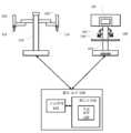
도 1은 일부 실시 예에 따른 컴퓨터 보조 시스템(100)의 개략도이다. 도 1에 도시된 바와 같이, 컴퓨터 보조 시스템(100)은 하나 이상의 이동가능하거나 또는 관절형(articulated) 팔(120)을 가진 장치(110)를 포함한다. 하나 이상의 관절형 팔(120)의 각각은 하나 이상의 하나 이상의 엔드 이펙터(125)를 지지할 수 있다. 일부 실시 예에서, 장치(110)는 컴퓨터 보조 수술 장치와 호환할 수 있다. 하나 이상의 엔드 이펙터(125)는 수술 도구, 촬상 장치, 및/또는 등을 포함할 수 있다. 일부 실시 예에서, 수술 도구는 클램프, 그리퍼, 견인기, 소작(cautery) 도구, 흡인(suction) 도구, 봉합(suturing) 장치, 및/또는 등을 포함할 수 있다. 일부 실시 예에서, 촬상 장치는 내시경, 카메라, 입체영상(stereoscopic) 장치, 및/또는 등을 포함할 수 있다.1 is a schematic diagram of a computer assistance system 100 in accordance with some embodiments. As shown in FIG. 1 , computer assistance system 100 includes
장치(110)는 인터페이스를 통해 제어 유닛(130)에 결합된다. 인터페이스는 하나 이상의 케이블, 커넥터 및/또는 버스를 포함할 수 있으며, 하나 이상의 네트워크 스위칭 및/또는 라우팅 장치를 가진 하나 이상의 네트워크를 더 포함할 수 있다. 제어 유닛(130)은 메모리(150)에 결합된 프로세서(140)를 포함한다. 제어 유닛(130)의 동작은 프로세서(140)에 의해 제어된다. 제어 유닛(130)이 단지 하나의 프로세서(140) 만을 가진 것으로 도시되었지만, 프로세서(140)는 제어 유닛(130) 내에서의 하나 이상의 중앙처리장치, 멀티코어 프로세서, 마이크로프로세서, 마이크로컨트롤러, 디지털 신호 프로세서, FPGA(field programmable gate array), 주문형 집적회로(ASIC) 및/또는 등을 대표한다. 제어 유닛(130)은 스탠드 어론형 서브시스템 및/또는 컴퓨팅 장치에 부가된 보드로서, 또는 가상 기계로서 구현될 수 있다.The
메모리(150)는 제어 유닛(130)에 의해 실행되는 소프트웨어 및/또는 제어 유닛(130)의 동작 동안 사용되는 하나 이상의 데이터 구조를 저장하기 위해 사용된다. 메모리(150)는 하나 이상의 유형의 기계 판독가능 매체를 포함할 수 있다. 기계 판독가능 매체의 일부 일반적인 형태는 플로피 디스크, 플렉시블 디스크, 하드 디스크, 자기 테이프, 임의의 기타 자기 매체, CD-ROM, 임의의 기타 광학 매체, 천공 카드, 종이 테이프, 홀 패턴을 가진 임의의 기타 물리적 매체, RAM, PROM, EPROM, FLASH-EPROM, 임의의 기타 메모리 칩 또는 카트리지, 및/또는 프로세서 또는 컴퓨터가 판독하도록 하는 임의의 기타 매체를 포함한다.Memory 150 is used to store software executed by control unit 130 and/or one or more data structures used during operation of control unit 130 . Memory 150 may include one or more tangible machine-readable media. Some common forms of machine-readable media are floppy disks, flexible disks, hard disks, magnetic tape, any other magnetic media, CD-ROM, any other optical media, punched cards, paper tape, any other having a hole pattern. physical media, RAM, PROM, EPROM, FLASH-EPROM, any other memory chip or cartridge, and/or any other medium that is readable by a processor or computer.
도시된 바와 같이, 메모리(150)는 장치(110)의 자율 및/또는 반자율 제어를 지원하기 위해 사용될 수 있는 모션 제어 애플리케이션(160)을 포함한다. 모션 제어 애플리케이션(160)은 장치(110)로부터 위치, 모션 및/또는 기타 센서 정보를 수신하고, 기타 장치에 관한 기타 제어 유닛과 위치, 모션 및/또는 충돌 방지 정보를 교환하고, 및/또는 장치(110), 장치(110)의 관절형 팔(120), 및/또는 엔드 이펙터(125)를 위한 모션을 계획하고 및/또는 계획을 보조하기 위한 하나 이상의 애플리케이션 프로그래밍 인터페이스(API)를 포함할 수 있다. 모션 제어 애플리케이션(160)이 소프트웨어 애플리케이션으로 도시되었지만, 모션 제어 애플리케이션(160)은 하드웨어, 소프트웨어, 및/또는 하드웨어와 소프트웨어의 조합으로 구현될 수 있다.As shown, memory 150 includes a motion control application 160 that may be used to support autonomous and/or semi-autonomous control of
제어 유닛(130)은 인터페이스를 통해 조작자 워크스테이션(170)에 더 결합될 수 있다. 조작자 워크스케이션(170)은 외과 의사와 같은 조작자에 의해 관절형 팔(120) 및 엔드 이펙터(125)의 움직임 및/또는 동작을 제어하도록 사용될 수 있다. 관절형 팔(120)의 동작을 지원하기 위해, 조작자 워크스테이션(170)은 관절형 팔(120) 및/또는 엔드 이펙터(125) 중 하나 이상의 적어도 일부의 이미지들을 디스플레이하는 디스플레이 시스템(180)을 포함한다. 예를 들면, 디스플레이 시스템(180)은 그것들이 사용되고 있을 때 관절형 팔(120) 및/또는 엔드 이펙터(125)를 조작자가 보는 것이 비실용적이고 및/또는 불가능할 때 사용될 수 있다. 조작자 워크스테이션(170)은 장치(110), 관절형 팔(120), 및/또는 엔드 이펙터(125)를 조작하는 데에 이용될 수 있는 하나 이상의 입력 또는 마스터 제어(195)를 가진 콘솔 워크스테이션을 더 포함할 수 있다. 입력 컨트롤(195)의 각각은 입력 컨트롤(195)의 움직임이 조작자 워크스테이션(170)에 의해 검출되고 제어 유닛(130)에 통신되도록 자신들의 관절형 팔의 원단부에 결합될 수 있다. 개선된 인체공학을 제공하기 위해, 콘솔 워크스테이션은 또한 입력 컨트롤(195)을 조정하는 동안 조작자가 자신의 팔을 기댈 수 있는 팔 거치대(rest)(190)와 같은 하나 이상의 거치대를 포함할 수 있다. 일부 예시에서, 디스플레이 시스템(180) 및 입력 컨트롤(195)은 관절형 팔(120) 및/또는 엔드 이펙터(125)를 원격조작하기 위해 조작자에 의해 사용될 수 있다. 일부 실시예에서, 장치(110), 조작자 워크스테이션(170) 및 제어 유닛(130)은 미국 캘리포니아 서니베일의 인튜어티브 서지컬, 인코포레이티드 사의 da Vinci® Surgical System에 대응할 수 있다.The control unit 130 may be further coupled to the
일부 실시 예에서, 다른 구조 및/또는 아키텍처가 컴퓨터 보조 시스템(100)과 함께 사용될 수 있다. 일부 실시예에서, 제어 유닛(130)이 조작자 워크스테이션(170) 및/또는 장치(110)의 일부로서 포함될 수 있다. 일부 실시 예에서, 컴퓨터 보조 시스템(100)은 수술실 및/또는 중재실(interventional suite)에서 발견 될 수 있다. 컴퓨터 보조 시스템(100)이 2개의 관절형 팔(120)을 가진 단 하나의 장치(110) 만을 포함하지만, 당업자는 컴퓨터 보조 시스템(100)이 관절형 팔 및/또는 장치(110)와 유사하고 및/또는 상이한 설계의 엔드 이펙터를 가진 임의의 수의 장치를 포함할 수 있다는 것을 이해할 것이다.. 일부 실시예에서, 장치들의 각각은 더 적은 수 또는 더 많은 수의 관절형 팔(120) 및/또는 엔드 이펙터(125)를 포함할 수 있다.In some embodiments, other structures and/or architectures may be used with computer assistance system 100 . In some embodiments, control unit 130 may be included as part of
도 2는 일부 실시 예에 따른 엔드 이펙터 및 입력 컨트롤을 중심복귀(recentering)하는 방법(200)의 개략도이다. 방법(200)의 프로세스(210-280) 중 하나 이상은 하나 이상의 프로세서(예를 들면, 제어 유닛(130) 내의 프로세서(140))에 의해 실행될 때 하나 이상의 프로세서로 하여금 프로세스(210-280) 중 하나 이상을 수행하도록 할 수 있는 비일시적인, 촉지가능한 기계 판독가능한 매체 상에 저장된 실행가능한 코드의 형태로(적어도 부분적으로) 구현될 수 있다. 일부 실시 예에서, 방법(200)은 모션 제어 애플리케이션(160)과 같은 애플리케이션에 의해 수행될 수 있다. 일부 실시예에서, 방법(200)은 촬상 장치에 의해 캡처되고 디스플레이 시스템(180) 상에 표시된 이미지에서의 엔드 이펙터(125)의 하나 이상을 중심복귀하고 및/또는 콘솔 워크스테이션에서 입력 컨트롤(195)의 하나 이상을 중심복귀하기 위해 사용되어, 입력 컨트롤(195)의 위치 및/또는 배향이 이미지에서 표시되는 엔드 이펙터(125)의 위치 및/또는 배향으로 대응할 수 있도록 한다.2 is a schematic diagram of a
프로세스(210)에서, 중심복귀 요청이 검출된다. 일부 실시 예에서, 전자 장치의 조작자가 수동으로 스위치, 페달, 레벨, 음성 인식 및/또는 등과 같은 하나 이상의 입력 컨트롤을 이용하여 중심복귀 요청을 트리거 할 수 있다. 일부 실시 예에서, 중심복귀 요청의 완료 및/또는 그것이 철회될 때까지 중심복귀를 트리거하는 순간 입력 및/또는 중심복귀를 활성화하는 연속한 입력으로서 요청이 발급될 수 있다. 일부 예시에서, 중심복귀 요청은 시스템 상태 변화에 응답하여 자동화될 수 있다. 일부 예시에서, 시스템의 상태의 변화는 입력 컨트롤과 원격조작된 엔드 이펙터 사이에서 연관된 변화를 포함할 수 있다. 일부 예시에서, 시스템 상태 변화는 입력 컨트롤과 하나 이상의 엔드 이펙터가 촬상 장치의 시야 외부에서 검출되는 원격 조작된 엔드 이펙터 사이에서 연관된 변화를 포함할 수 있다. 일부 실시 예에서, 시스템 상태 변화는 촬상 장치의 시야 외부에 하나 이상의 엔드 이펙터가 있는 촬상 장치의 모드 변화(즉, 디지털 줌의 변화, 원거리 시야 각도(distal viewing angle) 변화, 및/또는 등과 같은)를 포함할 수 있다. 일부 예시에서, 중심복귀 요청은 중심복귀되는 관절형 팔과 엔드 이펙터의 위치를 포함할 수 있다. 일부 실시 예에서, 중심복귀 요청의 검출은 고유한 사운드, 콘솔 상의 메시지, 지시자 및/또는 등과 같은 조작자에 대한 적절한 피드백에 의해 수신확인될 수 있다.At
프로세스(220)에서, 하나 이상의 엔드 이펙터의 조작자 제어가 중단된다. 중심복귀가 시작할 수 있기 전에, 전자 장치의 엔드 이펙터의 하나 이상을 제어 및/또는 원격 조작하는 조작자 기능이 중단된다. 조작자에 의한 제어의 중단은 중심복귀 동작이 조작자의 명령을 받은 모션의 간섭없이 계속되도록 허용한다.At
프로세스(230)에서, 원하는 시야 중심복귀 이동이 판정된다. 예를 들면, 관절형 팔과 관절형 팔에 결합된 엔드 이펙터 및 관절형 팔과 엔드 이펙터의 하나 이상의 키네메틱 모델에서의 감지된 조인트 위치를 이용하여, 시야 중심복귀 이동이 판정된다. 일부 예시에서, 이는 제어되고 있는 전자 장치에 연관된 관심있는 하나 이상의 엔드 이펙터의 판정 프로세스(예를 들면, 위치 및/또는 배향)를 포함할 수 있다. 일부 실시예에서, 판정된 포즈의 각각이 세계 좌표계 및/또는 시야 좌표계와 같은 일반적인 좌표계에 맵핑될 수 있다. 촬상 장치에 대한 바람직한 작업 거리의 포즈 및 지식의 지오메트리를 이용하여, 촬상 장치의 시야 공간 내에 엔드 이펙터를 위치시키는 촬상 시스템에 대한 원하는 포즈가 판정된다. 촬상 장치의 포즈 및 하나 이상의 키네매틱 모델이 그런다음 촬상 장치에 대한 원하는 시야 중심복귀 이동을 판정하는 데에 이용될 수 있다.At
프로세스(240)에서, 원하는 입력 컨트롤 중심복귀 이동이 판정된다. 프로세스(230) 동안 판정된 엔드 이펙터에 대한 포즈가 엔드 이펙터에 대응하는 입력 컨트롤이 로케이팅되는 콘솔 작업 공간에 대한 좌표계로 맵핑될 수 있다. 포즈는 콘솔 작업 공간의 바람직한 인체공학적 중심과 엔드 이펙터에 의해 사용된 작업 공간에서의 거리와 입력 컨트롤을 포함하는 콘솔 작업 공간에서의 거리 사이의 환산 계수에 관한 지식을 이용하여 맵핑될 수 있다. 맵핑된 포즈 및 입력 컨트롤을 위한 하나 이상의 키네매틱 모델은 그런 다음 입력 컨트롤을 위한 대응하는 입력 컨트롤 중심복귀 이동을 판정하는 데에 이용될 수 있다. 일부 실시예에서, 2개의 입력 컨트롤 중심복귀 이동이 판정되는 데, 하나는 엔드 이펙터 중 제1 엔드 엔드 이펙터와 연관된 좌측 입력 컨트롤에 대응하고, 또다른 것은 엔드 이펙터 중 제2 엔드 이펙터에 연관된 우측 입력 컨트롤에 대응한다. 일부 실시예에서, 다른 수의 입력 컨트롤이 또한 대응하는 중심복귀 이동을 판정했을 수 있다.In
프로세스(250)에서, 시야 중심복귀 이동 및/또는 입력 컨트롤 중심복귀 이동이 유효한지 여부가 판정된다. 촬상 장치의 키네매틱 모델과 프로세스(230) 동안 판정된 촬상 장치에 대한 원하는 중심복귀 이동을 이용하여, 촬상 장치에 대한 원하는 중심복귀 이동이 유효한지 여부가 판정된다. 일부 실시예에서, 엔드 이펙터의 적절한 이미지를 얻기 위해, 이 유효성 판정은 촬상 장치의 움직임, 다른 관절형 팔의 위치, 기타 엔드 이펙터, 및/또는 전자 장치의 작업 공간에서의 장치, 및/또는 촬상 장치의 기능에 대한 하나 이상의 구속을 리뷰하는 단계를 포함할 수 있다. 입력 컨트롤의 키네매틱 모델과 프로세스(240) 동안 판정된 입력 컨트롤에 대한 원하는 중심복귀 이동을 이용하여, 입력 컨트롤에 대한 원하는 중심복귀 이동이 유효한지 여부가 판정된다, 일부 실시예에서, 이 유효성 판정은 입력 컨트롤의 움직임, 콘솔 작업 공간에서의 조작자의 워크스테이션의 부분들의 위치, 및/또는 입력 컨트롤의 조작자에 대한 인체공학적 고려사항 중 하나 이상의 구속을 리뷰하는 단계를 포함한다. 중심복귀 이동이 유효한 것으로 판정될 때, 중심복귀 이동이 프로세스(260)를 이용하여 수행된다. 임의의 중심복귀 이동이 유효하지 않은 것으로 판정될 때, 오류가 프로세스(270)를 이용하여 표시된다.At
프로세스(260)에서, 시야 및 입력 컨트롤 중심복귀 이동이 조정된다. 하나 이상의 움직임 명령이 촬상 장치로 하여금 시야 중심복귀 이동을 실행하도록 명령 및/또는 지식하도록 촬상 장치에 결합된 관절형 팔의 하나 이상의 액추에이터에 전송된다. 하나 이상의 움직임 명령이 또한 입력 컨트롤로 하여금 입력 컨트롤 중심복귀 이동을 실행하도록 명령 및/또는 지시하도록 하기 위해 입력 컨트롤에 연결된 관절로 결합된 팔의 하나 이상의 액추에이터에 전송된다. 촬상 장치 및 입력 컨트롤을 위한 움직임 명령이 일반적으로 조정된다. 일부 예시에서, 조정은 촬상 장치와 입력 컨트롤 모두를 동시에 중심복귀할 수 있도록 할 수 있다. 일부 예시에서, 조정은 적어도 일부의 위치 및/또는 배향 일치가 중심복귀 이동동안 촬상 장치의 시야 공간 내의 엔드 이펙터들과 입력 컨트롤의 포즈들 사이에서 유지되고 있도록 수행될 수 있다. 일부 실시예에서, 프로세스(260)는 또한 중심복귀 동작이 발생하고 있다는 것을 나타내는 오디오 및/또는 시각적 피드백을 조작자에게 제공하는 단계를 포함할 수 있다. 일부 예시에서, 오디오 피드백은 고유한 사운드, 발성된 어구(spoken phrase), 및/또는 등을 포함할 수 있다. 중심복귀 이동의 완료시, 조작자 제어가 프로세스(280)를 이용하여 재시작될 수 있다.In
프로세스(270)에서, 오류가 표시된다. 판정된 중심복귀 이동이 유효하지 않은 것으로 판정되면, 조작자에게 통지된다. 일부 예시에서, 통지는 임의의 적절한 오디오 및/또는 시각적 피드백을 포함할 수 있다. 일부 예시에서, 오디오 피드백은 고유한 사운드의 재생을 포함할 수 있다. 오류가 표시된 후에, 조작자 제어가 프로세스(280)를 통해 반복된다.At
프로세스(280)에서, 엔드 이펙터의 조작자 제어가 원상복귀된다. 중심복귀 이동이 프로세스(260)를 이용하여 수행되거나 또는 오류가 프로세스(270)를 이용하여 표시되건 아니건 간에, 입력 컨트롤을 이용한 엔드 이펙터의 제어가 조작자에게로 리턴된다. 오류가 표시될 때, 촬상 장치 및/또는 입력 컨트롤의 중심복귀는 조작자가 담당하게 될 수 있다. 조작자에 의한 엔드 이펙터 및/또는 촬상 장치의 제어 기간후, 또다른 중심복귀 동작이 프로세스(210)를 이용하여 검출될 수 있다.In
상술되고 여기에서 더 강조된 바와 같이, 도 2는 단지 청구 범위를 과도하게 한정하지 않는 예시일 뿐이다. 당업자는 다수의 변형, 대안, 변경을 인식할 것이다. 일부 실시예에 따라, 추가적인 조건은 예를 들면 프로세스(280)를 이용하고 있는 조작자 제어를 리턴하고 및/또는 장치 조작을 중단하는 것에 의해 방법(200)의 이른 종료를 가져올 수 있다. 일부 예시에서, 추가적인 조건은 조작자 워크스테이선 또는 관절형 팔에 대한 하나 이상의 제어를 이용한 조작자로부터의 수동 개입 또는 오버라이딩(override), 하나 이상의 안전 인터로크(interlock)를 이용한 조작자 워크스테이션과의 조작자 이탈(disengagement)의 검출, 관절형 팔 및/또는 입력 컨트롤에서의 위치 추적 오류, 시스템 고장 및/또는 등을 포함할 수 있다.As discussed above and further emphasized herein, FIG. 2 is merely an example that does not unduly limit the claims. Those skilled in the art will recognize many variations, alternatives, and modifications. According to some embodiments, the additional condition may result in early termination of
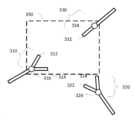
도 3a 및 3b는 일부 실시예에 따른 시야 중심복귀 동작 전후로부터의 이미징 뷰의 개략도이다. 도 3a에 도시된 바와 같이, 작업공간은 시야 중심복귀 동작의 수행 이전에 3개의 관절형 팔을 포함하는 것으로 도시된다. 제1 관절형 팔은 그리퍼 유형 엔드 이펙터(310)를 가진 종단을 가진다. 그리퍼 유형 엔드 이펙터(310)는 2개의 핑거(312 및 314) 및 피봇 조인트(316)를 포함한다. 제2 관절형 팔은 또한 2개의 그리핑 핑거(322 및 334)와 피봇 조인트(326)를 포함하는 그리퍼 유형 엔드 이펙터(320)를 가진 종단을 가진다. 제3 관절형 팔은 엔드 포인트(332) 및 기준점(334)를 구비하는 단일 핑거 엔드 이펙터(330)를 포함한다. 일부 예시에서, 기준점(334)은 회전 조인트에 대응한다. 일부 예시에서, 단일 핑거 엔드 이펙터(330)는 소작(cautery) 도구, 흡인(suction) 도구, 및/또는 등의 대표적인 예시일 수 있다. 일부 예시에서, 관절형 팔은 관절형 팔(120)의 대표적인 예시이며 그리퍼 유형 및/또는 단일 핑거 엔드 이펙터(310, 320, 및/또는 330)는 엔드 이펙터(125)의 대표적인 예시이다.3A and 3B are schematic diagrams of imaging views from before and after a recenter operation in accordance with some embodiments. As shown in FIG. 3A , the workspace is shown to include three articulated arms prior to performing the recentric motion. The first articulated arm has an end with a gripper
또한 시야 공간(340)이 도 3a에 도시된다. 일부 예시에서, 시야 공간(340)은 촬상 장치에 의해 캡처된 이미지에 대응한다. 도시된 바와 같이, 시야 공간(340)은 그리퍼 유형 엔드 이펙터(320), 그리퍼 유형 엔드 이펙터(310)의 일부를 포함하고, 단일 핑거 엔드 이펙터(330)는 포함하지 않는다. 일부 예시에서, 도 3a는 조작자가 엔드 이펙터(310 및/또는 320)를 제어하고 있는 동안 취해진 이미지에 대응할 수 있다.A
일부 예시에서, 조작자가 엔드 이펙터(310 및 330) 보다는 엔드 이펙터(310 및 330)를 제어하는 것으로 스위칭하고자 할 때, 이는 문제를 일으킬 수 있다. 예를 들면, 엔드 이펙터(330)는 시야 공간 내에 없기 때문에, 엔드 이펙터(330)는 시야 공간(340)의 이미지에서 보이지 않고 조작자는 어디에 엔드 이펙터(330)가 위치되는지 기억할 수 없다. 일부 예시에서, 조작자는 시야 공간(340) 내에 양 엔드 이펙터(310 및 330)을 배치하기 위해 시야 공간(340)을 수동으로 중심복귀시킬 수 있다. 일부 예시에서, 조작자는 방법(200)과 유사한 방법을 이용하여 자동 중심복귀를 트리거하고 중심복귀가 발생하는 엔드 이펙터로서 엔드 이펙터(310 및 330)를 지정할 수 있다.In some instances, this can cause problems when the operator wishes to switch to
도 3b는 중심복귀 후 엔드 이펙터(310 및 330)의 시야 공간(350)을 도시한다. 시야 중심복귀 이동을 이용하여, 엔드 이펙터(310 및 330)의 이미지 캡처에 이용된 촬상 장치가 엔드 이펙터(310 및 330)를 포함하는 포즈로 위치조정 및/또는 재배향된다. 중심복귀 이동은 시야 중심복귀 이동 이전으로부터의 시야 공간(340)을 시야 중심복귀 이동이 발생한 후의 시야 공간(350)으로 변경한다. 이 시야 중심복귀 이동은 그리핑 핑거(312 및 314), 피봇 조인트(316), 엔드 포인트(332) 및 기준점(334)를 포함하는 시야 공간(350)을 가져온다. 시야 공간(350)은 또한 그리핑 핑거(312 및 314), 피봇 조인트(316), 엔드 포인트(332) 및 기준점(334)에 관해 중심을 이룬다.3B shows the
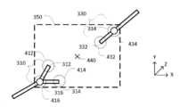
도 4a 및 4b는 각각 일부 실시예에 따른 시야 중심복귀 동작 후의 이미징 뷰 및 측면 뷰의 개략도이다. 도 4a 및 4b는 엔드 이펙터(310 및 330) 상에 시야 공간(350)을 중심으로 두도록 하기 위한 엔드 이펙터(310 및 330)에 대한 타겟의 사용을 도시한다. 도 4a는 시야 공간(350)을 이용하여 촬상 장치에 의해 캡처될 수 있는 이미지로부터 이를 도시한다. 일부 예시에서, 시야 좌표계가 사용될 때, 시야 공간(350)은 시야 공간(350)에서의 좌로부터 우로의 x축과, 뷰 위쪽 방향으로 있는 y축, 및 시야 방향으로 있는 z축을 포함할 수 있다.4A and 4B are schematic diagrams of an imaging view and a side view, respectively, after a field-of-view centering operation in accordance with some embodiments. 4A and 4B illustrate the use of a target for the
시야 공간(350) 내에서의 엔드 이펙터(310 및 330)의 중심복귀를 돕기 위해, 엔드 이펙터(310 및/또는 330)의 각각의 상의 하나 이상의 타겟이 선택된다. 일부 실시예에서, 타겟의 각각은 엔드 이펙터(310 및/또는 330)의 핑거의 각각의 팁 뿐만이 아니라 도 4a에 도시된 바와 같이 관심의 대상인 임의의 조인트 및/또는 기준점에 연관될 수 있다. 일부 실시 예에서, 핑거들의 바로 위 상에 및/또는 엔드 이펙터(310 및/또는 330) 및/또는 관절형 팔들에서 타겟들을 연관시키는 것과 같이, 타겟들을 선택하기 위한 기타 기준이 사용될 수 있다. 도 4a에 도시된 바와 같이, 3개의 타겟들이 그리퍼 유형의 엔드 이펙터(310) 상에 사용되고, 2개의 타겟들이 단일 핑거 엔드 이펙터(330) 상에서 사용된다. 그리퍼 유형의 엔드 이펙터(310) 상의 3개의 타겟들은 각각 그리핑 핑거(312 및 314)의 팁 상에 중심을 둔 타겟(412 및 414) 및 피봇 조인트(316) 상에 중심을 둔 타겟팅 포인트(416)를 포함한다. 단일 핑거 엔드 이펙터(330) 상의 2개의 타겟들은 엔드 포인트(332) 상에 중심을 둔 타겟팅 포인트(432) 및 기준점(334) 상에 중심을 둔 타겟팅 포인트(434)를 포함한다.One or more targets on each phase of the
일부 예시에서, 타겟(412-416 및/또는 432-434)의 각각은 핑거의 대응하는 팁들 및/또는 대응하는 조인트 및/또는 기준점의 중심에서 또는 그 근방에서 중심을 가지는 가상 바운딩 구체로서 모델링될 수 있다. 일부 예시에서, 가상 구체 각각의 반경은 각각의 타겟팅 포인트와 연관된 엔드 이펙터의 대응하는 부분의 최소 최적을 캡처하기에 충분히 크다. 일부 예시에서, 반경은 시야 공간(350)이 대응하는 엔드 이펙터 뿐만이 아니라 대응하는 엔드 이펙터에 관한 가장자리 공간을 캡처할 수 있도록 엔드 이펙터의 대응 부분의 체적보다 2배 내지 3배 더 클 수 있다. 이는 엔드 이펙터들이 시야 공간(350)의 에지 바로 위에 위치되는 것을 방지한다. 일부 예시에서, 반경은 타겟 포인트의 위치에서의 키네매틱 불확실성을 처리하기 위해 크기조정될 수 있다.In some examples, each of the targets 412-416 and/or 432-434 is to be modeled as a virtual bounding sphere having a center at or near the center of the corresponding tips and/or corresponding joints and/or fiducials of the fingers. can In some examples, the radius of each virtual sphere is large enough to capture the minimum optimality of the corresponding portion of the end effector associated with each targeting point. In some examples, the radius may be two to three times greater than the volume of the corresponding portion of the end effector such that the
일부 예시예서, 각각의 타겟(412-416 및/또는 432-434)의 중심점의 질량 중심(440)이 연산될 수 있다. 질량 중심(440)은 그런다음 시야 공간(350)의 중심점으로서 사용될 수 있다. 질량 중심(440)과 촬상 장치 사이의 작업 거리는 그런다음 시야 공간(350)이 각각의 타겟(412-416 및/또는 432-434)을 포함하도록 조정될 수 있다.In some examples, the center of
도 4b는 시야 공간(350)의 대응하는 측면도를 도시한다. 도 4b의 측면도는 시야 공간(350)이 그것이 촬상 장치(450)로부터 멀어지는 방향으로 이동할 때 넓어지는 시야 절단부인 것을 도시한다. 일부 예시에서, 절단부의 각도 폭은 촬상 장치(450)의 광학 속성으로부터 판정될 수 있다. 일부 예시에서, 촬상 장치(450)는 캐뉼러(460)를 통해 환자에게 삽입되는 내시경일 수 있다. 일부 예시에서, 촬상 장치(450)는 입체영상일 수 있다. 일부 예시에서, 캐뉼러(460)는 촬상 장치(450)의 롤, 피치 및 수평 회전(yaw rotation)이 원격 중심에 관해 중심을 이루도록 촬상 장치(450)에 대한 원격 중심 근방에 위치될 수 있다. 도 4b에 더 도시된 바와 같이, 촬상 장치(450)는 시야 좌표계의 z축에서의 시야 방향을 따라서 있는 질량 중심을 가지고 방향을 가진다. 질량 중심(440)은 또한 각각의 타겟(412-416 및/또는 332-334)의 z 방향의 평균 깊이에 위치될 수 있다. 질량 중심(440)은 또한 촬상 장치(450)의 팁(470)으로부터 작업 거리(480)에 위치된다.4B shows a corresponding side view of the
일부 실시예에서, 작업 거리(480)는 하나 이상의 기준에 기초하여 선택될 수 있다. 프로세스는 질량 중심(440)을 판정하고 시야 또는 z축 방향으로서 촬상 장치 상의 기준점으로부터 질량 중심(440)로의 방향을 이용하여 시작한다. 일부 예시에서, 기준점은 촬상 장치가 캐뉼러(460)와 팁(470) 사이에서 직선에 있을 때의 캐뉼러(460)에 대응할 수 있다. 일부 예시에서, 촬상 장치의 하나 이상의 키네매틱 모델이 캐뉼러(460)에 대한 기준점의 위치를 판정하기 위해 사용될 수 있다. 일부 예시에서, 기준점은 팁(470)에 연관될 수 있다. 타겟(412-416 및/또는 432-434)의 각각에 대한 최대 x 축 및/또는 y축 정도가 그런다음 타겟(412-416 및/또는 432-434)이 시야 공간(350)의 절단부 내에 있도록 하기 위해 각각의 타겟(4120416 및/또는 432-434)에 대한 각각의 최소 뷰 거리를 판정하기 위해 사용된다. 최대 뷰 거리는 그런다음 각각의 타겟(412-416 및/또는 432-434)에 연관된 체적이 시야 공간(350) 내에 포함되는 것을 보장하기 위해 작업 거리(480)로서 선택될 수 있다. 일부 예시에서, 작업 거리(480)는 어느 하나가 규정이 되고 그것이 최대 최소 시야 거리보다 더 클 때 촬상 장치(450)에 대한 바람직한 작업 거리까지 증가될 수 있다. 일부 예시에서, 작업 거리(480)는 또한 촬상 장치(450)에 대한 최소 및 최대 초점거리 내에 있도록 구속될 수 있다.In some embodiments, the working
시야 방향/시야 좌표계 z축 및 작업 거리(480)가 판정되면, 촬상 장치(450)에 대한 시야 중심복귀 이동이 판정될 수 있다. 시야 중심복귀 이동은 시야 방향과 정렬하기 위해 촬상 장치(450)의 피치 및 요(yaw)를 조정하는 단계 및 작업 거리(480)에 기초하여 캐뉼러(460)에 대한 팁(470)의 삽입 및/또는 접기(retraction) 크기를 조정하는 단계를 포함할 수 있다. 일부 예시에서, 시야 중심복귀 이동은 그것이 유효한지 여부를 판정하기 위해 분석될 수 있다. 일부 예시에서, 이는 촬상 장치(450)가 부착되는 관절형 팔이 시야 중심복귀 이동을 실행할 수 있는지 여부를 판정하는 단계를 포함할 수 있다. 일부 예시에서, 관절형 팔은 조인트 제한, 시야 중심복귀 이동에서 부여된 최대 움직임 제한, 및/또는 다른 관절형 팔(예를 들면, 관절형 팔(310, 320 및/또는 330), 환자 해부구조, 및/또는 작업 공간 내의 기타 물체와의 충돌방지에 기인하여 시야 중심복귀 이동을 실행할 수 없을 수 있다. 일부 예시에서, 최대 움직임 제한은 30°이하로 피치 및 요 모션을 제한하는 피치 및 요 각도 제한 및/또는 자신의 사전 움직임 위치를 벗어나는 팁(470)의 삽입을 금지하는 것을 포함할 수 있다. 일부 예시에서, 시야 중심복귀 이동은 촬상 장치(450)의 움직임에 대해 부여된 임의의 구속이 타겟들이 시야 공간(350)의 절단부에서는 더이상 구속되지 않는 것을 가져올 수 있을 때 유효하지 않다고 판정될 수 있다.When the viewing direction/viewing coordinate system z-axis and the
일부 예시에서, 시야 중심복귀 이동은 질량 중심(440)으로부터 멀어지는 촬상 장치(450)의 접힘, 시야 방향과 정렬하도록 피치 및/또는 요 방위를 수행하는 단계, 및 그런다음 질량 중심(440)으로부터의 작업 거리로의 팁(470) 삽입을 포함하는 다중 단계 이동으로 계획될 수 있다. 일부 예시에서, 시야 중심복귀 이동이 줌인을 포함할 때, 다중 단계 이동은 팁(470)을 질량 중심(440)으로부터의 작업 거리(480)로 삽입하기 전에 시야 방향과 정렬하도록 피치 및/또는 요 방향을 수행하는 단계를 포함할 수 있다. 일부 예시에서, 시야 중심복귀 이동이 줌아웃을 포함할 때, 다중 단계 이동은 피치 및/또는 요 방위의 수행 전에 촬상 장치를 작업 거리(480)로 접히는 단계를 포함할 수 있다. 일부 예시에서, 다중 단계 이동은 팁(470)이 관절형 팔의 엔드 이펙터(310, 320 및/또는 330), 환자 해부구조, 및/또는 작업 공간 내의 기타 물체와 충돌할 가능성을 감소하는 것을 도울 수 있다. 일부 예시에서, 시야 중심복귀 이동은 또한 뷰 업/뷰 좌표계의 y축이 세계 좌표계와 정렬하도록 촬상 장치(450)를 회전하는 단계를 포함한다. 일부 예시에서, 시야 중심복귀 이동은 촬상 장치(450)의 방위 및/또는 위치지정 오류를 최소화하기 위해 촬상 장치(450)의 관절형 팔을 제어하는 조인트에서의 정확도 한계에 기초하여 촬상 장치(450)의 피치, 요 및 삽입을 최적화하는 양방향 모션 계획 동작을 이용하여 판정된다.In some examples, the recentric movement includes folding of the
일부 실시예에서, 시야 중심복귀 이동이 유효하지 않은 것으로 판정될 때, 팁(470)이 최소 삽입 깊이로 접히는 대안의 시야 중심복귀 이동이 판정된다. 일부 예시에서, 최소 삽입 깊이는 촬상 장치가 촬상 장치(450)를 위치지정 및/또는 배향지정하는 데에 사용되는 관절형 팔의 하나 이상의 부분들에 의해 부분적으로 폐색될 수 있는 것을 벗어난 깊이에 대응할 수 있다. 일부 예시에서, 부분적으로 촬상 장치를 폐색할 수 있는 관절형 팔의 부분들은 캐뉼러(460)에 대응할 수 있다. 일부 예시에서, 최소 삽입 깊이는 촬상 장치에 대한 원격 중심으로부터의 미리 정해진 거리의 포인트에 대응할 수 있다. 일부 예시에서, 미리정해진 거리는 캐뉼러(460)의 길이에 기초할 수 있다. 일부 예시에서, 미리정해진 거리는 2 내지 9cm일 수 있다. 캐뉼러(460)로 접힌 팁(470)으로, 촬상 장치(450)에 대한 시야 방향은 그런다음 질량 중심(440)을 향한 포인트에 대해 설정된다. 각각의 타겟(412-416 및/또는 432-434)에 대한 최대 x축 및/또는 y축 정도는 그런다음 그것들이 시야 공간(350) 내에 놓이는지 여부를 보기 위해 체크된다. 각각의 타겟(412-416 및/또는 432-434)이 시야 공간(350) 내에 놓이지 않을 때, 대안의 시야 중심복귀 이동이 또한 유효하지 않은 것으로 판정된다. 시야 중심복귀 이동에 관해, 대안의 시야 중심복귀 이동의 유효성을 추가적으로 체크하는 것은 촬상 장치(450)가 부착된 관절형 팔이 대안의 시야 중심복귀 이동을 실행할 수 있는지를 판정하는 단계를 포함할 수 있다. 일부 예시에서, 관절형 팔은 조인트 제한, 시야 중심복귀 이동에서 부여된 최대 움직임 제한, 및/또는 다른 관절형 팔(예를 들면, 관절형 팔(310, 320 및/또는 330), 및/또는 환자 해부구조와의 충돌방지에 기인하여 대안의 시야 중심복귀 이동을 실행할 수 없을 수 있다. 대안의 시야 중심복귀 이동이 유효하지 않을 때, 시야 중심복귀는 중단되고 적절한 오류가 표시된다.In some embodiments, when a re-centering movement is determined to be invalid, an alternative re-centering movement is determined in which the
도 5는 일부 실시예에 따른 시야 중심복귀의 방법(500)의 개략도이다. 방법(500)의 프로세스(510-580) 중 하나 이상은 적어도 부분적으로 하나 이상의 프로세서(예를 들면, 제어 유닛(130) 내의 프로세서(140))에 의해 실행될 때 하나 이상의 프로세서로 하여금 프로세스(510-580) 중 하나 이상을 수행하도록 할 수 있는 비일시적인, 촉지가능한 기계판독 가능 매체에 저장된 실행가능한 코드의 형태로 구현될 수 있다. 일부 실시예에서, 방법(500)은 모션 제어 애플리케이션(160)과 같은 애플리케이션에 의해 수행될 수 있다. 일부 실시예에서, 방법(500)은 대응하는 이미지들이 디스플레이 시스템(180) 상에 디스플레이될 수 있도록 촬상 장치(450)와 같은 촬상 장치의 시야 공간 내에서 엔드 이펙터(125) 및/또는 엔드 이펙터(310-330) 중 하나 이상을 중심복귀하도록 사용될 수 있다.5 is a schematic diagram of a
프로세스(510)에서, 시야 중심점이 판정된다. 일부 예시에서, 시야 중심점은 촬상 장치(450)와 같은 촬상 장치에 의해 캡처된 이미지에서 중심복귀되는 하나 이상의 엔드 이펙터의 질량 중심에 대응할 수 있다. 도 3a, 3b, 4a, 및 4b의 예시에서, 엔드 이펙터는 엔드 이펙터(310 및 330)에 대응하고, 시야 중심점은 질량 중심(440)에 대응할 수 있다. 일부 예시에서, 질량 중심은 타겟(412-416 및/또는 432-434)과 같은 하나 이상의 타겟의 질량 중심을 취함으로써 판정될 수 있다. 일부 예시에서, 엔드 이펙터(310 및/또는 330)의 관절형 팔에 연관된 센서들이 관절형 팔에서의 조인트의 위치들을 판정하기 위해 사용될 수 있다. 엔드 이펙터(310 및/330) 및 그것들의 관절형 팔의 하나 이상의 키네매틱 모델과 조합한 이들 조인트 위치들이 그런다음 질량 중심을 판정하는 데에 이용될 수 있는 엔드 이펙터(310 및/330)의 위치들을 판정하는 데에 이용될 수 있다.At
프로세스(520)에서, 작업 거리가 판정된다. 일부 예시에서, 각각의 타겟들이 촬상 장치의 시야 공간 내에 있도록 하기 위해 엔드 이펙터의 타겟들이 얼마나 멀리 있어야 하는지를 판정함으로써 작업 거리가 판정될 수 있다. 일부 예시에서, 작업 거리는 타겟들이 시야 공간의 절단부 내에 있도록 각각의 타겟들에 대해 시야 방향에 직교하는 최대 x축 및/또는 y축 정도를 판정하고, 그런 다음 각각의 타겟에 대한 각각의 최소 시야 거리를 판정함으로써 판정될 수 있다. 최대 최소 시야 거리는 그런다음 타겟의 각각이 시야 공간 내에 구속되는 것을 보장하기 위해 작업 거리로서 선택될 수 있다. 일부 예시에서, 작업 거리는 바람직한 작업 거리가 규정되고 그것이 최대 최소 시야 거리보다 더 클 때 촬상 장치에 대한 바람직한 작업 거리까지 증가될 수 있다. 일부 예시에서, 바람직한 작업 거리는 촬상 장치의 조작자에 의해 설정될 수 있다. 일부 예시에서, 작업 거리는 또한 촬상 장치에 대한 최소 및 최대 초점 거리가 되도록 구속될 수 있다.In
프로세스(530)에서, 바람직한 촬상 장치 위치 및 방위가 판정된다. 촬상 장치의 방위는 촬상 장치 상의 기준점과 프로세스(510) 동안 판정된 시야 중심 사이의 벡터에 의해 판정된다. 일부 예시에서, 기준점은 촬상 장치가 원격 중심과 촬상 장치가 촬상 장치(450)의 캐뉼러(460)와 같은 원격 중심에 관한 움직임에 의해 구속될 때 촬상 장치의 팁 사이에서 직선일 때의 원격 중심에 대응할 수 있다. 일부 실시예에서, 촬상 장치의 하나 이상의 키네매틱 모델이 기준점의 위치를 판정하기 위해 사용될 수 있다. 일부 실시예에서, 기준점은 촬상 장치의 팁에 연관될 수 있다. 일부 실시예에서, 방향 벡터는 촬상 장치의 회전 위치를 유지하고 그런다음 방향 벡터로서 촬상 장치의 시야 방향을 이용하면서 시야 중심과 촬상 장치의 팁을 함께 배열함으로써 판정될 수 있다. 촬상 장치의 팁의 위치는 그런다음 프로세스(520) 동안 판정된 바와 같이 시야 방향에 반대 방향으로 시야 중심으로부터 멀어지는 방향으로의 작업 거리의 촬상 장치의 팁을 위치시키는 것에 기초하여 판정된다.In
프로세스(540)에서, 원하는 촬상 장치 위치 및 방위가 유효한지 여부가 판정된다. 일부 예시에서, 이는 촬상 장치가 부착되는 관절형 팔이 자신의 현재 위치 및 방위로부터 프로세스(530) 동안 판정된 촬상 장치 위치 및 방위로의 시야 중심복귀 이동을 실행할 수 있는지 여부를 판정하는 것을 포함할 수 있다. 일부 예시에서, 관절형 팔은 조인트 제한, 시야 중심복귀 이동에서 부여된 최대 움직임 제한, 및/또는 다른 관절형 팔, 환자 해부구조, 및/또는 작업 공간 내의 기타 물체와의 충돌방지에 기인하여 시야 중심복귀 이동을 실행할 수 없을 수 있다. 일부 예시에서, 최대 움직임 제한은 30°이하로 피치 및 요 모션을 제한하는 피치 및 요 각도 제한 및/또는 자신의 사전 움직임 위치를 벗어나는 촬상 장치의 삽입을 금지하는 것을 포함할 수 있다. 일부 예시에서, 시야 중심복귀 이동은 촬상 장치의 움직임에 대해 부여된 임의의 구속이 타겟들이 시야 공간의 절단부에서는 더이상 구속되지 않는 것을 가져올 수 있을 때 유효하지 않다고 판정될 수 있다. 원하는 촬상 장치 위치 및 방위가 유효할 때, 촬상 장치는 프로세스(550)를 이용하여 원하는 촬상 장치 위치 및 방위로 이동된다. 원하는 촬상 장치 위치 및 방위가 유효하지 않을 때, 대안의 촬상 장치 위치 및 방위가 프로세스(560)를 이용하여 판정된다.In
프로세스(550)에서, 촬상 장치가 이동된다. 촬상 장치는 그것이 부착된 관절형 팔과 촬상 장치에 대한 적절한 모션을 계획함으로써 이동되고, 그런다음 계획된 모션은 하나 이상의 명령을 관절형 팔의 액추에이터로 전송함으로써 실행된다. 일부 예시에서, 모션 계획은 시야 중심점으로부터 멀어지는 촬상 장치의 접힘, 촬상 장치가 시야 중심점을 향해 위치되도록 하기 위해 시야 방향과 정렬하도록 피치 및/또는 요 방위를 수행하는 단계, 및 그런다음 시야 중심점으로부터의 작업 거리로의 촬상 장치 삽입을 포함하는 다중 단계 이동을 포함할 수 있다. 일부 예시에서, 촬상 장치 이동이 줌인을 포함할 때, 다중 단계 이동은 촬상 장치를 작업 거리로 삽입하기 전에 시야 방향과 정렬하도록 피치 및/또는 요 방향을 수행하는 단계를 포함할 수 있다. 일부 예시에서, 촬상 장치 이동이 줌아웃을 포함할 때, 다중 단계 이동은 피치 및/또는 요 방위의 수행 전에 촬상 장치를 작업 거리로 접히는 단계를 포함할 수 있다. 일부 예시에서, 다중 단계 이동은 촬상 장치가 다른 관절형 팔의 엔드 이펙터, 환자 해부구조, 및/또는 작업 공간 내의 기타 물체와 충돌할 가능성을 감소하는 것을 도울 수 있다. 일부 예시에서, 촬상 장치가 프로세스(560) 동안 판정된 바와 같이 접힐 때, 삽입 단계는 생략될 수 있다. 일부 실시예에서, 계획된 모션은 또한 촬상 장치에 대한 뷰 업방향이 세계 좌표계와 정렬하도록 촬상 장치를 회전하는 단계를 포함한다. 일부 예시에서, 촬상 장치에 연관된 관절형 팔의 하나 이상의 키네매틱 모델이 모션 플래닝을 보조하기 위해 사용될 수 있다. 일부 예시에서, 계획된 모션은 촬상 장치의 방위 및/또는 위치지정 오류를 최소화하기 위해 촬상 장치에 연관된 관절형 팔을 제어하는 조인트에서의 정확도 한계에 기초하여 촬상 장치의 피치, 요 및 삽입 및/또는 수축을 최적화하는 양방향 모션 계획 동작을 이용하여 판정될 수 있다. 촬상 장치가 이동되면 중심복귀 동작이 완료된다.At
프로세스(560)에서, 대안의 촬상 장치 위치 및 방위가 판정된다, 프로세스(540) 동안 판정된 원하는 촬상 장치 위치 및 방위가 유효하지 않을 때, 촬상 장치가 시야 중심점으로부터 수축되는 대안의 촬상 장치 위치 및 방위가 판정된다. 일부 예시에서, 대안의 촬상 장치 위치 및 방위는 촬상 장치를 최소 사용가능한 삽입 깊이로 수축하는 단계 및 프로세스(520) 동안 판정된 작업 거리를 무시하는 단계를 포함한다. 일부 예시에서, 최소 삽입 깊이는 촬상 장치를 위치지정하고 및/또는 방향지정하도록 사용되는 관절형 팔의 하나 이상의 부분에 의해 촬상 장치가 부분적으로 폐색되는 것을 벗어나는 깊이에 대응할 수 있다. 일부 예시에서, 부분적으로 촬상 장치를 폐색할 수 있는 관절형 팔의 부분들은 캐뉼러(460)와 같은 캐뉼러에 대응할 수 있다. 일부 예시에서, 최소 삽입 깊이는 촬상 장치에 대해 원격 중심으로부터 미리정해진 거리의 포인트에 대응할 수 있다. 일부 예시에서, 미리정해진 거리는 캐뉼러의 길이에 기초할 수 있다. 일부 예시에서, 미리정해진 거리는 2 내지 9cm 길이일 수 있다. 그런 다음 대안의 촬상 장치 방향은 프로세스(530) 동안 사용된 바와 유사한 접근 방식을 이용하여 시야 중심점을 향해 촬상 장치를 방향을 지정하는 것을 포함한다.In
프로세스(570)에서, 대안의 촬상 장치 위치 및 방위가 유효한지 여부가 판정된다. 일부 예시에서, 이는 촬상 장치가 부착되는 관절형 팔이 자신의 현재 위치 및 방위로부터 프로세스(560) 동안 판정된 대안의 촬상 장치 위치 및 방위로의 시야 중심복귀 이동을 실행할 수 있는지 여부를 판정하는 것을 포함할 수 있다. 일부 예시에서, 관절형 팔은 조인트 제한, 시야 중심복귀 이동에서 부여된 최대 움직임 제한, 및/또는 다른 관절형 팔, 환자 해부구조, 및/또는 작업 공간 내의 기타 물체와의 충돌방지에 기인하여 시야 중심복귀 이동을 실행할 수 없을 수 있다. 일부 예시에서, 최대 움직임 제한은 30°이하로 피치 및 요 모션을 제한하는 피치 및 요 각도 제한을 포함할 수 있다. 대안의 촬상 장치 위치 및 방위가 유효할 때, 촬상 장치는 프로세스(550)를 이용하여 대안의 촬상 장치 위치 및 방위로 이동된다. 대안의 촬상 장치 위치 및 방위가 유효하지 않을 때, 프로세스(580)를 이용하여 오류가 표시된다.At
프로세스(580)에서, 오류가 표시된다. 판정되고 대안의 촬상 장치 위치 및 방위가 유효하지 않은 것으로 판정되면, 조작자에게 통지된다. 일부 예시에서, 통지는 임의의 적절한 오디오 및/또는 시각적 피드백을 포함할 수 있다. 일부 예시에서, 오디오 피드백은 고유한 사운드의 재생을 포함할 수 있다.At
상술되고 여기에서 더 강조된 바와 같이, 도 5는 단지 청구 범위를 과도하게 한정하지 않는 예시일 뿐이다. 당업자는 다수의 변형, 대안, 변경을 인식할 것이다. 일부 실시예에 따라, 추가적인 조건 및/또는 안전 팩터가 방법(500) 동안 고려될 수 있고, 보다 특히 촬상 장치가 자동 움직임 하에 있을 때 프로세스(550) 동안 고려될 수 있다.As discussed above and further emphasized herein, FIG. 5 is merely an example that does not unduly limit the claims. Those skilled in the art will recognize many variations, alternatives, and modifications. Additional conditions and/or safety factors may be considered during
일부 실시예에서, 하나 이상의 경고가 촬상 장치와 촬상 장치에 근접한 환자의 해부구조 및/또는 기타 방해물 사이의 접촉 및/또는 간섭을 감소 및/또는 방지하기 위해 사용될 수 있다. 일부 예시에서, 환자의 해부구조의 하나 이상의 수술전 및/또는 수술중 이미지가 촬상 장치가 들어가지 말아야 하는 하나 이상의 작업금지(no-fly) 구역을 식별하기 위해 사용될 수 있다. 일부 예시에서, 예측되지 않은 외력 및/또는 토크가 촬상 장치가 환자의 해부구조 및/또는 기타 방해물과 수용되지 않는 접촉을 하는지를 나타낼 수 있는지를 판정하기 위해 촬상 장치를 조정하는 데에 이용되는 조인트들 중 하나 이상에 대한 외력 및/또는 토크가 적절한 센서를 이용하여 모니터링될 수 있다. 일부 예시에서, 오류가 설정가능한 임계치를 초과하는지 여부를 판정하기 위해 명령을 받은 위치 및/또는 속도와 촬상 장치의 실제 위치 및/또는 속도 사이의 오류 및/또는 촬상 장치를 조정하는 데에 이용되는 조인트가 모니터링될 수 있다. 일부 예시에서, 설정가능한 임계치는 조인트 각각에 대해 상이할 수 있다. 일부 예시에서, 오류는 그렇지 않으면 수용가능한 천이 상태(transient condition)일 수 있는 긍정 오류(false positive) 검출을 방지하기 위해 저역통과 필터링되고 및/또는 평탄화될 수 있다. 일부 예시에서, 촬상 장치가 환자의 해부 구조 및/또는 기타 방해물과 접촉하고 있는지 여부를 판정하기 위해 촬상 장치의 원단에 근접하여 위치된 하나 이상의 접점이 모니터링될 수 있다. 일부 예시에서, 촬상 장치가 환자 해부 구조와 접촉하고 있는지 및/또는 그와 간섭하는지를 판정하는 것은 촬상 장치의 움직임의 이른 종료 및/또는 하나 이상의 시각 및/또는 오디오 알람의 활성화를 가져올 수 있다.In some embodiments, one or more alerts may be used to reduce and/or prevent contact and/or interference between the imaging device and the patient's anatomy and/or other obstructions in proximity to the imaging device. In some examples, one or more pre- and/or intra-operative images of a patient's anatomy may be used to identify one or more no-fly areas where the imaging device should not enter. In some examples, joints used to adjust the imaging device to determine whether an unexpected external force and/or torque may be indicative of whether the imaging device is making unacceptable contact with the patient's anatomy and/or other obstructions. External forces and/or torques for one or more of these may be monitored using suitable sensors. In some examples, the error between the commanded position and/or velocity and the actual position and/or velocity of the imaging device to determine whether the error exceeds a settable threshold and/or is used to reconcile the imaging device. The joint can be monitored. In some examples, the settable threshold may be different for each joint. In some examples, errors may be low-pass filtered and/or smoothed to prevent false positive detection, which may otherwise be an acceptable transient condition. In some examples, one or more contacts located proximate to the distal end of the imaging device may be monitored to determine whether the imaging device is in contact with the patient's anatomy and/or other obstructions. In some examples, determining whether the imaging device is in contact with and/or interfering with the patient anatomy may result in an early termination of movement of the imaging device and/or activation of one or more visual and/or audio alarms.
일부 실시예에서, 조작자가 중심복귀 모션을 감독하기 위해 존재하는 것을 보장하도록 하나 이상의 인터로크가 사용될 수 있다. 일부 예시에서, 조작자가 조작자 콘솔에 있는지 그리고 촬상 장치로부터의 이미지를 보는 위치에 있는지를 판정하기 위해 헤드인 센서와 같은 하나 이상의 입력 컨트롤이 사용될 수 있다. 일부 예시에서, 조도 센서가 촬상 장치로부터의 이미지가 조작자 콘솔의 뷰어 상에서 조작자에게 표시되고 있는지를 판정하기 위해 사용될 수 있다. 일부 예시에서, 인터로크 중 하나 이상이 조작자의 부재 및/또는 촬상 장치 상의 이미지의 손실을 검출하는 판정이 촬상 장치의 움직임의 이른 종료 및/또는 하나 이상의 시각 및/또는 오디오 알람의 활성화를 가져올 수 있다.In some embodiments, one or more interlocks may be used to ensure that the operator is present to supervise the centrifugal motion. In some examples, one or more input controls, such as a head-in sensor, may be used to determine whether the operator is at the operator console and is in a position to view images from the imaging device. In some examples, an illuminance sensor may be used to determine whether an image from the imaging device is being displayed to the operator on a viewer of the operator console. In some examples, a determination that one or more of the interlocks detects the absence of an operator and/or loss of images on the imaging device may result in an early termination of movement of the imaging device and/or activation of one or more visual and/or audio alarms. have.
일부 실시예에서, 프로세스(550) 동안 계획되고 실행된 모션은 촬상 장치 및/또는 촬상 장치를 조정하는 데에 이용되는 하나 이상의 조인트의 속도 및/또는 가속도에 대한 상한을 제공하도록 설계될 수 있다. 일부 예시에서, 속도 및/또는 가속도는 중심복귀 모션이 촬상 장치 내에서의 잠재적으로 원하지 않는 모션에 대해 반응하고 중심복귀 모션을 오버라이딩 및/또는 종료하기 위한 적절한 시간을 가질 수 있도록 제한될 수 있다. 일부 예시에서, 속도 및/또는 가속도는 환자의 해부구조, 촬상 장치에 근접한 기타 엔드 이펙터 및/또는 예측되지 않은 기타 방해물과의 과도하게 힘이 가해진 접촉을 가져올 수 있는 움직임을 허용하지 않으면서 촬상 장치를 조정하는 데에 이용되는 조인트 내에서의 피드 포워드(feedforward) 토크가 예측된 관성, 점성 마찰, 및/또는 등을 극복하는 촬상 장치 내에서의 모션을 허용하는 충분히 최소한의 레벨로 유지되도록 속도 및/또는 가속도가 제한될 수 있다. 일부 예시에서, 촬상 장치를 조정하기 위해 사용되는 조인트 내의 피드백 토크는 위생천(sterile drape), 캐뉼러 실내의 점성, 및/또는 등과 같은 예측된 소스의 저항을 극복하기에 충분한 최소 값으로 제한될 수 있다.In some embodiments, the motions planned and executed during
도 6은 일부 실시예에 따른 촬상 장치에 대한 바람직한 작업 거리를 판정하는 방법(600)의 개략도이다. 방법(600)의 프로세스(610-660) 중 하나 이상은 적어도 부분적으로 하나 이상의 프로세서(예를 들면, 제어 유닛(130) 내의 프로세서(140))에 의해 실행될 때 하나 이상의 프로세서로 하여금 프로세스(610-660) 중 하나 이상을 수행하도록 할 수 있는 비일시적인, 촉지가능한 기계판독 가능 매체에 저장된 실행가능한 코드의 형태로 구현될 수 있다. 일부 실시예에서, 방법(600)은 모션 제어 애플리케이션(160)과 같은 애플리케이션에 의해 수행될 수 있다. 일부 실시예에서, 방법(600)은 촬상 장치와 시야 중심점 사이에서의 바람직한 작업 거리를 판정하기 위해 사용될 수 있다. 일부 예시에서, 바람직한 작업 거리는 프로세스(520) 동안 사용되는 바람직한 작업 거리가 될 수 있다. 일부 실시예에서, 방법(600)은 조작자에 대한 바람직한 작업 거리를 알기 위해 조작자에 의해 촬상 장치의 수동 위치조정 동작을 모니터링하도록 사용될 수 있다.6 is a schematic diagram of a
프로세스(610)에서, 촬상 장치에 대한 모션의 시작이 검출된다. 조작자가 하나 이상의 관절형 팔과 촬상 장치를 가진 장치를 동작 시키면서, 촬상 장치의 움직임을 위치조정하는 것이 모니터링될 수 있다. 일부 예시에서, 촬상 장치의 모션은 팁(470)과 같은 촬상 장치의 팁에 연관될 수 있다. 일부 예시에서, 관심있는 움직임은 조작자에 의한 촬상 장치의 수동 위치조정에 연관될 수 있다. 촬상 장치의 수동 위치 조정을 모니터링함으로써, 촬상 장치에 의해 취해진 이미지들로 캡처된 하나 이상의 엔드 이펙터들과 촬상 장치 사이의 조작자의 바람직한 거리를 아는 것이 가능하다. 일부 예시에서, 각각의 수동 위치조정 동작은 촬상 장치에 대한 위치조정 및/또는 재배향 제어의 활성화에 의해 검출될 수 있다. 일부 예시에서, 수동 위치조정의 시작이 검출되면, 촬상 장치의 현재 위치 및/또는 배향이 기록될 수 있다.At
프로세스(620)에서, 촬상 장치에 대한 모션의 종료가 검출된다. 촬상 장치의 모션이 프로세스(610) 동안 검출되면, 모션은 그것이 종료될 때까지 모니터링된다. 일부 예시에서, 모션의 종료는 촬상 장치 내의 움직임의 결여에 의해 검출될 수 있다. 일부 예시에서, 움직임의 결여는 촬상 장치의 속도가 최소 임계값 이하가 되는지를 판정함으로써 검출될 수 있다. 일부 예시에서, 움직임의 결여는 촬상 장치의 속도가 미리정해진 시간동안 최소 임계값 이하로 유지되는지를 판정함으로써 검출될 수 있다. 일부 예시에서, 모션의 종료는 위치조정 및/또는 재배향 제어의 비활성화에 의해 지적된 바와 같이 수동 위치조정의 종료에 연관될 수 있다. 일부 예시에서, 모션의 종료가 검출되면, 촬상 장치의 현재 위치 및/또는 배향이 기록될 수 있다.At
프로세스(630)에서, 충분한 모션이 촬상 장치 내에서 검출되는지 여부가 판정된다. 프로세스(610 및 620) 동안 기록된 현재 위치 및/또는 배향 값을 이용하여, 촬상 장치의 모션의 크기가 판정될 수 있다. 일부 예시에서, 모션의 크기는 시작 위치와 종료 위치 사이의, 유클리드 거리와 같은, 거리가 될 수 있다. 일부 예시에서, 모션의 크기는 시작 위치와 종료 위치 사이의 각도 변화에 더 기초할 수 있다. 일부 예시에서, 각도 변화는 각도 변화의 사인 및/또는 코사인을 판정하고 그것들 중 하나를 모션의 시작이 프로세스(610) 동안 검출되기 전으로부터 촬상 장치의 작업 거리에 연관된 거리로 곱함으로써 거리로 변환될 수 있다. 모션의 크기가 0.5cm 등과 같은 최소 임계값을 초과할 때, 새로운 바람직한 작업 거리가 프로세스(640)와 시작하면서 판정된다. 모션의 크기가 최소 임계값을 초과하지 않으면, 방법(600)은 촬상 장치내의 미래의 모션을 검출하기 위해 프로세스(610)로 리턴할 수 있다.At
프로세스(640)에서, z거리는 관심 포인트로 판정된다. 일부 예시에서, 촬상 장치의 작업 거리는 촬상 장치로부터 시야 방향을 따라서 있는 하나 이상의 관심 포인트로의 수직 거리에 기초하여 특징지어질 수 있다. 일부 예시에서, 관심 포인트가 촬상 장치의 시야 좌표계로 맵핑될 때, 각각의 관심 포인트의 z값은 대응하는 z 거리를 나타낼 수 있다. 일부 예시에서, 관심 포인트는 하나 이상의 엔드 이펙터 상의 하나 이상의 타겟의 중심에 대응할 수 있다. 일부 예시에서, 엔드 이펙터는 조작자에 의해 및/또는 촬상 장치에 의해 캡처된 이미지에서 볼 수 있는 것으로 판정된 엔드 이펙터에 기초하여 자동으로 선택될 수 있다. 도 4a 및 4b의 예시에서, 타겟은 타겟(412-416, 422-426 및/또는 432-434)로부터 선택될 수 있다.In
프로세스(650)에서, 현재 작업 거리가 판정된다. 일부 예시에서, 현재 작업 거리는 프로세스(640) 동안 판정된 z 거리 각각을 합산함으로써 판정될 수 있다. 일부 예시에서, 합산은 평균, 중간값, 최소갑, 최대값 및/또는 등을 포함할 수 있다. 일부 예시에서, 질량 중심(440)과 같은 관심있는 포인트의 질량 중심의 z 좌표가 현재 작업 거리를 판정하기 위해 사용될 수 있다.At
프로세스(660)에서, 현재 작업 거리는 이전의 작업 거리와 합산된다. 프로세스(650) 동안 판정된 현재 작업 거리는 바람직한 작업 거리를 판정하기 위해 이전의 작업 거리 값과 합산된다. 일부 예시에서, 프로세스(650) 동안 판정된 현재 작업 거리는 더 큰 움직임이 바람직한 작업 거리에 대해 더 큰 효과를 가지도록 촬상 장치의 모션의 시작과 종료 사이의 모션의 크기에 기초하여 가중치가 부여될 수 있다. 일부 예시에서, 합산은 이동 평균(running average), 미리정해진 시간에 대한 기하 평균(windowed average), 지수 평활(exponential smoothing), 및/또는 등을 판정하는 단계를 포함할 수 있다. 일부 예시에서, 바람직한 작업 거리는 디폴트 값으로 초기화될 수 있다. 일부 예시에서, 디폴트 값은 촬상 장치에 대한 최소 및/또는 최대 초점 거리에 기초할 수 있다. 일부 예시에서, 디폴트 값은 7cm 등으로 설정될 수 있다. 일부 실시예에서, 다수의 바람직한 작업 거리는 검출 모션의 컨텍스트에 관해 기초하여 판정할 수 있다. 일부 예시에서, 컨텍스트는 상이한 조작자, 상이한 프로시저, 상이한 프로시저의 단계, 디지털 줌 설정, 초점 거리 설정, 입체 영상 디스패리티(stereoscopic disparity) 설정, 및/또는 등에 대해 상이한 바람직한 작업 거리를 유지하는 단계를 포함할 수 있다. 합산이 수행되면, 방법(600)은 바람직한 작업 거리인 합산에서의 촬상 장치 내의 추가적인 움직임을 포함하도록 반복할 수 있다.In
도 7은 일부 실시예에 따른 입력 컨트롤 중심복귀 동작에 후속하여 디스플레이 시스템 상에서의 이미지 내의 엔드 이펙터와 콘솔 작업 공간 내에서의 대응하는 입력 컨트롤 사이의 관계를 도시하는 개략도이다. 일부 예시에서, 입력 컨트롤 중심복귀 동작은 방법(200) 동안 중심복귀의 일부로서 발생한 입력 컨트롤 중심복귀에 대응할 수 있다. 일부 예시에서, 중심복귀 동작의 목적 중 하나는 시야 중심복귀 동안의 촬상 장치의 시야 공간 내에서의 엔드 이펙터들과 엔드 이펙터들에 대응하는 입력 컨트롤들 사이의 위치 및/또는 배향 일치를 유지하도록 하는 것이다. 일부 예시에서, 입력 컨트롤 중심복귀는 각각의 엔드 이펙터들의 위치 및/또는 배향에 대응하도록 각각의 입력 컨트롤의 위치 및/또는 배향을 변경하는 것을 포함한다.7 is a schematic diagram illustrating the relationship between an end effector in an image on a display system and a corresponding input control in a console workspace following an input control recenter operation in accordance with some embodiments. In some examples, an input control centrifugation action may correspond to an input control centrifugation that occurred as part of a centrifugation during
도 7의 상부는 그것들이 도 3b 및 4a의 시야 중심복귀 이동에 후속하여 디스플레이 시스템(180) 상에 디스플레이되는 이미지로 캡처될 수 있을 때 엔드 이펙터(310 및 330)의 이미지를 도시한다. 촬상 장치(450)를 이용하여 캡처된 이미지가 디스플레이 시스템(180)의 경계(710) 내에 도시된 이미지처럼 디스플레이 시스템(180) 상에 표시될 수 있다. 명료화의 목적으로, 엔드 이펙터(310 및 330)와 그것들의 관절형 팔의 추가 부분들이 디스플레이 시스템(180) 표시되어 있지 않고 엔드 이펙터들을 부분적으로 또는 전체적으로 폐색하는 임의의 물체들이 또한 이미지로부터 제거되어있을 지라도, 그것들은 도 7에 도시된다. 질량 중심(440)에 대응하는 시야 중심점(720)이 또한 도시된다. 일부 예시에서, 입력 컨트롤의 중심복귀를 용이하게 하기위해, 엔드 이펙터(310 및 330) 상의 각각의 관심 포인트들이 또한 xv, yv, zv 축들에 의해 표시된 바와 같이 시야 좌표계로 맵핑될 수 있다. 일부 예시에서, 관심 포인트들은 타겟(412-416 및/또는 432-434)에 대응할 수 있다.The top of FIG. 7 shows images of
도 7의 하부는 각각 엔드 이펙터(310 및 330)에 대응하는 입력 컨트롤(760 및 770)를 포함하는 콘솔 작업 공간을 도시한다. 입력 컨트롤(760 및 770)는 그것들 자신의 관절형 팔을 통해 조작자 워크스테이션의 바디(730)로 결합될 수 있다. 일부 예시에서, 콘솔 작업공간이 팔 거치대(rest)(740)에 대해 위치될 수 있다. 일부 예시에서, 조작자 워크스테이션은 조작자 워크스테이션(170)에 대응하고 팔 거치대(740)는 팔 거치대(190)에 대응할 수 있다. 각각의 조작자가 팔 거치대(740)에 대해 상이한 높이를 선호하고, 상이한 크기 및 길이의 팔, 손목 및/또는 손을 가지고, 및/또는 엘보우 배치 및/또는 수축(flex)에 대해 상이한 선호도를 가질 수 있기 때문에, 인체공학적 중심(750)은 콘솔 작업공간 내에서 판정될 수 있다. 일부 예시에서, 콘솔 작업 공간 좌표계는 xc, yc, zc 축에 의해 도시된 바와 같이 정의될 수 있다.The lower portion of FIG. 7 shows a console workspace including input controls 760 and 770 corresponding to end
일부 실시예에서, 엔드 이펙터(310 및 330)와 입력 컨트롤(760 및 770) 사이의 위치 및/또는 배향 일치는 입력 컨트롤(760 및 770) 상의 제어 포인트와 엔드 이펙터(310 및 330) 상의 대응하는 포인트 사이의 맵핑에 기초하여 판정될 수 있다. 보다 구체적으로, 도 7의 예시에 도시된 바와 같이, 입력 컨트롤(760)의 핑거 루프 상의 제어 포인트들(762 및 764)은, 조작자가 원격조작 동안 제어 포인트들(762 및 764) 사이에서의 거리를 개폐할 때 그리핑 핑거(312 및 314)들이 개폐하도록 각각 타겟(412 및 414)으로 맵핑될 수 있다. 추가로, 입력 컨트롤(760) 상의 제어 포인트(766)는 피봇 포인트(766)가 원격 조작 동안 이동될 때 피봇 조인트(316)가 그에 따라 이동할 수 있도록 타겟팅 포인트(416)로 맵핑될 수 있다. 유사하게, 입력 컨트롤(770) 상의 제어 포인트(772 및 774)는 각각 타겟(432 및 434)으로 맵핑될 수 있다.In some embodiments, position and/or orientation matching between
엔드 이펙터(310 및 330)와 입력 컨트롤(760 및 770) 사이의 위치 및/또는 배향 일치를 각각 유지하기 위해, 입력 컨트롤 중심복귀 동작은 경계(710)를 가진 이미지에 대응하는 시야 공간 내의 엔드 이펙터(310 및 330)의 위치 및/또는 배향에 대략적으로 대응하도록 인체공학적 중심(750)에 관한 입력 컨트롤(760 및 770)를 위치조정 및/또는 재배향한다. 따라서, 도 7에 도시된 바와 같이, 입력 컨트롤(760)는 콘솔 작업공간의 좌측 하부로 위치되고 엔드 이펙터(310)의 위치 및 배향과 매칭하는 우측 상방으로 배향된다. 유사하게, 입력 컨트롤(770)는 콘솔 작업 공간의 우측 상부에 위치되고 엔드 이펙터(330)의 위치 및 배향과 매칭하는 좌측 하방으로 배향된다. 위치 및/또는 배향 일치를 각각 유지하기 위해, 시야 및 콘솔 입체영상 뷰어 작업 공간 좌표계는 일반적으로 좌-우(xc 및 xv), 위-아래(yc 및 yv) 및 인-아웃(zc 및 zv) 방향으로 정렬된다. 일반적으로, 이는 입력 컨트롤의 조작자 손 움직임이 엔드 이펙터(310 및/또는 330)의 대응하는 움직임으로 변환될 수 있는 원격조작 동안 엔드 이펙터(310 및/또는 330)의 직관적인 동작을 제공한다.To maintain position and/or orientation match between
일부 실시예에서, 엔드 이펙터(310 및/330) 및 입력 컨트롤(760 및 770) 사이의 위치 및/또는 배향 일치는 각각 시야 좌표계로부터 콘솔 작업 공간 좌표계로 엔드 이펙터(310 및 330)의 타겟들(412-416 및/또는 432-434)을 맵핑하고, 그런 다음 콘솔 작업 공간 좌표계 내의 맵핑된 위치에서의 대응하는 제어 입력 포인트(762-766 및/또는 772-774)를 위치 및/또는 배향시키기 위해 입력 컨트롤(760 및 770)에 연관된 관절형 팔에서 하나 이상의 액추에이터를 이용하여 유지된다. 일부 예시에서, 이는 환산(translation) 및 스케일링 변환을 이용하여 달성될 수 있다. 일부 예시에서, 하나 이상의 환산 변환이 시야 중심점(720)을 인체공학적 중심(740)으로 맵핑하는 데에 이용될 수 있다. 시야 중심점(720) 및 인체공학적 중심(740)이 정렬되면, 시야 좌표계 내의 거리는 콘솔 워크스테이션 좌표계에서의 대응하는 거리로 크기조정될 수 있다. 일부 예시에서, 크기조정을 위한 하나 이상의 환산 계수(scale factor)가 조작자 워크스테이션의 조작자에 의해 설정될 수 있다. 일부 예시에서, 하나 이상의 환산 계수는 이미지 경계(710) 및 콘솔 작업 공간의 상대적 크기에 기초하여 설정될 수 있다. 엔드 이펙터의 포인터(312-316 및/또는 332-334)의 각각이 대응하는 제어 포인트(762-766 및/또는 772-774)의 위치를 판정하기 위해 맵핑되면, 입력 컨트롤(760 및 770)에 대한 모션 계획이 개발되고 수행될 수 있다.In some embodiments, the position and/or orientation match between
일부 실시예에서, 제어 포인트(762-766 및/또는 772-774)의 각각의 위치는 모션 계획이 개발 및 수행되기 전에 제한될 수 있다. 제어 포인트(762-766 및/또는 772-774)의 위치 및/또는 배향은 입력 컨트롤(760 및 770) 사이의 최소 및/또는 최대 거리를 유지하고, 팔 거치대(740) 및/또는 조작자 워크스테이션의 기타 부분과의 충돌을 방지하고, 입력 컨트롤(760 및 770)의 좌/우 십자교차를 방지하고, 바람직하지 않은 입력 컨트롤(760 및 770)의 위치 및/또는 배향을 방지하고, 타겟(412-416 및/또는 432-434) 및/또는 제어 포인트(762-766 및/또는 772-774)의 위치 정밀도를 처리하고(예를 들면, 1cm 등) 및/또는 등을 위해 대응하는 관절형 팔에서의 조인트의 모션 제한의 범위에 의해 구속될 수 있다.In some embodiments, the positions of each of the control points 762-766 and/or 772-774 may be constrained before a motion plan is developed and performed. The position and/or orientation of the control points 762-766 and/or 772-774 maintains a minimum and/or maximum distance between the input controls 760 and 770, and the
도 7에 도시되지 않았지만, 입력 컨트롤(760 및/또는 770)의 전면-후면 위치지정은 대응하는 엔드 이펙터(310 및/또는 330)의 깊이에 매칭된다. 따라서, 타겟(412-416 및/또는 432-434)의 zv 좌표는 제어 포인트(762-766 및/또는 772-774)의 zc 좌표를 판정하기 위해 대응하여 시프트 및 크기조정된다. 따라서, 도 4b에 도시된 측면도의 관계와 일치하여, 제어 포인트(672 및 674)가 제어 포인트(762-766) 보다 조작자에게 더 근접하여 위치될 수 있다.Although not shown in FIG. 7 , the front-to-back positioning of the input controls 760 and/or 770 is matched to the depth of the
도 8은 일부 실시예에 따른 입력 컨트롤 중심복귀 방법(800)의 개략도이다. 방법(800)의 프로세스(810-860) 중 하나 이상은 하나 이상의 프로세서(예를 들면, 제어 유닛(130) 내의 프로세서(140))에 의해 실행될 때 하나 이상의 프로세서로 하여금 프로세스(810-860) 중 하나 이상을 수행하도록 할 수 있는 비일시적인, 촉지가능한 기계 판독가능한 매체상에 저장된 실행가능한 코드의 형태로(적어도 부분적으로) 구현될 수 있다. 일부 실시 예에서, 방법(800)은 모션 제어 애플리케이션(160)과 같은 애플리케이션에 의해 수행될 수 있다. 일부 실시예에서, 방법(800)은 촬상 장치(450)와 같은 촬상 장치에 의해 캡처되고 디스플레이 시스템(180) 상에 표시된 이미지로 표시된 바와 같이 대응하는 엔드 이펙터(125, 310, 320 및/또는 330)와 위치 및/또는 배향 일치를 유지하기 위해 콘솔 작업 공간에 입력 컨트롤(195, 760 및/또는 770) 중 하나 이상을 중심복귀하는 데에 이용될 수 있다.8 is a schematic diagram of an input
프로세스(810)에서, 엔드 이펙터 위치가 판정된다. 일부 예시에서, 엔드 이펙터에 연관된 관절형 팔에 연관된 센서들이 관절형 팔의 조인트 위치를 판정하기 위해 이용될 수 있다. 관절형 팔과 엔드 이펙터의 하나 이상의 키네매틱 모델과 결합하여 이들 조인트 위치가 엔드 이펙터의 위치를 판정하는 데에 이용될 수 있다. 일부 예시에서, 엔드 이펙터의 하나 이상의 이미지가 엔드 이펙터의 위치를 판정하는 데에 이용될 수 있다. 도 3a, 3b, 4a, 4b 및 7의 예시에서, 엔드 이펙터는 엔드 이펙터(310 및 330)에 대응하고, 엔드 이펙터(310 및/또는 330)의 위치는 타겟(412-416 및/또는 432-434)에 의해 특징지어진다.At
프로세스(820)에서, 엔드 이펙터 위치는 시야 좌표계로 맵핑된다. 촬상 장치에 연관된 관절형 팔에 연관된 센서와 촬상 장치에 연관된 관절형 팔의 하나 이상의 키네매틱 모델을 이용하여, 시야 좌표계가 촬상 장치에 대해 결정된다. 프로세스(810) 동안 판정된 엔드 이펙터 위치는 그런다음 시야 좌표계로 맵핑된다. 이 맵핑은 촬상 장치에 의해 캡처된 이미지 내의 엔드 이펙터의 x 및 y 위치뿐만이 아니라 엔드 이펙터가 시야 방행에서 촬상 장치로부터 얼마나 멀리있는지를 나타내는 엔드 이펙터의 z 위치를 판정하는 것을 돕는다. 도 7의 예시에서, 시야 좌표계의 엔드 이펙터 위치는 타겟(412-416 및/또는 432-434)의 xv, yv, 및 zv 좌표 값에 대응할 수 있다.In
프로세스(830)에서, 엔드 이펙터 위치는 인체공학적 중심에 관해 시프트된다. 엔드 이펙터와 조작자 콘솔의 하나 이상의 입력 컨트롤 사이의 위치 및/또는 배향 일치를 유지하는 것을 돕기 위해, 시야 좌표계가 콘솔 작업 공간 좌표계로 맵핑된다. 일부 예시에서, 시야 좌표계와 콘솔 작업 공간 좌표계 사이의 맵핑은 시야 좌표계 내의 중심점을 콘솔 작업 공간 좌표계 내의 중심점에 연관시킴으로써 시작한다. 일부 예시에서, 엔드 이펙터 위치의 질량 중심은 시야 좌표계 내의 중심점으로서 선택될 수 있다. 일부 예시에서, 콘솔 작업 공간의 인체공학적 중심은 콘솔 작업 공간 좌표계의 중심점으로서 선택될 수 있다. 일부 예시에서, 2개의 중심점은 시야 좌표계 및/또는 콘솔 작업 공간 좌표계의 시작점이 선택된 중심점과 일치하지 않을 때 하나 이상의 환산 변환을 이용하여 연관될 수 있다. 일부 예시에서, 콘솔 작업 공간의 인체공학적 중심은 조작자 콘솔의 조작자에 의해 및/또는 조작자 콘솔 및 그의 입력 컨트롤의 지오메트리에 의해 미리선택될 수 있다. 일부 예시에서, 인체공학적 중심은 콘솔 워크스테이션 상의 팔 거치대와 같은 하나 이상의 거치대가 위치조정될 때 이동될 수 있다. 일부 예시에서, 인체공학적 중심은 도 9에 대해 더 상세히 기술되는 바와 같이 조작자 워크스테이션의 동작을 모니터링함으로써 알 수 있다. 도 7의 예시에서, 프로세스(830)는 질량 중심(720)을 인체공학적 중심(750)과 정렬하는 것에 대응한다.In
프로세스(840)에서, 엔드 이펙터 위치는 제어 포인트 위치를 판정하기 위해 인체공학적 중심에 관해 크기조정된다. 시야 좌표계 및 콘솔 작업공간 좌표계의 스케일은 일반적으로 상이하기 때문에, 시야 좌표계 내의 중심점에 대한 시야 좌표계 내의 엔드 이펙터의 위치들은 콘솔 작업공간 좌표계 내의 인체공학적 중심에 관해 크기조정된다. 스케일링은 시야 좌표계 내의 엔드 이펙터와 중심점 사이의 상대적 거리를 콘솔 작업 공간 좌표계 내의 입력 컨트롤 위치와 인체공학적 중심 사이의 대응하는 상대적 거리로 변환한다. 시야 좌표계로부터의 스케일링된 포인트 각각은 그런다음 콘솔 작업공간 좌표계 내의 제어 포인트가 된다. 일부 예시에서, 스케일링의 하나 이상의 환산 계수는 조작자 워크스테이션의 조작자에 의해 설정될 수 있다. 일부 예시에서, 하나 이상의 환산 계수는 시야 좌표계에서 캡처된 이미지의 상대적 크기와 콘솔 작업 공간의 크기에 기초하여 설정될 수 있다. 도 7의 예시에서, 프로세스(840)의 스케일링은 타겟(412-416 및/또는 432-434)의 위치들이 각각 제어 포인트(762-766 및/또는 772-774)로 변환되도록 상대적 xv, yv 및 zv 거리를 각각 xc, yc, 및 zc로 변환한다.In
프로세스(850)에서 제어 포인트 위치가 구속된다. 일부 예시에서, 시야 좌표계 내의 엔드 이펙터 위치에 연관된 포인트들을 콘솔 작업 공간 좌표계 내의 중심점 위치들로 맵핑하는 것은 입력 컨트롤(195, 760 및/또는 770)와 같은 입력 컨트롤에 대한 적절한 위치 및/또는 배향을 가져오지 못할 수 있다. 일부 실시 예에서, 프로세스(830 및/또는 940) 동안 맵핑된 중심점 각각의 위치들이 구속될 수 있다. 일부 예시에서, 제어 포인트의 위치 및/또는 배향은 상이한 입력 컨트롤 사이의 최소 및/또는 최대 거리를 유지하고, 팔 거치대 및/또는 조작자 워크스테이션의 기타 부분과의 충돌을 방지하고, 입력 컨트롤의 좌/우 십자교차를 방지하고, 입력 컨트롤의 바람직하지 않은 위치 및/또는 배향을 방지하고, 엔드 이펙터의 포인트들 및/또는 입력 컨트롤의 제어 포인트들 중 어느 하나의 위치 정밀도를 처리하고(예를 들면, 1cm 등) 및/또는 등을 위해 대응하는 관절형 팔에서의 조인트의 모션 제한의 범위에 의해 구속될 수 있다.In
프로세스(860)에서, 입력 컨트롤이 제어 포인트 위치로 이동된다. 입력 컨트롤에 연관된 관절형 팔의 하나 이상의 키네매틱 모델을 이용하여, 입력 컨트롤 상의 제어 포인트들을 자신들의 이전 위치로부터 프로세스(830-850)를 이용하여 판정된 중심점 위치로 이동시키는 입력 컨트롤로부터 모션 계획이 판정된다. 일부 예시에서, 입력 컨트롤의 원하는 모션 및 제어 포인트 위치가 입력 컨트롤와 연관된 관절형 팔들 사이의 충돌을 가져오고 및/또는 거의 충돌하도록 할 수 있을 때, 모션 계획은 충돌 및/또는 거의 충돌을 방지하는 중간 제어 위치 포인트를 가진 다중 세그먼트 계획을 포함할 수 있다. 모션 계획은 그런다음 관절형 팔에 연관된 액추에이터로 하나 이상의 명령을 전송함으로써 구현될 수 있다. 일부 예시에서, 적절한 모션 계획이 없다고 판정될 때, 오류가 표시된다.In
도 9는 일부 실시 예에 따라 입력 컨트롤을 위한 인체공학적 중심을 판정하는 방법(900)의 개략도이다. 방법(900)의 프로세스(910-950) 중 하나 이상은 하나 이상의 프로세서(예를 들면, 제어 유닛(130) 내의 프로세서(140))에 의해 실행될 때 하나 이상의 프로세서로 하여금 프로세스(910-950) 중 하나 이상을 수행하도록 할 수 있는 비일시적인, 촉지가능한 기계 판독가능한 매체상에 저장된 실행가능한 코드의 형태로(적어도 부분적으로) 구현될 수 있다. 일부 실시 예에서, 방법(900)은 모션 제어 애플리케이션(160)과 같은 애플리케이션에 의해 수행될 수 있다. 일부 실시예에서, 방법(900)은 콘솔 작업 공간 내에서의 하나 이상의 입력 컨트롤의 인체공학적 중심을 판정하는 데에 이용될 수 있다. 일부 실시예에서, 방법(900)은 조작자를 위한 바람직한 인체공학적 중심을 알기 위해 입력 컨트롤의 수동 위치조정 동작을 모니터링하는 데에 이용될 수 있다.9 is a schematic diagram of a
프로세스(910)에서, 입력 컨트롤 위치조정 움직임의 시작이 검출된다. 조작자 워크스테이션을 이용한 원격 조작 장치의 동작 동안, 조작자는 하나 이상의 입력 컨트롤을 보다 편안하고 및/또는 인체공학적인 위치로 주기적으로 위치조정할 수 있다. 일부 예시에서, 이는 입력 컨트롤의 움직임을 각각의 입력 컨트롤에 의해 원격 조작되고 있는 엔드 이펙터로부터 맞물림 해제하는 클러치를 맞물리면서 조작자에 의해 트리거될 수 있다. 일부 예시에서, 클러치의 맞물림 검출은 입력 컨트롤 위치조정 움직임의 시작을 나타낸다. 일부 예시에서, 입력 컨트롤 위치조정 움직임의 시작이 검출되면, 입력 컨트롤의 현재 위치 및/또는 배향이 입력 컨트롤의 하나 이상의 제어 포인트에 대해 기록될 수 있다.At
프로세스(920)에서, 입력 컨트롤 위치 조정 움직임의 종료가 검출된다. 조작자가 입력 컨트롤 위치조정 움직임을 완료할 때, 클러치가 맞물림 해제되고, 관절형 팔과 엔드 이펙터의 원격 조작이 재개된다. 일부 예시에서, 클러치의 맞물림 해제를 검출한 것은 입력 컨트롤 위치조정 움직임의 종료를 나타낸다. 일부 예시에서, 입력 컨트롤 위치조정 움직임의 종료가 검출될 때, 입력 컨트롤의 현재 위치 및/또는 배향은 입력 컨트롤의 하나 이상의 제어 포인트에 기초하여 기록될 수 있다.In
프로세스(930)에서, 충분한 모션이 입력 컨트롤 위치조정 움직임의 시작과 종료 사이에서의 입력 컨트롤에서 검출되는지가 판정된다. 프로세스(910 및 920) 동안 기록된 현재 위치 및/또는 배향 값을 이용하여, 입력 컨트롤의 모션의 크기가 판정될 수 있다. 일부 예시에서, 모션의 크기는 유클리드 거리와 같은 시작과 종료 위치 사이의 거리이다. 일부 예시에서, 모션의 크기는 하나 이상의 제어 포인트의 시작 위치와 종료 위치 사이의 하나 또는 거리들의 합산일 수 있다. 일부 예시에서, 합산은 합, 가중된 합, 평균 및/또는 등일 수 있다. 모션의 크기가 2cm 등과 같은 최소 임계값을 초과할 때, 입력 컨트롤은 프로세스(940)로 시작하면서 판정될 수 있다. 모션의 크기가 최소 임계값을 초과하지 않으면, 방법(900)은 미래의 입력 컨트롤 위치조정 움직임을 검출하기 위해 프로세스(910)로 리턴할 수 있다.In
프로세스(940)에서, 입력 컨트롤 중심이 판정된다. 프로세스(920) 동안 기록된 입력 컨트롤의 종료 위치를 이용하여 입력 컨트롤의 중심이 판정된다. 일부 예시에서, 입력 컨트롤의 중심은 질량 중심과 같은 입력 컨트롤의 하나 이상의 제어 포인트의 종료 위치들의 합산을 이용하여 판정될 수 있다.At
프로세스(950)에서, 입력 컨트롤 중심은 이전의 입력 컨트롤 중심과 합산된다. 프로세스(940) 동안 판정된 입력 컨트롤 중심은 인체공학적 중심을 판정하기 위해 이전의 입력 컨트롤 중심과 합산된다. 일부 예시에서, 프로세스(940) 동안 판정된 입력 컨트롤 중심은 더 큰 움직임이 인체공학적 중심에 대해 더 큰 영향을 가지도록 입력 컨트롤 위치조정 움직임의 시작과 종료 사이의 모션이 크기에 기초하여 가중치가 부여될 수 있다. 일부 예시에서, 합산은 이동 평균(running average), 미리정해진 시간에 대한 기하 평균(windowed average), 지수 평활(exponential smoothing), 및/또는 등을 판정하는 단계를 포함할 수 있다. 일부 예시에서, 인체공학적 중심은 디폴트 값으로 초기화될 수 있다. 일부 예시에서, 디폴트 값은 입력 컨트롤, 콘솔 작업 공간 및/또는 조작자의 예측된 생리의 지오메트리에 기초할 수 있다. 일부 실시예에서, 다중 인체공학적 중심은 검출된 모션의 컨텍스트에 기초하여 판정될 수 있다. 일부 예시에서, 컨텍스트는 상이한 조작자, 상이한 프로시저, 프로시저의 상이한 단계들, 입력 컨트롤에 의해 원격 조작되고 있는 상이한 엔드 이펙터 및/또는 등을 유지하는 것을 포함할 수 있다. 합산이 수행되면, 방법(900)은 인체공학적 중심인 합산에서의 추가적인 입력 컨트롤 위치조정 움직임을 포함하도록 반복할 수 있다. 일부 예시에서, 인체공학적 중심은 콘솔 작업 공간에서 팔 거치대와 같은 하나 이상의 거치대의 위치를 처리하도록 조정될 수 있다.In
도 10은 일부 실시 예에 따라 촬상 장치를 제어하는 방법(1000)의 개략도이다. 방법(1000)의 프로세스(1005-1050) 중 하나 이상은 하나 이상의 프로세서(예를 들면, 제어 유닛(130) 내의 프로세서(140))에 의해 실행될 때 하나 이상의 프로세서로 하여금 프로세스(1005-1050) 중 하나 이상을 수행하도록 할 수 있는 비일시적인, 촉지가능한 기계 판독가능한 매체상에 저장된 실행가능한 코드의 형태로(적어도 부분적으로) 구현될 수 있다. 일부 실시 예에서, 방법(1000)은 모션 제어 애플리케이션(160)과 같은 애플리케이션에 의해 수행될 수 있다. 일부 실시예에서, 방법(1000)은 촬상 장치의 자동 중심복귀를 하는 콘솔 작업 공간에서의 하나 이상의 입력 컨트롤을 이용하여 촬상 장치(450)와 같은 촬상 장치의 수동 제어를 합성하는 데에 이용될 수 있다. 일부 실시예에서, 프로세스 내의 변형이 가능하다. 일부 예시에서, 프로세스(1020-1035)는 상이한 순서로 및/또는 실질적으로 병렬로 수행될 수 있다.10 is a schematic diagram of a
프로세스(1005)에서, 촬상 장치 모션 모드의 활성화가 검출된다. 일부 예시에서, 전자 장치의 조작자는 스위치, 버튼, 페달, 레벨, 음성 인식, 및/또는 등과 같은 하나 이상의 입력 컨트롤을 이용하여 촬상 장치 모션 모드의 활성화를 트리거할 수 있다. 일부 예시에서, 요청이 촬상 장치 모션 모드를 트리거하는 순간 입력 및/또는 촬상 장치 모션 모드를 활성화하는 연속한 입력으로서 발급될 수 있다.At
프로세스(1010)에서, 촬상 장치 모션 모드로 들어간다. 일부 예시에서, 촬상 장치 모션 모드로 들어가기 전에, 하나 이상의 엔드 이펙터의 조작자 제어가 중단된다. 일부 예시에서, 하나 이상의 마스터 제어(195)와 같은 하나 이상의 모션 입력 컨트롤이 하나 이상의 엔드 이펙터의 제어로부터 디커플링될 수 있다. 일부 예시에서, 디커플링은 관절형 팔의 원단부에 부착된 장치들을 제어하는 제한된 수의 조작자 제어 및/또는 전자 장치의 엔드 이펙터의 하나 이상을 제어 및/또는 원격조작하기 위한 조작자의 기능을 제한하는 것에 기인하여 발생할 수 있다. 조작자에 의한 제어의 중단은 촬상 장치로 하여금 조작자에 의해 명령을 받은 하나 이상의 엔드 이펙터의 모션으로부터의 간섭 없이 이동되도록 허용할 수 있다.At
프로세스(1015)에서, 모션 입력 컨트롤의 하나 이상이 사용되고 있는지가 판정된다. 일부 예시에서, 프로세스(1010) 동안 촬상 장치 모션 모드로 들어갈 때, 타임아웃 기간이 시작할 수 있다. 타임아웃 기간 동안, 하나 이상의 모션 입력 컨트롤이 조작자가 하나 이상의 모션 입력 컨트롤을 이용하여 촬상 장치의 위치 및/또는 배향을 수동 제어하도록 시도하는지 여부를 판정하기 위해 모니터링될 수 있다. 일부 예시에서, 타임아웃 기간은 0.5초 등과 같은 설정가능한 길이가 될 수 있다. 일부 예시에서, 하나 이상의 모션 입력 컨트롤의 사용은 조작자가 임계 거리보다 하나 이상의 모션 입력 컨트롤을 더 이동시키고, 임계각도 보다 하나 이상의 모션 입력 컨트롤을 더 회전시키고 및/또는 그 양측의 조합을 일부 합산하는지 여부에 기초하여 판정될 수 있다. 일부 예시에서, 임계 거리는 5-10mm일 수 있다. 일부 예시에서, 임계 각도는 5° 이상일 수 있다. 타임아웃 기간이 하나 이상의 모션 입력 컨트롤을 사용하지 않고 종료할 때, 중심복귀가 프로세스(1020)과 함께 시작한다. 하나 이상의 입력 컨트롤의 사용이 타임아웃 기간동안 검출될 때, 촬상 장치의 수동 제어는 프로세스(1040)으로 시작한다.At
프로세스(1020)에서, 촬상 장치의 중심복귀가 수행된다. 일부 예시에서, 방법(500)의 프로세스(510-580)와 유사한 프로세스들이 프로세스(1020) 동안 촬상 장치의 중심복귀를 수행하기 위해 사용될 수 있다. 일부 예시에서, 촬상 장치가 프로세스(1020) 동안 중심복귀되는 동안, 하나 이상의 모션 입력 컨트롤이 하나 이상의 모션 입력 컨트롤와 촬상 장치 사이의 위치 및/또는 배향 일치를 유지하기 위해 자동으로 이동될 수 있다. 일부 예시에서, 방법(800)의 프로세스(810-860)와 유사한 프로세스들이 촬상 장치의 위치 및/또는 배향이 엔드 이펙터의 위치 및/또는 배향에 대해 대체되는 촬상 장치와 하나 이상의 모션 입력 컨트롤 사이의 위치 및/또는 배향 일치를 유지하기 위해 변형된다.In
프로세스(1025)에서, 모션 입력 컨트롤의 하나 이상이 사용되고 있는지가 판정된다. 일부 예시에서, 하나 이상의 모션 입력 컨트롤의 사용은 조작자에 의한 하나 이상의 모션 입력 컨트롤의 신중한(deliberate) 모션 및/또는 하나 이상의 모션 입력 컨트롤와 촬상 장치 사이의 위치 및/또는 배향 일치가 유지되고 있을 때 하나 이상의 모션 입력 컨트롤의 위치 및/또는 배향을 변경하기 위한 조작자에 의한 충분한 저항에 대응할 수 있다. 일부 예시에서, 신중한 모션은 프로세스(1015) 동안 사용된 접근 방식과 유사한 접근 방식을 이용하여 검출될 수 있다. 일부 예시에서, 조작자에 의한 저항은 임계 거리 및/또는 임계 각도를 초과한 모션 입력 컨트롤의 명령을 받은 위치 및/또는 배향과 실제 위치 및/또는 배향 사이의 차이를 판정함으로써 검출될 수 있다. 일부 예시에서, 임계 거리는 1 내지 3cm 등일 수 있다. 일부 예시에서, 임계 각도는 5°이상일 수 있다. 하나 이상의 모션 입력 컨트롤의 사용이 검출되지 않을 때, 촬상 장치의 수동 제어가 프로세스(1040)로 시작한다.At
프로세스(1030)에서, 중심복귀가 완료되었는지가 판정된다. 프로세스(1020)에 의해 수행되는 중심복귀는 중심복귀의 일부로서 계획된 모션이 원하는 포즈를 가진 촬상 장치를 가지고 완료되었는지 여부를 판정하기 위해 모니터링된다. 중심복귀가 완료되면, 촬상 장치의 수동 제어가 프로세스(1040)으로 시작한다. 중심복귀가 완료되지 않으면, 중심복귀는 프로세스(1035)를 가지고 계속된다.At
프로세스(1035)에서, 촬상 장치 모션 모드의 비활성화가 검출된다. 일부 예시에서, 조작자는 스위치, 버튼, 페달, 레벨, 음성 인식 및/또는 등과 같은 하나 이상의 입력 컨트롤을 이용하여 촬상 장치 모션 모드의 비활성화를 나타낼 수 있다. 일부 예시에서, 촬상 장치 모션 모드를 활성화하기 위한 요청이 순간 입력을 이용하여 프로세스(1005) 동안 활성화될 때, 보완적인 입력이 촬상 장치 모션 모드 비활성화를 위해 사용될 수 있다. 일부 예시에서, 촬상 장치 모션 모드를 활성화하기 위한 요청이 연속 입력을 이용하여 프로세스(1005) 동안 활성화될 때, 페달로부터 발을 떼는 것과 같은 연속한 입력의 제거가 촬상 장치 모션 모드 비활성화를 위해 사용될 수 있다. 일부 예시에서, 경고, 안전 특징 및/또는 방법(500) 및/또는 프로세스(550)에 연관된 인터로크가 촬상 장치 모션 모드의 비활성화가 발생해야 하는지를 판정하기 위해 사용될 수 있다. 촬상 장치 모션 모드의 비활성화가 검출되지 않을 때, 중심복귀는 프로세스(1020-1035)를 반복함으로써 계속된다. 촬상 장치 모션 모드의 비활성화가 검출될 때, 촬상 장치 모션 모드가 프로세스(105)를 이용하여 빠져나간다.At
프로세스(1040)에서, 촬상 장치는 모션 입력 컨트롤에 기초하여 이동된다. 일부 예시에서, 모션 입력 컨트롤은 촬상 장치의 위치 및/또는 배향을 수동 제어하기 위해 사용될 수 있다. 일부 예시에서, 하나 이상의 모션 입력 컨트롤와 촬상 장치 사이의 위치 및/또는 배향 일치를 유지하기 위해 촬상 장치가 이동될 수 있다. 일부 예시에서, 모션 입력 컨트롤의 위치 및/또는 배향의 변경을 촬상 장치의 위치 및/또는 배향에서의 대응하는 변경으로 미러링함으로써 촬상 장치를 원격 조작하기 위해 모션 입력 컨트롤이 사용될 수 있다. 일부 예시에서, 모션 입력 컨트롤, 촬상 장치, 및/또는 촬상 장치가 부착되는 관절형 팔의 하나 이상의 키네매틱 모델이 모션 입력 컨트롤에서의 변경을 촬상 장치에서의 대응하는 변경으로 변환하기 위해 사용될 수 있다. 일부 예시에서, 하나 이상의 키네매틱 모델이 모션 입력 컨트롤에서의 변경을 촬상 장치에서의 대응하는 변경으로 맵핑하는 하나 이상의 좌표 변환 매트릭스를 판정하기 위해 사용될 수 있다. 일부 예시에서, 좌표 변환 매트릭스는 하나 이상의 시프트 및/또는 스케일 변환을 구현할 수 있다. 일부 예시에서, 촬상 장치의 위치 및/또는 배향에서의 변경은 촬상 장치가 부착되는 관절형 팔에서의 액추에이터로 하나 이상의 명령을 전송함으로써 실행될 수 있다.At
프로세스(1045)에서, 촬상 장치 모션 모델의 비활성화가 검출되는지 여부가 판정된다. 프로세스(1035)와 유사한 프로세스를 이용하여, 촬상 장치 모션 모드에서 빠져나왔는지 여부가 판정된다. 촬상 장치 모션 모드의 비활성화가 검출되지 않으면, 프로세스(1040)를 반복함으로써 촬상 장치의 수동 제어가 계속된다. 촬상 장치 모션 모드의 비활성화가 검출되면, 촬상 장치 모션 모드에서 프로세스(105)를 이용하여 빠져나온다.At
프로세스(1050)에서, 촬상 장치 모션 모드에서 빠져나온다. 프로세스(1035 및/또는 1045) 동안 촬상 장치 모션 모드의 비활성화시, 촬상 장치 모션 모드에서 빠져나온다. 일부 예시에서, 촬상 장치 모션 모드에서 빠져나올 때, 프로세스(1020)의 중심복귀에 기인하여 촬상 장치의 임의의 모션이 종료되고 하나 이상의 모션 입력 컨트롤이 촬상 장치의 위치 및/또는 배향을 제어하는 것으로부터 디커플링된다. 일부 예시에서, 촬상 장치 모션 모드에서 빠져나올 때, 촬상 장치의 수동 및/또는 중심복귀 제어가 종료한다. 일부 예시에서, 촬상 장치 모션 모드에서 빠져나올 때, 전자 장치는 하나 이상의 모션 입력 컨트롤이 휴면 중이고 및/또는 전자 장치의 하나 이상의 엔드 이펙터의 제어로 복귀하는 모드로 리턴될 수 있다.At
제어 유닛(130)과 같은 제어 유닛들의 일부 예시는 하나 이상의 프로세서(예를 들면, 프로세서(140))에 의해 실행될 때 하나 이상의 프로세서로 하여금 방법(200, 500, 600, 800, 900, 및/또는 1000) 중 하나 이상을 수행하도록 할 수 있는 비일시적인, 촉지가능한 기계 판독가능한 매체를 포함할 수 있다. 방법(200, 500, 600, 800, 900, 및/또는 1000)의 프로세스들을 포함하는 기계 판독 가능 매체의 일부 공통적인 형태는 예를 들면, 플로피 디스크, 플렉서블 디스크, 하드 디스크, 자기 테이프, 임의의 기타 자기 매체, CD-ROM, 임의의 기타 광학 매체, 펀치 카드, 종이 테이프, 천공 패턴을 가진 임의의 기타 물리적 매체, RAM, PROM, EPROM, FLASH-EPROM, 임의의 기타 메모리 칩 또는 카트리지, 및/또는 프로세서 또는 컴퓨터가 판독을 위해 적응되는 기타 매체를 포함할 수 있다.Some examples of control units, such as control unit 130 , when executed by one or more processors (eg, processor 140 ), cause one or more processors to cause
예시적인 실시 예들이 도시되고 설명되었지만, 폭 넓은 범위의 수정, 변경 및 치환이 상술한 개시물에서 고려되며, 일부 경우에서, 실시 예들의 몇몇 특징들은 다른 특징들의 대응하는 사용없이 채용될 수 있다. 당업자는 다수의 변형, 대안, 및 수정을 인지할 것이다. 따라서, 본 발명의 범위는 하기의 청구 범위에 의해서만 한정되어야 하고, 청구범위는 본원에 기술된 실시예들의 범위와 호환하는 방식으로 폭넓게 해석되는 것이 적절할 것이다.While exemplary embodiments have been shown and described, a wide range of modifications, changes, and substitutions are contemplated in the foregoing disclosure, and in some instances, some features of the embodiments may be employed without corresponding use of other features. Those skilled in the art will recognize many variations, alternatives, and modifications. Accordingly, the scope of the present invention should be limited only by the following claims, which should suitably be broadly construed in a manner compatible with the scope of the embodiments described herein.
Claims (20)
Translated fromKorean입력 컨트롤; 및
입력 컨트롤에 결합된 하나 이상의 프로세서를 포함하는 제어 유닛
을 포함하고,
제어 유닛은
입력 컨트롤에 대한 위치조정 움직임의 시작을 검출하도록,
위치조정 움직임의 종료를 검출하도록,
위치조정 움직임의 종료에서 입력 컨트롤과 연관된 하나 이상의 제어 포인트의 위치들을 판정하도록,
위치들을 합산함으로써 입력 컨트롤 중심점을 판정하도록,
입력 컨트롤 중심점을 미리 획득한 입력 컨트롤 중심점과 합산하여 인체공학적 중심을 판정하도록
구성되어 있는, 컴퓨터 보조 의료 기기.A computer-assisted medical device comprising:
input control; and
a control unit comprising one or more processors coupled to an input control
including,
the control unit
to detect the start of a positioning movement for the input control,
to detect the end of the positioning movement,
determine positions of one or more control points associated with the input control at the end of the positioning movement;
to determine the input control center point by summing the positions;
To determine the ergonomic center by summing the input control center point with the previously acquired input control center point
Consisting of a computer-assisted medical device.
위치들을 합산하는 것이 위치들의 질량 중심을 판정하는 것을 포함하는, 컴퓨터 보조 의료 기기.According to claim 1,
wherein summing the positions comprises determining a center of mass of the positions.
입력 컨트롤 중심점을 판정하기 위하여, 제어 유닛은 입력 컨트롤의 충분한 모션이 위치조정 움직임의 시작과 종료 사이에 발생하는지 여부를 판정하도록 구성되어 있는, 컴퓨터 보조 의료 기기.According to claim 1,
and the control unit is configured to determine whether sufficient motion of the input control occurs between the start and end of the positioning movement, to determine the input control center point.
입력 컨트롤의 충분한 모션이 발생하는지 여부를 판정하기 위하여, 제어 유닛은 위치조정 움직임의 종료에서 하나 이상의 제어 포인트의 위치들과 위치조정 움직임의 시작에서 하나 이상의 제어 포인트의 위치들 사이의 거리들의 합산이 임계값을 초과하는지 여부를 판정하도록 구성되어 있는, 컴퓨터 보조 의료 기기.4. The method of claim 3,
To determine whether sufficient motion of the input control has occurred, the control unit determines that the sum of the distances between the positions of the one or more control points at the end of the positioning movement and the positions of the one or more control points at the beginning of the positioning movement is and determine whether a threshold is exceeded.
제어 유닛은 위치조정 움직임의 시작과 종료 사이의 입력 컨트롤의 모션의 크기에 기초하여 입력 컨트롤 중심점에 가중치를 부여하도록 추가로 구성되어 있는, 컴퓨터 보조 의료 기기.5. The method according to any one of claims 1 to 4,
and the control unit is further configured to weight the input control center point based on a magnitude of motion of the input control between the start and end of the positioning movement.
입력 컨트롤은 머니퓰레이터 아암 또는 엔드 이펙터를 원격조작하기 위하여 구성되어 있고,
위치조정 움직임의 시작을 검출하기 위하여, 제어 유닛은 머니퓰레이터 아암 또는 엔드 이펙터의 원격조작으로부터 입력 컨트롤의 움직임을 맞물림 해제하는 클러치의 맞물림을 검출하도록 구성되어 있고,
위치조정 움직임의 종료를 검출하기 위하여, 제어 유닛은 클러치가 맞물림 해제되어 있는 것을 검출하도록 구성되어 있는, 컴퓨터 보조 의료 기기.5. The method according to any one of claims 1 to 4,
the input control is configured to remotely operate the manipulator arm or the end effector;
to detect the start of the positioning movement, the control unit is configured to detect engagement of the clutch disengaging movement of the input control from remote operation of the manipulator arm or the end effector;
and the control unit is configured to detect that the clutch is disengaged, to detect the end of the positioning movement.
상기 방법은
의료 기기의 입력 컨트롤에 대한 위치조정 움직임의 시작을 검출하는 단계;
위치조정 움직임의 종료를 검출하는 단계;
위치조정 움직임의 종료에서 입력 컨트롤과 연관된 하나 이상의 제어 포인트의 위치들을 판정하는 단계;
위치들을 합산함으로써 입력 컨트롤 중심점을 판정하는 단계; 및
입력 컨트롤 중심점을 미리 획득한 입력 컨트롤 중심점과 합산하여 인체공학적 중심을 판정하는 단계
를 포함하는, 비일시적 기계 판독 가능 매체.A non-transitory machine readable medium comprising a plurality of machine readable instructions configured to, when executed by one or more processors associated with a medical device, cause the one or more processors to perform a method comprising the steps of:
the method
detecting the start of a positioning movement for an input control of the medical device;
detecting the end of the positioning movement;
determining positions of one or more control points associated with the input control at the end of the positioning movement;
determining an input control center point by summing the positions; and
Determining the ergonomic center by summing the input control center point with the previously acquired input control center point
A non-transitory machine-readable medium comprising:
위치들을 합산하는 것이 위치들의 질량 중심을 판정하는 것을 포함하는, 비일시적 기계 판독 가능 매체.8. The method of claim 7,
A non-transitory machine-readable medium, wherein summing the positions includes determining a center of mass of the positions.
입력 컨트롤 중심점을 판정하는 단계는 입력 컨트롤의 충분한 모션이 위치조정 움직임의 시작과 종료 사이에 발생하는지 여부를 판정하는 단계를 포함하는, 비일시적 기계 판독 가능 매체.8. The method of claim 7,
and determining the input control center point comprises determining whether sufficient motion of the input control occurs between the beginning and the end of the positioning movement.
상기 방법이 위치조정 움직임의 시작과 종료 사이의 입력 컨트롤의 모션의 크기에 기초하여 입력 컨트롤 중심점에 가중치를 부여하는 단계를 더 포함하는, 비일시적 기계 판독 가능 매체.10. The method according to any one of claims 7 to 9,
wherein the method further comprises weighting the input control center point based on a magnitude of motion of the input control between the start and end of the positioning movement.
위치조정 움직임의 시작을 검출하는 단계는 머니퓰레이터 아암 또는 엔드 이펙터의 원격조작으로부터 입력 컨트롤의 움직임을 맞물림 해제하는 클러치의 맞물림을 검출하는 단계를 포함하고,
위치조정 움직임의 종료를 검출하는 단계는 클러치가 맞물림 해제되어 있는 것을 검출하는 단계를 포함하는, 비일시적 기계 판독 가능 매체.10. The method according to any one of claims 7 to 9,
detecting the onset of the positioning movement comprises detecting engagement of a clutch disengaging movement of the input control from remote manipulation of the manipulator arm or end effector;
and detecting the end of the positioning movement comprises detecting that the clutch is disengaged.
촬상 장치를 원격조작하기 위한 입력 컨트롤; 및
입력 컨트롤 및 촬상 장치에 결합된 하나 이상의 프로세서를 포함하는 제어 유닛
을 포함하고,
제어 유닛은
촬상 장치에 대한 위치조정 움직임의 시작을 검출하도록,
위치조정 움직임의 종료를 검출하도록,
촬상 장치와 하나 이상의 타겟 사이의 하나 이상의 제1 거리에 기초하여 현재 작업 거리를 판정하도록 - 하나 이상의 타겟은 위치조정 움직임의 종료에서 촬상 장치의 시야 체적 내에 있는 컴퓨터 보조 의료 기기의 하나 이상의 엔드 이펙터와 연관되어 있음 -,
현재 작업 거리를 미리 획득한 현재 작업 거리와 합산하여 촬상 장치의 바람직한 작업 거리를 판정하도록
구성되어 있는, 컴퓨터 보조 의료 기기.A computer-assisted medical device comprising:
an input control for remotely operating the imaging device; and
A control unit comprising an input control and one or more processors coupled to the imaging device.
including,
the control unit
to detect the onset of a positioning movement relative to the imaging device;
to detect the end of the positioning movement,
determine a current working distance based on the one or more first distances between the imaging device and the one or more targets, the one or more targets having one or more end effectors of the computer assisted medical device within the field of view volume of the imaging device at the end of the positioning movement; Associated -,
summing the current working distance with the pre-obtained current working distance to determine a desirable working distance of the imaging device
Consisting of a computer-assisted medical device.
하나 이상의 제1 거리는 촬상 장치의 시야 방향에서 측정되고,
현재 작업 거리를 판정하기 위하여, 제어 유닛은 촬상 장치와 하나 이상의 타겟의 질량 중심 사이의 제2 거리를 판정하도록 구성되어 있는, 컴퓨터 보조 의료 기기.13. The method of claim 12,
the at least one first distance is measured in a viewing direction of the imaging device;
and the control unit is configured to determine a second distance between the imaging device and the center of mass of the one or more targets to determine the current working distance.
제어 유닛은 조작자에 의한 선택에 기초하여 하나 이상의 엔드 이펙터를 식별하도록 추가로 구성되어 있는, 컴퓨터 보조 의료 기기.13. The method of claim 12,
and the control unit is further configured to identify the one or more end effectors based on the selection by the operator.
현재 작업 거리를 판정하기 위하여, 제어 유닛은 촬상 장치의 충분한 모션이 위치조정 움직임의 시작과 종료 사이에 발생하는지 여부를 판정하도록 구성되어 있는, 컴퓨터 보조 의료 기기.15. The method according to any one of claims 12 to 14,
and the control unit is configured to determine whether sufficient motion of the imaging device occurs between the start and end of the positioning movement, to determine the current working distance.
제어 유닛은 촬상 장치에 대한 위치조정 움직임의 시작과 종료 사이의 촬상 장치의 모션의 크기에 기초하여 현재 작업 거리에 가중치를 부여하도록 추가로 구성되어 있는, 컴퓨터 보조 의료 기기.15. The method according to any one of claims 12 to 14,
and the control unit is further configured to weight the current working distance based on a magnitude of motion of the imaging device between the start and end of the positioning movement relative to the imaging device.
위치조정 움직임의 종료를 검출하기 위하여, 제어 유닛은 촬상 장치의 속도가 임계값 미만인지 여부를 판정하도록 구성되어 있는, 컴퓨터 보조 의료 기기.15. The method according to any one of claims 12 to 14,
and the control unit is configured to determine whether the speed of the imaging device is less than a threshold value, to detect the end of the positioning movement.
상기 방법은
의료 기기의 촬상 장치에 대한 위치조정 움직임의 시작을 검출하는 단계;
위치조정 움직임의 종료를 검출하는 단계;
촬상 장치와 하나 이상의 타겟 사이의 하나 이상의 제1 거리에 기초하여 현재 작업 거리를 판정하는 단계 - 하나 이상의 타겟은 위치조정 움직임의 종료에서 촬상 장치의 시야 체적 내에 있는 의료 기기의 하나 이상의 엔드 이펙터와 연관되어 있음 -; 및
현재 작업 거리를 미리 획득한 현재 작업 거리와 합산하여 촬상 장치의 바람직한 작업 거리를 판정하는 단계
를 포함하는, 비일시적 기계 판독 가능 매체.A non-transitory machine readable medium comprising a plurality of machine readable instructions configured to, when executed by one or more processors associated with a medical device, cause the one or more processors to perform a method comprising the steps of:
the method
detecting the start of a positioning movement of the medical instrument with respect to the imaging device;
detecting the end of the positioning movement;
determining a current working distance based on one or more first distances between the imaging device and the one or more targets, wherein the one or more targets are associated with one or more end effectors of the medical device within the field of view volume of the imaging device at the end of the positioning movement. has been -; and
determining a preferred working distance of the imaging device by summing the current working distance with the previously acquired current working distance
A non-transitory machine-readable medium comprising:
하나 이상의 제1 거리는 촬상 장치의 시야 방향에서 측정되고,
현재 작업 거리를 판정하는 단계는 촬상 장치와 하나 이상의 타겟의 질량 중심 사이의 제2 거리를 판정하는 단계를 포함하는, 비일시적 기계 판독 가능 매체.19. The method of claim 18,
the at least one first distance is measured in a viewing direction of the imaging device;
wherein determining the current working distance comprises determining a second distance between the imaging device and the center of mass of the one or more targets.
현재 작업 거리를 판정하는 단계는 촬상 장치의 충분한 모션이 위치조정 움직임의 시작과 종료 사이에 발생하는지 여부를 판정하는 단계를 포함하는, 비일시적 기계 판독 가능 매체.20. The method of claim 18 or 19,
and determining the current working distance comprises determining whether sufficient motion of the imaging device occurs between the beginning and the end of the positioning movement.
Applications Claiming Priority (4)
| Application Number | Priority Date | Filing Date | Title |
|---|---|---|---|
| US201461954191P | 2014-03-17 | 2014-03-17 | |
| US61/954,191 | 2014-03-17 | ||
| PCT/US2015/021105WO2015142953A1 (en) | 2014-03-17 | 2015-03-17 | System and method for recentering imaging devices and input controls |
| KR1020167028759AKR102311986B1 (en) | 2014-03-17 | 2015-03-17 | System and method for recentering imaging devices and input controls |
Related Parent Applications (1)
| Application Number | Title | Priority Date | Filing Date |
|---|---|---|---|
| KR1020167028759ADivisionKR102311986B1 (en) | 2014-03-17 | 2015-03-17 | System and method for recentering imaging devices and input controls |
Publications (2)
| Publication Number | Publication Date |
|---|---|
| KR20210126149Atrue KR20210126149A (en) | 2021-10-19 |
| KR102446091B1 KR102446091B1 (en) | 2022-09-22 |
Family
ID=54145245
Family Applications (2)
| Application Number | Title | Priority Date | Filing Date |
|---|---|---|---|
| KR1020217032043AActiveKR102446091B1 (en) | 2014-03-17 | 2015-03-17 | System and method for recentering imaging devices and input controls |
| KR1020167028759AActiveKR102311986B1 (en) | 2014-03-17 | 2015-03-17 | System and method for recentering imaging devices and input controls |
Family Applications After (1)
| Application Number | Title | Priority Date | Filing Date |
|---|---|---|---|
| KR1020167028759AActiveKR102311986B1 (en) | 2014-03-17 | 2015-03-17 | System and method for recentering imaging devices and input controls |
Country Status (6)
| Country | Link |
|---|---|
| US (3) | US10398521B2 (en) |
| EP (4) | EP3884901B1 (en) |
| JP (4) | JP6662785B2 (en) |
| KR (2) | KR102446091B1 (en) |
| CN (3) | CN106456251B9 (en) |
| WO (1) | WO2015142953A1 (en) |
Families Citing this family (181)
| Publication number | Priority date | Publication date | Assignee | Title |
|---|---|---|---|---|
| CA2706860C (en) | 2007-11-26 | 2017-08-01 | Eastern Virginia Medical School | Magnaretractor system and method |
| US11871901B2 (en) | 2012-05-20 | 2024-01-16 | Cilag Gmbh International | Method for situational awareness for surgical network or surgical network connected device capable of adjusting function based on a sensed situation or usage |
| US8764769B1 (en) | 2013-03-12 | 2014-07-01 | Levita Magnetics International Corp. | Grasper with magnetically-controlled positioning |
| WO2015112645A1 (en) | 2014-01-21 | 2015-07-30 | Levita Magnetics International Corp. | Laparoscopic graspers and systems therefor |
| WO2015142953A1 (en) | 2014-03-17 | 2015-09-24 | Intuitive Surgical Operations, Inc. | System and method for recentering imaging devices and input controls |
| WO2015142955A1 (en) | 2014-03-17 | 2015-09-24 | Intuitive Surgical Operations, Inc. | Automated structure with pre-established arm positions in a teleoperated medical system |
| JP6725424B2 (en) | 2014-03-17 | 2020-07-15 | インテュイティブ サージカル オペレーションズ, インコーポレイテッド | Guidance setup for teleoperated medical system |
| US11504192B2 (en) | 2014-10-30 | 2022-11-22 | Cilag Gmbh International | Method of hub communication with surgical instrument systems |
| WO2016075046A1 (en)* | 2014-11-10 | 2016-05-19 | Telefonaktiebolaget L M Ericsson (Publ) | Reducing interference caused by uplink carrier aggregation |
| ES2895900T3 (en) | 2015-04-13 | 2022-02-23 | Levita Magnetics Int Corp | Magnetically controlled location handle |
| WO2016168377A1 (en) | 2015-04-13 | 2016-10-20 | Levita Magnetics International Corp. | Retractor systems, devices, and methods for use |
| US10355789B2 (en)* | 2015-07-21 | 2019-07-16 | Huawei Technologies Co., Ltd. | Interference reduction method and apparatus |
| CN107925890B (en)* | 2015-09-04 | 2022-03-25 | 索尼公司 | wireless communication system |
| JP6272291B2 (en)* | 2015-12-24 | 2018-01-31 | 株式会社Subaru | Vehicle power supply |
| JP6180692B1 (en)* | 2015-12-28 | 2017-08-16 | オリンパス株式会社 | Medical manipulator system |
| EP3399902B1 (en)* | 2016-01-08 | 2024-06-12 | Levita Magnetics International Corp. | One-operator surgical system |
| CA3010863C (en) | 2016-01-19 | 2024-01-16 | Titan Medical Inc. | Method and apparatus for positioning a workstation for controlling a robotic system |
| US10717194B2 (en) | 2016-02-26 | 2020-07-21 | Intuitive Surgical Operations, Inc. | System and method for collision avoidance using virtual boundaries |
| US20190105112A1 (en)* | 2016-03-31 | 2019-04-11 | Koninklijke Philips N.V. | Image guided robot for catheter placement |
| CN114052854B (en) | 2016-07-01 | 2024-11-12 | 直观外科手术操作公司 | Computer-assisted medical system and method |
| US11020137B2 (en) | 2017-03-20 | 2021-06-01 | Levita Magnetics International Corp. | Directable traction systems and methods |
| WO2018225132A1 (en)* | 2017-06-05 | 2018-12-13 | オリンパス株式会社 | Medical system and method for operating medical system |
| CN110996825B (en)* | 2017-07-13 | 2023-12-05 | 直观外科手术操作公司 | Systems and methods for switching control between multiple instrument arms |
| US20200261160A1 (en)* | 2017-09-05 | 2020-08-20 | Covidien Lp | Robotic surgical systems and methods and computer-readable media for controlling them |
| WO2019083886A1 (en) | 2017-10-25 | 2019-05-02 | Intuitive Surgical Operations, Inc. | System and method for repositioning input control devices |
| US11291510B2 (en) | 2017-10-30 | 2022-04-05 | Cilag Gmbh International | Method of hub communication with surgical instrument systems |
| US11317919B2 (en) | 2017-10-30 | 2022-05-03 | Cilag Gmbh International | Clip applier comprising a clip crimping system |
| US11911045B2 (en) | 2017-10-30 | 2024-02-27 | Cllag GmbH International | Method for operating a powered articulating multi-clip applier |
| US11311342B2 (en) | 2017-10-30 | 2022-04-26 | Cilag Gmbh International | Method for communicating with surgical instrument systems |
| US11229436B2 (en) | 2017-10-30 | 2022-01-25 | Cilag Gmbh International | Surgical system comprising a surgical tool and a surgical hub |
| US11026687B2 (en) | 2017-10-30 | 2021-06-08 | Cilag Gmbh International | Clip applier comprising clip advancing systems |
| US11510741B2 (en) | 2017-10-30 | 2022-11-29 | Cilag Gmbh International | Method for producing a surgical instrument comprising a smart electrical system |
| US11564756B2 (en) | 2017-10-30 | 2023-01-31 | Cilag Gmbh International | Method of hub communication with surgical instrument systems |
| US11801098B2 (en) | 2017-10-30 | 2023-10-31 | Cilag Gmbh International | Method of hub communication with surgical instrument systems |
| US11925373B2 (en) | 2017-10-30 | 2024-03-12 | Cilag Gmbh International | Surgical suturing instrument comprising a non-circular needle |
| KR102577474B1 (en)* | 2017-11-21 | 2023-09-12 | 인튜어티브 서지컬 오퍼레이션즈 인코포레이티드 | System and method for master/tool matching and control for intuitive movement |
| US11666331B2 (en) | 2017-12-28 | 2023-06-06 | Cilag Gmbh International | Systems for detecting proximity of surgical end effector to cancerous tissue |
| US12396806B2 (en) | 2017-12-28 | 2025-08-26 | Cilag Gmbh International | Adjustment of a surgical device function based on situational awareness |
| US11559308B2 (en) | 2017-12-28 | 2023-01-24 | Cilag Gmbh International | Method for smart energy device infrastructure |
| US11013563B2 (en) | 2017-12-28 | 2021-05-25 | Ethicon Llc | Drive arrangements for robot-assisted surgical platforms |
| US11308075B2 (en) | 2017-12-28 | 2022-04-19 | Cilag Gmbh International | Surgical network, instrument, and cloud responses based on validation of received dataset and authentication of its source and integrity |
| US11273001B2 (en) | 2017-12-28 | 2022-03-15 | Cilag Gmbh International | Surgical hub and modular device response adjustment based on situational awareness |
| US11304763B2 (en) | 2017-12-28 | 2022-04-19 | Cilag Gmbh International | Image capturing of the areas outside the abdomen to improve placement and control of a surgical device in use |
| US11389164B2 (en) | 2017-12-28 | 2022-07-19 | Cilag Gmbh International | Method of using reinforced flexible circuits with multiple sensors to optimize performance of radio frequency devices |
| US11744604B2 (en) | 2017-12-28 | 2023-09-05 | Cilag Gmbh International | Surgical instrument with a hardware-only control circuit |
| US11786245B2 (en) | 2017-12-28 | 2023-10-17 | Cilag Gmbh International | Surgical systems with prioritized data transmission capabilities |
| US11179175B2 (en) | 2017-12-28 | 2021-11-23 | Cilag Gmbh International | Controlling an ultrasonic surgical instrument according to tissue location |
| US11696760B2 (en) | 2017-12-28 | 2023-07-11 | Cilag Gmbh International | Safety systems for smart powered surgical stapling |
| US10892899B2 (en) | 2017-12-28 | 2021-01-12 | Ethicon Llc | Self describing data packets generated at an issuing instrument |
| US20190201142A1 (en) | 2017-12-28 | 2019-07-04 | Ethicon Llc | Automatic tool adjustments for robot-assisted surgical platforms |
| US20190201112A1 (en) | 2017-12-28 | 2019-07-04 | Ethicon Llc | Computer implemented interactive surgical systems |
| US10918310B2 (en) | 2018-01-03 | 2021-02-16 | Biosense Webster (Israel) Ltd. | Fast anatomical mapping (FAM) using volume filling |
| US11464535B2 (en) | 2017-12-28 | 2022-10-11 | Cilag Gmbh International | Detection of end effector emersion in liquid |
| US11633237B2 (en) | 2017-12-28 | 2023-04-25 | Cilag Gmbh International | Usage and technique analysis of surgeon / staff performance against a baseline to optimize device utilization and performance for both current and future procedures |
| US10892995B2 (en) | 2017-12-28 | 2021-01-12 | Ethicon Llc | Surgical network determination of prioritization of communication, interaction, or processing based on system or device needs |
| US10943454B2 (en)* | 2017-12-28 | 2021-03-09 | Ethicon Llc | Detection and escalation of security responses of surgical instruments to increasing severity threats |
| US11234756B2 (en) | 2017-12-28 | 2022-02-01 | Cilag Gmbh International | Powered surgical tool with predefined adjustable control algorithm for controlling end effector parameter |
| US10898622B2 (en) | 2017-12-28 | 2021-01-26 | Ethicon Llc | Surgical evacuation system with a communication circuit for communication between a filter and a smoke evacuation device |
| US11202570B2 (en) | 2017-12-28 | 2021-12-21 | Cilag Gmbh International | Communication hub and storage device for storing parameters and status of a surgical device to be shared with cloud based analytics systems |
| US11056244B2 (en) | 2017-12-28 | 2021-07-06 | Cilag Gmbh International | Automated data scaling, alignment, and organizing based on predefined parameters within surgical networks |
| US11076921B2 (en) | 2017-12-28 | 2021-08-03 | Cilag Gmbh International | Adaptive control program updates for surgical hubs |
| US11304745B2 (en) | 2017-12-28 | 2022-04-19 | Cilag Gmbh International | Surgical evacuation sensing and display |
| US10966791B2 (en) | 2017-12-28 | 2021-04-06 | Ethicon Llc | Cloud-based medical analytics for medical facility segmented individualization of instrument function |
| US12127729B2 (en) | 2017-12-28 | 2024-10-29 | Cilag Gmbh International | Method for smoke evacuation for surgical hub |
| US11659023B2 (en) | 2017-12-28 | 2023-05-23 | Cilag Gmbh International | Method of hub communication |
| US10755813B2 (en) | 2017-12-28 | 2020-08-25 | Ethicon Llc | Communication of smoke evacuation system parameters to hub or cloud in smoke evacuation module for interactive surgical platform |
| US11069012B2 (en) | 2017-12-28 | 2021-07-20 | Cilag Gmbh International | Interactive surgical systems with condition handling of devices and data capabilities |
| US11571234B2 (en) | 2017-12-28 | 2023-02-07 | Cilag Gmbh International | Temperature control of ultrasonic end effector and control system therefor |
| US11291495B2 (en) | 2017-12-28 | 2022-04-05 | Cilag Gmbh International | Interruption of energy due to inadvertent capacitive coupling |
| US11284936B2 (en) | 2017-12-28 | 2022-03-29 | Cilag Gmbh International | Surgical instrument having a flexible electrode |
| US11786251B2 (en) | 2017-12-28 | 2023-10-17 | Cilag Gmbh International | Method for adaptive control schemes for surgical network control and interaction |
| US11304699B2 (en) | 2017-12-28 | 2022-04-19 | Cilag Gmbh International | Method for adaptive control schemes for surgical network control and interaction |
| US11051876B2 (en) | 2017-12-28 | 2021-07-06 | Cilag Gmbh International | Surgical evacuation flow paths |
| US11464559B2 (en) | 2017-12-28 | 2022-10-11 | Cilag Gmbh International | Estimating state of ultrasonic end effector and control system therefor |
| US20190206569A1 (en) | 2017-12-28 | 2019-07-04 | Ethicon Llc | Method of cloud based data analytics for use with the hub |
| US11376002B2 (en) | 2017-12-28 | 2022-07-05 | Cilag Gmbh International | Surgical instrument cartridge sensor assemblies |
| US11903601B2 (en) | 2017-12-28 | 2024-02-20 | Cilag Gmbh International | Surgical instrument comprising a plurality of drive systems |
| US11324557B2 (en) | 2017-12-28 | 2022-05-10 | Cilag Gmbh International | Surgical instrument with a sensing array |
| US11529187B2 (en) | 2017-12-28 | 2022-12-20 | Cilag Gmbh International | Surgical evacuation sensor arrangements |
| US11602393B2 (en) | 2017-12-28 | 2023-03-14 | Cilag Gmbh International | Surgical evacuation sensing and generator control |
| WO2019133144A1 (en) | 2017-12-28 | 2019-07-04 | Ethicon Llc | Detection and escalation of security responses of surgical instruments to increasing severity threats |
| US10944728B2 (en) | 2017-12-28 | 2021-03-09 | Ethicon Llc | Interactive surgical systems with encrypted communication capabilities |
| US11832899B2 (en) | 2017-12-28 | 2023-12-05 | Cilag Gmbh International | Surgical systems with autonomously adjustable control programs |
| US11166772B2 (en) | 2017-12-28 | 2021-11-09 | Cilag Gmbh International | Surgical hub coordination of control and communication of operating room devices |
| US11540855B2 (en) | 2017-12-28 | 2023-01-03 | Cilag Gmbh International | Controlling activation of an ultrasonic surgical instrument according to the presence of tissue |
| US11446052B2 (en) | 2017-12-28 | 2022-09-20 | Cilag Gmbh International | Variation of radio frequency and ultrasonic power level in cooperation with varying clamp arm pressure to achieve predefined heat flux or power applied to tissue |
| US11253315B2 (en) | 2017-12-28 | 2022-02-22 | Cilag Gmbh International | Increasing radio frequency to create pad-less monopolar loop |
| US20190201090A1 (en) | 2017-12-28 | 2019-07-04 | Ethicon Llc | Capacitive coupled return path pad with separable array elements |
| US11832840B2 (en) | 2017-12-28 | 2023-12-05 | Cilag Gmbh International | Surgical instrument having a flexible circuit |
| US10849697B2 (en) | 2017-12-28 | 2020-12-01 | Ethicon Llc | Cloud interface for coupled surgical devices |
| US20190201039A1 (en) | 2017-12-28 | 2019-07-04 | Ethicon Llc | Situational awareness of electrosurgical systems |
| US11317937B2 (en) | 2018-03-08 | 2022-05-03 | Cilag Gmbh International | Determining the state of an ultrasonic end effector |
| US12376855B2 (en) | 2017-12-28 | 2025-08-05 | Cilag Gmbh International | Safety systems for smart powered surgical stapling |
| US11896322B2 (en) | 2017-12-28 | 2024-02-13 | Cilag Gmbh International | Sensing the patient position and contact utilizing the mono-polar return pad electrode to provide situational awareness to the hub |
| US11857152B2 (en) | 2017-12-28 | 2024-01-02 | Cilag Gmbh International | Surgical hub spatial awareness to determine devices in operating theater |
| US11132462B2 (en) | 2017-12-28 | 2021-09-28 | Cilag Gmbh International | Data stripping method to interrogate patient records and create anonymized record |
| US12062442B2 (en) | 2017-12-28 | 2024-08-13 | Cilag Gmbh International | Method for operating surgical instrument systems |
| US11419630B2 (en) | 2017-12-28 | 2022-08-23 | Cilag Gmbh International | Surgical system distributed processing |
| US11266468B2 (en) | 2017-12-28 | 2022-03-08 | Cilag Gmbh International | Cooperative utilization of data derived from secondary sources by intelligent surgical hubs |
| US11419667B2 (en) | 2017-12-28 | 2022-08-23 | Cilag Gmbh International | Ultrasonic energy device which varies pressure applied by clamp arm to provide threshold control pressure at a cut progression location |
| US12096916B2 (en) | 2017-12-28 | 2024-09-24 | Cilag Gmbh International | Method of sensing particulate from smoke evacuated from a patient, adjusting the pump speed based on the sensed information, and communicating the functional parameters of the system to the hub |
| US11424027B2 (en) | 2017-12-28 | 2022-08-23 | Cilag Gmbh International | Method for operating surgical instrument systems |
| US10987178B2 (en) | 2017-12-28 | 2021-04-27 | Ethicon Llc | Surgical hub control arrangements |
| US11937769B2 (en) | 2017-12-28 | 2024-03-26 | Cilag Gmbh International | Method of hub communication, processing, storage and display |
| US11410259B2 (en) | 2017-12-28 | 2022-08-09 | Cilag Gmbh International | Adaptive control program updates for surgical devices |
| US11179208B2 (en) | 2017-12-28 | 2021-11-23 | Cilag Gmbh International | Cloud-based medical analytics for security and authentication trends and reactive measures |
| US11864728B2 (en) | 2017-12-28 | 2024-01-09 | Cilag Gmbh International | Characterization of tissue irregularities through the use of mono-chromatic light refractivity |
| US10758310B2 (en) | 2017-12-28 | 2020-09-01 | Ethicon Llc | Wireless pairing of a surgical device with another device within a sterile surgical field based on the usage and situational awareness of devices |
| US11160605B2 (en) | 2017-12-28 | 2021-11-02 | Cilag Gmbh International | Surgical evacuation sensing and motor control |
| US11026751B2 (en) | 2017-12-28 | 2021-06-08 | Cilag Gmbh International | Display of alignment of staple cartridge to prior linear staple line |
| US11998193B2 (en) | 2017-12-28 | 2024-06-04 | Cilag Gmbh International | Method for usage of the shroud as an aspect of sensing or controlling a powered surgical device, and a control algorithm to adjust its default operation |
| US11818052B2 (en) | 2017-12-28 | 2023-11-14 | Cilag Gmbh International | Surgical network determination of prioritization of communication, interaction, or processing based on system or device needs |
| US11364075B2 (en) | 2017-12-28 | 2022-06-21 | Cilag Gmbh International | Radio frequency energy device for delivering combined electrical signals |
| US11559307B2 (en) | 2017-12-28 | 2023-01-24 | Cilag Gmbh International | Method of robotic hub communication, detection, and control |
| US10695081B2 (en) | 2017-12-28 | 2020-06-30 | Ethicon Llc | Controlling a surgical instrument according to sensed closure parameters |
| US11147607B2 (en) | 2017-12-28 | 2021-10-19 | Cilag Gmbh International | Bipolar combination device that automatically adjusts pressure based on energy modality |
| US11311306B2 (en) | 2017-12-28 | 2022-04-26 | Cilag Gmbh International | Surgical systems for detecting end effector tissue distribution irregularities |
| US10932872B2 (en) | 2017-12-28 | 2021-03-02 | Ethicon Llc | Cloud-based medical analytics for linking of local usage trends with the resource acquisition behaviors of larger data set |
| US11432885B2 (en) | 2017-12-28 | 2022-09-06 | Cilag Gmbh International | Sensing arrangements for robot-assisted surgical platforms |
| US11576677B2 (en) | 2017-12-28 | 2023-02-14 | Cilag Gmbh International | Method of hub communication, processing, display, and cloud analytics |
| US11096693B2 (en) | 2017-12-28 | 2021-08-24 | Cilag Gmbh International | Adjustment of staple height of at least one row of staples based on the sensed tissue thickness or force in closing |
| US11100631B2 (en) | 2017-12-28 | 2021-08-24 | Cilag Gmbh International | Use of laser light and red-green-blue coloration to determine properties of back scattered light |
| US11969142B2 (en) | 2017-12-28 | 2024-04-30 | Cilag Gmbh International | Method of compressing tissue within a stapling device and simultaneously displaying the location of the tissue within the jaws |
| US11896443B2 (en) | 2017-12-28 | 2024-02-13 | Cilag Gmbh International | Control of a surgical system through a surgical barrier |
| US11423007B2 (en) | 2017-12-28 | 2022-08-23 | Cilag Gmbh International | Adjustment of device control programs based on stratified contextual data in addition to the data |
| US11969216B2 (en) | 2017-12-28 | 2024-04-30 | Cilag Gmbh International | Surgical network recommendations from real time analysis of procedure variables against a baseline highlighting differences from the optimal solution |
| US11589888B2 (en) | 2017-12-28 | 2023-02-28 | Cilag Gmbh International | Method for controlling smart energy devices |
| US11109866B2 (en) | 2017-12-28 | 2021-09-07 | Cilag Gmbh International | Method for circular stapler control algorithm adjustment based on situational awareness |
| US11678881B2 (en) | 2017-12-28 | 2023-06-20 | Cilag Gmbh International | Spatial awareness of surgical hubs in operating rooms |
| US11304720B2 (en) | 2017-12-28 | 2022-04-19 | Cilag Gmbh International | Activation of energy devices |
| US11278281B2 (en) | 2017-12-28 | 2022-03-22 | Cilag Gmbh International | Interactive surgical system |
| US11612444B2 (en) | 2017-12-28 | 2023-03-28 | Cilag Gmbh International | Adjustment of a surgical device function based on situational awareness |
| US11257589B2 (en) | 2017-12-28 | 2022-02-22 | Cilag Gmbh International | Real-time analysis of comprehensive cost of all instrumentation used in surgery utilizing data fluidity to track instruments through stocking and in-house processes |
| CN111587095A (en)* | 2018-01-10 | 2020-08-25 | 柯惠Lp公司 | Robotic surgical system and method of controlling a robotic surgical system |
| US11534196B2 (en) | 2018-03-08 | 2022-12-27 | Cilag Gmbh International | Using spectroscopy to determine device use state in combo instrument |
| US12303159B2 (en) | 2018-03-08 | 2025-05-20 | Cilag Gmbh International | Methods for estimating and controlling state of ultrasonic end effector |
| US11259830B2 (en) | 2018-03-08 | 2022-03-01 | Cilag Gmbh International | Methods for controlling temperature in ultrasonic device |
| US11986233B2 (en) | 2018-03-08 | 2024-05-21 | Cilag Gmbh International | Adjustment of complex impedance to compensate for lost power in an articulating ultrasonic device |
| US11278280B2 (en) | 2018-03-28 | 2022-03-22 | Cilag Gmbh International | Surgical instrument comprising a jaw closure lockout |
| US11213294B2 (en) | 2018-03-28 | 2022-01-04 | Cilag Gmbh International | Surgical instrument comprising co-operating lockout features |
| US11219453B2 (en) | 2018-03-28 | 2022-01-11 | Cilag Gmbh International | Surgical stapling devices with cartridge compatible closure and firing lockout arrangements |
| US11096688B2 (en) | 2018-03-28 | 2021-08-24 | Cilag Gmbh International | Rotary driven firing members with different anvil and channel engagement features |
| US11090047B2 (en) | 2018-03-28 | 2021-08-17 | Cilag Gmbh International | Surgical instrument comprising an adaptive control system |
| US11207067B2 (en) | 2018-03-28 | 2021-12-28 | Cilag Gmbh International | Surgical stapling device with separate rotary driven closure and firing systems and firing member that engages both jaws while firing |
| US10973520B2 (en) | 2018-03-28 | 2021-04-13 | Ethicon Llc | Surgical staple cartridge with firing member driven camming assembly that has an onboard tissue cutting feature |
| US11471156B2 (en) | 2018-03-28 | 2022-10-18 | Cilag Gmbh International | Surgical stapling devices with improved rotary driven closure systems |
| US11589865B2 (en) | 2018-03-28 | 2023-02-28 | Cilag Gmbh International | Methods for controlling a powered surgical stapler that has separate rotary closure and firing systems |
| CN112437643B (en)* | 2018-05-15 | 2024-12-31 | 直观外科手术操作公司 | Methods and devices for manipulating tissue |
| KR102115446B1 (en)* | 2019-01-04 | 2020-05-27 | 대진대학교 산학협력단 | Side lobe suppression method using centroid weighting for medical ultrasonic imaging |
| US11357503B2 (en) | 2019-02-19 | 2022-06-14 | Cilag Gmbh International | Staple cartridge retainers with frangible retention features and methods of using same |
| US11464511B2 (en) | 2019-02-19 | 2022-10-11 | Cilag Gmbh International | Surgical staple cartridges with movable authentication key arrangements |
| US11369377B2 (en) | 2019-02-19 | 2022-06-28 | Cilag Gmbh International | Surgical stapling assembly with cartridge based retainer configured to unlock a firing lockout |
| US11331100B2 (en) | 2019-02-19 | 2022-05-17 | Cilag Gmbh International | Staple cartridge retainer system with authentication keys |
| US11317915B2 (en) | 2019-02-19 | 2022-05-03 | Cilag Gmbh International | Universal cartridge based key feature that unlocks multiple lockout arrangements in different surgical staplers |
| CN118975854A (en)* | 2019-04-03 | 2024-11-19 | 直观外科手术操作公司 | System and method for view restoration |
| USD964564S1 (en) | 2019-06-25 | 2022-09-20 | Cilag Gmbh International | Surgical staple cartridge retainer with a closure system authentication key |
| USD950728S1 (en) | 2019-06-25 | 2022-05-03 | Cilag Gmbh International | Surgical staple cartridge |
| USD952144S1 (en) | 2019-06-25 | 2022-05-17 | Cilag Gmbh International | Surgical staple cartridge retainer with firing system authentication key |
| WO2021034682A1 (en)* | 2019-08-16 | 2021-02-25 | Intuitive Surgical Operations, Inc. | Systems and methods for performance of depth sensor and auxiliary sensor-based operations associated with a computer-assisted surgical system |
| CN110559083B (en)* | 2019-09-10 | 2020-08-25 | 深圳市精锋医疗科技有限公司 | Surgical robot and control method and control device for tail end instrument of surgical robot |
| EP4084721B1 (en) | 2019-12-31 | 2025-10-01 | Auris Health, Inc. | Anatomical feature identification and targeting |
| WO2021194903A1 (en)* | 2020-03-23 | 2021-09-30 | Intuitive Surgical Operations, Inc. | Systems and methods for optimizing configurations of a computer-assisted surgical system for reachability of target objects |
| US11737663B2 (en)* | 2020-03-30 | 2023-08-29 | Auris Health, Inc. | Target anatomical feature localization |
| CN111658144B (en)* | 2020-06-15 | 2021-07-27 | 青岛市中心医院 | Control system and method of vascular robot based on autonomous control |
| US12251175B2 (en) | 2020-06-22 | 2025-03-18 | Auris Health, Inc. | Medical instrument driving |
| US12251177B2 (en) | 2020-06-22 | 2025-03-18 | Auris Health, Inc. | Control scheme calibration for medical instruments |
| CN111991085B (en)* | 2020-10-08 | 2022-03-04 | 深圳市精锋医疗科技股份有限公司 | Surgical robot and its graphic control device and graphic display method |
| US11102381B1 (en) | 2021-01-05 | 2021-08-24 | Board Of Regents, The University Of Texas System Clearcam Inc. | Methods, systems and controllers for facilitating cleaning of an imaging element of an imaging device |
| WO2022208414A1 (en)* | 2021-03-31 | 2022-10-06 | Moon Surgical Sas | Co-manipulation surgical system for use with surgical instruments for performing laparoscopic surgery |
| GB2605812B (en) | 2021-04-14 | 2024-03-20 | Prec Robotics Limited | An apparatus, computer-implemented method and computer program |
| CN118102996A (en)* | 2021-12-27 | 2024-05-28 | 瑞德医疗机器股份有限公司 | Surgical auxiliary device |
| EP4212287A1 (en)* | 2022-01-18 | 2023-07-19 | Siemens Aktiengesellschaft | Project management of safety-oriented monitoring for a multi-axis kinematic with multiple movable segments |
| KR102700208B1 (en)* | 2022-05-23 | 2024-08-28 | 대진대학교 산학협력단 | Suppression method for side lobe and grating lobe in ultrasound medical imaging system |
| CN114952806B (en)* | 2022-06-16 | 2023-10-03 | 法奥意威(苏州)机器人系统有限公司 | Constrained motion control method, constrained motion control device, constrained motion control system and electronic equipment |
| JP2024036816A (en)* | 2022-09-06 | 2024-03-18 | 川崎重工業株式会社 | Control method for surgical support system and operating device |
| EP4593748A1 (en)* | 2022-09-30 | 2025-08-06 | Vicarious Surgical Inc. | Hand controllers, systems, and control methods for surgical robotic systems |
| EP4598473A1 (en)* | 2022-10-04 | 2025-08-13 | Intuitive Surgical Operations, Inc. | Increasing mobility of computer-assisted systems while maintaining a partially constrained field of view |
| WO2024126668A1 (en)* | 2022-12-16 | 2024-06-20 | Koninklijke Philips N.V. | Device tracking and monitoring outside imaging field of view |
| EP4437993A1 (en)* | 2023-03-30 | 2024-10-02 | Koninklijke Philips N.V. | Device tracking and monitoring outside imaging field of view |
| KR102773972B1 (en)* | 2023-03-16 | 2025-02-26 | 대진대학교 산학협력단 | Suppression method for side lobe in medical ultrasound imaging system |
| WO2025136980A1 (en)* | 2023-12-22 | 2025-06-26 | Intuitive Surgical Operations, Inc. | Surgical performance management via triangulation adjustment |
Citations (8)
| Publication number | Priority date | Publication date | Assignee | Title |
|---|---|---|---|---|
| US20070156126A1 (en) | 2005-12-29 | 2007-07-05 | Flaherty J C | Medical device insertion system and related methods |
| KR20120107909A (en)* | 2009-06-23 | 2012-10-04 | 인튜어티브 서지컬 오퍼레이션즈 인코포레이티드 | Medical robotic system providing an auxiliary view including range of motion limitations for articulatable instruments extending out of a distal end of an entry guide |
| KR20130010091A (en)* | 2005-05-19 | 2013-01-25 | 인튜어티브 서지컬 인코포레이티드 | Software center and highly configurable robotic systems for surgery and other uses |
| US20130103197A1 (en) | 2008-09-26 | 2013-04-25 | Intuitive Surgical Operations, Inc. | Method for graphically providing continuous change of state directions to a user of medical robotic system |
| KR20130092615A (en)* | 2011-01-07 | 2013-08-20 | 레스토레이션 로보틱스, 인코포레이티드 | Methods and systems for modifying a parameter of an automated procedure |
| KR20130121590A (en) | 2012-04-27 | 2013-11-06 | 주식회사 고영테크놀러지 | Surgical robot enabled to change positions of end-effectors |
| US20130304084A1 (en) | 2010-10-11 | 2013-11-14 | Ecole Polytechnique Federale De Lausanne (Epfl) | Mechanical manipulator for surgical instruments |
| US20140039681A1 (en) | 2012-08-03 | 2014-02-06 | Stryker Corporation | Surgical Manipulator Capable of Controlling a Surgical Instrument in Multiple Modes |
Family Cites Families (46)
| Publication number | Priority date | Publication date | Assignee | Title |
|---|---|---|---|---|
| JP3094091B2 (en) | 1991-10-16 | 2000-10-03 | 工業技術院長 | Space robot controller |
| US5631973A (en) | 1994-05-05 | 1997-05-20 | Sri International | Method for telemanipulation with telepresence |
| US5524180A (en)* | 1992-08-10 | 1996-06-04 | Computer Motion, Inc. | Automated endoscope system for optimal positioning |
| EP0699053B1 (en)* | 1993-05-14 | 1999-03-17 | Sri International | Surgical apparatus |
| US6459926B1 (en)* | 1998-11-20 | 2002-10-01 | Intuitive Surgical, Inc. | Repositioning and reorientation of master/slave relationship in minimally invasive telesurgery |
| US6468265B1 (en)* | 1998-11-20 | 2002-10-22 | Intuitive Surgical, Inc. | Performing cardiac surgery without cardioplegia |
| DE10025285A1 (en) | 2000-05-22 | 2001-12-06 | Siemens Ag | Fully automatic, robot-assisted camera guidance using position sensors for laparoscopic interventions |
| WO2002045567A2 (en)* | 2000-12-07 | 2002-06-13 | Given Imaging Ltd. | Method and system for use of a pointing device with moving images |
| JP4812190B2 (en)* | 2001-06-20 | 2011-11-09 | オリンパス株式会社 | Image file device |
| WO2005087128A1 (en) | 2004-03-05 | 2005-09-22 | Hansen Medical, Inc. | Robotic catheter system |
| US9789608B2 (en) | 2006-06-29 | 2017-10-17 | Intuitive Surgical Operations, Inc. | Synthetic representation of a surgical robot |
| US10258425B2 (en)* | 2008-06-27 | 2019-04-16 | Intuitive Surgical Operations, Inc. | Medical robotic system providing an auxiliary view of articulatable instruments extending out of a distal end of an entry guide |
| JP4916011B2 (en) | 2007-03-20 | 2012-04-11 | 株式会社日立製作所 | Master / slave manipulator system |
| US9469034B2 (en) | 2007-06-13 | 2016-10-18 | Intuitive Surgical Operations, Inc. | Method and system for switching modes of a robotic system |
| US8620473B2 (en) | 2007-06-13 | 2013-12-31 | Intuitive Surgical Operations, Inc. | Medical robotic system with coupled control modes |
| US9138129B2 (en) | 2007-06-13 | 2015-09-22 | Intuitive Surgical Operations, Inc. | Method and system for moving a plurality of articulated instruments in tandem back towards an entry guide |
| US9084623B2 (en) | 2009-08-15 | 2015-07-21 | Intuitive Surgical Operations, Inc. | Controller assisted reconfiguration of an articulated instrument during movement into and out of an entry guide |
| US8155479B2 (en)* | 2008-03-28 | 2012-04-10 | Intuitive Surgical Operations Inc. | Automated panning and digital zooming for robotic surgical systems |
| US8808164B2 (en)* | 2008-03-28 | 2014-08-19 | Intuitive Surgical Operations, Inc. | Controlling a robotic surgical tool with a display monitor |
| US8189738B2 (en) | 2008-06-02 | 2012-05-29 | Elekta Ltd. | Methods and systems for guiding clinical radiotherapy setups |
| US8864652B2 (en)* | 2008-06-27 | 2014-10-21 | Intuitive Surgical Operations, Inc. | Medical robotic system providing computer generated auxiliary views of a camera instrument for controlling the positioning and orienting of its tip |
| US9179832B2 (en) | 2008-06-27 | 2015-11-10 | Intuitive Surgical Operations, Inc. | Medical robotic system with image referenced camera control using partitionable orientational and translational modes |
| US8332072B1 (en)* | 2008-08-22 | 2012-12-11 | Titan Medical Inc. | Robotic hand controller |
| US20100331856A1 (en) | 2008-12-12 | 2010-12-30 | Hansen Medical Inc. | Multiple flexible and steerable elongate instruments for minimally invasive operations |
| US8335590B2 (en)* | 2008-12-23 | 2012-12-18 | Intuitive Surgical Operations, Inc. | System and method for adjusting an image capturing device attribute using an unused degree-of-freedom of a master control device |
| US8918207B2 (en) | 2009-03-09 | 2014-12-23 | Intuitive Surgical Operations, Inc. | Operator input device for a robotic surgical system |
| US8521331B2 (en) | 2009-11-13 | 2013-08-27 | Intuitive Surgical Operations, Inc. | Patient-side surgeon interface for a minimally invasive, teleoperated surgical instrument |
| EP2549943B1 (en)* | 2010-03-22 | 2018-01-31 | Brainlab AG | Controlling a surgical microscope |
| DE102010029275A1 (en)* | 2010-05-25 | 2011-12-01 | Siemens Aktiengesellschaft | Method for moving an instrument arm of a Laparoskopierobotors in a predetermined relative position to a trocar |
| WO2012078989A1 (en)* | 2010-12-10 | 2012-06-14 | Wayne State University | Intelligent autonomous camera control for robotics with medical, military, and space applications |
| US9498289B2 (en)* | 2010-12-21 | 2016-11-22 | Restoration Robotics, Inc. | Methods and systems for directing movement of a tool in hair transplantation procedures |
| US20130033164A1 (en)* | 2011-08-03 | 2013-02-07 | Yosi Shani | Planar remote phosphor illumination apparatus |
| US10866783B2 (en)* | 2011-08-21 | 2020-12-15 | Transenterix Europe S.A.R.L. | Vocally activated surgical control system |
| WO2013027202A2 (en) | 2011-08-21 | 2013-02-28 | M.S.T. Medical Surgery Technologies Ltd. | Device and method for asissting laparoscopic surgery - rule based approach |
| US9204939B2 (en)* | 2011-08-21 | 2015-12-08 | M.S.T. Medical Surgery Technologies Ltd. | Device and method for assisting laparoscopic surgery—rule based approach |
| US10052157B2 (en)* | 2011-08-21 | 2018-08-21 | M.S.T. Medical Surgery Technologies Ltd | Device and method for assisting laparoscopic surgery—rule based approach |
| US9707043B2 (en)* | 2011-09-02 | 2017-07-18 | Stryker Corporation | Surgical instrument including housing, a cutting accessory that extends from the housing and actuators that establish the position of the cutting accessory relative to the housing |
| US9795282B2 (en)* | 2011-09-20 | 2017-10-24 | M.S.T. Medical Surgery Technologies Ltd | Device and method for maneuvering endoscope |
| FR2983059B1 (en) | 2011-11-30 | 2014-11-28 | Medtech | ROBOTIC-ASSISTED METHOD OF POSITIONING A SURGICAL INSTRUMENT IN RELATION TO THE BODY OF A PATIENT AND DEVICE FOR CARRYING OUT SAID METHOD |
| JP5912627B2 (en)* | 2012-02-14 | 2016-04-27 | 川崎重工業株式会社 | Imaging inspection apparatus, control apparatus and control method thereof |
| WO2013122889A1 (en) | 2012-02-15 | 2013-08-22 | Intuitive Surgical Operations, Inc. | Switching control of an instrument to an input device upon the instrument entering a display area viewable by an operator of the input device |
| WO2014024038A1 (en)* | 2012-08-09 | 2014-02-13 | Université De Strasbourg (Établissement Public National À Caractère Scientifique, Culturel Et Professionnel) | Device for grasping an elongated body, such as a needle, and robotized device comprising the same |
| US9283046B2 (en) | 2013-03-15 | 2016-03-15 | Hansen Medical, Inc. | User interface for active drive apparatus with finite range of motion |
| CN105992568B (en) | 2014-02-12 | 2018-06-08 | 皇家飞利浦有限公司 | Robotic control of surgical instrument visibility |
| WO2015142953A1 (en) | 2014-03-17 | 2015-09-24 | Intuitive Surgical Operations, Inc. | System and method for recentering imaging devices and input controls |
| WO2019083886A1 (en) | 2017-10-25 | 2019-05-02 | Intuitive Surgical Operations, Inc. | System and method for repositioning input control devices |
- 2015
- 2015-03-17WOPCT/US2015/021105patent/WO2015142953A1/enactiveApplication Filing
- 2015-03-17KRKR1020217032043Apatent/KR102446091B1/enactiveActive
- 2015-03-17EPEP21170697.3Apatent/EP3884901B1/enactiveActive
- 2015-03-17EPEP19191254.2Apatent/EP3590460B1/enactiveActive
- 2015-03-17EPEP15764617.5Apatent/EP3119323B1/enactiveActive
- 2015-03-17CNCN201580023718.5Apatent/CN106456251B9/enactiveActive
- 2015-03-17CNCN201910658710.6Apatent/CN110236682B/enactiveActive
- 2015-03-17CNCN202211259251.2Apatent/CN115590628A/enactivePending
- 2015-03-17EPEP23172384.2Apatent/EP4233768A3/enactivePending
- 2015-03-17KRKR1020167028759Apatent/KR102311986B1/enactiveActive
- 2015-03-17JPJP2016557612Apatent/JP6662785B2/enactiveActive
- 2015-03-17USUS15/125,679patent/US10398521B2/enactiveActive
- 2019
- 2019-07-03USUS16/503,403patent/US11246671B2/enactiveActive
- 2019-10-29JPJP2019195983Apatent/JP6882422B2/enactiveActive
- 2021
- 2021-05-06JPJP2021078669Apatent/JP7170784B2/enactiveActive
- 2022
- 2022-01-06USUS17/569,729patent/US20220125534A1/enactivePending
- 2022-11-01JPJP2022175258Apatent/JP7408754B2/enactiveActive
Patent Citations (8)
| Publication number | Priority date | Publication date | Assignee | Title |
|---|---|---|---|---|
| KR20130010091A (en)* | 2005-05-19 | 2013-01-25 | 인튜어티브 서지컬 인코포레이티드 | Software center and highly configurable robotic systems for surgery and other uses |
| US20070156126A1 (en) | 2005-12-29 | 2007-07-05 | Flaherty J C | Medical device insertion system and related methods |
| US20130103197A1 (en) | 2008-09-26 | 2013-04-25 | Intuitive Surgical Operations, Inc. | Method for graphically providing continuous change of state directions to a user of medical robotic system |
| KR20120107909A (en)* | 2009-06-23 | 2012-10-04 | 인튜어티브 서지컬 오퍼레이션즈 인코포레이티드 | Medical robotic system providing an auxiliary view including range of motion limitations for articulatable instruments extending out of a distal end of an entry guide |
| US20130304084A1 (en) | 2010-10-11 | 2013-11-14 | Ecole Polytechnique Federale De Lausanne (Epfl) | Mechanical manipulator for surgical instruments |
| KR20130092615A (en)* | 2011-01-07 | 2013-08-20 | 레스토레이션 로보틱스, 인코포레이티드 | Methods and systems for modifying a parameter of an automated procedure |
| KR20130121590A (en) | 2012-04-27 | 2013-11-06 | 주식회사 고영테크놀러지 | Surgical robot enabled to change positions of end-effectors |
| US20140039681A1 (en) | 2012-08-03 | 2014-02-06 | Stryker Corporation | Surgical Manipulator Capable of Controlling a Surgical Instrument in Multiple Modes |
Also Published As
| Publication number | Publication date |
|---|---|
| JP2020022806A (en) | 2020-02-13 |
| JP7170784B2 (en) | 2022-11-14 |
| EP3590460A1 (en) | 2020-01-08 |
| JP2017512549A (en) | 2017-05-25 |
| CN110236682B (en) | 2022-11-01 |
| US10398521B2 (en) | 2019-09-03 |
| KR102446091B1 (en) | 2022-09-22 |
| JP7408754B2 (en) | 2024-01-05 |
| KR102311986B1 (en) | 2021-10-14 |
| EP3884901A1 (en) | 2021-09-29 |
| EP3119323A4 (en) | 2017-08-02 |
| EP4233768A3 (en) | 2023-12-27 |
| CN106456251B9 (en) | 2019-10-15 |
| US20190321117A1 (en) | 2019-10-24 |
| CN106456251A (en) | 2017-02-22 |
| US20220125534A1 (en) | 2022-04-28 |
| JP6662785B2 (en) | 2020-03-11 |
| US20170000574A1 (en) | 2017-01-05 |
| KR20160135298A (en) | 2016-11-25 |
| CN110236682A (en) | 2019-09-17 |
| EP3590460B1 (en) | 2021-06-02 |
| JP2022189986A (en) | 2022-12-22 |
| JP6882422B2 (en) | 2021-06-02 |
| JP2021126523A (en) | 2021-09-02 |
| CN106456251B (en) | 2019-08-30 |
| EP3119323A1 (en) | 2017-01-25 |
| WO2015142953A1 (en) | 2015-09-24 |
| EP3884901B1 (en) | 2023-06-14 |
| EP4233768A2 (en) | 2023-08-30 |
| EP3119323B1 (en) | 2019-08-28 |
| US11246671B2 (en) | 2022-02-15 |
| CN115590628A (en) | 2023-01-13 |
Similar Documents
| Publication | Publication Date | Title |
|---|---|---|
| KR102311986B1 (en) | System and method for recentering imaging devices and input controls | |
| JP6543742B2 (en) | Collision avoidance between controlled movements of an image capture device and an operable device movable arm | |
| EP3179954B1 (en) | Detecting uncontrolled movement | |
| US11500472B2 (en) | System and method for assisting operator engagement with input devices | |
| US20240407877A1 (en) | System and method for repositioning input control devices |
Legal Events
| Date | Code | Title | Description |
|---|---|---|---|
| A107 | Divisional application of patent | ||
| PA0104 | Divisional application for international application | St.27 status event code:A-0-1-A10-A18-div-PA0104 St.27 status event code:A-0-1-A10-A16-div-PA0104 | |
| PG1501 | Laying open of application | St.27 status event code:A-1-1-Q10-Q12-nap-PG1501 | |
| A201 | Request for examination | ||
| PA0201 | Request for examination | St.27 status event code:A-1-2-D10-D11-exm-PA0201 | |
| E902 | Notification of reason for refusal | ||
| PE0902 | Notice of grounds for rejection | St.27 status event code:A-1-2-D10-D21-exm-PE0902 | |
| P11-X000 | Amendment of application requested | St.27 status event code:A-2-2-P10-P11-nap-X000 | |
| P13-X000 | Application amended | St.27 status event code:A-2-2-P10-P13-nap-X000 | |
| E701 | Decision to grant or registration of patent right | ||
| PE0701 | Decision of registration | St.27 status event code:A-1-2-D10-D22-exm-PE0701 | |
| PR0701 | Registration of establishment | St.27 status event code:A-2-4-F10-F11-exm-PR0701 | |
| PR1002 | Payment of registration fee | St.27 status event code:A-2-2-U10-U12-oth-PR1002 Fee payment year number:1 | |
| PG1601 | Publication of registration | St.27 status event code:A-4-4-Q10-Q13-nap-PG1601 | |
| P22-X000 | Classification modified | St.27 status event code:A-4-4-P10-P22-nap-X000 | |
| P22-X000 | Classification modified | St.27 status event code:A-4-4-P10-P22-nap-X000 | |
| PR1001 | Payment of annual fee | St.27 status event code:A-4-4-U10-U11-oth-PR1001 Fee payment year number:4 |