KR20210119437A - microfluidic device - Google Patents
microfluidic deviceDownload PDFInfo
- Publication number
- KR20210119437A KR20210119437AKR1020217025908AKR20217025908AKR20210119437AKR 20210119437 AKR20210119437 AKR 20210119437AKR 1020217025908 AKR1020217025908 AKR 1020217025908AKR 20217025908 AKR20217025908 AKR 20217025908AKR 20210119437 AKR20210119437 AKR 20210119437A
- Authority
- KR
- South Korea
- Prior art keywords
- microfluidic device
- chromosomes
- flow channel
- metaphase
- chromosome
- Prior art date
- Legal status (The legal status is an assumption and is not a legal conclusion. Google has not performed a legal analysis and makes no representation as to the accuracy of the status listed.)
- Pending
Links
- 210000000349chromosomeAnatomy0.000claimsabstractdescription278
- 230000031864metaphaseEffects0.000claimsabstractdescription116
- 238000000034methodMethods0.000claimsabstractdescription46
- 210000004027cellAnatomy0.000claimsdescription123
- 239000012530fluidSubstances0.000claimsdescription52
- 239000012139lysis bufferSubstances0.000claimsdescription21
- 230000009089cytolysisEffects0.000claimsdescription17
- 230000002934lysing effectEffects0.000claimsdescription6
- 238000011144upstream manufacturingMethods0.000claimsdescription5
- 230000015572biosynthetic processEffects0.000claimsdescription2
- 239000000523sampleSubstances0.000description25
- 238000001514detection methodMethods0.000description16
- 239000000872bufferSubstances0.000description15
- 238000000605extractionMethods0.000description15
- QTBSBXVTEAMEQO-UHFFFAOYSA-NAcetic acidChemical compoundCC(O)=OQTBSBXVTEAMEQO-UHFFFAOYSA-N0.000description12
- 238000004090dissolutionMethods0.000description11
- 230000008569processEffects0.000description11
- 238000013459approachMethods0.000description10
- 239000002699waste materialSubstances0.000description10
- 238000000926separation methodMethods0.000description9
- 102000054766genetic haplotypesHuman genes0.000description8
- 239000011521glassSubstances0.000description8
- 102000057297Pepsin AHuman genes0.000description6
- 108090000284Pepsin AProteins0.000description6
- 229940111202pepsinDrugs0.000description6
- 210000000170cell membraneAnatomy0.000description5
- 238000010586diagramMethods0.000description5
- 238000012546transferMethods0.000description5
- WCUXLLCKKVVCTQ-UHFFFAOYSA-MPotassium chlorideChemical compound[Cl-].[K+]WCUXLLCKKVVCTQ-UHFFFAOYSA-M0.000description4
- 230000008859changeEffects0.000description4
- 230000008602contractionEffects0.000description4
- 238000000684flow cytometryMethods0.000description4
- 239000000203mixtureSubstances0.000description4
- 108090000623proteins and genesProteins0.000description4
- 102000004169proteins and genesHuman genes0.000description4
- 239000000126substanceSubstances0.000description4
- 239000000725suspensionSubstances0.000description4
- 108700028369AllelesProteins0.000description3
- WSFSSNUMVMOOMR-UHFFFAOYSA-NFormaldehydeChemical compoundO=CWSFSSNUMVMOOMR-UHFFFAOYSA-N0.000description3
- 238000004458analytical methodMethods0.000description3
- 239000003153chemical reaction reagentSubstances0.000description3
- 239000003795chemical substances by applicationSubstances0.000description3
- 239000006185dispersionSubstances0.000description3
- 230000000694effectsEffects0.000description3
- 230000001973epigenetic effectEffects0.000description3
- 230000002209hydrophobic effectEffects0.000description3
- 239000006166lysateSubstances0.000description3
- 239000000463materialSubstances0.000description3
- 230000035772mutationEffects0.000description3
- 241000282412HomoSpecies0.000description2
- CSNNHWWHGAXBCP-UHFFFAOYSA-LMagnesium sulfateChemical compound[Mg+2].[O-][S+2]([O-])([O-])[O-]CSNNHWWHGAXBCP-UHFFFAOYSA-L0.000description2
- 241001465754MetazoaSpecies0.000description2
- 229920004890Triton X-100Polymers0.000description2
- 239000013504Triton X-100Substances0.000description2
- 230000009471actionEffects0.000description2
- 230000002776aggregationEffects0.000description2
- 238000004220aggregationMethods0.000description2
- 238000005266castingMethods0.000description2
- 230000009087cell motilityEffects0.000description2
- 230000001413cellular effectEffects0.000description2
- 230000002759chromosomal effectEffects0.000description2
- 238000009792diffusion processMethods0.000description2
- 239000000834fixativeSubstances0.000description2
- 239000012634fragmentSubstances0.000description2
- 238000009396hybridizationMethods0.000description2
- 230000003993interactionEffects0.000description2
- 238000012423maintenanceMethods0.000description2
- 239000003550markerSubstances0.000description2
- 230000007246mechanismEffects0.000description2
- 238000006386neutralization reactionMethods0.000description2
- 230000003287optical effectEffects0.000description2
- 238000003752polymerase chain reactionMethods0.000description2
- SCVFZCLFOSHCOH-UHFFFAOYSA-Mpotassium acetateChemical compound[K+].CC([O-])=OSCVFZCLFOSHCOH-UHFFFAOYSA-M0.000description2
- 239000001103potassium chlorideSubstances0.000description2
- 235000011164potassium chlorideNutrition0.000description2
- 238000005204segregationMethods0.000description2
- 238000010008shearingMethods0.000description2
- 238000010186stainingMethods0.000description2
- 238000011179visual inspectionMethods0.000description2
- AJDONJVWDSZZQF-UHFFFAOYSA-N1-(2,4,4-trimethylpentan-2-yl)-4-[4-(2,4,4-trimethylpentan-2-yl)phenoxy]benzeneChemical compoundC1=CC(C(C)(C)CC(C)(C)C)=CC=C1OC1=CC=C(C(C)(C)CC(C)(C)C)C=C1AJDONJVWDSZZQF-UHFFFAOYSA-N0.000description1
- 241000282472Canis lupus familiarisSpecies0.000description1
- OKTJSMMVPCPJKN-UHFFFAOYSA-NCarbonChemical compound[C]OKTJSMMVPCPJKN-UHFFFAOYSA-N0.000description1
- KCXVZYZYPLLWCC-UHFFFAOYSA-NEDTAChemical compoundOC(=O)CN(CC(O)=O)CCN(CC(O)=O)CC(O)=OKCXVZYZYPLLWCC-UHFFFAOYSA-N0.000description1
- 241000196324EmbryophytaSpecies0.000description1
- IAYPIBMASNFSPL-UHFFFAOYSA-NEthylene oxideChemical groupC1CO1IAYPIBMASNFSPL-UHFFFAOYSA-N0.000description1
- 241000206602EukaryotaSpecies0.000description1
- 241000287828Gallus gallusSpecies0.000description1
- 239000002202Polyethylene glycolSubstances0.000description1
- 241000282887SuidaeSpecies0.000description1
- 102000004142TrypsinHuman genes0.000description1
- 108090000631TrypsinProteins0.000description1
- 239000003513alkaliSubstances0.000description1
- 230000003321amplificationEffects0.000description1
- 239000007864aqueous solutionSubstances0.000description1
- 238000000149argon plasma sinteringMethods0.000description1
- 125000002029aromatic hydrocarbon groupChemical group0.000description1
- 238000004630atomic force microscopyMethods0.000description1
- 239000011324beadSubstances0.000description1
- 230000008901benefitEffects0.000description1
- 230000008236biological pathwayEffects0.000description1
- 210000001185bone marrowAnatomy0.000description1
- 239000002041carbon nanotubeSubstances0.000description1
- 229910021393carbon nanotubeInorganic materials0.000description1
- 230000015556catabolic processEffects0.000description1
- 238000005119centrifugationMethods0.000description1
- 235000013330chicken meatNutrition0.000description1
- 239000011248coating agentSubstances0.000description1
- 238000000576coating methodMethods0.000description1
- 238000007796conventional methodMethods0.000description1
- 230000002559cytogenic effectEffects0.000description1
- 210000000805cytoplasmAnatomy0.000description1
- 230000001086cytosolic effectEffects0.000description1
- 230000007423decreaseEffects0.000description1
- 230000003247decreasing effectEffects0.000description1
- 238000006731degradation reactionMethods0.000description1
- 238000011161developmentMethods0.000description1
- 238000002405diagnostic procedureMethods0.000description1
- 238000007599dischargingMethods0.000description1
- 201000010099diseaseDiseases0.000description1
- 208000037265diseases, disorders, signs and symptomsDiseases0.000description1
- 238000006073displacement reactionMethods0.000description1
- 238000010494dissociation reactionMethods0.000description1
- 230000005593dissociationsEffects0.000description1
- 230000005684electric fieldEffects0.000description1
- 238000009472formulationMethods0.000description1
- 230000006870functionEffects0.000description1
- 230000014509gene expressionEffects0.000description1
- 238000012268genome sequencingMethods0.000description1
- 238000011331genomic analysisMethods0.000description1
- 210000005260human cellAnatomy0.000description1
- 229920013746hydrophilic polyethylene oxidePolymers0.000description1
- 238000010348incorporationMethods0.000description1
- 238000002955isolationMethods0.000description1
- 229910052943magnesium sulfateInorganic materials0.000description1
- 235000019341magnesium sulphateNutrition0.000description1
- 230000008774maternal effectEffects0.000description1
- 230000001394metastastic effectEffects0.000description1
- 206010061289metastatic neoplasmDiseases0.000description1
- 238000000386microscopyMethods0.000description1
- 238000002156mixingMethods0.000description1
- 230000003472neutralizing effectEffects0.000description1
- 239000002736nonionic surfactantSubstances0.000description1
- 238000003199nucleic acid amplification methodMethods0.000description1
- 230000003204osmotic effectEffects0.000description1
- 230000008775paternal effectEffects0.000description1
- 230000002093peripheral effectEffects0.000description1
- 230000000704physical effectEffects0.000description1
- 238000000678plasma activationMethods0.000description1
- 229920001223polyethylene glycolPolymers0.000description1
- 238000012805post-processingMethods0.000description1
- 235000011056potassium acetateNutrition0.000description1
- 238000012545processingMethods0.000description1
- 230000004853protein functionEffects0.000description1
- 238000011160researchMethods0.000description1
- 238000012552reviewMethods0.000description1
- 150000003839saltsChemical class0.000description1
- 238000012163sequencing techniqueMethods0.000description1
- 230000003381solubilizing effectEffects0.000description1
- 239000003381stabilizerSubstances0.000description1
- 238000002560therapeutic procedureMethods0.000description1
- 239000012588trypsinSubstances0.000description1
- 229910021642ultra pure waterInorganic materials0.000description1
- 239000012498ultrapure waterSubstances0.000description1
Images


Classifications
- C—CHEMISTRY; METALLURGY
- C12—BIOCHEMISTRY; BEER; SPIRITS; WINE; VINEGAR; MICROBIOLOGY; ENZYMOLOGY; MUTATION OR GENETIC ENGINEERING
- C12Q—MEASURING OR TESTING PROCESSES INVOLVING ENZYMES, NUCLEIC ACIDS OR MICROORGANISMS; COMPOSITIONS OR TEST PAPERS THEREFOR; PROCESSES OF PREPARING SUCH COMPOSITIONS; CONDITION-RESPONSIVE CONTROL IN MICROBIOLOGICAL OR ENZYMOLOGICAL PROCESSES
- C12Q1/00—Measuring or testing processes involving enzymes, nucleic acids or microorganisms; Compositions therefor; Processes of preparing such compositions
- C12Q1/68—Measuring or testing processes involving enzymes, nucleic acids or microorganisms; Compositions therefor; Processes of preparing such compositions involving nucleic acids
- B—PERFORMING OPERATIONS; TRANSPORTING
- B01—PHYSICAL OR CHEMICAL PROCESSES OR APPARATUS IN GENERAL
- B01L—CHEMICAL OR PHYSICAL LABORATORY APPARATUS FOR GENERAL USE
- B01L3/00—Containers or dishes for laboratory use, e.g. laboratory glassware; Droppers
- B01L3/50—Containers for the purpose of retaining a material to be analysed, e.g. test tubes
- B01L3/502—Containers for the purpose of retaining a material to be analysed, e.g. test tubes with fluid transport, e.g. in multi-compartment structures
- B01L3/5027—Containers for the purpose of retaining a material to be analysed, e.g. test tubes with fluid transport, e.g. in multi-compartment structures by integrated microfluidic structures, i.e. dimensions of channels and chambers are such that surface tension forces are important, e.g. lab-on-a-chip
- B01L3/502761—Containers for the purpose of retaining a material to be analysed, e.g. test tubes with fluid transport, e.g. in multi-compartment structures by integrated microfluidic structures, i.e. dimensions of channels and chambers are such that surface tension forces are important, e.g. lab-on-a-chip specially adapted for handling suspended solids or molecules independently from the bulk fluid flow, e.g. for trapping or sorting beads, for physically stretching molecules
- C—CHEMISTRY; METALLURGY
- C12—BIOCHEMISTRY; BEER; SPIRITS; WINE; VINEGAR; MICROBIOLOGY; ENZYMOLOGY; MUTATION OR GENETIC ENGINEERING
- C12N—MICROORGANISMS OR ENZYMES; COMPOSITIONS THEREOF; PROPAGATING, PRESERVING, OR MAINTAINING MICROORGANISMS; MUTATION OR GENETIC ENGINEERING; CULTURE MEDIA
- C12N15/00—Mutation or genetic engineering; DNA or RNA concerning genetic engineering, vectors, e.g. plasmids, or their isolation, preparation or purification; Use of hosts therefor
- C12N15/09—Recombinant DNA-technology
- C12N15/10—Processes for the isolation, preparation or purification of DNA or RNA
- C12N15/1003—Extracting or separating nucleic acids from biological samples, e.g. pure separation or isolation methods; Conditions, buffers or apparatuses therefor
- C—CHEMISTRY; METALLURGY
- C12—BIOCHEMISTRY; BEER; SPIRITS; WINE; VINEGAR; MICROBIOLOGY; ENZYMOLOGY; MUTATION OR GENETIC ENGINEERING
- C12Q—MEASURING OR TESTING PROCESSES INVOLVING ENZYMES, NUCLEIC ACIDS OR MICROORGANISMS; COMPOSITIONS OR TEST PAPERS THEREFOR; PROCESSES OF PREPARING SUCH COMPOSITIONS; CONDITION-RESPONSIVE CONTROL IN MICROBIOLOGICAL OR ENZYMOLOGICAL PROCESSES
- C12Q1/00—Measuring or testing processes involving enzymes, nucleic acids or microorganisms; Compositions therefor; Processes of preparing such compositions
- C12Q1/68—Measuring or testing processes involving enzymes, nucleic acids or microorganisms; Compositions therefor; Processes of preparing such compositions involving nucleic acids
- C12Q1/6806—Preparing nucleic acids for analysis, e.g. for polymerase chain reaction [PCR] assay
- B—PERFORMING OPERATIONS; TRANSPORTING
- B01—PHYSICAL OR CHEMICAL PROCESSES OR APPARATUS IN GENERAL
- B01L—CHEMICAL OR PHYSICAL LABORATORY APPARATUS FOR GENERAL USE
- B01L3/00—Containers or dishes for laboratory use, e.g. laboratory glassware; Droppers
- B01L3/50—Containers for the purpose of retaining a material to be analysed, e.g. test tubes
- B01L3/502—Containers for the purpose of retaining a material to be analysed, e.g. test tubes with fluid transport, e.g. in multi-compartment structures
- B01L3/5027—Containers for the purpose of retaining a material to be analysed, e.g. test tubes with fluid transport, e.g. in multi-compartment structures by integrated microfluidic structures, i.e. dimensions of channels and chambers are such that surface tension forces are important, e.g. lab-on-a-chip
- B01L3/502746—Containers for the purpose of retaining a material to be analysed, e.g. test tubes with fluid transport, e.g. in multi-compartment structures by integrated microfluidic structures, i.e. dimensions of channels and chambers are such that surface tension forces are important, e.g. lab-on-a-chip characterised by the means for controlling flow resistance, e.g. flow controllers, baffles
- B—PERFORMING OPERATIONS; TRANSPORTING
- B01—PHYSICAL OR CHEMICAL PROCESSES OR APPARATUS IN GENERAL
- B01L—CHEMICAL OR PHYSICAL LABORATORY APPARATUS FOR GENERAL USE
- B01L2200/00—Solutions for specific problems relating to chemical or physical laboratory apparatus
- B01L2200/06—Fluid handling related problems
- B01L2200/0647—Handling flowable solids, e.g. microscopic beads, cells, particles
- B01L2200/0652—Sorting or classification of particles or molecules
- B—PERFORMING OPERATIONS; TRANSPORTING
- B01—PHYSICAL OR CHEMICAL PROCESSES OR APPARATUS IN GENERAL
- B01L—CHEMICAL OR PHYSICAL LABORATORY APPARATUS FOR GENERAL USE
- B01L2300/00—Additional constructional details
- B01L2300/08—Geometry, shape and general structure
- B01L2300/0861—Configuration of multiple channels and/or chambers in a single devices
- B01L2300/0877—Flow chambers
- B—PERFORMING OPERATIONS; TRANSPORTING
- B01—PHYSICAL OR CHEMICAL PROCESSES OR APPARATUS IN GENERAL
- B01L—CHEMICAL OR PHYSICAL LABORATORY APPARATUS FOR GENERAL USE
- B01L2300/00—Additional constructional details
- B01L2300/14—Means for pressure control
- B—PERFORMING OPERATIONS; TRANSPORTING
- B01—PHYSICAL OR CHEMICAL PROCESSES OR APPARATUS IN GENERAL
- B01L—CHEMICAL OR PHYSICAL LABORATORY APPARATUS FOR GENERAL USE
- B01L2400/00—Moving or stopping fluids
- B01L2400/02—Drop detachment mechanisms of single droplets from nozzles or pins
- B01L2400/022—Drop detachment mechanisms of single droplets from nozzles or pins droplet contacts the surface of the receptacle
- B01L2400/024—Drop detachment mechanisms of single droplets from nozzles or pins droplet contacts the surface of the receptacle touch-off at the side wall of the receptacle
- B—PERFORMING OPERATIONS; TRANSPORTING
- B01—PHYSICAL OR CHEMICAL PROCESSES OR APPARATUS IN GENERAL
- B01L—CHEMICAL OR PHYSICAL LABORATORY APPARATUS FOR GENERAL USE
- B01L2400/00—Moving or stopping fluids
- B01L2400/04—Moving fluids with specific forces or mechanical means
- B01L2400/0403—Moving fluids with specific forces or mechanical means specific forces
Landscapes
- Chemical & Material Sciences (AREA)
- Health & Medical Sciences (AREA)
- Engineering & Computer Science (AREA)
- Life Sciences & Earth Sciences (AREA)
- Organic Chemistry (AREA)
- Genetics & Genomics (AREA)
- Wood Science & Technology (AREA)
- Zoology (AREA)
- Analytical Chemistry (AREA)
- Biomedical Technology (AREA)
- Biotechnology (AREA)
- General Engineering & Computer Science (AREA)
- Bioinformatics & Cheminformatics (AREA)
- General Health & Medical Sciences (AREA)
- Physics & Mathematics (AREA)
- Biophysics (AREA)
- Biochemistry (AREA)
- Molecular Biology (AREA)
- Microbiology (AREA)
- Proteomics, Peptides & Aminoacids (AREA)
- Chemical Kinetics & Catalysis (AREA)
- Plant Pathology (AREA)
- Crystallography & Structural Chemistry (AREA)
- Immunology (AREA)
- Clinical Laboratory Science (AREA)
- Hematology (AREA)
- Dispersion Chemistry (AREA)
- Fluid Mechanics (AREA)
- Apparatus Associated With Microorganisms And Enzymes (AREA)
- Measuring Or Testing Involving Enzymes Or Micro-Organisms (AREA)
- Physical Or Chemical Processes And Apparatus (AREA)
Abstract
Translated fromKorean
Description
Translated fromKorean본 출원은 2019년 1월 23일자 오스트레일리아 특허출원 제2019900210호의 우선권의 이익을 주장하며, 그 전부를 참조에 의해 본 출원에 포함한다.This application claims the benefit of priority from Australian Patent Application No. 2019900210, filed 23 January 2019, which is incorporated herein by reference in its entirety.
본 발명은 염색체의 분리를 위한 미세유체 장치에 관한 것이다.The present invention relates to a microfluidic device for the separation of chromosomes.
동물과 식물 종들을 포함하는 많은 진핵 생물들의 세포들은 한 세트 이상의 염색체를 포함하며, 세트들의 수는 배수성으로 알려져 있다. 예를 들어, 인간은 이배체이며, 게놈을 형성하는 쌍으로 짝지어진 염색체 세트들(모계 및 부계 복제본들)을 갖는다. 특정 염색체를 위한 각각의 위치 또는 장소에, 개체는 (유전자 대립 형질(gene allele), 돌연변이, 표지(marker) 또는 후생 성분과 같은) 동일한 서열로 된 2개의 복제본, 또는 염색체 쌍의 각각의 염색체에 하나의 버전을 구비하는 2개의 서로 다른 서열들을 가질 수 있다. 각기 다른 장소들로부터 유전자 대립 형질, 돌연변이, 표지 또는 후생 성분과 같은 서열 요소들이 염색체 쌍의 동일한 멤버 상에서 (시스(cis) 배열로) 함께 또는 염색체 쌍의 반대쪽 멤버 상에서 (트랜스(trans) 배열로) 일어나는지를 결정하는 것은 페이징(phasing)으로 알려져 있다. 2개 이상의 서열들(대립 형질, 돌연변이, 표지 또는 후생 성분)이 시스로 발생할 때, 이는 하플로타입(haplotype)으로 알려져 있다. 이러한 하플로타입들의 서열에서의 변이들은 기능적 유전자 발현, 단백질 기능 및 질병의 차이와 같은 기능적 차이를 초래할 수 있다. 따라서 개체의 페이징 또는 하플로타입을 알면 개선된 진단 방법 및/또는 치료 방법과 같은 생물학적 경로를 이해하고 통제할 수 있다. 불행하게도, 페이징 및 하플로타입 결정을 위한 기존의 프로세스에는 많은 단점이 있다.Cells of many eukaryotes, including animal and plant species, contain more than one set of chromosomes, and the number of sets is known as ploidy. For example, humans are diploid and have paired paired sets of chromosomes (maternal and paternal copies) that form the genome. At each location or location for a particular chromosome, an individual has two copies of the same sequence (such as a gene allele, mutation, marker, or epigenetic component), or on each chromosome of a chromosome pair. You can have two different sequences with one version. Sequence elements such as gene alleles, mutations, markers, or epigenetic elements from different places are brought together (in cis configuration) on the same member of a chromosome pair or on opposite members of a chromosome pair (in trans configuration) Determining what happens is known as phasing. When two or more sequences (allele, mutation, marker or epigenetic component) occur in cis, it is known as a haplotype. Variations in the sequence of these haplotypes can lead to functional differences, such as differences in functional gene expression, protein function, and disease. Thus, knowledge of an individual's phasing or haplotype may allow understanding and control of biological pathways, such as improved diagnostic and/or therapeutic methods. Unfortunately, existing processes for paging and haplotype determination have many drawbacks.
Quake 등의 리뷰 기사(Nature Methods, Vol. 11, No. 1, 2014, pp 19-21)에서, Quake는 비록 게놈 "분석이 '평균적인' 인간의 기준 서열을 결정하는 것에서부터 개인의 게놈들의 많은 서열화에 이르기까지 진행되었지만", 게놈 분석의 어떤 측면들은 여전히 어렵다는 것을 확인했다. 특히, Quake는 계속해서 기존의 통상적인 기법들이 하플로타입을 결정하는 데에는 적합하지 않다고 언급하고 있다.In a review article by Quake et al. (Nature Methods, Vol. 11, No. 1, 2014, pp 19-21), Quake states that although genomic "analysis determines the 'average' human reference sequence, Although much has gone down to sequencing," it confirmed that certain aspects of genomic analysis were still difficult. In particular, Quake continues to state that the existing conventional techniques are not suitable for determining haplotypes.


다른 기법은 Fan 등이 채택한 접근법이다(Nat. Biotechnol., 2011년 1월, 29(1):51-57). Fan 등은 (메이트-페어 샷건 게놈 서열화(mate-pair shotgun genome sequencing), 다양한 형태의 중합 효소 연쇄 반응(PCR), 탄소 나노튜브를 이용한 원자력 현미경, 포스미드/코스미드 클로닝(fosmid/cosmid cxloning) 및 하이브리드화 프로브들의 사용과 같은) 현재의 기법들 전부가 광범위한 채택을 방해하는 여러 가지 심각한 단점들이 있다는 것을 확인했다. 대신 Fan 등은 단일의 인간 중기 세포(metaphase cell)로부터 각각의 염색체의 상동 복제본들을 나누고 증폭하기 위한 미세유체 장치의 개발을 보고한다. Fan 등의 소자는 그 기능에 따라 5개의 각기 다른 영역들로 나누어진다. 제1 영역은 광학 현미경을 사용하여 단일의 중기 세포를 식별하는 것을 포함한다. 중기 세포가 식별되고 나면, 세포가 소자의 제2 영역으로 도입될 수 있도록 일련의 주변 밸브들이 작동되어 세포를 포획한다. 제2 영역에서, 중기 세포는 펩신과 접촉하여 세포의 세포질을 소화되고 염색체 현탁액을 형성한다. 그런 다음 이 현탁액은 소자 내의 일련의 밸브들의 작동에 의해 48개의 챔버들로 분할되는 제3 영역으로 전달된다. 그런 다음, 제4 영역에서, 48개의 챔버들 각각의 내용물은 트립신, 알칼리를 이용한 처리 및 후속하는 다중 가닥 전위 증폭(multiple strand displacement amplification)을 위한 중화를 거쳐 일련의 상이한 채널들을 통과하면서 소자에서 개별적으로 증폭된다. 소자의 제5 영역은 증폭된 염색체들 각각을 수집하기 위한 별도의 출구 포트들을 포함한다.Another technique is the approach adopted by Fan et al. (Nat. Biotechnol., Jan. 2011, 29(1):51-57). Fan et al. (mate-pair shotgun genome sequencing, various types of polymerase chain reaction (PCR), atomic force microscopy using carbon nanotubes, fosmid/cosmid cxloning) and the use of hybridization probes) have confirmed that all of the current techniques have a number of serious drawbacks that prevent their widespread adoption. Instead, Fan et al report the development of a microfluidic device to divide and amplify homologous copies of each chromosome from a single human metaphase cell. Elements such as fans are divided into 5 different areas according to their functions. The first area involves identifying single metaphase cells using light microscopy. Once metaphase cells are identified, a series of peripheral valves are actuated to capture the cells so that they can be introduced into the second region of the device. In the second region, metaphase cells are contacted with pepsin to digest the cytoplasm of the cell and form a chromosomal suspension. This suspension is then delivered to a third region which is divided into 48 chambers by actuation of a series of valves in the device. Then, in the fourth region, the contents of each of the 48 chambers are individually in the device as they pass through a series of different channels through treatment with trypsin, alkali and subsequent neutralization for multiple strand displacement amplification. is amplified to A fifth region of the device includes separate exit ports for collecting each of the amplified chromosomes.
특히, 본 발명자들의 최고의 지식에 의하면, Fan 등에 의해 개시된 소자는 채택되지 않았다. 본 발명자들은 Fan 등에 의해 보고된 프로토콜을 복제하려고 시도했지만 성공하지 못했다. 본 발명자들은 Fan 등의 소자와 프로세스의 반복성 부족이 채택을 방해했다고 추측한다. 이와 관련하여,
직접 페이징을 위해 염색체들을 나누는 기술의 단점들 때문에, (예를 들어, 골수 이식 환자들을 잠재적인 기증자들과 부합시키기 위해) 페이징 또는 하플로타입들을 추정하는 가장 최근의 시도들은 가족 분리 연구(family segregation studies), 연관 불균형(linkage disequilibrium) 또는 서열화된 DNA 단편들로부터의 페이징 확률들을 생성하기 위한 알고리듬들과 같은 간접적인 추정법 또는 가정법들을 사용한다.Because of the shortcomings of techniques that divide chromosomes for direct paging (e.g., to match bone marrow transplant patients with potential donors), the most recent attempts to estimate paging or haplotypes are family segregation studies. studies), linkage disequilibrium, or using indirect estimates or assumptions such as algorithms to generate paging probabilities from sequenced DNA fragments.
중기 상태에서, 염색체들은 단단히 접힌 DNA와 단백질들로 개별 번들들을 구성한다. 이러한 염색체들은 서로 군집을 형성하여 염색체 클러스터의 형태로 존재할 수 있다.In metaphase, chromosomes make up individual bundles of tightly folded DNA and proteins. These chromosomes form a cluster with each other and may exist in the form of a chromosome cluster.
상술한 관점에서, 직접 페이징 및 하플로타입 결정이 가능하도록 염색체들을 분류하고 분리하는 소자 및/또는 프로세스를 개발할 필요가 있다. 그러나 종래 기술의 접근법들에는 심각한 단점들이 있다. 따라서 본 발명의 목적은 종래 기술의 하나 이상의 단점들을 해결하고 그리고/또는 개선하는 데 있다.In view of the above, there is a need to develop devices and/or processes for classifying and separating chromosomes to enable direct paging and haplotype determination. However, prior art approaches have serious drawbacks. Accordingly, it is an object of the present invention to solve and/or ameliorate one or more disadvantages of the prior art.
본 명세서에서 임의의 종래 기술에 대한 참조는 이 종래 기술이 모든 관할권에서 공통된 일반 지식의 일부를 형성한다는 점 또는 이 종래 기술이 통상의 기술자에 의해 이해되고, 관련이 있는 것으로 간주되고, 그리고/또는 종래 기술의 다른 부분들과 조합될 것으로 합리적으로 예측될 것이라는 점을 시인하거나 혹은 암시하는 것이 아니다.Reference in this specification to any prior art indicates that this prior art forms part of the common general knowledge in all jurisdictions or that this prior art is understood and deemed relevant by those skilled in the art, and/or It is not an admission or implying that it would reasonably be expected to be combined with other parts of the prior art.

본 발명의 제1 태양에서, 중기 염색체 함유 유체에서 중기 염색체들을 분리하기 위한 미세유체 장치로,In a first aspect of the present invention, there is provided a microfluidic device for separating metaphase chromosomes from a metaphase chromosome-containing fluid, comprising:
유동 채널을 포함하고,a flow channel;
유동 채널은,The flow channel is
중기 염색체들을 포함하는 유체를 받아들이는 입구,an inlet for receiving a fluid containing metaphase chromosomes;
개개의 중기 염색체들을 개별적으로 분배하는 출구,an outlet that separately distributes individual metaphase chromosomes,
일련의 확장 영역들, 및a series of extension regions, and
일련의 확장 영역들 중 연속하는 확장 영역들 사이에 위치된 하나 이상의 수축부들을 포함하되,one or more constrictions positioned between successive ones of the series of extensions;
수축부들이 중기 염색체들을 서로 분리하기에 충분한 전단 응력을 가하도록 작동 가능하고, 그리고the constrictions are operable to apply a shear stress sufficient to separate metaphase chromosomes from one another, and
확장 영역들은 염색체들을 서로 분산시키도록 작동 가능한 미세유체 장치가 제공된다.The extended regions are provided with a microfluidic device operable to disperse chromosomes from one another.
본 발명의 다른 태양에서는, 유체 내의 클러스터화된 중기 염색체들을 분리하기 위한 미세유체 장치로,In another aspect of the present invention, there is provided a microfluidic device for separating clustered metaphase chromosomes in a fluid, comprising:
유동 채널을 포함하고,a flow channel;
유동 채널은,The flow channel is
유체를 받아들이는 입구,an inlet for receiving fluid;
분리된 중기 염색체들을 분배하는 출구,an outlet for distributing segregated metaphase chromosomes,
하나 이상의 확장 영역, 및one or more extension regions, and
하나 이상의 수축부로, 수축 영역의 하류에 적어도 하나의 확장 영역이 있는 수축부를 포함하고,at least one constriction comprising a constriction having at least one enlarged region downstream of the constricted region;
수축부들이 클러스터화된 중기 염색체들을 서로 분리하기에 충분한 전단 응력을 가하도록 작동 가능하고, 그리고the constrictions are operable to apply a shear stress sufficient to separate the clustered metaphase chromosomes from one another, and
확장 영역들은 분리된 중기 염색체들을 분산시키도록 작동 가능한 미세유체 장치가 제공된다.The extended regions are provided with a microfluidic device operable to disperse separated metaphase chromosomes.
'작동 가능한'은 염색체들이 수축부들에서 비교적 높은 전단 응력을 받고 그리고/또는 확장 영역들에서는 (유동 채널의 비확장 영역들에서의 유동 속도와 비교하여) 유속이 비교적 낮은 유동 및/또는 압력 조건 하에서 미세유체 장치가 작동하는 것을 의미한다. 예를 들어, 장치는 수축부들 및 확장부들에서의 유속 변화가 각각의 전단 응력 및 분산을 일으키는 일정한 압력에서, 혹은 염색체들이 수축부들을 통해 유동할 때 염색체들이 전단 응력을 받게 하는 압력 펄스가 인가되고 그리고 염색체들이 확장 영역들을 통해 유동할 때에는 속도 감소에 의해 염색체들이 분산되게 하는 가변 압력에서 작동할 수 있다.'Operable' means that the chromosomes are subjected to relatively high shear stress in the constrictions and/or under flow and/or pressure conditions in which the flow rate is relatively low (compared to the flow rate in the non-expanded regions of the flow channel) in the expanded regions. It means that microfluidic devices work. For example, the device can be applied at a constant pressure where a change in flow rate at the constrictions and extensions causes shear stress and dispersion, respectively, or a pressure pulse is applied that causes the chromosomes to be subjected to shear stress as they flow through the constrictions and And as chromosomes flow through regions of extension, they can operate at variable pressures that cause them to disperse by decreasing velocity.
본 발명의 하나의 형태에서, 중기 염색체들은 하나 이상의 중기 염색체 클러스터의 형태이고, 미세유체 장치는 하나 이상의 중기 염색체 클러스터를 개개의 중기 염색체들로 분리하기 위한 것이다. 이러한 경우들에서, 수축부들은 하나 이상의 중기 염색체 클러스터에 충분한 전단 응력을 가하여 클러스터로부터 중기 염색체들을 분리하거나 혹은 클러스터를 보다 작은 클러스터들로 파괴하도록 작동 가능하고, 확장 영역들은 분리된 중기 염색체들 및/또는 하나 이상의 중기 염색체 클러스터를 서로 분산시키도록 작동 가능하다.In one form of the invention, the metaphase chromosomes are in the form of one or more metaphase chromosome clusters, and the microfluidic device is for separating the one or more metaphase chromosome clusters into individual metaphase chromosomes. In such cases, the constrictions are operable to apply a sufficient shear stress to one or more metaphase chromosome clusters to separate metaphase chromosomes from the cluster or to break the cluster into smaller clusters, and the regions of extension may separate the metaphase chromosomes and/or separate them into smaller clusters. or to disperse one or more metaphase chromosome clusters from one another.
'클러스터들' 또는 '클러스터화된'은 중기 염색체들이 서로 '달라붙거나' 혹은 밀접하게 결합되는 중기 염색체들의 그룹화 또는 집합화를 의미한다. 이러한 클러스터화는 다수의 물리화학적 상호작용의 결과로 일어날 수 있는데, 예를 들어 클러스터화는 염색체들이 (단백질 또는 DNA 상호 작용을 통해) 직접 또는 세포질 기질과 같은 물질의 존재 때문에 서로 군집을 형성할 수 있을 때 일어날 수 있다. 따라서 유체 중의 염색체들은, 특히 다른 세포 내용물과 결합될 때, 서로 달라붙거나 뭉치는 경향이 있다.'Clustered' or 'clustered' refers to a grouping or aggregation of metaphase chromosomes in which metaphase chromosomes are 'attached' or closely linked to each other. Such clustering can occur as a result of multiple physicochemical interactions, for example, in which chromosomes can cluster with each other either directly (via protein or DNA interactions) or because of the presence of substances such as cytoplasmic matrices. can happen when Thus, chromosomes in a fluid tend to stick or cling to each other, especially when associating with other cellular contents.
본 발명의 하나의 형태에서, 확장 영역들은 분리된 중기 염색체들을 서로 분산시키도록 작동 가능하다.In one form of the invention, the extension regions are operable to disperse separated metaphase chromosomes from one another.
이해할 수 있는 바와 같이, 장치의 출구로부터 분배되는 중기 염색체들 중 상당한 비율 또는 바람직하게는 전부가 개별적으로 분배되는 개개의 중기 염색체들이다.As will be appreciated, a significant proportion or preferably all of the metaphase chromosomes distributed from the outlet of the device are individual metaphase chromosomes distributed individually.
본 발명의 하나의 형태에서, 중기 염색체들을 포함하는 유체는 유체 제제에 포함되는 중기 세포 또는 중기 세포들로부터의 용해물 또는 용해물의 성분이다.In one form of the invention, the fluid comprising metaphase chromosomes is a metaphase cell or lysate from metaphase cells or a component of the lysate included in the fluid formulation.
여기서 사용하는 '유체'는 용해된 물질들을 포함할 수 있다. 예를 들어, 유체는 용해 완충액 및/또는 분리 완충액과 같은 완충액의 용해된 성분들을 포함할 수 있다.As used herein, 'fluid' may include dissolved substances. For example, the fluid may include dissolved components of a buffer, such as a lysis buffer and/or a separation buffer.
본 발명의 다른 태양에서, 중기 염색체 함유 유체에서 중기 염색체들을 분리하기 위한 미세유체 장치로,In another aspect of the invention, there is provided a microfluidic device for separating metaphase chromosomes from a metaphase chromosome-containing fluid, comprising:
약 10μm 내지 약 30μm의 폭을 가지는 유동 채널을 포함하고,a flow channel having a width of about 10 μm to about 30 μm;
유동 채널은,The flow channel is
입구,Entrance,
출구, 및exit, and
일련의 확장 영역들 및 일련의 확장 영역들의 연속하는 확장 영역들 사이에 위치되는 하나 이상의 수축부를 포함하되,a series of extensions and one or more constrictions positioned between successive extensions of the series of extensions;
복수의 확장 영역들의 채널 폭이 약 50μm 내지 약 150μm이며, 복수의 수축부들의 각각의 수축부의 최소 폭이 약 1μm 내지 약 3μm인 미세유체 장치가 제공된다.A microfluidic device is provided, wherein a channel width of the plurality of expansion regions is from about 50 μm to about 150 μm, and a minimum width of each of the constricted portions of the plurality of constricted portions is from about 1 μm to about 3 μm.
각각의 수축부의 최소 폭들은 중기 염색체들을 수축부를 통해 추진시키고 중기 염색체들을 서로 분리시키는 전단 응력을 염색체에 가하기에 충분한 압력이 필요하도록 염색체들의 통과를 방해하는 크기로 정해진다.The minimum widths of each constriction are sized to impede passage of the chromosomes so that sufficient pressure is required to propel the metaphase chromosomes through the constriction and apply a shear stress to the chromosomes that separate the metaphase chromosomes from each other.
확장 영역들은 분리된 중기 염색체들을 염색체들이 확장 부분을 빠져 나갈 때 염색체들 사이의 간격을 증가시키는 것을 돕는 확산 및 이류 중 하나 이상을 통해 횡 방향 및 축선 방향 양쪽으로 분산시키는 크기로 정해진다. 확장 영역들은 임의의 적당한 크기와 형상을 취할 수 있다.The regions of extension are sized to disperse separated metaphase chromosomes in both the transverse and axial directions through one or more of diffusion and advection that help increase the spacing between chromosomes as they exit the extension. The extended regions may take any suitable size and shape.
본 발명의 하나의 형태에서, 중기 염색체는 하나 이상의 염색체 클러스터의 형태이고, 미세유체 장치는 하나 이상의 염색체 클러스터를 개개의 중기 염색체들로 분리하기 위한 것이다.In one form of the invention, the metaphase chromosome is in the form of one or more chromosome clusters, and the microfluidic device is for separating the one or more chromosome clusters into individual metaphase chromosomes.
본 발명의 상술한 태양의 실시예에서, (선택적으로 확장 영역들 및/또는 수축부들 및/또는 수축부들에 바로 인접한 유동 채널의 영역들 이외의) 유동 채널의 깊이가 약 5μm 내지 최대 약 40μm이다. 바람직하게는, 유동 채널 깊이는 약 12μm부터이다. 보다 바람직하게는, 유동 채널 깊이는 약 14μm부터이다. 훨씬 더 바람직하게는, 유동 채널 깊이는 약 16μm부터이다. 가장 바람직하게는, 유동 채널 깊이는 약 18μm부터이다. 대안적으로 또는 부가적으로, 유동 채널 깊이는 최대 35μm이다. 더 바람직하게는, 유동 채널 깊이는 최대 30μm이다. 가장 바람직하게는 유동 채널 깊이는 최대 25μm이다. 하나의 비제한적인 예에서, 유동 채널 깊이는 20μm ± 2μm이다.In an embodiment of the aforementioned aspect of the invention, the depth of the flow channel (other than the regions of the flow channel immediately adjacent to the enlarged regions and/or the constrictions and/or the constrictions) is from about 5 μm to a maximum of about 40 μm. . Preferably, the flow channel depth is from about 12 μm. More preferably, the flow channel depth is from about 14 μm. Even more preferably, the flow channel depth is from about 16 μm. Most preferably, the flow channel depth is from about 18 μm. Alternatively or additionally, the flow channel depth is at most 35 μm. More preferably, the flow channel depth is at most 30 μm. Most preferably the flow channel depth is at most 25 μm. In one non-limiting example, the flow channel depth is 20 μm±2 μm.
실시예에서, 수축부들의 깊이는 유동 채널의 깊이보다 작다. 바람직하게는 수축부들의 깊이는 유동 채널의 깊이보다 작은 약 5μm 내지 약 15μm이다. 수축부들의 깊이가 약 5μm 내지 약 15μm일 수 있으면 바람직하다. 유동 채널과 비교하여 수축부들의 깊이가 더 작을수록 수축부들에서 염색체들이 받는 전단력을 증가시키는 데 유용하다.In an embodiment, the depth of the constrictions is less than the depth of the flow channel. Preferably the depth of the constrictions is from about 5 μm to about 15 μm which is less than the depth of the flow channel. It is desirable if the depth of the constrictions can be from about 5 μm to about 15 μm. The smaller depth of the constrictions compared to the flow channel is useful for increasing the shear force the chromosomes receive at the constrictions.
상술한 실시예의 하나의 형태에서, 유동 채널의 벌크 깊이(bulk depth)와 수축부 깊이 사이에 단계적인 깊이 변화가 있다. 바람직하게는, 단계적 깊이 변화는 약 5μm 내지 약 15μm이며, 예를 들어 유동 채널의 벌크 깊이가 10μm 이상일 때 수축부 깊이는 약 5μm이다.In one form of the embodiment described above, there is a step depth change between the bulk depth of the flow channel and the constriction depth. Preferably, the step depth change is from about 5 μm to about 15 μm, for example, the constriction depth is about 5 μm when the bulk depth of the flow channel is 10 μm or more.
수축부에 바로 인접한 유동 채널의 영역들은 그 깊이가 수축부와 동일하여 단계적 깊이 변화가 유동 채널 내에서 이루어지는 것이 또한 바람직하다.It is also preferred that the regions of the flow channel immediately adjacent to the constriction have the same depth as the constriction so that a step-by-step depth change is made within the flow channel.
상술한 실시예의 하나의 형태에서, (확장 영역들 및/또는 수축부들 및/또는 수축부들에 바로 인접한 유동 채널의 영역들 이외의) 유동 채널의 깊이가 유동 채널의 길이를 따라 일정하다. 즉, 유동 채널의 깊이는 예를 들어 ±2μm 내로 유동 채널의 길이를 따라 실질적으로 변하지 않는다.In one form of the embodiment described above, the depth of the flow channel (other than the enlarged regions and/or the regions of the flow channel immediately adjacent to the constrictions and/or constrictions) is constant along the length of the flow channel. That is, the depth of the flow channel does not substantially vary along the length of the flow channel, for example within ±2 μm.
본 발명의 상술한 태양의 실시예에서, (확장 영역들과 수축부들 이외의) 유동 채널의 폭이 약 10μm 내지 약 30μm이다. 바람직하게는, 유동 채널 폭은 약 12μm부터이다. 더 바람직하게는, 유동 채널 폭은 약 14μm부터이다. 가장 바람직하게는, 유동 채널 폭은 약 16μm부터이다. 대안적으로 또는 부가적으로, 유동 채널 폭은 최대 28μm이다. 보다 바람직하게는, 유동 채널 폭은 최대 26μm이다. 가장 바람직하게는, 유동 채널 폭은 최대 24μm이다. 하나의 비제한적인 예에서, 유동 채널 폭은 20μm ± 2μm이다.In an embodiment of the aforementioned aspect of the invention, the width of the flow channel (other than the expanded regions and the constricted portions) is between about 10 μm and about 30 μm. Preferably, the flow channel width is from about 12 μm. More preferably, the flow channel width is from about 14 μm. Most preferably, the flow channel width is from about 16 μm. Alternatively or additionally, the flow channel width is at most 28 μm. More preferably, the flow channel width is at most 26 μm. Most preferably, the flow channel width is at most 24 μm. In one non-limiting example, the flow channel width is 20 μm±2 μm.
이해할 수 있는 바와 같이, 유동 채널의 기하학적 형태는 특정 용도에 적합하도록 선택된다. 예를 들어, 유동 채널의 폭이 유동 채널의 깊이보다 클 수 있고, 반대로 유동 채널의 깊이가 유동 채널의 폭보다 클 수 있다. As will be appreciated, the geometry of the flow channel is selected to suit a particular application. For example, the width of the flow channel may be greater than the depth of the flow channel, and conversely, the depth of the flow channel may be greater than the width of the flow channel.
본 발명의 상술한 태양의 실시예에서, 유동 채널의 길이가 약 2mm 내지 약 15mm이다. 바람직하게는, 유동 채널 길이는 약 3mm부터이다. 가장 바람직하게는, 유동 채널 길이는 약 4mm부터이다. 대안적으로 또는 부가적으로, 유동 채널 길이는 최대 12mm이다. 더 바람직하게는, 유동 채널 길이는 최대 약 10mm이다. 가장 바람직하게는, 유동 채널 길이는 최대 약 8mm이다. 하나의 비제한적인 예에서, 유동 채널 길이는 대략 5mm이다.In an embodiment of the aforementioned aspect of the invention, the length of the flow channel is from about 2 mm to about 15 mm. Preferably, the flow channel length is from about 3 mm. Most preferably, the flow channel length is from about 4 mm. Alternatively or additionally, the flow channel length is at most 12 mm. More preferably, the flow channel length is at most about 10 mm. Most preferably, the flow channel length is at most about 8 mm. In one non-limiting example, the flow channel length is approximately 5 mm.
실시예에서, 하나 이상의 수축부 또는 각각의 수축부의 최소 폭이 약 1.00μm 내지 약 3.00μm이다. 바람직하게는, 최소 폭은 약 1.25μm부터이다. 더 바람직하게는, 최소 폭은 약 1.50μm부터이다. 가장 바람직하게는, 최소 폭은 약 1.75μm부터이다. 대안적으로 또는 부가적으로, 최소 폭은 최대 약 2.75μm이다. 바람직하게는, 최소 폭은 최대 약 2.50μm이다. 가장 바람직하게는, 최소 폭은 최대 약 2.25μm이다. 하나의 비제한적인 예에서, 최소 폭은 2.00μm ± 0.20μm이다.In an embodiment, the minimum width of the one or more or each constriction is between about 1.00 μm and about 3.00 μm. Preferably, the minimum width is from about 1.25 μm. More preferably, the minimum width is from about 1.50 μm. Most preferably, the minimum width is from about 1.75 μm. Alternatively or additionally, the minimum width is at most about 2.75 μm. Preferably, the minimum width is at most about 2.50 μm. Most preferably, the minimum width is at most about 2.25 μm. In one non-limiting example, the minimum width is 2.00 μm ± 0.20 μm.
실시예에서, 수축부의 최소 폭 부분의 길이가 약 4μm 내지 약 16μm이다. 바람직하게는, 길이는 약 6μm부터이다. 가장 바람직하게는, 길이는 약 8μm부터이다. 대안적으로 또는 부가적으로, 길이가 최대 14μm인 것이 바람직하다. 가장 바람직하게는, 최대 12μm이다. 하나의 비제한적인 예에서, 길이는 약 10μm이다.In an embodiment, the length of the minimum width portion of the constriction is from about 4 μm to about 16 μm. Preferably, the length is from about 6 μm. Most preferably, the length is from about 8 μm. Alternatively or additionally, it is preferred that the length be at most 14 μm. Most preferably, it is at most 12 μm. In one non-limiting example, the length is about 10 μm.
실시예에서, 입구로부터 출구까지 각각의 연속하는 수축부의 최소 폭 및/또는 깊이가 앞선 수축부의 최소 폭 및/또는 깊이보다 작다. 실시예에서, 연속하는 수축부들 중 적어도 일부는 최소 폭 및/또는 깊이가 동일하다.In an embodiment, the minimum width and/or depth of each successive constriction from the inlet to the outlet is less than the minimum width and/or depth of the preceding constriction. In an embodiment, at least some of the successive constrictions have the same minimum width and/or depth.
실시예에서, 하나 이상의 수축부 중 하나 이상이 확장형으로 테이퍼진 출구를 구비한다. 바람직하게는, 확장형으로 테이퍼진 출구는 유동 채널의 폭의 약 2/3 이하의 폭까지 확장된다. 바람직하게는, 확장형으로 테이퍼진 출구는 유동 채널의 폭의 약 절반 이하의 폭까지 확장된다.In embodiments, at least one of the one or more constrictions has an enlargedly tapered outlet. Preferably, the enlargedly tapered outlet extends to a width of no more than about two-thirds the width of the flow channel. Preferably, the enlargedly tapered outlet extends to a width of no more than about half the width of the flow channel.
실시예에서, 확장 영역들의 폭이 약 50μm 내지 약 150μm이다. 바람직하게는, 확장 영역의 폭은 약 60μm부터이다. 더 바람직하게는, 확장 영역의 폭은 약 70μm부터이다. 가장 바람직하게는, 확장 영역의 폭은 약 80μm부터이다. 대안적으로 또는 부가적으로, 확장 영역의 폭은 최대 140μm이다. 더 바람직하게는, 확장 영역의 폭은 최대 130μm이다. 가장 바람직하게는, 확장 영역의 폭은 최대 120μm이다. 하나의 비제한적인 예에서, 확장 영역의 폭은 약 100μm이다.In an embodiment, the width of the extension regions is between about 50 μm and about 150 μm. Preferably, the width of the extension region is from about 60 μm. More preferably, the width of the extension region is from about 70 μm. Most preferably, the width of the extension region is from about 80 μm. Alternatively or additionally, the width of the extension region is at most 140 μm. More preferably, the width of the extended region is at most 130 μm. Most preferably, the width of the extended region is at most 120 μm. In one non-limiting example, the width of the extension region is about 100 μm.
실시예에서, 확장 영역의 길이가 약 0.2mm 내지 약 0.8mm이다. 바람직하게는, 길이는 약 0.3mm부터이다. 가장 바람직하게는, 길이는 약 0.4mm부터이다. 대안적으로 또는 부가적으로, 길이가 최대 0.7mm인 것이 바람직하다. 가장 바람직하게는, 길이는 최대 약 0.6mm이다. 하나의 비제한적인 예에서, 길이는 대략 5mm이다.In an embodiment, the length of the extended region is between about 0.2 mm and about 0.8 mm. Preferably, the length is from about 0.3 mm. Most preferably, the length is from about 0.4 mm. Alternatively or additionally, it is preferred that the length be at most 0.7 mm. Most preferably, the length is at most about 0.6 mm. In one non-limiting example, the length is approximately 5 mm.
실시예에서, 일련의 확장 영역들의 확장 영역들 각각의 폭이 실질적으로 동일하다.In an embodiment, the width of each of the extension regions of the series of extension regions is substantially the same.
실시예에서, 유동 채널이 일련의 확장 영역들에 적어도 3개의 확장 영역들을 포함한다. 바람직하게는, 적어도 4개의 확장 영역들을 포함한다. 가장 바람직하게는, 적어도 5개의 확장 영역들을 포함한다. 대안적으로 또는 부가적으로, 유동 채널은 최대 20개의 확장 영역들을 포함한다. 바람직한 형태에서, 유동 채널은 5, 6, 7, 8, 9, 10, 11, 12, 13, 14, 15, 16, 17, 18, 19 중에서 선택되는 수의 확장 영역들을 포함한다.In an embodiment, the flow channel comprises at least three extension regions in a series of extension regions. Preferably, it comprises at least four extension regions. Most preferably, it comprises at least five extension regions. Alternatively or additionally, the flow channel comprises up to 20 extension zones. In a preferred form, the flow channel comprises a number of extension regions selected from among 5, 6, 7, 8, 9, 10, 11, 12, 13, 14, 15, 16, 17, 18, 19.
실시예에서, 유동 채널은 일련의 확장 영역들의 각각의 확장 영역 사이에 하나 이상의 수축부를 포함한다.In an embodiment, the flow channel includes one or more constrictions between each extension of the series of extensions.
실시예에서, 유동 채널의 입구의 폭이 2μm 내지 3μm이다. 바람직하게는, 수축부들의 폭은 입구의 폭보다 좁다.In an embodiment, the width of the inlet of the flow channel is between 2 μm and 3 μm. Preferably, the width of the constrictions is narrower than the width of the inlet.
실시예에서, 유동 채널의 출구의 폭이 약 1μm 내지 2μm이다.In an embodiment, the width of the outlet of the flow channel is between about 1 μm and 2 μm.
실시예에서, 미세유체 장치가 입구의 상류측에 세포 포획 및 용해 구조물을 더 포함하고,In an embodiment, the microfluidic device further comprises a cell trapping and lysing construct upstream of the inlet,
세포 포획 및 용해 구조물은 세포를 포함하는 유체 시료로부터 세포를 포획하여 유지하도록 구성되고 유동 채널 입구에 인접한 세포 트랩 및 세포 트랩에 용해 완충액을 도입하도록 구성된 용해 포트를 포함하고,The cell capture and lysis construct comprises a cell trap configured to capture and retain cells from a fluid sample comprising the cells and a cell trap adjacent the flow channel inlet and a lysis port configured to introduce a lysis buffer into the cell trap;
세포 트랩은 세포의 검사를 가능하게 하는 관찰 요소, 및 통로를 통해 유동 채널에 연결된 개구를 포함하며, 개구와 통로는 세포가 통과하는 것을 방해하는 크기를 갖는다.The cell trap includes an observation element that allows for examination of cells, and an opening connected to a flow channel through a passageway, the opening and passageway sized to prevent passage of cells.
실시예에서, 개구의 크기가 약 10μm 내지 20μm이고, 통로의 폭은 약 2μm 내지 약 3μm이다.In an embodiment, the size of the opening is between about 10 μm and 20 μm and the width of the passage is between about 2 μm and about 3 μm.
실시예에서, 세포 트랩이 미세유체 장치 내의 직육면체 형상의 중공 형성물이고, 세포가 세포 트랩에 유입되는 것을 허용하는 개방된 면을 구비한다.In an embodiment, the cell trap is a cuboid-shaped hollow formation within the microfluidic device, and has an open face that allows cells to enter the cell trap.
바람직하게는, 세포 트랩 개구가 개방된 면의 반대쪽 면에 있다.Preferably, the cell trap opening is on the side opposite the open side.
바람직하게는, 세포 트랩의 깊이가 유동 채널의 깊이와 실질적으로 동일하다. 더 바람직하게는, 세포트랩의 폭과 길이 치수는 깊이와 동일하다. 바람직한 크기는 20μm × 20μm × 20μm의 (±5μm)이다.Preferably, the depth of the cell trap is substantially equal to the depth of the flow channel. More preferably, the width and length dimensions of the cell trap are equal to the depth. A preferred size is (±5 μm) of 20 μm×20 μm×20 μm.
세포 트랩이 유동 채널 입구에 연결된 개구를 유동 채널 입구 및/또는 세포가 세포 트랩으로 유입되게 하는 개구로부터 고립시키는 밸브들 및/또는 펌프들을 포함할 수 있다.The cell trap may include valves and/or pumps that isolate an opening connected to the flow channel inlet from the flow channel inlet and/or an opening allowing cells to enter the cell trap.
실시예에서, 미세유체 장치가 출구의 하류측에 염색체 분배 구조물을 더 포함하고,In an embodiment, the microfluidic device further comprises a chromosome distribution structure downstream of the outlet;
염색체 분배 구조물은 채널 입구와 채널 출구 사이에 획정되는 분배 채널을 구비하며, 분배 채널은 유동 채널의 출구로부터 개개의 염색체를 받아들이는 포트를 구비하고,The chromosome distribution structure has a distribution channel defined between the channel inlet and the channel outlet, the distribution channel having a port for receiving individual chromosomes from the outlet of the flow channel;
채널 출구는 분배 튜브에 연결되고, 분배 튜브는 미세유체 장치로부터의 단일 염색체들을 단일 염색체를 포함하는 유체 액적의 형태로 분배하도록 구성된다. 실시예에서, 분배 채널의 깊이는 유동 채널의 깊이와 동일하다.The channel outlet is connected to the distribution tube, the distribution tube configured to dispense single chromosomes from the microfluidic device in the form of fluid droplets comprising the single chromosome. In an embodiment, the depth of the distribution channel is equal to the depth of the flow channel.
실시예에서, 분배 구조가 일련의 확장 부분의 하류측에 염색체 유지 영역을 더 포함하고, 염색체 유지 부분은 하나 이상의 염색체를 하류로 이동하지 않도록 유지하는 반면 상류측 중기 염색체들은 여전히 유동 채널을 통해 이동하게 하는 역할을 하는 확장 영역을 포함한다.In an embodiment, the distribution structure further comprises a chromosome maintenance region downstream of the series of extension portions, the chromosome maintenance portion keeping one or more chromosomes from moving downstream while the upstream metaphase chromosomes still migrate through the flow channel It contains an extension area that serves to make
실시예에서, 미세유체 장치가 검출 존을 더 포함하고, 검출 존은 중기 염색체들의 존재를 검출하는 장치를 포함하거나 혹은 이러한 장치와 결합된다. 실시예에서, 검출 장치는 개개의 중기 염색체들을 검출할 수 있다. 검출 장치는 예를 들어 광검출기일 수 있다. 검출을 대한 적합한 출력은 형광을 포함한다.In an embodiment, the microfluidic device further comprises a detection zone, wherein the detection zone comprises or is associated with a device for detecting the presence of metaphase chromosomes. In an embodiment, the detection device may detect individual metaphase chromosomes. The detection device may be, for example, a photodetector. Suitable outputs for detection include fluorescence.
검출 존에서, 개개의 중기 염색체들이 유동 채널의 출구 하류측에서 검출될 수 있고, 여기서 추가 분석을 위해 슬라이드 또는 웰 플레이트 위에 개별적으로 분배되고 안착될 수 있다. In the detection zone, individual metaphase chromosomes can be detected downstream of the outlet of the flow channel, where they can be individually dispensed and seated on a slide or well plate for further analysis.
본 발명의 다른 태양에서, 중기 염색체 함유 유체에서 중기 염색체들을 분리하기 위한 방법으로,In another aspect of the invention, there is provided a method for isolating metaphase chromosomes in a metaphase chromosome-containing fluid, comprising:
중기 염색체 함유 유체를 본 발명의 하나 이상의 태양들에서 위에서와 같이 정의된 미세유체 장치를 통과시키되, 수축부들이 중기 염색체들에 충분한 전단 응력을 가하여 중기 염색체들을 서로 분리시키는 압력에서 통과시키는 단계를 포함하는 방법이 제공된다.passing the metaphase chromosome-containing fluid through a microfluidic device as defined above in one or more aspects of the invention, wherein the constrictions apply a sufficient shear stress to the metaphase chromosomes to separate the metaphase chromosomes from each other. method is provided.
본 발명의 이 태양의 실시예에서, 방법은 염색체들을 출구로부터 개별적으로 분배하는 단계를 더 포함한다.In an embodiment of this aspect of the invention, the method further comprises distributing the chromosomes individually from the outlet.
본 발명의 이 태양의 하나의 형태에서, 중기 염색체들은 하나 이상의 중기 염색체 클러스터의 형태이고, 수축부들은 하나 이상의 중기 염색체 클러스터가 하나 이상의 중기 염색체들을 개개의 중기 염색체들로 분리시키기에 충분한 전단 응력을 받게 하고, 개개의 중기 염색체들은 출구로부터 개별적으로 분배된다.In one form of this aspect of the invention, the metaphase chromosomes are in the form of one or more metaphase chromosome clusters, and the constrictions exert a shear stress sufficient to cause the one or more metaphase chromosome clusters to separate the one or more metaphase chromosomes into individual metaphase chromosomes. and individual metaphase chromosomes are distributed separately from the exit.
본 발명의 이 태양의 하나의 형태에서, 압력은 펄스 압력이다. 펄스 압력은 유동 채널을 따라 전방과 후방의 양 방향으로 교대로 인가될 수 있고, 인가되는 전체 압력 균형은 중기 염색체들이 점진적으로 출구를 향해 이동하게 한다. 대안적으로 압력은 일정한 압력일 수 있다.In one form of this aspect of the invention, the pressure is a pulsed pressure. Pulsed pressure can be applied alternately in both anterior and posterior directions along the flow channel, and the total pressure balance applied causes metaphase chromosomes to move progressively towards the exit. Alternatively, the pressure may be a constant pressure.
본 발명의 다른 태양에서, 염색체 함유 유체에서 중기 염색체들을 분리하기 위한 방법으로,In another aspect of the invention, there is provided a method for isolating metaphase chromosomes in a chromosome containing fluid, comprising:
중기 염색체를 포함하는 염색체 함유 유체를 미세유체 장치를 통과시키는 단계로, 미세유체 장치는 유동 채널을 구비하고, 유동 채널은, 입구와 출구 사이에 위치되는 복수의 확장 영역들 및 확장 영역들 중 하나 이상 사이에 위치되는 하나 이상의 수축부들을 포함하는 단계,passing a chromosome-containing fluid comprising metaphase chromosomes through a microfluidic device, the microfluidic device having a flow channel, the flow channel comprising one of a plurality of expansion regions and expansion regions positioned between the inlet and the outlet comprising one or more constrictions positioned between the ideals;
중기 염색체들이 수축부들에서 또는 수축부들 내에서 중기 염색체들을 서로 분리하기에 충분한 전단 응력을 받게 하는 단계, 및subjecting the metaphase chromosomes to shear stress sufficient to separate the metaphase chromosomes from each other at or within the constrictions, and
복수의 확장 영역들에서 분리된 중기 염색체들을 서로 분산시키는 단계를 포함하는 방법이 제공된다.A method is provided comprising dispersing the metaphase chromosomes separated from each other in a plurality of extension regions.
본 발명의 이 태양의 실시예에서, 방법은 분리된 중기 염색체들을 미세유체 장치로부터 개별적으로 배출하는 단계를 더 포함한다.In an embodiment of this aspect of the invention, the method further comprises separately draining the separated metaphase chromosomes from the microfluidic device.
본 발명의 이 태양의 하나의 형태에서, 중기 염색체들은 하나 이상의 중기 염색체 클러스터의 형태이고, 수축부들은 하나 이상의 중기 염색체 클러스터가 하나 이상의 중기 염색체들을 개개의 중기 염색체들로 분리시키기에 충분한 전단 응력을 받게 한다.In one form of this aspect of the invention, the metaphase chromosomes are in the form of one or more metaphase chromosome clusters, and the constrictions exert a shear stress sufficient to cause the one or more metaphase chromosome clusters to separate the one or more metaphase chromosomes into individual metaphase chromosomes. to receive
본 발명의 다른 태양에서, 미세유체 장치를 이용하여 염색체 함유 유체에서 중기 염색체들을 분리하기 위한 방법으로,In another aspect of the present invention, there is provided a method for isolating metaphase chromosomes from a chromosome-containing fluid using a microfluidic device, comprising:
유체를 미세유체 장치의 유동 채널을 통과시키는 단계로, 유동 채널은 복수의 교번하는 수축부들과 확장부들을 구비하는 단계를 포함하고,passing a fluid through a flow channel of a microfluidic device, the flow channel comprising a plurality of alternating constrictions and extensions;
유체가 수축부를 통과할 때, 방법이 중기 염색체들을 서로 분리하기에 충분한 전단 응력을 중기 염색체들이 받게 하는 압력을 인가하는 단계를 포함하고,When the fluid passes through the constriction, the method comprises applying a pressure such that the metaphase chromosomes are subjected to a shear stress sufficient to separate the metaphase chromosomes from each other;
유체가 확장부를 통과할 때, 미세유체 장치는 서로 분리된 염색체들을 분산시키는 압력에서 작동되는 하는 방법이 제공된다.A method is provided in which the microfluidic device is operated at pressure to disperse the chromosomes separated from each other as the fluid passes through the extension.
본 발명의 태양의 실시예에서, 방법이 분리된 염색체들을 미세유체 장치로부터 개별적으로 배출하는 단계를 더 포함한다.In an embodiment of an aspect of the invention, the method further comprises separately draining the separated chromosomes from the microfluidic device.
본 발명의 이 태양의 하나의 형태에서, 중기 염색체들은 하나 이상의 중기 염색체 클러스터의 형태이고, 유체가 수축부를 통과할 때, 압력 펄스는 하나 이상의 중기 염색체 클러스터에 하나 이상의 중기 염색체 클러스터로부터 중기 염색체들을 분리하기에 충분한 전단 응력을 가한다.In one form of this aspect of the invention, the metaphase chromosomes are in the form of one or more metaphase chromosome clusters, and when the fluid passes through the constriction, the pressure pulse separates metaphase chromosomes from the one or more metaphase chromosome clusters in the one or more metaphase chromosome clusters. Apply sufficient shear stress to
본 발명의 상술한 여러 태양들에 따르면, 전단 응력이 수축부의 최소 폭의 벽들에서 측정할 때 적어도 약 0.02N/m2 내지 적어도 약 15,000N/m2까지이거나, 또는 그 사이에 있는 임의의 값일 수 있다. 바람직하게는, 전단 응력은 수축부의 최소 폭의 벽들에서 측정할 때 약 0.02N/m2 내지 약 12,500N/m2, 약 0.02N/m2 내지 약 10,000N/m2, 약 0.02N/m2 내지 약 9,000N/m2, 약 0.02N/m2 내지 약 8,500N/m2, 약 0.02N/m2 내지 약 8,000N/m2, 약 0.02N/m2 내지 약 7,000N/m2, 약 0.02N/m2 내지 약 6,000N/m2, 약 0.02N/m2 내지 약 5,000N/m2, 약 0.02N/m2 내지 약 4,000N/m2, 약 0.02N/m2 내지 약 3,500N/m2, 약 0.02N/m2 내지 약 3,000N/m2, 약 0.02N/m2 내지 약 2,500N/m2, 약 0.02N/m2 내지 약 2,000N/m2, 약 0.02N/m2 내지 약 1,500N/m2, 약 0.02N/m2 내지 약 1,000N/m2, 약 0.02N/m2 내지 약 800N/m2, 약 0.02N/m2 내지 약 600N/m2, 약 0.02N/m2 내지 약 500N/m2, 약 0.02N/m2 내지 약 400N/m2, 약 0.02N/m2 내지 약 300N/m2, 약 0.02N/m2 내지 약 250N/m2, 약 0.02N/m2 내지 약 200N/m2, 약 0.02N/m2 내지 약 150N/m2, 약 0.02N/m2 내지 약 100N/m2, 약 0.02N/m2 내지 80N/m2, 약 0.02N/m2 내지 60N/m2, 약 0.02N/m2 내지 50N/m2, 약 0.02N/m2 내지 40N/m2, 약 0.02N/m2 내지 30N/m2, 약 0.02N/m2 내지 25N/m2, 약 0.02N/m2 내지 10N/m2, 약 0.02N/m2 내지 5N/m2, 또는 약 0.02N/m2 내지 1N/m2이다. 바람직하게는, 전단 응력은 수축부의 최소 폭의 벽들에서 측정할 때 약 1N/m2 내지 약 15,000N/m2, 약 2N/m2 내지 약 12,500N/m2, 약 5N/m2 내지 약 10,000N/m2, 약 5N/m2 내지 약 9,000N/m2, 약 10N/m2 내지 약 8,500N/m2, 약 10N/m2 내지 약 8,000N/m2, 약 15N/m2 내지 약 7,000N/m2, 약 15N/m2 내지 약 6,000N/m2, 약 20N/m2 내지 약 5,000N/m2, 약 20N/m2 내지 약 4000N/m2, 약25N/m2 내지 약 4,000N/m2, 약 50N/m2 내지 약 3,000N/m2, 약 100N/m2 내지 약 2,000N/m2, 약 200N/m2 내지 약 1,000N/m2, 약 100N/m2 내지 약 500N/m2, 약 200N/m2 내지 약 400N/m2, 약 5N/m2 내지 약 500N/m2, 약 10N/m2 내지 약 400N/m2, 약 20N/m2 내지 약 100N/m2, 또는 약 30N/m2 내지 약 60N/m2이다. 바람직하게는, 전단 응력은 수축부의 최소 폭의 벽들에서 측정할 때 약 0.2N/m2, 약 1N/m2, 약 5N/m2, 약 10N/m2, 약 25N/m2, 약 30N/m2, 40N/m2, 약 50N/m2, 약 60N/m2, 약 80N/m2, 약 100N/m2, 약 150N/m2, 약 200N/m2, 약 250N/m2, 약 300N/m2, 약 400N/m2, 약 500N/m2, 약 600N/m2, 약 800N/m2, 약 1,000N/m2, 약 1,500N/m2, 약 2,000N/m2, 약 2,500N/m2, 약 3,000N/m2, 약 3,500N/m2, 약 4,000N/m2, 약 5,000N/m2, 약 6,000N/m2, 약 7,000N/m2, 약 8000N/m2, 약 8500N/m2, 약 9000N/m2, 약 10,000N/m2, 또는 약 12,500N/m2보다 클 수 있다. 바람직하게는, 전단 응력은 수축부의 최소 폭의 벽들에서 측정할 때 약 1N/m2, 약 5N/m2, 약 10N/m2, 약 25N/m2, 약 30N/m2, 40N/m2, 약 50N/m2, 약 60N/m2, 약 80N/m2, 약 100N/m2, 약 150N/m2, 약 200N/m2, 약 250N/m2, 약 300N/m2, 약 400N/m2, 약 500N/m2, 약 600N/m2, 약 800N/m2, 약 1,000N/m2, 약 1,500N/m2, 약 2,000N/m2, 약 2,500N/m2, 약 3,000N/m2, 약 3,500N/m2, 약 4,000N/m2, 약 5,000N/m2, 약 6,000N/m2, 약 7,000N/m2, 약 8000N/m2, 약 8500N/m2, 약 9000N/m2, 약 10,000N/m2, 약 12,500N/m2, 또는 약 12,500N/m2보다 작을 수 있다.According to a different aspect of the present invention described above, a shear stress of at least about 0.02N as measured at the walls of the contraction portion minimum width / m2 to about or at least about 15,000N / m2, or any value in between can Preferably, the shear stress as measured at the walls of the contraction portion minimum width of about 0.02N / m2 to about 12,500N / m2, about 0.02N / m2 to about 10,000N / m2, about 0.02N / m2 to about 9,000N / m2, about 0.02N / m2 to about 8,500N / m2, about 0.02N / m2 to about 8,000N / m2, about 0.02N / m2 to about 7,000N / m2 , from about 0.02N/m2 to about 6,000N/m2 , from about 0.02N/m2 to about 5,000N/m2 , from about 0.02N/m2 to about 4,000N/m2 , from about 0.02N/m2 to about 3,500N / m2, about 0.02N / m2 to about 3,000N / m2, about 0.02N / m2 to about 2,500N / m2, about 0.02N / m2 to about 2,000N / m2, about 0.02N/m2 to about 1,500N/m2 , about 0.02N/m2 to about 1,000N/m2 , about 0.02N/m2 to about 800N/m2 , about 0.02N/m2 to about 600N/ m2 , about 0.02N/m2 to about 500N/m2 , about 0.02N/m2 to about 400N/m2 , about 0.02N/m2 to about 300N/m2 , about 0.02N/m2 to about 250N/m2 , about 0.02N/m2 to about 200N/m2 , about 0.02N/m2 to about 150N/m2 , about 0.02N/m2 to about 100N/m2 , about 0.02N/m2 to 80N/m2 , about 0.02N/m2 to 60N/m2 , about 0.02N/m2 to 50N/m2 , about 0.02N/m2 to 40N/m2 , about 0.02N/m2 to 30N /m2 , about 0.02N/m2 to 25N/m2 , about 0.02N/m2 to 10N/m2 , about 0.02N/m2 to 5N/m2 , or about 0.02N/m2 to 1N/ a m2. Preferably, the shear stress as measured at the walls of the contraction portion minimum width of about 1N / m2 to about 15,000N / m2, about 2N / m2 to about 12,500N / m2, about 5N / m2 to about 10,000N / m2, about 5N / m2 to about 9,000N / m2, about 10N / m2 to about 8,500N / m2, about 10N / m2 to about 8,000N / m2, about 15N / m2 to about 7,000N/m2 , about 15N/m2 to about 6,000N/m2 , about 20N/m2 to about 5,000N/m2 , about 20N/m2 to about 4000N/m2 , about 25N/m2 to about 4,000N/m 2 , about 50 N/m2 to about 3,000 N/m2 , about 100 N/m2 to about 2,000N/m 2 , about 200 N/m2 to about 1,000N/m 2 , about 100N /m2 to about 500N/m2 , about 200N/m2 to about 400N/m2 , about 5N/m2 to about 500N/m2 , about 10N/m2 to about 400N/m2 , about 20N/m2 to about 100N / m2, or about 30N / m2 to about 60N / m2.Preferably, the shear stress is about 0.2 N/m 2 , about 1 N/m2 , about 5 N/m2 , about 10 N/m2 , about 25 N/m2 , about 30 N as measured at the walls of the smallest width of the constriction. /m2 , 40N/m2 , about 50N/m2 , about 60N/m2 , about 80N/m2 , about 100N/m2 , about 150N/m2 , about 200N/m2 , about 250N/m2 , about 300N/m2 , about 400N/m2 , about 500N/m2 , about 600N/m2 , about 800N/m2 , about 1,000N/m2 , about 1,500N/m2 , about 2,000N/m2, of about 2,500N / m2, about 3,000N / m2, about 3,500N / m2, about 4,000N / m2, about 5,000N / m2, about 6,000N / m2, about 7,000N / m2 , about 8000N / m2, about 8500N / m2, about 9000N / m2, it can be from about greater than 10,000N / m2, or from about 12,500N / m2. Preferably, the shear stress as measured at the walls of the contraction portion minimum width of about 1N / m2, about 5N / m2, about 10N / m2, about 25N / m2, about 30N / m2, 40N / m2 , about 50N/m2 , about 60N/m2 , about 80N/m2 , about 100N/m2 , about 150N/m2 , about 200N/m2 , about 250N/m2 , about 300N/m2 , About 400N/m2 , about 500N/m2 , about 600N/m2 , about 800N/m2 , about 1,000N/m2 , about 1,500N/m2 , about 2,000N/m2 , about 2,500N/m2, of about 3,000N / m2, about 3,500N / m2, about 4,000N / m2, about 5,000N / m2, about 6,000N / m2, about 7,000N / m2, about 8000N / m2, approximately 8500N / m2, about 9000N / m2, approximately 10,000N / m2, it may be less than approximately 12,500N / m2, or from about 12,500N / m2.
본 발명의 상술한 여러 태양들에 따르면, 압력이 바람직하게는 유동 채널을 가로질러 인가된다. 유동 채널에 인가되는 압력은 약 0mBar 내지 약 10,000mBar까지, 또는 그 사이의 임의의 값일 수 있다. 바람직하게, 인가되는 압력은 약 2mBar 내지 약 7,000mBar, 약 30mBar 내지 약 5,000mBar, 약 50mBar 내지 약 2,500mBar, 약 100mBar 내지 약 1,000mBar, 약 250mBar 내지 약 1,000mBar, 약 300mBar 내지 약 1,000mBar, 또는 약 400mBar 내지 약 700mBar이다. 바람직하게는, 인가되는 압력은 약 0mBar, 약 2mBar, 약 30mBar, 약 50mBar, 약 100mBar, 약 250mBar, 약 300mBar, 약 400mBar, 약 700mBar, 약 1,000mBar, 약 2,500mBar, 약 5,000mBar, 또는 약 7,000mBar보다 클 수 있다. 바람직하게는 인가되는 압력은 약 2mBar, 약 30mBar, 약 50mBar, 약 100mBar, 약 250mBar, 약 300mBar, 약 400mBar, 약 700mBar, 약 1,000mBar, 약 2,500mBar, 약 5,000mBar, 약 7,000mBar, 또는 약 10,000mBar보다 작을 수 있다.According to the various aspects described above of the present invention, pressure is preferably applied across the flow channel. The pressure applied to the flow channel can be from about 0 mBar to about 10,000 mBar, or any value in between. Preferably, the applied pressure is from about 2 mBar to about 7,000 mBar, from about 30 mBar to about 5,000 mBar, from about 50 mBar to about 2,500 mBar, from about 100 mBar to about 1,000 mBar, from about 250 mBar to about 1,000 mBar, from about 300 mBar to about 1,000 mBar, or from about 400 mBar to about 700 mBar. Preferably, the applied pressure is about 0 mBar, about 2 mBar, about 30 mBar, about 50 mBar, about 100 mBar, about 250 mBar, about 300 mBar, about 400 mBar, about 700 mBar, about 1,000 mBar, about 2,500 mBar, about 5,000 mBar, or about 7,000. May be greater than mBar. Preferably the applied pressure is about 2 mBar, about 30 mBar, about 50 mBar, about 100 mBar, about 250 mBar, about 300 mBar, about 400 mBar, about 700 mBar, about 1,000 mBar, about 2,500 mBar, about 5,000 mBar, about 7,000 mBar, or about 10,000. May be smaller than mBar.
본 발명의 상술한 여러 태양들에 따르면, 방법이,According to the above-mentioned various aspects of the present invention, a method comprises:
미세유체 장치의 세포 트랩에 중기 세포를 포획하는 단계, 및trapping metaphase cells in a cell trap of a microfluidic device, and
용해 완충액을 중기 세포에 도입하고, 압력 펄스를 인가하여 세포를 용해시키고 염색체 함유 유체에 염색체들을 제공하기에 충분한 전단 응력 하에서 중기 세포를 세포 트랩으로부터 유동 채널로 추진시키는 단계를 포함할 수 있다.introducing a lysis buffer into the metaphase cells and applying a pressure pulse to propel the metaphase cells from the cell trap into the flow channel under shear stress sufficient to lyse the cells and provide the chromosomes to the chromosome-containing fluid.
본 발명의 상술한 여러 태양들에서, 방법이,In the aforementioned various aspects of the invention, a method comprises:
미세유체 장치의 유동 채널의 출구로부터 분배 채널로 분배되는 개개의 염색체들을 받아들이는 단계,receiving individual chromosomes to be distributed from the outlet of the flow channel of the microfluidic device to the distribution channel;
개개의 염색체들을 분배 튜브로 운반하는 단계, 및transferring the individual chromosomes to a distribution tube, and
단일 염색체를 단일 염색체를 포함하는 유체 액적의 형태로 분배하는 미세유체 장치로부터 분배 튜브를 통해 분배하는 단계를 더 포함할 수 있다.The method may further include dispensing the single chromosome from the microfluidic device in the form of fluid droplets containing the single chromosome through the dispensing tube.
바람직하게는, 유체 액적의 체적은 약 100nL 내지 약 500nL일 수 있다. 더 바람직하게는, 약 100nL 내지 약 400nL이다. 훨씬 더 바람직하게는, 약 100nL 내지 약 300nL이다.Preferably, the volume of the fluid droplet may be from about 100 nL to about 500 nL. More preferably, from about 100 nL to about 400 nL. Even more preferably, from about 100 nL to about 300 nL.
위에서 설명한 본 발명의 태양들 및 그 실시예들 중 하나 이상에서, 염색체 함유 유체가 용해 완충액을 포함하고, 이에 따라 방법은 중기 염색체들의 화학적으로 보조되는 전단 분리 방법이다.In one or more of the aspects of the invention described above and embodiments thereof, the chromosome containing fluid comprises a lysis buffer, whereby the method is a method of chemically assisted shear separation of metaphase chromosomes.
이해할 수 있는 바와 같이, 용해 완충액은 세포의 용해를 돕는 완충액이다. 분리 완충액은 염색체들의 분리를 돕는 완충액이다. 용해 완충액은 분리 완충액을 포함할 수 있고, 반대로 분리 완충액이 용해 완충액을 포함할 수도 있다.As will be appreciated, lysis buffer is a buffer that aids in lysis of cells. Separation buffer is a buffer that aids in the separation of chromosomes. The lysis buffer may include a separation buffer, and conversely, the separation buffer may include a lysis buffer.
위에서 설명한 본 발명의 태양들 및 그 실시예들 중 하나 이상에서, 용해 완충액이 도입되고, 이에 따라 용해 완충액의 화학 작용을 통해 또는 화학 작용과 물리 작용의 조합을 통해 세포가 용해된다. 용해 완충액에 통합되거나 혹은 용해 완충액에 이어서, 염색체 함유 유체 중의 중기 염색체들을 유동 채널의 입구로 도입하기 전에 혹은 그러한 도입과 함께 분리 완충액이 도입된다.In one or more of the aspects of the invention and embodiments thereof described above, a lysis buffer is introduced, whereby the cells are lysed either through the chemical action of the lysis buffer or through a combination of chemical and physical action. Incorporation into the lysis buffer or subsequent to the lysis buffer, a dissociation buffer is introduced prior to or with introduction of metaphase chromosomes in the chromosome containing fluid into the inlet of the flow channel.
위에서 설명한 본 발명의 태양들 및 그 실시예들 중 하나 이상에서, 세포를 장치의 입구로 도입하기 전에 염색체 특이적 라벨 및/또는 DNA 착색제가 부가될 수 있다. 위에서 설명한 본 발명의 태양들 및 그 실시예들 중 하나 이상에서, 세포를 장치의 입구로 도입하기 전에 염색체 특이적 라벨 및/또는 DNA 착색제의 혼성화(hybridisation)를 용이하게 하도록 중기 세포들이 고정되고 투과성이 될 수 있다.In one or more of the aspects of the invention described above and embodiments thereof, a chromosome specific label and/or DNA staining agent may be added prior to introducing the cell to the entrance of the device. In one or more of the aspects of the invention described above and embodiments thereof, metaphase cells are immobilized and permeabilized to facilitate hybridisation of a chromosome-specific label and/or DNA staining agent prior to introducing the cell into the entrance of the device. this can be
본 발명의 다른 태양들 및 앞선 단락들에서 설명한 태양의 다른 실시예들은 예시로 주어진 아래의 설명을 첨부 도면을 참조하여 읽으면 명확하게 알 것이다.Other aspects of the present invention and other embodiments of the aspect described in the preceding paragraphs will become apparent upon reading the following description, given by way of example, with reference to the accompanying drawings.
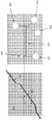
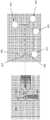
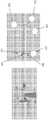
도 1: 본 발명의 일 실시예에 따른 미세유체 장치의 개략도
도 2: 수축부를 도시하는 미세유체 장치의 개략도
도 3: 세포들이 통과하여 미세유체 장치로 도입되게 하는 시료 포트를 도시하는 미세유체 장치의 개략도
도 4: 상류측 세포 트랩 및 용해 구조물을 도시하는 미세유체 장치의 개략도
도 5: 세포의 화학적 보조 전단 용해 및 세포 트랩으로부터 유동 채널로의 압력 펄스 하에서의 전달을 도시하는 미세유체 장치의 개략도
도 6: 유동 채널과 확장 영역을 도시하는 미세유체 장치의 개략도
도 7: 유동 채널 출구 및 염색체 검출을 도시하는 미세유체 장치의 개략도
도 8: 개개의 염색체 분배를 위한 하류측 염색체 고립을 도시하는 미세유체 장치의 개략도
도 9: 단일 염색체를 함유하는 액적을 미세유체 장치로부터 웰 플레이트로 분배하는 것을 도시하는 개략도
도 10 : 미세유체 장치의 펌프 배열 형태를 도시하는 개략도
도 11: 미세 유체 장치의 유동 채널 내에서 수축부의 세부 사항을 나타내는 확대도Figure 1: Schematic diagram of a microfluidic device according to an embodiment of the present invention;
Figure 2: Schematic of the microfluidic device showing the constriction.
Figure 3: Schematic of the microfluidic device showing the sample port through which cells can pass through and introduced into the microfluidic device.
Figure 4: Schematic of the microfluidic device showing upstream cell traps and lysate structures.
Figure 5: Schematic of a microfluidic device showing chemically assisted shear lysis of cells and transfer under pressure pulses from the cell trap to the flow channel.
Figure 6: Schematic diagram of a microfluidic device showing flow channels and expansion regions.
Figure 7: Schematic of the microfluidic device showing flow channel outlets and chromosome detection.
Figure 8: Schematic diagram of a microfluidic device showing downstream chromosome isolation for individual chromosome distribution.
Figure 9: Schematic depicting the dispensing of a droplet containing a single chromosome from a microfluidic device to a well plate.
Figure 10: A schematic diagram showing the configuration of the pump arrangement of the microfluidic device
Figure 11: Enlarged view showing details of the constriction within the flow channel of the microfluidic device.
본 발명은 중기 염색체들을 서로 분리하기 위한 미세유체 장치 및 방법에 관한 것이다.The present invention relates to a microfluidic device and method for isolating metaphase chromosomes from each other.
바람직한 형태에서, 미세유체 장치는 단일 중기 세포를 포획하여 용해시키고, 방출된 염색체들을 개별화된 염색체들로 현탁시키고, 각각의 개별화된 염색체를 검출하고 나서, 후처리를 위해 각각의 염색체를 미세유체 장치로부터 리셉터클(예를 들어 유리 슬라이드 또는 웰 플레이트)로 분배하도록 구성된다.In a preferred form, the microfluidic device captures and lyses a single metaphase cell, suspends the released chromosomes into individualized chromosomes, detects each individualized chromosome, and then transfers each chromosome to the microfluidic device for post-processing. configured to dispense from to a receptacle (eg a glass slide or well plate).
광의로, 세포는 미세유체 장치로 도입되고, 이 미세유체 장치에서 (예컨대 광학 현미경을 통해) 세포가 분석되어 중기 세포인지 여부가 결정된다. 세포가 중기 세포이면, 세포는 포획되며, 그런 다음 고압 펄스를 동반한 용해 완충액이 미세유체 장치로 도입되어 세포 및 그 내용물들을 채널 리스트릭션(channel restriction)을 통해 세포 트랩으로부터 미세유체 장치의 유동 채널로 추진시키면서 세포가 채널 리스트릭션을 통과할 때 세포막을 깎아내는 것을 통해 세포를 용해시킨다. 그런 다음 전형적으로 하나 이상의 클러스터의 형태로 된 염색체들이 미세유체 유동 채널로 들어간다. 미세유체 유동 채널에서, 하나 이상의 염색체 클러스터는 일련의 수축부들 및 확장부들을 교대로 통과한다.Broadly speaking, cells are introduced into a microfluidic device, in which the cells are analyzed (eg, through a light microscope) to determine whether they are metaphase cells. If the cells are metaphase cells, the cells are captured, and then a lysis buffer accompanied by a high-pressure pulse is introduced into the microfluidic device to release the cells and their contents from the cell trap through channel restriction into the flow channels of the microfluidic device. lysing the cells by shearing the cell membrane as the cells pass through the channel restriction. The chromosomes, typically in the form of one or more clusters, then enter the microfluidic flow channel. In a microfluidic flow channel, one or more chromosome clusters alternately pass through a series of constrictions and extensions.
수축부들은 유동 채널을 통과하는 하나 이상의 염색체 클러스터의 유동에 장애물을 제공한다. 압력 펄스는 수축부들을 통과하는 하나 이상의 염색체 클러스터를 추진시키고, 동시에 하나 이상의 염색체 클러스터에 상당한 전단 응력을 가하여 하나 이상의 클러스터를 분해시킨다.The constrictions provide an obstacle to the flow of one or more chromosome clusters through the flow channel. The pressure pulse propels one or more chromosome clusters through the constrictions, while simultaneously applying significant shear stress to the one or more chromosome clusters to disintegrate the one or more clusters.
확장부들에서는, 염색체들이 낮은 유동 속도 및 가변 유동 프로파일을 겪게 되고, 이에 따라 염색체들은 분산되어 서로 분리된다. 확장부들은 개개의 염색체들과 혼합되어 이 염색체들을 안정화시키고 그리고 하나 이상의 염색체 클러스터와 혼합되어 후속하는 수축부들에서 염색체들의 전단 분리를 화학적으로 보조하는 용해 완충액을 또한 제공한다.In extensions, the chromosomes experience low flow rates and variable flow profiles, so that the chromosomes are dispersed and separated from each other. The extensions mix with individual chromosomes to stabilize them and mix with one or more chromosome clusters to also provide a lysis buffer that chemically aids in shear separation of chromosomes in subsequent constrictions.
하나 이상의 염색체 클러스터는 하나 이상의 염색체 클러스터가 분리된 개개의 염색체들로 파괴될 때까지 다수의 서로 교대하는 수축부들과 확장부들을 통과한다. 이러한 개개의 염색체들은 유동 채널의 출구에서 검출되고, 추가적인 분석을 위해 슬라이드 또는 웰 플레이트에 개별적으로 분배되어 안착된다.The one or more chromosome clusters pass through a number of alternating constrictions and extensions until the one or more chromosome clusters are broken into separate individual chromosomes. These individual chromosomes are detected at the outlet of the flow channel and individually dispensed and seated on a slide or well plate for further analysis.
이러한 방식으로, 본 발명의 장치 및 방법은 후속하는 하플로타입 결정을 위해 개개의 염색체들을 분리하는 메커니즘을 제공한다.In this way, the devices and methods of the present invention provide a mechanism to separate individual chromosomes for subsequent haplotype determination.
본 발명의 실시예를 아래에서 설명한다.Embodiments of the present invention are described below.
도 1은 염색체 현탁액으로부터 단일 염색체들을 분리하여 분배하기 위한 미세유체 장치(100)의 개략도이다. 이 경우, 미세유체 장치(100)는 웨이퍼 공구 위에 폴리디메틸실록산(PDMS: polydimethilsiloxane) 캐스팅으로 형성된다. 통상의 기술자는 다수의 각기 다른 소재들이 사용될 수 있음을 알 것이다. PDMS 캐스팅은 유리 커버 슬립으로 캐핑된다. 다시 말하지만, 다른 소재들이 사용될 수 있다. 그러나 미세유체 장치(100)의 성분들을 용이하게 관찰할 수 있게 하는 광학적 특성(예컨대, 광학적 투명도 및 자가형광 없음) 및 플라즈마 활성화를 통해 PDMS와 결합하는 능력으로 인해 유리를 캐핑 소재로 선택했다.1 is a schematic diagram of a
미세유체 장치(100)는 입구(104)와 출구(106)를 구비하는 미세유체 유동 채널(102)을 포함한다. 이 실시예에서, 유동 채널(102)은 길이가 5mm이다. 그러나 3mm 내지 15mm와 같은 다른 길이도 사용될 수 있다. 유동 채널(102)은 5개의 존들(도 1에서 1 내지 5로 표시됨)로 분할되어 있다. 이 존들 각각은 제1 유동 채널 부분(108) 및 확장 부분(100)을 나타내는 제2 유동 채널 부분을 포함한다. 제1 유동 채널 부분(108)은 유동 방향에 대해 횡인 방향으로 그 단면적이 확장 부분(110)의 단면적보다 작다. 이러한 특정 경우에, 유동 채널(102)의 깊이는 20㎛이고, 제1 채널 부분(108)의 폭은 20㎛(예컨대, 유동 단면적이 400㎛2)이고, 확장 부분(110)의 폭은 100㎛(예컨대 유동 단면적이 2000㎛2)이다. 따라서, 본 실시예에서, 제1 채널 부분(108)의 확장 부분(110)에 대한 유동 단면적의 비는 1:5이다. 이 실시예에서는 비가 1:5이지만, 발명자들은 1:2 내지 1:10의 비가 적절하다고 생각한다.The
제1 유동 채널 부분들(108) 각각은 수축부(202)(도 2 및 도 11, 확대도 참조)를 포함한다. 제1 유동 채널 부분들(108) 각각이 다수의 수축부들(202)을 포함할 수 있음을 알 것이다. 본 실시예에서, 수축부들(202)은 그 폭이 약 1μm 내지 2μm이다. 또한, 입구(104)로부터 출구(106)까지 연속하는 제1 유동 채널 부분들(108) 각각에서 수축부들(202)의 폭은 앞에 있는 제1 유동 채널 부분들(108)의 수축부들(202)의 폭보다 작다.Each of the first
도 11은 유동 채널 부분들(1102, 1104) 사이의 수축부(1100)의 실시예를 도시한다. 수축부(1100)는 유동 채널의 폭의 대략 절반인 폭까지 넓어지게 테이퍼지는 출구(1106)를 구비한다. 도 11에서, 수축부의 깊이는 유동 채널 부분들(1102, 1104)보다 작다. 이러한 특정 실시예에서, 수축부의 깊이가 5μm인 반면, 유동 채널 부분들(1102, 1104)의 벌크 깊이는 약 20μm이다. 1108 및 1110으로 표시된, 수축부(1100)에 바로 인접한 유동 채널의 영역들은 그 깊이가 수축부(1100)의 깊이(예컨대, 약 5μm)와 동일하고, 이에 따라 유동 채널 내에서 깊이가 수축부(1100)의 깊이(예컨대, 약 5μm)로부터 유동 채널의 벌크 깊이(예컨대, 약 20μm)까지 단계적으로 변한다.11 shows an embodiment of a
이제 유동 채널(102)의 컴포넌트들의 작동을 간략하게 설명한다. 작동 중에, 하나 이상의 염색체 클러스터를 포함하는 유체는 압력 하에서 입구(104)를 통해 유동 채널(102)로 도입된다. 유체는 존(1)의 제1 유동 채널 부분(108)을 통해 유동하고, 여기서 유체는 수축부(202)를 통과한다. 수축부(202)는 하나 이상의 염색체 클러스터가 수축부를 통과하는 것을 방해한다. 단일 중기 염색체의 대략적인 크기가 약 0.5μm로부터 약 3μm인 반면, 염색체 클러스터는 단일 중기 염색체보다 약간 큰 크기로부터 중기 세포의 크기(약 10μm 내지 15μm)보다 약간 작은 크기까지의 범위에 있다. 어떤 경우에도, 수축부의 유체는 좁은 유동 면적 때문에 유동 채널(102)과 비교하여 유동 속도가 증가되고, 이렇게 증가된 유동 속도는 수축부의 치수, 가해지는 압력(이는 다시 속도에 영향을 미침) 및 유체 특성에 따라 하나 이상의 염색체 클러스터가 벽들에서 약 0.02N/m2 내지 약 1N/m2과 같은 상당한 전단 응력을 받으면서 수축부를 통과하게 만든다. 이러한 전단 응력은 하나 이상의 염색체들을 단편화시키기에 충분하여, 단일 염색체들이 하나 이상의 염색체 클러스터로부터 떨어져 나가 보다 작은 염색체 클러스터들로 분해되게 한다. 그런 다음 단일 염색체들(203) 및/또는 보다 작은 염색체 클러스터들(204)이 유동 채널(102)의 제1 유동 채널 부분(108)의 수축부(202)의 점차 확대되는 테이퍼진 출구를 통해 수축부(202)의 하류로 빠져나가서 제2 채널 부분, 예컨대 존(1)의 확장 부분(110)으로 간다. 확장 부분(110)에서, 단일 염색체들 및/또는 보다 작은 염색체 클러스터들의 유동 속도는 보다 넓은 유동 면적 때문에 제1 채널 부분(108)과 비교하여 감소된다. 이 확장 부분(110)에서, 단일 염색체들 및/또는 보다 작은 염색체 클러스터들은 확산 및 이류(advection)의 조합을 통해 반경 방향 및 축선 방향 양쪽으로 분산되고, 이에 따라 확장 부분을 빠져나가서 존(2)의 보다 좁은 제1 유동 채널 부분(108)로 갈 때 염색체들 간의 간격이 증가할 수 있다. 또한, 확장 영역(110)에서 염색체들 및/또는 보다 작은 염색체 클러스터들이 분산되면, 염색체 함유 유체 내에 존재할 수 있는 시약들이 염색체들 및/또는 보다 작은 염색체 클러스터들의 표면 주변에서 혼합되고 확산되게 한다(예컨대, 안정화제 또는 염색체들의 분리를 촉진하고 그리고/또는 응집을 방지하거나 최소화하는 기타 시약들).The operation of the components of the
존(2)에서, 단일 염색체들(203) 및/또는 보다 작은 염색체 클러스터들(204)은 수축부(202)를 구비하는 제1 유동 채널 부분(108)을 통과한다는 점에서 유사한 프로세스를 거친다. 그러나, 이 경우, 존(2)의 수축부(202)는 존(1)의 수축부(202)보다 좁다. 그 이유는 보다 작은 염색체 클러스터들의 통과를 방해하고 유동 속도를 보다 높여 보다 작은 염색체 클러스터들이 보다 높은 전단 응력을 받게 함으로써, 염색체 클러스터들을 추가로 파괴하고 그리고/또는 염색체 클러스터들로부터 단일 염색체들을 분리하기 위한 것이다. 다시, 이 수축부를 통과한 후에, 염색체들은 유사하게 존(2)의 제1 유동 채널 부분(108)으로 빠져 나오고, 추가 분산을 위해 존(2)의 확장 영역(110)으로 간다.In zone 2 ,
상술한 프로세스는 존들(3, 4, 5)을 통과하면서 반복되고, 이에 의해 이 존들의 제1 유동 부분(110)에 있는 각각의 수축부(202)는 그 폭이 감소하여 보다 작은 염색체 클러스터들(204)의 통과를 방해하고 파괴하며, 이 존들의 각각의 확장 영역(110)은 단일 염색체들(203) 및/또는 염색체 클러스터들(204)을 추가로 서로 분산시킨다.The process described above is repeated passing through zones 3, 4 and 5, whereby each
유동 채널(102)의 존들 각각을 통과한 후에, 염색체들은 축선 방향으로 서로 이격된 단일 염색체들로 유동 채널의 출구(106)를 통과한다. 단일 염색체들이 축선 방향으로 서로 이격되어 있기 때문에, 단일 염색체들은 하류측에서의 목적을 위해 서로 고립될 수 있다.After passing through each of the zones of the
도 1에 도시된 실시예에서, 미세유체 장치(100)는 유동 채널(102)의 상류측에 세포 포획 및 용해 구조물(112)을 포함한다. 세포 포획 및 용해 구조물(112)은 세포들을 함유하는 유체를 도입하기 위한 시료 포트(114), 세포를 포착하여 세포의 질의(interrogation)를 가능하게 하는 세포 트랩(402)(도 4, 확대도 참조), 세포가 적합한 것으로 판단되면 용해 완충액을 도입하여 세포를 용해시키고 세포 안에 함유된 염색체들을 방출하기 위한 용해 포트(116), 및 폐기 시약들과 부적합한 것으로 판단되는 세포들을 배출하기 위한 폐기 포트(118)를 포함한다. 유동 채널의 출구에서, 장치는 개별 중기 염색체들을 검출하여 이 염색체들이 분배되는 것을 보장하기 위한 검출 존(119)(도 7, 확대도 참조)을 포함한다. 유동 채널(102)의 하류측에서, 미세유체 장치는 분배 포트(122), 추출 포트(124) 및 분배 채널(704)을 포함하는 분배 구조물(120)을 포함한다. 세포 트랩(402)의 치수는 20μm × 20μm × 20μm이며, 이는 단일 중기 세포를 보유하기에 충분히 작다. 세포 트랩(402)은 유동 채널(102)의 입구로 이어지는 개구(404)를 포함한다. 개구(404)의 폭은 약 2μm 내지 약 3μm이어서, 세포가 세포 트랩(402)을 통과하여 유동 채널(102)로 가는 것을 방지한다.In the embodiment shown in FIG. 1 , the
작동 중에, 세포 시료가 시료 포트(114)를 통해 미세유체 장치에 제공될 수 있다.During operation, a cell sample may be provided to the microfluidic device through the
도 3은 세포(403)를 포함하는 유체 시료의 시료 포트(114)를 통한 추가를 도시한다. 도 3에서, 시료 포트(114)는 고압에서 작동하고, 폐기 포트(118)는 저압에서 작동하며, 용해 포트(116)와 분배 포트(122)는 기준 압력(datum pressure)에서 작동하고, 추출 포트(124)는 폐쇄되어 있다. 이러한 배열 형태를 고려하면, 시료는 시료 전달 채널(126)을 통해 폐기 포트(118)로 유동한다.3 shows the addition of a fluid
도 4는 질의를 위한 세포 트랩(402)에서의 세포(403)의 포획을 도시한다. 도 4에서, 시료 포트(114), 용해 포트(116) 및 폐기 포트(118)가 기준 압력에서 작동하고, 분배 포트(122)는 저압에서 작동하고, 추출 포트(124)는 폐쇄되어 있다. 이러한 배열 형태의 효과는 세포(403)를 세포 트랩에 유지시키는 차압을 제공한다는 것인데, 예컨대 세포 트랩(402) 내의 세포를 개구(404) 쪽으로 바이어스시키는 흡입 효과가 있다. 그러나 세포(403)는 개구(404)를 통과할 수 없다. 세포(403)가 세포 트랩(402)에 유지되고 나면, 유리 커버슬립을 통한 육안 검사가 가능하다. 육안 검사의 목적은 세포(403)가 중기 세포이고 이에 따라 염색체 현탁액을 얻기에 적합하다는 것을 확인하는 것이다.4 shows the capture of
만일 세포(403)가 중기 세포가 아니면, 예컨대 분배 포트(122)를 통해 배압을 인가하고 폐기 포트(118)를 통해 세포를 배출하는 것에 의해, 세포(403)는 세포 트랩(402)으로부터 비워진다. 즉, 분배 포트(122)는 고압에서 작동하고, 폐기 포트(118)는 저압에서 작동하고, 시료 포트(114)와 용해 포트(116)는 기준 압력에서 작동하고, 추출 포트(124)는 폐쇄되어 있다.If the
만일 세포가 중기 세포이면, 세포는 세포막을 파열시키고 세포 내로부터 염색체를 방출시키는 용해 프로세스를 거친다. 이 프로세스는 도 5에 도시되어 있다. 도 5에서,If the cell is metaphase, the cell undergoes a lysis process that ruptures the cell membrane and releases chromosomes from within the cell. This process is illustrated in FIG. 5 . 5,
용해 포트(116)를 고압(예컨대, 40 내지 45mBar)에서 작동시키는 것에 의해 용해 완충액(405)이 가해지고, 분배 포트(122)는 저압(예컨대, 35mBar의 기준 압력 이하, 예컨대 30mBar 미만)에서 작동하고, 시료 포트(114)와 폐기 포트(118)는 기준 압력(예컨대, 35mBar)에서 작동하고, 추출 포트(124)는 폐쇄되어 있다. 이 배열 형태의 효과는 용해 완충액(405)이 용해 포트(116)로부터 용해될 세포와 접촉하는 용해 채널(502)을 통해 유동한다는 것이다.Lysis buffer 405 is applied by operating
그러면 압력 펄스는 세포를 개구를 통해 그리고 세포막을 전단시키는 것에 의해 세포를 용해시키는 수축부를 따라 밀어 넣고, 그리고 세포의 (하나 이상의 염색체 클러스터를 포함하는) 내용물을 입구(104)를 통해 유동 채널(102)로 전달하는 데 사용된다. 이러한 압력 배열 형태에서는, 시료 포트(114), 폐기 포트(118) 및 용해 포트(116)가 펄스 압력 하에서 작동하고, 분배 포트(122)는 저압에서 작동하며, 추출 포트(124)는 폐쇄되어 있다.The pressure pulse then pushes the cell through the opening and along the constriction that lyses the cell by shearing the cell membrane, and pushes the cell's contents (including one or more chromosome clusters) through the
용해 완충액은 타입 1 초순수, 2v/v% 아세트산, 폴리에틸렌글리콜 p-(1,1,3,3-테트라메틸부틸)-페닐 에테르(친수성 폴리에틸렌 옥사이드 사슬(평균적으로 9.5개의 에틸렌 옥사이드 단위를 가짐) 및 친유성 또는 소수성 방향족 탄화수소 그룹들을 갖는 비이온성 계면활성제)이라고도 하는 5w/v% 트리톤 X-100, 0.1w/v% 펩신, 75mM 포타슘 클로라이드를 포함할 수 있는 수용액이다. 이 완충액에서, 아세트산은 염색체 형태를 고정시키고 보존하고, 트리톤 X-100은 세포막 성분들 및 소수성 단백질들을 가용화/용해시키며 염색체들을 해제시키는 2차적 역할을 하고, 펩신은 개개의 염색체들을 클러스터들로부터 해제하며 세포 분해를 돕고 세포 단백질들을 제거하고, 포타슘 클로라이드는 삼투압을 통해 세포들을 팽창시키고 펩신 용해도를 향상시키는 데 사용되는 염이다. 대안적으로, 완충액은 0.1w/v% 펩신, 1mM EDTA, 73mM 포타슘 아세테이트 완충액, 2mM 마그네슘 설페이트를 포함할 수 있으며, 아세트산을 이용하여 pH5로 완충될 수 있다. 대안적으로, 이 완충액들 중 어느 것에서도 아세트산의 고정 역할은 정착성 포름알데히드에 의해 수행될 수 있다. 통상의 기술자는 본 발명이 속하는 기술 분야에서 공지된 다른 완충액 조성물이 또한 용해 및/또는 분리 완충액으로 사용되기에 적합할 것임을 이해할 것이다.The lysis buffer is type 1 ultrapure water, 2v/v% acetic acid, polyethyleneglycol p-(1,1,3,3-tetramethylbutyl)-phenyl ether (hydrophilic polyethylene oxide chains with an average of 9.5 ethylene oxide units) and It is an aqueous solution which may contain 5w/v% Triton X-100, 0.1w/v% Pepsin, 75mM Potassium Chloride, also called lipophilic or nonionic surfactant with hydrophobic aromatic hydrocarbon groups). In this buffer, acetic acid fixes and preserves chromosome morphology, Triton X-100 plays a secondary role in solubilizing/dissolving cell membrane components and hydrophobic proteins and releasing chromosomes, and pepsin releases individual chromosomes from clusters. Potassium chloride is a salt used to swell cells and improve pepsin solubility through osmotic pressure, which aids in cell degradation and removal of cellular proteins. Alternatively, the buffer may comprise 0.1 w/v% pepsin, 1 mM EDTA, 73 mM potassium acetate buffer, 2 mM magnesium sulfate, and may be buffered to pH5 using acetic acid. Alternatively, the fixative role of acetic acid in any of these buffers may be performed by fixative formaldehyde. One of ordinary skill in the art will appreciate that other buffer compositions known in the art will also be suitable for use as lysis and/or separation buffers.
도 2는 압력 펄스를 사용하여 수축부(202)를 통해 염색체 클러스터들을 추진시키는 것을 도시한다. 이는 용해 포트(116)를 통해 고압 펄스(예컨대 300 내지 1000mBar)를 인가하는 것에 의해 달성된다. 이 작동 모드 하에서, 시료 포트(114)와 폐기 포트(118)는 기준 압력(예컨대, 35mBar)에서 작동하고, 분배 포트(122)는 저압(예컨대, <30mBar)에서 작동하고, 추출 포트(124)는 폐쇄되어 있다. 용해 포트(118)로부터의 추가 압력은 막혀 있는 클러스터 염색체들(204)(예컨대, 수축부(202)의 좁은 개구에서 포획되었을 수 있는 하나 이상의 염색체 클러스터)을 수축부(202)를 통해 추진시킴으로써 하나 이상의 염색체 클러스터가 높은 전단 응력 조건을 거치게 하여 하나 이상의 염색체 클러스터(204)를 단일 염색체들(203) 및/또는 보다 작은 염색체 클러스터들로 파괴한다. 이 프로세스는 여러 존들에 대해 반복된다.2 shows the use of pressure pulses to propel chromosome clusters through
대안적인 접근법은 고압 펄스를 시료 포트(114)(예컨대, 250 내지 950mBar 또는 250 내지 1,000mBar), 폐기 포트(예컨대, 250 내지 950mBar 또는 250 내지 1,000mBar), 및 용해 포트(116)(예컨대, 300 내지 1,000mBar)를 통해 인가하는 것인데, 분배 포트(122)는 저압(예컨대, 0mBar)이고, 추출 포트(124)는 폐쇄된다.An alternative approach is to apply high pressure pulses to the sample port 114 (eg, 250 to 950 mBar or 250 to 1,000 mBar), the waste port (eg, 250 to 950 mBar or 250 to 1,000 mBar), and the dissolution port 116 (eg, 300). to 1,000 mBar), the dispensing
위에서 설명한 압력 체제 하에서, 수축부 존들을 통한 전단 응력은 수축부의 치수와 인가되는 압력에 따라 약 0.02N/m2 내지 15,000N/m2 범위에 있다.Under the pressure system described above, a shear stress through the constriction zone is approximately 0.02N / m2 to 15,000N / m2 range, depending on the pressure applied and the dimensions shrink portion.
용해 완충액과 용해 포트(116)와 분배 포트(122) 간의 차압의 조합은 세포막을 파열시키고 세포 내용물을 개구(404)를 통해 유동 채널(102)로 추진시키는 화학적으로 보조되는 전단 용해 프로세스를 유도한다. 세포의 내용물은 하나 이상의 염색체 클러스터(204)(및 잠재적으로 단일 염색체들(203))를 포함한다. 그러면 하나 이상의 염색체 클러스터는 염색체들을 분리하는 위에서 설명한 바와 같은 채널(102) 내에서의 전단력 처리 프로세스를 거치게 된다.The combination of lysis buffer and differential pressure between
도 6은 세포가 용해되고 염색체들(105)이 유동 채널(102)로 배출되고 난 후에 존들 중 하나의 확장 영역(110)을 통해 이동하는 미세유체 장치(100)의 작동을 도시한다. 도 6에서, 시료 포트(114), 용해 포트(116), 폐기 포트(118)는 용해 완충액 설정을 유지하며, 분배 포트(122)는 기준 압력에서 작동하고, 추출 포트(124)는 폐쇄되어 있다. 따라서 염색체들을 유동 채널(102)의 입구(104)로부터 유동 채널의 출구(106)를 향해 추진시키는 차압이 유동 채널을 가로질러 존재한다. 확장 영역은 존(1)의 확장 영역(110)을 통해 분산되고 분리되는 단일 염색체들(203)을 보이고 있다. 확장 영역(110)은 단일 염색체들의 분산을 보조하는 예컨대 헤링본 믹서(herringbone mixer)와 같은 혼합 장치를 포함할 수 있다.FIG. 6 shows the operation of the
염색체들이 분리되고 나면, 예컨대 형광 신호들의 실시간 기록에 의해 염색체들이 출구(106)에서 검출된다. 각각의 검출 이벤트는 분배 시스템이 활성화되게 트리거한다. 도 7과 도 8은 염색체들의 검출 및 카운트, 그리고 추출 포트(124)를 통한 단일 염색체들의 미세유체 장치(100) 외부로의 전달을 도시한다. 도 7은 광검출기(702)를 이용하여 출구(106)에서 단일 염색체들(203)을 검출하는 것을 도시한다. 검출 리스트릭션(703)은 염색체들이 단일 파일(single file)로 있는 것을 보장한다. 염색체의 검출시, 분배 시스템에 활성화된다. (만일 있다면, 펩신 작용에 의해 염색체 형태가 붕괴되는 것을 중지시키는) 중화 완충액의 유동이 분배 포트(122)를 통해 제공됨으로써 검출된 염색체를 포획하여 미세유체 장치(100)로부터 분배한다. 각각의 염색체는 미세유체 장치로부터 액적의 형태로 배출된다. 액적은 리셉터클(예컨대, 유리 슬라이드 또는 특수 웰 플레이트) 위에 분배된다. 구체적으로, 염색체가 검출되고 나면, 추출 포트(124)의 밸브가 (도 7에 도시된) 폐쇄 위치로부터 개방 위치로 전환되고, 분배 포트(122)의 압력이 증가하여 중화제를 제공한다. (도 8에 도시된) 증가한 유동은 단일 염색체(203)가 출구(106)로부터 분배 채널(704)로 분배되게 하고, 단일 염색체는 후속해서 웰 플레이트 또는 유리 슬라이드 상에 안착된다. 증가한 유동(709)은 또한 유동 채널(102)에서의 유동 역전을 일으켜서 염색체들이 분리된 상태로 유지되는 것을 돕는다.Once the chromosomes are separated, they are detected at the
예를 들어, 검출 중에 시료 포트(116)와 폐기 포트(118)는 0mBar에서 작동하고, 용해 포트(116)는 2 내지 5mBar에서 작동하며, 분배 포트(122)는 2mBar에서 작동한다. 대안적인 예로, 검출 중에 시료 포트(116)와 폐기 포트(118)는 10mBar에서 작동하고, 용해 포트(116)는 20mBar에서 작동하며, 분배 포트(122)는 2mBar에서 작동한다. 이러한 낮은 차압은 유동 채널(102)을 통과하는 유동을 느리게 함으로써 출구(106)에서 염색체들을 검출할 수 있게 한다. 염색체가 검출되고 나면, 분배 포트(122)의 압력이 15mBar로 증가하여 염색체를 출구(106)로부터 분배 채널(704)로 분배한다.For example, during detection,
도 9는 단일 염색체(203)를 포함하는 200nL 액적(900)이 분배 채널(704)의 출구로부터 분배 튜브(705)를 통한 이동 중인 웰 플레이트 상에 안착하는 것을 도시한다. 이 프로세스는 각각의 염색체가 웰 플레이트(902) 상에 어레이로 안착될 때까지 반복될 수 있는데, 예컨대 인간 세포로부터 채취된 염색체들의 경우 각각이 단일 염색체를 포함하는 46개의 개별 액적들이 있을 것이다. 분배 튜브의 소수성 코팅(706)은 액적들이 분배 튜브(705)에 달라붙지 않는 것을 보장한다. 도 9는 또한 분배 채널(704)을 카트리지(707)와 유리 커버슬립(708)과의 관계에서 도시한다FIG. 9 shows a 200
도 10은 기준 압력을 갖는 본 발명의 일 실시예에 따른 펌프 장치를 도시한다. 이 실시예에서, 시료 포트(114)는 기준 압력이 35mBar로 설정된 69mBar 압력 펌프를 사용하도록 구성되고, 용해 포트(116)는 기준 압력이 35mBar로 설정된 1000mBar 압력 펌프를 사용하도록 구성되고, 폐기 포트(118)는 기준 압력이 35mBar로 설정된 70mBar 압력 펌프를 사용하도록 구성되고, 분배 포트(122)는 기준 압력이 35mBar로 설정된 345mBar 압력 펌프를 사용하도록 구성되고, 추출 포트(124)는 보통 폐쇄되어 있다.10 shows a pump arrangement according to an embodiment of the invention with a reference pressure. In this embodiment,
위에서 개괄적으로 설명한 바와 같이, 미세유체 장치(100)는 미세유체 장치의 여러 유체 포트들을 압력/유동 제어기들에 연결하는 것에 의해 실시된다. 345mBar 압력 펌프들은 시료 포트(114) 및 폐기 포트(118)에 연결되는데, 이는 이들이 낮은 유속을 생성하고 유지시키는 압력 변화 시에 높은 분해능을 필요로 하는 세포 선별 및 포획 중에 세포 운동을 제어하는 데 사용되기 때문이다. 하나의 1000mBar 압력 펌프가 용해 포트(116)에 연결되어 트랩에 유지되는 세포에 전단력을 유도하는 고압 펄스를 제공한다. 69mBar는 분배 포트(122)에 연결되어 염색체 전달을 위한 분배 채널 내의 압력 강하를 허용한다. 분배 채널(704)은 액적들을 분배할 때를 제외하고는 작동 중에 보통은 폐쇄되어 있을 추출 포트(124)에 밸브(개스킷 상의 착좌 튜브)를 구비할 것이다. 모든 압력 제어기들은 초기에는 35mBar의 기준 압력으로 설정되고, 미세유체 장치(100) 내에서 필요로 하는 유동 방향에 따라 각각의 압력 라인이 이 기준 압력으로부터 상승하거나 하강할 수 있다.As outlined above, the
대안적으로, 이 실시예에서, 시료 포트(114)는 기준 압력이 35mBar로 설정된 1000mBar 압력 펌프를 사용하도록 구성되고, 용해 포트(116)는 기준 압력이 35mBar로 설정된 1000mBar 압력 펌프를 사용하도록 구성되고, 폐기 포트(118)는 기준 압력이 35mBar로 설정된 1000mBar 압력 펌프를 사용하도록 구성되고, 분배 포트(122)는 기준 압력이 35mBar로 설정된 345mBar 압력 펌프를 사용하도록 구성되고, 추출 포트(124)는 보통 폐쇄되어 있다.Alternatively, in this embodiment, the
위에서 개괄적으로 설명한 바와 같이, 미세유체 장치(100)는 미세유체 장치의 여러 유체 포트들을 압력/유동 제어기들에 연결하는 것에 의해 실시된다. 1000mBar 압력 펌프들은 시료 포트(114) 및 폐기 포트(118)에 연결되는데, 이는 이들이 낮은 유속을 생성하고 유지시키는 압력 변화 시에 높은 분해능을 필요로 하는 세포 선별 및 포획 중에 세포 운동을 제어하는 데 사용되기 때문이다. 하나의 1000mBar 압력 펌프가 용해 포트(116)에 연결되어 트랩에 유지되는 세포에 전단력을 유도하는 고압 펄스를 제공한다. 345mBar는 분배 포트(122)에 연결되어 염색체 전달을 위한 분배 채널 내의 압력 강하를 허용한다. 분배 채널(704)은 액적들을 분배할 때를 제외하고는 작동 중에 보통은 폐쇄되어 있을 추출 포트(124)에 밸브(개스킷 상의 착좌 튜브)를 구비할 것이다. 모든 압력 제어기들은 초기에는 35mBar의 기준 압력으로 설정되고, 미세유체 장치(100) 내에서 필요로 하는 유동 방향에 따라 각각의 압력 라인이 이 기준 압력으로부터 상승하거나 하강할 수 있다.As outlined above, the
분배는 분배 튜브(705)(예를 들어, 본 실시예의 분배 튜브는 외경이 0.79mm이고, 내경이 0.15mm이고 길이가 7mm임)를 통해 미세유체 장치(100)로부터 액적들을 분배하는 것에 의해 수행되는데, 각각의 액적은 염색체를 함유한다. 이는 분배 포트(122)에 더 높은 압력을 생성하고 추출 포트(124)의 밸브를 개방하는 것에 의해 실시된다. 그러면, 압력 강하로 인해 유체가 유동 채널(704)을 통과하여, 분배 튜브를 통과하여 그리고 분배 튜브 팁 밖으로 이동한다. 정확한 액적 크기(액적 크기는 압력 강하의 변화에 따라 변화하지만 예시적인 크기는 200nL임)가 생성되면, 각각의 액적이 유리 슬라이드 또는 특수하게 설계된 웰 플레이트 상에 분배될 것이다. 그런 다음 분배 포트(122)로부터의 압력 기준 압력으로 복귀할 것이다. 액적은 형성된 액적의 표면 장력에 의해 리셉터클에 부착된다. 각각의 액적을 어레이로 그리고 리셉터클 위에 분배하기 위해, 리셉터클을 유지하는 자동화된 기구가 사용된다. 기구는 카트리지와 독립적으로 3개의 축선으로 이동하는데, 예를 들어 x축선 및 y 축선을 따라 이동하여 리셉터클 위에 액적 어레이를 생성하고 z축선으로는 각각의 액적을 리셉터클에 부착시킨다.Dispensing is performed by dispensing droplets from the
본 명세서에 개시되고 정의된 본 발명이 발명의 설명 또는 도면에 언급되거나 혹은 그로부터 명백하게 알 수 있는 개별 피처들 중 둘 이상의 모든 대안적인 조합들에까지 확장된다는 점을 이해할 것이다. 이러한 각기 다른 조합들 전부가 본 발명의 여러 대안적인 태양들을 구성한다. 예를 들어, 위에서 설명한 개별 피처들의 대안적인 구성 형태(topologies)가 본 발명의 대안적인 태양들을 구성한다는 점을 이해할 것이다.It will be understood that the invention disclosed and defined herein extends to all alternative combinations of two or more of the individual features mentioned in, or apparent from, the description or drawings. All of these different combinations constitute several alternative aspects of the invention. For example, it will be understood that alternative topologies of individual features described above constitute alternative aspects of the present invention.
Claims (20)
Translated fromKorean유동 채널을 포함하고,
유동 채널은,
중기 염색체들을 포함하는 유체를 받아들이는 입구,
개별 중기 염색체들을 개별적으로 분배하는 출구,
일련의 확장 영역들, 및
일련의 확장 영역들 중 연속하는 확장 영역들 사이에 위치된 하나 이상의 수축부들을 포함하되,
수축부들이 중기 염색체들을 서로 분리하기에 충분한 전단 응력을 가하도록 작동 가능하고, 그리고
확장 영역들은 염색체들을 서로 분산시키도록 작동 가능한 것을 특징으로 하는 미세유체 장치.A microfluidic device for separating metaphase chromosomes from a metaphase chromosome-containing fluid, comprising:
a flow channel;
The flow channel is
an inlet for receiving a fluid containing metaphase chromosomes;
an exit that separates individual metaphase chromosomes,
a series of extension regions, and
one or more constrictions positioned between successive ones of the series of extensions;
the constrictions are operable to apply a shear stress sufficient to separate metaphase chromosomes from one another, and
The microfluidic device of claim 1, wherein the extension regions are operable to disperse chromosomes from one another.
약 10μm 내지 약 30μm의 폭을 가지는 유동 채널을 포함하고,
유동 채널은,
입구,
출구, 및
일련의 확장 영역들 및 일련의 확장 영역들의 연속하는 확장 영역들 사이에 위치되는 하나 이상의 수축부를 포함하되,
복수의 확장 영역들의 채널 폭이 약 50μm 내지 약 150μm이며, 복수의 수축부들의 각각의 수축부의 최소 폭이 약 1μm 내지 약 3μm인 것을 특징으로 하는 미세유체 장치.A microfluidic device for separating metaphase chromosomes from a metaphase chromosome-containing fluid, comprising:
a flow channel having a width of about 10 μm to about 30 μm;
The flow channel is
Entrance,
exit, and
a series of extensions and one or more constrictions positioned between successive extensions of the series of extensions;
A microfluidic device, characterized in that a channel width of the plurality of expansion regions is from about 50 μm to about 150 μm, and a minimum width of each of the constricted portions of the plurality of constricted portions is from about 1 μm to about 3 μm.
유동 채널의 깊이가 약 5μm 내지 최대 약 40μm인 것을 특징으로 하는 미세유체 장치.The method according to claim 1 or 2,
A microfluidic device, characterized in that the flow channel has a depth of about 5 μm to a maximum of about 40 μm.
유동 채널의 길이가 약 2mm 내지 약 15mm인 것을 특징으로 하는 미세유체 장치.In any one of the preceding claims,
A microfluidic device, characterized in that the flow channel has a length of about 2 mm to about 15 mm.
입구로부터 출구까지 각각의 연속하는 수축부의 최소 폭이 앞선 수축부의 최소 폭보다 작은 것을 특징으로 하는 미세유체 장치.In any one of the preceding claims,
A microfluidic device, characterized in that the minimum width of each successive constriction from the inlet to the outlet is smaller than the minimum width of the preceding constriction.
하나 이상의 수축부 중 하나 이상이 확장형으로 테이퍼진 출구를 구비하는 것을 특징으로 하는 미세유체 장치.In any one of the preceding claims,
A microfluidic device, characterized in that at least one of the at least one constriction has an expandable tapered outlet.
일련의 확장 영역들의 확장 영역들 각각의 폭이 실질적으로 동일한 것을 특징으로 하는 미세유체 장치.In any one of the preceding claims,
A microfluidic device, characterized in that the width of each of the extension regions of the series of extension regions is substantially the same.
일련의 확장 영역들이 적어도 3개의 확장 영역들 및 최대 20개의 확장 영역들을 포함하는 것을 특징으로 하는 미세유체 장치.In any one of the preceding claims,
A microfluidic device, characterized in that the series of extension regions comprises at least 3 extension regions and at most 20 extension regions.
유동 채널이 일련의 확장 영역들의 각각의 확장 영역들 사이에 하나 이상의 수축부를 포함하는 것을 특징으로 하는 미세유체 장치.In any one of the preceding claims,
A microfluidic device, wherein the flow channel comprises at least one constriction between each of the extensions of the series of extensions.
입구의 폭이 2μm 내지 3μm인 것을 특징으로 하는 미세유체 장치.In any one of the preceding claims,
A microfluidic device, characterized in that the width of the inlet is 2 μm to 3 μm.
미세유체 장치가 입구의 상류측에 세포 포획 및 용해 구조물을 더 포함하고,
세포 포획 및 용해 구조물은 세포를 포함하는 유체 시료로부터 세포를 포획하여 유지하도록 구성되고 유동 채널 입구에 인접한 세포 트랩 및 세포 트랩에 용해 완충액을 도입하도록 구성된 용해 포트를 포함하고,
세포 트랩은 세포의 검사를 가능하게 하는 관찰 요소, 및 통로를 통해 유동 채널에 연결된 개구를 포함하며, 개구와 통로는 세포가 통과하는 것을 방해하는 크기를 가지는 것을 특징으로 하는 미세유체 장치.In any one of the preceding claims,
the microfluidic device further comprises a cell trapping and lysing construct upstream of the inlet;
the cell capture and lysis construct comprises a cell trap configured to capture and retain cells from a fluid sample comprising the cells and a cell trap adjacent the flow channel inlet and a lysis port configured to introduce a lysis buffer into the cell trap;
A microfluidic device, characterized in that the cell trap comprises an observation element enabling examination of cells, and an aperture connected to the flow channel through a passageway, the aperture and passageway sized to impede passage of cells.
개구의 크기가 약 10μm 내지 20μm이고, 통로의 폭은 약 2μm 내지 약 3μm인 것을 특징으로 하는 미세유체 장치.12. The method of claim 11,
A microfluidic device, characterized in that the size of the opening is about 10 μm to 20 μm, and the width of the passage is about 2 μm to about 3 μm.
세포 트랩이 미세유체 장치 내의 직육면체 형상의 중공 형성물이고, 세포가 세포 트랩에 유입되는 것을 허용하는 개방된 면을 구비하는 것을 특징으로 하는 미세유체 장치.In any one of the preceding claims,
A microfluidic device, characterized in that the cell trap is a rectangular parallelepiped hollow formation in the microfluidic device, and has an open side that allows the cells to enter the cell trap.
출구의 하류측에 염색체 분배 구조물을 더 포함하고,
염색체 분배 구조물은 채널 입구와 채널 출구 사이에 획정되는 분배 채널을 구비하며, 분배 채널은 유동 채널의 출구로부터 개개의 염색체를 받아들이는 포트를 구비하고,
채널 출구는 분배 튜브에 연결되고, 분배 튜브는 미세유체 장치로부터의 단일 염색체들을 단일 염색체를 포함하는 유체 액적의 형태로 분배하도록 구성된 것을 특징으로 하는 미세유체 장치.In any one of the preceding claims,
further comprising a chromosome distribution construct downstream of the outlet;
The chromosome distribution structure has a distribution channel defined between the channel inlet and the channel outlet, the distribution channel having a port for receiving individual chromosomes from the outlet of the flow channel;
The channel outlet is connected to the distribution tube, wherein the distribution tube is configured to dispense single chromosomes from the microfluidic device in the form of fluid droplets comprising the single chromosome.
중기 염색체 함유 유체를 선행하는 청구항들 중 어느 한 청구항에 따른 미세유체 장치를 통과시키되, 수축부들이 중기 염색체들에 충분한 전단 응력을 가하여 중기 염색체들을 서로 분리시키는 압력에서 통과시키는 단계를 포함하는 것을 특징으로 하는 방법.A method for isolating metaphase chromosomes from a metaphase chromosome-containing fluid, comprising:
Passing the metaphase chromosome-containing fluid through a microfluidic device according to any one of the preceding claims, wherein the constrictions apply a sufficient shear stress to the metaphase chromosomes to separate the metaphase chromosomes from each other. how to do it
중기 염색체를 포함하는 염색체 함유 유체를 미세유체 장치를 통과시키는 단계로, 미세유체 장치는 유동 채널을 구비하고, 유동 채널은, 입구와 출구 사이에 위치되는 복수의 확장 영역들 및 확장 영역들 중 하나 이상 사이에 위치되는 하나 이상의 수축부들을 포함하는 단계,
중기 염색체들이 수축부들에서 또는 수축부들 내에서 중기 염색체들을 서로 분리하기에 충분한 전단 응력을 받게 하는 단계, 및
복수의 확장 영역들에서 분리된 중기 염색체들을 서로 분산시키는 단계를 포함하는 것을 특징으로 하는 방법.A method for isolating metaphase chromosomes from a chromosome-containing fluid, comprising:
passing a chromosome-containing fluid comprising metaphase chromosomes through a microfluidic device, the microfluidic device having a flow channel, the flow channel comprising one of a plurality of expansion regions and expansion regions positioned between the inlet and the outlet comprising one or more constrictions positioned between the ideals;
subjecting the metaphase chromosomes to shear stress sufficient to separate the metaphase chromosomes from each other at or within the constrictions, and
A method comprising dispersing metaphase chromosomes separated from each other in a plurality of extension regions.
유체를 미세유체 장치의 유동 채널을 통과시키는 단계로, 유동 채널은 복수의 교번하는 수축부들과 확장부들을 구비하는 단계를 포함하고,
유체가 수축부를 통과할 때, 방법이 중기 염색체들을 서로 분리하기에 충분한 전단 응력을 중기 염색체들이 받게 하는 압력을 인가하는 단계를 포함하고,
유체가 확장부를 통과할 때, 미세유체 장치는 서로 분리된 염색체들을 분산시키는 압력에서 작동되는 것을 특징으로 하는 방법.A method for separating metaphase chromosomes from a chromosome-containing fluid using a microfluidic device, comprising:
passing a fluid through a flow channel of a microfluidic device, the flow channel comprising a plurality of alternating constrictions and extensions;
When the fluid passes through the constriction, the method comprises applying a pressure such that the metaphase chromosomes are subjected to a shear stress sufficient to separate the metaphase chromosomes from each other;
When the fluid passes through the extension, the microfluidic device is actuated at a pressure to disperse the chromosomes separated from each other.
전단 응력이 수축부의 최소 폭의 벽에서 측정할 때 적어도 약 0.02N/m2 내지 적어도 약 15,000N/m2인 것을 특징으로 하는 방법.18. The method according to any one of claims 15 to 17,
wherein the shear stress is at least about 0.02 N/m2 to at least about 15,000 N/m2 as measured at the wall of the minimum width of the constriction.
방법이, 초기에,
미세유체 장치의 세포 트랩에 중기 세포를 포획하는 단계, 및
용해 완충액을 중기 세포에 도입하고, 압력 펄스를 인가하여 세포를 용해시키고 염색체 함유 유체에 염색체들을 제공하기에 충분한 전단 응력 하에서 중기 세포를 세포 트랩으로부터 유동 채널로 추진시키는 단계를 포함하는 것을 특징으로 하는 방법.19. The method according to any one of claims 15 to 18,
method, initially,
trapping metaphase cells in a cell trap of a microfluidic device, and
introducing a lysis buffer into the metaphase cells and applying a pressure pulse to propel the metaphase cells from the cell trap into the flow channel under a shear stress sufficient to lyse the cells and provide the chromosomes to the chromosome-containing fluid. Way.
미세유체 장치의 유동 채널의 출구로부터 분배 채널로 분배되는 개개의 염색체들을 받아들이는 단계,
개개의 염색체들을 분배 튜브로 운반하는 단계, 및
단일 염색체를 단일 염색체를 포함하는 유체 액적의 형태로 분배하는 미세유체 장치로부터 분배 튜브를 통해 분배하는 단계를 더 포함하는 것을 특징으로 하는 방법.20. The method according to any one of claims 15 to 19,
receiving individual chromosomes to be distributed from the outlet of the flow channel of the microfluidic device to the distribution channel;
transferring the individual chromosomes to a distribution tube, and
The method of claim 1, further comprising dispensing the single chromosome from the microfluidic device in the form of a fluid droplet comprising the single chromosome through the dispensing tube.
Applications Claiming Priority (3)
| Application Number | Priority Date | Filing Date | Title |
|---|---|---|---|
| AU2019900210AAU2019900210A0 (en) | 2019-01-23 | Microfluidic device | |
| AU2019900210 | 2019-01-23 | ||
| PCT/AU2020/050042WO2020150781A1 (en) | 2019-01-23 | 2020-01-23 | Microfluidic device |
Publications (1)
| Publication Number | Publication Date |
|---|---|
| KR20210119437Atrue KR20210119437A (en) | 2021-10-05 |
Family
ID=71735581
Family Applications (1)
| Application Number | Title | Priority Date | Filing Date |
|---|---|---|---|
| KR1020217025908APendingKR20210119437A (en) | 2019-01-23 | 2020-01-23 | microfluidic device |
Country Status (9)
| Country | Link |
|---|---|
| US (1) | US20220064627A1 (en) |
| EP (1) | EP3914707A4 (en) |
| JP (2) | JP2022518798A (en) |
| KR (1) | KR20210119437A (en) |
| CN (1) | CN113330114A (en) |
| AU (1) | AU2020211642B2 (en) |
| CA (1) | CA3124966A1 (en) |
| SG (1) | SG11202106780TA (en) |
| WO (1) | WO2020150781A1 (en) |
Family Cites Families (20)
| Publication number | Priority date | Publication date | Assignee | Title |
|---|---|---|---|---|
| US6833242B2 (en)* | 1997-09-23 | 2004-12-21 | California Institute Of Technology | Methods for detecting and sorting polynucleotides based on size |
| US6762059B2 (en)* | 1999-08-13 | 2004-07-13 | U.S. Genomics, Inc. | Methods and apparatuses for characterization of single polymers |
| WO2003085379A2 (en)* | 2002-04-01 | 2003-10-16 | Fluidigm Corporation | Microfluidic particle-analysis systems |
| EP1546412B1 (en)* | 2002-10-02 | 2014-05-21 | California Institute Of Technology | Microfluidic nucleic acid analysis |
| EP2109666A4 (en)* | 2007-02-05 | 2011-09-14 | Integenx Inc | Microfluidic and nanofluidic devices, systems, and applications |
| WO2009134395A2 (en)* | 2008-04-28 | 2009-11-05 | President And Fellows Of Harvard College | Microfluidic device for storage and well-defined arrangement of droplets |
| SG184592A1 (en)* | 2011-03-18 | 2012-10-30 | Univ Singapore | Isolating target cells from a biological fluid |
| US9133499B2 (en)* | 2010-09-14 | 2015-09-15 | The Regents Of The University Of California | Method and device for isolating cells from heterogeneous solution using microfluidic trapping vortices |
| US8877442B2 (en)* | 2010-12-07 | 2014-11-04 | The Board Of Trustees Of The Leland Stanford Junior University | Non-invasive determination of fetal inheritance of parental haplotypes at the genome-wide scale |
| WO2012170560A2 (en)* | 2011-06-06 | 2012-12-13 | Cornell University | Microfluidic device for extracting, isolating, and analyzing dna from cells |
| US10752945B2 (en)* | 2012-09-12 | 2020-08-25 | The Regents Of The University Of California | Accurate genome sequencing of single cells by single-stranded amplification and sequencing |
| CN110186835B (en)* | 2013-03-15 | 2022-05-31 | Gpb科学有限公司 | On-chip microfluidic processing of particles |
| CN105593415A (en)* | 2013-09-26 | 2016-05-18 | 伯乐生命医学产品有限公司 | Methods and compositions for chromosome mapping |
| EP3052219B1 (en)* | 2013-10-01 | 2020-04-22 | The Broad Institute, Inc. | Sieve valves, microfluidic circuits, microfluidic devices, kits, and methods for isolating an analyte |
| EP3722001A1 (en)* | 2013-11-22 | 2020-10-14 | The General Hospital Corporation | Microfluidic methods and systems for isolating particle clusters |
| US10137673B2 (en)* | 2013-12-31 | 2018-11-27 | Canon U.S. Life Sciences, Inc. | Methods and systems for continuous flow cell lysis in a microfluidic device |
| WO2015134523A1 (en)* | 2014-03-03 | 2015-09-11 | The Board Of Trustees Of The University Of Illinois | Chromatin immunocapture devices and methods of use |
| US12290811B2 (en)* | 2015-01-23 | 2025-05-06 | Unchained Labs | Microfluidic serial dilution platform based well-plate using an oil-free immiscible phase driven by manual or electronic pipettors |
| WO2017200249A1 (en)* | 2016-05-17 | 2017-11-23 | 울산대학교 산학협력단 | Nucleic acid extraction method using solid subject |
| US11154864B2 (en)* | 2018-01-17 | 2021-10-26 | Qiagen Sciences, Llc | Microfluidic device with vented microchambers |
- 2020
- 2020-01-23KRKR1020217025908Apatent/KR20210119437A/enactivePending
- 2020-01-23WOPCT/AU2020/050042patent/WO2020150781A1/ennot_activeCeased
- 2020-01-23USUS17/418,603patent/US20220064627A1/enactivePending
- 2020-01-23CACA3124966Apatent/CA3124966A1/enactivePending
- 2020-01-23SGSG11202106780TApatent/SG11202106780TA/enunknown
- 2020-01-23JPJP2021543311Apatent/JP2022518798A/enactivePending
- 2020-01-23EPEP20745348.1Apatent/EP3914707A4/enactivePending
- 2020-01-23AUAU2020211642Apatent/AU2020211642B2/enactiveActive
- 2020-01-23CNCN202080010575.5Apatent/CN113330114A/enactivePending
- 2024
- 2024-12-13JPJP2024218864Apatent/JP2025061655A/enactivePending
Non-Patent Citations (3)
| Title |
|---|
| et al. (Funct. Integr. Genomics, 2012, 12:397-416) |
| Fan et al. (Nat. Biotechnol., January 2011, 29(1):51-57) |
| Quake et al. (Nature Methods, Vol. 11, No. 1, 2014, pp 19-21) |
Also Published As
| Publication number | Publication date |
|---|---|
| US20220064627A1 (en) | 2022-03-03 |
| JP2022518798A (en) | 2022-03-16 |
| AU2020211642B2 (en) | 2025-06-05 |
| NZ777552A (en) | 2025-02-28 |
| EP3914707A1 (en) | 2021-12-01 |
| SG11202106780TA (en) | 2021-08-30 |
| EP3914707A4 (en) | 2022-09-28 |
| CA3124966A1 (en) | 2020-07-30 |
| AU2020211642A1 (en) | 2021-07-22 |
| JP2025061655A (en) | 2025-04-11 |
| WO2020150781A1 (en) | 2020-07-30 |
| CN113330114A (en) | 2021-08-31 |
Similar Documents
| Publication | Publication Date | Title |
|---|---|---|
| TWI835713B (en) | Dna barcode compositions and methods of in situ identification in a microfluidic device | |
| US10697007B2 (en) | PCR-activated sorting (PAS) | |
| US8372629B2 (en) | Devices and processes for analysing individual cells | |
| CA2874343C (en) | Single-particle analysis of particle populations | |
| EP2882872B1 (en) | Methods and systems for detecting biological components | |
| US20220034869A1 (en) | Multi-stage, multiplexed target isolation and processing from heterogeneous populations | |
| US9849456B2 (en) | Microfluidic device | |
| WO2018126205A1 (en) | Methods for selection and generation of genome edited t cells | |
| EP2861761A1 (en) | Uniquely tagged rearranged adaptive immune receptor genes in a complex gene set | |
| EP3525933B1 (en) | Systems and methods to encapsulate and preserve organic matter for analysis | |
| JP2015213909A (en) | Method and device for separating particle | |
| US20240326050A1 (en) | Integrated droplet-digital microfluidic system for on-demand droplet creation, mixing, incubation, and sorting of droplets in a cell trapping array | |
| US20230069843A1 (en) | Pairing antigen specificity of a t cell with t cell receptor sequences | |
| KR20210119437A (en) | microfluidic device | |
| Zimny et al. | Hydrogel droplet single-cell processing: DNA purification, handling, release, and on-chip linearization | |
| EP3554704A1 (en) | Microfluidic device for accommodating, isolating, treating and/or processing cells having an inlet chamber with a chute structure. | |
| HK40012459A (en) | Dna barcode compositions and methods of in situ identification in a microfluidic device | |
| HK1139892A (en) | Device and process for analysing individual cells |
Legal Events
| Date | Code | Title | Description |
|---|---|---|---|
| PA0105 | International application | Patent event date:20210813 Patent event code:PA01051R01D Comment text:International Patent Application | |
| PG1501 | Laying open of application | ||
| E902 | Notification of reason for refusal | ||
| PE0902 | Notice of grounds for rejection | Comment text:Notification of reason for refusal Patent event date:20250327 Patent event code:PE09021S01D |