KR20210118874A - Implant loading tools, compression devices and loading systems - Google Patents
Implant loading tools, compression devices and loading systemsDownload PDFInfo
- Publication number
- KR20210118874A KR20210118874AKR1020217026401AKR20217026401AKR20210118874AKR 20210118874 AKR20210118874 AKR 20210118874AKR 1020217026401 AKR1020217026401 AKR 1020217026401AKR 20217026401 AKR20217026401 AKR 20217026401AKR 20210118874 AKR20210118874 AKR 20210118874A
- Authority
- KR
- South Korea
- Prior art keywords
- protective tube
- loading
- compression device
- guide cap
- implants
- Prior art date
- Legal status (The legal status is an assumption and is not a legal conclusion. Google has not performed a legal analysis and makes no representation as to the accuracy of the status listed.)
- Granted
Links
- 239000007943implantSubstances0.000titleclaimsabstractdescription72
- 238000007906compressionMethods0.000titleclaimsabstractdescription68
- 230000006835compressionEffects0.000titleclaimsabstractdescription65
- 230000001681protective effectEffects0.000claimsabstractdescription218
- 239000002775capsuleSubstances0.000claimsdescription71
- 238000000034methodMethods0.000claimsdescription23
- 238000006073displacement reactionMethods0.000claimsdescription17
- 230000002265preventionEffects0.000claimsdescription10
- 230000008569processEffects0.000description14
- 238000010586diagramMethods0.000description5
- 230000008859changeEffects0.000description4
- 230000009471actionEffects0.000description3
- 230000007423decreaseEffects0.000description3
- 239000000463materialSubstances0.000description3
- 230000007704transitionEffects0.000description3
- 230000000694effectsEffects0.000description2
- 208000027896Aortic valve diseaseDiseases0.000description1
- 208000010496Heart ArrestDiseases0.000description1
- VYPSYNLAJGMNEJ-UHFFFAOYSA-NSilicium dioxideChemical compoundO=[Si]=OVYPSYNLAJGMNEJ-UHFFFAOYSA-N0.000description1
- 230000002159abnormal effectEffects0.000description1
- 238000005299abrasionMethods0.000description1
- 210000000709aortaAnatomy0.000description1
- 210000001765aortic valveAnatomy0.000description1
- 238000010009beatingMethods0.000description1
- 238000005452bendingMethods0.000description1
- 230000002950deficientEffects0.000description1
- 238000005516engineering processMethods0.000description1
- 230000006870functionEffects0.000description1
- 230000004217heart functionEffects0.000description1
- 210000003709heart valveAnatomy0.000description1
- 238000002513implantationMethods0.000description1
- 208000014674injuryDiseases0.000description1
- 238000003780insertionMethods0.000description1
- 230000037431insertionEffects0.000description1
- 230000001788irregularEffects0.000description1
- 230000004048modificationEffects0.000description1
- 238000012986modificationMethods0.000description1
- 230000000452restraining effectEffects0.000description1
- 239000000741silica gelSubstances0.000description1
- 229910002027silica gelInorganic materials0.000description1
- 230000008733traumaEffects0.000description1
Images


Classifications
- A—HUMAN NECESSITIES
- A61—MEDICAL OR VETERINARY SCIENCE; HYGIENE
- A61F—FILTERS IMPLANTABLE INTO BLOOD VESSELS; PROSTHESES; DEVICES PROVIDING PATENCY TO, OR PREVENTING COLLAPSING OF, TUBULAR STRUCTURES OF THE BODY, e.g. STENTS; ORTHOPAEDIC, NURSING OR CONTRACEPTIVE DEVICES; FOMENTATION; TREATMENT OR PROTECTION OF EYES OR EARS; BANDAGES, DRESSINGS OR ABSORBENT PADS; FIRST-AID KITS
- A61F2/00—Filters implantable into blood vessels; Prostheses, i.e. artificial substitutes or replacements for parts of the body; Appliances for connecting them with the body; Devices providing patency to, or preventing collapsing of, tubular structures of the body, e.g. stents
- A61F2/95—Instruments specially adapted for placement or removal of stents or stent-grafts
- A61F2/9522—Means for mounting a stent or stent-graft onto or into a placement instrument
- A61F2/9525—Means for mounting a stent or stent-graft onto or into a placement instrument using a funnel
- A—HUMAN NECESSITIES
- A61—MEDICAL OR VETERINARY SCIENCE; HYGIENE
- A61F—FILTERS IMPLANTABLE INTO BLOOD VESSELS; PROSTHESES; DEVICES PROVIDING PATENCY TO, OR PREVENTING COLLAPSING OF, TUBULAR STRUCTURES OF THE BODY, e.g. STENTS; ORTHOPAEDIC, NURSING OR CONTRACEPTIVE DEVICES; FOMENTATION; TREATMENT OR PROTECTION OF EYES OR EARS; BANDAGES, DRESSINGS OR ABSORBENT PADS; FIRST-AID KITS
- A61F2/00—Filters implantable into blood vessels; Prostheses, i.e. artificial substitutes or replacements for parts of the body; Appliances for connecting them with the body; Devices providing patency to, or preventing collapsing of, tubular structures of the body, e.g. stents
- A61F2/02—Prostheses implantable into the body
- A61F2/24—Heart valves ; Vascular valves, e.g. venous valves; Heart implants, e.g. passive devices for improving the function of the native valve or the heart muscle; Transmyocardial revascularisation [TMR] devices; Valves implantable in the body
- A61F2/2412—Heart valves ; Vascular valves, e.g. venous valves; Heart implants, e.g. passive devices for improving the function of the native valve or the heart muscle; Transmyocardial revascularisation [TMR] devices; Valves implantable in the body with soft flexible valve members, e.g. tissue valves shaped like natural valves
- A61F2/2418—Scaffolds therefor, e.g. support stents
- A—HUMAN NECESSITIES
- A61—MEDICAL OR VETERINARY SCIENCE; HYGIENE
- A61F—FILTERS IMPLANTABLE INTO BLOOD VESSELS; PROSTHESES; DEVICES PROVIDING PATENCY TO, OR PREVENTING COLLAPSING OF, TUBULAR STRUCTURES OF THE BODY, e.g. STENTS; ORTHOPAEDIC, NURSING OR CONTRACEPTIVE DEVICES; FOMENTATION; TREATMENT OR PROTECTION OF EYES OR EARS; BANDAGES, DRESSINGS OR ABSORBENT PADS; FIRST-AID KITS
- A61F2/00—Filters implantable into blood vessels; Prostheses, i.e. artificial substitutes or replacements for parts of the body; Appliances for connecting them with the body; Devices providing patency to, or preventing collapsing of, tubular structures of the body, e.g. stents
- A61F2/02—Prostheses implantable into the body
- A61F2/24—Heart valves ; Vascular valves, e.g. venous valves; Heart implants, e.g. passive devices for improving the function of the native valve or the heart muscle; Transmyocardial revascularisation [TMR] devices; Valves implantable in the body
- A61F2/2442—Annuloplasty rings or inserts for correcting the valve shape; Implants for improving the function of a native heart valve
- A61F2/2466—Delivery devices therefor
- A—HUMAN NECESSITIES
- A61—MEDICAL OR VETERINARY SCIENCE; HYGIENE
- A61F—FILTERS IMPLANTABLE INTO BLOOD VESSELS; PROSTHESES; DEVICES PROVIDING PATENCY TO, OR PREVENTING COLLAPSING OF, TUBULAR STRUCTURES OF THE BODY, e.g. STENTS; ORTHOPAEDIC, NURSING OR CONTRACEPTIVE DEVICES; FOMENTATION; TREATMENT OR PROTECTION OF EYES OR EARS; BANDAGES, DRESSINGS OR ABSORBENT PADS; FIRST-AID KITS
- A61F2/00—Filters implantable into blood vessels; Prostheses, i.e. artificial substitutes or replacements for parts of the body; Appliances for connecting them with the body; Devices providing patency to, or preventing collapsing of, tubular structures of the body, e.g. stents
- A61F2/02—Prostheses implantable into the body
- A61F2/24—Heart valves ; Vascular valves, e.g. venous valves; Heart implants, e.g. passive devices for improving the function of the native valve or the heart muscle; Transmyocardial revascularisation [TMR] devices; Valves implantable in the body
- A61F2/2427—Devices for manipulating or deploying heart valves during implantation
- A61F2/2436—Deployment by retracting a sheath
- A—HUMAN NECESSITIES
- A61—MEDICAL OR VETERINARY SCIENCE; HYGIENE
- A61F—FILTERS IMPLANTABLE INTO BLOOD VESSELS; PROSTHESES; DEVICES PROVIDING PATENCY TO, OR PREVENTING COLLAPSING OF, TUBULAR STRUCTURES OF THE BODY, e.g. STENTS; ORTHOPAEDIC, NURSING OR CONTRACEPTIVE DEVICES; FOMENTATION; TREATMENT OR PROTECTION OF EYES OR EARS; BANDAGES, DRESSINGS OR ABSORBENT PADS; FIRST-AID KITS
- A61F2/00—Filters implantable into blood vessels; Prostheses, i.e. artificial substitutes or replacements for parts of the body; Appliances for connecting them with the body; Devices providing patency to, or preventing collapsing of, tubular structures of the body, e.g. stents
- A61F2/82—Devices providing patency to, or preventing collapsing of, tubular structures of the body, e.g. stents
- A61F2/844—Devices providing patency to, or preventing collapsing of, tubular structures of the body, e.g. stents folded prior to deployment
Landscapes
- Health & Medical Sciences (AREA)
- Cardiology (AREA)
- Engineering & Computer Science (AREA)
- Biomedical Technology (AREA)
- Heart & Thoracic Surgery (AREA)
- Transplantation (AREA)
- Oral & Maxillofacial Surgery (AREA)
- Vascular Medicine (AREA)
- Life Sciences & Earth Sciences (AREA)
- Animal Behavior & Ethology (AREA)
- General Health & Medical Sciences (AREA)
- Public Health (AREA)
- Veterinary Medicine (AREA)
- Prostheses (AREA)
- Media Introduction/Drainage Providing Device (AREA)
Abstract
Translated fromKoreanDescription
Translated fromKorean본 발명은 의료 기기의 기술 분야에 관한 것으로, 보다 상세하게는 임플란트용 로딩 도구(loading tool), 압축 디바이스(compression device) 및 로딩 시스템(loading system)에 관한 것이다.The present invention relates to the technical field of a medical device, and more particularly, to a loading tool for an implant, a compression device, and a loading system.
중재적 대동맥 판막 배치는 최근 몇 년 동안 국제적으로 개발된 새로운 최소 침습 판막 교체 기술이다. 그 원리는 판막 보철물(스텐트(stent) 포함)을 전달 디바이스에 장착하고 카테터(catheter)를 통해 대동맥 뿌리까지 전달하는 것이며, 스텐트를 해제한 후, 판막 보철물이 대동맥 판막 고리에 고정되어 저하된 원래 판막을 교체하고 환자의 심장 기능을 개선할 수 있다. 이 기술은 가슴을 열지 않고 심장이 뛰는 동안 대동맥판막 질환을 치료하는데 사용할 수 있어 외과적 개흉술과 심정지로 인한 큰 외상을 피할 수 있다.Interventional aortic valve placement is a novel minimally invasive valve replacement technique that has been developed internationally in recent years. The principle is to mount a valve prosthesis (including a stent) to the delivery device and deliver it to the root of the aorta through a catheter. replacement and improve the patient's heart function. This technology can be used to treat aortic valve disease while the heart is beating without opening the chest, avoiding major trauma from surgical thoracotomy and cardiac arrest.
이 기술은 전달 카테터에 로딩하기 위한 작은 직경을 얻기 위해 스텐트를 압축해야 한다. 상기 스텐트 또는 스텐트의 밸브는 과도한 압축, 불균일한 압축 또는 국부적인 우발적인 굽힘으로 인해 손상되기 쉽고, 결국 스텐트나 판막의 기능에 결함이 생기거나 수명이 단축되고 이식 및 비정상 작동에 실패할 수도 있다. 특히 자가팽창 스텐트를 로드 할 경우, 자가팽창 스텐트는 자체 장력으로 인해 고정 및 압축될 가능성이 적고, 손상되거나 파손될 가능성이 더 높아 로드 하기가 더 어렵다. 로딩 인력에 대한 기술 요구 사항은 더 높으며 또한 이식 작업 시간을 눈에 띄게 연장하고 작업 위험을 증가시킨다.This technique requires compressing the stent to obtain a small diameter for loading into the delivery catheter. The stent or valve of the stent is prone to damage due to excessive compression, non-uniform compression, or local accidental bending, and eventually the function of the stent or valve may be defective or the lifespan may be shortened, and implantation and abnormal operation may fail. In particular, when loading a self-expanding stent, the self-expanding stent is less likely to be fixed and compressed due to its own tension, and is more likely to be damaged or broken, making it more difficult to load. The technical requirements for the loading manpower are higher, which also significantly prolongs the transplant operation time and increases the operation risk.
일반적으로, 기존의 로딩 도구로 스텐트를 장착할 때 전달 카테터에 스텐트를 장착하기 전에, 스텐트의 러그(lug)를 수용하기 위한 고정 요소와 같은 전달 카테터의 일부에 스텐트를 고정한 다음 점진적으로 로딩을 완료해야 한다. 상기 스텐트를 잘못 고정하면 스텐트가 변형되거나 로드되지 않거나 스텐트가 손상될 수 있다. 긴 전달 카테터 때문에 전체 전달 디바이스의 크기가 크다. 스텐트가 전달 카테터에 원활하게 장착될 수 있도록, 한 사람이 양손으로 고정된 자세로 스텐트를 작동해야 하며, 그리고 핸들을 조작하기 위해서는 최소한 한 사람이 추가로 필요하므로 전체 스텐트의 로딩 과정을 완료하기 위해서는 적어도 두 사람 또는 그 이상의 사람이 필요하다.Generally, when stenting with conventional loading tools, the stent is secured to a portion of the delivery catheter, such as a fixation element for receiving the lug of the stent, before the stent is placed on the delivery catheter, and then loading is gradually completed. Should be. Improper fixation of the stent may result in deformation or failure of the stent to load, or damage to the stent. The size of the overall delivery device is large because of the long delivery catheter. To complete the loading process of the entire stent, one person must actuate the stent in a fixed position with both hands, and at least one additional person is required to manipulate the handle so that the stent can be seated smoothly in the delivery catheter. At least two or more people are required.
따라서, 조작이 간단하고, 로딩 효율이 높으며, 1인이 조작할 수 있는 로딩 디바이스(loading device)가 필요하다.Therefore, there is a need for a loading device that is simple in operation, has high loading efficiency, and can be operated by one person.
본 발명의 목적은 기존의 로딩 도구를 사용시 여러 명이 조작해야 하는 문제를 해결하기 위해 임플란트를 위한 로딩 도구, 압축 디바이스 및 로딩 시스템을 제공하는 것이다.An object of the present invention is to provide a loading tool, a compression device, and a loading system for an implant in order to solve the problem of having to be operated by several people when using the existing loading tool.
위와 같은 문제점을 해결하기 위해, 본 발명은 임플란트를 전달 디바이스에 로드하기 위해 압축 디바이스와 협력하도록 구성된 임플란트용 로드 도구를 제공하며, 상기 로딩 도구는 다음을 포함한다:In order to solve the above problems, the present invention provides a loading tool for an implant configured to cooperate with a compression device to load the implant into a delivery device, the loading tool comprising:
상기 전달 디바이스가 통과할 수 있는 보호 튜브, 상기 보호 튜브는 상기 임플란트가 삽입될 수 있는 원위 단부와 근위 단부를 가지며, 상기 근위 단부와 원위 단부는 서로 대향함; 및a protective tube through which the delivery device can pass, the protective tube having a distal end and a proximal end into which the implant can be inserted, the proximal end and the distal end opposite to each other; and
상기 보호 튜브 상에 이동 가능하게 슬리브(sleeve) 된 보호 슬리브, 상기 보호 슬리브는 압축 디바이스와 분리 가능하게 연결되는 제1 연결부를 가짐;a protective sleeve movably sleeved on said protective tube, said protective sleeve having a first connection releasably connected to a compression device;
여기서, 상기 보호 튜브는 압축 디바이스와 동축이 되도록 제1 연결부를 통해 상기 압축 디바이스에 연결되도록 구성된다.Here, the protective tube is configured to be connected to the compression device via a first connection so as to be coaxial with the compression device.
선택적으로, 상기 전달 디바이스는 캡슐을 포함하고, 상기 보호 튜브에는 낙하 방지 구조가 제공되며, 상기 낙하 방지 구조는 캡슐이 보호 튜브의 근위 단부를 넘어 연장되는 것을 방지하도록 구성된다.Optionally, the delivery device comprises a capsule, and the protective tube is provided with an anti-drop structure, wherein the anti-drop structure is configured to prevent the capsule from extending beyond the proximal end of the protective tube.
선택적으로, 상기 보호 튜브는 보호 튜브의 내부를 향해 연장되는 돌출부를 갖는 내벽을 가지며, 상기 돌출부는 낙하 방지 구조를 구성한다.Optionally, the protective tube has an inner wall having a protrusion extending toward the inside of the protective tube, and the protrusion constitutes a fall prevention structure.
선택적으로, 상기 보호 튜브의 근위 단부에는 보호 튜브의 내부로 연장된 제한 부분을 갖는 낙하 방지 패스너(anti-dropping fastener)가 제공되고, 상기 제한 부분은 낙하 방지 구조를 구성한다.Optionally, the proximal end of the protective tube is provided with an anti-dropping fastener having a limiting portion extending into the interior of the protective tube, wherein the limiting portion constitutes an anti-dropping structure.
선택적으로, 상기 보호 튜브의 근위 단부는 보호 튜브의 원위 단부로부터 근위 단부로의 방향을 따라 점진적으로 증가하는 내경을 갖는 나팔형 구조를 갖는다.Optionally, the proximal end of the protection tube has a flared structure having an inner diameter that gradually increases along a direction from the distal end to the proximal end of the protection tube.
선택적으로, 상기 보호 튜브에 제2 연결부가 제공되고, 상기 제2 연결부는 상기 보호 튜브의 원위 단부를 향해 보호 슬리브에 대한 보호 튜브의 축 방향 변위를 제한하기 위해 보호 슬리브와 연결하도록 구성된다.Optionally, the protective tube is provided with a second connection, the second connection being configured to connect with the protective sleeve to limit an axial displacement of the protective tube relative to the protective sleeve towards the distal end of the protective tube.
선택적으로, 상기 제2 연결부는 보호 튜브의 외면으로부터 원주방향으로 돌출된 제1 제한 표면을 가지며; 상기 보호 슬리브는 제2 제한 표면을 가지며, 상기 제1 제한 표면은 보호 슬리브에 대한 보호 튜브의 축 방향 변위를 보호 튜브의 원위 단부 쪽으로 제한하기 위해 제2 제한 표면에 접하도록 구성된다.Optionally, the second connection portion has a first limiting surface circumferentially protruding from the outer surface of the protective tube; The protective sleeve has a second limiting surface, the first limiting surface being configured to abut the second limiting surface to limit axial displacement of the protective tube relative to the protective sleeve towards the distal end of the protective tube.
선택적으로, 상기 제1 연결부는 원주 방향으로 보호 슬리브의 내벽에 배열되고 압축 디바이스의 맞물림 홈과 일치하도록 구성된 복수의 맞물림 톱니를 포함한다.Optionally, the first connecting portion comprises a plurality of engaging teeth arranged in a circumferential direction on the inner wall of the protective sleeve and configured to coincide with an engaging groove of the compression device.
선택적으로, 상기 제1 연결부는 보호 슬리브의 내벽에 제공된 내부 스레드(internal thread)를 갖고, 상기 내부 스레드는 압축 디바이스의 외부 스레드(external thread)와 정합 되도록 구성된다.Optionally, the first connection portion has an internal thread provided on the inner wall of the protective sleeve, the internal thread being configured to mate with an external thread of the compression device.
선택적으로, 상기 보호 슬리브의 외벽에 미끄럼 방지 구조가 제공된다.Optionally, an anti-skid structure is provided on the outer wall of the protective sleeve.
위와 같은 문제점을 해결하기 위해, 본 발명은 또한 상기 로딩 도구와 협력하도록 구성된 임플란트용 압축 디바이스를 제공하며, 상기 압축 디바이스는 다음을 포함한다:In order to solve the above problems, the present invention also provides a compression device for an implant configured to cooperate with the loading tool, the compression device comprising:
제3 연결부를 갖는 가이드 캡, 상기 제3 연결부는 보호 튜브와 가이드 캡이 동축을 유지하도록 제1 연결부와 정합 및 연결되도록 구성됨; 및a guide cap having a third connection portion, wherein the third connection portion is configured to mate and connect with the first connection portion such that the protective tube and the guide cap remain coaxial; and
가이드 캡과 탈착 가능하게 연결되어 상기 임플란트를 압축하는 가이드 베이스.A guide base detachably connected to the guide cap to compress the implant.
선택적으로, 상기 제3 연결부는 가이드 캡의 원주 방향을 따라 가이드 캡의 외벽에 배치되는 복수의 맞물림 홈을 포함하고 로딩 도구의 맞물림 톱니와 정합 되도록 구성된다.Optionally, the third connecting portion includes a plurality of engaging grooves disposed in an outer wall of the guide cap along a circumferential direction of the guide cap and configured to mate with the engaging teeth of the loading tool.
선택적으로, 제3 연결부는 가이드 캡의 외벽 상에 제공된 외부 스레드를 갖는다.Optionally, the third connecting portion has an external thread provided on the outer wall of the guide cap.
선택적으로, 상기 가이드 캡은 서로 대향하는 제1 단부와 제2 단부를 가지며; 상기 가이드 캡은 가이드 캡을 관통하여 연장되는 제1 내부 캐비티(cavity)를 더 갖고, 상기 제1 내부 캐비티는 단면이 제1 단부에서 제2 단부로 갈수록 점점 작아지며; 상기 가이드 베이스는 서로 대향하는 제3 단부와 제4 단부를 갖고; 상기 가이드 베이스는 상기 제3 단부에서 제4 단부로의 방향을 따라 제1 단부로부터 제1 내부 캐비티로 들어가도록 구성된다.Optionally, the guide cap has a first end and a second end opposite to each other; the guide cap further has a first inner cavity extending through the guide cap, the first inner cavity becoming smaller in cross section from the first end to the second end; the guide base has a third end and a fourth end opposite to each other; The guide base is configured to enter the first interior cavity from a first end along a direction from the third end to the fourth end.
위와 같은 문제점을 해결하기 위해, 본 발명은 또한 다음을 포함하는 임플란트용 로딩 시스템을 제공한다:In order to solve the above problems, the present invention also provides a loading system for an implant comprising:
상기 로딩 도구;the loading tool;
상기 압축 디바이스; 및the compression device; and
전달 디바이스, 상기 로딩 도구 및 압축 디바이스는 상기 전달 디바이스에 임플란트를 로드하기 위해 전달 디바이스와 협력하도록 구성되며; 보호 튜브의 근위 단부는 가이드 캡의 제2 단부와 마주하게 배치되고; 보호 슬리브의 제1 연결부는 가이드 캡의 제3 연결부에 연결되어 보호 튜브와 가이드 캡이 동축을 유지한다.the delivery device, the loading tool and the compression device are configured to cooperate with the delivery device to load an implant into the delivery device; the proximal end of the protective tube is disposed opposite the second end of the guide cap; The first connection of the protective sleeve is connected to the third connection of the guide cap so that the protective tube and the guide cap are coaxial.
선택적으로, 상기 임플란트는 판막 스텐트이며; 상기 전달 디바이스 캡슐을 포함하고, 상기 밸브 스텐트는 캡슐 내로 로드 되도록 구성된다.Optionally, the implant is a valve stent; and the delivery device capsule, wherein the valve stent is configured to be loaded into the capsule.
요약하면, 본 발명에서 제안하는 로딩 도구, 압축 디바이스 및 로딩 시스템에서, 상기 로딩 도구는 임플란트를 전달 디바이스에 로드하기 위해 압축 디바이스와 협력하도록 구성된다. 상기 로딩 도구는 보호 튜브와 보호 슬리브를 포함하고, 상기 전달 디바이스가 통과할 수 있도록 보호 튜브가 제공되고, 상기 보호 슬리브는 제1 연결부를 통해 압축 디바이스에 분리 가능하게 연결되어, 상기 보호 튜브는 압축 디바이스와 동축을 유지한다. 이와 같은 구성으로, 상기 전달 디바이스와 임플란트 사이의 연결 위치를 고정하기 위해 특별히 배정된 인력이 필요하지 않으며, 상기 로딩 도구와 압축 디바이스가 안정적이고 견고하게 고정되어 있어 1인이 임플란트를 장착할 수 있어서 로딩 효율이 높고 조작이 간단하다.In summary, in the loading tool, compression device and loading system proposed in the present invention, the loading tool is configured to cooperate with the compression device to load the implant into the delivery device. The loading tool comprises a protective tube and a protective sleeve, the protective tube being provided for passage of the delivery device, the protective sleeve being releasably connected to the compression device via a first connection, the protective tube being compressed Stay coaxial with the device. With this configuration, a specially assigned manpower is not required to fix the connection position between the delivery device and the implant, and since the loading tool and the compression device are stably and firmly fixed, one person can mount the implant. The loading efficiency is high and the operation is simple.
본 기술 분야의 통상의 지식을 가진 자는 첨부된 도면이 본 발명의 더 나은 이해를 위해 제공되고 본 발명의 범위에 대한 어떠한 제한도 구성하지 않는다는 것을 이해할 것이다.
도 1은 본 발명의 실시예 1에 따른 보호 튜브의 정면도이다.
도 2는 도 1에 도시된 보호 튜브의 축 방향 단면도이다.
도 3은 도 2에 도시된 보호 튜브의 일부 확대도이다.
도 4는 본 발명의 실시예 2에 따른 보호 튜브의 일부의 축 방향 단면도이다.
도 5는 본 발명의 실시예 1에 따른 보호 슬리브의 정면도이다.
도 6은 도 5에 도시된 보호 슬리브의 축 방향 단면도이다.
도 7은 본 발명의 실시예 2에 따른 보호 슬리브의 정면도이다.
도 8은 도 7에 도시된 보호 슬리브의 축 방향 단면도이다.
도 9는 본 발명의 실시예 1에 따른 가이드 캡의 정면도이다.
도 10은 도 9에 도시된 가이드 캡의 축 방향 단면도이다.
도 11은 본 발명의 실시예 1에 따른 가이드 베이스의 정면도이다.
도 12는 도 11에 도시된 가이드 베이스의 축 방향 단면도이다.
도 13은 본 발명의 실시예 1에서 제공되는 가이드 캡과 가이드 베이스의 매칭을 나타내는 개략도이고, 상기 가이드 캡의 제4 연결부는 상기 가이드 베이스의 제5 연결부와 연결된다.
도 14는 도 13에 도시된 가이드 캡과 가이드 베이스의 축 방향 단면도이다.
도 15는 본 출원의 실시예 1에 따른 전달 디바이스를 나타내는 개략도이다.
도 16은 임플란트가 캡슐 내로 로드 되려는 본 발명의 실시예 1에 제공된 로딩 시스템의 정면도(부분 단면도 포함)이다.
도 17은 도 16에 도시된 로딩 시스템의 축 방향 단면도이다.
도 18은 도 17에 도시된 로딩 시스템의 일부 확대도이다.
도 19는 임플란트 부품이 캡슐에 장착된 본 발명의 실시예 1에 제공된 로딩 시스템의 축 방향 단면도이다.
도 20은 도 19에 도시된 로딩 시스템의 일부의 확대도이다.
도 21은 본 발명의 실시예 1에 제공된 로딩 시스템의 축 방향 단면도이며, 보호 슬리브와 가이드 캡이 보호 튜브의 근위 단부를 노출시키기 위해 보호 튜브의 원위 단부로 이동된다.
도 22는 본 발명의 실시예 1에 따른 임플란트의 개략도이다.Those of ordinary skill in the art will understand that the accompanying drawings are provided for a better understanding of the present invention and do not constitute any limitation on the scope of the present invention.
1 is a front view of a protective tube according to a first embodiment of the present invention.
FIG. 2 is an axial cross-sectional view of the protective tube shown in FIG. 1 ;
FIG. 3 is a partially enlarged view of the protective tube shown in FIG. 2 .
4 is an axial cross-sectional view of a portion of a protective tube according to Embodiment 2 of the present invention;
5 is a front view of a protective sleeve according to Embodiment 1 of the present invention;
FIG. 6 is an axial cross-sectional view of the protective sleeve shown in FIG. 5 ;
7 is a front view of a protective sleeve according to Embodiment 2 of the present invention;
FIG. 8 is an axial cross-sectional view of the protective sleeve shown in FIG. 7 ;
9 is a front view of the guide cap according to the first embodiment of the present invention.
FIG. 10 is an axial cross-sectional view of the guide cap shown in FIG. 9 ;
11 is a front view of a guide base according to Embodiment 1 of the present invention.
12 is an axial cross-sectional view of the guide base shown in FIG. 11 ;
13 is a schematic view showing matching of the guide cap and the guide base provided in Embodiment 1 of the present invention, and a fourth connection part of the guide cap is connected to a fifth connection part of the guide base.
14 is an axial cross-sectional view of the guide cap and the guide base shown in FIG. 13 .
15 is a schematic diagram showing a delivery device according to Embodiment 1 of the present application;
Fig. 16 is a front view (including a partial cross-sectional view) of the loading system provided in Embodiment 1 of the present invention in which an implant is to be loaded into a capsule;
17 is an axial cross-sectional view of the loading system shown in FIG. 16 ;
FIG. 18 is a partially enlarged view of the loading system shown in FIG. 17 .
19 is an axial cross-sectional view of the loading system provided in Embodiment 1 of the present invention with an implant component mounted in a capsule;
FIG. 20 is an enlarged view of a portion of the loading system shown in FIG. 19 ;
21 is an axial cross-sectional view of the loading system provided in Embodiment 1 of the present invention, wherein the protective sleeve and guide cap are moved to the distal end of the protective tube to expose the proximal end of the protective tube;
22 is a schematic diagram of an implant according to Example 1 of the present invention;
본 발명의 목적, 이점 및 특징을 보다 명확하게 하기 위해, 본 발명을 도면 및 실시예를 참조하여 이하에서 더욱 상세하게 설명한다. 도면은 개시된 실시예를 설명함에 있어 편의 및 명료성을 용이하게 하기 위한 유일한 의도로, 반드시 축척으로 제시되지 않은 매우 단순화된 형태로 제공된다는 점에 유의한다. 또한, 도면에 나타난 구조는 실제 구조의 일부인 경우가 많다. 특히, 도면은 일반적으로 다른 세부 사항을 강조하고 따라서 다른 축척으로 그려진다.In order to make the objects, advantages and features of the present invention clearer, the present invention will be described in more detail below with reference to the drawings and examples. It is noted that the drawings are presented in a highly simplified form, which is not necessarily to scale, solely intended to facilitate convenience and clarity in describing the disclosed embodiments. Also, the structures shown in the drawings are often part of the actual structures. In particular, the drawings are usually drawn to different scales and emphasize different details.
본 명세서 및 첨부된 청구범위에서 사용된 바와 같이, "일", "한" 및 "상기"의 단수 형태는 문맥이 명백하게 달리 지시하지 않는 한 복수 참조를 포함한다. 본 명세서 및 첨부된 청구범위에서 사용된 바와 같이, 용어 "또는"은 문맥이 명백하게 달리 지시하지 않는 한 "및/또는"을 지칭한다.As used in this specification and the appended claims, the singular forms of "a", "an" and "the" include plural references unless the context clearly dictates otherwise. As used herein and in the appended claims, the term “or” refers to “and/or” unless the context clearly dictates otherwise.
본 발명은 임플란트를 위한 로딩 도구, 압축 디바이스 및 로딩 시스템을 제공한다. 상기 로딩 도구는 임플란트를 전달 디바이스에 로드하기 위해 압축 디바이스와 협력하는데 사용된다. 로딩 도구는 보호 튜브와 보호 슬리브를 포함한다. 전달 디바이스가 통과할 수 있도록 보호 튜브가 제공된다. 보호 튜브는 서로 대향되는 근위 단부와 원위 단부를 가지고 있다. 상기 근위 단부는 임플란트가 내부에 삽입되도록 제공되고, 상기 원위 단부는 전달 디바이스가 삽입될 수 있도록 제공된다. 보호 슬리브는 보호 튜브에 이동 가능하게 슬리브 되고 압축 디바이스에 분리 가능하게 연결된 제1 연결부를 갖는다. 상기 보호 튜브는 제1 연결부를 통해 압축 디바이스에 연결되도록 구성되며 압축 디바이스와 동축을 유지한다. 이러한 구성으로, 캡슐과 임플란트 사이의 연결 위치를 고정하기 위해 특별히 지정된 사람이 필요하지 않으며, 상기 로딩 도구와 상기 압축 디바이스가 안정적이고 견고하게 고정되어 있어 한 사람이 보형물을 로딩 할 수 있어 로딩 효율이 높고 조작이 간단하다.The present invention provides a loading tool, a compression device and a loading system for an implant. The loading tool is used to cooperate with the compression device to load the implant into the delivery device. The loading tool includes a protective tube and a protective sleeve. A protective tube is provided to allow the delivery device to pass therethrough. The protective tube has a proximal end and a distal end opposite to each other. The proximal end is provided for inserting an implant therein, and the distal end is provided for inserting a delivery device therein. The protective sleeve is movably sleeved to the protective tube and has a first connection releasably connected to the compression device. The protective tube is configured to be connected to the compression device via a first connection and remains coaxial with the compression device. With this configuration, there is no need for a specially designated person to fix the connection position between the capsule and the implant, and the loading tool and the compression device are stably and firmly fixed, so that one person can load the implant, thereby increasing the loading efficiency. high and simple to operate.
도 1 내지 도 22를 참조하며, 여기서 도 1은 본 발명의 실시예 1에 따른 보호 튜브의 정면도이다; 도 2는 도 1에 도시된 보호 튜브의 축 방향 단면도이다; 도 3은 도 2에 도시된 보호 튜브의 일부 확대도이다; 도 4는 본 발명의 실시예 2에 따른 보호 튜브의 일부의 축 방향 단면도이다; 도 5는 본 발명의 실시예 1에 따른 보호 슬리브의 정면도이다; 도 6은 도 5에 도시된 보호 슬리브의 축 방향 단면도이다; 도 7은 본 발명의 실시예 2에 따른 보호 슬리브의 정면도이다; 도 8은 도 7에 도시된 보호 슬리브의 축 방향 단면도이다; 도 9는 본 발명의 실시예 1에 따른 가이드 캡의 정면도이다; 도 10은 도 9에 도시된 가이드 캡의 축 방향 단면도이다; 도 11은 본 발명의 실시예 1에 따른 가이드 베이스의 정면도이다; 도 12는 도 11에 도시된 가이드 베이스의 축 방향 단면도이다; 도 13은 본 발명의 실시예 1에서 제공되는 가이드 캡과 가이드 베이스의 매칭을 나타내는 개략도이고, 상기 가이드 캡의 제4 연결부는 상기 가이드 베이스의 제5 연결부와 연결된다; 도 14는 도 13에 도시된 가이드 캡과 가이드 베이스의 축 방향 단면도이다; 도 15는 본 출원의 실시예 1에 따른 전달 디바이스를 나타내는 개략도이다; 도 16은 임플란트가 캡슐에 로딩되려는 본 발명의 실시예 1에 제공된 로딩 시스템의 정면도(부분 단면도 포함)이다; 도 17은 도 16에 도시된 로딩 시스템의 축 방향 단면도이다; 도 18은 도 17에 도시된 로딩 시스템의 일부 확대도이다; 도 19는 임플란트 부품이 캡슐에 장착된 본 발명의 실시예 1에 제공된 로딩 시스템의 축 방향 단면도이다; 도 20은 도 19에 도시된 로딩 시스템의 일부 확대도이다; 도 21은 본 발명의 실시예 1에 제공된 로딩 시스템의 축 방향 단면도이고, 보호 슬리브와 가이드 캡이 보호 튜브의 원위 단부로 이동하여 보호 튜브의 근위 단부를 노출시킨다; 도 22는 본 발명의 실시예 1에 따른 임플란트의 개략도이다.1 to 22, wherein FIG. 1 is a front view of a protective tube according to Embodiment 1 of the present invention; Fig. 2 is an axial cross-sectional view of the protective tube shown in Fig. 1; Fig. 3 is a partially enlarged view of the protective tube shown in Fig. 2; 4 is an axial cross-sectional view of a portion of a protective tube according to Embodiment 2 of the present invention; 5 is a front view of a protective sleeve according to Embodiment 1 of the present invention; Fig. 6 is an axial cross-sectional view of the protective sleeve shown in Fig. 5; 7 is a front view of a protective sleeve according to Embodiment 2 of the present invention; 8 is an axial cross-sectional view of the protective sleeve shown in FIG. 7 ; 9 is a front view of a guide cap according to Embodiment 1 of the present invention; Fig. 10 is an axial cross-sectional view of the guide cap shown in Fig. 9; 11 is a front view of a guide base according to Embodiment 1 of the present invention; Fig. 12 is an axial cross-sectional view of the guide base shown in Fig. 11; 13 is a schematic diagram illustrating matching of a guide cap and a guide base provided in Embodiment 1 of the present invention, wherein a fourth connection portion of the guide cap is connected to a fifth connection portion of the guide base; Fig. 14 is an axial cross-sectional view of the guide cap and the guide base shown in Fig. 13; 15 is a schematic diagram showing a delivery device according to Embodiment 1 of the present application; Fig. 16 is a front view (including a partial cross-sectional view) of the loading system provided in Embodiment 1 of the present invention in which an implant is to be loaded into the capsule; Fig. 17 is an axial cross-sectional view of the loading system shown in Fig. 16; Fig. 18 is a partially enlarged view of the loading system shown in Fig. 17; 19 is an axial cross-sectional view of the loading system provided in Embodiment 1 of the present invention with an implant component mounted in a capsule; Fig. 20 is a partially enlarged view of the loading system shown in Fig. 19; 21 is an axial cross-sectional view of the loading system provided in Embodiment 1 of the present invention, wherein the protective sleeve and guide cap are moved to the distal end of the protective tube to expose the proximal end of the protective tube; 22 is a schematic diagram of an implant according to Example 1 of the present invention;
이하, 도면을 참조하여 설명한다.Hereinafter, it will be described with reference to the drawings.
실시예 1Example 1
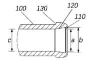
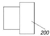
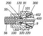
도 1 내지 도 3 및 도 5 내지 도 6을 참조한다. 이 실시예는 임플란트를 위한 로딩 도구를 제공하고, 로딩 도구는 임플란트를 전달 디바이스에 로딩하기 위해 압축 디바이스와 협력하도록 구성된다. 로딩 도구는 보호 튜브(100) 및 보호 슬리브(200)를 포함한다. 보호 튜브(100)는 서로 대향하는 근위 단부(101) 및 원위 단부(102)를 갖는다. 여기서, 근위 단부(101)와 원위 단부(102)는 보호 튜브(100)의 대향하는 2개의 단부이다. 보호 튜브(100)는 전달 디바이스가 통과하도록 마련되며, 바람직하게는 전달 디바이스는 보호 튜브(100)를 관통하는 캡슐을 포함한다. 근위 단부(101)는 내부에 삽입될 임플란트를 위해 제공되고, 원위 단부(102)는 내부에 삽입될 전달 디바이스를 위해 제공된다. 보호 슬리브(200)는 보호 튜브(100) 상에 이동 가능하게 슬리브(sleeve) 된다. 보호 슬리브(200)는 임플란트의 압축 디바이스와 탈착 가능하게 연결되는 제1 연결부를 갖는다. 제1 연결부가 압축 디바이스와 연결되면, 보호 슬리브(200)는 보호 튜브(100)를 압축 디바이스와 동축으로 유지할 수 있다.Reference is made to FIGS. 1 to 3 and 5 to 6 . This embodiment provides a loading tool for the implant, wherein the loading tool is configured to cooperate with the compression device to load the implant into the delivery device. The loading tool includes a
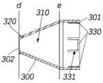
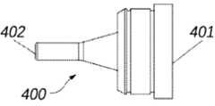
또한, 도 9 내지 도 14를 참조하면, 본 실시예는 임플란트를 위한 압축 디바이스를 제공하며, 상기 압축 디바이스는 임플란트를 위한 로딩 도구와 협력하는데 사용된다. 상기 압축 디바이스는 가이드 캡(300)과 가이드 베이스(400)를 포함한다. 가이드 캡(300)은 보호 튜브(100)가 가이드 베이스(300)와 동축을 유지하도록 제1 연결부와 연결되는 제3 연결부를 갖는다. 가이드 베이스(400)와 가이드 캡(300)은 탈착 가능하게 결합되어 임플란트를 압축한다.Referring also to FIGS. 9 to 14 , the present embodiment provides a compression device for an implant, wherein the compression device is used to cooperate with a loading tool for the implant. The compression device includes a
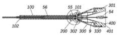
또한, 도 15 내지 도 21을 참조하면, 이 실시예는 또한 임플란트를 위한 로딩 시스템을 제공한다. 상기 로딩 시스템은 위에서 언급한 로딩 도구 및 압축 디바이스를 포함하고, 전달 디바이스(5)도 포함한다. 전달 디바이스(5)는 바람직하게는 캡슐(56)을 포함한다. 로딩 도구 및 압축 디바이스는 전달 디바이스(5)의 캡슐(56)에 임플란트를 로딩하기 위해 전달 디바이스(5)와 협력하는데 사용된다. 보호 튜브(100)의 근위 단부(101)와 가이드 캡(300)의 제2 단부(302)는 서로 마주보도록 배치된다. 보호 슬리브(200)의 제1 연결부는 가이드 캡(300)의 제3 연결부에 연결되어 보호 튜브(100)가 가이드 캡(300)과 동축을 유지하도록 한다. 이러한 구성으로, 캡슐(56)과 임플란트 사이의 연결 위치를 고정하기 위해 특별히 배정된 사람이 필요하지 않으며, 보호 슬리브(200)와 가이드 캡(300) 사이의 연결은 압축 디바이스와 보호 튜브(100)가 서로 동축을 유지하도록 보장할 수 있기 때문에, 높은 로딩 효율과 간단한 조작으로 한 사람이 임플란트를 로딩할 수 있다.15-21 , this embodiment also provides a loading system for the implant. The loading system includes the above-mentioned loading tool and compression device, and also includes a
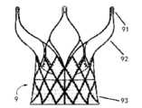
다음에서, 밸브 스텐트(9)는 이 실시예에서 제공되는 로딩 도구, 압축 디바이스 및 로딩 시스템을 상세하게 설명하기 위해 임플란트의 예로서 취해진다. 도 22에 도시된 바와 같이, 판막 스텐트(9)는 유출관(92), 유입관(93) 및 러그(91)를 포함한다. 판막 스텐트(9)는 전달 디바이스(5)의 도움으로 이 실시예에 제공된 로딩 시스템에 의해 캡슐(56) 내로 압축 및 로딩된다. 그 다음 사용시, 판막 스텐트(9)는 전달 디바이스(5)의 카테터를 통해 환자 신체의 목표 영역으로 수축된 구성으로 전달되고 도 22에 도시된 바와 같이 확장된 구성을 형성하도록 해제된다. 여기서 임플란트는 심장 판막 스텐트와 같은 압축 가능한 임플란트를 말하지만 판막 스텐트(9)로 제한되지 않는다는 것을 이해해야 한다. 본 발명은 당해 기술분야에 존재하는 임의의 임플란트일 수 있는 임플란트의 기하학적 구조 및 재료를 특별히 제한하지 않는다.In the following, the
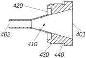
도 1 및 도 2를 참조하고, 도 15와 조합하여, 보호 튜브(100)는 내부 직경이 캡슐(56)의 외부 직경과 정합하는 중공 내부 캐비티를 가지며, 예를 들어, 보호 튜브(100)의 내경은 캡슐(56)의 외경보다 약간 더 크므로, 캡슐(56)은 이동 가능하게 삽입된다. 도 6에 도시된 바와 같이, 보호 슬리브(200)는 내경이 보호 튜브(100)의 외경과 정합하는 내경(210)을 가지며, 예를 들어, 내부 캐비티(210)의 내부 직경은 보호 튜브(100)의 외부 직경보다 약간 더 크므로, 보호 슬리브(200)는 보호 튜브(100) 상에 이동 가능하게 슬리브 된다. 구체적으로, 보호 슬리브(200)가 보호 튜브(100)에 슬리브 되는 경우, 보호 슬리브(200)와 보호 튜브(100)는 축 방향으로 이동할 수 있고 서로 동축을 유지할 수 있다. 이와 같이, 보호 튜브(100)에 대한 보호 슬리브(200)의 반경방향 변위를 제한하여 보호 슬리브(200)가 제1 연결부를 통해 가이드 캡(300)의 제3 연결부에 연결될 때, 보호 튜브(100)는 가이드 캡(300)에 대해 방사상의 변위가 없다.1 and 2 , and in combination with FIG. 15 , the
바람직하게는, 도 6, 9 및 16에 도시된 바와 같이, 이 실시예에서, 보호 슬리브(200)의 제1 연결부는 보호 슬리브(200)의 내벽에 원주방향으로 배치된 복수의 맞물림 톱니(220)를 포함한다. 가이드 캡(300)의 제3 연결부는 가이드 캡(300)의 외벽에 원주방향으로 배치되는 복수의 맞물림 홈(320)을 포함한다. 맞물림 톱니(220)의 개수는 맞물림 홈(320)의 개수와 동일하며, 맞물림 톱니(220)의 크기 및 위치는 맞물림 홈(320)의 크기 및 위치와 일치하여, 맞물림 톱니(220)와 맞물림 홈(320)이 맞물려 가이드 캡(300)에 대한 축 방향 변위나 반경방향 변위가 없도록 보호 슬리브(200)의 위치를 제한할 수 있도록 하고, 보호 튜브(100)의 위치는 가이드 캡(300)에 대해 적어도 방사상 변위가 없는 방식으로 보호 슬리브(200)의 내부 캐비티(210)에 의해 제한되며, 바람직하게는, 보호 튜브(100)의 경우, 가이드 캡(300)에 대한 축 방향 변위도 존재하지 않는다. 보다 바람직하게는, 보호 튜브(100), 보호 슬리브(200) 및 가이드 캡(300)은 맞물림 톱니(220)가 맞물림 홈(320)에 결합될 때 서로 동축이다.Preferably, as shown in FIGS. 6 , 9 and 16 , in this embodiment, the first connection of the
또한, 도 3에 도시된 바와 같이, 보호 튜브(100)의 근위 단부(101)에는 나팔형 구조(120)가 제공된다. 나팔형 구조(120)의 내경은 보호 튜브(100)의 원위 단부(102)에서 근위 단부(101)로 향하는 방향을 따라 점진적으로 증가한다. 나팔형 구조(120)의 최대 내경(b)은 근위 단부(101)에 가까운 위치에 있다. 나팔형 구조(120)의 최소 내경은 보호 튜브(100)의 내경(c)과 동일하다. 도 20을 참조하면, 판막 스텐트(9)는 팽창된 구성으로부터 압축되고 판막 스텐트(9)의 로딩 과정 동안 캡슐(56) 내로 로딩될 것이며, 판막 스텐트(9)를 수용하는 캡슐(56)의 단부(헤드 단부)는 판막 스텐트(9)에 의해 가해지는 반경방향 지지력의 작용하에 약간의 형태 변화(팽창)를 겪을 것이다. 이때, 나팔형 구조(120)는 캡슐(56)의 헤드 단부를 지지한다. 나팔형 구조(120)는 캡슐(56)의 헤드 단부가 과도하게 팽창되어 손상되는 것을 방지하기 위해 캡슐(56)의 헤드 단부와 잘 끼워 맞춰진다. 또한, 나팔형 구조(120)는 판막 스텐트(9)의 압축 과정 동안 판막 스텐트(9)에 압축 변형을 제공할 수 있으며, 이는 판막 스텐트(9)의 마모를 감소시킬 수 있다. 나팔형 구조(120)의 모선은 도 3의 직선에 한정되지 않고, 그러나 보호 튜브(100) 내부로 볼록한 곡선 등의 곡선일 수도 있고, 직선과 곡선의 조합일 수도 있으며, 이는 본 발명에 의해 제한되지 않는다. 바람직하게는, 축 방향에서, 나팔형 구조(120)의 길이는 캡슐 길이의 10%-30%이다.Also, as shown in FIG. 3 , the
또한, 보호 튜브(100)의 근위 단부(101)에는 판막 스텐트(9)를 로딩하는 과정에서 캡슐(56)이 보호 튜브(100)의 근위 단부(101)를 넘지 않게 제한하도록 구성된 낙하 방지 구조(110)가 제공된다. 바람직하게는, 보호 튜브(100)의 내벽에는 보호 튜브(100)의 내측을 향하여 연장되는 돌출부가 형성되고, 이 돌출부가 낙하 방지 구조(110)를 구성한다. 바람직하게는, 돌출부는 링 형상을 가지며, 근위 단부(101) 또는 근위 단부(101)에 가까운 보호 튜브(100)의 내벽에 배치된다. 상기 돌출부의 내경(a)은 보호 튜브(100)의 내경(c) 보다 약간 작고, 정상 구성에서 캡슐(56)의 외경(x) 보다 크거나 같고, 확장된 구성에서 캡슐(56)의 단부의 외경(x')과 작거나 동일하다. 정상 구성에서 캡슐(56)의 외경(x) 보다 크거나 같도록 설정되는 내경(a)은, 판막 스텐트(9)가 로드 되지 않을 때 캡슐(56)이 보호 튜브(100)를 통과할 수 있도록 보장하므로, 테이퍼 헤드의 최대 외경이 캡슐(56)의 외경과 실질적으로 동일하기 때문에 보호 튜브(100)를 통한 테이퍼 헤드의 통과를 용이하게 한다. 확장된 형태의 캡슐(56)의 단부의 외경(x') 이하로 내경(a)을 설정하는 이유는 다음과 같다. 로딩 과정에서, 판막 스텐트(9)의 반경방향 지지력으로 인해, 캡슐(56)의 헤드 단부는 판막 스텐트(9)에 의해 가해지는 반경방향 지지력의 작용 하에 약간의 형상 변화(팽창)를 겪을 것이다. 이때, 확장된 형태의 캡슐(56)의 단부의 외경(x')은 정상 구성의 캡슐(56)의 외경(x) 보다 크며, 내경(a)만이 확장된 구성에서 캡슐(56)의 단부의 외경(x') 보다 작거나 같도록 설정되며, 캡슐(56)은 돌출부의 원위 단부에서 위치적으로 제한될 수 있다. 판막 스텐트(9)의 로딩 과정에서 원위 단부(102)로부터 삽입된 캡슐(56)을 보호 튜브(100) 내부로 위치 제한하기 위한 낙하 방지 구조물(110)이 구비되어, 캡슐(56)이 보호 튜브(100)의 근위 단부(101)를 넘어 연장되는 것을 방지하고 따라서 판막 스텐트(9)가 로드 될 때 손상을 피할 수 있다. 구체적으로, 판막 스텐트(9)의 로딩 과정에서 판막 스텐트(9)와 캡슐(56)은 서로를 향해 이동한다. 판막 스텐트(9)가 프로세스 동안 캡슐(56)에 로딩될 때, 캡슐(56)은 판막 스텐트(9)의 이동 방향과 반대의 이동 경향을 가질 것이고, 낙하 방지 구조물(110)의 차단 하에서, 캡슐(56)이 축 방향으로 보호 튜브(100)의 내부로 제한되는 것이 보장될 수 있다. 돌출부의 내경(a)은 보호 튜브(100)의 내경(c)보다 작은 것으로 이해하여야 하며, 이는 돌출부의 내경이 돌출부에 인접한 보호 튜브(100) 부분의 내경보다 작은 것을 의미한다. 나팔형 구조(120)가 근위 단부(101)에 제공되는 경우, 돌출부의 내경(a)은 근위 단부(101)에 인접한 나팔형 구조(120) 부분의 내경(b)보다 작다. 이때, 상기 나팔형 구조(120)는 상기 돌출부의 내경이 상기 보호 튜브(100)의 내경보다 작지 않도록 하고, 캡슐(56)은 보호 튜브(100)에 더 가까울 수 있고, 보호 튜브(100)에서 캡슐(56)의 반경 방향 위치는 고정되며, 이는 보호 튜브(100), 보호 슬리브(200) 및 압축 디바이스가 동축이라는 것을 깨닫는데 유리하며; 바람직하게는, 낙하 방지 구조(110), 나팔형 구조(120) 및 보호 튜브(100)의 돌출부가 일체로 형성되어 높은 구조적 강도를 보장한다. 일부 다른 실시예에서, 돌출부는 링형 구조가 아니라 보호 튜브(100)의 축 주위에 분포된 복수의 돌출 치형일 수 있으며, 이는 또한 유사한 효과를 제공할 수 있다.In addition, the
도 16과 함께 도 3 및 도 6을 참조하면, 보호 튜브(100)는 원위 단부(102)를 향해 보호 슬리브(200)에 대한 보호 튜브(100)의 축 방향 변위를 제한하기 위해 보호 슬리브(200)와 연결하도록 구성된 제2 연결부를 갖는다. 바람직하게는, 상기 제2 연결부는 상기 보호 튜브(100)의 외면에서 원주방향으로 돌출된 제1 제한 표면(130)을 갖는다. 보호 슬리브(200)는 제1 제한 표면(130)에 접하도록 구성된 제2 제한 표면(230)을 갖는다. 보호 슬리브(200)가 보호 튜브(100)에 슬리브 되면, 2개의 대향하는 제1 제한 표면(130) 및 제2 제한 표면(230)은 원위 단부(102)를 향해 보호 슬리브(200)에 대한 보호 튜브(100)의 축 방향 변위를 제한하기 위해 서로 맞닿아 있다. 도 3, 도 6 및 도 16에 도시된 바와 같이, 보호 튜브(100)는 보호 튜브의 근위 단부(101)로부터 원위 단부(102)로의 방향을 따라 보호 슬리브(200)에 대해 축 방향으로 이동하는 것이 방지된다. 보호 슬리브의 내부 캐비티(210)와 보호 튜브(100) 사이의 조립 관계에 따라 (즉, 보호 슬리브(200)가 보호 튜브(100)에 이동 가능하게 슬리브 됨), 보호 튜브(100)는 축 방향(원위 단부(102) 쪽으로) 또는 반경 방향으로 보호 슬리브(200)에 대해 자유도를 갖지 않는다. 보호 슬리브(200)의 제1 연결부와 가이드 캡(300)의 제3 연결부 사이를 연결하고, 보호 튜브(100)와 가이드 캡(300)이 동축으로 유지되어 판막 스텐트(9)가 캡슐(56) 내로 로딩될 수 있도록 보장될 수 있다. 바람직하게는, 도 6에 도시된 바와 같이, 보호 슬리브(200)의 제1 연결부는 보호 슬리브의 내부 캐비티(210)의 내경보다 큰 내경을 갖는 캐비티를 가지며, 상기 캐비티는 보호 튜브(100)의 제2 연결부의 외주면에서 융기된 부분을 수용하기 위해 사용된다. 상기 캐비티의 축 방향 단면 형상은 직사각형 또는 사다리꼴을 포함하지만 이에 국한되지 않는다. 제2 연결부는 보호 슬리브(200)와 연결하기 위한 제1 제한 표면(130)에 한정되지 않고, 보호 튜브(100)와 보호 슬리브(200)는 보호 튜브(100)가 보호 슬리브(200)에 대해 축 방향 (원위 단부(102)를 향한 방향을 따라) 및 반경 방향 자유도가 없는 한 억지 끼워맞춤, 나사 끼워맞춤 또는 스냅 끼워맞춤과 같은 수단에 의해 분리 가능하게 연결될 수도 있다. 바람직하게는, 보호 슬리브(200)의 외면은 작업자가 파지하여 힘을 가할 수 있도록 단차로 형성될 수 있으며, 다만, 보호 슬리브(200)의 외면은 단차 형상에 한정되지 않고, 원기둥 형상, 원뿔 형상 또는 불규칙 형상일 수도 있으며, 이에 한정되는 것은 아니다.Referring to FIGS. 3 and 6 in conjunction with FIG. 16 , the
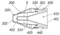
도 9 내지 도 14를 참조하면, 가이드 캡(300)은 서로 대향하는 제1 단부(301) 및 제2 단부(302)를 갖고, 가이드 캡(300)도 제1 내부 캐비티(310)를 갖는다. 가이드 베이스(400)는 서로 대향하는 제3 단부(401)와 제4 단부(402)를 갖는다. 가이드 베이스(400)는 제3 단부(401)로부터 제4 단부(402)로의 방향을 따라 제1 단부(301)로부터 제1 내부 캐비티(310)로 진입하여 판막 스텐트(9)를 압축하기 위한 조립된 구조를 형성하도록 구성된다. 바람직하게는, 제1 내부 캐비티(310)의 단면은 제1 단부(301)에서 제2 단부(302)로 갈수록 점차 작아진다. 즉, 제1 내부 캐비티(310)의 단면은 제1 단부(301)에서 제2 단부(302) 방향으로 갈수록 작아지는 경향을 나타내고, 이것은 제1 내부 캐비티(310)의 단면이 제2 단부(302)에 더 가까운 측의 단면의 단면보다 커야 함을 의미하지 않는다.9 to 14 , the
바람직하게는, 도 10에 도시된 바와 같이, 가이드 캡(300)의 제1 캐비티(310)는 제1 단부(301)에서 제2 단부(302)까지 차례로 연결된 제1 영역 및 제2 영역을 포함한다. 상기 제1 영역과 제2 영역의 단면은 모두 원형이며, 제1 영역(즉, 도 10에서 단면(e)의 오른쪽 영역)의 내경은 가이드 캡(300)의 축 방향을 따라 변하지 않고 유지된다. 제2 영역의 내경은 제1 단부(301)에 가까운 측에서 제2 단부(302)에 가까운 측으로 감소한다 (즉, 도 10에서 단면(e)의 내경이 단면(d)의 내경보다 크다). 제2 영역의 모선(기하학적으로, 곡면의 형상은 이동선의 궤적이라고 볼 수 있으며, 곡면을 이루는 이동선을 모선이라고 함)은 직선 또는 가이드 캡(300)의 내측으로 볼록한 곡선 또는 오목한 곡선과 같은 곡선일 수 있으며, 직선과 곡선의 조합일 수도 있다. 보다 바람직하게는, 제1 영역의 모선과 제2 영역의 모선 사이에 부드러운 천이가 형성된다. 실제로, 제1 영역은 가이드 베이스(400)와 접촉하거나 접하거나 연결하는데 사용되며, 제2 영역은 판막 스텐트(9)를 압축하는데 사용된다. 보다 바람직하게는, 제1 단부(301)에 가까운 제1 영역의 단부에는 원주 방향을 따라 복수의 톱니 홈(331)이 제공되고, 상기 톱니 홈(331) 중 인접한 두 개의 톱니 홈(331) 사이에는 간격이 형성되어 제1 영역이 확장에 의해 가이드 베이스(400)에 용이하게 연결될 수 있다.Preferably, as shown in FIG. 10 , the
또한, 가이드 캡(300)은 제4 연결부(330)를 갖는다. 가이드 베이스(400)는 제5 연결부(430)와 제6 연결부(440)를 갖고, 제5 연결부(430)는 제6 연결부(440)보다 제4 단부(402)에 더 가깝다. 제4 연결부(330)는 제5 연결부(430) 및 제6 연결부(440)와 착탈 가능하게 연결되어 가이드 베이스(400)에 대한 가이드 캡(300)의 축 방향 및 반경 방향 변위를 제한한다. 제5 연결부(430)는 제4 단부(402)에 가까우므로, 제4 연결부(330)와 제5 연결부(430) 사이의 연결은 제4 연결부(330)와 제6 연결부(440) 사이의 연결보다 먼저 이루어지고, 제4 연결부(330)와 제6 연결부(440) 사이의 연결은 제4 연결부(330)와 제5 연결부(430)가 분리된 후에 이루어진다. 제4 연결부(330)와 제5 연결부(430)가 연결되면, 가이드 캡(300)과 가이드 베이스(400) 사이에 반경방향 변위가 없고, 축 변위도 제한되고 동축 안정 상태가 달성되며, 이는 전달 디바이스(5)의 테이퍼진 헤드(54)의 삽입을 용이하게 하고, 판막 스텐트(9)의 추가 압축을 용이하게 하며, 또한 압축 과정 동안 판막 스텐트(9)가 기울어지거나 마모되는 것을 방지한다. 이에 비해, 제4 연결부(330)가 제6 연결부(440)에 연결되면, 가이딩 베이스(400)는 가이딩 캡(300)의 제1 내측 캐비티(310)에 더 깊게 들어가게 된다. 이 경우 형성된 조립 구조는 판막 스텐트(9)의 예비 압축을 완료한다.In addition, the
바람직하게는, 제4 연결부(330)는 제1 단부(301)에 가까운 간격의 단부에 배열된 복수의 수 커넥터(male connector)를 포함하고, 제5 연결부(430)와 제6 연결부(440)는 모두 제4 연결부(330)의 수 커넥터와 짝을 이루는 암 커넥터(female connector)(예를 들어, 가이드 베이스(400) 둘레를 따라 형성된 환형 홈) 역할을 한다. 가이드 캡(300)과 가이드 베이스(400)는 수 커넥터와 암 커넥터의 맞물림을 통해 연결되며, 조립 및 작동이 편리하고 분해가 용이하여 판막 스텐트(9)의 압축 효율을 향상시킨다. 가이드 캡(300)의 제1 영역은 복수의 톱니 홈(331)에 의해 원주 방향으로 복수의 부분으로 분할된다. 가이드 베이스(400)를 가이드 캡(300)의 제1 내측 캐비티(310)에 밀어 넣는 과정에서, 다수의 서브 부품은 가이드 베이스(400)의 안내에 따라 가이드 캡(300)의 반경 방향을 따라 외측으로 탄성 변형되기 쉬우므로, 제4 연결부(330)의 수 커넥터가 제5 연결부(430) 또는 제6 연결부(440)의 암 커넥터와 맞물려서, 가이드 베이스(400)는 가이드 캡(300)에 대해 반경 방향 변위를 갖는 것이 방지된다. 톱니 홈(331)의 수는 필요에 따라 다양할 수 있으며, 예를 들어 2~12개일 수 있음을 이해할 수 있다. 톱니 홈(331)은 가이드 캡(300)의 둘레에 고르게 분포되는 것이 바람직하므로, 상기 가이드 캡(300)의 둘레에 복수의 간격이 대칭적으로 분포되며, 예를 들어, 축 대칭, 중심 대칭 또는 회전 대칭이다. 또한, 각각의 간격에는 제4 연결부(330)의 수 커넥터 중 하나가 제공될 수 있다. 바람직하게는, 동축 고정 및 용이한 분해가 모두 보장될 수 있도록 간격의 일부에만 수형 커넥터가 제공된다. 보다 바람직하게는, 수형 커넥터는 가이드 캡(300)과 가이드 베이스(400)가 연결될 때 기울어짐 없이 균일하게 응력을 받도록 가이드 캡(300)의 둘레에서 중심 대칭이다. 다른 실시예에서, 제4 연결부(330)와 제5 및 제6 연결부(430, 440) 사이의 연결은 마찰 고정 또는 억지 끼움에 의해 달성될 수도 있으며, 이는 본 발명에서 제한하지 않는다.Preferably, the fourth connecting
도 12를 참조하여, 상기 가이드 베이스(400)는 상기 가이드 베이스(400)를 통해 축방향으로 연장되는 제2 내부 캐비티(410)를 가지며, 제2 내부 캐비티(410)의 단면은 제3 단부(401)에서 제4 단부(402)로 향하는 방향으로 점차 작아지고 있다. 즉, 점점 작아지는 경향을 나타내며, 이는 제한을 두지 않는다. 바람직하게는, 제2 내부 캐비티(410)는 제3 단부(401)로부터 제4 단부(402)까지, 연결되는 제3 영역 및 제4 영역을 포함한다. 제3 단부(401)에 가까운 제3 영역 부분의 내경은 제4 단부(402)에 가까운 제3 영역 부분의 내경보다 크다. 제3 단부(401)에 가까운 제4 영역의 일부의 내경은 제4 단부(402)에 가까운 제3 영역의 일부의 내경과 동일하고, 제4 단부(402)에 가까운 제4 영역의 일부의 내경보다 작지 않다. 실제로 제3 영역은 임플란트를 압축하는데 사용된다.12, the
바람직하게는, 제3 영역 및 제4 영역의 단면은 원형이고, 제3 영역 및 제4 영역의 모선은 직선이다. 즉, 제3 영역은 제3 단부(401)를 향하는 더 큰 바닥면을 갖는 원뿔대 형상으로 형성되고, 제4 영역은 원기둥 또는 원뿔대 형상으로 형성된다. 보다 바람직하게는, 제3 영역의 모선과 제4 영역의 모선 사이에 부드러운 천이가 형성된다. 이러한 방식으로 구성된 제2 내부 캐비티(410)는 판막 스텐트(9)를 압축하는데 사용되며 더 나은 결과를 얻을 수 있다. 물론, 제3 영역의 모선과 제4 영역의 모선 사이에 부드러운 천이가 형성되지 않고 직선 사이에 대신 모서리가 형성되는 것도 가능하다. 대안적인 예에서, 제3 영역의 모선 또는 제4 영역의 모선 중 하나 또는 둘은 곡선형이며, 이는 또한 실제 사용에서 더 나은 결과를 달성할 수 있으며, 이에 대해 본 발명이 이에 제한되지 않는다.Preferably, the cross sections of the third region and the fourth region are circular, and the busbars of the third region and the fourth region are straight. That is, the third region is formed in a truncated cone shape having a larger bottom surface facing the
또한, 도 12에 도시된 바와 같이, 가이드 베이스(400)의 외벽에는 원주방향을 따라 개구된 고정 홈(420)이 형성되고, 고정 홈(420)의 개구는 제4 단부(402)를 향한다. 고정 홈(420)은 판막 스텐트(9)가 고정 홈(420)에 맞닿도록 판막 스텐트(9)(주로 판막 스텐트(9)의 유입로(93))를 수용하여 제3 단부(401)를 향한 판막 스텐트(9)의 축방향 변위를 제한하도록 구성된다.In addition, as shown in FIG. 12 , a fixing
임플란트를 위한 로딩 시스템의 사용과 로딩 시스템의 구조와 원리는 아래에서 설명될 것이다.The use of the loading system for implants and the structure and principle of the loading system will be described below.
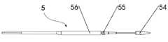
도 15를 참조하여, 이는 테이퍼 헤드(54), 고정 헤드(55), 캡슐(56), 카테터 및 핸들(도시되지 않음)을 포함하는 전달 디바이스(5)를 도시한다. 테이퍼진 헤드(54)는 고정 헤드(55)에 고정 연결되고 캡슐(56)은 핸들의 제어 하에 고정 헤드(55)에 이동 가능하게 슬리빙된다. 고정 헤드(55)는 판막 스텐트(9)의 러그(91)와 연결되어 판막 스텐트(9)에 힘을 가하는 힘 인가 단부 역할을 한다.Referring to FIG. 15 , this shows a
로딩 시스템 사용시, 판막 스텐트(9)의 유입로(93)가 가이드 베이스(400)의 고정 홈(420)에 안착되도록 판막 스텐트(9)가 배치되고, 따라서 가이드 캡(300)을 판막 스텐트(9)의 유출로(92)에서 가이드 베이스(400) 방향으로 가압하여 (즉, 가이드 베이스(400)는 제1 내측 캐비티(310)로 진입) 가이드 캡(300)의 제4 연결부(330)와 가이드 베이스(400)의 제5 연결부(430)를 연결하여, 가이드 캡(300)은 축 방향 및 반경 방향 모두에서 가이드 베이스(400)에 대해 위치적으로 고정된다. 이때, 판막 스텐트(9)의 일단은 고정 홈(420)에 의해 위치가 제한되기 때문에, 판막 스텐트(9)는 가이드 캡(300)의 제2 영역에 의해 처음으로 압축된다. 이때, 제4 연결부(330)는 제5 연결부(430)와 연결되므로, 가이드 캡(300)과 가이드 베이스(400)는 제1 잠금 상태를 형성하고, 가이드 캡(300), 가이드 베이스(400) 및 판막 스텐트(9)는 동축 안정 상태에 있으므로, 테이퍼 헤드(54)가 도 13 및 도 14에 도시된 바와 같이 판막 스텐트의 추가 압축을 위해 통과하는 것이 편리하도록 한다.When using the loading system, the
도 15 내지 도 18에 도시된 바와 같이, 고정 헤드(55)는 핸들의 작동에 의해 캡슐(56)의 외부로 연장된다. 가이드 베이스(400)의 제4 단부(402)로부터 제2 내측 캐비티(410)에 테이퍼 헤드(54)를 삽입하고 (이때, 가이드 캡(300)과 가이드 베이스(400)는 제1 잠금 상태이고, 가이드 캡(300)과 가이드 베이스(400) 사이에는 판막 스텐트(9)가 배치됨), 러그(91)와 고정 헤드(55)가 대략 정렬된 후, 가이드 캡(300)이 가이드 베이스(400)를 향하여 지속적으로 밀리게 되어, 제4 연결부(330)와 제6 연결부(440)가 맞물려 판막 스텐트(9)의 추가 압축이 완료되도록 한다. 이 과정에서, 판막 스텐트(9)의 유출관(92)의 일부 및 러그(91)는 가이드 캡(300), 가이드 베이스(400) 및 판막 스텐트(9)를 위한 고정 연결을 형성하기 위해 가이드 캡(300)의 제2 단부(302) 밖으로 밀려나서, 러그(91)는 고정 헤드(55)의 홈에 쉽게 잠길 수 있다.15 to 18 , the fixed
도 16 및 도 18에 도시된 바와 같이, 러그(91)가 고정 헤드(55)의 홈에 잠긴 것을 확인한 후, 보호 슬리브(200)의 제1 연결부와 가이드 캡(300)의 제3 연결부가 보호 튜브(100), 보호 슬리브(200), 가이드 캡(300)과 판막 스텐트(9)가 동축이 되도록 연결되고, 러그(91)와 고정 헤드(55)의 홈 사이의 긴밀한 연결과 안정적이고 신뢰할 수 있는 고정을 달성하며, 작업자는 다른쪽 단부에 있는 핸들을 조작하기 위해 손을 자유롭게 할 수 있으므로 한 사람이 작업을 수행할 수 있다. 핸들의 작동하에 캡슐(56)은 유입로(93)를 향해 이동되고 (즉, 가이드 베이스(400)의 제3 단부(401)를 향하여, 도면의 우측); 상대적으로, 고정 헤드(55)는 판막 스텐트(9)를 구동하여 캡슐(56)의 내부를 향해 이동하고, 판막 스텐트(9)는 캡슐(56) 내로 로드 되기 시작한다. 이 과정에서, 판막 스텐트(9)는 먼저 보호 튜브(100)의 근위 단부(101)와 접촉하고, 이는 판막 스텐트(9)가 캡슐(56)의 단부에 대해 직접 압착 및 마찰하는 것을 방지한다. 따라서, 보호 튜브(100)는 판막 스텐트(9)에 의해 가해지는 힘을 캡슐(56)에 분산시키고, 캡슐(56)을 보호한다. 도 19 및 도 20에 도시된 바와 같이, 판막 스텐트(9)의 유출로(92)가 점차적으로 캡슐(56) 내부로 로딩됨에 따라, 상대적인 이동 경향에 의해 캡슐(56)은 가이드 캡(300) 쪽으로 밀려나게 된다. 캡슐(56)의 단부가 보호 튜브(100)의 낙하 방지 구조(110)에 도달하면, 캡슐(56)이 보호 튜브(100)의 보호 범위를 초과하지 않도록 낙하 방지 구조(110)에 의해 차단된다. 또한, 가이드 캡(300)에 가까운 캡슐(56)의 헤드 단부(즉, 판막 스텐트(9)가 들어가는 단부)는 판막 스텐트(9)의 반경방향 지지력에 의해 약간의 형상 변화(팽창)를 겪게 되며, 그 다음 보호 튜브(100)가 캡슐(56)의 헤드 단부를 더 잘 보호할 수 있도록, 그 근위 단부에서 보호 튜브(100)의 나팔형 구조(120)와 잘 끼워진다. 판막 스텐트(9)가 캡슐(56)에 미리 정해진 거리(임플란트에 따라 다르게 설정될 수 있음)까지 로드 되면, 도 20에 도시된 바와 같이, 판막 스텐트(9)의 로딩 프로세스의 제1 단계가 완료된다. 판막 스텐트(9)의 로딩 과정의 1단계가 완료된 후, 가이드 베이스(400)와 가이드 캡(300)이 분리되고, 판막 스텐트(9)의 다른 부분을 로드하기 위해, 보호 슬리브(200) 및 가이드 캡(300)은 보호 튜브(100)의 근위 단부(101)가 노출될 때까지(즉, 판막 스텐트(9)가 노출될 때까지) 보호 튜브(100)의 원위 단부(102)를 향해 모두 이동된다. 이 과정에서, 보호 슬리브(200)와 가이드 캡(300)은 분리되거나 전체적으로 함께 이동될 수 있다.16 and 18 , after confirming that the
도 21을 참조하면, 판막 스텐트(9)의 로딩 과정의 1단계를 완료하고 보호 슬리브(200)와 가이드 캡(300)을 제거하고, 보호 튜브(100)의 근위 단부(101)를 노출시킨 후, 가이드 베이스(400)가 뒤집힌 상태로 되며 (즉, 제3 단부(401)와 제4 단부(402)가 위치를 바꿈), 가이드 베이스(400)는 제4 단부(402)에서 제3 단부(401) 방향을 따라 캡슐(56)(도면에서 좌측)을 향해 이동하고, 판막 스텐트(9)의 유입로(93)는 가이드 베이스(400)의 제3 영역의 작용에 의해 제4 영역으로 밀려나서, 유입로(93)는 외부 직경이 캡슐(56)의 내부 직경과 거의 같은 방식으로 압축된다. 그 다음, 계속된 핸들 조작하에 캡슐(56)을 밀어서 전방으로 이동시킨 후 판막 스텐트(9)를 당겨서 도면의 좌측으로 이동시켜서, 판막 스텐트(9)가 캡슐(56)에 완전히 장착되어 판막 스텐트(9)의 전체 장착 프로세스가 완료된다.Referring to Figure 21, after completing step 1 of the loading process of the
요약하면, 본 발명에서 제공하는 압축 디바이스에 판막 스텐트(9)를 설치한 후, 보호 슬리브(200)의 제1 연결부는 가이드 캡(300)의 제3 연결부와 연결되어, 보호 튜브(100), 보호 슬리브(200) 및 가이드 캡(300)이 동축을 유지하도록 하여 판막 스텐트(9)의 러그(91)를 고정 헤드(55)에 고정하는데 유리하며, 로딩 도구 및 압축 디바이스는 안정적이고 견고하게 고정되며, 작업자는 다른쪽 단부에 있는 핸들을 조작하기 위해 손을 자유롭게 할 수 있으므로 작업에는 한 사람만 필요하다. 동시에, 로딩 효율 및 로딩 효과가 더욱 향상되고, 압축 과정에서 판막 스텐트(9)가 기울어지거나 파손되는 것이 방지된다.In summary, after installing the
실시예 2Example 2
도 4, 도 7 및 도 8을 참조하면, 본 발명의 실시예 2에서 임플란트를 위한 로딩 도구, 압축 디바이스 및 로딩 시스템은 기본적으로 실시예 1에서와 동일하다. 동일한 부분은 다시 설명하지 않고 차이점만 아래에서 설명한다.4, 7 and 8 , the loading tool, the compression device and the loading system for the implant in the second embodiment of the present invention are basically the same as in the first embodiment. The same parts are not described again, only the differences are described below.
도 4에 도시된 바와 같이, 본 실시예에서, 보호 튜브(100)의 근위 단부(101)에는 보호 튜브(100) 재료의 경도보다 경도가 낮은 재료로 제조된 낙하 방지 패스너(140)가 제공된다. 예를 들어, 실리카겔 또는 고무를 사용할 수 있다. 낙하 방지 패스너(140)의 축방향 단면은 보호 튜브(100)의 근위 단부(101)의 외주에 일단이 슬리브 된 L자형이며, 타단은 보호 튜브(100)의 반경 방향을 따라 보호 튜브(100) 내부로 연장되어 제한부를 형성한다. 상기 제한부는 낙하 방지 구조(110)를 형성한다. 유사하게, 제한부는 바람직하게는 링 형상이고, 그것에 인접한 보호 튜브(100)의 근위 단부(101)의 내경(b)보다 작은 내경(a)을 갖는다. 이와 같이 구성하면, 낙하 방지 구조(110)가 신축성 구조이므로, 판막 스텐트(9)는 판막 스텐트(9)가 통과할 때 더 잘 보호될 수 있어, 낙하 방지 구조(110)가 판막 스텐트(9)를 손상시키는 것을 방지한다. 또한, 신축성 낙하 방지 구조(110)는 캡슐(56)의 헤드 단부가 압착되어 손상되는 것을 방지하기 위해 캡슐(56)의 헤드 단부를 더 잘 보호할 수도 있다.4 , in this embodiment, the
도 7 및 도 8에 도시된 바와 같이, 본 실시예에서, 보호 슬리브(200)의 제1 연결부는 보호 슬리브(200)의 내벽에 배치되는 내부 스레드(250)를 갖고, 제3 연결부는 내부 스레드(250)와 맞물리도록 가이드 캡(300)의 외벽에 마련되는 외부 스레드를 포함한다. 내부 스레드(250)에 외부 스레드를 맞추어 연결한 후, 상기 압축 디바이스에 대한 보호 슬리브(200)의 축방향 및 반경방향 변위는 제한될 수 있다. 따라서, 보호 튜브(100)는 압축 디바이스에 대해 축 방향 및 반경 방향 모두에서 고정될 수 있다.7 and 8 , in this embodiment, the first connection part of the
또한, 본 실시예에서는 보호 슬리브(200)의 외벽에 미끄럼 방지 구조(240)를 구비하여 마찰력을 증가시켜 작업자가 파지할 수 있도록 하였다. 미끄럼 방지 구조(240)는, 예를 들어, 미끄럼 방지 홈 또는 미끄럼 방지 돌기일 수 있다. 미끄럼 방지 구조(240)의 구체적인 구조는 작업자와의 파지를 용이하게 하거나 마찰을 증가시킬 수 있는 한 본 발명에서 특별히 제한되지 않는다.In addition, in this embodiment, an
본 명세서의 다양한 실시예 사이의 상이한 부분은 또한 서로 조합하여 사용될 수 있으며, 이는 본 발명에서 제한되지 않음에 유의해야 한다.It should be noted that different parts between the various embodiments of the present specification may also be used in combination with each other, which is not limited in the present invention.
위의 설명은 본 발명의 바람직한 실시예를 위한 것일 뿐, 본 발명의 범위를 제한하려는 것은 아니다. 상기 개시내용에 따라 당업자에 의해 행해진 임의의 변경 및 수정은 모두 첨부된 청구범위의 보호 범위 내에 있다.The above description is only for preferred embodiments of the present invention, and is not intended to limit the scope of the present invention. Any changes and modifications made by those skilled in the art in accordance with the above disclosure are all within the protection scope of the appended claims.
100: 보호 튜브, 101: 근위 단부, 102: 원위 단부, 110: 낙하 방지 구조, 120: 나팔형 구조, 130: 제1 제한 표면, 140: 낙하 방지 패스너; 200: 보호 슬리브, 210: 보호 슬리브의 내부 캐비티, 220: 맞물림 톱니, 230: 제2 제한 표면, 240: 미끄럼 방지 구조, 250: 내부 스레드; 300: 가이드 캡, 301: 제1 단부, 302: 제2 단부, 310: 제1 내부 캐비티, 320: 맞물림 홈, 330: 제4 연결부, 331: 톱니 홈; 400: 가이드 베이스, 401: 제3 단부, 402: 제4 단부, 410: 제2 내부 캐비티, 420: 고정 홈, 430: 제5 연결부, 440: 제6 연결부; 5: 전달 디바이스, 54: 테이퍼진 헤드, 55: 고정 헤드, 56: 캡슐; 9: 밸브 스텐트, 91: 러그, 92: 유출로; 93: 유입로.100: protective tube, 101: proximal end, 102: distal end, 110: anti-drop structure, 120: flared structure, 130: first restraining surface, 140: anti-drop fastener; 200 protective sleeve, 210 inner cavity of protective sleeve, 220 meshing teeth, 230 second limiting surface, 240 anti-slip structure, 250 internal thread; 300 guide cap, 301 first end, 302 second end, 310 first inner cavity, 320 engaging groove, 330 fourth connecting portion, 331 toothed groove; 400: guide base, 401: third end, 402: fourth end, 410: second inner cavity, 420: fixing groove, 430: fifth connection, 440: sixth connection; 5: delivery device, 54 tapered head, 55 fixed head, 56 capsule; 9: valve stent, 91: lug, 92: outflow path; 93: Inflow.
Claims (16)
Translated fromKorean전달 디바이스가 통과할 수 있는 보호 튜브, -상기 보호 튜브는 원위 단부와 근위 단부를 가지며, 상기 근위 단부로부터 상기 임플란트가 삽입될 수 있고, 상기 근위 단부와 원위 단부는 서로 대향함-; 및
상기 보호 튜브 상에 이동 가능하게 슬리브된 보호 슬리브, -상기 보호 슬리브는 상기 압축 디바이스와 분리 가능하게 연결되는 제1 연결부를 가짐-;
을 포함하고,
상기 보호 튜브는 상기 압축 디바이스와 동축이 되도록 제1 연결부를 통해 상기 압축 디바이스에 연결되도록 구성되는,
임플란트용 로딩 도구.
A loading tool for an implant, configured to cooperate with a compression device to load the implant into a delivery device, comprising:
a protective tube through which a delivery device can pass, the protective tube having a distal end and a proximal end from which the implant can be inserted, the proximal and distal ends opposing each other; and
a protective sleeve movably sleeved on said protective tube, said protective sleeve having a first connection releasably connected with said compression device;
including,
wherein the protective tube is configured to be connected to the compression device via a first connection so as to be coaxial with the compression device.
Loading tools for implants.
상기 전달 디바이스는 캡슐을 포함하고, 상기 보호 튜브에는 낙하 방지 구조가 제공되며, 상기 낙하 방지 구조는 상기 캡슐이 상기 보호 튜브의 근위 단부를 넘어 연장되는 것을 방지하도록 구성되는,
임플란트용 로딩 도구.
According to claim 1,
wherein the delivery device comprises a capsule and the protective tube is provided with an anti-drop structure, wherein the anti-drop structure is configured to prevent the capsule from extending beyond the proximal end of the protective tube.
Loading tools for implants.
상기 보호 튜브는 상기 보호 튜브의 내부를 향해 연장되는 돌출부를 갖는 내벽을 가지며, 상기 돌출부는 상기 낙하 방지 구조를 구성하는,
임플란트용 로딩 도구.
3. The method of claim 2,
the protective tube has an inner wall having a protrusion extending toward the inside of the protective tube, the protrusion constituting the fall prevention structure,
Loading tools for implants.
상기 보호 튜브의 근위 단부에는 상기 보호 튜브의 내부로 연장된 제한 부분을 갖는 낙하 방지 패스너가 제공되고, 상기 제한 부분은 낙하 방지 구조를 구성하는,
임플란트용 로딩 도구.
3. The method of claim 2,
A proximal end of the protection tube is provided with an anti-fall fastener having a restriction portion extending into the interior of the protection tube, the restriction portion constituting a fall protection structure;
Loading tools for implants.
상기 보호 튜브의 근위 단부는 상기 보호 튜브의 원위 단부로부터 근위 단부로의 방향을 따라 점진적으로 증가하는 내경을 갖는 나팔형 구조를 가지는,
임플란트용 로딩 도구.
According to claim 1,
wherein the proximal end of the protective tube has a flared structure with an inner diameter that gradually increases along a direction from the distal end to the proximal end of the protective tube.
Loading tools for implants.
제2 연결부는 상기 보호 튜브 상에 제공되고, 상기 제2 연결부는 상기 보호 튜브의 원위 단부를 향해 보호 슬리브에 대한 보호 튜브의 축 방향 변위를 제한하기 위해 보호 슬리브와 연결하도록 구성되는,
임플란트용 로딩 도구.
According to claim 1,
a second connection is provided on the protective tube, wherein the second connection is configured to connect with the protective sleeve to limit an axial displacement of the protective tube relative to the protective sleeve towards a distal end of the protective tube;
Loading tools for implants.
상기 제2 연결부는 상기 보호 튜브의 외부 표면으로부터 원주방향으로 돌출된 제1 제한 표면을 가지며; 상기 보호 슬리브는 제2 제한 표면을 가지며, 상기 제1 제한 표면은 상기 보호 슬리브에 대한 상기 보호 튜브의 축 방향 변위를 보호 튜브의 원위 단부 쪽으로 제한하기 위해 제2 제한 표면에 접하도록 구성되는,
임플란트용 로딩 도구.
7. The method of claim 6,
the second connection portion has a first limiting surface circumferentially protruding from the outer surface of the protective tube; the protective sleeve has a second limiting surface, the first limiting surface being configured to abut a second limiting surface to limit axial displacement of the protective tube relative to the protective sleeve towards a distal end of the protective tube;
Loading tools for implants.
상기 제1 연결부는 원주 방향으로 상기 보호 슬리브의 내벽에 배치되고 상기 압축 디바이스의 맞물림 홈과 정합 되도록 구성된 복수의 맞물림 톱니를 포함하는,
임플란트용 로딩 도구.
According to claim 1,
wherein the first connecting portion comprises a plurality of engaging teeth disposed on the inner wall of the protective sleeve in a circumferential direction and configured to mate with an engaging groove of the compression device.
Loading tools for implants.
상기 제1 연결부는 상기 보호 슬리브의 내벽 상에 제공된 내부 스레드를 가지며, 상기 내부 스레드는 상기 압축 디바이스의 외부 스레드와 정합 되도록 구성되는,
임플란트용 로딩 도구.
According to claim 1,
the first connection portion has an internal thread provided on an inner wall of the protective sleeve, the inner thread configured to mate with an external thread of the compression device;
Loading tools for implants.
미끄럼 방지 구조가 상기 보호 슬리브의 외벽 상에 제공되는,
임플란트용 로딩 도구.
According to claim 1,
an anti-skid structure is provided on the outer wall of the protective sleeve;
Loading tools for implants.
제3 연결부를 갖는 가이드 캡, -상기 제3 연결부는 보호 튜브와 가이드 캡이 동축을 유지하도록 제1 연결부와 정합 및 연결되도록 구성됨-; 및
상기 가이드 캡과 탈착 가능하게 연결되어 상기 임플란트를 압축하는 가이드 베이스;
를 포함하는,
임플란트용 압축 디바이스.
11. A compression device for an implant, configured to cooperate with a loading tool according to any one of the preceding claims, comprising:
a guide cap having a third connection portion, the third connection portion configured to mate and connect with the first connection portion such that the protective tube and the guide cap remain coaxial; and
a guide base detachably connected to the guide cap to compress the implant;
containing,
Compression device for implants.
상기 제3 연결부는 가이드 캡의 원주 방향을 따라 가이드 캡의 외벽에 배치되는 복수의 맞물림 홈을 포함하고 상기 로딩 도구의 맞물림 톱니와 정합 되도록 구성되는,
임플란트용 압축 디바이스.
12. The method of claim 11,
wherein the third connecting portion includes a plurality of engaging grooves disposed on an outer wall of the guide cap along a circumferential direction of the guide cap and configured to mate with the engaging teeth of the loading tool,
Compression device for implants.
상기 제3 연결부는 가이드 캡의 외벽 상에 제공된 외부 스레드를 가지는,
임플란트용 압축 디바이스.
12. The method of claim 11,
the third connecting portion has an external thread provided on the outer wall of the guide cap;
Compression device for implants.
상기 가이드 캡은 서로 대향하는 제1 단부와 제2 단부를 갖고; 상기 가이드 캡은 가이드 캡을 관통하여 연장되는 제1 내부 캐비티를 더 가지며, 상기 제1 내부 캐비티는 제1 단부에서 제2 단부로 갈수록 점점 작아지는 단면을 가지며; 상기 가이드 베이스는 서로 대향하는 제3 단부와 제4 단부를 가지며; 상기 가이드 베이스는 상기 제3 단부에서 제4 단부로의 방향을 따라 제1 단부로부터 제1 내부 캐비티로 들어가도록 구성되는,
임플란트용 압축 디바이스.
12. The method of claim 11,
the guide cap has a first end and a second end opposite to each other; the guide cap further has a first inner cavity extending through the guide cap, the first inner cavity having a cross-section that becomes smaller from the first end to the second end; the guide base has a third end and a fourth end opposite to each other; wherein the guide base is configured to enter the first interior cavity from a first end along a direction from the third end to the fourth end;
Compression device for implants.
제11항 내지 제14항 중 어느 한 항에 따른 압축 디바이스; 및
전달 디바이스;
를 포함하고,
상기 로딩 도구 및 압축 디바이스는 상기 전달 디바이스에 임플란트를 로드하기 위해 전달 디바이스와 협력하도록 구성되며; 보호 튜브의 근위 단부는 가이드 캡의 제2 단부와 마주하게 배치되고; 보호 슬리브의 제1 연결부는 가이드 캡의 제3 연결부에 연결되어 보호 튜브와 가이드 캡이 동축을 유지하는,
임플란트용 로딩 시스템.
A loading tool according to any one of claims 1 to 10;
a compression device according to any one of claims 11 to 14; and
delivery device;
including,
the loading tool and compression device are configured to cooperate with a delivery device to load an implant into the delivery device; the proximal end of the protective tube is disposed opposite the second end of the guide cap; The first connection of the protective sleeve is connected to the third connection of the guide cap so that the protective tube and the guide cap are coaxial.
Loading system for implants.
상기 임플란트는 판막 스텐트이며; 상기 전달 디바이스 캡슐을 포함하고, 상기 밸브 스텐트는 상기 캡슐 내로 로드 되도록 구성되는,
임플란트용 로딩 시스템.16. The method of claim 15,
the implant is a valve stent; the delivery device capsule, wherein the valve stent is configured to be loaded into the capsule.
Loading system for implants.
Applications Claiming Priority (3)
| Application Number | Priority Date | Filing Date | Title |
|---|---|---|---|
| CN201910069078.1 | 2019-01-24 | ||
| CN201910069078.1ACN111467080B (en) | 2019-01-24 | 2019-01-24 | Implant loading tool, compression device and loading system |
| PCT/CN2020/072134WO2020151538A1 (en) | 2019-01-24 | 2020-01-15 | Implant loading tool, compression device and loading system |
Publications (2)
| Publication Number | Publication Date |
|---|---|
| KR20210118874Atrue KR20210118874A (en) | 2021-10-01 |
| KR102640498B1 KR102640498B1 (en) | 2024-02-27 |
Family
ID=71735430
Family Applications (1)
| Application Number | Title | Priority Date | Filing Date |
|---|---|---|---|
| KR1020217026401AActiveKR102640498B1 (en) | 2019-01-24 | 2020-01-15 | Implant loading tools, compression devices and loading systems |
Country Status (5)
| Country | Link |
|---|---|
| EP (1) | EP3915520B1 (en) |
| KR (1) | KR102640498B1 (en) |
| CN (1) | CN111467080B (en) |
| ES (1) | ES2976644T3 (en) |
| WO (1) | WO2020151538A1 (en) |
Cited By (1)
| Publication number | Priority date | Publication date | Assignee | Title |
|---|---|---|---|---|
| KR20240032349A (en)* | 2022-09-02 | 2024-03-12 | 주식회사 엠아이텍 | Jig for loading of biodegradable polymer stent and method for loading stent using thereof |
Families Citing this family (7)
| Publication number | Priority date | Publication date | Assignee | Title |
|---|---|---|---|---|
| CN111467080B (en)* | 2019-01-24 | 2024-12-06 | 上海微创心通医疗科技有限公司 | Implant loading tool, compression device and loading system |
| JP7371266B2 (en)* | 2020-10-29 | 2023-10-30 | クリアストリーム・テクノロジーズ・リミテッド | Connector for transfer of graft tissue to catheter |
| CN112618103B (en)* | 2020-12-07 | 2022-08-02 | 赛诺心畅医疗科技有限公司 | Loading tool and loading method capable of recycling implants |
| CN113648106A (en)* | 2021-06-28 | 2021-11-16 | 科凯(南通)生命科学有限公司 | A loading tool for a heart valve |
| CN113332000B (en)* | 2021-07-12 | 2024-04-26 | 上海臻亿医疗科技有限公司 | Bracket loading system and method |
| CN114948365B (en)* | 2022-05-18 | 2025-02-14 | 江苏博朗森思医疗器械有限公司 | Bracket loading device |
| WO2024059254A1 (en)* | 2022-09-16 | 2024-03-21 | Edwards Lifesciences Corporation | Capsule loading assist apparatuses and associated methods |
Citations (5)
| Publication number | Priority date | Publication date | Assignee | Title |
|---|---|---|---|---|
| US4423730A (en)* | 1982-03-01 | 1984-01-03 | Shelhigh Inc. | Atriotomy button and implantation device |
| US20120083875A1 (en)* | 2010-09-17 | 2012-04-05 | Johnson Michael A | Assembly and method for loading a self-expanding collapsible heart valve |
| US20120330408A1 (en)* | 2011-02-02 | 2012-12-27 | St. Jude Medical, Inc. | System for loading a collapsible heart valve |
| US20170000634A1 (en)* | 2015-06-29 | 2017-01-05 | Marc Helmick | Scaffold loading and delivery systems |
| CN111467080A (en)* | 2019-01-24 | 2020-07-31 | 上海微创心通医疗科技有限公司 | Loading tools, compression devices and loading systems for implants |
Family Cites Families (8)
| Publication number | Priority date | Publication date | Assignee | Title |
|---|---|---|---|---|
| US20070239271A1 (en)* | 2006-04-10 | 2007-10-11 | Than Nguyen | Systems and methods for loading a prosthesis onto a minimally invasive delivery system |
| CA2961053C (en)* | 2009-04-15 | 2019-04-30 | Edwards Lifesciences Cardiaq Llc | Vascular implant and delivery system |
| EP2520251A1 (en)* | 2011-05-05 | 2012-11-07 | Symetis SA | Method and Apparatus for Compressing Stent-Valves |
| CN106562840B (en)* | 2013-10-31 | 2018-06-22 | 上海微创心通医疗科技有限公司 | A kind of guiding lid and Load System being loaded into implant in transport system |
| US10368986B2 (en)* | 2015-04-15 | 2019-08-06 | Medtronic, Inc. | Transcatheter prosthetic heart valve delivery system and method |
| CN204814285U (en)* | 2015-07-24 | 2015-12-02 | 上海微创医疗器械(集团)有限公司 | Implant loading attachment of body |
| CN108464877B (en)* | 2018-03-05 | 2020-11-06 | 金仕生物科技(常熟)有限公司 | Transcatheter heart valve preassembly system and preassembly method |
| CN209827106U (en)* | 2019-01-24 | 2019-12-24 | 上海微创心通医疗科技有限公司 | Implant loading tool, compression device and loading system |
- 2019
- 2019-01-24CNCN201910069078.1Apatent/CN111467080B/enactiveActive
- 2020
- 2020-01-15ESES20745653Tpatent/ES2976644T3/enactiveActive
- 2020-01-15EPEP20745653.4Apatent/EP3915520B1/enactiveActive
- 2020-01-15WOPCT/CN2020/072134patent/WO2020151538A1/ennot_activeCeased
- 2020-01-15KRKR1020217026401Apatent/KR102640498B1/enactiveActive
Patent Citations (5)
| Publication number | Priority date | Publication date | Assignee | Title |
|---|---|---|---|---|
| US4423730A (en)* | 1982-03-01 | 1984-01-03 | Shelhigh Inc. | Atriotomy button and implantation device |
| US20120083875A1 (en)* | 2010-09-17 | 2012-04-05 | Johnson Michael A | Assembly and method for loading a self-expanding collapsible heart valve |
| US20120330408A1 (en)* | 2011-02-02 | 2012-12-27 | St. Jude Medical, Inc. | System for loading a collapsible heart valve |
| US20170000634A1 (en)* | 2015-06-29 | 2017-01-05 | Marc Helmick | Scaffold loading and delivery systems |
| CN111467080A (en)* | 2019-01-24 | 2020-07-31 | 上海微创心通医疗科技有限公司 | Loading tools, compression devices and loading systems for implants |
Cited By (1)
| Publication number | Priority date | Publication date | Assignee | Title |
|---|---|---|---|---|
| KR20240032349A (en)* | 2022-09-02 | 2024-03-12 | 주식회사 엠아이텍 | Jig for loading of biodegradable polymer stent and method for loading stent using thereof |
Also Published As
| Publication number | Publication date |
|---|---|
| EP3915520A1 (en) | 2021-12-01 |
| EP3915520B1 (en) | 2024-04-10 |
| WO2020151538A1 (en) | 2020-07-30 |
| CN111467080B (en) | 2024-12-06 |
| EP3915520A4 (en) | 2022-03-16 |
| ES2976644T3 (en) | 2024-08-06 |
| CN111467080A (en) | 2020-07-31 |
| EP3915520C0 (en) | 2024-04-10 |
| KR102640498B1 (en) | 2024-02-27 |
Similar Documents
| Publication | Publication Date | Title |
|---|---|---|
| KR102640498B1 (en) | Implant loading tools, compression devices and loading systems | |
| US11833040B2 (en) | System and method for crimping a prosthetic valve | |
| CN209827106U (en) | Implant loading tool, compression device and loading system | |
| CN111374801B (en) | Implant loading tool and medical device | |
| US9119717B2 (en) | Retainers for transcatheter heart valve delivery systems | |
| JP6099906B2 (en) | Modular intraocular lens injector | |
| JP7220669B2 (en) | elbow joint prosthesis | |
| CN108309511B (en) | Interventional valve loading device | |
| JP7358377B2 (en) | Implant loading device | |
| CN213525690U (en) | Implant loading tool and medical device | |
| CN209661884U (en) | The loading tool and medical device of implantation material | |
| CN110811927A (en) | Implant loading device | |
| CN116531146A (en) | Easy-to-position prosthetic heart valves | |
| KR102852174B1 (en) | Implant loading tools and medical devices | |
| CN212522086U (en) | Implant loading tool and medical device | |
| CN218458210U (en) | Transapical mitral valve replacement transporter | |
| EP4134048B1 (en) | Loading tool and system for implant | |
| KR20220129558A (en) | Implant Component Assemblies | |
| CN221470082U (en) | Valve fixing device, inner core tube structure, inner catheter structure and conveying system | |
| CN119768635A (en) | Tube connectors and related tools | |
| CN119632729A (en) | Valve fixation device and delivery system |
Legal Events
| Date | Code | Title | Description |
|---|---|---|---|
| PA0105 | International application | Patent event date:20210819 Patent event code:PA01051R01D Comment text:International Patent Application | |
| PA0201 | Request for examination | ||
| PG1501 | Laying open of application | ||
| E902 | Notification of reason for refusal | ||
| PE0902 | Notice of grounds for rejection | Comment text:Notification of reason for refusal Patent event date:20230203 Patent event code:PE09021S01D | |
| E902 | Notification of reason for refusal | ||
| PE0902 | Notice of grounds for rejection | Comment text:Notification of reason for refusal Patent event date:20230825 Patent event code:PE09021S01D | |
| E701 | Decision to grant or registration of patent right | ||
| PE0701 | Decision of registration | Patent event code:PE07011S01D Comment text:Decision to Grant Registration Patent event date:20240207 | |
| GRNT | Written decision to grant | ||
| PR0701 | Registration of establishment | Comment text:Registration of Establishment Patent event date:20240221 Patent event code:PR07011E01D | |
| PR1002 | Payment of registration fee | Payment date:20240222 End annual number:3 Start annual number:1 | |
| PG1601 | Publication of registration |