KR20210116943A - An optical device with wider field of view using concave lens and a head mounted display apparatus having thereof - Google Patents
An optical device with wider field of view using concave lens and a head mounted display apparatus having thereofDownload PDFInfo
- Publication number
- KR20210116943A KR20210116943AKR1020200033155AKR20200033155AKR20210116943AKR 20210116943 AKR20210116943 AKR 20210116943AKR 1020200033155 AKR1020200033155 AKR 1020200033155AKR 20200033155 AKR20200033155 AKR 20200033155AKR 20210116943 AKR20210116943 AKR 20210116943A
- Authority
- KR
- South Korea
- Prior art keywords
- user
- image light
- auxiliary lens
- display
- beam splitter
- Prior art date
- Legal status (The legal status is an assumption and is not a legal conclusion. Google has not performed a legal analysis and makes no representation as to the accuracy of the status listed.)
- Ceased
Links
Images


Classifications
- G—PHYSICS
- G02—OPTICS
- G02B—OPTICAL ELEMENTS, SYSTEMS OR APPARATUS
- G02B27/00—Optical systems or apparatus not provided for by any of the groups G02B1/00 - G02B26/00, G02B30/00
- G02B27/01—Head-up displays
- G02B27/017—Head mounted
- G02B27/0172—Head mounted characterised by optical features
- G—PHYSICS
- G02—OPTICS
- G02B—OPTICAL ELEMENTS, SYSTEMS OR APPARATUS
- G02B27/00—Optical systems or apparatus not provided for by any of the groups G02B1/00 - G02B26/00, G02B30/00
- G02B27/10—Beam splitting or combining systems
- G—PHYSICS
- G02—OPTICS
- G02B—OPTICAL ELEMENTS, SYSTEMS OR APPARATUS
- G02B3/00—Simple or compound lenses
- G02B3/0087—Simple or compound lenses with index gradient
Landscapes
- Physics & Mathematics (AREA)
- General Physics & Mathematics (AREA)
- Optics & Photonics (AREA)
Abstract
Description
Translated fromKorean본 발명은 광학 장치 및 이를 이용한 머리 착용형 디스플레이 장치에 관한 것으로서, 보다 구체적으로는 보조렌즈를 이용해 시야를 넓힌 광학 장치 및 이를 이용한 머리 착용형 디스플레이 장치에 관한 것이다.The present invention relates to an optical device and a head-wearable display device using the same, and more particularly, to an optical device in which a field of view is broadened using an auxiliary lens and a head-wearable display device using the same.
디지털 디바이스의 경량화 및 소형화 추세에 따라 다양한 웨어러블 디바이스(wearable device)들이 개발되고 있다. 이러한 웨어러블 디바이스의 일종인 헤드 마운티드 디스플레이(Head Mounted Display)는 사용자가 머리에 착용하여 멀티미디어 컨텐츠 등을 제공받을 수 있는 각종 디바이스를 의미한다. 여기서 헤드 마운티드 디스플레이(HMD)는 사용자의 신체에 착용 되어 사용자가 이동함에 따라서 다양한 환경에서 사용자에게 영상을 제공하게 된다. 이러한 헤드 마운티드 디스플레이(HMD)는 투과(see-through)형과 밀폐(see-closed)형으로 구분되고 있으며, 투과형은 주로 증강현실(Augmented Reality, AR)용으로 사용되고, 밀폐형은 주로 가상현실(Virtual Reality, VR)용으로 사용되고 있다.Various wearable devices are being developed according to the trend of weight reduction and miniaturization of digital devices. A head mounted display, which is a type of wearable device, refers to various devices that a user can wear on the head to receive multimedia contents. Here, the head mounted display (HMD) is worn on the user's body and provides images to the user in various environments as the user moves. Such a head mounted display (HMD) is divided into a see-through type and a see-closed type, and the transparent type is mainly used for Augmented Reality (AR), and the closed type is mainly used for virtual reality (Virtual Reality). Reality, VR).
도 1은 일반적인 안경 형태의 헤드 마운티드 디스플레이(HMD)의 개략적인 구성을 도시한 도면이고, 도 2는 일반적인 밴드형태의 헤드 마운티드 디스플레이(HMD)의 개략적인 구성을 도시한 도면이다. 도 1 및 도 2에 각각 도시된 바와 같이, 일반적인 안경 형태 또는 밴드 형태의 헤드 마운티드 디스플레이는 사용자의 안면 또는 두부에 착용되어 투과되는 렌즈를 통해 실제 세계에 증강현실(AR)의 영상 정보를 투영하여 사용자에게 제공하게 된다.FIG. 1 is a diagram illustrating a schematic configuration of a general glasses-type head mounted display (HMD), and FIG. 2 is a diagram illustrating a schematic configuration of a general band-type head mounted display (HMD). As shown in FIGS. 1 and 2, a general head-mounted display in the form of glasses or a band is worn on the user's face or head and is transmitted through a lens that projects augmented reality (AR) image information to the real world. will be provided to the user.
이와 같은 헤드 마운티드 디스플레이에서 증강현실을 구현하기 위해, 복잡한 구조의 광학 장치가 사용되는데, 영상에 대한 몰입감을 증대시키기 위해서는 시야(Field of View; FOV)가 넓어져야 하지만, 헤드 마운티드 디스플레이는 표시 패널과 사용자 사이의 간격이 좁아서 시야가 좁은 문제가 있다.In order to implement augmented reality in such a head-mounted display, an optical device having a complex structure is used. In order to increase the immersion in the image, the field of view (FOV) needs to be widened, but the head-mounted display has a display panel and There is a problem in that the field of view is narrow because the distance between the users is narrow.
한편, 본 발명과 관련된 선행기술로서, 공개특허 제10-2016-0032656호(발명의 명칭: 증강현실을 위한 광학장치, 공개일자: 2016년 03월 24일) 등이 개시된 바 있다.On the other hand, as prior art related to the present invention, Patent Publication No. 10-2016-0032656 (title of the invention: optical device for augmented reality, publication date: March 24, 2016) and the like have been disclosed.
본 발명은 기존에 제안된 방법들의 상기와 같은 문제점들을 해결하기 위해 제안된 것으로서, 디스플레이와 빔 스플리터 사이에서 영상 광의 광 경로상에 보조렌즈를 배치하여, 디스플레이에서 출력되는 영상 광이 굴절되어 광학계로 입사되도록 함으로써, 시야(Field of View; FOV)를 넓히고, 이를 통해 영상에 대한 몰입감을 증대시키고, 화면 활용의 효율을 증가시킬 수 있는, 보조렌즈를 이용해 시야를 넓힌 광학 장치 및 이를 이용한 머리 착용형 디스플레이 장치를 제공하는 것을 그 목적으로 한다.The present invention has been proposed to solve the above problems of the previously proposed methods, and by disposing an auxiliary lens on the optical path of the image light between the display and the beam splitter, the image light output from the display is refracted to the optical system. An optical device that widens the field of view (FOV) using an auxiliary lens, which can increase the field of view (FOV) by allowing it to be incident, thereby increasing the sense of immersion in the image, and increasing the efficiency of screen utilization, and a head-wearing type using the same An object of the present invention is to provide a display device.
상기한 목적을 달성하기 위한 본 발명의 특징에 따른 보조렌즈를 이용해 시야를 넓힌 광학 장치는,An optical device with a wider field of view by using an auxiliary lens according to a feature of the present invention for achieving the above object,
광학 장치로서,An optical device comprising:
사용자의 눈의 전방에 배치되며, 사용자의 시야를 통한 실제 세계(real world)가 투과되어 보일 수 있도록 하는 광학계; 및an optical system disposed in front of the user's eyes and allowing the real world to be transmitted through the user's field of view; and
상기 광학계를 통해 투과되어 보이는 실제 세계와 함께 영상 정보가 사용자에게 최적화된 화면으로 제공될 수 있도록 영상 광을 출력하는 디스플레이를 포함하되,and a display for outputting image light so that image information can be provided to the user as an optimized screen along with the real world transmitted through the optical system,
상기 광학계는,The optical system is
상기 디스플레이에서 출력되는 영상 광을 상기 사용자의 눈 방향으로 반사하고, 실제 세계의 광을 투과시키는 빔 스플리터;a beam splitter that reflects the image light output from the display toward the user's eyes and transmits real world light;
상기 디스플레이와 상기 빔 스플리터 사이에서 상기 영상 광의 광 경로상에 배치되는 단일한 렌즈로서, 상기 디스플레이에서 출력되는 영상 광을 굴절시키는 보조렌즈; 및a single lens disposed on an optical path of the image light between the display and the beam splitter, the auxiliary lens refracting the image light output from the display; and
상기 빔 스플리터를 기준으로 상기 보조렌즈의 반대편에 배치되며, 상기 빔 스플리터를 투과한 영상 광을 상기 빔 스플리터 방향으로 반사시키는 미러를 포함하며,a mirror disposed on the opposite side of the auxiliary lens with respect to the beam splitter and reflecting the image light transmitted through the beam splitter in the direction of the beam splitter,
상기 보조렌즈에 의해 상기 영상 광이 굴절되어 시야(Field of View; FOV)를 넓힌 것을 그 구성상의 특징으로 한다.It is characterized in that the image light is refracted by the auxiliary lens to widen a field of view (FOV).
바람직하게는, 상기 보조렌즈는,Preferably, the auxiliary lens,
상기 영상 광의 발산 각도 및 광 경로 중 적어도 어느 하나에 따라 오목렌즈 또는 볼록렌즈로 구성될 수 있다.A concave lens or a convex lens may be configured according to at least one of a divergence angle and an optical path of the image light.
더욱 바람직하게는, 상기 빔 스플리터는,More preferably, the beam splitter,
상기 디스플레이 및 보조렌즈를 마주 보는 면으로서 상기 영상 광을 투과하는 제1면; 및a first surface that faces the display and the auxiliary lens and transmits the image light; and
상기 미러를 마주 보는 면으로서 상기 미러에서 반사된 영상 광을 상기 사용자의 눈 방향으로 반사하는 제2면을 포함할 수 있다.A surface facing the mirror may include a second surface that reflects the image light reflected from the mirror in the direction of the user's eyes.
더욱 바람직하게는, 상기 미러는,More preferably, the mirror,
상기 빔 스플리터를 향하여 오목한 오목 미러로 구성될 수 있다.It may consist of a concave mirror concave towards the beam splitter.
또한, 상기한 목적을 달성하기 위한 본 발명의 특징에 따른 보조렌즈를 이용해 시야를 넓힌 광학 장치를 이용한 머리 착용형 디스플레이 장치는,In addition, a head-wearable display device using an optical device that widens the field of view using an auxiliary lens according to a feature of the present invention for achieving the above object,
머리 착용형 디스플레이 장치로서,A head mounted display device comprising:
사용자가 머리에 착용할 수 있는 HMD 프레임; 및HMD frame that can be worn on the user's head; and
상기 HMD 프레임을 착용한 사용자에게 증강 현실 또는 혼합 현실을 제공하는 광학 장치를 포함하며,An optical device that provides augmented reality or mixed reality to a user wearing the HMD frame,
상기 광학 장치는,The optical device is
상기 HMD 프레임을 착용한 사용자의 눈의 전방에 배치되며, 사용자의 시야를 통한 실제 세계(real world)가 투과되어 보일 수 있도록 하는 광학계;an optical system disposed in front of the user's eyes wearing the HMD frame and allowing the real world to be transmitted through the user's field of view;
상기 광학계를 통해 투과되어 보이는 실제 세계와 함께 영상 정보가 사용자에게 최적화된 화면으로 제공될 수 있도록 영상 광을 출력하는 디스플레이를 포함하되,and a display for outputting image light so that image information can be provided to the user as an optimized screen along with the real world transmitted through the optical system,
상기 광학계는,The optical system is
상기 디스플레이에서 출력되는 영상 광을 상기 사용자의 눈 방향으로 반사하고, 실제 세계의 광을 투과시키는 빔 스플리터;a beam splitter that reflects the image light output from the display toward the user's eyes and transmits real world light;
상기 디스플레이와 상기 빔 스플리터 사이에서 상기 영상 광의 광 경로상에 배치되는 단일한 렌즈로서, 상기 디스플레이에서 출력되는 영상 광을 굴절시키는 보조렌즈; 및a single lens disposed on an optical path of the image light between the display and the beam splitter, the auxiliary lens refracting the image light output from the display; and
상기 빔 스플리터를 기준으로 상기 보조렌즈의 반대편에 배치되며, 상기 빔 스플리터를 투과한 영상 광을 상기 빔 스플리터 방향으로 반사시키는 미러를 포함하며,a mirror disposed on the opposite side of the auxiliary lens with respect to the beam splitter and reflecting the image light transmitted through the beam splitter in the direction of the beam splitter,
상기 보조렌즈에 의해 상기 영상 광이 굴절되어 시야(Field of View; FOV)를 넓힌 것을 그 구성상의 특징으로 한다.It is characterized in that the image light is refracted by the auxiliary lens to widen a field of view (FOV).
바람직하게는, 상기 보조렌즈는,Preferably, the auxiliary lens,
상기 영상 광의 발산 각도 및 광 경로 중 적어도 어느 하나에 따라 오목렌즈 또는 볼록렌즈로 구성되며,It is composed of a concave lens or a convex lens according to at least one of the divergence angle and the optical path of the image light,
상기 미러는,The mirror is
상기 빔 스플리터를 향하여 오목한 오목 미러로 구성될 수 있다.It may consist of a concave mirror concave towards the beam splitter.
더욱 바람직하게는, 상기 빔 스플리터는,More preferably, the beam splitter,
상기 디스플레이 및 보조렌즈를 마주 보는 면으로서 상기 영상 광을 투과하는 제1면; 및a first surface that faces the display and the auxiliary lens and transmits the image light; and
상기 미러를 마주 보는 면으로서 상기 미러에서 반사된 영상 광을 상기 사용자의 눈 방향으로 반사하는 제2면을 포함할 수 있다.A surface facing the mirror may include a second surface that reflects the image light reflected from the mirror in the direction of the user's eyes.
바람직하게는, 상기 디스플레이는,Preferably, the display comprises:
상기 HMD 프레임에서 사용자의 좌안 및/또는 우안의 위쪽에 위치하여, 상기 사용자의 좌안 및/또는 우안의 전방에 배치된 상기 광학계 방향으로, 위에서 아래 방향으로 상기 영상 광을 출력하거나,Positioned above the user's left and/or right eye in the HMD frame, and outputting the image light from top to bottom in the optical system direction disposed in front of the user's left and/or right eye,
상기 HMD 프레임에서 사용자의 좌안 및/또는 우안의 측면에 위치하여, 상기 사용자의 좌안 및/또는 우안의 전방에 배치된 상기 광학계 방향으로, 측면에서 사용자의 코 방향으로 상기 영상 광을 출력할 수 있다.The image light may be output in the direction of the optical system disposed in front of the user's left and/or right eye by being located on the side of the user's left and/or right eye in the HMD frame, and in the direction of the user's nose from the side. .
본 발명에서 제안하고 있는 본 발명의 특징에 따른 보조렌즈를 이용해 시야를 넓힌 광학 장치 및 이를 이용한 머리 착용형 디스플레이 장치에 따르면, 디스플레이와 빔 스플리터 사이에서 영상 광의 광 경로상에 보조렌즈를 배치하여, 디스플레이에서 출력되는 영상 광이 굴절되어 광학계로 입사되도록 함으로써, 시야(Field of View; FOV)를 넓히고, 이를 통해 영상에 대한 몰입감을 증대시키고, 화면 활용의 효율을 증가시킬 수 있다.According to the optical device and the head-wearable display device using the same, the field of view is widened using the auxiliary lens according to the features of the present invention proposed in the present invention, by disposing the auxiliary lens on the optical path of the image light between the display and the beam splitter, By allowing the image light output from the display to be refracted and incident on the optical system, the field of view (FOV) can be widened, thereby increasing the immersion in the image and increasing screen utilization efficiency.
도 1은 일반적인 안경 형태의 헤드 마운티드 디스플레이(HMD)의 개략적인 구성을 도시한 도면.
도 2는 일반적인 밴드형태의 헤드 마운티드 디스플레이(HMD)의 개략적인 구성을 도시한 도면.
도 3은 본 발명의 일실시예에 따른 보조렌즈를 이용해 시야를 넓힌 광학 장치를 설명하기 위해 도시한 도면.
도 4는 기존의 빔 스플리터를 이용한 광학 장치를 통해 영상 광이 사용자의 눈에 전달되는 모습을 도시한 도면.
도 5는 본 발명의 일실시예에 따른 보조렌즈를 이용해 시야를 넓힌 광학 장치를 통해 영상 광이 사용자의 눈에 전달되는 모습을 도시한 도면.
도 6은 본 발명의 일실시예에 따른 보조렌즈를 이용해 시야를 넓힌 광학 장치를 이용한 머리 착용형 디스플레이 장치의 구성을 기능블록으로 도시한 도면.1 is a view showing a schematic configuration of a general glasses-type head mounted display (HMD).
2 is a view showing a schematic configuration of a general band-type head mounted display (HMD).
FIG. 3 is a view for explaining an optical device in which a field of view is widened by using an auxiliary lens according to an embodiment of the present invention; FIG.
4 is a diagram illustrating a state in which image light is transmitted to a user's eyes through an optical device using a conventional beam splitter;
5 is a diagram illustrating a state in which image light is transmitted to a user's eyes through an optical device that widens a field of view using an auxiliary lens according to an embodiment of the present invention.
6 is a view showing the configuration of a head-wearable display device using an optical device that widens the field of view using an auxiliary lens according to an embodiment of the present invention as a functional block.
이하, 첨부된 도면을 참조하여 본 발명이 속하는 기술분야에서 통상의 지식을 가진 자가 본 발명을 용이하게 실시할 수 있도록 바람직한 실시예를 상세히 설명한다. 다만, 본 발명의 바람직한 실시예를 상세하게 설명함에 있어, 관련된 공지 기능 또는 구성에 대한 구체적인 설명이 본 발명의 요지를 불필요하게 흐릴 수 있다고 판단되는 경우에는 그 상세한 설명을 생략한다. 또한, 유사한 기능 및 작용을 하는 부분에 대해서는 도면 전체에 걸쳐 동일한 부호를 사용한다.Hereinafter, preferred embodiments will be described in detail so that those of ordinary skill in the art can easily practice the present invention with reference to the accompanying drawings. However, in describing a preferred embodiment of the present invention in detail, if it is determined that a detailed description of a related known function or configuration may unnecessarily obscure the gist of the present invention, the detailed description thereof will be omitted. In addition, the same reference numerals are used throughout the drawings for parts having similar functions and functions.
덧붙여, 명세서 전체에서, 어떤 부분이 다른 부분과 ‘연결’ 되어 있다고 할 때, 이는 ‘직접적으로 연결’ 되어 있는 경우뿐만 아니라, 그 중간에 다른 소자를 사이에 두고 ‘간접적으로 연결’ 되어 있는 경우도 포함한다. 또한, 어떤 구성요소를 ‘포함’ 한다는 것은, 특별히 반대되는 기재가 없는 한 다른 구성요소를 제외하는 것이 아니라 다른 구성요소를 더 포함할 수 있다는 것을 의미한다.In addition, throughout the specification, when a part is 'connected' with another part, it is not only 'directly connected' but also 'indirectly connected' with another element interposed therebetween. include In addition, "including" a certain component means that other components may be further included, rather than excluding other components, unless otherwise stated.
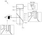
도 3은 본 발명의 일실시예에 따른 보조렌즈(130)를 이용해 시야를 넓힌 광학 장치(100)를 설명하기 위해 도시한 도면이다. 도 3에 도시된 바와 같이, 본 발명의 일실시예에 따른 보조렌즈(130)를 이용해 시야를 넓힌 광학 장치(100)는, 보조렌즈(130)를 포함하는 광학계(110), 및 디스플레이(120)를 포함하여 구성될 수 있고, 광학계(100)에 포함된 보조렌즈(130)에 의해 영상 광이 굴절되어 시야(Field of View; FOV)를 넓힐 수 있다.FIG. 3 is a diagram illustrating the
즉, 광학 장치(100)에서는, 사용자의 눈의 전방에 배치되며, 사용자의 시야를 통한 실제 세계(real world)가 투과되어 보일 수 있도록 하는 광학계(110), 및 광학계(110)를 통해 투과되어 보이는 실제 세계와 함께 영상 정보가 사용자에게 최적화된 화면으로 제공될 수 있도록 영상 광을 출력하는 디스플레이(120)를 포함하여 증강현실을 구현할 수 있다. 광학계(110)에 포함된 빔 스플리터(111)는 디스플레이(120)에서 출력되는 영상 광을 반사해 사용자의 눈으로 영상 정보를 전달한다. 빔 스플리터(111)는 입사되는 광의 일부는 반사하고 일부는 투과하는 광학 소자로서, 도 3에 도시된 바와 같이, 빔 스플리터(111)는 실제 세계는 투과되어 보이도록 하면서, 디스플레이(120)에서 출력되는 영상 광을 투과 및/또는 반사하여 사용자의 눈으로 영상 정보를 전달할 수 있다. 따라서 사용자는 광학계(110)를 통해 투과되어 보이는 실제 세계와 빔 스플리터(111)에서 반사된 영상 정보가 결합한 증강현실을 경험할 수 있게 된다.That is, in the
이때, 본 발명의 일실시예에 따른 보조렌즈(130)를 이용해 시야를 넓힌 광학 장치(100)는, 도 3에 도시된 바와 같이, 디스플레이(120)와 빔 스플리터(111) 사이에서 영상 광의 광 경로상에 보조렌즈(130)를 배치할 수 있다. 따라서, 디스플레이(120)에서 출력되는 영상 광이 보조렌즈(130)에 의해 굴절되어 빔 스플리터(111)로 입사되도록 함으로써, 시야(Field of View; FOV)를 넓히고, 이를 통해 영상에 대한 몰입감을 증대시키고 화면 활용의 효율을 증가시킬 수 있다.At this time, as shown in FIG. 3 , in the
이하에서는, 도 3을 참조하여 본 발명의 일실시예에 따른 보조렌즈(130)를 이용해 시야를 넓힌 광학 장치(100)를 구성하는 각 구성요소에 대해 상세히 설명하도록 한다.Hereinafter, each component constituting the
광학계(110)는, 사용자의 눈의 전방에 배치되며, 사용자의 시야를 통한 실제 세계(real world)가 투과되어 보일 수 있도록 하는 구성이다. 이러한 광학계(110)는 사용자의 시야를 통한 실제 세계가 투과되어 보일 수 있는 글라스 형태로서 투명한 렌즈로 구성될 수 있으며, 빔 스플리터(111)를 포함하여 증강현실을 구현할 수 있다.The
디스플레이(120)는, 광학계(110)를 통해 투과되어 보이는 실제 세계와 함께 영상 정보가 사용자에게 최적화된 화면으로 제공될 수 있도록 영상 광을 출력할 수 있다. 이러한 디스플레이(120)는 후술하게 될 제어부(300)의 제어 하에, 각종 정보를 증강현실 기반으로 사용자에게 제공하는 영상 정보를 출력할 수 있다. OLED(Organic Light Emitting Diodes) 등 다양한 디스플레이 소자를 이용해 구현될 수 있다.The
이때, 디스플레이(120)는, 도 3에 도시된 바와 같이, 사용자 눈의 전방에 있는 광학계(110)의 상측에 위치할 수 있으나, 좌측이나 우측, 광학계(110)의 아래 등에 위치할 수도 있다.In this case, the
도 4는 기존의 빔 스플리터를 이용한 광학 장치를 통해 영상 광이 사용자의 눈에 전달되는 모습을 도시한 도면이다. 도 4에 도시된 바와 같이, 빔 스플리터를 이용한 기존의 광학 장치는, 빔 스플리터가 디스플레이에서 출력된 영상 광을 반사하여 사용자의 눈으로 영상 정보를 전달하는 방식으로 증강 현실을 구현할 수 있다. 이때, 빔 스플리터를 기준으로 디스플레이의 반대편에 미러를 배치하여, 빔 스플리터를 투과한 영상 광을 반사시켜 사용자의 눈에 효과적으로 전달되도록 할 수 있다. 다만, 도 4에 도시된 바와 같은 기존의 방식에 따르면 FOV가 약 15도 정도로 매우 좁은 문제가 있고, 이를 넓히기 위해서는 디스플레이를 크게 하거나, 미러를 크게 만들어야 해서, 광학 장치의 크기와 무게가 늘어나게 되는 문제가 있다.4 is a diagram illustrating a state in which image light is transmitted to a user's eyes through an optical device using a conventional beam splitter. As shown in FIG. 4 , in a conventional optical device using a beam splitter, augmented reality may be implemented in such a way that the beam splitter reflects image light output from the display and transmits image information to the user's eyes. In this case, by disposing a mirror on the opposite side of the display with respect to the beam splitter, the image light passing through the beam splitter can be reflected to be effectively transmitted to the user's eyes. However, according to the conventional method as shown in FIG. 4 , there is a problem that the FOV is very narrow about 15 degrees. there is
도 5는 본 발명의 일실시예에 따른 보조렌즈(130)를 이용해 시야를 넓힌 광학 장치(100)를 통해 영상 광이 사용자의 눈에 전달되는 모습을 도시한 도면이다. 도 5에 도시된 바와 같이, 본 발명의 일실시예에 따른 보조렌즈(130)를 이용해 시야를 넓힌 광학 장치(100)는, 디스플레이(120)와 빔 스플리터(111) 사이에서 영상 광의 광 경로상에 배치되는 단일한 렌즈로서, 디스플레이(120)에서 출력되는 영상 광을 굴절시키는 보조 렌즈(130)를 포함할 수 있다. 따라서 디스플레이(120)에서 출력되는 영상 광이 보조렌즈(130)를 통해 바깥쪽으로 굴절되어 빔 스플리터(111)에 전달됨으로써, 디스플레이(120)를 크게 하거나, 미러를 크게 만들지 않더라도 FOV를 넓힐 수 있다.FIG. 5 is a diagram illustrating a state in which image light is transmitted to a user's eyes through the
이때, 보조렌즈(130)는, 영상 광의 발산 각도 및 광 경로 중 적어도 어느 하나에 따라 오목렌즈 또는 볼록렌즈로 구성될 수 있다. 예를 들어, 보조렌즈(130)는, 디스플레이(120)와 빔 스플리터(111) 사이에 빔 스플리터(111)를 향하여 오목하게 배치되어 디스플레이(120)에서 출력되는 영상 광을 굴절시키는 오목렌즈로 구현될 수 있다. 따라서 보조렌즈(130)에 의해 영상 광이 바깥쪽으로 굴절되어 시야(Field of View; FOV)를 넓힐 수 있다.In this case, the
이와 같은 보조렌즈(130)는, 단일한 렌즈로서, 1개의 렌즈를 추가하여 시야를 넓힐 수 있으므로, 광학계(110)가 많이 무거워지지 않으면서 시야각을 키울 수 있다. 실험결과, 도 4에 도시된 바와 같은 종래의 구조에서는 15도 정도의 시야각을 가진 반면, 도 5에 도시된 바와 같이 보조렌즈(130)를 포함하는 구조에서는, 시야각을 35도 이상으로 넓힐 수 있다.Such an
보다 구체적으로, 도 5에 도시된 바와 같이, 광학계(110)는, 디스플레이(120)에서 출력되는 영상 광을 사용자의 눈 방향으로 반사하고, 실제 세계의 광을 투과시키는 빔 스플리터(111) 및 빔 스플리터(111)를 기준으로 보조렌즈(130)의 반대편에 배치되며, 빔 스플리터(111)를 투과한 영상 광을 빔 스플리터(111) 방향으로 반사시키는 미러(112)를 포함할 수 있고, 이때, 미러(112)는, 빔 스플리터(111)를 향하여 오목한 오목 미러(112)로 구성될 수 있다.More specifically, as shown in FIG. 5 , the
또한, 빔 스플리터(111)는, 디스플레이(120) 및 보조렌즈(130)를 마주 보는 면으로서 영상 광을 투과하는 제1면(111-1) 및 미러(112)를 마주 보는 면으로서 미러(112)에서 반사된 영상 광을 사용자의 눈 방향으로 반사하는 제2면(111-2)을 포함할 수 있다.In addition, the
즉, 도 5에 도시된 바와 같이, 디스플레이(120)에서 출력되는 영상 광은, 보조렌즈(130)에서 굴절되어 빔 스플리터(111)의 제1면(111-1)으로 입사하여 미러(112)를 마주보는 제2면(111-2)으로 투과되어 미러(110)에 입사되며, 미러(112)에서 반사된 영상 광은 제2면(111-2)으로 입사하여 사용자의 눈 방향으로 반사되게 된다. 이때, 본 발명의 일실시예에 따른 보조렌즈(130)를 이용해 시야를 넓힌 광학 장치(100)는, 도 5에 도시된 바와 같이 보조렌즈(130)를 포함함으로써, 보조렌즈(130)가 없는 도 4의 기존 방식에 비하여, 광축을 기준으로 하였을 때, 빔 스플리터(111)에서 반사되어 눈으로 들어오는 각도가 더 커지고, 이에 따라 FOV가 더 넓어져서 사용자의 눈으로 더 큰 영상 정보가 전달될 수 있다.That is, as shown in FIG. 5 , the image light output from the
도 6은 본 발명의 일실시예에 따른 보조렌즈(130)를 이용해 시야를 넓힌 광학 장치(100)를 이용한 머리 착용형 디스플레이 장치(10)의 구성을 기능블록으로 도시한 도면이다. 도 6에 도시된 바와 같이, 본 발명의 일실시예에 따른 보조렌즈(130)를 이용해 시야를 넓힌 광학 장치(100)를 이용한 머리 착용형 디스플레이 장치(10)는, 광학 장치(100)와 HMD 프레임(200)을 포함하여 구성될 수 있으며, 제어부(300), GPS 모듈(400), 카메라(500), 전원 공급부(600), 스위치부(700) 및 통신부(800)를 더 포함하여 구성될 수 있다. 광학 장치(100)에 대해서는 도 3 내지 도 5에서 상세히 설명한 바 있으므로, 이하에서는 광학 장치(100)에 대한 설명은 생략하고 나머지 구성요소에 대해 상세히 설명하도록 한다.FIG. 6 is a functional block diagram illustrating the configuration of the head-
HMD 프레임(200)은, 사용자가 머리에 착용할 수 있는 머리 착용형 디스플레이 장치(10)의 프레임 구성이다. 이러한 HMD 프레임(200)은, 사용자가 머리에 착용한 상태에서 빛이 들어올 수 있는 프레임 구조를 갖는 헬멧(helmet) 형태 또는 고글(goggles) 형태로 구성될 수 있다. 여기서, HMD 프레임(200)이 헬멧 형태로 이루어지는 경우, 사용자의 머리에 착용되는 헬멧(미도시)과 헬멧의 전방에 배치되는 디스플레이(120) 프레임(미도시) 구조로 구성될 수 있다. 또한, HMD 프레임(200)이 고글 형태로 구성되는 경우, 사용자의 머리에 착용될 수 있는 밴드 프레임(미도시)과, 밴드 프레임에 체결 고정되는 고글 프레임(미도시) 구조로 구성될 수 있다.The
본 발명의 일실시예에 따른 보조렌즈(130)를 이용해 시야를 넓힌 광학 장치(100)를 이용한 머리 착용형 디스플레이 장치(10)는, 영상 정보를 생성하여 디스플레이(120)로 전송되도록 제어하는 제어부(300), HMD 프레임(200)에 장착되어 위치 정보를 제공하기 위한 GPS 모듈(400), HMD 프레임(200)에 장착되어 사용자의 시선 방향의 영상을 촬영하기 위한 카메라(500), 머리 착용형 디스플레이 장치(10)의 구동을 위한 전원을 공급하기 위한 전원 공급부(600), 전원 공급부(600)의 온/오프를 위한 스위치부(700), 및 제어부(300)의 제어 하에 데이터 통신을 수행하는 통신부(800)를 더 포함하여 구성될 수 있다.The head-
여기서, GPS 모듈(400)은 사용자의 위치 정보를 제공하고, 카메라(500)는 사용자가 바라보는 시선의 실제 세계를 촬영할 수 있다. 제어부(300)는, GPS 모듈(400), 카메라(500), 그 외 각종 센서에서 수집한 정보에 기초하여, 사용자에게 제공할 영상 정보를 생성해 디스플레이(120)로 전송되도록 제어함으로써, 사용자가 증강현실을 통해 외부 환경에 대한 추가 정보 등을 최적화된 화면으로 전달받도록 할 수 있다.Here, the
또한, 스위치부(700)는 전원 공급부(600)의 온/오프를 위한 스위치를 HMD 프레임(200)의 일 측에 설치하거나, 또는 HMD 프레임(200)과 유선으로 연결되는 별도의 디바이스에 형성될 수 있다. 한편, 통신부(800)는 인접하는 다른 머리 착용형 디스플레이 장치(10)의 통신부(800)와 연동하여 연결 접속되고, 위치 정보, 센싱 정보 등 각종 정보가 서로 공유될 수 있도록 데이터 통신을 수행할 수 있다. 여기서, 통신부(800)는 인터넷 접속이 가능한 3G/4G/5G 및 LTE를 포함하는 다양한 무선 통신 방식이 적용되는 것으로 이해될 수 있다.In addition, the
한편, 디스플레이(120)는, 사용자의 좌안을 위한 영상 광과 사용자의 우안을 위한 영상 광을 각각 출력하도록, 복수 개로 구성될 수 있다. 즉, 머리 착용형 디스플레이 장치(10)는, 보조렌즈(130)를 포함하는 광학계(110)와 디스플레이(120)로 각각 구성된 2개의 광학 장치(100)를 포함해, 사용자의 좌안 및 우안을 위한 영상 광을 각각 출력 및 반사하여 사용자의 좌안과 우안에 각각 영상 정보를 전달하여 증강현실을 구현할 수 있다. 예를 들어, 디스플레이(120)는, HMD 프레임(200)에서 사용자의 양안 위치의 상면에 2개가 위치할 수 있다. 실시예에 따라서는, 디스플레이(120)는 HMD 프레임(200)의 양 측면에 위치할 수도 있다.Meanwhile, a plurality of
또한, 디스플레이(120)는, HMD 프레임(200)에서 사용자의 좌안 및/또는 우안의 위쪽에 위치하여, 사용자의 좌안 및/또는 우안의 전방에 배치된 광학계(110) 방향으로, 위에서 아래 방향으로 영상 광을 출력하거나, HMD 프레임(200)에서 사용자의 좌안 및/또는 우안의 측면에 위치하여, 사용자의 좌안 및/또는 우안의 전방에 배치된 광학계(110) 방향으로, 측면에서 사용자의 코 방향으로 영상 광을 출력할 수 있다.In addition, the
즉, 본 발명의 일실시예에 따른 보조렌즈(130)를 이용해 시야를 넓힌 광학 장치(100)를 이용한 머리 착용형 디스플레이 장치(10)에서는, 사용자의 좌안 및/또는 우안 앞에서, 위에서 아래 방향으로, 디스플레이(120), 보조렌즈(130) 및 광학계(110)가 순서대로 배치될 수 있다. 또는, 사용자의 좌안 앞에서는 좌측에서 우측 방향으로, 사용자의 우안 앞에서는 우측에서 좌측 방향으로, 디스플레이(120), 보조렌즈(130) 및 광학계(110)가 순서대로 배치될 수 있다. 이와 같이, 머리 착용형 디스플레이 장치(10)의 최적화를 위해 광학 장치(100)를 구성하는 구성요소들은 적절한 방향으로 회전하여 배치될 수 있다.That is, in the head-
전술한 바와 같이, 본 발명에서 제안하고 있는 본 발명의 특징에 따른 보조렌즈를 이용해 시야를 넓힌 광학 장치 및 이를 이용한 머리 착용형 디스플레이 장치에 따르면, 디스플레이와 빔 스플리터 사이에서 영상 광의 광 경로상에 보조렌즈를 배치하여, 디스플레이에서 출력되는 영상 광이 굴절되어 광학계로 입사되도록 함으로써, 시야(Field of View; FOV)를 넓히고, 이를 통해 영상에 대한 몰입감을 증대시키고, 화면 활용의 효율을 증가시킬 수 있다.As described above, according to the optical device with a wider field of view using the auxiliary lens according to the features of the present invention proposed in the present invention and the head-wearable display device using the same, the auxiliary lens is provided on the optical path of the image light between the display and the beam splitter. By arranging the lens so that the image light output from the display is refracted and incident on the optical system, the field of view (FOV) is widened, thereby increasing the sense of immersion in the image and increasing the efficiency of screen utilization. .
이상 설명한 본 발명은 본 발명이 속한 기술분야에서 통상의 지식을 가진 자에 의하여 다양한 변형이나 응용이 가능하며, 본 발명에 따른 기술적 사상의 범위는 아래의 특허청구범위에 의하여 정해져야 할 것이다.Various modifications and applications of the present invention described above are possible by those skilled in the art to which the present invention pertains, and the scope of the technical idea according to the present invention should be defined by the following claims.
10: 본 발명에 따른 머리 착용형 디스플레이 장치
100: 광학 장치
110: 광학계
111: 빔스플리터
111-1: 제1면
111-2: 제2면
112: 미러
120: 디스플레이
130: 보조렌즈
200: HMD 프레임
300: 제어부
400: GPS 모듈
500: 카메라
600: 전원 공급부
700: 스위치부
800: 통신부10: head mounted display device according to the present invention
100: optical device
110: optical system
111: beam splitter
111-1: page 1
111-2: 2nd page
112: mirror
120: display
130: auxiliary lens
200: HMD frame
300: control unit
400: GPS module
500: camera
600: power supply
700: switch unit
800: communication department
Claims (8)
Translated fromKorean사용자의 눈의 전방에 배치되며, 사용자의 시야를 통한 실제 세계(real world)가 투과되어 보일 수 있도록 하는 광학계(110); 및
상기 광학계(110)를 통해 투과되어 보이는 실제 세계와 함께 영상 정보가 사용자에게 최적화된 화면으로 제공될 수 있도록 영상 광을 출력하는 디스플레이(120)를 포함하되,
상기 광학계(110)는,
상기 디스플레이(120)에서 출력되는 영상 광을 상기 사용자의 눈 방향으로 반사하고, 실제 세계의 광을 투과시키는 빔 스플리터(111);
상기 디스플레이(120)와 상기 빔 스플리터(111) 사이에서 상기 영상 광의 광 경로상에 배치되는 단일한 렌즈로서, 상기 디스플레이(120)에서 출력되는 영상 광을 굴절시키는 보조렌즈(130); 및
상기 빔 스플리터(111)를 기준으로 상기 보조렌즈(130)의 반대편에 배치되며, 상기 빔 스플리터(111)를 투과한 영상 광을 상기 빔 스플리터(111) 방향으로 반사시키는 미러(112)를 포함하며,
상기 보조렌즈(130)에 의해 상기 영상 광이 굴절되어 시야(Field of View; FOV)를 넓힌 것을 특징으로 하는, 보조렌즈(130)를 이용해 시야를 넓힌 광학 장치(100).
An optical device (100) comprising:
an optical system 110 disposed in front of the user's eyes and allowing the real world to be transmitted through the user's field of view; and
and a display 120 that outputs image light so that image information can be provided to the user as an optimized screen along with the real world transmitted through the optical system 110,
The optical system 110,
a beam splitter 111 that reflects the image light output from the display 120 toward the user's eyes and transmits real world light;
a single lens disposed on the optical path of the image light between the display 120 and the beam splitter 111, the auxiliary lens 130 refracting the image light output from the display 120; and
It is disposed on the opposite side of the auxiliary lens 130 with respect to the beam splitter 111 and includes a mirror 112 for reflecting the image light transmitted through the beam splitter 111 in the direction of the beam splitter 111, ,
An optical device 100 that widens the field of view using the auxiliary lens 130, characterized in that the image light is refracted by the auxiliary lens 130 to widen a field of view (FOV).
상기 영상 광의 발산 각도 및 광 경로 중 적어도 어느 하나에 따라 오목렌즈 또는 볼록렌즈로 구성되는 것을 특징으로 하는, 보조렌즈(130)를 이용해 시야를 넓힌 광학 장치(100).
According to claim 1, wherein the auxiliary lens 130,
An optical device (100) with a wider field of view by using an auxiliary lens (130), characterized in that it is composed of a concave lens or a convex lens according to at least one of the divergence angle and the optical path of the image light.
상기 디스플레이(120) 및 보조렌즈(130)를 마주 보는 면으로서 상기 영상 광을 투과하는 제1면(111-1); 및
상기 미러(112)를 마주 보는 면으로서 상기 미러(112)에서 반사된 영상 광을 상기 사용자의 눈 방향으로 반사하는 제2면(111-2)을 포함하는 것을 특징으로 하는, 보조렌즈(130)를 이용해 시야를 넓힌 광학 장치(100).
According to claim 2, wherein the beam splitter (111),
a first surface 111-1 that faces the display 120 and the auxiliary lens 130 and transmits the image light; and
Auxiliary lens 130, which is a surface facing the mirror 112 and includes a second surface 111-2 that reflects the image light reflected from the mirror 112 in the direction of the user's eye. An optical device 100 with a wider field of view using
상기 빔 스플리터(111)를 향하여 오목한 오목 미러(112)로 구성되는 것을 특징으로 하는, 보조렌즈(130)를 이용해 시야를 넓힌 광학 장치(100).
According to claim 2, wherein the mirror (112),
An optical device (100) with a wider field of view by using an auxiliary lens (130), characterized in that it consists of a concave mirror (112) concave toward the beam splitter (111).
사용자가 머리에 착용할 수 있는 HMD 프레임(200); 및
상기 HMD 프레임(200)을 착용한 사용자에게 증강 현실 또는 혼합 현실을 제공하는 광학 장치(100)를 포함하며,
상기 광학 장치(100)는,
상기 HMD 프레임(200)을 착용한 사용자의 눈의 전방에 배치되며, 사용자의 시야를 통한 실제 세계(real world)가 투과되어 보일 수 있도록 하는 광학계(110); 및
상기 광학계(110)를 통해 투과되어 보이는 실제 세계와 함께 영상 정보가 사용자에게 최적화된 화면으로 제공될 수 있도록 영상 광을 출력하는 디스플레이(120)를 포함하되,
상기 광학계(110)는,
상기 디스플레이(120)에서 출력되는 영상 광을 상기 사용자의 눈 방향으로 반사하고, 실제 세계의 광을 투과시키는 빔 스플리터(111);
상기 디스플레이(120)와 상기 빔 스플리터(111) 사이에서 상기 영상 광의 광 경로상에 배치되는 단일한 렌즈로서, 상기 디스플레이(120)에서 출력되는 영상 광을 굴절시키는 보조렌즈(130); 및
상기 빔 스플리터(111)를 기준으로 상기 보조렌즈(130)의 반대편에 배치되며, 상기 빔 스플리터(111)를 투과한 영상 광을 상기 빔 스플리터(111) 방향으로 반사시키는 미러(112)를 포함하며,
상기 보조렌즈(130)에 의해 상기 영상 광이 굴절되어 시야(Field of View; FOV)를 넓힌 것을 특징으로 하는, 보조렌즈(130)를 이용해 시야를 넓힌 광학 장치(100)를 이용한 머리 착용형 디스플레이 장치(10).
A head mounted display device (10) comprising:
HMD frame 200 that can be worn on the user's head; and
and an optical device 100 that provides augmented reality or mixed reality to a user wearing the HMD frame 200,
The optical device 100,
an optical system 110 disposed in front of the user's eyes wearing the HMD frame 200 and allowing the real world to be transmitted through the user's field of view; and
and a display 120 that outputs image light so that image information can be provided to the user as an optimized screen along with the real world transmitted through the optical system 110,
The optical system 110,
a beam splitter 111 that reflects the image light output from the display 120 toward the user's eyes and transmits real world light;
a single lens disposed on the optical path of the image light between the display 120 and the beam splitter 111, the auxiliary lens 130 refracting the image light output from the display 120; and
It is disposed on the opposite side of the auxiliary lens 130 with respect to the beam splitter 111 and includes a mirror 112 for reflecting the image light transmitted through the beam splitter 111 in the direction of the beam splitter 111, ,
The image light is refracted by the auxiliary lens 130 to widen the field of view (FOV). device (10).
상기 영상 광의 발산 각도 및 광 경로 중 적어도 어느 하나에 따라 오목렌즈 또는 볼록렌즈로 구성되며,
상기 미러(112)는,
상기 빔 스플리터(111)를 향하여 오목한 오목 미러(112)로 구성되는 것을 특징으로 하는, 보조렌즈(130)를 이용해 시야를 넓힌 광학 장치(100)를 이용한 머리 착용형 디스플레이 장치(10).
According to claim 5, wherein the auxiliary lens 130,
It is composed of a concave lens or a convex lens according to at least one of the divergence angle and the optical path of the image light,
The mirror 112 is
A head-wearable display device (10) using an optical device (100) with a wider field of view using an auxiliary lens (130), characterized in that it is composed of a concave mirror (112) concave toward the beam splitter (111).
상기 디스플레이(120) 및 보조렌즈(130)를 마주 보는 면으로서 상기 영상 광을 투과하는 제1면(111-1); 및
상기 미러(112)를 마주 보는 면으로서 상기 미러(112)에서 반사된 영상 광을 상기 사용자의 눈 방향으로 반사하는 제2면(111-2)을 포함하는 것을 특징으로 하는, 보조렌즈(130)를 이용해 시야를 넓힌 광학 장치(100)를 이용한 머리 착용형 디스플레이 장치(10).
According to claim 6, The beam splitter (111),
a first surface 111-1 that faces the display 120 and the auxiliary lens 130 and transmits the image light; and
Auxiliary lens 130, which is a surface facing the mirror 112 and includes a second surface 111-2 that reflects the image light reflected from the mirror 112 in the direction of the user's eye. A head-mounted display device 10 using the optical device 100 with a wider field of view using
상기 HMD 프레임(200)에서 사용자의 좌안 및/또는 우안의 위쪽에 위치하여, 상기 사용자의 좌안 및/또는 우안의 전방에 배치된 상기 광학계(110) 방향으로, 위에서 아래 방향으로 상기 영상 광을 출력하거나,
상기 HMD 프레임(200)에서 사용자의 좌안 및/또는 우안의 측면에 위치하여, 상기 사용자의 좌안 및/또는 우안의 전방에 배치된 상기 광학계(110) 방향으로, 측면에서 사용자의 코 방향으로 상기 영상 광을 출력하는 것을 특징으로 하는, 보조렌즈(130)를 이용해 시야를 넓힌 광학 장치(100)를 이용한 머리 착용형 디스플레이 장치(10).According to claim 5, wherein the display 120,
Positioned above the user's left and/or right eye in the HMD frame 200, the image light is outputted from top to bottom in the direction of the optical system 110 disposed in front of the user's left and/or right eye do or,
The image is located on the side of the user's left and/or right eye in the HMD frame 200, in the direction of the optical system 110 disposed in front of the user's left and/or right eye, and in the direction of the user's nose from the side. A head-wearable display device (10) using an optical device (100) with a wider field of view using an auxiliary lens (130), characterized in that it outputs light.
Priority Applications (1)
| Application Number | Priority Date | Filing Date | Title |
|---|---|---|---|
| KR1020200033155AKR20210116943A (en) | 2020-03-18 | 2020-03-18 | An optical device with wider field of view using concave lens and a head mounted display apparatus having thereof |
Applications Claiming Priority (1)
| Application Number | Priority Date | Filing Date | Title |
|---|---|---|---|
| KR1020200033155AKR20210116943A (en) | 2020-03-18 | 2020-03-18 | An optical device with wider field of view using concave lens and a head mounted display apparatus having thereof |
Publications (1)
| Publication Number | Publication Date |
|---|---|
| KR20210116943Atrue KR20210116943A (en) | 2021-09-28 |
Family
ID=77923397
Family Applications (1)
| Application Number | Title | Priority Date | Filing Date |
|---|---|---|---|
| KR1020200033155ACeasedKR20210116943A (en) | 2020-03-18 | 2020-03-18 | An optical device with wider field of view using concave lens and a head mounted display apparatus having thereof |
Country Status (1)
| Country | Link |
|---|---|
| KR (1) | KR20210116943A (en) |
Cited By (1)
| Publication number | Priority date | Publication date | Assignee | Title |
|---|---|---|---|---|
| WO2023080362A1 (en)* | 2021-11-04 | 2023-05-11 | 주식회사 피앤씨솔루션 | Field of vision-matching type optical device for augmented reality glasses and augmented reality glasses device including same |
- 2020
- 2020-03-18KRKR1020200033155Apatent/KR20210116943A/ennot_activeCeased
Cited By (1)
| Publication number | Priority date | Publication date | Assignee | Title |
|---|---|---|---|---|
| WO2023080362A1 (en)* | 2021-11-04 | 2023-05-11 | 주식회사 피앤씨솔루션 | Field of vision-matching type optical device for augmented reality glasses and augmented reality glasses device including same |
Similar Documents
| Publication | Publication Date | Title |
|---|---|---|
| US11327307B2 (en) | Near-eye peripheral display device | |
| US9298002B2 (en) | Optical configurations for head worn computing | |
| US10162180B2 (en) | Efficient thin curved eyepiece for see-through head wearable display | |
| EP3134763B1 (en) | Compact architecture for near-to-eye display system | |
| Haas | 40‐2: Invited paper: Microdisplays for augmented and virtual reality | |
| EP3129980B1 (en) | Near-eye display with self-emitting microdisplay engine | |
| US9696552B1 (en) | System and method for providing an augmented reality lightweight clip-on wearable device | |
| JP5240214B2 (en) | Display device | |
| US20140362447A1 (en) | Head mounted display | |
| US20140153103A1 (en) | Dual axis internal optical beam tilt for eyepiece of an hmd | |
| US10620438B2 (en) | Head-borne viewing system comprising crossed optics | |
| WO2013142086A1 (en) | Optical beam tilt for offset head mounted display | |
| US20230152592A1 (en) | Augmented reality display device | |
| CN107664839A (en) | Head-mounted display device | |
| US9519092B1 (en) | Display method | |
| KR102410872B1 (en) | Head mounted display device with projector mode | |
| JP2006098820A (en) | Display device | |
| KR20210116943A (en) | An optical device with wider field of view using concave lens and a head mounted display apparatus having thereof | |
| KR20210039582A (en) | A head mounted display apparatus having plural optical elements of different transmittances and reflectances | |
| US20150219900A1 (en) | Adjustable Display Mounting | |
| KR100713024B1 (en) | Projection Type Head Mounted Display Unit | |
| KR102329612B1 (en) | An optical device with plural pin-holes and a head mounted display apparatus using thereof | |
| KR102331938B1 (en) | An optical device with wider field of view using convex lens and a head mounted display apparatus having thereof | |
| KR102316459B1 (en) | Wireless augmented reality glasses device for providing subtitles in concert halls | |
| KR102431165B1 (en) | Beam splitter optical system with reflective surfaces spaced at regular intervals and a head mounted display apparatus using thereof |
Legal Events
| Date | Code | Title | Description |
|---|---|---|---|
| PA0109 | Patent application | St.27 status event code:A-0-1-A10-A12-nap-PA0109 | |
| PA0201 | Request for examination | St.27 status event code:A-1-2-D10-D11-exm-PA0201 | |
| D13-X000 | Search requested | St.27 status event code:A-1-2-D10-D13-srh-X000 | |
| R18-X000 | Changes to party contact information recorded | St.27 status event code:A-3-3-R10-R18-oth-X000 | |
| P11-X000 | Amendment of application requested | St.27 status event code:A-2-2-P10-P11-nap-X000 | |
| P13-X000 | Application amended | St.27 status event code:A-2-2-P10-P13-nap-X000 | |
| D14-X000 | Search report completed | St.27 status event code:A-1-2-D10-D14-srh-X000 | |
| PG1501 | Laying open of application | St.27 status event code:A-1-1-Q10-Q12-nap-PG1501 | |
| E902 | Notification of reason for refusal | ||
| PE0902 | Notice of grounds for rejection | St.27 status event code:A-1-2-D10-D21-exm-PE0902 | |
| E13-X000 | Pre-grant limitation requested | St.27 status event code:A-2-3-E10-E13-lim-X000 | |
| P11-X000 | Amendment of application requested | St.27 status event code:A-2-2-P10-P11-nap-X000 | |
| P13-X000 | Application amended | St.27 status event code:A-2-2-P10-P13-nap-X000 | |
| E601 | Decision to refuse application | ||
| PE0601 | Decision on rejection of patent | St.27 status event code:N-2-6-B10-B15-exm-PE0601 | |
| E13-X000 | Pre-grant limitation requested | St.27 status event code:A-2-3-E10-E13-lim-X000 | |
| P11-X000 | Amendment of application requested | St.27 status event code:A-2-2-P10-P11-nap-X000 | |
| E601 | Decision to refuse application | ||
| E801 | Decision on dismissal of amendment | ||
| PE0601 | Decision on rejection of patent | St.27 status event code:N-2-6-B10-B15-exm-PE0601 | |
| PE0801 | Dismissal of amendment | St.27 status event code:A-2-2-P10-P12-nap-PE0801 | |
| R18-X000 | Changes to party contact information recorded | St.27 status event code:A-3-3-R10-R18-oth-X000 | |
| R18-X000 | Changes to party contact information recorded | St.27 status event code:A-3-3-R10-R18-oth-X000 | |
| PN2301 | Change of applicant | St.27 status event code:A-3-3-R10-R13-asn-PN2301 St.27 status event code:A-3-3-R10-R11-asn-PN2301 | |
| PN2301 | Change of applicant | St.27 status event code:A-3-3-R10-R13-asn-PN2301 St.27 status event code:A-3-3-R10-R11-asn-PN2301 | |
| R18-X000 | Changes to party contact information recorded | St.27 status event code:A-3-3-R10-R18-oth-X000 | |
| R18-X000 | Changes to party contact information recorded | St.27 status event code:A-3-3-R10-R18-oth-X000 |