KR20210109157A - Flow rate regulator for intravenous fluid therapy capable of smart type monitoring - Google Patents
Flow rate regulator for intravenous fluid therapy capable of smart type monitoringDownload PDFInfo
- Publication number
- KR20210109157A KR20210109157AKR1020200024047AKR20200024047AKR20210109157AKR 20210109157 AKR20210109157 AKR 20210109157AKR 1020200024047 AKR1020200024047 AKR 1020200024047AKR 20200024047 AKR20200024047 AKR 20200024047AKR 20210109157 AKR20210109157 AKR 20210109157A
- Authority
- KR
- South Korea
- Prior art keywords
- infusion
- hole
- lever
- flow rate
- infusion set
- Prior art date
- Legal status (The legal status is an assumption and is not a legal conclusion. Google has not performed a legal analysis and makes no representation as to the accuracy of the status listed.)
- Granted
Links
- 238000012544monitoring processMethods0.000titleabstractdescription10
- 239000003978infusion fluidSubstances0.000titledescription9
- 238000002560therapeutic procedureMethods0.000title1
- 238000001802infusionMethods0.000claimsabstractdescription108
- 238000007789sealingMethods0.000claimsabstractdescription32
- 238000004891communicationMethods0.000claimsabstractdescription7
- 239000012530fluidSubstances0.000claimsdescription23
- 238000000034methodMethods0.000claimsdescription9
- 230000005540biological transmissionEffects0.000claimsdescription8
- 230000007423decreaseEffects0.000claimsdescription8
- 230000008878couplingEffects0.000claimsdescription7
- 238000010168coupling processMethods0.000claimsdescription7
- 238000005859coupling reactionMethods0.000claimsdescription7
- 238000001514detection methodMethods0.000claimsdescription6
- 238000001990intravenous administrationMethods0.000description7
- 239000007924injectionSubstances0.000description6
- 238000002347injectionMethods0.000description6
- 238000003780insertionMethods0.000description4
- 230000037431insertionEffects0.000description4
- 230000000694effectsEffects0.000description2
- 238000009434installationMethods0.000description2
- 238000005259measurementMethods0.000description2
- 238000010586diagramMethods0.000description1
- 201000010099diseaseDiseases0.000description1
- 208000037265diseases, disorders, signs and symptomsDiseases0.000description1
- 239000003814drugSubstances0.000description1
- 229940079593drugDrugs0.000description1
- 230000008676importEffects0.000description1
- 239000007788liquidSubstances0.000description1
- 230000000474nursing effectEffects0.000description1
- 239000004575stoneSubstances0.000description1
- 210000003462veinAnatomy0.000description1
Images


Classifications
- A—HUMAN NECESSITIES
- A61—MEDICAL OR VETERINARY SCIENCE; HYGIENE
- A61M—DEVICES FOR INTRODUCING MEDIA INTO, OR ONTO, THE BODY; DEVICES FOR TRANSDUCING BODY MEDIA OR FOR TAKING MEDIA FROM THE BODY; DEVICES FOR PRODUCING OR ENDING SLEEP OR STUPOR
- A61M5/00—Devices for bringing media into the body in a subcutaneous, intra-vascular or intramuscular way; Accessories therefor, e.g. filling or cleaning devices, arm-rests
- A61M5/14—Infusion devices, e.g. infusing by gravity; Blood infusion; Accessories therefor
- A61M5/168—Means for controlling media flow to the body or for metering media to the body, e.g. drip meters, counters ; Monitoring media flow to the body
- A61M5/16877—Adjusting flow; Devices for setting a flow rate
- A—HUMAN NECESSITIES
- A61—MEDICAL OR VETERINARY SCIENCE; HYGIENE
- A61M—DEVICES FOR INTRODUCING MEDIA INTO, OR ONTO, THE BODY; DEVICES FOR TRANSDUCING BODY MEDIA OR FOR TAKING MEDIA FROM THE BODY; DEVICES FOR PRODUCING OR ENDING SLEEP OR STUPOR
- A61M5/00—Devices for bringing media into the body in a subcutaneous, intra-vascular or intramuscular way; Accessories therefor, e.g. filling or cleaning devices, arm-rests
- A61M5/14—Infusion devices, e.g. infusing by gravity; Blood infusion; Accessories therefor
- A61M5/168—Means for controlling media flow to the body or for metering media to the body, e.g. drip meters, counters ; Monitoring media flow to the body
- A61M5/16831—Monitoring, detecting, signalling or eliminating infusion flow anomalies
- A61M5/1684—Monitoring, detecting, signalling or eliminating infusion flow anomalies by detecting the amount of infusate remaining, e.g. signalling end of infusion
- A—HUMAN NECESSITIES
- A61—MEDICAL OR VETERINARY SCIENCE; HYGIENE
- A61M—DEVICES FOR INTRODUCING MEDIA INTO, OR ONTO, THE BODY; DEVICES FOR TRANSDUCING BODY MEDIA OR FOR TAKING MEDIA FROM THE BODY; DEVICES FOR PRODUCING OR ENDING SLEEP OR STUPOR
- A61M5/00—Devices for bringing media into the body in a subcutaneous, intra-vascular or intramuscular way; Accessories therefor, e.g. filling or cleaning devices, arm-rests
- A61M5/14—Infusion devices, e.g. infusing by gravity; Blood infusion; Accessories therefor
- A61M5/168—Means for controlling media flow to the body or for metering media to the body, e.g. drip meters, counters ; Monitoring media flow to the body
- A61M5/16886—Means for controlling media flow to the body or for metering media to the body, e.g. drip meters, counters ; Monitoring media flow to the body for measuring fluid flow rate, i.e. flowmeters
- A61M5/1689—Drip counters
- G—PHYSICS
- G16—INFORMATION AND COMMUNICATION TECHNOLOGY [ICT] SPECIALLY ADAPTED FOR SPECIFIC APPLICATION FIELDS
- G16H—HEALTHCARE INFORMATICS, i.e. INFORMATION AND COMMUNICATION TECHNOLOGY [ICT] SPECIALLY ADAPTED FOR THE HANDLING OR PROCESSING OF MEDICAL OR HEALTHCARE DATA
- G16H20/00—ICT specially adapted for therapies or health-improving plans, e.g. for handling prescriptions, for steering therapy or for monitoring patient compliance
- G16H20/10—ICT specially adapted for therapies or health-improving plans, e.g. for handling prescriptions, for steering therapy or for monitoring patient compliance relating to drugs or medications, e.g. for ensuring correct administration to patients
- G16H20/17—ICT specially adapted for therapies or health-improving plans, e.g. for handling prescriptions, for steering therapy or for monitoring patient compliance relating to drugs or medications, e.g. for ensuring correct administration to patients delivered via infusion or injection
- A—HUMAN NECESSITIES
- A61—MEDICAL OR VETERINARY SCIENCE; HYGIENE
- A61M—DEVICES FOR INTRODUCING MEDIA INTO, OR ONTO, THE BODY; DEVICES FOR TRANSDUCING BODY MEDIA OR FOR TAKING MEDIA FROM THE BODY; DEVICES FOR PRODUCING OR ENDING SLEEP OR STUPOR
- A61M2205/00—General characteristics of the apparatus
- A61M2205/18—General characteristics of the apparatus with alarm
- A—HUMAN NECESSITIES
- A61—MEDICAL OR VETERINARY SCIENCE; HYGIENE
- A61M—DEVICES FOR INTRODUCING MEDIA INTO, OR ONTO, THE BODY; DEVICES FOR TRANSDUCING BODY MEDIA OR FOR TAKING MEDIA FROM THE BODY; DEVICES FOR PRODUCING OR ENDING SLEEP OR STUPOR
- A61M2205/00—General characteristics of the apparatus
- A61M2205/35—Communication
- A61M2205/3576—Communication with non implanted data transmission devices, e.g. using external transmitter or receiver
Landscapes
- Health & Medical Sciences (AREA)
- Engineering & Computer Science (AREA)
- General Health & Medical Sciences (AREA)
- Public Health (AREA)
- Life Sciences & Earth Sciences (AREA)
- Veterinary Medicine (AREA)
- Animal Behavior & Ethology (AREA)
- Hematology (AREA)
- Heart & Thoracic Surgery (AREA)
- Biomedical Technology (AREA)
- Vascular Medicine (AREA)
- Anesthesiology (AREA)
- Physics & Mathematics (AREA)
- Fluid Mechanics (AREA)
- Bioinformatics & Cheminformatics (AREA)
- Primary Health Care (AREA)
- Medical Informatics (AREA)
- Chemical & Material Sciences (AREA)
- Medicinal Chemistry (AREA)
- Epidemiology (AREA)
- Infusion, Injection, And Reservoir Apparatuses (AREA)
Abstract
Description
Translated fromKorean본 발명은 수액세트용 유량조절기에 관한 것으로서, 보다 구체적으로는 수액의 낙하 유량을 측정하고 측정된 유량을 병동 스테이션(station)에서 모니터링 할 수 있도록 함으로써, 간호사들이 수액의 교체시기를 편리하고 용이하게 알 수 있도록 한 스마트화 모니터링이 가능한 수액세트용 유량조절기에 관한 것이다.The present invention relates to a flow controller for an infusion set, and more particularly, by measuring the falling flow rate of the infusion and monitoring the measured flow in a ward station, nurses can conveniently and easily change the infusion time It is about a flow controller for an infusion set that can be monitored smartly.
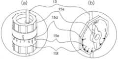
정맥에 수액을 투여하는 정맥주사(IV) 시스템은, 도 1에 도시된 바와 같이, 수액이 담긴 수액병(1)과, 상기 수액병(1)의 밀폐용 마개에 삽입되어 수액이 수액병(1)으로부터 흘러나오게 하는 삽입침(11)과, 삽입침(11)의 하단에 고정되어 내부에서 수액을 점적(12a, drop, 단위:gtt)의 형태로 떨어지게 하는 드립챔버(12, Drip Chamber)와, 정맥에 삽입되는 주사바늘(14)과, 드립챔버(12)와 주사바늘(14) 사이를 연결하여 수액의 주입 통로 역할을 하는 튜브(13)와, 튜브(13)의 중간에 장착되어 수액의 유량을 조절 가능하게 하는 수액유량 조절기(15)로 구성된다.In the intravenous (IV) system for administering an intravenous fluid, as shown in FIG. 1 , the
일반적으로 삽입침(11), 드립챔버(12), 튜브(13), 주사바늘(14) 및 수액유량 조절기(15)를 하나의 세트로 제작하며, 이와 같이 제작된 세트를 수액세트(10)라고 한다. 그리고, 수액세트(10)를 수액병(1)에 연결하여 수액을 주입한 후에 동일 환자에게 연속으로 수액을 주입할 경우에 소진된 수액병(1)만 교체하기도 한다.In general, the
또한, 드립챔버(12)의 내부에서 떨어지는 점적(12a)은 수액이 물방울 형태로 낙하하는 것으로서 일정한 부피를 갖도록 삽입침(11) 및 드립챔버(12)를 제작하며, 예를 들면, 수액 1cc당 20점적이 되게 제작하면 1개의 점적 부피는 1/20cc가 되고, 수액 1cc당 60점적이 되게 제작하면 1개의 점적 부피는 1/60cc가 된다. 따라서, 드립챔버(12) 내부에서 점적이 떨어지는 주기를 측정하면 수액세트(10)를 통해 주입되는 수액의 유량을 산출할 수 있다.In addition, the
한편, 수액을 환자에게 주입할 때에는 수액의 종류, 수액에 혼합한 약제의 종류, 환자의 상태, 앓고 있는 병의 종류 등에 따라 주입 유량을 처방하여서, 처방한 유량으로 주입되도록 수액유량 조절기(15)를 조절한다.On the other hand, when injecting an infusion into a patient, the infusion
여기서, 주입되는 수액의 유량을 처방 유량에 맞추지 못하면 자칫 의료사고의 원인이 되기도 하므로 수액의 유량 조절은 매우 중요하며, 이러한 수액유량 조절기(15)는 튜브(13)를 통한 수액의 통과 단면적을 조절하는 조작부(15a)를 갖추고 있어서 조작부(15a)의 조작으로 수액의 주입 유량을 조절할 수 있다.Here, if the flow rate of the injected infusion is not matched to the prescribed flow rate, it may cause a medical accident, so it is very important to control the flow rate of the infusion. It is provided with the
도 1에 도시된 수액유량 조절기(15)는, 일명 롤러클램프(Roller Clamp)라고 명명되는 타입으로서, 조작부(15a)를 롤러 타입으로 구비한다. 자세히 살펴보면, 상하를 개방한 홈(15b)에 튜브(13)를 끼워 관통시킨 후에 튜브(13)를 누르는 롤러(15a)를 장요홈(15c)에 가이드시키며 상하 이동할 수 있게 구성된다. 여기서, 홈(15b)의 깊이는 하부로 갈수록 얕아서 롤러(15a)를 하부로 이동시킬수록 튜브(15)를 더욱 눌려지게 하므로, 롤러(15a)를 이동시켜가며 이동 위치마다 유량을 측정하여 원하는 유량이 될 때에 롤러(15a)의 이동을 멈추는 방식으로 수입의 주입 유량을 조절한다.The infusion fluid
하지만, 상기 도 1에 도시된 롤러클램프 타입의 수액유량 조절기(15)는, 롤러 타입의 조작부(15a)를 매번 이동시킬 때마다 드립챔버(12)를 보며 유량을 측정해야 하므로, 번거로운 측정작업을 반복해야 했고, 유량조절의 정확성도 떨어졌다.However, in the roller clamp type infusion
도 2는 수액유량 조절기(15)의 종류 중에 아이브이 플로우 레귤레이터(IV Flow Regulator) 타입을 보여주는 도면으로서, 이와 같은 아이브이 플로우 레귤레이터(IV Flow Regulator) 타입의 수액유량 조절기(15)는 다이얼(dial)처럼 돌릴 수 있게 한 조작부(15a)를 유량을 수치(15e)로 병기한 눈금(15d)에 맞추어 한번의 조작으로 유량을 조절할 수 있게 구성된다. 이는 주입하려는 수액 유량값이 새겨진 수치(15e)의 눈금(15d)에 조작부(15a)를 맞추면 그 수치(15e)에 대응되는 유량으로 수액이 주입되도록 수액 통로(미도시) 단면적을 조절하는 구조를 갖추었기 때문이다. 여기에 새겨진 수치(15e)는 수액유량 조절기의 제작시에 지정한 기준 높이에 수액병(1)을 걸어놓고 수액세트(10)를 셋팅한 후에 주입되는 유량을 측정하여 얻어진 값으로서, 이에 따라, 수액병(1)을 기준 높이에 걸어놓고 수치(15e)를 맞추어가며 유량을 간편하게 조절할 수 있다.2 is a view showing an IV Flow Regulator type among the types of the IV Flow Regulator 15. This IV Flow Regulator type IV Flow Regulator 15 is a dial (dial). ) is configured to adjust the flow rate in one operation by matching the
하지만, 정맥주사 시스템으로 주입되는 수액의 유량은 수액병(1)의 설치 높이만으로 결정되는 것이 아니라, 수액의 종류에 따른 수액의 점도, 주사바늘(14)의 굵기, 환자의 정맥압, 튜브의 굵기, 튜브의 제질, 주변 온도, 기압 등의 다양한 요인에 의해서 결정되므로, 실제 사용 시에는 상술한 아이브이 플로우 레귤레이터(IV Flow Regulator) 타입의 수액유량 조절기(15)에 새겨진 수치(15e)로 지시되는 유량과 조작부(15a)를 수치(15e)에 맞춘 상태에서 실제 측정된 유량 사이에는 차이가 크게 나타난다. 이에 따라, 새겨진 수치(15e)에 맞게 조작부(15e)를 조작한 후에라도 롤러클램프 타입의 수액유량 조절기와 마찬가지로 유량 측정과정을 반복하며 조절해야만 하였다.However, the flow rate of the infusion injected into the intravenous system is not determined only by the installation height of the
그러나 이러한 수액세트용 유량조절기는 낙하하는 수액량을 조절하기 위한 것에 불과하여, 수액 봉지에 유량이 얼마나 남았는지를 판단할 수가 없고, 이러한 이유때문에 간호사가 수시로 병실로 출입하여 수액 백의 남은 량을 육안으로 살펴봐야 하는 문제점이 있었다.However, this flow controller for the infusion set is only for controlling the amount of infusion that falls, and it is impossible to determine how much flow is left in the infusion bag. There was a problem that had to be looked into.
다른 한편으로는, 환자나 보호자 또는 제 3자가 수액세트용 유량 조절기를 임의로 조정하여서 환자에게 적정한 유량이 투여되지 못하게 하는 사례가 발생할 수 있는 문제점이 있는 것이다.On the other hand, there is a problem that the patient, guardian, or a third party arbitrarily adjusts the flow rate controller for the infusion set, so that an appropriate flow rate may not be administered to the patient.
따라서, 보다 안전하고 신뢰성이 있으면서, 간호병동의 스테이션에서 유량 체크가 가능할 수 있도록 하는 수액세트용 유량조절기에 대한 요구가 지속적으로 있어 왔다.Therefore, while being safer and more reliable, there has been a continuous demand for a flow rate regulator for an infusion set that enables a flow rate check at a station of a nursing ward.
본 발명의 목적은 상기 문제점을 해결하기 위하여 안출된 것으로서, 수액세트로부터 낙하하는 수액량을 측정하여 수액 백의 교체시기를 알 수 있도록 한 스마트화 모니터링이 가능한 수액세트용 유량조절기를 제공하는 데 있다.It is an object of the present invention to provide a flow rate controller for an infusion set capable of smart monitoring that measures the amount of infusion falling from the infusion set to know when to replace the infusion bag.
본 발명의 다른 목적은 압전소자를 이용하여 유량조절기의 유량조절 변동 내용을 모니터링할 수 있도록 하는 스마트화 모니터링이 가능한 수액세트용 유량조절기를 제공하는 데 있다.Another object of the present invention is to provide a flow rate controller for an infusion set capable of smart monitoring that enables monitoring of changes in the flow rate control of the flow rate controller using a piezoelectric element.
상기 목적을 달성하기 위하여, 본 발명의 일 실시예에 따른 스마트화 모니터링이 가능한 수액세트용 유량조절기는, 수액 백과 연결된 상부튜브가 결합되는 상부레버, 상기 상부레버와 결합되며 수액출구를 일체로 구비하는 하부레버 및 상기 상부레버와 상기 하부레버 사이에 설치되는 시일부재를 포함하는 수액세트용 유량조절기에 있어서,In order to achieve the above object, the flow regulator for an infusion set capable of smart monitoring according to an embodiment of the present invention includes an upper lever to which an upper tube connected to an infusion bag is coupled, and an infusion outlet to be combined with the upper lever. In the flow regulator for an infusion set comprising a lower lever and a sealing member installed between the upper lever and the lower lever,
상기 수액출구와 하부튜부 사이에 결합되어 낙하하는 수액량을 측정하는 유량체크기를 더 포함하고, 상기 유량체크기는 낙하하는 유량측정센서와 외부와 통신할 수 있는 통신모듈을 포함하는 것을 특징으로 한다.Further comprising a flow rate checker coupled between the infusion outlet and the lower tube to measure the amount of falling infusion, the flow rate checker is characterized in that it comprises a communication module capable of communicating with the falling flow rate sensor and the outside.
상기 수액출구의 일정 부분에는 결합요홈이 형성되어 있고, 상기 유량체크기의 내측에는 상기 결합요홈에 대응하는 환형 돌부가 형성되어 있는 것을 특징으로 한다.A coupling groove is formed in a certain portion of the infusion outlet, and an annular protrusion corresponding to the coupling groove is formed inside the flow rate checker.
상기 상부레버의 저면부에는 수액이 관통하는 상부관통공이 형성되고, 상기 상부관통공과 연통되어 원형의 수액이동로가 형성되며,An upper through-hole through which the sap passes is formed in the lower surface of the upper lever, and a circular sap passage is formed in communication with the upper through-hole,
상기 수액이동로는 상부관통공과 연통하는 쪽의 깊이가 깊고, 상기 상부관통공으로부터 멀어지는 원주방향을 따라서 그 깊이가 점점 낮아지게 형성되는 것을 특징으로 한다.The fluid passageway is characterized in that the depth of the side communicating with the upper through-hole is deep, and the depth is formed to be gradually lowered along the circumferential direction away from the upper through-hole.
상기 시일부재의 일측에는 수액이 통과하는 통과홀이 형성되고, 상기 시일부재의 일측벽에는 돌부가 돌출형성되는 것을 특징으로 한다.A passage hole through which the sap passes is formed on one side of the sealing member, and a protrusion is formed on one side wall of the sealing member.
상기 하부레버의 상면부에는 하부관통공이 형성되어 있고, 일측에는 상기 시일부재의 돌부가 삽입될 수 있는 요부가 형성되어 있으며,A lower through-hole is formed in the upper surface of the lower lever, and a recess into which the protrusion of the sealing member can be inserted is formed on one side,
상기 시일부재의 통과홀과 상기 하부레버의 하부관통공은 동심으로 마주하여 배치되는 것을 특징으로 한다.The through hole of the sealing member and the lower through hole of the lower lever are concentrically disposed to face each other.
본 발명의 일 실시예에 따른 스마트화 모니터링이 가능한 수액세트용 유량조절기는, 수액 백과 연결된 상부튜브가 결합되는 제 2상부레버 및 상기 제 2상부레버와 결합되며 하부튜브와 연결되는 수액출구를 일체로 구비하는 제 2하부레버를 포함하는 수액세트용 유량조절기에 있어서,The flow regulator for an infusion set capable of smart monitoring according to an embodiment of the present invention includes a second upper lever to which an upper tube connected to an infusion bag is coupled, and an infusion outlet connected to the lower tube and coupled to the second upper lever. In the flow regulator for an infusion set comprising a second lower lever provided with
상기 제 2상부레버의 저면 중앙부에 위치하며, 수액이 관통하는 제 2상부관통공이 연통되도록 형성된 원형의 제 2수액이동로; 상기 제 2수액이동로의 반경방향 외곽에 위치하며, 일측에 누름볼이 일체로 형성된 원형의 압력탐지로; 상기 제 2상부레버의 제 2수액이동로 저면부에 설치되고, 일측에 제 2통과홀이 형성된 원형의 제 2시일부재; 상기 압력탐지로에 면접하도록 구성되고, 상부벽에 원형의 볼 수용요부가 형성된 압력전달부재; 및 상기 압력전달부재의 하단과 상기 제 2하부레보 사이에 설치되는 압전소자;를 포함하는 것을 특징으로 한다.a circular second fluid passageway positioned at the center of the bottom surface of the second upper lever and formed to communicate with a second upper through-hole through which the sap passes; a circular pressure detection furnace that is located on the radially outward side of the second fluid passage and has a pressing ball integrally formed on one side; a circular second sealing member installed on the lower surface of the second fluid passageway of the second upper lever and having a second passage hole on one side; a pressure transmission member configured to face the pressure detection furnace and formed with a circular ball receiving recess on an upper wall; and a piezoelectric element installed between the lower end of the pressure transmission member and the second lower lever.
상기 제 2수액이동로는 제 2상부관통공과 연통하는 쪽의 깊이가 깊고, 상기 제 2상부관통공으로부터 멀어지는 원주방향을 따라서 그 깊이가 점점 낮아지게 형성되는 것을 특징으로 한다.The second fluid passageway is characterized in that the depth of the side communicating with the second upper through-hole is deep, and the depth is formed to gradually decrease along the circumferential direction away from the second upper through-hole.
상기 제 2하부레버의 상면부에는 제 1안착부와 그에 인접한 외측에 제 2안착부가 형성되고, 상기 제 1안착부의 일측에제 2하부관통공이 형성되는 것을 특징으로 한다.A second seating part is formed on an upper surface of the second lower lever on an outer side adjacent to the first seating part, and a second lower through hole is formed on one side of the first seating part.
상기 압력전달부재의 볼 수용요부는 시작점으로부터 원주방향을 따라서 그 깊이가 점점 낮아지는 형상을 취하는 것을 특징으로 한다.The ball receiving recess of the pressure transmission member is characterized in that it takes a shape in which the depth gradually decreases along the circumferential direction from the starting point.
상기 제 1안착부에는 상기 제 2시일부재가 안착되고, 상기 제 2안착부에는 압전소자가 안착되고 상기 압전소자의 상단에는 압력전달부재가 설치되는 것을 특징으로 한다.The second sealing member is seated on the first seating part, a piezoelectric element is seated on the second seating part, and a pressure transmitting member is installed on an upper end of the piezoelectric element.
본 발명에 따르면, 수액세트로부터 낙하하는 수액량을 측정하여 수액 백의 교체시기를 알 수 있는 효과가 있다. 즉, 유량조절기의 일측에 시간당 낙하 용량을 계산하여 수액 백에 용량이 어느 정도 남았을 때 알람이 울릴 수 있게 한다.According to the present invention, there is an effect of knowing the replacement time of the infusion bag by measuring the amount of infusion falling from the infusion set. That is, by calculating the hourly drop capacity on one side of the flow controller, an alarm can sound when there is a certain amount of capacity left in the infusion bag.
본 발명에 따르면, 압전소자를 이용하여 유량조절기 내부의 상레버와 하레버 상의 압력을 측정함으로써, 환자, 보호자 또는 제3자에 의한 유량조절기 임의 변동 내용을 모니터링할 수 있는 효과가 있다.According to the present invention, by measuring the pressure on the upper lever and the lower lever inside the flow controller using a piezoelectric element, there is an effect that can monitor arbitrary changes in the flow controller by a patient, guardian, or a third party.
도 1은 종래 수액세트의 설치 상태 및 수액세트에 장착되는 수액유량 조절기를 도시한 사시도이다.
도 2는 종래에 따른 다른 형태의 수액유량 조절기를 도시한 사시도이다.
도 3은 본 발명의 제 1실시예에 따른 수액세트용 유량조절기의 사시도이다.
도 4는 도 3의 분해사시도이다.
도 5는 도 3의 단면도이다.
도 6은 본 발명의 제 2실시예에 따른 수액세트용 유량조절기의 사시도이다.
도 7은 도 6의 분해사시도이다.
도 8은 도 6의 단면도이다.
도 9는 도 8의 사용상태 단면도이다.
도 10은 본 발명의 제 2실시예에 따른 수액세트용 유량조절기의 동작을 설명하기 위한 개략도이다.1 is a perspective view illustrating an installation state of a conventional infusion set and an infusion flow rate regulator mounted to the infusion set.
Figure 2 is a perspective view showing another type of fluid flow regulator according to the prior art.
3 is a perspective view of a flow rate regulator for an infusion set according to a first embodiment of the present invention.
4 is an exploded perspective view of FIG. 3 .
FIG. 5 is a cross-sectional view of FIG. 3 .
6 is a perspective view of a flow rate regulator for an infusion set according to a second embodiment of the present invention.
7 is an exploded perspective view of FIG. 6 .
FIG. 8 is a cross-sectional view of FIG. 6 .
9 is a cross-sectional view of the use state of FIG.
Figure 10 is a schematic diagram for explaining the operation of the flow regulator for the infusion set according to the second embodiment of the present invention.
이하, 첨부된 도면을 참조하여 본 발명에 따른 스마트화 모니터링이 가능한 수액세트용 유량조절기에 대하여 상세히 설명한다.Hereinafter, with reference to the accompanying drawings, it will be described in detail with respect to the flow rate controller for an infusion set capable of smart monitoring according to the present invention.
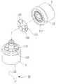
도 3은 본 발명의 제 1실시예에 따른 수액세트용 유량조절기의 사시도이고, 도 4는 도 3의 분해사시도이며, 도 5는 도 3의 단면도이다.3 is a perspective view of a flow rate regulator for an infusion set according to a first embodiment of the present invention, FIG. 4 is an exploded perspective view of FIG. 3 , and FIG. 5 is a cross-sectional view of FIG.
도 3 내지 도 4에 도시된 바와 같이, 본 발명에 따른 수액세트용 유량조절기는, 크게 수액 백과 연결된 상부튜브(1)가 결합되는 상부레버(3), 상기 상부레버(3)와 결합되며 수액출구(6)를 일체로 구비하는 하부레버(5), 상기 수액출구(6)에 결합되어 낙하하는 수액량을 측정하는 유량체크기(10) 및 상기 유량체크기(10)와 주사바늘 사이를 연결하는 하부튜브(9)를 포함한다.3 to 4, the flow regulator for an infusion set according to the present invention is largely coupled to the
상기 상부레버(3)와 상기 하부레버(5) 사이에는 눈금부(7)를 구비하고 있어서, 사용자가 눈금부(7)의 표시를 확인하면서 낙하하는 수액의 유량을 용이하게 조절할 수 있는 것이다.A scale part 7 is provided between the
상기 수액출구(6)의 일정 부분에는 결합요홈(8)이 형성되어 있고, 상기 유량체크기(10)의 내측에는 상기 결합요홈에 대응하는 환형 돌부가 형성되어 있어서, 상기 유량체크기(10)를 상기 수액출구(6)에 삽입할 때 상기 환형돌부가 상기 결합요홈(8)에 끼워지면서, 상기 수액출구(6)에 상기 유량체크기(10)가 견고하게 결합될 수 있는 것이다.A
상기 상부레버(3)는 상기 하부레버(5)에 대하여 회전할 수 있고, 그 회전에 따라서 낙하하는 유량을 조절할 수 있는 것이다.The
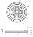
또한, 본 발명에 따른 수액세트용 유량조절기의 내부구조를 좀 더 구체적으로 살펴보면, 상기 상부레버(3)의 저면부에는 수액이 관통하는 상부관통공(113)이 형성되고, 상기 상부관통공(113)과 연통되어 원형의 수액이동로(111)가 형성되어 있다.In addition, looking at the internal structure of the flow regulator for an infusion set according to the present invention in more detail, an upper through-
상기 수액이동로(111)는 상부관통공(113)과 연통하는 쪽의 깊이가 깊고, 상기 상부관통공(113)으로부터 멀어지는 원주방향을 따라서 그 깊이가 점점 낮아지게 형성된다.The
상기 상부레버(3)의 저면부와 상기 하부레버(5)의 상면부 사이에는 원형의 시일부재(120)가 설치된다. 상기 시일부재(120)은 상기 수액이동로(111)과 면접하면서 수액이 누수되지 않도록 하는 역할을 하게 된다.A
상기 시일부재(120)의 일측에는 통과홀(123)이 형성되어 있으며, 상기 통과홀(123)이 상기 수액이동로(111)와 마주치는 지점에서 그 깊이에 따라 흐르는 수액을 통과시킬 수 있는 것이다. 또한 상기 시일부재(120)의 일측벽에는 돌부(121)이 돌출형성되어 있어서, 상기 시일부재(120)가 상기 하부레버(5)의 상면부에 움직이지 않고 안착될 수 있도록 한다.A
상기 하부레버(5)의 상면부에는 하부관통공(133)이 형성되어 있고, 일측에는 상기 시일부재(120)의 돌부(121)가 삽입될 수 있는 요부(131)가 형성되어 있다. 이때, 상기 시일부재(120)의 통과홀(123)과 상기 하부레버(5)의 하부관통공(133)은 동심으로 마주하여 배치되어야만 한다.A lower through
따라서, 상기 상부레버(3)를 회전시켜서 눈금부(7)를 확인하면서 낙하 유량을 조절할 때, 상기 수액이동로(111)의 깊이에 해당하는 만큼의 수액 유량이 상기 시일부재(120)의 통과홀(123)을 통과하여 상기 하부레버(5)의 하부관통공(133)을 통해 배출될 수 있는 것이다.Therefore, when adjusting the falling flow rate while checking the scale part 7 by rotating the
상기 유량체크기(10)의 내부에는 유량측정센서와 통신모듈이 포함될 수 있다. 유량측정센서는 낙하하는 수액의 유량을 측정할 수 있으며, 통신모듈은 유량측정센서를 통해서 측정된 유량 수치를 간호사 병동 스테이션에 알림으로써, 간호사가 언제든지 많은 환자들의 수액백 교체시기를 확인할 수 있도록 할 수 있다.The
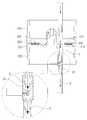
도 6은 본 발명의 제 2실시예에 따른 수액세트용 유량조절기의 사시도이고, 도 7은 도 6의 분해사시도이고, 도 8은 도 6의 단면도이며, 도 9는 도 8의 사용상태 단면도이다.6 is a perspective view of a flow rate regulator for an infusion set according to a second embodiment of the present invention, FIG. 7 is an exploded perspective view of FIG. 6 , FIG. 8 is a cross-sectional view of FIG. 6, and FIG. .
본 발명의 제 2실시예에 따른 수액세트용 유량조절기 낙하하는 유량을 측정함과 동시에 압전소자와 누름볼을 이용하여 간호사 이외에 환자, 보호자 또는 제 3자가 유량조절기를 조정했을 때, 그러한 상황을 모니터링 할 수 있도록 하는 구성을 포함한다.The flow regulator for infusion set according to the second embodiment of the present invention measures the falling flow rate and monitors such a situation when a patient, guardian, or a third person other than a nurse adjusts the flow regulator using a piezoelectric element and a push ball at the same time configuration that allows it to be done.
도 6 내지 도 9를 참조하면, 본 발명의 제 2실시예에 따른 수액세트용 유량조절기는, 크게 수액 백과 연결된 상부튜브(1)가 결합되는 제 2상부레버(210), 상기 제 2상부레버(210)와 결합되며 수액출구(6)를 일체로 구비하는 제 2하부레버(230), 상기 수액출구(6)에 결합되어 낙하하는 수액량을 측정하는 유량체크기(10) 및 상기 유량체크기(10)와 주사바늘 사이를 연결하는 하부튜브(9)를 포함한다.6 to 9 , the flow regulator for an infusion set according to a second embodiment of the present invention includes a second
또한, 상기와 같은 외부의 구성요소들은 본 발명의 제 1실시예의 구성과 동일 또는 유사하며 그에 대한 구체적인 설명은 상기에 언급된 내용을 참고할 수 있다.In addition, the external components as described above are the same as or similar to those of the first embodiment of the present invention, and for detailed description thereof, reference may be made to the above-mentioned contents.
상기 제 2상부레버(210)의 저면부에는 수액이 관통하는 제 2상부관통공(213)이 형성되고, 상기 제 2상부관통공(213)과 연통되어 원형의 제 2수액이동로(211)가 형성되어 있다.A second upper through-
상기 제 2수액이동로(211)는 제 2상부관통공(213)과 연통하는 쪽의 깊이가 깊고, 상기 제 2상부관통공(213)으로부터 멀어지는 원주방향을 따라서 그 깊이가 점점 낮아지게 형성된다.The
또한, 상기 제 2수액이동로(211)의 반경방향 외곽에는 원형의 압력탐지로(215)가 형성되어 있으며, 상기 압력탐지로(215)의 일측에는 누름볼(217)이 일체로 형성되어 있다.In addition, a circular pressure detection passage 215 is formed on the radially outer side of the
상기 제 2상부레버(210)의 제 2수액이동로(211) 저면부에는 원형의 제 2시일부재(220)가 설치된다. 상기 제 2시일부재(220)는 상기 제 2수액이동로(211)과 면접하면서 수액이 누수되지 않도록 하는 역할을 하게 된다.A circular second sealing member 220 is installed on the lower surface of the
상기 제 2시일부재(220)의 일측에는 제 2통과홀(223)이 형성되어 있으며, 상기 제 2통과홀(223)이 상기 제 2수액이동로(211)와 마주치는 지점에서 그 깊이에 따라 흐르는 수액을 통과시킬 수 있는 것이다. 또한 상기 제 2시일부재(220)의 일측벽에는 제 2돌부(221)이 돌출형성되어 있어서, 상기 제 2시일부재(220)가 상기 제 2하부레버(230)의 상면부에 움직이지 않고 안착될 수 있도록 한다.A second passage hole 223 is formed at one side of the second sealing member 220 , and at a point where the second passage hole 223 meets the
상기 제 2하부레버(230)의 상면부에는 제 1안착부(235)와 그에 인접한 외측에 제 2안착부(237)가 형성되어 있다. 상기 제 1안착부(235)의 일측에제 2하부관통공(233)이 형성되어 있고, 일측에는 상기 제 2시일부재(220)의 제 2돌부(221)가 삽입될 수 있는 제 2요부(231)가 형성되어 있다. 이때, 상기 제 2시일부재(220)의 제 2통과홀(223)과 상기 제 2하부레버(230)의 제 2하부관통공(233)은 동심으로 마주하여 배치되어야만 한다.A
따라서, 상기 제 2상부레버(210)를 회전시켜서 낙하 유량을 조절할 때, 상기 제 2수액이동로(211)의 깊이에 해당하는 만큼의 수액 유량이 상기 제 2시일부재(220)의 제 2통과홀(223)을 통과하여 상기 제 2하부레버(230)의 제 2하부관통공(233)을 통해 배출될 수 있는 것이다.Therefore, when the falling flow rate is adjusted by rotating the second
또한, 상기 제 1안착부(235)에는 상기 제 2시일부재(220)가 안착되고, 상기 제 2안착부(237)에는 압전소자(240)가 안착되고 상기 압전소자(240)의 상단에는 압력전달부재(250)가 설치된다.In addition, the second sealing member 220 is seated on the
상기 압력전달부재(250)는 그 상부벽에 볼 수용요부(255)가 원형으로 형성되어 있으며, 상기 볼 수용요부(255)는 시작점으로부터 원주방향을 따라서 그 깊이가 점점 낮아지는 형상을 취하는 것이 바람직하다. 예를들어, 상기 볼 수용요부(255)에는 상기 누름볼(217)이 수용될 수 있으며, 사용자가 상기 제 2상부레버(210)를 상기 제 2하부레버(230)에 대하여 회전시킬 때 상기 누름볼(217)은 상기 볼 수용요부(255)의 깊이 단차를 따라서 이동할 수 있는 것이다.It is preferable that the
도 8을 참조하면, 확대도 S1에서 압력전달부재(250)의 볼 수용요부(255)는 요부의 깊이가 낮아서, 누름볼(217)이 위치할 때 압전소자(240)에 강한 압력을 제공하게 된다. 그에 대비해서, 확대도 S2에서 압력전달부재(250)의 볼 수용요부(2550는 요부의 깊이가 깊어서, 누름볼(217)이 위치할 때 압전소자(240)에 보다 약한 압력을 제공하게 되는 것이다.Referring to FIG. 8, in the enlarged view S1, the
따라서, 도 10에 도시된 바와 같이, 최초 간호사가 A라는 위치에 유량조절기를 맞춰 놓은 상태에서, 제3자가 유량조절기를 회전시켜서 B라는 위치로 조절하게 되면 압전소자에 감지되는 압력이 변하면서, 간호사 병동의 스테이션에서 모니터링을 통해서 쉽게 알 수 있는 것이다.Therefore, as shown in FIG. 10, when the first nurse adjusts the flow controller to position B by rotating the flow controller in a state where the first nurse sets the flow controller to position A, the pressure sensed by the piezoelectric element changes, This can be easily identified through monitoring at the station in the nurse's ward.
상기와 같은 내용의 본 발명이 속하는 기술분야의 당업자는 본 발명의 기술적 사상이나 필수적 특징을 변경하지 않고서 다른 구체적인 형태로 실시될 수 있다는 것을 이해할 수 있을 것이다. 그러므로 이상에서 기술한 실시 예들은 모든 면에서 예시된 것이며 한정적인 것이 아닌 것으로서 이해해야만 한다.Those skilled in the art to which the present invention of the above contents pertain will be able to understand that the present invention may be implemented in other specific forms without changing the technical spirit or essential features of the present invention. Therefore, it should be understood that the embodiments described above are illustrative in all aspects and not restrictive.
1: 상부튜브3: 상부레버
5: 하부레버7: 눈금부
6: 수액출구10: 유량 체크기
111: 수액이동로113: 상부관통공
121: 돌부123: 통과홀
131: 요부133: 하부관통공1: Upper tube 3: Upper lever
5: Lower lever 7: Graduation part
6: Fluid outlet 10: Flow checker
111: sap transfer-ro 113: upper through hole
121: stone 123: through hole
131: recess 133: lower through hole
Claims (10)
Translated fromKorean상기 수액출구와 하부튜부 사이에 결합되어 낙하하는 수액량을 측정하는 유량체크기를 더 포함하고,
상기 유량체크기는 낙하하는 유량측정센서와 외부와 통신할 수 있는 통신모듈을 포함하는 것을 특징으로 하는 수액세트용 유량조절기.In a flow regulator for an infusion set, comprising an upper lever to which an upper tube connected to an infusion bag is coupled, a lower lever coupled to the upper lever and integrally provided with an infusion outlet, and a sealing member installed between the upper lever and the lower lever ,
Further comprising a flow rate checker coupled between the infusion outlet and the lower tube to measure the amount of falling infusion,
The flow rate checker is a flow rate regulator for an infusion set, characterized in that it comprises a communication module that can communicate with the falling flow rate sensor and the outside.
상기 수액출구의 일정 부분에는 결합요홈이 형성되어 있고, 상기 유량체크기의 내측에는 상기 결합요홈에 대응하는 환형 돌부가 형성되어 있는 것을 특징으로 하는 수액세트용 유량조절기.The method of claim 1,
A portion of the infusion outlet is formed with a coupling groove, and an annular protrusion corresponding to the coupling groove is formed inside the flow rate checker.
상기 상부레버의 저면부에는 수액이 관통하는 상부관통공이 형성되고, 상기 상부관통공과 연통되어 원형의 수액이동로가 형성되며,
상기 수액이동로는 상부관통공과 연통하는 쪽의 깊이가 깊고, 상기 상부관통공으로부터 멀어지는 원주방향을 따라서 그 깊이가 점점 낮아지게 형성되는 것을 특징으로 하는 수액세트용 유량조절기.The method of claim 1,
An upper through-hole through which the sap passes is formed in the lower surface of the upper lever, and a circular sap passage is formed in communication with the upper through-hole,
The infusion passageway has a deeper depth on the side communicating with the upper through-hole, and the depth of the infusion set flow controller is formed to gradually decrease along the circumferential direction away from the upper through-hole.
상기 시일부재의 일측에는 수액이 통과하는 통과홀이 형성되고, 상기 시일부재의 일측벽에는 돌부가 돌출형성되는 것을 특징으로 하는 수액세트용 유량조절기.4. The method of claim 3,
A passage hole through which the infusion passes is formed at one side of the sealing member, and a protrusion is formed on one side wall of the sealing member.
상기 하부레버의 상면부에는 하부관통공이 형성되어 있고, 일측에는 상기 시일부재의 돌부가 삽입될 수 있는 요부가 형성되어 있으며,
상기 시일부재의 통과홀과 상기 하부레버의 하부관통공은 동심으로 마주하여 배치되는 것을 특징으로 하는 수액세트용 유량조절기.5. The method of claim 4,
A lower through-hole is formed in the upper surface of the lower lever, and a recess into which the protrusion of the sealing member can be inserted is formed on one side,
The flow rate regulator for an infusion set, characterized in that the through hole of the sealing member and the lower through hole of the lower lever are arranged to face concentrically.
상기 제 2상부레버의 저면 중앙부에 위치하며, 수액이 관통하는 제 2상부관통공이 연통되도록 형성된 원형의 제 2수액이동로;
상기 제 2수액이동로의 반경방향 외곽에 위치하며, 일측에 누름볼이 일체로 형성된 원형의 압력탐지로;
상기 제 2상부레버의 제 2수액이동로 저면부에 설치되고, 일측에 제 2통과홀이 형성된 원형의 제 2시일부재;
상기 압력탐지로에 면접하도록 구성되고, 상부벽에 원형의 볼 수용요부가 형성된 압력전달부재; 및
상기 압력전달부재의 하단과 상기 제 2하부레보 사이에 설치되는 압전소자;를 포함하는 것을 특징으로 하는 수액세트용 유량조절기.In the flow controller for an infusion set, comprising a second upper lever coupled to an upper tube connected to an infusion bag and a second lower lever integrally provided with an infusion outlet connected to the second upper lever and connected to the lower tube,
a circular second fluid passageway positioned at the center of the bottom surface of the second upper lever and formed to communicate with a second upper through-hole through which the sap passes;
a circular pressure detection furnace that is located on the radially outer side of the second fluid passage and has a pressing ball integrally formed on one side;
a circular second sealing member installed on the lower surface of the second sap passage of the second upper lever and having a second passage hole on one side;
a pressure transmission member configured to face the pressure detection furnace and formed with a circular ball receiving recess on the upper wall; and
A piezoelectric element installed between the lower end of the pressure transmitting member and the second lower lever; Flow regulator for infusion set comprising a.
상기 제 2수액이동로는 제 2상부관통공과 연통하는 쪽의 깊이가 깊고, 상기 제 2상부관통공으로부터 멀어지는 원주방향을 따라서 그 깊이가 점점 낮아지게 형성되는 것을 특징으로 하는 수액세트용 유량조절기.7. The method of claim 6,
The second fluid passageway has a greater depth on the side communicating with the second upper through-hole, and the depth of the second infusion set flow controller is formed to gradually decrease along the circumferential direction away from the second upper through-hole.
상기 제 2하부레버의 상면부에는 제 1안착부와 그에 인접한 외측에 제 2안착부가 형성되고, 상기 제 1안착부의 일측에제 2하부관통공이 형성되는 것을 특징으로 하는 수액세트용 유량조절기.7. The method of claim 6,
A flow regulator for an infusion set, characterized in that the first seating part and the second seating part are formed on the outer side adjacent to the first seating part on the upper surface of the second lower lever, and a second lower through hole is formed on one side of the first seating part.
상기 압력전달부재의 볼 수용요부는 시작점으로부터 원주방향을 따라서 그 깊이가 점점 낮아지는 형상을 취하는 것을 특징으로 하는 수액세트용 유량조절기.7. The method of claim 6,
A flow regulator for an infusion set, characterized in that the ball receiving portion of the pressure transmission member takes a shape in which the depth gradually decreases along the circumferential direction from the starting point.
상기 제 1안착부에는 상기 제 2시일부재가 안착되고, 상기 제 2안착부에는 압전소자가 안착되고 상기 압전소자의 상단에는 압력전달부재가 설치되는 것을 특징으로 하는 수액세트용 유량조절기.
9. The method of claim 8,
The flow regulator for an infusion set, characterized in that the second sealing member is seated on the first seating part, a piezoelectric element is seated on the second seating part, and a pressure transmitting member is installed on the upper end of the piezoelectric element.
Priority Applications (1)
| Application Number | Priority Date | Filing Date | Title |
|---|---|---|---|
| KR1020200024047AKR102405751B1 (en) | 2020-02-27 | 2020-02-27 | Flow rate regulator for intravenous fluid therapy capable of smart type monitoring |
Applications Claiming Priority (1)
| Application Number | Priority Date | Filing Date | Title |
|---|---|---|---|
| KR1020200024047AKR102405751B1 (en) | 2020-02-27 | 2020-02-27 | Flow rate regulator for intravenous fluid therapy capable of smart type monitoring |
Publications (2)
| Publication Number | Publication Date |
|---|---|
| KR20210109157Atrue KR20210109157A (en) | 2021-09-06 |
| KR102405751B1 KR102405751B1 (en) | 2022-06-08 |
Family
ID=77782376
Family Applications (1)
| Application Number | Title | Priority Date | Filing Date |
|---|---|---|---|
| KR1020200024047AActiveKR102405751B1 (en) | 2020-02-27 | 2020-02-27 | Flow rate regulator for intravenous fluid therapy capable of smart type monitoring |
Country Status (1)
| Country | Link |
|---|---|
| KR (1) | KR102405751B1 (en) |
Cited By (4)
| Publication number | Priority date | Publication date | Assignee | Title |
|---|---|---|---|---|
| KR20230111560A (en)* | 2022-01-18 | 2023-07-25 | 마그닉스엔지니어링 (주) | Medical regulator with injection volume setting function |
| KR20230112518A (en)* | 2022-01-20 | 2023-07-27 | 마그닉스엔지니어링 (주) | Medical regulator with injection volume setting function |
| CN116808358A (en)* | 2023-05-18 | 2023-09-29 | 昆山安卓医疗科技有限公司 | Infusion flow regulator and infusion device |
| KR102692339B1 (en)* | 2023-08-31 | 2024-08-07 | (주)메딕프로코리아 | Regulatorintegrated drip chamber with locking device and infusion set including the same |
Citations (7)
| Publication number | Priority date | Publication date | Assignee | Title |
|---|---|---|---|---|
| JP2004533856A (en)* | 2000-07-31 | 2004-11-11 | アボット・ラボラトリーズ | Closed loop flow control for IV fluid delivery |
| KR101058539B1 (en) | 2011-02-23 | 2011-08-23 | 이두용 | Sap flow rate controller, Sap flow rate control set and Sap flow rate control method |
| US20130138075A1 (en)* | 2011-11-30 | 2013-05-30 | Emed Technologies Corp. (Nv) | Variable flow control device, system and method |
| JP2016013333A (en)* | 2014-07-03 | 2016-01-28 | サンリツオートメイション株式会社 | Transfusion safety apparatus and transfusion management system |
| KR20180015551A (en)* | 2016-08-03 | 2018-02-13 | 주식회사한빛엠디 | Flow Rate Monitering Device for Intravenous Fluid |
| KR101837519B1 (en) | 2017-12-22 | 2018-03-13 | (주)메디라인액티브코리아 | Flow regulator for medical infusion set |
| KR20190098802A (en)* | 2018-01-31 | 2019-08-23 | 임기현 | Sap monitoring system |
- 2020
- 2020-02-27KRKR1020200024047Apatent/KR102405751B1/enactiveActive
Patent Citations (7)
| Publication number | Priority date | Publication date | Assignee | Title |
|---|---|---|---|---|
| JP2004533856A (en)* | 2000-07-31 | 2004-11-11 | アボット・ラボラトリーズ | Closed loop flow control for IV fluid delivery |
| KR101058539B1 (en) | 2011-02-23 | 2011-08-23 | 이두용 | Sap flow rate controller, Sap flow rate control set and Sap flow rate control method |
| US20130138075A1 (en)* | 2011-11-30 | 2013-05-30 | Emed Technologies Corp. (Nv) | Variable flow control device, system and method |
| JP2016013333A (en)* | 2014-07-03 | 2016-01-28 | サンリツオートメイション株式会社 | Transfusion safety apparatus and transfusion management system |
| KR20180015551A (en)* | 2016-08-03 | 2018-02-13 | 주식회사한빛엠디 | Flow Rate Monitering Device for Intravenous Fluid |
| KR101837519B1 (en) | 2017-12-22 | 2018-03-13 | (주)메디라인액티브코리아 | Flow regulator for medical infusion set |
| KR20190098802A (en)* | 2018-01-31 | 2019-08-23 | 임기현 | Sap monitoring system |
Cited By (5)
| Publication number | Priority date | Publication date | Assignee | Title |
|---|---|---|---|---|
| KR20230111560A (en)* | 2022-01-18 | 2023-07-25 | 마그닉스엔지니어링 (주) | Medical regulator with injection volume setting function |
| KR20230112518A (en)* | 2022-01-20 | 2023-07-27 | 마그닉스엔지니어링 (주) | Medical regulator with injection volume setting function |
| CN116808358A (en)* | 2023-05-18 | 2023-09-29 | 昆山安卓医疗科技有限公司 | Infusion flow regulator and infusion device |
| KR102692339B1 (en)* | 2023-08-31 | 2024-08-07 | (주)메딕프로코리아 | Regulatorintegrated drip chamber with locking device and infusion set including the same |
| WO2025048479A1 (en)* | 2023-08-31 | 2025-03-06 | (주)메딕프로코리아 | Regulator-integrated drip chamber having locking device and infusion set comprising same |
Also Published As
| Publication number | Publication date |
|---|---|
| KR102405751B1 (en) | 2022-06-08 |
Similar Documents
| Publication | Publication Date | Title |
|---|---|---|
| KR102405751B1 (en) | Flow rate regulator for intravenous fluid therapy capable of smart type monitoring | |
| US12420013B2 (en) | IV flow management systems and methods | |
| US9814833B2 (en) | Pressure based refill status monitor for implantable pumps | |
| US8448523B2 (en) | Device and method for determining at least one flow parameter | |
| US8403908B2 (en) | Differential pressure based flow sensor assembly for medication delivery monitoring and method of using the same | |
| US6086561A (en) | Fluid delivery apparatus with reservoir fill assembly | |
| EP2296725B1 (en) | Cassette for differential pressure based medication delivery flow sensor assembly for medication delivery monitoring and method of making the same | |
| CA2472724C (en) | Pressure compensating iv flow control regulator | |
| KR101838953B1 (en) | Flow regulator for medical infusion set | |
| US20100114027A1 (en) | Fluid medication delivery systems for delivery monitoring of secondary medications | |
| US20100280486A1 (en) | System and method for delivering and monitoring medication | |
| EP0183351A1 (en) | Implantable medical infusion system | |
| JP7468934B2 (en) | Flow regulator for infusion | |
| KR101952322B1 (en) | Flow regulator for medical infusion set | |
| KR102650747B1 (en) | Flow rate regulator |
Legal Events
| Date | Code | Title | Description |
|---|---|---|---|
| PA0109 | Patent application | Patent event code:PA01091R01D Comment text:Patent Application Patent event date:20200227 | |
| PA0201 | Request for examination | ||
| PG1501 | Laying open of application | ||
| E902 | Notification of reason for refusal | ||
| PE0902 | Notice of grounds for rejection | Comment text:Notification of reason for refusal Patent event date:20211128 Patent event code:PE09021S01D | |
| E701 | Decision to grant or registration of patent right | ||
| PE0701 | Decision of registration | Patent event code:PE07011S01D Comment text:Decision to Grant Registration Patent event date:20220228 | |
| GRNT | Written decision to grant | ||
| PR0701 | Registration of establishment | Comment text:Registration of Establishment Patent event date:20220531 Patent event code:PR07011E01D | |
| PR1002 | Payment of registration fee | Payment date:20220602 End annual number:3 Start annual number:1 | |
| PG1601 | Publication of registration |