KR20210107803A - Soft-threaded cannula and cannula seal assembly - Google Patents
Soft-threaded cannula and cannula seal assemblyDownload PDFInfo
- Publication number
- KR20210107803A KR20210107803AKR1020217023566AKR20217023566AKR20210107803AKR 20210107803 AKR20210107803 AKR 20210107803AKR 1020217023566 AKR1020217023566 AKR 1020217023566AKR 20217023566 AKR20217023566 AKR 20217023566AKR 20210107803 AKR20210107803 AKR 20210107803A
- Authority
- KR
- South Korea
- Prior art keywords
- cannula
- assembly
- extending
- distal
- proximal
- Prior art date
- Legal status (The legal status is an assumption and is not a legal conclusion. Google has not performed a legal analysis and makes no representation as to the accuracy of the status listed.)
- Granted
Links
Images


Classifications
- A—HUMAN NECESSITIES
- A61—MEDICAL OR VETERINARY SCIENCE; HYGIENE
- A61B—DIAGNOSIS; SURGERY; IDENTIFICATION
- A61B17/00—Surgical instruments, devices or methods
- A61B17/34—Trocars; Puncturing needles
- A61B17/3417—Details of tips or shafts, e.g. grooves, expandable, bendable; Multiple coaxial sliding cannulas, e.g. for dilating
- A61B17/3421—Cannulas
- A61B17/3439—Cannulas with means for changing the inner diameter of the cannula, e.g. expandable
- A—HUMAN NECESSITIES
- A61—MEDICAL OR VETERINARY SCIENCE; HYGIENE
- A61B—DIAGNOSIS; SURGERY; IDENTIFICATION
- A61B17/00—Surgical instruments, devices or methods
- A61B17/34—Trocars; Puncturing needles
- A61B17/3462—Trocars; Puncturing needles with means for changing the diameter or the orientation of the entrance port of the cannula, e.g. for use with different-sized instruments, reduction ports, adapter seals
- A—HUMAN NECESSITIES
- A61—MEDICAL OR VETERINARY SCIENCE; HYGIENE
- A61B—DIAGNOSIS; SURGERY; IDENTIFICATION
- A61B17/00—Surgical instruments, devices or methods
- A61B17/34—Trocars; Puncturing needles
- A61B17/3494—Trocars; Puncturing needles with safety means for protection against accidental cutting or pricking, e.g. limiting insertion depth, pressure sensors
- A61B17/3496—Protecting sleeves or inner probes; Retractable tips
- A—HUMAN NECESSITIES
- A61—MEDICAL OR VETERINARY SCIENCE; HYGIENE
- A61B—DIAGNOSIS; SURGERY; IDENTIFICATION
- A61B17/00—Surgical instruments, devices or methods
- A61B17/34—Trocars; Puncturing needles
- A61B17/3498—Valves therefor, e.g. flapper valves, slide valves
- A—HUMAN NECESSITIES
- A61—MEDICAL OR VETERINARY SCIENCE; HYGIENE
- A61B—DIAGNOSIS; SURGERY; IDENTIFICATION
- A61B17/00—Surgical instruments, devices or methods
- A61B17/34—Trocars; Puncturing needles
- A61B17/3417—Details of tips or shafts, e.g. grooves, expandable, bendable; Multiple coaxial sliding cannulas, e.g. for dilating
- A61B17/3421—Cannulas
- A61B17/3423—Access ports, e.g. toroid shape introducers for instruments or hands
- A—HUMAN NECESSITIES
- A61—MEDICAL OR VETERINARY SCIENCE; HYGIENE
- A61B—DIAGNOSIS; SURGERY; IDENTIFICATION
- A61B17/00—Surgical instruments, devices or methods
- A61B2017/00831—Material properties
- A61B2017/00862—Material properties elastic or resilient
- A—HUMAN NECESSITIES
- A61—MEDICAL OR VETERINARY SCIENCE; HYGIENE
- A61B—DIAGNOSIS; SURGERY; IDENTIFICATION
- A61B17/00—Surgical instruments, devices or methods
- A61B17/34—Trocars; Puncturing needles
- A61B17/3417—Details of tips or shafts, e.g. grooves, expandable, bendable; Multiple coaxial sliding cannulas, e.g. for dilating
- A61B2017/3419—Sealing means between cannula and body
- A—HUMAN NECESSITIES
- A61—MEDICAL OR VETERINARY SCIENCE; HYGIENE
- A61B—DIAGNOSIS; SURGERY; IDENTIFICATION
- A61B17/00—Surgical instruments, devices or methods
- A61B17/34—Trocars; Puncturing needles
- A61B17/3417—Details of tips or shafts, e.g. grooves, expandable, bendable; Multiple coaxial sliding cannulas, e.g. for dilating
- A61B2017/3454—Details of tips
- A61B2017/3458—Details of tips threaded
- A—HUMAN NECESSITIES
- A61—MEDICAL OR VETERINARY SCIENCE; HYGIENE
- A61B—DIAGNOSIS; SURGERY; IDENTIFICATION
- A61B17/00—Surgical instruments, devices or methods
- A61B17/34—Trocars; Puncturing needles
- A61B2017/348—Means for supporting the trocar against the body or retaining the trocar inside the body
- A61B2017/3482—Means for supporting the trocar against the body or retaining the trocar inside the body inside
- A61B2017/349—Trocar with thread on outside
Landscapes
- Health & Medical Sciences (AREA)
- Surgery (AREA)
- Life Sciences & Earth Sciences (AREA)
- Medical Informatics (AREA)
- Nuclear Medicine, Radiotherapy & Molecular Imaging (AREA)
- Engineering & Computer Science (AREA)
- Biomedical Technology (AREA)
- Heart & Thoracic Surgery (AREA)
- Pathology (AREA)
- Molecular Biology (AREA)
- Animal Behavior & Ethology (AREA)
- General Health & Medical Sciences (AREA)
- Public Health (AREA)
- Veterinary Medicine (AREA)
- Surgical Instruments (AREA)
- Infusion, Injection, And Reservoir Apparatuses (AREA)
Abstract
Translated fromKorean
Description
Translated fromKorean현재 출원은, 2018년 12월 27일에 출원되고, 제목이 "캐뉼러 시일(seal) 메커니즘"인 미국 가특허 출원 번호 제62/785,331호 및 2018년 12월 28일에 출원되고, 제목이 "소프트-나사산(thread) 캐뉼러"인 미국 가특허 출원 번호 제62/786,085호에 대한 우선권 및 이익을 주장하고, 그 전체가 참조로 여기에 포함된다.Current applications are U.S. Provisional Patent Application Serial No. 62/785,331, filed December 27, 2018, entitled "Cannula Seal Mechanism," and U.S. Provisional Patent Application No. 62/785,331, filed December 28, 2018, entitled " Priority and benefit to U.S. Provisional Patent Application No. 62/786,085, "soft-thread cannula," which is incorporated herein by reference in its entirety.
현재 발명은 수술 디바이스 및 어셈블리에 관한 것으로, 보다 상세하게는 호환가능한 가요성 캐뉼러를 갖는 캐뉼러 시일 어셈블리에 관한 것이다.The present invention relates to surgical devices and assemblies, and more particularly, to a cannula seal assembly having a compatible flexible cannula.
캐뉼러는 수술 부위에 대한 포털에 대한 접근을 제공함으로써 관절경 또는 내시경 절차를 지원하는 데 사용된다. 유체 관리 문제로 인해, 캐뉼러들에는 종종 근위 단부에 시일이 장착되어 있다. 시일은 캐뉼러를 통한 유체 흐름을 제한하지만 유체 압력의 발달에도 기여할 수 있다. 캐뉼러를 통해 기구나 장치를 통과시켜 시일을 방해하면, 자발적이고 제어할 수 없는 발사체 유체 누출이 발생할 수 있다.A cannula is used to support arthroscopic or endoscopic procedures by providing access to a portal to the surgical site. Due to fluid management issues, cannulas are often equipped with a seal at the proximal end. The seal restricts fluid flow through the cannula, but can also contribute to the development of fluid pressure. Interrupting the seal by passing an instrument or device through a cannula may result in spontaneous and uncontrolled projectile fluid leakage.
또한, 전통적인 캐뉼러는 종종 강성 나사산을 갖는 강체를 갖는다. 강체는 기구와 장치를 통과시키기 위한 튜브와 같은 구조를 유지하는 반면, 강성 나사산은 수술 부위의 조직을 잡고 캐뉼러를 고정한다. 그러나 캐뉼러 몸체의 단단한 나사산은 캐뉼러를 삽입할 때 수술 부위에 추가적인 외상과 부상 위험을 유발할 수 있다.In addition, traditional cannulas often have a rigid body with rigid threads. The rigid body holds a tube-like structure for passing instruments and devices, while the rigid thread holds the tissue at the surgical site and secures the cannula. However, the tight threads of the cannula body can introduce additional trauma and risk of injury to the surgical site when the cannula is inserted.
따라서, 부상을 감소시키기 위한 가요성 특징을 갖는 캐뉼러 및 기구를 수술 부위로 전달할 때 수술 부위로부터 유체의 유출을 제어하기 위한 시일 어셈블리가 필요하다.Accordingly, there is a need for a cannula having flexible features to reduce injury and a seal assembly for controlling the outflow of fluid from a surgical site when delivering an instrument to the surgical site.
관련 기술 섹션에 대한 설명 면책 조항: 특정 특허/간행물/제품이 이 관련 기술 섹션의 설명 또는 본 개시의 다른 곳에서 위에서 논의된 범위 내에서, 이러한 논의는 논의된 특허/간행물/제품이 특허법 목적을 위한 선행 기술임을 인정하는 것으로 간주되어서는 안 된다. 예를 들어, 논의된 특허/간행물/제품의 일부 또는 전부는 제시간에 충분히 빠르지 않을 수 있고, 제 시간에 충분히 일찍 개발된 주제를 반영하지 않을 수 있으며 및/또는 특허법 목적을 위한 선행 기술에 해당할 정도로 충분히 가능하지 않을 수 있다. 특정 특허/간행물/제품이 이 관련 기술 섹션의 설명 및/또는 출원 전반에 걸쳐 위에서 논의된 범위 내에서, 이에 대한 설명/공개는 모두 참조에 의해 각각의 전체가 이 문서에 통합된다.Disclaimer of Disclaimer of Related Art Section: To the extent that a particular patent/publication/product is discussed above in the description of this Related Art section or elsewhere in this disclosure, such discussion does not indicate that the discussed patent/publication/product serves patent law purposes. It should not be construed as an admission that it is prior art for For example, some or all of the patents/publications/products discussed may not be fast enough in time, may not reflect subjects developed early enough in time, and/or are prior art for patent law purposes. It may not be possible enough to do that. To the extent that a particular patent/publication/product is discussed above throughout the description and/or application in this Related Art section, all descriptions/disclosures thereof are hereby incorporated by reference in their respective entireties.
현재 발명의 실시예는 호환가능한 가요성 캐뉼러를 갖는 캐뉼러 시일 어셈블리에 관한 것이다. 일 양태에 따르면, 현재 발명은 근위 몸체 단부 및 원위 몸체 단부를 갖는 강성 캐뉼러 몸체를 포함하는 캐뉼러이다. 캐뉼러 몸체는 제1 두께를 갖는 재료로 구성된다. 가요성 나사산이 캐뉼러 몸체의 적어도 일부를 따라 원위 몸체 단부로부터 근위 몸체 단부를 향해 연장된다. 나사산은 제1 두께보다 작은 제2 두께를 갖는 재료로 구성된다.Embodiments of the present invention are directed to a cannula seal assembly having a compatible flexible cannula. According to one aspect, the present invention is a cannula comprising a rigid cannula body having a proximal body end and a distal body end. The cannula body is constructed of a material having a first thickness. A flexible thread extends along at least a portion of the cannula body from the distal body end toward the proximal body end. The threads are made of a material having a second thickness less than the first thickness.
다른 양태에 따르면, 캐뉼러는 근위 몸체 단부 및 원위 몸체 단부를 갖는 강성 캐뉼러 몸체를 포함한다. 가요성 슬리브는 캐뉼러 몸체의 적어도 일부를 따라 원위 몸체 단부로부터 근위 몸체 단부를 향해 연장된다. 캐뉼러는 또한 슬리브의 적어도 일부를 따라 연장되는 가요성 나사산을 포함한다.According to another aspect, a cannula includes a rigid cannula body having a proximal body end and a distal body end. The flexible sleeve extends along at least a portion of the cannula body from the distal body end toward the proximal body end. The cannula also includes a flexible thread extending along at least a portion of the sleeve.
다른 양태에 따르면, 현재 발명은 캐뉼러 시일 어셈블리다. 어셈블리는 내부에 1차 시일과 2차 시일이 있는 하우징을 포함한다. 어셈블리는 1차 시일과 2차 시일 사이에 스페이서가 연결되어 있고 1차 시일과 2차 시일 사이에 저장소가 있다.According to another aspect, the present invention is a cannula seal assembly. The assembly includes a housing having a primary seal and a secondary seal therein. The assembly has a spacer connected between the primary and secondary seals and a reservoir between the primary and secondary seals.
발명의 이들 및 다른 측면은 이하에서 설명되는 실시예(들)를 참조하여 명백하고 설명될 것이다.These and other aspects of the invention will be apparent and elucidated with reference to the embodiment(s) described below.
현재 발명은 첨부된 도면과 함께 다음의 상세한 설명을 읽음으로써 더 완전히 이해되고 이해될 것이다. 첨부된 도면은 개시된 주제의 전형적인 실시예만을 예시하고, 따라서 개시된 주제가 다른 동등하게 효과적인 실시예를 허용할 수 있기 때문에 그 범위를 제한하는 것으로 간주되어서는 안 된다. 이제 다음과 같은 첨부 도면을 간략하게 참조한다.
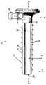
도 1은 일 실시예에 따른 캐뉼러의 개략적인 부분 단면도이다.
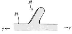
도 2는 일 실시예에 따른 나사산의 근접 측단면도 개략도이다.
도 3은 일 실시예에 따른, 압축된 위치에 있는 나사산의 개략적인 확대 측단면도이다.
도 4는 일 실시예에 따른 확장된 위치에 있는 나사산의 개략적인 확대 측단면도이다.
도 5는 대안적인 실시예에 따른 나사산의 개략적인 확대 측단면도이다.
도 6은 다른 대안적인 실시예에 따른 나사산의 개략적인 확대 측단면도이다.
도 7은 대안적인 실시예에 따른 캐뉼러의 개략적인 부분 분해도이다.
도 8은 도 7의 캐뉼러의 개략적인 사시도이다.
도 9는 도 7의 캐뉼러의 원위 단부의 부분 내부도이다.
도 10은 일 실시예에 따른 캐뉼러 시일 어셈블리의 부분 내부 측면도 개략도이다.
도 11은 일 실시예에 따른 1차 및 2차 시일의 개략적인 부분 내부 사시도이다.
도 12는 일 실시예에 따른 캐뉼러 시일 어셈블리의 개략적인 평면도이다.
도 13은 일 실시예에 따른 캐뉼러 시일 어셈블리의 개략적인 사시도이다.
도 14는 일 실시예에 따른 캐뉼러 시일 어셈블리의 다른 사시도 개략도이다.BRIEF DESCRIPTION OF THE DRAWINGS The present invention will be more fully understood and understood by reading the following detailed description in conjunction with the accompanying drawings. The accompanying drawings illustrate only typical embodiments of the disclosed subject matter and are therefore not to be considered limiting of its scope, as the disclosed subject matter may admit to other equally effective embodiments. BRIEF DESCRIPTION OF THE DRAWINGS Reference is now made briefly to the accompanying drawings as follows.
1 is a schematic partial cross-sectional view of a cannula according to an embodiment;
2 is a schematic cross-sectional view of a close-up side of a thread according to an embodiment;
3 is a schematic enlarged side cross-sectional view of a thread in a compressed position, according to one embodiment;
Fig. 4 is a schematic enlarged cross-sectional side view of a thread in an extended position according to an embodiment;
Fig. 5 is a schematic enlarged cross-sectional side view of a thread according to an alternative embodiment;
6 is a schematic enlarged cross-sectional side view of a thread according to another alternative embodiment;
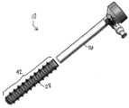
7 is a schematic partial exploded view of a cannula according to an alternative embodiment;
Fig. 8 is a schematic perspective view of the cannula of Fig. 7;
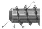
9 is a partial interior view of the distal end of the cannula of FIG. 7 ;
10 is a schematic partial interior side view of a cannula seal assembly according to one embodiment;
11 is a schematic partial interior perspective view of a primary and secondary seal according to an embodiment;
12 is a schematic plan view of a cannula seal assembly according to one embodiment.
13 is a schematic perspective view of a cannula seal assembly according to one embodiment;
14 is another perspective schematic view of a cannula seal assembly according to one embodiment;
현재 발명의 양태 및 이의 특정 특징, 이점, 및 세부사항은 첨부 도면에 예시된 비제한적인 예를 참조하여 아래에서 보다 완전하게 설명된다. 공지된 구성에 대한 설명은 발명을 상세하게 불필요하게 모호하게 하지 않도록 생략된다. 그러나, 상세한 설명 및 특정한 비제한적인 실시예는 발명의 측면을 나타내면서 단지 예시로서 제공되고 제한을 위한 것이 아님을 이해해야 한다. 기본 발명 개념의 사상 및/또는 범위 내에서 다양한 대체, 수정, 추가 및/또는 배열이 본 개시로부터 당업자에게 명백할 것이다.Aspects of the present invention and certain features, advantages, and details thereof are more fully described below with reference to the non-limiting examples illustrated in the accompanying drawings. Descriptions of known configurations are omitted so as not to unnecessarily obscure the invention in detail. It is to be understood, however, that the detailed description and specific non-limiting examples, while indicating aspects of the invention, are provided by way of illustration only and not limitation. Various substitutions, modifications, additions and/or arrangements within the spirit and/or scope of the basic inventive concept will be apparent to those skilled in the art from this disclosure.
이제, 동일한 참조 번호는 전체에 걸쳐 동일한 부분을 나타내는, 도면들을 참조하면, 도 1은 일 실시예에 따른 캐뉼러(10)의 개략적인 부분 단면도를 도시한다. 캐뉼러(10)는 근위 단부(12) 및 원위 단부(14)를 갖는다. 원위 단부(14)는 수술 부위의 포털 내로 삽입되도록 구성된다. 캐뉼러 몸체(16)는 중심 종방향 y-y축을 따라 근위 단부(12)로부터 원위 단부(14)로 연장된다. 캐뉼러(10)는 그 근위 단부(12)로부터 연장되는 포트(18)를 추가로 포함한다. 포트(18)는 캐뉼러(10)로부터 유체의 흐름을 위한 출구를 제공한다. 포트(18)는 포트(18)를 통한 유체의 흐름을 허용하거나 금지하기 위한 제어 밸브(미도시)를 포함한다. (제어 밸브는 당업자에 의해 이해되는 바와 같이 제어 밸브 개구(20)를 통해 연장될 것이다).DETAILED DESCRIPTION OF THE PREFERRED EMBODIMENTS Turning now to the drawings, in which like reference numerals denote like parts throughout, FIG. 1 shows a schematic partial cross-sectional view of a
캐뉼러 몸체(16)는 개방된 근위 몸체 단부(22) 및 개방된 원위 몸체 단부(24)를 갖고 그 사이에 연장되는 내부 체적(26)을 갖는 세장형이고 관형이다. 내부 체적(26)은 수술 기구 및 디바이스들을 수용하도록 크기 및 구성된다. 도시된 실시예에서, 캐뉼러 몸체(16)의 원위 몸체 단부(24)는 나사산(28)이 도시된 바와 같이 그 원위 몸체 단부(24)로부터 캐뉼러 몸체(16)의 외부 표면(30)의 적어도 일부를 따라 근위 방향으로 연장하도록 나사산이 형성되어 있다. 나사산(28)은 수술 부위에 캐뉼러(10)를 고정하기 위한 고정 특징부로서 기능한다.The
이제 도 2를 참조하면, 실시예에 따른 나사산(28)의 개략적인 확대 측단면도가 도시되어 있다. 도시된 바와 같이, 나사산(28)은 중심 종방향 y-y축에 대해 일정 각도로 연장된다. 특히, 나사산(28)은 근위 방향으로(즉, 캐뉼러(10)의 근위 단부(12)를 향하여) 연장된다. 나사산(28)의 프로파일은 삽입 방향에서 멀어지는 근위 방향으로 기울어져 있다. 대안적인 실시예에서, 나사산(28)의 프로파일은 삽입 방향을 향해 원위 방향으로 각을 이룰 수 있다.Referring now to FIG. 2 , there is shown an enlarged schematic cross-sectional side view of a
이제 도 3을 참조하면, 일 실시예에 따른, 압축된 위치에 있는 나사산(28)의 개략적인 확대 측단면도가 도시되어 있다. 도시된 바와 같이, 나사산(28)은 미리 결정된 압축력 하에서 나사산(28)이 항복하도록 가요성 재료로 구성된다. 다시 말해서, 나사산(28)의 팁(32)은 캐뉼러 몸체(16)의 외부 표면(30)을 향하여 근위 방향(중앙 종방향 y-y축을 향하여)으로 압축된 위치로 구부러진다. 근위 방향으로의 이러한 굽힘은 삽입 동안 압축될 때(즉, 조직에 의해 근위 방향으로 힘이 가해질 때) 캐뉼러(10)의 전체 프로파일을 감소시킨다. 따라서, 삽입 동안 나사산(28)의 더 작은 프로파일은 간섭을 최소화한다.Referring now to FIG. 3 , there is shown an enlarged schematic cross-sectional side view of the
이제 도 4로 돌아가면, 일 실시예에 따른, 확장된 위치에 있는 나사산(28)의 개략적인 확대 측단면도가 도시되어 있다. 나사산(28)은 가요성이지만, 나사산(28)은 수술 부위에 고정을 제공할 수 있어야 한다. 도 4에 도시된 바와 같이, 나사산(28)은 사용 동안 캐뉼러(10)의 전체 프로파일을 최대화하기 위해 인장 하중(즉, 원위 방향으로의 힘) 하에서 팽창한다. 따라서, 사용 동안 나사산(28)의 더 큰 프로파일은 수술 부위의 조직에서 캐뉼러(10)의 고정 강도를 증가시킨다. 도 3의 압축된 위치로부터, 나사산(28)의 팁(32)은 확장된 위치로 원위 방향으로 약간 뒤로 구부러진다.Turning now to FIG. 4 , there is shown an enlarged schematic cross-sectional side view of the
도 5 및 도 6을 이제 참조하면, 대안적인 실시예에 따른 나사산(28)의 개략적인 근접 측단면도가 도시되어 있다. 도 5 및 도6에 도시된 실시예에서, 나사산(28)의 기하학적 구조는 근위 방향으로 압축을 허용하고 원위 방향으로 압축에 대한 저항을 허용한다. 도 5에서, 나사산(28)은 나사산(28)의 베이스(34)에서 상이한 반경을 갖는다. 구체적으로, 나사산(28)은 베이스(34)의 원위 측(36) 상의 제1 반경(R1) 및 베이스(34)의 근위 측(38) 상의 제2 반경(R2)을 갖는다. 도시된 실시예에서, 제2 반경(R2)은 제1 반경(R1)보다 작다. 근위 측(38) 상의 더 작은 제2 반경(R2)으로, 나사산(28)은 근위 방향(D1)으로 압축되기에 더 민감하다. 유사하게, 원위 측(36) 상의 더 큰 제1 반경(R1)으로, 베이스(34)는 원위 방향(D2)에서의 압축에 대해 더 저항적이다.Referring now to FIGS. 5 and 6 , there is shown a schematic close-up cross-sectional side view of a
도 6에서, 나사산(28)은 원위 방향(D2)으로 압축에 저항하는 강화된 베이스(34)를 갖는다. 도시된 실시예에서, 나사산(28)은 베이스(34)(또는 나사산(28))의 원위 측(36)에 인접한 보조 나사산과 같은 지지 특징부(40)를 갖는다. 도 6에서, 지지 특징부(40)는 삼각형 단면을 갖는다. 특히, 지지 특징부(40)는 나사산(28)에 더 가깝도록(또는 더 넓도록) 기울어져 있다. 지지 특징부(40)의 각도는 나사산(28)의 팁(32)이 근위 방향(D1)으로 압축되도록 허용하고(즉, 원위 방향(D1)으로 가해지는 힘을 방해하지 않는다) 근위 방향(D1)으로 나사산(28)에 힘이 가해질 때 나사산(28)의 베이스(34)를 지지한다. 또한, 지지 특징부(40)는 나사산(28)이 압축 위치에 있을 때 나사산(28)을 지나 연장되지 않을 만큼 충분히 작다.In FIG. 6 , the
캐뉼러(10)에서 강성 및 가요성 특징의 조합은 단일 재료 또는 재료의 조합을 사용하여 달성될 수 있다. 도 1의 캐뉼러(10)는 단일 재료로 구성된다. 캐뉼러(10)의 강성 및 가요성 특징의 조합은 기재의 재료 특성 및 캐뉼러(10)의 기하학적 구조를 최적화함으로써 달성될 수 있다. 도 1에 도시된 캐뉼러(10)의 실시예에서, 캐뉼러 몸체(16)는 튜브 두께(t)를 갖는다. 두께(t)는 가요성 재료의 사용이 여전히 강성 캐뉼러 몸체(16)를 생성할 수 있을 만큼 충분히 크다. 유사하게, 재료의 두께를 변화시킴으로써 동일한 재료가 가요성 나사산(28)에 사용될 수 있다. 도 1에 도시된 바와 같이, 나사산(28)은 나사산(28)이 유연하기에 충분히 작은 두께(t')를 갖는다. 도시된 실시예에서, 나사산(28)의 두께(t')는 캐뉼러 몸체(16)의 두께(t)보다 작다.The combination of rigid and flexible features in the
도 7 및 도 8을 이제 참조하면, 대안적인 실시예에 따른 캐뉼러(10)의 개략적인 부분 분해도 및 사시도가 도시되어 있다. 도 7 및 도8에 도시된 캐뉼러(10)는 재료의 조합으로 구성된다. 다시 말해서, 캐뉼러(10)의 일부 특징부는 가요성 재료로 구성되는 반면, 캐뉼러(10)의 다른 특징부는 강성 재료로 구성된다. 도 7에 도시된 바와 같이, 캐뉼러 몸체(16)는 캐뉼러(10)의 구조적 강도를 제공하는 강성 재료로 제조되거나 그렇지 않으면 구성된다.Referring now to FIGS. 7 and 8 , there are shown schematic partial exploded and perspective views of a
다른 한편으로, 나사산(28)은 삽입 동안 간섭을 감소시키기 위해 요구되는 유연성을 제공하는 가요성 재료로 제조되거나 그렇지 않으면 가요성 재료로 구성된다. 도 7 및 도8에 도시된 실시예에서, 나사산(28)은 가요성 재료로 구성된 슬리브(42) 상에 제조된다. 슬리브(42)는 슬리브(42)가 캐뉼러 몸체(16) 위로 당겨질 수 있도록(즉, 캐뉼러 몸체(16)가 도 8에 도시된 바와 같이 슬리브(42)를 통해 연장하도록) 캐뉼러가 삽입된다. 이것은 도 1의 캐뉼러(10)의 동일한 기능을 달성하기 위해 사용되는 재료의 조합을 허용한다.On the other hand, the
간단히 도 9를 참조하면, 도 7 및 도 8의 캐뉼러(10)의 원위 단부(14)의 부분 내부도가 도시되어 있다. 강성 캐뉼러 몸체(16)가 가요성 슬리브(42)를 통해 연장할 때, 슬리브(42)는 캐뉼러 몸체(16)의 윈위 몸체 단부(24)를 지나 원위로 연장된다. 슬리브(42)의 이러한 추가 길이는 도 9에 도시된 바와 같이 순응성(compliant) 팁(44)이다. 순응성 팁(44)은 의도하지 않은 부상으로부터 수술 부위를 보호한다.Referring briefly to FIG. 9 , a partial interior view of the
도 10을 이제 참조하면, 일 실시예에 따른 캐뉼러 시일 어셈블리(100)의 부분 내부 측면도 개략도가 도시되어 있다. 어셈블리(100)는 캐뉼러(10)(도 1 및 7-9에 도시된 것과 같은)의 근위 단부(12)에 부착하기 위한 크기 및 구성을 갖는다. 어셈블리(100)는 내부에 위치된 2개의 시일들을 갖는 하우징(102)을 포함한다. 2개의 시일들은 하나 이상의 원위 1차 시일(104) 및 근위 2차 시일(106)을 포함한다. 또한 도 10에 도시된 바와 같이, 저장소(108)는 1차 시일(104)을 2차 시일(106)로부터 분리한다.Referring now to FIG. 10 , there is shown a schematic partial interior side view of a
1차 시일(104)은 어셈블리(100) 내의 메인 시일이다. 유체는 캐뉼러 몸체(16)의 원위 몸체 단부(24)로부터 1차 시일(104)을 향해 캐뉼러(10)를 통해 흐른다. 1차 시일(104)이 방해받지 않을 때, 이는 캐뉼러(10)를 통한 유체 흐름을 제한하는 장벽을 제공한다. 1차 시일(104)이 교란될 때(예를 들어, 수술 기구에 의해), 유체는 1차 시일(104)을 통해 저장소(108) 내로 통과한다. 도10에 도시된 바와 같이, 저장소(108)는 1차 및 2차 시일(104, 106)들 사이의 공간이다. 1차 시일(104)을 우회하는 모든 발사체 누출은 2차 시일(106)에 의해 포착된다. 2차 시일(106)은 사용자가 경험하는 "스플래시하는" 양을 크게 줄인다. 특히, 2차 시일(106)은 유체 압력을 견디지 못하기 때문에 스플래시 가드 역할을 하지만 발사체 누출을 포착한다.
도 11을 이제 참조하면, 실시예에 따른 1차 및 2차 시일(104, 106)들의 개략적인 부분 내부 투시도가 도시되어 있다. 도시된 바와 같이, 2차 시일(106)로부터 1차 시일(104)의 분리는 스페이서(110)에 의해 유지된다. 스페이서(110)는 저장소(108)와의 간섭을 피하기 위해 중앙 개구(114)를 갖는 원형 디스크(112A, 112B)들로 구성된다. 도 11에 도시된 바와 같이, 스페이서(110)는 제1 원형 디스크(112A) 및 제2 원형 디스크(112B)를 포함하고 그 사이에 하나 이상의 커넥터(116)가 연장한다. 커넥터(116)는 제1 원형 디스크(112A)를 제2 원형 디스크(112B)로부터 일정 거리에 유지하여 그 사이에 적어도 하나의 횡방향 스페이서 슬롯(118)을 생성하는 강성 재료의 임의의 조각 또는 부분일 수 있다. 스페이서 슬롯(들)(118)의 목적은 유체가 저장소(108)로부터 흘러나오도록 하는 것이다.Referring now to FIG. 11 , there is shown a schematic partial interior perspective view of primary and
사용 과정에 걸쳐, 1차 시일(104)과 2차 시일(106) 사이의 저장소(108)는 유체로 채워진다. 저장소(108)에 저압 유체의 존재는 발사체 누출에 대한 추가 보호를 제공한다. 임의의 초과 유체는 저장소(108)로부터 그리고 하우징(102)(도 10)의 외벽(122)에 있는 하나 이상의 횡방향 외부 슬롯(120)을 통해 누출되어 1차 및 2차 시일(104, 106)들 사이에 유체가 축적되는 것을 방지한다. 스페이서 슬롯(118) 및 외부 슬롯(120)은 캐뉼러(10)를 통해 연장되는 중앙 종방향 y-y축을 가로지른다. 구체적으로, 슬롯(118, 120)들은 중심 종방향 y-y 축에 실질적으로 수직이고 포트(18)의 연장 방향에 실질적으로 평행한 x-x 축을 따른(또는 실질적으로 평행한) 방향으로 연장된다(도10).Over the course of use, the
도 12 내지 14를 이제 참조하면, 실시예에 따른 캐뉼러 시일 어셈블리(100)의 다양한 도면이 개략적으로 도시되어 있다. 저장소(108)가 누출 방지를 돕기 위해 유체로 일관되게 채워지는 것을 보장하기 위해, 어셈블리(100)는 저장소(108) 주위로 연장되는 하나 이상의 챔버(124)를 포함한다. 도12에 도시된 바와 같이, 챔버(124)는 동심이며, 저장소(108) 주위에서 적어도 부분적으로 연장된다. 도시된 실시예에서, 챔버(124)는 2차 시일(106)과 하우징(102) 사이에 생성된다. (명확성을 위해 도 12 내지 도 14에서 하우징(102)이 제거되었음을 유의하라). 1차 및 2차 시일(104, 106)들 사이의 유체 레벨은 유체가 1차 시일(104)을 통해 들어갈 때 상승한다. 결국, 유체는 저장소(108)의 부피를 초과하고 챔버(124)를 통해 흐른다.Referring now to FIGS. 12-14 , various views of a
도 13 및 도 14에 도시된 바와 같이, 어셈블리(100)는 또한 저장소(108) 주위로 연장되는 하나 이상의 채널(126)을 포함한다. 도시된 실시예에서, 시일(104, 106)들은 내부 벽(128)에 의해 동심으로 둘러싸여 있다. 내부 벽(128)은 에지(130)가 내부 벽(128)과 하우징(102) 사이에 있도록 연장되는 하나 이상의 에지(130)를 갖는다. 에지(130)는 저장소(108) 주위로 연장되는 채널(126)을 생성한다. 도시된 실시예에서, 에지(130) 및 결과적인 채널(126)은 저장소(108) 주위에서 부분적으로만 연장된다. 또한, 도 13 및 도 14에서 도시된 채널(126)은 유출물의 수위가 항상 스페이서(110)의 높이를 초과하는 것을 보장하기 위해 챔버(124)로부터 오프셋된다.13 and 14 ,
구체적으로, 도 12는 챔버(124) 외부의 유체 경로(p)를 도시한다. 도 13은 챔버(124)로부터 채널(126)로의 유체 경로(p)를 도시한다. 유체 레벨은 어셈블리(100) 밖으로 흐르기 전에 피크를 초과해야 한다. 도 14의 챔버(124) 및 채널(126)의 오프셋 구성은 유체의 견고한 층이 저장소(108)의 1차 시일(104) 위에 남도록 보장한다. 궁극적으로, 스페이서(110) 및 시일(104, 106)들의 구성은 저장소(108)가 사용 과정에 걸쳐 유체로 프라이밍되는 것을 허용한다.Specifically, FIG. 12 shows the fluid path p outside the
현재 발명의 실시예가 특정 예시적인 실시예를 참조하여 특히 도시되고 설명되었지만, 기술분야의 통상의 지식을 가진 자는 상세한 설명 및 도면에 의해 지지될 수 있는 청구범위에 의해 정의된 발명의 사상 및 범위를 벗어나지 않고 상세한 다양한 변경이 이루어질 수 있음을 이해할 것이다. 또한, 예시적인 실시예가 특정 수의 요소를 참조하여 설명되는 경우 예시적인 실시예가 특정 수의 요소보다 적거나 더 많이 이용하여 실시될 수 있음을 이해할 것이다.While embodiments of the present invention have been particularly shown and described with reference to specific exemplary embodiments, those of ordinary skill in the art will appreciate the spirit and scope of the invention as defined by the claims, which may be supported by the detailed description and drawings. It will be understood that various changes may be made in detail without departing from it. Further, where exemplary embodiments are described with reference to a specific number of elements, it will be understood that the exemplary embodiments may be practiced using fewer or more than the specified number of elements.
Claims (20)
Translated fromKorean원위 몸체 단부로부터 근위 몸체 단부를 향해 캐뉼러 몸체의 적어도 일부를 따라 연장되는 가요성 나사산;
을 포함하고,
상기 캐뉼러 몸체는 제1 두께를 갖는 재료로 구성되고;
상기 나사산은 제1 두께보다 작은 제2 두께를 갖는 재료로 구성되는,
캐뉼러.
an elongate rigid cannula body extending along a longitudinal axis and having a proximal body end and a distal body end; and
a flexible thread extending along at least a portion of the cannula body from the distal body end toward the proximal body end;
including,
the cannula body is constructed of a material having a first thickness;
wherein the threads are made of a material having a second thickness less than the first thickness;
cannula.
상기 나사산은 제1 반경을 갖는 원위 측 및 제2 반경을 갖는 근위 측을 갖는 베이스를 포함하고, 상기 제2 반경은 상기 제1 반경보다 더 작은,
캐뉼러.
According to claim 1,
wherein the thread comprises a base having a distal side having a first radius and a proximal side having a second radius, wherein the second radius is smaller than the first radius;
cannula.
상기 나사산은 근위 측, 원위 측, 및 상기 원위 측에 인접하고 상기 캐뉼러 몸체로부터 연장하는 지지 특징부를 갖는 베이스를 포함하는,
캐뉼러.
According to claim 1,
wherein the thread comprises a base having a proximal side, a distal side, and a support feature adjacent the distal side and extending from the cannula body;
cannula.
상기 지지 특징부는 삼각형 단면을 가지고 있는,
캐뉼러.
4. The method of claim 3,
wherein the support feature has a triangular cross-section;
cannula.
상기 지지 특징부는 각이 지고, 상기 나사산의 원위 측으로 크기가 증가하는,
캐뉼러.
4. The method of claim 3,
wherein the support features are angled and increase in size distally of the threads;
cannula.
원위 몸체 단부로부터 근위 몸체 단부를 향해 캐뉼러 몸체의 적어도 일부를 따라 연장하는 가요성 슬리브; 및
상기 슬리브의 적어도 일부를 따라 연장하는 가요성 나사산;
를 포함하는,
캐뉼러.
an elongate rigid cannula body having a proximal body end and a distal body end;
a flexible sleeve extending along at least a portion of the cannula body from the distal body end toward the proximal body end; and
a flexible thread extending along at least a portion of the sleeve;
containing,
cannula.
상기 캐뉼러 몸체는 제1 두께를 갖는 재료로 구성되고, 상기 슬리브는 제1 두께보다 작은 제2 두께를 갖는 재료로 구성되는,
캐뉼러.
7. The method of claim 6,
wherein the cannula body is constructed of a material having a first thickness and the sleeve is constructed of a material having a second thickness less than the first thickness;
cannula.
상기 캐뉼러 몸체를 적어도 부분적으로 지나 연장하는 가요성 슬리브 상에 순응성 팁을 더 포함하는,
캐뉼러.
7. The method of claim 6,
a compliant tip on a flexible sleeve extending at least partially past the cannula body;
cannula.
상기 나사산은 제1 반경을 갖는 원위 측 및 제2 반경을 갖는 근위 측을 갖는 베이스를 포함하고, 제2 반경은 상기 제1 반경보다 더 작은,
캐뉼러.
7. The method of claim 6,
wherein the thread comprises a base having a distal side having a first radius and a proximal side having a second radius, the second radius being smaller than the first radius;
cannula.
상기 나사산은 근위 측, 원위 측, 및 상기 원위 측에 인접하고 상기 캐뉼러 몸체로부터 연장하는 지지 특징부를 갖는 베이스를 포함하는,
캐뉼러.
7. The method of claim 6,
wherein the thread comprises a base having a proximal side, a distal side, and a support feature adjacent the distal side and extending from the cannula body;
cannula.
상기 지지 특징부는 각이 지고, 상기 나사산의 원위 측으로 크기가 증가하는,
캐뉼러.
7. The method of claim 6,
wherein the support features are angled and increase in size distally of the threads;
cannula.
상기 1차 시일과 상기 2차 시일 사이에 연결된 스페이서; 및
상기 1차 시일과 상기 2차 시일 사이의 저장소;
를 포함하는,
캐뉼러 시일 어셈블리.
a housing having a primary seal and a secondary seal therein;
a spacer connected between the primary seal and the secondary seal; and
a reservoir between the primary seal and the secondary seal;
containing,
cannula seal assembly.
상기 스페이서는 관통하여 연장하는 중앙 개구를 구비한 적어도 하나의 원형 디스크를 포함하는,
어셈블리.
13. The method of claim 12,
wherein the spacer comprises at least one circular disk having a central opening extending therethrough;
assembly.
상기 2차 시일과 상기 하우징 사이에서 연장하는 챔버를 더 포함하는,
어셈블리.
13. The method of claim 12,
and a chamber extending between the secondary seal and the housing.
assembly.
상기 1차 및 상기 2차 시일들 주위로 연장하는 내벽, 및 상기 내벽과 상기 하우징 사이에서 연장되는 채널을 더 포함하는,
어셈블리.
13. The method of claim 12,
an inner wall extending about the primary and secondary seals, and a channel extending between the inner wall and the housing;
assembly.
상기 하우징으로부터 연장하는 캐뉼러를 더 포함하는,
어셈블리.
13. The method of claim 12,
further comprising a cannula extending from the housing;
assembly.
상기 스페이서를 통해 상기 저장소 내로 연장하는 하나 이상의 횡방향 스페이서 슬롯들을 더 포함하는,
어셈블리.
17. The method of claim 16,
one or more transverse spacer slots extending through the spacer and into the reservoir;
assembly.
상기 하우징의 외벽에 있는 하나 이상의 횡방향 외부 슬롯들을 더 포함하는,
어셈블리.
18. The method of claim 17,
one or more transverse external slots in the outer wall of the housing;
assembly.
상기 하나 이상의 횡방향 스페이서 슬롯들 및 상기 하나 이상의 횡방향 외부 슬롯들은 상기 캐뉼러를 통해 연장하는 중심 종축에 대해 횡방향인,
어셈블리.
19. The method of claim 18,
wherein the one or more transverse spacer slots and the one or more transverse outer slots are transverse to a central longitudinal axis extending through the cannula;
assembly.
상기 하나 이상의 횡방향 스페이서 슬롯들 및 상기 하나 이상의 횡방향 외부 슬롯들은 상기 중심 종축에 수직인 축을 따라 연장하는,
어셈블리.
20. The method of claim 19,
wherein the one or more lateral spacer slots and the one or more lateral outer slots extend along an axis perpendicular to the central longitudinal axis;
assembly.
Priority Applications (1)
| Application Number | Priority Date | Filing Date | Title |
|---|---|---|---|
| KR1020247012940AKR20240054415A (en) | 2018-12-27 | 2019-12-27 | Soft-thread cannula and cannula seal assembly |
Applications Claiming Priority (5)
| Application Number | Priority Date | Filing Date | Title |
|---|---|---|---|
| US201862785331P | 2018-12-27 | 2018-12-27 | |
| US62/785,331 | 2018-12-27 | ||
| US201862786085P | 2018-12-28 | 2018-12-28 | |
| US62/786,085 | 2018-12-28 | ||
| PCT/US2019/068728WO2020140025A2 (en) | 2018-12-27 | 2019-12-27 | Soft-thread cannula and cannula seal assembly |
Related Child Applications (1)
| Application Number | Title | Priority Date | Filing Date |
|---|---|---|---|
| KR1020247012940ADivisionKR20240054415A (en) | 2018-12-27 | 2019-12-27 | Soft-thread cannula and cannula seal assembly |
Publications (2)
| Publication Number | Publication Date |
|---|---|
| KR20210107803Atrue KR20210107803A (en) | 2021-09-01 |
| KR102660166B1 KR102660166B1 (en) | 2024-04-24 |
Family
ID=69411529
Family Applications (2)
| Application Number | Title | Priority Date | Filing Date |
|---|---|---|---|
| KR1020217023566AActiveKR102660166B1 (en) | 2018-12-27 | 2019-12-27 | Soft-Threaded Cannulas and Cannula Seal Assemblies |
| KR1020247012940APendingKR20240054415A (en) | 2018-12-27 | 2019-12-27 | Soft-thread cannula and cannula seal assembly |
Family Applications After (1)
| Application Number | Title | Priority Date | Filing Date |
|---|---|---|---|
| KR1020247012940APendingKR20240054415A (en) | 2018-12-27 | 2019-12-27 | Soft-thread cannula and cannula seal assembly |
Country Status (9)
| Country | Link |
|---|---|
| US (2) | US12096958B2 (en) |
| EP (2) | EP4218631B1 (en) |
| JP (2) | JP7344966B2 (en) |
| KR (2) | KR102660166B1 (en) |
| CN (2) | CN118000850A (en) |
| AU (2) | AU2019416369B2 (en) |
| CA (1) | CA3123233A1 (en) |
| ES (2) | ES2953573T3 (en) |
| WO (1) | WO2020140025A2 (en) |
Families Citing this family (4)
| Publication number | Priority date | Publication date | Assignee | Title |
|---|---|---|---|---|
| WO2020005896A1 (en)* | 2018-06-26 | 2020-01-02 | Conmed Corporation | Pressure release cannula |
| US11717781B2 (en)* | 2019-04-10 | 2023-08-08 | Conmed Corporation | Filter cartridge assembly having fluid management structure |
| CN116829083A (en)* | 2020-11-19 | 2023-09-29 | 西拉格国际有限责任公司 | Remote center and stabilization system for robotic medical systems |
| JP2024104068A (en)* | 2023-01-23 | 2024-08-02 | 朝日インテック株式会社 | Medical Devices |
Citations (4)
| Publication number | Priority date | Publication date | Assignee | Title |
|---|---|---|---|---|
| US5997515A (en)* | 1995-05-19 | 1999-12-07 | General Surgical Innovations, Inc. | Screw-type skin seal with inflatable membrane |
| US20150065808A1 (en)* | 2013-08-27 | 2015-03-05 | Hanshi Llc | Simplified arthroscopy cannula |
| CN206261645U (en)* | 2016-08-25 | 2017-06-20 | 江苏明朗医疗器械科技有限公司 | Single use laparoscope puncture outfit |
| WO2018094458A1 (en)* | 2016-11-22 | 2018-05-31 | Alfred Health | Surgical system and method of use |
Family Cites Families (21)
| Publication number | Priority date | Publication date | Assignee | Title |
|---|---|---|---|---|
| US5478329A (en)* | 1994-05-06 | 1995-12-26 | Ternamian; Artin M. | Trocarless rotational entry cannula |
| US5817062A (en)* | 1996-03-12 | 1998-10-06 | Heartport, Inc. | Trocar |
| US5993471A (en) | 1996-10-22 | 1999-11-30 | Erol D. Riza | Trocar assembly |
| US8506475B2 (en)* | 2001-09-19 | 2013-08-13 | James K. Brannon | Flexible scope endoscope |
| US9486241B2 (en) | 2003-03-21 | 2016-11-08 | Ethicon Endo-Surgery, Llc | Trocar seal assembly |
| WO2007093957A2 (en) | 2006-02-17 | 2007-08-23 | Roesch Theodor Gerhard | A cannula with a deployable external thread |
| EP2476384B1 (en)* | 2006-11-22 | 2015-11-04 | Applied Medical Resources Corporation | Trocar cannula with atraumatic tip |
| US20090204081A1 (en)* | 2008-02-13 | 2009-08-13 | Depuy Mitek, Inc. | Compression expanded cannula |
| US20100069716A1 (en)* | 2008-09-12 | 2010-03-18 | Yem Chin | Flexible guide conduit |
| EP2485663B1 (en)* | 2009-10-09 | 2017-03-22 | Applied Medical Resources Corporation | Trocar with retention cannula |
| US20110196206A1 (en)* | 2010-02-05 | 2011-08-11 | Tyco Healthcare Group Lp | Port fixation with varying thread diameter |
| KR200465473Y1 (en)* | 2012-04-06 | 2013-02-20 | 김철우 | Thoracic Trocar |
| US9119663B2 (en)* | 2013-01-24 | 2015-09-01 | Hybrid Cannula LP | Hybrid cannula and methods for manufacturing the same |
| DE102013107630A1 (en)* | 2013-07-17 | 2015-01-22 | Hochschule Koblenz | Dental implant with coronal groove structure |
| US10219799B2 (en)* | 2013-08-05 | 2019-03-05 | Endo-Tagss, Llc | Transabdominal gastric device and method |
| US9408631B2 (en)* | 2013-09-27 | 2016-08-09 | Depuy Mitek, Llc | Flexible cannula and obturator |
| US9788893B2 (en)* | 2014-11-20 | 2017-10-17 | Biosense Webster (Israel) Ltd. | Catheter with soft distal tip for mapping and ablating tubular region |
| US10206706B2 (en)* | 2015-05-29 | 2019-02-19 | Medtronic Xomed, Inc. | Inner tubular member for angled rotary surgical instrument |
| DE102016101462B4 (en)* | 2016-01-27 | 2019-01-17 | Karl Storz Se & Co. Kg | Trocar sleeve, trocar system and method for producing a trocar sleeve |
| CN108601635B (en)* | 2016-01-29 | 2021-10-08 | 诺贝尔生物服务公司 | Dental implant, insertion tool for dental implant and combination of dental implant and insertion tool |
| GB2565575A (en)* | 2017-08-17 | 2019-02-20 | Creo Medical Ltd | Electrosurgical apparatus for delivering RF and/or microwave energy into biological tissue |
- 2019
- 2019-12-27USUS17/415,371patent/US12096958B2/enactiveActive
- 2019-12-27JPJP2021537077Apatent/JP7344966B2/enactiveActive
- 2019-12-27EPEP23163295.1Apatent/EP4218631B1/enactiveActive
- 2019-12-27EPEP19845875.4Apatent/EP3902488B1/enactiveActive
- 2019-12-27ESES19845875Tpatent/ES2953573T3/enactiveActive
- 2019-12-27AUAU2019416369Apatent/AU2019416369B2/enactiveActive
- 2019-12-27CACA3123233Apatent/CA3123233A1/enactivePending
- 2019-12-27KRKR1020217023566Apatent/KR102660166B1/enactiveActive
- 2019-12-27ESES23163295Tpatent/ES3036694T3/enactiveActive
- 2019-12-27CNCN202410193414.4Apatent/CN118000850A/enactivePending
- 2019-12-27KRKR1020247012940Apatent/KR20240054415A/enactivePending
- 2019-12-27WOPCT/US2019/068728patent/WO2020140025A2/ennot_activeCeased
- 2019-12-27CNCN201980088863.XApatent/CN113301863B/enactiveActive
- 2022
- 2022-10-20AUAU2022256162Apatent/AU2022256162B2/enactiveActive
- 2023
- 2023-09-04JPJP2023142816Apatent/JP2023166499A/enactivePending
- 2024
- 2024-08-21USUS18/811,025patent/US20240407803A1/enactivePending
Patent Citations (4)
| Publication number | Priority date | Publication date | Assignee | Title |
|---|---|---|---|---|
| US5997515A (en)* | 1995-05-19 | 1999-12-07 | General Surgical Innovations, Inc. | Screw-type skin seal with inflatable membrane |
| US20150065808A1 (en)* | 2013-08-27 | 2015-03-05 | Hanshi Llc | Simplified arthroscopy cannula |
| CN206261645U (en)* | 2016-08-25 | 2017-06-20 | 江苏明朗医疗器械科技有限公司 | Single use laparoscope puncture outfit |
| WO2018094458A1 (en)* | 2016-11-22 | 2018-05-31 | Alfred Health | Surgical system and method of use |
Also Published As
| Publication number | Publication date |
|---|---|
| KR20240054415A (en) | 2024-04-25 |
| AU2022256162A1 (en) | 2022-11-24 |
| KR102660166B1 (en) | 2024-04-24 |
| AU2019416369A1 (en) | 2021-07-01 |
| EP3902488B1 (en) | 2023-06-21 |
| JP2022516069A (en) | 2022-02-24 |
| ES2953573T3 (en) | 2023-11-14 |
| EP4218631B1 (en) | 2025-06-11 |
| AU2022256162B2 (en) | 2024-05-02 |
| CN113301863A (en) | 2021-08-24 |
| CN118000850A (en) | 2024-05-10 |
| JP7344966B2 (en) | 2023-09-14 |
| CN113301863B (en) | 2024-12-13 |
| WO2020140025A3 (en) | 2020-08-06 |
| CA3123233A1 (en) | 2020-07-02 |
| AU2019416369B2 (en) | 2022-07-21 |
| ES3036694T3 (en) | 2025-09-23 |
| WO2020140025A2 (en) | 2020-07-02 |
| EP3902488A2 (en) | 2021-11-03 |
| EP4218631A1 (en) | 2023-08-02 |
| US12096958B2 (en) | 2024-09-24 |
| US20240407803A1 (en) | 2024-12-12 |
| US20220054164A1 (en) | 2022-02-24 |
| JP2023166499A (en) | 2023-11-21 |
Similar Documents
| Publication | Publication Date | Title |
|---|---|---|
| KR102660166B1 (en) | Soft-Threaded Cannulas and Cannula Seal Assemblies | |
| JP6785853B2 (en) | Extension tube strain removal | |
| ES2388649T3 (en) | Self-sealing cannula | |
| ES2949935T3 (en) | Blood control with button | |
| US9522266B2 (en) | Hemostasis sealing device | |
| US20100185057A1 (en) | Low-Profile Surgical Access Devices with Anchoring | |
| US20100241068A1 (en) | Vascular cannula assembly with an improved structure for confining blood flow | |
| KR101535899B1 (en) | Medical tube fixing device | |
| AU2018241145B2 (en) | Connector device for gastric calibration hoses, as well as medical system comprising a connector device for gastric calibration hoses and a gastric calibration hose | |
| US9078981B2 (en) | Catheter system including an embolism protection device | |
| CN108939214A (en) | A kind of syringe | |
| AU2022256103A1 (en) | Pressure release cannula | |
| JP7395843B2 (en) | drain catheter | |
| KR200488954Y1 (en) | Drainage set of medical suction unit |
Legal Events
| Date | Code | Title | Description |
|---|---|---|---|
| PA0105 | International application | St.27 status event code:A-0-1-A10-A15-nap-PA0105 | |
| PA0201 | Request for examination | St.27 status event code:A-1-2-D10-D11-exm-PA0201 | |
| PG1501 | Laying open of application | St.27 status event code:A-1-1-Q10-Q12-nap-PG1501 | |
| R18-X000 | Changes to party contact information recorded | St.27 status event code:A-3-3-R10-R18-oth-X000 | |
| E902 | Notification of reason for refusal | ||
| PE0902 | Notice of grounds for rejection | St.27 status event code:A-1-2-D10-D21-exm-PE0902 | |
| E13-X000 | Pre-grant limitation requested | St.27 status event code:A-2-3-E10-E13-lim-X000 | |
| P11-X000 | Amendment of application requested | St.27 status event code:A-2-2-P10-P11-nap-X000 | |
| P13-X000 | Application amended | St.27 status event code:A-2-2-P10-P13-nap-X000 | |
| E701 | Decision to grant or registration of patent right | ||
| PE0701 | Decision of registration | St.27 status event code:A-1-2-D10-D22-exm-PE0701 | |
| A107 | Divisional application of patent | ||
| PA0104 | Divisional application for international application | St.27 status event code:A-0-1-A10-A18-div-PA0104 St.27 status event code:A-0-1-A10-A16-div-PA0104 | |
| PR0701 | Registration of establishment | St.27 status event code:A-2-4-F10-F11-exm-PR0701 | |
| PR1002 | Payment of registration fee | St.27 status event code:A-2-2-U10-U12-oth-PR1002 Fee payment year number:1 | |
| PG1601 | Publication of registration | St.27 status event code:A-4-4-Q10-Q13-nap-PG1601 |