KR20210106865A - Tattoo needle structure - Google Patents
Tattoo needle structureDownload PDFInfo
- Publication number
- KR20210106865A KR20210106865AKR1020200066390AKR20200066390AKR20210106865AKR 20210106865 AKR20210106865 AKR 20210106865AKR 1020200066390 AKR1020200066390 AKR 1020200066390AKR 20200066390 AKR20200066390 AKR 20200066390AKR 20210106865 AKR20210106865 AKR 20210106865A
- Authority
- KR
- South Korea
- Prior art keywords
- tattoo
- needle
- ink
- alloy film
- component alloy
- Prior art date
- Legal status (The legal status is an assumption and is not a legal conclusion. Google has not performed a legal analysis and makes no representation as to the accuracy of the status listed.)
- Granted
Links
- 239000000956alloySubstances0.000claimsabstractdescription116
- 229910045601alloyInorganic materials0.000claimsabstractdescription116
- 238000000034methodMethods0.000claimsabstractdescription22
- 238000004544sputter depositionMethods0.000claimsabstractdescription14
- 229910052759nickelInorganic materials0.000claimsdescription50
- 229910052802copperInorganic materials0.000claimsdescription47
- 229910052782aluminiumInorganic materials0.000claimsdescription42
- 229910052726zirconiumInorganic materials0.000claimsdescription40
- 238000005516engineering processMethods0.000claimsdescription12
- 238000000168high power impulse magnetron sputter depositionMethods0.000claimsdescription10
- 239000000203mixtureSubstances0.000claimsdescription6
- 230000002209hydrophobic effectEffects0.000claimsdescription4
- 238000001755magnetron sputter depositionMethods0.000claimsdescription3
- 101150097381Mtor geneProteins0.000claims1
- 238000005054agglomerationMethods0.000claims1
- 230000002776aggregationEffects0.000claims1
- 230000000694effectsEffects0.000abstractdescription5
- 239000000976inkSubstances0.000description130
- 229910052719titaniumInorganic materials0.000description21
- XLYOFNOQVPJJNP-UHFFFAOYSA-NwaterSubstancesOXLYOFNOQVPJJNP-UHFFFAOYSA-N0.000description19
- 238000010586diagramMethods0.000description14
- 229910052727yttriumInorganic materials0.000description13
- 229910052796boronInorganic materials0.000description12
- 229910052758niobiumInorganic materials0.000description9
- 238000001179sorption measurementMethods0.000description9
- 206010052428WoundDiseases0.000description8
- 208000027418Wounds and injuryDiseases0.000description8
- 229910052749magnesiumInorganic materials0.000description8
- 229910052710siliconInorganic materials0.000description8
- 229910052742ironInorganic materials0.000description7
- 230000000052comparative effectEffects0.000description6
- 229910052790berylliumInorganic materials0.000description4
- 238000004043dyeingMethods0.000description4
- 229910052735hafniumInorganic materials0.000description4
- 229910052763palladiumInorganic materials0.000description4
- 229910052721tungstenInorganic materials0.000description4
- 229910052709silverInorganic materials0.000description3
- 206010061218InflammationDiseases0.000description2
- 229910052779NeodymiumInorganic materials0.000description2
- 230000000172allergic effectEffects0.000description2
- 208000010668atopic eczemaDiseases0.000description2
- 229910052804chromiumInorganic materials0.000description2
- 230000004054inflammatory processEffects0.000description2
- 238000012986modificationMethods0.000description2
- 230000004048modificationEffects0.000description2
- 229910052698phosphorusInorganic materials0.000description2
- 229910052715tantalumInorganic materials0.000description2
- 229910052718tinInorganic materials0.000description2
- 229910052725zincInorganic materials0.000description2
- 229910052684CeriumInorganic materials0.000description1
- 201000004624DermatitisDiseases0.000description1
- 229910052692DysprosiumInorganic materials0.000description1
- 229910052688GadoliniumInorganic materials0.000description1
- 206010020751HypersensitivityDiseases0.000description1
- 229910052772SamariumInorganic materials0.000description1
- 229910052771TerbiumInorganic materials0.000description1
- 238000005299abrasionMethods0.000description1
- 230000007815allergyEffects0.000description1
- 229910052799carbonInorganic materials0.000description1
- 230000007547defectEffects0.000description1
- 230000007717exclusionEffects0.000description1
- 238000007654immersionMethods0.000description1
- 229910052748manganeseInorganic materials0.000description1
- 239000012528membraneSubstances0.000description1
- 229910052750molybdenumInorganic materials0.000description1
- 231100000252nontoxicToxicity0.000description1
- 230000003000nontoxic effectEffects0.000description1
- 238000012827research and developmentMethods0.000description1
- 238000010186stainingMethods0.000description1
- 229910052720vanadiumInorganic materials0.000description1
Images


Classifications
- A—HUMAN NECESSITIES
- A61—MEDICAL OR VETERINARY SCIENCE; HYGIENE
- A61M—DEVICES FOR INTRODUCING MEDIA INTO, OR ONTO, THE BODY; DEVICES FOR TRANSDUCING BODY MEDIA OR FOR TAKING MEDIA FROM THE BODY; DEVICES FOR PRODUCING OR ENDING SLEEP OR STUPOR
- A61M37/00—Other apparatus for introducing media into the body; Percutany, i.e. introducing medicines into the body by diffusion through the skin
- A61M37/0076—Tattooing apparatus
- A61M37/0084—Tattooing apparatus with incorporated liquid feeding device
- A—HUMAN NECESSITIES
- A61—MEDICAL OR VETERINARY SCIENCE; HYGIENE
- A61L—METHODS OR APPARATUS FOR STERILISING MATERIALS OR OBJECTS IN GENERAL; DISINFECTION, STERILISATION OR DEODORISATION OF AIR; CHEMICAL ASPECTS OF BANDAGES, DRESSINGS, ABSORBENT PADS OR SURGICAL ARTICLES; MATERIALS FOR BANDAGES, DRESSINGS, ABSORBENT PADS OR SURGICAL ARTICLES
- A61L31/00—Materials for other surgical articles, e.g. stents, stent-grafts, shunts, surgical drapes, guide wires, materials for adhesion prevention, occluding devices, surgical gloves, tissue fixation devices
- A61L31/02—Inorganic materials
- A61L31/022—Metals or alloys
- A—HUMAN NECESSITIES
- A61—MEDICAL OR VETERINARY SCIENCE; HYGIENE
- A61L—METHODS OR APPARATUS FOR STERILISING MATERIALS OR OBJECTS IN GENERAL; DISINFECTION, STERILISATION OR DEODORISATION OF AIR; CHEMICAL ASPECTS OF BANDAGES, DRESSINGS, ABSORBENT PADS OR SURGICAL ARTICLES; MATERIALS FOR BANDAGES, DRESSINGS, ABSORBENT PADS OR SURGICAL ARTICLES
- A61L31/00—Materials for other surgical articles, e.g. stents, stent-grafts, shunts, surgical drapes, guide wires, materials for adhesion prevention, occluding devices, surgical gloves, tissue fixation devices
- A61L31/08—Materials for coatings
- A61L31/082—Inorganic materials
- A61L31/088—Other specific inorganic materials not covered by A61L31/084 or A61L31/086
- A—HUMAN NECESSITIES
- A61—MEDICAL OR VETERINARY SCIENCE; HYGIENE
- A61M—DEVICES FOR INTRODUCING MEDIA INTO, OR ONTO, THE BODY; DEVICES FOR TRANSDUCING BODY MEDIA OR FOR TAKING MEDIA FROM THE BODY; DEVICES FOR PRODUCING OR ENDING SLEEP OR STUPOR
- A61M5/00—Devices for bringing media into the body in a subcutaneous, intra-vascular or intramuscular way; Accessories therefor, e.g. filling or cleaning devices, arm-rests
- A61M5/178—Syringes
- A61M5/31—Details
- A61M5/32—Needles; Details of needles pertaining to their connection with syringe or hub; Accessories for bringing the needle into, or holding the needle on, the body; Devices for protection of needles
- A61M5/3295—Multiple needle devices, e.g. a plurality of needles arranged coaxially or in parallel
- A61M5/3297—Needles arranged coaxially
- C—CHEMISTRY; METALLURGY
- C23—COATING METALLIC MATERIAL; COATING MATERIAL WITH METALLIC MATERIAL; CHEMICAL SURFACE TREATMENT; DIFFUSION TREATMENT OF METALLIC MATERIAL; COATING BY VACUUM EVAPORATION, BY SPUTTERING, BY ION IMPLANTATION OR BY CHEMICAL VAPOUR DEPOSITION, IN GENERAL; INHIBITING CORROSION OF METALLIC MATERIAL OR INCRUSTATION IN GENERAL
- C23C—COATING METALLIC MATERIAL; COATING MATERIAL WITH METALLIC MATERIAL; SURFACE TREATMENT OF METALLIC MATERIAL BY DIFFUSION INTO THE SURFACE, BY CHEMICAL CONVERSION OR SUBSTITUTION; COATING BY VACUUM EVAPORATION, BY SPUTTERING, BY ION IMPLANTATION OR BY CHEMICAL VAPOUR DEPOSITION, IN GENERAL
- C23C14/00—Coating by vacuum evaporation, by sputtering or by ion implantation of the coating forming material
- C23C14/06—Coating by vacuum evaporation, by sputtering or by ion implantation of the coating forming material characterised by the coating material
- C23C14/14—Metallic material, boron or silicon
- C23C14/16—Metallic material, boron or silicon on metallic substrates or on substrates of boron or silicon
- C23C14/165—Metallic material, boron or silicon on metallic substrates or on substrates of boron or silicon by cathodic sputtering
- C—CHEMISTRY; METALLURGY
- C23—COATING METALLIC MATERIAL; COATING MATERIAL WITH METALLIC MATERIAL; CHEMICAL SURFACE TREATMENT; DIFFUSION TREATMENT OF METALLIC MATERIAL; COATING BY VACUUM EVAPORATION, BY SPUTTERING, BY ION IMPLANTATION OR BY CHEMICAL VAPOUR DEPOSITION, IN GENERAL; INHIBITING CORROSION OF METALLIC MATERIAL OR INCRUSTATION IN GENERAL
- C23C—COATING METALLIC MATERIAL; COATING MATERIAL WITH METALLIC MATERIAL; SURFACE TREATMENT OF METALLIC MATERIAL BY DIFFUSION INTO THE SURFACE, BY CHEMICAL CONVERSION OR SUBSTITUTION; COATING BY VACUUM EVAPORATION, BY SPUTTERING, BY ION IMPLANTATION OR BY CHEMICAL VAPOUR DEPOSITION, IN GENERAL
- C23C14/00—Coating by vacuum evaporation, by sputtering or by ion implantation of the coating forming material
- C23C14/22—Coating by vacuum evaporation, by sputtering or by ion implantation of the coating forming material characterised by the process of coating
- C23C14/34—Sputtering
- C23C14/35—Sputtering by application of a magnetic field, e.g. magnetron sputtering
- A—HUMAN NECESSITIES
- A61—MEDICAL OR VETERINARY SCIENCE; HYGIENE
- A61L—METHODS OR APPARATUS FOR STERILISING MATERIALS OR OBJECTS IN GENERAL; DISINFECTION, STERILISATION OR DEODORISATION OF AIR; CHEMICAL ASPECTS OF BANDAGES, DRESSINGS, ABSORBENT PADS OR SURGICAL ARTICLES; MATERIALS FOR BANDAGES, DRESSINGS, ABSORBENT PADS OR SURGICAL ARTICLES
- A61L2420/00—Materials or methods for coatings medical devices
- A61L2420/02—Methods for coating medical devices
- A—HUMAN NECESSITIES
- A61—MEDICAL OR VETERINARY SCIENCE; HYGIENE
- A61M—DEVICES FOR INTRODUCING MEDIA INTO, OR ONTO, THE BODY; DEVICES FOR TRANSDUCING BODY MEDIA OR FOR TAKING MEDIA FROM THE BODY; DEVICES FOR PRODUCING OR ENDING SLEEP OR STUPOR
- A61M37/00—Other apparatus for introducing media into the body; Percutany, i.e. introducing medicines into the body by diffusion through the skin
- A61M37/0015—Other apparatus for introducing media into the body; Percutany, i.e. introducing medicines into the body by diffusion through the skin by using microneedles
- A61M2037/0053—Methods for producing microneedles
- A—HUMAN NECESSITIES
- A61—MEDICAL OR VETERINARY SCIENCE; HYGIENE
- A61M—DEVICES FOR INTRODUCING MEDIA INTO, OR ONTO, THE BODY; DEVICES FOR TRANSDUCING BODY MEDIA OR FOR TAKING MEDIA FROM THE BODY; DEVICES FOR PRODUCING OR ENDING SLEEP OR STUPOR
- A61M2205/00—General characteristics of the apparatus
- A61M2205/02—General characteristics of the apparatus characterised by a particular materials
- A61M2205/0238—General characteristics of the apparatus characterised by a particular materials the material being a coating or protective layer
- A—HUMAN NECESSITIES
- A61—MEDICAL OR VETERINARY SCIENCE; HYGIENE
- A61M—DEVICES FOR INTRODUCING MEDIA INTO, OR ONTO, THE BODY; DEVICES FOR TRANSDUCING BODY MEDIA OR FOR TAKING MEDIA FROM THE BODY; DEVICES FOR PRODUCING OR ENDING SLEEP OR STUPOR
- A61M2207/00—Methods of manufacture, assembly or production
Landscapes
- Health & Medical Sciences (AREA)
- Chemical & Material Sciences (AREA)
- Engineering & Computer Science (AREA)
- Life Sciences & Earth Sciences (AREA)
- Veterinary Medicine (AREA)
- Public Health (AREA)
- General Health & Medical Sciences (AREA)
- Heart & Thoracic Surgery (AREA)
- Animal Behavior & Ethology (AREA)
- Biomedical Technology (AREA)
- Mechanical Engineering (AREA)
- Anesthesiology (AREA)
- Organic Chemistry (AREA)
- Metallurgy (AREA)
- Hematology (AREA)
- Chemical Kinetics & Catalysis (AREA)
- Materials Engineering (AREA)
- Virology (AREA)
- Dermatology (AREA)
- Medical Informatics (AREA)
- Vascular Medicine (AREA)
- Inorganic Chemistry (AREA)
- Surgery (AREA)
- Epidemiology (AREA)
- Infusion, Injection, And Reservoir Apparatuses (AREA)
- Media Introduction/Drainage Providing Device (AREA)
Abstract
Translated fromKoreanDescription
Translated fromKorean본 발명은 문신 니들 구조에 관한 것이다. 특히, 본 발명은 니들 팁이 다수개인 문신 니들을 포함하는 문신 니들 구조에 관한 것으로, 여기서 스퍼터링 기술에 의해 멀티-성분 합금막(multi-component alloy film)이 각 니들 팁에 증착되고, 문신 잉크는 멀티-성분 합금막의 소수성(hydrophobicity)을 통해 문신하는 동안 잉크 보유 공간(ink holding space)에 집중되어서, 이로 인하여 문신의 윤곽 해상도(contouring resolution)를 향상시킨다.The present invention relates to a tattoo needle structure. In particular, the present invention relates to a tattoo needle structure comprising a tattoo needle having a plurality of needle tips, wherein a multi-component alloy film is deposited on each needle tip by a sputtering technique, wherein the tattoo ink is Through the hydrophobicity of the multi-component alloy film, the ink is concentrated in the ink holding space during tattooing, thereby improving the contouring resolution of the tattoo.
문신 기술에서, 니들 도구는 상이한 기능으로 인해 두 가지 범주로 나눌 수 있는데, 하나는 문신 윤곽을 보여주기 위해 사용되는 니들 도구이고, 다른 하나는 문신을 채색하기 위해 생성된 니들 도구이다. 문신 이미지의 복잡성이 증가함에 따라, 요구되는 정확도가 증가하고, 문신 이미지의 섬세함과 동시에 피부를 천공하기 위한 편안한 수준을 향상시키는 효과를 얻으려면 현재 니들 도구의 특성을 개선해야하며, 이것이 현재 연구 개발의 목표이다.In tattoo technology, needle tools can be divided into two categories due to their different functions, one is a needle tool used to show the outline of a tattoo, and the other is a needle tool created to color a tattoo. As the complexity of tattoo images increases, the required accuracy increases, and in order to achieve the effect of improving the delicacy of the tattoo image and the comfortable level for puncturing the skin at the same time, it is necessary to improve the characteristics of the current needle tool, which is currently research and development is the goal of
문신의 윤곽을 그리는데 사용되는 기존의 문신 니들 도구에 대해서는 정확도가 불충분하다는 문제가 여전히 존재한다. 문신 이미지가 멀리서 보면, 문신 이미지의 전체 윤곽을 볼 수 있고, 보는 사람은 문신 이미지의 윤곽에 이상이 있다고 생각하지 않는다. 그러나 문신 패턴을 근거리에서 보면, 문신 이미지의 윤곽이 흐려지는 것을 알 수 있다.There is still the problem of insufficient accuracy for existing tattoo needle tools used to outline tattoos. When the tattoo image is viewed from a distance, the entire outline of the tattoo image can be seen, and the viewer does not think there is anything wrong with the outline of the tattoo image. However, if you look closely at the tattoo pattern, you can see that the outline of the tattoo image is blurred.
요약하면, 문신의 윤곽을 그리는데 사용되는 종래의 문신 니들 도구에 대해 정확도가 불충분하다는 문제가 있음을 알 수 있다. 따라서 이 문제를 해결하려면 향상된 기술적인 해결책을 제안하는 것이 필요하다.In summary, it can be seen that there is a problem that the accuracy is insufficient for the conventional tattoo needle tool used to draw the outline of the tattoo. Therefore, it is necessary to propose an improved technical solution to solve this problem.
종래기술의 관점에서는, 문신을 윤곽을 그리는데 사용된 기존의 문신 니들 도구는 정확도가 불충분하다는 문제가 있으며, 본 발명은 문신 니들 구조를 개시한다.In view of the prior art, there is a problem that the existing tattoo needle tool used to outline a tattoo has insufficient accuracy, and the present invention discloses a tattoo needle structure.
본 발명에 개시된 문신 니들 구조는 문신 니들 및 멀티-성분 합금막을 포함한다.The tattoo needle structure disclosed herein includes a tattoo needle and a multi-component alloy film.
문신 니들은 복수의 니들 팁들을 가지며, 잉크 보유 공간은 복수의 니들 팁들의 배열을 통해 형성된다. 멀티-성분 합금막은 스퍼터링 기술에 의해 복수의 니들 팁들 상에 증착된다.The tattoo needle has a plurality of needle tips, and an ink holding space is formed through the arrangement of the plurality of needle tips. A multi-component alloy film is deposited on a plurality of needle tips by a sputtering technique.
문신 니들이 문신 잉크에 침지될 때, 문신 잉크는 멀티-성분 합금막의 소수성에 의해 멀티-성분 합금막의 표면에 달라붙지 않고, 문신 잉크는 집중되며 복수의 니들 팁의 배열 및 문신 잉크의 응집 특성에 의한 잉크 보유 공간에 보관되어서, 문신 니들이 침지되고 문신 절차가 수행될 때 문신 잉크를 갖는 피부의 염색 영역이 잉크 보유 공간의 단면적이 된다.When the tattoo needle is immersed in the tattoo ink, the tattoo ink does not stick to the surface of the multi-component alloy film due to the hydrophobicity of the multi-component alloy film, the tattoo ink is concentrated, and Stored in the ink holding space, the dyed area of the skin with the tattoo ink becomes the cross-sectional area of the ink holding space when the tattoo needle is immersed and the tattoo procedure is performed.
본 발명에 개시된 문신 니들 구조는 상술한 바와 같다. 종래 기술과의 차이는 문신 니들이 복수의 니들 팁을 갖고, 니들 팁의 배열이 잉크 보유 공간을 형성하고, 멀티-성분 합금막이 스퍼터링 기술에 의해 각각의 바늘 팁 상에 배치된다는 점이다; 문신 니들이 문신 잉크에 침지될 때, 문신 잉크는 멀티-성분 합금막의 소수성 특성에 의해 다중 성분 합금 필름의 표면에 달라붙지 않으며, 문신 잉크의 응집 특성에 의한 문신 잉크는 집중되며 잉크 보유 공간에 보관되어서, 문신 니들이 문신 잉크에 침지되고 문신 공정이 수행될 때, 문신 잉크를 갖는 피부의 염색 영역은 잉크 보유 공간의 단면적이다.The tattoo needle structure disclosed in the present invention is as described above. The difference from the prior art is that the tattoo needle has a plurality of needle tips, the arrangement of the needle tips forms an ink holding space, and a multi-component alloy film is disposed on each needle tip by sputtering technique; When the tattoo needle is immersed in the tattoo ink, the tattoo ink does not stick to the surface of the multi-component alloy film due to the hydrophobic property of the multi-component alloy film, and the tattoo ink due to the cohesive property of the tattoo ink is concentrated and stored in the ink holding space. , when the tattoo needle is immersed in the tattoo ink and the tattoo process is performed, the dyed area of the skin with the tattoo ink is the cross-sectional area of the ink holding space.
상술한 기술적 해결책에 의해서, 본 발명은 문신의 윤곽 해상도를 향상시키는 기술적 효과를 달성할 수 있다.By the above technical solution, the present invention can achieve the technical effect of improving the outline resolution of the tattoo.
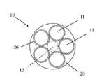
도 1은 본 발명의 일실시예에 따른 문신 니들 구조의 니들 팁의 평면도를 나타낸다.
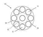
도 2a 및 도 2b는 본 발명의 일실시예에 따른 문신 니들 구조의 문신 니들의 평면도이다.
도 3a 및 도 3b는 본 발명의 다른 문신 니들 구조의 다른 문신 잉크의 물 접촉각을 나타낸다.
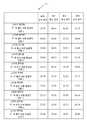
도 3c는 본 발명의 다른 문신 니들 구조의 다른 문신 잉크의 평균 물 접촉각을 나타낸다.
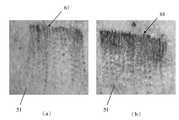
도 4는 본 발명의 문신 니들 구조에 따른 스퍼터-증착된 멀티-성분 합금 필름의 유무에 따른 니들 팁들에 의해 생성된 실제 상처의 비교 다이어그램을 나타낸다.
도 5는 본 발명의 문신 니들 구조에 따라 스퍼터-증착된 멀티-성분 합금막의 유무에 따른 니들 팁들에 의해 문신된 피부 조직의 비교 다이어그램을 나타낸다.
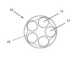
도 6a는 본 발명의 문신 니들 구조의 문신 바늘이 문신 잉크에 침지된 후의 잉크 흡착의 개략도이며, 니들 팁에는 스퍼터-증착된 멀티-성분 합금막이 없다.
도 6b는 본 발명의 문신 니들 구조의 문신 니들의 문신 영역을 나타내는 개략도이며, 니들 팁에는 스퍼터-증착된 멀티-성분 합금막이 없다.
도 7a는 본 발명의 문신 니들 구조의 문신 바늘이 문신 잉크에 침지된 후의 잉크 흡착의 개략도이며, 니들 팁은 스퍼터-증착된 멀티-성분 합금막을 갖는다.
도 7b는 본 발명의 문신 니들 구조의 문신 니들의 문신 영역을 나타내는 개략도이며, 니들 팁은 스퍼터-증착된 멀티-성분 합금막을 갖는다.
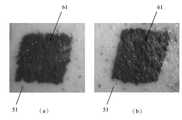
도 8 및 도 9는 본 발명의 문신 니들 구조에 따라 스퍼터-증착된 멀티-성분 합금막의 유무에 따른 니들 팁에 의해 수행된 실제 문신 결과의 비교 다이어그램을 나타낸다.
도 10은 본 발명의 문신 니들 구조의 멀티-성분 합금막의 원자 백분율을 나타낸다.1 shows a plan view of a needle tip of a tattoo needle structure according to an embodiment of the present invention.
2A and 2B are plan views of a tattoo needle having a tattoo needle structure according to an embodiment of the present invention.
3A and 3B show water contact angles of different tattoo inks of different tattoo needle structures of the present invention.
Figure 3c shows the average water contact angle of different tattoo inks of different tattoo needle structures of the present invention.
4 shows a comparative diagram of actual wounds created by needle tips with and without sputter-deposited multi-component alloy film according to the tattoo needle structure of the present invention.
5 shows a comparative diagram of skin tissue tattooed by needle tips with and without sputter-deposited multi-component alloy film according to the tattoo needle structure of the present invention.
6A is a schematic diagram of ink adsorption after the tattoo needle of the tattoo needle structure of the present invention is immersed in tattoo ink, and there is no sputter-deposited multi-component alloy film at the needle tip.
Figure 6b is a schematic diagram showing the tattoo area of the tattoo needle of the tattoo needle structure of the present invention, the needle tip has no sputter-deposited multi-component alloy film.
7A is a schematic diagram of ink adsorption after a tattoo needle of the tattoo needle structure of the present invention is immersed in tattoo ink, wherein the needle tip has a sputter-deposited multi-component alloy film.
7B is a schematic diagram showing a tattoo area of a tattoo needle of the tattoo needle structure of the present invention, the needle tip having a sputter-deposited multi-component alloy film.
8 and 9 show comparative diagrams of actual tattoo results performed by needle tips with and without sputter-deposited multi-component alloy film according to the tattoo needle structure of the present invention.
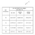
10 shows the atomic percentage of the multi-component alloy film of the tattoo needle structure of the present invention.
본 발명의 구조, 작동 원리 및 효과는 첨부 도면에 도시된 다양한 실시예를 통해 상세하게 설명될 것이다.The structure, operation principle and effect of the present invention will be described in detail through various embodiments shown in the accompanying drawings.
본 발명의 아래의 실시예는 첨부도면을 참조하여 본 명세서에서 상세하게 설명된다. 이들 도면은 본 발명의 실시예의 특정 실시예를 나타낸다. 이들 실시예는 본 발명의 개시가 완전하고 완전하도록 제공되며, 본 발명의 범위를 당업자에게 완전히 전달할 것이다. 이들 실시예는 예시적인 구현이며 어떠한 방식으로도 본 발명의 범위를 제한하는 것으로 해석되지 않아야 한다. 다른 실시예들 뿐만 아니라 개시된 실시예들에 대한 추가적인 수정들 또한 첨부된 청구 범위의 범주 내에 포함된다. 이들 실시예는 본 발명의 개시가 완전하고 완전하도록 제공되며, 본 발명의 개념을 당업자에게 완전히 전달한다. 도면과 관련하여, 도면의 구성 요소의 상대적인 크기 및 비율은 명확성 및 편의를 위해 과장되거나 축소될 수 있다. 이러한 임의의 크기는 단지 예시적인 것이며 어떠한 식으로도 제한하지 않는다. 도면 및 설명에서 동일한 참조 번호는 동일하거나 유사한 부분을 지칭하기 위해 사용된다.The following embodiments of the present invention are described in detail herein with reference to the accompanying drawings. These drawings show specific embodiments of embodiments of the present invention. These examples are provided so that this disclosure will be thorough and complete, and will fully convey the scope of the invention to those skilled in the art. These examples are exemplary implementations and should not be construed as limiting the scope of the invention in any way. Additional modifications to the disclosed embodiments as well as other embodiments are also included within the scope of the appended claims. These examples are provided so that this disclosure will be thorough and complete, and will fully convey the inventive concept to those skilled in the art. Referring to the drawings, the relative sizes and proportions of the elements in the drawings may be exaggerated or reduced for clarity and convenience. Any such size is exemplary only and is not limiting in any way. In the drawings and description, the same reference numbers are used to refer to the same or like parts.
비록 "제1", "제2", "제3" 등의 용어가 본 명세서에서 다양한 요소를 설명하기 위해 사용될 수 있지만, 이들 요소는 이들 용어에 의해 제한되지 않아야 한다. 이들 용어는 하나의 구성 요소를 다른 구성 요소와 구별하기 위한 목적으로만 사용된다. 따라서, 본 명세서에서 논의되는 제1 구성 요소는 본 발명 개시의 설명을 변경하지 않고 제2 구성 요소로 지칭될 수 있다. 본원에 사용된 용어 "또는"은 하나 이상의 관련된 열거된 항목의 임의의 어느 하나 및 모든 조합을 포함한다.Although the terms "first", "second", "third", etc. may be used herein to describe various elements, these elements should not be limited by these terms. These terms are used only for the purpose of distinguishing one component from another. Accordingly, a first component discussed herein may be referred to as a second component without changing the description of the present disclosure. As used herein, the term “or” includes any and all combinations of one or more related listed items.
구성요소 또는 층이 다른 구성요소 또는 층을 "위", "연결된" 또는 "결합된" 것으로 언급될 때, 이는 다른 구성요소 또는 층에 직접적으로 위로, 연결되거나, 결합될 수 있는 것으로 인식되거나, 또는 구성요소 또는 층이 개재하여 존재할 수도 있다. 반면에, 어떤 구성요소가 다른 구성요소에 "직접 위", "직접 연결되어", 또는 "직접 결합되어" 있다고 언급된 때에는, 중간에 다른 구성요소 또는 층이 존재하지 않는 것으로 이해되어야 할 것이다.When a component or layer is referred to as “above,” “connected,” or “coupled to” another component or layer, it is recognized as being directly over, connected to, or capable of being coupled to the other component or layer; Alternatively, there may be intervening components or layers. On the other hand, when an element is referred to as being “directly on”, “directly connected to,” or “directly coupled to” another element, it should be understood that there is no intervening element or layer.
또한, 반대로 명시적으로 언급되지 않는 한, 단어 "포함하다"(comprise), "포함하다(include)" 및 "가지고 있다(have)", 및 "포함하다(comprises)", "포함하는(comprising)", "포함한다(includes)", "포함하는(including)", "갖는다(has)", 및 "가지고 있는(having)"와 같은 변형들은 언급된 구성요소의 포함을 암시하지만 다른 구성요소의 배제를 의미하지 않는 것으로 인정될 것이다.Also, unless explicitly stated to the contrary, the words "comprise", "include" and "have", and "comprises", "comprising" )", "includes", "including", "has", and "having" imply the inclusion of the stated element but other elements. It will be recognized that this does not mean the exclusion of
이하, 도 1을 참조하여, 먼저 본 발명에 개시된 문신 니들 구조를 설명한다. 도 1은 본 발명의 문신 니들 구조의 니들 팁의 평면도이다.Hereinafter, with reference to FIG. 1, the structure of the tattoo needle disclosed in the present invention will be described first. 1 is a plan view of the needle tip of the tattoo needle structure of the present invention.
문신 니들은 복수의 니들 팁(11)을 갖는다. 도 1에서, 단일 니들 팁(11) 만이 각각의 니들 팁의 예시로서 사용된다. 본 발명에서, 멀티-성분 합금막(20)이 스퍼터링 기술에 의해 문신 니들의 니들 팁(11)의 표면에 증착된다. 도 1에 도시된 니들 팁(11)은 과장된 방식으로 제시된 것이며, 본 발명은 이에 한정되지 않는다.The tattoo needle has a plurality of
상기 멀티-성분 합금막(20)은 Zr, Cu, Al 및 Ni의 원소 조합; Zr, Al 및 Co의 원소 조합; Zr, Cu, Al 및 Ta의 원소 조합; Zr, Cu, Al 및 Ag의 원소 조합; Zr, Cu, Al, Ni 및 Ti의 원소 조합; Zr, Al, Cu, Ti 및 Be의 원소 조합; Zr, Cu, Al, Ni 및 Si의 원소 조합; Zr, Cu, Al, Ni 및 Nb의 원소 조합; Zr, Hf, Ti, Cu, Ni 및 Al의 원소 조합; 또는 Zr, Ti, Cu, Ni, Be, Y 및 Mg의 원소조합을 포함하는 Zr-계 멀티-성분 합금막일 수 있다. 상기 멀티-성분 합금막(20)은 Ti, Zr, Cu, Nb 및 Co의 원소 조합; Ti, Zr, Cu 및 Ni의 원소 조합; Ti, Ni, Cu, Sn 및 Be의 원소 조합; Ti, Zr, Hf, Ni 및 Cu의 원소 조합; Ti, Cu, Ni, Si 및 B의 원소 조합; Ti, Zr, Ni, Cu 및 Be의 원소 조합; 또는 Ti, Cu, Ni, Zr, Al, Si 및 B의 원소 조합 조합을 포함하는 Ti-계 멀티-성분 합금막일 수 있다. 상기 멀티-성분 합금막(20)은 Pd, Cu 및 Si의 원소; Pd, Ni 및 P의 원소 조합; 또는 Pd, Ni, Cu 및 P의 원소 조합을 포함하는 Pd-계 멀티-성분 합금막일 수 있다. 상기 멀티-성분 합금막(20)은 Fe, Co, Sm 및 B의 원소; Fe, Co, Tb 및 B의 원소 조합; Fe, Co, Nd, Dy 및 B의 원소 조합; Fe, Co, Ni, Zr 및 B의 원소 조합; Fe, Co, Ni, Si 및 B의 원소 조합; Fe, Zr, Co, Mo, W 및 B의 원소 조합; 또는 Fe, Cr, Mo, Er, C 및 B의 원소 조합을 포함하는 Fe-계 멀티-성분 합금막일 수 있다. 상기 멀티-성분 합금막(20)은 Cu, Hf 및 Ti의 원소; Cu, Zr 및 Al; Cu, Zr 및 Nb의 원소 조합; Cu, Zr, Al 및 Ag의 원소 조합; Cu, Zr, Ti 및 Ni의 원소 조합; Cu, Zr, Al 및 Y의 원소 조합; Cu, Zr, Al 및 Ti의 원소 조합; 또는 Cu, Zr, Hf 및 Ti의 원소 조합 조합을 포함하는 Cu-계 멀티-성분 합금막일 수 있다. 상기 멀티-성분 합금막(20)은 Ni, Zr 및 Al의 원소; Ni, Nb 및 Ta의 원소 조합; Ni, Nb 및 Sn의 원소 조합; Ni, Nb, Hf 및 Ti의 원소 조합; Ni, Zr, Al 및 Nb의 원소 조합; Ni, Zr, Ti 및 Al의 원소 조합; Ni, Zr, Ti 및 Pd의 원소 조합; Ni, Nb, Ti 및 Zr의 원소 조합; Ni, Cu, Zr, Ti 및 Al의 원소 조합; Ni, Cu, Zr, Ti, Al 및 Si의 원소 조합; 또는 Ni, Nb, Cr, Mo, P 및 B의 원소 조합을 포함하는 Ni-계 멀티-성분 합금막일 수 있다. 상기 멀티-성분 합금막(20)은 Al, Ni 및 Mn의 원소 조합; Al, Ni 및 Y의 원소 조합; Al, V 및 M의 원소 조합; Al, Ni 및 Ce의 원소 조합; Al, Co 및 Y의 원소 조합; Al, Ni, Y, Zr 및 Co의 원소 조합; 또는 Al, Ni, Y, Co 및 Cu의 원소 조합 조합을 포함하는 Al-계 멀티-성분 합금막일 수 있다. 상기 멀티-성분 합금막(20)은 W, Ni 및 B의 원소; 또는 W, Zr 및 Si의 원소 조합 조합을 포함하는 W-계 다 성분 합금 막일 수 있다. 상기 멀티-성분 합금막(20)은 Mg, Cu 및 Y의 원소; Mg, Ni 및 Nd의 원소 조합; Mg, Cu 및 Gd의 원소 조합; Mg, Al, Cu 및 Y의 원소 조합; Mg, Cu, Y 및 Si의 원소 조합; Mg, Cu, Zn 및 Y의 원소 조합; 또는 Mg, Cu, Ni, Zn, Ag 및 Y의 원소 조합 조합을 포함하는 Mg-계 멀티-성분 합금막일 수 있다. 상술한 모든 예시는 본 발명의 적용 범위를 제한하지 않는다.The
도 2a 및 도 2b를 참조하면, 도 2a 및 도 2b는 본 발명의 문신 니들 구조의 문신 니들의 평면도이다.2A and 2B, FIGS. 2A and 2B are plan views of the tattoo needle structure of the present invention.
본 발명에 개시된 문신 니들 구조는 문신 니들(10) 및 멀티-성분 합금막(20)을 포함한다 (도 1 참조). 문신 니들(10)은 복수의 니들 팁(11)을 가지며, 니들 팁(11)의 배열은 잉크 보유 공간(12)을 형성하고, 멀티-성분 합금막(20)은 스퍼터링 기술에 의해 문신 니들(10)의 각각의 니들 팁(11) 상에 증착된다. 멀티-성분 합금막(20)의 두께는 50 nm와 200 nm 사이에 있다는 것을 주목할 가치가 있다. 이것은 단지 예시를 위한 것이며, 본 발명의 적용 범위를 제한하지 않는다. 멀티-성분 합금막(20)은 비정질 구조를 가지며, 긴 거리 및 규칙적인 원자 주기성이 결여되어, 격자(lattice) 또는 입계(grain boundary) 결함으로 인한 손상을 줄이고 기계적 강도를 높일 수 있다. 멀티-성분 합금막(20)은 또한 강도, 마찰 계수, 내마모성, 세포에 쉽게 달라붙지 않는 우수한 생체 적합성 등의 특성을 갖는다.The tattoo needle structure disclosed herein includes a
도 2a에서, 문신 니들(10)은 원형으로 배열된 5 개의 니들 팁(11)을 가지며, 5 개의 니들 팁(11)의 원형 배열의 내부는 잉크 보유 공간(12)이다. 도 2b에서는, 도시된 바와 같이, 문신 니들(10)은 원형으로 배열된 8 개의 니들 팁(11)을 갖고, 8 개의 니들 팁(11)의 원형 배열의 내부는 잉크 보유 공간(12)이며, 추가 니들 팁은 잉크 보유 공간(12)에 제공될 수 있다. 문신 니들(10)에 포함된 니들 팁(11)의 이러한 배열은 단지 설명을 위한 것이며 본 발명의 적용 범위를 제한하기 위해 사용되지는 않는다.In FIG. 2A , the
도 3a 내지 도 3c를 참조하면, 본 발명의 서로 다른 문신 니들 구조의 서로 다른 문신 잉크의 물 접촉각(water contact angles)을 도시한 도면이며, 도 3c는 본 발명의 다른 문신 니들 구조의 다른 문신 잉크의 평균 물 접촉각(average water contact angle)을 도시한다.3A to 3C, it is a view showing water contact angles of different tattoo inks of different tattoo needle structures of the present invention, and FIG. 3C is another tattoo ink of another tattoo needle structure of the present invention. shows the average water contact angle of .
도 3a를 참조하면, 실험 데이터 테이블(31)은 스퍼터 증착된 멀티-성분 합금 막이 없는 니들 팁들과 문신 니들이 문신 잉크에 5 회 침지된 후 문신 잉크 사이에 형성된 물 접촉각과, Zr, Cu, Al 및 Ni의 원소 조합을 포함하는 스퍼터 증착된 Zr- 계 멀티-성분 합금막을 갖는 니들 팁들과 문신 니들이 문신 잉크에 5 회 침지된 후 문신 잉크 사이의 물 접촉각을 포함하며, 여기서 문신 잉크는 흑색 문신 잉크, 적색 문신 잉크, 청색 문신 잉크 또는 녹색 문신 잉크이다. 실제 실험 데이터에 관해서는 도 3a에 제시된 데이터를 참조하며, 여기서는 반복되지 않는다.Referring to FIG. 3A , the experimental data table 31 shows the water contact angle formed between needle tips without sputter deposited multi-component alloy film and the tattoo ink after the tattoo needle was immersed in the tattoo ink 5 times, Zr, Cu, Al and a water contact angle between needle tips having a sputter deposited Zr-based multi-component alloy film comprising an elemental combination of Ni and the tattoo ink after the tattoo needle has been immersed in the tattoo ink five times, wherein the tattoo ink is black tattoo ink; Red tattoo ink, blue tattoo ink or green tattoo ink. For actual experimental data, reference is made to the data presented in Fig. 3a, which is not repeated here.
도 3b를 참조하면, 실험 데이터 테이블(31)은 W, Ni 및 B의 원소 조합을 포함하는 스퍼터 증착된 W-계 멀티-성분 합금막을 갖는 니들 팁들과 문신 니들이 문신 잉크에 5 회 침지된 문신 잉크 사이에 형성된 물 접촉각을 포함하며, Al, Ni 및 Y의 원소 조합을 포함하는 스퍼터-증착 된 Al-계 멀티-성분 합금막을 갖는 니들 팁과 문신 니들이 문신 잉크에 5 회 침지된 후의 문신 잉크 사이에 형성된 물 접촉각을 포함하며, 여기에서 문신 잉크는 흑색 문신 잉크, 적색 문신 잉크, 청색 문신 잉크 또는 녹색 문신 잉크이다. 실제 실험 데이터에 관해서는 도 3b에 제시된 데이터를 참조하며, 여기서는 반복되지 않는다.Referring to FIG. 3B , the experimental data table 31 is a tattoo ink in which needle tips having a sputter deposited W-based multi-component alloy film containing an elemental combination of W, Ni and B and a tattoo needle are immersed in the tattoo ink 5 times. Between a needle tip having a sputter-deposited Al-based multi-component alloy film comprising an elemental combination of Al, Ni and Y, comprising a water contact angle formed therebetween, and the tattoo ink after the tattoo needle has been immersed in the tattoo ink five times. a water contact angle formed, wherein the tattoo ink is a black tattoo ink, a red tattoo ink, a blue tattoo ink, or a green tattoo ink. For actual experimental data, reference is made to the data presented in Fig. 3b, which is not repeated here.
도 3c를 참조하면, 평균 데이터 테이블(32)은 스퍼터-증착된 멀티-성분 합금막이 없는 니들 팁과 문신 니들이 문신 잉크에 침지된 후 문신 잉크 사이에 형성된 평균 물 접촉각, Zr, Cu, Al 및 Ni의 원소 조합을 포함하는 스퍼터 증착 된 Zr-계 멀티-성분 합금막을 갖는 니들 팁들과 문신 니들이 문신 잉크에 침지된 후 문신 잉크 사이에 형성된 평균 물 접촉각, W, Ni 및 B의 원소 조합을 포함하는 스퍼터 증착된 W-계 멀티-성분 합금막을 갖는 니들 팁들과 문신 니들이 문신 잉크에 침지된 후 문신 잉크 사이에 형성된 평균 물 접촉각, 및 Al, Ni 및 Y의 원소 조합을 포함하는 스퍼터 증착된 Al-계 멀티-성분 합금막과 문신 니들이 문신 잉크에 침지된 후 문신 잉크 사이에 형성된 평균 물 접촉각을 포함하며, 여기에서 문신 잉크는 흑색 문신 잉크, 적색 문신 잉크, 청색 문신 잉크 또는 녹색 문신 잉크이다.Referring to FIG. 3C , an average data table 32 shows the average water contact angle, Zr, Cu, Al and Ni formed between a needle tip without a sputter-deposited multi-component alloy film and the tattoo ink after the tattoo needle is immersed in the tattoo ink. The average water contact angle formed between needle tips having a sputter deposited Zr-based multi-component alloy film containing an elemental combination of A sputter deposited Al-based multi comprising an elemental combination of Al, Ni and Y, and an average water contact angle formed between needle tips with a deposited W-based multi-component alloy film and the tattoo ink after the tattoo needle is immersed in the tattoo ink. -contains the average water contact angle formed between the component alloy film and the tattoo ink after the tattoo needle is immersed in the tattoo ink, wherein the tattoo ink is a black tattoo ink, a red tattoo ink, a blue tattoo ink or a green tattoo ink.
상기 평균 데이터 테이블(32)에 따르면, 스퍼터 증착된 멀티-성분 합금막이 없는 니들 팁들과 문신 니들이 흑색 문신 잉크에 침지된 후 흑색 문신 잉크 사이에 형성된 평균 물 접촉각, 스퍼터 증착된 멀티-성분 합금막이 없는 니들 팁들과 문신 니들이 적색 문신 잉크에 침지된 후 적색 문신 잉크 사이에 형성된 평균 물 접촉각, 스퍼터 증착된 멀티-성분 합금막이 없는 니들 팁들과 문신 니들이 청색 문신 잉크에 침지된 후 청색 문신 잉크 사이에 형성된 평균 물 접촉각, 및 스퍼터 증착된 멀티-성분 합금막이 없는 니들 팁들과 문신 니들이 녹색 문신 잉크에 침지된 후 녹색 문신 잉크 사이에 형성된 평균 물 접촉각은 가장 낮은 값인 것을 얻을 수 있다. 이는 스퍼터 증착된 멀티-성분 합금막이 없는 문신 니들의 니들 팁은 소수성이 좋지 않다는 것을 나타내며, 즉 문신 잉크는 문신 니들의 니들 팁에 쉽게 달라붙는다.According to the average data table 32, the average water contact angle formed between the needle tips without the sputter deposited multi-component alloy film and the black tattoo ink after the tattoo needle was immersed in the black tattoo ink, without the sputter deposited multi-component alloy film. Average water contact angle formed between needle tips and red tattoo ink after immersion in red tattoo ink, average formed between needle tips without sputter deposited multi-component alloy film and blue tattoo ink after tattoo needle was immersed in blue tattoo ink The water contact angle, and the average water contact angle formed between the needle tips without the sputter deposited multi-component alloy film and the green tattoo ink after the tattoo needle is immersed in the green tattoo ink, can be obtained with the lowest values. This indicates that the needle tip of the tattoo needle without the sputter deposited multi-component alloy film has poor hydrophobicity, ie the tattoo ink easily sticks to the needle tip of the tattoo needle.
상기 평균 데이터 테이블(32)에 따르면, 스퍼터 증착된 Zr-계 멀티-성분 합금막을 갖는 니들 팁과 문신 니들이 흑색 문신 잉크에 침지된 후 흑색 문신 잉크 사이에 형성된 평균 물 접촉각, 스퍼터 증착된 Zr-계 멀티-성분 합금막을 갖는 니들 팁과 문신 니들이 적색 문신 잉크에 침지된 후 적색 문신 잉크 사이에 형성된 평균 물 접촉각, 스퍼터 증착된 Zr-계 멀티-성분 합금막을 갖는 니들 팁과 문신 니들이 청색 문신 잉크에 침지된 후 청색 문신 잉크 사이에 형성된 평균 물 접촉각, 및 스퍼터 증착된 Zr-계 멀티-성분 합금막을 갖는 니들 팁과 문신 니들이 녹색 문신 잉크에 침지된 후 녹색 문신 잉크 사이에 형성된 평균 물 접촉각은 가장 높은 값인 것을 얻을 수 있다. 이는 스퍼터 증착된 Zr-계 멀티-성분 합금막을 갖는 문신 니들의 니들 팁은 소수성이 높은 것을 나타내는데, 즉 문신 잉크는 문신 니들의 니들 팁에 쉽게 달라붙지 않는다.According to the above average data table 32, the average water contact angle formed between the needle tip having a sputter deposited Zr-based multi-component alloy film and the black tattoo ink after the tattoo needle was immersed in the black tattoo ink, sputter deposited Zr-based Average water contact angle formed between a needle tip having a multi-component alloy film and a tattoo needle after being immersed in the red tattoo ink, a needle tip having a sputter deposited Zr-based multi-component alloy film and a tattoo needle being immersed in a blue tattoo ink The average water contact angle formed between the blue tattoo ink after being immersed in the green tattoo ink and the needle tip with the sputter deposited Zr-based multi-component alloy film and the green tattoo ink after the tattoo needle was immersed in the green tattoo ink were the highest values. can get something This indicates that the needle tip of the tattoo needle with the sputter deposited Zr-based multi-component alloy film is highly hydrophobic, that is, the tattoo ink does not easily stick to the needle tip of the tattoo needle.
도 4 및 도 5를 참조하면, 도 4는 본 발명의 문신 니들 구조에 따라 스퍼터 증착된 멀티-성분 합금막의 유무에 따른 니들 팁에 의해 생성된 실제 상처의 비교 다이어그램을 나타낸다. 도 5는 본 발명의 문신 니들 구조에 따라 스퍼터-증착된 멀티-성분 합금막의 유무에 따른 니들 팁에 의해 문신된 피부 조직의 비교 다이어그램을 나타낸다.4 and 5, FIG. 4 shows a comparative diagram of an actual wound created by a needle tip with and without a multi-component alloy film sputter deposited according to the tattoo needle structure of the present invention. 5 shows a comparative diagram of skin tissue tattooed by a needle tip with and without a sputter-deposited multi-component alloy film according to the tattoo needle structure of the present invention.
도 4의 (a) 부분은 스퍼터 증착된 멀티-성분 합금막이 없는 문신 니들의 니들 팁에 의해 생성된 상처(81)를 나타낸다. 도 4의 (b) 부분은 스퍼터 증착된 Zr-계 멀티-성분 합금막을 갖는 문신 니들의 니들 팁에 의해 생성된 상처(81)를 나타낸다. 스퍼터 증착된 Zr-계 멀티-성분 합금막을 갖는 문신 니들의 니들 팁에 의해 생성된 상처(81)의 크기(도 4의 (b)에 도시됨)는 스퍼터 증착된 멀티-성분 합금막이 없는 문신 니들의 니들 팁에 의하여 생성된 상처의 크기 (도 4의 (a) 참조)보다 휠씬 적다는 것을 명백하게 알 수 있다.Part (a) of FIG. 4 shows a
도 5의 (a) 부분은 스퍼터 증착된 멀티-성분 합금막 없는 문신 니들의 니들 팁에 의해 문신을 수행한 6일 후에도 피부(51)에 알레르기성 염증 반응이 여전히 존재함을 나타낸다. (도 5의 부분 (a)에 도시됨). 도 5의 (b) 부분은 스퍼터-증착된 Zr-계 멀티-성분 합금막으로 문신 니들의 니들 팁에 의해 문신을 수행한 6일 후에 피부(51)에 알레르기성 염증 반응이 발생하지 않음을 나타낸다. (도 5의 부분 (b)에 도시됨).Part (a) of FIG. 5 shows that an allergic inflammatory reaction still exists on the
따라서, 본 발명에서는, Zr, Cu, Al 및 Ni의 원소 조합을 포함하는 스퍼터 증착된 Zr-계 멀티-성분 합금막을 갖는 니들 팁을 갖는 문신 니들이 후속 설명을 위해 사용된다. 본 발명의 멀티-성분 합금막은 내구성, 비 쉘링(non-shelling), 비 독성 및 낮은 운동력(low exertion force)의 특성을 갖는 문신 니들을 제공할 수 있어서, 스퍼터 증착된 멀티-성분 합금막을 갖는 문신 니들은 피부에 천공된 후 상처의 크기, 피부에 문신을 한 후 피부의 알레르기 및 염증 지속 시간, 및 문신 과정으로 인한 위험을 감소시킬 수 있다.Accordingly, in the present invention, a tattoo needle with a needle tip having a sputter deposited Zr-based multi-component alloy film comprising an elemental combination of Zr, Cu, Al and Ni is used for the following description. The multi-component alloy film of the present invention can provide a tattoo needle with the properties of durability, non-shelling, non-toxic and low exertion force, so that a tattoo having a sputter deposited multi-component alloy film The needle may reduce the size of the wound after puncturing the skin, the duration of allergies and inflammation of the skin after the skin is tattooed, and the risk from the tattoo process.
도 6a 및 도 6b를 참조하면, 도 6a는 본 발명의 문신 니들 구조의 문신 니들이 문신 잉크에 침지된 후의 잉크 흡착의 개략도이며, 니들 팁에는 스퍼터 증착된 멀티-성분 합금막이 없다. 도 6b는 본 발명의 문신 니들 구조의 문신 니들의 문신 영역을 나타내는 개략도이며, 여기서 니들 팁은 스퍼터 증착된 멀티-성분 합금막이 없다.6A and 6B, FIG. 6A is a schematic diagram of ink adsorption after a tattoo needle of the tattoo needle structure of the present invention is immersed in tattoo ink, and there is no sputter deposited multi-component alloy film at the needle tip. 6B is a schematic diagram showing the tattoo area of a tattoo needle of the tattoo needle structure of the present invention, wherein the needle tip is free of a sputter deposited multi-component alloy film.
상기로부터, 문신 니들(10)의 니들 팁(11)이 스퍼터-증착된 멀티-성분 합금막 갖지 않기 때문에 니들(11)은 열악한 소수성을 갖는다. 즉, 문신 니들(10)이 문신 잉크에 침지된 후, 문신 잉크는 문신 니들(10)의 니들 팁(11)에 쉽게 부착된다. 도 6a에서, 문신 잉크의 흡착 구역(41)은 문신 니들(10)의 니들 팁(11)에 의해 형성된 잉크 보유 공간(12), 문신 니들(10)의 니들 팁 (11) 사이의 간극, 및 문신 니들(10)의 니들 팁(11)의 낮은 소수성 및 문신 잉크의 응집성으로 인하여 문신 니들(10)의 니들 팁(11)의 표면을 포함한다. 도 6는 더 과장된 방식으로 개략적으로 표현되어 있다.From the above, since the
문신 니들(10)이 문신 잉크에 침지된 후, 문신 니들(10)의 니들 팁(11)은 피부(51)를 천공한다. 문신 잉크의 흡착 구역(41, adsorption zone)은 니들 팁(11)에 의해 형성된 잉크 보유 공간(12), 문신 니들(10)의 니들 팁(11) 사이의 간극, 및 문신 니들(10)의 니들 팁(11)의 표면을 포함하므로, 문신 잉크를 갖는 피부(51)의 염색 영역(52, dyeing area)은 도 6b에서는 잉크 보유 공간((12)의 단면적보다 훨씬 크며, 문신 잉크는 잉크 보유 공간(12)에 집중될 수 없다. 따라서, 문신 후에 피부에 대한 문신 결과가 흐려진다. 즉, 문신의 해상도 낮다.After the
도 7a 및 도 7b를 참조하면, 도 7a는 본 발명의 문신 니들 구조의 문신 니들이 문신 잉크에 침지된 후의 잉크 흡착의 개략도이며, 여기에서 니들 팁은 스퍼터 증착된 멀티-성분 합금막을 갖는다. 도 7b는 본 발명의 문신 니들 구조의 문신 니들의 문신 영역을 나타내는 개략도이며, 여기에서 니들 팁은 스퍼터 증착된 멀티-성분 합금막을 갖는다.7A and 7B, FIG. 7A is a schematic diagram of ink adsorption after a tattoo needle of a tattoo needle structure of the present invention is immersed in tattoo ink, wherein the needle tip has a sputter deposited multi-component alloy film. 7B is a schematic diagram showing the tattoo area of a tattoo needle of the tattoo needle structure of the present invention, wherein the needle tip has a sputter deposited multi-component alloy film.
상기로부터, 문신 니들(10)의 니들 팁(11) 상에 스퍼터 증착된 멀티-성분 합금막(상기 멀티-성분 합금막은 Zr, Cu, Al 및 Ni의 원소 조합을 포함하는 Zr-계 다 성분 합금막임)이기 때문에 문신 니들(10)의 니들 팁(11)은 더 높은 소수성을 갖는다. 즉, 문신 니들(10)이 문신 잉크에 침지된 후에 문신 잉크가 문신 니들(10)의 니들 팁(11)에 쉽게 부착되지 않는다. 도 7a에서, 문신 잉크의 흡착 구역(41)은 문신 니들(10)의 니들 팁(11)이 더 높은 소수성을 가지며, 문신 잉크의 응집성 때문에 문신 니들(10)의 니들 팁(11)에 의해 형성된 잉크 보유 공간(12)만을 포함한다. 도 7a는 더 과장된 방식으로 개략적인 표현이다. 실제로, 문신 니들(10)의 니들 팁(11)에 부착되는 문신 잉크가 다소 있지만, 문신 잉크는 잉크 보유 공간(12)에 있지않는 문신 니들(10)의 니들 팁(11)의 표면에 부착되지 않으며, 멀티-성분 합금막의 소수성으로 인하여 문신 니들(10)의 니들 팁(11) 사이에는 간극이 있다.From the above, a multi-component alloy film sputter deposited on the
문신 니들(10)이 문신 잉크에 침지된 후, 문신 니들(10)의 니들 팁(11)은 피부(51)를 천공한다. 문신 잉크의 흡착 구역(41)은 니들 팁(11)에 의해 형성된 잉크 보유 공간(12)만을 포함하므로, 문신 잉크가 있는 피부(51)의 염색 영역(52)은 도 7b에서 잉크 보유 공간(12)의 단면적보다 약간 더 크며, 문신 잉크는 잉크 보유 공간(12)에 집중될 수 있다. 따라서, 문신 후에 피부에 대한 문신 결과는 더 선명하다. 즉, 문신의 해상도가 높다.After the
도 8 및 도 9를 참조하면, 도 8 및 도 9는 본 발명의 문신 니들 구조에 따른 스퍼터-증착된 멀티-성분 합금막의 유무에 따라서 니들 팁에 의해 수행된 실제 문신 결과의 비교 다이어그램을 나타낸다.8 and 9, FIGS. 8 and 9 show comparative diagrams of actual tattoo results performed by needle tips with and without sputter-deposited multi-component alloy film according to the tattoo needle structure of the present invention.
도 8의 (a) 부분은 문신 잉크에 침지된 후 문신 니들(10)의 실제 사용으로 많은 피부 천공을 수행함으로써 형성된 문신의 구배 패턴(61, gradient pattern)을 나타내며, 여기서 문신 니들(10)의 니들 팁(11)은 스퍼터-증착된 멀티-성분 합금막이 없다. 도 8의 (b) 부분은 문신 잉크에 침지된 후 문신 니들(10)의 실제 사용으로 많은 피부 천공을 수행함으로써 형성된 문신의 구배 패턴(61)을 나타내며, 여기서 문신 니들 10)의 니들 팁 (11)은 스퍼터 증착된 멀티-성분 합금막(상기 멀티-성분 합금막은 Zr, Cu, Al 및 Ni의 원소 조합을 포함하는 Zr-계 멀티-성분 합금막)이다. 도 8의 (a) 부분에서 각 피부 천공 부분에 의해 제시된 문신 결과는 도 8의 (b) 부분보다 흐릿하다는 것이 명확하게 나타나며, 또한 도 8의 (a) 부분의 각 피부 천공의 채도(color saturation)가 도 8의 (b) 부분보다 불량하다는 것을 나타낸다. 이상으로부터, 도 8의 (a) 부분의 문신 결과는 문신 잉크를 갖는 피부의 염색 면적이 잉크 보유 공간의 단면적보다 훨씬 크다는 사실에 기인하며, 도 8의 (b) 부분의 문신 결과는 문신 잉크를 갖는 피부의 염색 영역이 잉크 보유 공간의 단면적에 집중되어 있다는 사실에 기인한다.Part (a) of FIG. 8 shows a
도 9의 (a) 부분은 문신 니들(10)의 실제 사용으로 형성된 문신 영역(tattooed area)의 결과를 나타내며, 문신 니들(10)의 니들 팁(11)은 스퍼터 증착된 멀티-성분 합금막이 없다. 도 9의 (b) 부분은 문신 니들(10)의 실제 사용으로 형성된 문신 영역의 결과를 나타내며, 문신 니들(10)의 니들 팁(11)은 스퍼터 증착된 멀티-성분 합금막(상기 멀티-성분 합금막은 Zr, Cu, Al 및 Ni의 원소 조합을 포함하는 Zr-계 멀티-성분 합금막)이다. 도 9의 (a)부분에 도시된 문신 후 문신된 영역(62)은 도 9의 (b) 부분과 비교하여, 피부의 원래 외관(original appearance of the skin)을 명확하게 보여줄 수 없다. 즉, 도 9의 (a) 부분에서 문신을 한 문신 영역(62)의 결과는 도 9의 (b) 부분보다 흐릿하다. 다시 말해서, 도 9의 (a) 부분의 문신 영역의 해상도는 도 9의 (b) 부분보다 낮다. 이상으로부터, 도 9의 (a) 부분의 문신 결과는 문신 잉크를 갖는 피부의 염색 면적(dyeing area)이 잉크 보유 공간의 단면적보다 훨씬 크다는 사실에 기인하며, 도 9의 (b) 부분의 문신 결과는 문신 잉크를 갖는 피부의 염색 영역이 잉크 보유 공간의 단면적에 집중되어 있다는 사실에 기인한다.Part (a) of FIG. 9 shows the result of a tattooed area formed by actual use of the
도 8 및 도 9에 도시된 바와 같이, 스퍼터 증착된 멀티-성분 합금막을 갖는 문신 니들(10)의 니들 팁(11)에 의해 생성된 문신의 채도가 스퍼터 증착된 멀티-성분 합금막을 갖지 않는 문신 니들(10)의 니들 팁(11)에 의해 생성된 것보다 높다는 것을 명확하게 볼 수 있다. 스퍼터 증착된 멀티-성분 합금막이 없는 경우, 스퍼터 증착된 멀티-성분 합금막이 있는 문신 니들(10)의 니들 팁(11)에 의해 생성된 채도와 유사한 채도를 달성하기 위해 더 많은 피부 천공을 수행할 필요가 있다. 스퍼터 증착된 멀티-성분 합금막이 없는 문신 니들(10)의 니들 팁(11)은 유사한 색 채도를 달성하기 위해 더 많은 피부 천공을 수행해야 한다. 스퍼터 증착된 멀티-성분 합금막을 갖지 않는 문신 니들(10)의 니들 팁(11)은 스퍼터 증착된 멀티-성분 합금막을 갖는 문신 니들(10)의 니들 팁 (11)에 의해 생성된 채도와 유사한 채도를 달성하기 위하여 더 많은 천공을 수행할 필요가 있으므로, 스퍼터 증착된 멀티-성분 합금막을 갖지 않는 문신 니들(10)의 니들 팁(11)은 더 많은 문신 잉크를 사용해야 한다.8 and 9, the saturation of the tattoo produced by the
도 10을 참조하면, 도 10은 본 발명에 따른 문신 니들 구조의 멀티-성분 합금막의 원자 백분율(atomic percentages)을 나타낸다.Referring to FIG. 10, FIG. 10 shows atomic percentages of a multi-component alloy film of a tattoo needle structure according to the present invention.
도 10에서, 원소 조합 테이블(71, element combination table)은 상이한 스퍼터링 기술 및 상이한 공정 파라미터에 의해 제조된 멀티-성분 합금막의 원자 백분율을 포함한다. 상술한 멀티-성분 합금막은 스퍼터링 기술에 의하여 문신 니들(10)의 니들 팁(11)들 상에 증착되며, 스퍼터링 기술에는 DC 마그네트론 스퍼터링(DC magnetron sputtering) 기술 및 고출력 임펄스 마그네트론 스퍼터링 (HIPIMS, high-power impulse magnetron sputtering) 기술이 포함된다. 스퍼터링 기술이 1kW의 작동 전력을 갖는 DC 마그네트론 스퍼터링 기술인 조건하에서는, 상기 멀티-성분 합금막은 원자 백분율로 아래의 조성을 갖는다: Zr은 56.61 ± 0.37 at%, Cu는 24.79 ± 0.23 at%, Al은 12.33 ± 0.08 at%, 및 Ni는 6.27 ± 0.11 at%이다. 이것은 단지 예시를 위한 것이며, 본 발명의 적용 범위를 제한하지 않는다.In Fig. 10, an element combination table 71 includes atomic percentages of multi-component alloy films produced by different sputtering techniques and different process parameters. The multi-component alloy film described above is deposited on the
스퍼터링 기술이 1kW의 작동 전력을 갖는 고전력 임펄스 마그네트론 스퍼터링 기술인 조건 하에서는, 멀티-성분 합금막은 원자 백분율로 아래의 조성을 갖는다 : Zr은 60.69 ± 0.19 at%, Cu는 22.94 ± 0.17at%, Al은 10.44 ± 0.26 at%, Ni는 5.93 ± 0.2 at%입니다. 이것은 단지 예시를 위한 것이며, 본 발명의 적용 범위를 제한하지 않는다.Under the condition that the sputtering technique is a high-power impulse magnetron sputtering technique with an operating power of 1 kW, the multi-component alloy film has the following composition in atomic percent: Zr 60.69 ± 0.19 at%, Cu 22.94 ± 0.17 at%, Al 10.44 ± 0.26 at%, Ni is 5.93 ± 0.2 at%. This is for illustrative purposes only and does not limit the scope of application of the present invention.
스퍼터링 기술이 고출력 임펄스 마그네트론 스퍼터링 기술 조건하에서는, 고출력 임펄스 마그네트론 스퍼터링 기술에 의해 사용되는 공정 파라미터는 6.7 × 10⁻⁵ Pa의 진공도, 3.7 mTorr의 작동 압력, 2.5 kW의 작동 전력, 1 rpm의 회전 속도를 포함하며, 지속 시간(duration) 및 바이어스 값(bias value)은 각각 다음 순서로 설정된다: 100초 동안 바이어스 값 600V, 100초 동안 바이어스 값 500V, 100초 동안 바이어스 값 400V, 100초 동안 바이어스 값 300V, 100초 동안 바이어스 값 200V, 100초 동안 바이어스 값 100V, 및 18초 동안 바이어스 값이 60V인 경우, 멀티-성분 합금막은 원자 백분율로 아래 조성을 갖는다: Zr은 59.36 ± 0.33 at%, Cu는 24.21 ± 0.21 at%, Al은 10.24 ± 0.1 at%이고, Ni는 6.19 ± 0.12 at%이다.Under the conditions of high-power impulse magnetron sputtering technology, the process parameters used by the high-power impulse magnetron sputtering technology are 6.7 × 10⁻⁵ Pa vacuum, 3.7 mTorr working pressure, 2.5 kW operating power, and 1 rpm rotation speed. The duration and bias value are respectively set in the following order: a bias value of 600V for 100 seconds, a bias value of 500V for 100 seconds, a bias value of 400V for 100 seconds, and a bias value of 300V for 100 seconds. , a bias value of 200 V for 100 seconds, a bias value of 100 V for 100 seconds, and a bias value of 60 V for 18 seconds, the multi-component alloy film had the following composition in atomic percent: Zr 59.36 ± 0.33 at%, Cu 24.21 ± 0.21 at%, Al is 10.24 ± 0.1 at%, and Ni is 6.19 ± 0.12 at%.
요약하면, 본 발명과 종래 기술의 차이는 문신 니들이 복수의 니들 팁을 가지며, 니들 팁의 배열이 잉크 보유 공간을 형성하고, 멀티-성분 합금막이 스퍼터링 기술에 의해 니들 팁 상에 필름이 배치되는 점을 알 수 있다; 문신 니들이 문신 잉크에 침지될 때, 문신 잉크는 멀티-성분 합금막의 소수성 특성으로 인해 멀티-성분 합금막의 표면에 달라붙지 않으며, 문신 잉크는 집중되어 문신 잉크의 응집 특성으로 인한 잉크 보유 공간에 보관되어서, 문신 니들이 문신 잉크에 침지되고 문신 과정이 수행될 때 문신 잉크를 갖는 피부의 염색 영역은 잉크 보유 공간의 단면적이 되도록 한다.In summary, the difference between the present invention and the prior art is that the tattoo needle has a plurality of needle tips, the arrangement of the needle tips forms an ink holding space, and a multi-component alloy film is disposed on the needle tip by a sputtering technique. can be seen; When the tattoo needle is immersed in the tattoo ink, the tattoo ink does not stick to the surface of the multi-component alloy film due to the hydrophobic nature of the multi-component alloy film, and the tattoo ink is concentrated and stored in the ink holding space due to the cohesive nature of the tattoo ink. , when the tattoo needle is immersed in the tattoo ink and the tattooing process is performed, the dyed area of the skin with the tattoo ink is made to be the cross-sectional area of the ink holding space.
상술한 기술적 해결책에 의해, 본 발명은 문신의 윤곽을 그리는데 사용되는 기존의 문신 니들 도구에 대한 불충분한 정확도의 문제를 해결하고 문신의 윤곽 해상도를 향상시키는 기술적 효과를 달성할 수 있다.By the above-described technical solution, the present invention can achieve the technical effect of solving the problem of insufficient accuracy for the existing tattoo needle tool used for drawing the outline of a tattoo and improving the resolution of the outline of the tattoo.
본 명세서에 개시된 본 발명은 특정 실시예에 의해 설명되었다. 그러나, 청구 범위에 개시된 사상 및 범위를 벗어나지 않고 당업자에 의해 수많은 수정, 변형 및 개선이 이루어질 수 있다.The invention disclosed herein has been illustrated by way of specific examples. However, numerous modifications, variations and improvements can be made by those skilled in the art without departing from the spirit and scope disclosed in the claims.
10: 문신 니들 11: 이들 팁
12: 잉크 보유 공간 20: 멀티-성분 합금막
31: 실험 데이터 테이블 32: 평균 데이터 테이블
41: 흡착구역 51: 피부
52: 염색 영역 61: 구배영역
71: 원소 조합 테이블 81: 상처10: Tattoo Needles 11: These Tips
12: ink holding space 20: multi-component alloy film
31: Experimental data table 32: Average data table
41: adsorption zone 51: skin
52: staining area 61: gradient area
71: element combination table 81: wounds
Claims (9)
Translated fromKorean상기 복수의 니들 팁 상에 스퍼터링 기술에 의해 증착된 멀티-성분 합금막을 포함하며,
상기 문신 니들이 문신 잉크에 침지될 때, 상기 문신 잉크는 멀티-성분 합금막의 소수성 특성에 의해 멀티-성분 합금막의 표면에 달라붙지 않으며, 상기 문신 잉크는 집중되며 복수의 바늘 팁의 배열 및 문신 잉크의 응집에 의해 잉크 보유 공간에 있어서, 문신 니들이 문신 잉크에 침지되고 문신 과정이 수행될 때, 문신 잉크에 의한 피부의 염색 영역은 잉크 보유 공간의 단면적이 되는 것을 특징으로 하는 문신 니들 구조.a tattoo needle having a plurality of needle tips and having an ink holding space formed through an arrangement of the plurality of needle tips; and
a multi-component alloy film deposited by sputtering on the plurality of needle tips;
When the tattoo needle is immersed in the tattoo ink, the tattoo ink does not stick to the surface of the multi-component alloy film due to the hydrophobic nature of the multi-component alloy film, the tattoo ink is concentrated and the arrangement of the plurality of needle tips and the In the ink holding space by agglomeration, when the tattoo needle is immersed in the tattoo ink and the tattoo process is performed, the area of the skin dyed by the tattoo ink becomes the cross-sectional area of the ink holding space.
상기 멀티-성분 합금막의 원소 조합이 Zr, Cu, Al 및 Ni을 포함하는 것을 특징으로 하는 문신 니들 구조.According to claim 1,
A tattoo needle structure, characterized in that the elemental combination of the multi-component alloy film comprises Zr, Cu, Al and Ni.
상기 멀티-성분 합금막은 1kW의 작동 전력을 갖는 DC 마그네트론 스퍼터링 기술이라는 조건에서, 원자 백분율로 아래의 조성: Zr은 56.61 ± 0.37 at%, Cu는 24.79 ± 0.23 at%, A l은 12.33 ± 0.08 at%, Ni는 6.27 ± 0.11 at%인 것을 특징으로 하는 문신 니들 구조.According to claim 1,
The multi-component alloy film has the following composition in atomic percent under the condition of DC magnetron sputtering technology having an operating power of 1 kW: Zr is 56.61 ± 0.37 at%, Cu is 24.79 ± 0.23 at%, Al is 12.33 ± 0.08 at %, Ni is 6.27 ± 0.11 at% tattoo needle structure, characterized in that.
상기 멀티-성분 합금막은 1kW의 작동 전력을 갖는 고전력 임펄스 마그네트론 스퍼터링 기술 조건에서, 원자 백분율로 아래의 조성: Zr은 60.69 ± 0.19 at%, Cu는 22.94 ± 0.17 at%, Al은 10.44 ± 0.26 at%, Ni는 5.93 ± 0.2 at%인 것을 특징으로 하는 문신 니들 구조.According to claim 1,
The multi-component alloy film has the following composition in atomic percent under high-power impulse magnetron sputtering technology conditions with an operating power of 1 kW: Zr 60.69 ± 0.19 at%, Cu 22.94 ± 0.17 at%, Al 10.44 ± 0.26 at% , Ni is a tattoo needle structure, characterized in that 5.93 ± 0.2 at%.
상기 멀티-성분 합금막은 2.5kW의 작동 전력을 갖는 고전력 임펄스 마그네트론 스퍼터링 기술인 조건에서, 원자 백분율로 아래의 조성: Zr은 59.36 ± 0.33 at%, Cu는 24.21 ± 0.21 at%, Al은 10.24 ± 0.1 at%, 및 Ni는 6.19 ± 0.12 at% 인 것을 특징으로 하는 문신 니들 구조.According to claim 1,
The multi-component alloy film has the following composition in atomic percent under the condition that it is a high power impulse magnetron sputtering technique with an operating power of 2.5 kW: Zr 59.36 ± 0.33 at%, Cu 24.21 ± 0.21 at%, Al 10.24 ± 0.1 at %, and Ni is 6.19 ± 0.12 at% tattoo needle structure.
상기 스퍼터링 기술은 고전력 임펄스 마그네트론 스퍼터링 기술이고, 상기 고전력 임펄스 마그네트론 스퍼터링 기술에 의해 사용되는 공정 파라미터는 6.7 × 10⁻⁵ Pa의 진공도, 3.7 mTor의 압력, 2.5 kW의 작동 전력, 1 rpm의 회전 속도, 및 지속 시간 및 바이어스 값은 각각 아래 순서로 설정: 100초 동안 600V의 바이어스 값, 100초 동안 500V의 바이어스 값, 100초 동안 400V의 바이어스 값, 100초 동안 300V의 바이어스 값, 100초 동안 200V의 바이어스 값, 100초 동안 바이어스 값 100V, 18초 동안 바이어스 값 60V인 것을 특징으로 하는 문신 바늘 구조.According to claim 1,
The sputtering technology is a high-power impulse magnetron sputtering technology, and the process parameters used by the high-power impulse magnetron sputtering technology are a vacuum degree of 6.7 × 10⁻⁵ Pa, a pressure of 3.7 mTor, an operating power of 2.5 kW, a rotation speed of 1 rpm, and duration and bias values are respectively set in the following order: a bias value of 600 V for 100 sec, a bias value of 500 V for 100 sec, a bias value of 400 V for 100 sec, a bias value of 300 V for 100 sec, and a bias value of 200 V for 100 sec. A tattoo needle structure, characterized in that a bias value, a bias value of 100V for 100 seconds, and a bias value of 60V for 18 seconds.
상기 멀티-성분 합금막의 두께가 50 nm 내지 200 nm인 것을 특징으로 하는 문신 니들 구조.According to claim 1,
Tattoo needle structure, characterized in that the thickness of the multi-component alloy film is 50 nm to 200 nm.
상기 문신 니들의 복수의 니들 팁은 원형 배열이고, 상기 복수의 니들 팁의 원형 배열의 내부는 잉크 보유 공간인 것을 특징으로 하는 문신 니들 구조.According to claim 1,
A tattoo needle structure, characterized in that the plurality of needle tips of the tattoo needles are in a circular arrangement, and the inside of the circular arrangement of the plurality of needle tips is an ink holding space.
상기 잉크 보유 공간에 추가 니들 팁이 더 제공되는 것을 특징으로 하는 문신 니들 구조.9. The method of claim 8,
A tattoo needle structure, characterized in that an additional needle tip is further provided in the ink holding space.
Applications Claiming Priority (2)
| Application Number | Priority Date | Filing Date | Title |
|---|---|---|---|
| TW109105507 | 2020-02-20 | ||
| TW109105507ATWI702935B (en) | 2020-02-20 | 2020-02-20 | Tattoo needle structure |
Publications (2)
| Publication Number | Publication Date |
|---|---|
| KR20210106865Atrue KR20210106865A (en) | 2021-08-31 |
| KR102362981B1 KR102362981B1 (en) | 2022-02-14 |
Family
ID=70740448
Family Applications (1)
| Application Number | Title | Priority Date | Filing Date |
|---|---|---|---|
| KR1020200066390AActiveKR102362981B1 (en) | 2020-02-20 | 2020-06-02 | Tattoo needle structure |
Country Status (5)
| Country | Link |
|---|---|
| US (1) | US11607533B2 (en) |
| EP (1) | EP3868436A1 (en) |
| KR (1) | KR102362981B1 (en) |
| CN (1) | CN113274630A (en) |
| TW (1) | TWI702935B (en) |
Citations (5)
| Publication number | Priority date | Publication date | Assignee | Title |
|---|---|---|---|---|
| KR20140031572A (en)* | 2012-09-05 | 2014-03-13 | 문성수 | Handler with needles for semi-permanant makeup |
| KR101909615B1 (en)* | 2016-11-15 | 2018-10-18 | 주식회사 파이룩스 | Needle for skin stimulation combined |
| KR101926314B1 (en)* | 2018-07-30 | 2018-12-06 | 김미정 | Needle set for drawing eyebrows |
| KR20190002217U (en) | 2019-08-22 | 2019-09-02 | 내셔널 타이완 유니버시티 오브 사이언스 앤드 테크놀로지 | Medical needle |
| KR20190116105A (en)* | 2018-04-04 | 2019-10-14 | 신용균 | Embo resin needle |
Family Cites Families (10)
| Publication number | Priority date | Publication date | Assignee | Title |
|---|---|---|---|---|
| US7695486B2 (en)* | 2002-10-02 | 2010-04-13 | Linda Dixon | Intradermal color introducing needle device, and apparatus and method involving the same |
| TWM240132U (en)* | 2003-05-01 | 2004-08-11 | De-Shr Huang | Improved structure of needle set for eyebrow tattoo |
| CN2834422Y (en)* | 2005-11-14 | 2006-11-08 | 刘国学 | Tattoo pen |
| US9433767B2 (en)* | 2007-06-01 | 2016-09-06 | Brett Colton | Wireless tattoo applicator system |
| CN101099685B (en)* | 2007-07-02 | 2010-06-02 | 沃尔夫冈·豪斯勒 | Tattooing needle |
| CA2914539C (en)* | 2013-06-13 | 2016-11-01 | Microdermics Inc. | Metallic microneedles |
| EP3064250A1 (en)* | 2015-03-06 | 2016-09-07 | MT Derm GmbH | Skin puncturing tool and puncturing tool for local puncturing of human or animal skin and puncturing tool assembly |
| TWI554391B (en)* | 2015-05-15 | 2016-10-21 | 國立臺灣科技大學 | Thin film metallic glass |
| CN105833424A (en)* | 2016-03-21 | 2016-08-10 | 南通纺织丝绸产业技术研究院 | Silk fibroin micro-needle patch and preparation method thereof |
| CN207520450U (en)* | 2017-05-09 | 2018-06-22 | 夏婷婷 | A kind of sewing needle |
- 2020
- 2020-02-20TWTW109105507Apatent/TWI702935B/enactive
- 2020-03-10CNCN202010166743.1Apatent/CN113274630A/enactivePending
- 2020-05-06USUS16/868,532patent/US11607533B2/enactiveActive
- 2020-05-15EPEP20175103.9Apatent/EP3868436A1/ennot_activeWithdrawn
- 2020-06-02KRKR1020200066390Apatent/KR102362981B1/enactiveActive
Patent Citations (5)
| Publication number | Priority date | Publication date | Assignee | Title |
|---|---|---|---|---|
| KR20140031572A (en)* | 2012-09-05 | 2014-03-13 | 문성수 | Handler with needles for semi-permanant makeup |
| KR101909615B1 (en)* | 2016-11-15 | 2018-10-18 | 주식회사 파이룩스 | Needle for skin stimulation combined |
| KR20190116105A (en)* | 2018-04-04 | 2019-10-14 | 신용균 | Embo resin needle |
| KR101926314B1 (en)* | 2018-07-30 | 2018-12-06 | 김미정 | Needle set for drawing eyebrows |
| KR20190002217U (en) | 2019-08-22 | 2019-09-02 | 내셔널 타이완 유니버시티 오브 사이언스 앤드 테크놀로지 | Medical needle |
Also Published As
| Publication number | Publication date |
|---|---|
| KR102362981B1 (en) | 2022-02-14 |
| CN113274630A (en) | 2021-08-20 |
| US20210260352A1 (en) | 2021-08-26 |
| TW202131869A (en) | 2021-09-01 |
| TWI702935B (en) | 2020-09-01 |
| US11607533B2 (en) | 2023-03-21 |
| EP3868436A1 (en) | 2021-08-25 |
Similar Documents
| Publication | Publication Date | Title |
|---|---|---|
| JP7301904B2 (en) | Modified sintered Nd--Fe--B magnet, production method and use thereof | |
| KR102362981B1 (en) | Tattoo needle structure | |
| JP2005190517A (en) | Perpendicular magnetic recording medium and magnetic storage device | |
| TW533514B (en) | Physical vapor deposition target/backing plate assemblies; and methods of forming physical vapor deposition target/backing plate assemblies | |
| CN103797549B (en) | NdFeB based sintered magnet | |
| EP1843864A1 (en) | Component with a coating for reducing the wettability of the surfaces and method for production thereof | |
| JP2003507574A5 (en) | ||
| CN106384637B (en) | A method for preparing high-performance NdFeB magnets by improving boundary structure | |
| CN101914764A (en) | A kind of micro-arc oxidation is used as the pretreatment method of titanium alloy electroless nickel plating | |
| CN106448984A (en) | NdFeB SYSTEM SINTERED MAGNET | |
| WO2024003759A3 (en) | Magnetic conductive material for cookware, preparation method for magnetic conductive material, and cookware | |
| CN101274397B (en) | A kind of activator for TIG welding of nickel base superalloy and its application method | |
| JP5492159B2 (en) | High temperature superconducting wire | |
| CN216091861U (en) | Tattoo needle structure to reduce cell adhesion and wound trauma during tattooing | |
| DE3841443C1 (en) | Surgical needle | |
| KR920008157B1 (en) | Sterile surgical needle and preparation method thereof | |
| DE102013102746A1 (en) | Process for coating surgical and medical instruments and coated instruments | |
| US6036825A (en) | Magnetic film forming method | |
| EP0022033B1 (en) | Lithographic printing plates with hydrophilic surface matted with a thin chrome layer | |
| JP3135174B2 (en) | R-TM-B permanent magnet with improved corrosion resistance and method for producing the same | |
| TW201836552A (en) | Medical needle and method for maintaining needle sharpness capable of maintaining needle sharpness after multiple piericing operations | |
| CN110129731A (en) | A kind of anti-fatigue high entropy alloy thin film and its preparation method | |
| JPH1147979A (en) | Method for joining different kinds of metallic material | |
| JP4591729B2 (en) | Surface treatment method for RTB permanent magnet | |
| JPH051363A (en) | Oxidation resistant surface treatment of tial intermetallic compound |
Legal Events
| Date | Code | Title | Description |
|---|---|---|---|
| PA0109 | Patent application | Patent event code:PA01091R01D Comment text:Patent Application Patent event date:20200602 | |
| PA0201 | Request for examination | ||
| E902 | Notification of reason for refusal | ||
| PE0902 | Notice of grounds for rejection | Comment text:Notification of reason for refusal Patent event date:20210726 Patent event code:PE09021S01D | |
| PG1501 | Laying open of application | ||
| E90F | Notification of reason for final refusal | ||
| PE0902 | Notice of grounds for rejection | Comment text:Final Notice of Reason for Refusal Patent event date:20211223 Patent event code:PE09021S02D | |
| E701 | Decision to grant or registration of patent right | ||
| PE0701 | Decision of registration | Patent event code:PE07011S01D Comment text:Decision to Grant Registration Patent event date:20220127 | |
| GRNT | Written decision to grant | ||
| PR0701 | Registration of establishment | Comment text:Registration of Establishment Patent event date:20220210 Patent event code:PR07011E01D | |
| PR1002 | Payment of registration fee | Payment date:20220210 End annual number:3 Start annual number:1 | |
| PG1601 | Publication of registration | ||
| PR1001 | Payment of annual fee | Payment date:20250121 Start annual number:4 End annual number:4 |