KR20210105017A - Ultrasonic prove and the method of manufacturing the same - Google Patents
Ultrasonic prove and the method of manufacturing the sameDownload PDFInfo
- Publication number
- KR20210105017A KR20210105017AKR1020200019455AKR20200019455AKR20210105017AKR 20210105017 AKR20210105017 AKR 20210105017AKR 1020200019455 AKR1020200019455 AKR 1020200019455AKR 20200019455 AKR20200019455 AKR 20200019455AKR 20210105017 AKR20210105017 AKR 20210105017A
- Authority
- KR
- South Korea
- Prior art keywords
- connection part
- center
- electrode layer
- electrode
- sound absorbing
- Prior art date
- Legal status (The legal status is an assumption and is not a legal conclusion. Google has not performed a legal analysis and makes no representation as to the accuracy of the status listed.)
- Pending
Links
Images


Classifications
- A—HUMAN NECESSITIES
- A61—MEDICAL OR VETERINARY SCIENCE; HYGIENE
- A61B—DIAGNOSIS; SURGERY; IDENTIFICATION
- A61B8/00—Diagnosis using ultrasonic, sonic or infrasonic waves
- A61B8/44—Constructional features of the ultrasonic, sonic or infrasonic diagnostic device
- A61B8/4483—Constructional features of the ultrasonic, sonic or infrasonic diagnostic device characterised by features of the ultrasound transducer
- A61B8/4494—Constructional features of the ultrasonic, sonic or infrasonic diagnostic device characterised by features of the ultrasound transducer characterised by the arrangement of the transducer elements
- A—HUMAN NECESSITIES
- A61—MEDICAL OR VETERINARY SCIENCE; HYGIENE
- A61B—DIAGNOSIS; SURGERY; IDENTIFICATION
- A61B8/00—Diagnosis using ultrasonic, sonic or infrasonic waves
- A61B8/44—Constructional features of the ultrasonic, sonic or infrasonic diagnostic device
- A61B8/4444—Constructional features of the ultrasonic, sonic or infrasonic diagnostic device related to the probe
- A—HUMAN NECESSITIES
- A61—MEDICAL OR VETERINARY SCIENCE; HYGIENE
- A61B—DIAGNOSIS; SURGERY; IDENTIFICATION
- A61B8/00—Diagnosis using ultrasonic, sonic or infrasonic waves
- A61B8/44—Constructional features of the ultrasonic, sonic or infrasonic diagnostic device
- A61B8/4483—Constructional features of the ultrasonic, sonic or infrasonic diagnostic device characterised by features of the ultrasound transducer
- A61B8/4488—Constructional features of the ultrasonic, sonic or infrasonic diagnostic device characterised by features of the ultrasound transducer the transducer being a phased array
- A—HUMAN NECESSITIES
- A61—MEDICAL OR VETERINARY SCIENCE; HYGIENE
- A61B—DIAGNOSIS; SURGERY; IDENTIFICATION
- A61B8/00—Diagnosis using ultrasonic, sonic or infrasonic waves
- A61B8/52—Devices using data or image processing specially adapted for diagnosis using ultrasonic, sonic or infrasonic waves
- A61B8/5207—Devices using data or image processing specially adapted for diagnosis using ultrasonic, sonic or infrasonic waves involving processing of raw data to produce diagnostic data, e.g. for generating an image
- B—PERFORMING OPERATIONS; TRANSPORTING
- B06—GENERATING OR TRANSMITTING MECHANICAL VIBRATIONS IN GENERAL
- B06B—METHODS OR APPARATUS FOR GENERATING OR TRANSMITTING MECHANICAL VIBRATIONS OF INFRASONIC, SONIC, OR ULTRASONIC FREQUENCY, e.g. FOR PERFORMING MECHANICAL WORK IN GENERAL
- B06B1/00—Methods or apparatus for generating mechanical vibrations of infrasonic, sonic, or ultrasonic frequency
- B06B1/02—Methods or apparatus for generating mechanical vibrations of infrasonic, sonic, or ultrasonic frequency making use of electrical energy
- B06B1/0207—Driving circuits
- B06B1/0215—Driving circuits for generating pulses, e.g. bursts of oscillations, envelopes
- B—PERFORMING OPERATIONS; TRANSPORTING
- B06—GENERATING OR TRANSMITTING MECHANICAL VIBRATIONS IN GENERAL
- B06B—METHODS OR APPARATUS FOR GENERATING OR TRANSMITTING MECHANICAL VIBRATIONS OF INFRASONIC, SONIC, OR ULTRASONIC FREQUENCY, e.g. FOR PERFORMING MECHANICAL WORK IN GENERAL
- B06B1/00—Methods or apparatus for generating mechanical vibrations of infrasonic, sonic, or ultrasonic frequency
- B06B1/02—Methods or apparatus for generating mechanical vibrations of infrasonic, sonic, or ultrasonic frequency making use of electrical energy
- B06B1/06—Methods or apparatus for generating mechanical vibrations of infrasonic, sonic, or ultrasonic frequency making use of electrical energy operating with piezoelectric effect or with electrostriction
- B06B1/0607—Methods or apparatus for generating mechanical vibrations of infrasonic, sonic, or ultrasonic frequency making use of electrical energy operating with piezoelectric effect or with electrostriction using multiple elements
- B06B1/0622—Methods or apparatus for generating mechanical vibrations of infrasonic, sonic, or ultrasonic frequency making use of electrical energy operating with piezoelectric effect or with electrostriction using multiple elements on one surface
- B06B1/0629—Square array
- B—PERFORMING OPERATIONS; TRANSPORTING
- B06—GENERATING OR TRANSMITTING MECHANICAL VIBRATIONS IN GENERAL
- B06B—METHODS OR APPARATUS FOR GENERATING OR TRANSMITTING MECHANICAL VIBRATIONS OF INFRASONIC, SONIC, OR ULTRASONIC FREQUENCY, e.g. FOR PERFORMING MECHANICAL WORK IN GENERAL
- B06B1/00—Methods or apparatus for generating mechanical vibrations of infrasonic, sonic, or ultrasonic frequency
- B06B1/02—Methods or apparatus for generating mechanical vibrations of infrasonic, sonic, or ultrasonic frequency making use of electrical energy
- B06B1/06—Methods or apparatus for generating mechanical vibrations of infrasonic, sonic, or ultrasonic frequency making use of electrical energy operating with piezoelectric effect or with electrostriction
- B06B1/0644—Methods or apparatus for generating mechanical vibrations of infrasonic, sonic, or ultrasonic frequency making use of electrical energy operating with piezoelectric effect or with electrostriction using a single piezoelectric element
- B06B1/0662—Methods or apparatus for generating mechanical vibrations of infrasonic, sonic, or ultrasonic frequency making use of electrical energy operating with piezoelectric effect or with electrostriction using a single piezoelectric element with an electrode on the sensitive surface
- B06B1/0677—Methods or apparatus for generating mechanical vibrations of infrasonic, sonic, or ultrasonic frequency making use of electrical energy operating with piezoelectric effect or with electrostriction using a single piezoelectric element with an electrode on the sensitive surface and a high impedance backing
- G—PHYSICS
- G01—MEASURING; TESTING
- G01S—RADIO DIRECTION-FINDING; RADIO NAVIGATION; DETERMINING DISTANCE OR VELOCITY BY USE OF RADIO WAVES; LOCATING OR PRESENCE-DETECTING BY USE OF THE REFLECTION OR RERADIATION OF RADIO WAVES; ANALOGOUS ARRANGEMENTS USING OTHER WAVES
- G01S7/00—Details of systems according to groups G01S13/00, G01S15/00, G01S17/00
- G01S7/52—Details of systems according to groups G01S13/00, G01S15/00, G01S17/00 of systems according to group G01S15/00
- G01S7/52017—Details of systems according to groups G01S13/00, G01S15/00, G01S17/00 of systems according to group G01S15/00 particularly adapted to short-range imaging
- G01S7/52019—Details of transmitters
- G01S7/5202—Details of transmitters for pulse systems
- G—PHYSICS
- G01—MEASURING; TESTING
- G01S—RADIO DIRECTION-FINDING; RADIO NAVIGATION; DETERMINING DISTANCE OR VELOCITY BY USE OF RADIO WAVES; LOCATING OR PRESENCE-DETECTING BY USE OF THE REFLECTION OR RERADIATION OF RADIO WAVES; ANALOGOUS ARRANGEMENTS USING OTHER WAVES
- G01S7/00—Details of systems according to groups G01S13/00, G01S15/00, G01S17/00
- G01S7/52—Details of systems according to groups G01S13/00, G01S15/00, G01S17/00 of systems according to group G01S15/00
- G01S7/52017—Details of systems according to groups G01S13/00, G01S15/00, G01S17/00 of systems according to group G01S15/00 particularly adapted to short-range imaging
- G01S7/52023—Details of receivers
- G01S7/52025—Details of receivers for pulse systems
- G—PHYSICS
- G01—MEASURING; TESTING
- G01S—RADIO DIRECTION-FINDING; RADIO NAVIGATION; DETERMINING DISTANCE OR VELOCITY BY USE OF RADIO WAVES; LOCATING OR PRESENCE-DETECTING BY USE OF THE REFLECTION OR RERADIATION OF RADIO WAVES; ANALOGOUS ARRANGEMENTS USING OTHER WAVES
- G01S7/00—Details of systems according to groups G01S13/00, G01S15/00, G01S17/00
- G01S7/52—Details of systems according to groups G01S13/00, G01S15/00, G01S17/00 of systems according to group G01S15/00
- G01S7/52017—Details of systems according to groups G01S13/00, G01S15/00, G01S17/00 of systems according to group G01S15/00 particularly adapted to short-range imaging
- G01S7/52079—Constructional features
- A—HUMAN NECESSITIES
- A61—MEDICAL OR VETERINARY SCIENCE; HYGIENE
- A61B—DIAGNOSIS; SURGERY; IDENTIFICATION
- A61B2562/00—Details of sensors; Constructional details of sensor housings or probes; Accessories for sensors
- A61B2562/12—Manufacturing methods specially adapted for producing sensors for in-vivo measurements
- B—PERFORMING OPERATIONS; TRANSPORTING
- B06—GENERATING OR TRANSMITTING MECHANICAL VIBRATIONS IN GENERAL
- B06B—METHODS OR APPARATUS FOR GENERATING OR TRANSMITTING MECHANICAL VIBRATIONS OF INFRASONIC, SONIC, OR ULTRASONIC FREQUENCY, e.g. FOR PERFORMING MECHANICAL WORK IN GENERAL
- B06B2201/00—Indexing scheme associated with B06B1/0207 for details covered by B06B1/0207 but not provided for in any of its subgroups
- B06B2201/70—Specific application
- B06B2201/76—Medical, dental
Landscapes
- Health & Medical Sciences (AREA)
- Life Sciences & Earth Sciences (AREA)
- Engineering & Computer Science (AREA)
- Physics & Mathematics (AREA)
- Medical Informatics (AREA)
- Animal Behavior & Ethology (AREA)
- Biophysics (AREA)
- Nuclear Medicine, Radiotherapy & Molecular Imaging (AREA)
- Pathology (AREA)
- Radiology & Medical Imaging (AREA)
- Biomedical Technology (AREA)
- Heart & Thoracic Surgery (AREA)
- Veterinary Medicine (AREA)
- Molecular Biology (AREA)
- Surgery (AREA)
- Public Health (AREA)
- General Health & Medical Sciences (AREA)
- Mechanical Engineering (AREA)
- Gynecology & Obstetrics (AREA)
- Computer Networks & Wireless Communication (AREA)
- General Physics & Mathematics (AREA)
- Radar, Positioning & Navigation (AREA)
- Remote Sensing (AREA)
- Computer Vision & Pattern Recognition (AREA)
- Ultra Sonic Daignosis Equipment (AREA)
Abstract
Translated fromKoreanDescription
Translated fromKorean초음파를 이용하여 대상체 내부의 영상을 생성하기 위한 초음파 프로브에 관한 것으로, 더욱 상세하게는 Multi-row 초음파 프로브 및 그 제조 방법에 관한 것이다.To an ultrasound probe for generating an image of an inside of an object by using ultrasound, and more particularly, to a multi-row ultrasound probe and a method of manufacturing the same.
초음파 영상장치는 대상체의 체표로부터 체내의 타겟 부위를 향하여 초음파 신호를 조사하고, 반사된 초음파 신호(초음파 에코신호)의 정보를 이용하여 연부조직의 단층이나 혈류에 관한 이미지를 무침습으로 얻는 장치이다.An ultrasound imaging device irradiates an ultrasound signal from a body surface of an object toward a target site in the body, and uses information of the reflected ultrasound signal (ultrasound echo signal) to obtain an image of a tomography or blood flow of a soft tissue non-invasively. .
초음파 영상장치는 X 선 진단장치, X 선 CT 스캐너(Computerized Tomography Scanner), MRI(Magnetic Resonance Image), 핵의학 진단장치 등의 다른 영상진단장치와 비교할 때, 소형이고, 저렴하며, 실시간으로 표시 가능하고, 방사선 등의 피폭이 없어 안정성이 높은 장점이 있으므로, 심장, 복부, 비뇨기 및 산부인과 진단을 위해 널리 이용되고 있다.Compared with other imaging devices such as X-ray diagnostic devices, X-ray CT scanners (Computerized Tomography Scanner), MRI (Magnetic Resonance Image), and nuclear medicine diagnostic devices, the ultrasound imaging device is compact, inexpensive, and can be displayed in real time. And, since there is no exposure to radiation, and there is an advantage of high stability, it is widely used for diagnosis of the heart, abdomen, urology and obstetrics and gynecology.
초음파 영상장치는 대상체의 초음파 영상을 얻기 위해 초음파 신호를 대상체로 송신하고, 대상체로부터 반사되어 온 초음파 에코신호를 수신하기 위한 초음파 프로브와 초음파 프로브에서 수신한 초음파 에코신호를 이용하여 대상체 내부의 영상을 생성하는 본체를 포함한다.The ultrasound imaging apparatus transmits an ultrasound signal to an object to obtain an ultrasound image of the object, and uses an ultrasound probe for receiving an ultrasound echo signal reflected from the object and an ultrasound echo signal received from the ultrasound probe to image the inside of the object. body that creates it.
종래의 싱글-로우(Single-row, 1D) 프로브는 렌즈의 곡률에 의해 물리적으로 초점이 고정되어 있어 초점 범위(focal range)에 제약이 있었다.In the conventional single-row (1D) probe, the focus is physically fixed by the curvature of the lens, so there is a limitation in the focal range.
이를 개선하기 위한 멀티-로우(Multi-row) 프로브는 물리적 또는 적기적으로 초점 영역을 조절할 수 있어 보다 넓은 영역에서 고해상도 이미지 구현이 가능하다. 따라서, 최근에는 1.25D(3 Row) 이상의 멀티-로우(Multi-row) 프로브가 1D(1 Row) 프로브를 대체하는 추세이다.To improve this, the multi-row probe can adjust the focus area physically or timely, so that high-resolution images can be realized in a wider area. Accordingly, in recent years, multi-row probes of 1.25D (3 Row) or higher have been replaced with 1D (1 Row) probes.
본 발명의 일 측면은 고도(elevation) 방향을 따라 복수개의 열을 형성하는 복수개의 압전 소자를 포함하는 초음파 프로브 및 그 제조 방법을 제공한다.One aspect of the present invention provides an ultrasonic probe including a plurality of piezoelectric elements forming a plurality of columns along an elevation direction, and a method of manufacturing the same.
본 발명의 일 측면은 제조가 용이하고 성능 저하를 방지할 수 있는 구조를 갖는 초음파 프로브를 제공한다.One aspect of the present invention provides an ultrasonic probe having a structure that is easy to manufacture and can prevent performance degradation.
본 발명의 사상에 따른 초음파 프로브는 흠음층을 형성하는 복수의 흡음체, 상기 흡음체들 사이에 접합되는 적어도 하나의 접지 연결부, 상기 흡음체들 사이에 접합되고 전극을 구비하는 적어도 하나의 센터 연결부, 상기 흡음체들 사이에 접합되고 상기 센터 연결부보다 외측에 배치되며 전극을 구비하는 복수의 사이드 연결부 및 상기 접지 연결부, 상기 센터 연결부 및 상기 사이드 연결부와 전기적으로 연결되도록 상기 흡음층의 전방에 배치되는 복수의 압전체를 포함할 수 있다.The ultrasonic probe according to the spirit of the present invention includes a plurality of sound absorbing bodies forming a sound absorbing layer, at least one ground connection part joined between the sound absorbing bodies, and at least one center connection part joined between the sound absorbing bodies and having an electrode. , A plurality of side connection parts and the ground connection part and the ground connection part, which are joined between the sound absorbing bodies and disposed outside the center connection part and having an electrode, are disposed in front of the sound absorbing layer so as to be electrically connected to the center connection part and the side connection part It may include a plurality of piezoelectric bodies.
상기 흡음층의 표면에는 복수의 전극층이 형성될 수 있다.A plurality of electrode layers may be formed on the surface of the sound absorbing layer.
상기 전극층은 상기 접지 연결부와 전기적으로 연결되는 적어도 하나의 제1 전극층과, 상기 사이드 연결부와 전기적으로 연결되는 복수의 제2 전극층과,The electrode layer includes at least one first electrode layer electrically connected to the ground connection part, and a plurality of second electrode layers electrically connected to the side connection part;
상기 센터 연결부와 전기적으로 연결되는 적어도 하나의 제3 전극층을 포함할 수 있다.It may include at least one third electrode layer electrically connected to the center connection part.
상기 제1 전극층, 상기 제2 전극층 및 상기 제3 전극층 각각은 분리되게 형성되고, 상기 제2 전극층 및 상기 제3 전극층은 상기 압전체의 하단에서 상기 압전체와 전기적으로 연결될 수 있다.Each of the first electrode layer, the second electrode layer, and the third electrode layer may be formed separately, and the second electrode layer and the third electrode layer may be electrically connected to the piezoelectric body at a lower end of the piezoelectric body.
상기 센터 연결부는 제1 센터 연결부 및 상기 제1 센터 연결부의 전극과 마주하지 않도록 형성되는 전극을 갖는 제2 센터 연결부로서, 상기 제1 센터 연결부와 이격되게 배치되는 제2 센터 연결부를 포함할 수 있다.The center connection part may include a second center connection part spaced apart from the first center connection part as a second center connection part having a first center connection part and an electrode formed not to face the electrodes of the first center connection part. .
상기 사이드 연결부는 제1 사이드 연결부와, 제2 사이드 연결부를 포함하고, 상기 제1 사이드 연결부의 전극과 상기 제2 사이드 연결부의 전극은 서로 마주보게 형성될 수 있다.The side connection part may include a first side connection part and a second side connection part, and the electrode of the first side connection part and the electrode of the second side connection part may be formed to face each other.
상기 제1 사이드 연결부는 상기 제1 센터 연결부와 상기 제1 센터 연결부와 인접한 상기 접지 연결부 사이에 배치되고, 상기 제2 사이드 연결부는 상기 제2 센터 연결부와 상기 제2 센터 연결부와 인접한 상기 접지 연결부 사이에 배치될 수 있다.The first side connection part is disposed between the first center connection part and the ground connection part adjacent to the first center connection part, and the second side connection part is between the second center connection part and the ground connection part adjacent to the second center connection part. can be placed in
상기 제1 센터 연결부 및 제2 센터 연결부와 전기적으로 연결되는 압전체들과 상기 사이드 연결부와 전기적으로 연결되는 압전체들은 분리될 수 있다.The piezoelectric bodies electrically connected to the first center connection part and the second center connection part and the piezoelectric bodies electrically connected to the side connection part may be separated.
상기 흡음층에는 장착홈이 형성되고 상기 압전체는 상기 장착홈에 삽입될 수 있다.A mounting groove may be formed in the sound absorbing layer, and the piezoelectric body may be inserted into the mounting groove.
상기 제2 전극층과 상기 제3 전극층은 상기 장착홈의 바닥면에 형성될 수 있다.The second electrode layer and the third electrode layer may be formed on a bottom surface of the mounting groove.
상기 장착홈은 상기 제1 전극층과 상기 제2 전극층을 분리하도록 상기 장착홈의 양측면에 형성되는 제1 분리홈과, 상기 제2 전극층과 상기 제3 전극층을 분리하도록 상기 장착홈의 바닥면에 형성되는 제2 분리홈을 포함할 수 있다.The mounting groove includes a first separation groove formed on both sides of the mounting groove to separate the first electrode layer and the second electrode layer, and a bottom surface of the mounting groove to separate the second electrode layer and the third electrode layer. It may include a second separation groove that becomes.
상기 제1 분리홈의 바닥면과 상기 제2 분리홈의 바닥면은 상기 제2 전극층과 상기 제3 전극층 하방에 위치하도록 형성될 수 있다.A bottom surface of the first separation groove and a bottom surface of the second separation groove may be formed to be positioned below the second electrode layer and the third electrode layer.
본 발명의 다른 측면의 사상에 따른 초음파 프로브는 복수의 흡음체가 배열되어 형성되는 흡음층과, 상기 흡음체의 배열 방향과 수직하는 방향으로 상기 흡음층에 접합되는 압전체를 포함하고, 상기 압전체는 복수의 센터 압전체와, 상기 센터 압전체와 분리되어 상기 센터 압전체의 측방에 배치되는 복수의 사이드 압전체를 포함하고, 상기 흡음층은 상기 복수의 센터 압전체 중 일부에 신호를 전달하는 제1 센터 연결부와, 상기 복수의 센터 압전체 중 상기 제1 센터 연결부로부터 신호를 전달받지 않는 상기 복수의 센터 압전체에 신호를 전달하는 제2 센터 연결부와, 상기 제1 센터 연결부와 상기 제2 센터 연결부 보다 외측에 마련되고 상기 복수의 사이드 압전체에 신호를 전달하는 복수의 사이드 연결부를 포함할 수 있다.An ultrasonic probe according to another aspect of the present invention includes a sound absorbing layer formed by arranging a plurality of sound absorbing bodies, and a piezoelectric body bonded to the sound absorbing layer in a direction perpendicular to the arrangement direction of the sound absorbing body, wherein the piezoelectric body includes a plurality of a center piezoelectric body and a plurality of side piezoelectric bodies separated from the center piezoelectric body and disposed on the side of the center piezoelectric body, wherein the sound absorbing layer includes a first center connection part for transmitting a signal to some of the plurality of center piezoelectric bodies; a second center connection part for transmitting a signal to the plurality of center piezoelectric bodies that do not receive a signal from the first center connection part among a plurality of center piezoelectric bodies, and a second center connection part provided outside the first center connection part and the second center connection part It may include a plurality of side connection parts for transmitting a signal to the side piezoelectric body of the.
상기 복수의 센터 압전체 및 상기 복수의 사이드 압전체에 신호가 전달된 경우는 상기 복수의 센터 압전체에만 신호가 전달된 경우와는 다른 위치에서 고해상도의 이미지를 얻을 수 있다.When signals are transmitted to the plurality of center piezoelectric bodies and the plurality of side piezoelectric bodies, a high-resolution image can be obtained at a different position than when signals are transmitted only to the plurality of center piezoelectric bodies.
상기 복수의 사이드 연결부를 매개로 상기 복수의 사이드 압전체로 전달되는 신호를 제어하도록 스위치를 더 포함할 수 있고, 상기 스위치가 열린 상태에서는 상기 복수의 사이드 압전체로 신호가 전달되지 않고, 상기 스위치가 닫힌 상태에서는 상기 복수의 사이드 압전체로 신호가 전달될 수 있다.A switch may further include a switch to control the signal transmitted to the plurality of side piezoelectric bodies through the plurality of side connection parts, and in an open state, the signal is not transmitted to the plurality of side piezoelectric bodies, and the switch is closed In this state, a signal may be transmitted to the plurality of side piezoelectric bodies.
본 발명의 사상에 따른 초음파 프로브 제조방법은 흡음층을 형성할 수 있도록 복수의 흡음체를 마련하고, 상기 복수의 흡음체들 사이에 접합되는 제1 센터 연결부에 서로 이격되게 배치되는 복수의 전극을 형성하고, 상기 제1 센터 연결부와 이격되게 상기 복수의 흡음체들 사이에 접합되는 제2 센터 연결부에 서로 이격되게 배치되는 복수의 전극을 형성하고, 상기 제1 센터 연결부 및 상기 제2 센터 연결부 보다 외측에 배치되는 복수의 사이드 연결부에 전극을 형성하고, 상기 사이드 연결부 보다 외측에 배치되는 복수의 접지 연결부를 마련하고, 상기 제1 센터 연결부, 상기 제2 센터 연결부, 상기 복수의 사이드 연결부 및 상기 복수의 접지 연결부를 상기 흡음체들 사이에 접합하여 상기 흡음층을 형성하는 것을 포함할 수 있다.The ultrasonic probe manufacturing method according to the spirit of the present invention provides a plurality of sound absorbing bodies to form a sound absorbing layer, and a plurality of electrodes arranged to be spaced apart from each other in a first center connection part joined between the plurality of sound absorbing bodies. and forming a plurality of electrodes disposed to be spaced apart from each other in a second center connection part joined between the plurality of sound absorbing bodies to be spaced apart from the first center connection part, and from the first center connection part and the second center connection part An electrode is formed in a plurality of side connection parts disposed outside, a plurality of ground connection parts disposed outside the side connection part are provided, and the first center connection part, the second center connection part, the plurality of side connection parts and the plurality of ground connection parts are provided. It may include bonding the ground connection portion of the sound absorbing body between the sound absorbing body to form the sound absorbing layer.
상기 흡음층의 일면에 장착홈을 형성하고, 상기 장착홈이 형성된 상기 흡음층의 일면에 상기 접지 연결부, 상기 제1 센터 연결부, 상기 제2 센터 연결부 및 상기 사이드 연결부와 전기적으로 연결되는 전극층을 형성하는 것을 포함할 수 있다.A mounting groove is formed on one surface of the sound absorbing layer, and an electrode layer electrically connected to the ground connection part, the first center connection part, the second center connection part and the side connection part is formed on one surface of the sound absorbing layer in which the mounting groove is formed. may include doing
상기 전극층을 분리하여 상기 접지 연결부와 전기적으로 연결되는 제1 전극층이 형성되도록 상기 접지 연결부와 상기 사이드 연결부 사이에 복수의 제1 분리홈을 형성하는 것을 포함할 수 있다.Separating the electrode layer may include forming a plurality of first separation grooves between the ground connection part and the side connection part to form a first electrode layer electrically connected to the ground connection part.
상기 장착홈에 상기 전극층과 전기적으로 연결되는 압전체를 삽입하고,Inserting a piezoelectric body electrically connected to the electrode layer into the mounting groove,
상기 압전체는 상기 전극층과 결합되고, 서로 분리된 제2 전극층 및 제3 전극층을 형성하면서 서로 분리되어 각각 제2 전극층 또는 제3 전극층과 전기적으로 연결되는 복수의 압전체를 형성하기 위하여 상기 제1 센터 연결부와 상기 사이드 연결부 사이 또는 상기 제2 센터 연결부와 상기 사이드 연결부 사이에 복수의 제2 분리홈을 형성하는 것을 포함할 수 있다.The piezoelectric body is coupled to the electrode layer and separated from each other while forming a second electrode layer and a third electrode layer separated from each other to form a plurality of piezoelectric bodies electrically connected to the second electrode layer or the third electrode layer, respectively. and forming a plurality of second separation grooves between the side connection part or between the second center connection part and the side connection part.
서로 분리된 제2 전극층 및 제3 전극층이 형성되도록 상기 전극층에 복수의 제2분리홈을 형성하고, 상기 전극층에 형성된 상기 제2 분리홈과 대응되도록 상기 압전체에 복수의 제3 분리홈을 형성하고, 상기 제2 분리홈과 상기 제3 분리홈이 마주하도록 상기 압전체가 상기 장착홈에 삽입되는 것을 포함할 수 있다.A plurality of second separation grooves are formed in the electrode layer to form a second electrode layer and a third electrode layer separated from each other, and a plurality of third separation grooves are formed in the piezoelectric body to correspond to the second separation groove formed in the electrode layer, , and inserting the piezoelectric body into the mounting groove so that the second separation groove and the third separation groove face each other.
솔더링 작업 대신 전극층을 이용하여 압전체에 복수의 전극을 접속시킬 수 있으므로 접속 작업이 용이해지고 접속 불량으로 인한 성능 저하를 방지할 수 있다.Since a plurality of electrodes can be connected to the piezoelectric body by using an electrode layer instead of a soldering operation, the connection operation can be facilitated and performance degradation due to poor connection can be prevented.
전극이 마련되어 있는 흡음층이 독립적으로 제작될 수 있고, 이에 다른 부품들을 손쉽게 조립하여 초음파 프로브를 제조할 수 있으므로 제조 비용이 절감되고, 그 제조를 용이하게 할 수 있다.Since the sound-absorbing layer provided with the electrode can be independently manufactured, and other parts can be easily assembled thereto to manufacture the ultrasonic probe, the manufacturing cost can be reduced, and the manufacturing can be facilitated.
도 1은 일 실시예에 따른 초음파 영상 장치의 사시도이다.
도 2는 도 1에 도시된 초음파 프로브의 구성을 개략적으로 도시한 도면이다.
도 3은 도 2에 도시된 보조선 X-X' 에서의 단면을 도시한 단면도이다.
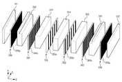
도 4는 도 2에 도시된 흡음층을 분해하여 도시한 분해사시도이다.
도 5는 측 방향(L)과 고도 방향(E) 평면 상의 전극을 도시한 단면도이다.
도 6은 다른 실시예에 따른 초음파 프로브의 구성을 도시한 단면도이다.
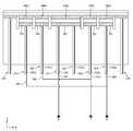
도 7은 도 2에 도시된 초음파 프로브의 회로 일부를 도시한 도면이다.
도 8은 도 6에 도시된 초음파 프로브에서 일 실시예에 따른 회로 일부를 도시한 도면이다.
도 9는 도 6에 도시된 초음파 프로브에서 다른 실시예에 따른 회로 일부를 도시한 도면이다.
도 10은 도 2에 도시된 초음파 프로브의 제조방법을 나타낸 흐름도이다.
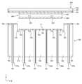
도 11은 도 10의 제조과정에서 장착홈이 형성된 상태를 도시한 도면이다.
도 12은 도 10의 제조과정에서 전극층이 형성된 상태를 도시한 도면이다.
도 13는 도 10의 제조과정에서 제1 분리홈이 형성된 상태를 도시한 도면이다.
도 14은 도 10의 제조과정에서 압전체가 마련된 상태를 도시한 도면이다.
도 15은 도 10의 제조과정에서 제2 분리홈이 형성된 상태를 도시한 도면이다.
도 16는 도 2에 도시된 초음파 프로브의 다른 제조방법을 나타낸 흐름도이다.
도 17은 도 16의 제조과정에서 제3 분리홈이 형성된 상태를 도시한 도면이다.1 is a perspective view of an ultrasound imaging apparatus according to an exemplary embodiment;
FIG. 2 is a diagram schematically illustrating a configuration of the ultrasound probe shown in FIG. 1 .
FIG. 3 is a cross-sectional view illustrating a cross-section taken along the auxiliary line XX' shown in FIG. 2 .
4 is an exploded perspective view showing the sound-absorbing layer shown in FIG.
5 is a cross-sectional view showing an electrode on the plane in the lateral direction (L) and in the elevation direction (E).
6 is a cross-sectional view illustrating a configuration of an ultrasound probe according to another exemplary embodiment.
FIG. 7 is a diagram illustrating a part of a circuit of the ultrasound probe shown in FIG. 2 .
FIG. 8 is a diagram illustrating a part of a circuit in the ultrasound probe shown in FIG. 6 according to an exemplary embodiment.
FIG. 9 is a diagram illustrating a part of a circuit in the ultrasound probe shown in FIG. 6 according to another exemplary embodiment.
10 is a flowchart illustrating a method of manufacturing the ultrasound probe shown in FIG. 2 .
11 is a view illustrating a state in which a mounting groove is formed in the manufacturing process of FIG. 10 .
12 is a view illustrating a state in which an electrode layer is formed in the manufacturing process of FIG. 10 .
13 is a view illustrating a state in which a first separation groove is formed in the manufacturing process of FIG. 10 .
14 is a view illustrating a state in which a piezoelectric body is provided in the manufacturing process of FIG. 10 .
15 is a view illustrating a state in which a second separation groove is formed in the manufacturing process of FIG. 10 .
16 is a flowchart illustrating another method of manufacturing the ultrasound probe shown in FIG. 2 .
17 is a view illustrating a state in which a third separation groove is formed in the manufacturing process of FIG. 16 .
본 명세서에 기재된 실시예와 도면에 도시된 구성은 개시된 발명의 바람직한 일 예에 불과할 뿐이며, 본 출원의 출원시점에 있어서 본 명세서의 실시예와 도면을 대체할 수 있는 다양한 변형 예들이 있을 수 있다.The configuration shown in the embodiments and drawings described in this specification is only a preferred example of the disclosed invention, and there may be various modifications that can replace the embodiments and drawings of the present specification at the time of filing of the present application.
본 명세서의 각 도면에서 제시된 동일한 참조번호 또는 부호는 실질적으로 동일한 기능을 수행하는 부품 또는 구성요소를 나타낸다. 도면에서 요소들의 형상 및 크기 등은 명확한 설명을 위해 과장된 것일 수 있다.The same reference numerals or reference numerals in each drawing in this specification indicate parts or components that perform substantially the same functions. The shapes and sizes of elements in the drawings may be exaggerated for clear explanation.
본 명세서에서 사용한 용어는 실시예를 설명하기 위해 사용된 것으로, 개시된 발명을 제한 및/또는 한정하려는 의도가 아니다. 단수의 표현은 문맥상 명백하게 다르게 뜻하지 않는 한, 복수의 표현을 포함한다. 본 명세서에서, "포함하다" 또는 "가지다" 등의 용어는 명세서상에 기재된 특징, 숫자, 단계, 동작, 구성요소, 부품 또는 이들을 조합한 것이 존재함을 지정하려는 것이지, 하나 또는 그 이상의 다른 특징들이나 숫자, 단계, 동작, 구성요소, 부품 또는 이들을 조합한 것들의 존재 또는 부가 가능성을 미리 배제하지 않는다.The terminology used herein is used to describe the embodiments, and is not intended to limit and/or limit the disclosed invention. The singular expression includes the plural expression unless the context clearly dictates otherwise. In this specification, terms such as "comprises" or "have" are intended to designate that the features, numbers, steps, operations, components, parts, or combinations thereof described in the specification exist, but one or more other features It does not preclude the possibility of the presence or addition of figures, numbers, steps, operations, components, parts, or combinations thereof.
본 명세서에서 사용한 "제1", "제2"등과 같이 서수를 포함하는 용어는 다양한 구성요소들을 설명하는데 사용될 수 있지만, 상기 구성요소들은 상기 용어들에 의해 한정되지는 않으며, 상기 용어들은 하나의 구성요소를 다른 구성요소로부터 구별하는 목적으로만 사용된다. 예를 들어, 본 발명의 권리 범위를 벗어나지 않으면서 제1 구성요소는 제2 구성요소로 명명될 수 있고, 유사하게 제2 구성요소도 제1 구성요소로 명명될 수 있다. "및/또는"이라는 용어는 복수의 관련된 기재된 항목들의 조합 또는 복수의 관련된 기재된 항목들 중의 어느 항목을 포함한다.As used herein, terms including ordinal numbers such as "first", "second", etc. may be used to describe various elements, but the elements are not limited by the terms, and the terms are It is used only for the purpose of distinguishing a component from other components. For example, without departing from the scope of the present invention, a first component may be referred to as a second component, and similarly, a second component may also be referred to as a first component. The term “and/or” includes a combination of a plurality of related listed items or any of a plurality of related listed items.
이하에서 사용되는 용어 "전방", "후방", "상부", "하부" 등은 도면을 기준으로 정의한 것이며, 이 용어에 의하여 각 구성요서의 형상 및 위치가 제한되는 것은 아니다.The terms "front", "rear", "upper", "lower", etc. used below are defined based on the drawings, and the shape and position of each component is not limited by these terms.
각 단계들에 있어 식별부호는 설명의 편의를 위하여 사용되는 것으로 식별부호는 각 단계들의 순서를 설명하는 것이 아니며, 각 단계들은 문맥상 명백하게 특정 순서를 기재하지 않는 이상 명기된 순서와 다르게 실시될 수 있다.In each step, the identification code is used for convenience of description, and the identification code does not describe the order of each step, and each step may be performed differently from the specified order unless the specific order is clearly stated in the context. have.
이하에서는 본 발명에 따른 실시예를 첨부된 도면을 참조하여 상세히 설명한다.Hereinafter, an embodiment according to the present invention will be described in detail with reference to the accompanying drawings.
도 1은 일 실시예에 따른 초음파 영상 장치의 사시도이다.1 is a perspective view of an ultrasound imaging apparatus according to an exemplary embodiment;
도 1을 참조하면, 초음파 영상 장치(10)는 대상체에 초음파 신호를 송신하고, 대상체로부터 에코 초음파 신호를 수신하여 전기적 신호로 변환하는 초음파 프로브(100), 초음파 신호를 기초로 초음파 영상을 생성하는 본체(200)를 포함한다. 본체(200)는 유선 통신망 또는 무선 통신망을 통해 초음파 프로브(100)와 연결될 수 있다. 본체(200)는 디스플레이(300)와 입력 장치(400)를 구비한 워크 스테이션일 수 있다.Referring to FIG. 1 , the
초음파 프로브(100)는 하우징(h) 내에 구비되어 초음파를 대상체로 조사하고, 대상체로부터 반사된 에코 초음파를 수신하며, 전기적 신호와 초음파를 상호 변환시키는 트랜스듀서 모듈(110), 본체(200)의 암 커넥터(female connector)와 물리적으로 결합되어 본체(200)에 신호를 송수신하는 수 커넥터(male connector, 130), 수 커넥터(130)와 트랜스듀서 모듈(110)을 연결하는 케이블(120)을 포함한다.The
여기서 대상체는 인간이나 동물의 생체, 또는 혈관, 뼈, 근육 등과 같은 생체 내 조직일 수도 있으나 이에 한정되지는 않으며, 초음파 영상 장치(10)에 의해 그 내부 구조가 영상화 될 수 있는 것이라면 대상체가 될 수 있다.Here, the object may be a living body of a human or an animal, or an in-vivo tissue such as blood vessels, bones, muscles, etc., but is not limited thereto, and may be any object whose internal structure can be imaged by the
또한, 초음파 프로브(100)는 무선 통신망을 통해 본체(200)와 연결되어 초음파 프로브(100)의 제어에 필요한 각종 신호를 수신하거나 또는 초음파 프로브(100)가 수신한 에코 초음파 신호에 대응되는 아날로그 신호 또는 디지털 신호를 전달할 수 있다. 한편, 무선 통신망은 무선으로 신호를 주고 받을 수 있는 통신망을 의미한다.In addition, the
에코 초음파는 초음파가 조사된 대상체로부터 반사된 초음파로서, 진단 모드에 따라 다양한 초음파 영상을 생성하기 위한 다양한 주파수 대역 또는 에너지 강도를 갖는다.The echo ultrasound is ultrasound reflected from an object irradiated with ultrasound, and has various frequency bands or energy intensities for generating various ultrasound images according to a diagnosis mode.
트랜스듀서 모듈(110)은 인가된 교류 전원에 따라 초음파를 생성할 수 있다. 구체적으로, 트랜스듀서 모듈(110)은 외부의 전원 공급 장치 또는 내부의 축전장치 예를 들어, 배터리 등으로부터 교류 전원을 공급받을 수 있다. 트랜스듀서 모듈(110)의 진동자는 공급받은 교류 전원에 따라 진동함으로써 초음파를 생성할 수 있다.The
트랜스듀서 모듈(110)의 중심을 기준으로 직각을 이루는 세방향을 축 방향(axis direction; A), 측 방향(lateral direction; L), 고도 방향(elevation direction; E)으로 각각 정의할 수 있다. 구체적으로, 초음파가 조사되는 방향을 축 방향(A)으로 정의하고, 트랜스듀서 모듈(110)이 가로 열을 형성하는 방향을 측 방향(L)으로 정의하며, 축 방향(A) 및 측 방향(L)과 수직한 나머지 한 방향을 고도 방향(E)으로 정의할 수 있다. 트랜스듀서 모듈(110)은 고도 방향(E)으로도 복수개의 로우(row)를 형성할 수 있으며, 이 경우 멀티-로우(Multi-row) 어레이 배열 형태를 형성할 수 있다.Three directions forming a right angle with respect to the center of the
케이블(120)은 일단에 트랜스듀서 모듈(110)과 연결되고, 타단에 수 커넥터(130)와 연결됨으로써, 트랜스듀서 모듈(110)과 수 커넥터(130)를 연결시킨다.The
수 커넥터(male connector, 130)는 케이블(120)의 타단에 연결되어 본체(200)의 암 커넥터(female connector, 201)와 물리적으로 결합할 수 있다. 이러한 수 커넥터(130)는 트랜스듀서 모듈(110)에 의해 생성된 전기적 신호를 물리적으로 결합된 암 커넥터(201)에 전달하거나, 본체(200)에 의해 생성된 제어 신호를 암 커넥터(201)로부터 수신한다.The
그러나, 초음파 프로브(100)가 무선 초음파 프로브(100)로서 구현된 경우, 이러한 케이블(120) 및 수 커넥터(130)는 생략될 수 있고, 초음파 프로브(100)에 포함된 별도의 무선 통신모듈(미도시)을 통해 초음파 프로브(100)와 본체(200)가 신호를 송수신할 수 있는 바, 반드시 도 1에 도시된 초음파 프로브(100)의 형태에 한정되는 것은 아니다.However, when the
본체(200)는 근거리 통신 모듈, 및 이동 통신 모듈 중 적어도 하나를 통해 초음파 프로브(100)와 무선 통신을 수행할 수 있다.The
근거리 통신 모듈은 소정 거리 이내의 근거리 통신을 위한 모듈을 의미한다. 예를 들어, 근거리 통신 기술에는 무선 랜(Wireless LAN), 와이파이(Wi-Fi), 블루투스(Bluetooth), 지그비(Zigbee), WFD(Wi-Fi Direct), UWB(Ultra wideband), 적외선 통신(IrDA; Infrared Data Association), BLE (Bluetooth Low Energy), NFC(Near Field Communication) 등이 있을 수 있으나, 이에 한정되는 것은 아니다.The short-range communication module refers to a module for short-range communication within a predetermined distance. For example, short-distance communication technologies include wireless LAN, Wi-Fi, Bluetooth, Zigbee, Wi-Fi Direct, UWB (Ultra wideband), and infrared communication (IrDA). ; Infrared Data Association), BLE (Bluetooth Low Energy), NFC (Near Field Communication), etc. may be there, but is not limited thereto.
이동 통신 모듈은 이동 통신망 상에서 기지국, 외부 단말, 서버 중 적어도 하나와 무선 신호를 송수신할 수 있다. 여기에서, 무선 신호는 다양한 형태의 데이터를 포함하는 신호를 의미한다. 즉, 본체(200)는 기지국, 및 서버 중 적어도 하나를 거쳐, 초음파 프로브(100)와 다양한 형태의 데이터를 포함한 신호를 주고 받을 수 있다.The mobile communication module may transmit/receive a wireless signal to/from at least one of a base station, an external terminal, and a server on a mobile communication network. Here, the radio signal means a signal including various types of data. That is, the
예를 들어, 본체(200)는 3G, 4G와 같은 이동 통신망 상에서 기지국을 거쳐, 초음파 프로브(100)와 다양한 형태의 데이터를 포함한 신호를 주고 받을 수 있다. 이외에도, 본체(200)는 의료 영상 정보 시스템(PACS; Picture Archiving and Communication System)을 통해 연결된 병원 서버나 병원 내의 다른 의료 장치와 데이터를 주고 받을 수 있다. 또한, 본체(200)는 의료용 디지털 영상 및 통신(DICOM; Digital Imaging and Communications in Medicine) 표준에 따라 데이터를 주고 받을 수 있으며, 제한이 없다.For example, the
이외에도, 본체(200)는 유선 통신망을 통해 초음파 프로브(100)와 데이터를 주고 받을 수 있다. 유선 통신망은 유선으로 신호를 주고 받을 수 있는 통신망을 의미한다. 일 실시예에 따르면, 본체(200)는 PCI(Peripheral Component Interconnect), PCI-express, USB(Universe Serial Bus) 등의 유선 통신망을 이용하여 초음파 프로브(100)와 각종 신호를 주고 받을 수 있으나, 이에 한정되는 것은 아니다.In addition, the
한편, 초음파 영상장치(10)의 본체(200)에는 디스플레이(300), 입력부(400)가 마련될 수 있다. 입력부(400)는 사용자로부터 초음파 프로브(100)에 관한 설정 정보뿐만 아니라, 각종 제어 명령 등을 입력 받을 수 있다.Meanwhile, the
초음파 프로브(100)에 관한 설정 정보는 이득(gain) 정보, 배율(zoom) 정보, 초점(focus) 정보, 시간이득 보상(TGC, Time Gain Compensation) 정보, 깊이(depth) 정보, 주파수 정보, 파워 정보, 프레임 평균값(frame average) 정보, 및 다이나믹 레인지(dynamic range) 정보 등을 포함한다. 그러나, 초음파 프로브(100)에 관한 설정 정보는 이에 한정되지 않으며, 초음파 영상을 촬영하기 위해 설정할 수 있는 다양한 정보를 포함한다.Setting information about the
이 정보들은 무선 통신망 또는 유선 통신망을 통해 초음파 프로브(100)로 전달되고, 초음파 프로브(100)는 전달 받은 정보들에 맞추어 설정될 수 있다. 이외에도, 본체(200)는 입력부(400)를 통해 초음파 신호의 송신 명령 등과 같은 각종 제어 명령을 사용자로부터 입력 받아, 이를 초음파 프로브(100)에 전달할 수 있다.This information is transmitted to the
한편, 입력부(400)는 키보드, 풋 스위치(foot switch) 또는 풋 페달(foot pedal) 방식으로 구현될 수도 있다. 예를 들어, 키보드는 하드웨어적으로 구현될 수 있다. 이러한 키보드는 스위치, 키, 조이스틱 및 트랙볼 중 적어도 하나를 포함할 수 있다. 다른 예로, 키보드는 그래픽 유저 인터페이스와 같이 소프트웨어적으로 구현될 수도 있다. 이 경우, 키보드는 디스플레이(300)를 통해 표시될 수 있다. 풋 스위치나 풋 페달은 본체(200)의 하부에 마련될 수 있으며, 사용자는 풋 페달을 이용하여 초음파 영상장치(10)의 동작을 제어할 수 있다.Meanwhile, the
디스플레이(300)는 브라운관(Cathode Ray Tube; CRT), LCD(Liquid Crystal Display), LED(Light Emitting Diode), PDP(Plasma Display Panel), OLED(Organic Light Emitting Diode) 등과 같이, 공지된 다양한 방식으로 구현될 수 있으나, 이에 한하지 않는다.The
디스플레이(300)는 대상체 내부의 목표 부위에 대한 초음파 영상을 표시할 수 있다. 디스플레이(300)에 표시되는 초음파 영상은 2차원 초음파 영상, 또는 3차원 입체 초음파 영상일 수 있으며, 초음파 영상장치(10)의 동작 모드에 따라 다양한 초음파 영상이 표시될 수 있다. 또한, 디스플레이(300)는 초음파 진단에 필요한 메뉴나 안내 사항뿐만 아니라, 초음파 프로브(100)의 동작 상태에 관한 정보 등을 표시할 수 있다.The
초음파 영상은 A-모드(Amplitude mode, A-모드) 영상, B-모드(Brightness Mode; B-Mode) 영상, M-모드(Motion Mode; M-mode) 영상을 포함할 뿐만 아니라, C(Color)-모드 영상 및 D(Doppler)-모드 영상을 포함한다.The ultrasound image includes an A-mode (Amplitude mode, A-mode) image, a B-mode (Brightness Mode; B-Mode) image, and an M-mode (Motion Mode; M-mode) image, as well as a C (Color) image. )-mode images and D (Doppler)-mode images.
A-모드 영상은 에코 초음파 신호에 대응되는 초음파 신호의 크기를 나타내는 초음파 영상을 의미하며, B-모드 영상은 에코 초음파 신호에 대응되는 초음파 신호의 크기를 밝기로 나타낸 초음파 영상을 의미하며, M-모드 영상은 특정 위치에서 시간에 따른 대상체의 움직임을 나타내는 초음파 영상을 의미한다. D-모드 영상은 도플러 효과를 이용하여 움직이는 대상체를 파형 형태로 나타내는 초음파 영상을 의미하며, 또한, C-모드 영상은 움직이는 대상체를 컬러 스펙트럼 형태로 나타내는 초음파 영상을 의미한다.The A-mode image refers to an ultrasound image indicating the size of an ultrasound signal corresponding to the echo ultrasound signal, and the B-mode image refers to an ultrasound image indicating the brightness of the ultrasound signal corresponding to the echo ultrasound signal. The mode image refers to an ultrasound image representing the movement of an object according to time at a specific location. The D-mode image refers to an ultrasound image representing a moving object in the form of a waveform using the Doppler effect, and the C-mode image refers to an ultrasound image representing the moving object in the form of a color spectrum.
한편, 디스플레이(300)가 터치 스크린 타입으로 구현되는 경우, 디스플레이(300)는 입력부(400)의 기능도 함께 수행할 수 있다. 즉, 본체(200)는 디스플레이(300), 및 입력부(400) 중 적어도 하나를 통해 사용자로부터 각종 명령을 입력 받을 수 있다.Meanwhile, when the
이외에도, 도면에는 도시되어 있지 않으나, 본체(200)에는 음성 인식 센서가 마련되어, 사용자로부터 음성 명령을 입력 받을 수도 있다. 이하에서는 트랜스듀서 모듈(110)의 구조를 중점으로 초음파 프로브(100)의 구성에 대해서 보다 구체적으로 살펴보도록 한다.In addition, although not shown in the drawings, a voice recognition sensor may be provided in the
도 2는 도 1에 도시된 초음파 프로브의 구성을 개략적으로 도시한 도면이다. 도 3은 도 2에 도시된 보조선 X-X' 에서의 단면을 도시한 단면도이다. 도 4는 도 2에 도시된 흡음층을 분해하여 도시한 분해사시도이다. 도 5는 측 방향(L)과 고도 방향(E) 평면 상의 전극을 도시한 단면도이다.FIG. 2 is a diagram schematically illustrating a configuration of the ultrasound probe shown in FIG. 1 . FIG. 3 is a cross-sectional view taken along the auxiliary line X-X' shown in FIG. 2 . 4 is an exploded perspective view showing the sound-absorbing layer shown in FIG. 5 is a cross-sectional view showing an electrode on the plane in the lateral direction (L) and in the elevation direction (E).
도 2 내지 도 5에 도시된 초음파 프로브(100)는 흡음층(500)과 압전체(600)를 포함할 수 있다. 흡음층(500)은 압전체(600)의 후방에 배치될 수 있다. 흡음층(500)은 압전체(600)의 자유 진동을 억제하여 초음파의 펄스 폭을 감소시키며, 초음파가 불필요하게 압전체(600)의 후방으로 전파되는 것을 차단시켜 영상 왜곡을 방지할 수 있다.The
흡음층(500)은 흡음체(510)를 포함할 수 있다. 흡음체(510)는 복수의 흡음체(511,512,513,514,515,516,517)를 포함할 수 있고, 흡음층(500)은 흡음체들(510)의 접합에 의해 형성될 수 있다. 구체적으로, 복수의 흡음체들(510)은 고도 방향(E)으로 배열되어 적층될 수 있다. 흡음층(500)은 에폭시 수지 및 텅스텐 파우더 등이 추가된 고무를 포함하는 재질로 형성될 수 있다.The
흡음층(500)의 전면에는 압전체(600)가 마련될 수 있다. 즉, 흡음체(510)들이 배열되는 방향과 수직한 방향의 흡음층(500) 일면에 압전체(600)가 마련될 수 있다. 압전체(600)는 복수의 압전체(600)를 포함할 수 있다.A
흡음층(500)의 전면에는 장착홈(520)이 형성될 수 있고, 장착홈(520)에는 압전체(600)가 삽입될 수 있다. 장착홈(520)은 압전체(600)가 삽입될 수 있도록 압전체(600)와 대응되는 형상으로 흡음층(500) 전면에 오목하게 형성될 수 있다.A mounting
압전체(600)는 복수 개의 압전체(600)가 어레이 형상으로 배열되는 형태로 구비됨으로써 다채널로 사용될 수 있다. 구체적으로, 측 방향(L)으로 연장되는 복수의 분리홈(530)에 의해 분리된 복수의 압전체는 고도 방향으로 배열될 수 있고, 다이싱에 의해 고도 방향(E)으로 연장되는 복수의 커프(540)에 의해 분리된 복수의 압전체(600)는 측 방향(L)으로 배열될 수 있다. 도 2에서 B 영역에도 커프(540)가 형성될 수 있으나 그 도시가 생략되어 있다.The
커프(540)는 도 5의 분리선(d)이 도시된 위치에 형성될 수 있다. 따라서, 도 5에서 분리선(d)과 커프(540)는 동일하게 인식되어도 무관하다. 인접한 두 커프(d) 사이 영역(이하 "열(column, C)"이라 한다)에 배치되는 복수의 압전체(600)는 고도 방향(E)으로 배열될 수 있고, 복수의 열(C) 각각에는 고도 방향(E)으로 압전체(600)가 배열될 수 있고, 고도 방향(E)으로의 압전체(600) 어레이는 복수의 열(C) 각각에서 동일할 수 있다. 아래에서 후술하는 압전체(600), 전극층(700) 및 음향정합층(800) 등은 커프(540)에 의해 분리될 수 있다.The
초음파 프로브(100)는 적어도 하나의 센터 연결부(550)와, 복수 개의 사이드 연결부(560)와, 적어도 하나의 접지 연결부(570)를 포함할 수 있다. 센터 연결부(550)와 사이드 연결부(560)는 복수의 흠음체들(510,511,512,513,514,515, 516,517) 사이에 접합되어 배치될 수 있다. 접지 연결부(570)는 복수의 흠음체들(510,511,512,513,514,515, 516,517) 사이에 접합되어 배치될 수 있다. 즉, 흠음층(500)은 센터 연결부(550)와, 사이드 연결부(560)와, 접지 연결부(570)를 포함할 수 있다.The
구체적으로, 흡음층(500)의 내측에는 센터 연결부(550)가 배치되고, 센터 연결부(550)의 외측에는 사이드 연결부(560)가 배치되고, 사이드 연결부(560)의 외측에는 접지 연결부(570)가 배치될 수 있다. 달리 말하면, 흡음층(500) 내부의 가장 외측에는 접지 연결부(570)가 배치되고, 흡음층(500)의 가장 내측에는 센터 연결부(550)가 배치되며, 접지 연결부(570)와 센터 연결부(550) 사이에 사이드 연결부(560)가 배치될 수 있다.Specifically, the
접지 연결부(570)는 절연부(미도시) 및 전극(570a)을 포함한다. 접지 연결부(570)는 흡음체들(510,511,512,513,514,515,516,517) 사이에 접합된다. 도면에 따르면, 접지 연결부(570)는 복수개의 접지 연결부(570)이고, 흡음체들(511,512) 사이에 접합되거나 다른 흡읍체들(516,517) 사이에 접합될 수 있다. 다만 이에 한정되는 것은 아니고, 접지 연결부(570)는 흡음층(500)의 외측에 형성될 수 있다. 즉, 흡음체들(511,517) 외측에 배치될 수 있다.The
접지 연결부(570)의 일면에는 전극(570a)이 형성될 수 있다. 접지 연결부(570)의 전극(570a)은 측 방향(L)의 압전체(600) 배열에 대응되도록 측 방향(L)으로 복수 개 형성될 수 있다. 다만 이에 한정되는 것은 아니고, 접지 연결부(570)의 일면 자체가 전극(570a)에 해당할 수도 있다.An
센터 연결부(550)는 제1 센터 연결부(511)와 제2 센터 연결부(512)를 포함할 수 있다.The
제1 센터 연결부(551)는 흡음체들(513,514) 사이에 접합될 수 있다. 도면에 따르면, 제1 센터 연결부(551)는 일곱 개의 흡음체(511,512,513,514,515, 516,517) 중 두 개의 흡음체(513,514) 사이에 삽입되어 흡음체들(513,514) 사이에 접합될 수 있다.The first
제1 센터 연결부(551)는 절연부(미도시) 및 전극(551a)을 포함한다. 제1 센터 연결부(551)의 일면에는 전극(551a)이 형성될 수 있다. 전극(551a)은 절연부 상에 복수개가 구비되며, 복수개의 전극(551a) 각각은 측 방향(L)으로 이격되게 형성될 수 있다. 제1 센터 연결부(551)에 구비되는 전극(551a)은 후술할 압전체(600)의 제1 전극(601)과 전기적으로 연결되는 신호전극일 수 있다.The first
제1 센터 연결부(551)는, 가요성 인쇄회로기판(Flexible Printed Circuit Board)을 포함할 수 있으며, 그 외 인쇄회로기판(Printed Circuit Board; PCB), 기타 신호나 전기를 공급할 수 있는 모든 구성을 포함할 수 있다.The first
흡음체(513,514) 사이에 접합되는 제1 센터 연결부(551)의 일단은 압전체(600)와 인접한 흡음층(500)의 전방으로 노출되며, 타단은 흡음층(500)의 후방을 통해 흡음층(500)의 외측으로 연장된다. 제1 센터 연결부(551)의 일단이 흡음층(500)의 전방으로 노출되므로 흡음층(500)의 전방에는 제1 센터 연결부(551)의 전극(551a)이 외부로 노출될 수 있다.One end of the first
제2 센터 연결부(552)는 흠음체들(514,515) 사이에 접합될 수 있다. 도면에 따르면, 제2 센터 연결부(552)는 일곱 개의 흠음체(511,512,513,514,515,516,517) 중 두 개의 흡음체(514,515) 사이에 삽입되어 흡음체(514,515) 사이에 접합될 수 있다.The second
제2 센터 연결부(552)는 제1 센터 연결부(551)와 이격되게 배치될 수 있다. 구체적으로, 제2 센터 연결부(552)와 제1 센터 연결부(551) 사이에는 흡음체(514)가 배치되므로, 제2 센터 연결부(552)는 제1 센터 연결부(551)와 고도 방향(E)으로 흡음체(514)가 차지하는 공간만큼 이격되게 배치될 수 있다.The second
제2 센터 연결부(552)는 절연부(미도시) 및 전극(552a)을 포함한다. 제2 센터 연결부(552)의 일면에는 전극(552a)이 형성될 수 있다. 제2 센터 연결부(552)의 전극(552a)은 절연부 상에 복수 개가 구비되며, 복수개의 전극(552a) 각각은 측 방향(L)으로 이격되게 형성될 수 있다. 구체적으로, 제2 센터 연결부(552)의 전극(552a)은 제1 센터 연결부(551)의 전극(551a)과 마주하지 않게 형성될 수 있다. 제2 센터 연결부(552)에 구비되는 전극(552a)은 후술할 압전체(600)의 제1 전극(601)과 전기적으로 연결되는 신호전극일 수 있다.The second
제2 센터 연결부(552)는, 가요성 인쇄회로기판(Flexible Printed Circuit Board)을 포함할 수 있으며, 그 외 인쇄회로기판(Printed Circuit Board; PCB), 기타 신호나 전기를 공급할 수 있는 모든 구성을 포함할 수 있다.The second
흡음체(514,515) 사이에 접합되는 제2 센터 연결부(552)의 일단은 압전체(600)와 인접한 흡음층(500)의 전방으로 노출되며, 타단은 흡음층(500)의 후방을 통해 흡음층(500)의 외측으로 연장된다. 제2 센터 연결부(552)의 일단이 흡음층(500)의 전방으로 노출되므로 흡음층(500)의 전방에는 제2 센터 연결부(552)의 전극(552a)이 외부로 노출될 수 있다.One end of the second
흡음층(500)의 내부에는 사이드 연결부(560)가 형성될 수 있다. 구체적으로, 사이드 연결부(560) 제1 사이드 연결부(561)과 제2 사이드 연결부(562)를 포함할 수 있다. 다만 이에 한정되는 것은 아니며, 4개의 사이드 연결부(560) 또는 6개의 사이드 연결부(560)를 가질 수 있다.A
사이드 연결부(561,562)는 절연부(미도시) 및 전극(561a.562a)을 포함할 수 있다. 사이드 연결부(560)의 일면에는 전극(561a,562a)이 형성될 수 있다. 사이드 연결부(561,562)의 전극(561a,562a)은 측 방향(L)의 압전체(600) 배열에 대응되도록 측 방향(L)으로 복수 개 형성될 수 있다.The
구체적으로 복수개로 형성된 제1 사이드 연결부(561)의 전극(561a)와 복수개로 형성된 제2 사이드 연결부(562)의 전극(562a)는 마주보게 배치될 수 있다. 즉, 모든 열(C)에는 제1 사이드 연결부(561)의 전극(561a)과 제2 사이드 연결부(562)의 전극(562a)이 각각 하나씩 마련될 수 있다. 다만 이에 한정되는 것은 아니고, 사이드 연결부(561,562)의 일면 자체가 전극(561a,562a)에 해당될 수도 있다.Specifically, the plurality of
사이드 연결부(560)는, 가요성 인쇄회로기판(Flexible Printed Circuit Board)을 포함할 수 있으며, 그 외 인쇄회로기판(Printed Circuit Board; PCB), 기타 신호나 전기를 공급할 수 있는 모든 구성을 포함할 수 있다.The
흡음층(500)에 센터 연결부(551,552), 사이드 연결부(561,562), 접지 연결부(570)가 접합되고 전극(551a)과 제2 센터 연결부(552)의 전극(552a)은 상기와 같이 어긋나게 배치되는 구조를 하고 있으므로, 커프(540)에 의해 분리된 각 열(C)이 충분한 강도를 가지면서도 좀 더 좁은 피치를 가질 수 있어 고밀도이면서도 작은 크기를 가질 수 있다.The
또한, 상기 복수의 연결부(550,560,570)의 인쇄회로기판은 흡음층(500)과 압전체(600) 사이에 가로로 배치되는 것이 아니라 흡음층(500) 내부에서 세로로 배치될 수 있으므로, 인쇄회로기판이 흡음층(500)과 압전체(600) 사이에 가로로 배치될 때 발생할 수 있는 공간해상도 저하 등의 성능 저하를 방지할 수 있다.In addition, since the printed circuit board of the plurality of
흡음층(500)은 흡음층(500)의 전면에 형성되는 전극층(700)을 포함할 수 있다. 전극층(700)은 제1 전극층(701), 제2 전극층(702), 제3 전극층(703)을 포함할 수 있다. 분리홈(530)에 의해 제1 전극층(701), 제2 전극층(702), 제3 전극층(703)은 각각 분리되어 형성될 수 있다. 제2 전극층(702)과 제3 전극층(703)은 장착홈(520)의 바닥면에 형성될 수 있고, 제1 전극층(701)은 장착홈(520)의 양측에 형성될 수 있다.The
제1 전극층(701), 제2 전극층(702) 및 제3 전극층(703)은 금, 은 또는 구리 등과 같은 고전도성 금속으로 형성될 수 있으며, 증착, 스퍼터링, 도금 또는 스프레이 등과 같은 방법으로 형성될 수 있다. 제1 전극층(701), 제2 전극층(702) 및 제3 전극층(703)은 하나의 전극층(700)으로 서로 연결되게 형성된 후 컷팅에 의해 분리될 수도 있고, 최초부터 분리되게 형성될 수도 있다.The
다만, 이에 한정되는 것은 아니다. 도 6은 다른 실시예에 따른 초음파 프로브의 구성을 도시한 단면도이다. 중복되는 부분에 대한 설명은 생략한다.However, the present invention is not limited thereto. 6 is a cross-sectional view illustrating a configuration of an ultrasound probe according to another exemplary embodiment. A description of overlapping parts will be omitted.
도 6을 참조하면, 초음파 프로브는 사이드 연결부(560)는 제3 사이드 연결부(563)와 제4 사이드 연결부(564)를 더 포함할 수 있다.Referring to FIG. 6 , the
이 경우, 제3 사이드 연결부(563) 및 제4 사이드 연결부(564)와 전기적으로 연결되는 제4 전극층(704)을 더 포함할 수 있다. 또한, 제4 전극층(704)을 매개로 제3 사이드 연결부(563) 또는 제4 사이드 연결부(564)와 전기적으로 연결되는 사이드 압전체(600c)를 더 포함할 수 있다.In this case, a
도 6에 도시된 것과 같이 제3 사이드 연결부(563)와 제4 사이드 연결부(564)는 흡음체들(512,518,519,516) 사이에 배치되어 접합될 수 있다.As shown in FIG. 6 , the third
제3 사이드 연결부(563) 또는 제4 사이드 연결부(564)와 연결되는 사이드 압전체(600c)는 제1 사이드 연결부(561) 또는 제2 사이드 연결부(562)와 연결되는 사이드 압전체(600b)와 분리되도록 분리홈(533)이 형성될 수 있다.The side
초음파 프로브는 음향정합층(800)을 더 포함할 수 있다. 음향정합층(800)은 압전체(600)의 전방에 배치된다. 음향정합층(800)은 압전체(600)의 음향 임피던스와 대상체의 음향 임피던스를 정합시켜 압전체(600)에서 발생되는 초음파 신호가 대상체로 효율적으로 전달되도록 하는 역할을 하는 것으로, 압전체(600)의 음향 임피던스와 대상체의 음향 임피던스의 중간값을 갖도록 구비될 수 있다.The ultrasound probe may further include an
음향정합층(800)은 유리 또는 수지 재질로 형성될 수 있고, 음향 임피던스가 압전체(600)로부터 대상체를 향해 단계적으로 변화하도록 재질이 서로 다른 제1 음향정합층(801)과 제2 음향정합층(802)을 포함할 수 있다.The
음향정합층(800)은 전극부(810)를 포함할 수 있다. 전극부(810)는 압전체(600)와 연결되도록 제1 음향정합층(801)과 압전체(600) 사이에 배치될 수 있다. 전극부(810)는 금, 은 또는 구리 등과 같은 고전도성 금속으로 형성될 수 있고, 증착, 스퍼터링, 도금 또는 스프레이 등의 방법으로 형성될 수 있다.The
한편, 도시하지는 않았으나, 초음파 프로브(100)는 음향정합층(800)의 전방에 배치되어 전방으로 진행하는 초음파 신호를 특정 지점에 집속시키는 렌즈층을 더 구비할 수 있다.Meanwhile, although not shown, the
제1 센터 연결부(551)와, 제2 센터 연결부(552)와, 사이드 연결부(56)와, 접지 연결부(570)는 압전체(600)와 전기적으로 연결될 수 있다. 이에 관하여 상세히 설명한다.The first
압전체(600)는 하면에 형성되는 제1 전극(601)과 상면에 형성되는 제2 전극(602)을 포함할 수 있다. 압전체(600)는 제1 센터 연결부(551), 제2 센터 연결부(552), 또는 사이드 연결부(560)와 전기적으로 연결될 수 있다.The
제3 전극층(703)은 흡음층(500)의 전방에 노출된 제1 센터 연결부(551)의 전극(551a) 또는 제2 센터 연결부(552)의 전극(552a)과 전기적으로 연결될 수 있다. 압전체(600)는 센터 압전체(600a)를 포함하고, 센터 압전체(600a)의 제1 전극(601)은 제3 전극층(703)을 매개로 하여 제1 센터 연결부(551)의 전극(551a) 또는 제2 센터 연결부(552)의 전극(552a)과 전기적으로 연결될 수 있다.The
좀 더 구체적으로, 다이싱에 의해 형성되는 커프(540)로 인하여 압전체는 복수의 열(C)로 분리된다. 복수의 열(C) 각각에는 제3 전극층(703)과 센터 압전체(600a)가 마련된다. 제1 센터 압전체(551)의 전극(551a)과 제2 센터 압전체(552)의 전극(552a)은 측 방향(L)으로 하나의 열(C) 간격만큼 어긋나게 배열되어 있으므로, 복수의 열(C) 각각에 존재하는 센터 압전체(600a)의 제1 전극(601)과 제3 전극층(703)에는 제1 센터 연결부(551)의 전극(551a) 또는 제2 센터 연결부(552)의 전극(552a) 중 어느 하나만 전기적으로 연결될 수 있다.More specifically, the piezoelectric body is separated into a plurality of columns C due to the
제2 전극층(702)은 흡음층(500)의 전방에 노출된 사이드 연결부(560)의 전극(560a)과 전기적으로 연결될 수 있다. 압전체(600)는 사이드 압전체(600b)를 포함하고, 사이드 압전체(600b)의 제1 전극(601)은 제2 전극층(702)을 매개로 하여 사이드 연결부(560)의 전극(560a)과 전기적으로 연결될 수 있다.The
사이드 연결부(560)의 전극(560a)은 모든 열(C)에 대응되도록 형성되므로 복수의 열(C) 각각에는 사이드 연결부(560)의 전극(560a)이 배치될 수 있다.Since the
제1 전극층(701)은 흡음층(500)의 전방에 노출된 접지 연결부(570)의 전극(570a)과 전기적으로 연결될 수 있다. 접지 연결부(570)의 전극(570a)은 모든 열(C)에 대응되도록 형성되므로 복수의 열(C) 각각에는 접지 연결부(570)의 전극(570a)이 배치될 수 있다.The
음향정합층(800)의 전극부(810)는 압전체(600)의 제2 전극(602) 및 제1 전극층(701)과 전기적으로 연결될 수 있다. 이러한 연결에 의해 압전체(600)는 전극부(810)와 전기적으로 연결될 수 있다. 구체적으로, 복수의 열(C) 각각에 마련되는 음향정합층(800)의 전극부(810)는 해당 열(C)에 마련되는 제2 전극(602) 및 제1 전극층(701)과 전기적으로 연결될 뿐이며, 다른 열(C)의 제2 전극(602) 및 제1 전극층(701)과는 전기적으로 연결되지 않도록 분리되어 있을 수 있다.The
도면에 따른 초음파 프로브(100)의 전극부(810)는 압전체(600)와 인접한 제 1 음향정합층(801)의 후방에 형성되는 것으로 도시되었으나 이에 한정되는 것은 아니며, 음향정합층(800)은 음향정합층(800)의 전체를 둘러싸도록 형성되는 전극부(810)를 갖는 형태로 구비될 수도 있고, 압전체(600)와 전기적으로 직접 연결될 수 있도록 그 전체 또는 일부분(예를 들어 제1 음향정합층(801))이 전도성 재질로 형성되는 형태로 구비될 수도 있는 등 다양한 변형 실시가 가능하다.The
도 7은 도 2에 도시된 초음파 프로브의 회로 일부를 도시한 도면이다. 도 8은 도 6에 도시된 초음파 프로브에서 일 실시예에 따른 회로 일부를 도시한 도면이다. 도 9는 도 6에 도시된 초음파 프로브에서 다른 실시예에 따른 회로 일부를 도시한 도면이다.FIG. 7 is a diagram illustrating a part of a circuit of the ultrasound probe shown in FIG. 2 . FIG. 8 is a diagram illustrating a part of a circuit in the ultrasound probe shown in FIG. 6 according to an exemplary embodiment. FIG. 9 is a diagram illustrating a part of a circuit in the ultrasound probe shown in FIG. 6 according to another exemplary embodiment.
도 7 내지 도 9를 참조하여 초음파 프로브의 구성을 제어적 측면에서 설명한다.The configuration of the ultrasound probe will be described in terms of control with reference to FIGS. 7 to 9 .
도 7을 참조하면, 센터 연결부(550) 또는 사이드 연결부(560)를 통하여 센터 압전체(600a) 또는 사이드 압전체(600b)와 전기적으로 연결될 수 있는 복수의 커넥터(900)를 포함할 수 있다.Referring to FIG. 7 , a plurality of
초음파 프로브(100)는 소정 주파수의 전압을 생성하는 펄서(미도시)를 포함하고, 커넥터(900)는 펄서에서 생성된 전압을 압전체(600)로 전달할 수 있다. 압전체(600)는 펄서에서 출력되는 전압의 진폭 및 주파수에 따라 진동하여 초음파를 생성할 수 있다.The
커넥터(900)는 센터 연결부(550)와 연결되는 제1 커넥터(901), 제1 사이드 연결부(561)에 연결되는 제2 커넥터(902), 제2 사이드 연결부(562)에 연결되는 제3 커넥터(903)를 포함할 수 있다. 도면에 도시된 커넥터(900)는 하나의 열(C)에 마련되는 커넥터(900)를 도시한 것이다. 따라서, 제1 커넥터(901)는 그 열(C)에 마련되는 센터 연결부(550)의 전극이 무엇인지에 따라 제1 센터 연결부(551) 또는 제2 센터 연결부(552)와 연결될 수 있다. 도 7의 경우 예시적으로, 제1 센터 연결부(551)의 전극(551a)에 연결된 경우가 도시되었다.The
각 커넥터(900)는 연결되는 연결부(550,560)의 전극과 전기적으로 연결될 수 있다. 즉, 제1 커넥터(901)는 제1 센터 연결부(551)의 전극(551a) 또는 제2 센터 연결부(552)의 전극(552a)과 전기적으로 연결될 수 있고, 제2 커넥터(902)는 제1 사이드 연결부(561)의 전극(561a)과 전기적으로 연결될 수 있고, 제3 커넥터(903)는 제2 사이드 연결부(562a)의 전극(562a)과 전기적으로 연결될 수 있다.Each
이와 같이, 커넥터(900)는 별도의 전선이나 전극 등일 수 있지만 이에 한정되는 것은 아니며 연결부(551,552,561,562)의 전극(551a,552a,561a,562a) 자체가 커넥터(900)에 해당될 수 있다. 즉, 도 7 내지 도 9에 도시된 커넥터의 구조는 통상적인 방법으로 구현된 회로의 형상을 간략히 도시한 것에 해당될 수 있다.As such, the
제2 커넥터(902)와 제3 커넥터(903)는 전기적으로 병렬일 수 있고, 제2 커넥터(902)와 제3 커넥터(903)는 병렬 연결된 상태에서 제1 커넥터(901)와 전기적으로 연결될 수 있다. 제1 커넥터(901)와 서로 병렬 연결된 상태의 제2 커넥터(902) 및 제3 커넥터(903) 사이에는 스위치(910)가 마련될 수 있다. 스위치(910)는 그 개폐에 따라 물리적 또는 전자적인 방법으로 펄서에서 생성된 신호를 제2 커넥터(902) 및 제3 커넥터(903)로 전달 또는 차단함으로써 사이드 연결부(561,562)에 의해 사이드 압전체(600b)로 흐르는 신호를 제어할 수 있다.The
스위치(910)가 열린 경우, 제1 커넥터(901)만 신호를 송수신할 수 있다. 즉, 센터 압전체(600a)만 초음파를 생성할 수 있다. 이 때, 압전체(600a)에 의해 발생되는 초음파 신호를 이용하여 대상체 깊이 방향으로 얕은 영역(near-field)에 대해서 고해상도의 이미지를 얻을 수 있다.When the
스위치(910)가 닫힌 경우, 제1 내지 제3 커넥터(901,902,903) 모두 신호를 송수신할 수 있다. 즉, 사이드 압전체(600b)와 센터 압전체(600a)의 진동에 의해 초음파가 생성될 수 있다. 이 때, 압전체(600)들에 의해 발생되는 초음파 신호를 이용하여 대상체 깊이 방향으로 깊은 영역(far-field)에 대해서 고해상도의 이미지를 얻을 수 있다.When the
본체(200) 내부나 그 밖의 위치에 마련될 수 있는 프로세서(미도시)는 스위치(910)가 열린 경우일 때의 near-field 이미지와 스위치(910)가 닫힌 경우일 때의 far-field 이미지를 이용하여 취합, 합성, 편집 등의 방법으로 전 영역에서의 고해상도 이미지를 구현할 수 있다.A processor (not shown), which may be provided inside the
다만, 이에 한정되는 것은 아니고 스위치(910)의 개폐 여부에 따라 고해상도의 이미지를 얻을 수 있는 대상체의 부분은 다를 수 있으며, 프로세서는 스위치가 열린 경우와 닫힌 경우의 고해상도 이미지 부분을 이용하여 전 영역에서의 고해상도 이미지를 구현할 수 있다.However, the present invention is not limited thereto, and the part of the object capable of obtaining a high-resolution image may be different depending on whether the
도 8을 참조하면, 초음파 프로브는 제3 사이드 연결부(563)와 제4 사이드 연결부(564)를 더 포함할 수 있다. 또한, 제3 사이드 연결부(563)의 전극(563a)과 전기적으로 연결되는 제4 커넥터(904) 및 제4 사이드 연결부(564)의 전극(564a)과 전기적으로 연결되는 제5 커넥터(905)를 더 포함할 수 있다. 제2 커넥터(902)와 제3 커넥터(903)는 전기적으로 병렬일 수 있고, 제4 커넥터(904)와 제5 커넥터(905)는 전기적으로 병렬일 수 있다.Referring to FIG. 8 , the ultrasound probe may further include a third
제2 커넥터(902)와 제3 커넥터(903)가 병렬 연결된 상태에서 제1 커넥터(901)와 전기적으로 연결될 수 있다. 제1 커넥터(901)와 서로 병렬 연결된 상태의 제2 커넥터(902)와 제3 커넥터(903) 사이에는 제1 스위치(910)가 마련될 수 있다. 제4 커넥터(904)와 제5 커넥터(905)가 병렬 연결된 상태에서 제1 커넥터(901)와 전기적으로 연결될 수 있다. 제1 커넥터(901)와 서로 병렬 연결된 상태의 제4 커넥터(904)와 제5 커넥터(905) 사이에는 제2 스위치(920)가 마련될 수 있다.The
제1 스위치(910)는 열리고 제2 스위치(920)는 닫힌 경우, 제1 커넥터(901), 제4 커넥터(904), 제5 커넥터(905)만 신호를 송수신할 수 있다. 즉, 사이드 압전체(600c)와 센터 압전체(600a)의 진동에 의해 초음파가 생성될 수 있다. 이 때, 압전체(600)들에 의해 발생되는 초음파 신호를 이용하여 대상체 깊이 방향으로 얕은 영역(near-field)에 대해서 고해상도의 이미지를 얻을 수 있다.When the
제2 스위치(920)는 열리고 제1 스위치(910)는 닫힌 경우, 제1 커넥터(901), 제2 커넥터(902), 제3 커넥터(903)만 신호를 송수신할 수 있다. 즉, 즉, 사이드 압전체(600b)와 센터 압전체(600a)의 진동에 의해 초음파가 생성될 수 있다. 이 때, 압전체(600)들에 의해 발생되는 초음파 신호를 이용하여 대상체 깊이 방향으로 깊은 영역(far-field)에 대해서 고해상도의 이미지를 얻을 수 있다.When the
다만, 이에 한정되는 것은 아니다. 예를 들어, 제1 스위치(910)는 열리고 제2 스위치(920)는 닫힌 경우에 far-field에 대해서 고해상도의 이미지를 얻을 수 있고, 제2 스위치(920)는 열리고 제1 스위치(910)는 닫힌 경우에 near-field에 대해서 고해상도의 이미지를 얻을 수 있다.However, the present invention is not limited thereto. For example, when the
프로세서(미도시)는 각각의 경우에서 얻은 이미지들을 비교하여 가장 고해상도인 near-field의 이미지와 가장 고해상도인 far-field의 이미지를 이용하여 취합, 합성, 편집 등의 방법으로 전 영역에서의 고해상도 이미지를 구현할 수 있다. 즉, 각각의 경우의 이미지들을 비교하여 특정 깊이일 때의 가장 고해상도인 이미지를 이용하는 방식으로 대상체의 깊이 방향 전 영역에 대해서 고해상도 이미지를 얻을 수 있다.The processor (not shown) compares the images obtained in each case and uses the highest resolution near-field image and the highest resolution far-field image to collect, synthesize, and edit high-resolution images in the entire area. can be implemented. That is, a high-resolution image can be obtained for the entire depth direction of the object by comparing the images in each case and using the highest-resolution image at a specific depth.
또 다른 예를 들 수 있다. 센터 압전체(600a)만 진동하도록 제1 스위치(910)와 제2 스위치(920) 모두 열린 경우, 센터 압전체(600a)와 사이드 압전체의 일부(600b)만 진동하도록 제1 스위치(910)만 닫힌 경우, 모든 압전체(600a,600b,600c)가 진동하도록 제1 스위치(910)와 제2 스위치(920)가 닫힌 경우로 나누어 질 수 있다.Another example can be given. When both the
각각의 경우 대상체 깊이 방향으로 서로 다른 영역에 대해서 고해상도의 이미지를 얻을 수 있다. 각각의 경우의 이미지들을 비교하여 특정 깊이일 때의 가장 고해상도인 이미지를 이용하는 방식으로 대상체의 깊이 방향 전 영역에 대해서 고해상도 이미지를 얻을 수 있다.In each case, high-resolution images can be obtained for different regions in the depth direction of the object. A high-resolution image may be obtained for the entire depth direction of the object by comparing the images in each case and using the highest-resolution image at a specific depth.
다만, 이에 한정되는 것은 아니다. 도 9와 같이 제1 커넥터(901), 병렬 연결 상태인 제2 커넥터(902)와 제3 커넥터(903), 병렬 연결 상태인 제4 커넥터(904)와 제5 커넥터(905)는 각각 독립적으로 신호를 송수신할 수 있도록 마련될 수 있다. 전달되는 신호는 하나의 펄서에서 생성되거나 복수의 펄서에서 생성될 수 있다.However, the present invention is not limited thereto. 9, the
복수의 사이드 압전체(600b,600c) 및 사이드 연결부(561,562,563,564)는 센터 압전체(600a) 및 센터 연결부(550)의 좌우 측에 마련되어 상술한 내용과 같은 방식으로 제어됨으로써 초음파 프로브의 성능을 증대시키고, 초음파 이미지의 품질을 향상시킬 수 있다.A plurality of side
도 10은 도 2에 도시된 초음파 프로브의 제조방법을 나타낸 흐름도이다. 도 11은 도 10의 제조과정에서 장착홈이 형성된 상태를 도시한 도면이다. 도 12은 도 10의 제조과정에서 전극층이 형성된 상태를 도시한 도면이다. 도 13는 도 10의 제조과정에서 제1 분리홈이 형성된 상태를 도시한 도면이다. 도 14은 도 10의 제조과정에서 압전체가 마련된 상태를 도시한 도면이다. 도 15은 도 10의 제조과정에서 제2 분리홈이 형성된 상태를 도시한 도면이다.10 is a flowchart illustrating a method of manufacturing the ultrasound probe shown in FIG. 2 . 11 is a view illustrating a state in which a mounting groove is formed in the manufacturing process of FIG. 10 . 12 is a view illustrating a state in which an electrode layer is formed in the manufacturing process of FIG. 10 . 13 is a view illustrating a state in which a first separation groove is formed in the manufacturing process of FIG. 10 . 14 is a view illustrating a state in which a piezoelectric body is provided in the manufacturing process of FIG. 10 . 15 is a view illustrating a state in which a second separation groove is formed in the manufacturing process of FIG. 10 .
도 10 내지 도 15을 참조하여 초음파 프로브(100)의 제조방법에 대하여 설명한다.A method of manufacturing the
도 10의 흐름도 따른 초음파 프로브(100)의 제조방법에 따르면, 흡음층(500)을 마련할 수 있다(S110).According to the manufacturing method of the
흡음층(500)은 중심에 배치되는 흡음체(514)의 양측면에 제1 센터 연결부(551)와 제2 센터 연결부(552)가 접합되고, 제1 센터 연결부(551)와 제2 센터 연결부(552) 각각의 측면에 흡음체들(513,515)이 접합되고, 흡음체들(513,515) 각각의 측면에 사이드 연결부(560)가 접합되고, 사이드 연결부(560)의 측면에 흡음체들(512,516)이 접합되고, 흡음체들(512,516) 각각의 측면에 접지 연결부(570)가 접합되고, 접지 연결부(570)의 측면에 흡음체들(511,517)이 접합되어 마련될 수 있다.The sound-absorbing
흡음체(511,512,513,514,515,516,517)는 에폭시 수지 및 텅스텐 파우더 등이 추가된 고무를 포함하는 재질로 형성될 수 있다. 다만 이에 한정되는 것은 아니다.The sound absorbing body 511,512,513,514,515,516,517 may be formed of a material including rubber to which an epoxy resin and tungsten powder are added. However, the present invention is not limited thereto.
흡음층(500)을 마련하는 것은 제1 센터 연결부(551)와 제2 센터 연결부(552)에 전극(551a,552a)을 형성하는 것을 포함할 수 있다. 도에 도시된 것과 같이, 제1 센터 연결부(551)에는 측 방향(L)으로 서로 이격되어 배치되는 복수의 전극(551a)이 형성될 수 있고, 제2 센터 연결부(552)에는 제1 센터 연결부(551)의 전극(551a)과 어긋나게 배치되는 복수의 전극(552a)이 형성될 수 있다.Providing the
이렇게 마련된 흡음층(500)의 전면은 편평하게 마련될 수 있다. 따라서, 흡음층(500)의 전면이 오목한 형태가 되도록 흡음층(500)을 절삭하여 장착홈(520)을 형성할 수 있다(S120). 장착홈(520)은 압전체(600)가 삽입될 수 있도록 압전체(600)와 대응되는 형상으로 흡음층(500)에 오목하게 형성될 수 있다.The front surface of the
다만, 이에 한정되는 것은 아니다. 도 4와 도 7을 참조하여 예를 들면, 흡음체(510,511,512,513,514,515,516,517)가 장착홈(520)을 형성할 수 있도록 가장 외측에 배치되는 흡음체들(511,517)과 인접한 흡음체들(512,516)은 단턱지게 형성될 수 있다. 단턱지게 형성된 흡음체들(512,516) 보다 내측에 배치되는 흡음체들(513,514,515)은 단턱지게 형성된 흡음체의 하부와 대응되는 높이를 갖고, 단턱지게 형성된 흡음체들(512,516) 보다 외측에 배치되는 흡음체들(511,517)은 단턱지게 형성된 흡음체(512,516)의 상부와 대응되는 높이로 형성될 수 있다.However, the present invention is not limited thereto. With reference to FIGS. 4 and 7, for example, the sound absorbing body (510,511,512,513,514,515,516,517) is disposed on the outermost so that the mounting
이와 함께, 제1 센터 연결부(551) 및 제2 센터 연결부(552)에 전극(551a,552a)을 형성하고, 사이드 연결부(560)와 접지 연결부(570)를 마련할 수 있다.In addition,
도면과 같이 제1 센터 연결부(551), 제2 센터 연결부(552), 사이드 연결부(560), 접지 연결부(570)를 흡음체(511,512,513,514,515,516,517) 사이에 접합하여 흡음층(500)을 마련할 수 있다. 이렇게 형성된 흡음층(500)에는 장착홈(520)이 마련되어 있다.As shown in the figure, a sound-absorbing
상술한 바와 같이, 흡음층(500)을 마련하는 것과 장착홈(520)을 형성하는 것은 순서에 제한되지 않으며 동시에 수행되는 것도 가능하다.As described above, providing the sound-absorbing
장착홈(520)이 형성된 흡음층(500)에 전극층(700)을 형성할 수 있다(S130).The
장착홈(520)의 바닥면에는 제1 센터 연결부(551)의 전극(551a), 제2 센터 연결부(552)의 전극(552a), 사이드 연결부(560)의 전극(560a)이 노출될 수 있고, 장착홈(520)의 양옆에 위치하는 단턱진 부분의 상부에는 접지 연결부(570)의 전극(570a)이 노출될 수 있다. 흡음층(500)의 전면에 전극층(700)이 형성되면 전극층(700)은 상기 전극들(551a,552a,560a,570a)과 전기적으로 연결될 수 있다.On the bottom surface of the mounting
전극층(700)은 금, 은 또는 구리 등과 같은 고전도성 금속으로 형성될 수 있으며, 증착, 스퍼터링, 도금 또는 스프레이 등과 같은 방법으로 형성될 수 있다. 다만 이에 한정되는 것은 아니며, 고전도성 금속을 흡음층(500)의 전면에 적층시킬 수 있는 다른 방법을 포함할 수 있다.The
이렇게 형성된 전극층(700)은 장착홈(520)의 바닥면과, 장착홈(520)의 양측면과, 장착홈(520)의 양옆에 위치하는 흡음층(500)의 단턱진 부분을 포함하는 흡음층(500)의 전면에 일체로 형성될 수 있다.The
전극층(700)을 분할하여 제1 전극층(701)을 형성하기 위하여 장착홈(520)의 양측면에 제1 분리홈(531)을 형성할 수 있다(S140). 제1 분리홈(531)은 다이싱 공정에 의해 형성될 수 있다. 제1 분리홈(531)을 형성하기 위하여 다이싱 공정이 이루어 질 때 장착홈(520)의 양측면에 형성된 전극층(700)은 절삭되어 제거될 수 있다. 따라서, 장착홈(520)의 양 옆에는 제1 전극층(701)이 형성될 수 있다.In order to divide the
이 때, 제1 분리홈(531)은 장착홈(520)의 깊이보다 더 깊게 절삭될 수 있다. 달리 말하면, 제1 분리홈(531)의 바닥면은 장착홈(520)의 바닥면의 하방에 위치하도록 형성될 수 있다.In this case, the
장착홈(520)에 압전체(600)를 적층할 수 있다(S150). 압전체(600)는 장착홈(520)의 바닥면에 위치하는 전극층(700)의 위에 적층될 수 있다. 따라서, 장착홈(520)의 바닥면에 위치하는 전극층(700)과 압전체(600)의 제1 전극(601)은 전기적으로 연결될 수 있다.A
장착홈(520)에 압전체(600)가 삽입되어 적층된 상태에서, 제2 전극층(702)과 제3 전극층(703)을 형성하기 위하여 제2 분리홈(532)을 형성할 수 있다(S160). 제2 분리홈(532)은 다이싱 공정에 의해 형성될 수 있다. 제2 분리홈(532)은 제1 센터 연결부(551)와 사이드 연결부(560) 사이 또는 제2 센터 연결부(552)와 사이드 연결부(560) 사이에 형성될 수 있다.In a state in which the
제2 분리홈(532)은 장착홈(520)의 바닥면에 위치하는 전극층(700) 및 그 전극층(700)에 적층된 압전체(600)를 함께 절삭하여 형성할 수 있다. 제2 분리홈(532)에 의해 전극층(700)은 제2 전극층(702)과 제3 전극층(703)으로 분리되고, 압전체(600)는 사이드 압전체(600b)와 센터 압전체(600a)로 분리될 수 있다. 따라서, 제2 전극층(702)과 전기적으로 연결되는 사이드 압전체(600b)와, 센터 연결부(551,552)와 전기적으로 연결되는 센터 압전체(600a)를 형성할 수 있다.The
음향정합층(800)을 마련할 수 있다(S170). 압전체(600)에 음향정합층(800)을 적층할 수 있다. 압전체(600)의 제2 전극(602)과 제1 전극층(701)의 전방 측은 음향정합층(800)의 전극부(810)와 전기적으로 연결될 수 있다. 제1 전극층(701)은 그 후방 측이 접지 연결부(570)의 전극(570a)과 전기적으로 연결되는 상태이므로, 압전체(600)는 서로 전기적으로 연결되는 제1 전극층(701)과 전극부(810) 및 제2 전극(602)을 매개로 접지 연결부(570)의 전극(570a)과 전기적으로 연결될 수 있다.An
다이싱 공정으로 형성되는 커프(540)에 의하여 압전체(600)는 복수 개의 열(C)로 분리될 수 있다(S180). 커프(540)를 형성하는 다이싱 공정은 제1 전극층(701), 제2 전극층(702), 제3 전극층(703) 및 전극부(810)가 신뢰성 있게 분리될 정도의 깊이로 수행될 수 있다.The
커프(540)를 형성하는 다이싱 공정은 음향정합층(800)이 적층된 후 수행될 수 있으나, 이에 한정되는 것은 아니고 음향정합층(800)이 적층되기 전에 먼저 수행될 수도 있다.The dicing process of forming the
커프(540)를 형성하는 다이싱 공정에 의하여 압전체(600)는 소정 간격을 갖는 복수 개의 열(C)로 분할될 수 있고, 복수 개의 열(C) 각각에 배치되는 전극층(700)은 인접한 다른 열의 전극층(700)과 전기적으로 분리될 수 있다.By the dicing process of forming the
상기한 초음파 프로브(100)의 제조방법은 반드시 상술한 순서대로 실시되어야 하는 것은 아니며 그 순서가 바뀌어 실시되거나 동시에 실시되어도 무방하다.The method of manufacturing the
도 16는 도 2에 도시된 초음파 프로브의 다른 제조방법을 나타낸 흐름도이다. 도 17은 도 16의 제조과정에서 제3 분리홈이 형성된 상태를 도시한 도면이다. 이하에서, 상기한 설명과 중복되는 부분은 생략한다.16 is a flowchart illustrating another method of manufacturing the ultrasound probe shown in FIG. 2 . 17 is a view illustrating a state in which a third separation groove is formed in the manufacturing process of FIG. 16 . Hereinafter, portions overlapping with the above description will be omitted.
도 16의 흐름도에 따른 초음파 프로브(100)의 제조방법에 따르면, 제1 분리홈(531) 형성 후, 제2 전극층(702)과 제3 전극층(703)을 형성하기 위하여 제2 분리홈(532)을 형성할 수 있다(S250).According to the method of manufacturing the
도 17과 같이, 압전체(600)에 제2 분리홈(532)과 대응되는 제3 분리홈(610)을 형성할 수 있다(S260). 압전체(600)가 제2 전극층(702) 및 제3 전극층(703) 위에 적층되면 압전체(600)에 형성된 제3 분리홈(610)은 제2 분리홈(532)과 마주할 수 있도록 배치될 수 있다.17 , a
압전체(600)와 음향정합층(800)을 마련할 수 있다(S270). 압전체(600)에는 제3 분리홈(610)이 형성될 수 있다. 압전체(600)는 장착홈(520)에 적층될 수 있고, 음향정합층(800)은 장착홈(520)에 위에 적층될 수 있다. 압전체(600)와 음향정합층(800)의 적층은 동시에 수행될 수 있다.The
이상 특정 실시 예에 의하여 상기와 같은 본 발명의 기술적 사상을 설명하였으나, 본 발명의 권리범위는 이러한 실시 예에 한정되는 것은 아니다. 특허청구범위에 명시된 본 발명의 기술적 사상으로서의 요지를 일탈하지 아니하는 범위 안에서, 본 발명의 기술 분야에서 통상의 지식을 가진 자에 의하여 수정 또는 변형 가능한 다양한 실시 예들도 본 발명의 권리범위에 속한다 할 것이다.Although the technical idea of the present invention has been described above with reference to specific embodiments, the scope of the present invention is not limited to these embodiments. Various embodiments that can be modified or modified by those of ordinary skill in the art within the scope not departing from the gist of the present invention specified in the claims are also included in the scope of the present invention. will be.
흡음층; 500
흡음체; 510,511,512,513,514,515,516,517
장착홈; 520
분리홈; 530
커프; 540
센터 연결부; 550
제1 센터 연결부; 551
제2 센터 연결부; 552
사이드 연결부; 560
제1 사이드 연결부; 561
제2 사이드 연결부; 562
접지 연결부; 570
압전체; 600
제1 전극; 601
제2 전극; 602
제3 분리홈; 610
전극층; 700
제1 전극층; 701
제2 전극층; 702
제3 전극층; 703
음향정합층; 800
제1 음향정합층; 801
제2 음향정합층; 802
전극부; 810sound absorbing layer; 500
sound absorbing body; 510,511,512,513,514,515,516,517
mounting groove; 520
separation groove; 530
cuff; 540
center connection; 550
a first center connector; 551
a second center connector; 552
side connection; 560
a first side connection part; 561
a second side connection part; 562
ground connection; 570
piezoelectric; 600
a first electrode; 601
a second electrode; 602
a third separation groove; 610
electrode layer; 700
a first electrode layer; 701
a second electrode layer; 702
a third electrode layer; 703
acoustic matching layer; 800
a first acoustic matching layer; 801
a second acoustic matching layer; 802
electrode part; 810
Claims (20)
Translated fromKorean상기 흡음체들 사이에 접합되는 적어도 하나의 접지 연결부;
상기 흡음체들 사이에 접합되고 전극을 구비하는 적어도 하나의 센터 연결부;
상기 흡음체들 사이에 접합되고 상기 센터 연결부보다 외측에 배치되며 전극을 구비하는 복수의 사이드 연결부; 및
상기 접지 연결부, 상기 센터 연결부 및 상기 사이드 연결부와 전기적으로 연결되도록 상기 흡음층의 전방에 배치되는 복수의 압전체;를 포함하는 초음파 프로브.a plurality of sound absorbing members forming a sound barrier layer;
at least one ground connection part joined between the sound absorbing bodies;
at least one center connection part joined between the sound absorbing bodies and having an electrode;
a plurality of side connection parts joined between the sound absorbing bodies and disposed outside the center connection part and having electrodes; and
The ultrasonic probe comprising a; a plurality of piezoelectric bodies disposed in front of the sound absorbing layer so as to be electrically connected to the ground connection part, the center connection part, and the side connection part.
상기 흡음층의 표면에는 복수의 전극층이 형성되는 초음파 프로브.According to claim 1,
An ultrasonic probe in which a plurality of electrode layers are formed on the surface of the sound absorbing layer.
상기 전극층은
상기 접지 연결부와 전기적으로 연결되는 적어도 하나의 제1 전극층과,
상기 사이드 연결부와 전기적으로 연결되는 복수의 제2 전극층과,
상기 센터 연결부와 전기적으로 연결되는 적어도 하나의 제3 전극층을 포함하는 초음파 프로브.3. The method of claim 2,
The electrode layer is
at least one first electrode layer electrically connected to the ground connection part;
a plurality of second electrode layers electrically connected to the side connection part;
and at least one third electrode layer electrically connected to the center connection part.
상기 제1 전극층, 상기 제2 전극층 및 상기 제3 전극층 각각은 분리되게 형성되고,
상기 제2 전극층 및 상기 제3 전극층은 상기 압전체의 하단에서 상기 압전체와 전기적으로 연결되는 초음파 프로브.4. The method of claim 3,
Each of the first electrode layer, the second electrode layer and the third electrode layer is formed separately,
The second electrode layer and the third electrode layer are electrically connected to the piezoelectric body at a lower end of the piezoelectric body.
상기 센터 연결부는
제1 센터 연결부 및 상기 제1 센터 연결부의 전극과 마주하지 않도록 형성되는 전극을 갖는 제2 센터 연결부로서, 상기 제1 센터 연결부와 이격되게 배치되는 제2 센터 연결부를 포함하는 초음파 프로브.According to claim 1,
The center connection
An ultrasound probe comprising a second center connection part spaced apart from the first center connection part as a second center connection part having a first center connection part and an electrode formed not to face the electrodes of the first center connection part.
상기 사이드 연결부는
제1 사이드 연결부와, 제2 사이드 연결부를 포함하고,
상기 제1 사이드 연결부의 전극과 상기 제2 사이드 연결부의 전극은 서로 마주보게 형성되는 초음파 프로브.6. The method of claim 5,
The side connection
A first side connection part and a second side connection part,
The electrode of the first side connection part and the electrode of the second side connection part are formed to face each other.
상기 제1 사이드 연결부는 상기 제1 센터 연결부와 상기 제1 센터 연결부와 인접한 상기 접지 연결부 사이에 배치되고, 상기 제2 사이드 연결부는 상기 제2 센터 연결부와 상기 제2 센터 연결부와 인접한 상기 접지 연결부 사이에 배치되는 초음파 프로브.7. The method of claim 6,
The first side connection part is disposed between the first center connection part and the ground connection part adjacent to the first center connection part, and the second side connection part is between the second center connection part and the ground connection part adjacent to the second center connection part. An ultrasonic probe placed on the
상기 제1 센터 연결부 및 제2 센터 연결부와 전기적으로 연결되는 압전체들과 상기 사이드 연결부와 전기적으로 연결되는 압전체들은 분리되어 있는 초음파 프로브.8. The method of claim 7,
An ultrasonic probe in which piezoelectric bodies electrically connected to the first center connection part and the second center connection part and piezoelectric bodies electrically connected to the side connection part are separated.
상기 흡음층에는 장착홈이 형성되고 상기 압전체는 상기 장착홈에 삽입되는 초음파 프로브.4. The method of claim 3,
A mounting groove is formed in the sound absorbing layer and the piezoelectric body is inserted into the mounting groove.
상기 제2 전극층과 상기 제3 전극층은 상기 장착홈의 바닥면에 형성되는 초음파 프로브.10. The method of claim 9,
The second electrode layer and the third electrode layer are formed on a bottom surface of the mounting groove.
상기 장착홈은
상기 제1 전극층과 상기 제2 전극층을 분리하도록 상기 장착홈의 양측면에 형성되는 제1 분리홈과, 상기 제2 전극층과 상기 제3 전극층을 분리하도록 상기 장착홈의 바닥면에 형성되는 제2 분리홈을 포함하는 초음파 프로브.11. The method of claim 10,
The mounting groove is
A first separation groove formed on both sides of the mounting groove to separate the first electrode layer and the second electrode layer, and a second separation groove formed on a bottom surface of the mounting groove to separate the second electrode layer and the third electrode layer An ultrasonic probe comprising a groove.
상기 제1 분리홈의 바닥면과 상기 제2 분리홈의 바닥면은 상기 제2 전극층과 상기 제3 전극층 하방에 위치하도록 형성되는 초음파 프로브.12. The method of claim 11,
The bottom surface of the first separation groove and the bottom surface of the second separation groove are formed to be positioned below the second electrode layer and the third electrode layer.
상기 흡음체의 배열 방향과 수직하는 방향으로 상기 흡음층에 접합되는 압전체;를 포함하고,
상기 압전체는
복수의 센터 압전체와, 상기 센터 압전체와 분리되어 상기 센터 압전체의 측방에 배치되는 복수의 사이드 압전체를 포함하고,
상기 흡음층은
상기 복수의 센터 압전체 중 일부에 신호를 전달하는 제1 센터 연결부;
상기 복수의 센터 압전체 중 상기 제1 센터 연결부로부터 신호를 전달받지 않는 상기 복수의 센터 압전체에 신호를 전달하는 제2 센터 연결부;
상기 제1 센터 연결부와 상기 제2 센터 연결부 보다 외측에 마련되고 상기 복수의 사이드 압전체에 신호를 전달하는 복수의 사이드 연결부;를 포함하는 초음파 프로브.a sound-absorbing layer formed by arranging a plurality of sound-absorbing bodies;
Includes; a piezoelectric body bonded to the sound-absorbing layer in a direction perpendicular to the arrangement direction of the sound-absorbing body;
The piezoelectric body is
a plurality of center piezoelectric bodies, and a plurality of side piezoelectric bodies separated from the center piezoelectric body and disposed on a side of the center piezoelectric body,
The sound-absorbing layer is
a first center connector for transmitting a signal to some of the plurality of center piezoelectric bodies;
a second center connection part for transmitting a signal to the plurality of center piezoelectric bodies that do not receive a signal from the first center connection part among the plurality of center piezoelectric bodies;
and a plurality of side connection parts provided outside the first center connection part and the second center connection part and transmitting signals to the plurality of side piezoelectric bodies.
상기 복수의 센터 압전체 및 상기 복수의 사이드 압전체에 신호가 전달된 경우는 상기 복수의 센터 압전체에만 신호가 전달된 경우와는 다른 위치에서 고해상도의 이미지를 얻을 수 있는 초음파 프로브.14. The method of claim 13,
An ultrasonic probe capable of obtaining a high-resolution image at a different position when a signal is transmitted to the plurality of center piezoelectric bodies and the plurality of side piezoelectric bodies, from a case in which signals are transmitted only to the plurality of center piezoelectric bodies.
상기 복수의 사이드 연결부를 매개로 상기 복수의 사이드 압전체로 전달되는 신호를 제어하도록 스위치를 더 포함하고,
상기 스위치가 열린 상태에서는 상기 복수의 사이드 압전체로 신호가 전달되지 않고, 상기 스위치가 닫힌 상태에서는 상기 복수의 사이드 압전체로 신호가 전달되는 초음파 프로브.15. The method of claim 14,
Further comprising a switch to control the signal transmitted to the plurality of side piezoelectric body through the plurality of side connection portion,
An ultrasonic probe in which signals are not transmitted to the plurality of side piezoelectric bodies in an open state of the switch, and signals are transmitted to the plurality of side piezoelectric bodies in a closed state.
상기 복수의 흡음체들 사이에 접합되는 제1 센터 연결부에 서로 이격되게 배치되는 복수의 전극을 형성하고;
상기 제1 센터 연결부와 이격되게 상기 복수의 흡음체들 사이에 접합되는 제2 센터 연결부에 서로 이격되게 배치되는 복수의 전극을 형성하고;
상기 제1 센터 연결부 및 상기 제2 센터 연결부 보다 외측에 배치되는 복수의 사이드 연결부에 전극을 형성하고;
상기 사이드 연결부 보다 외측에 배치되는 복수의 접지 연결부를 마련하고;
상기 제1 센터 연결부, 상기 제2 센터 연결부, 상기 복수의 사이드 연결부 및 상기 복수의 접지 연결부를 상기 흡음체들 사이에 접합하여 상기 흡음층을 형성하는 것;을 포함하는 초음파 프로브의 제조방법.providing a plurality of sound-absorbing bodies to form a sound-absorbing layer;
forming a plurality of electrodes spaced apart from each other in a first center connection portion joined between the plurality of sound absorbing members;
forming a plurality of electrodes spaced apart from each other in a second center connection part joined between the plurality of sound absorbing bodies to be spaced apart from the first center connection part;
forming electrodes on a plurality of side connection portions disposed outside the first center connection portion and the second center connection portion;
providing a plurality of ground connection parts disposed outside the side connection part;
and bonding the first center connection part, the second center connection part, the plurality of side connection parts, and the plurality of ground connection parts between the sound absorbing bodies to form the sound absorbing layer.
상기 흡음층의 일면에 장착홈을 형성하고;
상기 장착홈이 형성된 상기 흡음층의 일면에 상기 접지 연결부, 상기 제1 센터 연결부, 상기 제2 센터 연결부 및 상기 사이드 연결부와 전기적으로 연결되는 전극층을 형성하는 것;을 포함하는 초음파 프로브의 제조방법.17. The method of claim 16,
forming a mounting groove on one surface of the sound-absorbing layer;
Forming an electrode layer electrically connected to the ground connection part, the first center connection part, the second center connection part, and the side connection part on one surface of the sound absorbing layer in which the mounting groove is formed; Method of manufacturing an ultrasonic probe comprising a.
상기 전극층을 분리하여 상기 접지 연결부와 전기적으로 연결되는 제1 전극층이 형성되도록 상기 접지 연결부와 상기 사이드 연결부 사이에 복수의 제1 분리홈을 형성하는 것;을 포함하는 초음파 프로브의 제조방법.18. The method of claim 17,
and forming a plurality of first separation grooves between the ground connection part and the side connection part by separating the electrode layer to form a first electrode layer electrically connected to the ground connection part.
상기 장착홈에 상기 전극층과 전기적으로 연결되는 압전체를 삽입하고;
상기 압전체는 상기 전극층과 결합되고;
서로 분리된 제2 전극층 및 제3 전극층을 형성하면서 서로 분리되어 각각 제2 전극층 또는 제3 전극층과 전기적으로 연결되는 복수의 압전체를 형성하기 위하여 상기 제1 센터 연결부와 상기 사이드 연결부 사이 또는 상기 제2 센터 연결부와 상기 사이드 연결부 사이에 복수의 제2 분리홈을 형성하는 것;을 포함하는 초음파 프로브의 제조방법.19. The method of claim 18,
inserting a piezoelectric body electrically connected to the electrode layer into the mounting groove;
the piezoelectric body is coupled to the electrode layer;
In order to form a plurality of piezoelectric bodies separated from each other while forming a second electrode layer and a third electrode layer separated from each other and electrically connected to the second electrode layer or the third electrode layer, respectively, between the first center connection part and the side connection part or the second A method of manufacturing an ultrasound probe comprising: forming a plurality of second separation grooves between the center connection part and the side connection part.
서로 분리된 제2 전극층 및 제3 전극층이 형성되도록 상기 전극층에 복수의 제2분리홈을 형성하고;
상기 전극층에 형성된 상기 제2 분리홈과 대응되도록 상기 압전체에 복수의 제3 분리홈을 형성하고;
상기 제2 분리홈과 상기 제3 분리홈이 마주하도록 상기 압전체가 상기 장착홈에 삽입되는 것;을 포함하는 초음파 프로브의 제조방법.
19. The method of claim 18,
forming a plurality of second separation grooves in the electrode layer to form a second electrode layer and a third electrode layer separated from each other;
forming a plurality of third separation grooves in the piezoelectric body to correspond to the second separation grooves formed in the electrode layer;
and inserting the piezoelectric body into the mounting groove so that the second separation groove and the third separation groove face each other.
Priority Applications (4)
| Application Number | Priority Date | Filing Date | Title |
|---|---|---|---|
| KR1020200019455AKR20210105017A (en) | 2020-02-18 | 2020-02-18 | Ultrasonic prove and the method of manufacturing the same |
| EP21756457.4AEP4070732A4 (en) | 2020-02-18 | 2021-02-05 | ULTRASONIC PROBE AND PRODUCTION METHOD THEREOF |
| PCT/KR2021/001514WO2021167274A1 (en) | 2020-02-18 | 2021-02-05 | Ultrasonic probe and manufacturing method therefor |
| US17/797,595US12364459B2 (en) | 2020-02-18 | 2021-02-05 | Ultrasonic probe and manufacturing method therefor |
Applications Claiming Priority (1)
| Application Number | Priority Date | Filing Date | Title |
|---|---|---|---|
| KR1020200019455AKR20210105017A (en) | 2020-02-18 | 2020-02-18 | Ultrasonic prove and the method of manufacturing the same |
Publications (1)
| Publication Number | Publication Date |
|---|---|
| KR20210105017Atrue KR20210105017A (en) | 2021-08-26 |
Family
ID=77391995
Family Applications (1)
| Application Number | Title | Priority Date | Filing Date |
|---|---|---|---|
| KR1020200019455APendingKR20210105017A (en) | 2020-02-18 | 2020-02-18 | Ultrasonic prove and the method of manufacturing the same |
Country Status (4)
| Country | Link |
|---|---|
| US (1) | US12364459B2 (en) |
| EP (1) | EP4070732A4 (en) |
| KR (1) | KR20210105017A (en) |
| WO (1) | WO2021167274A1 (en) |
Cited By (3)
| Publication number | Priority date | Publication date | Assignee | Title |
|---|---|---|---|---|
| KR20210130872A (en)* | 2020-04-22 | 2021-11-02 | 삼성메디슨 주식회사 | Ultrasonic probe thereof |
| KR20220115445A (en)* | 2021-02-10 | 2022-08-17 | 주식회사 에프씨유 | Ultrasound prove |
| KR102608457B1 (en)* | 2022-10-17 | 2023-12-01 | 주식회사 소닉랩 | Ultrasonic prove and the method of manufacturing the same |
Families Citing this family (1)
| Publication number | Priority date | Publication date | Assignee | Title |
|---|---|---|---|---|
| US20230201876A1 (en)* | 2021-12-23 | 2023-06-29 | Fujifilm Sonosite, Inc. | Array architecture and interconnection for transducers |
Family Cites Families (13)
| Publication number | Priority date | Publication date | Assignee | Title |
|---|---|---|---|---|
| CA2139151A1 (en)* | 1994-01-14 | 1995-07-15 | Amin M. Hanafy | Two-dimensional acoustic array and method for the manufacture thereof |
| JP4408974B2 (en) | 1998-12-09 | 2010-02-03 | 株式会社東芝 | Ultrasonic transducer and manufacturing method thereof |
| US6784600B2 (en)* | 2002-05-01 | 2004-08-31 | Koninklijke Philips Electronics N.V. | Ultrasonic membrane transducer for an ultrasonic diagnostic probe |
| JP4253334B2 (en)* | 2006-07-12 | 2009-04-08 | 株式会社東芝 | Two-dimensional array type ultrasonic probe |
| JP2009060501A (en)* | 2007-09-03 | 2009-03-19 | Fujifilm Corp | Backing material, ultrasonic probe, ultrasonic endoscope, ultrasonic diagnostic apparatus, and ultrasonic endoscope apparatus |
| US8531178B2 (en)* | 2007-11-26 | 2013-09-10 | Konica Minolta Medical & Graphic, Inc. | Ultrasound probe, method for manufacturing the same, and ultrasound diagnostic apparatus |
| KR101137262B1 (en) | 2009-03-18 | 2012-04-20 | 삼성메디슨 주식회사 | Probe for ultrasonic diagnostic apparatus and manufacturing method thereof |
| KR101137261B1 (en) | 2009-03-18 | 2012-04-20 | 삼성메디슨 주식회사 | Probe for ultrasonic diagnostic apparatus and manufacturing method thereof |
| JP5699690B2 (en) | 2011-03-03 | 2015-04-15 | コニカミノルタ株式会社 | Manufacturing method of ultrasonic probe |
| KR101354603B1 (en) | 2012-01-02 | 2014-01-23 | 삼성메디슨 주식회사 | Ultrasound Probe and Manufacturing Method thereof |
| KR101491802B1 (en) | 2013-05-13 | 2015-02-12 | 알피니언메디칼시스템 주식회사 | Method of manufacturing transducer and transducer manufactured thereby |
| WO2014210063A1 (en)* | 2013-06-24 | 2014-12-31 | Zetroz, Inc. | Low-profile, low-frequency, and low-impedance broad-band ultrasound transducer and methods thereof |
| KR102185362B1 (en) | 2013-10-08 | 2020-12-02 | 삼성전자주식회사 | Ultrasonic probe and medical apparatus including the same |
- 2020
- 2020-02-18KRKR1020200019455Apatent/KR20210105017A/enactivePending
- 2021
- 2021-02-05WOPCT/KR2021/001514patent/WO2021167274A1/ennot_activeCeased
- 2021-02-05USUS17/797,595patent/US12364459B2/enactiveActive
- 2021-02-05EPEP21756457.4Apatent/EP4070732A4/enactivePending
Cited By (4)
| Publication number | Priority date | Publication date | Assignee | Title |
|---|---|---|---|---|
| KR20210130872A (en)* | 2020-04-22 | 2021-11-02 | 삼성메디슨 주식회사 | Ultrasonic probe thereof |
| KR20220115445A (en)* | 2021-02-10 | 2022-08-17 | 주식회사 에프씨유 | Ultrasound prove |
| KR102608457B1 (en)* | 2022-10-17 | 2023-12-01 | 주식회사 소닉랩 | Ultrasonic prove and the method of manufacturing the same |
| KR20240053561A (en)* | 2022-10-17 | 2024-04-24 | 주식회사 소닉랩 | Ultrasonic prove and the method of manufacturing the same |
Also Published As
| Publication number | Publication date |
|---|---|
| WO2021167274A1 (en) | 2021-08-26 |
| US20230082716A1 (en) | 2023-03-16 |
| EP4070732A4 (en) | 2024-01-10 |
| US12364459B2 (en) | 2025-07-22 |
| EP4070732A1 (en) | 2022-10-12 |
Similar Documents
| Publication | Publication Date | Title |
|---|---|---|
| US12364459B2 (en) | Ultrasonic probe and manufacturing method therefor | |
| CN105395216B (en) | Probe of ultrasonic imaging apparatus and method for manufacturing the same | |
| KR102656560B1 (en) | The Ultrasonic Diagnostic Apparatus And Control Method Thereof | |
| CN108291963A (en) | Ultrasonic system with the microbeamformers for different transducer arrays | |
| US11754534B2 (en) | Ultrasonic probe and method of manufacturing the same | |
| KR102627726B1 (en) | Ultrasound Probe | |
| KR102457217B1 (en) | Probe and manufacturing method thereof | |
| KR20200108642A (en) | Ultrasonic probe and manufacture method thereof | |
| US10016179B2 (en) | Probe and manufacturing method thereof | |
| KR20170087632A (en) | A ultrasound probe and manufacturing method thereof | |
| US11564664B2 (en) | Ultrasound diagnostic apparatus and control method thereof | |
| US20210278515A1 (en) | Transmitting/receiving dual-mode focused ultrasonic transducer and microbubble cavitation image visualization method using same | |
| EP3581110B1 (en) | Ultrasonic probe | |
| KR102607016B1 (en) | Ultrasonic probe | |
| KR102660557B1 (en) | A ultrasound imaging apparatus and control method thereof | |
| KR20190093977A (en) | The Ultrasonic Probe | |
| EP4534215A1 (en) | Ultrasound probe, method of manufacturing the same, and structure combinable with main backing layer of the same | |
| US12059297B2 (en) | Ultrasonic probe |
Legal Events
| Date | Code | Title | Description |
|---|---|---|---|
| PA0109 | Patent application | St.27 status event code:A-0-1-A10-A12-nap-PA0109 | |
| PG1501 | Laying open of application | St.27 status event code:A-1-1-Q10-Q12-nap-PG1501 | |
| A201 | Request for examination | ||
| PA0201 | Request for examination | St.27 status event code:A-1-2-D10-D11-exm-PA0201 | |
| E902 | Notification of reason for refusal | ||
| PE0902 | Notice of grounds for rejection | St.27 status event code:A-1-2-D10-D21-exm-PE0902 | |
| E13-X000 | Pre-grant limitation requested | St.27 status event code:A-2-3-E10-E13-lim-X000 | |
| P11-X000 | Amendment of application requested | St.27 status event code:A-2-2-P10-P11-nap-X000 | |
| PE0902 | Notice of grounds for rejection | St.27 status event code:A-1-2-D10-D21-exm-PE0902 |