KR20210101288A - End piece for cue - Google Patents
End piece for cueDownload PDFInfo
- Publication number
- KR20210101288A KR20210101288AKR1020217021758AKR20217021758AKR20210101288AKR 20210101288 AKR20210101288 AKR 20210101288AKR 1020217021758 AKR1020217021758 AKR 1020217021758AKR 20217021758 AKR20217021758 AKR 20217021758AKR 20210101288 AKR20210101288 AKR 20210101288A
- Authority
- KR
- South Korea
- Prior art keywords
- shaft
- ribs
- cue
- end piece
- notches
- Prior art date
- Legal status (The legal status is an assumption and is not a legal conclusion. Google has not performed a legal analysis and makes no representation as to the accuracy of the status listed.)
- Ceased
Links
- 238000000034methodMethods0.000claimsdescription20
- 238000004519manufacturing processMethods0.000claimsdescription8
- 239000002131composite materialSubstances0.000claimsdescription6
- 230000000007visual effectEffects0.000claimsdescription5
- 239000000853adhesiveSubstances0.000claimsdescription3
- 230000001070adhesive effectEffects0.000claimsdescription3
- 239000000463materialSubstances0.000description8
- 230000007704transitionEffects0.000description6
- 239000006260foamSubstances0.000description5
- 230000008901benefitEffects0.000description4
- 238000013016dampingMethods0.000description3
- 230000004075alterationEffects0.000description2
- 230000000694effectsEffects0.000description2
- 230000005484gravityEffects0.000description2
- FYYHWMGAXLPEAU-UHFFFAOYSA-NMagnesiumChemical compound[Mg]FYYHWMGAXLPEAU-UHFFFAOYSA-N0.000description1
- RTAQQCXQSZGOHL-UHFFFAOYSA-NTitaniumChemical compound[Ti]RTAQQCXQSZGOHL-UHFFFAOYSA-N0.000description1
- 239000012790adhesive layerSubstances0.000description1
- 239000000956alloySubstances0.000description1
- 229910045601alloyInorganic materials0.000description1
- XAGFODPZIPBFFR-UHFFFAOYSA-NaluminiumChemical compound[Al]XAGFODPZIPBFFR-UHFFFAOYSA-N0.000description1
- 229910052782aluminiumInorganic materials0.000description1
- 229910052790berylliumInorganic materials0.000description1
- ATBAMAFKBVZNFJ-UHFFFAOYSA-Nberyllium atomChemical compound[Be]ATBAMAFKBVZNFJ-UHFFFAOYSA-N0.000description1
- 238000010276constructionMethods0.000description1
- 230000008878couplingEffects0.000description1
- 238000010168coupling processMethods0.000description1
- 238000005859coupling reactionMethods0.000description1
- 239000010410layerSubstances0.000description1
- 239000003562lightweight materialSubstances0.000description1
- 230000007774longtermEffects0.000description1
- 229910052749magnesiumInorganic materials0.000description1
- 239000011777magnesiumSubstances0.000description1
- 230000009467reductionEffects0.000description1
- 238000004088simulationMethods0.000description1
- 229910052719titaniumInorganic materials0.000description1
- 239000010936titaniumSubstances0.000description1
- 239000002023woodSubstances0.000description1
Images


Classifications
- A—HUMAN NECESSITIES
- A63—SPORTS; GAMES; AMUSEMENTS
- A63D—BOWLING GAMES, e.g. SKITTLES, BOCCE OR BOWLS; INSTALLATIONS THEREFOR; BAGATELLE OR SIMILAR GAMES; BILLIARDS
- A63D15/00—Billiards, e.g. carom billiards or pocket billiards; Billiard tables
- A63D15/08—Cues
- A63D15/12—Tip fastenings
Landscapes
- Golf Clubs (AREA)
- Percussive Tools And Related Accessories (AREA)
- Storage Of Web-Like Or Filamentary Materials (AREA)
- Mutual Connection Of Rods And Tubes (AREA)
- Joining Of Building Structures In Genera (AREA)
- Toys (AREA)
Abstract
Translated fromKoreanDescription
Translated fromKorean본 발명은 큐 및 큐를 제조하기 위한 방법에 관한 것이다.The present invention relates to cues and methods for making cues.
큐(cue)는 당구 플레이어를 위한 보조 수단이며 정해진 속도와 원하는 효과로 큐 볼(cue ball)을 올바른 방향으로 향하게 하는 역할을 한다. 종래 기술의 큐는 일반적으로 샤프트와 엔드 피스(end piece)를 포함하며, 이는 타격 단부(striking end)에서 샤프트에 연결된다. 엔드 피스는 일반적으로 팁, 페룰(ferrule) 및 선택적으로 흡음 디스크(sound-absorbing disc)를 포함한다. 샤프트는 일반적으로 타격 단부에서 큐의 무게를 줄이기 위해 타격 단부에서 속이 비어 있다. 감소된 무게는 큐 볼이 커브로 이동하는 현상을 줄인다. 이러한 큐 볼의 만곡은 큐 볼 편향(cue ball deflection)이라고도 한다.A cue is an auxiliary means for the billiards player and serves to direct the cue ball in the right direction with a set speed and desired effect. Prior art cues generally include a shaft and an end piece, which are connected to the shaft at a striking end. The end piece generally comprises a tip, a ferrule and optionally a sound-absorbing disc. The shaft is generally hollow at the striking end to reduce the weight of the cue at the striking end. Reduced weight reduces cue ball movement into curves. This curvature of the cue ball is also called cue ball deflection.
US 2018/0085657 A1은 가장 가까운 선행기술로 간주되며 타격 단부에 캐비티가 있는 큐용 엔드 피스를 설명한다. 엔드 피스는 큐를 큐 볼에 타격하도록 구성된 디스크, 및 캐비티에서 연장되고 캐비티의 내부 표면에 대한 부착물을 형성하도록 구성된 부분을 포함한다. 캐비티에서 연장되는 부분은 하나 이상의 센터링 플랜지 및 부착 표면을 포함하며, 센터링 플랜지는 캐비티의 내부 표면과 합쳐지고 부착 표면과 캐비티의 내부 표면 사이의 연결을 형성한다. 엔드 피스는 캐비티의 내부 표면에 고정식으로 접착되며, 이에 따라 큐 볼을 침으로써 발생한 힘은 더 효율적으로 전달된다. 이 문서에 설명된 본 발명의 장점은 엔드 피스의 무게가 작고 타격 단부가 거의 마모되지 않는다는 것이다.US 2018/0085657 A1 is considered the closest prior art and describes an end piece for a cue with a cavity at the striking end. The end piece includes a disk configured to strike the cue against the cue ball, and a portion extending from the cavity and configured to form an attachment to an interior surface of the cavity. The portion extending from the cavity includes one or more centering flanges and an attachment surface, wherein the centering flange joins an interior surface of the cavity and forms a connection between the attachment surface and the interior surface of the cavity. The end piece is fixedly bonded to the inner surface of the cavity, so that the force generated by striking the cue ball is transmitted more efficiently. An advantage of the invention described in this document is that the weight of the end piece is small and the striking end wears little.
본 발명의 목적은 가벼운 타격 단부를 구비하고 거의 마모되지 않는 큐의 대안적인 장치 및 방법을 제공하는것이다.It is an object of the present invention to provide an alternative apparatus and method for cues with a light striking end and with little wear.
본 발명은 이러한 목적을 위해 샤프트 및 엔드 피스를 포함하는 큐를 제공하는 것이며, 샤프트는 큐의 타격 단부의 위치에 캐비티를 구비하고, 캐비티는 큐의 종축을 따라 연장되고, 엔드 피스는 캐비티에 위치하는 코어를 포함하고, 엔드 피스는 코어로부터 종축의 반경 방향으로 연장되는 적어도 2개의 리브들을 더 포함하고, 샤프트는 캐비티의 위치에서 적어도 2개의 노치들을 포함하며, 이는 각각 적어도 2개의 리브들이 적어도 부분적으로 연장되는 2개의 대향 내벽을 포함하고, 적어도 2개의 리브들의 측벽들은 샤프트에 엔드 피스를 연결하기 위해 대향 내벽들에 대해 놓인다.The invention provides for this purpose a cue comprising a shaft and an end piece, the shaft having a cavity at the position of the striking end of the cue, the cavity extending along the longitudinal axis of the cue, the end piece located in the cavity wherein the end piece further comprises at least two ribs extending in a radial direction of the longitudinal axis from the core, the shaft comprising at least two notches at the location of the cavity, each of the at least two ribs at least partially and two opposing inner walls extending from
본 발명은 샤프트 및 엔드 피스를 제공한다. 샤프트는 타격 단부에서 무게를 줄이기 위해 캐비티가 제공된다. 샤프트는 타격 단부에서 적어도 2개의 노치들을 더 구비한다. 이러한 노치들은 엔드 피스에 대한 연결을 제공하도록 구성된다. 엔드 피스는 이러한 목적을 위해 적어도 2개의 리브들을 포함한다. 이러한 리브들은 캐비티에 위치하는 코어로부터 연장된다. 적어도 2개의 리브들은 노치들을 통해 적어도 부분적으로 연장된다. 리브들의 측벽들은 노치의 내벽들에 대해 놓여 있어, 엔드 피스의 샤프트에 대한 회전이 방지된다.The present invention provides a shaft and an end piece. The shaft is provided with a cavity to reduce weight at the striking end. The shaft further has at least two notches at the striking end. These notches are configured to provide a connection to the end piece. The end piece comprises at least two ribs for this purpose. These ribs extend from the core located in the cavity. At least two ribs extend at least partially through the notches. The sidewalls of the ribs lie against the inner walls of the notch, preventing rotation of the end piece relative to the shaft.
노치들을 만들 위해 샤프트로부터 재료가 제거되어, 노치들에서 재료의 부재로 인해 타격 단부에서 샤프트의 무게는 더 작아진다.Material is removed from the shaft to make the notches so that the weight of the shaft at the striking end is smaller due to the absence of material in the notches.
테스트 및 시뮬레이션은, 엔드 피스가 리브들- 리브들은 샤프트의 노치들에 배치됨-을 포함할 때 큐를 큐 볼에 타격함으로써 발생되는 충격이 더 잘 흡수된다는 것을 보여줬다. 충격은 엔드 피스에서 종 방향 및 회전력을 유발한다. 리브들의 측벽들은 노치의 내벽들에 대해 놓이기 때문에, 노치의 대향 내벽들의 위치에서 회전력이 흡수된다. 다시 말해서, 충격력은 더 잘 분산되며, 큐는 거의 마모되지 않는다.Tests and simulations have shown that the impact generated by striking the cue against the cue ball is better absorbed when the end piece includes ribs, the ribs being placed in the notches of the shaft. The impact induces longitudinal and rotational forces in the end piece. Since the side walls of the ribs lie against the inner walls of the notch, the rotational force is absorbed at the location of the opposite inner walls of the notch. In other words, the impact force is better distributed, and the cue wears little.
이로써 본 발명은 가벼운 타격 단부를 구비하고 거의 마모되지 않는 큐의 대안적인 구성을 제공한다.The present invention thus provides an alternative construction of a cue with a light striking end and with little wear.
놀라운 장점은 리브들이 플레이어를 위한 시각적 기준점을 형성한다는 것이다. 리브들이 샤프트의 벽을 통해 방사형으로 연장되기 때문에, 이들은 샤프트의 외부 케이싱에서 가시적입니다. 이로써 플레이어는 시각적 기준점을 사용하여 플레이 후 큐 볼의 트랙 라인을 더 잘 추정할 수 있다. 트랙 라인은 플레이어가 이 큐 볼을 타격한 후 큐 볼을 추정하는 가상의 라인이다. 당구에서는 정확한 트랙 라인을 식별하고 플레이하는 것이 중요하다. 이로써 본 발명은 플레이어에게 시각적 장점을 주는 큐를 더 제공한다.A surprising advantage is that the ribs form a visual reference point for the player. Because the ribs extend radially through the wall of the shaft, they are visible in the outer casing of the shaft. This allows players to better estimate the cue ball's track line after play using a visual reference point. The track line is an imaginary line from which the player estimates the cue ball after hitting it. In billiards, it is important to identify and play the correct track line. The present invention thereby further provides a cue that gives the player a visual advantage.
적어도 2개의 노치들은 바람직하게는 종축을 따라 연장된다.The at least two notches preferably extend along the longitudinal axis.
큐의 종축을 따르는 노치들의 연장은 노치들의 내벽들과 리브들의 측벽들 사이에 상대적으로 큰 접촉면을 제공한다. 이로써 충격력은 더 잘 분산된다. 충격력을 분산시키면 큐가 마모에 덜 민감해진다.The extension of the notches along the longitudinal axis of the cue provides a relatively large contact surface between the inner walls of the notches and the sidewalls of the ribs. In this way, the impact force is better distributed. Distributing the impact force makes the cue less susceptible to wear.
마모를 줄이는 것 외에도, 리브들이 종축을 따라 삽입될 수 있기 때문에 큐의 조립이 더 간단하다.In addition to reducing wear, assembly of the cue is simpler because the ribs can be inserted along the longitudinal axis.
적어도 2개의 노치들은 바람직하게는 타격 단부로부터 연장된다. 노치들이 타격 단부로부터 연장될 때 샤프트를 노칭하는 것은 생산 공정에서 더 간단하다. 노치들에 리브들을 배치하는 하는 것은 생산 공정에서 훨씬 더 간단하다. 이로써 큐는 더 비용 효율적으로 제조될 수 있다.At least two notches preferably extend from the striking end. Notching the shaft as the notches extend from the striking end is simpler in the production process. Placing the ribs in the notches is much simpler in the production process. This allows the queue to be manufactured more cost-effectively.
적어도 2개의 노치들은 바람직하게는 각각 종축을 따라 측정된 바와 같은 깊이를 갖고, 적어도 2개의 리브들이 적어도 2개의 노치들과 형상이 호환 가능하도록 적어도 2개의 리브들은 바람직하게는 각각 깊이와 실질적으로 동일한 길이를 갖는다. 형상의 호환 가능성은 샤프트 상에 엔드 피스를 더 간단하게 장착할 수 있게 한다.The at least two notches each preferably have a depth as measured along the longitudinal axis, and the at least two ribs preferably each have substantially the same depth so that the at least two ribs are compatible in shape with the at least two notches. have a length The compatibility of the shapes allows for simpler mounting of the end piece on the shaft.
적어도 2개의 리브들의 원위 외부 표면들은 바람직하게는 샤프트의 외부 표면에서 연장되어, 원위 외부 표면과 샤프트의 외부 표면은 매끄러운 외부 케이싱을 형성한다. 노치들을 통해 더 연장되는 리브들은 리브들과 샤프트 사이의, 보다 구체적으로는 대향 내벽들의 위치에서 접촉면을 증가시킨다. 접촉면이 더 크면, 충격력이 더 잘 분산된다. 이는 마모의 정도를 감소시킨다.The distal outer surfaces of the at least two ribs preferably extend from the outer surface of the shaft, such that the distal outer surface and the outer surface of the shaft form a smooth outer casing. The ribs extending further through the notches increase the contact surface between the ribs and the shaft, more specifically at the location of the opposing inner walls. The larger the contact surface, the better the impact force is distributed. This reduces the degree of wear.
코어는 바람직하게는 캐비티의 위치에서 샤프트의 내부 표면으로부터 일정 거리에 위치한다. 이로써 엔드 피스의 코어는 캐비티를 완전히 채우는 것보다 더 작다. 이는 재료가 절약되고 코어가 더 가벼운 형태를 취할 수 있기 때문에 유리하다.The core is preferably located at a distance from the inner surface of the shaft at the location of the cavity. This makes the core of the end piece smaller than it completely fills the cavity. This is advantageous because material is saved and the core can take on a lighter form.
엔드 피스는 바람직하게는 종축의 반경 방향으로 적어도 샤프트의 외부 표면까지 연장되는 디스크를 더 포함한다. 이러한 디스크를 제공하는 것은 충격력이 더 잘 분산되는 것을 보장한다. 보다 구체적으로, 큐의 종축을 따라 향하는 종 방향 힘은 디스크에서 샤프트의 외부 단부로 전달될 수 있다. 이는 마모를 더욱 감소시킨다.The end piece preferably further comprises a disk extending in the radial direction of the longitudinal axis at least to the outer surface of the shaft. Providing such a disk ensures that the impact force is better distributed. More specifically, a longitudinal force directed along the longitudinal axis of the cue may be transmitted from the disc to the outer end of the shaft. This further reduces wear.
엔드 피스는 바람직하게는 팁을 포함하고, 엔드 피스는 선택적으로 댐퍼를 포함한다. 충격 중 생성된 소리를 감쇠시키기 위해 큐에는 종종 댐퍼가 제공된다. 큐와 큐 볼 사이의 마찰을 증가시키기 위해 큐에는 종종 팁이 제공된다. 이로써 플레이어는 스핀을 더 쉽게 사용할 수 있다.The end piece preferably comprises a tip, and the end piece optionally comprises a damper. To attenuate the sound produced during impact, cues are often provided with dampers. To increase friction between the cue and cue ball, cues are often provided with tips. This makes it easier for players to use spin.
샤프트는 바람직하게는 복합 재료로 만들어진다. 복합 재료들은 가볍고 동시에 강한 재료이므로, 큐의 제조에 자주 사용되는 재료이다.The shaft is preferably made of a composite material. Composite materials are lightweight and strong at the same time, so they are often used in the manufacture of cues.
엔드 피스는 바람직하게는 샤프트와 미리 결정된 시각적 대비를 갖도록 선택된다. 이로써 조준하는 동안 리브들은 플레이어에게 더 명확하게 가시적이다. 큐의 종축을 따르는 방향으로 연신되는 리브들은 이로써 조준하는 동안 가이드라인으로써 보조 수단들로써 사용될 수 있다. 이는 큐 볼을 통해 플레이될 볼까지 눈이 따라갈 수 있는 라인을 리브들이 형성하기 때문이다. 볼까지의 거리는 리브의 길이에 기초하여 추정될 수 있다. 이로써 플레이어는 더 쉽게 조준할 수 있다.The end piece is preferably selected to have a predetermined visual contrast with the shaft. This makes the ribs more clearly visible to the player while aiming. The ribs extending in the direction along the longitudinal axis of the cue can thereby be used as auxiliary means as a guideline during aiming. This is because the ribs form a line that the eye can follow through the cue ball to the ball to be played. The distance to the ball may be estimated based on the length of the rib. This makes it easier for the player to aim.
엔드 피스는 바람직하게는 엔드 피스의 무게를 줄이기 위해 하나 이상의 홀을 구비한다. 더 작은 무게의 엔드 피스는 재료의 부재 때문에 무게가 타격 단부에서 더 작은 결과를 갖는다. 이 더 작은 무게는 위에서 언급한 바와 같은 장점들을 갖는다.The end piece preferably has one or more holes to reduce the weight of the end piece. A smaller weight end piece results in a lower weight at the striking end due to the absence of material. This smaller weight has the advantages mentioned above.
본 발명은 또한 샤프트 및 엔드 피스를 갖는 큐를 제조하는 방법에 관한 것이며, 엔드 피스는 코어를 포함하고 코어로부터 코어의 종축의 반경 방향으로 연장되는 적어도 2개의 리브들을 포함하고, 방법은 다음의 단계들을 포함한다: 큐의 타격 단부의 위치에서 캐비티를 갖는 샤프트를 제공하는 단계- 캐비티는 샤프트의 종축을 따라 종 방향으로 연장됨-; 적어도 2개의 노치들을 만들기 위해 타격 단부의 위치에서 적어도 두 번 샤프트를 노칭하는 단계- 노치들은 각각 2개의 대향 내벽들을 포함함-; 리브들이 적어도 2개의 노치들을 통해 샤프트의 종축의 반경 방향으로 연장되도록 캐비티에 코어를 배치하고 적어도 2개의 노치들에 적어도 2개의 리브들을 배치하는 단계, 및 적어도 2개의 리브들을 적어도 2개의 노치들의 2개의 대향 내벽들에 연결하는 단계.The invention also relates to a method for manufacturing a cue having a shaft and an end piece, the end piece comprising a core and comprising at least two ribs extending from the core in a radial direction of a longitudinal axis of the core, the method comprising the steps of providing a shaft having a cavity at the location of the striking end of the cue, the cavity extending longitudinally along a longitudinal axis of the shaft; notching the shaft at least twice at the location of the striking end to make at least two notches, each of the notches comprising two opposing inner walls; disposing the core in the cavity such that the ribs extend in the radial direction of the longitudinal axis of the shaft through the at least two notches, and disposing the at least two ribs in the at least two notches; connecting to opposite inner walls of the dog.
이 방법은 엔드 피스의 리브들이 위치하는 노치들을 샤프트에 구비하는 큐를 제공한다. 위에서 길게 설명된 바와 같이, 이로써 더 가볍고 마모에 덜 민감한 큐가 제공될 수 있다.This method provides a cue having in the shaft notches in which the ribs of the end piece are located. As discussed at length above, this may provide a cue that is lighter and less susceptible to wear.
방법은 바람직하게는 리브들의 원위 외부 표면과 샤프트의 외부 표면이 매끄러운 외부 케이싱을 형성하도록 선반(lathe)에서 큐를 돌리는 단계를 포함한다. 선반에서 회전하는 동안 종축의 방사형으로 돌출되는 구성 요소들은 매끄러운 외부 케이싱이 형성되도록 절단된다. 돌출된 구성요소들을 절단하는 것은 큐의 무게를 더욱 감소시킨다. 이로써 큐는 더 비용 효율적으로 제조될 수 있다. 이는, 회전이 절단에 의해 수차(aberrations)를 수정하기 때문에, 전술한 단계들에서의 수차가 허용될 수 있기 때문이다.The method preferably comprises turning the cue in a lathe such that the distal outer surface of the ribs and the outer surface of the shaft form a smooth outer casing. During rotation on the lathe, the radially projecting components of the longitudinal axis are cut to form a smooth outer casing. Cutting the protruding components further reduces the weight of the cue. This allows the queue to be manufactured more cost-effectively. This is because the aberrations in the above steps can be tolerated, as rotation corrects for aberrations by cutting.
연결은 바람직하게는 적어도 2개의 노치들의 2개의 대향 내벽들과 적어도 2개의 리브들 사이에 접착제를 도포함으로써 수행된다. 접착제는 2개의 대향 내벽들과 적어도 2개의 리브들 사이에 장기적이고 견고한 연결을 제공한다. 이로써 충격력은 더 잘 분산된다.The connection is preferably carried out by applying an adhesive between the two opposite inner walls of the at least two notches and the at least two ribs. The adhesive provides a long-term, robust connection between the two opposing inner walls and the at least two ribs. In this way, the impact force is better distributed.
위에서 설명된 바와 같이, 이로써 마모에 덜 민감한 큐가 제공될 수 있다.As described above, this may provide a cue that is less susceptible to wear.
본 발명은 도면에 도시된 예시적인 실시예를 참조하여 더 설명될 것이다.
도면에서:
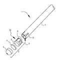
도 1a는 본 발명의 실시예에 따른 큐를 도시한다.
도 1b는 본 발명의 실시예에 따른 큐의 분해도를 도시한다.
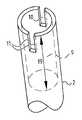
도 2a는 본 발명의 추가 실시예에 따른 타격 단부의 사시도를 도시한다.
도 2b는 본 발명의 추가 실시예에 따른 엔드 피스의 개략적인 단면을 도시한다.
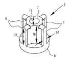
도 3은 본 발명의 특정 실시예에 따른 엔드 피스를 도시한다.
도 4는 본 발명의 실시예에 따른 큐의 샤프트의 타격 단부에서의 단면을 도시한다.
도 5는 본 발명의 제조 단계 동안 큐의 종단면을 도시한다.
동일하거나 유사한 요소들은 도면에 동일한 참조 번호로 지정된다.The invention will be further explained with reference to exemplary embodiments shown in the drawings.
From the drawing:
1A illustrates a queue according to an embodiment of the present invention.
1B shows an exploded view of a queue according to an embodiment of the present invention.
2a shows a perspective view of a striking end according to a further embodiment of the present invention;
2b shows a schematic cross-section of an end piece according to a further embodiment of the invention;
3 shows an end piece according to a specific embodiment of the present invention.
4 shows a cross-section at the striking end of the shaft of the cue according to an embodiment of the invention;
Figure 5 shows a longitudinal section of the queue during the manufacturing phase of the present invention.
Identical or similar elements are designated by the same reference numbers in the drawings.
본 발명에 따른 큐는 당구를 플레이할 때 보조 수단으로 사용하기 위한 것이다. 당구는 캐롬 당구(carom billiards), 범퍼 풀(bumper pool), 스누커(snooker) 및 풀과 같은 다양한 스포츠의 포괄적인 용어이다. 큐는 일반적으로 다양한 스포츠에서의 요구사항들이 다르기 때문에 다양한 크기 및 두께로 제조된다. 예를 들어 풀 큐와 스누커 큐를 구별하는 것이 가능하다. 큐 볼이 스누커에서보다 풀에서 더 무겁기 때문에, 풀 큐는 일반적으로 스누커 큐보다 훨씬 더 두껍다. 큐는 당구를 플레이할 때 연장의 역할을 한다. 이를 위해 큐는 당구를 플레이할 때 큐 볼을 타격하기 위한 연장의 역할을 한다. 플레이어는 큐로 원하는 일반적으로 흰색의 큐 볼을 치며, 이 볼은 당구 테이블 위로 굴러 다른 볼들을 타격한다. 큐의 길이 및 형상은 플레이어의 희망과 플레이되는 당구의 유형에 맞게 조정된다.The cue according to the invention is for use as an auxiliary means when playing billiards. Billiards is an umbrella term for various sports such as carom billiards, bumper pool, snooker and pool. Cues are usually manufactured in different sizes and thicknesses due to the different requirements in different sports. For example, it is possible to distinguish between a pool cue and a snooker cue. Pool cues are usually much thicker than snooker cues because cue balls are heavier in the pool than in snooker. The cue acts as an extension when playing billiards. To this end, the cue acts as an extension for hitting the cue ball when playing billiards. The player hits the desired normally white cue ball with the cue, which rolls over the billiard table and hits the other balls. The length and shape of the cue is adapted to the player's wishes and the type of billiards being played.
도 1a는 본 발명의 실시예에 따른 큐(1)를 도시한다. 큐(1)는 샤프트(2)와 엔드 피스(3)를 포함한다. 엔드 피스는 베이스 바디(3')를 통해 샤프트(2)에 연결된다. 엔드 피스(3)는 댐퍼(4)와 팁(5)을 더 포함한다. 당업자는 베이스 바디(3'), 댐퍼(4) 및 팁(5)이 구성요소일 수 있거나 일체로 제조될 수 있음을 이해할 것이다. 베이스 바디(3')는 리브들(6)을 포함한다. 샤프트(2)는 일반적으로 나무 또는 복합 재료로 제조된다. 샤프트(2)는 바람직하게는 복합 재료로 제조된다.1a shows a
큐(1)는 플레이어가 보유한다. 큐(1)는 큐 볼을 타격하도록 구성된 타격 단부를 더 포함한다. 엔드 피스(3)는 이를 위해 샤프트(2)의 타격 단부에 결합된다. 엔드 피스(3)는 플레이어에 의해 큐 볼에 대하여 타격되는 구성 요소이다. 큐 볼이 다양한 조건에서 고속에 도달해야 하기 때문에, 엔드 피스(3)는 종종 높은 힘을 받는다. 이러한 높은 힘은 큐(1)의 마모를 야기한다. 보다 구체적으로, 샤프트(2)와 엔드 피스(3) 사이의 결합은 깨질 수 있고, 또는 극단적인 경우 샤프트(2)가 파손될 수 있다.The
결과적으로, 엔드 피스(3)는 높은 힘을 흡수하도록 구성되어야 한다.Consequently, the
큐 볼 편향은 사이드 스핀을 사용할 때 큐 볼이 편향되는 공지된 문제이다. 이로써 큐 볼은 플레이어가 조준하는 방향으로부터 편향된다. 사이드 스핀을 사용하는 것은 종종 당구에서 영어로 언급된다. 큐(1)의 타격 단부를 가볍게 하는 것은 큐 볼 편향을 감소시키는 것으로 더 알려져 있다.Cue ball deflection is a known problem where the cue ball deflects when using side spin. This deflects the cue ball from the direction the player is aiming. Using a side spin is often referred to in English in billiards. Lightening the striking end of the
따라서 큐(1)의 타격 단부는 큐 볼 편향을 감소시키기 위해 가벼워야 한다. 엔드 피스(3)는 바람직하게는 복합 재료로 제조된다. 엔드 피스(3)는 대안적으로 알루미늄, 티타늄, 마그네슘, 베릴륨 또는 합급과 같은 가벼운 재료로 제조될 수 있다.Therefore, the striking end of the
엔드 피스(3)는 하나 이상의 홀이 더 제공될 수 있다. 이러한 홀은 엔드 피스(3)의 무게를 줄여서, 큐 볼 편향이 더 감소된다. 하나 이상의 홀의 위치 및 방향은 큐 볼 편향에 영향을 미치도록 선택된다. 다시 말해서, 홀은 큐 볼 편향을 최적화하기 위해 엔드 피스(3)의 다양한 위치에 제공된다. 최적의 큐 볼 편향은 게임의 유형에 따라 다를 수 있다.The
댐퍼(4)는 일반적으로 베이스 바디(3')와 팁(5) 사이에 위치한다. 댐퍼(4)의 기능은 큐 볼의 타격 동안 생성되는 소리를 감소시키는 것이다. 큐(1)에서 댐퍼(4)의 사용은 선택 사항이다. 댐퍼(4)를 포함하지 않는 본 발명의 실시예들이 있음은 당업자에게 명백할 것이다.The
팁(5)은 큐(1)의 가장 바깥쪽 구성요소이다. 이로써 팁(5)은 플레이어에 의해 큐 볼에 대해 타격되는 요소이다. 일반적으로 재료 및 경도의 유형에 의해 서로 구별할 수 있는 다양한 유형의 팁(5)이 있다. 따라서 부드러운 팁(5)은 더 부드러운 고무의 자동차 타이어처럼 더 많은 그립을 제공하며, 더 단단한 팁(5)을 갖는 것보다 부드러운 팁(5)을 갖는 큐(1)로 더 많은 효과가 더 쉽게 적용될 수 있다. 당업자는 팁(5)의 기능이 베이스 바디(3') 또는 댐퍼(4)에 의해 취해질 수 있도록 베이스 바디(3') 또는 댐퍼(4)가 조정될 수 있음을 이해할 것이다. 베이스 바디(3'), 댐퍼(4) 및 팁(5)은 하나의 구성요소를 더 형성할 수 있다.
도 1b는 본 발명의 실시예에 다른 큐(1)의 분해도를 도시한다. 샤프트(2)는 타격 단부에서 속이 비어 있다. 대안적으로, 샤프트(2)는 그 전체 길이를 따라 중공이다. 적어도 타격 단부는 캐비티(9)를 포함한다. 캐비티(9)는 타격 단부에서 큐(1)의 전체 무게를 감소시키고, 이는 큐 볼 편향을 감소시킨다. 이 실시예에서 샤프트(2)는 타격 단부에서 4개의 노치들(10)을 더 포함한다. 4개의 노치들(10)은 엔드 피스(3)의 베이스 바디(3')의 4개의 리브들(6)과 형상이 호환 가능하다. 디스크(8)는 댐퍼(4)를 통해 팁(5)에 연결된다. 이로써 엔드 피스(3)가 형성된다.1B shows an exploded view of a
도 2a 및 2b는 각각 본 발명의 추가 실시예에 따른 샤프트(2)의 타격 단부의 사시도와 엔드 피스(3)의 측면도를 도시한다. 캐비티(9)는 도 2a에서 가시적으로 도시되어 있다. 2개의 노치들(10)은 샤프트(2)의 타격 단부에서 가시적이며, 이러한 노치들은 각각 2개의 대향 내벽들(11)을 구비한다. 도 2b는 베이스 바디(3'), 댐퍼(4) 및 팁(5)을 포함하는 엔드 피스(3)를 도시한다. 베이스 바디(3')는 코어(7)로부터 연장되는 2개의 리브들(6), 및 디스크(8)를 더 포함한다. 당업자는 생산자가 리브들(6)의 수를 선택할 수 있도록 리브들(6)의 수가 변경 가능함을 이해할 것이다. 리브들(6)은 바람직하게는 동일한 형상을 갖는다.2a and 2b respectively show a perspective view of the striking end of the
리브들은 바람직하게는 종축을 중심으로 회전 대칭을 갖는다. 회전 대칭 객체는 정해진 회전 후에 객체가 동일하게 유지되는 특징을 갖는다. 이 객체는 회전이 회전 지점을 중심으로 하는 회전인 2차원 이미지일 수 있고, 또는 회전이 축을 중심으로 하는 회전인 다차원 객체일 수 있다. 보다 구체적으로, n 차의 회전 대칭에서. 360°/n의 최소 회전 각도로 회전될 때 객체는 동일하다. 여기서 리브들은 바람직하게는 1보다 더 큰 n 차, 가장 바람직하게는 2보다 더 큰 n 차로 종축을 중심으로 회전 대칭을 갖는다.The ribs preferably have rotational symmetry about the longitudinal axis. A rotationally symmetric object has the characteristic that the object remains the same after a given rotation. This object may be a two-dimensional image in which the rotation is a rotation about a point of rotation, or it may be a multidimensional object in which the rotation is a rotation about an axis. More specifically, in rotational symmetry of the nth order. Objects are identical when rotated with a minimum rotation angle of 360°/n. Here the ribs have rotational symmetry about the longitudinal axis, preferably by order n greater than one, most preferably greater than two orders of magnitude.
캐비티(9)는 큐(1)의 전체 무게를 줄이는 역할을 한다. 캐비티(9)는 미리 결정된 단면적과 미리 결정된 깊이(19)를 갖는다. 예를 들어 큐(1)로 플레이되는 당구의 유형에 따라 캐비티(9)의 깊이(19)가 조정 가능함은 당업자에게 명백할 것이다. 캐비티(9)는 샤프트(2)의 타격 단부에서 오목(recessed)하다. 당업자는 캐비티(9)가 대안적으로 큐(1)의 전체 길이에 걸쳐 연장될 수 있음을 이해할 것이다. 완전히 속이 비어 있는 경우, 큐(1)는 중공 튜브로 형성된다. 캐비티(9)의 단면적이 조정 가능함은 당업자에게 더 명백할 것이다. 이로써 캐비티(9) 주위에 위치한 샤프트(2)의 벽의 두께를 선택하는 것이 가능하다. 단면적을 증가시키는 것은 전체 무게를 감소시킨다. 그러나 벽을 더 얇게 만드는 것은 벽을 덜 강하게 한다. 샤프트(2)는 파손 없이 충격에 덜 견딜 수 있다. 다시 말해서, 샤프트(2)의 벽의 최적의 두께는 큐(1)로 플레이되는 당구의 유형에 크게 의존한다.The
캐비티(9)는 필링 폼(filling foam)으로 적어도 부분적으로 더 채워질 수 있다. 필링 폼은 소리감쇠 기능을 갖는다. 큐(1)를 큐 볼에 치는 것은 엔드 피스(3)에 진동을 야기한다. 진동은 마모를 야기하기 때문에, 진동의 감쇠가 필요하다. 필링 폼은 바람직하게는 샤프트의 내부 표면(13)에 직면한다. 이로써 필링 폼은 사용 중 고정식으로 위치하며, 접착제와 같은 부착이 필요하지 않다. 이로써 필링 폼은 무시할만한 접착 기능을 갖고 주로 감쇠 기능을 갖는다는 것이 당업자에게 명백할 것이다.The
노치들(10)은 샤프트(2)의 타격 단부로부터 연장된다. 이들은 리브들(6)을 수용하도록 구성된다. 샤프트(2)의 타격 단부로부터의 노칭은 캐비티(9)에 코어(7)를 배치하는 것을 용이하게 한다. 코어(7)의 배치 동안 리브들(6)은 노치들(10)로 슬라이드된다. 리브들(6)의 측벽들은 대향 내벽들(11)에 대해 놓인다. 리브들(6)과 결과적으로 엔드 피스(3)는 이로써 샤프트(2)에 연결된다. 노치들(10)은 바람직하게는 리브들(6)의 길이(20)와 실질적으로 동일한 깊이로 절단되어, 리브들(6)은 노치들과 형상이 호환 가능하다.
노치들(10)과 리브들(6)의 수는 동일하여, 엔드 피스(3)가 간단한 방식으로 샤프트(2)에 장착될 수 있다. 리브들이 샤프트의 벽을 통해 방사형으로 연장되기 때문에, 이들은 샤프트의 외부 케이싱에서 가시적이다. 리브들(6)은 바람직하게는 샤프트(2)의 색상과 대비되는 색상을 가져서, 리브들(2)은 플레이어에게 더 명확하게 가시적이다. 이로써 큐(1)의 종축을 따르는 방향으로 연신되는 리브들은 조준 시 가이드라인으로 사용될 수 있다. 이는 눈이 따라갈 수 있는 라인을 리브들(6)이 형성하기 때문이다. 이로써 플레이어는 더 쉽게 조준할 수 있다.The number of
도 3은 본 발명의 특정 실시예에 따른 4개의 리브들을 갖는 엔드 피스(3)를 도시한다. 엔드 피스(3)는 코어(7), 4개의 리브들(6) 및 디스크(8)를 포함한다. 장착 후, 코어(7)는 캐비티(9)에 위치된다. 코어(7)는 장착 후 디스크(8)로부터 연장되고 캐비티에서 연장되는 길쭉한 형상을 갖는다. 리브들(6)은 코어(7)의 종축으로부터 방사형으로 연장된다. 장착된 형태에서 코어(7)의 종축은 큐(1)의 종축과 실질적으로 일치한다.3 shows an
장착 후 엔드 피스(3)는 큐(1)의 타격 단부에 위치한다. 이로써 엔드 피스(3)의 무게의 감소가 큐 볼 편향을 감소시킨다. 엔드 피스(3)는 이를 위해 바람직하게는 세제곱미터 당 3 그램(g/cm3)보다 더 작은 비중을 갖는 재료로 제조되고, 비중은 더 바람직하게는 2 g/cm3보다 더 작고, 더 바람직하게는 1 g/cm3보다 더 작다. 재료의 유형에 더하여, 엔드 피스(3)의 형상 또한 무게를 줄이기 위해 조정될 수 있다.After mounting, the
코어(7)는 이를 위해 엔드 피스(3)의 무게를 줄이도록 구성된다. 코어(7)는 코어(7)의 종축을 따라 측정된 길이(18)를 갖고, 코어(7)는 종축의 반경 방향으로 측정된 단면적(17)을 갖는다. 단면적(17)은 전체 길이(18)에 걸쳐 일정할 수 있다. 대안적으로, 단면적(17)은 변할 수 있다. 따라서 단면적(17)은 디스크(8)까지의 거리에 따라 변할 수 있다.The
큐(1)의 제조 동안 베이스 바디(3')의 리브들(6)은 노치들(10)에 배치된다. 이를 위해 리브들(6)은 코어(7)로부터 방사형으로 연장되며, 리브들(6)은 노치들(10)을 통해 연장된다. 리브들(6)은 바람직하게는 샤프트(2)의 외부 케이싱까지 연장되며, 큐(1)는 매끄러운 외부 케이싱을 갖는다. 리브들(6)의 원위 외부 표면은 바람직하게는 샤프트(2)의 외부 케이싱과 동일한 곡률을 가지며, 샤프트의 외부 케이싱과 리브들(6) 사이의 차이가 느껴지지 않거나, 거의 느껴지지 않는다. 리브들(6)은 두께(20)를 갖는다. 도 3에서 4개의 리브들(6) 각각은 동일한 두께(20)를 갖는다. 당업자는 이 두께(20)가 각 리브 별로 다를 수도 있음을 이해할 것이다. 두께(20)가 반경 거리에 따라 변경될 수 있음은 당업자에게 더 명백할 것이다. 따라서 종축을 따라 볼 때 리브들(6)은 사다리꼴 또는 기타 유사한 형태를 가질 수 있다. 리브들(6)과 코어(7) 사이의 전이는(transition) 매끄럽거나 날카로울 수 있다. 전이가 매끄럽다면, 리브들(6)의 사다리꼴 형태는 전이의 위치에서 변형된다. 디스크(8)는 종축에 대해 방사형으로 연장된다. 그 결과 큐 볼을 타격하기 위해 사용될 수 있는 타격 측을 생긴다. 대안적으로, 디스크(8)는 타격 측의 위치에서 댐퍼(4) 또는 팁(5)에 연결된다. 디스크(8)는 단부 표면(15)의 위치에서 샤프트(2)에 대한 연결 측과 함께 놓인다. 디스크(8)는 바람직하게는 단부 표면(15)의 위치에서 샤프트(2)에 연결된다. 디스크(8)는 바람직하게는 이를 위해 샤프트(2)의 단면적과 실질적으로 동일한 단면적을 갖는다. 다시 말해서, 디스크(8)는 샤프트(2)의 외부 케이싱으로 연장된다. 이는 샤프트(2)와 엔드 피스(3) 사이의 매끄러운 전이를 제공하기 때문에 이러한 동일한 단면적이 필요하다. 당업자는 이것이 큐 볼에 대한 큐(1)의 조준에 유리하다는 것을 이해할 것이다. 리브들(6)은 바람직하게는 디스크(8)에 대해 놓인다. 리브들(6)은 더 바람직하게는 디스크(8)에 연결된다. 이로써, 리브들(6)은 노치들(10)의 전체 노치 깊이에 걸쳐 연장되고 엔드 피스(3)와 샤프트(2)의 연결이 더 최적이다.During the manufacture of the
도 4는 본 발명의 실시예에 따른 큐(1)의 타격 단부에서의 단면을 도시한다. 보다 구체적으로, 도 4는 샤프트(2)의 단부 표면(15)을 도시하며, 베이스 바디(3')의 코어(7)는 캐비티(9)에 위치된다. 리브들(6)은 노치들(10)을 통해 코어로부터 방사형으로 연장된다. 코어(7)는 샤프트(2)의 내부 표면(12)으로부터 일정 거리에 위치된다. 이로써 캐비티(9)는 단면의 위치에서 코어(7)에 의해 완전히 채워지지 않아, 중량이 절약된다.4 shows a cross-section at the striking end of the
리브들(6)은 노치들(10)의 대향 내벽들(11)에 대해 놓인다. 도 4에서 대향 내벽들(11)과 리브들(6) 사이의 접촉면(16)은 가시적이다. 노치들(10)은 종축을 따르는 방향으로 단부 표면(15)의 위치에서 샤프트의 벽 부분을 제거함으로써 형성된다. 제거되는 벽 부분은 절단면과 노치 깊이에 의해 형성된다. 절단면은 외부 표면(13) 상의 외부 호와 내부 표면(12) 상의 내부 호에 의해 정의된다. 내부 호의 제1 외부 단부와 외부 호의 제1 외부 단부 사이의 제1 연결부는 대향 내벽들(11)의 제1 벽을 나타내고, 내부 호의 제2 외부 단부와 외부 호의 제2 외부 단부 사이의 제2 연결부는 대향 내벽들(11)의 제2 벽을 나타낸다. 각도 α와 각도 β는 이를 위해 외부 표면(13)과 대향 내벽들(11) 사이에 정의될 수 있다. 각도 α는 바람직하게는 각도 β와 실질적으로 동일하다. 각도 α와 각도 β 리브들(6)의 형태와 관련된다. 각도 α는 바람직하게는 60° 내지 120°의 각도 크기, 더 바람직하게는 70° 내지 110°의 각도 크기, 가장 바람직하게는 80° 내지 100°의 각도 크기를 갖는다. 각도 β는 바람직하게는 60° 내지 120°의 각도 크기, 더 바람직하게는 70° 내지 110°의 각도 크기, 가장 바람직하게는 80° 내지 100°의 각도 크기를 갖는다. 벽 부분은 바람직하게는 절단에 의해 제거된다.The
샤프트(2)와 엔드 피스(3)는 접촉면의 위치에서 서로에 연결된다. 샤프트(2)와 엔드 피스(3)는 바람직하게는 접촉면(16) 상에 접착층을 제공함으로써 연결된다. 대향 내벽들(11)은 만들어지는 노치들(10)의 결과로써 생성되는 표면들이며, 이러한 표면들은 내부 표면(12)과 외부 표면(13) 사이에서 연장된다는 것이 당업자에게 명백할 것이다.The
보다 구체적으로, 리브들(6)은 샤프트의 외부 표면(13)까지 연장된다. 보다 구체적으로, 리브들의 원위 외부 표면(14)은 리브들(6)과 샤프트의 외부 표면(13) 사이에서 매끄러운 전이를 갖는다. 이로써 큐(1)는 매끄러운 외부 케이싱을 갖는다. 외부 케이싱은 원위 외부 표면(14) 및 샤프트의 외부 표면(13)을 포함한다. 원위 외부 표면(14)은 바람직하게는 샤프트(2)의 외부 케이싱과 동일한 곡률을 가지며, 샤프트의 외부 케이싱과 리브들(6) 사이의 차이는 느낄 수 없거나 거의 느낄 수 없다.More specifically, the
노치들(10)은 노치 깊이와 노치 너비를 갖는다. 깊이는 종축을 따라 측정된다. 노치 너비는 정해진 노치 깊이에서의 대향 내벽들(11) 사이의 거리와 종축의 방사형으로의 정해진 거리로 정의된다. 노치 깊이는 바람직하게는 각 노치에 대해 실질적으로 동일하다. 노치 깊이는 바람직하게는 5 밀리미터보다 더 크고, 더 바람직하게는 1 센치미터보다 더 크고, 가장 바람직하게는 2 센치미터보다 더 크다. 노치 깊이는 게임의 유형 및/또는 플레이어의 희망에 관계없이 선택된다. 더 큰 노치 깊이는 접촉면(16)을 증가시켜서, 샤프트(13)와 리브들(6) 사이의 연결이 더 강하다. 더 작은 노치 깊이는 더 쉽게 제조될 수 있어서, 생산 비용이 낮게 유지될 수 있다. 원위 방향에서 노치 너비는 각도 α 및 각도 β와 관련이 있다. 최대 노치 너비는 바람직하게는 1cm보다 더 작고, 더 바람직하게는 0.8cm보다 더 작고, 가장 바람직하게는 0.6cm보다 더 작다. 노치 너비는 게임의 유형 및/또는 플레이어의 희망에 관계없이 선택된다.The
도 5는 선반 상에서 회전되는 큐(1)를 도시한다. 회전 동안 큐(1)는 회전 방향(24)으로 회전하고, 절삭 공구(22)는 이동 방향(23)으로 진행한다. 절삭 공구(22)의 포인트는 큐(1)를 누르고, 회전의 결과로, 샤프트(2)와 엔드 피스(3)의 재료 층을 절단한다. 큐(1)의 타격 단부가 원하는 형상을 얻도록 절삭 공구(22)는 경로(25)를 따른다. 회전은 원위 외부 표면(14)과 샤프트(2) 사이에 매끄러운 전이가 있도록 큐(1)가 절단되는 것을 보장한다. 큐(1)는 이로써 매끄러운 외부 케이싱이 제공된다.5 shows a
당업자는 본 발명이 상이한 방식으로 상이한 원리에 기초하여 구현될 수 있음을 상기 설명에 기초하여 이해할 것이다. 본 발명은 여기서 전술한 실시예로 제한되지 않는다. 전술한 실시예들과 도면들은 순전히 예시적이며 본 발명의 이해를 높이는 역할만을 한다. 본 발명은 여기에 설명된 실시예들에 제한되지 않고, 청구범위에 정의된다.Those skilled in the art will understand, based on the above description, that the present invention can be implemented in different ways and based on different principles. The present invention is not limited to the above-described embodiments herein. The foregoing embodiments and drawings are purely exemplary and serve only to enhance the understanding of the present invention. The invention is not limited to the embodiments described herein, but is defined in the claims.
Claims (14)
Translated fromKoreanA cue comprising a shaft and an end piece, the shaft having a cavity at the location of a striking end of the cue, the cavity being a longitudinal axis of the cue wherein the end piece comprises a core positioned in the cavity, the end piece further comprising at least two ribs extending from the core in a radial direction of the longitudinal axis; the shaft comprises at least two notches at a location of the cavity, each comprising two opposing inner walls from which the at least two ribs at least partially extend, the sidewalls of the at least two ribs being configured to be disposed on the shaft lie against the opposing inner walls to connect the end piece to a cue.
상기 적어도 2개의 노치들은 상기 종축을 따라 연장되는, 큐.
According to claim 1,
wherein the at least two notches extend along the longitudinal axis.
상기 적어도 2개의 노치들은 상기 타격 단부로부터 연장되는, 큐.
3. The method of claim 1 or 2,
wherein the at least two notches extend from the striking end.
상기 적어도 2개의 노치들은 각각 상기 종축을 따라 측정된 바와 같은 깊이를 갖고, 상기 적어도 2개의 리브들이 상기 적어도 2개의 노치들과 형상이 호환 가능하도록 상기 적어도 2개의 리브들은 각각 상기 깊이와 실질적으로 동일한 길이를 갖는, 큐.
4. The method of claim 3,
the at least two notches each have a depth as measured along the longitudinal axis, the at least two ribs each being substantially equal to the depth such that the at least two ribs are compatible in shape with the at least two notches A queue with a length.
상기 적어도 2개의 리브들의 원위 외부 표면들은 상기 샤프트의 외부 표면에서 연장되어, 상기 원위 외부 표면과 상기 샤프트의 외부 표면은 매끄러운 외부 케이싱을 형성하는, 큐.
5. The method according to any one of claims 1 to 4,
the distal outer surfaces of the at least two ribs extend from an outer surface of the shaft, such that the distal outer surface and the outer surface of the shaft form a smooth outer casing.
상기 코어는 상기 캐비티의 위치에서 상기 샤프트의 내부 표면으로부터 일정 거리에 위치하는, 큐.
6. The method according to any one of claims 1 to 5,
wherein the core is located at a distance from the inner surface of the shaft at the location of the cavity.
상기 엔드 피스는 상기 종축의 반경 방향으로 적어도 상기 샤프트의 외부 표면까지 연장되는 디스크를 더 포함하는, 큐.
7. The method according to any one of claims 1 to 6,
wherein the end piece further comprises a disk extending in a radial direction of the longitudinal axis to at least an outer surface of the shaft.
상기 엔드 피스는 댐퍼 또는 팁 중 적어도 하나를 포함하는, 큐.
8. The method according to any one of claims 1 to 7,
wherein the end piece comprises at least one of a damper or a tip.
상기 샤프트는 복합 재료로 만들어지는, 큐.
9. The method according to any one of claims 1 to 8,
The shaft is made of a composite material, Q.
상기 엔드 피스는 상기 샤프트와 미리 결정된 시각적 대비를 갖도록 선택되는, 큐.
10. The method according to any one of claims 1 to 9,
wherein the end piece is selected to have a predetermined visual contrast with the shaft.
상기 엔드 피스는 상기 엔드 피스의 무게를 줄이기 위해 하나 이상의 홀을 갖는, 큐.
11. The method according to any one of claims 1 to 10,
wherein the end piece has one or more holes to reduce the weight of the end piece.
상기 엔드 피스는 코어를 포함하고 상기 코어로부터 상기 코어의 종축의 반경 방향으로 연장되는 적어도 2개의 리브들을 포함하고,
상기 방법은,
상기 큐의 타격 단부의 위치에서 캐비티를 갖는 샤프트를 제공하는 단계- 상기 캐비티는 상기 샤프트의 종축을 따라 종 방향으로 연장됨-;
적어도 2개의 노치들을 만들기 위해 상기 타격 단부의 위치에서 적어도 두 번 상기 샤프트를 노칭하는 단계- 노치들은 각각 2개의 대향 내벽들을 포함함-;
상기 리브들이 상기 적어도 2개의 노치들을 통해 상기 샤프트의 상기 종축의 반경 방향으로 연장되도록, 상기 캐비티에 코어를 배치하고 상기 적어도 2개의 노치들에 상기 적어도 2개의 리브들을 배치하는 단계; 및
상기 적어도 2개의 리브들을 상기 적어도 2개의 노치들의 2개의 대향 내벽들에 연결하는 단계;
를 포함하는, 방법.
A method of manufacturing a cue having a shaft and an end piece, the method comprising:
the end piece comprises a core and at least two ribs extending from the core in a radial direction of a longitudinal axis of the core;
The method is
providing a shaft having a cavity at the location of the striking end of the cue, the cavity extending longitudinally along a longitudinal axis of the shaft;
notching the shaft at least twice at the location of the striking end to make at least two notches, each notches comprising two opposing inner walls;
disposing a core in the cavity and disposing the at least two ribs in the at least two notches such that the ribs extend through the at least two notches in a radial direction of the longitudinal axis of the shaft; and
connecting the at least two ribs to two opposing inner walls of the at least two notches;
A method comprising
상기 리브들의 원위 외부 표면과 상기 샤프트의 외부 표면이 매끄러운 외부 케이싱을 형성하도록, 선반(lathe)에서 상기 큐를 돌리는 단계를 포함하는, 방법.
13. The method of claim 12,
turning the cue on a lathe such that the distal outer surface of the ribs and the outer surface of the shaft form a smooth outer casing.
상기 연결하는 단계는 상기 적어도 2개의 노치들의 상기 2개의 대향 내벽들과 상기 적어도 2개의 리브들 사이에 접착제를 도포함으로써 수행되는, 방법.
14. The method of claim 12 or 13,
wherein the connecting step is performed by applying an adhesive between the at least two ribs and the two opposite inner walls of the at least two notches.
Applications Claiming Priority (3)
| Application Number | Priority Date | Filing Date | Title |
|---|---|---|---|
| BEBE2018/5890 | 2018-12-17 | ||
| BE20185890ABE1026872B1 (en) | 2018-12-17 | 2018-12-17 | End piece for cue |
| PCT/IB2019/060748WO2020128745A1 (en) | 2018-12-17 | 2019-12-13 | End piece for cue |
Publications (1)
| Publication Number | Publication Date |
|---|---|
| KR20210101288Atrue KR20210101288A (en) | 2021-08-18 |
Family
ID=65013421
Family Applications (1)
| Application Number | Title | Priority Date | Filing Date |
|---|---|---|---|
| KR1020217021758ACeasedKR20210101288A (en) | 2018-12-17 | 2019-12-13 | End piece for cue |
Country Status (9)
| Country | Link |
|---|---|
| US (1) | US12318681B2 (en) |
| EP (1) | EP3897889B1 (en) |
| JP (1) | JP2022515387A (en) |
| KR (1) | KR20210101288A (en) |
| CN (1) | CN113195066A (en) |
| BE (1) | BE1026872B1 (en) |
| CO (1) | CO2021009299A2 (en) |
| PH (1) | PH12021551432A1 (en) |
| WO (1) | WO2020128745A1 (en) |
Family Cites Families (14)
| Publication number | Priority date | Publication date | Assignee | Title |
|---|---|---|---|---|
| US1040362A (en)* | 1911-08-21 | 1912-10-08 | Walter H La Fevre | Cue-tip holder. |
| GB191400904A (en)* | 1914-02-03 | 1914-12-17 | Laurence Pearson | Improvements relating to Billiard Cues. |
| US1182160A (en)* | 1914-10-15 | 1916-05-09 | Edmond Edward Fournier | Cue-tip. |
| US1648613A (en)* | 1927-04-19 | 1927-11-08 | Belle Jacobs | Cue tip |
| US3598409A (en)* | 1968-08-26 | 1971-08-10 | Kieckhefer Mfg Corp | Integral billiard cue tip and backing member |
| US5356345A (en) | 1993-12-20 | 1994-10-18 | Peuplie Robert E | Chalk holding device for a pool cue |
| US6183371B1 (en)* | 1996-06-25 | 2001-02-06 | Pamela Gene Wethered-McClung | Replaceable cue tip system |
| JP2002346023A (en)* | 2001-05-29 | 2002-12-03 | Miki Co Ltd | Billiard cue |
| US7520817B2 (en)* | 2005-03-30 | 2009-04-21 | Diamond Billiard Products, Inc. | Billiard cue tips and methods of assembly |
| CN101208138A (en)* | 2005-05-12 | 2008-06-25 | 克劳森手工球桿公司 | Cue stick for reducing cue ball deflection |
| JP2007125108A (en)* | 2005-07-11 | 2007-05-24 | Miki Co Ltd | Billiard cue |
| US8109836B1 (en)* | 2009-09-22 | 2012-02-07 | Probst Frederick E | Interchangeable billiard cue tip assembly and billiard cue utilizing same |
| EP2978512B1 (en)* | 2014-03-24 | 2019-06-12 | Clawson Custom Cues, Inc. | Cue shaft tip insert |
| US20190344155A1 (en)* | 2018-05-09 | 2019-11-14 | Hamson Global Co., Ltd | Cue shaft with ball control enhancement function and billiard cue thereof |
- 2018
- 2018-12-17BEBE20185890Apatent/BE1026872B1/enactiveIP Right Grant
- 2019
- 2019-12-13CNCN201980083783.5Apatent/CN113195066A/enactivePending
- 2019-12-13WOPCT/IB2019/060748patent/WO2020128745A1/ennot_activeCeased
- 2019-12-13EPEP19836826.8Apatent/EP3897889B1/enactiveActive
- 2019-12-13KRKR1020217021758Apatent/KR20210101288A/ennot_activeCeased
- 2019-12-13JPJP2021535085Apatent/JP2022515387A/enactivePending
- 2019-12-13USUS17/413,671patent/US12318681B2/enactiveActive
- 2021
- 2021-06-17PHPH12021551432Apatent/PH12021551432A1/enunknown
- 2021-07-15COCONC2021/0009299Apatent/CO2021009299A2/enunknown
Also Published As
| Publication number | Publication date |
|---|---|
| PH12021551432A1 (en) | 2021-12-06 |
| US12318681B2 (en) | 2025-06-03 |
| WO2020128745A1 (en) | 2020-06-25 |
| EP3897889B1 (en) | 2024-12-04 |
| US20220008813A1 (en) | 2022-01-13 |
| JP2022515387A (en) | 2022-02-18 |
| CN113195066A (en) | 2021-07-30 |
| EP3897889A1 (en) | 2021-10-27 |
| EP3897889C0 (en) | 2024-12-04 |
| BE1026872B1 (en) | 2020-07-13 |
| BE1026872A1 (en) | 2020-07-10 |
| CO2021009299A2 (en) | 2021-07-30 |
Similar Documents
| Publication | Publication Date | Title |
|---|---|---|
| CN107519625B (en) | Golf club with double wall hitting face | |
| US5492327A (en) | Shock Absorbing iron head | |
| JP3760386B2 (en) | Billiard cue | |
| US7520817B2 (en) | Billiard cue tips and methods of assembly | |
| US7479069B2 (en) | Insert for altering the stiffness of a golf club shaft | |
| US20180085657A1 (en) | Cue shaft tip insert | |
| US5797806A (en) | Golf club having shock isolation between the head and the shaft | |
| KR20210101288A (en) | End piece for cue | |
| US20180345103A1 (en) | Bat with filled exterior grooves | |
| WO2006124382A1 (en) | Billiard cue for reducing cue ball deflection | |
| US20090048032A1 (en) | Shaft of cue sticks | |
| US20200086190A1 (en) | Bat with foam core insert | |
| US7806776B2 (en) | Detachable cue tip assemblies and cue sticks having same | |
| US7549928B1 (en) | Detachable cue tip assemblies | |
| JPH02207Y2 (en) | ||
| CN110801620B (en) | Kinetic energy absorbing insert, shaft portion thereof and cue | |
| JP2007117605A (en) | Shaft of billiard cue | |
| US7708646B2 (en) | Low deflection cue | |
| US20080132345A1 (en) | Article of manufacture for improved segmented jump cue stick | |
| JP3113641U (en) | Billiard cue vibration control structure | |
| JP2021065399A (en) | Bat with foam core insert | |
| JP2005261600A (en) | Gravity center adjusting structure of cue | |
| JPH06218085A (en) | Manufacture of metal bat | |
| JPH10328339A (en) | Golf club | |
| JP2006198173A (en) | Club for ground golf |
Legal Events
| Date | Code | Title | Description |
|---|---|---|---|
| PA0105 | International application | Patent event date:20210712 Patent event code:PA01051R01D Comment text:International Patent Application | |
| PA0201 | Request for examination | ||
| PG1501 | Laying open of application | ||
| N231 | Notification of change of applicant | ||
| PN2301 | Change of applicant | Patent event date:20220901 Comment text:Notification of Change of Applicant Patent event code:PN23011R01D | |
| E902 | Notification of reason for refusal | ||
| PE0902 | Notice of grounds for rejection | Comment text:Notification of reason for refusal Patent event date:20230510 Patent event code:PE09021S01D | |
| E601 | Decision to refuse application | ||
| PE0601 | Decision on rejection of patent | Patent event date:20240423 Comment text:Decision to Refuse Application Patent event code:PE06012S01D Patent event date:20230510 Comment text:Notification of reason for refusal Patent event code:PE06011S01I |