KR20210099047A - Three-dimensional nonwoven material and manufacturing method thereof - Google Patents
Three-dimensional nonwoven material and manufacturing method thereofDownload PDFInfo
- Publication number
- KR20210099047A KR20210099047AKR1020217019986AKR20217019986AKR20210099047AKR 20210099047 AKR20210099047 AKR 20210099047AKR 1020217019986 AKR1020217019986 AKR 1020217019986AKR 20217019986 AKR20217019986 AKR 20217019986AKR 20210099047 AKR20210099047 AKR 20210099047A
- Authority
- KR
- South Korea
- Prior art keywords
- nodes
- nonwoven material
- zone
- nonwoven
- perforated
- Prior art date
- Legal status (The legal status is an assumption and is not a legal conclusion. Google has not performed a legal analysis and makes no representation as to the accuracy of the status listed.)
- Granted
Links
Images


Classifications
- A—HUMAN NECESSITIES
- A61—MEDICAL OR VETERINARY SCIENCE; HYGIENE
- A61F—FILTERS IMPLANTABLE INTO BLOOD VESSELS; PROSTHESES; DEVICES PROVIDING PATENCY TO, OR PREVENTING COLLAPSING OF, TUBULAR STRUCTURES OF THE BODY, e.g. STENTS; ORTHOPAEDIC, NURSING OR CONTRACEPTIVE DEVICES; FOMENTATION; TREATMENT OR PROTECTION OF EYES OR EARS; BANDAGES, DRESSINGS OR ABSORBENT PADS; FIRST-AID KITS
- A61F13/00—Bandages or dressings; Absorbent pads
- A61F13/15—Absorbent pads, e.g. sanitary towels, swabs or tampons for external or internal application to the body; Supporting or fastening means therefor; Tampon applicators
- A61F13/51—Absorbent pads, e.g. sanitary towels, swabs or tampons for external or internal application to the body; Supporting or fastening means therefor; Tampon applicators characterised by the outer layers of the pads
- A61F13/511—Topsheet, i.e. the permeable cover or layer facing the skin
- A61F13/51104—Topsheet, i.e. the permeable cover or layer facing the skin the top sheet having a three-dimensional cross-section, e.g. corrugations, embossments, recesses or projections
- A—HUMAN NECESSITIES
- A61—MEDICAL OR VETERINARY SCIENCE; HYGIENE
- A61F—FILTERS IMPLANTABLE INTO BLOOD VESSELS; PROSTHESES; DEVICES PROVIDING PATENCY TO, OR PREVENTING COLLAPSING OF, TUBULAR STRUCTURES OF THE BODY, e.g. STENTS; ORTHOPAEDIC, NURSING OR CONTRACEPTIVE DEVICES; FOMENTATION; TREATMENT OR PROTECTION OF EYES OR EARS; BANDAGES, DRESSINGS OR ABSORBENT PADS; FIRST-AID KITS
- A61F13/00—Bandages or dressings; Absorbent pads
- A61F13/15—Absorbent pads, e.g. sanitary towels, swabs or tampons for external or internal application to the body; Supporting or fastening means therefor; Tampon applicators
- A61F13/15577—Apparatus or processes for manufacturing
- A61F13/15699—Forming webs by bringing together several webs, e.g. by laminating or folding several webs, with or without additional treatment of the webs
- A—HUMAN NECESSITIES
- A61—MEDICAL OR VETERINARY SCIENCE; HYGIENE
- A61F—FILTERS IMPLANTABLE INTO BLOOD VESSELS; PROSTHESES; DEVICES PROVIDING PATENCY TO, OR PREVENTING COLLAPSING OF, TUBULAR STRUCTURES OF THE BODY, e.g. STENTS; ORTHOPAEDIC, NURSING OR CONTRACEPTIVE DEVICES; FOMENTATION; TREATMENT OR PROTECTION OF EYES OR EARS; BANDAGES, DRESSINGS OR ABSORBENT PADS; FIRST-AID KITS
- A61F13/00—Bandages or dressings; Absorbent pads
- A61F13/15—Absorbent pads, e.g. sanitary towels, swabs or tampons for external or internal application to the body; Supporting or fastening means therefor; Tampon applicators
- A61F13/15577—Apparatus or processes for manufacturing
- A61F13/15707—Mechanical treatment, e.g. notching, twisting, compressing, shaping
- A61F13/15731—Treating webs, e.g. for giving them a fibrelike appearance, e.g. by embossing
- A—HUMAN NECESSITIES
- A61—MEDICAL OR VETERINARY SCIENCE; HYGIENE
- A61F—FILTERS IMPLANTABLE INTO BLOOD VESSELS; PROSTHESES; DEVICES PROVIDING PATENCY TO, OR PREVENTING COLLAPSING OF, TUBULAR STRUCTURES OF THE BODY, e.g. STENTS; ORTHOPAEDIC, NURSING OR CONTRACEPTIVE DEVICES; FOMENTATION; TREATMENT OR PROTECTION OF EYES OR EARS; BANDAGES, DRESSINGS OR ABSORBENT PADS; FIRST-AID KITS
- A61F13/00—Bandages or dressings; Absorbent pads
- A61F13/15—Absorbent pads, e.g. sanitary towels, swabs or tampons for external or internal application to the body; Supporting or fastening means therefor; Tampon applicators
- A61F13/45—Absorbent pads, e.g. sanitary towels, swabs or tampons for external or internal application to the body; Supporting or fastening means therefor; Tampon applicators characterised by the shape
- A61F13/47—Sanitary towels, incontinence pads or napkins
- A61F13/475—Sanitary towels, incontinence pads or napkins characterised by edge leakage prevention means
- A—HUMAN NECESSITIES
- A61—MEDICAL OR VETERINARY SCIENCE; HYGIENE
- A61F—FILTERS IMPLANTABLE INTO BLOOD VESSELS; PROSTHESES; DEVICES PROVIDING PATENCY TO, OR PREVENTING COLLAPSING OF, TUBULAR STRUCTURES OF THE BODY, e.g. STENTS; ORTHOPAEDIC, NURSING OR CONTRACEPTIVE DEVICES; FOMENTATION; TREATMENT OR PROTECTION OF EYES OR EARS; BANDAGES, DRESSINGS OR ABSORBENT PADS; FIRST-AID KITS
- A61F13/00—Bandages or dressings; Absorbent pads
- A61F13/15—Absorbent pads, e.g. sanitary towels, swabs or tampons for external or internal application to the body; Supporting or fastening means therefor; Tampon applicators
- A61F13/45—Absorbent pads, e.g. sanitary towels, swabs or tampons for external or internal application to the body; Supporting or fastening means therefor; Tampon applicators characterised by the shape
- A61F13/49—Absorbent pads, e.g. sanitary towels, swabs or tampons for external or internal application to the body; Supporting or fastening means therefor; Tampon applicators characterised by the shape specially adapted to be worn around the waist, e.g. diapers, nappies
- A61F13/494—Absorbent pads, e.g. sanitary towels, swabs or tampons for external or internal application to the body; Supporting or fastening means therefor; Tampon applicators characterised by the shape specially adapted to be worn around the waist, e.g. diapers, nappies characterised by edge leakage prevention means
- A—HUMAN NECESSITIES
- A61—MEDICAL OR VETERINARY SCIENCE; HYGIENE
- A61F—FILTERS IMPLANTABLE INTO BLOOD VESSELS; PROSTHESES; DEVICES PROVIDING PATENCY TO, OR PREVENTING COLLAPSING OF, TUBULAR STRUCTURES OF THE BODY, e.g. STENTS; ORTHOPAEDIC, NURSING OR CONTRACEPTIVE DEVICES; FOMENTATION; TREATMENT OR PROTECTION OF EYES OR EARS; BANDAGES, DRESSINGS OR ABSORBENT PADS; FIRST-AID KITS
- A61F13/00—Bandages or dressings; Absorbent pads
- A61F13/15—Absorbent pads, e.g. sanitary towels, swabs or tampons for external or internal application to the body; Supporting or fastening means therefor; Tampon applicators
- A61F13/51—Absorbent pads, e.g. sanitary towels, swabs or tampons for external or internal application to the body; Supporting or fastening means therefor; Tampon applicators characterised by the outer layers of the pads
- A61F13/511—Topsheet, i.e. the permeable cover or layer facing the skin
- A61F13/51121—Topsheet, i.e. the permeable cover or layer facing the skin characterised by the material
- A—HUMAN NECESSITIES
- A61—MEDICAL OR VETERINARY SCIENCE; HYGIENE
- A61F—FILTERS IMPLANTABLE INTO BLOOD VESSELS; PROSTHESES; DEVICES PROVIDING PATENCY TO, OR PREVENTING COLLAPSING OF, TUBULAR STRUCTURES OF THE BODY, e.g. STENTS; ORTHOPAEDIC, NURSING OR CONTRACEPTIVE DEVICES; FOMENTATION; TREATMENT OR PROTECTION OF EYES OR EARS; BANDAGES, DRESSINGS OR ABSORBENT PADS; FIRST-AID KITS
- A61F13/00—Bandages or dressings; Absorbent pads
- A61F13/15—Absorbent pads, e.g. sanitary towels, swabs or tampons for external or internal application to the body; Supporting or fastening means therefor; Tampon applicators
- A61F13/51—Absorbent pads, e.g. sanitary towels, swabs or tampons for external or internal application to the body; Supporting or fastening means therefor; Tampon applicators characterised by the outer layers of the pads
- A61F13/511—Topsheet, i.e. the permeable cover or layer facing the skin
- A61F13/5116—Topsheet, i.e. the permeable cover or layer facing the skin being formed of multiple layers
- A—HUMAN NECESSITIES
- A61—MEDICAL OR VETERINARY SCIENCE; HYGIENE
- A61F—FILTERS IMPLANTABLE INTO BLOOD VESSELS; PROSTHESES; DEVICES PROVIDING PATENCY TO, OR PREVENTING COLLAPSING OF, TUBULAR STRUCTURES OF THE BODY, e.g. STENTS; ORTHOPAEDIC, NURSING OR CONTRACEPTIVE DEVICES; FOMENTATION; TREATMENT OR PROTECTION OF EYES OR EARS; BANDAGES, DRESSINGS OR ABSORBENT PADS; FIRST-AID KITS
- A61F13/00—Bandages or dressings; Absorbent pads
- A61F13/15—Absorbent pads, e.g. sanitary towels, swabs or tampons for external or internal application to the body; Supporting or fastening means therefor; Tampon applicators
- A61F13/51—Absorbent pads, e.g. sanitary towels, swabs or tampons for external or internal application to the body; Supporting or fastening means therefor; Tampon applicators characterised by the outer layers of the pads
- A61F13/511—Topsheet, i.e. the permeable cover or layer facing the skin
- A61F13/512—Topsheet, i.e. the permeable cover or layer facing the skin characterised by its apertures, e.g. perforations
- A61F13/5121—Topsheet, i.e. the permeable cover or layer facing the skin characterised by its apertures, e.g. perforations characterised by the vertical shape of the apertures, e.g. three dimensional apertures, e.g. macro-apertures
- A—HUMAN NECESSITIES
- A61—MEDICAL OR VETERINARY SCIENCE; HYGIENE
- A61F—FILTERS IMPLANTABLE INTO BLOOD VESSELS; PROSTHESES; DEVICES PROVIDING PATENCY TO, OR PREVENTING COLLAPSING OF, TUBULAR STRUCTURES OF THE BODY, e.g. STENTS; ORTHOPAEDIC, NURSING OR CONTRACEPTIVE DEVICES; FOMENTATION; TREATMENT OR PROTECTION OF EYES OR EARS; BANDAGES, DRESSINGS OR ABSORBENT PADS; FIRST-AID KITS
- A61F13/00—Bandages or dressings; Absorbent pads
- A61F13/15—Absorbent pads, e.g. sanitary towels, swabs or tampons for external or internal application to the body; Supporting or fastening means therefor; Tampon applicators
- A61F13/51—Absorbent pads, e.g. sanitary towels, swabs or tampons for external or internal application to the body; Supporting or fastening means therefor; Tampon applicators characterised by the outer layers of the pads
- A61F13/511—Topsheet, i.e. the permeable cover or layer facing the skin
- A61F13/512—Topsheet, i.e. the permeable cover or layer facing the skin characterised by its apertures, e.g. perforations
- A61F13/5123—Topsheet, i.e. the permeable cover or layer facing the skin characterised by its apertures, e.g. perforations the apertures being formed on a multilayer top sheet
- A61F13/5125—Topsheet, i.e. the permeable cover or layer facing the skin characterised by its apertures, e.g. perforations the apertures being formed on a multilayer top sheet the apertures not being formed through the complete thickness of the topsheet, e.g. blind holes
- A—HUMAN NECESSITIES
- A61—MEDICAL OR VETERINARY SCIENCE; HYGIENE
- A61F—FILTERS IMPLANTABLE INTO BLOOD VESSELS; PROSTHESES; DEVICES PROVIDING PATENCY TO, OR PREVENTING COLLAPSING OF, TUBULAR STRUCTURES OF THE BODY, e.g. STENTS; ORTHOPAEDIC, NURSING OR CONTRACEPTIVE DEVICES; FOMENTATION; TREATMENT OR PROTECTION OF EYES OR EARS; BANDAGES, DRESSINGS OR ABSORBENT PADS; FIRST-AID KITS
- A61F13/00—Bandages or dressings; Absorbent pads
- A61F13/15—Absorbent pads, e.g. sanitary towels, swabs or tampons for external or internal application to the body; Supporting or fastening means therefor; Tampon applicators
- A61F13/51—Absorbent pads, e.g. sanitary towels, swabs or tampons for external or internal application to the body; Supporting or fastening means therefor; Tampon applicators characterised by the outer layers of the pads
- A61F13/511—Topsheet, i.e. the permeable cover or layer facing the skin
- A61F13/512—Topsheet, i.e. the permeable cover or layer facing the skin characterised by its apertures, e.g. perforations
- A61F13/5126—Topsheet, i.e. the permeable cover or layer facing the skin characterised by its apertures, e.g. perforations characterised by the planar distribution of the apertures, e.g. in a predefined pattern
- A—HUMAN NECESSITIES
- A61—MEDICAL OR VETERINARY SCIENCE; HYGIENE
- A61F—FILTERS IMPLANTABLE INTO BLOOD VESSELS; PROSTHESES; DEVICES PROVIDING PATENCY TO, OR PREVENTING COLLAPSING OF, TUBULAR STRUCTURES OF THE BODY, e.g. STENTS; ORTHOPAEDIC, NURSING OR CONTRACEPTIVE DEVICES; FOMENTATION; TREATMENT OR PROTECTION OF EYES OR EARS; BANDAGES, DRESSINGS OR ABSORBENT PADS; FIRST-AID KITS
- A61F13/00—Bandages or dressings; Absorbent pads
- A61F13/15—Absorbent pads, e.g. sanitary towels, swabs or tampons for external or internal application to the body; Supporting or fastening means therefor; Tampon applicators
- A61F13/51—Absorbent pads, e.g. sanitary towels, swabs or tampons for external or internal application to the body; Supporting or fastening means therefor; Tampon applicators characterised by the outer layers of the pads
- A61F13/511—Topsheet, i.e. the permeable cover or layer facing the skin
- A61F13/513—Topsheet, i.e. the permeable cover or layer facing the skin characterised by its function or properties, e.g. stretchability, breathability, rewet, visual effect; having areas of different permeability
- B—PERFORMING OPERATIONS; TRANSPORTING
- B32—LAYERED PRODUCTS
- B32B—LAYERED PRODUCTS, i.e. PRODUCTS BUILT-UP OF STRATA OF FLAT OR NON-FLAT, e.g. CELLULAR OR HONEYCOMB, FORM
- B32B3/00—Layered products comprising a layer with external or internal discontinuities or unevennesses, or a layer of non-planar shape; Layered products comprising a layer having particular features of form
- B32B3/26—Layered products comprising a layer with external or internal discontinuities or unevennesses, or a layer of non-planar shape; Layered products comprising a layer having particular features of form characterised by a particular shape of the outline of the cross-section of a continuous layer; characterised by a layer with cavities or internal voids ; characterised by an apertured layer
- B32B3/266—Layered products comprising a layer with external or internal discontinuities or unevennesses, or a layer of non-planar shape; Layered products comprising a layer having particular features of form characterised by a particular shape of the outline of the cross-section of a continuous layer; characterised by a layer with cavities or internal voids ; characterised by an apertured layer characterised by an apertured layer, the apertures going through the whole thickness of the layer, e.g. expanded metal, perforated layer, slit layer regular cells B32B3/12
- B—PERFORMING OPERATIONS; TRANSPORTING
- B32—LAYERED PRODUCTS
- B32B—LAYERED PRODUCTS, i.e. PRODUCTS BUILT-UP OF STRATA OF FLAT OR NON-FLAT, e.g. CELLULAR OR HONEYCOMB, FORM
- B32B3/00—Layered products comprising a layer with external or internal discontinuities or unevennesses, or a layer of non-planar shape; Layered products comprising a layer having particular features of form
- B32B3/26—Layered products comprising a layer with external or internal discontinuities or unevennesses, or a layer of non-planar shape; Layered products comprising a layer having particular features of form characterised by a particular shape of the outline of the cross-section of a continuous layer; characterised by a layer with cavities or internal voids ; characterised by an apertured layer
- B32B3/30—Layered products comprising a layer with external or internal discontinuities or unevennesses, or a layer of non-planar shape; Layered products comprising a layer having particular features of form characterised by a particular shape of the outline of the cross-section of a continuous layer; characterised by a layer with cavities or internal voids ; characterised by an apertured layer characterised by a layer formed with recesses or projections, e.g. hollows, grooves, protuberances, ribs
- B—PERFORMING OPERATIONS; TRANSPORTING
- B32—LAYERED PRODUCTS
- B32B—LAYERED PRODUCTS, i.e. PRODUCTS BUILT-UP OF STRATA OF FLAT OR NON-FLAT, e.g. CELLULAR OR HONEYCOMB, FORM
- B32B5/00—Layered products characterised by the non- homogeneity or physical structure, i.e. comprising a fibrous, filamentary, particulate or foam layer; Layered products characterised by having a layer differing constitutionally or physically in different parts
- B32B5/02—Layered products characterised by the non- homogeneity or physical structure, i.e. comprising a fibrous, filamentary, particulate or foam layer; Layered products characterised by having a layer differing constitutionally or physically in different parts characterised by structural features of a fibrous or filamentary layer
- B32B5/022—Non-woven fabric
- B—PERFORMING OPERATIONS; TRANSPORTING
- B32—LAYERED PRODUCTS
- B32B—LAYERED PRODUCTS, i.e. PRODUCTS BUILT-UP OF STRATA OF FLAT OR NON-FLAT, e.g. CELLULAR OR HONEYCOMB, FORM
- B32B5/00—Layered products characterised by the non- homogeneity or physical structure, i.e. comprising a fibrous, filamentary, particulate or foam layer; Layered products characterised by having a layer differing constitutionally or physically in different parts
- B32B5/02—Layered products characterised by the non- homogeneity or physical structure, i.e. comprising a fibrous, filamentary, particulate or foam layer; Layered products characterised by having a layer differing constitutionally or physically in different parts characterised by structural features of a fibrous or filamentary layer
- B32B5/12—Layered products characterised by the non- homogeneity or physical structure, i.e. comprising a fibrous, filamentary, particulate or foam layer; Layered products characterised by having a layer differing constitutionally or physically in different parts characterised by structural features of a fibrous or filamentary layer characterised by the relative arrangement of fibres or filaments of different layers, e.g. the fibres or filaments being parallel or perpendicular to each other
- D—TEXTILES; PAPER
- D04—BRAIDING; LACE-MAKING; KNITTING; TRIMMINGS; NON-WOVEN FABRICS
- D04H—MAKING TEXTILE FABRICS, e.g. FROM FIBRES OR FILAMENTARY MATERIAL; FABRICS MADE BY SUCH PROCESSES OR APPARATUS, e.g. FELTS, NON-WOVEN FABRICS; COTTON-WOOL; WADDING ; NON-WOVEN FABRICS FROM STAPLE FIBRES, FILAMENTS OR YARNS, BONDED WITH AT LEAST ONE WEB-LIKE MATERIAL DURING THEIR CONSOLIDATION
- D04H1/00—Non-woven fabrics formed wholly or mainly of staple fibres or like relatively short fibres
- D04H1/40—Non-woven fabrics formed wholly or mainly of staple fibres or like relatively short fibres from fleeces or layers composed of fibres without existing or potential cohesive properties
- D04H1/44—Non-woven fabrics formed wholly or mainly of staple fibres or like relatively short fibres from fleeces or layers composed of fibres without existing or potential cohesive properties the fleeces or layers being consolidated by mechanical means, e.g. by rolling
- D04H1/46—Non-woven fabrics formed wholly or mainly of staple fibres or like relatively short fibres from fleeces or layers composed of fibres without existing or potential cohesive properties the fleeces or layers being consolidated by mechanical means, e.g. by rolling by needling or like operations to cause entanglement of fibres
- D04H1/492—Non-woven fabrics formed wholly or mainly of staple fibres or like relatively short fibres from fleeces or layers composed of fibres without existing or potential cohesive properties the fleeces or layers being consolidated by mechanical means, e.g. by rolling by needling or like operations to cause entanglement of fibres by fluid jet
- D04H1/495—Non-woven fabrics formed wholly or mainly of staple fibres or like relatively short fibres from fleeces or layers composed of fibres without existing or potential cohesive properties the fleeces or layers being consolidated by mechanical means, e.g. by rolling by needling or like operations to cause entanglement of fibres by fluid jet for formation of patterns, e.g. drilling or rearrangement
- A—HUMAN NECESSITIES
- A61—MEDICAL OR VETERINARY SCIENCE; HYGIENE
- A61F—FILTERS IMPLANTABLE INTO BLOOD VESSELS; PROSTHESES; DEVICES PROVIDING PATENCY TO, OR PREVENTING COLLAPSING OF, TUBULAR STRUCTURES OF THE BODY, e.g. STENTS; ORTHOPAEDIC, NURSING OR CONTRACEPTIVE DEVICES; FOMENTATION; TREATMENT OR PROTECTION OF EYES OR EARS; BANDAGES, DRESSINGS OR ABSORBENT PADS; FIRST-AID KITS
- A61F13/00—Bandages or dressings; Absorbent pads
- A61F13/15—Absorbent pads, e.g. sanitary towels, swabs or tampons for external or internal application to the body; Supporting or fastening means therefor; Tampon applicators
- A61F13/15203—Properties of the article, e.g. stiffness or absorbency
- A61F2013/15284—Properties of the article, e.g. stiffness or absorbency characterized by quantifiable properties
- A—HUMAN NECESSITIES
- A61—MEDICAL OR VETERINARY SCIENCE; HYGIENE
- A61F—FILTERS IMPLANTABLE INTO BLOOD VESSELS; PROSTHESES; DEVICES PROVIDING PATENCY TO, OR PREVENTING COLLAPSING OF, TUBULAR STRUCTURES OF THE BODY, e.g. STENTS; ORTHOPAEDIC, NURSING OR CONTRACEPTIVE DEVICES; FOMENTATION; TREATMENT OR PROTECTION OF EYES OR EARS; BANDAGES, DRESSINGS OR ABSORBENT PADS; FIRST-AID KITS
- A61F13/00—Bandages or dressings; Absorbent pads
- A61F13/15—Absorbent pads, e.g. sanitary towels, swabs or tampons for external or internal application to the body; Supporting or fastening means therefor; Tampon applicators
- A61F13/15577—Apparatus or processes for manufacturing
- A61F2013/15821—Apparatus or processes for manufacturing characterized by the apparatus for manufacturing
- A61F2013/15829—Apparatus or processes for manufacturing characterized by the apparatus for manufacturing using pressure liquid jet
- A—HUMAN NECESSITIES
- A61—MEDICAL OR VETERINARY SCIENCE; HYGIENE
- A61F—FILTERS IMPLANTABLE INTO BLOOD VESSELS; PROSTHESES; DEVICES PROVIDING PATENCY TO, OR PREVENTING COLLAPSING OF, TUBULAR STRUCTURES OF THE BODY, e.g. STENTS; ORTHOPAEDIC, NURSING OR CONTRACEPTIVE DEVICES; FOMENTATION; TREATMENT OR PROTECTION OF EYES OR EARS; BANDAGES, DRESSINGS OR ABSORBENT PADS; FIRST-AID KITS
- A61F13/00—Bandages or dressings; Absorbent pads
- A61F13/15—Absorbent pads, e.g. sanitary towels, swabs or tampons for external or internal application to the body; Supporting or fastening means therefor; Tampon applicators
- A61F13/15577—Apparatus or processes for manufacturing
- A61F2013/15821—Apparatus or processes for manufacturing characterized by the apparatus for manufacturing
- A61F2013/15861—Apparatus or processes for manufacturing characterized by the apparatus for manufacturing for bonding
- A61F2013/1591—Apparatus or processes for manufacturing characterized by the apparatus for manufacturing for bonding via adhesive
- A—HUMAN NECESSITIES
- A61—MEDICAL OR VETERINARY SCIENCE; HYGIENE
- A61F—FILTERS IMPLANTABLE INTO BLOOD VESSELS; PROSTHESES; DEVICES PROVIDING PATENCY TO, OR PREVENTING COLLAPSING OF, TUBULAR STRUCTURES OF THE BODY, e.g. STENTS; ORTHOPAEDIC, NURSING OR CONTRACEPTIVE DEVICES; FOMENTATION; TREATMENT OR PROTECTION OF EYES OR EARS; BANDAGES, DRESSINGS OR ABSORBENT PADS; FIRST-AID KITS
- A61F13/00—Bandages or dressings; Absorbent pads
- A61F13/15—Absorbent pads, e.g. sanitary towels, swabs or tampons for external or internal application to the body; Supporting or fastening means therefor; Tampon applicators
- A61F13/15577—Apparatus or processes for manufacturing
- A61F2013/15821—Apparatus or processes for manufacturing characterized by the apparatus for manufacturing
- A61F2013/15934—Apparatus or processes for manufacturing characterized by the apparatus for manufacturing for making non-woven
- A61F2013/15983—Apparatus or processes for manufacturing characterized by the apparatus for manufacturing for making non-woven by hydroentangled technique
- A—HUMAN NECESSITIES
- A61—MEDICAL OR VETERINARY SCIENCE; HYGIENE
- A61F—FILTERS IMPLANTABLE INTO BLOOD VESSELS; PROSTHESES; DEVICES PROVIDING PATENCY TO, OR PREVENTING COLLAPSING OF, TUBULAR STRUCTURES OF THE BODY, e.g. STENTS; ORTHOPAEDIC, NURSING OR CONTRACEPTIVE DEVICES; FOMENTATION; TREATMENT OR PROTECTION OF EYES OR EARS; BANDAGES, DRESSINGS OR ABSORBENT PADS; FIRST-AID KITS
- A61F13/00—Bandages or dressings; Absorbent pads
- A61F13/15—Absorbent pads, e.g. sanitary towels, swabs or tampons for external or internal application to the body; Supporting or fastening means therefor; Tampon applicators
- A61F13/51—Absorbent pads, e.g. sanitary towels, swabs or tampons for external or internal application to the body; Supporting or fastening means therefor; Tampon applicators characterised by the outer layers of the pads
- A61F13/511—Topsheet, i.e. the permeable cover or layer facing the skin
- A61F13/5116—Topsheet, i.e. the permeable cover or layer facing the skin being formed of multiple layers
- A61F2013/51165—Topsheet, i.e. the permeable cover or layer facing the skin being formed of multiple layers with the combination of films and nonwovens
- B—PERFORMING OPERATIONS; TRANSPORTING
- B32—LAYERED PRODUCTS
- B32B—LAYERED PRODUCTS, i.e. PRODUCTS BUILT-UP OF STRATA OF FLAT OR NON-FLAT, e.g. CELLULAR OR HONEYCOMB, FORM
- B32B2555/00—Personal care
- B32B2555/02—Diapers or napkins
- B—PERFORMING OPERATIONS; TRANSPORTING
- B32—LAYERED PRODUCTS
- B32B—LAYERED PRODUCTS, i.e. PRODUCTS BUILT-UP OF STRATA OF FLAT OR NON-FLAT, e.g. CELLULAR OR HONEYCOMB, FORM
- B32B5/00—Layered products characterised by the non- homogeneity or physical structure, i.e. comprising a fibrous, filamentary, particulate or foam layer; Layered products characterised by having a layer differing constitutionally or physically in different parts
- B32B5/22—Layered products characterised by the non- homogeneity or physical structure, i.e. comprising a fibrous, filamentary, particulate or foam layer; Layered products characterised by having a layer differing constitutionally or physically in different parts characterised by the presence of two or more layers which are next to each other and are fibrous, filamentary, formed of particles or foamed
- B32B5/24—Layered products characterised by the non- homogeneity or physical structure, i.e. comprising a fibrous, filamentary, particulate or foam layer; Layered products characterised by having a layer differing constitutionally or physically in different parts characterised by the presence of two or more layers which are next to each other and are fibrous, filamentary, formed of particles or foamed one layer being a fibrous or filamentary layer
- D—TEXTILES; PAPER
- D10—INDEXING SCHEME ASSOCIATED WITH SUBLASSES OF SECTION D, RELATING TO TEXTILES
- D10B—INDEXING SCHEME ASSOCIATED WITH SUBLASSES OF SECTION D, RELATING TO TEXTILES
- D10B2401/00—Physical properties
- D10B2401/06—Load-responsive characteristics
- D—TEXTILES; PAPER
- D10—INDEXING SCHEME ASSOCIATED WITH SUBLASSES OF SECTION D, RELATING TO TEXTILES
- D10B—INDEXING SCHEME ASSOCIATED WITH SUBLASSES OF SECTION D, RELATING TO TEXTILES
- D10B2401/00—Physical properties
- D10B2401/06—Load-responsive characteristics
- D10B2401/063—Load-responsive characteristics high strength
- D—TEXTILES; PAPER
- D10—INDEXING SCHEME ASSOCIATED WITH SUBLASSES OF SECTION D, RELATING TO TEXTILES
- D10B—INDEXING SCHEME ASSOCIATED WITH SUBLASSES OF SECTION D, RELATING TO TEXTILES
- D10B2509/00—Medical; Hygiene
- D10B2509/02—Bandages, dressings or absorbent pads
- D—TEXTILES; PAPER
- D10—INDEXING SCHEME ASSOCIATED WITH SUBLASSES OF SECTION D, RELATING TO TEXTILES
- D10B—INDEXING SCHEME ASSOCIATED WITH SUBLASSES OF SECTION D, RELATING TO TEXTILES
- D10B2509/00—Medical; Hygiene
- D10B2509/02—Bandages, dressings or absorbent pads
- D10B2509/026—Absorbent pads; Tampons; Laundry; Towels
- Y—GENERAL TAGGING OF NEW TECHNOLOGICAL DEVELOPMENTS; GENERAL TAGGING OF CROSS-SECTIONAL TECHNOLOGIES SPANNING OVER SEVERAL SECTIONS OF THE IPC; TECHNICAL SUBJECTS COVERED BY FORMER USPC CROSS-REFERENCE ART COLLECTIONS [XRACs] AND DIGESTS
- Y10—TECHNICAL SUBJECTS COVERED BY FORMER USPC
- Y10T—TECHNICAL SUBJECTS COVERED BY FORMER US CLASSIFICATION
- Y10T428/00—Stock material or miscellaneous articles
- Y10T428/24—Structurally defined web or sheet [e.g., overall dimension, etc.]
- Y10T428/24058—Structurally defined web or sheet [e.g., overall dimension, etc.] including grain, strips, or filamentary elements in respective layers or components in angular relation
- Y10T428/24124—Fibers
- Y—GENERAL TAGGING OF NEW TECHNOLOGICAL DEVELOPMENTS; GENERAL TAGGING OF CROSS-SECTIONAL TECHNOLOGIES SPANNING OVER SEVERAL SECTIONS OF THE IPC; TECHNICAL SUBJECTS COVERED BY FORMER USPC CROSS-REFERENCE ART COLLECTIONS [XRACs] AND DIGESTS
- Y10—TECHNICAL SUBJECTS COVERED BY FORMER USPC
- Y10T—TECHNICAL SUBJECTS COVERED BY FORMER US CLASSIFICATION
- Y10T428/00—Stock material or miscellaneous articles
- Y10T428/24—Structurally defined web or sheet [e.g., overall dimension, etc.]
- Y10T428/24174—Structurally defined web or sheet [e.g., overall dimension, etc.] including sheet or component perpendicular to plane of web or sheet
- Y10T428/24182—Inward from edge of web or sheet
- Y—GENERAL TAGGING OF NEW TECHNOLOGICAL DEVELOPMENTS; GENERAL TAGGING OF CROSS-SECTIONAL TECHNOLOGIES SPANNING OVER SEVERAL SECTIONS OF THE IPC; TECHNICAL SUBJECTS COVERED BY FORMER USPC CROSS-REFERENCE ART COLLECTIONS [XRACs] AND DIGESTS
- Y10—TECHNICAL SUBJECTS COVERED BY FORMER USPC
- Y10T—TECHNICAL SUBJECTS COVERED BY FORMER US CLASSIFICATION
- Y10T428/00—Stock material or miscellaneous articles
- Y10T428/24—Structurally defined web or sheet [e.g., overall dimension, etc.]
- Y10T428/24273—Structurally defined web or sheet [e.g., overall dimension, etc.] including aperture
- Y10T428/24298—Noncircular aperture [e.g., slit, diamond, rectangular, etc.]
- Y—GENERAL TAGGING OF NEW TECHNOLOGICAL DEVELOPMENTS; GENERAL TAGGING OF CROSS-SECTIONAL TECHNOLOGIES SPANNING OVER SEVERAL SECTIONS OF THE IPC; TECHNICAL SUBJECTS COVERED BY FORMER USPC CROSS-REFERENCE ART COLLECTIONS [XRACs] AND DIGESTS
- Y10—TECHNICAL SUBJECTS COVERED BY FORMER USPC
- Y10T—TECHNICAL SUBJECTS COVERED BY FORMER US CLASSIFICATION
- Y10T428/00—Stock material or miscellaneous articles
- Y10T428/24—Structurally defined web or sheet [e.g., overall dimension, etc.]
- Y10T428/24273—Structurally defined web or sheet [e.g., overall dimension, etc.] including aperture
- Y10T428/24322—Composite web or sheet
- Y10T428/24331—Composite web or sheet including nonapertured component
- Y—GENERAL TAGGING OF NEW TECHNOLOGICAL DEVELOPMENTS; GENERAL TAGGING OF CROSS-SECTIONAL TECHNOLOGIES SPANNING OVER SEVERAL SECTIONS OF THE IPC; TECHNICAL SUBJECTS COVERED BY FORMER USPC CROSS-REFERENCE ART COLLECTIONS [XRACs] AND DIGESTS
- Y10—TECHNICAL SUBJECTS COVERED BY FORMER USPC
- Y10T—TECHNICAL SUBJECTS COVERED BY FORMER US CLASSIFICATION
- Y10T442/00—Fabric [woven, knitted, or nonwoven textile or cloth, etc.]
- Y10T442/60—Nonwoven fabric [i.e., nonwoven strand or fiber material]
- Y10T442/689—Hydroentangled nonwoven fabric
Landscapes
- Health & Medical Sciences (AREA)
- Engineering & Computer Science (AREA)
- Epidemiology (AREA)
- Animal Behavior & Ethology (AREA)
- Public Health (AREA)
- Heart & Thoracic Surgery (AREA)
- Vascular Medicine (AREA)
- Life Sciences & Earth Sciences (AREA)
- Veterinary Medicine (AREA)
- General Health & Medical Sciences (AREA)
- Biomedical Technology (AREA)
- Mechanical Engineering (AREA)
- Textile Engineering (AREA)
- Manufacturing & Machinery (AREA)
- Nonwoven Fabrics (AREA)
- Absorbent Articles And Supports Therefor (AREA)
- Investigating Or Analysing Biological Materials (AREA)
Abstract
Translated fromKoreanDescription
Translated fromKorean본 발명은 부직포 물질에 관한 것이다. 보다 구체적으로, 본 발명은 3차원 부직포 물질에 관한 것이다.The present invention relates to nonwoven materials. More specifically, the present invention relates to three-dimensional nonwoven materials.
섬유성 부직포 웹 물질은 대부분 일회용인 흡수성 구조체 및 닦아내는 제품(wiping product)을 포함하지만 이에 한정되지 않는 다수의 응용예에서 널리 사용되고 있다. 구체적으로, 상기 물질은 개인 위생 흡수 용품, 예컨대 기저귀, 기저귀 팬티, 훈련용 팬티, 여성 위생 제품, 성인 실금 제품, 붕대, 및 아기와 성인 물수건 같은 닦아내는 제품에 일반적으로 사용된다. 또한 손으로 사용하거나 자루 걸레 같은 세정 장치와 함께 사용하도록 설계되는 세정 및 기타 화합물로 처리될 수도 있는 습식 및 건식 일회용 수건(wipe) 같은 세정 제품에도 일반적으로 사용된다. 또 다른 응용예는 클렌징과 메이크업 제거 패드와 수건 같은 미용 보조도구 용도이다.Fibrous nonwoven web materials are widely used in a number of applications including, but not limited to, absorbent structures and wiping products, which are mostly disposable. Specifically, the material is commonly used in personal care absorbent articles such as diapers, diaper panties, training pants, feminine hygiene products, adult incontinence products, bandages, and wiping products such as baby and adult wipes. It is also commonly used in cleaning products such as wet and dry disposable wipes that may be treated with cleaning and other compounds designed for use by hand or with cleaning devices such as mops. Another application is the use of cosmetic aids such as cleansing and makeup removal pads and towels.
이 응용예들 중 다수에서, 3차원성과 증가된 표면적은 바람직한 속성이다. 이는 상술한 개인 위생 흡수 용품과 세정 제품을 위한 물질에서 특히 해당된다. 예를 들어, 개인 위생 흡수 용품의 주요 기능들 중 하나는 혈액, 생리혈, 소변 및 대변 같은 신체 삼출물을 흡수하고 보유하는 것이다. 고체 분비물과 반고체 분비물 및 월경 등의 일부 신체 삼출물은, 소변 등의 저 점도 분비물만큼 쉽게 흡수 용품의 이러한 구성요소들을 통과하기 어렵고, 이러한 물질의 표면을 가로질러 확산하는 경향이 있다. 부직포 물질을 가로지르는 신체 삼출물의 확산은 물질이 사용되는 흡수 용품으로부터 신체 삼출물의 누출을 초래할 수 있다. 어린 아이들에게 있어서 흔할 수 있는 저 점도 분비물 및 월경액 등의 반고체 분비물은 흡수 용품에 함유되기가 특히 어려울 수 있다. 이러한 삼출물들은, 흡수 용품의 착용자에 의한 중력, 운동, 압력의 영향 하에, 흡수 용품의 신체 대향 물질 주위로 이동할 수 있다. 삼출물은, 흔히 흡수 용품의 둘레를 향하여 이동하게 되어, 착용자의 피부에 대한 얼룩과 누출 가능성을 증가시켜, 피부 청결을 어렵게 할 수 있고 흡수 용품의 착용자의 피부 자극 가능성을 증가시킬 수 있다.In many of these applications, three-dimensionality and increased surface area are desirable attributes. This is particularly true of the materials for personal care absorbent articles and cleaning products described above. For example, one of the main functions of personal care absorbent articles is to absorb and retain body exudates such as blood, menstrual blood, urine and feces. Solid and semi-solid secretions and some body exudates, such as menses, do not pass through these components of an absorbent article as readily as low viscosity secretions such as urine, and tend to diffuse across the surface of such materials. Diffusion of body exudates across the nonwoven material can result in leakage of body exudates from absorbent articles in which the material is used. Semi-solid secretions, such as menses and low-viscosity secretions, which may be common in young children, can be particularly difficult to contain in absorbent articles. These exudates may migrate around the body-facing material of the absorbent article under the influence of gravity, motion, and pressure by the wearer of the absorbent article. Exudate can often migrate towards the perimeter of the absorbent article, increasing the likelihood of stains and leaks on the wearer's skin, which can make skin cleaning difficult and increase the likelihood of skin irritation of the wearer of the absorbent article.
과거에는 3차원 표면형태의 생성을 통해 신체 삼출물의 확산을 감소시키기 위한 부직포 물질을 제공하려는 시도가 있었지만, 개선의 기회가 여전히 존재한다. 예를 들어, 다양한 유형의 엠보싱이 사용되어 3차원성을 생성하였다. 그러나, 이러한 접근법은 상당한 표면형태를 갖는 구조를 생성하기 위해 고 평량 물질을 필요로 하며, 공정은 엠보싱의 파쇄 및 접합 공정의 고유한 성질로 인해 물질의 두께를 감소시킬 수 있다. 엠보싱으로부터 치밀화된 섹션은 또한 신체 삼출물의 통과에 불침투성인 용접 지점을 생성할 수 있고, 물질을 뻣뻣해지게 하여 촉감이 거칠게 될 수 있다.Although attempts have been made in the past to provide nonwoven materials for reducing the diffusion of body exudates through the creation of three-dimensional surface morphologies, opportunities for improvement still exist. For example, various types of embossing have been used to create three-dimensionality. However, this approach requires a high basis weight material to produce a structure with significant surface morphology, and the process can reduce the thickness of the material due to the intrinsic nature of the bonding process and the fracturing of the embossing. Sections densified from embossing can also create weld spots that are impermeable to the passage of body exudates and can stiffen the material, making it rough to the touch.
부직포 물질에 입체성을 제공하기 위한 다른 접근법은 3차원 형성 표면 상에 섬유를 형성하는 것 및 섬유상 웹을 천공하는 것을 포함할 수 있다. 섬유 형성을 포함하는 현재 기술은 (바람직한 미적 속성이 있는 부드러운 섬유가 사용된다고 가정할 때) 저 평량에서 낮은 탄성을 갖는 부직포 물질을 생성할 수 있고, 롤(roll)로 감겨 후속 변환 공정을 거치는 경우 표면형태가 상당히 열화된다. 천공은 원래 2차원 웹의 평면으로부터 섬유를 변위시킴으로써 3차원성을 생성하고자 할 수 있다. 통상적으로, 3차원성의 정도는 제한되며, 충분한 하중 하에서, 변위된 섬유는 자신의 초기 위치로 다시 가압될 수 있어서, 천공이 적어도 부분적으로 폐쇄될 수 있다. 초기 웹의 평면 밖으로 변위된 섬유를 "세팅"하려는 천공화 공정도, 출발 웹의 연성을 열화시키기 쉽다.Another approach for providing stereoscopic properties to nonwoven materials may include forming fibers on a three-dimensional forming surface and perforating a fibrous web. Current techniques involving fiber formation can produce nonwoven materials with low elasticity at low basis weight (assuming soft fibers with desirable aesthetic properties are used), which are then rolled into rolls and subjected to a subsequent conversion process. The surface morphology is significantly deteriorated. Perforations may seek to create a three-dimensionality by displacing fibers from the plane of the original two-dimensional web. Typically, the degree of three-dimensionality is limited, and under a sufficient load, the displaced fiber can be forced back to its initial position so that the perforation can be at least partially closed. Perforation processes that attempt to “set” displaced fibers out of the plane of the initial web also tend to degrade the ductility of the starting web.
결과적으로, 상술한 요구를 충족시키는 3차원 특성을 제공하는 물질과 공정 및 장치 모두에 대한 필요성이 여전히 존재한다. 흡수 용품에서 신체 삼출물의 확산을 적절히 감소시켜 흡수 용품으로부터 삼출물의 누출 가능성을 감소시키는 것을 도울 수 있는 부직포 물질이 필요하다. 착용자의 피부와 접촉하는 신체 삼출물의 양을 최소화할 수 있는 부직포 물질이 필요하다. 흡수 용품의 착용자에게 신체적 및 감정적 편안함을 제공할 수 있는 흡수 용품이 필요하다.Consequently, there is still a need for both materials and processes and devices that provide three-dimensional properties that meet the aforementioned needs. There is a need for a nonwoven material that can adequately reduce the spread of body exudates in an absorbent article, thereby reducing the likelihood of exudate leaking from the absorbent article. There is a need for a nonwoven material that can minimize the amount of body exudates that come into contact with the wearer's skin. There is a need for an absorbent article that can provide physical and emotional comfort to the wearer of the absorbent article.
일 실시예에서, 부직포 물질은 복수의 섬유를 포함할 수 있고, 제1 물질 말단과 제2 물질 말단 사이에서 길이방향을 따라 연장될 수 있고, 제1 표면은 제2 표면과 대향하는, 상기 제1 표면 및 제2 표면, 및 천공 구역을 더 포함할 수 있으며, 상기 천공 구역은 상기 제1 표면 상의 베이스 평면으로부터 멀리 연장되는 복수의 노드, 상기 복수의 노드를 상호 연결하는 복수의 연결 인대로서, 상기 복수의 노드의 대부분은 인접 노드에 연결하는 적어도 3개의 연결 인대를 포함하는, 상기 복수의 연결 인대, 및 복수의 개구부를 포함한다. 상기 천공 구역은 실질적으로 길이방향으로 연장되는 노드들의 레인을 더 포함할 수 있고, 여기서 상기 실질적으로 길이방향으로 연장되는 노드들의 레인은, 노드들의 레인 내의 길이방향으로 인접한 노드의 중심들 사이에 그려진 선들이 각각 약 20도 미만의 길이방향에 대한 각도를 형성하도록 정렬되는 길이방향으로 인접한 노드들로 형성되어 있다.In one embodiment, the nonwoven material may comprise a plurality of fibers and may extend longitudinally between a first material end and a second material end, wherein the first surface is opposite the second surface. It may further include a first surface and a second surface, and a perforation region, wherein the perforation region is a plurality of nodes extending away from a base plane on the first surface, a plurality of connecting ligaments interconnecting the plurality of nodes, Most of the plurality of nodes include the plurality of connecting ligaments, including at least three connecting ligaments connecting to adjacent nodes, and the plurality of openings. The perforation zone may further comprise a substantially longitudinally extending lane of nodes, wherein the substantially longitudinally extending lane of nodes is drawn between centroids of longitudinally adjacent nodes within the lane of nodes. The lines are formed of longitudinally adjacent nodes that are each aligned to form an angle with respect to the longitudinal direction of less than about 20 degrees.
다른 실시예에서, 부직포 물질은 복수의 섬유를 포함할 수 있고, 제1 물질 말단과 제2 물질 말단 사이에서 연장될 수 있고, 제1 표면은 제2 표면과 대향하는, 상기 제1 표면 및 제2 표면, 및 천공 구역을 더 포함할 수 있으며, 상기 천공 구역은 상기 제1 표면 상의 베이스 평면으로부터 멀리 연장되는 복수의 노드; 상기 복수의 노드를 상호 연결하는 복수의 연결 인대로서, 상기 복수의 노드의 대부분은 인접 노드에 연결하는 적어도 3개의 연결 인대를 포함하는, 상기 복수의 연결 인대; 및 복수의 개구부를 포함한다. 상기 천공 구역은 복수의 측방향으로 인접한 노드를 포함할 수 있고, 상기 천공 구역 내의 측방향으로 인접한 노드 쌍의 대부분에 대해, 한 쌍의 측방향으로 인접한 노드의 중심들 사이에 그려진 선은 약 10도 초과 및 약 35도 미만인 측방향에 대한 각도를 형성할 수 있다.In another embodiment, the nonwoven material may include a plurality of fibers, the first surface and the second surface extending between the first material end and the second material end, the first surface opposite the second surface. It may further include two surfaces, and a perforation region, the perforation region comprising: a plurality of nodes extending away from a base plane on the first surface; a plurality of connecting ligaments interconnecting the plurality of nodes, wherein most of the plurality of nodes include at least three connecting ligaments connecting to adjacent nodes; and a plurality of openings. The punctured zone may comprise a plurality of laterally adjacent nodes, wherein for a majority of the laterally adjacent pairs of nodes within the drilling zone, a line drawn between the centers of a pair of laterally adjacent nodes is about 10. An angle to the lateral direction may be formed that is greater than a degree and less than about 35 degrees.
또 다른 실시예에서, 다른 부직포 물질은 복수의 섬유를 포함할 수 있고, 제1 물질 말단과 제2 물질 말단 사이에서 연장될 수 있고, 제1 표면은 제2 표면과 대향하는, 상기 제1 표면 및 제2 표면, 및 천공 구역을 더 포함할 수 있으며, 상기 천공 구역은 상기 제1 표면 상의 베이스 평면으로부터 멀리 연장되는 복수의 노드; 상기 복수의 노드를 상호 연결하는 복수의 연결 인대로서, 상기 복수의 노드의 대부분은 인접 노드에 연결하는 적어도 3개의 연결 인대, 길이방향으로 인접한 노드를 연결하는 제1 복수의 연결 인대 및 측방향으로 인접한 노드를 연결하는 제2 복수의 연결 인대를 포함하는, 상기 복수의 연결 인대; 및 복수의 개구부를 포함한다. 상기 제1 복수의 연결 인대는 1.3 초과의 이방성을 포함할 수 있고, 상기 제2 복수의 연결 인대는 약 1.1 미만의 이방성을 포함할 수 있다.In yet another embodiment, another nonwoven material may comprise a plurality of fibers, the first surface extending between a first material end and a second material end, the first surface opposite the second surface. and a second surface, and a perforation region, the perforation region comprising: a plurality of nodes extending away from a base plane on the first surface; a plurality of connecting ligaments interconnecting the plurality of nodes, wherein most of the plurality of nodes include at least three connecting ligaments connecting adjacent nodes, a first plurality of connecting ligaments connecting adjacent nodes in the longitudinal direction, and laterally The plurality of connecting ligaments, including a second plurality of connecting ligaments connecting adjacent nodes; and a plurality of openings. The first plurality of connecting ligaments may comprise an anisotropy of greater than 1.3 and the second plurality of connecting ligaments may comprise an anisotropy of less than about 1.1.
당업자를 위해 충분히 실시가능한 개시 내용을, 첨부 도면이 참조되는 명세서의 나머지 부분에서 더욱 구체적으로 기재한다.
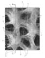
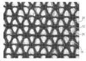
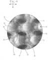
도 1은 본 발명에 따른 3차원 부직포 물질의 예시적인 실시예의 상면도이다.
도 2는 도 1의 실시예로부터 취한 상세도를 제공하는 주사 전자 현미경(SEM) 이미지이다.
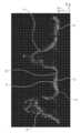
도 3은 3-3 선을 따라 도 1의 실시예로부터 취한 단면도를 제공하는 SEM 이미지이다.
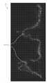
도 4는 도 1의 부직포 물질의 천공 구역의 개방 면적 백분율을 계산하기 위해 사용되는 투과된 광을 도시하는, 도 1로부터 취한 상세도이다.
도 5a 및 도 5b는 노드를 통해 취한, 부직포의 2개의 예시적인 실시예의 단면의 Micro-CT 이미지이다.
도 5c는 HUGGIES® Little Snugglers® 기저귀로부터의 GentleAbsorb® 라이너의 단면을 제공하는 Mirco-CT이다.
도 5d는 압축 에너지 시험 방법에 따라 완료된 시험 결과를 나타내는 막대 그래프이다.
도 5e는 압축 선형성 시험 방법에 따라 완료된 시험 결과를 나타내는 막대 그래프이다.
도 6a는 3차원 부직포 물질의 대안적인 실시예의 상면도이다.
도 6b는 6B-6B 선을 따라 본 도 6a의 물질의 일부의 단면도이다.
도 6c는 도 6a의 물질의 일부의 상세도이다.
도 6d는 도 6a의 물질의 일부의 광학 이미지이다.
도 6e는 도 6a의 부직포 물질의 하나의 예시적 측면 구역의 개방 면적 백분율을 계산하기 위해 사용되는 투과된 광을 도시하는, 도 6a로부터 취한 상세도이다.
도 6f 및 도 6g는 3차원 부직포 물질의 대안적인 실시예의 상면도이다.
도 7a는 본 발명에 따른 3차원 부직포를 제조하기 위한 예시적인 장치 및 공정의 개략적인 측면도이다.
도 7b는 본 발명에 따른 3차원 부직포를 제조하기 위한 대안적인 예시적 장치 및 공정의 개략적인 측면도이다.
도 7c는 본 발명에 따른 3차원 부직포를 제조하기 위한 또 다른 대안적인 예시적 장치 및 공정의 개략적인 측면도이다.
도 7d는 도 7c의 7D-7D 선을 따라 취한 부직포 물질 및 캐리어 물질의 단면도이다.
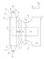
도 8a는 도 7a 내지 도 7c의 공정에서 이용될 수 있는 형성 표면의 일부의 사시도이다.
도 8b는 도 7a 내지 도 7c의 공정에서 이용될 수 있는 대안적인 형성 표면의 일부의 상세 상면도이다.
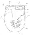
도 9는 본 발명에 따른 3차원 부직포 물질을 포함하는 흡수 용품의 일 실시예의 사시도이다.
도 10은 명확성을 위해 일부를 절단한 도 9의 흡수 용품의 상부 평면도이다.
도 11a는 도 10에서 11-11 선을 따라서 취한 단면도이다.
도 11b는 도 11a와 유사하지만, 흡수 용품의 대안적인 실시예의 단면도이다.
도 11c는 도 11a 및 도 11b와 유사하지만, 흡수 용품의 또 다른 대안적인 실시예의 단면도이다.
도 12는 도 9의 흡수 용품의 대안적인 실시예의 상부 평면도이다.
도 13은 부직포 물질에 대하여 예시적인 접합 구성이 도시된 도 12의 흡수 용품으로부터의 예시적인 부직포 물질의 상부 평면도이다.
도 14는 도 12에서 14F-14F 선을 따라 취한 단면도이다.
도 15는 본원에 기술된 바와 같은 물질 샘플 분석 시험 방법을 수행하기 위한 예시적인 장비 및 설정의 사시도이다.
본 명세서 및 도면에서 참조 문자의 반복적인 사용은 본 발명의 동일하거나 유사한 특징 또는 요소를 나타내기 위해 의도된다.The disclosure, which is sufficiently feasible for those skilled in the art, is set forth in more detail in the remainder of the specification to which the accompanying drawings are referenced.
1 is a top view of an exemplary embodiment of a three-dimensional nonwoven material according to the present invention.
FIG. 2 is a scanning electron microscope (SEM) image providing a detailed view taken from the embodiment of FIG. 1 ;
3 is an SEM image providing a cross-sectional view taken from the embodiment of FIG. 1 along line 3-3;
FIG. 4 is a detail taken from FIG. 1 showing transmitted light used to calculate the percent open area of the perforated zone of the nonwoven material of FIG. 1 ;
5A and 5B are Micro-CT images of cross-sections of two exemplary embodiments of a nonwoven fabric, taken through a node.
5C is a Mirco-CT providing a cross-section of a GentleAbsorb® liner from a HUGGIES® Little Snugglers® diaper.
5D is a bar graph showing test results completed according to the compressive energy test method.
5E is a bar graph showing test results completed according to the compression linearity test method.
6A is a top view of an alternative embodiment of a three-dimensional nonwoven material.
6B is a cross-sectional view of a portion of the material of FIG. 6A taken along line 6B-6B.
6C is a detailed view of a portion of the material of FIG. 6A .
6D is an optical image of a portion of the material of FIG. 6A .
6E is a detail taken from FIG. 6A showing transmitted light used to calculate the percentage open area of one exemplary side region of the nonwoven material of FIG. 6A .
6F and 6G are top views of an alternative embodiment of a three-dimensional nonwoven material.
7A is a schematic side view of an exemplary apparatus and process for making a three-dimensional nonwoven fabric in accordance with the present invention.
7B is a schematic side view of an alternative exemplary apparatus and process for making three-dimensional nonwovens in accordance with the present invention.
7C is a schematic side view of another alternative exemplary apparatus and process for making a three-dimensional nonwoven according to the present invention.
7D is a cross-sectional view of the nonwoven material and carrier material taken along line 7D-7D of FIG. 7C.
8A is a perspective view of a portion of a forming surface that may be used in the process of FIGS. 7A-7C ;
8B is a detailed top view of a portion of an alternative forming surface that may be used in the process of FIGS. 7A-7C ;
9 is a perspective view of one embodiment of an absorbent article comprising a three-dimensional nonwoven material in accordance with the present invention.
10 is a top plan view of the absorbent article of FIG. 9 with portions cut away for clarity.
11A is a cross-sectional view taken along line 11-11 in FIG. 10;
11B is a cross-sectional view similar to FIG. 11A , but of an alternative embodiment of an absorbent article.
11C is a cross-sectional view similar to FIGS. 11A and 11B , but of another alternative embodiment of an absorbent article.
12 is a top plan view of an alternative embodiment of the absorbent article of FIG. 9 ;
13 is a top plan view of an exemplary nonwoven material from the absorbent article of FIG. 12 showing an exemplary bonding configuration for the nonwoven material.
Fig. 14 is a cross-sectional view taken along
15 is a perspective view of exemplary equipment and setup for performing a material sample analysis test method as described herein.
Repeat use of reference characters in the specification and drawings is intended to represent the same or similar features or elements of the invention.
일 실시예에서, 본 발명은 일반적으로 부직포 물질(10, 110, 210, 310), 이를 제조하는 방법(100', 100", 100'"), 및 이러한 예시적인 부직포 물질을 포함하는 흡수 용품(410, 510, 610, 710)에 관한 것이다. 각 예는, 설명하기 위한 것이며, 본 발명을 한정하려는 것이 아니다. 예를 들어, 일 실시예 또는 도면의 일부로서 예시되거나 기술된 특징들은 여전히 추가적인 실시예를 만들기 위해 또 다른 실시예 또는 도면에 대해 사용될 수 있다. 본 개시내용은 이러한 수정과 변경을 포함하려는 것이다. 특정 예시적인 부직포 물질(10, 110, 210, 310)을 참조하는 하기의 임의의 논의는, 달리 언급되지 않는 한, 본원에 기술된 부직포 물질(10, 110, 210, 310)의 다른 실시예들 중 어느 하나에 적용되도록 의도된다. 또한, 부직포 물질을 제조하는 특정 방법(100', 100", 100'")을 참조하는 하기의 임의의 논의는, 달리 언급되지 않는 한, 본원에 기술된 부직포 물질을 제조하는 방법(100', 100", 100'")의 임의의 다른 실시예에 적용되도록 의도된다. 또한, 특정 흡수 용품(410, 510, 610, 710)을 참조하는 하기의 임의의 논의는, 달리 언급되지 않는 한, 본원에서 설명된 흡수 용품(410, 510, 610, 710)의 다른 실시예들 중 어느 하나에 적용하도록 의도된다.In one embodiment, the present invention relates generally to nonwoven materials (10, 110, 210, 310), methods of making them (100', 100'', 100'''), and absorbent articles comprising these exemplary nonwoven materials ( 410, 510, 610, 710). Each example is for the purpose of explanation and is not intended to limit the present invention. For example, features illustrated or described as part of one embodiment or figure may still be used with respect to another embodiment or figure to create a further embodiment. This disclosure is intended to cover such modifications and variations. Any discussion below with reference to certain exemplary
본 개시내용의 요소들 또는 본 개시내용의 바람직한 실시예(들)을 도입할 때, "한", "하나", "그", "상기" 라는 구는 그 요소들의 하나 이상이 존재함을 의미하는 것이다. "포함하는", "구비하는", "갖는" 이라는 용어들은, 포괄적인 것이며, 열거된 요소들 외의 다른 추가 요소들이 존재할 수도 있음을 의미한다. 본 개시내용의 사상과 범위로부터 벗어나지 않고 본 개시내용의 많은 수정과 변형이 이루어질 수 있다. 따라서, 상술한 예시적인 실시예는 본 발명의 범위를 제한하는 것으로 사용되어서는 안 된다.When introducing elements of the present disclosure or preferred embodiment(s) of the present disclosure, the phrases “a”, “an”, “the”, “said” mean that one or more of the elements are present. will be. The terms “comprising,” “comprising,” “having,” are inclusive and mean that there may be additional elements other than those listed. Many modifications and variations of the present disclosure may be made without departing from the spirit and scope of the present disclosure. Accordingly, the above-described exemplary embodiments should not be used as limiting the scope of the present invention.
정의:Justice:
"흡수 용품(absorbent article)"이라는 용어는, 본원에서 착용자 신체에 맞대거나 또는 근접하게(즉, 신체에 인접하게) 놓여서 신체로부터 배출되는 다양한 액체, 고체, 반고체 삼출물들을 흡수하여 함유할 수 있는 용품을 의미한다. 이러한 흡수 용품은, 본원에서 설명하는 바와 같이, 재사용을 위해 세탁되거나 또는 다른 방식으로 복원되는 것이 아니라 제한된 사용 기간 후 폐기되는 것이다. 본 개시내용은 본 개시내용의 범위를 벗어나지 않으면서, 기저귀 팬티, 용변 연습용 팬티, 아동 팬티, 수영 팬티를 포함하지만 이에 한정되지 않는 기저귀류, 월경 패드 또는 팬티, 실금 제품, 의료용 의복, 수술용 패드 및 붕대를 포함하지만 이에 한정되지 않는 여성 위생 제품, 및 기타 개인 위생 또는 건강 의복, 기타 등등을 포함하는 다양한 일회용 흡수 용품들에 적용할 수 있는 것으로 이해해야 한다.The term "absorbent article" as used herein refers to an article that can be placed against or proximate (ie, adjacent to) the body of a wearer to absorb and contain various liquid, solid, and semi-solid exudates that are expelled from the body. means Such absorbent articles, as described herein, are discarded after a limited period of use, rather than being laundered or otherwise restored for reuse. The present disclosure provides diapers, menstrual pads or panties, incontinence products, medical garments, surgical pads, including but not limited to diaper panties, training panties, children's panties, swimming panties, without departing from the scope of the present disclosure. and feminine hygiene products including but not limited to bandages, and other personal care or health garments, and the like.
"취득층(acquisition layer)"이라는 용어는, 본원에서, 신체의 액체 삼출물의 배출이나 급증을 감속 및 확산시키고 후속하여 신체의 액체 삼출물을 흡수 용품의 다른 층이나 층들 내로 방출하도록 신체의 액체 삼출물을 수용하고 일시적으로 보유할 수 있는 층을 가리킨다.The term "acquisition layer" is used herein to slow and diffuse the exudation or surge of the body's liquid exudate and subsequently release the body's liquid exudate into other layers or layers of the absorbent article. It refers to a floor that can be accommodated and temporarily held.
"접합된"(bonded) 또는 "결합된"(coupled)이라는 용어는 본원에서 두 요소의 결합, 접착, 연결, 부착 등을 의미한다. 두 요소는, 그들이 서로 직접적으로 또는 각각이 중간 요소들에 직접적으로 접합될 때처럼 서로 간접적으로 결합, 접착, 연결, 부착 등이 될 때에 함께 접합되거나 결합된 것으로 간주될 것이다. 한가지 요소의 다른 것에 대한 접합 또는 결합은 연속적이거나 단속적 접합을 통해 일어날 수 있다.The term “bonded” or “coupled” refers herein to bonding, adhering, connecting, attaching, etc., two elements. Two elements will be joined or considered joined together when they are joined, glued, connected, attached, etc. to each other either directly or indirectly, such as when each is directly joined to intermediate elements. Bonding or bonding of one element to another may occur through continuous or intermittent bonding.
"카디드 웹"(carded web)은, 본원에서, 통상적으로 섬유 길이가 약 100mm 미만인 천연 또는 합성 주요 길이 섬유를 포함하는 웹을 가리킨다. 단섬유들의 더미는, 섬유들을 분리하도록 개방 공정을 거칠 수 있고, 이어서 이러한 섬유들은, 분리 및 코빙(comb)하여 기계 방향으로 정렬한 후 섬유들을 추가 처리를 위해 이동 와이어 상에 적층되는 카딩(carding) 공정을 거치게 된다. 이러한 웹은, 일반적으로, 열 및/또는 압력을 이용하는 열적 접합 등의 일부 유형의 접합 공정을 거친다. 또한 또는 대신, 섬유는, 분말 접착제 등을 사용하여 섬유들을 함께 접합하는 접착 공정을 거칠 수도 있다. 카디드 웹은, 섬유들을 더욱 뒤엉키게 하여 카디드 웹의 무결성을 개선하도록 수력엉킴(hydroentangling) 등의 유체 엉킴을 거칠 수도 있다. 카디드 웹은, 기계 방향으로의 섬유 정렬 때문에, 일단 접합되면, 통상적으로 교차 기계 방향 세기보다 큰 기계 방향 세기를 갖는다."Carded web" as used herein refers to a web comprising natural or synthetic major length fibers, typically less than about 100 mm in fiber length. The pile of short fibers can be subjected to an opening process to separate the fibers, which are then separated and cobbed to align in the machine direction and then the fibers are laminated on a moving wire for further processing by carding. ) to go through the process. Such webs are generally subjected to some type of bonding process, such as thermal bonding using heat and/or pressure. Alternatively or alternatively, the fibers may be subjected to an adhesion process for bonding the fibers together using a powder adhesive or the like. The carded web may be subjected to fluid entanglement, such as hydroentangling, to further entangle the fibers and thereby improve the integrity of the carded web. Carded webs, once bonded, typically have a machine direction strength greater than the cross machine direction strength because of fiber alignment in the machine direction.
"필름"이라는 용어는, 본원에서, 주조 필름 또는 블로운 필름 압출 공정 등의 압출 및/또는 형성 공정을 이용하여 제조된 열가소성 필름을 가리킨다. 이 용어는, 배리어 필름, 충전된 필름, 통기성 필름, 배향 필름을 포함한 유체를 전달하지 않는 필름뿐만 아니라, 액체 전달 필름을 구성하는, 천공화된 필름, 슬릿 필름, 및 기타 다공성 필름을 포함하지만, 이러한 예들로 한정되지는 않는다.The term "film" as used herein refers to a thermoplastic film made using extrusion and/or forming processes, such as cast film or blown film extrusion processes. The term includes perforated films, slit films, and other porous films, comprising barrier films, filled films, breathable films, non-fluid transfer films, including oriented films, as well as liquid transfer films, It is not limited to these examples.
"유체 엉킴"(fluid entangling) 및 "유체 엉킴된(fluid entangled)"이라는 용어는 일반적으로 본원에서 소정의 섬유성 부직포 웹 내에서 또는 섬유성 부직포 웹들과 기타 물질들 간의 섬유 엉킴의 정도를 더욱 증가시켜서 엉킴의 결과로 개별적인 섬유들 및/또는 층들의 분리가 더욱 어려워지게 하는 형성 공정을 가리킨다. 이는, 일반적으로, 영향을 가하는 가압된 유체에 대하여 적어도 소정의 정도의 투과성을 갖는 소정의 유형의 형성 또는 캐리어 표면 상의 섬유성 부직포 웹을 지지함으로써 달성된다. 가압된 유체 스트림(일반적으로 다중 스트림)은 상기 웹의 지지된 면에 대향하는 부직포 웹의 표면에 마주하도록 유도된다. 가압된 유체는 섬유들과 접촉하게 되어 섬유들 중 일부를 유체 흐름 방향으로 향하게 하며, 이에 따라 복수의 섬유 중 일부 또는 전부를 부직포 웹의 지지면을 향하도록 변위시킨다. 그 결과, 웹의 평면 차원인 X-Y 면에 대하여 웹(웹의 두께)의 소위 Z 방향으로 섬유들이 더욱 엉키게 된다. 두 개 이상의 개별적인 웹 또는 기타 층이 형성/캐리어 면 상에 서로 인접하게 배치되어 가압 유체를 겪게 되는 경우, 일반적으로, 바람직한 결과는, 웹들 중 적어도 하나의 섬유들 중 일부가 인접하는 웹이나 층으로 향하게 되어 두 개의 표면의 계면 간의 섬유 엉킴을 야기하여 섬유들의 엉킴 증가에 의해 웹들/층들의 접합 또는 결합을 발생시키는 것이다. 접합 또는 엉킴 정도는, 사용중인 섬유의 종류, 그들의 섬유 길이, 유체에 거치기 전 웹 또는 웹들의 예비 접합 또는 엉킴 정도, 사용중인 유체의 종류(물, 증기 같은 액체, 또는 공기 같은 가스), 유체의 압력, 유체 스트림의 수, 공정의 속도, 유체의 체류 시간 및 웹 또는 웹들/기타 층들 및 성형/담체 표면의 다공성을 포함하여 많은 요인에 따라 달라질 것이지만, 이에 한정되지 않는다. 가장 흔한 유체 엉킴 공정들 중 하나는, 부직포 웹의 통상의 기술자에게 공지되어 있는 공정인 수력엉킴(hydroentangling)이라 칭한다. 유체 엉킴 공정의 예는 Radwanski 등의 미국 특허 번호 제4,939,016호, Evans의 미국 특허 번호 제3,485,706호, 및 Radwanski의 미국 특허 번호 제4,970,104호 및 제4,959,531호에서 발견할 수 있는데, 이들 각각은 그 전문이 참고 문헌으로 모든 목적을 위해 본원에 원용된다.The terms "fluid entangling" and "fluid entangled" are used herein generally to further increase the degree of fiber entanglement within a given fibrous nonwoven web or between fibrous nonwoven webs and other materials. refers to a forming process that makes the separation of individual fibers and/or layers more difficult as a result of entanglement. This is generally accomplished by supporting a fibrous nonwoven web on the surface of a carrier or forming or carrier of any type having at least some degree of permeability to the pressurized fluid exerting it. Pressurized fluid streams (generally multiple streams) are directed to face the surface of the nonwoven web opposite the supported side of the web. The pressurized fluid is brought into contact with the fibers and directs some of the fibers in the direction of fluid flow, thereby displacing some or all of the plurality of fibers toward the support surface of the nonwoven web. As a result, the fibers become more entangled in the so-called Z direction of the web (thickness of the web) with respect to the X-Y plane, which is the plane dimension of the web. When two or more separate webs or other layers are disposed adjacent to each other on the forming/carrier face and subjected to pressurized fluid, generally the desired result is that some of the fibers of at least one of the webs become adjacent to the web or layer. oriented to cause fiber entanglement between the interface of the two surfaces resulting in bonding or bonding of the webs/layers by increasing the entanglement of the fibers. The degree of bonding or entanglement depends on the type of fibers being used, their fiber length, the degree of pre-bonding or entanglement of the web or webs prior to being subjected to the fluid, the type of fluid being used (liquid such as water, vapor, or gas such as air), and the will depend on many factors including, but not limited to, pressure, number of fluid streams, speed of the process, residence time of the fluid and porosity of the web or webs/other layers and the forming/carrier surface. One of the most common fluid entangling processes is referred to as hydroentangling, a process known to those skilled in the art of nonwoven webs. Examples of fluid entanglement processes can be found in US Pat. No. 4,939,016 to Radwanski et al., US Pat. No. 3,485,706 to Evans, and US Pat. Nos. 4,970,104 and 4,959,531 to Radwanski, each of which is in its entirety. It is incorporated herein by reference for all purposes.
"gsm"이라는 용어는 본원에서 제곱 미터당 그램을 가리킨다.The term "gsm" refers herein to grams per square meter.
"친수성"이라는 용어는, 본원에서 섬유와 접촉하고 있는 수성 액체에 의해 습윤되는 섬유 또는 섬유의 표면을 칭한다. 이에 따라, 물질의 습윤 정도는 연관된 액체 및 물질의 접촉각 및 표면 장력 측면에서 설명될 수 있다. 특정한 섬유 물질들 또는 섬유 물질들의 혼합물의 젖음성을 측정하기 위한 적합한 장비 및 기술은, Cahn SFA-222 표면력 분석기 시스템(Surface Force Analyzer System) 또는 실질적으로 등가의 시스템에 의해 제공될 수 있다. 이 시스템으로 측정될 때, 90 미만의 접촉각을 갖는 섬유는 "젖음성" 또는 친수성인 것으로 지정되고, 90 초과의 접촉각을 갖는 섬유는 "비젖음성" 또는 소수성인 것으로 지정된다.The term “hydrophilic” herein refers to a fiber or surface of a fiber that is wetted by an aqueous liquid in contact with the fiber. Accordingly, the degree of wetting of a material can be described in terms of the contact angle and surface tension of the liquid and material involved. Suitable equipment and techniques for measuring the wettability of particular fiber materials or mixtures of fiber materials may be provided by the Cahn SFA-222 Surface Force Analyzer System or a substantially equivalent system. As measured with this system, fibers with a contact angle less than 90 are designated as "wettable" or hydrophilic, and fibers with a contact angle greater than 90 are designated as "non-wetting" or hydrophobic.
"액체 불투과성"이라는 용어는, 본원에서 소변 등의 신체의 액체 삼출물이 정상 사용 조건 하에서, 액체 접촉점에서 층 또는 적층체의 평면에 일반적으로 수직인 방향으로 그 층 또는 적층체를 통과하지 않는 층 또는 다중층 적층체를 칭한다.The term "liquid impermeable" as used herein refers to a layer in which liquid exudates of the body, such as urine, do not pass through, under normal conditions of use, the layer or laminate in a direction generally perpendicular to the plane of the layer or laminate at the point of liquid contact. or a multilayer laminate.
"액체 투과성"이라는 용어는 본원에서 액체 불투과성이 아닌 임의의 물질을 칭한다.The term "liquid permeable" herein refers to any material that is not liquid impermeable.
"멜트블로운"(meltblown)이라는 용어는, 본원에서 용융된 실(thread) 또는 필라멘트로서 복수의 미세한 일반적으로 원형인 다이 모세관을 통해 용융된 열가소성 물질을, 마이크로섬유 직경일 수 있는 그 직경을 감소시키기 위해 용융된 열가소성 물질의 필라멘트를 가늘게 하는 수렴 고속 가열 가스(예를 들어, 공기) 스트림으로 압출함으로써 형성된 섬유를 칭한다. 그런 다음 멜트블로운 섬유는 고속 가스 스트림에 의해 운반되고 수집 표면 위에 쌓여서 무작위 분산된 멜트블로운 섬유 웹이 형성된다. 이러한 공정은, 예를 들어, 본 명세서에 참조로 원용되는 Butin 등에 의한 미국특허 제3,849,241호에 개시되어 있다. 멜트블로운 섬유는, 연속적이거나 불연속적일 수 있는 마이크로섬유이고, 일반적으로 약 0.6 데니어(denier) 미만이고, 수집면 상에 적층될 때 끈적이면서 자체 접합형일 수 있다.The term "meltblown" is used herein as a molten thread or filament through a plurality of fine, generally circular die capillaries to reduce the diameter of a molten thermoplastic, which may be a microfiber diameter. refers to fibers formed by extruding filaments of molten thermoplastic with a stream of converging high-velocity heating gas (eg, air) to thin them to form a fiber. The meltblown fibers are then carried by the high velocity gas stream and piled up on a collecting surface to form a web of randomly dispersed meltblown fibers. Such a process is disclosed, for example, in US Pat. No. 3,849,241 to Butin et al., which is incorporated herein by reference. Meltblown fibers are microfibers, which may be continuous or discontinuous, generally less than about 0.6 denier, and may be sticky and self-bonding when laminated onto a collecting surface.
"부직포"(nonwoven)라는 용어는, 본원에서 직물 직조(weaving) 또는 편직(knitting) 공정의 도움 없이 형성된 물질 및 물질들의 웹을 칭한다. 상기 물질 및 물질들의 웹은, 편직물에서와 같이 식별 가능한 방식은 아니지만 짜일(interlay) 수 있는 개별적인 섬유, 필라멘트, 또는 실(총칭하여 "섬유"라 칭함)의 구조를 가질 수 있다. 부직포 물질 또는 웹은, 멜트블로운 공정, 스펀본딩 공정, 카디드 웹 공정 등의 많은 공정들로부터 형성될 수 있지만, 이러한 예로 한정되지는 않는다.The term "nonwoven" refers herein to a material and a web of materials formed without the aid of a fabric weaving or knitting process. The material and web of materials may have a structure of individual fibers, filaments, or threads (collectively referred to as “fibers”) that can be interlaced, but not in an identifiable manner, as in knitted fabrics. Nonwoven materials or webs can be formed from many processes, including, but not limited to, meltblown processes, spunbonding processes, carded web processes, and the like.
"유연한"이라는 용어는, 본원에서 순응적이며 착용자의 신체의 대략적인 형상과 윤곽을 쉽게 따르는 물질을 칭한다.The term “flexible” herein refers to a material that is compliant and readily conforms to the approximate shape and contour of the wearer's body.
용어 "스펀본드"(spunbond)는 본원에서, 원형 또는 기타 구성을 갖는 스피너레트(spinnerette)의 복수의 미세 모세관으로부터 용융된 열가소성 물질을 필라멘트로서 압출함으로써 형성되는 소 직경의 섬유들을 가리키며, 이어서, 압출된 필라멘트들의 직경은 이덕티브 드로잉(eductive drawing)과 같은 종래의 공정에 의해 급속하게 감소되며, 그 예는, Appel 등의 미국특허 제4,340,563호, Dorschner 등의 미국특허 제3,692,618호, Matsuki 등의 미국특허 제3,802,817호, Kinney의 미국특허 제3,338,992호와 제3,341,394호, Hartman의 미국특허 제3,502,763호, Peterson의 미국특허 제3,502,538호, Dobo 등의 미국특허 제3,542,615호에 개시되어 있으며, 이들 각각은 그 전문이 본 명세서에 참고문헌으로 원용된다. 스펀본드 섬유는, 일반적으로 연속적이며, 약 0.3보다 큰 평균 데니어를 종종 가지고, 일 실시예에서는, 약 0.6, 5, 10 내지 약 15, 20, 40의 데니어를 갖는다. 스펀본드 섬유는, 수집면 상에 피착되는 경우 일반적으로 끈적거리지 않는다.The term "spunbond" as used herein refers to small diameter fibers formed by extruding, as filaments, a molten thermoplastic from a plurality of microcapillaries of a spinnerette having a circular or other configuration, followed by extrusion. The diameter of the filaments produced is rapidly reduced by a conventional process such as eductive drawing, examples of which include U.S. Patent No. 4,340,563 to Appel et al., U.S. Patent No. 3,692,618 to Dorschner et al., and U.S. Patent No. Matsuki et al. No. 3,802,817, U.S. Patent Nos. 3,338,992 and 3,341,394 to Kinney, U.S. Patent No. 3,502,763 to Hartman, U.S. Patent No. 3,502,538 to Peterson, U.S. Patent No. 3,542,615 to Dobo et al. It is incorporated herein by reference in its entirety. Spunbond fibers are generally continuous and often have an average denier greater than about 0.3, and in one embodiment, from about 0.6, 5, 10 to about 15, 20, 40 denier. Spunbond fibers are generally not sticky when deposited on a collecting surface.
"초흡수성"이라는 용어는, 본원에서 0.9 중량 퍼센트 염화나트륨을 함유하는 수용액 내에서, 가장 적당한 조건 하에서, 그 중량의 적어도 약 15배를, 일 실시예에서는 그 중량의 적어도 약 30배를 흡수할 수 있는 수팽창성(water-swellable) 수불용성(water-insoluble) 유기 또는 무기 물질을 지칭한다. 초흡수성 물질은, 천연, 합성, 및 개질된 천연 고분자 및 물질일 수 있다. 게다가, 초흡수성 물질은, 실리카 겔 등의 무기 물질 또는 가교 결합된 고분자 등의 유기 화합물일 수 있다.The term "superabsorbent" as used herein refers to the ability to absorb, under most suitable conditions, at least about 15 times its weight, and in one embodiment, at least about 30 times its weight, in an aqueous solution containing 0.9 weight percent sodium chloride. refers to water-swellable, water-insoluble organic or inorganic substances. Superabsorbent materials can be natural, synthetic, and modified natural polymers and materials. Furthermore, the superabsorbent material may be an inorganic material such as silica gel or an organic compound such as a cross-linked polymer.
"열가소성"이라는 용어는, 본원에서 열에 노출시 성형될 수 있으며 냉각시 비연성화 상태로 실질적으로 복귀하는 연성화되는 물질을 가리킨다.The term "thermoplastic" herein refers to a material that can be formed upon exposure to heat and that softens substantially upon cooling to a non-combustible state.
용어 "사용자" 또는 "돌보는 사람"은 본원에서, 흡수 용품, 예컨대 기저귀, 기저귀 팬티, 용변 연습용 팬티, 아동 팬티, 실금 제품, 또는 이들 흡수 용품 중 하나의 착용자 주변의 기타 흡수 용품이지만 이들에만 한정되지 않는 것을 착용하는 사람을 의미한다. 사용자 및 착용자는 한 명이고 동일한 사람일 수 있다.The term “user” or “caretaker” as used herein refers to, but is not limited to, an absorbent article, such as, but not limited to, a diaper, diaper panty, training pan, children's panty, incontinence article, or other absorbent article around the wearer of one of these absorbent articles. It means a person who wears something that does not. The user and the wearer are one and may be the same person.
노드, 인대 및 개구부가 있는 3차원 웹:Three-dimensional web with nodes, ligaments and openings:
도 1 내지 도 3에 도시된 바와 같이, 3차원 부직포 물질(10)은 복수의 노드(12) 및 복수의 연결 인대(14)를 포함할 수 있다(노드(12) 중 하나와 연결 인대(14) 중 하나만 명료성을 위해 도 1에 라벨링됨). 노드(12) 및 연결 인대(14)는 물질(10)의 천공 구역(16) 내에 배치될 수 있다. 도 3의 단면도에 가장 잘 도시된 바와 같이, 노드(12)는 부직포 물질(10)의 제1 표면(20) 상의 베이스 평면(18)으로부터 멀리 연장될 수 있다. 베이스 평면(18)은 노드(12)를 형성하는 부직포 물질(10)의 부분 이외의 부직포 물질(10)의 제1 표면(20)의 일반적으로 평면 영역으로서 정의될 수 있다. 즉, 도 1 내지 도 3에 도시된 실시예에 대해, 베이스 평면(18)은 연결 인대(14)를 제공하는 부직포 물질(10)의 제1 표면(20)에 의해 형성될 수 있다. 부직포 물질(10)은 또한 제2 표면(22)을 포함할 수 있다. 제1 표면(20)은 도 3에 도시된 대로 제2 표면(22)에 대향할 수 있다.1-3 , the three-dimensional
노드(12)는, 부직포 물질(10)의 제조에 대해 논의할 때 이하에서 더욱 상세히 논의되는 바와 같이 다양한 형상 및 크기로 구성될 수 있다. 일부 실시예에서, 노드(12)는 일반적으로 원통형 형상일 수 있다. 바람직한 실시예에서, 노드(12)는 임의의 개구 또는 천공을 포함하지 않도록 구성된다. 일부 실시예에서, 노드(12)는 약 1mm 내지 약 10mm, 보다 바람직하게는 약 3mm 내지 약 6mm의 높이(15)(베이스 평면(18)에 수직인 방향으로 측정됨)를 가질 수 있다. 노드(12)의 높이(15)는 본원의 시험 방법 섹션에 기술된 노드 분석 시험 방법에 기술된 분석 기술을 사용하여 측정된다. 일부 실시예에서, 대부분의 노드(12)는 각각 약 5mm2 내지 약 35mm2, 보다 바람직하게는 약 10mm2 내지 약 20mm2의 (베이스 평면(18) 내의 노드(12)의 면적에 의해 측정된 바와 같은) 면적을 가질 수 있다. 복수의 노드(12)는, 노드(12)가 약 1.0 노드/cm2 내지 약 3.0 노드/cm2의 노드 밀도를 제공하도록 천공 구역(16)에서 구성될 수 있다. 천공 구역(16) 내의 노드 면적 및 노드 밀도는 본원의 시험 방법 섹션에 기술된 물질 샘플 분석 시험 방법에 기술된 분석 기술을 사용하여 측정될 수 있다.
도 1에 도시되고 도 2에 보다 상세하게 도시된 바와 같이, 연결 인대(14)는 복수의 노드(12)를 상호 연결할 수 있다. 개별적인 연결 인대(14)는 단지 2개의 인접한 노드(12) 사이에서 연장되는 것으로 지칭될 수 있다. 즉, 개별적인 연결 인대(14)는 셋 이상의 노드(12)를 상호 연결하지 않는다. 바람직한 실시예에서, 복수의 노드(12)의 대부분은 인접 노드(12)에 연결된 적어도 3개의 연결 인대(14)를 포함할 수 있다. 바람직한 실시예에서, 복수의 노드(12)의 대부분은 인접 노드(12)에 연결되는 10개 이하의 연결 인대(14)를 포함할 수 있다. 일부 실시예에서, 부직포 물질(10)은, 복수의 노드(12)의 대부분이 인접 노드(12)에 연결된 3개 내지 8개의 연결 인대(14)를 포함할 수 있도록 구성될 수 있다. 예를 들어, 도 1 및 도 2에 도시된 실시예에서, 복수의 노드(12)의 대부분은 인접 노드(12)에 연결되는 6개의 연결 인대(14)를 포함한다. 다른 실시예에서, 복수의 노드(12)의 대부분이 인접 노드(12)에 연결된 3개 내지 6개의 연결 인대(14)를 포함하도록 하고, 일부 실시예에서는, 바람직하게 인접 노드(12)에 연결된 3개 내지 4개의 연결 인대(14)를 포함하도록 하는 것이 바람직할 수 있다.As shown in FIG. 1 and shown in more detail in FIG. 2 , the connecting
부직포 물질(10)은 또한 천공 구역(16)에 복수의 개구부(24)를 포함할 수 있다. 개구부(24)는 또한 본원에서 "천공"으로서 지칭될 수도 있다. 본원에서 설명된 바와 같은 개구부(24)는 노드(12) 및 연결 인대(14)와 비교하여 부직포 물질(10)의 더 낮은 밀도의 섬유를 갖는 부직포 물질(10)의 영역이다. 일부 실시예에서, 개구부(24)에는 실질적으로 섬유가 없을 수 있다. 본원에서 사용되는 바와 같이, 개구부(24)는 섬유성 부직포 물질에서 흔히 발견되는 정상적인 섬유간 간격과 구별되어야 한다. 예를 들어, 도 2는 인접한 노드(12) 및 연결 인대(14)보다 낮은 밀도의 섬유를 포함하는 하나의 개구부(24)를 라벨링하는 예시적인 부직포 물질(10)의 SEM 이미지를 제공한다. 개구부(24)는 복수의 연결 인대(14)와 복수의 노드(12) 사이에 형성될 수 있다. 개별 개구부(24)는 인접한 노드(12) 사이에 배치될 수 있다. 개별 개구부(24)는 적어도 3개의 연결 인대(14)와 적어도 3개의 노드(12) 사이에 정의될 수 있다. 일부 실시예에서, 개별 개구부(24)는 적어도 4개의 연결 인대(14)와 적어도 4개의 노드(12) 사이에 정의될 수 있다. 일부 실시예에서, 복수의 개구부(24)의 대부분은 각각 약 5mm2 내지 약 25mm2, 보다 바람직하게는 약 7mm2 내지 약 20mm2, 보다 더 바람직하게는 약 7mm2 내지 약 17mm2 범위의 면적(베이스 평면(18) 내 개구부(24)의 면적에 의해 측정됨)을 갖도록 구성될 수 있다. 천공 구역(16) 내 개구부(24)의 면적은 본원의 시험 방법 섹션에서 기술된 바와 같은 물질 샘플 분석 시험 방법의 분석 기술을 사용하여 측정될 수 있다.The
일부 실시예에서, 부직포 물질(10)을 위한 복수의 개구부(24)는 약 10% 내지 약 60%의 천공 구역(16)에 대한 개방 면적 백분율을 제공할 수 있다. 일부 바람직한 실시예에서, 부직포 물질(10)을 위한 복수의 개구부(24)는 약 15% 내지 약 45%의 천공 구역(16)에 대한 개방 면적 백분율을 제공할 수 있다. 일부 바람직한 실시예에서, 부직포 물질(10)은 약 20% 내지 약 40%, 또는 보다 더 바람직하게는 약 20% 내지 약 30%의 천공 구역(16)에 대한 개방 면적 백분율을 제공할 수 있다. 본원에서 사용되는 바와 같이, 개방 면적 백분율은 본원의 시험 방법 섹션에 기술된 바와 같은 물질 샘플 분석 시험 방법을 사용하여 결정된다. 시험 방법 섹션에서 상세히 설명되지만, 물질 샘플 분석 시험 방법은, 노드(12) 및 인대(14)에 비해, 도 4에 도시된 (명료성을 위해 단지 3개의 개구부(24)만 라벨링됨) 개구부(24)가 더 큰 백분율의 광이 부직포 물질(10)을 통과할 수 있게 하는 특성에 의해 개구부(24)가 식별될 수 있도록, 부직포 물질(10) 상에 광원을 투사하는 것을 포함한다.In some embodiments, the plurality of
복수의 개구부(24)는 부직포 물질(10)에 다양한 유익한 특성을 제공할 수 있다. 예를 들어, 개구부(24)는 부직포 물질(10)에 대한 향상된 유체 전달 및/또는 증가된 투과성을 제공할 수 있다. 일례로서, 부직포 물질(10)이 유체를 흡입하고 분배하는 물품에 활용되는 경우, 개구부(24)는 부직포 물질(10)을 통해 및/또는 그를 가로질러 유체의 증가된 흡입 및 분배를 제공하는 것을 도울 수 있다.The plurality of
특히, 복수의 개구부(24)는 부직포 물질(10)과 같은 물질이 BM 물질(본원에서 배설물 또는 분비물로도 지칭됨)을 흡입하고 분배하는 능력을 향상시킬 수 있어서, 물질(10) 상의 BM의 고임(pooling)을 줄이고, 따라서 이러한 부직포 물질(10)을 포함하는 흡수 용품의 착용자의 피부에 대해 배치되는 BM을 줄일 수 있다. 시뮬레이션된 BM을 효과적으로 취급하는 상이한 부직포 물질의 능력을 결정하기 위해서, 본 발명의 양태에 따라 다수의 상이한 부직포 물질(10)(물질 A 내지 F)을 BM 고임 백분율 값을 결정하는 시험 방법을 사용하여 시험하였다. 이러한 시험 방법은, 발명의 명칭이 "흡수 용품"인 미국 특허 번호 제9,480,609호에서 "잔여 분비물 모의물질의 결정"으로 기술되며, 그 전문은 본 명세서와 모순되지 않는 정도까지 참조로서 본원에 원용된다. 시험된 상이한 부직포 물질은 모두 유사한 방식이지만, 상이한 형성 표면으로 형성되어서, 노드(12), 인대(14), 및 개구부(24)의 상이한 패턴을 생성하였다. 이들 상이한 패턴은 천공 구역(16) 내의 개방 면적 백분율 값, 평균 개방 면적, 및 형성된 부직포 물질의 물질 벌크 특성에서 차이를 발생시켰다. 상이한 부직포 물질, 및 이들의 특성 및 성능 결과는 아래 표 1에 도시되어 있다.In particular, the plurality of
주로, 개구부(24)를 가져서, 이러한 물질에 천공 구역(16) 내 개방 면적 백분율 값을 제공하는 물질이 이러한 물질 상의 BM 고임 양을 감소시키는 것에 관하여 얼마나 효율적인지 알 수 있다. 예를 들어, 표 1에 나타낸 바와 같이, 가장 낮은 개방 면적 백분율 값을 갖는 물질 A는 여전히 고인 남은 BM의 양 측면에서 GentleAbsorb® 물질보다 상당히 양호하게 수행되었다. 실제로, 모든 시험 재료 A-F는 GentleAbsorb® 재료의 성능과 비교하여 양호하게 수행되었으며, 일반적으로 적어도 약 20%, 또는 적어도 약 25%, 또는 적어도 약 30%, 또는 약 20% 내지 약 30%의 바람직한 개방 면적 백분율 범위를 지지한다.Primarily, it can be seen how effective a
또한, 본원에 기술된 천공 구역(16)의 최소 개방 면적 백분율 값, 또는 본원에 기술된 개방 면적 백분율 값 범위를 갖는 이러한 부직포 물질(10)과 함께, 부직포 물질(10)이 비교적 더 큰 평균 면적을 갖는 개구부(24)를 갖는 것이 바람직할 수 있음을 알 수 있다. 예를 들어, 표 1에서 재료 A와 E가 유사한 개방 면적 백분율 값을 갖는다는 것을 알 수 있다. 그러나, 재료 E는 고인 채 남은 BM에 대해 재료 A보다 상당히 양호하게 수행되었다. 표 1에서 알 수 있듯이, 물질 E는 13.79mm2의 평균 개방 면적을 갖는 반면, 물질 A는 10.52mm2의 평균 개방 면적만 갖는다. 따라서, 본 발명의 부직포 물질(10)은 적어도 10.52mm2, 또는 적어도 약 11mm2, 또는 적어도 약 12mm2, 또는 적어도 약 13mm2, 또는 적어도 13.79mm2의 평균 개방 면적을 갖는 것이 바람직할 수 있다. 본 발명의 부직포 물질이 적어도 21.91%, 또는 적어도 약 22%, 또는 적어도 약 23%, 또는 약 20% 내지 약 30%의 천공 구역(16)에서 부직포 물질의 개방 면적 백분율 값을 가지면서 개구부(24)의 이러한 평균 면적을 갖는 것이 유익할 수 있다.Also, with such
본 발명의 부직포 물질의 일부 특히 바람직한 실시예에서, 이러한 물질은 약 27% 초과, 또는 약 27.31% 초과, 약 31% 미만, 또는 약 30.75% 미만의 개방 면적 백분율 값을 갖는 것이 바람직할 수 있다. 예를 들어, 재료 B, C, 및 D는 재료 B 및 C 둘 다보다 양호한 성능을 갖는 재료 C를 보여주며, 재료 B 및 D는 각각 재료 C보다 낮고 큰 개방 면적 백분율 값을 갖는다. 대안적으로, 본 발명의 부직포 물질의 실시예들은 약 11.81mm2 초과, 또는 약 12mm2 초과 및 약 20.13mm2 미만, 또는 약 21mm2 미만인 개구부(24)의 평균 면적을 갖는 것이 바람직할 수 있다. 예를 들어, 재료 B, C, 및 D는 재료 B 및 D 둘 다보다 더 양호한 성능을 갖는 재료 C를 보여주며, 재료 B 및 D는 각각 재료 C보다 더 작고 더 큰 개구부(24)의 평균 면적 값을 갖는다. 또 다른 실시예에서, 본 발명의 부직포 물질은 약 27% 초과, 또는 약 27.31% 초과, 약 31% 미만, 또는 약 30.75% 미만의 개방 면적 백분율 값을 가지고, 또한 약 11.81mm2 초과, 또는 약 12mm2 초과 및 약 20.13mm2 미만, 또는 약 21mm2 미만의 평균 개방 면적을 가지는 것이 바람직할 수 있다.In some particularly preferred embodiments of the nonwoven materials of the present invention, it may be desirable for such materials to have an open area percentage value greater than about 27%, or greater than about 27.31%, less than about 31%, or less than about 30.75%. For example, materials B, C, and D show material C with better performance than both materials B and C, and materials B and D have lower and larger open area percentage values than material C, respectively. Alternatively, the embodiment of the non-woven material of the invention may preferably have an average area of about 11.81mm2, greater than 12mm2 or greater than about2 and less than about 20.13mm, or less than about 21mm2
도 5a 내지 도 5c는 섬유 배향에 관한 부직포 물질(10)의 다른 유익한 특성의 예를 제공한다. 도 5a 및 도 5b의 단면도에 도시된 바와 같이, 부직포 물질(10)의 바람직한 실시예들에서, 복수의 노드(12) 중 적어도 대부분은 본원의 시험 방법 섹션에서 설명된 노드 분석 시험 방법에 의해 측정했을 때 1.0 초과의 이방성 값을 갖도록 구성될 수 있다. 노드(12)는 부직포 물질(10)의 제1 표면 상의 베이스 평면(18)에 수직인 방향(32)으로 더 높은 수준의 섬유 정렬을 갖는다. 도 5c는 Kimberly-Clark Global Sales, LLC에 의해 제조되고 판매되는 HUGGIES® Little Snugglers® 기저귀에서 GentleAbsorb® 라이너로서 현재 사용되고 시판되는 부직포 물질의 비교 예를 제공하는데, 이는 미국 특허 번호 제9,327,473호에 기술되어 있다. 도 5a 내지 도 5c의 부직포 물질에 대한 이방성 값들을 아래 표 2에 나타낸다. 표 2에 나타낸 바와 같이, 도 5a 및 도 5b의 부직포 물질(10)은 각각 1.07 및 1.25의 이방성 값을 갖는 1.0 초과 이방성 값을 포함하였다.5A-5C provide examples of other beneficial properties of the
이론에 얽매이지 않지만, 이하에서 더욱 상세히 논의되는 바와 같이, 본원에 설명된 부직포 물질(10)의 노드(12)에서의 개선된 이방성 값은 성형 구멍(54)의 직경에 비해 성형 구멍(54)의 깊이의 종횡비를 증가시킴으로써 생성될 수 있는 것으로 여겨진다.Without wishing to be bound by theory, as will be discussed in greater detail below, the improved anisotropy value at
또한, 본 설명에 따른 부직포 물질(10)의 증가된 이방성 값은 GentleAbsorb® 라이너 물질을 비롯해, 다른 부직포 물질과 비교하여 부직포 물질(10)에 대해 개선된 압축 저항을 제공하는 것으로 여겨진다. 개선된 압축 저항으로, 부직포 물질(10)은 압축력에 노출될 수 있는 다양한 환경에서의 적용 및 사용을 통해 로프트를 유지할 수 있다. 예를 들어, 흡수 용품에 사용될 때, 부직포 물질(10)은 압축된 포장 상태에 있는 초기 포장 상태로부터 착용자가 흡수 용품 상에 앉거나 누운 위치에 있는 경우 착용자에게 적용될 때까지 압축력 하에 있을 수 있다. 압축에 대한 개선된 저항을 제공함으로써, 부직포 물질(10)은 착용자로부터 신체 삼출물을 수용, 전달 및/또는 저장하기 위한 공극 부피를 유지하는 것을 도울 수 있다. 이렇게 함으로써, 부직포 물질(10)은, 신체 삼출물을 착용자의 피부로부터 멀리 유지하는 것을 도움으로써 착용자에게 향상된 피부 이점을 제공할 수 있고, 누출의 근원일 수 있는, 신체 삼출물을 흡수 용품의 에지로부터 멀리 유지함으로써 잠재적인 제품 개선을 제공할 수 있다.It is also believed that the increased anisotropy value of the
도 5d 및 도 5e에 도시된 바와 같이, (도 6a에 도시된) 본원에 설명된 예시적인 부직포 물질(110)을, 미국 특허 번호 제9,327,473호에 기술되어 있는, Kimberly-Clark Global Sales, LLC에 의해 제조되고 판매되는 HUGIES® Little Snugglers® 기저귀에서 GentleAbsorb® 라이너로서 현재 사용되고 시판되는 부직포 물질의 비교예에 대해 2개의 압축 관련 시험 방법으로 시험하였다. GentleAbsorb® 라이너 물질의 샘플의 Micro-CT 단면 이미지가 도 5c에 도시된다. 도 5d는 압축 에너지 시험의 결과를 보여주고 도 5e는 압축 선형성 시험의 결과를 보여준다. 이제 이러한 시험의 결과를 논의할 것이다.As shown in FIGS. 5D and 5E , the exemplary
압축 에너지 시험은 본원의 시험 방법 섹션에서 더욱 완전하게 설명되지만, 5 그램 힘에서 초기 두께로부터 약 1830 그램 힘(약 10 kPa)에서 최종 두께까지 부직포 물질을 압축하는 데 필요한 에너지를 측정함으로써 3 사이클의 압축을 통해 재료의 압축 탄성을 측정한다. 도 5d에 도시된 대로, 본 발명의 부직포 물질(110)은 GentleAbsorb® 라이너의 제어 코드를 압축하는 데 필요한 압축 에너지와 비교하여 압축하기 위해 각 사이클에서 더 많은 양의 압축 에너지를 요구하였으므로, 더 큰 압축 탄성을 제공한다. 실제로, 압축 에너지 시험의 결과는, 부직포 물질(110)가 제어 코드에 대해 이점을 제공한다는 것을 보여준다. 특히, 부직포 물질(110)는 사이클 1에서 40 gf*cm 초과, 사이클 2 및 3에서 35 gf*cm 초과의 압축 에너지를 제공하였다. 실제로, 부직포 물질은 사이클 2 및 3에서 50 gf*cm 초과, 사이클 1에서 60 gf*cm 초과의 압축 에너지를 제공하였다.The compressive energy test is described more fully in the Test Methods section herein, but is performed in 3 cycles by measuring the energy required to compress the nonwoven material from an initial thickness at a 5 gram force to a final thickness at about 1830 gram force (about 10 kPa). Compression measures the compressive elasticity of a material. As shown in FIG. 5D , the
따라서, 본 발명의 부직포 물질이 압축 에너지 시험의 사이클 1에서 40 gf*cm 초과, 보다 바람직하게는 45 gf*cm 초과, 보다 바람직하게는 50 gf*cm 초과, 보다 더 바람직하게는 55 gf*cm 초과, 더욱 더 바람직하게는 60 gf*cm 초과의 압축 에너지를 제공하는 것이 바람직하다. 본 발명의 부직포 물질이 압축 에너지 시험의 사이클 1에서 40 내지 65 gf*cm의 압축 에너지를 제공하는 것이 바람직하다. 또한, 본 발명의 부직포 물질이 압축 에너지 시험의 사이클 2에서 35 gf*cm 초과, 보다 바람직하게는 40 gf*cm 초과, 보다 바람직하게는 45 gf*cm 초과, 보다 더 바람직하게는 50 gf*cm 초과의 압축 에너지를 제공하는 것이 바람직하다. 따라서, 본 발명의 부직포 물질이 압축 에너지 시험의 사이클 2에서 40 내지 55 gf*cm의 압축 에너지를 제공하는 것이 바람직하다. 또한, 본 발명의 부직포 물질이 압축 에너지 시험의 사이클 3에서 35 gf*cm 초과, 보다 바람직하게는 40 gf*cm 초과, 보다 바람직하게는 45 gf*cm 초과, 보다 더 바람직하게는 50 gf*cm 초과의 압축 에너지를 제공하는 것이 바람직하다. 본 발명의 부직포 물질이 압축 에너지 시험의 사이클 3에서 40 내지 55 gf*cm의 압축 에너지를 제공하는 것이 바람직하다.Accordingly, the nonwoven material of the present invention is greater than 40 gf*cm, more preferably greater than 45 gf*cm, more preferably greater than 50 gf*cm, even more preferably greater than 55 gf*cm in cycle 1 of the compressive energy test. It is preferred to provide a compressive energy of greater than, even more preferably greater than 60 gf*cm. It is preferred that the nonwoven material of the present invention provides a compressive energy of 40 to 65 gf*cm in cycle 1 of the compressive energy test. In addition, the nonwoven material of the present invention is greater than 35 gf*cm, more preferably greater than 40 gf*cm, more preferably greater than 45 gf*cm, even more preferably greater than 50 gf*cm in cycle 2 of the compressive energy test. It is desirable to provide an excess of compressive energy. Accordingly, it is preferred that the nonwoven material of the present invention provides a compressive energy of 40 to 55 gf*cm in cycle 2 of the compressive energy test. Further, the nonwoven material of the present invention is greater than 35 gf*cm, more preferably greater than 40 gf*cm, more preferably greater than 45 gf*cm, even more preferably greater than 50 gf*cm in
더 많은 압축 탄성을 제공함으로써, 본 발명의 부직포 물질은 추가적인 이점을 제공할 수 있다. 예를 들어, 부직포 물질(10)이 흡수 용품(410)에 사용될 때, 부직포 물질(10)은 신체 삼출물을 취급하기 위한 공극 부피를 유지할 수 있고, 이를 흡수 조립체(444) 내로 흡입하여, 사용자의 피부를 더욱 건조하고 더욱 편안하게 유지하는 데 도움을 줄 수 있다. 이러한 이점은, 노드(12)가 부직포 물질(10)의 제1 표면(20)의 베이스 평면(18)으로부터 흡수체(434)를 향해 연장되도록 부직포 물질(10)가 흡수 용품(410)에 구성되는 실시예에서 특히 실현될 수 있다. 또한, 더 많은 압축 탄성을 가짐으로써, 부직포 물질(10)은 잠재적으로 이러한 흡수 용품(410)을 착용한 착용자의 피부에 더 많은 로프트와 더 부드러운 느낌을 제공할 수 있다.By providing more compressive elasticity, the nonwoven materials of the present invention may provide additional advantages. For example, when the
도 5e는 압축 선형성 시험의 결과를 도시한다. 본원의 시험 방법 섹션에서 충분히 설명된 바와 같이, 압축 선형성 시험은 최대 미리 설정된 힘에 도달할 때까지 2개의 플런저 사이에서 일정한 속도로 재료를 압축함으로써 부직포 물질의 압축 특성을 측정하도록 설계된다. 물질을 압축하는 상부 플런저의 변위는 전위차계에 의해 검출된다. 샘플을 압축하기 위해 취한 압력의 양(P, gf/cm2) 대 재료의 두께(변위)(T, mm)가 컴퓨터 스크린 상에 도표화된다. 압축 선형성의 값은 압축 곡선의 선형성 정도를 나타낸다. 압축 선형성 값이 더 높을수록, 재료가 압축되는 것에 대해 더 저항성이 있다. 도 5e에 도시된 대로, 부직포 물질(110)은 약 0.75의 압축 선형성을 나타내는 반면, GentleAbsorb® 라이너의 제어 코드는 0.50 미만의 압축 선형성을 나타냈다. 따라서, 바람직한 실시예에서, 부직포 물질은 바람직하게는 0.50 초과, 더 바람직하게는 0.55 초과, 더 바람직하게는 0.60 초과, 더욱 더 바람직하게는 0.65 초과, 가장 바람직하게는 0.70 초과의 압축 선형성을 갖는다. 일부 실시예에서, 부직포 물질은 약 0.50 내지 1.0, 또는 약 0.50 내지 약 0.80의 압축 선형성을 가질 수 있다.5E shows the results of the compression linearity test. As fully described in the Test Methods section herein, the Compression Linearity Test is designed to measure the compressive properties of a nonwoven material by compressing the material at a constant rate between two plungers until a maximum preset force is reached. The displacement of the upper plunger compressing the material is detected by a potentiometer. The amount of pressure taken to compress the sample (P, gf/cm2 ) versus the thickness (displacement) of the material (T, mm) is plotted on a computer screen. The value of compression linearity indicates the degree of linearity of the compression curve. The higher the compression linearity value, the more resistant the material is to being compressed. As shown in FIG. 5E , the
일부 실시예에서, 부직포 물질(10)은 천공 구역(16)과 상이한 측면 구역 및/또는 말단 구역을 포함할 수 있다. 예를 들어, 도 1에 도시된 바와 같이, 부직포 물질(10)은 제1 측면 구역(26a) 및 제2 측면 구역(26b)을 포함할 수 있다. 제1 및 제2 측면 구역(26a, 26b)은 일반적으로 서로 평행할 수 있고 길이 방향(28)으로 연장될 수 있다. 제1 및 제2 측면 구역(26a, 26b)은, 제1 측면 구역(26a)이 천공 구역(16)의 제1 측면(16a)에 인접하고 제2 측면 구역(26b)이 천공 구역(16)의 제2 측면(16b)에 인접하도록 구성될 수 있다. 달리 말하면, 천공 구역(16)은 제1 측면 구역(26a)과 제2 측면 구역(26b) 사이에 배치될 수 있다. 적어도 일부 실시예에서, 측면 구역(26a, 26b)은 물질(10)의 전방 에지(25)로부터 물질(10)의 후방 에지(27)까지 완전히 연장될 수 있다. 또한, 일부 실시예에서, 천공 구역(16)은 물질(10)의 전방 에지(25)로부터 물질(10)의 후방 에지(27)까지 완전히 연장될 수 있어서, 물질(10)은 어떠한 말단 구역(26c, 26d)도 갖지 않는다. 그러나, 다른 실시예들에서, 측면 구역(26a 및/또는 26b)은 부직포 물질(10)의 길이를 따라 부분적으로만 연장될 수 있다. 이러한 실시예에서, 천공 구역(16)은 재료(10)의 길이의 적어도 일부분을 따라 부직포 물질(10)의 측방향 측면 에지(47, 49) 사이에서 완전히 연장될 수 있다.In some embodiments, the
부직포 물질(10)은 측방향 측면 에지들(47, 49) 사이에 정의된 폭(35)을 가질 수 있다. 측면 구역(26a, 26b)은 각각 폭(31a, 31b)을 갖는 반면, 천공 구역(16)은 폭(33)을 갖는다. 도 1에서 일정한 것으로 도시되어 있지만, 폭(31a, 31b)은 다른 실시예들에서는 달라질 수 있다. 예를 들어, 물질(10)은 에지가 길이 방향(28)으로 만곡 및/또는 파형을 갖는 천공 구역(16)을 가지고 형성될 수 있다. 이러한 실시예에서, 폭(31a, 31b)은 천공 구역(16)의 형상에 상응하여 증가 및/또는 감소할 수 있다. 본원에서 사용되는 바와 같이, 폭(31a, 31b)은 측면 구역(26a, 26b)이 물질(10)의 길이를 따라 달성하는 최대 폭을 지칭할 수 있다.The
일반적으로, 측면 구역(26a, 26b)이 물질(10)의 전체 폭(35)의 백분율 중 너무 크지 않은 폭(31a, 31b)을 갖는 것이 유익할 수 있다. 예를 들어, 측면 구역(26a, 26b)은 일반적으로 천공 구역(16)보다 큰 인장 강도를 가질 수 있다. 따라서, 측면 구역(26a, 26b)의 한 가지 장점은, 이들이 물질(10)에 더 큰 전체 인장 강도를 제공하는 것을 도울 수 있고, 이에 따라 물질(10)이 장력 하에 처리되는 고속 제조 공정(예를 들어, 고속 흡수 용품 제조 공정) 내에서 물질(10)을 처리할 수 있게 돕는 것이다. 그러나, 측면 구역(26a, 26b)의 폭(31a, 31b)이 너무 큰 경우, 물질(10)이 원하는 고속 제조 공정에서 가공될 수 없도록 장력 하에 놓일 때 물질(10)이 바람직하지 않게 컬링될 것임을 발견하였다. 예를 들어, 이러한 컬링은, 재료가 제조 공정 내에서 웹 경로를 따라 횡단함에 따라 부직포 물질의 에지가 바람직하지 않게 접히게 할 수 있다. 측면 구역(26a, 26b)과 천공 구역(16) 사이의 인장 강도의 차이는 이러한 컬링에 중요한 기여 인자인 것으로 여겨진다.In general, it may be beneficial for the
물질(10)이 컬링되는 것을 방지하거나, 적어도 고속 제조 공정 내에서 물질(10)의 가공성에 영향을 미치는 정도로 컬링되는 것을 방지하는 것을 돕기 위해, 물질(10)의 전체 폭의 특정 백분율 값 하에 폭(31a, 31b)을 유지하는 것이 바람직한 것으로 밝혀졌다. 이러한 특징부는, 고속 제조 공정의 장력을 받을 때 측면 구역(26a, 26b)의 더 높은 인장 강도가 물질(10)의 성능을 지배하지 않는 것을 보장하는 데 도움이 되는 것으로 여겨진다. 폭(31a, 31b)이 각각 물질(10)의 전체 폭(35)의 약 20% 미만인 경우, 통상적인 고속 제조 공정에서 장력을 받을 때 물질(10) 및 본 발명의 다른 물질이 바람직한 컬링 특성을 유지하는 것으로 밝혀졌다. 폭(31a, 31b)이 각각 물질(10)의 전체 폭(35)의 약 25% 미만, 또는 약 20% 미만, 또는 약 17.5% 미만, 또는 약 15% 미만, 약 12.5% 미만 또는 약 10% 미만인 것이 더 바람직할 수 있다. 이들 실시예 중 적어도 일부에서, 폭(31a, 31b)은 각각 물질(10)의 전체 폭(35)의 약 5%를 초과할 수 있다. 결과적으로, 천공 구역 폭(33)은 물질(10)의 전체 폭(35)의 약 50% 내지 약 90%, 또는 약 60% 내지 약 90%, 또는 약 65% 내지 약 90%, 또는 약 70% 내지 약 90%, 또는 약 75% 내지 약 90%, 또는 약 80% 내지 약 90%일 수 있다.To help prevent the material 10 from curling, or at least to an extent that affects the processability of the
폭(31a, 31b)은 각각 유사한 값을 가질 수 있다. 예를 들어, 폭(31a, 31b)은 폭(31a, 31b) 중 하나가 폭(31a, 31b) 중 다른 하나의 값의 약 50% 이내, 또는 폭(31a, 31b) 중 다른 하나의 값의 약 25% 이내인 값을 가질 수 있다.The
물질(10)이 흡수 용품 내에 사용되는 실시예에서, 측면 구역(26a, 26b)은 물질(10)을 흡수 용품 섀시에 부착하는 데 사용될 수 있다. 이들 실시예에서, 폭(31a, 31b)은 물질(10)을 용품 섀시에 접합시키기에 충분한 영역을 제공하고 물질(10)이 제조 또는 사용 중에 층분리되지 않도록 충분한 강도로 물질(10)이 접합되는 것을 보장하도록 구성될 수 있다. 이러한 이점을 제공하는 폭(31a, 31b)은 약 10mm 내지 약 40mm, 또는 약 10mm 내지 약 35mm, 또는 약 10mm 내지 약 30mm, 또는 약 10mm 내지 약 25mm, 또는 약 10mm 내지 약 20mm인 것으로 밝혀졌다.In embodiments where the
장력 하에, 예컨대 물질(10)이 고속 제조 공정 내에 놓일 수 있는 장력 하에 물질(10)의 컬링을 관리하기 위해, 구역들(16, 26a, 26b) 사이에서 달성하도록 표적화될 수 있는 인장 강도 비가 있다는 것을 또한 발견하였다. 인장 강도 비는 본원의 시험 방법 섹션에서 인장 강도 시험 방법의 논의에서 상세히 기술된다. 일반적으로, 인장 강도 비는 천공 구역(16)의 인장 강도에 대한 양 측면 구역(26a, 26b)의 부가적인 인장 강도를 비교한다. 바람직한 인장 강도 비가 달성되는 경우, 원하는 컬링 성능을 달성하기 위해 측면 구역(26a, 26b)의 치수는 물질(10)의 전체 폭(35)의 특정 백분율로 제한될 필요가 없다. 일반적으로 말해서, 물질(10)의 인장 강도가 그 폭(35)을 더 많이 가로지를수록, 장력 하에 놓일 때 물질(10)이 덜 컬링되는 것으로 밝혀졌다. 보다 구체적으로, 물질(10) 및 본 발명의 다른 물질들은, 인장 강도 비가 약 0.8 초과, 약 2.5 미만인 경우, 컬링 관점에서 적절하게 수행할 수 있음을 발견하였다. 다른 실시예에서, 인장 강도 비는 약 0.8 내지 약 2, 또는 약 0.8 내지 약 1.75, 또는 약 0.8 내지 약 1.5인 것이 더 바람직할 수 있다. 상이한 구역들(16, 26a, 26b)의 인장 강도를 결정하기 위해, 물질(10)을 인장 강도 시험 방법으로 처리하였다. 그런 다음, 물질(10)의 인장 강도 비는 인장 강도 시험 방법에 언급된 바와 같이 수학식 (1)에 따라 계산될 수 있다.There is a tensile strength ratio that can be targeted to achieve between
측면 구역(26a, 26b)이 물질(10)에 더 큰 전체 인장 강도를 제공하는 것을 돕고 있지만, 물질(10)의 측면 구역들(26a, 26b)은 물질(10)의 네킹 특성에 눈에 띄게 영향을 미치지 않는 것으로 밝혀졌다. 본원에서 사용되는 바와 같이, 네킹은, 물질이 증가하는 길이방향 장력을 부여받을 때 물질의 폭이 감소하는 경향을 지칭하는 데 사용된다. 네킹의 척도로서 사용되는 하나의 물질 특성은 물질의 푸아송 비이다. 물질(10), 또는 보다 구체적으로 물질(10)의 천공 구역(16)은, 흡수 용품 제조 공정과 같은 고속 제조 공정에서 가공될 수 있도록 상대적으로 낮은 푸아송 비를 가질 필요가 있을 수 있다는 것을 발견하였다.While the
물질(10)이 흡수 용품의 일부로서 사용되는 예시적인 일 실시예로서, 물질(10)이 장력 하에 너무 많이 네킹되는 경우, 이는 결국 흡수 용품의 원하는 폭을 덮지 않을 수 있다. 이러한 극단적인 네킹은 용품 내의 접착제가 물질(10)에 의해 덮이지 않은 상태로 방치될 수 있다. 이러한 노출된 접착제는 바람직하지 않게 흡수 용품의 다른 특징부들을 함께 결합시키거나 이러한 용품의 개방을 어렵게 할 수 있다. 물질(10)의 임의의 네킹이 너무 크지 않도록 보장하는 물질(10)의 천공 구역(16)의 유익한 푸아송 비는 1% 변형률에서 약 3 미만, 또는 1% 변형률에서 약 2.5 미만, 또는 1% 변형률에서 약 2 미만, 또는 1% 변형률에서 약 1.5 미만인 비율인 것으로 밝혀졌다. 천공 구역(16)의 푸아송 비는 본원의 시험 방법 섹션에서 기술된 바와 같은 푸아송 비 시험 방법에 따라 발견될 수 있다.As an exemplary embodiment in which
측면 구역(26a, 26b)의 다른 특징은, 이들이 천공 구역(16)에 대한 이러한 개방 면적 백분율 값보다 낮은 개방 면적 백분율 값을 가질 수 있다는 것이다. 전술한 바와 같이, 천공 구역(16)의 개방 면적 백분율 값은 물질(10)의 바람직한 흡입 특성을 생성하는 것을 돕기에 충분히 높은 것이 바람직하다. 측면 구역(26a, 26b)은, 반대로, 흡입 또는 다른 유체 취급 특성에 대하여 천공 구역(16)과 유사하게 수행할 필요가 없다. 따라서, 일부 실시예에서, 측면 구역(26a, 26b)은 천공 구역(16)의 개방 면적 백분율 값보다 작은 개방 면적 백분율 값을 가질 수 있다. 측면 구역(26a, 26b)이 약 10% 미만, 또는 약 8% 미만, 또는 약 6% 미만인 개방 면적 백분율 값을 갖는 것이 더 바람직할 수 있다.Another characteristic of the
그것은 또한 측면 구역(26a, 26b)이 최소 개방 면적 백분율 값을 가질 수 있는 경우이다. 예를 들어, 물질(10)이 유체 엉킴된 재료인 경우, 형성 공정은 측면 구역(26a, 26b) 내에 마이크로 천공(81)을 형성하도록 작동할 수 있다. 형성 공정은, 추가적으로 또는 대안적으로, 상당히 감소된 섬유 밀도의 영역(39)을 형성할 수 있으며, 여기서 공정은 형성 표면의 제2 영역(예를 들어, 도 8a에 도시된 천공(71))을 향해 물질(10)을 형성하는 데 사용된 형성 표면의 제1 영역들(예를 들어, 도 8a에 도시된 대로 천공(71) 사이 형성 표면(50)의 외부 표면(58)의 부분들)로부터 섬유들을 이동시킨다. 이들 마이크로 천공(81) 및 크게 감소된 섬유 밀도의 영역(39) 모두 측면 구역(26a, 26b)의 결정된 개방 면적 백분율 값에 기여할 수 있다. 이들 특징부는 도 6e에서 볼 수 있다.It is also the case that the
물질(10)이 유체 엉킴된 재료인 경우, 재료 샘플 분석 시험 방법에 따라 결정된 바와 같이, 측면 구역(26a, 26b)의 개방 면적 백분율 값은 일반적으로 약 0.5% 초과, 또는 약 0.6% 초과, 또는 약 0.7% 초과, 또는 약 0.8% 초과, 또는 약 0.9% 초과, 또는 약 1.0% 초과, 또는 약 1.25% 초과, 또는 약 2.5% 초과일 수 있음을 발견하였다. 물질(10)과 같은, 본 발명의 유체 엉킴된 부직포 물질들에서 측면 구역들(26a, 26b)의 개방 면적 백분율 값들은, 개구부들 및/또는 돌기들을 갖지 않는 스펀본드 물질, 멜트블로운 물질, 심지어 스펀레이스 물질과 같은, 유사한 평량의 종래의 부직포 물질들의 개방 면적 백분율 값들보다 일반적으로 크거나, 그에 의해 개구부들 및/또는 돌기들은 이러한 물질들의 형성 중 일체로 형성되지 않는다는 것을 발견하였다.Where
전술한 바와 같이, 물질(10)이 유체 엉킴된 재료인 경우, 형성 공정은 측면 구역(26a, 26b) 내에서 감소된 섬유 밀도의 영역을 형성할 수 있다. 결과적으로, 형성 공정은 또한 측면 구역(26a, 26b) 내에서, 예를 들어, 형성 표면(50) 내 천공(71)에 대응하는 영역에서 증가된 섬유 밀도의 영역을 형성할 수 있다. 섬유가 형성 표면(50) 내 천공들(71)을 향해 이동함에 따라, 천공들(71)은 섬유로 적어도 부분적으로 채워져서, 도 6b에 도시된 대로, 마이크로-범프(13)를 형성한다. 마이크로-범프(13)의 이러한 형성 공정은 천공 구역(16)의 노드(12)를 형성하는 공정과 일반적으로 유사할 수 있지만, 생성된 마이크로-범프(13)는 노드(12)의 높이(15)보다 상당히 작은 높이(17)를 가질 수 있다. 예를 들어, 마이크로-범프(13)는 약 0.35mm 내지 약 1.0mm, 또는 약 0.4mm 내지 약 0.9mm, 또는 약 0.5mm 내지 약 0.9mm, 또는 약 0.5mm 내지 약 0.8mm의 높이(17)를 가질 수 있다.As noted above, where
선택사항이지만, 부직포 물질(10)은 제1 말단 구역(26c) 및 제2 말단 구역(26d)을 더 포함할 수 있다. 제1 말단 구역(26c)과 제2 말단 구역(26d)은 일반적으로 서로 평행할 수 있고 측방향(30)으로 연장될 수 있다. 제1 말단 구역(26c) 및 제2 말단 구역(26d)은, 제1 말단 구역(26c)이 천공 구역(16)의 제1 말단(16c)에 인접하고 제2 말단 구역(26d)이 천공 구역(16)의 제2 말단(16d)에 인접하도록 구성될 수 있다. 임의의 이러한 말단 구역(26c, 26d)은 전술한 바와 같이 측면 구역(26a, 26b)과 임의의 방식으로 유사할 수 있다.Optionally, the
천공 구역(16)의 개구부(24)는 다양한 형상 및 배향으로 구성될 수 있다. 도 1 내지 도 4에 도시된 실시예에서, 개구부(24)는 각각 일반적으로 삼각형 형상이 되도록 구성된다. 도 1 및 도 4에 가장 잘 도시된 바와 같이, 다양한 개구부(24)의 삼각형 형상은 다양한 배향으로 있을 수 있다. 이하에서 더욱 상세히 설명되는 바와 같이, 개구부(24)는 다양한 다른 형상 및 구성으로 구성될 수 있으며, 이는 부직포 물질(10)이 제조되는 방법을 위한 공정 및 장비에 의해 구동될 수 있다.The
일부 특정 실시예에서, 개구부(24)는 일반적으로 난형 형상을 가질 수 있다. 예를 들어, 도 6a, 도 6c 및 도 6d에 도시된 바와 같이, 개구부(24)는 일반적으로 둥근 측면을 갖는 장방형이다. 본 발명의 적어도 일부 실시예에서, 도 6d에 도시된 바와 같이, 개구부(24)는 큰 치수(41)와 작은 치수(43)를 가질 수 있다. 큰 치수(41)는 개별 개구부(24)를 둘러싸는 물질(110) 상의 2개의 지점들 사이 가장 큰 거리일 수 있는 반면에, 작은 치수(43)는 개구부(24)의 중심을 통과하고 개별 개구부(24)를 둘러싸는 물질(110) 상의 2개의 지점들 사이 가장 작은 거리일 수 있다. 중심은 기하학적 중심일 수 있다. 본 발명에 따른 일부 실시예에서, 실질적으로 길이 방향(28)으로 연장되도록 큰 치수(41)가 배향되는 것이 유익할 수 있다. 본원에서 사용되는 바와 같이, 큰 치수(41)가 45도 미만의 길이 방향(28)에 대한 각도(45)를 형성할 때, 큰 치수(41)는 실질적으로 길이 방향(28)으로 연장되도록 배향된다. 일부 특정 실시예에서, 대부분의 개구부(24)는 그들의 큰 치수(41)가 실질적으로 길이 방향(28)으로 연장되게 할 수 있다. 추가 실시예에서, 모든 개구부(24)는 그들의 큰 치수(41)가 실질적으로 길이 방향(28)으로 연장되게 할 수 있다.In some specific embodiments, the
물질(110) 및 본 발명의 다른 물질의 개구부(24)의 큰 치수(41)가 실질적으로 길이 방향(28)으로 연장되는 이러한 실시예는 흡수 용품 내에서 사용될 때 다른 실시예보다 흡입에 대해 더 양호하게 수행될 수 있다. 액체 및/또는 반-액체 배설물이 물질(10)과 같은 물질에 영향을 미치기 때문에, 액체 및/또는 반-액체 물질은 측방향(30)보다 길이 방향(28)으로 비교적 더 많이 확산되는 경향이 있을 것이다. 따라서, 개구부(24)의 큰 치수(41)가 실질적으로 길이 방향(28)으로 연장되는 경우, 액체 및/또는 반-액체 물질이 개구부(24)를 통해 흡수 용품 내에 존재하는 임의의 액체 관리 및 유지 시스템(예를 들어, 서지 재료 및/또는 흡수체) 내로 전달될 가능성이 더 많다. 일부 추가 이점은, 개구부(24)의 주변의 섬유가 길이 방향(28)으로 상대적으로 더 많이 배향될 수 있다는 것이며, 이는 물질(10)의 인장 강도를 향상시킬 수 있으며, 이는 고속 변환 공정에서 이러한 재료를 처리할 수 있는 중요한 인자이다.This embodiment, in which the large dimension 41 of the
본 발명의 보다 구체적인 실시예에 따르면, 개구부(24)의 큰 치수(41)는 약 35도 미만, 또는 약 25도 미만, 또는 약 15도 미만의 길이 방향(28)에 대한 각도(45)를 형성할 수 있다. 물론, 모든 개구부(24)가 길이 방향(28)에 대해 정확히 동일한 각도(45)로 배향된 그들의 큰 치수(41)를 가질 수 있다는 것은 아니다. 예를 들어, 개구부(24)의 대부분 또는 그 이상이 그들의 큰 치수(41)가 실질적으로 길이방향(28)으로 연장되게 하는 실시예에서도, 개별 개구부(24)의 큰 치수(41)에 의해 형성된 특정 각도(45)는 약 0도 내지 약 45도의 범위일 수 있다.According to a more specific embodiment of the present invention, the large dimension 41 of the
또 다른 실시예에서, 상이한 개구부(24)는 그들의 큰 치수(41)가 실질적으로 길이 방향(28)으로 연장되지만 대향하는 측방향으로 배향되게 할 수 있다. 예를 들어, 도 6a, 도 6c 및 도 6d에서 알 수 있듯이, 다양한 개구부(24)는 길이 방향(28)으로 실질적으로 연장되지만 제1 측방향을 향해 연장되도록 배향된 그들의 큰 치수(41)를 갖는 것으로 도시되어 있다. 알 수 있는 바와 같이, 이들의 큰 치수(41)가 실질적으로 길이 방향(28)으로 연장되게 하는 다른 개구부(24)는, 이들의 큰 치수(41)가 제1 측방향에 대향하는 제2 측방향을 향해 연장되도록 배향된다.In another embodiment, the
물질(110), 및 본 발명에 의해 고려되는 다른 물질의 다른 특징은, 개구부(24)의 종횡비가 특정 범위 내에 포함될 수 있다는 것이다. 본 발명의 적어도 일부 실시예에서, 본 발명의 물질의 개구부의 평균 종횡비는 약 1.3 내지 약 3.25, 또는 약 1.4 내지 약 3.0, 또는 약 1.3 내지 약 2.5, 또는 약 1.3 내지 약 2.0일 수 있다. 개구부(24)의 이들 종횡비 범위는 특히 개구부(24)의 전술한 배향과 함께 배설된 체액의 흡입을 용이하게 하는 것을 도울 수 있으며, 이는 이러한 물질의 전체 유체 취급 성능을 증가시킨다.Another characteristic of
도 6c는, 물질(110)의 노드(12), 연결 인대(14), 및 개구부(24)의 정렬 및 배향을 보다 상세하게 도시하는, 후방 에지(27)를 포함하는 물질(110)의 영역의 확대도를 도시한다. 특징부(12, 14, 24)의 특정 정렬 및 배향이 본 발명의 물질 내에서 바람직한 특성을 생성할 수 있음이 밝혀졌다. 예를 들어, 특정 정렬 및 배향은 물질의 가공성을 위해 원하는 인장 강도 특성 및/또는 원하는 네킹 특성을 생성하는 것을 도울 수 있는 한편, 여전히 고도로 개방된 물질을 허용하여 유익한 유체-취급 특성을 달성할 수 있다. 이러한 정렬 및 배향이 물질(110)의 특정 패턴과 관련하여 설명되지만, 본 발명에 의해 고려되는 다른 물질은 다른 패턴 및 물질에서 이러한 설명된 정렬 및 배향을 달성할 수 있음을 이해해야 한다.6C shows in more detail the alignment and orientation of
물질(110)의 노드(12), 연결 인대(14)와 개구부(24)의 패턴은 일련의 길이방향으로 인접한 노드(12) 및 측방향으로 인접한 노드(12)를 생성한다. 중심(C1, C2) 사이에 그려진 선(85)이 임의의 개구부(24) 또는 다른 노드(12)를 통과하지 않고 길이 방향(28)에 대해 45도 미만의 각도를 형성하는 경우, 노드(12a, 12b)와 같은 노드(12)는 길이방향으로 인접한다. 마찬가지로, 노드(12c, 12d)의 중심들 사이에 그려진 선이 임의의 개구부(24) 또는 임의의 다른 노드(12)를 통과하지 않고, 45도 미만의 측방향(30)에 대한 각도를 형성한다면, 노드(12c, 12d)(또는 노드(12d 및 12e))와 같은 노드(12)가 측방향으로 인접한다.The pattern of
일부 실시예에서, 물질(110)이 실질적으로 길이 방향(28)으로 연장되는 길이방향으로 인접한 노드(12)의 하나 이상의 레인(21)을 갖는 것이 유익할 수 있다. 실질적으로 길이 방향(28)으로 연장되는 이러한 레인(21)은 물질(110)의 인장 강도를 향상시키는 것을 도울 수 있으므로, 물질(110)이 고속 제조 과정에서 존재하는 힘을 견딜 수 있게 한다. 실질적으로 길이 방향(28)으로 연장되는 레인(21)은 또한 물질(110)의 유익한 네킹 성능을 제공하는 것을 도울 수 있다.In some embodiments, it may be beneficial to have one or
레인(21)은 일련의 연결된 길이방향으로 인접한 노드(12)를 포함한다. 레인(21)은 실질적으로 길이 방향(28)으로 연장되는 것으로 고려되며, 여기서 레인(21) 내의 길이방향으로 인접한 노드(12)의 중심들 사이에 그려진 선들, 예컨대, 노드(12a, 12b)의 중심(C1, C2) 사이에 그려진 선(85)은 길이 방향 치수(28)에 대하여 약 20도 미만, 보다 바람직하게는 약 15도 미만, 보다 더 바람직하게는 약 10도 미만, 보다 더 바람직하게는 약 5도 미만의 각도를 형성한다. 도 6c에는 각도가 도시되지 않았는데, 길이 방향(28)에 대해 선(85)에 의해 형성된 각도가 0이기 때문이다.
2개 이상의 노드(12)의 중심과 연결된 종방향으로 인접한 기준 노드(12)의 중심 사이에 선이 그려지는 경우, 각각은 약 20도 미만의 길이 방향(28)에 대한 각도를 형성하고, 기준 노드(12)와 함께 레인(21)에 있는 것으로 간주되는 연결된, 종방향으로 인접한 노드(12)는 연결된 종방향으로 인접한 노드(12)이고, 그 노드에 대해 그것의 중심과 기준 노드(12)의 중심 사이에 그려진 선이 더 작은 각도를 형성한다. 연결된 종방향으로 인접한 노드(12)의 중심과 기준 노드(12)의 중심 사이에 그려진 선이 종방향(28)에 대하여 동일한 각도를 형성하는 경우, 레인(21)은 끝나고 연결된 종방향으로 인접한 노드(12) 중 어느 것도 기준 노드(12)를 갖는 그 특정 레인(21)의 일부로 간주되지 않는다.When a line is drawn between the centers of two or
일부 실시예에서, 물질(110)이 실질적으로 길이 방향(28)으로 연장되는 적어도 3개의 레인(21), 또는 실질적으로 길이 방향(28)으로 연장되는 적어도 4개의 레인(21), 또는 실질적으로 길이 방향(28)으로 연장되는 적어도 5개의 레인(21), 또는 실질적으로 길이 방향(28)으로 연장되는 6개의 레인(21)을 갖는 것이 바람직할 수 있다.In some embodiments, at least three
추가 실시예에서, 물질(110)은 물질(110)의 천공 구역(16)의 폭(33)에 기초하여 실질적으로 길이 방향(28)으로 연장되는 최소 수의 레인(21)을 갖는 것이 유리할 수 있다. 물질(110)과 같은 물질이 실질적으로 길이 방향(28)으로 연장되는 최소 원하는 수의 레인(21)을 갖는지 여부를 결정하는 것을 돕기 위해, 단위 없는 레인 수 비율이 개발되었다. 이러한 레인 수 비율의 값은, 실질적으로 길이 방향(28)으로 연장되는 물질(110)의 레인(21)의 수로 나눈 밀리미터 단위의 물질(110)의 천공 구역(16)의 폭(33)과 동일하다. 약 15 미만의 레인 수 비율 값을 갖는 물질(110)은 고속 제조 공정에 사용하기에 적합한 충분한 인장 강도를 가질 수 있다는 것이 밝혀졌다. 보다 바람직한 실시예에서, 레인 수 비율은 약 12 미만, 또는 약 10 미만, 또는 약 8 미만일 수 있다. 모든 적절한 고려된 실시예를 포함하는 것이 바람직하지는 않지만, 레인 수 비율은 일반적으로 약 3 초과, 또는 약 4 초과, 또는 약 5 초과일 수 있다.In a further embodiment, the
실질적으로 길이 방향(28)으로 연장되는 레인(21)은 길이(23)를 갖는다. 길이(23)는, 레인(21) 내 물질(10)의 후방 에지(27) 및 전방 에지(25)에 가장 근접하게 배치되는, 실질적으로 길이 방향(28)으로 연장되는 레인(21)의 노드(12)의 중심 사이에서 측정된 종방향 길이이다. 일반적으로, 실질적으로 길이 방향(28)으로 연장되는 레인(21)은 물질(110)의 전체 길이(L)의 약 25% 초과, 또는 물질(110)의 전체 길이(L)의 약 50% 초과, 또는 약 75% 초과, 또는 약 80% 초과, 또는 약 90% 초과의 길이(23)에 대해 연장되는 것이 유익할 수 있다. 적어도 일부 실시예에서, 실질적으로 길이 방향(28)으로 연장되는 레인(21)은 물질(110)의 전체 길이(L)에 대해 연장될 수 있다. 그러나, 실질적으로 길이 방향(28)으로 연장되는 모든 레인(21)이 이러한 길이(23)에 대해 연장될 필요가 없다는 것을 이해해야 한다. 오히려, 실질적으로 길이 방향(28)으로 연장되는 레인(21)의 대부분이 상기 인용된 값보다 큰 길이(23)에 대해 연장되는 경우일 수 있다.The
전체적으로, 전술한 방식으로 노드(12)의 정렬은 연결 인대(14)를 길이 방향(28)으로 일반적으로 정렬하도록 기능할 수 있다. 예를 들어, 종방향으로 인접한 노드(12)의 중심들 사이에 그려진 선(85)은 이러한 종방향으로 인접한 노드(12)를 연결하는 연결 인대(14)의 위치와 방향에 근접할 수 있다. 실질적으로 길이 방향(28)으로 연장되는 이러한 레인(21)을 가짐으로써, 재료(110)의 연결 인대(14)의 적어도 일부는 실질적으로 길이방향으로 정렬될 수 있다. 이들 실질적으로 길이방향으로 정렬된 연결 인대(14)는 전술한 바와 같이 물질(110)에 유익한 인장 강도 및/또는 네킹 특성을 제공하도록 작동할 수 있다.Overall, alignment of
물질(110)은 실질적으로 길이 방향(28)으로 연장되는 개구부(24)의 하나 이상의 레인(37)을 더 가질 수 있다. 노드(12)의 레인(21)과 마찬가지로, 개구부(24)의 레인(37)은 일련의 길이방향으로 인접한 개구부(24)를 포함한다. 개구부(24)는 길이방향으로 인접해 있고 여기서 인접한 개구부(24)의 중심들 사이에 그려진 선이 단지 하나의 연결 인대(13)에 걸쳐 있고, 길이 방향(28)에 대해 약 45도 미만의 각도를 형성한다. 개구부(24)의 중심은 개구부(24)의 기하학적 중심일 수 있다.
레인(37)은 실질적으로 길이방향(28)으로 연장되는 것으로 간주되며, 여기서 레인(37) 내의 길이방향으로 인접한 개구부들(24)의 중심들 사이에 그려진 선들, 개구부들(24a, 24b)의 중심들 사이에 그려진 이러한 선(77)은 길이방향 치수(28)에 대해 약 20도 미만, 보다 바람직하게는 약 15도 미만, 보다 더 바람직하게는 약 10도 미만, 및 보다 더 바람직하게는 약 5도 미만의 각도를 형성한다. 도 6c에는 각도가 도시되지 않았는데, 이는 길이 방향(28)에 대해 선(77)에 의해 형성된 각도가 0도이기 때문이다.
2개 이상의 개구부(24)의 중심과 길이방향으로 인접한 기준 개구부(24)의 중심 사이에 그려진 선이 각각 약 20도 미만의 길이방향(28)에 대한 각도를 형성하는 경우, 기준 개구부(24)를 갖는 레인(37)에 있는 것으로 간주되는 길이방향으로 인접한 개구부(24)는 길이방향으로 인접한 개구부(24)이고 이 개구부에 대해 그의 중심과 기준 개구부(24)의 중심 사이에 그려진 선이 더 작은 각도를 형성한다. 길이방향으로 인접한 개구부(24)의 중심과 기준 개구부(24)의 중심 사이에 그려진 선이 길이방향(28)에 대하여 동일한 각도를 형성하는 경우, 레인(37)은 끝나고 길이방향으로 인접한 개구부(24) 중 어느 것도 기준 개구부(24)를 갖는 특정 레인(37)의 일부인 것으로 간주되지 않는다.
도 6c에 도시된 바와 같이, 길이 방향(28)으로 실질적으로 연장되는 노드(12)의 레인(21)으로부터 길이방향으로 인접한 개구부(24)의 레인(37)이 측방향으로 오프셋된다. 즉, 적어도 실질적으로 길이 방향(28)으로 연장되는 노드(12)의 레인(21) 및 개구부(24)의 레인(37)에 대해, 길이방향으로 인접한 노드(12) 사이에 길이방향으로 배치되는 개구부(24)가 없으며, 이러한 구성은 길이 방향(28)으로 실질적으로 연장될 수 있고 부직포 물질(110) 인장 강도 및 전술한 감소된 네킹의 유익한 특성을 제공할 수 있는 복수의 연결 인대(14)를 제공한다.As shown in FIG. 6C ,
이는 측방향으로 인접한 노드(12)가 어느 정도의 길이 방향 오프셋을 유지하는 물질(110)에 대해 더 유익할 수 있다. 예를 들어, 노드(12c, 12d) 또는 노드(12d, 12e)와 같은 측방향으로 인접한 노드(12)의 중심들 사이에 그려진 선들이 약 0도 초과의 측방향(30)에 대한 각도(19)를 형성하는 것이 유익할 수 있다. 각도(19)가 약 10도를 초과하거나, 보다 바람직하게는 약 15도를 초과하거나, 보다 바람직하게는 약 20도를 초과하는 것이 더 바람직할 수 있다. 이들 실시예에서, 각도(19)는 약 25도 미만, 또는 약 20도 미만, 또는 약 15도 미만일 수 있다. 물론, 물질(110) 내의 모든 측방향으로 인접한 노드(12)는 이러한 특징을 가질 필요가 없으며, 그에 의해 측방향으로 인접한 노드(12)의 중심들 사이에 그려진 선은 설명된 범위 내에서 각도(19)를 형성한다. 일부 실시예에서, 측방향으로 인접한 노드(12)의 대부분만 이러한 특징을 가질 수 있고, 이에 의해 측방향으로 인접한 노드(12)의 중심들 사이에 그려진 선은 설명된 범위 내에서 각도(19)를 형성한다.This may be more beneficial for
물질(110)이 유체-엉킴된 물질인 경우, 물질(110)의 하나의 고유한 특성은, 길이방향으로 인접한 노드(12)를 연결하는 연결 인대(14) 및 측방향으로 인접한 노드(12)를 연결하는 연결 인대(14) 내 섬유 배향의 차이이다. 인대 이방성 시험 방법에 따르면, 종방향으로 인접한 노드(12)를 연결하는 연결 인대(14)의, 연결 인대(14) 내 섬유 정렬의 한 가지 척도인 이방성은 일반적으로 약 1.3 초과, 또는 약 1.4 초과, 또는 약 1.5 초과인 것으로 밝혀졌다. 대조적으로, 인대 이방성 시험 방법에 따르면, 측방향으로 인접한 노드(12)를 연결하는 연결 인대(14)의 이방성은 일반적으로 약 1.1 미만, 또는 약 1.08 미만, 또는 약 1.05 미만이다. 이러한 결과는 종방향으로 인접한 노드(12)를 연결하는 연결 인대(14) 내의 섬유가 측방향으로 인접한 노드(12)를 연결하는 연결 인대(14) 내의 섬유와 유사한 방향으로 더 일반적으로 정렬된다는 것을 나타낸다. 이러한 특징부는 길이 방향(28)으로 물질(110)에 인장 강도를 제공하는 것을 추가로 도울 수 있다.When the
부직포 물질(10)은 다양한 섬유로 구성될 수 있다. 일 실시예에서, 부직포 물질(10)은 합성 섬유 및 바인더 섬유를 포함할 수 있다. 합성 섬유 및 바인더 섬유를 포함하는 바람직한 실시예에서, 바인더 섬유는 부직포 물질(10)의 총 중량에 대해 적어도 약 5%의 복수의 섬유, 보다 바람직하게는, 부직포 물질(10)의 총 중량에 대해 적어도 약 10%의 복수의 섬유를 제공할 수 있다. 사용될 수 있는 합성 섬유의 예는 폴리에스테르 섬유, 폴리프로필렌 섬유, 및/또는 폴리프로필렌 및 폴리에틸렌의 이성분 섬유를 포함하지만, 그러나, 다른 섬유가 본 발명의 범주를 벗어나지 않으면서 사용될 수 있다는 것을 이해할 수 있다. 사용될 수 있는 예시적인 바인더 섬유는, 3 데니어의 선형 밀도, 40mm의 절단 길이, 및 인치당 18개의 크림프를 갖는, FiberVisions에 의해 공급된 ESC233 바인더 섬유, 및 1.5 데니어의 선형 밀도, 40mm의 절단 길이, 및 인치당 18개의 크림프를 갖는 FiberVisions에 의해 공급된 ESC215 바인더 섬유이다. 그러나, 다른 유형의 바인더 섬유가 사용될 수 있음이 고려된다.
일부 실시예에서, 부직포 물질(10)은 추가적으로 또는 대안적으로 천연 섬유를 포함할 수 있다. 부직포 물질(10)의 섬유는 무작위로 피착될 수 있고, 예를 들어 카디드 웹, 에어레이드 웹, 코폼 웹 등에 사용되는 것과 같은 스테이플 길이 섬유일 수 있고, 100mm 미만, 더 전형적으로는 10 내지 60mm 범위의 섬유 길이를 가질 수 있다. 대안적으로 또는 추가적으로, 부직포 물질의 섬유는, 예를 들어, 멜트블로운 또는 스펀본드 웹에서 발견되는 것과 같은 더 연속적인 섬유를 포함할 수 있고, 100mm 초과의 섬유 길이를 가질 수 있다.In some embodiments,
일부 실시예에서, 부직포 물질(10)은 단층 재료로서 구성될 수 있다. 다른 실시예들에서, 부직포 물질(10)은 적층체로서 구성될 수 있고, 적층체는 부직포 물질(10)이 결합될 수 있는 전구체 물질을 포함한다. 도 7과 관련하여 이하 더 상세히 설명되는 예시적인 전구체 재료는 스펀본드 재료일 수 있다.In some embodiments,
도 6f 및 도 6g는 부직포 물질(210, 310)의 대안적인 실시예들을 각각 디스플레이한다. 대안적인 실시예는 부직포 물질(10, 110, 210, 310)가 다양한 구성으로 노드(12), 연결 인대(14) 및 개구부(24)를 포함할 수 있음을 보여준다. 각각, 도 6a 내지 도 6g의 부직포 물질(110, 210, 310) 각각은 천공 구역(16) 및 측면 구역(26a, 26b, 26c, 26d)을 포함한다. 각각, 도 6a 내지 도 6g의 부직포 물질(110, 210, 310)의 설명에서, 노드(12), 연결 인대(14), 및 개구부(24) 전부 명확성을 위해 라벨링되는 것은 아님을 주목해야 한다.6F and 6G display alternative embodiments of
도 6f는 인접 노드(12)에 연결된 4개의 연결 인대(14)를 각각 갖는 복수의 노드(12)를 포함하는 천공 구역(16)을 포함하는 부직포 물질(210)을 보여준다. 부직포 물질(210) 내 개구부(24) 중 일부는 일반적으로 다이아몬드의 형상으로 구성될 수 있거나, 도 6f에 도시된 대로 렌즈(끝점에서 결합된 2개의 원형 호를 갖는 양면 볼록 형상)의 형태로 나타나는 일부 곡률을 포함할 수 있다. 도 6f에 도시된 대로, 개구부(24)는 서로에 대해 동일한 배향으로 구성될 수 있다.6F shows a
또한, 개구부들(24)이 다양한 노드들(12) 사이에 배치되어 일련의 노드들(12)이 실질적으로 길이 방향(28)으로 연장되는 노드들(12)의 레인(21)으로 구성되지 않기 때문에, 부직포 물질(210)이 길이 방향(28)으로 실질적으로 연장되는 노드들(12)의 레인들(21)을 포함하지 않는다는 점에서 도 6f에 도시된 부직포 물질(210)의 실시예는 도 6a 내지 도 6d에 도시된 부직포 물질(110)과 비교해 일부 물질 취급 측면에서 덜 바람직할 수도 있다.Further, the
도 6g는 복수의 노드(12)를 포함하는 천공 구역(16)을 포함하는 또 다른 예시적인 대안적인 부직포 물질(310)을 제공한다. 부직포 물질(310)은, 노드(12) 중 일부(예컨대 노드(12a))가 6개의 연결 인대(14)를 가지고, 노드(12) 중 일부(예컨대 노드(12b))는 3개의 연결 인대(14)를 가지도록 구성된다. 도 6g에 도시된 대로, 인대(14)는 서로 상이한 두께를 가질 수 있다. 또한 도 6g에 도시된 대로, 노드(12) 중 일부는 다른 노드(12)와 상이한 면적을 갖도록 구성될 수 있다. 천공 구역(16)은 또한 복수의 개구부(24)를 포함한다. 부직포 물질(310)은, 개구부(24) 중 일부(예컨대, 개구부(24a))가 일반적으로 육각형의 형상으로 구성되는 반면, 개구부(24) 중 일부(예컨대, 개구부(24b))는 일반적으로 다이아몬드의 형상으로 구성되거나, 렌즈의 형상으로 나타나도록 약간의 곡률을 갖도록 구성된다. 도 6g에 도시된 바와 같이, 개구부(24)는 개구부(24) 중 일부가 서로 다른 면적을 제공할 수 있도록 구성될 수 있다.6G provides another exemplary alternative
도 7a는 본 발명의 부직포 물질(10)이 제조될 수 있는 방법을 위한 예시적인 공정 및 장치(100')를 도시한다. 도 7a에서, 복수의 섬유를 포함하는 전구체 웹(36)이 제공된다. 전구체 웹(36)은 습식-레잉, 발포체-레잉, 또는 카딩 공정과 같은, 그러나 이에 한정되지 않는 다양한 웹 형성 기술로 형성될 수 있다. 도 7a에 도시된 바와 같은 바람직한 실시예에서, 전구체 웹(36)은, 전구체 형성 표면(42) 상의 드럼(40)으로부터 피착되는 섬유 및 물 슬러리(38)를 통한 습식 레잉 공정에 의해 형성될 수 있다. 도 7a에 도시된 바와 같은 전구체 형성 표면(42)은 스펀본드 웹과 같은 전구체 물질일 수 있다. 그러나, 섬유 및 물 슬러리(38)는 벨트, 스크린, 또는 전구체 형성 표면(42)을 제공하는 다른 표면 상에 직접 피착될 수 있는 것으로 고려된다. 전구체 웹(36)은 구동 롤(46)에 의해 구동되는 벨트(44)에 의해 이송될 수 있거나, 당업자에 의해 공지된 다른 이송 장치에 의해 이송될 수 있다. 전구체 웹(36)이 습식 레잉 공정을 통해 형성되는 경우, 전구체 웹(36)은 건조기(48)로 공지된 기술을 통해 건조될 수 있다.7A depicts an exemplary process and apparatus 100' for a method by which the
오프라인으로 또는 인라인으로 완료되든지 간에, 전구체 웹(36)은 형성 표면(50)으로 이송될 수 있다. 형성 표면(50)은 형성 스크린과 같은 질감화 드럼(52)의 표면일 수 있고, 예시적인 형성 표면(50)의 일부는 도 8a 및 도 8b에 더 상세히 도시되어 있다. 질감화 드럼(52)은 도 7a에 도시된 대로 회전할 수 있고 당 기술분야에서 숙련된 자에게 잘 알려진 대로 전기 모터 및 기어링과 같은 임의의 적합한 구동 수단(도시하지 않음)에 의해 구동될 수 있다. 질감화 드럼(52)을 형성하는 물질은 시트 금속, 플라스틱 및 기타 고분자 물질, 고무 등을 포함하지만 이에 한정되지 않는, 이러한 성형 드럼에 일반적으로 사용되는 임의의 수의 적합한 물질들일 수도 있다.Whether completed offline or inline, the
도 8a는 형성 표면(50)의 일부분의 제1 예시적인 실시예를 제공한다. 형성 표면(50)은 복수의 형성 구멍(54), 복수의 돌기(56), 및 복수의 연결 인대 형성 영역(69)을 포함할 수 있다. 연결 인대 형성 영역(69)은 복수의 형성 구멍(54)과 복수의 돌기(56) 사이에 배치될 수 있고, 일반적으로 형성 구멍(54) 또는 돌기(56)가 아닌 형성 표면(50)의 영역일 수 있다.8A provides a first exemplary embodiment of a portion of a forming
이하에서 더욱 상세히 논의되는 바와 같이, 형성 구멍들(54), 돌기들(56), 및 연결 인대 형성 영역들(69)의 기하학적 구조, 간격, 및 배향은 부직포 물질(10) 내의 노드들(12), 개구들(24), 및 연결 인대들(14)의 형성에 대응할 것이다. 실제로, 이들 형성 구멍들(54), 돌기들(56), 및 연결 인대 영역들(69)의 정렬 및 배향은 본원에 기술된 바와 같은 부직포 물질의 형성에 있어서 유익한 특성을 제공할 수 있다. 예를 들어, 특정 정렬 및 배향은 물질의 가공성을 위해 원하는 인장 강도 특성 및/또는 원하는 네킹 특성을 생성하는 것을 도울 수 있는 한편, 여전히 고도로 개방된 물질을 허용하여 유익한 유체-취급 특성을 달성할 수 있다. 이러한 정렬 및 배향은 도 8a의 형성 표면(50) 및 도 8b의 형성 표면(50')의 특정 패턴에 대해 설명되지만, 본 발명에 의해 고려되는 다른 형성 표면은 다른 패턴으로 이러한 설명된 정렬 및 배향을 달성할 수 있음을 이해해야 한다.As discussed in more detail below, the geometry, spacing, and orientation of the forming
도 8a에 도시된 바와 같이, 형성 표면(50)은 부직포 물질(10)의 원하는 노드(12)의 형상 및 패턴에 대응하는 복수의 형성 구멍(54)을 포함할 수 있다. 도 8에 도시된 상기 형성 구멍(54)은 원형이지만, 임의의 수의 형상 및 형상들의 조합이 최종 사용 응용예에 따라 사용될 수 있음을 이해하여야 한다. 부가적인 또는 대안적인 가능한 형성 구멍(54)의 예들은 타원형, 십자형, 정사각형, 직사각형, 다이아몬드형, 육각형 및 기타 다각형을 포함하지만, 이에 한정되지 않는다.As shown in FIG. 8A , the forming
형성 구멍(54)은, 형성 표면(50)의 길이 방향(57)으로 연장되는, 복수의 레인들(55)(도 8a에서는 3개의 레인(55)이 라벨링됨)로 배열될 수 있다. 형성 표면(50)의 길이 방향(57)은, 예를 들어, 형성 표면(50)이 원통형 질감화 드럼(52)의 일부인 경우, 원주 방향에 대응할 수 있다. 형성 구멍(54)의 레인(55)은 길이방향으로 인접한 형성 구멍(54)으로 형성될 수 있다. 도 6a 및 도 6c에 도시된 부직포 물질(110)의 노드들(12)에 대해 위에서 논의한 대로, 형성 구멍(54)의 중심들 사이에 그려진 선(63)이 임의의 돌기(56) 또는 임의의 다른 형성 구멍(54)을 통과하지 않고, 길이 방향(57)에 대해 45도 미만의 각도를 형성하는 경우, 형성 구멍(54)은 길이방향으로 인접한다. 유사하게, 형성 구멍(54)은, 형성 구멍(54)의 중심들 사이에 그려진 선이 임의의 돌기(56) 또는 임의의 다른 형성 구멍(54)을 통과하지 않고 형성 표면(50)의 측방향(61)에 대하여 45도 미만의 각도를 형성하는 경우, 형성 표면(50)의 측방향(61)으로 연장되는 레인에 배열될 수도 있다.The forming
2개 이상의 형성 구멍(54)의 중심과 연결된 종방향으로 인접한 형성 구멍(54)의 중심 사이에 선이 그어진 경우, 각각은 형성 표면(50)의 길이 방향(57)에 대해 약 20도 미만의 각도를 형성하고, 기준 형성 구멍(54)을 갖는 레인(55) 내에 있는 것으로 간주되는 연결된, 길이방향으로 인접한 형성 구멍(54)은, 그의 중심과 기준 형성 구멍(54)의 중심 사이에 그려진 선이 더 작은 각도를 형성하는, 연결된, 길이방향으로 인접한 형성 구멍(54)이다. 연결된, 길이방향으로 인접하는 형성 구멍(54)의 중심과 기준 형성 구멍(54)의 중심 사이에 그려진 선들이 형성 표면(57)의 길이 방향(57)에 대하여 동일한 각도를 형성하는 경우, 레인(55)은 끝나고, 연결된, 길이방향으로 인접하는 형성 구멍(54) 중 어느 것도 기준 형성 구멍(54)을 갖는 그 특정 레인(55)의 일부인 것으로 간주되지 않는다.When a line is drawn between the center of two or more forming
형성 구멍(54)의 레인(55)은 일련의 연결된, 길이방향으로 인접한 형성 구멍(54)을 포함한다. 형성 구멍(54)의 하나 이상의 레인(55)이 실질적으로 길이 방향(57)으로 연장되도록 구성되는 것이 바람직할 수 있다. 길이방향으로 인접한 형성 구멍(54)의 중심들 사이에 그려진 선들(예컨대, 선(63))이 길이 방향(57)에 대하여 약 20도 미만, 더욱 바람직하게는 약 15도 미만, 더욱 더 바람직하게는 약 10도 미만, 더욱 더 바람직하게는 약 5도 미만의 각도를 형성할 때, 레인(55)이 길이방향으로 연장되는 것으로 간주된다. 도 8a에 각도는 도시되지 않는데, 왜냐하면 길이 방향(57)에 대해 선(63)에 의해 형성된 각도는 0도이기 때문이다. 일부 바람직한 실시예에서, 길이 방향(57)으로 배열되는 형성 구멍(54)의 복수의 레인(55)의 대부분은 길이 방향(57)으로 실질적으로 연장되도록 구성될 수 있다. 도 8a에 도시된 바와 같은 일부 실시예들은, 이러한 방식으로 구성된 형성 표면(50) 상에 형성 구멍(54)의 모든 레인(55)을 가질 수 있다.
일부 실시예에서, 형성 표면(50)은 형성 표면(50)의 길이 방향(57)으로 실질적으로 연장되는 형성 구멍(54)의 적어도 3개의 레인(55), 또는 길이 방향(57)으로 실질적으로 연장되는 적어도 4개의 레인(55), 또는 길이 방향(57)으로 실질적으로 연장되는 적어도 5개의 레인(55), 또는 길이 방향(57)으로 실질적으로 연장되는 6개의 레인(55)을 갖는 것이 바람직할 수 있다.In some embodiments, the forming
형성 표면(50)의 길이 방향(57)으로 실질적으로 연장되는 형성 구멍(54)의 레인(55)은 전체 형성 표면(50)에 걸쳐 있는 길이를 가질 수 있거나, 길이 방향(57)으로 형성 표면(50) 길이의 일부분만을 형성할 수 있다(예컨대, 형성 표면(50)의 원주의 일부분). 예를 들어, 일부 실시예에서, 형성 표면(50)의 길이 방향(57)으로 실질적으로 연장되는 형성 구멍(54)의 단일 레인(55)이 형성 표면(50)의 길이의 5%, 또는 10%, 또는 15% 또는 20%, 또는 25% 이상 연장될 수 있는 것으로 고려된다. 일부 실시예에서, 형성 표면의 길이 방향(57)으로 실질적으로 연장되는 형성 구멍들(54)의 레인(55)은 형성 표면(50)의 길이의 95% 미만, 또는 90% 미만, 85% 미만, 또는 80% 미만, 또는 75% 미만으로 연장될 수 있다. 형성 표면(50)은 또한 형성 표면(50)의 외부 표면(58)으로부터 멀리 연장되는 복수의 돌기(56)를 포함할 수 있다. 도 8에 도시된 바와 같이, 돌기(56)는 피라미드형 기하학적 구조로 구성될 수 있지만, 돌기(56)는 다양한 다른 기하학적 구조, 단면 형상, 간격 및 배향으로 될 수 있다. 일부 실시예에서, 복수의 돌기(56)는 형성 표면(50)의 외부 표면(58)으로부터 더 멀리 연장됨에 따라 단면적이 감소할 수 있다. 예를 들어, 도 8에 도시된 돌기(56)의 피라미드형 형상은 면적을 감소시키며, 돌기(56)는 형성 표면(50)의 외부 표면(58)으로부터 더 멀리 연장된다.The
전체적으로, 실질적으로 길이 방향(57)으로 연장되는 형성 구멍들(54)의 레인(55)을 형성하기 위한 형성 구멍들(54)의 정렬은 연결 인대 형성 영역들(69)을 길이 방향(57)으로 정렬할 수 있다. 예를 들어, 길이방향으로 인접한 형성 구멍(54)의 중심들 사이에 그려진 선들(63)은, 이러한 길이방향으로 인접한 형성 구멍(54)을 연결하는 연결 인대 형성 영역들(69)의 위치와 방향에 근접할 수 있다. 실질적으로 길이 방향(57)으로 연장되는 형성 구멍(54)의 이러한 레인(55)을 가짐으로써, 연결 인대 형성 영역(69) 중 적어도 일부는 실질적으로 길이방향으로 정렬될 수 있다. 이들 실질적으로 길이방향으로 정렬된 연결 인대 형성 영역(69)은, 유리한 인장 강도 및/또는 네킹 특성을 제공하면서도 적절한 개방 면적 백분율을 유지할 수 있는 위에서 논의된 바와 같은 부직포 물질(110)을 이끌 수 있다.Overall, the alignment of the forming
돌기(56)는, 형성 표면(50)의 길이 방향(57)으로 연장되는, 복수의 레인(59)(도 8a에서는 3개의 레인(59)이 라벨링됨)으로 배열될 수 있다. 돌기들(56)의 레인들(59)은 일련의 연결된 길이방향으로 인접한 돌기들(56)로 형성될 수 있다. 도 6a 및 도 6c에 도시된 부직포 물질(110)의 개구부(24)에 대해 위에서 논의된 바와 같이, 돌기(56)는 길이방향으로 인접해 있는데, 여기서 선(예컨대, 도 8a의 선(65a, 65b))은 임의의 형성 구멍(54) 또는 임의의 다른 돌기(56)를 통과하지 않고 단지 하나의 연결 인대 형성 영역(69)에 걸쳐 있고 형성 표면(50)의 길이 방향(57)에 대해 약 45도 미만의 각도를 형성한다. 돌기(56)의 중심은 돌기(56)의 기하학적 중심일 수 있다. 유사하게, 돌기들(56)의 중심들 사이에 그려진 선이 임의의 형성 구멍(54) 또는 임의의 다른 돌기들(56)을 통과하지 않는 경우, 돌기들(56)은 측방향으로 인접할 수도 있고, 선은 단지 단일 연결 인대 형성 영역(69)에만 걸쳐 있고, 형성 표면(50)의 측방향(61)에 대해 45도 미만의 각도를 형성한다.The
일부 실시예에서, 길이 방향(57)으로 연장되는 돌기(56)의 복수의 레인(59)의 대부분은 실질적으로 길이 방향(57)으로 연장되는 형성 구멍들(54)의 가장 가까운 인접 레인(55)으로부터 측방향으로 오프셋된다. 도 8a에 도시된 바와 같은 이러한 구성으로 (또한 도 8b에 도시된 대안적인 실시예에서), 형성 구멍(54) 사이에 배치된 연결 인대 형성 영역(69)은 실질적으로 길이 방향(57)으로 연장될 수 있다. 결과적으로, 이러한 형성 표면(50)으로부터 형성된 부직포 물질(10)은, 도 6a 및 도 6c의 부직포 물질(110)에 대해 전술한 바와 같이, 부직포 물질(110)의 실질적으로 길이 방향(28)으로 연장되는 연결 인대(14)를 가질 수 있다. 전술한 바와 같이, 이는 부직포 물질(110)의 천공 구역(16)의 바람직한 개방 면적 백분율을 유지하면서 부직포 물질(110)의 개선된 인장 강도 및 감소된 네킹의 유익한 특성을 제공할 수 있다.In some embodiments, a majority of the plurality of
일부 실시예에서, 각각의 레인(59) 내의 돌기들(56)은, 길이방향으로 인접한 돌기들(56)이 길이 방향(57)과 각각 각도(67a, 67b)를 형성하는 선(65a 또는 65b)을 형성할 수 있도록 구성될 수 있다. 일부 실시예에서, 각도(67a 또는 67b)는 15도 내지 60도일 수 있다. 도 8a에 도시된 바와 같이, 돌기들(56)의 레인(59) 내의 길이방향으로 인접한 돌기들(56)은 길이 방향(57)으로 지그재그 유형 패턴을 형성할 수 있어서, 돌기들(56)의 단일 레인(59) 내 각 돌기(56)는 그의 이전 돌기(56) 및 동일한 측방향(61)으로 레인(59) 내 연속하는 돌기(56)로부터 측방향(61)으로 측방향 오프셋된다.In some embodiments,
그러나, 일부 바람직한 실시예에서, 예를 들어 도 8b의 대안적인 형성 표면(50')의 상세 상면도에 도시된 실시예에서, 형성 표면(50')은 실질적으로 길이 방향(57)으로 연장되는 돌기(56)의 하나 이상의 레인(59)을 포함하도록 구성될 수 있다. 길이방향으로 인접한 돌기들(56)의 중심들 사이에 그려진 선들(예컨대, 선(65))이 길이 방향(57)에 대하여 약 20도 미만, 더욱 바람직하게는 약 15도 미만, 더욱 더 바람직하게는 약 10도 미만, 더욱 더 바람직하게는 약 5도 미만의 각도를 형성할 때, 레인(59)이 길이방향으로 연장되는 것으로 간주된다. 도 8b에는 각도가 나타나 있지 않은데, 이는 길이 방향(57)에 대해 선(65)에 의해 형성된 각도가 0도이기 때문이다. 일부 실시예에서, 길이 방향(57)으로 연장되는 돌기(56)의 복수의 레인(59)의 대부분은 실질적으로 길이 방향(57)으로 연장되도록 구성된다. 그리고 일부 실시예에서, 돌기(56)의 복수의 레인(59)의 실질적으로 전부 또는 전부가 이러한 방식으로 구성될 수 있다.However, in some preferred embodiments, for example, in the embodiment shown in the detailed top view of the alternative forming surface 50' of FIG. 8B , the forming surface 50' extends substantially in the
여전히 도 8b를 참조하면, 각각의 돌기(56)는 길이(73) 및 폭(75)을 포함할 수 있다. 길이(73)는 또한 돌기(56)에 대한 큰 치수로서 지칭될 수 있고, 폭(75)은 돌기(56)에 대한 작은 치수로서 지칭될 수 있다. 위에서 언급한 바와 같이, 도 6d를 참조하여 위에서 논의한 대로, 돌기(56)의 폭(75)과 비교되는 길이(73)는 부직포 물질(110)에서 개구부(24)를 위한 종횡비를 형성할 수 있다. 바람직하게는, 돌기(56)의 길이(73) 대 폭(75)의 종횡비는 1.0보다 크다. 일부 실시예에서, 돌기(56)의 길이(73) 대 폭(75)의 종횡비는 약 1.3 내지 약 3.25, 또는 약 1.4 내지 약 3.0, 또는 약 1.3 내지 약 2.5, 또는 약 1.3 내지 약 2.0이다. 일부 실시예에서, 돌기(56)의 길이(73)는, 길이(75)가 형성 표면(50)의 길이 방향(57)으로 실질적으로 연장되도록 배향될 수 있다. 본원에서 사용되는 바와 같이, 길이 방향(57)으로 배향된 길이(73)를 갖는 돌기(56)는, 형성 표면(50)의 길이 방향(57)과 45도 미만의 각도를 형성하는 이들의 길이(73) 방향을 갖는 돌기(56)를 포함하는 것을 의미한다. 일부 실시예에서, 도 8b에 도시된 바와 같이, 레인(59) 내의 복수의 돌기(56)는 이러한 방식으로 구성될 수 있다. 일부 실시예에서, 돌기(56)의 레인(59) 내의 돌기(56)의 실질적으로 전부 또는 전부는 이러한 방식으로 구성될 수 있다. 또한 도 8b에 도시된 바와 같이, 돌기(56)의 인접한 레인(59)은 돌기(56)의 주요 치수(또는 길이(73))의 각도 배향이 상이한 측방향으로 배향되도록 구성될 수 있다. 예를 들어, 돌기들(56)의 최좌측 레인(59)은 제1 측방향으로 배향되는 그들의 길이(73)를 갖는 돌기들(56)을 갖는 반면, 돌기들(56)의 제2 레인(59)은 제1 측방향에 대향하는 제2 측방향으로 배향되는 그들의 길이(73)를 갖는 돌기들(56)을 갖는다. 일부 실시예에서, 돌기들(56)의 인접 레인들(59)에서의 돌기들(56)은 그들의 길이(73)가 서로 미러 이미지인 측방향으로 연장되도록 돌기들(56)이 배향되게 구성될 수 있다.Still referring to FIG. 8B , each
형성 표면(50)은 또한 돌기(56)가 실질적으로 없는 하나 이상의 영역(60a, 60b)을 포함할 수 있다. 이하에서 더욱 상세히 논의되는 바와 같이, 영역(60a, 60b)은 부직포 물질(10) 내의 측면 구역(26a, 26b)에 대응할 수 있다. 일부 실시예에서, 측면 구역(26a, 26b)에 대응하는 영역(60a, 60b)은 천공(71)을 포함할 수 있다. 그러나, 바람직한 실시예에서, 포함되는 경우, 영역(60a, 60b) 내의 천공(71)은 형성 표면(50) 내의 형성 구멍(54)보다 단면적이 더 작으며, 유체 엉킴 공정 동안 유체 제거에 도움을 줄 수 있다. 예를 들어, 영역(60a, 60b) 내의 천공(71)의 평균 면적은 형성 표면(50) 내의 형성 구멍(54)의 평균 면적보다 작을 수 있다. 영역(60a, 60b) 내의 천공(71)은 도 6b에 도시된 대로 마이크로-범프(13)의 형성을 이끌 수 있다. 구역(60a, 60b) 내의 천공들(71) 사이의 형성 표면(50)의 외부 표면(58)의 영역은 미세 천공(81) 및/또는 더 낮은 섬유 밀도의 영역(39)을 형성할 수 있다.Forming
도 7a로 돌아가, 통상적으로, 천공된 형성 표면(50)은 선택사양인 다공성 내부 드럼 쉘(62) 상에 그리고 그에 걸쳐서 제거 가능하게 맞춤되어, 상이한 형성 표면(52)이 상이한 최종 제품 디자인들을 위해 사용될 수 있다. 다공성 내부 드럼 쉘(62)은 엉킴 유체 및 섬유들을 형성 표면(50) 내의 형성 구멍들(54) 내로 아래로 당기는 것을 용이하게 하는 유체 제거 시스템(64)과 접속되어 부직포 물질(10) 내에 노드들(12)을 형성한다. 다공성 내부 드럼 쉘(62)은 또한 유체 제거 시스템(60) 및 장비의 다른 부분들 내로의 관련된 또 다른 섬유 이동에 대한 배리어로서 기능하여 장비의 오염을 감소시킨다. 다공성 내부 드럼 쉘(62)은 질감화 드럼(52)과 동일한 방향으로 그리고 동일한 속도로 회전한다. 또한, 부직포 물질(10) 상의 노드들(12)의 높이를 더욱 제어하기 위해서, 내부 드럼 쉘(62)과 형성 표면(50)의 외부 표면(58) 사이의 거리가 가변될 수 있다. 일반적으로, 형성 표면(50)의 외부 표면(58)과 내부 드럼 쉘(64)의 외부 표면 사이의 간격은 약 0과 약 5mm 사이의 범위일 것이다. 특정한 최종 사용 응용예 및 부직포 물질(10)의 원하는 특징들에 따라 그 외의 범위들이 사용될 수 있다.Returning to FIG. 7A , typically, the perforated forming
질감화 드럼(52) 또는 다른 돌기 형성 표면(50) 내의 형성 구멍들(54)의 깊이는 약 1mm와 10mm 사이일 수 있지만, 바람직하게는 예상되는 일반적인 응용예들에서 가장 유용한 형상을 갖는 노드들(12)을 생성하기 위해서는 3mm 부근과 6mm 사이이다. 형성 구멍(54) 횡단면 직경(또는 큰 치수)은 약 2mm와 10mm 사이일 수 있지만, 바람직하게는 주축을 따라 측정했을 때에 3mm와 6mm 사이이고, 중심간(center-to-center) 거리 기준 형성 구멍들(54)의 간격은 3mm와 10mm 사이일 수 있지만, 바람직하게는 4mm와 7mm 사이이다. 형성 구멍들(54) 사이의 간격의 패턴은 특정한 최종 사용에 따라 가변되거나 선택될 수 있다. 패턴의 일부 예는 정렬된 행 및/또는 열의 패턴, 경사진 패턴, 6각형 패턴, 물결 모양 패턴 및 사진, 그림 및 대상을 묘사하는 패턴을 포함하지만, 이에 한정되지 않는다.The depth of the forming
형성 구멍들(54)의 횡단면 치수 및 그들의 깊이는 부직포 물질(10)에 생성된 노드들(12)의 횡단면 및 높이에 영향을 준다. 일반적으로, 기계 방향으로 보았을 때에 형성 구멍들(54)의 선단 에지에서 날까롭거나 좁은 코너들을 갖는 형성 구멍(54)은, 때로는 노드들(12)에 손상을 주지 않고 형성 표면(50)으로부터 부직포 물질(10)을 안전하게 제거하는 능력을 악화시킬 수 있으므로 회피되어야 한다. 또한, 형성 표면(50) 내의 두께/구멍 깊이는 일반적으로 부직포 물질(10) 내의 노드(12)의 깊이 또는 높이에 대응하는 경향이 있을 것이다. 그러나, 각각의 구멍 깊이, 간격, 크기, 형상 및 기타 변수들은 서로 독립적으로 가변될 수 있고, 형성될 부직포 물질(10)의 특정한 최종 사용에 기초하여 가변될 수 있음을 유의하여야 한다.The cross-sectional dimensions of the forming
이론에 얽매이지 않지만, 형성 구멍(54)의 직경(또는 큰 치수)에 대한 형성 구멍(54)의 깊이의 특정 종횡비는 부직포 물질(10) 내 노드(12)의 이방성 증가에 기여한다고 여겨진다. 용어 "큰 치수"는, 형성 구멍(54)이 원형이 아닌 형상인 경우에, 예를 들어, 형성 구멍(54)이 타원으로서 형상화된 경우에, 큰 치수는 그의 주축을 따라 타원의 길이인 것으로 문맥에서 사용된다. 1.0 초과의 형성 구멍(54)의 직경(또는 주요 치수)에 대한 형성 구멍(54)의 깊이의 종횡비는 부직포 물질(10)의 노드(12)의 이방성 증가를 유도하는 것으로 여겨진다. 일부 바람직한 실시예에서, 형성 구멍(54)의 직경(또는 큰 치수)에 대한 형성 구멍(54)의 깊이의 종횡비는 1.0 내지 1.2일 수 있다. 전술한 바와 같이, 부직포 물질(10) 내의 노드(12)에서 증가된 이방성은 부직포 물질(10)의 개선된 압축 특성을 제공할 수 있다.Without wishing to be bound by theory, it is believed that the specific aspect ratio of the depth of the forming
도 7a에 도시된 실시예에서, 형성 표면(50)은 질감화 드럼(52) 상에 배치된 형성 스크린의 형태로 도시되어 있다. 그러나, 다른 수단이 형성 표면(50)을 생성하는 데에 사용될 수 있음을 이해하여야 한다. 예를 들면, 적절한 위치에서 벨트 또는 와이어 내에 형성된 형성 구멍들(54)을 포함하는 유공성(foraminous) 벨트 또는 와이어(도시하지 않음)가 사용될 수 있다. 대안적으로, 형성 구멍들(54)의 위치를 제외하고는 가압된 유체-엉킴 스트림들에 불투과성인 유연한 고무화 벨트(도시하지 않음)가 사용될 수도 있다. 이러한 벨트 및 와이어는 이러한 벨트 및 와이어를 구동하고 그 속도를 제어하기 위한 수단인 것으로 당 기술분야에 숙련된 자에게 잘 알려져 있다. 질감화 드럼(52)은 본 발명에 따른 부직포 물질(10)의 형성에 더 유리한데, 이는, 매끄럽고 엉킨 유체에 불침투성이며, 와이어 벨트가 그렇게 하기 쉽기 때문에 부직포 물질(10) 상에 와이어 직조 패턴을 남기지 않는 형성 구멍들(54)과 돌기들(56) 사이의 외부 표면(58)으로 제조될 수 있기 때문이다.In the embodiment shown in FIG. 7A , the forming
형성 표면(50)이 형성 스크린으로서 질감화 드럼(52)의 일부분을 형성하는 실시예에서, 형성 표면(50) 및 그의 특징은 다양한 기술을 사용함으로써 달성될 수 있다. 예를 들어, 형성 표면(50) 및 그것의 형성 구멍(54) 및 돌기(56)의 특징들은 주조, 성형, 펀칭, 스탬핑, 기계 가공, 레이저 절단, 워터 제트 절단, 및 3D 인쇄, 또는 임의의 다른 적절한 방법에 의해 형성될 수 있다.In embodiments where the forming
예시적인 장치 및 방법(100')은 또한 하나 이상의 유체 엉킴 장치(66)를 포함할 수 있다. 이와 관련하여 사용되는 가장 일반적인 기술은 엉킴을 위한 유체로서 가압수를 사용하는 스펀레이스(spunlace) 또는 수력엉킴(hydroentangling) 기술로 지칭된다. 이와 같이, 유체 엉킴 장치(66)는 복수의 가압 유체 스트림(68)을 방출하기 위한 복수의 고압 유체 제트(미도시)를 포함할 수 있다. 바람직하게는 물인 이들 유체 스트림(68)은 형성 표면(50) 상의 전구체 웹(36)을 향해 유도될 수 있고, 섬유가 부직포 물질(10) 및/또는 전구체 형성 표면(42) 내에 추가로 엉키게 할 수 있다(전구체 형성 표면이 물질의 하부 웹인 경우). 유체 스트림(68)은 또한 전구체 웹(36) 내의 섬유가 형성 구멍(54) 내로 그리고 부직포 물질(10)의 제1 표면(20)의 베이스 평면(18) 밖으로 그리고 베이스 평면(18)에 수직인 Z 방향(38)으로 유도되게 하여 부직포 물질(10) 내에 노드(12)를 형성할 수 있다(도 2 및 도 3 참조). 유체 스트림(68)은 또한 전술한 바와 같이 이들이 1.0 초과의 이방성 값을 갖도록 구성될 복수의 노드(12)의 적어도 대부분을 제공할 수 있다. 유체 스트림(68)은 또한 전구체 웹(36) 내의 섬유가 형성 표면(50) 상의 돌기들(56) 주위에 연결 인대 형성 영역(69) 내로 유도하여 부직포 물질(10) 상에 복수의 연결 인대(14) 및 복수의 개구부(24)를 형성할 수 있다.Exemplary apparatus and
도 7a에서, 그러나, 필요한 엉킴 수준 및 원하는 부직포 물질(10)의 특정 치수 및 품질에 따라, 하나의 유체 엉킴 장치(66)가 도시되어 있지만, 복수의 이러한 유체 엉킴 장치(66)가 사용될 수 있다. 유체 엉킴 장치들(66)의 엉킴 유체 스트림(68)은 일반적으로 0.08과 0.15mm의 직경의 작은 개구들 및 교차-기계 방향으로 0.5mm 부근의 간격을 갖는 가압된 유체 제트들의 행 또는 행들로 이루어지는 제트 팩(pack)들 또는 스트립(strip)들(도시하지 않음)을 통해 주입기로부터 나온다. 제트들 내의 압력은 약 5바와 약 400바 사이일 수 있지만, 통상적으로 무거운 부직포 물질들(10) 및 피브릴화(fibrillation)가 요구되는 경우를 제외하고는 200바 미만이다. 기타 제트 크기, 간격, 제트들의 수 및 제트 압력은 특정한 최종 응용예에 따라 사용될 수 있다. 이러한 유체-엉킴 장치들(66)은 당 기술분야에 숙련자에게 잘 알려져 있고, 독일의 Fleissner 및 프랑스의 Andritz-Perfojet와 같은 제조사들로부터 용이하게 입수 가능하다.Although one
유체 엉킴 장치들(66)은 통상적으로 형성 표면(50)으로부터 약 5mm와 약 20mm 사이 및 보다 통상적으로 약 5mm와 10mm 사이에 위치되거나 이격된 제트 오리피스들을 가질 것이지만 실제 간격은 유체 압력, 사용되는 개개의 제트들의 수, 유체 제거 시스템(64)을 통해 사용되는 진공량 및 장비가 실행되고 있는 속도에 의거하여 행해지는 물질들의 평량에 따라 가변될 수 있다.The
도 7a에 나타낸 실시예에서, 유체 엉킴 장치(66)는 당 기술분야에 숙련된 자에게 잘 알려진 구성 및 동작을 갖는 통상적인 수력엉킴 장치들이고, 예를 들어, Evans의 미국 특허 번호 제3,485,706호를 참조하고, 이 내용은 모든 목적을 위해 본원에 참고로 전부 원용된다. 또한, 모든 목적을 위해 그 내용이 전부 참조로 본원에 원용되는, INSIGHT '86 INTERNATIONAL ADVANCED FORMING/BONDING 컨퍼런스로부터 재인쇄되고, "Rotary Hydraulic Entanglement of Nonwovens"로 명명된 기사에서, 미국 메인주 비드퍼드의 Honeycomb Systems, Inc.에 의해 설명된 수압 엉킴 장비의 설명을 참조한다.In the embodiment shown in FIG. 7A ,
구동 롤(46)과 질감화 드럼(52)의 회전 속도는 서로에 대해 다양한 속도로 설정될 수 있다. 일부 실시예에서, 구동 롤(46)과 질감화 드럼(52)의 회전 속도는 동일할 수 있다. 다른 실시예들에서, 구동 롤(46)과 질감화 드럼(52)의 회전 속도는 상이할 수 있다. 예를 들어, 일부 실시예에서, 질감화 드럼(52)의 속도는, 질감화 드럼(52) 상의 형성 표면(50) 상의 전구체 웹(36)의 과잉송급을 제공하기 위해 구동 롤(46)의 속도보다 작을 수 있다. 이러한 과잉송급은 부직포 물질(10)에서 노드(12)의 형성 개선 및 노드(12)의 높이 증가와 같은, 부직포 물질(10)에서 다양한 특성을 제공하는 데 사용될 수 있다.The rotational speeds of
유체 엉킴 장치(66)에 의해 유체 엉킴 스트림(68)으로부터 유체 엉킴이 발생한 후, 전구체 웹(36)은 복수의 노드(12), 복수의 노드(12)를 상호 연결하는 복수의 연결 인대(14), 및 전술한 바와 같은 복수의 개구부(24)를 포함하는 전술한 부직포 물질(10)을 형성하는 수력엉킴된 웹이 된다. 장치(100') 및 공정은 부직포 물질(10)의 수력엉킴된 웹을 형성 표면(50)으로부터 제거하는 단계 및 수력엉킴된 웹을 건조시켜 3차원 부직포 물질(10)을 제공하는 단계를 더 포함할 수 있다. 부직포 물질(10)의 건조는 당업자에 의한 공지된 기술을 통해 발생할 수 있다. 전구체 웹이 바인더 섬유를 포함하는 실시예에서, 부직포 물질(10)의 건조는 바인더 섬유를 활성화시킬 수 있다. 바인더 섬유를 활성화하는 것은, 부직포 물질(10)의 제1 표면(20) 상의 베이스 평면(18)으로부터 멀리 연장되는 노드(12)의 기하학적 구조 및 높이를 보존하는 것을 도움으로써 부직포 물질(10)의 3차원성을 보존하는 데 도움이 될 수 있다(도 2 및 도 3에 도시됨).After fluid entanglement occurs from the
도 7b는 본원에서 설명된 바와 같은 부직포 물질(10)을 제조하기 위한 장치 및 방법(100")의 대안적인 구성을 제공한다. 도 7b에서, 장치 및 방법(100")은 유체-엉킴 유닛(66) 이전에 전구체 웹(36)과 접촉하게 되는 지지 웹(43)을 포함할 수 있다. 전구체 웹(36)을 지지 웹(43)으로부터 분리함으로써, 전구체 웹(36) 및 지지 웹(43)의 상이한 공급 옵션이 달성될 수 있다. 예를 들어, 전구체 웹(36)은, 질감화 드럼(52)과 비교하여 구동 롤(46)의 크기 및 속도를 통해 유체-엉킴 유닛(66)에 과잉 공급될 수 있는 반면에, 지지 웹(43)은 질감화 드럼(52)의 매칭 속도로 구동 롤(47)을 통해 유체-엉킴 유닛(66)에 공급될 수 있다. 이는 Kirby, Scott S.C. 등에 의해 발명된 미국 특허 제9,474,660호에 추가로 기술되어 있으며, 이는 본원과 모순되지 않는 정도로 본원에 전체로 원용된다.7B provides an alternative configuration of an apparatus and
또한 도 7c에 도시된 대로, 일부 실시예들에서, 부직포 물질(10)은 추가 웹, 예컨대 캐리어 물질(151)과 조합될 수 있다. 캐리어 물질(151)은, 예를 들어, 접착제 결합 또는 기계적 결합, 예를 들어, 초음파 결합, 압력 결합, 열 결합, 또는 임의의 다른 적절한 결합 메커니즘에 의해 임의의 적절한 결합 메커니즘을 통해 부직포 물질(10)에 결합될 수 있다. 일부 바람직한 실시예에서, 캐리어 물질(151)은 부직포 물질(10)의 제1 및 제2 측면 구역(26a, 26b)에서 부직포 물질(10)에 접합되지만, 부직포 물질의 천공 구역(16)에서는 접합되지 않는다. 캐리어 물질(151)은 유체-엉킴 유닛(66) 이후에 부직포 물질(10)에 결합될 수 있다. 일부 실시예에서, 캐리어 물질(151)은 부직포 물질(10)이 건조된 후에 부직포 물질(10)에 결합될 수 있다. 다른 실시예들에서, 캐리어 물질(151)은 부직포 물질(10)이 건조되기 전에 부직포 물질(10)에 결합될 수 있다. 캐리어 물질(151)은 부직포 물질(10)에 추가 인장 강도를 제공할 수 있고, 고속 변환 및/또는 제조 환경에서 그의 취급을 개선할 수 있다. 캐리어 물질(151)은 바람직하게는 액체 투과성 재료이고, 도 7d에 가장 잘 도시된 대로, 캐리어 물질(151)이 노드들(12)을 포함하는 부직포 물질(10)의 제1 표면(20)에 인접하도록 부직포 물질(10)에 결합된다. 또한, 캐리어 물질(151)은 도 7b에 대해 도시되고 설명된 대로 장치(100") 및 공정에 부가될 수 있고 여기서 지지 웹(43)이 전구체 웹(36)과 분리된 유체 엉킴 유닛(66)에 공급된다는 점에 주목한다.Also shown in FIG. 7C , in some embodiments, the
도 7d는 도 7c의 7D-7D 선을 따라 본 부직포 물질(10) 및 캐리어 물질(151)의 단면도를 도시한다. 도 7d에 도시된 바와 같이, 캐리어 물질(151)에 결합된 부직포 물질(10)은 제1 표면(155) 및 제2 표면(157)을 가질 수 있다. 도 7d에 도시된 특정 실시예에서, 물질(10)은 물질(10)의 노드(12)가 물질(10)의 베이스 평면(18)으로부터, 예컨대 제1 표면(20)으로부터 캐리어 물질(10)의 제2 표면(157)을 향해 연장되는 배향으로 캐리어 시트(151)에 결합된다. 그러나, 다른 실시예에서, 물질(10)과 캐리어 물질(151)의 다른 배향이 고려된다.7D shows a cross-sectional view of
일부 실시예에서, 캐리어 물질(151)은 도 7d에 도시된 것과 같은 물질(10)의 폭(35)보다 큰 폭을 가질 수도 있다. 이러한 구성은, 물질(10)과 캐리어 물질(151)의 적층체가 흡수 용품에서 라이너로서 사용되는 경우에 바람직할 수 있다. 이러한 실시예들에서, 물질(10)은 용품의 흡수체에 걸쳐서 국재화될 수 있는 반면, 캐리어 물질(151)은 흡수 용품의 섀시의 에지들 사이에 완전히 걸쳐질 수 있다. 그러나, 다른 실시예에서, 캐리어 물질(151)의 폭은 물질(10)의 폭과 동일할 수 있다. 본 발명의 부직포 물질, 예컨대, 흡수 용품 내에 배치된, 물질(10) 및 이차 물질, 예컨대 캐리어 물질(151)의 다양한 구성이 도 11a 내지 도 14를 참조하여 이하 더 상세히 설명되어 있다.In some embodiments, the
캐리어 물질(151)은, 스펀본드 물질, 멜트블로운 물질, 스펀본드-멜트블로운-스펀본드(SMS) 물질, 스펀레이스 물질 등과 같은 임의의 적절한 부직포 물질을 포함할 수 있다. 캐리어 물질(151)은 일반적으로 약 30gsm 내지 약 100gsm의 평량을 가질 수 있다. 조합된, 캐리어 물질(151)은 물질(10)이 고속 제조 공정에서 가공될 수 있도록 증가된 강도를 물질(10)에 제공할 수 있다. 적어도 일부 실시예에서, 캐리어 물질(151)은 물질(10)의 유체 취급 특성에 유익하게 기여할 수 있다.The
캐리어 물질(151)은 접합 영역(153) 내에서 물질(10)에 결합될 수 있다. 적어도 일부 실시예에서, 물질(10)은 접합 영역(153) 내에서만 캐리어 물질(151)에 결합된다. 보이는 바와 같이, 이들 접합 영역(153)은 물질(10)의 측면 구역(26a, 26b) 내에 배치될 수 있다. 일부 실시예에서, 접합 영역(153)은 측면 구역(26a, 26b)과 동일 공간에 있을 수 있다. 그러나, 다른 실시예에서는, 예를 들어 도 7d에 도시된 바와 같이, 접합 영역(153)은 측면 구역(26a, 26b)보다 좁을 수 있다. 물질(10) 및 캐리어 물질(151)은 열 접합, 초음파 접합, 압력 접합 등과 같은 기계적 접합 방법을 통해 접합될 수 있다. 대안적으로, 물질(10) 및 캐리어 물질(151)은 접착제로 접합될 수 있다.
그러나, 다른 실시예들에서, 물질(10)은 접합 영역(153) 내에서 뿐만 아니라 물질(10)의 천공 구역(16) 내에서 캐리어 물질(151)에 추가로 결합될 수 있다. 예를 들어, 접착제가 물질(10)의 천공 구역(16)과 접촉하게 되는 영역에서 캐리어 물질(151)에 도포될 수 있다. 이러한 실시예들에서, 물질(10)의 노드(12)는 측면 구역(26a, 26b)의 적어도 일부와 함께 캐리어 시트(151)에 추가적으로 접합될 수 있다.However, in other embodiments, the
도 7a 내지 도 7c는 부직포 물질(10)을 제조하기 위한 예시적인 장치(100', 100'', 및 100''') 및 유체 엉킴 방법을 디스플레이하지만, 이들 장치(100', 100'', 및 100''') 및 유체 엉킴 공정 변형예들이 사용될 수 있는 것으로 고려된다. 예를 들어, 전술한 바와 같이, 전구체 웹(36)은, 예를 들어, 발포체 적층 공정 또는 카딩 공정에 의해 형성되는 습식 적층 공정 이외의 다양한 기술을 사용하여 제공될 수 있다. 또한, 전구체 웹(36)은 별도의 라인 상에 제공되고 코어 롤(미도시) 상에 권취된 다음, 전술한 바와 같이 유체 엉킴 장치(66)에 의해 유체 엉킴 공정에 결합하도록 별도의 제조 라인으로 수송될 수 있다.7A-7C display exemplary apparatuses 100', 100'', and 100''' and methods of fluid entanglement for making
흡수 용품:Absorbent articles:
그의 많은 잠재적 용도 중 하나에서, 전술한 바와 같은 부직포 물질(10)은 흡수 용품(410) 내에 통합될 수 있다. 도 9 내지 도 11을 참조하면, 흡수 용품(410), 예를 들어 기저귀의 비-제한적인 예가 도시되어 있다. 흡수 용품의 다른 실시예는 용변 연습용 팬티, 아동 팬티, 성인용 실금 의류 및 여성용 위생 용품을 포함할 수 있다. 본원에서 설명하는 실시예들과 예시는 일반적으로 이하에서 제품의 기계 방향 제조라 칭하는 제품 길이방향(longitudinal direction)으로 제조되는 흡수 용품들에 적용될 수 있지만, 통상의 기술자라면 그 정보를 본 개시내용의 사상과 범위로부터 벗어나지 않고서 이하에서 제품의 교차 방향 제조라 칭하는 제품의 위도 방향으로 제조되는 흡수 용품에 적용할 수 있다는 점을 주목하기 바란다.In one of its many potential uses,
본 발명의 부직포 물질(10)은 이하에서 설명되는 바와 같이 흡수 용품(410)의 하나 이상의 성분, 또는 하나 이상의 성분의 부분을 형성할 수 있다. 후술하고 도 9 내지 도 11에 도시된 예시적인 실시예에서, 부직포 물질(10)은 흡수 용품(410)의 신체측 라이너(428)를 형성할 수 있다. 그러나, 전술한 바와 같이, 부직포 물질(10)은, 추가적으로 또는 대안적으로, 외부 커버(426), 유체 전달층(446), 유체 취득층(448), 허리 샘방지 부재(454), 및/또는 체결 시스템의 구성요소, 예컨대 전방 체결기구(492)를 포함하지만 이에 한정되지 않는, 흡수 용품(410)의 다른 구성요소, 또는 구성 요소들의 다른 부분들을 형성할 수 있는 것으로 고려된다.The
도 9에 도시된 흡수 용품(410)은 섀시(11)를 포함할 수 있다. 흡수 용품(410)은, 전방 허리 영역(412), 후방 허리 영역(414), 및 전방 허리 영역(412)과 후방 허리 영역(414) 사이에 배치되며 전방 및 후방 허리 영역들(412, 414)을 각각 상호 연결하는 가랑이 영역(416)을 포함할 수 있다. 전방 허리 영역(412)을 전방 말단 영역이라고 칭할 수 있으며, 후방 허리 영역(414)을 후방 말단 영역이라고 칭할 수 있으며, 가랑이 영역(416)을 중간 영역이라 칭할 수 있다.The
도 9 및 도 10에 도시된 대로, 흡수 용품(410)은, 한 쌍의 길이방향 측면 에지(418, 420), 및 전방 허리 에지(422)와 후방 허리 에지(424)로 각각 지정된 한 쌍의 대향하는 허리 에지들을 가질 수 있다. 전방 허리 영역(412)은 전방 허리 에지(422)와 인접할 수 있고, 후방 허리 영역(414)은 후방 허리 에지(424)와 인접할 수 있다. 길이방향 측면 에지들(418, 420)은 전방 허리 에지(422)로부터 후방 허리 에지(424)로 연장될 수 있다. 길이방향 측면 에지들(418, 420)은 도 10에 도시된 바와 같이 전방 허리 에지(422)와 후방 허리 에지(424) 사이에서 만곡되는 부분들을 가질 수 있는 반면, 다른 실시예들에서는 이들의 전체 길이에 대해 길이방향(430)에 평행한 방향으로 연장되도록 구성될 수 있다.9 and 10 , the
전방 허리 영역(412)은, 착용시 착용자의 전방에 적어도 부분적으로 위치하는 흡수 용품(410)의 일부를 포함할 수 있는 한편, 후방 허리 영역(414)은, 착용시 착용자의 후방에 적어도 부분적으로 위치하는 흡수 용품(410)의 일부를 포함할 수 있다. 흡수 용품(410)의 가랑이 영역(416)은, 착용시 착용자의 다리 사이에 위치하는 흡수 용품(410)의 부분을 포함할 수 있으며, 착용자의 하반신을 부분적으로 커버할 수 있다. 흡수 용품(410)의 허리 에지들(422 및 424)은 착용자의 허리를 에워싸고 착용자의 허리에 대한 (도 9에서 라벨링된 대로) 중앙 허리 개구부(423)를 함께 한정하도록 구성된다. 가랑이 영역(416) 내의 길이방향 측면 에지들(418, 420)의 부분들은 일반적으로 흡수 용품(410)이 착용될 때 착용자의 다리를 위한 다리 개구부들을 한정할 수 있다.The
흡수 용품(410)은 외부 커버(426)와 신체측 라이너(428)를 포함할 수 있다. 외부 커버(426)와 신체측 라이너(428)는 섀시(411)의 일부를 형성할 수 있다. 일 실시예에서, 신체측 라이너(428)는, 접착제, 초음파 접합, 열 접합, 압력 접합, 또는 기타 종래의 기술 등의 임의의 적절한 수단에 의해 중첩된 관계로 외부 커버(426)에 접합될 수 있지만, 이러한 수단의 예로 한정되지는 않는다. 외부 커버(426)는, 길이 방향(430)으로의 길이 및 측 방향(432)으로의 폭을 정의할 수 있으며, 이는 예시한 실시예에서, 흡수 용품(410)의 길이 및 폭과 일치할 수 있다.The
섀시(411)는 흡수체(434)를 포함할 수 있다. 흡수체(434)는 외부 커버(426)와 신체측 라이너(428) 사이에 배치될 수 있다. 일 실시예에서, 흡수체(434)는 흡수 용품(410)의 길이 및 폭과 동일하거나 작은 길이 및 폭을 가질 수 있다. 신체측 라이너(428), 외부 커버(426) 및 흡수체(434)는 흡수 조립체(444)의 부분을 형성할 수 있다. 흡수 조립체(444)는 또한 유체 전달층(446) (도 10 및 도 11에 도시) 및 신체측 라이너(428)와 흡수체(434) 사이에 유체 취득층(448)(도 10 및 도 11에 도시)을 포함할 수 있다. 일부 실시예들에서, 당 업계에 공지된 바와 같이 취득층(448)은, 유체 전달층(446)이 존재하는 경우 신체측 라이너(428)와 유체 전달층(446) 사이에 있을 수 있다. 흡수 조립체(444)는 또한 당 업계에 공지된 바와 같이 흡수체(434)와 외부 커버(426) 사이에 배치된 스페이서 층(미도시됨)을 포함할 수 있다. 흡수 조립체(444)는 일부 실시예들에서 다른 구성요소들을 포함할 수 있다. 또한, 일부 실시예는 유체 전달층(446), 및/또는 취득층(448), 및/또는 스페이서 층을 포함하지 않을 수 있는 것으로 고려된다.The
흡수 용품(10)은, 착용자로부터 배출되는 액체, 고체, 및 반고체 신체 삼출물을 함유 및/또는 흡수하도록 구성될 수 있다. 일부 실시예들에서, 한 쌍의 샘방지 플랩들(미도시)은 신체 삼출물의 측방향 흐름에 대한 배리어를 제공하도록 구성될 수 있다. 일부 실시예들에서, 흡수 용품(410)은 당 기술분야에 숙련된 자들에게 알려진 바와 같이, 다리 탄성 부재들(미도시)을 더 포함할 수 있다. 일부 실시예들에서, 흡수 용품(10)은 허리 샘방지 부재(454)를 포함할 수 있다. 허리 샘방지 부재(454)는 흡수 용품(410)의 후방 허리 영역(414)에 배치될 수 있다. 본원에 도시되지 않았지만, 허리 샘방지 부재(454)는 흡수 용품(410)의 전방 허리 영역(412)에 부가적으로 또는 대안적으로 배치될 수 있는 것으로 고려된다.The
본원에서 설명하는 흡수 용품(10)의 이러한 요소들의 각각에 대한 추가 세부사항을 하기에 도 1 내지 도 7을 참조하여 찾을 수 있다.Additional details about each of these elements of the
외부 커버:Outer cover:
외부 커버(426) 및/또는 그 부분들은 통기성 및/또는 액체 불투과성일 수 있다. 외부 커버(426) 및/또는 그 부분들은 탄성, 신축성 또는 비신축성일 수 있다. 외부 커버(426)는, 단일층, 다수의 층, 적층체, 스펀본드 직물, 멜트블로운 직물, 탄성 편직(netting), 미공성(microporous) 웹, 접합-카디드 웹, 또는 탄성중합체나 고분자 물질에 의해 제공되는 폼(foam)으로 구성될 수 있다. 일 실시예에서, 예를 들어, 외부 커버(426)는 폴리에틸렌 또는 폴리프로필렌 등의 미공성 고분자 필름으로 구성될 수 있다.The
일 실시예에서, 외부 커버(426)는 고분자 필름 같은, 액체 불투과성 물질의 단일 층일 수 있다. 일 실시예에서, 외부 커버(426)는, 흡수 용품(410)의 적어도 측 방향(432)으로 적절하게는 연신 가능하며, 더욱 적절하게는, 탄성을 가질 수 있다. 일 실시예에서, 외부 커버(26)는, 측방향(432)과 길이방향(430) 모두에 있어서 연신 가능하며, 더욱 적절하게는, 탄성을 가질 수 있다. 일 실시예에서, 외부 커버(426)는, 다중층 중 적어도 한 층이 액체 불투과성을 갖는 다중층 적층체일 수 있다. 일부 실시예에서, 외부 커버(426)는 2층 구조일 수 있고, 두 층은 적층체 접착제에 의해 함께 접합될 수 있다. 적절한 적층체 접착제는 비드, 스프레이, 평행한 소용돌이 등으로서 연속적으로 또는 간헐적으로 적용될 수 있지만, 내부층은 초음파 접합, 열 접합, 압력 접합 등을 포함하지만, 이에 제한되지 않는, 다른 접합 방법들에 의해 외부층에 접합될 수 있음을 이해해야 한다.In one embodiment, the
외부 커버(426)의 외부층은, 임의의 적절한 물질일 수 있으며, 일반적으로 의복형 텍스처나 외관을 착용자에게 제공하는 것일 수 있다. 이러한 물질의 일례는, 30gsm Sawabond 4185® 또는 균등물 등의 독일 Sandler A.G.에서 시판되고 있는 다이아몬드 접합 패턴을 갖는 100% 폴리프로필렌 접합-카디드 웹일 수 있다. 외부 커버(426)의 외부층으로서 사용하기에 적절한 다른 물질의 예는 20gsm 스펀본드 폴리프로필렌 부직포 웹일 수 있다. 외부층은 또한 신체측 라이너(428)가 본원에서 설명한 바와 같이 구성될 수 있는 것과 동일한 물질들로 구성될 수 있다.The outer layer of
외부 커버(426)(또는, 외부 커버(426)가 단일층 구성인 경우 액체 불투과성 외부 커버(426))의 액체 불투과성 내부층은 증기 투과성(즉, "통기성") 또는 증기 불투과성일 수 있다. 액체 불투과성 내부층(또는 외부 커버(426)가 단일층 구성인 경우 액체 불투과성 외부 커버(426))은 얇은 플라스틱 필름으로 제조될 수 있다. 액체 불투과성 내부층(또는 외부 커버(426)가 단일층 구성으로 된 경우 액체 불투과성 외부 커버(426))은, 흡수 용품(410)으로부터 신체의 액체 삼출물이 누출되는 것과 착용자와 돌보는 사람뿐만 아니라, 침대 시트와 의류 같은, 용품을 젖게 하는 것을 방지할 수 있다.The liquid impermeable inner layer of the outer cover 426 (or liquid impermeable
외부 커버(426)가 단일층 구성인 몇몇 실시예에서, 더욱 의류형 텍스처 또는 외관을 제공하도록 양각될 수 있고 및/또는 무광택 마감처리될 수 있다. 외부 커버(426)는, 액체가 흡수 용품을 통과하는 것을 방지하면서 기체가 흡수 용품(410)으로부터 벗어날 수 있게 한다. 적절한 액체 불투과성 증기 투과성 물질은 코팅되거나 달리 처리되는 미소공성 중합체 필름 또는 부직포 물질로 구성됨으로써 원하는 수준의 액체 불투과성을 부여하게 될 수 있다.In some embodiments where the
흡수체:Absorber:
흡수체(434)는, 일반적으로 압축성, 순응성, 유연성을 갖고 착용자의 피부에 자극을 주지 않고 신체의 액체 분비물을 흡수 및 보유할 수 있도록 적절히 구성될 수 있다. 흡수체(434)는, 다양한 크기와 형상(예컨대, 직사각형, 사다리꼴, T자 형상, I자 형상, 모래 시계 형상, 등)으로와 다양한 물질로 제조될 수 있다. 흡수체(434)의 크기와 흡수 용량은 의도한 착용자(유아 내지 성인)의 크기 및 흡수 용품(410)의 의도한 용도에 의해 부여되는 액체 로딩과 상용가능해야 한다. 흡수체(434)는, 흡수 용품(410)의 길이와 폭 이하일 수 있는 길이와 폭을 가질 수 있다.The
흡수체(434)는 흡수 물질을 포함할 수 있다. 일 실시예에서, 흡수체(434)는, 친수성 섬유, 셀룰로오스 섬유(예를 들면, 목재 펄프 섬유), 천연 섬유, 합성 섬유, 직물 또는 부직포 시트, 스크림 편직 또는 다른 안정화 구조, 초흡수성 물질, 바인더 물질, 계면활성제, 선택된 소수성 및 친수성 물질, 안료, 로션, 냄새 조절제 등뿐만 아니라 이들의 조합의 웹 물질로 구성될 수 있다. 일 실시예에서, 흡수체(434)는 셀룰로오스 플러프와 초흡수성 물질의 매트릭스일 수 있다. 일 실시예에서, 흡수체(434)는, 물질들의 단일층으로 구성될 수 있고, 대안적인 예에서는 물질들의 두 개 이상의 층으로 구성될 수 있다.The
흡수체(434)에 젖음성 친수성 섬유들의 다양한 유형들을 사용할 수 있다. 적절한 섬유의 예로는 천연 섬유, 셀룰로오스 섬유, 셀룰로오스 또는 셀룰로오스 유도체로 구성된 합성 섬유, 예를 들면 레이온 섬유; 본질적으로 젖음성 물질로 구성된 무기 섬유, 예를 들면 유리 섬유; 본질적으로 젖음성 열가소성 중합체로 이루어진 합성 섬유, 예를 들면 특정 폴리에스테르 또는 폴리아미드 섬유, 또는 비젖음성 열가소성 중합체로 구성된 합성 섬유, 예를 들면 적절한 수단에 의해 친수화되는 폴리올레핀 섬유를 포함한다. 섬유들은, 예를 들면 계면활성제에 의한 처리, 실리카에 의한 처리, 적절한 친수성 부분을 가지면서 섬유로부터 쉽게 제거되지 않는 물질에 의한 처리에 의해, 또는 섬유의 형성 동안 또는 그 후에 비젖음성의 소수성 섬유를 친수성 중합체로 감싸는 것에 의해 친수성화될 수 있다. 적절한 초흡수성 물질은 천연, 합성 및 개질된 천연 중합체 및 재료로부터 선택될 수 있다. 초흡수성 물질은 무기 물질, 예를 들면 실리카 겔, 또는 유기 화합물, 예를 들면 가교결합된 중합체일 수 있다. 일 실시예에서, 흡수체(434)에는 초흡수성 물질이 없을 수 있다.Various types of wettable hydrophilic fibers may be used for the absorbent 434 . Examples of suitable fibers include natural fibers, cellulose fibers, synthetic fibers composed of cellulose or cellulose derivatives, such as rayon fibers; inorganic fibers consisting essentially of wettable materials, such as glass fibers; synthetic fibers consisting essentially of wettable thermoplastic polymers, such as certain polyester or polyamide fibers, or synthetic fibers consisting of non-wetting thermoplastic polymers, such as polyolefin fibers hydrophilized by suitable means. Fibers can be made into non-wetting, hydrophobic fibers, for example, by treatment with a surfactant, treatment with silica, treatment with a material having a suitable hydrophilic moiety and not readily removed from the fiber, or during or after the formation of the fiber. It can be made hydrophilic by wrapping it with a hydrophilic polymer. Suitable superabsorbent materials may be selected from natural, synthetic and modified natural polymers and materials. The superabsorbent material may be an inorganic material, such as silica gel, or an organic compound, such as a crosslinked polymer. In one embodiment, the
스페이서 층이 존재한다면, 흡수체(434)는 스페이서 층에 배치되고 외부 커버(426) 위에 중첩될 수 있다. 스페이서 층은, 예를 들어, 접착제에 의해 외부 커버(426)에 접합될 수 있다. 일부 실시예들에서, 스페이서 층이 존재하지 않을 수도 있고 흡수체(434)는 외부 커버(426)와 직접 접촉할 수 있고 외부 커버(426)에 직접 접합될 수 있다. 그러나, 흡수체(434)가 외부 커버(426)와 접촉할 수도 있고 접촉하지 않을 수 있으며 본 개시내용의 범위 내에 있을 수 있다는 점을 이해하기 바란다. 일 실시예에서, 외부 커버(426)는 단일층으로 구성될 수 있고, 흡수체(434)는 외부 커버(426)의 단일층과 접촉할 수 있다. 일부 실시예들에서, 유체 전달층(446) 및/또는 스페이서 층과 같은, 그러나 이에 제한되지 않는 층의 적어도 일부는, 흡수체(434)와 외부 커버(426) 사이에 위치할 수 있다. 흡수체(434)는 유체 전달층(446) 및/또는 스페이서 층에 접합될 수 있다.If a spacer layer is present, an
신체측 라이너:Bodyside liner:
흡수 용품(410)의 신체측 라이너(428)는 흡수체(434) 및 외부 커버(426)를 덮어씌울 수 있고 착용자로부터 삼출물 배설을 수용하도록 구성될 수 있고 흡수체(434)에 의해 보유된 액체 오물로부터 착용자의 피부를 격리시킬 수 있다. 신체측 라이너(428)는 착용자의 피부에 맞닿도록 구성된 섀시(411)의 신체 대향면(419)의 적어도 일부로부터 나올 수 있다.The
다양한 실시예에서, 유체 전달층(446)은 신체측 라이너(428)와 흡수체(434) 사이에 위치될 수 있다 (도 11에 도시된 바와 같음). 다양한 실시예에서, 취득층(448)은 신체측 라이너(428)와 흡수체(434) 또는 존재하는 경우 유체 전달층(446) 사이에 위치될 수 있다 (도 11에 도시된 바와 같음). 다양한 실시예에서, 신체측 라이너(428)는 접착제를 통해 그리고/또는 포인트 융합 접합에 의해, 취득층(448)에, 또는 취득층(448)이 존재하지 않는 경우 유체 전달층(446)에 접합될 수 있다. 포인트 융합 접합은 초음파, 열, 압력 접합, 및 그들의 조합으로부터 선택될 수 있다.In various embodiments, a
일 실시예에서, 신체측 라이너(428)는 흡수체(434) 및/또는 존재하는 경우, 유체 전달층(446), 및/또는 존재하는 경우, 취득층(448), 및/또는 존재하는 경우 스페이서 층을 넘어서 연장될 수 있어 외부 커버(426)의 일부분을 덮어씌우고, 예를 들면 접착제에 의해 접합되는 것과 같은, 적합하게 여겨지는 임의의 방법에 의해 외부 커버에 접합되어, 외부 커버(426)와 신체측 라이너(428) 사이에 흡수체(434)를 실질적으로 에워쌀 수 있다. 일부 실시예들에서, 신체측 라이너(428)와 외부 커버(426)는 폭과 길이에서 동일한 치수를 가질 수도 있다. 그러나, 일부 실시예들에서, 신체측 라이너(428)는 외부 커버(426)보다 좁고/좁거나 외부 커버(426)보다 짧을 수 있다. 일부 실시예들에서, 신체측 라이너(428)의 길이는, 길이방향(430)에 평행한 방향으로 측정했을 때 흡수 용품(410)의 길이의 50% 내지 100%의 범위일 수 있다. 일부 실시예들에서, 신체측 라이너(428)는 외부 커버(426)보다 큰 폭을 가질 수 있다. 또한, 신체측 라이너(428)는 흡수체(434)를 넘어서 연장되지 않을 수 있고/있거나 외부 커버(426)에 고정되지 않을 수 있음이 고려된다. 일부 실시예들에서, 신체측 라이너(428)는, 흡수체(434)의 길이방향 에지들 양자 및/또는 흡수체(434)의 말단 에지들 중 하나 이상 둘레에 둘러싸는 것을 포함해, 흡수체(434)의 적어도 일부를 둘러쌀 수 있다. 신체측 라이너(428)는 하나 이상의 재료 부위로 구성될 수도 있다는 것이 또한 고려된다.In one embodiment,
신체측 라이너(428)는 직사각형, 모래 시계 또는 임의의 다른 형상을 포함하는 상이한 형상일 수 있다. 신체측 라이너(428)는, 적절하게 유연하고, 부드러운 느낌이고, 착용자의 피부에 무자극일 수 있고, 흡수체(434)와 동일하거나 그보다 적은 친수성일 수 있어 신체 삼출물이 흡수체(434)로 쉽게 관통하게 할 수 있고 착용자에게 비교적 건조한 표면을 제공하게 할 수 있다.The
신체측 라이너(428)는 합성 섬유(예를 들면, 폴리에스테르 또는 폴리프로필렌 섬유), 천연 섬유(예를 들면, 목재 또는 면 섬유), 천연 및 합성 섬유의 조합, 다공성 폼, 망형(reticulated) 폼, 개구형 플라스틱 필름 등과 같은 물질들의 광범위한 선택으로 제조될 수 있다. 적합한 물질의 예들은 레이온, 목재, 면, 폴리에스테르, 폴리프로필렌, 폴리에틸렌, 나일론, 또는 다른 열 접합 가능한 섬유, 한정되지는 않지만 폴리프로필렌 및 폴리에틸렌의 코폴리머와 같은 폴리올레핀, 선형의 저밀도 폴리에틸렌, 및 폴리락틱산, 미세 천공 필름 웹, 그물 물질과 같은 지방족 에스테르 등, 또한 그들의 조합도 포함하지만, 이에 한정되지 않는다.The
다양한 직포 및 부직포 직물이 신체측 라이너(428) 용으로 사용될 수 있다. 신체측 라이너(428)는 직포 직물, 부직포 직물, 고분자 필름, 필름-직물 적층체 등, 또한 그들의 조합을 포함할 수 있다. 부직포 직물의 예들은 스펀본드 직물, 멜트블로운 직물, 코폼 직물, 카디드 웹, 본디드 카디드 웹, 이성분 스펀본드 직물, 스펀레이스 등, 또한 그들의 조합을 포함할 수 있다. 신체측 라이너(428)는 단일 층 구조일 필요는 없으며, 따라서 한 층 보다 많은 직물, 필름 및/또는 웹 뿐만 아니라 이들의 조합을 포함할 수 있다. 예를 들어, 신체측 라이너(428)는 수력엉킴될 수 있는 지지층 및 돌출층을 포함할 수 있다. Kirby, Scott S.C. 등에 의해 발명된 미국 특허 제9,474,660호에 개시된 것들과 같으며, 도 8에 도시된 바와 같은 중공 돌기들을 포함할 수 있다.A variety of woven and nonwoven fabrics may be used for the
예를 들면, 신체측 라이너(428)는 폴리올레핀 섬유의 멜트블로운 또는 스펀본드 웹으로 구성될 수 있다. 대안적으로, 신체측 라이너(428)는 천연 및/또는 합성 섬유로 구성된 본디드 카디드 웹일 수 있다. 신체측 라이너(428)는 실질적으로 소수성 물질로 구성될 수 있고, 소수성 물질은 선택적으로 계면 활성제로 처리될 수 있거나, 달리 원하는 수준의 젖음성 및 친수성을 부여하도록 처리될 수 있다. 계면활성제는 분무, 인쇄, 브러쉬 코팅 등과 같은 임의의 통상적인 수단에 의해 적용될 수 있다. 계면 활성제가 전체 신체측 라이너(428)에 도포될 수 있거나, 또는 신체측 라이너(428)의 특정 부위들에 선택적으로 도포될 수 있다.For example, the
일 실시예에서, 신체측 라이너(428)는 부직포 이성분 웹으로 구성될 수 있다. 부직포 이성분 웹은 스펀본디드 이성분 웹, 또는 본디드 카디드 이성분 웹일 수 있다. 이성분 단섬유의 예는 폴리에틸렌/폴리프로필렌 이성분 섬유를 포함한다. 이러한 특정 이성분 섬유에서, 폴리프로필렌은 코어를 형성하고, 폴리에틸렌은 섬유의 시스(sheath)를 형성한다. 다엽(multi-robe), 사이드-바이-사이드(side-by-side), 말단-대-말단(end-to-end)와 같은, 다른 배향을 갖는 섬유가 본 개시내용의 범주를 벗어나지 않고 사용될 수 있다. 일 실시예에서, 신체측 라이너(428)는 약 10 또는 12 내지 약 15 또는 20gsm의 평량을 갖는 스펀본드 기재일 수 있다. 일 실시예에서, 신체측 라이너(428)는 2개의 스펀본드 층 사이에 도포된 10% 멜트블로운 함량을 갖는 12gsm 스펀본드-멜트블로운-스펀본드 기재일 수 있다.In one embodiment, the
외부 커버(426) 및 신체측 라이너(428)가 탄성중합체 물질을 포함할 수 있지만, 외부 커버(426) 및 신체측 라이너(428)는 일반적으로 비탄성중합체인 물질들로 구성될 수 있음이 고려된다. 일 실시예에서, 신체측 라이너(428)는 신축성일 수 있고, 보다 적절하게는 탄성일 수 있다. 일 실시예에서, 신체측 라이너(428)는 흡수 용품(410)의 적어도 측방향 또는 원주 방향으로 적절하게는 신축성일 수 있고, 보다 적절하게는 탄성일 수 있다. 다른 측면들에서, 신체측 라이너(428)는 각각, 측방향 및 길이방향(432 및 430) 양쪽으로 신축성일 수 있고, 보다 바람직하게는 탄성일 수 있다.While the
도 9 내지 도 11b에 도시된 예시적인 실시예에서, 전술한 수력엉킴된 부직포 물질(10)이 신체측 라이너(428)를 위해 사용될 수 있다. 도 11a를 참조하면, 본 발명의 부직포 물질(10)은 복수의 노드(12)가 제1 표면(20) 상의 베이스 평면(18)으로부터 흡수체(434)를 향해 연장되도록 배향될 수 있다. 즉, 부직포 물질(10)의 제2 표면(22)은 착용자의 피부에 맞닿도록 구성된 섀시(411)의 신체 대향면(419)의 적어도 일부분을 형성할 수 있다. 부직포 물질(10)의 천공 구역(16)은, 삼출물이 부직포 물질(10) 내의 복수의 개구부(24)를 통해 유체 취득층(448), 유체 전달층(446) 및 흡수체(434)와 같은, 흡수 조립체(444)의 하부 적층 구조까지 흐를 수 있도록 구성될 수 있다.9-11B , the hydroentangled
노드들(12)이 흡수체(434)를 향해 연장되도록 구성된 부직포 물질(10)을 가짐으로써, 노드들(12)은, 이들이 획득되고 흡수 조립체(444)로 그리고 흡수 조립체 전체에 걸쳐 전달되는 동안 삼출물이 샘 방지되지만 흡수 용품(410)의 섀시(411)의 신체 대향면(419)으로부터 멀리 남아 있도록 추가적인 공극 부피를 제공하는 것을 도울 수 있다. 이러한 배향에서, 부직포 물질(10)은, 부직포 물질(10)의 노드(12)로 인해 부직포 물질(10)과 흡수 용품(10) 내 임의의 하부 구조 사이의 삼출물에 대한 공극 부피를 생성할 수 있고, 이는 제1 표면(20)의 베이스 평면(18)과 임의의 이러한 하부 구조 사이에 공간을 생성한다. 부직포 물질(10)에 의해 생성된 삼출물에 대한 공극 부피는, 노드(12)의 높이, 노드(12) 밀도, 및 부직포 물질(10)의 천공 구역(16)의 면적에 기초하여 가변될 수 있고, 상이한 삼출물을 취급하도록 설계된 흡수 용품(410) 및 흡수 용품(410)의 다양한 단계 크기에 적절히 맞도록 설계될 수 있다. 이러한 성질의 공극 부피를 생성함으로써, 부직포 물질(10)은 흡수 용품(410)의 섀시(411)의 신체 대향면(419) 상의 삼출물의 최소 확산을 가지고 삼출물을 흡입할 수 있다. 이렇게 함으로써, 부직포 물질(10)은 착용자의 피부에 대한 삼출물의 접촉 면적을 감소시키는 것을 도울 수 있어서, 착용자의 피부의 자극 가능성을 감소시킬 수 있다.The
도 11a는 흡수 용품(410)용 신체측 라이너(428)를 형성하는 부직포 물질(10)을 도시한다. 이러한 구성에서, 부직포 물질(10)은 외부 커버(426)의 폭과 실질적으로 유사한 폭을 가질 수 있다. 부직포 물질(10)의 제2 표면(22)은 흡수 용품(410)용 신체 대향면(419)을 형성할 수 있고, 착용자의 피부와 접촉하도록 구성될 수 있다.11A shows a
도 11b는 본원에서 달리 명시하지 않는 한 도 11a에 도시된 흡수 용품(410)과 유사한 흡수 용품(510)의 대안적인 실시예를 제공한다. 도 11b에서, 흡수 용품(510)은, 신체측 라이너(528)를 형성하기 위해 캐리어 물질(151)에 결합된 부직포 물질(10)을 포함할 수 있다. 캐리어 물질(151)은, 예를 들어 도 7c를 참조하여 전술한 공정(100''')에서 부직포 물질(10)과 조합될 수 있다. 캐리어 물질(151)은 부직포 물질(10)의 제1 측면(20)에 결합될 수 있다. 캐리어 물질(151)은 부직포 물질과 흡수체(434) 사이에 배치될 수 있다. 도 11b에 도시된 실시예에서, 캐리어 물질(151)은 부직포 물질(10)과 유체 획득 물질(448) 사이에 배치될 수 있다.11B provides an alternative embodiment of an
흡수 용품 내의 부직포 물질(10)의 다른 배향 및 변형도 본 발명의 범위 내에 있다. 예를 들어, 부직포 물질(10)은 도 11a 및 도 11b에 도시된 바와 같이, 노드(12)가 제1 표면(20)의 베이스 평면(18)으로부터 흡수체(434)를 향해 연장된 상태로 배향되지만, 도 11c에 도시된 바와 같이, 노드(12)가 흡수체(434)로부터 멀리 제1 표면(20)의 베이스 평면(18)으로부터 연장되도록 부직포 물질(10)이 배향될 수 있는 것으로 또한 고려된다. 도 11c에 도시한 흡수 용품(610)의 실시예에서, 부직포 물질(10)은, 착용자의 피부에 접하도록 구성된 신체 대향면(419)을 제공하는 제1 표면(20)을 갖는 신체측 라이너(628)를 형성할 수 있다. 이러한 실시예에서, 노드(12)는 부직포 물질(10)의 제1 표면(20)의 베이스 평면(18) 상에 있을 수 있는 신체 삼출물로부터 분리를 제공할 수 있다. 또한, 노드(12)는 부직포 물질(10)의 제1 표면(20) 상에서 BM과 같은 신체 삼출물의 확산에 대한 장벽을 제공할 수 있다. 부직포 물질(10) 상에서 삼출물의 확산을 감소시킴으로써, 부직포 물질(10)은 착용자의 피부의 자극을 감소시키는 것을 도울 수 있고, 흡수 용품(610)으로부터 삼출물이 누출될 가능성을 감소시키는 것을 도울 수 있다.Other orientations and variations of the
도 12는 흡수 용품(410, 510, 및 610)과 유사한 흡수 용품(710)을 도시한다. 도 12의 실시예에서, 용품(710)은 본 발명에 따른 부직포 물질, 예컨대 물질(10)을 포함할 수 있다. 도 12의 14F-14F 선을 따라 보았을 때 용품(710)의 단면을 도시하는 도 14에서 더 명확하게 볼 수 있는 바와 같이, 부직포 물질(10)은 신체측 라이너(728)의 상단에 배치될 수 있다. 일부 예시적인 실시예에서, 신체측 라이너(728)는 도 7c의 공정(100''')을 참조하여 설명된 캐리어 물질(151)과 같은 물질일 수 있다.12 shows an
도 12의 실시예에서, 물질(10)은 일반적으로 신체측 라이너(728)의 폭보다 작은 폭(도 1에 설명된 폭(35))을 가질 수 있다. 이러한 실시예들에서, 물질(10)은 흡수체(434) 위에 일반적으로 배치되도록 용품(710)의 섀시(719) 상에 위치될 수 있다. 일부 실시예에서, 물질(10)의 천공 구역(16)은 흡수체(434)를 완전히 덮을 수 있다. 이러한 실시예들에서, 측면 구역(26a, 26b)은 흡수체(434)의 완전히 바깥쪽에 배치될 수 있다. 그러나, 다른 실시예들에서, 측면 구역(26a, 26b)은 흡수체(434)와 적어도 부분적으로 중첩될 수 있다.In the embodiment of FIG. 12 ,
물질(10)은 적어도 전방 허리 접합 영역(173) 및 후방 허리 접합 영역(171) 전체에 걸쳐 섀시(719)에 접합될 수 있다. 전방 허리 접합 영역(173)은 일반적으로 물질(10)의 전방 에지(25)에 근접하게 배치될 수 있다. 전방 허리 접합 영역(173)은 또한 물질(10)의 천공 구역(16) 전체에 걸쳐 연장되고, 도 12에 도시된 바와 같이, 일부 실시예에서, 측면 구역(26 및/또는 26b)을 통해 적어도 부분적으로 연장될 수 있다. 전방 허리 접합 영역(173)은, 물질(10)의 전체 길이의 약 20% 초과, 또는 물질(10)의 전체 길이의 약 30% 초과, 또는 약 35% 초과, 또는 약 40% 초과, 또는 약 45% 초과, 또는 약 50% 초과인 길이(186)를 가질 수 있다. 일부 바람직한 실시예에서, 길이(186)는 물질(10)의 전체 길이의 약 60% 미만, 또는 약 55% 미만, 또는 약 50% 미만일 수 있다. 적어도 일부 실시예에서, 전방 허리 접합 영역(173)은 일반적으로 기계적 접합 수단에 의해, 예를 들어 열 접합, 초음파 접합, 압력 접합 등에 의해 형성될 수 있다. 그러나, 다른 실시예들에서, 전방 허리 접합 영역(173)은 접착제 접합에 의해 형성될 수 있다.
전방 허리 접합 영역(173)이 덮는 큰 면적은, 천공 구역(16) 내의 물질(10)의 개구부(24)의 평균 면적이 약 17mm2를 초과하는 경우, 또는 보다 바람직하게는 평균 면적이 약 20mm2를 초과하는 경우에 특히 바람직할 수 있다. 개구부(24)의 이러한 큰 평균 면적으로, 이러한 물질(10)을 포함하는 용품(710)의 남성 착용자의 경우, 음경 협착의 위험이 증가한다. 물질(10)의 전방 영역의 큰 부분을 섀시(719)에 결합시킴으로써, 용품(710)의 전방 부분의 개구부(24)가 남성 착용자의 음경 주위에 래핑되는 것이 방지된다.The large area covered by the anterior
후방 허리 접합 영역(171)은 물질(10)의 후방 에지(27)에 근접하여 배치되고 물질(10)을 섀시(719)에 접합시킨다. 전방 허리 접합 영역(173)과 마찬가지로, 후방 허리 접합 영역(171)은 물질(10)의 천공 구역(16) 전체에 걸쳐 연장될 수 있고, 일부 실시예에서는 측면 구역(26 및/또는 26b)을 통해 적어도 부분적으로 더 연장될 수 있다. 후방 허리 접합 영역(171)은 일반적으로 기계적 접합 수단에 의해, 예를 들어 열 접합, 초음파 접합, 압력 접합 등에 의해 형성될 수 있다. 그러나, 다른 실시예들에서, 후방 허리 접합 영역(171)은 접착제 접합에 의해 형성될 수 있다.A back
후방 허리 접합 영역(171)은 전방 허리 접합 영역(173)의 길이(186)보다 훨씬 작은 길이(188)를 가지므로, 후방 허리 접합 영역(171)은 전방 허리 접합 영역(173)과 대조를 이룬다. 용품(719)의 후방 부분에서, 물질(10)이 섀시(719)에 일반적으로 부착되지 않는 것이 바람직하여, 물질(10)의 후방 에지(27)에 근접하여 용품(719)의 후방 영역 내로 일반적으로 삼출되는 배설물에 대한 향상된 흡입 및 저장 품질을 제공하기 위해, 물질(10)은 섀시(719)를 향하는 노드(12)에 의해서 공극 부피를 제공할 수 있다. 따라서, 길이(188)는 바람직하게는 물질(10)의 전체 길이의 약 10% 미만, 또는 더 바람직하게는 물질(10)의 전체 길이의 약 7.5% 미만, 또는 약 5% 미만, 또는 약 2.5% 미만이다. 일부 바람직한 실시예에서, 길이(188)는 바람직하게는 물질(10)의 전체 길이의 약 2% 초과이다. 후방 허리 접합 영역(171)은 일반적으로 물질(10)의 후방 에지(27)가 섀시(719)에 부착되는 것을 보장하도록 작동한다.The back waist
도 13은 용품(710)과 분리된 물질(10)을 도시하고, 흡수 용품(710)의 섀시(719)에 물질(10)을 접합하는 데 사용될 수 있는 예시적인 접합 구성을 추가로 도시한다. 도 13에 도시된 바와 같이, 보닝 영역(171, 173)(두 영역(171 및 173)은 도 13 내의 다른 특징부를 더 명확하게 도시하기 위해서 음영 없이 도 13에 도시됨)에 더하여, 물질(10)은 접착 접합부(175a, 175b)에 의해 측면 구역(26a, 26b) 내의 신체측 라이너(728)에 추가로 접합될 수 있다.13 shows the material 10 separated from the
물질(10)을 포함하는 용품(710)을 형성하는 일부 제조 공정에서, 물질(10)이 라이너(728)에 전달되어 접합부(175a, 175)를 형성하기 전에 접착제가 신체측 라이너(728)에 도포될 수 있다. 따라서, 이러한 실시예들에서, 접착제 접합부(175a, 175b)가 물질(10)의 측면 구역(26a, 26b)의 폭(31a, 31b)보다 일반적으로 더 작은 폭(177)을 갖는 것이 중요할 수 있다. 일부 실시예에 따르면, 폭(177)은 측면 구역(26a, 26b)의 폭(31a, 31b)의 약 50% 내지 약 90%, 또는 약 60% 내지 약 80%일 수 있다. 물질(10)의 전체 길이에 대해 연장되는 것으로 도시되어 있지만, 접착제 접합부(175a, 175b)는 물질(10)의 전체 길이의 약 80% 내지 약 97.5%, 또는 약 85% 내지 약 95%만큼만 연장될 수 있다.In some manufacturing processes for forming an
폭(31a, 31b)보다 작은 폭(177)은, 접합부(175a, 175b)를 형성하는 라이너(728)에 도포된 접착제 및 측면 구역(26a, 26b)의 정렬에 대하여 라이너(728)와 접합하게 되므로, 물질(10)의 원하는 배치에서 약간의 부정확성을 허용한다. 폭(177)이 너무 큰 경우, 정상적인 공정 변화는 라이너(728)에 대해 물질(10)의 충분히 큰 오정렬을 야기하여 라이너(728)에 도포된 접합부(175a, 175b)를 형성하는 데 사용되는 접착제를 물질(10)의 천공 구역(16)과 중첩시키거나 물질(10)의 측면 구역(26a 및/또는 26b)에 의해 덮이지 않게 할 수 있다. 이러한 접착제의 중첩 또는 덮이지 않은 노출은 개구부(24)를 통해 또는 다르게 접착제가 노출될 수 있으며, 이는 물질(10) 이외의 용품(710)의 부분에 이러한 접착제를 바람직하지 않게 접합시키는 것을 추가로 초래할 수 있다.
또한, 물질(10)과 라이너(728) 사이의 적절한 적층 강도를 보장하지만 측면 구역(26a, 26b)의 비교적 개방된 성질로 인해 접착제 블리드-스루를 갖지 않도록 접합부(175a, 175b)를 형성하는 접착제의 접착제 첨가량의 균형을 맞추는 것이 중요하다. 접착제 접합부(175a, 175b)를 형성하는 데 사용되는 접착제 첨가량은 약 6.0gsm 초과, 또는 약 6.5gsm 초과, 및 약 13gsm 미만, 또는 약 12gsm 미만이어야 한다는 것이 밝혀졌다. 이러한 범위의 접착제 부가량은, 물질(10)이 제조 또는 사용 중에 라이너(728)로부터 층분리되지 않고 접착제 블리드-스루가 측면 구역(26a, 26b)에서 발생하지 않도록 물질(10)과 라이너(728) 사이에 충분한 적층 강도를 보장하는 것으로 밝혀졌다.
일부 특정 실시예에서, 물질(10)은 전방 및/또는 후방 허리 접합 영역들(173, 171)이 형성되기 전에 적어도 접착제 접합부(175a, 175b)를 통해 라이너(728)에 결합될 수 있다. 예를 들어, 물질(10)은, 물질(10, 728)의 적층체가 접합 영역들(171, 173) 전체에 걸쳐 함께 접합되기 전에 접합부(175a, 175b)에 의해 라이너(728)에 접착식으로 접합될 수 있다. 이는 접합 영역들(171, 173)이 기계적 접합에 의해 형성되는 경우일 수 있다.In some particular embodiments,
이들 실시예 중 적어도 일부에서, 접합 영역(171, 173)이 형성되기 전에 하나 이상의 추가 접합부가 형성될 필요가 있을 수 있다. 일 실시예로서, 접합 영역들(171, 173)이 형성되기 전에 접합부(175a, 175b)를 통해 고속 제조 공정에서 물질(10)이 라이너(728)에 접합되는 경우, 접합 영역들(171, 173)이 형성되기 전에 물질(10)의 선단 에지(25 또는 27)가 역으로 바람직하지 않게 접힐 수 있다.In at least some of these embodiments, one or more additional junctions may need to be formed before
이러한 이유로, 물질(10)을 라이너(728)에 결합하는 일부 고려된 접합 구성은 적어도 하나의 추가 접합부(179 또는 181)를 포함한다. 일부 실시예에서, 물질(10)의 어느 말단(25 또는 27)이 가공 방향으로 선단부인지에 따라, 접합부(179 또는 181) 중 하나만 형성될 수 있다. 다른 실시예에서, 두 개의 접합부(179 및 181)가 형성될 수 있다. 일부 실시예에 따르면, 접합부(179 및/또는 181)는 접착제 접합부(175a, 175b)와 함께 형성되거나, 접합 영역(171 및/또는 173)을 형성하기 전에 적어도 형성될 수 있다. 이러한 추가 접합부(179 및/또는 181)는, 접합 영역(171, 173)이 형성될 때 물질(10)의 선단 에지(25 또는 27)가 라이너(728)에 대해 편평하거나, 또는 접합부(179 및 181)가 모두 형성되는 공정 방향으로 후방 에지 및 전방 에지(25 및 27) 둘 모두가 편평함을 보장하는 것을 돕는다.For this reason, some contemplated bonding configurations that
일부 실시예에서, 추가 접합부 또는 접합부들(179 및/또는 181)은 접착제 접합부일 수 있다. 일부 실시예에 따르면, 접합부(179 및/또는 181)는 각각의 전방 허리 또는 후방 허리 접합 영역(173, 171)과 적어도 부분적으로 중첩될 수 있다. 추가 실시예들에서, 접합부(179 및/또는 181)는 전방 허리 및/또는 후방 허리 접합 영역(173, 171)과 완전히 중첩될 수 있다.In some embodiments, the additional bond or
접합부(179 및/또는 181)가 존재하는 경우, 접합부(179 및/또는 181)는 전방 및 후방 에지(190, 192 및 194, 196)를 각각 가질 수 있다. 접합부(179 및/또는 181)는 각각 길이(193 및 191)를 가질 수도 있다. 일반적으로, 접합부(179 또는 181)는 주로 라이너(728)에 가공 방향으로 선단 에지(25 또는 27)를 고정시켜 접합 영역(171, 173)이 성공적으로 형성될 수 있게 하도록 작동할 수 있다. 접합부(179, 181)가 모두 존재하는 경우이지만, 접합부(179, 181)는 접합 영역(171, 173)이 형성되기 전에 가공 방향으로 물질(10)의 선단 및 후단 에지 모두, 예를 들어 에지(25 및 27)를 라이너(27)에 고정하도록 작동할 수 있다. 따라서, 길이(191, 193)는 비교적 짧을 수 있다. 일부 실시예에 따르면, 길이(191 및/또는 193)는 약 1.0mm 내지 약 5.0mm, 또는 약 2.0mm 내지 약 5.0mm, 또는 약 3.0mm 내지 약 5.0mm일 수 있다. 이러한 비교적 짧은 길이(191 및/또는 193)는, 접합부(179 및/또는 181)가 접착제 접합부인 경우에 특히 유리할 수 있다.Where
접합부(179 및/또는 181)가 접착제 접합부인 경우, 접합부(179, 181)의 후방 및/또는 전방 에지(192, 194)는 각각 도 13에 도시된 대로 물질(10)의 후방 에지(27) 및 전방 에지(25)로부터 각각 거리(182, 184)에 위치될 수 있다. 거리(182 및/또는 184)가 가능한 한 작은 것이 바람직할 수 있지만, 거리(182 및/또는 184)는 일반적으로 약 2.0mm 내지 약 5.0mm, 또는 약 2.5mm 내지 약 5.0mm, 또는 약 2.5mm 내지 약 4.0mm일 수 있다. 접합부(179 및/또는 181)가 접착제 접합부인 경우, 물질(10)의 후방 및 전방 에지(27, 25)로부터의 이러한 오프셋은 고속 흡수 용품 제조 공정 내에서 정상적인 정렬 변화가 접합부(179 및/또는 181)를 형성하는 접착제로 하여금 물질(10)의 에지(25 및/또는 27)를 지나서 바람직하지 않게 노출되게 하지 않도록 보장하는 것을 돕는다.When the
도 13에 도시된 바와 같이, 접합부(179, 181)는 물질(10)의 천공 구역(16)을 통해 연장된다. 접합부(179, 181)가 접착제 접합부인 경우, 접착제가 천공 구역(16)의 개구부(24)를 통해 블리딩하는 것을 방지하기 위해 접착제의 부가량이 비교적 적은 것이 중요하다. 이러한 접착제 블리드-스루는 용품(710)의 부분들 사이에 원하지 않는 결합을 야기할 수 있다. 접착제 접합부(179 및/또는 181)에 대한 접착제 부가량은 약 10 gsm 내지 약 40 gsm, 또는 약 10 gsm 내지 약 35 gsm, 또는 약 15 gsm 내지 약 35 gsm이어야 한다는 것이 밝혀졌다.As shown in FIG. 13 , the
비록, 두 접합부(179, 181)가 형성되는 실시예에서, 제조 공정에서 물질(10)의 선단 에지(25 또는 27)를 라이너(728)에 접합하는 접합부(179 또는 181)는 접합부(179, 181) 중 다른 것보다 더 높은 부가량을 가질 수 있다. 예를 들어, 물질(10)의 선단 에지(25 또는 27)는 후단 에지(25 또는 27)보다 고속 제조 공정에서 더 높은 힘을 받는다. 따라서, 선단 에지(25 또는 27)를 라이너(728)에 접합하는 접합부(179, 181)는 후단 에지(25 또는 27)를 라이너(728)에 접합하는 접합부(179, 181)보다 상대적으로 강할 필요가 있을 수 있다. 이들 실시예에서, 라이너(728)에 선단 에지(25 또는 27)를 접합시키는 접합부(179 또는 181)는 약 15gsm 내지 약 40gsm, 또는 약 25gsm 내지 약 35gsm의 부가량을 가질 수 있다. 대조적으로, 라이너(728)에 대한 물질(10)의 시험 에지(25 또는 27)를 접합하는 접합부들(179, 181) 중 다른 하나는 약 5 gsm 초과, 약 15 gsm 미만의 부가량을 가질 수 있다.Although, in embodiments in which two
다른 고려되는 접합 구성은 단지 접합 영역(173) 또는 단지 접합부(179)와 함께 접합부(173, 175a 및 175b)를 포함하는 구성을 포함할 수 있다. 추가 고려되는 접합 구성은 접합 영역(173) 및 단지 접합부(181)와 함께 접합부(175a 및 175b)를 포함하는 구성을 포함할 수 있다. 또 다른 고려되는 접합 구성은 접합 영역(171, 173) 없이 두 접합부(179 및 181)와 함께 접합부(175a 및 175b)를 포함하는 구성을 포함할 수 있다.Other contemplated bonding configurations may include configurations including
허리 샘방지 부재:Waist leak prevention member:
실시예에서, 흡수 용품(410)은 하나 이상의 허리 샘방지 부재들(454)을 가질 수 있다. 도 9 및 도 10은 기저귀와 같은 흡수 용품(410) 상의 허리 샘방지 부재(454)의 바람직한 실시예를 도시하고, 여기에서 허리 샘방지 부재(454)는 후방 허리 영역(414)에 배치될 수 있다. 일부 실시예들에서, 허리 샘방지 부재(454)는 전방 허리 영역(412)에 배치될 수 있다. 허리 샘방지 부재(454)는 섀시(411)의 신체 대향면(419)에 배치될 수 있다. 허리 샘방지 부재(454)는 섀시(411)에 결합될 수 있어서 허리 샘방지 부재(454)의 부분이 섀시(411)에 대해 자유롭게 움직일 수 있고 신체 삼출물을 함유하는 것을 돕기 위해 포켓을 형성할 수 있다.In an embodiment, the
허리 샘방지 부재(454)는 다양한 물질들로 이루어질 수 있다. 바람직한 실시예에서, 허리 샘방지 부재(454)는 스펀본드-멜트블로운-스펀본드 ("SMS") 물질로 이루어질 수 있다. 그러나, 허리 샘방지 부재(54)는 스펀본드-필름-스펀본드("SFS"), 접합된 소면된 웹("BCW"), 또는 임의의 부직포 물질을 포함하지만, 이에 제한되지 않는, 다른 물질들로 이루어질 수 있는 것으로 고려된다. 일부 실시예들에서, 허리 샘방지 부재(454)는 이런 예시적 물질들 중 하나 초과, 또는 다른 물질들의 적층체로 이루어질 수 있다. 일부 실시예들에서, 허리 샘방지 부재(454)는 액체 불투과성 물질로 이루어질 수 있다. 일부 실시예들에서, 허리 샘방지 부재(454)는 소수성 코팅으로 코팅된 물질로 이루어질 수 있다. 일부 실시예들에서, 허리 샘방지 부재(54)는, 흡수 용품(10)에 추가 착용감 및 샘방지 특성을 제공하도록 탄성 물질을 포함할 수 있다. 이러한 실시예에서, 적합한 탄성 물질은 천연 고무, 합성 고무, 또는 열가소성 탄성중합체 고분자의 시트, 가닥 또는 리본을 포함할 수 있지만, 이에 한정되지 않는다. 탄성 물질은 신축되고 기재에 접합될 수 있거나, 주름진 기재에 접합될 수 있거나, 또는 기재에 접합되고 나서 예를 들면 열 인가로 탄성화 또는 수축될 수 있어, 탄성 수축력이 기재에 부여된다. 그러나, 허리 샘방지 부재(454)는 본 개시내용의 범주를 벗어나지 않고 흡수 용품(410)으로부터 생략될 수 있음이 이해될 것이다.The waist
체결 시스템:Fastening system:
일 실시예에서, 흡수 용품(410)은 체결 시스템을 포함할 수 있다. 체결 시스템은 하나 이상의 후방 체결기구(491) 및 하나 이상의 전방 체결기구(492)를 포함할 수 있다. 도 9 및 도 10에 도시된 실시예는 하나의 전방 체결기구(492)를 구비한 실시예를 도시한다. 체결 시스템의 부분은, 전방 허리 영역(412), 후방 허리 영역(414), 또는 양측 허리 영역 모두에 포함될 수 있다.In one embodiment, the
체결 시스템은, 도 9에 도시된 바와 같이 체결된 상태로 착용자의 허리 둘레에 흡수 용품(410)을 고정하고 흡수 용품(410)을 사용시 제 위치에서 유지하는 것을 돕도록 구성될 수 있다. 일 실시예에서, 후면 체결기구(491)는, 함께 접합된 하나 이상의 물질을 포함해서 당 업계에 공지되어 있듯이 복합재 귀를 형성할 수 있다. 예를 들어, 복합 체결기구는, 도 10에 라벨링된 대로, 신축 성분(494), 부직포 캐리어 또는 후크 베이스(496), 및 체결 성분(498)으로 구성될 수 있다.The fastening system may be configured to secure the
시험 방법Test Methods
노드 분석 시험 방법Node Analysis Test Method
노드들(12)에서 섬유의 이방성은 본원에 개시된 화상 분석 측정 방법을 이용하여 결정될 수 있다. 이러한 시험 방법은 또한 노드 높이뿐만 아니라 노드(12) 내의 섬유 및 공극의 백분율을 측정할 수 있다.The anisotropy of the fibers at
이러한 맥락에서, 섬유 이방성은 각각의 재료로부터 복수의 노드(12)에 대해 고려된다. 일반적으로, 이미지 분석 방법은 이방성으로 명명된 특정 이미지 분석 측정 파라미터를 통해 노드(12)의 단면 이미지로부터 이방성의 수치 값을 결정한다. 노드(12)의 이방성은 x-선 마이크로-컴퓨터 단층촬영(마이크로-CT로도 알려짐)을 사용하여 후속 이미지 분석 기술로 이미지를 비파괴적으로 획득하여 섬유 성분을 검출한 다음 노드(12) 영역 내에서만 상기 구성 요소의 이방성을 측정함으로써 측정될 수 있다. 이미지 분석 알고리즘은 검출, 이미지 처리 및 측정을 수행하고, 또한 데이터를 디지털 방식으로 스프레드시트 데이터베이스에 전송한다. 그 결과 생성된 측정 데이터는 섬유성 노드(12) 구성요소들을 가지는 상이한 구조들의 이방성을 비교하기 위해 사용된다.In this context, fiber anisotropy is considered for a plurality of
각각의 구조 노드의 섬유에서 이방성을 결정하는 방법은 샘플의 디지털 x-선 Micro-CT 이미지를 획득하는 제1 단계를 포함한다. 이들 이미지는 Bruker microCT(2550 Kontich, 벨기에) 로부터 입수 가능한 SkyScan 1272 Micro-CT 시스템을 사용하여 취득된다. 샘플은 SkyScan 1272 시스템을 가진 Bruker사에 의해 공급된, 마운팅 장치(mounting apparatus)에 부착되어서, 주사 과정 중에 자체의 무게에 눌려 움직이지 못할 것이다. 다음의 SkyScan 1272 조건들이 주사 과정 중에 사용된다:A method for determining anisotropy in fibers of each structural node comprises a first step of acquiring a digital x-ray Micro-CT image of a sample. These images were acquired using a SkyScan 1272 Micro-CT system available from Bruker microCT (2550 Kontich, Belgium). The sample is attached to a mounting apparatus, supplied by Bruker with a SkyScan 1272 system, so that it will be immobilized under its own weight during the scanning process. The following SkyScan 1272 conditions are used during the scanning process:
-카메라 픽셀 크기(um) = 9.0-Camera Pixel Size (um) = 9.0
-소스 전압(kV) = 35-Source voltage (kV) = 35
-소스 전류(uA) = 225-Source Current (uA) = 225
-이미지 픽셀 크기(um) = 6.0-Image pixel size (um) = 6.0
-이미지 포맷 = TIFF-Image format = TIFF
-깊이(비트) = 16-Depth (bits) = 16
-회전 단차(도) = 0.10-Turning Step (degrees) = 0.10
-360 회전 사용 = 없음-Use 360 Rotation = None
-프레임 평균 = ON(6)-Frame Average = ON(6)
-무작위 이동 = ON(1)-Random move = ON(1)
-플랫 필드 보정 = ON-Flat field compensation = ON
-필터 = 필터 없음-filter = no filter
샘플 주사가 완료된 후에, 그 결과의 이미지 세트는 그 후 SkyScan 1272 Micro-CT 시스템이 구비된 NRecon 프로그램을 사용하여 복원된다. 복원 파라미터들이 다소 샘플 의존적일 수 있고, 당업자에게 공지되어야 하지만, 다음의 파라미터들은 분석자에게 기본적인 가이드라인을 제공해야 한다:After sample scanning is complete, the resulting image set is then reconstructed using the NRecon program equipped with a SkyScan 1272 Micro-CT system. Although reconstruction parameters may be somewhat sample dependent and should be known to those skilled in the art, the following parameters should provide the analyst with basic guidelines:
-이미지 파일 유형 = JPG-Image file type = JPG
-픽셀 크기(um) = 6.00-Pixel size (um) = 6.00
-평활도 = 1 (가우시안)-Smoothness = 1 (Gaussian)
-링 아티팩트 보정 = 10-Ring Artifact Correction = 10
-빔 경화 보정(%) = 10-Beam hardening correction (%) = 10
재구성이 완료된 후, 결과적인 이미지 데이터 세트는 이제 DataViewer라는 Bruker SkyScan 소프트웨어 패키지를 사용하여 단면 이미지 슬라이스를 추출할 준비가 되어 있다. 전체 재구성된 이미지 데이터 세트를 DataViewer로 다운로드한 후, Micro-CT 기술 분야에 숙련된, 분석자는 각각의 샘플에 존재하는 노드의 중앙에 또는 그 근처에 상주하는 단면 이미지 슬라이스를 선택하고 추출해야 한다. 선택된 각 이미지에 대해 하나의 중심 노드(12)가 획득되어야 한다. 일반적인 시편의 경우, 이 프로세스는 4-6개의 이미지를 생성하며, 이로부터 4-6개의 노드(12)를 분석에 사용할 수 있게 된다. 그런 다음, 분석자는 이미지 파일 접미사 번호를 변경함으로써 순차적으로(예를 들어, 1, 2, 3 등) 이미지의 번호를 재지정해야 한다.After reconstruction is complete, the resulting image data set is now ready to extract cross-sectional image slices using a Bruker SkyScan software package called DataViewer. After downloading the entire reconstructed image data set into the DataViewer, an analyst, skilled in the art of Micro-CT technology, must select and extract a cross-sectional image slice residing at or near the center of the node present in each sample. One
일단 단면 Micro-CT 이미지의 세트가 각 시편으로부터 획득되고 번호가 다시 매겨지면, 이제 이미지 분석 소프트웨어를 사용하여 이방성 측정을 수행할 수 있다.Once sets of cross-sectional Micro-CT images have been acquired and renumbered from each specimen, anisotropy measurements can now be performed using image analysis software.
이방성 측정을 수행하기 위해 사용되는 화상 분석 소프트웨어 플랫폼은 스위스 히어브루그에 사무소가 있는 Leica Microsystems로부터 입수 가능한 QWIN Pro(버전 3.5.1)이다.The image analysis software platform used to perform the anisotropy measurements is QWIN Pro (version 3.5.1) available from Leica Microsystems with offices in Hereburg, Switzerland.
따라서, 소정의 샘플의 이방성을 결정하기 위한 방법은 Micro-CT 이미지 세트에 대한 여러 이방성 측정을 수행하는 단계를 포함한다. 구체적으로는, 이미지 분석 알고리즘은 콴티메트 유저 인터액티브 프로그래밍 시스템(QUIPS) 언어를 이용하여 측정을 수행할 뿐만 아니라 이미지를 판독하고 처리하기 위해 사용된다. 이미지 분석 알고리즘은 아래와 같이 재현된다.Accordingly, a method for determining the anisotropy of a given sample includes performing several anisotropy measurements on a set of Micro-CT images. Specifically, image analysis algorithms are used to read and process images as well as perform measurements using the Quantimet User Interactive Programming System (QUIPS) language. The image analysis algorithm is reproduced as follows.
DEFINE VARIABLES & OPEN FILESDEFINE VARIABLES & OPEN FILES
다음 라인은 데이터를 보낼 컴퓨터 위치를 지정한다 The next line specifies the computer location to send the data to
Open File (C:\Data\94054 - Nhan (patent)\z-micro-ct data.xls, channel #1) Open File (C:\Data\94054 - Nhan (patent)\z-micro-ct data.xls, channel #1)
PauseText ("세트에 있는 최종 이미지의 번호를 입력하시오.") PauseText ("Enter the number of the last image in the set.")
입력(이미지) input (image)
SAMPLE ID AND SET UP SAMPLE ID AND SET UP
Enter Results Header Enter Results Header
File Results Header (channel #1) File Results Header (channel #1)
File Line (channel #1) File Line (channel #1)
Measure frame ( x 31, y 61, Width 1737, Height 793) Measure frame ( x 31, y 61, Width 1737, Height 793)
Image frame ( x 0, y 0, Width 1768, Height 854) Image frame ( x 0,
-- Calvalue = 6.0 um/pixel -- Calvalue = 6.0 um/pixel
CALVALUE = 6.0 CALVALUE = 6.0
Calibrate (CALVALUE CALUNITS$ per pixel) Calibrate (CALVALUE CALUNITS$ per pixel)
-- Enter image prefix name of set of images to analyze -- Enter image prefix name of set of images to analyze
PauseText ( "Enter image file prefix name." ) PauseText ( "Enter image file prefix name." )
Input ( TITLE$ ) Input ( TITLE$ )
File ( "Rep. #", channel #1 ) File("Rep. #", channel #1)
File ( "% Fiber", channel #1 ) File ("% Fiber", channel #1)
File ( "% Voids", channel #1 ) File("%Voids", channel #1)
File ( "Height (um)", channel #1 ) File("Height (um)", channel #1)
File ( "Anisotropy ", channel #1 ) File("Anisotropy", channel #1)
File Line ( channel #1 ) File Line ( channel #1 )
For (REPLICATE = 1 to IMAGES, step 1) For (REPLICATE = 1 to IMAGES, step 1)
Clear Accepts Clear Accepts
IMAGE ACQUISITION AND DETECTION IMAGE ACQUISITION AND DETECTION
ACQOUTPUT = 0 ACQOUTPUT = 0
다음 두 라인은 이미지 분석 과정에서 판독되는 Micro-CT 이미지의 컴퓨터 위치를 나타낸다.The next two lines represent the computer positions of the Micro-CT images that are read during the image analysis process.
ACQFILE$ = "C:\Images\94054 - Nhan\Z-slices\"+TITLE$+""+STR$(REPLICATE)+".jpg" ACQFILE$ = "C:\Images\94054 - Nhan\Z-slices\"+TITLE$+""+STR$(REPLICATE)+".jpg"
Read image ( from file ACQFILE$ into ACQOUTPUT ) Read image ( from file ACQFILE$ into ACQOUTPUT )
Colour Transform ( Mono Mode ) Color Transform ( Mono Mode )
Grey Transform (WSharpen from Image0 to Image1, cycles 3, operator Disc) Gray Transform (WSharpen from Image0 to Image1, cycles 3, operator Disc)
Detect ( whiter than 64, from Image1 into Binary0 ) Detect ( whiter than 64, from Image1 into Binary0 )
IMAGE PROCESSING IMAGE PROCESSING
PauseText ( "Select region of interest for analysis." ) PauseText ( "Select region of interest for analysis." )
Binary Edit [PAUSE] ( Accept from Binary0 to Binary1, nib Fill, width 2 ) Binary Edit [PAUSE] ( Accept from Binary0 to Binary1, nib Fill, width 2 )
Binary Amend ( Close from Binary1 to Binary2, cycles 30, operator Disc, edge erode on ) Binary Amend ( Close from Binary1 to Binary2, cycles 30, operator Disc, edge erode on )
Binary Identify ( FillHoles from Binary2 to Binary3) Binary Identify ( FillHoles from Binary2 to Binary3)
Binary Amend ( Open from Binary3 to Binary4, cycles 40, operator Disc, edge erode on ) Binary Amend ( Open from Binary3 to Binary4, cycles 40, operator Disc, edge erode on )
PauseText ( "Clean up any over extended ROI areas." ) PauseText ( "Clean up any over extended ROI areas." )
Binary Edit [PAUSE] ( Reject from Binary4 to Binary5, nib Fill, width 2 ) Binary Edit [PAUSE] ( Reject from Binary4 to Binary5, nib Fill, width 2 )
PauseText ( "Draw vertical lline thru the thickest region binary." ) PauseText ( "Draw vertical lline thru the thickest region binary." )
Binary Edit [PAUSE] ( Accept from Binary5 to Binary7, nib Rect, width 2 ) Binary Edit [PAUSE] ( Accept from Binary5 to Binary7, nib Rect, width 2 )
Binary Logical ( C = A AND B : C Binary6, A Binary1, B Binary5 ) Binary Logical ( C = A AND B : C Binary6, A Binary1, B Binary5 )
MEASURE ANALYSIS REGIONS MEASURE ANALYSIS REGIONS
-- Analysis Region Fiber Area -- Analysis Region Fiber Area
MFLDIMAGE = 6 MFLDIMAGE = 6
Measure field ( plane MFLDIMAGE, into FLDRESULTS(2), statistics into FLDSTATS(7,2) ) Measure field ( plane MFLDIMAGE, into FLDRESULTS(2), statistics into FLDSTATS(7,2) )
Selected parameters: Area, Anisotropy Selected parameters: Area, Anisotropy
FIBERAREA = FLDRESULTS(1) FIBERAREA = FLDRESULTS(1)
ANISOTROPY = FLDRESULTS(2) ANISOTROPY = FLDRESULTS(2)
-- Analysis Region Area -- Analysis Region Area
MFLDIMAGE = 5 MFLDIMAGE = 5
Measure field ( plane MFLDIMAGE, into FLDRESULTS(1), statistics into FLDSTATS(7,1) ) Measure field ( plane MFLDIMAGE, into FLDRESULTS(1), statistics into FLDSTATS(7,1) )
Selected parameters: Area Selected parameters: Area
ROIAREA = FLDRESULTS(1) ROIAREA = FLDRESULTS(1)
PERCFIBER = FIBERAREA/ROIAREA*100 PERCFIBER = FIBERAREA/ROIAREA*100
PERCVOIDS = 100-PERCFIBER PERCVOIDS = 100-PERCFIBER
-- Measure Node Height -- Measure Node Height
Measure feature ( plane Binary7, 8 ferets, minimum area: 24, grey image: Image0 ) Measure feature ( plane Binary7, 8 ferets, minimum area: 24, gray image: Image0 )
Selected parameters: X FCP, Y FCP, Length Selected parameters: X FCP, Y FCP, Length
LENGTH = Field Sum of ( PLENGTH(FTR) ) LENGTH = Field Sum of ( PLENGTH(FTR) )
OUTPUT DATA OUTPUT DATA
File ( REPLICATE, channel #1, 0 digits after '.') File ( REPLICATE,
File (PERCFIBER, channel #1, 1 digit after '.' ) File (PERCFIBER, channel #1, 1 digit after '.' )
File (PERCVOIDS, channel #1, 1 digit after '.' ) File (PERCVOIDS, channel #1, 1 digit after '.' )
File (LENGTH, channel #1, 1 digit after '.') File (LENGTH, channel #1, 1 digit after '.')
File (ANISOTROPY , channel #1, 2 digits after '.' ) File (ANISOTROPY , channel #1, 2 digits after '.' )
File Line ( channel #1 ) File Line ( channel #1 )
Next ( REPLICATE ) Next ( REPLICATE )
Close File (channel #1) Close File (channel #1)
END END
QUIPS 알고리즘은 QWIN Pro 소프트웨어 플랫폼을 이용하여 실행된다. 분석자는 초기에 특정 시편에 대한 세트의 이미지 번호를 입력하도록 유도된다. 다음에, 분석자가 엑셀 파일로 전송되는 시편 식별 정보를 입력하도록 유도된다.The QUIPS algorithm is implemented using the QWIN Pro software platform. The analyst is initially prompted to enter the image number of the set for a particular specimen. Next, the analyst is prompted to enter the specimen identification information, which is transmitted to the Excel file.
분석자는 다음에 상호 명령어 윈도우 및 입력 윈도우에 의해 분석될 Micro-CT 이미지의 이미지 파일 프레픽스에 들어가도록 촉구된다. 이 단계 후에, 주어진 샘플에 대한 모든 후속 이미지들은 상술된 이미지 분석 알고리즘에 의해 자동적으로 판독될 것이다.The analyzer is then prompted to enter the image file prefix of the Micro-CT image to be analyzed by the mutual command window and input window. After this step, all subsequent images for a given sample will be automatically read by the image analysis algorithm described above.
다음으로, 분석자는 분석을 위해 관심 노드 영역을 컴퓨터 마우스로 수동으로 선택하도록 유도된다. 물질의 베이스 평면(18) 바로 아래에 있는 테이퍼형 섹션을 포함하도록 전체 노드를 선택하도록 주의를 기울여야 한다.Next, the analyst is guided to manually select the node region of interest for analysis with a computer mouse. Care should be taken to select the entire node to include the tapered section just below the
자동으로 발생하는 이미지 처리의 여러 단계 후에, 분석자는 임의의 과도하게 확장된 관심 영역(ROI) 면적을 정리하도록 다시 유도될 것이다. 이는 컴퓨터 키보드 상의 'control' 및 'b' 키를 동시에 사용함으로써, 위에 놓인 이진수 이미지를 온/오프로 토글링할 뿐만 아니라 컴퓨터 마우스를 사용해 수행된다. 이 단계 후, 이진수는 단지 노드를 커버해야 한다.After several steps of image processing that occur automatically, the analyst will be prompted again to clean up any over-extended region of interest (ROI). This is done using a computer mouse, as well as toggling the overlying binary image on/off by simultaneously using the 'control' and 'b' keys on the computer keyboard. After this step, the binary number should only cover nodes.
마지막으로, 분석자는 컴퓨터 마우스를 사용하여 이진수 이미지의 가장 높은 영역을 통해 수직선을 그리도록 유도될 것이다. 이 선은 컴퓨터 알고리즘에 의해 노드(12)의 높이를 측정하기 위해 사용될 것이다.Finally, the analyst will be prompted to draw a vertical line through the highest region of the binary image using a computer mouse. This line will be used to measure the height of
관심 노드(12) 영역을 선택하고, 과도하게 연장된 영역을 정리하고, 노드(12)의 가장 높은 영역을 통해 수직선을 그리는 프로세스는 특정 시편에 대한 모든 이미지가 분석될 때까지 반복될 것이다.The process of selecting a region of the
모든 이미지를 분석한 후, 다음 측정 파라미터 데이터가 대응하는 엑셀 파일에 위치할 것이다:After analyzing all images, the following measurement parameter data will be located in the corresponding excel file:
Replicate #Replicate #
% Fiber% Fiber
% Voids% Voids
높이height
AnisotropyAnisotropy
이들 파라미터 각각에 대해 열에 4-6개의 값이 나열될 것이다. 시편들 간의 이방성 값을 비교하기 위한 목적으로, 90% 신뢰 수준에서 스튜던트 T 분석을 수행하여 상이한 시편들 간에 '이방성'으로 라벨링된 열의 데이터를 비교할 수 있다.There will be 4-6 values listed in the column for each of these parameters. For the purpose of comparing the values of anisotropy between specimens, a Student's T analysis can be performed at a 90% confidence level to compare the data in the column labeled 'Anisotropy' between different specimens.
물질 샘플 분석 시험 방법Material Sample Analysis Test Method
본원에서 설명된 바와 같은 물질 샘플 분석 시험 방법은 주어진 샘플 부직포 물질(10) 내의 개방 면적 백분율을 결정하는 데 사용될 수 있다. 이러한 맥락에서, 개방 면적 백분율은 광원으로부터 투과된 광이 방해받지 않고 직접 통과하는 부직포 물질의 면적의 백분율로서 간주된다. 일반적으로, 화상 분석 방법은 면적과 같은 특정 화상 분석 측정 변수들을 통해 물질을 위한 개방 면적 퍼센트의 수치를 결정한다. 이러한 시험 방법 및 장비는 또한 개구부(24)의 크기를 측정하는 능력, 개구부(24)의 진원도, 개구부(24)에 대한 종횡비, 노드(12)의 2차원 면적, 및 노드(12) 밀도 및 간격을 제공한다. 이 시험 방법은 샘플의 2개의 별도의 디지털 이미지를 획득하는 단계를 포함한다.A material sample analysis test method as described herein can be used to determine the percentage of open area within a given
물질 천공 구역 샘플 분석 설정 및 결정Material puncture zone sample analysis setup and determination
천공 구역의 화상들을 수득하기 위한 예시적인 구성은 도 15에 대표적으로 예시되어 있다. 구체적으로, CCD 비디오 카메라(70)(예를 들면, 스위스 히어부르그(heerbrugg)에 있는 라이카 마이크로시스템즈로부터 입수 가능한 라이카 DFC 300 FX 비디오 카메라)는 메사추세츠주 케임브리지에 있는 폴라로이드 리소스 센터로부터 이전에 입수 가능하고 현재 eBay와 같은 리소스로부터 잠재적으로 입수 가능한 폴라로이드 MP-4 랜드 카메라 표준 서포트 등의 표준 지지부(72) 상에 탑재된다. 표준 지지체(72)는 오클라호마주 빅스비에 사무실이 있는 Dunning Photo Equipment, Inc.으로부터 이용 가능한 KREONITE 마크로-뷰어와 같은 마크로-뷰어(74)에 부착되어 있다. 오토 스테이지(76)는 마크로-뷰어(74)의 상부 표면에 배치되어 있다. 오토 스테이지(76)는 카메라로 보기 위해 주어진 샘플의 위치를 자동적으로 이동시키는 데에 사용된다. 적합한 오토 스테이지(76)는 미국 매사추세츠주 록랜드에 사무소를 둔 Prior Scientific Inc.로부터 입수 가능한 Model H112이다.An exemplary configuration for obtaining images of the puncture zone is representatively illustrated in FIG. 15 . Specifically, a CCD video camera 70 (eg, a
시편(도 15에는 미도시)은 일본 도쿄에 사무소를 두고 Nikon Corporation에 의해 제조된 Nikon AF Micro Nikkor와 같은 4의 f-정지 설정을 갖는 60mm 렌즈(78)의 광학축 하에, Leica Microsystems QWIN Pro Image Analysis 시스템의 오토 스테이지(76) 상에 배치된다. 렌즈(78)는 c-마운트 어댑터(c-mount adaptor)를 사용하여 카메라(70)에 부착된다. 렌즈(78)의 전방면으로부터 샘플까지의 거리는 대략 55cm이다. 샘플을 오토 스테이지 표면(80) 위에 편평하게 놓고 그 외부 에지에서 투명한 접착 테이프를 사용해서 그것을 오토 스테이지 표면(80)에 부드럽게 신장 및/또는 체결해서 모든 주름을 제거한다. 샘플 표면은 16 인치 직경, 40 와트, 써클라인 형광등(82), 예컨대 매사추세츠주 보스턴에 사무소를 둔 General Electric Company에 의해 제조된 것에 의해 제공되는 입사 형광등으로 비추게 된다. 광(82)은 샘플 위에 중심이 맞춰지고 샘플 표면 위로 대략 3 cm에 있도록 위치되는 고정구 내에 포함된다. 광(82)의 조도는 오하이오주 데이톤에 사무소를 둔 Staco Energy Products Co.로부터 입수 가능한 Variable Auto-transformer(미도시), type 3PN1010로 제어한다. 또한, 투과된 광은, Fulight Optoelectronic Materials, LLC로부터 입수할 수 있고 밝기를 조절할 수 있는 4개의 2-foot, EMC, 이중 단부 전력 LED 튜브 광(84)의 뱅크에 의해 자동 스테이지 아래에서 샘플에 제공된다. LED 광(84)은 확산판(86)으로 덮인다. 확산판(86)을 삽입하고, 매크로 뷰어(74)의 일부분인 상부면(88)을 형성한다. 조명원을 3in X 3in 구멍(92)을 보유하는 블랙 마스크(90)로 덧씌운다. 구멍(92)을 카메라(70)와 렌즈(78) 시스템의 광학축 아래에 중심이 오도록 배치한다. 형광 구멍(92)으로부터 오토 스테이지(76)의 표면(80)까지 거리(D3)는 대략 17cm이다. 형광 광 뱅크의 조도는 또한 밝기를 조절할 수 있는 LED 광에 대해 구성된 별도의 전력 제어 박스(미도시)로 제어된다.Specimens (not shown in Fig. 15) were taken under the optical axis of a
개방 면적 퍼센트 및 천공 크기 측정을 수행하는 데에 사용되는 화상 분석 소프트웨어 플랫폼은 스위스 히어브루그에 사무소를 둔 라이카 마이크로시스템즈로부터 입수 가능한 QWIN Pro(Version 3.5.1)이다. 대안적으로, QWIN Pro를 따르는 차세대 소프트웨어인 LAS Macro Editor가 분석을 수행하는 데 사용될 수 있다. 시스템 및 이미지들은 또한 QWIN 소프트웨어 및 적어도 1 밀리미터보다 작은 메트릭 마킹들을 갖는 표준자(standard ruler)를 사용하여 정확하게 보정된다. 보정은, 비디오 카메라 화상의 수평 차원으로 수행된다. 픽셀 당 mm 단위를 상기 보정을 위해 사용된다.The image analysis software platform used to perform open area percent and perforation size measurements is QWIN Pro (Version 3.5.1) available from Leica Microsystems with offices in Hereburg, Switzerland. Alternatively, LAS Macro Editor, the next-generation software following QWIN Pro, can be used to perform the analysis. The system and images are also accurately calibrated using QWIN software and a standard ruler with metric markings that are at least less than one millimeter. The correction is performed in the horizontal dimension of the video camera image. The units in mm per pixel are used for the above calibration.
따라서, 소정의 시편의 개방 면적 퍼센트 및 개도를 결정하기 위한 방법은 투과광 이미지에 대한 측정을 수행하는 단계를 포함한다. 구체적으로는, 화상 분석 알고리즘은 콴티메트 유저 인터액티브 프로그래밍 시스템(QUIPS) 언어를 이용하여 측정을 수행할 뿐만 아니라, 화상을 수득하고 처리하기 위해 사용된다. 이미지 분석 알고리즘은 아래와 같이 재현된다. 명료성을 위해, 알고리즘에서 "범프" 또는 "돌기"에 대한 언급은 부직포 물질(10)에 대한 노드(12)를 지칭하고, "개방 영역" 또는 "천공"에 대한 언급은 부직포 물질(10)에 대한 개구부(24)를 지칭한다.Accordingly, a method for determining the open area percentage and the degree of opening of a given specimen includes performing measurements on the transmitted light image. Specifically, image analysis algorithms are used to obtain and process images as well as perform measurements using the Quantimet User Interactive Programming System (QUIPS) language. The image analysis algorithm is reproduced as follows. For clarity, references to “bumps” or “protrusions” in the algorithm refer to
DEFINE VARIABLES & OPEN FILESDEFINE VARIABLES & OPEN FILES
다음 라인은 데이터를 보낼 컴퓨터 위치를 지정한다 The next line specifies the computer location to send the data to
Open File (C:\Data\94054 - Nhan (patent)\data.xls, channel #1) Open File (C:\Data\94054 - Nhan (patent)\data.xls, channel #1)
TOTCOUNT = 0 TOTCOUNT = 0
TOTFIELDS = 0 TOTFIELDS = 0
MFRAMEH = 875 MFRAMEH = 875
MFRAMEW = 1249 MFRAMEW = 1249
SAMPLE ID AND SET UP SAMPLE ID AND SET UP
Configure ( Image Store 1392 x 1040, Grey Images 81, Binaries 24 ) Configure ( Image Store 1392 x 1040 ,
Enter Results Header Enter Results Header
File Results Header ( channel #1 ) File Results Header ( channel #1 )
File Line ( channel #1 ) File Line ( channel #1 )
PauseText ( "Enter sample image prefix name now." ) PauseText ( "Enter sample image prefix name now." )
Input ( TITLE$ ) Input ( TITLE$ )
PauseText ( "Set sample into position." ) PauseText ( "Set sample into position." )
Image Setup DC Twain [PAUSE] ( Camera 1, AutoExposure Off, Gain 0.00, ExposureTime 34.23 msec, Brightness 0, Lamp 38.83 ) Image Setup DC Twain [PAUSE] ( Camera 1, AutoExposure Off, Gain 0.00, ExposureTime 34.23 msec,
Measure frame ( x 74, y 110, Width 1249, Height 875 ) Measure frame ( x 74 ,
Image frame ( x 0, y 0, Width 1392, Height 1040 ) Image frame ( x 0 ,
-- Calvalue = 0.0377 mm/px -- Calvalue = 0.0377 mm/px
CALVALUE = 0.0377 CALVALUE = 0.0377
Calibrate ( CALVALUE CALUNITS$ per pixel ) Calibrate ( CALVALUE CALUNITS$ per pixel )
FRMAREA = MFRAMEH*MFRAMEW*(CALVALUE**2) FRMAREA = MFRAMEH*MFRAMEW*(CALVALUE**2)
Clear Accepts Clear Accepts
For ( SAMPLE = 1 to 1, step 1 ) For ( SAMPLE = 1 to 1 , step 1 )
Clear Accepts Clear Accepts
File ( "Field No.", channel #1, field width: 9, left justified ) File ( "Field No.", channel #1, field width: 9, left justified )
File ( "% Open Area", channel #1, field width: 7, left justified ) File ( "% Open Area", channel #1, field width: 7, left justified )
File ( "Bump Density", channel #1, field width: 13, left justified ) File ( "Bump Density", channel #1, field width: 13, left justified )
File ( "Bump Spacing", channel #1, field width: 15, left justified ) File ( "Bump Spacing", channel #1, field width: 15, left justified )
File Line ( channel #1 ) File Line ( channel #1 )
Stage ( Define Origin ) Stage (Define Origin)
Stage ( Scan Pattern, 1 x 5 fields, size 82500.000000 x 39000.000000 ) Stage ( Scan Pattern, 1 x 5 fields, size 82500.000000 x 39000.000000 )
IMAGE ACQUISITION I - Projection isolation IMAGE ACQUISITION I - Projection isolation
For ( FIELD = 1 to 5, step 1 ) For ( FIELD = 1 to 5 , step 1 )
Measure frame ( x 74, y 110, Width 1249, Height 875 ) Measure frame ( x 74 ,
Display ( Image0 (on), frames (on,on), planes (off,off,off,off,off,off), lut 0, x 0, y 0, z 1, Reduction off ) Display ( Image0 (on), frames (on,on), planes (off,off,off,off,off,off),
PauseText ( "Ensure incident lighting is correct (WL = 0.88 - 0.94) and acquire image." ) PauseText ( "Ensure incident lighting is correct (WL = 0.88 - 0.94) and acquire image." )
Image Setup DC Twain [PAUSE] ( Camera 1, AutoExposure Off, Gain 0.00, ExposureTime 34.23 msec, Brightness 0, Lamp 38.83 ) Image Setup DC Twain [PAUSE] ( Camera 1, AutoExposure Off, Gain 0.00, ExposureTime 34.23 msec,
Acquire ( into Image0 ) Acquire ( into Image0 )
DETECT - Projections only DETECT - Projections only
PauseText ( "Ensure that threshold is set at least to the right of the left gray-level histogram peak which corresponds to the 'land' region." ) PauseText ( "Ensure that threshold is set at least to the right of the left gray-level histogram peak which corresponds to the 'land' region." )
Detect [PAUSE] ( whiter than 129, from Image0 into Binary0 delineated ) Detect [PAUSE] ( whiter than 129, from Image0 into Binary0 delineated )
BINARY IMAGE PROCESSING BINARY IMAGE PROCESSING
Binary Amend ( Close from Binary0 to Binary1, cycles 10, operator Disc, edge erode on ) Binary Amend ( Close from Binary0 to Binary1, cycles 10, operator Disc, edge erode on )
Binary Identify ( FillHoles from Binary1 to Binary1 ) Binary Identify ( FillHoles from Binary1 to Binary1 )
Binary Amend ( Open from Binary1 to Binary2, cycles 20, operator Disc, edge erode on ) Binary Amend ( Open from Binary1 to Binary2, cycles 20, operator Disc, edge erode on )
Binary Amend ( Close from Binary2 to Binary3, cycles 8, operator Disc, edge erode on ) Binary Amend ( Close from Binary2 to Binary3, cycles 8, operator Disc, edge erode on )
PauseText ( "Toggle <control> and <b> keys to check projection detection and correct if necessary." ) PauseText ( "Toggle <control> and <b> keys to check projection detection and correct if necessary." )
Binary Edit [PAUSE] ( Reject from Binary3 to Binary3, nib Fill, width 2 ) Binary Edit [PAUSE] ( Reject from Binary3 to Binary3, nib Fill, width 2 )
Binary Logical ( copy Binary3, inverted to Binary4 ) Binary Logical ( copy Binary3, inverted to Binary4 )
IMAGE ACQUISITION 2 - % Open Area & Aperture Size IMAGE ACQUISITION 2 - % Open Area & Aperture Size
Measure frame ( x 74, y 110, Width 1249, Height 875 ) Measure frame ( x 74 ,
Display ( Image0 (on), frames (on,on), planes (off,off,off,off,off,off), lut 0, x 0, y 0, z 1, Reduction off ) Display ( Image0 (on), frames (on,on), planes (off,off,off,off,off,off),
PauseText ( "Turn off incident light & ensure transmitted lighting is correct (WL = 0.95) and acquire image." ) PauseText ( "Turn off incident light & ensure transmitted lighting is correct (WL = 0.95) and acquire image." )
Image Setup DC Twain [PAUSE] ( Camera 1, AutoExposure Off, Gain 0.00, ExposureTime 34.23 msec, Brightness 0, Lamp 38.83 ) Image Setup DC Twain [PAUSE] ( Camera 1, AutoExposure Off, Gain 0.00, ExposureTime 34.23 msec,
Acquire ( into Image0 ) Acquire ( into Image0 )
ACQFILE$ = "C:\Images\94054 - Nhan\"+TITLE$+"_"+STR$(FIELD)+".jpg" ACQFILE$ = "C:\Images\94054 - Nhan\"+TITLE$+"_"+STR$(FIELD)+".jpg"
Write image ( from ACQOUTPUT into file ACQFILE$ ) Write image ( from ACQOUTPUT into file ACQFILE$ )
DETECT - Open areas only DETECT - Open areas only
Detect ( whiter than 127, from Image0 into Binary10 delineated ) Detect ( whiter than 127, from Image0 into Binary10 delineated )
BINARY IMAGE PROCESSING BINARY IMAGE PROCESSING
Binary Amend ( Close from Binary10 to Binary11, cycles 5, operator Disc, edge erode on ) Binary Amend ( Close from Binary10 to Binary11, cycles 5, operator Disc, edge erode on )
Binary Identify ( FillHoles from Binary11 to Binary12 ) Binary Identify ( FillHoles from Binary11 to Binary12 )
Binary Amend ( Open from Binary12 to Binary13, cycles 10, operator Disc, edge erode on ) Binary Amend ( Open from Binary12 to Binary13, cycles 10, operator Disc, edge erode on )
Binary Identify ( EdgeFeat from Binary13 to Binary14 ) Binary Identify ( EdgeFeat from Binary13 to Binary14 )
PauseText ( "Ensure apertures are detected accurately." ) PauseText ( "Ensure apertures are detected accurately." )
Binary Edit [PAUSE] ( Reject from Binary14 to Binary14, nib Fill, width 2 ) Binary Edit [PAUSE] ( Reject from Binary14 to Binary14, nib Fill, width 2 )
FIELD MEASUREMENTS - % Open Area, Bump Density & Spacing FIELD MEASUREMENTS - % Open Area, Bump Density & Spacing
-- % open area -- % open area
MFLDIMAGE = 10 MFLDIMAGE = 10
Measure field ( plane MFLDIMAGE, into FLDRESULTS(1), statistics into FLDSTATS(7,1) ) Measure field ( plane MFLDIMAGE, into FLDRESULTS(1), statistics into FLDSTATS(7,1) )
Selected parameters: Area% Selected parameters: Area%
Field Histogram #1 ( Y Param Number, X Param Area%, from 0. to 60., linear, 20 bins ) Field Histogram #1 ( Y Param Number, X Param Area%, from 0. to 60., linear, 20 bins )
PERCOPENAREA = FLDRESULTS(1) PERCOPENAREA = FLDRESULTS(1)
-- bump density & spacing -- bump density & spacing
MFLDIMAGE = 3 MFLDIMAGE = 3
Measure field ( plane MFLDIMAGE, into FLDRESULTS(5), statistics into FLDSTATS(7,5) ) Measure field ( plane MFLDIMAGE, into FLDRESULTS(5), statistics into FLDSTATS(7,5) )
Selected parameters: Area, Intercept H, Intercept V, Area%, Selected parameters: Area, Intercept H, Intercept V, Area%,
Count/Area Count/Area
BUMPDENSITY = FLDRESULTS(5) BUMPDENSITY = FLDRESULTS(5)
MNSPACE1 = (FRMAREA-FLDRESULTS(1))/(FLDRESULTS(2)+FLDRESULTS(3))/2 MNSPACE1 = (FRMAREA-FLDRESULTS(1))/(FLDRESULTS(2)+FLDRESULTS(3))/2
Field Histogram #2 ( Y Param Number, X Param MNSPACE1, from 0. to 50., linear, 25 bins ) Field Histogram #2 ( Y Param Number, X Param MNSPACE1, from 0. to 50., linear, 25 bins )
File ( FIELD, channel #1, 0 digits after '.' ) File ( FIELD,
File ( PERCOPENAREA, channel #1, 1 digit after '.' ) File ( PERCOPENAREA, channel #1, 1 digit after '.' )
File ( BUMPDENSITY, channel #1, 1 digit after '.' ) File ( BUMPDENSITY, channel #1, 1 digit after '.' )
File ( MNSPACE1, channel #1, 1 digit after '.' ) File ( MNSPACE1, channel #1, 1 digit after '.' )
File Line ( channel #1 ) File Line ( channel #1 )
FEATURE MEASUREMENTS - Aperture and bump sizes FEATURE MEASUREMENTS - Aperture and bump sizes
-- Bump Size -- Bump Size
Measure feature ( plane Binary3, 8 ferets, minimum area: 24, grey image: Image0 ) Measure feature ( plane Binary3, 8 ferets, minimum area: 24, gray image: Image0 )
Selected parameters: Area, X FCP, Y FCP, EquivDiam Selected parameters: Area, X FCP, Y FCP, EquivDiam
Feature Histogram #1 ( Y Param Number, X Param Area, from 1. to 100., logarithmic, 20 bins ) Feature Histogram #1 ( Y Param Number, X Param Area, from 1. to 100., logarithmic, 20 bins )
Feature Histogram #2 ( Y Param Number, X Param EquivDiam, from 1. to 100., logarithmic, 20 bins ) Feature Histogram #2 ( Y Param Number, X Param EquivDiam, from 1. to 100., logarithmic, 20 bins )
-- Aperture Size -- Aperture Size
Measure feature ( plane Binary14, 8 ferets, minimum area: 24, grey image: Image0 ) Measure feature ( plane Binary14, 8 ferets, minimum area: 24, gray image: Image0 )
Selected parameters: Area, X FCP, Y FCP, Roundness, AspectRatio, Selected parameters: Area, X FCP, Y FCP, Roundness, AspectRatio,
EquivDiam EquivDiam
Feature Histogram #3 ( Y Param Number, X Param Area, from 1. to 100., logarithmic, 20 bins ) Feature Histogram #3 ( Y Param Number, X Param Area, from 1. to 100., logarithmic, 20 bins )
Feature Histogram #4 ( Y Param Number, X Param EquivDiam, from 1. to 100., logarithmic, 20 bins ) Feature Histogram #4 ( Y Param Number, X Param EquivDiam, from 1. to 100., logarithmic, 20 bins )
Feature Histogram #5 ( Y Param Number, X Param Roundness, from 0.8999999762 to 2.900000095, linear, 20 bins ) Feature Histogram #5 ( Y Param Number, X Param Roundness, from 0.8999999762 to 2.900000095, linear, 20 bins )
Feature Histogram #6 ( Y Param Number, X Param AspectRatio, from 1. to 3., linear, 20 bins ) Feature Histogram #6 ( Y Param Number, X Param AspectRatio, from 1. to 3., linear, 20 bins )
Stage ( Step, Wait until stopped + 1100 msecs ) Stage ( Step, Wait until stopped + 1100 msecs )
Next ( FIELD ) Next ( FIELD )
Next ( SAMPLE ) Next ( SAMPLE )
File Line ( channel #1 ) File Line ( channel #1 )
File Line ( channel #1 ) File Line ( channel #1 )
OUTPUT FEATURE HISTOGRAMS OUTPUT FEATURE HISTOGRAMS
File ( "Bump Size (area - sq. mm)", channel #1 ) File ("Bump Size (area - sq. mm)", channel #1)
File Line ( channel #1 ) File Line ( channel #1 )
File Feature Histogram Results ( #1, differential, statistics, bin details, channel #1 ) File Feature Histogram Results ( #1, differential, statistics, bin details, channel #1 )
File Line ( channel #1 ) File Line ( channel #1 )
File Line ( channel #1 ) File Line ( channel #1 )
File ( "Bump Size (ECD - mm)", channel #1 ) File ("Bump Size (ECD - mm)", channel #1)
File Line ( channel #1 ) File Line ( channel #1 )
File Feature Histogram Results ( #2, differential, statistics, bin details, channel #1 ) File Feature Histogram Results ( #2, differential, statistics, bin details, channel #1 )
File Line ( channel #1 ) File Line ( channel #1 )
File Line ( channel #1 ) File Line ( channel #1 )
File ( "Aperture Size (area - sq. mm)", channel #1 ) File ("Aperture Size (area - sq. mm)", channel #1)
File Line ( channel #1 ) File Line ( channel #1 )
File Feature Histogram Results ( #3, differential, statistics, bin details, channel #1 ) File Feature Histogram Results ( #3, differential, statistics, bin details, channel #1 )
File Line ( channel #1 ) File Line ( channel #1 )
File Line ( channel #1 ) File Line ( channel #1 )
File ( "Aperture Size (ECD - mm)", channel #1 ) File ("Aperture Size (ECD - mm)", channel #1)
File Line ( channel #1 ) File Line ( channel #1 )
File Feature Histogram Results ( #4, differential, statistics, bin details, channel #1 ) File Feature Histogram Results ( #4, differential, statistics, bin details, channel #1 )
File Line ( channel #1 ) File Line ( channel #1 )
File Line ( channel #1 ) File Line ( channel #1 )
File ( "Aperture Roundness", channel #1 ) File ("Aperture Roundness", channel #1)
File Line ( channel #1 ) File Line ( channel #1 )
File Feature Histogram Results ( #5, differential, statistics, bin details, channel #1 ) File Feature Histogram Results ( #5, differential, statistics, bin details, channel #1 )
File Line ( channel #1 ) File Line ( channel #1 )
File Line ( channel #1 ) File Line ( channel #1 )
File ( "Aperture Aspect Ratio", channel #1 ) File("Aperture Aspect Ratio", channel #1)
File Line ( channel #1 ) File Line ( channel #1 )
File Feature Histogram Results ( #6, differential, statistics, bin details, channel #1 ) File Feature Histogram Results ( #6, differential, statistics, bin details, channel #1 )
File Line ( channel #1 ) File Line ( channel #1 )
File Line ( channel #1 )File Line ( channel #1 )
Close File ( channel #1 )Close File ( channel #1 )
ENDEND
QUIPS 알고리즘은 QWIN Pro 소프트웨어 플랫폼을 이용하여 실행된다. 처음에는 분석자가 엑셀 파일로 전송되는 시편 세트 정보를 입력하도록 유도된다.The QUIPS algorithm is implemented using the QWIN Pro software platform. Initially, the analyst is prompted to enter the specimen set information, which is transmitted as an Excel file.
그런 다음, 분석자는 시편 식별에 대응하는 이미지 파일 접두어 이름을 입력한다. 이는 알고리즘에 의해 분석 중에 획득된 이미지를 지정된 파일 위치에 저장하기 위해 사용될 것이다. 다음으로, 분석자는 시편을 오토 스테이지 상에 배치하도록 컴퓨터 모니터 스크린 상의 라이브 화상 설정 윈도우에 의해 유도한다. 샘플은 편평하게 놓여지고 존재 가능한 임의의 매크로 주름을 제거하기 위해 이의 에지에 약한 힘을 가해야 한다. 동시에, 써클라인 형광등(82)은 시편을 배치시키는데 도움이 되도록 켜져 있을 수 있다. 다음으로, 분석자는 가변 자동 변압기를 경유하여 약 0.9의 백색 밝기 판독값(white level reading)까지 입사 써클라인 형광 입사광(82)을 조정하도록 유도한다. 서브-스테이지 투과광은 3인치Х3인치 크기의 구멍(92) 상부에 배치된 1장의 광 차단용 흑색 판지를 이용하여 동시에 끄거나 마스킹되어야 한다.The analyst then enters the image file prefix name corresponding to the specimen identification. This will be used by the algorithm to save the images acquired during analysis to a designated file location. Next, the analyst is guided by a live image setup window on the computer monitor screen to place the specimen on the auto stage. The sample should be laid flat and a slight force should be applied to its edge to remove any macro wrinkle that may be present. At the same time, circleline fluorescent lamp 82 may be turned on to aid in positioning the specimen. Next, the analyzer is guided via a variable autotransformer to adjust the incident circleline fluorescent incident light 82 to a white level reading of about 0.9. The sub-stage transmitted light should be turned off or masked at the same time using a sheet of black cardboard for light blocking placed on the top of the 3 inch
이제 분석자는 컴퓨터 모니터 스크린에 표시되어 있는 검출 윈도우를 이용하여 노드들(12)의 검출을 위해 검출 임계값이 적절한 수준으로 설정되어 있다는 것을 보장하도록 유도한다. 전형적으로, 상기 임계값은 8-비트 회색조 범위(예를 들어, 127)의 대략적으로 중간 정도의 지점에서 있는 백색 모드를 이용하여 설정된다. 필요한 경우, 상기 임계값 수준은 얻어진 검출 2진수가 획득된 화상에 도시된 노드들(12)을 최적으로 포함하도록 상부 또는 하부로 조절될 수 있다.The analyzer now uses the detection window displayed on the computer monitor screen to guide him to ensure that the detection threshold is set to an appropriate level for the detection of
상기 알고리즘이 노드들(12)의 검출된 2진수에 대하여 몇몇 2진수 화상 처리 단계를 자동적으로 수행한 후, 노드 검출을 다시 검토하고 임의의 오류들을 보정하기 위한 기회가 분석자에게 주어질 것이다. 분석자는 기저의 획득된 계조 화상에 대한 노드 검출을 다시 검토하기 위해 동시에 '제어' 및 'b' 키 둘 모두를 동시에 토글링(toggling)할 수 있다. 필요한 경우, 분석자는 임의의 미세한 조정을 하기 위해 한 세트의 2진수 편집 도구들(예를 들어, 그리기, 거부 등)로부터 선택할 수 있다. 상술한 단계들에서 적절한 조명 및 검출을 확실케 하기 위해 주의하는 경우, 이 시점에 보정은 거의 필요하지 않아야 한다.After the algorithm automatically performs some binary image processing steps on the detected binary of
다음으로, 분석자는 입사 써클라인 형광등(82)을 끄고, 서브-스테이지 투과광을 켜거나 광 차단 마스크를 제거하도록 유도한다. 서브-스테이지 투과광은 LED 전력 제어기에 의해 약 0.95의 백색 수준 판독값까지 조정된다. 이 시점에서, 이미지 초점은 개구부(24)를 포함하는 물질(10)의 천공 구역(16)에 대해 최적화될 수 있다.Next, the analyst turns off the incident circleline fluorescent lamp 82, turns on the sub-stage transmitted light, or induces the light blocking mask to be removed. The sub-stage transmitted light is adjusted by the LED power controller to a white level reading of about 0.95. At this point, the image focus may be optimized for the
알고리즘은, 개구부(24)에 대해 생성된 별도의 이진 이미지에 대한 추가 동작을 수행한 후, 하부의 계조 이미지에 대해 개구부(24) 검출을 재점검하도록 분석자에게 촉구할 것이다. 필요한 경우, 분석자는 임의의 미세한 조정을 하기 위해 한 세트의 2진수 편집 도구들(예를 들어, 그리기, 거부 등)로부터 선택할 수 있다.The algorithm will prompt the analyst to recheck the
이어서, 알고리즘은, 측정을 자동 수행하여 데이터를 지정된 EXCEL 스프레드시트 파일에 출력할 것이다.The algorithm will then automatically perform the measurements and output the data to the specified EXCEL spreadsheet file.
데이터의 전달 이후, 상기 알고리즘은 오토 스테이지가 다음 시계로 이동하도록 지시할 것이고, 입사 써클라인 형광등(82)을 켜고 투과된 서브-스테이지 조명을 차단하는 공정을 다시 시작할 것이다. 이러한 공정은 단일의 샘플링 복사 당 5개의 별개의 시계 화상(field-of-view image)으로부터의 5세트의 데이터가 존재하도록 4회 반복할 것이다.After the transfer of data, the algorithm will instruct the auto stage to move to the next clock, turn on the incident circleline fluorescent lamp 82 and restart the process of blocking the transmitted sub-stage illumination. This process will be repeated 4 times so that there are 5 sets of data from 5 distinct field-of-view images per single sampling copy.
분석을 완료한 후, 하기 측정 매개변수 데이터는 측정 및 데이터 전달이 일어난 이후에 엑셀 파일에 위치할 것이다:After completing the analysis, the following measurement parameter data will be located in the Excel file after measurement and data transfer have taken place:
개방 면적 백분율open area percentage
노드 밀도(제곱미터당 수)Node density (numbers per square meter)
노드 간격 (mm)Node spacing (mm)
노드 크기(mm2 단위의 면적에 대한 하나의 히스토그램 및 mm 단위의 등가 원형 직경에 대한 하나의 히스토그램)Node size (one histogram for area in mm 2 and one histogram for equivalent circular diameter in mm)
천공 크기(mm2 단위의 면적에 대한 하나의 히스토그램과 mm 단위의 등가 원형 직경에 대한 하나의 히스토그램)Perforation size (one histogram for area in mm 2 and one histogram for equivalent circular diameter in mm)
천공 진원도perforation roundness
천공 종횡비Perforated Aspect Ratio
최종 시편의 평균 확산값은 일반적으로 5개 별개의 시편 하위샘플 복사로부터 N=5 분석에 기반을 두고 있다. 상이한 시편들 간의 알고리즘에 의해 획득된 개방 면적 백분율, 개구부(24)(천공) 크기 및 다른 파라미터의 비교는 90% 신뢰 수준에서 스튜던트 T 분석을 사용하여 수행될 수 있다.The mean diffusion values of the final specimen are generally based on N=5 analyzes from 5 separate specimen subsample copies. Comparison of open area percentage, opening 24 (perforation) size and other parameters obtained by the algorithm between different specimens can be performed using Student's T analysis at 90% confidence level.
물질 측면 구역 개방 면적 백분율 설정 및 결정Establishing and Determining Material Side Zone Open Area Percentage
재료 측면 구역의 이미지를 획득하기 위한 설정은, 이하에서 설명되는 바와 같이, 약간의 차이를 가지고, 물질 천공 구역의 이미지를 획득하기 위한 설정과 유사하다.The setup for acquiring an image of the material lateral zone is similar to the setup for acquiring an image of the material puncture zone, with some differences, as described below.
카메라와 렌즈, 지지체, 및 재료 측면 구역의 이미지를 캡처하는 데 사용되는 스테이지, 및 그에 대한 설정은모두 물질 천공 구역 샘플 분석 설정 및 결정에서 사용되는 것과 동일하다. 그러나, 본 설정에서는, 매크로 뷰어가 사용되지 않았다. 시험 물질 측면 구역 샘플을 제조하여물질 천공 구역 샘플 분석 설정 및 결정에서와 같이 준비되어 자동-스테이지 표면(80) 상에 배치된다. 그러나, 써클라인 형광등에 의해 제공되는 입사 형광 조명으로 샘플 표면을 비추는 대신에, 그 표면 상에 오버레이된 3-inch x 3-inch 크기의 개구부 블랙 마스크를 갖는, 미국 애리조나주 템피 소재의 써클 S로부터 이전에 입수 가능한 ChromaPro 45 장치에 의해 샘플로부터 샘플로 광을 투과시켰다.The camera and lens, the support, and the stage used to capture images of the material lateral region, and the settings therefor, are all identical to those used in thematerial puncture zone sample analysis setup and determination. However, in this setting, the macro viewer was not used. A test material side zone sample is prepared and prepared as inMaterial Perforation Zone Sample Analysis Setup and Determination and placed on the auto-
물질 천공 구역 샘플 분석 설정 및 결정에서와 같이, 재료 측면 구역에 대한 개방 면적 백분율 측정을 수행하는 데 사용되는 이미지 분석 소프트웨어 플랫폼은 Leica Microsystems로부터 이용 가능한 QWIN Pro(버전 3.5.1)이다. 대안적으로, QWIN Pro를 따르는 차세대 소프트웨어인 LAS Macro Editor가 분석을 수행하는 데 사용될 수 있다. 시스템 및 이미지들은 또한 QWIN 소프트웨어 및 적어도 1 밀리미터보다 작은 메트릭 마킹들을 갖는 표준자(standard ruler)를 사용하여 정확하게 보정된다. 보정은, 비디오 카메라 화상의 수평 차원으로 수행된다. 픽셀 당 mm 단위를 상기 보정을 위해 사용된다.As in Material Perforated Area Sample Analysis Setup and Determination , the image analysis software platform used to perform percent open area measurements for material lateral areas is QWIN Pro (version 3.5.1) available from Leica Microsystems. Alternatively, LAS Macro Editor, the next-generation software following QWIN Pro, can be used to perform the analysis. The system and images are also accurately calibrated using QWIN software and a standard ruler with metric markings that are at least less than one millimeter. The correction is performed in the horizontal dimension of the video camera image. The units in mm per pixel are used for the above calibration.
물질 측면 구역 개방 면적 백분율 설정 및 결정에서, QWIN Pro 프로그램을 실행할 때, 광 레벨은, QWIN Pro 프로그램에서 백색 레벨 기능을 사용하여 0.95로 설정되어서 ChromaPro 광 출력의 광 출력을 조정하였다. QWIN Pro 프로그램은, 6개의 이미지가 샘플 물질의 각각의 측면으로부터 자동으로 획득되고 측정되도록, 이전 자동-스테이지를 이동시키도록 추가로 구성하여, 총 12개의 측정치를 생성하였다.In Setting and Determining Material Side Zone Open Area Percentage , when running the QWIN Pro program, the light level was set to 0.95 using the white level function in the QWIN Pro program to adjust the light output of the ChromaPro light output. The QWIN Pro program was further configured to move the previous auto-stage so that 6 images were automatically acquired and measured from each side of the sample material, resulting in a total of 12 measurements.
따라서, 측면 구역의 개방 면적 백분율을 결정하는 방법은 투과된 광 이미지 상에서 측정을 수행하는 단계를 포함한다. 구체적으로는, 화상 분석 알고리즘은 콴티메트 유저 인터액티브 프로그래밍 시스템(QUIPS) 언어를 이용하여 측정을 수행할 뿐만 아니라, 화상을 수득하고 처리하기 위해 사용된다. 이미지 분석 알고리즘은 아래와 같이 재현된다.Accordingly, a method of determining the percentage open area of a lateral region comprises performing measurements on the transmitted light image. Specifically, image analysis algorithms are used to obtain and process images as well as perform measurements using the Quantimet User Interactive Programming System (QUIPS) language. The image analysis algorithm is reproduced as follows.
DEFINE VARIABLES & OPEN FILESDEFINE VARIABLES & OPEN FILES
다음 라인은 데이터를 보낼 컴퓨터 위치를 지정한다The next line specifies the computer location to send the data to
Open File ( D:\Data\103470 - Nhan\data.xls, channel #1 )Open File ( D:\Data\103470 - Nhan\data.xls, channel #1)
TOTCOUNT = 0 TOTCOUNT = 0
TOTFIELDS = 0 TOTFIELDS = 0
MFRAMEH = 875 MFRAMEH = 875
MFRAMEW = 1249 MFRAMEW = 1249
SAMPLE ID AND SET UP SAMPLE ID AND SET UP
Configure ( Image Store 1392 x 1040, Grey Images 81, Binaries 24 ) Configure ( Image Store 1392 x 1040 ,
Enter Results Header Enter Results Header
File Results Header ( channel #1 ) File Results Header ( channel #1 )
File Line ( channel #1 ) File Line ( channel #1 )
PauseText ( "Enter sample image prefix name now." ) PauseText ( "Enter sample image prefix name now." )
Input ( TITLE$ ) Input ( TITLE$ )
Measure frame ( x 511, y 50, Width 446, Height 940 ) Measure frame ( x 511 ,
Image frame ( x 0, y 0, Width 1392, Height 1040 ) Image frame ( x 0 ,
PauseText ( "Set sample into position." ) PauseText ( "Set sample into position." )
Image Setup DC Twain [PAUSE] ( Camera 1, AutoExposure Off, Gain 0.00, ExposureTime 34.23 msec, Brightness 0, Lamp 38.83 ) Image Setup DC Twain [PAUSE] ( Camera 1, AutoExposure Off, Gain 0.00, ExposureTime 34.23 msec,
-- Calvalue = 0.0333 mm/px -- Calvalue = 0.0333 mm/px
CALVALUE = 0.0333 CALVALUE = 0.0333
Calibrate ( CALVALUE CALUNITS$ per pixel ) Calibrate ( CALVALUE CALUNITS$ per pixel )
FRMAREA = MFRAMEH*MFRAMEW*(CALVALUE**2) FRMAREA = MFRAMEH*MFRAMEW*(CALVALUE**2)
File ( "Field No.", channel #1, field width: 9, left justified ) File ( "Field No.", channel #1, field width: 9, left justified )
File ( "% Open Area", channel #1, field width: 7, left justified ) File ( "% Open Area", channel #1, field width: 7, left justified )
File Line ( channel #1 ) File Line ( channel #1 )
For ( SAMPLE = 1 to 2, step 1 ) For ( SAMPLE = 1 to 2 , step 1 )
Clear Accepts Clear Accepts
Stage ( Define Origin ) Stage (Define Origin)
Stage ( Scan Pattern, 1 x 6 fields, size 82500.000000 x 39000.000000 ) Stage ( Scan Pattern, 1 x 6 fields, size 82500.000000 x 39000.000000 )
For ( FIELD = 1 to FIELDS, step 1 ) For ( FIELD = 1 to FIELDS, step 1 )
IMAGE ACQUISITION IMAGE ACQUISITION
ACQOUTPUT = 0 ACQOUTPUT = 0
Measure frame ( x 511, y 50, Width 446, Height 940 ) Measure frame ( x 511 ,
Display ( Image0 (on), frames (on,on), planes (off,off,off,off,off,off), lut 0, x 0, y 0, z 1, Reduction off ) Display ( Image0 (on), frames (on,on), planes (off,off,off,off,off,off),
PauseText ( "Turn off incident light & ensure transmitted lighting is correct (WL = 0.95) and acquire image." ) PauseText ( "Turn off incident light & ensure transmitted lighting is correct (WL = 0.95) and acquire image." )
Image Setup DC Twain [PAUSE] ( Camera 1, AutoExposure Off, Gain 0.00, ExposureTime 34.23 msec, Brightness 0, Lamp 38.83 ) Image Setup DC Twain [PAUSE] ( Camera 1, AutoExposure Off, Gain 0.00, ExposureTime 34.23 msec,
Acquire ( into Image0 ) Acquire ( into Image0 )
ACQFILE$ = "D:\Images\103470 - Nhan\"+TITLE$+"_"+STR$(FIELD)+".jpg" ACQFILE$ = "D:\Images\103470 - Nhan\"+TITLE$+"_"+STR$(FIELD)+".jpg"
Write image ( from ACQOUTPUT into file ACQFILE$ ) Write image ( from ACQOUTPUT into file ACQFILE$ )
DETECT - Open areas only DETECT - Open areas only
Detect ( whiter than 164, from Image0 into Binary10 ) Detect ( whiter than 164, from Image0 into Binary10 )
BINARY IMAGE PROCESSING BINARY IMAGE PROCESSING
Binary Amend ( Close from Binary10 to Binary11, cycles 1, operator Disc, edge erode on ) Binary Amend ( Close from Binary10 to Binary11, cycles 1, operator Disc, edge erode on )
Binary Identify ( FillHoles from Binary11 to Binary12 ) Binary Identify ( FillHoles from Binary11 to Binary12 )
Binary Identify ( EdgeFeat from Binary12 to Binary13 ) Binary Identify ( EdgeFeat from Binary12 to Binary13 )
FIELD MEASUREMENTS FIELD MEASUREMENTS
-- % open area -- % open area
MFLDIMAGE = 13 MFLDIMAGE = 13
Measure field ( plane MFLDIMAGE, into FLDRESULTS(1), statistics into FLDSTATS(7,1) ) Measure field ( plane MFLDIMAGE, into FLDRESULTS(1), statistics into FLDSTATS(7,1) )
Selected parameters: Area% Selected parameters: Area%
Field Histogram #1 ( Y Param Number, X Param Area%, from 0. to 5., linear, 20 bins ) Field Histogram #1 ( Y Param Number, X Param Area%, from 0. to 5., linear, 20 bins )
Display Field Histogram Results ( #1, horizontal, differential, bins + graph (Y axis linear), statistics ) Display Field Histogram Results ( #1, horizontal, differential, bins + graph (Y axis linear), statistics )
Data Window ( 1449, 599, 423, 270 ) Data Window ( 1449, 599, 423, 270 )
PERCOPENAREA = FLDRESULTS(1) PERCOPENAREA = FLDRESULTS(1)
File ( FIELD, channel #1, 0 digits after '.' ) File ( FIELD,
File ( PERCOPENAREA, channel #1, 1 digit after '.' ) File ( PERCOPENAREA, channel #1, 1 digit after '.' )
File Line ( channel #1 ) File Line ( channel #1 )
FEATURE MEASUREMENTS FEATURE MEASUREMENTS
-- Aperture Size -- Aperture Size
Stage ( Step, Wait until stopped + 1100 msecs ) Stage ( Step, Wait until stopped + 1100 msecs )
Next ( FIELD ) Next ( FIELD )
File Line ( channel #1 ) File Line ( channel #1 )
PauseText ( "Load next replicate now." ) PauseText ( "Load next replicate now." )
Image Setup DC Twain [PAUSE] ( Camera 1, AutoExposure Off, Gain 0.00, ExposureTime 23.16 msec, Brightness 0, Lamp 38.83 ) Image Setup DC Twain [PAUSE] ( Camera 1, AutoExposure Off, Gain 0.00, ExposureTime 23.16 msec,
Next ( SAMPLE ) Next ( SAMPLE )
File Line ( channel #1 ) File Line ( channel #1 )
OUTPUT FEATURE HISTOGRAMS OUTPUT FEATURE HISTOGRAMS
File ( "% Area Histogram", channel #1 ) File ("% Area Histogram", channel #1)
File Line ( channel #1 ) File Line ( channel #1 )
File Line ( channel #1 ) File Line ( channel #1 )
File Field Histogram Results ( #1, differential, statistics, bin details, channel #1 ) File Field Histogram Results ( #1, differential, statistics, bin details, channel #1 )
Close File ( channel #1 ) Close File ( channel #1 )
ENDEND
물질 측면 구역 개방 면적 백분율 설정 및 결정에서, QUIPS 알고리즘은 QWIN Pro 소프트웨어 플랫폼을 사용하여 실행된다. 처음에는 분석자가 엑셀 파일로 전송되는 시편 세트 정보를 입력하도록 유도된다.In setting and determining the material lateral zone open area percentage , the QUIPS algorithm is implemented using the QWIN Pro software platform. Initially, the analyst is prompted to enter the specimen set information, which is transmitted as an Excel file.
그런 다음, 분석자는 시편 식별에 대응하는 이미지 파일 접두어 이름을 입력한다. 이는 알고리즘에 의해 분석 중에 획득된 이미지를 지정된 파일 위치에 저장하기 위해 사용될 것이다. 다음으로, 분석자는 시편을 오토 스테이지 상에 배치하도록 컴퓨터 모니터 스크린 상의 라이브 화상 설정 윈도우에 의해 유도한다. 샘플은 편평하게 놓여지고 존재 가능한 임의의 매크로 주름을 제거하기 위해 이의 에지에 약한 힘을 가해야 한다. 이 시점에서, 광 레벨은, 이미 설정되어 있지 않은 경우, ChromaPro 광 출력의 광 출력을 조정하기 위해 QWIN Pro 프로그램의 백색 레벨 함수를 사용하여 0.95로 설정되어야 한다. 이 시점에서, 이미지 초점은 미세 애퍼처(81) 및/또는 상당히 감소된 섬유 밀도 영역(39)을 포함하는 물질(10)의 측면 영역(26a 또는 26b)에 대해 최적화될 수 있다.The analyst then enters the image file prefix name corresponding to the specimen identification. This will be used by the algorithm to save the images acquired during analysis to a designated file location. Next, the analyst is guided by a live image setup window on the computer monitor screen to place the specimen on the auto stage. The sample should be laid flat and a slight force should be applied to its edge to remove any macro wrinkle that may be present. At this point, the light level, if not already set, should be set to 0.95 using the white level function in the QWIN Pro program to adjust the light output of the ChromaPro light output. At this point, image focus may be optimized for
그런 다음, 상기 알고리즘은, 마이크로 애퍼처(81) 및/또는 상당히 감소된 섬유 밀도 영역(39)에 대한 결과적인 별도의 이진 이미지들에 대한 추가 동작을 수행한 후, 분석자에게, 아래에 놓인 계조 이미지에 대해 마이크로 애퍼처(81) 및/또는 상당히 감소된 섬유 밀도 영역(39)의 검출을 재확인하도록 유도할 것이다. 필요한 경우, 분석자는 임의의 미세한 조정을 하기 위해 한 세트의 2진수 편집 도구들(예를 들어, 그리기, 거부 등)로부터 선택할 수 있다.The algorithm then, after performing additional operations on the resulting separate binary images for the micro-aperture 81 and/or the significantly reduced fiber density region 39, tells the analyst the underlying gradation It will lead to reconfirming the detection of the micro-aperture 81 and/or the significantly reduced fiber density area 39 on the image. If necessary, the analyst can choose from a set of binary editing tools (eg, draw, reject, etc.) to make any fine adjustments.
이어서, 알고리즘은, 측정을 자동 수행하여 데이터를 지정된 EXCEL 스프레드시트 파일에 출력할 것이다.The algorithm will then automatically perform the measurements and output the data to the specified EXCEL spreadsheet file.
데이터 전송 후, 알고리즘은 오토 스테이지가 다음 시계로 이동하도록 지시할 것이다. 이러한 공정은 단일의 샘플링 복사 당 12개의 별개의 시계 화상(field-of-view image)으로부터의 12 세트의 데이터가 존재하도록 물질 측면 구역 샘플의 각각의 에지를 따라 6회 반복할 것이다.After data transfer, the algorithm will instruct the auto stage to move to the next clock. This process will be repeated 6 times along each edge of the material side zone sample so that there are 12 sets of data from 12 distinct field-of-view images per single sampling copy.
분석을 완료한 후, 하기 측정 매개변수 데이터는 측정 및 데이터 전달이 일어난 이후에 엑셀 파일에 위치할 것이다:After completing the analysis, the following measurement parameter data will be located in the Excel file after measurement and data transfer have taken place:
개방 면적 백분율open area percentage
최종 시편의 평균 확산값은 일반적으로 5개 별개의 시편 하위샘플 복사로부터 N=5 분석에 기반을 두고 있다. 상이한 시편들 간의 알고리즘에 의해 획득된 개방 면적 백분율의 비교는 90% 신뢰 수준에서 스튜던트 T 분석을 사용하여 수행될 수 있다.The mean diffusion values of the final specimen are generally based on N=5 analyzes from 5 separate specimen subsample copies. Comparison of open area percentages obtained by the algorithm between different specimens can be performed using Student's T analysis at 90% confidence level.
압축 에너지 시험Compressive Energy Test
본원에서 사용되는 압축 에너지 시험은, 단일 층 돌기 층 상의 돌기들의 압축 탄성을 측정하기 위해 3 사이클 압축 시험을 수행할 수 있다. 압축 탄성은 압축 에너지를 측정함으로써 측정된다. 일반적으로, 압축 에너지는 5 그램 힘(약 0.027 kPa)에서 그의 초기 두께로부터 약 1830 그램 힘(약 10 kPa)에서 그의 최종 두께까지 돌기 층을 압축하는 데 필요한 에너지를 지칭한다. 압축 에너지는, 약 1830 그램 힘(약 10 kPa)에서 초기 접촉 압력(5 그램 힘) 및 최종 접촉 압력에 의해 정의되는 선형 두께 곡선에 대한 압축 응력 아래 면적(힘/면적)으로서 계산된다.As used herein, the compressive energy test may perform a three cycle compression test to measure the compressive elasticity of the protrusions on a single layer asperity layer. Compressive elasticity is measured by measuring the compressive energy. In general, compressive energy refers to the energy required to compress a layer of asperity from its initial thickness at a 5 gram force (about 0.027 kPa) to its final thickness at about 1830 gram force (about 10 kPa). The compressive energy is calculated as the area under the compressive stress (force/area) for a linear thickness curve defined by the initial contact pressure (5 gram force) and the final contact pressure at about 1830 gram force (about 10 kPa).
1. 시험하고자 하는 부직포 물질이 복합물 또는 흡수 용품의 일부를 형성하는 경우, "냉동" 분무를 사용하여 부직포 물질을 조심스럽게 제거한다.1. If the nonwoven material to be tested forms part of a composite or absorbent article, carefully remove the nonwoven material using a “frozen” spray.
2. 부직포 물질로부터, 47.8mm 직경의 절단 다이를 사용하여 원형 시험 샘플을 절단한다.2. From the nonwoven material, cut a circular test sample using a 47.8 mm diameter cutting die.
3. 스테인리스 스틸로 제조된 상하 플래튼을 인장 테스터에 부착한다.3. Attach the upper and lower platens made of stainless steel to the tensile tester.
4. 상측 플래튼은 89mm의 직경을 갖는 한편 하측 플래튼은 152mm의 직경을 갖는다. 상측 플래튼은 100N 하중 셀에 연결되는 한편 하측 플래튼은 인장 테스터의 베이스에 부착된다.4. The upper platen has a diameter of 89 mm while the lower platen has a diameter of 152 mm. The upper platen is connected to a 100N load cell while the lower platen is attached to the base of the tensile tester.
5. MTS에 의해 제공되는 TestWorks Version 4 소프트웨어 프로그램을 이용하여, 상측 플래튼의 이동을 제어하고 이 두 개의 플래튼 간의 거리와 하중을 기록한다.5. Using the TestWorks Version 4 software program provided by MTS, control the movement of the upper platen and record the distance and load between the two platens.
6. 상측 플래튼을 기동하여 천천히 하향 이동시키고, 압축 하중이 약 5000g에 도달할 때까지 하측 플래튼과 접촉시킨다. 이때, 두 개의 플래튼 간의 거리는 제로이다.6. Start the upper platen and move it slowly downward, contacting the lower platen until the compressive load reaches about 5000 g. At this time, the distance between the two platens is zero.
7. 이어서, 두 개의 플래튼 간의 거리가 15mm에 도달할 때까지 상측 플래튼을 (하측 플래튼으로부터 멀어지는 방향으로) 상향 이동시킨다.7. Then, move the upper platen upward (away from the lower platen) until the distance between the two platens reaches 15 mm.
8. TestWorks Version 4 소프트웨어 프로그램 상에 보이는 크로스헤드 판독값을 제로로 설정한다.8. Set the crosshead reading visible on the TestWorks Version 4 software program to zero.
9. 시험 샘플을, 노드들이 상측 플래튼을 향하도록 하여 하측 플래튼의 중심에 둔다.9. Place the test sample in the center of the lower platen with the nodes facing the upper platen.
10. 상측 플래튼을 기동하여 하측 플래튼을 향하여 하강시키고 시험 샘플을 10mm/min의 속도로 압축한다. 상측 플래튼이 이동하는 거리는, 크로스헤드 판독값에 의해 표시된다. 이것이 로딩 공정이다.10. Maneuver the upper platen to lower it towards the lower platen and compress the test sample at a rate of 10 mm/min. The distance the upper platen moves is indicated by the crosshead reading. This is the loading process.
11. 하중이 1830그램 힘(약 10 kPa)을 초과할 때까지 압축이 지속되어야 하고, 이 지점에서 힘이 5 그램 힘 아래로 떨어질 때까지 플래튼은 방향을 역전하고 10 mm/분의 속도로 이동해야 한다. 그런 후에, 플래튼은 방향을 다시 역전하고 1830 그램 힘(약 10 kPa)의 하중을 초과할 때까지 10mm/분의 속도로 두 번째 압축 주기를 시작해야 한다. 하중이 1830 그램 힘(약 10 kPa)을 초과하면, 이 지점에서 플래튼은 방향이 역전되고, 힘이 5 그램 힘 미만으로 감소할 때까지 10mm/분의 속도로 이동해야 한다. 그런 후에, 플래튼은 방향을 다시 역전하고 1830 그램 힘(약 10 kPa)의 하중을 초과할 때까지 10mm/분의 속도로 세 번째 압축 주기를 시작해야 한다. 그 지점에서, 상측 플래튼이 하향 이동을 정지하고, 10mm/min의 속도로 두 개의 플래튼 간의 거리가 15m인 자신의 초기 위치로 복귀한다.11. Compression should continue until the load exceeds the 1830 gram force (approximately 10 kPa), at which point the platen reverses direction and at a rate of 10 mm/min until the force drops below the 5 gram force have to move After that, the platen should reverse direction again and begin a second compression cycle at a rate of 10 mm/min until the load of 1830 gram force (approximately 10 kPa) is exceeded. If the load exceeds the 1830 gram force (approximately 10 kPa), at this point the platen reverses direction and must move at a rate of 10 mm/min until the force decreases below the 5 gram force. The platen should then reverse direction again and begin a third compression cycle at a rate of 10 mm/min until the load of 1830 gram force (approximately 10 kPa) is exceeded. At that point, the upper platen stops moving downward and returns to its initial position with a distance of 15 m between the two platens at a speed of 10 mm/min.
12. 로딩과 언로딩 동안 압축 하중 및 두 개의 플래튼 간의 대응하는 거리는, MTS에 의해 제공되는 TestWorks Version 4 소프트웨어 프로그램에 의해 컴퓨터에 기록된다.12. The compressive load during loading and unloading and the corresponding distance between the two platens are recorded on the computer by the TestWorks Version 4 software program provided by MTS.
13. 압축력을 17.94 cm2인 시험 샘플의 면적으로 나눔으로써 압축 하중을 압축 응력으로 변환한다.13. Convert the compressive load to compressive stress by dividing the compressive force by the area of the test sample, which is 17.94 cm2 .
14. 소정의 압축 응력에서의 두 개의 플래튼 간의 거리는 그러한 특정한 압축 응력 하에서의 두께를 나타낸다.14. The distance between two platens at a given compressive stress represents the thickness under that particular compressive stress.
15. 각 시험 샘플 코드마다 총 6개의 시험 샘플을 시험하여 각 시험 샘플 코드마다 대표적인 로딩 및 언로딩 곡선을 얻는다.15. Test a total of 6 test samples for each test sample code to obtain representative loading and unloading curves for each test sample code.
압축 선형성 시험Compression Linearity Test
압축 선형성은 Kato Tech Company로부터 다시 입수 가능한 Kawabata Evaluation System KES 모델 FB-3을 사용하여 측정된다.Compression linearity is measured using the Kawabata Evaluation System KES Model FB-3, available again from Kato Tech Company.
기기는 2개의 플런저 사이에서 샘플을 압축함으로써 재료의 압축 특성을 측정하도록 설계된다. 압축 특성을 측정하기 위해, 상부 플런저는 최대 미리 설정된 힘에 도달할 때까지 일정한 속도로 샘플 상에서 내려온다. 플런저의 변위는 전위계에 의해 검출된다. 샘플을 압축하기 위해 취한 압력의 양(P, gf/cm2) 대 재료의 두께(변위)(T, mm)가 컴퓨터 스크린 상에 도표화된다. 본 연구의 모든 재료에 대해, 다음의 기기 설정을 사용하였다:The instrument is designed to measure the compressive properties of a material by compressing the sample between two plungers. To measure the compressive properties, the upper plunger descends on the sample at a constant speed until it reaches a maximum preset force. The displacement of the plunger is detected by an electrometer. The amount of pressure taken to compress the sample (P, gf/cm 2 ) versus the thickness (displacement) of the material (T, mm) is plotted on a computer screen. For all materials in this study, the following instrument setup was used:
민감도=2Х5Sensitivity=2Х5
기어(속도)=1 mm/50초Gear (speed) = 1 mm/50 sec
Fm 세트=5.0Fm set=5.0
스트로크 선택=최대 5mmStroke selection = up to 5mm
압축 면적= 2 cm2Compressed area= 2 cm2
시간 지연=표준time delay = standard
최대 압축력=50 gfMaximum Compression Force = 50 gf
KES 알고리즘은 다음 압축 특성 값을 계산하여 그것을 컴퓨터 화면에 표시한다:The KES algorithm calculates the following compression property values and displays them on the computer screen:
압축 선형성(LC).Compression Linearity (LC).
각 샘플에 대해 5회 측정하였다.Five measurements were taken for each sample.
인장 강도 시험 방법Tensile strength test method
본원에서 사용되는 인장 강도 시험 방법은 본 발명의 물질의 측면 구역26a, 26b) 및 천공된 영역 각각의 압축 인장 강도를 측정하기 위해 수행된다. 인장 강도는 일반적으로 주어진 변형에서 lbs 힘 값(그램 힘)으로서 보고된다.The tensile strength test method used herein is performed to determine the compressive tensile strength of each of the
1. 시험하고자 하는 부직포 물질이 복합물 또는 흡수 용품의 일부를 형성하는 경우, "냉동" 분무를 사용하여 부직포 물질을 조심스럽게 제거해야 한다.1. If the nonwoven material to be tested forms part of a composite or absorbent article, the nonwoven material must be carefully removed using a “freeze” spray.
2. 부직포 물질로부터, 측면 구역은 기계 방향을 따라 종이 절단기를 사용하여 천공 구역으로부터 절단된다. 절단 후, 천공 구역의 각 측면에 약 1mm의 측면 구역이 남아 있어야 한다. 3개의 조각(측면 구역 1, 측면 구역 2 및 천공 구역)은 인장 프레임 상에서 별도로 시험된다.2. From the nonwoven material, the side sections are cut from the perforated section using a paper cutter along the machine direction. After cutting, a side area of about 1 mm should remain on each side of the perforated area. The three pieces (Side Zone 1, Side Zone 2 and Perforated Zone) are tested separately on the tensile frame.
3. 상부 및 하부 그립은 시험 샘플의 폭보다 넓어야 한다. 상부 그립은 100N 하중 셀에 연결되는 한편 하부 그립은 인장 테스터의 베이스에 부착된다.3. The upper and lower grips shall be wider than the width of the test sample. The upper grip is connected to a 100N load cell while the lower grip is attached to the base of the tensile tester.
4. MTS에 의해 제공되는 TestWorks Version 4 소프트웨어 프로그램을 이용하여, 상측 그립의 이동을 제어하고 이 두 개의 그립 간의 거리와 하중을 기록한다. 시험 설정은 다음과 같다:4. Using the TestWorks Version 4 software program provided by MTS, control the movement of the upper grip and record the distance and load between the two grips. The test setup is as follows:
게이지 길이 = 76.2mmGauge Length = 76.2mm
크로스헤드 속도 = 305mm/분Crosshead speed = 305 mm/min
슬랙 전-하중 = 25 그램 힘Slack pre-load = 25 gram force
5. 수직으로 배향된 종 방향을 갖는 시험 샘플은 하부 그립의 중앙에 위치된다5. A test sample with a vertically oriented longitudinal direction is placed in the center of the lower grip
6. 상부 그립은 305mm/분의 속도로 위로 당겨지도록 활성화된다. 상부 그립이 이동하는 거리는 크로스헤드 판독에 의해 표시된다.6. The upper grip is activated to pull upwards at a rate of 305 mm/min. The distance the upper grip travels is indicated by the crosshead reading.
7. 시험 동안 인장 하중 및 상부 그립이 이동한 대응하는 거리는, MTS에 의해 제공되는 TestWorks Version 4 소프트웨어 프로그램을 사용해 컴퓨터에 기록된다.7. The tensile load and the corresponding distance traveled by the upper grip during the test are recorded on a computer using the TestWorks Version 4 software program provided by MTS.
8.상부 그립의 이동 거리는 이동 거리를 게이지 길이로 나누고 100을 곱함으로써 변형 백분율로 변환된다.8. The top grip travel distance is converted to a percent strain by dividing the travel distance by the gauge length and multiplying by 100.
일단 데이터가 기록되면, 인장 강도 비율 파라미터가 계산될 수 있다. 인장 강도 비율은 다음과 같은 방식으로 결정된다. 인장 강도 시험 방법의 결과, 측면 구역(1, 2) 각각 및 천공 구역(16)에 대해, 측면 구역(1), 측면 구역(2) 및 천공 구역 샘플 각각에 공통인 변형(공통 변형 시 측면 구역(1)의 하중 + 공통 변형 시 측면 구역(2)의 하중 + 공통 변형시 천공 구역의 하중)의 총 하중이 1.2 파운드 힘(544.3 그램 힘)과 동일한 것으로 밝혀졌다. 결합된 하중이 1.2 lbs 힘과 동일한 공통 변형이 없는 경우, 조합된 하중이 가능한 한 1.2 lbs 힘에 가까운 공통 변형이 선택된다. 그러나, 결합된 하중은 여전히 1.2 lbs 힘의 +/- 10% 이내여야 한다. 일단 이러한 공통 변형 값이 발견되면, 인장 강도 비율 파라미터는 아래 식 (1)에 따라 결정될 수 있다.Once the data are recorded, the tensile strength ratio parameter can be calculated. The tensile strength ratio is determined in the following way. As a result of the tensile strength test method, for each of the side sections 1 and 2 and the
비율 = (공통 변형시 측면 구역(1)의 하중 + 공통 변형시 측면 구역(2)의 하중) / (공통 변형시 천공 구역의 하중)(1)Ratio = (load in side section (1) at common strain + load at side section (2) at common strain) / (load at perforated section at common strain)(One)
푸아송 비율 시험 방법Poisson Ratio Test Method
푸아송 비율 시험 방법은 종방향 장력 하에 놓일 때 물질이 경험할 수 있는 네킹의 양을 결정하는 데 사용될 수 있다. 보다 구체적으로, 푸아송 비는 종 방향 변형으로 나눈 물질의 횡 방향 변형의 척도이다. 본원의 푸아송 비율은 주어진 종 방향 변형에서의 비율로 보고된다.The Poisson's ratio test method can be used to determine the amount of necking that a material can experience when placed under longitudinal tension. More specifically, the Poisson's ratio is a measure of the transverse strain of a material divided by the longitudinal strain. Poisson ratios herein are reported as ratios at a given longitudinal strain.
푸아송 비율 시험 방법의 단계는 인장 강도 시험 방법의 단계 1-5와 동일하게 시작하되, 샘플은 샘플 물질의 천공 구역이다. 다음 단계는 푸아송 비율 시험 방법에 특이적이다:The steps of the Poisson's ratio test method begin the same as steps 1-5 of the tensile strength test method, except that the sample is a perforated zone of the sample material. The following steps are specific to the Poisson's ratio test method:
6. 샘플 천공 구역 물질의 폭은, 펠트-팁 마커 또는 다른 마킹 장치로 상부 그립과 하부 그립 사이의 샘플 물질의 중간 지점에서 마킹되고, 샘플 물질의 폭은 마킹된 섹션을 따라 측정되고 기록된다.6. The width of the sample puncture zone material is marked with a felt-tip marker or other marking device at the midpoint of the sample material between the upper and lower grips, and the width of the sample material is measured and recorded along the marked section.
7. 상부 그립은 샘플 물질의 1% 종방향 변형이 달성될 때까지 305mm/분의 속도로 위로 당겨지도록 활성화된다. 일단 1% 종방향 변형이 달성되면, 상부 그립이 정지된다.7. The upper grip is activated to be pulled upward at a rate of 305 mm/min until 1% longitudinal strain of the sample material is achieved. Once 1% longitudinal strain is achieved, the upper grip is stopped.
8. 샘플 물질의 폭은 표시된 섹션을 따라 측정되고 기록된다.8. The width of the sample material is measured and recorded along the marked section.
9. 단계 7 및 8은 2%, 3%, 4% 및 5% 종방향 변형에 대해 반복된다.9.
10. 샘플 물질에 대한 횡방향 변형 값은 달성된 종방향 변형 각각에서 계산된다.10. A transverse strain value for the sample material is calculated at each achieved longitudinal strain.
11. 그런 다음, 결정된 횡 방향 변형 값을 이들의 연관된 종 방향 변형 값으로 나눔으로써 각각의 기록된 종 방향 변형에서 샘플 물질에 대한 푸아송 비율을 결정한다.11. Then, determine the Poisson's ratio for the sample material at each recorded longitudinal strain by dividing the determined transverse strain values by their associated longitudinal strain values.
인대 이방성 시험 방법Ligament Anisotropy Test Method
종방향으로 인접한 노드(12) 사이에서 연장되는 연결 인대(14) 및 측방향으로 인접한 노드(12) 사이에서 연장되는 연결 인대(14) 내 섬유의 이방성은 본원에 기술된 이미지 분석 측정 방법을 사용하여 결정될 수 있다.The anisotropy of fibers in the connecting
이러한 맥락에서, 섬유 이방성은 각각의 재료에 대해 재료의 천공 구역(16) 내 복수의 연결 인대(14)에 대해 고려된다. 일반적으로, 이미지 분석 방법은 이방성으로 명명된 특정 이미지 분석 측정 파라미터를 통해, 연결 인대(14)의 대략 8개의 단면(관상) 이미지로부터 이방성의 수치 값을 결정한다. 연결 인대(14)의 이방성은 X-선 마이크로-컴퓨터 단층촬영(Micro-CT라고도 함)을 사용하여 후속 이미지 분석 기술로 이미지를 비파괴적으로 획득하여 섬유 성분을 검출한 다음, 연결 인대(14) 영역 내에서만 상기 성분의 이방성을 측정함으로써 측정될 수 있다. 이미지 분석 알고리즘은 검출, 이미지 처리 및 측정을 수행하고, 또한 데이터를 디지털 방식으로 스프레드시트 데이터베이스에 전송한다. 결과적인 측정 데이터는, 종방향으로 인접한 노드(12) 사이에서 연장되는 연결 인대(14)와 측방향으로 인접한 노드(12) 사이에서 연장되는 연결 인대(14)의 이방성을 비교하기 위해 사용된다.In this context, fiber anisotropy is taken into account for the plurality of connecting
각각의 연결 인대 섬유에서 이방성을 결정하는 방법은 샘플의 디지털 x-선 Micro-CT 이미지를 획득하는 제1 단계를 포함한다. 이들 이미지는 Bruker microCT(2550 Kontich, 벨기에) 로부터 입수 가능한 SkyScan 1272 Micro-CT 시스템을 사용하여 취득된다. 샘플은 SkyScan 1272 시스템을 가진 Bruker사에 의해 공급된, 마운팅 장치(mounting apparatus)에 부착되어서, 주사 과정 중에 자체의 무게에 눌려 움직이지 못할 것이다. 다음의 SkyScan 1272 조건들이 주사 과정 중에 사용된다:A method for determining anisotropy in each connective ligament fiber comprises a first step of acquiring a digital x-ray Micro-CT image of a sample. These images were acquired using a SkyScan 1272 Micro-CT system available from Bruker microCT (2550 Kontich, Belgium). The sample is attached to a mounting apparatus, supplied by Bruker with a SkyScan 1272 system, so that it will be immobilized under its own weight during the scanning process. The following SkyScan 1272 conditions are used during the scanning process:
카메라 픽셀 크기(um) = 9.0Camera Pixel Size (um) = 9.0
-소스 전압(kV) = 35-Source voltage (kV) = 35
-소스 전류(uA) = 225-Source Current (uA) = 225
-이미지 픽셀 크기(um) = 6.0-Image pixel size (um) = 6.0
-이미지 포맷 = TIFF-Image format = TIFF
-깊이(비트) = 16-Depth (bits) = 16
-회전 단차(도) = 0.10-Turning Step (degrees) = 0.10
-360 회전 사용 = 없음-Use 360 Rotation = None
-프레임 평균 = ON(6)-Frame Average = ON(6)
-무작위 이동 = ON(1)-Random move = ON(1)
-플랫 필드 보정 = ON-Flat field compensation = ON
-필터 = 필터 없음-filter = no filter
샘플 주사가 완료된 후에, 그 결과의 이미지 세트는 그 후 SkyScan 1272 Micro-CT 시스템이 구비된 NRecon 프로그램을 사용하여 복원된다. 복원 파라미터들이 다소 샘플 의존적일 수 있고, 당업자에게 공지되어야 하지만, 다음의 파라미터들은 분석자에게 기본적인 가이드라인을 제공해야 한다:After sample scanning is complete, the resulting image set is then reconstructed using the NRecon program equipped with a SkyScan 1272 Micro-CT system. Although reconstruction parameters may be somewhat sample dependent and should be known to those skilled in the art, the following parameters should provide the analyst with basic guidelines:
-이미지 파일 유형 = JPG-Image file type = JPG
-픽셀 크기(um) = 6.00-Pixel size (um) = 6.00
-평활도 = 1 (가우시안)-Smoothness = 1 (Gaussian)
-링 아티팩트 보정 = 10-Ring Artifact Correction = 10
-빔 경화 보정(%) = 10-Beam hardening correction (%) = 10
재구성이 완료된 후, 결과적인 이미지 데이터 세트는 이제 DataViewer (v. 1.5.6.3)라는 Bruker SkyScan 소프트웨어 패키지를 사용하여 단면 이미지 슬라이스를 추출할 준비가 되어 있다. 전체 재구성된 이미지 데이터 세트를 DataViewer로 다운로드한 후, Micro-CT 기술 분야에 숙련된, 분석자는 각각의 검사된 연결 인대(14)를 따라 8개의 상이한 위치에서 단면(관상) 이미지 슬라이스를 선택하고 추출해야 한다. 통상적인 과정에서, 각 유형의 6개의 상이한 연결 인대(14)(예를 들어, 종방향으로 인접한 노드(12) 사이에서 연장되는 연결 인대(14) 및 측방향으로 인접한 노드(12) 사이에서 연장되는 연결 인대(14))가 분석된다. 각각의 원하는 연결 인대(14)에 대해 단면 Micro-CT 이미지 세트가 획득되면, 이제 이미지 분석 소프트웨어를 사용하여 이방성 측정을 할 수 있다.After reconstruction is complete, the resulting image data set is now ready to extract cross-sectional image slices using a Bruker SkyScan software package called DataViewer (v. 1.5.6.3). After downloading the entire reconstructed image data set into DataViewer, an analyst, skilled in Micro-CT technology, selects and extracts cross-sectional (coronary) image slices at 8 different locations along each examined connecting
이방성 측정을 수행하기 위해 사용되는 화상 분석 소프트웨어 플랫폼은 스위스 히어브루그에 사무소가 있는 Leica Microsystems로부터 입수 가능한 QWIN Pro(버전 3.5.1)이다.The image analysis software platform used to perform the anisotropy measurements is QWIN Pro (version 3.5.1) available from Leica Microsystems with offices in Hereburg, Switzerland.
따라서, 소정의 샘플의 이방성을 결정하기 위한 방법은 Micro-CT 이미지 세트에 대한 여러 이방성 측정을 수행하는 단계를 포함한다. 구체적으로는, 이미지 분석 알고리즘은 콴티메트 유저 인터액티브 프로그래밍 시스템(QUIPS) 언어를 이용하여 측정을 수행할 뿐만 아니라 이미지를 판독하고 처리하기 위해 사용된다. 이미지 분석 알고리즘은 아래와 같이 재현된다.Accordingly, a method for determining the anisotropy of a given sample includes performing several anisotropy measurements on a set of Micro-CT images. Specifically, image analysis algorithms are used to read and process images as well as perform measurements using the Quantimet User Interactive Programming System (QUIPS) language. The image analysis algorithm is reproduced as follows.
OPEN DATA FILES & SET VARIABLES OPEN DATA FILES & SET VARIABLES
다음 라인은 데이터를 보낼 컴퓨터 위치를 지정한다The next line specifies the computer location to send the data to
Open File ( C:\Data\103470 - Nhan\data.xls, channel #1 ) Open File ( C:\Data\103470 - Nhan\data.xls, channel #1)
ACQOUTPUT = 0 ACQOUTPUT = 0
SET-UP AND CALIBRATION SET-UP AND CALIBRATION
Configure ( Image Store 1504 x 1250, Grey Images 102, Binaries 32 ) Configure ( Image Store 1504 x 1250 , Gray Images 102 , Binaries 32 )
-- Pixel calibration value = 6.00 um/px -- Pixel calibration value = 6.00 um/px
CALVALUE = 6.00 CALVALUE = 6.00
Calibration ( Local ) Calibration ( Local )
Image frame ( x 0, y 0, Width 1504, Height 1250 ) Image frame ( x 0 ,
Measure frame ( x 31, y 61, Width 1442, Height 1188 ) Measure frame ( x 31, y 61, Width 1442, Height 1188 )
Enter Results Header Enter Results Header
File Results Header ( channel #1 ) File Results Header ( channel #1 )
File Line ( channel #1 ) File Line ( channel #1 )
File Line ( channel #1 ) File Line ( channel #1 )
-- Enter image file information -- Enter image file information
PauseText ( "Enter image file prefix name." ) PauseText ( "Enter image file prefix name." )
Input ( TITLE$ ) Input ( TITLE$ )
Clear Feature Histogram #1 Clear Feature Histogram #1
Clear Feature Histogram #2 Clear Feature Histogram #2
Clear Field Histogram #1 Clear Field Histogram #1
FIELD/ANALYSIS LOOP FIELD/ANALYSIS LOOP
For ( FIELD = 440 to 480, step 5 ) For ( FIELD = 440 to 480 , step 5 )
IMAGE ACQUISITION & DETECTION IMAGE ACQUISITION & DETECTION
-- Image File location -- Image File location
ACQFILE$ = "C:\Images\103470 - Nhan\Coronal Images\Rep #3\"+TITLE$+""+STR$(FIELD)+".jpg" ACQFILE$ = "C:\Images\103470 - Nhan\Coronal Images
Read image ( from file ACQFILE$ into ACQOUTPUT ) Read image ( from file ACQFILE$ into ACQOUTPUT )
DETECTION OF FIBERS DETECTION OF FIBERS
Clear Feature Histogram #1 Clear Feature Histogram #1
Clear Feature Histogram #2 Clear Feature Histogram #2
Detect ( whiter than 55, from Image0 into Binary0 delineated ) Detect ( whiter than 55, from Image0 into Binary0 delineated )
IMAGE PROCESSING IMAGE PROCESSING
Binary Amend ( Close from Binary0 to Binary1, cycles 1, operator Disc, edge erode on ) Binary Amend ( Close from Binary0 to Binary1, cycles 1, operator Disc, edge erode on )
Binary Amend ( White Exh. Skeleton from Binary1 to Binary2, cycles 1, operator Disc, edge erode on, alg. 'L' Type ) Binary Amend ( White Exh. Skeleton from Binary1 to Binary2, cycles 1, operator Disc, edge erode on, alg. 'L' Type )
Binary Identify ( Remove White Triples from Binary2 to Binary3 ) Binary Identify ( Remove White Triples from Binary2 to Binary3 )
Display ( Image0 (on), frames (on,on), planes (off,off,off,3,off,off), lut 0, x 0, y 0, z 1, Reduction off ) Display ( Image0 (on), frames (on,on), planes (off,off,off,3,off,off),
MEASURE FIELD ANISOTROPY MEASURE FIELD ANISOTROPY
PauseText ( "Set measure frame region now." ) PauseText ( "Set measure frame region now." )
Measure frame [PAUSE] ( x 1296, y 255, Width 506, Height 497 ) Measure frame [PAUSE] ( x 1296, y 255, Width 506, Height 497 )
MFLDIMAGE = 3 MFLDIMAGE = 3
Measure field ( plane MFLDIMAGE, into FLDRESULTS(1), statistics into FLDSTATS(7,1) ) Measure field ( plane MFLDIMAGE, into FLDRESULTS(1), statistics into FLDSTATS(7,1) )
Selected parameters: Anisotropy Selected parameters: Anisotropy
ANISOT = FLDRESULTS(1) ANISOT = FLDRESULTS(1)
MEASURE FEATURE ORIENTATION MEASURE FEATURE ORIENTATION
Clear Accepts Clear Accepts
Measure feature ( plane Binary3, 64 ferets, minimum area: 10, grey image: Image0 ) Measure feature ( plane Binary3, 64 ferets, minimum area: 10, gray image: Image0 )
Selected parameters: X FCP, Y FCP, VertProj, HorizProj, Length, Selected parameters: X FCP, Y FCP, VertProj, HorizProj, Length,
Perimeter, UserDef1, UserDef2, DerivOrient Perimeter, UserDef1, UserDef2, DerivOrient
Feature Expression ( UserDef1 ( all features ), title Orient = PHPROJ(FTR)/PVPROJ(FTR) ) Feature Expression ( UserDef1 ( all features ), title Orient = PHPROJ(FTR)/PVPROJ(FTR) )
Feature Expression ( UserDef2 ( all features ), title Length = PPERIMETER(FTR)/2 ) Feature Expression ( UserDef2 ( all features ), title Length = PPERIMETER(FTR)/2 )
Feature Histogram #1 ( Y Param UserDef2, X Param DerivOrient, from 0. to 180., linear, 20 bins ) Feature Histogram #1 ( Y Param UserDef2, X Param DerivOrient, from 0. to 180., linear, 20 bins )
Feature Histogram #2 ( Y Param UserDef2, X Param UserDef1, from 1.999999955e-002 to 200., logarithmic, 20 bins ) Feature Histogram #2 ( Y Param UserDef2, X Param UserDef1, from 1.999999955e-002 to 200., logarithmic, 20 bins )
Display Feature Histogram Results ( #1, horizontal, differential, bins + graph (Y axis linear), statistics ) Display Feature Histogram Results ( #1, horizontal, differential, bins + graph (Y axis linear), statistics )
Data Window ( 1336, 117, 341, 454 ) Data Window ( 1336, 117, 341, 454 )
Display Feature Histogram Results ( #2, horizontal, differential, bins + graph (Y axis linear), statistics ) Display Feature Histogram Results ( #2, horizontal, differential, bins + graph (Y axis linear), statistics )
Data Window ( 1329, 566, 341, 454 ) Data Window ( 1329, 566, 341, 454 )
-- Output data to spreadsheet -- Output data to spreadsheet
File Feature Histogram Results ( #1, differential, statistics, bin details, channel #1 ) File Feature Histogram Results ( #1, differential, statistics, bin details, channel #1 )
File Line ( channel #1 ) File Line ( channel #1 )
File Line ( channel #1 ) File Line ( channel #1 )
File Feature Histogram Results ( #2, differential, statistics, bin details, channel #1 ) File Feature Histogram Results ( #2, differential, statistics, bin details, channel #1 )
File Line ( channel #1 ) File Line ( channel #1 )
File Line ( channel #1 ) File Line ( channel #1 )
File ( "Anisotropy = ", channel #1 ) File("Anisotropy = ", channel #1)
File ( ANISOT, channel #1, 3 digits after '.' ) File ( ANISOT,
File Line ( channel #1 ) File Line ( channel #1 )
File Line ( channel #1 ) File Line ( channel #1 )
File Line ( channel #1 ) File Line ( channel #1 )
Next ( FIELD ) Next ( FIELD )
Close File ( channel #1 ) Close File ( channel #1 )
QUIPS 알고리즘은 QWIN Pro 소프트웨어 플랫폼을 이용하여 실행된다. 분석자는 초기에 특정 시편에 대한 세트의 이미지 번호를 입력하도록 유도된다. 다음에, 분석자가 엑셀 파일로 전송되는 시편 식별 정보를 입력하도록 유도된다.The QUIPS algorithm is implemented using the QWIN Pro software platform. The analyst is initially prompted to enter the image number of the set for a particular specimen. Next, the analyst is prompted to enter the specimen identification information, which is transmitted to the Excel file.
분석자는 다음에 상호 명령어 윈도우 및 입력 윈도우에 의해 분석될 Micro-CT 이미지의 이미지 파일 프레픽스에 들어가도록 촉구된다. 이 단계 후에, 주어진 샘플에 대한 모든 후속 이미지들은 상술된 이미지 분석 알고리즘에 의해 자동적으로 판독될 것이다.The analyzer is then prompted to enter the image file prefix of the Micro-CT image to be analyzed by the mutual command window and input window. After this step, all subsequent images for a given sample will be automatically read by the image analysis algorithm described above.
다음으로, 분석자는 컴퓨터 마우스로, 분석을 위한 관심있는 연결 인대 영역을 수동으로 선택하도록 유도된다. 관심있는 연결 인대만 선택하도록 주의해야 한다.Next, the analyst is guided to manually select, with a computer mouse, the connective ligament region of interest for analysis. Care should be taken to select only the connecting ligaments of interest.
자동으로 발생하는 이미지 처리의 여러 단계 후에, 분석자는 임의의 과도하게 확장된 관심 영역(ROI) 면적을 정리하도록 다시 유도될 것이다. 이는 컴퓨터 키보드 상의 'control' 및 'b' 키를 동시에 사용함으로써, 위에 놓인 이진수 이미지를 온/오프로 토글링할 뿐만 아니라 컴퓨터 마우스를 사용해 수행된다. 이 단계 후, 이진수가 연결 인대만을 덮어야 한다.After several steps of image processing that occur automatically, the analyst will be prompted again to clean up any over-extended region of interest (ROI). This is done using a computer mouse, as well as toggling the overlying binary image on/off by simultaneously using the 'control' and 'b' keys on the computer keyboard. After this step, the binary number should cover only the connecting ligaments.
관심있는 연결 인대(14) 영역을 선택하고 과도하게 연장된 영역을 정리하는 프로세스는 특정 시편에 대한 모든 이미지가 분석될 때까지 반복될 것이다.The process of selecting the
모든 이미지를 분석한 후, 다음 측정 파라미터 데이터가 대응하는 엑셀 파일에 위치할 것이다:After analyzing all images, the following measurement parameter data will be located in the corresponding excel file:
Replicate #Replicate #
AnisotropyAnisotropy
이방성 파라미터의 열에 6개의 값이 나열될 것이다. 종방향으로 인접한 노드(12)를 연결하는 연결 인대(14)와 측방향으로 인접한 노드(12)를 연결하는 연결 인대(14) 사이의 이방성 값을 비교하기 위한 목적으로, 90% 신뢰 수준에서 스튜던트 T 분석을 수행하여 상이한 시편들 사이에서 '이방성'으로 표지된 컬럼의 데이터를 비교할 수 있다.Six values will be listed in the column of anisotropy parameters. For the purpose of comparing the values of anisotropy between the connecting
실시예Example
실시예 1: 제1 실시예에서, 부직포 물질은 복수의 섬유를 포함할 수 있고, 제1 물질 말단과 제2 물질 말단 사이에서 길이방향을 따라 연장될 수 있고, 제1 표면은 제2 표면과 대향하는, 상기 제1 표면 및 제2 표면, 및 천공 구역을 더 포함할 수 있으며, 상기 천공 구역은 상기 제1 표면 상의 베이스 평면으로부터 멀리 연장되는 복수의 노드, 상기 복수의 노드를 상호 연결하는 복수의 연결 인대로서, 상기 복수의 노드의 대부분은 인접 노드에 연결하는 적어도 3개의 연결 인대를 포함하는, 상기 복수의 연결 인대, 및 복수의 개구부를 포함한다. 상기 천공 구역은 실질적으로 길이방향으로 연장되는 노드들의 레인을 더 포함할 수 있고, 여기서 상기 실질적으로 길이방향으로 연장되는 노드들의 레인은, 노드들의 레인 내의 길이방향으로 인접한 노드의 중심들 사이에 그려진 선들이 각각 약 20도 미만의 길이방향에 대한 각도를 형성하도록 정렬되는 길이방향으로 인접한 노드들로 형성되어 있다.Embodiment 1: In a first embodiment, the nonwoven material may comprise a plurality of fibers and may extend along a longitudinal direction between the first material end and the second material end, the first surface and the second surface It may further include opposing first and second surfaces, and a perforation region, a plurality of nodes extending away from a base plane on the first surface, a plurality of interconnecting the plurality of nodes. of the plurality of connecting ligaments, wherein most of the plurality of nodes include at least three connecting ligaments connecting to adjacent nodes, the plurality of connecting ligaments, and a plurality of openings. The perforation zone may further comprise a substantially longitudinally extending lane of nodes, wherein the substantially longitudinally extending lane of nodes is drawn between centroids of longitudinally adjacent nodes within the lane of nodes. The lines are formed of longitudinally adjacent nodes that are each aligned to form an angle with respect to the longitudinal direction of less than about 20 degrees.
실시예 2: 제2 실시예에서, 실시예 1의 천공 구역은 길이방향 길이를 가질 수 있고, 여기서 실질적으로 길이방향으로 연장되는 노드들의 레인은 천공 구역 길이방향 길이의 적어도 25%만큼 연장된다.Example 2: In a second embodiment, the perforated zone of Example 1 may have a longitudinal length, wherein the substantially longitudinally extending lanes of nodes extend at least 25% of the perforated zone longitudinal length.
실시예 3: 제3 실시예에서, 실시예 1의 천공 구역은 길이방향 길이를 가질 수 있고, 여기서 실질적으로 길이방향으로 연장되는 노드들의 레인은 천공 구역 길이방향 길이의 적어도 50%만큼 연장된다.Example 3: In a third embodiment, the perforated zone of Example 1 may have a longitudinal length, wherein the substantially longitudinally extending lanes of nodes extend at least 50% of the perforated zone longitudinal length.
실시예 4: 제4 실시예에서, 실시예 1의 천공된 구역은 길이방향 길이를 가질 수 있고, 여기서 실질적으로 길이방향으로 연장되는 노드들의 레인은 천공 구역 길이방향 길이의 적어도 80%만큼 연장된다.Embodiment 4: In a fourth embodiment, the perforated region of embodiment 1 may have a longitudinal length, wherein the substantially longitudinally extending lanes of nodes extend at least 80% of the longitudinal length of the perforated region .
실시예 5: 제5 실시예에서, 실시예 1-4 중 어느 하나의 천공 구역은 실질적으로 길이방향으로 연장되는 복수의 측방향으로 이격된 노드들의 레인을 포함할 수 있다.Embodiment 5: In a fifth embodiment, the perforation zone of any one of embodiments 1-4 may include a plurality of lanes of laterally spaced nodes extending substantially longitudinally.
실시예 6: 제6 실시예에서, 실시예 1-5 중 어느 하나의 천공 구역은 천공 구역 폭을 추가로 가질 수 있고, 천공 구역은 실질적으로 길이방향으로 연장되는 노드들의 레인의 수를 더 포함할 수 있고, 밀리미터 단위인, 천공 구역 폭을 실질적으로 길이방향으로 연장되는 노드들의 레인의 수로 나눔으로써 결정되는, 레인 수 비율 값은 약 4 초과 및 약 15 미만일 수 있다.Embodiment 6: In a sixth embodiment, the punched zone of any one of embodiments 1-5 may further have a punched zone width, wherein the punched zone further comprises a number of lanes of nodes extending substantially longitudinally and the number of lanes ratio values, determined by dividing the perforation zone width, in millimeters, by the number of lanes of nodes extending substantially longitudinally, may be greater than about 4 and less than about 15.
실시예 7: 제7 실시예에서, 실시예 6의 레인 수 비율은 약 5 초과 및 약 12 미만일 수 있다.Example 7: In a seventh embodiment, the number of lanes ratio of Example 6 may be greater than about 5 and less than about 12.
실시예 8: 제8 실시예에서, 실시예 1-7 중 어느 하나의 부직포 물질의 복수의 노드의 대부분은 실질적으로 길이방향으로 연장되는 노드들의 레인 내에 배치될 수 있다.Example 8 In an eighth example, a majority of the plurality of nodes of the nonwoven material of any one of Examples 1-7 may be disposed within a substantially longitudinally extending lane of nodes.
실시예 9: 제9 실시예에서, 실시예 1-8 중 어느 하나의 개구부는 재료 샘플 분석 시험 방법에 의해 결정된 바와 같이, 약 15% 초과인 천공 구역에 대한 개방 면적 백분율을 제공할 수 있다.Example 9: In a ninth example, the openings of any one of Examples 1-8 can provide an open area percentage to puncture zone of greater than about 15%, as determined by the Material Sample Analysis Test Method.
실시예 10: 제10 실시예에서, 실시예 1-9 중 어느 하나의 부직포 물질은 제1 측면 구역 및 제2 측면 구역을 더 포함할 수 있고, 상기 제1 측면 구역과 상기 제2 측면 구역은 각각 제1 물질 말단과 제2 물질 말단 사이에서 연장되고, 각각 상기 재료 샘플 분석 시험 방법에 의해 결정된 바와 같이, 약 0.5% 초과 및 상기 천공 구역의 개방 면적 백분율 미만인 개방 면적 백분율을 갖는다.Example 10: In Example 10, the nonwoven material of any one of Examples 1-9 may further comprise a first side zone and a second side zone, wherein the first side zone and the second side zone include: each extending between the first material end and the second material end, each having an open area percentage greater than about 0.5% and less than the perforated area percentage open area, as determined by the material sample analysis test method above.
실시예 11: 제11 실시예에서, 실시예 10의 부직포 물질은 물질 폭을 가질 수 있고, 제1 측면 구역은 제1 측면 구역 폭을 가질 수 있고, 제2 측면 구역은 제2 측면 구역 폭을 가질 수 있고, 여기서 제1 측면 구역 폭과 제2 측면 구역 폭의 각각은 부직포 물질 폭의 약 5% 내지 약 25%일 수 있다.Example 11: In an eleventh example, the nonwoven material of Example 10 can have a material width, the first side section can have a first side section width, and the second side section can have a second side section width wherein each of the first side section width and the second side section width can be from about 5% to about 25% of the width of the nonwoven material.
실시예 12: 제12 실시예에서, 실시예 10의 제1 측면 구역 및 제2 측면 구역은 각각 제1 측면 구역 폭 및 제2 측면 구역 폭을 가질 수 있고, 제1 측면 구역 폭의 값은 제2 측면 구역 폭의 값의 약 50% 이내일 수 있다.Embodiment 12: In a twelfth embodiment, the first side region and the second side region of
실시예 13: 제13 실시예에서, 부직포 물질은 복수의 섬유를 포함할 수 있고, 제1 물질 말단과 제2 물질 말단 사이에서 연장될 수 있고, 제1 표면은 제2 표면과 대향하는, 상기 제1 표면 및 제2 표면, 및 천공 구역을 더 포함할 수 있으며, 상기 천공 구역은 상기 제1 표면 상의 베이스 평면으로부터 멀리 연장되는 복수의 노드, 상기 복수의 노드를 상호 연결하는 복수의 연결 인대로서, 상기 복수의 노드의 대부분은 인접 노드에 연결하는 적어도 3개의 연결 인대를 포함하는, 상기 복수의 연결 인대, 및 복수의 개구부를 포함한다. 상기 천공 구역은 복수의 측방향으로 인접한 노드를 포함할 수 있고, 상기 천공 구역 내의 측방향으로 인접한 노드 쌍의 대부분에 대해, 한 쌍의 측방향으로 인접한 노드의 중심들 사이에 그려진 선은 약 10도 초과 및 약 35도 미만인 측방향에 대한 각도를 형성할 수 있다.Embodiment 13: The nonwoven material of
실시예 14: 제14 실시예에서, 실시예 13의 천공 구역 내의 측방향으로 인접한 노드 쌍의 대부분에 대해, 한 쌍의 측방향으로 인접한 노드의 중심들 사이에 그려진 선은 약 10도 초과 및 약 25도 미만의 측방향에 대한 각도를 형성한다.Example 14 In a fourteenth example, for most of the pair of laterally adjacent nodes in the puncturing zone of Example 13, the line drawn between the centers of the pair of laterally adjacent nodes is greater than about 10 degrees and about Forms an angle to the lateral direction of less than 25 degrees.
실시예 15 제15 실시예에서, 실시예 13 또는 실시예 14 중 어느 하나의 천공 구역은 실질적으로 길이방향으로 연장되는 노드들의 레인을 더 포함할 수 있고, 여기서 상기 실질적으로 길이방향으로 연장되는 노드들의 레인은, 노드들의 레인 내의 길이방향으로 인접한 노드의 중심들 사이에 그려진 선들이 각각 약 20도 미만의 길이방향에 대한 각도를 형성하도록 정렬되는 길이방향으로 인접한 노드들로 형성되어 있다.
실시예 16: 제16 실시예에서, 실시예 13-15 중 어느 하나의 천공 구역은 실질적으로 길이방향으로 연장되는 복수의 측방향으로 이격된 노드들의 레인을 포함할 수 있다.
실시예 17: 제17 실시예에서, 실시예 13-16 중 어느 하나의 개구부는 재료 샘플 분석 시험 방법에 의해 결정된 바와 같이, 약 15% 초과인 천공 구역에 대한 개방 면적 백분율을 제공할 수 있고, 상기 재료는 제1 측면 구역 및 제2 측면 구역을 더 포함할 수 있으며, 상기 제1 측면 구역과 상기 제2 측면 구역은 각각 제1 물질 말단과 제2 물질 말단 사이에서 연장되고, 상기 제1 측면 구역과 상기 제2 측면 구역의 각각은 상기 재료 샘플 분석 시험 방법에 의해 결정된 바와 같이, 약 0.5% 초과 및 상기 천공 구역의 개방 면적 백분율 미만인 개방 면적 백분율을 갖는다.Example 17: In Example 17, the opening of any one of Examples 13-16 can provide a percentage of open area to perforation zone that is greater than about 15%, as determined by the Material Sample Analysis Test Method; The material may further comprise a first side section and a second side section, the first side section and the second side section extending between the first material end and the second material end, respectively, the first side section each of the zone and the second side zone has an open area percentage greater than about 0.5% and less than the perforated area percentage open area, as determined by the material sample analysis test method.
실시예 18: 제18 실시예에서, 부직포 물질은 복수의 섬유를 포함할 수 있고, 제1 물질 말단과 제2 물질 말단 사이에서 연장될 수 있고, 제1 표면은 제2 표면과 대향하는, 상기 제1 표면 및 제2 표면, 및 천공 구역을 더 포함할 수 있으며, 상기 천공 구역은 상기 제1 표면 상의 베이스 평면으로부터 멀리 연장되는 복수의 노드; 상기 복수의 노드를 상호 연결하는 복수의 연결 인대로서, 상기 복수의 노드의 대부분은 인접 노드에 연결하는 적어도 3개의 연결 인대, 길이방향으로 인접한 노드를 연결하는 제1 복수의 연결 인대 및 측방향으로 인접한 노드를 연결하는 제2 복수의 연결 인대를 포함하는, 상기 복수의 연결 인대; 및 복수의 개구부를 포함한다. 상기 제1 복수의 연결 인대는 1.3 초과의 이방성을 포함할 수 있고, 상기 제2 복수의 연결 인대는 약 1.1 미만의 이방성을 포함할 수 있다.Embodiment 18: The nonwoven material of
실시예 19: 제19 실시예에서, 실시예 18의 제1 복수의 연결 인대 및 제2 복수의 연결 인대는 각각 1.4 초과의 이방성 및 약 1.08 미만의 이방성을 포함할 수 있다.Example 19: In a 19th embodiment, the first plurality of connecting ligaments and the second plurality of connecting ligaments of example 18 can each comprise greater than 1.4 anisotropy and less than about 1.08 anisotropy.
실시예 20: 제20 실시예에서, 실시예 18 또는 실시예 19의 각각의 연결 인대는 단지 2개의 인접 노드 사이에서 연장될 수 있다.Embodiment 20: In a twentieth embodiment, each connecting ligament of
상세한 설명에서 인용된 모든 문헌은 관련 부분에서, 본 명세서에서 참고로 원용되며; 임의의 문헌 인용이 본 발명에 대한 종래 기술이라는 점을 인정하는 것으로 해석해서는 안 된다. 본 명세서 내의 용어의 임의의 의미 또는 정의가 참고로 원용된 문헌에서의 용어의 임의의 의미 또는 정의와 모순되는 정도까지 본 명세서 내의 용어에 할당된 의미 또는 정의가 적용될 것이다.All documents cited in the Detailed Description are, in relevant part, incorporated herein by reference; Citation of any document is not to be construed as an admission that it is prior art to the present invention. To the extent that any meaning or definition of a term in this specification contradicts any meaning or definition of a term in a document incorporated by reference, the meaning or definition assigned to a term in this specification shall apply.
본 발명의 특정 실시예들을 예시되고 설명되었지만, 본 발명의 사상과 범위로부터 벗어나지 않고서 다양한 다른 변경 및 변형이 이루어질 수 있다는 것은 당업자에게 명백할 것이다. 따라서, 첨부된 청구범위는 본 발명의 범위 내에 있는 이러한 모든 변경 및 변형을 포함하는 것으로 의도된다.While specific embodiments of the invention have been illustrated and described, it will be apparent to those skilled in the art that various other changes and modifications can be made therein without departing from the spirit and scope of the invention. Accordingly, the appended claims are intended to cover all such modifications and variations that fall within the scope of this invention.
Claims (20)
Translated fromKorean제1 표면은 제2 표면과 대향하는, 상기 제1 표면 및 상기 제2 표면;
천공 구역을 포함하되, 상기 천공 구역은,
상기 제1 표면 상의 베이스 평면으로부터 멀리 연장되는 복수의 노드,
상기 복수의 노드를 상호 연결하는 복수의 연결 인대로서, 상기 복수의 노드의 대부분은 인접 노드에 연결하는 적어도 3개의 연결 인대를 포함하는, 상기 복수의 연결 인대, 및
복수의 개구부를 포함하고; 및
여기서 상기 천공 구역은 실질적으로 길이방향으로 연장되는 노드들의 레인을 포함하고, 여기서 상기 실질적으로 길이방향으로 연장되는 노드들의 레인은, 노드들의 레인 내의 길이방향으로 인접한 노드의 중심들 사이에 그려진 선들이 각각 약 20도 미만의 길이방향에 대한 각도를 형성하도록 정렬되는 길이방향으로 인접한 노드들로 형성되는, 부직포 물질.A nonwoven material comprising a plurality of fibers and extending longitudinally between an end of a first material and an end of a second material, the nonwoven material comprising:
a first surface comprising: the first surface and the second surface opposite a second surface;
A perforated zone comprising:
a plurality of nodes extending away from a base plane on the first surface;
a plurality of connecting ligaments interconnecting the plurality of nodes, wherein most of the plurality of nodes include at least three connecting ligaments connecting to adjacent nodes, and
a plurality of openings; and
wherein the perforation zone comprises a substantially longitudinally extending lane of nodes, wherein the substantially longitudinally extending lane of nodes comprises lines drawn between centers of longitudinally adjacent nodes in the lane of nodes. A nonwoven material formed of longitudinally adjacent nodes each aligned to form an angle with respect to the longitudinal direction of less than about 20 degrees.
상기 천공 구역은 천공 구역 폭을 가지고;
상기 천공 구역은 실질적으로 길이방향으로 연장되는 노드들의 레인의 수를 포함하고; 그리고
밀리미터 단위인, 상기 천공 구역 폭을 상기 실질적으로 길이방향으로 연장되는 노드들의 레인의 수로 나눔으로써 결정되는, 레인 수 비율 값은 약 4 초과 및 약 15 미만인, 부직포 물질.According to claim 1,
the perforated section has a perforated section width;
the perforation zone comprises a number of lanes of nodes extending substantially longitudinally; And
wherein the number of lanes ratio values are greater than about 4 and less than about 15, as determined by dividing the perforation zone width, in millimeters, by the number of lanes of said substantially longitudinally extending nodes.
제1 표면은 제2 표면에 대향하는, 상기 제1 표면 및 상기 제2 표면; 및
천공 구역을 포함하되, 상기 천공 구역은,
상기 제1 표면 상의 베이스 평면으로부터 멀리 연장되는 복수의 노드,
상기 복수의 노드를 상호 연결하는 복수의 연결 인대로서, 상기 복수의 노드의 대부분은 인접 노드에 연결하는 적어도 3개의 연결 인대를 포함하는, 상기 복수의 연결 인대, 및
복수의 개구부를 포함하고;
여기서 상기 천공 구역은 복수의 측방향으로 인접한 노드를 포함하고, 그리고
여기서, 상기 천공 구역 내의 측방향으로 인접한 노드 쌍의 대부분에 대해, 한 쌍의 측방향으로 인접한 노드의 중심들 사이에 그려진 선은 약 10도 초과 및 약 35도 미만인 측방향에 대한 각도를 형성하는, 방법.A nonwoven material comprising a plurality of fibers and extending between a first material end and a second material end, the nonwoven material comprising:
a first surface comprising: the first surface and the second surface opposite a second surface; and
A perforated zone comprising:
a plurality of nodes extending away from a base plane on the first surface;
a plurality of connecting ligaments interconnecting the plurality of nodes, wherein most of the plurality of nodes include at least three connecting ligaments connecting to adjacent nodes, and
a plurality of openings;
wherein the perforation zone comprises a plurality of laterally adjacent nodes, and
wherein, for a majority of a pair of laterally adjacent nodes within the piercing zone, a line drawn between the centers of a pair of laterally adjacent nodes forms an angle to the lateral direction that is greater than about 10 degrees and less than about 35 degrees. , method.
제1 표면은 제2 표면에 대향하는, 상기 제1 표면 및 상기 제2 표면; 및
천공 구역을 포함하되, 상기 천공 구역은,
상기 제1 표면 상의 베이스 평면으로부터 멀리 연장되는 복수의 노드,
상기 복수의 노드를 상호 연결하는 복수의 연결 인대로서, 상기 복수의 노드의 대부분은 인접 노드에 연결하는 적어도 3개의 연결 인대, 길이방향으로 인접한 노드를 연결하는 제1 복수의 연결 인대 및 측방향으로 인접한 노드를 연결하는 제2 복수의 연결 인대를 포함하는, 상기 복수의 연결 인대; 및
복수의 개구부를 포함하고;
여기서 상기 제1 복수의 연결 인대는 1.3 초과의 이방성을 포함하고, 상기 제2 복수의 연결 인대는 약 1.1 미만의 이방성을 포함하는, 부직포 물질.A nonwoven material comprising a plurality of fibers and extending between a first material end and a second material end, the nonwoven material comprising:
a first surface comprising: the first surface and the second surface opposite a second surface; and
A perforated zone comprising:
a plurality of nodes extending away from a base plane on the first surface;
a plurality of connecting ligaments interconnecting the plurality of nodes, wherein most of the plurality of nodes include at least three connecting ligaments connecting adjacent nodes, a first plurality of connecting ligaments connecting longitudinally adjacent nodes, and laterally a second plurality of connecting ligaments connecting adjacent nodes, the plurality of connecting ligaments; and
a plurality of openings;
wherein the first plurality of connecting ligaments comprises an anisotropy greater than 1.3 and the second plurality of connecting ligaments comprises an anisotropy of less than about 1.1.
Applications Claiming Priority (3)
| Application Number | Priority Date | Filing Date | Title |
|---|---|---|---|
| US201862773529P | 2018-11-30 | 2018-11-30 | |
| US62/773,529 | 2018-11-30 | ||
| PCT/US2019/063559WO2020112968A1 (en) | 2018-11-30 | 2019-11-27 | Three-dimensional nonwoven materials and methods of manufacturing thereof |
Publications (2)
| Publication Number | Publication Date |
|---|---|
| KR20210099047Atrue KR20210099047A (en) | 2021-08-11 |
| KR102840302B1 KR102840302B1 (en) | 2025-07-30 |
Family
ID=70852563
Family Applications (7)
| Application Number | Title | Priority Date | Filing Date |
|---|---|---|---|
| KR1020217019985AActiveKR102837942B1 (en) | 2018-11-30 | 2019-11-27 | Three-dimensional nonwoven materials |
| KR1020217019984AActiveKR102842983B1 (en) | 2018-11-30 | 2019-11-27 | Three-dimensional nonwoven materials |
| KR1020217019992AActiveKR102762740B1 (en) | 2018-11-30 | 2019-11-27 | Three-dimensional nonwoven material and method for producing the same |
| KR1020217019986AActiveKR102840302B1 (en) | 2018-11-30 | 2019-11-27 | Three-dimensional nonwoven materials |
| KR1020217019988AActiveKR102755105B1 (en) | 2018-11-30 | 2019-11-27 | Three-dimensional nonwoven material and method for producing the same |
| KR1020217019987ACeasedKR20210095200A (en) | 2018-11-30 | 2019-11-27 | Three-dimensional nonwoven material and manufacturing method thereof |
| KR1020217019991AActiveKR102855029B1 (en) | 2018-11-30 | 2019-11-27 | 3D nonwoven material |
Family Applications Before (3)
| Application Number | Title | Priority Date | Filing Date |
|---|---|---|---|
| KR1020217019985AActiveKR102837942B1 (en) | 2018-11-30 | 2019-11-27 | Three-dimensional nonwoven materials |
| KR1020217019984AActiveKR102842983B1 (en) | 2018-11-30 | 2019-11-27 | Three-dimensional nonwoven materials |
| KR1020217019992AActiveKR102762740B1 (en) | 2018-11-30 | 2019-11-27 | Three-dimensional nonwoven material and method for producing the same |
Family Applications After (3)
| Application Number | Title | Priority Date | Filing Date |
|---|---|---|---|
| KR1020217019988AActiveKR102755105B1 (en) | 2018-11-30 | 2019-11-27 | Three-dimensional nonwoven material and method for producing the same |
| KR1020217019987ACeasedKR20210095200A (en) | 2018-11-30 | 2019-11-27 | Three-dimensional nonwoven material and manufacturing method thereof |
| KR1020217019991AActiveKR102855029B1 (en) | 2018-11-30 | 2019-11-27 | 3D nonwoven material |
Country Status (7)
| Country | Link |
|---|---|
| US (9) | US12232939B2 (en) |
| KR (7) | KR102837942B1 (en) |
| CN (7) | CN113207279B (en) |
| AU (7) | AU2019387223B2 (en) |
| GB (9) | GB2594189B (en) |
| MX (7) | MX2021005792A (en) |
| WO (7) | WO2020112924A1 (en) |
Families Citing this family (11)
| Publication number | Priority date | Publication date | Assignee | Title |
|---|---|---|---|---|
| US9474660B2 (en) | 2012-10-31 | 2016-10-25 | Kimberly-Clark Worldwide, Inc. | Absorbent article with a fluid-entangled body facing material including a plurality of hollow projections |
| RU2718655C1 (en) | 2017-03-30 | 2020-04-13 | Кимберли-Кларк Ворлдвайд, Инк. | Inclusion of the area with holes in the absorbent product |
| US20210267820A1 (en)* | 2018-11-16 | 2021-09-02 | Fitesa Film Products Llc | Formed films and absorbent articles including same |
| US12232939B2 (en)* | 2018-11-30 | 2025-02-25 | Kimberly-Clark Worldwide, Inc. | Three-dimensional nonwoven materials and methods of manufacturing thereof |
| JPWO2022138276A1 (en) | 2020-12-24 | 2022-06-30 | ||
| CN116761576A (en)* | 2021-01-29 | 2023-09-15 | 金伯利-克拉克环球有限公司 | Methods of manufacturing zoned fiber webs |
| EP4059483A1 (en)* | 2021-03-19 | 2022-09-21 | Fameccanica.Data S.p.A. | A transversely extensible continuous elastic laminate, and a method for producing the same |
| US20250134730A1 (en)* | 2021-10-08 | 2025-05-01 | Essity Hygiene And Health Aktiebolag | Absorbent article |
| US20230259851A1 (en)* | 2022-02-17 | 2023-08-17 | Toyota Research Institute, Inc. | Actively learning and adapting a workflow |
| AU2022479201A1 (en)* | 2022-09-21 | 2025-04-24 | Kimberly-Clark Worldwide, Inc. | A nonwoven material and methods of manufacture |
| JP7670793B1 (en) | 2023-12-08 | 2025-04-30 | ユニ・チャーム株式会社 | Sheet member and absorbent article |
Citations (5)
| Publication number | Priority date | Publication date | Assignee | Title |
|---|---|---|---|---|
| US5244711A (en)* | 1990-03-12 | 1993-09-14 | Mcneil-Ppc, Inc. | Apertured non-woven fabric |
| US5575874A (en) | 1993-04-29 | 1996-11-19 | Kimberly-Clark Corporation | Method for making shaped nonwoven fabric |
| KR20080084950A (en)* | 2008-06-12 | 2008-09-22 | 에스체아 히기에너 프로덕츠 악티에볼라그 | Absorbent products |
| US20080294138A1 (en)* | 2005-12-16 | 2008-11-27 | Sca Hygiene Products Ab | Absorbent Product |
| US20160167334A1 (en)* | 2014-11-06 | 2016-06-16 | The Procter & Gamble Company | Crimped Fiber Spunbond Nonwoven Webs/Laminates |
Family Cites Families (427)
| Publication number | Priority date | Publication date | Assignee | Title |
|---|---|---|---|---|
| US6440114B1 (en) | 1909-11-14 | 2002-08-27 | The Procter & Gamble Company | Disposable absorbent article having fecal management layer |
| US2275874A (en)* | 1941-09-04 | 1942-03-10 | Tubize Chatillon Corp | Take-up mechanism for textile machines |
| GB816673A (en) | 1954-06-16 | 1959-07-15 | Hector Wallace Griswold | Non-woven fabric and method of producing same |
| DE1065364B (en)* | 1954-06-16 | 1959-09-17 | John Joseph Smith, Highland Park N. J. (V. St. A.) | Non-woven fiber |
| US2862251A (en) | 1955-04-12 | 1958-12-02 | Chicopee Mfg Corp | Method of and apparatus for producing nonwoven product |
| US3014263A (en) | 1958-03-24 | 1961-12-26 | Minnesota Mining & Mfg | Manufacture of nonwoven fabrics |
| US2958608A (en) | 1958-04-18 | 1960-11-01 | Chicopee Mfg Corp | Textile fabrics and methods of making the same |
| US3095878A (en) | 1960-06-23 | 1963-07-02 | Johnson & Johnson | Sanitary napkins and methods of making the same |
| US3193436A (en) | 1960-07-22 | 1965-07-06 | Johnson & Johnson | Nonwoven fabric |
| DE1560701C3 (en) | 1961-03-02 | 1973-11-15 | Johnson & Johnson, New Brunswick, N.J. (V.St.A.) | Device for the production of a non-woven fiber material |
| NL275457A (en) | 1961-03-02 | 1900-01-01 | ||
| US3413182A (en) | 1963-01-15 | 1968-11-26 | Kendall & Co | Patterned non-woven fabrics comprising electrically-spun polymeric filaments |
| US3218381A (en) | 1963-02-15 | 1965-11-16 | Kendall & Co | Process for making apertured non-woven fabric |
| US3345243A (en) | 1963-11-01 | 1967-10-03 | Johnson & Johnson | Apertured nonwoven fabric with channels between apertures |
| NL147200B (en) | 1964-08-04 | 1975-09-15 | Du Pont | PROCESS OF MANUFACTURE OF AN OPENED NON-WOVEN FABRIC AND NON-WOVEN FABRIC MANUFACTURED BY THIS PROCESS. |
| US3498874A (en)* | 1965-09-10 | 1970-03-03 | Du Pont | Apertured tanglelaced nonwoven textile fabric |
| US3357074A (en) | 1965-12-28 | 1967-12-12 | Celanese Corp | Apparatus for the production of fluid entangled non-woven fabrics |
| US3485706A (en)* | 1968-01-18 | 1969-12-23 | Du Pont | Textile-like patterned nonwoven fabrics and their production |
| US3485708A (en) | 1968-01-18 | 1969-12-23 | Du Pont | Patterned nonwoven fabric of multifilament yarns and jet stream process for its production |
| CA948388A (en) | 1970-02-27 | 1974-06-04 | Paul B. Hansen | Pattern bonded continuous filament web |
| US3750237A (en) | 1970-03-24 | 1973-08-07 | Johnson & Johnson | Method for producing nonwoven fabrics having a plurality of patterns |
| US3679535A (en) | 1970-03-24 | 1972-07-25 | Johnson & Johnson | Nonwoven fabric comprising discontinuous groups of small holes connected by ribbons defining large holes |
| US3679536A (en) | 1970-03-24 | 1972-07-25 | Johnson & Johnson | Nonwoven fabric comprising buds plus bundles connected by aligned fibers including bundles |
| US3681183A (en) | 1970-03-24 | 1972-08-01 | Johnson & Johnson | Nonwoven fabric comprising rosebuds connected by bundles |
| GB1395402A (en) | 1970-08-28 | 1975-05-29 | Scott Paper Co | Disposable diapers |
| US3766922A (en) | 1970-08-28 | 1973-10-23 | Scott Paper Co | Throw-away boy and girl diapers |
| US3717532A (en) | 1970-12-24 | 1973-02-20 | E Kamp | Method and apparatus for producing controllably oriented fibrous product |
| US3873255A (en) | 1971-01-27 | 1975-03-25 | Johnson & Johnson | Apparatus for producing nonwoven fabric |
| US3747161A (en)* | 1971-08-20 | 1973-07-24 | Johnson & Johnson | Method for producing a rearranged fabric having improved cross-strength |
| US4016317A (en)* | 1972-11-13 | 1977-04-05 | Johnson & Johnson | Nonwoven fabric |
| US3860003B2 (en) | 1973-11-21 | 1990-06-19 | Contractable side portions for disposable diaper | |
| JPS5266772A (en) | 1975-11-21 | 1977-06-02 | Mitsubishi Rayon Co | Manufacture of unwoven fabric with a woven fabric appearance |
| US4041951A (en) | 1976-03-02 | 1977-08-16 | The Procter & Gamble Company | Absorptive structure having improved surface dryness and improved resistance to rewetting in-use |
| GB1585591A (en) | 1976-07-01 | 1981-03-04 | Maruzen Petrochem Co Ltd | Production of high-density carbon materials |
| US4297404A (en) | 1977-06-13 | 1981-10-27 | Johnson & Johnson | Non-woven fabric comprising buds and bundles connected by highly entangled fibrous areas and methods of manufacturing the same |
| US4183995A (en) | 1978-09-21 | 1980-01-15 | The Kendall Company | Octa-directional nonwoven fabric |
| US4333979A (en) | 1980-08-18 | 1982-06-08 | Kimberly-Clark Corporation | Soft, bulky, lightweight nonwoven web and method of producing; the web has both fused spot bonds and patterned embossments |
| JPS5739268A (en) | 1980-08-20 | 1982-03-04 | Uni Charm Corp | Production of nonwoven fabric |
| US4612226A (en) | 1982-01-22 | 1986-09-16 | Chicopee | Fabric having excellent wiping properties |
| JPS58132155A (en)* | 1982-01-31 | 1983-08-06 | ユニ・チヤ−ム株式会社 | Production of nonwoven fabric with pattern |
| FR2536432A1 (en) | 1982-11-19 | 1984-05-25 | Fontanaroux Ets | PROCESS FOR PRODUCING NON-WOVEN ETOFFS HAVING HOLLOW OR RELIEF PATTERNS, AND NONWOVEN ETOFS THUS OBTAINED |
| US4614679A (en) | 1982-11-29 | 1986-09-30 | The Procter & Gamble Company | Disposable absorbent mat structure for removal and retention of wet and dry soil |
| US4960630A (en) | 1988-04-14 | 1990-10-02 | International Paper Company | Apparatus for producing symmetrical fluid entangled non-woven fabrics and related method |
| US4555430A (en) | 1984-08-16 | 1985-11-26 | Chicopee | Entangled nonwoven fabric made of two fibers having different lengths in which the shorter fiber is a conjugate fiber in which an exposed component thereof has a lower melting temperature than the longer fiber and method of making same |
| JPH0663165B2 (en) | 1985-11-20 | 1994-08-17 | ユニ・チヤ−ム株式会社 | Nonwoven fabric manufacturing method and apparatus |
| PH23956A (en) | 1985-05-15 | 1990-01-23 | Procter & Gamble | Absorbent articles with dual layered cores |
| US4609518A (en) | 1985-05-31 | 1986-09-02 | The Procter & Gamble Company | Multi-phase process for debossing and perforating a polymeric web to coincide with the image of one or more three-dimensional forming structures |
| IT1182491B (en) | 1985-07-04 | 1987-10-05 | Faricerca Spa | COATING STRUCTURE FOR ABSORBENT SANITARY AND SANITARY PRODUCTS AND ABSORBENT PRODUCT PROVIDED WITH SUCH COATING |
| US4693922A (en) | 1985-09-26 | 1987-09-15 | Chicopee | Light weight entangled non-woven fabric having excellent machine direction and cross direction strength and process for making the same |
| US4735842A (en) | 1985-09-26 | 1988-04-05 | Chicopee | Light weight entangled non-woven fabric and process for making the same |
| US4741941A (en) | 1985-11-04 | 1988-05-03 | Kimberly-Clark Corporation | Nonwoven web with projections |
| DE3666140D1 (en) | 1986-01-31 | 1989-11-16 | Uni Charm Corp | Facing for absorptive articles and process for making it |
| JPH0737702B2 (en)* | 1986-12-31 | 1995-04-26 | ユニ・チヤ−ム株式会社 | Non-woven fabric with perforated pattern |
| USRE40362E1 (en) | 1987-04-23 | 2008-06-10 | Polymer Group, Inc. | Apparatus and method for hydroenhancing fabric |
| US4781710A (en) | 1987-05-15 | 1988-11-01 | The Procter & Gamble Company | Absorbent pad having improved liquid distribution |
| US4846821A (en) | 1987-08-24 | 1989-07-11 | The Procter & Gamble Company | Substantially fluid-impervious microbubbled polymeric web exhibiting low levels of noise when subjected to movement |
| US4950531A (en) | 1988-03-18 | 1990-08-21 | Kimberly-Clark Corporation | Nonwoven hydraulically entangled non-elastic web and method of formation thereof |
| US4939016A (en) | 1988-03-18 | 1990-07-03 | Kimberly-Clark Corporation | Hydraulically entangled nonwoven elastomeric web and method of forming the same |
| US4970104A (en) | 1988-03-18 | 1990-11-13 | Kimberly-Clark Corporation | Nonwoven material subjected to hydraulic jet treatment in spots |
| US4931355A (en) | 1988-03-18 | 1990-06-05 | Radwanski Fred R | Nonwoven fibrous hydraulically entangled non-elastic coform material and method of formation thereof |
| US4879170A (en) | 1988-03-18 | 1989-11-07 | Kimberly-Clark Corporation | Nonwoven fibrous hydraulically entangled elastic coform material and method of formation thereof |
| US5632072A (en) | 1988-04-14 | 1997-05-27 | International Paper Company | Method for hydropatterning napped fabric |
| AU622171B2 (en) | 1988-05-13 | 1992-04-02 | Minnesota Mining And Manufacturing Company | Sheet material for forming the loop portion for hook and loop fasteners |
| US4988345A (en)* | 1988-05-24 | 1991-01-29 | The Procter & Gamble Company | Absorbent articles with rapid acquiring absorbent cores |
| US4988344A (en) | 1988-05-24 | 1991-01-29 | The Procter & Gamble Company | Absorbent articles with multiple layer absorbent layers |
| US5019062A (en) | 1988-06-23 | 1991-05-28 | The Procter & Gamble Company | Bicomponent material |
| DE3824485A1 (en) | 1988-07-20 | 1990-01-25 | Bayer Ag | LOWER LOCK |
| CA1318115C (en) | 1988-10-05 | 1993-05-25 | Hugo P. Watts | Hydraulically entangled wet laid base sheets for wipes |
| EP0409535B1 (en) | 1989-07-18 | 1994-03-23 | Mitsui Petrochemical Industries, Ltd. | A nonwoven fabric and a method of manufacturing the same |
| US5242632A (en) | 1989-07-18 | 1993-09-07 | Mitsui Petrochemical Industries, Ltd. | Nonwoven fabric and a method of manufacturing the same |
| EP0418493A1 (en) | 1989-07-28 | 1991-03-27 | Fiberweb North America, Inc. | A nonwoven composite fabric combined by hydroentangling and a method of manufacturing the same |
| CA2023772C (en) | 1989-09-19 | 1995-02-07 | Charles Frederick Battrell | Absorbent article having a textured fastener |
| CA2026326A1 (en) | 1989-10-04 | 1991-04-05 | James Arthur Davis | Disposable diaper having a humidity transfer region, breathable zone panel and separation layer |
| US5144729A (en) | 1989-10-13 | 1992-09-08 | Fiberweb North America, Inc. | Wiping fabric and method of manufacture |
| GB8923575D0 (en) | 1989-10-19 | 1989-12-06 | Shipley Arthur R | Sanitary articles |
| GB9001917D0 (en) | 1990-01-27 | 1990-03-28 | Smith & Nephew | Hygienic absorbent products |
| CA2011515C (en) | 1990-03-05 | 1994-10-11 | Roger Boulanger | Method for producing a non-woven fabric with a thermally activated adhesive surface, resulting product and applications thereof |
| US5098764A (en)* | 1990-03-12 | 1992-03-24 | Chicopee | Non-woven fabric and method and apparatus for making the same |
| US5142752A (en) | 1990-03-16 | 1992-09-01 | International Paper Company | Method for producing textured nonwoven fabric |
| JPH0791764B2 (en)* | 1990-05-17 | 1995-10-04 | 花王株式会社 | Nonwoven fabric, method for producing the same, and absorbent article |
| JP2843123B2 (en) | 1990-06-29 | 1999-01-06 | ユニ・チャーム株式会社 | Surface sheet for absorbent article and method for producing the same |
| US5238644A (en) | 1990-07-26 | 1993-08-24 | Johnson & Johnson Inc. | Low fluid pressure dual-sided fiber entanglement method, apparatus and resulting product |
| CA2022080C (en) | 1990-07-26 | 1996-12-24 | Roger Boulanger | Low fluid pressure dual-sided fiber entanglement method, apparatus and resulting product |
| US5137600A (en) | 1990-11-01 | 1992-08-11 | Kimberley-Clark Corporation | Hydraulically needled nonwoven pulp fiber web |
| CA2048905C (en) | 1990-12-21 | 1998-08-11 | Cherie H. Everhart | High pulp content nonwoven composite fabric |
| WO1992020250A1 (en) | 1991-05-20 | 1992-11-26 | The Procter & Gamble Company | Multilayer female component for refastenable fastening device and method of making the same |
| AU662531B2 (en) | 1991-06-12 | 1995-09-07 | Mcneil-Ppc, Inc. | Melt blown menstrual pad for application to the body |
| CA2053930C (en) | 1991-07-17 | 1997-01-07 | Robert Emmet Kirby | Bodyside cover for an absorbent article |
| TW273531B (en) | 1991-08-14 | 1996-04-01 | Chicopee | Textile-like apertured plastic films |
| US7102054B1 (en) | 1991-12-17 | 2006-09-05 | The Procter & Gamble Company | Absorbent article having fused layers |
| US5514120A (en)* | 1991-12-18 | 1996-05-07 | Minnesota Mining And Manufacturing Company | Liquid management member for absorbent articles |
| US5393599A (en) | 1992-01-24 | 1995-02-28 | Fiberweb North America, Inc. | Composite nonwoven fabrics |
| DE69310406T2 (en) | 1992-02-13 | 1997-09-18 | Japan Absorbent Technology Ins | Compound elastic sheet for hygiene articles, their manufacturing process and their use |
| CA2065120C (en) | 1992-04-03 | 1997-08-05 | Roger Boulanger | Method and apparatus for manufacturing a non-woven fabric marked with a print |
| SE502661C2 (en) | 1993-03-01 | 1995-12-04 | Moelnlycke Ab | Surface materials for absorbent articles, including rigid projections and perforations passing through the projections as well as apparatus for manufacturing the surface material |
| JP3058533B2 (en) | 1993-04-27 | 2000-07-04 | ユニ・チャーム株式会社 | Surface sheet for body fluid absorbent article and method for producing the same |
| BR9407302A (en) | 1993-08-17 | 1996-10-08 | Procter & Gamble | Disposable absorbent article |
| AU693461B2 (en) | 1993-09-13 | 1998-07-02 | Mcneil-Ppc, Inc. | Tricot nonwoven fabric |
| US5562650A (en)* | 1994-03-04 | 1996-10-08 | Kimberly-Clark Corporation | Absorbent article having an improved surge management |
| US5500270A (en) | 1994-03-14 | 1996-03-19 | The Procter & Gamble Company | Capillary laminate material |
| CA2127759A1 (en) | 1994-04-20 | 1995-10-21 | Thomas Peter Van Iten | Panty shield |
| US5830202A (en) | 1994-08-01 | 1998-11-03 | The Procter & Gamble Company | Absorbent comprising upper and lower gel layers |
| US5460884A (en) | 1994-08-25 | 1995-10-24 | Kimberly-Clark Corporation | Soft and strong thermoplastic polymer fibers and nonwoven fabric made therefrom |
| US5527300A (en) | 1994-08-31 | 1996-06-18 | Kimberly-Clark Corporation | Absorbent article with high capacity surge management component |
| USRE38505E1 (en) | 1994-09-16 | 2004-04-20 | Mcneil-Ppc, Inc. | Nonwoven fabrics having raised portions |
| CA2133299C (en) | 1994-09-29 | 1999-07-27 | Roger Boulanger | Tri-dimensional non-woven fabric for use as a skin-contacting cover layer of a sanitary absorbent article, a method for manufacturing the non-woven fabric and a sanitary article utilizing same |
| JPH08109564A (en) | 1994-10-05 | 1996-04-30 | Nippon Petrochem Co Ltd | Long-fiber hydroentangled nonwoven fabric and method for producing the same |
| US5624427A (en) | 1995-01-18 | 1997-04-29 | The Procter & Gamble Company | Female component for refastenable fastening device |
| WO1996026697A1 (en) | 1995-02-28 | 1996-09-06 | Tredegar Industries, Inc. | Three-dimensional film formed by melt bonding fibers on the surface of a polymeric film |
| MY128983A (en)* | 1995-03-03 | 2007-03-30 | Kao Corp | Surface sheet for absorbent article |
| US5587225A (en) | 1995-04-27 | 1996-12-24 | Kimberly-Clark Corporation | Knit-like nonwoven composite fabric |
| US6022818A (en) | 1995-06-07 | 2000-02-08 | Kimberly-Clark Worldwide, Inc. | Hydroentangled nonwoven composites |
| JP3181195B2 (en) | 1995-06-22 | 2001-07-03 | 大和紡績株式会社 | Nonwoven fabric and surface fastener female material having irregularities on the surface and method for producing the same |
| US6222092B1 (en) | 1995-08-28 | 2001-04-24 | Paragon Trade Brands, Inc. | Absorbent garment with top sheet impediment to liquid flow |
| US6206865B1 (en) | 1995-11-13 | 2001-03-27 | Kimberly-Clark Worldwide, Inc. | Absorbent article having a cellulosic transfer layer |
| US5614281A (en) | 1995-11-29 | 1997-03-25 | Kimberly-Clark Corporation | Creped nonwoven laminate loop fastening material for mechanical fastening systems |
| US5858515A (en) | 1995-12-29 | 1999-01-12 | Kimberly-Clark Worldwide, Inc. | Pattern-unbonded nonwoven web and process for making the same |
| MY117643A (en) | 1996-02-29 | 2004-07-31 | Uni Charm Corp | Liquid-permeable topsheet for body exudates absorbent article, apparatus and method for manufacturing same |
| DE19609462A1 (en) | 1996-03-11 | 1997-09-18 | Kimberly Clark Gmbh | Absorbent article and method for the directed discharge of locally escaping fluids |
| JP3453031B2 (en) | 1996-09-09 | 2003-10-06 | 花王株式会社 | Surface sheet for absorbent articles |
| US5735840A (en) | 1996-09-20 | 1998-04-07 | The Procter & Gamble Company | Disposable diaper with integral backsheet landing zone |
| JP3408078B2 (en) | 1996-09-20 | 2003-05-19 | 花王株式会社 | Absorbent articles |
| US5962112A (en) | 1996-12-19 | 1999-10-05 | Kimberly-Clark Worldwide, Inc. | Wipers comprising point unbonded webs |
| AU6464698A (en) | 1997-03-21 | 1998-10-20 | Kimberly-Clark Worldwide, Inc. | Dual-zoned absorbent webs |
| US5990377A (en) | 1997-03-21 | 1999-11-23 | Kimberly-Clark Worldwide, Inc. | Dual-zoned absorbent webs |
| US5906879A (en) | 1997-04-30 | 1999-05-25 | Kimberly-Clark Worldwide, Inc. | Ultra resilient three-dimensional nonwoven fiber material and process for producing the same |
| DE69828829T3 (en) | 1997-05-23 | 2010-07-22 | The Procter & Gamble Company, Cincinnati | Three-dimensional structures for cleaning wipes |
| US5785697A (en) | 1997-06-02 | 1998-07-28 | The Procter & Gamble Company | Absorbent composite web |
| US5888607A (en) | 1997-07-03 | 1999-03-30 | Minnesota Mining And Manufacturing Co. | Soft loop laminate and method of making |
| US6290685B1 (en) | 1998-06-18 | 2001-09-18 | 3M Innovative Properties Company | Microchanneled active fluid transport devices |
| DE19737219C2 (en) | 1997-08-27 | 2001-04-05 | Kapser Detlev | Fabric tape as a crack-bridging carrier on thermal insulation facades |
| US5997981A (en) | 1997-09-15 | 1999-12-07 | Kimberly-Clark Worldwide, Inc. | Breathable barrier composite useful as an ideal loop fastener component |
| US6120783A (en) | 1997-10-31 | 2000-09-19 | The Procter & Gamble Company | Web materials with two or more skin care compositions disposed thereon and articles made therefrom |
| US6186992B1 (en) | 1997-11-14 | 2001-02-13 | The Procter & Gamble Company | Viscous fluid bodily waste management article |
| AR017406A1 (en) | 1997-11-14 | 2001-09-05 | Procter & Gamble | ABSORBENT DISPOSABLE ARTICLE THAT HAS A MEMBER FOR THE MANAGEMENT OF FECAL MATTERS |
| SE514391C2 (en) | 1997-12-03 | 2001-02-19 | Sca Hygiene Prod Ab | Absorbent articles |
| JP4008136B2 (en) | 1998-02-23 | 2007-11-14 | 日本バイリーン株式会社 | Hook and loop fastener female material and manufacturing method thereof |
| EP0955159A1 (en) | 1998-04-28 | 1999-11-10 | The Procter & Gamble Company | Method for forming apertured laminate web |
| AR018822A1 (en) | 1998-05-05 | 2001-12-12 | Kimberly Clark Co | A MATERIAL FOR PRODUCTS FOR PERSONAL HYGIENE AND PRODUCTS FOR PERSONAL HYGIENE OBTAINED |
| US6314627B1 (en) | 1998-06-30 | 2001-11-13 | Polymer Group, Inc. | Hydroentangled fabric having structured surfaces |
| JP2000023715A (en) | 1998-07-09 | 2000-01-25 | Unitika Ltd | Nonwoven fabric for surface fastener female material |
| US6228216B1 (en) | 1998-07-10 | 2001-05-08 | Kimberly-Clark Worldwide, Inc. | Transfer of a cellulosic web between spaced apart transport means using a moving air as a support |
| EP0976375A1 (en) | 1998-07-29 | 2000-02-02 | The Procter & Gamble Company | Disposable absorbent article having fecal management layer |
| FR2781818B1 (en)* | 1998-07-31 | 2000-09-01 | Icbt Perfojet Sa | PROCESS FOR THE PRODUCTION OF A COMPLEX NON-WOVEN MATERIAL AND NEW TYPE OF MATERIAL THUS OBTAINED |
| AU6265099A (en) | 1998-10-01 | 2000-04-26 | Kimberly-Clark Worldwide, Inc. | Differential basis weight nonwoven webs |
| DE19846857C1 (en) | 1998-10-12 | 2000-03-02 | Freudenberg Carl Fa | Perforated non-woven for top sheet of nappies comprises microfibers with different hydrophobic properties fibrillated from sectored bicomponent filaments |
| US6291050B1 (en) | 1998-10-30 | 2001-09-18 | The Procter & Gamble Company | Topsheet systems for absorbent articles exhibiting improved hydrophilicity gradients |
| DE19852717A1 (en) | 1998-11-16 | 2000-05-18 | Fleissner Maschf Gmbh Co | Device for the production of perforated nonwovens by means of hydrodynamic needling |
| JP3616728B2 (en) | 1999-01-19 | 2005-02-02 | ユニ・チャーム株式会社 | Body fluid absorbent article |
| DE19912279A1 (en) | 1999-03-18 | 2000-09-21 | Fleissner Maschf Gmbh Co | Process and device for producing nonwovens with embossed or perforated patterns by means of hydrodynamic needling |
| DE19912905A1 (en) | 1999-03-22 | 2000-09-28 | Fleissner Maschf Gmbh Co | Process and device for the production of perforated nonwovens by means of hydrodynamic needling |
| US7091140B1 (en) | 1999-04-07 | 2006-08-15 | Polymer Group, Inc. | Hydroentanglement of continuous polymer filaments |
| US6521555B1 (en) | 1999-06-16 | 2003-02-18 | First Quality Nonwovens, Inc. | Method of making media of controlled porosity and product thereof |
| US20030119410A1 (en) | 1999-06-16 | 2003-06-26 | Hassan Bodaghi | Method of making media of controlled porosity and product thereof |
| US6413344B2 (en) | 1999-06-16 | 2002-07-02 | First Quality Nonwovens, Inc. | Method of making media of controlled porosity |
| JP3467432B2 (en) | 1999-06-24 | 2003-11-17 | ユニ・チャーム株式会社 | Flexible sheet for disposable wearing articles |
| WO2001011130A1 (en) | 1999-08-03 | 2001-02-15 | Kuraray Co., Ltd. | Nonwoven fabric having engaging function |
| US6319455B1 (en) | 1999-08-13 | 2001-11-20 | First Quality Nonwovens, Inc. | Nonwoven fabric with high CD elongation and method of making same |
| US6331345B1 (en) | 1999-08-13 | 2001-12-18 | First Quality Nonwovens, Inc. | Nonwoven fabric with high CD elongation and method of making same |
| US6331268B1 (en) | 1999-08-13 | 2001-12-18 | First Quality Nonwovens, Inc. | Nonwoven fabric with high CD elongation and method of making same |
| US20030036741A1 (en) | 1999-10-14 | 2003-02-20 | Kimberly-Clark Worldwide, Inc. | Textured airlaid materials |
| JP4103269B2 (en) | 1999-10-19 | 2008-06-18 | チッソ株式会社 | Stretched nonwoven fabric and molded product using the same |
| US6509513B2 (en) | 1999-11-12 | 2003-01-21 | Tyco Healthcare Retail Services Ag | Absorbent article with improved fluid acquisition system |
| US6430788B1 (en)* | 1999-12-30 | 2002-08-13 | Polymer Group, Inc. | Hydroentangled, low basis weight nonwoven fabric and process for making same |
| EP1268907B1 (en) | 2000-01-20 | 2011-04-06 | Polymer Group, Inc. | Durable imaged nonwoven fabric |
| US6502288B2 (en) | 2000-02-11 | 2003-01-07 | Polymer Group, Inc. | Imaged nonwoven fabrics |
| AR028271A1 (en) | 2000-03-24 | 2003-04-30 | Kimberly Clark Co | A SYSTEM FOR A HYGIENIC PRODUCT AND A PAD FOR WOMEN'S HYGIENE THAT UNDERSTANDS THIS SYSTEM |
| JP3537775B2 (en) | 2000-03-24 | 2004-06-14 | 花王株式会社 | Bulk sheet and method for producing the same |
| US7687681B2 (en) | 2000-05-26 | 2010-03-30 | Kimberly-Clark Worldwide, Inc. | Menses specific absorbent systems |
| US6735832B1 (en) | 2000-06-01 | 2004-05-18 | Polymer Group, Inc. | Process to produce imaged scrim composite nonwoven and product thereof |
| US6671936B1 (en) | 2000-06-23 | 2004-01-06 | Polymer Group, Inc. | Method of fabricating fibrous laminate structures with variable color |
| EP1299587B1 (en) | 2000-07-11 | 2008-10-01 | Polymer Group, Inc. | Multi-component nonwoven fabric for use in disposable absorbent articles |
| JP3875007B2 (en) | 2000-09-01 | 2007-01-31 | ユニ・チャーム株式会社 | Absorbent article using surface layer having continuous filament and method for producing the same |
| BR0114061B1 (en) | 2000-09-21 | 2011-07-12 | absorbent product. | |
| US6610904B1 (en) | 2000-09-22 | 2003-08-26 | Tredegar Film Products Corporation | Acquisition distribution layer having void volumes for an absorbent article |
| US6926948B2 (en) | 2000-09-22 | 2005-08-09 | Kao Corporation | Topsheet for absorbent article |
| KR100665456B1 (en) | 2000-10-12 | 2007-01-04 | 가오가부시끼가이샤 | Solid sheet material with three-dimensional protrusions |
| JP3609361B2 (en) | 2000-10-12 | 2005-01-12 | 花王株式会社 | Three-dimensional sheet material |
| US6610173B1 (en) | 2000-11-03 | 2003-08-26 | Kimberly-Clark Worldwide, Inc. | Three-dimensional tissue and methods for making the same |
| US6660362B1 (en) | 2000-11-03 | 2003-12-09 | Kimberly-Clark Worldwide, Inc. | Deflection members for tissue production |
| JP4023996B2 (en) | 2000-12-01 | 2007-12-19 | 花王株式会社 | Absorbent article surface sheet |
| US6564436B2 (en) | 2000-12-06 | 2003-05-20 | Polymer Group, Inc. | Method of forming an imaged compound textile fabric |
| US6675429B2 (en) | 2001-01-05 | 2004-01-13 | Polymer Group, Inc. | Imaged nonwoven fabric for imparting an improved aesthetic texture to surfaces |
| JP4840895B2 (en) | 2001-02-20 | 2011-12-21 | 株式会社日本吸収体技術研究所 | Liquid distribution unit and absorbent product comprising the same |
| US20020133132A1 (en) | 2001-02-21 | 2002-09-19 | Copat Marcelo S. | Absorbent article with a response surface |
| JP2002339221A (en) | 2001-03-13 | 2002-11-27 | Toyoda Spinning & Weaving Co Ltd | 3-d nonwoven fabric and method for producing the same |
| US6689242B2 (en) | 2001-03-26 | 2004-02-10 | First Quality Nonwovens, Inc. | Acquisition/distribution layer and method of making same |
| JP2002287228A (en) | 2001-03-28 | 2002-10-03 | Fuji Photo Optical Co Ltd | Camera |
| US20020143311A1 (en) | 2001-03-30 | 2002-10-03 | Henri Brisebois | Absorbent articles kit |
| MXPA03010068A (en) | 2001-05-02 | 2004-04-02 | Japan Absorbent Tech Inst | Highly permeable and water resistant barrier sheet, and absorber product using the barrier sheet. |
| US6725512B2 (en) | 2001-06-05 | 2004-04-27 | Polymer Group, Inc. | Imaged nonwoven fabric for cleaning applications |
| SG114551A1 (en) | 2001-06-08 | 2005-09-28 | Uni Charm Corp | Absorbent article and methods of manufacturing the same |
| US20030003832A1 (en) | 2001-06-29 | 2003-01-02 | The Procter & Gamble Company | Cleaning sheets comprising a fibrous web of carded staple fibers hydroentangled with a reinforcing fibrous web |
| US7207979B2 (en)* | 2001-07-05 | 2007-04-24 | Kimberly-Clark Worldwide, Inc. | Refastenable absorbent garment |
| EP1283028B1 (en)* | 2001-08-10 | 2008-03-05 | Kao Corporation | Topsheet for absorbent article |
| AR031489A1 (en) | 2001-11-21 | 2003-09-24 | Freudenberg S A | NON-WOVEN FABRIC, APPARATUS FOR GOFRING THE SAME AND ROLLER FOR USE IN THIS DEVICE |
| JP3611838B2 (en) | 2001-12-28 | 2005-01-19 | 花王株式会社 | Top sheet for absorbent articles |
| FR2834725B1 (en)* | 2002-01-15 | 2004-06-11 | Rieter Perfojet | MACHINE FOR PRODUCING A PATTERNED TEXTILE PRODUCT AND NON-WOVEN PRODUCT THUS OBTAINED |
| US6936038B2 (en) | 2002-02-22 | 2005-08-30 | Kimberly-Clark Worldwide, Inc. | Absorbent article having a pair of fringes |
| JP3625804B2 (en) | 2002-02-25 | 2005-03-02 | 花王株式会社 | Three-dimensional sheet material |
| EP1338262B1 (en) | 2002-02-25 | 2005-10-12 | Kao Corporation | Topsheet for absorbent article |
| WO2003076706A1 (en) | 2002-03-06 | 2003-09-18 | Polymer Group, Inc. | Method for improvemed aperture clarity in three-dimensional nonwoven fabrics and the products thereof |
| US20030181882A1 (en) | 2002-03-22 | 2003-09-25 | Yasuo Toyoshima | Absorbent article |
| US20030203162A1 (en) | 2002-04-30 | 2003-10-30 | Kimberly-Clark Worldwide, Inc. | Methods for making nonwoven materials on a surface having surface features and nonwoven materials having surface features |
| US6838591B2 (en) | 2002-05-06 | 2005-01-04 | Tyco Healthcare Retail Services, Ag | Absorbent article with C-fold layer fluid acquisition system, C-fold layer fluid acquisition system for use in absorbent articles and method of making the same |
| US20030211802A1 (en) | 2002-05-10 | 2003-11-13 | Kimberly-Clark Worldwide, Inc. | Three-dimensional coform nonwoven web |
| AR034469A1 (en) | 2002-06-11 | 2004-02-25 | Freudenberg S A | A TRANSFER LAYER OF LIQUID FLUIDS AND ABSORBENT ARTICLE THAT INCLUDES IT. |
| US6682672B1 (en)* | 2002-06-28 | 2004-01-27 | Hercules Incorporated | Process for making polymeric fiber |
| US8323435B2 (en) | 2002-07-31 | 2012-12-04 | Kimberly-Clark Worldwide, Inc. | Mechanical fastening system for an article |
| US6855220B2 (en) | 2002-08-05 | 2005-02-15 | Tietex International, Ltd. | Fastener fabric and related method |
| JP4716638B2 (en) | 2002-09-26 | 2011-07-06 | 旭化成せんい株式会社 | Flexible non-woven fabric for sanitary materials and disposable sanitary materials |
| JP3868880B2 (en) | 2002-10-07 | 2007-01-17 | 花王株式会社 | Absorbent articles |
| US20040087924A1 (en) | 2002-11-06 | 2004-05-06 | Kimberly-Clark Worldwide, Inc. | Semi-hydrophobic cover for an absorbent product |
| US7468114B2 (en) | 2002-11-13 | 2008-12-23 | Kao Corporation | Composite sheet and process and apparatus for producing the same |
| JP3868892B2 (en) | 2002-11-19 | 2007-01-17 | 花王株式会社 | Absorbent article surface sheet |
| US7547469B2 (en) | 2002-12-03 | 2009-06-16 | Velcro Industries B.V. | Forming loop materials |
| US7132585B2 (en) | 2002-12-05 | 2006-11-07 | Uni-Charm Corporation | Absorbent article with liquid acquisition layer |
| CN2599035Y (en) | 2002-12-11 | 2004-01-14 | 东纶科技实业有限公司 | Pearl net water stabbing non-woven fabric |
| US7682686B2 (en) | 2002-12-20 | 2010-03-23 | The Procter & Gamble Company | Tufted fibrous web |
| KR100761571B1 (en) | 2002-12-20 | 2007-10-04 | 더 프록터 앤드 갬블 캄파니 | Tufted fibrous web |
| US7838099B2 (en) | 2002-12-20 | 2010-11-23 | The Procter & Gamble Company | Looped nonwoven web |
| US7507459B2 (en)* | 2002-12-20 | 2009-03-24 | The Procter & Gamble Company | Compression resistant nonwovens |
| MXPA05006477A (en) | 2002-12-20 | 2009-04-01 | Procter & Gamble | Tufted laminate web. |
| KR100874282B1 (en) | 2002-12-20 | 2008-12-18 | 더 프록터 앤드 갬블 캄파니 | Tuft formed laminate web |
| US8057729B2 (en) | 2002-12-20 | 2011-11-15 | The Procter & Gamble Company | Method for making a forming structure |
| US7632258B2 (en) | 2003-03-19 | 2009-12-15 | Kimberly-Clark Worldwide, Inc. | Multilayer absorbent article |
| AR042713A1 (en) | 2003-01-13 | 2005-06-29 | Kimberly Clark Co | AN ABSORBENT ARTICLE FOR FEMALE HYGIENE |
| US7815995B2 (en) | 2003-03-03 | 2010-10-19 | Kimberly-Clark Worldwide, Inc. | Textured fabrics applied with a treatment composition |
| US7611594B2 (en) | 2003-04-02 | 2009-11-03 | Reifenhauser Gmbh & Co. Maschinenfabrik | Method of making a fiber laminate |
| US8211815B2 (en) | 2003-06-13 | 2012-07-03 | Kimberly-Clark Worldwide, Inc. | Absorbent structure having three-dimensional topography on upper and lower surfaces |
| EP1644564B1 (en) | 2003-07-11 | 2016-06-01 | Nonwovens Innovation & Research Institute Limited | Nonwoven spacer fabric |
| FR2857675B1 (en) | 2003-07-18 | 2006-01-13 | Staubli Sa Ets | SMOOTH FRAME AND WORK WITH AT LEAST ONE SUCH FRAME |
| US20050148960A1 (en) | 2003-12-18 | 2005-07-07 | Kimberly-Clark Worldwide, Inc. | Absorbent pad with three-dimensional end containment |
| US7303805B2 (en) | 2003-12-22 | 2007-12-04 | 3M Innovative Properties Company | Loop fabric |
| US7194788B2 (en) | 2003-12-23 | 2007-03-27 | Kimberly-Clark Worldwide, Inc. | Soft and bulky composite fabrics |
| US7105716B2 (en) | 2003-12-31 | 2006-09-12 | Kimberly-Clark Worldwide, Inc. | Absorbent articles |
| US20070020440A1 (en) | 2004-02-19 | 2007-01-25 | The Procter & Gamble Company | Cleaning sheets |
| US7511187B2 (en) | 2004-03-12 | 2009-03-31 | Mcneil - Ppc Inc. | Absorbent article having stain masking characteristics |
| TWI348902B (en) | 2004-03-23 | 2011-09-21 | Kao Corp | Topsheet for absorbent article |
| JP4204518B2 (en) | 2004-05-27 | 2009-01-07 | 花王株式会社 | Absorbent article surface sheet |
| US8198200B2 (en) | 2004-03-29 | 2012-06-12 | The Procter & Gamble Company | Web materials having both plastic and elastic properties |
| CN1997786A (en) | 2004-04-16 | 2007-07-11 | 优质无纺布公司 | Plastically deformable nonwoven web |
| JP4229869B2 (en) | 2004-04-27 | 2009-02-25 | 花王株式会社 | Absorbent articles |
| US7222654B2 (en) | 2004-04-30 | 2007-05-29 | The Procter & Gamble Company | Apparatus for producing elastomeric nonwoven laminates |
| JP4301999B2 (en) | 2004-05-07 | 2009-07-22 | 花王株式会社 | Absorbent articles |
| US20050261649A1 (en) | 2004-05-19 | 2005-11-24 | Cohen Richmond R | Absorbent article with layered acquisition/distribution system |
| US8167862B2 (en) | 2004-05-24 | 2012-05-01 | The Procter And Gamble Company | Absorbent article having a fit guide |
| FI121182B (en) | 2004-06-18 | 2010-08-13 | Suominen Nonwovens Ltd | Process for the manufacture of nonwovens |
| US7717150B2 (en) | 2004-06-28 | 2010-05-18 | Daio Paper Corporation | Manufacturing facility of absorbent body, absorbent body and absorbent article |
| US7884259B2 (en) | 2004-06-28 | 2011-02-08 | Daio Paper Corporation | Absorbent article |
| CN101849876B (en) | 2004-06-28 | 2014-09-03 | 大王制纸株式会社 | Absorbent article and process for producing absorber |
| US20050288647A1 (en) | 2004-06-29 | 2005-12-29 | Ellingson Alissa R | Topographical composite liners |
| EP1787611B1 (en) | 2004-06-30 | 2011-09-07 | Daio Paper Corporation | Humor absorbent article and process for producing the same |
| US8324446B2 (en) | 2004-06-30 | 2012-12-04 | Kimberly-Clark Worldwide, Inc. | Unitary absorbent core with binding agents |
| US7981822B2 (en) | 2004-07-21 | 2011-07-19 | Aplix S.A. | Hook and loop fastener device |
| KR100709966B1 (en) | 2004-07-24 | 2007-04-25 | 주식회사 한진피앤씨 | Nonwoven Roof Sheet and Manufacturing Method Thereof |
| JP3989476B2 (en) | 2004-08-24 | 2007-10-10 | 花王株式会社 | Method for manufacturing surface sheet of absorbent article |
| JP3989477B2 (en) | 2004-08-24 | 2007-10-10 | 花王株式会社 | Method for manufacturing surface sheet of absorbent article |
| US7858544B2 (en) | 2004-09-10 | 2010-12-28 | First Quality Nonwovens, Inc. | Hydroengorged spunmelt nonwovens |
| US20060058772A1 (en) | 2004-09-10 | 2006-03-16 | Hamzeh Karami | Absorbent article having a loopless fastening system |
| US7608070B2 (en) | 2004-09-30 | 2009-10-27 | Kimberly-Clark Worldwide, Inc. | Foam-based fasteners |
| JP4518906B2 (en) | 2004-10-20 | 2010-08-04 | 花王株式会社 | Top sheet for absorbent articles |
| FR2877679B1 (en) | 2004-11-10 | 2007-04-27 | Rieter Perfojet Sa | DRUM NATURALLY FOR A MACHINE FOR ENCHEVETREMENT OF A NONTISSE BY JETS OF WATER. |
| JP4368297B2 (en) | 2004-12-22 | 2009-11-18 | 花王株式会社 | 3D sheet |
| JP2008525147A (en) | 2004-12-29 | 2008-07-17 | エスセーアー・ハイジーン・プロダクツ・アーベー | Absorbent articles with improved properties of handling low viscosity fecal matter |
| US20060141217A1 (en) | 2004-12-29 | 2006-06-29 | Ellis Clifford J | Deep patterned nonwoven fabrics and method of making them |
| DE102005036759A1 (en) | 2005-02-28 | 2006-08-31 | Fleissner Gmbh | Device for patterning and strengthening nonwoven or knitted material by water jet treatment comprises a form with openings for patterning the material and punches for making holes in the material |
| JP4512512B2 (en) | 2005-03-29 | 2010-07-28 | 大王製紙株式会社 | Absorbent article and surface sheet thereof |
| JP4566109B2 (en) | 2005-10-06 | 2010-10-20 | 花王株式会社 | Panty liner |
| JP4889273B2 (en) | 2005-10-05 | 2012-03-07 | 花王株式会社 | Surface sheet |
| JP4627014B2 (en) | 2005-07-12 | 2011-02-09 | 花王株式会社 | Absorbent articles |
| US7641641B2 (en) | 2005-04-20 | 2010-01-05 | Kimberly-Clark Worldwide, Inc. | Absorbent article product line |
| CA2611314C (en) | 2005-06-21 | 2011-04-12 | The Procter & Gamble Company | Tufted fibrous web |
| JP4895710B2 (en) | 2005-08-09 | 2012-03-14 | 花王株式会社 | Nonwoven manufacturing method |
| JP4827509B2 (en) | 2005-12-05 | 2011-11-30 | 花王株式会社 | Bulky sheet |
| ES2371478T3 (en) | 2005-12-07 | 2012-01-03 | Sca Hygiene Products Ab | NON-WOVEN MATERIAL AND METHOD FOR PRODUCING NON-WOVEN MATERIAL. |
| US8853108B2 (en)* | 2005-12-07 | 2014-10-07 | Sca Hygiene Products Ab | Nonwoven material and absorbing article comprising nonwoven material |
| US20070130713A1 (en) | 2005-12-14 | 2007-06-14 | Kimberly-Clark Worldwide, Inc. | Cleaning wipe with textured surface |
| JP4925812B2 (en) | 2005-12-27 | 2012-05-09 | 花王株式会社 | Absorbent articles |
| JP4627500B2 (en) | 2006-01-23 | 2011-02-09 | 王子ネピア株式会社 | Disposable diapers |
| DE102006003413B3 (en) | 2006-01-24 | 2007-08-30 | Lindauer Dornier Gmbh | Fabric with tucked selvage including weft end sections, used in manufacture of jeans, includes woven field near edge, to carry brand name and other information |
| US8034431B2 (en) | 2006-01-25 | 2011-10-11 | 3M Innovative Properties Company | Intermittently bonded fibrous web laminate |
| JP4972335B2 (en) | 2006-02-09 | 2012-07-11 | 大王製紙株式会社 | Absorbent article |
| DE102006007834A1 (en) | 2006-02-17 | 2007-09-06 | Fleissner Gmbh | Drum tray for creating structures and / or relief patterns on the surface of a woven or non-woven cell material or nonwoven |
| US7812214B2 (en)* | 2006-02-28 | 2010-10-12 | Kimberly-Clark Worldwide, Inc. | Absorbent article featuring a laminated material with a low Poisson's Ratio |
| JP2009532590A (en)* | 2006-03-30 | 2009-09-10 | エスセーアー・ハイジーン・プロダクツ・アーベー | Hydroentangled nonwoven fabric, method for producing the same, and absorbent article comprising hydroentangled nonwoven fabric |
| CN101432477B (en)* | 2006-04-27 | 2013-11-20 | 因维斯塔技术有限公司 | Anisotropic extensible nonwovens |
| CN2923758Y (en) | 2006-04-30 | 2007-07-18 | 台元纺织股份有限公司 | Selvedge construction to prevent curling |
| US7686921B2 (en) | 2006-05-01 | 2010-03-30 | Rayonier Trs Holding Inc. | Liquid distribution mat made of enhanced cellulosic fibers |
| JP5328089B2 (en) | 2006-06-23 | 2013-10-30 | ユニ・チャーム株式会社 | Multilayer nonwoven fabric and method for producing multilayer nonwoven fabric |
| JP5123497B2 (en) | 2006-06-23 | 2013-01-23 | ユニ・チャーム株式会社 | Nonwoven fabric, nonwoven fabric manufacturing method and nonwoven fabric manufacturing apparatus |
| JP5328113B2 (en) | 2006-06-23 | 2013-10-30 | ユニ・チャーム株式会社 | Absorbent articles |
| JP5069891B2 (en) | 2006-06-23 | 2012-11-07 | ユニ・チャーム株式会社 | Non-woven |
| JP5123512B2 (en) | 2006-06-23 | 2013-01-23 | ユニ・チャーム株式会社 | Non-woven |
| JP5328088B2 (en) | 2006-06-23 | 2013-10-30 | ユニ・チャーム株式会社 | Non-woven |
| JP5069890B2 (en) | 2006-06-23 | 2012-11-07 | ユニ・チャーム株式会社 | Non-woven |
| JP5123511B2 (en) | 2006-06-23 | 2013-01-23 | ユニ・チャーム株式会社 | Non-woven |
| JP5123513B2 (en) | 2006-06-23 | 2013-01-23 | ユニ・チャーム株式会社 | Absorber |
| US20080003908A1 (en) | 2006-06-29 | 2008-01-03 | Hien Nguyen | Non-woven structures and methods of making the same |
| US8198505B2 (en) | 2006-07-12 | 2012-06-12 | The Procter & Gamble Company | Disposable absorbent articles comprising non-biopersistent inorganic vitreous microfibers |
| DE102006035914B3 (en) | 2006-07-31 | 2008-01-31 | Fleissner Gmbh | Device for the production of openwork nonwovens |
| EP1900512A1 (en) | 2006-09-15 | 2008-03-19 | 3M Innovative Properties Company | An activatable zero strain composite laminate |
| US7518032B2 (en) | 2006-11-14 | 2009-04-14 | Tredegar Film Products Corporation | Three-dimensional apertured film for transmitting dynamically-deposited and statically-retained fluids |
| CA2709170A1 (en) | 2006-11-29 | 2008-06-05 | The Procter & Gamble Company | Substrates with printed patterns thereon providing a three-dimensional appearance |
| JP4726773B2 (en) | 2006-12-15 | 2011-07-20 | 花王株式会社 | Sheet for absorbent articles |
| JP4989960B2 (en) | 2006-12-27 | 2012-08-01 | 花王株式会社 | Absorbent article and manufacturing method thereof |
| JP4804337B2 (en) | 2006-12-27 | 2011-11-02 | 花王株式会社 | Top sheet for absorbent article and method for producing the same |
| US20080172018A1 (en) | 2007-01-11 | 2008-07-17 | Chien Yuan-Cheng | Pad |
| US20080275415A1 (en) | 2007-05-04 | 2008-11-06 | Wheeler Katherine C | Gender-specific, disposable, adult-incontinence articles |
| EP2152217B1 (en) | 2007-05-30 | 2014-11-12 | Sca Hygiene Products AB | Non-woven material for use as a body facing sheet in an absorbent article |
| US20100130952A1 (en) | 2007-06-29 | 2010-05-27 | Daio Paper Corporation | Disposable diaper |
| US20090030391A1 (en)* | 2007-07-25 | 2009-01-29 | John Lee Hammons | Absorbent article |
| CN101790606B (en) | 2007-08-28 | 2012-09-05 | 花王株式会社 | Shaped sheet and absorbent article using the same |
| JP4990070B2 (en) | 2007-08-29 | 2012-08-01 | 王子ネピア株式会社 | Disposable diapers |
| JP5086035B2 (en) | 2007-11-12 | 2012-11-28 | 花王株式会社 | Absorbent article surface sheet |
| JP4944743B2 (en) | 2007-11-26 | 2012-06-06 | 花王株式会社 | Composite sheet |
| BRPI0820917A2 (en) | 2007-12-13 | 2015-06-23 | Procter & Gamble | Absorbent composite sheet article comprising elastic material |
| US8575418B2 (en) | 2007-12-21 | 2013-11-05 | Sca Hygiene Products Ab | Absorbent article with ventilated topsheet |
| JP2009153556A (en) | 2007-12-25 | 2009-07-16 | Kao Corp | Absorbent articles |
| US20090188098A1 (en) | 2008-01-24 | 2009-07-30 | Senorx, Inc. | Multimen brachytherapy balloon catheter |
| JP5087419B2 (en) | 2008-02-05 | 2012-12-05 | 花王株式会社 | Non-woven |
| US8178748B2 (en) | 2008-02-15 | 2012-05-15 | The Procter & Gamble Company | Absorbent article |
| TW200936108A (en) | 2008-02-29 | 2009-09-01 | Chen-Cheng Huang | Thin-layer with liquid diversion function |
| US8079994B2 (en) | 2008-04-18 | 2011-12-20 | Kimberly-Clark Worldwide, Inc. | Disposable absorbent articles having gender-specific containment flaps |
| JP5441356B2 (en) | 2008-05-15 | 2014-03-12 | ユニ・チャーム株式会社 | Top sheet for absorbent article, method for producing the same, and absorbent article using the same |
| JP5184966B2 (en) | 2008-05-20 | 2013-04-17 | 花王株式会社 | Absorbent articles |
| JP5255323B2 (en) | 2008-05-20 | 2013-08-07 | 花王株式会社 | Absorbent articles |
| JP5074301B2 (en) | 2008-06-13 | 2012-11-14 | 花王株式会社 | Nonwoven manufacturing method |
| DE102008029057A1 (en) | 2008-06-18 | 2009-12-24 | Fleissner Gmbh | Method and device for producing a filament-containing nonwoven fabric |
| JP5144411B2 (en) | 2008-07-17 | 2013-02-13 | 花王株式会社 | Non-woven |
| US7993317B2 (en) | 2008-08-08 | 2011-08-09 | The Procter & Gamble Company | Zoned topsheet |
| CA2736770C (en) | 2008-09-11 | 2017-03-28 | Albany International Corp. | Industrial fabric, and method of making thereof |
| US20100108554A1 (en) | 2008-11-04 | 2010-05-06 | Shannon Kathleen Melius | Gender-specific, disposable absorbent articles |
| JP5189960B2 (en) | 2008-11-13 | 2013-04-24 | 王子ネピア株式会社 | Absorbent articles |
| JP5374128B2 (en) | 2008-12-08 | 2013-12-25 | 花王株式会社 | Solid shaped sheet |
| JP2010148730A (en) | 2008-12-25 | 2010-07-08 | Kao Corp | Surface sheet of absorbent article |
| US8206628B2 (en) | 2009-03-13 | 2012-06-26 | The Procter & Gamble Company | Process for making an embossed web |
| WO2010119535A1 (en) | 2009-04-15 | 2010-10-21 | 大王製紙株式会社 | Emboss roller and method for producing surface sheet using emboss roller and absorbent article employing surface sheet |
| JP5520124B2 (en) | 2009-05-14 | 2014-06-11 | ユニ・チャーム株式会社 | Liquid permeable non-woven fabric |
| US8759606B2 (en) | 2009-06-03 | 2014-06-24 | The Procter & Gamble Company | Structured fibrous web |
| JP5590834B2 (en) | 2009-08-11 | 2014-09-17 | ユニ・チャーム株式会社 | Nonwoven fabric and method for producing the same |
| JP5328586B2 (en) | 2009-09-28 | 2013-10-30 | ユニ・チャーム株式会社 | Disposable body fluid absorbent article |
| JP2011131044A (en) | 2009-11-24 | 2011-07-07 | Kao Corp | Absorbent article |
| JP5479865B2 (en) | 2009-11-30 | 2014-04-23 | 花王株式会社 | Pants-type absorbent article |
| US9260808B2 (en) | 2009-12-21 | 2016-02-16 | Kimberly-Clark Worldwide, Inc. | Flexible coform nonwoven web |
| US8383227B2 (en) | 2010-01-28 | 2013-02-26 | Tredegar Film Products Corporation | Transfer layer for absorbent article |
| JP5842353B2 (en) | 2010-04-13 | 2016-01-13 | Jnc株式会社 | Bulky nonwoven fabric |
| JP5506520B2 (en) | 2010-04-16 | 2014-05-28 | ユニ・チャーム株式会社 | A nonwoven fabric having irregularities, including an extensible fiber and a stretchable fiber, and a method for producing the nonwoven fabric |
| JP5506519B2 (en) | 2010-04-16 | 2014-05-28 | ユニ・チャーム株式会社 | A method for easily manufacturing a nonwoven fabric having irregularities, and a method for easily processing a nonwoven fabric |
| JP5543268B2 (en) | 2010-05-10 | 2014-07-09 | 大王製紙株式会社 | Disposable absorbent article |
| US9446163B2 (en) | 2010-08-20 | 2016-09-20 | First Quality Nonwovens, Inc. | Nonwoven having improved softness signals, and methods for manufacturing |
| JP5649377B2 (en) | 2010-08-31 | 2015-01-07 | ユニ・チャーム株式会社 | Nonwoven fabric and method for producing the same, absorbent article |
| JP5729948B2 (en)* | 2010-08-31 | 2015-06-03 | ユニ・チャーム株式会社 | Nonwoven sheet, method for producing the same, and absorbent article |
| JP5773604B2 (en) | 2010-09-30 | 2015-09-02 | ユニ・チャーム株式会社 | Absorbent articles and disposable diapers |
| JP5780731B2 (en) | 2010-09-30 | 2015-09-16 | ユニ・チャーム株式会社 | Disposable diapers |
| JP5868110B2 (en) | 2010-10-18 | 2016-02-24 | 花王株式会社 | Absorbent articles |
| WO2012086766A1 (en) | 2010-12-24 | 2012-06-28 | 花王株式会社 | Method for producing non-woven fabric, non-woven fabric, device for producing non-woven fabric, and support for producing non-woven fabric |
| US9242406B2 (en) | 2011-04-26 | 2016-01-26 | The Procter & Gamble Company | Apparatus and process for aperturing and stretching a web |
| FR2975036B1 (en)* | 2011-05-10 | 2013-05-17 | Hutchinson | MULTI-INJECTION MOLD PROFILE FORMING A SEAL OR A BODY FOR MOTOR VEHICLE BODYWORK, AND METHOD FOR MANUFACTURING THE SAME. |
| WO2012167210A1 (en) | 2011-06-03 | 2012-12-06 | Tredegar Film Products Corporation | Absorbent article having a troughed film as a transfer layer providing a cool fluid dynamic |
| US9339420B2 (en) | 2011-06-23 | 2016-05-17 | Kimberly-Clark Worldwide, Inc. | Disposable absorbent article with side lying leakage improvement |
| RU2606570C2 (en) | 2011-07-07 | 2017-01-10 | Као Корпорейшн | Absorbent product |
| CN103718664B (en) | 2011-07-26 | 2017-03-08 | 加川清二 | Electromagnetic wave absorbing film with high heat dissipation |
| DE102011113672A1 (en) | 2011-09-20 | 2013-03-21 | Trützschler Nonwovens Gmbh | Method and device for perforating a nonwoven by hydrodynamic needling |
| JP5717602B2 (en) | 2011-09-30 | 2015-05-13 | ユニ・チャーム株式会社 | Laminated nonwoven fabric and method for producing the laminated nonwoven fabric |
| MX364995B (en) | 2011-12-23 | 2019-05-16 | Kimberly Clark Worldwide Incorporated | Three-dimensional sheet material and absorbent articles including such material. |
| JP5869336B2 (en) | 2011-12-27 | 2016-02-24 | 花王株式会社 | Absorbent articles |
| US9237973B2 (en) | 2012-01-31 | 2016-01-19 | Kimberly-Clark Worldwide, Inc. | Treated apertures |
| EP2679209B1 (en) | 2012-06-28 | 2015-03-04 | The Procter & Gamble Company | Absorbent articles with improved core |
| JP2014021449A (en) | 2012-07-23 | 2014-02-03 | Panasonic Liquid Crystal Display Co Ltd | Liquid crystal display device and manufacturing method of liquid crystal display device |
| US20140154459A1 (en) | 2012-10-31 | 2014-06-05 | Kimberly-Clark Worldwide, Inc. | Fluid-Entangled Laminate Webs Having Hollow Projections and a Process and Apparatus for Making the Same |
| US10070999B2 (en) | 2012-10-31 | 2018-09-11 | Kimberly-Clark Worldwide, Inc. | Absorbent article |
| US9480608B2 (en)* | 2012-10-31 | 2016-11-01 | Kimberly-Clark Worldwide, Inc. | Absorbent article with a fluid-entangled body facing material including a plurality of hollow projections |
| US9474660B2 (en) | 2012-10-31 | 2016-10-25 | Kimberly-Clark Worldwide, Inc. | Absorbent article with a fluid-entangled body facing material including a plurality of hollow projections |
| US9480609B2 (en)* | 2012-10-31 | 2016-11-01 | Kimberly-Clark Worldwide, Inc. | Absorbent article with a fluid-entangled body facing material including a plurality of hollow projections |
| US9327473B2 (en)* | 2012-10-31 | 2016-05-03 | Kimberly-Clark Worldwide, Inc. | Fluid-entangled laminate webs having hollow projections and a process and apparatus for making the same |
| US20140121625A1 (en) | 2012-10-31 | 2014-05-01 | Kimberly-Clark Worldwide, Inc. | Absorbent Article |
| EP2762116A1 (en)* | 2013-02-01 | 2014-08-06 | The Procter & Gamble Company | Diaper with separator sheet |
| US20140296821A1 (en) | 2013-03-29 | 2014-10-02 | Kimberly-Clark Worldwide, Inc. | Absorbent Article |
| US9861533B2 (en) | 2013-05-08 | 2018-01-09 | The Procter & Gamble Company | Apertured nonwoven materials and methods for forming the same |
| CN103352327A (en) | 2013-07-04 | 2013-10-16 | 绍兴县和中合纤有限公司 | Three-dimensional bulging cover |
| US10258516B2 (en) | 2013-07-31 | 2019-04-16 | Kimberly-Clark Worldwide, Inc. | Treated three-dimensional apertured liners |
| US9789009B2 (en) | 2013-12-19 | 2017-10-17 | The Procter & Gamble Company | Absorbent articles having channel-forming areas and wetness indicator |
| DE112014006261T5 (en) | 2014-02-25 | 2016-12-01 | Kimberly-Clark Worldwide, Inc. | Product line of absorbent articles |
| WO2015134371A1 (en)* | 2014-03-06 | 2015-09-11 | The Procter & Gamble Company | Multi-component topsheets |
| WO2015134375A1 (en) | 2014-03-06 | 2015-09-11 | The Procter & Gamble Company | Multi-component topsheets |
| US20150282998A1 (en) | 2014-04-08 | 2015-10-08 | The Procter & Gamble Company | Absorbent articles having substrates having zonal treatments |
| US20150282997A1 (en) | 2014-04-08 | 2015-10-08 | The Procter & Gamble Company | Absorbent articles having substrates having flow control materials |
| JP5634632B1 (en) | 2014-05-09 | 2014-12-03 | ユニ・チャーム株式会社 | Absorbent articles |
| RU2674705C2 (en) | 2014-05-29 | 2018-12-12 | Кимберли-Кларк Ворлдвайд, Инк. | Absorbing article with fluid absorbing layer with channels |
| JP5931131B2 (en) | 2014-06-26 | 2016-06-08 | ユニ・チャーム株式会社 | Non-woven |
| KR20170026575A (en) | 2014-08-06 | 2017-03-08 | 더 프록터 앤드 갬블 캄파니 | Method for making an apertured web |
| JP2017532462A (en)* | 2014-09-12 | 2017-11-02 | ザ プロクター アンド ギャンブル カンパニー | Non-woven material with separable three-dimensional deformation, with wide base opening |
| JP2017527367A (en) | 2014-09-12 | 2017-09-21 | ザ プロクター アンド ギャンブル カンパニー | Absorbent article comprising topsheet / trapping layer laminate |
| US10076898B2 (en) | 2014-09-12 | 2018-09-18 | The Procter & Gamble Company | Apparatus having forming members with surface texture for making nonwoven material having discrete three-dimensional deformations with wide base openings |
| RU2017106030A (en) | 2014-09-12 | 2018-10-12 | Дзе Проктер Энд Гэмбл Компани | Non-woven material with discrete three-dimensional deforming elements characterized by a wide mouth and various fiber concentrations |
| JP2017531531A (en) | 2014-10-24 | 2017-10-26 | ビーエーエスエフ ソシエタス・ヨーロピアBasf Se | Fluid absorbent article |
| US10765570B2 (en) | 2014-11-18 | 2020-09-08 | The Procter & Gamble Company | Absorbent articles having distribution materials |
| CH710439A1 (en) | 2014-12-18 | 2016-06-30 | Intellistent Ag | Adjustable multi-lumen stent. |
| US10045884B2 (en) | 2015-01-23 | 2018-08-14 | Winner Medical Co., Ltd. | Non-woven gauze and method and system for manufacturing the same |
| KR101861501B1 (en) | 2015-03-30 | 2018-05-28 | 킴벌리-클라크 월드와이드, 인크. | An absorbent article having a three-dimensional shape retention structure |
| DE102015106490B3 (en) | 2015-04-28 | 2016-09-29 | TRüTZSCHLER GMBH & CO. KG | Plant and process for the consolidation and structuring of fibers into a nonwoven |
| MX385550B (en)* | 2015-04-30 | 2025-03-18 | Kimberly Clark Co | IMPROVED PERFORATED AND EMBOSSED LAMINATE FOR ABSORBENT AND SIMILAR ARTICLES. |
| CA2990701A1 (en) | 2015-07-15 | 2017-01-19 | Avintiv Specialty Materials Inc. | Low linting imaged hydroentangled nonwoven composite |
| WO2017039629A1 (en) | 2015-08-31 | 2017-03-09 | Kimberly-Clark Worldwide, Inc. | Low basis weight nonwoven web with visibly distinct patterns |
| US20170065460A1 (en) | 2015-09-03 | 2017-03-09 | The Procter & Gamble Company | Absorbent article comprising a three-dimensional substrate |
| CN204939744U (en) | 2015-09-11 | 2016-01-06 | 广东溢达纺织有限公司 | Prevent the fabric structure of crimping |
| CN105063846B (en)* | 2015-09-11 | 2016-08-17 | 广东溢达纺织有限公司 | Prevent the fabric structure of crimping |
| JP6189394B2 (en) | 2015-10-16 | 2017-08-30 | ユニ・チャーム株式会社 | Manufacturing method of nonwoven fabric with uneven pattern |
| ES2929710T3 (en) | 2015-11-04 | 2022-12-01 | Procter & Gamble | Thin, flexible absorbent articles |
| WO2017124092A1 (en) | 2016-01-15 | 2017-07-20 | First Quality Nonwovens, Inc | Nonwoven composite including natural fiber web layer and method of forming the same |
| CN108738307B (en) | 2016-03-11 | 2021-08-10 | 宝洁公司 | Nonwoven material with discrete three-dimensional deformations having improved tab size after compression |
| WO2017156197A1 (en)* | 2016-03-11 | 2017-09-14 | The Procter & Gamble Company | Multi-component topsheets having three-dimensional materials |
| CN105748209B (en) | 2016-03-16 | 2022-04-26 | 厦门延江新材料股份有限公司 | Perforated non-woven fabric and production method thereof |
| JP6329983B2 (en) | 2016-03-24 | 2018-05-23 | 大王製紙株式会社 | Absorbent articles |
| CN114224612A (en) | 2016-05-05 | 2022-03-25 | 宝洁公司 | Topsheet integrated with heterogeneous bulk layer |
| KR20180060050A (en) | 2016-11-28 | 2018-06-07 | 주식회사 영도벨벳 | Velvet Having Buffer Selvage |
| EP3579799B1 (en) | 2017-02-13 | 2023-12-06 | The Procter & Gamble Company | Absorbent articles comprising laminates |
| WO2018160161A1 (en)* | 2017-02-28 | 2018-09-07 | Kimberly-Clark Worldwide, Inc. | Process for making fluid-entangled laminate webs with hollow projections and apertures |
| RU2718655C1 (en) | 2017-03-30 | 2020-04-13 | Кимберли-Кларк Ворлдвайд, Инк. | Inclusion of the area with holes in the absorbent product |
| JP6462758B2 (en) | 2017-04-19 | 2019-01-30 | ユニ・チャーム株式会社 | Spunlace nonwoven fabric |
| CN108374239B (en) | 2018-02-06 | 2020-06-30 | 杭州萧山凤凰纺织有限公司 | Preparation method of composite jacquard spunlace nonwoven fabric |
| CN108103664A (en) | 2018-02-07 | 2018-06-01 | 欣龙控股(集团)股份有限公司 | A kind of tridimensional spunlace non-woven cloth and preparation method thereof |
| DE102018119570A1 (en) | 2018-08-13 | 2020-02-13 | TRüTZSCHLER GMBH & CO. KG | Device for strengthening and / or structuring a fleece and a structural shell |
| US12232939B2 (en) | 2018-11-30 | 2025-02-25 | Kimberly-Clark Worldwide, Inc. | Three-dimensional nonwoven materials and methods of manufacturing thereof |
| CN109737219A (en) | 2019-01-30 | 2019-05-10 | 济南弋泽展特机械有限公司 | It is a kind of suitable for high temperature, the stop change valve of more dust atmosphere electrolytic aluminium factories |
| EP4621115A2 (en) | 2019-04-24 | 2025-09-24 | The Procter & Gamble Company | Highly extensible nonwoven webs and absorbent articles having such webs |
- 2019
- 2019-11-27USUS17/295,565patent/US12232939B2/enactiveActive
- 2019-11-27MXMX2021005792Apatent/MX2021005792A/enunknown
- 2019-11-27USUS17/295,637patent/US12138143B2/enactiveActive
- 2019-11-27USUS17/295,670patent/US12268584B2/enactiveActive
- 2019-11-27AUAU2019387223Apatent/AU2019387223B2/enactiveActive
- 2019-11-27GBGB2108943.8Apatent/GB2594189B/enactiveActive
- 2019-11-27KRKR1020217019985Apatent/KR102837942B1/enactiveActive
- 2019-11-27KRKR1020217019984Apatent/KR102842983B1/enactiveActive
- 2019-11-27WOPCT/US2019/063490patent/WO2020112924A1/ennot_activeCeased
- 2019-11-27MXMX2021006149Apatent/MX2021006149A/enunknown
- 2019-11-27KRKR1020217019992Apatent/KR102762740B1/enactiveActive
- 2019-11-27CNCN201980077185.7Apatent/CN113207279B/enactiveActive
- 2019-11-27CNCN201980077743.XApatent/CN113179628B/enactiveActive
- 2019-11-27USUS17/295,607patent/US20220015961A1/ennot_activeAbandoned
- 2019-11-27MXMX2021005800Apatent/MX2021005800A/enunknown
- 2019-11-27AUAU2019387232Apatent/AU2019387232B2/enactiveActive
- 2019-11-27AUAU2019389022Apatent/AU2019389022B2/enactiveActive
- 2019-11-27GBGB2303535.5Apatent/GB2614154B/enactiveActive
- 2019-11-27KRKR1020217019986Apatent/KR102840302B1/enactiveActive
- 2019-11-27CNCN201980077896.4Apatent/CN113164303B/enactiveActive
- 2019-11-27KRKR1020217019988Apatent/KR102755105B1/enactiveActive
- 2019-11-27USUS17/295,585patent/US12268583B2/enactiveActive
- 2019-11-27USUS17/295,505patent/US12350134B2/enactiveActive
- 2019-11-27GBGB2108941.2Apatent/GB2594397B/enactiveActive
- 2019-11-27CNCN201980075928.7Apatent/CN113056249B/enactiveActive
- 2019-11-27MXMX2021005791Apatent/MX2021005791A/enunknown
- 2019-11-27AUAU2019386095Apatent/AU2019386095B2/enactiveActive
- 2019-11-27AUAU2019387234Apatent/AU2019387234B2/enactiveActive
- 2019-11-27AUAU2019387231Apatent/AU2019387231B2/enactiveActive
- 2019-11-27WOPCT/US2019/063545patent/WO2020112959A1/ennot_activeCeased
- 2019-11-27MXMX2021006001Apatent/MX2021006001A/enunknown
- 2019-11-27WOPCT/US2019/063492patent/WO2020112926A1/ennot_activeCeased
- 2019-11-27WOPCT/US2019/063491patent/WO2020112925A1/ennot_activeCeased
- 2019-11-27WOPCT/US2019/063542patent/WO2020112956A1/ennot_activeCeased
- 2019-11-27AUAU2019390408Apatent/AU2019390408B2/enactiveActive
- 2019-11-27GBGB2108961.0Apatent/GB2594191B/enactiveActive
- 2019-11-27MXMX2021005787Apatent/MX2021005787A/enunknown
- 2019-11-27CNCN201980076075.9Apatent/CN113099717B/enactiveActive
- 2019-11-27WOPCT/US2019/063546patent/WO2020112960A1/ennot_activeCeased
- 2019-11-27USUS17/295,703patent/US20210388547A1/enactivePending
- 2019-11-27GBGB2108963.6Apatent/GB2594007B/enactiveActive
- 2019-11-27CNCN201980077899.8Apatent/CN113226240B/enactiveActive
- 2019-11-27MXMX2021005790Apatent/MX2021005790A/enunknown
- 2019-11-27WOPCT/US2019/063559patent/WO2020112968A1/ennot_activeCeased
- 2019-11-27GBGB2108960.2Apatent/GB2594398B/enactiveActive
- 2019-11-27KRKR1020217019987Apatent/KR20210095200A/ennot_activeCeased
- 2019-11-27GBGB2303532.2Apatent/GB2613982B/enactiveActive
- 2019-11-27CNCN201980078348.3Apatent/CN113194900B/enactiveActive
- 2019-11-27KRKR1020217019991Apatent/KR102855029B1/enactiveActive
- 2019-11-27GBGB2108964.4Apatent/GB2594399B/enactiveActive
- 2019-11-27GBGB2108967.7Apatent/GB2594400B/enactiveActive
- 2024
- 2024-10-02USUS18/904,808patent/US20250017788A1/enactivePending
- 2025
- 2025-01-16USUS19/023,843patent/US20250152432A1/enactivePending
Patent Citations (5)
| Publication number | Priority date | Publication date | Assignee | Title |
|---|---|---|---|---|
| US5244711A (en)* | 1990-03-12 | 1993-09-14 | Mcneil-Ppc, Inc. | Apertured non-woven fabric |
| US5575874A (en) | 1993-04-29 | 1996-11-19 | Kimberly-Clark Corporation | Method for making shaped nonwoven fabric |
| US20080294138A1 (en)* | 2005-12-16 | 2008-11-27 | Sca Hygiene Products Ab | Absorbent Product |
| KR20080084950A (en)* | 2008-06-12 | 2008-09-22 | 에스체아 히기에너 프로덕츠 악티에볼라그 | Absorbent products |
| US20160167334A1 (en)* | 2014-11-06 | 2016-06-16 | The Procter & Gamble Company | Crimped Fiber Spunbond Nonwoven Webs/Laminates |
Also Published As
Similar Documents
| Publication | Publication Date | Title |
|---|---|---|
| KR102842983B1 (en) | Three-dimensional nonwoven materials | |
| RU2813180C2 (en) | Three-dimensional nonwoven materials and methods for their manufacture |
Legal Events
| Date | Code | Title | Description |
|---|---|---|---|
| PA0105 | International application | St.27 status event code:A-0-1-A10-A15-nap-PA0105 | |
| P11-X000 | Amendment of application requested | St.27 status event code:A-2-2-P10-P11-nap-X000 | |
| P13-X000 | Application amended | St.27 status event code:A-2-2-P10-P13-nap-X000 | |
| R15-X000 | Change to inventor requested | St.27 status event code:A-3-3-R10-R15-oth-X000 | |
| R16-X000 | Change to inventor recorded | St.27 status event code:A-3-3-R10-R16-oth-X000 | |
| R17-X000 | Change to representative recorded | St.27 status event code:A-3-3-R10-R17-oth-X000 | |
| PG1501 | Laying open of application | St.27 status event code:A-1-1-Q10-Q12-nap-PG1501 | |
| PA0201 | Request for examination | St.27 status event code:A-1-2-D10-D11-exm-PA0201 | |
| E902 | Notification of reason for refusal | ||
| PE0902 | Notice of grounds for rejection | St.27 status event code:A-1-2-D10-D21-exm-PE0902 | |
| P11-X000 | Amendment of application requested | St.27 status event code:A-2-2-P10-P11-nap-X000 | |
| P13-X000 | Application amended | St.27 status event code:A-2-2-P10-P13-nap-X000 | |
| E902 | Notification of reason for refusal | ||
| PE0902 | Notice of grounds for rejection | St.27 status event code:A-1-2-D10-D21-exm-PE0902 | |
| P11-X000 | Amendment of application requested | St.27 status event code:A-2-2-P10-P11-nap-X000 | |
| E701 | Decision to grant or registration of patent right | ||
| PE0701 | Decision of registration | St.27 status event code:A-1-2-D10-D22-exm-PE0701 | |
| PR1002 | Payment of registration fee | St.27 status event code:A-2-2-U10-U12-oth-PR1002 Fee payment year number:1 | |
| PG1601 | Publication of registration | St.27 status event code:A-4-4-Q10-Q13-nap-PG1601 |