KR20210099021A - Method and sensor device for operating a sensor device for detecting particles or aerosols - Google Patents
Method and sensor device for operating a sensor device for detecting particles or aerosolsDownload PDFInfo
- Publication number
- KR20210099021A KR20210099021AKR1020217018936AKR20217018936AKR20210099021AKR 20210099021 AKR20210099021 AKR 20210099021AKR 1020217018936 AKR1020217018936 AKR 1020217018936AKR 20217018936 AKR20217018936 AKR 20217018936AKR 20210099021 AKR20210099021 AKR 20210099021A
- Authority
- KR
- South Korea
- Prior art keywords
- sensor device
- output signal
- spot
- laser light
- double peak
- Prior art date
- Legal status (The legal status is an assumption and is not a legal conclusion. Google has not performed a legal analysis and makes no representation as to the accuracy of the status listed.)
- Ceased
Links
- 239000002245particleSubstances0.000titleclaimsabstractdescription86
- 238000000034methodMethods0.000titleclaimsabstractdescription30
- 239000000443aerosolSubstances0.000titleclaimsabstractdescription16
- 230000005855radiationEffects0.000claimsabstractdescription26
- 238000011156evaluationMethods0.000claimsabstractdescription23
- 238000004458analytical methodMethods0.000claimsabstractdescription13
- 239000012530fluidSubstances0.000claimsabstractdescription13
- 238000003745diagnosisMethods0.000claimsabstractdescription7
- 230000001419dependent effectEffects0.000claimsabstractdescription4
- 238000013473artificial intelligenceMethods0.000claimsdescription2
- 238000003909pattern recognitionMethods0.000claimsdescription2
- 230000001681protective effectEffects0.000description19
- 239000007789gasSubstances0.000description14
- 238000002485combustion reactionMethods0.000description11
- 230000006870functionEffects0.000description8
- 230000003287optical effectEffects0.000description7
- 238000001514detection methodMethods0.000description5
- 238000010586diagramMethods0.000description5
- 238000005259measurementMethods0.000description5
- 230000007257malfunctionEffects0.000description4
- 238000012544monitoring processMethods0.000description4
- 238000012360testing methodMethods0.000description4
- 239000004071sootSubstances0.000description3
- XUIMIQQOPSSXEZ-UHFFFAOYSA-NSiliconChemical compound[Si]XUIMIQQOPSSXEZ-UHFFFAOYSA-N0.000description2
- 238000012512characterization methodMethods0.000description2
- 238000007689inspectionMethods0.000description2
- 230000000630rising effectEffects0.000description2
- 239000004065semiconductorSubstances0.000description2
- 229910052710siliconInorganic materials0.000description2
- 239000010703siliconSubstances0.000description2
- 238000010521absorption reactionMethods0.000description1
- 230000001174ascending effectEffects0.000description1
- 230000015572biosynthetic processEffects0.000description1
- 230000015556catabolic processEffects0.000description1
- 238000004590computer programMethods0.000description1
- 238000006731degradation reactionMethods0.000description1
- 238000013461designMethods0.000description1
- 230000010339dilationEffects0.000description1
- 239000000446fuelSubstances0.000description1
- 238000012545processingMethods0.000description1
- 238000004092self-diagnosisMethods0.000description1
- 230000035945sensitivityEffects0.000description1
- 230000003595spectral effectEffects0.000description1
Images


Classifications
- G—PHYSICS
- G01—MEASURING; TESTING
- G01N—INVESTIGATING OR ANALYSING MATERIALS BY DETERMINING THEIR CHEMICAL OR PHYSICAL PROPERTIES
- G01N15/00—Investigating characteristics of particles; Investigating permeability, pore-volume or surface-area of porous materials
- G01N15/02—Investigating particle size or size distribution
- G01N15/0205—Investigating particle size or size distribution by optical means
- G—PHYSICS
- G01—MEASURING; TESTING
- G01M—TESTING STATIC OR DYNAMIC BALANCE OF MACHINES OR STRUCTURES; TESTING OF STRUCTURES OR APPARATUS, NOT OTHERWISE PROVIDED FOR
- G01M15/00—Testing of engines
- G01M15/04—Testing internal-combustion engines
- G01M15/10—Testing internal-combustion engines by monitoring exhaust gases or combustion flame
- G01M15/102—Testing internal-combustion engines by monitoring exhaust gases or combustion flame by monitoring exhaust gases
- G01M15/108—Testing internal-combustion engines by monitoring exhaust gases or combustion flame by monitoring exhaust gases using optical methods
- G—PHYSICS
- G01—MEASURING; TESTING
- G01N—INVESTIGATING OR ANALYSING MATERIALS BY DETERMINING THEIR CHEMICAL OR PHYSICAL PROPERTIES
- G01N15/00—Investigating characteristics of particles; Investigating permeability, pore-volume or surface-area of porous materials
- G01N15/10—Investigating individual particles
- G01N15/14—Optical investigation techniques, e.g. flow cytometry
- G01N15/1456—Optical investigation techniques, e.g. flow cytometry without spatial resolution of the texture or inner structure of the particle, e.g. processing of pulse signals
- G01N15/1459—Optical investigation techniques, e.g. flow cytometry without spatial resolution of the texture or inner structure of the particle, e.g. processing of pulse signals the analysis being performed on a sample stream
- G—PHYSICS
- G01—MEASURING; TESTING
- G01N—INVESTIGATING OR ANALYSING MATERIALS BY DETERMINING THEIR CHEMICAL OR PHYSICAL PROPERTIES
- G01N21/00—Investigating or analysing materials by the use of optical means, i.e. using sub-millimetre waves, infrared, visible or ultraviolet light
- G01N21/62—Systems in which the material investigated is excited whereby it emits light or causes a change in wavelength of the incident light
- G01N21/71—Systems in which the material investigated is excited whereby it emits light or causes a change in wavelength of the incident light thermally excited
- G01N21/718—Laser microanalysis, i.e. with formation of sample plasma
- G—PHYSICS
- G01—MEASURING; TESTING
- G01N—INVESTIGATING OR ANALYSING MATERIALS BY DETERMINING THEIR CHEMICAL OR PHYSICAL PROPERTIES
- G01N15/00—Investigating characteristics of particles; Investigating permeability, pore-volume or surface-area of porous materials
- G01N2015/0038—Investigating nanoparticles
- G—PHYSICS
- G01—MEASURING; TESTING
- G01N—INVESTIGATING OR ANALYSING MATERIALS BY DETERMINING THEIR CHEMICAL OR PHYSICAL PROPERTIES
- G01N15/00—Investigating characteristics of particles; Investigating permeability, pore-volume or surface-area of porous materials
- G01N2015/0042—Investigating dispersion of solids
- G01N2015/0046—Investigating dispersion of solids in gas, e.g. smoke
Landscapes
- Chemical & Material Sciences (AREA)
- Physics & Mathematics (AREA)
- Health & Medical Sciences (AREA)
- General Physics & Mathematics (AREA)
- Life Sciences & Earth Sciences (AREA)
- Analytical Chemistry (AREA)
- Biochemistry (AREA)
- General Health & Medical Sciences (AREA)
- Immunology (AREA)
- Pathology (AREA)
- Engineering & Computer Science (AREA)
- Dispersion Chemistry (AREA)
- Combustion & Propulsion (AREA)
- Nuclear Medicine, Radiotherapy & Molecular Imaging (AREA)
- Optics & Photonics (AREA)
- Plasma & Fusion (AREA)
- Investigating Or Analysing Materials By Optical Means (AREA)
Abstract
Translated fromKoreanDescription
Translated fromKorean본 발명은 각각 독립 청구항들의 전제부에 따른 레이저 유도 백열 원리를 사용하여 유동 유체 내의 입자 또는 에어로졸을 검출하기 위한 센서 장치를 작동하는 방법 및 센서 장치에 관한 것이다.The present invention relates to a sensor device and a method of operating a sensor device for detecting particles or aerosols in a flowing fluid using the laser-induced incandescent principle, respectively, according to the preamble of the independent claims.
DE 10 2017 207 402 A1에는 입자 센서 형태의 레이저 유도 백열의 원리를 사용하여 유체를 운반하는 영역 내의 입자를 검출하기 위한 센서 장치가 공지되어 있다. 배기 가스를 운반하는 영역 내에 있는 입자, 예를 들어 그을음 입자는 레이저 광 스팟에 포커싱된 레이저 광에 의해 섭씨 수천도로 가열되고 이로써 상당한 열 복사를 방출한다. 입자의 열적으로 유도된 이러한 광 방출은 측정된 광 강도에 상응하는 출력 신호를 제공하는 광 검출기에 의해 측정된다.DE 10 2017 207 402 A1 discloses a sensor device for detecting particles in a fluid-carrying area using the principle of laser-induced incandescence in the form of a particle sensor. Particles within the area carrying the exhaust gas, for example soot particles, are heated to thousands of degrees Celsius by laser light focused on a laser light spot, thereby emitting significant thermal radiation. This thermally induced light emission of the particles is measured by a photodetector which provides an output signal corresponding to the measured light intensity.
본 발명의 과제는 독립 청구항들의 특징들을 가진 방법 및 센서 장치에 의해 해결된다. 바람직한 실시예들은 종속 청구항들에 제시된다.The object of the invention is solved by a method and a sensor device having the features of the independent claims. Preferred embodiments are presented in the dependent claims.
본 발명에 따른 방법 및 본 발명에 따른 센서 장치는 레이저 유도 백열(LII)의 원리를 사용하여 유체 내의 입자를 검출하는 것을 기초로 한다. 여기에서, 입자로서는 특히 그을음 입자가, 그리고 및 유체로서는 특히 연소 시스템 또는 내연 기관의 배기 가스가 고려된다. 장치는 예를 들어 가솔린 또는 디젤 차량의 입자 필터의 상태 모니터링에 사용될 수 있다. 그러나 원칙적으로 장치는 일반적으로 모든 유체 내의 입자 및 에어로졸을 검출하기에 적합하다. 예를 들어, 장치가 다른 시나리오 및 적용 분야에 사용될 수 있다(예: 휴대용 배출 모니터링 시스템, 실내 공기질의 측정, 연소 시스템의 배출). 이 컨셉은 입자의 질량(mg/m3 또는 mg/mi) 및 수 농도(입자/m3 또는 입자/mi) 모두를 결정할 수 있게 한다. 입자 크기 분포의 측정도 가능하다.The method according to the invention and the sensor device according to the invention are based on the detection of particles in a fluid using the principle of laser induced incandescence (LII). Considered here are in particular soot particles as particles and in particular exhaust gases of combustion systems or internal combustion engines as fluids. The device can be used, for example, for condition monitoring of particulate filters in gasoline or diesel vehicles. In principle, however, the device is generally suitable for detecting particles and aerosols in all fluids. For example, the device may be used in different scenarios and applications (eg portable emission monitoring systems, measurement of indoor air quality, emissions from combustion systems). This concept makes it possible to determine both the mass (mg/m3 or mg/mi) and number concentration (particles/m3 or particles/mi) of a particle. It is also possible to measure the particle size distribution.
레이저 유도 백열의 원리에서는 우선, 레이저로부터 나와서 레이저 광 스팟, 즉 ㎛ 또는 nm 범위의 가장 작은 치수를 가진 체적 범위에서 충분히 높은 강도로 번들링된 레이저 광에 의해, 입자가 레이저 광의 부분 흡수에 의해 수 천도로 가열된다. 플랑크의 복사 법칙에 따르면 이러한 뜨거운 입자는 특징적인 열 복사를 방출하며(백열 또는 발광), 상기 열 복사는 측정 신호 역할을 하며 검출기에 의해 수신된다.In the principle of laser-induced incandescence, first of all, by laser light coming out of the laser and bundled with a sufficiently high intensity in a laser light spot, i.e. a volume range with the smallest dimension in the μm or nm range, the particles are moved several thousand degrees by partial absorption of the laser light. is heated with According to Planck's law of radiation, these hot particles emit characteristic thermal radiation (incandescent or luminescent), which serves as a measurement signal and is received by the detector.
이를 위해 예를 들어 레이저의 빔 경로 내에 배치된(예를 들어 포커싱 렌즈의 형태의) 광학 요소가 사용되고, 상기 광학 요소는 레이저로부터 나오는 레이저 광을 매우 작은 레이저 광 스팟에서 번들링하도록 형성 및 설계된다. 포커스 직경이 10㎛ 인 경우 입자 농도가 1013/m3이라고 하면 주어진 시점에서 항상 하나의 입자만이 레이저 광 스팟을 통과한다고(고유 단일 입자 검출성) 가정된다. 검출기는 레이저 광 스팟으로부터 나오는 열 복사를 검출하도록 설계 및 배치된다. 저렴한 반도체 레이저 다이오드가 레이저로서 사용될 수 있다. 열 복사의 검출은 예를 들어 다중 픽셀 광자 계수기(MPPC) 또는 실리콘 광자 증배기(SiPM)에 의해 이루어진다.For this purpose, for example an optical element disposed in the beam path of the laser (eg in the form of a focusing lens) is used, which optical element is formed and designed to bundle the laser light from the laser into a very small laser light spot. If the focus diameter is 10 μm and the particle concentration is 1013 /m3 , it is assumed that only one particle always passes through the laser light spot (intrinsic single particle detectability) at a given time point. The detector is designed and arranged to detect thermal radiation emanating from the laser light spot. An inexpensive semiconductor laser diode can be used as the laser. The detection of thermal radiation is made, for example, by a multi-pixel photon counter (MPPC) or a silicon photon multiplier (SiPM).
본 발명에 따른 방법은 구체적으로 다음 단계들을 포함한다:The method according to the invention specifically comprises the following steps:
a. 레이저에 의해 레이저 광을 생성하는 단계;a. generating laser light by means of a laser;
b. 레이저 광을 스팟에서 번들링하는 단계;b. bundling the laser light at the spot;
c. 스팟에서 가열된 입자로부터 방출되는 열 복사를 검출기에 의해 감지하는 단계;c. detecting, by a detector, thermal radiation emitted from the heated particles at the spot;
d. 감지된 열 복사에 의존하는 출력 신호를 검출기를 통해 제공하는 단계.d. providing an output signal dependent on the sensed thermal radiation through the detector.
e. 출력 신호의 적어도 하나의 특성, 특히 시간에 따른 강도 프로파일을 평가 장치에 의해 분석하는 단계, 및e. analyzing by the evaluation device at least one characteristic of the output signal, in particular an intensity profile over time, and
f. 분석을 기초로 평가 장치에 의해 센서 장치의 진단을 실시하는 단계.f. performing a diagnosis of the sensor device by the evaluation device on the basis of the analysis.
본 발명에 따른 센서 장치는 구체적으로 레이저 광을 생성하는 장치; 스팟에서 레이저 광을 번들링하는 장치; 스팟에서 가열된 입자로부터 방출되는 열 복사를 감지하는 검출기 및 검출기의 출력 신호를 평가하는 평가 장치를 포함하고, 상기 평가 장치는 예를 들어 메모리에 저장된 컴퓨터 프로그램에 의해 상기 유형의 방법을 실시하도록 프로그래밍되게 설계된다.The sensor device according to the present invention specifically includes a device for generating laser light; a device for bundling laser light at the spot; a detector for sensing thermal radiation emitted from particles heated in the spot and an evaluation device for evaluating an output signal of the detector, said evaluation device being programmed to carry out a method of said type, for example by means of a computer program stored in a memory designed to be
따라서 본 발명에 따른 방법 및 본 발명에 따른 센서 장치는 센서 장치의 신호 경로의 기본 기능이, 구체적으로는 레이저 광의 생성으로부터 백열 또는 열 복사의 검출에 이르기까지 검사될 수 있는 장점을 가진 자가 진단을 가능하게 한다. 기능의 검사는 높은 신뢰 수준으로 실시되는데, 왜냐하면 분석의 기초가 되는 검출기의 출력 신호는 검출기 자체의 오작동에 의해 무시할 수 있을 정도로 낮은 확률로 생성될 수 있기 때문이다. 따라서 높은 수준의 신뢰성으로 검출기의 출력 신호가 실제 검출기 상에 입사하는 열 복사에 상응하므로, 특정 적용 경우에 대해 예측 가능한 특정 특성을 가진다. 이로써 분석의 범주에서, 센서 장치의 작동 동안 실제로 얻어진 출력 신호의 적어도 하나의 특성이 상응하는 예측 특성과 비교되고 이러한 비교에 기초하여 센서 장치의 진단이 실시될 수 있고, 즉, 센서 장치의 정확한 그리고 현재의 기능에 대한 결론이 얻어질 수 있다. 이러한 자가 진단은 부품에 대한 매우 적은 추가 비용으로 실시될 수 있으므로 해당 센서 장치는 여전히 매우 저렴하다.The method according to the invention and the sensor device according to the invention thus provide self-diagnosis with the advantage that the basic function of the signal path of the sensor device can be examined, in particular from the generation of laser light to the detection of incandescent or thermal radiation. make it possible The functional check is carried out with a high level of confidence, since the output signal of the detector on which the analysis is based can be generated by a malfunction of the detector itself with a negligible probability. Thus, with a high degree of reliability, the output signal of the detector corresponds to the thermal radiation incident on the actual detector, and therefore has certain predictable properties for specific application cases. In this way, within the scope of the analysis, at least one characteristic of the output signal actually obtained during the operation of the sensor device is compared with a corresponding predictive characteristic and a diagnosis of the sensor device can be carried out on the basis of this comparison, i.e. the correct and Conclusions can be drawn about the present function. Such self-diagnostics can be done with very little extra cost for the parts, so the sensor device is still very cheap.
전술했듯이, 센서 장치는 예를 들어 연소 시스템, 특히 자동차 내연 기관의 배기 시스템 내의 입자 필터의 상태를 OBD 모니터링(OBD=온보드 진단)하는 것에 사용될 수 있다. OBD 모니터링에 사용되는 센서 장치의 경우 센서 기능의 연속적인 검사, 즉 셀프 테스트가 법률상 규정되어 있다. 이러한 연속 검사는 본 발명에 따른 방법에 의해 매우 간단한 방식으로 구현된다.As mentioned above, the sensor device can be used, for example, for OBD monitoring (OBD = on-board diagnostics) of the condition of a particulate filter in a combustion system, in particular an exhaust system of an automobile internal combustion engine. For sensor devices used for OBD monitoring, continuous inspection of the sensor function, ie, self-test, is stipulated by law. This continuous inspection is implemented in a very simple manner by the method according to the invention.
실시예에서는 단계(e)에서, 출력 신호가 적어도 하나의 이중 피크를 갖는지의 여부가 분석된다. 이는 스팟에서 레이저 광이 포커싱됨으로써 레이저 광이 스팟의 앞뒤에서 펼쳐지므로(레이저 광의 전체 방향에서 볼 때), 레이저 광이 정확하게 포커싱된 경우 레이저 광의 강도 분포는 단면으로 볼 때, 그의 축 방향 중심에서 수축부를 가지는 "덤벨" 모양을 가진다는 물리적 사실을 기초로 한다. 또한, 이는 센서 장치의 작동 동안 모든 입자가 정확히 스팟의 중심을 통해 꼭 이동하는 것이 아니라, 예측 가능한 통계 분포의 범주에서 특정 수의 입자들이 스팟의 중심에서 측면으로 상기 중심에 대해 특정 거리를 두고 지나간다는 물리적 사실을 기초로 한다. 따라서 이렇게 지나가는 동안 이러한 입자들은 두 번 가열되고, 즉, 레이저 광의 이동 방향 또는 빔 방향에서 볼 때, 스팟의 위치를 통과하기 직전에 한번 그리고 통과한 직후에 다른 한 번 가열되므로, 입자들이 두 번 상응하는 열 복사를 방출한다.In an embodiment, in step (e), it is analyzed whether the output signal has at least one double peak. This is because the laser light is focused at the spot, so that the laser light is spread out in front of and behind the spot (viewed in the entire direction of the laser light), so when the laser light is accurately focused, the intensity distribution of the laser light contracts at its axial center when viewed in cross section. It is based on the physical fact that it has a "dumbbell" shape with wealth. Also, this means that during operation of the sensor device, not all particles necessarily travel through the center of the spot exactly, but in the range of a predictable statistical distribution, a certain number of particles pass laterally from the center of the spot at a certain distance relative to the center. is based on physical facts. Thus during this pass these particles are heated twice, i.e., once just before passing through the location of the spot and the other time immediately after passing, when viewed from the direction of travel or beam direction of the laser light, so that the particles correspond twice emits thermal radiation.
따라서, 검출기는 이러한 입자의 플래싱을 두 번 짧게 연속적으로 관찰하게 되므로 검출기는 이중 피크를 가진 상응하는 출력 신호를 제공한다. 여기에서 "이중 피크"는 시간상 바로 연속적으로 놓이는 2 개의 고점들 및 그 사이에 놓인 저점을 가지는 아날로그 출력 신호를 반드시 의미하는 것은 아니다. 물론, 이러한 이중 피크는 디지털 출력 신호에 의해서도, 예를 들어 시간상 인접하게 놓인 2 개의 "펄스 클러스터"에 의해서도 생성될 수도 있다. 일반적으로 "이중 피크"와 "단일 피크"의 구분은 유속 및 이로써 입자의 이동 속도에 의존하는, 지나가는 하나의 동일한 입자가 공통 스팟에 의해 여기되어 열 복사를 두 번 방출할 수 있는 기간을 고려하여 이루어진다. 이러한 기간 내에 있는 2 개의 피크들 만이 이중 피크로서 여겨진다.Thus, the detector will observe the flashing of these particles twice in succession, so that the detector provides a corresponding output signal with double peaks. A “double peak” herein does not necessarily mean an analog output signal having two highs that lie immediately consecutively in time and a low that lies between them. Of course, such a double peak can also be generated by the digital output signal, for example by two "pulse clusters" lying adjacent in time. In general, the distinction between "double peak" and "single peak" takes into account the period during which one and the same passing particle can be excited by a common spot to emit thermal radiation twice, which depends on the flow rate and thus the rate of movement of the particles. is done Only two peaks that fall within this period are considered double peaks.
전술했듯이 예측 가능한 통계 분포의 범주에서 특정 수의 입자가 스팟의 중심에서 측면으로 중심에 대한 특정 간격으로 지나가고 검출기의 출력 신호에서 상응하는 이중 피크들이 생성되는 것이 가정될 수 있다. 출력 신호가 이중 피크를 포함하지 않으면, 신호 경로의 근본적인 오작동이 가정될 수 있다. 레이저의 제어, 유체 내의 적합한 지점(스팟)에 레이저 광의 포커싱, 상기 지점에 유체의 공급, 검출기에 의한 열 복사의 검출, 및 신호 처리가 작동하는 경우에만, 언급된 이중 피크들이 출력 신호에서 관찰될 수 있다. 이중 피크들이 없다면, 즉 이중 피크들이 전혀 없으면, 센서 장치의 앞서 언급된 영역들 중 적어도 하나에서의 오작동이 가정될 수 있다.As mentioned above, in the scope of a predictable statistical distribution, it can be assumed that a certain number of particles pass from the center of the spot laterally to the center at a certain interval and corresponding double peaks are generated in the output signal of the detector. If the output signal does not contain double peaks, a fundamental malfunction in the signal path can be assumed. Only when the control of the laser, focusing the laser light to a suitable point (spot) in the fluid, supplying the fluid to that point, detection of thermal radiation by the detector, and signal processing are in operation, the mentioned double peaks can be observed in the output signal can If there are no double peaks, ie no double peaks at all, a malfunction in at least one of the aforementioned regions of the sensor device can be assumed.
실시예에서, 단계(e)에서 출력 신호가 적어도 하나의 한계 값에 상응하는 이중 피크들의 수를 특정 기간 내에 가지는지의 여부가 분석되고, 만약 기간 내의 이중 피크의 수가 적어도 상기 한계 값에 상응하지 않으면, 단계(f)에서 센서 장치의 에러가 추론되고, 특히 에러 메모리 내로의 입력이 이루어진다. 이러한 구체적 정의는 센서 장치의 오작동을 훨씬 더 민감하게 결정할 수 있다. 다른 프로세스에 의해 다수의 특징적인 이중 피크들을 포함하는 출력 신호를 생성하는 것은 아주 가능성이 낮다. 따라서, 한계 값에 상응하거나 또는 이를 넘어서는 수의 이중 피크들이 있다는 것은 센서 장치의 신호 경로의 근본적으로 정확한 기능을 증명하는 것이라고 할 수 있다.In an embodiment, in step (e) it is analyzed whether the output signal has within a specified period a number of double peaks corresponding to at least one threshold value, if the number of double peaks in the period does not correspond to at least said threshold value Otherwise, in step (f) an error of the sensor device is inferred, in particular an input into the error memory is made. This specific definition can determine the malfunction of the sensor device much more sensitively. It is very unlikely to produce an output signal comprising multiple characteristic double peaks by another process. Thus, the presence of a number of double peaks corresponding to or exceeding the limit value proves a fundamentally correct functioning of the signal path of the sensor device.
실시예에서, 단계(f)에서 하나의 기간 내에 감지된 이중 피크의 수와 동일한 기간 내에 감지된 단일 피크의 수의 비율이 형성되고, 상기 비율이 미리 정해진 범위 밖에 있으면, 센서 장치의 에러가 추론되고, 특히 에러 메모리 내로의 입력이 이루어진다. 단일 피크와 이중 피크 사이의 이러한 비율 및 일반적인 값과의 비교, 예를 들어 배기 가스 시스템 내에 센서 장치가 설치된 내연 기관의 특정 작동 점에 대한 일반적인 값과의 비교에 의해, 센서 기능에 대한 추가 신뢰성이 확보될 수 있다.In an embodiment, in step (f) a ratio of the number of double peaks detected within one period to the number of single peaks detected within the same period is formed, and if the ratio is outside a predetermined range, an error of the sensor device is inferred and, in particular, an input into the error memory is made. By comparing this ratio between single and double peaks and with typical values, for example with typical values for a specific operating point of an internal combustion engine in which a sensor device is installed in the exhaust gas system, additional reliability of the sensor function can be obtained. can be secured.
다른 실시예에서, 출력 신호가 적어도 하나의 이중 피크를 포함하면, 단계(e)에서 이중 피크의 형상이 미리 정해진 형상에 적어도 대략 상응하는지의 여부가 분석된다. 이중 피크의 형상은 센서 장치가 작동하는 특정 작동 비율 또는 작동 조건에 대해서도 예측 가능하므로 센서 장치의 개별 영역들의 현재 기능 상태에 대한 중요한 정보를 제공한다. 이중 피크의 형상의 분석에 의해, 센서 장치 전체 뿐만 아니라 센서 장치의 소정 개별 요소들 또는 영역들의 계속적인 진단이 얻어질 수 있다. 감지된 다수의 이중 피크들로부터 "평균" 형상이 형성되고, 상기 평균 형상이 미리 정해진 형상과 다시 비교되는 것도 원칙적으로 가능하다.In another embodiment, if the output signal comprises at least one double peak, it is analyzed in step (e) whether the shape of the double peak at least approximately corresponds to the predetermined shape. The shape of the double peak is also predictable for the specific operating rate or operating conditions at which the sensor device operates, providing important information about the current functional state of individual regions of the sensor device. By means of the analysis of the shape of the double peak, a continuous diagnosis of the entire sensor device as well as certain individual elements or regions of the sensor device can be obtained. It is also possible in principle for an "average" shape to be formed from a plurality of detected double peaks, and said average shape to be compared again with a predetermined shape.
실시예에서 단계(e)에서 이중 피크가 대칭인지의 여부가 분석되고, 이중 피크의 비대칭이 특정 수준에 도달하거나 초과하면, 단계(f)에서 스팟의 잘못된, 특히 잘못 경사진 유입 흐름이 추론되고, 특히 에러 메모리 내로의 입력이 이루어진다. 이는 유체의 흐름이 레이저 광의 전체 방향에 대해 적어도 실질적으로 평행하지 않으면, 스팟을 겨우 지나가고 출력 신호에서 이중 피크를 생성하는 입자는 스팟 앞에서 제 1 강도 영역을 지나가고 스팟 뒤에서 제 2 강도 영역을 지나가고, 2 개의 강도 영역들의 강도가 서로 다르므로, 따라서 검출기의 출력 신호의 고점들의 온도 및 절대 값들이 서로 상이하다는 생각을 기초로 한다. 이와 달리, 레이저 광의 빔 축에 대해 대체로 평행한 흐름의 경우, 이중 피크의 2 개의 고점들은 적어도 거의 동일한 수준에 있다. 스팟을 평행하지 않고 경사지게 지나는 흐름은 예를 들어 스팟을 반경 방향으로 둘러싸는 보호 튜브 내의 균열 또는 부분적인 막힘에 의해 야기되고, 따라서 센서 장치의 측정 정확도가 저하되거나 또는 더 이상 보장될 수 없다. 이는 본 발명에 따른 분석 및 평가 또는 진단에 의해 인식될 수 있다.In the embodiment it is analyzed whether the double peak is symmetrical in step (e), and if the asymmetry of the double peak reaches or exceeds a certain level, an erroneous, particularly erroneously inclined inflow flow of the spot is inferred in step (f) and , in particular an input into the error memory is made. This means that unless the flow of fluid is at least substantially parallel to the overall direction of the laser light, it barely passes the spot and particles producing a double peak in the output signal pass a first intensity region in front of the spot and a second intensity region behind the spot, 2 It is based on the idea that the intensities of the intensity regions are different from each other, and therefore the temperature and absolute values of the peaks of the output signal of the detector are different from each other. In contrast, in the case of a flow generally parallel to the beam axis of the laser light, the two peaks of the double peak are at least about the same level. A flow that runs obliquely and not parallel to the spot is caused, for example, by cracks or partial blockages in the protective tube radially surrounding the spot, and thus the measurement accuracy of the sensor device is degraded or can no longer be guaranteed. This can be recognized by analysis and evaluation or diagnosis according to the present invention.
실시예에서, 출력 신호가 적어도 하나의 이중 피크를 포함하면, 단계(e)에서 이중 피크의 2 개의 고점들과 상기 2 개의 고점들 사이의 저점의 비율이 한계 값에 적어도 도달하는지의 여부가 분석되고, 비율이 한계 값에 도달하거나 초과하면, 단계(f)에서 스팟에서의 레이저 광의 잘못된 포커싱이 추론되고, 특히 에러 메모리 내로의 입력이 이루어진다. 예를 들어 광학 부품들의 바람직하지 않은 상대 이동에 의한 레이저 광의 포커싱의 저하는 감도의 감소와 관련이 있기 때문에 센서 장치에 있어서 중요한 것으로 간주될 수 있다.In an embodiment, if the output signal contains at least one double peak, it is analyzed in step (e) whether the ratio of the two highs of the double peak and the low between the two highs reaches at least a threshold value. and if the ratio reaches or exceeds a limit value, in step (f) an erroneous focusing of the laser light at the spot is deduced, in particular an input into the error memory is made. Degradation of the focusing of the laser light, for example due to the undesirable relative movement of the optical components, can be considered important for a sensor device because it is associated with a decrease in sensitivity.
이러한 에러 경우도 검출기의 출력 신호의 본 발명에 따라 제공된 분석에 의해 검출될 수 있다. 이중 피크의 특수성은 포커스 영역, 즉 스팟의 확대(예를 들어 확장)에 따라 감소되는데, 그 이유는 위에서 언급한 덤벨 모양이 덜 뚜렷하기 때문이다. 광학 장치의 설계 및 디포커싱의 정도에 따라, 이중 피크의 이러한 변화가 측정 신호로부터 검출될 수 있다. 다른 경우, 단일 및 이중 피크들의 상대적 빈도의 비교에 의해 및/또는 유속, 입자 농도 및 크기 분포의 인지 하에서 포커싱의 저하가 검출될 수 있다. 이러한 값들은 예를 들어 배기 시스템 내에 센서 장치가 설치된 내연 기관의 작동점으로부터 특성 맵을 이용해서 또는 개별 피크의 특성화에 의해 얻을 수 있다. 개별 피크의 특성화는 예를 들어 반치전폭 및 강도의 분포의 분석에 의해 이루어질 수 있다.This case of error can also be detected by the analysis provided according to the invention of the output signal of the detector. The specificity of the double peak diminishes with the enlargement (eg dilation) of the focus area, ie the spot, since the above mentioned dumbbell shape is less pronounced. Depending on the design of the optical device and the degree of defocusing, this change in the double peak can be detected from the measurement signal. In other cases, a decrease in focus may be detected by comparison of the relative frequencies of single and double peaks and/or under the knowledge of flow rate, particle concentration and size distribution. These values can be obtained, for example, by characterization of individual peaks or by means of a characteristic map from the operating point of an internal combustion engine equipped with a sensor device in the exhaust system. Characterization of individual peaks can be made, for example, by analysis of the full-width at half maximum and the distribution of intensities.
실시예에서, 단계(e)에서의 분석은 인공 지능에 의한 패턴 인식 또는 이중 피크의 곡선을 패턴 곡선 형상에 맞추는 것 또는 알고리즘을 사용하여 이중 피크의 고점들 및/또는 저점들을 찾고 이중 피크의 고점들 사이의 시간 간격을 평가하는 것을 포함한다. 이러한 방법들은 특히 효율적이고 신뢰할 수 있다.In an embodiment, the analysis in step (e) includes pattern recognition by artificial intelligence or fitting the curve of the double peak to the pattern curve shape or using an algorithm to find the highs and/or lows of the double peak and the high point of the double peak evaluation of the time interval between them. These methods are particularly efficient and reliable.
본 발명의 실시예들이 첨부된 도면을 참조하여 아래에 설명된다.DETAILED DESCRIPTION OF THE PREFERRED EMBODIMENTS Embodiments of the present invention are described below with reference to the accompanying drawings.
도 1은 레이저 유도 백열의 원리를 사용하여 유동 유체 내의 입자를 검출하기 위한 센서 장치의 구조의 개략도이고,
도 2는 입자의 제 1 궤적이 표시된 도 1의 센서 장치의 스팟의 개략적인 단면도이고,
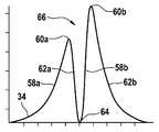
도 3은 도 2의 입자에 대한 도 1의 센서 장치의 검출기의 출력 신호를 시간에 따라 도시한 다이어그램이고,
도 4는 입자의 3 개의 경사진 제 2 궤적이 표시된 도 2와 유사한 단면도이고,
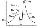
도 5 내지 도 7은 도 4의 3 개의 입자들에 대한 도 3과 유사한 다이어그램들이고,
도 8은 도 2에 비해 약간 디포커싱된 스팟 및 입자의 제 3 궤적이 표시된 도 2와 유사한 단면도이고,
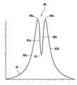
도 9는 도 8의 입자에 대한 도 3과 유사한 다이어그램이고,
도 10은 도 2에 비해 디포커싱된 스팟 및 입자의 제 4 궤적이 표시된 도 2와 유사한 단면도이고,
도 11은 도 10의 입자에 대한 도 3과 유사한 다이어그램이고,
도 12는 도 1의 센서 장치를 작동하는 방법의 흐름도이다.1 is a schematic diagram of the structure of a sensor device for detecting particles in a flowing fluid using the principle of laser induced incandescence;
Fig. 2 is a schematic cross-sectional view of a spot of the sensor device of Fig. 1 marked with a first trajectory of a particle;
Fig. 3 is a diagram showing the output signal of the detector of the sensor device of Fig. 1 for the particles of Fig. 2 over time;
Fig. 4 is a cross-sectional view similar to Fig. 2 in which three oblique second trajectories of the particle are shown;
Figures 5-7 are diagrams similar to Figure 3 for the three particles of Figure 4,
Fig. 8 is a cross-sectional view similar to Fig. 2, showing the third trajectory of the spot and particle slightly defocused compared to Fig. 2;
Fig. 9 is a diagram similar to Fig. 3 for the particle of Fig. 8;
10 is a cross-sectional view similar to FIG. 2 in which a fourth trajectory of the defocused spot and particle is displayed compared to FIG. 2;
Fig. 11 is a diagram similar to Fig. 3 for the particle of Fig. 10;
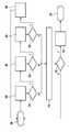
Fig. 12 is a flow chart of a method of operating the sensor device of Fig. 1;
기능상 동등한 요소들 및 영역들은 다음 설명에서 동일한 도면 부호를 가지며 일반적으로 중복 설명되지 않는다.Functionally equivalent elements and regions have the same reference numerals in the following description and are generally not duplicated.
도 1은 레이저 유도식 백열의 원리를 사용하여, 구체적으로 입자 센서(10)의 형태로 유동 유체 내의 입자 또는 에어로졸을 검출하기 위한 센서 장치의 실시예를 도시한다. 먼저, 레이저 광(14)을 방출하는 레이저(12), 여기에서는 예를 들어 CW 레이저(CW=연속파)가 도시된다. 레이저(12)는 레이저 다이오드를 포함할 수 있으므로, 비용이 매우 저렴해진다. 레이저 광(10)은 렌즈(16)("시준 렌즈")에 의해 우선 평행 빔으로 형성되어, 예를 들어 빔 스플리터 또는 다이크로익 미러 형태의 빔 스플리터(18)를 통과한다. 거기서부터 상기 빔이 포커싱 렌즈(20)에 도달하고 더 포커싱된 형태로 레이저 광 스팟(22)(이하 "스팟"으로 약칭)에 도달한다. 여기에서 스팟(22)은 레이저 광(14)이 극도로 포커싱되어서 에너지 밀도가 극도로 높거나 또는 집약적인 ㎛ 범위 또는 심지어 nm 범위의 매우 작은 치수를 가진 체적 요소를 의미한다.1 shows an embodiment of a sensor device for detecting particles or aerosols in a flowing fluid, specifically in the form of a
고강도의 레이저 광(14)은 스팟(22)에서 거기에 있는 입자(24), 예를 들어 내연 기관의 배기 가스 흐름 내의 그을음 입자(24)에 부딪칠 수 있다. 스팟(22)에서 레이저 광(14)의 강도는 입자(24)에 의해 흡수된 레이저 광(14)의 에너지가 입자(24)를 섭씨 수천도로 가열할 정도로 높다(스팟(22)의 체적에서만 레이저 광(14)의 강도가 레이저 유도 백열(LII)에 필요한 높은 값에 도달한다). 입자(24)는 가열됨으로써 자발적이고 및 실질적으로 우선 방향 없이 상당한, LII 광이라고도 하는 열 복사(26)를 방출한다. 따라서 열 복사(26)의 일부는 입사 레이저 광(14)의 방향과 반대 방향으로도 방출된다. 열 복사(26)는 예를 들어 근적외선 및 가시 스펙트럼 범위에 있지만 이러한 스펙트럼 범위로 제한되지 않는다. 레이저(12), 렌즈(16), 빔 스플리터(18) 및 포커싱 렌즈(20)는 스팟(22)을 생성하는 장치(27)를 형성한다.The high
스팟(22)에서 레이저 광(14)에 의해 여기된 입자(24)의 열 복사(26)는 다시 포커싱 렌즈(20)를 통해 빔 스플리터(18)에 도달해서 90°만큼 편향되어, 포커싱 렌즈(28)를 통과하고 필터(30)(반드시 제공되어야 하는 것은 아님)를 통해 검출기(32)에 도달한다. 필터(30)는 레이저 광(14)의 파장이 적어도 대체로 필터링되고, 레이저 광의 소량이 반사되도록 형성된다. 즉, 간섭 배경은 필터(30)에 의해 감소된다. 단순한 에지 필터의 사용도 가능하다. 따라서, 신호 대 잡음비가 향상된다.The
스팟(22)의 치수는 수 ㎛의 범위, 특히 최대 200 ㎛의 범위에 있으므로, 스팟(22)을 가로 지르는 입자(24)가 여기되어 평가 가능한 복사 전력을 방출한다. 따라서, 스팟(22)에는 항상 최대 하나의 입자(24)가 있고 입자 센서(10)의 순간 출력 신호(34)는 상기 최대 하나의 입자(24)로부터만 발생한다고 가정할 수 있다.The dimensions of the
출력 신호(34)는 검출기(32)에 의해 생성되고, 상기 검출기(32)는 스팟(22)을 통과하는 입자(24)로부터 나오는 복사(26), 특히 열 복사를 검출하도록 입자 센서(10) 내에 배치된다. 검출기(32)는 열 복사(26)를 감지하고 출력 신호(34)를 생성하는 바람직하게는 다중 픽셀 광자 계수기(MPPC) 또는 실리콘 광자 증배기(SiPM) 또는 SPAD 다이오드(단일 광자 애벌랜치 다이오드)를 포함한다. 전술한 유형의 검출기(32)에 의해, 예를 들어 몇몇의 광자에 의해 형성되는, 특히 작은 입자(24)에 의해 생성되므로 매우 작은 광 신호가 검출될 수 있다. 따라서, 겨우 검출될 수 있는 입자(24)의 치수는 최대 10nm의 검출 한계로 낮아진다.The
레이저(12)가 변조되거나 또는 스위치 온 및 오프되 것이 전적으로 가능하다(듀티 사이클 < 100%). 그러나, 레이저(12)는 CW 레이저인 것이 바람직하다. 이로써 저렴한 반도체 레이저 요소들(레이저 다이오드)이 사용될 수 있고, 이는 전체 입자 센서(10)를 더 저렴하게 하고 레이저 모듈(12)의 제어 및 출력 신호(34)의 평가를 크게 단순화시킨다. 그러나 펄스 레이저의 사용이 배제되지 않는다.It is entirely possible for the
도 1에서, 화살표(36)는 예를 들어 자동차 내연 기관(디젤 또는 가솔린 또는 임의의 다른 연료)의 배기 시스템 내의 연소 공정에서 생성되는 바와 같은 배기 가스를 상징한다. 센서 장치(10)는 외부 보호 튜브(38) 및 내부 보호 튜브(40)로 이루어진 어셈블리를 포함한다. 보호 튜브들(38, 40)의 축들은 배기 가스(36)의 흐름에 대해 횡 방향으로 정렬된다. 내부 보호 튜브(40)는 외부 보호 튜브(38)를 넘어 축들의 방향으로 돌출하고 유동 배기 가스(36) 내로 돌출한다. 2 개의 보호 튜브들(38, 40)의, 유동 배기 가스(36)로부터 먼 단부 상에서 외부 보호 튜브(38)가 내부 보호 튜브(40)를 넘어 돌출된다. 외부 보호 튜브(38)의 내부 폭은 2 개의 보호 튜브들(38, 40) 사이에 여기에서는 대략 원형인 제 1 유동 단면이 생길 정도로 바람직하게는 내부 보호 튜브(40)의 외부 직경보다 훨씬 더 크다. 내부 보호 튜브(40)의 내부 폭은 여기에서는 원형인 제 2 유동 단면을 형성한다.1 ,
이러한 기하학적 구조에 의해, 배기 가스(36)가 제 1 유동 단면을 통해 2 개의 보호 튜브들(38, 40)의 어셈블리 내로 들어가고, 그 후 배기 가스(36)로부터 먼 보호 튜브들(38, 40)의 단부 상에서 방향을 변경하여, 내부 보호 튜브(40) 내로 들어가고, 지나가는 배기 가스(48)에 의해 상기 내부 보호 튜브로부터 흡입되게 된다(화살표 42). 내부 보호 튜브(46) 내에 층류가 발생되고, 상기 층류의 방향은 일점쇄선으로 표시된 레이저 광(14)의 길이 방향 축(44)에 대해 일반적 경우 평행하다. 보호 튜브들(38, 40)의 이러한 어셈블리는 배기 가스(36)의 흐름 방향에 대해 횡 방향으로 배기 파이프(도시되지 않음) 상에 또는 내에 고정된다. 스팟(22)은 내부 보호 튜브(40)의 내부에서 층류(42)의 영역 내에 놓인다.With this geometry, the
입자 센서(10)는 바람직하게는 배기 가스(36)에 노출된 제 1 부분(46)(보호 튜브들(38 및 40)) 및 배기 가스(36)에 노출되지 않은 제 2 부분(48)을 포함하고, 상기 제 2 부분은 입자 센서(10)의 광학 및 전자 부품들을 포함한다. 부분(46)은 "센서 헤드"라고도 하고 부분(48)은 "SCU"("센서 제어 장치")라고도 한다. 부분(48)은 검출기(32)의 출력 신호(34)가 분석되는, 구체적으로는 시간에 따른 출력 신호(34)의 강도 프로파일과 관련해서 분석되는 평가 장치(49)도 포함한다. 이러한 평가 장치(49)에서 센서 장치(10)의 진단이 방금 언급한 분석에 기초하여 이루어진다. 따라서, 센서 장치(10)의 기능은 아래에서 상세히 제시되듯이 "셀프 테스트"라는 개념으로 검사될 수 있다.
도 2에는, 포커싱된 레이저 광(14)에 의해 형성된 스팟(22)이 단면도로 도시되어 있다. 렌즈(20)에 의해 포커싱된 2 개의 레이저 광 빔에 대한 예시가 도 2에 도시되고, 이러한 2 개의 빔들은 14'및 14"로 표시된다. 스팟(22)은 길이 방향 축(44)의 방향으로 길이 방향 연장부(L) 및 길이 방향 연장부(L)에 대해 횡 방향인 최대 연장부(B)를 가진 길쭉한 확장부를 가지는 것이 도시되어 있다. 또한 도 2에는 레이저 광(14)의 포커싱에 의해 스팟(22)이 (길이 방향 축(44)의 방향으로 볼 때) 축의 중심에 수축된 영역(50)을 가진 일종의 덤벨 모양을 가지고, 수축된 영역(50)은 각각 직경(B)을 가지는 상부 및 하부 축 방향 단부 영역들(52a 및 52b)의 직경보다 작은 직경(C)을 가지는 것이 도시된다. 도 2에는 레이저 광(14)의 동일한 강도의 라인들(54)도 표시되나, 명확성을 위해 라인들 중 제일 바깥쪽 라인만 도면 부호로 표시되어 있다. 가장 안쪽에 그려진 라인(54)은 전체가 실질적으로 계란 또는 타원 형상을 가지지만, 가장 바깥쪽에 그려진 라인(50)은 전술한 덤벨 모양을 가지는 것이 도시되어 있다. 강도는 스팟(22)의 내부에서 가장 높고 스팟(22)의 가장자리에서 가장 낮다.2, a
화살표(56)는 입자(24)의 궤적을 나타낸다(도 1의 흐름(42)에 대응). 상기 궤적은 여기에서 스팟(22)의 중심을 정확히 통과하지 않고, 중심에서 좌측으로 지나가고, 구체적으로 길이 방향 축(44)에 대해 그리고 이로써 스팟(22)의 중심에 대해 입자(24)가 먼저 하부 영역(52a)을 통과한 후 상기 영역으로부터 나와서 수축된 영역(50) 옆을 지나가므로, 그 후 상부 영역(52b) 내로 들어가서 마지막으로 상기 영역을 떠나는 정도의 간격으로 지나간다.
레이저 광(14)의 강도는 입자(24)가 통과하는 2 개의 영역들(52a 및 52b)의 가장자리 영역에서도 입자를 여기하여 열 복사(26)를 방출하기에 충분하고, 구체적으로는 두 번이고, 즉 입자(24)가 하부 영역(52a)을 통과할 때가 한 번 그리고 입자(24)가 상부 영역(52b)을 통과할 때가 2번이다. 상응하게 출력 신호(34)가 생성되고, 도 3에는 상기 출력 신호가 시간에 따라 도시되어 있다. 제 1 고점(60a)까지 상승하는 제 1 급상승 플랭크(58a) 및 저점(64)까지 떨어지는 급하강 플랭크(62a)가 도시되어 있다. 거기에서부터 제 2 급상승 플랭크(58b)를 따라 제 2 고점(60b)으로 가고, 그리고 다시 급하강 플랭크(62b)를 따르고 다시 낮은 일정한 신호 레벨이 된다.The intensity of the
2 개의 고점들(60a 및 60b)은 거의 동일한 절대 값을 가지며, 즉 대략 동일한 수준에 있다. 따라서, 출력 신호(34)는 시간상 밀접하게 놓인, 즉 시간 간격(t) 내에 있는 2 개의 고점들(60a 및 60b)을 포함하고, 상기 고점들은 "이중 피크"(66)를 형성한다. 시간 간격(t)의 길이는 특히 유체의 속도 및 이로써 입자(24)의 속도에 의존할 수 있다. 이중 피크(66)는 저점(64)에 대해 대체로 대칭이고, 즉, 예를 들어 제 1 상승 플랭크(58a)와 제 2 하강 플랭크(62b)가 서로 대칭이고, 제 1 하강 플랭크(62a)와 제 2 상승 플랭크(58b)도 서로 대칭이다. 이로부터, 평가 장치(49)에 의한 이중 피크(66)의 형상을 분석하는 범주에서, 한편으로는 스팟(22)이 기술된 덤벨 모양의 기하학적 구조를 가지는 것이 추론되고, 다른 한편으로는 입자(24)가 레이저 광(14)의 길이 방향 축(44)에 대해 실질적으로 평행하게 연장하는 궤적(56) 상에서 스팟(22)을 통과하는 것이 추론될 수 있다. 이는 센서 장치(10)의 소정의 정상 기능에 상응한다.The two
도 4 내지 도 7에는 궤적들(56a 내지 56c)이 레이저 광(14)의 길이 방향 축(44)에 평행하지 않게 연장하는 작동 상황이 도시된다. 예를 들어, 내부 보호 튜브(40) 내의 균열 또는 부분적 막힘으로 인해, 흐름(42)이 보호 튜브(40) 또는 길이 방향 축(44)에 평행한 이상적인 흐름으로부터 벗어나므로, 센서 장치(10)의 측정 정확도가 더 이상 보장되지 않는다.4 to 7 show an operating situation in which the
길이 방향 축(44)에 대한 궤적(56c)의 각도는 궤적(56b)의 각도보다 크고, 길이 방향 축(44)에 대한 궤적(56b)의 각도는 궤적(56a)의 각도보다 크다. 도 5에는 궤적(56a)에 대한 출력 신호(34)가 도시된다. 도 3에 비해 출력 신호(34)의 이중 피크(66)의 형상이 더 이상 대칭이지 않는 것을 알 수 있다. 이는 입자(24)가 하부 영역(52a)을 더 바깥쪽에서 그리고 이로써 더 낮은 강도의 영역에서 통과하는 한편, 상부 영역(52b)을 더 안쪽에서 그리고 이로써 더 높은 강도의 영역에서 통과한 것과 관련있다. 따라서, 입자(24)는 상부 영역(52b)을 통과할 때보다 하부 영역(52a)을 통과할 때 덜 강하게 가열된다. 이로써, 출력 신호(34)의 제 1 고점(60a)의 절대 값은 제 2 고점(60b)의 절대 값보다 낮다. 이러한 차이는 궤적(56)이 경사질수록 더 크다.The angle of the
길이 방향 축(44)에 대한 2 개의 궤적들(56b 및 56c)의 더 큰 각도는 도 6(궤적 56b에 대응) 및 도 7(궤적 56c에 대응)로부터 알 수 있듯이 이중 피크(66)의 더 강한 비대칭으로 나타난다. 따라서, 입자(24)의 궤적(56)이 레이저 광(14)의 길이 방향 축(44)에 대해 경사진 경우 이중 피크(66)는 특징적인 비대칭 형상을 가지고, 상기 비대칭 형상은 평가 장치(49)에 의해 분석되고 평가 장치(49)에 의해 경사진 궤적(56)으로서 진단된다.The larger angle of the two
도 8 내지 도 9에는 입자(24)의 궤적(56)이 레이저 광(14)의 길이 방향 축(44)에 평행하게 연장하지만, 스팟(22)이 약간 디포커싱된 경우가 도시되고, 이로써 수축된 영역(50)은 도 2 내지 도 4에 도시된 더 강하게(더 양호하게) 포커싱된 경우보다 더 큰 직경(C)을 가진다. 도 8의 스팟(22)의 덤벨 모양은 도 2 내지 도 4에 도시된 스팟(22)에서보다 덜 뚜렷하다. 이러한 디포커싱은 예를 들어 센서 장치(10)의 광학 부품들, 예를 들어 렌즈(16), 빔 스플리터(18), 렌즈(20) 및 렌즈(28)의 바람직하지 않은 상대 이동에 의해 발생할 수 있다.8-9 show the case where the
도 9의 상응하는 출력 신호(34)를 참조하면, 플랭크들(58a, 58b 및 62a, 62b)은 도 3에서의 플랭크들보다 덜 가파르고 특히 저점(64)이 도 3에서의 저점보다 더 높다는 것을 알 수 있다. 따라서, 도 9의 출력 신호(34)의 형태에서의 2 개의 고점들(60a, 60b)의 절대 값들과 저점(64)의 절대 값의 비율은 도 3의 출력 신호(34)의 형태에서의 상응하는 비율과는 현저히 다르고, 즉 훨씬 더 낮은 값을 가진다고 볼 수 있다.Referring to the
이것은 도 10에 도시된 스팟(22)의 디포커싱에서 더욱 뚜렷하고 도 10에 도시된 스팟(10)은 덤벨 모양을 거의 가지고 있지 않게 된다. 따라서, 이로부터 얻어진 출력 신호(34)의 경우, 2 개의 고점들(60a 및 60b)의 절대 값들은 그 사이에 놓인 저점(64)의 절대 값과 거의 다르지 않으므로, 도 11에 도시되듯이, 이중 피크(66)의 특징적 형상이 거의 보이지 않는다. 출력 신호(34)의 이러한 특징적 형상이 평가 장치(49)에 의해 분석되고, 이로써 스팟(22)의 디포커싱이 진단된다.This is more pronounced in the defocusing of the
센서 장치(10)를 작동하는 방법은 도 12를 참조하여 설명된다. 방법은 블록(68)에서 예를 들어 내연 기관의 경우 그의 시동 후 시작된다. 그 후, 블록(69)에서, 출력 신호(34)의 평가는 예상 빈도로, 구체적으로 단일 피크의 빈도에 대해 절대적으로 및 상대적으로 이중 피크들(22)의 존재와 관련하여 이루어진다. 따라서, 블록(70)에서 검출기(32)의 출력 신호(34)가 적어도 하나의 한계 값에 상응하는 이중 피크(66)의 수를 특정 기간 내에 포함하는지의 여부가, 그리고 이중 피크와 단일 피크 사이의 비율이 적어도 하나의 예상 한계 값에 상응하는지의 여부가 검사된다. 블록(70)에서의 대답이 "아니오"이면, 선택적인 추가 및 독립적 진단 기능들이 블록(72)에서 실시된다. 언급했듯이 이러한 진단 기능들은 선택적이고 절대적으로 필요하지는 않다. 마찬가지로 단지 선택적인 블록(74)에서 에러 경우가 실제로 인식되었는지의 여부가 검사된다. 대답이 "아니오"이면 시작 블록(68)으로 돌아간다. 그렇지 않으면 블록(76)에서 센서 장치(10)의 (근본적) 에러가 추론되고 이로써 에러 메모리 내로의 일반적 입력이 이루어진다. 그 후 방법이 블록(78)에서 끝날 것이다.A method of operating the
블록(70)에서의 대답이 "예"이면, 블록(80)에서 이중 피크(66)의 평가가 특히 고점들(60a 및 60b)의 대칭과 관련하여 이루어진다. 따라서, 블록(82)에서 감지된 이중 피크(66) 또는 감지된 이중 피크들(66)이 미리 정해진 대칭 조건을 충족하는지의 여부가, 특히 고점들(60a 및 60b)이 적어도 대략 동일하게 높은지의 여부가 검사된다. 대답이 "아니오"이면, 이는 길이 방향 축(44)에 대해 허용 불가능하게 경사진 흐름(42)을 나타내는 것이다. 전술한 선택적인 블록(72)에서 다른 독립적 진단이 다시 실시될 수 있고, 선택적 블록(74)에서 실제로 에러가 있는지의 여부가 검사될 수 있다. 대답이 "예"이면, 블록(76)에서 에러가 있다고 다시 인식되고, 위의 일반적 입력에 비해 추정된 허용 불가능하게 경사진 흐름(42)이 구체화된 에러 메모리 내로의 상응하는 입력이 이루어진다.If the answer at
블록(82)에서의 대답이 "예"이면, 길이 방향 축(44)에 평행한 흐름(42)이 가정되므로, 블록(84)에서 아주 일반적으로 예상 형상과 관련하여, 예를 들어 고점들(60a 및 60b) 및 그 사이에 있는 저점들(64)의 절대 값들 간의 비율과 관련하여 이중 피크(66) 또는 이중 피크들(66)의 평가가 이루어진다. 상기 비율이 한계 값에 도달하거나 또는 초과하거나 또는 미달하면, 이중 피크(66)의 형성이 예상과 다르다. 따라서 테스트 블록(86)에서의 대답이 "아니오"이면, 다시 블록들(72 및 74)로 이동하고 경우에 따라 블록들(76 및 78)로 이동하고, 블록(76)에서 에러 메모리 내로의 에러 입력이 스팟(22)의 허용 불가능한 디포커싱이 가정되도록 구체화된다. 그러나, 테스트 블록(86)에서의 대답이 "예"이면, 정확한 포커싱이 가정되고 블록(88)에서 특정 시간이 경과한 후 시작 블록(68)으로 복귀하게 하는 카운터가 시작된다.If the answer to block 82 is “yes”, then flow 42 parallel to
10센서 장치
12레이저
14레이저 광
22스팟
24입자
26열 복사
32검출기
34출력 신호
49평가 장치
60a, 60b고점
64저점
66이중 피크10 sensor unit
12 lasers
14 laser light
22 spot
24 particles
26 heat radiation
32 detector
34 output signal
49 evaluation device
60a, 60b highs
64 low
66 double peak
Claims (10)
Translated fromKoreana. 레이저(12)에 의해 레이저 광(14)을 생성하는 단계;
b. 스팟(22)에서 상기 레이저 광(14)을 번들링하는 단계;
c. 상기 스팟(22)에서 가열된 입자(24)로부터 방출되는 열 복사(26)를 검출기(32)에 의해 감지하는 단계; 및
d. 감지된 상기 열 복사(26)에 의존하는 출력 신호(34)를 상기 검출기(32)를 통해 제공하는 단계를 포함하는, 상기 방법에 있어서, 상기 방법은
e. 평가 장치(49)에 의해 상기 출력 신호(34)의 적어도 하나의 특성, 특히 시간에 따른 강도 프로파일을 분석하는 단계,
f. 상기 분석에 기초하여 상기 평가 장치(49)에 의해 상기 센서 장치(10)의 진단을 실시하는 단계를 더 포함하는 것을 특징으로 하는 입자(24) 또는 에어로졸을 검출하기 위한 센서 장치(10)를 작동하는 방법.A method of operating a sensor device (10) for detecting a particle (24) or aerosol in a flowing fluid (42) using the principle of laser induced incandescence, the method comprising:
a. generating laser light (14) by means of a laser (12);
b. bundling the laser light (14) at a spot (22);
c. sensing by a detector (32) thermal radiation (26) emitted from the heated particles (24) at the spot (22); and
d. providing an output signal (34) dependent on the sensed thermal radiation (26) via the detector (32), the method comprising:
e. analyzing by means of an evaluation device (49) at least one characteristic of the output signal (34), in particular the intensity profile over time;
f. actuating the sensor device (10) for detecting particles (24) or aerosols, characterized in that it further comprises the step of carrying out a diagnosis of the sensor device (10) by means of the evaluation device (49) on the basis of the analysis How to.
상기 평가 장치(49)가 제 1 항 내지 제 9 항 중 어느 한 항에 따른 방법을 실시하도록 설계된 것을 특징으로 하는 입자(24) 또는 에어로졸을 검출하기 위한 센서 장치(10).A sensor device (10) for detecting particles (24) or aerosols in a flowing fluid (36, 42) using the principle of laser induced incandescence, a device (12) for generating laser light (14), a spot (22) apparatus 20 for bundling the laser light 14 in In the sensor device (10) comprising an evaluation device (49) for evaluating an output signal (34),
A sensor device (10) for detecting particles (24) or aerosols, characterized in that the evaluation device (49) is designed to carry out the method according to any one of claims 1 to 9.
Applications Claiming Priority (3)
| Application Number | Priority Date | Filing Date | Title |
|---|---|---|---|
| DE102018222771.3ADE102018222771A1 (en) | 2018-12-21 | 2018-12-21 | Method for operating a sensor device for the detection of particles or aerosol, and sensor device |
| DE102018222771.3 | 2018-12-21 | ||
| PCT/EP2019/080352WO2020126194A1 (en) | 2018-12-21 | 2019-11-06 | Method for operating a sensor device for detecting particles or an aerosol, and sensor device |
Publications (1)
| Publication Number | Publication Date |
|---|---|
| KR20210099021Atrue KR20210099021A (en) | 2021-08-11 |
Family
ID=68501611
Family Applications (1)
| Application Number | Title | Priority Date | Filing Date |
|---|---|---|---|
| KR1020217018936ACeasedKR20210099021A (en) | 2018-12-21 | 2019-11-06 | Method and sensor device for operating a sensor device for detecting particles or aerosols |
Country Status (4)
| Country | Link |
|---|---|
| KR (1) | KR20210099021A (en) |
| CN (1) | CN113227758A (en) |
| DE (1) | DE102018222771A1 (en) |
| WO (1) | WO2020126194A1 (en) |
Families Citing this family (2)
| Publication number | Priority date | Publication date | Assignee | Title |
|---|---|---|---|---|
| DE102022123464A1 (en)* | 2022-09-14 | 2024-03-14 | Q.ant GmbH | Device and method for characterizing a particle |
| DE102023135353A1 (en)* | 2023-12-15 | 2025-06-18 | Q.ant GmbH | Device and method for characterizing at least one particle in a measuring volume |
Family Cites Families (7)
| Publication number | Priority date | Publication date | Assignee | Title |
|---|---|---|---|---|
| US4251733A (en)* | 1978-06-29 | 1981-02-17 | Hirleman Jr Edwin D | Technique for simultaneous particle size and velocity measurement |
| CA2477390C (en)* | 2004-01-13 | 2011-09-27 | National Research Council Of Canada | Small particle analysis by laser induced incandescence |
| EP1959121B1 (en)* | 2007-02-14 | 2009-08-19 | Ford Global Technologies, LLC | Sensor activation monitor |
| US9128047B2 (en)* | 2008-09-05 | 2015-09-08 | Xtralis Technologies Ltd | Detection of particle characteristics |
| US20110228257A1 (en)* | 2010-03-17 | 2011-09-22 | The Board Of Trustees Of The University Of Alabama | Hollow core fiber laser induced incandescence |
| CN106814015A (en)* | 2017-02-08 | 2017-06-09 | 深圳市赛纳威环境科技有限公司 | A kind of big flow particle concentration detects sensor-based system |
| DE102017207402A1 (en) | 2017-05-03 | 2018-11-08 | Robert Bosch Gmbh | Optical soot particle sensor for motor vehicles |
- 2018
- 2018-12-21DEDE102018222771.3Apatent/DE102018222771A1/ennot_activeWithdrawn
- 2019
- 2019-11-06CNCN201980085109.0Apatent/CN113227758A/enactivePending
- 2019-11-06WOPCT/EP2019/080352patent/WO2020126194A1/ennot_activeCeased
- 2019-11-06KRKR1020217018936Apatent/KR20210099021A/ennot_activeCeased
Also Published As
| Publication number | Publication date |
|---|---|
| WO2020126194A1 (en) | 2020-06-25 |
| CN113227758A (en) | 2021-08-06 |
| DE102018222771A1 (en) | 2020-06-25 |
Similar Documents
| Publication | Publication Date | Title |
|---|---|---|
| KR20210087517A (en) | Particle sensor for detecting particles or aerosols in flowing fluids using the laser-induced incandescent principle | |
| CN102539654B (en) | For determining method and the device of black concentration in the engine oil of internal combustion engine | |
| US8134711B2 (en) | Device for remote sensing of vehicle emission | |
| US6701256B2 (en) | Exhaust opacity measuring device | |
| US8873053B2 (en) | Method and system for gas measurements in a combustion chamber | |
| JP2017211357A (en) | Laser type gas analyzer | |
| KR20210099021A (en) | Method and sensor device for operating a sensor device for detecting particles or aerosols | |
| JP2020528151A (en) | Methods and systems for optically measuring the concentration of gas species in exhaust gas | |
| US20220003657A1 (en) | Method for operating a particle sensor | |
| JP6997336B2 (en) | A particle sensor operated by laser-induced incandescence with a confocal arrangement of laser spots and temperature radiation spots. | |
| US20220050041A1 (en) | Method for processing the signal of a particle sensor that operates in accordance with the principle of laser-induced incandescence, assembly for processing such a signal, and particle sensor | |
| US20220026338A1 (en) | Method for detecting particles or aerosol in a flowing fluid, computer program, as well as electrical memory medium | |
| US8451444B2 (en) | Optical backscatter probe for sensing particulate in a combustion gas stream | |
| CN114659952B (en) | A near backscattering vehicle-mounted particulate matter sensor and exhaust pipe | |
| CN118549492A (en) | Combustion state monitoring system | |
| KR20230017862A (en) | particle count sensor | |
| KR20210113241A (en) | A sensor device that uses the principle of laser-induced incandescence to detect particles or aerosols in a flowing fluid | |
| JP2020030112A (en) | Laser analyzer | |
| ES2360084T3 (en) | DEVICE FOR MEASURING THE OPPORTUNITY OF EXHAUST GASES. | |
| HK1066058B (en) | Exhaust opacity measuring device |
Legal Events
| Date | Code | Title | Description |
|---|---|---|---|
| PA0105 | International application | Patent event date:20210618 Patent event code:PA01051R01D Comment text:International Patent Application | |
| PG1501 | Laying open of application | ||
| PA0201 | Request for examination | Patent event code:PA02012R01D Patent event date:20221007 Comment text:Request for Examination of Application | |
| E902 | Notification of reason for refusal | ||
| PE0902 | Notice of grounds for rejection | Comment text:Notification of reason for refusal Patent event date:20240411 Patent event code:PE09021S01D | |
| E601 | Decision to refuse application | ||
| PE0601 | Decision on rejection of patent | Patent event date:20240617 Comment text:Decision to Refuse Application Patent event code:PE06012S01D Patent event date:20240411 Comment text:Notification of reason for refusal Patent event code:PE06011S01I |