KR20210095928A - Launcher and stapler - Google Patents
Launcher and staplerDownload PDFInfo
- Publication number
- KR20210095928A KR20210095928AKR1020217020013AKR20217020013AKR20210095928AKR 20210095928 AKR20210095928 AKR 20210095928AKR 1020217020013 AKR1020217020013 AKR 1020217020013AKR 20217020013 AKR20217020013 AKR 20217020013AKR 20210095928 AKR20210095928 AKR 20210095928A
- Authority
- KR
- South Korea
- Prior art keywords
- firing handle
- pin post
- groove
- inclined surface
- firing
- Prior art date
- Legal status (The legal status is an assumption and is not a legal conclusion. Google has not performed a legal analysis and makes no representation as to the accuracy of the status listed.)
- Granted
Links
Images


Classifications
- A—HUMAN NECESSITIES
- A61—MEDICAL OR VETERINARY SCIENCE; HYGIENE
- A61B—DIAGNOSIS; SURGERY; IDENTIFICATION
- A61B17/00—Surgical instruments, devices or methods
- A61B17/11—Surgical instruments, devices or methods for performing anastomosis; Buttons for anastomosis
- A61B17/115—Staplers for performing anastomosis, e.g. in a single operation
- A61B17/1155—Circular staplers comprising a plurality of staples
- A—HUMAN NECESSITIES
- A61—MEDICAL OR VETERINARY SCIENCE; HYGIENE
- A61B—DIAGNOSIS; SURGERY; IDENTIFICATION
- A61B17/00—Surgical instruments, devices or methods
- A61B17/068—Surgical staplers, e.g. containing multiple staples or clamps
- A61B17/072—Surgical staplers, e.g. containing multiple staples or clamps for applying a row of staples in a single action, e.g. the staples being applied simultaneously
- A—HUMAN NECESSITIES
- A61—MEDICAL OR VETERINARY SCIENCE; HYGIENE
- A61B—DIAGNOSIS; SURGERY; IDENTIFICATION
- A61B17/00—Surgical instruments, devices or methods
- A61B17/11—Surgical instruments, devices or methods for performing anastomosis; Buttons for anastomosis
- A61B17/1114—Surgical instruments, devices or methods for performing anastomosis; Buttons for anastomosis of the digestive tract, e.g. bowels or oesophagus
- A—HUMAN NECESSITIES
- A61—MEDICAL OR VETERINARY SCIENCE; HYGIENE
- A61B—DIAGNOSIS; SURGERY; IDENTIFICATION
- A61B90/00—Instruments, implements or accessories specially adapted for surgery or diagnosis and not covered by any of the groups A61B1/00 - A61B50/00, e.g. for luxation treatment or for protecting wound edges
- A61B90/03—Automatic limiting or abutting means, e.g. for safety
- A—HUMAN NECESSITIES
- A61—MEDICAL OR VETERINARY SCIENCE; HYGIENE
- A61B—DIAGNOSIS; SURGERY; IDENTIFICATION
- A61B17/00—Surgical instruments, devices or methods
- A61B2017/00017—Electrical control of surgical instruments
- A61B2017/00115—Electrical control of surgical instruments with audible or visual output
- A61B2017/00119—Electrical control of surgical instruments with audible or visual output alarm; indicating an abnormal situation
- A61B2017/00123—Electrical control of surgical instruments with audible or visual output alarm; indicating an abnormal situation and automatic shutdown
- A—HUMAN NECESSITIES
- A61—MEDICAL OR VETERINARY SCIENCE; HYGIENE
- A61B—DIAGNOSIS; SURGERY; IDENTIFICATION
- A61B17/00—Surgical instruments, devices or methods
- A61B2017/00367—Details of actuation of instruments, e.g. relations between pushing buttons, or the like, and activation of the tool, working tip, or the like
- A61B2017/00407—Ratchet means
- A—HUMAN NECESSITIES
- A61—MEDICAL OR VETERINARY SCIENCE; HYGIENE
- A61B—DIAGNOSIS; SURGERY; IDENTIFICATION
- A61B17/00—Surgical instruments, devices or methods
- A61B2017/0042—Surgical instruments, devices or methods with special provisions for gripping
- A—HUMAN NECESSITIES
- A61—MEDICAL OR VETERINARY SCIENCE; HYGIENE
- A61B—DIAGNOSIS; SURGERY; IDENTIFICATION
- A61B17/00—Surgical instruments, devices or methods
- A61B2017/0046—Surgical instruments, devices or methods with a releasable handle; with handle and operating part separable
- A—HUMAN NECESSITIES
- A61—MEDICAL OR VETERINARY SCIENCE; HYGIENE
- A61B—DIAGNOSIS; SURGERY; IDENTIFICATION
- A61B90/00—Instruments, implements or accessories specially adapted for surgery or diagnosis and not covered by any of the groups A61B1/00 - A61B50/00, e.g. for luxation treatment or for protecting wound edges
- A61B90/03—Automatic limiting or abutting means, e.g. for safety
- A61B2090/033—Abutting means, stops, e.g. abutting on tissue or skin
- A61B2090/034—Abutting means, stops, e.g. abutting on tissue or skin abutting on parts of the device itself
- A61B2090/035—Abutting means, stops, e.g. abutting on tissue or skin abutting on parts of the device itself preventing further rotation
Landscapes
- Health & Medical Sciences (AREA)
- Surgery (AREA)
- Life Sciences & Earth Sciences (AREA)
- Heart & Thoracic Surgery (AREA)
- Molecular Biology (AREA)
- Veterinary Medicine (AREA)
- Engineering & Computer Science (AREA)
- Biomedical Technology (AREA)
- Nuclear Medicine, Radiotherapy & Molecular Imaging (AREA)
- Medical Informatics (AREA)
- Public Health (AREA)
- Animal Behavior & Ethology (AREA)
- General Health & Medical Sciences (AREA)
- Pathology (AREA)
- Oral & Maxillofacial Surgery (AREA)
- Physiology (AREA)
- Portable Nailing Machines And Staplers (AREA)
- Surgical Instruments (AREA)
Abstract
Translated fromKoreanDescription
Translated fromKorean본 발명은 의료 기기 기술 분야에 관한 것으로서, 특히 발사 기구 및 스테이플러에 관한 것이다.FIELD OF THE INVENTION The present invention relates to the field of medical device technology, and more particularly to firing instruments and staplers.
소화관 종양은 발병률이 높은 인간 질환의 일종이다. 치료 과정에서 일반적으로 의사의 수동 조작 대신에 원형 스테이플러를 사용하여 소화관 등의 생리적 조직을 문합한다. 선형 스테이플러는 일반적인 수술 기구이며, 선형 스테이플링 방식을 많이 사용하고, 수술시 식도, 위, 장 등의 생리적 조직에 대해 문합을 실시한다.Gastrointestinal tumors are a type of human disease with a high incidence. In the course of treatment, physiological tissues, such as the digestive tract, are anastomosed using a circular stapler instead of manual manipulation by a physician. A linear stapler is a general surgical instrument, and a linear stapling method is widely used, and anastomosis is performed on physiological tissues such as the esophagus, stomach, and intestine during surgery.
선형 스테이플러는 일반적으로 기구 스테이지와 해당 스테이지에 착탈 가능하게 장착되는 헤드부를 포함하고, 헤드부는 천자 기구에 의해 몸의 작은 절개를 통과하여 수술 부위에 접근하여 수술을 실시할 수 있다. 구체적으로, 기구 스테이지는 발사 핸들을 포함하고, 착탈 가능한 헤드부는 스테이플 박스 하우징과 스테이플 박스 하우징의 원위 단에 장착되는 스테이플 헤드부를 포함하고, 스테이플 박스 하우징의 내부에는 발사 어셈블리가 설치되고, 스테이플 헤드는 절단 및 봉합 동작을 실시하는 부분이다. 발사 핸들의 구동에 의해, 발사 어셈블리는 스테이플 헤드부를 구동하여 봉합 및 절단 수술을 완성할 수 있다.A linear stapler generally includes an instrument stage and a head unit detachably mounted on the stage, and the head unit passes through a small incision in the body by a puncture instrument to access a surgical site and perform an operation. Specifically, the instrument stage includes a firing handle, and the removable head includes a staple box housing and a staple head portion mounted to a distal end of the staple box housing, the staple box housing having a firing assembly installed therein, the staple head comprising: This is the part that performs cutting and suturing operations. By driving the firing handle, the firing assembly can drive the staple head to complete the suturing and amputation operation.
기존의 선형 스테이플러에서, 의사의 부주의 또는 경험 부족으로 인해 수술 준비가 완료되지 않은 경우에 발사 핸들을 잘못 파지하여, 스테이플러가 잘못 발사되어, 수술의 효과에 영향을 주고, 심지어 환자에 대해 손상을 줄 수 있다.In the conventional linear stapler, when the operation preparation is not completed due to the negligence or inexperience of the surgeon, by improperly gripping the firing handle, the stapler is fired incorrectly, which may affect the effectiveness of the operation and even cause damage to the patient. can
본 발명은 종래 기술의 문제점을 감안하여, 핀 포스크가 작동로드의 스토퍼 홈에 삽입되는 경우, 조작자가 발사 핸들을 파지하여 스테이플러를 발사할 수 없는 발사 기구 및 스테이플러를 제공하는 것을 목적으로 한다.In view of the problems of the prior art, an object of the present invention is to provide a firing mechanism and a stapler in which an operator cannot fire a stapler by gripping a firing handle when a pin force is inserted into a stopper groove of an actuating rod.
본 발명의 실시예는 스테이플러에 적용되는 발사 기구를 제공하고, 상기 발사 기구는 스토퍼 홈이 개설되는 작동로드와 발사 핸들과 누름 버튼을 포함하고, 상기 발사 핸들의 내부에 핀 포스트가 설치되고, 상기 핀 포스트의 제 1 단은 상기 발사 핸들의 제 1 단으로부터 돌출하여 상기 스토퍼 홈에 삽입되어, 상기 발사 핸들이 상기 작동로드에 대해 회전 불가능하고, 상기 누름 버튼은 제 1 방향을 따라 이동하여, 상기 핀 포스트의 제 1 단을 눌러 상기 발사 핸들의 제 2 단 방향으로 이동시킨다.An embodiment of the present invention provides a firing mechanism applied to a stapler, wherein the firing mechanism includes an operation rod having a stopper groove formed therein, a firing handle, and a push button, a pin post is installed inside the firing handle, the firing mechanism comprising: The first end of the pin post protrudes from the first end of the firing handle and is inserted into the stopper groove, so that the firing handle is non-rotatable with respect to the actuating rod, and the push button is moved along a first direction, so that the Depress the first end of the pin post and move it toward the second end of the firing handle.
선택적으로, 밸런스를 더 포함하고, 상기 밸런스는 회전부와 연결부를 포함하고, 상기 밸런스의 연결부는 상기 누름 버튼에 연결되고, 상기 밸런스의 회전부가 회전하는 경우, 상기 누름 버튼을 이동시킨다.Optionally, further comprising a balance, wherein the balance includes a rotating part and a connecting part, the connecting part of the balance is connected to the push button, and when the rotating part of the balance rotates, the push button is moved.
선택적으로, 상기 발사 핸들의 내부에는 핀 홈이 설치되고, 상기 핀 포스트는 상기 핀 홈에 설치되고, 상기 핀 포스트의 제 2 단과 상기 핀 홈 사이에는 핀 포스트 복귀 부재가 설치되어, 상기 핀 포스트가 상기 핀 홈에 의해 한정되는 방향을 따라 직선 이동된다.Optionally, a pin groove is installed inside the firing handle, the pin post is installed in the pin groove, and a pin post return member is installed between the second end of the pin post and the pin groove, so that the pin post is It linearly moves along the direction defined by the said pin groove.
선택적으로, 상기 핀 포스트 복귀 부재는 압축 스프링이다.Optionally, the pin post return member is a compression spring.
선택적으로, 상기 핀 포스트 및 상기 누름 버튼에는 제 1 결합부 및 제 2 결합부가 각각 설치되고, 상기 누름 버튼이 제 1 방향을 따라 이동하는 경우, 상기 제 1 결합부는 상기 제 2 결합부를 눌러, 상기 핀 포스트의 제 1 단이 상기 발사 핸들의 방향으로 이동된다.Optionally, a first coupling part and a second coupling part are respectively installed on the pin post and the push button, and when the push button moves in a first direction, the first coupling part presses the second coupling part, A first end of the pin post is moved in the direction of the firing handle.
선택적으로, 상기 제 1 결합부는 보스이고, 상기 보스는 스토퍼부와 단차부를 포함하고, 상기 제 2 결합부는 오목한 플랫폼이다.Optionally, the first engaging portion is a boss, the boss includes a stopper portion and a step portion, and the second engaging portion is a concave platform.
선택적으로, 상기 누름 버튼은 상기 제 2 결합부에 연결되는 누름부를 포함하고, 상기 누름부는 상기 스테이플러의 하우징을 관통하여 설치된다.Optionally, the push button includes a pressing part connected to the second coupling part, and the pressing part is installed through the housing of the stapler.
선택적으로, 상기 스테이플러 하우징에는 누름 버튼 위치 제한 부재가 설치되고, 상기 누름 버튼 위치 제한 부재는 상기 누름 버튼이 제 1 방향을 따라 이동하는 경로 상에 위치한다.Optionally, the stapler housing is provided with a push button position limiting member, wherein the push button position limiting member is positioned on a path along which the push button moves in the first direction.
선택적으로, 상기 스토퍼 홈의 근위 단에는 상기 작동로드의 내부를 향해 패인 원호 홈이 설치된다.Optionally, a proximal end of the stopper groove is provided with a circular arc groove that is recessed toward the inside of the actuating rod.
선택적으로, 상기 발사 핸들에는 구동 부재가 더 설치되고, 상기 스토퍼 홈의 근위 단 및 원위 단에는 기어랙 및 푸싱 투스가 각각 설치되고, 상기 구동 부재는 상기 푸싱 투스와 접촉하고, 상기 작동로드를 눌러 상기 스테이플러의 원위 단으로 이동시킨다.Optionally, a driving member is further installed in the firing handle, a gear rack and a pushing tooth are respectively installed at the proximal end and the distal end of the stopper groove, the driving member is in contact with the pushing tooth, and pressing the actuating rod Move to the distal end of the stapler.
본 발명의 실시예는 스테이플러에 적용되는 다른 발사 기구를 제공하고, 상기 발사 기구는 스토퍼 홈이 개설되는 작동로드와 발사 핸들과 버튼 어셈블리를 포함하고, 상기 발사 핸들 내부에는 핀 포스트가 설치되고, 상기 버튼 어셈블리는 누름로드를 포함하고, 상기 누름로드의 제 1 단은 상기 발사 핸들의 내부에 삽입되고, 상기 핀 포스트의 제 1 단은 상기 발사 핸들로부터 돌출하여 상기 스톱퍼 홈에 삽입되어, 상기 발사 핸들이 상기 작동로드에 대해 회전 불가능하고, 상기 누름로드는 진일보로 상기 발사 핸들의 내부로 삽입되어, 상기 누름로드가 상기 핀 포스트의 제 1 단을 눌러 상기 발사 핸들의 제 2 단 방향으로 이동시킨다.An embodiment of the present invention provides another firing mechanism applied to a stapler, wherein the firing mechanism includes an actuating rod having a stopper groove formed therein, a firing handle, and a button assembly, a pin post is installed inside the firing handle, the firing mechanism comprising: The button assembly includes a push rod, wherein a first end of the push rod is inserted into the firing handle, and a first end of the pin post protrudes from the firing handle and is inserted into the stopper groove, the firing handle It is non-rotatable relative to the actuating rod, and the push rod is further inserted into the interior of the firing handle, so that the push rod presses the first end of the pin post and moves it toward the second end of the firing handle.
선택적으로, 상기 핀 포수트에는 제 1 결합부가 설치되고, 상기 제 1 결합부는 제 1 경사면을 포함하고, 상기 누름로드의 제 1 단에는 제 2 결합부가 설치되며, 상기 제 2 결합부는 제 3 경사면을 포함한다. 상기 누름로드가 상기 초기 위치에 위치하는 경우, 상기 제 3 경사면은 상기 제 1 경사면에 밀착된다.Optionally, a first coupling part is installed in the pin catcher, the first coupling part includes a first inclined surface, a second coupling part is installed at the first end of the pressing rod, and the second coupling part is a third inclined surface includes When the pressing rod is positioned at the initial position, the third inclined surface is in close contact with the first inclined surface.
선택적으로, 상기 제 1 결합부는 제 2 경사면을 더 포함하고, 상기 제 2 경사면은 상기 제 1 경사면과 대향하여 설치되고, 상기 제 2 결합부는 제 4 경사면을 더 포함하고, 상기 제 4 경사면은 상기 제 3 경사면과 대향하여 설치되고, 상기 누름로드가 초기 위치에 위치하는 경우, 상기 제 4 경사면은 상기 제 2 경사면에 밀착된다.Optionally, the first coupling part further includes a second inclined surface, the second inclined surface is installed to face the first inclined surface, the second coupling part further includes a fourth inclined surface, and the fourth inclined surface is the It is installed to face the third inclined surface, and when the pressing rod is located in the initial position, the fourth inclined surface is in close contact with the second inclined surface.
선택적으로, 상기 제 1 경사면과 상기 제 2 경사면의 경계부는 상기 핀 포스트의 제 1 단 방향으로 돌출하고, 상기 제 3 경사면과 상기 제 4 경사면의 경계부에는 캐비티가 설치되고, 상기 제 1 경사면과 상기 제 2 경사면의 경계부는 상기 캐비티에 들어간다.Optionally, a boundary portion between the first inclined surface and the second inclined surface protrudes in a first end direction of the pin post, and a cavity is installed at a boundary portion between the third inclined surface and the fourth inclined surface, and the first inclined surface and the first inclined surface The boundary of the second inclined surface enters the cavity.
선택적으로, 상기 발사 핸들의 내부에는 상기 핀 포스트를 수용하기 위한 핀 홈 및 상기 누름로드를 수용하기 위한 누름로드 가이드 홈이 설치되고, 상기 핀 홈은 제 3 방향으로 연장되며, 상기 누름로드 가이드 홈은 제 2 방향으로 연장된다.Optionally, a pin groove for accommodating the pin post and a pressing rod guide groove for accommodating the pressing rod are installed inside the firing handle, the pin groove extending in a third direction, the pressing rod guide groove extends in the second direction.
선택적으로, 상기 버튼 어셈블리는 연결부 및 가이드로드를 더 포함하고, 상기 가이드로드는 상기 연결부를 통해 상기 누름로드에 연결되고, 상기 발사 핸들의 내부에는 상기 가이드로드를 수용하기 위한 버튼 가이드 홈이 설치되고, 상기 가이드로드의 제 1 단은 상기 버튼 가이드 홈에 삽입된다.Optionally, the button assembly further includes a connection part and a guide rod, the guide rod is connected to the pressing rod through the connection part, and a button guide groove for accommodating the guide rod is installed inside the firing handle, , the first end of the guide rod is inserted into the button guide groove.
선택적으로, 상기 버튼 가이드 홈의 일측에는 걸림부를 수용하기 위한 걸림부 슬라이딩 홈이 더 개설되고, 상기 가이드로드의 제 1 단에는 걸림부가 설치된다.Optionally, a locking part sliding groove for accommodating the locking part is further opened on one side of the button guide groove, and the locking part is installed at the first end of the guide rod.
선택적으로, 상기 버튼 어셈블리는 연결부 및 버튼 축을 더 포함하고, 상기 버튼 축은 상기 연결부를 통해 상기 누름로드에 연결된다.Optionally, the button assembly further includes a connecting portion and a button shaft, wherein the button shaft is connected to the pressing rod through the connecting portion.
선택적으로, 상기 발사 핸들의 내부에는 버튼 축을 수용하기 위한 버튼 축 장착 홈이 설치되고, 상기 버튼 축 장착 홈에는 버튼 복귀 스프링이 설치된다.Optionally, a button shaft mounting groove for accommodating a button shaft is provided in the firing handle, and a button return spring is installed in the button shaft mounting groove.
선택적으로, 상기 발사 핸들의 내부에는 핀 홈이 설치되고, 상기 핀 포스트는 상기 핀 홈에 설치되고, 상기 핀 포스트의 제 2 단과 상기 핀 홈 사이에는 핀 포스트 복귀 부재가 설치되어, 상기 핀이 상기 핀 홈에 의해 한정되는 방향을 따라 직선 이동된다.Optionally, a pin groove is installed inside the firing handle, the pin post is installed in the pin groove, and a pin post return member is installed between the second end of the pin post and the pin groove, so that the pin It moves linearly along the direction defined by the pin groove.
본 발명의 실시예는 상기 발사 기구를 포함하는 스테이플러를 더 제공한다.An embodiment of the present invention further provides a stapler comprising the firing mechanism.
본 발명에 의해 제공되는 발사 기구 및 스테이플러는 다음과 같은 장점이 있다.The firing mechanism and stapler provided by the present invention have the following advantages.
본 발명은 스테이플러에 적용되는 발사 기구를 제공하고, 핀 포스트와 작동로드의 결합에 의해 스테이플러의 발사 안전을 구현하고, 스테이플러가 오프된 후, 의사는 조직을 평탄화하는 등, 스테이플 헤드부에 있는 조직의 축적 상태를 조정하여, 발사 가능한 상태로 도달시킬 필요가 있다. 조직이 발사 가능한 상태에 도달하지 않은 경우, 핀 포스트는 작동로드의 스토퍼 홈에 삽입되어, 발사 핸들의 회전 동작을 제한하고, 발사 핸들의 구동 부재는 작동로드를 구동할 수 없기 때문에 작동로드를 눌러 원위 단으로 이동시킬 수 없고, 조작자가 발사 핸들을 파지하여 스테이플러를 발사할 수 없고, 따라서 수술의 준비가 완료되기 전에 스테이플러가 발사되는 것을 피하고, 누름 버튼이 제 1 방향을 따라 이동하는 경우, 발사 핸들의 회전 동작을 제한하지 않도록 핀 포스트를 눌러 스토퍼 홈으로부터 이탈시킬 수 있으며, 구동 부재가 작동로드를 구동하여 스테이플러가 발사될 때까지 핸들을 회전시킬 수 있다.The present invention provides a firing mechanism applied to a stapler, realizing firing safety of the stapler by coupling a pin post and an operating rod, and after the stapler is turned off, a doctor flattening the tissue, etc., the tissue in the staple head It is necessary to adjust the accumulation state of When the tissue has not reached the firing state, the pin post is inserted into the stopper groove of the actuating rod, limiting the rotational action of the firing handle, and pressing the actuating rod because the driving member of the firing handle cannot drive the actuating rod cannot be moved to the distal end, the operator cannot hold the firing handle to fire the stapler, thus avoiding firing the stapler before the preparation for surgery is complete, and when the push button moves along the first direction, firing The pin post can be pushed out of the stopper groove so as not to restrict the rotational operation of the handle, and the driving member can drive the actuating rod to rotate the handle until the stapler is fired.
또한, 본 발명의 일 실시예에서, 버튼 어셈블리를 눌러 핀 포스트의 위치의 전환을 구현하고, 버튼 어셈블리가 발사 핸들에 설치되기 때문에, 별도로 설치할 필요가 없고, 의사는 한손으로도 조작 가능하기 때문에, 버튼 어셈블리의 조작이 용이하고, 의사의 사용에 편의를 도모한다.In addition, in one embodiment of the present invention, since the button assembly is pressed to implement the switching of the position of the pin post, since the button assembly is installed on the firing handle, there is no need to install it separately, and the doctor can operate it with one hand, The button assembly is easy to operate, and it is convenient for the doctor to use.
본 발명은 선형 스테이플러뿐만 아니라, 다른 유형의 스테이플러에도 적용 가능하다.The present invention is applicable not only to the linear stapler, but also to other types of staplers.
이하, 본 발명의 실시예에 따른 기술적 해결책을 더욱 명확하게 설명하기 위해, 실시예의 설명에 사용할 필요가 있는 도면에 대해서 간단하게 소개한다. 또한, 이하의 설명에 있어서 도면은 단지 본 발명의 일부 실시예에 불과하며, 당업자의 경우, 창조적인 노동을 부여하지 않는 전제에서 이러한 도면에 따라 다른 도면을 얻을 수 있다.
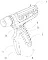
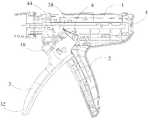
도 1은 본 발명의 일 실시예에 따른 발사 기구와 스테이플러 본체의 결합 구조를 나타내는 모식도이다.
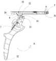
도 2는 본 발명의 일 실시예에 따른 발사 기구가 초기 상태에 있을 때의 구조를 나타내는 모식도이다.
도 3 ~도 4는 본 발명의 일 실시예에 따른 핀 포스트와 누름 버튼 및 기어랙의 결합을 나타내는 모식도이다.
도 5 ~도 6은 본 발명의 일 실시예에 따른 핀 포스트와 누름 버튼의 결합을 나타내는 모식도이다.
도 7 ~ 도 8은 본 발명의 일 실시예에 따른 기어랙의 구조를 나타내는 모식도이다.
도 9 ~도 10은 본 발명의 일 실시예에 따른 발사 핸들을 누를 때의 발사 기구의 구조를 나타내는 모식도이다.
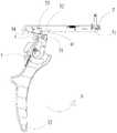
도 11은 본 발명의 일 실시예에 따른 발사 기구가 안전 위치에 위치할 때의 구조를 나타내는 모식도이다.
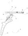
도 12는 본 발명의 일 실시예에 따른 발사 기구가 발사 가능한 위치에 위치할 때의 구조를 나타내는 모식도이다.
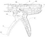
도 13은 본 발명의 다른 실시예에 따른 발사 기구의 구조를 나타내는 모식도이다.
도 14는 본 발명의 일 실시예에 따른 발사 핸들 및 버튼 어셈블리의 분해도이다.
도 15는 본 발명의 일 실시예에 따른 발사 핸들과 버튼 어셈블리의 결합 구조를 나타내는 모식도이다.
도 16은 본 발명의 일 실시예에 따른 발사 핸들과 버튼 어셈블리의 결합의 측면도이다.
도 17은 도 16의 A'-A '방향에 따른 단면도이다.
도 18은 본 발명의 일 실시예에 따른 작동로드의 사시도이다.
도 19는 본 발명의 일 실시예에 따른 작동로드의 구조를 나타내는 모식도이다.
도 20은 본 발명의 일 실시예에 따른 발사 핸들의 구조를 나타내는 모식도이다.
도 21은 본 발명의 일 실시예에 따른 발사 핸들의 구조를 나타내는 모식도이다.
도 22는 본 발명의 일 실시예에 따른 발사 핸들의 구조를 나타내는 모식도이다.Hereinafter, in order to more clearly describe the technical solution according to the embodiment of the present invention, the drawings that need to be used for the description of the embodiment will be briefly introduced. In addition, the drawings in the following description are only some embodiments of the present invention, and those skilled in the art may obtain other drawings according to these drawings on the premise that creative labor is not given.
1 is a schematic diagram showing a coupling structure of a firing mechanism and a stapler body according to an embodiment of the present invention.
2 is a schematic diagram showing the structure when the firing mechanism according to an embodiment of the present invention is in an initial state.
3 to 4 are schematic diagrams showing the coupling of the pin post, push button and gear rack according to an embodiment of the present invention.
5 to 6 are schematic diagrams showing a combination of a pin post and a push button according to an embodiment of the present invention.
7 to 8 are schematic views showing the structure of a gear rack according to an embodiment of the present invention.
9 to 10 are schematic diagrams showing the structure of the firing mechanism when the firing handle is pressed according to an embodiment of the present invention.
11 is a schematic diagram showing a structure when the firing mechanism is positioned in a safe position according to an embodiment of the present invention.
12 is a schematic diagram illustrating a structure when the firing mechanism according to an embodiment of the present invention is positioned in a position capable of firing.
13 is a schematic diagram showing the structure of a launch mechanism according to another embodiment of the present invention.
14 is an exploded view of a firing handle and button assembly in accordance with an embodiment of the present invention.
15 is a schematic diagram illustrating a coupling structure of a firing handle and a button assembly according to an embodiment of the present invention.
16 is a side view of a combination of a trigger handle and a button assembly in accordance with an embodiment of the present invention.
17 is a cross-sectional view taken along a direction A'-A' of FIG. 16 .
18 is a perspective view of an operation rod according to an embodiment of the present invention.
19 is a schematic diagram showing the structure of an operating rod according to an embodiment of the present invention.
20 is a schematic diagram showing the structure of a firing handle according to an embodiment of the present invention.
21 is a schematic diagram showing the structure of a firing handle according to an embodiment of the present invention.
22 is a schematic diagram showing the structure of a firing handle according to an embodiment of the present invention.
본 발명의 실시예의 목적, 기술적 해결책 및 장점이 보다 명확하도록, 이하 본 발명의 실시예의 도면을 참조하면서, 본 발명의 실시예에 따른 기술적 해결책을 보다 명확하고 완벽하게 설명하고, 물론, 설명되는 실시예는 단지 본 발명의 일부 실시예에 불과하며, 모든 실시예는 아니다.In order for the object, technical solution and advantage of the embodiment of the present invention to be more clear, the technical solution according to the embodiment of the present invention will be more clearly and completely described below with reference to the drawings of the embodiment of the present invention, and, of course, the described implementation Examples are merely some embodiments of the present invention and not all embodiments.
이하, 도면을 참조하면서 실시예와 결합하여, 본 발명을 상세하게 설명한다.Hereinafter, the present invention will be described in detail in combination with embodiments with reference to the drawings.
본 발명은 종래 기술의 기술 과제를 해결하기 위해, 스테이플러에 적용되는 발사 기구를 제공하고, 상기 발사 기구는 스토퍼 홈이 개설되는 작동로드와 발사 핸들과 누름 버튼을 포함하고, 상기 발사 핸들은 제 1 위치를 가지며, 상기 발사 핸들의 내부에는 핀 포스트가 설치되고, 상기 핀 포스트는 제 1 상태 및 제 2 상태를 가지며, 상기 핀 포스트가 상기 제 1 상태에 있고, 상기 발사 핸들이 상기 제 1 위치에 위치하는 경우, 상기 핀 포스트의 제 1 단은 상기 발사 핸들의 제 1 단으로부터 돌출하여 상기 스토퍼 홈에 삽입되어, 상기 발사 핸들이 상기 작동로드에 대해 회전 및 복귀 불가능하고, 상기 누름 버튼이 제 1 방향을 따라 이동하는 경우, 상기 핀 포스트의 제 1 단을 눌러 상기 발사 핸들의 제 2 단 방향으로 이동시켜, 상기 핀 포스트가 상기 제 1 상태로부터 상기 제 2 상태가 된다. 본 발명의 실시예는 상기 발사 기구를 포함하는 스테이플러를 더 제공한다. 상기 스테이플러는 선형 스테이플러에 한정되지 않고, 다른 종류의 스테이플러일 수 있다.In order to solve the technical problems of the prior art, the present invention provides a firing mechanism applied to a stapler, wherein the firing mechanism includes an operation rod having a stopper groove, a firing handle, and a push button, wherein the firing handle is a first position, wherein a pin post is installed within the firing handle, the pin post has a first state and a second condition, the pin post is in the first condition, and the firing handle is in the first position. When positioned, the first end of the pin post protrudes from the first end of the firing handle and is inserted into the stopper groove, such that the firing handle is non-rotatable and non-returnable with respect to the actuation rod, and the push button engages the first When moving along the direction, the first end of the pin post is depressed and moved in the direction of the second end of the firing handle, so that the pin post is from the first state to the second state. An embodiment of the present invention further provides a stapler comprising the firing mechanism. The stapler is not limited to a linear stapler, and may be another type of stapler.
따라서, 본 발명의 발사 기구에서, 핀 포스트와 작동로드의 결합에 의해 스테이플러의 발사 안전을 구현하고, 스테이플러가 발사 가능한 상태에 도달되지 않은 경우, 핀 포스트는 제 1 상태에 있고, 핀 포스트가 작동로드의 스토퍼 홈에 삽입되고, 발사 핸들의 회전 복귀를 제한하고, 발사 핸들의 구동 부재는 작동로드와 상호 작용할 수 없기 때문에, 발사 핸들을 누르더라도 작동로드를 눌러 원위 단으로 이동시킬 수 없고, 조작자는 발사 핸들을 파지하여 스테이플러를 발사할 수 없고, 이로 인해 스테이플러의 잘못된 발사을 피한다. 따라서, 핀 포스트가 제 1 상태에 있을 경우, 스테이플러는 안전 상태에 있고, 스테이플러를 성공적으로 발사할 수 없다. 누름 버튼이 제 1 방향을 따라 이동하는 경우, 발사 핸들의 회전 동작을 제한하지 않도록 핀 포스트를 눌러 스토퍼 홈으로부터 이탈시킬 수 있다.Therefore, in the firing mechanism of the present invention, the firing safety of the stapler is realized by the engagement of the pin post and the actuating rod, and when the stapler has not reached the firing state, the pin post is in the first state, and the pin post is operated Inserted into the stopper groove of the rod, limiting the return of rotation of the firing handle, since the driving member of the firing handle cannot interact with the actuating rod, even if the firing handle is pressed, the actuating rod cannot be moved to the distal end by pressing the operating rod, The ruler cannot fire the stapler by gripping the firing handle, thereby avoiding the erroneous firing of the stapler. Thus, when the pin post is in the first state, the stapler is in a safe state and cannot successfully fire the stapler. When the push button moves along the first direction, the pin post can be pushed out of the stopper groove so as not to restrict the rotational operation of the firing handle.
이하, 도면을 참조하면서 본 발명의 각각의 실시예의 발사 기구의 구조를 각각 설명한다.Hereinafter, the structure of the firing mechanism of each embodiment of the present invention will be described respectively with reference to the drawings.
도 1 ~ 12에 나타낸 바와 같이, 본 발명의 제 1 실시예에 따른 발사 기구 및 그 중 어셈블리의 구조를 나타낸다. 해당 실시예에 있어서, 상기 발사 기구는 작동로드(5), 발사 핸들(3), 및 누름 버튼(8)을 포함한다. 상기 작동로드(5)에는 스토퍼 홈(53)이 개설된다. 상기 발사 핸들(3)은 제 1 위치와 제 2 위치를 가지며, 상기 발사 핸들(3)의 내부에는 핀 포스트(6)가 설치되고, 상기 핀 포스트(6)는 제 1 상태 및 제 2 상태를 가지며, 상기 핀 포스트(6)가 상기 제 1 상태에 있고, 상기 발사 핸들(3)이 상기 제 1 위치에 위치하는 경우, 상기 핀 포스트(6)의 제 1 단(61)은 상기 발사 핸들(3)의 제 1 단(31)으로부터 돌출하여 상기 스토퍼 홈(53)으로 삽입되고, 상기 발사 핸들(3)은 상기 작동로드(5)에 대해 회전 불가능하다. 상기 누름 버튼(8)이 제 1 방향을 따라 이동하는 경우, 상기 핀 포스트(6)의 제 1 단(61)을 눌러 상기 발사 핸들(3)의 제 2 단(32)의 방향으로 이동시켜, 상기 핀 포스트(6)이 상기 제 1 상태로부터 상기 제 2 상태가 된다. 해당 실시예에서 제 1 방향은 도 4에 나타낸 B를 향한 방향이다. 해당 실시예에서, 핀 포스트(6)가 제 2 상태에 있는 경우, 핀 포스트(6)는 발사 핸들(3)의 제 2 단 방향으로 후퇴되어 스토퍼 홈(53)으로부터 이탈한다.1 to 12, the structure of the firing mechanism and its assembly according to the first embodiment of the present invention is shown. In this embodiment, the firing mechanism comprises an actuating rod (5), a firing handle (3), and a push button (8). A
도 1에 나타낸 바와 같이, 본 발명의 일 실시예에 따른 발사 기구와 스테이플러 본체의 결합의 모식도이다. 스테이플러(1)의 내부에는 상기 작동로드(5)가 설치되고, 작동로드(5)의 원위 단은 커터 푸시 어셈블리에 연결된다. 작동로드(5)는 제 3 위치와 제 4 위치를 가지며, 제 3 위치는 제 4 위치의 근위 단에 위치하고, 작동로드(5)가 제 4 위치로부터 스테이플러의 원위 단으로 이동을 계속하는 경우, 커터 푸시 어셈블리를 눌러 스테이플러의 발사를 구현할 수 있다. 스테이플러 본체(1)에는 고정 핸들(2)이 설치되고, 상기 발사 핸들(3)의 제 1 단(31)은 스테이플러 본체(1)에 회전 가능하게 연결되고, 발사 핸들(3)과 스테이플러 본체(1) 사이에는 발사 핸들 복귀 구조가 설치되고, 해당 발사 핸들 복귀 구조는 인장 스프링, 비틀림 스프링 및 압축 스프링 등의 구조일 수 있다. 발사 핸들(3)은 조작자에 의해 파지되는 경우, 스테이플러 본체(1)에 대해 도면에서 A 방향을 따라 회전할 수 있다. 도 1에 나타낸 발사 핸들(3)의 위치는 제 2 위치이며, 이때 발사 기구는 초기 상태에 있고, 조작자가 발사 핸들(3)을 파지하고, 발사 핸들(3)의 제 2 단(32)을 고정 핸들(2)에 근접시키는 경우, 발사 핸들(3)은 제 1 위치로 들어가고, 조작자가 발사 핸들(3)을 놓는 경우, 발사 핸들(3)은 발사 핸들 복귀 구조의 작용에 의해, A 방향과 반대되는 방향을 따라 회전할 수 있고, 발사 핸들(3)의 제 2 단(32)은 고정 핸들(2)로부터 이탈되어, 발사 핸들(3)이 제 2 위치로 돌아간다.As shown in Figure 1, it is a schematic diagram of the coupling of the firing mechanism and the stapler body according to an embodiment of the present invention. The
본 발명에서 원위 단 및 근위 단은 조작자에 대하여 나타내는 것이며, 여기서, 원위 단은 조작자로부터 떨어진 일단을 가리키며, 근위 단은 조작자와 가까운 일단을 가리킨다. 예를 들어, 도 1의 관점에서 보면, 스테이플러(1)의 원위 단은 도면의 왼쪽 일단을 가리키며, 근위 단은 도면의 오른쪽 일단을 가리킨다.In the present invention, the distal end and the proximal end refer to the operator, wherein the distal end refers to one end away from the operator, and the proximal end refers to an end close to the operator. For example, when viewed from the perspective of FIG. 1 , the distal end of the
도 2에 나타낸 바와 같이, 본 발명의 일 실시예에 따른 발사 기구가 초기 상태에 있을 때의 구조를 나타내는 모식도이다. 이때, 발사 핸들(32)은 제 2 위치에 위치하며, 핀 포스트(6)는 제 1 상태에 있다. 해당 실시예에 있어서, 상기 발사 핸들(3)의 내부에는 핀 홈(33)이 설치되고, 상기 핀 포스트(6)는 상기 핀 홈(33)에 설치되고, 상기 핀 포스트(6)는 핀 홈(33)에 의해 한정되는 방향으로만 이동할 수 있으며, 상기 핀 포스트(6)의 제 2 단(62)과 상기 핀 홈(33) 사이에는 핀 포스트 복귀 부재(7)가 설치된다. 해당 실시예에 있어서, 상기 핀 포스트 복귀 부재(7)는 압축 스프링이고, 상기 핀 포스트(6)가 누름 버튼(8)으로부터 발사 핸들(3)의 제 2 단(32)을 향한 압력을 받을 경우, 핀 포스트(6)가 제 1 상태로부터 상기 제 2 상태가 되는 동시에, 상기 핀 포스트(6)의 제 2 단(62)은 상기 압축 스프링을 압축 변형시키고, 즉, 상기 핀 포스트(6)의 제 1 상태는 돌출 상태이며, 상기 핀 포스트(6)의 제 2 상태는 후퇴 상태이다. 누름 버튼(8)이 제 1 방향과 반대되는 방향을 따라 이동하는 경우, 누름 버튼(8)은 핀 포스트(6)를 누르지 않고, 핀 포스트(6)는 압축 스프링의 변형 복원력의 작용에 의해 다시 제 1 상태로 돌아간다.As shown in Fig. 2, it is a schematic diagram showing the structure when the launch mechanism according to an embodiment of the present invention is in an initial state. At this time, the firing handle 32 is in the second position and the
도 3 내지 도 6에 나타낸 바와 같이, 해당 실시예에서, 발사 기구는 밸런스(9)를 더 포함하고, 상기 밸런스(9)는 회전부(91) 및 연결부(92)를 포함하고, 상기 밸런스(9)의 연결부(92)는 상기 누름 버튼(8)에 고정 연결되고, 상기 회전부(91)는 상기 고정 핸들(2)에 회전 가능하게 설치되고, 상기 회전부(91)가 제 1 방향을 따라 회전하는 경우, 상기 누름 버튼(8)을 제 1 방향을 따라 이동시킨다. 상기 밸런스(9)는 스테이플러 본체(1)의 하우징에 회전 가능하게 고정될 수 있고, 예를 들면, 스테이플러 본체(1)의 하우징의 내측에는 대응되는 회전축이 설치되고, 밸런스(9)는 회전축의 외부에 슬리브 설치되지만, 본 발명은 이에 한정되지 않는다. 밸런스(9)는 다른 고정 방식을 사용할 수도 있다.3 to 6 , in this embodiment, the firing mechanism further comprises a
따라서, 해당 실시예는 밸런스(9), 누름 버튼(8) 및 핀 포스트(6)의 결합에 의해, 누름 버튼(8)을 이동시킴으로써 핀 포스트(6)의 상태를 변경할 수 있다. 누름 버튼(8)의 이동은 항상 밸런스(9)를 중심으로 하고, 누름 버튼(8)은 스테이플러 본체(1)에 대해 밸런스(9)의 축 방향으로 변위가 발생하지 않음으로써, 발사 기구 전체의 구조의 안정성을 향상시킴과 동시에, 조작자의 사용에 편의를 도모한다.Accordingly, the embodiment can change the state of the
도 3 내지 도 6에 나타낸 바와 같이, 해당 실시예에 있어서, 상기 핀 포스트(6) 및 상기 누름 버튼(8)에는 서로 결합하는 제 1 결합부(63) 및 제 2 결합부(81)가 각각 설치되고, 상기 누름 버튼(8)이 제 1 방향을 따라 이동하는 경우, 상기 제 1 결합부(63)는 상기 제 2 결합부(81)를 눌러, 상기 핀 포스트(6)의 제 1 단(61)을 상기 발사 핸들(3)의 제 2 단(32)의 방향으로 이동시킨다.3 to 6 , in this embodiment, the
해당 실시예에 있어서, 상기 제 1 결합부(63)는 보스이고, 상기 보스는 스토퍼부(631) 및 단차부(681)를 포함하고, 상기 제 2 결합부(81)는 상기 스토퍼부(631)와 결합하는 오목한 플랫폼이다. 도 4의 관점에서 보면, 스토퍼부(631)는 단차부(681)의 위쪽에 위치하고, 제 2 결합부(81)와 직접 결합한다. 다른 대안적인 실시예에서, 상기 제 1 결합부(63) 및 제 2 결합부(81)의 모두를 보스로 설치하거나, 또는 상기 제 1 결합부(63)를 다른 형태의 보스로 설치하고, 상기 제 2 결합부(81)를 오목한 플랫폼으로 설치하거나, 또는 상기 제 1 결합부(63)를 오목한 플랫폼으로 설치하고, 상기 제 2 결합부(81)를 보스로 설치할 수 있다. 밸런스(9)가 제 1 방향을 따라 회전하는 경우, 누름 버튼(8)을 제 1 방향을 따라 이동시켜, 누름 버튼(8)의 오목한 플랫폼이 핀 포스트(6)의 보스를 가압하고, 하향으로 경사진 방향으로 압축 스프링(7)을 압축하여, 핀 포스트(6)의 제 1 단(61)은 발사 핸들(3)의 제 2 단(32) 방향으로 이동시켜, 핀 포스트(6)는 제 1 상태로부터 제 2 상태가 될 수 있다.In this embodiment, the
상기 누름 버튼(8)은 상기 제 2 결합부(81)에 연결되는 누름부(82)를 포함하고, 상기 누름부(82)는 상기 스테이플러의 하우징을 관통하여 설치되고, 상기 하우징으로부터 돌출한다. 해당 실시예에 있어서, 상기 누름부(82)는 2 개이며, 각각 상기 스테이플러 본체(1)의 양측의 하우징에 관통하여 설치된다. 또한, 상기 스테이플러의 하우징에는 누름 버튼 위치 제한 부재(11)가 더 설치되고, 상기 누름 버튼 위치 제한 부재(11)는 상기 누름 버튼(8)이 제 1 방향을 따라 이동하는 경로 상에 위치하고, 누름 버튼(8)이 제 1 방향으로 이동하는 위치를 제한하는 것이다. 누름부(82)에는 하나의 손가락 위치(821)를 각각 설치할 수도 있고, 이를 통해 조작자가 하우징의 좌우 양측에서 편리하게 조작할 수 있다.The
도 7 및 도 9에 나타낸 바와 같이, 상기 스토퍼 홈(53)의 근위 단에는 상기 작동로드(5)의 내부로 함몰된 원호 홈(52)이 설치될 수 있고, 상기 핀 포스트(6)가 상기 제 1 상태에 있고, 상기 발사 핸들(3)이 상기 제 2 위치로부터 상기 제 1 위치까지 회전하는 경우, 상기 원호 홈(52)은 상기 핀 포스트(6)의 제 1 단(61)과 결합하고, 상기 핀 포스트(6)의 제 1 단(61)이 상기 스토퍼 홈(53)에 들어가도록 안내한다.7 and 9, an
해당 실시예에 있어서, 상기 발사 핸들(3)에는 구동 부재(4)가 더 설치되고, 작동로드(5)의 아래쪽에는 기어랙(51) 및 푸싱 투스(54)가 더 설치되며, 상기 기어랙(51)은 상기 푸싱 투스(54)의 근위 단에 위치하고, 상기 기어랙(51)과 푸싱 투스(54) 사이에는 평활부(58)가 더 설치되고, 기어랙(51) 및 푸싱 투스(54)는 각각 발사 핸들(3)의 구동 부재(4)와 결합될 수 있다. 초기 상태에서, 상기 작동로드(5)는 상기 제 3 위치에 위치하고, 상기 발사 핸들(3)이 상기 제 2 위치로부터 상기 제 1 위치로 회전하는 경우, 상기 구동 부재(4)는 상기 푸싱 투스(54)와 접촉하는 동시에, 상기 스테이플러의 원위 단으로 이동하여 상기 제 4 위치에 들어가도록 상기 작동로드(5)를 구동한다. 상기 작동로드(5)가 상기 제 4 위치에 있고, 상기 발사 핸들(3)이 상기 제 2 위치로부터 상기 제 1 위치로 회전하는 경우, 상기 구동 부재(4)는 상기 기어랙(51)의 영역에 들어감과 동시에, 상기 작동로드(5)를 진일보로 눌러 상기 스테이플러의 원위 단으로 이동시킴으로써, 커터 푸시 어셈블리를 눌러 스테이플러를 발사할 수 있다.In this embodiment, a driving
이하, 도 9 내지 도 12을 참조하면서, 해당 실시예의 발사 기구의 다양한 상태의 구조를 구체적으로 설명한다.Hereinafter, the structures of various states of the firing mechanism of the embodiment will be described in detail with reference to FIGS. 9 to 12 .
초기 위치에 위치하는 경우, 도 2에 나타낸 바와 같이, 핀 포스트(6)의 제 1 단(61)은 발사 핸들(3)로부터 돌출하고, 기어랙(51)의 영역에 위치하고, 상기 구동 부재(4)는 평활부(58)에 위치한다.When located in the initial position, as shown in Fig. 2, the
스테이플러가 오프되는 경우, 도 9 및 도 10에 나타낸 바와 같이, 발사 핸들(3)이 파지는 경우, 발사 핸들(3)이 제 2 위치로부터 제 1 위치로 회전 과정에서 2 개의 위치를 나타낸다. 해당 과정에서 작동로드(5)는 제 3 위치로부터 제 4 위치로 들어가고, 도 9에 나나탠 바와 같이, 발사 핸들(3)이 약간 파지된 상태이며, 이때 핀 포스트(6)는 제 1 상태에 있지만, 이미 원호 홈(52)에 의해 약간 압축되며, 핀 포스트(6)의 제 1 단(61)는 여전히 발사 핸들(3)로부터 돌출한다. 도 10에 나타낸 바와 같이, 발사 핸들(3)이 최대로 파지된 상태이며, 이때 핀 포스트(6)는 여전히 제 1 상태에 있고, 이미 원호 홈(52)의 가장 원위 단에 도달한다. 즉, 발사 핸들(3)이 제 2 위치로부터 제 1 위치로 회전하는 경우, 핀 포스트(6)의 제 1 단(61)이 원호 홈(52)에 의해 안내되어 스토퍼 홈(53)의 위치로 점차 근접한다. 이때 발사 핸들(3)을 파악하고 있으면, 도 11에 나타낸 바와 같이, 발사 핸들(3)은 구동 부재(4)가 푸싱 투스(54)와 접촉할 때까지 제 1 위치로 회전하고, 발사 핸들(3)을 계속하여 누르고, 발사 핸들(3)은 구동 부재(4)에 의해 푸싱 투스(54)를 갖는 작동로드(5)를 눌러 스테이플러의 원위 단으로 이동시킬 수 있으며, 이를 통해 작동로드(5)가 밀려 도면의 C 방향에 따라 이동하여 제 4 위치로 들어간다. 핀 포스트(6)는 스토퍼 홈(53)에 들어간다.When the stapler is off, as shown in FIGS. 9 and 10 , when the firing handle 3 is gripped, the firing handle 3 exhibits two positions in the course of rotation from the second position to the first position. In the process, the
이때 작동로드(5)가 제 4 위치까지 밀리기 때문에, 발사 핸들(3)이 제 2 위치로 돌아갈 경우, 구동 부재(4)의 위치는 기어랙(51)의 위치에 대향하고, 조작자가 발사 핸들(3)을 계속 누르고, 제 2 위치로부터 제 1 위치로 회전시키는 경우, 구동 부재(4)는 기어랙(51)을 진일보로 눌러 스테이플러의 원위 단으로 이동시켜, 스테이플러를 발사할 수 있다. 그러나, 수술의 준비가 완료되기 전에, 조작자가 발사 핸들(3)을 잘못 누르는 경우, 스테이플러의 잘못된 발사을 초래한다. 따라서, 도 11의 상태에서, 핀 포스트(6)의 제 1 단(61)이 스토퍼 홈(53)에 삽입되어, 스토퍼 홈(53)은 핀 포스트(6)의 회전 이동을 제한하고, 즉 발사 핸들(3)의 회전 및 복귀 이동을 제한하고, 발사 핸들(3)은 도 11의 제 1 위치로부터 제 2 위치로 돌아갈 수 없고, 조작자는 다시 발사 핸들(3)을 누룰 수 없어, 수술 준비가 완료되기 전의 잘못된 발사을 피한다.At this time, since the
도 11의 상태에서, 누름 버튼(8)을 아래쪽으로 누르는 경우, 누름 버튼(8)은 밸런스(9)의 회전부(91)를 중심으로 제 1 방향을 따라 회전 이동하고, 핀 포스트(6)의 제 1 단(61)를 발사 핸들(3)의 제 2 단의 32 방향으로 이동시켜, 핀 포스트(6)의 제 1 단이 작동로드(5)의 스토퍼 홈(53)으로부터 이탈하여, 스토퍼 홈(53)이 발사 핸들(3)의 회전을 제한하지 않게 된다. 이때 작업자가 발사 핸들(3)을 놓을 경우, 발사 핸들(3)은 발사 핸들 복귀 구조의 복귀 작용에 의해 제 2 위치로 돌아갈 수 있고, 도 12의 상태가 된다. 발사 핸들(3)이 복귀된 후, 누름 버튼(8)을 놓을 수 있고, 핀 포스트(6)는 다시 제 1 상태가 된다.In the state of FIG. 11 , when the
도 12에 나타낸 바와 같이, 해당 실시예에 따른 발사 기구가 발사 가능한 위치에 위치할 때의 구조를 나타내는 모식도이다. 이때 작동로드(5)는 제 4 위치에 위치하고, 발사 핸들(3)의 구동 부재(4)는 기어랙(51)과 결합한다. 발사 핸들(3)을 파지하고, 발사 핸들(3)을 A 방향을 따라 제 2 위치로부터 제 1 위치로 회전시킬 경우, 구동 부재(4)는 기어랙(51)에 의해 작동로드(5)를 눌러 스테이플러의 원위 단으로 이동시켜, 스테이플러의 발사을 구현한다. 핀 포스트(6)의 제 1 단(61)이 발사 핸들(3)의 회전에 과도한 저항을 주지 않도록, 기어랙(51)과 핀 포스트(6)의 제 1 단(61)의 연결되는 부분에 기어랙 홈(511)을 더 개설할 수 있으며, 이를 통해 핀 포스트(6)의 제 1 단(61)이 기어랙 홈(511)을 따라 기어랙의 원위 단으로 이동한다.As shown in Fig. 12, it is a schematic diagram showing the structure when the firing mechanism according to the embodiment is located in a position capable of firing. At this time, the
본 발명의 다른 실시예는 스테이플러에 적용되는 발사 기구를 제공하고, 상기 발사 기구는 작동로드와 발사 핸들과 버튼 어셈블리를 포함하고, 발사 핸들에는 안전 핀 포스트가 설치되고, 발사 핸들이 파지된 경우, 핀 포스트가 작동로드의 스토퍼 홈에 삽입되어, 발사 핸들이 회전 불가능하며, 이때 스테이플러가 안전 상태에 있어, 수술 준비가 완료되지 않은 경우에 스테이플러가 잘못 발사되는 것을 피한다. 버튼 어셈블리는 발사 핸들의 고정 핸들로부터 떨어진 일측에 설치되고, 버튼 어셈블리와 핀 포스트에 의해 결합되어, 핀 포스트의 상태를 전환할 수 있다. 의사가 수술 준비를 완료한 경우, 발사 핸들을 향한 방향으로 버튼 어셈블리를 누를 수 있고, 버튼 어셈블리가 핀 포스트를 눌러 진일보로 발사 핸들의 내부로 삽입시킴으로써, 스토퍼 홈으로부터 이탈시키고, 발사 핸들을 정상적으로 회전시켜 사용할 수 있으며, 이때 스테이플러는 발사 가능한 상태에 있고, 스테이플러를 정상적으로 발사할 수 있다.Another embodiment of the present invention provides a firing mechanism applied to a stapler, wherein the firing mechanism includes an actuating rod, a firing handle, and a button assembly, the firing handle is provided with a safety pin post, and when the firing handle is gripped, A pin post is inserted into the stopper groove of the actuating rod, so that the firing handle is non-rotatable, and at this time the stapler is in a safe state, avoiding the stapler being accidentally fired when the operation preparation is not completed. The button assembly is installed on one side away from the fixed handle of the firing handle, and is coupled by the button assembly and the pin post, so that the state of the pin post can be switched. When the surgeon is ready for surgery, he can depress the button assembly in the direction towards the firing handle, and the button assembly presses the pin post and further inserts it into the interior of the firing handle, thereby disengaging from the stopper groove and rotating the firing handle normally. At this time, the stapler is in a firing state and the stapler can be fired normally.
본 발명의 다른 실시예는 상기의 발사 기구를 포함하는 스테이플러를 제공하고, 발사 핸들의 안전 핀 포스트와 작동로드의 스토퍼 홈의 결합을 통해, 수술 준비가 완료되지 않은 경우에 스테이플러가 잘못 발사되는 것을 피하고, 발사 핸들에 설치되는 버튼 어셈블리에 의해 핀 포스트의 상태를 전환하는 것이 가능하고, 버튼 어셈블리를 누르는 경우, 스테이플러를 성공적으로 발사하는 것을 구현할 수 있다. 본 발명은 선형 스테이플러뿐만 아니라, 예를 들면 원호 형 스테이플러와 같은 다른 유형의 스테이플러에도 적용 가능하다.Another embodiment of the present invention provides a stapler including the firing mechanism, and through the coupling of the safety pin post of the firing handle and the stopper groove of the actuating rod, it is possible to prevent the stapler from being fired incorrectly when preparation for surgery is not completed. Avoid, it is possible to switch the state of the pin post by the button assembly installed on the firing handle, and when the button assembly is pressed, it is possible to implement successful firing of the stapler. The present invention is applicable not only to a linear stapler, but also to other types of staplers such as, for example, arc-shaped staplers.
이하, 도 13 ~ 22을 참조하면서 본 발명의 다른 실시예에 따른 발사 기구의 구조를 더 설명한다. 여기서, 도 13은 해당 실시예의 발사 기구와 스테이플러의 결합 구조를 나타낸다. 본 실시예에 있어서, 이때 발사 핸들은 파지되어 있지 않고, 또한, 버튼 어셈블리는 초기 위치에 위치한다. 작동로드(5)는 스테이플러 본체(1)에 설치되고, 스테이플러 본체(1)의 일측에는 고정 핸들(2)과 발사 핸들(3)이 설치된다. 도 13 ~ 19에 나타낸 바와 같이, 작동로드(5)에는 스토퍼 홈(43)이 설치되고, 발사 핸들(3)의 내부에는 핀 포스트(6)이 설치된다. 핀 포스트(6)이 스토퍼 홈(43)으로 삽입되어 있지 않은 경우, 발사 핸들(3)은 고정 핸들(2)에 대해 회전하고, 고정 핸들(2)에 대해 근접 또는 이탈시킬 수 있으며, 초기 상태에 있는 경우, 발사 핸들(3)이 고정 핸들(2)로부터 멀어지고, 발사 핸들(3)이 파지된 후, 고정 핸들(2)에 근접한다. 상기 핀 포스트(6)는 제 1 상태 및 제 2 상태를 갖는다. 상기 핀 포스트(6)가 제 1 상태에 있는 경우, 상기 핀 포스트(6)의 제 1 단은 상기 스토퍼 홈(43)으로 삽입되고, 발사 핸들(3)은 작동로드(5)에 대해 회전 불가능하기 때문에, 발사 핸들(3)과 작동로드(5)의 상대적인 위치에 대한 제한을 구현하고, 이때 스테이플러는 안전 상태에 있다. 상기 핀 포스트(6)가 제 2 상태에 있는 경우, 상기 핀 포스트(6)의 제 1 단은 상기 스토퍼 홈(43)으로부터 이탈하여, 상기 발사 핸들(3)의 회전 동작을 저해하지 않고, 이때 스테이플러는 발사 가능한 상태에 있다. 상기 발사 핸들(3)의 일측에는 핀 포스트(6)의 상태를 전환하는 버튼 어셈블리(10)가 설치되고, 버튼 어셈블리(10)는 바람직하게는 발사 핸들(3)의 고정 핸들(2)로부터 떨어진 일측에 설치되어, 의사의 조작의 편의를 도모한다. 상기 버튼 어셈블리(10)는 누름로드(71)를 포함하고, 상기 누름로드(71)의 제 1 단은 상기 발사 핸들(3)의 내부로 삽입되고, 상기 버튼 어셈블리(10)가 초기 위치에 위치하고 상기 발사 핸들(3)이 파지된 경우, 상기 핀 포스트(6)의 제 1 단은 상기 스토퍼 홈(43)으로 삽입되고, 이때 발사 핸들(3)을 놓으면, 발사 핸들(3)은 핀 포스트(6)의 작용에 의해 초기 위치로 돌아갈 수 없다. 발사 핸들(3)을 향한 방향으로 버튼 어셈블리(10)를 누르는 경우, 버튼 어셈블리(10) 전체는 초기 위치로부터 상기 발사 핸들(3)로 이동하여 상기 누름로드(71)는 진일보로 상기 발사 핸들(3)의 내부로 들어가고, 상기 누름로드(71)는 상기 핀 포스트(6)를 눌러 핀 포스트(6)의 제 1 단(61)을 상기 발사 핸들(3)의 제 2 단(32) 방향으로 이동시키고, 이에 따라, 상기 핀 포스트(6)는 상기 제 1 상태로부터 상기 제 2 상태가 되고, 즉, 상기 핀 포스트(6)의 제 1 단은 상기 스토퍼 홈(43)으로부터 이탈하고, 동시에 발사 핸들(3)은 복귀 구조의 작용에 의해 초기 위치로 돌아간다.Hereinafter, the structure of the launch mechanism according to another embodiment of the present invention will be further described with reference to FIGS. 13 to 22 . Here, Figure 13 shows the coupling structure of the firing mechanism and the stapler of the embodiment. In this embodiment, the firing handle is not gripped at this time, and the button assembly is in the initial position. The working
도 14 ~ 17에 나타낸 바와 같이, 상기 발사 핸들(3)의 내부에는 상기 핀 포스트(6)를 수용하기 위한 핀 홈(33) 및 상기 누름로드(71)를 수용하기 위한 누름로드 가이드 홈(34)이 설치되고, 상기 핀 홈(33)은 제 3 방향으로 연장되고, 상기 누름로드 가이드 홈(34)은 제 2 방향(83)으로 연장되고, 또한, 상기 핀 홈(33)과 상기 누름로드 가이드 홈(34)은 교차되도록 설치된다. 도 17에 나타낸 바와 같이, 상기 제 3 방향은 상기 발사 핸들(3)의 길이 방향을 대략적으로 따른 방향이고, 상기 제 2 방향은 제 3 방향(85)에 대해 수직되거나 또는 거의 수직되는 방향이다. 핀 홈(33)과 누름로드 가이드 홈(34)의 교차 위치는 핀 포스트(6)의 제 1 결합부(63)와 누름로드(71)의 제 2 결합부(72)의 결합 위치이며, 누름로드(71)와 핀 포스트(6)는 2 개의 홈의 교차 위치에서 서로 교차되어, 누름로드(71)가 압력을 핀 포스트(6)에 전달하는 것을 구현할 수 있다. 핀 포스트(6)가 핀 홈(33)의 방향을 따라서만 직선 이동할 수 있으며, 제 1 상태와 제 2 상태 사이에서 전환한다. 누름로드(71)는 누름로드 가이드 홈(34)의 연장 방향을 따라서만 이동할 수 있다.14 to 17 , in the inside of the
해당 실시예에 있어서, 상기 핀 포스트(6)에는 제 1 결합부(63)가 설치되고, 상기 제 1 결합부(63)는 제 1 경사면(531)을 포함하고, 상기 누름로드(71)의 제 1 단에는 제 2 결합부(72)가 설치되고, 상기 제 2 결합부(72)는 제 3 경사면(721)을 포함한다. 상기 누름로드(71)가 초기 위치에 위치하는 경우, 상기 제 3 경사면(721)은 상기 제 1 경사면(531)에 밀착되고, 상기 누름로드(71)가 초기 위치로부터 진일보로 상기 발사 핸들(3)의 내부로 들어가는 경우, 상기 제 1 경사면(531)은 상기 제 3 경사면(721)을 따라 슬라이드하여, 상기 핀 포스트(6)의 제 1 단(61)을 상기 발사 핸들(3)의 제 2 단(32) 방향으로 이동시킨다. 도 5의 관점에서 보면, 제 1 경사면(531)은 우측변으로부터 좌측변을 향해 위쪽으로 경사져 있으며, 제 3 경사면(721)은 그 경사 방향이 제 1 경사면(531)과 일치하고, 우측변으로부터 좌측변을 향해 위쪽으로 경사져 있다. 누름로드(71)가 오른쪽으로부터 왼쪽으로 진일보로 발사 핸들(3)의 내부로 들어가는 경우, 제 3 경사면(721)의 작용에 의해, 제 1 경사면(531)에 대해 아래로 압력을 주고, 제 1 결합부(63)는 핀 포스트(6) 전체를 발사 핸들(3)의 제 2 단(32)으로 이동시킨다.In this embodiment, a
또한, 상기 제 1 결합부(63)는 제 2 경사면(532)을 더 포함할 수 있으며, 상기 제 2 경사면(532)은 상기 제 1 경사면(531)과 대향하여 설치되고, 상기 제 2 결합부(72)는 제 4 경사면(722)을 더 포함할 수 있으며, 상기 제 4 경사면(722)은 상기 제 3 경사면(731)과 대향하여 설치된다. 상기 누름로드(71)가 상기 초기 위치에 위치하는 경우, 상기 제 4 경사면(722)은 상기 제 2 경사면(532)에 밀착된다. 도 5의 관점에서 보면, 제 2 경사면(532)은 좌측변에서 우측변을 향해 위쪽으로 경사져 있으며, 제 4 경사면(722)은 그 경사 방향이 제 2 경사면(532)과 일치하고, 좌측변에서 우측변을 향해 위쪽으로 경사져 있다.In addition, the
도 17에 나타낸 바와 같이, 상기 제 1 경사면(531)과 상기 제 2 경사면(532)의 경계부(81)는 상기 핀 포스트(6)의 제 1 단(61)의 방향으로 돌출하고, 상기 제 3 경사면(721)과 상기 제 4 경사면(722)의 경계부(81)에는 캐비티(723)가 설치되고, 상기 누름로드(71)가 초기 위치에 위치하는 경우, 상기 제 1 경사면(531)과 상기 제 2 경사면(532)의 경계부는 상기 캐비티(723)로 들어가, 버튼 어셈블리(10)를 누르지 않은 경우, 제 1 결합부(63)와 제 2 결합부(72)가 상대적으로 이동하는 것을 피하고, 이를 통해 버튼 어셈블리(10)가 눌리우지 않은 경우, 누름로드(71)의 상기 초기 위치에서의 안정성을 확보한다.As shown in FIG. 17 , the
도 14 ~ 17에 나타낸 바와 같이, 누름 과정에서 버튼 어셈블리(10)의 가이드 작용을 더 잘 구현함과 동시에, 누름로드(71)가 초기 위치에 위치하는 경우에 버튼 어셈블리(10)가 발사 핸들(3)로부터 이탈하는 것을 피하기 위해, 상기 버튼 어셈블리(10)는 연결부(76) 및 가이드로드(73)를 더 포함할 수 있다. 상기 가이드로드(73)는 상기 연결부(76)를 통해 상기 누름로드(71)에 연결되고, 상기 발사 핸들(3)의 내부에는 상기 가이드로드(73)를 수용하기 위한 버튼 가이드 홈(35)이 설치되고, 상기 가이드 로드(73)의 제 1 단은 상기 버튼 가이드 홈(35)에 삽입된다. 해당 실시예에 있어서, 상기 가이드로드(73)는 2 개이고, 상기 버튼 가이드 홈(35)도 2 개이며, 또한, 상기 가이드로드(73)는 탄성 가이드로드이다. 상기 가이드로드(73)가 초기 상태에 있는 경우, 2 개의 가이드로드(73)가 열린 후의 거리는 2 개의 버튼 가이드 홈(35) 사이의 거리보다 크다. 설치시, 2 개의 가이드로드(73)를 중간을 향해 압축하여, 2 개의 가이드로드(73)는 중간을 향해 일정한 탄성 변형이 발생하고, 2 개의 버튼 가이드 홈(35)으로 삽입되고, 삽입된 후 가이드로드(73)의 탄성 복원력의 작용에 의해, 가이드로드(73)가 버튼 가이드 홈(35)에 유지될 수 있다. 가이드로드(73)의 안정성을 향상시키고, 가이드로드(73)가 부주의로 버튼 가이드 홈(35)으로부터 이탈하는 것을 피하기 위해, 상기 가이드로드(73)의 제 1 단에는 걸림부(731)가 더 설치되고, 상기 버튼 가이드 홈(35)의 측면에는 걸림부 슬라이딩 홈(341)이 설치되고, 가이드로드(73)가 버튼 가이드 홈(35)에 삽입되는 경우, 걸림부(731)는 걸림부 슬라이딩 홈(341)에 삽입되어, 걸림부(731)의 이동을 제한한다. 따라서, 가이드로드(73)는 버튼 가이드 홈(35)의 연장 방향으로만 따라 직선 이동할 수 있고, 또한, 걸림부(731)의 버튼 가이드 홈(35)에서의 걸림 작용에 의해, 누름로드(71)가 초기 위치에 위치하는 경우, 버튼 어셈블리(10)는 발사 핸들(3)로부터 이탈되지 않는다.14 to 17, while better realizing the guiding action of the
버튼 어셈블리(10)가 눌린 후의 자동 복귀를 구현하기 위해, 상기 버튼 어셈블리(10)는 연결부(76) 및 버튼 축(74)을 더 포함할 수 있으며, 상기 버튼 축(74)은 상기 연결부(76)를 통해 상기 누름로드(71)에 연결되고, 상기 발사 핸들(3)의 내부에는 상기 버튼 축(74)을 수용하기 위한 버튼 축 가이드 홈(36)이 설치되고, 상기 버튼 축 가이드 홈(36)에는 버튼 복귀 스프링(75)이 설치되고, 상기 누름로드(71)가 진일보로 상기 발사 핸들(3)의 내부로 들어가도록 상기 버튼 어셈블리(10)가 초기 위치로부터 상기 발사 핸들(3)을 향해 이동하는 경우, 상기 버튼 복귀 스프링(75)이 변형된다. 버튼 어셈블리(10)에 대한 외력이 제거된 후, 버튼 복귀 스프링(75)의 변형 복귀 작용에 의해 버튼 어셈블리(10)를 눌러 발사 핸들(3)로부터 멀어지는 방향으로 이동시킴으로써, 버튼 어셈블리(10)는 초기 위치로 돌아간다. 버튼 축 가이드 홈(36)에는 축 슬리브(37)가 더 설치될 수 있고, 상기 버튼 축(74)은 상기 축 슬리브(37)를 관통하여 설치되고, 상기 버튼 어셈블리(10)가 상기 버튼 축 가이드 홈(36)에서 이동하는 과정에서, 상기 버튼 어셈블리(10)가 더 순조롭게 이동하도록 한다.In order to realize automatic return after the
또한, 핀 포스트(6)의 자동 복귀를 구현하기 위해, 상기 핀 포스트(6)의 제 2 단(62)과 상기 핀 홈(33) 사이에는 핀 포스트 복귀 부재가 설치될 수 있다. 해당 핀 포스트 복귀 부재는 핀 포스트 복귀 스프링(7)일 수 있다.In addition, in order to realize the automatic return of the
도 18 및 도 19에 나타낸 바와 같이, 상기 스토퍼 홈(43)의 근위 단에는 상기 작동로드(5)의 내부로 오목한 원호 홈(42)이 설치되고, 상기 발사 핸들(3)이 파지되는 과정에 있어서, 상기 발사 핸들(3)이 초기 위치로부터 고정 핸들(2)에 가까운 위치로 회전하는 경우, 상기 원호 홈(42)은 상기 핀 포스트(6)의 제 1 단(61)과 결합하고, 상기 핀 포스트(6)의 제 1 단(61)이 상기 스토퍼 홈(43)으로 들어가도록 안내하고, 핀 포스트(6)의 제 1 단(61)이 작동로드(5)와 접촉할 때의 간섭을 피하고, 핀 포스트(6)의 제 1 단(61)이 작동로드(5)에 따라 이동하는 평활성을 향상시킨다.18 and 19, an
본 발명에서, 원위 단 및 근위 단은 조작자에 대하여 나타내는 것이며, 여기서, 원위 단은 조작자로부터 떨어진 일단을 가리키며, 근위 단은 조작자와 가까운 일단을 가리킨다. 예를 들어, 도 13의 관점에서 보면, 스테이플러 본체(1)의 원위 단은 도면의 왼쪽 일단을 가리키며, 근위 단은 도면의 오른쪽 일단을 가리킨다. 도 19의 관점에서 보면, 작동로드(5)의 원위 단은 도면의 왼쪽 일단을 가리키며, 근위 단은 도면의 오른쪽 일단을 가리킨다.In the present invention, the distal end and the proximal end refer to the operator, wherein the distal end refers to one end away from the operator, and the proximal end refers to the end close to the operator. For example, when viewed from the perspective of FIG. 13 , the distal end of the
또한, 작동로드(5)는 스토퍼 홈(43)의 원위 단에 푸싱 투스(44)가 더 설치될 수 있고, 푸싱 투스(44)는 발사 핸들(3)에 설치되는 클로(38)와 결합할 수 있으며, 구체적인 결합 방식에 대해서는 후술한다. 작동로드(5)는 스토퍼 홈(43)의 근위 단의 위치로부터 기어랙(41)이 더 설치되고, 기어랙(41)은 발사 핸들(3)에 설치되는 클로(38)와 결합할 수 있으며, 구체적인 결합 방식에 대해서는 후술한다. 기어랙(41)의 중간 부분에는 기어랙 홈(411)이 설치될 수 있고, 기어랙 홈(411)에 의해 핀 포스트(6)의 제 1 단(61)에 대한 후퇴를 구현하고, 후퇴 방식에 대해서는 후술한다.In addition, the
이하, 도 13, 도 20 및 도 21을 참조하면서 핀 포스트(6)가 제 1 상태에 있을 때의 발사 기구의 상태를 진일보로 설명한다. 도 13은 스테이플러가 초기 상태에 있을 때의 구조를 나타낸다. 핀 포스트(6)와 발사 핸들(3)은 모두 초기 상태에 있고, 이때 발사 핸들(3)의 제 2 단(32)은 고정 핸들(2)로부터 멀어진다. 도 13의 상태에 있어서, 이때 작동로드(5)는 작동로드의 초기 위치에 위치한다. 이때 발사 핸들(3)을 파지하여, 발사 핸들(3)을 고정 핸들(2)의 방향으로 회전시켜 고정 핸들(2)에 근접시키는 경우, 도 20에 나타낸 상태가 된다. 본 실시예에 있어서, 이때 발사 핸들이 파지되고, 또한, 버튼 어셈블리가 초기 위치에 위치한다. 이때 발사 핸들(3)의 클로(38)는 작동로드(5)의 푸싱 투스(44)와 접촉하여 푸싱 투스(44)를 스테이플러 원위 단으로 누르고, 푸싱 투스(44)는 작동로드(5)를 눌러 스테이플러의 원위 단으로 이동시키고, 즉 작동로드(5)는 도 20의 B 방향을 따라 이동하고, 이때 작동로드(5)는 작동로드(5)의 초기 위치로부터 스테이플러의 원위 단으로 일정한 거리만큼 이동한다. 이때, 핀 포스트 복귀 스프링(7)의 작용에 의해, 핀 포스트(6)의 제 1 단(61)은 원호 홈(42)에 의해 가이드되어 작동로드(5)의 스토퍼 홈(43)으로 삽입되어 제 1 상태가 된다. 이때, 발사 핸들(3)을 놓더라도, 발사 핸들(3)은 핀 포스트(6) 및 스토퍼 홈(43)의 위치 제한 작용에 의해 다시 회전하여 초기 위치로 돌아갈 수 없다. 이때 스테이플러를 발사할 수 없어, 안전 상태가 된다.Hereinafter, the state of the firing mechanism when the
의사가 수술 준비를 완료한 후, 도 21에 나타낸 바와 같이, 본 실시예에 있어서, 이때 발사 핸들이 파지되고, 또한, 버튼 어셈블리가 눌리운다. 도 21의 C 방향에 따라 버튼 어셈블리(10)를 누르는 경우, 누름로드(71)는 진일보로 발사 핸들(3)로 들어간다. 압력의 작용에 의해, 핀 포스트(6)는 제 1 상태로부터 제 2 상태가 되도록 발사 핸들(3)의 제 2 단(32)의 방향으로 이동하고, 핀 포스트(6)의 제 1 단(61)은 스토퍼 홈(43)로부터 이탈되어, 도 21에 나타낸 상태가 된다. 이때, 발사 핸들(3)은 발사 핸들(3)의 복귀 구조(예를 들어, 복귀 스프링)의 작용에 의해, 다시 회전하여 도 22에 나타낸 초기 위치로 돌아갈 수 있으며, 이때 발사 과정에서 발사 핸들은 초기 상태로 돌아기며, 또한, 버튼 어셈블리는 초기 위치에 위치한다. 발사 핸들(3)이 초기 위치로 돌아간 후, 클로(38)의 위치는 작동로드(5)의 기어랙(41)의 위치에 대응한다. 이때 버튼 어셈블리(10)를 놓으면, 버튼 어셈블리(10)는 버튼 복귀 스프링(75)의 작용에 의해 초기 위치로 돌아가고, 핀 포스트 복귀 스프링(7)의 작용에 의해 핀 포스트(6)의 제 1 단(61)은 발사 핸들(3)의 제 2 단(32)으로부터 멀어지는 방향으로 이동하고 다시 상기 발사 핸들(3)의 제 1 단(31)으로부터 돌출된다. 의사가 다시 발사 핸들(3)을 파지하고, 발사 핸들(3)을 상기 고정 핸들(2)에 근접시키는 방향으로 회전시키는 경우, 핀 포스트(6)의 제 1 단(61)과 기어랙 홈(411)이 접촉하고, 기어랙 홈(411)은 핀 포스트(6)의 제 1 단(61)의 이동에 대한 후퇴를 구현한다. 다시 발사 핸들(3)을 파지하여, 발사 핸들(3)의 클로(38)와 기어랙(41)이 접촉하고, 기어랙(41)을 눌러 작동로드(5)를 스테이플러의 원위 단 방향으로 이동시키고, 이에 따라 스테이플러를 발사한다.After the surgeon completes the preparation for the operation, as shown in FIG. 21 , in this embodiment, the trigger handle is gripped at this time, and the button assembly is depressed. When the
본 발명에 의해 제공되는 발사 기구 및 스테이플러는 다음과 같은 장점이 있다.The firing mechanism and stapler provided by the present invention have the following advantages.
본 발명은 스테이플러에 적용되는 발사 기구를 제공하고, 핀 포스트와 작동로드의 결합에 의해 스테이플러의 발사 안전을 구현하고, 스테이플러가 오프된 후, 의사는 조직을 평탄화하는 등 스테이플 헤드에서 조직의 축적 상태를 조정하여, 발사 가능한 상태에 도달시킬 필요가 있다. 조직이 발사 가능한 상태에 도달하지 않은 경우, 핀 포스트는 작동로드의 스토퍼 홈에 삽입되어, 발사 핸들의 회전 동작을 제한하고, 발사 핸들의 구동 부재는 작동로드를 구동할 수 없기 때문에 작동로드를 눌러 원위 단으로 이동시킬 수 없고, 조작자는 발사 핸들을 파지하고 스테이플러를 발사할 수 없고, 따라서 수술의 준비가 완료되기 전에 스테이플러가 발사되는 것을 피한다. 누름 어셈블리가 제 2 방향을 따라 이동하는 경우, 발사 핸들의 회전 동작을 제한하지 않도록 핀 포스트를 눌러 스토퍼 홈으로부터 이탈시킬 수 있으며, 구동 부재가 작동로드를 구동하여 스테이플러를 발사할 때까지 핸들을 회전시킬 수 있다. 또한, 본 발명의 일 실시예에서, 버튼 어셈블리를 눌러 핀 포스트의 위치의 전환을 구현하고, 버튼 어셈블리를 발사 핸들에 설치하기 때문에, 별도로 설치할 필요가 없고, 의사는 한손으로 조작할 수 있어, 버튼 어셈블리의 조작이 용이하고, 의사의 사용에 편의를 도모한다. 본 발명은 선형 스테이플러뿐만 아니라 다른 유형의 스테이플러에도 적용 가능하다.The present invention provides a firing mechanism applied to a stapler, realizes firing safety of the stapler by coupling a pin post and an operation rod, and after the stapler is turned off, the doctor flattens the tissue, etc. The state of accumulation of tissue in the staple head It is necessary to adjust to reach a firing state. When the tissue has not reached the firing state, the pin post is inserted into the stopper groove of the actuating rod, limiting the rotational action of the firing handle, and pressing the actuating rod because the driving member of the firing handle cannot drive the actuating rod It cannot be moved to the distal end, and the operator cannot hold the firing handle and fire the stapler, thus avoiding firing the stapler before the preparation for surgery is complete. When the pressing assembly moves along the second direction, it can disengage from the stopper groove by pressing the pin post so as not to restrict the rotational action of the firing handle, and rotate the handle until the driving member drives the actuating rod to fire the stapler can do it Further, in one embodiment of the present invention, by pressing the button assembly to implement the switching of the position of the pin post, since the button assembly is installed on the firing handle, there is no need to install it separately, and the doctor can operate it with one hand, the button The assembly is easy to operate, and it is convenient for the doctor to use. The present invention is applicable not only to the linear stapler, but also to other types of staplers.
이상 구체적인 바람직한 실시예를 참조하여, 본 발명을 더욱 상세하게 설명하였고, 본 발명의 구체적인 실시는 이러한 설명에만 한정된다고 인정할 수 없다. 당업자에 대해, 본 발명의 구상을 벗어나지 않는 범위에서 다양한 간단한 추론 또는 대체를 수행할 수 있고, 그들 모두는 본 발명의 보호 범위에 속하는 간주되어야 한다.The present invention has been described in more detail with reference to the above specific preferred embodiments, and it cannot be admitted that the specific implementation of the present invention is limited only to these descriptions. A person skilled in the art can make various simple inferences or substitutions without departing from the spirit of the present invention, all of which should be considered to fall within the protection scope of the present invention.
Claims (21)
Translated fromKorean상기 발사기구는 스토퍼 홈이 개설되는 작동로드와 발사 핸들과 누름 버튼을 포함하고,
상기 발사 핸들의 내부에는 핀 포스트가 설치되고, 상기 핀 포스트의 제 1 단은 상기 발사 핸들의 제 1 단으로부터 돌출하여 상기 스토퍼 홈에 삽입되어, 상기 발사 핸들이 상기 작동로드에 대해 회전 불가능하고,
상기 누름 버튼은 제 1 방향을 따라 이동하여, 상기 핀 포스트의 제 1 단을 눌러 상기 발사 핸들의 제 2 단의 방향으로 이동시키는,
것을 특징으로 하는 발사 기구.
A firing mechanism applied to a stapler, comprising:
The firing mechanism includes an actuating rod having a stopper groove, a firing handle, and a push button,
A pin post is installed inside the firing handle, and a first end of the pin post protrudes from the first end of the firing handle and is inserted into the stopper groove, so that the firing handle is non-rotatable with respect to the actuating rod;
wherein the push button moves along a first direction to press the first end of the pin post and move it in the direction of the second end of the firing handle;
A launch mechanism, characterized in that.
밸런스를 더 포함하고, 상기 밸런스는 회전부와 연결부를 포함하고, 상기 밸런스의 연결부는 상기 누름 버튼에 연결되고, 상기 밸런스의 회전부가 회전하는 경우, 상기 누름 버튼을 이동시키는,
것을 특징으로 하는 발사 기구.
The method of claim 1,
Further comprising a balance, wherein the balance includes a rotating part and a connection part, the connection part of the balance is connected to the push button, and when the rotating part of the balance rotates, moving the push button,
A launch mechanism, characterized in that.
상기 발사 핸들의 내부에는 핀 홈이 설치되고, 상기 핀 포스트는 상기 핀 홈에 설치되고, 상기 핀 포스트의 제 2 단과 상기 핀 홈 사이에 핀 포스트 복귀 부재가 설치되어, 상기 핀 포스트가 상기 핀 홈에 의해 한정되는 방향을 따라 직선 이동되는,
것을 특징으로 하는 발사 기구.
The method of claim 1,
A pin groove is installed inside the firing handle, the pin post is installed in the pin groove, and a pin post return member is installed between the second end of the pin post and the pin groove, so that the pin post is the pin groove moving in a straight line along the direction defined by
A launch mechanism, characterized in that.
상기 핀 포스트 복귀 부재는 압축 스프링인,
것을 특징으로 하는 발사 기구.
4. The method of claim 3,
wherein the pin post return member is a compression spring;
A launch mechanism, characterized in that.
상기 핀 포스트 및 상기 누름 버튼에는 제 1 결합부 및 제 2 결합부가 각각 설치되고, 상기 누름 버튼이 제 1 방향을 따라 이동하는 경우, 상기 제 1 결합부는 상기 제 2 결합부를 눌러, 상기 핀 포스트의 제 1 단이 상기 발사 핸들의 제 2 단의 방향으로 이동되는,
것을 특징으로 하는 발사 기구.
The method of claim 1,
A first coupling part and a second coupling part are respectively installed in the pin post and the push button, and when the push button moves in a first direction, the first coupling part presses the second coupling part, the first end is moved in the direction of the second end of the firing handle,
A launch mechanism, characterized in that.
상기 제 1 결합부는 보스이고, 상기 보스는 스토퍼부와 단차부를 포함하고, 상기 제 2 결합부는 오목한 플랫폼인,
것을 특징으로 하는 발사 기구.
6. The method of claim 5,
The first coupling part is a boss, the boss includes a stopper part and a step part, and the second coupling part is a concave platform,
A launch mechanism, characterized in that.
상기 누름 버튼은 상기 제 2 결합부에 연결되는 누름부를 포함하고, 상기 누름부는 상기 스테이플러의 하우징을 관통하여 설치되는,
것을 특징으로 하는 발사 기구.
6. The method of claim 5,
The push button includes a pressing part connected to the second coupling part, and the pressing part is installed through the housing of the stapler,
A launch mechanism, characterized in that.
상기 스테이플러의 하우징에는 누름 버튼 위치 제한 부재가 설치되고, 상기 누름 버튼 위치 제한 부재는 상기 누름 버튼이 제 1 방향을 따라 이동하는 경로 상에 위치하는,
것을 특징으로 하는 발사 기구.
8. The method of claim 7,
A push button position limiting member is installed in the housing of the stapler, and the push button position limiting member is positioned on a path along which the push button moves in the first direction,
A launch mechanism, characterized in that.
상기 스토퍼 홈의 근위 단에는 상기 작동로드의 내부를 향해 오목된 원호 홈이 설치되는,
것을 특징으로 하는 발사 기구.
The method of claim 1,
At the proximal end of the stopper groove, an arc groove concave toward the inside of the operation rod is installed,
A launch mechanism, characterized in that.
상기 발사 핸들에는 구동 부재가 더 설치되고, 상기 스토퍼 홈의 근위 단 및 원위 단에는 기어랙 및 푸싱 투스가 각각 설치되고,
상기 구동 부재는 상기 푸싱 투스와 접촉하고, 상기 작동로드를 눌러 상기 스테이플러의 원위 단으로 이동시키는,
것을 특징으로 하는 발사 기구.
10. The method of claim 9,
A driving member is further installed in the firing handle, and a gear rack and a pushing tooth are respectively installed at the proximal end and the distal end of the stopper groove,
wherein the drive member is in contact with the pushing tooth and presses the actuating rod to move it to the distal end of the stapler,
A launch mechanism, characterized in that.
상기 발사 기구는 스토퍼 홈이 개설되는 작동로드와 발사 핸들과 버튼 어셈블리를 포함하고,
상기 발사 핸들의 내부에는 핀 포스트가 설치되고,
상기 버튼 어셈블리는 누름로드를 포함하고, 상기 누름로드의 제 1 단은 상기 발사 핸들의 내부에 삽입되고,
상기 핀 포스트의 제 1 단은 상기 발사 핸들로부터 돌출하여 상기 스토퍼 홈에 삽입되어, 상기 발사 핸들이 상기 작동로드에 대해 회전 불가능하고,
상기 누름로드는 진일보로 상기 발사 핸들의 내부로 삽입되어, 상기 누름로드가 상기 핀 포스트의 제 1 단을 눌러 상기 발사 핸들의 제 2 단 방향으로 이동시키는,
것을 특징으로 하는 발사 기구.
A firing mechanism applied to a stapler, comprising:
The firing mechanism includes an actuating rod having a stopper groove formed therein, a firing handle, and a button assembly,
A pin post is installed inside the firing handle,
the button assembly includes a push rod, the first end of the push rod being inserted into the interior of the firing handle;
a first end of the pin post protrudes from the firing handle and inserted into the stopper groove, so that the firing handle is non-rotatable with respect to the actuating rod;
the pressing rod is further inserted into the interior of the firing handle, such that the pressing rod presses the first end of the pin post to move in the direction of the second end of the firing handle,
A launch mechanism, characterized in that.
상기 핀 포수트에는 제 1 결합부가 설치되고, 상기 제 1 결합부는 제 1 경사면을 포함하고, 상기 누름로드의 제 1 단에는 제 2 결합부가 설치되고, 상기 제 2 결합부는 제 3 경사면을 포함하고,
상기 누름로드가 상기 초기 위치에 위치하는 경우, 상기 제 3 경사면은 상기 제 1 경사면에 밀착되는,
것을 특징으로 하는 발사 기구.
12. The method of claim 11,
A first coupling part is installed in the pin catcher, the first coupling part includes a first inclined surface, a second coupling part is installed at the first end of the pressing rod, and the second coupling part includes a third inclined surface, and ,
When the pressing rod is located in the initial position, the third inclined surface is in close contact with the first inclined surface,
A launch mechanism, characterized in that.
상기 제 1 결합부는 제 2 경사면을 더 포함하고, 상기 제 2 경사면은 상기 제 1 경사면과 대향하여 설치되고, 상기 제 2 결합부는 제 4 경사면을 더 포함하고, 상기 제 4 경사면은 상기 제 3 경사면과 대향하여 설치되고,
상기 누름로드가 초기 위치에 위치하는 경우, 상기 제 4 경사면은 상기 제 2 경사면에 밀착되는,
것을 특징으로 하는 발사 기구.
13. The method of claim 12,
The first coupling part further includes a second inclined surface, the second inclined surface is installed to face the first inclined surface, the second coupling part further includes a fourth inclined surface, and the fourth inclined surface is the third inclined surface installed opposite to
When the pressing rod is located in the initial position, the fourth inclined surface is in close contact with the second inclined surface,
A launch mechanism, characterized in that.
상기 제 1 경사면과 상기 제 2 경사면의 경계부는 상기 핀 포스트의 제 1 단 방향으로 돌출하고, 상기 제 3 경사면과 상기 제 4 경사면의 경계부에는 캐비티가 설치되고, 상기 제 1 경사면과 상기 제 2 경사면의 경계부는 상기 캐비티로 들어가는,
것을 특징으로 하는 발사 기구.
14. The method of claim 13,
A boundary portion between the first inclined surface and the second inclined surface protrudes in a first end direction of the pin post, a cavity is installed at a boundary between the third inclined surface and the fourth inclined surface, and the first inclined surface and the second inclined surface The boundary of entering the cavity,
A launch mechanism, characterized in that.
상기 발사 핸들의 내부에는 상기 핀 포스트를 수용하기 위한 핀 홈 및 상기 누름로드를 수용하기 위한 누름로드 가이드 홈이 설치되고, 상기 핀 홈은 제 3 방향으로 연장되고, 상기 누름로드 가이드 홈은 제 2 방향으로 연장되는,
것을 특징으로 하는 발사 기구.
12. The method of claim 11,
A pin groove for accommodating the pin post and a pressing rod guide groove for accommodating the pressing rod are installed inside the firing handle, the pin groove extending in a third direction, and the pressing rod guide groove forming a second extending in the direction
A launch mechanism, characterized in that.
상기 버튼 어셈블리는 연결부 및 가이드로드를 더 포함하고, 상기 가이드로드는 상기 연결부를 통해 상기 누름로드에 연결되고, 상기 발사 핸들의 내부에는 상기 가이드로드를 수용하기 위한 버튼 가이드 홈이 설치되고, 상기 가이드로드의 제 1 단은 상기 버튼 가이드 홈에 삽입되는,
것을 특징으로 하는 발사 기구.
12. The method of claim 11,
The button assembly further includes a connection part and a guide rod, the guide rod is connected to the pressing rod through the connection part, and a button guide groove for accommodating the guide rod is installed inside the firing handle, and the guide The first end of the rod is inserted into the button guide groove,
A launch mechanism, characterized in that.
상기 버튼 가이드 홈의 일측에는 걸림부 슬라이딩 홈이 더 개설되고, 상기 가이드로드의 제 1 단에는 걸림부가 설치되고, 상기 걸림부 슬라이딩 홈은 상기 걸림부를 수용하는,
것을 특징 으로하는 발사 기구.
17. The method of claim 16,
A locking part sliding groove is further opened on one side of the button guide groove, a locking part is installed at the first end of the guide rod, and the locking part sliding groove receives the locking part,
A launch mechanism, characterized in that.
상기 버튼 어셈블리는 연결부 및 버튼 축을 더 포함하고, 상기 버튼 축은 상기 연결부를 통해 상기 누름로드에 연결되는,
것을 특징으로 하는 발사 기구.
12. The method of claim 11,
The button assembly further includes a connection part and a button shaft, wherein the button shaft is connected to the pressing rod through the connection part,
A launch mechanism, characterized in that.
상기 발사 핸들의 내부에는 버튼 축을 수용하기 위한 버튼 축 장착 홈이 설치되고, 상기 버튼 축 장착 홈에는 버튼 복귀 스프링이 설치되는,
것을 특징으로 하는 발사 기구.
12. The method of claim 11,
A button shaft mounting groove for accommodating the button shaft is installed inside the firing handle, and a button return spring is installed in the button shaft mounting groove,
A launch mechanism, characterized in that.
상기 발사 핸들의 내부에는 핀 홈이 설치되고, 상기 핀 포스트는 상기 핀 홈에 설치되고, 상기 핀 포스트의 제 2 단과 상기 핀 홈 사이에는 핀 포스트 복귀 부재가 설치되어, 상기 핀 포스트가 상기 핀 홈에 의해 한정되는 방향을 따라 직선 이동되는,
것을 특징으로 하는 발사 기구.
12. The method of claim 11,
A pin groove is installed inside the firing handle, the pin post is installed in the pin groove, and a pin post return member is installed between the second end of the pin post and the pin groove, so that the pin post is the pin groove moving in a straight line along the direction defined by
A launch mechanism, characterized in that.
것을 특징으로 하는 스테이플러.12. Comprising the launch mechanism according to any one of claims 1 to 11,
A stapler, characterized in that.
Applications Claiming Priority (7)
| Application Number | Priority Date | Filing Date | Title |
|---|---|---|---|
| CN201822152931.X | 2018-12-20 | ||
| CN201822152931.XUCN209529241U (en) | 2018-12-20 | 2018-12-20 | Firing lock and stapler |
| CN201811563035.0 | 2018-12-20 | ||
| CN201811563035.0ACN111345862B (en) | 2018-12-20 | 2018-12-20 | Firing mechanism and anastomat |
| CN201920187434.5 | 2019-02-02 | ||
| CN201920187434.5UCN209644987U (en) | 2019-02-02 | 2019-02-02 | Firing lock and stapler |
| PCT/CN2019/127100WO2020125765A1 (en) | 2018-12-20 | 2019-12-20 | Firing mechanism and anastomat |
Publications (2)
| Publication Number | Publication Date |
|---|---|
| KR20210095928Atrue KR20210095928A (en) | 2021-08-03 |
| KR102705648B1 KR102705648B1 (en) | 2024-09-11 |
Family
ID=71100669
Family Applications (1)
| Application Number | Title | Priority Date | Filing Date |
|---|---|---|---|
| KR1020217020013AActiveKR102705648B1 (en) | 2018-12-20 | 2019-12-20 | Launcher and stapler |
Country Status (8)
| Country | Link |
|---|---|
| US (1) | US12096939B2 (en) |
| EP (1) | EP3900646B1 (en) |
| JP (1) | JP7441842B2 (en) |
| KR (1) | KR102705648B1 (en) |
| AU (1) | AU2019410648B2 (en) |
| CA (1) | CA3121953A1 (en) |
| ES (1) | ES2999984T3 (en) |
| WO (1) | WO2020125765A1 (en) |
Families Citing this family (3)
| Publication number | Priority date | Publication date | Assignee | Title |
|---|---|---|---|---|
| CN113100904A (en)* | 2021-04-12 | 2021-07-13 | 徐州医科大学 | An orthopedic reducer with a Kirschner wire guide device |
| CN115153697B (en)* | 2022-08-11 | 2024-07-05 | 杭州锐健马斯汀医疗器材有限公司 | Suture device |
| WO2024120234A1 (en)* | 2022-12-08 | 2024-06-13 | 天臣国际医疗科技股份有限公司 | Staple head and surgical stapler |
Citations (5)
| Publication number | Priority date | Publication date | Assignee | Title |
|---|---|---|---|---|
| US20080314958A1 (en)* | 2006-10-06 | 2008-12-25 | Tyco Healthcare Group Lp | Grasping Jaw Mechanism |
| EP2090251A2 (en)* | 2008-02-14 | 2009-08-19 | Ethicon Endo-Surgery, Inc. | Surgical stapling apparatus with retractable firing systems |
| CN104224260A (en)* | 2014-09-19 | 2014-12-24 | 重庆康美唯外科器械有限公司 | Mistaken-percussion-proof safety mechanism for anastomat and anastomat |
| US20150297216A1 (en)* | 2014-04-21 | 2015-10-22 | Covidien Lp | Stapling device with features to prevent inadvertent firing of staples |
| JP2018508278A (en)* | 2015-02-15 | 2018-03-29 | コヴィディエン リミテッド パートナーシップ | Universal handle for surgical instruments |
Family Cites Families (12)
| Publication number | Priority date | Publication date | Assignee | Title |
|---|---|---|---|---|
| US5403312A (en)* | 1993-07-22 | 1995-04-04 | Ethicon, Inc. | Electrosurgical hemostatic device |
| US5597107A (en)* | 1994-02-03 | 1997-01-28 | Ethicon Endo-Surgery, Inc. | Surgical stapler instrument |
| CN2383477Y (en)* | 1999-08-04 | 2000-06-21 | 马剑文 | Safety automatic opening device |
| AU2012250197B2 (en)* | 2011-04-29 | 2017-08-10 | Ethicon Endo-Surgery, Inc. | Staple cartridge comprising staples positioned within a compressible portion thereof |
| US8931679B2 (en)* | 2011-10-17 | 2015-01-13 | Covidien Lp | Surgical stapling apparatus |
| RU145252U1 (en) | 2014-05-07 | 2014-09-10 | Михаил Александрович Судаков | DEVICE FOR APPLICATION OF CIRCULAR ANASTOMOSIS OF HOLLOW TUBULAR BODIES |
| CN104586452B (en) | 2015-02-15 | 2017-01-11 | 江苏孜航精密五金有限公司 | Clamping insurance device for surgical suture device |
| US10905415B2 (en)* | 2015-06-26 | 2021-02-02 | Ethicon Llc | Surgical stapler with electromechanical lockout |
| CN206641873U (en)* | 2016-08-08 | 2017-11-17 | 南京迈迪欣医疗器械有限公司 | A kind of hysteroscope firing handle closes stretching mechanism |
| CN108403176A (en)* | 2018-03-29 | 2018-08-17 | 盈甲医疗器械制造(上海)有限公司 | A kind of stapler with safety device |
| CN209644987U (en)* | 2019-02-02 | 2019-11-19 | 苏州天臣国际医疗科技有限公司 | Firing lock and stapler |
| CN209529241U (en)* | 2018-12-20 | 2019-10-25 | 苏州天臣国际医疗科技有限公司 | Firing lock and stapler |
- 2019
- 2019-12-20USUS17/311,215patent/US12096939B2/enactiveActive
- 2019-12-20KRKR1020217020013Apatent/KR102705648B1/enactiveActive
- 2019-12-20AUAU2019410648Apatent/AU2019410648B2/enactiveActive
- 2019-12-20CACA3121953Apatent/CA3121953A1/enactivePending
- 2019-12-20ESES19900141Tpatent/ES2999984T3/enactiveActive
- 2019-12-20EPEP19900141.3Apatent/EP3900646B1/enactiveActive
- 2019-12-20WOPCT/CN2019/127100patent/WO2020125765A1/ennot_activeCeased
- 2019-12-20JPJP2021535931Apatent/JP7441842B2/enactiveActive
Patent Citations (5)
| Publication number | Priority date | Publication date | Assignee | Title |
|---|---|---|---|---|
| US20080314958A1 (en)* | 2006-10-06 | 2008-12-25 | Tyco Healthcare Group Lp | Grasping Jaw Mechanism |
| EP2090251A2 (en)* | 2008-02-14 | 2009-08-19 | Ethicon Endo-Surgery, Inc. | Surgical stapling apparatus with retractable firing systems |
| US20150297216A1 (en)* | 2014-04-21 | 2015-10-22 | Covidien Lp | Stapling device with features to prevent inadvertent firing of staples |
| CN104224260A (en)* | 2014-09-19 | 2014-12-24 | 重庆康美唯外科器械有限公司 | Mistaken-percussion-proof safety mechanism for anastomat and anastomat |
| JP2018508278A (en)* | 2015-02-15 | 2018-03-29 | コヴィディエン リミテッド パートナーシップ | Universal handle for surgical instruments |
Also Published As
| Publication number | Publication date |
|---|---|
| AU2019410648B2 (en) | 2022-07-07 |
| BR112021010637A2 (en) | 2021-08-24 |
| KR102705648B1 (en) | 2024-09-11 |
| AU2019410648A1 (en) | 2021-06-24 |
| ES2999984T3 (en) | 2025-02-27 |
| EP3900646B1 (en) | 2024-11-20 |
| US20220031330A1 (en) | 2022-02-03 |
| EP3900646A4 (en) | 2022-04-27 |
| EP3900646A1 (en) | 2021-10-27 |
| WO2020125765A1 (en) | 2020-06-25 |
| JP7441842B2 (en) | 2024-03-01 |
| CA3121953A1 (en) | 2020-06-25 |
| US12096939B2 (en) | 2024-09-24 |
| EP3900646C0 (en) | 2024-11-20 |
| JP2022514665A (en) | 2022-02-14 |
Similar Documents
| Publication | Publication Date | Title |
|---|---|---|
| KR101190028B1 (en) | Surgical stapling instrument incorporating a multi-stroke firing mechanism with return spring rotary manual retraction system | |
| KR101141031B1 (en) | Surgical stapling instrument incorporating a multistroke firing mechanism having a rotary transmission | |
| JP5154060B2 (en) | Surgical instrument having a lockout mechanism and a lockout mechanism | |
| US8424736B2 (en) | Grasping jaw mechanism | |
| US9668733B2 (en) | Stapling device with features to prevent inadvertent firing of staples | |
| KR101169914B1 (en) | Surgical stapling instrument incorporating a multistroke firing mechanism having a rotary slip-clutch transmission | |
| KR101233999B1 (en) | Multi-stroke mechanism with automatic end of stroke retraction | |
| WO2017028361A1 (en) | Single-handed-operation surgical instrument and operation method thereof | |
| WO2017028362A1 (en) | Surgical instrument having single-handed-operation safety device, and operation method thereof | |
| CN209644987U (en) | Firing lock and stapler | |
| KR102705648B1 (en) | Launcher and stapler | |
| CN205307029U (en) | Surgical instrument capable of being operated by signal hand | |
| CN209347125U (en) | Medical Stapler | |
| CN209996389U (en) | Firing mechanism and anastomat | |
| CN111345862B (en) | Firing mechanism and anastomat | |
| KR102443146B1 (en) | Handle assembly and anastomosis including same | |
| CN109953789B (en) | Handle assembly and stapler including same | |
| RU2778732C1 (en) | Trigger mechanism and stapler | |
| CN209529225U (en) | Firing lock and stapler | |
| CN218338485U (en) | Drive structure and chamber mirror anastomat of chamber mirror anastomat | |
| WO2019128798A1 (en) | Handle assembly and anastomat comprising same | |
| CN109953788A (en) | Handle assembly and stapler including the same | |
| CN119214713A (en) | Stapler handle and stapler | |
| CN119924917A (en) | Surgical instruments | |
| CN111374727A (en) | Control mechanism for surgical instrument and surgical instrument |
Legal Events
| Date | Code | Title | Description |
|---|---|---|---|
| A201 | Request for examination | ||
| E13-X000 | Pre-grant limitation requested | St.27 status event code:A-2-3-E10-E13-lim-X000 | |
| P11-X000 | Amendment of application requested | St.27 status event code:A-2-2-P10-P11-nap-X000 | |
| P13-X000 | Application amended | St.27 status event code:A-2-2-P10-P13-nap-X000 | |
| PA0105 | International application | St.27 status event code:A-0-1-A10-A15-nap-PA0105 | |
| PA0201 | Request for examination | St.27 status event code:A-1-2-D10-D11-exm-PA0201 | |
| PG1501 | Laying open of application | St.27 status event code:A-1-1-Q10-Q12-nap-PG1501 | |
| E902 | Notification of reason for refusal | ||
| PE0902 | Notice of grounds for rejection | St.27 status event code:A-1-2-D10-D21-exm-PE0902 | |
| P11-X000 | Amendment of application requested | St.27 status event code:A-2-2-P10-P11-nap-X000 | |
| P13-X000 | Application amended | St.27 status event code:A-2-2-P10-P13-nap-X000 | |
| E601 | Decision to refuse application | ||
| PE0601 | Decision on rejection of patent | St.27 status event code:N-2-6-B10-B15-exm-PE0601 | |
| E13-X000 | Pre-grant limitation requested | St.27 status event code:A-2-3-E10-E13-lim-X000 | |
| P11-X000 | Amendment of application requested | St.27 status event code:A-2-2-P10-P11-nap-X000 | |
| P13-X000 | Application amended | St.27 status event code:A-2-2-P10-P13-nap-X000 | |
| PX0901 | Re-examination | St.27 status event code:A-2-3-E10-E12-rex-PX0901 | |
| E902 | Notification of reason for refusal | ||
| PE0902 | Notice of grounds for rejection | St.27 status event code:A-1-2-D10-D21-exm-PE0902 | |
| E13-X000 | Pre-grant limitation requested | St.27 status event code:A-2-3-E10-E13-lim-X000 | |
| P11-X000 | Amendment of application requested | St.27 status event code:A-2-2-P10-P11-nap-X000 | |
| P13-X000 | Application amended | St.27 status event code:A-2-2-P10-P13-nap-X000 | |
| PX0701 | Decision of registration after re-examination | St.27 status event code:A-3-4-F10-F13-rex-PX0701 | |
| X701 | Decision to grant (after re-examination) | ||
| PR0701 | Registration of establishment | St.27 status event code:A-2-4-F10-F11-exm-PR0701 | |
| PR1002 | Payment of registration fee | St.27 status event code:A-2-2-U10-U12-oth-PR1002 Fee payment year number:1 | |
| PG1601 | Publication of registration | St.27 status event code:A-4-4-Q10-Q13-nap-PG1601 |