KR20210095861A - Apparatus and method for coating a substrate using a wash coat - Google Patents
Apparatus and method for coating a substrate using a wash coatDownload PDFInfo
- Publication number
- KR20210095861A KR20210095861AKR1020217013199AKR20217013199AKR20210095861AKR 20210095861 AKR20210095861 AKR 20210095861AKR 1020217013199 AKR1020217013199 AKR 1020217013199AKR 20217013199 AKR20217013199 AKR 20217013199AKR 20210095861 AKR20210095861 AKR 20210095861A
- Authority
- KR
- South Korea
- Prior art keywords
- washcoat
- showerhead
- central body
- substrate
- baffle
- Prior art date
- Legal status (The legal status is an assumption and is not a legal conclusion. Google has not performed a legal analysis and makes no representation as to the accuracy of the status listed.)
- Granted
Links
Images


Classifications
- B—PERFORMING OPERATIONS; TRANSPORTING
- B05—SPRAYING OR ATOMISING IN GENERAL; APPLYING FLUENT MATERIALS TO SURFACES, IN GENERAL
- B05C—APPARATUS FOR APPLYING FLUENT MATERIALS TO SURFACES, IN GENERAL
- B05C7/00—Apparatus specially designed for applying liquid or other fluent material to the inside of hollow work
- B05C7/04—Apparatus specially designed for applying liquid or other fluent material to the inside of hollow work the liquid or other fluent material flowing or being moved through the work; the work being filled with liquid or other fluent material and emptied
- B—PERFORMING OPERATIONS; TRANSPORTING
- B05—SPRAYING OR ATOMISING IN GENERAL; APPLYING FLUENT MATERIALS TO SURFACES, IN GENERAL
- B05B—SPRAYING APPARATUS; ATOMISING APPARATUS; NOZZLES
- B05B1/00—Nozzles, spray heads or other outlets, with or without auxiliary devices such as valves, heating means
- B05B1/14—Nozzles, spray heads or other outlets, with or without auxiliary devices such as valves, heating means with multiple outlet openings; with strainers in or outside the outlet opening
- B05B1/18—Roses; Shower heads
- B05B1/185—Roses; Shower heads characterised by their outlet element; Mounting arrangements therefor
- B—PERFORMING OPERATIONS; TRANSPORTING
- B05—SPRAYING OR ATOMISING IN GENERAL; APPLYING FLUENT MATERIALS TO SURFACES, IN GENERAL
- B05B—SPRAYING APPARATUS; ATOMISING APPARATUS; NOZZLES
- B05B12/00—Arrangements for controlling delivery; Arrangements for controlling the spray area
- B05B12/16—Arrangements for controlling delivery; Arrangements for controlling the spray area for controlling the spray area
- B05B12/20—Masking elements, i.e. elements defining uncoated areas on an object to be coated
- B—PERFORMING OPERATIONS; TRANSPORTING
- B05—SPRAYING OR ATOMISING IN GENERAL; APPLYING FLUENT MATERIALS TO SURFACES, IN GENERAL
- B05C—APPARATUS FOR APPLYING FLUENT MATERIALS TO SURFACES, IN GENERAL
- B05C5/00—Apparatus in which liquid or other fluent material is projected, poured or allowed to flow on to the surface of the work
- B05C5/02—Apparatus in which liquid or other fluent material is projected, poured or allowed to flow on to the surface of the work the liquid or other fluent material being discharged through an outlet orifice by pressure, e.g. from an outlet device in contact or almost in contact, with the work
- B05C5/027—Coating heads with several outlets, e.g. aligned transversally to the moving direction of a web to be coated
- B—PERFORMING OPERATIONS; TRANSPORTING
- B05—SPRAYING OR ATOMISING IN GENERAL; APPLYING FLUENT MATERIALS TO SURFACES, IN GENERAL
- B05C—APPARATUS FOR APPLYING FLUENT MATERIALS TO SURFACES, IN GENERAL
- B05C7/00—Apparatus specially designed for applying liquid or other fluent material to the inside of hollow work
- B05C7/02—Apparatus specially designed for applying liquid or other fluent material to the inside of hollow work the liquid or other fluent material being projected
- B—PERFORMING OPERATIONS; TRANSPORTING
- B05—SPRAYING OR ATOMISING IN GENERAL; APPLYING FLUENT MATERIALS TO SURFACES, IN GENERAL
- B05C—APPARATUS FOR APPLYING FLUENT MATERIALS TO SURFACES, IN GENERAL
- B05C9/00—Apparatus or plant for applying liquid or other fluent material to surfaces by means not covered by any preceding group, or in which the means of applying the liquid or other fluent material is not important
- B05C9/02—Apparatus or plant for applying liquid or other fluent material to surfaces by means not covered by any preceding group, or in which the means of applying the liquid or other fluent material is not important for applying liquid or other fluent material to surfaces by single means not covered by groups B05C1/00 - B05C7/00, whether or not also using other means
- B—PERFORMING OPERATIONS; TRANSPORTING
- B05—SPRAYING OR ATOMISING IN GENERAL; APPLYING FLUENT MATERIALS TO SURFACES, IN GENERAL
- B05D—PROCESSES FOR APPLYING FLUENT MATERIALS TO SURFACES, IN GENERAL
- B05D1/00—Processes for applying liquids or other fluent materials
- B05D1/02—Processes for applying liquids or other fluent materials performed by spraying
Landscapes
- Application Of Or Painting With Fluid Materials (AREA)
- Nozzles (AREA)
- Catalysts (AREA)
- Exhaust Gas Treatment By Means Of Catalyst (AREA)
- Coating Apparatus (AREA)
- Details Or Accessories Of Spraying Plant Or Apparatus (AREA)
Abstract
Translated fromKoreanDescription
Translated fromKorean본 발명은 워시코트(washcoat)를 이용하여 기재(substrate)를 코팅하기 위한 장치 및 방법에 관한 것이다. 특히, 본 발명은 배기 가스의 정화에 사용되는 기재의 코팅에 관한 것이다.The present invention relates to an apparatus and method for coating a substrate using a washcoat. In particular, the present invention relates to coatings of substrates used for the purification of exhaust gases.
코팅된 모놀리식(monolithic) 기재를 포함하는 다수의 배기 제어 장치(emissions control device)가 매년 제조된다. 그러한 장치의 주요 용도들 중 하나는 배기 가스, 예를 들어 발전소에 의해 또는 내연 기관, 특히 차량용 내연 기관에 의해 생성되는 배기 가스의 처리를 위한 것이다. 모놀리식 기재는 배기 가스가 기재 내의 채널 벽 상의 코팅과 접촉하게 하는 복수의 채널을 포함한다. 이러한 코팅은 인간의 건강에 유해하거나 환경 친화적이지 않은 배기 가스의 성분들을 포집(trap), 산화 및/또는 감소시킬 수 있다. 모놀리식 기재는 또한 그을음(soot), 예를 들어 내연 기관에 의해 생성되는 그을음(즉, 미립자 물질)을 제거할 수 있는 필터 기재일 수 있다.A number of emissions control devices comprising coated monolithic substrates are manufactured annually. One of the main uses of such a device is for the treatment of exhaust gases, for example those produced by power plants or by internal combustion engines, in particular internal combustion engines for vehicles. The monolithic substrate includes a plurality of channels that allow exhaust gases to contact the coating on the channel walls in the substrate. Such coatings may trap, oxidize and/or reduce components of exhaust gases that are hazardous to human health or are not environmentally friendly. The monolithic substrate may also be a filter substrate capable of removing soot, eg, soot (ie, particulate matter) produced by an internal combustion engine.
배기 가스의 정화를 위한 기재는 전형적으로 배기 가스의 관류(through-flow)를 위한 통로가 제공되는 모놀리식 기재를 포함할 수 있다. 기재는 촉매 코팅일 수 있는 코팅을 구비할 수 있다. 코팅은 기재의 통로를 통과하는 워시코트로서 기재에 도포될 수 있다. 코팅을 기재에 도포하기 위한 다양한 방법이 공지되어 있다. 하나의 그러한 방법은 기재의 제1 면(예를 들어, 상부 면)에 워시코트를 도포하는 단계, 및 기재의 반대편의 제2 면(예를 들어, 하부 면)에 적어도 부분적인 진공을 가하여 통로를 통한 워시코트의 이동을 달성하는 단계를 포함한다. 코팅 후에, 기재는 건조 및 하소될 수 있다.Substrates for purification of exhaust gases may typically comprise monolithic substrates provided with passages for through-flow of exhaust gases. The substrate may have a coating, which may be a catalytic coating. The coating may be applied to the substrate as a washcoat that passes through the passageways of the substrate. Various methods are known for applying a coating to a substrate. One such method involves applying a washcoat to a first side (eg, a top side) of a substrate, and applying at least a partial vacuum to a second, opposite side (eg, bottom side) of the substrate to pass through. and achieving movement of the washcoat through the After coating, the substrate can be dried and calcined.
기재는 관류 기재로서 구성될 수 있으며, 여기서 각각의 통로는 기재의 제1 면 및 제2 면 둘 모두에서 개방되고, 이 통로는 기재의 전체 길이를 통해 연장된다. 결과적으로, 기재의 제1 면을 통해 통로 내로 들어오는 배기 가스가 기재의 제2 면을 빠져나갈 때까지 이 배기 가스는 동일한 통로 내에서 기재를 통과하게 된다. 대안적으로, 기재는 필터 기재로서 구성될 수 있으며, 여기서 일부 통로는 기재의 제1 면에서 막히고 다른 통로는 기재의 제2 면에서 막히게 된다. 그러한 구성에서, 기재의 제1 면을 통해 제1 통로 내로 들어오는 배기 가스는 기재를 따라 어느 정도 제1 통로를 따라 유동하고 이어서 기재의 여과 벽을 통해 제2 통로 내로 통과하게 된다. 이어서, 배기 가스는 상기 제2 통로를 따라 그리고 기재의 제2 면 밖으로 지나가게 된다. 그러한 배열은 벽-유동 필터(wall-flow filter)로서 당업계에 알려져 있다.The substrate may be configured as a flow-through substrate, wherein each passageway is open on both a first side and a second side of the substrate, the passageway extending through the entire length of the substrate. As a result, the exhaust gas entering the passageway through the first side of the substrate will pass through the substrate in the same passageway until it exits the second side of the substrate. Alternatively, the substrate may be configured as a filter substrate, wherein some passageways are blocked on a first side of the substrate and other passageways are blocked on a second side of the substrate. In such a configuration, exhaust gas entering the first passageway through the first side of the substrate flows along the first passageway along the substrate to some extent and then passes through the filtering wall of the substrate into the second passageway. The exhaust gas is then passed along the second passageway and out of the second side of the substrate. Such an arrangement is known in the art as a wall-flow filter.
코팅된 필터 기재 또는 제품은, 예를 들어, 산화 촉매(예를 들어, 촉매화된 그을음 필터[CSF]), 선택적 촉매 환원(SCR) 촉매(예를 들어, 그 제품은 이어서 선택적 촉매 환원 필터[SCRF] 촉매로 불릴 수 있음), NOx 흡착제 조성물(예를 들어, 그 제품은 이어서 희박 NOx 포집 필터[LNTF]로 불릴 수 있음), 3원 촉매 조성물(예를 들어, 그 제품은 이어서 가솔린 미립자 필터[GPF]로 불릴 수 있음), 암모니아 슬립 촉매[ASC] 또는 이들의 둘 이상의 조합(예를 들어, 선택적 촉매 환원(SCR) 촉매 및 암모니아 슬립 촉매[ASC]를 포함하는 필터 기재)을 포함하는 필터 기재일 수 있다.The coated filter substrate or article may be, for example, an oxidation catalyst (e.g., a catalyzed soot filter [CSF]), a selective catalytic reduction (SCR) catalyst (e.g., the article is then subjected to a selective catalytic reduction filter [CSF]) SCRF] catalyst), NOx adsorbent composition (e.g., the product may then be referred to as a lean NOx capture filter [LNTF]), a three-way catalyst composition (e.g., the product may then be referred to as a gasoline particulate filter) [GPF]), an ammonia slip catalyst [ASC], or a combination of two or more thereof (e.g., a filter substrate comprising a selective catalytic reduction (SCR) catalyst and an ammonia slip catalyst [ASC]); It may be a description.
기재는 1회 용량(dose)으로 코팅될 수 있으며, 여기서 워시코트는 단일 단계에서 기재에 도포될 수 있으며, 이때 기재는 단일 배향으로 남아 있다. 대안적으로, 기재는 2회 용량으로 코팅될 수 있다. 예를 들어, 제1 용량으로, 기재는 제1 면이 맨 위가 되고 제2 면이 맨 아래가 되는 제1 배향 상태에 있게 된다. 코팅이 제1 면에 도포되고 기재의 길이의 일부분을 코팅한다. 이어서, 기재는 제2 면이 맨 위가 되도록 뒤집히게 된다. 이어서, 제1 용량에 의해 코팅되지 않은 기재의 부분을 코팅하기 위하여 코팅이 제2 면에 도포된다. 유리하게는, 2회 용량 공정은 상이한 코팅이 기재의 각각의 단부에 도포될 수 있게 한다.The substrate may be coated in a single dose, wherein the washcoat may be applied to the substrate in a single step, wherein the substrate remains in a single orientation. Alternatively, the substrate may be coated in two doses. For example, with a first dose, the substrate is in a first orientation with the first side on top and the second side on the bottom. A coating is applied to the first side and covers a portion of the length of the substrate. The substrate is then turned over so that the second side is on top. A coating is then applied to the second side to coat the portion of the substrate that is not coated with the first dose. Advantageously, the two dose process allows a different coating to be applied to each end of the substrate.
기재의 최상의 성능을 제공하기 위하여, 코팅된 기재의 표면적이 최대화되도록 기재가 완전히 코팅되는 것을 보장하는 것이 유리할 수 있다. 그러나, 기재 내의 압력 손실 증가로 이어질 수 있기 때문에, 기재의 일부분이 (예를 들어, 2회 용량 공정에서) 워시코트의 하나 초과의 층에 의해 코팅되지 않는 것을 보장하는 것이 또한 유리하다. 그러므로, 기재에 워시코트를 도포하는 공정이 기재의 신뢰성 있고 제어가능한 코팅 프로파일(profile)을 달성하는 것이 바람직하다.In order to provide the best performance of the substrate, it may be advantageous to ensure that the substrate is completely coated so that the surface area of the coated substrate is maximized. However, it is also advantageous to ensure that a portion of the substrate is not coated by more than one layer of washcoat (eg, in a two dose process), as this may lead to increased pressure loss within the substrate. Therefore, it is desirable that the process of applying a washcoat to a substrate achieves a reliable and controllable coating profile of the substrate.
코팅된 필터 기재를 제조하는 데 있어서의 난제들 중 하나는 필터 기재의 채널의 벽 상으로 균일한 코팅을 도포하는 것에 관한 것이다. 이는 필터 기재의 각각의 채널이 일반적으로 단지 하나의 개방 단부(다른 단부는 보통 마개류(plugging)에 의해 폐쇄됨)만을 갖기 때문인데, 이는 워시코트의 도포에 문제가 된다. 필터 기재의 채널에 워시코트를 도포하여 원하는 코팅 깊이, 모든 채널에 걸친 균등한 코팅 깊이 및 각각의 채널 내에서의 균일한 워시코트 분포를 얻는 것이 어려울 수 있다.One of the challenges in making coated filter substrates relates to applying a uniform coating onto the walls of the channels of the filter substrate. This is because each channel of the filter substrate generally has only one open end (the other end is usually closed by plugging), which is problematic for the application of washcoats. It can be difficult to apply the washcoat to the channels of the filter substrate to achieve the desired coating depth, an even coating depth across all channels, and a uniform washcoat distribution within each channel.
국제특허 공개 WO 99/47260호는 모놀리식 지지체를 코팅하기 위한 일반적인 방법을 기술한다. 관류 허니콤 기재를 코팅하는 방법이 국제특허 공개 WO 99/47260호에 예시되어 있다. 이러한 방법은 상대적으로 높은 점도를 갖는 워시코트를 도포하는 데 전형적으로 사용된다.WO 99/47260 describes a general method for coating monolithic supports. A method for coating a perfusion honeycomb substrate is exemplified in WO 99/47260. This method is typically used to apply washcoats having relatively high viscosities.
필터 기재의 벽 상으로 워시코트를 균일하게 도포하기 위한 양호한 결과를 나타내는 한 가지 방법이 국제특허 공개 WO 2011/080525호에 기재되어 있다. 국제특허 공개 WO 2011/080525호는 촉매 성분을 포함하는 액체로 복수의 채널을 포함하는 허니콤 모놀리스 기재를 코팅하는 방법을 기술하고 있는데, 이 방법은 (i) 허니콤 모놀리스 기재를 실질적으로 수직으로 유지하는 단계; (ii) 사전결정된 체적의 액체를 기재의 하단부에 있는 채널의 개방 단부를 통해 기재 내로 도입하는 단계; (iii) 도입된 액체를 기재 내에 밀봉식으로 보유하는 단계; (iv) 보유된 액체를 포함하는 기재를 뒤집는 단계; 및 (v) 기재의 채널을 따라 액체를 흡인하기 위해 기재의 뒤집힌 하단부에 있는 기재의 채널의 개방 단부에 진공을 가하는 단계를 포함한다.One method with good results for uniformly applying a washcoat onto the wall of a filter substrate is described in WO 2011/080525. International Patent Publication No. WO 2011/080525 describes a method of coating a honeycomb monolith substrate including a plurality of channels with a liquid containing a catalyst component, the method comprising: (i) substantially coating the honeycomb monolith substrate keeping it vertical; (ii) introducing a predetermined volume of liquid into the substrate through the open end of a channel at the bottom of the substrate; (iii) sealingly retaining the introduced liquid within the substrate; (iv) inverting the substrate comprising the retained liquid; and (v) applying a vacuum to the open end of the channel of the substrate at the inverted lower end of the substrate to draw liquid along the channel of the substrate.
필터 기재의 벽 상으로의 워시코트의 도포를 위한 다른 방법이 국제특허 공개 WO 2015/145122호에 기술되어 있다. 이 방법은 액체를 필터 기재의 상단부 면 상으로 균등하게 침착시키도록 배열된 복수의 개구(aperture)를 포함하는 "샤워헤드"(showerhead)를 이용한다.Another method for application of a washcoat onto the wall of a filter substrate is described in WO 2015/145122. The method utilizes a "showerhead" comprising a plurality of apertures arranged to evenly deposit liquid onto the top face of the filter substrate.
일부 제품의 경우, 상대적으로 낮은 점도 및 최소의 리올로지(rheology) 특성을 갖는 필터 기재를 위한 워시코트를 사용하고자 하는 필요가 있을 수 있다. 본 출원인은, 워시코트의 리올로지가 기재의 상부 면에 워시코트를 균일하게 도포하는 것이 어렵다는 것을 의미하기 때문에, 이는 기재의 신뢰성 있고 제어가능한 코팅 프로파일을 달성함에 있어서 문제를 야기할 수 있음을 알아내었다. 특히, 기재의 상부 면에 대한 워시코트의 도포는 노즐 개구의 어레이가 구비된 샤워헤드 플레이트를 포함하는 워시코트 샤워헤드의 사용에 의한 것일 수 있다. 저점도 워시코트의 경우, 샤워헤드 플레이트로부터 워시코트의 균일한 토출을 보장하는 것이 어려운 것으로 밝혀졌다. 이는 너무 적은 워시코트가 기재의 영역에 도포되는 경우 코팅 후에 기재의 일부분이 코팅되지 않는 문제로 이어질 수 있거나, 또는 대안적으로 너무 많은 워시코트가 기재의 영역에 도포되는 경우 과도한 기재가 기재의 하부 면으로부터 인출되는 '풀-스루'(pull-through)로 이어질 수 있다.For some products, it may be desirable to use washcoats for filter substrates that have relatively low viscosity and minimal rheology properties. Applicants recognize that this can pose problems in achieving reliable and controllable coating profiles of substrates, since the rheology of the washcoat means that it is difficult to apply the washcoat uniformly to the upper side of the substrate. gave out In particular, application of the washcoat to the upper surface of the substrate may be by use of a washcoat showerhead comprising a showerhead plate provided with an array of nozzle openings. In the case of a low-viscosity washcoat, it has been found to be difficult to ensure uniform discharge of the washcoat from the showerhead plate. This can lead to problems where a portion of the substrate is not coated after coating if too little washcoat is applied to an area of the substrate, or alternatively, if too much washcoat is applied to an area of the substrate, excessive substrate may be applied to the underside of the substrate. This can lead to a 'pull-through' being drawn from the face.
미국 특허 출원 공개 제2012/0021896호는 촉매 층의 원료를 포함하는 유체를 기재에 토출하도록 구성된 노즐을 교시하며, 이 노즐에는 유체를 기재의 제1 단부 면을 향해 토출하기 위한 토출 포트(port)가 제공된다. 노즐에는 메시 또는 천공 플레이트 형태의 편향기(deflector)가 제공될 수 있는데, 이는 노즐 내의 유체의 유동의 변화를 야기한다.US Patent Application Publication No. 2012/0021896 teaches a nozzle configured to discharge a fluid comprising a raw material of a catalyst layer to a substrate, the nozzle having an ejection port for ejecting the fluid toward a first end face of the substrate is provided The nozzle may be provided with a deflector in the form of a mesh or perforated plate, which causes a change in the flow of the fluid in the nozzle.
제1 태양에서, 본 발명은 워시코트 샤워헤드 아래에 위치된 기재의 면 상에 워시코트를 침착시키기 위한 워시코트 샤워헤드를 제공하는데, 워시코트 샤워헤드는In a first aspect, the present invention provides a washcoat showerhead for depositing a washcoat on a side of a substrate positioned below the washcoat showerhead, the washcoat showerhead comprising:
워시코트를 수용하기 위한, 입구를 갖는 하우징;a housing having an inlet for receiving the washcoat;
샤워헤드 플레이트, 및showerhead plate, and
배플을 포함하며,includes a baffle,
하우징 및 샤워헤드 플레이트는 샤워헤드 공동을 한정하고, 배플은 샤워헤드 공동 내에 위치되고;the housing and showerhead plate define a showerhead cavity, the baffle positioned within the showerhead cavity;
샤워헤드 플레이트는 기재의 면을 향해 워시코트를 토출하기 위한 복수의 노즐 개구를 포함하고;the showerhead plate includes a plurality of nozzle openings for ejecting the washcoat toward the side of the substrate;
배플은 불투과성 중심 본체 및 불투과성 중심 본체로부터 연장되는 복수의 아암을 포함하고, 복수의 아암은 불투과성 중심 본체 둘레에 원주방향으로 배열된 복수의 유동 개구를 한정하고;the baffle includes an impermeable central body and a plurality of arms extending from the impermeable central body, the plurality of arms defining a plurality of flow openings circumferentially arranged about the impermeable central body;
배플은 불투과성 중심 본체가 샤워헤드 플레이트로부터 이격되도록 샤워헤드 공동 내에 장착되고;the baffle is mounted within the showerhead cavity such that the impermeable central body is spaced from the showerhead plate;
불투과성 중심 본체는 입구를 통해 샤워헤드 공동으로 들어오는 워시코트가 샤워헤드 플레이트의 노즐 개구를 통해 토출되기 전에 불투과성 중심 본체 둘레로 그리고 복수의 유동 개구를 통해 유동하게 방향전환되도록 하우징의 입구 아래에 정렬된다.The impermeable central body is positioned below the inlet of the housing such that the washcoat entering the showerhead cavity through the inlet is flowably redirected around the impermeable central body and through the plurality of flow openings before being discharged through the nozzle opening of the showerhead plate. are sorted
유리하게는, 그러한 배플을 포함하는 본 발명의 워시코트 샤워헤드는 기재의 더 균일한 코팅을 초래할 수 있으며, 특히 더 신뢰성 있고 제어가능한 코팅 프로파일을 생성할 수 있다. 따라서, 워시코트 샤워헤드를 사용함으로써, 워시코트의 코팅의 중첩 및/또는 풀-스루의 정도를 최소화하면서 코팅되는 기재의 표면적을 최대화할 수 있다.Advantageously, the washcoat showerhead of the present invention comprising such a baffle may result in a more uniform coating of the substrate, in particular a more reliable and controllable coating profile. Thus, by using a washcoat showerhead, it is possible to maximize the surface area of the substrate being coated while minimizing the degree of overlap and/or pull-through of the coating of the washcoat.
배플은 불투과성 중심 본체로부터 연장되는 복수의 아암, 예를 들어 4개의 아암을 포함할 수 있으며, 복수의(예컨대, 4개의) 아암은 불투과성 중심 본체 둘레에 원주방향으로 배열된 복수의(예컨대, 4개의) 유동 개구를 한정하고; 선택적으로 복수의(예컨대, 4개의) 아암은 불투과성 중심 본체 둘레에 원주방향으로 등간격으로 이격될 수 있다. 복수의 아암은 불투과성 중심 본체로부터 반경방향으로 연장될 수 있고, 선택적으로 복수의 아암의 각각의 폭은 불투과성 중심 본체에 근접한 위치로부터 불투과성 중심 본체에서 먼 위치까지 증가할 수 있다. 4개의 아암이 바람직하게는 제공될 수 있다.The baffle may include a plurality of arms, eg, four arms, extending from the impermeable central body, the plurality of (eg, four) arms comprising a plurality of (eg, four) arms arranged circumferentially around the impermeable central body. , 4) define flow openings; Optionally, a plurality of (eg, four) arms may be equally spaced circumferentially around the impermeable central body. The plurality of arms may extend radially from the impermeable central body, and optionally, the width of each of the plurality of arms may increase from a position proximate the impermeable central body to a position distal from the impermeable central body. Four arms may preferably be provided.
불투과성 중심 본체는 평면도에서 형상이 원형일 수 있다. 불투과성 중심 본체는 하우징에 대한 입구의 직경보다 더 큰 직경을 가질 수 있고, 선택적으로 입구의 중심 길이방향 축과 불투과성 중심 본체의 중심 축은 일치할 수 있다. 불투과성 중심 본체는 직경이 20 내지 55 mm, 바람직하게는 25 내지 50 mm일 수 있고; 더욱 바람직하게는 27, 35 또는 50 mm가 되도록 선택될 수 있다.The opaque central body may be circular in shape in plan view. The impermeable central body may have a diameter greater than the diameter of the inlet to the housing, and optionally, the central longitudinal axis of the inlet and the central axis of the impermeable central body may coincide. The impermeable central body may have a diameter of 20 to 55 mm, preferably 25 to 50 mm; More preferably, it may be selected to be 27, 35 or 50 mm.
하우징의 입구는 내경이 25.4 mm(1 인치) 이하일 수 있다.The mouth of the housing may have an inner diameter of 25.4 mm (1 inch) or less.
입구를 향하는 불투과성 중심 본체의 상부 면은 돌출부를 포함할 수 있고; 바람직하게는 돌출부는 원추형 또는 부분 원추형 표면이다.The upper face of the impermeable central body facing the inlet may include a protrusion; Preferably the projection is a conical or partially conical surface.
유리하게는, 상부 면 상에 돌출부를 제공함으로써 워시코트가 샤워헤드 플레이트의 주연부로 향하게 됨에 따라 워시코트 샤워헤드 내의 난류를 최소화하는 것으로 밝혀졌다.Advantageously, it has been found to minimize turbulence within the washcoat showerhead as the washcoat is directed to the perimeter of the showerhead plate by providing a projection on the top face.
배플은 하우징 및 샤워헤드 플레이트 중 적어도 하나에 장착될 수 있고; 바람직하게는, 배플은 하우징에만 장착된다. 배플은 하우징의 입구를 둘러싸지만 부딪히지는 않는 하우징의 장착 지점들에 장착될 수 있다. 배플은 하우징 및 샤워헤드 플레이트 중 적어도 하나와 복수의 아암 사이에서 연장되는 고정구(fixative)에 의해 장착될 수 있다. 고정구는 복수의 아암의 각각의 말단부로부터 연장될 수 있다. 고정구는 65 내지 75 mm, 바람직하게는 70 mm의 피치 원 직경(pitch circle diameter) 상에 위치될 수 있고, 불투과성 중심 본체의 중심 축 상에 중심이 맞춰질 수 있다. 바람직하게는, 고정구는 불투과성의 중심 본체의 직경 외부에 위치된다.the baffle may be mounted to at least one of the housing and the showerhead plate; Preferably, the baffle is mounted only on the housing. The baffle may be mounted at mounting points of the housing that surround the mouth of the housing but do not impinge. The baffle may be mounted by a fixative extending between the plurality of arms and at least one of the housing and showerhead plate. A fixture may extend from a distal end of each of the plurality of arms. The fixture may be positioned on a pitch circle diameter of 65 to 75 mm, preferably 70 mm, and may be centered on the central axis of the impermeable central body. Preferably, the fixture is located outside the diameter of the impermeable central body.
유리하게는, 고정구를 불투과성의 중심 본체의 직경 밖에 위치시킴으로써 유입 워시코트와의 고정구의 간섭을 최소화하여 기재의 상부 면 상으로의 워시코트의 더 균일한 분포를 초래할 수 있는 것으로 밝혀졌다.Advantageously, it has been found that by positioning the fixture outside the diameter of the impermeable central body, interference of the fixture with the incoming washcoat can be minimized, resulting in a more uniform distribution of the washcoat onto the upper surface of the substrate.
샤워헤드 공동은 깊이가 12 내지 40 mm, 바람직하게는 15 내지 30 mm일 수 있다.The showerhead cavity may have a depth of 12-40 mm, preferably 15-30 mm.
불투과성 중심 본체는 5 내지 10 mm의 간격만큼 샤워헤드 플레이트로부터 이격될 수 있다.The impermeable central body may be spaced from the showerhead plate by a spacing of 5 to 10 mm.
유리하게는, 샤워헤드 플레이트로부터 5 내지 10 mm의 간격으로 불투과성 중심 본체를 위치시킴으로써 샤워헤드 공동 내에서 워시코트 순환을 개선할 수 있고, 특히 충분한 워시코트가 샤워헤드 플레이트의 상부 면의 중심으로 다시 유동하여 기재의 상부 면 상으로의 워시코트의 더 균일한 분배를 달성할 수 있다는 것으로 밝혀졌다.Advantageously, it is possible to improve washcoat circulation within the showerhead cavity by positioning the impermeable central body at a distance of 5 to 10 mm from the showerhead plate, in particular sufficient washcoat is centered on the upper face of the showerhead plate. It has been found that it can flow again to achieve a more even distribution of the washcoat onto the top side of the substrate.
제2 태양에서, 본 발명은 전술된 바와 같은 워시코트 샤워헤드의 일부를 형성하기 위한 배플을 제공하며, 여기서 배플은 불투과성 중심 본체 및 불투과성 중심 본체로부터 연장되는 복수의 아암을 포함하고, 복수의 아암은 불투과성 중심 본체 둘레에 원주방향으로 배열된 복수의 유동 개구를 한정한다.In a second aspect, the present invention provides a baffle for forming part of a washcoat showerhead as described above, wherein the baffle comprises an impermeable central body and a plurality of arms extending from the impermeable central body, the plurality of The arms of the to define a plurality of flow openings arranged circumferentially around the impermeable central body.
복수의 아암은 불투과성 중심 본체로부터 반경방향으로 연장될 수 있고/있거나; 복수의 아암의 각각의 폭은 불투과성 중심 본체에 근접한 위치로부터 불투과성 중심 본체에서 먼 위치까지 증가할 수 있고/있거나; 불투과성 중심 본체는 평면도에서 형상이 원형일 수 있고/있거나; 불투과성 중심 본체는 직경이 20 내지 55 mm, 바람직하게는 25 내지 50 mm일 수 있으며, 더욱 바람직하게는 27, 35 또는 50 mm가 되도록 선택되고/되거나; 불투과성의 중심 본체의 상부 면은 돌출부를 포함할 수 있고; 바람직하게는, 돌출부는 원추형 또는 부분 원추형 표면이고/이거나; 복수의 아암에는 연결 고정구를 위한 장착 지점들이 제공될 수 있고/있거나; 장착 지점들은 복수의 아암들의 각각의 밀단부에 위치될 수 있고/있거나; 장착 지점들은 65 내지 75 mm, 바람직하게는 70 mm의 피치 원 직경 상에 위치될 수 있고, 불투과성 중심 본체의 중심 축 상에 중심이 맞춰질 수 있다.the plurality of arms may extend radially from the opaque central body; and/or the width of each of the plurality of arms may increase from a position proximate to the impermeable central body to a position distal to the impermeable central body; The opaque central body may be circular in shape in plan view; The impermeable central body may have a diameter of from 20 to 55 mm, preferably from 25 to 50 mm, more preferably selected to be 27, 35 or 50 mm; The upper face of the opaque central body may include a protrusion; Preferably, the projection is a conical or partially conical surface; The plurality of arms may be provided with mounting points for connection fixtures; The mounting points may be located at the proximal end of each of the plurality of arms; The mounting points may be located on a pitch circle diameter of 65 to 75 mm, preferably 70 mm, and may be centered on the central axis of the impermeable central body.
제3 태양에서, 본 발명은 전술한 바와 같은 워시코트 샤워헤드를 포함하는 기재 코팅 장치를 제공한다.In a third aspect, the present invention provides a substrate coating apparatus comprising a washcoat showerhead as described above.
제4 태양에서, 본 발명은 워시코트 샤워헤드를 사용하여 워시코트로 기재를 코팅하는 방법을 제공하며;In a fourth aspect, the present invention provides a method of coating a substrate with a washcoat using a washcoat showerhead;
워시코트 샤워헤드는wash coat shower head
입구를 갖는 하우징;a housing having an inlet;
샤워헤드 플레이트; 및showerhead plate; and
배플을 포함하는 유형의 것이고;of the type comprising a baffle;
하우징 및 샤워헤드 플레이트는 샤워헤드 공동을 한정하고, 배플은 샤워헤드 공동 내에 위치되고;the housing and showerhead plate define a showerhead cavity, the baffle positioned within the showerhead cavity;
샤워헤드 플레이트는 복수의 노즐 개구를 포함하고;the showerhead plate includes a plurality of nozzle openings;
배플은 불투과성 중심 본체 및 불투과성 중심 본체로부터 연장되는 복수의 아암을 포함하고, 복수의 아암은 불투과성 중심 본체 둘레에 원주방향으로 배열된 복수의 유동 개구를 한정하고;the baffle includes an impermeable central body and a plurality of arms extending from the impermeable central body, the plurality of arms defining a plurality of flow openings circumferentially arranged about the impermeable central body;
배플은 불투과성 중심 본체가 샤워헤드 플레이트로부터 이격되도록 샤워헤드 공동 내에 장착되고;the baffle is mounted within the showerhead cavity such that the impermeable central body is spaced from the showerhead plate;
불투과성 중심 본체는 하우징의 입구 아래에 정렬되며;the impermeable central body is aligned below the inlet of the housing;
본 방법은this method
- 기재를 워시코트 샤워헤드 아래에 위치시키는 단계;- positioning the substrate under the washcoat showerhead;
- 샤워헤드 공동을 통해 입구로부터 샤워헤드 플레이트의 노즐 개구들로 워시코트를 통과시키는 단계; 및- passing the washcoat from the inlet through the showerhead cavity to the nozzle openings of the showerhead plate; and
- 워시코트를 노즐 개구로부터 필터 기재의 면을 향해 토출하는 단계- discharging the washcoat from the nozzle opening towards the face of the filter substrate
를 포함하며;includes;
샤워헤드 공동을 통한 워시코트의 통과 동안, 워시코트는 샤워헤드 플레이트의 노즐 개구를 통해 토출되기 전에 배플의 불투과성 중심 본체 주위로 그리고 복수의 유동 개구를 통해 유동하도록 방향전환된다.During passage of the washcoat through the showerhead cavity, the washcoat is redirected to flow around the impermeable central body of the baffle and through the plurality of flow openings before being ejected through the nozzle openings of the showerhead plate.
관류 기재(예컨대, 모놀리식 관류 기재) 및 필터 기재(예를 들어, 모놀리식 필터 기재), 비드(bead) 및 세라믹 폼(foam)을 포함하는 다양한 기재가 알려져 있다. 그러나, 바람직하게는 기재는 관류 기재 또는 필터 기재(예를 들어, 벽-유동 필터 기재)로부터 선택된다.A variety of substrates are known, including flow-through substrates (eg, monolithic flow-through substrates) and filter substrates (eg, monolithic filter substrates), beads, and ceramic foams. Preferably, however, the substrate is selected from a flow-through substrate or a filter substrate (eg, a wall-flow filter substrate).
관류 기재는 전형적으로 관통 연장되는 복수의 채널을 일반적으로 포함하며, 여기서 각각의 채널은 양 단부에서 개방된다(즉, 입구의 개방 단부 및 출구의 개방 단부). 채널은 복수의 벽 사이에 형성된다. 벽은 일반적으로 비다공성 재료를 포함한다. 관통 연장되는 평행 채널들의 어레이를 포함하는 관류 모놀리식 기재가 또한 본 명세서에서 허니콤 모놀리식 기재로 또한 지칭된다.The flow-through substrate typically includes a plurality of channels extending therethrough, wherein each channel is open at both ends (ie, an open end of an inlet and an open end of an outlet). A channel is formed between the plurality of walls. The wall generally comprises a non-porous material. A flow-through monolithic substrate comprising an array of parallel channels extending therethrough is also referred to herein as a honeycomb monolithic substrate.
대조적으로, 필터 기재는 복수의 채널을 포함하며, 여기서 각각의 채널은 개방 단부 및 폐쇄 단부(예컨대, 차단된 또는 막힌 단부)를 갖는다. 각각의 채널은 전형적으로 벽에 의해 인접한 또는 이웃하는 채널로부터 분리된다. 벽은 다공성 재료를 포함하거나 또는 이들로 본질적으로 이루어진다. 그러한 다공성 재료는 당업계에 잘 알려져 있다.In contrast, a filter substrate includes a plurality of channels, wherein each channel has an open end and a closed end (eg, blocked or blind ends). Each channel is typically separated from an adjacent or neighboring channel by a wall. The wall comprises or consists essentially of a porous material. Such porous materials are well known in the art.
일반적으로, 필터 기재는 복수의 입구 채널 및 복수의 출구 채널을 포함한다. 각각의 입구 채널은 기재의 제1 면에서의 개방 단부 및 기재의 반대편의 제2 면에서의 폐쇄(예컨대, 차단되거나 막힌) 단부를 가지며(즉, 제2 단부는 제1 단부에 대해 반대편의 단부이고), 각각의 출구 채널은 기재의 제1 면에서의 폐쇄(예를 들어, 차단되거나 막힌) 단부 및 기재의 반대편의 제2 면에서의 개방 단부를 갖는다.Generally, the filter substrate includes a plurality of inlet channels and a plurality of outlet channels. Each inlet channel has an open end on a first side of the substrate and a closed (eg, blocked or blocked) end on an opposite second side of the substrate (ie, the second end has an end opposite to the first end). ), each outlet channel has a closed (eg, blocked or blocked) end on a first side of the substrate and an open end on a second side opposite the substrate.
필터 기재에서, 기재의 제1 면에서의 개방 단부 및 기재의 제2(즉, 반대편) 면에서의 폐쇄 단부를 갖는 각각의 채널은 기재의 제1 면에서의 폐쇄 단부 및 기재의 제2(즉, 반대편) 면에서의 개방 단부를 갖는 채널에 전형적으로 인접한다. 채널들 사이의 유체 연통은 기재의 벽을 통한 (예를 들어, 다공성 재료를 통한) 것이다.In a filter substrate, each channel having an open end on a first side of the substrate and a closed end on a second (ie, opposite) side of the substrate is configured with a closed end on the first side of the substrate and a second (ie, opposite) side of the substrate. , which is typically adjacent to a channel with an open end on the opposite side). Fluid communication between the channels is through the wall of the substrate (eg, through the porous material).
벽은 전형적으로 두께가 0.002 내지 0.1 인치(0.05 내지 2.54 mm), 예를 들어 0.005 내지 0.050 인치(0.12 내지 1.27 mm), 특히 0.010 내지 0.025 인치(0.25 내지 0.64 mm)이다.The wall is typically 0.002 to 0.1 inches (0.05 to 2.54 mm) thick, such as 0.005 to 0.050 inches (0.12 to 1.27 mm), particularly 0.010 to 0.025 inches (0.25 to 0.64 mm).
전형적으로, 필터 기재의 채널은 교대로 폐쇄되고(예컨대, 차단되거나 막히고) 개방된 단부들을 갖는다. 따라서, 각각의 입구 채널은 출구 채널에 인접할 수 있고, 각각의 출구 채널은 입구 채널에 인접할 수 있다. 필터 기재의 어느 하나의 단부로부터 볼 때, 채널들은 체스판(chessboard)의 외관을 가질 수 있다.Typically, the channels of the filter substrate are alternately closed (eg, blocked or blocked) and have open ends. Accordingly, each inlet channel may be adjacent to an outlet channel, and each outlet channel may be adjacent to an inlet channel. When viewed from either end of the filter substrate, the channels may have the appearance of a chessboard.
그러나, 필터 기재는 입구 채널(즉, "제1" 입구 채널)을 가질 수 있으며, 이는 다른 입구 채널(즉, "제2" 입구 채널) 및 선택적으로 출구 채널, 예를 들어 "제1" 출구 채널 및/또는 "제2" 출구 채널에 인접하게 된다. 그러나, 필터 기재는 출구 채널(즉, "제1" 출구 채널)을 가질 수 있으며, 이는 다른 출구 채널(즉, "제2" 출구 채널) 및 선택적으로 입구 채널, 예를 들어 "제1" 입구 채널 및/또는 "제2" 입구 채널에 인접하게 된다.However, the filter substrate may have an inlet channel (ie, a “first” inlet channel), which may have another inlet channel (ie, a “second” inlet channel) and optionally an outlet channel, eg, a “first” outlet. adjacent to the channel and/or the “second” outlet channel. However, the filter substrate may have an outlet channel (ie, a “first” outlet channel), which may have another outlet channel (ie, a “second” outlet channel) and optionally an inlet channel, eg, a “first” inlet. adjacent to the channel and/or the “second” inlet channel.
필터 기재는 제곱인치당 100 내지 700개의 셀(또는 "채널")("cpsi"), 특히 250 내지 400 cpsi를 가질 수 있다.The filter substrate may have from 100 to 700 cells (or “channels”) per square inch (“cpsi”), particularly from 250 to 400 cpsi.
워시코트는 액체, 및 전형적으로 촉매 성분을 포함한다. 액체는 용액 또는 현탁액일 수 있다. 현탁액은 콜로이드 현탁액, 예컨대 졸, 또는 비-콜로이드 현탁액일 수 있다. 액체가 용액 또는 현탁액인 경우, 액체는 수용액 또는 수성 현탁액일 수 있다. 전형적으로, 액체는 현탁액, 특히 수성 현탁액이다.The washcoat comprises a liquid, and typically a catalyst component. The liquid may be a solution or suspension. The suspension may be a colloidal suspension, such as a sol, or a non-colloidal suspension. When the liquid is a solution or suspension, the liquid may be an aqueous solution or aqueous suspension. Typically, the liquid is a suspension, particularly an aqueous suspension.
전형적으로, 액체는 촉매 성분을 포함한다. "촉매 성분" 이라는 표현은, 생성된 배기 제어 장치, 예를 들어, 백금족 금속(PGM), 지지체 재료(예를 들어, 내화 산화물) 또는 제올라이트의 활성에 기여하는 워시코트 제형에 포함될 수 있는 임의의 성분을 포함한다. 용어 "촉매 성분"은 성분 자체가 용어 "촉매"의 엄격한 의미에서 (예를 들어, 반응 속도를 증가시키는) 촉매 활성을 가질 것을 필요로 하지 않는다는 것이 이해되어야 한다. 예를 들어, 촉매 성분은 NOx 또는 탄화수소를 저장 또는 흡수할 수 있는 재료를 지칭할 수 있다. 촉매 성분을 포함하는 액체(예를 들어, 워시코트)는 당업자에게 공지되어 있다. 액체에 포함된 촉매 성분(들)은 제조하고자 하는 제품에 좌우될 것이다.Typically, the liquid contains a catalyst component. The expression "catalyst component" refers to any washcoat formulation that contributes to the activity of the resulting emission control device, for example, platinum group metal (PGM), support material (eg, refractory oxide) or zeolite. contains ingredients. It should be understood that the term "catalyst component" does not require that the component itself have catalytic activity (eg, to increase the rate of a reaction) in the strict sense of the term "catalyst". For example, a catalyst component may refer to a material capable of storing or absorbing NOx or hydrocarbons. Liquids (eg washcoats) comprising catalyst components are known to those skilled in the art. The catalyst component(s) included in the liquid will depend on the product to be manufactured.
본 발명의 방법에 의해 또는 본 발명의 장치를 사용하여 얻어진 코팅된 필터 기재 또는 제품은, 예를 들어, 산화 촉매(예를 들어, 촉매화된 그을음 필터[CSF]), 선택적 촉매 환원(SCR) 촉매(예를 들어, 그 제품은 이어서 선택적 촉매 환원 필터[SCRF] 촉매로 불릴 수 있음), NOx 흡착제 조성물(예를 들어, 그 제품은 이어서 희박 NOx 포집 필터[LNTF]로 불릴 수 있음), 3원 촉매 조성물(예를 들어, 그 제품은 이어서 가솔린 미립자 필터[GPF]로 불릴 수 있음), 암모니아 슬립 촉매[ASC] 또는 이들의 둘 이상의 조합(예를 들어, 선택적 촉매 환원(SCR) 촉매 및 암모니아 슬립 촉매[ASC]를 포함하는 필터 기재)를 포함하는 필터 기재일 수 있다.The coated filter substrate or article obtained by the method of the invention or using the apparatus of the invention can be, for example, an oxidation catalyst (eg catalysed soot filter [CSF]), selective catalytic reduction (SCR) catalyst (eg, the product may then be referred to as a selective catalytic reduction filter [SCRF] catalyst), NOx adsorbent composition (eg, the product may then be referred to as a lean NOx trapping filter [LNTF]), 3 a raw catalyst composition (eg, the product of which may then be referred to as a gasoline particulate filter [GPF]), an ammonia slip catalyst [ASC], or a combination of two or more thereof (eg, a selective catalytic reduction (SCR) catalyst and ammonia a filter substrate comprising a slip catalyst [ASC]).
"촉매 성분" 외에도, 액체는 제형 보조제를 추가로 포함할 수 있다. 용어 "제형 보조제"는, 액체 내에 포함되어 필터 기재 상으로의 코팅을 위해 그의 화학적 또는 물리적 특성을 변경시키는 성분을 지칭한다. 예를 들어, 제형 보조제는 액체 중에서의 촉매 성분의 분산을 돕거나 액체의 점도를 변화시킬 수 있다. 제형 보조제는 최종 코팅된 필터 기재 제품에 존재하지 않을 수 있다(예를 들어, 이는 하소 동안 분해되거나 열화될 수 있다). 예를 들어, 제형 보조제는 산, 염기, 증점제(예를 들어, 유기 화합물 증점제) 또는 결합제일 수 있다.In addition to the “catalyst component”, the liquid may further comprise formulation aids. The term “formulation aid” refers to an ingredient that is included in a liquid to alter its chemical or physical properties for coating onto a filter substrate. For example, formulation aids can aid in the dispersion of catalyst components in a liquid or change the viscosity of a liquid. Formulation aids may not be present in the final coated filter base product (eg, they may degrade or degrade during calcination). For example, formulation adjuvants can be acids, bases, thickeners (eg, organic compound thickeners) or binders.
워시코트는 50 rpm의 브룩필드(Brookfield)에서 1 내지 3000 cP, 바람직하게는 50 rpm의 브룩필드에서 100 내지 3000 cP, 더욱 바람직하게는 50 rpm의 브룩필드에서 600 cP 미만의 점도를 가질 수 있으며; 일 실시 형태에서, 워시코트는 50 rpm의 브룩필드에서 100 내지 3000 cP의 점도를 가질 수 있으며; 다른 실시 형태에서, 워시코트는 50 rpm의 브룩필드에서 1 내지 350 cP, 더 바람직하게는 50 rpm의 브룩필드에서 1 내지 100 cP의 점도를 가질 수 있다. 본 출원에서, 모든 점도 측정은 미국 매사추세츠주 미들보로 소재의 브룩필드 엔지니어링 래보러토리즈, 인크.(Brookfield Engineering Laboratories, Inc.)로부터 입수가능한 SC4-18 스핀들을 사용하여 브룩필드 DV-II+ Pro (LV) 점도계에서 수행되는 측정을 지칭한다.The washcoat may have a viscosity of from 1 to 3000 cP at Brookfield at 50 rpm, preferably from 100 to 3000 cP at Brookfield at 50 rpm, more preferably less than 600 cP at Brookfield at 50 rpm, ; In one embodiment, the washcoat may have a viscosity of 100 to 3000 cP at Brookfield at 50 rpm; In another embodiment, the washcoat may have a viscosity of from 1 to 350 cP at Brookfield at 50 rpm, more preferably from 1 to 100 cP at Brookfield at 50 rpm. In this application, all viscosity measurements were made using a Brookfield DV-II+ Pro using an SC4-18 spindle available from Brookfield Engineering Laboratories, Inc., Middleboro, Massachusetts. (LV) refers to measurements performed on a viscometer.
워시코트는 보어 내에서 이동가능한 피스톤을 사용하여 워시코트 공급부로부터 워시코트 샤워헤드에 공급되며, 보어는 내경이 38 mm 내지 170 mm이고, 피스톤은 45 내지 150 mm/s로 이동된다.The washcoat is fed to the washcoat showerhead from the washcoat supply using a piston movable within the bore, the bore having an inner diameter of 38 mm to 170 mm and the piston moving at 45 to 150 mm/s.
워시코트는 9 내지 540 ㎤s-1의 유량으로, 바람직하게는 9 내지 270 ㎤s-1의 유량으로 공급될 수 있다.The washcoat may be supplied at a flow rate of 9 to 540 cm3 s -1 , preferably at a flow rate of 9 to 270 cm3 s -1 .
본 발명의 실시 형태는 이제 첨부 도면을 참조하여 단지 예로서 설명될 것이다:
도 1은 코팅 장치의 단면도이고;
도 2는 도 1의 일부분의 확대도이고;
도 3은 본 발명에 따른 샤워헤드의 단면 사시도이고;
도 4는 본 발명에 따른 다른 샤워헤드의 단면도이고;
도 5는 본 발명에 따른 배플의 제1 버전(version)의 아래에서 본 도면이고;
도 6은 본 발명에 따른 배플의 제2 버전의 측면도이고;
도 7은 도 6의 배플의 제2 버전의 아래에서 본 도면이고;
도 8은 도 6의 배플의 제2 버전의 위에서 본 사시도이고;
도 9는 본 발명에 따른 배플의 제3 버전의 측면도이고;
도 10은 도 9의 배플의 제3 버전의 아래로부터 본 도면이고;
도 11은 도 6의 배플의 제3 버전의 위로부터 본 사시도이고;
도 12a 내지 도 12d는 바람직한 코팅 프로파일 및 바람직하지 않은 코팅 프로파일의 개략도이고;
도 13은 저점도 워시코트가 변형 없이 워시코트 샤워헤드로부터 침착되는 것을 도시하는 도면이고;
도 14는 변형 없이 워시코트 샤워헤드로부터 기재 상으로 침착된 저점도 워시코트의 x-선 이미지이고;
도 15는 본 발명의 배플의 제1 버전을 사용하여 워시코트 샤워헤드로부터 기재 상으로 침착된 워시코트의 x-선 이미지이고;
도 16은 본 발명의 배플의 제2 버전을 사용하여 워시코트 샤워헤드로부터 기재 상으로 침착된 워시코트의 x-선 이미지이고;
도 17은 본 발명의 배플의 제3 버전을 사용하여 워시코트 샤워헤드로부터 기재 상으로 침착된 워시코트의 x-선 이미지이다.Embodiments of the present invention will now be described by way of example only with reference to the accompanying drawings:
1 is a cross-sectional view of a coating apparatus;
Fig. 2 is an enlarged view of a portion of Fig. 1;
3 is a cross-sectional perspective view of a showerhead according to the present invention;
4 is a cross-sectional view of another showerhead according to the present invention;
Figure 5 is a bottom view of a first version of a baffle according to the invention;
6 is a side view of a second version of the baffle according to the present invention;
Fig. 7 is a bottom view of a second version of the baffle of Fig. 6;
Fig. 8 is a perspective view from above of a second version of the baffle of Fig. 6;
9 is a side view of a third version of the baffle according to the present invention;
Fig. 10 is a view from below of a third version of the baffle of Fig. 9;
Fig. 11 is a perspective view from above of a third version of the baffle of Fig. 6;
12a to 12d are schematic diagrams of preferred and undesirable coating profiles;
13 is a diagram showing that a low viscosity washcoat is deposited from a washcoat showerhead without deformation;
14 is an x-ray image of a low viscosity washcoat deposited onto a substrate from a washcoat showerhead without deformation;
15 is an x-ray image of a washcoat deposited onto a substrate from a washcoat showerhead using a first version of the baffle of the present invention;
16 is an x-ray image of a washcoat deposited onto a substrate from a washcoat showerhead using a second version of the baffle of the present invention;
17 is an x-ray image of a washcoat deposited onto a substrate from a washcoat showerhead using a third version of the baffle of the present invention.
이제 본 발명을 추가로 설명할 것이다. 하기의 어구들에서, 본 발명의 상이한 태양들/실시 형태들이 더 상세히 정의된다. 그렇게 정의된 각각의 태양/실시 형태는 반대로 명확하게 지시되지 않는 한 임의의 다른 태양/실시 형태 또는 태양들/실시 형태들과 조합될 수 있다. 특히, 바람직하거나 유리한 것으로 나타내어지는 임의의 특징부는 바람직하거나 유리한 것으로 나타내어지는 임의의 다른 특징부 또는 특징부들과 조합될 수 있다. 제품과 관련하여 개시된 특징부들이 본 방법과 관련하여 개시된 것들과 조합될 수 있고 그 역도 성립될 수 있는 것으로 의도된다.The present invention will now be further described. In the following phrases, different aspects/embodiments of the invention are defined in more detail. Each aspect/embodiment so defined may be combined with any other aspect/embodiment or aspects/embodiments unless expressly indicated to the contrary. In particular, any feature indicated as preferred or advantageous may be combined with any other feature or features indicated as preferred or advantageous. It is intended that features disclosed in connection with the product may be combined with those disclosed in connection with the method and vice versa.
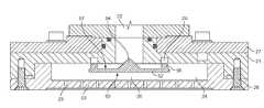
도 1은 워시코트로 기재(10)를 코팅하는 데 사용될 수 있는 코팅 장치(1)의 단면도를 도시한다.1 shows a cross-sectional view of a
코팅 장치(1)는 분배 기구를 작동하기 위한 장치를 포함하는 하우징(40)을 갖는 침착기(2)를 포함할 수 있다. 도시된 바와 같이, 분배 기구는 유체를 출구(43)로부터 침착기(2)의 하류에 위치된 도관(35)을 향해 변위시키기 위해 보어(42) 내에서 축방향으로 이동가능한 피스톤(41)을 포함할 수 있다.The
코팅 장치(1)는 다이어프램 밸브(32)를 통해 침착기(2)의 출구(43)와 연결되는 출구(31)를 갖는 호퍼 저장조(30)를 한정하는 호퍼(3)를 추가로 포함할 수 있다. 호퍼(3)는 다른 위치에서 제형화되고 사전 혼합된 워시코트로 채워질 수 있다. 워시코트는 호퍼 저장조(30) 내로 펌핑될 수 있거나, 적합한 도관을 통해 중력 하에서 호퍼 저장조(30) 내로 공급될 수 있다.The
침착기(2)의 출구(43)는 도관(35)과 유체 연결되고, 도관(35)은 이어서 투여 밸브(4)와 유체 연통하도록 연장될 수 있다. 워시코트 샤워헤드(5)가 투여 밸브(4)의 하부 면에 연결될 수 있으며, 이때 워시코트 샤워헤드(5)는 기재(10) 위에 위치된다.The
기재(10)는 헤드셋(headset)(6)과 팔레트 인서트(pallet insert)(8) 사이에 위치 및 배치될 수 있다. 진공 콘(cone)(7)을 포함하는 진공 장치가 기재(10) 아래에 위치될 수 있다.The
도 2는 도 1의 코팅 장치(1)의 확대된 부분을 도시하고, 기재(10)가 워시코트 샤워헤드(5) 및 헤드셋(6)에 대해 어떻게 위치될 수 있는 지를 보다 상세히 도시한다.FIG. 2 shows an enlarged portion of the
기재(10)는 그의 종방향 길이를 따라 균일한 단면 형상을 가질 수 있는 기재 본체(11)를 갖는 모놀리식 블록일 수 있다. 기재 본체(11)는 단면이 원형인 또는 거의 원형인 형상을 가질 수 있다. 기재 본체(11)는 직경(d)을 가질 수 있다.The
기재 본체(11)는, 기재 본체(11)의 상부 면(12)이 가장 위가 되고 기재 본체(11)의 하부 면(13)이 가장 아래가 되도록 헤드셋(6)과 팔레트 인서트(8) 사이에서 연장되도록 위치될 수 있다. 워시코트 샤워헤드(5)는 헤드셋(6) 위에 위치될 수 있고, 도 2에 도시된 바와 같이 워시코트 샤워헤드(5)의 중심 길이방향 축(x)이 헤드셋(6) 및 기재(10) 둘 모두의 중심 길이방향 축과 일치하도록 정렬될 수 있도록 헤드셋(6) 및 기재(10)와 바람직하게는 정렬될 수 있다.The
워시코트 샤워헤드(5)는 하부 면 상에 볼트(28)에 의해 샤워헤드 플레이트(23)가 결합될 수 있는 샤워헤드 하우징(21)을 포함할 수 있다. 어댑터 플레이트(27)가 또한 볼트에 의해 샤워헤드 하우징(21)의 상부 면에 결합될 수 있다.The
샤워헤드 하우징(21)은 샤워헤드 하우징(21)과 샤워헤드 플레이트(23) 사이에 한정된 샤워헤드 공동(24)에 대한 입구(22)를 한정하는 중심에 위치된 개구를 포함할 수 있다. 입구(22)의 축은 길이방향 축(x)과 일치할 수 있다. 어댑터 플레이트(27)는, 길이방향 축(x)과 일치할 수 있고 샤워헤드 하우징(21)의 중심 부분(20)을 수용하도록 크기가 설정되는 중심에 위치된 개구를 또한 포함할 수 있다. 투여 밸브(4)는 샤워헤드 하우징(21)의 입구(22)와 유체 연통되고 유지될 수 있다.The
샤워헤드 플레이트(23)에는 노즐 개구(25)의 어레이가 제공될 수 있다.The
사용 시에, 다이어프램 밸브(32)는 개방되고, 워시코트는 (도 1에서 보이는 바와 같이) 피스톤을 우측으로 이동시킴으로써 호퍼 저장조(30)로부터 보어(42) 내로 흡인된다. 다이어프램 밸브(32)는 이어서 폐쇄되고, 이어서 워시코트의 용량은 (도 1에서 보이는 바와 같이) 좌측으로 이동하는 침착기(2)의 피스톤(41)의 작용에 의해 도관(35)을 통해 변위된다. 워시코트는 투여 밸브(4) 및 입구(22)를 통해 샤워헤드 공동(24) 내로 통과하게 된다. 이어서, 워시코트는 노즐 개구(25)를 통과하고 낙하하여 기재(10)의 상부 면(12)과 접촉하게 된다. 이어서, 워시코트는 기재(10)의 통로를 통해 하향으로 흡인된다. 기재(10)를 통한 워시코트의 흡인은 적어도 부분적으로 진공 콘(7)에 의해 기재(10)의 하부 면(13)에 가해지는 흡입력에 의해 행해진다.In use, the
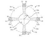
도 3 내지 도 5는 본 발명에 따른 배플(50)의 제1 버전을 도시한다. 도 3은 배플(50)이 샤워헤드 공동(24) 내에 제공되는 본 발명에 따른 워시코트 샤워헤드(5)를 도시한다.3 to 5 show a first version of the
샤워헤드 공동(24)은 깊이가 12 내지 40 mm, 바람직하게는 15 내지 30 mm일 수 있다. 샤워헤드 공동(24)은 직경이 150 내지 200 mm, 바람직하게는 160 내지 170 mm일 수 있다. 샤워헤드 플레이트(23)는 샤워헤드 공동(24)의 전체 직경을 가로질러 연장될 수 있다. 노즐 개구(25)는 샤워헤드 플레이트(23)에 걸쳐 배열될 수 있다. 노즐 개구(25)는 규칙적이거나 불규칙적인 어레이로 배열될 수 있다. 노즐 개구(25)는 복수의 동심 원형 어레이로 배열될 수 있다.The
배플(50)은 불투과성 중심 본체(51)와 복수의 아암(52)을 포함하며, 이들 아암은 불투과성 중심 본체(51)로부터 연장되어 불투과성 중심 본체(51) 둘레에 원주방향으로 배열된 복수의 유동 개구(53)를 형성한다.The
배플(50)은 볼트 구멍(55)를 통해 각각의 아암(52)의 말단부를 향해 연장될 수 있는 볼트(29)에 의해 샤워헤드 하우징(21)에 장착될 수 있다. 배플(50)의 장착 지점들은 샤워헤드 하우징(21)의 입구(22)를 둘러쌀 수 있지만 바람직하게는 부딪히지는 않는다. 볼트(29)는 4 mm 볼트일 수 있다. 각각의 볼트 구멍(55)은, 배플(50)의 상부 면(57)과 샤워헤드 하우징(21)의 상부 내측 면 사이의 간격을 한정하는 역할을 함과 동시에 배플(50)의 하부 면(58)과 샤워헤드 플레이트(23)의 상부 내측 면 사이의 간격(26)을 한정할 수 있는 스탠드오프 링(standoff ring)(56)에 의해 둘러싸일 수 있다. 각각의 스탠드오프 링(56)은 높이가 4 내지 6 mm, 바람직하게는 4.5 mm일 수 있다. 간격(26)은 5 내지 10 mm, 바람직하게는 대략 8 mm일 수 있다.The
(다른 버전은 이하 설명되며 도 3 내지 도 5에 도시된 버전의) 배플(50)에는 도 3에 도시된 바와 같이 평평할 수 있는 상부 면(57)이 제공될 수 있거나, 도 4에 도시된 바와 같이 상부 면(57) 상에서 중심에 위치된 원추형 또는 부분 원추형 돌출부(54)가 제공될 수 있다.The baffle 50 (another version described below and of the version shown in FIGS. 3-5 ) may be provided with a
도 5에서 가장 명확하게 볼 수 있는 바와 같이, (원추형 또는 부분 원추형 돌출부(54)가 제공되든 그렇지 않든 간에) 배플(50)은 4개의 아암(52a 내지 52d)이 제공되는 십자형 형상을 가질 수 있다. 바람직하게는, 4개의 아암(52a 내지 52d)은 불투과성 중심 본체(51)의 주연부 둘레에 등간격으로 이격되며, 이들 아암은 각각 이웃하는 아암들로부터 90° 이격되게 된다. 유사하게, 배플(50)은 불투과성 중심 본체(51)의 주연부 둘레에 등간격으로 이격된 4개의 유동 개구(53a 내지 53d)를 포함할 수 있으며, 이들 유동 개구는 각각 이웃하는 유동 개구로부터 90° 이격되게 된다.As can be seen most clearly in FIG. 5 , the baffle 50 (whether or not conical or partially
아암(52a 내지 52d)의 길이는 불투과성 중심 본체(51)의 직경에 비해 상대적으로 짧을 수 있다. 아암(52a 내지 52d)은 폭과 깊이가 균일할 수 있다. 도 5의 도시된 예에서, 볼트 구멍(55)은 70 mm의 피치 원 직경 상에 배열될 수 있고, 불투과성 중심 본체(51)는 반경(r1)이 25 mm이고 직경이 50 mm일 수 있다.The length of the
배플(50)은 스테인레스강, 예를 들어 타입 316으로 형성될 수 있다.The
배플(50)의 제1 버전은, 원형 단면 형상을 갖고 대략 175 mm 미만, 더 구체적으로 172.8 mm 미만의 직경을 갖는 기재(10)를 코팅할 때 특히 유리한 용도를 가질 수 있다. 배플(50)의 제1 버전은 또한 비-원형 단면 형상을 갖는 기재(10)를 코팅할 때 특히 유리한 용도를 가질 수 있다. 또한, 배플(50)의 제1 버전은 선택적 촉매 환원 필터(SCRF), 소형 디젤 촉매 그을음 필터(LDD CSF), 또는 가솔린 미립자 필터(GPF)를 위한 기재(10)를 코팅할 때 특히 유리한 용도를 가질 수 있다.The first version of the
도 6 내지 도 8는 본 발명에 따른 배플(50)의 제2 버전을 도시한다. 도 7 및 도 8에서 가장 명확하게 볼 수 있는 바와 같이, (원추형 또는 부분 원추형 돌출부(54)가 제공되든 그렇지 않든 간에) 배플(50)은 4개의 아암(52a 내지 52d)이 제공되는 십자형 형상을 가질 수 있다. 제1 버전에서와 같이, 4개의 아암(52a 내지 52d)은 불투과성 중심 본체(51)의 주연부 둘레에 등간격으로 이격될 수 있으며, 이들 아암은 각각 이웃하는 아암들로부터 90° 이격되게 된다. 유사하게, 배플(50)은 불투과성 중심 본체(51)의 주연부 둘레에 등간격으로 이격된 4개의 유동 개구(53a 내지 53d)를 포함할 수 있으며, 이들 유동 개구는 각각 이웃하는 유동 개구로부터 90° 이격되게 된다.6-8 show a second version of the
아암(52a 내지 52d)의 길이는 제1 버전에서보다 더 길다. 도 7의 도시된 예에서, 볼트 구멍(55)은 70 mm의 피치 원 직경 상에 배열될 수 있고, 불투과성 중심 본체(51)는 반경(r2)이 17.5 mm이고 직경이 35 mm일 수 있다. 결과적으로, 불투과성 중심 본체(51)의 면적이 감소되고, 유동 개구(53a 내지 53d)의 개방 면적이 배플(50)의 제1 버전에 비해 증가한다.The length of the
아암(52a 내지 52d)은 깊이가 균일할 수 있다. 아암(52a 내지 52d)의 폭은 점점 작아질 수 있다. 복수의 아암(52a 내지 52d) 중 각각의 폭은 불투과성 중심 본체(51)에 근접한 위치로부터 불투과성 중심 본체(51)에서 먼 위치까지 증가할 수 있다.
배플(50)은 스테인레스강, 예를 들어 타입 316으로 형성될 수 있다.The
배플(50)의 제2 버전은 대략 250 mm 초과, 더 구체적으로 266.7 mm 초과의 직경을 갖는 기재(10)를 코팅할 때 특히 유리한 용도를 가질 수 있다. 또한, 배플(50)의 제2 버전은 대형 디젤 필터(HDD)를 위한 기재(10)를 코팅할 때 특히 유리한 용도를 가질 수 있다.The second version of the
도 9 내지 도 11은 본 발명에 따른 배플(50)의 제3 버전을 도시한다. 도 10 및 도 11에서 가장 명확하게 볼 수 있는 바와 같이, (원추형 또는 부분 원추형 돌출부(54)가 제공되든 그렇지 않든 간에) 배플(50)은 4개의 아암(52a 내지 52d)이 제공되는 십자형 형상을 가질 수 있다. 제1 및 제2 버전에서와 같이, 4개의 아암(52a 내지 52d)은 불투과성 중심 본체(51)의 주연부 둘레에 등간격으로 이격될 수 있으며, 이들 아암은 각각 이웃하는 아암들로부터 90° 이격되게 된다. 유사하게, 배플(50)은 불투과성 중심 본체(51)의 주연부 둘레에 등간격으로 이격된 4개의 유동 개구(53a 내지 53d)를 포함할 수 있으며, 이들 유동 개구는 각각 이웃하는 유동 개구로부터 90° 이격되게 된다.9 to 11 show a third version of the
아암(52a 내지 52d)의 길이는 제2 버전에서보다 더 길다. 도 10의 도시된 예에서, 볼트 구멍(55)은 70 mm의 피치 원 직경 상에 배열될 수 있고, 불투과성 중심 본체(51)는 반경(r3)이 13.5 mm이고 직경이 27 mm일 수 있다. 결과적으로, 불투과성 중심 본체(51)의 면적이 감소되고, 유동 개구(53a 내지 53d)의 개방 면적이 배플(50)의 제2 버전에 비해 증가한다.The length of the
아암(52a 내지 52d)은 깊이가 균일할 수 있다. 제2 버전에서와 같이, 아암(52a 내지 52d)의 폭은 작아질 수 있다. 복수의 아암(52a 내지 52d) 중 각각의 폭은 불투과성 중심 본체(51)에 근접한 위치로부터 불투과성 중심 본체(51)에서 먼 위치까지 증가할 수 있다.
배플(50)은 스테인레스강, 예를 들어 타입 316으로 형성될 수 있다.The
배플(50)의 제3 버전은 170 mm 내지 275 mm, 더 구체적으로는 172.8 mm 내지 266.7 mm의 직경을 갖는 기재(10)를 코팅할 때 특히 유리한 용도를 가질 수 있다. 또한, 배플(50)의 제3 버전은 촉매 그을음 필터(CSF)를 위한 기재(10)를 코팅할 때 특히 유리한 용도를 가질 수 있다.The third version of the
사용 시, 워시코트는 침착기(2)의 피스톤(41)을 사용하여 워시코트 공급부로부터 워시코트 샤워헤드(5)에 공급될 수 있다. 피스톤(41)은 보어(42) 내에서 이동가능하고, 보어(42)는 38 mm 내지 170 mm의 내경을 가질 수 있고, 피스톤(41)은 45 내지 150 mm/s로 이동될 수 있다. 워시코트는 도관(35)을 따라 투여 밸브(4)를 통과하여 워시코트 샤워헤드(5) 내로 변위된다. 워시코트는 7 내지 640 ㎤s-1의 유량으로 워시코트 샤워헤드(5)에 공급될 수 있다.In use, the washcoat may be supplied to the
워시코트는 입구(22)를 통해 샤워헤드 공동(24)에 들어갈 수 있다. 워시코트는 샤워헤드 플레이트(23)에 도달하기 전에 (존재하는 경우, 원추형 또는 부분 원추형 돌출부를 포함하는) 배플의 불투과성 중심 본체(51)와 접촉하게 된다. 그러므로, 워시코트는 샤워헤드 공동(24)의 주연부를 향해 측방향으로 편향되어, 워시코트가 샤워헤드 플레이트(23)의 중심에 또는 그 부근에 위치된 노즐 개구(25)에 즉시 도달하지 않게 된다. 워시코트는 배플의 복수의 유동 개구(53a 내지 53d)를 통해 유동하고, 이어서 샤워헤드 공동(24) 내에서 순환하여 노즐 개구(25)를 통과한다. 아암(52a 내지 52d)과 유동 개구(53a 내지 53d)의 크기 및 형상의 구성으로 인해, 노즐 개구(25)를 통한 워시코트의 균일한 또는 거의 균일한 토출이 달성되도록 충분한 워시코트가 샤워헤드 플레이트(23)의 중심으로 다시 재순환되는 것이 가능하게 될 수 있다.The washcoat may enter the
이어서, 워시코트는 기재(10)의 상부 면(12) 상에 침착되고, 진공 콘(7)에 의해 가해지는 흡입력에 의해 기재 본체(11)의 통로를 통해 흡인된다.The washcoat is then deposited on the
워시코트는 액체 및 전형적으로 촉매 성분을 포함한다. 액체는 용액 또는 현탁액일 수 있다. 현탁액은 콜로이드 현탁액, 예컨대 졸, 또는 비-콜로이드 현탁액일 수 있다. 액체가 용액 또는 현탁액일 때, 액체는 수용액 또는 수성 현탁액일 수 있다. 전형적으로, 액체는 현탁액, 특히 수성 현탁액이다.The washcoat comprises a liquid and typically a catalyst component. The liquid may be a solution or suspension. The suspension may be a colloidal suspension, such as a sol, or a non-colloidal suspension. When the liquid is a solution or suspension, the liquid may be an aqueous solution or an aqueous suspension. Typically, the liquid is a suspension, particularly an aqueous suspension.
전형적으로, 액체는 촉매 성분을 포함한다. "촉매 성분" 이라는 표현은, 생성된 배기 제어 장치, 예를 들어, 백금족 금속(PGM), 지지체 재료(예를 들어, 내화 산화물) 또는 제올라이트의 활성에 기여하는 워시코트 제형에 포함될 수 있는 임의의 성분을 포함한다. 용어 "촉매 성분"은 성분 자체가 용어 "촉매"의 엄격한 의미에서 (예를 들어, 반응 속도를 증가시키는) 촉매 활성을 가질 것을 필요로 하지 않는다는 것이 이해되어야 한다. 예를 들어, 촉매 성분은 NOx 또는 탄화수소를 저장 또는 흡수할 수 있는 재료를 지칭할 수 있다. 촉매 성분을 포함하는 액체(예를 들어, 워시코트)는 당업자에게 공지되어 있다. 액체에 포함된 촉매 성분(들)은 제조하고자 하는 제품에 좌우될 것이다.Typically, the liquid contains a catalyst component. The expression "catalyst component" refers to any washcoat formulation that contributes to the activity of the resulting emission control device, for example, platinum group metal (PGM), support material (eg, refractory oxide) or zeolite. contains ingredients. It should be understood that the term “catalyst component” does not require that the component itself have catalytic activity (eg, to increase the rate of a reaction) in the strict sense of the term “catalyst”. For example, a catalyst component may refer to a material capable of storing or absorbing NOx or hydrocarbons. Liquids (eg washcoats) comprising catalyst components are known to those skilled in the art. The catalyst component(s) included in the liquid will depend on the product to be manufactured.
본 발명의 방법에 의해 또는 본 발명의 장치를 사용하여 얻어진 코팅된 필터 기재 또는 제품은, 예를 들어, 산화 촉매(예를 들어, 촉매화된 그을음 필터[CSF]), 선택적 촉매 환원(SCR) 촉매(예를 들어, 그 제품은 이어서 선택적 촉매 환원 필터[SCRF] 촉매로 불릴 수 있음), NOx 흡착제 조성물(예를 들어, 그 제품은 이어서 희박 NOx 포집 필터[LNTF]로 불릴 수 있음), 3원 촉매 조성물(예를 들어, 그 제품은 이어서 가솔린 미립자 필터[GPF]로 불릴 수 있음), 암모니아 슬립 촉매[ASC] 또는 이들의 둘 이상의 조합(예를 들어, 선택적 촉매 환원(SCR) 촉매 및 암모니아 슬립 촉매[ASC]를 포함하는 필터 기재)를 포함하는 필터 기재일 수 있다.The coated filter substrate or article obtained by the method of the invention or using the apparatus of the invention can be, for example, an oxidation catalyst (eg catalysed soot filter [CSF]), selective catalytic reduction (SCR) catalyst (eg, the product may then be referred to as a selective catalytic reduction filter [SCRF] catalyst), NOx adsorbent composition (eg, the product may then be referred to as a lean NOx trapping filter [LNTF]), 3 a raw catalyst composition (eg, the product of which may then be referred to as a gasoline particulate filter [GPF]), an ammonia slip catalyst [ASC], or a combination of two or more thereof (eg, a selective catalytic reduction (SCR) catalyst and ammonia a filter substrate comprising a slip catalyst [ASC]).
"촉매 성분" 외에도, 액체는 제형 보조제를 추가로 포함할 수 있다. 용어 "제형 보조제"는, 액체 내에 포함되어 필터 기재 상으로의 코팅을 위해 그의 화학적 또는 물리적 특성을 변경시키는 성분을 지칭한다. 예를 들어, 제형 보조제는 액체 중에서의 촉매 성분의 분산을 돕거나 액체의 점도를 변화시킬 수 있다. 제형 보조제는 최종 코팅된 필터 기재 제품에 존재하지 않을 수 있다(예를 들어, 이는 하소 동안 분해되거나 열화될 수 있다). 예를 들어, 제형 보조제는 산, 염기, 증점제(예를 들어, 유기 화합물 증점제) 또는 결합제일 수 있다.In addition to the “catalyst component”, the liquid may further comprise formulation aids. The term “formulation aid” refers to an ingredient that is included in a liquid to alter its chemical or physical properties for coating onto a filter substrate. For example, formulation aids can aid in the dispersion of catalyst components in a liquid or change the viscosity of a liquid. Formulation aids may not be present in the final coated filter base product (eg, they may degrade or degrade during calcination). For example, formulation adjuvants can be acids, bases, thickeners (eg, organic compound thickeners) or binders.
워시코트는 50 rpm의 브룩필드에서 1 내지 3000 cP, 바람직하게는 50 rpm의 브룩필드에서 100 내지 3000 cP, 더욱 바람직하게는 50 rpm의 브룩필드에서 600 cP 미만의 점도를 가질 수 있으며; 일 실시 형태에서, 워시코트는 50 rpm의 브룩필드에서 100 내지 3000 cP의 점도를 가질 수 있으며; 다른 실시 형태에서, 워시코트는 50 rpm의 브룩필드에서 1 내지 350 cP, 더 바람직하게는 50 rpm의 브룩필드에서 1 내지 100 cP의 점도를 가질 수 있다. (모든 측정치는 SC4-18 스핀들을 사용하여 브룩필드 DV-II+ Pro (LV) 점도계에서 얻었다.)The washcoat may have a viscosity of 1 to 3000 cP at Brookfield at 50 rpm, preferably 100 to 3000 cP at Brookfield at 50 rpm, more preferably less than 600 cP at Brookfield at 50 rpm; In one embodiment, the washcoat may have a viscosity of 100 to 3000 cP at Brookfield at 50 rpm; In another embodiment, the washcoat may have a viscosity of from 1 to 350 cP at Brookfield at 50 rpm, more preferably from 1 to 100 cP at Brookfield at 50 rpm. (All measurements were taken on a Brookfield DV-II+ Pro (LV) viscometer using an SC4-18 spindle.)
기재 부피의 이용을 최대화하고 기재(10)의 일부분에 다수의 코트를 도포하는 것을 방지하고 워시코트의 풀-스루를 방지하기 위하여, 일관적이고 예측가능한 코팅 프로파일을 달성하는 것이 바람직하다. 예를 들어, 도 12a에 개략적으로 도시된 바와 같이 평평한 코팅 프로파일이 바람직하다. 도시된 바와 같이, 기재(10)는 워시코트에 의해 코팅된 코팅 부분(45) 및 워시코트가 도달되지 않은 비-코팅 부분(46)을 갖는다. 코팅 부분(45)과 비-코팅 부분(46) 사이의 계면은 평탄하며, 이는 바람직한 결과이다.It is desirable to achieve a consistent and predictable coating profile in order to maximize utilization of the substrate volume and to avoid applying multiple coats to a portion of the
도 12b는 코팅 부분(45)과 비-코팅 부분(46) 사이의 바람직하지 않은 "V-형상" 계면을 나타낸다. 이는 기재(10)의 상부 면(12)의 중심 부분에 너무 많은 워시코트가 도포되는 경우의 결과로 여겨지며, 워시코트가 낮은 점도를 갖는 경우의 특정 문제일 수 있다.12B shows an undesirable “V-shaped” interface between the
도 12c는 도 12b의 코팅 프로파일과 유사한 코팅 프로파일을 도시하지만, 기재의 주변 부분이 충분히 코팅되기 전에 워시코트가 기재의 하부 면(13)의 중심 부분으로부터 당겨지는 경우 풀-스루가 어떻게 일어날 수 있는지를 도시한다.12C shows a coating profile similar to that of FIG. 12B , but how pull-through can occur if the washcoat is pulled from the central portion of the
마지막으로, 도 12d는 코팅 부분(45)과 비-코팅 부분(46) 사이의 "M-형상" 계면을 갖는 다른 바람직하지 않은 코팅 프로파일을 도시한다. 이는 워시코트가 노즐 개구(25)를 통과하기 전에 샤워헤드 플레이트(23)의 중심으로 충분히 다시 재순환될 수 없는 경우의 결과로 여겨진다.Finally, FIG. 12D shows another undesirable coating profile having an “M-shaped” interface between the
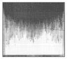
비교예 1Comparative Example 1
고형물 함량이 10%이고 브룩필드 DV-II+ Pro (LV) 및 SC4-18 스핀들을 사용할 때 스핀들 회전 속도 25 내지 100 rpm에 걸쳐 뉴턴 점도가 5 cP인 기재용 촉매 워시코트를 제조하였다.Catalyst washcoats for substrates were prepared with a solids content of 10% and a Newtonian viscosity of 5 cP over a spindle rotation speed of 25 to 100 rpm when using a Brookfield DV-II+ Pro (LV) and SC4-18 spindle.
도 1의 코팅 장치(1)를 사용하여 탄화규소 필터 기재 상에 워시코트를 코팅하였을 때, 배플이 존재하지 않는 워시코트 샤워헤드(5)를 이용하면, 도 13에 도시된 바와 같이 더 많은 워시코트가 워시코트 샤워헤드(5)의 중심 구멍으로부터 배출된다.When the washcoat is coated on the silicon carbide filter substrate using the
이는 도 14에 도시된 v-형상의 불균일한 코팅 프로파일을 야기하는 것으로 밝혀졌다. 이 도면은, 워시코트의 코팅이 워시코트의 코팅의 더 높은 질량 밀도로 인해 밝은 노출된 기재에 대해 더 어두운 것으로 나타나는 기재의 x-선 이미지이다.This was found to result in a non-uniform coating profile of the v-shape shown in FIG. 14 . This figure is an x-ray image of a substrate where the coating of the washcoat appears darker relative to the bright exposed substrate due to the higher mass density of the coating of the washcoat.
실시예 1Example 1
도 14에 도시된 효과를 개선하기 위해, 도 3 내지 도 5에 도시된 바와 같은 배플(50)의 제1 버전을 도 3에 도시된 바와 같이 샤워헤드 하우징(21)에 추가하였다.To improve the effect shown in FIG. 14 , a first version of the
이어서, 이러한 배플 플레이트(50) 및 상기의 비교예와 동일한 촉매 워시코트를 사용하여 143.8 mm 직경의 탄화규소 필터 기재(10)를 코팅하였다. 워시코트의 코팅이 워시코트의 코팅의 더 높은 질량 밀도로 인해 밝은 노출된 기재에 대해 더 어두운 것으로 나타나는 도 15의 x-선 이미지에 의해 도시된 바와 같이, 더욱 균일한 코팅 프로파일을 얻었다.Subsequently, the silicon
실시예 2Example 2
도 14에 도시된 효과를 개선하기 위해, 도 6 내지 도 8에 도시된 바와 같은 배플(50)의 제2 버전을 샤워헤드 하우징(21)에 추가하였다.To improve the effect shown in FIG. 14 , a second version of the
이어서, 이러한 배플 플레이트(50) 및 상기의 비교예와 동일한 촉매 워시코트를 사용하여 330.3 mm 직경의 탄화규소 필터 기재(10)를 코팅하였다. 워시코트의 코팅이 워시코트의 코팅의 더 높은 질량 밀도로 인해 밝은 노출된 기재에 대해 더 어두운 것으로 나타나는 도 16의 x-선 이미지에 의해 도시된 바와 같이, 더욱 균일한 코팅 프로파일을 얻었다.Subsequently, the silicon
실시예 3Example 3
도 14에 도시된 효과를 개선하기 위해, 도 9 내지 도 11에 도시된 바와 같은 배플(50)의 제3 버전을 샤워헤드 하우징(21)에 추가하였다.To improve the effect shown in FIG. 14 , a third version of the
이어서, 이러한 배플 플레이트(50) 및 상기의 비교예와 동일한 촉매 워시코트를 사용하여 172.8 mm 직경의 탄화규소 필터 기재(10)를 코팅하였다. 워시코트의 코팅이 워시코트의 코팅의 더 높은 질량 밀도로 인해 밝은 노출된 기재에 대해 더 어두운 것으로 나타나는 도 17의 x-선 이미지에 의해 도시된 바와 같이, 더욱 균일한 코팅 프로파일을 얻었다.Subsequently, the silicon
위에 언급된 바와 같이, 본 출원인은 본 명세서에 기술된 바와 같이 배플(50)을 포함하는 워시코트 샤워헤드(5)를 사용하여 광범위한 크기의 기재에 걸쳐 평평하거나 거의 평평한 바람직한 코팅 프로파일이 달성될 수 있음을 알아내었다.As noted above, Applicants have demonstrated that the desired coating profile, flat or nearly flat, can be achieved over a wide range of sized substrates using a
의심을 피하기 위해, 본 명세서에 확인된 모든 문서의 전체 내용이 본 명세서에 참고로 포함된다.For the avoidance of doubt, the entire contents of all documents identified herein are incorporated herein by reference.
Claims (24)
Translated fromKorean상기 워시코트를 수용하기 위한, 입구를 갖는 하우징;
샤워헤드 플레이트; 및
배플을 포함하며,
상기 하우징 및 샤워헤드 플레이트는 샤워헤드 공동(cavity)을 형성하고, 상기 배플은 상기 샤워헤드 공동 내에 위치되고;
상기 샤워헤드 플레이트는 상기 기재의 상기 면을 향해 상기 워시코트를 토출하기 위한 복수의 노즐 개구(aperture)를 포함하고;
상기 배플은 불투과성 중심 본체 및 상기 불투과성 중심 본체로부터 연장되는 복수의 아암을 포함하고, 상기 복수의 아암은 상기 불투과성 중심 본체 둘레에 원주방향으로 배열된 복수의 유동 개구를 한정하고;
상기 배플은 상기 불투과성 중심 본체가 상기 샤워헤드 플레이트로부터 이격되도록 상기 샤워헤드 공동 내에 장착되고;
상기 불투과성 중심 본체는 상기 입구를 통해 상기 샤워헤드 공동으로 들어오는 워시코트가 상기 샤워헤드 플레이트의 상기 노즐 개구를 통해 토출되기 전에 상기 불투과성 중심 본체 둘레로 그리고 상기 복수의 유동 개구를 통해 유동하게 방향전환되도록 상기 하우징의 상기 입구 아래에 정렬되는, 워시코트 샤워헤드.A washcoat showerhead for depositing a washcoat on the face of a substrate positioned thereunder, comprising:
a housing having an inlet for receiving the washcoat;
showerhead plate; and
includes a baffle,
the housing and showerhead plate define a showerhead cavity, the baffle positioned within the showerhead cavity;
the showerhead plate includes a plurality of nozzle apertures for ejecting the washcoat toward the side of the substrate;
the baffle includes an impermeable central body and a plurality of arms extending from the impermeable central body, the plurality of arms defining a plurality of flow openings circumferentially arranged about the impermeable central body;
the baffle is mounted within the showerhead cavity such that the impermeable central body is spaced from the showerhead plate;
The impermeable central body is oriented such that a washcoat entering the showerhead cavity through the inlet flows around the impermeable central body and through the plurality of flow openings before being discharged through the nozzle openings in the showerhead plate. a washcoat showerhead aligned below the inlet of the housing to be diverted.
- 상기 복수의 아암은 상기 불투과성 중심 본체로부터 반경방향으로 연장되고/되거나;
- 상기 복수의 아암의 각각의 폭은 상기 불투과성 중심 본체에 근접한 위치로부터 상기 불투과성 중심 본체에서 먼 위치까지 증가하고/하거나;
- 상기 불투과성 중심 본체는 평면도에서 형상이 원형이고/이거나;
- 상기 불투과성 중심 본체는 직경이 20 내지 55 mm이고, 바람직하게는 25 내지 50 mm이고, 더욱 바람직하게는 27, 35 또는 50 mm가 되도록 선택되고/되거나;
- 상기 불투과성 중심 본체의 상부 면은 돌출부를 포함하고, 바람직하게는 상기 돌출부는 원추형 또는 부분 원추형 표면이고/이거나;
- 상기 복수의 아암에는 연결 고정구들을 위한 장착 지점들이 제공되고/되거나;
- 상기 장착 지점들은 상기 복수의 아암의 각각의 말단부에 위치되고/되거나;
- 상기 장착 지점들은 상기 불투과성 중심 본체의 중심 축 상에 중심이 맞춰진 65 내지 75 mm, 바람직하게는 70 mm의 피치 원 직경 상에 위치되는, 배플.17. The method of claim 16,
- said plurality of arms extend radially from said impermeable central body;
- the width of each of said plurality of arms increases from a position proximate to said impermeable central body to a position distal to said impermeable central body;
- said impermeable central body is circular in shape in plan view;
- said impermeable central body is selected to have a diameter of 20 to 55 mm, preferably 25 to 50 mm, more preferably 27, 35 or 50 mm;
- the upper face of the impermeable central body comprises a protrusion, preferably the protrusion is a conical or partially conical surface;
- said plurality of arms are provided with mounting points for connection fasteners;
- said mounting points are located at each distal end of said plurality of arms;
- the baffle, wherein the mounting points are located on a pitch circle diameter of 65 to 75 mm, preferably 70 mm centered on the central axis of the impermeable central body.
상기 워시코트 샤워헤드는
입구를 갖는 하우징,
샤워헤드 플레이트, 및
배플을 포함하는 유형의 것이고;
상기 하우징 및 샤워헤드 플레이트는 샤워헤드 공동을 한정하고, 상기 배플은 상기 샤워헤드 공동 내에 위치되고;
상기 샤워헤드 플레이트는 복수의 노즐 개구를 포함하고;
상기 배플은 불투과성 중심 본체 및 상기 불투과성 중심 본체로부터 연장되는 복수의 아암을 포함하고, 상기 복수의 아암은 상기 불투과성 중심 본체 둘레에 원주방향으로 배열된 복수의 유동 개구를 한정하고;
상기 배플은 상기 불투과성 중심 본체가 상기 샤워헤드 플레이트로부터 이격되도록 상기 샤워헤드 공동 내에 장착되고;
상기 불투과성 중심 본체는 상기 하우징의 상기 입구 아래에 정렬되며;
상기 방법은
- 상기 기재를 상기 워시코트 샤워헤드 아래에 위치시키는 단계;
- 상기 샤워헤드 공동을 통해 상기 입구로부터 상기 샤워헤드 플레이트의 상기 노즐 개구들로 상기 워시코트를 통과시키는 단계; 및
- 상기 워시코트를 상기 노즐 개구로부터 상기 필터 기재의 면을 향해 토출하는 단계
를 포함하며;
상기 샤워헤드 공동을 통한 상기 워시코트의 통과 동안, 상기 워시코트는 상기 샤워헤드 플레이트의 상기 노즐 개구를 통해 토출되기 전에 상기 배플의 상기 불투과성 중심 본체 주위로 그리고 상기 복수의 유동 개구를 통해 유동하도록 방향전환되는, 방법.A method of coating a substrate with a washcoat using a washcoat showerhead, comprising:
The wash coat shower head
housing having an inlet,
showerhead plate, and
of the type comprising a baffle;
the housing and showerhead plate define a showerhead cavity, the baffle positioned within the showerhead cavity;
the showerhead plate includes a plurality of nozzle openings;
the baffle includes an impermeable central body and a plurality of arms extending from the impermeable central body, the plurality of arms defining a plurality of flow openings circumferentially arranged about the impermeable central body;
the baffle is mounted within the showerhead cavity such that the impermeable central body is spaced from the showerhead plate;
the impermeable central body is aligned below the inlet of the housing;
the method
- positioning said substrate under said washcoat showerhead;
- passing the washcoat from the inlet through the showerhead cavity to the nozzle openings of the showerhead plate; and
- discharging the washcoat from the nozzle opening toward the face of the filter substrate
includes;
During passage of the washcoat through the showerhead cavity, the washcoat flows around the impermeable central body of the baffle and through the plurality of flow openings before being ejected through the nozzle openings of the showerhead plate. diverted way.
Applications Claiming Priority (3)
| Application Number | Priority Date | Filing Date | Title |
|---|---|---|---|
| GB1819454.8 | 2018-11-29 | ||
| GBGB1819454.8AGB201819454D0 (en) | 2018-11-29 | 2018-11-29 | Apparatus and method for coating substrates with washcoats |
| PCT/GB2019/053332WO2020109771A1 (en) | 2018-11-29 | 2019-11-26 | Apparatus and method for coating substrates with washcoats |
Publications (2)
| Publication Number | Publication Date |
|---|---|
| KR20210095861Atrue KR20210095861A (en) | 2021-08-03 |
| KR102757708B1 KR102757708B1 (en) | 2025-01-21 |
Family
ID=65024923
Family Applications (1)
| Application Number | Title | Priority Date | Filing Date |
|---|---|---|---|
| KR1020217013199AActiveKR102757708B1 (en) | 2018-11-29 | 2019-11-26 | Substrate coating device and method using washcoat |
Country Status (10)
| Country | Link |
|---|---|
| US (2) | US11911780B2 (en) |
| EP (1) | EP3887062B1 (en) |
| JP (1) | JP7526178B2 (en) |
| KR (1) | KR102757708B1 (en) |
| CN (1) | CN112888510A (en) |
| BR (1) | BR112021007268B8 (en) |
| CA (1) | CA3117094A1 (en) |
| GB (2) | GB201819454D0 (en) |
| WO (1) | WO2020109771A1 (en) |
| ZA (1) | ZA202102281B (en) |
Families Citing this family (7)
| Publication number | Priority date | Publication date | Assignee | Title |
|---|---|---|---|---|
| GB201819454D0 (en)* | 2018-11-29 | 2019-01-16 | Johnson Matthey Plc | Apparatus and method for coating substrates with washcoats |
| GB201911704D0 (en)* | 2019-08-15 | 2019-10-02 | Johnson Matthey Plc | Treatment of particulate filters |
| PL3834933T3 (en)* | 2019-12-10 | 2024-04-29 | Johnson Matthey Public Limited Company | Apparatus and method for coating substrates with washcoats |
| CA3196209A1 (en)* | 2020-12-23 | 2022-06-30 | Johnson Matthey Public Limited Company | Apparatus and method for coating substrates with washcoats |
| DE202021103624U1 (en) | 2021-07-06 | 2022-10-14 | Umicore Ag & Co. Kg | WC applicator |
| CN114760376A (en)* | 2022-03-21 | 2022-07-15 | 合肥金龙浩科技有限公司 | Lid, be used for its hole inkjet hole patching device of making a video recording and tool behind cell-phone |
| DE102022121499A1 (en)* | 2022-08-25 | 2024-03-07 | Umicore Ag & Co. Kg | Applicator for applying coating medium to substrates |
Citations (4)
| Publication number | Priority date | Publication date | Assignee | Title |
|---|---|---|---|---|
| US3948213A (en)* | 1974-10-21 | 1976-04-06 | Universal Oil Products Company | Coating-impregnating chamber for catalyst support members |
| KR20030065531A (en)* | 2001-01-31 | 2003-08-06 | 빌리 보겔 아크티엔 게젤샤프트 | Device and method for producing an aerosol |
| KR20160114177A (en)* | 2014-01-31 | 2016-10-04 | 어플라이드 머티어리얼스, 인코포레이티드 | Chamber coatings |
| KR20170117333A (en)* | 2016-04-13 | 2017-10-23 | 램 리써치 코포레이션 | Baffle plate and showerhead assemblies and corresponding manufacturing method |
Family Cites Families (43)
| Publication number | Priority date | Publication date | Assignee | Title |
|---|---|---|---|---|
| JPS60116126A (en)* | 1983-11-28 | 1985-06-22 | Ricoh Co Ltd | Plasma cvd device |
| GB9805815D0 (en) | 1998-03-19 | 1998-05-13 | Johnson Matthey Plc | Manufacturing process |
| KR100406176B1 (en) | 2000-06-19 | 2003-11-19 | 주식회사 하이닉스반도체 | Showerhead and an Apparatus for Supplying a Liquid Raw Materials Using the Same |
| US6513735B1 (en)* | 2001-08-13 | 2003-02-04 | Frank Clark | Showerhead with textured water distribution surface |
| DE10232984A1 (en)* | 2002-07-19 | 2004-02-05 | Steag Hamatech Ag | Nozzle arrangement for applying a liquid to a substrate |
| RU2241065C2 (en) | 2003-01-27 | 2004-11-27 | Институт солнечно-земной физики СО РАН | Method for applying conductive transparent cover |
| JP4343573B2 (en)* | 2003-04-10 | 2009-10-14 | 芝浦メカトロニクス株式会社 | Coating device and head cleaning method |
| KR100490049B1 (en)* | 2003-04-14 | 2005-05-17 | 삼성전자주식회사 | Chemical vapor deposition apparatus having a single body type diffuser frame |
| US7255747B2 (en)* | 2004-12-22 | 2007-08-14 | Sokudo Co., Ltd. | Coat/develop module with independent stations |
| US20070209583A1 (en)* | 2006-03-10 | 2007-09-13 | Garner Jay R | Apparatus for treating particles |
| US7879183B2 (en)* | 2008-02-27 | 2011-02-01 | Applied Materials, Inc. | Apparatus and method for front side protection during backside cleaning |
| CA2678769C (en)* | 2008-09-15 | 2014-07-29 | Water Pik, Inc. | Shower assembly with radial mode changer |
| EP3354340A1 (en) | 2009-04-03 | 2018-08-01 | Cataler Corporation | Method and apparatus of manufacturing exhaust gas-purifying catalyst and nozzle used therefor |
| GB201000019D0 (en) | 2010-01-04 | 2010-02-17 | Johnson Matthey Plc | Coating a monolith substrate with catalyst component |
| US20110256692A1 (en)* | 2010-04-14 | 2011-10-20 | Applied Materials, Inc. | Multiple precursor concentric delivery showerhead |
| JP6104157B2 (en)* | 2010-05-21 | 2017-03-29 | アプライド マテリアルズ インコーポレイテッドApplied Materials,Incorporated | Ceramic insulator fitted snugly to a large area electrode |
| US8888020B2 (en)* | 2012-03-21 | 2014-11-18 | So Mei Huang | Multi-stage showerhead for preventing mixed-flow and back-pressure |
| US9121097B2 (en)* | 2012-08-31 | 2015-09-01 | Novellus Systems, Inc. | Variable showerhead flow by varying internal baffle conductance |
| US9677176B2 (en)* | 2013-07-03 | 2017-06-13 | Novellus Systems, Inc. | Multi-plenum, dual-temperature showerhead |
| CN203417779U (en)* | 2013-07-31 | 2014-02-05 | 伟特(厦门)淋浴设备有限公司 | Novel shower nozzle |
| JP2015039672A (en) | 2013-08-22 | 2015-03-02 | 株式会社キャタラー | Slurry supplying nozzle and production apparatus and production method of exhaust gas purifying catalyst using the same |
| GB201405277D0 (en) | 2014-03-25 | 2014-05-07 | Johnson Matthey Plc | Method for coating a filter substrate |
| US10741365B2 (en) | 2014-05-05 | 2020-08-11 | Lam Research Corporation | Low volume showerhead with porous baffle |
| DE102015118215A1 (en)* | 2014-11-28 | 2016-06-02 | Aixtron Se | Substrate holding device with isolated support projections for supporting the substrate |
| US20170326561A1 (en)* | 2015-02-14 | 2017-11-16 | Waxman Consumer Products Group Inc. | Showerhead with filter cartridge assembly |
| US10159991B2 (en)* | 2015-02-14 | 2018-12-25 | Waxman Consumer Products Group Inc. | Showerhead with filter cartridge assembly |
| KR102363241B1 (en)* | 2015-03-27 | 2022-02-16 | 삼성전자주식회사 | Plasma-enhanced chemical vapor deposition (PE-CVD) apparatus and method of operating the same |
| US10023959B2 (en)* | 2015-05-26 | 2018-07-17 | Lam Research Corporation | Anti-transient showerhead |
| US9960072B2 (en)* | 2015-09-29 | 2018-05-01 | Asm Ip Holding B.V. | Variable adjustment for precise matching of multiple chamber cavity housings |
| US10373810B2 (en)* | 2016-02-21 | 2019-08-06 | Applied Materials, Inc. | Showerhead having an extended detachable gas distribution plate |
| US10770272B2 (en)* | 2016-04-11 | 2020-09-08 | Applied Materials, Inc. | Plasma-enhanced anneal chamber for wafer outgassing |
| US10358715B2 (en)* | 2016-06-03 | 2019-07-23 | Applied Materials, Inc. | Integrated cluster tool for selective area deposition |
| US10607817B2 (en)* | 2016-11-18 | 2020-03-31 | Applied Materials, Inc. | Thermal repeatability and in-situ showerhead temperature monitoring |
| CN111556791B (en)* | 2017-11-13 | 2022-10-04 | 洁碧有限公司 | Shower head with remote port communication |
| US11944988B2 (en)* | 2018-05-18 | 2024-04-02 | Applied Materials, Inc. | Multi-zone showerhead |
| US11970775B2 (en)* | 2018-08-10 | 2024-04-30 | Applied Materials, Inc. | Showerhead for providing multiple materials to a process chamber |
| GB201819454D0 (en)* | 2018-11-29 | 2019-01-16 | Johnson Matthey Plc | Apparatus and method for coating substrates with washcoats |
| GB201819455D0 (en)* | 2018-11-29 | 2019-01-16 | Johnson Matthey Plc | Apparatus and method for coating substrates with washcoats |
| US11548017B2 (en)* | 2019-07-10 | 2023-01-10 | Kohler Co. | Showerhead |
| US11420217B2 (en)* | 2019-12-19 | 2022-08-23 | Applied Materials, Inc. | Showerhead for ALD precursor delivery |
| JP2023513001A (en)* | 2020-01-29 | 2023-03-30 | ラム リサーチ コーポレーション | Gas distribution faceplate with oblique channels |
| CA3196209A1 (en)* | 2020-12-23 | 2022-06-30 | Johnson Matthey Public Limited Company | Apparatus and method for coating substrates with washcoats |
| KR20230018969A (en)* | 2021-07-30 | 2023-02-07 | 램 리써치 코포레이션 | Showerheads with high solidity plenums |
- 2018
- 2018-11-29GBGBGB1819454.8Apatent/GB201819454D0/ennot_activeCeased
- 2019
- 2019-11-26GBGB1917195.8Apatent/GB2580515B/enactiveActive
- 2019-11-26WOPCT/GB2019/053332patent/WO2020109771A1/ennot_activeCeased
- 2019-11-26CACA3117094Apatent/CA3117094A1/enactivePending
- 2019-11-26BRBR112021007268Apatent/BR112021007268B8/enactiveIP Right Grant
- 2019-11-26KRKR1020217013199Apatent/KR102757708B1/enactiveActive
- 2019-11-26JPJP2021525284Apatent/JP7526178B2/enactiveActive
- 2019-11-26USUS16/695,531patent/US11911780B2/enactiveActive
- 2019-11-26CNCN201980069680.3Apatent/CN112888510A/enactivePending
- 2019-11-26EPEP19816400.6Apatent/EP3887062B1/enactiveActive
- 2021
- 2021-04-06ZAZA2021/02281Apatent/ZA202102281B/enunknown
- 2023
- 2023-10-04USUS18/480,527patent/US12275024B2/enactiveActive
Patent Citations (4)
| Publication number | Priority date | Publication date | Assignee | Title |
|---|---|---|---|---|
| US3948213A (en)* | 1974-10-21 | 1976-04-06 | Universal Oil Products Company | Coating-impregnating chamber for catalyst support members |
| KR20030065531A (en)* | 2001-01-31 | 2003-08-06 | 빌리 보겔 아크티엔 게젤샤프트 | Device and method for producing an aerosol |
| KR20160114177A (en)* | 2014-01-31 | 2016-10-04 | 어플라이드 머티어리얼스, 인코포레이티드 | Chamber coatings |
| KR20170117333A (en)* | 2016-04-13 | 2017-10-23 | 램 리써치 코포레이션 | Baffle plate and showerhead assemblies and corresponding manufacturing method |
Also Published As
| Publication number | Publication date |
|---|---|
| EP3887062A1 (en) | 2021-10-06 |
| US12275024B2 (en) | 2025-04-15 |
| GB2580515B (en) | 2021-04-14 |
| JP7526178B2 (en) | 2024-07-31 |
| US20200171515A1 (en) | 2020-06-04 |
| BR112021007268A2 (en) | 2021-08-10 |
| US20240024898A1 (en) | 2024-01-25 |
| WO2020109771A1 (en) | 2020-06-04 |
| KR102757708B1 (en) | 2025-01-21 |
| ZA202102281B (en) | 2023-01-25 |
| EP3887062B1 (en) | 2024-10-16 |
| US11911780B2 (en) | 2024-02-27 |
| JP2022509052A (en) | 2022-01-20 |
| CN112888510A (en) | 2021-06-01 |
| GB201917195D0 (en) | 2020-01-08 |
| CA3117094A1 (en) | 2020-06-04 |
| BR112021007268B1 (en) | 2023-06-20 |
| BR112021007268B8 (en) | 2024-02-15 |
| GB201819454D0 (en) | 2019-01-16 |
| GB2580515A (en) | 2020-07-22 |
Similar Documents
| Publication | Publication Date | Title |
|---|---|---|
| KR102709614B1 (en) | Device and method for coating substrates with washcoats | |
| KR102757708B1 (en) | Substrate coating device and method using washcoat | |
| EP3003582B1 (en) | Method of coating a substrate with a catalyst component | |
| KR20230162017A (en) | Apparatus and method for coating filters with dry powder | |
| US11426754B2 (en) | Fluid feed ring and associated apparatus and method | |
| US20220193651A1 (en) | Apparatus and method for coating substrates with washcoats | |
| RU2778988C1 (en) | Apparatus and method for applying a porous oxide coating on substrates | |
| RU2785965C1 (en) | Fluid ring and related device and method | |
| CN205995725U (en) | Coated tool |
Legal Events
| Date | Code | Title | Description |
|---|---|---|---|
| PA0105 | International application | Patent event date:20210430 Patent event code:PA01051R01D Comment text:International Patent Application | |
| PG1501 | Laying open of application | ||
| PA0201 | Request for examination | Patent event code:PA02012R01D Patent event date:20221115 Comment text:Request for Examination of Application | |
| PE0902 | Notice of grounds for rejection | Comment text:Notification of reason for refusal Patent event date:20240704 Patent event code:PE09021S01D | |
| E701 | Decision to grant or registration of patent right | ||
| PE0701 | Decision of registration | Patent event code:PE07011S01D Comment text:Decision to Grant Registration Patent event date:20250112 | |
| GRNT | Written decision to grant | ||
| PR0701 | Registration of establishment | Comment text:Registration of Establishment Patent event date:20250116 Patent event code:PR07011E01D | |
| PR1002 | Payment of registration fee | Payment date:20250117 End annual number:3 Start annual number:1 | |
| PG1601 | Publication of registration |