KR20210095738A - Methods and devices for heating fluid in fluid enhanced ablation therapy - Google Patents
Methods and devices for heating fluid in fluid enhanced ablation therapyDownload PDFInfo
- Publication number
- KR20210095738A KR20210095738AKR1020217023589AKR20217023589AKR20210095738AKR 20210095738 AKR20210095738 AKR 20210095738AKR 1020217023589 AKR1020217023589 AKR 1020217023589AKR 20217023589 AKR20217023589 AKR 20217023589AKR 20210095738 AKR20210095738 AKR 20210095738A
- Authority
- KR
- South Korea
- Prior art keywords
- elongated body
- fluid
- tissue
- inner lumen
- ablation
- Prior art date
- Legal status (The legal status is an assumption and is not a legal conclusion. Google has not performed a legal analysis and makes no representation as to the accuracy of the status listed.)
- Ceased
Links
- 239000012530fluidSubstances0.000titleclaimsabstractdescription139
- 238000010438heat treatmentMethods0.000titleclaimsabstractdescription65
- 238000000034methodMethods0.000titleabstractdescription35
- 238000010317ablation therapyMethods0.000titledescription11
- 125000006850spacer groupChemical group0.000claimsabstractdescription106
- 238000002679ablationMethods0.000abstractdescription83
- 230000003190augmentative effectEffects0.000abstractdescription14
- 210000001519tissueAnatomy0.000description115
- 230000001225therapeutic effectEffects0.000description27
- FAPWRFPIFSIZLT-UHFFFAOYSA-MSodium chlorideChemical compound[Na+].[Cl-]FAPWRFPIFSIZLT-UHFFFAOYSA-M0.000description25
- 238000011282treatmentMethods0.000description24
- 239000011810insulating materialSubstances0.000description19
- 239000011780sodium chlorideSubstances0.000description12
- 229910052751metalInorganic materials0.000description9
- 239000002184metalSubstances0.000description9
- 238000010586diagramMethods0.000description8
- 239000000463materialSubstances0.000description8
- BQCADISMDOOEFD-UHFFFAOYSA-NSilverChemical class[Ag]BQCADISMDOOEFD-UHFFFAOYSA-N0.000description7
- 229910052709silverChemical class0.000description7
- 239000004332silverChemical class0.000description7
- 239000011248coating agentSubstances0.000description6
- 238000000576coating methodMethods0.000description6
- 238000009413insulationMethods0.000description6
- 239000007788liquidSubstances0.000description6
- 230000008569processEffects0.000description6
- 150000003839saltsChemical class0.000description6
- 229910021607Silver chlorideInorganic materials0.000description5
- 230000008901benefitEffects0.000description5
- 238000004519manufacturing processMethods0.000description5
- 229920003023plasticPolymers0.000description5
- 239000004033plasticSubstances0.000description5
- HKZLPVFGJNLROG-UHFFFAOYSA-Msilver monochlorideChemical compound[Cl-].[Ag+]HKZLPVFGJNLROG-UHFFFAOYSA-M0.000description5
- 238000012546transferMethods0.000description5
- 239000000853adhesiveSubstances0.000description4
- 230000001070adhesive effectEffects0.000description4
- 230000000712assemblyEffects0.000description4
- 238000000429assemblyMethods0.000description4
- 239000004020conductorSubstances0.000description4
- 238000001125extrusionMethods0.000description4
- 238000003780insertionMethods0.000description4
- 230000037431insertionEffects0.000description4
- 238000007674radiofrequency ablationMethods0.000description4
- 238000002271resectionMethods0.000description4
- 229910001220stainless steelInorganic materials0.000description4
- 239000010935stainless steelSubstances0.000description4
- 230000001954sterilising effectEffects0.000description4
- 238000004659sterilization and disinfectionMethods0.000description4
- 238000011298ablation treatmentMethods0.000description3
- 206010003119arrhythmiaDiseases0.000description3
- 230000036760body temperatureEffects0.000description3
- 210000004027cellAnatomy0.000description3
- 238000004140cleaningMethods0.000description3
- 230000006378damageEffects0.000description3
- 230000009977dual effectEffects0.000description3
- 230000007246mechanismEffects0.000description3
- 230000017074necrotic cell deathEffects0.000description3
- 230000005855radiationEffects0.000description3
- 238000002560therapeutic procedureMethods0.000description3
- 206010047302ventricular tachycardiaDiseases0.000description3
- 229910001006ConstantanInorganic materials0.000description2
- IAYPIBMASNFSPL-UHFFFAOYSA-NEthylene oxideChemical compoundC1CO1IAYPIBMASNFSPL-UHFFFAOYSA-N0.000description2
- 206010020843HyperthermiaDiseases0.000description2
- 206010028980NeoplasmDiseases0.000description2
- 230000003416augmentationEffects0.000description2
- 238000003763carbonizationMethods0.000description2
- 238000004891communicationMethods0.000description2
- 239000012777electrically insulating materialSubstances0.000description2
- 230000006870functionEffects0.000description2
- 230000036031hyperthermiaEffects0.000description2
- 238000002955isolationMethods0.000description2
- 239000012811non-conductive materialSubstances0.000description2
- 230000021715photosynthesis, light harvestingEffects0.000description2
- BASFCYQUMIYNBI-UHFFFAOYSA-NplatinumChemical class[Pt]BASFCYQUMIYNBI-UHFFFAOYSA-N0.000description2
- 230000008439repair processEffects0.000description2
- 239000007787solidSubstances0.000description2
- 238000001356surgical procedureMethods0.000description2
- 238000011287therapeutic doseMethods0.000description2
- XLYOFNOQVPJJNP-UHFFFAOYSA-NwaterSubstancesOXLYOFNOQVPJJNP-UHFFFAOYSA-N0.000description2
- 241000894006BacteriaSpecies0.000description1
- 239000004593EpoxySubstances0.000description1
- 229920000690TyvekPolymers0.000description1
- 239000004775TyvekSubstances0.000description1
- 206010046798Uterine leiomyomaDiseases0.000description1
- 230000002159abnormal effectEffects0.000description1
- 230000006793arrhythmiaEffects0.000description1
- 238000013153catheter ablationMethods0.000description1
- 230000008859changeEffects0.000description1
- 238000010276constructionMethods0.000description1
- 230000009849deactivationEffects0.000description1
- 230000007423decreaseEffects0.000description1
- 230000001419dependent effectEffects0.000description1
- 238000013461designMethods0.000description1
- 238000009826distributionMethods0.000description1
- 238000001035dryingMethods0.000description1
- 230000000694effectsEffects0.000description1
- 238000009760electrical discharge machiningMethods0.000description1
- 239000000839emulsionSubstances0.000description1
- 238000001704evaporationMethods0.000description1
- 230000008020evaporationEffects0.000description1
- 210000001723extracellular spaceAnatomy0.000description1
- 229920002457flexible plasticPolymers0.000description1
- 229920002313fluoropolymerPolymers0.000description1
- 239000004811fluoropolymerSubstances0.000description1
- PCHJSUWPFVWCPO-UHFFFAOYSA-NgoldChemical class[Au]PCHJSUWPFVWCPO-UHFFFAOYSA-N0.000description1
- 239000010931goldChemical class0.000description1
- 229910052737goldInorganic materials0.000description1
- 210000005003heart tissueAnatomy0.000description1
- 230000006872improvementEffects0.000description1
- 230000001939inductive effectEffects0.000description1
- 208000015181infectious diseaseDiseases0.000description1
- 238000005342ion exchangeMethods0.000description1
- 230000002427irreversible effectEffects0.000description1
- 201000010260leiomyomaDiseases0.000description1
- 210000004185liverAnatomy0.000description1
- 238000005259measurementMethods0.000description1
- 150000002739metalsChemical class0.000description1
- 238000002324minimally invasive surgeryMethods0.000description1
- 238000002156mixingMethods0.000description1
- 239000000203mixtureSubstances0.000description1
- 238000012986modificationMethods0.000description1
- 230000004048modificationEffects0.000description1
- 238000012544monitoring processMethods0.000description1
- 238000002355open surgical procedureMethods0.000description1
- 150000002924oxiranesChemical class0.000description1
- 230000000704physical effectEffects0.000description1
- 229910052697platinumInorganic materials0.000description1
- 239000002861polymer materialSubstances0.000description1
- 238000003825pressingMethods0.000description1
- 230000000452restraining effectEffects0.000description1
- 239000004065semiconductorSubstances0.000description1
- 230000003685thermal hair damageEffects0.000description1
- 239000010409thin filmSubstances0.000description1
- 208000037816tissue injuryDiseases0.000description1
- 238000003466weldingMethods0.000description1
Images


Classifications
- A—HUMAN NECESSITIES
- A61—MEDICAL OR VETERINARY SCIENCE; HYGIENE
- A61B—DIAGNOSIS; SURGERY; IDENTIFICATION
- A61B18/00—Surgical instruments, devices or methods for transferring non-mechanical forms of energy to or from the body
- A61B18/04—Surgical instruments, devices or methods for transferring non-mechanical forms of energy to or from the body by heating
- A61B18/08—Surgical instruments, devices or methods for transferring non-mechanical forms of energy to or from the body by heating by means of electrically-heated probes
- A61B18/082—Probes or electrodes therefor
- A—HUMAN NECESSITIES
- A61—MEDICAL OR VETERINARY SCIENCE; HYGIENE
- A61B—DIAGNOSIS; SURGERY; IDENTIFICATION
- A61B17/00—Surgical instruments, devices or methods
- A61B17/32—Surgical cutting instruments
- A61B17/3203—Fluid jet cutting instruments
- A—HUMAN NECESSITIES
- A61—MEDICAL OR VETERINARY SCIENCE; HYGIENE
- A61B—DIAGNOSIS; SURGERY; IDENTIFICATION
- A61B18/00—Surgical instruments, devices or methods for transferring non-mechanical forms of energy to or from the body
- A61B18/04—Surgical instruments, devices or methods for transferring non-mechanical forms of energy to or from the body by heating
- A61B18/12—Surgical instruments, devices or methods for transferring non-mechanical forms of energy to or from the body by heating by passing a current through the tissue to be heated, e.g. high-frequency current
- A61B18/14—Probes or electrodes therefor
- A61B18/1477—Needle-like probes
- A—HUMAN NECESSITIES
- A61—MEDICAL OR VETERINARY SCIENCE; HYGIENE
- A61B—DIAGNOSIS; SURGERY; IDENTIFICATION
- A61B18/00—Surgical instruments, devices or methods for transferring non-mechanical forms of energy to or from the body
- A61B18/04—Surgical instruments, devices or methods for transferring non-mechanical forms of energy to or from the body by heating
- A61B18/12—Surgical instruments, devices or methods for transferring non-mechanical forms of energy to or from the body by heating by passing a current through the tissue to be heated, e.g. high-frequency current
- A61B18/14—Probes or electrodes therefor
- A61B18/16—Indifferent or passive electrodes for grounding
- F—MECHANICAL ENGINEERING; LIGHTING; HEATING; WEAPONS; BLASTING
- F04—POSITIVE - DISPLACEMENT MACHINES FOR LIQUIDS; PUMPS FOR LIQUIDS OR ELASTIC FLUIDS
- F04B—POSITIVE-DISPLACEMENT MACHINES FOR LIQUIDS; PUMPS
- F04B17/00—Pumps characterised by combination with, or adaptation to, specific driving engines or motors
- F04B17/03—Pumps characterised by combination with, or adaptation to, specific driving engines or motors driven by electric motors
- F—MECHANICAL ENGINEERING; LIGHTING; HEATING; WEAPONS; BLASTING
- F04—POSITIVE - DISPLACEMENT MACHINES FOR LIQUIDS; PUMPS FOR LIQUIDS OR ELASTIC FLUIDS
- F04B—POSITIVE-DISPLACEMENT MACHINES FOR LIQUIDS; PUMPS
- F04B41/00—Pumping installations or systems specially adapted for elastic fluids
- F04B41/02—Pumping installations or systems specially adapted for elastic fluids having reservoirs
- A—HUMAN NECESSITIES
- A61—MEDICAL OR VETERINARY SCIENCE; HYGIENE
- A61B—DIAGNOSIS; SURGERY; IDENTIFICATION
- A61B17/00—Surgical instruments, devices or methods
- A61B2017/00526—Methods of manufacturing
- A—HUMAN NECESSITIES
- A61—MEDICAL OR VETERINARY SCIENCE; HYGIENE
- A61B—DIAGNOSIS; SURGERY; IDENTIFICATION
- A61B18/00—Surgical instruments, devices or methods for transferring non-mechanical forms of energy to or from the body
- A61B2018/00005—Cooling or heating of the probe or tissue immediately surrounding the probe
- A61B2018/00011—Cooling or heating of the probe or tissue immediately surrounding the probe with fluids
- A61B2018/00029—Cooling or heating of the probe or tissue immediately surrounding the probe with fluids open
- A—HUMAN NECESSITIES
- A61—MEDICAL OR VETERINARY SCIENCE; HYGIENE
- A61B—DIAGNOSIS; SURGERY; IDENTIFICATION
- A61B18/00—Surgical instruments, devices or methods for transferring non-mechanical forms of energy to or from the body
- A61B2018/00005—Cooling or heating of the probe or tissue immediately surrounding the probe
- A61B2018/00041—Heating, e.g. defrosting
- A—HUMAN NECESSITIES
- A61—MEDICAL OR VETERINARY SCIENCE; HYGIENE
- A61B—DIAGNOSIS; SURGERY; IDENTIFICATION
- A61B18/00—Surgical instruments, devices or methods for transferring non-mechanical forms of energy to or from the body
- A61B2018/00571—Surgical instruments, devices or methods for transferring non-mechanical forms of energy to or from the body for achieving a particular surgical effect
- A61B2018/00577—Ablation
- A—HUMAN NECESSITIES
- A61—MEDICAL OR VETERINARY SCIENCE; HYGIENE
- A61B—DIAGNOSIS; SURGERY; IDENTIFICATION
- A61B18/00—Surgical instruments, devices or methods for transferring non-mechanical forms of energy to or from the body
- A61B2018/00636—Sensing and controlling the application of energy
- A61B2018/00642—Sensing and controlling the application of energy with feedback, i.e. closed loop control
- A—HUMAN NECESSITIES
- A61—MEDICAL OR VETERINARY SCIENCE; HYGIENE
- A61B—DIAGNOSIS; SURGERY; IDENTIFICATION
- A61B18/00—Surgical instruments, devices or methods for transferring non-mechanical forms of energy to or from the body
- A61B2018/00636—Sensing and controlling the application of energy
- A61B2018/00696—Controlled or regulated parameters
- A61B2018/00744—Fluid flow
- A—HUMAN NECESSITIES
- A61—MEDICAL OR VETERINARY SCIENCE; HYGIENE
- A61B—DIAGNOSIS; SURGERY; IDENTIFICATION
- A61B18/00—Surgical instruments, devices or methods for transferring non-mechanical forms of energy to or from the body
- A61B2018/00636—Sensing and controlling the application of energy
- A61B2018/00773—Sensed parameters
- A61B2018/00791—Temperature
- A61B2018/00797—Temperature measured by multiple temperature sensors
- A—HUMAN NECESSITIES
- A61—MEDICAL OR VETERINARY SCIENCE; HYGIENE
- A61B—DIAGNOSIS; SURGERY; IDENTIFICATION
- A61B18/00—Surgical instruments, devices or methods for transferring non-mechanical forms of energy to or from the body
- A61B2018/00636—Sensing and controlling the application of energy
- A61B2018/00773—Sensed parameters
- A61B2018/00791—Temperature
- A61B2018/00809—Temperature measured thermochromatically
- A—HUMAN NECESSITIES
- A61—MEDICAL OR VETERINARY SCIENCE; HYGIENE
- A61B—DIAGNOSIS; SURGERY; IDENTIFICATION
- A61B18/00—Surgical instruments, devices or methods for transferring non-mechanical forms of energy to or from the body
- A61B2018/00636—Sensing and controlling the application of energy
- A61B2018/00773—Sensed parameters
- A61B2018/00791—Temperature
- A61B2018/00821—Temperature measured by a thermocouple
- A—HUMAN NECESSITIES
- A61—MEDICAL OR VETERINARY SCIENCE; HYGIENE
- A61B—DIAGNOSIS; SURGERY; IDENTIFICATION
- A61B18/00—Surgical instruments, devices or methods for transferring non-mechanical forms of energy to or from the body
- A61B18/04—Surgical instruments, devices or methods for transferring non-mechanical forms of energy to or from the body by heating
- A61B2018/044—Surgical instruments, devices or methods for transferring non-mechanical forms of energy to or from the body by heating the surgical action being effected by a circulating hot fluid
- A61B2018/046—Surgical instruments, devices or methods for transferring non-mechanical forms of energy to or from the body by heating the surgical action being effected by a circulating hot fluid in liquid form
- A—HUMAN NECESSITIES
- A61—MEDICAL OR VETERINARY SCIENCE; HYGIENE
- A61B—DIAGNOSIS; SURGERY; IDENTIFICATION
- A61B18/00—Surgical instruments, devices or methods for transferring non-mechanical forms of energy to or from the body
- A61B18/04—Surgical instruments, devices or methods for transferring non-mechanical forms of energy to or from the body by heating
- A61B18/12—Surgical instruments, devices or methods for transferring non-mechanical forms of energy to or from the body by heating by passing a current through the tissue to be heated, e.g. high-frequency current
- A61B18/14—Probes or electrodes therefor
- A61B2018/1405—Electrodes having a specific shape
- A61B2018/1425—Needle
- A—HUMAN NECESSITIES
- A61—MEDICAL OR VETERINARY SCIENCE; HYGIENE
- A61B—DIAGNOSIS; SURGERY; IDENTIFICATION
- A61B18/00—Surgical instruments, devices or methods for transferring non-mechanical forms of energy to or from the body
- A61B18/04—Surgical instruments, devices or methods for transferring non-mechanical forms of energy to or from the body by heating
- A61B18/12—Surgical instruments, devices or methods for transferring non-mechanical forms of energy to or from the body by heating by passing a current through the tissue to be heated, e.g. high-frequency current
- A61B18/14—Probes or electrodes therefor
- A61B2018/1472—Probes or electrodes therefor for use with liquid electrolyte, e.g. virtual electrodes
- A—HUMAN NECESSITIES
- A61—MEDICAL OR VETERINARY SCIENCE; HYGIENE
- A61B—DIAGNOSIS; SURGERY; IDENTIFICATION
- A61B18/00—Surgical instruments, devices or methods for transferring non-mechanical forms of energy to or from the body
- A61B18/04—Surgical instruments, devices or methods for transferring non-mechanical forms of energy to or from the body by heating
- A61B18/12—Surgical instruments, devices or methods for transferring non-mechanical forms of energy to or from the body by heating by passing a current through the tissue to be heated, e.g. high-frequency current
- A61B18/14—Probes or electrodes therefor
- A61B18/16—Indifferent or passive electrodes for grounding
- A61B2018/162—Indifferent or passive electrodes for grounding located on the probe body
- F—MECHANICAL ENGINEERING; LIGHTING; HEATING; WEAPONS; BLASTING
- F04—POSITIVE - DISPLACEMENT MACHINES FOR LIQUIDS; PUMPS FOR LIQUIDS OR ELASTIC FLUIDS
- F04B—POSITIVE-DISPLACEMENT MACHINES FOR LIQUIDS; PUMPS
- F04B19/00—Machines or pumps having pertinent characteristics not provided for in, or of interest apart from, groups F04B1/00 - F04B17/00
- F04B19/20—Other positive-displacement pumps
- F04B19/22—Other positive-displacement pumps of reciprocating-piston type
- F—MECHANICAL ENGINEERING; LIGHTING; HEATING; WEAPONS; BLASTING
- F04—POSITIVE - DISPLACEMENT MACHINES FOR LIQUIDS; PUMPS FOR LIQUIDS OR ELASTIC FLUIDS
- F04B—POSITIVE-DISPLACEMENT MACHINES FOR LIQUIDS; PUMPS
- F04B43/00—Machines, pumps, or pumping installations having flexible working members
- F04B43/02—Machines, pumps, or pumping installations having flexible working members having plate-like flexible members, e.g. diaphragms
- F04B43/04—Pumps having electric drive
- F—MECHANICAL ENGINEERING; LIGHTING; HEATING; WEAPONS; BLASTING
- F04—POSITIVE - DISPLACEMENT MACHINES FOR LIQUIDS; PUMPS FOR LIQUIDS OR ELASTIC FLUIDS
- F04B—POSITIVE-DISPLACEMENT MACHINES FOR LIQUIDS; PUMPS
- F04B49/00—Control, e.g. of pump delivery, or pump pressure of, or safety measures for, machines, pumps, or pumping installations, not otherwise provided for, or of interest apart from, groups F04B1/00 - F04B47/00
- F04B49/06—Control using electricity
- F—MECHANICAL ENGINEERING; LIGHTING; HEATING; WEAPONS; BLASTING
- F04—POSITIVE - DISPLACEMENT MACHINES FOR LIQUIDS; PUMPS FOR LIQUIDS OR ELASTIC FLUIDS
- F04C—ROTARY-PISTON, OR OSCILLATING-PISTON, POSITIVE-DISPLACEMENT MACHINES FOR LIQUIDS; ROTARY-PISTON, OR OSCILLATING-PISTON, POSITIVE-DISPLACEMENT PUMPS
- F04C2270/00—Control; Monitoring or safety arrangements
- F04C2270/04—Force
- F04C2270/041—Controlled or regulated
- Y—GENERAL TAGGING OF NEW TECHNOLOGICAL DEVELOPMENTS; GENERAL TAGGING OF CROSS-SECTIONAL TECHNOLOGIES SPANNING OVER SEVERAL SECTIONS OF THE IPC; TECHNICAL SUBJECTS COVERED BY FORMER USPC CROSS-REFERENCE ART COLLECTIONS [XRACs] AND DIGESTS
- Y10—TECHNICAL SUBJECTS COVERED BY FORMER USPC
- Y10T—TECHNICAL SUBJECTS COVERED BY FORMER US CLASSIFICATION
- Y10T29/00—Metal working
- Y10T29/49—Method of mechanical manufacture
- Y10T29/49002—Electrical device making
- Y10T29/49016—Antenna or wave energy "plumbing" making
- Y—GENERAL TAGGING OF NEW TECHNOLOGICAL DEVELOPMENTS; GENERAL TAGGING OF CROSS-SECTIONAL TECHNOLOGIES SPANNING OVER SEVERAL SECTIONS OF THE IPC; TECHNICAL SUBJECTS COVERED BY FORMER USPC CROSS-REFERENCE ART COLLECTIONS [XRACs] AND DIGESTS
- Y10—TECHNICAL SUBJECTS COVERED BY FORMER USPC
- Y10T—TECHNICAL SUBJECTS COVERED BY FORMER US CLASSIFICATION
- Y10T29/00—Metal working
- Y10T29/49—Method of mechanical manufacture
- Y10T29/49002—Electrical device making
- Y10T29/49082—Resistor making
- Y10T29/49085—Thermally variable
Landscapes
- Health & Medical Sciences (AREA)
- Engineering & Computer Science (AREA)
- Surgery (AREA)
- Life Sciences & Earth Sciences (AREA)
- Animal Behavior & Ethology (AREA)
- Veterinary Medicine (AREA)
- Nuclear Medicine, Radiotherapy & Molecular Imaging (AREA)
- Public Health (AREA)
- Biomedical Technology (AREA)
- Heart & Thoracic Surgery (AREA)
- Medical Informatics (AREA)
- Molecular Biology (AREA)
- General Health & Medical Sciences (AREA)
- Physics & Mathematics (AREA)
- Plasma & Fusion (AREA)
- Otolaryngology (AREA)
- Mechanical Engineering (AREA)
- General Engineering & Computer Science (AREA)
- Surgical Instruments (AREA)
- Cardiology (AREA)
- Separation Using Semi-Permeable Membranes (AREA)
- Degasification And Air Bubble Elimination (AREA)
- Infusion, Injection, And Reservoir Apparatuses (AREA)
- External Artificial Organs (AREA)
- Medicines That Contain Protein Lipid Enzymes And Other Medicines (AREA)
Abstract
Translated fromKorean
Description
Translated fromKorean본 발명은 일반적으로 유체 증강 절제, 예컨대 SERFTM 절제술(Saline Enhanced 고주파TM절제)에 관한 것이다. 더욱 상세하게, 본 발명은 절제 과정에서 조직내로 유입되는 유체를 가열하는데 사용되는 어셈블리를 가열하기 위한 개선된 장치 및 방법에 관한 것이다.FIELD OF THE INVENTION The present invention relates generally to fluid enhanced ablation, such as SERFTM ablation (Saline EnhancedRadio Frequency TM ablation). More particularly, the present invention relates to an improved apparatus and method for heating an assembly used to heat a fluid introduced into tissue during an ablation process.
본 출원은 2011년 4월 12일에 출원된 미국 가출원 제61/474,574호(발명의 명칭: "도관 절제의 개선")에 기초한 우선권을 주장한다. 또한, 본 출원은 미국 특허출원 제호(발명의 명칭: "유체 증강 절제 치료법에서 원격 온도 관찰 장치 및 방법"), 미국 특허출원 제호(발명의 명칭: "유체 증강 절제에 있어서 치료를 전개하는 장치 및 방법"), 미국 특허출원 제호(발명의 명칭: "절제 치료를 제어하는 방법 및 장치", 및 미국 특허출원 제호(발명의 명칭: "유체 증강 절제 장치와 함께 가스제거된 유체를 사용하기 위한 방법 및 장치")에 각각 관련이 있으며, 이들 출원들은 본 출원과 동시에 출원되었다. 상기 각 출원들의 명세서 및 도면에 개시된 모든 내용은 본 출원에 원용된다.This application claims priority based on U.S. Provisional Application No. 61/474,574, entitled "Improvement of Catheter Ablation", filed on April 12, 2011. In addition, this application is a US patent application(Title of the Invention: "Remote Temperature Monitoring Apparatus and Method in Fluid Enhanced Ablation Therapy"), U.S. Patent Application Serial No.(Title of the Invention: "Devices and Methods for Deploying Treatment in Fluid Enhanced Ablation"), U.S. Patent Application Serial No.No. (titled "Method and Apparatus for Controlling Ablation Therapy," and U.S. Patent Application Serial No.(title of the invention: "Method and Apparatus for Using Degassed Fluid with a Fluid Enhanced Ablation Device"), these applications were filed concurrently with this application. All contents disclosed in the specification and drawings of each of the above applications are incorporated herein by reference.
생체 조직을 파괴하기 위한 열 에너지의 사용은 종양 파괴를 포함한 다양한 치료적 절차들에 이용될 수 있다. 열 에너지는 다양한 에너지 형태, 예컨대 고주파 전기 에너지, 마이크로파 또는 광파 전자기 에너지, 또는 초음파 진동 에너지를 사용하여 조직에 전해질 수 있다. 예를 들어, 고주파(radio frequency, RF) 절제는 치료하고자 하는 조직에 또는 그 내부로 하나 이상의 전극을 놓은 후 상기 조직내로 고주파수의 전류를 통과시킴으로써 이루어질 수 있다. 상기 전류는 밀접하게 배치된 방출 전극들 사이, 또는 방출 전극과 치료하고자 하는 조직으로부터 멀리 위치한 더 큰 공통 전극 사이에서 흐를 수 있다.The use of thermal energy to destroy living tissue can be used in a variety of therapeutic procedures, including tumor destruction. Thermal energy can be delivered to tissues using various forms of energy, such as high-frequency electrical energy, microwave or light-wave electromagnetic energy, or ultrasonic vibrational energy. For example, radio frequency (RF) ablation may be performed by placing one or more electrodes on or into a tissue to be treated and then passing a high-frequency current into the tissue. The current may flow between closely spaced emission electrodes, or between the emission electrodes and a larger common electrode located further away from the tissue to be treated.
이러한 기술의 한 가지 단점은 최대 가열이 종종 치료적 도구와 조직 사이의 계면에서 또는 그 가까이에서 일어나는 점이다. RF 절제에 있어서, 예를 들어, 최대 가열은 방출 전극에 바로 인접한 조직에서 일어날 수 있다. 이는 조직의 전도도를 감소시키며, 일부 경우에는 조직 내부에서 물이 끊게 하거나, 수증기가 되게 할 수 있다. 이러한 과정이 계속됨에 따라, 조직의 임피던스가 증가하여 전류가 둘러싸고 있는 조직내로 유입되는 것을 막을 수 있다. 이와 같이, 통상적인 RF 기구들은 치료할 수 있는 조직의 용적에 있어서 한계가 있다.One disadvantage of this technique is that maximum heating often occurs at or near the interface between the therapeutic tool and the tissue. In RF ablation, for example, maximum heating may occur in the tissue immediately adjacent to the emitting electrode. This reduces the conductivity of the tissue, and in some cases can cause water to boil inside the tissue or turn into water vapor. As this process continues, the impedance of the tissue may increase to prevent current from flowing into the surrounding tissue. As such, conventional RF devices are limited in the volume of tissue that can be treated.
유체 증강 절제 치료, 예컨대 SERF(Saline Enhanced Radio Frequency) 절제술 (식염수 증강 고주파 절제)은 통상적인 RF 절제 보다 더 많은 양의 조직을 치료할 수 있다. 이러한 SERF 절제술은 미국 특허 제6,328,735호에 개시되어 있으며, 상기 문헌의 모든 내용은 본원에 원용된다. 상기 SERF 절제술을 이용할 경우, 식염수가 니들을 통해 통과하면서 가열되고, 가열된 유체는 니들을 바로 둘러싸고 있는 조직으로 전달된다. 식염수는 니들 가까이에 발생된 열이 분포되는 것을 도움으로써 더 많은 용적의 조직이 치료적 용량의 에너지로 치료되게 한다. 이 치료법은 일반적으로 일단 목표 용적의 조직이 원하는 치료적 온도에 도달하거나, 그렇지 않으면 치료적 용량의 에너지를 수용하는 경우에 완료된다.Fluid enhanced ablation treatments, such as saline enhanced radio frequency (SERF) ablation (saline enhanced radio frequency ablation), can treat a greater amount of tissue than conventional RF ablation. Such SERF resection is disclosed in US Pat. No. 6,328,735, the entire contents of which are incorporated herein by reference. When using the SERF resection, saline is heated while passing through the needle, and the heated fluid is delivered to the tissue immediately surrounding the needle. The saline solution helps distribute the heat generated near the needle, allowing a larger volume of tissue to be treated with a therapeutic dose of energy. This therapy is generally completed once the target volume of tissue has reached the desired therapeutic temperature or has otherwise received a therapeutic dose of energy.
유체 증강 절제 치료법 과정에서, 유체는 여러 가지 상이한 방법들로 원하는 온도로 가열될 수 있다. 예를 들어, 유체는 니들로부터 떨어져서 가열된 후 증가된 온도에서 상기 니들 내로 펌핑될 수 있다. 그러나, 가열된 유체의 이동은 떨어져 있는 가열기와 치료 부위 사이에서 원하지 않는 온도 손실, 및 환자 신체 중 떨어져 있는 부분들에서 원하지 않는 가열을 초래할 수 있다. 대안적으로, 유체는 니들에 유입되고 나서 조직내로 주입되기 전에 가열될 수 있다. 그러나, 유체 증강 절제에서 사용되는 간혹 매우 작은 니들 내부에 배치할 수 있는 가열 어셈블리를 구성하고 반복적으로 제조하기는 어려울 수 있다. 더욱이, 니들 본체 자체가 치료 부위에 에너지를 전달하는데 사용되는 전도성 물질이어서, 니들 본체를 통과하는 에너지가 방해받는 것을 피하기 위해서는 주의가 필요하다.In the course of fluid augmented ablation therapy, the fluid may be heated to a desired temperature in a number of different ways. For example, the fluid may be heated off the needle and then pumped into the needle at an increased temperature. However, movement of the heated fluid can result in unwanted temperature loss between the remote heater and the treatment site, and unwanted heating in remote parts of the patient's body. Alternatively, the fluid may be heated after entering the needle before being injected into the tissue. However, it can be difficult to construct and repeatedly manufacture a heating assembly that can be placed inside the sometimes very small needles used in fluid augmented ablation. Moreover, since the needle body itself is a conductive material used to deliver energy to the treatment site, care must be taken to avoid disturbing the energy passing through the needle body.
따라서, 유체 증강 절제 치료법 과정에서 사용되는 유체를 가열하기 위한 개선된 장치 및 방법이 여전히 요구되고 있다.Accordingly, there is still a need for improved devices and methods for heating fluids used in fluid augmented ablation therapy procedures.
본 발명은 일반적으로 유체 증강 절제 장치에서 사용하기 위한 유체를 신뢰성 있고 균일하게 가열하는 장치들 및 방법들을 제공한다.SUMMARY OF THE INVENTION The present invention generally provides devices and methods for reliably and uniformly heating a fluid for use in a fluid augmented ablation device.
본 발명의 한 가지 일면에 따르면, 근위단 및 원위단을 구비한 길쭉한 본체, 상기 길쭉한 본체를 관통하여 뻗어 있는 내부 루멘, 및 상기 길쭉한 본체를 둘러싸고 있는 조직에 유체를 전달하도록 상기 길쭉한 본체에 형성되어 있는 하나 이상의 배출 포트를 포함하는 절제 장치가 제공된다. 상기 장치는 또한 상기 내부 루멘을 관통하여 뻗어 있으며, 상기 내부 루멘을 통과하여 이동하는 유체를 가열하기 위한 하나 이상의 와이어; 및 상기 루멘 내부에 배치되어 있는 하나 이상의 스페이서를 포함한다. 상기 하나 이상의 스페이서는 상기 하나 이상의 와이어의 인접 부분을 상기 내부 루멘과 실질적으로 고정된 기하학적 관계가 되도록 유지시키는데 효과적이다.According to one aspect of the present invention, an elongated body having a proximal end and a distal end, an inner lumen extending therethrough, and an elongated body formed in the elongated body to deliver a fluid to tissue surrounding the elongated body. An ablation device is provided that includes one or more evacuation ports. The device also includes one or more wires extending through the inner lumen for heating a fluid traveling through the inner lumen; and one or more spacers disposed within the lumen. The one or more spacers are effective to maintain an adjacent portion of the one or more wires in a substantially fixed geometrical relationship with the inner lumen.
앞서 기술된 절제 장치는 본 발명의 범위 내에서 다양하게 변형될 수 있다. 예를 들어, 일부 구체예들에서는, 상기 장치는 또한 상기 하나 이상의 배출 포트에 인접하여 상기 길쭉한 본체의 길이를 따라 배치되어 있는 절제 부재를 포함할 수 있으며, 상기 절제 부재는 상기 길쭉한 본체가 조직 내로 삽입될 때 상기 절제 부재를 둘러싸고 있는 조직을 가열시키도록 구성될 수 있다. 다른 구체예들에서는, 상기 하나 이상의 와이어 및 상기 하나 이상의 스페이서가 상기 절제 부재의 근위에 위치될 수 있다.The ablation device described above may be variously modified within the scope of the present invention. For example, in some embodiments, the device may also include an ablation member disposed along the length of the elongated body adjacent to the one or more evacuation ports, the ablation member allowing the elongated body to pass into tissue. and may be configured to heat tissue surrounding the ablation member when inserted. In other embodiments, the one or more wires and the one or more spacers may be positioned proximal to the ablation member.
여전히 다른 구체예들에서는, 상기 하나 이상의 스페이서가 디스크형 부재를 포함하고, 상기 하나 이상의 와이어가 상기 스페이서에 있는 제1 및 제2 구멍들 관통해 뻗어 있는 제1 및 제2 와이어들을 포함할 수 있다. 일부 구체예들에서는, 상기 하나 이상의 스페이서가 상기 하나 이상의 와이어상에 형성된 하나 이상의 돌출부를 포함할 수 있다.In still other embodiments, the one or more spacers may include a disk-shaped member, and the one or more wires may include first and second wires extending through first and second apertures in the spacer. . In some embodiments, the one or more spacers may include one or more protrusions formed on the one or more wires.
일부 다른 구체예들에서는, 상기 하나 이상의 스페이서가 상기 하나 이상의 와이어가 상기 길쭉한 본체의 내부 루멘에 접촉하는 것을 방지할 수 있다. 특정 구체예들에서는, 상기 하나 이상의 와이어가 상기 하나 이상의 스페이서의 근위에서 격리되어 상기 길쭉한 본체의 내부 루멘에 접촉하는 것을 방지할 수 있다. 여전히 다른 구체예들에서는, 상기 내부 루멘이 절연층과 함께 배열되어 상기 하나 이상의 와이어가 상기 길쭉한 본체의 내부 벽에 접촉하는 것을 방지할 수 있다.In some other embodiments, the one or more spacers may prevent the one or more wires from contacting the inner lumen of the elongated body. In certain embodiments, the one or more wires may be isolated proximally of the one or more spacers to prevent contacting the inner lumen of the elongated body. In still other embodiments, the inner lumen may be arranged with an insulating layer to prevent the one or more wires from contacting the inner wall of the elongated body.
다른 구체예들에서는, 상기 하나 이상의 스페이서가 상기 내부 루멘의 직경 보다 작은 최대 외부 직경을 가져, 상기 하나 이상의 스페이서가 상기 내부 루멘 내부에서 방사상으로 이동할 수 있다. 여전히 다른 구체예들에서는, 상기 하나 이상의 스페이서가 상기 내부 루멘의 직경과 균등한 최대 외부 직경을 가지면, 이 경우 상기 하나 이상의 스페이서가 상기 내부 루멘 내부에서 방사상으로 이동할 수 없다. 특정 구체예들에서는, 상기 하나 이상의 스페이서가 상기 하나 이상의 와이어를 상기 길쭉한 본체의 길이 축과 실질적으로 동축인 위치에 유지시키도록 구성될 수 있다.In other embodiments, the one or more spacers have a maximum outer diameter that is less than the diameter of the inner lumen, such that the one or more spacers can move radially within the inner lumen. In still other embodiments, if the one or more spacers have a maximum outer diameter equal to the diameter of the inner lumen, then the one or more spacers cannot move radially inside the inner lumen. In certain embodiments, the one or more spacers may be configured to hold the one or more wires in a position substantially coaxial with the longitudinal axis of the elongated body.
일부 구체예들에서는, 상기 절제 장치가 상기 하나 이상의 스페이서에서 원위에 있는 상기 내부 루멘 내부에 배치되어, 상기 내부 루멘을 통해 흐르는 유체의 온도를 측정하는 하나 이상의 온도 센서를 추가로 포함할 수 있다. 일부 다른 구체예들에서는, 상기 절제 장치가 상기 하나 이상의 스페이서에서 근위에 있는 상기 내부 루멘 내부에 배치되어, 가열되기 전 상기 내부 루멘을 통해 흐르는 유체의 온도를 측정하는 제2 온도 센서를 추가로 포함할 수 있다. 일부 구체예들에 따르면, 상기 하나 이상의 온도 센서는 열전쌍일 수 있다. 여전히 다른 구체예들에서는, 상기 하나 이상의 온도 센서가 상기 하나 이상의 스페이서로부터 약 10mm의 거리를 둘 수 있다. 다른 구체예들에 따르면, 상기 하나 이상의 온도 센서는 상기 하나 이상의 스페이서로부터 약 2mm의 거리를 둘 수 있다.In some embodiments, the ablation device may further comprise one or more temperature sensors disposed within the inner lumen distal to the one or more spacers to measure a temperature of a fluid flowing through the inner lumen. In some other embodiments, the ablation device further comprises a second temperature sensor disposed within the inner lumen proximal to the one or more spacers to measure a temperature of a fluid flowing through the inner lumen prior to being heated. can do. According to some embodiments, the one or more temperature sensors may be thermocouples. In still other embodiments, the one or more temperature sensors may be spaced about 10 mm from the one or more spacers. According to other embodiments, the one or more temperature sensors may be spaced at a distance of about 2 mm from the one or more spacers.
본 발명의 또 다른 일면에 따르면, 조직 덩어리 내로 길쭉한 본체를 삽입하는 단계, 및 상기 길쭉한 본체의 하나 이상의 배출 포트를 통해 상기 조직 덩어리 내로 이동하게 되는 유체를 상기 길쭉한 본체의 내부 루멘을 통해 전달하는 단계를 포함하는 조직 절제 방법이 제공된다. 상기 방법은 추가로 상기 내부 루멘을 관통해 뻗어 있는 하나 이상의 와이어를 통해 에너지를 전달하여 상기 루멘 내부의 유체를 소정의 온도로 가열하는 단계를 포함할 수 있다.According to another aspect of the present invention, the method comprises the steps of inserting an elongated body into a mass of tissue, and delivering a fluid that is intended to travel into the mass of tissue through one or more evacuation ports of the elongated body through the internal lumen of the elongated body. There is provided a tissue resection method comprising a. The method may further include transferring energy through one or more wires extending through the inner lumen to heat the fluid within the inner lumen to a predetermined temperature.
일부 구체예들에서는, 하나 이상의 와이어를 통해 에너지를 전달하는 단계가 상기 내부 루멘을 관통해 뻗어 있는 둘 이상의 와이어 사이에 에너지를 통과시키는 것을 포함할 수 있다. 다른 구체예들에서는, 하나 이상의 와이어를 통해 에너지를 전달하는 단계가 하나 이상의 와이어와 상기 길쭉한 본체 사이, 또는 하나 이상의 와이어와 상기 길쭉한 본체 내에 포함된 전도성 튜브 사이에 에너지를 통과시키는 것을 포함할 수 있다. 여전히 다른 구체예들에 따르면, 상기 방법은 추가로 상기 하나 이상의 배출 포트에 인접하여 위치한 하나 이상의 절제 부재로부터 상기 조직 덩어리 내로 에너지를 전달하는 단계를 포함할 수 있다.In some embodiments, transferring energy through the one or more wires can include passing the energy between two or more wires extending through the inner lumen. In other embodiments, transferring energy through one or more wires may comprise passing energy between one or more wires and the elongated body, or between one or more wires and a conductive tube contained within the elongated body. . According to still other embodiments, the method may further comprise delivering energy into the mass of tissue from one or more ablation members positioned adjacent the one or more outlet ports.
본 발명의 또 다른 일면에 따르면, 하나 이상의 스페이서를 관통해 뻗어 있는 하나 이상의 와이어를 구비한 제1 가열 어셈블리를 제1 길쭉한 본체 내부에 위치시킴으로써 제1 절제 장치를 형성하는 단계를 포함하는, 복수의 절제 장치를 제조하는 방법이 제공된다. 상기 방법은 추가로 하나 이상의 스페이서를 관통해 뻗어 있는 하나 이상의 와이어를 구비한 제2 가열 어셈블리를 제2 길쭉한 본체 내부에 위치시킴으로써 제2 절제 장치를 형성하는 단계를 포함할 수 있다. 또한, 상기 제1 가열 어셈블리의 전기 저항은 상기 제2 가열 어셈블리의 전기 저항과 실질적으로 동일할 수 있다.According to yet another aspect of the present invention, a plurality of ablation devices comprising forming a first ablation device by positioning a first heating assembly having one or more wires extending therethrough one or more spacers within a first elongated body. A method of making an ablation device is provided. The method may further include forming a second ablation device by positioning a second heating assembly having one or more wires extending therethrough one or more spacers within the second elongated body. Further, the electrical resistance of the first heating assembly may be substantially equal to the electrical resistance of the second heating assembly.
본 발명의 여전히 또 다른 일면에 따르면, 근위단 및 원위단을 구비한 길쭉한 본체, 상기 길쭉한 본체를 관통하여 뻗어 있는 내부 루멘, 및 상기 길쭉한 본체를 둘러싸고 있는 조직에 유체를 전달하도록 상기 길쭉한 본체에 형성되어 있는 하나 이상의 배출 포트를 포함하는 절제 장치가 제공된다. 상기 장치는 또한 상기 내부 루멘을 관통하여 뻗어 있으며, 상기 내부 루멘을 통과하여 이동하는 유체를 가열하기 위한 둘 이상의 와이어를 포함하는 가열 어셈블리를 포함한다. 추가로, 상기 장치는 상기 루멘 내부에 배치되어 있는 하나 이상의 스페이서를 포함한다. 상기 둘 이상의 와이어는 상기 하나 이상의 스페이서를 관통하여 뻗어 있어, 상기 하나 이상의 스페이서는 상기 둘 이상의 와이어를 상기 내부 루멘과 실질적으로 고정된 기하학적 관계가 되도록 유지시키는데 효과적이다. 일부 구체예들에서는, 상기 장치가 상기 하나 이상의 배출 포트에 인접하여 상기 길쭉한 본체의 길이를 따라 배치되어 있는 절제 부재를 포함할 수 있으며, 상기 절제 부재는 상기 길쭉한 본체가 조직내로 삽입될 때 둘러싸고 있는 조직을 가열시키도록 구성될 수 있다.According to still another aspect of the present invention, an elongated body having a proximal end and a distal end, an inner lumen extending therethrough, and formed in the elongated body for delivering fluid to tissue surrounding the elongated body An ablation device is provided that includes one or more evacuation ports configured to: The apparatus also includes a heating assembly extending through the inner lumen and including two or more wires for heating a fluid traveling through the inner lumen. Additionally, the device includes one or more spacers disposed within the lumen. The two or more wires extend through the one or more spacers, such that the one or more spacers are effective to maintain the two or more wires in a substantially fixed geometrical relationship with the inner lumen. In some embodiments, the device may include an ablation member disposed along the length of the elongated body adjacent the one or more outlet ports, the ablation member surrounding the elongated body when it is inserted into tissue. may be configured to heat tissue.
앞서 기술된 본 발명의 여러 양태 및 구체예들은 본원에 첨부되는 다음의 도면과 하기의 상세한 설명으로부터 보다 완전하게 이해될 것이다.
도 1은 유체 증강 절제 시스템의 한 가지 구체예의 다이어그램이고;
도 2는 유체 증강 절제에 사용하기 위한 길쭉한 본체를 구비한 의료 장치의 한 가지 구체예의 사시도이고;
도 3은 다양한 형태의 절제에 대한 모의 가열 프로파일을 나타낸 그래프이고;
도 4는 이중 와이어 가열 어셈블리를 구비한 길쭉한 본체의 한 가지 구체예의 다이어그램이고;
도 5a는 스페이서 부재의 근위에 있는 도 4의 길쭉한 본체를 나타낸 단면도이고;
도 5b는 스페이서 부재의 위치에 있는 도 4의 길쭉한 본체를 나타낸 단면도이고;
도 5c는 스페이서 부재들 사이의 위치에 있는 도 4의 길쭉한 본체를 나타낸 단면도이고;
도 6은 이중 와이어 가열 어셈블리를 구비한 길쭉한 본체의 한 가지 구체예의 확대 사시도이고;
도 7은 도 4의 길쭉한 본체 및 가열 어셈블리 구동하기 위한 전기 회로의 한 가지 구체예의 다이어그램이고;
도 8은 단일-와이어 가열 어셈블리를 구비한 길쭉한 본체의 한 가지 구체예의 다이어그램이고;
도 9a는 스페이서 부재에 인접한 위치에 있는 도 8의 길쭉한 본체를 나타낸 단면도이고;
도 9b는 스페이서 부재의 위치에 있는 도 8의 길쭉한 본체를 나타낸 단면도이고;
도 10은 도 8의 길쭉한 본체 및 가열 어셈블리 구동하기 위한 전기 회로의 한 가지 구체예의 다이어그램이고;
도 11a는 와이어상에 형성된 스페이서 부재의 대안적인 구체예의 다이어그램이고;
도 11b는 도 11a의 와이어 및 스페이서 부재를 나타낸 단면도이고;
도 12는 와이어상에 형성된 스페이서 부재의 대안적인 구체예의 다이어그램이고;
도 13a는 모의 전류 유동선을 보여주는 스페이서 부재에 인접한 위치에 있는 도 4의 길쭉한 본체를 나타낸 단면도이며;
도 13b는 모의 전류 유동선을 보여주는 스페이서 부재에 인접한 위치에 있는 도 8의 길쭉한 본체를 나타낸 단면도이다.BRIEF DESCRIPTION OF THE DRAWINGS The various aspects and embodiments of the present invention described above will be more fully understood from the following detailed description and the following drawings appended hereto.
1 is a diagram of one embodiment of a fluid enhanced ablation system;
2 is a perspective view of one embodiment of a medical device having an elongated body for use in fluid augmented ablation;
3 is a graph showing simulated heating profiles for various types of ablation;
4 is a diagram of one embodiment of an elongated body with a dual wire heating assembly;
Fig. 5a is a cross-sectional view of the elongated body of Fig. 4 proximal of a spacer member;
Fig. 5b is a cross-sectional view of the elongated body of Fig. 4 in position of a spacer member;
Fig. 5c is a cross-sectional view of the elongated body of Fig. 4 in a position between spacer members;
6 is an enlarged perspective view of one embodiment of an elongated body with a dual wire heating assembly;
7 is a diagram of one embodiment of an electrical circuit for driving the elongate body and heating assembly of FIG. 4;
8 is a diagram of one embodiment of an elongated body with a single-wire heating assembly;
Fig. 9A is a cross-sectional view of the elongated body of Fig. 8 in a position adjacent a spacer member;
Fig. 9B is a cross-sectional view of the elongated body of Fig. 8 in position of a spacer member;
10 is a diagram of one embodiment of an electrical circuit for driving the elongate body and heating assembly of FIG. 8;
11A is a diagram of an alternative embodiment of a spacer member formed on a wire;
Fig. 11B is a cross-sectional view of the wire and spacer member of Fig. 11A;
12 is a diagram of an alternative embodiment of a spacer member formed on a wire;
Fig. 13A is a cross-sectional view of the elongated body of Fig. 4 in a position adjacent a spacer member showing simulated current flow lines;
13B is a cross-sectional view of the elongated body of FIG. 8 in a position adjacent a spacer member showing simulated current flow lines;
이하에서는 특정의 예시적 구체예들이 본원에 기술된 장치 및 방법들의 원리에 대한 전반적인 이해를 제공하기 위해 기술될 것이다. 이들 구체예들의 하나 이상의 예가 첨부된 도면에 예시되어 있다. 당해 분야에서 통상의 지식을 가진 자들은 본원에 구체적으로 기술되어 첨부된 도면에 예시된 장치들 및 방법들은 비제한적인 예시적 구체예들이며, 본 발명의 범위는 청구범위에 의해서만 한정된다. 한 가지 예시적 구체예와 관련하여 예시되거나 기술되는 특징들은 다른 구체예들의 특징들과 결부될 수 있다. 이러한 수정 및 변형은 본 발명의 범위내에 포함되는 것이다.DETAILED DESCRIPTION OF THE PREFERRED EMBODIMENTS Certain exemplary embodiments will be described below to provide a general understanding of the principles of the apparatus and methods described herein. One or more examples of these embodiments are illustrated in the accompanying drawings. Those of ordinary skill in the art will recognize that the devices and methods specifically described herein and illustrated in the accompanying drawings are non-limiting exemplary embodiments, the scope of the invention being limited only by the claims. Features illustrated or described in connection with one exemplary embodiment may be combined with features of other embodiments. Such modifications and variations are intended to be included within the scope of the present invention.
본원에 사용된 단수 표현들("a" 및 "an")은 교체 사용이 가능하며, "하나 이상의"와 균등한 의미를 갖는다. 본원에 사용된 용어들인 "포함하는", "구비하는", "비롯한" 및 "함유하는" 은 다르게 명시되지 않는 한, 개방형 용어들(즉, "포함하나, 이에 제한되지 않는"의 의미)로서 해석된다. 본원에서 임의 수치나 범위에 대해서 사용된 용어인 "약" 및 "대략"은 구성요소들의 조성, 부분 또는 집합이 본원에 기술된 바와 같이 그의 의도된 목적을 위해 작용케 하는 적합한 치수적 허용 오차를 나타내는 것이다. 이들 용어들은 일반적으로 중심 값에서 ±10% 편차를 나타낸다. 본원에 기술된 결합하고자 하는 성분들은 직접 결합되거나, 하나 이상의 중간 성분을 통해 간접적으로 결합될 수 있다. 본원에서 임의 수치 범위의 기재는 다르게 명시되지 않는 한, 단지 상기 범위에 속하는 각각의 별도의 값을 개별적으로 나타내는 약칭 방법에 속하며, 각각의 별도 값은 개별적으로 기재된 것처럼 본 명세서에 원용된다. 본원에 기술된 모든 방법들은 다르게 명시되거나 그렇지 않으면 맥락상에 명확하게 부정되지 않는 한, 임의의 적합한 순서로 수행될 수 있다. 본원에 제시된 모든 실시예, 또는 예시적 언어(예를 들어, "예컨대")는 단지 본 발명을 보다 잘 설명하기 위해 사용되는 것이며, 다르게 요청되지 않는 한, 본 발명의 범위를 제한하려는 것이 아니다. 본 명세서에서 본 발명의 실시에 필수적인 임의의 비청구 요소를 나타내는 것으로 해석되어야 하는 언어는 없다. 추가로, 본원에서 용어 "식염수"가 임의의 구체예와 관련하여 사용되는 정도에 있어서, 명백하게 명시되지 않는 한, 그러한 구체예는 또 다른 유체를 반대하는 식의 "식염수" 사용에만 제한되지 않는다. 다른 유체가 유사한 방식으로 전형적으로 사용될 수 있다.As used herein, the terms "a" and "an" are used interchangeably and have the meaning equivalent to "one or more." As used herein, the terms “comprising,” “comprising,” “including,” and “comprising,” are open-ended terms (ie, meaning “including, but not limited to”) unless otherwise specified. interpreted. The terms “about” and “approximately” as used herein for any number or range are subject to suitable dimensional tolerances that allow the composition, portion, or collection of components to function for their intended purpose as described herein. will indicate These terms generally represent ±10% deviation from the central value. The components to be bound described herein may be bound directly or indirectly through one or more intermediate moieties. The recitation of any numerical range herein, unless otherwise indicated, merely constitutes a shorthand method of individually indicating each separate value falling within that range, and each separate value is incorporated herein by reference as if it were individually recited. All methods described herein can be performed in any suitable order unless otherwise indicated or otherwise clearly contradicted by context. All examples, or illustrative language (eg, "such as") presented herein are used merely to better illuminate the invention, and are not intended to limit the scope of the invention unless otherwise requested. No language in this specification should be construed as indicating any non-claimed element essential to the practice of the invention. Further, to the extent that the term "saline" is used in connection with any embodiment herein, unless expressly specified, such embodiment is not limited to the use of "saline" in a manner that opposes another fluid. Other fluids may typically be used in a similar manner.
유체 증강 절제 시스템Fluid Augmented Ablation System
본 발명은 일반적으로 유체 증강 절제 장치에 사용되는 가열 부재에 관한 것이다. 앞서 기재한 바와 같이, 유체 증강 절제는 유제를 조직내로 통과시키는 동안 절제 부재로부터 치료적 에너지를 전달하는 것으로 정의된다. 조직내로 치료적 에너지의 전달은 조직내에서 이상 고열을 유발하여 궁극적으로 괴사를 일으킨다. 이러한 온도-유도된 선택적 조직 파괴는 종양, 유섬유종, 심부정맥 (예를 들어, 심실빈맥 등) 등을 비롯한 다양한 증상들을 치료하는데 유용할 수 있다.FIELD OF THE INVENTION The present invention relates generally to a heating element used in a fluid augmented ablation device. As previously described, fluid-enhanced ablation is defined as the delivery of therapeutic energy from an ablation member while passing an emulsion into the tissue. The delivery of therapeutic energy into the tissue causes abnormal hyperthermia in the tissue and ultimately causes necrosis. Such temperature-induced selective tissue destruction may be useful for treating a variety of conditions, including tumors, fibroids, deep arrhythmias (eg, ventricular tachycardia, etc.).
유체 증강 절제, 예컨대 미국 특허 제6,328,735호에 개시되어 있고 본원에 원용되는 SERFTM 절제술(식염수 증강 고주파TM절제)은 조직내로 절제 에너지와 함께 치료적 온도로 가열된 유체를 전달한다. 치료 조직의 세포외 공간을 통과하는 유체 흐름은 상기 조직을 통한 열 전달을 20배 이상으로 증가시킬 수 있기 때문에 가열된 유체의 전달은 절제 치료를 향상시킨다. 그러므로, 가열된 유체의 흐름은 열 에너지를 절제 에너지 공급원으로부터 목표 조직으로 대류 순환시킨다. 또한, 유체가 치료적 온도로 가열된다는 점은 조직내로 전달될 수 있는 에너지의 양을 증가시킨다. 최종적으로, 상기 유체는 또한 조직을 일정하게 수화시키는 작용을 하여 임의의 탄화 및 관련된 임피던스 상승을 방지할 수 있으며, 이러한 점은 이하에서 보다 상세하게 기술될 것이다.Fluid-enhanced ablation, such as SERF TM ablation (saline-enhanced radiofrequencyTM , disclosed in US Pat. No. 6,328,735 and incorporated herein).ablation) delivers a fluid heated to a therapeutic temperature with ablation energy into the tissue. Delivery of heated fluid enhances ablation therapy because fluid flow through the extracellular space of the treated tissue can increase heat transfer through that tissue by a factor of 20 or more. Thus, the flow of heated fluid convectively circulates thermal energy from the ablation energy source to the target tissue. Additionally, the fact that the fluid is heated to a therapeutic temperature increases the amount of energy that can be transferred into the tissue. Finally, the fluid may also act to consistently hydrate the tissue to prevent any carbonization and associated impedance rise, which will be described in more detail below.
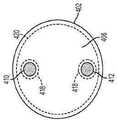
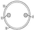
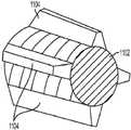
도 1은 한 가지 구체예에 따른 유체 증강 절제 시스템(100)의 다이어그램을 예시한 것이다. 상기 시스템은 목표 용적의 조직내로 삽입하도록 구성된 길쭉한 본체(102)를 포함한다. 상기 길쭉한 본체는 상기 목표 조직의 기하학 구조에 따라서 다양한 형태 및 크기를 가질 수 있다. 추가로, 길쭉한 본체의 특정 크기는 치료하고자 하는 조직의 종류 및 위치 등을 포함하는 다양한 요인에 따라 달라질 수 있다. 그 예로서, 한 가지 구체예에서, 상기 길쭉한 본체는 약 16 내지 약 18 게이지 (약 1.27 mm 내지 약 1.65 mm의 외부 직경)이고 대략 25cm의 길이 L (예를 들어, 도 2에 도시됨)을 갖는 박막(thin-walled) 스테인레스 스틸 니들일 수 있다. 길쭉한 본체(102)는 조직에 구멍을 뚫어 장치가 목표 용적의 조직내로 도입되는 것을 용이하게 하도록 구성된 뾰쪽한 원위 팁(104)을 포함할 수 있으나, 다른 구체예에서는, 상기 팁이 뭉툭하여 다양한 다른 구성을 취할 수 있다. 길쭉한 본체(102)는 전도성 물질로 형성됨으로써 이의 길이를 따라 이의 근위 부분에 위치한 하나 이상의 절제 부재들에 전기 에너지를 전도할 수 있다. 방출 전극(105)은 길쭉한 본체로부터 RF 에너지를 전달할 수 있는 절제 부재의 한 가지 예이다.1 illustrates a diagram of a fluid
일부 구체예들에서는, 방출 전극(105)가 길쭉한 본체(102)의 일부분일 수 있다. 예를 들어, 길쭉한 본체(102)는 방출 전극(105)를 나타내는 부분을 제외하고 전체 길이를 따라 절연성 물질로 코팅될 수 있다. 더욱 상세하게, 한 가지 구체예에서, 길쭉한 본체(102)는 1.5ml의 불소 중합체 크실란(XylanTM) 8840으로 코팅될 수 있다. 전극(105)은 다양한 길이 및 형태를 가질 수 있다. 한 가지 구체예에서, 전극(105)은 둘러싸고 있는 조직에 노출된, 단면이 4mm인 관형 길쭉한 본체일 수 있다. 추가로, 전극(105)는 길쭉한 본체(105)의 길이를 따라 어느 곳에나 위치할 있다(또한, 하나 보다 많은 전극이 길쭉한 본체의 길이를 따라 배치될 수 있다). 한 가지 구체예에서, 전극은 원위 팁(104)에 인접하여 위치될 수 있다. 다른 구체예들에서, 길쭉한 본체는 절연성 물질로 형성될 수 있고, 전극은 길쭉한 본체 주위 또는 길쭉한 본체의 부분들 사이에 배치될 수 있다.In some embodiments, the
다른 구체예들에서, 전극은 전류를 전도하기에 적합한 다양한 다른 물질들로 형성될 수 있다. 임의의 금속 또는 금속염이 사용될 수 있다. 스테인레스 스틸 외에도, 가능한 금속으로는 백금, 금 또는 은이 포함되고, 금속 염으로는 은/염화은이 포함된다. 한 가지 구체예에서, 전극은 은/염화은으로 형성될 수 있다. 금속 전극들이 둘러싸고 있는 조직 및/또는 액체의 전압 전위와 다른 전압 전위를 나타내는 것은 공지되어 있다. 이러한 전압 차이를 통해 전류를 통과시키는 경우 전극/조직 계면에서 에너지 소실이 일어나, 전극 근처에서 조직의 과도한 가열을 악화시킬 수 있다. 은/염화은과 같은 금속염을 사용했을 때의 한 가지 장점은 상기 금속염이 높은 교환 전류 밀도를 갖는 점이다. 그 결과, 많은 양의 전류가 단지 작은 전압 강하에 의해서도 그러한 전극을 통해 조직내로 통과됨으로써, 그러한 계면에서의 에너지 소실을 최소할 수 있다. 이와 같이, 은/염화은과 같은 금속염으로 형성된 전극은 조직 계면에서 과도한 에너지 발생을 감소시킴으로써 전극 주위에 액체 흐름이 없는 경우 조차도 더욱 바람직한 치료적 온도 프로파일을 생성할 수 있다.In other embodiments, the electrode may be formed of a variety of other materials suitable for conducting electrical current. Any metal or metal salt may be used. Besides stainless steel, possible metals include platinum, gold or silver, and metal salts include silver/silver chloride. In one embodiment, the electrode may be formed of silver/silver chloride. It is known that metal electrodes exhibit a voltage potential different from that of the surrounding tissue and/or liquid. When a current is passed through this voltage difference, energy dissipation occurs at the electrode/tissue interface, which may exacerbate excessive heating of the tissue near the electrode. One advantage of using a metal salt such as silver/silver chloride is that the metal salt has a high exchange current density. As a result, a large amount of current can be passed through such an electrode into the tissue with only a small voltage drop, thereby minimizing energy dissipation at such interfaces. As such, electrodes formed of metal salts such as silver/silver chloride can produce a more desirable therapeutic temperature profile even in the absence of liquid flow around the electrode by reducing excessive energy generation at the tissue interface.
전극(105) 또는 기타 절제 부재는 유체를 길쭉한 본체(102)를 관통해 뻗어 있는 내부 루멘(106)으로부터 둘러싸고 있는 조직내로 전달하도록(화살표(109)로 도시한 바와 같음) 구성된 하나 이상의 배출 포트(108)을 포함할 수 있다. 대안적으로, 전극(105)는 길쭉한 본체(102)에 형성된 하나 이상의 배출 포트(108) 근처에 위치될 수 있다. 많은 구체예들에서, 전극을 하나 이상의 배출 포트 주위에 위치시켜 치료에 대한 흐르는 유체의 효과를 극대화하는 것이 바람직할 수 있다. 배출 포트(108)는 다양한 크기, 수 및 패턴 구성으로 형성될 수 있다. 또한, 배출 포트(108)는 길쭉한 본체(102)에 대해 다양한 방향으로 유체를 유도하도록 구성될 수 있다. 이들은 도 1에서 화살표(109)로 도시된 바와 같이, 길쭉한 본체 주위에서 원형 또는 방사상 액체 흐름을 전개하는 다양한 배향을 비롯하여, 정상적인 배향(즉, 길쭉한 본체 표면에 수직) 뿐만 아니라, 길쭉한 본체(102)의 길이 축을 따라 근위 또는 원위로 유도되는 배향을 포함할 수 있다. 아울러, 일부 구체예들에서는, 길쭉한 본체(102)가 배출 포트로서 작용하는 개방 원위단을 구비하여 형성될 수 있다. 그 예로서, 한 가지 구체예에서, 직경이 약 0.4mm이고, 균등한 거리로 배치된 24개의 배출 포트(108)는 방전 가공기(electrical discharge machining, EDM)을 이용하여 전극(105)의 둘레 주위에 형성될 수 있다. 당해 분야에서 통상의 지식을 가진 자는 부가의 제조 방법들이 상기 배출 포트(108)를 형성하는데 이용될 수 있음을 인지할 것이다. 또한, 일부 구체예들에서, 배출 포트는 전극 자체에 배치되기 보다는, 전극에 인접한 길쭉한 본체의 일부분을 따라 배치될 수 있다.The
배출 포트(108)와 소통되는 내부 루멘(106)은 또한 유체가 조직내로 유입되기 바로 직전에 내부 루멘(106)을 통과함에 따라 유체를 가열하도록 구성된 가열 어셈블리(110)를 구비할 수 있다. 더욱이, 전극(105) 또는 다른 절제 부재의 원위에 위치한 길쭉한 본체 부분은 내부 루멘(106)이 전극(105)의 원위단에서 끝날 수 있도록 고체형이거나 채워질 수 있다. 한 가지 구체예에서, 전극의 원위에 있는 길쭉한 본체 부분의 내부 용적은 적소에서 에폭시드에 의해 고정되거나 끼워맞춤쇠에 의해 유지될 수 있는 플라스틱 플러그로 채워질 수 있다. 다른 구체예들에서, 전극의 원위에 있는 길쭉한 본체 부분은 고체 금속으로 형성되어, 용접, 스웨이징, 또는 당해 분야에 공지된 기타 다른 기술에 의해 길쭉한 본체의 근위 부분에 부착될 수 있다.The
유체는 유체 저장부(112)로부터 내부 루멘(106) 및 가열 어셈블리(110)에 공급될 수 있다. 유체 저장부(112)는 유체 도관(114)을 통해 내부 루멘(106)에 연결될 수 있다. 유체 도관(114)은 예를 들어, 가요성 플라스틱 배관 한 가닥일 수 있다. 또한, 유체 도관(114)은 단단한 튜브이거나 단단한 배관과 가요성 배관의 조합일 수 있다.Fluid may be supplied from the
유체는 펌프(116)에 의해 유체 저장부(112)로부터 내부 루멘(106)에 밀어넣어질 수 있다. 펌프(116)는 전진 플런저(도시되지 않음)를 이용해 고정된 용적의 흐름을 생상하는 주사형 펌프일 수 있다. 그러한 펌프의 예로는, 콜-팔머 코포레이션(일리노이주 시카고 소재)에서 시판하고 있는 모델 74900 이 있다. 다른 유형의 펌프로서, 예컨대 횡경막 펌프가 또한 사용될 수 있다.Fluid may be pushed into the
펌프(116)는 파워 공급원 및 제어기(118)에 의해 제어될 수 있다. 파워 공급원 및 제어기(118)는 펌프(116)로 전기 제어 신호들을 전달하여 펌프로 하여금 원하는 유체 유량을 생성케 할 수 있다. 파워 공급원 및 제어기(118)은 전기 연결부(120)를 통해 펌프(116)에 연결될 수 있다. 파워 공급원 및 제어기(118)는 또한 연결부(122)를 통해 길쭉한 본체(102)에, 또는 연결부(126)을 통해 집전 전극(124)에 전기적으로 연결될 수 있다. 또한, 파워 공급원 및 제어기(118)는 하기에 기술되는 바와 같이, 유사한 전기 연결부를 통해 가열 어셈블리(110)에 연결될 수 있다.Pump 116 may be controlled by a power supply and
집전 전극(124)은 다양한 형태일 수 있다. 예를 들어, 집전 전극(124)은 환자의 신체 밖에 위치한 거대 전극일 수 있다. 다른 구체예들에서, 집전 전극(124)은 길쭉한 본체(102)를 따라 다른 곳에 위치한 리턴 전극이거나, 치료 부위 가까이에서 환자의 신체내로 유입되는 제2의 길쭉한 본체상에 위치할 수 있다.The
작동에 있어서, 파워 공급원 및 제어기(118)는 목표 조직내로 원하는 유량의 유체 전달, 원하는 치료적 온도로의 유체 가열, 및 하나 이상의 절제 부재, 예컨대 전극(105)을 통한 치료적 절제 에너지의 전달을 유도할 수 있다. 이를 위해서, 파워 공급원 및 제어기(118)는 그 자체가 필요한 전기적 제어 및 치료적 에너지 신호들을 발생, 조절 및 전달하기 위한 다양한 성분들을 포함할 수 있다. 예를 들어, 파워 공급원 및 제어기(118)는 주어진 진폭 및 주파수로 하나 이상의 RF 신호들을 형성하기 위한 하나 이상의 주파수 발생기를 포함할 수 있다. 이들 신호들은 하나 이상의 RF 증폭기들에 의해 비교적 고전압 및 고암페어의 신호들, 예를 들어 50 볼트 및 1 amp의 신호들로 증폭될 수 있다. 이러한 RF 신호들은 하나 이상의 전기 연결부(122) 및 길쭉한 본체(102)를 통해 절제 부재로 전달되어 RF 에너지가 환자의 신체상에서 멀리 떨어져 위치할 수 있는 집전 전극(124) 및 방출 전극(105) 사이로 통과하게 할 수 있다. 길쭉한 본체가 비전도성 물질로 형성된 구체예들에서, 하나 이상의 전기 연결부(122)는 길쭉한 본체의 내부 루멘을 관통하거나 또는 이의 외부 표면을 따라 뻗어 있어 방출 전극(105)으로 전류를 전달할 수 있다. 절제 부재 및 집전 전극(124) 사이로 RF 에너지가 통과함으로써 조직의 고유 전기적 저항력으로 인해 길쭉한 본체(102)를 둘러싸고 있는 조직을 가열할 수 있다. 파워 공급원 및 제어기(118)는 또한 하나 이상의 RF 신호들의 일부를 예를 들어, 파워 모니터에 공급하여 RF 신호 파워를 원하는 치료 수준으로 조정하게 할 수 있는 방향성 결합기를 포함할 수 있다.In operation, the power source and
도 1에 예시된 길쭉한 본체(102)는 다양한 방식으로 환자의 신체내로 삽입되도록 구성될 수 있다. 도 2는 한 가지 구체예에 따른 의료 장치(200)를 예시한 것으로, 상기 장치는 그의 원위단에 결합되고, 조직의 목표 영역내로 복강경 또는 직접 삽입을 위한 길쭉한 본체(202)를 구비한다. 또한, 길쭉한 본체(202)에 추가하여, 장치(200)는 조작자가 장치를 다룰 수 있게 하는 핸들(204)을 포함할 수 있다. 핸들(204)은 하나 이상의 전기 연결부(206)를 포함할 수 있는데, 상기 전기 연결부는 길쭉한 본체의 여러 가지 구성들(예를 들어, 가열 어셈블리 및 절제 부재(205))를 예를 들어, 앞서 기술된 파워 공급원 및 제어기(118)에 연결한다. 핸들(204)은 또한 유체 공급원을 장치(200)에 연결하기 위한 하나 이상의 유체 도관(208)을 포함할 수 있다.The
장치(200)이 유체 증강 절제에서 사용하기에 적합할 수 있는 의료 장치의 한 가지 예시적 구체예일지라도, 수많은 다른 장치들 또한 사용될 수 있다. 예를 들어, 매우 작은 길쭉한 본체는 심부정맥, 예컨대 심실빈맥을 치료하는데 요구될 수 있다. 이러한 경우, 적당한 크기의 길쭉한 본체가 예를 들어, 혈액순환 시스템을 통해 심장내로 삽입되도록 구성된 카테테르의 원위단에 배치될 수 있다. 한 가지 구체예에서, 약 20 내지 약 25 게이지 (즉, 약 0.5mm 내지 약 0.9mm의 외부 직경) 크기의 스테인레스 스틸 니들 본체가 카테테르의 원위단에 배치될 수 있다. 상기 카테테르의 크기는 다양할 수 있지만, 일부 구체예들에서는, 그 길이가 약 120cm이고 직경이 약 8 프렌지(French) ("French"는 카테테르의 크기를 나타내기 위해 카테테르 산업부분에서 사용된 측정 단위이며, 이는 mm로 나타낸 카테테르 직경 수치의 3배에 해당된다).Although
유체 증강 절제를 이용한 치료학적 치료Therapeutic treatment with fluid augmentation ablation
절제는 일반적으로 고온 또는 저온을 적용하여 조직의 선택적 괴사 및/또는 제거를 유발하는 것을 수반한다. 절제에 의해 수행된 조직의 열적 파괴에 있어서 시간-온도의 관계가 공지되어 있다. 조직에 비가역적 열 손상을 일으키는 한계 온도는 일반적으로 약 41℃(섭씨 온도)가 되어야 하는 것으로 인정되고 있다. 또한, 치료 온도가 추가로 41℃ 보다 높게 증가함에 따라 특정 수준의 세포 괴사를 달성하는데 필요한 시간이 감소하는 것으로 공지되어 있다. 정확한 시간/온도 관계는 세포 유형에 따라 달라지지만, 원하는 열 용량(dose) 수준을 결정하는데 사용될 수 있는 많은 세포 유형에 대해 일반적인 관계가 있는 것으로 생각된다. 이러한 관계는 보통 하기 식(1)로 표현되는 바와 같이, 43℃에서의 등가 시간으로서 나타낸다.Ablation generally involves applying high or low temperatures to cause selective necrosis and/or removal of tissue. The time-temperature relationship is known in the thermal destruction of tissue performed by ablation. It is accepted that the threshold temperature for causing irreversible thermal damage to tissue should generally be about 41 °C (degrees Celsius). It is also known that the time required to achieve a certain level of cell necrosis decreases as the treatment temperature is further increased above 41°C. The exact time/temperature relationship is cell type dependent, but it is thought to be a general relationship for many cell types that can be used to determine the desired heat dose level. This relationship is usually expressed as an equivalent time at 43 DEG C, as expressed by the following formula (1).

상기 식에서, T는 조직 온도이고, R은 0 내지 5의 범위내에서 치료적 효율을 나타내는 단위없는 지표(보편적으로, 43℃ 보다 높거나 같은 온도에 대해서는 2, 41℃ 미만의 온도에 대해서는 0, 41℃와 43℃ 사이의 온도에 대해서는 4)로서, 이에 대한 사항은 문헌[Sapareto S.A. and W.C. Dewey,Int. J. Rad. Onc. Biol. Phys.10(6):787-800 (1984)]에 기술되어 있다. 상기 식 및 변수 세트는 열 용량을 컴퓨팅하기 위한 여러가지 공지의 방법들 중 한 가지 예를 단지 나타내는 것이며, 임의의 방법론이 본 발명의 방법 및 장치와 함께 사용될 수 있다. 상기 식(1)을 사용할 경우, teq.43℃ = 20분 내지 1시간인 범위에서의 열 용량은 조직을 치사시키는데 요구되는 용량이 조직의 유형에 의존하는 몇 가지 사상이 있을지라도, 일반적으로 치료로서 인정된다. 이와 같이, 치료적 온도는 41℃를 초과하는 어느 온도를 가리킬 수 있지만, 전달된 용량, 및 궁극적으로 치료적 효과는 온도의 시간 히스토리(즉, 조직이 이전에 견뎠던 가열의 양), 가열되는 조직의 유형 및 식(1)에 의해 결정된다. 예를 들어, 문헌[Nath, S. and Haines, D. E.,Prog. Card. Dis. 37(4):185-205 (1995) (Nathet al.)]에서는 치료목적으로서 1분 동안의 50℃의 온도를 제시하고 있으며, 이는 R=2인 경우 128분인 43℃에서의 등가 시간이다. 또한, 최대 효율을 위해, 열 용량이 균일하게 전달되도록 치료적 온도는 치료받는 조직 전체에 대해서 균일해야 한다.where T is the tissue temperature and R is a unitless indicator of therapeutic efficacy within the range of 0 to 5 (generally, 2 for temperatures above or equal to 43°C, 0 for temperatures below 41°C, 4) for temperatures between 41° C. and 43° C., as described in Sapareto SA and WC Dewey,Int. J. Rad. Onc. Biol. Phys. 10(6):787-800 (1984). The above equations and sets of variables represent only one example of several known methods for computing heat capacity, any methodology may be used with the methods and apparatus of the present invention. When using Equation (1) above, the heat capacity in the range oft eq.43°C = 20 minutes to 1 hour is generally accepted as a treatment. As such, the therapeutic temperature can refer to any temperature above 41° C., but the dose delivered, and ultimately the therapeutic effect, depends on the time history of the temperature (i.e., the amount of heating the tissue previously tolerated), at which time it is heated. It is determined by the type of tissue and equation (1). See, eg, Nath, S. and Haines, DE,Prog. Card. Dis. 37(4):185-205 (1995) (Nathet al. )] suggested a temperature of 50°C for 1 min for therapeutic purposes, which is the equivalent time at 43°C, which is 128 min for R=2. . Also, for maximum efficiency, the therapeutic temperature should be uniform throughout the tissue being treated so that the heat dose is uniformly delivered.
도 3은 전극(105)와 같은 절제 부재로부터의 거리에 대한 함수로서 얻어지는 모의 온도 프로파일을 보여줌으로써 여러 가지 절제술의 실행 프로파일을 예시한 것이다. 제1 프로파일(302)은 유체 증강의 이용 없이 RF 절제의 실행을 예시한 것이다. 도면에 도시된 바와 같이, 조직의 온도는 전극으로부터의 거리가 멀어짐에 따라 급격히 떨어진다. 이는 절제 부재로부터의 10mm 내에서는 조직의 온도가 여전히 대략 체온(37℃)으로, 앞서 기술된 50℃의 치료적 온도 보다 훨씬 낮음을 의미하는 것이다. 더욱이, 절제 부재에 매우 가까워지는 경우 온도는 매우 높아지며, 이는 조직이 더욱 빠르게 건조 또는 말라 붙고 탄화될 것임을 의미한다. 일단 이러한 상황이 발생하게 되면, 조직의 임피던스는 현저하게 상승함으로써, 에너지는 절제 부재로부터 더 멀리 떨어진 조직을 통과하기 어렵게 된다.3 illustrates the performance profile of several ablation procedures by showing simulated temperature profiles obtained as a function of distance from an ablation member, such as
제2 조직 온도 프로파일(304)은 미국 특허 제5,431,649호에 개시된 것과 유사한 제2의 종래 시스템과 관련이 있다. 이러한 제2 시스템에서, 전극은 조직내로 삽입되어 400 kHz RF 전류 흐름 (약 525 mA)을 전달함으로써 조직을 가열한다. 체온(37℃) 식염수 용액은 동시에 10 ml/분의 유량으로 조직내로 주입된다. 생성된 조직 온도 프로파일(304)은 프로파일(302) 보다 균일하지만, 얻게 된 최대 온도는 어느 곳에서나 대략 50℃ 이다. 이와 같이, 온도 프로파일(304)은 조직의 단지 작은 부분에서의 1분 동안의 치료법에 있어서 구체화되어, 일반적으로 인정된 조직 손상 온도 한계를 초과한다. 앞서 기술된 바와 같이, 이러한 작은 온도 증가는 치료적으로 의미있는 임의의 결과를 달성하는데 상당한 치료 시간을 필요로 한다.The second
제3의 조직 온도 프로파일(306)은 본 발명에 제시된 내용을 이용하여 달성된 것이다. 예시된 구체예에서, 은/염화은으로부터 형성된 전극은 조직내에 삽입되어 480 kHz RF 전류 흐름(525 mA)을 전달함으로써 조직을 가열한다. 50℃로 가열된 식염수 용액은 동시에 10 ml/분의 유량으로 조직내로 주입된다. 생성된 조직 온도 프로파일(306)은 균일하며, 전극으로부터 15mm 떨어진 거리에서 치료적 한계인 50℃ 보다 상당히 높게 나오고 있다. 더욱이, 온도가 용적내에서 균일하기 때문에, 전달된 열 용량 또한 용적내에서 균일하다.A third
도 3에 보여진 균일한 온도 프로파일은 절제 에너지의 적용 동안에 목표 조직내로 가열된 유체의 도입에 의해 달성될 수 있다. 유체는 조직내 더 깊숙히 열을 대류순환시킴으로써, 프로파일(302)에 도시된 바와 같이, 절제 부재 근처에서 일어나는 조직에서의 탄화 및 임피던스 변화를 감소시킨다. 추가로, 유체는 치료적 수준으로 가열되기 때문에, 프로파일(304)에 도시된 바와 같이, 둘러싸고 있는 조직의 온도의 하락을 유도하는 열 싱크로서 작용하지 않아야 한다. 그러므로, 조직내에 RF 에너지의 적용 및 가열된 식염수의 살포의 동시 발생은 전극에 인접한 조직의 건조 및/또는 증발이 일어나지 않게 하고, 유효한 조직 임피던스를 유지하며, RF 에너지로 가열된 조직 내부에서 열 전달을 증가시킨다. 이로써, 치료적 온도, 예를 들어 41℃를 초과하는 온도로 가열될 수 있는 조직의 전체 용적이 증가된다. 예를 들어, 직경이 대략 8cm인 용적(즉, 대략 156cm3의 구형 용적)의 조직은 본원에 기술된 유체 증강 절제술을 이용하여 5분 내에 치료될 수 있다. 대조적으로, 통상적인 RF는 단지 직경이 대략 3cm인 용적(즉, 대략 14cm3의 구형 용적)을 동일한 5분의 기간내에 치료할 수 있다.The uniform temperature profile shown in FIG. 3 can be achieved by introduction of a heated fluid into the target tissue during application of the ablation energy. The fluid convectively circulates heat deeper within the tissue, thereby reducing carbonization and impedance changes in the tissue that occur near the ablation member, as shown in
또한, 본 발명에 따른 유체 증강 절제 장치는 치료되는 조직에 따른 치료 프로파일의 형태를 조정하여 변할 수 있는 다수의 변수들을 보유할 수 있다. 예를 들어, SERF 절제술을 이용하는 경우, 작동 또는 제어 시스템은 식염수 온도(예를 들어, 약 40 내지 약 80℃), 식염수 유량(예를 들어, 약 0 ml/분 내지 20 ml/분), RF 파워(예를 들어, 약 0 W 내지 약 100 W), 및 치료 기간(예를 들어, 약 0분 내지 약 10분)와 같은 변수들을 수정하여 온도 프로파일(306)을 조정할 수 있다. 또한, 상이한 전극 구성들 또한 치료를 변화시키는데 사용될 수 있다. 예를 들어, 도 1에 예시된 방출 전극(105)이 단극(mono-polar) 전류 흐름에 적합한 연속적인 원통형 밴드로서 구성될지라도, 상기 전극은 또한 연속적인 표면 영역을 형성하는 다른 기하학적 구조, 예컨대 구형 또는 나선형으로도 형성될 수 있거나, 상기 전극은 또한 복수의 별개 부분들을 구비할 수 있다. 또한, 상기 전극들은 이극(bipolar) 조작을 위해 구성될 수 있으며, 이때 하나의 전극(또는 전극의 일부분)은 양극으로 작용하고, 또 다른 전극(또는 이의 부분)은 음극으로서 작용한다.In addition, the fluid-enhanced ablation device according to the present invention can have a number of variables that can be changed by adjusting the shape of the treatment profile according to the tissue to be treated. For example, when using SERF ablation, the actuation or control system may include saline temperature (eg, about 40 to about 80° C.), saline flow rate (eg, about 0 ml/min to 20 ml/min), RF Variables such as power (eg, from about 0 W to about 100 W), and treatment duration (eg, from about 0 minutes to about 10 minutes) can be modified to adjust the
SERF 절제술에서 사용하기 위한 바람직한 유체는 일반적인 살균 식염수 용액(염-함유 용액으로서 정의됨)이다. 그러나, 링거 용액 또는 농축 식염수 용액을 비롯한 다른 액체들도 사용될 수 있다. 유체는 목표 조직에 적용되었을 때 원하는 치료적 및 물리적 성질을 제공하도록 선택될 수 있으며, 조직을 감염으로부터 보호하기 위해서 살균 유체가 추천된다.A preferred fluid for use in SERF resection is a common sterile saline solution (defined as a salt-containing solution). However, other liquids may be used, including Ringer's solution or concentrated saline solution. The fluid can be selected to provide the desired therapeutic and physical properties when applied to the target tissue, and a sterile fluid is recommended to protect the tissue from infection.
이중-와이어 가열 어셈블리double-wire heating assembly
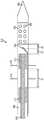
앞서 기술한 바와 같이, 길쭉한 본체의 내부 루멘 내에 흐르는 식염수 또는 또 다른 유체는 내부 루멘 내부에 배치된 가열 어셈블리에 의해 치료적 온도로 가열될 수 있다. 도 4는 그러한 어셈블리의 한 가지 구체예를 예시한 것이다. 근위단 및 뾰족한 원위단(404)을 구비한 길쭉한 본체(402)는 내부 루멘(406)을 포함한다. 길쭉한 본체(402)는 또한 길쭉한 본체(402)를 둘러싸고 있는 조직에 RF 에너지를 전달하도록 구성된 방출 전극(405)과 같은 하나 이상의 절제 부재를 포함한다. 전극(405)은 또한 내부 루멘(406)으로부터 둘러싸고 있는 조직으로 유체를 전달하도록 구성된 하나 이상의 배출 포트(408)를 포함한다.As previously described, the saline solution or another fluid flowing within the inner lumen of the elongated body may be heated to a therapeutic temperature by a heating assembly disposed within the inner lumen. 4 illustrates one embodiment of such an assembly. An
내부 루멘(406) 내부에는 가열 어셈블리가 배치되어 있으며, 상기 가열 어셈블리는 2개의 와이어(410, 412)를 포함하고, 이들 와이어는 거리를 두고 하나 이상의 스페이서(414, 414')에 의해 매달려 있다. 상기 와이어(410, 412)는 파워 공급원에 연결되어 전기 에너지를 와이어와 내부 루멘(406)에 흐르는 유체 사이에 통과시킬 수 있다. 전기(예를 들어, RF) 에너지가 내부 루멘(406) 내의 유체를 통과함으로써 유체의 본연 전기적 저항력으로 인해 유체의 온도가 증가할 수 있으며, 이는 길쭉한 본체를 둘러싸고 있는 조직이 RF 에너지를 이용하여 가열될 수 있는 앞서 기술된 메카니즘과 유사하다. 와이어(410, 412)는 전극(105)와 관련하여 앞서 기술된 물질과 유사하게, 임의의 전도성 물질로도 형성될 수 있다. 그러나, 한 가지 구체예에서, 와이어(410, 412)는 은 와이어로 형성될 수 있으며 스페이서(414, 414') 사이 또는 가까이에서 염화된 노출 표면을 가질 수 있다. 상기에 기술한 바와 같이, 이들 물질들은 와이어/유체 계면에 대해 전압 강하를 최소화하고 둘러싸고 있는 유체의 과도한 가열을 방지하는 이온 교환 공정에 관여할 수 있다.Disposed within the
내부 루멘(406) 내부에 흐르는 유체에 에너지를 효율적으로 통과시키기 위해서, 한 가지 예시적 구체예에서는, 와이어(410, 412)(또는 적어도 와이어의 노출 부분)가 누전을 일으킬 수 있기 때문에 서로 접촉하는 것을 방지한다. 스페이서(414, 414')는 다양하게 구성될 수 있지만, 한 가지 구체예에서 이들은 와이어(410, 412)가 서로의 고정된 기하학적 관계를 유지(즉, 서로에 대해 고정된 거리를 두고 있으며 공간에서 고정된 배향을 유지)하게 하는 디스크형 부재일 수 있다. 일부 구체예들에서, 와이어(410, 412)는 전극(405) 및 배출 포트(408)에서 단지 근위에 위치한 짧은 거리에 대해서만 노출된다. 도 4에 도시된 바와 같이, 와이어들은 와이어들의 원위 부분의 근위단 및 원위단에 위치하고 있는 2개의 스페이서(414, 414') 사이의 거리인 d1 에 대해서만 노출될 수 있다. 스페이서(414)의 근위에서, 와이어(410, 412)는 전기 절연재(418)로 피복되어 그들 사이에 전기 에너지가 통과하는 것을 방지할 수 있다. 또한, 2개의 와이어(410, 412) 모두가 동시에 전기적으로 전도성인 길쭉한 본체에 접촉함으로써 누전이 발생될 수 있기 때문에, 와이어(410, 412)가 길쭉한 본체(402)에 직접 접촉하는 것을 방지할 수 있다. 따라서, 일부 구체예들에서는, 길쭉한 본체(402)는 길쭉한 본체(402)의 내벽상에 배치된 절연재(420), 예컨대 플라스틱 튜브, 라이너 또는 코팅물과 함께 배열될 수 있다.In order to efficiently pass energy through the fluid flowing inside the
더욱이, 스페이서(414, 414')는 길쭉한 본체(402)의 전체 내부 직경을 차지하도록 구성될 수 있거나, 내부 루멘(406)의 직경 보다 작은 최대 외부 직경을 가짐으로써 길쭉한 본체의 내부 루멘(406) 내에 움직이도록 구성될 수 있다. 이러한 구성은 스페이서(414, 414')가 내부 루멘(406)의 중심 길이축에 대해 방사상으로 이동하게 할 수 있다. 스페이서(414, 414')의 위치는 스페이서들을 길쭉한 본체(402)의 내벽 사이에 끼워맞춤쇠 또는 절연재(420)를 구비하도록 구성하거나, 스페이서(414, 414')를 예를 들어, 접착제를 사용하여 길쭉한 본체의 일부분에 접착시키거나, 스페이서 바깥쪽으로 방사상으로 뻗어 내부 루멘의 내벽에 맞물리는 스포크(spokes), 암(arms) 또는 기타 표면 특징부들 사용함으로써 고정될 수 있다. 따라서, 스페이서(414, 414')는 와이어(410, 412)를 길쭉한 본체(402)와 실질적으로 고정된 기하학적 관계가 되도록 유지시키는데 효과적일 수 있다.Moreover, the
와이어(410, 412)가 서로의 관계 및/또는 길쭉한 본체(402)와의 관계를 유지하는데 필요한 스페이서(414)의 수는 노출된 와이어 부분의 길이, 길쭉한 본체(402)의 내부 직경, 와이어(410, 412)의 직경, 사용된 와이어의 강도 및 길쭉한 본체(402)의 크기를 비롯한 수많은 요인에 따라 달라질 수 있다. 도 4에 예시된 구체예에서, 2개의 스페이서(414, 414')는 와이어(410, 412)가 거리 d1 으로 떨어져 유지하는데 사용된다. 거리 d1은 변할 수 있으며, 한 가지 구체예서는 약 5mm 일 수 있다. 아울러, 스페이서(414)의 두께가 또한 길쭉한 본체(402) 및 와이어(410, 412)의 특정 구성에 필요한 기계적 요구사항에 따라 조정될 수 있다.The number of
내부 루멘(406)은 또한 내부 루멘 내에 흐르는 유체의 가열을 제어하는데 있어서 관찰 및 보조를 위한 하나 이상의 온도 센서를 수용할 수 있다. 도 4에 예시된 구체예는 스페이서(414')에서 거리 d2만큼 떨어져 유체중에서 움직이도록 구성된 크로멜-콘스탄탄 미세-와이어 열전쌍을 포함한다. 당해 분야에서 통상의 지식을 가진 자는 열전쌍이 흐르는 유체의 온도를 측정하는데 사용될 수 있는 온도 센서의 한 가지 예에 불과하며, 서미스터(thermistor) 및 다이오드를 비롯한 다양한 센서들이 또한 사용될 수 있음을 인지할 것이다. 추가로, 거리 d2는 변할 수 있으며, 한 가지 구체예의 경우 약 10mm 일 수 있다. 열전쌍(422)은 또한 전극(405) 및 배출 포트(408)에서 근위에 있는 거리 d3 에 배치될 수 있다. 이 거리 역시 변할 수 있으며, 한 가지 구체예의 경우 거리 d3 가 약2 mm이다. 거리 d1, d2 및 d3 (및 스페이서(414, 414')의 상응하는 위치들)는 내부 루멘(406) 내에서 흐르는 유체의 충분한 가열, 뿐만 아니라 배출 포트(408)를 통해 흐르기 전 가열된 유체의 충분한 혼합을 고려하여 선택됨으로써, 길쭉한 본체(402)를 둘러싸고 있는 조직내로 주입되는 유체가 균일한 온도를 갖도록 할 수 있다. 그러나, 내부 루멘(406) 내부에 흐르는 유체의 가열이 가능한 한 배출 포트(408) 가까이에서 일어나도록 거리 d2 및 d3는 최소의 거리의 되어야 한다. 이러한 구성은 환자의 신체 내부에서 멀리 떨어진 위치로부터 가열된 유체의 전달과 관련된 열 손실 및 의도하지 않은 주변 가열을 최소화한다.The
도 5a 내지 5c는 각각 도 4에 도시된 장치의 위치 A, B 및 C에서의 단면을 예시한 것이다. 도 5a는 가열 어셈블리의 근위 부분에 있는 길쭉한 본체(402)를 예시한 것이다. 도면에 도시된 바와 같이, 길쭉한 본체(402)는 절연재와 함께 배열될 수 있으며, 와이어(410, 412)는 또한 각각 절연재(418)로 코팅될 수 있다. 당해 분야에서 통상의 지식을 가진 자는 와이어(410, 412)가 절연재(418)로 코팅된 부분에서는 절연재(420)가 필요하지 않음을 인지할 것이다. 그러므로, 절연재(420)는 도 5a에 도시된 바와 같이, 길쭉한 본체의 전체 길이를 따라 존재할 수 있거나, 이하에서 도 5c와 관련하여 기술하는 바와 같이 와이어(410, 412)가 노출된 부분만을 따라서 위치할 수 있다. 추가로, 하기에 보다 상세하게 설명되는 바와 같이, 절연재는 와이어(410, 412) 및 절제 부재(405)에 연결되는 별도의 파워 공급원의 격리로 인해 일부 구체예에서는 전혀 존재하지 않아도 된다. 와이어(410, 412)가 절연재(418)로 코팅되는 길쭉한 본체의 어느 부분에 있어서나, 와이어(410, 412)는 내부 루멘(406)에서 자유롭게 움직이도록 허용될 수 있다. 대안적으로, 하나 이상의 스페이서(414)는 길쭉한 본체(402)의 길이를 따라 와이어(410, 412)가 서로에 대한 위치 및 길쭉한 본체(402)에 대한 위치를 유지하도록 배치될 수 있다.5A-5C illustrate cross-sections at positions A, B and C of the device shown in FIG. 4, respectively. 5A illustrates an
도 5b는 스페이서(414)가 존재하는 부분에서 길쭉한 본체(402)를 예시한 것이다. 상기 도면상에서는 길쭉한 본체(402), 내부 루멘(406), 절연재(420), 스페이서(414), 및 와이어(410, 412)가 도시되어 있다. 이로부터, 스페이서(414)는 2개의 구멍 및 하나 이상의 중심 루멘(502)을 갖는 디스크 또는 원통형 부재인 것으로 나타나 있으며, 스페이서(414)가 길쭉한 본체(402)의 전체 내부 직경을 차지하는 경우 유체가 상기 루멘을 통과하여 상기 스페이서를 우회할 수 있다. 다른 구체예들의 경우, 특히 스페이서가 길쭉한 본체(402)의 전체 내부 직경을 차지하지 않아 유체가 스페이서 주위를 흐를 수 있는 경우, 스페이서는 중심 루멘을 가질 필요가 없다. 한 가지 구체예에서, 스페이서(414, 414')는 단일의 3-루멘 압출관으로 부터 형성될 수 있으며, 상기 압출관은 이어서 원하는 두께의 개별 스페이서로 절단된다. 와이어(410, 412)는 스페이서(414) (도 5b에서 와이어(410, 412)와 함께 위치하는 것으로 도시됨)에 형성된 2개의 구멍을 통해 관통할 수 있으며, 예를 들어, 끼워맞춤쇠 또는 에폭시 접착제에 의해 적소에 유지될 수 있다.5B illustrates an
도 5c는 스페이서(414)에 인접하고 스페이서(414, 414') 사이의 부분에 있는 길쭉한 본체(402)를 도시한 것이다. 와이어(410, 412)가 이 부분에 노출되어 그 사이에 흐르는 유체를 가열하도록 구성되어 있다. 길쭉한 본체(402) 내부의 이러한 위치에서, 와이어(410, 412)가 임의의 절연과정 없이, 절연재(420) 및 인접한 스페이서(414, 414')의 제지력에 의해 길쭉한 본체(402)와 접촉하는 것을 방지한다.5C shows the
도 6은 도 4 및 도 5a 내지 5c에 도시된 것과 유사한 가열 어셈블리의 확대도를 예시한 것이다. 도면에 도시된 바와 같이, 스테인레스 스틸로 된 길쭉한 본체(602)의 내부 루멘은 플라스틱 튜브와 같은 절연재(604)와 함께 배열될 수 있다. 그리고 나서, 2개의 와이어(606, 608) 및 하나 이상의 스페이서(610)를 포함하는 가열 어셈블리가 내부 루멘 내부에 설치되어, 와이어(606, 608)가 서로 또는 길쭉한 본체(602)와 직접 접촉하는 것을 방지한다.6 illustrates an enlarged view of a heating assembly similar to that shown in FIGS. 4 and 5A-5C ; As shown in the figure, the inner lumen of the
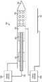
도 7은 길쭉한 본체(402)를 둘러싸고 있는 조직 및 길쭉한 본체(402)의 내부 루멘(406)을 통과해 흐르는 유체 모두에 RF 에너지를 전달하기 위한 예시적 전기 도관을 나타낸 것이다. 예시된 구체예에서, 2개의 별도 파워 공급원(702, 704)이 전기 에너지, 예를 들어 RF 에너지를 전달하는데 이용된다. 파워 공급원(702)은 길쭉한 본체(402)의 내부 루멘(406)을 통해 작동하는 2개의 와이어(410, 412)에 연결될 수 있다. 상기 와이어들을 통해 전류를 통과시킴으로써, 에너지는 와이어(410, 412) 노출 부분 사이의 내부 루멘(406) 사이에 흐르는 유체를 통해 전달될 수 있다.7 illustrates an exemplary electrical conduit for delivering RF energy to both the tissue surrounding the
파워 공급원(704)은 길쭉한 본체(402) 및 집전 전극(124) 모두에 연결될 수 있다. 집전 전극은 환자의 신체상에서 멀리 위치할 수 있는데, 예를 들어, 작업 테이블상에서 환자의 등 아래에 설치될 수 있다. 앞서 언급한 바와 같이, 다른 구체예들에서, 집전 전극(124)은 길쭉한 본체(402) 상에 함께 위치하거나 길쭉한 본체(402) 가까이에 위치한 제2 길쭉한 본체 상에 위치할 수 있다. 당해 분야에서 통상의 지식을 가진 자는 길쭉한 본체(402) 상에 집전 전극(124)이 위치할 경우 집전 전극으로부터 방출 전극(405)을 격리시키는 것이 필요함을 인지할 것이다. 이는 다양한 방식, 예를 들어 길쭉한 본체(402)를 비전도성 물질로 형성한 후 2개의 전극을 길쭉한 본체(402)의 표면상에 설치함으로써 수행될 수 있다. 그러한 구체예에서, 파워 공급원(704)은 와이어와 같이 길쭉한 본체(402)의 내부 루멘을 관통하거나 그 외부 표면을 따라 뻗어 있는 임의의 적합한 연결부에 의해 2개의 전극에 연결될 수 있다.A
다시 도면을 참조하여, 파워 공급원(704)은 길쭉한 본체(402)에 전류를 통과시킴으로써 RF 에너지를 전극(405)으로부터 집전 전극(124)에 전달할 수 있다. 2개의 파워 스페이서(702, 704)는 공통의 전기적 접지부를 공유하지 않으므로 서로 전기적인 격리를 유지한다. 이로써, 공급원(702)으로부터의 파워가 길쭉한 본체(402) 내부에 흐르는 식염수만을 가열하는 동안, 공급원(704)으로부터의 파워는 길쭉한 본체(402)를 둘러싸고 있는 본체를 가열하게 된다. 앞서 언급된 스페이서 및 절연재들은 서로 닿거나 동시에 길쭉한 본체(402)와 접촉하는 2개의 와이어(410, 412)로부터 유발될 수 있는 상기 와이어 사이의 단락을 방지하는데 사용된다. 당해 분야에서 통상의 지식을 가진 자는 와이어 및 길쭉한 본체의 내벽을 피복하는 절연재 및 스페이서의 다양한 조합이 그러한 전기 단락을 방지하는 사용될 수 있음을 인지할 것이다.Referring back to the figures, the
예시적 구체예에서는, 식염수 용액이 길쭉한 본체의 내부 루멘(406)을 통해 펌핑됨에 따라, 식염수가 파워 공급원(702)에 의해 상기 본체 온도, 바람직하게 50 내지 70℃로 가열될 수 있다. 이는 RF 에너지를 와이어(410, 412)를 통해 내부 루멘(406) 내의 유체로 전달함으로써 수행될 수 있다. 예를 들어, 변수들을 작동시키는 전형적인 유체 증강 절제 치료법은 와이어(410, 412)에 20V 이상의 전압 적용을 수반한다. 일부 구체예들에서는, 적용된 전압은 120V 정도로 높을 수도 있고, 일부 구체예들에서는 약 30V(예를 들어, 한 가지 구체예에서는 31.25V)일 수 있다. 가열되어 흐르는 식염수 용액은 이어서 다양한 유량으로 배출 포트(408)를 통해 길쭉한 본체(402)를 둘러싸고 있는 조직내로 주입될 수 있다. 예를 들어, 일부 구체예들의 경우, 유체는 약 10 ml/분의 유량으로 길쭉한 본체(402)로부터 방출될 수 있다. 가열된 유체의 전달은 파워 공급원(704)으로부터의 절제 에너지의 전달과 무관하게 또는 그와 함께 수행될 수 있다. 유체 증강 절제 치료법의 작동 변수들은 원하는 치료적 효과, 치료 용적의 기하학적 구조 및 조직 성질등과 같은 수많은 요인에 따라 변할 수 있다. 그 예로서, 한 가지 구체예에서는, 환자의 간에서 수행되는 절제 치료법이 40 와트의 파워를 이용하여 식염수를 50℃로 가열하고 그 식염수를 약 5분 동안 10 ml/분의 유량으로 전달한다. 또 다른 예로서, 이들과 동일한 변수들을 사용하는 절제 치료법에서는 심장 조직을 치료할 때 단 약 90초 동안에 식염수를 전달할 수 있다. 의도된 치료 부위의 특정 성질들이 궁극적으로 선택된 작동 변수들을 지배할 경우, 유체 증강 절제 치료법은 전형적으로 약 0 내지 약 20 ml/분의 유량으로의 식염수 전달을 수반한다. 식염수는 보편적으로 80W 이하의 파워 및 120 V 이하의 전압을 이용하여 약 50 내지 80℃로 가열된다. 이러한 예시적 작동 변수들에 따라 가열된 유체는 전기 에너지와 함께 조직에 직접 전달되어 절제 치료를 수행할 수 있다. 일부 구체예들에서는, 100W 이하의 파워가 예를 들어, 방출 전극으로부터 조직에 적용될 수 있다.In an exemplary embodiment, as the saline solution is pumped through the
단일-와이어 가열 어셈블리Single-Wire Heating Assemblies
가열 어셈블리(110)의 제2 구체예가 도 8에 예시되어 있다. 이 구체예에서는 전도성 길쭉한 본체 또는 길쭉한 본체 내에 설치된 전도성 튜브와 함께 단일 와이어를 사용하여 RF 에너지를 길쭉한 본체의 내부 루멘내에 흐르는 유체에 전달한다. 이러한 가열기 고안은 소형의 길쭉한 본체가 예를 들어, 심실빈맥과 같은 심부정맥의 치료에 있어서 환자의 심장 영역을 액세스하는데 사용되는 구체예의 경우 유리하다. 추가로, 이러한 구성은 하기에 기술되는 바와 같이, 길쭉한 본체의 내부 루멘을 통해 흐르는 유체의 보다 균일한 가열을 제공할 수 있다. 더욱이, 당해 분야에서 통상의 지식을 가진 자는 이중-와이어 및 단일-와이어 어셈블리가 각각의 구체예에 대해 본원에 기술된 특징들의 임의의 조합을 포함할 수 있음을 인지할 것이다.A second embodiment of a
도면상에 도시된 바와 같이, 길쭉한 본체(802)는 근위단 및 뾰족한 원위 팁(804)를 포함하며, 그 길이에 따라 배치된 전극(805)과 같은 하나 이상의 절제 부재를 포함한다. 길쭉한 본체(802)는 또한 내부 루멘(806)을 포함하며, 상기 내부 루멘과 전극에 형성된 하나 이상의 배출 포트(808)를 통해 유체 소통이 이루어진다. 길쭉한 본체(802)는 앞서 언급된 길쭉한 본체(102)와 유사한 재질, 즉 파워 공급원으로부터 전극(805)에 전류를 통과시킬 수 있는 전기적 전도성 재질로 형성될 수 있다.As shown in the figure, the
길쭉한 본체(802)의 내부 루멘(806) 내부에는 2개의 스페이서 부재(812, 812') 사이의 거리 d1 만큼 뻗어 있는 노출 부분을 통해 내부 루멘 내에 흐르는 유체에 RF 에너지를 전달하도록 구성된 와이어(810)가 배치될 수 있다. 스페이서 부재(812, 812')는 와이어(810)가 길쭉한 본체(802)와 함께 실질적으로 고정된 기하학적 관계를 유지하게 할 수 있으며, 플라스틱과 같은 전기적 절연재로 형성될 수 있다. 실질적으로 고정된 기하학적 관계를 유지함으로써, 스페이서(812, 812')는 와이어(810)의 노출 부분이 길쭉한 본체(802)와 직접 접촉하여 누전을 일으키는 것을 방지할 수 있다. 와이어(810)가 스페이서(812)의 근위에 위치한 어떠한 부분을 따라서든 절연재(418)와 유사한 절연재(도시되지 않음)로 코팅될 수 있음을 주지해야 한다.Inside the
스페이서(812, 812') 사이에서 떨어져 있는 거리 d1은 특정 구체예에서 원하는 가열 용량, 파워 공급원, 와이어 직경, 및 길쭉한 본체 크기에 따라 변할 수 있다. 한 가지 구체예에서, 길쭉한 본체는 박막의 25-게이지의 박막형 니들(내부 직경: 약 0.4mm)일 수 있다. 길쭉한 본체의 내부 직경보다 작은 외부 직경을 갖는 와이어는 d1이 약 2mm일 수 있는 경우 노출 부분을 가질 수 있다. 한 가지 구체예에서, 와이어는 외부 직경이 약 0.125mm 일 수 있다. 와이어(810)의 노출 부분은 전극(805) 및 그의 배출 포트(808)의 바로 근위에 위치할 수 있지만, 일부 거리는 상기 성분들과 떨어져 있어야 와이어(810)에 의해 가열되는 유체가 충분히 혼합되고 길쭉한 본체를 둘러싸고 있는 조직내로 유입되기 전에 보다 균일한 온도에 도달할 시간을 확보하게 된다.The distance d 1 spaced between the
앞서 언급된 제1 구체예와 유사하게, 하나 이상의 온도 센서(814)가 또한 내부 루멘(806) 내에 배치되어 내부 루멘을 통해 흐르는 유체의 가열 제어를 돕는다. 예를 들어, 온도 센서(814)는 와이어(810)의 원위단 및 전극(805)의 근위단 사이에 위치할 수 있다. 즉, 온도 센서(814)는 와이어(810)의 원위단 위쪽에 거리 d2, 및 전극(805)의 근위단 앞에 거리 d3 을 두고 위치하고 있다. 일부 구체예들의 경우, 거리 d2는 약 1mm일 수 있고, 거리 d3은 거의 0mm 일 수 있다. 상기 온도 센서는 다양한 센서들 중 어느 하나 일 수 있으며, 일부 구체예에서는 당해 분야에 공지된, 미세-와이어 크로멜-콘스탄탄 열전쌍일 수 있다.Similar to the first embodiment mentioned above, one or
도 9a 및 9b는 각각 도 8의 길쭉한 본체의 위치 A 및 B에서의 단면을 도시한 것이다. 도 9a에 도시된 바와 같이, 와이어(810)가 스페이서(812, 812') 사이에 노출되는 경우, 전기 에너지가 길쭉한 본체(802)로 자유롭게 통과함으로써, 내부 루멘(806) 중에서 유체를 가열하게 된다. 주목해야 할 점은 길쭉한 본체(802)가 앞서 기술된 바와 같이 절연재와 함께 배열되지 않는 점이다. 오히려, 이 구체예에서 길쭉한 본체(802)는 제2 전극으로서 작용하여 와이어(810)로부터 에너지를 수용한다. 그러나, 일부 구체예들의 경우, 길쭉한 본체(802)는 스페이서(812)의 근위에서 절연재와 함께 배열될 수 있다.9a and 9b show cross-sections at positions A and B of the elongated body of FIG. 8, respectively; As shown in FIG. 9A , when the
도 9b는 와이어(810)가 스페이서(812)에 의해 길쭉한 본체(802)와 접촉하는 것이 방지된 위치에서의 길쭉한 본체를 예시하고 있다. 스페이서(812)는 와이어(810)를 길쭉한 본체의 길이 축과 실질적으로 동축인 위치에 유지하게 할 수 있다. 도면에 도시된 바와 같이, 스페이서(812)는 내부 루멘(806)의 전체 직경을 차지할 필요가 없다. 오히려, 스페이서(812)는 다양한 크기로 형성될 수 있으며, 일부 구체예들에서는, 내부 루멘(806)에서 실질적으로 이용가능한 공간 모두를 차지할 수 있는 반면, 다른 구체예들에서, 상당히 작을 수 있다. 스페이서(812)가 내부 루멘(806)을 실질적으로 모두 차지하게 되는 구체예의 경우, 스페이서가 하나 이상의 통로를 구비하도록 형성함으로써, 앞서 언급한 스페이서(414)의 중심 루멘(502)와 유사하게, 유체가 상기 스페이서 주위를 흐를 수 있게 하는 것이 필요할 수 있다. 당해 분야에서 통상의 지식을 가진 자는 스페이서(812)가 스페이서(414)와 유사하게 압출관으로서 형성될 수 있음을 인지할 것이다. 그러한 압출부는 유체용 통로로서 작용할 수 있는 하나 이상의 루멘으로 형성될 수 있다. 또한, 와이어(810)는 에너지 전달이 바람직하지 않은 부분 위에서 절연재로 코팅될 수 있다. 예를 들어, 와이어(810)는 스페이서(812)로부터 근위에 뻗어 있는 와이어의 부분 위에서 절연재로 코팅될 수 있다.9B illustrates the elongated body in a position where the
도 10은 길쭉한 본체(802)의 내부 루멘(806)을 흐르는 유체, 및 길쭉한 본체를 둘러싸고 있는 조직에 RF 에너지를 독립적으로 전달하기 위한 전기적 도관의 한 가지 구체예를 예시한 것이다. 도면에 도시된 바와 같이, 도 7에 예시된 도관과 유사하게, 이중 파워 공급원(1002, 1004)은 내부 루멘(806) 내의 유체 및 길쭉한 본체를 둘러싸고 있는 조직 내에 에너지를 전달하는데 사용된다. 그러나, 예시된 구체예에서, 각각의 파워 공급원(1002, 1004)에 의해 형성된 도관은 공통 전극으로서 길쭉한 본체(802)를 공유한다. 즉, 내부 루멘(806) 내에 흐르는 유체에 RF 에너지를 전달하도록 구성된 파워 공급원(1002)은 내부 루멘(806) 내에 위치한 와이어(810) 및 길쭉한 본체(802) 자체에 연결된다. 그 후, 길쭉한 본체(802)는 파워 공급원(1002)용 전극으로서 작용한다. 한편, 파워 공급원(1004)은 길쭉한 본체(802) 및 집전 전극(124)에 연결된다. 따라서, 파워 공급원(1004)은 RF 에너지를 전극(805)에서 길쭉한 본체(802)를 둘러싸고 있는 조직으로 전달할 수 있다. 2개의 파워 공급원(1002, 1004)이 단지 길쭉한 본체(802)를 통해서면 연결(즉, 리턴 연결부 없이 단일 지점에서만 연결됨)되는 결과, 파워 공급원은 그 사이의 어떠한 전류 흐름 없이 독립적으로 동시에 작동할 수 있다.10 illustrates one embodiment of an electrical conduit for independently delivering RF energy to the fluid flowing through the
도 11a, 11b, 및 12는 스페이서(812)의 대안적인 구체예를 예시한 것이다. 앞서 기술한 바와 같이, 스페이서(812)는 중합체 재질과 같은 절연재의 압출부로서 형성될 수 수 있으며, 이는 이후에 예를 들어, 가압 도구를 구비한 과보강(overjacketing) 압출부 또는 접착제를 사용하여 와이어(810)에 고정될 수 있다. 스페이서(812)는 내부 루멘(806)의 원통형 모양과 어울리는 원통형일 수 있으며, 비원통형 길쭉한 본체가 사용되는 구체예에서, 스페이서(812)는 내부 루멘(806)에 상응하는 임의 모양으로나 형성될 수 있다. 그러나, 스페이서(812)는 또한 다른 구성을 취할 수도 있다. 예를 들어, 스페이서(812)는 그 길이를 따라 와이어(810)에 부착된 하나 이상의 특징부로서 형성될 수 있다. 도 11a는 그러한 스페이서의 한 가지 구체예를 도시한 것이다. 전도성 와이어(1102)의 위에는 여러 가지 길이방향으로 뻗어 있으며, 절연재로 형성된 돌출부 또는 융기부(1104)가 형성될 수 있다. 돌출부(1104)는 스페이서(812)와 유사하게 작용하여 와이어(1102)가 길쭉한 본체(802)에 직접 결합하는 것을 방지한다. 이들 돌출부는, 스페이서(812)와 달리, 완전히 와이어(1102)를 둘러싸지 못하여, 와이어 위로 흐르는 유체를 통한 전기 에너지의 통과를 방해하지 않으면서 와이어(1102)의 전체 노출 부분을 따라 뻗을 수 있다. 그 결과, 와이어의 노출 길이를 유지할 개별 스페이서 부재의 필요 없이(예를 들어, 스페이서(812, 821')), 에너지는 임의의 원하는 길이를 따라 와이어(1102) 및 길쭉한 본체(802) 사이를 통과할 수 있다.11A, 11B, and 12 illustrate an alternative embodiment of a
도 11b는 와이어(1102), 더욱 명확하게는 그 위에 4개의 돌출부(1104 )가 형성되어 있는 와이어(1102)의 단면도를 예시한 것이다. 당해 분야에서 통상의 지식을 가진 자는 어떠한 수의 돌기부 또는 융기부가 와이어(1102)의 둘레 주위에 형성될 수 있지만, 그 수는 길쭉한 본체(802)와의 직접적인 전기적 접촉을 방지하는데 충분해야 하는 한편 와이어(1102)의 표면적을 완전히 둘러싸지 않아야 한다. 아울러, 돌출부는 다양한 크기로 형성될 수 있다. 예를 들어, 돌출부는 길쭉한 본체(802)의 내벽에 도달하는 높이를 갖도록 형성됨으로써, 와이어(1102)가 내부 루멘(806) 내부에서 이동하는 것을 방지할 수 있다. 다른 구체예들에서, 돌출부는 더 낮은 높이를 가져 와이어(1102)가 내부 루멘(806) 내에서 방사상으로 이동하는 한편 와이어의 노출 부분과 길쭉한 본체(802)의 내벽 사이의 직접적인 접촉을 방지할 수 있다.11B illustrates a cross-sectional view of
돌출부(1104)는 다양한 방식으로 와이어(1102) 상에 형성될 수 있다. 예를 들어, 돌출부는 압출되고 이어서 와이어(1102)의 표면에 적용될 수 있다. 대안적으로, 와이어는 당해 분야에 공지된 절연 코팅물로 형성될 수 있으며, 절연재의 돌출부(1104)만이 남아있도록 상기 코팅물은 절제 공정을 통해 선택적으로 제거될 수 있다. 대안적으로, 와이어는 형성된 후 과보강 압출부를 사용하여 절연성 돌출부를 적용할 수 있다. 또한, 돌출부(1104)는 도 11a 및 11b에 도시된, 길이상으로 뻗어 있는 융기부와 다른 여러 가지 모양으로 형성될 수 있다. 예를 들어, 도 12는 절연재 코팅물이 나사송곳(auger) 또는 코르크 스크류(corkscrew)의 모양으로 구비된 와이어(1202)의 한 예를 예시하고 있다. 이러한 모양은 예를 들어, 앞서 기술된 선택적 절제 공정을 이용해 와이어(1202) 위에 형성된 절연성 코팅물의 부분을 제거함으로써 형성될 수 있다.The
고안 장점devising advantages
본원에 기술된 가열 어셈블리(110)의 다양한 구체예들이 유체 증강 절제 시스템들에 있어서 여러 가지 장점들을 제공한다. 예를 들어, 하나 이상의 와이어를 제2 와이어 및/또는 길쭉한 본체 자체와 실질적으로 고정된 기학학적 구조 관계를 유지하게 하는 스페이서의 능력은 유체 증강 절제 장치 또는 시스템의 신뢰성 있는 생산을 가능케 한다. 이는 길쭉한 본체의 내부 루멘 내에 흐르는 유체에 RF 에너지를 전달하는데 사용되는 어떠한 파워 공급원이든 단지 제한된 범위의 저항으로 효과적으로 가열하도록 구성될 수 있기 때문이다. 그러므로, 일관된 성능을 달성하기 위해서는, 파워 공급원에 의해 생기는 저항이 파워 공급원의 유효 가열 범위 내에서 유지되어야 한다. 구조체의 전기 저항은 일반적으로 상기 구조체를 구성하는 물질의 비저항 및 그의 기하학적 구조 모두에 좌우된다. 길쭉한 본체(102) 내에 흐르는 유체의 비저항 및 길쭉한 본체 및 가열기(110)를 형성하는데 사용되는 물질의 비저항은 알려져 있다. 이는 저항에 있어서 남아있는 알려지지 않은 변화가 구성성분들의 기하학적 구조에서의 변화(예를 들어, 전극들의 서로에 대한 이동 등)로부터 초래될 수 있음을 의미하는 것이다. 이러한 기하학적 구조 변화를 최소화함으로써, 스페이서는 유체 증강 절제 시스템의 더욱 일관된 성능 수행을 가능케 한다.The various embodiments of the
아울러, 스페이서는 유체 증강 절제 장치의 어셈블링에 있어서 간단한 제조 공정을 고려할 수 있게 한다. 앞서 언급한 바와 같이, 스페이서는 용이하게 압출되고 일정 크기로 절단되거나 전기 전도성 와이어 등으로부터 코팅물을 제거함으로써 형성될 수 있다. 그 후, 이들 구성성분들을 예를 들어, 끼워맞춤쇠 또는 접착성 물질들을 사용하여 길쭉한 본체의 내부 루멘 내에 용이하게 설치하고 위치시킬 수 있거나, 이들은 내부 루멘 내에서 움직이도록 허용될 수 있다.In addition, the spacer allows for a simple manufacturing process to be considered in assembling the fluid-enhanced ablation device. As mentioned above, the spacer can be easily extruded and cut to size or formed by removing the coating from an electrically conductive wire or the like. These components may then be readily installed and positioned within the inner lumen of the elongated body using, for example, fittings or adhesive materials, or they may be allowed to move within the inner lumen.
본원에 기술된 고안들의 또 다른 잇점은 이들 고안이 길쭉한 본체의 내부 루멘을 통해 흐르는 유체의 균일한 가열을 제공하는 점이다. 전극들 사이에 RF 에너지를 통과시킴으로써 유체를 가열하는 경우 발생되는 한 가지 문제점은 유체의 국부 끊음이 전류 밀도가 특히 높은 영역에서 발생하는 점이다. 예를 들어, 2개의 전극(예를 들어, 2개의 와이어)이 서로 매우 가깝게 위치하는 경우, 전극들을 둘러싸고 있는 용적의 다른 영역에서 볼 수 있는 전류 유동선과 비교할 때, 전극들 사이의 작은 공간에 불균형적으로 높은 전류 유동선이 있을 수 있다. 그 결과, 전극들 사이의 작은 공간을 통해 흐르는 유체가 과가열되어 끊을 수 있다. 이는 환자에게서 (예를 들어 가스 버블이 심장의 혈류 내로 유입됨으로써) 의학적 합병증을 유발할 수 있기 때문에 바람직하지 않다. 따라서, 내부 루멘 내에서 유체의 가열 동안에 끊는 형상을 최소화하기 위해서는 가능한한 유체의 가장 균일한 가열을 달성하는 것이 바람직하다.Another advantage of the inventions described herein is that they provide uniform heating of the fluid flowing through the inner lumen of the elongated body. One problem with heating a fluid by passing RF energy between the electrodes is that local breakage of the fluid occurs in regions where the current density is particularly high. For example, when two electrodes (e.g., two wires) are placed very close to each other, there is an imbalance in the small space between the electrodes compared to the current flow lines seen in other regions of the volume surrounding the electrodes. In general, there may be high current flow lines. As a result, the fluid flowing through the small space between the electrodes may overheat and break. This is undesirable because it can cause medical complications in the patient (eg gas bubbles entering the bloodstream of the heart). Accordingly, it is desirable to achieve the most uniform heating of the fluid possible in order to minimize the shape of breakage during heating of the fluid within the inner lumen.
본원에 기술된 스페이서는 유체를 가열하는데 사용되는 전극들이 전극들 사이에 불균형적으로 높은 전류 유동선을 최소화하는 관계를 유지하게 함으로써 내부 루멘 내에서 유체의 균일한 가열을 돕는다. 이러한 개념은 개의 전극 사이를 통과하는 모의 전류선들이 도시된 이중-와이어 및 단일-와이어 가열 어셈블리의 단면을 보여주는 도 13a 및 13b에 예시되어 있다. 도 5c에 도시된 이중-와이어 가열 어셈블리를 예시하고 있는 도 13a는 와이어들을 분리된 구성으로 유지시킴으로써, 내부 루멘(406) 전체에 걸친 전류 유동선에서의 변화를 최소화할 수 있음을 보여주는 것이다. 도 9a 및 13b에 도시된 단일-와이어 가열 부재는 내부 루멘 내에서 보다 균일한 전류 분포를 제공한다. 도 13b에 도시된 바와 같이, 전류는 와이어(810)의 전체 둘레 주위로부터 길쭉한 본체(802) 내로 균일하게 통과할 수 있다. 이로부터 내부 루멘(806) 내에 분포된 유체의 매우 균일한 가열이 달성된다.The spacer described herein aids in uniform heating of the fluid within the inner lumen by ensuring that the electrodes used to heat the fluid maintain a relationship between the electrodes that minimizes disproportionately high current flow lines. This concept is illustrated in Figures 13a and 13b, which show cross-sections of double-wire and single-wire heating assemblies with simulated current lines passing between the electrodes. 13A , illustrating the dual-wire heating assembly shown in FIG. 5C , shows that by maintaining the wires in a separate configuration, the change in the current flow line throughout the
다른 유형의 절제에 대한 적용성Applicability to other types of ablation
당해 분야에 지식을 가진 자들은 목표 조직 내에서 조직을 파괴하는데 충분한 이상고열을 일으키는 가열 메카니즘이 다른 유형의 에너지를 포함할 수 있음을 인식할 것이다. 초음파 진동 에너지는 마이크로파 및 광파 전자기 에너지와 같이, 조직에 의해 흡수되어 열로 전환되는 것으로 알려져 있다. 대안적인 구체예들에서는, 길쭉한 본체의 원위단에 배치된 방출부로서 초음파 변환기, 마이크로파 안테나 또는 광파 확산기가 사용될 수 있다. 광파 전자기 에너지는 가시선, 근적외선 및 원적외선을 포괄하는 범위에 속할 수 있으며, 필라멘트, 아크 램프, 다양한 유형의 레이저(예를 들어, 다이오드, 반도체, 또는 펌프), 또는 다른 수단에 의해 발생될 수 있다. 유사하게, 길쭉한 본체의 원위단은 전도를 통해 조직을 가열하기 위한 저항성 와이어와 같은 가열 메카니즘을 포함하는데 적합할 수 있다. 이용된 절제 부재의 종류에 관계 없이, 이들 절제 부재 어느 곳이든 그 근위에 있는 조직 내로 가열된 액체를 주입하는 것은 거대 용적의 조직을 가열하기 위한 각 장치의 능력을 개선시킬 것이다. 따라서, 본원에 개시된 가열 어셈블리는 이들 대안적 절제 에너지 공급원들 중 어느 하나를 이용하는 장치들에 적용가능하다. 또한, 전달 장치가 치료하고자 하는 조직에 따라서 임의의 표준 의료 전달 장치도 가능한 것으로 인식된다. 대안적인 구체예들은 금속성 또는 비금속성 니들, 시스(sheaths) 또는 삽입기를 포함할 수 있다.Those skilled in the art will recognize that heating mechanisms that produce hyperthermia sufficient to destroy tissue within the target tissue may include other types of energy. Ultrasonic vibration energy, like microwave and light wave electromagnetic energy, is known to be absorbed by tissues and converted into heat. In alternative embodiments, an ultrasonic transducer, microwave antenna or light diffuser may be used as the emitter disposed at the distal end of the elongated body. Lightwave electromagnetic energy may fall within a range encompassing visible, near, and far infrared, and may be generated by filaments, arc lamps, various types of lasers (eg, diodes, semiconductors, or pumps), or other means. Similarly, the distal end of the elongated body may be adapted to include a heating mechanism, such as a resistive wire, for heating tissue through conduction. Regardless of the type of ablation member used, injecting heated liquid into the tissue proximal to any of these ablation members will improve the ability of each device to heat large volumes of tissue. Accordingly, the heating assembly disclosed herein is applicable to devices utilizing either of these alternative ablation energy sources. It is also appreciated that any standard medical delivery device is possible depending on the tissue to which the delivery device is to be treated. Alternative embodiments may include metallic or non-metallic needles, sheaths or inserts.
사용 방법How to use
앞서 기술한 바와 같이, 본원에 개시된 장치 및 시스템의 다양한 구체예들은 다양한 공정들로 수많은 의학적 증상들을 치료하는데 사용될 수 있다. 예를 들어, 본원에 개시된 의료 장치는 개방된 외과적 과정 또는 경피적 절제 치료 과정동안에 조직의 목표 용적내로 직접 삽입할 수 있도록 구성될 수 있다. 대안적으로, 상기 의료 장치들은 복강경 또는 기타 최소량의 침습 과정 동안에 조직의 하나 이상의 층을 통과하도록 구성될 수 있다. 아울러, 상기 장치들은 조직의 하나 이상의 층을 통해 형성되는 액세스 포트 또는 기타 개구를 통해, 또는 천연 오리피스(즉, 내시경 방식)를 통해 환자내로 유입되도록 구성될 수 있다. 사용된 장치에 따라서, 도 2에 도시된 바와 같은 길쭉한 본체를 직접 삽입하거나, 예를 들어 환자의 순환계 시스템을 통해 길쭉한 본체를 함유하는 카테테르를 유입시킴으로써 전달을 용이하게 할 수 있다. 치료 부위로의 전달 후에, 외과용 장치의 일부분, 예를 들어, 길쭉한 본체(102)의 근위 부분이 목표 치료 용적내로 삽입하여 절제 부재를 치료 용적내에 배치시킬 수 있다. 일부 구체예들에서, 절제 부재는 치료 용적의 중심 근처에 위치될 수 있다.As noted above, various embodiments of the devices and systems disclosed herein can be used to treat numerous medical conditions in a variety of processes. For example, the medical devices disclosed herein may be configured for direct insertion into a target volume of tissue during an open surgical procedure or percutaneous ablation treatment procedure. Alternatively, the medical devices may be configured to pass through one or more layers of tissue during a laparoscopic or other minimally invasive procedure. Additionally, the devices may be configured to be introduced into a patient through an access port or other opening formed through one or more layers of tissue, or through a natural orifice (ie, endoscopically). Depending on the device used, delivery may be facilitated either by direct insertion of an elongated body as shown in FIG. 2 or, for example, by introducing a catheter containing the elongated body through the patient's circulatory system. After delivery to the treatment site, a portion of the surgical device, eg, the proximal portion of the
일단 장치가 치료 용적내에 위치하게 되면, 유체가 장치를 통해 치료 용적 내로 전달될 수 있다. 본원에 개시된 가열 어셈블리들은 앞서 기술한 바와 같이, 유체를 치료적 온도로 전달하는데 이용될 수 있다. 또한, 하나 이상의 절제 부재는 동시에 치료적 에너지, 예컨대 RF 에너지를 치료 용적의 조직 내로 전달하도록 활성화될 수 있다. 그러나, 일부 구체예들에서는, 하나 이상의 절제 부재가 활성화될 필요가 없으며, 치료법은 가열된 유체를 길쭉한 본체 단독으로부터만 전달함으로써 수행될 수 있다. 일정 기간 이후, 또는 하나 이상의 피드백 정보(예를 들어, 치료 용적 내에 배치된 온도 센서의 판독내용)에 따라, 절제 부재의 비활성화가 수반되어 용적 내로의 유체 흐름이 중단될 수 있다. 그리고 나서, 상기 장치는 제거되고/거나 부가의 치료가 요구되는 경우 재위치될 수 있다.Once the device is positioned within the treatment volume, fluid may be delivered through the device and into the treatment volume. The heating assemblies disclosed herein can be used to deliver a fluid to a therapeutic temperature, as previously described. In addition, one or more ablation members may be activated to simultaneously deliver therapeutic energy, such as RF energy, into the tissue of the therapeutic volume. However, in some embodiments, one or more ablation members do not need to be activated, and therapy can be performed by delivering heated fluid only from the elongated body alone. After a period of time, or according to one or more feedback information (eg, a reading of a temperature sensor disposed within the treatment volume), deactivation of the ablation member may be accompanied by cessation of fluid flow into the volume. The device can then be removed and/or repositioned if additional treatment is desired.
살균 및 재사용Sterilization and reuse
본원에 개시된 장치들은 단일 사용 후에 폐기되도록 고안되거나, 다회 사용을 위해 고안될 수도 있다. 그러나, 어느 경우든, 장치는 1회 이상의 사용 후 재사용을 위해 수리될 수 있다. 수리는 장치의 해체 및 이후 특정 피이스들의 세척 또는 교체, 및 이어지는 재어셈블리 단계들의 어느 조합을 포함할 수 있다. 특히, 장치는 해체될 수 있으며, 장치의 많은 특정 피이스 또는 부분들이 임의의 조합으로나 선택적으로 교체 또는 제거될 수 있다. 특정 부분의 세척 및/또는 교체시에, 장치는 외과적 과정 바로 전에 외과 팀에 의해 또는 수리 시설에서 이후 사용을 위해 재어셈블링될 수 있다. 당해 분야에 통상의 지식을 가진 자들은 장치를 수리하는데 해체, 세척/교체 및 재어셈블리를 위한 다양한 기술이 이용됨을 인지할 것이다. 그러한 기술의 이용 및 그 결과 수리된 장치는 모두 본 발명의 범위 내에 있다.The devices disclosed herein may be designed to be discarded after a single use, or may be designed for multiple uses. In either case, however, the device may be repaired for reuse after one or more uses. Repair may include any combination of disassembly of the device followed by cleaning or replacement of certain pieces, followed by reassembly steps. In particular, the device may be disassembled, and many specific pieces or parts of the device may be selectively replaced or removed in any combination or combination. Upon cleaning and/or replacement of certain parts, the device may be reassembled for later use by the surgical team immediately prior to the surgical procedure or at a repair facility. Those of ordinary skill in the art will recognize that a variety of techniques for disassembly, cleaning/replacement and reassembly are used to service the device. The use of such techniques and consequently repaired devices are all within the scope of the present invention.
예를 들어, 본원에 개시된 외과용 장치들은 부분적으로 또는 완전히 해체될 수 있다. 특히, 도 2에 도시된 의료 장치의 길쭉한 본체(202)는 핸들(204)로부터 제거될 수 있거나, 전체 핸들 및 길쭉한 본체 어셈블리가 전기 및 유체 연결부(206, 208)로부터 분리될 수 있다. 다른 구체예들에서, 단지 길쭉한 본체(202)의 원위 부분(예를 들어, 환자의 신체 내로 뻗게 되는 부분) 만이 핸들(204)에의 연결을 유지할 수 있는 근위 부분으로부터 분리할 수 있다. 또 다른 구체예의 경우, 핸들, 길쭉한 본체 및 연결부들이 예를 들어, 도 1에 도시된 유체 저장부, 펌프, 및 파워 공급원과 제어기를 포함하는 하우징에 이동가능하게 연결될 수 있다.For example, the surgical devices disclosed herein may be partially or completely disassembled. In particular, the
바람직하게, 본원에 개시된 장치는 외과수술 전에 처리될 것이다. 먼저, 신규 또는 사용된 기기를 준비하여, 필요한 경우 세척한다. 그 다음, 기기를 살균한다. 한 가지 살균법에서는, 기기를 플라스틱 또는 타이벡(TYVEK) 백과 같은 밀폐 및 밀봉된 용기 내에 둔다. 그리고 나서, 상기 용기 및 그 내용물을 감마선, x-레이 또는 고에너지 전자와 같이 용기를 통과할 수 있는 조사선 영역에 둘 수 있다. 상기 조사선은 기기상 및 용기내 세균을 죽일 수 있다. 살균된 기기는 이후 살균 용기에 저장될 수 있다. 밀봉된 용기는 의료 시설에서 개봉될 때까지 살균 상태를 유지할 수 있다.Preferably, the devices disclosed herein will be treated prior to surgery. First, prepare a new or used device and clean it if necessary. Then, the device is sterilized. In one sterilization method, the device is placed in an airtight and sealed container such as a plastic or TYVEK bag. The container and its contents can then be placed in a field of radiation that can pass through the container, such as gamma rays, x-rays or high energy electrons. The radiation can kill bacteria on the device and in the container. The sterilized device may then be stored in a sterile container. The sealed container may remain sterile until opened in a medical facility.
많은 구체예들에서, 장치를 살균시키는 것이 바람직하다. 이는 베타선 또는 감마선, 에틸렌 옥사이드, 스팀, 또는 액체욕(예를 들어, 콜드 소크)를 비롯하여 당해 분야에서 통상의 지식을 가진 자들에게 알려진 수많은 방식으로 수행될 수 있다. 특정 구체예들에서는, 길쭉한 본체와 같은 구성성분들을 형성하는데 사용하도록 선택된 재질들이 특정 유형의 살균을 견디지 못할 수 있다. 그러한 경우, 에틸렌 옥사이드와 같이, 적합한 대안적인 살균 유형이 사용될 수 있다.In many embodiments, it is desirable to sterilize the device. This can be done in a number of ways known to those of ordinary skill in the art, including beta or gamma radiation, ethylene oxide, steam, or a liquid bath (eg, cold soak). In certain embodiments, materials selected for use in forming components such as an elongated body may not withstand certain types of sterilization. In such cases, suitable alternative types of sterilization may be used, such as ethylene oxide.
본원에 인용된 모든 문헌 및 공보들의 모든 내용은 본 출원에 원용된다. 당해 분야에서 통상의 지식을 가진 자는 앞서 기술된 구체예들에 기초하여 본 발명의 추가 특징 및 장점들을 인정할 것이다. 따라서, 본 발명은 첨부되는 청구범위에 의해서만 한정되어야 하며, 특별히 제시되고 기술된 사항에 의해 한정되는 것은 아니다.The entire contents of all documents and publications cited herein are incorporated herein by reference. Those of ordinary skill in the art will recognize further features and advantages of the present invention based on the above-described embodiments. Accordingly, the present invention should be limited only by the appended claims, and not by the particulars presented and described.
Claims (1)
Translated fromKorean내부를 관통하여 뻗어 있는 내부 루멘을 구비하며,
둘러싸고 있는 조직에 유체를 전달하기 위한 하나 이상의 배출 포트가 형성되어 있는 길쭉한 본체;
상기 내부 루멘을 관통하여 뻗어 있으며, 상기 내부 루멘을 통과하여 이동하는 유체를 가열하기 위한 하나 이상의 와이어; 및
상기 루멘 내부에 배치되어 있으며, 상기 하나 이상의 와이어가 관통하여 뻗어 있어 상기 하나 이상의 와이어의 인접 부분을 상기 내부 루멘과 실질적으로 고정된 기하학적 관계가 되도록 유지시키는데 효과적인 하나 이상의 스페이서를 포함하는 절제 장치.
a proximal end and a distal end;
having an inner lumen extending therethrough;
an elongated body having at least one outlet port for delivering a fluid to surrounding tissue;
one or more wires extending through the inner lumen for heating a fluid moving through the inner lumen; and
and one or more spacers disposed within the lumen and through which the one or more wires extend and effective to maintain an adjacent portion of the one or more wires in a substantially fixed geometrical relationship with the inner lumen.
Applications Claiming Priority (4)
| Application Number | Priority Date | Filing Date | Title |
|---|---|---|---|
| US201161474574P | 2011-04-12 | 2011-04-12 | |
| US61/474,574 | 2011-04-12 | ||
| KR1020207013609AKR102283571B1 (en) | 2011-04-12 | 2012-04-12 | Methods and devices for heating fluid in fluid enhanced ablation therapy |
| PCT/US2012/033216WO2012142219A1 (en) | 2011-04-12 | 2012-04-12 | Methods and devices for heating fluid in fluid enhanced ablation therapy |
Related Parent Applications (1)
| Application Number | Title | Priority Date | Filing Date |
|---|---|---|---|
| KR1020207013609ADivisionKR102283571B1 (en) | 2011-04-12 | 2012-04-12 | Methods and devices for heating fluid in fluid enhanced ablation therapy |
Publications (1)
| Publication Number | Publication Date |
|---|---|
| KR20210095738Atrue KR20210095738A (en) | 2021-08-02 |
Family
ID=47006969
Family Applications (9)
| Application Number | Title | Priority Date | Filing Date |
|---|---|---|---|
| KR1020137030022AActiveKR102061899B1 (en) | 2011-04-12 | 2012-04-12 | Devices and methods for shaping therapy in fluid enhanced ablation |
| KR1020197038383AActiveKR102168241B1 (en) | 2011-04-12 | 2012-04-12 | Devices and methods for shaping therapy in fluid enhanced ablation |
| KR1020137030027AActiveKR102112356B1 (en) | 2011-04-12 | 2012-04-12 | Methods and devices for heating fluid in fluid enhanced ablation therapy |
| KR1020197038391AActiveKR102212427B1 (en) | 2011-04-12 | 2012-04-12 | Methods and Devices for Use of Degassed Fluids with FLUID Enhanced ABLATION DEVICES |
| KR1020137030024AWithdrawnKR20140022884A (en) | 2011-04-12 | 2012-04-12 | Methods and devices for controlling ablation therapy |
| KR1020137030025AActiveKR102061901B1 (en) | 2011-04-12 | 2012-04-12 | Methods and Devices for Use of Degassed Fluids with FLUID Enhanced ABLATION DEVICES |
| KR1020207013609AActiveKR102283571B1 (en) | 2011-04-12 | 2012-04-12 | Methods and devices for heating fluid in fluid enhanced ablation therapy |
| KR1020137030026AActiveKR102123083B1 (en) | 2011-04-12 | 2012-04-12 | Devices and methods for remote temperature monitoring in fluid enhanced ablation therapy |
| KR1020217023589ACeasedKR20210095738A (en) | 2011-04-12 | 2012-04-12 | Methods and devices for heating fluid in fluid enhanced ablation therapy |
Family Applications Before (8)
| Application Number | Title | Priority Date | Filing Date |
|---|---|---|---|
| KR1020137030022AActiveKR102061899B1 (en) | 2011-04-12 | 2012-04-12 | Devices and methods for shaping therapy in fluid enhanced ablation |
| KR1020197038383AActiveKR102168241B1 (en) | 2011-04-12 | 2012-04-12 | Devices and methods for shaping therapy in fluid enhanced ablation |
| KR1020137030027AActiveKR102112356B1 (en) | 2011-04-12 | 2012-04-12 | Methods and devices for heating fluid in fluid enhanced ablation therapy |
| KR1020197038391AActiveKR102212427B1 (en) | 2011-04-12 | 2012-04-12 | Methods and Devices for Use of Degassed Fluids with FLUID Enhanced ABLATION DEVICES |
| KR1020137030024AWithdrawnKR20140022884A (en) | 2011-04-12 | 2012-04-12 | Methods and devices for controlling ablation therapy |
| KR1020137030025AActiveKR102061901B1 (en) | 2011-04-12 | 2012-04-12 | Methods and Devices for Use of Degassed Fluids with FLUID Enhanced ABLATION DEVICES |
| KR1020207013609AActiveKR102283571B1 (en) | 2011-04-12 | 2012-04-12 | Methods and devices for heating fluid in fluid enhanced ablation therapy |
| KR1020137030026AActiveKR102123083B1 (en) | 2011-04-12 | 2012-04-12 | Devices and methods for remote temperature monitoring in fluid enhanced ablation therapy |
Country Status (9)
| Country | Link |
|---|---|
| US (20) | US9445861B2 (en) |
| EP (8) | EP3498208A1 (en) |
| JP (14) | JP6297971B2 (en) |
| KR (9) | KR102061899B1 (en) |
| CN (10) | CN106901830B (en) |
| AU (7) | AU2012242739A1 (en) |
| BR (5) | BR112013026260A2 (en) |
| ES (4) | ES2864589T3 (en) |
| WO (5) | WO2012142219A1 (en) |
Families Citing this family (114)
| Publication number | Priority date | Publication date | Assignee | Title |
|---|---|---|---|---|
| US7918795B2 (en) | 2005-02-02 | 2011-04-05 | Gynesonics, Inc. | Method and device for uterine fibroid treatment |
| US11259825B2 (en) | 2006-01-12 | 2022-03-01 | Gynesonics, Inc. | Devices and methods for treatment of tissue |
| US10595819B2 (en) | 2006-04-20 | 2020-03-24 | Gynesonics, Inc. | Ablation device with articulated imaging transducer |
| US9403029B2 (en)* | 2007-07-18 | 2016-08-02 | Visualase, Inc. | Systems and methods for thermal therapy |
| WO2009048824A1 (en)* | 2007-10-09 | 2009-04-16 | Boston Scientific Scimed, Inc. | Electrophysiology electrodes and apparatus including the same |
| WO2009048943A1 (en) | 2007-10-09 | 2009-04-16 | Boston Scientific Scimed, Inc. | Cooled ablation catheter devices and methods of use |
| US8088072B2 (en) | 2007-10-12 | 2012-01-03 | Gynesonics, Inc. | Methods and systems for controlled deployment of needles in tissue |
| US9700365B2 (en) | 2008-10-06 | 2017-07-11 | Santa Anna Tech Llc | Method and apparatus for the ablation of gastrointestinal tissue |
| CN102271595A (en)* | 2008-11-06 | 2011-12-07 | 恩克斯特拉公司 | Systems and methods for treatment of bph |
| US8262574B2 (en) | 2009-02-27 | 2012-09-11 | Gynesonics, Inc. | Needle and tine deployment mechanism |
| US8632534B2 (en) | 2009-04-03 | 2014-01-21 | Angiodynamics, Inc. | Irreversible electroporation (IRE) for congestive obstructive pulmonary disease (COPD) |
| WO2010138919A2 (en) | 2009-05-28 | 2010-12-02 | Angiodynamics, Inc. | System and method for synchronizing energy delivery to the cardiac rhythm |
| US9277961B2 (en) | 2009-06-12 | 2016-03-08 | Advanced Cardiac Therapeutics, Inc. | Systems and methods of radiometrically determining a hot-spot temperature of tissue being treated |
| US8926605B2 (en) | 2012-02-07 | 2015-01-06 | Advanced Cardiac Therapeutics, Inc. | Systems and methods for radiometrically measuring temperature during tissue ablation |
| US9226791B2 (en) | 2012-03-12 | 2016-01-05 | Advanced Cardiac Therapeutics, Inc. | Systems for temperature-controlled ablation using radiometric feedback |
| US8954161B2 (en) | 2012-06-01 | 2015-02-10 | Advanced Cardiac Therapeutics, Inc. | Systems and methods for radiometrically measuring temperature and detecting tissue contact prior to and during tissue ablation |
| US9895189B2 (en) | 2009-06-19 | 2018-02-20 | Angiodynamics, Inc. | Methods of sterilization and treating infection using irreversible electroporation |
| US10588609B2 (en) | 2010-02-04 | 2020-03-17 | Procept Biorobotics Corporation | Gene analysis and generation of stem cell methods and apparatus |
| US11490957B2 (en) | 2010-06-16 | 2022-11-08 | Biosense Webster (Israel) Ltd. | Spectral sensing of ablation |
| US10314650B2 (en) | 2010-06-16 | 2019-06-11 | Biosense Webster (Israel) Ltd. | Spectral sensing of ablation |
| US20140171806A1 (en)* | 2012-12-17 | 2014-06-19 | Biosense Webster (Israel), Ltd. | Optical lesion assessment |
| EP2627274B1 (en) | 2010-10-13 | 2022-12-14 | AngioDynamics, Inc. | System for electrically ablating tissue of a patient |
| ES2864589T3 (en) | 2011-04-12 | 2021-10-14 | Thermedical Inc | Devices for conformal therapy in fluid-enhanced ablation |
| CN103917200B (en) | 2011-09-13 | 2016-03-30 | 恩克斯特拉公司 | Systems and methods for prostate treatment |
| US9078665B2 (en) | 2011-09-28 | 2015-07-14 | Angiodynamics, Inc. | Multiple treatment zone ablation probe |
| US9414881B2 (en) | 2012-02-08 | 2016-08-16 | Angiodynamics, Inc. | System and method for increasing a target zone for electrical ablation |
| EP2833815B1 (en) | 2012-04-03 | 2020-11-11 | Boston Scientific Scimed, Inc. | Induction coil vapor generator |
| US10022176B2 (en) | 2012-08-15 | 2018-07-17 | Thermedical, Inc. | Low profile fluid enhanced ablation therapy devices and methods |
| US8992427B2 (en) | 2012-09-07 | 2015-03-31 | Gynesonics, Inc. | Methods and systems for controlled deployment of needle structures in tissue |
| US10195467B2 (en)* | 2013-02-21 | 2019-02-05 | Boston Scientific Scimed, Inc. | Ablation catheter system with wireless radio frequency temperature sensor |
| BR112015022358A2 (en) | 2013-03-14 | 2017-07-18 | Nxthera Inc | method for treating abnormal prostate tissue, and, method for treating prostate cancer, and, prostate cancer therapy system |
| US9610396B2 (en) | 2013-03-15 | 2017-04-04 | Thermedical, Inc. | Systems and methods for visualizing fluid enhanced ablation therapy |
| US9033972B2 (en) | 2013-03-15 | 2015-05-19 | Thermedical, Inc. | Methods and devices for fluid enhanced microwave ablation therapy |
| US9579118B2 (en)* | 2013-05-01 | 2017-02-28 | Ethicon Endo-Surgery, Llc | Electrosurgical instrument with dual blade end effector |
| BR112016005036A2 (en) | 2013-09-06 | 2020-04-07 | Procept Biorobotics Corp | automated image guided tissue resection device |
| PL2859860T3 (en)* | 2013-10-08 | 2017-12-29 | Erbe Elektromedizin Gmbh | Multifunctional instrument |
| US10194970B2 (en) | 2013-12-10 | 2019-02-05 | Nxthera, Inc. | Vapor ablation systems and methods |
| US9968395B2 (en) | 2013-12-10 | 2018-05-15 | Nxthera, Inc. | Systems and methods for treating the prostate |
| US10617805B2 (en) | 2014-03-20 | 2020-04-14 | Exploramed Nc7, Inc. | Fluid measuring reservoir for breast pumps |
| WO2015153815A1 (en)* | 2014-04-01 | 2015-10-08 | Gregory Brucker | Temperature-responsive irrigated ablation electrode with reduced coolant flow and related methods for making and using |
| JP6651471B2 (en)* | 2014-06-30 | 2020-02-19 | プロセプト バイオロボティクス コーポレイション | Fluid jet tissue ablation and cold coagulation (AQUABLATION) method and apparatus |
| KR102531217B1 (en) | 2014-07-31 | 2023-05-10 | 바스프 에스이 | Process for preparing pyrazoles |
| US12114911B2 (en) | 2014-08-28 | 2024-10-15 | Angiodynamics, Inc. | System and method for ablating a tissue site by electroporation with real-time pulse monitoring |
| EP3188667B1 (en) | 2014-09-05 | 2020-12-09 | PROCEPT BioRobotics Corporation | Apparatus for isolation of cells |
| EP4477143A3 (en) | 2014-09-05 | 2025-03-19 | PROCEPT BioRobotics Corporation | Physician controlled tissue resection integrated with treatment mapping of target organ images |
| JP6825789B2 (en) | 2014-11-19 | 2021-02-03 | エピックス セラピューティクス,インコーポレイテッド | Systems and methods for high resolution mapping of tissues |
| JP6725178B2 (en) | 2014-11-19 | 2020-07-15 | エピックス セラピューティクス,インコーポレイテッド | Ablation apparatus, systems and methods using high resolution electrode assemblies |
| WO2016081611A1 (en) | 2014-11-19 | 2016-05-26 | Advanced Cardiac Therapeutics, Inc. | High-resolution mapping of tissue with pacing |
| US10342593B2 (en) | 2015-01-29 | 2019-07-09 | Nxthera, Inc. | Vapor ablation systems and methods |
| US9636164B2 (en) | 2015-03-25 | 2017-05-02 | Advanced Cardiac Therapeutics, Inc. | Contact sensing systems and methods |
| GB2536690B (en)* | 2015-03-26 | 2017-05-10 | Cook Medical Technologies Llc | Medical ablation system and method with reduced stray heating |
| WO2016164853A1 (en)* | 2015-04-08 | 2016-10-13 | Naya Health, Inc. | Fluid measuring reservoir for breast pumps |
| US20180071014A1 (en)* | 2015-04-10 | 2018-03-15 | Angiodynamics, Inc. | System and Methods for Irreversible Electroporation with Thermally Controlled Electrodes |
| BR112017023935B1 (en) | 2015-05-11 | 2020-07-07 | Basf Se | process for preparing a compound |
| CA2982372A1 (en) | 2015-05-13 | 2016-11-17 | Nxthera, Inc. | Systems and methods for treating the bladder with condensable vapor |
| CN108699003B (en) | 2016-02-02 | 2023-02-03 | 巴斯夫欧洲公司 | Catalytic hydrogenation process for the preparation of pyrazoles |
| WO2017160808A1 (en) | 2016-03-15 | 2017-09-21 | Advanced Cardiac Therapeutics, Inc. | Improved devices, systems and methods for irrigated ablation |
| US11172821B2 (en) | 2016-04-28 | 2021-11-16 | Medtronic Navigation, Inc. | Navigation and local thermometry |
| US20170325869A1 (en)* | 2016-05-10 | 2017-11-16 | Covidien Lp | Methods of ablating tissue |
| US11445911B2 (en)* | 2016-05-25 | 2022-09-20 | Ikomed Technologies Inc. | System for treating unwanted tissue |
| US9743984B1 (en)* | 2016-08-11 | 2017-08-29 | Thermedical, Inc. | Devices and methods for delivering fluid to tissue during ablation therapy |
| CN106388933B (en)* | 2016-09-14 | 2017-10-10 | 上海睿刀医疗科技有限公司 | Electrode for irreversible electroporation device |
| JP6718557B2 (en)* | 2016-10-04 | 2020-07-08 | セント・ジュード・メディカル,カーディオロジー・ディヴィジョン,インコーポレイテッド | Ablation catheter tip |
| CN115715689B (en) | 2016-11-11 | 2025-01-17 | 杰尼索尼克斯公司 | Tissue controlled treatment and dynamic interaction and comparison with tissue and/or treatment data |
| KR20190086485A (en) | 2016-11-14 | 2019-07-22 | 지네소닉스, 인크. | Methods and systems for real-time planning and monitoring of ablation needle deployment within an organization |
| US10905492B2 (en) | 2016-11-17 | 2021-02-02 | Angiodynamics, Inc. | Techniques for irreversible electroporation using a single-pole tine-style internal device communicating with an external surface electrode |
| CA3041114A1 (en) | 2016-11-28 | 2018-05-31 | Dfine, Inc. | Tumor ablation devices and related methods |
| JP7129980B2 (en) | 2016-12-21 | 2022-09-02 | ボストン サイエンティフィック サイムド,インコーポレイテッド | Steam cautery system and method |
| US10660656B2 (en) | 2017-01-06 | 2020-05-26 | Dfine, Inc. | Osteotome with a distal portion for simultaneous advancement and articulation |
| WO2018129466A1 (en) | 2017-01-06 | 2018-07-12 | Nxthera, Inc. | Transperineal vapor ablation systems and methods |
| US11147610B2 (en)* | 2017-02-10 | 2021-10-19 | Biosense Webster (Israel) Ltd. | Tissue thickness using pulsed power |
| CN106725827B (en)* | 2017-03-02 | 2023-11-17 | 上海伴诚医疗科技有限公司 | Intracranial hematoma removing hemostat and intracranial hematoma removing hemostatic device |
| CN110809448B (en) | 2017-04-27 | 2022-11-25 | Epix疗法公司 | Determining properties of contact between catheter tip and tissue |
| JP2020518385A (en) | 2017-05-04 | 2020-06-25 | ガイネソニックス, インコーポレイテッド | A method for monitoring ablation progression using Doppler ultrasound |
| EP4223243A1 (en) | 2017-06-20 | 2023-08-09 | Aegea Medical Inc. | Induction coil assembly for uterine ablation and method |
| US10058372B1 (en)* | 2017-08-17 | 2018-08-28 | John H. Shadduck | Medical ablation devices and methods |
| CN109549703B (en)* | 2017-09-25 | 2022-04-01 | 上海微创电生理医疗科技股份有限公司 | Cryoablation system and electrophysiology catheter thereof |
| US12239363B2 (en)* | 2017-12-27 | 2025-03-04 | Medlumics S.L. | Ablation catheter with a patterned textured active area |
| CN111801062B (en)* | 2018-02-21 | 2024-12-31 | 美敦力公司 | Focal pulsed field ablation device and method |
| US20190290300A1 (en)* | 2018-03-23 | 2019-09-26 | SPIRATION, INC., d/b/a OLYMPUS RESPIRATORY AMERICA | Rf bipolar steam generation ablation device |
| WO2019183624A1 (en)* | 2018-03-23 | 2019-09-26 | Avent, Inc. | System and method for controlling energy delivered to an area of tissue during a treatment procedure |
| US11083871B2 (en) | 2018-05-03 | 2021-08-10 | Thermedical, Inc. | Selectively deployable catheter ablation devices |
| MX2020012624A (en) | 2018-05-30 | 2021-01-29 | Avent Inc | Varying the length of a temperature sensing element of a radiofrequency probe based on desired lesion size. |
| EP3801339B1 (en) | 2018-05-30 | 2025-10-01 | Avent, Inc. | System for generating lesions of a certain size by controlling energy delivered and pump flow rate |
| US12232801B2 (en) | 2018-05-30 | 2025-02-25 | Avent, Inc. | System and method for mitigating rising impedance via a pump assembly during use of cooled radiofrequency probes |
| EP3801324B1 (en) | 2018-06-01 | 2025-05-28 | Aqua Medical, Inc. | Vapor generation and delivery systems |
| US11918277B2 (en)* | 2018-07-16 | 2024-03-05 | Thermedical, Inc. | Inferred maximum temperature monitoring for irrigated ablation therapy |
| JP7374135B2 (en)* | 2018-07-19 | 2023-11-06 | ザ・ユニバーシティ・オブ・シドニー | Ablation cauterization nest formation device |
| US11109999B2 (en)* | 2018-07-27 | 2021-09-07 | Cooltech, Llc | Device for removing heat, energy, and/or fluid from a living mammal |
| WO2020052231A1 (en)* | 2018-09-14 | 2020-03-19 | 杭州堃博生物科技有限公司 | Radio frequency ablation catheter, radio frequency ablation system for lungs, and corresponding control method, control device, and computer-readable storage medium |
| US11937864B2 (en)* | 2018-11-08 | 2024-03-26 | Dfine, Inc. | Ablation systems with parameter-based modulation and related devices and methods |
| AU2019384814B2 (en)* | 2018-11-21 | 2021-11-04 | Buffalo Filter Llc | Method and apparatus for flow |
| CN109481013B (en)* | 2018-12-19 | 2021-05-28 | 南京康友医疗科技有限公司 | Microwave ablation device with thermal field monitoring function |
| WO2020198150A2 (en)* | 2019-03-22 | 2020-10-01 | Stryker Corporation | Systems for ablating tissue |
| US11832873B2 (en)* | 2019-06-14 | 2023-12-05 | Eric Lee | Cannulas for radio frequency ablation |
| US20220241490A1 (en)* | 2019-09-27 | 2022-08-04 | St. Jude Medical, Cardiology Division, Inc. | Irrigated catheter system including fluid degassing apparatus and methods of using same |
| JP7335439B2 (en) | 2019-10-28 | 2023-08-29 | ボストン サイエンティフィック ニューロモデュレイション コーポレイション | RF electrode cannula |
| JP7334675B2 (en)* | 2020-05-25 | 2023-08-29 | 株式会社デンソー | In-vehicle camera and vehicle control system |
| EP4142630B1 (en)* | 2020-07-24 | 2024-12-04 | Channel Medsystems, Inc. | Exhaust removal for cryogenic treatment |
| CN112022326A (en)* | 2020-08-18 | 2020-12-04 | 上海市第十人民医院 | A spray freezing catheter with adjustable action range |
| CN111904590B (en)* | 2020-08-31 | 2025-03-25 | 赛诺微医疗科技(浙江)有限公司 | Ablation electrode needle and needle tract ablation device for irreversible electroporation ablation |
| CN112263322A (en)* | 2020-09-29 | 2021-01-26 | 杭州睿笛生物科技有限公司 | Tumor ablation needle with blood coagulation function |
| EP3984480A1 (en)* | 2020-10-16 | 2022-04-20 | Erbe Elektromedizin GmbH | Multi-lumen probe |
| US12329445B2 (en) | 2020-12-28 | 2025-06-17 | Boston Scientific Neuromodulation Corporation | RF ablation systems and methods using an integrated cannula and electrode |
| US20220241009A1 (en)* | 2021-02-01 | 2022-08-04 | Medtronic, Inc. | Irrigation in association with pulsed electric field ablation |
| US12191049B2 (en)* | 2021-03-31 | 2025-01-07 | Henry WOJTUNIK | Radio frequency wire assembly configured to withstand high temperatures |
| US12245806B2 (en)* | 2021-08-24 | 2025-03-11 | Medtronic Holding Company Sarl | Cooled bipolar radio-frequency ablation probe |
| EP4493091A4 (en)* | 2022-03-15 | 2025-05-21 | Baylis Medical Technologies Inc. | Probe, system, and method for forming a lesion in a target tissue |
| US12433646B2 (en) | 2023-02-21 | 2025-10-07 | Boston Scientific Neuromodulation Corporation | Interspinous spacer with actuator locking arrangements and methods and systems |
| US20240285332A1 (en)* | 2023-02-24 | 2024-08-29 | Neuwave Medical, Inc. | Temperature regulating devices and related systems and methods |
| IT202300012861A1 (en)* | 2023-06-21 | 2024-12-21 | Centro Sa Na Servizi Sanitari Privati S R L | PULSED RADIOFREQUENCY NEEDLE |
| EP4606358A1 (en)* | 2024-02-23 | 2025-08-27 | Schelin Medicin AB | Liquid injection device |
| EP4623846A1 (en)* | 2024-03-27 | 2025-10-01 | Siemens Healthineers AG | Method for determining an ablation parameter for an ablation treatment |
| CN118845193B (en)* | 2024-07-25 | 2025-06-10 | 北京大学人民医院 | Puncture needle with temperature measuring function and used in cooperation with tumor ablation needle |
Family Cites Families (261)
| Publication number | Priority date | Publication date | Assignee | Title |
|---|---|---|---|---|
| GB1582135A (en)* | 1976-07-14 | 1980-12-31 | Ferranti Ltd | Heaters |
| US4424190A (en) | 1982-02-22 | 1984-01-03 | Cordis Dow Corp. | Rigid shell expansible blood reservoir, heater and hollow fiber membrane oxygenator assembly |
| JPS6297971A (en) | 1985-10-21 | 1987-05-07 | 財団法人日本綿業技術・経済研究所 | Treatment agent for spinning cotton yarn |
| JPS62211056A (en) | 1986-03-12 | 1987-09-17 | オリンパス光学工業株式会社 | Tissue incision apparatus |
| JPH01146539A (en) | 1987-12-03 | 1989-06-08 | Olympus Optical Co Ltd | Ultrasonic treatment apparatus |
| US5549559A (en) | 1990-03-22 | 1996-08-27 | Argomed Ltd. | Thermal treatment apparatus |
| JPH05506174A (en) | 1990-09-14 | 1993-09-16 | アメリカン・メディカル・システムズ・インコーポレーテッド | Combined hyperthermia and dilatation catheter |
| US5190538A (en) | 1991-04-22 | 1993-03-02 | Trimedyne, Inc. | Method and apparatus for subjecting a body site to a movable beam of laterally directed laser radiation |
| CA2106410C (en) | 1991-11-08 | 2004-07-06 | Stuart D. Edwards | Ablation electrode with insulated temperature sensing elements |
| IT1251997B (en)* | 1991-11-11 | 1995-05-27 | San Romanello Centro Fond | RADIANT DEVICE FOR HYPERTHERMIA |
| JP3774477B2 (en) | 1992-02-10 | 2006-05-17 | アロカ株式会社 | Surgical device |
| US5333603A (en) | 1992-02-25 | 1994-08-02 | Daniel Schuman | Endoscope with palm rest |
| US5271413A (en) | 1992-07-22 | 1993-12-21 | Dalamagas Photios P | Method to sense the tissue for injection from a hypodermic needle |
| WO1994010948A1 (en)* | 1992-11-12 | 1994-05-26 | Neuwirth Robert S | Heated balloon medical apparatus |
| US5437673A (en) | 1993-02-04 | 1995-08-01 | Cryomedical Sciences, Inc. | Closed circulation tissue warming apparatus and method of using the same in prostate surgery |
| US6033383A (en) | 1996-12-19 | 2000-03-07 | Ginsburg; Robert | Temperature regulating catheter and methods |
| US5336222A (en) | 1993-03-29 | 1994-08-09 | Boston Scientific Corporation | Integrated catheter for diverse in situ tissue therapy |
| US5403311A (en) | 1993-03-29 | 1995-04-04 | Boston Scientific Corporation | Electro-coagulation and ablation and other electrotherapeutic treatments of body tissue |
| US5431649A (en) | 1993-08-27 | 1995-07-11 | Medtronic, Inc. | Method and apparatus for R-F ablation |
| US5449380A (en) | 1993-09-17 | 1995-09-12 | Origin Medsystems, Inc. | Apparatus and method for organ ablation |
| US5472441A (en) | 1993-11-08 | 1995-12-05 | Zomed International | Device for treating cancer and non-malignant tumors and methods |
| US5458597A (en) | 1993-11-08 | 1995-10-17 | Zomed International | Device for treating cancer and non-malignant tumors and methods |
| US5536267A (en)* | 1993-11-08 | 1996-07-16 | Zomed International | Multiple electrode ablation apparatus |
| US6071280A (en)* | 1993-11-08 | 2000-06-06 | Rita Medical Systems, Inc. | Multiple electrode ablation apparatus |
| US6641580B1 (en) | 1993-11-08 | 2003-11-04 | Rita Medical Systems, Inc. | Infusion array ablation apparatus |
| US5728143A (en)* | 1995-08-15 | 1998-03-17 | Rita Medical Systems, Inc. | Multiple antenna ablation apparatus and method |
| US5462521A (en) | 1993-12-21 | 1995-10-31 | Angeion Corporation | Fluid cooled and perfused tip for a catheter |
| US5409487A (en) | 1994-01-28 | 1995-04-25 | Yab Revo-Tech Inc. | Auxiliary tubing probe |
| US5573510A (en) | 1994-02-28 | 1996-11-12 | Isaacson; Dennis R. | Safety intravenous catheter assembly with automatically retractable needle |
| US5437629A (en) | 1994-04-14 | 1995-08-01 | Bei Medical Systems | Fluid delivery system for hysteroscopic endometrial ablation |
| US20050187599A1 (en) | 1994-05-06 | 2005-08-25 | Hugh Sharkey | Method and apparatus for controlled contraction of soft tissue |
| US5843021A (en) | 1994-05-09 | 1998-12-01 | Somnus Medical Technologies, Inc. | Cell necrosis apparatus |
| US6024743A (en) | 1994-06-24 | 2000-02-15 | Edwards; Stuart D. | Method and apparatus for selective treatment of the uterus |
| US5735846A (en)* | 1994-06-27 | 1998-04-07 | Ep Technologies, Inc. | Systems and methods for ablating body tissue using predicted maximum tissue temperature |
| US5545195A (en) | 1994-08-01 | 1996-08-13 | Boston Scientific Corporation | Interstitial heating of tissue |
| US5609151A (en)* | 1994-09-08 | 1997-03-11 | Medtronic, Inc. | Method for R-F ablation |
| CN1052170C (en)* | 1994-09-24 | 2000-05-10 | 华夏海南开发建设经营公司 | Purifying catalyst for gas exhausted from internal combustion engine |
| US6678552B2 (en) | 1994-10-24 | 2004-01-13 | Transscan Medical Ltd. | Tissue characterization based on impedance images and on impedance measurements |
| US6409722B1 (en)* | 1998-07-07 | 2002-06-25 | Medtronic, Inc. | Apparatus and method for creating, maintaining, and controlling a virtual electrode used for the ablation of tissue |
| US6030379A (en) | 1995-05-01 | 2000-02-29 | Ep Technologies, Inc. | Systems and methods for seeking sub-surface temperature conditions during tissue ablation |
| SE505332C2 (en)* | 1995-05-18 | 1997-08-11 | Lund Instr Ab | Device for heat treatment of body tissue |
| US5697949A (en) | 1995-05-18 | 1997-12-16 | Symbiosis Corporation | Small diameter endoscopic instruments |
| US6772012B2 (en) | 1995-06-07 | 2004-08-03 | Arthrocare Corporation | Methods for electrosurgical treatment of spinal tissue |
| WO2003024506A2 (en) | 2001-09-14 | 2003-03-27 | Arthrocare Corporation | Methods and apparatus for treating intervertebral discs |
| US20050004634A1 (en) | 1995-06-07 | 2005-01-06 | Arthrocare Corporation | Methods for electrosurgical treatment of spinal tissue |
| US7179255B2 (en) | 1995-06-07 | 2007-02-20 | Arthrocare Corporation | Methods for targeted electrosurgery on contained herniated discs |
| EP1025807B1 (en) | 1995-06-23 | 2004-12-08 | Gyrus Medical Limited | An electrosurgical instrument |
| US6689127B1 (en) | 1995-08-15 | 2004-02-10 | Rita Medical Systems | Multiple antenna ablation apparatus and method with multiple sensor feedback |
| US6235023B1 (en) | 1995-08-15 | 2001-05-22 | Rita Medical Systems, Inc. | Cell necrosis apparatus |
| US6669685B1 (en) | 1997-11-06 | 2003-12-30 | Biolase Technology, Inc. | Tissue remover and method |
| US5653692A (en)* | 1995-09-07 | 1997-08-05 | Innerdyne Medical, Inc. | Method and system for direct heating of fluid solution in a hollow body organ |
| US5891094A (en)* | 1995-09-07 | 1999-04-06 | Innerdyne, Inc. | System for direct heating of fluid solution in a hollow body organ and methods |
| US6283951B1 (en)* | 1996-10-11 | 2001-09-04 | Transvascular, Inc. | Systems and methods for delivering drugs to selected locations within the body |
| US6090106A (en) | 1996-01-09 | 2000-07-18 | Gyrus Medical Limited | Electrosurgical instrument |
| US6475213B1 (en) | 1996-01-19 | 2002-11-05 | Ep Technologies, Inc. | Method of ablating body tissue |
| US6032077A (en) | 1996-03-06 | 2000-02-29 | Cardiac Pathways Corporation | Ablation catheter with electrical coupling via foam drenched with a conductive fluid |
| US5800482A (en) | 1996-03-06 | 1998-09-01 | Cardiac Pathways Corporation | Apparatus and method for linear lesion ablation |
| US6419673B1 (en) | 1996-05-06 | 2002-07-16 | Stuart Edwards | Ablation of rectal and other internal body structures |
| US6565561B1 (en) | 1996-06-20 | 2003-05-20 | Cyrus Medical Limited | Electrosurgical instrument |
| US6468274B1 (en) | 1996-07-16 | 2002-10-22 | Arthrocare Corporation | Systems and methods for treating spinal pain |
| US6620155B2 (en)* | 1996-07-16 | 2003-09-16 | Arthrocare Corp. | System and methods for electrosurgical tissue contraction within the spine |
| US5891134A (en) | 1996-09-24 | 1999-04-06 | Goble; Colin | System and method for applying thermal energy to tissue |
| US5954719A (en) | 1996-12-11 | 1999-09-21 | Irvine Biomedical, Inc. | System for operating a RF ablation generator |
| US5827269A (en) | 1996-12-31 | 1998-10-27 | Gynecare, Inc. | Heated balloon having a reciprocating fluid agitator |
| US5797848A (en)* | 1997-01-31 | 1998-08-25 | Acuson Corporation | Ultrasonic transducer assembly with improved electrical interface |
| US6411852B1 (en) | 1997-04-07 | 2002-06-25 | Broncus Technologies, Inc. | Modification of airways by application of energy |
| US6272370B1 (en) | 1998-08-07 | 2001-08-07 | The Regents Of University Of Minnesota | MR-visible medical device for neurological interventions using nonlinear magnetic stereotaxis and a method imaging |
| US6139570A (en) | 1997-05-19 | 2000-10-31 | Gynelab Products, Inc. | Disposable bladder for intrauterine use |
| US6997925B2 (en) | 1997-07-08 | 2006-02-14 | Atrionx, Inc. | Tissue ablation device assembly and method for electrically isolating a pulmonary vein ostium from an atrial wall |
| US6139571A (en) | 1997-07-09 | 2000-10-31 | Fuller Research Corporation | Heated fluid surgical instrument |
| US6080151A (en) | 1997-07-21 | 2000-06-27 | Daig Corporation | Ablation catheter |
| US6056747A (en) | 1997-08-04 | 2000-05-02 | Gynecare, Inc. | Apparatus and method for treatment of body tissues |
| US6045549A (en) | 1997-09-30 | 2000-04-04 | Somnus Medical Technologies, Inc. | Tissue ablation apparatus and device for use therein and method |
| US6176857B1 (en)* | 1997-10-22 | 2001-01-23 | Oratec Interventions, Inc. | Method and apparatus for applying thermal energy to tissue asymmetrically |
| US6106516A (en) | 1997-10-30 | 2000-08-22 | Sonique Surgical Systems, Inc. | Laser-assisted liposuction method and apparatus |
| JPH11178787A (en) | 1997-12-18 | 1999-07-06 | Olympus Optical Co Ltd | Endoscope system |
| EP1042029B1 (en)* | 1997-12-22 | 2015-09-16 | Celgard, LLC | Device for removal of gas bubbles and dissolved gasses in liquid |
| US7001378B2 (en) | 1998-03-31 | 2006-02-21 | Innercool Therapies, Inc. | Method and device for performing cooling or cryo-therapies, for, e.g., angioplasty with reduced restenosis or pulmonary vein cell necrosis to inhibit atrial fibrillation employing tissue protection |
| US6337994B1 (en) | 1998-04-30 | 2002-01-08 | Johns Hopkins University | Surgical needle probe for electrical impedance measurements |
| US6540725B1 (en) | 1998-06-04 | 2003-04-01 | Biosense Webster, Inc. | Injection catheter with controllably extendable injection needle |
| US6315777B1 (en) | 1998-07-07 | 2001-11-13 | Medtronic, Inc. | Method and apparatus for creating a virtual electrode used for the ablation of tissue |
| US6238393B1 (en) | 1998-07-07 | 2001-05-29 | Medtronic, Inc. | Method and apparatus for creating a bi-polar virtual electrode used for the ablation of tissue |
| US6494902B2 (en) | 1998-07-07 | 2002-12-17 | Medtronic, Inc. | Method for creating a virtual electrode for the ablation of tissue and for selected protection of tissue during an ablation |
| US6112123A (en) | 1998-07-28 | 2000-08-29 | Endonetics, Inc. | Device and method for ablation of tissue |
| US6450990B1 (en)* | 1998-08-13 | 2002-09-17 | Alsius Corporation | Catheter with multiple heating/cooling fibers employing fiber spreading features |
| AU5365599A (en)* | 1998-08-14 | 2000-03-06 | K.U. Leuven Research & Development | Cooled-wet electrode |
| US6208881B1 (en) | 1998-10-20 | 2001-03-27 | Micropure Medical, Inc. | Catheter with thin film electrodes and method for making same |
| US6328735B1 (en) | 1998-10-30 | 2001-12-11 | E.P., Limited | Thermal ablation system |
| US6210406B1 (en) | 1998-12-03 | 2001-04-03 | Cordis Webster, Inc. | Split tip electrode catheter and signal processing RF ablation system |
| SE9804388D0 (en) | 1998-12-17 | 1998-12-17 | Wallsten Medical Sa | Device and method of medical treatment |
| US6233490B1 (en) | 1999-02-09 | 2001-05-15 | Kai Technologies, Inc. | Microwave antennas for medical hyperthermia, thermotherapy and diagnosis |
| ATE365058T1 (en)* | 1999-03-02 | 2007-07-15 | Atrionix Inc | ATRIAL ABLATION DEVICE WITH BALLOON AND SENSOR |
| US6203507B1 (en) | 1999-03-03 | 2001-03-20 | Cordis Webster, Inc. | Deflectable catheter with ergonomic handle |
| US6358273B1 (en) | 1999-04-09 | 2002-03-19 | Oratec Inventions, Inc. | Soft tissue heating apparatus with independent, cooperative heating sources |
| JP4290894B2 (en)* | 1999-05-21 | 2009-07-08 | アースロケア コーポレイション | System and method for electrosurgical treatment of an intervertebral disc |
| ATE233623T1 (en) | 1999-07-29 | 2003-03-15 | Hatebur Umformmaschinen Ag | DEVICE FOR GENERATING A LIFT AND LOWERING MOVEMENT |
| US7815590B2 (en) | 1999-08-05 | 2010-10-19 | Broncus Technologies, Inc. | Devices for maintaining patency of surgically created channels in tissue |
| US6463332B1 (en) | 1999-09-17 | 2002-10-08 | Core Medical, Inc. | Method and system for pericardial enhancement |
| US6529756B1 (en) | 1999-11-22 | 2003-03-04 | Scimed Life Systems, Inc. | Apparatus for mapping and coagulating soft tissue in or around body orifices |
| US20040220559A1 (en)* | 2000-03-01 | 2004-11-04 | Kramer Hans W. | Preparation of working fluid for use in cryotherapies |
| US6443947B1 (en) | 2000-03-01 | 2002-09-03 | Alexei Marko | Device for thermal ablation of a cavity |
| ES2306706T3 (en) | 2000-03-06 | 2008-11-16 | Salient Surgical Technologies, Inc. | FLUID SUPPLY SYSTEM AND CONTROLLER FOR ELECTROCHURGICAL DEVICES. |
| JP4723156B2 (en) | 2000-03-31 | 2011-07-13 | アンジオ ダイナミクス インコーポレイテッド | Tissue biopsy and treatment equipment |
| FR2807827B1 (en) | 2000-04-12 | 2002-07-05 | Technomed Medical Systems | FLUID HANDLING SYSTEM FOR THERAPY APPARATUS |
| US20020107514A1 (en) | 2000-04-27 | 2002-08-08 | Hooven Michael D. | Transmural ablation device with parallel jaws |
| US6511478B1 (en) | 2000-06-30 | 2003-01-28 | Scimed Life Systems, Inc. | Medical probe with reduced number of temperature sensor wires |
| US6405067B1 (en) | 2000-07-07 | 2002-06-11 | Biosense Webster, Inc. | Catheter with tip electrode having a recessed ring electrode mounted thereon |
| US6477396B1 (en) | 2000-07-07 | 2002-11-05 | Biosense Webster, Inc. | Mapping and ablation catheter |
| EP2430997A3 (en)* | 2000-07-13 | 2014-05-07 | ReCor Medical, Inc. | Ultrasonic emitter with reflective interface |
| JP2004520865A (en) | 2000-07-25 | 2004-07-15 | リタ メディカル システムズ インコーポレイテッド | Apparatus for tumor detection and treatment using localized impedance measurements |
| US6855154B2 (en) | 2000-08-11 | 2005-02-15 | University Of Louisville Research Foundation, Inc. | Endovascular aneurysm treatment device and method |
| CN1246052C (en) | 2000-09-06 | 2006-03-22 | 辅助呼吸产品公司 | Heating system of intravenous fluid infusion |
| US6564096B2 (en) | 2001-02-28 | 2003-05-13 | Robert A. Mest | Method and system for treatment of tachycardia and fibrillation |
| US6666862B2 (en)* | 2001-03-01 | 2003-12-23 | Cardiac Pacemakers, Inc. | Radio frequency ablation system and method linking energy delivery with fluid flow |
| US6418968B1 (en) | 2001-04-20 | 2002-07-16 | Nanostream, Inc. | Porous microfluidic valves |
| US7160296B2 (en)* | 2001-05-10 | 2007-01-09 | Rita Medical Systems, Inc. | Tissue ablation apparatus and method |
| US6752802B1 (en) | 2001-07-09 | 2004-06-22 | Ethicon, Inc. | Method and apparatus for the prevention of endometrial hyperplasis and uterine cancer |
| WO2003028524A2 (en)* | 2001-08-17 | 2003-04-10 | Innercool Therapies, Inc. | Preparation of working fluid for use in cryotherapies |
| AU2002336575A1 (en)* | 2001-09-14 | 2003-04-01 | Arthrocare Corporation | Electrosurgical apparatus and methods for tissue treatment and removal |
| GB2379878B (en)* | 2001-09-21 | 2004-11-10 | Gyrus Medical Ltd | Electrosurgical system and method |
| US6814730B2 (en) | 2001-10-09 | 2004-11-09 | Hong Li | Balloon catheters for non-continuous lesions |
| US7070597B2 (en) | 2001-10-18 | 2006-07-04 | Surgrx, Inc. | Electrosurgical working end for controlled energy delivery |
| US6603997B2 (en) | 2001-11-02 | 2003-08-05 | Michael C. Doody | Probe penetration detector and method of operation |
| US20050267552A1 (en) | 2004-05-26 | 2005-12-01 | Baylis Medical Company Inc. | Electrosurgical device |
| JP4347216B2 (en) | 2002-04-22 | 2009-10-21 | マルシオ マルク アブリュー | Biological parameter measuring device |
| JP4394864B2 (en) | 2002-05-07 | 2010-01-06 | テルモ株式会社 | Metal tubular body and manufacturing method thereof |
| IL149706A0 (en)* | 2002-05-16 | 2002-11-10 | Dolopaz Technologies Ltd | Multipurpose fluid jet surgical device |
| US7294143B2 (en) | 2002-05-16 | 2007-11-13 | Medtronic, Inc. | Device and method for ablation of cardiac tissue |
| US20060194164A1 (en)* | 2004-12-09 | 2006-08-31 | Palomar Medical Technologies, Inc. | Oral appliance with heat transfer mechanism |
| EP2298405B1 (en) | 2002-06-20 | 2020-05-27 | Becton, Dickinson and Company | Catheter and introducer needle assembly with needle shield |
| JP2004024331A (en) | 2002-06-21 | 2004-01-29 | Vayu:Kk | Catheter |
| US20040006336A1 (en) | 2002-07-02 | 2004-01-08 | Scimed Life Systems, Inc. | Apparatus and method for RF ablation into conductive fluid-infused tissue |
| AU2003268458A1 (en)* | 2002-09-05 | 2004-03-29 | Arthrocare Corporation | Methods and apparatus for treating intervertebral discs |
| EP1565118B1 (en)* | 2002-10-31 | 2016-03-09 | Boston Scientific Scimed, Inc. | Electrophysiology catheter with biased tip |
| AU2002952663A0 (en) | 2002-11-14 | 2002-11-28 | Western Sydney Area Health Service | An intramural needle-tipped surgical device |
| US8515560B2 (en) | 2002-11-29 | 2013-08-20 | Cochlear Limited | Medical implant drug delivery device |
| US6972014B2 (en) | 2003-01-04 | 2005-12-06 | Endocare, Inc. | Open system heat exchange catheters and methods of use |
| JP2004275594A (en) | 2003-03-18 | 2004-10-07 | Terumo Corp | Catheter with needle projection adjusting mechanism |
| US7025768B2 (en) | 2003-05-06 | 2006-04-11 | Boston Scientific Scimed, Inc. | Systems and methods for ablation of tissue |
| US20060129091A1 (en) | 2004-12-10 | 2006-06-15 | Possis Medical, Inc. | Enhanced cross stream mechanical thrombectomy catheter with backloading manifold |
| US7235070B2 (en) | 2003-07-02 | 2007-06-26 | St. Jude Medical, Atrial Fibrillation Division, Inc. | Ablation fluid manifold for ablation catheter |
| US7311703B2 (en) | 2003-07-18 | 2007-12-25 | Vivant Medical, Inc. | Devices and methods for cooling microwave antennas |
| US7104989B2 (en) | 2003-09-05 | 2006-09-12 | Medtronic, Inc. | RF ablation catheter including a virtual electrode assembly |
| US20050059963A1 (en) | 2003-09-12 | 2005-03-17 | Scimed Life Systems, Inc. | Systems and method for creating transmural lesions |
| US20050080410A1 (en) | 2003-10-14 | 2005-04-14 | Scimed Life Systems, Inc. | Liquid infusion apparatus for radiofrequency tissue ablation |
| US7155270B2 (en) | 2003-10-24 | 2006-12-26 | Biosense Webster, Inc. | Catheter with multi-spine mapping assembly |
| US7179256B2 (en) | 2003-10-24 | 2007-02-20 | Biosense Webster, Inc. | Catheter with ablation needle and mapping assembly |
| US7207989B2 (en) | 2003-10-27 | 2007-04-24 | Biosense Webster, Inc. | Method for ablating with needle electrode |
| NL1024658C2 (en)* | 2003-10-29 | 2005-05-02 | Univ Medisch Centrum Utrecht | Catheter and method, in particular for ablation and the like. |
| US7282051B2 (en) | 2004-02-04 | 2007-10-16 | Boston Scientific Scimed, Inc. | Ablation probe for delivering fluid through porous structure |
| US20050192652A1 (en) | 2004-02-26 | 2005-09-01 | Iulian Cioanta | Thermal treatment systems with enhanced tissue penetration depth using adjustable treatment pressures and related methods |
| US7771420B2 (en)* | 2004-03-05 | 2010-08-10 | Medelec-Minimeca S.A. | Saline-enhanced catheter for radiofrequency tumor ablation |
| KR101193709B1 (en)* | 2004-04-19 | 2012-10-23 | 프로리듬, 인크. | Ablation devices with sensor structures |
| US7101369B2 (en) | 2004-04-29 | 2006-09-05 | Wisconsin Alumni Research Foundation | Triaxial antenna for microwave tissue ablation |
| US20050245923A1 (en) | 2004-04-29 | 2005-11-03 | Medtronic, Inc. | Biopolar virtual electrode for transurethral needle ablation |
| US7244254B2 (en) | 2004-04-29 | 2007-07-17 | Micrablate | Air-core microwave ablation antennas |
| US9061120B2 (en) | 2004-08-05 | 2015-06-23 | Oscor Inc. | Catheter control mechanism and steerable catheter |
| WO2006031541A1 (en)* | 2004-09-09 | 2006-03-23 | Vnus Medical Technologies, Inc. | Methods and apparatus for treatment of hollow anatomical structures |
| US7412273B2 (en) | 2004-11-15 | 2008-08-12 | Biosense Webster, Inc. | Soft linear mapping catheter with stabilizing tip |
| JP5058813B2 (en)* | 2004-11-15 | 2012-10-24 | バイオセンス・ウエブスター・インコーポレーテツド | Catheter with multiple microfabricated temperature sensors |
| US20060118127A1 (en) | 2004-12-06 | 2006-06-08 | Chinn Douglas O | Tissue protective system and method for thermoablative therapies |
| US7666166B1 (en) | 2004-12-27 | 2010-02-23 | Blivic, Llc | Bloodless intravenous integrated catheter |
| KR100640283B1 (en)* | 2004-12-28 | 2006-11-01 | 최정숙 | High frequency electrosurgical electrode |
| GB0504988D0 (en) | 2005-03-10 | 2005-04-20 | Emcision Ltd | Device and method for the treatment of diseased tissue such as tumors |
| US8765116B2 (en)* | 2005-03-24 | 2014-07-01 | Medifocus, Inc. | Apparatus and method for pre-conditioning/fixation and treatment of disease with heat activation/release with thermoactivated drugs and gene products |
| US7942873B2 (en) | 2005-03-25 | 2011-05-17 | Angiodynamics, Inc. | Cavity ablation apparatus and method |
| JPWO2006103951A1 (en)* | 2005-03-29 | 2008-09-04 | テルモ株式会社 | Medical liquid supply tube with degassing module, medical device assembly using the medical liquid supply tube, degassing module, and liquid supply method |
| US7799019B2 (en) | 2005-05-10 | 2010-09-21 | Vivant Medical, Inc. | Reinforced high strength microwave antenna |
| US8128621B2 (en) | 2005-05-16 | 2012-03-06 | St. Jude Medical, Atrial Fibrillation Division, Inc. | Irrigated ablation electrode assembly and method for control of temperature |
| US8333776B2 (en) | 2005-05-20 | 2012-12-18 | Neotract, Inc. | Anchor delivery system |
| US7621890B2 (en) | 2005-06-09 | 2009-11-24 | Endocare, Inc. | Heat exchange catheter with multi-lumen tube having a fluid return passageway |
| US8123693B2 (en) | 2005-06-20 | 2012-02-28 | Conceptus, Inc. | Methods and devices for determining lumen occlusion |
| US7819868B2 (en) | 2005-06-21 | 2010-10-26 | St. Jude Medical, Atrial Fibrilation Division, Inc. | Ablation catheter with fluid distribution structures |
| US7879030B2 (en)* | 2005-07-27 | 2011-02-01 | St. Jude Medical, Atrial Fibrillation Division, Inc. | Multipolar, virtual-electrode catheter with at least one surface electrode and method for ablation |
| US8353906B2 (en)* | 2005-08-01 | 2013-01-15 | Ceramatec, Inc. | Electrochemical probe and method for in situ treatment of a tissue |
| US7766906B2 (en) | 2005-08-19 | 2010-08-03 | Boston Scientific Scimed, Inc. | Occlusion apparatus |
| US7416552B2 (en) | 2005-08-22 | 2008-08-26 | St. Jude Medical, Atrial Fibrillation Division, Inc. | Multipolar, multi-lumen, virtual-electrode catheter with at least one surface electrode and method for ablation |
| US20070078453A1 (en)* | 2005-10-04 | 2007-04-05 | Johnson Kristin D | System and method for performing cardiac ablation |
| US8182444B2 (en) | 2005-11-04 | 2012-05-22 | Medrad, Inc. | Delivery of agents such as cells to tissue |
| US8449535B2 (en) | 2005-12-06 | 2013-05-28 | St. Jude Medical, Atrial Fibrillation Division, Inc. | System and method for assessing coupling between an electrode and tissue |
| BRPI0621017A2 (en) | 2005-12-06 | 2011-11-29 | St Jude Medical Atrial Fibrill Div | tissue ablation electrode junction evaluation |
| WO2007069258A2 (en) | 2005-12-15 | 2007-06-21 | Galil Medical Ltd. | Apparatus for protecting a cavity wall during ablation of tissue near the cavity |
| JP2009522037A (en) | 2006-01-09 | 2009-06-11 | バイオスパイラル リミティッド | Tissue thermal treatment system and method |
| CN2885157Y (en)* | 2006-03-23 | 2007-04-04 | 迈德医疗科技(上海)有限公司 | Perfuseable probe electrode |
| US9814519B2 (en) | 2006-04-20 | 2017-11-14 | Boston Scientific Scimed, Inc. | Ablation probe with ribbed insulated sheath |
| US8486127B2 (en) | 2006-05-24 | 2013-07-16 | Kambiz Dowlatshahi | High temperature thermal therapy of breast cancer |
| WO2007143445A2 (en) | 2006-05-30 | 2007-12-13 | Arthrocare Corporation | Hard tissue ablation system |
| US7662152B2 (en) | 2006-06-13 | 2010-02-16 | Biosense Webster, Inc. | Catheter with multi port tip for optical lesion evaluation |
| US7559905B2 (en) | 2006-09-21 | 2009-07-14 | Focus Surgery, Inc. | HIFU probe for treating tissue with in-line degassing of fluid |
| WO2008045877A2 (en) | 2006-10-10 | 2008-04-17 | St. Jude Medical, Atrial Fibrillation Division, Inc. | Electrode tip and ablation system |
| WO2008045925A2 (en) | 2006-10-10 | 2008-04-17 | St. Jude Medical, Atrial Fibrillation Division, Inc. | Ablation electrode assembly with insulated distal outlet |
| US8728073B2 (en)* | 2006-10-10 | 2014-05-20 | Biosense Webster, Inc. | Multi-region staged inflation balloon |
| CN100574719C (en) | 2006-12-26 | 2009-12-30 | 上海导向医疗系统有限公司 | Gas throttling cooled radio frequency ablation electrode |
| US7766907B2 (en) | 2006-12-28 | 2010-08-03 | St. Jude Medical, Atrial Fibrillation Division, Inc. | Ablation catheter with sensor array and discrimination circuit to minimize variation in power density |
| US7951143B2 (en) | 2006-12-28 | 2011-05-31 | St. Jude Medical, Artial Fibrillation Divsion, Inc. | Cooled ablation catheter with reciprocating flow |
| US8460285B2 (en)* | 2006-12-29 | 2013-06-11 | St. Jude Medical, Atrial Fibrillation Division, Inc. | Ablation catheter electrode having multiple thermal sensors and method of use |
| US8764742B2 (en) | 2007-04-04 | 2014-07-01 | St. Jude Medical, Atrial Fibrillation Division, Inc. | Irrigated catheter |
| US9314298B2 (en) | 2007-04-17 | 2016-04-19 | St. Jude Medical, Atrial Fibrillation Divisions, Inc. | Vacuum-stabilized ablation system |
| US8579886B2 (en) | 2007-05-01 | 2013-11-12 | Covidien Lp | Accordion style cable stand-off |
| US20080275440A1 (en)* | 2007-05-03 | 2008-11-06 | Medtronic, Inc. | Post-ablation verification of lesion size |
| US20080281200A1 (en)* | 2007-05-10 | 2008-11-13 | Misonix, Incorporated | Elevated coupling liquid temperature during HIFU treatment method and hardware |
| CN101801445B (en) | 2007-08-14 | 2013-04-17 | 弗雷德哈钦森癌症研究中心 | Needle Array Assembly for Delivery of Therapeutic Drugs |
| EP2200526A1 (en) | 2007-09-20 | 2010-06-30 | Boston Scientific Scimed, Inc. | Hand-held thermal ablation device |
| US20090088785A1 (en)* | 2007-09-28 | 2009-04-02 | Shinya Masuda | Surgical operating apparatus |
| WO2009048943A1 (en) | 2007-10-09 | 2009-04-16 | Boston Scientific Scimed, Inc. | Cooled ablation catheter devices and methods of use |
| CN101411645A (en)* | 2007-10-19 | 2009-04-22 | 上海导向医疗系统有限公司 | The uniform radio-frequency ablation electrode of surface temperature |
| US8535306B2 (en) | 2007-11-05 | 2013-09-17 | Angiodynamics, Inc. | Ablation devices and methods of using the same |
| US8439907B2 (en) | 2007-11-07 | 2013-05-14 | Mirabilis Medica Inc. | Hemostatic tissue tunnel generator for inserting treatment apparatus into tissue of a patient |
| US8128620B2 (en) | 2007-11-13 | 2012-03-06 | St. Jude Medical, Atrial Fibrillation Division, Inc. | Irrigated ablation electrode having proximal direction flow |
| US20090125014A1 (en)* | 2007-11-14 | 2009-05-14 | Bouthillier Robert J | Thermal Ablation System |
| US8444579B2 (en)* | 2007-12-21 | 2013-05-21 | St. Jude Medical, Atrial Fibrillation Division, Inc. | System for delivering acoustic energy in connection with therapeutic ultrasound systems and catheters |
| US8273082B2 (en) | 2007-12-21 | 2012-09-25 | St. Jude Medical, Atrial Fibrillation Division, Inc. | Irrigated ablation catheter assembly having a flow member to create parallel external flow |
| US8333762B2 (en) | 2007-12-28 | 2012-12-18 | Biosense Webster, Inc. | Irrigated catheter with improved irrigation flow |
| EP2231002A1 (en) | 2008-01-09 | 2010-09-29 | Mayo Foundation for Medical Education and Research | Mapping and ablation catheter system |
| US8251993B2 (en) | 2008-01-25 | 2012-08-28 | Edward Luttich | Method and device for less invasive surgical procedures on animals |
| US20090254083A1 (en) | 2008-03-10 | 2009-10-08 | Hansen Medical, Inc. | Robotic ablation catheter |
| WO2009117523A2 (en) | 2008-03-18 | 2009-09-24 | Circa Medical, Llc | Large surface area temperature sensing device |
| US20100004595A1 (en) | 2008-07-01 | 2010-01-07 | Ethicon, Inc. | Balloon catheter systems for treating uterine disorders having fluid line de-gassing assemblies and methods therefor |
| JP2010046200A (en) | 2008-08-20 | 2010-03-04 | Fujinon Corp | High frequency treatment tool |
| US8439905B2 (en) | 2008-09-19 | 2013-05-14 | Endocare, Inc. | Nucleation enhanced surface modification to support physical vapor deposition to create a vacuum |
| JP5575777B2 (en) | 2008-09-30 | 2014-08-20 | ディファイン, インコーポレイテッド | System used to treat vertebral fractures |
| US8758349B2 (en) | 2008-10-13 | 2014-06-24 | Dfine, Inc. | Systems for treating a vertebral body |
| US8512328B2 (en)* | 2008-10-13 | 2013-08-20 | Covidien Lp | Antenna assemblies for medical applications |
| US9757189B2 (en)* | 2008-12-03 | 2017-09-12 | Biosense Webster, Inc. | Prevention of kinks in catheter irrigation tubes |
| EP2389218A4 (en) | 2009-01-20 | 2012-06-13 | Guided Delivery Systems Inc | Diagnostic catheters, guide catheters, visualization devices and chord manipulation devices, and related kits and methods |
| WO2010151619A2 (en)* | 2009-06-24 | 2010-12-29 | Optogen Medical Llc | Devices, systems and methods for treatment of soft tissue |
| CN201642316U (en) | 2009-11-18 | 2010-11-24 | 南京康友微波能应用研究所 | Microwave ablation needle and microwave ablation therapeutic instrument employing same |
| US20110160726A1 (en) | 2009-12-30 | 2011-06-30 | Frank Ingle | Apparatus and methods for fluid cooled electrophysiology procedures |
| US8764744B2 (en)* | 2010-01-25 | 2014-07-01 | Covidien Lp | System for monitoring ablation size |
| US10058336B2 (en) | 2010-04-08 | 2018-08-28 | Dfine, Inc. | System for use in treatment of vertebral fractures |
| US9943363B2 (en) | 2010-04-28 | 2018-04-17 | Biosense Webster, Inc. | Irrigated ablation catheter with improved fluid flow |
| US9510894B2 (en) | 2010-04-28 | 2016-12-06 | Biosense Webster (Israel) Ltd. | Irrigated ablation catheter having irrigation ports with reduced hydraulic resistance |
| US9125671B2 (en) | 2010-04-29 | 2015-09-08 | Dfine, Inc. | System for use in treatment of vertebral fractures |
| US8696659B2 (en) | 2010-04-30 | 2014-04-15 | Arthrocare Corporation | Electrosurgical system and method having enhanced temperature measurement |
| US9179968B2 (en) | 2010-05-10 | 2015-11-10 | St. Jude Medical Luxembourg Holding S.À.R.L. | Irrigated finned ablation head |
| US7938822B1 (en) | 2010-05-12 | 2011-05-10 | Icecure Medical Ltd. | Heating and cooling of cryosurgical instrument using a single cryogen |
| ES2626256T3 (en) | 2010-11-22 | 2017-07-24 | Dfine, Inc. | System to use in the treatment of vertebral fractures |
| WO2012071058A1 (en) | 2010-11-23 | 2012-05-31 | William Joseph Drasler | Venous heated ablation catheter |
| CN101999931B (en) | 2010-12-10 | 2012-11-14 | 上海导向医疗系统有限公司 | Cryoablation probe shell covered by expandable hydrogel and preparation method thereof |
| US9855094B2 (en) | 2010-12-28 | 2018-01-02 | St. Jude Medical, Atrial Fibrillation Division, Inc. | Multi-rate fluid flow and variable power delivery for ablation electrode assemblies used in catheter ablation procedures |
| EP2665433B1 (en) | 2011-01-19 | 2021-03-10 | Fractyl Laboratories Inc. | Devices for the treatment of tissue |
| US20120253188A1 (en) | 2011-03-29 | 2012-10-04 | University Of Rochester | Reducing risk of complications associated with tissue ablation |
| ES2864589T3 (en) | 2011-04-12 | 2021-10-14 | Thermedical Inc | Devices for conformal therapy in fluid-enhanced ablation |
| US20120310230A1 (en) | 2011-06-01 | 2012-12-06 | Angiodynamics, Inc. | Coaxial dual function probe and method of use |
| US9314588B2 (en) | 2011-10-28 | 2016-04-19 | Medtronic Cryocath Lp | Systems and methods for variable injection flow |
| CA2868869C (en) | 2012-03-27 | 2021-01-12 | Dfine, Inc. | Methods and systems for use in controlling tissue ablation volume by temperature monitoring |
| EP3711810B1 (en) | 2012-04-19 | 2023-02-22 | Fractyl Health, Inc. | Tissue expansion systems |
| US8700133B2 (en) | 2012-06-18 | 2014-04-15 | Smart Iv Llc | Apparatus and method for monitoring catheter insertion |
| US10022176B2 (en) | 2012-08-15 | 2018-07-17 | Thermedical, Inc. | Low profile fluid enhanced ablation therapy devices and methods |
| WO2014089373A1 (en) | 2012-12-05 | 2014-06-12 | University Of Rochester | Catheter with integrated transeptal puncture needle |
| US9610396B2 (en) | 2013-03-15 | 2017-04-04 | Thermedical, Inc. | Systems and methods for visualizing fluid enhanced ablation therapy |
| WO2014151822A2 (en) | 2013-03-15 | 2014-09-25 | Boston Scientific Scimed, Inc. | Open irrigated ablation catheter |
| US9033972B2 (en) | 2013-03-15 | 2015-05-19 | Thermedical, Inc. | Methods and devices for fluid enhanced microwave ablation therapy |
| AU2015236341B2 (en) | 2014-03-24 | 2020-03-05 | Old Dominion University Research Foundation | Expandable catheter devices electrode array |
| US9848943B2 (en) | 2014-04-18 | 2017-12-26 | Biosense Webster (Israel) Ltd. | Ablation catheter with dedicated fluid paths and needle centering insert |
| JP6725178B2 (en) | 2014-11-19 | 2020-07-15 | エピックス セラピューティクス,インコーポレイテッド | Ablation apparatus, systems and methods using high resolution electrode assemblies |
| US10463425B2 (en) | 2015-05-04 | 2019-11-05 | Biosense Webster (Israel) Ltd. | RF ablation with acoustic feedback |
| US9844664B2 (en) | 2015-10-12 | 2017-12-19 | Medtronic, Inc. | Interventional medical systems, catheters, and subassemblies |
| US9743984B1 (en) | 2016-08-11 | 2017-08-29 | Thermedical, Inc. | Devices and methods for delivering fluid to tissue during ablation therapy |
| US11083871B2 (en) | 2018-05-03 | 2021-08-10 | Thermedical, Inc. | Selectively deployable catheter ablation devices |
| US11918277B2 (en) | 2018-07-16 | 2024-03-05 | Thermedical, Inc. | Inferred maximum temperature monitoring for irrigated ablation therapy |
- 2012
- 2012-04-12ESES12770537Tpatent/ES2864589T3/enactiveActive
- 2012-04-12CNCN201611215279.0Apatent/CN106901830B/ennot_activeExpired - Fee Related
- 2012-04-12EPEP19151775.4Apatent/EP3498208A1/ennot_activeWithdrawn
- 2012-04-12CNCN202010767280.4Apatent/CN112057159A/enactivePending
- 2012-04-12JPJP2014505285Apatent/JP6297971B2/ennot_activeExpired - Fee Related
- 2012-04-12CNCN201280028609.9Apatent/CN103596513B/ennot_activeExpired - Fee Related
- 2012-04-12BRBR112013026260Apatent/BR112013026260A2/ennot_activeIP Right Cessation
- 2012-04-12BRBR112013026176Apatent/BR112013026176A2/ennot_activeIP Right Cessation
- 2012-04-12KRKR1020137030022Apatent/KR102061899B1/enactiveActive
- 2012-04-12AUAU2012242739Apatent/AU2012242739A1/ennot_activeAbandoned
- 2012-04-12CNCN201280028620.5Apatent/CN103619276B/ennot_activeExpired - Fee Related
- 2012-04-12USUS13/445,373patent/US9445861B2/ennot_activeExpired - Fee Related
- 2012-04-12CNCN201711019074.XApatent/CN107753098B/ennot_activeExpired - Fee Related
- 2012-04-12WOPCT/US2012/033216patent/WO2012142219A1/enactiveApplication Filing
- 2012-04-12WOPCT/US2012/033203patent/WO2012142211A1/enactiveApplication Filing
- 2012-04-12AUAU2012242853Apatent/AU2012242853B2/ennot_activeCeased
- 2012-04-12BRBR112013026029Apatent/BR112013026029A2/ennot_activeIP Right Cessation
- 2012-04-12ESES12770631Tpatent/ES2817851T3/enactiveActive
- 2012-04-12USUS13/445,040patent/US8945121B2/enactiveActive
- 2012-04-12EPEP12770537.4Apatent/EP2696789B1/enactiveActive
- 2012-04-12EPEP12771331.1Apatent/EP2696787B1/enactiveActive
- 2012-04-12WOPCT/US2012/033327patent/WO2012142291A1/enunknown
- 2012-04-12KRKR1020197038383Apatent/KR102168241B1/enactiveActive
- 2012-04-12JPJP2014505267Apatent/JP6170037B2/enactiveActive
- 2012-04-12EPEP12770631.5Apatent/EP2696786B1/ennot_activeNot-in-force
- 2012-04-12KRKR1020137030027Apatent/KR102112356B1/enactiveActive
- 2012-04-12BRBR112013026016Apatent/BR112013026016A2/ennot_activeIP Right Cessation
- 2012-04-12KRKR1020197038391Apatent/KR102212427B1/enactiveActive
- 2012-04-12CNCN201610676584.3Apatent/CN106420040B/enactiveActive
- 2012-04-12KRKR1020137030024Apatent/KR20140022884A/ennot_activeWithdrawn
- 2012-04-12CNCN201710537279.0Apatent/CN107334529B/enactiveActive
- 2012-04-12WOPCT/US2012/033332patent/WO2012142296A1/enunknown
- 2012-04-12CNCN201280028611.6Apatent/CN103764055B/enactiveActive
- 2012-04-12AUAU2012242744Apatent/AU2012242744B2/ennot_activeCeased
- 2012-04-12EPEP21191571.5Apatent/EP3932347A1/enactivePending
- 2012-04-12CNCN201280028621.XApatent/CN103764056B/ennot_activeExpired - Fee Related
- 2012-04-12JPJP2014505263Apatent/JP6189826B2/enactiveActive
- 2012-04-12KRKR1020137030025Apatent/KR102061901B1/enactiveActive
- 2012-04-12JPJP2014505266Apatent/JP6297970B2/enactiveActive
- 2012-04-12JPJP2014505282Apatent/JP6235458B2/enactiveActive
- 2012-04-12ESES12771876Tpatent/ES2864590T3/enactiveActive
- 2012-04-12ESES12771601Tpatent/ES2892774T3/enactiveActive
- 2012-04-12WOPCT/US2012/033213patent/WO2012142217A1/enactiveApplication Filing
- 2012-04-12USUS13/445,034patent/US20120277737A1/ennot_activeAbandoned
- 2012-04-12EPEP20184347.1Apatent/EP3785653A1/ennot_activeWithdrawn
- 2012-04-12KRKR1020207013609Apatent/KR102283571B1/enactiveActive
- 2012-04-12USUS13/445,365patent/US8702697B2/enactiveActive
- 2012-04-12EPEP12771876.5Apatent/EP2696790B1/enactiveActive
- 2012-04-12BRBR112013026126Apatent/BR112013026126A2/ennot_activeIP Right Cessation
- 2012-04-12KRKR1020137030026Apatent/KR102123083B1/enactiveActive
- 2012-04-12AUAU2012242845Apatent/AU2012242845A1/ennot_activeAbandoned
- 2012-04-12USUS13/445,036patent/US9138287B2/enactiveActive
- 2012-04-12EPEP12771601.7Apatent/EP2696788B1/enactiveActive
- 2012-04-12KRKR1020217023589Apatent/KR20210095738A/ennot_activeCeased
- 2012-04-12CNCN201280028612.0Apatent/CN103619275B/enactiveActive
- 2012-04-12AUAU2012242851Apatent/AU2012242851A1/ennot_activeAbandoned
- 2014
- 2014-03-10USUS14/202,425patent/US9730748B2/enactiveActive
- 2014-11-07USUS14/536,212patent/US9138288B2/enactiveActive
- 2015
- 2015-08-14USUS14/826,549patent/US9877768B2/enactiveActive
- 2015-08-14USUS14/826,563patent/US10307201B2/enactiveActive
- 2016
- 2016-08-18USUS15/240,693patent/US9937000B2/ennot_activeExpired - Fee Related
- 2016-10-27AUAU2016250432Apatent/AU2016250432B2/ennot_activeCeased
- 2017
- 2017-01-27AUAU2017200549Apatent/AU2017200549B2/ennot_activeCeased
- 2017-03-06USUS15/450,806patent/US10548654B2/enactiveActive
- 2017-06-29JPJP2017127654Apatent/JP6559186B2/enactiveActive
- 2017-07-31USUS15/663,914patent/US10881443B2/enactiveActive
- 2017-08-03JPJP2017151156Apatent/JP6753561B2/enactiveActive
- 2017-10-26JPJP2017207454Apatent/JP2018030000A/enactivePending
- 2018
- 2018-01-03USUS15/861,359patent/US20180140345A1/ennot_activeAbandoned
- 2018-02-22JPJP2018029767Apatent/JP6730341B2/ennot_activeExpired - Fee Related
- 2018-03-01USUS15/909,103patent/US10448987B2/enactiveActive
- 2019
- 2019-04-02USUS16/373,104patent/US11135000B2/enactiveActive
- 2019-07-16JPJP2019131314Apatent/JP6849747B2/enactiveActive
- 2019-08-16JPJP2019149270Apatent/JP2020014855A/enactivePending
- 2019-10-22USUS16/660,212patent/US11871979B2/enactiveActive
- 2019-12-19USUS16/720,581patent/US11583330B2/enactiveActive
- 2019-12-27JPJP2019239690Apatent/JP2020054873A/enactivePending
- 2021
- 2021-09-02USUS17/465,780patent/US11950829B2/enactiveActive
- 2021-10-15JPJP2021169803Apatent/JP2022009186A/enactivePending
- 2023
- 2023-01-20USUS18/099,508patent/US20230414267A1/ennot_activeAbandoned
- 2023-11-06JPJP2023189133Apatent/JP2024001360A/enactivePending
- 2024
- 2024-03-25USUS18/616,141patent/US20250082389A1/enactivePending
Also Published As
Similar Documents
| Publication | Publication Date | Title |
|---|---|---|
| KR102283571B1 (en) | Methods and devices for heating fluid in fluid enhanced ablation therapy | |
| JP7730527B2 (en) | Estimated maximum temperature monitoring for perfusion ablation therapy |
Legal Events
| Date | Code | Title | Description |
|---|---|---|---|
| A107 | Divisional application of patent | ||
| PA0104 | Divisional application for international application | Comment text:Divisional Application for International Patent Patent event code:PA01041R01D Patent event date:20210723 Application number text:1020207013609 Filing date:20200512 | |
| PG1501 | Laying open of application | ||
| PA0201 | Request for examination | Patent event code:PA02012R01D Patent event date:20210820 Comment text:Request for Examination of Application | |
| E902 | Notification of reason for refusal | ||
| PE0902 | Notice of grounds for rejection | Comment text:Notification of reason for refusal Patent event date:20211123 Patent event code:PE09021S01D | |
| E902 | Notification of reason for refusal | ||
| PE0902 | Notice of grounds for rejection | Comment text:Notification of reason for refusal Patent event date:20220929 Patent event code:PE09021S01D | |
| E601 | Decision to refuse application | ||
| PE0601 | Decision on rejection of patent | Patent event date:20230420 Comment text:Decision to Refuse Application Patent event code:PE06012S01D Patent event date:20220929 Comment text:Notification of reason for refusal Patent event code:PE06011S01I Patent event date:20211123 Comment text:Notification of reason for refusal Patent event code:PE06011S01I |