KR20210092787A - Fuel cell system, use thereof and method of operation thereof - Google Patents
Fuel cell system, use thereof and method of operation thereofDownload PDFInfo
- Publication number
- KR20210092787A KR20210092787AKR1020217018478AKR20217018478AKR20210092787AKR 20210092787 AKR20210092787 AKR 20210092787AKR 1020217018478 AKR1020217018478 AKR 1020217018478AKR 20217018478 AKR20217018478 AKR 20217018478AKR 20210092787 AKR20210092787 AKR 20210092787A
- Authority
- KR
- South Korea
- Prior art keywords
- reformer
- burner
- fuel cell
- flue gas
- wall
- Prior art date
- Legal status (The legal status is an assumption and is not a legal conclusion. Google has not performed a legal analysis and makes no representation as to the accuracy of the status listed.)
- Withdrawn
Links
- 239000000446fuelSubstances0.000titleclaimsabstractdescription207
- 238000000034methodMethods0.000titleclaimsdescription35
- 239000007789gasSubstances0.000claimsabstractdescription72
- UGFAIRIUMAVXCW-UHFFFAOYSA-NCarbon monoxideChemical compound[O+]#[C-]UGFAIRIUMAVXCW-UHFFFAOYSA-N0.000claimsdescription220
- 239000003546flue gasSubstances0.000claimsdescription215
- OKKJLVBELUTLKV-UHFFFAOYSA-NMethanolChemical compoundOCOKKJLVBELUTLKV-UHFFFAOYSA-N0.000claimsdescription153
- XLYOFNOQVPJJNP-UHFFFAOYSA-NwaterSubstancesOXLYOFNOQVPJJNP-UHFFFAOYSA-N0.000claimsdescription56
- 238000001816coolingMethods0.000claimsdescription39
- 239000003054catalystSubstances0.000claimsdescription33
- 238000012546transferMethods0.000claimsdescription33
- 239000002826coolantSubstances0.000claimsdescription32
- 238000002156mixingMethods0.000claimsdescription26
- 238000010438heat treatmentMethods0.000claimsdescription23
- 239000007788liquidSubstances0.000claimsdescription20
- 239000000203mixtureSubstances0.000claimsdescription20
- 238000011144upstream manufacturingMethods0.000claimsdescription16
- 238000004891communicationMethods0.000claimsdescription9
- 238000004064recyclingMethods0.000claimsdescription7
- 239000012528membraneSubstances0.000claimsdescription6
- 239000003792electrolyteSubstances0.000claimsdescription5
- 230000009969flowable effectEffects0.000claimsdescription4
- 230000001105regulatory effectEffects0.000claimsdescription4
- 239000002912waste gasSubstances0.000claimsdescription4
- 238000009413insulationMethods0.000claimsdescription3
- 230000003134recirculating effectEffects0.000claimsdescription3
- 230000008859changeEffects0.000claimsdescription2
- 238000001704evaporationMethods0.000claimsdescription2
- 238000007599dischargingMethods0.000claims1
- 239000003570airSubstances0.000description40
- 238000013021overheatingMethods0.000description17
- 238000002347injectionMethods0.000description13
- 239000007924injectionSubstances0.000description13
- 230000015572biosynthetic processEffects0.000description11
- 238000003786synthesis reactionMethods0.000description11
- 238000002485combustion reactionMethods0.000description9
- 230000005611electricityEffects0.000description7
- 239000000110cooling liquidSubstances0.000description5
- 239000000243solutionSubstances0.000description5
- 230000006872improvementEffects0.000description4
- 239000002184metalSubstances0.000description4
- 238000005457optimizationMethods0.000description4
- 238000002407reformingMethods0.000description4
- 239000000523sampleSubstances0.000description4
- 230000006866deteriorationEffects0.000description3
- 239000012530fluidSubstances0.000description3
- 238000004519manufacturing processMethods0.000description3
- 230000005855radiationEffects0.000description3
- LYCAIKOWRPUZTN-UHFFFAOYSA-NEthylene glycolChemical compoundOCCOLYCAIKOWRPUZTN-UHFFFAOYSA-N0.000description2
- NBIIXXVUZAFLBC-UHFFFAOYSA-NPhosphoric acidChemical compoundOP(O)(O)=ONBIIXXVUZAFLBC-UHFFFAOYSA-N0.000description2
- 239000012080ambient airSubstances0.000description2
- 230000008901benefitEffects0.000description2
- 230000003197catalytic effectEffects0.000description2
- 238000006555catalytic reactionMethods0.000description2
- 238000006243chemical reactionMethods0.000description2
- 230000001276controlling effectEffects0.000description2
- 239000001257hydrogenSubstances0.000description2
- 229910052739hydrogenInorganic materials0.000description2
- 238000012935AveragingMethods0.000description1
- UFHFLCQGNIYNRP-UHFFFAOYSA-NHydrogenChemical compound[H][H]UFHFLCQGNIYNRP-UHFFFAOYSA-N0.000description1
- 239000004693PolybenzimidazoleSubstances0.000description1
- 229910002830PrOxInorganic materials0.000description1
- 235000010724Wisteria floribundaNutrition0.000description1
- 230000004913activationEffects0.000description1
- 229910000147aluminium phosphateInorganic materials0.000description1
- 238000013459approachMethods0.000description1
- QVGXLLKOCUKJST-UHFFFAOYSA-Natomic oxygenChemical compound[O]QVGXLLKOCUKJST-UHFFFAOYSA-N0.000description1
- 239000006227byproductSubstances0.000description1
- 238000007084catalytic combustion reactionMethods0.000description1
- 238000010276constructionMethods0.000description1
- 238000010586diagramMethods0.000description1
- 230000002349favourable effectEffects0.000description1
- 239000008187granular materialSubstances0.000description1
- WGCNASOHLSPBMP-UHFFFAOYSA-NhydroxyacetaldehydeNatural productsOCC=OWGCNASOHLSPBMP-UHFFFAOYSA-N0.000description1
- 239000011810insulating materialSubstances0.000description1
- 230000003993interactionEffects0.000description1
- 230000005923long-lasting effectEffects0.000description1
- 239000000463materialSubstances0.000description1
- 150000007522mineralic acidsChemical class0.000description1
- -1optionallySubstances0.000description1
- 239000001301oxygenSubstances0.000description1
- 229910052760oxygenInorganic materials0.000description1
- 229920002480polybenzimidazolePolymers0.000description1
- 229920006254polymer filmPolymers0.000description1
- 230000008569processEffects0.000description1
- 239000007787solidSubstances0.000description1
- 230000001502supplementing effectEffects0.000description1
- 239000002918waste heatSubstances0.000description1
- 238000004804windingMethods0.000description1
Images


Classifications
- H—ELECTRICITY
- H01—ELECTRIC ELEMENTS
- H01M—PROCESSES OR MEANS, e.g. BATTERIES, FOR THE DIRECT CONVERSION OF CHEMICAL ENERGY INTO ELECTRICAL ENERGY
- H01M8/00—Fuel cells; Manufacture thereof
- H01M8/06—Combination of fuel cells with means for production of reactants or for treatment of residues
- H01M8/0606—Combination of fuel cells with means for production of reactants or for treatment of residues with means for production of gaseous reactants
- H01M8/0612—Combination of fuel cells with means for production of reactants or for treatment of residues with means for production of gaseous reactants from carbon-containing material
- H01M8/0618—Reforming processes, e.g. autothermal, partial oxidation or steam reforming
- H—ELECTRICITY
- H01—ELECTRIC ELEMENTS
- H01M—PROCESSES OR MEANS, e.g. BATTERIES, FOR THE DIRECT CONVERSION OF CHEMICAL ENERGY INTO ELECTRICAL ENERGY
- H01M8/00—Fuel cells; Manufacture thereof
- H01M8/06—Combination of fuel cells with means for production of reactants or for treatment of residues
- H01M8/0606—Combination of fuel cells with means for production of reactants or for treatment of residues with means for production of gaseous reactants
- H01M8/0612—Combination of fuel cells with means for production of reactants or for treatment of residues with means for production of gaseous reactants from carbon-containing material
- H01M8/0625—Combination of fuel cells with means for production of reactants or for treatment of residues with means for production of gaseous reactants from carbon-containing material in a modular combined reactor/fuel cell structure
- H01M8/0631—Reactor construction specially adapted for combination reactor/fuel cell
- C—CHEMISTRY; METALLURGY
- C01—INORGANIC CHEMISTRY
- C01B—NON-METALLIC ELEMENTS; COMPOUNDS THEREOF; METALLOIDS OR COMPOUNDS THEREOF NOT COVERED BY SUBCLASS C01C
- C01B3/00—Hydrogen; Gaseous mixtures containing hydrogen; Separation of hydrogen from mixtures containing it; Purification of hydrogen
- C01B3/02—Production of hydrogen or of gaseous mixtures containing a substantial proportion of hydrogen
- C01B3/32—Production of hydrogen or of gaseous mixtures containing a substantial proportion of hydrogen by reaction of gaseous or liquid organic compounds with gasifying agents, e.g. water, carbon dioxide, air
- C01B3/323—Catalytic reaction of gaseous or liquid organic compounds other than hydrocarbons with gasifying agents
- C—CHEMISTRY; METALLURGY
- C01—INORGANIC CHEMISTRY
- C01B—NON-METALLIC ELEMENTS; COMPOUNDS THEREOF; METALLOIDS OR COMPOUNDS THEREOF NOT COVERED BY SUBCLASS C01C
- C01B3/00—Hydrogen; Gaseous mixtures containing hydrogen; Separation of hydrogen from mixtures containing it; Purification of hydrogen
- C01B3/02—Production of hydrogen or of gaseous mixtures containing a substantial proportion of hydrogen
- C01B3/32—Production of hydrogen or of gaseous mixtures containing a substantial proportion of hydrogen by reaction of gaseous or liquid organic compounds with gasifying agents, e.g. water, carbon dioxide, air
- C01B3/34—Production of hydrogen or of gaseous mixtures containing a substantial proportion of hydrogen by reaction of gaseous or liquid organic compounds with gasifying agents, e.g. water, carbon dioxide, air by reaction of hydrocarbons with gasifying agents
- C01B3/38—Production of hydrogen or of gaseous mixtures containing a substantial proportion of hydrogen by reaction of gaseous or liquid organic compounds with gasifying agents, e.g. water, carbon dioxide, air by reaction of hydrocarbons with gasifying agents using catalysts
- C01B3/384—Production of hydrogen or of gaseous mixtures containing a substantial proportion of hydrogen by reaction of gaseous or liquid organic compounds with gasifying agents, e.g. water, carbon dioxide, air by reaction of hydrocarbons with gasifying agents using catalysts the catalyst being continuously externally heated
- H—ELECTRICITY
- H01—ELECTRIC ELEMENTS
- H01M—PROCESSES OR MEANS, e.g. BATTERIES, FOR THE DIRECT CONVERSION OF CHEMICAL ENERGY INTO ELECTRICAL ENERGY
- H01M10/00—Secondary cells; Manufacture thereof
- H01M10/60—Heating or cooling; Temperature control
- H01M10/65—Means for temperature control structurally associated with the cells
- H01M10/656—Means for temperature control structurally associated with the cells characterised by the type of heat-exchange fluid
- H01M10/6567—Liquids
- H01M10/6568—Liquids characterised by flow circuits, e.g. loops, located externally to the cells or cell casings
- H—ELECTRICITY
- H01—ELECTRIC ELEMENTS
- H01M—PROCESSES OR MEANS, e.g. BATTERIES, FOR THE DIRECT CONVERSION OF CHEMICAL ENERGY INTO ELECTRICAL ENERGY
- H01M10/00—Secondary cells; Manufacture thereof
- H01M10/60—Heating or cooling; Temperature control
- H01M10/66—Heat-exchange relationships between the cells and other systems, e.g. central heating systems or fuel cells
- H—ELECTRICITY
- H01—ELECTRIC ELEMENTS
- H01M—PROCESSES OR MEANS, e.g. BATTERIES, FOR THE DIRECT CONVERSION OF CHEMICAL ENERGY INTO ELECTRICAL ENERGY
- H01M16/00—Structural combinations of different types of electrochemical generators
- H01M16/003—Structural combinations of different types of electrochemical generators of fuel cells with other electrochemical devices, e.g. capacitors, electrolysers
- H01M16/006—Structural combinations of different types of electrochemical generators of fuel cells with other electrochemical devices, e.g. capacitors, electrolysers of fuel cells with rechargeable batteries
- H—ELECTRICITY
- H01—ELECTRIC ELEMENTS
- H01M—PROCESSES OR MEANS, e.g. BATTERIES, FOR THE DIRECT CONVERSION OF CHEMICAL ENERGY INTO ELECTRICAL ENERGY
- H01M8/00—Fuel cells; Manufacture thereof
- H01M8/04—Auxiliary arrangements, e.g. for control of pressure or for circulation of fluids
- H01M8/04007—Auxiliary arrangements, e.g. for control of pressure or for circulation of fluids related to heat exchange
- H01M8/04014—Heat exchange using gaseous fluids; Heat exchange by combustion of reactants
- H01M8/04022—Heating by combustion
- H—ELECTRICITY
- H01—ELECTRIC ELEMENTS
- H01M—PROCESSES OR MEANS, e.g. BATTERIES, FOR THE DIRECT CONVERSION OF CHEMICAL ENERGY INTO ELECTRICAL ENERGY
- H01M8/00—Fuel cells; Manufacture thereof
- H01M8/04—Auxiliary arrangements, e.g. for control of pressure or for circulation of fluids
- H01M8/04007—Auxiliary arrangements, e.g. for control of pressure or for circulation of fluids related to heat exchange
- H01M8/04029—Heat exchange using liquids
- H—ELECTRICITY
- H01—ELECTRIC ELEMENTS
- H01M—PROCESSES OR MEANS, e.g. BATTERIES, FOR THE DIRECT CONVERSION OF CHEMICAL ENERGY INTO ELECTRICAL ENERGY
- H01M8/00—Fuel cells; Manufacture thereof
- H01M8/04—Auxiliary arrangements, e.g. for control of pressure or for circulation of fluids
- H01M8/04007—Auxiliary arrangements, e.g. for control of pressure or for circulation of fluids related to heat exchange
- H01M8/04067—Heat exchange or temperature measuring elements, thermal insulation, e.g. heat pipes, heat pumps, fins
- H01M8/04074—Heat exchange unit structures specially adapted for fuel cell
- H—ELECTRICITY
- H01—ELECTRIC ELEMENTS
- H01M—PROCESSES OR MEANS, e.g. BATTERIES, FOR THE DIRECT CONVERSION OF CHEMICAL ENERGY INTO ELECTRICAL ENERGY
- H01M8/00—Fuel cells; Manufacture thereof
- H01M8/04—Auxiliary arrangements, e.g. for control of pressure or for circulation of fluids
- H01M8/04223—Auxiliary arrangements, e.g. for control of pressure or for circulation of fluids during start-up or shut-down; Depolarisation or activation, e.g. purging; Means for short-circuiting defective fuel cells
- H01M8/04225—Auxiliary arrangements, e.g. for control of pressure or for circulation of fluids during start-up or shut-down; Depolarisation or activation, e.g. purging; Means for short-circuiting defective fuel cells during start-up
- H—ELECTRICITY
- H01—ELECTRIC ELEMENTS
- H01M—PROCESSES OR MEANS, e.g. BATTERIES, FOR THE DIRECT CONVERSION OF CHEMICAL ENERGY INTO ELECTRICAL ENERGY
- H01M8/00—Fuel cells; Manufacture thereof
- H01M8/04—Auxiliary arrangements, e.g. for control of pressure or for circulation of fluids
- H01M8/04223—Auxiliary arrangements, e.g. for control of pressure or for circulation of fluids during start-up or shut-down; Depolarisation or activation, e.g. purging; Means for short-circuiting defective fuel cells
- H01M8/04268—Heating of fuel cells during the start-up of the fuel cells
- H—ELECTRICITY
- H01—ELECTRIC ELEMENTS
- H01M—PROCESSES OR MEANS, e.g. BATTERIES, FOR THE DIRECT CONVERSION OF CHEMICAL ENERGY INTO ELECTRICAL ENERGY
- H01M8/00—Fuel cells; Manufacture thereof
- H01M8/04—Auxiliary arrangements, e.g. for control of pressure or for circulation of fluids
- H01M8/04291—Arrangements for managing water in solid electrolyte fuel cell systems
- H—ELECTRICITY
- H01—ELECTRIC ELEMENTS
- H01M—PROCESSES OR MEANS, e.g. BATTERIES, FOR THE DIRECT CONVERSION OF CHEMICAL ENERGY INTO ELECTRICAL ENERGY
- H01M8/00—Fuel cells; Manufacture thereof
- H01M8/04—Auxiliary arrangements, e.g. for control of pressure or for circulation of fluids
- H01M8/04298—Processes for controlling fuel cells or fuel cell systems
- H01M8/043—Processes for controlling fuel cells or fuel cell systems applied during specific periods
- H01M8/04302—Processes for controlling fuel cells or fuel cell systems applied during specific periods applied during start-up
- H—ELECTRICITY
- H01—ELECTRIC ELEMENTS
- H01M—PROCESSES OR MEANS, e.g. BATTERIES, FOR THE DIRECT CONVERSION OF CHEMICAL ENERGY INTO ELECTRICAL ENERGY
- H01M8/00—Fuel cells; Manufacture thereof
- H01M8/04—Auxiliary arrangements, e.g. for control of pressure or for circulation of fluids
- H01M8/04298—Processes for controlling fuel cells or fuel cell systems
- H01M8/04694—Processes for controlling fuel cells or fuel cell systems characterised by variables to be controlled
- H01M8/04701—Temperature
- H01M8/04738—Temperature of auxiliary devices, e.g. reformer, compressor, burner
- H—ELECTRICITY
- H01—ELECTRIC ELEMENTS
- H01M—PROCESSES OR MEANS, e.g. BATTERIES, FOR THE DIRECT CONVERSION OF CHEMICAL ENERGY INTO ELECTRICAL ENERGY
- H01M8/00—Fuel cells; Manufacture thereof
- H01M8/04—Auxiliary arrangements, e.g. for control of pressure or for circulation of fluids
- H01M8/04298—Processes for controlling fuel cells or fuel cell systems
- H01M8/04694—Processes for controlling fuel cells or fuel cell systems characterised by variables to be controlled
- H01M8/04746—Pressure; Flow
- H01M8/04776—Pressure; Flow at auxiliary devices, e.g. reformer, compressor, burner
- C—CHEMISTRY; METALLURGY
- C01—INORGANIC CHEMISTRY
- C01B—NON-METALLIC ELEMENTS; COMPOUNDS THEREOF; METALLOIDS OR COMPOUNDS THEREOF NOT COVERED BY SUBCLASS C01C
- C01B2203/00—Integrated processes for the production of hydrogen or synthesis gas
- C01B2203/06—Integration with other chemical processes
- C01B2203/066—Integration with other chemical processes with fuel cells
- C—CHEMISTRY; METALLURGY
- C01—INORGANIC CHEMISTRY
- C01B—NON-METALLIC ELEMENTS; COMPOUNDS THEREOF; METALLOIDS OR COMPOUNDS THEREOF NOT COVERED BY SUBCLASS C01C
- C01B2203/00—Integrated processes for the production of hydrogen or synthesis gas
- C01B2203/08—Methods of heating or cooling
- C01B2203/0805—Methods of heating the process for making hydrogen or synthesis gas
- C01B2203/0811—Methods of heating the process for making hydrogen or synthesis gas by combustion of fuel
- C01B2203/0827—Methods of heating the process for making hydrogen or synthesis gas by combustion of fuel at least part of the fuel being a recycle stream
- C—CHEMISTRY; METALLURGY
- C01—INORGANIC CHEMISTRY
- C01B—NON-METALLIC ELEMENTS; COMPOUNDS THEREOF; METALLOIDS OR COMPOUNDS THEREOF NOT COVERED BY SUBCLASS C01C
- C01B2203/00—Integrated processes for the production of hydrogen or synthesis gas
- C01B2203/12—Feeding the process for making hydrogen or synthesis gas
- C01B2203/1205—Composition of the feed
- C01B2203/1211—Organic compounds or organic mixtures used in the process for making hydrogen or synthesis gas
- C01B2203/1217—Alcohols
- C01B2203/1223—Methanol
- C—CHEMISTRY; METALLURGY
- C01—INORGANIC CHEMISTRY
- C01B—NON-METALLIC ELEMENTS; COMPOUNDS THEREOF; METALLOIDS OR COMPOUNDS THEREOF NOT COVERED BY SUBCLASS C01C
- C01B2203/00—Integrated processes for the production of hydrogen or synthesis gas
- C01B2203/12—Feeding the process for making hydrogen or synthesis gas
- C01B2203/1288—Evaporation of one or more of the different feed components
- C—CHEMISTRY; METALLURGY
- C01—INORGANIC CHEMISTRY
- C01B—NON-METALLIC ELEMENTS; COMPOUNDS THEREOF; METALLOIDS OR COMPOUNDS THEREOF NOT COVERED BY SUBCLASS C01C
- C01B2203/00—Integrated processes for the production of hydrogen or synthesis gas
- C01B2203/16—Controlling the process
- C01B2203/1604—Starting up the process
- C—CHEMISTRY; METALLURGY
- C01—INORGANIC CHEMISTRY
- C01B—NON-METALLIC ELEMENTS; COMPOUNDS THEREOF; METALLOIDS OR COMPOUNDS THEREOF NOT COVERED BY SUBCLASS C01C
- C01B2203/00—Integrated processes for the production of hydrogen or synthesis gas
- C01B2203/16—Controlling the process
- C01B2203/1614—Controlling the temperature
- C01B2203/1619—Measuring the temperature
- H—ELECTRICITY
- H01—ELECTRIC ELEMENTS
- H01M—PROCESSES OR MEANS, e.g. BATTERIES, FOR THE DIRECT CONVERSION OF CHEMICAL ENERGY INTO ELECTRICAL ENERGY
- H01M8/00—Fuel cells; Manufacture thereof
- H01M8/10—Fuel cells with solid electrolytes
- H01M2008/1095—Fuel cells with polymeric electrolytes
- H—ELECTRICITY
- H01—ELECTRIC ELEMENTS
- H01M—PROCESSES OR MEANS, e.g. BATTERIES, FOR THE DIRECT CONVERSION OF CHEMICAL ENERGY INTO ELECTRICAL ENERGY
- H01M2250/00—Fuel cells for particular applications; Specific features of fuel cell system
- H01M2250/20—Fuel cells in motive systems, e.g. vehicle, ship, plane
- Y—GENERAL TAGGING OF NEW TECHNOLOGICAL DEVELOPMENTS; GENERAL TAGGING OF CROSS-SECTIONAL TECHNOLOGIES SPANNING OVER SEVERAL SECTIONS OF THE IPC; TECHNICAL SUBJECTS COVERED BY FORMER USPC CROSS-REFERENCE ART COLLECTIONS [XRACs] AND DIGESTS
- Y02—TECHNOLOGIES OR APPLICATIONS FOR MITIGATION OR ADAPTATION AGAINST CLIMATE CHANGE
- Y02E—REDUCTION OF GREENHOUSE GAS [GHG] EMISSIONS, RELATED TO ENERGY GENERATION, TRANSMISSION OR DISTRIBUTION
- Y02E60/00—Enabling technologies; Technologies with a potential or indirect contribution to GHG emissions mitigation
- Y02E60/10—Energy storage using batteries
- Y—GENERAL TAGGING OF NEW TECHNOLOGICAL DEVELOPMENTS; GENERAL TAGGING OF CROSS-SECTIONAL TECHNOLOGIES SPANNING OVER SEVERAL SECTIONS OF THE IPC; TECHNICAL SUBJECTS COVERED BY FORMER USPC CROSS-REFERENCE ART COLLECTIONS [XRACs] AND DIGESTS
- Y02—TECHNOLOGIES OR APPLICATIONS FOR MITIGATION OR ADAPTATION AGAINST CLIMATE CHANGE
- Y02E—REDUCTION OF GREENHOUSE GAS [GHG] EMISSIONS, RELATED TO ENERGY GENERATION, TRANSMISSION OR DISTRIBUTION
- Y02E60/00—Enabling technologies; Technologies with a potential or indirect contribution to GHG emissions mitigation
- Y02E60/30—Hydrogen technology
- Y02E60/50—Fuel cells
- Y—GENERAL TAGGING OF NEW TECHNOLOGICAL DEVELOPMENTS; GENERAL TAGGING OF CROSS-SECTIONAL TECHNOLOGIES SPANNING OVER SEVERAL SECTIONS OF THE IPC; TECHNICAL SUBJECTS COVERED BY FORMER USPC CROSS-REFERENCE ART COLLECTIONS [XRACs] AND DIGESTS
- Y02—TECHNOLOGIES OR APPLICATIONS FOR MITIGATION OR ADAPTATION AGAINST CLIMATE CHANGE
- Y02T—CLIMATE CHANGE MITIGATION TECHNOLOGIES RELATED TO TRANSPORTATION
- Y02T90/00—Enabling technologies or technologies with a potential or indirect contribution to GHG emissions mitigation
- Y02T90/40—Application of hydrogen technology to transportation, e.g. using fuel cells
Landscapes
- Chemical & Material Sciences (AREA)
- Engineering & Computer Science (AREA)
- Chemical Kinetics & Catalysis (AREA)
- General Chemical & Material Sciences (AREA)
- Electrochemistry (AREA)
- Sustainable Development (AREA)
- Sustainable Energy (AREA)
- Life Sciences & Earth Sciences (AREA)
- Manufacturing & Machinery (AREA)
- Combustion & Propulsion (AREA)
- Organic Chemistry (AREA)
- Health & Medical Sciences (AREA)
- General Health & Medical Sciences (AREA)
- Inorganic Chemistry (AREA)
- Fuel Cell (AREA)
Abstract
Translated fromKoreanDescription
Translated fromKorean본 발명은 버너 및 개질기를 갖는 연료 전지 시스템, 특히 HTPEM 연료 전지, 및 이의 차량용 용도, 및 이 연료 전지 시스템을 동작시키는 방법에 관한 것이다.FIELD OF THE INVENTION The present invention relates to a fuel cell system having a burner and a reformer, in particular an HTPEM fuel cell, and its use for vehicles, and a method of operating the fuel cell system.
연료 전지 시스템으로 전기를 생산할 때 부산물로 열이 또한 생성되며, 이 열은 연료 전지의 채널을 통해 순환하는 냉각-액체에 의해 제거된다. 온도는 연료 전지의 최적화된 기능을 위해 열 교환기와 라디에이터를 통해 예를 들어 글리콜 기반의 냉각-액체 흐름에 의해 조절된다.Heat is also produced as a by-product when generating electricity with a fuel cell system, and this heat is removed by cooling-liquid circulating through channels in the fuel cell. The temperature is regulated by, for example, glycol-based cooling-liquid flow through heat exchangers and radiators for optimized functioning of the fuel cell.
다른 한편으로 냉각제는 시동 상태 동안 연료 전지를 가열하는 데 사용될 수 있다.On the other hand, the coolant can be used to heat the fuel cell during the starting state.
그 예는 WO2016/008486에 개시되어 있고, 이 문헌에서 소형 연료 전지 시스템은 버너를 포함하고, 버너의 배기 가스는 증발된 연료에 기초하여 합성 가스를 생산하는 데 필요한 온도로 개질기를 가열하기 위해 개질기의 외벽을 따라 통과한다. 일단, 버너로부터 나오는 배기 가스(연도 가스라고도 불림)가 개질기로 열을 전달하기 위해 개질기를 통과하면 가스가 개질기의 하류의 열 교환기로 열을 전달한다. 열 교환기는 연료 전지 스택을 신속히 활성화하여야 하는 시동 상황에서 가열하기 위해 냉각 시스템의 냉각-액체로 열 에너지를 전달한다.An example is disclosed in WO2016/008486, in which a compact fuel cell system comprises a burner, the exhaust gas of the burner being a reformer for heating the reformer to a temperature necessary to produce synthesis gas based on the evaporated fuel. pass along the outer wall of Once the exhaust gas from the burner (also called flue gas) passes through the reformer to transfer heat to the reformer, the gas transfers the heat to the heat exchanger downstream of the reformer. The heat exchanger transfers thermal energy to the cooling-liquid of the cooling system to heat the fuel cell stack in a start-up situation where rapid activation is required.
연료 전지 시스템의 시동 중 연료 전지 시스템을 신속히 동작시키기 위해서는 온도를 신속히 상승시킬 것이 요구된다. 그러나 신속한 시동을 위해서는 버너를 적극적으로 사용하여 배기 가스를 고온으로 만들 필요가 있다. 이는 고온에서 버너를 효율적으로 사용한다는 것은 소위 깨끗한 연소를 의미한다는 점에서 어느 정도 유리하다.In order to quickly operate the fuel cell system during startup of the fuel cell system, it is required to rapidly increase the temperature. However, for a quick start, it is necessary to actively use the burner to heat the exhaust gas. This is somewhat advantageous in that efficient use of burners at high temperatures means so-called clean combustion.
그러나, 본 발명의 발명자들은 시동 상황에서 최적의 연소 동안 배기 가스의 온도가 너무 높으면 배기 가스의 열에 의해 개질기가 열화될 위험이 있다는 것을 알았다. 따라서 신속한 시동과 개질기의 과열 방지 사이에 균형을 찾을 수 있다면 바람직할 것이다. 이 문제는 종래 기술에서, 특히 소형 버너/개질기 결합의 경우 만족스럽게 해결되지 않은 것으로 보인다.However, the inventors of the present invention have found that there is a risk of deterioration of the reformer by the heat of the exhaust gas if the temperature of the exhaust gas during optimum combustion in the starting situation is too high. It would therefore be desirable if a balance could be found between quick start-up and overheating of the reformer. This problem does not appear to have been satisfactorily solved in the prior art, especially in the case of small burner/reformer combinations.
차량에서 연료 전지 시스템으로 전기를 생산할 때 연료 전지 시스템이 소형이고 효율적인 것이 중요하다. 다른 한편으로 시스템이 견고하고 오래 지속되는 것도 중요하다. 소형화가 필요한 구성 요소 중 하나는 개질 공정을 효율적으로 진행하기 위해 버너를 사용하여 개질기에 열 에너지를 제공하는 버너/개질기 결합형이다.When generating electricity from a vehicle to a fuel cell system, it is important that the fuel cell system be compact and efficient. On the other hand, it is also important that the system is robust and long-lasting. One of the components that require miniaturization is the burner/reformer combination type, which uses a burner to provide thermal energy to the reformer in order to efficiently proceed with the reforming process.
WO2018/189375는 관형 개질기 내부의 버너를 개시한다. 열 에너지는 열 교환기에서 가스를 가열하는 것을 통해서뿐만 아니라 중간에 있는 내벽을 통한 열 전도에 의해 제공된다. 개질기/버너 유닛은 소형이지만 이 유닛에는 개질기의 과열을 방지하는 기능은 없다. WO2018/189375의 11 페이지 14줄 내지 18줄을 참조하면, 개질기가 전체 길이를 따라 개질기-촉매로 둘러싸여 있기 때문에 버너로부터 개질기로 열이 잘 전달된다. 그러나 적극적인 시동에서 개질기는 벽을 통한 열 전도율에 의해 대응하여 가열되고, 과열로 인한 개질기의 열화를 적절히 방지하지 못한다.WO2018/189375 discloses a burner inside a tubular reformer. Thermal energy is provided not only through heating the gas in the heat exchanger, but also by heat conduction through the inner wall in the middle. Although the reformer/burner unit is small, it has no function to prevent overheating of the reformer. Referring to
버너와 개질기 사이의 벽을 통한 열 전달은 KR20060065779 및 US8617269(발명자: Son, 이는 Samsung에 양도됨) 및 US9238781(발명자: Du 및 KR)에도 개시되었으며, 후자의 미국 특허 문헌은 버너로부터 개질기로 연장되는 나선형 벽 부분을 개시한다. 개질기 내로 연장되는 유사한 벽 부분은 한국 마하 및 재료 연구원(Korea Mach and Materials Inst.)에 양도된 한국 KR100988470에 개시되어 있다.Heat transfer through the wall between the burner and the reformer has also been disclosed in KR20060065779 and US8617269 (inventor: Son, which is assigned to Samsung) and US9238781 (inventor: Du and KR), the latter US patent documents extending from the burner to the reformer. A spiral wall portion is disclosed. A similar wall portion extending into the reformer is disclosed in Korean KR100988470 assigned to Korea Mach and Materials Inst.
WO2016/008486의 시스템에는 과열 방지 기능이 제공되고, 여기서 소형 연료 전지 시스템은 버너를 포함하며, 버너의 배기 가스는 증발된 연료에 기초하여 합성 가스를 생산하는 데 필요한 온도로 개질기를 가열하기 위해 개질기의 외벽을 따라 통과한다. 구성은 소형이지만 에너지 전달은 최적화되지 않는다. 예를 들어, 버너로부터 나오는 복사 에너지는 사용되지 않으며, 만약 복사 에너지를 사용하는 경우 상당한 양의 에너지를 포함한다.The system of WO2016/008486 is provided with overheat protection, wherein the compact fuel cell system comprises a burner, the exhaust gas of the burner being a reformer for heating the reformer to a temperature necessary to produce synthesis gas based on the evaporated fuel. pass along the outer wall of Although the configuration is compact, the energy transfer is not optimized. For example, radiant energy from a burner is not used and contains a significant amount of energy if radiant energy is used.
US5998053은 벽을 통해 가스로부터의 복사 에너지 및 열 에너지를 전달하는 것을 모두 개시한다. 열 에너지는 버너로 둘러싸인 개질기의 외부 원통형 벽으로부터만 공급된다.US5998053 discloses the transfer of both radiant and thermal energy from a gas through a wall. Thermal energy is supplied only from the outer cylindrical wall of the reformer surrounded by burners.
US5019463은, 히터로부터 배기 가스를 개질기 주위로 안내하고 배기 파이프 및 대기 가스 출구를 통해 배출하는, 개질기의 상류에 버너를 갖는 연료 전지 시스템을 개시한다. 시동을 위해 가스는 선택적으로 밸브에 의해 파이프로 안내되어 연료 전지의 공기 포트와 냉각 재킷을 가열한다. 가스를 선택적으로 방향 전환하는 것이 있지만, 이 방향 전환이 개질기의 하류에서 있기 때문에 이것은 신속한 적극적인 시동 가열 하에서 개질기를 보호하지는 못한다.US5019463 discloses a fuel cell system having a burner upstream of the reformer, which guides exhaust gas from a heater around the reformer and discharges through an exhaust pipe and an atmospheric gas outlet. For start-up, gas is optionally led into a pipe by a valve to heat the fuel cell's air port and cooling jacket. Although there is a selective redirection of the gas, this does not protect the reformer under rapid aggressive start-up heating as this redirection is downstream of the reformer.
개질기의 일측을 따라 흐르면 효율이 최적이 아니다. 미국 특허 US6939567(발명자: Ueda)은 중공 원통형 관으로 형성된 개질기의 중심 공동 내부에 중심 관형 버너를 갖는 버너를 개시한다. 버너는 개질기가 개질할 원 연료를 공급받는, 개질기의 제1 단부에서 원위에 제공되며, 연도 가스는 버너 챔버 내부에서 제1 단부를 향해 흐르고, 180도 회전한 다음, 개질기 벽을 따라 개질기 가스와 같은 방향으로 흐른다. 개질기 가스와 연도 가스는 180도 회전하여 제1 단부 쪽으로 흐르고, 여기서 개질 가스와 연소 배기 가스가 방출된다. 연도 가스가 개질된 가스의 흐름 방향을 따르기 때문에 연도 가스는 개질기를 통한 개질기의 가스 흐름의 일측에서만 개질기 가스를 가열한다. 따라서 열 전달이 최적화되지 않는다. 유사한 구성이 US2013/0195736(발명자: Fischer)과 JPH07223801(Fuji Electric Co.에 양도됨)에서 발견된다.Efficiency is not optimal when flowing along one side of the reformer. US Patent US6939567 (inventor: Ueda) discloses a burner having a central tubular burner inside the central cavity of a reformer formed of a hollow cylindrical tube. A burner is provided distally from a first end of the reformer, from which the reformer is supplied with raw fuel to be reformed, flue gas flows within the burner chamber toward the first end, rotates 180 degrees, and then along the reformer wall with the reformer gas flows in the same direction The reformer gas and flue gas rotate 180 degrees and flow towards the first end, where the reformate gas and flue gas are discharged. Because the flue gas follows the flow direction of the reformed gas, the flue gas heats the reformer gas only on one side of the reformer's gas flow through the reformer. Therefore, the heat transfer is not optimized. Similar constructions are found in US2013/0195736 (inventor: Fischer) and JPH07223801 (assigned to Fuji Electric Co.).
US5998053은 배기 가스를 밸브에 의해 개질기를 또한 포함하는 연료 전지 시스템으로 안내하거나 또는 실내 난방 시스템으로 선택적으로 안내할 수 있는 연료 전지 시스템을 개시한다. 개질기의 상류에서 선택적으로 가스를 방향 전환하는 것이 있지만 이것이 신속한 적극적인 시동 가열 하에서 개질기를 보호하지는 못한다.US5998053 discloses a fuel cell system capable of directing the exhaust gas by means of a valve to a fuel cell system also comprising a reformer or selectively to a room heating system. There is selective gas redirection upstream of the reformer, but this does not protect the reformer under rapid aggressive start-up heating.
EP 3311911 A1(LG Electronics Inc.)은 버너가 설치된 연료 시스템을 또한 개시한다.EP 3311911 A1 (LG Electronics Inc.) also discloses a fuel system equipped with a burner.
시동 상황에서 개질기의 과열을 방지하는 더 나은 방법을 제공하는 것이 바람직하다.It would be desirable to provide a better way to prevent overheating of the reformer in start-up situations.
또한, 특히 자동차 산업의 연료 전지 시스템에서 최적화 방법이 꾸준히 요구된다.Also, there is a constant need for optimization methods, particularly in fuel cell systems in the automotive industry.
본 발명의 목적은 이 기술 분야의 개선을 제공하는 것이다. 특히, 버너/개질기 유닛을 갖는 연료 전지 시스템으로서, 버너의 배기 가스를 사용하여 개질기를 효율적으로 가열하되 연료 전지 시스템의 시동 동안 개질기의 과열을 방지하는 것을 포함하는, 연료 전지 시스템을 제공하는 것이 목적이다. 이러한 목적 및 추가 목적은 이하 설명 및 청구 범위에 기술된 바와 같은 연료 전지 시스템, 버너/개질기 유닛 및 방법으로 달성된다.It is an object of the present invention to provide an improvement in this technical field. In particular, it is an object to provide a fuel cell system having a burner/reformer unit, the fuel cell system comprising efficiently heating the reformer using exhaust gas of the burner and preventing overheating of the reformer during startup of the fuel cell system am. These and further objects are achieved with a fuel cell system, a burner/reformer unit and a method as set forth in the following description and claims.
이하에 제시된 바와 같이, 열 효율을 최적화하면서 소형화에도 불구하고 개질기의 과열을 방지하기 위한 다양한 원칙이 제시된다.As set forth below, various principles are presented for optimizing thermal efficiency and preventing overheating of the reformer despite miniaturization.
연료 전지 시스템에서 사용하기 위해, 연료 증기를 연료 전지를 위한 합성 가스로 촉매 변환하기 위한 촉매를 갖는 개질기를 포함하는 버너/개질기 유닛이 제공된다. 동작 시 개질기는 연료 전지에 합성 가스를 제공하기 위해 연료 전지의 애노드 쪽에 도관으로 연결된다. 또한 버너는 촉매를 가열하기 위해 개질기에 열 에너지를 제공한다. 버너는 애노드 폐가스 또는 연료 또는 이 둘 다를 연소시킴으로써 연도 가스를 제공하도록 구성된다. 일부 실제 실시형태에서, 버너/개질기 유닛은 또한 개질기 주위에 하우징을 포함한다. 선택 사항으로, 버너/개질기 유닛은 개질기 내부에 버너를 배치함으로써 소형으로 제공된다.A burner/reformer unit is provided that includes a reformer having a catalyst for catalytically converting fuel vapor to syngas for a fuel cell, for use in a fuel cell system. In operation, the reformer is conduited to the anode side of the fuel cell to provide synthesis gas to the fuel cell. The burner also provides thermal energy to the reformer to heat the catalyst. The burner is configured to provide flue gas by burning anode waste gas or fuel or both. In some practical embodiments, the burner/reformer unit also includes a housing around the reformer. Optionally, the burner/reformer unit is provided compact by placing the burner inside the reformer.
과열 방지를 위한 제1 기술 솔루션은 밸브 시스템이 특히 정상 동작 동안에는 개질기를 가열하기 위해 버너로부터 배기 가스를 개질기로 안내하고 또는 개질기를 가열하기 시작하기 전에 연료 전지 스택을 가열하기 위해 시동 상황에서는 배기 가스를 개질기를 우회하여 열 교환기로 선택적으로 안내하도록 사용된다는 점에서 위의 선행 기술의 개시와는 다르다. 이 시스템 및 방법은 버너의 열이 중간 벽을 통한 열 전도에 의해 개질기에 도달하는 소형 버너/개질기 유닛에 특히 유용하다.A first technical solution for overheating protection is that the valve system guides the exhaust gas from the burner to the reformer to heat the reformer, especially during normal operation, or in a startup situation to heat the fuel cell stack before starting to heat the reformer. It differs from the prior art disclosure above in that it is used to selectively guide the heat exchanger to the heat exchanger bypassing the reformer. This system and method is particularly useful for small burner/reformer units where heat from the burner reaches the reformer by heat conduction through an intermediate wall.
예를 들어, 밸브는 개질기 벽을 따라 흐르는 상태와 버너 챔버 밖으로 흐르는 상태 간을 전환하는 온/오프 밸브이다. 선택 사항으로, 밸브 시스템은 예를 들어 개질기로 부분적으로 흐르게 하기 위해 밸브의 개방을 조정함으로써 개질기의 온도를 조절할 수 있도록, 예를 들어, 지속적으로 조절할 수 있도록 개질기를 부분적으로만 통과하도록 버너로부터의 배기 가스를 조절하도록 구성된다. 연도 가스 흐름의 나머지 부분은 유리하게는 열을 냉각 회로로 전달하는 하류 열 교환기로 안내된다. 부분 우회를 점진적으로 조절하는 것은 개질기를 부드럽게 가열하고 제어할 수 있기 때문에 시동 상황에서 유용하다.For example, the valve is an on/off valve that switches between flowing along the reformer wall and flowing out of the burner chamber. Optionally, the valve system can be configured to control the temperature of the reformer by, for example, adjusting the opening of the valve to allow partial flow to the reformer, eg to allow continuous regulation of the temperature of the reformer so as to only partially pass through the reformer. configured to regulate exhaust gases. The remainder of the flue gas flow is advantageously conducted to a downstream heat exchanger which transfers the heat to the cooling circuit. Gradual adjustment of partial bypass is useful in start-up situations because it allows gentle heating and control of the reformer.
적극적인 시동 동안 개질기가 과열되는 것을 방지하기 위해, 개질기가 버너로부터 적어도 부분적으로 단열되는 것이 유리하다는 것이 밝혀졌다. 예를 들어, 개질기 벽은 버너 벽으로부터 거리를 두고 제공된다.It has been found advantageous for the reformer to be at least partially insulated from the burner in order to prevent the reformer from overheating during active start-up. For example, the reformer wall is provided at a distance from the burner wall.
이러한 이유로, 제1 기술 솔루션과 결합되는 것이 유리하지만 반드시 결합될 필요는 없는 제2 기술 솔루션이 제공되며, 버너와 개질기 사이에 공간을 포함하고, 이 공간을 통해 개질기의 가열을 제어하기 위해 연도 가스가 흐른다. 따라서 버너 벽은 개질기로 직접 열을 전달하지 않는다.For this reason, a second technical solution, advantageously but not necessarily coupled with the first technical solution, is provided, comprising a space between the burner and the reformer, through which the flue gas to control the heating of the reformer. flows Thus, the burner wall does not transfer heat directly to the reformer.
이러한 단열을 추가로 조절하기 위해, 일부 실시형태는 주변 공기를 버너와 개질기 사이의 공간을 따라 안내하고 개질기를 따라 흐르는 공기를 증가시킴으로써 중심 버너의 고온 벽으로부터 개질기 촉매를 단열시키는 공기 흐름 조절을 포함한다.To further control this insulation, some embodiments include airflow control that insulates the reformer catalyst from the hot walls of the central burner by directing ambient air along the space between the burner and the reformer and increasing the air flowing through the reformer. do.
또한 제1 및 제2 기술 솔루션의 다양한 양태를 선택 사항으로 결합하여 이하에서 보다 자세히 설명한다.In addition, various aspects of the first and second technical solutions are optionally combined and described in more detail below.
연료 전지를 위한 선택 사항Options for fuel cells
연료 전지 시스템은 연료 전지, 일반적으로, 연료 전지 스택을 포함한다. 여기서 연료 전지라는 용어는 단일 연료 전지뿐만 아니라 다수의 연료 전지, 예를 들어, 연료 전지 스택에도 사용된다.A fuel cell system includes a fuel cell, typically a fuel cell stack. The term fuel cell is used herein not only for a single fuel cell but also for a plurality of fuel cells, for example, a fuel cell stack.
예를 들어, 연료 전지는 섭씨 120도를 초과하여 동작하는 고온 양성자 전해질 막(HTPEM) 연료 전지라고도 불리는 고온 양성자 교환 막 연료 전지이며, 이러한 HTPEM 연료 전지는, 섭씨 100도 미만, 예를 들어, 섭씨 70도의 온도에서 동작하는 저온 PEM 연료 전지와 구별된다. HTPEM 연료 전지의 동작 온도는 섭씨 120도 내지 200도의 범위, 예를 들어, 섭씨 160도 내지 170도 범위이다. HTPEM 연료 전지의 전해질 막은 무기산 기반이며, 일반적으로, 중합체 필름, 예를 들어, 인산으로 도핑된 폴리벤즈이미다졸이다. HTPEM 연료 전지는 상대적으로 높은 CO 농도에 내성이 있어서 유리하고, 따라서 개질기와 연료 전지 스택 사이에 PrOx 반응기를 필요로 하지 않아서, 단순하고 가볍고 저렴한 개질기를 사용할 수 있고, 이에 예를 들어, 자동차 산업에서 소형 연료 전지 시스템을 제공하려는 목적에 맞춰 시스템의 전체 크기와 무게를 최소화한다.For example, the fuel cell is a high temperature proton exchange membrane fuel cell, also called a high temperature proton electrolyte membrane (HTPEM) fuel cell, which operates above 120 degrees Celsius, such HTPEM fuel cell being less than 100 degrees Celsius, e.g., Celsius It is distinct from low-temperature PEM fuel cells that operate at a temperature of 70°C. The operating temperature of the HTPEM fuel cell is in the range of 120 to 200 degrees Celsius, for example in the range of 160 to 170 degrees Celsius. The electrolyte membrane of HTPEM fuel cells is inorganic acid based and is typically a polymer film, for example polybenzimidazole doped with phosphoric acid. HTPEM fuel cells are advantageous in that they are resistant to relatively high CO concentrations, and thus do not require a PrOx reactor between the reformer and the fuel cell stack, allowing the use of a simple, light and inexpensive reformer, for example in the automotive industry. For the purpose of providing a compact fuel cell system, the overall size and weight of the system are minimized.
연료 전지는 예를 들어 자동차와 같은 차량을 구동하기 위해 전기를 생산하는 데 사용된다. 생산된 전기를 위한 버퍼를 제공하기 위해 일반적으로 연료 전지와 전기적으로 연결된 배터리 시스템이 제공된다.Fuel cells are used to generate electricity to power vehicles such as automobiles, for example. A battery system in electrical connection with a fuel cell is generally provided to provide a buffer for the electricity produced.
냉각제로 연료 전지의 온도를 조절하기 위해 연료 전지를 통해 냉각제를 재순환시키기 위해 냉각 회로가 제공된다. 정상 동작 동안 냉각 회로는 온도를 안정적이고 최적화된 범위로 유지하기 위해 연료 전지로부터 열을 흡수한다. 예를 들어, 연료 전지의 온도는 섭씨 170도이고, 냉각제는 연료 전지의 입구에서 섭씨 160도의 온도를 갖는다.A cooling circuit is provided for recirculating coolant through the fuel cell to regulate the temperature of the fuel cell with the coolant. During normal operation, the cooling circuit absorbs heat from the fuel cell to keep the temperature in a stable and optimized range. For example, the temperature of the fuel cell is 170 degrees Celsius, and the coolant has a temperature of 160 degrees Celsius at the inlet of the fuel cell.
촉매가 있는 개질기는 연료를 전기 생산을 위한 연료 전지에 사용되는 합성 가스로 촉매 변환하는 데 사용된다. 따라서, 개질기는 연료 전지의 애노드 측에 도관으로 연결된다. 개질기는 개질기 벽이 있는 개질기 하우징 내부에 촉매를 포함한다.Catalytic reformers are used to catalytically convert fuel to syngas used in fuel cells for electricity production. Thus, the reformer is conduited to the anode side of the fuel cell. The reformer contains the catalyst inside a reformer housing with reformer walls.
개질기에서 촉매 반응을 위해, 제공된 액체 연료는 하류 측에서 연료 증기 도관에 의해 개질기에 도관으로 연결된 증발기에서 증발된다. 증발기의 상류 측은 예를 들어 액체 메탄올과 물의 혼합물을 수용하기 위해 액체 연료 공급부에 도관으로 연결된다.For the catalytic reaction in the reformer, provided liquid fuel is evaporated in an evaporator conduited to the reformer by a fuel vapor conduit on the downstream side. The upstream side of the evaporator is conduited to a liquid fuel supply for receiving, for example, a mixture of liquid methanol and water.
예를 들어 섭씨 250도 내지 300도 범위의 적절한 촉매 변환 온도로 개질기를 가열하기 위해, 예를 들어, 섭씨 350도 내지 400도 범위의 온도의 연도 가스가 버너로부터 제공된다.In order to heat the reformer to a suitable catalytic conversion temperature, for example in the range of 250 to 300 degrees Celsius, flue gas is provided from the burner, for example at a temperature in the range of 350 to 400 degrees Celsius.
정상 동작에서, 버너로부터의 연도 가스는 개질기 벽을 따라 통과하며 개질기 벽을 가열한다. 연도 가스로부터 개질기 벽으로 열 에너지를 전달한 후 남은 열 에너지는 다른 구성 요소, 예를 들어, 연료 전지의 전기 에너지를 저장하는 데 사용되는 배터리를 가열하거나 차량 실내를 난방하는 데 사용될 수 있다.In normal operation, flue gases from the burners pass along the reformer wall and heat the reformer wall. The thermal energy remaining after transferring thermal energy from the flue gases to the reformer walls can be used to heat batteries used to store electrical energy in other components, for example fuel cells, or to heat the vehicle interior.
연료 전지 시스템의 시동 동안, 연료 전지는 정상 상태의 전기 생산 상태에 도달하기 위해 가열되어야 한다. 특히 차량에서 사용하는 경우 시동 절차가 신속해야 한다. 이러한 이유로 버너는 시동 단계에서 강력하게 사용되어 열을 연료 전지로 전달한다.During startup of the fuel cell system, the fuel cell must be heated to reach a steady state of electricity production. The start-up procedure must be rapid, especially when used in vehicles. For this reason, the burner is used strongly during the start-up phase to transfer heat to the fuel cell.
일반적으로, 이것은 정상 동작에 적합한 온도로 연료 전지를 가열하기 위해 연도 가스로부터의 열을 시동 동안 대신 가열 유체로 사용되는 냉각 사이클의 냉각제로 전달함으로써 실제 수행된다.In general, this is actually done by transferring heat from the flue gas to the coolant in the cooling cycle, which is instead used as the heating fluid during start-up to heat the fuel cell to a temperature suitable for normal operation.
실제 실시형태에서, 연도 가스 출구 도관의 하류 측은 열 에너지를 냉각제로 전달하기 위해 연도 가스로부터 냉각 회로의 냉각제로 열 에너지를 전달하기 위해 열 교환기와 흐름 가능하게 연통한다.In a practical embodiment, the downstream side of the flue gas outlet conduit is in flowable communication with the heat exchanger for transferring thermal energy from the flue gas to the coolant in the cooling circuit for transferring thermal energy to the coolant.
일부 실제 실시형태에서, 액체 연료 공급부는 메탄올을 공급하기 위한 메탄올 저장소뿐만 아니라 물을 공급하기 위한 물 공급부를 포함하고, 증발기의 상류에 있는 혼합 지점에서 물을 메탄올과 혼합하고, 물 공급부는 버너의 연도 가스로부터 재활용되는 물을 공급하도록 구성된다.In some practical embodiments, the liquid fuel supply comprises a water supply for supplying water as well as a methanol reservoir for supplying methanol, mixing the water with methanol at a mixing point upstream of the evaporator, the water supply being the burner's configured to supply recycled water from the flue gas.
구체적인 실시형태에서, 물과 메탄올이 혼합 지점으로 공급되고, 물과 메탄올의 혼합물은 증발기에서 증발되고, 증발된 혼합물은 연료로서 개질기에 공급되고, 촉매와 반응하여 합성 가스를 생성하고, 합성 가스는 연료 전지의 애노드 측으로 공급되어 오프 가스를 생성한다. 애노드로부터 나온 오프 가스는 버너로 공급되어 연소되고, 일반적으로 촉매 반응으로 연소되어 연도 가스를 생성하며, 이 연도 가스는 연도 가스에서 물을 응축하기 위해 응축기로 공급된다.In a specific embodiment, water and methanol are fed to the mixing point, the mixture of water and methanol is evaporated in the evaporator, the evaporated mixture is fed to the reformer as fuel, reacted with the catalyst to produce synthesis gas, and the synthesis gas is It is supplied to the anode side of the fuel cell to generate off-gas. The off-gas from the anode is fed to a burner where it is combusted, typically catalytically combusted to produce flue gas, which is fed to a condenser to condense water in the flue gas.
연료 전지의 동작fuel cell operation
위에서 논의한 바와 같이, 신속한 시동은 버너를 적극적으로 사용하고 배기 가스가 고온일 것을 필요로 하는데, 여기서 고온에서 버너를 효율적으로 사용한다는 것은 소위 깨끗한 연소를 의미한다는 점에서 유리하지만 이는 과열에 의해 개질기가 열화될 위험이 있다는 것을 의미한다. 이하에서는 이 문제에 대한 다양한 기술적 솔루션이 제공된다.As discussed above, rapid start-up requires active use of the burner and the high temperature of the exhaust gas, where efficient use of the burner at high temperature is advantageous in that it means a so-called clean combustion, but this means that overheating This means that there is a risk of deterioration. Various technical solutions to this problem are provided below.
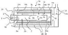
개질기의 과열을 방지하는 제1 방법은 버너-챔버와 연통하는 우회 밸브를 제공함으로써 달성된다. 우회 밸브는 개질기 벽을 따라 흐르는 상태와, 연도 가스가 개질기 벽을 따라 흐르는 것을 방지하기 위해 개질기 벽을 우회하여 연도 가스 출구 도관을 통해 버너-챔버 밖으로 흐르는 상태 간에 연도 가스의 흐름을 조절하도록 구성된다. 우회 밸브를 동작시킴으로써, 개질기 벽을 따라 흐르는 상태와, 개질기 벽을 우회하여 흐르는 상태 간에 연도 가스의 흐름이 조절된다.A first method of preventing overheating of the reformer is achieved by providing a bypass valve in communication with the burner-chamber. The bypass valve is configured to regulate the flow of flue gas between flowing along the reformer wall and flowing out of the burner-chamber through the flue gas outlet conduit bypassing the reformer wall to prevent the flue gas from flowing along the reformer wall . By operating the bypass valve, the flow of flue gas is regulated between flowing along the reformer wall and flowing bypassing the reformer wall.
예를 들어, 연도 가스의 우회량을 개질기 벽을 우회하여 연도 가스 출구 도관을 통해 버너-챔버 밖으로 안내하는 배기 경로가 우회 밸브에 의해 선택적으로 수립된다. 따라서 연도 가스의 일부 또는 전부인 우회량은 개질기 벽을 따라 흐르는 것이 방지된다.For example, an exhaust path is optionally established by the bypass valve that directs a bypass amount of flue gas out of the burner-chamber through the flue gas outlet conduit, bypassing the reformer wall. The bypass volume, which is part or all of the flue gas, is thus prevented from flowing along the reformer wall.
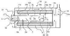
예를 들어 시동의 경우, 우회 밸브는 시동 단계의 모든 또는 대부분의 연도 가스가 개질기를 우회시키고 대신 연도 가스의 열 에너지를 연료 전지를 가열하는 데 사용하는 시동 구성으로 설정된다. 이것은 신속한 시동 절차로 이어진다. 시동 후 연도 가스가 개질기 벽을 따라 흐르도록 우회 밸브는 전환된다.For start-up, for example, the bypass valve is set in a start-up configuration in which all or most of the flue gas in the start-up phase bypasses the reformer and instead uses the thermal energy of the flue gas to heat the fuel cell. This leads to a quick start-up procedure. After start-up, the bypass valve is switched so that the flue gas flows along the reformer wall.
실제 실시형태에서, 연도 가스 출구 도관의 하류 측은 열 에너지를 냉각제로 전달하기 위해 연도 가스로부터 냉각 회로의 냉각제로 열 에너지를 전달하기 위해 열 교환기와 흐름 가능하게 연통한다. 연료 전지를 정상 동작 온도로 가열하기 위해 연도 가스의 열 에너지의 대부분을 개질기가 아닌 냉각제로 전달하기 위해 버너에서 나오는 연도 가스의 절반을 초과하는 우회량, 예를 들어, 모든 또는 실질적으로 모든 연도 가스가 시동 상황에서는 개질기를 우회하여 열 교환기에 도달한다.In a practical embodiment, the downstream side of the flue gas outlet conduit is in flowable communication with the heat exchanger for transferring thermal energy from the flue gas to the coolant in the cooling circuit for transferring thermal energy to the coolant. An amount of bypass in excess of half of the flue gas exiting the burner to transfer most of the thermal energy of the flue gas to the non-reformer coolant to heat the fuel cell to its normal operating temperature, e.g., all or substantially all of the flue gas In a start-up situation, it bypasses the reformer and reaches the heat exchanger.
그런 다음 시동 후, 우회 밸브는 정상 동작 구성으로 설정되어, 개질기를 우회하는 것을 폐쇄하고, 정상 동작 동안 개질기 촉매를 가열하기 위해 모든 연도 가스를 개질기 벽을 따라 흐르도록 한다.After start-up, the bypass valve is then set to the normal operating configuration, closing bypassing the reformer and allowing all flue gases to flow along the reformer walls to heat the reformer catalyst during normal operation.
일부 실시형태에서, 우회량은 버너로부터 개질기로 전달되는 열 에너지의 양을 조절하기 위해 연료 전지 시스템의 시동 동안 변경될 수 있다. 예를 들어, 연료 전지의 정상 동작 온도에 도달할 때까지 먼저 모든 연도 가스가 개질기를 우회하여 열 교환기에 도달하게 하는 대신, 특히 시동 절차의 후반 단계에서 시동 동안 개질기를 적당히 가열하기 위해 소량을 사용한다. 우회 밸브가 개질기를 우회하는 연도 가스의 양을 가변적으로 조절 가능한 경우, 시동 동안 개질기를 가열하는 온도 프로파일을 정밀하게 조절할 수 있다.In some embodiments, the bypass amount may be changed during startup of the fuel cell system to regulate the amount of thermal energy transferred from the burner to the reformer. For example, instead of first allowing all flue gases to bypass the reformer and reach the heat exchanger until the fuel cell's normal operating temperature is reached, a small amount is used to moderately heat the reformer during start-up, especially at later stages of the start-up procedure. do. If the bypass valve can variably control the amount of flue gas bypassing the reformer, it is possible to precisely adjust the temperature profile that heats the reformer during start-up.
원칙적으로, 정상 동작 동안 우회량을 제공하고 조절하는 것도 가능하다.In principle, it is also possible to provide and adjust the bypass amount during normal operation.
선택 사항으로, 소형 버너/개질기 유닛의 일 방법을 제공하기 위해, 개질기 벽은 관형이고 버너 벽을 둘러싼다. 그러나 이것은 반드시 필요한 것은 아니고, 버너/개질기의 나란한 구성 또는 개질기의 두 구획 사이에 끼인 버너 구성도 가능하다.Optionally, to provide one method of miniature burner/reformer unit, the reformer wall is tubular and surrounds the burner wall. However, this is not necessary, and a side-by-side configuration of the burner/reformer or a burner configuration sandwiched between two compartments of the reformer is possible.
버너와with burner개질기reformer 사이에 공간이 있는 양태 Aspect with space in between
이러한 소형 구성과 관련하여, 앞서 설명한 밸브를 이용하여 과열을 방지하는 제1 방법과 결합하기에 적합한, 개질기의 과열을 방지하는 제2 방법을 이하에서 설명한다.With respect to such a compact configuration, a second method of preventing overheating of the reformer, suitable for combining with the first method of preventing overheating using the valve described above, will be described below.
이 제2 방법에서는, 개질기를 따라 연도 가스를 안내하는 데 사용된 버너 벽으로부터의 전도성 열과 단열시키기 위해, 예를 들어, 절연 재료로 채워진 절연 공간이 개질기 벽과 버너 벽 사이에 제공된다.In this second method, an insulating space, eg filled with an insulating material, is provided between the reformer wall and the burner wall to insulate it from the conductive heat from the burner wall used to guide the flue gas along the reformer.
절연 공간을 통해 공기를 흐르게 하기 위해 공기, 선택 사항으로, 주변 공기를 절연 공간으로 공급하기 위해, 선택 사항으로, 공기 공급부가 제공된다. 예를 들어, 공기 흐름은 개질기의 벽을 따라 흐르며, 버너 벽으로부터 개질기 벽을 절연시킬 뿐만 아니라 절연 공간으로부터 오는 열을 제거한다. 공기 흐름은 버너 벽으로부터 오는 복사선에 의해 가열된 개질기를 냉각시킬 수도 있다.An air supply is optionally provided for supplying air, optionally, ambient air, into the insulating space for flowing air through the insulating space. For example, an air stream flows along the walls of the reformer, insulating the reformer walls from the burner walls as well as removing heat from the insulating space. The air stream may cool the reformer heated by radiation from the burner walls.
유리하게는, 개질기는 개질기 벽 및 이 개질기 벽으로 둘러싸인 촉매를 포함한다. 개질기 벽은 관형이고, 중심축을 갖는 중공 원통체를 형성하는 내부 원통형 벽과 외부 원통형 벽을 포함하고, 중공 원통체는 중심축을 따라 일 방향으로 측정했을 때 개질기 길이(L)를 갖는다. 중공 원통체는 제1 단부 및 제2 단부를 포함하고, 제1 단부는 제2 단부로부터 개질기 길이(L)만큼 이격된다. 일부 실시형태에서, 버너는 중공 원통체로 형성된 개질기의 중심 공동에 제공된다.Advantageously, the reformer comprises a reformer wall and a catalyst surrounded by the reformer wall. The reformer wall is tubular and includes an inner cylindrical wall and an outer cylindrical wall defining a hollow cylinder having a central axis, the hollow cylinder having a reformer length L as measured in one direction along the central axis. The hollow cylinder includes a first end and a second end, the first end being spaced apart from the second end by a reformer length L. In some embodiments, a burner is provided in the central cavity of the reformer formed as a hollow cylinder.
일부 양태에서, 버너는 관형 버너 벽을 포함한다. 유리하게는, 개질기의 내벽은 버너 벽을 둘러싸고, 버너 벽으로부터 이격되어 내벽과 버너 벽 사이에 공간을 제공하며, 버너-챔버는 연도 가스 도관에 의해 공간과 유체 흐름 가능하게 연통한다.In some aspects, the burner comprises a tubular burner wall. Advantageously, an inner wall of the reformer surrounds the burner wall and is spaced apart from the burner wall to provide a space between the inner wall and the burner wall, the burner-chamber being in fluid flow communication with the space by a flue gas conduit.
하우징은 개질기를 둘러싸고, 개질기의 외벽과 하우징 사이에 추가 공간이 제공된다. 공간과 추가 공간은 제1 단부에서 연결 전방-단부 챔버를 통해 상호 연결되어 열 교환 챔버를 형성한다. 원통형 개질기의 각각의 대향측에서 가열하면 가열 효율을 증가시킴과 동시에 열 과부하를 방지할 수 있다.The housing surrounds the reformer, and an additional space is provided between the housing and the outer wall of the reformer. The space and the further space are interconnected at the first end via a connecting front-end chamber to form a heat exchange chamber. Heating from each opposite side of the cylindrical reformer can increase heating efficiency and prevent thermal overload.
일부 양태에서, 개질기는 제1 단부에서 연료 증기용 입구와, 제2 단부에서 합성 가스용 출구, 및 입구로부터 출구로의 개질기 흐름 방향을 포함하고, 이 흐름 방향은 제1 단부로부터 제2 단부로 향하는 평균화된 일방향이다. 이 경우에, 공간에서 연도 가스의 흐름 방향은 개질기 흐름 방향과 반대이다.In some aspects, the reformer comprises an inlet for fuel vapor at a first end, an outlet for syngas at a second end, and a reformer flow direction from the inlet to the outlet, the flow direction from the first end to the second end. It is an averaged one-way towards In this case, the flow direction of the flue gas in space is opposite to the reformer flow direction.
동작을 위해 연도 가스는,For operation the flue gas is
- 버너 챔버로부터 연도 가스 도관을 통해 개질기 주변의 열 교환 챔버의 일부인 공간으로 흐르고,- flowing from the burner chamber through the flue gas conduit into the space that is part of the heat exchange chamber around the reformer,
- 그런 다음 개질기의 내부 원통형 벽을 따라 (유리하게는 버너 챔버에 다시 들어가지 않고) 개질기의 제1 단부로 흐르며, 내벽을 통한 열 전도에 의해 촉매를 가열하기 위해 연도 가스로부터 내벽으로 열을 전달하고,- then flows along the inner cylindrical wall of the reformer (advantageously without re-entering the burner chamber) to the first end of the reformer, transferring heat from the flue gas to the inner wall to heat the catalyst by heat conduction through the inner wall do,
- 그런 다음 전방-단부 챔버를 통해 추가 공간으로 흐르고,- then flows through the anterior-end chamber into an additional space,
- 그런 다음 외벽을 따라 개질기의 제2 단부로 흐르고,- then flows along the outer wall to the second end of the reformer,
- 연도 가스 출구 도관을 통해 버너/개질기 유닛 밖으로 흐른다.- flows out of the burner/reformer unit via the flue gas outlet conduit.
특히, 버너가 시동을 위해 대응하여 적극적인 연소로 사용되는 경우, 버너 벽과 내부 원통형 벽 사이의 공간이 개질기가 과열되는 것을 방지한다.In particular, the space between the burner wall and the inner cylindrical wall prevents the reformer from overheating when the burner is used with a correspondingly active combustion for start-up.
공간은 버너 벽과 개질기 벽 사이의 직접 접촉을 절연시키지만, 이 공간을 통해 버너 벽으로부터 나오는 열 복사선은 개질기 벽에 도달할 수 있다. 이 열 복사선은 개질기를 과열시킬 위험 없이 열 에너지가 전달되는 것을 추가한다.The space insulates the direct contact between the burner wall and the reformer wall, but through this space thermal radiation from the burner wall can reach the reformer wall. This thermal radiation adds to the transfer of thermal energy without the risk of overheating the reformer.
예를 들어, 버너는 오프 가스 또는 연료를 버너로 분사하기 위해 분사 매니폴드를 포함하며, 여기서 분사 매니폴드는 제1 단부에서 또는 제1 단부 근처에서 주로 개질기에 복사 에너지를 제공하기 위해 제2 단부보다 개질기의 제1 단부에 더 가깝게 제공된다. 제1 단부에서 대부분의 에너지가 필요하지만, 개질기를 과열시키지 않아야 하므로 제1 단부에서 복사 에너지를 추가하는 것이 유리하다.For example, the burner includes an injection manifold for injecting off-gas or fuel into the burner, wherein the injection manifold has a second end to provide radiant energy to the reformer primarily at or near the first end. provided closer to the first end of the reformer. Although most of the energy is needed at the first end, it is advantageous to add radiant energy at the first end as it should not overheat the reformer.
그러나, 버너로부터 개질기로 주된 열 전달은 연도 가스에 의해 열 에너지를 전달하는 것에 의해 달성된다.However, the main heat transfer from the burner to the reformer is achieved by transferring heat energy by means of the flue gas.
버너와 개질기의 내부 원통형 벽 사이의 공간 내부에서 연도 가스의 흐름은 개질기를 통한 개질기 가스의 흐름 방향과 반대 방향인 반면, 개질기의 외부 원통형 벽과 하우징 사이에 있는 추가 공간에서의 흐름은 개질기에서의 개질기 가스의 흐름과 같은 방향이라는 것이 주목된다. 개질기에서의 개질기 가스는 난류 및 가능하게는 심지어 나선형 경로를 받기 때문에 가스와 관련하여 "방향"이라는 용어는 평균화된 방향인 것으로 이해되어야 하는 것이 강조된다. 예를 들어, 개질기 내부의 흐름이 나선형 경로를 따르는 경우에도 이 흐름은 평균 방향을 입구로 변경함이 없이 입구로부터 출구로 향하는 라인을 따라 평균화된 것이다.The flow of flue gas inside the space between the burner and the inner cylindrical wall of the reformer is in the opposite direction to that of the reformer gas through the reformer, whereas the flow in the additional space between the outer cylindrical wall of the reformer and the housing is in the reformer. It is noted that it is in the same direction as the flow of the reformer gas. It is emphasized that the term “direction” in relation to gases should be understood to be an averaged direction since the reformer gas in the reformer is subjected to a turbulent and possibly even helical path. For example, even if the flow inside the reformer follows a helical path, this flow is averaged along the line from the inlet to the outlet without changing the average direction to the inlet.
일부 실시형태에서는, 위에서 설명된 바와 같이, 우회 밸브가 제공되지 않는다. 이러한 실시형태에서, 버너로부터의 전체 연도 가스는 개질기 주위로 안내되어, 연도 가스는 개질기의 외부 원통형 벽의 외측에 있는 추가 공간의 하류인 연도 가스 출구 도관을 통해서만 빠져나갈 수 있다. 특히, 이를 위해, 연도 가스가 하우징과 외부 원통형 벽 사이의 추가 공간을 우회하는 것을 방지하고 연도 가스가 개질기 주위로 항상 흐르도록 하기 위해 버너 챔버와 연도 가스 출구 도관 사이 및 공간과 연도 가스 출구 도관 사이에 분리 벽이 제공된다. 이러한 실시형태는 우회 밸브 없이 제공된다. 그러나, 다른 실시형태는 또한 전술한 바와 같이 이러한 우회 밸브를 포함한다.In some embodiments, no bypass valve is provided, as described above. In this embodiment, the entire flue gas from the burner is directed around the reformer so that the flue gas can only exit through a flue gas outlet conduit that is downstream of the additional volume outside of the external cylindrical wall of the reformer. In particular, for this purpose, between the burner chamber and the flue gas outlet conduit and between the space and the flue gas outlet conduit in order to prevent the flue gas from bypassing the additional space between the housing and the outer cylindrical wall and to ensure that the flue gas always flows around the reformer. A separating wall is provided. This embodiment is provided without a bypass valve. However, other embodiments also include such bypass valves as described above.
이하의 선택 사항인 유리한 실시형태는 개질기로의 열 전달 프로파일을 최적화하는데 유용하다. 예를 들어, 연도 가스 도관은 버너 벽에 제공된다. 선택 사항으로, 버너 챔버로부터 열 교환 챔버로 연도 가스를 흐르게 하기 위한 연도 가스 도관은 제2 단부로부터 거리를 두고 제공되고, 이 거리는 L의 10% 내지 50% 범위이고, 이 거리는 개질기의 중심축을 따라 측정된 것이다. 선택 사항으로, 버너 챔버로부터 열 교환 챔버로 연도 가스를 흐르게 하기 위한 연도 가스 도관은 L의 5% 내지 60% 범위의 길이에 걸쳐 연장되고, 이 길이는 개질기의 중심축을 따라 측정된 것이다. 선택 사항으로, 이 거리와 이 길이의 합은 L의 15% 내지 80% 범위이다.The following optional advantageous embodiments are useful for optimizing the heat transfer profile to the reformer. For example, a flue gas conduit is provided in the burner wall. Optionally, a flue gas conduit for flowing flue gas from the burner chamber to the heat exchange chamber is provided at a distance from the second end, the distance ranging from 10% to 50% of L, the distance along the central axis of the reformer it is measured Optionally, a flue gas conduit for flowing flue gas from the burner chamber to the heat exchange chamber extends over a length ranging from 5% to 60% of L, the length being measured along the central axis of the reformer. Optionally, the sum of this distance and this length ranges from 15% to 80% of L.
일부 실시형태에서, 개질기는 제1 단부와 제2 단부 사이 및 내부 원통형 벽과 외부 원통형 벽 사이에 연장되는 나선형 벽을 포함하고, 나선형 벽은 개질기를 통한 나선형 흐름 경로를 획정한다. 나선형 벽은 개질기를 통한 흐름 경로의 길이를 제1 단부로부터 제2 단부까지의 거리를 따른 직접 흐름보다 더 길게 연장한다. 이러한 나선형 경로는 개질기를 통해 두 방향으로 역류를 생성할 필요 없이 개질기의 흐름 경로를 더 길게 만든다는 점에서 종래 기술에 비해 이점이 있다. 또한 나선형 경로는 개질기에서 가스가 혼합되는 것을 개선한다.In some embodiments, the reformer includes a helical wall extending between the first end and the second end and between the inner cylindrical wall and the outer cylindrical wall, the helical wall defining a helical flow path through the reformer. The helical wall extends the length of the flow path through the reformer longer than the direct flow along the distance from the first end to the second end. This helical path has an advantage over the prior art in that it makes the flow path of the reformer longer without the need to create countercurrent in both directions through the reformer. The spiral path also improves gas mixing in the reformer.
예를 들어, 개질기 촉매는 효율적인 개질을 위해 나선형 벽의 선회부(winding)들 사이에 과립으로 제공된다.For example, the reformer catalyst is provided as granules between the windings of the spiral wall for efficient reforming.
선택 사항으로, 버너로부터 개질기의 벽으로 고온 연도 가스의 방출 위치를 조절함으로써 가열 프로파일을 최적화할 수 있다. 선택 사항으로, 하나를 초과하는 연도 가스 도관이 제공되며, 다수의 연도 가스 도관이 개질기의 온도 프로파일을 최적화하기 위해 개질기의 길이를 따라 서로 다른 위치에 제공된다.Optionally, the heating profile can be optimized by controlling the location of the discharge of hot flue gases from the burners to the walls of the reformer. Optionally, more than one flue gas conduit is provided, and a plurality of flue gas conduits are provided at different locations along the length of the reformer to optimize the temperature profile of the reformer.
물의 재활용에 관한 양태Aspects of water recycling
더 일반적인 개선은 이하에서 언급되며, 이는 상기 실시형태에도 적용될 뿐만 아니라, 연료 전지에 물을 사용하는 연료 전지에, 예를 들어, HTPEM 연료 전지에 위에서 설명한 바와 같이 메탄올과 물의 혼합물을 사용하는 일반적인 원리로서 유용하다. 이 개선예에서 연료 전지 및/또는 버너로부터 나오는 물은 재활용된다.A more general improvement is mentioned below, which applies not only to the above embodiments, but also to the general principle of using a mixture of methanol and water as described above for fuel cells using water in fuel cells, for example HTPEM fuel cells. useful as In this refinement the water from the fuel cell and/or burner is recycled.
일부 실제 실시형태에서, 액체 연료 공급부는 메탄올을 공급하기 위한 메탄올 저장소뿐만 아니라 물을 공급하기 위한 물 공급부를 포함하고, 증발기의 상류에 있는 혼합 지점에서 물을 메탄올과 혼합하고, 물 공급부는 버너의 연도 가스로부터 재활용되는 물을 공급하도록 구성된다.In some practical embodiments, the liquid fuel supply comprises a water supply for supplying water as well as a methanol reservoir for supplying methanol, mixing the water with methanol at a mixing point upstream of the evaporator, the water supply being the burner's configured to supply recycled water from the flue gas.
예를 들어, 물 공급부는 혼합 지점으로부터, 증발기를 통해, 개질기를 통해, 연료 전지의 애노드 측을 통해, 버너를 통해, 응축기를 통해, 다시 혼합 지점으로 돌아가는 재활용 회로의 일부이다.For example, the water supply is part of the recycling circuit from the mixing point, through the evaporator, through the reformer, through the anode side of the fuel cell, through the burner, through the condenser, and back to the mixing point.
선택 사항으로, 재활용 회로는 연료 전지의 캐소드 측의 출구로부터 물을 첨가하도록 구성된다.Optionally, the recycling circuit is configured to add water from an outlet on the cathode side of the fuel cell.
구체적인 실시형태에서, 물과 메탄올이 혼합 지점으로 공급되고, 물과 메탄올의 혼합물이 증발기에서 증발되며, 증발된 혼합물은 연료로서 개질기에 공급되고, 촉매와 반응하여 합성 가스를 생성하고, 이 합성 가스는 오프 가스를 생성하기 위해 연료 전지의 애노드 측으로 공급된다. 애노드로부터 나온 오프 가스는 버너로 공급되어 연소되고, 일반적으로 촉매 반응으로 연소되어 연도 가스를 생성하고, 이 연도 가스는 연도 가스에서 물을 응축하기 위해 응축기로 공급된다. 물은 사이클을 반복하기 위해 혼합 지점으로 다시 공급된다. 선택 사항으로 연료 전지의 캐소드 측의 출구로부터 나오는 물은 재활용 회로에 첨가된다.In a specific embodiment, water and methanol are fed to the mixing point, the mixture of water and methanol is evaporated in the evaporator, and the evaporated mixture is fed to the reformer as fuel, reacted with a catalyst to produce synthesis gas, and this synthesis gas is supplied to the anode side of the fuel cell to generate off-gas. The off-gas from the anode is fed to a burner where it is combusted, usually catalytically combusted to produce flue gas, which is fed to a condenser to condense water in the flue gas. Water is fed back to the mixing point to repeat the cycle. Optionally, water from the outlet on the cathode side of the fuel cell is added to the recycling circuit.
선택 사항으로, 폐열을 사용하기 위해, 연료 전지 시스템은 냉각제로부터 버너의 상류 공기로 열 에너지를 전달하기 위해 추가 열 교환기를 포함한다. 이것은 버너-챔버에 들어가기 전에 공기의 온도를 높이는 데 사용되어 연료 전지 시스템의 에너지 효율을 증가시킨다.Optionally, to use waste heat, the fuel cell system includes an additional heat exchanger to transfer thermal energy from the coolant to the air upstream of the burners. It is used to raise the temperature of the air before it enters the burner-chamber, increasing the energy efficiency of the fuel cell system.
양태mode
이하에서는 상호 관련되고 본 명세서에 언급된 다른 양태와 결합될 수 있는 다수의 양태를 설명한다.A number of aspects are set forth below that are interrelated and may be combined with other aspects mentioned herein.
양태 1. 연료 전지 시스템용 버너/개질기 유닛으로서, 버너/개질기 유닛은 연료 증기를 연료 전지를 위한 합성 가스로 촉매 변환하기 위한 촉매를 갖는 개질기, 개질기 주변의 하우징, 및 촉매를 가열하기 위해 개질기에 열 에너지를 제공하기 위한 버너를 포함하고;Aspect 1. A burner/reformer unit for a fuel cell system, wherein the burner/reformer unit includes a reformer having a catalyst for catalytically converting fuel vapor to syngas for a fuel cell, a housing around the reformer, and to the reformer for heating the catalyst. a burner for providing thermal energy;
개질기는 원통형 내벽과 원통형 외벽을 포함하고; 원통형 내벽과 원통형 외벽 사이에는 촉매가 위치되고; 내벽과 외벽은 중심축을 갖는 중공 원통체를 형성하고, 중공 원통체는 중심 축을 따라 일 방향으로 측정했을 때 개질기 길이(L)를 갖고, 중공 원통체는 제1 단부 및 제2 단부를 포함하고, 제1 단부는 제2 단부로부터 개질기 길이(L)만큼 이격되고;The reformer comprises a cylindrical inner wall and a cylindrical outer wall; A catalyst is positioned between the cylindrical inner wall and the cylindrical outer wall; the inner wall and the outer wall form a hollow cylinder having a central axis, the hollow cylinder having a reformer length (L) measured in one direction along the central axis, the hollow cylinder comprising a first end and a second end; the first end is spaced apart from the second end by a reformer length L;
버너는 애노드 폐가스 또는 연료 또는 이 둘 다를 연소시킴으로써 연도 가스를 제공하도록 구성되고, 관형 버너 벽을 포함하고, 개질기의 내벽은 버너 벽을 둘러싸고, 버너 벽으로부터 이격되어 내벽과 버너 벽 사이에 공간을 제공하고, 버너-챔버는 연도 가스 도관에 의해 공간과 유체 흐름 가능하게 연통하고;The burner is configured to provide flue gas by burning anode waste gas or fuel, or both, and includes a tubular burner wall, wherein an inner wall of the reformer surrounds the burner wall and is spaced apart from the burner wall to provide a space between the inner wall and the burner wall and the burner-chamber is in fluid flow communication with the space by a flue gas conduit;
하우징은 개질기를 둘러싸고, 개질기의 외벽과 하우징 사이에는 추가 공간이 제공되고; 공간과 추가 공간은 제1 단부에서 연결 전방-단부 챔버를 통해 상호 연결되고;The housing surrounds the reformer, and an additional space is provided between the housing and the outer wall of the reformer; the space and the further space are interconnected at the first end via a connecting front-end chamber;
버너/개질기 유닛은 연도 가스가 버너 챔버로부터 연도 가스 도관을 통해 공간으로 흐르고 나서, 버너 챔버로 다시 들어가지 않고 내부 원통형 벽을 따라 개질기의 제1 단부로 흐르며, 내벽을 통한 열 전도에 의해 촉매를 가열하기 위해 연도 가스로부터 내벽으로 열을 전달하고, 그런 다음 전방-단부 챔버를 통해 추가 공간으로 흐르고, 그런 다음 외벽을 따라 개질기의 제2 단부로 흐르고, 연도 가스 출구 도관을 통해 버너/개질기 유닛 밖으로 흐르도록 구성되고,The burner/reformer unit allows the flue gas to flow from the burner chamber through the flue gas conduit into the space and then, without re-entering the burner chamber, along an inner cylindrical wall to the first end of the reformer, and heat the catalyst by conduction through the inner wall. Transfers heat from the flue gas to the inner wall for heating, then flows through the front-end chamber into the further space, then along the outer wall to the second end of the reformer, and out of the burner/reformer unit through the flue gas outlet conduit configured to flow,
개질기는 제1 단부에서 연료 증기를 위한 입구와, 제2 단부에서 합성 가스를 위한 출구, 및 입구로부터 출구로 향하는 개질기 흐름 방향을 포함하고, 개질기 흐름 방향은 제1 단부로부터 제2 단부로 향하는 평균화된 일방향이고, 공간에서 연도 가스의 흐름 방향은 개질기 흐름 방향과 반대인 것을 특징으로 하는 버너/개질기 유닛.The reformer includes an inlet for fuel vapor at a first end, an outlet for syngas at a second end, and a reformer flow direction from the inlet to the outlet, wherein the reformer flow direction is averaging from the first end to the second end. Burner/reformer unit, characterized in that the flow direction of the flue gas in space is opposite to the reformer flow direction.
양태 2. 양태 1에 있어서, 버너 챔버로부터 열 교환 챔버로 연도 가스를 흐르게 하기 위한 연도 가스 도관은 제2 단부로부터 제1 도관 거리만큼 이격되고, 제1 도관 거리는 개질기 길이(L)의 15% 내지 50% 범위이고, 제1 도관 거리는 개질기의 중심축을 따라 측정된 것인, 버너/개질기 유닛.Aspect 2. A flue gas conduit for flowing flue gas from the burner chamber to the heat exchange chamber is spaced apart from the second end by a first conduit distance, the first conduit distance from 15% to 15% of the reformer length (L) 50% range, and wherein the first conduit distance is measured along the central axis of the reformer.
양태 3. 양태 2에 있어서, 버너 챔버로부터 열 교환 챔버로 연도 가스를 흐르게 하기 위한 연도 가스 도관은 개질기 길이(L)의 10% 내지 60% 범위에 있는 제1 도관 길이에 걸쳐 연장되고, 제1 도관 길이는 개질기의 중심축을 따라 측정된 것인, 버너/개질기 유닛.
양태 4. 양태 3에 있어서, 제1 도관 거리와 제1 도관 길이의 합은 L의 25% 내지 80% 범위에 있는, 버너/개질기 유닛.Aspect 4. The burner/reformer unit of
양태 5. 양태 1 내지 양태 4 중 어느 하나에 있어서, 연도 가스 도관은 버너 챔버에 제1 천공 그룹으로서 제공되는, 버너/개질기 유닛.Aspect 5. The burner/reformer unit of any of aspects 1-4, wherein the flue gas conduit is provided as a first group of perforations to the burner chamber.
양태 6. 양태 5에 있어서, 추가 연도 가스 도관이 버너 챔버에 제2 천공 그룹으로서 제공되고; 추가 연도 가스 도관은 연도 가스 도관보다 제1 단부에 더 가깝게 위치되고; 제1 그룹에서 인접한 천공들은 제1 간격으로 이격되고; 제1 그룹과 제2 그룹 간의 그룹 거리는 제1 간격의 적어도 10배이고; 추가 연도 가스 도관은 연도 가스 도관과 다른 총 흐름 면적을 갖는, 버너/개질기 유닛.
양태 7. 제1 양태 내지 제6 양태 중 어느 하나에 있어서, 버너는 버너 내로 오프 가스 또는 연료를 분사하기 위한 분사 매니폴드를 포함하고, 분사 매니폴드는 주로 제1 단부에서 개질기에 복사 에너지를 제공하기 위해 제2 단부보다 개질기의 제1 단부에 더 가까운 버너 챔버 내부에 제공되는, 버너/개질기 유닛.
양태 8. 제1 양태 내지 제7 양태 중 어느 하나에 있어서, 연도 가스가 개질기를 우회하는 것을 방지하고 대신 연도 가스가 공간과 추가 공간으로 흐르게 하기 위해 버너 챔버와 연도 가스 출구 도관 사이 및 공간과 연도 가스 출구 도관 사이에 분리 벽이 제공되는, 버너/개질기 유닛.
양태 9. 제1 양태 내지 제8 양태 중 어느 하나에 있어서, 개질기는 제1 단부와 제2 단부 사이 및 내부 원통형 벽과 외부 원통형 벽 사이에 연장되는 나선형 흐름 안내부를 포함하고, 나선형 흐름 안내부는 개질기의 중심축을 따라 측정했을 때 개질기를 통한 흐름 경로의 길이를 제1 단부로부터 제2 단부까지의 거리보다 더 길게 연장시키기 위해 개질기를 통한 나선형 흐름 경로를 획정하고, 촉매는 나선형 흐름 안내부의 선회부들 사이에 제공되는, 버너/개질기 유닛.
양태 10. 양태 1 내지 양태 7 중 어느 하나에 따른 버너/개질기 유닛을 동작시키는 방법으로서, 방법은 연도 가스가 버너 챔버로부터 연도 가스 도관을 통해 공간으로 흐르고 나서, 버너 챔버로 다시 들어가지 않고 내부 원통형 벽을 따라 개질기의 제1 단부로 흐른 다음, 전방-단부 챔버를 통해 추가 공간으로 흐른 후, 외벽을 따라 개질기의 제2 단부로 흐르고, 연도 가스 출구 도관을 통해 버너/개질기 유닛 밖으로 흐르는 단계를 포함하고, 방법은 제1 단부에서 연료 증기를 위한 입구와, 제2 단부에서 합성 가스를 위한 출구를 갖는 개질기를 제공하는 단계, 및 입구로부터 출구로 흐름 방향을 유발하는 단계를 포함하고, 상기 흐름 방향은 제1 단부로부터 제2 단부로 향하는 평균화된 일방향이며, 공간에서 연도 가스의 흐름 방향은 개질기 흐름 방향과 반대인 것을 특징으로 하는 버너/개질기 유닛을 동작시키는 방법.
양태 11. 자동차의 연료 전지 시스템을 위한 양태 1 내지 양태 9 중 어느 하나에 따른 버너/개질기 유닛의 용도.
양태 12. 양태 11에 있어서, 연료 전지 시스템은 메탄올과 물의 혼합물인 액체 연료와 함께 섭씨 120도 내지 200도 범위의 온도에서 동작하도록 구성된 HTPEM 연료 전지를 포함하는, 버너/개질기 유닛의 용도.
도면을 참조하여 본 발명을 보다 상세히 설명한다.
도 1은 연료 전지 시스템의 일례를 도시한다.
도 2a는 소형 버너/개질기 유닛이 정상 상태에서 동작하는 경우의 밸브를 갖는 대안적인 실시형태를 도시한다.
도 2b는 시동 상태의 대안적인 실시형태를 도시한다.
도 3은 연료 전지 시스템에 대한 흐름도를 도시한다.
도 4a, 도 4b, 도 4c 및 도 4d는 오프셋 연도 가스 도관을 갖는 대안적인 실시형태를 도시한다.
도 5a는 나선형 흐름 안내부를 포함하는 개질기를 갖는 소형 버너/개질기 유닛의 사시도를 예시한다.
도 5b는 나선형 흐름 안내부를 갖는 개질기의 단면도이다.The present invention will be described in more detail with reference to the drawings.
1 shows an example of a fuel cell system.
Figure 2a shows an alternative embodiment with a valve when the miniature burner/reformer unit is operating in steady state.
Figure 2b shows an alternative embodiment of the starting state.
3 shows a flow diagram for a fuel cell system.
4A, 4B, 4C and 4D show an alternative embodiment with an offset flue gas conduit.
5A illustrates a perspective view of a miniature burner/reformer unit having a reformer comprising a helical flow guide.
5B is a cross-sectional view of a reformer with a helical flow guide.
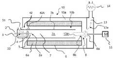
도 1은 연료 전지(16), 일반적으로, 연료 전지 스택, 및 버너(7)와 개질기(6)를 포함하는 버너/개질기 유닛(10)을 갖는 연료 전지 시스템(1)을 도시한다. 버너(7)는 개질기(6)를 가열하기 위한 열 에너지를 갖는 연도 가스를 생성하기 위한 버너-챔버(7a)를 포함한다. 버너-챔버(7a) 내에는 일반적으로 버너-촉매가 제공되지만, 도 1 및 도 2에서 간략화를 위해 도시되지 않았다.1 shows a fuel cell system 1 having a
예를 들어, 버너(7)는 개질기(6)가 내부에 위치된 열 교환 챔버(10b)의 두 층 사이에 끼워진다.For example, the
대안적으로, 버너(7)는 원통형이고, 내부 공동 및 링형 단면을 갖는 중공 관으로 형성된 원통형 관형 열 교환 챔버(10a)에 의해 둘러싸여 있다. 특히, 원통형 구성은 소형이어서 공간이 부족한 자동차에 사용할 때 유리하다.Alternatively, the
원통형 개질기(6)는 내부 원통형 벽(6c) 및 이 내부 원통형 벽(6c)과 동축인 외부 원통형 벽(6d)을 포함하는 개질기 벽(6b) 내에 제공된다.A
공기 입구(31)는 버너-챔버(7a)로 공기 흐름(32)을 제공한다. 오프 가스 입구(3)와 분사 매니폴드(4)를 통해, 연료 전지(16)의 애노드로부터 오프 가스(3a)가 버너-챔버(7a)로 들어가고, 오프 가스는 연료 전지(16)에서 반응한 후에도 연료가 남아 있기 때문에 버너(7)에서 연료로 사용된다. 버너-챔버(7a)에서 연소된 연도 가스(13a)는 열 교환 챔버(10a)로 흐른다.The
상당한 열을 함유하는 연도 가스(13a)는 개질기의 벽을 따라 흐름으로써 개질기(6)의 벽(6b)의 외측을 가열한다. 일반적인 금속 벽인 벽(6b)을 통해 열 에너지를 전도하는 것에 의해, 연도 가스(13a)로부터의 열 에너지는 개질기 벽(6b)에 의해 둘러싸인 공간 내 촉매(6a)로 전달된다.
개질기(6)의 가열된 촉매(6a)는, 투입 공급부(19)로부터 물이 공급되고 메탄올 투입 밸브(20)를 통해 메탄올이 공급되는 혼합 지점(38)의 하류에 배치된 증발기(28)로부터 물과 메탄올의 혼합물을 수용한다. 혼합물은 원통형 개질기(6)의 제1 단부(40a)에서 입구(24a)를 통해 개질기(6)로 들어간다. 개질기(6)에서, 혼합물은 촉매와 반응하여 합성 가스를 생성하고, 합성 가스는 원통형 개질기(6)의 제2 단부(40b)에서 출구(24b)를 통해 개질기(6)를 떠나고, 출구로부터 합성 가스는 연료 전지(16)의 애노드로 공급된다. 캐소드에는 산소를 제공하기 위해 압축기(17)로부터 공기가 공급된다.The
도 1에 도시된 바와 같이, 버너 챔버(7a)의 벽(7b)은 개질기 벽(6b)과 접하지 않고, 특히 개질기(6)의 내벽(6c)과 접하지 않고, 그 사이에 공간(10b)이 제공되고, 이 공간은 버너 챔버 벽(7b)으로부터 개질기 벽(6b)으로 직접 열 전도를 방지하며 절연성이다. 이것은 개질기(6)가 과열되는 것을 유리하게 방지한다.As shown in FIG. 1 , the
일부 종래 기술과 달리, 개질기(6)는 개질기 가스를 원통형 개질기(6)의 제1 단부(40a)를 향하는 역류 흐름으로 방향 전환시키는 제2 스테이지를 갖지 않는다. 대신에, 평균화된 개질기 흐름은 화살표로 표시된 바와 같이 개질기(6)의 제1 단부(40a)로부터 제2 단부(40b)로 향하는 일방향이다.Unlike some prior art, the
버너(7) 내 연도 가스(13a)는 제2 개질기 단부(40b)를 향하는 방향을 갖고, 그런 다음 분리 벽(52)에서 연도 가스 도관(12)을 통해 열 교환 챔버(10a)로 들어간다.The
분리 벽(52)은 개질기의 제2 단부(40b)에 제공되고 중실이며, 분리 벽은, 버너 챔버(7a)를 포함하고 내벽(6c)에 의해 구획되는 중공 챔버를 가로질러 연장된다. 분리 벽(52)은 연도 가스 출구 도관(9)과 연도 가스 챔버(13)로부터 버너(7)와 열 교환 챔버(10a)의 상류 부분을 분리하여, 따라서 연도 가스가 연도 가스 챔버(13a)에 도달하는 유일한 옵션은 개질기(6) 주위로 흐르는 것에 의하도록 한다. 도 1에 예시된 바와 같이, 열 교환 챔버(10a)의 상류 단부는 개질기(6)의 하류의 대략 제2 단부(40b)에 있다.A dividing
연도 가스(13a)가 버너 챔버(7a)의 단부에서 연도 가스 도관(12)을 통해 열 교환 챔버(10a)로 들어갈 때, 연도 가스는, 열 교환 챔버(10a)에서 내부 원통형 벽(6c)을 따라 개질기(6)의 제1 단부(40a)를 향해 반대 방향을 향하는 역류 흐름으로 방향을 변경하고, 이 변경된 방향은 버너 챔버(7a)에서 흐르는 방향과 반대 방향이고, 개질기(6)에서 개질기 가스의 흐름 방향과 반대 방향이다. 제1 단부(40a)에 도달할 때, 연도 가스(13a)는 개질기(6)의 제1 단부(40a) 주위로 흐르고, 하우징(39) 내에서 다시 한번 방향을 변경하여 개질기(6)의 외부 원통체 벽(6d)을 따라 버너 챔버(7a) 및 개질기(6)에서의 흐름과 동일한 방향으로 평행하게 흐른다.When the
연도 가스(13a)로부터 개질기(6)로 열 에너지를 전달한 후, 개질기(6)의 제2 단부(40b)에 도달하면, 연도 가스(13a)는 제2 단부(40b)에서 열 교환 챔버(10a)를 빠져나가 연도 가스 도관(9)을 통해 연도 가스 챔버(13)로 흐른다.After transferring the thermal energy from the
이러한 구성의 장점은, 내부 원통형 벽(6c)으로부터 뿐만 아니라 외부 원통형 벽(6d)으로부터 개질기(6)의 촉매 반응을 위한 열을 전달함으로써, 개질기가 비교적 큰 직경을 가지더라도 양측으로부터 보다 균일하게 개질기(6) 내 반응을 가열할 수 있다는 것이다. 내부 원통형 벽(6c)만이 가열되거나 외부 원통형 벽(6d)만이 가열되면, 열 전달이 최적화되지 않는다.The advantage of this configuration is that by transferring heat for the catalytic reaction of the
개질기의 일측만이 가열되는 종래 기술 구성에서는 버너의 벽을 나선형 벽 구조물에 의해 개질기 내로 연장함으로써 충분한 열의 부족을 개선하려고 시도하였다. 그러나, 이러한 종래 기술의 원리는 버너의 벽이 금속 벽을 통한 열 전도에 의해 열을 개질기 내로 안내한다는 것을 의미한다. 이것은 버너가 적당한 열로 사용하지 않는 경우 열 전달이 너무 적극적이기 때문에 버너가 적당한 열로만 사용될 것을 요구한다. 그 결과 종래 기술에서는 버너를 고효율로 사용할 수 없어 깨끗한 연소가 방지된다. 본 발명에서는 이러한 단점을 극복한다.In prior art configurations where only one side of the reformer is heated, attempts have been made to ameliorate the lack of sufficient heat by extending the walls of the burner into the reformer by means of a spiral wall structure. However, this prior art principle means that the walls of the burner conduct heat into the reformer by heat conduction through the metal walls. This requires that the burner be used only with moderate heat because heat transfer is too aggressive if the burner is not used with adequate heat. As a result, in the prior art, the burner cannot be used with high efficiency, thereby preventing clean combustion. The present invention overcomes these disadvantages.
대체로, 예시된 실시형태와 종래 기술을 비교하면, 개질기 벽(6b)을 따라 흐르는 연도 가스(13a)의 흐름을 통해 간접적으로 열을 전달하면 버너 벽(7b)으로부터 금속 벽을 통해 개질기 벽(6b)으로 직접 열을 전달하는 것보다 더 적당한 열을 생성할 수 있음과 동시에, 열이 내부 원통형 벽(6c)과 외부 원통형 벽(6d) 모두로 전달되기 때문에 크고 최적화된 총 열량을 제공할 수 있다.In general, comparing the illustrated embodiment with the prior art, the transfer of heat indirectly through the flow of
선택 사항으로, 버너(7)로부터 버너 벽(7b)을 통한 복사 에너지가 추가되어 효율을 증가시킨다.Optionally, radiant energy from the
선택 사항으로, 연료 전지(16)의 상류에 있는 냉각 회로(22)의 냉각된 냉각제는 연도 가스 챔버(13)의 하류에 있는 열 교환기(14)에서 열을 교환하는 것에 의해 연도 가스(13b)로부터 추가 열 에너지를 수용한다.Optionally, the cooled coolant in the
연료 전지(16)의 캐소드로부터 연결부(33)를 통해 공기와 수증기가 연도 가스 챔버(13)로 들어가고, 열 에너지를 냉각 회로(22)의 냉각제로 전달하기 위해 열 교환기(14)에 도달하기 전에 연도 가스(13a)와 혼합되고, 냉각-액체는 펌프(15)에 의해 냉각 회로를 통해 펌핑된다.Air and water vapor from the cathode of the
연료 전지(16)로부터 추가 열 에너지를 흡수함으로써 연료 전지(16)를 냉각시킨 후, 냉각제는 추가 열 교환기(18)로 들어가고, 이 추가 열 교환기를 통해 다른 구성 요소, 예를 들어, 차량의 배터리 또는 실내를 가열하기 위해 열을 사용한다.After cooling the
정상 상태 동작 동안 HTPEM 연료 전지 스택의 일반적인 섭씨 온도는,The typical Celsius temperature of the HTPEM fuel cell stack during steady-state operation is:
연료 전지: 섭씨 170도Fuel cell: 170 degrees Celsius
냉각-액체: 섭씨 160도Cooling-Liquid: 160 degrees Celsius
개질기의 촉매: 섭씨 280도Catalyst in reformer: 280 degrees Celsius
연도 가스: 섭씨 350도 내지 400도Flue gas: 350 to 400 degrees Celsius
선택 사항으로, 시동 상황에서 동일한 버너(7)를 초기 가열 버너로 사용할 수 있다. 이 경우, 메탄올은 메탄올 입구(2)를 통해 대응하는 메탄올 주입 밸브(21)로부터 수용되고, 메탄올 분사 노즐(5)을 통해 버너-챔버(7a)로 분사된다. 촉매 연소를 위해, 일반적으로 버너 촉매에 의한 연소를 위해, 공기(32)는 공기 입구(31)를 통해 들어온다.Optionally, the
연도 가스는 연도 가스(13a)가 버너 챔버(7a)를 빠져나가 개질기 벽(6b)에 접근하는 위치에서 가장 많은 양의 열을 내부 원통형 벽(6c)으로 전달한다. 점차적으로 연도 가스(13a)는 내부 원통형 벽(6c)을 따라 제1 단부(40a)를 향해 흐르면서 감소된 온도를 갖는다. 그러나, 이것은 반드시 제1 단부(40a)에 있는 내부 원통형 벽(6c)이 가장 낮은 총 열량을 수용한다는 것을 의미하는 것은 아니다. 이것은 버너 챔버(7a)의 온도가 노즐(5)에서 가장 높기 때문에 버너 벽(7b)으로부터의 복사 에너지가 특히 제1 단부(40a)에 있는 내부 원통형 벽(11c)에 추가되기 때문이다.The flue gas transfers the greatest amount of heat to the inner
추가 개선은 도 2a 및 도 2b에 도시되고, 도 2b는 설명의 편의를 위해 연료 전지 시스템의 일부만을 도시한다. 액추에이터(11)에 의해 조절되고 시동 상황에서 개질기(6)를 우회하도록 연도 가스(13a)를 연도 가스 챔버(13)로 안내하는 데 사용되는 폐쇄 부재(8a)가 있는 우회 밸브(8)가 특히 주목된다.A further improvement is shown in FIGS. 2A and 2B , which shows only a portion of the fuel cell system for convenience of explanation. A
도 2a의 시스템은, 밸브(8)가 폐쇄되어 있고 분리 벽(52)을 대체하기 때문에 도 1의 시스템과 유사한 상황을 도시한다. 이 실시형태에서, 도 2a는 정상 상태 동작 동안의 구성을 도시하고, 도 2b는 시동 상황을 도시한다.The system of FIG. 2A shows a situation similar to the system of FIG. 1 because the
도 2b에 도시된 바와 같이, 우회 밸브(8)의 폐쇄 부재(8a)는, 폐쇄 부재(8a)가 밸브 시트(8b)로부터 후퇴되고 우회 밸브(8)가 완전히 개방되어서, 연도 가스(13a)가 개질기(6)를 포함하는 열 교환 챔버(10a)를 우회하여 버너-챔버(7a)로부터 연도 가스 챔버(13)로 흐르도록 버너-챔버(7a)가 연도 가스 챔버(13)에 연결된 구성으로 된 것이다.As shown in Fig. 2b, the closing
시동 상황에서, 메탄올(2a)은 메탄올 입구(2)를 통해 수용되고 메탄올 분사 노즐(5)을 통해 버너-챔버(7a)로 분사된다. 연소, 일반적으로 버너 촉매에 의한 연소를 위해, 공기(32)는 공기 입구(31)를 통해 들어온다.In the start-up situation,
도시되고 논의된 바와 같이, 버너 벽(7b)은 개질기 벽(6b)과 접하지 않고, 이들 사이에 절연 공간(10b)이 제공되어, 버너-챔버 벽(7b)으로부터 개질기 벽(6b)으로 직접 열 전도가 일어나는 것을 방지한다. 선택 사항으로, 버너(7)의 열로부터 개질기(6)를 추가로 보호하기 위해, 우회 공기 흐름(42A)이 공기 우회 오리피스(42)를 통해 수립되어, 공기 입구(31)로부터 버너 벽(7b)과 내부 개질기 벽(6b) 사이의 절연 공간(10b)으로 버너-챔버(7a)의 외측을 따라 공기 흐름(42A)을 생성할 수 있다. 공기 흐름(42A)은 버너-챔버(7)의 고온 버너 벽(7b)으로부터 개질기(6)를 추가로 절연시킬 뿐만 아니라 개질기 벽(6b)으로부터 열을 제거할 수 있다. 도시된 실시형태에서, 우회 공기 흐름(42A)은 밸브(8)를 통해 열 교환 챔버(10a)를 떠나 연도 가스 챔버(13)에서 연도 가스(13a)와 결합된다. 선택 사항으로, 우회 오리피스는 우회 공기 흐름을 조절하기 위해 폐쇄될 수 있다.As shown and discussed, the
선택 사항으로, 우회 밸브(8)를 부분적으로만 개방하는 것이 가능하며, 이 경우 폐쇄 부재(8a)는 밸브 시트(8b)로부터 약간만 후퇴된다. 이 경우, 연도 가스(13a)의 일부는 열 교환 챔버(10a)를 통과하고, 다른 일부는 우회 밸브(8)를 통과한다. 이는 과열을 방지하면서 개질기(6) 및 촉매(6a)의 온도를 조절하는 데 유용하다. 예를 들어, 시동 상황에서, 연료 전지(16)를 적극적으로 신속히 가열하기 위해 우회 밸브(8)를 초기에는 완전히 개방한 다음, 구성 요소들이 충분히 높은 온도에 도달하여 일반적인 정상 상태의 연료 전지 동작으로 들어갈 때까지 개질기(6)를 점진적이고 부드럽게 가열하기 위해 우회 밸브(8)를 부분적으로 폐쇄하고 이후 우회 밸브(8)를 폐쇄한다.Optionally, it is possible to only partially open the
원칙적으로, 우회 밸브(8)를 사용하여, 연료 전지 시스템의 정상 상태 동작 동안에도 개질기(6)로의 열 전달을, 예를 들어, 지속적으로 조절하고 최적화하는 것이 가능하다.In principle, using the
도 3은 연료 전지 시스템을 통한 흐름의 일부를 도시한다. 메탄올 탱크(23)로부터, 메탄올(2a)이 물 공급부(19)로부터의 물과 혼합 지점(38)에서 혼합되기 위해 메탄올 주입 밸브(20)를 통해 흐른다. 혼합 지점(38)의 하류의 증발기(28)에서 증발된 후, 증발된 공기/메탄올 혼합물은 촉매와 반응하여 합성 가스로 변환되기 위해 입구(24a)를 통해 개질기(6)로 공급되고, 합성 가스는 출구(24b)를 통해 개질기(6)를 떠나 연료 전지(16)의 애노드 측으로 공급된다.3 shows a portion of a flow through a fuel cell system. From the
전기를 공급하기 위한 연료 전지에서 촉매와 반응한 후, 부분적으로 변환된 합성 가스는 연료 전지의 애노드 측에서 오프 가스로서 빠져나가고, 오프 가스는 버너 오프 가스 입구(3)를 통해 버너-챔버(7a)로 들어가 버너(7)에서 연료로 사용된다. 공기는 공기 입구(31)를 통해 버너(7)에 제공된다.After reacting with the catalyst in the fuel cell for supplying electricity, the partially converted syngas exits as off-gas at the anode side of the fuel cell, and the off-gas passes through the burner off-
이제 도 3을 참조한다. 도 2에 도시된 바와 같이, 밸브(8)가 개방될 때, 버너-챔버(7a)에서 촉매 변환된 합성 가스/공기 혼합물은 연도 가스(13a)로서 밸브(8)를 통해 버너를 빠져나가 연도 가스 챔버(13)로 흐르고, 도 3에 도시된 바와 같이, 캐소드로부터의 수증기 및 남아 있는 공기와 혼합 지점(33)에서 혼합된다. 고온 혼합물은 연도 가스 챔버(13)를 떠나 열 교환기(14)에서 열을 냉각 회로(22)의 액체로 전달한다. 그런 다음 증기는 응축기(27)에서 응축되고 물은 개질기(6)에 들어가기 전에 혼합 지점(38)에서 메탄올(2a)과 혼합하기 위해 재활용된다.Reference is now made to FIG. 3 . As shown in FIG. 2 , when
밸브(8)가 개방될 때, 열 교환기(10b)를 통한 흐름에 저항이 발생하는 것으로 인해 연도 가스의 극히 일부만이 개질기(6) 주위로 흐른다. 그러나, 밸브(8)가 폐쇄되면 도 2a에 도시된 바와 같이, 버너(7a)로부터의 연도 가스는 열 교환 챔버(10a) 내로 및 개질기(6) 주위로 가압되고 개질기(6)를 떠나 출구 도관(9)을 통해 연도 가스 챔버(13)로 흐른다. 밸브(8)의 완전 폐쇄 및 완전 개방 사이 임의의 중간 위치에서는 연도 가스의 대응하는 일부분은 열 교환 챔버(10a)를 통해 흐르고 나서 개질기(6)를 떠날 수 있고, 연도 가스의 다른 부분은 버너(7a)를 떠나 연도 가스 챔버(13)로 흐를 수 있다.When the
도 3의 도시된 예에서, 버너로부터 직접 또는 개질기(6)로 열을 전달한 후의 연도 가스(13a) 및 캐소드로부터의 증기는 재활용되고, 이후 합성 가스를 생성하기 위해 응축기(27)의 하류의 혼합 지점(38)에서 메탄올과 혼합된다. 이것은 연료 전지의 물 순환이 폐쇄 회로임을 의미한다.In the illustrated example of FIG. 3 , the
1차 냉각 회로(22)에서, 연료 전지 라디에이터(FC 라디에이터)는 냉각제 펌프(15)에 의해 펌핑되는 냉각제의 온도를 조절하기 위해 사용된다.In the
선택 사항으로, 냉각기(26)를 통한 2차 냉각 회로(35)는 다른 장비의 온도를 조절하기 위해, 예를 들어, 차량의 배터리(37)를 가열 및/또는 냉각하거나 차량의 실내를 가열하기 위해 제공된다. 도시된 바와 같이, 가열 또는 냉각을 위해, 1차 냉각 회로(22)와 2차 냉각 회로(35) 사이에 열 에너지를 교환하기 위해 열 교환기(18)가 제공된다. 펌프(36)에 의해 펌핑되는 2차 냉각 회로(35)의 냉각제로부터의 열은 배터리(37)를 유리한 고정된 온도를 유지하기 위해, 예를 들어, 시동 동안 가열된 온도를 유지하고 정상 상태 동작 동안 냉각된 온도를 유지하기 위해 대응하는 열 교환기(18)를 통해 전달된다.Optionally, the
선택 사항으로, 추가 냉각 회로는 예를 들어 차량의 실내 난방을 위해 추가 열 교환기(18a)를 통해 1차 냉각 회로(22)와 열 에너지를 교환한다.Optionally, the additional cooling circuit exchanges thermal energy with the
버너(7)의 상류에 있는 열 교환기(30)는 버너(7)에 들어가기 전에 공기를 예열하는 데 사용되며, 이는 시동 속도를 증가시키고 또한 버너(7)의 효율을 증가시키는 데 유리하다. 공기는 또한 압축기(17)로부터 공기의 온도를 조절하기 위해 연료 전지(16)의 캐소드 측의 상류의 상이한 열 교환기(29)에서 가열된다.A
도 1 및 도 2a와 관련하여, 제1 단부(40a)에서 버너 벽(7b)으로부터의 연도 가스 및 복사 열이 결합하는 것에 의해 제1 단부(40a)에서 전달되는 열량에 비해 직접 버너 가스로부터 제2 개질기 단부(40b)에서 전달되는 열의 양은 도 4a와 관련하여 설명된 구성으로 더 잘 조절될 수 있다.1 and 2A , at the
이 경우, 버너 챔버(7a)로부터 연도 가스(13a)를 위한 연도 가스 도관(12)은 개질기(6)의 제2 단부(40b)와 거리(45)를 두고 원통형 버너 벽(7b)에 복수의 개구(12')로서 제공되어, 연도 가스(13a)는 개질기(6)의 제2 단부(40b)로부터 원위에서 열 교환 챔버(10a)로 들어간다. 정확한 구성에 따라, 거리(25)는 조절된다. 또한, 개질기(6)의 중심축을 따라 연도 가스 도관(12)의 연장 거리(26)는 최적화를 위해 조절될 수 있다.In this case, a
다수의 개구에 대한 대안으로서, 단일 개구(12'), 예를 들어, 원통형 축을 따라 측정했을 때 거리(26)에 걸쳐 연장되는 슬릿 개구가 연도 가스 도관에 사용될 수 있다. 예를 들어 단일 개구는 나선형 슬릿이다. 그런 다음 거리(25)는 개구에 대해서와 유사하게, 즉 개질기(6)의 중심축을 따라 측정했을 때 제2 단부에 가장 가까운 개구의 위치로부터 측정된다.As an alternative to multiple openings, a single opening 12', for example a slit opening extending over a
추가 대안으로서, 연도 가스 도관(12)으로 작용하는 개구(12')를 갖는 여러 구역이 최적화를 위해 제1 단부(40a)와 제2 단부(40b) 사이에 배열될 수 있다. 연도 가스 도관(12)을 이격된 추가 연도 가스 도관(12A)으로 보충한 일례는 도 4d에 도시되어 있다.As a further alternative, several zones with
도 4a의 예시된 도시에서, 버너 단부 벽(7c)은 개질기(6)의 제2 단부(40b)에 제공되고 분리 벽(52)과 일체이다. 그러나, 반드시 그럴 필요는 없고, 도 4b에 도시된 바와 같이 버너(7)의 단부 벽(7c)은 개질기(6)의 제2 단부(40b)에 있는 분리 벽(52)에 대해 원위에 있을 수 있다.In the illustrated illustration of FIG. 4A , a
선택 사항으로, 버너 단부 벽(7c)은 도 4c에 도시된 바와 같이 연도 가스 도관(12)의 단부에 제공된다. 예를 들어, 버너 단부 벽(7c)은 연도 가스 도관(12)의 단부를 형성한다.Optionally, a
버너 챔버(7a)와 공간(10b)은 연도 가스 도관(9)으로부터 밀봉되고 분리되어, 연도 가스(13a)는 연도 가스 도관(9)을 통해 연도 가스 챔버(13)로 흐르기 전에 전방 단부(30)에서 개질기(6) 주위로 흐르고 나서 외부 원통형 벽과 하우징(39) 사이의 추가 공간(10c)을 통해 흘러야 한다는 것이 주목된다.The
그러나, 연도 가스 도관(12)이 개질기(6)의 제2 단부(40b)로부터 오프셋된 구성은 밸브(8)를 갖는 도 2의 실시형태와 결합될 수 있다.However, a configuration in which the
버너/개질기 유닛의 일례가 도 5a에 음영 처리된 반투명 예시로 도시되어 있고 도 5b에 단면도로 도시되어 있다. 분사 매니폴드(4)는 도시되지 않았지만 선택 사항으로 도 1 및 도 2의 것과 유사하고, 도 5에 도시된 바와 같이 버너 챔버(7a)에 삽입되어 있다. 또한, 버너-챔버(7a) 내에는, 일반적으로, 버너-촉매가 예를 들어 과립 형태로 제공되지만, 이는 간략화를 위해 도시되지 않았다.An example of a burner/reformer unit is shown as a shaded translucent example in FIG. 5A and in cross-sectional view in FIG. 5B . The injection manifold 4 is not shown but is optionally similar to that of FIGS. 1 and 2 and is inserted into the
개질기(6) 내부의 나선형 흐름 안내부(44)는 개질기 가스를 내부 원통형 벽(6c)과 외부 원통형 벽(6d) 사이의 개질기(6)에서 나선형으로 이동시킨다. 개질기 내부의 가스의 평균화된 흐름 방향은 가스의 나선형 운동에도 불구하고 입구(24a)로부터 출구(24b)로 향하는 일방향이라는 것이 주목된다.A
도 5b에 보다 상세히 도시된 바와 같이, 버너 챔버(7)의 연도 가스(13a)는, 예시된 도시에서, 개질기(6)의 총 길이(L)의 일부, 예를 들어, 5% 내지 50% 범위인, 연도 가스 도관(12)의 길이(26)에 걸쳐 분포된 복수의 개구(12')로 구성된 연도 가스 도관(12)을 통해 버너 챔버(7a)를 빠져나간다.As shown in more detail in FIG. 5b , the
연도 가스 도관(12)은 개질기(6)의 제2 단부(40b)로부터 거리(25)를 두고 제공되고, 이 거리(25)는 일반적으로 L의 10% 내지 60% 정도이다.A
총 길이(25+26)는 일반적으로 L의 80% 미만이고 일반적으로 L의 15%보다 크다.The total length (25+26) is typically less than 80% of L and typically greater than 15% of L.
연도 가스(13a)가 연도 가스 도관(12)을 통해 버너 챔버(7a)를 떠났을 때, 연도 가스(13a)는 버너 벽(7b)의 외측과 개질기(6)의 내부 원통형 벽(6c) 사이의 공간(10b)의 열 교환 챔버(10a) 내로 이동한다. 개질기(6)의 내부 원통형 벽(6c)을 따라 흐르는 동안, 연도 가스(13a)는 내부 원통형 벽(6c)으로 열을 전달하고 또한 원통형 고온 버너 벽(7b)으로부터 새로운 열을 흡수한다. 더욱이, 복사 에너지는 버너 벽(7b)으로부터 개질기(6)의 내부 원통형 벽(6c)으로 전달된다. 따라서, 버너(7)와 개질기(6) 사이의 열 전달은 복잡하다.When the
버너 벽(7b)의 외측과 개질기(6)의 내부 원통형 벽(6c) 사이의 공간(10b)의 열 교환 챔버(10a)의 연도 가스(13a)는 개질기(6)의 제1 단부(40a)를 향해 흐르고 나서, 환형 연도 가스 전방-단부 챔버(50)에서 방향을 변경하고, 하우징(39)과 개질기(6)의 외부 원통형 벽(6d) 사이의 추가 공간(10c)에서 개질기(6)의 제2 단부(40b)를 향해 열 교환 챔버(10a)에서 계속 흐른다. 개질기(6)의 제2 단부(40b)에서, 연도 가스(13a)는 연도 가스 출구 도관(9)을 통해 연도 가스 챔버(13)로 흐른다.The
탐침(47)은 개질기(6)의 온도를 모니터링하는 데 사용되고, 다른 탐침(48)은 버너(7)의 연도 가스(13a)의 온도를 모니터링하는 데 사용된다.A
가능한 예시적 치수는 다음과 같다:Possible exemplary dimensions are:
- 개질기 직경: 50 mm 내지 200 mm- Reformer diameter: 50 mm to 200 mm
- 개질기 길이: 300 mm 내지 1000 mm- Reformer length: 300 mm to 1000 mm
- 버너 직경: 개질기 직경의 20% 내지 40%- burner diameter: 20% to 40% of reformer diameter
- 열 교환 챔버(10a)의 폭: 1 mm 내지 4 mm- width of
- 버너 벽 및/또는 개질기 벽의 두께: 05 mm 내지 1.5 mm(일반적으로 금속)- thickness of burner wall and/or reformer wall: 05 mm to 1.5 mm (usually metal)
도 5의 실시형태는 다음과 같은 다양한 요인의 상호 작용을 포함한다:The embodiment of Figure 5 includes the interaction of various factors, such as:
- 버너 벽(7b)과 개질기(6)의 내부 원통형 벽(6c) 사이의 공간(10b);- the
- 내부 원통형 벽(6c)을 따라 연도 가스(13a)가 흐르기 위해 버너 벽(7b)과 개질기(6)의 내부 원통형 벽(6c) 사이의 공간(10b)에 있는 열 교환 챔버(10a);- a
- 개질기(6)의 제1 단부(40a) 주위를 거쳐 개질기(6)의 외부 원통형 벽(6d)을 따라 외부 원통형 벽(6d)과 하우징(39) 사이의 추가 공간(10c)으로 열 교환기 챔버(10a)의 연장 거리;- heat exchanger chamber along the outer
- 연도 가스가 버너 챔버(7a)를 떠나는 연도 가스 도관(12)의 제공, 여기서 연도 가스 도관(12)은 개질기(6)의 제1 단부(40a)와 제2 단부(40b) 사이에 그리고 개질기(6)의 중심축(43)을 따라 측정했을 때 제2 단부(40b)에 대해 원위에 제공된다;- provision of a
- 개질기(6) 내부의 나선형 흐름 안내부(44).-
버너 벽(7b)과 개질기(6)의 내부 원통형 벽(6c) 사이의 공간(10b)은 버너(7)에 의해 개질기(6)가 과열되는 것을 방지한다. 그러나, 버너(7)로부터 개질기(6)로 충분한 열 에너지가 전달되는 것을 여전히 보장할 필요가 있다. 이것은 특히 개질기(6) 내부의 개질기 가스의 흐름 경로를 연장시키는 나선형 흐름 안내부(44)가 있는 경우에 그러하다. 나선형 흐름 안내부(44)는 개질기(6)를 소형으로 유지하면서도 개질 효율을 증가시키기 때문에 유리하지만, 다른 한편으로 개질기의 제1 단부(40a)로부터 제2 단부(40b)로 직선 경로보다 더 많은 열 에너지를 요구한다는 것을 의미한다. 과열 없이 열 에너지의 전달을 증가시키기 위해, 연도 가스(13a)는 내부 원통형 벽(6c)뿐만 아니라 외부 원통형 벽(6d) 모두를 따라 안내되어, 중공 원통형 개질기의 양측으로부터 열 에너지를 전달한다. 입구(24a)로부터 출구(24b)로 향하는 일방향 경로 동안, 개질기(6) 내부의 가스는 양측으로부터 가열된다. 더욱이, 온도 프로파일은 개질기(6)의 제1 단부(40a)와 제2 단부(40b) 사이에 그리고 제2 단부(40b)에 대해 원위에 연도 가스 도관(12)을 위치시킴으로써 최적화될 수 있다. 이렇게 연도 가스 도관(12)의 위치를 조정함으로써 그리고 선택 사항으로 하나 이상의 추가 연도 가스 도관에 의해, 열 에너지에 대한 수요가 가장 높은 제1 단부(40a) 근처의 개질기(6)의 상류 부분에 더 많은 열 에너지를 제공할 수 있는 반면, 대부분의 가스가 이미 개질된 것으로 인해 에너지 수요가 적은 개질기(6)의 제2 단부(40b)에서 더 적은 열 에너지를 제공한다. 그러나, 제1 단부에서의 에너지의 공급은 버너 벽(7b)으로부터의 복사 에너지와 균형을 이루어야 하며, 이는 버너 매니폴드가 제공되어 연소 반응이 시작되는 제1 단부에서 가장 높기 때문이다. 따라서, 다양한 요인이 긴밀한 상호 작용을 하여 함께 최적화를 위한 시너지 효과를 초래한다.The
그러나, 버너/개질기 시스템, 예를 들어, 종래 기술의 버너/개질기 시스템에서 개별적으로 사용되는 경우에도, 이들 요인은, 위에 언급된 모든 다른 요인과 함께 사용되지 않음에도 불구하고 또한 개선을 가져올 수 있다.However, even when used individually in a burner/reformer system, for example in a burner/reformer system of the prior art, these factors can also lead to improvements, although not used together with all the other factors mentioned above. .
1) 연료 전지 시스템
2) 버너(7)용 메탄올 입구
2a) 메탄올 입구(2)로부터 챔버(7a)로 흐르는 메탄올
3) 연료 전지(16)의 애노드로부터의 오프 가스용 버너 입구
3a) 애노드 오프 가스
4) 버너(7)로 오프 가스 또는 연료를 분사하기 위한 분사 매니폴드
5) 메탄올 분사 노즐
6) 개질기
6a) 메탄올을 수소로 개질시키기 위한 메탄올-수소용 개질기(6)의 촉매
6b) 개질기 벽
6c) 개질기의 내부 원통형 벽
6d) 개질기(6)의 외부 원통형 벽
7) 버너
7a) 버너-챔버
7b) 버너 벽
7c) 버너 단부 벽
8) 우회 밸브
39a) 우회 밸브(8)의 폐쇄 부재
9) 연도 가스 출구 도관
10) 버너/개질기 유닛
10a) 버너 벽(7b)과 내부 개질기 벽(6c) 사이의 열 교환 챔버
10b) 버너 벽(7b)과 내부 개질기 벽(6c) 사이의 공간
10c) 하우징(43)과 외부 개질기 벽(6d) 사이의 추가 공간
11) 우회 밸브(8)용 액추에이터
12) 버너 챔버(7a)로부터 열 교환 챔버(10a)로의 연도 가스 도관
12') 연도 가스 도관(12)의 개구
12A) 추가 가스 도관
우회 13) 연도 가스 챔버
13a) 연도 가스
14) 연도 가스(13a)와 냉각 회로(22) 사이의 열 교환을 위한 열 교환기
15) 냉각 루프(2)의 액체 순환 펌프
16) 연료 전지
17) 공기 압축기
18) 예를 들어 배터리 가열용 보조 열 교환기
139a) 예를 들어 실내 또는 다른 장비 가열용 보조 열 교환기
19) 개질기용 물 투입 공급부
20) 개질기용 메탄올 투입 밸브
21) 시동 버너(20)용 메탄올 투입 밸브
22) 연료 전지용 1차 냉각 회로
23) 메탄올 탱크
24a) 합성 가스 생산용 메탄올/물 혼합물용 개질기 입구
24b) 합성 가스용 개질기 출구
25) 냉각 루프 라디에이터
26) 배터리 냉각기
27) 응축기
28) 개질기용 메탄올/물 혼합물을 증발시키는 증발기
29) 캐소드용 공기 예열용 열 교환기
30) 버너(7)용 공기 예열용 열 교환기
31) 버너(7)용 공기 입구
32) 공기 입구(31)로부터 버너-챔버(7a)로의 공기 흐름
33) 캐소드로부터의 공기와 증기를 연도 가스(13a)와 혼합하기 위한 연결부
34) 확장 용기
35) 배터리(37) 및 다른 목적용 2차 냉각 회로
36) 배터리 냉각 회로(35)용 펌프
37) 배터리
38) 메탄올과 물의 혼합 지점
39) 하우징
40a) 개질기(6)의 제1 단부
40b) 개질기(6)의 제2 단부
41) 버너 캠버(7a)의 단부로부터 열 교환 챔버(10a)로의 연도 가스 도관
42) 우회 오리피스(선택 사항)
42A) 우회 공기
42) 메탄올과 물 혼합물용 증발기
43) 개질기(6)의 중심축
44) 나선형 흐름 안내부
45) 연도 가스 도관(41)으로부터 개질기(6)의 제2 단부(40b)까지의 거리
46) 연도 가스 도관(41)의 연장 거리
47) 개질기(6)의 센서 탐침
48) 버너(7)의 센서 탐침
49) 개질기(6)의 길이(L)
50) 연도 가스 전방 단부 챔버
52) 연도 가스 출구 도관(9)으로부터 열 교환 챔버(10a)의 공간(10c)을 분리시키는 분리 벽1) Fuel cell system
2) Methanol inlet for burner (7)
2a) Methanol flowing from the methanol inlet (2) to the chamber (7a)
3) Burner inlet for off-gas from the anode of
3a) anode off gas
4) Injection manifold for injecting off-gas or fuel into the burner (7)
5) Methanol injection nozzle
6) reformer
6a) Catalyst of reformer (6) for methanol-hydrogen for reforming methanol into hydrogen
6b) reformer wall
6c) the inner cylindrical wall of the reformer
6d) the outer cylindrical wall of the reformer (6)
7) burner
7a) burner-chamber
7b) burner wall
7c) burner end wall
8) Bypass valve
39a) closing member of bypass valve (8)
9) flue gas outlet conduit
10) Burner/reformer unit
10a) heat exchange chamber between
10b) the space between the
10c) additional space between the
11) Actuator for bypass valve (8)
12) Flue gas conduit from
12') opening of
12A) additional gas conduit
Bypass 13) flue gas chamber
13a) flue gas
14) a heat exchanger for heat exchange between the
15) Liquid circulation pump in cooling loop (2)
16) fuel cell
17) Air Compressor
18) Auxiliary heat exchanger, for example for heating the battery
139a) auxiliary heat exchangers, for example for heating rooms or other equipment
19) Water input supply part for reformer
20) Methanol input valve for reformer
21) Methanol injection valve for starting burner (20)
22) Primary cooling circuit for fuel cell
23) methanol tank
24a) Reformer inlet for methanol/water mixture for synthesis gas production
24b) Reformer outlet for syngas
25) Cooling loop radiator
26) Battery Cooler
27) condenser
28) Evaporator for evaporating methanol/water mixture for reformer
29) Heat exchanger for preheating air for cathode
30) Heat exchanger for air preheating for burner (7)
31) Air inlet for burner (7)
32) Air flow from the
33) connection for mixing air and vapor from the cathode with
34) Expansion vessel
35) secondary cooling circuit for battery 37 and other purposes
36) Pump for battery cooling circuit (35)
37) Battery
38) the mixing point of methanol and water
39) housing
40a) the first end of the reformer (6)
40b) second end of reformer (6)
41) Flue gas conduit from the end of the
42) Bypass Orifice (optional)
42A) bypass air
42) Evaporator for methanol and water mixture
43) central axis of reformer (6)
44) spiral flow guide
45) distance from flue gas conduit 41 to
46) the extension of the flue gas conduit 41
47) sensor probe of reformer (6)
48) sensor probe of burner (7)
49) length (L) of reformer (6)
50) flue gas front end chamber
52) a dividing wall separating the
Claims (21)
Translated fromKorean연료 전지(16);
상기 연료 전지(16)의 온도를 냉각제로 조절하기 위해 상기 연료 전지(16)를 통해 냉각제를 재순환시키는 냉각 회로(22);
개질기 벽(6b)으로 둘러싸이고 연료 증기를 합성 가스로 촉매 변환하도록 구성된 촉매(6a)를 포함하는 개질기(6)로서, 상기 연료 전지(16)에 합성 가스를 제공하기 위해 상기 연료 전지(16)의 애노드 측에 도관으로 연결된 상기 개질기(6);
액체 연료를 증발시키도록 구성되고, 증발된 연료를 상기 개질기에 제공하기 위해 상기 개질기(6)에 도관으로 연결된 증발기(28);
상기 증발기에 액체 연료를 제공하기 위해 상기 증발기에 도관으로 연결된 액체 연료 공급부(2, 19); 및
버너 벽(7b) 내부에 버너-챔버(7a)를 포함하는 버너(7)
를 포함하되, 상기 버너-챔버(7a)는 애노드 폐가스 또는 연료 또는 이 둘 다를 연소시켜 연도 가스(13a)를 제공하도록 구성되고, 상기 버너-챔버(7a)는 상기 개질기 벽(6b)을 통한 열 전달에 의해 상기 촉매(6a)를 가열하기 위해 상기 연도 가스(13a)로부터 상기 개질기 벽(6b)으로 열을 전달하기 위해 상기 버너-챔버(7a)로부터 상기 개질기 벽(6b)으로 그리고 상기 개질기 벽을 따라 상기 연도 가스(13a)를 흐르게 하기 위해 상기 개질기 벽(6b)과 유체 흐름 가능하게 연통하고;
상기 연료 전지 시스템은 상기 버너-챔버(7a)와 연통하는 우회 밸브(8)를 포함하고, 상기 우회 밸브는,
a) 상기 개질기 벽(6b)을 따라 흐르는 상태와,
b) 상기 연도 가스가 상기 개질기 벽(6b)을 따라 흐르는 것을 방지하도록 상기 개질기 벽(6b)을 우회하여 연도 가스 출구 도관(9)을 통해 상기 버너-챔버(7a) 밖으로 흐르는 상태
간에 상기 연도 가스(13a)의 흐름을 조절하도록 구성된 것을 특징으로 하는 연료 전지 시스템.A fuel cell system comprising:
fuel cell 16;
a cooling circuit (22) for recirculating coolant through the fuel cell (16) to regulate the temperature of the fuel cell (16) with the coolant;
A reformer (6) surrounded by a reformer wall (6b) and comprising a catalyst (6a) configured to catalytically convert fuel vapor to syngas, the fuel cell (16) for providing syngas to the fuel cell (16) the reformer (6) conduited to the anode side of the;
an evaporator (28) configured to evaporate liquid fuel and conduited to said reformer (6) for providing vaporized fuel to said reformer;
a liquid fuel supply (2, 19) conduited to the evaporator for providing liquid fuel to the evaporator; and
A burner (7) comprising a burner-chamber (7a) inside the burner wall (7b)
wherein the burner-chamber (7a) is configured to combust anode waste gas or fuel or both to provide flue gas (13a), wherein the burner-chamber (7a) provides heat through the reformer wall (6b) from the burner-chamber 7a to the reformer wall 6b and to the reformer wall for transferring heat from the flue gas 13a to the reformer wall 6b for heating the catalyst 6a by transfer fluidly communicate with the reformer wall (6b) for flowing the flue gas (13a) along
The fuel cell system comprises a bypass valve (8) in communication with the burner-chamber (7a), the bypass valve comprising:
a) flowing along the reformer wall (6b);
b) flowing out of the burner-chamber 7a through the flue gas outlet conduit 9 bypassing the reformer wall 6b to prevent the flue gas from flowing along the reformer wall 6b
and to regulate the flow of the flue gas (13a) between the fuel cells.
연료 전지(16);
상기 연료 전지(16)의 온도를 냉각제로 조절하기 위해 상기 연료 전지(16)를 통해 냉각제를 재순환시키는 냉각 회로(22);
개질기 벽(6b)으로 둘러싸이고 연료 증기를 합성 가스로 촉매 변환하도록 구성된 촉매(6a)를 포함하는 개질기(6)로서, 상기 개질기(6)는 상기 연료 전지(16)에 합성 가스를 제공하기 위해 상기 연료 전지(16)의 애노드 측에 도관으로 연결된, 상기 개질기;
액체 연료를 증발시키도록 구성되고, 증발된 연료를 상기 개질기에 제공하기 위해 상기 개질기(6)에 도관으로 연결된 증발기(28);
상기 증발기에 액체 연료를 제공하기 위해 상기 증발기에 도관으로 연결된 액체 연료 공급부(2, 19); 및
버너 벽(7b) 내부에 버너-챔버(7a)를 포함하는 버너(7)를 포함하고, 상기 버너-챔버(7a)는 애노드 폐가스 또는 연료 또는 이 둘 다를 연소하여 연도 가스(13a)를 제공하도록 구성되고, 상기 버너-챔버(7a)는 상기 개질기 벽(6b)을 통한 열 전달에 의해 상기 촉매(6a)를 가열하기 위해 상기 연도 가스(13a)로부터 상기 개질기 벽(6b)으로 열을 전달하기 위해 상기 버너-챔버(7a)로부터 상기 개질기 벽(6b)으로 그리고 상기 개질기 벽을 따라 상기 연도 가스(13a)를 흐르게 하기 위해 상기 개질기 벽(6b)과 유체 흐름 가능하게 연통하고;
상기 연료 전지 시스템은 상기 버너-챔버(7a)와 연통하는 우회 밸브(8)를 포함하고, 상기 우회 밸브는,
a) 상기 개질기 벽(6b)을 따라 흐르는 상태와,
b) 상기 연도 가스가 상기 개질기 벽(6b)을 따라 흐르는 것을 방지하기 위해 상기 개질기 벽(6b)을 우회하여 연도 가스 출구 도관(9)을 통해 상기 버너-챔버(7a) 밖으로 흐르는 상태
간에 상기 연도 가스(13a)의 흐름을 조절하도록 구성되고,
상기 방법은,
상기 우회 밸브(8)를 동작시키는 단계, 및 상기 우회 밸브(8)를 동작시킨 결과 상기 개질기 벽(6b)을 따라 흐르는 상태와 상기 개질기 벽(6b)을 우회하여 흐르는 상태 간에 상기 연도 가스(13a)의 흐름을 조절하는 단계를 포함하는 것을 특징으로 하는 연료 전지 시스템을 동작시키는 방법.A method of operating a fuel cell system, the fuel cell system comprising:
fuel cell 16;
a cooling circuit (22) for recirculating coolant through the fuel cell (16) to regulate the temperature of the fuel cell (16) with the coolant;
a reformer (6) surrounded by a reformer wall (6b) and comprising a catalyst (6a) configured to catalytically convert fuel vapor to syngas, said reformer (6) for providing syngas to said fuel cell (16) the reformer, conduited to the anode side of the fuel cell (16);
an evaporator (28) configured to evaporate liquid fuel and conduited to said reformer (6) for providing vaporized fuel to said reformer;
a liquid fuel supply (2, 19) conduited to the evaporator for providing liquid fuel to the evaporator; and
a burner (7) comprising a burner-chamber (7a) inside the burner wall (7b), said burner-chamber (7a) configured to burn anode waste gas or fuel or both to provide flue gas (13a) wherein the burner-chamber 7a is configured to transfer heat from the flue gas 13a to the reformer wall 6b for heating the catalyst 6a by heat transfer through the reformer wall 6b. fluidly communicate with the reformer wall (6b) for flowing the flue gas (13a) from the burner-chamber (7a) to and along the reformer wall (6b) for
The fuel cell system comprises a bypass valve (8) in communication with the burner-chamber (7a), the bypass valve comprising:
a) flowing along the reformer wall (6b);
b) flowing out of the burner-chamber 7a through the flue gas outlet conduit 9 bypassing the reformer wall 6b to prevent the flue gas from flowing along the reformer wall 6b
configured to regulate the flow of the flue gas (13a) between
The method is
operating the bypass valve (8), and as a result of operating the bypass valve (8), the flue gas (13a) between flowing along the reformer wall (6b) and bypassing the reformer wall (6b) ), regulating the flow of the fuel cell system.
Applications Claiming Priority (5)
| Application Number | Priority Date | Filing Date | Title |
|---|---|---|---|
| DKPA201870763 | 2018-11-20 | ||
| DKPA201870763ADK180247B1 (en) | 2018-11-20 | 2018-11-20 | Fuel cell system, its use and method of its operation |
| DKPA201970389 | 2019-06-21 | ||
| DKPA201970389 | 2019-06-21 | ||
| PCT/DK2019/050362WO2020103995A1 (en) | 2018-11-20 | 2019-11-20 | Fuel cell system, its use and method of its operation |
Publications (1)
| Publication Number | Publication Date |
|---|---|
| KR20210092787Atrue KR20210092787A (en) | 2021-07-26 |
Family
ID=70773343
Family Applications (1)
| Application Number | Title | Priority Date | Filing Date |
|---|---|---|---|
| KR1020217018478AWithdrawnKR20210092787A (en) | 2018-11-20 | 2019-11-20 | Fuel cell system, use thereof and method of operation thereof |
Country Status (7)
| Country | Link |
|---|---|
| US (1) | US12021277B2 (en) |
| EP (1) | EP3884537A4 (en) |
| JP (1) | JP7417606B2 (en) |
| KR (1) | KR20210092787A (en) |
| CN (1) | CN113079706B (en) |
| PH (1) | PH12021551161A1 (en) |
| WO (1) | WO2020103995A1 (en) |
Families Citing this family (5)
| Publication number | Priority date | Publication date | Assignee | Title |
|---|---|---|---|---|
| TWI759922B (en)* | 2020-10-23 | 2022-04-01 | 財團法人工業技術研究院 | Burning nozzle with burning-reforming function |
| AT524310B1 (en)* | 2020-11-24 | 2022-05-15 | Avl List Gmbh | Burner device for a fuel cell system |
| US12276210B2 (en)* | 2022-12-28 | 2025-04-15 | Joby Aero, Inc. | Hydrogen expansion system for fuel cell use |
| US12308491B2 (en) | 2023-06-26 | 2025-05-20 | Tennessee Technological University | Integrated solid oxide fuel cell combustor assembly, system, and method thereof |
| US12304646B2 (en) | 2023-08-08 | 2025-05-20 | Tennessee Technological University | Fuel cell turboelectric fan for an aircraft |
Family Cites Families (41)
| Publication number | Priority date | Publication date | Assignee | Title |
|---|---|---|---|---|
| US4716023A (en) | 1986-11-13 | 1987-12-29 | Energy Research Corporation | Composite partial oxidizer and reformer |
| US5019463A (en)* | 1989-10-26 | 1991-05-28 | Yamaha Hatsudoki Kabushiki Kaisha | Fuel cell system |
| JP2703831B2 (en) | 1991-03-27 | 1998-01-26 | 東京瓦斯株式会社 | Fuel reformer |
| JP3470909B2 (en) | 1993-04-30 | 2003-11-25 | ヤマハ発動機株式会社 | Hybrid fuel cell |
| JPH07223801A (en) | 1994-02-16 | 1995-08-22 | Fuji Electric Co Ltd | Fuel reformer |
| ATE233953T1 (en) | 1996-06-19 | 2003-03-15 | Sulzer Hexis Ag | METHOD FOR OPERATING A DEVICE WITH FUEL CELLS |
| JPH10297903A (en) | 1997-04-25 | 1998-11-10 | Toyota Motor Corp | Fuel reformer |
| WO2001017540A1 (en) | 1999-09-07 | 2001-03-15 | Vaidya Balendu Prakash | A pharmaceutical ayurvedic preparation |
| JP4212322B2 (en)* | 2002-09-17 | 2009-01-21 | 株式会社Ihi | Combined power generation facilities for fuel cells and micro gas turbines and their startup methods |
| JP2005108649A (en) | 2003-09-30 | 2005-04-21 | Aisin Seiki Co Ltd | Method for stopping fuel cell system, method for starting fuel cell system, and fuel cell system |
| JP2005161284A (en) | 2003-11-28 | 2005-06-23 | Nittetu Chemical Engineering Ltd | Supply method of constant concentration ozone water |
| JP4009285B2 (en) | 2004-11-24 | 2007-11-14 | アイシン精機株式会社 | Reformer |
| KR101135494B1 (en) | 2004-12-10 | 2012-04-13 | 삼성에스디아이 주식회사 | Fuel cell system, reformer and burner |
| US20060199051A1 (en) | 2005-03-07 | 2006-09-07 | Dingrong Bai | Combined heat and power system |
| KR100707834B1 (en) | 2005-12-22 | 2007-04-13 | 한국에너지기술연구원 | Fuel reformer improves thermal efficiency by using internal heat exchange structure |
| KR101324413B1 (en) | 2006-02-27 | 2013-11-01 | 삼성에스디아이 주식회사 | Method for starting high temperature polymer electrolyte membrane fuel cell stack and fuel cell system using the method |
| CN101427410B (en) | 2006-04-19 | 2011-06-01 | 松下电器产业株式会社 | fuel cell system |
| JP2009280408A (en) | 2006-09-01 | 2009-12-03 | Panasonic Corp | Hydrogen generating apparatus and fuel cell system |
| GB0621784D0 (en)* | 2006-11-01 | 2006-12-13 | Ceres Power Ltd | Fuel cell heat exchange systems and methods |
| JP2008303128A (en) | 2007-06-11 | 2008-12-18 | Panasonic Corp | Fuel reformer |
| JP4740277B2 (en) | 2008-03-18 | 2011-08-03 | アイシン精機株式会社 | Reformer |
| JP5008613B2 (en) | 2008-06-30 | 2012-08-22 | アイシン精機株式会社 | Fuel cell system |
| KR100968541B1 (en) | 2008-07-09 | 2010-07-08 | 지에스퓨얼셀 주식회사 | Fuel converter of fuel cell system |
| KR20100030153A (en) | 2008-09-09 | 2010-03-18 | 삼성전자주식회사 | Fuel cell system and method to supply fuel the same |
| EP2420472B1 (en) | 2008-11-20 | 2019-09-18 | Panasonic Intellectual Property Management Co., Ltd. | Hydrogen generation and fuel cell system comprising the same |
| KR100988470B1 (en) | 2009-05-20 | 2010-10-18 | 한국기계연구원 | Apparatus for producing hyrdogen |
| KR101040885B1 (en) | 2009-05-28 | 2011-06-16 | 삼성에스디아이 주식회사 | Catalytic Combustor and Fuel Reformer With The Same |
| US20120231359A1 (en) | 2009-10-19 | 2012-09-13 | Eneos Celltech Co., Ltd. | Fuel cell system |
| KR101152586B1 (en) | 2010-03-04 | 2012-06-01 | 삼성에스디아이 주식회사 | fuel reformer |
| DE102010002276A1 (en)* | 2010-02-24 | 2011-08-25 | Robert Bosch GmbH, 70469 | Fuel cell system with a reformer in an improved arrangement |
| EP2767506B1 (en) | 2011-10-14 | 2018-08-01 | Panasonic Corporation | Hydrogen producing device and control method therefor, and fuel cell system |
| US20130195735A1 (en) | 2012-02-01 | 2013-08-01 | Delphi Technologies, Inc. | Heat exchanger reformer with thermal expansion management |
| US20130195736A1 (en) | 2012-02-01 | 2013-08-01 | Delphi Technologies, Inc. | Heat exchanger reformer |
| EP2823527A1 (en) | 2012-03-08 | 2015-01-14 | Helbio Societé Anonyme Hydrogen and Energy Production Systems | Catalytically heated fuel processor with replaceable structured supports bearing catalyst for fuel cell |
| US9238781B2 (en) | 2012-09-05 | 2016-01-19 | University Of South Carolina | Systems and methods for liquid fuel desulfurization |
| DK178844B1 (en) | 2014-07-16 | 2017-03-20 | Serenergy As | A burner evaporator for a fuel cell system |
| DK178852B1 (en)* | 2016-03-02 | 2017-03-27 | Serenergy As | System and method for adjusting the temperature of cooling-liquid for a fuel cell |
| US10833339B2 (en) | 2016-10-14 | 2020-11-10 | Panasonic Intellectual Property Management Co., Ltd. | Fuel cell system and method of running fuel cell system |
| KR20180044059A (en) | 2016-10-21 | 2018-05-02 | 엘지전자 주식회사 | Fuel reforming divice |
| KR101880553B1 (en) | 2016-12-23 | 2018-07-23 | 한국에너지기술연구원 | Fuel Reformer With Enhanced Partial Load Efficiency |
| AT519860B1 (en) | 2017-04-13 | 2020-11-15 | Avl List Gmbh | Fuel cell system with an annular reformer |
- 2019
- 2019-11-20KRKR1020217018478Apatent/KR20210092787A/ennot_activeWithdrawn
- 2019-11-20USUS17/295,580patent/US12021277B2/enactiveActive
- 2019-11-20CNCN202080006289.1Apatent/CN113079706B/enactiveActive
- 2019-11-20JPJP2021527855Apatent/JP7417606B2/enactiveActive
- 2019-11-20WOPCT/DK2019/050362patent/WO2020103995A1/ennot_activeCeased
- 2019-11-20EPEP19886735.0Apatent/EP3884537A4/enactivePending
- 2021
- 2021-05-20PHPH12021551161Apatent/PH12021551161A1/enunknown
Also Published As
| Publication number | Publication date |
|---|---|
| US12021277B2 (en) | 2024-06-25 |
| PH12021551161A1 (en) | 2021-11-03 |
| CN113079706B (en) | 2024-05-28 |
| CN113079706A (en) | 2021-07-06 |
| EP3884537A4 (en) | 2022-08-31 |
| EP3884537A1 (en) | 2021-09-29 |
| US20220021010A1 (en) | 2022-01-20 |
| WO2020103995A1 (en) | 2020-05-28 |
| JP2022507791A (en) | 2022-01-18 |
| JP7417606B2 (en) | 2024-01-18 |
Similar Documents
| Publication | Publication Date | Title |
|---|---|---|
| JP7417606B2 (en) | Fuel cell system, its use and method of operation | |
| JP5820873B2 (en) | System having a high temperature fuel cell | |
| US20080187797A1 (en) | Fuel processor for fuel cell systems | |
| JP4820404B2 (en) | Reformed fuel cell system with external combustor | |
| JP7296975B2 (en) | Fuel cell system and its operating method | |
| JP2020517070A (en) | Fuel cell system with annular reformer | |
| US10727510B2 (en) | Method of starting-up a fuel cell arrangement and fuel cell arrangement | |
| KR101413388B1 (en) | Fuel cell system | |
| CN111226337A (en) | Burner for fuel cell system having two reaction chambers | |
| CN113056837B (en) | Compact burner-reformer unit for a fuel cell system, use thereof and method of operation thereof | |
| CN114730894B (en) | Fuel cell module | |
| CN114631209B (en) | Fuel cell system with multi-stream heat exchanger, use thereof and method for operating the same | |
| JP7190079B2 (en) | Fuel cell system with combined fuel vaporization and cathode gas heater unit and method of use and operation | |
| JP2006139991A (en) | Fuel cell system | |
| WO2020103994A1 (en) | Compact burner-reformer unit for a fuel cell system and its use and method of operation | |
| JP2020009644A (en) | Fuel cell system and vehicle system having fuel cell system | |
| JP2007103034A (en) | Fuel cell system and starting method thereof | |
| WO2023054719A1 (en) | Cogeneration system | |
| JP2000143206A (en) | Fuel reformer and control method thereof |
Legal Events
| Date | Code | Title | Description |
|---|---|---|---|
| PA0105 | International application | Patent event date:20210615 Patent event code:PA01051R01D Comment text:International Patent Application | |
| PG1501 | Laying open of application | ||
| PA0201 | Request for examination | Patent event code:PA02012R01D Patent event date:20221117 Comment text:Request for Examination of Application | |
| PC1202 | Submission of document of withdrawal before decision of registration | Comment text:[Withdrawal of Procedure relating to Patent, etc.] Withdrawal (Abandonment) Patent event code:PC12021R01D Patent event date:20240611 | |
| WITB | Written withdrawal of application |