KR20210092676A - Stacked Fluid Circuits for Fluid Cartridges - Google Patents
Stacked Fluid Circuits for Fluid CartridgesDownload PDFInfo
- Publication number
- KR20210092676A KR20210092676AKR1020207037040AKR20207037040AKR20210092676AKR 20210092676 AKR20210092676 AKR 20210092676AKR 1020207037040 AKR1020207037040 AKR 1020207037040AKR 20207037040 AKR20207037040 AKR 20207037040AKR 20210092676 AKR20210092676 AKR 20210092676A
- Authority
- KR
- South Korea
- Prior art keywords
- substrate
- layer
- flexible conduit
- fluid
- channel
- Prior art date
- Legal status (The legal status is an assumption and is not a legal conclusion. Google has not performed a legal analysis and makes no representation as to the accuracy of the status listed.)
- Pending
Links
- 239000012530fluidSubstances0.000titleclaimsabstractdescription312
- 239000000758substrateSubstances0.000claimsabstractdescription221
- 238000000034methodMethods0.000claimsdescription52
- 239000011888foilSubstances0.000claimsdescription15
- 239000000463materialSubstances0.000claimsdescription12
- 238000010030laminatingMethods0.000claimsdescription7
- 238000010438heat treatmentMethods0.000claimsdescription3
- 239000003153chemical reaction reagentSubstances0.000description19
- 238000012545processingMethods0.000description11
- 238000005520cutting processMethods0.000description9
- 238000004891communicationMethods0.000description7
- 239000007788liquidSubstances0.000description6
- 239000004033plasticSubstances0.000description6
- 229920003023plasticPolymers0.000description6
- 239000000872bufferSubstances0.000description5
- 238000004108freeze dryingMethods0.000description4
- 238000007710freezingMethods0.000description4
- 230000008014freezingEffects0.000description4
- 238000002156mixingMethods0.000description4
- 238000013461designMethods0.000description3
- 230000036571hydrationEffects0.000description3
- 238000006703hydration reactionMethods0.000description3
- 238000007373indentationMethods0.000description3
- 238000002347injectionMethods0.000description3
- 239000007924injectionSubstances0.000description3
- 238000012986modificationMethods0.000description3
- 230000004048modificationEffects0.000description3
- 239000002991molded plasticSubstances0.000description3
- 239000004820Pressure-sensitive adhesiveSubstances0.000description2
- 239000011324beadSubstances0.000description2
- 238000011161developmentMethods0.000description2
- 239000004205dimethyl polysiloxaneSubstances0.000description2
- 239000011344liquid materialSubstances0.000description2
- 238000004519manufacturing processMethods0.000description2
- 229920000435poly(dimethylsiloxane)Polymers0.000description2
- 229920003229poly(methyl methacrylate)Polymers0.000description2
- -1polyethylene terephthalatePolymers0.000description2
- 229920000139polyethylene terephthalatePolymers0.000description2
- 239000005020polyethylene terephthalateSubstances0.000description2
- 239000004926polymethyl methacrylateSubstances0.000description2
- 230000008569processEffects0.000description2
- 239000012429reaction mediaSubstances0.000description2
- 239000007790solid phaseSubstances0.000description2
- 238000003466weldingMethods0.000description2
- 229920000089Cyclic olefin copolymerPolymers0.000description1
- 239000004713Cyclic olefin copolymerSubstances0.000description1
- 230000003213activating effectEffects0.000description1
- 238000004026adhesive bondingMethods0.000description1
- 230000000712assemblyEffects0.000description1
- 238000000429assemblyMethods0.000description1
- 238000005452bendingMethods0.000description1
- 230000008901benefitEffects0.000description1
- 238000012742biochemical analysisMethods0.000description1
- 238000010256biochemical assayMethods0.000description1
- 238000006243chemical reactionMethods0.000description1
- 238000001816coolingMethods0.000description1
- 229920001577copolymerPolymers0.000description1
- 230000008878couplingEffects0.000description1
- 238000010168coupling processMethods0.000description1
- 238000005859coupling reactionMethods0.000description1
- 238000010586diagramMethods0.000description1
- 238000000605extractionMethods0.000description1
- 239000003292glueSubstances0.000description1
- 239000007791liquid phaseSubstances0.000description1
- 230000007246mechanismEffects0.000description1
- 239000000203mixtureSubstances0.000description1
- 239000012071phaseSubstances0.000description1
- 239000002985plastic filmSubstances0.000description1
- 229920006255plastic filmPolymers0.000description1
- 239000004417polycarbonateSubstances0.000description1
- 229920000515polycarbonatePolymers0.000description1
- 229920000642polymerPolymers0.000description1
- 239000004800polyvinyl chlorideSubstances0.000description1
- 238000003825pressingMethods0.000description1
- 230000001568sexual effectEffects0.000description1
- 239000000243solutionSubstances0.000description1
- 239000002904solventSubstances0.000description1
- 238000003860storageMethods0.000description1
- 239000000126substanceSubstances0.000description1
- 238000012546transferMethods0.000description1
- XLYOFNOQVPJJNP-UHFFFAOYSA-NwaterSubstancesOXLYOFNOQVPJJNP-UHFFFAOYSA-N0.000description1
Images


Classifications
- B—PERFORMING OPERATIONS; TRANSPORTING
- B01—PHYSICAL OR CHEMICAL PROCESSES OR APPARATUS IN GENERAL
- B01L—CHEMICAL OR PHYSICAL LABORATORY APPARATUS FOR GENERAL USE
- B01L3/00—Containers or dishes for laboratory use, e.g. laboratory glassware; Droppers
- B01L3/50—Containers for the purpose of retaining a material to be analysed, e.g. test tubes
- B01L3/502—Containers for the purpose of retaining a material to be analysed, e.g. test tubes with fluid transport, e.g. in multi-compartment structures
- B01L3/5027—Containers for the purpose of retaining a material to be analysed, e.g. test tubes with fluid transport, e.g. in multi-compartment structures by integrated microfluidic structures, i.e. dimensions of channels and chambers are such that surface tension forces are important, e.g. lab-on-a-chip
- B01L3/502707—Containers for the purpose of retaining a material to be analysed, e.g. test tubes with fluid transport, e.g. in multi-compartment structures by integrated microfluidic structures, i.e. dimensions of channels and chambers are such that surface tension forces are important, e.g. lab-on-a-chip characterised by the manufacture of the container or its components
- B—PERFORMING OPERATIONS; TRANSPORTING
- B01—PHYSICAL OR CHEMICAL PROCESSES OR APPARATUS IN GENERAL
- B01L—CHEMICAL OR PHYSICAL LABORATORY APPARATUS FOR GENERAL USE
- B01L3/00—Containers or dishes for laboratory use, e.g. laboratory glassware; Droppers
- B01L3/50—Containers for the purpose of retaining a material to be analysed, e.g. test tubes
- B01L3/502—Containers for the purpose of retaining a material to be analysed, e.g. test tubes with fluid transport, e.g. in multi-compartment structures
- B01L3/5027—Containers for the purpose of retaining a material to be analysed, e.g. test tubes with fluid transport, e.g. in multi-compartment structures by integrated microfluidic structures, i.e. dimensions of channels and chambers are such that surface tension forces are important, e.g. lab-on-a-chip
- B01L3/502715—Containers for the purpose of retaining a material to be analysed, e.g. test tubes with fluid transport, e.g. in multi-compartment structures by integrated microfluidic structures, i.e. dimensions of channels and chambers are such that surface tension forces are important, e.g. lab-on-a-chip characterised by interfacing components, e.g. fluidic, electrical, optical or mechanical interfaces
- B—PERFORMING OPERATIONS; TRANSPORTING
- B01—PHYSICAL OR CHEMICAL PROCESSES OR APPARATUS IN GENERAL
- B01L—CHEMICAL OR PHYSICAL LABORATORY APPARATUS FOR GENERAL USE
- B01L3/00—Containers or dishes for laboratory use, e.g. laboratory glassware; Droppers
- B—PERFORMING OPERATIONS; TRANSPORTING
- B01—PHYSICAL OR CHEMICAL PROCESSES OR APPARATUS IN GENERAL
- B01L—CHEMICAL OR PHYSICAL LABORATORY APPARATUS FOR GENERAL USE
- B01L3/00—Containers or dishes for laboratory use, e.g. laboratory glassware; Droppers
- B01L3/50—Containers for the purpose of retaining a material to be analysed, e.g. test tubes
- B01L3/502—Containers for the purpose of retaining a material to be analysed, e.g. test tubes with fluid transport, e.g. in multi-compartment structures
- B01L3/5027—Containers for the purpose of retaining a material to be analysed, e.g. test tubes with fluid transport, e.g. in multi-compartment structures by integrated microfluidic structures, i.e. dimensions of channels and chambers are such that surface tension forces are important, e.g. lab-on-a-chip
- B01L3/502738—Containers for the purpose of retaining a material to be analysed, e.g. test tubes with fluid transport, e.g. in multi-compartment structures by integrated microfluidic structures, i.e. dimensions of channels and chambers are such that surface tension forces are important, e.g. lab-on-a-chip characterised by integrated valves
- B—PERFORMING OPERATIONS; TRANSPORTING
- B01—PHYSICAL OR CHEMICAL PROCESSES OR APPARATUS IN GENERAL
- B01L—CHEMICAL OR PHYSICAL LABORATORY APPARATUS FOR GENERAL USE
- B01L3/00—Containers or dishes for laboratory use, e.g. laboratory glassware; Droppers
- B01L3/52—Containers specially adapted for storing or dispensing a reagent
- B01L3/527—Containers specially adapted for storing or dispensing a reagent for a plurality of reagents
- B—PERFORMING OPERATIONS; TRANSPORTING
- B29—WORKING OF PLASTICS; WORKING OF SUBSTANCES IN A PLASTIC STATE IN GENERAL
- B29C—SHAPING OR JOINING OF PLASTICS; SHAPING OF MATERIAL IN A PLASTIC STATE, NOT OTHERWISE PROVIDED FOR; AFTER-TREATMENT OF THE SHAPED PRODUCTS, e.g. REPAIRING
- B29C53/00—Shaping by bending, folding, twisting, straightening or flattening; Apparatus therefor
- B29C53/02—Bending or folding
- B29C53/04—Bending or folding of plates or sheets
- B29C53/06—Forming folding lines by pressing or scoring
- G—PHYSICS
- G01—MEASURING; TESTING
- G01N—INVESTIGATING OR ANALYSING MATERIALS BY DETERMINING THEIR CHEMICAL OR PHYSICAL PROPERTIES
- G01N35/00—Automatic analysis not limited to methods or materials provided for in any single one of groups G01N1/00 - G01N33/00; Handling materials therefor
- G01N35/10—Devices for transferring samples or any liquids to, in, or from, the analysis apparatus, e.g. suction devices, injection devices
- G01N35/1002—Reagent dispensers
- B—PERFORMING OPERATIONS; TRANSPORTING
- B01—PHYSICAL OR CHEMICAL PROCESSES OR APPARATUS IN GENERAL
- B01L—CHEMICAL OR PHYSICAL LABORATORY APPARATUS FOR GENERAL USE
- B01L2200/00—Solutions for specific problems relating to chemical or physical laboratory apparatus
- B01L2200/12—Specific details about manufacturing devices
- B—PERFORMING OPERATIONS; TRANSPORTING
- B01—PHYSICAL OR CHEMICAL PROCESSES OR APPARATUS IN GENERAL
- B01L—CHEMICAL OR PHYSICAL LABORATORY APPARATUS FOR GENERAL USE
- B01L2200/00—Solutions for specific problems relating to chemical or physical laboratory apparatus
- B01L2200/16—Reagents, handling or storing thereof
- B—PERFORMING OPERATIONS; TRANSPORTING
- B01—PHYSICAL OR CHEMICAL PROCESSES OR APPARATUS IN GENERAL
- B01L—CHEMICAL OR PHYSICAL LABORATORY APPARATUS FOR GENERAL USE
- B01L2300/00—Additional constructional details
- B01L2300/04—Closures and closing means
- B01L2300/041—Connecting closures to device or container
- B01L2300/044—Connecting closures to device or container pierceable, e.g. films, membranes
- B—PERFORMING OPERATIONS; TRANSPORTING
- B01—PHYSICAL OR CHEMICAL PROCESSES OR APPARATUS IN GENERAL
- B01L—CHEMICAL OR PHYSICAL LABORATORY APPARATUS FOR GENERAL USE
- B01L2300/00—Additional constructional details
- B01L2300/04—Closures and closing means
- B01L2300/046—Function or devices integrated in the closure
- B01L2300/047—Additional chamber, reservoir
- B—PERFORMING OPERATIONS; TRANSPORTING
- B01—PHYSICAL OR CHEMICAL PROCESSES OR APPARATUS IN GENERAL
- B01L—CHEMICAL OR PHYSICAL LABORATORY APPARATUS FOR GENERAL USE
- B01L2300/00—Additional constructional details
- B01L2300/06—Auxiliary integrated devices, integrated components
- B01L2300/0627—Sensor or part of a sensor is integrated
- B01L2300/0636—Integrated biosensor, microarrays
- B—PERFORMING OPERATIONS; TRANSPORTING
- B01—PHYSICAL OR CHEMICAL PROCESSES OR APPARATUS IN GENERAL
- B01L—CHEMICAL OR PHYSICAL LABORATORY APPARATUS FOR GENERAL USE
- B01L2300/00—Additional constructional details
- B01L2300/06—Auxiliary integrated devices, integrated components
- B01L2300/0627—Sensor or part of a sensor is integrated
- B01L2300/0645—Electrodes
- B—PERFORMING OPERATIONS; TRANSPORTING
- B01—PHYSICAL OR CHEMICAL PROCESSES OR APPARATUS IN GENERAL
- B01L—CHEMICAL OR PHYSICAL LABORATORY APPARATUS FOR GENERAL USE
- B01L2300/00—Additional constructional details
- B01L2300/06—Auxiliary integrated devices, integrated components
- B01L2300/0672—Integrated piercing tool
- B—PERFORMING OPERATIONS; TRANSPORTING
- B01—PHYSICAL OR CHEMICAL PROCESSES OR APPARATUS IN GENERAL
- B01L—CHEMICAL OR PHYSICAL LABORATORY APPARATUS FOR GENERAL USE
- B01L2300/00—Additional constructional details
- B01L2300/08—Geometry, shape and general structure
- B01L2300/0809—Geometry, shape and general structure rectangular shaped
- B01L2300/0816—Cards, e.g. flat sample carriers usually with flow in two horizontal directions
- B—PERFORMING OPERATIONS; TRANSPORTING
- B01—PHYSICAL OR CHEMICAL PROCESSES OR APPARATUS IN GENERAL
- B01L—CHEMICAL OR PHYSICAL LABORATORY APPARATUS FOR GENERAL USE
- B01L2300/00—Additional constructional details
- B01L2300/08—Geometry, shape and general structure
- B01L2300/0861—Configuration of multiple channels and/or chambers in a single devices
- B01L2300/0877—Flow chambers
- B—PERFORMING OPERATIONS; TRANSPORTING
- B01—PHYSICAL OR CHEMICAL PROCESSES OR APPARATUS IN GENERAL
- B01L—CHEMICAL OR PHYSICAL LABORATORY APPARATUS FOR GENERAL USE
- B01L2300/00—Additional constructional details
- B01L2300/08—Geometry, shape and general structure
- B01L2300/0887—Laminated structure
- B—PERFORMING OPERATIONS; TRANSPORTING
- B01—PHYSICAL OR CHEMICAL PROCESSES OR APPARATUS IN GENERAL
- B01L—CHEMICAL OR PHYSICAL LABORATORY APPARATUS FOR GENERAL USE
- B01L2300/00—Additional constructional details
- B01L2300/12—Specific details about materials
- B—PERFORMING OPERATIONS; TRANSPORTING
- B01—PHYSICAL OR CHEMICAL PROCESSES OR APPARATUS IN GENERAL
- B01L—CHEMICAL OR PHYSICAL LABORATORY APPARATUS FOR GENERAL USE
- B01L2300/00—Additional constructional details
- B01L2300/12—Specific details about materials
- B01L2300/123—Flexible; Elastomeric
- B—PERFORMING OPERATIONS; TRANSPORTING
- B01—PHYSICAL OR CHEMICAL PROCESSES OR APPARATUS IN GENERAL
- B01L—CHEMICAL OR PHYSICAL LABORATORY APPARATUS FOR GENERAL USE
- B01L2300/00—Additional constructional details
- B01L2300/18—Means for temperature control
- B01L2300/1805—Conductive heating, heat from thermostatted solids is conducted to receptacles, e.g. heating plates, blocks
- B01L2300/1827—Conductive heating, heat from thermostatted solids is conducted to receptacles, e.g. heating plates, blocks using resistive heater
- B—PERFORMING OPERATIONS; TRANSPORTING
- B01—PHYSICAL OR CHEMICAL PROCESSES OR APPARATUS IN GENERAL
- B01L—CHEMICAL OR PHYSICAL LABORATORY APPARATUS FOR GENERAL USE
- B01L2400/00—Moving or stopping fluids
- B01L2400/06—Valves, specific forms thereof
- B—PERFORMING OPERATIONS; TRANSPORTING
- B01—PHYSICAL OR CHEMICAL PROCESSES OR APPARATUS IN GENERAL
- B01L—CHEMICAL OR PHYSICAL LABORATORY APPARATUS FOR GENERAL USE
- B01L2400/00—Moving or stopping fluids
- B01L2400/06—Valves, specific forms thereof
- B01L2400/0633—Valves, specific forms thereof with moving parts
- B01L2400/0655—Valves, specific forms thereof with moving parts pinch valves
- B—PERFORMING OPERATIONS; TRANSPORTING
- B01—PHYSICAL OR CHEMICAL PROCESSES OR APPARATUS IN GENERAL
- B01L—CHEMICAL OR PHYSICAL LABORATORY APPARATUS FOR GENERAL USE
- B01L2400/00—Moving or stopping fluids
- B01L2400/06—Valves, specific forms thereof
- B01L2400/0677—Valves, specific forms thereof phase change valves; Meltable, freezing, dissolvable plugs; Destructible barriers
- B01L2400/0683—Valves, specific forms thereof phase change valves; Meltable, freezing, dissolvable plugs; Destructible barriers mechanically breaking a wall or membrane within a channel or chamber
Landscapes
- Chemical & Material Sciences (AREA)
- Health & Medical Sciences (AREA)
- Analytical Chemistry (AREA)
- General Health & Medical Sciences (AREA)
- Chemical Kinetics & Catalysis (AREA)
- Clinical Laboratory Science (AREA)
- Hematology (AREA)
- Dispersion Chemistry (AREA)
- Biochemistry (AREA)
- Pathology (AREA)
- Immunology (AREA)
- General Physics & Mathematics (AREA)
- Physics & Mathematics (AREA)
- Life Sciences & Earth Sciences (AREA)
- Engineering & Computer Science (AREA)
- Mechanical Engineering (AREA)
- Medicinal Chemistry (AREA)
- Automatic Analysis And Handling Materials Therefor (AREA)
- Micromachines (AREA)
- Physical Or Chemical Processes And Apparatus (AREA)
- Laminated Bodies (AREA)
Abstract
Translated fromKoreanDescription
Translated fromKorean관련 출원의 상호참조Cross-referencing of related applications
본 출원은 미국 특허 가출원 일련번호 제62/768,278호(출원일: 2018년 11월 16일)의 출원일의 이득을 주장하고, 상기 기초출원의 개시내용은 참조에 의해 본 명세서에 원용된다.This application claims the benefit of the filing date of U.S. Provisional Patent Application Serial No. 62/768,278 (application date: November 16, 2018), the disclosure of which is incorporated herein by reference.
임상 처리 및 분자 처리를 위한 다양한 분석 프로토콜은 다양한 유형의 유체를 처리 기구(예를 들어, 시퀀서)에 수용하는 카트리지를 설치함으로써 구현되고, 다양한 유형의 유체가 유체 디바이스로 선택적으로 전달되어 하나 이상의 유체 작동, 예컨대, 혼합, 처리, 반응, 검출 등을 수행한다. 일반적으로, 카트리지가 다양한 유체 소자, 예컨대, 펌프, 채널, 매니폴드 및 밸브를 포함하여, 처리 기구가 선택된 유체를 계량하고 선택된 유체를 유체 디바이스로 전달하게 한다. 카트리지를 모든 필요한 유체 소자에 제공하기 위해, 일부 카트리지는 사출 성형된 플라스틱 본체로 형성되고, 홈이 플라스틱 본체의 표면을 따라 형성되고 플라스틱 본체의 표면 위에 적용되는 플라스틱 필름 또는 포일에 의해 밀봉되어 카트리지 내에 유체 채널을 형성한다. 그러나, 단단한 플라스틱 본체, 예컨대, 사출 성형된 플라스틱으로 카트리지를 형성하는 것은 더 긴 개발 주기를 발생시킬 수 있다.Various analytical protocols for clinical processing and molecular processing are implemented by installing cartridges that contain different types of fluids in a processing instrument (eg, a sequencer), wherein the various types of fluids are selectively delivered to the fluidic device to provide one or more fluids. operations, such as mixing, processing, reacting, detecting, and the like. In general, the cartridge includes various fluid components, such as pumps, channels, manifolds, and valves to allow a processing instrument to meter a selected fluid and deliver the selected fluid to a fluidic device. In order to provide cartridges with all the necessary fluid components, some cartridges are formed from an injection molded plastic body, with grooves formed along the surface of the plastic body and sealed by a plastic film or foil applied over the surface of the plastic body, so that the cartridge is placed inside the cartridge. form a fluid channel. However, forming cartridges from rigid plastic bodies, such as injection molded plastics, may result in longer development cycles.
하기의 내용은 본 명세서에 설명된 일부 양상의 기본적인 이해를 제공하기 위해 간략화된 요약을 제시한다. 이 요약은 청구된 주제의 광범위한 개요가 아니다. 청구된 주제의 중요하거나 또는 중심 요소를 식별하거나 또는 청구된 주제의 범위를 설명하는 것으로 의도되지 않는다. 유일한 목적은 나중에 제시되는 더 상세한 설명에 대한 서막으로서 간략화된 형태로 일부 개념을 제시하는 것이다.The following presents a simplified summary in order to provide a basic understanding of some aspects described herein. This summary is not an extensive overview of the claimed subject matter. It is not intended to identify key or central elements of the claimed subject matter or to delineate the scope of the claimed subject matter. Its sole purpose is to present some concepts in a simplified form as a prelude to the more detailed description that is presented later.
본 개시내용의 양상은 유체 저장소 및 유체 저장소 위에 배치된 적층형 유체 회로를 포함하는 장치를 포함한다. 적층형 유체 회로는 실질적으로 평면의 기판을 획정하도록 함께 적층된 2개 이상의 층, 상기 기판 내에 획정된 하나 이상의 채널, 및 상기 기판의 나머지로부터 부분적으로 분리되거나 또는 분리 가능한 채널 중 적어도 하나의 채널의 신장부(extent)를 포괄(encompass)하는 상기 기판의 부분에 의해 획정되는 가요성 도관을 포함한다. 상기 가요성 도관은 상기 기판의 상기 부분 및 상기 채널의 포괄된 신장부를 포함한다. 상기 가요성 도관이 상기 유체 저장소를 향하여 상기 평면의 기판에 대해 편향 가능하여 상기 가요성 도관이 상기 적어도 하나의 채널을 상기 유체 저장소에 유체 흐름 가능하게 연결시킨다.Aspects of the present disclosure include an apparatus comprising a fluid reservoir and a stacked fluid circuit disposed over the fluid reservoir. A layered fluid circuit is an elongation of at least one of two or more layers stacked together to define a substantially planar substrate, one or more channels defined within the substrate, and a channel partially separate or separable from the remainder of the substrate. and a flexible conduit defined by a portion of the substrate enclosing an extent. The flexible conduit includes the portion of the substrate and the encompassed extension of the channel. The flexible conduit is deflectable relative to the planar substrate towards the fluid reservoir such that the flexible conduit fluidly connects the at least one channel to the fluid reservoir.
본 개시내용의 양상은 채널을 제1 층에 형성하고 하나 이상의 층을 상기 제1 층에 적층하여 평면의 다층 기판을 형성해서 상기 채널이 상기 기판 내에 획정되는 과정, 및 상기 채널의 신장부를 포괄하는 상기 기판의 부분을 단절하여 단절된 부분이 상기 기판의 나머지로부터 부분적으로 분리되거나 또는 분리 가능하여 상기 기판의 상기 부분 및 상기 채널의 포괄된 신장부를 포함하는 가요성 도관을 형성하는 과정을 포함하되, 상기 가요성 도관은 평면의 기판에 대해 편향 가능하다.Aspects of the present disclosure include forming a channel in a first layer and laminating one or more layers to the first layer to form a planar multilayer substrate such that the channel is defined within the substrate, and encompassing an elongation of the channel. isolating a portion of the substrate such that the disconnected portion is partially separable or separable from the remainder of the substrate to form a flexible conduit comprising the portion of the substrate and an encompassed extension of the channel; The flexible conduit is deflectable relative to a planar substrate.
일부 실시예에서, 상기 채널을 상기 제1 층에 형성하는 과정은 홈을 상기 제1 층의 표면에 형성하는 것을 포함하고, 상기 제1 층에 적층된 상기 하나 이상의 층은 홈을 동봉한다. 일부 실시예에서, 상기 채널을 상기 제1 층에 형성하는 과정은 슬롯을 상기 제1 층을 통해 형성하는 것을 포함하고, 상기 제1 층에 적층된 상기 하나 이상의 층은 상기 슬롯을 동봉한다.In some embodiments, forming the channel in the first layer comprises forming a groove in a surface of the first layer, wherein the one or more layers laminated to the first layer enclose the groove. In some embodiments, forming the channel in the first layer comprises forming a slot through the first layer, wherein the one or more layers laminated to the first layer encloses the slot.
본 개시내용의 양상은 실질적으로 평면의 기판을 획정하도록 함께 적층된 2개 이상의 층; 상기 기판 내에 획정된 하나 이상의 채널, 및 상기 기판의 나머지로부터 부분적으로 분리되거나 또는 분리 가능한 채널 중 적어도 하나의 채널의 신장부를 포괄하는 상기 기판의 부분에 의해 획정되는 가요성 도관을 포함하는 장치를 포함하고, 상기 가요성 도관은 상기 기판의 상기 부분 및 상기 채널의 포괄된 신장부를 포함하고, 상기 가요성 도관은 상기 평면의 기판에 대해 편향 가능하다.Aspects of the present disclosure include two or more layers stacked together to define a substantially planar substrate; an apparatus comprising one or more channels defined within the substrate and a flexible conduit defined by a portion of the substrate encompassing an extension of at least one of the channels partially separable or separable from the remainder of the substrate and wherein the flexible conduit includes an encompassed extension of the channel and the portion of the substrate, the flexible conduit being deflectable relative to the planar substrate.
본 개시내용의 주제의 다른 특징 및 특성, 뿐만 아니라 작동 방법, 구조체의 관련된 소자의 기능 및 부품의 조합, 및 제작 비용은 유사한 참조 부호가 다양한 도면에서 대응하는 부분을 나타내는, 전부가 본 명세서의 일부를 형성하는, 첨부 도면을 참조하여 하기의 설명 및 첨부된 청구범위를 고려할 때 더 분명해질 것이다.Other features and characteristics of the subject matter of this disclosure, as well as methods of operation, combinations of functions and parts of related elements of structures, and manufacturing costs, are incorporated herein by reference in their entirety, in which like reference numerals indicate corresponding parts in the various drawings. It will become more apparent upon consideration of the following description and appended claims with reference to the accompanying drawings, which form
본 명세서에 포함되고 본 명세서의 일부를 형성하는 첨부 도면은 본 개시내용의 주제의 다양한 실시예를 예시한다. 도면에서, 유사한 참조 부호는 동일하거나 또는 기능적으로 유사한 소자를 나타낸다.
도 1은 복수의 유체 저장소를 포함하는 트레이를 덮는 적층형 유체 회로를 포함하는 장치의 사시도.
도 2는 도 1에 도시된 예시적인 적층형 유체 회로를 구성하도록 사용되는 3개의 층의 분해 사시도.
도 3은 도 1에 도시된 예시적인 다층 기판을 형성하도록 함께 적층된 3개의 층의 사시도.
도 4는 도 1에 도시된 예시적인 적층형 유체 회로의 사시도이고, 적층형 유체 회로는 비편향된 위치에 놓인 가요성 도관을 포함한다.
도 5는 도 1에 도시된 예시적인 적층형 유체 회로의 사시도이고, 적층형 유체 회로는 편향된 위치에 놓인 가요성 도관을 포함한다.
도 6은 절삭부에 의해 형성된 가요성 도관을 포함하는 다층 기판을 포함하는 예시적인 적층형 유체 회로의 개략적인 부분 평면도.
도 7은 도 6의 라인(A-A)을 따라 취해진 예시적인 적층형 유체 회로의 개략적인 단면도.
도 8은 도 6의 라인(B-B)을 따라 취해진 예시적인 적층형 유체 회로의 개략적인 단면도.
도 9는 도 6의 라인(A-A)을 따라 취해진 예시적인 적층형 유체 회로의 개략적인 단면도.
도 10은 도 6의 라인(B-B)을 따라 취해진 예시적인 적층형 유체 회로의 개략적인 단면도.
도 11은 스코어 라인에 의해 형성된 가요성 도관을 포함하는 다층 기판을 포함하는 예시적인 적층형 유체 회로의 개략적인 부분 평면도.
도 12는 도 11의 라인(C-C)을 따라 취해진 예시적인 적층형 유체 회로의 개략적인 단면도.
도 13은 도 11의 라인(C-C)을 따라 취해진 예시적인 적층형 유체 회로의 개략적인 단면도.
도 14는 적층형 유체 회로, 및 제1 유체 저장소와 제1 유체 저장소 내에 배치된 복수의 제2 유체 저장소를 포함하는 트레이를 포함하는 장치의 측면도.
도 15는 도 14에 도시된 장치의 분해도.
도 16은 트레이, 트레이 상에 장착된 적층형 유체 회로, 및 적층형 유체 회로 상에 배치된 단단한 덮개를 포함하는 예시적인 장치의 개략적인 단면도.
도 17은 적층형 유체 회로 및 적어도 하나의 유체 저장소를 포함하는 유체 카트리지를 조립하는 예시적인 방법의 흐름도.BRIEF DESCRIPTION OF THE DRAWINGS The accompanying drawings, which are incorporated in and form a part of this specification, illustrate various embodiments of the subject matter of the present disclosure. In the drawings, like reference numerals indicate identical or functionally similar elements.
1 is a perspective view of a device comprising a stacked fluid circuit covering a tray comprising a plurality of fluid reservoirs;
FIG. 2 is an exploded perspective view of three layers used to construct the exemplary stacked fluid circuit shown in FIG. 1;
Fig. 3 is a perspective view of three layers stacked together to form the exemplary multilayer substrate shown in Fig. 1;
4 is a perspective view of the exemplary layered fluid circuit shown in FIG. 1 , the layered fluid circuit including flexible conduits placed in an unbiased position;
5 is a perspective view of the exemplary layered fluid circuit shown in FIG. 1 , the layered fluid circuit including flexible conduits placed in a biased position;
6 is a schematic partial plan view of an exemplary layered fluid circuit including a multilayer substrate including flexible conduits formed by cuts;
FIG. 7 is a schematic cross-sectional view of an exemplary stacked fluid circuit taken along line AA of FIG. 6;
Fig. 8 is a schematic cross-sectional view of an exemplary stacked fluid circuit taken along line BB of Fig. 6;
9 is a schematic cross-sectional view of an exemplary stacked fluid circuit taken along line AA of FIG. 6;
FIG. 10 is a schematic cross-sectional view of an exemplary stacked fluid circuit taken along line BB of FIG. 6;
11 is a schematic partial plan view of an exemplary layered fluid circuit including a multilayer substrate including flexible conduits formed by score lines;
12 is a schematic cross-sectional view of an exemplary stacked fluid circuit taken along line CC of FIG. 11 ;
13 is a schematic cross-sectional view of an exemplary stacked fluid circuit taken along line CC of FIG. 11 ;
14 is a side view of a device including a stacked fluid circuit and a tray including a first fluid reservoir and a plurality of second fluid reservoirs disposed within the first fluid reservoir;
Fig. 15 is an exploded view of the device shown in Fig. 14;
16 is a schematic cross-sectional view of an exemplary device including a tray, a stacked fluid circuit mounted on the tray, and a rigid cover disposed over the stacked fluid circuit;
17 is a flow diagram of an exemplary method of assembling a fluid cartridge including a stacked fluid circuit and at least one fluid reservoir.
본 개시내용의 주제의 양상이 다양한 형태로 구현될 수도 있지만, 하기의 설명 및 첨부 도면은 단지 이 형태의 일부를 주제의 특정한 실시예로서 개시하는 것으로 의도된다. 따라서, 본 개시내용의 주제는 그렇게 설명되고 예시된 형태 또는 실시예로 제한되는 것으로 의도되지 않는다.While aspects of the subject matter of this disclosure may be embodied in various forms, the following description and accompanying drawings are intended to disclose only some of these forms as specific embodiments of the subject matter. Accordingly, the subject matter of this disclosure is not intended to be limited to the form or embodiment so described and illustrated.
달리 규정되지 않는다면, 모든 기술 용어, 기호 및 다른 기술적 용어 또는 본 명세서에서 사용되는 전문용어는 본 개시내용에 속하는 당업자라면 흔히 이해하는 바와 같은 동일한 의미를 갖는다. 모든 특허, 출원, 공개된 출원 및 본 명세서에 참조되는 다른 공보는 전문이 참조에 의해 원용된다. 이 섹션에서 제시된 정의가 특허, 출원, 공개된 출원 및 참조에 의해 본 명세서에 원용되는 다른 공보에 제시된 정의와 반대이거나 또는 다른 방식으로 불일치한다면, 이 섹션에 제시된 정의는 참조에 의해 본 명세서에 원용되는 정의보다 우위이다.Unless otherwise specified, all technical terms, symbols and other technical terms or terminology used herein have the same meaning as commonly understood by one of ordinary skill in the art to which this disclosure belongs. All patents, applications, published applications and other publications referenced herein are incorporated by reference in their entirety. To the extent that definitions set forth in this section are contrary to or otherwise inconsistent with definitions set forth in patents, applications, published applications, and other publications incorporated herein by reference, the definitions set forth in this section are incorporated herein by reference. precedence over justice.
달리 나타내지 않거나 또는 문맥이 달리 제안하지 않는 한, 본 명세서에서 사용될 때, 단수 관사는 "적어도 하나" 또는 "하나 이상"을 의미한다.Unless indicated otherwise or the context suggests otherwise, when used herein, the article singular means "at least one" or "one or more."
본 설명은 컴포넌트, 장치, 위치, 특징 또는 이들의 부분의 위치 및/또는 방향을 설명할 때 상대적인 공간 및/또는 방향 용어를 사용할 수도 있다. 특별히 언급되지 않거나 또는 본 설명의 맥락에서 달리 나타내지 않는 한, 상단부, 하단부, 위, 아래, 아래의, 상단부의, 상부, 하부, 좌측, 우측, 정면, 후면, 옆, 인접한, 사이, 수평, 수직, 사선, 길이방향, 횡방향, 방사, 축방향 등을 포함하지만 이들로 제한되지 않는 이러한 용어가 도면에서 이러한 컴포넌트, 장치, 위치, 특징 또는 이들의 부분을 참조할 때 편의를 위해 사용되고 제한적인 것으로 의도되지 않는다.This description may use relative spatial and/or directional terms when describing the location and/or orientation of components, devices, locations, features, or portions thereof. Unless specifically stated or otherwise indicated in the context of this description, top, bottom, top, bottom, under, top, top, bottom, left, right, front, back, side, adjacent, between, horizontal, vertical , slanted, longitudinal, transverse, radial, axial, etc. are used for convenience and limiting purposes when referring to such components, devices, locations, features, or portions thereof in the drawings. not intended
게다가, 달리 언급되지 않는 한, 본 설명에서 언급된 임의의 특정한 치수는 본 개시내용의 양상을 구현하는 디바이스의 예시적인 구현예를 단지 대표하고 제한적인 것으로 의도되지 않는다.Moreover, unless otherwise stated, any specific dimensions recited in this description are merely representative of example implementations of devices embodying aspects of the disclosure and are not intended to be limiting.
용어 "약"의 사용은 명백히 나타내든 아니든, 본 명세서에 명시된 모든 수치값에 적용된다. 이 용어는 일반적으로 당업자라면 본 개시내용의 맥락에서 언급된 수치값(즉, 등가 기능 또는 결과를 가짐)에 대한 편차의 합리적인 양으로서 고려할 다양한 수를 나타낸다. 예를 들어 그리고 제한적인 것으로 의도되지 않으면서, 이 용어는 이러한 편차가 값의 최종 기능 또는 결과를 변경하지 않는다면, 주어진 수치값의 ±10 퍼센트의 편차를 포함하는 것으로 해석될 수 있다. 따라서, 당업자라면 이해할 바와 같은 일부 환경하에서, 약 1%의 값은 0.9% 내지 1.1%의 범위인 것으로 해석될 수 있다.Use of the term “about” applies to all numerical values set forth herein, whether expressly stated or not. The term generally denotes various numbers that one of ordinary skill in the art would consider as a reasonable amount of deviation for a recited numerical value (ie, having an equivalent function or result) in the context of this disclosure. For example, and not intended to be limiting, this term may be construed to include deviations of ±10 percent of a given numerical value, provided such deviations do not alter the final function or result of the value. Thus, under some circumstances as would be understood by one of ordinary skill in the art, a value of about 1% may be interpreted as a range from 0.9% to 1.1%.
본 명세서에서 사용될 때, 용어 "인접한"은 근방에 있거나 또는 이웃한 것을 나타낸다. 인접한 물체는 서로로부터 이격될 수 있거나 또는 서로에 대해 실제로 또는 직접적으로 접촉할 수 있다. 일부 경우에, 인접한 물체는 서로에 대해 결합될 수 있거나 또는 서로에 대해 일체형으로 형성될 수 있다.As used herein, the term “adjacent” refers to being nearby or neighboring. Adjacent objects may be spaced apart from each other or may actually or directly contact each other. In some cases, adjacent objects may be coupled to or formed integrally with each other.
본 명세서에서 사용될 때, 용어 "실질적으로" 및 "상당한"은 상당한 정도 또는 크기를 나타낸다. 예를 들어, 이벤트, 상황, 특성, 또는 속성과 함께 사용될 때, 용어는 이벤트, 상황, 특성, 또는 속성이 정확하게 발생하는 경우뿐만 아니라 이벤트, 상황, 특성, 또는 속성이 본 명세서에서 설명된 실시예의 일반적인 허용 오차 레벨 또는 변동성을 고려하는 것과 같이, 거의 근사로 발생하는 경우를 나타낼 수 있다.As used herein, the terms "substantially" and "substantially" refer to a significant degree or magnitude. For example, when used in conjunction with an event, situation, characteristic, or attribute, the term refers not only to when the event, situation, characteristic, or attribute occurs precisely, but also to the embodiment in which the event, situation, characteristic, or attribute is described herein. It can represent cases that occur in close approximations, such as considering general tolerance levels or variability.
본 명세서에서 사용될 때, 용어 "임의의" 및 "임의적으로"는 후속하여 설명되는 컴포넌트, 구조, 소자, 이벤트, 상황, 특성, 속성 등이 포함될 수도 있거나 포함되지 않을 수도 있거나 또는 발생하는 것 그리고 설명이 컴포넌트, 구조, 소자, 이벤트, 상황, 특성, 속성 등이 포함되거나 또는 발생하는 경우 및 행해지지 않거나 또는 행해지는 경우를 포함하는 것을 의미한다.As used herein, the terms “optional” and “optionally” refer to what occurs and the description may or may not include the subsequently described component, structure, element, event, situation, characteristic, attribute, etc. This component, structure, element, event, circumstance, characteristic, attribute, etc. is meant to include instances where it is included or occurs and instances where it is not or is done.
다양한 실시예에 따르면, 본 명세서에서 설명된 바와 같은 조립체 및 디바이스는 하나 이상의 소자, 예를 들어, 채널, 분기 채널, 밸브, 흐름 분할기, 환기구, 포트, 액세스 영역, 비아, 비드, 시약 함유 비드, 덮개층, 반응 컴포넌트, 이들의 임의의 조합 등 중 하나 이상을 포함하는 하나 이상의 유체 처리 통로를 포함할 수도 있는 유체 카트리지와 조합하여 사용될 수도 있다. 임의의 소자는 또 다른 소자와 유체 연통(fluid communication)할 수도 있다.According to various embodiments, assemblies and devices as described herein may comprise one or more elements, e.g., channels, branch channels, valves, flow dividers, vents, ports, access regions, vias, beads, reagent-containing beads, It may be used in combination with a fluid cartridge, which may include one or more fluid processing passageways including one or more of a capping layer, a reactive component, any combination thereof, and the like. Any element may be in fluid communication with another element.
본 명세서에서 설명되거나 또는 청구범위에서 언급되는 소자 및 컴포넌트의 모든 가능한 조합은 본 개시내용의 일부인 것으로 고려되고 간주된다. 아래에서 더 상세히 논의되는 전술한 개념과 부가적인 개념(이러한 개념이 서로 불일치하지 않은 경우)의 모든 조합이 본 명세서에 개시된 본 발명의 주제의 일부인 것으로 고려된다는 것이 이해되어야 한다. 특히, 본 개시내용의 끝에서 나타나는 청구범위의 주제의 모든 조합은 본 명세서에 개시된 본 발명의 주제의 일부인 것으로 고려된다.All possible combinations of elements and components described herein or recited in the claims are considered and considered to be part of the present disclosure. It should be understood that all combinations of the foregoing and additional concepts (provided that such concepts are not inconsistent with each other) discussed in greater detail below are considered to be part of the inventive subject matter disclosed herein. In particular, all combinations of the subject matter of the claims appearing at the end of this disclosure are considered to be part of the subject matter of the invention disclosed herein.
첨부된 청구범위에서, 용어 "포함하는(including)"은 각각의 용어 "포함하는(comprising)"의 평이한 영어의 등가물로서 사용된다. 용어 "포함하는(comprising)"과 "포함하는(including)"은 개방형인 것으로 본 명세서에서 의도되어, 언급된 소자를 포함하는 것뿐만 아니라, 임의의 부가적인 소자를 더 포함한다. 게다가, 하기의 청구범위에서, 용어 "제1", "제2" 및 "제3" 등이 단지 라벨로서 사용되고 수치적 요건을 물체에 부과하는 것으로 의도되지 않는다. In the appended claims, the term "including" is used as the plain English equivalent of the respective term "comprising." The terms "comprising" and "including" are intended herein to be open-ended, including the recited element, as well as any additional element. Moreover, in the claims that follow, the terms “first,” “second,” and “third,” etc. are used merely as labels and are not intended to impose a numerical requirement on the object.
용어 "유체 연통"이 직접적인 유체 연통을 의미하고, 예를 들어, 2개의 구역이 2개의 구역을 연결시키는 비차단된 유체 처리 통로를 통해 서로에 대해 유체 연통할 수 있거나 또는 유체 연통 가능할 수 있고, 예를 들어, 2개의 구역은 이 구역이 내부에 배치된 밸브를 포함할 수 있는 유체 처리 통로를 통해 연결될 때 서로에 대해 유체 연통할 수 있고, 유체 연통은 밸브를 활성화시킬 때, 예를 들어, 해제 가능한 밸브를 해제하고, 열림 가능한 밸브를 열거나 또는 유체 처리 통로에 배치된 밸브를 다른 방식으로 개방함으로써, 2개의 구역 사이에 확립될 수 있다.The term "fluid communication" means direct fluid communication, e.g., two zones may be in fluid communication or may be in fluid communication with each other via an unobstructed fluid treatment passageway connecting the two zones, For example, two zones may be in fluid communication with each other when the zones are connected through a fluid processing passageway that may include a valve disposed therein, wherein the fluid communication is when activating a valve, for example, It may be established between the two zones by releasing the releasable valve, opening the releasable valve, or otherwise opening a valve disposed in the fluid treatment passageway.
용어 "동결 건조"는 일반적으로 부패성 물질을 보존하고/하거나 부패성 물질의 수송을 용이하게 하도록 사용되는 탈수 공정을 나타낸다. 동결 건조를 위한 조건은 물질 내 얼어 있는 물을 고체상으로부터 기체상으로 직접적으로 승화시키기 위해 주위 압력을 감소시키는 동안 액체 물질 및/또는 액체 물질을 함유하는 용기가 동결 조건을 겪게 하는 것을 포함할 수도 있다. 이러한 동결은 물질을 물질의 고체상과 액체상이 공존할 수 있는 가장 낮은 온도("삼중점"으로서 기술에 알려짐) 미만으로 냉각시키는 것을 포함할 수도 있다. 보통, 동결 온도가 -50℃ 내지 -80℃이지만, 당업자는 자동화된 생화학적 분석에서 사용되는 시약을 동결 건조시키기 위한 적절한 동결 온도를 결정할 수 있다.The term "lyophilization" generally refers to a dewatering process used to preserve perishables and/or to facilitate transport of perishables. Conditions for freeze drying may include subjecting the liquid material and/or the container containing the liquid material to freezing conditions while reducing ambient pressure to sublimate the frozen water in the material directly from the solid phase to the gas phase. . Such freezing may include cooling the material below the lowest temperature at which the solid and liquid phases of the material can coexist (known in the art as the "triple point"). Usually, the freezing temperature is -50°C to -80°C, but one of ordinary skill in the art can determine an appropriate freezing temperature for freeze-drying reagents used in automated biochemical assays.
유체 카트리지fluid cartridge
유체 카트리지의 개발 주기를 사실상 연장시키는 일 없이 유체 회로의 설계에 대한 변경이 신속하게 구현되게 하는 개선된 유체 카트리지 장치가 필요하다. 개선된 유체 카트리지가 대응하는 유체 회로 아래에 시약 저장소를 포함할 수도 있어서, 유체 회로 위에 시약을 저장하는 카트리지 설계를 위해 구현될 수도 있는 밸브를 제거한다. 이러한 설계는 시약 저장소에 대한 유체 회로의 위치가 시약의 배출을 제한하거나 또는 단절하기 때문에 유체 카트리지가 액체 형태인 시약을 수송하게 할 수 있다.There is a need for an improved fluid cartridge arrangement that allows changes to the design of a fluid circuit to be implemented quickly without substantially extending the development cycle of the fluid cartridge. An improved fluid cartridge may include a reagent reservoir below a corresponding fluid circuit, eliminating valves that may be implemented for cartridge designs that store reagents above the fluid circuit. This design may allow the fluid cartridge to transport reagents in liquid form because the location of the fluid circuit relative to the reagent reservoir limits or cuts off the discharge of reagents.
다양한 실시예에 따르면, 장치가 다양한 유형의 유체(예를 들어, 시약, 버퍼, 반응 매체)를 수용하고 유체 처리 기구와 인터페이싱하도록 구성된 유체 카트리지를 포함하여, 유체 카트리지는 저장된 유체가 관심 구역으로 선택적으로 전달되어 하나 이상의 유체 작동(예를 들어, 혼합, 처리, 반응, 검출)을 겪게 한다. 유체 카트리지는 유체를 수용하기 위한 적어도 하나의 유체 저장소 및 유체 저장소 위에 배치된 적층형 유체 회로를 포함한다. 적층형 유체 회로가 실질적으로 평면의 다층 기판, 다층 기판 내에 획정된 하나 이상의 채널, 및 각각의 채널의 신장부를 포괄하는 다층 기판의 일부에 의해 획정된 가요성 도관을 포함하고 기판의 나머지로부터 부분적으로 분리되거나 또는 분리 가능하여, 가요성 도관이 유체 저장소를 향하여 다층 기판에 대해 편향되어 하나 이상의 채널을 유체 저장소에 유체 흐름 가능하게 연결시키도록 구성된다. 따라서, 적층형 유체 회로는 유체가 다층 기판 아래에 저장되게 한다. 게다가, 적층형 유체 회로는 변경이 더 많은 층을 기판에 추가하고 더 많은 채널을 부가적인 층으로부터 형성함으로써 다층 기판에 쉽게 적용되게 한다.According to various embodiments, a device includes a fluid cartridge configured to receive various types of fluids (eg, reagents, buffers, reaction media) and interface with a fluid handling device, wherein the fluid cartridge selectively directs the stored fluid to a region of interest. to undergo one or more fluid operations (eg, mixing, processing, reacting, detecting). The fluid cartridge includes at least one fluid reservoir for receiving a fluid and a stacked fluid circuit disposed over the fluid reservoir. The layered fluid circuit includes a substantially planar multilayer substrate, one or more channels defined within the multilayer substrate, and a flexible conduit defined by a portion of the multilayer substrate encompassing an extension of each channel and is partially isolated from the remainder of the substrate. or detachable, the flexible conduit being biased relative to the multilayer substrate towards the fluid reservoir to fluidly connect the one or more channels to the fluid reservoir. Thus, the layered fluid circuit allows the fluid to be stored underneath the multilayer substrate. In addition, layered fluid circuits allow modifications to be easily applied to multilayer substrates by adding more layers to the substrate and forming more channels from the additional layers.
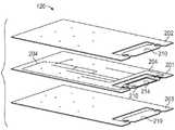
도 1에 도시된 바와 같이, 예시적인 장치는 유체 작동을 위한 다양한 유형의 유체를 수용하고 지향시키기 위한 유체 카트리지(100)를 포함한다. 일부 실시예에서, 유체 카트리지(100)가 다양한 유형의 유체를 수용하기 위한 하나 이상의 유체 저장소를 획정하는 트레이(110) 및 트레이(110) 상에 작동 가능하게 장착된 적층형 유체 회로(120)를 포함하여 적층형 유체 회로(120)는 트레이(110)에 수용된 다양한 유형의 유체가 하나 이상의 유체 저장소로부터 지향되어 하나 이상의 유체 작동을 위해 사용되게 한다.As shown in FIG. 1 , the exemplary apparatus includes a
다양한 실시예에서, 트레이(110)는 하나 이상의 유체 저장소(112)를 포함하고, 각각의 유체 저장소(112)는 지정된 유체 작동 동안 사용되도록 의도된 유체를 수용한다. 일부 실시예에서, 각각의 유체 저장소(112)가 하단부 및 하단부로부터 연장되는 하나 이상의 벽을 포함하여 유체 저장소(112)가 유체를 수용하기 위한 공간을 동봉한다. 일부 실시예에서, 저장소(112)는 지정된 유체 작동 동안 사용될 유체의 용적에 따라 가변적인 크기를 가질 수도 있다.In various embodiments,
다양한 실시예에서, 적층형 유체 회로(120)는 트레이(110) 상에 장착되고 유체 저장소(들)(112) 위에 배치되도록 구성되는 실질적으로 평면의 다층 기판(122)을 포함한다. 다양한 실시예에서, 적층형 유체 회로(120)는 기판(122) 내 유체를 적층형 유체 회로(120)에 유체 흐름 가능하게 연결된 다른 디바이스로 전송하는, 다층 기판(122) 내에 획정된 하나 이상의 채널(124)을 포함한다. 다양한 실시예에서, 적층형 유체 회로(120)는 유체 저장소(112)로 편향될 때 채널(124)을 트레이(110)의 유체 저장소(112)에 유체 흐름 가능하게 연결시키는 하나 이상의 가요성 도관(126)을 포함한다. 다양한 실시예에서, 가요성 도관(126)이 유체가 연관된 유체 저장소(112)로부터 흡입되게 하도록 구성되어, 유체 저장소(112)에 수용된 유체가 다층 기판(122) 내에 배치된 채널(124)로 전송될 수도 있다. 다양한 실시예에서, 채널(124) 및 가요성 도관(126)의 치수가 높은 종횡비(예를 들어, 길이/내경 ≥ 5)를 포함할 수도 있어서 적층형 유체 회로를 통한 더 효율적인 유체 흐름을 촉진한다. 다양한 실시예에서, 가요성 도관(126)의 길이는, 가요성 도관(126)이 유체 저장소(112)의 하단부에 도달하여 유체 저장소(112)에 수용된 유체 시약의 완전한 추출을 보장하도록 선택된다. 일부 실시예에서, 각각의 가요성 도관(126)은 1개 초과의 채널(124)을 포함할 수 있다. 예를 들어, 각각의 가요성 도관(126)은 2개의 채널(124), 예컨대, 유입 채널 및 유출 채널을 포함할 수 있다. 유입 채널은 유체, 예컨대, 또 다른 시약 또는 공기를 대응하는 유체 저장소(112) 내에 포함된 유체에 도입할 수 있다. 일부 경우에, 유입 채널이 1개 초과의 시약을 대응하는 유체 저장소(112)로 도입할 수 있어서 유체 저장소(112)를 혼합 저장소로서 활용한다. 일부 경우에, 유입 채널은 공기를 대응하는 유체 저장소(112)에 도입할 수 있다. 도입된 공기는 대응하는 유체 저장소(112) 내 유체를 버블링하고, 혼합하고/하거나 가압하도록 사용될 수 있다. 일부 경우에, 공기의 가열되거나 또는 냉각된 용적이 내부의 유체의 온도를 제어하도록 도입될 수 있다.In various embodiments,
일부 실시예에서, 가요성 도관(126)은 다층 기판(122)을 통해 형성된 하나 이상의 절삭부(128)에 의해 획정된다. 각각의 절삭부(128)가 각각의 채널(124)의 신장부를 포괄하는 다층 기판(122)의 부분을 부분적으로 둘러싸서, 기판(122)의 부분이 기판(122)의 나머지로부터 부분적으로 분리된다. 각각의 가요성 도관(126)은 기판(122)의 나머지로부터 부분적으로 분리되고 각각의 채널(124)의 신장부를 포괄하는 다층 기판(122)의 부분에 의해 획정된다.In some embodiments,
적층형 유체 회로(120)가 트레이(110) 상에 작동 가능하게 장착될 때, 다층 기판(122)은 각각의 절삭부(128) 및 가요성 도관(126)을 대응하는 유체 저장소(112) 위에 배치하는 방식으로 트레이(110)와 정렬된다. 다양한 실시예에서, 가요성 도관(126)은 가요성 도관의 대응하는 유체 저장소(112)를 향하여 다층 기판(122)에 대해 (예를 들어, 수동으로 또는 자동화된 디바이스에 의해) 편향되도록 구성된다. 가요성 도관의 대응하는 유체 저장소(112)를 향하여 편향될 때, 가요성 도관(126)은 각각의 채널(124)을 연관된 유체 저장소(112)에 유체 흐름 가능하게 연결시킨다. 가요성 도관(126)의 편향이 가요성 도관의 적어도 일부를 유체 저장소(112)로 활처럼 휘게 하고(bowing), 벤딩(bending)시키고, 만곡(curving)시키거나 또는 다른 방식으로 이동시키는 것을 포함할 수 있는 반면 가요성 도관(126) 내 채널은 유체 저장소(112) 내로부터 가요성 도관(126) 내 채널을 통해 다층 기판(122)의 하나 이상의 채널(124) 내로의 유체의 유체 흐름을 허용하도록 온전하다.When the stacked
다양한 실시예에서, 적층형 유체 회로(120)는 절삭부(128) 중 하나의 절삭부에 의해 노출되지 않은 유체 저장소(112) 중 하나의 유체 저장소에 유체 흐름 가능하게 연결된 포트(130)를 포함한다. 일부 실시예에서, 포트(130)는 다층 기판(122)을 통해 형성되고 하나 이상의 채널(124)에 유체 흐름 가능하게 연결된 개구를 포함한다.In various embodiments, the stacked
다양한 실시예에서, 유체 카트리지(100)가 하나 이상의 채널(124)에 유체 흐름 가능하게 연결된 유체 디바이스(140)(예를 들어, 흐름 셀)를 포함하여 적층형 유체 회로(120)는 유체가 유체 저장소(112)와 유체 디바이스(140) 사이에 선택적으로 전송되게 한다. 다양한 실시예에서, 유체 디바이스(140)가 채널(124) 중 하나의 채널에 연결된 유체 유입부(142), 채널(124) 중 하나의 채널에 연결된 유체 유출부(144) 및/또는 유체 유입부(142) 및 유체 유출부(144)에 유체 흐름 가능하게 연결된 하나 이상의 유체 통로(미도시)를 포함할 수도 있어서 유체 처리, 예컨대, 화학적 또는 생화학적 분석 또는 다른 반응이 발생하게 한다. 다양한 실시예에서, 유체 디바이스(140)는 유체 유입부(142)로의 다양한 유형의 유체(예를 들어, 시약, 버퍼, 반응 매체)의 도입을 허용하여 하나 이상의 유체 통로 내에서 유체 처리를 겪도록 구성된다. 다양한 실시예에서, 유체 디바이스(140)는 다양한 유형의 유체가 하나 이상의 유체 통로로부터 유체 유출부(144)로 플러시되게 하도록 더 구성된다.In various embodiments, the
유체 디바이스(140)가 적층형 유체 회로(120)의 내장된 부분일 수도 있고, 유체 디바이스(140)가 (예를 들어, 유체 유입부(142) 및 유체 유출부(144)를 기판(122) 내에 획정된 채널(124)에 연결시키는 유체 연결기를 통해) 적층형 유체 회로(120)에 제거 가능하게 부착되거나 또는 결합될 수도 있고/있거나 유체 디바이스(140)가 적층형 유체 회로(120)로부터 원격에 배치되는 별개의 디바이스일 수도 있다.
일부 실시예에서, 적층형 유체 회로(120)는 다층 기판(122)을 따라 배치되고 전력을 전력원으로부터 수신하도록 구성된 하나 이상의 전기 접촉부(150)를 포함한다. 일부 실시예에서, 적층형 유체 회로(120)는 가요성 도관(126) 상에 배치되고 적층형 유체 회로(120)에 그리고 그 상에 형성된 하나 이상의 전기 경로를 통해 전기 접촉부(150)에 전기적으로 연결된 하나 이상의 전극(미도시)을 포함한다. 일부 실시예에서, 도 6 내지 도 8에 도시된 바와 같이, 각각의 가요성 도관(126)은 개회로에서 단자로서 역할을 하는 적어도 2개의 전극(132a, 132b)을 포함한다. 따라서, 가요성 도관(126)이 유체 저장소(112)로 편향될 때, 유체 접촉 전극이 전도성 본체로서 역할을 하여, 전극은 유체 레벨 또는 유체 저장소(112)에 수용된 유체의 존재가 유체 카트리지(100)와 작동 가능하게 연관된 처리 기구에 의해 검출되게 한다. 예를 들어, 처리 기구는 용량성으로, 가요성 도관(126)과 전극(132a, 132b)이 액체와 접촉할 때 변경되는 개회로 간의 용량성 신호를 검출함으로써 액체 레벨을 검출할 수 있다. 일부 실시예에서, 가요성 도관(126) 상에 배치된 전극은 유체 저장소(112)에 수용된 유체를 가열하기 위한 전기 가열기로서 역할을 한다. 일부 구현예에서, 다른 전기 컴포넌트는 가요성 도관(126)(예를 들어, 센서, MEMS 디바이스 등)에 그리고/또는 그 상에 배치될 수 있다.In some embodiments, the
도 2 내지 도 5는 도 1에 도시된 실시예에 따른 적층형 유체 회로(120)의 3층 구성을 도시한다. 도 2에 도시된 바와 같이, 적층형 유체 회로(120)는 서로에 대해 겹쳐진 제1 층(201), 제2 층(202) 및 제3 층(203)을 포함한다. 제1 층(201)은 제2 층(202)과 제3 층(203) 사이에 배치되고 제1 층(201)을 통해 형성된 하나 이상의 슬롯(204)을 포함한다. 일부 실시예에서, 제1 층(201)은 또한 또는 하나 이상의 슬롯(204)에 대한 대안으로, 제1 층(201)에 형성된 채널, 함몰부, 또는 다른 특징부를 포함하다. 일부 실시예에서, 부분(210, 214)이 층(201 내지 203)의 각각의 하나의 단부에서 트리밍되어 유체 디바이스(140)를 형성한다. 일부 실시예에서, 층(201 내지 203)의 각각은 폴리머 물질(예를 들어, 플라스틱), 예컨대, 폴리에틸렌 테레프탈레이트(PET), 폴리메틸메타크릴레이트(PMMA), 폴리카보네이트 폴리염화비닐(PVC), 폴리다이메틸실록산(PDMS), 환식 올레핀 코폴리머(COP) 등을 포함한다.2 to 5 show a three-layer configuration of the stacked
도 3을 참조하면, 제1, 제2 및 제3 층(201 내지 203)이 함께 적층되어 실질적으로 평면의 다층 기판(122)을 형성한다. 일부 실시예에서, 제1, 제2 및 제3 층(201 내지 203)이 예를 들어, 감압 접착제(pressure sensitive adhesive)를 층(201 내지 203)의 측면에 적용함으로써 층(201 내지 203)의 측면을 서로에 대해 열 결합하고, 용매 결합하고, 레이저 용접하거나 또는 접착함으로써 함께 적층된다. 층(201 내지 203)이 함께 적층된 후, 제2 층(202)과 제3 층(203)이 제1 층(201)에 형성된 슬롯(204) 및/또는 다른 특징부를 동봉해서 다층 기판(122) 내에 획정된 채널(124)을 형성한다. 일부 실시예에서, 수개의 채널(124)은 각각의 가요성 도관(126)에 대해 획정될 수 있다. 층(201 내지 203)이 함께 적층됨에 따라, 트리밍된 부분(210, 214)이 정렬되어 다층 기판(122)의 하나의 단부에 유체 디바이스(140)를 형성한다. 일부 구현예에서, 트리밍된 부분(210, 214)은 생략될 수 있다.Referring to FIG. 3 , the first, second, and
도 4를 참조하면, 각각의 채널(124)의 신장부를 포괄하는 다층 기판(122)의 선택적인 부분은 다층 기판(122)을 통해 절삭부(128)를 형성함으로써 단절된다. 실례가 되는 실시예에서, 절삭부(128)가 채널(124)의 신장부(예를 들어, 단자 단부)를 부분적으로 둘러싸도록 성형되어(예를 들어, U자 형상임), 다층 기판(122)의 단절된 부분이 다층 기판(122)의 나머지로부터 부분적으로 분리되어, 가요성 도관(126)을 형성한다. 각각의 가요성 도관(126)은 다층 기판(122)의 단절된 부분 및 그 각각의 채널(124)의 포괄된 신장부를 포함한다. 도 4에 도시된 바와 같이, 가요성 도관(126)이 비편향된 위치에 설정되고, 가요성 도관(126)은 다층 기판(122)과 실질적으로 정렬된다(즉, 동일 평면 상에 있다). 일부 경우에, 적층형 유체 회로(120)가 트레이(110)로부터 최종 사용자로 별도로 수송되거나 또는 발송되는 동안 가요성 도관(126)이 비편향된 위치에 설정될 수도 있다. 일부 실시예에서, 수개의 채널(124)이 각각의 가요성 도관(126)에 대해 획정될 수 있다.Referring to FIG. 4 , an optional portion of the
도 5를 참조하면, 가요성 도관(126)이 편향된 위치에 설정되어 다층 기판(122)의 단절된 부분 및 채널(124)의 포괄된 신장부가 나머지 평면의 다층 기판(122)에 대해 기울어지고, 만곡되고, 벤딩되거나 또는 다른 방식으로 이동된다. 일단 적층형 유체 회로(120)가 트레이(110) 상에 작동 가능하게 장착되어 유체 저장소(112)에 수용된 유체를 유체 디바이스(140)로 전달한다면 가요성 도관(126)은 편향된 위치에 설정될 수도 있다.Referring to FIG. 5 , the
다층 기판(122) 내에 획정된 채널(124) 및 다층 기판(122)의 나머지로부터 부분적으로 단절된 가요성 도관(126)의 상세사항이 도 6 내지 도 13에 도시된다.Details of the
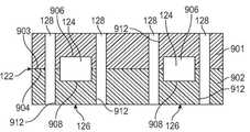
도 6은 가요성 도관(126)이 다층 기판(122)을 통해 절삭부(128)를 절삭함으로써 형성되는, 적층형 유체 회로(120)의 개략적인 부분 평면도를 도시한다. 일부 실시예에서, 수개의 채널(124)이 각각의 가요성 도관(126)에 대해 획정될 수 있다. 도 7 및 도 8은 도 6에서 각각 라인(A-A 및 B-B)을 따라 취한 다층 기판(122)의 3층 구성의 단면도를 도시한다. 도 9 및 도 10은 각각 라인(A-A 및 B-B)을 따라 취한 다층 기판(122)의 2층 구성의 단면도를 도시한다.FIG. 6 shows a schematic partial top view of a
도 7 및 도 8에 도시된 바와 같이, 다층 기판(122)의 3층 구성에 대해, 채널(124)은 층(701)의 상부면(706)으로부터 제1 층(701)의 하부면(708)으로 슬롯(704)을 절삭함으로써 형성된다. 채널(124)은 제2 층(702)의 접합면(705)을 제1 층(701)의 상부면(706)에 고정시키고 제3 층(703)의 접합면(707)을 제1 층(701)의 하부면(708)에 고정시킴으로써 동봉된다. 도 7을 참조하면, 각각의 가요성 도관(126)은 제1, 제2 및 제3 층(701 내지 703)을 통해 절삭부(128)를 절삭함으로써 형성된다. 다층 기판(122)의 층(701 내지 703)을 통해 절삭부(128)를 절삭함으로써, 가요성 도관(126)의 측면(712)은 다층 기판(122)의 나머지로부터 분리된다. 일부 실시예에서, 수개의 채널(124)이 각각의 가요성 도관(126)에 대해 획정될 수 있다. 도 8을 참조하면, 채널(124)은 다층 기판(122)의 나머지를 따라 가요성 도관(126)으로부터 멀리 연장된다. 도 8에 도시된 바와 같이, 채널(124)은 제1 층(701)을 통해 연장되는 슬롯(704)에 의해 획정되고 제2 층(702)의 접합면(705) 및 제3 층(703)의 접합면(707)에 의해 동봉된다.7 and 8 , for the three-layer configuration of the
도 9 및 도 10에 도시된 바와 같이, 다층 기판(122)의 2층 구성에 대해, 채널(124)은 제1 층(901)의 접합면(903)을 따라 제1 홈(906) 그리고 제2 층(902)의 접합면(904)을 따라 제2 홈(908)을 형성함으로써 형성된다. 채널(124)은 채널(124)을 획정하기 위해 제1 홈(906)을 제2 홈(908)과 정렬하는 방식으로 제1 층(901)의 접합면(903)을 제2 층(902)의 접합면(904)에 고정시킴으로써 동봉된다. 일부 실시예에서, 채널(124)은 제1 및 제2 층(901, 902)의 접합면 중 단 하나의 접합면을 따라 홈을 형성하고 홈을 다른 층(901, 902)의 접합면으로 동봉함으로써 형성될 수도 있다. 도 9를 참조하면, 가요성 도관(126)은 제1 및 제2 층(901 및 902)을 통해 절삭부(128)를 절삭함으로써 형성된다. 다층 기판(122)의 층(901, 902)을 통해 절삭부(128)를 절삭함으로써, 가요성 도관(126)의 측면(912)은 다층 기판(122)의 나머지로부터 분리된다. 일부 실시예에서, 수개의 채널(124)이 각각의 가요성 도관(126)에 대해 획정될 수 있다. 도 10을 참조하면, 채널(124)은 다층 기판(122)의 나머지를 따라 가요성 도관(126)으로부터 멀리 연장된다. 도 10에 도시된 바와 같이, 채널(124)은 제1 및 제2 층(901, 902)의 정렬된 홈(906, 908)에 의해 획정된다.9 and 10 , for the two-layer configuration of the
도 11은 가요성 도관(126)이 스코어 라인(1102)을 다층 기판(122)에 또는 다층 기판을 통해 형성하고 채널(124)의 신장부(예를 들어, 단자 단부)를 부분적으로 둘러쌈으로써 형성되는 적층형 유체 회로(120)의 개략적인 부분 평면도를 도시한다. 일부 구현예에서, 스코어 라인(1102)은 적층형 유체 회로(120)에 형성된 구멍 또는 다른 부분적인 절삭부, 만입부 등일 수도 있다. 일부 실시예에서, 수개의 채널(124)이 각각의 가요성 도관(126)에 대해 획정될 수 있다. 도 12는 도 11의 라인(C-C)을 따라 취한 다층 기판(122)의 3층 구성의 단면도를 도시한다. 도 13은 도 11의 라인(C-C)을 따라 취한 다층 기판(122)의 2층 구성의 단면도를 도시한다.11 illustrates that the
도 12에 도시된 바와 같이, 다층 기판(122)의 3층 구성하에서, 채널(124)은 제1 층(1201)의 상부면(1206)으로부터 제1 층(1201)의 하부면(1208)으로 슬롯(1204)을 절삭함으로써 형성된다. 채널(124)은 제2 층(1202)의 접합면(1205)을 제1 층(1201)의 상부면(1206)에 고정시키고 제3 층(1203)의 접합면(1207)을 제1 층(1201)의 하부면(1208)에 고정시킴으로써 동봉된다. 가요성 도관(126)은 실시예에서, 제1, 제2 및 제3 층(1201 내지 1203) 중 하나 이상의 층을 통해 형성되는, 스코어 라인(1102)을 다층 기판(122)에 형성함으로써 형성된다. 스코어 라인(1102)이 부분적인 홈, 천공된 라인, 선형 만입부, 또는 라인(1102)을 따라 기판(122)을 국부적으로 약하게 하고 외부 힘의 인가 시 스코어 라인(1102)에 의해 부분적으로 둘러싸인 다층 기판(122)의 부분이 기판(122)의 나머지로부터 제어 가능하게 분리되게 하는 임의의 다른 수단을 포함할 수도 있어서, 스코어 라인(1102)이 가요성 도관(126)의 측면을 획정한다. 일부 실시예에서, 수개의 채널(124)이 각각의 가요성 도관(126)에 대해 획정될 수 있다.12 , under the three-layer configuration of the
도 13에 도시된 바와 같이, 다층 기판(122)의 2층 구성하에서, 채널(124)은 제1 층(1301)의 접합면(1303)을 따라 제1 홈(1306) 그리고 제2 층(1302)의 접합면(1304)을 따라 제2 홈(1308)을 형성함으로써 형성된다. 채널(124)은 채널(124)을 획정하기 위해 제1 홈(1306)을 제2 홈(1308)과 정렬하는 방식으로 제1 층(1301)의 접합면(1303)을 제2 층(1304 )의 접합면(1304)에 고정시킴으로써 동봉된다. 가요성 도관(126)은 실시예에서, 제1 및 제2 층(1301, 1302) 중 하나 이상의 층을 통해 형성되는, 스코어 라인(1102)을 다층 기판(122)에 형성함으로써 형성된다. 다시, 스코어 라인(1102)이 부분적인 홈, 천공된 라인, 선형 만입부, 또는 라인(1102)을 따라 기판(122)을 국부적으로 약하게 하고 외부 힘의 인가 시 스코어 라인(1102)에 의해 부분적으로 둘러싸인 다층 기판(122)의 부분이 기판(122)의 나머지로부터 제거되게 하는 임의의 다른 수단을 포함할 수도 있어서, 스코어 라인(1102)이 가요성 도관(126)의 측면을 획정한다. 일부 실시예에서, 수개의 채널(124)이 각각의 가요성 도관(126)에 대해 획정될 수 있다.As shown in FIG. 13 , under the two-layer configuration of the
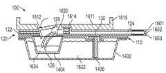
도 14 및 도 15에 도시된 바와 같이, 일부 실시예에서, 트레이(110)는 제1 저장소(1402) 및 제1 저장소(1402) 내에 배치된 하나 이상의 제2 저장소(1404)(예시된 구현예에서 3개)를 포함한다. 제1 저장소(1402)는 하단부(1410), 하단부(1410)로부터 연장되는 벽(1412)의 세트, 벽(1412)으로부터 돌출되고 제1 저장소(1402)를 둘러싸는 플랜지(1414)를 포함한다. 제2 저장소(1404)가 플레이트(1420)를 스탬핑함으로써 형성되어, 각각의 제2 저장소(1404)는 플레이트(1420)의 평면의 표면으로부터 함몰된 하단부(1422) 및 하단부(1422)로부터 플레이트(1420)의 평면의 표면으로 연장되는 벽(1424)의 세트를 포함한다. 플레이트(1420)가 제1 저장소(1402)의 상단부에 배치되고 플랜지(1414)에 의해 지지되어, 제2 저장소(1404)가 제1 저장소(1402) 내에 존재한다.14 and 15 , in some embodiments, the
일부 실시예에서, 제1 저장소(1402)는 제2 저장소(1404)의 각각보다 더 큰 용적의 유체를 수용한다. 일부 실시예에서, 제1 저장소(1402)는 제2 저장소(1404)에 수용된 유체의 유형보다 더 빈번하게 또는 광범위하게 사용되는, 유체, 예컨대, 수화 버퍼 또는 세척 용액을 수용한다. 일부 실시예에서, 제2 저장소(1404)는 제1 저장소(1402)에 저장된 수화 버퍼의 도입을 통해 건조 상태로부터 액체 상태로 변형되도록 구성되는 동결 건조된 시약을 수용한다. 일부 실시예에서, 트레이(110)가 트레이의 목적지로 수송되는 동안 그리고 트레이(110)가 다층 기판(122)에 처음에 연결될 때 제2 저장소(1404)가 비어 있을 수도 있다. 일부 실시예에서, 비어 있는 제2 유체 저장소(1404)가 혼합 웰(mixing well)로서 사용될 수도 있어서 비어 있는 제2 유체 저장소(114)가 유체 작동 동안 2개 이상의 다른 유체 저장소로부터 시약 유체를 수용한다. 일부 실시예에서, 비어 있는 제2 유체 저장소(1404)가 스테이징 웰(staging well)(예를 들어, 캐시 저장소)로서 사용될 수도 있어서 비어 있는 제2 유체 저장소(114)는 유체 작동 동안 또 다른 유체 저장소에 저장되는 시약 유체의 부분 표본을 수용한다. 일부 실시예에서, 제2 유체 저장소(1404)는 내부에 밀봉되는(예를 들어, 관통 가능한 포일에 의해 내부에 밀봉되는) 액체 시약을 포함할 수 있다.In some embodiments, the
일부 실시예에서, 제1 저장소(1402)가 가요성 도관(126) 중 임의의 가요성 도관에 유체 흐름 가능하게 연결되지 않지만, 오히려 포트(130)를 통해 채널(124)에 유체 흐름 가능하게 연결된다. 일부 실시예에서, 트레이(110)가 적층형 유체 회로(110)의 포트(130)에 연결되고 제1 저장소(1402)로 연장되는 도관(1406)을 포함하여 도관(1406)은 제1 저장소(1402)를 채널(124)에 유체 흐름 가능하게 연결시킨다. 일부 실시예에서, 각각의 제2 저장소(1404)는 적층형 유체 회로(120)의 기판(122)을 통해 형성된 대응하는 절삭부(128) 아래에 배치되고 대응하는 가요성 도관(126)에 의해 채널(124)에 유체 흐름 가능하게 연결된다. 일부 실시예에서, 제1 저장소(1402)는 가요성 도관(126)에 유체 흐름 가능하게 연결된다.In some embodiments, the
도 16은 하나의 실시예에 따른 유체 카트리지(100)의 측면 단면도를 도시한다. 실례가 되는 실시예에서, 적층형 유체 회로(120)는 제1 층(1601), 제2 층(1602), 및 제3 층(1603)을 포함한다. 제2 층(1602)은 제1 층(1601)과 제3 층(1603) 사이에 배치된다. 제2 층(1602)은 제1 층(1601) 및 제3 층(1603)에 의해 동봉된 하나 이상의 채널(124)을 형성하는 하나 이상의 슬롯을 포함한다.16 shows a cross-sectional side view of a
도 2 및 도 3에 도시된 실시예와 유사하게, 도 16의 트레이(110)는 제1 저장소(1402) 및 제1 저장소(1402) 내에 배치된 제2 저장소(1404)를 포함한다. 제1 저장소(1402)는 수화 버퍼 유체(1622)를 수용할 수도 있고 유체 포트(130)에 연결된 도관(1406)에 의해 적층형 유체 회로(120)에 유체 흐름 가능하게 연결된다. 제2 저장소(1404)는 동결 건조된 시약(1624)을 건조 상태로 수용할 수도 있다. 제2 저장소(1404)가 제2 유체 저장소(1404)의 개구를 덮는 포일(1620)에 의해 밀봉될 수도 있어서 포일(1620)이 수분이 제2 저장소(1404)에 진입하는 것을 방지해서, 동결 건조된 시약(1624)을 건조 상태로 유지한다. 일부 실시예에서, 제2 유체 저장소(1404)는 내부에 밀봉되는(예를 들어, 관통 가능한 포일(1620)에 의해 내부에 밀봉되는) 액체 시약을 포함할 수 있다.Similar to the embodiment shown in FIGS. 2 and 3 , the
다양한 실시예에서, 도 16에 도시된 바와 같이, 유체 카트리지(100)는 적층형 유체 회로(120) 상에 배치되고 트레이(110)의 반대편에 있는 단단한 덮개(1610)를 포함할 수도 있다. 일부 실시예에서, 단단한 덮개(1610)가 사출 성형된 플라스틱 물질로 이루어져서 단단한 덮개(1610)는 강성도를 적층형 유체 회로(120)의 다층 기판(122)에 제공한다.In various embodiments, as shown in FIG. 16 , the
일부 실시예에서, 단단한 덮개(1610)는 덮개(1610)의 평면의 표면(1611)에 대해 피벗되도록 구성되는 펀치(1612)를 포함한다. 덮개(1610)가 적층형 유체 회로(120) 상에 작동 가능하게 장착될 때, 덮개(1610)는 펀치(1612)를 대응하는 가요성 도관(126)의 적어도 일부 위에 배치하는 방식으로 다층 기판(122)에 대해 정렬된다. 덮개(1610)가 다층 기판(122) 상에서 정렬되는 경우에, 펀치(1612)는 가요성 도관(126)을 다층 기판(122)으로부터 멀리 그리고 유체 저장소, 예컨대, 본 실시예에서 유체 저장소(1404)로 편향시키도록 (예를 들어, 수동으로 또는 기계에 의해) 작동될 수도 있다. 가요성 도관(126)을 편향시키는 동안, 펀치(1612) 자체가 가요성 도관(126)을 천공하거나 또는 가요성 도관이 제2 유체 저장소(1404)를 덮는 포일(1620)을 통해 천공되게 하여, 가요성 도관(126)이 천공된 포일(1620)을 통해 편향되어 채널(124)을 제2 유체 저장소(1604)에 유체 흐름 가능하게 연결시킨다. 일부 실시예에서, 수개의 채널(124)이 각각의 가요성 도관(126)에 대해 획정될 수 있다.In some embodiments,
다양한 실시예에서, 덮개(1610)는 제2 유체 저장소(1404)와 대응하는 채널(124) 사이의 흐름을 제어하기 위해 제2 유체 저장소(1404) 및 채널(124) 중 하나의 채널과 작동 가능하게 연관된 밸브(1614)를 포함한다. 일부 실시예에서, 밸브(1614)는 소형의 둥근 딥으로 이루어진 핀치 밸브이고 대응하는 채널(124)을 밀봉하기 위해 (예를 들어, 외부 핀치 로드를 사용하여) 압축될 수도 있다.In various embodiments, the
유체 카트리지를 조립하기 위한 방법How to assemble a fluid cartridge
다양한 실시예에 따르면, 도 17은 적층형 유체 회로(120) 및 적어도 하나의 유체 저장소(112)를 포함하는 유체 카트리지(100)를 조립하기 위한 방법(1700)을 예시한다.17 illustrates a
도 17에 도시된 바와 같이, 방법(1700)은 기판 물질의 층의 표면 내 홈 또는 기판 물질의 층을 통한 슬롯을 형성하는 단계(1702)를 포함한다. 도 7, 도 8 및 도 12를 참조하면, 다층 기판(122)의 3층 구성하에서, 단계(1702)는 층(701, 1201)을 통해 슬롯(704, 1204)을 절삭하는 것을 포함한다. 일부 실시예에서, 슬롯(704, 1204)을 형성하는 단계(1702)는 레이저를 사용하여 층(701, 1201)을 통해 절삭하는 것을 포함한다. 도 9, 도 10 및 도 13을 참조하면, 다층 기판(122)의 2층 구성하에서, 단계(1702)는 제1 홈(906, 1306)을 제1 층(901, 1301)의 접합면(903, 1303)에 형성하고, 임의로, 제2 홈(908, 1308)을 제2 층(902, 1302)의 접합면(904, 1304)에 형성하는 것을 포함한다.As shown in FIG. 17 , the
도 17을 참조하면, 방법(1700)은 하나 이상의 층을 홈 또는 슬롯을 포함하는 층에 적층하여 실질적으로 평면의 다층 기판(122)을 형성하고 홈 또는 슬롯을 동봉하여 채널(124)을 형성하는 단계(1704)를 포함한다. 일부 실시예에서, 층은 폴리머 또는 플라스틱 물질을 포함하고, 단계(1704)는 다양한 플라스틱 층을 함께 접착식으로 또는 열적으로 결합하는 것을 포함한다.Referring to FIG. 17 , a
도 7, 도 8 및 도 12를 참조하면, 다층 기판(122)의 3층 구성하에서, 단계(1704)는 층(702, 1202)(상단층)과 층(703, 1203)(하단층)을 층(701, 1201)(중간층)에 적층하여 층(702, 1202)과 층(703, 1203)이 층(701, 1201)에 형성된 슬롯(704, 1104)을 동봉하여 채널(124)을 형성하는 것을 포함한다.7, 8 and 12, under the three-layer configuration of the
도 9, 도 10 및 도 13을 참조하면, 다층 기판(122)의 2층 구성하에서, 단계(1704)는 제1 층(901, 1301)을 제2 층(902, 1302)에 적층하여 제1 층(901, 1301)의 접합면(903, 1303)을 따라 형성된 제1 홈(906, 1306)이 제2 층(902, 1302)의 접합면(904, 1304)을 따라 형성된 제2 홈(908, 1308)과 정렬되어 채널(124)을 형성하는 것을 포함한다.9, 10 and 13 , under the two-layer configuration of the
도 17을 참조하면, 방법(1700)은 채널(124)의 신장부를 포괄하는 다층 기판(122)의 부분을 단절하여 단절된 부분이 다층 기판(122)의 나머지로부터 부분적으로 분리되거나 또는 분리 가능하여 가요성 도관(126)을 형성하는 단계(1706)를 포함한다.Referring to FIG. 17 , a
도 6 내지 도 10을 참조하면, 일부 실시예에서, 단절하는 단계(1706)는 다층 기판(122)의 하나 이상의 층(701 내지 703, 901 및 902)을 통해 절삭부(128)를 형성하는 것을 포함한다. 도 6에 도시된 바와 같이, 각각의 절삭부(128)가 다층 기판(122)의 단절된 부분을 부분적으로 둘러싸서 가요성 도관(126)을 형성하도록 성형된다. 일부 실시예에서, 절삭부(128)는 펀치를 포함하는 다이 커터(미도시)를 사용하고 절삭부(128)를 형성하기 위해 다층 기판(122)을 통해 펀치를 누름으로써 또는 다층 기판(122)에서 홈 및 절삭부를 절삭하는 레이저 커터에 의해 형성된다.6-10 , in some embodiments, the step of breaking 1706 comprises forming a
도 11 내지 도 13을 참조하면, 일부 실시예에서, 단절하는 단계(1706)는 스코어 라인(1102)을 다층 기판(122)에 형성하는 것을 포함한다. 도 11에 도시된 바와 같이, 각각의 스코어 라인(1102)이 채널(124)의 신장부를 포괄하는 다층 기판(122)의 단절된 부분을 부분적으로 둘러싸도록 성형되어, 스코어 라인(1102)은 다층 기판(122)의 단절된 부분이 기판(122)의 단절된 부분에 대한 외부 힘의 인가 시 다층 기판(122)의 나머지로부터 부분적으로 분리되게 한다. 일부 구현예에서, 구멍 또는 다른 부분적인 단절부는 스코어 라인(1102) 대신에 또는 스코어 라인에 더하여 사용될 수 있다.11-13 , in some embodiments, breaking 1706 includes forming a
도 17을 참조하면, 방법(1700)은 유체 저장소(112)가 가요성 도관(126) 아래에 배치되도록 다층 기판(122)을 유체 저장소(112)에 연결시키는 단계(1708)를 포함한다. 일부 실시예에서, 연결시키는 단계(1708)는 다층 기판(122)을 복수의 유체 저장소(112)를 포함하는 트레이(110) 상에 장착하는 것을 포함하고, 단계(1708)는 각각의 가요성 도관(126)을 대응하는 유체 저장소(112)의 적어도 일부 위에 배치하는 방식으로 다층 기판(122)을 트레이(110)에 대해 정렬하는 것을 더 포함한다. 일부 실시예에서, 다층 기판(122)은 다양한 공정, 예컨대, 풀 또는 감압 접착제를 사용하여 다층 기판(122)의 하단면을 트레이(110)의 상단면에 접착하는 것 또는 다층 기판(122)을 트레이(110)의 상단면에 레이저 용접하는 것에 의해 트레이(110)에 장착될 수도 있다.Referring to FIG. 17 , the
도 17을 참조하면, 방법(1700)은 가요성 도관(126)을 편향시키도록 구성된 펀치(1612)를 포함할 수도 있는, 단단한 덮개(1610)에 다층 기판을 연결시키는 단계(1710)를 포함한다. 일부 실시예에서, 단계(1710)는 펀치(1612)를 가요성 도관(126)의 적어도 일부 위에 배치하는 방식으로 덮개(1610)를 다층 기판(122)과 정렬시키는 것을 더 포함한다.Referring to FIG. 17 , the
도 17을 참조하면, 방법(1700)은 예를 들어, 펀치(1612)를 가요성 도관(126)에 대해 작동시킴으로써, 가요성 도관(126)을 유체 저장소(112)를 향하여 다층 기판(122)에 대해 편향시키는 단계(1712)를 포함한다. 일부 실시예에서, 단계(1712)는 유체 저장소(112)를 덮는 포일(1620)을 천공하여, 가요성 도관(126)이 천공된 포일(1620)을 통해 편향되어 다층 기판(122) 내 채널(124)을 유체 저장소(112)에 유체 흐름 가능하게 연결시키는 것을 더 포함한다. 단계(1712)는 저장소(112)가 발송 및 저장 동안 건조된 채로 있다면 제작 과정 동안 행해질 수 있거나 또는 단계(1712)는 유체 카트리지(100)를 사용하기 직전에 처리 기구에 의해 수행될 수 있다.Referring to FIG. 17 , the
아래에서 더 상세히 논의되는 전술한 개념과 부가적인 개념(이러한 개념이 서로 불일치하지 않은 경우)의 모든 조합이 본 명세서에 개시된 본 발명의 주제의 일부인 것으로 고려된다는 것이 이해되어야 한다. 특히, 본 개시내용의 끝에서 나타나는 청구범위의 주제의 모든 조합은 본 명세서에 개시된 본 발명의 주제의 일부인 것으로 고려된다. 참조에 의해 원용되는 임의의 개시내용에 또한 나타날 수도 있는 본 명세서에서 명백히 채용되는 전문용어는 본 명세서에 개시된 특정한 개념과 의미적으로 가장 일치한 것으로 또한 이해되어야 한다.It should be understood that all combinations of the foregoing and additional concepts (provided that such concepts are not inconsistent with each other) discussed in greater detail below are considered to be part of the inventive subject matter disclosed herein. In particular, all combinations of the subject matter of the claims appearing at the end of this disclosure are considered to be part of the subject matter of the invention disclosed herein. It is also to be understood that terminology expressly employed herein that may also appear in any disclosure incorporated by reference is most semantically consistent with the specific concepts disclosed herein.
구현예implementation
구현예 1. 장치로서, 유체 저장소; 및 유체 저장소 위에 배치된 적층형 유체 회로로서, 실질적으로 평면의 기판을 획정하도록 함께 적층된 2개 이상의 층; 기판 내에 획정된 하나 이상의 채널, 및 기판의 나머지로부터 부분적으로 분리되거나 또는 분리 가능한 채널 중 적어도 하나의 채널의 신장부를 포괄하는 기판의 부분에 의해 획정되는 가요성 도관을 포함하는, 적층형 유체 회로를 포함하되, 가요성 도관은 기판의 부분 및 채널의 포괄된 신장부를 포함하고, 가요성 도관이 유체 저장소를 향하여 평면의 기판에 대해 편향 가능하여 가요성 도관이 적어도 하나의 채널을 유체 저장소에 유체 흐름 가능하게 연결시키는, 장치.Embodiment 1. A device comprising: a fluid reservoir; and a stacked fluid circuit disposed over the fluid reservoir, comprising: two or more layers stacked together to define a substantially planar substrate; A layered fluid circuit comprising: a flexible conduit defined by a portion of the substrate encompassing one or more channels defined within the substrate and an extension of at least one of the channels partially separable or separable from the remainder of the substrate wherein the flexible conduit comprises a portion of the substrate and an encompassed elongation of the channel, wherein the flexible conduit is deflectable relative to the planar substrate towards the fluid reservoir such that the flexible conduit is capable of fluid flow of at least one channel to the fluid reservoir connecting, device.
구현예 2. 구현예 1에 있어서, 기판은 기판을 통해 형성되고 채널의 신장부를 포괄하는 기판의 부분을 부분적으로 둘러싸는 절삭부를 포함하는, 장치.Statement 2. The apparatus of statement 1, wherein the substrate comprises a cut formed through the substrate and partially enclosing a portion of the substrate encompassing the elongation of the channel.
구현예 3. 구현예 1에 있어서, 기판은 채널의 신장부를 포괄하는 기판의 부분을 부분적으로 둘러싸는 스코어 라인을 포함하고, 스코어 라인은 기판의 부분에 대한 외부 힘의 인가 시 기판의 부분이 기판의 나머지로부터 부분적으로 분리되게 하는, 장치.Embodiment 3. The substrate of Embodiment 1, wherein the substrate comprises a score line that partially surrounds a portion of the substrate encompassing the extension of the channel, wherein the score line indicates that upon application of an external force to the portion of the substrate, the portion of the substrate a device that allows it to be partially separated from the rest of
구현예 4. 구현예 1에 있어서, 2개 이상의 층은 제1 층, 제2 층 및 제3 층을 포함하고, 제1 층은 제2 층과 제3 층 사이에 배치되고 제2 층과 제3 층에 의해 반대측에서 덮일 때 하나 이상의 채널을 형성하는 적어도 하나의 슬롯을 포함하는, 장치.Embodiment 4. The embodiment of Embodiment 1, wherein the at least two layers comprise a first layer, a second layer and a third layer, the first layer disposed between the second layer and the third layer and the second layer and the second layer being disposed between the second layer and the second layer. and at least one slot defining one or more channels when covered on the opposite side by the three layers.
구현예 5. 구현예 1에 있어서, 2개 이상의 층은 제1 층 및 제1 층에 적층된 제2 층을 포함하고, 적어도 제1 층은 층의 표면에 형성되고 제2 층에 의해 덮일 때 하나 이상의 채널을 형성하는 적어도 하나의 홈을 포함하는, 장치.Statement 5. The method of statement 1, wherein the at least two layers comprise a first layer and a second layer laminated to the first layer, wherein at least the first layer is formed on the surface of the layer and is covered by the second layer. and at least one groove defining one or more channels.
구현예 6. 구현예 1에 있어서, 기판은 함께 접착식으로 또는 열적으로 결합된 폴리머 물질의 2개 이상의 층을 포함하는, 장치.Statement 6. The device of statement 1, wherein the substrate comprises two or more layers of polymeric material adhesively or thermally bonded together.
구현예 7. 구현예 1에 있어서, 가요성 도관 상에 배치된 하나 이상의 전극을 더 포함하는, 장치.Statement 7. The device of statement 1, further comprising one or more electrodes disposed on the flexible conduit.
구현예 8. 구현예 7에 있어서, 하나 이상의 전극은 유체 저장소에 수용된 유체의 유체 레벨을 검출하는 것, 유체 저장소에 수용된 유체의 존재를 검출하는 것 또는 유체 저장소에 수용된 유체를 가열하는 것 중 하나 이상을 위한 것인, 장치.Statement 8. The method of statement 7, wherein the one or more electrodes are one of detecting a fluid level of a fluid contained in the fluid reservoir, detecting the presence of a fluid contained in the fluid reservoir, or heating the fluid contained in the fluid reservoir. A device for ideals.
구현예 9. 구현예 1에 있어서, 유체 저장소와 채널 중 적어도 하나의 채널 사이의 흐름을 제어하기 위해 채널 중 적어도 하나의 채널 및 유체 저장소와 작동 가능하게 연관된 밸브를 더 포함하는, 장치.Statement 9. The apparatus of statement 1, further comprising a valve operatively associated with the fluid reservoir and at least one of the channels to control flow between the fluid reservoir and the at least one of the channels.
구현예 10. 구현예 1에 있어서, 유체 회로 상에 배치되고 가요성 도관을 평면의 기판으로부터 멀리 유체 저장소로 편향시키기 위한 펀치를 포함하는 단단한 덮개를 더 포함하는, 장치.Statement 10. The apparatus of statement 1, further comprising a rigid cover disposed on the fluid circuit and comprising a punch for biasing the flexible conduit away from the planar substrate and into the fluid reservoir.
구현예 11. 유체 저장소가 밀봉되도록 유체 저장소의 개구를 덮는 관통 가능한 포일을 더 포함하되, 펀치가 포일을 천공하고 가요성 도관을 천공된 포일을 통해 편향시켜서 가요성 도관을 유체 저장소에 유체 흐름 가능하게 연결시키는, 장치.Embodiment 11. A further comprising a pierceable foil covering the opening of the fluid reservoir such that the fluid reservoir is sealed, wherein a punch punctures the foil and deflects the flexible conduit through the perforated foil to enable fluid flow to the flexible conduit into the fluid reservoir connecting, device.
구현예 12. 방법으로서, 채널을 제1 층에 형성하고 하나 이상의 층을 제1 층에 적층하여 평면의 다층 기판을 형성해서 채널이 기판 내에 획정되는 단계; 및 채널의 신장부를 포괄하는 기판의 부분을 단절하여 단절된 부분이 기판의 나머지로부터 부분적으로 분리되거나 또는 분리 가능하여 기판의 부분 및 채널의 포괄된 신장부를 포함하는 가요성 도관을 형성하는 단계를 포함하되, 가요성 도관은 평면의 기판에 대해 편향 가능한, 방법.Statement 12. A method, comprising: forming a channel in a first layer and laminating one or more layers to the first layer to form a planar multilayer substrate such that the channel is defined within the substrate; and isolating the portion of the substrate encompassing the extension of the channel such that the disconnected portion is partially separable or separable from the remainder of the substrate to form a flexible conduit comprising the portion of the substrate and the encompassed extension of the channel; , wherein the flexible conduit is deflectable relative to a planar substrate.
구현예 13. 구현예 12에 있어서, 채널을 제1 층에 형성하는 단계는 홈을 제1 층의 표면에 형성하는 것을 포함하고, 제1 층에 적층된 하나 이상의 층은 홈을 동봉하는, 방법.Statement 13. The method of statement 12, wherein forming the channel in the first layer comprises forming a groove in the surface of the first layer, wherein one or more layers laminated to the first layer enclose the groove. .
구현예 14. 구현예 12에 있어서, 채널을 제1 층에 형성하는 단계는 슬롯을 제1 층을 통해 형성하는 것을 포함하고, 제1 층에 적층된 하나 이상의 층은 슬롯을 동봉하는, 방법.Statement 14. The method of statement 12, wherein forming the channel in the first layer comprises forming a slot through the first layer, wherein one or more layers laminated to the first layer enclose the slot.
구현예 15. 구현예 12에 있어서, 기판의 부분을 단절시키는 단계는 채널의 신장부를 포괄하는 기판의 부분을 부분적으로 둘러싸는 절삭부를 기판을 통해 형성하는 것을 포함하는, 방법.Statement 15. The method of statement 12, wherein isolating the portion of the substrate comprises forming a cut through the substrate that partially surrounds the portion of the substrate encompassing the stretch of the channel.
구현예 16. 구현예 12에 있어서, 기판의 부분을 단절시키는 단계는 채널의 신장부를 포괄하는 기판의 부분을 부분적으로 둘러싸는 스코어 라인을 형성하는 것을 포함하고, 스코어 라인은 기판의 부분에 대한 외부 힘의 인가 시 기판의 부분이 기판의 나머지로부터 부분적으로 분리되게 하는, 방법.Statement 16. The method of statement 12, wherein isolating the portion of the substrate comprises forming a score line partially surrounding the portion of the substrate encompassing the stretch of the channel, the score line being external to the portion of the substrate. causing a portion of the substrate to partially separate from the remainder of the substrate upon application of the force.
구현예 17. 구현예 12에 있어서, 가요성 도관이 비편향된 위치에 설정되는 동안 유체 저장소가 다층 기판 및 가요성 아래에 배치되도록 다층 기판을 유체 저장소에 연결시키는 단계를 더 포함하는, 방법.Statement 17. The method of statement 12, further comprising connecting the multilayer substrate to the fluid reservoir such that the fluid reservoir is disposed beneath the multilayer substrate and the flexible while the flexible conduit is set in the unbiased position.
구현예 18. 구현예 17에 있어서, 가요성 도관 내 채널의 포괄된 신장부가 기판 내에 획정된 채널을 유체 저장소에 유체 흐름 가능하게 연결시키도록, 가요성 도관을 유체 저장소를 향하여 기판에 대해 편향시키는 단계를 더 포함하는, 방법.Statement 18. The statement of statement 17, wherein the flexible conduit biases the flexible conduit relative to the substrate toward the fluid reservoir such that the encompassed extension of the channel in the flexible conduit fluidly connects the channel defined in the substrate to the fluid reservoir. A method further comprising a step.
구현예 19. 구현예 18에 있어서, 가요성 도관을 편향시키는 단계 후에, 유체 저장소에 수용된 유체를 가요성 도관 내 채널의 포괄된 신장부를 통해 기판에 획정된 채널로 흡입하는 단계를 더 포함하는, 방법.Statement 19. The method of statement 18, further comprising, after deflecting the flexible conduit, aspirating the fluid contained in the fluid reservoir through the encompassed extension of the channel in the flexible conduit into the channel defined in the substrate. method.
구현예 20. 구현예 18에 있어서, 가요성 도관을 편향시키는 단계 후에, 유체를 기판 내에 획정된 채널 및 가요성 도관 내 채널의 포괄된 신장부를 통해 유체 저장소로 도입하는 단계를 더 포함하는, 방법.Statement 20. The method of statement 18, further comprising, after deflecting the flexible conduit, introducing the fluid into the fluid reservoir through a channel defined in the substrate and an encompassed elongation of the channel in the flexible conduit. .
구현예 21. 구현예 12에 있어서, 다층 기판을 단단한 덮개에 연결시키는 단계를 더 포함하는, 방법.Statement 21. The method of statement 12, further comprising connecting the multilayer substrate to the rigid cover.
구현예 22. 구현예 18에 있어서, 단단한 덮개는 가요성 도관을 평면의 기판에 대해 편향시키기 위한 펀치를 포함하는, 방법.Statement 22. The method of statement 18, wherein the rigid sheath comprises a punch for biasing the flexible conduit relative to the planar substrate.
구현예 23. 구현예 16에 있어서, 제1 층 및 제1 층에 적층된 하나 이상의 층은 폴리머 물질의 2개 이상의 층을 포함하고, 하나 이상의 층을 제1 층에 적층하는 단계는 층을 함께 접착식으로 또는 열적으로 결합하는 것을 포함하는, 방법.Statement 23. The method of statement 16, wherein the first layer and the one or more layers laminated to the first layer comprise two or more layers of a polymeric material, and wherein laminating the one or more layers to the first layer comprises bringing the layers together. adhesively or thermally bonding.
구현예 24. 구현예 12에 있어서, 전극을 가요성 도관을 형성하는 기판의 부분에 적용하는 단계를 더 포함하는, 방법.Statement 24. The method of statement 12, further comprising applying an electrode to a portion of the substrate forming the flexible conduit.
구현예 25. 장치로서, 실질적으로 평면의 기판을 획정하도록 함께 적층된 2개 이상의 층; 기판 내에 획정된 하나 이상의 채널, 및 기판의 나머지로부터 부분적으로 분리되거나 또는 분리 가능한 채널 중 적어도 하나의 채널의 신장부를 포괄하는 기판의 부분에 의해 획정되는 가요성 도관을 포함하되, 가요성 도관은 기판의 부분 및 채널의 포괄된 신장부를 포함하고, 가요성 도관은 평면의 기판에 대해 편향 가능한, 장치.Statement 25. A device comprising: two or more layers stacked together to define a substantially planar substrate; a flexible conduit defined by a portion of the substrate encompassing one or more channels defined within the substrate and an extension of at least one of the channels partially separable or separable from the remainder of the substrate, wherein the flexible conduit comprises: and a portion of the channel and an enclosed elongation of the channel, wherein the flexible conduit is deflectable relative to a planar substrate.
구현예 26. 구현예 25에 있어서, 2개 이상의 층은 제1 층, 제2 층 및 제3 층을 포함하고, 제1 층은 제2 층과 제3 층 사이에 배치되고 제2 층과 제3 층에 의해 반대측에서 덮일 때 하나 이상의 채널을 형성하는 적어도 하나의 슬롯을 포함하는, 장치.Statement 26. The statement of statement 25, wherein the two or more layers comprise a first layer, a second layer and a third layer, the first layer disposed between the second layer and the third layer and the second layer and the second layer being disposed between the second layer and the second layer. and at least one slot defining one or more channels when covered on the opposite side by the three layers.
구현예 27. 구현예 25에 있어서, 2개 이상의 층은 제1 층 및 제1 층에 적층된 제2 층을 포함하고, 적어도 제1 층은 층의 표면에 형성되고 제2 층에 의해 덮일 때 하나 이상의 채널을 형성하는 적어도 하나의 홈을 포함하는, 장치.Statement 27. The method of statement 25, wherein the two or more layers comprise a first layer and a second layer laminated to the first layer, wherein at least the first layer is formed on a surface of the layer and is covered by the second layer. and at least one groove defining one or more channels.
구현예 28. 구현예 25에 있어서, 유체 저장소를 더 포함하되, 기판이 유체 저장소 위에 배치되어 가요성 도관이 유체 저장소를 향하여 편향 가능해서 기판 내에 획정된 적어도 하나의 채널을 유체 저장소에 유체 흐름 가능하게 연결시키고; 가요성 도관은 유체 저장소에 수용된 유체를 기판 내에 획정된 채널로 흡입하기 위한 제1 채널 및 유체를 유체 저장소로 도입하기 위한 제2 채널을 포함하는, 장치.Statement 28. The method of statement 25, further comprising a fluid reservoir, wherein the substrate is disposed over the fluid reservoir such that the flexible conduit is deflectable toward the fluid reservoir to allow fluid flow to the fluid reservoir through at least one channel defined in the substrate. to connect; wherein the flexible conduit comprises a first channel for aspirating a fluid contained in the fluid reservoir into a channel defined in the substrate and a second channel for introducing the fluid into the fluid reservoir.
구현예 29. 구현예 28에 있어서, 유체 저장소에 수용된 유체의 존재를 검출하기 위한 가요성 도관 상에 배치된 센서를 더 포함하는, 장치.Statement 29. The apparatus of statement 28, further comprising a sensor disposed on the flexible conduit for detecting the presence of a fluid contained in the fluid reservoir.
구현예 30. 구현예 25에 있어서, 전력원으로부터 전력을 수신하기 위한, 다층 기판을 따라 배치된 하나 이상의 전기 접촉부; 및 가요성 도관 상에 배치되고 하나 이상의 전기 접촉부에 전기적으로 연결되는 하나 이상의 전극을 더 포함하는, 장치.Statement 30. The statement of statement 25, further comprising: one or more electrical contacts disposed along the multilayer substrate for receiving power from a power source; and one or more electrodes disposed on the flexible conduit and electrically connected to the one or more electrical contacts.
구현예 31. 구현예 25에 있어서, 가요성 도관은 비편향된 위치와 하나 이상의 편향된 위치 간에서 편향 가능하고, 가요성 도관은 비편향된 위치에서 기판과 실질적으로 동일 평면 상에 있고, 가요성 도관은 하나 이상의 편향된 위치에서 기판에 대해 기울어지고, 만곡되거나 또는 벤딩되는, 장치.Statement 31. The flexible conduit of statement 25, wherein the flexible conduit is deflectable between an unbiased position and one or more biased positions, wherein the flexible conduit is substantially coplanar with the substrate in the unbiased position, the flexible conduit comprising: An apparatus that is tilted, curved, or bent relative to a substrate in one or more biased positions.
본 개시내용의 주제가 특징부의 다양한 조합 및 하위조합을 포함하는, 특정한 실례가 되는 실시예를 참조하여 상당히 상세하게 설명되고 도시되었지만, 당업자는 본 개시내용의 다른 실시예 및 변형 및 변경을 본 개시내용의 범위 내에 포함되는 것으로서 쉽게 이해할 것이다. 게다가, 이러한 실시예, 조합 및 하위조합의 설명은 청구된 주제가 청구범위에서 분명히 언급되는 것과는 다른 특징부 또는 특징부의 조합을 필요로 한다는 것을 전하는 것으로 의도되지 않는다. 따라서, 본 개시내용의 범위는 하기의 첨부된 청구범위의 정신 및 범위 내에 포함되는 모든 변경 및 변형을 포함하는 것으로 의도된다.While the subject matter of the present disclosure has been described and illustrated in considerable detail with reference to specific illustrative embodiments, including various combinations and subcombinations of features, those skilled in the art will appreciate other embodiments and modifications and variations of the present disclosure. It will be easily understood as being included within the scope of Moreover, the description of such embodiments, combinations, and subcombinations is not intended to convey that the claimed subject matter requires other features or combinations of features than are expressly recited in the claims. Accordingly, the scope of the present disclosure is intended to cover all modifications and variations included within the spirit and scope of the appended claims below.
Claims (31)
Translated fromKorean유체 저장소; 및
상기 유체 저장소 위에 배치된 적층형 유체 회로로서,
실질적으로 평면의 기판을 획정하도록 함께 적층된 2개 이상의 층;
상기 기판 내에 획정된 하나 이상의 채널, 및
상기 기판의 나머지로부터 부분적으로 분리되거나 또는 분리 가능한 채널 중 적어도 하나의 채널의 신장부(extent)를 포괄(encompass)하는 상기 기판의 부분에 의해 획정되는 가요성 도관을 포함하는, 상기 적층형 유체 회로를 포함하되, 상기 가요성 도관은 상기 기판의 상기 부분 및 상기 채널의 포괄된 신장부를 포함하고,
상기 가요성 도관이 상기 유체 저장소를 향하여 상기 평면의 기판에 대해 편향 가능하여 상기 가요성 도관이 상기 적어도 하나의 채널을 상기 유체 저장소에 유체 흐름 가능하게 연결시키는, 장치.As a device,
fluid reservoir; and
A stacked fluid circuit disposed over the fluid reservoir, comprising:
two or more layers stacked together to define a substantially planar substrate;
one or more channels defined within the substrate, and
and a flexible conduit defined by a portion of the substrate enclosing the extent of at least one of the channels partially separable or separable from the remainder of the substrate. wherein said flexible conduit comprises said portion of said substrate and an encompassed elongation of said channel;
wherein the flexible conduit is deflectable relative to the planar substrate towards the fluid reservoir such that the flexible conduit fluidly connects the at least one channel to the fluid reservoir.
상기 펀치가 상기 포일을 천공하고 상기 가요성 도관을 천공된 포일을 통해 편향시켜서 상기 가요성 도관을 상기 유체 저장소에 유체 흐름 가능하게 연결시키는, 장치.11. The method of claim 10, further comprising a pierceable foil covering the opening of the fluid reservoir such that the fluid reservoir is sealed;
wherein the punch punctures the foil and deflects the flexible conduit through the perforated foil to fluidly connect the flexible conduit to the fluid reservoir.
채널을 제1 층에 형성하고 하나 이상의 층을 상기 제1 층에 적층하여 평면의 다층 기판을 형성해서 상기 채널이 상기 기판 내에 획정되는 단계; 및
상기 채널의 신장부를 포괄하는 상기 기판의 부분을 단절하여 단절된 부분이 상기 기판의 나머지로부터 부분적으로 분리되거나 또는 분리 가능하여 상기 기판의 상기 부분 및 상기 채널의 포괄된 신장부를 포함하는 가요성 도관을 형성하는 단계를 포함하되, 상기 가요성 도관은 평면의 기판에 대해 편향 가능한, 방법.As a method,
forming a channel in a first layer and laminating one or more layers to the first layer to form a planar multilayer substrate such that the channel is defined within the substrate; and
isolates the portion of the substrate encompassing the extension of the channel such that the disconnected portion is partially separable or separable from the remainder of the substrate to form a flexible conduit comprising the portion of the substrate and the encompassed extension of the channel wherein the flexible conduit is deflectable relative to a planar substrate.
실질적으로 평면의 기판을 획정하도록 함께 적층된 2개 이상의 층;
상기 기판 내에 획정된 하나 이상의 채널, 및
상기 기판의 나머지로부터 부분적으로 분리되거나 또는 분리 가능한 채널 중 적어도 하나의 채널의 신장부를 포괄하는 상기 기판의 부분에 의해 획정되는 가요성 도관을 포함하되, 상기 가요성 도관은 상기 기판의 상기 부분 및 상기 채널의 포괄된 신장부를 포함하고, 상기 가요성 도관은 상기 평면의 기판에 대해 편향 가능한, 장치.As a device,
two or more layers stacked together to define a substantially planar substrate;
one or more channels defined within the substrate, and
a flexible conduit defined by a portion of the substrate encompassing an extension of at least one of the channels, wherein the flexible conduit comprises the portion of the substrate and the and an enclosed elongation of a channel, wherein the flexible conduit is deflectable relative to the planar substrate.
유체 저장소를 더 포함하되, 상기 기판이 상기 유체 저장소 위에 배치되어 상기 가요성 도관이 상기 유체 저장소를 향하여 편향 가능해서 상기 기판 내에 획정된 적어도 하나의 채널을 상기 유체 저장소에 유체 흐름 가능하게 연결시키고;
상기 가요성 도관은 상기 유체 저장소에 수용된 유체를 상기 기판 내에 획정된 상기 채널로 흡입하기 위한 제1 채널 및 유체를 상기 유체 저장소로 도입하기 위한 제2 채널을 포함하는, 장치.26. The method of claim 25,
further comprising a fluid reservoir, wherein the substrate is disposed over the fluid reservoir such that the flexible conduit is deflectable toward the fluid reservoir to fluidly connect at least one channel defined in the substrate to the fluid reservoir;
wherein the flexible conduit comprises a first channel for aspirating a fluid contained in the fluid reservoir into the channel defined within the substrate and a second channel for introducing a fluid into the fluid reservoir.
전력원으로부터 전력을 수신하기 위한, 상기 다층 기판을 따라 배치된 하나 이상의 전기 접촉부; 및
상기 가요성 도관 상에 배치되고 상기 하나 이상의 전기 접촉부에 전기적으로 연결되는 하나 이상의 전극을 더 포함하는, 장치.26. The method of claim 25,
one or more electrical contacts disposed along the multilayer substrate for receiving power from a power source; and
and one or more electrodes disposed on the flexible conduit and electrically connected to the one or more electrical contacts.
상기 가요성 도관은 상기 비편향된 위치에서 상기 기판과 실질적으로 동일 평면 상에 있고, 상기 가요성 도관은 상기 하나 이상의 편향된 위치에서 상기 기판에 대해 기울어지고, 만곡되거나 또는 벤딩되는, 장치.26. The flexible conduit of claim 25, wherein the flexible conduit is deflectable between an unbiased position and one or more biased positions;
wherein the flexible conduit is substantially coplanar with the substrate in the unbiased position, and wherein the flexible conduit is tilted, curved, or bent relative to the substrate in the one or more biased positions.
Applications Claiming Priority (3)
| Application Number | Priority Date | Filing Date | Title |
|---|---|---|---|
| US201862768278P | 2018-11-16 | 2018-11-16 | |
| US62/768,278 | 2018-11-16 | ||
| PCT/US2019/061461WO2020102521A1 (en) | 2018-11-16 | 2019-11-14 | Laminate fluidic circuit for a fluid cartridge |
Publications (1)
| Publication Number | Publication Date |
|---|---|
| KR20210092676Atrue KR20210092676A (en) | 2021-07-26 |
Family
ID=70731756
Family Applications (1)
| Application Number | Title | Priority Date | Filing Date |
|---|---|---|---|
| KR1020207037040APendingKR20210092676A (en) | 2018-11-16 | 2019-11-14 | Stacked Fluid Circuits for Fluid Cartridges |
Country Status (14)
| Country | Link |
|---|---|
| US (2) | US11511274B2 (en) |
| EP (1) | EP3880363A4 (en) |
| JP (1) | JP7449876B2 (en) |
| KR (1) | KR20210092676A (en) |
| CN (1) | CN112654427B (en) |
| AU (1) | AU2019378009A1 (en) |
| BR (1) | BR112020026480A2 (en) |
| CA (1) | CA3103828A1 (en) |
| IL (1) | IL279679B2 (en) |
| MX (1) | MX2020014071A (en) |
| SA (1) | SA520420875B1 (en) |
| SG (1) | SG11202012644TA (en) |
| TW (1) | TWI822905B (en) |
| WO (1) | WO2020102521A1 (en) |
Cited By (1)
| Publication number | Priority date | Publication date | Assignee | Title |
|---|---|---|---|---|
| WO2023121100A1 (en)* | 2021-12-24 | 2023-06-29 | 한국과학기술원 | Sensor cartridge for diagnosis and diagnosis method using same |
Families Citing this family (1)
| Publication number | Priority date | Publication date | Assignee | Title |
|---|---|---|---|---|
| KR20210092676A (en) | 2018-11-16 | 2021-07-26 | 일루미나, 인코포레이티드 | Stacked Fluid Circuits for Fluid Cartridges |
Family Cites Families (51)
| Publication number | Priority date | Publication date | Assignee | Title |
|---|---|---|---|---|
| US4848722A (en) | 1987-12-11 | 1989-07-18 | Integrated Fluidics, Inc. | Valve with flexible sheet member |
| US6293012B1 (en) | 1997-07-21 | 2001-09-25 | Ysi Incorporated | Method of making a fluid flow module |
| US6167910B1 (en) | 1998-01-20 | 2001-01-02 | Caliper Technologies Corp. | Multi-layer microfluidic devices |
| US6572830B1 (en) | 1998-10-09 | 2003-06-03 | Motorola, Inc. | Integrated multilayered microfludic devices and methods for making the same |
| DK1065378T3 (en) | 1999-06-28 | 2002-07-29 | California Inst Of Techn | Elastomeric micropump and micro valve systems |
| ATE372830T1 (en) | 1999-07-07 | 2007-09-15 | 3M Innovative Properties Co | MICROFLUIDIC ARTICLE |
| US6431212B1 (en) | 2000-05-24 | 2002-08-13 | Jon W. Hayenga | Valve for use in microfluidic structures |
| US7097809B2 (en) | 2000-10-03 | 2006-08-29 | California Institute Of Technology | Combinatorial synthesis system |
| AU2002248149A1 (en) | 2000-11-16 | 2002-08-12 | Fluidigm Corporation | Microfluidic devices for introducing and dispensing fluids from microfluidic systems |
| JP4248238B2 (en)* | 2001-01-08 | 2009-04-02 | プレジデント・アンド・フェローズ・オブ・ハーバード・カレッジ | Valves and pumps for microfluidic systems and methods for making microfluidic systems |
| WO2002072264A1 (en) | 2001-03-09 | 2002-09-19 | Biomicro Systems, Inc. | Method and system for microfluidic interfacing to arrays |
| US6814938B2 (en)* | 2001-05-23 | 2004-11-09 | Nanostream, Inc. | Non-planar microfluidic devices and methods for their manufacture |
| US6981522B2 (en) | 2001-06-07 | 2006-01-03 | Nanostream, Inc. | Microfluidic devices with distributing inputs |
| US6729352B2 (en) | 2001-06-07 | 2004-05-04 | Nanostream, Inc. | Microfluidic synthesis devices and methods |
| US7069952B1 (en) | 2001-11-14 | 2006-07-04 | Caliper Life Sciences, Inc. | Microfluidic devices and methods of their manufacture |
| WO2003072255A1 (en) | 2002-02-23 | 2003-09-04 | Nanostream, Inc. | Microfluidic multi-splitter |
| US8080221B2 (en)* | 2002-08-05 | 2011-12-20 | Palo Alto Research Center Incorporated | Capillary-channel probes for liquid pickup, transportation and dispense using stressy metal |
| US7241420B2 (en) | 2002-08-05 | 2007-07-10 | Palo Alto Research Center Incorporated | Capillary-channel probes for liquid pickup, transportation and dispense using stressy metal |
| US7402279B2 (en) | 2002-10-31 | 2008-07-22 | Agilent Technologies, Inc. | Device with integrated microfluidic and electronic components |
| US7390457B2 (en) | 2002-10-31 | 2008-06-24 | Agilent Technologies, Inc. | Integrated microfluidic array device |
| AU2003303594A1 (en) | 2002-12-30 | 2004-07-29 | The Regents Of The University Of California | Methods and apparatus for pathogen detection and analysis |
| US7476363B2 (en) | 2003-04-03 | 2009-01-13 | Fluidigm Corporation | Microfluidic devices and methods of using same |
| WO2005104717A2 (en)* | 2004-04-23 | 2005-11-10 | Research Triangle Institute | Flexible electrostatic actuator |
| US7608160B2 (en) | 2004-10-13 | 2009-10-27 | Rheonix, Inc. | Laminated microfluidic structures and method for making |
| WO2006053588A1 (en)* | 2004-11-17 | 2006-05-26 | Agilent Technologies, Inc. | Supply arrangement with supply reservoir element and fluidic device |
| GB0511132D0 (en) | 2005-06-01 | 2005-07-06 | Plastic Logic Ltd | Layer-selective laser ablation patterning |
| EP1926679A2 (en)* | 2005-09-09 | 2008-06-04 | Koninklijke Philips Electronics N.V. | A method of manufacturing a microsystem, such a microsystem, a stack of foils comprising such a microsystem, an electronic device comprising such a microsystem and use of the electronic device |
| JP2009509134A (en)* | 2005-09-20 | 2009-03-05 | コーニンクレッカ フィリップス エレクトロニクス エヌ ヴィ | Micro fluid regulating device |
| US9056291B2 (en)* | 2005-11-30 | 2015-06-16 | Micronics, Inc. | Microfluidic reactor system |
| US8987808B2 (en) | 2006-03-29 | 2015-03-24 | Cambridge Enterprise Limited | Thin film transistor with accurately aligned electrode patterns and electronic device(s) that include same |
| US8147774B2 (en) | 2006-07-05 | 2012-04-03 | Aida Engineering, Ltd. | Micro passage chip and fluid transferring method |
| US7863035B2 (en) | 2007-02-15 | 2011-01-04 | Osmetech Technology Inc. | Fluidics devices |
| US8506908B2 (en)* | 2007-03-09 | 2013-08-13 | Vantix Holdings Limited | Electrochemical detection system |
| CN102056838B (en) | 2008-04-11 | 2013-07-03 | 弗卢丁公司 | Microfluidic devices and methods |
| US8573259B2 (en) | 2009-03-25 | 2013-11-05 | The Regents Of The University Of Michigan | Modular microfluidic assembly block and system including the same |
| EP2438154A1 (en) | 2009-06-02 | 2012-04-11 | Integenx Inc. | Fluidic devices with diaphragm valves |
| CN102665913B (en)* | 2009-07-31 | 2015-11-25 | 西蒙·斯塔福德 | Improved liquid handling device for use in microplates |
| US8758704B2 (en) | 2009-08-11 | 2014-06-24 | Baril Corporation | Microfluidic diagnostic device |
| US9759718B2 (en) | 2009-11-23 | 2017-09-12 | Cyvek, Inc. | PDMS membrane-confined nucleic acid and antibody/antigen-functionalized microlength tube capture elements, and systems employing them, and methods of their use |
| DE102011015184B4 (en) | 2010-06-02 | 2013-11-21 | Thinxxs Microtechnology Ag | Device for transporting small volumes of a fluid, in particular micropump or microvalve |
| GB2481187B (en) | 2010-06-04 | 2014-10-29 | Plastic Logic Ltd | Processing substrates |
| KR20120015593A (en) | 2010-08-12 | 2012-02-22 | 삼성전자주식회사 | Microfluidic device with micro valve |
| WO2012158997A1 (en)* | 2011-05-18 | 2012-11-22 | 3M Innovative Properties Company | Systems and methods for detecting the presence of a selected volume of material in a sample processing device |
| ITTO20120703A1 (en) | 2012-08-03 | 2014-02-04 | Biomerieux Sa | DISPOSABLE MICROFLUID DEVICE, CARTRIDGE INCLUDING THE MICROFLUID DEVICE, APPARATUS TO PERFORM AN AMPLIFICATION OF NUCLEIC ACID, METHOD OF MANUFACTURING THE MICROFLUIDIC DEVICE, AND METHOD OF USING THE MICROFLUIDIC DEVICE |
| US8961904B2 (en)* | 2013-07-16 | 2015-02-24 | Premium Genetics (Uk) Ltd. | Microfluidic chip |
| CN105408466B (en)* | 2013-08-08 | 2018-04-17 | 伊鲁米那股份有限公司 | Fluidic system for reagent delivery to the flow cell |
| US8951825B1 (en)* | 2013-09-10 | 2015-02-10 | Palo Alto Research Center Incorporated | Solar cell texturing |
| US10286395B2 (en) | 2014-03-20 | 2019-05-14 | Nec Corporation | Microchip, microchip controlling method and microchip controlling apparatus |
| JP6360568B2 (en)* | 2014-06-16 | 2018-07-18 | コーニンクレッカ フィリップス エヌ ヴェKoninklijke Philips N.V. | Cartridge for rapid sample acquisition |
| CN106065391A (en) | 2016-07-20 | 2016-11-02 | 国家纳米科学中心 | For unicellular sorting and the micro-fluidic chip of unicellular whole genome amplification |
| KR20210092676A (en) | 2018-11-16 | 2021-07-26 | 일루미나, 인코포레이티드 | Stacked Fluid Circuits for Fluid Cartridges |
- 2019
- 2019-11-14KRKR1020207037040Apatent/KR20210092676A/enactivePending
- 2019-11-14WOPCT/US2019/061461patent/WO2020102521A1/ennot_activeCeased
- 2019-11-14AUAU2019378009Apatent/AU2019378009A1/ennot_activeAbandoned
- 2019-11-14CACA3103828Apatent/CA3103828A1/enactivePending
- 2019-11-14SGSG11202012644TApatent/SG11202012644TA/enunknown
- 2019-11-14BRBR112020026480-6Apatent/BR112020026480A2/enactiveSearch and Examination
- 2019-11-14MXMX2020014071Apatent/MX2020014071A/enunknown
- 2019-11-14JPJP2020572661Apatent/JP7449876B2/enactiveActive
- 2019-11-14EPEP19884074.6Apatent/EP3880363A4/enactivePending
- 2019-11-14USUS16/641,092patent/US11511274B2/enactiveActive
- 2019-11-14CNCN201980042670.0Apatent/CN112654427B/enactiveActive
- 2019-11-15TWTW108141590Apatent/TWI822905B/enactive
- 2020
- 2020-12-22ILIL279679Apatent/IL279679B2/enunknown
- 2020-12-23SASA520420875Apatent/SA520420875B1/enunknown
- 2022
- 2022-11-04USUS17/981,035patent/US12070750B2/enactiveActive
Cited By (1)
| Publication number | Priority date | Publication date | Assignee | Title |
|---|---|---|---|---|
| WO2023121100A1 (en)* | 2021-12-24 | 2023-06-29 | 한국과학기술원 | Sensor cartridge for diagnosis and diagnosis method using same |
Also Published As
| Publication number | Publication date |
|---|---|
| TW202024598A (en) | 2020-07-01 |
| AU2019378009A1 (en) | 2021-01-14 |
| IL279679B1 (en) | 2023-04-01 |
| US11511274B2 (en) | 2022-11-29 |
| IL279679A (en) | 2021-03-01 |
| SG11202012644TA (en) | 2021-01-28 |
| BR112020026480A2 (en) | 2021-05-18 |
| US20230048094A1 (en) | 2023-02-16 |
| JP2022505003A (en) | 2022-01-14 |
| EP3880363A4 (en) | 2022-08-10 |
| JP7449876B2 (en) | 2024-03-14 |
| WO2020102521A1 (en) | 2020-05-22 |
| CN112654427A (en) | 2021-04-13 |
| EP3880363A1 (en) | 2021-09-22 |
| TWI822905B (en) | 2023-11-21 |
| US20200254450A1 (en) | 2020-08-13 |
| SA520420875B1 (en) | 2023-11-13 |
| CA3103828A1 (en) | 2020-05-22 |
| CN112654427B (en) | 2022-12-27 |
| MX2020014071A (en) | 2021-05-27 |
| US12070750B2 (en) | 2024-08-27 |
| IL279679B2 (en) | 2023-08-01 |
Similar Documents
| Publication | Publication Date | Title |
|---|---|---|
| KR101472581B1 (en) | Microfluidic cartridge with parallel pneumatic interface plate | |
| US8425863B2 (en) | Micro fluidic device | |
| US7357898B2 (en) | Microfluidics packages and methods of using same | |
| US8808641B2 (en) | Assembly of a microfluidic device for analysis of biological material | |
| US12070750B2 (en) | Laminate fluidic circuit for a fluid cartridge | |
| US20090130766A1 (en) | Fluid sample transport device with reduced dead volume for processing, controlling and/or detecting a fluid sample | |
| EP2040839B1 (en) | Disposable for analyzing a liquid sample by nucleic acid amplification | |
| CA2971921A1 (en) | Heterogeneous membrane electrodes | |
| US9259731B2 (en) | Liquid reagent containing microchip and method of using the same, and packaged liquid reagent containing microchip | |
| CN115466656A (en) | A microfluidic nucleic acid extraction detection box and its use method | |
| JPWO2015186454A1 (en) | Biochemical reagent storage device and biochemical analyzer | |
| US20080073019A1 (en) | Microfluidics Chips and Methods of Using Same | |
| RU2807078C2 (en) | Layered fluid circuit for fluid cartridge | |
| US9901924B2 (en) | Fluid handling device, fluid handling method, and fluid handling system | |
| JP2006003145A (en) | Microchip and manufacturing method thereof | |
| CN118344969A (en) | Microfluidic card box | |
| HK40064510A (en) | Flow cell with flexible connection | |
| CN118341497A (en) | Microfluidic machine |
Legal Events
| Date | Code | Title | Description |
|---|---|---|---|
| PA0105 | International application | Patent event date:20201222 Patent event code:PA01051R01D Comment text:International Patent Application | |
| PG1501 | Laying open of application | ||
| A201 | Request for examination | ||
| PA0201 | Request for examination | Patent event code:PA02012R01D Patent event date:20221108 Comment text:Request for Examination of Application | |
| E902 | Notification of reason for refusal | ||
| PE0902 | Notice of grounds for rejection | Comment text:Notification of reason for refusal Patent event date:20241224 Patent event code:PE09021S01D |