KR20210090212A - surgical clip - Google Patents
surgical clipDownload PDFInfo
- Publication number
- KR20210090212A KR20210090212AKR1020217017032AKR20217017032AKR20210090212AKR 20210090212 AKR20210090212 AKR 20210090212AKR 1020217017032 AKR1020217017032 AKR 1020217017032AKR 20217017032 AKR20217017032 AKR 20217017032AKR 20210090212 AKR20210090212 AKR 20210090212A
- Authority
- KR
- South Korea
- Prior art keywords
- width
- surgical clip
- leg
- wing
- leg member
- Prior art date
- Legal status (The legal status is an assumption and is not a legal conclusion. Google has not performed a legal analysis and makes no representation as to the accuracy of the status listed.)
- Granted
Links
Images


Classifications
- A—HUMAN NECESSITIES
- A61—MEDICAL OR VETERINARY SCIENCE; HYGIENE
- A61B—DIAGNOSIS; SURGERY; IDENTIFICATION
- A61B17/00—Surgical instruments, devices or methods
- A61B17/12—Surgical instruments, devices or methods for ligaturing or otherwise compressing tubular parts of the body, e.g. blood vessels or umbilical cord
- A61B17/122—Clamps or clips, e.g. for the umbilical cord
- A61B17/1227—Spring clips
- A—HUMAN NECESSITIES
- A61—MEDICAL OR VETERINARY SCIENCE; HYGIENE
- A61B—DIAGNOSIS; SURGERY; IDENTIFICATION
- A61B17/00—Surgical instruments, devices or methods
- A61B17/068—Surgical staplers, e.g. containing multiple staples or clamps
- A—HUMAN NECESSITIES
- A61—MEDICAL OR VETERINARY SCIENCE; HYGIENE
- A61B—DIAGNOSIS; SURGERY; IDENTIFICATION
- A61B17/00—Surgical instruments, devices or methods
- A61B17/08—Wound clamps or clips, i.e. not or only partly penetrating the tissue ; Devices for bringing together the edges of a wound
- A61B17/083—Clips, e.g. resilient
Landscapes
- Health & Medical Sciences (AREA)
- Surgery (AREA)
- Life Sciences & Earth Sciences (AREA)
- Heart & Thoracic Surgery (AREA)
- Nuclear Medicine, Radiotherapy & Molecular Imaging (AREA)
- Engineering & Computer Science (AREA)
- Biomedical Technology (AREA)
- Medical Informatics (AREA)
- Molecular Biology (AREA)
- Animal Behavior & Ethology (AREA)
- General Health & Medical Sciences (AREA)
- Public Health (AREA)
- Veterinary Medicine (AREA)
- Vascular Medicine (AREA)
- Reproductive Health (AREA)
- Surgical Instruments (AREA)
Abstract
Translated fromKoreanDescription
Translated fromKorean본 출원은 미국 임시 특허 출원 번호 제 62/768,671(2018 년 11 월 16 일 출원)에 대해 우선권을 주장하고, 그 전체 개시 내용은 본 명세서에 참조로 포함된다.This application claims priority to U.S. Provisional Patent Application No. 62/768,671, filed on November 16, 2018, the entire disclosure of which is incorporated herein by reference.
본 발명은 일반적으로 의료 장치에 관한 것으로, 특히 조직 결찰(ligation)용 외과용 클립에 관한 것이다.FIELD OF THE INVENTION The present invention relates generally to medical devices, and more particularly to surgical clips for tissue ligation.
조직(예를 들어, 혈관, 림프절, 신경, 담낭 관 및 심장 조직)의 결찰은 많은 외과 수술에서 일반적이다. 이것은 외과용 클립으로 혈관을 닫거나 외과용 실로 혈관을 봉합하여 수행할 수 있다. 외과용 실을 사용하려면 혈관을 고정하는데 필요한 매듭을 형성하기 위하여 바늘과 외과용 실의 복잡한 조작이 필요하다. 이러한 복잡한 조작은 특히 제한된 공간 및/또는 가시성을 특징으로 하는 내시경 외과 수술에서 시간이 많이 걸리고 수행하기 어렵다. 반대로 외과용 클립은 비교적 빠르고 쉽게 적용할 수 있다. 따라서 내시경 및 공개 외과 수술시 외과용 클립의 사용이 급격히 증가했다.Ligation of tissues (eg, blood vessels, lymph nodes, nerves, gallbladder ducts, and cardiac tissue) is common in many surgical procedures. This can be done by closing the vessel with a surgical clip or suturing the vessel with a surgical thread. The use of surgical threads requires complicated manipulation of the needle and surgical thread to form the knots necessary to fix the blood vessels. Such complex manipulations are time consuming and difficult to perform, especially in endoscopic surgery, which is characterized by limited space and/or visibility. Conversely, surgical clips are relatively quick and easy to apply. Therefore, the use of surgical clips in endoscopic and open surgical operations has increased dramatically.
본 발명자들은 외과용 클립의 조직 유지 능력과 같은 외과용 클립의 하나 이상의 특징을 개선할 필요가 있음을 인식한다. 개시된 장치 및 방법은 전술한 문제 및/또는 종래 기술의 다른 문제 중 하나 이상을 완화 또는 극복하는 것에 관한 것이다.The inventors recognize a need to improve one or more characteristics of surgical clips, such as their ability to retain tissue. The disclosed apparatus and method are directed to alleviating or overcoming one or more of the problems described above and/or other problems of the prior art.
본 발명의 일 측면은 외과용 클립에 관한 것이다. 외과용 클립은 오목한 곡률을 갖는 제1 내면, 볼록한 곡률을 갖는 제2 내면을 갖는 제1 레그 부재, 제1 레그 부재와 피봇식으로 결합되는 힌지 부재, 및 제2 레그 부재를 포함할 수 있다. 제1 레그 부재는 압축 방향으로 제1 두께, 측면 방향으로 제1 폭, 및 길이 방향을 제1 길이를 가질 수 있다. 제2 레그 부재는 압축 방향으로 제2 두께, 측면 방향으로 제2 폭, 및 길이 방향으로 제1 길이를 가질 수 있다. 제1 폭은 제1 길이의 절반 이상을 따라 제1 두께보다 클 수 있고/있거나 제2 폭은 제2 길이의 절반 이상을 따라 제2 두께보다 클 수 있다.One aspect of the present invention relates to a surgical clip. The surgical clip can include a first leg member having a first inner surface having a concave curvature, a second inner surface having a convex curvature, a hinge member pivotally coupled with the first leg member, and a second leg member. The first leg member may have a first thickness in a compression direction, a first width in a lateral direction, and a first length in a longitudinal direction. The second leg member may have a second thickness in a compression direction, a second width in a lateral direction, and a first length in a longitudinal direction. The first width may be greater than the first thickness along at least half the first length and/or the second width may be greater than the second thickness along at least half the second length.
일부 실시예에서, 제1 폭은 제1 두께보다 적어도 1.5 배 이상 및/또는 제2 폭은 제2 두께 보다 적어도 1.5 배 이상이다. 일부 실시예에서, 제1 폭은 제1 두께보다 약 2 배 더 크고 및/또는 제2 폭은 제2 두께보다 약 2 배 더 크다. 일부 실시예에서, 제1 폭은 제1 길이의 적어도 약 2/3를 따라 제1 두께보다 크고 및/또는 제2 폭은 제2 길이의 적어도 약 2/3를 따라 제2 두께보다 더 크다. 일부 실시예에서, 외과용 클립은 제1 레그 부재 상의 적어도 하나의 제1 보스 부재; 및 제2 레그 부재 상의 적어도 하나의 제2 보스 부재를 포함하고, 여기서 제1 폭은 적어도 하나의 제1 보스 부재에서의 외과용 클립의 폭과 실질적으로 동일하고 및/또는 제2 폭은 적어도 하나의 제2 보스 부재에서의 외과용 클립의 폭과 실질적으로 동일하다. 일부 실시예에서, 제1 폭은 상기 힌지 부재의 폭과 실질적으로 동일하고, 및/또는 제2 폭은 상기 힌지 부재의 폭과 실질적으로 동일하다. 일부 실시예에서, 제1 레그 부재는 제1 폭을 규정하기 위해 제1 내면의 측 방향으로 연장하는 적어도 하나의 제1 윙 부재를 포함하고 및/또는 제2 레그 부재는 제2 폭을 규정하기 위해 제2 내면의 측 방향으로 연장하는 적어도 하나의 제2 윙 부재를 포함한다. 일부 실시예에서, 적어도 하나의 제1 윙 부재는 한 쌍의 제1 윙 부재를 포함하고 및/또는 적어도 하나의 제2 윙 부재는 한 쌍의 제2 윙 부재를 포함한다. 일부 실시예에서, 적어도 하나의 제1 윙 부재의 원위 부분은 제1 레그 부재의 원위 단부로부터 근위로 이격되고 및/또는 적어도 하나의 제2 윙 부재의 원위 부분은 제2 레그 부재의 원위 단부로부터 근위로 이격된다. 일부 실시예에서, 적어도 하나의 제1 윙 부재는 제1 두께보다 작은 두께를 갖고 및/또는 적어도 하나의 제2 윙 부재는 제2 두께보다 작은 두께를 갖는다. 일부 실시예에서, 적어도 하나의 제1 윙 부재 및/또는 적어도 하나의 제2 윙 부재는 경사진 내면을 포함한다. 일부 실시예에서, 적어도 하나의 제1 윙 부재는 제1 레그 부재의 외면과 연속적인 외면을 포함하고 및/또는 적어도 하나의 제2 윙 부재는 제2 레그 부재의 외면과 연속적인 외면을 포함한다. 일부 실시예에서, 적어도 하나의 제1 윙 부재 각각은 제1 폭의 약 1/4 이하의 폭을 갖고 및/또는 적어도 하나의 제2 윙 부재 각각은 제2 윙 부재의 약 1/4 이하의 폭을 갖는다. 일부 실시예에서, 적어도 하나의 제1 윙 부재 및/또는 적어도 하나의 제2 윙 부재는 실질적으로 평평한 측면을 포함한다. 일부 실시예에서, 외과용 클립은 제1 레그 부재의 원위 부분에 후크 부재; 및 제2 레그 부재의 원위 부분상의 팁 부재를 더 포함하며, 후크 부재는 외과용 클립을 닫힌 배치로 유지하기 위해 팁 부재를 수용하도록 구성된다. 일부 실시예에서, 외과용 클립은 제1 내면 및 제2 내면 중 하나로부터 연장되는 제1 및 제2 열의 티스; 제1 내면 및 제2 내면 중 다른 하나상의 제1 및 제2 채널을 포함하고; 닫힌 배치에서, 제1 채널은 제1 열의 티스를 수용하도록 구성되고, 제2 채널은 제2 열의 티스를 수용하도록 구성된다. 일부 실시예에서, 외과용 클립은 제1 레그 부재로부터 힌지 부재를 향해 연장하는 제1 근위 연장부를 더 포함하고; 및 제2 레그 부재로부터 힌지 부재를 향해 연장하는 제2 근위 연장부를 포함한다. 일부 실시예에서, 제1 근위 연장부는 볼록한 곡률을 갖는 내면을 포함하고, 제2 근위 연장부는 볼록한 곡률을 갖는 내면을 포함한다. 일부 실시예에서, 외과용 클립은 제1 레그 부재의 근위 부분에 제1 내부 부재; 및 제2 레그 부재의 근위 부분에있는 제1 개구를 더 포함하고, 여기서 제1 개구는 외과용 클립이 반전 및/또는 회전하는 것을 방지하기 위해 제1 내부 부재를 닫힌 배치로 수용하도록 구성되고, 제1 내부 부재는 제1 개구와 래치 및/또는 인터로크하지 않는다. 일부 실시예에서, 외과용 클립은 제2 레그 부재의 근위 부분에 있는 제2 내부 부재; 및 제1 레그 부재의 근위 부분에 있는 제2 개구를 더 포함하고, 여기서 제2 개구는 외과용 클립이 반전 및/또는 회전하는 것을 방지하기 위해 제2 내부 부재를 닫힌 배치로 수용하도록 구성되고, 제2 부재는 제2 개구와 래치 및/또는 인터로크하지 않는다.In some embodiments, the first width is at least 1.5 times greater than the first thickness and/or the second width is at least 1.5 times greater than the second thickness. In some embodiments, the first width is about 2 times greater than the first thickness and/or the second width is about 2 times greater than the second thickness. In some embodiments, the first width is greater than the first thickness along at least about two-thirds of the first length and/or the second width is greater than the second thickness along at least about two-thirds of the second length. In some embodiments, the surgical clip includes at least one first boss member on the first leg member; and at least one second boss member on the second leg member, wherein the first width is substantially equal to a width of the surgical clip in the at least one first boss member and/or the second width is at least one substantially equal to the width of the surgical clip in the second boss member of In some embodiments, the first width is substantially equal to the width of the hinge member, and/or the second width is substantially equal to the width of the hinge member. In some embodiments, the first leg member comprises at least one first wing member extending laterally of the first inner surface to define a first width and/or wherein the second leg member defines a second width and at least one second wing member extending laterally of the second inner surface. In some embodiments, the at least one first wing member comprises a pair of first wing members and/or the at least one second wing member comprises a pair of second wing members. In some embodiments, the distal portion of the at least one first wing member is spaced proximally from the distal end of the first leg member and/or the distal portion of the at least one second wing member is spaced from the distal end of the second leg member spaced proximally In some embodiments, the at least one first wing member has a thickness less than the first thickness and/or the at least one second wing member has a thickness less than the second thickness. In some embodiments, the at least one first wing member and/or the at least one second wing member comprises an inclined inner surface. In some embodiments, the at least one first wing member comprises an outer surface continuous with the outer surface of the first leg member and/or the at least one second wing member comprises an outer surface continuous with the outer surface of the second leg member . In some embodiments, each of the at least one first wing member has a width of no more than about 1/4 of the first width and/or each of the at least one second wing member has a width of no more than about 1/4 of the second wing member. have a width In some embodiments, the at least one first wing member and/or the at least one second wing member comprise substantially flat sides. In some embodiments, the surgical clip includes a hook member at the distal portion of the first leg member; and a tip member on the distal portion of the second leg member, wherein the hook member is configured to receive the tip member to maintain the surgical clip in the closed configuration. In some embodiments, the surgical clip includes first and second rows of teeth extending from one of the first inner surface and the second inner surface; first and second channels on the other of the first inner surface and the second inner surface; In a closed configuration, the first channel is configured to receive a first row of teeth and the second channel is configured to receive a second row of teeth. In some embodiments, the surgical clip further comprises a first proximal extension extending from the first leg member towards the hinge member; and a second proximal extension extending from the second leg member toward the hinge member. In some embodiments, the first proximal extension includes an inner surface having a convex curvature and the second proximal extension includes an inner surface having a convex curvature. In some embodiments, the surgical clip includes a first inner member at a proximal portion of the first leg member; and a first opening in the proximal portion of the second leg member, wherein the first opening is configured to receive the first inner member in a closed configuration to prevent the surgical clip from reversing and/or rotating; The first inner member does not latch and/or interlock with the first opening. In some embodiments, the surgical clip includes a second inner member at the proximal portion of the second leg member; and a second opening in the proximal portion of the first leg member, wherein the second opening is configured to receive the second inner member in a closed configuration to prevent the surgical clip from reversing and/or rotating; The second member does not latch and/or interlock with the second opening.
본 발명이 쉽게 이해될 수 있도록, 본 발명의 양태는 첨부 도면의 예를 통해 설명된다.
도 1은 본 발명의 외과용 클립의 제1 예시적인 실시예의 측면도를 도시한다.
도 2는 도 1의 외과용 클립의 제1 예시적인 실시예의 압축 또는 닫힌 배치의 측면도를 도시한다.
도 3은 도 1의 외과용 클립의 제1 예시적인 실시예의 사시도를 도시한다.
도 4는 도 1 내지 도 3의 외과용 클립의 제1 예시적인 실시예의 정면도를 도시한다.
도 5는 도 1 내지 도 4의 외과용 클립의 제1 예시적인 실시예의 제1 레그 부재의 정면도를 도시한다.
도 6은 도 1 내지 도 5의 외과용 클립의 제1 예시적인 실시예의 제2 레그 부재의 정면도를 도시한다.
도 7은 도 1 내지 도 6의 외과용 클립의 제1 예시적인 실시예의 제1 레그 부재의 절결도를 도시한다.
도 8은 도 7의 절결도의 단면을 도시한다.
도 9는 도 1 내지 도 8의 외과용 클립의 제1 예시적인 실시예의 제2 레그 부재의 절결도를 도시한다.
도 10은 도 9의 절개도의 단면을 도시한다.
도 11은 본 발명의 외과용 클립의 제2 예시적인 실시예의 측면도를 도시한다.
도 12는 도 11의 외과용 클립의 제2 예시적인 실시예의 압축된 배치의 측면도를 도시한다.
도 13은 도 11 및 도 12의 외과용 클립의 제2 예시적인 실시예의 사시도를 도시한다.
도 14 는 도 11 내지 도 13의 외과용 클립의 제2 예시적인 실시예의 정면도를 도시한다.
도 15는 도 11 내지 도 14의 외과용 클립의 제2 예시적인 실시예의 제1 레그 부재의 정면도를 도시한다.
도 16은 도 11 내지 도 15의 외과용 클립의 제2 예시적인 실시예의 제2 레그 부재의 정면도를 도시한다.In order that the present invention may be readily understood, aspects of the present invention are described by way of example in the accompanying drawings.
1 shows a side view of a first exemplary embodiment of a surgical clip of the present invention;
FIG. 2 shows a side view in a compressed or closed configuration of a first exemplary embodiment of the surgical clip of FIG. 1 ;
3 shows a perspective view of a first exemplary embodiment of the surgical clip of FIG. 1 ;
Figure 4 shows a front view of a first exemplary embodiment of the surgical clip of Figures 1-3;
Figure 5 shows a front view of a first leg member of a first exemplary embodiment of the surgical clip of Figures 1-4;
Fig. 6 shows a front view of the second leg member of the first exemplary embodiment of the surgical clip of Figs. 1-5;
7 shows a cutaway view of a first leg member of a first exemplary embodiment of the surgical clip of FIGS. 1-6 ;
FIG. 8 shows a cross-section of the cut-away view of FIG. 7 .
Fig. 9 shows a cutaway view of the second leg member of the first exemplary embodiment of the surgical clip of Figs. 1-8;
FIG. 10 shows a cross-section of the cutaway view of FIG. 9 .
11 shows a side view of a second exemplary embodiment of a surgical clip of the present invention;
12 shows a side view of a compressed configuration of a second exemplary embodiment of the surgical clip of FIG. 11 ;
13 shows a perspective view of a second exemplary embodiment of the surgical clip of FIGS. 11 and 12 ;
14 shows a front view of a second exemplary embodiment of the surgical clip of FIGS. 11-13 ;
Figure 15 shows a front view of the first leg member of the second exemplary embodiment of the surgical clip of Figures 11-14;
16 shows a front view of a second leg member of a second exemplary embodiment of the surgical clip of FIGS. 11-15 ;
본 발명은 도면을 참조하여 설명될 것이며, 도면에서 유사한 참조 번호는 전체에 걸쳐 유사한 부분을 지칭할 수 있다. 본 발명은 일반적으로 조직(예를 들어, 혈관, 림프 노드, 신경, 담낭 관, 또는 심장 조직)을 압축 및/또는 결찰하도록 구성되는 외과용 클립에 관한 것이다. 외과용 클립은 조직 유지 능력을 증가시키기 위하여 긴 레그 부재를 제공할 수 있다. 예를 들어, 외과용 클립은 5mm 클립 어플라이어(applier)에 맞게 크기가 조정될 수 있지만, 다른 5mm 클립에 비해 증가된 용량을 가질 수 있다. 더 긴 레그 부재를 강화하고 안정화하기 위해, 외과용 클립은 레그 부재의 측면 중 적어도 하나를 따라 연장되는 윙 부재를 가질 수 있다. 윙 부재는 각각의 레그 부재에 증가된 종횡비(폭/두께)를 제공할 수 있다. 따라서 외과용 클립은 레그 부재의 길이에 걸쳐 강성을 증가시키기 위해 상대적으로 더 넓다. 윙 부재는 외과용 클립의 상부 및 하부 주변을 따라 연장될 수 있으므로, 윙 부재는 내부 조직 결찰 표면을 방해하지 않는다. 폭은 힌지 부재를 통해 연속적으로 연장되어 레그 부재의 비틀림에 저항하고 정렬을 유지할 수 있다. 더욱이, 윙 부재에서의 외과용 클립의 폭은 보스 부재에서의 외과용 클립의 폭과 동일할 수 있어, 클립이 측면에 평평하게 놓일 수 있고, 자동 어플라이어의 공급 특성을 향상시킨다. 예를 들어, 자동 클립 어플라이어의 채널은 윙 부재, 보스 부재 및/또는 힌지 부재의 측면과의 접촉을 통해 외과용 클립의 측면 정렬을 보장할 수 있다. 따라서 자동 클립 어플라이어는 외과용 클립을 위한 별도의 정렬 특징이 필요하지 않다. 폭은 외과의가 클립에 너무 가깝게 결찰된 혈관을 절단하는 것을 방지하여 혈관에 대한 유지력을 손상시킬 수 있다.DETAILED DESCRIPTION OF THE PREFERRED EMBODIMENTS The present invention will be described with reference to the drawings, in which like reference numbers may refer to like parts throughout. The present invention relates generally to surgical clips configured to compress and/or ligate tissue (eg, blood vessels, lymph nodes, nerves, gallbladder ducts, or cardiac tissue). Surgical clips may provide elongated leg members to increase tissue retention capacity. For example, a surgical clip may be sized to fit a 5 mm clip applier, but may have an increased capacity compared to other 5 mm clips. To strengthen and stabilize the longer leg member, the surgical clip may have a wing member extending along at least one of the sides of the leg member. The wing members may provide an increased aspect ratio (width/thickness) to each leg member. The surgical clip is thus relatively wider to increase stiffness over the length of the leg member. The wing member may extend along the upper and lower perimeters of the surgical clip, such that the wing member does not interfere with the internal tissue ligation surface. The width may extend continuously through the hinge member to resist twisting of the leg member and maintain alignment. Moreover, the width of the surgical clip in the wing member can be the same as the width of the surgical clip in the boss member, so that the clip can lie flat on the side, improving the feeding characteristics of the automatic applier. For example, a channel of an automatic clip applier may ensure lateral alignment of the surgical clip through contact with the side of the wing member, boss member, and/or hinge member. The automatic clip applier thus eliminates the need for a separate alignment feature for surgical clips. The width can prevent the surgeon from cutting the ligated blood vessel too close to the clip, compromising retention on the blood vessel.
본 발명의 추가 측면은 조직의 축 방향 고정을 증가시키기 위해 그 사이에 레일을 수용하는 개선된 티스를 포함한다. 외과용 클립은 또한 외과용 클립이 닫힐 때 힌지에 근접한 조직을 유지하고 및/또는 외과용 클립의 회전 또는 반전을 방지하고 더 안정화시키는 특징을 가질 수 있다. 예를 들어, 제1 실시예에서, 외과용 클립은 조직 맞물림면 각각에 피벗식으로 부착된 볼록 표면을 포함한다. 볼록한 표면은 각각 티스를 포함할 수 있으며, 외과용 클립이 닫힐 때 힌지 부재 근방의 조직을 꼬집고 당긴다. 제2 실시예에서, 외과용 클립은 각 레그 부재의 근위 부분으로부터 연장되는 내부 부재를 포함할 수 있다. 내부 부재는 반대쪽 레그 부재와 외과용 클립의 반대쪽에 있을 수 있다. 각각의 내부 부재는 대향 레그 부재를 통해 개구와 정렬될 수 있다. 외과용 클립이 닫히면 내부 부재가 조직을 반대쪽 개구로 밀어 넣을 수 있다. 더욱이, 내부 부재가 개구에 수용될 때, 내부 부재는 외과용 클립이 반전 및/또는 회전하는 것을 막을 수 있다. 그러나, 내부 부재는 길이를 따라 레그 부재의 유연성을 유지하기 위해 래치 및/또는 인터로크되지 않을 수 있다.A further aspect of the present invention includes improved teeth that receive rails therebetween to increase the axial fixation of the tissue. The surgical clip may also have features that further stabilize and retain tissue proximate the hinge and/or prevent rotation or reversal of the surgical clip when the surgical clip is closed. For example, in a first embodiment, the surgical clip includes a convex surface pivotally attached to each of the tissue engaging surfaces. The convex surfaces may each include teeth, which pinch and pull tissue proximate the hinge member when the surgical clip is closed. In a second embodiment, the surgical clip may include an inner member extending from a proximal portion of each leg member. The inner member may be opposite the opposing leg member and the surgical clip. Each inner member may be aligned with the opening through an opposing leg member. When the surgical clip is closed, the inner member may push tissue into the opposite opening. Moreover, when the inner member is received in the opening, the inner member may prevent the surgical clip from reversing and/or rotating. However, the inner member may not be latched and/or interlocked to maintain the flexibility of the leg member along its length.
본 명세서에 사용된 종래 기술에 따라 그리고 본 며엣서에서 달리 지시되지 않는 한, 용어 "근위 부분"은 일반적으로 장치를 의도된 용도로 취급하거나 조작하는 의료인에 더 가까운 장치 또는 그 구성 요소의 특정 부분을 의미하고, 용어 "원위 부분"은 근위 부분에 반대편에 있는 장치 또는 구성 요소의 특정 부분을 의미한다. 용어 "길이 방향"은 당업자에 의해 일반적으로 이해되는 바와 같이, 외과용 클립 및/또는 레그 부재의 각각의 근위 단부 부분에서 각각의 원위 단부 부분으로 의료용 클립 및/또는 레그부재를 따라 연장하는 치수를 칭한다. 또한, 본원에서 사용되는 "횡" 방향은 외과용 클립 또는 레그 부재의 길이 방향 길이에 직교하는 임의의 축 또는 방향을 칭한다. 따라서, 용어 "길이"는 외과용 클립 및/또는 그 길이 방향을 따른 하나 이상의 구성 요소의 치수를 의미한다. 용어 "수직"은 레그 부재의 압축 축을 따라 외과용 클립 및/또는 하나 이상의 구성 요소의 치수를 의미한다. 용어 "두께"는 압축 또는 수직 방향을 따른 외과용 클립 및/또는 하나 이상의 구성 요소의 대향 에지들 사이의 치수를 의미한다. 용어 "폭"은 길이 및 두께를 실질적으로 가로지르는 측면 방향의 외과용 클립 및/또는 하나 이상의 구성 요소의 치수를 의미한다. 용어 "오목" 및 "볼록"은 표면 또는 구성 요소의 외부를 볼 때 보이는 표면 또는 구성 요소의 곡률을 의미한다. 유사한 용어가 기재된 개시 전반에 걸쳐 사용된다.In accordance with the prior art used herein and unless otherwise indicated herein, the term "proximal portion" generally refers to a particular portion of a device or component thereof that is closer to the healthcare provider handling or manipulating the device for its intended use. , and the term “distal portion” refers to a particular portion of a device or component opposite the proximal portion. The term “longitudinal direction” refers to a dimension extending along the medical clip and/or leg member from each proximal end portion of the surgical clip and/or leg member to the respective distal end portion, as is commonly understood by one of ordinary skill in the art. call it Also, as used herein, "transverse" direction refers to any axis or direction orthogonal to the longitudinal length of the surgical clip or leg member. Accordingly, the term “length” means the dimension of a surgical clip and/or one or more components along its longitudinal direction. The term “vertical” means the dimension of the surgical clip and/or one or more components along the compression axis of the leg member. The term “thickness” means the dimension between opposite edges of a surgical clip and/or one or more components along a compression or vertical direction. The term “width” means the dimension of the surgical clip and/or one or more components in a lateral direction substantially transverse to the length and thickness. The terms “concave” and “convex” refer to the curvature of a surface or component that is visible when viewed from the outside of the surface or component. Similar terms are used throughout the described disclosure.
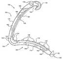
도 1 내지 도 8은 본 발명의 외과용 클립(100)의 제1 실시예를 도시한다. 외과용 클립(100)은 근위 단부 부분 및 원위 단부 부분을 가질 수 있다. 외과용 클립(100)은 근위 단부 부분 및 원위 단부 부분을 갖는 제1 레그 부재(102), 및 근위 단부 부분 및 원위 단부 부분을 갖는 제2 레그 부재(104)를 더 포함할 수 있다. 제1 및 제2 레그 부재(102, 104)는 힌지 부재(106)에 의해 근위 단부 부분에서 일체로 결합될 수 있다.1 to 8 show a first embodiment of a
제1 및 제2 레그 부재(102, 104)는 곡면을 포함할 수 있다. 예를 들어, 제1 레그 부재(102)는 제1 내면(108) 및 제1 외면(110)을 포함할 수 있고, 제2 레그 부재(104)는 제2 내면(112) 및 제2 외면(114)을 포함할 수 있다. 도 1에 도시된 바와 같이, 제1 내면(108)은 오목한 곡률을 가질 수 있고, 제1 외면(110)은 볼록한 곡률을 가질 수 있다. 제2 내면(112)은 볼록한 곡률을 가질 수 있고, 제2 외면(114)은 오목한 곡률을 가질 수 있다. 제1 레그 부재(102) 및 제2 레그 부재(104)의 곡률은 실질적으로 일치할 수 있고, 제1 내면(108) 및 제2 내면(112)의 각각의 오목/볼록은 실질적으로 정합할 수 있다. 제1 내면(108)의 오목 곡률 및/또는 제1 외면(110)의 볼록 곡률은 제1 레그 부재(102)의 전체 길이에 실질적으로 연장될 수 있다. 제2 내면(112)의 볼록 곡률 및/또는 제2 외면(114)의 오목 곡률은 제2 레그 부재(104)의 실질적으로 전체 길이로 연장될 수 있다. 제1 및 제2 내면(108, 112)은 닫힌 배치로 근사화되거나 접촉할 수 있다. 레그 부재(102, 104)의 일반적인 곡률에 대한 추가 논의는 미국 특허 제 4,834,096 호에서 찾을 수 있으며, 그 전체 내용은 참조에 의해 참조로 통합된다.The first and
힌지 부재(106)는 탄성적으로 유연하며 제1 및 제2 레그 부재(102, 104)에 일체형일 수 있다. 힌지 부재(106)는 제1 외면(110) 및 제2 외면(114)을 결합시키는 볼록한 외면(120)을 가질 수 있다. 힌지 부재(106)는 또한 볼록한 외면(120)에 의해 적어도 부분적으로 규정된 슬롯(122)을 포함할 수 있다. 슬롯(122)은 조직을 수용하고 조직 보유를 가능하게 하기 위해 열린 배치(예를 들어, 도 1)에서 원위 구멍(opening)을 가질 수 있다. 예를 들어, 슬롯(122)의 원위 구멍은 제1 및 제2 레그 부재(102, 104)로부터 연장되는 근위 플랩(flap) 또는 연장부(124)에 의해 규정될 수 있다. 근위 연장부(124)는 캔틸레버 구성으로 연장할 수 있어서, 조직의 존재에 기초하여 제1 및 제2 레그 부재(102, 104)에 대한 피봇 및 편향을 가능하게 한다. 근위 연장부(124)는 볼록한 내면 및 그 사이에 조직을 유지하고 폐쇄 동안 꼬집고 당기는(pinch-and-pull) 특징을 제공하도록 구성된 적어도 하나의 티스(126)를 가질 수 있다. 근위 연장부(124)는 슬롯(122)(예시적으로 도 2에 도시된 바와 같이)내로 근위로 연장될 수 있고 닫힌 배치에서 근사화 되거나 접촉될 수 있다. 따라서, 근위 연장부(124)의 볼록한 내면은 슬롯(122)내로 연장되는 조직과 함께 그 사이에 조직을 단단히 유지하도록 구성될 수 있다. 티스(126)는 측 방향으로 배치될 수 있고 중첩되지 않을 수 있으며, 각각의 근위 연장부(124)는 도 3 및 도 3에 예시된 것처럼 단일 측방향으로 연장하는 티스(126)를 포함할 수 있다.The
도 1 내지 도 6의 실시예에 더 도시된 것처럼, 외과용 클립(100)은 제2 레그 부재(104)의 내면(112) 상에 하나 이상의 티스(130)를 포함할 수 있다. 티스(130)는 조직과 맞물릴 때 티스(130)가 실질적으로 편향되지 않도록 실질적으로 강성일 수 있다. 도 3 내지 도 4에 도시된 바와 같이, 티스(130)는 제2 레그 부재(102)의 내면(112)에서 길이 방향으로 연장되는 제1 및 제2 열로 이격될 수 있다. 제1 및 제2 열의 티스(130)는 제2 내면(112)의 주변부 상에서 곡선의 제2 레그 부재(104)의 내면(112)의 중심선의 맞은편 상에서 서로로부터 횡방향으로 이격될 수 있다. 각각의 제1 및 제2 열의 티스(130)는 내면(112)의 길이 방향 축을 따라 엇갈리게 배치될 수 있다. 대응하여, 제1 내면(108)은 제1 내면(108) 상에서 길이 방향으로 연장되는 레일(132) 및 레일(132)의 대향하는 측면에서 연장되는 제1 및 제2 길이 방향 채널(134)을 규정할 수 있다. 따라서, 외과용 클립(100)의 닫힌 배치에서(예를 들어, 도 2), 티스(130)의 제1 열은 제1 채널(134)에 수용될 수 있고, 티스(130)의 제2 열은 제2 채널(134)에 수용될 수 있으며, 레일(132)은 티스(130)의 제1 및 제2 열 사이에 수용될 수 있다. 제1 및 제2 길이 방향 채널(134)은 실질적으로 L자 형상일 수 있고, 외과용 클립(100)의 측면에서 개방될 수 있다. 티스(130) 및 레일(132)의 이러한 구성은 조직과 근접한 조직 맞물림면의 바람직한 구불구불한 맞물림을 제공한다. 티스(130)는 실질적으로 편평한 조직 맞물림 내면을 갖는 더 크고 비외상성(atraumatic)일 수 있다. 더 큰 비 외상성 티스(130)는 조직 보유를 추가로 개선하고 조직이 외과용 클립에서 미끄러지는 것을 방지할 수 있다. 그러나, 대안적인 실시예에서, 티스(130)는 제1 내면(108) 상에 있을 수 있고, 레일(132) 및 채널(134)은 제2 내면(112) 상에 있을 수 있다.1-6 , the
외과용 클립(100)은 또한 하나 이상의 래칭 요소를 갖는 래칭 메카니즘을 포함할 수 있다. 예를 들면, 제1 레그 부재(102)는 그 원위 단부 부분에서 후크 부재(140)로 전환될 수 있고, 제2 레그 부재(104)는 그 원위 단부 부분에서 상보적인 홈이 있고 및 뾰족한 팁 부재(142)에 전환될 수 있다. 후크 부재(140)의 원위 단부 부분은 내측으로 만곡될 수 있고 일반적으로 힌지 부재(106)를 향할 수 있다. 후크 부재(140)는 하나 이상의 횡 방향 경사면 및 제1 내면(108)과 통합되는 오목 내면을 가져서, 래칭 리세스(144)를 규정한다. 팁 부재(142)는 후크 부재(140)가 팁 부재(142) 주위로 편향 및/또는 제2 레그 부재(104)가 압축됨에 따라 후크 부재(140)의 경사면을 수용하도록 구성된 슬롯을 규정하는 V 자형일 수 있다. 후크 부재(140)와 팁 부재(142)가 결합되어 래칭 메카니즘을 형성할 수 있다. 예를 들어, 래칭 리세스(144)는 혈관 또는 다른 조직 주위에 위치가 고정될 때 외과용 클립(100)을 닫힌 배치(예를 들어, 도 2)로 압축하는 과정에서 팁 부재(142)를 수용할 수 있다. 래칭 메커니즘에 대한 추가 논의는 미국 특허 제 4,834,096호에서 찾을 수 있으며, 그 전체 내용은 여기에 참조로 포함된다.
레그 부재(102, 104)는 상기 클립 어플라이어의 턱을 결합하도록 길이 방향을 따라 하나 이상의 보스 부재를 포함할 수 있다. 예를 들어, 제 1 레그 부재(102)는 제 1 레그 부재(102)의 원위 단부 부분에 인접하고 후크 부재(140)의 바로 안쪽의 대향 측면들에 수직으로 돌출하는 하나 이상의 보스 부재(150)를 포함할 수 있다. 외과용 클립(100)의 도시된 예에서, 하나 이상의 보스 부재(150)는 원통형일 수 있으며 제1 레그 부재(102)의 측면을 너머 외부로 돌출할 수 있다. 하나 이상의 보스 부재(150)는 제1 레그 부재(102)의 폭으로 연장하는 브리지 섹션(151)을 포함할 수 있다. 제2 레그 부재(104)는 또한 원위 단부 부분에서 하나 이상의 보스 부재(152)를 포함할 수 있다. 보스 부재(152)는 원통형일 수 있고 제2 레그 부재(104)의 대향 측면들에 수직으로 돌출하여, 팁 부재(142)의 첨부를 너머 전방으로 및 제2 레그 부재(104)의 측면을 너머 바깥으로 길이 방향으로 연장한다. 클립 어플라이어의 턱은 보스 부재(150, 151, 152)와 결합하고, 힌지 부재(106)를 중심으로 레그 부재(102, 104)를 피봇하게 하여, 외과용 클립(100)을 혈관 주변에서 닫힌 및/또는 래치된 배치로 압축하도록 한다.The
제1 레그 부재(102)는 제1 내면(108)의 측 방향으로 연장되는 하나의 제1 윙 부재(162)를 가질 수 있고, 및/또는 제2 레그 부재(104)는 제2 내면(112)의 측 방향으로 연장되는 적어도 하나의 제2 윙 부재(164)를 가질 수 있다. 예를 들어, 적어도 하나의 제1 윙 부재(162)는 제1 내면(108)의 대향 측면에서 연장되는 한 쌍의 제1 윙 부재(162)를 포함할 수 있다. 적어도 하나의 제2 윙 부재(164)는 제2 내면(112)의 대향 측면 상으로 연장되는 한 쌍의 제1 윙 부재(164)를 포함할 수 있다. 윙 부재(162, 164)는 비틀림 강성을 증가시킴으로써 레그 부재(102, 104)를 강화하고 안정화할 수 있다. 예를 들어, 윙 부재(162, 164)는 비틀림 및/또는 조직 유지 강도를 손상시키지 않으면서 레그 부재(162, 164)를 더 길게할 수 있다. 윙 부재(162, 164)는 레그 부재(102, 104)의 길이의 적어도 절반에 대해 길이 방향으로 연장될 수 있다. 일부 실시예에서, 윙 부재(162, 164)는 레그 부재(102, 104)의 적어도 2/3에 대해 길이 방향으로 연장될 수 있다. 윙 부재(162, 164)는 힌지 부재(106)의 비틀림에 저항하고 레그 부재(102, 104)의 정렬을 유지하기 위해 힌지 부재(106)를 통해 연속적으로 연장될 수 있어서, 윙 부재(162, 164)에서의 외과용 클립(100)의 폭이 힌지 부재(106)에서의 외과용 클립(100)의 폭과 실질적으로 같을 수 있다. 더욱이, 윙 부재(162, 164)에서의 외과용 클립(100)의 폭은 보스 부재(150, 151, 152)에서의 외과용 클립(100)의 폭과 동일할 수 있어서, 외과용 클립(100)이 그 측면 상에서 평평하게 놓일 수 있도록 하고, 자동식 어플라이어에서의 공급 특성을 개선하도록 한다. 그러나, 윙 부재(162, 164)는 레그 부재(102, 104)의 원위 단부 및/또는 보스 부재(150, 151, 152)로부터 근위로 이격된 원위 부분(168)을 가질 수 있어서, 윙 부재(162, 164)는 레그 부재(102, 104)의 전체 길이로 연장하지 않거나 또는 클립 어플라이어 인터페이스를 방해하지 않는다. 예를 들면, 원위 부분(168)은 각이 지고 및/또는 경사질 수 있다. 윙 부재(162, 164)는 감소된 두께를 제공하기 위해 각이 지고 및/또는 경사진 내면(166)을 각각 가질 수 있어서, 윙 부재(162, 164)는 조직 결찰을 방해하지 않는다.The
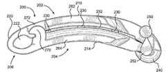
도 7의 절결도 및 도 8의 단면도에 더 도시된 것처럼, 제1 레그 부재(102)는 제1 두께(t1) 보다 큰 제1 폭(w1)을 가질 수 있다. 도 9의 절결도 및 도 10의 단면도에 유사하게 도시된 것처럼, 제2 레그 부재(104)는 제2 두께(t2) 보다 큰 제2 폭(w2)을 가질 수 있다. 두께(t)는 각각의 내면(108, 112)과 외면(110, 114) 사이의 거리에 의해 규정될 수 있다. 예를 들면, 제1 두께(t1)는 레일(132)의 내면과 제1 외면(110) 사이의 거리에 의해 규정될 수 있다. 제2 두께(t2)는 제2 내면(112)(티스(130) 제외)과 제2 외면(114) 사이의 거리에 의해 규정될 수 있다. 폭(w)은 윙 부재(162, 164)의 대향하는 측면들 사이의 거리에 의해 규정될 수 있다. 제1 폭(w1)은 제1 두께(t1)보다 적어도 1.5 배 클 수 있고 및/또는 제2 폭(w2)은 제2 두께(t2)보다 최소 1.5 배 더 클 수 있다. 일부 실시예, 제1 폭(w1)은 제1 두께(t1) 보다 약 2배 클 수 있고, 및/또는 제2 폭(w2)은 제2 두께(t2) 보다 약 2 배 클 수 있다. 제1 폭(w1) 및 제2 폭(w2)은 실질적으로 동일할 수 있고, 및/또는 제1 두께(t1) 및 제2 두께(t2)는 실질적으로 동일할 수 있다. 제1 윙 부재(162)는 제1 두께(t1) 보다 작은 두께를 가질 수 있고, 및/또는 제2 윙 부재(164)는 제2 두께(t2) 보다 작은 두께를 가질 수 있어서, 예를 들면 경사진 내면(166)으로 인하여 조직 결찰이 간섭되는 것을 방지한다. 제1 윙 부재(162)는 제1 외면(110)과 연속적이거나 정렬된 외면을 가질 수 있고, 및/또는 제2 윙 부재(164)는 제2 외면(110)과 연속적이거나 정렬된 외면을 가질 수 있다. 각각의 제1 윙 부재(162)는 제1 폭(w1)의 1/4 이하의 폭을 가질 수 있고 및/또는 각각의 제2 윙 부재(164)는 제2 폭(w2)의 1/4 이하의 폭을 가질 수 있다. 각각의 윙 부재(162, 164)의 측면은 외과의가 외과용 클립(100)에 너무 가깝게 결찰된 혈관을 절단하는 것을 방지하기 위해 가이드 표면을 제공하도록 실질적으로 평평할 수 있으며, 이는 혈관에서 외과용 클립(100)의 유지를 손상시킬 수 있다.As further shown in the cut-away view of FIG. 7 and the cross-sectional view of FIG. 8 , the
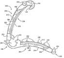
도 11-16은 본 발명의 외과용 클립(200)의 제2 실시예를 도시한다. 외과용 클립(200)은 근위 단부 부분 및 원위 단부 부분을 가질 수 있다. 외과용 클립(200)은 근위 단부 부분 및 원위 단부 부분을 갖는 제1 레그 부재(202), 근위 단부 부분 및 원위 단부 부분을 갖는 제2 레그 부재(204)를 더 포함할 수 있다. 제1 및 제2 레그 부재(202, 204)는 힌지 부재(206)에 의해 근위 단부 부분에서 일체로 결합될 수 있다. 외과용 클립(200)은 도 7 내지 도 10의 단면도를 포함하는 제1 실시예의 외과용 클립(100)과 유사한 특징을 갖는다. 따라서, 간결함을 위해 제2 실시예와 관련하여 도 7 내지 도 10의 논의가 본 명세서에 포함된다.11-16 show a second embodiment of a
제1 및 제2 레그 부재(202, 204)는 곡면을 포함할 수 있다. 예를 들어, 제1 레그 부재(202)는 제1 내면(208) 및 제1 외면(210)을 포함할 수 있고, 제2 레그 부재(204)는 제2 내면(212) 및 제2 외면(214)을 포함할 수 있다. 도 11에 도시된 바와 같이, 제1 내면(208)은 오목한 곡률을 가질 수 있고, 제1 외면(210)은 볼록한 곡률을 가질 수 있다. 제2 내면(212)은 볼록한 곡률을 가질 수 있고, 제2 외면(214)은 오목한 곡률을 가질 수 있다. 제1 레그 부재(202) 및 제2 레그 부재(204)의 곡률은 실질적으로 일치할 수 있고, 제1 내면(208)과 제2 내면(212)의 각각의 오목성/볼록성은 실질적으로 일치할 수 있다. 제1 내면(208)의 오목 곡률 및/또는 제1 외면(210)의 볼록 곡률은 실질적으로 제1 레그 부재(202)의 전체 길이로 연장될 수 있다. 제2 내면(212)의 볼록 곡률 및/또는 제2 외면(214)의 볼록 곡률은 실질적으로 제2 레그 부재(04)의 전체 길이로 연장될 수 있다. 제1 및 제2 내면(208, 212)은 닫힌 배치로 근사화되거나 접촉할 수 있다. 레그 부재(202, 204)의 일반적인 곡률에 대한 추가 논의는 미국 특허 번호 4,834,096에서 찾을 수 있으며, 그 전체 내용은 여기에 참조로 포함되어 있다.The first and
힌지 부재(206)는 탄성적으로 유연하며 제1 및 제2 레그 부재(202, 204)에 일체화될 수 있다. 힌지 부재(206)는 제1 외면(210)과 제2 외면(214)을 결합하는 볼록한 외면(220)을 가질 수 있다. 힌지 부재(206)는 또한 볼록한 외면(220)에 의해 적어도 부분적으로 규정되는 슬롯(222)을 포함할 수 있다. 슬롯(222)은 조직을 수용하고 조직 보유를 가능하게 하기 위하여 열린 배치(예를 들면, 도 11)에서 원위 구멍을 가질 수 있다.
제1 레그 부재는 제1 내부 부재(270) 및 근위 부분에 제1 개구(272)를 포함할 수 있고, 제2 레그 부재는 제2 내부 부재(270) 및 근위 부분에 제2 개구(272)을 포함할 수 있다. 내부 부재(270) 및 개구(272)는 제1 및 제2 레그 부재(202, 204)의 중심 라인의 대향 측면에서 반사 대칭 구조로 있을 수 있어서, 닫힌 배치에서, 제1 개구(272)는 제2 내부 부재(270)를 수용하고, 제2 개구(272)는 제1 내부 부재(270)를 수용한다. 따라서, 내부 부재(270) 및 개구(272)는 닫힌 배치에서 외과용 클립이 반전하거나 또는 측방향으로 회전하는 것을 방지한다. 그러나, 내부 부재(270) 및 개구(272)는 레그 부재(202, 204)의 근위 부분이 구부러지는 것을 억제하지 않도록 래치 및/또는 인터로크되지 않을 수 있다. 내부 부재(270) 및 개구(272)는 외과용 클립(200)의 축 방향으로 당기는 힘을 추가로 증가시킬 수 있다. 예를 들어, 내부 부재(270)는 조직을 대향하는 개구(272)로 밀어 넣어 그 사이에 조직을 끼울 수 있다. 내부 부재(270)는 후크 형상을 가질 수 있고, 개구(272)는 측면이 개방될 수 있다.The first leg member may include a first
도 11 내지 도 16의 실시예에 도시된 것처럼, 외과용 클립(200)은 제2 레그 부재(204)의 내면(212) 상에 하나 또는 복수의 티스(230)를 포함할 수 있다. 티스(230)는 실질적으로 단단할 수 있어서, 티스(230)는 조직과 맞물릴 때 실질적으로 편향되지 않는다. 도 13 및 도 14에 도시된 바와 같이, 티스(230)는 제2 레그 부재(202)의 내면(212)에서 길이 방향으로 연장되는 제1 및 제2 열로 이격될 수 있다. 티스(230)의 제1 및 제2 열은 제2 내면(212)의 주변에서 제2 레그 부재(204)의 내면(212)의 중심선의 대향 측면 상에서 서로로부터 횡방향으로 분리될 수 있다. 각각의 제1 및 제2 열의 티스(230)는 내면(212)의 길이 방향 축을 따라 엇갈리게 배치될 수 있다. 대응하여, 제1 내면(208)은 제1 내면(208)에서 길이 방향으로 연장되는 레일(232) 및 레일(232)의 대향하는 측면에서 연장되는 제1 및 제2 길이 방향 채널(234)을 규정할 수 있다. 따라서, 외과용 클립(200)의 닫힌 배치(예를 들어, 도 12)에서, 티스(230)의 제1 열은 제1 채널(234)에 수용될 수 있고, 제2 열(230)은 제2 채널(234)에 수용될 수 있으며, 레일(232)은 티스(230)의 제1 및 제2 열 사이에 수용될 수 있다. 제1 및 제2 길이 방향 채널(234)은 대체로 L 자형일 수 있고 외과용 클립(200)의 측면에서 개방될 수 있다. 티스(230) 및 레일(232)의 이러한 구성은 조직과 근접한 조직 맞물림면의 바람직한 구불구불한 맞물림을 제공한다. 티스(230)는 실질적으로 편평한 조직 맞물림 내면을 갖는 더 크고 비외상성(atraumatic)일 수 있다. 더 큰 비 외상성 티스(230)는 조직 보유를 추가로 개선하고 조직이 외과용 클립에서 미끄러지는 것을 방지할 수 있다. 그러나, 대안적인 실시예에서, 티스(230)는 제1 내면(208) 상에 있을 수 있고, 레일(232) 및 채널(234)은 제2 내면(210) 상에 있을 수 있다.11-16 , the
외과용 클립(200)은 또한 하나 이상의 래칭 요소를 갖는 래칭 메카니즘을 포함할 수 있다. 예를 들면, 제1 레그 부재(202)는 그 원위 단부 부분에서 후크 부재(240)로 전환될 수 있고, 제2 레그 부재(204)는 그 원위 단부 부분에서 상보적인 홈이 있고 및 뾰족한 팁 부재(242)에 전환될 수 있다. 후크 부재(240)의 원위 단부 부분은 내측으로 만곡될 수 있고 일반적으로 힌지 부재(206)를 향할 수 있다. 후크 부재(240)는 하나 이상의 횡 방향 경사면 및 제1 내면(208)과 통합되는 오목 내면을 가져서, 래칭 리세스(244)를 규정한다. 팁 부재(242)는 후크 부재(240)가 팁 부재(242) 주위로 편향 및/또는 제2 레그 부재(204)가 압축됨에 따라 후크 부재(240)의 경사면을 수용하도록 구성된 슬롯을 규정하는 V 자형일 수 있다. 후크 부재(240)와 팁 부재(242)가 결합되어 래칭 메카니즘을 형성할 수 있다. 예를 들어, 래칭 리세스(244)는 혈관 또는 다른 조직 주위에 위치가 고정될 때 외과용 클립(200)을 닫힌 배치(예를 들어, 도 12)로 압축하는 과정에서 팁 부재(242)를 수용할 수 있다. 래칭 메커니즘에 대한 추가 논의는 미국 특허 제 4,834,096호에서 찾을 수 있으며, 그 전체 내용은 여기에 참조로 포함된다.
레그 부재(202, 204)는 상기 클립 어플라이어의 턱을 결합하도록 길이 방향을 따라 하나 이상의 보스 부재를 포함할 수 있다. 예를 들어, 제1 레그 부재(202)는 제1 레그 부재(202)의 원위 단부 부분에 인접하고 후크 부재(240)의 바로 안쪽의 대향 측면들에 수직으로 돌출하는 하나 이상의 보스 부재(250)를 포함할 수 있다. 외과용 클립(200)의 도시된 예에서, 하나 이상의 보스 부재(250)는 원통형일 수 있으며 제1 레그 부재(202)의 측면을 너머 외부로 돌출할 수 있다. 하나 이상의 보스 부재(250)는 제1 레그 부재(202)의 폭으로 연장하는 브리지 섹션(251)을 포함할 수 있다. 제2 레그 부재(204)는 또한 원위 단부 부분에서 하나 이상의 보스 부재(252)를 포함할 수 있다. 보스 부재(252)는 원통형일 수 있고 제2 레그 부재(204)의 대향 측면들에 수직으로 돌출하여, 팁 부재(242)의 첨부를 너머 전방으로 및 제2 레그 부재(204)의 측면을 너머 바깥으로 길이 방향으로 연장한다. 클립 어플라이어의 턱은 보스 부재(250, 251, 252)와 결합하고, 힌지 부재(206)를 중심으로 레그 부재(202, 204)를 피봇하게 하여, 외과용 클립(200)을 혈관 주변에서 닫힌 및/또는 래치된 배치로 압축하도록 한다.The
제1 레그 부재(202)는 제1 내면(208)의 측 방향으로 연장되는 하나의 제1 윙 부재(262)를 가질 수 있고, 및/또는 제2 레그 부재(204)는 제2 내면(212)의 측 방향으로 연장되는 적어도 하나의 제2 윙 부재(264)를 가질 수 있다. 예를 들어, 적어도 하나의 제1 윙 부재(262)는 제1 내면(208)의 대향 측면에서 연장되는 한 쌍의 제1 윙 부재(262)를 포함할 수 있다. 적어도 하나의 제2 윙 부재(264)는 제2 내면(210)의 대향 측면 상으로 연장되는 한 쌍의 제1 윙 부재(264)를 포함할 수 있다. 윙 부재(262, 264)는 비틀림 강성을 증가시킴으로써 레그 부재(202, 204)를 강화하고 안정화할 수 있다. 예를 들어, 윙 부재(262, 264)는 비틀림 및/또는 조직 유지 강도를 손상시키지 않으면서 레그 부재(262, 264)를 더 길게할 수 있다. 윙 부재(262, 264)는 레그 부재(202, 204)의 길이의 적어도 절반에 대해 길이 방향으로 연장될 수 있다. 일부 실시예에서, 윙 부재(262, 264)는 레그 부재(202, 204)의 적어도 2/3에 대해 길이 방향으로 연장될 수 있다. 윙 부재(262, 264)는 힌지 부재(206)의 비틀림에 저항하고 레그 부재(202, 204)의 정렬을 유지하기 위해 힌지 부재(206)를 통해 연속적으로 연장될 수 있어서, 윙 부재(262, 264)에서의 외과용 클립(200)의 폭이 힌지 부재(206)에서의 외과용 클립(200)의 폭과 실질적으로 같을 수 있다. 더욱이, 윙 부재(262, 264)에서의 외과용 클립(200)의 폭은 보스 부재(250, 251, 252)에서의 외과용 클립(200)의 폭과 동일할 수 있어서, 외과용 클립(200)이 그 측면 상에서 평평하게 놓일 수 있도록 하고, 자동식 어플라이어에서의 공급 특성을 개선하도록 한다. 그러나, 윙 부재(262, 264)는 보스 부재(250, 251, 252)로부터 근위로 이격된 원위 부분(268)을 가질 수 있어서, 윙 부재(262, 264)는 클립 어플라이어 인터페이스를 방해하지 않는다. 예를 들면, 원위 부분(268)은 각이 지고 및/또는 경사질 수 있다. 윙 부재(262, 264)는 감소된 두께를 제공하기 위해 각이 지고 및/또는 경사진 내면(266)을 각각 가질 수 있어서, 윙 부재(262, 264)는 조직 결찰을 방해하지 않는다.The
본 발명의(200)의 외과용 클립(100)의 다양한 실시예들은 임의의 적절한 크기로 이루어질 수 있으며, 혈관, 림프절, 신경, 담낭 관 및 심장 조직과 같은 조직의 임의의 수에 적용할 수도 있다. 외과용 클립(100, 200)의 다양한 실시예는 금속 및 폴리머와 같은 임의의 적합한 생체 적합성 재료로 구성될 수 있다. 그러나, 본 발명은 폴리머 클립을 사용한 실행에 특히 적합하다. 따라서, 외과용 클립(100, 200)의 다양한 실시예는 바람직하게는 외과용 임플란트에 일반적으로 사용되는 유형과 같은 적합한 강력한 생체 적합성 엔지니어링 플라스틱으로 형성된 단일 조각 일체형 폴리머 본체로 구성된다. 예시적인 재료는 단일 중합체 또는 공중합체 폴리아세탈, 폴리에틸렌 테레프탈레이트(PET), 폴리부틸렌 테레프탈레이트(PBT), 폴리옥시메틸렌, 또는 사출 성형, 압출 또는 다른 방식으로 유사한 물품으로 가공될 수 있은 유사한 특성을 갖는 다른 열가소성 플라스틱 재료를 포함한다.The various embodiments of
Claims (20)
Translated fromKorean오목한 곡률을 갖는 제1 내면을 갖는 제1 레그 부재 - 상기 제1 레그 부재는 압축 방향으로 제1 두께, 측면 방향으로 제1 폭 및 길이 방향으로 제1 길이를 가짐 - ;
볼록한 곡률을 갖는 제2 내면을 갖는 제2 레그 부재 - 상기 제2 레그 부재는 압축 방향으로 제2 두께, 측면 방향으로 제2 폭 및 길이 방향으로 제1 길이를 가짐 - ; 및
상기 제1 레그 부재와 상기 제2 레그 부재를 피봇식으로 결합하는 힌지 부재를 포함하되,
상기 제1 폭은 상기 제1 길이의 적어도 절반을 따라 상기 제1 두께보다 크고, 및/또는 상기 제2 폭은 상기 제2 길이의 적어도 절반을 따라 상기 제2 두께보다 더 큰, 외과용 클립.As a surgical clip:
a first leg member having a first inner surface having a concave curvature, the first leg member having a first thickness in a compression direction, a first width in a lateral direction and a first length in a longitudinal direction;
a second leg member having a second inner surface having a convex curvature, the second leg member having a second thickness in a compression direction, a second width in a lateral direction, and a first length in a longitudinal direction; and
a hinge member pivotally coupling the first leg member and the second leg member;
wherein the first width is greater than the first thickness along at least half of the first length, and/or the second width is greater than the second thickness along at least half of the second length.
상기 제1 레그 부재 상의 적어도 하나의 제1 보스 부재; 및
상기 제2 레그 부재 상의 적어도 하나의 제2 보스 부재를 더 포함하되,
상기 제1 폭은 적어도 하나의 제1 보스 부재에서 상기 외과용 클립의 폭과 실질적으로 동일하고, 및/또는 상기 제2 폭은 적어도 하나의 제2 보스 부재에서 상기 외과용 클립의 폭과 실질적으로 동일한, 외과용 클립.5. The method according to any one of claims 1 to 4,
at least one first boss member on the first leg member; and
at least one second boss member on the second leg member;
the first width is substantially equal to a width of the surgical clip in at least one first boss member, and/or the second width is substantially equal to a width of the surgical clip in at least one second boss member Same, surgical clip.
상기 제1 레그 부재의 원위 부분 상의 후크 부재; 및
상기 제2 레그 부재의 원위 부분 상의 팁 부재를 더 포함하되,
상기 후크 부재는 상기 팁 부재를 수용하여 상기 외과용 클립을 닫힌 배치로 유지하도록 구성되는, 외과용 클립.15. The method of any one of claims 1 to 14,
a hook member on the distal portion of the first leg member; and
a tip member on the distal portion of the second leg member;
and the hook member is configured to receive the tip member and maintain the clip in a closed configuration.
상기 제1 내면 및 상기 제2 내면 중 하나로부터 연장되는 제1 및 제2 열의 티스; 및
상기 제1 내면 및 상기 제2 내면 중 다른 하나 상의 제1 및 제2 채널을 더 포함하되;
닫힌 배치에서, 상기 제1 채널은 제1 열의 티스를 수용하도록 구성되고, 상기 제2 채널은 제2 열의 티스를 수용하도록 구성되는, 외과용 클립.16. The method according to any one of claims 1 to 15,
first and second rows of teeth extending from one of the first inner surface and the second inner surface; and
further comprising first and second channels on the other of the first inner surface and the second inner surface;
In a closed configuration, the first channel is configured to receive a first row of teeth and the second channel is configured to receive a second row of teeth.
상기 제1 레그 부재의 근위 부분에 있는 제1 내부 부재; 및
상기 제2 레그 부재의 근위 부분에 있는 제1 개구를 더 포함하되,
상기 제1 개구는 닫힌 배치에서 상기 제1 내부 부재를 수용하여 상기 외과용 클립이 반전 및/또는 회전하는 것을 방지하도록 구성되며, 상기 제1 내부 부재는 상기 제1 개구와 래치 및/또는 인터로크하지 않는, 외과용 클립.19. The method according to any one of claims 1 to 18,
a first inner member at the proximal portion of the first leg member; and
a first opening in the proximal portion of the second leg member;
the first opening is configured to receive the first inner member in a closed configuration to prevent reversal and/or rotation of the surgical clip, the first inner member latching and/or interlocking with the first opening No, surgical clips.
상기 제2 레그 부재의 근위 부분에 있는 제2 내부 부재; 및
상기 제1 레그 부재의 근위 부분에 있는 제2 개구를 더 포함하되,
상기 제2 개구는 닫힌 배치에서 상기 제2 내부 부재를 수용하여 상기 외과용 클립이 반전 및/또는 회전하는 것을 방지하도록 구성되며, 상기 제2 부재는 상기 제2 개구와 래치 및/또는 인터로크하지 않는, 외과용 클립.20. The method of any one of claims 1 to 19,
a second inner member at the proximal portion of the second leg member; and
a second opening in the proximal portion of the first leg member;
the second opening is configured to receive the second inner member in a closed configuration to prevent reversal and/or rotation of the surgical clip, the second member not latching and/or interlocking with the second opening Do not use, surgical clips.
Priority Applications (1)
| Application Number | Priority Date | Filing Date | Title |
|---|---|---|---|
| KR1020247002778AKR102852635B1 (en) | 2018-11-16 | 2019-11-15 | Surgical clip |
Applications Claiming Priority (3)
| Application Number | Priority Date | Filing Date | Title |
|---|---|---|---|
| US201862768671P | 2018-11-16 | 2018-11-16 | |
| US62/768,671 | 2018-11-16 | ||
| PCT/US2019/061767WO2020102700A1 (en) | 2018-11-16 | 2019-11-15 | Surgical clip |
Related Child Applications (1)
| Application Number | Title | Priority Date | Filing Date |
|---|---|---|---|
| KR1020247002778ADivisionKR102852635B1 (en) | 2018-11-16 | 2019-11-15 | Surgical clip |
Publications (2)
| Publication Number | Publication Date |
|---|---|
| KR20210090212Atrue KR20210090212A (en) | 2021-07-19 |
| KR102631209B1 KR102631209B1 (en) | 2024-01-31 |
Family
ID=70731715
Family Applications (3)
| Application Number | Title | Priority Date | Filing Date |
|---|---|---|---|
| KR1020247002778AActiveKR102852635B1 (en) | 2018-11-16 | 2019-11-15 | Surgical clip |
| KR1020217017032AActiveKR102631209B1 (en) | 2018-11-16 | 2019-11-15 | surgical clips |
| KR1020257028233APendingKR20250130719A (en) | 2018-11-16 | 2019-11-15 | Surgical clip |
Family Applications Before (1)
| Application Number | Title | Priority Date | Filing Date |
|---|---|---|---|
| KR1020247002778AActiveKR102852635B1 (en) | 2018-11-16 | 2019-11-15 | Surgical clip |
Family Applications After (1)
| Application Number | Title | Priority Date | Filing Date |
|---|---|---|---|
| KR1020257028233APendingKR20250130719A (en) | 2018-11-16 | 2019-11-15 | Surgical clip |
Country Status (7)
| Country | Link |
|---|---|
| US (1) | US20210267603A1 (en) |
| EP (1) | EP3880085A4 (en) |
| JP (2) | JP7303877B2 (en) |
| KR (3) | KR102852635B1 (en) |
| CN (1) | CN113038888A (en) |
| AU (3) | AU2019379170B2 (en) |
| WO (1) | WO2020102700A1 (en) |
Cited By (1)
| Publication number | Priority date | Publication date | Assignee | Title |
|---|---|---|---|---|
| KR20230115040A (en)* | 2022-01-26 | 2023-08-02 | 주식회사 티플랜트 | Medical ligation clips |
Families Citing this family (7)
| Publication number | Priority date | Publication date | Assignee | Title |
|---|---|---|---|---|
| CA3068282C (en) | 2017-06-22 | 2022-06-28 | Teleflex Medical Incorporated | Surgical clip |
| ES2981210T3 (en) | 2017-11-14 | 2024-10-07 | Teleflex Medical Inc | Surgical clip |
| KR102647625B1 (en)* | 2018-07-18 | 2024-03-14 | 텔리플렉스 메디컬 인코포레이티드 | Clip Appliers and Cartridges |
| EP4076216A1 (en) | 2019-12-19 | 2022-10-26 | Teleflex Medical Incorporated | Surgical clip |
| AU2022270758A1 (en) | 2021-05-07 | 2023-11-23 | Teleflex Medical Incorporated | Device and method for unlatching a surgical clip |
| USD1031426S1 (en)* | 2022-07-27 | 2024-06-18 | Green Manatee, LLC | Holder |
| US20240415515A1 (en)* | 2023-03-22 | 2024-12-19 | Lsi Solutions, Inc. | Atrial clip assembly and delivery device |
Citations (3)
| Publication number | Priority date | Publication date | Assignee | Title |
|---|---|---|---|---|
| US20050165422A1 (en)* | 2004-01-22 | 2005-07-28 | Pilling Weck Incorporated | Ligating clip with integral cutting guide |
| WO2005074421A2 (en)* | 2004-01-23 | 2005-08-18 | Pilling Weck, Inc. | Ligating clip with integral tissue-securing mechanism |
| US20070083218A1 (en)* | 2005-10-12 | 2007-04-12 | A Morris Steven | Coated ligating clip |
Family Cites Families (29)
| Publication number | Priority date | Publication date | Assignee | Title |
|---|---|---|---|---|
| US4227730A (en)* | 1979-05-29 | 1980-10-14 | Baxter Travenol Laboratories, Inc. | Gripper member for retention of a plastic tube |
| US4476865A (en)* | 1982-02-12 | 1984-10-16 | Ethicon, Inc. | Non-metallic, bio-compatible hemostatic clips |
| JP2604833B2 (en)* | 1987-10-26 | 1997-04-30 | ピリング・ウェック・インコーポレイテッド | Plastic ligating clip |
| US4834096A (en)* | 1987-10-26 | 1989-05-30 | Edward Weck Incorporated | Plastic ligating clips |
| US5160339A (en)* | 1991-06-18 | 1992-11-03 | Ethicon, Inc. | Endoscopic suture clip |
| CA2094463A1 (en)* | 1992-04-28 | 1993-10-29 | Claude Vidal | Vessel clips |
| US7727248B2 (en)* | 2001-06-25 | 2010-06-01 | Ethicon Endo-Surgery, Inc. | Surgical clip |
| EP1876971A1 (en)* | 2005-03-24 | 2008-01-16 | Pilling Weck Incorporated | Reduced closure force ligating clip |
| US20070118161A1 (en)* | 2005-11-22 | 2007-05-24 | Kennedy Daniel L | Non-snag polymer ligating clip |
| US9445820B2 (en)* | 2007-12-31 | 2016-09-20 | Teleflex Medical Incorporated | Ligation clip with flexible clamping feature |
| RU2485908C2 (en)* | 2010-12-07 | 2013-06-27 | Компания с ограниченной ответственностью Глобитек 2000 | Method of creating hemostasis with possibility of blood flow recovery in tubular elastic structures of organism and devices for its realisation |
| US20130289588A1 (en)* | 2010-12-20 | 2013-10-31 | University Of Georgia Research Foundation, Inc. | Vascular clip |
| EP2755578A2 (en)* | 2011-09-15 | 2014-07-23 | Teleflex Medical Incorporated | Manual surgical ligation clip applier |
| EP3305217A1 (en)* | 2011-10-20 | 2018-04-11 | Teleflex Life Sciences Unlimited Company | Ligation clip |
| US9220507B1 (en)* | 2012-10-14 | 2015-12-29 | Manoj B. Patel | Tissue spreading vascular clips with locking mechanism and non-slip clamping surfaces |
| US10125906B2 (en)* | 2014-08-21 | 2018-11-13 | Nordson Corporation | Reusable clamp with latch release arm for connecting conduit sections and associated methods |
| JP2018518271A (en)* | 2015-06-16 | 2018-07-12 | ナノヴァ バイオマテリアルズ,インコーポレイテッド | Anti-surgical ligation clip |
| US10327762B2 (en)* | 2015-07-17 | 2019-06-25 | Suturegard Medical, Inc. | Suture locks |
| WO2017017587A2 (en)* | 2015-07-24 | 2017-02-02 | Cliptip Medical Ltd | Thickness-adjustable hemostatic clips, clip appliers, and applications thereof |
| US10383637B2 (en)* | 2015-07-30 | 2019-08-20 | Teleflex Medical Incorporated | Snap-on surgical clip cartridge |
| JP6694893B2 (en)* | 2015-10-23 | 2020-05-20 | 株式会社カネカ | Medical clip |
| CN105534558A (en)* | 2016-02-04 | 2016-05-04 | 徐斌 | Vascular clamp |
| US10265079B2 (en)* | 2016-04-28 | 2019-04-23 | Grena Usa Llc | Polymeric ligating clip |
| US10548609B2 (en)* | 2016-08-03 | 2020-02-04 | Teleflex Medical Incorporated | Surgical ligation clip |
| WO2018175610A1 (en)* | 2017-03-21 | 2018-09-27 | Teleflex Medical Incorporated | Surgical clip and clip applier |
| WO2018196935A1 (en)* | 2017-04-27 | 2018-11-01 | Price Invena Aps | A clamp and cutting device |
| CA3068282C (en)* | 2017-06-22 | 2022-06-28 | Teleflex Medical Incorporated | Surgical clip |
| US10932788B2 (en)* | 2018-04-11 | 2021-03-02 | Covidien Lp | Ligation clip with latching and retention features |
| US11317923B2 (en)* | 2018-08-13 | 2022-05-03 | Covidien Lp | Ligation clip with improved hinge |
- 2019
- 2019-11-15KRKR1020247002778Apatent/KR102852635B1/enactiveActive
- 2019-11-15KRKR1020217017032Apatent/KR102631209B1/enactiveActive
- 2019-11-15JPJP2021526797Apatent/JP7303877B2/enactiveActive
- 2019-11-15CNCN201980075495.5Apatent/CN113038888A/enactivePending
- 2019-11-15KRKR1020257028233Apatent/KR20250130719A/enactivePending
- 2019-11-15EPEP19884321.1Apatent/EP3880085A4/enactivePending
- 2019-11-15WOPCT/US2019/061767patent/WO2020102700A1/ennot_activeCeased
- 2019-11-15AUAU2019379170Apatent/AU2019379170B2/enactiveActive
- 2021
- 2021-05-14USUS17/321,123patent/US20210267603A1/enactivePending
- 2022
- 2022-04-26AUAU2022202708Apatent/AU2022202708B2/enactiveActive
- 2023
- 2023-06-23JPJP2023103351Apatent/JP7728819B2/enactiveActive
- 2024
- 2024-07-10AUAU2024204740Apatent/AU2024204740A1/enactivePending
Patent Citations (3)
| Publication number | Priority date | Publication date | Assignee | Title |
|---|---|---|---|---|
| US20050165422A1 (en)* | 2004-01-22 | 2005-07-28 | Pilling Weck Incorporated | Ligating clip with integral cutting guide |
| WO2005074421A2 (en)* | 2004-01-23 | 2005-08-18 | Pilling Weck, Inc. | Ligating clip with integral tissue-securing mechanism |
| US20070083218A1 (en)* | 2005-10-12 | 2007-04-12 | A Morris Steven | Coated ligating clip |
Cited By (1)
| Publication number | Priority date | Publication date | Assignee | Title |
|---|---|---|---|---|
| KR20230115040A (en)* | 2022-01-26 | 2023-08-02 | 주식회사 티플랜트 | Medical ligation clips |
Also Published As
| Publication number | Publication date |
|---|---|
| AU2024204740A1 (en) | 2024-08-01 |
| JP2022507653A (en) | 2022-01-18 |
| KR20250130719A (en) | 2025-09-02 |
| KR102852635B1 (en) | 2025-08-29 |
| US20210267603A1 (en) | 2021-09-02 |
| WO2020102700A1 (en) | 2020-05-22 |
| AU2019379170B2 (en) | 2022-01-27 |
| EP3880085A1 (en) | 2021-09-22 |
| KR20240015738A (en) | 2024-02-05 |
| CN113038888A (en) | 2021-06-25 |
| EP3880085A4 (en) | 2022-08-17 |
| AU2019379170A1 (en) | 2021-06-03 |
| KR102631209B1 (en) | 2024-01-31 |
| JP7303877B2 (en) | 2023-07-05 |
| JP7728819B2 (en) | 2025-08-25 |
| AU2022202708B2 (en) | 2024-04-11 |
| JP2023130387A (en) | 2023-09-20 |
| AU2022202708A1 (en) | 2022-05-26 |
Similar Documents
| Publication | Publication Date | Title |
|---|---|---|
| KR102631209B1 (en) | surgical clips | |
| US12064115B2 (en) | Clip applier having stabilizing member | |
| US12102334B2 (en) | Clip applier with stabilizing member | |
| US11992222B2 (en) | Surgical clip | |
| US20240188962A1 (en) | Surgical clip | |
| US20180271535A1 (en) | Clip applier with replaceable tips |
Legal Events
| Date | Code | Title | Description |
|---|---|---|---|
| PA0105 | International application | St.27 status event code:A-0-1-A10-A15-nap-PA0105 | |
| PA0201 | Request for examination | St.27 status event code:A-1-2-D10-D11-exm-PA0201 | |
| PG1501 | Laying open of application | St.27 status event code:A-1-1-Q10-Q12-nap-PG1501 | |
| E902 | Notification of reason for refusal | ||
| PE0902 | Notice of grounds for rejection | St.27 status event code:A-1-2-D10-D21-exm-PE0902 | |
| T11-X000 | Administrative time limit extension requested | St.27 status event code:U-3-3-T10-T11-oth-X000 | |
| E13-X000 | Pre-grant limitation requested | St.27 status event code:A-2-3-E10-E13-lim-X000 | |
| P11-X000 | Amendment of application requested | St.27 status event code:A-2-2-P10-P11-nap-X000 | |
| P13-X000 | Application amended | St.27 status event code:A-2-2-P10-P13-nap-X000 | |
| E701 | Decision to grant or registration of patent right | ||
| PE0701 | Decision of registration | St.27 status event code:A-1-2-D10-D22-exm-PE0701 | |
| PA0104 | Divisional application for international application | St.27 status event code:A-0-1-A10-A18-div-PA0104 St.27 status event code:A-0-1-A10-A16-div-PA0104 | |
| PR0701 | Registration of establishment | St.27 status event code:A-2-4-F10-F11-exm-PR0701 | |
| PR1002 | Payment of registration fee | St.27 status event code:A-2-2-U10-U12-oth-PR1002 Fee payment year number:1 | |
| PG1601 | Publication of registration | St.27 status event code:A-4-4-Q10-Q13-nap-PG1601 |