KR20210089292A - Voice recognition system and display device using the same - Google Patents
Voice recognition system and display device using the sameDownload PDFInfo
- Publication number
- KR20210089292A KR20210089292AKR1020200002146AKR20200002146AKR20210089292AKR 20210089292 AKR20210089292 AKR 20210089292AKR 1020200002146 AKR1020200002146 AKR 1020200002146AKR 20200002146 AKR20200002146 AKR 20200002146AKR 20210089292 AKR20210089292 AKR 20210089292A
- Authority
- KR
- South Korea
- Prior art keywords
- vibration detection
- plate structure
- vibration
- voice recognition
- detection sensor
- Prior art date
- Legal status (The legal status is an assumption and is not a legal conclusion. Google has not performed a legal analysis and makes no representation as to the accuracy of the status listed.)
- Pending
Links
Images


Classifications
- G—PHYSICS
- G10—MUSICAL INSTRUMENTS; ACOUSTICS
- G10L—SPEECH ANALYSIS TECHNIQUES OR SPEECH SYNTHESIS; SPEECH RECOGNITION; SPEECH OR VOICE PROCESSING TECHNIQUES; SPEECH OR AUDIO CODING OR DECODING
- G10L15/00—Speech recognition
- G10L15/22—Procedures used during a speech recognition process, e.g. man-machine dialogue
- G—PHYSICS
- G10—MUSICAL INSTRUMENTS; ACOUSTICS
- G10L—SPEECH ANALYSIS TECHNIQUES OR SPEECH SYNTHESIS; SPEECH RECOGNITION; SPEECH OR VOICE PROCESSING TECHNIQUES; SPEECH OR AUDIO CODING OR DECODING
- G10L15/00—Speech recognition
- G10L15/005—Language recognition
- G—PHYSICS
- G10—MUSICAL INSTRUMENTS; ACOUSTICS
- G10L—SPEECH ANALYSIS TECHNIQUES OR SPEECH SYNTHESIS; SPEECH RECOGNITION; SPEECH OR VOICE PROCESSING TECHNIQUES; SPEECH OR AUDIO CODING OR DECODING
- G10L15/00—Speech recognition
- G10L15/28—Constructional details of speech recognition systems
- G—PHYSICS
- G10—MUSICAL INSTRUMENTS; ACOUSTICS
- G10L—SPEECH ANALYSIS TECHNIQUES OR SPEECH SYNTHESIS; SPEECH RECOGNITION; SPEECH OR VOICE PROCESSING TECHNIQUES; SPEECH OR AUDIO CODING OR DECODING
- G10L15/00—Speech recognition
- G10L15/02—Feature extraction for speech recognition; Selection of recognition unit
- G—PHYSICS
- G10—MUSICAL INSTRUMENTS; ACOUSTICS
- G10L—SPEECH ANALYSIS TECHNIQUES OR SPEECH SYNTHESIS; SPEECH RECOGNITION; SPEECH OR VOICE PROCESSING TECHNIQUES; SPEECH OR AUDIO CODING OR DECODING
- G10L15/00—Speech recognition
- G10L15/08—Speech classification or search
- G—PHYSICS
- G10—MUSICAL INSTRUMENTS; ACOUSTICS
- G10L—SPEECH ANALYSIS TECHNIQUES OR SPEECH SYNTHESIS; SPEECH RECOGNITION; SPEECH OR VOICE PROCESSING TECHNIQUES; SPEECH OR AUDIO CODING OR DECODING
- G10L15/00—Speech recognition
- G10L15/28—Constructional details of speech recognition systems
- G10L15/30—Distributed recognition, e.g. in client-server systems, for mobile phones or network applications
- G—PHYSICS
- G10—MUSICAL INSTRUMENTS; ACOUSTICS
- G10L—SPEECH ANALYSIS TECHNIQUES OR SPEECH SYNTHESIS; SPEECH RECOGNITION; SPEECH OR VOICE PROCESSING TECHNIQUES; SPEECH OR AUDIO CODING OR DECODING
- G10L25/00—Speech or voice analysis techniques not restricted to a single one of groups G10L15/00 - G10L21/00
- G10L25/78—Detection of presence or absence of voice signals
- H01L41/1136—
- H—ELECTRICITY
- H04—ELECTRIC COMMUNICATION TECHNIQUE
- H04R—LOUDSPEAKERS, MICROPHONES, GRAMOPHONE PICK-UPS OR LIKE ACOUSTIC ELECTROMECHANICAL TRANSDUCERS; DEAF-AID SETS; PUBLIC ADDRESS SYSTEMS
- H04R1/00—Details of transducers, loudspeakers or microphones
- H04R1/20—Arrangements for obtaining desired frequency or directional characteristics
- H04R1/22—Arrangements for obtaining desired frequency or directional characteristics for obtaining desired frequency characteristic only
- H04R1/24—Structural combinations of separate transducers or of two parts of the same transducer and responsive respectively to two or more frequency ranges
- H04R1/245—Structural combinations of separate transducers or of two parts of the same transducer and responsive respectively to two or more frequency ranges of microphones
- H—ELECTRICITY
- H04—ELECTRIC COMMUNICATION TECHNIQUE
- H04R—LOUDSPEAKERS, MICROPHONES, GRAMOPHONE PICK-UPS OR LIKE ACOUSTIC ELECTROMECHANICAL TRANSDUCERS; DEAF-AID SETS; PUBLIC ADDRESS SYSTEMS
- H04R1/00—Details of transducers, loudspeakers or microphones
- H04R1/20—Arrangements for obtaining desired frequency or directional characteristics
- H04R1/32—Arrangements for obtaining desired frequency or directional characteristics for obtaining desired directional characteristic only
- H—ELECTRICITY
- H04—ELECTRIC COMMUNICATION TECHNIQUE
- H04R—LOUDSPEAKERS, MICROPHONES, GRAMOPHONE PICK-UPS OR LIKE ACOUSTIC ELECTROMECHANICAL TRANSDUCERS; DEAF-AID SETS; PUBLIC ADDRESS SYSTEMS
- H04R17/00—Piezoelectric transducers; Electrostrictive transducers
- H04R17/02—Microphones
- H—ELECTRICITY
- H04—ELECTRIC COMMUNICATION TECHNIQUE
- H04R—LOUDSPEAKERS, MICROPHONES, GRAMOPHONE PICK-UPS OR LIKE ACOUSTIC ELECTROMECHANICAL TRANSDUCERS; DEAF-AID SETS; PUBLIC ADDRESS SYSTEMS
- H04R17/00—Piezoelectric transducers; Electrostrictive transducers
- H04R17/10—Resonant transducers, i.e. adapted to produce maximum output at a predetermined frequency
- H—ELECTRICITY
- H04—ELECTRIC COMMUNICATION TECHNIQUE
- H04R—LOUDSPEAKERS, MICROPHONES, GRAMOPHONE PICK-UPS OR LIKE ACOUSTIC ELECTROMECHANICAL TRANSDUCERS; DEAF-AID SETS; PUBLIC ADDRESS SYSTEMS
- H04R7/00—Diaphragms for electromechanical transducers; Cones
- H04R7/02—Diaphragms for electromechanical transducers; Cones characterised by the construction
- H04R7/04—Plane diaphragms
- H04R7/045—Plane diaphragms using the distributed mode principle, i.e. whereby the acoustic radiation is emanated from uniformly distributed free bending wave vibration induced in a stiff panel and not from pistonic motion
- H—ELECTRICITY
- H04—ELECTRIC COMMUNICATION TECHNIQUE
- H04R—LOUDSPEAKERS, MICROPHONES, GRAMOPHONE PICK-UPS OR LIKE ACOUSTIC ELECTROMECHANICAL TRANSDUCERS; DEAF-AID SETS; PUBLIC ADDRESS SYSTEMS
- H04R7/00—Diaphragms for electromechanical transducers; Cones
- H04R7/16—Mounting or tensioning of diaphragms or cones
- H04R7/18—Mounting or tensioning of diaphragms or cones at the periphery
- H04R7/20—Securing diaphragm or cone resiliently to support by flexible material, springs, cords, or strands
- H—ELECTRICITY
- H10—SEMICONDUCTOR DEVICES; ELECTRIC SOLID-STATE DEVICES NOT OTHERWISE PROVIDED FOR
- H10N—ELECTRIC SOLID-STATE DEVICES NOT OTHERWISE PROVIDED FOR
- H10N30/00—Piezoelectric or electrostrictive devices
- H10N30/30—Piezoelectric or electrostrictive devices with mechanical input and electrical output, e.g. functioning as generators or sensors
- H10N30/304—Beam type
- H10N30/306—Cantilevers
- G—PHYSICS
- G10—MUSICAL INSTRUMENTS; ACOUSTICS
- G10L—SPEECH ANALYSIS TECHNIQUES OR SPEECH SYNTHESIS; SPEECH RECOGNITION; SPEECH OR VOICE PROCESSING TECHNIQUES; SPEECH OR AUDIO CODING OR DECODING
- G10L15/00—Speech recognition
- G10L15/22—Procedures used during a speech recognition process, e.g. man-machine dialogue
- G10L2015/223—Execution procedure of a spoken command
- H—ELECTRICITY
- H04—ELECTRIC COMMUNICATION TECHNIQUE
- H04R—LOUDSPEAKERS, MICROPHONES, GRAMOPHONE PICK-UPS OR LIKE ACOUSTIC ELECTROMECHANICAL TRANSDUCERS; DEAF-AID SETS; PUBLIC ADDRESS SYSTEMS
- H04R2440/00—Bending wave transducers covered by H04R, not provided for in its groups
- H04R2440/03—Resonant bending wave transducer used as a microphone
- H—ELECTRICITY
- H04—ELECTRIC COMMUNICATION TECHNIQUE
- H04R—LOUDSPEAKERS, MICROPHONES, GRAMOPHONE PICK-UPS OR LIKE ACOUSTIC ELECTROMECHANICAL TRANSDUCERS; DEAF-AID SETS; PUBLIC ADDRESS SYSTEMS
- H04R2440/00—Bending wave transducers covered by H04R, not provided for in its groups
- H04R2440/05—Aspects relating to the positioning and way or means of mounting of exciters to resonant bending wave panels
- H—ELECTRICITY
- H04—ELECTRIC COMMUNICATION TECHNIQUE
- H04R—LOUDSPEAKERS, MICROPHONES, GRAMOPHONE PICK-UPS OR LIKE ACOUSTIC ELECTROMECHANICAL TRANSDUCERS; DEAF-AID SETS; PUBLIC ADDRESS SYSTEMS
- H04R2499/00—Aspects covered by H04R or H04S not otherwise provided for in their subgroups
- H04R2499/10—General applications
- H04R2499/15—Transducers incorporated in visual displaying devices, e.g. televisions, computer displays, laptops
Landscapes
- Engineering & Computer Science (AREA)
- Physics & Mathematics (AREA)
- Acoustics & Sound (AREA)
- Multimedia (AREA)
- Health & Medical Sciences (AREA)
- Signal Processing (AREA)
- Computational Linguistics (AREA)
- Audiology, Speech & Language Pathology (AREA)
- Human Computer Interaction (AREA)
- Otolaryngology (AREA)
- Computer Vision & Pattern Recognition (AREA)
- User Interface Of Digital Computer (AREA)
Abstract
Translated fromKoreanDescription
Translated fromKorean본 개시는 음성 인식 시스템 및 이를 이용한 디스플레이 장치에 관한 것이다.The present disclosure relates to a voice recognition system and a display device using the same.
음성 인식을 위해서 기기의 내부 혹은 외부에 마이크로폰을 위치시키는 경우에는 기기의 외관에 사용자의 음성이 잘 전달될 수 있도록 하는 음향 구멍(acoustic hole)을 마련하는 조치가 필요하게 된다. 또한, 음성 인식이 가능한 거리를 증가시키기 위해서는 복수의 마이크로폰이 요구되며, 이 복수의 마이크로폰 사이의 적절한 위치 조절도 필요하다.In the case of locating a microphone inside or outside the device for voice recognition, it is necessary to prepare an acoustic hole on the exterior of the device so that the user's voice can be transmitted well. In addition, in order to increase the distance at which voice recognition is possible, a plurality of microphones are required, and appropriate position adjustment between the plurality of microphones is also required.
예시적인 실시예는 음성 인식 시스템 및 이를 이용한 디스플레이 장치를 제공한다.An exemplary embodiment provides a voice recognition system and a display device using the same.
일 측면에 있어서,In one aspect,
사용자로부터 발생된 음성 파동의 전파(propagation)에 의해 진동을 발생시키는 플레이트 구조체;a plate structure for generating vibration by propagation of a voice wave generated from a user;
상기 플레이트 구조체에 접촉하도록 마련되어 상기 플레이트 구조체의 진동을 검출하는 진동 감지 센서; 및a vibration detection sensor provided to contact the plate structure to detect vibration of the plate structure; and
상기 진동 감지 센서부터 출력되는 신호가 입력되어 상기 사용자의 음성을 인식하는 음성인식 장치;를 포함하는 음성 인식 시스템이 제공된다.A voice recognition system comprising a; a voice recognition device for recognizing the user's voice by receiving a signal output from the vibration sensor is provided.
상기 진동 감지 센서는 사용자 방향으로의 지향성을 가지도록 배치될 수 있다. 상기 진동 감지 센서는 상기 플레이트 구조체에 나란하게 배치될 수 있다.The vibration detection sensor may be disposed to have directivity toward a user. The vibration detection sensor may be disposed side by side on the plate structure.
상기 진동 감지 센서는 변위 센서를 포함할 수 있다.The vibration detection sensor may include a displacement sensor.
상기 진동 감지 센서는 일부분이 상기 플레이트 구조체에 고정되는 지지대와, 상기 지지대에 마련되는 적어도 하나의 센싱 요소를 포함할 수 있다.The vibration detection sensor may include a support part fixed to the plate structure, and at least one sensing element provided on the support support.
상기 센싱 요소는 압전 소자를 포함할 수 있다.The sensing element may include a piezoelectric element.
상기 지지대는 하나의 고정단을 포함하는 캔틸레버(cantilever) 형태의 구조를 가질 수 있다. 상기 지지대는 두개의 고정단을 포함하는 브릿지(bridge) 형태의 구조를 가질 수 있다. 상기 지지대는 세개 이상의 고정단을 포함하는 다각형 형태의 구조를 가질 수 있다.The support may have a structure in the form of a cantilever including one fixed end. The support may have a structure in the form of a bridge including two fixed ends. The support may have a polygonal structure including three or more fixed ends.
상기 지지대는 원주 부분이 고정된 원형 형태의 구조를 가질 수 있다. 여기서, 상기 지지대에는 지지대의 강성(stiffness)를 조절하기 위한 적어도 하나의 관통공이 형성될 수 있다.The support may have a circular structure in which a circumferential portion is fixed. Here, at least one through hole for adjusting the stiffness of the support may be formed in the support.
상기 진동 감지 센서는 상기 지지대에 마련되는 질량체(mass)를 더 포함할 수 있다.The vibration sensor may further include a mass provided on the support.
상기 진동 감지 센서는 각각 일부분이 상기 플레이트 구조체에 고정되는 복수의 지지대와, 상기 복수의 지지대에 마련되며 서로 다른 공진 주파수를 가지는 복수의 센싱 요소를 포함할 수 있다.The vibration detection sensor may include a plurality of supports each part of which is fixed to the plate structure, and a plurality of sensing elements provided on the plurality of supports and having different resonant frequencies.
상기 진동 감지 센서는 관성 센서, 스트레인(strain) 센서 또는 광학 센서를 포함할 수 있다.The vibration detection sensor may include an inertial sensor, a strain sensor, or an optical sensor.
상기 음성 인식 시스템은 상기 플레이트 구조체를 지지하는 케이스를 더 포함할 수 있다.The voice recognition system may further include a case supporting the plate structure.
상기 플레이트 구조체와 상기 케이스 사이에는 진동 감쇄 부재(vibration damping member)가 마련될 수 있다.A vibration damping member may be provided between the plate structure and the case.
다른 측면에 있어서,In another aspect,
사용자로부터 발생된 음향 파동의 전파에 의해 진동을 발생시키는 플레이트 구조체;a plate structure for generating vibration by propagation of an acoustic wave generated from a user;
상기 플레이트 구조체에 접촉하도록 마련되는 복수의 진동 감지 센서;a plurality of vibration detection sensors provided to contact the plate structure;
상기 복수의 진동 감지 센서로부터 출력되는 신호들을 처리하는 신호처리부(signal processor); 및a signal processor for processing signals output from the plurality of vibration detection sensors; and
상기 신호처리부에 의해 처리된 신호가 입력되어 상기 사용자의 음성을 인식하는 음성인식 장치;를 포함하는 음성 인식 시스템이 제공된다.A voice recognition system including a; a voice recognition device for recognizing the user's voice by receiving the signal processed by the signal processing unit is provided.
상기 복수의 진동 감지 센서는 사용자 방향으로의 지향성을 가지며, 변위의 크기에 따라 정해진 위치들에 배치될 수 있다.The plurality of vibration detection sensors may have directivity in the user direction and may be disposed at positions determined according to the magnitude of the displacement.
상기 복수의 진동 감지 센서는 사용자 방향으로의 지향성을 가지는 제1 진동 감지 센서와, 상기 제1 진동 감지 센서와 다른 방향의 지향성을 가지는 제2 진동 감지 센서를 포함할 수 있다.The plurality of vibration detection sensors may include a first vibration detection sensor having a directivity in a user direction, and a second vibration detection sensor having a directivity in a direction different from that of the first vibration detection sensor.
상기 음성 인식 시스템은 상기 플레이트 구조체를 지지하는 케이스를 더 포함할 수 있다.The voice recognition system may further include a case supporting the plate structure.
상기 플레이트 구조체와 상기 케이스 사이에는 진동 감쇄 부재가 마련될 수있다.A vibration damping member may be provided between the plate structure and the case.
또 다른 측면에 있어서,In another aspect,
사용자로부터 발생된 음성 파동의 전파에 의해 진동을 발생시키는 디스플레이 패널;a display panel for generating vibration by propagation of a voice wave generated from a user;
상기 디스플레이 패널을 지지하는 케이스;a case supporting the display panel;
상기 케이스의 내부에서 상기 디스플레이 패널에 접촉하도록 마련되어 상기 디스플레이 패널의 진동을 검출하는 적어도 하나의 진동 감지 센서; 및at least one vibration detection sensor provided to contact the display panel inside the case to detect vibration of the display panel; and
상기 적어도 하나의 진동 감지 센서부터 출력되는 신호가 입력되어 상기 사용자의 음성을 인식하는 음성인식 장치;를 포함하는 디스플레이 장치가 제공된다.A display device comprising a; a voice recognition device for recognizing the user's voice by receiving a signal output from the at least one vibration detection sensor is provided.
상기 플레이트 구조체와 상기 케이스 사이에는 진동 감쇄 부재가 마련될 수있다.A vibration damping member may be provided between the plate structure and the case.
상기 적어도 하나의 진동 센서는 상기 디스플레이 패널의 후면에 부착될 수있다.The at least one vibration sensor may be attached to a rear surface of the display panel.
상기 적어도 하나의 진동 센서는 사용자 방향으로의 지향성을 가지도록 배치될 수 있다.The at least one vibration sensor may be disposed to have directivity in a user direction.
상기 적어도 하나의 진동 감지 센서는 사용자 방향으로의 지향성을 가지는 제1 진동 감지 센서와, 상기 제1 진동 감지 센서와 다른 방향의 지향성을 가지는 제2 진동 감지 센서를 포함할 수 있다.The at least one vibration detection sensor may include a first vibration detection sensor having a directivity in a user direction, and a second vibration detection sensor having a directivity in a direction different from that of the first vibration detection sensor.
상기 디스플레이 장치는 상기 제1 및 제2 진동 감지 센서로부터 출력되는 신호들을 처리하여 상기 음성인식 장치로 출력하는 신호처리부를 더 포함할 수 있다.The display apparatus may further include a signal processing unit for processing signals output from the first and second vibration detection sensors and outputting them to the voice recognition apparatus.
예시적인 실시예에 따른 음성 인식 시스템에서는 진동 감지 센서가 플레이트 구조체에 접촉하도록 마련되어 사용자의 음성에 의한 플레이트 구조체의 진동을 검출할 수 있으므로, 사용자의 음성이 잘 전달될 수 있도록 하기 위한 음향 구멍(acoustic hole) 등은 필요하지 않게 된다. 그리고, 진동 감지 센서는 사용자가 볼 수 없는 부분인 플레이트 구조체의 후면에 부착될 수 있으므로, 플레이트 구조체의 전면 디자인 설계에 있어서 진동 감지 센서로 의한 제약은 받지 않을 수 있다. 또한, 진동 감지 센서가 사용자 방향으로 지향성을 가질 수 있도록 진동 감지 센서를 플레이트 구조체에 나란하게 배치함으로써 사용자 방향으로의 음성 신호 만을 지배적으로 획득할 수 있다.In the voice recognition system according to the exemplary embodiment, since the vibration detection sensor is provided to contact the plate structure to detect the vibration of the plate structure by the user's voice, an acoustic hole for the user's voice to be transmitted well holes) are not needed. In addition, since the vibration sensor may be attached to the rear surface of the plate structure, which is a part that cannot be seen by the user, restrictions by the vibration sensor may not be applied in designing the front design of the plate structure. In addition, by arranging the vibration detection sensor side by side on the plate structure so that the vibration detection sensor can have directivity in the user direction, only the voice signal in the user direction can be predominantly obtained.
도 1은 예시적인 실시예에 따른 음성 인식 시스템을 개략적으로 도시한 것이다.
도 2는 도 1에 도시된 진동 감지 센서를 도시한 사시도이다.
도 3은 도 2의 A-A' 선을 따라 본 단면도이다.
도 4는 도 2의 B-B'선을 따라 본 단면도이다.
도 5은 도 2 내지 도 4에서의 지지대에 마련된 센싱 요소를 등방성 물질(isotropic)로 이루어진 등가 모델(equivalent model)로 형상화한 것이다.
도 6은 도 1에 도시된 음성 인식 시스템에 채용될 수 있는 다른 진동 감지 센서를 도시한 것이다.
도 7 내지 도 10은 도 1에 도시된 음성 인식 시스템에 채용될 수 있는 또 다른 진동 감지 센서들을 도시한 것이다.
도 11은 다른 예시적인 실시예에 따른 음성 인식 시스템을 개략적으로 도시한 것이다.
도 12는 또 다른 예시적인 실시예에 따른 음성 인식 시스템을 개략적으로 도시한 것이다.
도 13a 내지 도 13f는 또 다른 예시적인 실시예에 따른 음성 인식 시스템을도시한 것이다.Fig. 1 schematically shows a speech recognition system according to an exemplary embodiment.
FIG. 2 is a perspective view illustrating the vibration detection sensor shown in FIG. 1 .
FIG. 3 is a cross-sectional view taken along line AA′ of FIG. 2 .
4 is a cross-sectional view taken along line B-B' of FIG. 2 .
5 is a shape of the sensing element provided on the support in FIGS. 2 to 4 as an equivalent model made of an isotropic material (isotropic).
FIG. 6 illustrates another vibration detection sensor that may be employed in the voice recognition system shown in FIG. 1 .
7 to 10 show other vibration detection sensors that may be employed in the voice recognition system shown in FIG. 1 .
Fig. 11 schematically shows a voice recognition system according to another exemplary embodiment.
Fig. 12 schematically shows a voice recognition system according to another exemplary embodiment.
13A to 13F show a voice recognition system according to another exemplary embodiment.
이하, 첨부된 도면을 참조하여 예시적인 실시예들에 대해 상세히 설명하기로 한다. 이하의 도면들에서 동일한 참조부호는 동일한 구성요소를 지칭하며, 도면상에서 각 구성요소의 크기는 설명의 명료성과 편의상 과장되어 있을 수 있다. 한편, 이하에 설명되는 실시예는 단지 예시적인 것에 불과하며, 이러한 실시예들로부터 다양한 변형이 가능하다.Hereinafter, exemplary embodiments will be described in detail with reference to the accompanying drawings. In the following drawings, the same reference numerals refer to the same components, and the size of each component in the drawings may be exaggerated for clarity and convenience of description. Meanwhile, the embodiments described below are merely exemplary, and various modifications are possible from these embodiments.
이하에서, "상부" 나 "상"이라고 기재된 것은 접촉하여 바로 위에 있는 것뿐만 아니라 비접촉으로 위에 있는 것도 포함할 수 있다. 단수의 표현은 문맥상 명백하게 다르게 뜻하지 않는 한, 복수의 표현을 포함한다. 또한 어떤 부분이 어떤 구성요소를 "포함"한다고 할 때, 이는 특별히 반대되는 기재가 없는 한 다른 구성요소를 제외하는 것이 아니라 다른 구성요소를 더 포함할 수 있는 것을 의미한다.Hereinafter, what is described as "upper" or "upper" may include not only those directly above in contact, but also those above in non-contact. The singular expression includes the plural expression unless the context clearly dictates otherwise. In addition, when a part "includes" a certain component, this means that other components may be further included, rather than excluding other components, unless otherwise stated.
“상기”의 용어 및 이와 유사한 지시 용어의 사용은 단수 및 복수 모두에 해당하는 것일 수 있다. 방법을 구성하는 단계들에 대하여 명백하게 순서를 기재하거나 반하는 기재가 없다면, 이러한 단계들은 적당한 순서로 행해질 수 있으며, 반드시 기재된 순서에 한정되는 것은 아니다. The use of the term “above” and similar referential terms may be used in both the singular and the plural. The steps constituting the method may be performed in an appropriate order, and are not necessarily limited to the order described, unless the order is explicitly stated or contrary to the description.
또한, 명세서에 기재된 “...부”, “모듈” 등의 용어는 적어도 하나의 기능이나 동작을 처리하는 단위를 의미하며, 이는 하드웨어 또는 소프트웨어로 구현되거나 하드웨어와 소프트웨어의 결합으로 구현될 수 있다.In addition, terms such as “…unit” and “module” described in the specification mean a unit that processes at least one function or operation, which may be implemented as hardware or software, or a combination of hardware and software. .
도면에 도시된 구성 요소들 간의 선들의 연결 또는 연결 부재들은 기능적인 연결 및/또는 물리적 또는 회로적 연결들을 예시적으로 나타낸 것으로서, 실제 장치에서는 대체 가능하거나 추가의 다양한 기능적인 연결, 물리적인 연결, 또는 회로 연결들로서 나타내어질 수 있다.Connections or connecting members of lines between the components shown in the drawings illustratively represent functional connections and/or physical or circuit connections, and in an actual device, various functional connections, physical connections, or as circuit connections.
모든 예들 또는 예시적인 용어의 사용은 단순히 기술적 사상을 상세히 설명하기 위한 것으로서 청구범위에 의해 한정되지 않는 이상 이러한 예들 또는 예시적인 용어로 인해 범위가 한정되는 것은 아니다.The use of all examples or exemplary terms is merely for describing the technical idea in detail, and the scope is not limited by these examples or exemplary terms unless limited by the claims.
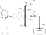
도 1은 예시적인 실시예에 따른 음성 인식 시스템을 개략적으로 도시한 것이다.Fig. 1 schematically shows a speech recognition system according to an exemplary embodiment.
도 1을 참조하면, 음성 인식 시스템(100)은 플레이트 구조체(plate structure, 110), 진동 감지 센서(vibration detecting sensor, 130)) 및 음성 인식 장치(voice recognition device, 150)를 포함한다. 플레이트 구조체(100)는 사용자(S)로부터 발생되는 음성(voice)에 의해 진동하게 되며, 진동 감지 센서(130)는 플레이트 구조체(110)에 부착되어 플레이트 구조체(110)의 진동을 검출할 수 있다. 그리고, 음성 인식 장치(150)는 진동 감지 센서(130)로부터 출력되는 신호(160)가 입력되어 사용자(S)의 음성을 인식할 수 있다.Referring to FIG. 1 , a
도 1에 도시된 음성 인식 시스템(100)에서는, 사용자(S)로부터 음성 파동이 발생되어 전파되면, 이 음성 파동에 동기되어 플레이트 구조체(110)가 미세하게 진동하게 된다. 이어서, 이러한 진동에 의해 플레이트 구조체(110) 중 진동 감지 센서(130)가 부착된 부분에서는 사용자(S)의 음성 신호와 높은 상관 관계(correlation)를 가지는 변위, 속도, 가속도, 스트레인(strain), 광학적 변위 등과 같은 동적 변화가 발생하게 된다. 다음으로, 이러한 동적 변화를 일으키는 진동을 진동 감지 센서(130)가 획득하게 되고, 진동 감지 센서(130)로부터 획득한 출력 신호(160)가 음성 인식 장치(150)에 입력됨으로써 사용자(S)의 음성을 인식할 수 있다.In the
플레이트 구조체(110)는 사용자(S)로부터 발생된 음성 파동의 전파(propagation)에 의해 진동을 발생시킬 수 있다 여기서, 사용자(S)는 플레이트 구조체(110)의 전면 방향(front direction), 예를 들면, 도 1에서의 z축 방향에 위치할 수 있다. 플레이트 구조체(110)는 사용자(S)와 마주보는 면인 전면(front surface, 110a)과 이 전면(110a)의 반대면인 후면(rear surface, 110b)을 포함할 수 있다.The
플레이트 구조체(110)는 진동을 발생시킬 수 있는 박판 형태를 가질 수 있다. 이러한 플레이트 구조체(110)는 예를 들면 디스플레이 패널, 스마트 윈도우(smart window), 스마트 미러(smart mirror) 등을 포함할 수 있다. 하지만, 이는 단지 예시적인 것이다. 예를 들어, 플레이트 구조체(110)로 디스플레이 패널이 사용되는 경우에는 본 실시예에 따른 음성 인식 시스템(100)은 디스플레이 장치가 될 수 있다.The
플레이트 구조체(110)의 외곽에는 플레이트 구조체(110)를 지지하는 케이스(case, 120)가 마련될 수 있다. 여기서, 케이스(120)는 예를 들면, 플레이트 구조체(110)의 후면(110b)을 커버하도록 마련될 수 있다. 하지만, 이는 단지 예시적인 것이다. 한편, 케이스(120)는 마련되지 않을 수도 있다.A
진동 감지 센서(130)는 사용자(S)의 음성에 의한 플레이트 구조체(110)의 진동을 검출하기 위한 것으로, 플레이트 구조체(110)에 접촉하도록 마련될 수 있다. 사용자(S)가 플레이트 구조체(110)의 전면 방향에 위치하는 경우에는 진동 감지 센서(130)는 예를 들면, 플레이트 구조체(110)의 후면(110b)에 부착될 수 있다. 이 경우, 진동 감지 센서(130)는 예를 들면, 플레이트 구조체(110) 중에서 진동이 가장 크게 일어나는 부분에 부착될 수 있지만, 반드시 이에 한정되는 것은 아니다. 또한, 진동 감지 센서(130)는 플레이트 구조체(110)의 후면(110b) 대신에 다른 부분에 부착되는 것도 가능하다.The
진동 감지 센서(130)는 예를 들면, 플레이트 구조체(110)의 진동에 의해 발생되는 변위를 검출하는 변위 센서(displacement sensor)를 포함할 수 있다. 이 경우, 진동 감지 센서(130)는 플레이트 구조체(110)에 나란하게 배치됨으로써 사용자 방향인 플레이트 구조체(110)의 전면 방향(예를 들면, 도 1에서의 z축 방향)으로의 지향성을 가질 수 있다.The
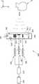
도 2는 도 1에 도시된 진동 감지 센서(130)를 도시한 사시도이다. 도 3은 도 2의 A-A' 선을 따라 본 단면도이며, 도 4는 도 2의 B-B'선을 따라 본 단면도이다. 도 2 내지 도 4에 도시된 진동 감지 센서(130)는 사용자(S)의 음성에 의한 플레이트 구조체(110)의 진동에 의해 발생되는 변위를 검출하는 변위 센서가 될 수 있다.FIG. 2 is a perspective view illustrating the
도 2 내지 도 4를 참조하면, 진동 감지 센서(130)는 기판(131)과 이 기판(131)에 마련되는 센싱 요소(sensing element, 140)를 포함할 수 있다. 여기서, 기판(131)은 플레이트 구조체(110)의 후면(110b)에 부착될 수 있다. 기판(131)과 플레이트 구조체(110) 사이에는 진동 감지 센서(130)를 플레이트 구조체(110)에 부착시키기 위한 접착층(135)이 더 마련될 수 있다.2 to 4 , the
기판(131)에는 캐비티(cavity, 131a)가 관통 형성되어 있으며, 이 기판(131)에서 캐비티(131a) 쪽으로 지지대(132)가 연장되어 형성되어 있다. 여기서, 지지대(132)는 플레이트 구조체(110))에 나란하도록 배치되어 있다. 기판(131)으로는 예를 들면 실리콘 기판이 사용될 수 있지만, 이에 한정되는 것은 아니며, 이외에도 다양한 재질의 기판이 사용될 수 있다.A
지지대(132)는 일단부가 플레이트 구조체(110)에 부착된 기판(131)에 고정되고, 타단부는 사용자 방향(예를 들면, 도 2에서의 z축 방향)을 따라 자유롭게 움직일 수 있는 캔틸레버(cantilever) 형태의 구조를 가질 수 있다.One end of the
지지대(132)의 일면에는 센싱 요소(140)가 마련되어 있다. 여기서, 센싱 요소(140)는 소정의 공진 주파수를 가지는 공진기(resonator)를 포함할 수 있다. 예를 들어, 센싱 요소(140)는 압전체의 변형에 의해 전기에너지를 발생시키는 압전 소자를 포함할 수 있다. 이 경우, 센싱 요소(140)는 지지대(132)에 마련되는 제1 전극(141)과, 제1 전극(141)에 마련되는 압전층(143)과, 압전층(143)에 마련되는 제2 전극(142)을 포함한다. 여기서, 제1 및 제2 전극(141,142)은 예를 들면, (+) 전극 및 (-) 전극이 될 수 있다. 하지만, 제1 및 제2 전극(141,142)은 (-) 전극 및 (+) 전극이 될 수도 있다. 제1 및 제2 전극(141)은 기판(131)에 마련된 제1 및 제2 단자(141a, 142a)와 전기적으로 연결될 수 있다.A
도 2 내지 도 4에 도시된 진동 감지 센서(130)에서, 사용자(S)의 음성에 의한 플레이트 구조체(110)의 진동에 의해 발생되는 변위가 플레이트 구조체(110)에 고정된 지지대(132)의 일단부에 전달되고, 이에 따른 관성력에 의해 지지대(132)의 타단부가 진동함으로써 변위를 증폭시킬 수 있다.In the
본 실시예에서, 진동 감지 센서(130)가 플레이트 구조체(110)(예를 들면, xy평면)와 나란하게 배치됨으로써 후술하는 바와 같이, 사용자 방향(예를 들면, z축 방향)으로의 지향성을 가질 수 있다.In this embodiment, the
도 5은 도 2 내지 도 4에서의 지지대(132)에 마련된 센싱 요소(140)를 등방성 물질(isotropic)로 이루어진 등가 모델(equivalent model)로 형상화한 것이다. 도 5에서, lx, ly, lz는 각각 등가 모델(145)의 길이(x축 방향으로의 크기), 폭(y축 방향으로의 크기), 두께(z축 방향으로의 크기)를 의미한다.5 is a shape of the
(식 1)은 z축 방향에 대한 y축 방향의 강성(stiffness) 비율을 나타내고, (식 2)는 z축 방향에 대한 x축 방향의 강성비율을 나타낸다. (식 1) 및 (식 2)에서 E는 Young's modulus 이다.(Equation 1) represents the ratio of stiffness in the y-axis direction to the z-axis direction, and (Equation 2) represents the ratio of stiffness in the x-axis direction to the z-axis direction. In (Equation 1) and (Equation 2), E is Young's modulus.


일반적인 소형 센서의 치수(dimension)의 예시로서 등가 모델(145)의 두께( lx), 폭(ly), 길이(lz)를 각각, 2㎛, 100㎛, 1000㎛ 라 하면 (식 1) 및 (식 2)로부터 y축 방향의 강성은 z축 방향의 강성에 비해 대략 2500배 정도 크고, x축 방향의 강성은 z축 방향의 강성에 비해 대략 25000배 정도 크다는 것을 알 수 있다.As an example of the dimensions of a typical small sensor, if the thickness ( lx ), width ( ly ), and length (lz ) of the
이와 같이, x축 방향의 강성 및 y축 방향의 강성이 z축 방향의 강성애 비해 매우 크므로 등가 모델(145)은 z축 방향으로의 지향성을 가지고 있음을 알 수 있다.As described above, since the stiffness in the x-axis direction and the stiffness in the y-axis direction are very large compared to the stiffness in the z-axis direction, it can be seen that the
따라서, 플레이트 구조체(110)에 나란하게 배치된 진동 감지 센서(130)는 플레이트 구조체(110)가 진동하는 경우 x축 방향 또는 y축 방향의 신호(예를 들면, 케이스 내에 설치되어 있는 스피커 등으로부터 발생되는 음향 신호 등) 보다는 사용자 방향인 z축 방향의 신호를 지배적으로(dominantly) 획득할 수 있다.Therefore, when the
도 6은 도 1에 도시된 음성 인식 시스템에 채용될 수 있는 다른 진동 감지 센서(230)를 도시한 것이다.FIG. 6 illustrates another
도 6을 참조하면, 진동 감지 센서(230)는 기판(231)에 마련되는 복수의 센싱 요소(241,232,243)를 포함한다. 기판(231)에는 캐비티(231a)가 관통되어 형성되어 이으며, 제1 기판(231)으로부터 캐비티(231a) 쪽으로 복수의 지지대(232a,232b,232c)가 연장되어 있다. 여기서, 복수의 지지대(232a,232b,232c)는 플레이트 구조체(도 1의 110))에 나란하도록 배치될 수 있다.Referring to FIG. 6 , the
복수의 지지대(232a,232b,232c) 각각은 일단부가 플레이트 구조체(110)에 부착된 기판(231)에 고정되고, 타단부는 사용자 방향(예를 들면, 도 6에서의 z축 방향)을 따라 자유롭게 움직일 수 있는 캔틸레버 형태의 구조를 가질 수 있다.Each of the plurality of
복수의 지지대(232a,232b,232c) 에는 복수의 센싱 요소(241,232,243)가 마련되어 있다. 전술한 바와 같이, 복수의 센싱 요소(241,232,243) 각각은 예를 들면, 압전체의 변형에 의해 전기에너지를 발생시키는 압전 소자를 포함할 수 있다.A plurality of sensing elements 241,232 and 243 are provided on the plurality of
복수의 센싱 요소(241,232,243)는 서로 다른 공진 주파수를 가지도록 마련될 수 있다. 이를 위해, 복수의 센싱 요소(241,232,243)는 서로 다른 치수(dimension)를 가지도록 마련될 수 있다. 예를 들면, 복수의 센싱 요소(241,232,243)는 서로 다른 길이, 서로 다른 폭 및 서로 다른 두께 중 적어도 하나를 가질 수 있다. 도 6에는 기판(231)에 서로 다른 길이를 가지는 복수의 지지대(232a,232b,232c) 가 마련되어 있으며, 이 지지대들(232a,232b,232c) 에 서로 다른 길이를 가지는 복수의 센싱 요소(241,232,243)가 마련된 경우가 예시적으로 도시되어 있다.The plurality of
도 6에는 서로 다른 3개의 공진 주파수를 가지는 3개의 센싱 요소(241,232,243)가 예시적으로 도시되어 있지만, 이는 예시적인 것으로, 센싱 요소들(241,232,243)의 개수는 다양하게 변형될 수 있다.Although three sensing elements 241,232 and 243 having three different resonant frequencies are exemplarily illustrated in FIG. 6 , these are exemplary and the number of sensing elements 241,232 and 243 may be variously modified.
이와 같이, 진동 감지 센서(230)가 서로 다른 공진 주파수를 가지는 복수의 센싱 요소(241,232,243)를 포함으로써 보다 넓은 주파수 대역의 음성 신호를 인식할 수 있다.As such, since the
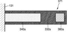
도 7 내지 도 10은 도 1에 도시된 음성 인식 시스템에 채용될 수 있는 또 다른 진동 감지 센서들(371,372,373,374)을 도시한 것이다.7 to 10 show other
도 7에 도시된 진동 감지 센서(371)는 지지대(332a)와 이 지지대(332a)에 마련되는 센싱 요소(340a)를 포함한다. 여기서, 지지대(332a)는 하나의 고정단을 포함하는 캔틸레버 형태의 구조를 가질 수 있다. 구체적으로, 지지대(332a)는 일단부가 플레이트 구조체(도 1의 110)에 부착된 기판(131)에 고정되고, 타단부는 사용자 방향으로 자유롭게 움직일 수 있는 구조를 가질 수 있다. 센싱 요소(340a)는 지지대(332a)의 고정 부분 주위에 마련될 수 있다. 지지대(332a)의 타단부에는 관성력을 증가시킬 수 있는 질량체(mass, 380a)가 더 마련됨으로써 진동 감지 센서(371)의 감도를 보다 향상시킬 수 있다.The
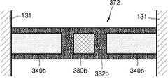
도 8에 도시된 진동 감지 센서(372)는 지지대(332b)와 이 지지대(332b)에 마련되는 복수의 센싱 요소(340b)를 포함한다. 여기서, 지지대(332b)는 두개의 고정단을 포함하는 브릿지(bridge) 형태의 구조를 가질 수 있다. 구체적으로, 지지대(332b)는 양단부가 플레이트 구조체(110)에 부착된 기판(131)에 고정되고, 가운데 부분이 사용자 방향으로 자유롭게 움직일 수 있는 구조를 가질 수 있다. 복수의 센싱 요소(340b)는 지지대(332b)의 고정 부분들 주위에 마련될 수 있다. 도 8에는 지지대(332b)에 두 개의 센싱 요소(340b)가 마련되는 경우가 예시적으로 도시되어 있다. 그러나, 이에 한정되지 않고 지지대(332b)에 하나의 센싱 요소(340b)가 마련될 수도 있다. 지지대(332b)의 가운데 부분에는 질량체(380b)가 더 마련됨으로써 진동 감지 센서(372)의 감도를 보다 향상시킬 수 있다.The
도 9에 도시된 진동 감지 센서(373)는 지지대(332c)와 이 지지대(332c)에 마련되는 복수의 센싱 요소(340c)를 포함한다. 여기서, 지지대(332c)는 네개의 고정단을 가지는 다각형 형태의 구조를 가질 수 있다. 복수의 센싱 요소(340c)는 지지대(332c)의 고정 부분들 주위에 마련될 수 있다. 도 9에는 지지대(332c)에 네 개의 센싱 요소(340c)가 마련되는 경우가 예시적으로 도시되어 있다. 그러나, 이에 한정되지 않고 지지대(332c)에는 다양한 개수의 센싱 요소(340c)가 마련될 수 있다. 지지대(332c)의 가운데 부분에는 질량체(380c)가 더 마련됨으로써 진동 감지 센서(373의 감도를 보다 향상시킬 수 있다.The
도 9에는 진동 감지 센서(373)가 네개의 고정단을 포함하는 다각형 형태의 지지대(332c)를 포함하는 경우가 예시적으로 도시되어 있다. 그러나, 이는 단지 예시적인 것으로, 이외에도 진동 감지 센서(373)는 세개의 고정단 또는 다섯개 이상의 고정단을 포함하는 다양한 다각형 형태의 지지대를 포함할 수 있다.9 exemplarily shows a case in which the
도 10에 도시된 진동 감지 센서(374)는 지지대(332d)와 이 지지대(332d)에 마련되는 센싱 요소(340d)를 포함한다. 여기서, 지지대(332d)는 원주 부분이 고정된 원형 형태의 구조를 가질 수 있다. 그리고, 센싱 요소(340d)는 지지대(332d)의 고정 부분 주위를 따라 마련될 수 있다. 도 10에는 지지대(332d)에 하나의 센싱 요소(340d)가 마련되는 경우가 예시적으로 도시되어 있다. 그러나, 이에 한정되지 않고 지지대(332d)에는 복수의 센싱 요소(340d)가 마련될 수도 있다. 지지대(332d)의 가운데 부분에는 질량체(380d)가 더 마련됨으로써 진동 감지 센서(374)의 감도를 보다 향상시킬 수 있다. 또한, 지지대(332d)에는 지지대(332d)의 강성을 조절하기 위한 적어도 하나의 관통공(332')이 형성될 수도 있다.The
도 1에 도시된 음성 인식 시스템에서, 진동 감지 센서(130,230,371,372,373,374)가 사용자(S)의 음성에 의해 발생되는 플레이트 구조체(110)의 진동을 검출하게 되며, 이러한 진동 감지 센서(130,230,371,372,373,374)로부터 출력되는 신호(160)는 음성 인식 장치(150)에 입력됨으로써 사용자(S)의 음성을 인식할 수 있게 된다.In the voice recognition system shown in FIG. 1 , the
본 실시예에 따른 음성 인식 시스템(100)에서는 진동 감지 센서(130,230,371,372,373,374)가 플레이트 구조체(110)에 접촉하도록 마련되어 사용자(S)의 음성에 의한 플레이트 구조체(110)의 진동을 검출할 수 있으므로, 사용자(S)의 음성이 잘 전달될 수 있도록 하기 위한 음향 구멍(acoustic hole) 등은 별도로 마련할 필요가 없다. 그리고, 진동 감지 센서(130,230,371,372,373,374)는 사용자(S)가 볼 수 없는 부분인 플레이트 구조체(110)의 후면(110b)에 부착될 수 있으므로, 플레이트 구조체(110)의 전면 디자인 설계에 있어서 진동 감지 센서(130,230,371,372,373,374)로 의한 제약은 받지 않을 수 있다. 또한, 진동 감지 센서(130,230,371,372,373,374)가 사용자 방향으로 지향성을 가질 수 있도록 진동 감지 센서(130,230,371,372,373,374)를 플레이트 구조체(110)에 나란하게 배치함으로써 사용자 방향으로의 음성 신호 만을 지배적으로 획득할 수 있다.In the
한편, 이상에서는 진동 감지 센서가 플레이트 구조체(110)의 진동에 의해 발생되는 변위를 검출하는 변위 센서를 포함하는 경우가 설명되었다. 그러나, 이는 단지 예시적인 것으로 진동 감지 센서는 다른 유형의 센서를 포함하는 것도 가능하다.Meanwhile, in the above description, the case in which the vibration detection sensor includes a displacement sensor for detecting displacement generated by vibration of the
예를 들어, 진동 감지 센서는 사용자(S)의 음성에 의한 플레이트 구조체(110)의 진동에 의해 발생되는 관성력을 검출하는 관성 센서(inertial sensor), 사용자(S)의 음성에 의한 플레이트 구조체(110)의 진동에 의해 발생되는 스트레인을 검출하는 스트레인 센서(strain sensor), 사용자(S)의 음성에 의한 플레이트 구조체(110)의 진동에 의해 발생되는 광학적 변위를 검출하는 광학 센서(optical sensor) 등을 포함할 수 있다. 여기서, 관성 센서, 스트레인 센서, 광학 센서는 통상적으로 잘 알려진 것이므로, 이러한 센서들에 대한 상세한 설명은 생략한다.For example, the vibration sensor is an inertial sensor for detecting an inertial force generated by vibration of the
도 11은 다른 예시적인 실시예에 따른 음성 인식 시스템을 개략적으로 도시한 것이다. 도 11에는 편의상 도 1에 도시된 음성 인식 장치(150)는 도시되지 않았다.Fig. 11 schematically shows a voice recognition system according to another exemplary embodiment. For convenience, the
도 11을 참조하면, 음성 인식 시스템(400)은 플레이트 구조체(110), 진동 감지 센서(430)), 음성 인식 장치(도 1의 150), 케이스(420) 및 진동 감쇄 부재(vibration damping member,490)를 포함한다.11, the
플레이트 구조체(110) 및 음성 인식 장치(150)는 전술하였으므로 이에 대한 설명은 생략한다. 또한, 진동 감지 센서(430)는 전술한 진동 감지 센서들(130,230,371,372,373,374) 중 어느 하나가 될 수 있으며, 이에 대한 상세한 설명은 생략한다.Since the
케이스(420)는 플레이트 구조체(110)를 지지하도록 마련되어 있다. 예를 들면, 케이스(420)는 플레이트 구조체(110)의 후면을 덮도록 마련될 수 있다. 플레이트 구조체(110)와 케이스(420) 사이에는 케이스(420)의 진동이 플레이트 구조체(110)에 전달되는 것을 감소시킬 수 있는 진동 감쇄 부재(490)가 마련될 수 있다. 여기서, 진동 감쇄 부재(490)는 예를 들면, 탄성 재질을 포함할 수 있다.The
예를 들어, 케이스(420) 내부에 스피커들(SP1, SP2)이 설치된 경우에는 스피커들(SP1,SP2)로부터 소리(sound)가 발생되면 케이스(420)가 진동하게 되고, 이러한 진동이 플레이트 구조체(110)에 전달될 수 있다. 본 실시예에 따른 음성 인식 시스템(400)에서는 플레이트 구조체(110)와 케이스(420) 사이에 진동 감쇄 부재(490)를 마련함으로써 스피커(SP1,SP2)로부터 발생된 소리에 의해 발생되는 케이스(420)의 진동이 진동 감쇄 부재(490)에 의해 플레이트 구조체(110)에 전달되는 것을 방지될 수 있고, 이에 따라, 진동 감시 센서(430)가 사용자(S)의 음성에 대해 보다 잘 반응할 수 있다.For example, when the speakers SP1 and SP2 are installed inside the
도 12는 또 다른 예시적인 실시예에 따른 음성 인식 시스템을 개략적으로 도시한 것이다.Fig. 12 schematically shows a voice recognition system according to another exemplary embodiment.
도 12를 참조하면, 음성 인식 시스템(500)은 플레이트 구조체(110), 플레이트 구조체(110)에 부착되는 복수의 진동 감지 센서(531,532,533), 신호처리부(signal processor,570) 및 음성 인식 장치(550)를 포함한다. 플레이트 구조체(110)는 케이스(420)에 의해 지지될 수 있으며, 플레이트 구조체(110)와 케이스(420) 사이에는 케이스(420)의 진동이 플레이트 구조체(110)에 전달되는 것을 감소시키기 위한 진동 감쇄 부재(490)가 마련될 수 있다. 플레이트 구조체(110), 케이스(420) 및 진동 감쇄 부재(490)에 대해서는 전술하였으므로 이에 대한 설명은 생략한다.12 , the
사용자(S)는 플레이트 구조체(110)의 전면 방향, 예를 들면, 도 12에서의 z축 방향에 위치할 수 있다. 플레이트 구조체(110)는 사용자(S)와 마주보는 면인 전면과 이 전면의 반대면인 후면을 포함할 수 있다. 플레이트 구조체(110)에는 복수의 진동 감지 센서(531,532,533)가 부착되어 있다. 예를 들면, 복수의 진동 감지 센서(531,532,533)는 플레이트 구조체의 후면에 부착될 수 있지만, 이에 한정되는 것은 아니다.The user S may be located in the front direction of the
복수의 진동 감지 센서(531,532,533)는 제1, 제2 및 제3 진동 감지 센서(531,532,533)를 포함할 수 있다. 여기서, 제1, 제2 및 제3 진동 감지 센서(531,532,533)는 플레이트 구조체(110)에 부착되는 방향에 따라 서로 다른 지향성을 가질 수 있다. 제1, 제2 및 제3 진동 감지 센서(531,532,533) 각각은 전술한 진동 감지 센서들(130,230,371,372,373,374) 중 어느 하나와 동일한 구성을 가질 수 있다.The plurality of
제1 진동 감지 센서(531)는 사용자(S)의 음성에 의한 플레이트 구조체(110)의 진동을 검출하는 것으로, 전술한 바와 같이 플레이트 구조체(110)에 나란하게 부착될 수 있다. 구체적으로, 제1 진동 감지 센서(531)는 도 12에서 xy 평면에 나란하게 배치됨으로써 사용자 방향, 즉, z축 방향으로의 지향성을 가질 수 있다. 따라서, 제1 진동 감지 센서(531)는 플레이트 구조체(110)의 z축 방향으로의 진동을 지배적으로 검출할 수 있다.The first
제2 진동 감지 센서(532)는 사용자(S) 이외의 음원, 예를 들면, 케이스 내부에 설치된 스피커들(SP1,SP2) 등에 의한 플레이트 구조체(110)의 진동을 검출하는 것으로, 예를 들면 플레이트 구조체(110)에 대해 수직으로 부착될 수 있다. 구체적으로, 제2 진동 감지 센서(532)는 도 12에서 xz 평면에 나란하게 배치됨으로써 y축 방향으로의 지향성을 가질 수 있다. 따라서, 제2 진동 감지 센서(532)는 플레이트 구조체(110)의 y축 방향으로의 진동을 지배적으로 검출할 수 있다.The second
제3 진동 감지 센서(533)는 사용자(S) 이외의 음원, 예를 들면, 케이스 내부에 설치된 스피커들(SP1, SP2) 등에 의한 플레이트 구조체(110)의 진동을 검출하는 것으로, 예를 들면 플레이트 구조체(110)에 대해 수직으로 부착될 수 있다. 구체적으로, 제3 진동 감지 센서(533)는 도 12에서 yz 평면에 나란하게 배치됨으로써 x축 방향으로의 지향성을 가질 수 있다. 따라서, 제3 진동 감지 센서(533)는 플레이트 구조체(100)의 x축 방향으로의 진동을 지배적으로 검출할 수 있다.The third
제1 진동 감지 센서(531)로부터 출력되는 제1 출력 신호(561), 제2 진동 감지 센서(532)로부터 출력되는 제2 출력 신호(562) 및 제3 진동 감지 센서(533)로부터 출력되는 제3 출력 신호(563)는 신호처리부(570)에 입력된다. 신호처리부(570)는 제1, 제2 및 제3 출력 신호(561,562,563)를 조합하여 처리한 다음, 이렇게 처리된 신호가 음성 인식 장치(550)에 입력됨으로써 사용자(S)의 음성을 인식할 수 있다.The
본 실시예에서, 신호처리부(570)는 사용자 방향인 z축 방향 이외의 다른 방향(예를 들면, x축 방향 및 y축 방향)의 진동에 의한 신호를 차분하여 제거함으로써 사용자 음성 이외의 신호를 효과적으로 감쇄시킬 수 있다.In this embodiment, the
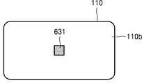
도 13a 내지 도 13f는 또 다른 예시적인 실시예에 따른 음성 인식 시스템을도시한 것이다. 도 13a 내지 도 13f은 플레이트 구조체(110)의 후면(110b)에 다양한 형태로 배치되는 진동 감지 센서들(631,632,633,634,635,636)을 도시한 것이다. 이하에서 설명되는 진동 감지 센서(631,632,633,634,635,636)는 전술한 진동 감지 센서들(130,230,371,372,373,374) 중 어느 하나가 될 수 있다.13A to 13F show a voice recognition system according to another exemplary embodiment. 13A to 13F illustrate
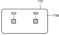
도 13a 내지 도 13f에는 사용자(S)의 음성에 의해 플레이트 구조체(110) 중 큰 변위가 발생되는 부분에 진동 감지 센서(631,632,633,634,635,636)가 배치되는 모습이 예시적으로 도시되어 있다. 도 13a에는 하나의 진동 감지 센서(631)가 플레이트 구조체(110)에 마련되는 경우가 도시되어 있으며, 도 13b 내지 도 13f에는 복수의 진동 감지 센서(632,633,634,635,636)가 플레이트 구조체(110)에 마련되는 경우가 도시되어 있다. 플레이트 구조체(110)에 복수의 진동 감지 센서(632,633,634,635,636)가 마련되는 경우에는 복수의 진동 감지 센서(632,633,634,635,636)에 의해 검출된 출력 신호들은 신호처리부(미도시)를 통해 처리된 후 음성 인식 장치(미도시)에 입력될 수 있다.13A to 13F, vibration detection sensors 631,632,633,634,635,636 are disposed in a portion of the
도 13a을 참조하면, 사용자(S)의 음성에 의해 플레이트 구조체(110)의 가운데 부분에서 큰 변위가 발생되는 경우에는 플레이트 구조체(110)의 가운데 부분에 진동 감지 센서(631)가 배치될 수 있다. 도 13b를 참조하면, 사용자(S)의 음성에 의해 플레이트 구조체(110)의 좌측 부분 및 우측 부분에서 큰 변위가 발생되는 경우에는 이 좌측 부분 및 우측 부분에 진동 감지 센서들(632)이 배치될 수 있다.Referring to FIG. 13A , when a large displacement occurs in the middle portion of the
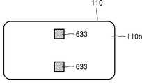
도 13c를 참조하면, 사용자(S)의 음성에 의해 플레이트 구조체(110)의 상부 및 하부에서 큰 변위가 발생되는 경우에는 이 상부 및 하부에 진동 감지 센서들(633)이 배치될 수 있다. 도 13d를 참조하면, 사용자(S)의 음성에 의해 플레이트 구조체(110)의 좌측 부분, 가운데 부분 및 우측 부분에서 이 세 부분에 진동 감지 센서들(634)이 배치될 수 있다.Referring to FIG. 13C , when a large displacement occurs in the upper and lower portions of the
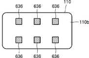
도 13e에 도시된 바와 같이, 플레이트 구조체(110)의 네 부분에 진동 감지 센서들(635)이 배치될 수도 있으며, 도 13f에 도시된 바와 같이, 플레이트 구조체(110)의 네 부분에 진동 감지 센서들(636)이 배치될 수도 있다.As shown in FIG. 13E ,
이상에서 살펴본 바와 같이, 예시적인 실시예들에 따르면, 진동 감지 센서가 플레이트 구조체에 접촉하도록 마련되어 사용자의 음성에 의한 플레이트 구조체의 진동을 검출할 수 있으므로, 사용자의 음성이 잘 전달될 수 있도록 하기 위한 음향 구멍 등은 필요하지 않게 된다. 그리고, 진동 감지 센서는 사용자가 볼 수 없는 부분인 플레이트 구조체의 후면에 부착될 수 있으므로, 플레이트 구조체의 전면 디자인 설계에 있어서 진동 감지 센서로 의한 제약은 받지 않을 수 있다. 또한, 진동 감지 센서가 사용자 방향으로 지향성을 가질 수 있도록 진동 감지 센서를 플레이트 구조체에 나란하게 배치함으로써 사용자 방향으로의 음성 신호 만을 지배적으로 획득할 수 있다.As described above, according to exemplary embodiments, since the vibration detection sensor is provided to contact the plate structure to detect the vibration of the plate structure by the user's voice, the user's voice can be transmitted well. An acoustic hole or the like is not required. In addition, since the vibration sensor may be attached to the rear surface of the plate structure, which is a part that cannot be seen by the user, restrictions by the vibration sensor may not be applied in designing the front design of the plate structure. In addition, by arranging the vibration detection sensor side by side on the plate structure so that the vibration detection sensor can have directivity in the user direction, only the voice signal in the user direction can be predominantly obtained.
이상에서 실시예가 설명되었으나, 이는 예시적인 것에 불과하며, 당해 분야에서 통상적 지식을 가진 자라면 이로부터 다양한 변형이 가능하다.Although the embodiment has been described above, this is only exemplary, and various modifications are possible therefrom by those skilled in the art.
100,400.. 음성 인식 시스템 110.. 플레이트 구조체
110a.. 플레이트 구조체의 전면 110b.. 플레이트 구조체의 후면
120,420.. 케이스
130,230,371,372,372,374,631,632,633,634,635,636.. 진동 감지 센서
131,231.. 기판 131a,231a.. 캐비티
132,232a,232b,232c,332a,332b,332c,332d.. 지지대
135.. 접착층
140,241,242,243,340a,340b,340c,340d.. 센싱 요소
141.. 제1 전극 141a.. 제1 단자
142.. 제2 전극 142a.. 제2 단자
143.. 압전층 150,550.. 음성 인식 장치
160.. 출력 신호 332'.. 관통공
380a,380b,380c,380d.. 질량체 490.. 진동 감쇄 부재
531.. 제1 진동 감지 센서 532.. 제2 진동 감지 센서
533.. 제3 진동 감지 센서 561.. 제1 출력 신호
562.. 제2 출력 신호 563.. 제3 출력 신호
570.. 신호처리부 S.. 사용자
SP1, SP2.. 스피커100,400..
110a. Front of
120,420.. Case
130,230,371,372,372,374,631,632,633,634,635,636.. vibration sensor
131,231..
132,232a,232b,232c,332a,332b,332c,332d.. support
135. Adhesive layer
140,241,242,243,340a,340b,340c,340d.. sensing element
141.
142.
143.. Piezoelectric layer 150,550.. Voice recognition device
160.. Output signal 332'.. Through hole
380a, 380b, 380c, 380d..
531.. first
533.. the third
562..
570.. Signal processing unit S.. User
SP1, SP2.. speaker
Claims (27)
Translated fromKorean상기 플레이트 구조체에 접촉하도록 마련되어 상기 플레이트 구조체의 진동을 검출하는 진동 감지 센서; 및
상기 진동 감지 센서부터 출력되는 신호가 입력되어 상기 사용자의 음성을 인식하는 음성 인식 장치;를 포함하는 음성 인식 시스템.a plate structure for generating vibration by propagation of a voice wave generated from a user;
a vibration detection sensor provided to contact the plate structure to detect vibration of the plate structure; and
A voice recognition system comprising a; a voice recognition device for recognizing the user's voice by receiving a signal output from the vibration sensor.
상기 진동 감지 센서는 사용자 방향으로의 지향성을 가지도록 배치되는 음성인식 시스템.The method of claim 1,
The vibration detection sensor is a voice recognition system that is arranged to have directivity in the direction of the user.
상기 진동 감지 센서는 상기 플레이트 구조체에 나란하게 배치되는 음성 인식 시스템.3. The method of claim 2,
The vibration detection sensor is a voice recognition system disposed side by side on the plate structure.
상기 진동 감지 센서는 변위 센서를 포함하는 음성 인식 시스템.The method of claim 1,
The vibration detection sensor is a voice recognition system including a displacement sensor.
상기 진동 감지 센서는 일부분이 상기 플레이트 구조체에 고정되는 지지대와, 상기 지지대에 마련되는 적어도 하나의 센싱 요소를 포함하는 음성 인식 시스템.5. The method of claim 4,
The vibration detection sensor includes a support part fixed to the plate structure, and at least one sensing element provided on the support support.
상기 센싱 요소는 압전 소자를 포함하는 음성 인식 시스템.6. The method of claim 5,
The sensing element comprises a piezoelectric element.
상기 지지대는 하나의 고정단을 포함하는 캔틸레버(cantilever) 형태의 구조를 가지는 음성 인식 시스템.6. The method of claim 5,
The support is a voice recognition system having a structure in the form of a cantilever including one fixed end.
상기 지지대는 두개의 고정단을 포함하는 브릿지(bridge) 형태의 구조를 가지는 음성 인식 시스템.6. The method of claim 5,
The support is a voice recognition system having a structure in the form of a bridge including two fixed ends.
상기 지지대는 세개 이상의 고정단을 포함하는 다각형 형태의 구조를 가지는 음성 인식 시스템.6. The method of claim 5,
The support is a voice recognition system having a polygonal structure including three or more fixed ends.
상기 지지대는 원주 부분이 고정된 원형 형태의 구조를 가지는 음성 인식 시스템.6. The method of claim 5,
The support is a voice recognition system having a circular structure in which a circumferential portion is fixed.
상기 지지대에는 지지대의 강성(stiffness)를 조절하기 위한 적어도 하나의 관통공이 형성된 음성 인식 시스템.11. The method of claim 10,
A voice recognition system in which at least one through hole for adjusting the stiffness of the support is formed in the support.
상기 진동 감지 센서는 상기 지지대에 마련되는 질량체(mass)를 더 포함하는 음성 인식 시스템.6. The method of claim 5,
The vibration detection sensor voice recognition system further comprising a mass (mass) provided on the support.
상기 진동 감지 센서는 각각 일부분이 상기 플레이트 구조체에 고정되는 복수의 지지대와, 상기 복수의 지지대에 마련되며 서로 다른 공진 주파수를 가지는 복수의 센싱 요소를 포함하는 음성 인식 시스템.5. The method of claim 4,
The vibration detection sensor includes a plurality of supports each part of which is fixed to the plate structure, and a plurality of sensing elements provided on the plurality of supports and having different resonant frequencies.
상기 진동 감지 센서는 관성 센서, 스트레인(strain) 센서 또는 광학 센서를 포함하는 음성 인식 시스템.The method of claim 1,
The vibration detection sensor is a voice recognition system comprising an inertial sensor, a strain sensor, or an optical sensor.
상기 플레이트 구조체를 지지하는 케이스를 더 포함하는 음성 인식 시스템.The method of claim 1,
The voice recognition system further comprising a case supporting the plate structure.
상기 플레이트 구조체와 상기 케이스 사이에는 진동 감쇄 부재(vibration damping member)가 마련되는 음성 인식 시스템.16. The method of claim 15,
A voice recognition system in which a vibration damping member is provided between the plate structure and the case.
상기 플레이트 구조체에 접촉하도록 마련되는 복수의 진동 감지 센서;
상기 복수의 진동 감지 센서로부터 출력되는 신호들을 처리하는 신호처리부(signal processor); 및
상기 신호처리부에 의해 처리된 신호가 입력되어 상기 사용자의 음성을 인식하는 음성 인식 장치;를 포함하는 음성 인식 시스템.a plate structure for generating vibration by propagation of an acoustic wave generated from a user;
a plurality of vibration detection sensors provided to contact the plate structure;
a signal processor for processing signals output from the plurality of vibration detection sensors; and
and a voice recognition device for recognizing the user's voice by receiving the signal processed by the signal processing unit.
상기 복수의 진동 감지 센서는 사용자 방향으로의 지향성을 가지며, 변위의 크기에 따라 정해진 위치들에 배치되는 음성 인식 시스템.18. The method of claim 17,
The plurality of vibration detection sensors have directivity in a user direction and are disposed at positions determined according to the magnitude of displacement.
상기 복수의 진동 감지 센서는 사용자 방향으로의 지향성을 가지는 제1 진동 감지 센서와, 상기 제1 진동 감지 센서와 다른 방향의 지향성을 가지는 제2 진동 감지 센서를 포함하는 음성 인식 시스템.18. The method of claim 17,
The plurality of vibration detection sensors includes a first vibration detection sensor having a directivity in a user direction, and a second vibration detection sensor having a directivity in a direction different from that of the first vibration detection sensor.
상기 플레이트 구조체를 지지하는 케이스를 더 포함하는 음성 인식 시스템.18. The method of claim 17,
The voice recognition system further comprising a case supporting the plate structure.
상기 플레이트 구조체와 상기 케이스 사이에는 진동 감쇄 부재가 마련되는 음성 인식 시스템.21. The method of claim 20,
A voice recognition system in which a vibration damping member is provided between the plate structure and the case.
상기 디스플레이 패널을 지지하는 케이스;
상기 케이스의 내부에서 상기 디스플레이 패널에 접촉하도록 마련되어 상기 디스플레이 패널의 진동을 검출하는 적어도 하나의 진동 감지 센서; 및
상기 적어도 하나의 진동 감지 센서부터 출력되는 신호가 입력되어 상기 사용자의 음성을 인식하는 음성 인식 장치;를 포함하는 디스플레이 장치.a display panel for generating vibration by propagation of a voice wave generated from a user;
a case supporting the display panel;
at least one vibration detection sensor provided to contact the display panel inside the case to detect vibration of the display panel; and
and a voice recognition device receiving a signal output from the at least one vibration detection sensor to recognize the user's voice.
상기 플레이트 구조체와 상기 케이스 사이에는 진동 감쇄 부재가 마련되는 디스플레이 장치.23. The method of claim 22,
A display device in which a vibration damping member is provided between the plate structure and the case.
상기 적어도 하나의 진동 센서는 상기 디스플레이 패널의 후면에 부착되는 디스플레이 장치.23. The method of claim 22,
The at least one vibration sensor is attached to a rear surface of the display panel.
상기 적어도 하나의 진동 센서는 사용자 방향으로의 지향성을 가지도록 배치되는 디스플레이 장치.23. The method of claim 22,
The at least one vibration sensor is disposed to have directivity in a user direction.
상기 적어도 하나의 진동 감지 센서는 사용자 방향으로의 지향성을 가지는 제1 진동 감지 센서와, 상기 제1 진동 감지 센서와 다른 방향의 지향성을 가지는 제2 진동 감지 센서를 포함하는 디스플레이 장치.23. The method of claim 22,
The at least one vibration detection sensor includes a first vibration detection sensor having a directivity in a user direction, and a second vibration detection sensor having a directivity in a direction different from that of the first vibration detection sensor.
상기 제1 및 제2 진동 감지 센서로부터 출력되는 신호들을 처리하여 상기 음성인식 장치로 출력하는 신호처리부를 더 포함하는 디스플레이 장치.
27. The method of claim 26,
The display apparatus further comprising a signal processing unit for processing the signals output from the first and second vibration detection sensors and outputting them to the voice recognition device.
Priority Applications (5)
| Application Number | Priority Date | Filing Date | Title |
|---|---|---|---|
| KR1020200002146AKR20210089292A (en) | 2020-01-07 | 2020-01-07 | Voice recognition system and display device using the same |
| US16/920,894US11587565B2 (en) | 2020-01-07 | 2020-07-06 | Voice recognition system and display device using the same |
| EP20191911.5AEP3848930B1 (en) | 2020-01-07 | 2020-08-20 | Voice recognition system and display device using the same |
| CN202010867667.7ACN113160829B (en) | 2020-01-07 | 2020-08-25 | Speech recognition system and display apparatus using the same |
| US18/082,977US11961520B2 (en) | 2020-01-07 | 2022-12-16 | Voice recognition system and display device using the same |
Applications Claiming Priority (1)
| Application Number | Priority Date | Filing Date | Title |
|---|---|---|---|
| KR1020200002146AKR20210089292A (en) | 2020-01-07 | 2020-01-07 | Voice recognition system and display device using the same |
Publications (1)
| Publication Number | Publication Date |
|---|---|
| KR20210089292Atrue KR20210089292A (en) | 2021-07-16 |
Family
ID=72178416
Family Applications (1)
| Application Number | Title | Priority Date | Filing Date |
|---|---|---|---|
| KR1020200002146APendingKR20210089292A (en) | 2020-01-07 | 2020-01-07 | Voice recognition system and display device using the same |
Country Status (4)
| Country | Link |
|---|---|
| US (2) | US11587565B2 (en) |
| EP (1) | EP3848930B1 (en) |
| KR (1) | KR20210089292A (en) |
| CN (1) | CN113160829B (en) |
Families Citing this family (2)
| Publication number | Priority date | Publication date | Assignee | Title |
|---|---|---|---|---|
| KR20210089292A (en)* | 2020-01-07 | 2021-07-16 | 삼성전자주식회사 | Voice recognition system and display device using the same |
| KR20230024872A (en)* | 2021-08-11 | 2023-02-21 | 썬전 샥 컴퍼니 리미티드 | microphone |
Family Cites Families (25)
| Publication number | Priority date | Publication date | Assignee | Title |
|---|---|---|---|---|
| US7580782B2 (en)* | 1995-10-30 | 2009-08-25 | Automotive Technologies International, Inc. | Vehicular electronic system with crash sensors and occupant protection systems |
| JP2005039652A (en)* | 2003-07-17 | 2005-02-10 | Hosiden Corp | Sound detection mechanism |
| JP4492432B2 (en)* | 2005-05-13 | 2010-06-30 | 株式会社デンソー | Manufacturing method of physical quantity sensor device |
| JP4595779B2 (en)* | 2005-10-12 | 2010-12-08 | 株式会社デンソー | Angular velocity sensor |
| WO2009031285A1 (en)* | 2007-09-03 | 2009-03-12 | Panasonic Corporation | Inertia force sensor |
| EP2610597B1 (en)* | 2010-08-24 | 2015-11-18 | Nec Corporation | Vibration sensor |
| US20130201316A1 (en)* | 2012-01-09 | 2013-08-08 | May Patents Ltd. | System and method for server based control |
| CN102890931A (en)* | 2012-09-25 | 2013-01-23 | 四川长虹电器股份有限公司 | Method for increasing voice recognition rate |
| EP2801974A3 (en) | 2013-05-09 | 2015-02-18 | DSP Group Ltd. | Low power activation of a voice activated device |
| CN105191349B (en)* | 2013-05-15 | 2019-01-08 | 索尼公司 | Sound output device, method of outputting acoustic sound and image display device |
| TW201513678A (en)* | 2013-09-25 | 2015-04-01 | Hon Hai Prec Ind Co Ltd | Speaker and display |
| WO2020220724A1 (en)* | 2019-04-30 | 2020-11-05 | 深圳市韶音科技有限公司 | Acoustic output apparatus |
| US10002478B2 (en)* | 2014-12-12 | 2018-06-19 | Qualcomm Incorporated | Identification and authentication in a shared acoustic space |
| CN104902402A (en)* | 2015-05-28 | 2015-09-09 | 深圳希格玛和芯微电子有限公司 | Voice recognition device, voice control system and voice communication system |
| KR101718214B1 (en)* | 2015-06-09 | 2017-03-20 | 한국과학기술원 | Low power piezoelectric voice recognition sensor used for IoT |
| KR20180118471A (en)* | 2017-04-21 | 2018-10-31 | 엘지전자 주식회사 | Voice recognition apparatus |
| KR102475893B1 (en)* | 2017-09-19 | 2022-12-08 | 삼성전자주식회사 | Sound/vibration spectrum analyzing device and methods of acquiring and analyzing frequency information |
| US10479300B2 (en)* | 2017-10-06 | 2019-11-19 | Ford Global Technologies, Llc | Monitoring of vehicle window vibrations for voice-command recognition |
| KR101980785B1 (en) | 2017-11-10 | 2019-08-28 | (주)다빛센스 | Back Plate Structure for a MEMS Acoustic Sensor and a Method for fabricating the same |
| CN108513241B (en)* | 2018-06-29 | 2024-04-19 | 潍坊歌尔微电子有限公司 | Vibration sensor and audio device |
| KR20200000594U (en)* | 2018-09-07 | 2020-03-17 | 이영옥 | A standard plastic garbage bag |
| CN114913791B (en)* | 2018-12-31 | 2024-03-05 | 乐金显示有限公司 | Display device |
| KR102630805B1 (en)* | 2019-05-31 | 2024-01-26 | 엘지디스플레이 주식회사 | Display apparatus |
| KR20210089292A (en)* | 2020-01-07 | 2021-07-16 | 삼성전자주식회사 | Voice recognition system and display device using the same |
| JP2021192482A (en)* | 2020-06-05 | 2021-12-16 | 船井電機株式会社 | Display device and display device speaker |
- 2020
- 2020-01-07KRKR1020200002146Apatent/KR20210089292A/enactivePending
- 2020-07-06USUS16/920,894patent/US11587565B2/enactiveActive
- 2020-08-20EPEP20191911.5Apatent/EP3848930B1/enactiveActive
- 2020-08-25CNCN202010867667.7Apatent/CN113160829B/enactiveActive
- 2022
- 2022-12-16USUS18/082,977patent/US11961520B2/enactiveActive
Also Published As
| Publication number | Publication date |
|---|---|
| CN113160829B (en) | 2025-09-16 |
| EP3848930B1 (en) | 2023-09-20 |
| US20230121066A1 (en) | 2023-04-20 |
| US11587565B2 (en) | 2023-02-21 |
| US20210210087A1 (en) | 2021-07-08 |
| US11961520B2 (en) | 2024-04-16 |
| EP3848930A1 (en) | 2021-07-14 |
| CN113160829A (en) | 2021-07-23 |
Similar Documents
| Publication | Publication Date | Title |
|---|---|---|
| Shah et al. | Design approaches of MEMS microphones for enhanced performance | |
| US9832573B2 (en) | Entrained microphones | |
| US7750540B2 (en) | Piezoelectric actuator and electronic device | |
| JP4293377B2 (en) | Voice input device, manufacturing method thereof, and information processing system | |
| US10536779B2 (en) | Electroacoustic transducer | |
| JP5305028B2 (en) | pressure sensor | |
| US11961520B2 (en) | Voice recognition system and display device using the same | |
| JPWO2007086337A1 (en) | Inertial force sensor | |
| JP6031682B2 (en) | Angular velocity sensor and detection element used therefor | |
| EP2113744A1 (en) | Inertia force sensor and composite sensor for detecting inertia force | |
| WO2008023573A1 (en) | Combined sensor | |
| WO2009142250A1 (en) | Integrated circuit device, sound inputting device and information processing system | |
| JP5088950B2 (en) | Integrated circuit device, voice input device, and information processing system | |
| CN115494263A (en) | Microelectromechanical system (MEMS) vibration sensor with segmented backplate | |
| JP2007256235A (en) | Inertial force sensor | |
| WO2022100551A1 (en) | Mems piezoelectric microspeaker, microspeaker unit, and electronic device | |
| US20230254635A1 (en) | Mems microphone with multiple sound ports | |
| JP2005533456A (en) | Ultrasonic transducer for electronic equipment | |
| EP4102854B1 (en) | Earphone and electronic device | |
| JP5262859B2 (en) | Microphone unit | |
| JPWO2010092806A1 (en) | Inertial force sensor and detection element used therefor | |
| US20240302205A1 (en) | Compact vibration sensor with piezo electric read-out | |
| CN115440241A (en) | Sound signal processing device and method for processing sound signals | |
| JP5125138B2 (en) | Compound sensor | |
| US20180352348A1 (en) | Bone conduction device |
Legal Events
| Date | Code | Title | Description |
|---|---|---|---|
| PA0109 | Patent application | St.27 status event code:A-0-1-A10-A12-nap-PA0109 | |
| PG1501 | Laying open of application | St.27 status event code:A-1-1-Q10-Q12-nap-PG1501 | |
| A201 | Request for examination | ||
| P22-X000 | Classification modified | St.27 status event code:A-2-2-P10-P22-nap-X000 | |
| PA0201 | Request for examination | St.27 status event code:A-1-2-D10-D11-exm-PA0201 | |
| P22-X000 | Classification modified | St.27 status event code:A-2-2-P10-P22-nap-X000 | |
| E902 | Notification of reason for refusal | ||
| PE0902 | Notice of grounds for rejection | St.27 status event code:A-1-2-D10-D21-exm-PE0902 | |
| E13-X000 | Pre-grant limitation requested | St.27 status event code:A-2-3-E10-E13-lim-X000 | |
| P11-X000 | Amendment of application requested | St.27 status event code:A-2-2-P10-P11-nap-X000 |