KR20210086748A - Method for lifting substrate and apparatus for treating substrate - Google Patents
Method for lifting substrate and apparatus for treating substrateDownload PDFInfo
- Publication number
- KR20210086748A KR20210086748AKR1020190177478AKR20190177478AKR20210086748AKR 20210086748 AKR20210086748 AKR 20210086748AKR 1020190177478 AKR1020190177478 AKR 1020190177478AKR 20190177478 AKR20190177478 AKR 20190177478AKR 20210086748 AKR20210086748 AKR 20210086748A
- Authority
- KR
- South Korea
- Prior art keywords
- speed
- substrate
- lift pin
- acceleration
- deceleration
- Prior art date
- Legal status (The legal status is an assumption and is not a legal conclusion. Google has not performed a legal analysis and makes no representation as to the accuracy of the status listed.)
- Ceased
Links
Images


Classifications
- H—ELECTRICITY
- H01—ELECTRIC ELEMENTS
- H01L—SEMICONDUCTOR DEVICES NOT COVERED BY CLASS H10
- H01L21/00—Processes or apparatus adapted for the manufacture or treatment of semiconductor or solid state devices or of parts thereof
- H01L21/67—Apparatus specially adapted for handling semiconductor or electric solid state devices during manufacture or treatment thereof; Apparatus specially adapted for handling wafers during manufacture or treatment of semiconductor or electric solid state devices or components ; Apparatus not specifically provided for elsewhere
- H01L21/67005—Apparatus not specifically provided for elsewhere
- H01L21/67011—Apparatus for manufacture or treatment
- H01L21/67155—Apparatus for manufacturing or treating in a plurality of work-stations
- H01L21/67161—Apparatus for manufacturing or treating in a plurality of work-stations characterized by the layout of the process chambers
- H01L21/67178—Apparatus for manufacturing or treating in a plurality of work-stations characterized by the layout of the process chambers vertical arrangement
- H—ELECTRICITY
- H01—ELECTRIC ELEMENTS
- H01L—SEMICONDUCTOR DEVICES NOT COVERED BY CLASS H10
- H01L21/00—Processes or apparatus adapted for the manufacture or treatment of semiconductor or solid state devices or of parts thereof
- H01L21/67—Apparatus specially adapted for handling semiconductor or electric solid state devices during manufacture or treatment thereof; Apparatus specially adapted for handling wafers during manufacture or treatment of semiconductor or electric solid state devices or components ; Apparatus not specifically provided for elsewhere
- H01L21/683—Apparatus specially adapted for handling semiconductor or electric solid state devices during manufacture or treatment thereof; Apparatus specially adapted for handling wafers during manufacture or treatment of semiconductor or electric solid state devices or components ; Apparatus not specifically provided for elsewhere for supporting or gripping
- H01L21/687—Apparatus specially adapted for handling semiconductor or electric solid state devices during manufacture or treatment thereof; Apparatus specially adapted for handling wafers during manufacture or treatment of semiconductor or electric solid state devices or components ; Apparatus not specifically provided for elsewhere for supporting or gripping using mechanical means, e.g. chucks, clamps or pinches
- H01L21/68714—Apparatus specially adapted for handling semiconductor or electric solid state devices during manufacture or treatment thereof; Apparatus specially adapted for handling wafers during manufacture or treatment of semiconductor or electric solid state devices or components ; Apparatus not specifically provided for elsewhere for supporting or gripping using mechanical means, e.g. chucks, clamps or pinches the wafers being placed on a susceptor, stage or support
- H01L21/68742—Apparatus specially adapted for handling semiconductor or electric solid state devices during manufacture or treatment thereof; Apparatus specially adapted for handling wafers during manufacture or treatment of semiconductor or electric solid state devices or components ; Apparatus not specifically provided for elsewhere for supporting or gripping using mechanical means, e.g. chucks, clamps or pinches the wafers being placed on a susceptor, stage or support characterised by a lifting arrangement, e.g. lift pins
- H—ELECTRICITY
- H01—ELECTRIC ELEMENTS
- H01L—SEMICONDUCTOR DEVICES NOT COVERED BY CLASS H10
- H01L21/00—Processes or apparatus adapted for the manufacture or treatment of semiconductor or solid state devices or of parts thereof
- H01L21/67—Apparatus specially adapted for handling semiconductor or electric solid state devices during manufacture or treatment thereof; Apparatus specially adapted for handling wafers during manufacture or treatment of semiconductor or electric solid state devices or components ; Apparatus not specifically provided for elsewhere
- H01L21/67005—Apparatus not specifically provided for elsewhere
- H01L21/67242—Apparatus for monitoring, sorting or marking
- H01L21/67259—Position monitoring, e.g. misposition detection or presence detection
- H—ELECTRICITY
- H01—ELECTRIC ELEMENTS
- H01L—SEMICONDUCTOR DEVICES NOT COVERED BY CLASS H10
- H01L21/00—Processes or apparatus adapted for the manufacture or treatment of semiconductor or solid state devices or of parts thereof
- H01L21/67—Apparatus specially adapted for handling semiconductor or electric solid state devices during manufacture or treatment thereof; Apparatus specially adapted for handling wafers during manufacture or treatment of semiconductor or electric solid state devices or components ; Apparatus not specifically provided for elsewhere
- H01L21/677—Apparatus specially adapted for handling semiconductor or electric solid state devices during manufacture or treatment thereof; Apparatus specially adapted for handling wafers during manufacture or treatment of semiconductor or electric solid state devices or components ; Apparatus not specifically provided for elsewhere for conveying, e.g. between different workstations
- H01L21/67763—Apparatus specially adapted for handling semiconductor or electric solid state devices during manufacture or treatment thereof; Apparatus specially adapted for handling wafers during manufacture or treatment of semiconductor or electric solid state devices or components ; Apparatus not specifically provided for elsewhere for conveying, e.g. between different workstations the wafers being stored in a carrier, involving loading and unloading
- H—ELECTRICITY
- H01—ELECTRIC ELEMENTS
- H01L—SEMICONDUCTOR DEVICES NOT COVERED BY CLASS H10
- H01L21/00—Processes or apparatus adapted for the manufacture or treatment of semiconductor or solid state devices or of parts thereof
- H01L21/67—Apparatus specially adapted for handling semiconductor or electric solid state devices during manufacture or treatment thereof; Apparatus specially adapted for handling wafers during manufacture or treatment of semiconductor or electric solid state devices or components ; Apparatus not specifically provided for elsewhere
- H01L21/68—Apparatus specially adapted for handling semiconductor or electric solid state devices during manufacture or treatment thereof; Apparatus specially adapted for handling wafers during manufacture or treatment of semiconductor or electric solid state devices or components ; Apparatus not specifically provided for elsewhere for positioning, orientation or alignment
- H—ELECTRICITY
- H01—ELECTRIC ELEMENTS
- H01L—SEMICONDUCTOR DEVICES NOT COVERED BY CLASS H10
- H01L21/00—Processes or apparatus adapted for the manufacture or treatment of semiconductor or solid state devices or of parts thereof
- H01L21/67—Apparatus specially adapted for handling semiconductor or electric solid state devices during manufacture or treatment thereof; Apparatus specially adapted for handling wafers during manufacture or treatment of semiconductor or electric solid state devices or components ; Apparatus not specifically provided for elsewhere
- H01L21/67005—Apparatus not specifically provided for elsewhere
- H01L21/67011—Apparatus for manufacture or treatment
- H01L21/67098—Apparatus for thermal treatment
Landscapes
- Engineering & Computer Science (AREA)
- Physics & Mathematics (AREA)
- Condensed Matter Physics & Semiconductors (AREA)
- General Physics & Mathematics (AREA)
- Manufacturing & Machinery (AREA)
- Computer Hardware Design (AREA)
- Microelectronics & Electronic Packaging (AREA)
- Power Engineering (AREA)
- Container, Conveyance, Adherence, Positioning, Of Wafer (AREA)
Abstract
Translated fromKoreanDescription
Translated fromKorean본 발명은 기판을 지지 플레이트로부터 들어올리는 기판 리프팅 방법 및 기판 처리 장치에 관한 것이다.The present invention relates to a substrate lifting method and a substrate processing apparatus for lifting a substrate from a support plate.
일반적으로, 반도체 소자를 제조하기 위하여, 기판에 증착, 도포, 현상, 식각, 세정 등과 같은 단위 공정들을 순차적 또는 반복적으로 처리한다. 각각의 공정은 서로 상이한 장치에서 진행되며, 기판 처리 장치에 구비된 로봇은 기판을 각각의 장치 간에 반송한다. 또한 각각의 장치에는 로봇으로부터 기판을 인수받거나 인계하는 핀 어셈블리가 제공된다. 이때 핀 어셈블리에는 기판을 로봇으로부터 인수받거나 로봇으로 인계하기 위한 리프트 핀이 제공된다.In general, in order to manufacture a semiconductor device, unit processes such as deposition, application, development, etching, and cleaning are sequentially or repeatedly processed on a substrate. Each process is performed in different apparatuses, and a robot provided in the substrate processing apparatus transfers the substrate between the apparatuses. Each device is also provided with a pin assembly to receive or take over the substrate from the robot. At this time, the pin assembly is provided with a lift pin for receiving the board from or handing over to the robot.
일반적으로 기판을 지지하는 지지 플레이트에는 이를 상하방향으로 관통하는 핀홀들이 형성된다. 핀홀들 각각에는 리프트 핀이 제공되며, 이는 승하강 이동하여 기판을 지지 플레이트에 안착시킨다.Generally, pinholes penetrating the support plate in the vertical direction are formed in the support plate for supporting the substrate. Each of the pinholes is provided with a lift pin, which moves up and down to seat the substrate on the support plate.
다만, 리프트 핀이 지지 플레이트로부터 기판을 들어 올릴 때, 순간적으로 기판과 지지 플레이트 사이에 음압이 형성되어 기판이 튕겨 오르거나 깨지는 스퀴즈 이펙트(Squeeze effect) 현상이 발생하는 문제가 있다.However, there is a problem in that when the lift pin lifts the substrate from the support plate, a negative pressure is instantaneously formed between the substrate and the support plate, causing the substrate to bounce or break, causing a squeeze effect.
본 발명은, 리프트 핀의 동작 시 스퀴즈 이펙트가 발생되는 것을 최소화하는 기판 리프팅 방법 및 기판 처리 장치를 제공하는 것을 일 목적으로 한다.An object of the present invention is to provide a substrate lifting method and a substrate processing apparatus for minimizing the occurrence of a squeeze effect during operation of a lift pin.
본 발명의 목적은 여기에 제한되지 않으며, 언급되지 않은 또 다른 목적들은 아래의 기재로부터 당업자에게 명확하게 이해될 수 있을 것이다.The object of the present invention is not limited thereto, and other objects not mentioned will be clearly understood by those skilled in the art from the following description.
본 발명은 기판 리프팅 방법을 제공한다. 일 실시예에 의하면, 기판 리프팅 방법은, 리프트 핀을 이용하여 기판이 놓이는 지지 플레이트로부터 기판을 승강시키되, 리프트 핀은 지지 플레이트의 하방으로 제1 거리만큼 이격된 하강 위치로부터 지지 플레이트의 상방으로 제2 거리만큼 이격된 승강 위치 사이를 수직이동 하면서 기판을 지지 플레이트로부터 들어올리고, 리프트 핀이 감속 또는 등속 이동되는 구간에서 기판에 접촉될 수 있다.The present invention provides a method for lifting a substrate. According to an embodiment, in the method for lifting a substrate, the substrate is lifted from a support plate on which the substrate is placed by using a lift pin, wherein the lift pin is moved upward of the support plate from a lowered position spaced a first distance downward of the support plate. The substrate may be lifted from the support plate while vertically moving between the lifting positions spaced apart by 2 distances, and the lift pin may come into contact with the substrate in a section in which the lift pin moves at a reduced or constant velocity.
일 실시예에 의하면, 리프트 핀을 제1 속도에서 제1 속도 보다 높은 제2 속도까지 제1 가속도의 가속도로 가속 이동시키는 제1 가속 단계와; 리프트 핀을 제2 속도에서 제2 속도보다 낮은 제3 속도까지 제1 감속도의 감속도로 감속 이동시키는 제1 감속 단계를 포함하고, 리프트 핀은 기판과 제1 감속 단계에서 접촉될 수 있다.According to an embodiment, a first acceleration step of accelerating the lift pin from a first speed to a second speed higher than the first speed with an acceleration of a first acceleration; and a first deceleration step of decelerating the lift pins from the second speed to a third speed lower than the second speed at a deceleration of the first deceleration, wherein the lift pins can be brought into contact with the substrate in the first deceleration step.
일 실시예에 의하면, 리프트 핀을 제1 속도에서 제1 속도 보다 높은 제2 속도까지 제1 가속도의 가속도로 가속 이동시키는 제1 가속 단계와; 리프트 핀을 제2 속도로 등속 이동시키는 제1 등속 단계를 포함하고, 리프트 핀은 기판과 제1 등속 단계에서 접촉될 수 있다.According to an embodiment, a first acceleration step of accelerating the lift pin from a first speed to a second speed higher than the first speed with an acceleration of a first acceleration; and a first constant velocity step of moving the lift pins at a constant speed at a second speed, wherein the lift pins may be brought into contact with the substrate in the first constant speed step.
일 실시예에 의하면, 제1 가속 단계 이후에, 리프트 핀을 제2 속도로 등속 이동시키는 제1 등속 단계를 더 포함할 수 있다.According to an embodiment, after the first acceleration step, a first constant speed step of moving the lift pin at a constant speed at a second speed may be further included.
일 실시예에 의하면, 제1 감속 단계 이후에, 리프트 핀을 제3 속도에서 제3 속도 보다 높은 제4 속도까지 제2 가속도의 가속도로 가속 이동시키는 제2 가속 단계와; 리프트 핀을 제4 속도에서 제4 속도보다 낮은 제5 속도까지 제2 감속도의 감속도로 감속 이동시키는 제2 감속 단계를 더 포함할 수 있다.According to an embodiment, after the first deceleration step, a second acceleration step of accelerating the lift pin from the third speed to a fourth speed higher than the third speed at an acceleration of the second acceleration; The method may further include a second deceleration step of decelerating the lift pin from the fourth speed to a fifth speed lower than the fourth speed at a deceleration of the second deceleration.
일 실시예에 의하면, 리프트 핀을 제4 속도로 등속 이동시키는 제2 등속 단계를 더 포함할 수 있다.According to an embodiment, the method may further include a second constant velocity step of moving the lift pins at a constant velocity at a fourth velocity.
일 실시예에 의하면, 제2 가속도는 제1 가속도 보다 크게 제공될 수 있다.According to an embodiment, the second acceleration may be greater than the first acceleration.
일 실시예에 의하면, 제1 속도는 0일 수 있다.According to an embodiment, the first speed may be zero.
일 실시예에 의하면, 제3 속도는 0일 수 있다.According to an embodiment, the third speed may be zero.
일 실시예에 의하면, 제5 속도는 0일 수 있다.According to an embodiment, the fifth speed may be zero.
또한, 본 발명은 기판 처리 장치를 제공한다. 일 실시예에 의하면, 기판 처리 장치는, 기판이 놓이는 지지 플레이트; 지지 플레이트에 기판을 로딩 또는 언로딩하는 리프트 핀; 리프트 핀을 승하강 시키는 구동 부재; 그리고, 구동 부재의 동작을 제어하는 제어기를 포함하되, 제어기는, 구동 부재가 리프트 핀을 지지 플레이트의 하방으로 제1 거리만큼 이격된 하강 위치로부터 지지 플레이트의 상방으로 제2 거리만큼 이격된 승강 위치 사이를 수직이동 하면서 기판을 지지 플레이트로부터 들어올리되, 리프트 핀이 감속 또는 등속 이동되는 구간에서 기판에 접촉되도록 구동 부재를 제어할 수 있다.The present invention also provides a substrate processing apparatus. According to an embodiment, a substrate processing apparatus includes: a support plate on which a substrate is placed; lift pins for loading or unloading the substrate to the support plate; a driving member for elevating the lift pin; and a controller for controlling an operation of the driving member, wherein the controller includes: a lowering position at which the driving member moves the lift pin downward of the support plate by a first distance to an elevation position spaced apart by a second distance upward of the support plate; The substrate may be lifted from the support plate while vertically moving therebetween, and the driving member may be controlled to contact the substrate in a section in which the lift pin is decelerated or moved at a constant speed.
일 실시예에 의하면, 제어기는, 구동 부재가 리프트 핀을 제1 속도에서 제1 속도 보다 높은 제2 속도까지 제1 가속도의 가속도로 가속 이동시킨 이후에, 제2 속도로 등속 이동시키고, 이후에 제2 속도에서 제2 속도보다 낮은 제3 속도까지 제1 감속도의 감속도로 감속 이동시키되, 리프트 핀이 감속 이동될 때에 기판과 접촉되도록 구동 부재를 제어할 수 있다.According to an embodiment, the controller is configured to: after the drive member accelerates the lift pin from the first speed to a second speed that is higher than the first speed at an acceleration of a first acceleration, then moves the lift pin at a constant speed at a second speed, and then The driving member may be controlled to contact the substrate when the lift pin is decelerated and moved from the second speed to a third speed lower than the second speed at the deceleration of the first deceleration.
일 실시예에 의하면, 제어기는, 리프트 핀을 제1 감속도로 감속 이동시킨 후에, 제3 속도에서 제3 속도 보다 높은 제4 속도까지 제2 가속도의 가속도로 가속 이동시키고, 이후에 제4 속도로 등속 이동시키고, 이후에 제4 속도에서 제4 속도보다 낮은 제5 속도까지 제2 감속도의 감속도로 감속 이동시키도록 구동 부재를 제어할 수 있다.According to an embodiment, after decelerating the lift pin at the first deceleration, the controller accelerates the lift pin from the third speed to a fourth speed higher than the third speed at an acceleration of the second acceleration, and then at the fourth speed. The driving member may be controlled to move at a constant speed, and then to move at a reduced rate of the second deceleration from the fourth speed to a fifth speed lower than the fourth speed.
일 실시예에 의하면, 제2 가속도는 제1 가속도 보다 크게 제공될 수 있다.According to an embodiment, the second acceleration may be greater than the first acceleration.
일 실시예에 의하면, 제1 속도는 0일 수 있다.According to an embodiment, the first speed may be zero.
일 실시예에 의하면, 제3 속도는 0일 수 있다.According to an embodiment, the third speed may be zero.
일 실시예에 의하면, 제5 속도는 0일 수 있다.According to an embodiment, the fifth speed may be zero.
일 실시예에 의하면, 구동 부재는 모터일 수 있다.According to an embodiment, the driving member may be a motor.
본 발명의 실시예에 의하면, 리프트 핀의 동작 시 스퀴즈 이펙트가 발생되는 것을 최소화되는 이점이 있다.According to the embodiment of the present invention, there is an advantage in that the squeeze effect is minimized when the lift pin is operated.
본 발명의 효과가 상술한 효과들로 한정되는 것은 아니며, 언급되지 아니한 효과들은 본 명세서 및 첨부된 도면으로부터 본 발명이 속하는 기술분야에서 통상의 지식을 가진 자에게 명확히 이해될 수 있을 것이다.Effects of the present invention are not limited to the above-described effects, and effects not mentioned will be clearly understood by those of ordinary skill in the art to which the present invention belongs from the present specification and accompanying drawings.
도 1은 본 발명의 일 실시 예에 따른 기판 처리 장치를 개략적으로 보여주는 사시도이다.
도 2는 도 1의 도포 블럭 또는 현상 블럭을 보여주는 기판 처리 장치의 단면도이다.
도 3은 도 1의 기판 처리 장치의 평면도이다.
도 4는 도 3의 반송 로봇의 핸드의 일 예를 보여주는 도면이다.
도 5는 도 2의 열처리 챔버의 평면도이다.
도 6은 도 3의 열처리 챔버의 정면도이다.
도 7은 본 발명의 일 실시예에 따른 가열 유닛의 단면도이다.
도 8은 본 발명의 일 실시예에 따른 기판 리프팅 방법의 순서도이다.
도 9는 본 발명의 일 실시예에 따른 리프트 핀의 이동 속도를 나타내는 그래프이다.
도 10 내지 도 13은 본 발명의 일 실시예에 따른 기판 리프팅 방법을 순차적으로 보여주는 도면이다.
도 14 내지 도 18은 본 발명의 다른 실시예에 따른 기판 리프팅 방법을 순차적으로 보여주는 도면이다.1 is a perspective view schematically showing a substrate processing apparatus according to an embodiment of the present invention.
FIG. 2 is a cross-sectional view of the substrate processing apparatus showing the application block or the developing block of FIG. 1 .
3 is a plan view of the substrate processing apparatus of FIG. 1 .
FIG. 4 is a view showing an example of a hand of the transport robot of FIG. 3 .
5 is a plan view of the heat treatment chamber of FIG. 2 .
6 is a front view of the heat treatment chamber of FIG. 3 .
7 is a cross-sectional view of a heating unit according to an embodiment of the present invention.
8 is a flowchart of a substrate lifting method according to an embodiment of the present invention.
9 is a graph showing the moving speed of a lift pin according to an embodiment of the present invention.
10 to 13 are views sequentially showing a substrate lifting method according to an embodiment of the present invention.
14 to 18 are views sequentially showing a substrate lifting method according to another embodiment of the present invention.
이하, 본 발명의 실시 예를 첨부된 도면들을 참조하여 더욱 상세하게 설명한다. 본 발명의 실시 예는 여러 가지 형태로 변형할 수 있으며, 본 발명의 범위가 아래의 실시 예들로 한정되는 것으로 해석되어서는 안 된다. 본 실시 예는 당 업계에서 평균적인 지식을 가진 자에게 본 발명을 더욱 완전하게 설명하기 위해 제공되는 것이다. 따라서 도면에서의 요소의 형상은 보다 명확한 설명을 강조하기 위해 과장된 것이다.Hereinafter, an embodiment of the present invention will be described in more detail with reference to the accompanying drawings. Embodiments of the present invention may be modified in various forms, and the scope of the present invention should not be construed as being limited to the following embodiments. This embodiment is provided to more completely explain the present invention to those of ordinary skill in the art. Accordingly, the shapes of elements in the drawings are exaggerated to emphasize a clearer description.
도 1은 본 발명의 일 실시 예에 따른 기판 처리 장치를 개략적으로 보여주는 사시도이고, 도 2는 도 1의 도포 블럭 또는 현상 블럭을 보여주는 기판 처리 장치의 단면도이며, 도 3은 도 1의 기판 처리 장치의 평면도이다.1 is a perspective view schematically showing a substrate processing apparatus according to an embodiment of the present invention, FIG. 2 is a cross-sectional view of the substrate processing apparatus showing the application block or the developing block of FIG. 1 , and FIG. 3 is the substrate processing apparatus of FIG. 1 is a plan view of
도 1 내지 도 3을 참조하면, 기판 처리 장치(1)는 인덱스 모듈(20, index module), 처리 모듈(30, treating module), 그리고 인터페이스 모듈(40, interface module)을 포함한다. 일 실시예에 의하며, 인덱스 모듈(20), 처리 모듈(30), 그리고 인터페이스 모듈(40)은 순차적으로 일렬로 배치된다. 이하, 인덱스 모듈(20), 처리 모듈(30), 그리고 인터페이스 모듈(40)이 배열된 방향을 제1 방향(12)이라 하고, 상부에서 바라볼 때 제1 방향(12)과 수직한 방향을 제2 방향(14)이라 하고, 제1 방향(12) 및 제2 방향(14)에 모두 수직한 방향을 제3 방향(16)이라 한다.1 to 3 , the
인덱스 모듈(20)은 기판(W)이 수납된 용기(10)로부터 기판(W)을 처리 모듈(30)로 반송하고, 처리가 완료된 기판(W)을 용기(10)로 수납한다. 인덱스 모듈(20)의 길이 방향은 제2 방향(14)으로 제공된다. 인덱스 모듈(20)은 로드포트(22)와 인덱스 프레임(24)을 가진다. 인덱스 프레임(24)을 기준으로 로드포트(22)는 처리 모듈(30)의 반대 측에 위치된다. 기판(W)들이 수납된 용기(10)는 로드포트(22)에 놓인다. 로드포트(22)는 복수 개가 제공될 수 있으며, 복수의 로드포트(22)는 제2 방향(14)을 따라 배치될 수 있다.The
용기(10)로는 전면 개방 일체 식 포드(Front Open Unified Pod:FOUP)와 같은 밀폐용 용기(10)가 사용될 수 있다. 용기(10)는 오버헤드 트랜스퍼(Overhead Transfer), 오버헤드 컨베이어(Overhead Conveyor), 또는 자동 안내 차량(Automatic GuidedVehicle)과 같은 이송 수단(도시되지 않음)이나 작업자에 의해 로드포트(22)에 놓일 수 있다.As the
인덱스 프레임(24)의 내부에는 인덱스 로봇(2200)이 제공된다. 인덱스 프레임(24) 내에는 길이 방향이 제2 방향(14)으로 제공된 가이드 레일(2300)이 제공되고, 인덱스 로봇(2200)은 가이드 레일(2300) 상에서 이동 가능하게 제공될 수 있다. 인덱스 로봇(2200)은 기판(W)이 놓이는 핸드(2220)를 포함하며, 핸드(2220)는 전진 및 후진 이동, 제3 방향(16)을 축으로 한 회전, 그리고 제3 방향(16)을 따라 이동 가능하게 제공될 수 있다.An
처리 모듈(30)은 기판(W)에 대해 도포 공정 및 현상 공정을 수행한다. 처리 모듈(30)은 도포 블럭(30a) 및 현상 블럭(30b)을 가진다. 도포 블럭(30a)은 기판(W)에 대해 도포 공정을 수행하고, 현상 블럭(30b)은 기판(W)에 대해 현상 공정을 수행한다. 도포 블럭(30a)은 복수 개가 제공되며, 이들은 서로 적층되게 제공된다. 현상 블럭(30b)은 복수 개가 제공되며, 현상 블럭들(30b)은 서로 적층되게 제공된다.The
도 1의 실시예에 의하면, 도포 블럭(30a)은 2개가 제공되고, 현상 블럭(30b)은 2개가 제공된다. 도포 블럭들(30a)은 현상 블럭들(30b)의 아래에 배치될 수 있다. 일 예에 의하면, 2개의 도포 블럭들(30a)은 서로 동일한 공정을 수행하며, 서로 동일한 구조로 제공될 수 있다. 또한, 2개의 현상 블럭들(30b)은 서로 동일한 공정을 수행하며, 서로 동일한 구조로 제공될 수 있다.According to the embodiment of Fig. 1, two
도 3을 참조하면, 도포 블럭(30a)은 열처리 챔버(3200), 반송 챔버(3400), 액 처리 챔버(3600), 그리고 버퍼 챔버(3800)를 가진다. 열처리 챔버(3200)는 기판(W)에 대해 열처리 공정을 수행한다. 열처리 공정은 냉각 공정 및 가열 공정을 포함할 수 있다. 액처리 챔버(3600)는 기판(W) 상에 액을 공급하여 액막을 형성한다. 액막은 포토 레지스트막 또는 반사 방지막일 수 있다. 반송 챔버(3400)는 도포 블럭(30a) 내에서 열처리 챔버(3200)와 액처리 챔버(3600) 간에 기판(W)을 반송한다.Referring to FIG. 3 , the
반송 챔버(3400)는 그 길이 방향이 제1 방향(12)과 평행하게 제공된다. 반송 챔버(3400)에는 반송 로봇(3422)이 제공된다. 반송 로봇(3422)은 열처리 챔버(3200), 액처리 챔버(3600), 그리고 버퍼 챔버(3800) 간에 기판(W)을 반송한다. 일 예에 의하면, 반송 로봇(3422)은 기판(W)이 놓이는 핸드(3420)를 가지며, 핸드(3420)는 전진 및 후진 이동, 제3 방향(16)을 축으로 한 회전, 그리고 제3 방향(16)을 따라 이동 가능하게 제공될 수 있다. 반송 챔버(3400) 내에는 그 길이 방향이 제1 방향(12)과 평행하게 제공되는 가이드 레일(3300)이 제공되고, 반송 로봇(3422)은 가이드 레일(3300) 상에서 이동 가능하게 제공될 수 있다.The
액처리 챔버(3600)는 복수 개로 제공된다. 액처리 챔버들(3600) 중 일부는 서로 적층되도록 제공될 수 있다. 액 처리 챔버들(3600)은 반송 챔버(3402)의 일측에 배치된다. 액 처리 챔버들(3600)은 제1 방향(12)을 따라 나란히 배열된다. 액 처리 챔버들(3600) 중 일부는 인덱스 모듈(20)과 인접한 위치에 제공된다. 이하, 이들 액처리 챔버를 전단 액처리 챔버(3602)(front liquid treating chamber)라 칭한다. 액 처리 챔버들(3600)은 중 다른 일부는 인터페이스 모듈(40)과 인접한 위치에 제공된다. 이하, 이들 액처리 챔버를 후단 액처리 챔버(3604)(rear heat treating chamber)라 칭한다.A plurality of
전단 액처리 챔버(3602)는 기판(W)상에 제1액을 도포하고, 후단 액처리 챔버(3604)는 기판(W) 상에 제2액을 도포한다. 제1액과 제2액은 서로 상이한 종류의 액일 수 있다. 일 실시예에 의하면, 제1액은 반사 방지막이고, 제2액은 포토레지스트이다. 포토레지스트는 반사 방지막이 도포된 기판(W) 상에 도포될 수 있다. 선택적으로 제1액은 포토레지스트이고, 제2액은 반사방지막일 수 있다. 이 경우, 반사방지막은 포토레지스트가 도포된 기판(W) 상에 도포될 수 있다. 선택적으로 제1액과 제2액은 동일한 종류의 액이고, 이들은 모두 포토레지스트일 수 있다.The front stage
버퍼 챔버(3800)는 복수 개로 제공된다. 버퍼 챔버들(3800) 중 일부는 인덱스 모듈(20)과 반송 챔버(3400) 사이에 배치된다. 이하, 이들 버퍼 챔버를 전단 버퍼(3802)(front buffer)라 칭한다. 전단 버퍼들(3802)은 복수 개로 제공되며, 상하 방향을 따라 서로 적층되게 위치된다. 버퍼 챔버들(3802, 3804) 중 다른 일부는 반송 챔버(3400)와 인터페이스 모듈(40) 사이에 배치된다 이하. 이들 버퍼 챔버를 후단 버퍼(3804)(rear buffer)라칭한다. 후단 버퍼들(3804)은 복수 개로 제공되며, 상하 방향을 따라 서로 적층되게 위치된다. 전단 버퍼들(3802) 및 후단 버퍼들(3804) 각각은 복수의 기판들(W)을 일시적으로 보관한다. 전단 버퍼(3802)에 보관된 기판(W)은 인덱스 로봇(2200) 및 반송 로봇(3422)에 의해 반입 또는 반출된다. 후단 버퍼(3804)에 보관된 기판(W)은 반송 로봇(3422) 및 제1로봇(4602)에 의해 반입 또는 반출된다.A plurality of buffer chambers 3800 are provided. Some of the buffer chambers 3800 are disposed between the
현상 블럭(30b)은 열처리 챔버(3200), 반송 챔버(3400), 그리고 액처리 챔버(3600)를 가진다. 현상 블럭(30b)의 열처리 챔버(3200), 반송 챔버(3400), 그리고 액처리 챔버(3600)는 도포 블럭(30a)의 열처리 챔버(3200), 반송 챔버(3400), 그리고 액처리 챔버(3600)와 대체로 유사한 구조 및 배치로 제공된다. 다만, 현상 블록(30b)에서 액처리 챔버들(3600)은 모두 동일하게 현상액을 공급하여 기판(W)을 현상 처리하는 현상 챔버(3600)로 제공된다.The developing
인터페이스 모듈(40)은 처리 모듈(30)을 외부의 노광 장치(50)와 연결한다. 인터페이스 모듈(40)은 인터페이스 프레임(4100), 부가 공정 챔버(4200), 인터페이스 버퍼(4400), 그리고 반송 부재(4600)를 가진다.The
인터페이스 프레임(4100)의 상단에는 내부에 하강기류를 형성하는 팬필터유닛이 제공될 수 있다. 부가 공정 챔버(4200), 인터페이스 버퍼(4400), 그리고 반송 부재(4600)는 인터페이스 프레임(4100)의 내부에 배치된다. 부가 공정 챔버(4200)는 도포 블럭(30a)에서 공정이 완료된 기판(W)이 노광 장치(50)로 반입되기 전에 소정의 부가 공정을 수행할 수 있다. 선택적으로 부가 공정 챔버(4200)는 노광 장치(50)에서 공정이 완료된 기판(W)이 현상 블럭(30b)으로 반입되기 전에 소정의 부가 공정을 수행할 수 있다. 일 예에 의하면, 부가 공정은 기판(W)의 에지 영역을 노광하는 에지 노광 공정, 또는 기판(W)의 상면을 세정하는 상면 세정 공정, 또는 기판(W)의 하면을 세정하는 하면 세정공정일 수 있다. 부가 공정 챔버(4200)는 복수 개가 제공되고, 이들은 서로 적층되도록 제공될 수 있다. 부가 공정 챔버(4200)는 모두 동일한 공정을 수행하도록 제공될 수 있다. 선택적으로 부가 공정 챔버(4200)들 중 일부는 서로 다른 공정을 수행하도록 제공될 수 있다.A fan filter unit for forming a descending airflow therein may be provided at an upper end of the
인터페이스 버퍼(4400)는 도포 블럭(30a), 부가 공정챔버(4200), 노광 장치(50), 그리고 현상 블럭(30b) 간에 반송되는 기판(W)이 반송도중에 일시적으로 머무르는 공간을 제공한다. 인터페이스 버퍼(4400)는 복수 개가 제공되고, 복수의 인터페이스 버퍼들(4400)은 서로 적층되게 제공될 수 있다.The
일 예에 의하면, 반송 챔버(3400)의 길이 방향의 연장선을 기준으로 일 측면에는 부가 공정 챔버(4200)가 배치되고, 다른 측면에는 인터페이스 버퍼(4400)가 배치될 수 있다.According to an example, the
반송 부재(4600)는 도포 블럭(30a), 부가 공정챔버(4200), 노광 장치(50), 그리고 현상 블럭(30b) 간에 기판(W)을 반송한다. 반송 부재(4600)는 1개 또는 복수 개의 로봇으로 제공될 수 있다. 일 예에 의하면, 반송 부재(4600)는 제1로봇(4602) 및 제2로봇(4606)을 가진다. 제1로봇(4602)은 도포 블럭(30a), 부가 공정챔버(4200), 그리고 인터페이스 버퍼(4400) 간에 기판(W)을 반송하고, 인터페이스 로봇(4606)은 인터페이스 버퍼(4400)와 노광 장치(50) 간에 기판(W)을 반송하고, 제2로봇(4604)은 인터페이스 버퍼(4400)와 현상 블럭(30b) 간에 기판(W)을 반송하도록 제공될 수 있다.The
제1로봇(4602) 및 제2로봇(4606)은 각각 기판(W)이 놓이는 핸드를 포함하며, 핸드는 전진 및 후진 이동, 제3 방향(16)에 평행한 축을 기준으로 한 회전, 그리고 제3 방향(16)을 따라 이동 가능하게 제공될 수 있다.The
인덱스 로봇(2200), 제1로봇(4602), 그리고 제2 로봇(4606)의 핸드는 모두 반송 로봇(3422, 3424)의 핸드(3420)와 동일한 형상으로 제공될 수 있다. 선택적으로 열처리 챔버의 반송 플레이트(3240)와 직접 기판(W)을 주고받는 로봇의 핸드는 반송 로봇(3422, 3424)의 핸드(3420)와 동일한 형상으로 제공되고, 나머지 로봇의 핸드는 이와 상이한 형상으로 제공될 수 있다.The hands of the
일 실시예에 의하면, 인덱스 로봇(2200)은 도포 블럭(30a)에 제공된 전단 열처리 챔버(3200)의 가열 유닛(3230)과 직접 기판(W)을 주고받을 수 있도록 제공된다.According to one embodiment, the
또한, 도포 블럭(30a) 및 현상 블럭(30b)에 제공된 반송 로봇(3422)은 열처리 챔버(3200)에 위치된 반송 플레이트(3240)와 직접 기판(W)을 주고받을 수 있도록 제공될 수 있다.In addition, the
도 4는 도 3의 반송 로봇의 핸드의 일 예를 보여주는 도면이다. 도 4를 참조하면, 핸드(3420)는 베이스(3428) 및 지지 돌기(3429)를 가진다. 베이스(3428)는 원주의 일부가 절곡된 환형의 링 형상을 가질 수 있다. 베이스(3428)는 기판(W)의 직경보다 큰 내경을 가진다. 지지 돌기(3429)는 베이스(3428)로부터 그 내측으로 연장된다. 지지 돌기(3429)는 복수 개가 제공되며, 기판(W)의 가장자리 영역을 지지한다. 일 예에 의하며, 지지 돌기(3429)는 등 간격으로 4개가 제공될 수 있다.FIG. 4 is a view showing an example of a hand of the transport robot of FIG. 3 . Referring to FIG. 4 , the
열처리 챔버(3200)는 복수 개로 제공된다. 열처리 챔버들(3200)은 제1 방향(12)을 따라 나열되게 배치된다. 열처리 챔버들(3200)은 반송 챔버(3400)의 일측에 위치된다.A plurality of
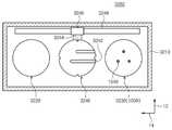
도 5는 도 3의 열처리 챔버의 일 예를 개략적으로 보여주는 평면도이고, 도 6은 도 3의 열처리 챔버의 정면도이다. 도 5 및 도 6을 참조하면, 열처리 챔버(3200)는 하우징(3210), 냉각 유닛(3220), 가열 유닛(3230), 그리고 반송 플레이트(3240)를 가진다.5 is a plan view schematically illustrating an example of the heat treatment chamber of FIG. 3 , and FIG. 6 is a front view of the heat treatment chamber of FIG. 3 . 5 and 6 , the
하우징(3210)은 대체로 직육면체의 형상으로 제공된다. 하우징(3210)의 측벽에는 기판(W)이 출입되는 반입구(도시되지 않음)가 형성된다. 반입구는 개방된 상태로 유지될 수 있다. 선택적으로 반입구를 개폐하도록 도어(도시되지 않음)가 제공될 수 있다. 냉각 유닛(3220), 가열 유닛(3230), 그리고 반송 플레이트(3240)는 하우징(3210) 내에 제공된다. 냉각 유닛(3220) 및 가열 유닛(3230)은 제2 방향(14)을 따라 나란히 제공된다. 일 예에 의하면, 냉각 유닛(3220)은 가열 유닛(3230)에 비해 반송 챔버(3400)에 더 가깝게 위치될 수 있다.The
냉각 유닛(3220)은 냉각판(3222)을 가진다. 냉각판(3222)은 상부에서 바라볼 때 대체로 원형의 형상을 가질 수 있다. 냉각판(3222)에는 냉각부재(3224)가 제공된다. 일 예에 의하면, 냉각부재(3224)는 냉각판(3222)의 내부에 형성되며, 냉각 유체가 흐르는 유로로 제공될 수 있다.The
가열 유닛(3230)은 기판(W)을 상온보다 높은 온도로 가열하는 장치(1000)로 제공된다. 가열 유닛(3230)은 상압 또는 이보다 낮은 감압 분위기에서 기판(W)을 가열 처리한다.The
반송 플레이트(3240)는 대체로 원판 형상을 제공되고, 기판(W)과 대응되는 직경을 가진다. 반송 플레이트(3240)의 가장자리에는 노치(3244)가 형성된다. 노치(3244)는 상술한 반송 로봇(3422, 3424)의 핸드(3420)에 형성된 돌기(3429)와 대응되는 형상을 가질 수 있다. 또한, 노치(3244)는 핸드(3420)에 형성된 돌기(3429)와 대응되는 수로 제공되고, 돌기(3429)와 대응되는 위치에 형성된다. 핸드(3420)와 반송 플레이트(3240)가 상하 방향으로 정렬된 위치에서 핸드(3420)와 반송 플레이트(3240)의 상하 위치가 변경하면 핸드(3420)와 반송 플레이트(3240) 간에 기판(W)의 전달이 이루어진다. 반송 플레이트(3240)는 가이드 레일(3249) 상에 장착되고, 구동기(3246)에 의해 가이드 레일(3249)을 따라 제1영역(3212)과 제2영역(3214) 간에 이동될 수 있다. 반송 플레이트(3240)에는 슬릿 형상의 가이드 홈(3242)이 복수 개 제공된다. 가이드 홈(3242)은 반송 플레이트(3240)의 끝단에서 반송 플레이트(3240)의 내부까지 연장된다. 가이드 홈(3242)은 그 길이 방향이 제2 방향(14)을 따라 제공되고, 가이드 홈(3242)들은 제1 방향(12)을 따라 서로 이격되게 위치된다. 가이드 홈(3242)은 반송 플레이트(3240)와 가열 유닛(3230) 간에 기판(W)의 인수인계가 이루어질 때 반송 플레이트(3240)와 리프트 핀(1340)이 서로 간섭되는 것을 방지한다.The
기판(W)의 가열은 기판(W)이 반송 플레이트(3240) 상에 직접 놓인 상태에서 이루어지고, 기판(W)의 냉각은 기판(W)이 놓인 반송 플레이트(3240)가 냉각판(3222)에 접촉된 상태에서 이루어진다. 냉각판(3222)과 기판(W) 간에 열전달이 잘 이루어지도록 반송 플레이트(3240)는 열전달율이 높은 재질로 제공된다. 일 예에 의하면, 반송 플레이트(3240)는 금속 재질로 제공될 수 있다.The substrate W is heated in a state where the substrate W is placed directly on the
열처리 챔버들(3200) 중 일부의 열처리 챔버에 제공된 가열 유닛(3230)은 기판(W) 가열 중에 가스를 공급하여 포토레지스트의 기판(W) 부착률을 향상시킬 수 있다. 일 예에 의하면, 가스는 헥사메틸디실란(hexamethyldisilane) 가스일 수 있다.The
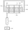
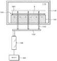
도 7는 도 6의 가열 유닛을 보여주는 단면도이다. 도 7을 참조하면, 가열 유닛(3230)은 챔버(1120), 지지 유닛(1300), 리프트 핀(1340), 구동 부재(1346), 히터 유닛(1420), 그리고 제어기(1500)를 포함한다.FIG. 7 is a cross-sectional view showing the heating unit of FIG. 6 . Referring to FIG. 7 , the
챔버(1100)는 내부에 기판(W)을 가열 처리하는 처리 공간(1110)을 제공한다. 처리 공간(1110)은 외부와 차단된 공간으로 제공된다.The chamber 1100 provides a
지지 유닛(1300)은 처리 공간(1110)에서 기판(W)을 지지한다. 지지 유닛(1300)은 지지 플레이트(1320), 리프트 핀(1340), 그리고 프록시미티 핀(1600)을 포함한다. 지지 플레이트(1320)는 히터 유닛(1400)으로부터 발생된 열을 기판(W)으로 전달한다. 일 예에서, 지지 플레이트(1320)는 원형의 판 형상으로 제공된다. 지지 플레이트(1320)의 상면은 기판(W)보다 큰 직경을 가진다. 지지 플레이트(1320)의 상면은 기판(W)이 놓이는 안착면으로 기능한다. 안착면에는 복수의 리프트 홀들이 형성된다.The
리프트 핀(1340)은 지지 플레이트(1320) 상에서 기판(W)을 승하강시킨다. 리프트 핀(1340)은 복수 개로 제공되며, 각각은 수직한 상하 방향을 향하는 핀 형상으로 제공된다. 리프트 핀(1340)은 단일의 플레이트(1342)에 장착될 수 있다. 각각의 리프트 홀에는 리프트 핀(1340)이 위치된다.The lift pins 1340 elevate the substrate W on the
구동 부재(1346)는 각각의 리프트 핀들(1342)을 승강 위치와 하강 위치 간에 이동시킨다. 여기서 승강 위치는 리프트 핀(1342)의 상단이 안착면보다 높은 위치이고, 하강 위치는 리프트 핀(1342)의 상단이 안착면과 동일하거나 이보다 낮은 위치로 정의한다. 구동 부재(1346)는 챔버(1100)의 외부에 위치될 수 있다. 일 예에서, 구동 부재(1346)는 모터일 수 있다.The
프록시미티 핀(1600)은 기판(W)이 지지 플레이트(1320)에 직접적으로 접촉되는 것을 방지한다. 프록시미티 핀(1600)은 리프트 핀(1340)과 평행한 길이 방향을 가지는 핀 형상으로 제공된다. 프록시미티 핀(1600)은 복수 개로 제공되며, 각각은 지지 플레이트(1320)의 안착면에 고정 설치된다. 프록시미티 핀(1600)은 안착면으로부터 위로 돌출되게 위치된다. 프록시미티 핀(1600)의 상단은 기판(W)의 저면에 직접 접촉되는 접촉면으로 제공되며, 접촉면은 위로 볼록한 형상을 가진다. 이에 따라 프록시미티 핀(1600)과 기판(W) 간의 접촉 면적을 최소화할 수 있다.The
히터 유닛(1420)은 지지 플레이트(1320)에 놓인 기판(W)을 가열 처리한다. 히터 유닛(1420)은 지지 플레이트(1320)에 놓인 기판(W)보다 아래에 위치된다. 일 예에서, 히터 유닛(1420)은 복수 개의 히터들을 포함한다. 히터들은 각각 지지 플레이트(1320) 내에 위치된다. 선택적으로 히터들(1420)은 지지 플레이트(1320)의 저면에 위치될 수 있다. 각 히터들(1420)은 동일 평면 상에 위치된다.The
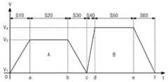
이하, 도 8 내지 도 13을 참조하여 본 발명의 기판 리프팅 방법에 대해 자세히 서술한다. 제어기(1500)는 본 발명의 기판 리프팅 방법을 수행하기 위해 구동 부재(1346)를 제어한다. 도 8은 본 발명의 기판 리프팅 방법의 순서도를 나타내고, 도 9는 본 발명의 기판 리프팅 방법에 따른 리프트 핀(1340)의 이동 속도를 나타내는 그래프이고, 도 10 내지 도 13은 각각 본 발명의 기판 리프팅 방법을 순서대로 보여주는 도면이다. 도 9에 도시된 리프트 핀(1340)의 이동 속도는, 제어기(1500)가 구동 부재(1346)로 하여금 리프트 핀(1340)을 이동시키기 위해 입력하는 속도를 의미한다.Hereinafter, the substrate lifting method of the present invention will be described in detail with reference to FIGS. 8 to 13 . The
도 8 내지 도 9를 참조하면, 본 발명의 기판 리프팅 방법은, 제1 가속 단계(S10), 제1 등속 단계(S20), 제1 감속 단계(S30), 제2 가속 단계(S40), 제2 등속 단계(S50) 그리고 제2 감속 단계(S60)를 포함한다. 리프트 핀(1340)은 제1 가속 단계(S10) 내지 제2 감속 단계(S60)를 거쳐 하강 위치로부터 승강 위치로 수직 이동하면서 기판(W)을 지지 플레이트(1320)로부터 들어올린다.8 to 9, the substrate lifting method of the present invention, the first acceleration step (S10), the first constant speed step (S20), the first deceleration step (S30), the second acceleration step (S40), the second 2 includes a constant speed step (S50) and a second deceleration step (S60). The
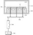
먼저, 리프트 핀(1340)은 리프트 홀 내에 위치된다. 이후, 제1 가속 단계(S10)에서, 리프트 핀(1340)은 프록시미티 핀(1600)에 지지된 기판(W)을 향해 수직 이동된다. 제1 가속 단계(S10)에서 리프트 핀(1340)은 제1 속도(V1)에서 제1 속도(V1) 보다 높은 제2 속도(V2)까지 제1 가속도의 가속도로 가속 이동된다.First, the lift pins 1340 are located in the lift holes. Thereafter, in the first acceleration step S10 , the lift pins 1340 are vertically moved toward the substrate W supported by the proximity pins 1600 . In the first acceleration step S10 , the
일 예에서, 제1 속도(V1)는 0으로 제공된다. 즉, 제1 가속 단계(S10)가 시작되는 시점에서 리프트 핀(1340)은 정지 상태로 제공된다. 도 10을 참조하면, 제1 가속 단계(S10)는 리프트 홀 내에 정지된 리프트 핀(1340)을, 리프트 핀(1340)이 기판(W)과 접촉되지 않는 위치까지 가속 이동시킨다.In one example, the first speed V1 is provided as zero. That is, when the first acceleration step S10 starts, the lift pins 1340 are provided in a stationary state. Referring to FIG. 10 , in the first acceleration step S10 , the
제1 가속 단계(S10) 이후에, 제1 등속 단계(S20)에서, 리프트 핀(1340)을 제2 속도(V2)로 등속 이동시킨다. 리프트 핀(1340)을 제2 속도(V2)로 등속 이동시킨 후, 제1 감속 단계(S30)에서, 리프트 핀(1340)을 제2 속도(V2)에서 제2 속도(V2)보다 낮은 제3 속도(V3)까지 제1 감속도의 감속도로 감속 이동시킨다. 선택적으로, 제1 가속 단계(S10) 이후에 제1 등속 단계(S20)를 거치지 않고, 제1 감속 단계(S30)가 수행될 수 있다. 일 예에서, 도 11에 도시된 바와 같이 제1 감속 단계(S30)에서 리프트 핀(1340)과 기판(W)이 접촉된다. 리프트 핀(1340)과 기판(W)이 접촉되는 시점에서 리프트 핀(1340)을 감속 이동시킴에 따라, 스퀴즈 이펙트를 감소시킬 수 있는 이점이 있다.After the first acceleration step (S10), in the first constant speed step (S20), the
리프트 핀(1340)과 기판(W)은 프록시미티 핀(1600)이 기판(W)을 지지하고 있는 위치에서 접촉된다. 일 예에서, 리프트 핀(1340)과 기판(W)은 지지 플레이트(1320)로부터 h1 만큼 이격된 거리에서 접촉된다. 이때 리프트 핀(1340)의 속도인 제3 속도(V3)는 0으로 제공된다. 리프트 핀(1340)과 기판(W)이 접촉된 이후에, 제2 가속 단계(S40), 제2 등속 단계(S50) 그리고 제2 감속 단계(S60)가 순차적으로 수행된다.The
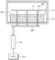
도 12에 도시된 바와 같이, 제2 가속 단계(S40)에서, 리프트 핀(1340)은 기판(W)의 저면에 접촉되어 기판(W)을 수직 상승시킨다. 제2 가속 단계(S40)에서는, 리프트 핀(1340)을 제3 속도(V3)에서 제3 속도(V3) 보다 높은 제4 속도(V4)까지 제2 가속도의 가속도로 가속 이동시킨다. 일 예에서, 제2 가속도는 제1 가속도 보다 크게 제공될 수 있다. 이후에, 제2 등속 단계(S50)에서, 리프트 핀(1340)을 제4 속도(V4)로 등속 이동시킨다. 리프트 핀(1340)을 제4 속도(V4)로 등속 이동시킨 후, 제2 감속 단계(S60)에서, 리프트 핀(1340)을 제4 속도(V4)에서 제4 속도(V4)보다 낮은 제5 속도(V5)까지 제2 감속도의 감속도로 감속 이동시킨다. 선택적으로, 제2 가속 단계(S40) 이후에 제2 등속 단계(S50)를 거치지 않고, 제2 감속 단계(S60)가 수행될 수 있다. 제5 속도(V5)는 0으로 제공되어 제2 감속 단계(S60)가 완료되면 리프트 핀(1340)의 동작이 멈춘다.As shown in FIG. 12 , in the second acceleration step S40 , the lift pins 1340 are in contact with the bottom surface of the substrate W to vertically lift the substrate W. As shown in FIG. In the second acceleration step S40 , the
도 13에 도시된 바와 같이, 제2 가속 단계(S40) 내지 제2 감속 단계(S60)를 거쳐 리프트 핀(1340)은 기판(W)을 지지 플레이트(1320)로부터 h2만큼 이격된 거리로 들어올린다.As shown in FIG. 13 , through the second acceleration step ( S40 ) to the second deceleration step ( S60 ), the
상술한 예에서는, 리프트 핀(1340)은 기판(W)과 제1 감속 단계(S30)에서 접촉하는 것으로 설명하였다. 그러나 다른 예에서, 리프트 핀(1340)은 기판(W)과 제1 등속 단계(S20)에서 접촉할 수 있다.In the above-described example, the
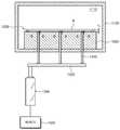
상술한 예에서는, 지지 유닛에 프록시미티 핀(1600)이 제공되어, 프록시미티 핀(1600)이 지지 플레이트(1320)로부터 기판(W)을 h1 만큼 이격된 거리에서 지지하고 있는 것으로 설명하였다. 그러나, 다른 예에서 지지 유닛에는 프록시미티 핀(1600)이 제공되지 않을 수 있다. 일 예에서, 도 14에 도시된 바와 같이, 리프트 핀(1340)이 지지 플레이트(1320)로부터 d1 만큼 이격된 거리에서 기판(W)을 지지할 수 있다. 예컨대, d1은 도 11의 h1과 같은 거리로 제공될 수 있다.In the above-described example, the
이후에, 앞서 서술한 제1 가속 단계(S10), 제1 등속 단계(S20), 제1 감속 단계(S30), 제2 가속 단계(S40), 제2 등속 단계(S50) 그리고 제2 감속 단계(S60)가 수행될 수 있다.Thereafter, the first acceleration step (S10), the first constant speed step (S20), the first deceleration step (S30), the second acceleration step (S40), the second constant speed step (S50) and the second deceleration step described above (S60) may be performed.
리프트 핀(1340)은 도 15 내지 도 16에 도시된 바와 같이 지지 플레이트(1320)로부터 d2 만큼 이격된 거리까지 상승 이동된다. 일 예에서, 기판(W)이 지지 플레이트(1320)로부터 d1 만큼 이격된 거리에서 d2 만큼 이격된 거리로 이동될 동안, 제1 가속 단계(S10), 제1 등속 단계(S20) 그리고 제1 감속 단계(S30)가 수행될 수 있다. 예컨대, d1으로부터 d2까지의 거리는 도 9에 도시된 면적 A에 해당하는 거리일 수 있다. 일 예에서, d2는 기판(W)을 지지 플레이트(1320)로부터 이격시킬 때 스퀴즈 이펙트가 발생하지 않는 거리로 설정될 수 있다.The
이후에, 리프트 핀(1340)은 도 17 내지 도 18에 도시된 바와 같이 지지 플레이트(1320)로부터 d3 만큼 이격된 거리까지 상승 이동된다. 일 예에서, 기판(W)이 지지 플레이트(1320)로부터 d2 만큼 이격된 거리에서 d3 만큼 이격된 거리로 이동될 동안, 제2 가속 단계(S40), 제2 등속 단계(S50) 그리고 제2 감속 단계(S60)가 수행될 수 있다. 예컨대, d2로부터 d3까지의 거리는 도 9에 도시된 면적 B에 해당하는 거리일 수 있다.Thereafter, the
본 발명에 따르면, 리프트 핀(1340)을 구동하는 구동 부재(1346)를 모터로 제공한다. 이에, 리프트 핀(1340)의 스트로크를 다양한 거리로 제공할 수 있는 이점이 있다. 또한, 리프트 핀(1340)의 구동 속도를 조절하기 용이하며, 리프트 핀(1340)의 구동 정밀도를 개선할 수 있는 이점이 있다. 또한, 도 14에 도시된 바와 같이 프록시미티 핀(1600)을 제거하여 원가를 절감할 수 있는 이점이 있다.According to the present invention, a driving
본 발명에 따르면, 제2 가속도를 제1가속도 보다 크게 제공함에 따라 하강 위치로부터 승강 위치로 리프트 핀(1340)을 이동시키는데 소요되는 시간을 단축할 수 있다.According to the present invention, as the second acceleration is greater than the first acceleration, the time required to move the
본 발명에 따르면, 제1 가속 단계(S10)에서 리프트 핀(1340)을 가속 이동시킴에 따라, 하강 위치로부터 승강 위치로 리프트 핀(1340)을 이동시키는데 소요되는 일부 시간을 단축할 수 있다.According to the present invention, as the
본 발명에 따르면, 제1 감속 단계(S30)에서 제3 속도(V3)를 0으로 제공함에 따라, 리프트 핀(1340)의 실제 이동에 있어서, 감속 구간이 보장될 수 있는 이점이 있다.According to the present invention, by providing the third speed V3 to 0 in the first deceleration step S30, there is an advantage that the deceleration section can be guaranteed in the actual movement of the
이상의 상세한 설명은 본 발명을 예시하는 것이다. 또한 상술한 내용은 본 발명의 바람직한 실시 형태를 나타내어 설명하는 것이며, 본 발명은 다양한 다른 조합, 변경 및 환경에서 사용할 수 있다. 즉 본 명세서에 개시된 발명의 개념의 범위, 저술한 개시 내용과 균등한 범위 및/또는 당업계의 기술 또는 지식의 범위내에서 변경 또는 수정이 가능하다. 저술한 실시예는 본 발명의 기술적 사상을 구현하기 위한 최선의 상태를 설명하는 것이며, 본 발명의 구체적인 적용 분야 및 용도에서 요구되는 다양한 변경도 가능하다. 따라서 이상의 발명의 상세한 설명은 개시된 실시 상태로 본 발명을 제한하려는 의도가 아니다. 또한 첨부된 청구범위는 다른 실시 상태도 포함하는 것으로 해석되어야 한다.The above detailed description is illustrative of the present invention. In addition, the above description shows and describes preferred embodiments of the present invention, and the present invention can be used in various other combinations, modifications, and environments. That is, changes or modifications are possible within the scope of the concept of the invention disclosed herein, the scope equivalent to the written disclosure, and/or within the scope of skill or knowledge in the art. The written embodiment describes the best state for implementing the technical idea of the present invention, and various changes required in the specific application field and use of the present invention are possible. Accordingly, the detailed description of the present invention is not intended to limit the present invention to the disclosed embodiments. Also, the appended claims should be construed to include other embodiments.
1300: 지지 유닛
1320: 지지 플레이트
1340: 리프트 핀
1346: 구동 부재
1600: 프록시미티 핀1300: support unit
1320: support plate
1340: lift pin
1346: drive member
1600: proximity pin
Claims (18)
Translated fromKorean리프트 핀을 이용하여 기판이 놓이는 지지 플레이트로부터 상기 기판을 승강시키되,
상기 리프트 핀은 상기 지지 플레이트의 하방으로 제1 거리만큼 이격된 하강 위치로부터 상기 지지 플레이트의 상방으로 제2 거리만큼 이격된 승강 위치 사이를 수직이동 하면서 상기 기판을 상기 지지 플레이트로부터 들어올리고,
상기 리프트 핀이 감속 또는 등속 이동되는 구간에서 상기 기판에 접촉되는 기판 리프팅 방법.A method for lifting a substrate, comprising:
Lifting the substrate from the support plate on which the substrate is placed using a lift pin,
The lift pin lifts the substrate from the support plate while vertically moving between a lowering position spaced a first distance downward of the support plate and an elevating position spaced a second distance upward of the support plate,
A method of lifting a substrate in which the lift pin is in contact with the substrate in a section in which the lift pin is decelerated or moved at a constant velocity.
상기 리프트 핀을 제1 속도에서 상기 제1 속도 보다 높은 제2 속도까지 제1 가속도의 가속도로 가속 이동시키는 제1 가속 단계와;
상기 리프트 핀을 상기 제2 속도에서 상기 제2 속도보다 낮은 제3 속도까지 제1 감속도의 감속도로 감속 이동시키는 제1 감속 단계를 포함하고,
상기 리프트 핀은 상기 기판과 상기 제1 감속 단계에서 접촉되는 기판 리프팅 방법.According to claim 1,
a first acceleration step of accelerating the lift pin from a first speed to a second speed higher than the first speed at an acceleration of a first acceleration;
a first deceleration step of decelerating the lift pin from the second speed to a third speed lower than the second speed at a deceleration rate of a first deceleration;
wherein the lift pin is in contact with the substrate in the first deceleration step.
상기 리프트 핀을 제1 속도에서 상기 제1 속도 보다 높은 제2 속도까지 제1 가속도의 가속도로 가속 이동시키는 제1 가속 단계와;
상기 리프트 핀을 상기 제2 속도로 등속 이동시키는 제1 등속 단계를 포함하고,
상기 리프트 핀은 상기 기판과 상기 제1 등속 단계에서 접촉되는 기판 리프팅 방법.According to claim 1,
a first acceleration step of accelerating the lift pin from a first speed to a second speed higher than the first speed at an acceleration of a first acceleration;
A first constant velocity step of moving the lift pin at a constant velocity at the second velocity,
The lift pin is a substrate lifting method in contact with the substrate in the first constant velocity step.
상기 제1 가속 단계 이후에,
상기 리프트 핀을 상기 제2 속도로 등속 이동시키는 제1 등속 단계를 더 포함하는 기판 리프팅 방법.3. The method of claim 2,
After the first acceleration step,
A substrate lifting method further comprising a first constant velocity step of moving the lift pin at a constant velocity at the second velocity.
상기 제1 감속 단계 이후에,
상기 리프트 핀을 제3 속도에서 상기 제3 속도 보다 높은 제4 속도까지 제2 가속도의 가속도로 가속 이동시키는 제2 가속 단계와;
상기 리프트 핀을 상기 제4 속도에서 상기 제4 속도보다 낮은 제5 속도까지 제2 감속도의 감속도로 감속 이동시키는 제2 감속 단계를 더 포함하는 기판 리프팅 방법.3. The method of claim 2,
After the first deceleration step,
a second acceleration step of accelerating the lift pin from a third speed to a fourth speed higher than the third speed at an acceleration of a second acceleration;
and a second deceleration step of decelerating the lift pin from the fourth speed to a fifth speed lower than the fourth speed at a deceleration of a second deceleration.
상기 리프트 핀을 상기 제4 속도로 등속 이동시키는 제2 등속 단계를 더 포함하는 기판 리프팅 방법.6. The method of claim 5,
A substrate lifting method further comprising a second constant velocity step of moving the lift pin at a constant velocity at the fourth velocity.
상기 제2 가속도는 상기 제1 가속도 보다 크게 제공되는 기판 리프팅 방법.6. The method of claim 5,
wherein the second acceleration is greater than the first acceleration.
상기 제1 속도는 0인 기판 리프팅 방법.8. The method according to any one of claims 2 to 7,
wherein the first speed is zero.
상기 제3 속도는 0인 기판 리프팅 방법.8. The method according to any one of claims 2, 4 to 7,
wherein the third speed is zero.
상기 제5 속도는 0인 기판 리프팅 방법.8. The method according to any one of claims 5 to 7,
wherein the fifth speed is zero.
상기 기판이 놓이는 지지 플레이트;
상기 지지 플레이트에 상기 기판을 로딩 또는 언로딩하는 리프트 핀;
상기 리프트 핀을 승하강 시키는 구동 부재; 그리고,
상기 구동 부재의 동작을 제어하는 제어기를 포함하되,
상기 제어기는,
상기 구동 부재가 상기 리프트 핀을 상기 지지 플레이트의 하방으로 제1 거리만큼 이격된 하강 위치로부터 상기 지지 플레이트의 상방으로 제2 거리만큼 이격된 승강 위치 사이를 수직이동 하면서 상기 기판을 상기 지지 플레이트로부터 들어올리되,
상기 리프트 핀이 감속 또는 등속 이동되는 구간에서 상기 기판에 접촉되도록 상기 구동 부재를 제어하는 기판 처리 장치.A support unit for supporting a substrate, comprising:
a support plate on which the substrate is placed;
a lift pin for loading or unloading the substrate to the support plate;
a driving member for elevating the lift pin; And,
A controller for controlling the operation of the driving member,
The controller is
The drive member lifts the substrate from the support plate while vertically moving the lift pin between a lowered position spaced a first distance downward of the support plate and an elevated position spaced a second distance upward of the support plate. raise it,
A substrate processing apparatus for controlling the driving member to contact the substrate in a section in which the lift pin moves at a deceleration or constant velocity.
상기 제어기는,
상기 구동 부재가 상기 리프트 핀을 제1 속도에서 상기 제1 속도 보다 높은 제2 속도까지 제1 가속도의 가속도로 가속 이동시킨 이후에,
상기 제2 속도로 등속 이동시키고,
이후에 상기 제2 속도에서 상기 제2 속도보다 낮은 제3 속도까지 제1 감속도의 감속도로 감속 이동시키되,
상기 리프트 핀이 감속 이동될 때에 상기 기판과 접촉되도록 상기 구동 부재를 제어하는 기판 처리 장치.12. The method of claim 11,
The controller is
after the drive member accelerates the lift pin from the first speed to a second speed higher than the first speed at an acceleration of a first acceleration;
moving at a constant speed at the second speed,
Thereafter, decelerating the movement from the second speed to a third speed lower than the second speed at a deceleration rate of the first deceleration,
A substrate processing apparatus for controlling the driving member to contact the substrate when the lift pin is decelerated.
상기 제어기는,
상기 리프트 핀을 상기 제1 감속도로 감속 이동시킨 후에,
상기 제3 속도에서 상기 제3 속도 보다 높은 제4 속도까지 제2 가속도의 가속도로 가속 이동시키고,
이후에 상기 제4 속도로 등속 이동시키고,
이후에 상기 제4 속도에서 상기 제4 속도보다 낮은 제5 속도까지 제2 감속도의 감속도로 감속 이동시키도록 상기 구동 부재를 제어하는 기판 처리 장치.13. The method of claim 12,
The controller is
After decelerating the lift pin at the first deceleration,
Accelerated movement from the third speed to a fourth speed higher than the third speed with an acceleration of a second acceleration;
Thereafter, moving at a constant speed at the fourth speed,
Thereafter, the substrate processing apparatus controls the driving member to decelerate the movement from the fourth speed to a fifth speed lower than the fourth speed at a deceleration rate of a second deceleration.
상기 제2 가속도는 상기 제1 가속도 보다 크게 제공되는 기판 처리 장치.14. The method of claim 13,
The second acceleration is provided to be greater than the first acceleration.
상기 제1 속도는 0인 기판 처리 장치.15. The method according to any one of claims 12 to 14,
and the first speed is zero.
상기 제3 속도는 0인 기판 처리 장치.15. The method according to any one of claims 12 to 14,
and the third speed is zero.
상기 제5 속도는 0인 기판 처리 장치.14. The method of claim 13,
and the fifth speed is zero.
상기 구동 부재는 모터인 기판 처리 장치.12. The method of claim 11,
The drive member is a motor.
Priority Applications (4)
| Application Number | Priority Date | Filing Date | Title |
|---|---|---|---|
| KR1020190177478AKR20210086748A (en) | 2019-12-30 | 2019-12-30 | Method for lifting substrate and apparatus for treating substrate |
| US17/138,427US20210202296A1 (en) | 2019-12-30 | 2020-12-30 | Method for lifting substrate and apparatus for treating substrate |
| CN202011609933.2ACN113130374A (en) | 2019-12-30 | 2020-12-30 | Method for lifting substrate and apparatus for processing substrate |
| KR1020220120821AKR102607731B1 (en) | 2019-12-30 | 2022-09-23 | Method for lifting substrate and apparatus for treating substrate |
Applications Claiming Priority (1)
| Application Number | Priority Date | Filing Date | Title |
|---|---|---|---|
| KR1020190177478AKR20210086748A (en) | 2019-12-30 | 2019-12-30 | Method for lifting substrate and apparatus for treating substrate |
Related Child Applications (1)
| Application Number | Title | Priority Date | Filing Date |
|---|---|---|---|
| KR1020220120821ADivisionKR102607731B1 (en) | 2019-12-30 | 2022-09-23 | Method for lifting substrate and apparatus for treating substrate |
Publications (1)
| Publication Number | Publication Date |
|---|---|
| KR20210086748Atrue KR20210086748A (en) | 2021-07-09 |
Family
ID=76546506
Family Applications (2)
| Application Number | Title | Priority Date | Filing Date |
|---|---|---|---|
| KR1020190177478ACeasedKR20210086748A (en) | 2019-12-30 | 2019-12-30 | Method for lifting substrate and apparatus for treating substrate |
| KR1020220120821AActiveKR102607731B1 (en) | 2019-12-30 | 2022-09-23 | Method for lifting substrate and apparatus for treating substrate |
Family Applications After (1)
| Application Number | Title | Priority Date | Filing Date |
|---|---|---|---|
| KR1020220120821AActiveKR102607731B1 (en) | 2019-12-30 | 2022-09-23 | Method for lifting substrate and apparatus for treating substrate |
Country Status (3)
| Country | Link |
|---|---|
| US (1) | US20210202296A1 (en) |
| KR (2) | KR20210086748A (en) |
| CN (1) | CN113130374A (en) |
Cited By (1)
| Publication number | Priority date | Publication date | Assignee | Title |
|---|---|---|---|---|
| WO2023219205A1 (en)* | 2022-05-11 | 2023-11-16 | 피에스케이홀딩스 (주) | Substrate processing device and substrate processing method for improving substrate stickiness |
Families Citing this family (1)
| Publication number | Priority date | Publication date | Assignee | Title |
|---|---|---|---|---|
| CN118073241B (en)* | 2024-02-29 | 2024-09-10 | 哈尔滨工业大学 | Multilayer flip chip high-flexibility stacking and integrated bonding device and method |
Family Cites Families (30)
| Publication number | Priority date | Publication date | Assignee | Title |
|---|---|---|---|---|
| US5252807A (en)* | 1990-07-02 | 1993-10-12 | George Chizinsky | Heated plate rapid thermal processor |
| US6456480B1 (en)* | 1997-03-25 | 2002-09-24 | Tokyo Electron Limited | Processing apparatus and a processing method |
| TW459266B (en)* | 1997-08-27 | 2001-10-11 | Tokyo Electron Ltd | Substrate processing method |
| KR20010052608A (en)* | 1998-06-05 | 2001-06-25 | 조셉 제이. 스위니 | Improved method and apparatus for contacting a wafer |
| US6231716B1 (en)* | 1998-11-09 | 2001-05-15 | Applied Materials, Inc. | Processing chamber with rapid wafer exchange |
| US7506746B2 (en)* | 2002-08-31 | 2009-03-24 | Applied Materials, Inc. | System for transporting substrate carriers |
| US7234584B2 (en)* | 2002-08-31 | 2007-06-26 | Applied Materials, Inc. | System for transporting substrate carriers |
| US6887317B2 (en)* | 2002-09-10 | 2005-05-03 | Applied Materials, Inc. | Reduced friction lift pin |
| JP2005129837A (en)* | 2003-10-27 | 2005-05-19 | Seiko Epson Corp | Substrate processing apparatus and substrate processing method |
| US20060236941A1 (en)* | 2005-04-20 | 2006-10-26 | Applied Materials, Inc. | Passive wafer support for particle free wafer acceleration |
| KR20060117537A (en)* | 2005-05-11 | 2006-11-17 | 삼성전자주식회사 | Lift pin height alignment jig and lift pin height alignment method using the same |
| CN1993035B (en)* | 2005-12-28 | 2011-04-13 | 富士机械制造株式会社 | Pellet type element supplying device and element mounting system |
| JP4597894B2 (en)* | 2006-03-31 | 2010-12-15 | 東京エレクトロン株式会社 | Substrate mounting table and substrate processing apparatus |
| US20090179366A1 (en)* | 2008-01-16 | 2009-07-16 | Sokudo Co., Ltd. | Apparatus for supporting a substrate during semiconductor processing operations |
| WO2010093568A2 (en)* | 2009-02-11 | 2010-08-19 | Applied Materials, Inc. | Non-contact substrate processing |
| US8363378B2 (en)* | 2009-02-17 | 2013-01-29 | Intevac, Inc. | Method for optimized removal of wafer from electrostatic chuck |
| JP5537380B2 (en)* | 2009-11-16 | 2014-07-02 | キヤノン株式会社 | Exposure apparatus and device manufacturing method |
| US20140007808A1 (en)* | 2011-07-05 | 2014-01-09 | Epicrew Corporation | Susceptor Device And Deposition Apparatus Having The Same |
| US20150064621A1 (en)* | 2013-08-30 | 2015-03-05 | Semes Co., Ltd. | Substrate treatment device and method of applying treatment solution |
| KR20150035124A (en)* | 2013-09-27 | 2015-04-06 | 주식회사 코디엠 | Method of controlling the height of proximity pin |
| CN103792707B (en)* | 2014-02-13 | 2016-04-13 | 北京京东方显示技术有限公司 | Support board |
| JP6419619B2 (en)* | 2015-03-24 | 2018-11-07 | 株式会社Screenホールディングス | Method for creating a peeling device recipe |
| KR101927699B1 (en)* | 2016-10-31 | 2018-12-13 | 세메스 주식회사 | Apparatus and method for treating substrate |
| JP6797063B2 (en)* | 2017-04-14 | 2020-12-09 | 東京エレクトロン株式会社 | Pin control method and substrate processing equipment |
| KR102030471B1 (en)* | 2017-07-25 | 2019-10-14 | 세메스 주식회사 | Lift pin unit and Unit for supporting substrate |
| KR102099116B1 (en)* | 2017-07-31 | 2020-04-09 | 세메스 주식회사 | Apparatus and Method for treating substrate |
| JP6974065B2 (en)* | 2017-08-16 | 2021-12-01 | 株式会社荏原製作所 | How to remove the board processing device and the board from the table of the board processing device |
| JP6896588B2 (en)* | 2017-11-06 | 2021-06-30 | 株式会社Screenホールディングス | Board delivery system and board delivery method |
| KR102121240B1 (en)* | 2018-05-03 | 2020-06-18 | 세메스 주식회사 | Apparatus and Method for treating substrate |
| JP6983206B2 (en)* | 2019-10-15 | 2021-12-17 | 株式会社アルバック | Board transfer device and board transfer method |
- 2019
- 2019-12-30KRKR1020190177478Apatent/KR20210086748A/ennot_activeCeased
- 2020
- 2020-12-30USUS17/138,427patent/US20210202296A1/ennot_activeAbandoned
- 2020-12-30CNCN202011609933.2Apatent/CN113130374A/enactivePending
- 2022
- 2022-09-23KRKR1020220120821Apatent/KR102607731B1/enactiveActive
Cited By (2)
| Publication number | Priority date | Publication date | Assignee | Title |
|---|---|---|---|---|
| WO2023219205A1 (en)* | 2022-05-11 | 2023-11-16 | 피에스케이홀딩스 (주) | Substrate processing device and substrate processing method for improving substrate stickiness |
| KR20230158256A (en)* | 2022-05-11 | 2023-11-20 | 피에스케이홀딩스 (주) | Apparatus for treating substrate and method of treating substrate for remedy of substrate sticky phenomenon |
Also Published As
| Publication number | Publication date |
|---|---|
| KR20220133843A (en) | 2022-10-05 |
| US20210202296A1 (en) | 2021-07-01 |
| CN113130374A (en) | 2021-07-16 |
| KR102607731B1 (en) | 2023-11-29 |
Similar Documents
| Publication | Publication Date | Title |
|---|---|---|
| KR102514452B1 (en) | Cooling unit, substrate treating apparatus including the same, and substrate treating method using the same | |
| KR102607731B1 (en) | Method for lifting substrate and apparatus for treating substrate | |
| KR102255278B1 (en) | Apparatus and Method for treating a substrate | |
| KR102701437B1 (en) | Transfer unit and substrate treating apparatus including the same | |
| KR102282146B1 (en) | Apparatus and Method for treating substrate | |
| KR102831548B1 (en) | Supporting unut and method for lifting substrate using the same | |
| KR102282145B1 (en) | Apparatus and Method for treating substrate | |
| KR102432533B1 (en) | Apparatus and Method for treating substrate and Apparatus for supporting substrate | |
| KR102280034B1 (en) | Transfer unit and Apparatus for treaitngsubstrate | |
| KR102633336B1 (en) | Apparatus for treating substrate | |
| KR20210003497A (en) | Apparatus and Method for treating substrate | |
| KR102850102B1 (en) | Transfer unit and substrate treating apparatus including the same | |
| KR102397850B1 (en) | Apparatus for treating substrate | |
| KR102303595B1 (en) | Supporting Unit And Apparatus For Treating Substrate | |
| KR102207312B1 (en) | Method and Apparatus for treating substrate | |
| KR20220011259A (en) | Apparatus and method for treating substrate with the unit | |
| KR102289939B1 (en) | Apparatus and Method for treating substrate | |
| KR102315664B1 (en) | Apparatus and Method for treating substrate | |
| KR20200034852A (en) | Apparatus and Method for treating substrate | |
| KR20220093563A (en) | Apparatus and mehtod for treating a substrate | |
| KR20220094022A (en) | Transfer unit and substrate treating apparatus including the same | |
| KR102296280B1 (en) | Apparatus for treating substrate | |
| KR102259066B1 (en) | Apparatus and Method for treating substrate | |
| KR102277549B1 (en) | Apparatus and Method for treating a substrate | |
| KR102315666B1 (en) | Transferring unit and Apparatus for treating substrate |
Legal Events
| Date | Code | Title | Description |
|---|---|---|---|
| PA0109 | Patent application | Patent event code:PA01091R01D Comment text:Patent Application Patent event date:20191230 | |
| PA0201 | Request for examination | ||
| E902 | Notification of reason for refusal | ||
| PE0902 | Notice of grounds for rejection | Comment text:Notification of reason for refusal Patent event date:20210525 Patent event code:PE09021S01D | |
| PG1501 | Laying open of application | ||
| AMND | Amendment | ||
| E601 | Decision to refuse application | ||
| PE0601 | Decision on rejection of patent | Patent event date:20220223 Comment text:Decision to Refuse Application Patent event code:PE06012S01D Patent event date:20210525 Comment text:Notification of reason for refusal Patent event code:PE06011S01I | |
| AMND | Amendment | ||
| PX0901 | Re-examination | Patent event code:PX09011S01I Patent event date:20220223 Comment text:Decision to Refuse Application Patent event code:PX09012R01I Patent event date:20211025 Comment text:Amendment to Specification, etc. | |
| PX0601 | Decision of rejection after re-examination | Comment text:Decision to Refuse Application Patent event code:PX06014S01D Patent event date:20220523 Comment text:Amendment to Specification, etc. Patent event code:PX06012R01I Patent event date:20220420 Comment text:Decision to Refuse Application Patent event code:PX06011S01I Patent event date:20220223 Comment text:Amendment to Specification, etc. Patent event code:PX06012R01I Patent event date:20211025 Comment text:Notification of reason for refusal Patent event code:PX06013S01I Patent event date:20210525 | |
| X601 | Decision of rejection after re-examination | ||
| PA0107 | Divisional application | Comment text:Divisional Application of Patent Patent event date:20220923 Patent event code:PA01071R01D |