KR20210083374A - pellet grill - Google Patents
pellet grillDownload PDFInfo
- Publication number
- KR20210083374A KR20210083374AKR1020217019887AKR20217019887AKR20210083374AKR 20210083374 AKR20210083374 AKR 20210083374AKR 1020217019887 AKR1020217019887 AKR 1020217019887AKR 20217019887 AKR20217019887 AKR 20217019887AKR 20210083374 AKR20210083374 AKR 20210083374A
- Authority
- KR
- South Korea
- Prior art keywords
- grease
- control system
- pellet grill
- block
- deflection bar
- Prior art date
- Legal status (The legal status is an assumption and is not a legal conclusion. Google has not performed a legal analysis and makes no representation as to the accuracy of the status listed.)
- Ceased
Links
- 239000008188pelletSubstances0.000titleclaimsabstractdescription602
- 239000004519greaseSubstances0.000claimsabstractdescription277
- 238000000034methodMethods0.000claimsabstractdescription226
- 238000010411cookingMethods0.000claimsabstractdescription91
- 238000002485combustion reactionMethods0.000claimsdescription283
- 235000013305foodNutrition0.000claimsdescription40
- 239000003795chemical substances by applicationSubstances0.000claims1
- 239000000446fuelSubstances0.000description262
- 239000002699waste materialSubstances0.000description143
- 239000002956ashSubstances0.000description99
- 238000001514detection methodMethods0.000description90
- 230000033001locomotionEffects0.000description56
- 230000008569processEffects0.000description52
- 238000010586diagramMethods0.000description23
- 230000004044responseEffects0.000description23
- 230000015654memoryEffects0.000description21
- 239000000523sampleSubstances0.000description16
- 230000005540biological transmissionEffects0.000description15
- 238000003860storageMethods0.000description15
- 230000002441reversible effectEffects0.000description14
- 230000008859changeEffects0.000description13
- 239000006227byproductSubstances0.000description10
- 230000007423decreaseEffects0.000description10
- 230000000977initiatory effectEffects0.000description10
- 230000008878couplingEffects0.000description9
- 238000010168coupling processMethods0.000description9
- 238000005859coupling reactionMethods0.000description9
- 238000004891communicationMethods0.000description7
- 230000010006flightEffects0.000description5
- XLYOFNOQVPJJNP-UHFFFAOYSA-NwaterSubstancesOXLYOFNOQVPJJNP-UHFFFAOYSA-N0.000description5
- 238000002405diagnostic procedureMethods0.000description4
- 230000000694effectsEffects0.000description4
- 238000004519manufacturing processMethods0.000description4
- 235000014676Phragmites communisNutrition0.000description3
- 230000004913activationEffects0.000description3
- 238000001994activationMethods0.000description3
- 230000005484gravityEffects0.000description3
- 238000010926purgeMethods0.000description3
- 238000011084recoveryMethods0.000description3
- 238000004513sizingMethods0.000description3
- 238000012546transferMethods0.000description3
- 230000009471actionEffects0.000description2
- 230000009286beneficial effectEffects0.000description2
- 230000003139buffering effectEffects0.000description2
- 230000000779depleting effectEffects0.000description2
- 238000009826distributionMethods0.000description2
- 230000004807localizationEffects0.000description2
- 239000007787solidSubstances0.000description2
- 230000006641stabilisationEffects0.000description2
- 238000011105stabilizationMethods0.000description2
- 235000002918Fraxinus excelsiorNutrition0.000description1
- 230000000712assemblyEffects0.000description1
- 238000000429assemblyMethods0.000description1
- 230000004888barrier functionEffects0.000description1
- 230000006399behaviorEffects0.000description1
- 230000008901benefitEffects0.000description1
- 238000004140cleaningMethods0.000description1
- 239000012141concentrateSubstances0.000description1
- 238000013479data entryMethods0.000description1
- 230000005611electricityEffects0.000description1
- 238000011049fillingMethods0.000description1
- 230000006870functionEffects0.000description1
- 230000001788irregularEffects0.000description1
- 239000004973liquid crystal related substanceSubstances0.000description1
- 238000011068loading methodMethods0.000description1
- 230000007774longtermEffects0.000description1
- 230000000737periodic effectEffects0.000description1
- 235000013550pizzaNutrition0.000description1
- 238000002360preparation methodMethods0.000description1
- 230000000644propagated effectEffects0.000description1
- 230000009467reductionEffects0.000description1
- 230000000391smoking effectEffects0.000description1
- 230000007480spreadingEffects0.000description1
- 238000003892spreadingMethods0.000description1
- 239000007858starting materialSubstances0.000description1
- 239000004575stoneSubstances0.000description1
- 230000000007visual effectEffects0.000description1
- 239000002023woodSubstances0.000description1
Images


Classifications
- A—HUMAN NECESSITIES
- A47—FURNITURE; DOMESTIC ARTICLES OR APPLIANCES; COFFEE MILLS; SPICE MILLS; SUCTION CLEANERS IN GENERAL
- A47J—KITCHEN EQUIPMENT; COFFEE MILLS; SPICE MILLS; APPARATUS FOR MAKING BEVERAGES
- A47J37/00—Baking; Roasting; Grilling; Frying
- A47J37/06—Roasters; Grills; Sandwich grills
- A47J37/07—Roasting devices for outdoor use; Barbecues
- F—MECHANICAL ENGINEERING; LIGHTING; HEATING; WEAPONS; BLASTING
- F24—HEATING; RANGES; VENTILATING
- F24B—DOMESTIC STOVES OR RANGES FOR SOLID FUELS; IMPLEMENTS FOR USE IN CONNECTION WITH STOVES OR RANGES
- F24B13/00—Details solely applicable to stoves or ranges burning solid fuels
- F24B13/04—Arrangements for feeding solid fuel, e.g. hoppers
- A—HUMAN NECESSITIES
- A47—FURNITURE; DOMESTIC ARTICLES OR APPLIANCES; COFFEE MILLS; SPICE MILLS; SUCTION CLEANERS IN GENERAL
- A47J—KITCHEN EQUIPMENT; COFFEE MILLS; SPICE MILLS; APPARATUS FOR MAKING BEVERAGES
- A47J36/00—Parts, details or accessories of cooking-vessels
- A47J36/32—Time-controlled igniting mechanisms or alarm devices
- A47J36/321—Time-controlled igniting mechanisms or alarm devices the electronic control being performed over a network, e.g. by means of a handheld device
- A—HUMAN NECESSITIES
- A47—FURNITURE; DOMESTIC ARTICLES OR APPLIANCES; COFFEE MILLS; SPICE MILLS; SUCTION CLEANERS IN GENERAL
- A47J—KITCHEN EQUIPMENT; COFFEE MILLS; SPICE MILLS; APPARATUS FOR MAKING BEVERAGES
- A47J37/00—Baking; Roasting; Grilling; Frying
- A47J37/06—Roasters; Grills; Sandwich grills
- A47J37/067—Horizontally disposed broiling griddles
- A—HUMAN NECESSITIES
- A47—FURNITURE; DOMESTIC ARTICLES OR APPLIANCES; COFFEE MILLS; SPICE MILLS; SUCTION CLEANERS IN GENERAL
- A47J—KITCHEN EQUIPMENT; COFFEE MILLS; SPICE MILLS; APPARATUS FOR MAKING BEVERAGES
- A47J37/00—Baking; Roasting; Grilling; Frying
- A47J37/06—Roasters; Grills; Sandwich grills
- A47J37/0694—Broiling racks
- A—HUMAN NECESSITIES
- A47—FURNITURE; DOMESTIC ARTICLES OR APPLIANCES; COFFEE MILLS; SPICE MILLS; SUCTION CLEANERS IN GENERAL
- A47J—KITCHEN EQUIPMENT; COFFEE MILLS; SPICE MILLS; APPARATUS FOR MAKING BEVERAGES
- A47J37/00—Baking; Roasting; Grilling; Frying
- A47J37/06—Roasters; Grills; Sandwich grills
- A47J37/07—Roasting devices for outdoor use; Barbecues
- A47J37/0704—Roasting devices for outdoor use; Barbecues with horizontal fire box
- A47J37/0709—Roasting devices for outdoor use; Barbecues with horizontal fire box with electric heating elements
- A—HUMAN NECESSITIES
- A47—FURNITURE; DOMESTIC ARTICLES OR APPLIANCES; COFFEE MILLS; SPICE MILLS; SUCTION CLEANERS IN GENERAL
- A47J—KITCHEN EQUIPMENT; COFFEE MILLS; SPICE MILLS; APPARATUS FOR MAKING BEVERAGES
- A47J37/00—Baking; Roasting; Grilling; Frying
- A47J37/06—Roasters; Grills; Sandwich grills
- A47J37/07—Roasting devices for outdoor use; Barbecues
- A47J37/0754—Roasting devices for outdoor use; Barbecues with blowers providing forced air circulation
- A—HUMAN NECESSITIES
- A47—FURNITURE; DOMESTIC ARTICLES OR APPLIANCES; COFFEE MILLS; SPICE MILLS; SUCTION CLEANERS IN GENERAL
- A47J—KITCHEN EQUIPMENT; COFFEE MILLS; SPICE MILLS; APPARATUS FOR MAKING BEVERAGES
- A47J37/00—Baking; Roasting; Grilling; Frying
- A47J37/06—Roasters; Grills; Sandwich grills
- A47J37/07—Roasting devices for outdoor use; Barbecues
- A47J37/0786—Accessories
- F—MECHANICAL ENGINEERING; LIGHTING; HEATING; WEAPONS; BLASTING
- F23—COMBUSTION APPARATUS; COMBUSTION PROCESSES
- F23B—METHODS OR APPARATUS FOR COMBUSTION USING ONLY SOLID FUEL
- F23B1/00—Combustion apparatus using only lump fuel
- F23B1/30—Combustion apparatus using only lump fuel characterised by the form of combustion chamber
- F23B1/36—Combustion apparatus using only lump fuel characterised by the form of combustion chamber shaft-type
- F—MECHANICAL ENGINEERING; LIGHTING; HEATING; WEAPONS; BLASTING
- F23—COMBUSTION APPARATUS; COMBUSTION PROCESSES
- F23B—METHODS OR APPARATUS FOR COMBUSTION USING ONLY SOLID FUEL
- F23B40/00—Combustion apparatus with driven means for feeding fuel into the combustion chamber
- F23B40/02—Combustion apparatus with driven means for feeding fuel into the combustion chamber the fuel being fed by scattering over the fuel-supporting surface
- F—MECHANICAL ENGINEERING; LIGHTING; HEATING; WEAPONS; BLASTING
- F23—COMBUSTION APPARATUS; COMBUSTION PROCESSES
- F23B—METHODS OR APPARATUS FOR COMBUSTION USING ONLY SOLID FUEL
- F23B40/00—Combustion apparatus with driven means for feeding fuel into the combustion chamber
- F23B40/06—Combustion apparatus with driven means for feeding fuel into the combustion chamber the fuel being fed along the fuel-supporting surface
- F23B40/08—Combustion apparatus with driven means for feeding fuel into the combustion chamber the fuel being fed along the fuel-supporting surface into pot- or trough-shaped grates
- F—MECHANICAL ENGINEERING; LIGHTING; HEATING; WEAPONS; BLASTING
- F23—COMBUSTION APPARATUS; COMBUSTION PROCESSES
- F23B—METHODS OR APPARATUS FOR COMBUSTION USING ONLY SOLID FUEL
- F23B50/00—Combustion apparatus in which the fuel is fed into or through the combustion zone by gravity, e.g. from a fuel storage situated above the combustion zone
- F23B50/12—Combustion apparatus in which the fuel is fed into or through the combustion zone by gravity, e.g. from a fuel storage situated above the combustion zone the fuel being fed to the combustion zone by free fall or by sliding along inclined surfaces, e.g. from a conveyor terminating above the fuel bed
- F—MECHANICAL ENGINEERING; LIGHTING; HEATING; WEAPONS; BLASTING
- F23—COMBUSTION APPARATUS; COMBUSTION PROCESSES
- F23B—METHODS OR APPARATUS FOR COMBUSTION USING ONLY SOLID FUEL
- F23B60/00—Combustion apparatus in which the fuel burns essentially without moving
- F23B60/02—Combustion apparatus in which the fuel burns essentially without moving with combustion air supplied through a grate
- F—MECHANICAL ENGINEERING; LIGHTING; HEATING; WEAPONS; BLASTING
- F23—COMBUSTION APPARATUS; COMBUSTION PROCESSES
- F23G—CREMATION FURNACES; CONSUMING WASTE PRODUCTS BY COMBUSTION
- F23G5/00—Incineration of waste; Incinerator constructions; Details, accessories or control therefor
- F23G5/40—Portable or mobile incinerators
- F—MECHANICAL ENGINEERING; LIGHTING; HEATING; WEAPONS; BLASTING
- F23—COMBUSTION APPARATUS; COMBUSTION PROCESSES
- F23G—CREMATION FURNACES; CONSUMING WASTE PRODUCTS BY COMBUSTION
- F23G7/00—Incinerators or other apparatus for consuming industrial waste, e.g. chemicals
- F23G7/10—Incinerators or other apparatus for consuming industrial waste, e.g. chemicals of field or garden waste or biomasses
- F23G7/105—Incinerators or other apparatus for consuming industrial waste, e.g. chemicals of field or garden waste or biomasses of wood waste
- F—MECHANICAL ENGINEERING; LIGHTING; HEATING; WEAPONS; BLASTING
- F24—HEATING; RANGES; VENTILATING
- F24B—DOMESTIC STOVES OR RANGES FOR SOLID FUELS; IMPLEMENTS FOR USE IN CONNECTION WITH STOVES OR RANGES
- F24B15/00—Implements for use in connection with stoves or ranges
- F24B15/005—Igniting devices; Fire-igniting fans
- G—PHYSICS
- G05—CONTROLLING; REGULATING
- G05B—CONTROL OR REGULATING SYSTEMS IN GENERAL; FUNCTIONAL ELEMENTS OF SUCH SYSTEMS; MONITORING OR TESTING ARRANGEMENTS FOR SUCH SYSTEMS OR ELEMENTS
- G05B23/00—Testing or monitoring of control systems or parts thereof
- G05B23/02—Electric testing or monitoring
- G05B23/0205—Electric testing or monitoring by means of a monitoring system capable of detecting and responding to faults
- G05B23/0259—Electric testing or monitoring by means of a monitoring system capable of detecting and responding to faults characterized by the response to fault detection
- G05B23/0262—Confirmation of fault detection, e.g. extra checks to confirm that a failure has indeed occurred
- G—PHYSICS
- G05—CONTROLLING; REGULATING
- G05B—CONTROL OR REGULATING SYSTEMS IN GENERAL; FUNCTIONAL ELEMENTS OF SUCH SYSTEMS; MONITORING OR TESTING ARRANGEMENTS FOR SUCH SYSTEMS OR ELEMENTS
- G05B23/00—Testing or monitoring of control systems or parts thereof
- G05B23/02—Electric testing or monitoring
- G05B23/0205—Electric testing or monitoring by means of a monitoring system capable of detecting and responding to faults
- G05B23/0259—Electric testing or monitoring by means of a monitoring system capable of detecting and responding to faults characterized by the response to fault detection
- G05B23/0267—Fault communication, e.g. human machine interface [HMI]
- G05B23/027—Alarm generation, e.g. communication protocol; Forms of alarm
- H—ELECTRICITY
- H04—ELECTRIC COMMUNICATION TECHNIQUE
- H04L—TRANSMISSION OF DIGITAL INFORMATION, e.g. TELEGRAPHIC COMMUNICATION
- H04L67/00—Network arrangements or protocols for supporting network services or applications
- H04L67/01—Protocols
- H04L67/12—Protocols specially adapted for proprietary or special-purpose networking environments, e.g. medical networks, sensor networks, networks in vehicles or remote metering networks
- H04L67/125—Protocols specially adapted for proprietary or special-purpose networking environments, e.g. medical networks, sensor networks, networks in vehicles or remote metering networks involving control of end-device applications over a network
- F—MECHANICAL ENGINEERING; LIGHTING; HEATING; WEAPONS; BLASTING
- F23—COMBUSTION APPARATUS; COMBUSTION PROCESSES
- F23G—CREMATION FURNACES; CONSUMING WASTE PRODUCTS BY COMBUSTION
- F23G2205/00—Waste feed arrangements
- F23G2205/12—Waste feed arrangements using conveyors
- F23G2205/121—Screw conveyor
- F—MECHANICAL ENGINEERING; LIGHTING; HEATING; WEAPONS; BLASTING
- F23—COMBUSTION APPARATUS; COMBUSTION PROCESSES
- F23G—CREMATION FURNACES; CONSUMING WASTE PRODUCTS BY COMBUSTION
- F23G2205/00—Waste feed arrangements
- F23G2205/14—Waste feed arrangements using hopper or bin
- F—MECHANICAL ENGINEERING; LIGHTING; HEATING; WEAPONS; BLASTING
- F23—COMBUSTION APPARATUS; COMBUSTION PROCESSES
- F23G—CREMATION FURNACES; CONSUMING WASTE PRODUCTS BY COMBUSTION
- F23G2209/00—Specific waste
- F23G2209/26—Biowaste
- F23G2209/261—Woodwaste
- Y—GENERAL TAGGING OF NEW TECHNOLOGICAL DEVELOPMENTS; GENERAL TAGGING OF CROSS-SECTIONAL TECHNOLOGIES SPANNING OVER SEVERAL SECTIONS OF THE IPC; TECHNICAL SUBJECTS COVERED BY FORMER USPC CROSS-REFERENCE ART COLLECTIONS [XRACs] AND DIGESTS
- Y02—TECHNOLOGIES OR APPLICATIONS FOR MITIGATION OR ADAPTATION AGAINST CLIMATE CHANGE
- Y02A—TECHNOLOGIES FOR ADAPTATION TO CLIMATE CHANGE
- Y02A40/00—Adaptation technologies in agriculture, forestry, livestock or agroalimentary production
- Y02A40/90—Adaptation technologies in agriculture, forestry, livestock or agroalimentary production in food processing or handling, e.g. food conservation
- Y02A40/924—Adaptation technologies in agriculture, forestry, livestock or agroalimentary production in food processing or handling, e.g. food conservation using renewable energies
- Y02A40/928—Cooking stoves using biomass
Landscapes
- Engineering & Computer Science (AREA)
- Food Science & Technology (AREA)
- Chemical & Material Sciences (AREA)
- Combustion & Propulsion (AREA)
- Mechanical Engineering (AREA)
- General Engineering & Computer Science (AREA)
- Physics & Mathematics (AREA)
- Thermal Sciences (AREA)
- General Physics & Mathematics (AREA)
- Automation & Control Theory (AREA)
- Environmental & Geological Engineering (AREA)
- Life Sciences & Earth Sciences (AREA)
- Health & Medical Sciences (AREA)
- Human Computer Interaction (AREA)
- Signal Processing (AREA)
- Medical Informatics (AREA)
- General Health & Medical Sciences (AREA)
- Computer Networks & Wireless Communication (AREA)
- Computing Systems (AREA)
- Sustainable Development (AREA)
- Sustainable Energy (AREA)
- Wood Science & Technology (AREA)
- Baking, Grill, Roasting (AREA)
- Glanulating (AREA)
- Seasonings (AREA)
- Freezing, Cooling And Drying Of Foods (AREA)
- Catching Or Destruction (AREA)
- Solid Fuels And Fuel-Associated Substances (AREA)
- Manufacture And Refinement Of Metals (AREA)
- Solid-Fuel Combustion (AREA)
- Food-Manufacturing Devices (AREA)
- Cookers (AREA)
- Display Devices Of Pinball Game Machines (AREA)
- Fire Alarms (AREA)
- Air Conditioning Control Device (AREA)
- Ignition Installations For Internal Combustion Engines (AREA)
Abstract
Translated fromKoreanDescription
Translated fromKorean본 출원은 2019년 11월 8일자로 출원된 미국 특허 출원 제16/677,931호, 2019년 8월 23일자로 출원된 미국 가출원 제62/891,011호 및 2019년 1월 25일자로 출원된 미국가 특허 출원 제62/796,861호의 우선권을 주장한다. 미국 특허 출원 제16/677,931호, 미국 가출원 제62/891,011호 및 미국 가출원 제62/796,861호의 전체 내용이 본 명세서에 참조로 포함된다.This application is for U.S. Patent Application No. 16/677,931, filed on November 8, 2019, U.S. Provisional Application No. 62/891,011, filed on August 23, 2019, and U.S. Provisional Patent Application, filed on January 25, 2019 No. 62/796,861 claims priority. The entire contents of U.S. Patent Application No. 16/677,931, U.S. Provisional Application No. 62/891,011, and U.S. Provisional Application No. 62/796,861 are incorporated herein by reference.
본 개시는 일반적으로 그릴에 관한 것으로, 보다 상사하게는 펠릿 그릴에 관한 것이다.FIELD OF THE INVENTION The present disclosure relates generally to grills, and more similarly to pellet grills.
펠릿 그릴은 펠릿 그릴의 조리실 내부에 내부에 위치된(예를 들어, 내부에 위치된 하나 이상의 조리 그레이트(들)에 놓인) 식품을 요리(예를 들어, 훈제, 그릴, 베이킹, 로스팅, 구이, 그슬리기, 및/또는 가열)하도록 구성된 전자 제어식 요리 장치이다. 펠릿 그릴의 제어 가능한 전자 부품은(예를 들어, 가정용 전기 또는 벽 전원을 통해 펠릿 그릴에 공급되는) AC 전원 또는(예를 들어, 온보드 또는 연결된 배터리 및/또는 DC 전원 장치를 통해 공급되는) DC 전원을 통해 전력을 공급받을 수 있다.A pellet grill is a method for cooking (e.g., smoked, grilled, baked, roasted, roasted, An electronically controlled cooking device configured to scorch, and/or heat). The controllable electronics of the pellet grill may be powered by AC power (e.g., supplied to the pellet grill via household electricity or wall power) or DC power (e.g. supplied via onboard or connected batteries and/or DC power supply) Power can be supplied through a power source.
종래의 펠릿 그릴은 펠릿 그릴에 장착 및/또는 결합되는 호퍼에 다량의 가연성 펠릿 연료(예를 들어, 목재 기반 펠릿)를 저장한다. 호퍼의 출구 개구와 연통하는 모터 구동식 오거(auger)가 제어 및/또는 자동화된 방식으로 호퍼로부터 펠릿 연료를 펠릿 그릴의 연소 포트로 피드 및/또는 공급한다. 오거의 속도, 비율 및/또는 듀티 사이클은 일반적으로 펠릿 그릴의 조리실에 대해 설정되고/되거나 요망되는 사용자 선택 온도(예를 들어, 온도 설정점)에 기초한다. 연소 포트에 넣어진 펠릿 연료는 처음에는 펠릿 그릴의 전자식 스타터를 통해 점화될 수 있다.Conventional pellet grills store a large amount of combustible pellet fuel (eg, wood-based pellets) in a hopper that is mounted and/or coupled to the pellet grill. A motor driven auger in communication with the outlet opening of the hopper feeds and/or supplies pellet fuel from the hopper to the combustion port of the pellet grill in a controlled and/or automated manner. The speed, rate, and/or duty cycle of the auger is generally based on a user selected temperature (eg, a temperature setpoint) set and/or desired for the galley of the pellet grill. Pellet fuel loaded into the combustion pot can initially be ignited via an electronic starter in the pellet grill.
연소 포트 내의 펠릿 연료의 연소 및/또는 소각으로 열이 생성, 발생 및/또는 출력되며, 연이어 조리실 내에 있는 음식물이 점차적으로 조리되도록 하는 방식으로 조리실 전체에 분포된다. 모터 구동 팬이 전형적으로 펠릿 연료의 연소를 돕고/돕거나 조리실 전체에 걸쳐(예를 들어, 연소된 펠릿 연료에 의해 생성될 수 있는) 열을 분배 및/또는 순환시키게 돕도록 구현된다.The combustion and/or incineration of the pellet fuel in the combustion pot generates, generates and/or outputs heat, which is subsequently distributed throughout the cooking compartment in such a way that the food in the cooking compartment is gradually cooked. A motor driven fan is typically implemented to aid in the combustion of the pellet fuel and/or to help distribute and/or circulate heat (eg, that may be generated by the burned pellet fuel) throughout the galley.
본 개시의 내용에 포함됨.Included in the content of this disclosure.
본 개시의 내용에 포함됨.Included in the content of this disclosure.
본 개시의 내용에 포함됨.Included in the content of this disclosure.
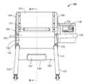
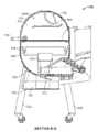
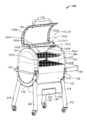
도 1은 본 개시의 교시에 따라 구성된 예시적인 펠릿 그릴의 제 1 사시도이다.
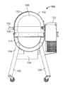
도 2는 도 1의 펠릿 그릴의 제 2 사시도이다.
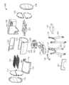
도 3은 도 1 및 도 2의 펠릿 그릴의 분해도이다.
도 4는 도 1 내지 도 3의 펠릿 그릴의 정면도이다.
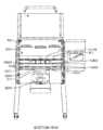
도 5는 도 1 내지 도 4의 펠릿 그릴의 배면도이다.
도 6은 도 1 내지 도 5의 펠릿 그릴의 제 1 측면도이다.
도 7은 도 1 내지 도 6의 펠릿 그릴의 제 2 측면도이다.
도 8은 도 1 내지 도 7의 펠릿 그릴의 평면도이다.
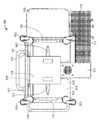
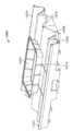
도 9는 도 1 내지 도 8의 펠릿 그릴의 저면도이다.
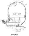
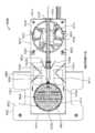
도 10은 도 8의 단면 A-A를 따라 취한 도 1 내지 도 9의 펠릿 그릴의 횡횡단면도가다.
도 11은 도 4의 단면 B-B를 따라 취한 도 1 내지 도 10의 펠릿 그릴의 횡횡단면도이다.
도 12는 예시적인 개방 위치에 펠릿 그릴의 리드가 있는 도 1 내지 도 11의 펠릿 그릴의 사시도이다.
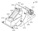
도 13은 예시적인 개방 위치에 펠릿 그릴의 폐기물 수거함이 있는 도 1 내지 12의 펠릿 그릴의 사시도이다.
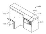
도 14는 도 1 내지 도 13의 펠릿 그릴의 호퍼의 사시도이다.
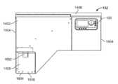
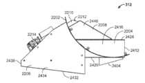
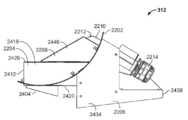
도 15는 예시적인 개방 위치에 호퍼의 리드가 있는 도 14의 호퍼의 사시도이다.
도 16은 도 14 및 15의 호퍼의 정면도이다.
도 17은 도 14-16의 호퍼의 배면도이다.
도 18은 도 14-17의 호퍼의 제 1 측면도이다.
도 19는 도 14-18의 호퍼의 제 2 측면도이다.
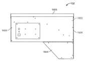
도 20은 도 14-19의 호퍼의 평면도이다.
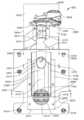
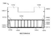
도 21은 도 20의 단면 C-C를 따라 취한 도 14-20의 호퍼의 횡횡단면도이다.
도 22는 도 1-13의 펠릿 그릴의 엔진의 제 1 사시도이다.
도 23은 도 22의 엔진의 제 2 사시도이다.
도 24a 및 24b는 도 22 및 도 23의 엔진의 분해도이다.
도 25는 도 22-24의 엔진의 제 1 측면도이다.
도 26은 도 22-25의 엔진의 제 2 측면도이다.
도 27은 도 22-26의 엔진의 정면도이다.
도 28은 도 27의 단면 D-D를 따라 취한 도 22-27의 엔진의 횡단면도이다.
도 29는 도 22-28의 엔진의 평면도이다.
도 30은 도 29의 단면 E-E를 따라 취한 도 22-29의 엔진의 횡단면도이다.
도 31은 도 22-30의 엔진의 연소 포트의 제 1 사시도이다.
도 32는 도 31의 연소 포트의 제 2 사시도이다.
도 33은 도 31 및 도 32의 연소 포트의 분해도이다.
도 34는 도 31-33의 연소 포트의 배면도이다. .
도 35는 도 31-34의 연소 포트의 측면도이다.
도 36은 도 31-35의 연소 포트의 평면도이다.
도 37은 도 31-36의 연소 포트의 저면도이다.
도 38은 도 34의 단면 F-F를 따라 취한 도 31-37의 연소 포트의 횡단면도이다.
도 39는 도 36의 단면 G-G를 따라 취한 도 도 31-38의 연소 포트의 횡단면도이다.
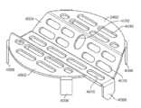
도 40은 도 31-39의 연소 포트의 연료 그레이트의 사시도이다.
도 41은 도 40의 연료 그레이트의 측면도이다.
도 42는 도 1-13의 펠릿 그릴의 히트 디퓨저의 사시도이다.
도 43은 도 42의 히트 디퓨저의 정면도이다.
도 44는 도 42 및 도 43의 히트 디퓨저의 측면도이다.
도 45는 도 42-44의 히트 디퓨저의 평면도이다.
도 46은 도 45의 단면 H-H를 따라 취한 도 42-45의 히트 디퓨저의 횡단면도이다.
도 47은 도 45의 단면 I-I를 따라 취한 도 42-46의 히트 디퓨저의 횡단면도이다.
도 48은 도 22-39의 연소 포트 위에 위치한 도 42-47의 히트 디퓨저의 사시도이다.
도 49는 도 22-39의 연소 포트 위에 위치한 도 42-47의 히트 디퓨저의 평면도이다.
도 50은 도 49의 J-J 단면을 따라 취한 도 22-39의 연소 포트 위에 위치한 도 42-47의 히트 디퓨저의 횡단면도이다.
도 51은 도 22-39의 연소 포트 위에 위치한 도 42-47의 히트 디퓨저의 정면도이다.
도 52는 도 51의 단면 K-K를 따라 취한 도 22-39의 연소 포트 위에 위치한 도 42-47의 히트 디퓨저의 횡단면도이다.
도 53은 도 22-30의 엔진에 대해 위치한 도 42-47의 히트 디퓨저의 사시도이다.
도 54는 그리스 디플렉션 바 어셈블리(grease deflection bar assembly)를 도시한 도 1-13의 펠릿 그릴의 부분 절결도이다.
도 55는 도 54의 그리스 디플렉션 바 어셈블리의 사시도이다.
도 56은 도 54 및 55의 그리스 디플렉션 바 어셈블리의 평면도이다.
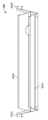
도 57은 도 54-56의 그리스 디플렉션 바의 정면도이다.
도 58은 도 54-57의 그리스 디플렉션 바 어셈블리의 측면도이다.
도 59는 도 42-53의 히트 디퓨저 및 도 22-39의 연소 포트 위에 위치한 도 54-58의 그리스 디플렉션 바 어셈블리의 정면도이다.
도 60은 도 42-53의 히트 디퓨저 및 도 22-39의 연소 포트 위에 위치한 도 54-58의 그리스 디플렉션 바 어셈블리의 측면도이다.
도 61은 숨은 선들로 도시된, 도 42-53의 히트 디퓨저 및 도 22-39의 연소 포트 위에 위치한, 도 54-58의 그리스 디플렉션 바 어셈블리의 정면도이다.
도 62는 숨은 선들로 도시된, 도 42-53의 히트 디퓨저 및 도 22-39의 연소 포트 위에 위치한, 도 54-58의 그리스 디플렉션 바 어셈블리의 측면도이다.
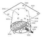
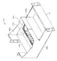
도 63은 도 1-13의 펠릿 그릴의 폐기물 수거함의 사시도이다.
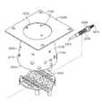
도 64는 도 63의 폐기물 수거함의 분해도이다.
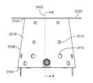
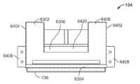
도 65는 도 63 및 도 64의 폐기물 수거함의 정면도이다.
도 66은 도 63-65의 폐기물 수거함의 배면도이다.
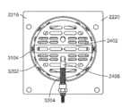
도 67은 도 63-66의 폐기물 수거함의 평면도이다.
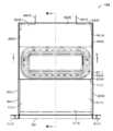
도 68은 도 67의 단면 L-L을 따라 취한 도 63-67의 폐기물 수거함의 횡단면도이다.
도 69는 도 67의 단면 M-M을 따라 취한 도 63-68의 폐기물 수거함의 횡단면도이다.
도 70은 도 63-69의 폐기물 수거함이 예시적인 폐쇄 위치에서 본체 아래에 있는 도 1-13의 펠릿 그릴의 일부의 정면도이다.
도 71은 도 70의 단면 N-N을 따라 취한 도 70의 횡단면도이다.
도 72는 도 1-13의 펠릿 그릴의 일부의 정면도로서, 다른 폐기물 수거함이 예시적인 폐쇄 위치에서 본체 아래에 있다.
도 73은 도 72의 단면 O-O를 따라 취한 도 72의 횡단면도이다.
도 74는 펠릿 그릴 리드의 힌지가 예시적인 개방 위치에 있는 도 1-13의 펠릿 그릴의 사시도이다.
도 75는 도 74의 일부 확대도이다.
도 76은 펠릿 그릴 리드의 힌지가 예시적인 개방 위치에 있는 도 1-13의 펠릿 그릴의 정면도이다.
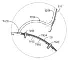
도 77은 도 76의 단면 P-P를 따라 취한 도 76의 횡단면도이다.
도 78은 도 76의 단면 Q-Q를 따라 취한 도 76의 횡단면도이다.
도 79는 도 76의 단면 R-R을 따라 취한 도 76의 횡단면도이다.
도 80은 도 78의 일부 확대도이다.
도 81은 도 79의 일부 확대도이다.
도 82는 도 1-13의 펠릿 그릴과 관련하여 구현될 예시적인 제어 시스템의 블록도이다.
도 83은 도 82의 제어 시스템을 통해 오거 잼 감지 프로토콜 및/또는 프로세스를 구현하기 위한 예시적인 방법을 나타내는 흐름도이다.
도 84는 도 82의 제어 시스템을 통해 리드 이동 감지 프로토콜 및/또는 프로세스를 구현하기 위한 예시적인 방법을 나타내는 흐름도이다.
도 85는 도 82의 제어 시스템을 통해 플레임 아웃(flame out) 프로토콜 및/또는 프로세스를 구현하기 위한 예시적인 방법을 나타내는 흐름도이다.
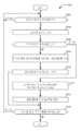
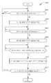
도 86은 도 82의 제어 시스템을 통해 연료 부족 감지 프로토콜 및/또는 프로세스를 구현하기 위한 예시적인 방법을 나타내는 흐름도이다.
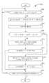
도 87a 및 87b는 도 82의 제어 시스템을 통해 조리 종료 감지 프로토콜 및/또는 프로세스를 구현하기 위한 예시적인 방법을 나타내는 흐름도이다.
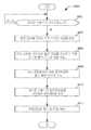
도 88은 도 82의 제어 시스템을 통해 셧다운 프로토콜 및/또는 프로세스를 구현하기 위한 예시적인 방법을 나타내는 흐름도이다.
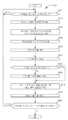
도 89는 도 82의 제어 시스템을 통해 부적절한 제 1 셧다운 감지 프로토콜 및/또는 프로세스를 구현하기 위한 예시적인 방법을 나타내는 흐름도이다.
도 90은 도 82의 제어 시스템을 통해 부적절한 제 2 셧다운 감지 프로토콜 및/또는 프로세스를 구현하기 위한 예시적인 방법을 나타내는 흐름도이다.
도 91은 도 82의 제어 시스템을 통해 점화기 듀티 사이클 감지 프로토콜 및/또는 프로세스를 구현하기 위한 예시적인 방법을 나타내는 흐름도이다.
도 92는 도 82의 제어 시스템을 통해 폐기물 수거함 듀티 사이클 감지 프로토콜 및/또는 프로세스를 구현하기 위한 예시적인 방법을 나타내는 흐름도이다.
도 93은 도 1-13의 펠릿 그릴의 다른 예시적인 엔진의 제 1 사시도이다.
도 94는 도 93의 엔진의 제 2 사시도이다.
도 95a 및 95b는 도 93 및 도 94의 엔진의 분해도이다.
도 96은 도 93-95의 엔진의 제 1 측면도이다.
도 97은 도 93-96의 엔진의 제 2 측면도이다.
도 98은 도 93-97의 엔진의 정면도이다.
도 99는 도 98의 단면 S-S를 따라 취한 도 93-98의 엔진의 횡단면도이다.
도 100은 도 93-99의 엔진의 평면도이다.
도 101은 도 100의 단면 T-T를 따라 취한 도 93-100의 엔진의 횡단면도이다.
도 102는 도 97의 U-U를 따라 취한 도 93-101의 엔진의 횡단면도이다.
도 103은 도 1-13의 펠릿 그릴의 그리스 디플렉션 바 어셈블리의 대안적인 예시의 사시도이다.
도 104는 도 1-13의 펠릿 그릴 내에 위치한 도 103의 그리스 디플렉션 바 어셈블리의 평면도이다.
도 105는 도 104의 단면 V-V를 따라 취한 도 103 및 도 104의 그리스 디플렉션 바 어셈블리의 횡단면도이다.
도 106은 도 104의 단면 W-W를 따라 취한 도 103-105의 그리스 디플렉션 바 어셈블리의 횡단면도이다.
도 107은 도 1-13의 펠릿 그릴의 다른 예시적인 폐기물 수거함의 사시도이다.
도 108은 도 107의 폐기물 수거함의 분해도이다.
도 109는 도 107 및 도 108의 폐기물 수거함의 정면도이다.
도 110은 도 107-109의 폐기물 수거함의 배면도이다.
도 111은 도 107-110의 폐기물 수거함의 평면도이다.
도 112는 도 111의 X-X 단면을 따라 취한 도 107-111의 폐기물 수거함의 횡단면도이다.
도 113은 도 111의 단면 Y-Y를 따라 취한 도 107-112의 폐기물 수거함의 횡단면도이다.
특정 예가 상기의 식별된 도면에 도시되고 아래에서 상세히 설명된다. 이러한 예를 설명할 때, 같거나 동일한 참조번호는 동일하거나 유사한 요소를 식별하는 데 사용된다. 도면은 반드시 축척일 필요는 없으며 특정한 특징 및 도면의 특정 보기는 명확성 및/또는 간결성을 위해 축척 또는 개략적으로 과장되어 표시될 수 있다.
서술어 "제 1", "제 2", "제 3"등은 본 명세서에서 별도로 언급될 수 있는 여러 요소 또는 구성요소를 식별할 때 사용된다. 사용 문맥을 기초로 달리 명시되거나 이해되지 않는 한, 그러한 서술어는 우선 순위 또는 시간 순서의 어떤 의미를 전가하려는 것이 아니라 개시된 예를 이해하기 쉽도록 여러 요소 또는 구성요소를 개별적으로 참조하기 위한 라벨로만 사용된다. 일부 예에서, 서술어 "제 1"은 상세한 설명에서 한 요소를 지칭하기 위해 사용될 수 있는 반면, 동일한 요소는 "제 2" 또는 "제 3"과 같은 다른 서술어와 함께 청구항에 인용될 수 있다. 그러한 경우에, 그러한 서술어는 단지 여러 요소 또는 구성요소를 쉽게 참조하기 위해 사용된다는 것을 이해해야 한다.1 is a first perspective view of an exemplary pellet grill constructed in accordance with the teachings of this disclosure;
FIG. 2 is a second perspective view of the pellet grill of FIG. 1 ;
3 is an exploded view of the pellet grill of FIGS. 1 and 2 .
Figure 4 is a front view of the pellet grill of Figures 1 to 3;
Figure 5 is a rear view of the pellet grill of Figures 1 to 4;
Fig. 6 is a first side view of the pellet grill of Figs. 1-5;
7 is a second side view of the pellet grill of FIGS. 1 to 6 ;
8 is a plan view of the pellet grill of FIGS. 1 to 7 ;
9 is a bottom view of the pellet grill of FIGS. 1 to 8 .
Fig. 10 is a cross-sectional view of the pellet grill of Figs. 1-9 taken along section AA of Fig. 8;
Fig. 11 is a cross-sectional view of the pellet grill of Figs. 1-10 taken along section BB of Fig. 4;
12 is a perspective view of the pellet grill of FIGS. 1-11 with the lid of the pellet grill in an exemplary open position;
13 is a perspective view of the pellet grill of FIGS. 1-12 with the waste bin of the pellet grill in an exemplary open position;
14 is a perspective view of the hopper of the pellet grill of FIGS. 1 to 13;
15 is a perspective view of the hopper of FIG. 14 with the lid of the hopper in an exemplary open position;
16 is a front view of the hopper of FIGS. 14 and 15;
17 is a rear view of the hopper of FIGS. 14-16;
Fig. 18 is a first side view of the hopper of Figs. 14-17;
Figure 19 is a second side view of the hopper of Figures 14-18;
20 is a plan view of the hopper of FIGS. 14-19;
Figure 21 is a cross-sectional view of the hopper of Figures 14-20 taken along section CC of Figure 20;
22 is a first perspective view of the engine of the pellet grill of FIGS. 1-13;
Fig. 23 is a second perspective view of the engine of Fig. 22;
24A and 24B are exploded views of the engine of FIGS. 22 and 23 ;
Fig. 25 is a first side view of the engine of Figs. 22-24;
Figure 26 is a second side view of the engine of Figures 22-25;
Fig. 27 is a front view of the engine of Figs. 22-26;
Fig. 28 is a cross-sectional view of the engine of Figs. 22-27 taken along section DD of Fig. 27;
29 is a plan view of the engine of FIGS. 22-28;
30 is a cross-sectional view of the engine of FIGS. 22-29 taken along section EE of FIG. 29 ;
31 is a first perspective view of a combustion port of the engine of FIGS. 22-30;
FIG. 32 is a second perspective view of the combustion port of FIG. 31 ;
33 is an exploded view of the combustion port of FIGS. 31 and 32;
Figure 34 is a rear view of the combustion port of Figures 31-33; .
Figure 35 is a side view of the combustion port of Figures 31-34;
Fig. 36 is a top view of the combustion port of Figs. 31-35;
Figure 37 is a bottom view of the combustion port of Figures 31-36;
FIG. 38 is a cross-sectional view of the combustion port of FIGS. 31-37 taken along section FF of FIG. 34 ;
Fig. 39 is a cross-sectional view of the combustion port of Figs. 31-38 taken along section GG of Fig. 36;
40 is a perspective view of the fuel grate of the combustion port of FIGS. 31-39;
FIG. 41 is a side view of the fuel grate of FIG. 40;
42 is a perspective view of the heat diffuser of the pellet grill of FIGS. 1-13;
43 is a front view of the heat diffuser of FIG. 42 .
44 is a side view of the heat diffuser of FIGS. 42 and 43 ;
45 is a plan view of the heat diffuser of FIGS. 42-44;
Figure 46 is a cross-sectional view of the heat diffuser of Figures 42-45 taken along section HH of Figure 45;
47 is a cross-sectional view of the heat diffuser of FIGS. 42-46 taken along section II of FIG. 45 ;
FIG. 48 is a perspective view of the heat diffuser of FIGS. 42-47 positioned above the combustion port of FIGS. 22-39;
49 is a plan view of the heat diffuser of FIGS. 42-47 positioned above the combustion port of FIGS. 22-39;
FIG. 50 is a cross-sectional view of the heat diffuser of FIGS. 42-47 positioned over the combustion port of FIGS. 22-39 taken along section JJ of FIG. 49 ;
Figure 51 is a front view of the heat diffuser of Figures 42-47 positioned above the combustion port of Figures 22-39;
52 is a cross-sectional view of the heat diffuser of FIGS. 42-47 positioned over the combustion port of FIGS. 22-39 taken along section KK of FIG. 51 ;
53 is a perspective view of the heat diffuser of FIGS. 42-47 positioned relative to the engine of FIGS. 22-30;
54 is a partial cut-away view of the pellet grill of FIGS. 1-13 showing the grease deflection bar assembly;
FIG. 55 is a perspective view of the grease deflection bar assembly of FIG. 54;
56 is a plan view of the grease deflection bar assembly of FIGS. 54 and 55;
57 is a front view of the grease deflection bar of FIGS. 54-56;
58 is a side view of the grease deflection bar assembly of FIGS. 54-57;
59 is a front view of the grease deflection bar assembly of FIGS. 54-58 positioned over the heat diffuser of FIGS. 42-53 and the combustion port of FIGS. 22-39;
60 is a side view of the grease deflection bar assembly of FIGS. 54-58 positioned over the heat diffuser of FIGS. 42-53 and the combustion port of FIGS. 22-39;
Figure 61 is a front view of the grease deflection bar assembly of Figures 54-58, positioned over the heat diffuser of Figures 42-53 and the combustion port of Figures 22-39, shown in hidden lines;
62 is a side view of the grease deflection bar assembly of FIGS. 54-58 positioned over the heat diffuser of FIGS. 42-53 and the combustion port of FIGS. 22-39, shown in hidden lines;
63 is a perspective view of the waste bin of the pellet grill of FIGS. 1-13;
64 is an exploded view of the waste collection box of FIG. 63;
65 is a front view of the waste collection box of FIGS. 63 and 64;
FIG. 66 is a rear view of the waste container of FIGS. 63-65;
67 is a plan view of the waste bin of FIGS. 63-66;
68 is a cross-sectional view of the waste bin of FIGS. 63-67 taken along section LL of FIG. 67;
69 is a cross-sectional view of the waste bin of FIGS. 63-68 taken along section MM of FIG. 67;
70 is a front view of a portion of the pellet grill of FIGS. 1-13 with the waste bin of FIGS. 63-69 below the body in the exemplary closed position;
71 is a cross-sectional view of FIG. 70 taken along section NN of FIG. 70 ;
FIG. 72 is a front view of a portion of the pellet grill of FIGS. 1-13 , with another waste bin below the body in an exemplary closed position;
73 is a cross-sectional view of FIG. 72 taken along section OO of FIG. 72 ;
74 is a perspective view of the pellet grill of FIGS. 1-13 with the hinges of the pellet grill lid in an exemplary open position;
FIG. 75 is a partially enlarged view of FIG. 74 .
76 is a front view of the pellet grill of FIGS. 1-13 with the hinges of the pellet grill lid in an exemplary open position;
77 is a cross-sectional view of FIG. 76 taken along section PP of FIG.
78 is a cross-sectional view of FIG. 76 taken along section QQ of FIG. 76;
79 is a cross-sectional view of FIG. 76 taken along section RR of FIG. 76 ;
FIG. 80 is a partially enlarged view of FIG. 78 .
81 is a partially enlarged view of FIG.
82 is a block diagram of an exemplary control system to be implemented in connection with the pellet grill of FIGS. 1-13;
83 is a flow diagram illustrating an exemplary method for implementing an auger jam detection protocol and/or process via the control system of FIG. 82 .
84 is a flow diagram illustrating an exemplary method for implementing a lead movement detection protocol and/or process via the control system of FIG. 82 .
85 is a flow diagram illustrating an exemplary method for implementing a flame out protocol and/or process via the control system of FIG. 82 .
86 is a flow diagram illustrating an exemplary method for implementing a low fuel detection protocol and/or process via the control system of FIG. 82 .
87A and 87B are flow diagrams illustrating an exemplary method for implementing an end-of-cook detection protocol and/or process via the control system of FIG. 82 ;
88 is a flow diagram illustrating an exemplary method for implementing a shutdown protocol and/or process via the control system of FIG. 82 .
89 is a flow diagram illustrating an exemplary method for implementing an improper first shutdown detection protocol and/or process via the control system of FIG. 82 ;
FIG. 90 is a flow diagram illustrating an exemplary method for implementing an improper second shutdown detection protocol and/or process via the control system of FIG. 82 .
91 is a flow diagram illustrating an exemplary method for implementing an igniter duty cycle sensing protocol and/or process via the control system of FIG. 82 .
92 is a flow diagram illustrating an exemplary method for implementing a waste bin duty cycle sensing protocol and/or process via the control system of FIG. 82 .
93 is a first perspective view of another exemplary engine of the pellet grill of FIGS. 1-13;
94 is a second perspective view of the engine of FIG. 93;
95A and 95B are exploded views of the engine of FIGS. 93 and 94 ;
96 is a first side view of the engine of FIGS. 93-95;
97 is a second side view of the engine of FIGS. 93-96;
98 is a front view of the engine of FIGS. 93-97;
99 is a cross-sectional view of the engine of FIGS. 93-98 taken along section SS of FIG. 98 ;
100 is a plan view of the engine of FIGS. 93-99;
FIG. 101 is a cross-sectional view of the engine of FIGS. 93-100 taken along section TT of FIG. 100 ;
102 is a cross-sectional view of the engine of FIGS. 93-101 taken along UU of FIG. 97;
103 is a perspective view of an alternative example of the grease deflection bar assembly of the pellet grill of FIGS. 1-13;
104 is a top view of the grease deflection bar assembly of FIG. 103 positioned within the pellet grill of FIGS. 1-13;
105 is a cross-sectional view of the grease deflection bar assembly of FIGS. 103 and 104 taken along section VV of FIG. 104 ;
106 is a cross-sectional view of the grease deflection bar assembly of FIGS. 103-105 taken along section WW of FIG. 104 ;
107 is a perspective view of another exemplary waste bin of the pellet grill of FIGS. 1-13;
108 is an exploded view of the waste collection box of FIG. 107;
109 is a front view of the waste collection box of FIGS. 107 and 108;
110 is a rear view of the waste container of FIGS. 107-109;
111 is a plan view of the waste collection box of FIGS. 107-110;
112 is a cross-sectional view of the waste bin of FIGS. 107-111 taken along section XX of FIG. 111 ;
113 is a cross-sectional view of the waste bin of FIGS. 107-112 taken along section YY of FIG. 111 ;
Specific examples are shown in the figures identified above and are described in detail below. In describing these examples, like or identical reference numbers are used to identify identical or similar elements. The drawings are not necessarily to scale and certain features and certain views of the drawings may be shown to scale or schematically exaggerated for clarity and/or brevity.
The predicates “first,” “second,” “third,” and the like are used herein to identify various elements or components that may be referred to separately. Unless otherwise specified or understood based on the context of use, such predicates are not intended to imply any meaning of precedence or chronological order, but are only used as labels to individually refer to the various elements or components to facilitate understanding of the disclosed examples. do. In some instances, the predicate “first” may be used to refer to an element in the specification, while the same element may be recited in a claim along with another predicate such as “second” or “third”. In such cases, it should be understood that such predicates are only used to readily refer to the various elements or components.
본 명세서에 개시된 예시적인 펠릿 그릴은 종래의 펠릿 그릴에 비해 많은 이점을 제공하는 특징을 포함한다. 일례로서, 개시된 펠릿 그릴은 측벽이 연소 포트의 하부(예를 들어, 하단)면으로부터 연소 포트의 상부(예를 들어, 상단)면으로 전개함에 따라 연소 포트의 중심축을 향해 내측으로 테이퍼지는 연소 포트를 포함한다. 일부 예에서, 연소 포트는 상기 연소 포트의 내측으로 테이퍼진 측벽에 의해 부분적으로 정의된 원추형 형상을 갖는다. 내측으로 테이퍼진 측벽은 연소된 펠릿 연료에 의해 연소 포트 내에서 생산 및/또는 발생된 열을 집중 및/또는 가운데 모아, 이로써 연소 포트에 걸쳐 더 높은 조리 온도의 생산, 발생 및/또는 출력을 이점적으로 가능하게 한다. 내측으로 테이퍼진 측벽은 또한 (예를 들어, 펠릿 연료의 연소 및/또는 소각 중에 발생될 수 있는) 재가 연소 포트로부터 위로 빠져 나와 펠릿 그릴의 조리실로 들어갈 가능성을 유리하게 제한 및/또는 감소시킨다.The exemplary pellet grills disclosed herein include features that provide many advantages over conventional pellet grills. As an example, the disclosed pellet grill is a combustion port that tapers inwardly toward a central axis of the combustion port as the sidewall develops from a lower (eg, bottom) side of the combustion port to an upper (eg, top) side of the combustion port. includes In some examples, the combustion port has a conical shape defined in part by an inwardly tapered sidewall of the combustion port. The inwardly tapered sidewalls concentrate and/or centralize heat produced and/or generated within the combustion port by the burned pellet fuel, thereby advantageously producing, generating and/or outputting higher cooking temperatures across the combustion port. make it possible The inwardly tapered sidewalls also advantageously limit and/or reduce the likelihood that ash (which may, for example, be generated during combustion and/or incineration of the pellet fuel) escapes upward from the combustion port and enters the galley of the pellet grill.
다른 예로서, 개시된 펠릿 그릴은 연소 포트의 하부(예를 들어, 하단)면을 향해 배치 및/또는 위치된 연료 그레이트(fuel grate)를 갖는 연소 포트를 포함한다. 연료 그레이트는 아직 연소되지 않은 펠릿 연료를 보유 및/또는 지지하도록 구성된(예를 들어 크기가 정해진, 형상된 및/또는 배열된) 복수의 개구(예를 들어, 슬롯 및/또는 홀)를 포함한다. 연료 그레이트에 의해 지지된 펠릿 연료가 연소 및/또는 소각됨에 따라, 연소 및/또는 소각 중에 생성 및/또는 발생된 재가 연료 그레이트의 개구를 통해 애쉬 슬라이드 및/또는 재 수거통로 떨어진다. 연료 그레이트는 유리하게는 연소 포트로부터 (예를 들어, 펠릿 연료의 연소 및/또는 소각 중에 생성 및/또는 발생될 수 있는 바와 같이) 재가 아래로 (예를 들어, 연료 그레이트의 개구를 통해) 통과하는 것을 용이하게 하며, 이는 차례로 재가 연소 포트에서 위쪽으로 빠져 나와 펠릿 그릴의 조리실로 들어갈 가능성을 감소시킨다.As another example, the disclosed pellet grill includes a combustion port having a fuel grate disposed and/or positioned toward a lower (eg, bottom) face of the combustion port. The fuel grate includes a plurality of openings (eg, slots and/or holes) configured (eg, sized, shaped, and/or arranged) to hold and/or support unburned pellet fuel. . As the pellet fuel supported by the fuel grate is combusted and/or incinerated, the ash produced and/or generated during the combustion and/or incineration falls through the opening of the fuel grate to the ash slide and/or the ash collection path. The fuel grate advantageously passes from the combustion port (eg, as may be generated and/or generated during combustion and/or incineration of the pellet fuel) ash down (eg through an opening in the fuel grate) This in turn reduces the likelihood of ash exiting the combustion pot upwards and entering the pellet grill's galley.
일부 예에서, 연소 포트의 연료 그레이트는 연료 그레이트의 중앙 위치 및/또는 장소를 향해 및/또는 내에 연소 포트에 넣어진 펠릿 연료를 한곳에 집중, 유도 및/또는 수집하도록 구성된 트로프(trough)를 더 포함한다. 일부 예에서, 점화기가 트로프로 전개된다. 이러한 예에서, 연료 그레이트의 트로프는 유리하게는 연료 그레이트의 중앙 위치 및/또는 장소를 향해 및/또는 그 내에서 펠릿 연료를 유도 및/또는 수집하여, 이로써 수집된 펠릿 연료가 점화기에 인접하고/하거나 점화기와 접촉하게 배치되도록 한다. 상술한 바와 같이 트로프 내에 펠릿 연료를 가운데 모으고/모으거나 국지화함으로써 펠릿 연료의 연소 시작 및/또는 개시가 유리하다. 상술한 바와 같이 트로프 내에 펠릿 연료를 가운데 모으고/모으거나 국지화함으로써 또한 연소 포트가 상대적으로 적은 양의 펠릿 연료를 포함하는 저온 조리 작업(예를 들어, 훈제)에도 유리하다.In some examples, the fuel grate of the combustion port further comprises a trough configured to centralize, direct, and/or collect pellet fuel loaded into the combustion port towards and/or within a central location and/or location of the fuel grate. do. In some examples, the igniter is deployed into a trough. In this example, the trough of the fuel grate advantageously guides and/or collects the pellet fuel towards and/or within a central location and/or location of the fuel grate such that the collected pellet fuel is adjacent to the igniter and/or or placed in contact with the igniter. It is advantageous to initiate and/or initiate combustion of the pellet fuel by centralizing and/or localizing the pellet fuel in the trough as described above. Centering and/or localizing the pellet fuel in the trough as described above is also advantageous for low temperature cooking operations (eg, smoking) where the combustion port contains a relatively small amount of pellet fuel.
다른 예로서, 개시된 펠릿 그릴은 측벽이 그 내부에 형성된 개구를 포함하는 연소 포트를 포함하고, 상기 개구는 점화기를 슬라이딩 가능하게 수용하도록 구성된다(예를 들어, 크기 지정, 형상 및/또는 배열된다).일부 예에서, 점화기는 (예를 들어, 사용자에 의해) 연소 포트로 미끄러질 수 있고/있거나 연소 포트의 측벽에 형성된 개구를 통해 연소 포트로부터 제거될 수 있다. 일부 예에서, 상술한 연료 그레이트의 트로프는 연소 포트의 측벽에 형성된 개구와 정렬된 개구를 포함하여, 이로써 점화기가 연소 포트의 측벽에 형성된 개구를 통해 그리고 또한 트로프에 형성된 개구를 통해 트로프 안으로 미끄러질 수 있도록 한다. 일부 예에서, 점화기는 연소 포트로부터 후방으로 전개되고 그에 대해 (예를 들어, 연소 포트를 향해 및/또는 연소 포트에서 멀리) 슬라이딩 가능한 점화기 캐리어에 의해 운반 및/또는 지지된다. 일부 예에서, 점화기 캐리어는 펠릿 그릴의 후면에서 (예를 들어, 후면 장착된 호퍼의 접근 도어를 통해) 펠릿 그릴의 사용자가 접근할 수 있으며, 이에 따라 사용자가 점화기 캐리어를 통해 연소 포트의 측벽에 형성된 개구 안팎으로 점화기를 슬라이딩 및/또는 가이드할 수 있다.As another example, the disclosed pellet grill includes a combustion port having a sidewall comprising an opening formed therein, the opening configured (eg, sized, shaped, and/or arranged to slidably receive an igniter). ). In some examples, the igniter may be slid into the combustion port (eg, by a user) and/or may be removed from the combustion port through an opening formed in a sidewall of the combustion port. In some examples, the trough of the fuel grate described above includes an opening aligned with an opening formed in the sidewall of the combustion port such that the igniter can slide into the trough through the opening formed in the sidewall of the combustion port and also through the opening formed in the trough. let it be In some examples, the igniter is carried and/or supported by an igniter carrier that deploys rearward from the combustion port and is slidable relative thereto (eg, towards and/or away from the combustion port). In some examples, the igniter carrier is accessible to a user of the pellet grill from the rear of the pellet grill (eg, via an access door of a back mounted hopper), such that a user can access the sidewall of the combustion port through the igniter carrier It is possible to slide and/or guide the igniter in and out of the formed opening.
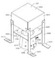
다른 예로서, 개시된 펠릿 그릴은 개방된 하단, 4 개의 폐쇄된 측벽 및 폐쇄된 상단을 갖는 직사각형 박스형 히트 디퓨저를 포함한다. 히트 디퓨저는 펠릿 그릴의 연소 포트 위의 중앙 위치 및/또는 장소에서 펠릿 그릴 내부에 위치 및/또는 배치된다. 일부 예에서, 히트 디퓨저의 중심축은 연소 포트의 중심축과 동축으로 정렬된다. 히트 디퓨저는 연소 포트로부터 발산 및/또는 그에 의해 출력되는 열을 수용하고, 유리하게는 펠릿 그릴의 조리실 전체에 수용된 열의 분포를 최적화하도록 구성된다(예를 들어, 연소 포트에 대해 크기 정해진, 형상된 및/또는 배치된다). 연소 포트에 대한 히트 디퓨저의 크기, 모양 및/또는 위치는 또한 유리하게는 (예를 들어, 펠릿 연료의 연소 및/또는 소각 중에 생성 및/또는 발생될 수 있는) 어떤 재가 펠릿 그릴의 조리실로 들어갈 가능성을 제한 및/또는 감소시킨다.As another example, the disclosed pellet grill includes a rectangular box-shaped heat diffuser having an open bottom, four closed sidewalls and a closed top. The heat diffuser is positioned and/or disposed within the pellet grill at a central location and/or location above the combustion port of the pellet grill. In some examples, the central axis of the heat diffuser is coaxially aligned with the central axis of the combustion port. The heat diffuser is configured to receive heat radiated from and/or output thereby from the combustion port, and advantageously optimize the distribution of heat received throughout the galley of the pellet grill (e.g., sized, shaped with respect to the combustion port). and/or disposed). The size, shape and/or location of the heat diffuser relative to the combustion port also advantageously determines which ash (which may be generated and/or generated during combustion and/or incineration of the pellet fuel, for example) will enter the galley of the pellet grill. Limits and/or reduces possibilities.
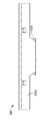
또 다른 예로서, 개시된 펠릿 그릴은 전면랙 및 후면랙 사이에 뻗어 있는 제 1(예를 들어, 큰) 그리스 디플렉션 바, 및 상기 제 1 그리스 디플렉션 바와 측면으로 이격된 위치에서 전면랙 및 후면랙 사이에 뻗어 있는 하나 이상의 제 2(예를 들어, 작은) 그리스 디플렉션 바를 수용하도록 구성된(예를 들어, 크기가 정해진, 형상된 및/또는 배치된) 전면랙과 후면랙을 갖는 그리스 디플렉션 바와(가령, FLAVORIZER® 바)를 포함한다. 일부 예에서, 제 1 그리스 디플렉션 바는 히트 디퓨저 위의 및/또는 펠릿 그릴의 연소 포트 위의 중앙 위치 및/또는 장소에서 펠릿 그릴 내에 위치 및/또는 배치된다. 제 1 그리스 디플렉션 바는 히트 디퓨저의 측면 범위 및/또는 연소 포트의 측면 범위와 동일 및/또는 그보다 큰 측면 범위를 갖는다. 제 1 그리스 디플렉션 바는 유리하게 (예를 들어, 제 1 그리스 디플렉션 바 위에 위치된 쿠킹 그레이트에서 조리되는 음식으로부터 제 1 그리스 디플렉션 바에 수용될 수 있는) 그리스를 펠릿 그릴의 조리실의 하단에 형성된 하나 이상의 그리스 슬롯(들)로 향하게 한다. 제 1 그리스 디플렉션 바의 측면 범위는 유리하게는 그리스가 히트 디퓨저 및/또는 연소 포트에 접촉 및/또는 들어갈 가능성을 제한 및/또는 감소시킨다. 일부 예에서, 그리스 디플렉션 바 어셈블리의 다양한 구성요소는 임의의 기계식 체결부를 제거할 필요없이 펠릿 그릴에서 제거될 수 있으며, 이에 따라 제 1 및 제 2 그리스 디플렉션 바 및/또는 전면랙 및 후면랙이 청소 및/또는 교체될 수 있는 용이성을 향상 및/또는 그렇지 않으면 그리스 디플렉션 바 어셈블리의 구성요소에 의해 방해를 받을 수 있는 펠릿 그릴의 조리실의 부분에 사용자가 접근할 수 있는 용이성을 향상시킬 수 있다.As yet another example, the disclosed pellet grill includes a first (eg, large) grease deflection bar extending between the front and rear racks, and the first grease deflection bar at a position laterally spaced apart from the front and rear racks. Grease deflection having a front rack and a rear rack configured (eg, sized, shaped, and/or positioned) to receive one or more second (eg, small) grease deflection bars extending between the racks. bars (eg, FLAVORIZER® bars). In some examples, the first grease deflection bar is positioned and/or disposed within the pellet grill at a central location and/or location above the heat diffuser and/or above the combustion port of the pellet grill. The first grease deflection bar has a lateral extent equal to and/or greater than a lateral extent of the heat diffuser and/or a lateral extent of the combustion port. The first grease deflection bar advantageously deposits grease (eg, that may be received in the first grease deflection bar from food being cooked in a cooking grate positioned above the first grease deflection bar) to the bottom of the galley of the pellet grill. one or more grease slot(s) formed. The lateral extent of the first grease deflection bar advantageously limits and/or reduces the likelihood that grease will contact and/or enter the heat diffuser and/or combustion port. In some examples, the various components of the grease deflection bar assembly may be removed from the pellet grill without the need to remove any mechanical fasteners, such that the first and second grease deflection bars and/or the front and rear racks This may improve the ease with which they can be cleaned and/or replaced and/or the ease of user access to portions of the galley of the pellet grill that might otherwise be obstructed by components of the grease deflection bar assembly. have.
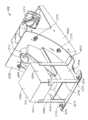
다른 예로서, 개시된 펠릿 그릴은 재 수거통 및 그리스 수거통을 포함하는 폐기물 수거함을 포함한다. 폐기물 수거함은 펠릿 그릴의 조리실 하단 아래에 위치 및/또는 배치되며, 폐쇄 위치와 개방 위치 사이에서 이동할 수 있다. 폐기물 수거함이 폐쇄 위치에 있을 때, 재 수거통은 펠릿 그릴의 연소 포트의 연료 그레이트 아래에(예를 들어, 수직 정렬로) 및/또는 연소 포트의 연료 그레이트 아래에 위치한 애쉬 슬라이드 아래에(예를 들어, 수직 정렬로) 위치 및/또는 배치되고, 그리스 수거통은 펠릿 그릴의 조리실의 하단에 형성된(예를 들어, 스탬핑된) 그리스 채널 아래에(예를 들어, 수직 정렬로) 위치 및/또는 배치된다. 따라서, 폐기물 수거함은 유리하게는 재 수거통에 재를 수집하고 그리스 수거통에 그리스를 수집하도록 구성된다(예를 들어, 크기가 정해지고, 형상되고/되거나 위치된다). 폐기물 수거함이 개방 위치에 있을 때, 각각의 내용물(예를 들어, 재 및/또는 그리스)을 제거 및/또는 폐기를 용이하게 하기 위해 재 수거통과 그리스 수거통을 폐기물 수거함에서 제거(예를 들어, 별개로 제거)할 수 있다.As another example, the disclosed pellet grill includes a waste bin comprising an ash bin and a grease bin. The waste bin is positioned and/or disposed below the bottom of the galley of the pellet grill and is movable between a closed position and an open position. When the waste bin is in the closed position, the ash bin is located below the fuel grate in the combustion port of the pellet grill (eg in a vertical alignment) and/or below the ash slide located below the fuel grate in the combustion port (eg , in vertical alignment) and/or disposed, and the grease container is positioned and/or disposed below (eg, in vertical alignment) a grease channel formed (eg stamped) at the bottom of the galley of the pellet grill. . Accordingly, the waste bin is advantageously configured (eg sized, shaped and/or positioned) to collect the ash in the ash bin and the grease in the grease bin. When the waste container is in the open position, the ash container and grease container are removed from the waste container (eg, separate can be removed).
다른 예로서, 개시된 펠릿 그릴은 펠릿 그릴의 작동 및/또는 사용에 유리한 다양한 감지 프로토콜 및/또는 프로세스를 구현, 관리 및/또는 제어하는 제어 시스템을 포함한다. 예를 들어, 펠릿 그릴의 제어 시스템은, 본 명세서에 더 설명되는 바와 같이, 오거 잼 감지 프로토콜 및/또는 프로세스, 리드 이동 감지 프로토콜 및/또는 프로세스, 플레임 아웃(flame out) 감지 프로토콜 및/또는 프로세스, 연료 부족 감지 프로토콜 및/또는 프로세스, 조리 종료 감지 프로토콜 및/또는 프로세스, 셧다운 프로토콜 및/또는 프로세스, 부적절한 셧다운 감지 프로토콜 및/또는 프로세스, 점화기 듀티 사이클 감지 프로토콜 및/또는 프로세스, 및/또는 폐기물 수거함 듀티 사이클 감지 프로토콜 및/또는 프로세스를 구현, 관리 및/또는 제어할 수 있다.As another example, the disclosed pellet grill includes a control system for implementing, managing, and/or controlling various sensing protocols and/or processes that are beneficial to the operation and/or use of the pellet grill. For example, a control system for a pellet grill may include an auger jam detection protocol and/or process, a lead movement detection protocol and/or process, a flame out detection protocol and/or process, as further described herein. , low fuel detection protocol and/or process, end-of-cook detection protocol and/or process, shutdown protocol and/or process, improper shutdown detection protocol and/or process, igniter duty cycle detection protocol and/or process, and/or waste bin Implement, manage, and/or control duty cycle sensing protocols and/or processes.
일부 예에서, 펠릿 그릴의 제어 시스템은 펠릿 그릴의 엔진의 오거 및/또는 오거 모터와 관련하여 오거 잼(jam) 감지 프로토콜 및/또는 프로세스를 구현, 관리 및/또는 제어한다. 제어 시스템은 (예를 들어, 확장, 팽창, 과대 포장 및/또는 기타 막힌 펠릿 연료로 인한) 오거의 잼을 감지하도록 구성된다. 일부 예에서, 오거의 잼은 제어 시스템에 의해 감지, 측정 및/또는 검출되는 오거 모터와 관련된 토크 부하의 증가에 기초하여 감지된다. 오거의 잼 감지에 응답하여, 제어 시스템은 오거 모터에 오거의 회전 방향(예를 들어, 시계 방향 회전에서 반시계 방향 회전으로 또는 그 반대로)을 변경(예를 들어, 역전)하여 유리하게 잼의 제거를 용이하게 한다. 일부 예에서, 제어 시스템은 오거 모터에 오거의 회전 방향을 1회 역회전하도록 명령한다. 다른 예들에서, 제어 시스템은 오거 모터가 제 1 회전 방향과 상기 제 1 회전 방향과 반대되는 제 2 회전 방향 사이에서 오거의 회전이 펄스되는 방식으로 오거의 기존 회전 방향을 자주 역전하도록 명령한다.In some examples, the control system of the pellet grill implements, manages and/or controls an auger jam detection protocol and/or process in connection with the auger and/or auger motor of the engine of the pellet grill. The control system is configured to detect jams in the auger (eg, due to expansion, expansion, overpacking, and/or other clogged pellet fuel). In some examples, a jam in the auger is detected based on an increase in torque load associated with the auger motor that is sensed, measured, and/or detected by the control system. In response to detecting a jam in the auger, the control system changes (eg, reverses) the direction of rotation of the auger (eg, from clockwise rotation to counterclockwise rotation or vice versa) to the auger motor to advantageously reduce the jam. facilitates removal. In some examples, the control system instructs the auger motor to reverse the direction of rotation of the auger once. In other examples, the control system instructs the auger motor to frequently reverse the existing direction of rotation of the auger in such a way that rotation of the auger is pulsed between a first direction of rotation and a second direction of rotation opposite the first direction of rotation.
일부 예에서, 제어 시스템은 오거의 잼을 감지한 것과 연계하여 펠릿 그릴의 사용자 인터페이스 상에 로컬로 제시될 (예를 들어, 명령, 메시지, 신호 등의 형태의) 하나 이상의 알림(들) 및/또는 경고(들)를 생성한다. 펠릿 그릴의 알림(들) 및/또는 경고(들)는, 예를 들어, 잼이 감지되었음을, 감지된 잼이 성공적으로 제거되었음을 및/또는 잼이 성공적으로 제거되지 않았음을 나타낼 수 있다. 제어 시스템은 추가로 또는 대안으로 생성된 알림(들) 및/또는 경고(들)가 프리젠테이션 및/또는 분석을 위해 펠릿 그릴에서 원격 디바이스(예를 들어, 클라우드 서버, 스마트 폰, 태블릿, 랩톱 컴퓨터, 개인용 컴퓨터 등)에 무선으로 전송되게 할 수 있다.In some examples, the control system may include one or more notification(s) (eg, in the form of commands, messages, signals, etc.) and/or to be presented locally on the user interface of the pellet grill in association with detecting a jam in the auger. or generate warning(s). The notification(s) and/or alert(s) on the pellet grill may, for example, indicate that a jam has been detected, that the detected jam has been successfully removed and/or that the jam has not been successfully removed. The control system may additionally or alternatively enable the generated notification(s) and/or alert(s) to be displayed on a remote device (eg cloud server, smart phone, tablet, laptop computer) at the pellet grill for presentation and/or analysis. , personal computer, etc.) can be transmitted wirelessly.
일부 예에서, 펠릿 그릴의 제어 시스템은 펠릿 그릴의 리드 및/또는 엔진과 관련하여 리드 이동 감지 프로토콜 및/또는 프로세스를 구현, 관리 및/또는 제어한다. 제어 시스템은 리드의 개방 이동(예를 들어, 리드를 폐쇄 위치에서 개방 위치로 이동)을 감지하도록 구성되며, 이는 조리실과 관련된 온도 설정점에 대해 조리실 온도의 급격한 저하가 감지된 것으로 나타낼 수 있다. 제어 시스템은 리드의 폐쇄 이동(예를 들어, 리드를 개방 위치에서 폐쇄 위치로 이동)을 감지하도록 더 구성되며, 이는 조리실 온도의 급격한 감소에 대한 상술한 감지 이후에 온도 설정값을 향한 조리실 온도의 안정화 및/또는 초기 회복의 감지로 표시될 수 있다. 일부 예에서, 리드 개방 및/또는 리드 폐쇄 이동(들)은 제어 시스템의 온도 센서에 의해 감지 및/또는 측정되는 데이터에 기초하여 감지된다. 다른 예에서, 리드 개방 및/또는 리드 폐쇄 이동(들)은 추가로 또는 대안으로 제어 시스템의 리드 위치 센서에 의해 감지 및/또는 측정되는 데이터에 기초하여 감지된다. 리드 개방 및/또는 리드 폐쇄 이동(들)을 감지하는 것에 응답하여, 제어 시스템은 오거 모터 및/또는, 보다 전반적으로, 펠릿 그릴의 엔진이 미리 결정된 시간 기간 동안 및/또는 펠릿 그릴의 조리실의 온도가 조리실와 관련된 온도 설정점으로 회복될 때까지 엔진의 열 출력을 증가(예를 들어, 최대화)시키는 출력 증가 모드로 작동하도록 명령한다.In some examples, the control system of the pellet grill implements, manages, and/or controls a lead movement sensing protocol and/or process with respect to the lid and/or engine of the pellet grill. The control system is configured to detect an opening movement of the lid (eg, movement of the lid from a closed position to an open position), which may indicate a detected abrupt drop in galley temperature relative to a temperature setpoint associated with the galley. The control system is further configured to detect a closing movement of the lid (eg, movement of the lid from an open position to a closed position), which is a movement of the galley temperature toward the temperature set point after the aforementioned detection of a sharp decrease in the galley temperature. This may be indicated by the detection of stabilization and/or initial recovery. In some examples, lid opening and/or lid closing movement(s) are sensed based on data sensed and/or measured by a temperature sensor of the control system. In another example, lid opening and/or lid closing movement(s) are additionally or alternatively sensed based on data sensed and/or measured by a lid position sensor of the control system. In response to detecting the lid opening and/or lid closing movement(s), the control system causes the auger motor and/or, more generally, the engine of the pellet grill to operate for a predetermined period of time and/or the temperature of the galley of the pellet grill. command to operate in an increase in power mode that increases (eg, maximizes) the heat output of the engine until it returns to the temperature setpoint associated with the galley.
일부 예에서, 제어 시스템은 (예를 들어, 명령, 메시지, 신호 등의 형태의) 하나 이상의 알림(들) 및/또는 및/또는 경고(들)를 리드 개방 및/또는 리드 폐쇄 이동(들)을 감지하는 것과 관련하여 펠릿 그릴의 사용자 인터페이스 상에 로컬로 제시되게 생성한다. 알림(들) 및/또는 경고(들)는, 예를 들어, 리드 개방 이동이 감지되었음을 및/또는 리드 폐쇄 이동이 감지되었음을 나타낼 수 있다. 제어 시스템은 추가로 또는 대안으로 생성된 알림(들) 및/또는 경고(들)가 프리젠테이션 및/또는 분석을 위해 펠릿 그릴에서 원격 디바이스(예를 들어, 클라우드 서버, 스마트 폰, 태블릿, 랩톱 컴퓨터, 및/또는 개인용 컴퓨터 등)로 무선으로 전송되게 할 수 있다.In some examples, the control system sends one or more notification(s) and/or and/or warning(s) (eg, in the form of commands, messages, signals, etc.) to the lid open and/or lid close movement(s). Create to be presented locally on the user interface of the pellet grill in connection with sensing. The notification(s) and/or alert(s) may indicate, for example, that a lid opening movement has been detected and/or that a lid closing movement has been detected. The control system may additionally or alternatively enable the generated notification(s) and/or alert(s) to be displayed on a remote device (eg cloud server, smart phone, tablet, laptop computer) at the pellet grill for presentation and/or analysis. , and/or to a personal computer, etc.).
일부 예에서, 펠릿 그릴의 제어 시스템은 펠릿 그릴의 엔진과 관련하여 플레임 아웃 감지 프로토콜 및/또는 프로세스를 구현, 관리 및/또는 제어한다. 제어 시스템은 플레임 아웃 상태(예를 들어, 의도하지 않은 연료 연소의 중단)의 존재를 감지하도록 구성되며, 이는 엔진의 오거가 엔진의 연소 포트에 펠릿 연료를 피드 및/또는 공급하려고 적극적으로 시도하는 반면, 일정 기간 동안 조리실의 온도가 지속적으로 감소하는 것을 감지함으로써 표시될 수 있다. 일부 예에서, 플레임 아웃 상태는 펠릿 그릴의 온도 센서에 의해 감지, 측정 및/또는 검출되는 데이터에 기초하여 감지된다. 플레임 아웃 상태를 감지하는 것에 응답하여, 제어 시스템은 엔진의 점화기에 작동 및/또는 점화를 명령하여, 엔진의 연소 포트에 있는 펠릿 연료가 연소 및/또는 소각을 재개하도록 한다.In some examples, the control system of the pellet grill implements, manages, and/or controls flame out detection protocols and/or processes in connection with the engine of the pellet grill. The control system is configured to detect the presence of a flame out condition (eg, unintended cessation of fuel combustion), which indicates that the engine's auger is actively attempting to feed and/or supply pellet fuel to the engine's combustion port On the other hand, it may be displayed by detecting that the temperature of the cooking chamber continuously decreases for a certain period of time. In some examples, the flame out condition is sensed based on data sensed, measured, and/or detected by a temperature sensor of the pellet grill. In response to sensing the flame out condition, the control system instructs the igniter of the engine to actuate and/or ignite, causing the pellet fuel at the combustion port of the engine to resume combustion and/or incineration.
일부 예에서, 제어 시스템은 플레임 아웃 상태의 감지와 관련하여 펠릿 그릴의 사용자 인터페이스 상에 로컬로 제시될 (예를 들어, 명령, 메시지, 신호 등의 형태의) 하나 이상의 알림(들) 및/또는 경고(들)를 생성한다. 알림(들) 및/또는 경고(들)는, 예를 들어, 플레임 아웃 상태가 감지되었음을, 플레임 아웃 상태가 성공적으로 해결되었음을 및/또는 플레임 아웃 상태가 성공적으로 해결되지 않았음을 나타낼 수 있다. 제어 시스템은 추가로 또는 대안으로 프레젠테이션 및/또는 분석을 위해 생성된 알림(들) 및/또는 경고(들)를 펠릿 그릴에서 원격 디바이스(예를 들어, 클라우드 서버, 스마트 폰, 태블릿, 랩톱 컴퓨터, 개인용 컴퓨터 등)로 무선 전송할 수 있다.In some examples, the control system may provide one or more notification(s) (eg, in the form of commands, messages, signals, etc.) to be presented locally on the user interface of the pellet grill in connection with the detection of a flame out condition and/or Generate warning(s). The notification(s) and/or alert(s) may indicate, for example, that a flame out condition was detected, that the flame out condition was successfully resolved, and/or that the flame out condition was not successfully resolved. The control system may additionally or alternatively transmit generated alert(s) and/or alert(s) for presentation and/or analysis to a remote device (eg, cloud server, smart phone, tablet, laptop computer, personal computer, etc.) can be transmitted wirelessly.
일부 예에서, 펠릿 그릴의 제어 시스템은 펠릿 그릴의 호퍼 및/또는 엔진과 관련하여 연료 부족 감지 프로토콜 및/또는 프로세스를 구현, 관리 및/또는 제어한다. 제어 시스템은 호퍼에 남아있는 펠릿 연료의 양 및/또는 레벨이 임계값 아래로 떨어졌는지 감지하도록 구성된다. 일부 예에서, 호퍼에 남아있는 펠릿 연료의 양 및/또는 레벨은 펠릿 그릴의 연료 레벨 센서에 의해 감지 및/또는 측정되는 데이터에 기초하여 감지된다. 연료 부족 상태를 감지하는 것에 응답하여, 제어 시스템은 오거 모터 및/또는, 보다 전반적으로, 펠릿 그릴의 엔진이 엔진의 열 출력을 감소(예를 들어, 최소화)시키고/시키거나 펠릿 연료가 소비되는 속도를 감소(예를 들어, 최소화)시켜 호퍼에 펠릿 연료가 고갈되기 전에 적절한 양의 시간을 끌어 출력 감소 모드로 작동하도록 명령한다.In some examples, the control system of the pellet grill implements, manages and/or controls the low fuel detection protocol and/or process in connection with the hopper and/or engine of the pellet grill. The control system is configured to detect whether the amount and/or level of pellet fuel remaining in the hopper has fallen below a threshold value. In some examples, the amount and/or level of pellet fuel remaining in the hopper is sensed based on data sensed and/or measured by a fuel level sensor of the pellet grill. In response to detecting the low fuel condition, the control system may cause the auger motor and/or, more generally, the engine of the pellet grill to reduce (eg, minimize) the thermal output of the engine and/or cause the pellet fuel to be consumed. Decrease speed (eg, minimize) to instruct the hopper to operate in reduced power mode, drawing the appropriate amount of time before pellet fuel is depleted.
일부 예에서, 제어 시스템은 연료 부족 상태 감지와 관련하여 펠릿 그릴의 사용자 인터페이스 상에 로컬로 제시될 (예를 들어, 명령, 메시지, 신호 등의 형태의) 하나 이상의 알림(들) 및/또는 경고(들)를 생성한다. 알림(들) 및/또는 경고(들)는 예를 들어 연료 부족 상태가 감지되었음을, 연료 부족 상태가 성공적으로 해결되었음을, 및/또는 연료 부족 상태가 성공적으로 해결되지 않았음을 나타낼 수 있다. 제어 시스템은 추가로 또는 대안으로 프레젠테이션 및/또는 분석을 위해 생성된 알림(들) 및/또는 경고(들)를 펠릿 그릴에서 원격 디바이스(예를 들어, 클라우드 서버, 스마트 폰, 태블릿, 랩톱 컴퓨터, 개인용 컴퓨터 등)로 무선 전송할 수 있다.In some examples, the control system may provide one or more notification(s) and/or warnings (eg, in the form of commands, messages, signals, etc.) to be presented locally on the user interface of the pellet grill in connection with low fuel condition detection. create(s) The notification(s) and/or alert(s) may indicate, for example, that a low fuel condition has been detected, that the low fuel condition has been successfully resolved, and/or that the low fuel condition has not been successfully resolved. The control system may additionally or alternatively transmit generated alert(s) and/or alert(s) for presentation and/or analysis to a remote device (eg, cloud server, smart phone, tablet, laptop computer, personal computer, etc.) can be transmitted wirelessly.
일부 예에서, 펠릿 그릴의 제어 시스템은 펠릿 그릴의 엔진과 관련하여 조리 종료 감지 프로토콜 및/또는 프로세스를 구현, 관리 및/또는 제어한다. 제어 시스템은 펠릿 그릴과 관련된 조리 작업이 완료되었음을(예를 들어, "조리 종료" 조건이 발생했음을) 감지하도록 구성되며, 이는 식품의 온도 설정점에 도달한 펠릿 그릴 상에 조리되는 식품 품목의 온도로 표시될 수 있다. 일부 예에서, 조리 종료 상태는 제어 시스템의 식품 품목 프로브에 의해 감지 및/또는 측정된 데이터에 기초하여 감지된다. 조리 종료 상태를 감지하는 것에 응답하여, 제어 시스템은 오거 모터 및/또는, 보다 전반적으로, 펠릿 그릴의 리드와 관련된 리드 개방 이동이 감지될 때까지, 및/또는 식품 품목과 관련된 조리 작업이 계속되어야 하는지 및/또는 펠릿 그릴의 셧다운 시퀀스가 시작될 것인지 여부를 나타내는 제어 시스템의 사용자 인터페이스를 통해 입력이 수신될 때까지 펠릿 그릴의 엔진이 상기 엔진의 열 출력을 감소(예를 들어, 최소화)시키는 출력 감소 모드로 작동하도록 명령한다.In some examples, the control system of the pellet grill implements, manages and/or controls the end-of-cook detection protocol and/or process in connection with the engine of the pellet grill. The control system is configured to detect that a cooking operation associated with the pellet grill has been completed (eg, that an "end cook" condition has occurred), which indicates that the temperature of the food item being cooked on the pellet grill has reached the temperature setpoint of the food. can be displayed as In some examples, the cooking end condition is sensed based on data sensed and/or measured by a food item probe of the control system. In response to detecting the end-of-cook condition, the control system determines that a reed opening movement associated with the auger motor and/or, more generally, the lid of the pellet grill, is detected, and/or the cooking operation associated with the food item should continue. and/or the engine of the pellet grill reduces (eg, minimizes) the thermal output of the engine until an input is received via the user interface of the control system indicating whether a shutdown sequence of the pellet grill is to be initiated. command to operate in mode.
일부 예에서, 제어 시스템은 조리 종료 상태 감지와 관련하여 펠릿 그릴의 사용자 인터페이스 상에 로컬로 제시될 (예를 들어, 명령, 메시지, 신호 등의 형태의) 하나 이상의 알림(들) 및/또는 경고(들)를 생성한다. 알림(들) 및/또는 경고(들)는, 예를 들어, 조리 종료 상태가 감지되었음을, 사용자 인터페이스를 통한 사용자 입력이 요청되었음을, 및/또는 사용자 인터페이스를 통해 요청된 사용자 입력이 수신되었음을 나타낼 수 있다. 제어 시스템은 추가로 또는 대안으로 프레젠테이션 및/또는 분석을 위해 생성된 알림(들) 및/또는 경고(들)를 펠릿 그릴에서 원격 디바이스(예를 들어, 클라우드 서버, 스마트 폰, 태블릿, 랩톱 컴퓨터, 개인용 컴퓨터 등)로 무선 전송할 수 있다.In some examples, the control system may include one or more notification(s) and/or warnings (eg, in the form of commands, messages, signals, etc.) to be presented locally on the user interface of the pellet grill in connection with the detection of the end of cooking condition create(s) The notification(s) and/or warning(s) may indicate, for example, that a cooking end condition has been detected, that user input has been requested via the user interface, and/or that the requested user input has been received via the user interface. have. The control system may additionally or alternatively transmit generated alert(s) and/or alert(s) for presentation and/or analysis to a remote device (eg, cloud server, smart phone, tablet, laptop computer, personal computer, etc.) can be transmitted wirelessly.
일부 예에서, 펠릿 그릴의 제어 시스템은 펠릿 그릴의 엔진과 관련하여 셧다운 프로토콜 및/또는 프로세스를 구현, 관리 및/또는 제어한다. 제어 시스템은 셧다운 시퀀스가 시작되었음을 감지하도록 구성된다. 일부 예에서, 셧다운 시퀀스의 개시는 제어 시스템의 사용자 인터페이스로부터 수신된 입력에 기초하여 감지된다. 셧다운 시퀀스의 시작을 감지한 것에 응답하여, 제어 시스템은 유리하게는 엔진의 연소 포트로부터 펠릿 연료를 제거하고 펠릿 그릴의 호퍼를 향하여 되돌아 가는 것을 용이하게 하기 위해 엔진의 오거 모터에 엔진 오거의 회전 방향을 (예를 들어, 시계 방향 회전에서 반시계 방향 회전으로 또는 그 반대로) 역전하도록 명령한다.In some examples, the control system of the pellet grill implements, manages, and/or controls shutdown protocols and/or processes in connection with the engine of the pellet grill. The control system is configured to detect that a shutdown sequence has been initiated. In some examples, initiation of the shutdown sequence is sensed based on input received from a user interface of the control system. In response to detecting the start of the shutdown sequence, the control system advantageously directs the direction of rotation of the engine auger to an auger motor of the engine to facilitate removal of pellet fuel from the combustion port of the engine and return towards a hopper of the pellet grill. to reverse (e.g., from clockwise rotation to counterclockwise rotation or vice versa).
일부 예에서, 제어 시스템은 셧다운 시퀀스의 개시 감지와 관련하여 펠릿 그릴의 사용자 인터페이스 상에 로컬로 제시될 (예를 들어, 명령, 메시지, 신호 등의 형태의) 하나 이상의 알림(들) 및/또는 경고(들)를 생성한다. 알림(들) 및/또는 경고(들)는, 예를 들어, 셧다운 시퀀스의 개시가 검출되었고/되었거나 셧다운 시퀀스가 완료되었음을 나타낼 수 있다. 제어 시스템은 추가로 또는 대안으로 프레젠테이션 및/또는 분석을 위해 생성된 알림(들) 및/또는 경고(들)를 원격 디바이스(예를 들어, 클라우드 서버, 스마트 폰, 태블릿, 랩톱 컴퓨터, 개인용 컴퓨터 등)로 무선 전송할 수 있다.In some examples, the control system may provide one or more notification(s) (eg, in the form of a command, message, signal, etc.) to be presented locally on the user interface of the pellet grill in connection with detecting the initiation of a shutdown sequence and/or Generate warning(s). The notification(s) and/or alert(s) may, for example, indicate that initiation of a shutdown sequence has been detected and/or that the shutdown sequence has been completed. The control system may additionally or alternatively send the generated alert(s) and/or alert(s) for presentation and/or analysis to a remote device (eg, cloud server, smart phone, tablet, laptop computer, personal computer, etc.). ) can be transmitted wirelessly.
일부 예에서, 펠릿 그릴의 제어 시스템은 펠릿 그릴의 엔진과 관련하여 부적절한 셧다운 감지 프로토콜 및/또는 프로세스를 구현, 관리 및/또는 제어한다. 제어 시스템은 엔진 및/또는, 보다 일반적으로, 펠릿 그릴이 부적절하게 셧다운되었음을 (예를 들어, 부적절한 셧다운 상태가 발생했음을) 감지하도록 구성되며, 이는 펠릿 그릴에 연결된 AC 라인 전원과 관련된 정전 또는 펠릿 그릴의 셧다운 시퀀스가 완료되기 전에 펠릿 그릴의 제어 시스템이 강제 종료로 인해 발생한 예상치 못한 전력 손실로 표시될 수 있다. 제어 시스템 및/또는, 보다 일반적으로, 부적절한 셧다운 상태의 감지 후 펠릿 그릴에 전원이 공급된 데 응답하여, 제어 시스템은 진단 점검 시퀀스 및/또는 시작 시퀀스를 개시하도록 펠릿 그릴의 엔진에 명령한다.In some examples, the control system of the pellet grill implements, manages, and/or controls improper shutdown detection protocols and/or processes in connection with the engine of the pellet grill. The control system is configured to detect that the engine and/or, more generally, the pellet grill has been improperly shut down (eg, an improper shutdown condition has occurred), which may be caused by a power outage associated with an AC line power source connected to the pellet grill or the pellet grill. The pellet grill's control system may be marked by an unexpected power loss caused by a forced shutdown before its shutdown sequence is complete. In response to energization of the control system and/or, more generally, the pellet grill after detection of an improper shutdown condition, the control system instructs the engine of the pellet grill to initiate a diagnostic check sequence and/or start sequence.
일부 예에서, 제어 시스템은 부적절한 셧다운 상태의 감지와 관련하여 펠릿 그릴의 사용자 인터페이스 상에 로컬로 제시될 (예를 들어, 명령, 메시지, 신호 등의 형태의) 하나 이상의 알림(들) 및/또는 경고(들)를 생성한다. 알림(들) 및/또는 경고(들)는, 예를 들어, 부적절한 셧다운 상태가 감지되었음을, 진단 검사가 시작 및/또는 완료되었음을, 시작 시퀀스가 시작 및/또는 완료되었음을 및/또는 시작 시퀀스를 시작 및/또는 완료할 수 없음을 나타낼 수 있다. 제어 시스템은 추가로 또는 대안으로 생성된 알림(들) 및/또는 경고(들)를 프레젠테이션 및/또는 분석을 위해 원격 디바이스(예를 들어, 클라우드 서버, 스마트 폰, 태블릿, 랩톱 컴퓨터, 개인용 컴퓨터 등)로 무선 전송할 수 있다.In some examples, the control system may provide one or more notification(s) (eg, in the form of a command, message, signal, etc.) to be presented locally on the user interface of the pellet grill in connection with the detection of an improper shutdown condition and/or Generate warning(s). The notification(s) and/or alert(s) may, for example, indicate that an improper shutdown condition has been detected, that a diagnostic test has been started and/or completed, that a startup sequence has been started and/or completed, and/or that a startup sequence has been initiated. and/or may indicate inability to complete. The control system may additionally or alternatively present the generated alert(s) and/or alert(s) to a remote device (eg, cloud server, smart phone, tablet, laptop computer, personal computer, etc.) for presentation and/or analysis. ) can be transmitted wirelessly.
일부 예에서, 펠릿 그릴의 제어 시스템은 펠릿 그릴의 점화기와 관련하여 점화기 듀티 사이클 감지 프로토콜 및/또는 프로세스를 구현, 관리 및/또는 제어한다. 제어 시스템은 점화기의 듀티 사이클(예를 들어, 소모된 횟수 또는 점화기의 남은 활성화 및/또는 점화 횟수)이 임계값을 위반했음을(예를 들어, 최대 소모 수명 임계값을 초과했거나 최소 잔여 수명 임계값 미만으로 떨어진 것을) 감지하도록 구성된다. 일부 예에서, 점화기의 듀티 사이클은 제어 시스템에 의해 감지, 측정 및/또는 검출되는 점화기 사용 데이터에 기초하여 감지된다. 일부 예에서, 임계값은 점화기에 대한 최대 소비 수명 임계값이다. 다른 예에서, 임계값은 점화기에 대한 최소 잔여 수명 임계값이다.In some examples, the control system of the pellet grill implements, manages, and/or controls the igniter duty cycle sensing protocol and/or process with respect to the igniter of the pellet grill. The control system detects that the duty cycle of the igniter (e.g., number of times consumed or number of remaining activations and/or ignition of the igniter) has violated a threshold (e.g., has exceeded a maximum consumed life threshold or has exceeded a minimum remaining life threshold). dropped below). In some examples, the duty cycle of the igniter is sensed based on igniter usage data sensed, measured, and/or detected by the control system. In some examples, the threshold is a maximum service life threshold for the igniter. In another example, the threshold is a minimum remaining life threshold for the igniter.
일부 예에서, 제어 시스템은 점화기의 듀티 사이클이 임계값을 위반했음을 감지하는 것과 관련하여 펠릿 그릴의 사용자 인터페이스 상에 로컬로 제시될 (예를 들어, 명령, 메시지, 신호 등의 형태의) 하나 이상의 알림(들) 및/또는 경고(들)를 생성한다. 알림(들) 및/또는 경고(들)는, 예를 들어, 점화기의 듀티 사이클이 임계값을 위반했음을 및/또는 점화기의 듀티 사이클이 리셋되었음을 나타낼 수 있다. 제어 시스템은 추가로 또는 대안으로 생성된 알림(들) 및/또는 경고(들)를 프레젠테이션 및/또는 분석을 위해 원격 디바이스(예를 들어, 클라우드 서버, 스마트 폰, 태블릿, 랩톱 컴퓨터, 개인용 컴퓨터 등)로 무선 전송할 수 있다.In some examples, the control system may include one or more (eg, in the form of commands, messages, signals, etc.) to be presented locally on the user interface of the pellet grill in connection with detecting that the duty cycle of the igniter has violated a threshold. Generate alert(s) and/or alert(s). The notification(s) and/or warning(s) may indicate, for example, that the duty cycle of the igniter has violated a threshold and/or that the duty cycle of the igniter has been reset. The control system may additionally or alternatively present the generated alert(s) and/or alert(s) to a remote device (eg, cloud server, smart phone, tablet, laptop computer, personal computer, etc.) for presentation and/or analysis. ) can be transmitted wirelessly.
일부 예에서, 펠릿 그릴의 제어 시스템은 펠릿 그릴의 폐기물 수거함과 관련하여 폐기물 수거함 듀티 사이클 감지 프로토콜 및/또는 프로세스를 구현, 관리 및/또는 제어한다. 제어 시스템은 폐기물 수거함의 듀티 사이클(예를 들어, 폐기물 수거함의 하나 이상의 수거통(들)이 마지막으로 비워진 이후 소비된 시간 기간 및/또는 요리 회수, 또는 폐기물 수거함의 하나 이상의 수거통(들)이 다음에 비워질 때까지 남은 시간 주기 및/또는 요리 회수)이 임계값을 위반했음(예를 들어, 최대 소모 사용 임계값을 초과했거나 최소 잔여 사용 임계값 아래로 떨어졌음)을 감지하도록 구성된다. 일부 예에서, 폐기물 수거함의 듀티 사이클은 제어 시스템에 의해 감지, 측정 및/또는 검출되는 폐기물 수거함 사용 데이터에 기초하여 감지된다. 일부 예에서, 임계값은 폐기물 수거함의 하나 이상의 수거통(들)에 대한 최대 소모 사용 임계값이다. 다른 예에서, 임계값은 폐기물 수거함의 하나 이상의 수거통(들)에 대한 최소 잔여 사용 임계값이다.In some examples, the control system of the pellet grill implements, manages, and/or controls a waste bin duty cycle sensing protocol and/or process with respect to the waste bin of the pellet grill. The control system controls the duty cycle of the waste bin (e.g., the period of time and/or cooking retrieval spent since the one or more bin(s) of the waste bin was last emptied, or when the one or more bin(s) of the waste bin and detect that a period of time remaining until empty and/or number of dishes) has violated a threshold (eg, has exceeded a maximum consumed use threshold or has fallen below a minimum remaining use threshold). In some examples, the duty cycle of the bin is sensed based on bin usage data sensed, measured and/or detected by the control system. In some examples, the threshold is a maximum consumed use threshold for one or more bin(s) of the waste bin. In another example, the threshold is a minimum remaining use threshold for one or more bin(s) of the waste bin.
일부 예에서, 제어 시스템은 폐기물 수거함의 듀티 사이클이 임계값을 위반했음을 감지하는 것과 관련하여 펠릿 그릴의 사용자 인터페이스 상에 로컬로 제시될 (예를 들어, 명령, 메시지, 신호 등의 형태의) 하나 이상의 알림(들) 및/또는 경고(들)를 생성한다. 알림(들) 및/또는 경고(들)는, 예를 들어, 폐기물 수거함의 듀티 사이클이 임계값을 위반했고/했거나 폐기물 수거함의 듀티 사이클이 리셋되었음을 나타낼 수 있다. 제어 시스템은 추가로 또는 대안으로 프레젠테이션 및/또는 분석을 위해 생성된 알림(들) 및/또는 경고(들)를 원격 디바이스(예를 들어, 클라우드 서버, 스마트 폰, 태블릿, 랩톱 컴퓨터, 개인용 컴퓨터 등)로 무선 전송할 수 있다.In some examples, the control system may be presented locally on the user interface of the pellet grill in connection with detecting that the duty cycle of the waste bin has violated a threshold (eg, in the form of a command, message, signal, etc.) Generates the above notification(s) and/or alert(s). The notification(s) and/or alert(s) may indicate, for example, that the duty cycle of the waste bin has violated a threshold and/or the duty cycle of the waste bin has been reset. The control system may additionally or alternatively send the generated alert(s) and/or alert(s) for presentation and/or analysis to a remote device (eg, cloud server, smart phone, tablet, laptop computer, personal computer, etc.). ) can be transmitted wirelessly.
개시된 펠릿 그릴의 다른 유리한 특징뿐만 아니라 상기 확인된 특징을 본 출원의 도면과 연계하여 아래에서 더 설명한다.The above-identified features as well as other advantageous features of the disclosed pellet grill are further described below in connection with the drawings of the present application.
도 1은 본 개시의 교시에 따라 구성된 예시적인 펠릿 그릴(100)의 제 1 사시도이다. 도 2는 도 1의 펠릿 그릴(100)의 제 2 사시도이다. 도 3은 도 1 및 도 2의 펠릿 그릴(100)의 분해도이다. 도 4는 도 1 내지 도 3의 펠릿 그릴(100)의 정면도이다. 도 5는 도 1 내지 도 4의 펠릿 그릴(100)의 배면도이다. 도 6은 도 1 내지 도 5의 펠릿 그릴(100)의 제 1(예를 들어, 좌측) 측면도이다. 도 7은 도 1 내지 도 6의 펠릿 그릴(100)의 제 2(예를 들어, 우측) 측면도이다. 도 8은 도 1 내지 도 7의 펠릿 그릴(100)의 평면도이다. 도 9는 도 1 내지 도 8의 펠릿 그릴(100)의 저면도이다. 도 10은 도 8의 단면 A-A를 따라 취한 도 1 내지 도 9의 펠릿 그릴(100)의 횡단면도이다. 도 11은 도 4의 단면 B-B를 따라 취한 도 1-10의 펠릿 그릴(100)의 횡단면도이다. 도 12는 예시적인 개방 위치에 펠릿 그릴(100)의 리드가 있는 도 1-11의 펠릿 그릴(100)의 사시도이다. 도 13은 도 1-12의 예시적인 개방 위치에 펠릿 그릴(100)의 폐기물 수거함이 있는 펠릿 그릴(100)의 사시도이다.1 is a first perspective view of an
도 1 내지 도 13의 예시된 예에서, 펠릿 그릴(100)은 예시적인 본체(102)를 포함한다. 펠릿 그릴(100)의 본체(102)는 예시적인 제 1(예를 들어, 좌측) 엔드캡(104), 상기 제 1 엔드캡(104) 반대편에 위치한 예시적인 제 2(예를 들어, 우측 ) 엔드캡(106), 및 상기 제 1 및 제 2 엔드캡(104, 106) 사이에서 뻗어 있는 예시적인 외벽(108)을 통해 형성 및/또는 정의된다. 도 1 내지 3, 6 및 7에 도시된 바와 같이, 본체(102)의 제 1 및 제 2 엔드캡(104, 106)은 타원형 및/또는 환형 프로파일을 갖는다. 본체(102)의 외벽(108)은 일반적으로 제 1 및 제 2 엔드캡(104, 106)의 타원형 및/또는 환형 프로파일에 전반적으로 일치하는 타원형 및/또는 환형 단면 구조를 갖는다.In the illustrated example of FIGS. 1-13 , the
도 10-12에 도시된 바와 같이, 펠릿 그릴(100)의 제 1 엔드캡(104), 제 2 엔드캡(106), 외벽(108) 및/또는, 보다 전반적으로, 본체(102)가 상기 본체(102) 내에 있는 펠릿 그릴(100)의 예시적인 조리실(1002)를 형성한다. 펠릿 그릴(100)의 조리실(1002) 및/또는, 보다 일반적으로, 본체(102)는 조리된, 조리 중인, 및/또는 조리실(102)내에 조리될 식품 품목을 각각 지지하는 예시적인 제 1 조리 그레이트(302) 및 예시적인 제 2 조리 그레이트(304)를 포함한다. 일부 예에서, 제 1 조리 그레이트(302)는 2 개 이상의 조리면 구성요소를 포함하는 모듈식 조리면으로서 구현될 수 있다. 예를 들어, 제 1 조리 그레이트(302)는 나란히 배치될 경우 연속적인 조리면을 형성하는 제 1 조리면 구성요소(예를 들어, 좌측 그레이트) 및 제 2 조리면 구성요소(예를 들어, 우측 그레이트)를 포함할 수 있다. 이러한 일부 예에서, 제 1 조리 그레이트(302)는 원형 그레이트, 웍, 피자 스톤 등으로 구현될 수 있는 (예를 들어, 중앙에 위치한) 제 3 조리면을 더 포함할 수 있다.10-12, the
도 1-13의 예시된 예에서, 본체(102)의 외벽(108)은 예시적인 제 1(예를 들어, 하부) 외벽 세그먼트(306) 및 상기 제 1 외벽 세그먼트에 결합 가능한 예시적인 제 2(예를 들어, 상부) 외벽 세그먼트(308)로부터 형성된다. 다른 예에서, 본체(102)의 외벽(108)의 제 1 및 제 2 외벽 세그먼트(306, 308)는 단일 구성요소로서 일체로 형성될 수 있다. 도 1-13의 예시된 예에서, 제 1 외벽 세그먼트(306) 및/또는, 보다 전반적으로, 본체(102)의 외벽(108)은 펠릿 그릴(100)의 예시적인 엔진(312)을 수용하도록 구성된(예를 들어, 크기가 정해진, 형상된 및/또는 배치된) 예시적인 제 1 개구(310)를 포함한다. 외벽(108) 및/또는, 보다 전반적으로, 펠릿 그릴의 본체(102)는 또한 펠릿 그릴(100)의 예시적인 리드(110)에 의해 선택적으로 덮히거나 덮이지 않게 구성된(예를 들어, 크기가 정해진, 형상된 및/또는 배치된) 예시적인 제 2 개구(1202)를 포함 및/또는 정의한다. 도 12는 예시적인 개방 위치에 있는 펠릿 그릴(100)의 리드(110)를 도시한 것으로, 이에 의해 펠릿 그릴의 본체(102)에 형성된 제 2 개구(1202)가 드러난다. 도 12)에 도시된 개방 위치에 리드(110)의 배치로 인해 사용자가 제 2 개구(1202)를 통해 조리실(1002)에 접근할 수 있고, 상기 제 2 개구는 조리실(1002) 내에서 조리된, 조리 중인 및/또는 조리될 식품 품목을 적재, 하적 및/또는 접근하는 데 필요할 수 있다. (예를 들어, 도 1, 2, 4-11 및 13에 도시된 바와 같은) 폐쇄 위치와 (예를 들어, 도 12)에 도시된 바와 같은) 개방 위치 사이에 리드의 이동은 리드(110)에 결합된 예시적인 핸들(112)을 통해 용이해 질 수 있다.In the illustrated example of FIGS. 1-13 , the
도 1, 2, 6, 7, 11 및 13에 도시된 바와 같이. 리드(110)는 외벽(108)의 타원형 및/또는 환형 횡단면 구조 및/또는 제 1 및 제 2 엔드캡(104, 106)의 타원형 및/또는 환형 프로파일의 만곡부를 보완 및/또는 이와 일치하는 만곡 형상부 및/또는 프로파일을 갖는다. 리드(110)의 형상은 리드(110)가 폐쇄 위치에 있는 동안 제 2 개구(1202)를 통해 손실되는 열을 감소(예를 들어, 최소화)하도록 구성된다. 펠릿 그릴(100)의 본체(102)는 제 1 엔드캡(104)으로부터 내측으로 및/또는 제 1 엔드캡(104)에 대해 조리실(1002) 내에 장착된 예시적인 제 1 라이너(314), 및/또는 제 2 엔드캡(106)으로부터 내측으로 및/또는 제 2 엔드캡(106)에 대해 조리실(1002) 내에 장착된 예시적인 제 2 라이너(316)를 더 포함한다. 도 3에 도시된 바와 같이, 제 1 라이너(314)는 제 1 엔드캡(104)의 타원형 및/또는 환형 프로파일을 일반적으로 보완 및/또는 이와 일치하는 타원형 및/또는 환형 프로파일을 갖고, 제 2 라이너(316)는 제 2 엔드캡(106)의 타원형 및/또는 환형 프로파일을 일반적으로 보완 및/또는 이와 일치시키는 타원형 및/또는 환형 프로파일을 갖는다.As shown in Figures 1, 2, 6, 7, 11 and 13. The
도 1-13의 펠릿 그릴(100)의 리드(110)는 제 1 라이너(314)에 근접 위치된 예시적인 제 1 힌지(1204) 및 제 2 라이너(316)에 근접 위치된 예시적인 제 2 힌지(1206)를 통해 펠릿 그릴(100)의 본체(102)에 회전 가능하게 결합된다. 각각의 제 1 및 제 2 힌지(1204, 1206)는 리드(110)에 견고하게 결합되고 대응하는 힌지 브래킷에 회전 가능하게 결합되는 예시적인 힌지 암(1208)을 포함한다. (예를 들어, 제 1 힌지(1204)와 연관된) 힌지 브래킷 중 제 1 브래킷은 펠릿 그릴의 본체(102)의 외벽(108)에 견고하게 결합되고, 펠릿 그릴의 본체(102)의 제 1 엔드캡(104)의 둘러싼 벽에 더 견고하게 결합된다. (예를 들어, 제 2 힌지(1206)와 관련된) 힌지 브래킷 중 제 2 브래킷은 펠릿 그릴의 본체(102)의 외벽(108)에 견고하게 결합되고 펠릿 그릴(100)의 본체(102)의 제 2 엔드캡(106)의 둘러싼 벽에 더 견고하게 결합된다. 각각의 힌지 암(1208)은 리드(110)의 만곡 형상부 및/또는 프로파일을 보완 및/또는 이와 일치하는 만곡 형상부 및/또는 프로파일을 갖는다. 도 1-13의 예시된 예에서, 힌지 암(1208)은 펠릿 그릴(100)의 리드(110)에 대한지지 및/또는 구조적 안정성을 제공하는 프레임을 형성한다. 도 74-81와 연계하여, 펠릿 그릴(100)의 제 1 및 제 2 힌지(1204, 1206)를 아래에서 더 설명한다.The
도 1-13의 펠릿 그릴(100)은 밑에 있는 지면 위의 (예를 들어, 대략 18 인치) 높이에서 펠릿 그릴(100)의 본체(102)를 지지하거나 밑에 있는 지면 위의 (예를 들어, 대략 32 인치) 높이에서 펠릿 그릴(100)의 제 1 조리 그레이트(302)를 지지하도록 구성된(예를 들어, 크기가 정해진, 형상된 및/또는 배열된) 예시적인 베이스(114)를 더 포함한다. 베이스(114)는 제 1 엔드캡(104)에 결합된 예시적인 제 1 지지부(116) 및 제 2 엔드캡(106)에 결합된 예시적인 제 2 지지부(118)를 포함한다. 제 1 지지부(116)는 (예를 들어, 전방에 위치된) 예시적인 제 1 레그(120) 및 펠릿 그릴(100)의 본체(102)로부터 각각 멀리(예를 들어, 아래로) 뻗어 있는 (예를 들어, 후방에 위치된) 예시적인 제 2 레그(202)를 포함한다. 제 2 지지부(118)는 마찬가지로 (예를 들어, 전방에 위치된) 예시적인 제 1 레그(122) 및 제 2 펠릿 그릴(100)의 본체(102)로부터 각각 멀어지도록(예를 들어, 아래쪽으로) 뻗어 있는 (예를 들어, 후방에 위치된) 예시적인 제 2 레그(124)를 포함한다. 제 1 및/또는 제 2 지지대의 레그(들)(116, 118) 중 하나 이상의 레그(120, 202, 122, 124)는 펠릿 그릴(100)을 한 위치에서 다른 위치로 이동시키는 것을 용이하게 하기 위해 하나 이상의 휠(들) 및/또는 캐스터(들)를 포함한다. 도 1-13의 예시된 예에서, 베이스(114)는 제 1 지지부(116)의 제 1 레그(120)와 제 2 지지부(118)의 제 1 레그(122) 사이에서 뻗어 있는 예시적인 크로스 부재(126)를 더 포함한다. 일부 예에서, 크로스 부재(126)는 제 1 지지부 및 제 2 지지부(116, 118) 및/또는, 보다 전반적으로, 펠릿 그릴(100)의 베이스(114)에 측면 안정성을 제공한다.The
도 1 내지 도 13의 예시된 예에서, 펠릿 그릴(100)은 베이스(114)의 제 1 지지부(116) 상에 및/또는 이에 장착된 예시적인 사이드 핸들(128), 및 베이스(114)의 제 2 지지부(118) 상에 및/또는 이에 장착된 예시적인 사이드 테이블(130)을 더 포함한다. 다른 예에서, 사이드 핸들(128)은 대안으로 베이스(114)의 제 2 지지부(118) 상에 및/또는 이에 장착될 수 있고, 사이드 테이블(130)은 대안으로 베이스(114)의 제 1 지지부(116) 상에 및/또는 이에 장착될 수 있다. 사이드 핸들(128)은 펠릿 그릴(100)을 한 위치에서 다른 위치로 이동시키는 것을 용이하게 한다. 사이드 테이블(130)은 식품 품목, 음식 준비 품목, 조리기구 및/또는 기타 물체가 위치, 설치 및/또는 현가될 수 있는 고가(高架) 지지면을 제공한다.In the illustrated example of FIGS. 1-13 ,
도 1-13의 펠릿 그릴은 예시적인 호퍼(132)를 더 포함한다. 호퍼(132)는 펠릿 그릴(100)의 엔진에 (예를 들어, 중력을 통해) 피드 및/또는 공급될 소정량의 펠릿을 보유한다. 도 1-13에 도시된 바와 같이, 호퍼(132)는 펠릿 그릴(100)의 후면 상에 및/또는 후면에 장착되고 일반적으로 본체(102)의 제 2 엔드캡(106)을 향해 배향된다. 호퍼(132)는 제 2 엔드캡(106)을 지나 측방향으로 뻗어 있어, 사이드 테이블(130)에 근접한 펠릿 그릴(100)의 전면 및/또는 측면 영역으로부터 호퍼(132)의 적재 및/또는 충전을 용이하게 한다. 다른 예에서, 호퍼(132)는 펠릿 그릴(100)의 후면 상에 및/또는 후면에 장착될 수 있으나, 대안으로 본체(102)의 제 1 엔드캡(104)을 향해 배향되고 제 1 엔드캡을 지나 측면으로 뻗어 있다. 또 다른 예에서, 호퍼(132)는 대안으로 펠릿 그릴의 좌측 또는 우측 상에 및/또는 좌측 또는 우측에 장착될 수 있다. 도 14-21와 연계하여, 펠릿 그릴(100)의 호퍼(132)를 아래에서 더 설명한다.The pellet grill of FIGS. 1-13 further includes an
도 1 내지 도 13의 펠릿 그릴은 엔진(312)을 더 포함한다. 엔진(312)은 본체(102)의 외벽(108)에 형성된 제 1 개구(310)를 통해 뻗어 있다. 엔진의 프레임은 외벽(108) 및/또는, 보다 전반적으로, 엔진(312)을 견고하게 고정하기 위해 본체(102)에 결합된다. 엔진(312)은 펠릿 그릴(100)의 호퍼(132)로부터 펠릿 연료를 수용한다. 엔진(312)은 수용된 펠릿 연료를 연소시켜 열을 생성, 발생 및/또는 출력하고, 이후 열이 펠릿 그릴(100)의 조리실(1002) 전체에 분포되어 그 안에 있는 하나 이상의 식품(들)을 조리한다. 도 22-41와 연계하여, 펠릿 그릴(100)의 엔진(312)을 아래에서 더 설명한다.The pellet grills of FIGS. 1-13 further include an
도 1-13의 펠릿 그릴은 예시적인 히트 디퓨저(318)를 더 포함한다. 히트 디퓨저(318)는 엔진(312)의 연소 포트로부터 발산 및/또는 이에 의해 출력되는 열을 수용하고 펠릿 그릴(100)의 조리실(1002) 전체에 수용된 열을 분포시키도록 구성된다(예를 들어, 엔진(312)에 대해 크기 지정, 형상 및/또는 배치된다). 히트 디퓨저(318)는 (예를 들어, 펠릿 연료의 연소 및/또는 소각 중에 발생 및 생성될 수 있는) 임의의 재가 엔진(312)으로부터(예를 들어, 엔진(312)의 연소 포트로부터) 위쪽으로 탈출해 펠릿 그릴(100)의 조리실(1002)로 들어갈 가능성을 제한 및/또는 감소시키도록 더 구성된다. 도 42-53과 연계하여 펠릿 그릴(100)의 히트 디퓨저(318)를 아래에서 더 설명한다.The pellet grill of FIGS. 1-13 further includes an
도 1-13의 펠릿 그릴은 예시적인 그리스 디플렉션 바(예를 들어, FLAVORIZER® 바) 어셈블리(320)를 더 포함한다. 그리스 디플렉션 바 어셈블리(320)는 (예를 들어, 펠릿 그릴(100)의 제 1 및/또는 제 2 조리 그레이트(302, 304)에서 조리되는 음식으로부터 그리스 디플렉션 바 어셈블리(320)에 수용될 수 있는 바와 같이) 그리스를 펠릿 그릴(100)의 본체(102)의 하단에 형성된(예를 들어, 스탬핑된) 하나 이상의 예시적인 그리스 채널(들)(902) 쪽으로 향하게 하도록 구성된다(예를 들어, 엔진(312) 및/또는 히트 디퓨저(318)에 대해 크기 지정, 형상 및/또는 배치된다). 그리스 디플렉션 바 어셈블리(320)는 그리스가 히트 디퓨저(318) 및/또는 엔진(312)과 접촉 및/또는 유입될 가능성을 제한 및/또는 감소시키도록 더 구성된다. 그리스 디플렉션 바 어셈블리(320)의 구성요소는 임의의 기계적 체결부를 제거할 필요없이 펠릿 그릴(100)로부터 제거될 수 있으며, 이로써 그리스 디플렉션 바 어셈블리(320)의 구성요소가 청소 및/또는 교체될 수 있는 용이함을 개선시키고/시키거나 그렇지 않으면 그리스 디플렉션 바 어셈블리(320)의 구성요소에 의해 방해될 수 있는 펠릿 그릴(100)의 조리실(1002) 부분에 사용자가 접근할 수 있는 용이성을 개선할 수 있다. 도 54-62와 연계하여, 펠릿 그릴(100)의 그리스 디플렉션 바 어셈블리(320)를 아래에서 더 설명한다.The pellet grill of FIGS. 1-13 further includes an exemplary grease deflection bar (eg, FLAVORIZER® bar)
도 1-13의 펠릿 그릴(100)은 베이스(114)의 제 1 및 제 2 지지부(116, 118) 사이(예를 들어, 제 1 지지부(116)의 레그(120, 202) 및 제 2 지지부(118)의 레그(122, 124) 사이)에 펠릿 그릴(100)의 본체(102) 아래에 위치 및/또는 설치되는 예시적인 폐기물 수거함(134)을 더 포함한다. 도 13은 폐기물 수거함(134)이 예시적인 개방 위치에 있는 도 1-13의 펠릿 그릴(100)을 도시한다. 도 13에 도시된 개방 위치에 폐기물 수거함(134)을 배치함으로써 사용자가 폐기물 수거함(134) 내에 저장된 재 수거통 및/또는 하나 이상의 그리스 수거통(들)에 접근하고 내용물(예를 들어, 수거된 재 및/또는 수거된 그리스)을 제거 및/또는 폐기할 수 있도록 한다. (예를 들어, 도 1, 2 및 4-12)에 도시된 바와 같은) 폐쇄 위치와 (예를 들어, 도 13에 도시된 바와 같은) 개방 위치 사이의 폐기물 수거함(134)의 이동은 폐기물 수거함(134)에 및/또는 폐기물 수거함(134) 앞에 형성된 예시적인 탭(136)을 통해 용이하게될 수 있다. 도 63-71과 연계하여, 펠릿 그릴(100)의 폐기물 수거함(134)을 아래에서 더 설명한다.The
도 1-13의 펠릿 그릴(100)은 예시적인 사용자 인터페이스(138)를 더 포함한다. 사용자 인터페이스(138)는 펠릿 그릴(100)의 사용자가 펠릿 그릴(100)의 제어 시스템과 상호 작용할 수 있게 하는 하나 이상의 입력 장치(예를 들어, 버튼, 스위치, 노브, 터치 스크린 등) 및/또는 하나 이상의 출력 장치(들)(예를 들어, 액정 디스플레이, 발광 다이오드, 스피커 등)를 포함한다. 도 1-13의 예시된 예에서, 사용자 인터페이스(138)는 호퍼(132)에 및/또는 호퍼(132)의 전면에 장착된다. 다른 예에서, 사용자 인터페이스(138)는 호퍼(132)의 다른 면 상에 및/또는 다른 면에 장착될 수 있다. 또 다른 예에서 , 사용자 인터페이스(138)는 펠릿 그릴(100)의 사이드 테이블(130)과 같이 펠릿 그릴(100)의 다른 구성요소 상에 및/또는 다른 구성요소에 장착될 수 있다. 도 82와 연계하여, 펠릿 그릴(100)의 사용자 인터페이스(138)를 더 설명한다.The
도 14는 도 1-13의 펠릿 그릴(100)의 호퍼(132)의 사시도이다. 도 15는 예시적인 개방 위치에 호퍼(132)의 리드가 있는 도 14의 호퍼(132)의 사시도이다. 도 16은 도 14 및 15의 호퍼(132)의 정면도이다. 도 17은 도 14-16의 호퍼(132)의 배면도이다. 도 18은 도 14-17의 호퍼(132)의 제 1(예를 들어, 좌측) 측면도이다. 도 19는 도 14-18의 호퍼(132)의 제 2(예를 들어, 우측) 측면도이다. 도 20은 도 14-19의 호퍼(132)의 평면도이다. 도 21은 도 20의 단면 C-C를 따라 취한 도 14-20의 호퍼(132)의 횡단면도이다.14 is a perspective view of the
도 14-21의 호퍼(132)는 펠릿 그릴(100)의 엔진(312)에 (예를 들어, 중력을 통해) 피드 및/또는 공급될 펠릿 소정량의 펠릿 연료를 보유하도록 구성된다(예를 들어, 크기 지정, 형상 및/또는 배열된다). 도 14-21의 예시된 예에서, 호퍼(132)는 예시적인 전방벽(1402), 상기 전방벽(1402) 반대편에 위치한 예시적인 후방벽(1502), 및 상기 전방벽(1402)과 후방벽(1502) 사이에서 뻗어 있는 예시적인 제 1(예를 들어, 좌측) 측벽(1504), 및 상기 제 1 측벽(1504)에 대향하고 전방벽(1402)과 후방벽(1502) 사이에서 뻗어 있는 예시적인 제 2(예를 들어, 우측) 측벽(1404)을 포함한다. 전방벽(1402), 후방벽(1502), 제 1 측벽(1504) 및 제 2 측벽(1404)이 호퍼(132)의 예시적인 공동(1506)을 정의하며, 상기 공동은 호퍼(132)의 예시적인 내부 벽(2102)에 의해 펠릿 연료를 보관 및/또는 수용하기 위한 예시적인 제 1 공간(1508) 및 펠릿 그릴(100)의 제어 시스템의 예시적인 전자 부품(예를 들어, 제어판)(2016)을 보관 및/또는 수용하기 위한 예시적인 제 2 공간(2104)으로 더 분리된다. 내부 벽(2102)은 호퍼(132)의 전방벽(1402)과 후방벽(1502) 사이에 뻗어 있고 호퍼(132)의 제 1 측벽(1504)에 근접한 공동(1506)의 제 1 공간(1508)의 예시적인 하부(2108)를 향해 펠릿 연료를 한 곳에 집중 및/또는 보내도록 구성된다.The
공동(1506)의 제 1 공간(1508)은 호퍼(132)의 전방벽(1402), 후방벽(1502), 제 1 측벽(1504) 및 제 2 측벽(1404)의 상부 에지에 의해 정의되는 연료 흡입 개구(1510)를 포함한다. 호퍼(132)는 (예를 들어, 도 14 및 16-21에 도시된 바와 같은) 폐쇄 위치와 (예를 들어, 도 15에 도시된 바와 같은) 개방 위치 사이에서 이동 가능한 예시적인 리드(1406)를 포함한다. 펠릿 연료는 리드(1406)가 개방 위치에 있을 때 연료 흡입 개구(1510)를 통해 호퍼(132)의 공동(1506)의 제 1 공간(1508)에 추가될 수 있다. 리드(1406)가 폐쇄 위치에 있을 때, 호퍼(132)의 공동(1506)의 제 1 공간(1508) 내에 저장된 펠릿 연료는 자연의 작용력(예를 들어, 비, 눈 등)으로부터 보호되고, 호퍼(132)의 공동(1506)의 제 1 공간(1508)은 실수로 이물질 및/또는 외부 물체가 받아지는 것으로부터 보호된다.The
도 14-21의 호퍼(132)는 호퍼(132)의 공동(1506)의 제 1 공간(1508)의 하부(2108)에 근접한 호퍼(132)의 내부 벽(2102)에 형성되고/되거나 이에 결합된 예시적인 피드 덕트(1602)를 더 포함한다. 피드 덕트(1602)는 내부 벽(2102)으로부터 아래로 뻗어 있다. 피드 덕트(1602)는 호퍼(132)의 공동(1506)의 제 1 공간(1508)의 하부(2108)로부터 펠릿 그릴(100)의 엔진(312)의 오거 어셈블리로 펠릿 연료를 피드, 공급 및/또는 전달하는 것을 집합적으로 용이하게 하는 개방 상부 및 개방 하부를 갖는다.The
도 14-21에 예시된 예에서, 호퍼(132)는 펠릿 그릴(100)의 본체(102)의 외벽(108)의 후방부 및/또는 펠릿 그릴(100)의 엔진(312)에 장착 및/또는 결합되도록 구성된다. 호퍼(132)가 엔진(312)의 하우징 및/또는 펠릿 그릴(100)의 본체(102)에 결합 및/또는 장착될 때, 호퍼(132)의 전방벽(1402)은 펠릿 그릴(100)의 엔진(312)의 오거 어셈블리의 일부를 수용하도록 구성된(예를 들어, 크기가 정해진, 형상된 및/또는 배치된) 예시적인 개구(1408)를 포함한다.In the example illustrated in FIGS. 14-21 , the
도 14-21에 예시된 예에서, 호퍼(132)의 후방벽(1502)은 호퍼(132)의 후방벽(1502)에 형성되고 전반적으로 호퍼(132)의 전방벽(1402)에 형성된 개구(1408)와 정렬되는 예시적인 개구(1606)를 덮는 예시적인 접근 도어(1604)를 포함한다. 접근 도어(1604)는 펠릿 그릴(100)의 본체(102)로부터 호퍼(132)를 제거할 필요없이 후방벽(1502)의 개구(1606)를 통해 오거 어셈블리에 접근할 수 있도록 호퍼(132)로부터 개방 및/또는 제거될 수 있다. 일부 예에서, 접근 도어(1604)가 호퍼(132)로부터 개방 및/또는 제거될 경우, 호퍼(132)가 펠릿 그릴(100)의 본체(102)에 장착된 채로 있으면서, 오거 어셈블리의 하나 이상의 구성요소(예를 들어, 오거 모터, 오거 덕트 및/또는 오거)가 호퍼(132)의 후방벽(1502)의 개구(1606)를 통해 펠릿 그릴(100)에 유리하게 접근 및/또는 제거될 수 있다.In the example illustrated in FIGS. 14-21 , the
도 22는 도 1-13의 펠릿 그릴(100)의 엔진(312)의 제 1 사시도이다. 도 23은 도 22의 엔진(312)의 제 2 사시도이다. 도 24a 및 24b는 도 22 및 23의 엔진(312)의 분해도이다. 도 25는 도 22-24의 엔진(312)의 제 1(예를 들어, 좌측) 측면도이다. 도 26은 도 22-25의 엔진(312)의 제 2(예를 들어, 우측) 측면도이다. 도 27은 도 22-26의 엔진(312)의 정면도이다. 도 28은 도 27의 단면 D-D를 따라 취한 도 22-27의 엔진(312)의 횡단면도이다. 도 29는 도 22-28의 엔진(312)의 평면도이다. 도 30은 도 29의 단면 E-E를 따라 취한 도 22-29의 엔진(312)의 횡단면도이다.22 is a first perspective view of the
도 22-30의 엔진(312)은 예시적인 프레임(2202), 예시적인 제 1 하우징(2204), 예시적인 제 2 하우징(2206), 예시적인 연료 슬라이드(2208), 예시적인 오거 덕트(2210), 예시적인 오거(2212), 예시적인 오거 모터(2214), 예시적인 연소 포트(2216), 예시적인 연료 그레이트(2402), 예시적인 애쉬 슬라이드(2404), 예시적인 점화기(2406), 예시적인 점화기 캐리어(2408), 및 예시적인 팬(2410)을 포함한다. 도 22-30의 예시된 예에서, 엔진(312)의 프레임(2202)은 외벽(108)의 제 1 개구(310)에 근접한 펠릿 그릴(100)의 본체(102)의 외벽(108)의 만곡 형상을 보완 및/또는 이와 일치시키는 만곡 형상부를 갖는다. 프레임(2202)은 (예를 들어, 체결부를 통해) 프레임(2202)을 펠릿 그릴(100)의 본체(102)의 외벽(108)에 결합을 용이하게 하기 위해 펠릿 그릴(100)의 본체(102)의 외벽(108)에 형성된 관통 구멍 중 대응하는 하나와 정렬되도록 구성된(예를 들어, 크기가 정해진, 형상된 및/또는 배열된) 복수의 예시적인 너트(2218)를 포함하여 엔진(312)의 일부가 본체(102)의 외벽(108)의 제 1 개구(310)를 통해 전개되도록 한다. 예를 들어, 도 22-30의 프레임(2202)이 (예를 들어, 도 10 및 11에 도시된 바와 같이) 펠릿 그릴(100)의 본체(102)의 외벽(108)에 결합되면, 제 1 하우징(2204), 연료 슬라이드(2208), 오거 덕트(2210), 오거(2212), 연소 포트(2216), 연료 그레이트(2402), 점화기(2406) 및 점화기 캐리어(2408) 중 일부가 외벽(108)의 제 1 개구(310)를 통해 내측으로 전개되고 펠릿 그릴(100)의 본체(102) 내에(예를 들어, 조리실(1002) 내에) 위치된다. 도 22-30의 프레임(2202)이 (예를 들어, 도 10 및 11에 도시된 바와 같이) 펠릿 그릴(100)의 본체(102)의 외벽(108)에 결합되면, 프레임(2202)의 하부가 본체(102)의 외벽(108)에 형성된 그리스 채널(902)을 부분적으로 덮는다. 프레임(2202)의 하부로 그리스 채널(902)을 부분적으로 덮음으로써 유리하게는 조리실(1002) 및/또는 본체(102) 내에 있는 어떤 화염(들)도 조리실(1002) 및/또는 본체(102) 외부로 전개되는 것이 방지된다.The
도 22-30의 엔진(312)의 제 1 하우징(2204)은 엔진(312)의 프레임(2202)을 통해 뻗어 있고 부분적으로 지지된다. 도 22-30의 예시적인 예에서, 제 1 하우징(2204)은 예시적인 전방벽(2412), 상기 전방벽(2412) 반대편에 위치된 예시적인 후방벽(2414), 상기 전방벽(2412)과 후방벽(2414) 사이에 뻗어 있는 예시적인 제 1(예를 들어, 좌측) 측벽(2416), 상기 전방벽(2412)과 후방벽(2414) 사이에 뻗어 있고 상기 제 1 측벽(2416)의 반대쪽에 위치한 예시적인 제 2(예를 들어, 우측) 측벽(2418), 및 상기 전방벽(2412)과 후방벽(2414) 사이에 뻗어 있고 상기 제 1 측벽(2416)과 제 2 측벽(2418) 사이에 또한 뻗어 있는 예시적인 하단벽(2420)을 포함하고/하거나 이에 의해 정의되는 직사각형 박스형 구조이다. 제 1 하우징(2204)의 제 1 측벽(2416) 및 제 2 측벽(2418)은 각각 내측으로 뻗어 있는 플랜지(2422)를 포함하고, 상기 플랜지는 예시적인 커버 플레이트(2424)와 함께 제 1 하우징(2204)의 예시적인 상부면(2426)을 정의한다.The
도 22-30의 예시된 예에서, 제 1 하우징(2204)의 전방벽(2412), 제 1 측벽(2416) 및 제 2 측벽(2418)은 닫힌 벽이다. 제 1 하우징(2204)은 예시적인 제 1 개구(2428), 예시적인 제 2 개구(2802), 예시적인 제 3 개구(2804) 및 예시적인 제 4 개구(2806)를 더 포함한다. 제 1 하우징(2204)의 제 1 개구(2428)는 제 1 하우징의 상부면(2426)에 위치하고 플랜지(2422)에 의해 정의된다. 제 1 하우징(2204)의 제 2 개구(2802)는 제 1 하우징(2204)의 하단벽(2420)에 근접한 제 1 하우징(2204)의 후방벽(2414)에 위치 및/또는 형성된다. 제 1 하우징(2204)의 제 3 개구(2804)는 제 1 하우징(2204)의 전방벽(2412)에 근접한 제 1 하우징(2204)의 하단벽(2420)에 위치 및/또는 형성된다. 제 1 하우징(2204)의 제 4 개구(2806)는 제 1 하우징(2204)의 후방벽(2414)에 근접한 제 1 하우징(2204)의 하단벽(2420)에 위치 및/또는 형성된다.In the illustrated example of FIGS. 22-30 , the
도 11, 28 및 30에 도시된 바와 같이, 엔진(312)의 제 1 하우징(2204)은 엔진(312)의 연소 포트(2216), 연료 그레이트(2402), 점화기(2406) 및 점화기 캐리어(2408)를 수용, 포함 및/또는 운반한다. (연료 그레이트(2402)를 포함하는) 연소 포트(2216)는 제 1 하우징(2204)의 제 1 개구(242428)를 통해 제 1 하우징(2204) 내에 수용되고, 제 1 하우징(2204)의 제 3 개구(2804) 위에 및/또는 수직 정렬로 위치 및/또는 설치된다. 도 11, 28 및 30에 나타낸 바와 같이 그리고 아래에 추가로 설명되는 바와 같이, 제 1 하우징(2204)의 제 3 개구(2804) 위의 연소 포트(2216) 및 연료 그레이트(2402)의 수직 정렬로 인해 이점적으로 (연소 포트(2216) 내에 포함된 펠릿 연료를 연소 및 소각하느 중에 발생 및/또는 생성될 수 있는) 재가 연료 그레이트(2402) 및 제 1 하우징(2204)의 제 3 개구(2804)를 통해 애쉬 슬라이드(2404)로, 그리고 상기 애쉬 슬라이드(2404)로부터 펠릿 그릴(100)의 본체(102) 아래에 위치한 폐기물 수거함(134)의 재 수거통으로 통과 및/또는 낙하한다. 애쉬 슬라이드(2404)는 재를 아래로(예를 들어, 연소 포트(2216)로부터 멀리) 가이드하여 재의 싸이클론 유동이 연소 포트(2216)를 향해 위쪽으로 이동하는 것을 막도록 구성된다(예를 들어, 크기 지정, 형상 및/또는 배열된다).일부 예에서, 애쉬 슬라이드(2404)는 바람직하게는 2.0 인치 내지 10.0 인치 범위의 길이를 가지며, 바람직하게는 제 1 하우징(2204)으로부터 아래쪽으로 5.0도 이상의 각도로 경사져 있다. 연소 포트(2216)가 제 1 하우징(2204) 내에 배치되었을 때, 연소 포트(2216)의 예시적인 상부 플레이트(2220)가 커버 플레이트(2424)의 전방에 있는 제 1 하우징(2204)의 제 1 개구(2428)의 일부를 덮거나 닫는다. 엔진(312)의 연료 슬라이드(2208)는 제 1 하우징(2204)의 상부면(2426) 및/또는 플랜지(2422)에서 제 1 하우징(2204)에 장착 및/또는 결합된다.11 , 28 and 30 , the
도 11 및 도 28에 더 도시된 바와 같이, 엔진(312)의 점화기(2406) 및 점화기 캐리어(2408)가 제 1 하우징(2204)의 제 2 개구(2802)를 통해 제 1 하우징(2204) 내에 슬라이딩식으로 수용된다. 점화기(2406) 및 점화기 캐리어(2408)가 제 1 하우징(2204) 내에 배치되었을 때, 점화기 캐리어(2408)의 예시적인 후방탭(2430)이 제 1 하우징(2204)의 제 2 개구(2802)를 덮고/덮거나 닫는다. 엔진(312)의 팬(2410)은 제 1 하우징(2204)의 하단벽에서 제 1 하우징(2204)에 장착 및/또는 결합되고 제 1 하우징(2204)의 제 4 개구(2806) 아래 및/또는 수직 정렬로 위치 및/또는 배치된다. 제 1 하우징(2204)의 제 4 개구(2806) 아래에 팬(2410)의 수직 정렬로 인해 팬(2410)에 의해 생성, 발생 및/또는 출력된 기류가 제 4 개구(2806)를 통해 제 1 하우징(2204)으로 통과된다. 일단 기류가 팬(2410)에서 제 1 하우징(2204)으로 통과하면, 기류는 연이어 후술하는 바와 같이, 연소 포트(2216)를 향해 및/또는 안으로 향해진다.11 and 28 , the
도 22-30의 엔진(312)의 제 2 하우징(2206)은 프레임(2202)이 본체(102)에 결합될 때 제 2 하우징(2206)이 펠릿 그릴(100)의 본체(102) 외부에 위치 및/또는 배치되도록 엔진(312)의 프레임(2202)으로부터 후방으로 뻗어 있다. 도 22-30의 예시된 예에서, 제 2 하우징(2206)은 예시적인 하단벽(2432), 상기 하단벽(2432)으로부터 위쪽으로 뻗어 있는 예시적인 제 1(예를 들어, 좌측) 측벽(2434), 상기 하단벽(2432)으로부터 위쪽으로 뻗어 있고 상기 제 1 측벽(2434)의 반대쪽에 위치한 예시적인 제 2(예를 들어, 우측) 측벽(2436), 및 상기 하단벽(2432)으로부터 위쪽으로 뻗어 있고 상기 제 1 측벽(2434)과 제 2 측벽(2436) 사이에서 또한 뻗어 있는 예시적인 후방벽(2438)을 포함하고/하거나 이에 의해 정의된다.The
제 2 하우징(2206)의 하단벽(2432), 제 1 측벽(2434), 제 2 측벽(2436) 및 후방벽(2438)은 각각 펠릿 그릴(100)의 상술한 호퍼(132)를 제 2 하우징(2206)에 그리고/또는, 보다 전반적으로, 펠릿 그릴(100)의 엔진(312)에 결합을 용이하게 하도록 구성된다(예를 들어, 크기 지정, 형상 및/또는 배열된다). 도 22-30의 예시된 예에서, 제 2 하우징(2206)의 제 1 측벽(2434) 및 후방벽(2438)은 (예를 들어, 체결부를 통해) 호퍼(132)를 제 2 하우징(2206) 및/또는, 보다 전반적으로, 펠릿 그릴(100)의 엔진(312)에 결합시키는 것을 용이하기 위해 후방벽(1502)에 형성된 관통 구멍들 중 대응하는 하나와 호퍼(132)의 제 1 측벽(1504)을 정렬하도록 구성된(예를 들어, 크기가 정해진, 형상된 및/또는 배열된) 관통 구멍을 포함한다.The
도 22-30의 제 2 하우징(2206)은 상기 제 2 하우징(2206)의 하단벽(2432)에 형성된 예시적인 개구(2302)를 더 포함한다. 도 23 및 도 28에 도시된 바와 같이, 제 2 하우징(2206)의 하단벽(2432)에 형성된 개구(2302)는 엔진(312)의 팬(2410)과 수직으로 정렬되고, 상기 팬(2410)은 엔진(312)의 제 1 하우징(2204)과 제 2 하우징(2206) 사이에 위치 및/또는 배치된다. 도 22-30의 예시된 예에서, 예시적인 그레이트(2304)가 제 2 하우징(2206)의 하단벽(2432)의 개구(2302)에 결합 및/또는 개구를 가로질러 일체로 형성된다. 그레이트(2304)는 고체 이물질이 제 2 하우징(2206)의 하단벽(2432)의 개구(2302)를 통해 팬(2410)으로 우연히 끌려 들어가는 것을 이점적으로 방지하면서 공기가 제 2 하우징(2206)의 하단벽(2432)의 개구(2302)를 통해 팬(2410)으로 통과할 수 있도록 구성된다(예를 들어, 크기 지정 및/또는 배열된다).The
도 22-30의 예시된 예에서, 연료 슬라이드(2208)는 예시적인 제 1 상부 에지(2442) 및 예시적인 제 1 하부 에지(2444)를 갖는 예시적인 제 1(예를 들어, 좌측) 측벽(2440) 및 상기 제 1 측벽에 대향해 위치되고 예시적인 제 2 상부 에지(2448) 및 예시적인 제 2 하부 에지(2450)를 갖는 예시적인 제 2(예를 들어, 우측) 측벽(2446)을 포함한다. 연료 슬라이드(2208)의 제 1 및 제 2 측벽(2440, 2446) 각각은 엔진(312)의 연료 슬라이드(2208)를 엔진(312)의 제 1 하우징(2204)에 장착 및/또는 연결을 용이하게 하기 위해 제 1 하우징(2204)의 플랜지(2422)와 정렬 및/또는 정합하도록 구성된(예를 들어, 크기가 정해진, 형상된 및/또는 배열된) (예를 들어, 제 1 및 제 2 하부 에지(2444, 2450) 중 대응하는 하나로부터 뻗어 있는) 예시적인 외측으로 뻗어 있는 플랜지(2452)를 포함한다.In the illustrated example of FIGS. 22-30 , the
도 22-30의 연료 슬라이드(2208)는 예시적인 전단부(2456) 및 예시적인 후단부(2458)를 갖는 예시적인 패널(2454)을 더 포함한다. 패널(2454)은 연료 슬라이드(2208)의 제 1 및 제 2 측벽(2440, 2446) 사이에 뻗어 있다. 패널(2454)의 후단부(2458)는 엔진(312)의 오거 덕트(2210)를 수용 및/또는 지지하도록 구성된(예를 들어, 크기가 정해진, 형상된 및/또는 배열된) 만곡 형상부를 갖는다. 도 22-30의 예시된 예에서, 연료 슬라이드(2208)의 패널(2454)은 뒤에서 앞으로의 내리막 경사로 배향 및/또는 경사져 있다(예를 들어, 패널(2454)의 후단부(2458)가 패널(2454)의 전단부(2456)보다 높다). 패널(2454)은 엔진(312)의 오거 덕트(2210)를 빠져 나가는 펠릿 연료를 수용하고, 수용된 펠릿 연료를 패널(2454)의 후단부(예를 들어, 상부)(2458)로부터 패널(2454)의 전단부(예를 들어, 하부)(2456)로, 이어서 엔진(312)의 연소 포트(2216)로 아래로 및/또는 전방으로 공급 및/또는 보내도록 구성된다.The
도 22-30의 엔진(312)의 오거 덕트(2210)는 엔진(312)의 프레임(2202)에 형성된 예시적인 개구(2460)를 통해 뻗어 있고 부분적으로 지지된다. 오거 덕트도 또한 너머로 뻗어 있고 연료 슬라이드(2208)의 패널(2454)의 후단부(예를 들어, 상부)(2458)에 의해 부분적으로 지지된다. 도 22-30의 예시된 예에서, 오거 덕트(2210)는 펠릿 그릴(100)의 호퍼(132)의 피드 덕트(1602)로부터 엔진(312)의 연료 슬라이드(2208)의 패널(2454)로 오거(2212)에 의해 피드 및/또는 공급될 펠릿 연료와 함께 엔진(312)의 오거(2212)를 수용 및/또는 포함하도록 구성된(예를 들어, 크기가 정해진, 형상된 및/또는 배열된) 원통형 구조이다. 도 22-30의 오거 덕트(2210)는 예시적인 전단부(2462), 상기 전단부(2462) 반대편에 위치한 예시적인 후단부(2464), 및 상기 전단부(2462)와 후단부(2464) 사이에서 뻗어 있는 예시적인 측벽(2466)을 포함하고/하거나 이에 의해 정의된다. 도 22-30의 예시적인 예에서, 오거 덕트(2210)는 후방에서 전방으로의 오르막 경사로 배향 및/또는 경사져 있다(예를 들어, 오거 덕트(2210)의 후단부(2464)가 오거 덕트(2210)의 전단부(2462)보다 낮다). 오거 덕트(2210)는 예시적인 덕트 베이스(2468)에 결합 및/또는 이와 일체로 형성된다. 덕트 베이스(2468)는 오거 덕트(2210)를 오거(2212)에 및/또는 엔진(312)의 오거 모터(2214)에 결합을 용이하게 하도록 구성된다(예를 들어, 크기 지정, 형상 및/또는 배열된다).The
도 22-30의 오거 덕트(2210)는 상기 오거 덕트(2210)의 전단부(2462)에 형성된 예시적인 제 1 개구(2470), 상기 오거 덕트(2210)의 후단부(2464)에 형성된 예시적인 제 2 개구(2808), 및 상기 오거 덕트(2210)의 측벽(2466)의 상부에 형성된 예시적인 제 3 개구(2810)를 더 포함한다. 오거 덕트(2210)의 제 1 및 제 2 개구(2470, 2808)는 오거(2212)가 오거 덕트(2210) 내에 수용 및/또는 포함되도록 (예를 들어, 오거의 길이에 걸쳐) 오거(2212) 주위에 및/또는 위에 오거 덕트(2210)가 슬라이딩 가능하게 위치될 수 있도록 각각 구성된다(예를 들어, 크기 지정, 형상 및/또는 배열된다). 오거 덕트(2210)의 제 3 개구(2810)는 펠릿 그릴(100)의 호퍼(132)의 피드 덕트(1602)로부터 펠릿 연료를 수용하도록 구성된다(예를 들어, 크기 지정, 형상 및/또는 배열된다).The
도 22-30의 엔진(312)의 오거(2212)는 엔진(312)의 오거 덕트(2210)를 통해 뻗어 있다. 오거(2212)는 오거 덕트(2210) 내에 수용된 펠릿 연료를 오거 덕트(2210)의 전단부(2462) 및/또는 엔진(312)의 연료 슬라이드(2208)의 패널(2454)을 (예를 들어, 조리 작업 동안) 향해 또는 (예를 들어, 오거(2212)의 잼에 응답하여 및/또는 펠릿 연료의 조리 종료 퍼지(purge) 동안) 멀리 이동시키도록 구성된다(예를 들어, 크기 지정, 형상 및/또는 배열된다). 도 22-30의 예에서, 오거(2212)는 오거 덕트(2210)의 전단부(2462)를 향해 배향된 예시적인 전단부(2812), 오거(2212)의 전단부(2812)에 대향해 위치되고 오거 덕트(2210)의 후단부(2464)를 향해 배향된 예시적인 후단부(2814), 및 상기 오거(2212)의 전단부(2812)와 후단부(2814) 사이에서 뻗어 있는 예시적인 나선형 코일 및/또는 플라이팅(2816)을 포함한다. 도 22-30의 오거(2212)의 플라이팅(2816)은 비가변 피치(예를 들어, 일정한 피치) 플라이팅이다. 다른 예들에서, 오거(2212)의 플라이팅(2816)은 증가하는 후방에서 전방으로의 피치(예를 들어, 오거(2212)의 후단부(2814)로부터 오거(2212)의 전단부(2812)로 이동하며 플라이팅 간격의 증가)를 갖는 가변 피치 플라이팅일 수 있다. 오거(2212)의 이동(예를 들어, 오거(2212)의 회전 방향, 회전 속도 및/또는 듀티 사이클)은 엔진(312)의 오거 모터(2214)를 통해 제어될 수 있다.The
도 22-30의 엔진(312)의 오거 모터(2214)가 오거(2212) 및 덕트 베이스(2468)에 연결되어 있다. 오거 모터(2214)는 상기 오거 모터(2214)를 오거(2212)의 플라이팅(2816)에 작동 가능하게 결합하여 모터 구동 회전을 제공하는 예시적인 샤프트(2818)를 포함한다. 오거 모터(2214)는 오거(2212)의 이동(예를 들어, 회전 방향, 회전 속도 및/또는 듀티 사이클)을 제어한다. 도 22-30의 예시적인 예에서, 오거 모터(2214)는 펠릿 그릴(100)의 제어 시스템(예를 들어, 후술된 도 82의 제어 시스템(8200))으로부터 수신된 데이터, 명령 및/또는 신호에 응답하여 작동하는 제어 가능한, DC 전원 가변 속도 전기 모터이다.The
일부 예에서, 도 22-30의 오거 모터(2214)는 오거(2212)가 오거 덕트(2210)에 포함된 펠릿 연료를 오거 덕트(2210)의 후단부(2464)로부터 멀리 및/또는 오거의 전단부(2462)를 향해 및/또는 엔진(312)의 연료 슬라이드(2208)의 패널(2454)을 향해 이동시키기 위해 제 1 방향(예를 들어, 시계 방향)으로 회전하게 한다. 도 22-30의 오거 모터(2214)는 또한 오거 덕트(2210)에 포함된 펠릿 연료를 오거 덕트(2210)의 전단부(2462)로부터 멀리 및/또는 오거 덕트(2210)의 후단부(2464)를 향해 및/또는 엔진(312)의 연료 슬라이드(2208)의 패널(2454)로부터 멀리 이동시키기 위해 오거(2212)가 제 2 방향(예를 들어, 반시계 방향)으로 회전하게 할 수 있다. 따라서, 엔진(312)의 오거(2212)는 회전 방향이 엔진(312)의 오거 모터(2214)를 통해 제어되는 가역적인 오거이다. 도 22-30의 오거 모터(2214), 오거(2212) 및 오거 덕트(2210)는 (예를 들어, 호퍼(132)의 후방벽(1502)의 개구(1606)를 덮는 접근 도어(1604)의 제거 및/또는 개방을 통해) 엔진(312)으로부터 (예를 들어, 후방으로) 제거 가능한 오거 어셈블리를 형성한다.In some examples, the
도 22-30의 연소 포트(2216) 및 엔진(312)의 연료 그레이트(2402)가 도 31-41에 더 도시되어 있다. 도 31은 도 22-30의 엔진(312)의 연소 포트(2216)의 제 1 사시도이다. 도 32는 도 31의 연소 포트(2216)의 제 2 사시도이다. 도 33은 도 31 및 32의 연소 포트(2216)의 분해도이다. 도 34는 도 31-33의 연소 포트(2216)의 배면도이다. 도 35는 도 31-34의 연소 포트(2216)의 측면도이다. 도 36은 도 31-35의 연소 포트(2216)의 평면도이다. 도 37은 도 31-36의 연소 포트(2216)의 저면도이다. 도 38은 도 34의 단면 F-F를 따라 취한 도 31-37의 연소 포트(2216)의 횡단면도이다. 도 39는 도 36의 단면 G-G를 따라 취한 도 31-38의 연소 포트(2216)의 횡단면도이다. 도 40은 도 31-39의 연소 포트(2216)의 연료 그레이트(2402)의 사시도이다. 도 41은 도 40의 연료 그레이트(2402)의 측면도이다.The
도 22-39의 연소 포트(2216)는 연소 포트(2216) 내에서 연소될, 연소 중인 및/또는 소각 중인 펠릿 연료를 포함하도록 구성된다. 연소 포트(2216)는 펠릿 연료 연소의 부산물로서 생성, 발생 및/또는 출력되고/되거나 펠릿 그릴(100)의 히트 디퓨저(318)를 향해 위쪽으로 연소되는 열을 보내고 펠릿 연료 연소의 부산물로서 생성 및/또는 발생되고/되거나 애쉬 슬라이드(2404) 및/또는 펠릿 그릴(100)의 폐기물 수거함(134)을 향해 아래쪽으로 연소되는 재를 보내도록 더 구성된다. 도 22-39의 예시된 예에서, 연소 포트(2216)는 상기 연소 포트(2216)의 상부 플레이트(2220)에 의해 정의된 예시적인 상단부(3102), 상기 연소 포트(2216)의 상단부(3102) 반대편에 위치된 예시적인 하단부(3104), 및 상기 연소 포트(2216)의 상단부(3102) 및 하단부(3104) 사이에 뻗어 있는 예시적인 측벽(3106)을 포함한다.
도 22 내지 도 39의 예시된 예에서, 연소 포트(2216)는 상기 연소 포트(2216)의 상단부(3102)를 따라 및/또는 상단부에 형성되고 연관된 제 1 기하학적 영역을 갖는 예시적인 제 1 개구(3108)를 더 포함한다. 연소 포트(2216)의 제 1 개구(3108)는 엔진(312)의 연료 슬라이드(2208)의 패널(2454)로부터 펠릿 연료를 수용하고, 펠릿 연료 연소의 부산물로서 생성 및/또는 발생되고/되거나 펠릿 그릴(100)의 히트 디퓨저(318)를 향해 위쪽으로 연소되는 열을 방출 및/또는 출력하도록 구성된다(예를 들어, 크기 지정, 형상 및/또는 배열된다). 도 22 내지 도 39의 연소 포트(2216)는 상기 연소 포트(2216)의 하단부(3104)를 따라 및/또는 하단부에 형성되고 상기 연소 포트의 제 1 개구(3108)의 제 1 기하학적 영역보다 큰 연관된 제 2 기하학적 영역을 갖는 예시적인 제 2 개구(3202)를 더 포함한다. 연소 포트(2216)의 제 2 개구(3202)는 펠릿 연료 연소의 부산물로서 생성 및/또는 발생되고/되거나, 엔진(312)의 제 1 하우징(2204)의 제 3 개구(2804)를 통해, 연소 포트(2216)로부터 펠릿 그릴(100)의 애쉬 슬라이드(2404) 및/또는 폐기물 수거함(134)을 향해 아래로 연소되는 재를 방출하도록 구성된다(예를 들어, 크기 지정, 형상 및/또는 배열된다). 연소 포트(2216)의 예시적인 중심축(3402)이 상기 연소 포트(2216)의 제 1 개구(3108)와 제 2 개구(3202)의 각각의 기하학적 중심과 교차한다. 연료 그레이트(2402)는 연소 포트(2216)의 제 1 개구(3108)와 제 2 개구(3202) 사이의 연소 포트(2216) 내에 위치 및/또는 배치된다. 연료 그레이트(2402)는 상기 연료 그레이트(2402)를 연소 포트(2216)의 측벽(3106)에 연결하고/하거나 엔진(312)의 제 1 하우징(2204)의 하단벽(2420)에 연료 그레이트(2402)를 지지하도록 구성된(예를 들어, 크기가 정해진, 형상된 및/또는 배열된) 하나 이상의 플랜지(들)을 포함한다.22-39, the
도 22-39의 연소 포트(2216)는 또한 상기 연소 포트(2216)의 측벽(3106)에 각각 형성된 예시적인 제 3 개구(3204) 및 예시적인 관통 구멍(3110)을 더 포함한다. 연소 포트(2216)의 제 3 개구(3204)는 엔진(312)의 점화기(2406)를 슬라이딩 식으로 수용하도록 구성(예를 들어, 크기 지정, 형상 및/또는 배열)되어 점화기(2406)의 팁이 연소 포트(2216)의 하단부(3104)에 근접하게 연소 포트(2216) 내에 위치 및/또는 배치되어 진다. 연소 포트(2216)의 관통 구멍(3110)는 엔진(312)의 팬(2410)에 의해 생성, 발생 및/또는 출력된 기류가 연소 포트(2216) 내에 수용될 수 있도록 연소 포트(2216)의 측벽(3106) 주위에 구성된다(예를 들어, 크기 지정, 형상 및/또는 배열된다). 관통 구멍(3110)을 통해 연소 포트(2216)로 기류의 이동을 통해 연소 포트(2216) 내의 펠릿 연료의 연소 및/또는 소각을 제어하는 것을 보조하고/하거나 펠릿 연료 연소의 부산물로서 생성, 발생 및 출력되고/되거나 펠릿 그릴(100)의 히트 디퓨저(318)를 향해 및/또는 펠릿 그릴(100)의 조리실(1002) 전체에 걸쳐 연소 포트(2216)로부터 연소되는 열의 이동을 제어하는 것을 보조한다.The
도 22-39의 예시된 예에서, 측벽(3106)이 연소 포트(2216)의 하단부(3104)으로부터 연소 포트(2216)의 상단부(3102)을 향해 전개됨에 따라 측벽(3106)이 내측으로(예를 들어, 연소 포트(2216)의 중심축(3402)을 향해) 테이퍼진다. 측벽(3106)의 내부 테이퍼는 펠릿 연료 연소의 부산물로서 생성, 발생 및/또는 출력되고/되거나 연소 포트(2216)의 중심축(3402)을 향해 및/또는 연소 포트(2216)의 제 1 개구(3108)의 기하학적 중심을 향해 연소되는 열을 가운데 모으고/모으거나 집중시켜, 이로써 유리하게는 연소 포트(2216)에 걸쳐 더 높은 조리 온도의 생산, 발생 및/또는 출력을 가능하게 한다. 측벽(3106)의 내부 테이퍼는 또한 재가 펠릿 연료 연소의 부산물로서 생성 및/또는 발생되고/되거나 연소 포트(2216)로부터 위쪽으로 빠져 나가며 연소되고/되거나 펠릿 그릴(100)의 조리실(1002)로 들어가는 것을 유리하게 제한 및/또는 감소시킨다.In the illustrated example of FIGS. 22-39 , the
도 22-39의 예시된 예에서, 연소 포트(2216)의 제 1 및 제 2 개구(3108, 3202)는 원형 형상을 가지며, 따라서 연소 포트(2216)는 제 1 및 제 2 개구(3108, 3202) 및 내측으로 테이퍼진 측벽(3106)에 의해 정의된 원추형 형상을 갖는다. 다른 예에서, 연소 포트(2216)의 제 1 및 제 2 개구(3108, 3202)는 도 22-39에 도시된 형상과 상이한 각각의 형상을 가질 수 있고, 따라서, 연소 포트(2216)의 다른 기하학적 형상(예를 들어, 규칙적 또는 불규칙한 3 차원 형상)이 초래된다. 예를 들어, 연소 포트(2216)의 제 1 및 제 2 개구(3108, 3202)는 대안으로 직사각형을 가질 수 있고, 따라서, 연소 포트(2216)는 (예를 들어, 크기 및/또는 횡단면적이 연소 포트(2216)의 하단부(3104)로부터 상단부(3102)로 이동하며 감소하는) 직사각형 피라미드의 형상과 필적한 형상을 가질 수 있다. 다른 예로서, 연소 포트(2216)의 제 1 및 제 2 개구(3108, 3202)는 대안으로 삼각형 형상을 가질 수 있고, 따라서, 연소 포트(2216)는 (예를 들어, 크기 및/또는 횡단면적이 연소 포트(2216)의 하단부(3104)로부터 상단부(3102)를 향해 이동하며 감소하는) 삼각형 피라미드의 형상에 필적한 형상을 가질 수 있다.In the illustrated example of FIGS. 22-39 , the first and
또 다른 예에서, 연소 포트(2216)의 제 1 및 제 2 개구(3108, 3202)는 연소 포트(2216)의 측벽(3106)이, 예를 들어, 연소 포트(2216)의 하단부(3104)에서 연소 포트(2216)의 상단부(3102)로 (예를 들어, 내측 테이퍼부 없이) 수직으로 뻗어 있는 균일한 크기 및 형상을 가질 수 있다. 예를 들어, 연소 포트(2216)는 원통형 형상(예를 들어, 이 경우 또는 균일한 크기 및 형상의 원형의 제 1 및 제 2 개구(3108, 3202)) 또는 입방형 형상(예를 들어, 이 경우 또는 균일한 크기 및 형상의 직사각형의 제 1 및 제 2 개구(3108, 3202))을 갖도록 대안으로 구현될 수 있다.In another example, the first and
도 22-41의 연소 포트(2216)의 연료 그레이트(2402)는 연소 포트(2216) 내에서 연소될, 연소 중인/중이거나 소각 중인 펠릿 연료를 지지 및/또는 유지하도록 구성된다. 연료 그레이트(2402)는 펠릿 연소의 부산물로서 생성 및/또는 발생되고/되거나 연소 포트(2216)의 하단부(3104) 및/또는 제 2 개구(3202)를 향해 및/또는 펠릿 그릴의 애쉬 슬라이드(2404) 및/또는 폐기물 수거함(134)을 향해 아래쪽으로 연소되는 재를 방출하도록 더 구성된다. 도 22-41의 예시된 예에서, 연료 그레이트(2402)는 예시적인 상부면(4002), 상기 상부면(4002)로부터 및/또는 그 아래로 뻗어 있는 예시적인 트로프(4004), 상기 상부면(4002)으로부터 및/또는 그 아래로 뻗어 있는 제 1 예시적인 플랜지(4006), 상기 트로프(4004)의 하단으로부터 및/또는 그 아래로 뻗어 있는 제 2 예시적인 플랜지(4008), 및 상기 연료 그레이트(2402)의 상부면(4002) 및 트로프(4004)를 따라 형성된 예시적인 개구(4010)(예를 들어, 슬롯 및/또는 구멍)를 포함한다.The
도 22-41의 연료 그레이트(2402)의 상부면(4002)은 연료 그레이트(2402)가 위치 및/또는 배치된 측벽(3106)에 의해 정의된 횡단면적을 채우도록 구성된(예를 들어, 크기가 정해진 및/또는 형상된) 연료 그레이트(2402)의 원형 및/또는 디스크 형 형상을 정의한다. 연료 그레이트(2402)는 연소 포트(2216)의 제 1 개구(3108)와 제 2 개구(3202) 사이의 연소 포트(2216) 내에 위치 및/또는 배치된다. 연료 그레이트(2402)의 제 1 플랜지(4006)는 연료 그레이트(2402)를 연소 포트(2216)의 측벽(3106)에 연결하고/하거나 엔진(312)의 제 1 하우징(2204)의 하단벽(2420)에 연료 그레이트(2402)를 지지하도록 구성된다(예를 들어, 크기 지정, 형상 및/또는 배열된다). 연료 그레이트(2402)의 제 2 플랜지(4008)는 트로프(4004) 및/또는, 보다 전반적으로, 제 1 하우징(2204) 및/또는 연소 포트(2216) 내에 연료 그레이트(2402)를 적절하게 배향 및/또는 배치하기 위해 엔진(312)의 제 1 하우징(2204)의 하단벽(2420)에 형성된 대응하는 슬롯 및/또는 개구와 정렬 및/또는 이를 통해 뻗어 있도록 구성된다(예를 들어, 크기 지정, 형상 및/또는 배열된다). 연료 그레이트(2402)의 상부면(4002) 및 트로프(4004)에 형성된 개구(4010)는 상기 개구(4010)를 통해 연료 그레이트(2402) 아래 위치로 하방으로 재(예를 들어, 펠릿 연료 연소의 부산물로서 생성 및/또는 발생되고/되거나 연소되는 재)의 통과를 용이하게 하는 방식으로 구성될 수 있다.(예를 들어, 크기 지정, 형상 및/또는 배열될 수 있다).The
도 22-41의 연료 그레이트(2402)의 트로프(4004)는 연소 포트(2216)에 쌓인 펠릿 연료를 연료 그레이트(2402)의 중앙 위치 및/또는 장소(예를 들어, 중앙 축(3402)를 향해)를 향해 및/또는 그 내부에 한데 모으고, 보내고 및/또는 수집하도록 구성된다. 도 22-41의 예시된 예에서, 연료 그레이트(2402)의 트로프(4004)는 연료 그레이트(2402)를 가로 질러 뻗어 있고 엔진(312)의 점화기(2406)의 샤프트의 방향에 수직인 방향을 갖는다. 다른 예에서, 연료 그레이트(2402)의 트로프(4004) 는 대안으로 도 22-41에 도시된 트로프(4004)의 방향과 다른 방향을 가질 수 있다. 예를 들어, 연료 그레이트(2402)의 트로프(4004)는 대안으로 엔진(312)의 점화기(2406)의 샤프트의 방향에 평행한 방향을 가질 수 있다.
일부 예에서, 트로프(4004) 및/또는, 보다 전반적으로, 도 22-41의 연소 포트(2216)의 연료 그레이트(2402)는 엔진(312)의 점화기(2406)의 일부(예를 들어, 팁)가 트로프(4004) 내에 위치 및/또는 배치되도록 배향된다. 이러한 예에서, 연료 그레이트(2402)의 트로프(4004)는 유리하게 연료 그레이트(2402)의 중앙 위치 및/또는 장소를 향해(예를 들어, 중앙축(3402)을 향해) 및/또는 그 내에 펠릿 연료를 보내고/보내거나 수집하여, 이로써 수집된 펠릿 연료가 점화기(2406)에 인접 및/또는 이와 접촉하게 배치되도록 한다. 상술한 바와 같이 트로프(4004) 내에 펠릿 연료를 집중 및/또는 국지화를 통해 펠릿 연료의 연소 시작 및/또는 개시가 유리해진다. 상술한 바와 같이 트로프(4004) 내에 펠릿 연료를 집중 및/또는 국지화를 통해 또한 엔진(312)의 연소 포트(2216)가 상대적으로 적은 양의 펠릿 연료를 포함하는 저온 요리 작업(예를 들어, 훈제)에도 유리하다.In some examples, the
도 22-41의 예시된 예에서, 연료 그레이트(2402)의 트로프(4004)는 일반적으로 v 자형이다. 다른 예에서, 트로프(4004)는 도 22-41에 도시된 형태와 다른 대안적인 형태를 가질 수 있다. 예를 들어, 연료 그레이트(2402)의 트로프(4004)는 대안으로 직사각형 형상 또는 만곡(예를 들어, 위로 오목한) 형상을 가질 수 있다. 도 22-41의 트로프(4004)는 연소 포트(2216)에 쌓인 펠릿 연료를 연소 포트(2216)의 연료 그레이트(2402)의 중앙 위치 및/또는 장소를 향해 및/또는 그 내부에 한데 모으고, 보내고/보내거나 수집하는 임의의 형상을 갖도록 구성될 수 있다.In the illustrated example of FIGS. 22-41 , the
도 22-39의 엔진(312)의 점화기(2406)는 예시적인 전단부(2472), 점화기(2406)의 전단부(2472) 반대편에 위치한 예시적인 후단부(2474), 및 점화기(2406)의 후단부(2474)를 향해 상기 전단부(2472)로부터 뻗어 있는 예시적인 샤프트(2476)를 포함한다. 도 22-39의 예시적인 예에서, 점화기(2406)의 전단부(2472)는 상기 점화기(2406)의 전단부(2472)가 연료 그레이트(2402)의 트로프(4004) 내에 및/또는, 보다 전반적으로, 엔진(312)의 연소 포트(2216) 내에 위치 및/또는 배치되도록 트로프(4004)에 형성된 개구(4010) 중 하나를 통해 뻗어 있다. 점화기(2406)의 후단부(2474)는 점화기 캐리어(2408) 내에 위치 및/또는 배치되고/되거나 이에 의해 지지된다. 점화기(2406)의 샤프트(2476)의 중간부는 연소 포트(2216)의 측벽(3106)의 제 3 개구(3204)를 통해 뻗어 있다. 샤프트(2476)의 후방부는 점화기 캐리어(2408)에 의해 지지되고/되거나 탈착식으로 결합된다. 점화기(2406)가 활성 및/또는 점화될 수 있어, 연소 포트(2216) 내에 위치 및/또는 배치된(예를 들어, 연소 포트(2216)의 연료 그레이트(2402) 상에 위치 및/또는 배치된) 펠릿 연료가 연소를 점화 및/또는 개시하도록 하는 열을 생성, 발생 및/또는 출력한다. 도 22-39의 예시된 예에서, 점화기(2406)는 펠릿 그릴(100)의 제어 시스템(예를 들어, 아래에 설명된 도 82의 제어 시스템(8200))으로부터 수신된 데이터, 명령 및/또는 신호에 응답하여 작동하는 제어 가능한 DC 전원 글로우 플러그이다.The
도 22-30의 엔진(312)의 점화기 캐리어(2408)는 예시적인 전단부(2478), 점화기 캐리어(2408)의 전단부(2478) 반대편에 위치한 예시적인 후단부(2480), 및 점화기 캐리어(2408)의 전단부(2478)와 후단부(2480) 사이에서 뻗어 있는 예시적인 암(2482)을 포함한다. 점화기 캐리어(2408)의 전단부(2478)는 점화기(2406)의 샤프트(2476)의 후단부(2474) 및/또는 후방부를 수용하도록 구성된(예를 들어, 크기가 정해진, 형상된 및/또는 배열된) 예시적인 개구(2820)를 포함한다. 점화기(2406)는 점화기 캐리어(2408)에 의해 지지 및/또는 운반되고, 점화기 캐리어(2408)의 전단부(2478)에 형성된 개구(2820)를 통해 점화기 캐리어(2408)에 탈착식으로 결합된다. 점화기 캐리어(2408)의 후단부(2480)는 상술한 바와 같이 펠릿 그릴(100)의 사용자가 (예를 들어, 호퍼(132)의 후방벽(1502)의 개구(1606)를 덮는 접근 도어(1604)의 제거 및/또는 개방을 통해) 도 22-30의 엔진(312)의 제 1 하우징(2204)의 후방측으로부터 접근할 수 있는 점화기 캐리어(2408)의 후방탭(2430)을 형성한다.The
도 22-30의 점화기 캐리어(2408) 및 점화기(2406)는 (예를 들어, 점화기(2406)의 교체를 용이하게 하기 위해) 엔진(312)의 제 1 하우징(2204)으로부터 및/또는, 보다 전반적으로, 점화기 캐리어(2408)의 후방탭(2430)을 통해 펠릿 그릴(100)로부터 제거될 수 있다. 예를 들어, 점화기 캐리어(2408)의 후방탭(2430)을 통해 점화기 캐리어(2408)를 후방으로 당김으로써 점화기(2406)가 (예를 들어, 트로프(4004)에 형성된 개구(4010) 중 하나를 통해) 연료 그레이트(2402)의 트로프(4004)로부터 제거되고, (예를 들어, 연소 포트(2216)의 측벽(3106)에 형성된 제 3 개구(3204)를 통해) 엔진(312)의 연소 포트(2216)로부터 제거되고, (예를 들어, 제 1 하우징(2204)의 후방벽(2414)에 형성된 제 2 개구(2802)를 통해) 엔진(312)의 제 1 하우징(2204)으로부터 제거된다. 점화기 캐리어(2408) 및 점화기(2406)가 제 1 하우징(2204) 및/또는 펠릿 그릴(100)로부터 제거되면, 점화기(2406)가 차례로 점화기 캐리어(2408)로부터 제거되고 다른 (예를 들어, 새로운 및/또는 교체) 점화기(2406)로 교체될 수 있다. 점화기 캐리어(2408) 및 교체 점화기(2406)는 그 후에 제 1 하우징(2204) 및/또는 펠릿 그릴(100)에 다시 삽입 및/또는 미끄러질 수 있다.The
도 22-30의 엔진(312)의 팬(2410)은 제 1 하우징(2204)의 제 4 개구(2806)와 수직 정렬되어 엔진(312)의 제 1 하우징(2204)의 하단벽(2420)에 결합된다. 팬(2410)은 제 1 하우징(2204)을 통해 팬(2410)으로부터 연소 포트(2216)로 보내지는 기류를 생성, 발생, 출력 및/또는 제어한다. 팬(2410)에 의해 생성, 발생 및/또는 출력되는 기류는 이어서 연소 포트(2216)로부터 펠릿 그릴(100)의 조리실(1002)을 통과하여 조리실(1002) 내의 뜨거운 공기의 제어된 순환을 제공한다. 도 22-30의 에시된 예에서, 팬(2410)은 펠릿 그릴(100)의 제어 시스템(예를 들어, 후술된 도 82의 제어 시스템(8200))으로부터 수신된 데이터, 명령 및/또는 신호에 응답하여 작동하는 제어 가능한 DC 전원 가변 속도 전기 모터 팬이다.The
도 42는 도 1-13의 펠릿 그릴의 히트 디퓨저(318)의 사시도이다. 도 43은 도 42의 히트 디퓨저(318)의 정면도이다. 도 44는 도 42 및 43의 히트 디퓨저(318)의 측면도이다. 도 45는 도 42-44의 히트 디퓨저(318)의 평면도이다. 도 46은 도 45의 단면 H-H를 따라 취한 도 42-45의 히트 디퓨저(318)의 횡단면도이다. 도 47은 도 45의 단면 I-I를 따라 취한 도 42-46의 히트 디퓨저(318)의 횡단면도이다. 도 48은 도 22-39의 연소 포트(2216) 위에 위치된 도 42-47의 히트 디퓨저(318)의 사시도이다. 도 49는 도 22-39의 연소 포트(2216) 위에 위치된 도 42-47의 히트 디퓨저(318)의 평면도이다. 도 50은 도 22-39의 연소 포트(2216) 위에 위치하고 도 49의 J-J 단면을 따라 취한 도 42-47의 히트 디퓨저(318)의 횡단면도이다. 도 51은 도 22-39의 연소 포트(2216) 위에 위치된 도 42-47의 히트 디퓨저(318)의 정면도이다. 도 52는 도 22-39의 연소 포트(2216) 위에 위치하고 도 51의 K-K 단면을 따라 취한 도 42-47의 히트 디퓨저(318)의 횡단면도이다. 도 53은 도 22-30의 엔진(312)에 대해 위치한 도 42-47의 히트 디퓨저(318)의 사시도이다.42 is a perspective view of the
도 42-53의 히트 디퓨저(318)는 예시적인 전방벽(4202), 히트 디퓨저(318)의 전방벽(4202) 반대편에 위치한 예시적인 후방벽(4402), 히트 디퓨저(318)의 전방벽(4202)과 후방벽(4402) 사이에서 뻗어 있는 예시적인 제 1(예를 들어, 좌측) 측벽(4302), 히트 디퓨저(318)의 전방벽(4202)과 후방벽(4402) 사이에 뻗어 있고 히트 디퓨저(318)의 제 1 측벽(4302)의 반대쪽에 위치한 예시적인 제 2(예를 들어, 우측) 측벽(4204), 및 히트 디퓨저(318)의 전방벽(4202)과 후방벽(4402) 사이에 뻗어 있고 히트 디퓨저(318)의 제 1 측벽(4302)과 제 2 측벽(4204) 사이에 더 뻗어 있는 예시적인 상부벽(4206)을 포함하고/하거나 이에 의해 정의되는 직사각형 박스형 구조이다.The
도 42-53의 예시된 예에서, 히트 디퓨저(318)의 전방벽(4202), 후방벽(4402), 제 1 측벽(4302), 제 2 측벽(4204) 및 상부벽(4206)은 폐쇄된 벽이다. 히트 디퓨저(318)는 상기 히트 디퓨저(318)의 전방벽(4202), 후방벽(4402), 제 1 측벽(4302) 및 제 2 측벽(4204)의 하부 에지에 의해 정의되는 예시적인 개방 하단부(4304)를 더 포함한다. 히트 디퓨저(318)가 펠릿 그릴(100)의 연소 포트(2216) 위의 중앙 위치 및/또는 장소에서 펠릿 그릴(100) 내에 위치 및/또는 배치된다. 예를 들어, 도 48-53에 도시된 바와 같이, 히트 디퓨저(318)는 상기 히트 디퓨저(318)의 상부벽(4206)의 기하학적 중심과 교차하는 히트 디퓨저(318)의 예시적인 중심축(4306)이 연소 포트(2216)의 중심축(3402)과 정렬되도록 (가령, 중심축(3402)에 대해 동일선상에 있도록) 연소 포트(2216) 위에 위치 및/또는 배치될 수 있다. 도 48-53의 예시된 예에서, 히트 디퓨저(318)의 상부벽(4206)은 연소 포트(2216)의 상부 플레이트(2220)에 상응하는 길이 및 상응하는 폭에 각각 근사한(예를 들어, 10 % 이내인) (예를 들어, 히트 디퓨저(318)의 전방벽(4202)에서 후방벽(4402)까지 측정된) 길이 및 (예를 들어, 히트 디퓨저(318)의 제 1 측벽(4302)에서 제 2 측벽까지 측정된) 폭을 갖는다. 히트 디퓨저(318)의 개방 하단부(4304)는 히트 디퓨저(318)의 상부벽(4206)의 치수와 실질적으로 동일한 방식으로 치수가 정해진다.42-53, the
도 42-53의 히트 디퓨저(318)는 연소 포트(2216)로부터 발산 및/또는 이에 의해 출력되는 열을 수용하고, 수용된 열을 펠릿 그릴(100)의 조리실(1002) 전체에 고르게 분배하도록 구성된다(예를 들어, 연소 포트(2216)에 대해 크기 지정, 형상 및/또는 배열된다). 연소 포트(2216)에 대한 히트 디퓨저(318)의 크기, 형상 및/또는 위치도 또한 이점적으로 (예를 들어, 펠릿 연료 연소의 부산물로서 연소 포트(2216)에 생성 및/또는 발생되고/되거나 연소되는) 어떤 재가 연소 포트(2216)로부터 위쪽으로 빠져 나와 펠릿 그릴(100)의 제 1 조리 그레이트(302)에 근접한 펠릿 그릴(100)의 조리실(1002)의 영역으로 들어갈 가능성을 제한 및/또는 감소시킨다. 예를 들어, 히트 디퓨저(318)의 전방벽(4202), 후방벽(4402), 제 1 측벽(4302) 및 제 2 측벽(4204) 각각은 바람직하게는 0.5 인치 내지 6.0 인치 범위의 높이를 갖는다. 일부 예에서, 히트 디퓨저(318)의 상부벽(4206)은 바람직하게는 3.0 내지 12.0 인치 범위의 길이 및 3.0 인치 내지 12.0 인치 범위의 폭을 갖는다.The
도 42-53의 예시된 예에서, 히트 디퓨저(318)는 상기 히트 디퓨저(318)의 전방벽 및 후방벽(4202, 4402)에 근접한 히트 디퓨저(318)의 제 1 및 제 2 측벽(4302, 4204)으로부터 아래로 뻗어 있는 예시적인 레그(4208)를 포함한다. 히트 디퓨저(318)의 레그(4208)는 펠릿 그릴(100)의 연소 포트(2216)의 상부 플레이트(2220) 위의 한 높이에서 히트 디퓨저(318)의 전방벽(4202), 후방벽(4402), 제 1 측벽(4302), 제 2 측벽(4204) 및/또는 상부벽(4206)을 지지하도록 구성된다(예를 들어, 크기 지정, 형상 및/또는 배열된다). 일부 예에서, 히트 디퓨저(318)의 레그(4208)는 바람직하게는 연소 포트(2216)의 상부 플레이트(2220) 위에 1.0 인치 내지 10.0 인치 범위의 높이에서 히트 디퓨저의 상부벽(4206)을 지지하도록 구성된다. 도 42-53의 히트 디퓨저(318)의 레그(4208) 각각은 암을 장착 및/또는 위치 지정하는 기능하는 (예를 들어, 히트 디퓨저(318)의 중심축(4306)에 대해 외부로 확장하는) 예시적인 외부 확장 플랜지(4210)를 포함한다. 예를 들어, 히트 디퓨저(318)는 전반적으로 도 53에 도시된 바와 같이 히트 디퓨저(318)의 플랜지(4210)를 통해 펠릿 그릴(100)의 엔진(312)의 프레임(2202)에 장착 및/또는 위치될 수 있다.42-53, the
도 54는 그리스 디플렉션 바 어셈블리(320)를 도시한 도 1-13의 펠릿 그릴(100)의 부분 절결도이다. 도 55는 도 54의 그리스 디플렉션 바 어셈블리(320)의 사시도이다. 도 56은 도 54 및 55의 그리스 디플렉션 바 어셈블리(320)의 평면도이다. 도 57은 도 54-56의 그리스 디플렉션 바 어셈블리(320)의 정면도이다. 도 58은 도 54-57의 그리스 디플렉션 바 어셈블리(320)의 측면도이다. 도 59는 도 42-53의 히트 디퓨저(318)와 도 22-39의 연소 포트(2216) 위에 위치된 도 54-58의 그리스 디플렉션 바 어셈블리(320)의 정면도이다. 도 60은 도 42-53의 히트 디퓨저(318)와 도 22-39의 연소 포트(2216) 위에 위치된 도 54-58의 그리스 디플렉션 바 어셈블리(320)의 측면도이다. 도 61은 도 42-53의 히트 디퓨저(318)와 도 22-39의 연소 포트(2216) 위에 위치되고, 숨은 선들로 도시된, 도 54-58의 그리스 디플렉션 바 어셈블리(320)의 정면도이다. 도 62는 도 42-53의 히트 디퓨저(318)와 도 22-39의 연소 포트(2216) 위에 위치되고, 숨은 선들로 도시된, 도 54-58의 그리스 디플렉션 바 어셈블리(320)의 측면도이다.54 is a partial cut-away view of the
도 54-62의 그리스 디플렉션 바(예를 들어, FLAVORIZER® 바) 어셈블리(320)는 예시적인 전면랙(5502), 상기 전면랙(5502) 반대편에 위치한 예시적인 후면랙(5504), 상기 전면랙(5502)에서 후면랙(5504)으로 뻗어 있는 예시적인 제 1(예를 들어, 더 큰) 그리스 디플렉션 바(5506), 및 상기 제 1 그리스 디플렉션 바(5506)의 위치로부터 측방향으로 이격된 각각의 위치에서 전면랙(5502)으로부터 후면랙(5504)으로 뻗어 있는 예시적인 제 2(예를 들어, 더 작은) 그리스 디플렉션 바(5508)를 포함한다. 도 54-62의 예시적인 예에서, 그리스 디플렉션 바 어셈블리(320)의 제 1 그리스 디플렉션 바(5506)는 그리스 디플렉션 바 어셈블리(320)의 중앙 측면 위치에 배치 및/또는 설치되며, 그리스 디플렉션 바 어셈블리(320)의 제 2 그리스 디플렉션 바(5508) 중 2 개는 각각의 측면 위치에서 제 1 그리스 디플렉션 바(5506)의 좌측에 위치하며, 그리스 디플렉션 바 어셈블리(320)의 제 2 그리스 디플렉션 바(5508) 중 다른 2 개는 각각의 측면 위치에서 제 1 그리스 디플렉션 바(5506)의 우측에 위치한다. 도 59-62에 도시된 바와 같이, 그리스 디플렉션 바 어셈블리(320)의 제 1 그리스 디플렉션 바(5506)는 히트 디퓨저(318) 위의 및/또는 펠릿 그릴(100)의 연소 포트(2216) 위의 중앙 위치 및/또는 장소에 위치 및/또는 배치된다.FIG grease deflection bar of 54-62 (e. G., FLAVORIZER® F)
도 54-62의 예시된 예에서, 그리스 디플렉션 바 어셈블리(320)의 제 1 그리스 디플렉션 바(5506)는 히트 디퓨저(318)의 측면 범위 및/또는 연소 포트(2216)의 측면 범위와 동일 및/또는 그보다 큰 측면 범위를 갖는다. 제 1 그리스 디플렉션 바(5506) 및/또는 제 2 그리스 디플렉션 바(5508)는 유리하게는 (예를 들어, 펠릿 그릴(100)의 그리스 디플렉션 바 어셈블리(320) 위에 위치된 제 1 조리 그레이트(302) 및/또는 제 2 조리 그레이트(304)에 조리되는 음식으로부터 제 1 그리스 디플렉션 바(5506) 및/또는 제 2 그리스 디플렉션 바(5508)에 수용될 수 있는 바와 같이) 그리스를 펠릿 그릴(100)의 본체(102)의 외벽(108) 하단에 형성된 하나 이상의 그리스 채널(902)을 향해 보낸다. 제 1 그리스 디플렉션 바(5506)의 측면 범위는 유리하게는 그리스가 펠릿 그릴(100)의 히트 디퓨저(318) 및/또는 연소 포트(2216)에 접촉 및/또는 진입하는 것을 제한 및/또는 감소시킨다.In the illustrated example of FIGS. 54-62 , the first
도 54-62의 그리스 디플렉션 바 어셈블리(320)의 전면랙(5502) 및 후면랙(5504)은 펠릿 그릴(100)의 본체(102)의 외벽(108)으로부터 내측으로 뻗어 있는 탭, 플랜지 및/또는 마운트에 의해 탈착식으로 위치 및/또는 지지된다. 도 54-62의 그리스 디플렉션 바 어셈블리(320)의 제 1 및 제 2 그리스 디플렉션 바(5506, 5508)는 그리스 디플렉션 바 어셈블리(320)의 전면랙 및 후면랙(5502, 5504)에 의해 탈착식으로 위치 및/또는 지지된다. 도 54-62의 예시된 예에서, 그리스 디플렉션 바 어셈블리(320)의 제 1 및 제 2 그리스 디플렉션 바(5506, 5508) 각각은 그리스 디플렉션 바 어셈블리(320)의 전면랙 및 후면랙(5502, 5504)으로부터 제거될 수 있고/있거나, 보다 전반적으로, 기계식 체결부를 제거할 필요없이 펠릿 그릴(100)에서 제거될 수 있어, 이로써 제 1 및 제 2 그리스 디플렉션 바(5506, 5508)를 세척 및/또는 교체할 수 있는 용이성을 개선하고/하거나 사용자가 펠릿 그릴(100)의 조리실(1002)의 하부에 접근할 수 있는 용이성을 개선한다. 그리스 디플렉션 바 어셈블리(320)의 전면랙 및 후면랙(5502, 5504) 중 각각은 기계식 체결부를 제거할 필요없이 펠릿 그릴(100)로부터 제거될 수 있으며, 이에 따라 전면랙 및 후면랙(5502, 5504)을 세척 및/또는 교체할 수 있는 용이성을 개선하고/하거나 그렇지 않으면 그리스 디플렉션 바 어셈블리(320)의 전면랙 및 후면랙(5502, 5504)에 의해 방해될 수 있는 사용자가 펠릿 그릴(100)의 조리실(1002)의 하부에 접근할 수 있는 용이성을 개선한다.The front and
도 63은 도 1-13의 펠릿 그릴(100)의 폐기물 수거함(134)의 사시도이다. 도 64는 도 63의 폐기물 수거함(134)의 분해도이다. 도 65는 도 63 및 64의 폐기물 수거함(134)의 정면도이다. 도 66은 도 63-65의 폐기물 수거함(134)의 배면도이다. 도 67은 도 63-66의 폐기물 수거함(134)의 평면도이다. 도 68은 도 67의 단면 L-L을 따라 취한 도 63-67의 폐기물 수거함(134)의 횡단면도이다. 도 69는 도 67의 단면 M-M을 따라 취한 도 63-68의 폐기물 수거함(134)의 횡단면도이다. 도 70은 도 63-69의 폐기물 수거함(134)이 예시적인 폐쇄 위치에서 본체(102) 아래에 위치된 도 1-13의 펠릿 그릴(100)의 일부의 정면도이다. 도 71은 도 70의 단면 N-N을 따라 취한 도 70의 횡단면도이다.63 is a perspective view of the
도 63-71의 예시된 예에서, 폐기물 수거함(134)은 예시적인 수거함 지지 프레임(6302), 예시적인 하부 패널(6304), 예시적인 수거함 베이스(drawer base)(6306), 예시적인 수거통 포지셔너(bin positioner)(6308), 예시적인 애쉬 컴파트먼트(6310) 및 예시적인 그리스 수거통(6312)을 포함한다. 폐기물 수거함(134)은 애쉬 컴파트먼트(6310)에 위치하도록 구성된(크기가 정해진, 형상된 및/또는 배열된) 재 수거통을 더 포함할 수 있다. 도 63-71의 폐기물 수거함(134) 및 하부 패널(6304)가 상기 폐기물 수거함(134)의 수거함 베이스(6306)을 지지 및/또는 운반한다. 도 63-71의 수거함 베이스(6306)가 수거통 포지셔너(6310)를 지지 및/또는 운반하고 폐기물 수거함(134)의 애쉬 컴파트먼트(6310)를 정의한다. 수거통 포지셔너(6310)가 그리스 수거통(6312)을 지지 및/또는 운반하고 폐기물 수거함(134)의 애쉬 컴파트먼트(6310)를 더 정의한다. 폐기물 수거함(134)의 애쉬 컴파트먼트(6310)는 펠릿 그릴(100)의 연소 포트(2216)의 제 2 개구(3202) 및/또는 연료 그레이트(2402)와 수직 정렬 및/또는 펠릿 그릴(100)의 엔진(312)의 애쉬 슬라이드(2404)와 수직 정렬로 위치된다. 그리스 수거통(6312)은 펠릿 그릴(100)의 본체(102)의 외벽(108)의 하단에 형성된 그리스 채널(902)과 수직으로 정렬되어 애쉬 컴파트먼트(6310)의 전방에 위치된다.In the illustrated example of FIGS. 63-71 ,
도 63-71의 예시된 예에서, 수거함 지지 프레임(6302)은 예시적인 제 1(예를 들어, 좌측) 측벽(6402), 상기 제 1 측벽(6402) 반대편에 위치한 예시적인 제 2(예를 들어, 우측) 측벽(6404), 상기 제 1 측벽과 제 2 측벽(6402, 6404) 사이에서 뻗어 있는 예시적인 후방벽(6406), 상기 제 1 및 제 2 측벽(6402, 6404)의 전단부로부터 외측으로 뻗어 있는 예시적인 제 1 플랜지(6440), 상기 후방벽(6406)으로부터 후방으로 뻗어 있는 예시적인 제 2 플랜지(6410), 상기 제 1 및 제 2 측벽(6402, 6404)의 하단 단부로부터 내측으로 뻗어 있는 예시적인 제 3 플랜지(6412), 및 상기 제 1 및 제 2 측벽(6402, 6404)의 전단부로부터 내측으로 뻗어 있는 예시적인 기계적 멈춤부(6414)를 포함한다.In the illustrated example of FIGS. 63-71 , a
수거함 지지 프레임(6302)의 제 1 플랜지(6408)는 상기 수거함 지지 프레임(6302)을 펠릿 그릴(100)의 크로스 부재(126)에 장착 및/또는 결합하도록 구성된다(예를 들어, 크기 지정, 형상 및/또는 배열된다). 수거함 지지 프레임(6302)의 제 2 플랜지(6410)는 상기 수거함 지지 프레임(6302)을 펠릿 그릴(100)의 엔진(312)의 제 2 하우징(2206)에 장착 및/또는 결합하도록 구성된다(예를 들어, 크기 지정, 형상 및/또는 배열된다). 폐기물 수거함(134)의 하부 패널(6304)은 수거함 지지 프레임(6302)의 제 3 플랜지(6412)에 장착 및/또는 결합되도록 구성된다(예를 들어, 크기 지정, 형상 및/또는 배열된다). 도 63-71의 예시된 예에서, 하부 패널(6304)은 펠릿 그릴(100)의 본체(102)의 외벽(108)의 하단부에 형성된 그리스 채널(902) 중 대응하는 하나와 수직 정렬로 위치된 예시적인 개구(6416)를 포함한다. 하부 패널(6304)의 개구(6416)는 폐기물 수거함(134)이 개방 위치에 있고 펠릿 그릴(100)이 사용 중일 때 (가령, 조리 작업을 수행하는 중일 때) 그리스가 하부 패널(6304)을 통과할 수 있도록 구성(예를 들어, 크기 지정, 형상 및/또는 배열)된다.The
수거함 지지 프레임(6302)의 기계적 멈춤부(6414)는 폐기물 수거함(134)이 폐쇄 위치에서 개방 위치로 이동될 때 도 63-71의 폐기물 수거함(134)의 수거함 베이스(6306)가 수거함 지지 프레임(6302)으로부터 의도치 않게 (가령, 전방으로) 제거되는 것을 방지기 위해 전방 멈춤부를 제공하도록 구성된다(예를 들어, 크기 지정, 형상 및/또는 배열된다). 수거함 지지 프레임(6302)의 후방벽(6406)은 폐기물 수거함(134)이 개방 위치에서 폐쇄 위치로 이동될 때 도 63-71의 폐기물 수거함(134)의 수거함 베이스(6306)가 너무 뒤쪽으로 멀리 전개되는 것을 방지하는 엔드스톱을 형성한다.The
도 63-71의 예시된 예에서, 수거함 베이스(6306)는 예시적인 전방벽(6418), 상기 전방벽(6418) 반대편에 위치한 예시적인 후방벽(6420), 상기 전방벽(6418)과 후방벽(6420) 사이에서 뻗어 있는 예시적인 제 1(예를 들어, 좌측) 측벽(6422), 상기 제 1 측벽(6422)에 대향하여 위치되고 상기 전방벽(6418)과 후방벽(6420) 사이에서 뻗어 있는 예시적인 제 2(예를 들어, 우측) 측벽(6424), 및 상기 전방벽(6418)과 후방벽(6420) 사이에 뻗어 있고 상기 제 1 측벽(6422) 및 제 2 측벽(6424) 사이에 더 뻗어 있는 예시적인 하단벽(6426)을 포함한다. 수거함 베이스(6306)는 수거함 지지 프레임(6302) 및/또는 하부 패널(6304)과 슬라이딩식으로 결합하도록 구성된다(예를 들어, 크기 지정, 형상 및/또는 배열된다). 도 63-71의 쓰레기 수거함(134)의 수거함 베이스(6306)가 이에 따라 도 63-71의 폐기물 수거함(134)의 수거함 지지 프레임(6302)에 대해 미끄러질 수 있다. 수거함 베이스(6306)의 제 1 및 제 2 측벽(6422, 6424)은 상술한 수거함 지지 프레임(6302)의 기계적 멈춤부(6414)와 맞물리도록 구성된(예를 들어, 크기가 정해진, 형상된 및/또는 배치된) 예시적인 기계적 멈춤부(6428)를 포함한다.In the illustrated example of FIGS. 63-71 , a
도 63-71의 수거함 베이스(6306)의 하단벽(6426)은 폐기물 수거함(134)의 수거통 포지셔너(6312)를 지지 및/또는 운반한다. 수거함 베이스(6306)의 제 1 및 제 2 측벽(6422, 6424)은 수거통 포지셔너(6312), 그리스 통(6312) 및/또는 (예를 들어, 애쉬 컴파트먼트(6310)에 위치한) 재 수거통이 수거함 베이스(6306) 및/또는, 보다 전반적으로, 펠릿 그릴(100)의 폐기물 수거함(134)으로부터 미끄러지고/지거나 떨어지는 것을 방지하는 지지면을 제공한다. 도 63-71의 수거함 베이스(6306)의 전방벽(6418)은 폐기물 수거함(134)의 전술한 탭(136)을 포함한다. 탭(136)은 수거함 베이스(6306) 및/또는, 보다 전반적으로, 폐기물 수거함(134)을 폐쇄 위치에서 개방 위치로 또는 그 반대로 이동시키는 것을 용이하게 한다.The
도 63-71의 예시된 예에서, 수거통 포지셔너(6308)는 예시적인 전방벽(6430), 상기 전방벽(6430) 반대편에 위치한 예시적인 후방벽(6432), 및 상기 전방벽(6430)과 후방벽(6432) 사이에서 뻗어 있는 예시적인 하단벽(6434)을 포함한다. 수거통 포지셔너(6308)는 고정된 위치에서 수거함 베이스(6306) 상에 및/또는 내부에 위치한다. 애쉬 컴파트먼트(6310)가 수거통 포지셔너의 후방벽(6432)과 수거함 베이스(6306)의 후방벽(6420) 사이에 뻗어 있다. 폐기물 수거함(134)의 애쉬 컴파트먼트(6310)는 재 수거통을 지지, 운반 및/또는 배치하도록 구성된다(예를 들어, 크기 지정, 형상 및/또는 배열된다). 애쉬 컴파트먼트(6310)는 펠릿 그릴(100)의 연소 포트(2216)의 제 2 개구(3202) 및/또는 연료 그레이트(2402) 아래에 및/또는 펠릿의 엔진(312)의 애쉬 슬라이드(2404) 아래에 수직으로 정렬 및/또는 배치되어, 재 수거통 및/또는 애쉬 컴파트먼트(6310)가 펠릿 그릴(100)의 연소 포트(2216) 및/또는 애쉬 슬라이드(2404)로부터 재를 수용하는 것을 용이하게 한다. 재 수거통은 폐기물 수거함(134)이 개방 위치에 있을 때 애쉬 컴파트먼트(6310)으로부터 탈착될 수 있어, 이로써 재 수거통의 내용물(예를 들어, 재)의 제거 및/또는 처분을 용이하게 한다.In the illustrated example of FIGS. 63-71 ,
폐기물 수거함(134)의 그리스 통(6312)은 수거통 포지셔너(6308)에 의해 지지, 운반 및/또는 위치하도록 구성된다(예를 들어, 크기 지정, 형상 및/또는 배열된다). 그리스 통(6312)은 펠릿 그릴(100)의 본체(102)의 외벽(108)의 하단에 형성된 그리스 채널(902) 아래에 수직으로 정렬 및/또는 배치되어, 이로써 그리스 통(6312)이 펠릿 그릴(100)의 조리실(1002) 및/또는 본체(102)로부터 그리스를 수용하기 용이하게 한다. 그리스 수거통(6312)은 폐기물 수거함(134)이 개방 위치에 있을 때 수거통 포지셔너(6308) 및/또는 수거함 베이스(6306)로부터 탈착될 수 있어, 그리스 수거통(6312)의 내용물(예를 들어, 그리스)의 제거 및/또는 폐기를 용이하게 한다.
도 72는 대안적인 폐기물 수거함(7202)이 예시적인 폐쇄 위치에서 펠릿 그릴(100)의 본체(102) 아래에 위치된 도 1-13의 펠릿 그릴(100)의 일부의 정면도이다. 도 73은 도 72의 단면 O-O를 따라 취한 도 72의 횡단면도이다. 도 72의 대안적인 폐기물 수거함(7202)은 사용자가 대안적인 폐기물 수거함(7202)의 예시적인 핸들(7204)을 쥐는 것에 응답하여 펠릿 그릴(100)의 본체(102)로부터 (예를 들어, 아래로) 탈착될 수 있는 수거통이다.72 is a front view of a portion of the
도 74는 펠릿 그릴(100)의 리드(110)의 제 1 및 제 2 힌지(1204, 1206)가 예시적인 개방 위치에 있는 도 1-13의 펠릿 그릴(100)의 사시도이다. 도 75는 도 74의 일부의 확대도이다. 도 76은 펠릿 그릴(100)의 리드(110)의 제 1 및 제 2 힌지(1204, 1206)가 예시적인 개방 위치에 있는 도 1-13의 펠릿 그릴(100)의 정면도이다. 도 77은 도 76의 단면 P-P를 따라 취한 도 76의 횡단면도이다. 도 78은 도 76의 단면 Q-Q를 따라 취한 도 76의 횡단면도이다. 도 79는 도 76의 단면 R-R을 따라 취한 도 76의 횡단면도이다. 도 80은 도 78의 일부의 확대도다. 도 81은 도 79의 일부의 확대면이다.74 is a perspective view of the
도 74-81의 예시된 예에서, 펠릿 그릴(100)의 리드(110)가 제 1 및 제 2 힌지(1204, 1206)를 통해 펠릿 그릴(100)의 본체(102)에 회전 가능하게 결합된다. 제 1 및 제 2 힌지(1204, 1206) 각각은 리드(110)에 견고하게 결합되고 대응하는 예시적인 힌지 브래킷(7402)에 회전 가능하게 결합된 힌지 암(1208)을 포함한다. 힌지 브래킷(7402) 중 (예를 들어, 제 1 힌지(1204)와 연관된) 제 1 브라켓이 펠릿 그릴(100)의 본체(102)의 외벽(108)에 견고하게 결합되고 펠릿 그릴(100)의 본체(102)의 제 1 엔드캡(104)의 둘러싼 벽에 더 견고하게 결합된다. 힌지 브래킷(7402) 중 (예를 들어, 제 2 힌지(1206)과 연관된) 제 2 브래킷이 펠릿 그릴의 본체(102)의 외벽(108)에 견고하게 결합되고 펠릿 그릴(100)의 본체(102)의 제 2 엔드캡(106)의 둘러싼 벽에 더 견고하게 결합된다. 각각의 힌지 암(1208)은 리드(110)의 만곡 형상부 및/또는 프로파일과 일치 및/또는 이를 보완하는 만곡 형상부 및/또는 프로파일을 갖는다. 도 74-81의 예시된 예에서, 힌지 암(1208)은 펠릿 그릴(100)의 리드(110)에 대한 지지 및/또는 구조적 안정성을 제공하는 프레임을 형성한다. 아래에 제공된 제 1 및 제 2 힌지(1204, 1206)의 나머지 설명은 주로 제 2 힌지(1206)의 구조 및/또는 동작에 관한 것이나, 정통한 독자는 제 1 힌지(1204)가 제 2 힌지(1206)에 대해 미러링된 구성으로 구현된다는 것을 이해할 것이다.In the illustrated example of FIGS. 74-81 , the
도 74-81의 제 2 힌지(1206)의 힌지 암(1208)은 예시적인 클레비스(7404)를 포함한다. 리드(110)의 만곡 형상부 및/또는 프로파일을 보완 및/또는 이와 일치하는 만곡 형상부 및/또는 프로파일을 갖는 것 이외에, 펠릿 그릴(100)의 본체(102)에 대해 리드(110)가 개방될 수 있는 정도를 제한 및/또는 한정하는 예시적인 기계적 멈춤부(7406)를 제공하기 위해 제 2 힌지(1206)의 힌지 암(1208)이 더 구성된다(예를 들어, 크기 지정, 형상 및/또는 배열된다). 도 74-81의 제 2 힌지(1206)는 예시적인 베이스(7902), 힌지 브래킷(7402)의 베이스(7902)로부터 아래로 뻗어 있는 예시적인 플랜지(7408), 및 힌지 브래킷의 플랜지(7408)로부터 내측으로(예를 들어, 조리실(1002)을 향해 내측으로) 뻗어 있는 예시적인 포스트(7410)를 포함한다. 제 2 힌지(1206)의 힌지 암(1208)의 클레비스(7404)는 제 2 힌지(1206)의 힌지 브래킷(7402)에 제 2 힌지(1206)의 힌지 암(1208)을 회전 가능하게 결합하도록 제 2 힌지(1206)의 힌지 브래킷(7402)의 포스트(7410)를 수용하도록 구성된다(예를 들어, 크기 지정, 형상 및/또는 배열된다).The
도 74-81의 예시된 예에서, 제 2 힌지(1206)의 힌지 브래킷(7402)의 베이스(7902)는 펠릿 그릴(100)의 본체(102)의 제 2 엔드캡(106)의 예시적인 둘러싼 벽(7904)의 상부에 인접해 위치 및/또는 배치되고, 제 2 힌지(1206)의 힌지 브래킷(7402)의 플랜지(7408)는 펠릿 그릴(100)의 본체(102) 내에 포함된 제 2 라이너(316)에 인접해 위치 및/또는 배치된다. 도 77-81에 도시된 바와 같이, 제 2 힌지(1206)의 힌지 브래킷(7402)의 베이스(7902)와 플랜지(7408)는 각각 펠릿 그릴의 본체(102)의 본체(102)의 제 2 엔드캡(106) 및/또는 외벽(108)의 만곡 형상부 및/또는 프로파일을 보완 및/또는 이와 일치하는 만곡 형상부 및/또는 프로파일을 갖는다. 도 79 및 81에 도시된 바와 같이, 제 2 힌지(1206)의 힌지 브래킷(7402)의 베이스(7902)는 펠릿 그릴의 본체(102)의 외벽(108) 및 펠릿 그릴의 외벽(7904) 및 펠릿 그릴(100)의 본체(102)의 제 2 엔드캡(106)에 (예를 들어, 체결부(7890)를 통해) 견고하게 결합된다.74-81 , the
도 82는 도 1-13의 펠릿 그릴(100)과 관련하여 구현될 예시적인 제어 시스템(8200)의 블록도이다. 도 82의 제어 시스템(8200)은 예시적인 DC 전원 장치(8202), 예시적인 제 1 제어판(8204), 예시적인 제 2 제어판(8202), 예시적인 메모리(8208), 예시적인 온도 센서(8210), 예시적인 리드 위치 센서(8212), 예시적인 연료 레벨 센서(8214), 예시적인 푸드 프로브(8216), (예를 들어, 예시적인 입력 장치(8218) 및 예시적인 출력 장치(들)(8220) 포함한) 사용자 인터페이스(138), 및 (예를 들어, 오거 모터(2214), 점화기(2406) 및 팬(2410)을 포함한) 엔진(312)을 포함한다.82 is a block diagram of an
도 82의 DC 전원 장치(8202)는 DC 전원 장치(8202) 및/또는 보다 전반적으로, 펠릿 그릴(100)이 전기적으로 연결되는 예시적인 AC 라인 전원(8222)(예를 들어, 벽 콘센트)로부터 AC 전력을 받는다. DC 전원 장치(8202)는 AC 라인 전원(8222)으로부터 받은 AC 전원을 제 1 제어판(8204), 제 2 제어판(8206), 메모리(8208), 온도 센서(8210), 리드 위치 센서(8212), 연료 레벨 센서(8214), 푸드 프로브(8216), 사용자 인터페이스(138), 오거 모터(2214), 점화기(2406) 및/또는 펠릿 그릴(100)의 팬(2410)에 공급될 수 있는 DC 전원으로 변환한다. 일부 예에서, DC 전원 장치(8202)로부터의 DC 전력을 제어 시스템(8200)의 전술한 구성요소들 중 어느 하나에 분배는 제 1 제어판(8204) 및/또는 제 2 제어판(8202)에 의해 제어 및/또는 관리될 수 있다.The DC power supply 8202 of FIG. 82 is connected from a DC power supply 8202 and/or more generally, an exemplary AC line power source 8222 (eg, a wall outlet) to which the
도 82의 제 1 및 제 2 제어판(8204, 8206)은 각각 임의의 수의 프로세서, 마이크로 프로세서, 컨트롤러, 마이크로 컨트롤러, 타이머, 카운터, 송신기, 수신기, 회로 및/또는 기타 전기 부품을 포함할 수 있다. 제 1 및 제 2 제어판(8204, 8206)이 별개 부품들로 도 82에 도시되어 있으나, 다른 예들에서 제 1 및 제 2 제어판(8204, 8206)은 단일 제어판으로서 구현될 수 있다. 도 82의 예시된 예에서, 도 82의 제 1 및 제 2 제어판(8204, 8206)은 서로 작동 가능하게 (예를 들어, 전기 통신으로) 결합된다. 제 1 제어판(8204) 및/또는 제 2 제어판(8206)은 메모리(8208), 온도 센서(8210), 리드 위치 센서(8212), 연료 레벨 센서(8214), 푸드 프로브(8216), 사용자 인터페이스(138), 오거 모터(2214), 점화기(2406) 및/또는 팬(2410)에 추가로 작동 가능하게 (예를 들어, 전기 통신으로) 결합된다.The first and second control panels 8204 and 8206 of FIG. 82 may each include any number of processors, microprocessors, controllers, microcontrollers, timers, counters, transmitters, receivers, circuits and/or other electrical components. . Although the first and second control panels 8204 and 8206 are shown in FIG. 82 as separate parts, in other examples the first and second control panels 8204 and 8206 may be implemented as a single control panel. In the illustrated example of FIG. 82 , the first and second control panels 8204 , 8206 of FIG. 82 are operatively (eg, in telecommunications) coupled to each other. The first control panel 8204 and/or the second control panel 8206 include a
도 82의 예시된 예에서, 제 1 제어판(8204) 및/또는 제 2 제어판(8206)은 사용자 인터페이스(138), 오거 모터(2214), 점화기(2406) 및/또는 팬(2410)의 하나 이상의 동작(들)을 제어 및/또는 관리한다. 일부 예에서, 제 1 제어판(8204) 및/또는 제 2 제어판(8202)은 데이터, 명령 및/또는 신호를 메모리(8208), 온도 센서(8210), 리드 위치 센서(8212), 연료 레벨 센서(8214), 푸드 프로브(8216), 사용자 인터페이스(138), 오거 모터(2214), 점화기(2406), 및/또는 도 82의 팬(2410)으로부터 수신하고/하거나 데이터, 명령 및/또는 신호를 전송한다. 다른 예에서, 제 1 제어판(8204) 및/또는 제 2 제어판(8204)은 하나 이상의 데이터, 명령 및/또는 신호(들)을 원격에 위치한 하나 이상의 전자 장치(예를 들어, 클라우드 서버, 스마트 폰, 태블릿, 랩톱 컴퓨터, 개인용 컴퓨터 등)로부터 무선으로 수신하고/하거나 데이터, 명령 및/또는 신호를 무선으로 전송한다.In the illustrated example of FIG. 82 , first control panel 8204 and/or second control panel 8206 may include one or more of
도 82의 메모리(8208)는 저장 드라이브, 플래시 메모리, 읽기 전용 메모리(ROM), 랜덤 액세스 메모리(RAM), 캐시 및/또는 정보가 임의의 기간 동안(예를 들어, 연장된 기간 동안, 영구적으로, 짧은 순간, 일시적인 버퍼링 동안 및/또는 정보 캐싱 동안) 저장되는 임의의 다른 물리적 저장 매체와 같은 임의의 유형(들) 및/또는 임의의 수의 저장 장치(들)로 구현될 수 있다. 도 82의 메모리(8208)에 저장된 정보는 임의의 파일 및/또는 데이터 구조 포맷, 조직 체계 및/또는 배열로 저장될 수 있다.The
메모리(8208)는 온도 센서(8210), 리드 위치 센서(8212), 연료 레벨 센서(8214), 푸드 프로브(8216), 사용자 인터페이스(138), 오거 모터(2214), 점화기(2406) 및/또는 도 82의 제어 시스템(8200)의 팬(2410)에 의해 감지, 측정 및/또는 감지된 데이터를 저장한다. 메모리(8208)는 또한 도 82의 제어 시스템(8200)의 제 1 제어판(8204) 및/또는 제 2 제어판(8106)에 의해 감지, 측정, 검출, 생성, 전송 및/또는 수신된 데이터를 저장한다. 메모리(8208)는 또한 오거 잼 감지, 리드 이동 감지, 플레임 아웃 감지, 연료 부족 감지, 조리 종료 감지, 셧다운 감지, 부적절한 셧다운 감지, 점화기 듀티 사이클 감지 및/또는 폐기물 수집함 듀티 사이클 감지 프로토콜, 프로세스, 시퀀스 및/또는 도 83-92와 관련하여 후술된 방법에 대응하는 명령어(예를 들어, 컴퓨터 판독 가능 명령어) 및 관련 데이터를 저장한다. 도 82의 메모리(8208)는 제 1 제어판(8204), 제 2 제어판(8206), 온도 센서(8210), 리드 위치 센서(8212), 연료 레벨 센서(8214), 푸드 프로브(8216), 사용자 인터페이스(138), 오거 모터(2214), 점화기(2406), 팬(2410) 중 하나 이상 및/또는, 보다 전반적으로, 도 82의 제어 시스템(8200)에 액세스할 수 있다.
도 82의 제어 시스템(8200)의 온도 센서(8210)는 펠릿 그릴(100)의 조리실(1002)의 온도를 감지, 측정 및/또는 검출한다. 일부 예에서, 온도 센서(8210)는 펠릿 그릴(100)의 조리실(1002) 내에 위치 및/또는 내부로 뻗어 있는 써모커플에 의해 및/또는 써모커플로 구현될 수 있다. 도 82의 온도 센서(8210)에 의해 감지, 측정 및/또는 검출된 데이터 및/또는 신호는 임의의 수량, 유형, 형태 및/또는 포맷일 수 있으며, 도 82의 메모리(8208)와 같은 컴퓨터 판독 가능 저장 매체에 저장될 수 있다.The
도 82의 제어 시스템(8200)의 리드 위치 센서(8212)는 펠릿 그릴(100)의 리드(110)의 위치(예를 들어, 개방 위치 및/또는 폐쇄 위치)를 감지, 측정 및/또는 검출한다. 일부 예에서, 리드 위치 센서(8212)는 펠릿 그릴(100)의 리드(110) 및/또는 본체(102)에 결합된 하나 이상의 구성요소(들)를 갖는 근접 센서에 의해 및/또는 근접 센서로 구현될 수 있다. 도 82의 리드 위치 센서(8212)에 의해 감지, 측정 및/또는 검출되는 데이터 및/또는 신호는 임의의 수량, 유형, 형태 및/또는 포맷일 수 있으며, 도 82의 메모리(8208)와 같은 컴퓨터 판독 가능 저장 매체에 저장될 수 있다.The
도 82의 제어 시스템(8200)의 연료 레벨 센서(8214)는 호퍼(132)에 있는 연료 레벨을 감지, 측정 및/또는 검출다. 일부 예에서, 연료 레벨 센서(8214)는 압력 센서, 무게 센서, 시각(예를 들어, 적외선) 센서 및/또는 펠릿 그릴(100)의 호퍼(132) 내에 위치 및/또는 내부로 뻗어 있는 임의의 유형의 레벨 센서에 의해 구현될 수 있다. 도 82의 연료 레벨 센서(8214)에 의해 감지, 측정 및/또는 검출되는 데이터 및/또는 신호는 임의의 수량, 유형, 형태 및/또는 포맷일 수 있으며, 도 82의 메모리(8208)와 같은 컴퓨터 판독 가능 저장 매체에 저장될 수 있다.The
도 82의 제어 시스템(8200)의 푸드 프로브(8216)는 푸드 프로브(8216)가 삽입 및/또는 접촉된 식품 품목의 온도를 감지, 측정 및/또는 검출한다. 일부 예에서, 푸드 프로브(8216)는 식품 품목에 삽입(예를 들어, 관통)되도록 구성된 프로브 써모커플에 의해 및/또는 프로브 써모커플로 구현될 수 있다. 도 82의 푸드 프로브(8216)에 의해 감지, 측정 및/또는 검출된 데이터 및/또는 신호는 임의의 수량, 유형, 형태 및/또는 포맷일 수 있으며, 도 82의 메모리(8208)와 같은 컴퓨터 판독 가능 저장 매체에 저장될 수 있다.The
제어 시스템(8200)을 구현하는 예시적인 방식이 도 82에 도시되어 있으나, 도 82에 도시된 구성요소, 소자 및/또는 장치 중 하나 이상이 임의의 다른 방식으로 결합, 분할, 재배열, 생략, 제거 및/또는 구현될 수 있다. 또한, DC 전원 장치(8202), 제 1 제어판(8204), 제 2 제어판(8206), 메모리(8208), 온도 센서(8210), 리드 위치 센서(8212), 연료 레벨 센서(8214), 푸드 프로브(8216), (입력 장치(들)(8218) 및 출력 장치(들)(8220)를 포함한) 사용자 인터페이스(138), 및/또는, 보다 전반적으로, 도 82의 제어 시스템(8200)은 하드웨어, 소프트웨어, 펌웨어 및/또는 하드웨어, 소프트웨어 및/또는 펌웨어의 임의의 조합으로 구현될 수 있다. 따라서, 예를 들어, DC 전원 장치(8202), 제 1 제어판(8204), 제 2 제어판(8206), 메모리(8208), 온도 센서(8210), 리드 위치 센서(8212), 연료 레벨 센서(8214), 푸드 프로브(8216), 및/또는 (입력 장치(들)(8218) 및 출력 장치(들)(8220)를 포함한) 사용자 인터페이스(138) 중 어느 하나는 하나 이상의 아날로그 또는 디지털 회로(들), 논리 회로(들), 프로그래밍 가능 프로세서(들), 프로그래밍 가능 컨트롤러(들), 디지털 신호 프로세서(들), 주문형 집적 회로(들), 프로그래밍 가능 논리 장치(들) 및/또는 필드 프로그래밍 가능 논리 장치(들)에 의해 구현될 수 있다. 순전히 소프트웨어 및/또는 펌웨어 구현을 포함하기 위해 본 출원의 장치 또는 시스템 청구항 중 어느 하나를 읽을 때, 도 82의 제어 시스템(8200)의 제 1 제어판(8204), 제 2 제어판(8206), 및/또는 메모리(8208) 중 적어도 하나는 소프트웨어 및/또는 펌웨어를 포함하는 메모리, 디지털 다용도 디스크, 컴팩트 디스크, 블루 레이 디스크 등과 같은 비일시적 컴퓨터 판독 가능 저장 장치 또는 저장 디스크를 포함하도록 명시적으로 정의된다. 본 명세서에서 사용된 바와 같이, "통신 중"이라는 문구는 그 변형을 포함하여 하나 이상의 중개 구성요소(들)를 통한 직접 통신 및/또는 간접 통신을 포함하며, 직접적인 물리적(예를 들어, 유선) 통신 및/또는 지속적인 통신을 필요로 하지 않고, 오히려 추가로 주기적 간격, 예정된 간격, 비주기적 간격 및/또는 일회성 이벤트에서의 선택적 통신을 포함한다.While an exemplary manner of implementing a
도 82의 제어 시스템(8200)을 구현하기 위한 예시적인 하드웨어 로직, 기계 판독 가능 명령어, 하드웨어 구현 상태 머신, 및/또는 이들의 임의의 조합을 나타내는 흐름도가 도 83-92에 도시되어있다. 기계 판독 가능 명령어는 하나 이상의 프로세서(들) 및/또는 컨트롤러(들)에 의해 실행되는 하나 이상의 실행 가능한 프로그램(들) 또는 실행 가능한 프로그램(들)의 일부(들)일 수 있다. 프로그램(들)은 하드 드라이브, 플래시 드라이브, 또는 프로세서 및/또는 컨트롤러(들)와 관련된 메모리와 같은 비일시적 컴퓨터 판독 가능 저장 매체에 저장된 소프트웨어로 구현될 수 있지만 전체 프로그램(들) 및/또는 그 일부는 대안으로 프로세서(들) 및/또는 컨트롤러(들) 이외의 장치에 의해 실행되고/되거나 펌웨어 또는 전용 하드웨어에 구현될 수 있다. 또한, 예시적인 프로그램(들)을 도 83-92)에 예시된 흐름도를 참조로 설명하였으나, 도 82의 제어 시스템(8200)을 구현하는 많은 다른 방법이 대안으로 사용될 수 있다. 예를 들어, 블록의 실행 순서를 변경할 수 있고/있거나 설명된 블록 중 일부를 변경, 제거 또는 결합할 수 있다. 추가로 또는 대안으로, 블록의 일부 또는 전부는 소프트웨어 또는 펌웨어를 실행하지 않고 해당 작업을 수행하도록 구성된 하나 이상의 하드웨어 회로(들)(예를 들어, 이산 및/또는 집적 아날로그 및/또는 디지털 회로(들), FPGA, ASIC, 비교기, 연산 증폭기(op-amp), 논리 회로 등)에 의해 구현될 수 있다.Flow diagrams representing example hardware logic, machine readable instructions, hardware implemented state machines, and/or any combination thereof for implementing the
본 명세서에 기술된 기계 판독 가능 명령어는 압축 포맷, 암호화 포맷, 단편화된 포맷, 패키지 포맷 등 중 하나 이상으로 저장될 수 있다. 본 명세서에 기술된 기계 판독 가능 명령어는 기계 실행 가능 명령어를 생성, 제조 및/또는 생산하는 데 사용될 수 있는 데이터(예를 들어, 명령어, 코드, 코드의 표현 등의 일부)로서 저장될 수 있다. 예를 들어, 기계 판독 가능 명령어는 단편화되어 하나 이상의 저장 장치(들) 및/또는 컴퓨팅 장치(들)(예를 들어, 서버)에 저장될 수 있다. 기계 판독 가능 명령어는 컴퓨팅 장치 및/또는 기타 기계에 의해 직접 판독되고/되거나 실행되도록 하기 위해 설치, 수정, 적응, 업데이트, 결합, 보충, 구성, 암호 해독, 압축 해제, 압축 풀기, 배포, 재할당 등 중 하나 이상이 필요할 수 있다. 예를 들어, 기계 판독 가능 명령어는 개별적으로 압축되고 암호화되어 별도의 컴퓨팅 장치에 저장되는 여러 부분에 저장될 수 있고, 암호 해독, 압축 해제 및 결합될 때 상기 부분들은 본 명세서에 설명된대로 프로그램을 구현하는 실행 가능한 명령어 세트를 형성한다. 다른 예에서, 기계 판독 가능 명령어는 컴퓨터가 판독할 수 있는 상태로 저장될 수 있지만, 특정 컴퓨팅 장치 또는 기타 장치에서 명령어를 실행하기 위한 라이브러리(예를 들어, DLL(동적 연결 라이브러리), 소프트웨어 개발 키트(SDK), API(응용 프로그래밍 인터페이스) 등의 추가가 필요하다. 다른 예에서, 기계 판독 가능 명령어는 상기 기계 판독 가능 명령어 및/또는 해당 프로그램(들)이 전체적으로 또는 부분적으로 실행되기 전에 구성(예를 들어, 저장된 셋팅, 데이터 입력, 기록된 네트워크 주소 등)이 필요할 수 있다. 따라서, 개시된 기계 판독 가능 명령어 및/또는 대응하는 프로그램(들)은 보관 또는 기타 휴지 또는 운송 중일 때 기계 판독 가능 명령어 및/또는 프로그램(들)의 특정 포맷 또는 상태에 관계없이 그러한 기계 판독 가능 명령어 및/또는 프로그램(들)을 포함하도록 의도된다.The machine-readable instructions described herein may be stored in one or more of a compressed format, an encrypted format, a fragmented format, a packaged format, and the like. The machine-readable instructions described herein may be stored as data (eg, instructions, code, representations of code, etc.) that may be used to generate, manufacture, and/or produce machine-executable instructions. For example, machine-readable instructions may be fragmented and stored on one or more storage device(s) and/or computing device(s) (eg, a server). The machine readable instructions may be installed, modified, adapted, updated, combined, supplemented, configured, decrypted, decompressed, unpacked, distributed, reassigned to be directly read and/or executed by a computing device and/or other machine. One or more of these may be required. For example, the machine readable instructions may be stored in multiple portions that are individually compressed and encrypted and stored on separate computing devices, wherein when decrypted, decompressed, and combined, the portions execute the program as described herein. It forms a set of executable instructions that implement it. In another example, machine-readable instructions may be stored in a computer-readable state, but may include a library (eg, a dynamic link library (DLL), a software development kit) for executing the instructions on a particular computing device or other device. (SDK), application programming interface (API), etc. In another example, machine readable instructions are configured (e.g., for example, stored settings, data entry, recorded network addresses, etc.) Accordingly, the disclosed machine readable instructions and/or corresponding program(s) may contain machine readable instructions and/or the corresponding program(s) when stored or otherwise at rest or in transit. It is intended to include such machine-readable instructions and/or program(s) regardless of the particular format or state of the program(s).
위에서 언급한 바와 같이, 도 83-92의 예시적인 프로세스는는 하드 디스크 드라이브, 플래시 메모리, 읽기 전용 메모리, 캐시, 랜덤 액세스 메모리와 같은 비일시적 컴퓨터 및/또는 기계 판독 가능 매체 및/또는 정보가 임의의 기간 동안(예를 들어, 장기간, 영구적으로, 짧은 순간 동안, 일시적으로 버퍼링 동안 및/또는 정보의 캐싱 동안) 저장되는 임의의 기타 저장 장치 또는 저장 디스크를 사용하여 구현될 수 있다. 본 명세서에서 사용된 바와 같이, "비일시적 컴퓨터 판독 가능 매체"라는 용어는 임의의 유형의 컴퓨터 판독 가능 저장 장치 및/또는 저장 디스크를 포함하고 전파 신호를 배제하고 전송 매체를 배제하도록 명시적으로 정의된다.As noted above, the exemplary process of Figures 83-92 is a non-transitory computer and/or machine-readable medium such as a hard disk drive, flash memory, read-only memory, cache, random access memory, and/or information It may be implemented using any other storage device or storage disk that is stored for a period of time (eg, long term, permanently, for a short period of time, temporarily during buffering and/or during caching of information). As used herein, the term "non-transitory computer readable medium" is explicitly defined to include any tangible computer readable storage device and/or storage disk and exclude propagated signals and exclude transmission media. do.
"포함하는" 및 "구비하는"(및 이의 모든 형태 및 시제)은 본 명세서에서 개방형 용어로 사용된다. 따라서, 청구항이 "포함하다" 또는 "구비하다"의 어떤 형태(예를 들어, 구비한다, 포함한다, 구비하는, 포함하는, 갖는 등)도 전제부로서 또는 모든 종류의 인용 청구항 내에서 사용할 때마다, 추가 요소, 용어 등이 해당 청구항 또는 인용항의 범위를 벗어나지 않고 있을 수 있음을 알아야 한다. 본 명세서에 사용된 바와 같이, "적어도"라는 어구가 예를 들어 청구항의 전제에서 전환 용어로 사용되는 경우, "구비하는" 및 "포함하는"이라는 용어와 동일한 방식으로 개방형으로 종료된다. 예를 들어, A, B 및/또는 C와 같은 형태로 사용될 때 "및/또는"이라는 용어는 (1) A 단독으로, (2) B 단독으로, (3) C 단독으로, (4) A와 B, (5) A와 C, (6) B와 C, 및 (7) A와 B 및 C와 같은 A, B, C의 임의의 조합 또는 서브세트를 지칭한다. 구조, 구성 요소, 항목, 객체 및/또는 사물을 설명하는 맥락에서 본원에 사용된 바와 같이, "A 및 B 중 적어도 하나"라는 문구는 (1) 적어도 하나의 A, (2) 적어도 하나의 B 및 (3) 적어도 하나의 A 및 적어도 하나의 B 중 어느 하나를 포함하는 구현을 의미하도록 되어 있다. 마찬가지로, 구조, 구성 요소, 항목, 객체 및/또는 사물을 설명하는 맥락에서 본 명세서에서 사용된 바와 같이, "A 또는 B 중 적어도 하나"라는 문구는 (1) 적어도 하나의 A, (2) 적어도 하나의 B, (3) 적어도 하나의 A 및 적어도 하나의 B 중 어느 하나를 포함하는 구현을 지칭하도록 의도된다. 프로세스, 명령, 동작, 활동 및/또는 단계의 수행 또는 실행을 설명하는 맥락에서 본 명세서에서 사용된 바와 같이, "A 및 B 중 적어도 하나"라는 문구는 (1) 적어도 하나의 A, (2) 적어도 하나의 B 및 (3) 적어도 하나의 A 및 적어도 하나의 B 중 어느 하나를 포함하는 구현을 의미하도록 되어 있다. 마찬가지로, 프로세스의 성능 또는 실행, 명령, 동작, 활동 및/또는 단계를 설명하는 맥락에서 본 명세서에서 사용된 바와 같이 "A 또는 B 중 적어도 하나"라는 문구는 (1) 적어도 하나의 A, (2) 적어도 하나의 B 및 (3) 적어도 하나의 A 및 적어도 하나의 B 중 어느 하나를 포함하는 구현을 의미하도록 되어 있다.“comprising” and “comprising” (and all forms and tenses thereof) are used herein as open-ended terms. Accordingly, any form of "comprises" or "comprises" a claim (eg, comprises, includes, comprising, including, has, etc.) when used as a preamble or within a recited claim of any kind In each case, it is to be understood that additional elements, terms, etc. may be added without departing from the scope of the applicable claim or reference. As used herein, when the phrase "at least" is used as a transitional term in the premise of a claim, for example, it ends openly in the same manner as the terms "comprising" and "comprising". For example, the term "and/or" when used in the form A, B and/or C means (1) A alone, (2) B alone, (3) C alone, (4) A and B, (5) A and C, (6) B and C, and (7) A and B and C, any combination or subset of A, B, C. As used herein in the context of describing a structure, component, item, object, and/or thing, the phrase “at least one of A and B” means (1) at least one A, (2) at least one B and (3) at least one A and at least one B. Likewise, as used herein in the context of describing a structure, component, item, object, and/or thing, the phrase “at least one of A or B” means (1) at least one A, (2) at least one one B, (3) at least one A and at least one B. As used herein in the context of describing the performance or execution of a process, instruction, action, activity, and/or step, the phrase “at least one of A and B” means (1) at least one of A, (2) at least one B and (3) at least one A and at least one B. Likewise, the phrase “at least one of A or B” as used herein in the context of describing the performance or execution, instruction, action, activity and/or step of a process means (1) at least one of A, (2) ) at least one B and (3) at least one A and at least one B.
도 82의 제어 시스템(8200)은 펠릿 그릴(100)의 오거(2212) 및/또는 오거 모터(2214)와 관련하여 오거 잼 감지 프로토콜 및/또는 프로세스를 구현, 관리 및/또는 제어한다. 제어 시스템(8200)의 제 1 제어판(8204) 및/또는 제 2 제어판(8206)은 (예를 들어, 확장, 팽창, 과대 포장 및/또는 그렇지 않으면 막힌 펠릿 연료로 인한) 오거(2212)의 잼을 감지하도록 구성된다. 일부 예에서, 오거(2212)의 잼은 제어 시스템(8200)의 제 1 제어판(8204) 및/또는 제 2 제어판(8206)에 의해 측정, 감지 및/또는 검출되는 오거 모터(2214)와 관련된 증가된 토크 요구에 기초하여 감지된다. 오거(2212)의 잼을 감지한 것에 응답하여, 제어 시스템(8200)의 제 1 제어판(8204) 및/또는 제 2 제어판(8206)은 오거 모터(2214)에게 오거(2212)의 회전 방향(예를 들어, 시계 방향 회전에서 반시계 방향 회전으로 또는 그 반대로)을 변경(예를 들어, 반전)하도록 명령하여 이점적으로 잼 제거를 용이하게 한다. 일부 예에서, 제어 시스템(8200)의 제 1 제어판(8204) 및/또는 제 2 제어판(8206)은 한 번만 미리 결정된 시간 기간 동안 오거 모터(2214)에게 오거(2212)의 회전 방향을 역전하도록 명령한 후에 연이어 오거 모터(2214)가 오거(2212)를 원래의 회전 방향으로 복귀하도록 명령한다. 다른 예에서, 제어 시스템(8200)의 제 1 제어판(8204) 및/또는 제 2 제어판(8206)은 오거 모터(2214)에게 오거(2212)의 회전이 제 1 회전 방향과 상기 제 1 회전 방향에 반대되는 제 2 회전 방향 사이에서 반복적으로 펄스되는 식으로 오거(2212)의 기존 회전 방향을 자주 반전하도록 명령한다.
일부 예에서, 제어 시스템(8200)의 제 1 제어판(8204) 및/또는 제 2 제어판(8206)은 오거(2212)의 잼을 감지하는 것과 관련하여 펠릿 그릴(100)의 사용자 인터페이스(138) 상에 로컬로 제시될(들) (예를 들어, 명령, 메시지, 신호 등의 형태의) 알림(들) 및/또는 경고(들)을 생성한다. 알림(들) 및/또는 경고(들)는 예를 들어 잼이 감지되었음을, 감지된 잼이 성공적으로 제거되었음을, 및/또는 감지된 잼이 성공적으로 제거되지 않았음을 나타낼 수 있다. 제어 시스템(8200)의 제 1 제어판(8204) 및/또는 제 2 제어판(8206)은 프레젠테이션 및/또는 분석을 위해 생성된 알림(들) 및/또는 경고(들)를 펠릿 그릴(100)에서 원격 디바이스(예를 들어, 클라우드 서버, 스마트 폰, 태블릿, 랩톱 컴퓨터, 개인용 컴퓨터 등)로 무선 전송할 수 있다.In some examples, the first control panel 8204 and/or the second control panel 8206 of the
도 83은 도 82의 제어 시스템(8200)을 통해 오거 잼 감지 프로토콜 및/또는 프로세스를 구현하기 위한 예시적인 방법(8300)을 나타내는 흐름도이다. 도 83의 방법(8300)은 펠릿 그릴(100)의 엔진(312)의 오거(2212)의 잼이 감지되었는지를 결정하는 제어 시스템(8200)으로 시작한다(블록(8302)). 예를 들어, 제어 시스템(8200)의 제 1 제어판(8204) 및/또는 제 2 제어판(8206)은 제어 시스템(8200)의 제 1 제어판(8204) 및/또는 제 2 제어판(8206)에 의해 측정, 감지 및/또는 검출된 엔진(312)의 오거 모터(2214)와 관련해 증가된 토크 요구에 기초하여 오거(2212)가 잼되었음을 결정할 수 있다. 제어 시스템(8200)이 블록(8302)에서 오거(2212)의 잼이 감지되지 않았다고 결정하면, 도 83의 방법(8300)은 블록(8302)에 남아있다. 제어 시스템(8200)이 대신에 블록(8302)에서 오거(2212)의 잼이 감지었다고 결정하면, 도 83의 방법(8300)은 블록(8304)으로 진행한다.83 is a flow diagram illustrating an
블록(8304)에서, 제어 시스템(8200)은 엔진(312)의 오거 모터(2214)에 엔진(312)의 오거(2212)의 회전을 변경하도록 명령한다(블록(8304)). 예를 들어, 제어 시스템(8200)의 제 1 제어판(8204) 및/또는 제 2 제어판(8206)은 잼의 제거를 쉽게 하도록 오거 모터(2214)에게 오거(2212)의 회전 방향(예를 들어, 시계 방향 회전에서 반시계 방향으로 또는 그 반대로)을 변경(예를 들어, 반전)하도록 명령할 수 있다. 일부 예에서, 제 1 제어판(8204) 및/또는 제 2 제어판(8202)은 오거 모터(2214)에게 미리 결정된 시간 동안 한 번 오거(2212)의 회전 방향을 반전하도록 명령한 다음 연이어 오거 모터(2214)가 오거(2212)를 원래의 회전 방향으로 복귀하도록 명령한다. 다른 예에서, 제 1 제어판(8204) 및/또는 제 2 제어판(8202)은 오거 모터(2214)에게 오거(2212)의 회전이 제 1 회전 방향과 상기 제 1 회전 방향에 반대되는 제 2 회전 방향 사이에서 반복적으로 펄스되는 식으로 오거(2212)의 기존 회전 방향을 자주 반전하도록 명령한다. 블록(8304)에 이어, 도 83의 방법(8300)은 블록(8306)으로 진행한다.At
블록(8306)에서, 제어 시스템(8200)은 엔진(312)의 오거(2212)의 잼이 제거되었는지 여부를 결정한다(블록(8306)). 예를 들어, 제어 시스템(8200)의 제 1 제어판(8204) 및/또는 제 2 제어판(8206)은 제어 시스템(8200)의 제 1 제어판(8204) 및/또는 제 2 제어판(8206)에 의해 측정, 감지 및/또는 검출된 엔진(312)의 오거 모터(2214)와 관련된 토크 요구의 감소에 기초하여 오거(2212)가 더 이상 잼되지 않음을 결정할 수 있다. 제어 시스템(8200)이 블록(8306)에서 오거(2212)의 잼이 제거되었다고 결정하면, 도 83의 방법(8300)은 블록(8308)으로 진행한다. 제어 시스템(8200)이 대신에 블록(8306)에서 오거(2212)의 잼이 제거되지 않았다고 결정하면, 도 83의 방법(8300)은 블록(8312)으로 진행한다.At
블록(8308)에서, 제어 시스템(8200)은 오거(2212)의 잼이 제거되었음을 검출하는 것과 관련된 하나 이상의 알림(들) 및/또는 경고(들)를 생성한다(블록(8308)). 예를 들어, 제어 시스템(8200)의 제 1 제어판(8204) 및/또는 제 2 제어판(8206)은 오거(2212)의 잼이 감지되었고 성공적으로 제거되었음을 나타내는 하나 이상의 알림(들) 및/또는 경고(들)를 생성할 수 있다 . 블록(8308)에 이어, 도 83의 방법(8300)은 블록(8310)으로 진행한다.At
블록(8310)에서, 제어 시스템(8200)은 (예를 들어, 블록(8308)에서 생성된) 생성된 알림(들) 및/또는 경고(들)를 펠릿 그릴(100)의 사용자 인터페이스(138)에 로컬로 제공한다(블록(8310)). 예를 들어, 제어 시스템(8200)의 제 1 제어판(8204) 및/또는 제 2 제어판(8106)을 통해 생성된 알림(들) 및/또는 경고(들)가 펠릿 그릴(100)의 사용자 인터페이스(138)에 제시될 수 있다. 블록(8310)에서, 제어 시스템은 추가로 또는 대안으로 프레젠테이션 및/또는 분석을 위해 생성된(예를 들어, 블록(8308)에서 생성된) 알림(들) 및/또는 경고(들)를 펠릿 그릴(100)로부터 원격 디바이스(예를 들어, 클라우드 서버, 스마트 폰, 태블릿, 랩톱 컴퓨터, 개인용 컴퓨터 등)로 무선 전송할 수 있다(블록(8310)). 예를 들어, 제어 시스템(8200)의 제 1 제어판(8204) 및/또는 제 2 제어판(8206)은 생성된 알림(들) 및/또는 경고(들)가 펠릿 그릴(100)로부터 원격 디바이스로 무선 전송되게 할 수 있다. 블록(8310)에 이어, 도 83의 방법(8300)은 블록(8316)으로 진행한다.At
블록(8312)에서, 제어 시스템(8200)은 오거(2212)의 잼이 제거되지 않았다는 것을 감지하는 것과 관련된 하나 이상의 알림(들) 및/또는 경고(들)를 생성한다(블록(8312)). 예를 들어, 제어 시스템(8200)의 제 1 제어판(8204) 및/또는 제 2 제어판(8206)은 오거(2212)의 잼이 감지되었지만 성공적으로 제거되지 않았음을 나타내는 하나 이상의 알림(들) 및/또는 경고(들)를 생성할 수 있다. 블록(8312)에 이어, 도 83의 방법(8300)은 블록(8314)으로 진행한다.At
블록(8314)에서, 제어 시스템(8200)은 (예를 들어, 블록(8312)에서 생성된) 생성된 알림(들) 및/또는 경고(들)를 펠릿 그릴(100)의 사용자 인터페이스(138)에 로컬로 제공한다(블록(8314)). 예를 들어, 제어 시스템(8200)의 제 1 제어판(8204) 및/또는 제 2 제어판(8106)은 생성된 알림(들) 및/또는 경고(들)가 펠릿 그릴(100)의 사용자 인터페이스(138)에 제시되게 할 수 있다. 블록(8314)에서, 제어 시스템은 추가로 또는 대안으로 프레젠테이션 및/또는 분석을 위해 생성된(예를 들어, 블록(8312)에서 생성된) 알림(들) 및/또는 경고(들)를 펠릿 그릴(100)로부터 원격 디바이스(예를 들어, 클라우드 서버, 스마트 폰, 태블릿, 랩톱 컴퓨터, 개인용 컴퓨터 등)로 무선 전송할 수 있다(블록(8314)). 예를 들어, 제어 시스템(8200)의 제 1 제어판(8204) 및/또는 제 2 제어판(8206)은 생성된 알림(들) 및/또는 경고(들)가 펠릿 그릴(100)로부터 원격 디바이스로 무선으로 전송되게 할 수 있다. 블록(8314)에 이어, 도 83의 방법(8300)은 블록(8316)으로 진행한다.At
블록(8316)에서, 제어 시스템(8200)은 오거 잼 감지 프로토콜을 종료(예를 들어, 중단)할지 여부를 결정한다(블록(8316)). 예를 들어, 제어 시스템(8200)의 제 1 제어판(8204) 및/또는 제 2 제어판(8206)은 제어 시스템(8200)이 오거 잼 감지 프로토콜을 종료하도록 지시 및/또는 명령하고/하거나 제어 시스템(8200)이 펠릿 그릴(100)의 셧다운 시퀀스를 개시하도록 에 지시하는 펠릿 그릴(100)의 사용자 인터페이스(138)를 통해 수신된 사용자 입력에 기초하여 오거 잼 감지 프로토콜이 중단될 것임을 감지할 수 있다. 제어 시스템(8200)이 블록(8316)에서 오거 잼 감지 프로토콜이 종료되지 않을 것을 결정하는 경우, 도 83의 방법(8300)은 블록(8302)으로 복귀한다. 제어 시스템(8200)이 대신에 블록(8316)에서 오거 잼 감지 프로토콜이 종료될 것이라고 결정하면, 도 83의 방법(8300)은 종료된다.At
도 82의 제어 시스템(8200)은 펠릿 그릴(100)의 엔진(312) 및/또는 리드(110)와 관련하여 리드 이동 감지 프로토콜 및/또는 프로세스를 구현, 관리 및/또는 제어한다. 제어 시스템(8200)의 제 1 제어판(8204) 및/또는 제 2 제어판(8206)은, 조리실(1002)과 관련된 온도 설정점에 대한 조리실(1002) 온도의 급격한 감소로 표시될 수 있는 바와 같이, 리드 개방 이동(예를 들어, 리드(110)를 폐쇄 위치에서 개방 위치로 이동)을 감지하도록 구성된다. 제어 시스템(8200)의 제 1 제어판(8204) 및/또는 제 2 제어판(8206)은 또한 위에서 설명한 조리실(1002)의 급격한 감소를 감지한 이후에 조리실(1002) 온도가 온도 설정점으로 안정되고/되거나 초기의 회복을 감지함으로써 나타낼 수 있는 리드 폐쇄 이동(예를 들어, 리드(110)을 개방 위치에서 폐쇄 위치)을 감지하도록 구성된다.The
일부 예에서, 리드 개방 및/또는 리드 폐쇄 이동(들)은 제어 시스템(8200)의 온도 센서(8210)에 의해 감지 및/또는 측정된 데이터에 기초하여 감지된다. 다른 예에서, 리드 개방 및/또는 리드 폐쇄 이동(들)은 제어 시스템(8200)의 리드 위치 센서(8212)에 의해 감지 및/또는 측정되는 데이터에 기초하여 추가로 또는 대안으로 감지된다. 리드 개방 및/또는 리드 폐쇄 이동(들)을 감지한데 응답하여, 제어 시스템(8200)의 제 1 제어판(8204) 및/또는 제 2 제어판(8206)은 오거 모터(2214) 및/또는, 보다 전반적으로, 펠릿 그릴(100)의 엔진(312)이 엔진(312)의 열 출력을 미리 결정된 기간 동안 및/또는 펠릿 그릴(100)의 조리실(1002)의 온도가 상기 조리실(1002)과 관련된 온도 설정점으로 회복할 때까지 증가하는(예를 들어, 최대화하는) 출력 모드로 작동하도록 명령한다.In some examples, lid opening and/or lid closing movement(s) are sensed based on data sensed and/or measured by
일부 예에서, 제어 시스템(8200)의 제 1 제어판(8204) 및/또는 제 2 제어판(8206)은 리드 개방 및/또는 리드 폐쇄 이동(들)을 감지하는 것과 관련하여 펠릿 그릴(100)의 사용자 인터페이스(138) 상에 로컬로 제시될(들) (예를 들어, 명령, 메시지, 신호 등의 형태의) 하나 이상의 알림(들) 및/또는 경고(들)를 생성한다. 알림(들) 및/또는 경고(들)는, 예를 들어, 리드 개방 이동이 감지되었음을 표시할 수 있고/있거나 리드 폐쇄 이동이 감지되었음을 나타낼 수 있다. 제어 시스템(8200)의 제 1 제어판(8204) 및/또는 제 2 제어판(8206)은 프레젠테이션 및/또는 분석을 위해 생성된 알림(들) 및/또는 경고(들)를 펠릿 그릴(100)에서 원격 디바이스(예를 들어, 클라우드 서버, 스마트 폰, 태블릿, 랩톱 컴퓨터, 개인용 컴퓨터 등)로 무선 전송할 수 있다.In some examples, the first control panel 8204 and/or the second control panel 8206 of the
도 84는 도 82의 제어 시스템(8200)을 통해 리드 이동 감지 프로토콜 및/또는 프로세스를 구현하기 위한 예시적인 방법(8400)을 나타내는 흐름도이다. 도 84의 방법(8400)은 펠릿 그릴(100)의 리드(110)의 리드 개방 이동이 감지되었는지를 결정하는 제어 시스템(8200)으로 시작한다(블록(8402)). 예를 들어, 제어 시스템(8200)의 제 1 제어판(8204) 및/또는 제 2 제어판(8206)은, 조리실(1002)과 관련된 온도 설정점에 대한 조리실(1002) 온도의 급격한 감소의 감지로 나타낼 수 있는 바와 같이, 리드(110)가 폐쇄 위치에서 개방 위치로 이동되었음을 결정할 수 있다. 일부 예에서, 리드 개방 이동은 제어 시스템(8200)의 온도 센서(8210)에 의해 감지 및/또는 측정되는 데이터에 기초하여 감지될 수 있다. 다른 예에서, 리드 개방 이동은 추가로 또는 대안으로 제어 시스템(8200)의 리드 위치 센서(8212)에 의해 감지 및/또는 측정된 데이터에 기초하여 검출될 수 있다. 제어 시스템(8200)이 블록(8402)에서 리드 개방 이동이 감지되지 않았다고 결정하면, 도 84의 방법(8400)은 블록(8402)에서 유지된다. 제어 시스템(8200)이 대신에 블록(8402)에서 리드(110)의 리드 개방 이동이 감지되었다고 결정하면, 도 84의 방법(8400)은 블록(8404)으로 진행한다.84 is a flow diagram illustrating an
블록(8404)에서, 제어 시스템(8200)은 엔진(312)이 펠릿의 보존을 용이하게 하는 감소된 출력 모드에서 작동하도록 명령한다(블록(8404)). 예를 들어, 제어 시스템(8200)의 제 1 제어판(8204) 및/또는 제 2 제어판(8206)은 엔진(312)의 오거 모터(2214) 및/또는 팬(2410)에 엔진(312)이 펠릿 연료를 소비 및/또는 연소하는 속도를 감소시키는(예를 들어, 최소화하는) 감소된 출력 모드로 그/그들의 작동(들)을 변경하도록 명령할 수 있다. 블록(8404)에 이어, 도 84의 방법(8400)은 블록(8406)으로 진행한다.At
블록(8406)에서, 제어 시스템(8200)은 펠릿 그릴(100)의 리드(110)의 리드 폐쇄 이동이 감지되었는지 여부를 결정한다(블록(8406)). 예를 들어, 제어 시스템(8200)의 제 1 제어판(8204) 및/또는 제 2 제어판(8206)은 상술한 조리실(1002) 온도의 급격한 감소를 감지한 후에 온도 설정점을 향한 조리실(1002) 온도의 안정화 및/또는 초기 회복의 감지로 표시될 수 있는 바와 같이 리드(110)가 개방 위치에서 폐쇄 위치로 이동되었음을 결정할 수 있다. 일부 예에서, 리드 폐쇄 이동은 제어 시스템(8200)의 온도 센서(8210)에 의해 감지 및/또는 측정된 데이터에 기초하여 감지될 수 있다. 다른 예에서, 리드 폐쇄 이동은 추가로 또는 대안으로 제어 시스템(8200)의 리드 위치 센서(8212)에 의해 감지 및/또는 측정된 데이터에 기초하여 감지될 수 있다. 제어 시스템(8200)이 블록(8406)에서 리드(110)의 리드 폐쇄 이동이 감지되지 않았다고 결정하면, 도 84의 방법(8400)은 블록(8402)에서 유지된다. 제어 시스템(8200)이 대신에 블록(8406)에서 리드(110)의 리드 폐쇄 이동이 감지되었다고 결정하면, 도 84의 방법(8400)은 블록(8408)으로 진행한다.At
블록(8408)에서, 제어 시스템(8200)은 엔진(312)이 가능한 한 빨리 조리실(1002) 내의 온도를 증가시키는 것을 촉진하는 증가된 출력 모드에서 작동하도록 엔진(312)에 명령한다(블록(8408)). 예를 들어, 제어 시스템(8200)의 제 1 제어판(8204) 및/또는 제 2 제어판(8206)은 엔진(312)의 오거 모터(2214) 및/또는 팬(2410)에게 (가령, 감소된 출력 모드에서) 엔진(312)의 열 출력을 증가시키는(예를 들어, 최대화하는) 증가된 출력 모드로 그/그들의 작동(들)을 변경하도록 명령할 수 있다. 블록(8408)에 이어, 도 84의 방법(8400)은 블록(8410)으로 진행한다.At
블록(8410)에서, 제어 시스템(8200)은 조리실(1002) 내의 온도가 온도 설정 점으로 회복되었는지를 결정한다(블록(8410)). 예를 들어, 제어 시스템(8200)의 제 1 제어판(8204) 및/또는 제 2 제어판(8206)은 제어 시스템(8200)의 온도 센서(8210)에 의해 감지 및/또는 측정된 데이터에 기초하여 조리실(1002) 내의 온도가 온도 설정점으로 회복되었음을 결정할 수 있다. 제어 시스템(8200)이 블록(8410)에서 조리실(1002) 내의 온도가 온도 설정점으로 회복되지 않았다고 결정하면, 도 84의 방법(8400)은 블록(8410)에 유지된다. 제어 시스템(8200)이 대신에 블록(8410)에서 조리실(1002) 내의 온도가 온도 설정점으로 회복되었다고 결정하면, 도 84의 방법(8400)은 블록(8412)으로 진행한다.At
블록(8412)에서, 제어 시스템(8200)은 엔진(312)이 온도 설정점에 기초하여 정상 출력 모드로 작동하도록 명령한다(블록(8412)). 예를 들어, 제어 시스템(8200)의 제 1 제어판(8204) 및/또는 제 2 제어판(8206)은 엔진(312)의 오거 모터(2214) 및/또는 팬(2410)에게 온도 설정점과 관련된 정상 출력 모드로 작동하도록 (가령, 증가된 출력 모드에서) 그/그들의 작동(들)을 변경하게 명령할 수 있다. 블록(8412)에 이어, 도 84의 방법(8400)은 블록(8414)으로 진행한다.At
블록(8414)에서, 제어 시스템(8200)은 리드 이동 감지 프로토콜을 종료(예를 들어, 중단)할지 여부를 결정한다(블록(8414)). 예를 들어, 제어 시스템(8200)의 제 1 제어판(8204) 및/또는 제 2 제어판(8206)은 제어 시스템(8200)이 리드 이동 감지 프로토콜을 종료하도록 지시 및/또는 명령하고/하거나 제어 시스템(8200)이 펠릿 그릴(100)의 종료 시퀀스를 개시하도록 지시하는 펠릿 그릴(100)의 사용자 인터페이스(138)를 통해 수신된 사용자 입력에 기초하여 리드 이동 감지 프로토콜이 중단될 것임을 감지할 수 있다. 제어 시스템(8200)이 블록(8414)에서 리드 이동 감지 프로토콜이 종료되지 않을 것을 결정하는 경우, 도 84의 방법(8400)은 블록(8402)으로 돌아간다. 제어 시스템(8200)이 대신 블록(8414)에서 리드 이동 감지 프로토콜이 종료될 것이라고 결정하면, 도 84의 방법(8400)은 종료된다.At
도 82의 제어 시스템(8200)은 펠릿 그릴(100)의 엔진(312)과 관련하여 플레임 아웃 감지 프로토콜 및/또는 프로세스를 구현, 관리 및/또는 제어한다. 제어 시스템(8200)의 제 1 제어판(8204) 및/또는 제 2 제어판(8206)은, 오거(2212)가 연소 포트(2216)에 펠릿 연료를 피드 및/또는 공급하려고 활발히 시도하는 동안에도 일정 기간 동안 조리실(1002)의 온도가 지속적으로 감소하는 것을 감지함으로써 표시될 수 있는 바와 같이, 플레임 아웃 상태(예를 들어, 의도하지 않은 연료 연소의 중단)의 존재를 감지하도록 구성된다. 일부 예에서, 플레임 아웃 상태는 제어 시스템(8200)의 온도 센서(8210)에 의해 감지, 측정 및/또는 검출되는 데이터에 기초하여 감지된다. 플레임 아웃 상태를 감지한데 응답해, 제어 시스템(8200)의 제 1 제어판(8204) 및/또는 제 2 제어판(8206)은 엔진(312)의 점화기(2406)에 활성화 및/또는 점화하도록 명령하여, 연소 포트(2216)에 있는 펠릿 연료가 연소 및/또는 소각을 재개하도록 한다.The
일부 예에서, 제어 시스템(8200)의 제 1 제어판(8204) 및/또는 제 2 제어판(8206)은 플레임 아웃 상태를 감지하는 것과 관련하여 펠릿 그릴(100)의 사용자 인터페이스(138) 상에 로컬로 제시될 (예를 들어, 명령, 메시지, 신호 등의 형태의) 하나 이상의 알림(들) 및/또는 경고(들)를 생성한다. 알림(들) 및/또는 경고(들)는, 예를 들어, 플레임 아웃 상태가 감지되었음을, 플레임 아웃 상태가 성공적으로 해결되었음을, 및/또는 플레임 아웃 상태가 성공적으로 해결되지 않았음을 나타낼 수 있다. 제어 시스템(8200)의 제 1 제어판(8204) 및/또는 제 2 제어판(8206)은 프레젠테이션 및/또는 분석을 위해 생성된 알림(들) 및/또는 경고(들)를 펠릿 그릴(100)에서 원격 디바이스(예를 들어, 클라우드 서버, 스마트 폰, 태블릿, 랩톱 컴퓨터, 개인용 컴퓨터 등)로 무선 전송할 수 있다.In some examples, the first control panel 8204 and/or the second control panel 8206 of the
도 85는 도 82의 제어 시스템(8200)을 통해 플레임 아웃 감지 프로토콜 및/또는 프로세스를 구현하기 위한 예시적인 방법(8500)을 나타내는 흐름도이다. 도 85의 방법(8500)은 펠릿 그릴(100)의 엔진(312)의 플레임 아웃 상태가 감지되었는지를 결정하는 제어 시스템(8200)으로 시작한다(블록(8502)). 예를 들어, 제어 시스템(8200)의 제 1 제어판(8204) 및/또는 제 2 제어판(8206)은 엔진(312)의 오거(2212)가 엔진(312)의 연소 포트(2216)에 펠릿 연료를 피드 및/또는 공급하려고 활발히 시도하는 동안에도 일정 기간 동안 조리실(1002)의 온도가 지속적으로 감소하는 것으로 표시될 수 있는 바와 같이, 플레임 아웃 상태(예를 들어, 의도하지 않은 연료 연소 중단)가 발생했다고 결정할 수 있다. 일부 예에서, 제어 시스템(8200)의 온도 센서(8210)에 의해 감지, 측정 및/또는 검출된 데이터를 기초로 플레임 아웃 상태가 감지된다. 제어 시스템(8200)이 블록(8502)에서 엔진(312)의 플레임 아웃 상태가 감지되지 않았다고 결정하면, 도 84의 방법(8500)은 블록(8502)에 남아있다. 제어 시스템(8200)이 대신에 블록(8502)에서 엔진(312)의 플레임 아웃 상태가 감지되었다고 결정하면, 도 85의 방법(8500)은 블록(8504)으로 진행한다.85 is a flow diagram illustrating an
블록(8504)에서, 제어 시스템(8200)은 엔진(312)의 오거 모터(2214)에 엔진(312)의 오거(2212)를 회전시켜 엔진(312)의 연소 포트(2216)에 펠릿 연료를 추가하도록 명령한다(블록(8504)). 예를 들어, 제어 시스템(8200)의 제 1 제어판(8204) 및/또는 제 2 제어판(8206)은 엔진(312)의 오거 모터(2214)에 엔진(312)의 오거(2212)를 회전시켜 펠릿 연료를 엔진(312)의 연소 포트(2216)에 추가하도록 명령할 수 있다. 블록(8504)에 이어, 도 85의 방법(8500)은 블록(8506)으로 진행한다.At
블록(8506)에서, 제어 시스템(8200)은 엔진(312)의 점화기(2406)에 활성화 및/또는 점화를 명령한다(블록(8506)). 예를 들어, 제어 시스템(8200)의 제 1 제어판(8204) 및/또는 제 2 제어판(8206)은 엔진(312)의 점화기(2406)에 활성화 및/또는 점화를 명령할 수 있다. 블록(8506)에 이어, 도 85의 방법(8500)은 블록(8508)으로 진행한다.At
블록(8508)에서, 제어 시스템(8200)은 조리실(1002) 내의 온도가 증가하고 있는지를 결정한다(블록(8508)). 예를 들어, 제어 시스템(8200)의 제 1 제어판(8204) 및/또는 제 2 제어판(8206)은 제어 시스템(8200)의 온도 센서(8210)에 의해 감지 및/또는 측정된 데이터에 기초하여 조리실(1002) 내의 온도가 증가하고 있음을 결정할 수 있다. 제어 시스템(8200)이 블록(8508)에서 조리실(1002) 내의 온도가 증가하고 있다고 결정하면, 도 85의 방법(8500)은 블록(8510)으로 진행한다. 제어 시스템(8200)이 대신에 블록(8508)에서 조리실(1002) 내의 온도가 증가하지 않는다고 결정하면, 도 85의 방법(8500)은 블록(8514)으로 진행한다.At
블록(8510)에서, 제어 시스템(8200)은 플레임 아웃 상태가 해결되었음을 감지하는 것과 관련된 하나 이상의 알림(들) 및/또는 경고(들)를 생성한다(블록(8510)). 예를 들어, 제어 시스템(8200)의 제 1 제어판(8204) 및/또는 제 2 제어판(8206)은 플레임 아웃 상태가 감지되었고 성공적으로 해결되었음을 나타내는 하나 이상의 알림(들) 및/또는 경고(들)를 생성할 수 있다. 블록(8510)에 이어, 도 85의 방법(8500)은 블록(8512)으로 진행한다.At
블록(8512)에서, 제어 시스템(8200)은 펠릿 그릴(100)의 사용자 인터페이스(138)에 로컬로 생성된(예를 들어, 블록(8510)에서 생성된) 알림(들) 및/또는 경고(들)를 제시한다(블록(8512)). 예를 들어, 제어 시스템(8200)의 제 1 제어판(8204) 및/또는 제 2 제어판(8106)은 생성된 알림(들) 및/또는 경고(들)가 펠릿 그릴(100)의 사용자 인터페이스(138)에 제시되게 할 수 있다. 블록(8512)에서, 제어 시스템은 추가로 또는 대안으로 (예를 들어, 블록(8510)에서 생성된) 생성된 알림(들) 및/또는 경고(들)를 펠릿 그릴(100)로부터 원격 디바이스(예를 들어, 클라우드 서버, 프레젠테이션 및/또는 분석을 위한 스마트 폰, 태블릿, 랩톱 컴퓨터, 개인용 컴퓨터 등)로 무선 전송하게 할 수 있다(블록(8512)). 예를 들어, 제어 시스템(8200)의 제 1 제어판(8204) 및/또는 제 2 제어판(8206)은 생성된 알림(들) 및/또는 경고(들)가 펠릿 그릴(100)로부터 원격 디바이스로 무선 전송되게 할 수 있다. 블록(8512)에 이어, 도 85의 방법(8500)이 블록(8518)으로 진행한다.At
블록(8514)에서, 제어 시스템(8200)은 플레임 아웃 상태가 해결되지 않은 것을 감지하는 것과 관련된 하나 이상의 알림(들) 및/또는 경고(들)를 생성한다(블록(8514)). 예를 들어, 제어 시스템(8200)의 제 1 제어판(8204) 및/또는 제 2 제어판(8206)은 플레임 아웃 상태가 감지되었고 성공적으로 해결되지 않았음을 나타내는 하나 이상의 알림(들) 및/또는 경고(들)를 생성할 수 있다. 블록(8514)에 이어, 도 85의 방법(8500)은 블록(8516)으로 진행한다.At
블록(8516)에서, 제어 시스템(8200)은 펠릿 그릴(100)의 사용자 인터페이스(138)에 로컬로 생성된(예를 들어, 블록(8514)에서 생성된) 알림(들) 및/또는 경고(들)를 제시한다(블록(8516)). 예를 들어, 제어 시스템(8200)의 제 1 제어판(8204) 및/또는 제 2 제어판(8106)은 생성된 알림(들) 및/또는 경고(들)가 펠릿 그릴(100)의 사용자 인터페이스(138)에 제시되게 할 수 있다. 블록(8516)에서, 제어 시스템은 추가로 또는 대안으로 프레젠테이션 및/또는 분석을 위해 생성된(예를 들어, 블록(8514)에서 생성된) 알림(들) 및/또는 경고(들)를 펠릿 그릴(100)로부터 원격 디바이스(예를 들어, 클라우드 서버, 스마트 폰, 태블릿, 랩톱 컴퓨터, 개인용 컴퓨터 등)로 무선 전송할 수 있다(블록(8516)). 예를 들어, 제어 시스템(8200)의 제 1 제어판(8204) 및/또는 제 2 제어판(8206)은 생성된 알림(들) 및/또는 경고(들)가 펠릿 그릴(100)로부터 원격 디바이스로 무선으로 전송되게 할 수 있다. 블록(8516)에 이어, 도 85의 방법(8500)은 블록(8518)으로 진행한다.At
블록(8518)에서, 제어 시스템(8200)은 플레임 아웃 감지 프로토콜을 종료(예를 들어, 중단)할지 여부를 결정한다(블록(8518)). 예를 들어, 제어 시스템(8200)의 제 1 제어판(8204) 및/또는 제 2 제어판(8206)은 제어 시스템(8200)에 플레임 아웃 감지 프로토콜을 종료하도록 지시 및/또는 명령하고/하거나 제어 시스템(8200)에 펠릿 그릴(100)의 종료 시퀀스를 시작하도록 지시하는 펠릿 그릴(100)의 사용자 인터페이스(138)를 통해 수신된 사용자 입력에 기초하여 플레임 아웃 감지 프로토콜이 중단될 것임을 감지할 수 있다. 제어 시스템(8200)이 블록(8518)에서 플레임 아웃 감지 프로토콜이 종료되지 않은 것으로 결정하면, 도 85의 방법(8500)은 블록(8502)으로 돌아간다. 제어 시스템(8200)이 대신 블록(8518)에서 플레임 아웃 감지 프로토콜이 종료되지 않는 것으로 결정하면, 도 85의 방법(8500)은 종료된다.At
도 82의 제어 시스템(8200)은 펠릿 그릴(100)의 호퍼(132)와 관련하여 연료 부족 감지 프로토콜 및/또는 프로세스를 구현, 관리 및/또는 제어한다. 제어 시스템(8200)의 제 1 제어판(8204) 및/또는 제 2 제어판(8206)은 호퍼(132)에 남아있는 펠릿 연료의 양 및/또는 레벨이 임계값 아래로 떨어졌음을 감지하도록 구성된다. 일부 예에서, 호퍼에 남아있는 펠릿 연료의 양 및/또는 레벨은 제어 시스템(8200)의 연료 레벨 센서(8214)에 의해 감지 및/또는 측정된 데이터에 기초하여 감지된다. 연료 부족 상태를 감지한 것에 응답하여, 제어 시스템(8200)의 제 1 제어판(8204) 및/또는 제 2 제어판(8206)은 오거 모터(2214) 및/또는, 보다 전반적으로, 펠릿 그릴(100)의 엔진(312)이 엔진(312)의 열 출력을 감소(예를 들어, 최소화) 및/또는 펠릿 연료가 소비되는 속도를 감소(예를 들어, 최소화)하는 감소된 출력 모드로 작동해 호퍼(132)가 펠릿 연료를 고갈시키기 전에 시간을 적절히 연장시키도록 명령한다.The
일부 예에서, 제어 시스템(8200)의 제 1 제어판(8204) 및/또는 제 2 제어판(8206)은 연료 부족 상태를 감지하는 것과 관련하여 펠릿 그릴(100)의 사용자 인터페이스(138) 상에 로컬로 제시될 (예를 들어, 명령, 메시지, 신호 등의 형태의) 하나 이상의 알림(들) 및/또는 경고(들)를 생성한다. 알림(들) 및/또는 경고(들)는 예를 들어 연료 부족 상태가 감지되었음을, 연료 부족 상태가 성공적으로 해결되었음을, 및/또는 연료 부족 상태가 성공적으로 해결되지 않았음을 나타낼 수 있다. 제어 시스템(8200)의 제 1 제어판(8204) 및/또는 제 2 제어판(8206)은 프레젠테이션 및/또는 분석을 위해 생성된 알림(들) 및/또는 경고(들)를 펠릿 그릴(100)에서 원격 디바이스(예를 들어, 클라우드 서버, 스마트 폰, 태블릿, 랩톱 컴퓨터, 개인용 컴퓨터 등)로 무선 전송할 수 있다.In some examples, the first control panel 8204 and/or the second control panel 8206 of the
도 86은 도 82의 제어 시스템(8200)을 통해 연료 부족 감지 프로토콜 및/또는 프로세스를 구현하기 위한 예시적인 방법(8600)을 나타내는 흐름도이다. 도 86의 방법(8600)은 펠릿 그릴(100)의 호퍼(132)에서 펠릿 연료의 레벨 및/또는 양과 관련된 연료 부족 상태가 감지되었는지를 결정하는 제어 시스템(8200)으로 시작한다(블록(8602)). 예를 들어, 제어 시스템(8200)의 제 1 제어판(8204) 및/또는 제 2 제어판(8206)은 호퍼(132)에 남아있는 펠릿 연료의 레벨 및/또는 양이 임계값 아래로 떨어졌다고 결정할 수 있다. 일부 예에서, 연료 부족 상태는 제어 시스템(8200)의 연료 레벨 센서(8214)에 의해 감지 및/또는 측정되는 데이터에 기초하여 감지될 수 있다. 제어 시스템(8200)이 블록(8602)에서 연료 부족 상태가 감지되지 않았다고 결정하는 경우, 도 86의 방법(8600)은 블록(8602)에 남아있다. 제어 시스템(8200)이 대신에 블록(8602)에서 연료 부족 상태가 감지되었다고 결정하면, 도 86의 방법(8600)은 블록(8604)으로 진행한다.86 is a flow diagram illustrating an
블록(8604)에서, 제어 시스템(8200)은 연료 부족 상태를 감지하는 것과 관련된 하나 이상의 알림(들) 및/또는 경고(들)를 생성한다(블록(8604)). 예를 들어, 제어 시스템(8200)의 제 1 제어판(8204) 및/또는 제 2 제어판(8206)은 연료 부족 상태가 감지되었음을 나타내는 하나 이상의 알림(들) 및/또는 경고(들)를 생성할 수 있다. 블록(8604)에 이어, 도 86의 방법(8600) 블록(8606)으로 진행한다.At
블록(8606)에서, 제어 시스템(8200)은 펠릿 그릴(100)의 사용자 인터페이스(138)에 로컬로 생성된(예를 들어, 블록(8604)에서 생성된) 알림(들) 및/또는 경고(들)를 제시한다(블록(8606)). 예를 들어, 제어 시스템(8200)의 제 1 제어판(8204) 및/또는 제 2 제어판(8106)은 생성된 알림(들) 및/또는 경고(들)가 펠릿 그릴(100)의 사용자 인터페이스(138)에 제시되게 할 수 있다. 블록(8606)에서, 제어 시스템은 추가로 또는 대안으로 프레젠테이션 및/또는 분석을 위해 생성된(예를 들어, 블록(8604)에서 생성된) 알림(들) 및/또는 경고(들)를 펠릿 그릴(100)로부터 원격 디바이스(예를 들어, 클라우드 서버, 스마트 폰, 태블릿, 랩톱 컴퓨터, 개인용 컴퓨터 등)로 무선 전송할 수 있다(블록(8606)). 예를 들어, 제어 시스템(8200)의 제 1 제어판(8204) 및/또는 제 2 제어판(8206)은 생성된 알림(들) 및/또는 경고(들)가 펠릿 그릴(100)로부터 원격 디바이스로 무선으로 전송되게 할 수 있다. 블록(8606)에 이어, 도 86의 방법(8600)은 블록(8608)으로 진행한다.At
블록(8608)에서, 제어 시스템(8200)은 연료 부족 상태를 감지하는 것과 관련된 타이머를 시작한다(블록(8608)). 예를 들어, 제어 시스템(8200)의 제 1 제어판(8204) 및/또는 제 2 제어판(8206)은 연료 부족 상태가 감지된 이후로 경과 한 시간 길이를 계산하는 타이머를 시작할 수 있다. 블록(8608)에 이어, 도 86의 방법(8600)은 블록(8610)으로 진행한다.At
블록(8610)에서, 제어 시스템은 타이머가 만료되었는지를 결정한다(블록(8610)). 예를 들어, 제어 시스템(8200)의 제 1 제어판(8204) 및/또는 제 2 제어판(8206)은 타이머에 의해 측정, 감지 및/또는 검출된 시간의 지속 기간이 임계값을 초과한다고 결정할 수 있다. 제어 시스템(8200)이 블록(8610)에서 타이머가 만료되지 않았다고 결정하면, 도 86의 방법(8600)은 블록(8610)에 남아있다. 제어 시스템(8200)이 대신 블록(8610)에서 타이머가 만료되었다고 결정하면, 도 86의 방법(8600)은 블록(8612)으로 진행한다.At
블록(8612)에서, 제어 시스템(8200)은 펠릿 그릴(100)의 엔진(312)이 엔진(312)의 열 출력을 감소(예를 들어, 최소화) 및/또는 펠릿 연료가 소비되는 속도를 감소(예를 들어, 최소화)하는 감소된 출력 모드로 작동하도록 명령한다(블록(8612)). 예를 들어, 제어 시스템(8200)의 제 1 제어판(8204) 및/또는 제 2 제어판(8206)은 엔진(312)의 오거 모터(2214) 및/또는 팬(2410)에게 엔진(312)의 열 출력을 감소(예를 들어, 최소화)하고/하거나 펠릿 연료가 소비되는 속도를 감소(예를 들어, 최소화)함으로써, 호퍼(132)가 펠릿 연료를 고갈시키기 전에 시간을 적절히 연장하게 하는 감소된 출력 모드로 그/그들의 작동(들)을 변경하도록 명령할 수 있다. 블록(8612)에 이어, 도 86의 방법(8600)은 블록(8614)으로 진행한다.At
블록(8614)에서, 제어 시스템(8200)은 펠릿 그릴(100)의 호퍼(132)에서 펠릿 연료의 레벨 및/또는 양과 관련된 연료 부족 상태가 해소되었는지 여부를 결정한다(블록(8614). 예를 들어, 제어 시스템(8200)의 제 1 제어판(8204) 및/또는 제 2 제어판(8206))은, 호퍼(132)에 펠릿 연료의 추가에 응답하여 발생할 수 있는 바와 같이, 호퍼(132)에 남아있는 펠릿 연료의 레벨 및/또는 양이 임계값 이상으로 상승했다고 결정할 수 있다. 일부 예에서, 연료 부족 상태의 해결은 제어 시스템(8200)의 연료 레벨 센서(8214)에 의해 감지 및/또는 측정된 데이터를 기반으로 감지될 수 있다. 제어 시스템(8200)이 블록(8614)에서 연료 부족 상태가 해결되지 않았다고 결정하면, 도 86의 방법(8600)은 블록(8614)에 남아있다. 제어 시스템(8200)이 대신에 블록(8614)에서 연료 부족 상태가 해결되었다고 결정하면, 도 86의 방법(8600)은 블록(8616)으로 진행한다.At
블록(8616)에서, 제어 시스템(8200)은 온도 설정점에 기초하여 정상 출력 모드로 작동하도록 엔진(312)에 명령한다(블록(8616)). 예를 들어, 제어 시스템(8200)의 제 1 제어판(8204) 및/또는 제 2 제어판(8206)은 엔진(312)의 오거 모터(2214) 및/또는 팬(2410)에게 온도 설정점과 관련된 정상 출력 모드로 작동하도록 (가령, 감소된 출력 모드에서) 그/그들의 작동(들)을 변경하도록 명령할 수 있다. 블록(8616)에 이어, 도 86의 방법(8600)은 블록(8618)으로 진행한다.At
블록(8618)에서, 제어 시스템(8200)은 연료 부족 감지 프로토콜을 종료(예를 들어, 중단)할지 여부를 결정한다(블록(8618)). 예를 들어, 제어 시스템(8200)의 제 1 제어판(8204) 및/또는 제 2 제어판(8206)은 제어 시스템(8200)에 연료 부족 감지 프로토콜을 종료하도록 지시 및/또는 명령하고/하거나 펠릿 그릴(100)의 셧다운 시퀀스를 시작하도록 제어 시스템(8200)에 지시하는 펠릿 그릴(100)의 사용자 인터페이스(138)를 통해 수신된 사용자 입력에 기초하여 연료 부족 감지 프로토콜이 중단될 것임을 감지할 수 있다. 제어 시스템(8200)이 블록(8618)에서 연료 부족 감지 프로토콜이 종료되지 않음을 결정하면, 도 86의 방법(8600)은 블록(8602)으로 복귀한다. 제어 시스템(8200)이 대신에 블록(8618)에서 연료 부족 감지 프로토콜이 종료될 것이라 결정하면, 도 86의 방법(8600)은 종료된다.At
도 82의 제어 시스템(8200)은 펠릿 그릴(100)의 엔진(312)과 관련하여 조리 종료 감지 프로토콜 및/또는 프로세스를 구현, 관리 및/또는 제어한다. 제어 시스템(8200)의 제 1 제어판(8204) 및/또는 제 2 제어판(8206)은 식품 품목에 대한 온도 설정점에 도달한 펠릿 그릴(100) 상에 조리된 식품 품목의 온도로 표시될 수 있는 바와 같이 펠릿 그릴과 관련된 조리 작업이 완료되었음을(예를 들어, "조리 종료" 상태가 발생했음을) 감지하도록 구성된다. 일부 예에서, 조리 종료 상태는 제어 시스템(8200)의 푸드 프로브(8216)에 의해 감지 및/또는 측정된 데이터에 기초하여 감지된다. 조리 종료 상태를 감지한 것에 응답하여, 제어 시스템(8200)의 제 1 제어판(8204) 및/또는 제 2 제어판(8206)은 오거 모터(2214) 및/또는, 보다 전반적으로, 펠릿 그릴(100)의 엔진(312)에 펠릿 그릴(100)의 리드(110)과 관련된 리드 개방 이동이 감지될 때까지 및/또는 제어 시스템(8200)의 사용자 인터페이스(138)를 통해 식품 품목과 관련된 조리 작업이 계속되고/되거나 펠릿 그릴의 셧다운 시퀀스가 개시될 것인지 여부를 나타내는 입력이 수신될 때까지 엔진(312)의 열 출력을 감소(가령, 최소화)하는 감소된 출력 모드로 작동하도록 명령한다.The
일부 예에서, 제어 시스템(8200)의 제 1 제어판(8204) 및/또는 제 2 제어판(8206)은 조리 종료 상태를 감지하는 것과 관련하여 펠릿 그릴(100)의 사용자 인터페이스(138) 상에 로컬로 제시될(들) (예를 들어, 명령, 메시지, 신호 등의 형태의) 하나 이상의 알림(들) 및/또는 경고(들)를 생성한다. 알림(들) 및/또는 경고(들)는, 예를 들어, 조리 종료 상태가 감지되었음을, 제어 시스템(8200)의 사용자 인터페이스(138)를 통한 사용자 입력이 요청되었음을, 및/또는 요청된 사용자 입력이 제어 시스템(8200)의 사용자 인터페이스(138)를 통해 수신되었음을 나타낼 수 있다. 제어 시스템(8200)의 제 1 제어판(8204) 및/또는 제 2 제어판(8206)은 프레젠테이션 및/또는 분석을 위해 생성된 알림(들) 및/또는 경고(들)를 펠릿 그릴(100)로부터 원격 디바이스(예를 들어, 클라우드 서버, 스마트 폰, 태블릿, 랩톱 컴퓨터, 개인용 컴퓨터 등)로 무선 전송할 수 있다.In some examples, the first control panel 8204 and/or the second control panel 8206 of the
도 87a 및 87b는 도 82의 제어 시스템(8200)을 통해 조리 종료 감지 프로토콜 및/또는 프로세스를 구현하기 위한 예시적인 방법(8700)을 나타내는 흐름도이다. 도 87a 및 87b의 방법(8700)은 펠릿 그릴(100)에서 조리되는 음식과 관련된 조리 종료 상태가 감지되었는지를 결정하는 제어 시스템(8200)으로 시작한다(블록(8702)). 예를 들어, 제어 시스템(8200)의 제 1 제어판(8204) 및/또는 제 2 제어판(8206)은 식품 품목에 대한 온도 설정점에 도달한 펠릿 그릴(100) 상에 조리된 식품 품목의 온도로 표시될 수 있는 바와 같이 조리 종료 상태가 감지되었음을 결정할 수 있다. 일부 예에서, 조리 종료 상태는 제어 시스템(8200)의 푸드 프로브(8216)에 의해 감지 및/또는 측정된 데이터에 기초하여 감지된다. 제어 시스템(8200)이 블록(8702)에서 조리 종료 상태를 감지하지 못했다면, 도 87a 및 87b의 방법(8700)은 블록(8702)에 유지된다. 제어 시스템(8200)이 대신에 블록(8702)에서 조리 종료 상태가 감지되었다고 결정하면, 도 87a 및 87b의 방법(8700)은 블록(8704)으로 진행한다.87A and 87B are flow diagrams illustrating an
블록(8704)에서, 제어 시스템(8200)은 조리 종료 상태를 감지하는 것과 관련된 하나 이상의 알림(들) 및/또는 경고(들)를 생성한다(블록(8704)). 예를 들어, 제어 시스템(8200)의 제 1 제어판(8204) 및/또는 제 2 제어판(8106)은 조리 종료 상태가 감지되었음을 나타내는 하나 이상의 알림(들) 및/또는 경고(들)를 생성할 수 있다. 블록(8704)에 이어, 도 87a 및 87b의 방법(8700)은 블록(8706)으로 진행한다.At
블록(8706)에서, 제어 시스템(8200)은 (예를 들어, 블록(8704)에서 생성된) 생성된 알림(들) 및/또는 경고(들)를 펠릿 그릴(100)의 사용자 인터페이스(138)에 로컬로 제공한다(블록(8706)). 예를 들어, 제어 시스템(8200)의 제 1 제어판(8204) 및/또는 제 2 제어판(8106)은 생성된 알림(들) 및/또는 경고(들)가 펠릿 그릴(100)의 사용자 인터페이스(138)에 제시되게 할 수 있다. 블록(8706)에서, 제어 시스템은 추가로 또는 대안으로 프레젠테이션 및/또는 분석을 위해 생성된(예를 들어, 블록(8704)에서 생성된) 알림(들) 및/또는 경고(들)를 펠릿 그릴(100)로부터 원격 디바이스(예를 들어, 클라우드 서버, 스마트 폰, 태블릿, 랩톱 컴퓨터, 개인용 컴퓨터 등)로 무선 전송할 수 있다(블록(8706)). 예를 들어, 제어 시스템(8200)의 제 1 제어판(8204) 및/또는 제 2 제어판(8206)은 생성된 알림(들) 및/또는 경고(들)가 펠릿 그릴(100)로부터 원격 디바이스로 무선으로 전송되게 할 수 있다. 블록(8706)에 이어, 도 87a 및 87b의 방법(8700)은 블록(8708)으로 진행한다.At
블록(8708)에서, 제어 시스템(8200)은 조리 종료 상태를 감지하는 것과 관련된 타이머를 시작한다(블록(8708)). 예를 들어, 제어 시스템(8200)의 제 1 제어판(8204) 및/또는 제 2 제어판(8206)은 조리 종료 상태가 감지된 이후 경과한 시간 길이를 계산하는 타이머를 시작할 수 있다. 블록(8708)에 이어, 도 87a 및 87b의 방법(8700)은 블록(8710)으로 진행한다.At
블록(8710)에서, 제어 시스템은 타이머가 만료되었는지를 결정한다(블록(8710)). 예를 들어, 제어 시스템(8200)의 제 1 제어판(8204) 및/또는 제 2 제어판(8206)은 타이머에 의해 측정, 감지 및/또는 검출된 시간의 지속 기간이 임계값을 초과한다고 결정할 수 있다. 제어 시스템(8200)이 블록(8710)에서 타이머가 만료되지 않았다고 결정하면, 도 87a 및 87b의 방법(8700)은 블록(8710)에서 유지된다. 제어 시스템(8200)이 대신에 블록(8710)에서 타이머가 만료되었다고 결정하면, 도 87a 및 87b의 방법(8700)은 블록(8712)으로 진행한다.At
블록(8712)에서, 제어 시스템(8200)은 펠릿 그릴(100)의 엔진(312)이 엔진(312)의 열 출력을 감소(예를 들어, 최소화) 및/또는 펠릿 연료가 소비되는 속도를 감소(예를 들어, 최소화)하는 감소된 출력 모드에서 작동하도록 명령한다(블록(8712)). 예를 들어, 제어 시스템(8200)의 제 1 제어판(8204) 및/또는 제 2 제어판(8206)은 엔진(312)의 오거 모터(2214) 및/또는 팬(2410)에 엔진(312)의 열 출력을 감소(예를 들어, 최소화)하고/하거나 펠릿 연료가 소비되는 속도를 감소(예를 들어, 최소화)시켜 이로써 조리 종료와 관련된 식품 품목이 너무 익혀질 가능성을 줄이는 감소된 출력 모드로 그/그들의 작동(들)을 변경하도록 명령할 수 있다. 블록(8712)에 이어, 도 87a 및 87b의 방법(8700)은 블록(8714)으로 진행한다.At
블록(8714)에서, 제어 시스템은 펠릿 그릴(100)의 리드(110)의 리드 개방 이동이 감지되었는지 여부를 결정한다(블록(8714)). 예를 들어, 제어 시스템(8200)의 제 1 제어판(8204) 및/또는 제 2 제어판(8206)은 조리실(1002)과 관련된 온도 설정점에 대한 조리실(1002) 온도의 급격한 감소를 감지함으로써 표시될 수 있는 바와 같이 리드(110)가 폐쇄 위치에서 개방 위치로 이동되었음을 결정할 수 있다. 일부 예에서, 리드 개방 이동은 제어 시스템(8200)의 온도 센서(8210)에 의해 감지 및/또는 측정되는 데이터에 기초하여 감지될 수 있다. 다른 예에서, 리드 개방 이동은 제어 시스템(8200)의 리드 위치 센서(8212)에 의해 감지 및/또는 측정된 데이터에 기초하여 추가로 또는 대안으로 감지될 수 있다. 제어 시스템(8200)이 블록(8714)에서 리드(110)의 리드 개방 이동이 감지되지 않았고 결정하면, 도 87a 및 87b의 방법(8700)은 블록(8702)에 남아있다. 제어 시스템(8200)이 대신 블록(8714)에서 리드(110)의 리드 개방 이동이 감지되었다고 결정하면, 도 87a 및 87b의 방법(8800)은 블록(8716)으로 진행한다.At
블록(8716)에서, 제어 시스템(8200)은 감지된 조리 종료 상태와 관련하여 요구되는 정보 요청과 관련된 하나 이상의 알림(들) 및/또는 경고(들)를 생성한다(블록(8716)). 예를 들어, 제어 시스템(8200)의 제 1 제어판(8204) 및/또는 제 2 제어판(8206)은 감지된 조리 종료 상태와 관련하여 사용자 입력이 필요함을 나타내는 하나 이상의 알림(들) 및/또는 경고(들)를 생성할 수 있다. 블록(8716)에 이어, 도 87a 및 87b의 방법(8700)은 블록(8718)으로 진행한다.At
블록(8718)에서, 제어 시스템(8200)은 펠릿 그릴(100)의 사용자 인터페이스(138)에 로컬로 생성된(예를 들어, 블록(8716)에서 생성된) 알림(들) 및/또는 경고(들)를 제시한다(블록(8718)). 예를 들어, 제어 시스템(8200)의 제 1 제어판(8204) 및/또는 제 2 제어판(8106)은 생성된 알림(들) 및/또는 경고(들)가 펠릿 그릴(100)의 사용자 인터페이스(138)에 제시되게 할 수 있다. 블록(8718)에서, 제어 시스템은 추가로 또는 대안으로 프레젠테이션 및/또는 분석을 위해 생성된(예를 들어, 블록(8716)에서 생성된) 알림(들) 및/또는 경고(들)를 펠릿 그릴(100)로부터 원격 디바이스(예를 들어, 클라우드 서버, 스마트 폰, 태블릿, 랩톱 컴퓨터, 개인용 컴퓨터 등)로 무선 전송할 수 있다(블록(8718)). 예를 들어, 제어 시스템(8200)의 제 1 제어판(8204) 및/또는 제 2 제어판(8206)은 생성된 알림(들) 및/또는 경고(들)가 펠릿 그릴(100)로부터 원격 디바이스로 무선으로 전송되게 할 수 있다. 블록(8718) 이후, 도 87a 및 87b의 방법(8700)은 블록(8720)으로 진행한다.At
블록(8720)에서, 제어 시스템(8200)은 감지된 조리 종료 상태와 관련하여 사용자 입력이 수신되었는지 여부를 결정한다(블록(8720)). 예를 들어, 제어 시스템(8200)의 제 1 제어판(8204) 및/또는 제 2 제어판(8206)은 제어 시스템(8200)이 감지된 조리 종료 상태와 관련하여 펠릿 그릴(100)의 사용자 인터페이스(138)를 통해 사용자 입력을 수신했음을 결정할 수 있다. 제어 시스템(8200)이 블록(8720)에서 감지된 조리 종료 상태과 관련하여 사용자 입력이 수신되지 않았다고 결정하면, 도 87a 및 87b의 방법(8700)은 블록(8720)에서 유지된다. 제어 시스템(8200)이 대신에 블록(8720)에서 감지된 조리 종료 상태과 관련하여 사용자 입력이 수신되었다고 결정하면, 도 87a 및 87b의 방법(8700)은 블록(8722)으로 진행한다.At
블록(8722)에서, 제어 시스템(8200)은 수신된 사용자 입력이 추가 요리 작업이 발생할 것임을 나타내는 지 여부를 결정한다(블록(8722)). 예를 들어, 제어 시스템(8200)의 제 1 제어판(8204) 및/또는 제 2 제어판(8206)은 수신된 사용자 입력이 식품 품목이 (예를 들어, 더 긴 시간 동안 및/또는 더 높은 온도로) 계속 조리되어야 함을 표시한다고 결정할 수 있다. 제어 시스템(8200)이 블록(8722)에서 사용자 입력이 추가 요리 작업이 발생할 것임을 나타낸다고 결정하면, 도 87a 및 87b의 방법(8700)은 블록(8724)으로 진행한다. 제어 시스템(8200)이 대신 블록(8724)에서 사용자 입력이 추가 조리 작업이 발생하지 않을 것(예를 들어, 조리 작업이 완료 됨)을 표시한다고 결정하는 경우, 도 87a 및 87b의 방법(8700)은 블록(8726)으로 진행한다.At
블록(8724)에서, 제어 시스템(8200)은 온도 설정점에 기초하여 정상 출력 모드로 작동하도록 엔진(312)에 명령한다(블록(8724)). 예를 들어, 제어 시스템(8200)의 제 1 제어판(8204) 및/또는 제 2 제어판(8206)은 엔진(312)의 오거 모터(2214) 및/또는 팬(2410)에게 온도 설정점과 관련된 정상 출력 모드로 작동하도록 (가령, 감소된 출력 모드로부터) 그/그들의 작동(들)을 변경하게 명령할 수 있다. 블록(8724)에 이어, 도 87a 및 87b의 방법(8700)은 블록(8728)으로 진행한다.At
블록(8726)에서, 제어 시스템(8200)은 펠릿 그릴(100)에 대한 셧다운 프로토콜을 시작한다(블록(8726)). 예를 들어, 제어 시스템(8200)의 제 1 제어판(8204) 및/또는 제 2 제어판(8206)은 펠릿 그릴(100)의 제어 시스템(8200) 및/또는 엔진(312)에 셧다운 프로토콜을 개시하도록 명령할 수 있다. 도 87a 및 87b의 방법(8700)의 블록(8726)에서 수행될 수 있는 예시적인 셧다운 프로토콜이 도 88과 연계하여 아래에서 더 설명된다. 블록(8726)에 이어, 도 87a 및 87b의 방법(8700)은 블록(8728)으로 진행한다.At
블록(8728)에서, 제어 시스템(8200)은 조리 종료 감지 프로토콜을 종료(예를 들어, 중단)할지 여부를 결정한다(블록(8728)). 예를 들어, 제어 시스템(8200)의 제 1 제어판(8204) 및/또는 제 2 제어판(8206)은 제어 시스템(8200)에 조리 종료 감지 프로토콜을 종료하도록 지시 및/또는 명령하고/하거나 제어 시스템(8200)에 펠릿 그릴(100)의 종료 시퀀스를 시작하도록 지시하는 펠릿 그릴(100)의 사용자 인터페이스(138)를 통해 수신된 사용자 입력에 기초하여 조리 종료 감지 프로토콜이 중단될 것임을 감지할 수 있다. 제어 시스템(8200)이 블록(8728)에서 조리 종료 감지 프로토콜이 종료되지 않을 것으로 결정하면, 도 87a 및 87b의 방법(8700)은 블록(8702)으로 돌아간다. 제어 시스템(8200)이 대신에 블록(8728)에서 조리 종료 감지 프로토콜이 종료될 것이라고 결정하면, 도 87a 및 87b의 방법(8700)은 종료된다.At
도 82의 제어 시스템(8200)은 펠릿 그릴(100)의 엔진(312)과 관련하여 셧다운 프로토콜 및/또는 프로세스를 구현, 관리 및/또는 제어한다. 제어 시스템(8200)의 제 1 제어판(8204) 및/또는 제 2 제어판(8206)은 셧다운 시퀀스가 시작되었는지 감지하도록 구성된다. 일부 예에서, 셧다운 시퀀스의 개시는 제어 시스템(8200)의 사용자 인터페이스(138)로부터 수신된 입력에 기초하여 감지된다. 셧다운 시퀀스의 개시를 감지한 것에 응답하여, 제어 제어 시스템(8200)의 제 1 제어판(8204) 및/또는 제 2 제어판(8206)은 엔진(312)의 오거 모터(2214)에 오거(2212)의 회전 방향을 역전하게(예를 들어, 시계 방향에서 반시계 방향으로 또는 그 반대로) 명령하여 이점적으로 펠릿 연료가 엔진(312)의 연소 포트(2216)로부터 떨어져서 펠릿 그릴(100)의 호퍼(132)쪽으로 되돌아 가기 용이하게 한다.The
일부 예에서, 제어 시스템(8200)의 제 1 제어판(8204) 및/또는 제 2 제어판(8206)은 셧다운 시퀀스의 개시를 감지하는 것과 관련하여 펠릿 그릴(100)의 사용자 인터페이스(138) 상에 로컬로 제시될 (예를 들어, 명령, 메시지, 신호 등의 형태의) 하나 이상의 알림(들) 및/또는 경고(들)를 생성한다. 알림(들) 및/또는 경고(들)는, 예를 들어, 셧다운 시퀀스의 개시가 검지되었음을 및/또는 셧다운 시퀀스가 완료되었음을 나타낼 수 있다. 제어 시스템(8200)의 제 1 제어판(8204) 및/또는 제 2 제어판(8206)은 프레젠테이션 및/또는 분석을 위해 생성된 알림(들) 및/또는 경고(들)를 펠릿 그릴(100)에서 원격 디바이스(예를 들어, 클라우드 서버, 스마트 폰, 태블릿, 랩톱 컴퓨터, 개인용 컴퓨터 등)로 무선 전송할 수 있다.In some examples, the first control panel 8204 and/or the second control panel 8206 of the
도 88은 도 82의 제어 시스템(8200)을 통해 셧다운 프로토콜 및/또는 프로세스를 구현하기 위한 예시적인 방법(8800)을 나타내는 흐름도이다. 도 88의 방법(8800)은 펠릿 그릴(100)과 관련된 셧다운 시퀀스가 개시되었는지를 결정하는 제어 시스템(8200)으로 시작한다(블록(8802)). 예를 들어, 제어 시스템(8200)의 제 1 제어판(8204) 및/또는 제 2 제어판(8206)은 셧다운 시퀀스를 개시하게 지시 및/또는 명령하는 펠릿 그릴(100)의 사용자 인터페이스(138)를 통해 수신된 사용자 입력에 기초하여 셧다운 시퀀스가 시작되었음을 결정할 수 있다. 제어 시스템(8200)이 블록(8802)에서 셧다운 시퀀스가 개시되지 않았다고 결정하면, 도 88의 방법(8800)은 블록(8802)에 유지된다. 제어 시스템(8200)이 블록(8802)에서 셧다운 시퀀스가 개시되었다고 대신 결정하면, 도 88의 방법(8800)은 블록(8804)으로 진행한다.88 is a flow diagram illustrating an
블록(8804)에서, 제어 시스템(8200)은 엔진(312)의 오거 모터(2214)에 엔진(312)의 연소 포트(2216)로부터 펠릿 연료를 퍼지하도록 명령한다(블록(8804)). 예를 들어, 제어 시스템(8200)의 제 1 제어판(8204) 및/또는 제 2 제어판(8206)은 엔진(312)의 연소 포트(2216)로부터 펠릿 연료를 퍼지하고 펠릿 그릴(100)의 호퍼(132)를 향하여 되돌아 가기 용이하게 하기 위해 엔진(312)의 오거 모터(2214)에 오거(2212)의 회전 방향을 (예를 들어, 시계 방향 회전에서 반시계 방향 회전으로, 또는 그 반대로) 역전하도록 명령할 수 있다. 블록(8804)에 이어, 도 88의 방법(8800)은 블록(8806)으로 진행한다.At
블록(8806)에서, 제어 시스템(8200)은 엔진(312)이 할 수 있는 한 빨리 엔진(312)의 연소 포트(2216)에 남아있는 펠릿 연료를 연소시키는 것을 촉진하게 하는 증가된 출력 모드로 작동하도록 엔진(312)의 팬(2410)에 명령한다(블록(8806)). 예를 들어, 제어 시스템(8200)의 제 1 제어판(8204) 및/또는 제 2 제어판(8206)은 엔진(312)의 팬(2410)이 팬(2410)의 기류를 증가(예를 들어, 최대화)하는 증가된 출력 모드로 작동하기 위해 (예를 들어, 정상 출력 모드에서) 그 작동을 변경하도록 명령할 수 있다. 블록(8806)에 이어, 도 88의 방법(8800)은 블록(8808)으로 진행한다.At
블록(8808)에서, 제어 시스템(8200)은 엔진(312)의 팬(2410)이 엔진(312)의 연소 포트(2216)로부터 재를 제거하는 것을 용이하게 하는 펄스 출력 모드로 작동하도록 명령한다(블록(8808)). 예를 들어, 제어 시스템(8200)의 제 1 제어판(8204) 및/또는 제 2 제어판(8206)은 엔진(312)의 팬(2410)이 팬(2410)의 기류를 펄스화하는 펄스 출력 모드로 작동하도록 (예를 들어, 증가된 출력 모드로부터) 작동을 변경하도록 명령할 수 있다. 블록(8808)에 이어, 도 88의 방법(8800)은 블록(8810)으로 진행한다.At
블록(8810)에서, 제어 시스템(8200)은 셧다운 시퀀스와 관련된 하나 이상의 알림(들) 및/또는 경고(들)를 생성한다(블록(8810)). 예를 들어, 제어 시스템(8200)의 제 1 제어판(8204) 및/또는 제 2 제어판(8206)은 셧다운 시퀀스가 완료되었음을 나타내는 하나 이상의 알림(들) 및/또는 경고(들)를 생성할 수 있다. 블록(8810)에 이어, 도 88의 방법(8800)은 블록(8812)으로 진행한다.At
블록(8812)에서, 제어 시스템(8200)은 펠릿 그릴(100)의 사용자 인터페이스(138)에 로컬로 생성된(예를 들어, 블록(8810)에서 생성된) 알림(들) 및/또는 경고(들)를 제시한다(블록(8812)). 예를 들어, 제어 시스템(8200)의 제 1 제어판(8204) 및/또는 제 2 제어판(8106)은 생성된 알림(들) 및/또는 경고(들)가 펠릿 그릴(100)의 사용자 인터페이스(138)에 제시되게 할 수 있다. 블록(8812)에서, 제어 시스템은 추가로 또는 대안으로 프레젠테이션 및/또는 분석을 위해 생성된(예를 들어, 블록(8810)에서 생성된) 알림(들) 및/또는 경고(들)를 펠릿 그릴(100)로부터 원격 디바이스(예를 들어, 클라우드 서버, 위한 스마트 폰, 태블릿, 랩톱 컴퓨터, 개인용 컴퓨터 등)로 무선 전송할 수 있다(블록(8812)). 예를 들어, 제어 시스템(8200)의 제 1 제어판(8204) 및/또는 제 2 제어판(8206)은 생성된 알림(들) 및/또는 경고(들)가 펠릿 그릴(100)로부터 원격 디바이스로 무선으로 전송되게 할 수 있다. 블록(8812)에 이어, 도 88의 방법(8800)은 종료된다.At
도 82의 제어 시스템(8200)은 펠릿 그릴(100)의 엔진(312)과 관련하여 부적절한 셧다운 감지 프로토콜 및/또는 프로세스를 구현, 관리 및/또는 제어한다. 제어 시스템(8200)의 제 1 제어판(8204) 및/또는 제 2 제어판(8206)은 AC 라인 전원(8222)과 연관된 정전으로 인한 또는 셧다운 시퀀스가 완료되기 전에 제어 시스템(8200)의 강제 종료로 인해 발생한 예상치 못한 전력 손실로 나타낼 수 있는 바와 같이 엔진(312) 및/또는, 보다 전반적으로, 펠릿 그릴(100)이 부적절하게 셧다운되었음을(예를 들어, 부적절한 셧다운 상태가 발생했음을) 감지하도록 구성된다. 제어 시스템(8200) 및/또는, 보다 일반적으로, 펠릿 그릴(100)이 부적절한 셧다운 상태의 감지에 따라 전원이 켜지는 것에 응답하여, 제어 시스템(8200)의 제 1 제어판(8204) 및/또는 제 2 제어판(8206)은 펠릿 그릴(100)의 엔진(312)이 진단 점검 시퀀스 및/또는 시작 시퀀스를 개시하도록 명령한다.The
일부 예에서, 제어 시스템(8200)의 제 1 제어판(8204) 및/또는 제 2 제어판(8206)은 부적절한 셧다운 상태을 감지하는 것과 관련하여 펠릿 그릴(100)의 사용자 인터페이스(138) 상에 로컬로 제시될 (예를 들어, 명령, 메시지, 신호 등의 형태의) 하나 이상의 알림(들) 및/또는 경고(들)를 생성한다. 알림(들) 및/또는 경고(들)는 예를 들어 부적절한 셧다운 상태가 감지되었음을, 진단 검사가 시작 및/또는 완료되었음을, 시작 시퀀스가 시작 및/또는 완료되었음을, 및/또는 시작 시퀀스가 시작 및/또는 완료될 수 없음을 나타낼 수 있다. 제어 시스템(8200)의 제 1 제어판(8204) 및/또는 제 2 제어판(8206)은 추가로 또는 대안으로 프레젠테이션 및/또는 분석을 위해 생성된 알림(들) 및/또는 경고(들)를 펠릿 그릴(100)에서 원격 디바이스(예를 들어, 클라우드 서버, 스마트 폰, 태블릿, 랩톱 컴퓨터, 개인용 컴퓨터 등)로 무선 전송할 수 있다.In some examples, the first control panel 8204 and/or the second control panel 8206 of the
도 89는 도 82의 제어 시스템(8200)을 통해 제 1 부적절한 셧다운 감지 프로토콜 및/또는 프로세스를 구현하기 위한 예시적인 방법(8900)을 나타내는 흐름도이다. 도 89의 방법(8900)은 펠릿 그릴(100)의 부적절한 셧다운이 감지되었는지를 제어 시스템(8200)이 결정하는 것으로 시작한다(블록(8902)). 예를 들어, 제어 시스템(8200)의 제 1 제어판(8204) 및/또는 제 2 제어판(8206)은 셧다운 시퀀스가 완료되기 전에 AC 라인 전원(8222)과 관련된 정전으로 인한 예상치 못한 전력 손실로 표시될 수 있는 바와 같이 엔진(312) 및/또는, 보다 전반적으로, 펠릿 그릴(100)이 부적절하게 셧다운되었다고(예를 들어, 부적절한 셧다운 상태가 발생했다고) 결정할 수 있다. 제어 시스템(8200)이 블록(8902)에서 펠릿 그릴(100)의 부적절한 셧다운이 감지되지 않았다고 결정하면, 도 89의 방법(8900)은 블록(8902)에 남아있다. 제어 시스템(8200)이 블록(8902)에서 펠릿 그릴(100)의 부적절한 셧다운이 감지되었다고 대신 결정하면, 도 89의 방법(8900)은 블록(8904)으로 진행한다.89 is a flow diagram illustrating an
블록(8904)에서, 제어 시스템(8200)은 펠릿 그릴(100)이 전력을 회복했음을 감지한다(블록(8904)). 예를 들어, 제어 시스템(8200)의 제 1 제어판(8204) 및/또는 제 2 제어판(8206)은 AC 라인 전원(8222)에 의해 다시 한번 공급된 전력으로 나타낼 수 있는 바와 같이 제어 시스템(8200) 및/또는, 보다 전반적으로, 펠릿 그릴(100)이 전력을 회복했다는 것을 감지할 수 있다. 블록(8904)에 이어, 도 89의 방법(8900)은 블록(8906)으로 진행한다.At
블록(8906)에서, 제어 시스템(8200)은 펠릿 그릴(100)의 조리실(1002) 내의 온도가 임계값 미만인지 여부를 결정한다(블록(8906)). 예를 들어, 제어 시스템(8200)의 제 1 제어판(8204) 및/또는 제 2 제어판(8206)은 제어 시스템(8200)의 온도 센서(8210)에 의해 감지 및/또는 측정된 데이터에 기초하여 조리실(1002) 내의 온도가 임계값 미만임을 결정할 수 있다. 제어 시스템(8200)이 블록(8906)에서 조리실(1002) 내의 온도가 임계값 미만이 아니라고 결정하면, 도 89의 방법(8900)은 블록(8906)으로 진행한다. 제어 시스템(8200)이 대신에 블록(8906)에서 조리실(1002) 내의 온도가 임계값 미만이라고 결정하면, 도 89의 방법(8900)은 블록(8912)으로 진행한다.At
블록(8908)에서, 제어 시스템(8200)은 부적절한 셧다운 상태의 감지 후에 시작 시퀀스를 시작할 수 없는 것과 관련된 하나 이상의 알림(들) 및/또는 경고(들)를 생성한다(블록(8908)). 예를 들어, 제어 시스템(8200)의 제 1 제어판(8204) 및/또는 제 2 제어판(8206)은 부적절한 셧다운 상태가 감지되었음을, 그리고 제어 시스템(8200)이 엔진(312) 및/또는, 보다 전반적으로, 펠릿 그릴(100)의 시작 시퀀스를 개시할 수 없었음을 나타내는 하나 이상의 알림(들) 및/또는 경고(들)를 생성할 수 있다. 블록(8908)에 이어, 도 89의 방법(8900)은 블록(8910)으로 진행한다.At
블록(8910)에서, 제어 시스템(8200)은 펠릿 그릴(100)의 사용자 인터페이스(138)에 로컬로 생성된(예를 들어, 블록(8908)에서 생성된) 알림(들) 및/또는 경고(들)를 제시한다(블록(8910)). 예를 들어, 제어 시스템(8200)의 제 1 제어판(8204) 및/또는 제 2 제어판(8106)은 생성된 알림(들) 및/또는 경고(들)가 펠릿 그릴(100)의 사용자 인터페이스(138)에 제시되게 할 수 있다. 블록(8910)에서, 제어 시스템은 추가로 또는 대안으로 프레젠테이션 및/또는 분석을 위해 생성된(예를 들어, 블록(8908)에서 생성된) 알림(들) 및/또는 경고(들)를 펠릿 그릴(100)로부터 원격 디바이스(예를 들어, 클라우드 서버, 스마트 폰, 태블릿, 랩톱 컴퓨터, 개인용 컴퓨터 등)로 무선 전송할 수 있다(블록(8910)). 예를 들어, 제어 시스템(8200)의 제 1 제어판(8204) 및/또는 제 2 제어판(8206)은 생성된 알림(들) 및/또는 경고(들)가 펠릿 그릴(100)로부터 원격 디바이스로 무선으로 전송되게 할 수 있다. 블록(8910)에 이어, 도 89의 방법(8900)은 블록(8906)으로 복귀한다.At
블록(8912)에서, 제어 시스템(8200)은 펠릿 그릴(100)의 시작 시퀀스를 시작한다(블록(8912)). 예를 들어, 제어 시스템(8200)의 제 1 제어판(8204) 및/또는 제 2 제어판(8106)은 엔진(312) 및/또는, 보다 전반적으로, 펠릿 그릴(100)이 시작 시퀀스를 개시하게 할 수 있다. 블록(8912)에 이어, 도 89의 방법(8900)은 블록(8914)으로 진행한다.At
블록(8914)에서, 제어 시스템(8200)은 부적절한 셧다운 상태의 감지 후에 시작 시퀀스를 시작할 수 있다는 것과 관련된 하나 이상의 알림(들) 및/또는 경고(들)를 생성한다(블록(8914)). 예를 들어, 제어 시스템(8200)의 제 1 제어판(8204) 및/또는 제 2 제어판(8206)은 부적절한 셧다운 상태가 감지되었음을, 그리고 제어 시스템(8200)이 엔진(312) 및/또는, 보다 전반적으로, 펠릿 그릴(100)의 시작 시퀀스를 개시할 수 있음을 나타내는 하나 이상의 알림(들) 및/또는 경고(들)를 생성할 수 있다. 블록(8914)에 이어, 도 89의 방법(8900)은 블록(8916)으로 진행한다.At
블록(8916)에서, 제어 시스템(8200)은 펠릿 그릴(100)의 사용자 인터페이스(138)에 로컬로 생성된(예를 들어, 블록(8914)에서 생성된) 알림(들) 및/또는 경고(들)를 제시한다(블록(8916)). 예를 들어, 제어 시스템(8200)의 제 1 제어판(8204) 및/또는 제 2 제어판(8106)은 생성된 알림(들) 및/또는 경고(들)가 펠릿 그릴(100)의 사용자 인터페이스(138)에 제시되게 할 수 있다. 블록(8916)에서, 제어 시스템은 추가로 또는 대안으로 프레젠테이션 및/또는 분석을 위해 생성된(예를 들어, 블록(8914)에서 생성된) 알림(들) 및/또는 경고(들)를 펠릿 그릴(100)로부터 원격 디바이스(예를 들어, 클라우드 서버, 스마트 폰, 태블릿, 랩톱 컴퓨터, 개인용 컴퓨터 등)로 무선 전송할 수 있다(블록(8916)). 예를 들어, 제어 시스템(8200)의 제 1 제어판(8204) 및/또는 제 2 제어판(8206)은 생성된 알림(들) 및/또는 경고(들)가 펠릿 그릴(100)로부터 원격 디바이스로 무선으로 전송되게 할 수 있다. 블록(8916)에 이어, 도 89의 방법(8900)은 블록(8918)으로 진행한다.At
블록(8918)에서, 제어 시스템(8200)은 부적절한 셧다운 감지 프로토콜을 종료(예를 들어, 중단)할지 여부를 결정한다(블록(8918)). 예를 들어, 제어 시스템(8200)의 제 1 제어판(8204) 및/또는 제 2 제어판(8206)은 제어 시스템(8200)에 부적절한 셧다운 감지 프로토콜을 종료하도록 지시 및/또는 명령하고/하거나 제어 시스템(8200)에 펠릿 그릴(100)의 셧다운 시퀀스를 개시하도록 지시하는 펠릿 그릴(100)의 사용자 인터페이스(138)를 통해 수신된 사용자 입력에 기초하여 부적절한 셧다운 감지 프로토콜이 중단될 것임을 감지할 수 있다. 제어 시스템(8200)이 블록(8918)에서 부적절한 셧다운 감지 프로토콜이 종료되지 않을 것이라고 결정하면, 도 89의 방법(8900)은 블록(8902)으로 복귀한다. 제어 시스템(8200)이 대신에 블록(8918)에서 부적절한 셧다운 감지 프로토콜이 종료될 것이라고 결정하면, 도 89의 방법(8900)은 종료된다.At
도 90은 도 82의 제어 시스템(8200)을 통해 제 2 부적절한 셧다운 감지 프로토콜 및/또는 프로세스를 구현하기 위한 예시적인 방법(9000)을 나타내는 흐름도이다. 도 90의 방법(9000)은 펠릿 그릴(100)의 부적절한 셧다운이 감지되었는지를 결정하는 제어 시스템(8200)으로 시작한다(블록(9002)). 예를 들어, 제어 시스템(8200)의 제 1 제어판(8204) 및/또는 제 2 제어판(8206)은 셧다운 시퀀스가 완료되기 전에 제어 시스템(8200)의 하드 킬(hard kill)로 인한 예기치 않은 전력 손실로 표시될 수 있는 바와 같이 엔진(312) 및/또는, 보다 전반적으로, 펠릿 그릴(100)이 부적절하게 셧다운되었다고(예를 들어, 부적절한 셧다운 상태가 발생했다고) 결정할 수 있다. 제어 시스템(8200)이 블록(9002)에서 펠릿 그릴(100)의 부적절한 셧다운이 감지되지 않았다고 결정하면, 도 90의 방법(9000)은 블록(9002)으로 진행한다. 제어 시스템(8200)이 대신에 블록(9002)에서 펠릿 그릴(100)의 부적절한 셧다운이 감지되었다고 결정하면, 도 90의 방법(9000)은 블록(9004)으로 진행한다.FIG. 90 is a flow diagram illustrating an
블록(9004)에서, 제어 시스템(8200)은 펠릿 그릴(100)이 전력을 회복했음을 감지한다(블록(9004)). 예를 들어, 제어 시스템(8200)의 제 1 제어판(8204) 및/또는 제 2 제어판(8206)은 제어 시스템(8200) 및/또는, 보다 전반적으로, 펠릿 그릴(100)이 AC 라인 전원(8222)에 의해 공급된 전력으로 표시될 수 있는 전력을 회복했을 감지할 수 있다. 블록(9004)에 이어, 도 90의 방법(9000)은 블록(9006)으로 진행한다.At
블록(9006)에서, 제어 시스템(8200)은 부적절한 셧다운 상태를 감지하는 것과 관련된 하나 이상의 알림(들) 및/또는 경고(들)를 생성한다(블록(9006)). 예를 들어, 제어 시스템(8200)의 제 1 제어판(8204) 및/또는 제 2 제어판(8206)은 부적절한 셧다운 상태가 감지되었음을 나타내는 하나 이상의 알림(들) 및/또는 경고(들)를 생성할 수 있다. 블록(9006)에 이어, 도 90의 방법(9000)은 블록(9008)으로 진행한다.At
블록(9008)에서, 제어 시스템(8200)은 펠릿 그릴(100)의 사용자 인터페이스(138)에 로컬로 생성된(예를 들어, 블록(9006)에서 생성된) 알림(들) 및/또는 경고(들)를 제시한다(블록(9008)). 예를 들어, 제어 시스템(8200)의 제 1 제어판(8204) 및/또는 제 2 제어판(8106)은 생성된 알림(들) 및/또는 경고(들)가 펠릿 그릴(100)의 사용자 인터페이스(138)에 제시되게 할 수 있다. 블록(9008)에서, 제어 시스템은 추가로 또는 대안으로 프레젠테이션 및/또는 분석을 위해 생성된(예를 들어, 블록(9006)에서 생성된) 알림(들) 및/또는 경고(들)를 펠릿 그릴(100)로부터 원격 디바이스(예를 들어, 클라우드 서버, 스마트 폰, 태블릿, 랩톱 컴퓨터, 개인용 컴퓨터 등)로 무선 전송할 수 있다(블록(9008)). 예를 들어, 제어 시스템(8200)의 제 1 제어판(8204) 및/또는 제 2 제어판(8206)은 생성된 알림(들) 및/또는 경고(들)가 펠릿 그릴(100)로부터 원격 디바이스로 무선으로 전송되게 할 수 있다. 블록(9008)에 이어, 도 90의 방법(9000)은 블록(9010)으로 진행한다.At
블록(9010)에서, 제어 시스템(8200)은 진단 검사 시퀀스를 개시한다(블록(9010)). 예를 들어, 제어 시스템(8200)의 제 1 제어판(8204) 및/또는 제 2 제어판(8206)은 제어 시스템(8200)의 하나 이상의 구성요소가 하나 이상의 진단 검사(들)를 수행하게 할 수 있다. 블록(9010)에 이어, 도 90의 방법(9000)은 블록(9012)으로 진행한다.At
블록(9012)에서, 제어 시스템(8200)은 펠릿 그릴(100)의 엔진(312)의 오거 모터(2214)에 엔진(312)의 오거(2212)를 펄스하도록 명령한다(블록(9012)). 예를 들어, 제어 시스템(8200)의 제 1 제어판(8204) 및/또는 제 2 제어판(8206)은 오거 모터(2214)에게 제 1 회전 방향과 상기 제 1 회전 방향에 반대되는 제 2 회전 방향 사이에서 반복적으로 펄스되는 오거(2212)의 회전을 초래하는 방식으로 오거(2212)의 기존 회전 방향을 자주 반전하도록 명령할 수 있다. 블록(9012)에 이어, 도 90의 방법(9000)은 블록(9014)으로 진행한다.At
블록(9014)에서, 제어 시스템(8200)은 펠릿 그릴(100)의 엔진(312)의 오거(2212)의 잼이 감지되었는지 여부를 결정한다(블록(9014)). 예를 들어, 제어 시스템(8200)의 제 1 제어판(8204) 및/또는 제 2 제어판(8206)은 제어 시스템(8200)의 제 1 제어판(8204) 및/또는 제 2 제어판(8206)에 의해 측정, 감지, 및/또는 검출되는 엔진(312)의 오거 모터(2214)와 관련된 증가된 토크 요구에 기초하여 오거(2212)가 잼되었음을 결정할 수 있다. 제어 시스템(8200)이 블록(9014)에서 오거(2212)의 잼이 감지되었다고 결정하면, 도 90의 방법(9000)은 블록(9016)으로 진행한다. 제어 시스템(8200)이 대신에 블록(9014)에서 오거(2212)의 잼이 감지되지 않았다고 결정하면, 도 90의 방법(9000)은 블록(9018)으로 진행한다.At
블록(9016)에서, 제어 시스템(8200)은 오거 잼 감지 프로토콜을 수행한다(블록(9016)). 예를 들어, 제어 시스템(8200)의 제 1 제어판(8204) 및/또는 제 2 제어판(8106)은 제어 시스템(8200)에게 도 83과 관련하여 전술한 오거 잼 감지 프로토콜을 수행하도록 명령할 수 있다. 블록(9016)에 이어, 도 90의 방법(9000)은 블록(9018)으로 진행한다.At
블록(9018)에서, 제어 시스템(8200)은 엔진(312)의 팬(2410)에 엔진(312)의 연소 포트(2216)로부터 재를 제거하는 것을 용이하게 하는 펄스 출력 모드로 작동하도록 명령한다(블록(9018)). 예를 들어, 제어 시스템(8200)의 제 1 제어판(8204) 및/또는 제 2 제어판(8206)은 엔진(312)의 팬(2410)이 팬(2410)의 기류를 펄스화하는 펄스 출력 모드로 작동하도록 작동을 변경하게 명령할 수 있다. 블록(9018)에 이어, 도 90의 방법(9000)은 블록(9020)으로 진행한다.At
블록(9020)에서, 제어 시스템(8200)은 펠릿 그릴(100)의 시작 시퀀스를 시작한다(블록(9020)). 예를 들어, 제어 시스템(8200)의 제 1 제어판(8204) 및/또는 제 2 제어판(8106)은 엔진(312) 및/또는, 보다 전반적으로, 펠릿 그릴(100)이 시작 시퀀스를 개시하게 할 수 있다. 블록(9020)에 이어, 도 90의 방법(9000)은 블록(9022)으로 진행한다.At
블록(9022)에서, 제어 시스템(8200)은 부적절한 셧다운 감지 프로토콜을 종료(예를 들어, 중단)할지 여부를 결정한다(블록(9022)). 예를 들어, 제어 시스템(8200)의 제 1 제어판(8204) 및/또는 제 2 제어판(8206)은 제어 시스템(8200)에 부적절한 셧다운 감지 프로토콜을 종료하도록 지시 및/또는 명령하고/하거나 제어 시스템(8200)에 펠릿 그릴(100)의 셧다운 시퀀스를 개시하도록 지시하는 펠릿 그릴(100)의 사용자 인터페이스(138)를 통해 수신된 사용자 입력에 기초하여 부적절한 셧다운 감지 프로토콜이 중단될 것임을 감지할 수 있다. 제어 시스템(8200)이 블록(9022)에서 부적절한 셧다운 감지 프로토콜이 종료되지 않을 것이라 결정하면, 도 90의 방법(9000)은 블록(9002)으로 복귀한다. 제어 시스템(8200)이 블록(9022)에서 부적절한 셧다운 감지 프로토콜이 종료될 것이라고 대신 결정하면, 도 90의 방법(9000)은 종료된다.At
도 82의 제어 시스템(8200)은 펠릿 그릴(100)의 점화기(2406)와 관련하여 점화기 듀티 사이클 감지 프로토콜 및/또는 프로세스를 구현, 관리 및/또는 제어한다. 제어 시스템(8200)의 제 1 제어판(8204) 및/또는 제 2 제어판(8106)은 점화기(2406)의 듀티 사이클(예를 들어, 점화기(2406)의 활성화 및/또는 점화의 소비된 횟수 또는 남은 횟수)이 임계값을 위반했음을(예를 들어, 최대 소비 수명 임계값을 초과했거나, 최소 잔여 수명 임계값 미만으로 떨어졌음을) 감지하도록 구성된다. 일부 예에서, 점화기(2406)의 듀티 사이클은 제어 시스템(8200)의 제 1 제어판(8204) 및/또는 제 2 제어판(8206)에 의해 감지, 측정 및/또는 검출되는 점화기 사용 데이터에 기초하여 감지된다. 일부 예에서 에서, 임계값은 점화기(2406)에 대한 최대 소비 수명 임계값이다. 다른 예들에서, 임계값은 점화기(2406)에 대한 최소 잔여 수명 임계값이다.The
일부 예에서, 제어 시스템(8200)의 제 1 제어판(8204) 및/또는 제 2 제어판(8206)은 점화기(2406)의 듀티 사이클이 임계값을 위반했음을 검출하는 것과 관련하여 펠릿 그릴(100)의 사용자 인터페이스(138) 상에 로컬로 제시될 (예를 들어, 명령, 메시지, 신호 등의 형태의) 하나 이상의 알림(들) 및/또는 경고(들)를 생성한다. 알림(들) 및/또는 경고(들)는, 예를 들어, 점화기(2406)의 듀티 사이클이 임계치를 위반했음을 및/또는 점화기(2406)의 듀티 사이클이 리셋되었음을 나타낼 수 있다. 제어 시스템(8200)의 제 1 제어판(8204) 및/또는 제 2 제어판(8206)은 추가로 또는 대안으로 프레젠테이션 및/또는 분석을 위해 생성된 알림(들) 및/또는 경고(들)를 펠릿 그릴(100)에서 원격 디바이스(예를 들어, 클라우드 서버, 스마트 폰, 태블릿, 랩톱 컴퓨터, 개인용 컴퓨터 등)로 무선 전송할 수 있다.In some examples, the first control panel 8204 and/or the second control panel 8206 of the
도 91은 도 82의 제어 시스템(8200)을 통해 점화기 듀티 사이클 감지 프로토콜 및/또는 프로세스를 구현하기 위한 예시적인 방법(9100)을 나타내는 흐름도이다. 도 91의 방법(9100)은 펠릿 그릴(100)의 점화기(2406)의 듀티 사이클이 임계값을 위반했는지를 결정하는 제어 시스템(8200)으로 시작한다(블록(9102)). 예를 들어, 제어 시스템(8200)의 제 1 제어판(8204) 및/또는 제 2 제어판(8206)은 점화기(2406)의 활성화 및/또는 점화의 소비된 횟수 또는 남은 횟수를 카운팅하도록 구성된 듀티 사이클 카운터를 구현할 수 있다. 상기 듀티 사이클 카운터에 의해 유지되는 카운트를 기초로, 제어 시스템(8200)의 제 1 제어판(8204) 및/또는 제 2 제어판(8206)은 점화기(2406)의 듀티 사이클이 임계값을 위반했는지(예를 들어, 최대 소비 수명 임계값을 초과했거나, 최소 잔여 수명 임계값 미만으로 떨어졌는지) 여부를 감지할 수 있다. 제어 시스템(8200)이 블록(9102)에서 점화기(2406)의 듀티 사이클이 임계값을 위반하지 않았다고 결정하면, 도 91의 방법(9100)은 블록(9102)에 남아있다. 제어 시스템(8200)이 대신 블록(9102)에서 점화기(2406)의 듀티 사이클이 임계값을 위반했다고 결정하면, 도 91의 방법(9100)은 블록(9104)으로 진행한다.91 is a flow diagram illustrating an
블록(9104)에서, 제어 시스템(8200)은 점화기(2406)의 듀티 사이클이 임계값을 위반했음을 검출하는 것과 관련된 하나 이상의 알림(들) 및/또는 경고(들)를 생성한다(블록(9104)). 예를 들어, 제어 시스템(8200)의 제 1 제어판(8204) 및/또는 제 2 제어판(8206)은 점화기(2406)의 듀티 사이클이 임계값을 위반했음을 나타내고/내거나 점화기(2406)의 듀티 사이클을 리셋하도록 사용자 입력을 요청하는 하나 이상의 알림(들) 및/또는 경고(들)를 생성할 수 있다. 블록(9104)에 이어, 도 91의 방법(9100)은 블록(9106)으로 진행한다.At
블록(9106)에서, 제어 시스템(8200)은 펠릿 그릴(100)의 사용자 인터페이스(138)에 로컬로 생성된(예를 들어, 블록(9104)에서 생성된) 알림(들) 및/또는 경고(들)를 제시한다(블록(9106)). 예를 들어, 제어 시스템(8200)의 제 1 제어판(8204) 및/또는 제 2 제어판(8106)은 생성된 알림(들) 및/또는 경고(들)가 펠릿 그릴(100)의 사용자 인터페이스(138)에 제시되게 할 수 있다. 블록(9106)에서, 제어 시스템은 추가로 또는 대안으로 프레젠테이션 및/또는 분석을 위해 생성된(예를 들어, 블록(9104)에서 생성된) 알림(들) 및/또는 경고(들)를 펠릿 그릴(100)로부터 원격 디바이스(예를 들어, 클라우드 서버, 스마트 폰, 태블릿, 랩톱 컴퓨터, 개인용 컴퓨터 등)로 무선 전송할 수 있다(블록(9106)). 예를 들어, 제어 시스템(8200)의 제 1 제어판(8204) 및/또는 제 2 제어판(8206)은 생성된 알림(들) 및/또는 경고(들)가 펠릿 그릴(100)로부터 원격 디바이스로 무선으로 전송되게 할 수 있다. 블록(9106)에 이어, 도 91의 방법(9100)은 블록(9108)으로 진행한다.At
블록(9108)에서, 제어 시스템(8200)은 펠릿 그릴(100)의 점화기(2406)의 듀티 사이클이 리셋되었는지 여부를 결정한다(블록(9108)). 예를 들어, 제어 시스템(8200)의 제 1 제어판(8204) 및/또는 제 2 제어판(8206)은 듀티 사이클 카운터를 리셋하도록 제어 시스템(8200)에 지시 및/또는 명령하는 펠릿 그릴(100)의 사용자 인터페이스(138)를 통해 수신된 사용자 입력에 기초하여 점화기(2406)의 듀티 사이클이 리셋되었음을 감지할 수 있다. 제어 시스템(8200)이 블록(9108)에서 점화기(2406)의 듀티 사이클이 리셋되지 않았다고 결정하면, 도 91의 방법(9100)은 블록(9102)으로 복귀한다. 제어 시스템(8200)이 대신 블록(9108)에서 점화기(2406)의 듀티 사이클이 리셋되었다고 결정하면, 도 91의 방법(9100)은 블록(9110)으로 진행한다.At
블록(9110)에서, 제어 시스템(8200)은 점화기(2406)의 듀티 사이클이 리셋되었음을 검출하는 것과 관련된 하나 이상의 알림(들) 및/또는 경고(들)를 생성한다(블록(9110)). 예를 들어, 제어 시스템(8200)의 제 1 제어판(8204) 및/또는 제 2 제어판(8206)은 점화기(2406)의 듀티 사이클이 리셋되었음을 나타내는 하나 이상의 알림(들) 및/또는 경고(들)를 생성할 수 있다. 블록(9110)에 이어, 도 91의 방법(9100)은 블록(9112)으로 진행한다.At block 91110 , the
블록(9112)에서, 제어 시스템(8200)은 생성된(예를 들어, 블록(9110)에서 생성된) 알림(들) 및/또는 경고(들)를 펠릿 그릴(100)의 사용자 인터페이스(138)에 로컬로 제시한다(블록(9112)). 예를 들어, 제어 시스템(8200)의 제 1 제어판(8204) 및/또는 제 2 제어판(8106)은 생성된 알림(들) 및/또는 경고(들)가 펠릿 그릴(100)의 사용자 인터페이스(138)에 제시되게 할 수 있다. 블록(9112)에서, 제어 시스템은 추가로 또는 대안으로 프레젠테이션 및/또는 분석을 위해 생성된(예를 들어, 블록(9110)에서 생성된) 알림(들) 및/또는 경고(들)를 펠릿 그릴(100)로부터 원격 디바이스(예를 들어, 클라우드 서버, 스마트 폰, 태블릿, 랩톱 컴퓨터, 개인용 컴퓨터 등)로 무선 전송할 수 있다(블록(9112)). 예를 들어, 제어 시스템(8200)의 제 1 제어판(8204) 및/또는 제 2 제어판(8206)은 생성된 알림(들) 및/또는 경고(들)가 펠릿 그릴(100)로부터 원격 디바이스로 무선으로 전송되게 할 수 있다. 블록(9112)에 이어, 도 91의 방법(9100)은 블록(9114)으로 진행한다.At
블록(9114)에서, 제어 시스템(8200)은 점화기 듀티 사이클 감지 프로토콜을 종료(예를 들어, 중단)할지 여부를 결정한다(블록(9114)). 예를 들어, 제어 시스템(8200)의 제 1 제어판(8204) 및/또는 제 2 제어판(8206)은 점화기 듀티 사이클 감지 프로토콜을 종료하도록 제어 시스템(8200)에 지시 및/또는 명령하고/하거나 펠릿 그릴(100)의 셧다운 시퀀스를 개시하도록 제어 시스템(8200)에 지시하는 펠릿 그릴(100)의 사용자 인터페이스(138)를 통해 수신된 사용자 입력에 기초하여 점화기 듀티 사이클 감지 프로토콜이 중단될 것임을 감지할 수 있다. 제어 시스템(8200)이 블록(9114)에서 점화기 듀티 사이클 감지 프로토콜이 종료되지 않을 것으로 결정하면, 도 91의 방법(9100)은 블록(9102)으로 복귀한다. 제어 시스템(8200)이 블록(9114)에서 점화기 듀티 사이클 감지 프로토콜이 종료될 것이라고 대신 결정하면, 도 91의 방법(9100)은 종료된다.At
도 82의 제어 시스템(8200)은 펠릿 그릴(100)의 폐기물 수거함(134)과 관련하여 폐기물 수거함 듀티 사이클 감지 프로토콜 및/또는 프로세스를 구현, 관리 및/또는 제어한다. 제어 시스템(8200)의 제 1 제어판(8204) 및/또는 제 2 제어판(8206)은 폐기물 수거함(134)의 듀티 사이클(예를 들어, 폐기물 수거함(134)의 하나 이상의 수거통(들)이 마지막으로 비워진 이후 소비된 시간 기간 및/또는 조리 회수 또는 폐기물 수거함(134)의 하나 이상의 수거통(들)이 다음에 비워질 때까지 남은 시간 주기 및/또는 요리 횟수)이 임계값을 위반했음을(예를 들어, 최대 소비 사용 임계값을 초과했거나 최소 잔여 사용 임계값 아래로 떨어졌음을) 감지하도록 구성된다. 일부 예에서, 폐기물 수거함(134)의 듀티 사이클은 제어 시스템(8200)의 제 1 제어판(8204) 및/또는 제 2 제어판(8206)에 의해 감지, 측정 및/또는 감지되는 폐기물 수거함 사용 데이터에 기초하여 감지된다. 일부 예에서, 임계값은 폐기물 수거함(134)의 하나 이상의 수거통(들)에 대한 최대 소비 사용 임계값이다. 다른 예들에서, 임계값은 폐기물 수거함(134)의 하나 이상의 수거통(들)에 대한 최소 잔여 사용 임계값이다.The
일부 예에서, 제어 시스템(8200)의 제 1 제어판(8204) 및/또는 제 2 제어판(8206)은 폐기물 수거함(134)의 듀티 사이클이 임계값을 위반했음을 검출하는 것과 관련하여 펠릿 그릴(100)의 사용자 인터페이스(138) 상에 로컬로 제시될(들) (예를 들어, 명령, 메시지, 신호 등의 형태의) 하나 이상의 알림(들) 및 또는 경고(들)를 생성한다. 알림(들) 및/또는 경고(들)는, 예를 들어, 폐기물 수거함(134)의 듀티 사이클이 임계값을 위반했음을 및/또는 폐기물 수거함(134)의 듀티 사이클이 리셋되었음을 나타낼 수 있다. 제어 시스템(8200)의 제 1 제어판(8204) 및/또는 제 2 제어판(8206)은 추가로 또는 대안으로 프레젠테이션 및/또는 분석을 위해 생성된 알림(들) 및/또는 경고(들)를 펠릿 그릴(100)에서 원격 디바이스(예를 들어, 클라우드 서버, 스마트 폰, 태블릿, 랩톱 컴퓨터, 개인용 컴퓨터 등)로 무선 전송 할 수 있다.In some examples, the first control panel 8204 and/or the second control panel 8206 of the
도 92는 도 82의 제어 시스템(8200)을 통해 폐기물 수거함 듀티 사이클 감지 프로토콜 및/또는 프로세스를 구현하기 위한 예시적인 방법(9200)을 나타내는 흐름도이다. 도 92의 방법(9200)은 펠릿 그릴(100)의 폐기물 수거함(134)의 듀티 사이클이 임계값을 위반했는지를 결정하는 제어 시스템(8200)으로 시작한다(블록(9202)). 예를 들어, 제어 시스템(8200)의 제 1 제어판(8204) 및/또는 제 2 제어판(8206)은 폐기물 수거함(134)의 하나 이상의 수거통(들)이 마지막으로 비워진 이후 소비된 요리 횟수 또는 폐기물 수거함(134)의 하나 이상의 수거통(들)이 다음에 비워질 때까지 남은 요리 횟수를 카운팅하도록 구성된 듀티 사이클 카운터를 구현할 수 있다. 다른 예로서, 제어 시스템(8200)의 제 1 제어판(8204) 및/또는 제 2 제어판(8206)은 폐기물 수거함(134)의 하나 이상의 수거통(들)이 마지막으로 비워진 이후 소모된 시간 기간 또는 폐기물 수거함(134)의 하나 이상의 수거통(들)이 다음에 비워질 때까지 남은 시간 기간을 카운팅하도록 구성된 듀티 사이클 카운터를 구현할 수 있다. 듀티 사이클 카운터에 의해 유지되는 카운트 또는 듀티 사이클 카운터에 의해 유지되는 시간에 기초하여, 제어 시스템(8200)의 제 1 제어판(8204) 및/또는 제 2 제어판(8206)은 폐기물 수거함(134)의 듀티 사이클이 임계값을 위반했는지(예를 들어, 최대 소비 사용 임계값을 초과했는지 또는 최소 잔여 사용 임계값 미만으로 떨어졌는지) 여부를 검출할 수 있다. 제어 시스템(8200)이 블록(9202)에서 폐기물 수거함(134)의 듀티 사이클이 임계값을 위반하지 않았다고 결정하면, 도 92의 방법(9200)은 블록(9202)에 남아있다. 제어 시스템(8200)이 대신에 블록(9202)에서 폐기물 수거함(134)의 듀티 사이클이 임계값을 위반했다고 결정하면, 도 92의 방법(9200)은 블록(9204)으로 진행한다.92 is a flow diagram illustrating an
블록(9204)에서, 제어 시스템(8200)은 폐기물 수거함(134)의 듀티 사이클이 임계값을 위반했음을 검출하는 것과 관련된 하나 이상의 알림(들) 및/또는 경고(들)를 생성한다(블록(9204)). 예를 들어, 제어 시스템(8200)의 제 1 제어판(8204) 및/또는 제 2 제어판(8206)은 폐기물 수거함(134)의 듀티 사이클이 임계값을 위반했음을 및/또는 폐기물 수거함(134)의 듀티 사이클을 리셋하기 위해 사용자 입력을 요청했음을 나타내는 하나 이상의 알림(들) 및/또는 경고(들)를 생성할 수 있다. 블록(9204)에 이어, 도 92의 방법(9200)은 블록(9206)으로 진행한다.At
블록(9206)에서, 제어 시스템(8200)은 펠릿 그릴(100)의 사용자 인터페이스(138)에 로컬로 생성된(예를 들어, 블록(9204)에서 생성된) 알림(들) 및/또는 경고(들)를 제시한다(블록(9206)). 예를 들어, 제어 시스템(8200)의 제 1 제어판(8204) 및/또는 제 2 제어판(8106)은 생성된 알림(들) 및/또는 경고(들)가 펠릿 그릴(100)의 사용자 인터페이스(138)에 제시되게 할 수 있다. 블록(9206)에서, 제어 시스템은 추가로 또는 대안으로 프레젠테이션 및/또는 분석을 위해 생성된(예를 들어, 블록(9204)에서 생성된) 알림(들) 및/또는 경고를 펠릿 그릴(100)로부터 원격 디바이스(예를 들어, 클라우드 서버, 스마트 폰, 태블릿, 랩톱 컴퓨터, 개인용 컴퓨터 등)로 무선 전송할 수 있다(블록(9206)). 예를 들어, 제어 시스템(8200)의 제 1 제어판(8204) 및/또는 제 2 제어판(8206)은 생성된 알림(들) 및/또는 경고(들)가 펠릿 그릴(100)로부터 원격 디바이스로 무선으로 전송되게 할 수 있다. 블록(9206)에 이어, 도 92의 방법(9200)은 블록(9208)으로 진행한다.At
블록(9208)에서, 제어 시스템(8200)은 펠릿 그릴(100)의 폐기물 수거함(134)의 듀티 사이클이 리셋되었는지 여부를 결정한다(블록(9208)). 예를 들어, 제어 시스템(8200)의 제 1 제어판(8204) 및/또는 제 2 제어판(8206)은 제어 시스템(8200)에 듀티 사이클 카운터 또는 듀티 사이클 타이머를 리셋하도록 지시 및/또는 명령하는 펠릿 그릴(100)의 사용자 인터페이스(138)를 통해 수신된 사용자 입력에 기초하여 폐기물 수거함(134)의 듀티 사이클이 리셋되었음을 감지할 수 있다. 제어 시스템(8200)이 블록(9208)에서 폐기물 수거함(134)의 듀티 사이클이 리셋되지 않았다고 결정하면, 도 92의 방법(9200)은 블록(9202)으로 복귀한다. 제어 시스템(8200)이 대신에 블록(9208)에서 폐기물 수거함(134)의 듀티 사이클이 리셋되었다고 결정하면, 도 92의 방법(9200)은 블록(9210)으로 진행한다.At
블록(9210)에서, 제어 시스템(8200)은 폐기물 수거함(134)의 듀티 사이클이 리셋되었음을 검출하는 것과 관련된 하나 이상의 알림(들) 및/또는 경고(들)를 생성한다(블록(9210)). 예를 들어, 제어 시스템(8200)의 제 1 제어판(8204) 및/또는 제 2 제어판(8206)은 폐기물 수거함(134)의 듀티 사이클이 리셋되었음을 나타내는 하나 이상의 알림(들) 및/또는 경고(들)를 생성할 수 있다. 블록(9210)에 이어, 도 92의 방법(9200)은 블록(9212)으로 진행한다.At
블록(9212)에서, 제어 시스템(8200)은 펠릿 그릴(100)의 사용자 인터페이스(138)에 로컬로 생성된(예를 들어, 블록(9210)에서 생성된) 알림(들) 및/또는 경고(들)를 제시한다(블록(9212)). 예를 들어, 제어 시스템(8200)의 제 1 제어판(8204) 및/또는 제 2 제어판(8106)은 생성된 알림(들) 및/또는 경고(들)가 펠릿 그릴(100)의 사용자 인터페이스(138)에 제시되게 할 수 있다. 블록(9212)에서, 제어 시스템은 추가로 또는 대안으로 프레젠테이션 및/또는 분석을 위해 생성된(예를 들어, 블록(9210)에서 생성된) 알림(들) 및/또는 경고를 무선으로 펠릿 그릴(100)로부터 원격 디바이스(예를 들어, 클라우드 서버, 스마트 폰, 태블릿, 랩톱 컴퓨터, 개인용 컴퓨터 등)로 무선 전송할 수 있다(블록(9212)). 예를 들어, 제어 시스템(8200)의 제 1 제어판(8204) 및/또는 제 2 제어판(8206)은 생성된 알림(들) 및/또는 경고(들)가 펠릿 그릴(100)로부터 원격 디바이스로 무선으로 전송되게 할 수 있다. 블록(9212)에 이어, 도 92의 방법(9200)은 블록(9214)으로 진행한다.At
블록(9214)에서, 제어 시스템(8200)은 폐기물 수거함 듀티 사이클 감지 프로토콜을 종료(예를 들어, 중단)할지 여부를 결정한다(블록(9214)). 예를 들어, 제어 시스템(8200)의 제 1 제어판(8204) 및/또는 제 2 제어판(8206)은 제어 시스템(8200)에 폐기물 수거함 듀티 사이클 감지 프로토콜을 종료하도록 지시 및/또는 명령하고/하거나 제어 시스템(8200)에 펠릿 그릴(100)의 종료 시퀀스를 시작하도록 지시하는 펠렛 그릴(100)의 사용자 인터페이스(138)를 통해 수신된 사용자 입력에 기초하여 폐기물 수거함 듀티 사이클 감지 프로토콜이 중단될 것임을 감지할 수 있다. 제어 시스템(8200)이 블록(9214)에서 폐기물 수거함 듀티 사이클 감지 프로토콜이 종료되지 않을 것이로 결정하는 경우, 도 92의 방법(9200)은 블록(9202)으로 복귀한다. 제어 시스템(8200)이 대신에 블록(9214)에서 폐기물 수거함 듀티 사이클 감지 프로토콜이 종료될 것이라고 결정하면, 도 92의 방법(9200)은 종료된다.At
도 93은 도 1-13의 펠릿 그릴(100)의 대안적인 예시적인 엔진(312A)의 제 1 사시도이다. 도 94는 도 93의 엔진(312A)의 제 2 사시도이다. 도 95a 및 95b는 도 93 및 94의 엔진(312A)의 분해도이다. 도 96은 93-95의 엔진(312A)의 제 1 측면도이다. 도 97은 도 93-96의 엔진(312A)의 제 2 측면도이다. 도 98은 도 93-97의 엔진(312A)의 정면도이다. 도 99는 도 98의 단면 S-S를 따라 취한 도 93-98의 엔진(312A)의 횡단면도이다. 도 100은 도 93-99의 엔진(312A)의 평면도이다. 도 101은 도 100의 단면 T-T를 따라 취한 93-100의 엔진(312A)의 횡단면도이다. 도 102는 도 97의 단면 U-U를 따라 취한 도 93-101의 엔진(312A)의 횡단면도이다. 도 93-102의 엔진(312A)은 위에 설명된 도 22-30의 엔진(312)에 대한 대안으로서 구현될 수 있다.93 is a first perspective view of an alternative
도 93-102의 엔진(312A)은 예시적인 프레임(9302), 예시적인 하우징(9304), 예시적인 연료 슬라이드(9306), 예시적인 오거 덕트(9308), 예시적인 오거(9310), 예시적인 오거 모터(9312), 예시적인 연소 포트(9314), 예시적인 애쉬 슬라이드(9316), 예시적인 팬(9318), 예시적인 팬 리테이너(9320), 예시적인 연료 그레이트(9502), 예시적인 점화기(9504), 예시적인 점화기 캐리어(9506), 예시적인 제 1 예시적인 에어 가이드(9508), 예시적인 제 2 예시적인 에어 가이드(9510) 및 예시적인 점화기 캐리어 가이드(9512)를 포함한다. 도 93-102의 예시된 예에서, 엔진(312A)의 프레임(9302)은 외벽(108)의 제 1 개구(310)에 근접한 펠릿 그릴(100)의 본체(102)의 외벽(108)의 만곡 형상을 보완 및/또는 이와 일치하는 만곡 형상을 갖는다. 프레임(9302)은 엔진(312A)의 일부가 본체(102)의 외벽(108)의 제 1 개구(310)를 통해 연장되도록 펠릿 그릴(100)의 본체(102)의 외벽(108)에 상기 프레임(9302)을 (예를 들어, 체결부를 통해) 결합을 용이하게 하기 위해 펠릿 그릴(100)의 본체(102)의 외벽(108)에 형성된 관통 구멍 중 대응하는 하나와 정렬되도록 구성된(예를 들어, 크기가 정해진, 형상된 및/또는 배치된) 복수의 예시적인 너트(9322)를 포함한다. 예를 들어, 도 93-102의 프레임(9302)이 펠릿 그릴(100)의 본체(102)의 외벽(108)에 결합되면, 하우징(9304), 연료 슬라이드(9306), 오거 덕트(9308), 오거(9310), 연소 포트(9314), 연료 그레이트(9502), 점화기(9504) 및 점화기 캐리어(9504) 중 일부가 외벽(108)의 제 1 개구(310)를 통해 내측으로 연장되고 펠릿 그릴(100)의 본체(102)(예를 들어, 조리실(1002) 내) 내에 위치된다. 도 93-102의 프레임(9302)이펠릿 그릴(100)의 본체(102)의 외벽(108)에 결합되면, 프레임(9302)의 하부는 본체(102)의 외벽(108)에 형성된 그리스 채널(902)을 부분적으로 덮는다. 그리스 채널(902)을 프레임(9302)의 하부로 부분적으로 덮음으로써 이점적으로 조리실(1002) 및/또는 본체(102) 내에 존재하는 임의의 화염(들)이 조리실(1002) 및/또는 본체(102) 외부로 뻗어 있는 것이 방지된다.The
도 93-102의 엔진(312A)의 하우징(9304)은 상기 엔진(312A)의 프레임(9302)을 통해 연장되고 부분적으로 지지된다. 도 93-102의 예시된 예에서, 하우징(9304)은 예시적인 전방벽(9514), 상기 전방벽(9514) 반대편에 위치된 예시적인 후방벽(9516), 상기 전방벽(9514)과 후방벽(9516) 사이에서 뻗어 있는 예시적인 제 1(예를 들어, 좌측) 측벽(9518), 상기 전방벽(9514)과 후방벽(9516) 사이에서 뻗어 있고 상기 제 1 측벽(9518)의 반대편에 위치한 예시적인 제 2(예를 들어, 우측) 측벽(9520), 및 상기 전방벽(9514)과 후방벽(9516) 사이에서 뻗어 있고 상기 제 1 측벽(9518)과 제 2 측벽(9520) 사이에서 더 뻗어 있는 예시적인 하단벽(9522)을 포함하고/하거나 이에 의해 정의되는 직사각형 박스형 구조이다. 예시적인 커버 플레이트(9524)가 하우징(9304)의 예시적인 상부면(9526)을 정의한다.The
도 93-102의 예시된 예에서, 하우징(9304)의 전방벽(9514)은 폐쇄 벽이다. 하우징(9304)은 예시적인 제 1 개구(9528), 예시적인 제 2 개구(9530), 예시적인 제 3 개구(9502), 예시적인 제 4 개구(9532), 예시적인 제 1 슬롯(9534), 제 2 예시 슬롯(9536), 제 3 예시 슬롯(10202) 및 제 4 예시 슬롯(10204)을 더 포함한다. 하우징(9304)의 제 1 개구(9528)는 커버 플레이트(9524)의 전방으로 하우징(9304)의 상부면(9526)에 위치한다. 하우징(9304)의 제 2 개구(9530)는 하우징(9304)의 하단벽(9522)에 근접해 하우징(9304)의 후방벽(9516)에 위치 및/또는 형성된다. 하우징(9304)의 제 3 개구(9022)는 하우징(9304)의 전방벽(9514)에 근접해 하우징(9304)의 하단벽(9522)에 위치 및/또는 형성된다. 하우징(9304)의 제 4 개구(9532)는 상기 하우징(9304)의 후방벽(9516)에 근접해 하우징(9304)의 하단벽(9522)에 위치 및/또는 형성된다. 하우징(9304)의 제 1 슬롯(9534)은 하우징의 제 1 측벽(9518)에 형성되고, 엔진(312A)의 제 1 에어 가이드(9508)의 탭을 수용하도록 구성된다. 하우징(9304)의 제 2 슬롯(9536)은 상기 하우징(9304)의 제 2 측벽(9520)에 형성되고, 엔진(312A)의 제 2 에어 가이드(9510)의 탭을 수용하도록 구성된다. 하우징(9304)의 제 3 슬롯(1022)은 하우징(9304)의 하단벽(9522)에 형성되고, 엔진(312A)의 애쉬 슬라이드(9316)의 탭을 수용하도록 구성된다. 하우징(9304)의 제 4 슬롯(10204)은 하우징(9304)의 하단벽(9522)에 형성되고, 엔진(312A)의 점화기 캐리어 가이드(9512)의 플랜지(예를 들어, 수직 벽)를 수용하도록 구성된다.93-102, the
도 99, 101 및 102에 도시된 바와 같이, 엔진(312A)의 하우징(9304)은 연소 포트(9314), 연료 그레이트(9502), 점화기(9504), 점화기 캐리어(9506), 제 1 에어 가이드(9508), 제 2 에어 가이드(9510), 및 엔진(312A)의 점화기 캐리어 가이드(9512)를 수용, 포함 및/또는 운반한다. (연료 그레이트(9502)를 포함한) 연소 포트(9314)가 하우징(9304의 제 1 개구(9528)를 통해 하우징(9304) 내에 수용되고, 하우징의 제 3 개구(9902) 위에 및/또는 이와 수직 정렬로 위치 및/또는 배치된다. 도 99, 101 및 102에 도시되고 및 아래에서 더 설명되는 바와 같이, 하우징(9314)의 제 3 개구(9022) 위에 연소 포트(9314) 및 연료 그레이트(9502)의 수직 정렬로 이점적으로 (예를 들어, 연소 포트(9314) 내에 포함된 펠릿 연료의 연소 및/또는 소각 중에 생성 및/또는 발생될 수 있는) 재가 연료 그레이트(9502)를 통해 그리고 하우징(9304)의 제 3 개구(9902를 통해 애쉬 슬라이드(9316)으로, 그리고 상기 애쉬 슬라이드(9316)에서 펠릿 그릴(100)의 본체(102) 아래에 위치한 폐기물 수거함(134)의 재 수거통으로 보내지고/지거나 떨어진다. 애쉬 슬라이드(9316)는 재를 아래로(예를 들어, 연소 포트(9314)로부터 멀리) 가이드하여, 재의 사이클론 유동이 연소 포트(9314)를 향해 위쪽으로 이동하는 것을 막도록 구성된다(예를 들어, 크기 지정, 형상 및/또는 배열된다). 일부 예에서, 애쉬 슬라이드(9316)는 바람직하게는 2.0 인치 내지 10.0 인치 범위의 길이를 가지며, 바람직하게는 하우징(9314)으로부터 아래로 5.0 도 이상의 각도로 경사져 있다. 연소 포트(9314)가 하우징(9314) 내에 배치되면, 연소 포트(9314)의 예시적인 상부 플레이트(9324)가 커버 플레이트(9524)의 전방으로 하우징(9304)의 제 1 개구(9528)의 일부를 덮고/덮거나 폐쇄한다. 엔진(312A)의 연료 슬라이드(9314)는 후술하는 바와 같이 연소 포트(9314)의 상부 플레이트(9324)에 장착 및/또는 결합된다.99, 101 and 102, the
도 99, 101 및 102에 더 도시된 바와 같이, 엔진(312A)의 점화기(9504) 및 점화기 캐리어(9506)는 하우징(9304)의 제 2 개구(9530)을 통해 하우징(9304) 내에서 슬라이딩 방식으로 수용된다. 점화기 캐리어 가이드(9512)는 하우징(9304)의 제 1 측벽(9518)과 제 2 측벽(9520) 사이의 중앙 위치에서 하우징(9304) 내의 점화기(9504) 및 점화기 캐리어(9506)의 위치를 보조한다. 도 93-102의 예시된 예에서, 점화기 캐리어 가이드(9512)는 후방벽(9516)에서부터 하우징(9304)의 전방벽(9514)을 향해 내측으로 이동하며 테이퍼지는 플랜지(10206)(예를 들어, 수직 벽)를 포함한다. 점화기(9504) 및 점화기 캐리어(9506)가 하우징(9304) 내에 (예를 들어, 점화기 캐리어 가이드(9512)의 플랜지(10206) 사이에) 배치되었을 때, 점화기 캐리어(9506)의 예시적인 후방탭(9538)이 하우징(9304)의 제 2 개구(9530)를 덮고/덮거나 폐쇄한다.99 , 101 and 102 , the
엔진(312A)의 팬(9318)은 팬 리테이너(9320)를 통해 하우징(9304)의 하단벽(9522)에서 하우징(9320)에 장착 및/또는 결합되고, 하우징(9304)의 제 4 개구(9532) 아래 및/또는 이와 수직 정렬로 위치 및/또는 배치된다. 하우징(9304)의 제 4 개구(9532) 아래의 팬(9318)의 수직 정렬로 팬(9318)에 의해 생성, 발생 및/또는 출력된 기류가 제 4 개구(9532)를 통해 하우징으로 통과하게 된다. 일단 기류가 팬(9318)으로부터 하우징(9314)으로 통과되면, 기류는 이어서 제 1 및 제 2 에어 가이드(9508, 9510)를 통해 연소 포트(9314)를 향하고/하거나 그 내로 보내진다. 도 95 및 102에 도시된 바와 같이, 제 1 및 제 2 에어 가이드(9508, 9510) 각각은 기류가 하우징(9304) 내에 위치한 연소 포트(9314)를 향해 이동함에 따라 팬(9318)으로부터 하우징(9304)으로 들어가는 기류가 (예를 들어, 제 1 및 제 2 에어 가이드(9508, 9510) 사이에 및/또는 하우징(9304)의 제 1 및 제 2 측벽(9518, 9520) 사이에) 중앙에 집중시키도록 하는 내측으로 지향된 V 자형 프로파일을 갖는다. 제 1 및 제 2 에어 가이드(9508, 9510)를 통한 기류를 중앙에 집중시킴으로써 기류가 제 1 및 제 2 에어 가이드(9508, 9510)를 지나 연소 포트(9314)를 향해 이동함에 따라 기류에 벤츄리 효과(Venturi effect)가 발생 및/또는 생성된다.The
도 93-102의 예시된 예에서, 연료 슬라이드(9306)는 예시적인 전단부(9542), 상기 전단부(9542) 반대편에 위치한 예시적인 후단부(9544), 상기 전단부(9542)와 후단부 사이에서 뻗어 있는 예시적인 제 1 외측 연장 플랜지(9546), 및 상기 전단부(9542)와 후단부(9544) 사이에서 뻗어 있고 상기 제 1 외측 연장 플랜지(9546) 반대편에 위치된 제 2 예시적인 외측 연장 플랜지(9548)를 갖는 예시적인 패널(9540)을 포함한다. 패널(9540)은 패널(9540)의 전단부(9542)에 근접 위치되고 제 1 외측 연장 플랜지(9546)로부터 전방으로 뻗어 있는 제 1 예시 장착탭(9550), 패널(9540)의 전단부(9542)에 근접 위치되고 제 2 외측 연장 플랜지(9548)로부터 전방으로 뻗어 있는 제 2 예시적인 장착탭(9552), 및 패널(9540)의 후단부(9544)에 근접한 예시적인 개구(9554)를 더 포함한다.In the illustrated example of FIGS. 93-102 ,
도 93-102의 예시된 예에서, 패널(9540)의 제 1 및 제 2 장착탭(9550, 9552) 각각은 엔진(312A)의 연료 슬라이드(9306)를 엔진(312A)의 연소 포트(9314)에 장착 및/또는 결합하는 것을 용이하게 하기 위해 연소 포트(9314)의 상부 플레이트(9324)에 형성된 관통 구멍과 정렬 및/또는 이와 정합하도록 구성된다(예를 들어, 크기 지정, 형상 및/또는 배열된다). 패널(9540)의 개구(9555)는 엔진(312A)의 연료 슬라이드(9306)를 엔진(312A)의 오거 덕트(9308)에 장착 및/또는 결합을 용이하게 하기 위해 오거 덕트(9308)를 슬라이딩식으로 수용하도록 구성된다(예를 들어, 크기 지정, 형상 및/또는 배열된다). 연료 슬라이드(9306)의 패널(9540)은 후방에서 전방으로의 내리막 경사로 배향 및/또는 경사진다(예를 들어, 패널(9540)의 후단부(9544)가 패널(9540)의 전단부(952)보다 높다). 패널(9540)은 엔진(312A)의 오거 덕트(9308)를 빠져 나가는 펠릿 연료를 수용하고, 수용된 펠릿 연료를 패널(9540)의 후단부(예를 들어, 상부)(9544)로부터 패널(9540)의 전단부(예를 들어, 하부)(9542)로, 이어서 엔진(312A)의 연소 포트(9314) 내로 아래로 및/또는 전방으로 피드 및/또는 보내도록 구성된다.93-102, first and second mounting
도 93-102의 엔진(312A)의 오거 덕트(9308)는 엔진(312A)의 프레임(9302)에 형성된 예시적인 개구(9555)를 통해 뻗어 있고 부분적으로 지지된다. 오거 덕트(9308)는 또한 연료 슬라이드(9306)의 패널(9540)의 후단부(예를 들어, 상부)(9544)에 근접 형성된 개구(9545)를 통해 뻗어 있고 부분적으로 지지된다. 도 93-102의 예시된 예에서, 오거 덕트(9308)는 오거(9310)에 의해 펠릿 그릴(100)의 호퍼(132)의 피드 덕트(1602)로부터 엔진(312A)의 연료 슬라이드(9306)의 패널(9540)로 피드 및/또는 공급될 펠릿 연료와 함께 엔진(312A)의 오거(9310)를 수용 및/또는 포함하도록 구성된(예를 들어, 크기가 정해진, 형상된 및/또는 배치된) 원통형 구조이다. 도 93-102의 오거 덕트(9308)는 예시적인 전단부(9558), 상기 전단부(9558) 반대편에 위치한 예시적인 후단부(9560), 및 상기 전단부(9558)와 후단부(9560) 사이에서 뻗어 있는 예시적인 측벽(9626)을 포함하고/하거나 그에 의해 정의된다. 도 93-102의 예시된 예에서, 오거 덕트(9308)는 후방에서 전방으로의 경오르막 경사로 배향 및/또는 경사진다(예를 들어, 오거 덕트(9308)의 후단부(9560)가 오거 덕트(9308)의 전단부(9558)보다 낮다). 오거 덕트(9308)는 예시적인 덕트 베이스(9564)에 결합된다. 덕트 베이스(9564)는 오거 덕트(9308)를 오거(9310) 및/또는 엔진(312A)의 오거 모터(9312)에 결합을 용이하게 하도록 구성된다(예를 들어, 크기 지정, 형상 및/또는 배열된다).The
도 93-102의 오거 덕트(9308)는 오거 덕트(9308)의 전단(9558)에 형성된 예시적인 제 1 개구(9566), 오거 덕트(9308)의 후단(9560)에 형성된 예시적인 제 2 개구(9568), 및 오거 덕트(9308)의 측벽(9562)의 상부에 형성된 예시적인 제 3 개구(9570)를 더 포함한다. 오거 덕트(9308)의 제 1 및 제 2 개구(9566, 9568)는 오거(9310)가 오거 덕트(9308) 내에 수용 및/또는 포함되도록 오거(9310) 주위 및/또는 위에(예를 들어, 오거의 길이 위에) 슬라이딩식으로 위치될 수 있도록 각각 구성된다(예를 들어, 크기 지정, 형상 및/또는 배열된다). 오거 덕트(9308)의 제 3 개구(9570)가 펠릿 그릴(100)의 호퍼(132)의 피드 덕트(1602)로부터 펠릿 연료를 수용하도록 구성된다(예를 들어, 크기, 형상 및/또는 배열된다).The
도 93-102의 엔진(312A)의 오거(9310)가 엔진(312A)의 오거 덕트(9308)를 통해 뻗어 있다. 오거(9310)는 오거 덕트(9308) 내에 수용된 펠릿 연료를 (예를 들어, 조리 작업 동안) 오거 덕트(9308)의 전단부(9558) 및/또는 엔진(312A)의 연료 슬라이드(9306)의 패널(9540)을 향해 또는 (예를 들어, 오거(9310)의 잼에 응답하여 및/또는 펠릿 연료의 조리 후 퍼지 동안) 이와 멀어지게 이동하도록 구성된다(예를 들어, 크기, 형상 및/또는 배열된다). 도 93-102의 예시된 예에서, 오거(9310)는 오거 덕트(9308)의 전단부(9558)를 향해 배향된 예시적인 전단부(9572), 오거(9310)의 전단부(9572) 반대편에 위치하고 오거의 후단부(9560)를 향해 배향된 예시적인 후단부(9574), 및 상기 오거(9310)의 전단부(9572)와 후단부(9574) 사이에서 뻗어 있는 예시적인 나선형 코일 및/또는 플라이팅(9576)을 포함한다. 도 93-102의 오거(9310)의 플라이팅(9576)은 비가변 피치(예를 들어, 일정한 피치) 플라이팅이다. 다른 예에서, 오거(9310)의 플라이팅(9576)은 후방에서 전방으로의 피치가 증가하는(예를 들어, 오거(9310)의 후단부(9574)에서 전단부(952)로 가며 플라이팅 간격이 증가하는) 가변 피치 플라이팅일 수 있다. 오거(9310)의 이동(예를 들어, 오거(2212)의 회전 방향, 회전 속도 및/또는 듀티 사이클)은 엔진(312A)의 오거 모터(9312)를 통해 제어될 수 있다.
도 93-102의 엔진(312A)의 오거 모터(9312)가 오거(9310) 및 덕트 베이스(9564)에 결합된다. 오거 모터(9312)는 상기 오거 모터(9312)를 오거(9310)의 플라이팅(9576)에 작동 가능하게 결합하여 모터 구동 회전을 제공하는 예시적인 샤프트(9578)를 포함한다. 오거 모터(9312)는 오거(9310)의 이동(예를 들어, 회전 방향, 회전 속도 및/또는 듀티 사이클)을 제어한다. 도 93-102의 예시된 예에서, 오거 모터(9312)는 펠릿 그릴(100)의 제어 시스템(예를 들어, 상술한 도 82의 제어 시스템(8200))으로부터 수신된 데이터, 명령 및/또는 신호에 응답하여 작동하는 제어 가능한 DC 전원 가변 속도 전기 모터이다.
일부 예에서, 도 93-102의 오거 모터(9312)는 오거(9310)가 오거 덕트(9308)에 포함된 펠릿 연료를 상기 오거 덕트(9308)의 후단부(9560)로부터 멀어지게 및/또는 상기 오거 덕트(9308)의 전단부(9558)를 향해 및/또는 엔진(312A)의 연료 슬라이드(9306)의 패널(9540)을 향해 이동시키기 위해 제 1 방향(예를 들어, 시계 방향)으로 회전하게 한다. 도 93-102의 오거 모터(9312)는 또한 오거(9310)가 오거 덕트(9308)에 포함된 펠릿 연료를 상기 오거 덕트(9308)의 전단부(9558)로부터 멀리 및/또는 상기 오거 덕트(9308)의 후단부(9560)를 향해, 및/또는 엔진(312A)의 연료 슬라이드(9306)의 패널(9540)로부터 멀리 이동시키기 위해 제 2 방향(예를 들어, 반시계 방향)으로 회전하게 한다. 따라서, 엔진(312A)의 오거(9310)는 가역적 오거이며, 회전 방향은 엔진(312A)의 오거 모터(9312)를 통해 제어된다. 도 93-102의 오거 모터(9312), 오거(9310) 및 오거 덕트(9308)가 (예를 들어, 호퍼(132)의 후방벽(1502)의 개구(1606)를 덮는 접근 도어(1604)의 제거 및/또는 개방을 통해) 엔진(312A)으로부터 (예를 들어, 후방으로) 탈착 가능한 오거 어셈블리를 형성한다.In some examples, the
도 93-102의 엔진(312A)의 연소 포트(9314) 및 연료 그레이트(9502)는 상술한 도 22-41의 엔진(312)의 연소 포트(2216) 및 연료 그레이트(2402)와 실질적으로 동일한 방식으로 구조화 및/또는 구성된다. 따라서, 도 22-41의 엔진(312)의 연소 포트(2216) 및 연료 그레이트(2402)는 엔진(312A)의 연소 포트(9314) 및 연료 그레이트(9502)로서 구현될 수 있다. 예를 들어, 도 93-102의 연소 포트(9314)는 상단부(3102), 하단부(3104), 측벽(3106), 제 1 개구(3108), 관통 구멍(3110), 제 2 개구(3202), 제 3 개구(3204) 및 상술한 도 22-41의 연소 포트(2216)의 중심축(3402)을 포함할 수 있고, 도 93-102의 연료 그레이트(9502)는 상부면(4002), 트로프(4004), 제 1 플랜지(4006), 제 2 플랜지(4010) 및 도 22-41의 연료 그레이트(2402)의 개구(4010)를 포함할 수 있다. 도 93-102의 예시된 예에서, 연소 포트(9314)는 엔진(312A)의 하우징(9304)의 제 1 측벽(9518) 및 제 2 측벽(9520)의 외측으로 연소 포트(9314)의 상부 플레이트(9324)로부터 아래로 뻗어 있는 예시적인 플랜지(9326)를 포함한다. 연소 포트(9314)의 플랜지(9326)는 하우징(9304)의 제 1 측벽(9518)과 제 2 측벽(9520) 사이의 중앙 위치에서 하우징(9304) 내에 연소 포트(9314)를 위치시키는 것을 보조한다.
도 93-102의 엔진(312A)의 점화기(9504)는 예시적인 전단부(9580), 상기 점화기(9504)의 전단부(9580) 반대편에 위치된 예시적인 후단부(952), 및 상기 점화기(9504)의 전단부(9580)에서 후단부(952)를 향해 뻗어 있는 예시적인 샤프트(9558)를 포함한다. 도 93-102의 예에서, 점화기(9504)의 전단부(9580)가 연료 그레이트(9502)의 트로프(예를 들어, 트로프(4004))에 형성된 개구 중 하나(예를 들어, 개구(4010) 중 하나)를 통해 뻗어 있어 상기 점화기(9504)의 전단부(9580)가 연료 그레이트(9502)의 트로프 내에, 보다 전반적으로, 엔진(312A)의 연소 포트(9314) 내에 위치 및/또는 배치되어 진다. 점화기(9504)의 후단부(952)가 점화기 캐리어(9506) 내에 위치 및/또는 배치되고/되거나 이에 의해 지지된다. 점화기(9504)의 샤프트(9545)의 중간부가 연소 포트(9314)의 측벽의 제 3 개구(예를 들어, 측벽(3106)의 제 3 개구)를 통해 뻗어 있다. 샤프트(9584)의 후방부가 점화기 캐리어(9506)에 의해 지지 및/또는 탈착식으로 결합된다. 점화기(9504)는 연소 포트(9314) 내에 위치 및/또는 배치된(예를 들어, 연소 포트(9314)의 연료 그레이트(9502) 상에 위치 및/또는 배치된) 펠릿 연료이 연소를 점화 및/또는 개시하게 하는 열을 생성, 발생 및/또는 출력하게 활성화 및/또는 점화될 수 있다. 도 93-102의 예시된 예에서, 점화기(9504)는 펠릿 그릴(100)의 제어 시스템(예를 들어, 아래에 설명된 도 82의 제어 시스템(8200))으로부터 수신된 데이터, 명령 및/또는 신호에 응답하여 작동하는 제어 가능한 DC 전원 글로우 플러그이다.The
도 93-102의 엔진(312A)의 점화기 캐리어(9506)는 예시적인 전단부(9586), 점화기 캐리어(9506)의 전단부(9586) 반대편에 위치한 예시적인 후단부(9588), 및 점화기 캐리어(9506)의 전단부(9586)와 후단부(9588) 사이에서 뻗어 있는 예시적인 암(9590)을 포함한다. 점화기 캐리어(9506)의 전단부(9586)는 점화기(9504)의 샤프트(9586)의 후단부(9582) 및/또는 후방부를 수용하도록 구성된(예를 들어, 크기가 정해진, 형상된 및/또는 배치된) 예시적인 연결 소켓(9592)을 포함한다. 점화기(9504)는 점화기 캐리어(9506)에 의해 지지 및/또는 운반되고, 점화기 캐리어(9506)의 전단부(9586)에 위치한 연결 소켓(9592)을 통해 점화기 캐리어(9506)에 탈착식으로 결합될 수 있다. 점화기 캐리어(9506)의 후단부(9588)는 (예를 들어, 호퍼(132)의 후방벽(1502)의 개구(1606)를 덮는 접근 도어(1604)의 제거 및/또는 개방을 통해), 전술한 바와 같이, 도 93-102의 엔진(312A)의 하우징(9304)의 후방측으로부터 펠릿 그릴(100)의 사용자가 접근할 수 있는 점화기 캐리어(9506)의 후방탭(9538)을 형성한다.The
도 93-102의 점화기 캐리어(9506) 및 점화기(9504)는 (예를 들어, 점화기(9504)의 교체를 용이하게 하기 위해) 엔진(312A)의 하우징(9304)으로부터 및/또는, 보다 전반적으로, 점화기 캐리어(9506)의 후방탭(9538)을 통해 펠릿 그릴(100)로부터 제거될 수 있다. 예를 들어, 점화기 캐리어(9506)의 후방탭(9538)을 통해 점화기 캐리어(9506)를 후방으로 당기면 점화기(9504)가 (예를 들어, 트로프(4004)에 형성된 개구(4010) 중 하나를 통해) 연료 그레이트(9502)의 트로프로부터 제거되고, (예를 들어, 연소 포트(9314)의 측벽(3106)에 형성된 제 3 개구(3204)를 통해) 엔진(312A)의 연소 포트(9314)로부터 제거되고, (예를 들어, 하우징(9304)의 후방벽(9516)에 형성된 제 2 개구(9530)를 통해) 엔진(312A)의 하우징(9304)으로부터 제거된다. 점화기 캐리어(9506) 및 점화기(9504)가 하우징(9304 및/또는 펠릿 그릴(100)에서 제거되면, 점화기(9504)는 차례로 (예를 들어, 점화기(9504)를 점화기 캐리어(9506)의 연결 소켓(9592)에서 빼냄으로써) 점화기 캐리어(9506)에서 제거될 수 있고 다른(예를 들어, 새로운 및/또는 교체) 점화기(9506)로 교체될 수 있다. 점화기 캐리어(9506) 및 교체 점화기(9504)는 그 후에 하우징(9304) 및/또는 펠릿 그릴(100)에 다시 삽입 및/또는 미끄러질 수 있고, 점화기(9504) 및 점화기 캐리어(9506)의 재삽입, 슬라이딩 및/또는 위치 설정은 하우징(9304) 내에 위치된 점화기 캐리어 가이드(9512)의 플랜지(10206)에 의해 가이드된다.The
도 93-102의 엔진(312A)의 팬(9318)은 팬 리테이너(9320)를 통해 엔진(312A)의 하우징(9304)의 하단벽(9522)에 결합된다. 팬 리테이너(9320)는 공기가 팬(9318)으로 통과할 수 있도록 하는 한편, 또한, 고체 이물질이 우연히 팬(9318) 안으로 유입되는 것을 이점적으로 방지하도록 구성되는(예를 들어, 크기가 정해진 및/또는 형상되는) 예시적인 그레이트(9402)를 포함한다. 도 93-102의 예시된 예에서, 팬(9318) 및 팬 리테이너(9320)는 하우징(9310)의 제 4 개구(9532)와 수직 정렬로 위치 및/또는 배치된다. 팬(9318)은 하우징(9314)을 통해 팬(9318)에서 제 1 및 제 2 에어 가이드(9508, 9510)를 지나 연소 포트(9314)로 향해 보내질 기류를 생성, 발생, 출력 및/또는 제어한다. 팬(9318)에 의해 생성, 발생 및/또는 출력된 기류가 이어서 연소 포트(9314)로부터 펠릿 그릴(100)의 조리실(1002)로 통과할 수 있어 조리실(1002) 내의 제어된 뜨거운 공기 순환을 제공한다. 도 93-102의 예시된 예에서, 팬(9318)은 펠릿 그릴(100)의 제어 시스템(예를 들어, 후술된 도 82의 제어 시스템(8200))으로부터 수신된 데이터, 명령 및/또는 신호에 응답하여 작동하는 제어 가능한 DC 전원의 가변 속도 전기 모터 팬이다.The
도 103은 도 1-13의 펠릿 그릴(100)의 대안적인 예시적인 그리스 디플렉션 바 어셈블리(320A)의 사시도이다. 도 104는 도 1-13의 펠릿 그릴(100) 내에 위치하는 도 103의 그리스 디플렉션 바 어셈블리(320A)의 평면도이다. 도 105는 도 104의 단면 V-V를 따라 취한 도 103 및 104의 그리스 디플렉션 바 어셈블리(320A)의 횡단면도이다. 도 106은 도 104의 단면 W-W를 따라 취한 도 103-105의 그리스 디플렉션 바 어셈블리(320A)의 횡단면도이다. 도 103-106의 그리스 디플렉션 바 어셈블리(320A)는 상술한 도 54-62의 그리스 디플렉션 바 어셈블리(320)에 대한 대안으로서 구현될 수 있다.103 is a perspective view of an alternative exemplary grease
도 103-106의 그리스 디플렉션 바(예를 들어, FLAVORIZER® 바) 어셈블리(320A)는 예시적인 전면랙(10302), 상기 전면랙(10302) 반대편에 위치한 예시적인 후면랙(10304), 상기 전면랙(10302)과 후면랙(10304) 사이에 위치하고 그에 평행하게 뻗어 있는 예시적인 제 1(예를 들어, 더 큰) 그리스 디플렉션 바(10306), 및 상기 전면랙(10302)과 후면랙(10304) 사이에 위치하고 이에 평행하게 뻗어 있는 예시적인 제 2(예를 들어, 더 작은) 그리스 디플렉션 바(10308)를 포함하고, 상기 제 2 그리스 디플렉션 바(10308)의 각각의 위치는 서로 이격되고 상기 제 1 그리스 디플렉션 바의 위치로부터 이격되어 있다. 도 105 및 106에 도시된 바와 같이, 그리스 디플렉션 바 어셈블리(320A)는 서로 측면으로 이격된 각각의 위치에서 전면랙(10302)으로부터 후면랙(10304)으로 뻗어 있는 예시적인 제 3(예를 들어, 더 작은) 그리스 디플렉션 바(10502)를 더 포함한다. 도 103-106의 예시된 예에서, 제 3 그리스 디플렉션 바(10502)는 제 1(예를 들어, 더 큰) 그리스 디플렉션 바(10306) 및 제 2(예를 들어, 더 작은) 그리스 디플렉션 바(10308)를 지지, 운반 및/또는 배치한다.The grease deflection bar (eg, FLAVORIZER® bar)
도 103-106의 예시된 예에서, 그리스 디플렉션 바 어셈블리(320A)의 제 1 그리스 디플렉션 바(10306)는 그리스 디플렉션 바 어셈블리(320A)의 중심 전후 위치에 위치 및/또는 배치되며, 상기 그리스 디플렉션 바 어셈블리(320A)의 제 2 그리스 디플렉션 바(10308) 중 하나가 상기 제 1 그리스 디플렉션 바(10306)의 전방에 위치되고, 상기 그리스 디플렉션 바 어셈블리(320A)의 제 2 그리스 디플렉션 바(10308) 중 다른 하나가 상기 제 1 그리스 디플렉션 바(10306)의 후방에 위치된다. 도 105 및 106에 도시된 바와 같이, 그리스 디플렉션 바 어셈블리(320A)의 제 1 그리스 디플렉션 바(10306)는 히트 디퓨저(318) 위의 및/또는 펠릿 그릴(100)의 연소 포트(2216) 위의 중앙 위치 및/또는 장소에 위치 및/또는 배치된다.In the illustrated example of Figures 103-106, the first
도 103-106의 예시된 예에서, 그리스 디플렉션 바 어셈블리(320A)의 제 1 그리스 디플렉션 바(10306)는 히트 디퓨저(318) 및/또는 연소 포트(2216)의 전후 범위와 같고/같거나 그보다 큰 전후 범위를 갖는다. 제 1 그리스 디플렉션 바(10306), 제 2 그리스 디플렉션 바(10308), 및/또는 제 3 그리스 디플렉션 바(10502)는 (예를 들어, 펠릿 그릴(100)의 그리스 디플렉션 바 어셈블리(320A) 위에 위치한 제 1 조리 그레이트(302) 및/또는 제 2 조리 그레이트(304)에서 조리되는 음식으로부터 제 1 그리스 디플렉션 바(10306), 제 2 그리스 디플렉션 바(10308), 및/또는 제 3 그리스 디플렉션 바(10502)에 수용될 수 있는 바와 같이) 이점적으로 그리스를 펠릿 그릴(100)의 본체(102)의 외벽(108)의 하단에 형성된 하나 이상의 그리스 채널(902)을 향하여 보낸다. 제 1 그리스 디플렉션 바(10306)의 전후 범위는 유리하게 그리스가 펠릿 그릴(100)의 히트 디퓨저(318) 및/또는 연소 포트(2216)에 접촉 및/또는 유입될 가능성을 제한 및/또는 감소시킨다.In the illustrated example of FIGS. 103-106 , the first
도 103-106의 그리스 디플렉션 바 어셈블리(320A)의 전면랙(10302) 및 후면랙(10304)은 펠릿 그릴(100)의 본체(102)의 외벽(108)으로부터 내측으로 뻗어 있는 탭, 플랜지 및/또는 마운트에 의해 탈착식으로 위치 및/또는 지지된다. 도 103-106의 그리스 디플렉션 바 어셈블리(320A)의 제 3 그리스 디플렉션 바(10502)가 그리스 디플렉션 바 어셈블리(320A)의 전면랙 및 후면랙(10302, 10304) 상에 탈착식으로 위치 및/또는 이에 의해 지지된다. 도 103-106의 그리스 디플렉션 바 어셈블리(320A)의 제 1 그리스 디플렉션 바(10306) 및 제 2 그리스 디플렉션 바(10308)는 제 3 그리스 디플렉션 바(10502) 상에 탈착식으로 위치 및/또는 이에 의해 지지된다.The
도 103-106의 예시된 예에서, 그리스 디플렉션 바 어셈블리(320A)의 제 1, 제 2 및 제 3 그리스 디플렉션 바(10306, 10308, 10502) 각각이 그리스 디플렉션 바 어셈블리(320A)의 전면랙 및 후면랙(10302, 10304)으로부터 제거될 수 있고/있거나, 보다 전반적으로, 기계적 체결부를 제거할 필요없이 펠릿 그릴(100)로부터 제거됨으로써, 제 1, 제 2 및 제 3 그리스 디플렉션 바(10306, 10308, 10502)가 세척 및/또는 교체될 수 있는 용이성을 개선하고/하거나 사용자가 펠릿 그릴(100)의 조리실(1002)의 하부에 접근할 수 있는 용이성을 개선할 수 있다. 그리스 디플렉션 바 어셈블리(320A)의 전면랙 및 후면랙(10302, 10304)의 각각의 하나가 또한 기계식 체결부를 제거할 필요없이 펠릿 그릴(100)로부터 제거될 수 있어, 이로써 전면랙 및 후면랙(103002, 10304)이 청소 및/또는 교체될 수 있는 용이성을 개선하고/하거나, 그렇지 않으면, 그리스 디플렉션 바 어셈블리(320A)의 전면랙 및 후면랙(10302, 10304)에 의해 차단될 펠릿 그릴(100)의 조리실(1002)의 일부에 사용자가 접근할 수 있는 용이성을 개선할 수 있다.In the illustrated example of FIGS. 103-106 , each of the first, second, and third grease deflection bars 10306 , 10308 , 10502 of the grease
도 103-106에 더 도시된 바와 같이, 예시적인 지지 프레임(10310)은 상기 지지 프레임(10310)이 그리스 디플렉션 바 어셈블리(320A)의 전면랙 및 후면랙(10302, 10304) 사이에 뻗어 있도록 그리스 디플렉션 바 어셈블리(320A) 상에 위치될 수 있다. 지지 프레임(10310)은 소정량의 물로 채워질 수 있는 예시적인 워터 팬(10312)을 지지 및/또는 운반하도록 구성된다(예를 들어, 크기 지정, 형상 및/또는 배열된다). 지지 프레임(10310)은 워터 팬(10312)의 위치가 펠릿 그릴(100)의 조리실(1002) 내에서 측 방향으로 이동 및/또는 조정될 수 있도록 그리스 디플렉션 바 어셈블리(302A)의 전면랙 및 후면랙(10302, 10304)을 따라 측면으로 슬라이딩 가능하도록 더 구성된다(예를 들어, 크기 지정, 형상 및/또는 배열된다). 도 104-106에 도시된 바와 같이, 그리스 디플렉션 바 어셈블리(320A), 지지 프레임(10310) 및 워터 팬(10312)은 지지 프레임(10310) 및 워터 팬(10312) 모두가 그리스 디플렉션 바 어셈블리(320A)와 펠릿 그릴(100)의 제 1 조리 그레이트(302) 사이에 위치될 수 있도록 집합적으로 구성된다(예를 들어, 크기 지정, 형상 및/또는 배열된다).103-106, an
도 107은 도 1-13의 펠릿 그릴(100)의 대안적인 예시적인 폐기물 수거함(134A)의 사시도이다. 도 108은 도 107의 폐기물 수거함(134A)의 분해도이다. 도 109는 도 107 및 108의 폐기물 수거함(134A)의 정면도이다. 도 110은 도 107-109의 폐기물 수거함(134A)의 배면도이다. 도 111은 도 107-110의 폐기물 수거함(134A)의 평면도이다. 도 112는 도 111의 X-X 단면을 따라 취한 도 107-111의 폐기물 수거함(134A)의 횡단면도이다. 도 113은 도 111의 단면 Y-Y를 따라 취한 도 107-112의 폐기물 수거함(134A)의 횡단면도이다. 도 107-113의 폐기물 수거함(134A)은 상술한 도 63-69의 폐기물 수거함(134)에 대한 대안으로 구현될 수 있다.107 is a perspective view of an alternative
도 107-113의 예시된 예에서, 폐기물 수거함(134A)은 예시적인 수거함 지지 프레임(10702), 예시적인 상자(10704), 예시적인 수거통 포지셔너(10706), 예시적인 애쉬 컴파트먼트(10708), 예시적인 그리스 수거통 리셉터클(10710) 및 예시적인 그리스 수거통(10712)을 포함한다. 도 107-113의 지지 프레임(10702)이 폐기물 수거함(134A)의 상자(10704)를 지지 및/또는 운반한다. 도 107-113의 상자(10704)의 내부가 폐기물 수거함(134A)의 애쉬 컴파트먼트(10708)를 정의한다. 도 107-113의 수거통 포지셔너(10706)가 폐기물 수거함(134A)의 그리스 수거통 리셉터클(10710)을 지지 및/또는 운반한다. 도 107-113의 그리스 수거통 리셉터클(10710)이 그리스 수거통(10712)을 지지 및/또는 운반한다. 일부 예에서, 그리스 수거통 리셉터클(10710)의 하단이 도 107-113의 애쉬 컴파트먼트(10708)의 하부 표면으로부터 이격되어 있어 애쉬 컴파트먼트(10708)의 예시적인 후방부(10714)로 통과하는 재가 그리스 수거통 리셉터클(10710)의 하단 아래에서 그리고 애쉬 컴파트먼트(10708)의 예시적인 전방부(10802)를 향해 자유롭게 통과할 수 있다.In the illustrated example of FIGS. 107 - 113 , the
폐기물 수거함(134A)의 애쉬 컴파트먼트(10708)의 후방부(10714)는 제 2 개구(3202) 및/또는 펠릿 그릴(100)의 연소 포트(2216)의 연료 그레이트(2402)와 수직 정렬되고/되거나 펠릿 그릴(100)의 엔진(312)의 애쉬 슬라이드(2404)와 수직 정렬되는 위치에 있다. 대안으로, 폐기물 수거함(134A)의 애쉬 컴파트먼트(10708)의 후방부(10714)는 제 2 개구(3202) 및/또는 펠릿 그릴(100)의 연소 포트(9314)의 연료 그레이트(9502), 및/또는 펠릿 그릴(100)의 엔진(312A)의 애쉬 슬라이드(9316)와 수직으로 정렬되는 위치에 있다. 폐기물 수거함(134A)의 그리스 수거통(10712)은 애쉬 컴파트먼트(10708)의 후방부(10714)의 전방에 및/또는 펠릿 그릴(100)의 본체(102)의 외벽(108)의 하단에 형성된 그리스 채널(902)과 수직으로 정렬되는 위치에 있다.The
도 107-113의 폐기물 수거함(134A)의 수거함 지지 프레임(10702)은 예시적인 제 1(예를 들어, 좌측) 측벽(10804), 상기 제 1 측벽(10804) 반대편에 위치한 예시적인 제 2(예를 들어, 우측) 측벽(10806), 상기 제 1 측벽과 제 2 측벽(10804, 10806) 사이에서 뻗어 있는 예시적인 후방벽(10808), 상기 후방벽(10808)의 전방으로 상기 제 1 및 제 2 측벽(10804, 10806) 사이에서 뻗어 있는 하단벽(10810), 상기 제 1 및 제 2 측벽(10804, 10806) 사이에 뻗어 있는 예시적인 커버 플레이트(10812), 상기 제 1 및 제 2 측벽(10804, 10806)의 전단부로부터 외측으로 뻗어 있는 예시적인 제 1 플랜지(10814), 및 상기 후방벽(10808)으로부터 후방으로 뻗어 있는 예시적인 제 2 플랜지(10816)를 포함한다. 수거함 지지 프레임(10702)의 제 1 플랜지(10814)는 수거함 지지 프레임(1062)을 펠릿 그릴(100)의 크로스 부재(126)에 장착 및/또는 결합하도록 구성된다(예를 들어, 크기 지정, 형상 및/또는 배열된다). 수거함 지지 프레임(10702)의 제 2 플랜지(10816)는 수거함 지지 프레임(10702)을 펠릿 그릴(100)의 엔진(312)의 제 2 하우징(2206)(또는 대안으로 엔진(312A)의 하우징(9304)에)에 장착 및 결합하도록 구성된다(예를 들어, 크기가 정해진, 형상된 및/또는 배열된다). 커버 플레이트(10812)는 예를 들어, 아래쪽으로 뻗어 있는 플랜지에 의해, 형성될 수 있는 예시적인 기계적 멈춤부(10818)를 포함한다. 수거함 지지 프레임(10702)의 기계적 멈춤부(10818)는 상기 상자(10704)가 폐쇄 위치에서 개방 위치로 이동될 때 수거함 지지 프레임(10702)으로부터 의도하지 않게 (예를 들어, 전방으로) 도 107-113의 폐기물 수거함(134A)의 상자(10704)가 제거되지 않도록 전방 멈춤부를 제공하도록 구성된다(예를 들어, 크기 지정, 형상 및/또는 배열된다).The
도 107-113의 폐기물 수거함(134A)의 상자(10704)는 예시적인 전방벽(10820), 상기 상자(10704)의 전방벽(10820) 반대편에 위치한 예시적인 후방벽(1082), 상기 상자(10704)의 전방벽(10820)과 후방벽(1082) 사이에 뻗어 있는 예시적인 제 1(예를 들어, 좌측) 측벽(10824), 상기 상자(10704)의 제 1 측벽(10824) 반대편에 위치하고 상기 상자(10704)의 전방벽(10820)과 후방벽(1082) 사이에서 뻗어 있는 예시적인 제 2(예를 들어, 우측) 측벽(10826), 및 상기 상자(10704)의 전방벽(10820)과 후방벽(1082) 사이에 뻗어 있고 상기 상자(10704)의 제 1 측벽(10824)과 제 2 측벽(10826) 사이에서 더 뻗어 있는 예시적인 하단벽(10828)을 포함한다. 상자(10704)는 수거함 지지 프레임(10702)과 슬라이딩식으로 정합하도록 구성된다(예를 들어, 크기 지정, 형상 및/또는 배열된다). 도 107-113의 폐기물 수거함(134A)의 상자(10704)도 이에 따라 도 107-113의 폐기물 수거함(134A)의 수거함 지지 프레임에 대해 슬라이딩될 수 있다. 도 107-113의 상자(10704)의 전방벽(10820)은 상술한 도 63-69의 폐기물 수거함(134)의 탭(136)과 같이 상자(10704)를 폐쇄 위치에서 개방 위치로 또는 그 반대로 이동을 용이하게 하는 예시적인 탭(10830)을 포함한다.The
도 107-113의 폐기물 수거함(134A)의 수거통 포지셔너(10706)는 상자(10704)의 제 1 및 제 2 측벽(10824, 10826) 사이에 뻗어 있고 고정된 위치에 이와 결합되는 바(bar)로서 형성된다. 수거통 포지셔너(10706)는 애쉬 컴파트먼트(10708) 및/또는 폐기물 수거함(134A)의 상자(10704) 내에서 그리스 수거통 리셉터클(10710)을 지지 및/또는 운반하도록 구성된다(예를 들어, 크기 지정, 형상 및/또는 배열된다). 일부 예에서, 도 107-113의 수거통 포지셔너(10706)는 그리스 수거통 리셉터클(10710)의 하단벽이 도 107-113의 애쉬 컴파트먼트(10708)의 하부면으로부터 이격되게 하는 높이에 폐기물 수거함(134A)의 그리스 수거통 리셉터클(10710)을 위치시키도록 구성되어(예를 들어, 크기 지정, 형상 및/또는 배열되어), 애쉬 컴파트먼트(10708)의 후방부(10714)로 통과하는 재가 그리스 수거통 리셉터클(10710)의 하단 아래에서 그리고 애쉬 컴파트먼트(10708)의 전방부(10802)를 향해 자유롭게 통과할 수 있다.The
도 107-113의 상자(10704)의 전방벽(10820), 후방벽(1082), 제 1 측벽(10824), 제 2 측벽(10826) 및 하단벽(10828)이 폐기물 수거함(134A)의 애쉬 컴파트먼트(10708)을 집합적으로 정의한다. 애쉬 컴파트먼트(10708)의 후방부(10714)는 폐기물 수거함(134A)의 그리스 수거통 리셉터클(10710)의 후방에 위치하고, 애쉬 컴파트먼트(10708)의 전방부(10802)는 폐기물 수거함(134A)의 그리스 수거통 리셉터클(10710)의 전방에 위치한다. 일부 예에서, 애쉬 컴파트먼트(10708)가 펠릿 그릴(100)의 연소 포트(2216)의 제 2 개구(3202) 및/또는 연료 그레이트(2402)와 수직으로 정렬 및/또는 그 아래에 및/또는 펠릿 그릴(100)의 엔진의 애쉬 슬라이드(2404) 아래에 위치함으로써, 애쉬 컴파트먼트(10708)가 펠릿 그릴(100)의 연소 포트(2216) 및/또는 애쉬 슬라이드(2404)로부터 재를 수용하기 용이하게 한다. 다른 예에서, 애쉬 컴파트먼트(10708)는 펠릿 그릴(100)의 연소 포트(9314)의 제 2 개구(3202) 및/또는 연료 그레이트(9502)와 수직으로 정렬되고/되거나 그 아래에, 및/또는 펠릿 그릴(100)의 엔진(312A)의 애쉬 슬라이드(9316) 아래에 위치함으로써, 애쉬 컴파트먼트(10708)가 연소 포트(9314) 및/또는 펠릿 그릴(100)의 애쉬 슬라이드(9316)로부터 재를 수용하기 용이하게 한다. 폐기물 수거함(134A)이 개방 위치에 있을 때(예를 들어, 상자(10704)가 앞으로 당겨지고/되거나 수거함 지지 프레임(10702)으로부터 제거될 때), 애쉬 컴파트먼트(10708)의 내용물(예를 들어, 재)이 상기 애쉬 컴파트먼트(10708)으로부터 제거 및/또는 폐기될 수 있다.The
도 107-113의 폐기물 수거함(134A)의 그리스 수거통 리셉터클(10710)은 예시적인 전방벽(10832), 상기 그리스 수거통 리셉터클(10710)의 전방벽(10832) 반대편에 위치한 예시적인 후방벽(10834), 상기 전방벽(10832)과 후방벽(10834) 사이에서 뻗어 있는 예시적인 제 1(예를 들어, 좌측) 측벽(10836), 상기 그리스 수거통 리셉터클(10710)의 제 1 측벽(10836)의 반대편에 위치하고 상기 그리스 수거통 리셉터클(10710)의 전방벽(10832)과 후방벽(10834) 사이에 뻗어 있는 예시적인 제 2(예를 들어, 우측) 측벽(10838), 상기 그리스 수거통 리셉터클(10710)의 전방벽(10832)과 후방벽(10834) 사이에 뻗어 있고 상기 그리스 수거통 리셉터클(10710)의 제 1 측벽(10836)과 제 2 측벽(10838) 사이에 더 뻗어 있는 예시적인 하단벽(10840), 및 상기 그리스 수거통 리셉터클(10710)의 후방벽(10834)의 상부로부터 후방으로 및 아래로 뻗어 있는 예시적인 플랜지(10842)를 포함한다. 그리스 수거통 리셉터클(10710)은 그리스 수거통(10712)을 지지, 운반 및/또는 위치시키도록 구성된다(예를 들어, 크기 지정, 형상 및/또는 배열된다). 그리스 수거통 리셉터클(10710)의 플랜지(10842)는 폐기물 수거함(134A)의 수거통 포지셔너(10706) 위에 연장 및/또는 현가되도록 구성되어(예를 들어, 크기 지정, 형상 및/또는 배열되어), 이에 의해 애쉬 컴파트먼트(10708) 및/또는 폐기물 수거함(134A)의 상자(10704) 내부에 그리스 수거통 용기(10710)의 위치 및/또는 배치를 고정시킨다.The
도 107-113의 폐기물 수거함(134A)의 그리스 수거통(10712)은 그리스 수거통 리셉터클(10710)에 의해 지지, 운반 및/또는 위치되도록 구성된다(예를 들어, 크기 지정, 형상 및/또는 배열된다). 그리스 수거통(10712)은 펠릿 그릴(100)의 본체(102)의 외벽(108)의 하단에 형성된 그리스 채널(902)과 수직으로 정렬 및/또는 그 아래에 위치됨으로써 그리스 수거통(10712)이 조리실(1002) 및/또는 펠릿 그릴(100)의 본체(102)로부터 그리스를 수용하는 것을 용이하게 한다. 그리스 수거통(10712)은 폐기물 수거함(134A)이 개방 위치에 있을 때(예를 들어, 상자(10704)가 수거함 지지 프레임(10702)에서 당겨지고/지거나 제거될 때) 그리스 수거통 리셉터클(10710) 및/또는 상자(10704)에서 제거 가능하여, 이로써 그리스 수거통(10712)의 내용물(예를 들어, 그리스)의 제거 및/또는 폐기를 용이하게 한다.The
특정 예시적인 방법, 장치 및 제조 물품이 본 명세서에 개시되었으나, 본 출원의 적용 범위는 이에 국한되지 않는다. 반대로, 본 출원은 본 특허 청구 범위에 속하는 모든 방법, 장치 및 제조품을 포함한다.Although certain exemplary methods, devices, and articles of manufacture have been disclosed herein, the scope of application of the present application is not limited thereto. To the contrary, this application includes all methods, devices, and articles of manufacture falling within the scope of the present claims.
Claims (20)
Translated fromKorean상기 본체 내부에 위치하고, 상기 본체의 제 1 탭에 탈착식으로 배치된 제 1 랙, 상기 본체의 제 2 탭에 탈착식으로 배치된 제 2 랙, 및 상기 제 1 및 제 2 랙 사이에 뻗어 있고 상기 제 1 및 제 2 랙 상에 탈착식으로 배치된 그리스 디플렉션 바를 포함하는 그리스 디플렉션 바 어셈블리를 구비하는 펠릿 그릴.a body forming a cooking chamber; and
a first rack positioned within the body and releasably disposed on a first tab of the body, a second rack removably disposed on a second tab of the body, and extending between the first and second racks and extending between the first and second racks A pellet grill comprising a grease deflection bar assembly comprising a grease deflection bar removably disposed on first and second racks.
본체 내부에 위치된 조리 그레이트를 더 포함하고, 그리스 디플렉션 바가 상기 조리 그레이트 아래에 위치되는 펠릿 그릴.The method of claim 1,
A pellet grill, further comprising a cooking grate positioned within the body, wherein a grease deflection bar is positioned below the cooking grate.
그리스 디플렉션 바는:
조리 그레이트에 위치한 식품 품목에서 나온 그리스를 그리스 디플렉션 바에 수용하고,
상기 그리스 디플렉션 바에 수용된 그리스를 본체 외벽 하단부에 형성된 그리스 채널을 향해 보내도록 구성된 펠릿 그릴.3. The method of claim 2,
Grease deflection bars are:
receiving grease from food items located on the cooking grate into the grease deflection bar;
A pellet grill configured to direct the grease contained in the grease deflection bar toward the grease channel formed at the lower end of the outer wall of the body.
본체 내에 위치된 연소 포트를 더 포함하고, 상기 연소 포트는 그리스 디플렉션 바 아래에 위치되며, 상기 연소 포트는 제 1 측면 범위를 갖고, 상기 그리스 디플렉션 바는 상기 제 1 측면 범위보다 크거나 같은 제 2 측면 범위를 갖는 펠릿 그릴.4. The method of claim 3,
a combustion port located within the body, the combustion port located below the grease deflection bar, the combustion port having a first lateral extent, the grease deflection bar being greater than or equal to the first lateral extent A pellet grill having a second side extent.
그리스 디플렉션 바의 제 2 측면 범위는 그리스가 그리스 채널을 향해 보내질 때 상기 그리스 디플렉션 바에 수용된 그리스가 연소 포트와 접촉하는 것을 제한하기 위해 상기 연소 포트의 제 1 측면 범위에 걸쳐 놓이는 펠릿 그릴.5. The method of claim 4,
and a second lateral extent of the grease deflection bar spans the first lateral extent of the combustion port to limit contact of grease contained in the grease deflection bar with the combustion port as the grease is directed towards the grease channel.
본체 내에 위치된 히트 디퓨저를 더 포함하고, 상기 히트 디퓨저는 연소 포트 위에 그리고 그리스 디플렉션 바 아래에 위치되며, 상기 히트 디퓨저는 제 1 측면 범위보다 크거나 같은 제 3 측면 범위를 갖고, 제 2 측면 범위는 제 3 측면 범위보다 크거나 같은 펠릿 그릴.5. The method of claim 4,
further comprising a heat diffuser positioned within the body, the heat diffuser positioned above the combustion port and below the grease deflection bar, the heat diffuser having a third lateral extent greater than or equal to the first lateral extent, the second lateral extent A pellet grill whose extent is greater than or equal to the extent of the third side.
그리스 디플렉션 바의 제 2 측면 범위는 그리스가 그리스 채널을 향해 보내질 때 그리스 디플렉션 바에 수용된 그리스가 히트 디퓨저와 접촉하는 것을 제한하기 위해 히트 디퓨저의 제 3 측면 범위에 걸쳐 놓이는 펠릿 그릴.7. The method of claim 6,
a second lateral extent of the grease deflection bar spans a third lateral extent of the heat diffuser to limit grease received in the grease deflection bar from contacting the heat diffuser as the grease is directed towards the grease channel.
히트 디퓨저는:
전방벽;
상기 전방벽 반대편에 위치한 후방벽;
상기 전방벽과 후방벽 사이에서 뻗어 있는 제 1 측벽;
상기 전방벽과 후방벽 사이에서 뻗어 있고 제 1 측벽 반대편에 위치한 제 2 측벽;
상기 전방벽과 후방벽 사이에서 뻗어 있고 상기 제 1 측벽과 제 2 측벽 사이에서 더 뻗어 있는 상부벽; 및
연소 포트로부터 출력되는 열을 받도록 구성된 개방 하단부를 포함하는 펠릿 그릴.7. The method of claim 6,
The heat diffuser is:
front wall;
a rear wall located opposite the front wall;
a first sidewall extending between the front wall and the rear wall;
a second sidewall extending between the front wall and the rear wall and positioned opposite the first sidewall;
a top wall extending between the front wall and the rear wall and further extending between the first side wall and the second side wall; and
A pellet grill comprising an open lower end configured to receive heat output from the combustion port.
그리스 디플렉션 바는 제 1 그리스 디플렉션 바이고, 상기 그리스 디플렉션 바 어셈블리는:
제 1 및 제 2 랙 사이에 뻗어 있고 상기 제 1 및 제 2 랙 상에 탈착식으로 위치하며, 상기 제 1 그리스 디플렉션 바로부터 측면으로 이격된 제 2 그리스 디플렉션 바; 및
제 1 및 제 2 랙 사이에 뻗어 있고 상기 제 1 및 제 2 랙 상에 탈착식으로 위치하며, 상기 제 1 그리스 디플렉션 바로부터 측면으로 이격되고 상기 제 2 그리스 디플렉션 바로부터도 측면으로 이격된 제 3 그리스 디플렉션 바를 더 포함하는 펠릿 그릴.The method of claim 1,
The grease deflection bar is a first grease deflection bar, and the grease deflection bar assembly comprises:
a second grease deflection bar extending between the first and second racks and removably positioned on the first and second racks and laterally spaced apart from the first grease deflection bar; and
a second agent extending between the first and second racks and removably positioned on the first and second racks, laterally spaced from the first grease deflection bar and laterally spaced from the second grease deflection bar as well. 3 Pellet grill further comprising a grease deflection bar.
제 1 그리스 디플렉션 바는 중앙 위치에서 본체 내부에 측면으로 위치되고, 제 2 그리스 디플렉션 바는 제 1 그리스 디플렉션 바의 제 1 측면에 대해 상기 본체 내에서 측방향으로 위치되며, 제 3 그리스 디플렉션 바는 제 1 측면에 대향해 위치된 제 1 그리스 디플렉션 바의 제 2 측면에 대해 본체 내에서 측면으로 위치되는 펠릿 그릴.10. The method of claim 9,
A first grease deflection bar is positioned laterally within the body in a central position, a second grease deflection bar is positioned laterally within the body relative to a first side of the first grease deflection bar, and a third grease wherein the deflection bar is laterally positioned within the body relative to a second side of the first grease deflection bar positioned opposite the first side.
제 1 그리스 디플렉션 바는 제 1 측면 범위를 갖고, 제 2 그리스 디플렉션 바는 제 1 측면 범위보다 작은 제 2 측면 범위를 갖는 펠릿 그릴.10. The method of claim 9,
A pellet grill wherein the first grease deflection bar has a first lateral extent and the second grease deflection bar has a second lateral extent that is less than the first lateral extent.
본체 내부에 위치한 조리 그레이트; 및
상기 본체 내부에 위치하고, 제 1 랙, 제 2 랙 및 상기 제 1 랙과 제 2 랙 사이에서 뻗어 있으며 조리 그레이트 아래에 위치하고; 상기 조리 그레이트에 위치한 식품 품목에서 나온 그리스를 수용하며, 그리스 디플렉션 바에 수용된 그리스를 본체 외벽의 하단부에 형성된 그리스 채널을 향해 보내도록 구성된 그리스 디플렉션 바를 포함하는 그리스 디플렉션 바 어셈블리를 구비하는 펠릿 그릴.a body forming a cooking chamber;
a cooking grate located inside the body; and
located within the body, a first rack, a second rack, and extending between the first and second racks and located below the cooking grate; A pellet grill having a grease deflection bar assembly for receiving grease from a food item positioned on the cooking grate and including a grease deflection bar configured to direct the grease contained in the grease deflection bar toward a grease channel formed in a lower end portion of an outer body wall. .
제 1 랙은 본체의 제 1 탭에 탈착 가능하게 배치되고, 제 2 랙은 본체의 제 2 탭에 탈착 가능하게 배치되며, 그리스 디플렉션 바가 상기 제 1 랙 및 제 2 랙에 탈착 가능하게 배치되는 펠릿 그릴.13. The method of claim 12,
The first rack is detachably arranged on the first tab of the main body, the second rack is detachably arranged on the second tab of the main body, and the grease deflection bar is detachably arranged on the first and second racks. pellet grill.
본체 내에 위치된 연소 포트를 더 포함하고, 상기 연소 포트는 그리스 디플렉션 바 아래에 위치되며, 상기 연소 포트는 제 1 측면 범위를 갖고, 그리스 디플렉션 바는 제 1 측면 범위보다 크거나 같은 제 2 측면 범위를 갖는 펠릿 그릴.13. The method of claim 12,
a combustion port located within the body, the combustion port located below the grease deflection bar, the combustion port having a first lateral extent, the grease deflection bar having a second lateral extent greater than or equal to the first lateral extent Pellet grill with lateral extent.
그리스 디플렉션 바의 제 2 측면 범위는 그리스가 그리스 채널을 향해 보내질 때 그리스 디플렉션 바에 수용된 그리스가 연소 포트와 접촉하는 것을 제한하기 위해 연소 포트의 제 1 측면 범위에 걸쳐 놓이는 펠릿 그릴.15. The method of claim 14,
A second lateral extent of the grease deflection bar spans the first lateral extent of the combustion port to limit grease received in the grease deflection bar from contacting the combustion port as the grease is directed towards the grease channel.
본체 내에 위치된 히트 디퓨저를 더 포함하고, 상기 히트 디퓨저는 연소 포트 위에 그리고 그리스 디플렉션 바 아래에 위치하며, 상기 히트 디퓨저는 제 1 측면 범위 보다 크거나 같은 제 3 측면 범위를 갖고, 제 2 측면 범위는 제 3 측면 범위보다 크거나 같은 펠릿 그릴.15. The method of claim 14,
further comprising a heat diffuser positioned within the body, the heat diffuser positioned above the combustion port and below the grease deflection bar, the heat diffuser having a third lateral extent greater than or equal to the first lateral extent, the second lateral extent A pellet grill whose extent is greater than or equal to the extent of the third side.
그리스 디플렉션 바의 제 2 측면 범위는 그리스가 그리스 채널을 향해 보내질 때 그리스 디플렉션 바에 수용된 그리스가 히트 디퓨저와 접촉하는 것을 제한하기 위해 히트 디퓨저의 제 3 측면 범위에 걸쳐 놓이는 펠릿 그릴.17. The method of claim 16,
a second lateral extent of the grease deflection bar spans a third lateral extent of the heat diffuser to limit grease received in the grease deflection bar from contacting the heat diffuser as the grease is directed towards the grease channel.
상기 연소 포트 위에 위치하고, 상기 제 1 측면 범위보다 크거나 같은 제 2 측면 범위를 갖는 히트 디퓨저; 및
상기 히트 디퓨저 위에 위치하고, 상기 제 2 측면 범위보다 크거나 같은 제 3 측면 범위를 갖는 그리스 디플렉션 바를 포함하는 펠렛 그릴.a combustion port having a first lateral extent;
a heat diffuser positioned above the combustion port and having a second lateral extent greater than or equal to the first lateral extent; and
and a grease deflection bar positioned above the heat diffuser and having a third lateral extent greater than or equal to the second lateral extent.
조리실을 형성하는 본체를 더 포함하고,
연소 포트, 히트 디퓨저 및 그리스 디플렉션 바가 상기 본체 내부에 위치하며, 상기 그리스 디플렉션 바는:
본체 내부에 위치한 조리 그레이트에 배치된 식품 품목에서 나온 그리스를 수용하고,
상기 그리스 디플렉션 바에 수용된 그리스를 본체 외벽의 하단부에 형성된 그리스 채널을 향해 보내도록 구성되며,
상기 그리스 디플렉션 바는 조리 그레이트 아래에 위치하는 펠렛 그릴.19. The method of claim 18,
Further comprising a body forming a cooking chamber,
A combustion port, a heat diffuser and a grease deflection bar are located inside the body, the grease deflection bar comprising:
receiving grease from a food item disposed on a cooking grate located within the body;
It is configured to send the grease accommodated in the grease deflection bar toward the grease channel formed at the lower end of the outer wall of the body,
The grease deflection bar is a pellet grill located below the cooking grate.
그리스 디플렉션 바의 제 3 측면 범위는 그리스가 그리스 채널을 향해 보내질 때 그리스 디플렉션 바에 수용된 그리스가 히트 디퓨저 및 연소 포트와 접촉하는 것을 제한하기 위해 히트 디퓨저의 제 2 측면 범위 및 연소 포트의 제 1 측면 범위에 걸쳐 놓이는 펠릿 그릴.20. The method of claim 19,
A third lateral extent of the grease deflection bar includes a second lateral extent of the heat diffuser and a first lateral extent of the combustion port to limit the grease contained in the grease deflection bar from contacting the heat diffuser and combustion port when the grease is directed towards the grease channel. A pellet grill that spans the lateral extent.
Applications Claiming Priority (7)
| Application Number | Priority Date | Filing Date | Title |
|---|---|---|---|
| US201962796861P | 2019-01-25 | 2019-01-25 | |
| US62/796,861 | 2019-01-25 | ||
| US201962891011P | 2019-08-23 | 2019-08-23 | |
| US62/891,011 | 2019-08-23 | ||
| US16/677,931 | 2019-11-08 | ||
| US16/677,931US11739938B2 (en) | 2019-01-25 | 2019-11-08 | Pellet grills |
| PCT/US2019/061677WO2020154016A1 (en) | 2019-01-25 | 2019-11-15 | Pellet grills |
Publications (1)
| Publication Number | Publication Date |
|---|---|
| KR20210083374Atrue KR20210083374A (en) | 2021-07-06 |
Family
ID=71733554
Family Applications (9)
| Application Number | Title | Priority Date | Filing Date |
|---|---|---|---|
| KR1020217019886ACeasedKR20210083373A (en) | 2019-01-25 | 2019-11-15 | pellet grill |
| KR1020217019888ACeasedKR20210083375A (en) | 2019-01-25 | 2019-11-15 | pellet grill |
| KR1020217019892ACeasedKR20210084654A (en) | 2019-01-25 | 2019-11-15 | pellet grill |
| KR1020217019885ACeasedKR20210084653A (en) | 2019-01-25 | 2019-11-15 | pellet grill |
| KR1020217019889ACeasedKR20210083376A (en) | 2019-01-25 | 2019-11-15 | pellet grill |
| KR1020217019893ACeasedKR20210084655A (en) | 2019-01-25 | 2019-11-15 | pellet grill |
| KR1020217019891ACeasedKR20210083378A (en) | 2019-01-25 | 2019-11-15 | pellet grill |
| KR1020217019887ACeasedKR20210083374A (en) | 2019-01-25 | 2019-11-15 | pellet grill |
| KR1020217019890ACeasedKR20210083377A (en) | 2019-01-25 | 2019-11-15 | pellet grill |
Family Applications Before (7)
| Application Number | Title | Priority Date | Filing Date |
|---|---|---|---|
| KR1020217019886ACeasedKR20210083373A (en) | 2019-01-25 | 2019-11-15 | pellet grill |
| KR1020217019888ACeasedKR20210083375A (en) | 2019-01-25 | 2019-11-15 | pellet grill |
| KR1020217019892ACeasedKR20210084654A (en) | 2019-01-25 | 2019-11-15 | pellet grill |
| KR1020217019885ACeasedKR20210084653A (en) | 2019-01-25 | 2019-11-15 | pellet grill |
| KR1020217019889ACeasedKR20210083376A (en) | 2019-01-25 | 2019-11-15 | pellet grill |
| KR1020217019893ACeasedKR20210084655A (en) | 2019-01-25 | 2019-11-15 | pellet grill |
| KR1020217019891ACeasedKR20210083378A (en) | 2019-01-25 | 2019-11-15 | pellet grill |
Family Applications After (1)
| Application Number | Title | Priority Date | Filing Date |
|---|---|---|---|
| KR1020217019890ACeasedKR20210083377A (en) | 2019-01-25 | 2019-11-15 | pellet grill |
Country Status (10)
| Country | Link |
|---|---|
| US (11) | US20200237148A1 (en) |
| EP (9) | EP3883440B1 (en) |
| JP (9) | JP2022523470A (en) |
| KR (9) | KR20210083373A (en) |
| CN (9) | CN113227651A (en) |
| AU (10) | AU2019424099B2 (en) |
| CA (9) | CA3122523C (en) |
| DK (5) | DK3883442T3 (en) |
| MX (9) | MX2021008949A (en) |
| WO (9) | WO2020154019A1 (en) |
Families Citing this family (54)
| Publication number | Priority date | Publication date | Assignee | Title |
|---|---|---|---|---|
| CN107529920A (en) | 2015-10-23 | 2018-01-02 | 特雷格佩列特烤架有限公司 | Smoke generating cooking system and method |
| US11825010B2 (en) | 2015-10-23 | 2023-11-21 | Traeger Pellet Grills, Llc | Mobile application for controlling outdoor grill |
| US10791208B2 (en) | 2015-10-23 | 2020-09-29 | Traeger Pellet Grills, Llc | Mobile application for controlling outdoor grill |
| US10455022B2 (en) | 2015-10-23 | 2019-10-22 | Traeger Pellet Grills, Llc | Cloud system for controlling outdoor grill with mobile application |
| GB2545929B (en)* | 2015-12-31 | 2018-12-05 | Uuni Ltd | Cooking apparatus |
| WO2018191960A1 (en)* | 2017-04-21 | 2018-10-25 | 陈翠虹 | Multifunctional food processor |
| USD921426S1 (en)* | 2018-10-02 | 2021-06-08 | Logan Outdoor Products, Llc | Controller housing |
| AU2019358216A1 (en) | 2018-10-12 | 2021-06-17 | W.C. Bradley Co. | Pellet grill |
| WO2020176883A1 (en) | 2019-02-28 | 2020-09-03 | W.C. Bradley Co. | Combustion chamber for pellet grills |
| USD915141S1 (en)* | 2019-06-07 | 2021-04-06 | Weber-Stephen Products Llc | Controller for cooking apparatus |
| USD914429S1 (en)* | 2019-06-07 | 2021-03-30 | Weber-Stephen Products Llc | Cooking apparatus |
| USD914444S1 (en)* | 2019-06-07 | 2021-03-30 | Weber-Stephen Products Llc | Controller for cooking apparatus |
| USD914428S1 (en)* | 2019-06-07 | 2021-03-30 | Weber-Stephen Products Llc | Cooking apparatus |
| USD915120S1 (en)* | 2019-06-07 | 2021-04-06 | Weber-Stephen Products Llc | Cooking apparatus |
| USD915812S1 (en)* | 2019-06-07 | 2021-04-13 | Weber-Stephen Products Llc | Cooking apparatus |
| USD935840S1 (en)* | 2019-08-08 | 2021-11-16 | Masterbuilt Manufacturing, Llc | Gravity fed smoker |
| US10842317B1 (en)* | 2019-08-21 | 2020-11-24 | Align Machine Works, LLC | Kamado-style cooker with pellet feed |
| US11231178B2 (en)* | 2019-12-11 | 2022-01-25 | Dansons Us, Llc | Removable burn pot |
| CN114867395A (en)* | 2019-12-31 | 2022-08-05 | 特雷格佩列特烤架有限公司 | Grill apparatus, components of grill apparatus, and related methods |
| US12241627B2 (en) | 2020-04-30 | 2025-03-04 | W.C. Bradley Co. | Hopper cleanout and pellet handling mechanism |
| US20210352923A1 (en)* | 2020-05-13 | 2021-11-18 | Dansons Us, Llc | Smoke generator, ultrasonic sound sensor and lid sensor |
| CN111878650B (en)* | 2020-07-31 | 2021-12-14 | 山西富兴通重型环锻件有限公司 | Pipeline flange interfacing apparatus for hydraulic engineering |
| WO2022060796A1 (en)* | 2020-09-15 | 2022-03-24 | Masterbuilt Manufacturing, Llc | Temperature controlled charcoal grill and smoker |
| WO2022060803A1 (en)* | 2020-09-15 | 2022-03-24 | Masterbuilt Manufacturing, Llc | Temperature controlled gravity fed grill and smoker |
| AU2021347171A1 (en) | 2020-09-22 | 2023-05-11 | W.C. Bradley Co. | Pellet auger release system |
| CN116669601A (en) | 2020-11-04 | 2023-08-29 | W.C.布拉德利公司 | Particle grill with two-piece firebox |
| US11412890B2 (en) | 2020-11-12 | 2022-08-16 | Jeffrey E. Myra | System, method, and device for providing a cutting board for a pellet grill hopper lid |
| US12318038B2 (en) | 2020-12-02 | 2025-06-03 | Weber-Stephen Products Llc | Slidable waste management systems for cookboxes of grills |
| CN112856387B (en)* | 2021-01-07 | 2022-11-01 | 郑颖 | Particle combustion furnace |
| CN112704405A (en)* | 2021-01-26 | 2021-04-27 | 宁波辉格休闲用品有限公司 | Particle barbecue oven |
| CA3151454A1 (en)* | 2021-03-08 | 2022-09-08 | United States Stove Company | Griddle with smoke vents |
| US11703228B2 (en)* | 2021-03-15 | 2023-07-18 | Halo Products Group, Llc | Pellet grill |
| US12379102B2 (en)* | 2021-03-23 | 2025-08-05 | Weber-Stephen Products Llc | Cooking chamber lighting for pellet grills |
| WO2022216990A1 (en)* | 2021-04-07 | 2022-10-13 | Halo Products Group, Llc | Outdoor cooking appliance control system |
| US11615076B2 (en)* | 2021-07-13 | 2023-03-28 | International Business Machines Corporation | Monolith database to distributed database transformation |
| US20230084010A1 (en)* | 2021-09-10 | 2023-03-16 | Weber-Stephen Products Llc | Methods and apparatus for controlling gas flow in grills based on position data detected via rotary encoders |
| US20230092837A1 (en)* | 2021-09-17 | 2023-03-23 | Weber-Stephen Products Llc | Methods and apparatus for automatically advancing steps of cook programs for grills based on detected lid position data |
| CN114165779A (en)* | 2021-12-23 | 2022-03-11 | 广东万和电气有限公司 | Burner and smoker |
| CN114451114B (en)* | 2022-01-25 | 2023-02-17 | 农业农村部南京农业机械化研究所 | An automatic anti-blockage and blockage removal screw conveying and spreading device |
| US11375725B1 (en)* | 2022-02-10 | 2022-07-05 | Vladimir Morales | Rotisserie smoker |
| CN217013665U (en)* | 2022-03-11 | 2022-07-22 | 宁波北吉鑫科技有限公司 | Oven that possesses quick cleaning device |
| USD1032279S1 (en) | 2022-03-29 | 2024-06-25 | Sharkninja Operating Llc | Outdoor grill |
| US11732895B1 (en) | 2022-05-16 | 2023-08-22 | Sharkninja Operating Llc | Methods and systems for open-loop ignition of a smoke generator fuel source |
| USD1062368S1 (en)* | 2022-08-16 | 2025-02-18 | Traeger Pellet Grills, Llc | Tilted and recessed controller panel for an outdoor grill |
| US12035725B2 (en) | 2022-12-12 | 2024-07-16 | Sharkninja Operating, Llc | Grill systems |
| US12070042B2 (en) | 2022-12-12 | 2024-08-27 | Sharkninja Operating Llc | Grill systems |
| WO2024196280A1 (en)* | 2023-03-17 | 2024-09-26 | Николай Викторович МАЛИКОВ | Operating method for a charcoal grill |
| US12342960B1 (en) | 2023-04-10 | 2025-07-01 | Dansons Us, Llc | Grill feed and burn system |
| US11792895B1 (en) | 2023-06-01 | 2023-10-17 | Sharkninja Operating Llc | Methods and systems for TRIAC set point based control of power delivery |
| US11849884B1 (en) | 2023-06-01 | 2023-12-26 | Sharkninja Operating Llc | Methods and systems for ignition of a smoke unit fuel source |
| USD1063487S1 (en) | 2023-06-07 | 2025-02-25 | Sharkninja Operating Llc | Countertop grill |
| USD1063483S1 (en) | 2023-06-15 | 2025-02-25 | Sharkninja Operating Llc | Cooking device |
| US20250204722A1 (en)* | 2023-12-20 | 2025-06-26 | Weber-Stephen Products Llc | Pellet grills including heat diffusers configured for optimum heat distribution |
| US20250216246A1 (en)* | 2024-01-03 | 2025-07-03 | Weber-Stephen Products Llc | Fuel level sensors for hoppers of pellet grills |
Family Cites Families (305)
| Publication number | Priority date | Publication date | Assignee | Title |
|---|---|---|---|---|
| US2734499A (en)* | 1956-02-14 | Charcoal broiler | ||
| US2983269A (en) | 1961-05-09 | Furniture barbecue stand | ||
| US1787081A (en) | 1926-10-16 | 1930-12-30 | Joseph R Mclellan | Incinerator |
| US1656181A (en)* | 1927-03-22 | 1928-01-17 | Bonnie L Elbert | Cooking apparatus |
| US2069824A (en)* | 1936-05-01 | 1937-02-09 | Anastas Elioff | Cooking device |
| US2894448A (en) | 1957-12-13 | 1959-07-14 | Henderson Elmer | Combination smoke oven and all purpose cooker |
| US2975698A (en)* | 1959-05-14 | 1961-03-21 | Paul W Miller | Twin charcoal vertical broiler |
| US3159119A (en) | 1963-06-24 | 1964-12-01 | Z Z Corp | Charcoal starter and cooker |
| US3327698A (en) | 1965-10-21 | 1967-06-27 | Freeland H Leslie | Camp cook stove |
| US3361184A (en) | 1966-05-23 | 1968-01-02 | Vapor Corp | Heater |
| US3474725A (en) | 1968-05-27 | 1969-10-28 | Cecil L Mcclaren | Electric cooking apparatus |
| US3816857A (en)* | 1971-04-16 | 1974-06-18 | J West | Incinerating commode |
| JPS53107168A (en)* | 1977-02-28 | 1978-09-18 | Shii Taiyaa Robaato | Wastes incinerator |
| GB2118707B (en) | 1982-04-20 | 1985-07-10 | Coal Ind | Combustion and air or water heating equipment |
| JPS6183825A (en)* | 1984-10-02 | 1986-04-28 | Babcock Hitachi Kk | Ignition device of burner |
| US4727853A (en)* | 1985-08-08 | 1988-03-01 | Weber-Stephen Products Co. | Sear grid for portable grill |
| US4619209A (en) | 1985-08-08 | 1986-10-28 | Traeger Joseph P | Furnace construction |
| US4922889A (en) | 1987-09-29 | 1990-05-08 | Thermic, Inc. | Pelletized fuel burning heater |
| US4823684A (en) | 1987-10-19 | 1989-04-25 | Traeger Joseph P | Pellet-fired barbecue |
| US4773319A (en)* | 1988-01-25 | 1988-09-27 | Holland Robert B | Barbecue grill and cooker |
| US5155160A (en) | 1988-05-02 | 1992-10-13 | James River Ii, Inc. | Polyolefin films having improved barrier properties |
| US4886044A (en)* | 1988-08-17 | 1989-12-12 | Best Willie H | Infrared gas grill |
| CH681186A5 (en) | 1989-11-09 | 1993-01-29 | Battelle Memorial Institute | |
| US5123360A (en) | 1989-12-06 | 1992-06-23 | Burke Terrence M | Pellet stove with enhanced air circulation efficiency |
| US4989521A (en) | 1990-04-06 | 1991-02-05 | Traeger Joseph P | Gravity fed pellet burner |
| JPH0417039U (en)* | 1990-05-30 | 1992-02-12 | ||
| US5121676A (en) | 1991-05-14 | 1992-06-16 | Jurgens Heinrich J W | Barbecue grill and cooker |
| US5295474A (en) | 1991-08-14 | 1994-03-22 | Pyro Industries, Inc. | Combustion grate with rods for pellet fueled stove |
| US5617841A (en) | 1991-08-14 | 1997-04-08 | Pyro Industries, Inc. | Grate with self ignitor for burning pellet fuel |
| US5383446A (en) | 1991-08-14 | 1995-01-24 | Pyro Industries, Inc. | Self concentrating combustion grate for pellet fueled stoves |
| US5137010A (en) | 1991-08-14 | 1992-08-11 | Pyro Industries, Inc. | Combustion grate for pellet fueled stove |
| US5488943A (en) | 1991-08-14 | 1996-02-06 | Pyro Industries, Inc. | Self-distributing combustion grate for pellet fueled stoves |
| US5178076A (en)* | 1991-09-06 | 1993-01-12 | Hand David J | Bio-mass burner construction |
| US5133266A (en) | 1991-10-17 | 1992-07-28 | Mountain Home Development Company | Pellet burning heating device |
| US5183028A (en) | 1991-12-09 | 1993-02-02 | Traeger Joseph P | Burning apparatus with pellet fuel burner |
| JP2735725B2 (en)* | 1992-02-19 | 1998-04-02 | 京セラ株式会社 | Ceramic heating element |
| US5251607A (en) | 1992-03-02 | 1993-10-12 | Traeger Joseph P | Pellet-fired cooking grill |
| JPH0626656A (en)* | 1992-05-14 | 1994-02-04 | Mitsubishi Electric Home Appliance Co Ltd | Heating cooker |
| JPH075785Y2 (en)* | 1992-06-08 | 1995-02-15 | 治 山口 | Furnace for grilled meat |
| US5285739A (en) | 1992-10-05 | 1994-02-15 | Dennis Huang | Transmission mechanism for a mini-sewing machine |
| US5368009A (en)* | 1992-12-11 | 1994-11-29 | Jones; Richard R. | Turbo broiler |
| US5313877A (en)* | 1993-09-21 | 1994-05-24 | Holland Robert B | Barbecue grill with controlled heat distribution |
| US5429110A (en) | 1994-09-09 | 1995-07-04 | Tsd Industries, Inc. | Mobile pellet stove with thermal barrier and ventilated firepot |
| US5765469A (en) | 1995-05-05 | 1998-06-16 | Weber-Stephen Products Co. | Portable gas grill |
| USD377391S (en) | 1995-05-30 | 1997-01-14 | Whitehurst Sr Richard E | Pellet hopper for a pellet-burning grill |
| CA2150768A1 (en)* | 1995-06-01 | 1996-12-02 | Wolfgang Schroeter | Gas barbecue |
| US5873356A (en) | 1995-06-26 | 1999-02-23 | Control Options, Inc. | High efficiency wood pellet stove |
| US5875882A (en) | 1995-09-08 | 1999-03-02 | The Gsi Group | Auger drive and method of driving an auger |
| US5628242A (en)* | 1996-09-05 | 1997-05-13 | Higley; John E. | Gas grill with automatic shut off controlled by dynamic activity sensor |
| US5941234A (en) | 1996-12-30 | 1999-08-24 | Energex Inc. | Combustion cage for wood pellet and other solid fuel combustion |
| US5730114A (en) | 1997-01-15 | 1998-03-24 | Fabrikant; Marvin | Charcoal grilling system with electric ignition |
| US6336449B1 (en) | 1997-04-24 | 2002-01-08 | Dell-Point Combustion Inc. | Solid fuel burner for a heating apparatus |
| JP3091171B2 (en)* | 1997-09-05 | 2000-09-25 | 株式会社 環境システムズ | Trash can |
| US6155160A (en) | 1998-06-04 | 2000-12-05 | Hochbrueckner; Kenneth | Propane detector system |
| US6276356B1 (en)* | 1998-07-09 | 2001-08-21 | Atd Corporation | Portable gas grill |
| GB2344743B (en) | 1998-12-18 | 2003-11-05 | Stephen Manningham | Barbecue hood |
| US6125838A (en)* | 1998-12-22 | 2000-10-03 | Grills And Gadgets, Inc. | Gas grill with internal baffles for use in high wind conditions |
| JP2000283463A (en)* | 1999-03-30 | 2000-10-13 | Bunwa Tei | Cooker |
| US6222445B1 (en) | 1999-05-06 | 2001-04-24 | Micro Technology Services, Inc. | Engine monitoring system and associated method |
| US5996572A (en) | 1999-05-18 | 1999-12-07 | Ilagan; Artemio M. | Turbo-charcoal barbecue |
| JP3065310U (en)* | 1999-06-29 | 2000-02-02 | 大和重工株式会社 | Oven set |
| US6223737B1 (en) | 1999-09-27 | 2001-05-01 | Carrol E. Buckner | Pellet fuel burning device |
| NO312260B1 (en)* | 2000-03-24 | 2002-04-15 | Organic Power As | Method and device for the conversion of energy by the combustion of solid fuel |
| US20010035176A1 (en) | 2000-03-28 | 2001-11-01 | Bush Thomas Jefferson | Barbecue pit |
| CN2426320Y (en)* | 2000-06-01 | 2001-04-11 | 杨志标 | Rotisserie with auxiliary ignition |
| US6213006B1 (en) | 2000-06-26 | 2001-04-10 | Lee J. Reardon | Cooking apparatus |
| US6257130B1 (en) | 2000-08-11 | 2001-07-10 | Weber-Stephen Products Co. | Ducted smoker for barbecue grill |
| US6276286B1 (en) | 2000-10-10 | 2001-08-21 | The United States Of America As Represented By The United States Department Of Energy | Compression device for feeding a waste material to a reactor |
| US6922033B2 (en) | 2000-11-28 | 2005-07-26 | John T. Ziegenhorn | Barbeque cover support device |
| JP2002171692A (en) | 2000-12-06 | 2002-06-14 | Hitachi Ltd | DC power supply |
| JP2002177150A (en)* | 2000-12-15 | 2002-06-25 | Hitachi Hometec Ltd | Cooking device |
| TW544492B (en) | 2001-03-27 | 2003-08-01 | Copeland Corp | Compressor diagnostic system |
| HUP0302081A3 (en) | 2001-10-23 | 2005-10-28 | Bosch Gmbh Robert | Electrically heatable glow plug and method for producing said electrically heatable glow plug |
| US6520174B1 (en) | 2001-11-28 | 2003-02-18 | Luigi Scigliuolo | Two stage fire control barbecue cooking apparatus |
| US6622716B2 (en) | 2001-12-05 | 2003-09-23 | William L. Cushing | Grill heat miser |
| JP2004077988A (en)* | 2002-08-21 | 2004-03-11 | Seiko Epson Corp | Printing equipment |
| JP2004115247A (en) | 2002-09-27 | 2004-04-15 | Tsukishima Kikai Co Ltd | Spiral conveyor |
| US7181611B2 (en)* | 2002-10-28 | 2007-02-20 | Sandisk Corporation | Power management block for use in a non-volatile memory system |
| US7406402B1 (en)* | 2003-02-06 | 2008-07-29 | Mgm Services, Inc. | Systems and methods for material management |
| US20040226550A1 (en) | 2003-02-27 | 2004-11-18 | Hutton William B. | Barbecue grill with smoke generator |
| US7665406B2 (en) | 2003-04-09 | 2010-02-23 | Even Temp, Inc. | Apparatus and method for combustion |
| US20070215021A1 (en) | 2003-04-09 | 2007-09-20 | Even Temp, Inc. | Apparatus and method for combustion |
| US6705213B1 (en) | 2003-04-28 | 2004-03-16 | Thomas A. Thomas | Smoke generator for food processing |
| KR20050026609A (en) | 2003-09-09 | 2005-03-15 | 삼성전자주식회사 | Module type grill cooker and complex cooking apparatus having the grill cooker |
| JP2005090802A (en) | 2003-09-16 | 2005-04-07 | Sunpot Co Ltd | Wood pellet fuel combustion system |
| US20050121020A1 (en)* | 2003-12-04 | 2005-06-09 | Mclemore Don | Cooking apparatus |
| US6810792B1 (en)* | 2003-12-17 | 2004-11-02 | David B. Knight & Associates, Inc. | Barbecue oven having improved heat circulation |
| JP2005192770A (en)* | 2004-01-07 | 2005-07-21 | Hsiung Chao Hui | Device for effective utilization of heat source |
| US7318431B1 (en) | 2004-02-03 | 2008-01-15 | Bixby Energy Systems, Inc. | Biomass fuel burning stove and method |
| US7107983B1 (en) | 2004-02-20 | 2006-09-19 | West Jeffrey C | Portable stove |
| US20050217659A1 (en) | 2004-04-01 | 2005-10-06 | Mcclenahan James | Outdoor cooker having improved heat and combustion gas controls |
| US20060112949A1 (en) | 2004-11-05 | 2006-06-01 | Ducate John Sr | Burner shield |
| US20080257331A1 (en) | 2004-11-15 | 2008-10-23 | Lockhart Chris | Automated opening/closing apparatus and method for a container having a hinged lid |
| US7392804B2 (en) | 2004-11-15 | 2008-07-01 | Lockhart Chris A | Automated opening/closing apparatus and method for a container having a hinged lid |
| DE202004017817U1 (en) | 2004-11-17 | 2005-02-10 | Wedermann, Andre | Barbecue has pipe which blows air from below through perforations into charcoal pan, air supply being regulated to prevent overheating of charcoal and burning of food on grill |
| US20060168984A1 (en) | 2005-02-01 | 2006-08-03 | Triteq Lock And Security, L.L.C. | Ice dispenser for cubed or crushed ice |
| IL170823A (en) | 2005-09-12 | 2011-06-30 | Daud Farid | Portable charcoal grill with incorporated fan |
| US20070080223A1 (en)* | 2005-10-07 | 2007-04-12 | Sherwood Services Ag | Remote monitoring of medical device |
| US7331278B2 (en) | 2005-11-07 | 2008-02-19 | Stokes Jr Elbert Harvey | System for a gas grill that allows it to cook fatty and slow cooking meats |
| US20070137634A1 (en) | 2005-12-16 | 2007-06-21 | Traeger Joseph P | Pellet-fired BBQ |
| US7621227B2 (en) | 2005-12-16 | 2009-11-24 | Sterr Kevin K | Granular biomass burning heating system |
| US8267078B2 (en) | 2006-01-10 | 2012-09-18 | John Kuntz | System for converting a kettle-type barbecue to employ fuel pellets |
| US20070157858A1 (en) | 2006-01-11 | 2007-07-12 | Gagner Charles A | High efficiency bio-fuel pellet and grain furnace |
| EP1819009B1 (en) | 2006-02-14 | 2008-11-26 | Research In Motion Limited | Method and apparatus for displaying battery fault notifications on wireless devices |
| CA2586311A1 (en)* | 2006-04-28 | 2007-10-28 | Thermalco Inc. | Apparatus and method for conversion of animal litter biomass into useful energy |
| US8307756B1 (en)* | 2006-05-19 | 2012-11-13 | Gold Medal Products Company | Time-to-clean-filter indicator system for a popcorn popping machine and method |
| US20080047448A1 (en) | 2006-08-28 | 2008-02-28 | Thomas G Cocklin | Printing device and method |
| EP2059725A4 (en) | 2006-09-07 | 2014-08-27 | Grillson Gmbh | HEATING ASSEMBLY BURNING PELLETS |
| US8210110B2 (en) | 2006-10-18 | 2012-07-03 | Hestia Heating Products, Inc. | Apparatus for combustion of biofuels |
| US7721661B2 (en) | 2006-10-18 | 2010-05-25 | Hestia Heating Products, Inc. | Apparatus for combustion of biofuels |
| US20080121221A1 (en) | 2006-10-27 | 2008-05-29 | Bu-Jiunn Wang | Barbecue with grease pan |
| US20080160470A1 (en)* | 2006-12-01 | 2008-07-03 | Mark Holtan | Igniter for furnace |
| US7885521B2 (en)* | 2007-03-01 | 2011-02-08 | Restaurant Technology, Inc. | Automated fryer filtration device and method |
| AU2007202168A1 (en)* | 2007-05-15 | 2008-12-11 | Pioneer Waste Management Holdings Trust Pty Limited | Putrescible organic waste treatment |
| JP2008298395A (en)* | 2007-06-01 | 2008-12-11 | Masaji Furukawa | Groove type combustion pot |
| TWI394373B (en) | 2007-10-17 | 2013-04-21 | Dadny Inc | Duty cycle detecting circuit for pulse width modulation |
| US7681568B2 (en) | 2007-10-29 | 2010-03-23 | Original Ideas, Inc. | Barbecue cooking apparatus with ash scraper assembly |
| US7900553B1 (en) | 2007-11-15 | 2011-03-08 | Maurin Edward C | Apparatus for cooking using wood pellets |
| USD577945S1 (en) | 2007-11-16 | 2008-10-07 | Traeger Pellet Grills, Llc | Tractor pellet grill |
| US9289096B2 (en) | 2007-11-16 | 2016-03-22 | Wolfedale Engineering Limited | Temperature control device and method |
| WO2009062281A1 (en) | 2007-11-16 | 2009-05-22 | Wolfedale Engineering Limited | Temperature control apparatus for a barbeque grill |
| WO2009102495A1 (en) | 2008-02-14 | 2009-08-20 | Jim Sacherman | Indoor range-top grill |
| US8281709B2 (en) | 2008-02-14 | 2012-10-09 | Headwater Holding Company Ltd. | Indoor range-top grill |
| JP5360459B2 (en)* | 2008-02-21 | 2013-12-04 | サンポット株式会社 | Wood fuel combustion equipment |
| EP2103872A1 (en) | 2008-03-17 | 2009-09-23 | Jørn Pøhl Christensen | Wood burning stove with wood pellet burner |
| WO2009134904A2 (en) | 2008-04-29 | 2009-11-05 | Timothy Randall Carlson | Systems and methods relating to fireplaces comprising modular feed and combustion systems for biomass solid particulate fuels |
| WO2010034094A1 (en)* | 2008-09-23 | 2010-04-01 | Applied Radio Technologies Corporation | Waste compactor and container monitoring system |
| CA2644734A1 (en) | 2008-11-25 | 2010-05-25 | Harold Angus Swanson | Burner for combustion of fuel in pellet or granular form |
| US8176843B2 (en) | 2008-12-09 | 2012-05-15 | Whirlpool Corporation | Multi-compartment grease tray |
| US8109263B2 (en) | 2008-12-09 | 2012-02-07 | Whirlpool Corporation | User activated grease tray drain |
| JP5268684B2 (en)* | 2009-02-03 | 2013-08-21 | 三菱電機株式会社 | Cooker |
| US8997639B2 (en) | 2009-02-03 | 2015-04-07 | Charcoal Companion Incorporated | Smoker box for holding food flavoring wood chips or the like |
| US8118019B2 (en) | 2009-02-23 | 2012-02-21 | Original Ideas, Inc | Cooking apparatus with charcoal starting device |
| KR100958366B1 (en)* | 2009-03-30 | 2010-05-17 | 최광호 | Rotating-type barbecue device |
| US8931400B1 (en) | 2009-05-28 | 2015-01-13 | iDevices. LLC | Remote cooking systems and methods |
| US8399810B2 (en)* | 2009-08-11 | 2013-03-19 | W. C. Bradley Co. | Electric patio bistro |
| US20110136066A1 (en) | 2009-12-09 | 2011-06-09 | Geselle James B | Bio-fuel furnace |
| KR101172363B1 (en) | 2009-12-17 | 2012-08-08 | (주)귀뚜라미 | Pellet supplier having load sensing function |
| GB201003153D0 (en)* | 2010-02-25 | 2010-04-14 | Pryde Foundation | Waste processor and compactor |
| KR101141228B1 (en) | 2010-05-06 | 2012-05-04 | 여황현 | The roaster that using the pellets |
| US8833360B2 (en) | 2010-05-10 | 2014-09-16 | David B. Knight & Associates, Inc. | Convection oven |
| US9237828B2 (en) | 2010-05-21 | 2016-01-19 | Phase 2, Llc | Charcoal barbecue grills |
| US8657485B2 (en) | 2010-07-12 | 2014-02-25 | Roto-Mix, Llc | Agricultural mixer with hydraulic drive system including jam detection and resolution features and method of using same |
| US8800542B1 (en) | 2010-07-20 | 2014-08-12 | John Matthew Kennington | Automatic temperature control device for solid fuel fired food cooker |
| JP2012063457A (en)* | 2010-09-14 | 2012-03-29 | Ricoh Co Ltd | Image forming apparatus, control method for image forming apparatus, program and recording medium |
| US9322547B2 (en)* | 2010-11-10 | 2016-04-26 | The Clorox Company | Fire ignition system |
| CN201929779U (en)* | 2011-01-14 | 2011-08-17 | 崔志铭 | Smokeless grill |
| US20120206266A1 (en) | 2011-02-15 | 2012-08-16 | William Moons | Heat Detection System |
| DE202011002803U1 (en)* | 2011-02-17 | 2011-05-19 | Golombek, Peter-Michael, 59929 | Combined gas and charcoal grill |
| US8813738B2 (en)* | 2011-03-03 | 2014-08-26 | W.C. Bradley Co. | Cooking grate assembly and cooking apparatus |
| US20120251698A1 (en)* | 2011-04-04 | 2012-10-04 | Gilbert Dennis | Camp tailgate cooking systems |
| US20120266856A1 (en) | 2011-04-19 | 2012-10-25 | Weber-Stephen Products Co. | Heat and Grease Deflector for a Barbecue Grill |
| US9657950B2 (en) | 2011-05-25 | 2017-05-23 | Paul Michael Boucher | Collapsible cooking device |
| US9427107B2 (en) | 2011-09-13 | 2016-08-30 | Iot Controls Llc | Automated temperature control system for a solid-fueled cooker |
| KR101347212B1 (en) | 2011-09-19 | 2014-01-03 | 이상수 | Heater |
| EP2575120A3 (en)* | 2011-09-30 | 2014-01-22 | The Boeing Company | Systems and methods for processing flight information |
| US9186020B1 (en) | 2011-10-27 | 2015-11-17 | Yoder Smokers, Inc | Outdoor cooker |
| CN202312904U (en)* | 2011-11-15 | 2012-07-11 | 隋治波 | Charcoal oven |
| US9635978B2 (en) | 2012-01-06 | 2017-05-02 | S. Ty Measom | Pellet fueled grill with cleanout port |
| US20130174834A1 (en) | 2012-01-06 | 2013-07-11 | S. Ty Measom | Pellet fueled grill with cleanout port |
| FR2985649B1 (en)* | 2012-01-16 | 2016-03-11 | Seb Sa | METHOD FOR COOKING FOOD AND APPARATUS USING THE SAME |
| WO2013116946A1 (en) | 2012-02-08 | 2013-08-15 | Sherwood Industries Ltd. | Pellet kamado cooker |
| US8925714B1 (en) | 2012-02-09 | 2015-01-06 | William J. Buser | Feed mechanism of a smoke generating device |
| US9423178B2 (en) | 2012-02-13 | 2016-08-23 | Albert Avedis Mardikian | Device for conversion of waste to sources of energy or fertilizer and a method thereof |
| US8730038B2 (en) | 2012-04-05 | 2014-05-20 | Michael Durian, Inc. | Device to remotely control an outdoor grill or an indoor oven with a web-enabled computing device |
| US20130298894A1 (en) | 2012-05-11 | 2013-11-14 | Jonathan Kleinsasser | Cooking Grill Using Pellet Fuel |
| US8875622B2 (en) | 2012-05-25 | 2014-11-04 | Kiosky Chung | Heat transfer element for barbecue grill |
| JP2014009866A (en)* | 2012-06-28 | 2014-01-20 | Hoshizaki Electric Co Ltd | Apparatus and gas combustion type heating cooker |
| US20140079856A1 (en)* | 2012-06-29 | 2014-03-20 | Darren Hatherell | Beverage Carbonating System and Method for Carbonating a Beverage |
| CN202897568U (en)* | 2012-07-23 | 2013-04-24 | 北京时代桃源环境科技有限公司 | Kitchen waste treatment feed receiving device |
| KR20120114207A (en) | 2012-09-21 | 2012-10-16 | 강덕규 | A triple grill dividing nutritive and harmful substance |
| US20150282668A1 (en) | 2012-10-20 | 2015-10-08 | Hongfeng Zhu | Barbeque oven |
| KR101271748B1 (en) | 2012-11-19 | 2013-06-10 | 제이에스바이오에너지 주식회사 | Pellet stove |
| US20140259895A1 (en) | 2013-03-14 | 2014-09-18 | Bonfire Biomass Conversions, LLC | Mobile Pelletizing System |
| AU2014233183B2 (en) | 2013-03-15 | 2018-03-29 | Kevin VINETT | Grill smoker apparatus |
| US10258195B2 (en)* | 2013-03-29 | 2019-04-16 | Jim Blomberg | Barbeque grill and oven |
| US10670276B2 (en) | 2013-05-02 | 2020-06-02 | Original Pellet Grill Company Llc | Double-sealed high-temperature resistant DC ignitor for use with wood pellet burner assemblies |
| US10711995B2 (en) | 2013-05-02 | 2020-07-14 | Original Pellet Grill Company Llc | Dual-fuel gas-pellet burner assembly |
| US20140326233A1 (en) | 2013-05-02 | 2014-11-06 | Joe Traeger | Dc pellet burner assembly |
| US20140343515A1 (en) | 2013-05-17 | 2014-11-20 | Dornoch Medical Systems, Inc. | User interlock for a medical waste fluid collection and disposal system |
| KR101514396B1 (en) | 2013-06-24 | 2015-04-24 | 대한민국 | Circular strawberry cultivation system of mount-type |
| US9585518B1 (en) | 2013-06-27 | 2017-03-07 | Yoder Smokers, Inc. | Outdoor cooker with a heat management plate |
| KR20150000302U (en)* | 2013-07-12 | 2015-01-21 | 김문수 | Charcoal bucket of roaster |
| US20150025687A1 (en)* | 2013-07-22 | 2015-01-22 | HomeSquared Corporation | Remote-controlled food-related appliance |
| CN203404807U (en)* | 2013-07-29 | 2014-01-22 | 河北荣凯生物能源科技有限公司 | Energy-saving environment-friendly biomass automatic deslagging water heating cooking stove |
| US20150047625A1 (en) | 2013-08-13 | 2015-02-19 | Fred Weil | Barbecue grill |
| USD733483S1 (en) | 2013-08-21 | 2015-07-07 | GMG Products LLC | Portable barbecue grill |
| US20150064314A1 (en) | 2013-08-27 | 2015-03-05 | David Briden Manuel | System and method of monitoring and adjusting a temperature of an object |
| US9442716B2 (en) | 2013-09-24 | 2016-09-13 | GM Global Technology Operations LLC | Methods and apparatus for adjusting a variable rate of requesting software data from a vehicle |
| USD761055S1 (en) | 2013-10-08 | 2016-07-12 | Electrolux Professional S.P.A | Smoker |
| JP6182049B2 (en)* | 2013-10-25 | 2017-08-16 | 株式会社ハーマン | Cooking device |
| US9441838B2 (en) | 2013-11-18 | 2016-09-13 | Edward Baker | Pellet bin insert and storage system for smoker grills |
| CA2871240C (en) | 2013-11-18 | 2018-07-10 | Cabela's Incorporated | Hopper for a pellet grill |
| US9928672B2 (en) | 2013-12-05 | 2018-03-27 | Wallflower Labs Inc. | System and method of monitoring and controlling appliances and powered devices using radio-enabled proximity sensing |
| US9777697B2 (en) | 2013-12-19 | 2017-10-03 | Ford Global Technologies, Llc | Spark plug fouling detection for ignition system |
| JP3189881U (en)* | 2014-01-23 | 2014-04-03 | 株式会社グリーンライフ | kitchenware |
| JP6586274B2 (en) | 2014-01-24 | 2019-10-02 | パナソニック インテレクチュアル プロパティ コーポレーション オブ アメリカPanasonic Intellectual Property Corporation of America | Cooking apparatus, cooking method, cooking control program, and cooking information providing method |
| US20170135159A1 (en) | 2014-03-14 | 2017-05-11 | Spectrum Brands, Inc. | Wirelessly operable slow cooker |
| EP3116358B2 (en) | 2014-03-14 | 2022-12-07 | Spectrum Brands, Inc. | Wirelessly operable cooking appliance |
| JP6322460B2 (en)* | 2014-04-03 | 2018-05-09 | 達男 橋本 | Solid fuel supply device |
| GB2525629C (en) | 2014-04-30 | 2018-09-05 | Warmflow Engineering Company Ltd | Improved wood pellet boiler access door and burner assembly |
| KR101508505B1 (en)* | 2014-05-03 | 2015-04-07 | 최상태 | Heater |
| US9759429B2 (en) | 2014-05-06 | 2017-09-12 | Mak Grills, LLC | Pellet grill |
| JP2015223330A (en) | 2014-05-28 | 2015-12-14 | 株式会社ニチネン | Charcoal stove |
| GB2527830A (en)* | 2014-07-03 | 2016-01-06 | Dps Bristol Holdings Ltd | Waste processing apparatus |
| US10820750B2 (en) | 2014-08-05 | 2020-11-03 | Lynx Grills, Inc. | Computer-controlled grills |
| EP4063737A1 (en) | 2014-09-03 | 2022-09-28 | Electrolux Appliances Aktiebolag | Control of an operational feature of a cooking appliance |
| KR20170052643A (en)* | 2014-09-11 | 2017-05-12 | 파우벨 엘엘씨 | Trashcan system and related methods of use |
| US20160081515A1 (en) | 2014-09-18 | 2016-03-24 | Tahi Techologies, Inc. | System and method for assistive interactions with an automated cooking device |
| US20160127928A1 (en) | 2014-10-30 | 2016-05-05 | Neil L. McClure | Alert device system and method |
| US9653910B2 (en) | 2014-11-14 | 2017-05-16 | Rockwell Automation Technologies, Inc. | Power structure diagnostic method and apparatus for improved motor drive diagnostic coverage |
| CN105003908B (en)* | 2014-12-12 | 2017-04-19 | 杭州千岛湖丰凯实业有限公司 | Biomass particle fuel burning machine |
| US10070754B2 (en) | 2014-12-18 | 2018-09-11 | Weber-Stephen Products Llc | Fuel efficient grill for direct and indirect cooking |
| US10070755B2 (en) | 2014-12-18 | 2018-09-11 | Weber-Stephen Products Llc | Fuel efficient grill for direct and indirect cooking |
| USD740607S1 (en) | 2014-12-31 | 2015-10-13 | Fire Butler, Llc | Solid-fuel cooking device assembly |
| USD784759S1 (en) | 2014-12-31 | 2017-04-25 | Fire Butler, Llc | Solid fuel cooking device including polygonal shaped upper body |
| US9955818B2 (en) | 2014-12-31 | 2018-05-01 | Fire Butler, Llc | Cooking device for a solid-fuel cooker including tubular fuel container and related methods |
| US9669500B2 (en) | 2014-12-31 | 2017-06-06 | Fire Butler, Llc | Cooking device for a solid-fuel cooker including fuel container and solid cover and related methods |
| US20160374501A1 (en) | 2015-01-13 | 2016-12-29 | Twin Harbor Labs, LLC | Intelligent Cooking Apparatuses and Methods |
| US9439530B2 (en) | 2015-01-13 | 2016-09-13 | Twin Harbor Labs, LLC | Intelligent cooking apparatuses and methods |
| WO2016123111A1 (en) | 2015-01-26 | 2016-08-04 | President And Fellows Of Harvard College | Systems and methods for an automated barbecue smoker |
| TWI534609B (en)* | 2015-02-03 | 2016-05-21 | Automatic scanning and repair method for electronic devices | |
| US10323846B2 (en) | 2015-02-05 | 2019-06-18 | William Lawrence Sweet | Safety and convenience system for a gas grill |
| US20160227981A1 (en)* | 2015-02-09 | 2016-08-11 | Electrolux Home Products, Inc. | Motor control based on vibration sensing |
| US9814354B2 (en) | 2015-03-04 | 2017-11-14 | Crystal Spring Colony Farms Ltd. | Cooking grill using pellet fuel |
| US10729283B2 (en) | 2015-03-04 | 2020-08-04 | Crystal Spring Colony Farms Ltd. | Cooking grill using pellet fuel |
| USD760539S1 (en) | 2015-03-11 | 2016-07-05 | Traeger Pellet Grills, Llc | Grill skirt |
| CN106211752B (en) | 2015-03-25 | 2020-12-08 | 特雷格佩列特烤架有限公司 | Barbecue device with heat preservation cabinet |
| CN104771089A (en)* | 2015-05-05 | 2015-07-15 | 蒙阴恒源节能炉业有限公司 | Drawer type smoke-free barbecue trolley |
| KR101688860B1 (en) | 2015-05-27 | 2016-12-22 | 김진성 | Ignition device using pellet fuel |
| JP6503234B2 (en) | 2015-06-01 | 2019-04-17 | 株式会社ハーマン | Gas grill |
| US9959728B2 (en) | 2015-06-04 | 2018-05-01 | International Business Machines Corporation | Managing a smart appliance with a mobile device |
| US10694892B2 (en) | 2015-09-09 | 2020-06-30 | Traeger Pellet Grills, Llc | Internal chimney system for grills and smokers |
| US10568461B2 (en) | 2015-09-09 | 2020-02-25 | Traeger Pellet Grills, Llc | Multi-tiered grill rack system and grill mounts |
| US10213051B2 (en) | 2015-09-09 | 2019-02-26 | Traeger Pellet Grills, Llc | Oval-shaped grill with hinged lid |
| CA2958007A1 (en)* | 2015-09-09 | 2017-03-09 | Traeger Pellet Grills, Llc | Oval-shaped grill with hinged lid |
| DE212016000157U1 (en)* | 2015-09-09 | 2018-03-06 | Traeger Pellet Grills, Llc | Smoke trap device and system |
| US20170164783A1 (en) | 2015-09-10 | 2017-06-15 | SmokeSteak LLC | Multiple fuel cooking unit |
| JP7221689B2 (en) | 2015-09-10 | 2023-02-14 | ブラバ・ホーム・インコーポレイテッド | in-oven camera |
| USD839047S1 (en) | 2015-09-17 | 2019-01-29 | Traeger Pellet Grills, Llc | Grill with elongate oval profile |
| USD825990S1 (en) | 2015-09-17 | 2018-08-21 | Traeger Pellet Grills, Llc | Hinged grill lid |
| USD817091S1 (en) | 2015-09-17 | 2018-05-08 | Traeger Pellet Grills, Llc | Grill internal chimney |
| US20170099989A1 (en) | 2015-10-07 | 2017-04-13 | Peiying Feng | Oven |
| GB2600024B (en) | 2015-10-23 | 2022-07-13 | Traeger Pellet Grills Llc | Mobile application for controlling outdoor grill |
| CN107529920A (en)* | 2015-10-23 | 2018-01-02 | 特雷格佩列特烤架有限公司 | Smoke generating cooking system and method |
| US10455022B2 (en) | 2015-10-23 | 2019-10-22 | Traeger Pellet Grills, Llc | Cloud system for controlling outdoor grill with mobile application |
| US10708409B2 (en) | 2015-10-23 | 2020-07-07 | Traeger Pellet Grills, Llc | Mobile application for controlling outdoor grill |
| US10491738B2 (en) | 2015-10-23 | 2019-11-26 | Traeger Pellet Grills, Llc | Cloud system for controlling outdoor grill with mobile application |
| US10058212B2 (en) | 2015-11-10 | 2018-08-28 | Nexgrill Industries, Inc. | Barbecue grill heating and smoking plates and method |
| JP2017089985A (en)* | 2015-11-11 | 2017-05-25 | 株式会社荏原製作所 | Exhaust gas treatment device |
| USD814014S1 (en) | 2015-11-12 | 2018-03-27 | Green Mountain Grill Outdoor Product (Wuhan) Ltd. | Ash removal device |
| KR101635714B1 (en) | 2015-12-07 | 2016-07-01 | 김국경 | Wood Pellet Grill for Outdoor |
| US11889224B2 (en) | 2015-12-31 | 2024-01-30 | C. Douglass Thomas | Electronic cooking assistant |
| US20170202394A1 (en)* | 2016-01-19 | 2017-07-20 | Landmann Usa | Barbecue Grill Cooking System |
| US10092135B2 (en) | 2016-02-03 | 2018-10-09 | Stephen Mark DeBruler | Firebox with fire/air control for kamado style stove |
| US20170238751A1 (en) | 2016-02-18 | 2017-08-24 | Meyer Intellectual Properties Limited | Wirelessly controlled cooking system |
| US11766151B2 (en) | 2016-02-18 | 2023-09-26 | Meyer Intellectual Properties Ltd. | Cooking system with error detection |
| CN205988235U (en)* | 2016-02-24 | 2017-03-01 | 无锡百川诺克机械科技有限公司 | Square wood pellet oven |
| DE112017001407T5 (en) | 2016-03-18 | 2019-02-28 | Bunn-O-Matic Corp. | Virtual service diagnostic and control system for a beverage device |
| JP6654501B2 (en) | 2016-04-25 | 2020-02-26 | 株式会社ハーマン | Gas grill |
| CN107339688B (en)* | 2016-04-28 | 2020-06-16 | 富兴Safe株式会社 | Roaster for burning granular fuel |
| KR101891402B1 (en) | 2016-04-28 | 2018-08-23 | 부흥세이프 주식회사 | Roaster pellet for combustion |
| US20170332841A1 (en) | 2016-05-23 | 2017-11-23 | Michael Reischmann | Thermal Imaging Cooking System |
| US10524312B2 (en) | 2016-07-01 | 2019-12-31 | Weber-Stephen Products Llc | Electric grill with current protection circuitry |
| US11454677B2 (en) | 2016-07-01 | 2022-09-27 | Weber-Stephen Products Llc | Wireless control and status monitoring for electric grill with current protection circuitry |
| USD825988S1 (en) | 2016-07-22 | 2018-08-21 | GMG Outdoor Products (Wuhan) Co., Ltd. | Heat shield |
| USD828713S1 (en) | 2016-08-22 | 2018-09-18 | Smoke Daddy, Inc. | Sear station for a pellet grill style barbeque |
| KR101864026B1 (en) | 2016-08-31 | 2018-06-01 | 엘지전자 주식회사 | Cooking apparatus and control method for cooking apparatus |
| US20180084946A1 (en) | 2016-09-29 | 2018-03-29 | W.C. Bradley Co. | Outdoor cooker and system for detecting and reacting to over-temperature events |
| US20180084944A1 (en)* | 2016-09-29 | 2018-03-29 | W.C. Bradley Co. | Cooking grate with adjustable heating characteristics |
| WO2018089127A1 (en) | 2016-11-09 | 2018-05-17 | W.C. Bradley Co. | Geo-fence enabled system, apparatus, and method for outdoor cooking and smoking |
| US20180153346A1 (en) | 2016-11-22 | 2018-06-07 | A&J Manufacturing, LLC | Dual fuel grill having slidable drawer for solid fuel |
| CA3008643C (en) | 2016-12-27 | 2020-08-04 | Michael COLSTON | Leg assembly methods and systems |
| US20180183974A1 (en)* | 2016-12-27 | 2018-06-28 | Datamax-O'neil Corporation | Printer error checking with nfc technology |
| CN207152494U (en) | 2017-01-04 | 2018-03-30 | 江苏鸿烤电器有限公司 | A kind of outdoor roaster |
| USD826619S1 (en) | 2017-01-07 | 2018-08-28 | Logan Outdoor Products | Smoker |
| WO2018191372A1 (en)* | 2017-04-12 | 2018-10-18 | Masterbuilt Manufacturing, Llc | Smoker or grill ash management system |
| CN207429000U (en)* | 2017-04-28 | 2018-06-01 | 林岐欣 | Smokeless roaster |
| US20180325314A1 (en) | 2017-05-09 | 2018-11-15 | Phase 2, Llc | Grills having flavorizing material containers |
| WO2018208919A1 (en)* | 2017-05-09 | 2018-11-15 | Phase 2, Llc | Pellet grills and grills having flavorizing material containers |
| US11723489B2 (en) | 2017-06-01 | 2023-08-15 | Apption Labs Limited | Temperature sensing devices and wireless communication improvements for cooking appliances |
| WO2018220440A2 (en) | 2017-06-01 | 2018-12-06 | Apption Labs Limited | Wireless communication improvements for cooking appliances |
| US20180368617A1 (en)* | 2017-06-25 | 2018-12-27 | Klaus Karl Allmendinger | Charcoal Grilling Insert for Pellet Barbecues |
| CN110753507A (en)* | 2017-06-26 | 2020-02-04 | 洛根户外用品有限责任公司 | Direct and indirect heating particle barbecue system |
| US10342384B2 (en)* | 2017-07-05 | 2019-07-09 | Klaus Karl Allmendinger | Pellet barbecue with exhaust gas recirculation |
| WO2019032876A1 (en) | 2017-08-09 | 2019-02-14 | Sharkninja Operating Llc | Cooking device and components thereof |
| WO2019069497A1 (en) | 2017-10-04 | 2019-04-11 | 三菱電機株式会社 | Heating cooker |
| CN208017401U (en) | 2018-01-07 | 2018-10-30 | 颜杨媚 | Biological particles oven |
| CN108143303A (en)* | 2018-01-18 | 2018-06-12 | 淄博萃智工业设计咨询有限公司 | A kind of application method of the smokeless roaster with high-efficiency environment friendly energy-conservation |
| US11690476B2 (en) | 2018-02-09 | 2023-07-04 | Traeger Pellet Grills, Llc | Direct-current solid-fuel grill |
| USD867065S1 (en) | 2018-02-13 | 2019-11-19 | Traeger Pellet Grills, Llc | Pellet hopper liner for barbecue smoker |
| US11162684B2 (en) | 2018-02-13 | 2021-11-02 | Traeger Pellet Grills, Llc | Pellet hopper liner |
| US11678767B2 (en) | 2018-03-19 | 2023-06-20 | Traeger Pellet Grills Llc | Grill with component feedback and remote monitoring |
| DE102019106552A1 (en) | 2018-03-19 | 2019-09-19 | Traeger Pellet Grills, Llc | GRILL WITH COMPONENT RETURN AND REMOTE MONITORING |
| US10634541B2 (en) | 2018-03-20 | 2020-04-28 | Haier Us Appliance Solutions, Inc. | Methods for safe operation of a cooktop appliance |
| US11181276B2 (en) | 2018-03-26 | 2021-11-23 | Traeger Pellet Grills Llc | Self-cleaning grill |
| US11350791B2 (en) | 2018-03-26 | 2022-06-07 | Traeger Pellet Grills, Llc | Self-cleaning grilling devices |
| US11259667B2 (en) | 2018-03-26 | 2022-03-01 | Traeger Pellet Grills, Llc | Grill with cold smoke grilling modes |
| US10986960B2 (en) | 2018-03-26 | 2021-04-27 | Traeger Pellet Grills, Llc | Grill with battery power system and measurement |
| CN108523695B (en) | 2018-04-03 | 2020-06-23 | 绿山烧烤用品(武汉)有限公司 | Portable pellet fuel frequency conversion oven, electrical cabinet subassembly and control circuit |
| CN109114541A (en)* | 2018-06-26 | 2019-01-01 | 浙江中力工具制造有限公司 | The fireplace feeding combustion apparatus of automatic slag removal |
| CA3066299C (en) | 2019-01-05 | 2022-04-26 | Traeger Pellet Grills, Llc | Pellet grills having pellet level detection systems and related methods |
| US11045048B2 (en) | 2019-05-09 | 2021-06-29 | Daisin Industries, inc. | Apparatus, system, and method for cooking food |
| CN114867395A (en) | 2019-12-31 | 2022-08-05 | 特雷格佩列特烤架有限公司 | Grill apparatus, components of grill apparatus, and related methods |
| US12004546B2 (en) | 2020-03-27 | 2024-06-11 | Traeger Pellet Grills, LLC. | Method of cooking multiple different food items on a grill device and related systems methods |
- 2019
- 2019-11-08USUS16/677,980patent/US20200237148A1/ennot_activeAbandoned
- 2019-11-08USUS16/677,995patent/US11371712B2/enactiveActive
- 2019-11-08USUS16/677,931patent/US11739938B2/enactiveActive
- 2019-11-08USUS16/677,938patent/US11181277B2/enactiveActive
- 2019-11-08USUS16/678,006patent/US11359817B2/enactiveActive
- 2019-11-08USUS16/677,959patent/US11248800B2/enactiveActive
- 2019-11-08USUS16/677,874patent/US11248798B2/enactiveActive
- 2019-11-08USUS16/678,022patent/US11248801B2/enactiveActive
- 2019-11-08USUS16/677,914patent/US11248799B2/enactiveActive
- 2019-11-15DKDK19912073.4Tpatent/DK3883442T3/enactive
- 2019-11-15CACA3122523Apatent/CA3122523C/enactiveActive
- 2019-11-15JPJP2021541287Apatent/JP2022523470A/enactivePending
- 2019-11-15CNCN201980086888.6Apatent/CN113227651A/enactivePending
- 2019-11-15AUAU2019424099Apatent/AU2019424099B2/enactiveActive
- 2019-11-15KRKR1020217019886Apatent/KR20210083373A/ennot_activeCeased
- 2019-11-15CNCN201980086884.8Apatent/CN113260290B/enactiveActive
- 2019-11-15KRKR1020217019888Apatent/KR20210083375A/ennot_activeCeased
- 2019-11-15MXMX2021008949Apatent/MX2021008949A/enunknown
- 2019-11-15MXMX2021008948Apatent/MX2021008948A/enunknown
- 2019-11-15MXMX2021008956Apatent/MX2021008956A/enunknown
- 2019-11-15WOPCT/US2019/061681patent/WO2020154019A1/ennot_activeCeased
- 2019-11-15JPJP2021541289Apatent/JP2022523472A/enactivePending
- 2019-11-15KRKR1020217019892Apatent/KR20210084654A/ennot_activeCeased
- 2019-11-15MXMX2021008954Apatent/MX2021008954A/enunknown
- 2019-11-15AUAU2019424802Apatent/AU2019424802B2/enactiveActive
- 2019-11-15WOPCT/US2019/061679patent/WO2020154017A1/ennot_activeCeased
- 2019-11-15WOPCT/US2019/061686patent/WO2020154020A1/ennot_activeCeased
- 2019-11-15WOPCT/US2019/061689patent/WO2020154021A1/ennot_activeCeased
- 2019-11-15JPJP2021541216Apatent/JP2022524700A/enactivePending
- 2019-11-15EPEP19911931.4Apatent/EP3883440B1/enactiveActive
- 2019-11-15KRKR1020217019885Apatent/KR20210084653A/ennot_activeCeased
- 2019-11-15JPJP2021541286Apatent/JP2022523469A/enactivePending
- 2019-11-15CACA3122519Apatent/CA3122519C/enactiveActive
- 2019-11-15CNCN201980086794.9Apatent/CN113316409B/enactiveActive
- 2019-11-15DKDK19911989.2Tpatent/DK3883441T3/enactive
- 2019-11-15WOPCT/US2019/061674patent/WO2020154015A1/ennot_activeCeased
- 2019-11-15CACA3122512Apatent/CA3122512A1/enactivePending
- 2019-11-15JPJP2021541221Apatent/JP2022522982A/enactivePending
- 2019-11-15CACA3122657Apatent/CA3122657C/enactiveActive
- 2019-11-15MXMX2021008947Apatent/MX2021008947A/enunknown
- 2019-11-15AUAU2019424191Apatent/AU2019424191B2/enactiveActive
- 2019-11-15CNCN201980086886.7Apatent/CN113226132B/enactiveActive
- 2019-11-15EPEP19911287.1Apatent/EP3884208A4/ennot_activeWithdrawn
- 2019-11-15AUAU2019424803Apatent/AU2019424803B2/enactiveActive
- 2019-11-15CNCN201980086889.0Apatent/CN113260291B/enactiveActive
- 2019-11-15CNCN201980086887.1Apatent/CN113226133A/ennot_activeWithdrawn
- 2019-11-15WOPCT/US2019/061693patent/WO2020154022A1/ennot_activeCeased
- 2019-11-15EPEP19912155.9Apatent/EP3883443A4/enactivePending
- 2019-11-15JPJP2021541218Apatent/JP2022524701A/enactivePending
- 2019-11-15CNCN201980086874.4Apatent/CN113260289B/enactiveActive
- 2019-11-15EPEP19912073.4Apatent/EP3883442B1/enactiveActive
- 2019-11-15AUAU2019423839Apatent/AU2019423839B2/enactiveActive
- 2019-11-15WOPCT/US2019/061672patent/WO2020154014A1/ennot_activeCeased
- 2019-11-15DKDK19911931.4Tpatent/DK3883440T3/enactive
- 2019-11-15WOPCT/US2019/061680patent/WO2020154018A1/ennot_activeCeased
- 2019-11-15CACA3122525Apatent/CA3122525C/enactiveActive
- 2019-11-15JPJP2021541288Apatent/JP2022523471A/enactivePending
- 2019-11-15KRKR1020217019889Apatent/KR20210083376A/ennot_activeCeased
- 2019-11-15AUAU2019424805Apatent/AU2019424805B2/enactiveActive
- 2019-11-15EPEP19911847.2Apatent/EP3883439B1/enactiveActive
- 2019-11-15EPEP19911754.0Apatent/EP3883438B1/enactiveActive
- 2019-11-15CNCN201980086808.7Apatent/CN113226131B/enactiveActive
- 2019-11-15AUAU2019424192Apatent/AU2019424192B2/enactiveActive
- 2019-11-15DKDK19911847.2Tpatent/DK3883439T3/enactive
- 2019-11-15JPJP2021541285Apatent/JP2022523468A/enactivePending
- 2019-11-15KRKR1020217019893Apatent/KR20210084655A/ennot_activeCeased
- 2019-11-15AUAU2019424100Apatent/AU2019424100B2/enactiveActive
- 2019-11-15CACA3122516Apatent/CA3122516C/enactiveActive
- 2019-11-15WOPCT/US2019/061677patent/WO2020154016A1/ennot_activeCeased
- 2019-11-15CACA3122495Apatent/CA3122495C/enactiveActive
- 2019-11-15CACA3122497Apatent/CA3122497C/enactiveActive
- 2019-11-15CNCN201980086792.XApatent/CN113226130B/enactiveActive
- 2019-11-15KRKR1020217019891Apatent/KR20210083378A/ennot_activeCeased
- 2019-11-15MXMX2021008946Apatent/MX2021008946A/enunknown
- 2019-11-15CACA3122521Apatent/CA3122521C/enactiveActive
- 2019-11-15EPEP19911209.5Apatent/EP3883436A4/enactivePending
- 2019-11-15MXMX2021008957Apatent/MX2021008957A/enunknown
- 2019-11-15JPJP2021541220Apatent/JP2022523463A/enactivePending
- 2019-11-15EPEP19911989.2Apatent/EP3883441B1/enactiveActive
- 2019-11-15AUAU2019423840Apatent/AU2019423840B2/enactiveActive
- 2019-11-15MXMX2021008955Apatent/MX2021008955A/enunknown
- 2019-11-15EPEP19911288.9Apatent/EP3883437A4/ennot_activeWithdrawn
- 2019-11-15KRKR1020217019887Apatent/KR20210083374A/ennot_activeCeased
- 2019-11-15MXMX2021008952Apatent/MX2021008952A/enunknown
- 2019-11-15DKDK19911754.0Tpatent/DK3883438T3/enactive
- 2019-11-15KRKR1020217019890Apatent/KR20210083377A/ennot_activeCeased
- 2022
- 2022-10-18AUAU2022256109Apatent/AU2022256109B2/enactiveActive
- 2023
- 2023-07-12USUS18/221,040patent/US12140314B2/enactiveActive
- 2023-10-06USUS18/377,323patent/US20240035665A1/enactivePending
Also Published As
Similar Documents
| Publication | Publication Date | Title |
|---|---|---|
| KR20210083374A (en) | pellet grill |
Legal Events
| Date | Code | Title | Description |
|---|---|---|---|
| PA0105 | International application | Patent event date:20210625 Patent event code:PA01051R01D Comment text:International Patent Application | |
| PA0201 | Request for examination | ||
| PG1501 | Laying open of application | ||
| E902 | Notification of reason for refusal | ||
| PE0902 | Notice of grounds for rejection | Comment text:Notification of reason for refusal Patent event date:20220416 Patent event code:PE09021S01D | |
| E601 | Decision to refuse application | ||
| PE0601 | Decision on rejection of patent | Patent event date:20220714 Comment text:Decision to Refuse Application Patent event code:PE06012S01D Patent event date:20220416 Comment text:Notification of reason for refusal Patent event code:PE06011S01I |