KR20210082238A - conveyor system - Google Patents
conveyor systemDownload PDFInfo
- Publication number
- KR20210082238A KR20210082238AKR1020217016235AKR20217016235AKR20210082238AKR 20210082238 AKR20210082238 AKR 20210082238AKR 1020217016235 AKR1020217016235 AKR 1020217016235AKR 20217016235 AKR20217016235 AKR 20217016235AKR 20210082238 AKR20210082238 AKR 20210082238A
- Authority
- KR
- South Korea
- Prior art keywords
- conveyor
- line
- article
- backup
- unit
- Prior art date
- Legal status (The legal status is an assumption and is not a legal conclusion. Google has not performed a legal analysis and makes no representation as to the accuracy of the status listed.)
- Ceased
Links
Images


Classifications
- B—PERFORMING OPERATIONS; TRANSPORTING
- B65—CONVEYING; PACKING; STORING; HANDLING THIN OR FILAMENTARY MATERIAL
- B65G—TRANSPORT OR STORAGE DEVICES, e.g. CONVEYORS FOR LOADING OR TIPPING, SHOP CONVEYOR SYSTEMS OR PNEUMATIC TUBE CONVEYORS
- B65G15/00—Conveyors having endless load-conveying surfaces, i.e. belts and like continuous members, to which tractive effort is transmitted by means other than endless driving elements of similar configuration
- B65G15/06—Conveyors having endless load-conveying surfaces, i.e. belts and like continuous members, to which tractive effort is transmitted by means other than endless driving elements of similar configuration with oppositely-moving parts of the endless surface located in the same plane and parallel to one another
- B—PERFORMING OPERATIONS; TRANSPORTING
- B65—CONVEYING; PACKING; STORING; HANDLING THIN OR FILAMENTARY MATERIAL
- B65G—TRANSPORT OR STORAGE DEVICES, e.g. CONVEYORS FOR LOADING OR TIPPING, SHOP CONVEYOR SYSTEMS OR PNEUMATIC TUBE CONVEYORS
- B65G37/00—Combinations of mechanical conveyors of the same kind, or of different kinds, of interest apart from their application in particular machines or use in particular manufacturing processes
- B65G37/02—Flow-sheets for conveyor combinations in warehouses, magazines or workshops
- B—PERFORMING OPERATIONS; TRANSPORTING
- B65—CONVEYING; PACKING; STORING; HANDLING THIN OR FILAMENTARY MATERIAL
- B65G—TRANSPORT OR STORAGE DEVICES, e.g. CONVEYORS FOR LOADING OR TIPPING, SHOP CONVEYOR SYSTEMS OR PNEUMATIC TUBE CONVEYORS
- B65G43/00—Control devices, e.g. for safety, warning or fault-correcting
- B65G43/02—Control devices, e.g. for safety, warning or fault-correcting detecting dangerous physical condition of load carriers, e.g. for interrupting the drive in the event of overheating
- B—PERFORMING OPERATIONS; TRANSPORTING
- B65—CONVEYING; PACKING; STORING; HANDLING THIN OR FILAMENTARY MATERIAL
- B65G—TRANSPORT OR STORAGE DEVICES, e.g. CONVEYORS FOR LOADING OR TIPPING, SHOP CONVEYOR SYSTEMS OR PNEUMATIC TUBE CONVEYORS
- B65G47/00—Article or material-handling devices associated with conveyors; Methods employing such devices
- B65G47/52—Devices for transferring articles or materials between conveyors i.e. discharging or feeding devices
- B65G47/53—Devices for transferring articles or materials between conveyors i.e. discharging or feeding devices between conveyors which cross one another
- H—ELECTRICITY
- H01—ELECTRIC ELEMENTS
- H01L—SEMICONDUCTOR DEVICES NOT COVERED BY CLASS H10
- H01L21/00—Processes or apparatus adapted for the manufacture or treatment of semiconductor or solid state devices or of parts thereof
- H01L21/67—Apparatus specially adapted for handling semiconductor or electric solid state devices during manufacture or treatment thereof; Apparatus specially adapted for handling wafers during manufacture or treatment of semiconductor or electric solid state devices or components ; Apparatus not specifically provided for elsewhere
- H01L21/677—Apparatus specially adapted for handling semiconductor or electric solid state devices during manufacture or treatment thereof; Apparatus specially adapted for handling wafers during manufacture or treatment of semiconductor or electric solid state devices or components ; Apparatus not specifically provided for elsewhere for conveying, e.g. between different workstations
- H01L21/67703—Apparatus specially adapted for handling semiconductor or electric solid state devices during manufacture or treatment thereof; Apparatus specially adapted for handling wafers during manufacture or treatment of semiconductor or electric solid state devices or components ; Apparatus not specifically provided for elsewhere for conveying, e.g. between different workstations between different workstations
- H01L21/67715—Changing the direction of the conveying path
- H—ELECTRICITY
- H01—ELECTRIC ELEMENTS
- H01L—SEMICONDUCTOR DEVICES NOT COVERED BY CLASS H10
- H01L21/00—Processes or apparatus adapted for the manufacture or treatment of semiconductor or solid state devices or of parts thereof
- H01L21/67—Apparatus specially adapted for handling semiconductor or electric solid state devices during manufacture or treatment thereof; Apparatus specially adapted for handling wafers during manufacture or treatment of semiconductor or electric solid state devices or components ; Apparatus not specifically provided for elsewhere
- H01L21/677—Apparatus specially adapted for handling semiconductor or electric solid state devices during manufacture or treatment thereof; Apparatus specially adapted for handling wafers during manufacture or treatment of semiconductor or electric solid state devices or components ; Apparatus not specifically provided for elsewhere for conveying, e.g. between different workstations
- H01L21/67703—Apparatus specially adapted for handling semiconductor or electric solid state devices during manufacture or treatment thereof; Apparatus specially adapted for handling wafers during manufacture or treatment of semiconductor or electric solid state devices or components ; Apparatus not specifically provided for elsewhere for conveying, e.g. between different workstations between different workstations
- H01L21/67727—Apparatus specially adapted for handling semiconductor or electric solid state devices during manufacture or treatment thereof; Apparatus specially adapted for handling wafers during manufacture or treatment of semiconductor or electric solid state devices or components ; Apparatus not specifically provided for elsewhere for conveying, e.g. between different workstations between different workstations using a general scheme of a conveying path within a factory
- B—PERFORMING OPERATIONS; TRANSPORTING
- B65—CONVEYING; PACKING; STORING; HANDLING THIN OR FILAMENTARY MATERIAL
- B65G—TRANSPORT OR STORAGE DEVICES, e.g. CONVEYORS FOR LOADING OR TIPPING, SHOP CONVEYOR SYSTEMS OR PNEUMATIC TUBE CONVEYORS
- B65G2201/00—Indexing codes relating to handling devices, e.g. conveyors, characterised by the type of product or load being conveyed or handled
- B65G2201/02—Articles
- B65G2201/0297—Wafer cassette
- B—PERFORMING OPERATIONS; TRANSPORTING
- B65—CONVEYING; PACKING; STORING; HANDLING THIN OR FILAMENTARY MATERIAL
- B65G—TRANSPORT OR STORAGE DEVICES, e.g. CONVEYORS FOR LOADING OR TIPPING, SHOP CONVEYOR SYSTEMS OR PNEUMATIC TUBE CONVEYORS
- B65G2203/00—Indexing code relating to control or detection of the articles or the load carriers during conveying
- B65G2203/02—Control or detection
- B65G2203/0266—Control or detection relating to the load carrier(s)
- B—PERFORMING OPERATIONS; TRANSPORTING
- B65—CONVEYING; PACKING; STORING; HANDLING THIN OR FILAMENTARY MATERIAL
- B65G—TRANSPORT OR STORAGE DEVICES, e.g. CONVEYORS FOR LOADING OR TIPPING, SHOP CONVEYOR SYSTEMS OR PNEUMATIC TUBE CONVEYORS
- B65G2207/00—Indexing codes relating to constructional details, configuration and additional features of a handling device, e.g. Conveyors
- B65G2207/14—Combination of conveyors
Landscapes
- Engineering & Computer Science (AREA)
- Mechanical Engineering (AREA)
- Physics & Mathematics (AREA)
- Condensed Matter Physics & Semiconductors (AREA)
- General Physics & Mathematics (AREA)
- Manufacturing & Machinery (AREA)
- Computer Hardware Design (AREA)
- Microelectronics & Electronic Packaging (AREA)
- Power Engineering (AREA)
- Control Of Conveyors (AREA)
- Relays Between Conveyors (AREA)
- Intermediate Stations On Conveyors (AREA)
- Structure Of Belt Conveyors (AREA)
- Formation And Processing Of Food Products (AREA)
- Screw Conveyors (AREA)
Abstract
Translated fromKoreanDescription
Translated fromKorean[0001] 본 발명의 일 측면은, 컨베이어 시스템에 관한 것이다.[0001] One aspect of the present invention relates to a conveyor system.
[0002] 물품을 반송(搬送)하는 반송장치로서, 컨베이어 장치가 알려져 있다. 예컨대, 특허문헌 1에는, 일방향을 따라 서로 역방향으로 물품을 반송하는 2개의 컨베이어 라인이, 벨트 컨베이어의 폭 방향으로 병렬 배치되어 있는 컨베이어 시스템이 개시되어 있다. 이와 같은 컨베이어 시스템에서는, 예컨대, 컨베이어 라인의 고장 시 또는 메인터넌스 시(이후, 이들을 아울러 「컨베이어 라인의 이상시(異常時)」라고 칭함.)에, 물품의 반송을 대체할 수 있는 백업 라인을 설치하고 싶은 경우가 있다. 이 경우, 예컨대, 서로 역방향으로 물품을 반송하는 컨베이어 라인의 각각에 백업 라인을 설치하는 것이 고려된다.[0002] As a conveying device for conveying articles, a conveyor device is known. For example,
[0004] 그러나, 2개의 컨베이어 라인의 각각에 대응하여 백업 라인을 설치하기 위해서는, 광대한 설치 공간(space)이 필요해진다. 컨베이어 시스템이 설치되는 공장 등의 안에는, 한정된 공간밖에 없어, 2개의 백업 라인을 설치할 수 없는 경우도 있다.[0004] However, in order to install a backup line corresponding to each of the two conveyor lines, a vast installation space is required. In a factory or the like where a conveyor system is installed, there is only a limited space, and two backup lines cannot be installed in some cases.
[0005] 따라서, 본 발명의 일 측면의 목적은, 컨베이어 라인에 이상이 발생했을 때에 물품의 반송을 대체하는 백업 라인을 컴팩트하게 구축할 수 있는 컨베이어 시스템을 제공하는 데 있다.Accordingly, an object of one aspect of the present invention is to provide a conveyor system capable of compactly constructing a backup line that replaces the conveyance of goods when an abnormality occurs in the conveyor line.
[0006] 본 발명의 일 측면에 따른 컨베이어 시스템은, 물품의 저부(底部)를 지지하여 반송하는 컨베이어 장치를 포함하여 구성되는 컨베이어 시스템으로서, 물품을 제1 방향으로 반송하는 제1 컨베이어 라인과, 제1 컨베이어 라인에 대해 평행하게 설치되는 동시에, 물품을 제1 방향과 역방향인 제2 방향으로 반송하는 제2 컨베이어 라인과, 제1 컨베이어 라인 및 제2 컨베이어 라인에 대해 평행하게 설치되는 동시에, 물품을 제1 방향으로 반송하는 상태와 물품을 제2 방향으로 반송하는 상태를 전환 가능하게 설치되는 백업 라인과, 제1 컨베이어 라인과 백업 라인 사이에서 물품을 반송하는 복수의 제1 접속 라인과, 제2 컨베이어 라인과 백업 라인 사이에서 물품을 반송하는 복수의 제2 접속 라인을 구비한다.[0006] A conveyor system according to an aspect of the present invention is a conveyor system configured to include a conveyor device for transporting and supporting a bottom of an article, and a first conveyor line for transporting the article in a first direction; a second conveyor line installed parallel to the first conveyor line and conveying articles in a second direction opposite to the first direction; and a second conveyor line installed parallel to the first conveyor line and the second conveyor line; a backup line installed so as to be able to switch between a state of conveying in a first direction and a state of conveying an article in a second direction, a plurality of first connection lines for conveying articles between the first conveyor line and the backup line; and a plurality of second connection lines for conveying articles between the two conveyor lines and the backup line.
[0007] 이 구성의 컨베이어 시스템에서는, 제1 컨베이어 라인 및 제2 컨베이어 라인의 각각에 대응하는 백업 라인이 설치되는 것이 아니라, 제1 컨베이어 라인 및 제2 컨베이어 라인에 겸용되는 백업 라인이 하나만 설치되어 있다. 그리고, 이 하나의 백업 라인은, 제1 방향 및 제2 방향의 쌍방향으로 물품을 반송 가능하게 구성되는 동시에, 이 하나의 백업 라인과 제1 컨베이어 라인 및 제2 컨베이어 라인 양쪽과의 사이에서, 물품의 반입(搬入) 및 반출(搬出)이 가능한 제1 접속 라인 및 제2 접속 라인이 설치되어 있다. 이에 의해, 제1 컨베이어 라인 및 제2 컨베이어 라인의 각각에 백업 라인이 설치되는 구성과 동일한 기능을, 하나의 백업 라인에 의해 구성할 수 있다. 이 결과, 컨베이어 라인에 이상이 발생했을 때에 물품의 반송을 대체하는 백업 라인을 컴팩트하게 구축할 수 있다.[0007] In the conveyor system of this configuration, the backup line corresponding to each of the first conveyor line and the second conveyor line is not installed, but only one backup line that is used for both the first conveyor line and the second conveyor line is installed. have. And this one backup line is comprised so that the goods can be conveyed in both directions of a 1st direction and a 2nd direction, and while this one backup line and both the 1st conveyor line and the 2nd conveyor line are comprised, the goods A first connection line and a second connection line that can carry in and take out are provided. Thereby, the same function as the structure in which a backup line is installed in each of a 1st conveyor line and a 2nd conveyor line can be comprised by one backup line. As a result, when an abnormality occurs in the conveyor line, it is possible to construct a compact backup line that replaces the conveyance of articles.
[0008] 본 발명의 일 측면에 따른 컨베이어 시스템은, 제1 컨베이어 라인, 제2 컨베이어 라인, 백업 라인, 제1 접속 라인, 및 제2 접속 라인의 각각을 구성하는 컨베이어 장치를 제어하는 제어부와, 제1 컨베이어 라인 및 제2 컨베이어 라인의 각각을 구성하는 컨베이어 장치 중 적어도 하나에 이상이 있음을 취득하는 이상 상태 취득부를 더 구비하고, 제어부는, 이상 상태 취득부에 있어서 이상이 있음이 취득되면, 백업 라인을 구성하는 적어도 일부의 컨베이어 장치를 정지 상태로부터 기동(起動)시키는 동시에, 제1 접속 라인, 제2 접속 라인, 및 백업 라인을 이용하여, 이상이 있는 컨베이어 장치를 회피하도록 물품을 반송하는 백업 제어를 실행해도 된다. 이 구성에서는, 이상시에 기동하는, 백업 라인, 제1 접속 라인, 및 제2 접속 라인을 이용하여 이상이 있는 곳을 회피하도록 물품이 반송된다. 이 결과, 제1 컨베이어 라인 및 제2 컨베이어 라인 중 적어도 한쪽에 이상이 발생하더라도, 물품의 반송을 정지하는 일 없이 반송을 계속할 수 있다.A conveyor system according to an aspect of the present invention includes a control unit for controlling a conveyor device constituting each of a first conveyor line, a second conveyor line, a backup line, a first connection line, and a second connection line, Further comprising an abnormal state acquisition unit for acquiring that there is an abnormality in at least one of the conveyor apparatuses constituting each of the first conveyor line and the second conveyor line, wherein the control unit is configured to: At the same time, the first connecting line, the second connecting line, and the back-up line are used to transport the goods so as to avoid the abnormal conveyor device by starting at least a part of the conveyor apparatus constituting the backup line from a stopped state. Backup control may be implemented. In this configuration, articles are conveyed so as to avoid the abnormality by using the backup line, the first connection line, and the second connection line, which are started at the time of an abnormality. As a result, even if an abnormality occurs in at least one of the first conveyor line and the second conveyor line, the conveyance can be continued without stopping the conveyance of the article.
[0009] 본 발명의 일 측면에 따른 컨베이어 시스템에서는, 제1 컨베이어 라인과 제1 접속 라인의 접속부, 백업 라인과 제1 접속 라인의 접속부, 제2 컨베이어 라인과 제2 접속 라인의 접속부, 및 백업 라인과 제2 접속 라인의 접속부의 각각에는, 컨베이어 장치로서, 물품의 저부를 지지하여 반송하는 동시에, 연직 방향을 회전축으로 하여 물품을 회전시키는 선회 컨베이어 장치가 배치되어도 된다. 이 구성에 따르면, 전후의 방향이 정해진 물품을 반송시키는 경우에, 그 방향을 유지한 채 반송시킬 수 있다.[0009] In the conveyor system according to an aspect of the present invention, a connection part of a first conveyor line and a first connection line, a connection part of a backup line and a first connection line, a connection part of a second conveyor line and a second connection line, and a backup In each of the connecting portions of the line and the second connecting line, a revolving conveyor device may be disposed as a conveyor device for supporting and conveying the bottom of the article and rotating the article with a vertical direction as a rotation axis. According to this configuration, when an article having a fixed front-back direction is conveyed, it can be conveyed while maintaining the direction.
[0010] 본 발명의 일 측면에 따른 컨베이어 시스템에서는, 제어부는, 서로 이웃하는 2개의 접속부 사이에 배치된 컨베이어 장치에 물품이 위치하는 경우에는, 상기 2개의 접속부의 각각에 배치된 선회 컨베이어의 회전을 금지해도 된다. 이 구성에 따르면, 백업 제어 시에, 물품끼리 충돌하는 것을 회피할 수 있다.[0010] In the conveyor system according to an aspect of the present invention, when an article is located in a conveyor device disposed between two adjacent connecting units, the control unit rotates the orbiting conveyor arranged at each of the two connecting units. may be prohibited. According to this configuration, it is possible to avoid colliding with each other during backup control.
[0011] 본 발명의 일 측면에 따른 컨베이어 시스템에서는, 제어부는, 이상이 있는 컨베이어 장치를 회피하기 위한 최단 경로를 검색하고, 백업 라인을 구성하는 컨베이어 장치 중, 최단 경로에 해당하는 컨베이어 장치만을 기동해도 된다. 이 구성에 따르면, 백업 라인으로서 기동하는 컨베이어 장치의 수를 최소한으로 억제할 수 있다. 또한, 하나의 이상이 있는 곳을 회피하기 위해 이용되는 백업 라인의 반송 방향에 있어서의 거리를 짧게 할 수 있으므로, 다른 이상이 있는 곳을 회피하기 위해 이용하는 백 라인의 반송 방향에 있어서의 거리를 보다 길게 남겨 둘 수 있다. 이에 의해, 복수 군데에서 이상이 발생한 경우라 하더라도, 동시에 회피할 수 있는 가능성을 높일 수 있다. 이 결과, 제1 컨베이어 라인 및 제2 컨베이어 라인 중 적어도 한쪽에 이상이 발생했을 때의 가동률의 저하를 회피 또는 저감할 수 있다.[0011] In the conveyor system according to an aspect of the present invention, the control unit searches for the shortest path for avoiding the abnormal conveyor device, and starts only the conveyor device corresponding to the shortest path among the conveyor devices constituting the backup line. You can do it. According to this structure, the number of conveyor apparatuses which start as a backup line can be suppressed to the minimum. In addition, since the distance in the conveying direction of the backup line used to avoid the place where there is one abnormality can be shortened, the distance in the conveying direction of the back line used to avoid the place where there is another abnormality can be shortened. can be left long. Thereby, even if it is a case where the abnormality generate|occur|produces in several places, the possibility of simultaneously avoiding can be raised. As a result, the fall of the operating rate when abnormality generate|occur|produces in at least one of a 1st conveyor line and a 2nd conveyor line can be avoided or reduced.
[0012] 본 발명의 일 측면에 따른 컨베이어 시스템에서는, 백업 라인은, 제1 방향에 직교하는 폭 방향에 있어서, 제1 컨베이어 라인과 제2 컨베이어 라인 사이에 설치되어 있어도 된다. 이 구성에 따르면, 제1 접속 라인 및 제2 접속 라인의 구성을 간이하게 구축할 수 있다.[0012] In the conveyor system according to one aspect of the present invention, the backup line may be provided between the first conveyor line and the second conveyor line in the width direction orthogonal to the first direction. According to this structure, the structure of a 1st connection line and a 2nd connection line can be built simply.
[0013] 본 발명의 일 측면에 따른 컨베이어 시스템에서는, 제1 접속 라인 및 제2 접속 라인은, 백업 라인에 물품을 반입하는 반입 방향 또는 백업 라인으로부터 물품을 반출하는 반출 방향의 쌍방향으로 반송 가능하게 설치되어 있어도 된다. 이 구성에 따르면, 백업 제어를 실행할 때, 보다 많은 회피 루트의 선택이 가능해진다. 이 결과, 예컨대, 보다 짧은 루트로 이상이 있는 곳을 회피하는 것이 가능해진다.[0013] In the conveyor system according to one aspect of the present invention, the first connection line and the second connection line can be transported in both directions of a carry-in direction for bringing in an article to the backup line or a carrying-out direction for carrying out an article from the backup line. may be installed. According to this configuration, it becomes possible to select more avoidance routes when performing backup control. As a result, it becomes possible to avoid, for example, an abnormality in a shorter route.
[0014] 본 발명의 일 측면에 따른 컨베이어 시스템에서는, 제1 컨베이어 라인 및 제2 컨베이어 라인은, 연직 방향으로 물품을 반송하는 층간(階間) 반송장치에 면하여 배치되는 동시에, 층간 반송장치의 입출고 컨베이어에 접속되어 있어도 된다. 층간 반송장치가 설치하려면 공간을 필요로 하여, 컨베이어 장치를 설치하는 공간이 제한되는 경우가 많다. 이 구성에 따르면, 백업 라인을 컴팩트하게 구축할 수 있으므로, 층간 반송장치가 설치되는 경우라 하더라도, 백업 라인을 구축할 수 있다.[0014] In the conveyor system according to an aspect of the present invention, the first conveyor line and the second conveyor line are disposed to face an interlayer conveying device for conveying articles in a vertical direction, and at the same time, the interlayer conveying device You may be connected to the arrival/exit conveyor. In order to install the interfloor conveying device, space is required, and the space for installing the conveyor device is limited in many cases. According to this configuration, since the backup line can be built compactly, it is possible to construct the backup line even when the interfloor conveying device is installed.
[0015] 본 발명의 일 측면에 따른 컨베이어 시스템은, 서로 다른 건물 상호 간에 배치되고, 서로 다른 건물의 내부에 각각 배치된 처리 시스템끼리 접속해도 된다. 서로 다른 건물 사이에 컨베이어 시스템을 배치하게 되면, 그 부설 거리가 비교적 거리가 길어져 비용이 증대된다. 이 구성에 따르면, 하나의 백업 라인을 부설하는 것으로 충분하므로, 비용이 증대되는 것을 억제할 수 있다.[0015] The conveyor system according to an aspect of the present invention may be disposed between different buildings and may be connected to processing systems respectively disposed inside different buildings. If the conveyor system is arranged between different buildings, the distance to be laid is relatively long, which increases the cost. According to this structure, since it is sufficient to lay one backup line, it can suppress that cost increases.
[0016] 본 발명의 일 측면에 따르면, 컨베이어 라인에 이상이 발생했을 때에 물품의 반송을 대체하는 백업 라인을 컴팩트하게 구축할 수 있다.According to one aspect of the present invention, it is possible to build a compact backup line that replaces the conveyance of goods when an abnormality occurs in the conveyor line.
[0017] 도 1은, 일 실시형태에 따른 컨베이어 시스템이 배치되는 제1 동(棟), 제2 동 및 동간(棟間) 복도를 나타내는 개략 평면도이다.
도 2는, 제1 동에 배치되는 컨베이어 시스템의 일부를 나타내는 평면도이다.
도 3의 (A)는, 제1 컨베이어 유닛의 평면도이고, 도 3의 (B)는, 도 3의 (A)의 IIIB-IIIB선에서 본 단면도이다.
도 4의 (A)는, 제2 컨베이어 유닛의 평면도이고, 도 4의 (B)는, 도 4의 (A)의 IVB-IVB선에서 본 단면도이다.
도 5의 (A)는, 선회 컨베이어 유닛의 평면도이고, 도 5의 (B)는, 도 5의 (A)의 VB-VB선에서 본 단면도이다.
도 6의 (A)~도 6의 (D)의 각각은, 제1 컨베이어 라인 또는 제2 컨베이어 라인에 이상이 발생했을 때의 백업 제어의 일례를 설명하는 도면이다.
도 7의 (A)~도 7의 (D)의 각각은, 은, 제1 컨베이어 라인 및 제2 컨베이어 라인 양쪽 모두에 이상이 발생했을 때의 백업 제어의 일례를 설명하는 도면이다.
도 8은, 제2 동에 배치되는 컨베이어 시스템의 일부를 나타내는 평면도이다.
도 9는, 동간 건물에 배치되는 컨베이어 시스템의 일부를 나타내는 평면도이다.
도 10은, 변형예 1에 따른 컨베이어 시스템의 일부를 나타내는 평면도이다.
도 11은, 변형예 2에 따른 컨베이어 시스템의 일부를 나타내는 평면도이다.1 is a schematic plan view showing a corridor between a first building (棟), a second building (棟間), and a building (棟間) in which a conveyor system according to an embodiment is disposed.
2 : is a top view which shows a part of the conveyor system arrange|positioned in the 1st building.
Fig. 3A is a plan view of the first conveyor unit, and Fig. 3B is a cross-sectional view taken along the line IIIB-IIIB in Fig. 3A.
Fig. 4A is a plan view of the second conveyor unit, and Fig. 4B is a cross-sectional view taken along the line IVB-IVB in Fig. 4A.
Fig. 5A is a plan view of the revolving conveyor unit, and Fig. 5B is a cross-sectional view taken along the line VB-VB in Fig. 5A.
Each of FIG.6(A) - FIG.6(D) is a figure explaining an example of backup control when abnormality generate|occur|produced in a 1st conveyor line or a 2nd conveyor line.
Each of FIG.7(A) - FIG.7(D) is a figure explaining an example of backup control when abnormality generate|occur|produced in both a silver 1st conveyor line and a 2nd conveyor line.
8 : is a top view which shows a part of the conveyor system arrange|positioned in the 2nd building.
9 : is a top view which shows a part of the conveyor system arrange|positioned in the building between buildings.
Fig. 10 is a plan view showing a part of the conveyor system according to Modification Example 1;
11 is a plan view showing a part of a conveyor system according to a second modification.
[0018] 이하, 도면을 참조하여, 본 발명의 일 측면의 바람직한 일 실시형태에 대해 상세히 설명한다. 또한, 도면의 설명에 있어서, 동일 요소에는 동일 부호를 달고, 중복되는 설명을 생략한다.[0018] Hereinafter, a preferred embodiment of an aspect of the present invention will be described in detail with reference to the drawings. In addition, in description of drawing, the same code|symbol is attached|subjected to the same element, and the overlapping description is abbreviate|omitted.
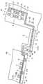
[0019] 도 1에 나타나는 바와 같이, 본 실시형태의 컨베이어 시스템(1)은, 제1 동(B1), 제2 동(B2), 및 동간 건물(C)에 각각 배치되어 있다. 제1 동(B1)에는, 피(被)반송물이 격납된 용기(이하, 「물품(F)」라고 칭함. 도 2 참조)를 보관하는 복수의 스토커(stocker)(6)와, 물품(F)을 스토커(6)에 반입하거나, 스토커(6)로부터 물품(F)을 반출하거나 하는 컨베이어 시스템(1A)을 구비하는 처리 시스템이 구축되어 있다. 물품(F)에는, 예컨대, 반도체 제조장치 또는 액정 제조장치 등에 의해 처리되는 웨이퍼를 수용하는 FOUP(Front-Opening Unified Pod), 및 반도체 제조장치 또는 액정 제조장치 등에서 이용되는 레티클을 수용하는 레티클 포드(reticle pod)가 포함된다. 본 실시형태에서는, FOUP를 예로서 설명한다.As shown in FIG. 1, the
[0020] 제2 동(B2)에는, 물품(F)에 수용된 웨이퍼에 어떠한 처리를 하는 처리장치(7)와, 연직 방향으로 이동하며, 물품(F)을 다른 층으로 반송하는 층간 반송장치(8)와, 물품(F)을 처리장치(7) 또는 층간 반송장치(8)에 반입하거나, 처리장치(7) 또는 층간 반송장치(8)로부터 물품(F)을 반출하거나 하는 컨베이어 시스템(1B)을 구비하는 처리 시스템이 구축되어 있다. 처리장치(7)의 예에는, 웨이퍼에 세정, 이온 주입, 열처리, 리소그래피, 에칭, 막 형성(成膜), 및 평탄화 등의 각종 프로세스의 처리를 행하는 장치가 포함된다.[0020] In the second building (B2), a
[0021] 동간 건물(C)은, 제1 동(B1)과 제2 동(B2) 사이에 배치되어 있다. 동간 건물(C)에는, 컨베이어 시스템(1C)이 배치되어 있다. 컨베이어 시스템(1C)은, 서로 다른 제1 동(B1) 및 제2 동(B2) 상호 간에 배치되고, 서로 다른 제1 동(B1) 및 제2 동(B2)의 내부에 각각 배치된 처리 시스템끼리 접속하고 있다.[0021] The inter-building building (C) is disposed between the first building (B1) and the second building (B2). A
[0022] 제1 동(B1)에 배치된 컨베이어 시스템(1A)에 대해 상세히 설명한다. 컨베이어 시스템(1A)은, 물품(F)의 저부(底部)를 지지하여 반송하는 컨베이어 유닛(컨베이어 장치)(3)으로서의 제1 컨베이어 유닛(30)(도 3의 (A) 및 도 3의 (B) 참조), 제2 컨베이어 유닛(40)(도 4의 (A) 및 도 4의 (B) 참조), 및 선회 컨베이어 유닛(선회 컨베이어 장치)(50)(도 5의 (A) 및 도 5의 (B) 참조)을 포함하여 구성되어 있다. 도 2에 나타나는 바와 같이, 컨베이어 시스템(1A)은, 제1 컨베이어 라인(11)과, 제2 컨베이어 라인(13)과, 백업 라인(15)과, 복수의 제1 접속 라인(17)과, 복수의 제2 접속 라인(19)과, 물품 반입출(搬入出) 라인(21)과, 이상 상태 취득부(80)(도 1 참조)와, 제어부(90)(도 1 참조)를 구비한다.[0022] The
[0023] 제1 컨베이어 라인(11)은, 물품(F)을 제1 방향으로 반송하는 부분이다. 제1 컨베이어 라인(11)은, 제1 컨베이어 유닛(30)과, 선회 컨베이어 유닛(50)을 포함하여 구성되어 있다.[0023] The
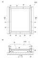
[0024] 도 3의 (A) 및 도 3의 (B)에 나타나는 바와 같이, 제1 컨베이어 유닛(30)은, 물품(F)의 저부에 있어서의 폭 방향의 양 단부(端部)를 지지하여 반송하는 한 쌍의 벨트(31, 31)를 갖고 있다. 한 쌍의 벨트(31, 31)는, 링형상(輪狀)의 무단(無端; 이음매가 없는) 벨트이며, 벨트(31, 31)의 각각이, 반송 방향으로 배열되는 한 쌍의 컨베이어 롤러(35, 35)에 감겨 있다. 컨베이어 롤러(35)는, 벨트(31)가 감기는 롤러부(32)와, 롤러부(32, 32)끼리 연결하는 연결축(34)을 갖고 있다. 각각의 벨트(31, 31)는, 적어도 한쪽 컨베이어 롤러(35, 35)가 구동부(36)에 의해 구동됨으로써 회전하며, 지지하는 물품(F)을 제1 방향으로 반송한다. 한 쌍의 컨베이어 롤러(35, 35)는, 가이드부(33)에 의해 지지되어 있다. 가이드부(33)는, 한 쌍의 컨베이어 롤러(35, 35)를 지지하는 동시에, 물품(F)의 측면을 가이드하는 기능을 갖는다. 가이드부(33)는, 베이스부(39)에 지지되어 있다.3A and 3B, the
[0025] 도 5의 (A) 및 도 5의 (B)에 나타나는 바와 같이, 선회 컨베이어 유닛(50)은, 물품(F)의 저부에 있어서의 폭 방향의 양 단부를 지지하여 반송하는 한 쌍의 벨트(51, 51)를 갖고 있다. 한 쌍의 벨트(51, 51)는, 링형상의 무단 벨트이며, 벨트(51, 51)의 각각이, 반송 방향으로 배열되는 한 쌍의 컨베이어 롤러(55, 55)에 감겨 있다. 컨베이어 롤러(55)는, 벨트(51)가 감기는 롤러부(52)와, 롤러부(52, 52)끼리 연결하는 연결축(54)을 갖고 있다. 각각의 벨트(51, 51)는, 적어도 한쪽 컨베이어 롤러(55, 55)가 구동부(56)에 의해 구동됨으로써 회전하며, 지지하는 물품(F)을 제1 방향으로 반송한다.[0025] As shown in FIGS. 5A and 5B, the orbiting
[0026] 한 쌍의 컨베이어 롤러(55, 55)에는, 가이드부(53)가 설치되어 있다. 가이드부(53)는, 물품(F)의 측면을 가이드하는 기능을 갖는다. 한 쌍의 컨베이어 롤러(55, 55)는, 선회부(57)에 의해 지지되어 있다. 선회부(57)는, 한 쌍의 컨베이어 롤러(55, 55)를 지지하는 동시에, 한 쌍의 컨베이어 롤러(55, 55)를 선회시켜 물품(F)의 진행 방향을 변화시킨다. 선회부(57)는, 구동부(58)에 의해 회전되며, 지지하는 한 쌍의 컨베이어 롤러(55, 55)를 선회시킨다. 선회부(57)는, 베이스부(59)에 지지되어 있다. 즉, 선회부(57)에 의해 지지되는 한 쌍의 컨베이어 롤러(55, 55)는, 베이스부(59)에 대해 선회 가능하게 설치되어 있다.The pair of conveyor rollers (55, 55), the
[0027] 또한, 본 실시형태의 컨베이어 시스템(1)에서는, 제1 컨베이어 라인(11)과 제1 접속 라인(17)의 접속부, 백업 라인(15)과 제1 접속 라인(17)의 접속부, 제2 컨베이어 라인(13)과 제2 접속 라인(19)의 접속부, 및 백업 라인(15)과 제2 접속 라인(19)의 접속부에 배치되는 컨베이어 장치로서, 상기의 선회 컨베이어 유닛(50)이 설치되어 있다. 이와 같은 선회 컨베이어 유닛(50)이 설치된 컨베이어 시스템(1)에서는, 전후 방향이 정해져 있는 FOUP와 같은 물품(F)을, 그 전후 방향을 유지한 상태로 반송할 수 있다.In addition, in the
[0028] 도 2에 나타나는 바와 같이, 제2 컨베이어 라인(13)은, 제1 방향에 직교하는 폭 방향에 있어서 서로 평행하게 설치되는 동시에, 물품(F)을 제1 방향과 역방향인 제2 방향으로 반송하는 부분이다. 제2 컨베이어 라인(13)은, 제1 컨베이어 라인(11)과 마찬가지로, 제1 컨베이어 유닛(30)과, 선회 컨베이어 유닛(50)을 포함하여 구성되어 있다. 제2 컨베이어 라인(13)에 이용되는 제1 컨베이어 유닛(30) 및 선회 컨베이어 유닛(50)은, 물품(F)을 제2 방향으로 반송하는 점을 제외하고, 제1 컨베이어 라인(11)에 이용되는 제1 컨베이어 유닛(30) 및 선회 컨베이어 유닛(50)의 구성과 동일하다. 이에, 여기서는, 제1 컨베이어 유닛(30) 및 선회 컨베이어 유닛(50)의 상세한 설명은 생략한다.[0028] As shown in FIG. 2, the
[0029] 백업 라인(15)은, 제1 컨베이어 라인(11) 및 제2 컨베이어 라인(13)의 백업으로서 기능하는 부분이다. 백업 라인(15)은, 제1 컨베이어 라인(11) 및 제2 컨베이어 라인(13)에 포함되는 제1 컨베이어 유닛(30) 및 선회 컨베이어 유닛(50) 모두에 이상이 없는 통상시(通常時)에 있어서 정지 상태에 있고, 제1 컨베이어 라인(11) 및 제2 컨베이어 라인(13)에 포함되는 제1 컨베이어 유닛(30) 및 선회 컨베이어 유닛(50) 중 적어도 하나에 이상이 있는 경우(이하, 단순히 「이상시」라고 칭함.)에, 회피 루트로서 이용된다.The
[0030] 또한, 여기서 말하는 정지 상태에는, 전원이 투입되고 있지 않은 경우, 및 전원은 투입되고 있지만 동작을 하고 있지 않은 경우의 양쪽 모두의 상태를 포함하고 있다.[0030] In addition, the stop state referred to herein includes both states when power is not turned on and when power is turned on but not operating.
[0031] 백업 라인(15)은, 제1 컨베이어 라인(11) 및 제2 컨베이어 라인(13)에 대해 평행하게 설치되는 동시에, 제1 컨베이어 라인(11) 및 제2 컨베이어 라인(13)의 폭 방향에 있어서, 제1 컨베이어 라인(11)과 제2 컨베이어 라인(13) 사이에 설치되어 있다. 백업 라인(15)은, 물품(F)을 제1 방향으로 반송하는 상태와 물품(F)을 제2 방향으로 반송하는 상태를 전환 가능하게 설치되어 있다. 백업 라인(15)은, 제1 컨베이어 라인(11)과 마찬가지로, 제1 컨베이어 유닛(30)과, 선회 컨베이어 유닛(50)을 포함하여 구성되어 있다. 백업 라인(15)에 이용되는 제1 컨베이어 유닛(30) 및 선회 컨베이어 유닛(50)은, 물품(F)을 제1 방향 및 제2 방향의 쌍방향으로 반송 가능하게 설치되어 있는 점을 제외하고, 제1 컨베이어 라인(11)에 이용되는 제1 컨베이어 유닛(30) 및 선회 컨베이어 유닛(50)의 구성과 동일하다. 이에, 여기서는, 제1 컨베이어 유닛(30) 및 선회 컨베이어 유닛(50)의 상세한 설명은 생략한다.[0031] The
[0032] 제1 접속 라인(17)은, 제1 컨베이어 라인(11) 및 제2 컨베이어 라인(13)의 백업으로서 기능하는 부분이다. 제1 접속 라인(17)은, 제1 컨베이어 라인(11)과 백업 라인(15) 사이에서 물품(F)을 반송한다. 제1 접속 라인(17)은, 제1 컨베이어 라인(11)을 구성하는 선회 컨베이어 유닛(50)과, 백업 라인(15)을 구성하는 선회 컨베이어 유닛(50)과, 이들 선회 컨베이어 유닛(50, 50) 사이에 끼워지는 제2 컨베이어 유닛(40)을 포함하여 구성되어 있다.The
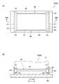
[0033] 도 4의 (A) 및 도 4의 (B)에 나타나는 바와 같이, 제2 컨베이어 유닛(40)은, 물품(F)의 저부에 있어서의 폭 방향의 양 단부를 지지하여 반송하는 한 쌍의 벨트(41, 41)를 갖고 있다. 한 쌍의 벨트(41, 41)는, 링형상의 무단 벨트이며, 벨트(41, 41)의 각각이, 반송 방향으로 배열되는 한 쌍의 컨베이어 롤러(45, 45)에 감겨 있다. 제2 컨베이어 유닛(40)에 있어서의 한 쌍의 컨베이어 롤러(45, 45) 간의 거리는, 제1 컨베이어 유닛(30)에 있어서의 한 쌍의 컨베이어 롤러(35, 35) 간의 거리에 비해 짧다.As shown in FIGS. 4A and 4B , the
[0034] 컨베이어 롤러(45)는, 벨트(41)가 감기는 롤러부(42)와, 롤러부(42, 42)끼리 연결하는 연결축(44)을 갖고 있다. 각각의 벨트(41, 41)는, 적어도 한쪽 컨베이어 롤러(45, 45)가 구동부(46)에 의해 구동됨으로써 회전하며, 지지하는 물품(F)을 제1 방향(또는 제2 방향)에 직교하는 제3 방향 또는 제4 방향으로 반송한다. 즉, 구동부(46)는, 컨베이어 롤러(45, 45)의 회전 방향이 전환 가능하게 설치되어 있다. 한 쌍의 컨베이어 롤러(45, 45)는, 가이드부(43)에 의해 지지되어 있다. 가이드부(43)는, 한 쌍의 컨베이어 롤러(45, 45)를 지지하는 동시에, 물품(F)의 측면을 가이드하는 기능을 갖는다. 가이드부(43)는, 베이스부(49)에 지지되어 있다.The
[0035] 제1 접속 라인(17)에 이용되는 선회 컨베이어 유닛(50)은, 물품(F)을 제1 방향(또는 제2 방향)에 직교하는 제3 방향 및 제4 방향의 쌍방향으로 반송 가능하게 설치되어 있는 점을 제외하고, 제1 컨베이어 라인(11)에 이용되는 선회 컨베이어 유닛(50)의 구성과 동일하다. 이에, 여기서는, 선회 컨베이어 유닛(50)의 상세한 설명은 생략한다.[0035] The turning
[0036] 제2 접속 라인(19)은, 제1 컨베이어 라인(11) 및 제2 컨베이어 라인(13)의 백업으로서 기능하는 부분이다. 제2 접속 라인(19)은, 제2 컨베이어 라인(13)과 백업 라인(15) 사이에서 물품(F)을 반송한다. 제2 접속 라인(19)은, 제2 컨베이어 라인(13)을 구성하는 선회 컨베이어 유닛(50)과, 백업 라인(15)을 구성하는 선회 컨베이어 유닛(50)과, 이들 선회 컨베이어 유닛(50, 50) 사이에 끼워지는 제2 컨베이어 유닛(40)을 포함하여 구성되어 있다. 제2 접속 라인(19)에 이용되는 제2 컨베이어 유닛(40) 및 선회 컨베이어 유닛(50)은, 제1 접속 라인(17)에 이용되는 제2 컨베이어 유닛(40) 및 선회 컨베이어 유닛(50)의 구성과 동일하다. 이에, 여기서는, 제2 컨베이어 유닛(40) 및 선회 컨베이어 유닛(50)의 상세한 설명은 생략한다.The
[0037] 도 2에 나타나는 바와 같이, 물품 반입출 라인(21)은, 제1 컨베이어 라인(11) 및 제2 컨베이어 라인(13)과 스토커(6) 사이에 있어서 물품(F)을 반송하는 부분이다. 물품 반입출 라인(21)은, 제1 컨베이어 유닛(30)과, 제2 컨베이어 유닛(40)과, 선회 컨베이어 유닛(50)을 포함하여 구성되어 있다. 제1 컨베이어 유닛(30), 제2 컨베이어 유닛(40) 및 선회 컨베이어 유닛(50)의 구성은, 상술한 제1 컨베이어 유닛(30), 제2 컨베이어 유닛(40) 및 선회 컨베이어 유닛(50)의 구성과 동일하므로, 여기서의 설명은 생략한다.As shown in FIG. 2 , the article carrying-in/out
[0038] 스토커(6)는, 물품(F)을 반입하는 반입 포트(61)와, 물품(F)을 반출하는 반출 포트(62)를 구비하고 있다. 반입 포트(61)와 선회 컨베이어 유닛(50) 사이에는, 스토커(6)의 입고 컨베이어(23)를 구성하는 제2 컨베이어 유닛(40)이 배치되어 있다. 물품(F)은, 선회 컨베이어 유닛(50)의 선회에 의해 제2 컨베이어 유닛(40) 방향을 향하고, 제2 컨베이어 유닛(40)에 송출된다. 그 후, 물품(F)은, 반입 포트(61)에 설치된 미도시된 핸드 장치에 의해 수취된다.[0038] The
[0039] 또한, 반출 포트(62)와 선회 컨베이어 유닛(50) 사이에는, 스토커(6)의 출고 컨베이어(24)를 구성하는 제2 컨베이어 유닛(40)이 배치되어 있다. 물품(F)은, 반출 포트(62)에 설치된 미도시된 핸드 장치에 의해 반출 포트(62)로부터 제2 컨베이어 유닛(40)으로 건네진다. 그 후, 물품(F)은, 선회 컨베이어 유닛(50)에 송출되고, 선회 컨베이어 유닛(50)의 선회에 의해 하류측으로 반송된다.In addition, between the carrying out
[0040] 이상 상태 취득부(80)(도 1 참조)는, 제1 컨베이어 라인(11) 및 제2 컨베이어 라인(13)에 포함되는 제1 컨베이어 유닛(30) 및 선회 컨베이어 유닛(50) 중 적어도 하나에 이상이 있음을 취득하는 장치이다. 이상 상태 취득부(80)는, 상기의 제1 컨베이어 유닛(30) 및 선회 컨베이어 유닛(50) 중 적어도 하나에 이상이 있음을 검지하거나, 또는 이상이 있음이 입력된다. 예컨대, 이상 상태 취득부(80)는, 각 컨베이어 유닛(3) 상에 놓인 물품(F)을 검지하는 센서 등의 검지부(미도시)여도 된다. 또한, 이와 같은 검지부가 컨베이어 유닛(3)마다 대응지어 설치되어 있고, 하나의 검지부에 있어서 물품(F)이 검지된 상태가 소정 시간 이상 계속된 경우, 물품(F)이 하나의 검지부에 대응하는 컨베이어 유닛 위로부터 움직이고 있지 않음을 검지(컨베이어 유닛(3)이 정지해 있음을 검지)함으로써 상술한 이상을 취득하는 장치여도 된다. 또한, 예컨대, 이상 상태 취득부(80)는, 컨베이어 시스템(1A)을 관리하는 관리자 등에 의해, 예컨대, 터치 패널 등의 인터페이스를 통해, 이상이 있는 컨베이어 장치가 입력(지정)되는 구성의 장치여도 된다.[0040] The abnormal state acquisition unit 80 (see FIG. 1 ) is one of the
[0041] 제어부(90)는, 제1 동(B1)에 배치된 컨베이어 시스템(1A)의 동작을 제어한다. 제어부(90)는, CPU(Central Processing Unit), ROM(Read Only Memory) 및 RAM(Random Access Memory) 등으로 이루어진 전자 제어 유닛이다. 제어부(90)는, 예컨대 ROM에 저장되어 있는 프로그램이 RAM 상에 로딩되고 CPU로 실행되는 소프트웨어로서 구성할 수 있다. 제어부(90)는, 전자 회로 등에 의한 하드웨어로서 구성되어도 된다.[0041] The
[0042] 예컨대, 제어부(90)는, 이상 상태 취득부(80)에 있어서, 제1 컨베이어 라인(11) 및 제2 컨베이어 라인(13)에 포함되는 제1 컨베이어 유닛(30)에 이상이 있음이 검지되거나, 또는 이상이 있음이 입력되면, 통상시에는 정지해 있는 백업 라인(15)을 구성하는 적어도 일부의 제1 컨베이어 유닛(30) 및 선회 컨베이어 유닛(50)을 정지 상태로부터 기동시키는 동시에, 제1 접속 라인(17), 제2 접속 라인(19), 및 백업 라인(15)을 이용하여, 이상이 있는 제1 컨베이어 유닛(30)을 회피하도록 물품(F)을 반송하는 백업 제어를 실행한다. 제어부(90)는, 이상이 있는 제1 컨베이어 유닛(30)을 회피하기 위한 최단 경로를 검색하고, 백업 라인(15), 제1 접속 라인(17), 및 제2 접속 라인(19)을 구성하는 제1 컨베이어 유닛(30) 및 선회 컨베이어 유닛(50) 중, 최단 경로에 해당하는 제1 컨베이어 유닛(30) 및 선회 컨베이어 유닛(50)만을 기동시킨다. 이하, 도 6의 (A)~도 6의 (D) 및 도 7의 (A)~도 7의 (D)를 이용하여, 제어부(90)의 백업 제어에 대해 상세히 설명한다.[0042] For example, the
[0043] 도 6의 (A) 및 도 6의 (B)에 나타나는 바와 같이, 제1 컨베이어 라인(11)을 구성하는 제1 컨베이어 유닛(30) 중 하나에 이상이 발생했음(도 6의 (A) 및 도 6의 (B)에 나타나는 × 부분)이 이상 상태 취득부(80)에 의해 검지(또는 입력)되면, 제어부(90)는, 이상이 있는 제1 컨베이어 유닛(30)을 회피할 수 있는 최단의 루트를 검색한다. 구체적으로는, 제어부(90)는, 이상이 있는 제1 컨베이어 유닛(30)(뒷 단락에서 설명하는 노드부)의 양단(兩端)에 있는 제1 접속 라인(17) 또는 제2 접속 라인(19)을 구성하는 컨베이어 유닛(3, 3), 즉, 선회 컨베이어 유닛(50, 50)(뒷 단락에서 설명하는 링크부)을 추출하고, 해당 선회 컨베이어 유닛(50, 50)을 기점 및 종점으로 하는 회피 루트를 검색한다.As shown in (A) and (B) of Figure 6, an abnormality occurred in one of the
[0044] 제어부(90)는, 이상이 있는 제1 컨베이어 유닛(30)의 양단에 각각 배치되며, 제1 컨베이어 라인(11) 및 제1 접속 라인(17)을 구성하는 선회 컨베이어 유닛(50, 50)과, 해당 선회 컨베이어 유닛(50, 50)의 각각에 접속되며, 제1 접속 라인(17)을 구성하는 제2 컨베이어 유닛(40, 40)과, 이들 제2 컨베이어 유닛(40, 40)의 각각에 접속되며, 제1 접속 라인(17) 및 백업 라인(15)을 구성하는 선회 컨베이어 유닛(50, 50)과, 이들 선회 컨베이어 유닛(50, 50) 사이에 끼워지며, 백업 라인(15)을 구성하는 제1 컨베이어 유닛(30)을 이용하는 회피 루트를 결정한다. 제어부(90)는, 정지 상태에 있고, 해당 회피 루트에 포함되는 백업 라인(15) 상의 제1 컨베이어 유닛(30)과, 2개의 선회 컨베이어 유닛(50, 50)과, 2개의 제2 컨베이어 유닛(40, 40)을 정지 상태로부터 기동시킨다. 그리고, 제어부(90)는, 결정된 회피 루트를 이용하여, 이상이 있는 제1 컨베이어 유닛(30)을 회피하도록 물품(F)을 반송한다.[0044] The
[0045] 도 6의 (C) 및 도 6의 (D)에 나타나는 바와 같이, 제2 컨베이어 라인(13)을 구성하는 제1 컨베이어 유닛(30) 중 하나에 이상이 발생했음(도 6의 (C) 및 도 6의 (D)에 나타나는 × 부분)이 이상 상태 취득부(80)에 의해 검지(또는 입력)되면, 제어부(90)는, 이상이 있는 제1 컨베이어 유닛(30)을 회피할 수 있는 최단의 루트를 검색한다. 또한, 회피 루트의 결정 방법은 상기에서 설명한 바와 같다.As shown in FIGS. 6 (C) and 6 (D), an abnormality occurred in one of the
[0046] 제어부(90)는, 이상이 있는 제1 컨베이어 유닛(30)의 양단에 각각 배치되며, 제2 컨베이어 라인(13) 및 제2 접속 라인(19)을 구성하는 선회 컨베이어 유닛(50, 50)과, 해당 선회 컨베이어 유닛(50, 50)의 각각에 접속되며, 제2 접속 라인(19)을 구성하는 제2 컨베이어 유닛(40, 40)과, 이들 제2 컨베이어 유닛(40, 40)의 각각에 접속되며, 제2 접속 라인(19) 및 백업 라인(15)을 구성하는 선회 컨베이어 유닛(50, 50)과, 이들 선회 컨베이어 유닛(50, 50) 사이에 끼워지며, 백업 라인(15)을 구성하는 제1 컨베이어 유닛(30)을 이용하는 회피 루트를 결정한다. 제어부(90)는, 정지 상태에 있고, 해당 회피 루트에 포함되는 백업 라인(15) 상의 제1 컨베이어 유닛(30)과, 2개의 선회 컨베이어 유닛(50, 50)과, 2개의 제2 컨베이어 유닛(40, 40)을 정지 상태로부터 기동시킨다. 그리고, 제어부(90)는, 결정된 회피 루트를 이용하여, 이상이 있는 제1 컨베이어 유닛(30)을 회피하도록 물품(F)을 반송한다.[0046] The
[0047] 다음으로, 제1 컨베이어 라인(11)을 구성하는 제1 컨베이어 유닛(30)과, 제2 컨베이어 라인(13)을 구성하는 제1 컨베이어 유닛(30) 양쪽 모두에 이상이 발생했음이, 이상 상태 취득부(80)에 의해 검지(또는 입력)된 경우에 대해, 도 7의 (A)~도 7의 (D)를 이용하여 설명한다.Next, it is determined that an abnormality has occurred in both the
[0048] 도 7의 (A)~도 7의 (D)에 나타나는 바와 같이, 제1 컨베이어 라인(11)을 구성하는 제1 컨베이어 유닛(30) 중 하나에 이상이 발생했음(도 7의 (A)~도 7의 (D)에 나타나는 × 부분)이 이상 상태 취득부(80)에 의해 검지(또는 입력)되면, 제어부(90)는, 이상이 있는 제1 컨베이어 유닛(30)을 회피할 수 있는 최단의 루트를 검색한다. 또한, 회피 루트의 결정 방법은 상기에서 설명한 바와 같다.[0048] As shown in (A) to (D) of FIG. 7, an abnormality occurred in one of the
[0049] 구체적으로는, 제어부(90)는, 이상이 있는 제1 컨베이어 유닛(30)의 양단에 각각 배치되며, 제1 컨베이어 라인(11) 및 제1 접속 라인(17)을 구성하는 선회 컨베이어 유닛(50, 50)과, 해당 선회 컨베이어 유닛(50, 50)의 각각에 인접되며, 제1 접속 라인(17)을 구성하는 제2 컨베이어 유닛(40, 40)과, 이들 제2 컨베이어 유닛(40, 40)의 각각에 접속되며, 제1 접속 라인(17) 및 백업 라인(15)을 구성하는 선회 컨베이어 유닛(50, 50)과, 이들 선회 컨베이어 유닛(50, 50) 사이에 끼워지며, 백업 라인(15)을 구성하는 제1 컨베이어 유닛(30)을 이용하는 회피 루트를 결정한다. 제어부(90)는, 정지 상태에 있고, 해당 회피 루트에 포함되는 백업 라인(15) 상의 제1 컨베이어 유닛(30)과, 2개의 선회 컨베이어 유닛(50, 50)과, 2개의 제2 컨베이어 유닛(40, 40)을 정지 상태로부터 기동시킨다. 그리고, 제어부(90)는, 결정된 회피 루트를 이용하여, 이상이 있는 제1 컨베이어 유닛(30)을 회피하도록 물품(F)을 반송한다.[0049] Specifically, the
[0050] 마찬가지로, 제2 컨베이어 라인(13)을 구성하는 제1 컨베이어 유닛(30) 중 하나에 이상이 발생했음이 이상 상태 취득부(80)에 의해 검지되면, 제어부(90)는, 이상이 있는 제1 컨베이어 유닛(30)을 회피할 수 있는 최단의 루트를 검색한다. 또한, 회피 루트의 결정 방법은 상기에서 설명한 바와 같다.Similarly, when it is detected by the abnormal
[0051] 구체적으로는, 제어부(90)는, 이상이 있는 제1 컨베이어 유닛(30)의 양단에 각각 배치되며, 제2 컨베이어 라인(13) 및 제2 접속 라인(19)을 구성하는 선회 컨베이어 유닛(50, 50)과, 해당 선회 컨베이어 유닛(50, 50)의 각각에 접속되며, 제2 접속 라인(19)을 구성하는 제2 컨베이어 유닛(40, 40)과, 이들 제2 컨베이어 유닛(40, 40)의 각각에 접속되며, 제2 접속 라인(19) 및 백업 라인(15)을 구성하는 선회 컨베이어 유닛(50, 50)과, 이들 선회 컨베이어 유닛(50, 50) 사이에 끼워지며, 백업 라인(15)을 구성하는 제1 컨베이어 유닛(30)을 이용하는 회피 루트를 결정한다. 제어부(90)는, 정지 상태에 있고, 해당 회피 루트에 포함되는 백업 라인(15) 상의 제1 컨베이어 유닛(30)과 2개의 선회 컨베이어 유닛(50, 50)을 정지 상태로부터 기동시킨다. 그리고, 제어부(90)는, 결정된 회피 루트를 이용하여, 이상이 있는 제1 컨베이어 유닛(30)을 회피하도록 물품(F)을 반송한다.[0051] Specifically, the
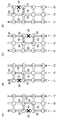
[0052] 도 7의 (A)에 나타나는 예에서는, 제1 컨베이어 라인(11)의 회피 루트의 일부와, 제2 컨베이어 라인(13)의 회피 루트의 일부가, 백업 라인(15)을 구성하는 하나의 제1 컨베이어 유닛(30) 및 2개의 선회 컨베이어 유닛(50, 50)에 있어서 중복된다(도 7의 (A)에 나타나는 해칭부). 이하, 제1 컨베이어 라인(11)과 제1 접속 라인(17)의 접속부, 백업 라인(15)과 제1 접속 라인(17)의 접속부, 제2 컨베이어 라인(13)과 제2 접속 라인(19)의 접속부, 및 백업 라인(15)과 제2 접속 라인(19)의 접속부의 각각을 링크부로서 설명하고, 서로 이웃하는 링크부 사이에 끼워지는 부분을 노드부로서 설명한다.In the example shown in FIG. 7A, a part of the avoidance route of the
[0053] 제1 컨베이어 라인(11) 및 제2 컨베이어 라인(13)의 회피 루트가 중복되면, 물품(F)끼리 충돌하는 경우가 있다. 따라서, 제어부(90)는, 노드부에 물품(F)이 위치하는 경우에는, 해당 노드부의 양단의 링크부에 설치된 선회 컨베이어 유닛(50, 50)의 회전을 금지한다. 보다 상세하게는, 제어부(90)는, 선회 컨베이어 유닛(50, 50) 사이에 끼워지는 노드부로부터 선회 컨베이어 유닛(50, 50)으로 진입 가능한 상태로 하는 회전 이외의 선회 컨베이어 유닛(50, 50)의 회전을 금지한다. 이에 의해, 동일한 노드부에 2개 이상의 물품(F)이 반입되는 일이 없어진다. 이 결과, 제어부(90)에 의해 백업 제어가 실행되었다고 하더라도, 물품(F, F)끼리 충돌하는 일은 없다.[0053] When the avoidance routes of the
[0054] 도 7의 (B) 및 도 7의 (C)에 나타나는 예에서는, 제1 컨베이어 라인(11)의 회피 루트의 일부와, 제2 컨베이어 라인(13)의 회피 루트의 일부가, 백업 라인(15)을 구성하는 하나의 선회 컨베이어 유닛(50)에 있어서 중복된다(도 7의 (B) 및 도 7의 (C)에 나타나는 해칭부). 이 경우도, 제어부(90)는, 노드부에 물품(F)이 위치하는 경우에는, 해당 노드부의 양단의 링크부에 설치된 선회 컨베이어 유닛(50, 50)의 회전을 금지한다. 보다 상세하게는, 제어부(90)는, 선회 컨베이어 유닛(50, 50) 사이에 끼워지는 노드부로부터 선회 컨베이어 유닛(50, 50)으로 진입 가능한 상태로 하는 회전 이외의 선회 컨베이어 유닛(50, 50)의 회전을 금지한다.[0054] In the example shown in FIGS. 7B and 7C, a part of the avoidance route of the
[0055] 도 7의 (D)에 나타나는 예에서는, 제1 컨베이어 라인(11)의 회피 루트의 일부와, 제2 컨베이어 라인(13)의 회피 루트의 일부는, 백업 라인(15)을 구성하는 제1 컨베이어 유닛(30) 및 선회 컨베이어 유닛(50)에 있어서 중복되지 않는다. 즉, 제어부(90)에 의해, 백업 제어가 실행되었다고 하더라도, 물품(F, F)끼리 충돌하는 일은 없다. 다시 말해, 제1 컨베이어 라인(11)의 회피 동작과, 제2 컨베이어 라인(13)의 회피 동작은, 병행하여 처리할 수 있다. 또한, 이 경우도, 제어부(90)는, 노드부에 물품(F)이 위치하는 경우에는, 해당 노드부의 양단의 링크부에 설치된 선회 컨베이어 유닛(50, 50)의 회전을 금지해도 된다.In the example shown in FIG. 7D, a part of the avoidance route of the
[0056] 다음으로, 제2 동(B2)에 배치된 컨베이어 시스템(1B)에 대해 상세히 설명한다. 컨베이어 시스템(1B)도, 컨베이어 시스템(1A)과 마찬가지로, 물품(F)의 저부를 지지하여 반송하는 컨베이어 유닛(3)으로서의 제1 컨베이어 유닛(30)(도 3의 (A) 및 도 3의 (B) 참조), 제2 컨베이어 유닛(40)(도 4의 (A) 및 도 4의 (B) 참조), 및 선회 컨베이어 유닛(50)(도 5의 (A) 및 도 5의 (B) 참조)을 포함하여 구성되어 있다. 도 8에 나타나는 바와 같이, 컨베이어 시스템(1B)은, 제1 컨베이어 라인(11)과, 제2 컨베이어 라인(13)과, 백업 라인(15)과, 복수의 제1 접속 라인(17B)과, 복수의 제2 접속 라인(19B)과, 이상 상태 취득부(80)(도 1 참조)와, 제어부(90)(도 1 참조)를 구비한다.Next, the
[0057] 컨베이어 시스템(1B)이, 컨베이어 시스템(1A)과 다른 점은, 제1 컨베이어 라인(11)과 백업 라인(15) 사이에서 물품(F)을 반송하는 제1 접속 라인(17B)의 구성과, 제2 컨베이어 라인(13)과 백업 라인(15) 사이에서 물품(F)을 반송하는 제2 접속 라인(19B)의 구성과, 컨베이어 시스템(1A)에 설치되어 있는 물품 반입출 라인(21)이 없다는 것이다. 구체적으로는, 도 8에 나타나는 바와 같이, 제1 컨베이어 라인(11)과 백업 라인(15) 사이 및 제2 컨베이어 라인(13)과 백업 라인(15) 사이에, 제2 컨베이어 유닛(40)이 배치되어 있지 않다. 즉, 제1 접속 라인(17B)은, 제1 컨베이어 라인(11)을 구성하는 선회 컨베이어 유닛(50) 및 백업 라인(15)을 구성하는 선회 컨베이어 유닛(50)만으로 구성되며, 해당 선회 컨베이어 유닛(50)끼리 직접 물품(F)을 주고받는다. 마찬가지로, 제2 접속 라인(19B)은, 제2 컨베이어 라인(13)을 구성하는 선회 컨베이어 유닛(50) 및 백업 라인(15)을 구성하는 선회 컨베이어 유닛(50)만으로 구성된다.[0057] The
[0058] 또한, 컨베이어 시스템(1B)에서는, 제1 컨베이어 라인(11) 및 제2 컨베이어 라인(13)의 각각은, 연직 방향으로 물품을 반송하는 층간 반송장치(8)에 면하여 배치되어 있다. 상세하게는, 제1 컨베이어 라인(11)을 구성하는 선회 컨베이어 유닛(50)에, 층간 반송장치(8)의 입출고 컨베이어(입고 컨베이어(23) 및 출고 컨베이어(24))를 각각 구성하는 제2 컨베이어 유닛(40, 40)이 접속되어 있다. 한편, 백업 라인(15)은, 층간 반송장치(8)에는 면해 있지 않다(직접 접속되어 있지 않다). 상기 이외의 구성은, 컨베이어 시스템(1A)과 동일하므로, 여기서의 상세한 설명은 생략한다.[0058] Further, in the
[0059] 컨베이어 시스템(1B)의 제어부(90)에 의한 백업 제어도, 제1 접속 라인(17) 및 제2 접속 라인(19)을 구성하는 제2 컨베이어 유닛(40)이 관여하지 않는 것을 제외하고, 윗 단락에서 설명한, 컨베이어 시스템(1A)의 제어부(90)에 의한 백업 제어와 동일하다. 즉, 컨베이어 시스템(1B)에 있어서 제1 컨베이어 라인(11) 및 제2 컨베이어 라인(13)의 일부의 제1 컨베이어 유닛(30) 및 선회 컨베이어 유닛(50)에 이상이 발생한 경우라 하더라도, 해당 이상이 발생한 제1 컨베이어 유닛(30) 및 선회 컨베이어 유닛(50)을 회피하면서, 물품(F)을 반송하는 것이 가능하다.Backup control diagram by the
[0060] 다음으로, 동간 건물(C)에 배치된 컨베이어 시스템(1C)에 대해 상세히 설명한다. 컨베이어 시스템(1C)도, 컨베이어 시스템(1A)과 마찬가지로, 물품(F)의 저부를 지지하여 반송하는 컨베이어 유닛(3)으로서의 제1 컨베이어 유닛(30)(도 3의 (A) 및 도 3의 (B) 참조), 제2 컨베이어 유닛(40)(도 4의 (A) 및 도 4의 (B) 참조), 및 선회 컨베이어 유닛(50)(도 5의 (A) 및 도 5의 (B) 참조)을 포함하여 구성되어 있다.Next, the conveyor system (1C) disposed in the building (C) between the building will be described in detail. Similarly to the
[0061] 도 9에 나타나는 바와 같이, 컨베이어 시스템(1C)은, 제1 컨베이어 라인(11)과, 제2 컨베이어 라인(13)과, 백업 라인(15)과, 복수의 제1 접속 라인(17)과, 복수의 제2 접속 라인(19)과, 이상 상태 취득부(80)(도 1 참조)와, 제어부(90)(도 1 참조)를 구비한다. 컨베이어 시스템(1C)은, 서로 다른 건물(제1 동(B1) 및 제2 동(B2)) 사이에 배치되고, 서로 다른 건물(제1 동(B1) 및 제2 동(B2))의 내부에 각각 배치된 처리 시스템끼리 접속한다.As shown in FIG. 9 , the
[0062] 컨베이어 시스템(1C)이, 컨베이어 시스템(1A)과 다른 점은, 도 8에 나타나는 바와 같이, 반송 방향(제1 방향 및 제2 방향)에 있어서의 제1 접속 라인(17) 및 제2 접속 라인(19)의 설치 간격이 컨베이어 시스템(1A)에 비해 길다는 것, 컨베이어 시스템(1A)에 설치되어 있는 물품 반입출 라인(21)이 설치되어 있지 않다는 것이다. 상기 이외의 구성은, 컨베이어 시스템(1A)과 동일하므로, 여기서의 상세한 설명은 생략한다.[0062] The
[0063] 컨베이어 시스템(1C)의 제어부(90)에 의한 백업 제어도, 윗 단락에서 설명한, 컨베이어 시스템(1A)의 제어부(90)에 의한 백업 제어와 동일하다. 즉, 컨베이어 시스템(1C)에 있어서 제1 컨베이어 라인(11) 및 제2 컨베이어 라인(13)의 일부의 제1 컨베이어 유닛(30) 및 선회 컨베이어 유닛(50)에 이상이 발생한 경우라 하더라도, 해당 이상이 발생한 제1 컨베이어 유닛(30) 및 선회 컨베이어 유닛(50)을 회피하면서, 물품(F)을 반송하는 것이 가능하다.[0063] The backup control by the
[0064] 다음으로, 상기 실시형태의 컨베이어 시스템(1)의 작용 효과에 대해 설명한다. 상기 실시형태의 컨베이어 시스템(1)에서는, 제1 컨베이어 라인(11) 및 제2 컨베이어 라인(13)의 각각에 대응하는 백업 라인이 설치되는 것이 아니라, 제1 컨베이어 라인(11) 및 제2 컨베이어 라인(13)에 겸용되는 백업 라인(15)이 하나만 설치되어 있다. 그리고, 이 하나의 백업 라인(15)은, 제1 방향 및 제2 방향의 쌍방향으로 물품(F)을 반송 가능하게 구성되는 동시에, 이 하나의 백업 라인(15)과 제1 컨베이어 라인(11) 및 제2 컨베이어 라인(13) 양쪽과의 사이에서, 물품(F)의 반입 및 반출이 가능한 제1 접속 라인(17) 및 제2 접속 라인(19)이 설치되어 있다. 이에 의해, 제1 컨베이어 라인(11) 및 제2 컨베이어 라인(13)의 각각에 백업 라인이 설치되는 구성과 동일한 기능을, 하나의 백업 라인(15)에 의해 구성할 수 있다. 이 결과, 제1 컨베이어 라인(11) 및 제2 컨베이어 라인(13)에 이상이 발생했을 때에 물품(F)의 반송을 대체하는 백업 라인(15)을 컴팩트하게 구축할 수 있다.[0064] Next, the operation and effect of the
[0065] 상기 실시형태의 컨베이어 시스템(1)에서는, 통상시에는 정지 상태에 있는 백업 라인(15)을 구성하는 제1 컨베이어 유닛(30) 및 선회 컨베이어 유닛(50)이, 이상시에는 자동적으로 기동한다. 구체적으로는, 이상시에는, 백업 라인(15), 제1 접속 라인(17), 및 제2 접속 라인(19)이 자동적으로 기동한다. 이에 의해, 백업 라인(15), 제1 접속 라인(17), 및 제2 접속 라인(19)을 이용하여 이상이 있는 곳을 회피한 물품 반송이 가능해진다. 이 결과, 제1 컨베이어 라인(11) 및 제2 컨베이어 라인(13) 중 적어도 한쪽에 이상이 발생하더라도, 물품(F)의 반송을 정지하는 일 없이 반송을 계속할 수 있다.[0065] In the
[0066] 상기 실시형태의 컨베이어 시스템(1)에서는, 링크부에 배치되는 컨베이어 유닛(3)은, 물품(F)의 저부를 지지하여 반송하는 동시에, 연직 방향을 회전축으로 하여 물품(F)을 회전시키는 선회 컨베이어 유닛(50)이다. 이에 의해, 예컨대, FOUP 등, 전후의 방향이 정해진 물품(F)을 반송시키는 경우에, 그 방향을 유지한 채 반송시킬 수 있다.[0066] In the
[0067] 상기 실시형태의 컨베이어 시스템(1)에서는, 제어부(90)는, 노드부에 물품(F)이 위치하는 경우에는, 해당 노드부의 양단의 링크부에 설치된 선회 컨베이어 유닛(50)의 회전을 금지하고 있다. 이에 의해, 제어부(90)에 의한 백업 제어 시에, 물품(F, F)끼리 충돌하는 것을 회피할 수 있다.[0067] In the
[0068] 상기 실시형태의 컨베이어 시스템(1)에서는, 제어부(90)는, 제1 컨베이어 라인(11) 및 제2 컨베이어 라인(13)에 있어서 이상이 있는 제1 컨베이어 유닛(30)을 회피하기 위한 최단 경로를 검색하고, 백업 라인(15)을 구성하는 컨베이어 유닛(3)(제1 컨베이어 유닛(30) 및 선회 컨베이어 유닛(50)) 중, 최단 경로에 해당하는 제1 컨베이어 유닛(30) 및 선회 컨베이어 유닛(50)만을 기동하고 있다. 이에 의해, 백업 라인(15)으로서 기동하는 제1 컨베이어 유닛(30) 및 선회 컨베이어 유닛(50)의 수를 최소한으로 억제할 수 있다. 또한, 상기 실시형태에서는, 하나의 이상이 있는 곳을 회피하기 위해 이용되는 백업 라인(15)의 반송 방향에 있어서의 거리가 짧아지므로, 복수 군데에서 이상이 발생한 경우라 하더라도, 동시에 회피할 수 있는 가능성을 높일 수 있다. 이 결과, 제1 컨베이어 라인(11) 및 제2 컨베이어 라인(13) 중 적어도 한쪽에 이상이 발생했을 때의 가동률의 저하를 회피 또는 저감할 수 있다.[0068] In the
[0069] 상기 실시형태의 컨베이어 시스템(1)에서는, 백업 라인(15)은, 폭 방향에 있어서, 제1 컨베이어 라인(11)과 제2 컨베이어 라인(13) 사이에 설치되어 있으므로, 제1 접속 라인(17) 및 제2 접속 라인(19)의 구성을 간이하게 구축할 수 있다.[0069] In the
[0070] 상기 실시형태의 컨베이어 시스템(1)에서는, 제1 접속 라인(17) 및 제2 접속 라인(19)은, 제3 방향 및 제4 방향의 쌍방향으로 물품(F)을 반송 가능하게 설치되어 있으므로, 제어부(90)에 의한 백업 제어를 실행할 때, 보다 많은 회피 루트의 선택이 가능해진다. 이 결과, 예컨대, 보다 짧은 루트로 이상이 있는 곳을 회피하는 것이 가능해진다.[0070] In the
[0071] 상기 실시형태의 컨베이어 시스템(1)에서는, 백업 라인(15)을 컴팩트하게 구축할 수 있으므로, 층간 반송장치(8)가 설치되고, 설치 공간에 제한이 있는 장소라 하더라도, 백업 라인(15)을 구축할 수 있다.[0071] In the
[0072] 상기 실시형태의 컨베이어 시스템(1)에서는, 하나의 백업 라인을 부설하는 것으로 충분하므로, 비교적 거리가 긴 동간에 컨베이어 시스템을 부설하는 경우라 하더라도, 비용의 증대를 억제할 수 있다.[0072] In the
[0073] 이상, 본 발명의 일 측면의 일 실시형태에 대해 설명하였지만, 본 발명의 일 측면은 상기 실시형태에 한정되는 것은 아니고, 발명의 취지를 벗어나지 않는 범위에서 다양한 변경이 가능하다.[0073] In the above, one embodiment of one aspect of the present invention has been described, but one aspect of the present invention is not limited to the above embodiment, and various changes are possible without departing from the spirit of the invention.
[0074] <변형예 1>[0074] <
상기 실시형태의 제1 접속 라인(17) 및 제2 접속 라인(19)에 이용되는 선회 컨베이어 유닛(50)은, 물품(F)을 제3 방향 및 제4 방향의 쌍방향으로 반송 가능하게 설치되어 있는 예를 들어 설명하였지만, 이에 한정되지 않는다.The turning
[0075] 예컨대, 도 10에 나타나는 바와 같이, 제1 접속 라인(17)은, 백업 라인(15)에 물품(F)을 반입하는 반입 방향(제3 방향)으로만 반송 가능한 제2 컨베이어 유닛(40A)이 하나 이상 설치되고, 백업 라인(15)으로부터 물품(F)을 반출하는 반출 방향(제4 방향)으로만 반송 가능한 제2 컨베이어 유닛(40B)이 하나 이상 설치되어 있는 컨베이어 시스템(1D)으로서 구성되어도 된다.[0075] For example, as shown in FIG. 10 , the
[0076] 또한, 예컨대, 제2 접속 라인(19)은, 백업 라인(15)에 물품(F)을 반입하는 반입 방향(제4 방향)으로만 반송 가능한 제2 컨베이어 유닛(40A)이 하나 이상 설치되고, 백업 라인(15)으로부터 물품(F)을 반출하는 반출 방향(제3 방향)으로만 반송 가능한 제2 컨베이어 유닛(40B)이 하나 이상 설치되어 있는 컨베이어 시스템(1D)으로서 구성되어도 된다.[0076] In addition, for example, the
[0077] 변형예 1에 따른 구성이라 하더라도, 예컨대, 제1 컨베이어 라인(11)(또는 제2 컨베이어 라인(13))에 있어서 제2 컨베이어 유닛(40A)과 제2 컨베이어 유닛(40B) 사이의 제1 컨베이어 유닛(30)에 이상이 발생한 경우라 하더라도, 제어부(90)는, 해당 이상이 발생한 제1 컨베이어 유닛(30)을 회피하는 백업 제어를 실행할 수 있다. 그리고, 해당 백업 제어를 실행할 때, 간이한 제어가 가능해진다.[0077] Even with the configuration according to Modification Example 1, for example, between the
[0078] <변형예 2>[0078] <Modification 2>
상기 실시형태의 컨베이어 시스템(1)(1A~1D)에서는, 반송 방향으로 상대적으로 길어지도록 구축되어 있는 예를 들어 설명하였지만, 도 11에 나타나는 바와 같이, 제1 컨베이어 라인(11)과, 제2 컨베이어 라인(13)과, 백업 라인(15)과, 제1 접속 라인(17)과, 제2 접속 라인(19)이, 격자형상으로 배치된 컨베이어 시스템(1E)으로서 구성되어도 된다. 또한, 제1 컨베이어 라인(11) 및 제2 컨베이어 라인(13)은, 컨베이어 시스템(1E)에 물품(F)을 반입하는 반입 포트(71) 및 컨베이어 시스템(1E)으로부터 물품(F)을 반출하는 반출 포트(72)가 면해 있다.In the conveyor system 1 (1A-1D) of the said embodiment, although the example constructed so that it may become relatively long in a conveyance direction was given and demonstrated, as shown in FIG. 11, the
[0079] 또한, 상기 실시형태에서는, 제1 컨베이어 라인(11) 및/또는 제2 컨베이어 라인(13)을 구성하는 제1 컨베이어 유닛(30)에 이상이 발생한 예를 들어 설명하였지만 이에 한정되지 않는다. 예컨대, 도 11에 나타나는 바와 같이, 제1 컨베이어 라인(11) 및/또는 제2 컨베이어 라인(13)을 구성하는 선회 컨베이어 유닛(50)(링크부)에 이상이 발생한 경우, 제1 방향 또는 제2 방향(반송 방향)에 있어서 해당 선회 컨베이어 유닛(50)에 인접한 2개의 선회 컨베이어 유닛(50, 50)(링크부)을 이용하여, 물품(F)을 백업 라인(15)에 반입 또는 백업 라인(15)으로부터 반출해도 된다. 이 경우라 하더라도, 제어부(90)는, 해당 선회 컨베이어 유닛(50, 50)을 기점 및 종점으로 하여 회피 루트를 검색하고, 이상이 있는 선회 컨베이어 유닛(50)을 회피할 수 있는 최단 루트를 결정할 수 있다.[0079] In addition, in the above embodiment, an example in which an abnormality occurred in the
[0080] <기타 변형예>[0080] <Other Modifications>
상기 실시형태 또는 변형예에서는, 제1 방향 또는 제2 방향으로 물품(F)을 반송하는 데 있어서, 복수의 제1 컨베이어 유닛(30)을 배열시키는 예를 들어 설명하였지만, 노드부에 해당하는 부분에는, 반송 방향으로 연장되어 있는 하나의 컨베이어 유닛(3)을 배치해도 된다.In the above embodiment or modified example, in conveying the article F in the first direction or the second direction, an example of arranging the plurality of
[0081] 또한, 상기 실시형태 또는 변형예에서는, 컨베이어 시스템(1A~1C)의 각각에 제어부(90) 및 이상 상태 취득부(80)가 구비되어 있는 예를 들어 설명하였지만, 컨베이어 시스템(1A~1C)을 통괄하는 하나의 제어부 및 이상 상태 취득부가 구비되어도 되고, 컨베이어 유닛마다 제어부 및 이상 상태 취득부가 구비되어도 된다.[0081] In addition, in the above embodiment or modified example, although the description has been given as an example in which the
[0082] 상기 실시형태 또는 변형예에서는, 백업 라인(15)은, 제1 컨베이어 라인(11)과 제2 컨베이어 라인(13) 사이에 배치되어 있는 예를 들어 설명하였지만, 백업 라인(15)은, 예컨대, 제1 컨베이어 라인(11)의 외측에 배치해도 되고, 제2 컨베이어 라인(13)의 외측에 배치해도 된다.[0082] In the above embodiment or modified example, the
[0083] 상기 실시형태 또는 변형예에서는, 도 2, 도 8~도 11에 나타나는 바와 같이, 반송 방향에 직교하는 폭 방향으로 제1 접속 라인(17)과 제2 접속 라인(19)이 일직선으로 배치되어 있는 예를 들어 설명하였지만, 제1 접속 라인(17) 및 제2 접속 라인(19)의 연장(延在) 방향으로 어긋난 상태(폭 방향으로 일직선이 아닌 상태)로 배치되어도 된다.[0083] In the above embodiment or modification, as shown in FIGS. 2 and 8 to 11 , the
[0084] 상기 실시형태 또는 변형예에서는, 링크부에 해당하는 곳에 선회 컨베이어 유닛(50)을 설치함으로써 제1 접속 라인(17) 및 제2 접속 라인(19)을 구성하는 예를 들어 설명하였지만 이에 한정되지 않는다. 예컨대, 제3 방향 또는 제4 방향으로 물품(F)을 밀어내는 푸셔를 설치하여, 제1 접속 라인(17) 및 제2 접속 라인(19)을 구성해도 된다. 즉, 푸셔에 의해, 제1 컨베이어 라인(11) 또는 제2 컨베이어 라인(13)으로부터 백업 라인(15)으로 물품(F)을 반입하거나, 제1 컨베이어 라인(11) 또는 제2 컨베이어 라인(13)으로 물품(F)을 반출하거나 해도 된다. 이 경우, 제1 접속 라인(17) 및 제2 접속 라인(19)의 일부를 구성하는, 도 2 등에 나타나는 제2 컨베이어 유닛(40)은, 구동부(46)를 갖지 않는, 롤러 컨베이어로서 구성해도 된다.[0084] In the above embodiment or modified example, an example of configuring the
1(1A, 1B, 1C, 1D, 1E)…컨베이어 시스템, 3…컨베이어 유닛(컨베이어 장치), 6…스토커, 7…처리장치, 8…층간 반송장치, 11…제1 컨베이어 라인, 13…제2 컨베이어 라인, 15…백업 라인, 17, 17B…제1 접속 라인, 19, 19B…제2 접속 라인, 23…입고 컨베이어, 24…출고 컨베이어, 30…제1 컨베이어 유닛, 40, 40A, 40B…제2 컨베이어 유닛, 50…선회 컨베이어 유닛(선회 컨베이어 장치), 80…이상 상태 취득부, 90…제어부, B1…제1 동, B2…제2 동, C…동간 건물, F…물품.1(1A, 1B, 1C, 1D, 1E)... Conveyor system, 3… Conveyor unit (conveyor unit), 6... Stalker, 7… processing unit, 8... Interlayer conveying device, 11... First conveyor line, 13... A second conveyor line, 15... Backup line, 17, 17B… 1st connection line, 19, 19B... a second connection line, 23... Receiving conveyor, 24… Outgoing conveyor, 30… First conveyor unit, 40, 40A, 40B... A second conveyor unit, 50... Slewing Conveyor Unit (Slewing Conveyor Device), 80... Abnormal state acquisition unit, 90 ... control unit, B1...
Claims (9)
Translated fromKorean상기 물품을 제1 방향으로 반송하는 제1 컨베이어 라인과,
상기 제1 컨베이어 라인에 대해 평행하게 설치되는 동시에, 상기 물품을 상기 제1 방향과 역방향인 제2 방향으로 반송하는 제2 컨베이어 라인과,
상기 제1 컨베이어 라인 및 상기 제2 컨베이어 라인에 대해 평행하게 설치되는 동시에, 상기 물품을 상기 제1 방향으로 반송하는 상태와 상기 물품을 상기 제2 방향으로 반송하는 상태를 전환 가능하게 설치되는 백업 라인과,
상기 제1 컨베이어 라인과 상기 백업 라인 사이에서 상기 물품을 반송하는 복수의 제1 접속 라인과,
상기 제2 컨베이어 라인과 상기 백업 라인 사이에서 상기 물품을 반송하는 복수의 제2 접속 라인을 구비하는, 컨베이어 시스템.A conveyor system comprising a conveyor device for supporting and conveying a bottom of an article, the conveyor system comprising:
a first conveyor line for conveying the article in a first direction;
a second conveyor line installed parallel to the first conveyor line and conveying the article in a second direction opposite to the first direction;
A backup line installed parallel to the first conveyor line and the second conveyor line and installed so as to be able to switch between a state of transporting the article in the first direction and a state of transporting the article in the second direction and,
a plurality of first connection lines for conveying the article between the first conveyor line and the backup line;
and a plurality of second connection lines for conveying the article between the second conveyor line and the backup line.
상기 제1 컨베이어 라인, 상기 제2 컨베이어 라인, 상기 백업 라인, 상기 제1 접속 라인, 및 상기 제2 접속 라인의 각각을 구성하는 상기 컨베이어 장치를 제어하는 제어부와,
상기 제1 컨베이어 라인 및 상기 제2 컨베이어 라인의 각각을 구성하는 상기 컨베이어 장치 중 적어도 하나에 이상이 있음을 취득하는 이상 상태 취득부를 더 구비하고,
상기 제어부는, 상기 이상 상태 취득부에 의해 상기 컨베이어 장치 중 적어도 하나에 상기 이상이 있음이 취득되면, 상기 백업 라인을 구성하는 적어도 일부의 상기 컨베이어 장치를 정지 상태로부터 기동(起動)시키는 동시에, 상기 제1 접속 라인, 상기 제2 접속 라인, 및 백업 라인을 이용하여, 이상이 있는 상기 컨베이어 장치를 회피하도록 상기 물품을 반송하는 백업 제어를 실행하는, 컨베이어 시스템.According to claim 1,
a control unit for controlling the conveyor devices constituting each of the first conveyor line, the second conveyor line, the backup line, the first connection line, and the second connection line;
Further comprising an abnormal state acquisition unit for acquiring that there is an abnormality in at least one of the conveyor devices constituting each of the first conveyor line and the second conveyor line,
When it is acquired by the abnormal state acquisition unit that the abnormality exists in at least one of the conveyor devices, the control unit starts at least a portion of the conveyor devices constituting the backup line from a stopped state, and A conveyor system for executing a backup control for conveying the article so as to avoid the conveyor device having an abnormality by using the first connection line, the second connection line, and the backup line.
상기 제1 컨베이어 라인과 상기 제1 접속 라인의 접속부, 상기 백업 라인과 상기 제1 접속 라인의 접속부, 상기 제2 컨베이어 라인과 상기 제2 접속 라인의 접속부, 및 상기 백업 라인과 상기 제2 접속 라인의 접속부의 각각에는, 상기 컨베이어 장치로서, 상기 물품의 저부를 지지하여 반송하는 동시에, 연직 방향을 회전축으로 하여 상기 물품을 회전시키는 선회 컨베이어 장치가 배치되는, 컨베이어 시스템.3. The method of claim 2,
a connection part of the first conveyor line and the first connection line, a connection part of the backup line and the first connection line, a connection part of the second conveyor line and the second connection line, and the backup line and the second connection line and a revolving conveyor device configured to support and convey the bottom of the article as the conveyor device, and rotate the article in a vertical direction as a rotation axis, in each of the connecting portions of the conveyor system.
상기 제어부는, 서로 이웃하는 2개의 상기 접속부 사이에 배치된 상기 컨베이어 장치에 상기 물품이 위치하는 경우에는, 상기 2개의 접속부의 각각에 배치된 상기 선회 컨베이어의 회전을 금지하는, 컨베이어 시스템.4. The method of claim 3,
Wherein the control unit prohibits rotation of the orbiting conveyor disposed at each of the two connecting portions when the article is located in the conveyor device disposed between the two adjacent connecting portions.
상기 제어부는, 이상이 있는 컨베이어 장치를 회피하기 위한 최단 경로를 검색하고, 상기 백업 라인을 구성하는 상기 컨베이어 장치 중, 상기 최단 경로에 해당하는 컨베이어 장치만을 기동하는, 컨베이어 시스템.5. The method according to any one of claims 2 to 4,
The control unit searches for a shortest path for avoiding an abnormal conveyor device, and starts only a conveyor device corresponding to the shortest path among the conveyor devices constituting the backup line.
상기 백업 라인은, 상기 제1 방향에 직교하는 폭 방향에 있어서, 상기 제1 컨베이어 라인과 상기 제2 컨베이어 라인 사이에 설치되어 있는, 컨베이어 시스템.6. The method according to any one of claims 1 to 5,
The said backup line is the width direction orthogonal to the said 1st direction. WHEREIN: The conveyor system which is provided between the said 1st conveyor line and the said 2nd conveyor line.
상기 제1 접속 라인 및 상기 제2 접속 라인은, 상기 백업 라인에 상기 물품을 반입(搬入)하는 반입 방향 또는 상기 백업 라인으로부터 상기 물품을 반출(搬出)하는 반출 방향의 쌍방향으로 상기 물품을 반송 가능하게 설치되어 있는, 컨베이어 시스템.7. The method according to any one of claims 1 to 6,
The first connection line and the second connection line can transport the article in both directions: a carry-in direction in which the article is loaded into the backup line or a carry-out direction in which the article is taken out from the backup line. Well installed, conveyor system.
상기 제1 컨베이어 라인 및 상기 제2 컨베이어 라인은, 연직 방향으로 물품을 반송하는 층간(階間) 반송장치에 면하여 배치되는 동시에, 상기 층간 반송장치의 입출고 컨베이어에 접속되어 있는, 컨베이어 시스템.8. The method according to any one of claims 1 to 7,
The first conveyor line and the second conveyor line are disposed facing an interfloor transport device that transports articles in a vertical direction, and are connected to an entry/exit conveyor of the interfloor transport device.
서로 다른 건물 상호 간에 배치되고, 상기 서로 다른 건물의 내부에 각각 배치된 처리 시스템끼리 접속하는, 컨베이어 시스템.
9. The method according to any one of claims 1 to 8,
A conveyor system that is disposed between different buildings and connects processing systems respectively disposed inside the different buildings.
Applications Claiming Priority (3)
| Application Number | Priority Date | Filing Date | Title |
|---|---|---|---|
| JPJP-P-2018-207432 | 2018-11-02 | ||
| JP2018207432 | 2018-11-02 | ||
| PCT/JP2019/038627WO2020090323A1 (en) | 2018-11-02 | 2019-09-30 | Conveyor system |
Publications (1)
| Publication Number | Publication Date |
|---|---|
| KR20210082238Atrue KR20210082238A (en) | 2021-07-02 |
Family
ID=70462326
Family Applications (1)
| Application Number | Title | Priority Date | Filing Date |
|---|---|---|---|
| KR1020217016235ACeasedKR20210082238A (en) | 2018-11-02 | 2019-09-30 | conveyor system |
Country Status (9)
| Country | Link |
|---|---|
| US (1) | US11591166B2 (en) |
| EP (1) | EP3875405A4 (en) |
| JP (1) | JP7127696B2 (en) |
| KR (1) | KR20210082238A (en) |
| CN (1) | CN112955387B (en) |
| IL (1) | IL282684B2 (en) |
| SG (1) | SG11202104252QA (en) |
| TW (1) | TWI809216B (en) |
| WO (1) | WO2020090323A1 (en) |
Families Citing this family (7)
| Publication number | Priority date | Publication date | Assignee | Title |
|---|---|---|---|---|
| KR102319196B1 (en)* | 2020-01-08 | 2021-10-29 | 세메스 주식회사 | Conveyor system and alignment method in the conveyor system |
| US11542101B2 (en)* | 2020-07-23 | 2023-01-03 | Intelligrated Headquarters, Llc | Systems, methods, and computer program products for improved container transportation |
| JP7426672B2 (en) | 2021-03-24 | 2024-02-02 | 株式会社豊田自動織機 | sorting equipment |
| CN216547929U (en)* | 2021-11-02 | 2022-05-17 | 深圳市海柔创新科技有限公司 | Conveying line and intelligent warehousing system |
| CN114220754B (en)* | 2021-12-14 | 2025-04-22 | 拓荆科技股份有限公司 | A substrate processing device |
| CN115610946B (en)* | 2022-09-29 | 2023-06-13 | 广州载德自动化智能科技有限公司 | Power battery assembly production line and electric core conveying and scheduling system thereof |
| JP2024168809A (en) | 2023-05-24 | 2024-12-05 | 株式会社ダイフク | Transport System |
Citations (1)
| Publication number | Priority date | Publication date | Assignee | Title |
|---|---|---|---|---|
| JPS617133A (en) | 1984-06-19 | 1986-01-13 | Nakamura Kiki Eng:Kk | Conveyor line converter for conveyed load |
Family Cites Families (19)
| Publication number | Priority date | Publication date | Assignee | Title |
|---|---|---|---|---|
| US3752339A (en)* | 1968-01-23 | 1973-08-14 | Rapistan Inc | Cargo handling system and method |
| US5078257A (en)* | 1989-11-21 | 1992-01-07 | Donald W. Carter, Jr. | Lattice production line and method of operating such a line |
| JP2001315960A (en) | 2000-05-09 | 2001-11-13 | Meidensha Corp | Substrate carrying device |
| EP1275600A1 (en)* | 2001-07-11 | 2003-01-15 | Westfalia-WST-Systemtechnik GmbH & Co. KG | Apparatus for feeding articles to a processing unit, particulary to a printing machine |
| JP4933055B2 (en)* | 2005-05-06 | 2012-05-16 | 国立大学法人 熊本大学 | Work transport system, route setting method and route setting program |
| US7850411B2 (en)* | 2005-08-01 | 2010-12-14 | Worthwhile Products | Storage and retrieval system |
| US8272827B2 (en)* | 2005-11-07 | 2012-09-25 | Bufano Michael L | Reduced capacity carrier, transport, load port, buffer system |
| US20090000908A1 (en)* | 2006-04-18 | 2009-01-01 | Brain Michael D | Systems and methods for buffering articles in transport |
| WO2007148547A1 (en) | 2006-06-23 | 2007-12-27 | Hirata Corporation | Transport system |
| CN201250013Y (en)* | 2007-08-31 | 2009-06-03 | 大福自动输送机(天津)有限公司 | Electric, double-orbit, hanging and complete conveying equipment |
| DE102008059529A1 (en)* | 2008-11-28 | 2010-06-02 | Karlsruher Institut für Technologie | Decentralized material handling |
| WO2010106659A1 (en)* | 2009-03-19 | 2010-09-23 | 平田機工株式会社 | Liftable placing apparatus and transfer system |
| EP3064455A4 (en)* | 2013-10-28 | 2017-06-21 | Murata Machinery, Ltd. | Conveyor device |
| US9878857B2 (en)* | 2014-02-28 | 2018-01-30 | Itoh Denki Co., Ltd. | Transportation device and conveyor device |
| EP3222564B1 (en)* | 2014-11-18 | 2021-01-06 | Itoh Denki Co., Ltd. | Conveyor and method for manufacturing conveyor |
| US20160300291A1 (en)* | 2015-04-13 | 2016-10-13 | Sigal Carmeli | Supermarket shopping management system |
| EP3336022A1 (en) | 2016-12-19 | 2018-06-20 | Carl Zeiss Vision International GmbH | Manufacturing system for spectacle lenses |
| EP3336021B1 (en) | 2016-12-19 | 2020-08-19 | Carl Zeiss Vision International GmbH | Transfer device for a transport container |
| JP6729466B2 (en) | 2017-03-28 | 2020-07-22 | 株式会社ダイフク | Goods transport facility |
- 2019
- 2019-09-30KRKR1020217016235Apatent/KR20210082238A/ennot_activeCeased
- 2019-09-30ILIL282684Apatent/IL282684B2/enunknown
- 2019-09-30JPJP2020553694Apatent/JP7127696B2/enactiveActive
- 2019-09-30WOPCT/JP2019/038627patent/WO2020090323A1/ennot_activeCeased
- 2019-09-30USUS17/288,937patent/US11591166B2/enactiveActive
- 2019-09-30EPEP19879593.2Apatent/EP3875405A4/ennot_activeWithdrawn
- 2019-09-30CNCN201980070553.5Apatent/CN112955387B/enactiveActive
- 2019-09-30SGSG11202104252QApatent/SG11202104252QA/enunknown
- 2019-10-31TWTW108139519Apatent/TWI809216B/enactive
Patent Citations (1)
| Publication number | Priority date | Publication date | Assignee | Title |
|---|---|---|---|---|
| JPS617133A (en) | 1984-06-19 | 1986-01-13 | Nakamura Kiki Eng:Kk | Conveyor line converter for conveyed load |
Also Published As
| Publication number | Publication date |
|---|---|
| JP7127696B2 (en) | 2022-08-30 |
| WO2020090323A1 (en) | 2020-05-07 |
| IL282684B2 (en) | 2024-11-01 |
| IL282684B1 (en) | 2024-07-01 |
| SG11202104252QA (en) | 2021-05-28 |
| TW202106591A (en) | 2021-02-16 |
| EP3875405A1 (en) | 2021-09-08 |
| EP3875405A4 (en) | 2022-08-10 |
| TWI809216B (en) | 2023-07-21 |
| CN112955387A (en) | 2021-06-11 |
| US20210380348A1 (en) | 2021-12-09 |
| JPWO2020090323A1 (en) | 2021-09-02 |
| CN112955387B (en) | 2022-09-16 |
| IL282684A (en) | 2021-06-30 |
| US11591166B2 (en) | 2023-02-28 |
Similar Documents
| Publication | Publication Date | Title |
|---|---|---|
| KR20210082238A (en) | conveyor system | |
| JP3914717B2 (en) | Flat panel transfer system | |
| US9670002B2 (en) | Conveyor device | |
| TWI633582B (en) | Coating, developing device, coating, developing method and memory medium | |
| EP3389084B1 (en) | Conveyance system and conveyance method | |
| CN102315090B (en) | Coating and developing apparatus | |
| JP5549736B2 (en) | Automatic warehouse and article delivery method | |
| JP2007217078A (en) | Direction changing device | |
| US10571927B2 (en) | Transport system and transport method | |
| CN113120505A (en) | Conveying device and conveying method | |
| JP2000353735A (en) | Equipment for manufacturing semiconductor products | |
| JP4008134B2 (en) | Conveying device, conveying method, and conveying system | |
| US11984338B2 (en) | Substrate transfer system | |
| EP4464626A1 (en) | Conveyance system | |
| JP2018052658A (en) | Goods transport equipment | |
| KR101411767B1 (en) | Automatic conveying system and control method thereof | |
| WO2023203911A1 (en) | Transport system | |
| KR20250100163A (en) | Substrate transfer system | |
| JP2020066495A (en) | Conveyor system | |
| KR20080042563A (en) | Wafer transport with sensing units to detect alignment of wafers | |
| JPH10338306A (en) | Stocker system | |
| JP2004273763A (en) | Transfer device and transfer method | |
| JP2007005503A (en) | Container transfer equipment and transferring method | |
| KR20170070548A (en) | Substrate treatment apparatus with sharing chamber | |
| KR20080079049A (en) | Semiconductor manufacturing apparatus having a sensing unit in the in / out port and a cassette transfer method using the same |
Legal Events
| Date | Code | Title | Description |
|---|---|---|---|
| PA0105 | International application | Patent event date:20210527 Patent event code:PA01051R01D Comment text:International Patent Application | |
| PA0201 | Request for examination | ||
| PG1501 | Laying open of application | ||
| E902 | Notification of reason for refusal | ||
| PE0902 | Notice of grounds for rejection | Comment text:Notification of reason for refusal Patent event date:20230401 Patent event code:PE09021S01D | |
| E601 | Decision to refuse application | ||
| PE0601 | Decision on rejection of patent | Patent event date:20230916 Comment text:Decision to Refuse Application Patent event code:PE06012S01D Patent event date:20230401 Comment text:Notification of reason for refusal Patent event code:PE06011S01I |