KR20210082188A - Artificial heart valve with non-cylindrical frame - Google Patents
Artificial heart valve with non-cylindrical frameDownload PDFInfo
- Publication number
- KR20210082188A KR20210082188AKR1020217014651AKR20217014651AKR20210082188AKR 20210082188 AKR20210082188 AKR 20210082188AKR 1020217014651 AKR1020217014651 AKR 1020217014651AKR 20217014651 AKR20217014651 AKR 20217014651AKR 20210082188 AKR20210082188 AKR 20210082188A
- Authority
- KR
- South Korea
- Prior art keywords
- prosthetic valve
- frame
- radially
- actuator
- strut
- Prior art date
- Legal status (The legal status is an assumption and is not a legal conclusion. Google has not performed a legal analysis and makes no representation as to the accuracy of the status listed.)
- Pending
Links
Images


Classifications
- A—HUMAN NECESSITIES
- A61—MEDICAL OR VETERINARY SCIENCE; HYGIENE
- A61F—FILTERS IMPLANTABLE INTO BLOOD VESSELS; PROSTHESES; DEVICES PROVIDING PATENCY TO, OR PREVENTING COLLAPSING OF, TUBULAR STRUCTURES OF THE BODY, e.g. STENTS; ORTHOPAEDIC, NURSING OR CONTRACEPTIVE DEVICES; FOMENTATION; TREATMENT OR PROTECTION OF EYES OR EARS; BANDAGES, DRESSINGS OR ABSORBENT PADS; FIRST-AID KITS
- A61F2/00—Filters implantable into blood vessels; Prostheses, i.e. artificial substitutes or replacements for parts of the body; Appliances for connecting them with the body; Devices providing patency to, or preventing collapsing of, tubular structures of the body, e.g. stents
- A61F2/02—Prostheses implantable into the body
- A61F2/24—Heart valves ; Vascular valves, e.g. venous valves; Heart implants, e.g. passive devices for improving the function of the native valve or the heart muscle; Transmyocardial revascularisation [TMR] devices; Valves implantable in the body
- A61F2/2412—Heart valves ; Vascular valves, e.g. venous valves; Heart implants, e.g. passive devices for improving the function of the native valve or the heart muscle; Transmyocardial revascularisation [TMR] devices; Valves implantable in the body with soft flexible valve members, e.g. tissue valves shaped like natural valves
- A61F2/2418—Scaffolds therefor, e.g. support stents
- A—HUMAN NECESSITIES
- A61—MEDICAL OR VETERINARY SCIENCE; HYGIENE
- A61F—FILTERS IMPLANTABLE INTO BLOOD VESSELS; PROSTHESES; DEVICES PROVIDING PATENCY TO, OR PREVENTING COLLAPSING OF, TUBULAR STRUCTURES OF THE BODY, e.g. STENTS; ORTHOPAEDIC, NURSING OR CONTRACEPTIVE DEVICES; FOMENTATION; TREATMENT OR PROTECTION OF EYES OR EARS; BANDAGES, DRESSINGS OR ABSORBENT PADS; FIRST-AID KITS
- A61F2/00—Filters implantable into blood vessels; Prostheses, i.e. artificial substitutes or replacements for parts of the body; Appliances for connecting them with the body; Devices providing patency to, or preventing collapsing of, tubular structures of the body, e.g. stents
- A61F2/02—Prostheses implantable into the body
- A61F2/24—Heart valves ; Vascular valves, e.g. venous valves; Heart implants, e.g. passive devices for improving the function of the native valve or the heart muscle; Transmyocardial revascularisation [TMR] devices; Valves implantable in the body
- A61F2/2427—Devices for manipulating or deploying heart valves during implantation
- A61F2/2439—Expansion controlled by filaments
- A—HUMAN NECESSITIES
- A61—MEDICAL OR VETERINARY SCIENCE; HYGIENE
- A61F—FILTERS IMPLANTABLE INTO BLOOD VESSELS; PROSTHESES; DEVICES PROVIDING PATENCY TO, OR PREVENTING COLLAPSING OF, TUBULAR STRUCTURES OF THE BODY, e.g. STENTS; ORTHOPAEDIC, NURSING OR CONTRACEPTIVE DEVICES; FOMENTATION; TREATMENT OR PROTECTION OF EYES OR EARS; BANDAGES, DRESSINGS OR ABSORBENT PADS; FIRST-AID KITS
- A61F2/00—Filters implantable into blood vessels; Prostheses, i.e. artificial substitutes or replacements for parts of the body; Appliances for connecting them with the body; Devices providing patency to, or preventing collapsing of, tubular structures of the body, e.g. stents
- A61F2/02—Prostheses implantable into the body
- A61F2/24—Heart valves ; Vascular valves, e.g. venous valves; Heart implants, e.g. passive devices for improving the function of the native valve or the heart muscle; Transmyocardial revascularisation [TMR] devices; Valves implantable in the body
- A61F2/2442—Annuloplasty rings or inserts for correcting the valve shape; Implants for improving the function of a native heart valve
- A61F2/2463—Implants forming part of the valve leaflets
- A—HUMAN NECESSITIES
- A61—MEDICAL OR VETERINARY SCIENCE; HYGIENE
- A61F—FILTERS IMPLANTABLE INTO BLOOD VESSELS; PROSTHESES; DEVICES PROVIDING PATENCY TO, OR PREVENTING COLLAPSING OF, TUBULAR STRUCTURES OF THE BODY, e.g. STENTS; ORTHOPAEDIC, NURSING OR CONTRACEPTIVE DEVICES; FOMENTATION; TREATMENT OR PROTECTION OF EYES OR EARS; BANDAGES, DRESSINGS OR ABSORBENT PADS; FIRST-AID KITS
- A61F2/00—Filters implantable into blood vessels; Prostheses, i.e. artificial substitutes or replacements for parts of the body; Appliances for connecting them with the body; Devices providing patency to, or preventing collapsing of, tubular structures of the body, e.g. stents
- A61F2/02—Prostheses implantable into the body
- A61F2/24—Heart valves ; Vascular valves, e.g. venous valves; Heart implants, e.g. passive devices for improving the function of the native valve or the heart muscle; Transmyocardial revascularisation [TMR] devices; Valves implantable in the body
- A61F2/2442—Annuloplasty rings or inserts for correcting the valve shape; Implants for improving the function of a native heart valve
- A61F2/2466—Delivery devices therefor
- A—HUMAN NECESSITIES
- A61—MEDICAL OR VETERINARY SCIENCE; HYGIENE
- A61F—FILTERS IMPLANTABLE INTO BLOOD VESSELS; PROSTHESES; DEVICES PROVIDING PATENCY TO, OR PREVENTING COLLAPSING OF, TUBULAR STRUCTURES OF THE BODY, e.g. STENTS; ORTHOPAEDIC, NURSING OR CONTRACEPTIVE DEVICES; FOMENTATION; TREATMENT OR PROTECTION OF EYES OR EARS; BANDAGES, DRESSINGS OR ABSORBENT PADS; FIRST-AID KITS
- A61F2/00—Filters implantable into blood vessels; Prostheses, i.e. artificial substitutes or replacements for parts of the body; Appliances for connecting them with the body; Devices providing patency to, or preventing collapsing of, tubular structures of the body, e.g. stents
- A61F2/95—Instruments specially adapted for placement or removal of stents or stent-grafts
- A61F2/9522—Means for mounting a stent or stent-graft onto or into a placement instrument
- A—HUMAN NECESSITIES
- A61—MEDICAL OR VETERINARY SCIENCE; HYGIENE
- A61L—METHODS OR APPARATUS FOR STERILISING MATERIALS OR OBJECTS IN GENERAL; DISINFECTION, STERILISATION OR DEODORISATION OF AIR; CHEMICAL ASPECTS OF BANDAGES, DRESSINGS, ABSORBENT PADS OR SURGICAL ARTICLES; MATERIALS FOR BANDAGES, DRESSINGS, ABSORBENT PADS OR SURGICAL ARTICLES
- A61L27/00—Materials for grafts or prostheses or for coating grafts or prostheses
- A61L27/02—Inorganic materials
- A61L27/04—Metals or alloys
- A—HUMAN NECESSITIES
- A61—MEDICAL OR VETERINARY SCIENCE; HYGIENE
- A61F—FILTERS IMPLANTABLE INTO BLOOD VESSELS; PROSTHESES; DEVICES PROVIDING PATENCY TO, OR PREVENTING COLLAPSING OF, TUBULAR STRUCTURES OF THE BODY, e.g. STENTS; ORTHOPAEDIC, NURSING OR CONTRACEPTIVE DEVICES; FOMENTATION; TREATMENT OR PROTECTION OF EYES OR EARS; BANDAGES, DRESSINGS OR ABSORBENT PADS; FIRST-AID KITS
- A61F2/00—Filters implantable into blood vessels; Prostheses, i.e. artificial substitutes or replacements for parts of the body; Appliances for connecting them with the body; Devices providing patency to, or preventing collapsing of, tubular structures of the body, e.g. stents
- A61F2/95—Instruments specially adapted for placement or removal of stents or stent-grafts
- A61F2/9517—Instruments specially adapted for placement or removal of stents or stent-grafts handle assemblies therefor
- A—HUMAN NECESSITIES
- A61—MEDICAL OR VETERINARY SCIENCE; HYGIENE
- A61F—FILTERS IMPLANTABLE INTO BLOOD VESSELS; PROSTHESES; DEVICES PROVIDING PATENCY TO, OR PREVENTING COLLAPSING OF, TUBULAR STRUCTURES OF THE BODY, e.g. STENTS; ORTHOPAEDIC, NURSING OR CONTRACEPTIVE DEVICES; FOMENTATION; TREATMENT OR PROTECTION OF EYES OR EARS; BANDAGES, DRESSINGS OR ABSORBENT PADS; FIRST-AID KITS
- A61F2/00—Filters implantable into blood vessels; Prostheses, i.e. artificial substitutes or replacements for parts of the body; Appliances for connecting them with the body; Devices providing patency to, or preventing collapsing of, tubular structures of the body, e.g. stents
- A61F2/95—Instruments specially adapted for placement or removal of stents or stent-grafts
- A61F2002/9505—Instruments specially adapted for placement or removal of stents or stent-grafts having retaining means other than an outer sleeve, e.g. male-female connector between stent and instrument
- A61F2002/9511—Instruments specially adapted for placement or removal of stents or stent-grafts having retaining means other than an outer sleeve, e.g. male-female connector between stent and instrument the retaining means being filaments or wires
- A—HUMAN NECESSITIES
- A61—MEDICAL OR VETERINARY SCIENCE; HYGIENE
- A61F—FILTERS IMPLANTABLE INTO BLOOD VESSELS; PROSTHESES; DEVICES PROVIDING PATENCY TO, OR PREVENTING COLLAPSING OF, TUBULAR STRUCTURES OF THE BODY, e.g. STENTS; ORTHOPAEDIC, NURSING OR CONTRACEPTIVE DEVICES; FOMENTATION; TREATMENT OR PROTECTION OF EYES OR EARS; BANDAGES, DRESSINGS OR ABSORBENT PADS; FIRST-AID KITS
- A61F2210/00—Particular material properties of prostheses classified in groups A61F2/00 - A61F2/26 or A61F2/82 or A61F9/00 or A61F11/00 or subgroups thereof
- A61F2210/0014—Particular material properties of prostheses classified in groups A61F2/00 - A61F2/26 or A61F2/82 or A61F9/00 or A61F11/00 or subgroups thereof using shape memory or superelastic materials, e.g. nitinol
- A—HUMAN NECESSITIES
- A61—MEDICAL OR VETERINARY SCIENCE; HYGIENE
- A61F—FILTERS IMPLANTABLE INTO BLOOD VESSELS; PROSTHESES; DEVICES PROVIDING PATENCY TO, OR PREVENTING COLLAPSING OF, TUBULAR STRUCTURES OF THE BODY, e.g. STENTS; ORTHOPAEDIC, NURSING OR CONTRACEPTIVE DEVICES; FOMENTATION; TREATMENT OR PROTECTION OF EYES OR EARS; BANDAGES, DRESSINGS OR ABSORBENT PADS; FIRST-AID KITS
- A61F2220/00—Fixations or connections for prostheses classified in groups A61F2/00 - A61F2/26 or A61F2/82 or A61F9/00 or A61F11/00 or subgroups thereof
- A61F2220/0008—Fixation appliances for connecting prostheses to the body
- A—HUMAN NECESSITIES
- A61—MEDICAL OR VETERINARY SCIENCE; HYGIENE
- A61F—FILTERS IMPLANTABLE INTO BLOOD VESSELS; PROSTHESES; DEVICES PROVIDING PATENCY TO, OR PREVENTING COLLAPSING OF, TUBULAR STRUCTURES OF THE BODY, e.g. STENTS; ORTHOPAEDIC, NURSING OR CONTRACEPTIVE DEVICES; FOMENTATION; TREATMENT OR PROTECTION OF EYES OR EARS; BANDAGES, DRESSINGS OR ABSORBENT PADS; FIRST-AID KITS
- A61F2230/00—Geometry of prostheses classified in groups A61F2/00 - A61F2/26 or A61F2/82 or A61F9/00 or A61F11/00 or subgroups thereof
- A61F2230/0002—Two-dimensional shapes, e.g. cross-sections
- A61F2230/0004—Rounded shapes, e.g. with rounded corners
- A61F2230/0008—Rounded shapes, e.g. with rounded corners elliptical or oval
- A—HUMAN NECESSITIES
- A61—MEDICAL OR VETERINARY SCIENCE; HYGIENE
- A61F—FILTERS IMPLANTABLE INTO BLOOD VESSELS; PROSTHESES; DEVICES PROVIDING PATENCY TO, OR PREVENTING COLLAPSING OF, TUBULAR STRUCTURES OF THE BODY, e.g. STENTS; ORTHOPAEDIC, NURSING OR CONTRACEPTIVE DEVICES; FOMENTATION; TREATMENT OR PROTECTION OF EYES OR EARS; BANDAGES, DRESSINGS OR ABSORBENT PADS; FIRST-AID KITS
- A61F2230/00—Geometry of prostheses classified in groups A61F2/00 - A61F2/26 or A61F2/82 or A61F9/00 or A61F11/00 or subgroups thereof
- A61F2230/0063—Three-dimensional shapes
- A61F2230/0067—Three-dimensional shapes conical
- A—HUMAN NECESSITIES
- A61—MEDICAL OR VETERINARY SCIENCE; HYGIENE
- A61F—FILTERS IMPLANTABLE INTO BLOOD VESSELS; PROSTHESES; DEVICES PROVIDING PATENCY TO, OR PREVENTING COLLAPSING OF, TUBULAR STRUCTURES OF THE BODY, e.g. STENTS; ORTHOPAEDIC, NURSING OR CONTRACEPTIVE DEVICES; FOMENTATION; TREATMENT OR PROTECTION OF EYES OR EARS; BANDAGES, DRESSINGS OR ABSORBENT PADS; FIRST-AID KITS
- A61F2230/00—Geometry of prostheses classified in groups A61F2/00 - A61F2/26 or A61F2/82 or A61F9/00 or A61F11/00 or subgroups thereof
- A61F2230/0063—Three-dimensional shapes
- A61F2230/0073—Quadric-shaped
- A61F2230/0078—Quadric-shaped hyperboloidal
- A—HUMAN NECESSITIES
- A61—MEDICAL OR VETERINARY SCIENCE; HYGIENE
- A61F—FILTERS IMPLANTABLE INTO BLOOD VESSELS; PROSTHESES; DEVICES PROVIDING PATENCY TO, OR PREVENTING COLLAPSING OF, TUBULAR STRUCTURES OF THE BODY, e.g. STENTS; ORTHOPAEDIC, NURSING OR CONTRACEPTIVE DEVICES; FOMENTATION; TREATMENT OR PROTECTION OF EYES OR EARS; BANDAGES, DRESSINGS OR ABSORBENT PADS; FIRST-AID KITS
- A61F2250/00—Special features of prostheses classified in groups A61F2/00 - A61F2/26 or A61F2/82 or A61F9/00 or A61F11/00 or subgroups thereof
- A61F2250/0004—Special features of prostheses classified in groups A61F2/00 - A61F2/26 or A61F2/82 or A61F9/00 or A61F11/00 or subgroups thereof adjustable
- A61F2250/001—Special features of prostheses classified in groups A61F2/00 - A61F2/26 or A61F2/82 or A61F9/00 or A61F11/00 or subgroups thereof adjustable for adjusting a diameter
- A—HUMAN NECESSITIES
- A61—MEDICAL OR VETERINARY SCIENCE; HYGIENE
- A61F—FILTERS IMPLANTABLE INTO BLOOD VESSELS; PROSTHESES; DEVICES PROVIDING PATENCY TO, OR PREVENTING COLLAPSING OF, TUBULAR STRUCTURES OF THE BODY, e.g. STENTS; ORTHOPAEDIC, NURSING OR CONTRACEPTIVE DEVICES; FOMENTATION; TREATMENT OR PROTECTION OF EYES OR EARS; BANDAGES, DRESSINGS OR ABSORBENT PADS; FIRST-AID KITS
- A61F2250/00—Special features of prostheses classified in groups A61F2/00 - A61F2/26 or A61F2/82 or A61F9/00 or A61F11/00 or subgroups thereof
- A61F2250/0014—Special features of prostheses classified in groups A61F2/00 - A61F2/26 or A61F2/82 or A61F9/00 or A61F11/00 or subgroups thereof having different values of a given property or geometrical feature, e.g. mechanical property or material property, at different locations within the same prosthesis
- A61F2250/0036—Special features of prostheses classified in groups A61F2/00 - A61F2/26 or A61F2/82 or A61F9/00 or A61F11/00 or subgroups thereof having different values of a given property or geometrical feature, e.g. mechanical property or material property, at different locations within the same prosthesis differing in thickness
- A—HUMAN NECESSITIES
- A61—MEDICAL OR VETERINARY SCIENCE; HYGIENE
- A61F—FILTERS IMPLANTABLE INTO BLOOD VESSELS; PROSTHESES; DEVICES PROVIDING PATENCY TO, OR PREVENTING COLLAPSING OF, TUBULAR STRUCTURES OF THE BODY, e.g. STENTS; ORTHOPAEDIC, NURSING OR CONTRACEPTIVE DEVICES; FOMENTATION; TREATMENT OR PROTECTION OF EYES OR EARS; BANDAGES, DRESSINGS OR ABSORBENT PADS; FIRST-AID KITS
- A61F2250/00—Special features of prostheses classified in groups A61F2/00 - A61F2/26 or A61F2/82 or A61F9/00 or A61F11/00 or subgroups thereof
- A61F2250/0014—Special features of prostheses classified in groups A61F2/00 - A61F2/26 or A61F2/82 or A61F9/00 or A61F11/00 or subgroups thereof having different values of a given property or geometrical feature, e.g. mechanical property or material property, at different locations within the same prosthesis
- A61F2250/0037—Special features of prostheses classified in groups A61F2/00 - A61F2/26 or A61F2/82 or A61F9/00 or A61F11/00 or subgroups thereof having different values of a given property or geometrical feature, e.g. mechanical property or material property, at different locations within the same prosthesis differing in height or in length
- A—HUMAN NECESSITIES
- A61—MEDICAL OR VETERINARY SCIENCE; HYGIENE
- A61F—FILTERS IMPLANTABLE INTO BLOOD VESSELS; PROSTHESES; DEVICES PROVIDING PATENCY TO, OR PREVENTING COLLAPSING OF, TUBULAR STRUCTURES OF THE BODY, e.g. STENTS; ORTHOPAEDIC, NURSING OR CONTRACEPTIVE DEVICES; FOMENTATION; TREATMENT OR PROTECTION OF EYES OR EARS; BANDAGES, DRESSINGS OR ABSORBENT PADS; FIRST-AID KITS
- A61F2250/00—Special features of prostheses classified in groups A61F2/00 - A61F2/26 or A61F2/82 or A61F9/00 or A61F11/00 or subgroups thereof
- A61F2250/0014—Special features of prostheses classified in groups A61F2/00 - A61F2/26 or A61F2/82 or A61F9/00 or A61F11/00 or subgroups thereof having different values of a given property or geometrical feature, e.g. mechanical property or material property, at different locations within the same prosthesis
- A61F2250/0039—Special features of prostheses classified in groups A61F2/00 - A61F2/26 or A61F2/82 or A61F9/00 or A61F11/00 or subgroups thereof having different values of a given property or geometrical feature, e.g. mechanical property or material property, at different locations within the same prosthesis differing in diameter
- A—HUMAN NECESSITIES
- A61—MEDICAL OR VETERINARY SCIENCE; HYGIENE
- A61L—METHODS OR APPARATUS FOR STERILISING MATERIALS OR OBJECTS IN GENERAL; DISINFECTION, STERILISATION OR DEODORISATION OF AIR; CHEMICAL ASPECTS OF BANDAGES, DRESSINGS, ABSORBENT PADS OR SURGICAL ARTICLES; MATERIALS FOR BANDAGES, DRESSINGS, ABSORBENT PADS OR SURGICAL ARTICLES
- A61L2400/00—Materials characterised by their function or physical properties
- A61L2400/16—Materials with shape-memory or superelastic properties
- A—HUMAN NECESSITIES
- A61—MEDICAL OR VETERINARY SCIENCE; HYGIENE
- A61L—METHODS OR APPARATUS FOR STERILISING MATERIALS OR OBJECTS IN GENERAL; DISINFECTION, STERILISATION OR DEODORISATION OF AIR; CHEMICAL ASPECTS OF BANDAGES, DRESSINGS, ABSORBENT PADS OR SURGICAL ARTICLES; MATERIALS FOR BANDAGES, DRESSINGS, ABSORBENT PADS OR SURGICAL ARTICLES
- A61L2430/00—Materials or treatment for tissue regeneration
- A61L2430/20—Materials or treatment for tissue regeneration for reconstruction of the heart, e.g. heart valves
Landscapes
- Health & Medical Sciences (AREA)
- Cardiology (AREA)
- Engineering & Computer Science (AREA)
- Biomedical Technology (AREA)
- Life Sciences & Earth Sciences (AREA)
- Public Health (AREA)
- Veterinary Medicine (AREA)
- Transplantation (AREA)
- Oral & Maxillofacial Surgery (AREA)
- Animal Behavior & Ethology (AREA)
- General Health & Medical Sciences (AREA)
- Vascular Medicine (AREA)
- Heart & Thoracic Surgery (AREA)
- Chemical & Material Sciences (AREA)
- Inorganic Chemistry (AREA)
- Dermatology (AREA)
- Medicinal Chemistry (AREA)
- Epidemiology (AREA)
- Prostheses (AREA)
Abstract
Translated fromKoreanDescription
Translated fromKorean관련 출원에 대한 상호 참조CROSS-REFERENCE TO RELATED APPLICATIONS
본원은 2019년 1월 31일에 출원된 미국 가출원 제62/799,678호 및 2018년 10월 19일에 출원된 미국 가출원 제62/748,284호의 이익을 주장하며, 그러한 가출원 모두의 전체가 본원에서 참조로 포함된다.This application claims the benefit of U.S. Provisional Application No. 62/799,678, filed on January 31, 2019, and U.S. Provisional Application No. 62/748,284, filed on October 19, 2018, all of which are incorporated herein by reference in their entirety. Included.
본 개시 내용은 이식 가능한, 기계적으로 확장될 수 있는 인공 디바이스, 예를 들어 인공 심장 판막에, 그리고 그러한 인공 디바이스를 위한 그리고 인공 디바이스를 포함하는 압괴 가능 프레임(collapsible frame)을 조립하기 위한 방법 및 조립체에 관한 것이다.The present disclosure relates to an implantable, mechanically expandable prosthetic device, such as a prosthetic heart valve, and methods and assemblies for assembling a collapsible frame for and including the prosthetic device. is about
인간 심장은 다양한 판막 질병을 앓을 수 있다. 이러한 판막 질병은 심장의 상당한 오기능을 초래할 수 있고, 최종적으로 천연 판막의 치료 또는 천연 판막을 인공 판막으로 대체하는 것을 필요로 할 수 있다. 많은 수의 알려진 치료 디바이스(예를 들어, 스텐트) 및 인공 판막뿐만 아니라 많은 수의 알려진 이러한 디바이스 및 판막의 인간 이식 방법이 있다. 수술에 의해서 용이하게 접근할 수 없는 신체 내의 위치 또는 수술하지 않고 접근하는 것이 바람직한 곳에 인공 의료 디바이스를 전달하기 위해서, 경피적 및 최소-침습적 수술적 접근방식이 많은 절차에서 이용된다. 하나의 특정 예에서, 인공 심장 판막이 전달 디바이스의 원위 단부 상에서 크림핑 상태(crimped state)로 장착될 수 있고, 인공 판막이 심장 내의 이식 장소에 도달할 때까지, 환자의 맥관 구조를 통해서(예를 들어, 대퇴 동맥 및 대동맥을 통해서) 전진된다. 이어서, 인공 판막은, 예를 들어 인공 판막이 장착된 풍선을 팽창시키는 것, 인공 판막에 확장력을 인가하는 기계적 작동기를 작동시키는 것, 또는 인공 판막 그 기능적 크기로 자가-확장될 수 있도록 인공 판막을 전달 디바이스의 외피로부터 전개하는 것에 의해서, 그 기능적 크기로 확장된다.The human heart can suffer from a variety of valvular diseases. Such valvular disease can result in significant malfunction of the heart and may ultimately require treatment of the native valve or replacement of the native valve with an artificial valve. There are a large number of known therapeutic devices (eg, stents) and prosthetic valves, as well as a large number of known methods for human implantation of such devices and valves. To deliver artificial medical devices to locations within the body that are not readily accessible by surgery or where non-surgical access is desirable, percutaneous and minimally-invasive surgical approaches are used in many procedures. In one specific example, a prosthetic heart valve may be mounted in a crimped state on the distal end of the delivery device, and through the patient's vasculature (e.g., until the prosthetic valve reaches the implantation site in the heart). for example, through the femoral artery and aorta). The prosthetic valve is then, for example, inflating a balloon equipped with the prosthetic valve, actuating a mechanical actuator that applies an expanding force to the prosthetic valve, or the prosthetic valve so that it can self-expand to its functional size. By deploying from the envelope of the delivery device, it expands to its functional size.
확장을 위해서 기계적 작동기에 의존하는 인공 판막은 "기계적으로 확장 가능한" 인공 심장 판막으로 지칭될 수 있다. 작동기는 전형적으로, 확장력을 전달 장치의 핸들로부터 인공 판막으로 전달하도록 구성된, 당김 케이블, 봉합사, 와이어 및/또는 샤프트의 형태를 취한다.A prosthetic valve that relies on a mechanical actuator for expansion may be referred to as a “mechanically expandable” prosthetic heart valve. The actuator typically takes the form of a pull cable, suture, wire, and/or shaft configured to transmit an extension force from the handle of the delivery device to the prosthetic valve.
대부분의 확장 가능한 카테터경유 심장 판막은 원통형 금속 프레임 또는 스텐트 및 프레임 내에 장착된 인공 판막엽을 포함한다. 전형적으로, 판막엽은, 판막엽이 혈액의 유동 하에서 개방될 때 판막엽의 마멸(abrasion)을 방지하기 위해서 판막엽의 분절(articulating) 또는 접착(coaptation) 연부가 프레임의 내측으로 반경방향으로 이격되는 방식으로, 프레임에 부착된다. 그러한 판막에서, 유효 유출 오리피스는 전형적으로 유입 오리피스보다 더 좁고, 결과적으로 인공 판막의 배출구에서 하류의 와류 또는 난류를 초래하고, 이는, 판막엽이 개방되고 혈액이 인공 판막을 통해서 유동할 때, 인공 판막에 걸쳐 비교적 큰 압력 구배를 생성할 수 있다. 판막을 확장시키기 위한 작동기와 같은, 프레임의 유출 단부에 인접한 부가적인 구성요소의 존재는 인공 판막에 걸친 압력 구배를 더 증가시킬 수 있다. 증가된 압력 구배는 인공물-환자-불일치(PPM)를 초래할 수 있고, 그러한 경우에 인공 판막은 본질적으로 환자에 필요한 것보다 작고, 이는 혈역학적 기능 저하, 더 많은 심장 관련 이벤트(cardiac event), 및 낮은 생존율과 연관되는 것으로 확인되었다.Most expandable transcatheter heart valves include a cylindrical metal frame or stent and an artificial valve mounted within the frame. Typically, the leaflets have articulating or coating edges radially spaced inside the frame to prevent abrasion of the leaflets when the leaflets open under the flow of blood. attached to the frame in such a way that In such valves, the effective outlet orifice is typically narrower than the inlet orifice, resulting in a vortex or turbulence downstream at the outlet of the prosthetic valve, which, when the leaflet opens and blood flows through the prosthetic valve, A relatively large pressure gradient can be created across the valve. The presence of additional components adjacent the outlet end of the frame, such as an actuator to expand the valve, may further increase the pressure gradient across the prosthetic valve. Increased pressure gradients can result in artifact-patient-inconsistency (PPM), in which case the prosthetic valve is essentially smaller than what is needed for the patient, which leads to reduced hemodynamic function, more cardiac events, and It was found to be associated with a low survival rate.
따라서, 개선된 인공 심장 판막 프레임 설계 및 이식 방법이 필요하다.Therefore, there is a need for an improved prosthetic heart valve frame design and implantation method.
인공 심장 판막과 같은 개선된 이식 가능 의료 디바이스, 및 그러한 디바이스를 이식하기 위한 방법의 실시예가 본원에서 설명된다.Embodiments of improved implantable medical devices, such as prosthetic heart valves, and methods for implanting such devices are described herein.
이식 가능 인공 디바이스는, 반경방향 압축 구성과 반경방향 확장 구성 사이에서 반경방향으로 확장 및 압축될 수 있는 프레임을 포함할 수 있다. 프레임은 제1 방향으로 연장되는 복수의 스트럿의 제1 세트 및 제2 방향으로 연장되는 복수의 스트럿의 제2 세트를 포함할 수 있다. 스트럿의 제1 세트 중의 각각의 스트럿은 스트럿의 제2 세트 중의 적어도 하나의 스트럿에 피벗 가능하게 연결될 수 있다. 각각의 스트럿은 프레임의 제1 길이방향 축에 대해서 나선형으로 곡선화될 수 있고, 각각의 스트럿은, 프레임의 제1 길이방향 축에 수직인 제2 축에 대해서 곡선화될 수 있다.The implantable prosthetic device may include a frame that is radially expandable and compressible between a radially compressed configuration and a radially expanded configuration. The frame may include a first set of a plurality of struts extending in a first direction and a second set of a plurality of struts extending in a second direction. Each strut of the first set of struts may be pivotally connected to at least one strut of the second set of struts. Each strut may be helically curved about a first longitudinal axis of the frame and each strut may be curved about a second axis perpendicular to the first longitudinal axis of the frame.
일부 실시예에서, 각각의 스트럿은 프레임의 유출 단부에 대해서 오목할 수 있다. 다른 실시예에서, 각각의 스트럿은 프레임의 유출 단부에 대해서 볼록할 수 있다.In some embodiments, each strut may be concave with respect to the exit end of the frame. In other embodiments, each strut may be convex relative to the exit end of the frame.
일부 실시예에서, 프레임이 반경방향 확장 구성에 있을 때, 프레임은 프레임 상의 제1 위치에서의 제1 직경으로부터, 제1 위치로부터 축방향으로 이격된 프레임 상의 제2 위치에서의 제2 직경까지 테이퍼링될(taper) 수 있다. 제1 직경은 제2 직경보다 클 수 있다.In some embodiments, when the frame is in the radially extended configuration, the frame tapers from a first diameter at a first location on the frame to a second diameter at a second location on the frame axially spaced from the first location. can be taper. The first diameter may be greater than the second diameter.
일부 실시예에서, 각각의 스트럿은, 스트럿들이 서로 피벗 가능하게 연결된 위치들 사이에서 복수의 세그먼트(segment)를 포함할 수 있다. 스트럿이 스트럿의 길이를 따라서 곡선화되도록, 각각의 세그먼트가 제2 축에 대해서 곡선화될 수 있다. 일부 실시예에서, 각각의 스트럿은, 스트럿들이 서로 피벗 가능하게 연결된 위치들 사이에서 복수의 세그먼트를 포함할 수 있고, 각각의 세그먼트는, 스트럿이 스트럿의 길이를 따라서 곡선화되도록, 각각의 인접한 세그먼트로부터 오프셋될 수 있다.In some embodiments, each strut may include a plurality of segments between positions where the struts are pivotably connected to each other. Each segment may be curved about a second axis such that the strut curves along the length of the strut. In some embodiments, each strut may include a plurality of segments between positions where the struts are pivotally connected to each other, each segment comprising: each adjacent segment such that the strut curves along the length of the strut can be offset from
일부 실시예에서, 각각의 스트럿은 프레임의 제1 단부로부터, 축방향으로 대향된 프레임의 제2 단부까지 연장될 수 있다.In some embodiments, each strut may extend from a first end of the frame to an axially opposed second end of the frame.
일부 실시예에서, 이식 가능 인공 디바이스는, 프레임의 내측에 장착된 복수의 판막엽을 포함하는 판막 조립체를 더 포함할 수 있다.In some embodiments, the implantable prosthetic device may further comprise a valve assembly comprising a plurality of leaflets mounted to the inside of the frame.
대표적인 실시예에서, 이식 가능 인공 디바이스는 제1 및 제2의 대향 축방향 단부들을 가지는 프레임을 포함한다. 프레임은 제1 방향으로 연장되는 복수의 스트럿의 제1 세트 및 제2 방향으로 연장되는 복수의 스트럿의 제2 세트를 포함할 수 있다. 각각의 스트럿은 스트럿의 길이를 따라서 곡선화될 수 있고, 길이를 따라서 연장되는 제1 및 제2 길이방향 연부를 가질 수 있다. 제1 길이방향 연부는 프레임의 제1 단부에 대면되는 볼록 곡선을 형성할 수 있고, 제2 길이방향 연부는 프레임의 제2 단부에 대면되는 오목 곡선을 형성할 수 있다.In an exemplary embodiment, the implantable prosthetic device includes a frame having first and second opposing axial ends. The frame may include a first set of a plurality of struts extending in a first direction and a second set of a plurality of struts extending in a second direction. Each strut may be curved along the length of the strut and may have first and second longitudinal edges extending along the length. The first longitudinal edge may define a convex curve facing the first end of the frame, and the second longitudinal edge may define a concave curve facing the second end of the frame.
일부 실시예에서, 각각의 스트럿은 프레임의 제1 단부로부터 제2 단부까지 연장될 수 있다. 일부 실시예에서, 프레임의 길이방향 축에 평행한 평면 내의 각각의 스트럿의 투영(projection)이 곡선화될 수 있다.In some embodiments, each strut may extend from a first end to a second end of the frame. In some embodiments, the projection of each strut in a plane parallel to the longitudinal axis of the frame may be curved.
일부 실시예에서, 프레임은 제1 단부에서의 제1 직경 및 제2 단부에서의 제2 직경을 가질 수 있다. 일부 실시예에서, 프레임이 반경방향 확장 구성에 있을 때, 제2 직경은 제1 직경보다 클 수 있다. 일부 실시예에서, 프레임이 반경방향 압축 구성에 있을 때, 제2 직경은 제1 직경보다 작을 수 있다.In some embodiments, the frame may have a first diameter at the first end and a second diameter at the second end. In some embodiments, when the frame is in a radially expanded configuration, the second diameter may be greater than the first diameter. In some embodiments, when the frame is in a radially compressed configuration, the second diameter may be less than the first diameter.
다른 대표적인 실시예에서, 이식 가능 인공 디바이스는 반경방향 압축 구성과 반경방향 확장 구성 사이에서 이동될 수 있는 프레임을 포함한다. 반경방향 확장 구성에 있을 때, 프레임은 테이퍼링된 절두원추형 형상을 가질 수 있다. 프레임은, 반경방향 압축 구성에 있을 때 제1 경사 각도(draft angle)를 그리고 반경방향 확장 구성에 있을 때 제2 경사 각도를 가질 수 있다.In another representative embodiment, the implantable prosthetic device includes a frame that is movable between a radially compressed configuration and a radially expanded configuration. When in the radially expanded configuration, the frame may have a tapered frusto-conical shape. The frame may have a first draft angle when in a radially compressed configuration and a second draft angle when in a radially expanded configuration.
일부 실시예에서, 제1 경사 각도가 제2 경사 각도보다 작을 수 있다. 일부 실시예에서, 제1 경사 각도가 제2 경사 각도보다 클 수 있다.In some embodiments, the first inclination angle may be less than the second inclination angle. In some embodiments, the first inclination angle may be greater than the second inclination angle.
대표적인 실시예에서, 방법은 인공 판막을 전달 장치의 외피 내에 배치하는 단계를 포함할 수 있다. 인공 판막은 원위 방향으로 대면되는 곡선형 유입 단부 부분을 가지는 프레임을 포함할 수 있다. 방법은 전달 장치를 환자의 맥관 구조 내로 삽입하는 단계 및 전달 장치 및 인공 판막을 순행 대동맥을 통해서 그리고 환자의 천연 대동맥 판막 내로 전진시키는 단계를 더 포함할 수 있다. 방법은 인공 판막을 외피로부터 전개하는 단계, 인공 판막을 반경방향으로 확장시키는 단계, 인공 판막을 반경방향으로 압축하는 단계, 및 인공 판막을 순행 대동맥 내로 퇴축시키는 단계(retracting)를 더 포함할 수 있다. 이어서, 인공 판막이 완전히 외피의 외측에 있는 동안, 인공 판막은 환자의 천연 대동맥 판막 내로 전진될 수 있다.In an exemplary embodiment, the method may include placing the prosthetic valve within the envelope of the delivery device. The prosthetic valve may include a frame having a curved inlet end portion facing in a distal direction. The method may further comprise inserting the delivery device into the vasculature of the patient and advancing the delivery device and the prosthetic valve through the labial aorta and into the native aortic valve of the patient. The method may further comprise deploying the prosthetic valve from the sheath, radially expanding the prosthetic valve, radially compressing the prosthetic valve, and retracting the prosthetic valve into the labial aorta. . The prosthetic valve can then be advanced into the patient's native aortic valve, while the prosthetic valve is completely outside the integument.
일부 실시예에서, 프레임은, 적어도 프레임이 반경방향으로 압축될 때 유입 단부 부분이 프레임의 길이방향 축을 향해서 곡선화되도록 설정된 형상을 가질 수 있다.In some embodiments, the frame may have a shape set such that at least the inlet end portion curves toward the longitudinal axis of the frame when the frame is compressed in the radial direction.
다른 대표적인 실시예에서, 이식 가능 인공 디바이스는 제1 및 제2의 대향 축방향 단부들을 가지는 프레임을 포함한다. 프레임은 제1 방향으로 연장되는 복수의 스트럿의 제1 세트 및 제2 방향으로 연장되는 복수의 스트럿의 제2 세트를 포함할 수 있다. 각각의 스트럿은 비-유클리드 기하형태(non-Euclidian geometry)를 포함할 수 있다.In another representative embodiment, an implantable prosthetic device includes a frame having first and second opposing axial ends. The frame may include a first set of a plurality of struts extending in a first direction and a second set of a plurality of struts extending in a second direction. Each strut may include non-Euclidean geometry.
일부 실시예에서, 각각의 스트럿은 타원형 기하형태를 포함할 수 있다. 일부 실시예에서, 각각의 스트럿은 쌍곡선형 기하형태를 포함할 수 있다.In some embodiments, each strut may include an elliptical geometry. In some embodiments, each strut may include a hyperbolic geometry.
또 다른 대표적인 실시예에서, 이식 가능 인공 디바이스는 제1 및 제2의 대향 축방향 단부들을 가지는 프레임을 포함한다. 프레임은 제1 방향으로 연장되는 복수의 스트럿의 제1 세트 및 제2 방향으로 연장되는 복수의 스트럿의 제2 세트를 포함할 수 있다. 제1의 복수의 스트럿 중의 각각의 스트럿은 제2의 복수의 스트럿 중의 하나 이상의 스트럿에 피벗 가능하게 커플링될 수 있다. 프레임이 영구적인 소성 변형이 없이 적어도 부분적으로 자가-확장될 수 있도록, 각각의 스트럿은 반경방향으로 압축될 때 소성적 및 탄성적으로 변형될 수 있다.In another representative embodiment, an implantable prosthetic device includes a frame having first and second opposing axial ends. The frame may include a first set of a plurality of struts extending in a first direction and a second set of a plurality of struts extending in a second direction. Each strut of the first plurality of struts may be pivotally coupled to one or more struts of the second plurality of struts. Each strut may be plastically and elastically deformable when compressed in a radial direction, such that the frame may at least partially self-extend without permanent plastic deformation.
대표적인 실시예에서, 의료 디바이스 조립체는 반경방향 확장 가능 및 압축 가능 인공 판막 및 전달 장치를 포함한다. 전달 장치는, 인공 판막에 해제 가능하게 커플링되는 원위 단부 부분을 가지는 복수의 연결 부재, 및 복수의 연결 부재에 연결되는 장력 부재를 포함할 수 있다. 인공 판막이 반경방향 확장 상태에 있을 때, 장력 부재를 장력화하는 것(tensioning)은 연결 부재를 반경방향 내측으로 당길 수 있고 인공 판막이 반경방향 확장 상태로부터 반경방향 압축 상태로 압축되게 할 수 있다.In an exemplary embodiment, a medical device assembly includes a radially expandable and compressible prosthetic valve and a delivery device. The delivery device may include a plurality of connecting members having a distal end portion releasably coupled to the prosthetic valve, and a tensioning member connected to the plurality of connecting members. When the prosthetic valve is in the radially expanded state, tensioning the tensioning member may pull the connecting member radially inward and cause the prosthetic valve to be compressed from the radially expanded state to the radially compressed state. .
일부 실시예에서, 장력 부재는 연결 부재 주위에서 루프를 형성한다.In some embodiments, the tension member forms a loop around the connecting member.
일부 실시예에서, 전달 장치는 장력 부재에 커플링된 원위 단부 부분 및 전달 장치의 핸들에 커플링된 근위 단부 부분을 가지는 장력 부재 작동기를 더 포함한다. 근위 지향력을 장력 부재 작동기에 인가하는 것은 장력 부재를 효과적으로 장력화하고, 이는 다시 반경방향 지향력을 연결 부재에 인가하여 인공 판막을 반경방향으로 압축할 수 있다.In some embodiments, the delivery device further comprises a tension member actuator having a distal end portion coupled to the tension member and a proximal end portion coupled to a handle of the delivery device. Applying a proximal directing force to the tension member actuator effectively tensions the tensioning member, which in turn may apply a radially directed force to the connecting member to radially compress the prosthetic valve.
일부 실시예에서, 각각의 연결 부재가 유지 부재를 포함할 수 있고, 장력 부재가 각각의 유지 부재를 통해서 연장된다. 일부 실시예에서, 유지 부재는 작은 구멍을 포함한다.In some embodiments, each connecting member may include a retaining member, the tension member extending through the respective retaining member. In some embodiments, the retaining member includes a small aperture.
일부 실시예에서, 장력 부재는, 전달 장치의 길이방향 축을 향해서 내측으로 반경방향으로 오프셋된 위치에서 장력 부재 작동기의 원위 단부 부분에 연결될 수 있다.In some embodiments, the tension member may be coupled to the distal end portion of the tension member actuator at a location radially offset inward toward the longitudinal axis of the delivery device.
일부 실시예에서, 전달 장치는 장력 부재 작동기 위에서 동축적으로 연장되는 외피를 더 포함할 수 있다.In some embodiments, the delivery device may further include a shell extending coaxially over the tension member actuator.
일부 실시예에서, 인공 판막은 프레임, 및 프레임에 장착되고 인공 판막을 반경방향 확장 상태로 반경방향으로 확장시키도록 동작될 수 있는 복수의 작동기를 포함할 수 있다. 전달 장치는 인공 판막의 작동기에 해제 가능하게 연결된 복수의 작동기 조립체를 포함할 수 있고, 연결 부재는 작동기 조립체의 구성요소일 수 있다.In some embodiments, the prosthetic valve may include a frame and a plurality of actuators mounted to the frame and operable to radially expand the prosthetic valve to a radially expanded state. The delivery device may include a plurality of actuator assemblies releasably connected to an actuator of the prosthetic valve, and the connecting member may be a component of the actuator assembly.
일부 실시예에서, 작동기 조립체는 인공 판막의 작동기에 해제 가능하게 연결된 작동기 부재를 포함할 수 있고, 연결 부재는 작동기 부재 위에서 연장되는 지지 관을 포함할 수 있다.In some embodiments, the actuator assembly may include an actuator member releasably connected to an actuator of the prosthetic valve, and the connection member may include a support tube extending above the actuator member.
일부 실시예에서, 인공 판막은, 원위 단부에서의 제1 직경 및 근위 단부에서의 제2 직경을 가지는 부분 압축 상태에서 테이퍼링된 형상을 가질 수 있다. 제2 직경은 제1 직경보다 클 수 있고, 장력 부재는, 장력화될 때, 인공 판막을 부분 압축 상태로부터, 인공 판막이 부분 압축 상태에서보다 덜 테이퍼링되는 추가적인 압축 상태까지 압축할 수 있다.In some embodiments, the prosthetic valve may have a tapered shape in partial compression having a first diameter at the distal end and a second diameter at the proximal end. The second diameter may be greater than the first diameter, and the tensioning member, when tensioned, may compress the prosthetic valve from a partially compressed state to a further compressed state where the prosthetic valve tapers less than in its partially compressed state.
일부 실시예에서, 인공 판막은 추가적인 압축 상태에서 실질적으로 원통형일 수 있다.In some embodiments, the prosthetic valve may be substantially cylindrical in further compression.
다른 대표적인 실시예에서, 방법은 전달 장치의 원위 단부 부분을 환자의 맥관 구조 내로 삽입하는 단계를 포함한다. 원위 단부 부분은 외피, 및 반경방향 압축 상태에서 외피 내에서 유지되는 인공 판막을 포함한다. 인공 판막은 전달 장치의 복수의 연결 부재에 해제 가능하게 연결될 수 있다. 방법은 인공 판막이 부분 확장 상태까지 확장되도록, 인공 판막을 외피로부터 전개하는 단계, 및 연결 부재에 연결된 장력 부재를 장력화하는 단계를 더 포함한다. 장력 부재를 장력화하는 단계는 연결 부재가 반경방향 내측으로 이동하게 할 수 있고, 이는 인공 판막을 부분 확장 상태로부터 완전 압축 상태로 압축한다. 방법은 완전히 압축된 인공 판막을 이식 장소에 배치하는 단계를 더 포함한다.In another representative embodiment, a method includes inserting a distal end portion of a delivery device into a vasculature of a patient. The distal end portion includes a sheath and a prosthetic valve held within the sheath in a radially compressed state. The prosthetic valve may be releasably connected to a plurality of connecting members of the delivery device. The method further includes deploying the prosthetic valve from the sheath, and tensioning the tensioning member connected to the connecting member, such that the prosthetic valve expands to a partially expanded state. Tensioning the tensioning member may cause the connecting member to move radially inward, which compresses the prosthetic valve from a partially expanded state to a fully compressed state. The method further includes placing the fully compressed prosthetic valve at the implantation site.
일부 실시예에서, 방법은 인공 판막의 복수의 작동기를 작동시키는 것 그리고 연결 부재를 인공 판막으로부터 분리하는 것에 의해서, 이식 장소에서 인공 판막을 반경방향으로 확장시키는 단계를 더 포함할 수 있다.In some embodiments, the method may further comprise radially expanding the prosthetic valve at the implantation site by actuating a plurality of actuators of the prosthetic valve and separating the connecting member from the prosthetic valve.
일부 실시예에서, 전달 장치는 인공 판막의 작동기에 해제 가능하게 연결된 복수의 작동기 조립체를 포함할 수 있다. 연결 부재는 작동기 조립체의 구성요소일 수 있고, 인공 판막을 이식 장소에서 반경방향으로 확장시키는 단계는 작동기 조립체를 작동시키는 단계를 포함할 수 있고, 이는 다시 인공 판막의 작동기를 작동시킨다.In some embodiments, the delivery device may include a plurality of actuator assemblies releasably coupled to an actuator of the prosthetic valve. The connecting member may be a component of the actuator assembly, and radially expanding the prosthetic valve at the implantation site may include actuating the actuator assembly, which in turn actuates the actuator of the prosthetic valve.
일부 실시예에서, 작동기 조립체는 인공 판막의 작동기에 해제 가능하게 연결된 작동기 부재를 포함할 수 있고, 연결 부재는 작동기 부재 위에서 연장되는 지지 관을 포함할 수 있다.In some embodiments, the actuator assembly may include an actuator member releasably connected to an actuator of the prosthetic valve, and the connection member may include a support tube extending above the actuator member.
일부 실시예에서, 인공 판막은, 원위 단부에서의 제1 직경 및 근위 단부에서의 제2 직경을 가지는 부분 확장 상태에서 테이퍼링된 형상을 가질 수 있다. 제2 직경은 제1 직경보다 클 수 있고, 완전 압축 상태의 인공 판막은 장력 부재의 장력화 후의 부분 확장 상태에서보다 덜 테이퍼링될 수 있다.In some embodiments, the prosthetic valve may have a tapered shape in a partially expanded state having a first diameter at the distal end and a second diameter at the proximal end. The second diameter may be greater than the first diameter, and the prosthetic valve in the fully compressed state may taper less than in the partially expanded state after tensioning of the tensioning member.
일부 실시예에서, 인공 판막은 완전 압축 상태에서 실질적으로 원통형일 수 있다.In some embodiments, the prosthetic valve may be substantially cylindrical in full compression.
일부 대표적인 실시예에서, 이식 가능 인공 디바이스는, 반경방향 압축 구성과 반경방향 확장 구성 사이에서 반경방향으로 확장 및 압축될 수 있는 프레임을 포함할 수 있다. 프레임은 제1 방향으로 연장되는 복수의 스트럿의 제1 세트 및 제2 방향으로 연장되는 복수의 스트럿의 제2 세트를 포함할 수 있다. 스트럿의 제1 세트 중의 각각의 스트럿은 스트럿의 제2 세트 중의 적어도 하나의 스트럿에 피벗 가능하게 연결될 수 있고, 각각의 스트럿은 프레임의 길이방향 축에 대해서 나선형으로 곡선화될 수 있다. 각각의 스트럿은, 프레임의 유입 단부 및 유출 단부를 통해서 연장되고 임의의 각도로 길이방향 축과 교차되는 라인에 대해서 오목할 수 있다.In some representative embodiments, the implantable prosthetic device can include a frame that can be radially expanded and compressed between a radially compressed configuration and a radially expanded configuration. The frame may include a first set of a plurality of struts extending in a first direction and a second set of a plurality of struts extending in a second direction. Each strut of the first set of struts may be pivotally connected to at least one strut of the second set of struts, and each strut may be spirally curved about a longitudinal axis of the frame. Each strut may be concave with respect to a line extending through the inlet and outlet ends of the frame and intersecting the longitudinal axis at any angle.
대표적인 실시예에서, 전달 조립체는 반경방향 확장 구성과 반경방향 압축 구성 사이에서 이동될 수 있는 인공 판막, 전달 장치, 및 크림핑 메커니즘을 포함할 수 있다. 전달 장치는 핸들, 및 핸들로부터 원위적으로 연장되고 인공 판막에 해제 가능하게 커플링되도록 그리고 인공 판막을 반경방향 확장 구성과 반경방향 압축 구성 사이에서 이동시키도록 구성된 복수의 작동기를 포함한다. 크림핑 메커니즘은 내부 내강(inner lumen)을 형성하는 장력 부재 작동기, 및 내부 내강을 통해서 연장되고 인공 판막 주위에서 선택적으로 연장되도록 구성되는 장력 부재를 포함한다. 크림핑 메커니즘은 전달 장치의 핸들로부터 원위적으로 연장될 수 있다. 장력 부재 작동기는 축방향 힘을 장력 부재에 선택적으로 가하도록, 그에 의해서 인공 판막을 반경방향으로 압축하도록 구성된다.In an exemplary embodiment, the delivery assembly may include a prosthetic valve movable between a radially expanding configuration and a radially compressive configuration, a delivery device, and a crimping mechanism. The delivery device includes a handle and a plurality of actuators extending distally from the handle and releasably coupled to the prosthetic valve and configured to move the prosthetic valve between a radially expanded configuration and a radially compressed configuration. The crimping mechanism includes a tension member actuator defining an inner lumen, and a tension member extending through the interior lumen and configured to selectively extend around the prosthetic valve. The crimping mechanism may extend distally from the handle of the delivery device. The tension member actuator is configured to selectively apply an axial force to the tension member, thereby radially compressing the prosthetic valve.
일부 실시예에서, 크림핑 메커니즘은 노출 위치와 퇴축 위치 사이에서 이동될 수 있고, 노출 위치에 있을 때 크림핑 메커니즘은 인공 판막의 원주 주위에서 연장되도록 구성되고, 퇴축 위치에 있을 때 크림핑 메커니즘은 인공 판막과 접촉하지 않는다.In some embodiments, the crimping mechanism may be moved between the exposed position and the retracted position, wherein when in the exposed position the crimping mechanism is configured to extend around a circumference of the prosthetic valve, wherein when in the retracted position the crimping mechanism is configured to: Avoid contact with artificial valves.
일부 실시예에서, 장력 부재는 장력 부재 작동기의 원위 단부에서 루프 부분을 형성할 수 있다. 일부 실시예에서, 루프 부분은 폐쇄 루프를 포함한다. 다른 실시예에서, 루프 부분은 개방 루프를 포함한다.In some embodiments, the tension member may form a loop portion at the distal end of the tension member actuator. In some embodiments, the loop portion comprises a closed loop. In another embodiment, the loop portion comprises an open loop.
일부 실시예에서, 장력 부재는, 반경방향 압축력을 전달 장치의 핸들로부터 전달하도록 구성된 봉합사, 와이어, 당김 케이블, 샤프트, 또는 이들의 조합을 포함할 수 있다.In some embodiments, the tension member may include a suture, wire, pull cable, shaft, or combination thereof configured to transmit a radial compressive force from the handle of the delivery device.
일부 실시예에서, 크림핑 메커니즘은 노출 위치와 퇴축 위치 사이에서 이동될 수 있고, 노출 위치에 있을 때 크림핑 메커니즘은 복수의 작동기의 주위에서 연장되도록 구성된다.In some embodiments, the crimping mechanism can be moved between an exposed position and a retracted position, wherein when in the exposed position the crimping mechanism is configured to extend about the plurality of actuators.
대표적인 실시예에서, 인공 판막을 환자의 신체 내측에서 전달 장치의 외피로부터 전개하기 위한 방법은, 작동 메커니즘이 확장력을 인공 판막에 인가하도록 전달 장치의 작동 메커니즘을 작동시키는 것에 의해서 인공 판막을 확장시키는 단계를 포함할 수 있다. 크림핑 메커니즘이 부분적으로 압축된 인공 판막 주위에서 연장되도록, 크림핑 메커니즘이 전달 장치 내로부터 전개될 수 있다. 크림핑 메커니즘은 내강을 갖는 장력 부재 작동기, 및 장력 부재 작동기의 내강을 통해서 연장되는 장력 부재를 포함할 수 있다. 장력 부재는 장력 부재 작동기의 원위 단부에서 루프 부분을 형성할 수 있다. 루프 부분이 장력을 선택된 크림핑 위치에 인가하여 인공 판막을 반경방향 확장 상태로부터 반경방향 압축 상태로 압축시키도록, 장력 부재 작동기가 장력 부재에 대해서 이동될 수 있다.In an exemplary embodiment, a method for deploying a prosthetic valve from an envelope of a delivery device inside a patient's body includes expanding the prosthetic valve by actuating an actuating mechanism of the delivery device such that the actuating mechanism applies an expanding force to the prosthetic valve. may include. The crimping mechanism may be deployed from within the delivery device such that the crimping mechanism extends around the partially compressed prosthetic valve. The crimping mechanism may include a tension member actuator having a lumen, and a tension member extending through the lumen of the tension member actuator. The tension member may form a loop portion at the distal end of the tension member actuator. The tension member actuator may be moved relative to the tension member such that the loop portion applies tension to the selected crimping position to compress the prosthetic valve from a radially expanded state to a radially compressed state.
일부 실시예에서, 선택된 크림핑 위치는 인공 판막에 위치될 수 있다. 다른 실시예에서, 선택된 크림핑 위치는 전달 장치의 작동 메커니즘 상에 위치될 수 있다.In some embodiments, the selected crimping location may be located on the prosthetic valve. In another embodiment, the selected crimping location may be located on an actuation mechanism of the delivery device.
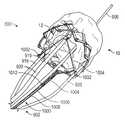
다른 대표적인 실시예에서, 전달 조립체는 반경방향 압축 구성과 반경방향 확장 구성 사이에서 이동될 수 있는 인공 판막 및 전달 장치를 포함할 수 있다. 전달 장치는 핸들, 핸들로부터 원위적으로 연장되고 근위 단부 부분 및 원위 단부 부분을 가지는 샤프트, 인공 판막에 커플링되고 인공 판막을 압축 구성과 확장 구성 사이에 이동시키도록 구성된 복수의 작동기, 및 샤프트의 원위 단부 부분에 커플링된 노우즈 단편(nose piece)을 포함한다. 전달 장치는 노우즈 단편의 근위 단부 부분에 커플링된 캡슐을 더 포함하고, 캡슐은, 인공 심장 판막이 샤프트에 장착될 때 인공 심장 판막의 원위 단부를 압축 구성에서 유지하도록 구성된다. 캡슐은, 인공 판막이 압축 구성으로부터 확장 구성으로 이동할 때 인공 심장 판막의 원위 단부로부터 원위적으로 활주하도록 구성된다.In another representative embodiment, the delivery assembly may include a prosthetic valve and a delivery device movable between a radially compressed configuration and a radially expanded configuration. The delivery device includes a handle, a shaft extending distally from the handle and having a proximal end portion and a distal end portion, a plurality of actuators coupled to the prosthetic valve and configured to move the prosthetic valve between a compressed configuration and an expanded configuration of the shaft; and a nose piece coupled to the distal end portion. The delivery device further includes a capsule coupled to the proximal end portion of the nose segment, the capsule configured to maintain the distal end of the prosthetic heart valve in a compressed configuration when the prosthetic heart valve is mounted to the shaft. The capsule is configured to slide distally from the distal end of the prosthetic valve as the prosthetic valve moves from the compressed configuration to the expanded configuration.
일부 실시예에서, 캡슐은 직물을 포함한다. 직물은 폴리테트라플루오로에틸렌(PTFE), 폴리아민, 폴리우레탄, 폴리프로필렌, 또는 이들의 조합을 포함할 수 있다. 다른 실시예에서, 캡슐은 비-텍스타일(non-textile) 중합체 멤브레인을 포함한다. 비-텍스타일 중합체 멤브레인은 폴리테트라플루오로에틸렌(PTFE), 폴리아민, 폴리우레탄, 폴리프로필렌, 또는 이들의 조합을 포함할 수 있다.In some embodiments, the capsule comprises a fabric. The fabric may include polytetrafluoroethylene (PTFE), polyamine, polyurethane, polypropylene, or combinations thereof. In another embodiment, the capsule comprises a non-textile polymer membrane. The non-textile polymeric membrane may include polytetrafluoroethylene (PTFE), polyamine, polyurethane, polypropylene, or combinations thereof.
일부 실시예에서, 인공 판막은, 반경방향 압축 구성에 있을 때 그리고 반경방향 확장 구성에 있을 때 비-원통형 형상을 갖는다.In some embodiments, the prosthetic valve has a non-cylindrical shape when in a radially compressed configuration and when in a radially expanded configuration.
일부 실시예에서, 캡슐은 반경방향으로 압축된 인공 판막의 길이의 절반 미만에 걸쳐 연장된다.In some embodiments, the capsule extends over less than half the length of the radially compressed prosthetic valve.
다른 대표적인 실시예에서, 방법은, 전달 장치 및 반경방향으로 압축된 인공 판막을 포함하는 전달 조립체를 환자의 신체 내로 삽입하는 단계를 포함한다. 전달 장치는 핸들로부터 원위적으로 연장되는 샤프트, 샤프트의 원위 단부 부분에 커플링된 노우즈 단편, 및 노우즈 단편의 근위 단부 부분에 커플링된 캡슐을 갖는다. 캡슐은, 인공 판막이 샤프트 상에 장착될 때 인공 판막의 원위 단부 부분을 반경방향 압축 구성에서 유지하도록 구성될 수 있다. 방법은, 반경방향으로 압축된 인공 판막이 적어도 부분적으로 천연 환대(native annulus) 내에 배치될 때까지 전달 조립체를 전진시키는 단계, 및 전달 장치의 확장 메커니즘을 작동시키는 것에 의해서 인공 판막을 확장시켜, 캡슐이 인공 판막으로부터 원위적으로 활주되게 하는 단계를 더 포함한다.In another representative embodiment, a method includes inserting a delivery assembly comprising a delivery device and a radially compressed prosthetic valve into a body of a patient. The delivery device has a shaft extending distally from the handle, a nose piece coupled to a distal end portion of the shaft, and a capsule coupled to a proximal end portion of the nose piece. The capsule may be configured to maintain the distal end portion of the prosthetic valve in a radially compressed configuration when the prosthetic valve is mounted on the shaft. The method comprises advancing a delivery assembly until the radially compressed prosthetic valve is at least partially positioned within a native annulus, and expanding the prosthetic valve by actuating an expansion mechanism of the delivery device, thereby encapsulating the capsule. and allowing it to slide distally from the prosthetic valve.
일부 실시예에서, 인공 판막을 확장시키는 단계는 인공 판막이 쐐기 형상을 형성하게 한다. 일부 실시예에서, 캡슐은 직물을 포함한다.In some embodiments, expanding the prosthetic valve causes the prosthetic valve to form a wedge shape. In some embodiments, the capsule comprises a fabric.
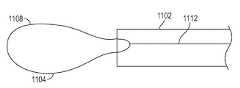
다른 대표적인 실시예에서, 크림핑 메커니즘은 인공 판막에 커플링되도록 구성된 지지 관을 포함하고, 지지 관은 내강을 형성한다. 크림핑 메커니즘은 지지 관의 내강 내에 배치된 연결기, 및 연결기에 커플링되고 인공 판막의 원주 주위에서 연장되도록 구성된 장력 부재를 포함할 수 있다. 근위 지향력을 장력 부재 작동기에 인가하는 것은 장력 부재를 효과적으로 장력화하고, 장력 부재는 다시 반경방향 지향력을 인공 판막의 프레임에 인가하여 인공 판막을 반경방향으로 압축하도록 구성된다.In another exemplary embodiment, the crimping mechanism includes a support tube configured to couple to the prosthetic valve, the support tube defining a lumen. The crimping mechanism may include a connector disposed within a lumen of the support tube, and a tension member coupled to the connector and configured to extend around a circumference of the prosthetic valve. Applying the proximal directing force to the tension member actuator effectively tensions the tensioning member, which in turn is configured to apply a radially directed force to the frame of the prosthetic valve to radially compress the prosthetic valve.
일부 실시예에서, 연결기는 커플링 부분을 포함하고, 장력 부재 작동기는 커플링 부분에 해제 가능하게 커플링되도록 구성된 수용 부분을 포함한다. 일부 실시예에서, 커플링 부분은 나사산을 포함하고, 수용 부분은 상응 나사산을 포함한다. 일부 실시예에서, 장력 부재는 와이어를 포함한다.In some embodiments, the connector includes a coupling portion and the tension member actuator includes a receiving portion configured to be releasably coupled to the coupling portion. In some embodiments, the coupling portion includes a thread and the receiving portion includes a corresponding thread. In some embodiments, the tension member comprises a wire.
다른 대표적인 실시예에서, 의료 디바이스 조립체는 프레임을 가지는 반경방향 확장 가능 및 압축 가능 인공 판막, 전달 장치, 및 크림핑 메커니즘을 포함한다. 전달 장치는 핸들, 및 핸들로부터 원위적으로 연장되고 인공 판막에 해제 가능하게 커플링되도록 그리고 인공 판막을 반경방향 확장 구성과 반경방향 압축 구성 사이에서 이동시키도록 구성된 복수의 작동기를 포함할 수 있다. 크림핑 메커니즘은 인공 판막에 커플링되고 내강을 형성하는 지지 관, 커플링 부분을 포함하고 지지 관의 내강 내에 배치되는 연결기, 연결기에 커플링되고 인공 판막의 원주 주위에서 연장되는 장력 부재, 및 전달 장치의 핸들로부터 연장되고 연결기에 해제 가능하게 커플링되도록 구성된 장력 부재 작동기를 포함할 수 있다. 근위 지향력을 장력 부재 작동기에 인가하는 것은 장력 부재를 효과적으로 장력화하고, 장력 부재는 다시 반경방향 지향력을 인공 판막의 프레임에 인가하여 인공 판막을 완전히 압축한다.In another representative embodiment, a medical device assembly includes a radially expandable and compressible prosthetic valve having a frame, a delivery device, and a crimping mechanism. The delivery device may include a handle and a plurality of actuators extending distally from the handle and configured to be releasably coupled to the prosthetic valve and to move the prosthetic valve between a radially expanded configuration and a radially compressed configuration. The crimping mechanism includes a support tube coupled to the prosthetic valve and defining a lumen, a connector comprising a coupling portion and disposed within a lumen of the support tube, a tension member coupled to the connector and extending about a circumference of the prosthetic valve, and delivery and a tension member actuator extending from the handle of the device and configured to be releasably coupled to the connector. Applying a proximal directing force to the tension member actuator effectively tensions the tensioning member, which in turn applies a radially directed force to the frame of the prosthetic valve to fully compress the prosthetic valve.
일부 실시예에서, 장력 부재는 와이어를 포함한다.In some embodiments, the tension member comprises a wire.
일부 실시예에서, 인공 판막은 원위 단부에서의 제1 직경 및 근위 단부에서의 제2 직경을 가지는 부분 확장 상태에서 테이퍼링된 형상을 가지고, 제2 직경은 제1 직경보다 크고, 완전 압축 상태의 인공 판막은 장력 부재의 장력화 후에 부분 확장 상태에서보다 덜 테이퍼링된다. 일부 실시예에서, 인공 판막은 완전 압축 상태에서 실질적으로 원통형이다.In some embodiments, the prosthetic valve has a tapered shape in a partially expanded state having a first diameter at the distal end and a second diameter at the proximal end, the second diameter is greater than the first diameter, and the prosthetic valve in a fully compressed state. The valve tapers less after tensioning of the tension member than in the partially expanded state. In some embodiments, the prosthetic valve is substantially cylindrical in full compression.
일부 실시예에서, 지지 관은 작동기 중 하나에 장착될 수 있다.In some embodiments, the support tube may be mounted on one of the actuators.
일부 실시예에서, 장력 부재는, 인공 판막의 원주 주위에서 그리고 연결기의 개구부를 통해서 연장되는 루프를 포함한다. 일부 실시예에서, 장력 부재는 봉합사를 포함한다.In some embodiments, the tension member includes a loop extending around the circumference of the prosthetic valve and through the opening of the connector. In some embodiments, the tension member comprises a suture.
일부 실시예에서, 인공 판막은 프레임의 외측부에서 슬리브를 포함하고, 장력 부재는 슬리브를 통해서 연장된다.In some embodiments, the prosthetic valve includes a sleeve on the outside of the frame, and the tension member extends through the sleeve.
다른 대표적인 실시예에서, 방법은 전달 장치의 원위 단부 부분 및 크림핑 메커니즘을 환자의 맥관 구조 내로 삽입하는 단계를 포함한다. 원위 단부 부분은 외피, 및 외피 내에서 유지되는 인공 판막을 포함할 수 있다. 크림핑 메커니즘은 인공 판막에 커플링된 지지 관, 지지 관 내에 배치된 연결기, 인공 판막을 둘러싸는 장력 부재, 및 연결기에 해제 가능하게 커플링된 장력 부재 작동기를 포함할 수 있다. 방법은 인공 판막이 적어도 부분적으로 확장된 상태로 적어도 부분적으로 확장되도록 인공 판막을 전달 장치의 외피로부터 전개하는 단계, 장력 부재를 장력화하기 위해서 근위 지향력을 장력 부재 작동기에 인가하는 단계로서, 그에 의해서 반경방향 지향력을 인공 판막의 프레임에 인가하고, 이는 인공 판막을 부분 확장 상태로부터 완전 압축 상태로 압축하는, 단계, 및 완전 압축된 인공 판막을 이식 장소에 배치하는 단계를 더 포함할 수 있다.In another representative embodiment, a method includes inserting a crimping mechanism and a distal end portion of a delivery device into a vasculature of a patient. The distal end portion may include a sheath and a prosthetic valve retained within the sheath. The crimping mechanism can include a support tube coupled to the prosthetic valve, a connector disposed within the support tube, a tension member surrounding the prosthetic valve, and a tension member actuator releasably coupled to the connector. The method includes deploying the prosthetic valve from the sheath of a delivery device such that the prosthetic valve is at least partially expanded to an at least partially expanded state, applying a proximal directing force to the tensioning member actuator to tension the tensioning member, wherein applying a radial directing force to the frame of the prosthetic valve by means of a method, which may further include compressing the prosthetic valve from a partially expanded state to a fully compressed state, and placing the fully compressed prosthetic valve at the implantation site .
일부 실시예에서, 방법은 인공 판막의 복수의 작동기를 작동시키는 것에 의해서 이식 장소에서 인공 판막을 완전 확장 상태로 반경방향으로 확장시키는 단계를 더 포함할 수 있다. 일부 실시예에서, 방법은 장력 부재를 장력화하기 위해서 근위 지향력을 장력 부재 작동기에 인가하는 단계로서, 그에 의해서 반경방향 지향력을 인공 판막의 프레임에 인가하고, 이는 인공 판막을 완전 확장 상태로부터 완전 압축 상태로 압축하는, 단계를 더 포함한다. 일부 실시예에서, 방법은, 인공 판막을 외피에 대해서 근위적으로 퇴축시키는 것에 의해서 인공 판막을 외피 내로 다시 캡쳐하는 단계, 및 전달 장치, 인공 판막 및 크림핑 메커니즘을 환자의 신체로부터 제거하는 단계를 더 포함한다.In some embodiments, the method may further comprise radially expanding the prosthetic valve to a fully expanded state at the implantation site by actuating a plurality of actuators of the prosthetic valve. In some embodiments, the method includes applying a proximal directing force to the tensioning member actuator to tension the tensioning member, thereby applying a radially directed force to a frame of the prosthetic valve, which causes the prosthetic valve to move out of its fully expanded state. Compressing to a fully compressed state, further comprising the step of. In some embodiments, the method comprises recapturing the prosthetic valve into the sheath by retracting the prosthetic valve proximally relative to the sheath, and removing the delivery device, the prosthetic valve, and the crimping mechanism from the patient's body. include more
본 발명의 전술한 그리고 다른 목적, 특징 및 장점이, 첨부 도면을 참조하여 작성된 이하의 구체적인 설명으로부터 보다 명확해질 것이다.The above and other objects, features and advantages of the present invention will become more apparent from the following detailed description made with reference to the accompanying drawings.
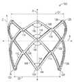
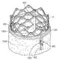
도 1은 인공 심장 판막의 실시예의 사시도이다.
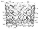
도 2는 다른 실시예에 따른, 인공 심장 판막용 프레임의 측면 입면도이다.
도 3은 도 2의 프레임의 2개의 프레임 스트럿들 사이의 연결을 도시하는 확대 측면도이다.
도 4a는 편평한 구성으로 도시된 도 2의 프레임의 스트럿의 평면도이다.
도 4b는 편평한 구성으로 도시된 도 2의 프레임의 스트럿의 평면도이다.
도 5는 인공 심장 판막용 프레임의 다른 실시예의 측면 입면도이다.
도 6a는 편평한 구성으로 도시된 도 5의 프레임의 스트럿의 평면도이다.
도 6b는 편평한 구성으로 도시된 도 5의 프레임의 스트럿의 평면도이다.
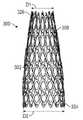
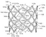
도 7은 완전 확장 구성으로 도시된 인공 심장 판막용 프레임의 다른 실시예의 측면 입면도이다.
도 8은 부분 확장 구성으로 도시된 도 7의 프레임의 측면 입면도이다.
도 9는 부분 확장 구성으로 도시된 도 7의 프레임의 측면 입면도이다.
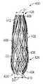
도 10은 완전 압축 구성으로 도시된 도 7의 프레임의 측면 입면도이다.
도 11은 힘-크림핑된 구성으로 도시된 도 7의 프레임의 측면 입면도이다.
도 12는 인공 심장 판막용 프레임의 다른 실시예의 측면 입면도이다.
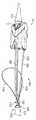
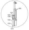
도 13은 인공 심장 판막을 이식하기 위해서 이용되는 것으로 도시된 인공 판막 전달 장치의 실시예의 측면도이다.
도 14는, 부분적으로 도시된, 심장의 천연 대동맥 판막 내에 이식되는 인공 판막의 실시예의 측면도이다.
도 15는, 부분적으로 도시된, 심장의 천연 대동맥 판막 내에 이식된 인공 판막의 실시예의 측면도이다.
도 16은 인공 심장 판막용 프레임의 다른 실시예의 측면 입면도이다.
도 17a는 완전 확장 구성으로 도시된 인공 심장 판막용 프레임의 다른 실시예의 측면 입면도이다.
도 17b는 부분 확장 구성으로 도시된 도 17a의 프레임의 측면 입면도이다.
도 17c는 완전 압축 구성으로 도시된 도 17a의 프레임의 측면 입면도이다.
도 18a는 예시적인 확장 및 결속 메커니즘의 나사의 사시도이다.
도 18b는 예시적인 확장 및 결속 메커니즘의 사시도이다.
도 18c는 도 18b의 확장 및 결속 메커니즘의 다른 사시도이다.
도 19는 도 18b에 따른 복수의 확장 및 결속 메커니즘을 가지는, 반경방향 확장 상태에서 도시된, 인공 판막 프레임의 사시도이다.
도 20은, 프레임의 일부와 함께, 예시적인 크림핑 메커니즘을 포함하는 예시적인 확장 및 결속 부재의 횡단면도이다.
도 21은, 일 실시예에 따른, 도 20의 크림핑 메커니즘을 포함하는 전달 장치의 원위 단부 부분 및 전달 장치에 커플링된 인공 판막의 사시도이다.
도 22는, 일 실시예에 따른, 확장 구성의 크림핑 메커니즘을 포함하는 전달 장치의 원위 단부 부분 및 전달 장치에 커플링된 인공 판막의 측면 입면도이다.
도 23은 인공 판막 주위에 배치된 크림핑 메커니즘을 보여주는, 도 22의 전달 장치 및 인공 판막의 측면 입면도이다.
도 24a는 예시적인 크림핑 메커니즘의 횡단면도이다.
도 24b는 다른 예시적인 크림핑 메커니즘의 횡단면도이다.
도 25는 수축 구성의 크림핑 메커니즘을 보여주는, 도 22의 전달 장치 및 인공 판막의 측면 입면도이다.
도 26은, 반경방향 압축 상태의 인공 판막 위에서 연장되는 캡슐을 보여주는, 일 실시예에 따른, 캡슐을 포함하는 전달 장치의 원위 단부 부분 및 전달 장치에 커플링된 인공 판막의 측면 입면도이다.
도 27는 반경방향 확장 상태의 인공 판막을 보여주는, 도 26의 전달 장치 및 인공 판막의 다른 측면 입면도이다.
도 28은, 일 실시예에서, 인공 판막에 커플링된 크림핑 메커니즘을 포함하는 인공 심장 판막의 사시도이다.
도 29는 도 28의 크림핑 메커니즘의 일부의 확대도이다.
도 30은 크림핑 메커니즘의 일부의 확대된 분해도이다.
도 31은 장력 부재 작동기 및 외피를 더 포함하는, 도 28의 인공 판막 및 크림핑 메커니즘의 사시도이다.
도 32는 완전 압축 구성의 인공 판막과 함께 도시된, 도 28의 인공 판막 및 크림핑 메커니즘의 측면 입면도이다.
도 33은, 일 실시예에서, 프레임에 커플링된 크림핑 메커니즘을 포함하는 인공 심장 판막의 사시도이다.
도 34는 인공 심장 판막용 프레임의 실시예의 측면 입면도이다.
도 35는 인공 심장 판막용 프레임의 다른 실시예의 측면 입면도이다.
도 36은 인공 심장 판막용 프레임의 다른 실시예의 측면 입면도이다.
도 37은 인공 심장 판막용 프레임의 다른 실시예의 측면 입면도이다.1 is a perspective view of an embodiment of an artificial heart valve.
2 is a side elevational view of a frame for an artificial heart valve according to another embodiment.
Fig. 3 is an enlarged side view showing the connection between two frame struts of the frame of Fig. 2;
Fig. 4a is a top view of the struts of the frame of Fig. 2 shown in a flat configuration;
Fig. 4b is a plan view of the struts of the frame of Fig. 2 shown in a flat configuration;
5 is a side elevational view of another embodiment of a frame for a prosthetic heart valve.
Fig. 6a is a top view of the struts of the frame of Fig. 5 shown in a flat configuration;
Fig. 6b is a top view of the struts of the frame of Fig. 5 shown in a flat configuration;
7 is a side elevational view of another embodiment of a frame for a prosthetic heart valve shown in a fully expanded configuration;
Fig. 8 is a side elevational view of the frame of Fig. 7 shown in a partially expanded configuration;
Fig. 9 is a side elevational view of the frame of Fig. 7 shown in a partially expanded configuration;
10 is a side elevational view of the frame of FIG. 7 shown in a fully compressed configuration;
11 is a side elevational view of the frame of FIG. 7 shown in a force-crimped configuration;
12 is a side elevational view of another embodiment of a frame for a prosthetic heart valve.
13 is a side view of an embodiment of a prosthetic valve delivery device shown for use to implant a prosthetic heart valve.
14 is a side view, partially shown, of an embodiment of a prosthetic valve implanted into the native aortic valve of the heart.
15 is a side view of an embodiment of a prosthetic valve implanted in the native aortic valve of the heart, partially shown.
16 is a side elevational view of another embodiment of a frame for a prosthetic heart valve.
17A is a side elevational view of another embodiment of a frame for a prosthetic heart valve shown in a fully expanded configuration.
17B is a side elevational view of the frame of FIG. 17A shown in a partially expanded configuration;
17C is a side elevational view of the frame of FIG. 17A shown in a fully compressed configuration;
18A is a perspective view of a screw of an exemplary expansion and engagement mechanism.
18B is a perspective view of an exemplary expansion and engagement mechanism.
18C is another perspective view of the expansion and engagement mechanism of FIG. 18B;
19 is a perspective view of a prosthetic valve frame, shown in a radially expanded state, with a plurality of expansion and engagement mechanisms according to FIG. 18B ;
20 is a cross-sectional view of an exemplary expansion and engagement member including an exemplary crimping mechanism, along with a portion of a frame.
FIG. 21 is a perspective view of a prosthetic valve coupled to the delivery device and a distal end portion of the delivery device including the crimping mechanism of FIG. 20 , in accordance with one embodiment.
22 is a side elevational view of a prosthetic valve coupled to a delivery device and a distal end portion of a delivery device including a crimping mechanism in an expanded configuration, according to one embodiment.
23 is a side elevational view of the delivery device of FIG. 22 and the prosthetic valve, showing a crimping mechanism disposed around the prosthetic valve;
24A is a cross-sectional view of an exemplary crimping mechanism.
24B is a cross-sectional view of another exemplary crimping mechanism.
25 is a side elevational view of the delivery device and prosthetic valve of FIG. 22, showing the crimping mechanism in a retracted configuration.
26 is a side elevational view of a prosthetic valve coupled to the delivery device and a distal end portion of a delivery device comprising the capsule, according to one embodiment, showing the capsule extending over the prosthetic valve in radial compression.
27 is another side elevational view of the delivery device and prosthetic valve of FIG. 26, showing the prosthetic valve in a radially expanded state.
28 is a perspective view of a prosthetic heart valve including a crimping mechanism coupled to the prosthetic valve, in one embodiment.
29 is an enlarged view of a portion of the crimping mechanism of FIG. 28 ;
30 is an enlarged exploded view of a portion of a crimping mechanism.
FIG. 31 is a perspective view of the prosthetic valve and crimping mechanism of FIG. 28 , further including a tension member actuator and sheath;
FIG. 32 is a side elevational view of the prosthetic valve and crimping mechanism of FIG. 28, shown with the prosthetic valve in a fully compressed configuration.
33 is a perspective view of a prosthetic heart valve including a crimping mechanism coupled to a frame, in one embodiment.
34 is a side elevational view of an embodiment of a frame for a prosthetic heart valve.
35 is a side elevational view of another embodiment of a frame for a prosthetic heart valve.
36 is a side elevational view of another embodiment of a frame for a prosthetic heart valve.
37 is a side elevational view of another embodiment of a frame for a prosthetic heart valve.
예시적인 실시예Exemplary embodiment
몇가지 예를 들면 인공 판막(예를 들어, 인공 심장 판막 또는 정맥 판막), 스텐트, 또는 그래프트(graft)와 같은 인공 이식체에서 이용하기 위한 프레임의 실시예를 본원에서 설명한다. 프레임은, 확장될 때, 비-원통형 형상을 형성하도록 성형된 스트럿을 포함할 수 있다. 개시된 프레임 형상은 인공 이식체에 걸친 압력 구배를 줄일 수 있고 및/또는 판막 주위 누출을 줄일 수 있다.Embodiments of frames for use in prosthetic implants such as prosthetic valves (eg, prosthetic heart valves or venous valves), stents, or grafts are described herein to name a few. The frame may include struts shaped to form a non-cylindrical shape when expanded. The disclosed frame shape may reduce pressure gradients across the implant and/or reduce perivalvular leakage.
본원에서 개시된 인공 디바이스(예를 들어, 인공 판막)는 반경방향 압축 구성과 반경방향 확장 구성 사이에서 반경방향으로 압축 및 확장될 수 있다. 따라서, 인공 디바이스는 전달 중에 반경방향 압축 구성으로 이식체 전달 장치 상에서 크림핑될 수 있고, 이어서 인공 디바이스가 이식 장소에 도달하면 반경방향 확장 구성으로 확장될 수 있다.A prosthetic device (eg, a prosthetic valve) disclosed herein can be compressed and expanded radially between a radially compressed configuration and a radially expanded configuration. Accordingly, the prosthetic device may be crimped on the implant delivery device in a radially compressed configuration during delivery, and then expanded into a radially expanded configuration when the prosthetic device reaches the implantation site.
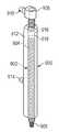
도 1은 일 실시예에 따른 예시적인 인공 판막(10)을 도시한다. 특정 실시예에서, 인공 판막(10)은 천연 대동맥 환대 내에 이식될 수 있으나, 인공 판막은 또한, 천연 승모판, 천연 폐판 및 천연 삼첨판 내를 포함하는, 심장 내의 다른 위치에 이식될 수 있다. 인공 판막(10)은 제1 단부(14) 및 제2 단부(16)를 가지는 환형 스텐트 또는 프레임(12)을 포함할 수 있다. 도시된 실시예에서, 제1 단부(14)는 유입 단부이고, 제2 단부(16)는 유출 단부이다. 다른 실시예에서, 제1 단부(14)는 유출 단부일 수 있고, 제2 단부(16)는 유입 단부일 수 있다. 인공 판막(10)은 또한, 프레임(12)에 커플링되고 인공 판막(10)을 통한 유입 단부(14)로부터 유출 단부(16)로의 혈액의 유동을 조절하도록 구성되는 판막 구조물(18)을 포함할 수 있다. 인공 판막(10)은 프레임(12)의 내부 표면에 장착되고 그 주위에서 균일하게 이격되는 하나 이상의 ("확장 메커니즘"으로도 지칭되는) 작동기(20)를 더 포함할 수 있다. 작동기(20)의 각각은, 이하에서 더 설명되는 바와 같이, 전달 장치의 하나 이상의 각각의 작동기와 해제 가능한 연결을 형성하도록 구성될 수 있다.1 shows an exemplary
판막 구조물(18)은, 예를 들어 가요성 재료로 제조된 하나 이상의 판막엽(22)을 포함하는 판막엽 조립체를 포함할 수 있다. 판막엽 조립체의 판막엽(22)은, 전체적으로 또는 부분적으로, 생물학적 재료, 생체-적합 합성 재료, 또는 다른 그러한 재료로 제조될 수 있다. 적합한 생물학적 재료는, 예를 들어, 소의 심낭(또는 다른 공급원으로부터의 심낭)을 포함할 수 있다. 판막엽(22)은, 예를 들어 각각의 작동기(20)에 장착될 수 있는, 이음매(24)를 형성하도록 배열될 수 있다. 판막 구조물이 인공 판막(10)의 프레임(12)에 커플링될 수 있는 방식을 포함하는, 카테터경유 인공 심장 판막과 관련된 추가적인 상세 내용이, 예를 들어, 미국 특허 제6,730,118호, 제7,393,360호, 제7,510,575호, 제7,993,394호, 및 제 8,652,202호, 그리고 미국 공개 제2018/0325665호에서 확인될 수 있고, 이들 모두는 전체 내용이 본원에서 참조로 포함된다.The
작동기(20)는 프레임(12)을 반경방향으로 확장 및 압축하도록 구성된다. 작동기(20)의 각각은 나사 또는 나사산형 막대(32), 원통체 또는 슬리브(34) 형태의 제1 앵커(anchor), 나사산형 너트(36) 형태의 제2 앵커를 포함할 수 있다. 막대(32)는 슬리브(34) 및 너트(36)를 통해서 연장된다. 예를 들어 2개의 스트럿들 사이의 접합부에서 경첩을 형성하는 각각의 체결구로, 슬리브(34) 및 너트(36)가 프레임(12)에 고정될 수 있다. 각각의 작동기(20)는, 각각의 슬리브(34) 및 너트(36)의 부착 위치들 사이의 거리를 증가시켜 프레임(12)을 축방향으로 늘리고 반경방향으로 압축하도록, 그리고 각각의 슬리브(34) 및 너트(36)의 부착 위치들 사이의 거리를 감소시켜 프레임(12)을 축방향으로 단축하고 반경방향으로 확장시키도록, 구성된다.The
예를 들어, 각각의 막대(32)는 너트(36)의 내부 나사산과 결합되는 외부 나사산을 가질 수 있고, 그에 따라 막대의 회전은 (막대(32)의 회전 방향에 따라) 슬리브(34)를 향하는 또는 그로부터 멀어지는 너트(36)의 상응 축방향 이동을 유발한다. 이는, 막대(32)의 회전 방향에 따라, 슬리브(34) 및 너트(36)를 지지하는 경첩들이 서로를 향해서 더 가까이 이동되게 하여 프레임을 반경방향으로 확장시키거나, 서로로부터 더 멀리 이동되게 하여 프레임을 반경방향으로 압축시킨다.For example, each
다른 실시예에서, 작동기(20)는, 프레임의 반경방향 확장 및 압축을 생성하기 위해서 프레임에 축방향 지향력을 인가하도록 구성된 왕복 유형 작동기일 수 있다. 예를 들어, 각각의 작동기의 막대(32)가 슬리브(34)에 대해서 축방향으로 고정될 수 있고 슬리브(34)에 대해서 활주될 수 있다. 따라서, 이러한 방식으로, 막대(32)를 슬리브(34)에 대해서 원위적으로 이동시키는 것 및/또는 슬리브(34)를 막대(32)에 대해서 근위적으로 이동시키는 것은 프레임을 반경방향으로 압축한다. 역으로, 막대(32)를 슬리브(34)에 대해서 근위적으로 이동시키는 것 및/또는 슬리브(34)를 막대(32)에 대해서 원위적으로 이동시키는 것은 프레임을 반경방향으로 확장시킨다.In another embodiment, the
왕복 유형 작동기가 이용될 때, 인공 판막은 또한, 프레임을 확장 상태에서 유지하는 하나 이상의 결속 메커니즘을 포함할 수 있다. 결속 메커니즘은, 작동기와 별도로 프레임에 장착되는 분리된 구성요소들일 수 있거나, 작동기 자체의 하위-구성요소일 수 있다. 특정 실시예에서, 작동기는, 본원에서 참조로 포함되는, 미국 공개 제2018/0153689호에서 더 설명되는 바와 같이, 조합된 확장 및 결속 메커니즘을 포함할 수 있다.When a reciprocating type actuator is used, the prosthetic valve may also include one or more engagement mechanisms that hold the frame in an extended state. The engagement mechanism may be separate components mounted to the frame separately from the actuator, or may be a sub-component of the actuator itself. In certain embodiments, the actuator may include a combined expansion and engagement mechanism, as further described in US Publication No. 2018/0153689, incorporated herein by reference.
각각의 막대(32)는, 전달 장치의 상응 작동기와 해제 가능하게 연결을 형성하도록 구성된 막대(32)의 근위 단부 부분을 따른 부착 부재(38)를 포함할 수 있다. 전달 장치의 작동기(들)는 인공 판막(10)을 반경방향으로 압축 또는 팽창하기 위해서 힘을 막대에 인가할 수 있다. 도시된 구성의 부착 부재(38)는, 이하에서 더 설명되는 바와 같이, 전달 장치의 작동기의 상응 돌출부(projection)와 결합될 수 있는 노치(40) 및 돌출부(42)를 포함한다.Each
도시된 실시예에서, 인공 판막(10)은 3개의 그러한 작동기(20)를 포함하나, 더 많거나 적은 수의 작동기가 다른 실시예에서 이용될 수 있다. 판막엽(22)은, 작동기(20)의 슬리브(34) 주위를 둘러싸는 이음매 부착 부재(44)를 가질 수 있다. 작동기, 결속 메커니즘, 및 작동기를 작동시키기 위한 전달 장치에 관한 추가적인 상세 내용이 미국 공개 제2019/0060057호, 제2018/0153689호, 제2018/0153689호 및 제2018/0325665호에서 확인할 수 있고, 이들 각각은 그 전체가 본원에서 참조로 포함된다. 이전에 출원에서 개시된 임의의 작동기 및 결속 메커니즘이 본원에서 개시된 임의의 인공 판막에 포함될 수 있다. 또한, 이전 출원에서 개시된 임의의 전달 장치가 본원에서 개시된 임의의 인공 판막을 전달하고 이식하기 위해서 사용될 수 있다.In the illustrated embodiment, the
도 1에는 도시되지 않았지만, 인공 판막(10)은 또한 하나 이상의 스커트 또는 밀봉 부재를 포함할 수 있다. 예를 들어, 인공 판막(10)은 프레임의 내부 표면에 장착된 내부 스커트를 포함할 수 있다. 내부 스커트가 밀봉 부재로서 기능하여, 판막 주위의 누출을 방지하거나 감소시킬 수 있고, 판막엽(22)을 프레임에 고정할 수 있고, 및/또는 크림핑 중에 그리고 인공 판막의 작업 사이클 중에 프레임과의 접촉에 의해서 유발되는 손상으로부터 판막엽을 보호할 수 있다. 인공 판막(10)은 또한 프레임(12)의 외부 표면에 장착된 외부 스커트를 포함할 수 있다(도 15의 외부 스커트(150) 참조). 외부 스커트는, 천연 판막 환대의 조직에 대해서 밀봉하는 것 그리고 인공 판막을 통한 판막 주위 누출을 줄이는데 도움을 주는 것에 의해서, 인공 판막을 위한 밀봉 부재로서 기능할 수 있다. 내부 및 외부 스커트는, 다양한 합성 재료(예를 들어, PET) 또는 천연 조직(예를 들어, 심막 조직) 중 임의의 재료를 포함하는, 다양한 적합한 생체 적합 재료 중 임의의 재료로 형성될 수 있다. 내부 및 외부 스커트는 봉합사, 접착제, 접합, 및/또는 스커트를 프레임에 부착하기 위한 다른 수단을 이용하여 프레임에 장착될 수 있다.Although not shown in FIG. 1 , the
프레임은, 스테인리스 강, 코발트 크롬 합금, 또는 니켈 티타늄 합금("NiTi"), 예를 들어 니티놀과 같은 다양한 적합 재료 중 임의의 재료로 제조될 수 있다. 도 1을 다시 참조하면, 도시된 바와 같이, 프레임(12)은 격자-유형 패턴으로 배열된 복수의 상호 연결된 스트럿(28)을 포함할 수 있다. 스트럿(28)은, 인공 판막(10)이 확장 구성에 있을 때, 대각선 방향으로 배치된 것으로, 또는 인공 판막(10)의 길이방향 축에 대해서 각도를 이루어 오프셋되고 그로부터 반경방향으로 오프셋된 것으로 도시되어 있다. 다른 구현예에서, 스트럿(28)은 도 1에 도시된 것과 상이한 양만큼 오프셋될 수 있거나, 스트럿(28)의 일부 또는 전부가 인공 판막(10)의 길이방향 축에 평행하게 배치될 수 있다.The frame may be made of any of a variety of suitable materials, such as stainless steel, a cobalt chromium alloy, or a nickel titanium alloy (“NiTi”), for example nitinol. Referring back to FIG. 1 , as shown,
도시된 실시예에서, 스트럿들(28)은 각각의 스트럿의 길이를 따라 하나 이상의 피벗 조인트에서 서로 피벗 가능하게 커플링된다. 예를 들어, 도시된 구성에서, 스트럿(28)의 각각에는 스트럿의 대향 단부들에 위치되는 개구들(110)(예를 들어, 도 4a 참조) 및 스트럿의 길이를 따라서 이격된 개구들(110)이 형성될 수 있다. 각각의 경첩은, 개구를 통해서 연장되는 리벳 또는 핀(30)과 같은 체결구를 통해서 스트럿들(28)이 서로 중첩되는 위치에서 형성될 수 있다. 경첩은, 인공 판막(10)의 조립, 준비 또는 이식 중과 같이, 프레임(12)이 반경방향으로 확장 또는 압축될 때, 스트럿들(28)이 서로에 대해서 피벗될 수 있게 한다.In the illustrated embodiment, the
일부 실시예에서, 프레임(12)은, 개별적인 구성요소(예를 들어, 프레임의 스트럿 및 체결구)를 형성하는 것 그리고 이어서 개별적인 구성요소를 함께 기계적으로 조립하고 연결하는 것에 의해서 구성될 수 있다. 다른 실시예에서, 스트럿들(28)은 각각의 경첩으로 서로 커플링되지 않고, 서로에 대해서 달리 피벗되거나 굽혀져 프레임(12)의 반경방향 확장 및 수축을 가능하게 할 수 있다. 예를 들어, 프레임(12)은 (예를 들어, 레이저 컷팅, 전기 성형 또는 물리 기상 증착을 통해서) 단일 재료 단편(예를 들어, 금속 관)으로부터 형성될 수 있다. 프레임의 구성 및 인공 판막과 관련한 추가적인 상세 내용이 미국 공개 제2018/0153689호; 제2018/0344456호; 제2019/0060057호에 설명되어 있고, 이들 모두는 본원에서 참조로 포함된다. 본원에서 개시된 전달 장치와 함께 이용될 수 있는 확장 가능 인공 판막의 부가적인 예가, 본원에서 참조로 포함되는 미국 공개 제2015/0135506호 및 제2014/0296962호에 설명되어 있다.In some embodiments,
도 2는, 전개되어 반경방향으로 확장 구성으로 도시된 프레임(102)을 포함하는 인공 판막(100)의 다른 실시예를 도시한다. 인공 판막(100)은 전술한 바와 같은 판막 구조물(예를 들어, 판막 구조물(18)), 내부 및/또는 외부 스커트, 및 작동기(예를 들어, 작동기(20))를 포함할 수 있으나, 이러한 구성요소는 설명을 위해서 생략되었다. 프레임(102)은 프레임의 유입 단부(124)를 형성하는 유입 단부 부분(104) 및 프레임의 유출 단부(126)를 형성하는 유출 단부 부분(106)을 가질 수 있다. 인공 판막(100)은 유입 단부 부분(104)으로부터 유출 단부 부분(106)까지 연장되는 길이방향 축(A) 및 길이방향 축(A)에 수직으로 연장되는 측방향 축(B)을 형성할 수 있다. 프레임(102)의 하나의 측면만이 도 2에 도시되어 있지만, 프레임(102)이, 도시된 부분과 동일한 대향 측면을 갖는 환형 구조물을 형성한다는 것을 이해하여야 한다.2 shows another embodiment of a
프레임(102)은 격자-유형의 패턴으로 배열된 복수의 상호 연결된 스트럿(108)을 포함한다. 각각의 스트럿은 프레임(102)의 유입 단부(124)로부터 프레임의 유출 단부(126)까지 완전히 연장될 수 있다. 따라서, 도시된 실시예에서, 프레임(102)은, 전체적으로, 유입 단부(124)로부터 유출 단부(126)까지 연속적으로 연장되는 스트럿으로부터 형성될 수 있다. 대안적인 실시예에서, 프레임(102)은, 프레임의 길이를 따라서 단부-대-단부로 연결되는 스트럿들을 가질 수 있다.
스트럿(108)의 각각이 복수의 개구(110)(도 4a 참조)를 포함할 수 있다. 도 4a에 도시된 바와 같이, 개구들(110)이 각각의 스트럿(108)의 길이를 따라서 불균일하게 이격되어, 불균일한 길이를 갖는 복수의 세그먼트(112)를 형성할 수 있다. 도시된 실시예에서, 스트럿(108)은 세그먼트(112a, 112b, 112c, 및 112d)를 포함하고, 세그먼트(112a)가 가장 길고, 각각의 후속 세그먼트(112b, 112c, 및 112d)는 점점 더 짧아지는 길이를 갖는다. 조립된 프레임(102)에서, 스트럿(108)은 복수의 원주방향으로 연장되는 셀의 행(row)으로 배열된 복수의 폐쇄 셀을 형성하고, 셀들은 유입 단부(124)로부터 유출 단부(126)까지 점점 더 작아지기 시작한다. 도시된 실시예에서, 각각의 스트럿(108)은 4개의 세그먼트(112) 및 3개의 셀의 행을 형성하는 5개의 개구(110)를 가지며, 3개의 셀의 행은 셀(128)의 제1 행, 셀(130)의 제2 행, 및 셀(132)의 제3 행을 포함하고, 셀(128)이 가장 크고, 셀(130)은 셀(128)보다 작고, 셀(132)은 셀(130)보다 작다.Each of the
도 2에 도시된 바와 같이, 스트럿 세그먼트의 가변적인 길이들은 또한 피벗 가능하게 연결된 스트럿들 사이에서 각도(144, 146, 148, 150)를 형성하고, 그러한 각도들은 유입 단부(124)로부터 유출 단부(126)까지 점점 더 증가된다. 대안적인 실시예에서, 하나 이상의 세그먼트가 불균일한 길이들을 가질 수 있고, 하나 이상의 세그먼트가 동일한 길이를 가질 수 있다. 예를 들어, 세그먼트(112a)가 가장 긴 세그먼트일 수 있고, 세그먼트(112b, 112c)가 동일한 길이를 가질 수 있고, 세그먼트(112d)가 가장 짧은 세그먼트일 수 있다.As shown in FIG. 2 , the variable lengths of the strut segments also form
도 4a를 다시 참조하면, 도시된 실시예에서, 각각의 세그먼트(112)는 동일한 폭(W)을 갖는다. 그러나, 다른 실시예에서, 각각의 세그먼트(112)의 폭이 스트럿(108)의 길이를 따라서 다를 수 있다. 예를 들어, 프레임(102)의 유입 단부 부분(104)에 인접한 세그먼트(112a)의 폭이 프레임의 유출 단부 부분(106)에 인접한 세그먼트(112d)의 폭보다 넓을 수 있거나, 그 반대일 수 있다. 일부 실시예에서, 스트럿(108)은 세그먼트(112a, 112b, 112c, 및 112d)를 포함할 수 있고, 세그먼트(112a)가 가장 넓고, 각각의 후속 세그먼트(112b, 112c, 112d)는 점점 더 좁아지는 폭을 갖는다. 다른 실시예에서, 스트럿(108)은 세그먼트(112a, 112b, 112c, 및 112d)를 포함할 수 있고, 세그먼트(112a)가 가장 좁고, 각각의 후속 세그먼트(112b, 112c, 112d)는 점점 더 넓어지는 폭을 갖는다.Referring again to FIG. 4A , in the illustrated embodiment, each
다른 실시예에서, 유입 단부 부분(104) 및 유출 단부 부분(106)에 인접한 프레임의 스트럿의 세그먼트 즉, 각각의 세그먼트(112a 및 112d)만이 가변적인 폭을 가지고, 단부 세그먼트들 사이의 세그먼트들은 동일한 폭을 가질 수 있다. 예를 들어, 일 실시예에서, 세그먼트(112a)는 제1의 가장 넓은 폭을 가질 수 있고, 세그먼트(112b 및 112c)의 각각은 제2의 더 좁은(세그먼트(112a)보다 좁은) 폭을 가질 수 있고, 세그먼트(112d)는 제3의 가장 좁은(세그먼트(112a, 112b, 및 112c)보다 좁은) 폭을 가질 수 있다. 다른 실시예에서, 세그먼트(112a)는 제1의 가장 좁은 폭을 가질 수 있고, 세그먼트(112b 및 112c)의 각각은 제2의 더 넓은(세그먼트(112a)보다 넓은) 폭을 가질 수 있고, 세그먼트(112d)는 제3의 가장 넓은(세그먼트(112a, 112b, 및 112c)보다 넓은) 폭을 가질 수 있다.In another embodiment, only the segments of the strut of the frame adjacent the
스트럿들(108)을 따른 세그먼트들(112)의 폭들의 변경은, 프레임(102)이 반경방향 압축 구성에 있을 때 테이퍼링된 형상을 가질 수 있게 한다. 예를 들어, 스트럿 세그먼트들이 유출 단부 부분을 따라서 보다 유입 단부 부분을 따라서 더 좁은 실시예에서(세그먼트(112a)가 세그먼트(112d)보다 좁다), 프레임이 반경방향으로 압축될 때, 유입 단부 부분(104)은 유출 단부 부분(106)의 직경보다 작은 직경을 가질 수 있다. 따라서, 외부 스커트(예를 들어, 도 15에 도시된 스커트(150))가 프레임(102)의 유입 단부 부분(104)의 외부 표면에 장착될 때, 반경방향으로 압축된 프레임(102)은, 유출 단부 부분(106)에서의 프레임의 직경과 실질적으로 동일한 (외부 스커트를 포함하는) 유입 단부 부분에서의 직경을 가질 수 있다. 그에 따라, 프레임 및 스커트의 조합은, 반경방향으로 압축될 때, 실질적으로 원통형인 형상 및 실질적으로 일정한 직경을 가질 수 있고, 그에 따라 환자의 맥관 구조를 통한 인공 판막의 전진을 촉진할 수 있다.Changing the widths of
또 다른 실시예에서, 각각의 세그먼트(112)는 프레임의 유입 단부로부터 프레임의 유출 단부까지의 방향으로, 또는 프레임의 유출 단부로부터 프레임의 유입 단부까지의 방향으로 각각의 세그먼트의 길이를 따라서 테이퍼링되는 폭(W)을 가질 수 있다. 예를 들어, 세그먼트(112a)는 세그먼트(112a)의 길이를 따라서 테이퍼링되는 폭을 가질 수 있다. 일부 실시예에서, 각각의 세그먼트(112)는, 스트럿(108)의 길이를 따라서 감소되는 평균 폭을 더 가질 수 있다.In another embodiment, each
본원에서 개시된 임의의 스트럿 및 프레임이, 전술한 바와 같이 각각의 세그먼트를 따라서 폭이 달라지는 스트럿을 가질 수 있다.Any of the struts and frames disclosed herein may have struts that vary in width along each segment as described above.
도 2에 도시된 바와 같이, 각각의 스트럿(108)이 프레임의 길이방향 축(A)에 대해서 나선형으로 곡선화되어 프레임(102)의 환형 형상을 형성할 수 있다. 나선형 곡선은 각각의 스트럿(108)에 오목한 반경방향 내부 표면(길이방향 축(A)에 대면되는 표면) 및 대향되는 볼록한 반경방향 외부 표면(길이방향 축(A)으로부터 멀어지는 쪽으로 대면되는 표면)을 제공한다.As shown in FIG. 2 , each
도시된 실시예에서, 각각의 스트럿(108)은 4개의 세그먼트(112) 및 3개의 셀의 행을 형성하는 5개의 개구(110)를 포함한다. 다른 실시예에서, 각각의 스트럿은 상이한 수의 스트럿 세그먼트 및 프레임 셀의 행을 형성하기 위한 더 많거나 적은 수의 개구를 가질 수 있다. 예를 들어, 도 7 내지 도 9는 (후술되는) 인공 판막(300)을 도시하고, 각각의 스트럿은 7개의 개구를 포함한다.In the illustrated embodiment, each
도 3을 참조하면, 개구(110)는, 인공 판막(10)(도 1)을 참조하여 전술한 것과 같이, 체결구(114)를 이용하여 스트럿들(108)을 서로 연결하기 위해서 사용된다. 각각의 체결구(114)는 샤프트(114a) 및 확대된 헤드 부분(114b)으로 형성될 수 있다. 각각의 경첩 조인트에 위치되는 개구(110) 중 하나가, 헤드 부분(114b)을 수용하기 위한 크기의 대응-보어(134)로 형성될 수 있다. 와셔 또는 부싱과 같은 이격부재(116)가 스트럿들(108) 사이에서 조인트 내에 배치될 수 있다. 이격부재(116)는 스트럿들(108)이 서로에 대해서 이동하는 것을 보조할 수 있다. 스트럿에 관한 추가적인 상세 내용이 미국 공개 제2018/0344456호에서 확인될 수 있다. 다른 실시예에서, 개구(110), 체결구(114) 및/또는 이격부재(116)가 생략될 수 있다. 예를 들어, 스트럿들(108)이, 예를 들어 접합 또는 접착에 의해서, 또는 금속 관으로부터 프레임의 개별적인 스트럿을 레이저-컷팅하는 것에 의해서, 서로 고정적으로 연결될 수 있다.Referring to FIG. 3 , the
도 4a는 프레임의 길이방향 축(A)에 평행한 평면(P) 내의 단일 스트럿(108)의 편평한 투영을 도시한다. 평면(P)은 XY-평면(도 4b에 도시된 좌표계 참조)이고, 그러한 평면으로부터 축(B)이 Z-축에 평행하게 그리고 길이방향 축(A) 및 평면(P)에 수직으로 연장된다. 도시된 바와 같이, 세그먼트들(112)은, 인접 단부들이 중간 세그먼트(118)에 의해서 서로 상호 연결되어, 서로에 대해서 단부-대-단부로 배열될 수 있다. 스트럿(108)은, 프레임(102)의 유입 단부(124) 및 유출 단부(126)에서 정점들(122)을 형성하는 (세그먼트(112)에 비해서) 확대된 단부 부분들(120)을 가질 수 있다. 중간 세그먼트(118) 및 단부 부분(120)의 각각이, 예를 들어 그 기하형태적 중심에서, 체결구(114)를 수용하기 위한 각각의 개구(110)를 가질 수 있다. 각각의 세그먼트(112)는 도시된 바와 같이 스트럿(108)의 전체 길이에 수직인 방향으로 인접한 세그먼트(112)로부터 측방향으로 약간 오프셋될 수 있다. 대안적인 실시예에서, 세그먼트들(112)은 서로에 대해서 어떠한 오프셋도 없이 배열될 수 있다.Figure 4a shows a flat projection of a
도시된 실시예에서, 스트럿(108)의 전체적인 형상이 평면(P) 내에서 측방향 축(B)(또는 축(B)에 평행하고 축(A)에 수직인 임의의 라인)에 대해서 곡선화되도록, 스트럿(108)의 각각의 세그먼트(112)가 곡선화된다. 본원에서 사용된 바와 같이, 특정 축에 대해서 곡선화된, 스트럿 또는 스트럿 세그먼트와 같은, 구성요소는, 그러한 구성요소가 해당 축을 중심으로 곡선화된다는 것 그리고 해당 축이, 평면(P)에 수직이고 곡선의 곡률의 중심을 통해서 연장되는 라인에 평행하다는 것을 의미한다. 다시 말해서, 스트럿(108)은, (평면(P)의 내외로 연장되는) 축(B)을 중심으로 굽혀져 곡선을 형성하는 직선형 막대로 생각될 수 있다. 축(B)은, 스트럿(108)의 곡률의 중심을 통해서 연장되는 라인에 평행하다.In the illustrated embodiment, the overall shape of the
특정 실시예에서, 각각의 스트럿은 스트럿의 하나의 단부로부터 스트럿의 다른 단부까지 연속적이고 일정한 곡선을 가질 수 있다. 다른 실시예에서, 길이방향 축(A)에 평행한 평면 내의 각각의 세그먼트(112)의 투영이 직선형일 수 있고(즉, 길이방향 축(A)에 대한 임의의 나선형 곡률을 제외하고, 각각의 세그먼트(112)가 직선형이고), 스트럿(108)의 길이를 따른 인접한 세그먼트(112)에 대한 각각의 세그먼트(112)의 오프셋의 양이 달라질 수 있고, 그에 따라 스트럿(108)의 전체적인 형상이 그 길이를 따라서 축(B)(또는 축(B)에 평행하고 축(A)에 수직인 임의의 라인)에 대해서 곡선화되고; 다시 말해서, 스트럿의 일 단부로부터 타 단부까지 연장되고 각각의 세그먼트(112)와 교차되는 라인이 축(B)에 대해서 곡선화된다. 대안적으로, 개별적인 스트럿 세그먼트(112)는 직선형일 수 있고 0이 아닌 각도로 서로에 대해서 단부-대-단부 연결될 수 있고, 그에 따라 스트럿(108)의 전체적인 형상은 그 길이를 따라서 측방향 축(B)(또는 축(B)에 평행하고 축(A)에 수직인 임의의 라인)에 대해서 곡선화된다. 다른 실시예에서, 프레임의 스트럿의 하나 이상이 그 길이를 따라서 일정하지 않은 또는 가변적인 곡률을 가질 수 있다(그러한 경우에, 스트럿의 길이를 따라서 이동함에 따라, 스트럿의 곡률의 중심이 달라질 수 있다). 예를 들어, 곡률 반경은 세그먼트(112b, 112c)를 따라서 더 클 수 있고 세그먼트(112a, 112d)를 따라서 더 작을 수 있다.In certain embodiments, each strut may have a continuous and constant curve from one end of the strut to the other end of the strut. In other embodiments, the projection of each
도 4b는, 도시된 좌표계의 X-축 및 Y-축에 의해서 형성된 평면(P) 내의 미롤링 또는 미랩핑(unwrapped) 구성에서의 프레임(102)인, 프레임(102') 위에 중첩된 프레임(102)의 윤곽선을 도시한다. 프레임의 임의의 스트럿(108)에서, 스트럿의 단부 및 프레임(102')의 유입 및 유출 단부를 통해서 연장되는 대각선 또는 축(D)이 그려질 수 있고, 축(D)은 축(A)과 임의의 각도를 형성한다. 각각의 스트럿(108)은 축(D) 위의 공간 내에서 스트럿의 길이를 따라서 축(D)으로부터 멀리 그리고 다시 축(D)을 향해서 곡선화된다. 또한, 스트럿은 축(D)에 대해서 오목한 것으로 설명될 수 있다.4B shows a frame superimposed over frame 102',
도 2에 도시된 바와 같이, 각각의 스트럿(108)은, 프레임(102)의 유출 단부(126)에 대해서 볼록하도록, 곡선화되고 배열될 수 있다. 따라서, 도시된 실시예에서 각각의 스트럿(108)은 프레임의 유출 단부(126)에 대면되는 볼록한 제1 길이방향 연부(136), 및 프레임의 유입 단부(124)에 대면되는 오목한 제2의 길이방향 연부(138)를 갖는다. 스트럿(108)의 고유 형상으로 인해서, 스트럿에 의해서 형성된 프레임(102)은 비-유클리드 기하형태를 가지고, 특히, (리만 기하형태(Riemannian geometry)로도 지칭되는) 타원형 기하형태를 갖는다. 그에 따라, 도시된 실시예에서 프레임(102)은 "리만" 프레임으로 지칭될 수 있다.As shown in FIG. 2 , each
평면(P) 내의 스트럿(108)의 곡률의 정도는, 이하의 수학식에서 확인되는 바와 같은, 원호로서 스트럿을 포함하는 원의 반경의 역수로서 정의될 수 있다:The degree of curvature of the
수학식 1:
도 2를 다시 참조하면, 확장 구성에서, 평면(P) 내의 스트럿(108)의 곡률은 비-원통형의 테이퍼링된 형상(예를 들어, 절두형 형상, V-형상, 또는 Y-형상)을 프레임(102)에 부여할 수 있고, 유출 단부(126)는 유입 단부(124)의 제2 직경(D2)보다 큰 제1 직경(D1)을 갖는다. 테이퍼의 정도는, 길이방향 축(A)과 프레임의 외부 표면에 접선으로 그려진 라인(C) 사이의 각도의 측정치일 수 있는, 프레임(102)의 경사 각도로 지칭될 수 있다. 환자의 천연 환대 내에 이식될 때, 테이퍼링된 형상에 의해서 생성된 유입에 비해서 더 큰 유출은 인공 판막에 걸친 압력 구배를 줄일 수 있고, 그에 따라 혈역학을 개선하고 판막 주위 누출 위험을 줄이는데 도움을 줄 수 있다.Referring again to FIG. 2 , in the expanded configuration, the curvature of the
특정 실시예에서, 라인(A)와 라인(C) 사이의 경사 각도는 적어도 2도, 적어도 5도, 적어도 10도, 적어도 20도, 적어도 30도, 적어도 40도, 또는 적어도 50도일 수 있다. 특정 실시예에서, 경사 각도는 2도 내지 15도일 수 있다. 특정 실시예에서, 유출 직경(D1) 대 유입 직경(D2)의 비율은 적어도 1 초과, 적어도 1.1 초과, 적어도 1.2 초과, 적어도 1.3 초과, 적어도 1.4 초과, 또는 적어도 1.5 초과이다.In certain embodiments, the angle of inclination between line A and line C may be at least 2 degrees, at least 5 degrees, at least 10 degrees, at least 20 degrees, at least 30 degrees, at least 40 degrees, or at least 50 degrees. In certain embodiments, the angle of inclination may be between 2 degrees and 15 degrees. In certain embodiments, the ratio of outlet diameter D1 to inlet diameter D2 is at least greater than 1, greater than at least 1.1, greater than at least 1.2, greater than at least 1.3, greater than at least 1.4, or greater than at least 1.5.
일부 실시예에서, 유출 직경(D1)과 유입 직경(D2) 사이에 2 내지 3 mm의 차이가 있다. 하나의 특정 예에서, 유출 직경(D1)은 약 30 mm이고 유입 직경(D2)은 약 27 mm이다. 다른 예에서, 유출 직경(D1)은 약 31.5 mm이고 유입 직경(D2)은 약 29 mm이다. 다른 예에서, 유출 직경(D1)은 약 24.5 mm이고 유입 직경(D2)은 약 22 mm이다.In some embodiments, there is a difference of 2-3 mm between the outlet diameter D1 and the inlet diameter D2. In one specific example, the outlet diameter D1 is about 30 mm and the inlet diameter D2 is about 27 mm. In another example, the outlet diameter D1 is about 31.5 mm and the inlet diameter D2 is about 29 mm. In another example, the outlet diameter D1 is about 24.5 mm and the inlet diameter D2 is about 22 mm.
일부 실시예에서, 크림핑된 또는 반경방향으로 압축 구성에 있는 동안, 프레임(102)은 테이퍼링된 형상을 유지할 수 있고, 유출 단부(126)는 유입 단부(124)의 직경보다 큰 직경을 가지고, 압축 구성의 프레임의 경사 각도는 프레임이 확장 구성에 있을 때의 프레임의 경사 각도보다 클 수 있다(예를 들어, 후술되는 도 17c 참조).In some embodiments, while in the crimped or radially compressed configuration, the
또한, 구체적인 실시예에서, 반경방향 압축 구성으로 압축될 때, 특정 실시예에서, 스트럿(108)(또는 본원에서 개시된 임의의 프레임의 스트럿)은, (양 단부에서 지지되는 빔의 굽힘과 유사하게) 중첩되는 스트럿들 사이의 고정된 연결로 인해서 그 길이를 따라서 탄성적으로 변형되고, 및/또는 스트럿에 인가된 트위스팅(twisting) 또는 비틀림 힘으로 인해서 그 길이방향 축에 대해서 탄성적으로 변형될 수 있다. 프레임이 (예를 들어, 전달 장치의 외피 내에서) 반경방향 압축 상태로 유지될 때, 탄성적으로 변형된 스트럿(108)은 프레임을 장력 상태로 배치한다. 따라서, 반경방향 압축 상태로부터 해제될 때(예를 들어, 전달 장치의 외피로부터 전개될 때), 스트럿은, 프레임이 적어도 부분적으로 그 "자유" 상태 또는 이완 상태로 확장되게 하는 스프링력을 제공한다. 필요한 경우, 작동기(예를 들어, 작동기(20))를 이용하여, 프레임을 부분 확장 상태로부터 완전 확장 상태로 더 확장할 수 있다.Also, in certain embodiments, when compressed into a radially compressed configuration, in certain embodiments, the struts 108 (or struts of any frame disclosed herein) (similar to bending of a beam supported at both ends) ) to be elastically deformed along its length due to the fixed connection between the overlapping struts, and/or to be elastically deformed about its longitudinal axis due to a twisting or torsional force applied to the strut. can When the frame is held in radial compression (eg, within the envelope of the delivery device), the elastically
프레임의 자유 상태 또는 이완 상태는, 프레임에 작용하는 어떠한 외부 힘도 없을 때 프레임이 일반적으로 가지는 형상이다. 이완 상태는, 프레임의 형상 및 프레임이 조립될 때 스트럿 내에 도입된 탄성 변형의 범위에 따라서, 프레임의 완전 확장 상태 또는 부분 확장 상태일 수 있다. 예를 들어, 스트럿은, 예를 들어 스트럿을 재료의 원통형 단편으로부터 가공하는 것(예를 들어, 레이저 컷팅하는 것) 그리고 이어서 테이퍼링된 형상을 가지는 프레임을 형성하기 위한 방식으로 스트럿들을 서로 조립하는 것에 의해서, 원통체의 곡률에 일치되도록 제조될 수 있다. 이는 스트럿 내에서 굽힘 및 비틀림 스트레인을 유도하고, 재료의 탄성 범위 내에서 스트럿을 변형시킨다. 탄성 변형은, 프레임이, 반경방향 압축 상태로부터 해제된 후에, 자가-확장되거나 그 이완 상태로 다시 되돌아 가게 하는 스프링력을 제공한다.The free state or relaxed state of the frame is the shape that the frame generally has when there is no external force acting on the frame. The relaxed state may be a fully expanded state or a partially expanded state of the frame, depending on the shape of the frame and the extent of elastic deformation introduced into the struts when the frame is assembled. For example, struts may be used, for example, by machining (eg, laser cutting) the strut from a cylindrical piece of material and then assembling the struts together in a manner to form a frame having a tapered shape. Thus, it can be manufactured to match the curvature of the cylindrical body. This induces bending and torsional strain in the strut and deforms the strut within the elastic range of the material. The elastic deformation provides a spring force that causes the frame to self-expand or return back to its relaxed state after being released from its radially compressed state.
전술한 바와 같이, 프레임의 스트럿은, 스테인리스 강 또는 코발트 크롬 합금과 같은 소성 변형 가능 금속, 또는 니켈 티타늄 합금("NiTi"), 예를 들어 니티놀과 같은 초-탄성 재료를 포함하는, 다양한 금속으로 형성될 수 있다. 소성적으로 변형 가능한 금속으로 형성될 때, 스트럿(108) 및 스트럿들(108) 사이의 연결은, 프레임이 반경방향 확장 상태로부터 반경방향 압축 상태로 압축될 때(그리고 그 반대일 때), 금속의 탄성 변형 범위 내에서 스트럿을 유지하도록, 그에 따라 반경방향 압축 상태와 반경방향 확장 상태 사이에서 전이될 때 프레임의 소성 변형을 방지하도록 구성될 수 있다.As noted above, the struts of the frame may be made of a variety of metals, including plastically deformable metals such as stainless steel or cobalt chromium alloys, or super-elastic materials such as nickel titanium alloys (“NiTi”), such as nitinol. can be formed. When formed from a plastically deformable metal, the
일부 실시예에서, 프레임의 이완 상태는 프레임의 완전 확장 및 동작 상태이고, 판막엽(22)은 인공 판막을 통한 혈액의 유동을 조절하는 기능을 할 수 있고, 스트럿(108)의 스프링력은 압축 상태로부터 확장 및 동작 상태로의 프레임의 완전한 반경방향 확장을 생성하기에 충분할 수 있다. 이러한 방식으로, 프레임(102)은 작동기(20)를 이용하지 않고도 압축 상태로부터 확장 상태로 완전히 자가-확장될 수 있다. 그러나, 프레임이 그 자체의 탄성에 의해서 완전히 확장되는 것을 천연 해부조직이 저지하는 경우에(예를 들어, 대동맥 협착증의 경우에), 작동기를 제공하여 프레임의 확장을 보조할 수 있다. 작동기의 제공 여부와 관계없이, 인공 판막(100)은, 프레임을 확장 상태에서 유지하도록 구성된 (전술한) 하나 이상의 결속 메커니즘을 포함할 수 있다.In some embodiments, the relaxed state of the frame is the fully extended and operational state of the frame, the
대안적인 실시예에서, 프레임의 이완 상태는 완전 확장 상태와 반경방향으로 압축된 전달 상태 사이에서 부분적으로 확장된 상태일 수 있다. 예를 들어, (후술되는) 프레임(302)의 이완 상태가 도 8 및 도 9에 도시된 부분 확장 상태들 중 어느 하나일 수 있다. 이완 상태가 부분 확장 상태일 때, 하나 이상의 작동기를 제공하여 인공 판막을 완전히 확장시킬 수 있다. 또 다른 실시예에서, 프레임을 반경방향 압축 상태로부터 완전 확장 상태로 확장시키기 위해서 하나 이상의 작동기가 이용될 수 있는 경우에, 반경방향으로 압축될 때 스트럿이 탄성적으로 변형되지 않도록 그리고 그에 따라 스트럿이 어떠한 스프링력도 제공하지 않도록 또는 프레임을 확장으로 편향시키지 않도록, 프레임이 구성된다.In an alternative embodiment, the relaxed state of the frame may be a partially expanded state between a fully expanded state and a radially compressed transfer state. For example, the relaxed state of the frame 302 (described later) may be any one of the partially expanded states shown in FIGS. 8 and 9 . When the relaxed state is the partially expanded state, one or more actuators may be provided to fully expand the prosthetic valve. In yet another embodiment, where one or more actuators may be used to expand the frame from a radially compressed state to a fully expanded state, such that the strut is not elastically deformed when compressed in the radial direction and thus the strut is The frame is constructed such that it does not provide any spring force or bias the frame into extension.
도 17a 내지 도 17c는 다른 실시예에 따른 인공 판막(800)을 도시한다. 인공 판막(800)이 프레임(802)을 갖는다는 것을 제외하고, 인공 판막(800)은 인공 판막(100)과 유사하고, 각각의 스트럿(808)은 7개의 개구(810)를 포함하고 그에 따라 인공 판막(100)의 스트럿보다 많은 스트럿 세그먼트 및 프레임 셀을 갖는다. 프레임(802)은 리만 프레임의 다른 예이다. 인공 판막(10)과 마찬가지로, 인공 판막(800)은 전술한 바와 같이 판막 구조물(예를 들어, 판막 구조물(18)), 내부 및/또는 외부 스커트, 및 작동기(예를 들어, 작동기(20))를 포함할 수 있으나, 이러한 구성요소들은 설명을 위해서 생략되었다. 프레임(802)은 프레임의 유입 단부(824)를 형성하는 유입 단부 부분(804) 및 프레임의 유출 단부(826)를 형성하는 유출 단부 부분(806)를 가질 수 있다. 인공 판막은 유입 단부 부분(804)으로부터 유출 단부 부분(806)까지 연장되는 길이방향 축(A) 및 길이방향 축(A)에 수직으로 연장되는 측방향 축(B)을 형성할 수 있다.17A-17C illustrate a
프레임(802)은, 프레임(802)의 유입 단부(824)로부터 유출 단부(826)까지 연장되는 복수의 상호 연결된 스트럿(808)을 포함한다. 따라서, 도시된 실시예에서, 프레임(802)은, 전체적으로, 유입 단부(824)로부터 유출 단부(826)까지 연속적으로 연장되는 스트럿으로부터 형성될 수 있다. 대안적인 실시예에서, 프레임(802)은, 프레임의 길이를 따라서 단부-대-단부로 연결되는 스트럿들을 가질 수 있다.The
스트럿(808)의 각각이 복수의 개구(810)를 포함할 수 있다. 도시된 바와 같이, 개구들(810)이 스트럿(308)의 길이를 따라서 불균일하게 이격되어, 불균일한 길이를 갖는 복수의 세그먼트(812)를 형성할 수 있다. 도시된 실시예에서, 스트럿(808)은 세그먼트(812a, 812b, 812c, 812d, 812e, 및 812f)를 포함하고, 세그먼트(812a)가 가장 길고, 각각의 후속 세그먼트(812b, 812c, 812d, 812e, 및 812f)는 점점 더 짧아지는 길이를 갖는다. 조립된 프레임(802)에서, 스트럿(808)은 복수의 원주방향으로 연장되는 셀의 행으로 배열된 복수의 폐쇄 셀을 형성하고, 셀들은 유입 단부(824)로부터 유출 단부(826)까지 점점 더 작아지기 시작한다. 도시된 실시예에서, 각각의 스트럿(808)은 6개의 세그먼트(812) 및 5개의 셀의 행을 형성하는 7개의 개구(810)를 가지며, 5개의 셀의 행은 셀(828)의 제1 행, 셀(830)의 제2 행, 셀(832)의 제3 행, 셀(834)의 제4 행, 및 셀(836)의 제5 행을 포함하고, 셀(828)이 가장 크고, 셀의 각각의 행은 유입 단부로부터 유출 단부까지 점점 더 작아지기 시작한다.Each of the
스트럿 세그먼트의 가변적인 길이들은 또한 피벗 가능하게 연결된 스트럿들 사이에서 각도(838, 840, 842, 844, 846, 848)를 형성하고, 그러한 각도들은 유입 단부(824)로부터 유출 단부(826)까지 점점 더 증가된다.The variable lengths of the strut segments also form
대안적인 실시예에서, 하나 이상의 세그먼트가 불균일한 길이들을 가질 수 있고, 하나 이상의 세그먼트가 동일한 길이를 가질 수 있다. 예를 들어, 세그먼트(812a)가 가장 긴 세그먼트일 수 있고, 세그먼트(812b, 812c, 812d, 812e)가 동일한 길이를 가질 수 있고, 세그먼트(812f)가 가장 짧은 세그먼트일 수 있다. 또 다른 실시예에서, 개구들(810)이 각각의 스트럿의 길이를 따라서 균일하게 이격되어, 동일한 길이의 세그먼트들을 형성할 수 있다. 스트럿(808)은, 도 4a에 도시된 스트럿(108)과 관련하여 전술한 바와 같이, 가변적인 폭의 세그먼트들(812)을 더 포함할 수 있다.In an alternative embodiment, one or more segments may have non-uniform lengths, and one or more segments may have the same length. For example,
도 17a에 도시된 바와 같이, 각각의 스트럿(808)이 프레임의 길이방향 축(A)에 대해서 나선형으로 곡선화되어 프레임(802)의 환형 형상을 형성할 수 있다. 나선형 곡선은 각각의 스트럿에 오목한 반경방향 내부 표면(길이방향 축(A)에 대면되는 표면) 및 대향되는 볼록한 반경방향 외부 표면(길이방향 축(A)으로부터 멀어지는 쪽으로 대면되는 표면)을 제공한다.As shown in FIG. 17A , each
스트럿들(808)은, 예를 들어, 전술한 바와 같이 개구 내에 배치된 체결구(114)와 같은 체결구를 이용하여, 개구(810)에서 서로 연결될 수 있다.
프레임의 길이방향 축(A)에 평행한 평면(P) 내의 스트럿(808)의 편평한 투영은, 스트럿(808)이 7개의 개구(810) 및 6개의 세그먼트(812)를 갖는다는 것을 제외하고, 도 4a의 스트럿(108)에 도시된 투영과 유사하다. 일부 실시예에서, 각각의 세그먼트(812)는 (길이방향 축(A)에 대한 나선형 곡률을 가지는 것을 제외하고) 직선형일 수 있고, 스트럿의 전체적인 형상이 축(B)에 대해서 그 길이를 따라서 곡선화되도록 인접한 세그먼트들로부터 오프셋될 수 있다. 다른 실시예에서, 각각의 세그먼트(812)가 곡선화되어, 스트럿의 길이를 따라 축(B)에 대해서 연속적이고 일정한 곡선을 생성할 수 있다.A flat projection of the
각각의 스트럿(808)은, 프레임(802)의 유출 단부(826)에 대해서 오목하도록, 곡선화되고 배열될 수 있다. 각각의 스트럿(808)의 곡률의 정도는 전술한 수학식 1을 이용하여 계산될 수 있다. 도시된 실시예에서, 각각의 스트럿(808)은 평면(P) 내에서 동일한 정도의 곡률을 갖는다. 그러나, 다른 실시예에서, 각각의 스트럿들(808)이 상이한 곡률의 정도를 가질 수 있다.Each
도 17a 내지 도 17c를 여전히 참조하면, 스트럿(808)의 탄성 및 중첩되는 스트럿들 사이의 연결로 인해서, 스트럿의 곡률의 정도는 프레임의 반경방향 압축 및 확장 중에 변경될 수 있다. 도 17c에 도시된 바와 같이, 반경방향으로 압축 구성에서, 스트럿이 반경방향으로 확장 구성(도 17a 참조)에 있을 때보다 작은 정도의 곡률을 갖도록(각각의 스트럿이 평면(P) 내에서 더 직선형이거나 직선형이 되도록), 각각의 스트럿이 변형될 수 있다.Still referring to FIGS. 17A-17C , due to the elasticity of the
인공 판막(100)에서와 같이, 확장 구성에서, 평면(P) 내의 스트럿(808)의 곡률은 비-원통형의 테이퍼링된 형상(예를 들어, 절두형 형상, V-형상, 또는 Y-형상)을 프레임(802)에 부여할 수 있고, 유출 단부(826)는 유입 단부(824)의 제2 직경(D2)보다 큰 제1 직경(D1)을 갖는다. 이러한 구성은 프레임에 커플링된 판막 구조물이, 확장기 중에 프레임에 충돌하거나 닿지 않는, 원통형 도관의 형상을 가지게 할 수 있고, 그에 의해서 인공 판막(300)에 걸친 압력 구배를 줄일 수 있고 혈역학을 개선할 수 있다.As with the
특정 실시예에서, 프레임(802) 내의 라인(A)과 라인(C) 사이의 경사 각도는 2도 내지 15도일 수 있다. 특정 실시예에서, 그러한 경사 각도는 적어도 2도, 적어도 5도, 적어도 10도, 적어도 20도, 적어도 30도, 적어도 40도, 또는 적어도 50도일 수 있다. 특정 실시예에서, 유출 직경(D1) 대 유입 직경(D2)의 비율은 적어도 1 초과, 적어도 1.1 초과, 적어도 1.2 초과, 적어도 1.4 초과, 또는 적어도 1.5 초과이다.In certain embodiments, the angle of inclination between line A and line C within
일부 실시예에서, 유출 직경(D1)과 유입 직경(D2) 사이에 2 내지 3 mm의 차이가 있다. 하나의 특정 예에서, 유출 직경(D1)은 약 30 mm이고 유입 직경(D2)은 약 27 mm이다. 다른 예에서, 유출 직경(D1)은 약 31.5 mm이고 유입 직경(D2)은 약 29 mm이다. 다른 예에서, 유출 직경(D1)은 약 24.5 mm이고 유입 직경(D2)은 약 22 mm이다.In some embodiments, there is a difference of 2-3 mm between the outlet diameter D1 and the inlet diameter D2. In one specific example, the outlet diameter D1 is about 30 mm and the inlet diameter D2 is about 27 mm. In another example, the outlet diameter D1 is about 31.5 mm and the inlet diameter D2 is about 29 mm. In another example, the outlet diameter D1 is about 24.5 mm and the inlet diameter D2 is about 22 mm.
도 17c를 참조하면, 일부 실시예에서, 부분적으로 크림핑된 또는 부분적으로 반경방향으로 압축 구성에 있는 동안, 프레임(802)은 테이퍼링된 형상을 유지할 수 있고, 유출 단부(826)는 유입 단부(824)의 직경보다 큰 직경(D1)을 가지고, 압축 구성의 프레임의 경사 각도는 프레임이 확장 구성에 있을 때의 프레임의 경사 각도보다 클 수 있다. 부분 압축 구성의 테이퍼링된 형상은, 선택된 이식 장소에서의 인공 판막(800)의 배치 및 이식을 보조할 수 있다. 전달 장치 내에 수납하기 위한 인공 판막의 크림핑 중에, 크림핑 메커니즘을 이용하여, 스트럿을 스트럿의 탄성 및 소성 변형 범위 내에서 변형시키기에 충분한 힘을 프레임에 인가하는 것에 의해서, 인공 판막을 도 17c의 구성을 넘어서 더 크림핑할 수 있고, 그에 의해서 유입 단부(824)에서의 직경(D2)이 유출 단부(826)에서의 직경(D1)과 동일해지게 하거나 실질적으로 동일해지게 할 수 있다. 이는, 인공 판막(800)의 중간 부분에서의 직경이 유출 부분 및 유입 부분 각각에서의 직경(D1, D2)보다 약간 더 큰 형상을 가지는 "배럴 형상" 판막을 생성할 수 있다. 다른 실시예에서, 크림핑은, 완전 압축 구성에서 인공 판막이 원통형이라는 것을 의미하는 것으로서 인공 판막이 0의 경사 각도를 가질 때까지, 인공 판막을 반경방향으로 압축할 수 있다.Referring to FIG. 17C , in some embodiments, while in a partially crimped or partially radially compressed configuration, the
도 16을 참조하면, 다른 실시예에서, 인공 판막(700)이 프레임(702)을 가질 수 있고, 각각의 스트럿(708)은 각각의 스트럿(708)의 길이를 따라서 균일하게 이격된 개구(710)를 가지고, 그에 따라 동일한 길이의 세그먼트(712)를 형성한다. 프레임(702)은 리만 프레임의 다른 예이다. 조립된 프레임에서, 스트럿(708)은 복수의 원주방향으로 연장되는 셀의 행으로 배열된 복수의 폐쇄 셀(714)을 형성하고, 셀들(714)은 크기가 실질적으로 동일하다. 스트럿(708)은, 개구들(710) 사이의 간격 및 스트럿 세그먼트(712)의 길이를 제외하고, 스트럿(108)과 동일할 수 있다. (스트럿(108)에 대해서 전술한 곡률과 동일한) 스트럿(708)의 곡률로 인해서, 조립된 프레임(702)은 직경(D1)을 가지는 유출 단부, 및 D1보다 작은 직경(D2)을 가지는 유입 단부를 형성하는 전체적으로 테이퍼링된 형상을 갖는다.Referring to FIG. 16 , in another embodiment, the
특정 실시예에서, 프레임이 반경방향으로 압축될 때 프레임(702)의 경사 각도가 증가된다는 점에서, 프레임(702)은 프레임(102 및 802)과 유사하게 동작한다.In certain embodiments,
도 5는, 전개되어 반경방향으로 확장 구성으로 도시된 프레임(202)을 포함하는 인공 판막(200)의 다른 실시예를 도시한다. 인공 판막(10)과 유사하게, 인공 판막(200)은 전술한 바와 같은 판막 구조물(예를 들어, 판막 구조물(18)), 내부 및/또는 외부 스커트, 및 작동기(예를 들어, 작동기(20))를 포함할 수 있으나, 이러한 구성요소는 설명을 위해서 생략되었다. 프레임(202)은 프레임의 유입 단부(224)를 형성하는 유입 단부 부분(204) 및 프레임의 유출 단부(226)를 형성하는 유출 단부 부분(206)을 가질 수 있다. 인공 판막(200)은 유입 단부 부분(204)으로부터 유출 단부 부분(206)까지 연장되는 길이방향 축(A) 및 길이방향 축(A)에 수직으로 연장되는 측방향 축(B)을 형성할 수 있다. 프레임(202)의 하나의 측면만이 도 5에 도시되어 있지만, 프레임(202)이, 도시된 부분과 동일한 대향 측면을 갖는 환형 구조물을 형성한다는 것을 이해하여야 한다.5 shows another embodiment of a
프레임(202)은 격자-유형의 패턴으로 배열된 복수의 상호 연결된 스트럿(208)을 포함한다. 각각의 스트럿(208)은 프레임(202)의 유입 단부(224)로부터 프레임의 유출 단부(226)까지 완전히 연장될 수 있다. 따라서, 도시된 실시예에서, 프레임(202)은, 전체적으로, 유입 단부(224)로부터 유출 단부(226)까지 연속적으로 연장되는 스트럿으로부터 형성될 수 있다. 대안적인 실시예에서, 프레임(202)은, 프레임의 길이를 따라서 단부-대-단부로 연결되는 스트럿들을 가질 수 있다.
도 6a는 프레임의 길이방향 축(A)에 평행한 평면(P) 내의 인공 판막(200)의 단일 스트럿(208)의 편평한 투영을 도시한다. 평면(P)은 좌표 축(X 및 Y)(도 6b에 도시된 좌표계 참조)에 의해서 형성된 XY 평면이고, 그러한 평면으로부터 축(B)이 길이방향 축(A) 및 평면(P)에 평행하게 연장된다. 길이방향 축(A)은 좌표 Y-축에 평행할 수 있고, 측방향 축(B)은 좌표 Z-축에 평행할 수 있다. 인공 판막(200)의 스트럿(208)이 프레임(202)의 유출 단부 부분(206)에 대해서 오목하도록 배열되고 곡선화된다는 것을 제외하고, 인공 판막(200)의 스트럿(208)은 인공 판막(100)의 스트럿(108)과 유사하고, 개구(210), 세그먼트(212), 중간 세그먼트(218), 및 단부 부분(220)을 갖는다. 스트럿(208)은, 도 4a에 도시된 스트럿(108)과 관련하여 전술한 바와 같이, 가변적인 폭의 세그먼트들(212)을 더 포함할 수 있다.6A shows a flat projection of a
도시된 실시예에서, 스트럿(208)은 세그먼트(212a, 212b, 212c, 및 212d)를 포함하고, 세그먼트(212a)가 가장 짧고, 각각의 후속 세그먼트(212b, 212c 및 212d)는 점점 더 길어지는 길이를 갖는다. 조립된 프레임(202)에서, 스트럿(208)은 복수의 원주방향으로 연장되는 셀의 행으로 배열된 복수의 폐쇄 셀을 형성하고, 셀들은 유입 단부(224)로부터 유출 단부(226)까지 점점 더 커지기 시작한다.In the illustrated embodiment, strut 208 includes
도시된 실시예에서, 각각의 스트럿(208)은 4개의 세그먼트(212) 및 3개의 셀의 행을 형성하는 5개의 개구(210)를 가지며, 3개의 셀의 행은 셀(228)의 제1 행, 셀(230)의 제2 행, 및 셀(232)의 제3 행을 포함하고, 셀(228)이 가장 작고, 셀(230)은 셀(228)보다 크고, 셀(232)은 셀(230)보다 크다.In the illustrated embodiment, each
스트럿 세그먼트의 가변적인 길이들은 또한 피벗 가능하게 연결된 스트럿들 사이에서 각도(244, 246, 248, 250)를 형성하고, 그러한 각도들은 유입 단부(224)로부터 유출 단부(226)까지 점점 더 감소된다.The variable lengths of the strut segments also form
대안적인 실시예에서, 하나 이상의 세그먼트가 불균일한 길이들을 가질 수 있고, 하나 이상의 세그먼트가 동일한 길이를 가질 수 있다. 예를 들어, 세그먼트(212a)가 가장 짧은 세그먼트일 수 있고, 세그먼트(212b, 212c)가 동일한 길이를 가질 수 있고, 세그먼트(212d)가 가장 긴 세그먼트일 수 있다. 또 다른 실시예에서, 개구들(210)이 각각의 스트럿의 길이를 따라서 균일하게 이격되어, 동일한 길이의 세그먼트들을 형성할 수 있다.In an alternative embodiment, one or more segments may have non-uniform lengths, and one or more segments may have the same length. For example,
도 5에 도시된 바와 같이, 각각의 스트럿(208)이 프레임의 길이방향 축(A)에 대해서 나선형으로 곡선화되어 프레임(202)의 환형 형상을 형성할 수 있다. 나선형 곡선은 각각의 스트럿(208)에 오목한 반경방향 내부 표면(길이방향 축(A)에 대면되는 표면) 및 대향되는 볼록한 반경방향 외부 표면(길이방향 축(A)으로부터 멀어지는 쪽으로 대면되는 표면)을 제공한다.5 , each
도시된 실시예에서, 각각의 스트럿(208)은 4개의 세그먼트(212) 및 3개의 셀의 행을 형성하는 5개의 개구(210)를 포함한다. 다른 실시예에서, 각각의 스트럿은 상이한 수의 스트럿 세그먼트 및 프레임 셀의 행을 형성하기 위한 더 많거나 적은 수의 개구를 가질 수 있다.In the illustrated embodiment, each
스트럿들(208)은, 예를 들어, 전술한 바와 같이 개구 내에 배치된 체결구(114)와 같은 체결구를 이용하여, 개구(210)에서 서로 연결될 수 있다.The
도 6a를 다시 참조하면, 도시된 바와 같이, 세그먼트들(212)은 서로에 대해서 단부-대-단부로 배열될 수 있고 중간 세그먼트(218)에 의해서 연결될 수 있으며 프레임(202)의 유입 단부(224) 및 유출 단부(226)에서 단부 부분(220) 내에서 종료될 수 있다. 각각의 세그먼트(212)는 도시된 바와 같이 스트럿(208)의 전체 길이에 수직인 방향으로 인접한 세그먼트(112)로부터 측방향으로 약간 오프셋될 수 있다. 대안적인 실시예에서, 세그먼트들(212)은 서로에 대해서 어떠한 측방향 오프셋도 없이 배열될 수 있다.Referring again to FIG. 6A , as shown,
도시된 실시예에서, 스트럿(208)의 전체적인 형상이 평면(P) 내에서 측방향 축(B)(또는 축(B)에 평행하고 축(A)에 수직인 임의의 라인)에 대해서 곡선화되도록, 스트럿(208)의 각각의 세그먼트(212)가 곡선화된다. 특정 실시예에서, 각각의 스트럿은 스트럿의 하나의 단부로부터 스트럿의 다른 단부까지 연속적이고 일정한 곡선을 가질 수 있다. 다른 실시예에서, 평면(P) 내의 각각의 세그먼트(112)의 투영이 직선형일 수 있고(즉, 길이방향 축(A)에 대한 임의의 나선형 곡률을 제외하고, 각각의 세그먼트(212)가 직선형이고), 스트럿(208)의 길이를 따른 인접한 세그먼트(212)에 대한 각각의 세그먼트(212)의 오프셋의 양이 달라질 수 있고, 그에 따라 스트럿(208)의 전체적인 형상이 측방향 축(B)에 대해서 곡선화된다. 다른 실시예에서, 프레임의 하나 이상의 스트럿이 그 길이를 따라서 일정하지 않은 또는 가변적인 곡률을 가질 수 있다(그러한 경우에, 스트럿의 길이를 따라서 이동함에 따라, 스트럿의 곡률의 중심이 달라질 수 있다). 예를 들어, 곡률 반경은 세그먼트(212b, 212c)를 따라서 더 클 수 있고 세그먼트(212a, 212d)를 따라서 더 작을 수 있다.In the illustrated embodiment, the overall shape of the
도 6b는, 좌표계의 X-축 및 Y-축에 의해서 형성된 평면(P) 내의 미롤링 또는 미랩핑(unwrapped) 구성에서의 프레임(202)인, 프레임(202') 위에 중첩된 프레임(202)의 윤곽선을 도시한다. 이러한 프레임의 임의의 스트럿(208)에서, 스트럿의 단부 및 프레임(202')의 유입 및 유출 단부를 통해서 연장되는 대각선 또는 축(D)이 그려질 수 있고, 축(D)은 축(A)과 임의의 각도를 형성한다. 각각의 스트럿(208)은 축(D) 아래의 공간 내에서 스트럿의 길이를 따라서 축(D)으로부터 멀리 그리고 다시 축(D)을 향해서 곡선화된다. 또한, 스트럿(208)은 축(D)에 대해서 오목한 것으로 설명될 수 있다.6B shows a
도 5에 도시된 바와 같이, 각각의 스트럿(208)은, 프레임(202)의 유출 단부(226)에 대해서 오목하도록, 곡선화되고 배열될 수 있다. 따라서, 도시된 실시예에서 각각의 스트럿(208)은 프레임의 유출 단부(226)에 대면되는 오목한 제1 길이방향 연부(236), 및 프레임(202)의 유입 단부(224)에 대면되는 볼록한 제2의 길이방향 연부(238)를 갖는다. 각각의 스트럿(208)은 비-유클리드 기하형태를 가질 수 있고, 특히 (로바체프스키 기하형태(Lobachevsky geometry)로도 지칭되는) 쌍곡선형 기하형태를 가질 수 있다. 그에 따라, 도시된 실시예에서 프레임(202)은 "로바체프스키" 프레임으로 지칭될 수 있다.5 , each
프레임의 유출 단부에 대해서 오목한 곡률을 가지는 스트럿(208)에 의해서 제공되는 하나의 장점은, 스트럿의 형상이 일반적으로 판막엽(22)의 뾰족한(유입) 연부(33)(도 1 참조)의 곡률에 상응한다는 것이다. 따라서, 스트럿(208)은 뾰족한 연부(33)가 프레임에 보다 확실하게 부착될 수 있게 한다.One advantage provided by the
평면(P) 내의 인공 판막(200)의 스트럿(208)의 곡률의 정도는, 인공 판막(100)을 참조하여 전술한 수학식 1을 이용하여 결정될 수 있다.The degree of curvature of the
확장 구성에서, 평면(P) 내의 스트럿(208)의 곡률은 비-원통형의 테이퍼링된 형상(예를 들어, 절두형 형상, V-형상, 또는 Y-형상)을 프레임(202)에 부여할 수 있고, 유출 단부(226)는 유입 단부(224)의 제2 직경(D2)보다 큰 제1 직경(D1)을 갖는다. 프레임(202)은 프레임(102)을 참조하여 전술한 바와 같은 경사 각도를 가질 수 있다.In the expanded configuration, the curvature of the
특정 실시예에서, 프레임(202) 내의 라인(A)과 라인(C) 사이의 경사 각도는 2도 내지 15도일 수 있다. 특정 실시예에서, 그러한 경사 각도는 적어도 2도, 적어도 5도, 적어도 10도, 적어도 20도, 적어도 30도, 적어도 40도, 또는 적어도 50도일 수 있다. 특정 실시예에서, 유출 직경(D1) 대 유입 직경(D2)의 비율은 적어도 1 초과, 적어도 1.1 초과, 적어도 1.2 초과, 적어도 1.4 초과, 또는 적어도 1.5 초과이다.In certain embodiments, the angle of inclination between line A and line C within
일부 실시예에서, 유출 직경(D1)과 유입 직경(D2) 사이에 2 내지 3 mm의 차이가 있다. 하나의 특정 예에서, 유출 직경(D1)은 약 30 mm이고 유입 직경(D2)은 약 27 mm이다. 다른 예에서, 유출 직경(D1)은 약 31.5 mm이고 유입 직경(D2)은 약 29 mm이다. 다른 예에서, 유출 직경(D1)은 약 24.5 mm이고 유입 직경(D2)은 약 22 mm이다.In some embodiments, there is a difference of 2-3 mm between the outlet diameter D1 and the inlet diameter D2. In one specific example, the outlet diameter D1 is about 30 mm and the inlet diameter D2 is about 27 mm. In another example, the outlet diameter D1 is about 31.5 mm and the inlet diameter D2 is about 29 mm. In another example, the outlet diameter D1 is about 24.5 mm and the inlet diameter D2 is about 22 mm.
일부 실시예에서, 크림핑된 또는 반경방향으로 압축 구성에 있는 동안, 프레임(202)은 테이퍼링된 형상을 가질 수 있고, 유출 단부(226)의 직경(D1)은 유입 단부(224)의 직경(D2)보다 작고, 그에 따라 반경방향으로 압축된 프레임(202)에 음의 경사 각도를 부여한다. 다시 말해서, 프레임(202)이 반경방향 확장 상태에 있을 때, 프레임은 유출 단부(226)로부터 유입 단부(224)까지의 방향으로 테이퍼링된다. 프레임(202)이 반경방향 압축 상태에 있을 때, 프레임은 유입 단부(224)로부터 유출 단부(226)까지 테이퍼링된다. 프레임이 반경방향으로 압축될 때 테이퍼의 방향이 변경되기 때문에, 라인(A)과 라인(C)의 교차부에 위치되는 동일 원점으로부터 측정할 때, 경사 각도(라인(A)과 라인(C) 사이의 각도)는 양의 각도로부터 음의 각도로 변경된다.In some embodiments, while in the crimped or radially compressed configuration, the
또한, 프레임(102)에 대해서 전술한 바와 가이, 반경방향 압축 구성으로 압축될 때, 특정 실시예에서, 양 단부에서 지지되는 빔의 굽힘과 유사하게, 중첩되는 스트럿들 사이의 고정된 연결로 인해서, 스트럿(208)은 특정 실시예에서 그 길이를 따라서 탄성적으로 변형될 수 있다. 프레임이 (예를 들어, 전달 장치의 외피 내에서) 반경방향 압축 상태로 유지될 때, 탄성적으로 변형된 스트럿(208)은 프레임(202)을 장력 상태로 배치한다. 따라서, 반경방향 압축 상태로부터 해제될 때(예를 들어, 전달 장치의 외피로부터 전개될 때), 스트럿은, 프레임이 적어도 부분적으로 확장되게 하는 스프링력을 제공한다. 필요한 경우, 작동기(예를 들어, 작동기(20))를 이용하여, 프레임을 완전 확장 상태로 더 확장할 수 있다. 전술한 바와 같이, 프레임의 스트럿은, 스테인리스 강 또는 코발트 크롬 합금과 같은 소성 변형 가능 금속, 또는 니켈 티타늄 합금("NiTi"), 예를 들어 니티놀과 같은 초-탄성 재료를 포함하는, 다양한 금속으로 형성될 수 있다. 소성적으로 변형 가능한 금속으로 형성될 때, 스트럿(208) 및 스트럿들(208) 사이의 연결은, 프레임이 반경방향 확장 상태로부터 반경방향 압축 상태로 압축될 때(그리고 그 반대일 때), 금속의 탄성 변형 범위 내에서 스트럿을 유지하도록, 그에 따라 반경방향 압축 상태와 반경방향 확장 상태 사이에서 전이될 때 프레임의 소성 변형을 방지하도록 구성될 수 있다.Also, as described above for
일부 실시예에서, 스트럿(208)의 스프링력은, 프레임의 압축 상태로부터 확장된 동작 상태까지의 완전한 반경방향 확장을 생성하기에 충분할 수 있고, 판막엽(22)은 인공 판막을 통한 혈액의 유동을 조절하는 기능을 할 수 있다. 이러한 방식으로, 프레임(202)은 작동기(20)를 이용하지 않고도 압축 상태로부터 확장 상태로 완전히 자가-확장될 수 있다. 인공 판막(200)은, 프레임을 확장 상태에서 유지하도록 구성된 (전술한) 하나 이상의 결속 메커니즘을 포함할 수 있다.In some embodiments, the spring force of the
도 7 내지 도 11은 인공 판막(300)의 다른 실시예를 도시한다. 인공 판막(300)이 프레임(302)을 갖는다는 것을 제외하고, 인공 판막(300)은 인공 판막(200)과 유사하고, 각각의 스트럿(308)은 7개의 개구(310)를 포함하고 그에 따라 인공 판막(200)의 스트럿보다 많은 스트럿 세그먼트 및 프레임 셀을 갖는다. 프레임(302)은 로바체프스키 프레임의 다른 예이다. 인공 판막(10)과 유사하게, 인공 판막(300)은 전술한 바와 같은 판막 구조물(예를 들어, 판막 구조물(18)), 내부 및/또는 외부 스커트, 및 작동기(예를 들어, 작동기(20))를 포함할 수 있으나, 이러한 구성요소는 설명을 위해서 생략되었다. 프레임(302)은 프레임의 유입 단부(324)를 형성하는 유입 단부 부분(304) 및 프레임의 유출 단부(326)를 형성하는 유출 단부 부분(306)을 가질 수 있다. 인공 판막은 유입 단부 부분(304)으로부터 유출 단부 부분(306)까지 연장되는 길이방향 축(A) 및 길이방향 축(A)에 수직으로 연장되는 측방향 축(B)을 형성할 수 있다.7 to 11 show another embodiment of the
프레임(302)은, 프레임(302)의 유입 단부(324)로부터 유출 단부(326)까지 연장되는 복수의 상호 연결된 스트럿(308)을 포함한다. 따라서, 도시된 실시예에서, 프레임(302)은, 전체적으로, 유입 단부(324)로부터 유출 단부(326)까지 연속적으로 연장되는 스트럿으로부터 형성될 수 있다. 대안적인 실시예에서, 프레임(302)은, 프레임의 길이를 따라서 단부-대-단부로 연결되는 스트럿들을 가질 수 있다.The
스트럿(308)의 각각이 복수의 개구(310)를 포함할 수 있다. 도시된 바와 같이, 개구들(310)이 스트럿(308)의 길이를 따라서 불균일하게 이격되어, 불균일한 길이를 갖는 복수의 세그먼트(312)를 형성할 수 있다. 도시된 실시예에서, 스트럿(308)은 세그먼트(312a, 312b, 312c, 312d, 312e, 및 312f)를 포함하고, 세그먼트(312a)가 가장 짧고, 각각의 후속 세그먼트(312b, 312c, 312d, 312e, 및 312f)는 점점 더 길어지는 길이를 갖는다. 조립된 프레임(302)에서, 스트럿(308)은 복수의 원주방향으로 연장되는 셀의 행으로 배열된 복수의 폐쇄 셀을 형성하고, 셀들은 유입 단부(324)로부터 유출 단부(326)까지 점점 더 커지기 시작한다. 도시된 실시예에서, 각각의 스트럿(308)은 6개의 세그먼트(312) 및 5개의 셀의 행을 형성하는 7개의 개구(310)를 가지며, 5개의 셀의 행은 셀(328)의 제1 행, 셀(330)의 제2 행, 셀(332)의 제3 행, 셀(334)의 제4 행, 및 셀(336)의 제5 행을 포함하고, 셀(328)이 가장 작고, 셀의 각각의 행은 유입 단부로부터 유출 단부까지 점점 더 커지기 시작한다.Each of the
스트럿 세그먼트의 가변적인 길이들은 또한 피벗 가능하게 연결된 스트럿들 사이에서 각도(338, 340, 342, 346, 348)를 형성하고, 그러한 각도들은 유입 단부(324)로부터 유출 단부(326)까지 점점 더 감소된다.The variable lengths of the strut segments also form
대안적인 실시예에서, 하나 이상의 세그먼트가 불균일한 길이들을 가질 수 있고, 하나 이상의 세그먼트가 동일한 길이를 가질 수 있다. 예를 들어, 세그먼트(312a)가 가장 짧은 세그먼트일 수 있고, 세그먼트(312b, 312c, 312d, 312e)가 동일한 길이를 가질 수 있고, 세그먼트(312f)가 가장 긴 세그먼트일 수 있다. 또 다른 실시예에서, 개구들(310)이 각각의 스트럿의 길이를 따라서 균일하게 이격되어, 동일한 길이의 세그먼트들을 형성할 수 있다.In an alternative embodiment, one or more segments may have non-uniform lengths, and one or more segments may have the same length. For example,
도 7에 도시된 바와 같이, 각각의 스트럿(308)이 프레임의 길이방향 축(A)에 대해서 나선형으로 곡선화되어 프레임(302)의 환형 형상을 형성할 수 있다. 나선형 곡선은 각각의 스트럿에 오목한 반경방향 내부 표면(길이방향 축(A)에 대면되는 표면) 및 대향되는 볼록한 반경방향 외부 표면(길이방향 축(A)으로부터 멀어지는 쪽으로 대면되는 표면)을 제공한다.As shown in FIG. 7 , each
전술한 바와 같은 체결구(114)와 같은 체결구를 이용하여 스트럿들(308)을 서로 연결하기 위해서, 개구(310)가 이용될 수 있다.To connect the
프레임의 길이방향 축(A)에 평행한 평면(P) 내의 스트럿(308)의 편평한 투영은, 스트럿(308)이 7개의 개구(310) 및 6개의 세그먼트(312)를 갖는다는 것을 제외하고, 도 6a의 스트럿(208)에 도시된 투영과 유사하다. 일부 실시예에서, 각각의 세그먼트(312)는 (길이방향 축(A)에 대한 나선형 곡률을 가지는 것을 제외하고) 직선형일 수 있고, 스트럿의 전체적인 형상이 축(B)에 대해서 그 길이를 따라서 곡선화되도록 인접한 세그먼트들로부터 오프셋될 수 있다. 다른 실시예에서, 각각의 세그먼트(312)가 곡선화되어, 스트럿의 길이를 따라 축(B)에 대해서 연속적이고 일정한 곡선을 생성할 수 있다.A flat projection of the
각각의 스트럿(308)은, 프레임(302)의 유출 단부(326)에 대해서 오목하도록, 곡선화되고 배열될 수 있다. 각각의 스트럿(308)의 곡률의 정도는 전술한 수학식 1을 이용하여 계산될 수 있다. 도시된 실시예에서, 각각의 스트럿(308)은 평면(P) 내에서 동일한 정도의 곡률을 갖는다. 그러나, 다른 실시예에서, 각각의 스트럿들(308)이 상이한 곡률의 정도를 가질 수 있다.Each
도 7 내지 도 11을 여전히 참조하면, 스트럿(308)의 탄성 및 중첩되는 스트럿들 사이의 연결로 인해서, 스트럿의 곡률의 정도는 프레임의 반경방향 압축 및 확장 중에 변경될 수 있다. 도 11에 도시된 바와 같이, 반경방향으로 압축 구성에서, 스트럿이 반경방향으로 확장 구성(도 7 참조)에 있을 때보다 작은 정도의 곡률을 갖도록(각각의 스트럿이 평면(P) 내에서 더 직선형이거나 직선형이 되도록), 각각의 스트럿이 변형될 수 있다.7-11, due to the elasticity of the
인공 판막(100 및 200)에서와 같이, 확장 구성에서, 평면(P) 내의 스트럿(308)의 곡률은 비-원통형의 테이퍼링된 형상(예를 들어, 절두형 형상, V-형상, 또는 Y-형상)을 프레임(302)에 부여할 수 있고, 유출 단부(326)는 유입 단부(324)의 제2 직경(D2)보다 큰 제1 직경(D1)을 갖는다. 이러한 구성은 인공 판막(300)에 걸친 압력 구배를 줄일 수 있고 혈역학을 개선할 수 있다.As with the
특정 실시예에서, 프레임(802) 내의 라인(A)과 라인(C) 사이의 경사 각도는 2도 내지 15도일 수 있다. 특정 실시예에서, 그러한 경사 각도는 적어도 2도, 적어도 5도, 적어도 10도, 적어도 20도, 적어도 30도, 적어도 40도, 또는 적어도 50도일 수 있다. 특정 실시예에서, 유출 직경(D1) 대 유입 직경(D2)의 비율은 적어도 1 초과, 적어도 1.1 초과, 적어도 1.2 초과, 적어도 1.4 초과, 또는 적어도 1.5 초과이다.In certain embodiments, the angle of inclination between line A and line C within
일부 실시예에서, 유출 직경(D1)과 유입 직경(D2) 사이에 2 내지 3 mm의 차이가 있다. 하나의 특정 예에서, 유출 직경(D1)은 약 30 mm이고 유입 직경(D2)은 약 27 mm이다. 다른 예에서, 유출 직경(D1)은 약 31.5 mm이고 유입 직경(D2)은 약 29 mm이다. 다른 예에서, 유출 직경(D1)은 약 24.5 mm이고 유입 직경(D2)은 약 22 mm이다.In some embodiments, there is a difference of 2-3 mm between the outlet diameter D1 and the inlet diameter D2. In one specific example, the outlet diameter D1 is about 30 mm and the inlet diameter D2 is about 27 mm. In another example, the outlet diameter D1 is about 31.5 mm and the inlet diameter D2 is about 29 mm. In another example, the outlet diameter D1 is about 24.5 mm and the inlet diameter D2 is about 22 mm.
이제 도 10을 참조하면, 일부 실시예에서, 크림핑된 또는 반경방향으로 압축 구성에 있는 동안, 프레임(302)은 테이퍼링된 형상을 가질 수 있고, 유출 단부(326)의 직경(D1)은 유입 단부(324)의 직경(D2)보다 작고, 그에 따라 반경방향으로 압축된 프레임(302)에 음의 경사 각도를 부여한다. 음의 경사 각도에 의해서 생성된 테이퍼링된 형상은, 인공 판막(300)이 이식 프로세스 중에 회수 또는 제거될 필요가 있는 경우에, 프레임(302)을 전달 장치의 외피 내로 퇴축시키는데 있어서 유리할 수 있다.Referring now to FIG. 10 , in some embodiments, while in a crimped or radially compressed configuration, the
인공 판막(300)의 유입 직경과 유출 직경 사이의 비율은 확장 및 압축 중에 변경될 수 있고, 그에 따라 프레임(302)의 경사 각도를 변경할 수 있다. 예를 들어, 인공 판막(300)은 반경방향 압축 구성에 있을 때(도 10) 제1 경사 각도를, 부분 확장/부분 압축 구성에 있을 때(도 8 및 도 9) 제2 경사 각도를, 그리고 완전 확장 구성에 있을 때(도 7) 제3 경사 각도를 가질 수 있다. 도 10은, 스트럿(308)의 어떠한 소성 변형도 없이 프레임이 반경방향으로 압축된 후에의 프레임(302)의 반경방향 압축 구성을 도시한다. 프레임(302)은, 프레임이 어떻게 조립되는지에 따라, 스트럿의 어떠한 탄성 변형도 없이 또는 스트럿(308)의 탄성 변형을 가지고, 도 10에 도시된 형상으로 크림핑될 수 있다.The ratio between the inlet diameter and the outlet diameter of the
도 7은 양의 경사 각도를 갖는(예를 들어, 인공 판막(300)의 유출 단부(326)에서의 직경이 유입 단부(324)에서의 직경보다 큰) 완전 확장 구성에서 프레임(302)을 도시한다. 도 8 및 도 9는, 음의 경사 각도를 가지는(예를 들어, 프레임(302)의 유입 단부(324)에서의 직경(D2)이 유출 단부(326)에서의 직경(D1)보다 큰), 프레임(302)의 부분적인 반경방향 압축 구성을 도시한다. 도 10은 완전히 반경방향으로 압축 구성의 프레임을 도시하고, 프레임(302)은 음의 경사 각도를 갖는다. 이러한 테이퍼링된 형상은, 도 12를 참조하여 후술하는 바와 같이, 필요할 때, 천연 대동맥 환대를 다시-가로지르는 데 도움을 줄 수 있다.7 shows
이제 도 11을 참조하면, 일부 실시예에서, 인공 판막의 크림핑 중에, 크림핑 메커니즘을 이용하여, 스트럿을 스트럿의 탄성 및 소성 변형 범위 내에서 변형시키기에 충분한 힘을 프레임에 인가하는 것에 의해서, 인공 판막을 도 10의 구성을 넘어서 더 크림핑할 수 있고, 그에 의해서 유입 단부(324)에서의 직경(D2)이 유출 단부에서의 직경(D1)과 동일해지게 하거나 실질적으로 동일해지게 할 수 있다. 이는, 인공 판막(300)의 중간 부분에서의 직경(D3)이 유출 부분 및 유입 부분 각각에서의 직경(D1, D2)보다 약간 더 큰 형상을 가지는 "배럴 형상" 판막을 생성할 수 있다. 다른 실시예에서, 크림핑은, 완전 압축 구성에서 인공 판막이 원통형이라는 것을 의미하는 것으로서 인공 판막이 0의 경사 각도를 가질 때까지, 인공 판막을 반경방향으로 압축할 수 있다.Referring now to FIG. 11 , in some embodiments, during crimping of the prosthetic valve, using a crimping mechanism, by applying a force to the frame sufficient to deform the strut within the elastic and plastic deformation range of the strut, The prosthetic valve may be crimped further beyond the configuration of FIG. 10 , thereby causing the diameter D2 at the
프레임(302)은, 환자의 맥관 구조를 통해서 이식 장소까지 전진되는 동안 전달 장치에 의해서 배럴 또는 원통형 구성으로 유지될 수 있다. 예를 들어, 배럴 또는 원통형 형상을 달성하기 위한 인공 판막의 크림핑 후에, 인공 판막은 전달 장치의 외피 내에 배치될 수 있고, 그러한 외피는 프레임의 확장력에 대항하여 프레임의 형상을 유지할 수 있다. 이식 장소에서 또는 그 부근에서 외피로부터 일단 전개되면, 프레임(302)은 도 11의 변형된 형상으로부터 회복될 수 있고 그 이완 상태로 다시 돌아갈 수 있으며, 그러한 이완 상태는 도 10의 압축 상태, 도 9 및 도 10의 부분 확장 상태, 또는 도 7의 완전 확장 상태 중 하나 일 수 있다.
인공 판막(100, 200, 300, 700, 및 800)의 테이퍼링된 프레임은, 이식되었을 때, 인공 판막의 유효 유출 오리피스를 증가시키는 것 그리고 인공 판막을 통한 유동의 가속 및 인공 판막의 유출에서의 와류 및 난류의 형성을 완화하는 것에 의해서, 인공 판막을 통한 압력 구배를 줄이는데 도움을 줄 수 있다. 예를 들어, 도 15는 환자의 천연 환대 내에 이식된 예시적인 인공 판막(100)을 도시한다. 또한, 인공 판막의 유출 단부에서의 증가된 직경은, 필요한 경우에, 확장 작동기(예를 들어, 인공 판막(10)의 작동기(20))를 위한 부가적인 공간을 제공하여, 프레임 내의 작동기의 위치에 의해서 유발되는 유동의 임의의 요동을 완화하는데 도움을 준다.The tapered frames of the
프레임의 테이퍼링된 형상은 또한 외부 스커트(150)와 주위 조직(예를 들어, 천연 대동맥 판막엽) 사이의 판막을 통한 밀봉을 개선할 수 있다. 도 15에 도시된 바와 같이, 프레임의 테이퍼링된 형상은, 원뿔형 클러치 조립체의 암놈형 원뿔에 의해서 수용되는 숫놈형 원뿔과 유사하게, 인공 판막을 천연 판막엽들(도시된 구성에서 대동맥 판막의 판막엽들(604)) 사이에서 효과적으로 쐐기화할 수 있다.The tapered shape of the frame may also improve sealing through the valve between the
도 12는 프레임(402)을 포함하는, 다른 실시예에 따른, 인공 판막(400)을 도시한다. 인공 판막(10)과 유사하게, 인공 판막(400)은 전술한 바와 같은 판막 구조물(예를 들어, 판막 구조물(18)), 내부 및/또는 외부 스커트, 및 작동기(예를 들어, 작동기(20))를 포함할 수 있으나, 이러한 구성요소는 설명을 위해서 생략되었다.12 shows a
도 12는 반경방향 압축 상태의 프레임(402)을 도시한다. 프레임(402)은 유입 단부 부분(404) 및 유출 단부 부분(406)을 포함한다. 유입 단부 부분(404) 및 유출 단부 부분(406)은 인공 판막의 길이방향 축을 향해서 반경방향 내측으로 곡선화된다. 곡선화된 유입 단부 부분(404)은, 이하에서 더 구체적으로 설명되는 바와 같이, 전달 장치 내에서 인공 판막(400)을 다시 둘러쌀 필요가 없이, 이식 중에 천연 대동맥 환대를 다시-가로지르는 것을 돕는다. 일부 실시예에서, 인공 판막(400)이 확장 구성에 있을 때, 프레임의 유입 및/또는 유출 단부 부분은, 반경방향 내측으로 곡선화된 형상을 유지할 수 있다. 유입 및/또는 유출 단부 부분(404, 406)의 내측으로 곡선화된 형상은, 프레임(402)의 유입 정점(410)과 유출 정점(412) 사이의 접촉부가 천연 해부조직과 접촉하는 것을 방지하거나 완화하는데 도움을 줄 수 있고, 그에 의해서 천연 해부조직을 손상시키는 것을 방지하거나 완화한다.12 shows the
다른 실시예에서, 유입 및/또는 유출 단부 부분 중 하나 이상이 인공 판막의 길이방향 축으로부터 멀리 반경방향 외측으로 펼쳐지도록 구성될 수 있다. 프레임이 반경방향 압축 상태, 반경방향 확장 상태, 또는 그 둘 모두에 있을 때, 유입 및/또는 유출 단부 부분은 반경방향 외측으로 펼쳐질 수 있다. 일부 특정 실시예에서, 이하에서 더 구체적으로 설명되는 바와 같이, 프레임의 유입 및/또는 유출 단부 부분은 프레임이 압축 상태에 있을 때 반경방향 내측으로 곡선화될 수 있고, 프레임이 확장 상태에 있을 때 반경방향 외측으로 펼쳐질 수 있다.In other embodiments, one or more of the inlet and/or outlet end portions may be configured to unfold radially outwardly away from the longitudinal axis of the prosthetic valve. When the frame is in a radially compressed state, a radially expanded state, or both, the inlet and/or outlet end portions may unfold radially outward. In some specific embodiments, as will be described in more detail below, the inlet and/or outlet end portions of the frame may be curved radially inward when the frame is in a compressed state and when the frame is in an expanded state. It can unfold radially outward.
도 12에 도시된 바와 같이, 곡선화된 유입 부분(404)은 프레임(402)의 유입 단부(424)를 형성할 수 있고, 유출 단부 부분(406)은 유출 단부(426)를 형성할 수 있다. 크림핑된 구성에서, 곡선화된 유입 및/또는 유출 부분(404, 406)은 프레임에 비-원통형의 테이퍼링된 형상을 부여할 수 있고, 유출 단부(426)는 제1 직경(D1)을 가지고, 유입 단부(424)는 제2 직경(D2)을 가지며, 유입 단부(424)에 인접한 프레임의 중간 부분(428)은 제3 직경(D3)을 갖는다. 유입 단부 부분(404)의 곡률은 테이퍼링된 형상을 생성하고, 제3 직경(D3)은 유입 단부(424)에서의 제2 직경(D2)보다 크다. 이는, 도 14에 도시된 바와 같이, 프레임(402)의 유입 단부 부분(404)과 노우즈 원뿔체(512) 사이에서 매끄러운 테이퍼가 형성될 수 있게 한다.12 , the
도시된 실시예의 프레임(402)은 또한 중간 부분(428)으로부터 유출 단부(426)까지 더 점진적인 테이퍼를 가지며, 그에 따라 직경(D3)은 유출 단부에서의 직경(D1)보다 크다. 도시된 실시예에서 직경(D1)은 직경(D2)보다 작지만, 대안적인 실시예에서 직경(D1)은 D2와 동일하거나 D2보다 클 수 있다.The
프레임(402)의 곡선화된 유입 및/또는 유출 단부 부분(404, 406) 및 중간 부분(428)으로부터 유출 단부(426)까지의 테이퍼는, 프레임의 스트럿을 형상-셋팅하는 것(shape-setting)에 의해서, 예를 들어 프레임(402)을 가열하고 스트럿(408)을 소성적으로 변형시켜 도 12에 도시된 형상을 형성하는 것에 의해서 형성될 수 있다. 일부 실시예에서, 프레임은, 프레임이 조립된 상태에서 곡선화된 및/또는 펼쳐진 단부 부분을 갖도록 형상-셋팅될 수 있다. 다른 실시예에서, 각각의 스트럿은, 프레임의 조립전에 곡선화된 및/또는 펼쳐진 형상을 갖도록 미리 형상-셋팅될 수 있다. 또 다른 실시예에서, 프레임의 곡선화된 또는 펼쳐진 부분은, 이하에서 더 구체적으로 설명되는 바와 같이, 다양한 다른 방식으로 형성될 수 있다.The curved inlet and/or
전술한 바와 같이, 일부 실시예에서, 스트럿은 스트럿의 길이를 따라서 반경방향으로 곡선화되거나 펼쳐질 수 있다. 다른 실시예에서, 스트럿은 하나 이상의 반경방향으로 곡선화된 또는 펼쳐진 세그먼트를 포함할 수 있다. 예를 들어, 스트럿의 하나 이상의 세그먼트는, 인공 판막의 길이방향 축을 향해서 반경방향 내측으로 곡선화되거나 인공 판막의 길이방향 축으로부터 멀리 반경방향 외측으로 펼쳐지도록, 형상-셋팅되거나 굽혀질 수 있다. 일부 실시예에서, 스트럿의 최-원위 및/또는 최-근위의 세그먼트만이 곡선화 및/또는 펼쳐질 수 있다. 다른 실시예에서, 스트럿은 스트럿의 길이를 따라서 곡선화되거나 펼쳐질 수 있고, 스트럿의 최-원위 및/또는 최-근위 세그먼트는, 더 가파른 각도로 반경방향 내측 또는 외측으로 굽혀지도록, 더 곡선화되거나 펼쳐질 수 있다.As noted above, in some embodiments, the strut may be curved or unfolded radially along the length of the strut. In other embodiments, the strut may comprise one or more radially curved or unfolded segments. For example, one or more segments of the strut may be shape-set or bent to curve radially inward toward the longitudinal axis of the prosthetic valve or unfold radially outward away from the longitudinal axis of the prosthetic valve. In some embodiments, only the distal-most and/or proximal-most segments of the strut may be curved and/or unfolded. In other embodiments, the strut may be curved or unfolded along the length of the strut, and the distal-most and/or proximal segment of the strut may be further curved or unfolded to bend radially inward or outward at a steeper angle. can unfold
또 다른 실시예에서, 곡선화된 또는 펼쳐진 단부 부분은, 상이한 길이들의 세그먼트를 갖는 스트럿을 이용하여 형성될 수 있다. 예를 들어, 일부 실시예에서, (함께 크라운(crown)을 형성하는) 선택된 스트럿들의 최-원위 및/또는 최-근위 세그먼트가, 인접 크라운을 형성하는 스트럿들의 최-원위 또는 최-근위 세그먼트보다 짧은 및/또는 긴 길이를 가질 수 있다. 프레임이 크림핑됨에 따라, 최-원위 및/또는 최-근위 세그먼트의 상이한 길이들은, 프레임의 유입 및/또는 유출 단부 부분이 반경방향 내측으로 굽혀지게 하고, 그에 따라 테이퍼링된 또는 곡선화된 단부 부분을 형성한다. 압축 구성에 있을 때 인공 판막의 곡선화된 유입 부분은, 특히 천연 판막엽이 석회화되기 시작한 경우에, 천연 환대를 다시-가로지르는 것을 도울 수 있다. 프레임이 확장됨에 따라, 스트럿들은 서로에 대해서 피벗되고, 그에 따라 프레임의 유입 및/또는 유출 단부가 반경방향 외측으로 굽혀져 펼쳐진 단부 부분을 형성한다. 펼쳐진 유입 단부 부분은, 인공 판막의 유입 단부 부분과 천연 환대 사이에 간극이 있는 경우에 발생될 수 있는 판막 주위 누출(PVL)의 위험을 방지하거나 완화하는데 도움을 줄 수 있다.In another embodiment, the curved or flattened end portion may be formed using struts having segments of different lengths. For example, in some embodiments, the distal-most and/or most-proximal segments of selected struts (which together form a crown) are greater than the distal-most or proximal segments of the struts that form an adjacent crown. It may have a short and/or a long length. As the frame is crimped, the different lengths of the distal-most and/or proximal segments cause the inlet and/or outlet end portions of the frame to bend radially inwardly, and thus tapered or curved end portions. to form The curved inlet portion of the prosthetic valve when in compression configuration can help re-traverse the natural annulus, especially when the natural valve leaflet begins to calcify. As the frame expands, the struts pivot relative to each other, such that the inlet and/or outlet ends of the frame bend radially outward to form an unfolded end portion. The unfolded inlet end portion may help prevent or mitigate the risk of perivalvular leakage (PVL) that may occur if there is a gap between the inlet end portion of the prosthetic valve and the natural annulus.
도 34 내지 도 37은, 복수의 접합부(1406)에서 서로 피벗 가능하게 연결된 복수의 스트럿(1404)을 포함하는 프레임(1402)을 가지는 인공 심장 판막(1400)의 다양한 예시적인 실시예를 도시한다. 접합부는 (근위 크라운(1410)으로 지칭되는) 프레임(1402)의 유출 단부 부분(1408)에 위치되는 접합부 및 (원위 크라운(1414)으로 지칭되는) 프레임의 유입 단부 부분(1412)에 위치되는 접합부를 포함할 수 있다. 인공 판막(1402)은 전술한 바와 같은 판막 구조물(예를 들어, 판막 구조물(18)) 그리고 내부 및/또는 외부 스커트를 포함할 수 있으나, 이러한 구성요소는 설명을 위해서 생략되었다. 프레임(1402)의 하나의 측면만이 도 34 내지 도 37에 도시되어 있지만, 프레임(1402)이, 도시된 부분과 동일한 대향 측면을 갖는 환형 구조물을 형성한다는 것을 이해하여야 한다.34-37 show various exemplary embodiments of a
도 34를 참조하면, 각각의 스트럿은, 연결 세그먼트(1418)에 의해서 서로 상호 연결된 인접 단부들을 갖는, 서로 단부-대-단부로 배열된 복수의 세그먼트(1416)를 포함할 수 있다. 연결 세그먼트(1418)의 각각은 체결구를 수용하기 위해서 그 기하형태적 중심에서 각각의 개구를 가질 수 있다.Referring to FIG. 34 , each strut may include a plurality of
도 34에 도시된 바와 같이, 프레임(1402)의 유출 단부 부분(1408)은 하나 이상의 제1 근위 크라운(1410a)을 포함할 수 있고, 각각의 제1 근위 크라운은 제1 스트럿(1404a) 및 제2 스트럿(1404b)을 포함한다. 도시된 실시예에서, 제1 스트럿(1404a)은 제2 스트럿(1404b)의 반경방향 외측으로 이격되나, 다른 실시예에서, 제2 스트럿(1404b)이 제1 스트럿(1404a)의 반경방향 외측으로 이격될 수 있다. 스트럿(1404a, 1404b)의 각각은 길이(L1)를 가지는 최-근위 세그먼트(1416a, 1416b)를 포함할 수 있다. 프레임(1402)은 하나 이상의 제2 근위 크라운(1416b)을 더 포함할 수 있고, 각각의 제2 근위 크라운은 제3 스트럿(1404c) 및 제4 스트럿(1404d)을 포함한다. 스트럿(1404c, 1404d)의 각각은 길이(L1)보다 짧은 길이(L2)를 가지는 최-근위 세그먼트(1416c, 1416d)를 포함할 수 있다. 마찬가지로, 프레임(1402)의 유입 단부 부분(1412)은 하나 이상의 제1 원위 크라운(1414a)을 포함할 수 있고, 각각의 제1 원위 크라운은 제1 스트럿(1404a) 및 제2 스트럿(1404b)을 포함한다. 제1 및 제2 스트럿(1404a, 1404b)의 각각은 길이(L3)를 가지는 최-원위 세그먼트(1416e, 1416f)를 포함할 수 있다. 도시된 실시예에서, L3은 L1과 동일하나, 다른 실시예에서, L3은 L1보다 크거나 그 반대일 수 있다. 프레임은 하나 이상의 제2 원위 크라운(1414b)을 더 포함할 수 있고, 각각의 제2 원위 크라운은 제3 스트럿(1404c) 및 제4 스트럿(1404d)을 포함한다. 스트럿(1404c, 1404d)의 각각은 길이(L3)보다 짧은 길이(L4)를 가지는 최-원위 세그먼트(1416g, 1416h)를 포함할 수 있다. 도시된 실시예에서, L4는 L2와 동일하나, 다른 실시예에서, L4는 L2보다 크거나 그 반대일 수 있다. 프레임의 대향 단부들에 위치되는 세그먼트들 사이의 스트럿 세그먼트의 모두가 길이(L1)를 가질 수 있고; 즉, 어떠한 근위 및 원위 크라운도 형성하지 않는 스트럿 세그먼트의 모두가 길이(L1)를 가질 수 있다.34 , the
용이한 참조를 위해서, 최-근위 또는 최-원위 세그먼트가 길이(L1 또는 L3)를 가지는 크라운(예를 들어, 제1 근위 크라운(1410a) 및 제1 원위 크라운(1414a))은 "표준 크라운"(1410a, 1414a)으로 지칭될 수 있고, 최-근위 또는 최-원위 세그먼트가 길이(L2 또는 L4)를 가지는 크라운(예를 들어, 제2 근위 크라운(1410b) 및 제2 원위 크라운(1414b)은 "짧은 크라운"(1410b, 1414b)으로 지칭될 수 있다.For ease of reference, crowns (eg, first
도 34에 도시된 실시예에서, 짧은 크라운들(1410b, 1414b) 또는 긴 크라운들(1410c, 1414c)이 표준 크라운들(1410a, 1414a) 사이에 배치되고, 그에 따라 짧은 크라운 및 표준 크라운 또는 긴 크라운 및 표준 크라운이 교번적인 구성을 갖는다. 그러나, 다른 실시예에서, 짧은 크라운 및 표준 크라운이 임의의 다양한 구성으로 배치될 수 있다. 예를 들어, 2개의 짧은 크라운(1410b, 1414b)이 표준 크라운(1410a, 1414a)의 각각의 쌍 사이에 배치될 수 있거나, 그 반대로 배치될 수 있다. 또 다른 실시예에서, 인공 판막의 모든 유입 및/또는 유출 크라운이 짧은 크라운일 수 있다. 일부 특정 실시예에서, 천연 환대 내에 이식될 때, 짧은 크라운(1410b, 1414b)이 천연 판막엽의 이음매와 정렬되도록 그리고 표준 크라운이 천연 정맥동(native sinuses)과 정렬되도록, 프레임(1402)이 구성될 수 있다.34,
일부 실시예에서, 표준 크라운(1410a, 1414a) 및/또는 짧은 크라운(1410b, 1414b) 대신 또는 그에 더하여, 프레임(1402)은, (최-근위 세그먼트를 위한, 도 36 참조) 길이(L5) 또는 (최-원위 세그먼트를 위한, 도 35 참조) 길이(L6)를 가지는 최-근위 또는 최-원위 세그먼트를 가지는 하나 이상의 크라운을 포함할 수 있고, L5 및 L6은 L1 및 L3 보다 길다. 최-근위 또는 최-원위 세그먼트가 길이(L5 또는 L6)를 가지는 크라운은 "긴 크라운" 또는 "세장형 크라운(1410c, 1414c)"으로 지칭될 수 있다. 도 35는, 유입 단부 부분(1412)이 하나 이상의 세장형 크라운(1414c)을 포함하는 프레임(1402)의 실시예를 도시한다. 긴 크라운(1414c)은, 인접 표준 크라운(1414a)의 최-원위 세그먼트의 길이(L3)보다 긴 길이(L6)를 가지는, 각각의 최-원위 세그먼트(1416i, 1416j)를 각각 포함하는, 제1 스트럿(1404a) 및 제2 스트럿(1404b)을 포함할 수 있다. 도 35에 도시된 실시예에서, 긴 크라운(1414c)은 2개의 표준 크라운들(1414a) 사이에 배치되고, 그에 따라 긴 크라운 및 표준 크라운은 교번적인 구성을 갖는다. 그러나, 다른 실시예에서, 긴 크라운 및 표준 크라운이 임의의 다양한 구성으로 배치될 수 있다. 일부 실시예에서, 프레임(1402)의 유입 및/또는 유출 단부 부분이 긴 크라운만을 포함할 수 있다.In some embodiments, instead of or in addition to
일부 실시예에서, 판막의 유입 및/또는 유출 단부 부분(1408, 1412)이 임의의 패턴의 짧은 크라운, 긴 크라운, 및 표준 크라운의 임의의 조합을 포함할 수 있다.In some embodiments, the inlet and/or
도 34 내지 도 37은 근위 및 원위 크라운(1410, 1414)의 다양한 조합을 가지는 프레임을 도시한다. 도 34는, 유출 단부 부분(1408) 및 유입 단부 부분(1412)의 모두가 하나 이상의 짧은 크라운(1410b, 1414b) 및 하나 이상의 표준 크라운(1410a, 1414a)을 포함하는 실시예를 도시한다. 도 35는, 유출 단부 부분(1408)이 하나 이상의 짧은 크라운(1410b) 및 하나 이상의 표준 크라운(1410a)을 포함하고 유입 단부 부분(1412)이 하나 이상의 긴 크라운(1414c) 및 하나 이상의 표준 크라운(1414a)을 포함하는 실시예를 도시한다. 도 36은, 유출 단부 부분(1408)이 하나 이상의 긴 크라운(1410c) 및 하나 이상의 표준 크라운(1410a)을 포함하는 실시예를 도시하고, 유입 단부 부분은 하나 이상의 짧 크라운(1414b) 및 하나 이상의 표준 크라운(1414a)을 포함한다. 도 37은, 유출 단부 부분(1408) 및 유입 단부 부분(1412)의 각각이 하나 이상의 긴 크라운(1410c, 1414c) 및 하나 이상의 표준 크라운(1410a, 1414a)을 포함하는 실시예를 도시한다.34-37 show frames with various combinations of proximal and
스트럿(1404)의 탄성 및 중첩되는 스트럿들 사이의 연결로 인해서, (길이방향 축(A)에 대한 반경방향 내측 및 외측으로의) 스트럿의 곡률의 정도는 프레임(1402)의 반경방향 압축 및 확장 중에 변경될 수 있다. 예를 들어, 프레임(1402)이 크림핑될 때, 스트럿들(1404)이 서로를 향해서 피벗되어, 접합부(1406)의 원주방향 행 내의 인접 접합부들(1406) 사이의 거리를 감소시킨다. 이는, 프레임이 크림핑될 때 근위 및/또는 원위 크라운(1410, 1414)이 반경방향 내측으로 굽혀지게 하여, 테이퍼링된 또는 곡선화된 유출 단부 부분(1408) 및/또는 유입 단부 부분(1412)을 초래한다. 짧은 크라운은 표준 및/또는 긴 크라운보다 빠른 속도로 반경방향 내측으로 굽혀질 수 있다.Due to the elasticity of the
프레임(1402)이 확장될 때, 스트럿들(1404)이 서로로부터 멀리 피벗되어, 접합부의 원주방향 행 내의 접합부들(1406) 사이의 거리를 증가시킨다. 이는, 프레임이 확장될 때 근위 및/또는 원위 크라운(1410, 1414)이 반경방향 외측으로 굽혀지게 하여, 펼쳐진 유출 단부 부분(1408) 및/또는 유입 단부 부분(1412)을 초래한다. 전술한 바와 같이, 펼쳐진 유입 단부 부분은 PVL을 방지 또는 완화하는데 도움을 줄 수 있다.When the
도 34 내지 도 37의 실시예에서, 프레임의 스트럿은 나선형으로 곡선화되나 축(D)에 대해서는 곡선화되지 않는다(도 4b 및 도 6b)(즉, 스트럿은 프레임의 편평한 투영에서 직선형이다). 그러나, 도 34 내지 도 37과 관련하여 설명된 임의의 개념이, 축(D)에 대해서 곡선화된 스트럿을 갖는 프레임을 포함하는, 본원에서 개시된 임의의 프레임에 적용될 수 있다는 것을 이해하여야 한다.34-37 , the struts of the frame are helically curved but not about the axis D ( FIGS. 4B and 6B ) (ie, the struts are straight in the flat projection of the frame). However, it should be understood that any of the concepts described in connection with FIGS. 34-37 may be applied to any frame disclosed herein, including frames having struts curved about axis D.
도 12를 다시 참조하면, 도시된 실시예에서, 각각의 스트럿(408)은 평면(P)(도 4a의 평면(P) 참조) 내에서 직선형이고; 즉, 스트럿은 축(B)에 대해서 곡률을 가지지 않고 축(A)에 대해서 나선형으로 곡선화될 수 있다. 그러나, 대안적인 실시예에서, 전술한 방법 및/또는 스트럿 구성 중 임의의 것이, 전술한 인공 판막(100, 200, 300, 700, 및 800) 중 임의의 인공 판막의 유입 또는 유출 단부 부분에서 곡선화된 부분을 생성하기 위해서 이용될 수 있다.Referring again to FIG. 12 , in the illustrated embodiment, each
비록 도시하지는 않았지만, 본원에서 설명된 인공 판막(예를 들어, 인공 판막(100, 200, 300, 400, 700, 및 800))은, 인공 판막의 반경방향 확장 및 압축을 생성하기 위해서, 인공 판막(10)의 작동기(20)와 같은, 작동기를 포함할 수 있다.Although not shown, the prosthetic valves described herein (eg,
도 13은, 본원에서 개시된 임의의 인공 판막을 환자의 신체 내에 전달 및 이식하기 위해서 이용될 수 있는 전달 조립체(500)의 일 예를 도시한다. 전달 조립체(500)는 2개의 주 구성요소: 전달 장치(502) 및 인공 심장 판막(인공 심장 판막(10)은 인공 판막의 대표적인 예로서 도 13에 도시되어 있다)을 포함할 수 있다. 인공 판막(10)은 환자의 신체 내로의 삽입을 위해서 전달 장치(502)의 원위 단부 부분 주위에서 반경방향 압축 구성으로 장착될 수 있다. 일부 실시예에서, 유출 단부가 유입 단부에 대해서 근위적으로 배치되도록, 인공 판막(10)이 배향될 수 있다. 이러한 배향에서, 인공 판막은, 천연 대동맥 판막에서의 이식을 위해서, 환자의 맥관 구조를 통해서 역행 접근방식으로(예를 들어, 대퇴 동맥 및 대동맥을 통해서) 심장까지 진행될 수 있다. 다른 실시예에서, 이용되는 특정 전달 접근방식 및 인공 판막의 이식 위치에 따라, 유입 단부가 유출 단부에 대해서 근위적으로 배치되도록, 인공 판막(10)이 배향될 수 있다.13 shows an example of a
도시된 실시예에서 전달 장치(502)는 핸들(504), 핸들(504)로부터 원위적으로 연장되는 제1 샤프트(506), 핸들(504)로부터 원위적으로 연장되는 복수의 작동기 부재(508), 제1 샤프트(506) 및 작동기 부재(508) 위에서 동축적으로 연장되는 제2 샤프트(510), 및 노우즈 원뿔체(512)를 포함한다. 제1 샤프트(506)는 도시된 실시예에서 최-내측 샤프트이고, 전달 장치(502)의 내부 샤프트로서 지칭될 수 있다. 마찬가지로, 제2 샤프트(510)는 도시된 실시예에서 최-외측 샤프트이고, 전달 장치(502)의 외부 샤프트 또는 외부 외피로서 지칭될 수 있다. 샤프트(506, 510) 및 작동기 부재(508)는 서로에 대해서 축방향으로 및/또는 회전방향으로 이동될 수 있다.In the illustrated embodiment, the
노우즈 원뿔체(512)는 내부 샤프트(506)의 원위 단부에 연결될 수 있다. 안내 와이어(미도시)는 내부 샤프트(506)의 중앙 내강 및 노우즈 원뿔체(512)의 내부 내강을 통해서 연장될 수 있고, 그에 따라 전달 장치(502)는 안내 와이어를 통해서 환자의 맥관 구조 내에서 전진될 수 있다.The
샤프트(506, 510)의 근위 단부 및 작동기 부재(508)는 핸들(504)에 커플링될 수 있다. 인공 판막의 전달 중에, 핸들(504)은 환자의 맥관 구조를 통해서 전달 장치를 전진 또는 퇴축시키기 위해서 외과 의사에 의해서 조작될 수 있다. 일부 실시예에서, 핸들(504)은, 인공 판막을 확장 및/또는 전개하기 위해서 전달 조립체(500)의 상이한 구성요소들을 제어하기 위한 복수의 노브 또는 다른 작동 메커니즘을 포함할 수 있다. 예를 들어, 핸들(504)은 하나 이상의 노브 또는 다른 작동 메커니즘을 포함할 수 있고, 이들 각각은 선택된 샤프트(506 또는 510) 또는 선택된 작동기 부재(508)의 서로에 대한 축방향 및/또는 회전방향 이동을 생성하도록 구성된다.The proximal ends of the
도 13에 도시된 바와 같이, 외부 외피(510)의 원위 단부 부분(510d)이 인공 판막(10) 위에서 연장될 수 있고 전달 장치(502)의 전달 구성에서 노우즈 원뿔체(512)와 접촉될 수 있다. 따라서, 외부 외피(510)의 원위 단부 부분(510d)은, 환자의 맥관 구조를 통한 전달을 위해서 인공 판막(10)을 반경방향 압축 구성으로 포함하거나 수용하는 전달 캡슐로서의 역할을 할 수 있다. 외부 외피(510) 및 내부 샤프트(506)는 서로에 대해서 그리고 작동기 부재(508)에 대해서 축방향으로 이동 가능하도록 구성되며, 그에 따라 내부 샤프트(506) 및 작동기 부재(508)에 대한 외부 외피(510)의 근위적 이동(또는 내부 샤프트(506) 및 작동기 부재(508)의 외부 외피(510)에 대한 원위적 이동)이 인공 판막(10)을 외부 외피(510)로부터 노출시킬 수 있다. 대안적인 실시예에서, 인공 판막(10)이 전달 중에 외부 외피(510) 내에 수용될 필요는 없다. 따라서, 일부 실시예에서, 전달 장치(502)는 외부 외피(510)를 포함하지 않는다.13 , a
각각의 작동기 부재(508)는 핸들(504)에 연결된 근위 단부 부분, 및 인공 심장 판막(10)의 각각의 작동기(20)에 해제 가능하게 연결된 원위 단부 부분을 가질 수 있다(예를 들어, 도 20 및 도 21 참조). 인공 판막 상의 각각의 작동기(20)를 위해서, 하나의 작동기 부재(508)가 제공될 수 있다. 도시된 실시예에서, 전달 장치(502)가 3개의 그러한 작동기 부재(508)(예시를 위해서 2개만이 도 13 및 도 14에 도시되어 있으나, 예를 들어 도 21을 참조한다)를 포함하나, 다른 실시예에서, 인공 판막 상에 제공되는 작동기의 수에 따라, 더 많거나 적은 수의 작동기 부재(508)가 이용될 수 있다.Each
일부 실시예에서, 전달 장치의 작동기 부재(508)는, 막대(32)의 상응 부착 부재(38)와 교합되도록 구성된 원위 단부 부분을 가지는 토크 샤프트일 수 있다. 그러한 실시예에서, 토크 샤프트는 (예를 들어, 시계방향으로) 회전될 수 있고, 그에 의해서 막대 또는 나사(32)가 회전되게 하고 인공 판막(10)을 반경방향으로 압축하게 한다. 이식 장소에서 또는 그에 인접하여, 핸들(504) 상의 제어 노브 또는 다른 작동기를 작동시켜 토크 샤프트를 (예를 들어, 반시계방향으로) 회전시킬 수 있고, 그에 의해서 막대 또는 나사(32)가 회전되게 하고 인공 판막(10)의 프레임(12)을 반경방향으로 확장시키게 한다. 작동기 부재, 그 이용, 및 이들을 인공 판막의 각각의 작동기에 연결하는 방식에 관한 추가적인 상세 내용을, 본원에서 참조로 포함되는, 미국 출원 제16/105,353호; 제15/831,197호(미국 공개 제2018/0153689호로서 공개) 및 제15/959,623호에서 확인할 수 있다.In some embodiments, the
전달 장치(502)를 이용하여, 테이퍼링된 프레임을 가지는 인공 심장 판막, 예를 들어 인공 심장 판막(400)을 이하의 예시적인 방식으로 전달 및 이식할 수 있다. 인공 판막은 인공 판막(10)에 대해서 전술한 바와 같이 전달 장치(502)에 연결될 수 있다. (인공 판막(400)과 함께) 전달 장치(502)의 원위 단부 부분은 환자의 맥관 구조를 통해서 선택된 이식 장소까지 전진될 수 있다. 이어서, 인공 판막(400)은 이식 장소(예를 들어, 천연 대동맥 환대)에서 전개될 수 있다.The
특정 예에서, 인공 판막(400)은, 판막엽(604)(도 14)을 갖는 천연 대동맥 판막(602)에 도달하도록 전달 장치를 대퇴 동맥 및 대동맥(600)(도 14)을 통해서 전진시키는 것에 의해서 역행 접근방식으로 전달될 수 있다. 테이퍼링된 노우즈 원뿔체(512)는 천연 환대를 가로지르는 것을 돕고, 그에 따라 외피 처리된 인공 판막(400)이 천연 판막 내에 배치될 수 있게 한다. 예를 들어 외피(510)를 인공 판막(400)에 대해서 근위적으로 퇴축시키는 것에 의해서, 인공 판막(400)이 외부 외피(510)로부터 전개될 수 있다.In a specific example, the
외피로부터 일단 전개되면, 인공 판막(400)이 전달 디바이스의 작동기 부재(508)를 이용하여 확장될 수 있고, 그에 따라 인공 판막(400)의 상응 작동기(예를 들어, 작동기(20))에 힘을 인가하여, 각각의 슬리브 및 너트의 부착 위치들 사이의 거리를 감소시킬 수 있고, 이는, 판막 주위 누출이 없거나 최소인 상태로, 인공 판막을 주위 조직에 대해서 제 위치에 고정하기에 충분한 프레임의 직경에 도달할 때까지, 프레임(402)이 축방향으로 단축되게 하고 반경방향으로 확장되게 한다.Once deployed from the sheath, the
일부 경우에, 예를 들어, 인공 판막이 최종 전개 전에 우발적으로 대동맥 내로 역으로 당겨진 경우에, 또는 의사가 인공 판막을 대동맥 내로 역으로 먼저 당기는 것에 의해서 인공 판막을 재-배치할 것을 의도적으로 결정한 경우에, 의사가 천연 대동맥 판막을 다시-가로지를 필요가 있을 수 있다. 그러한 경우에, 인공 판막(400)은 전달 장치(502)의 작동기 부재(508)를 이용하여 반경방향으로 재-압축될 수 있다. 일단 재-압축되면, 인공 판막이 천연 환대를 다시-가로지르도록 인공 판막(400)이 원위적으로 전진될 수 있고, 그에 따라 인공 판막(400)이 이식 장소에 재-배치될 수 있게 한다.In some cases, for example, when the prosthetic valve is accidentally pulled back into the aorta prior to final deployment, or when the physician intentionally decides to re-position the prosthetic valve by first pulling the prosthetic valve back into the aorta first. In this case, the physician may need to re-cross the natural aortic valve. In such a case, the
인공 판막(400)의 곡선화된 유입 단부 부분(404)은, 인공 판막(400)을 외피(510) 내에서 재-외피 처리할 필요가 없이, 천연 환대를 다시-가로지르는 것을 돕는다. 도 14에 도시된 바와 같이, 테이퍼링된 유입 부분(404)은 노우즈 원뿔체(512)와 프레임(402) 사이에서 매끄러운 전이부를 생성하여, 프레임이 천연 판막엽 또는 대동맥 벽에 걸리거나 손상시킬 위험을 감소시키는데 도움을 준다. 노우즈 원뿔체(512)의 근위 단부의 직경이 프레임의 유입 단부의 직경(D2)과 동일하거나 그보다 약간 더 클 수 있다. 인공 판막(400)이 이식 장소에 위치된 후에, 인공 판막(400)이 재-확장될 수 있다.The curved
프레임이 (예를 들어, 전달 장치의 외피 내에서) 반경방향 압축 상태로 유지될 때, 탄성적으로 변형된 스트럿은 프레임을 장력 상태로 배치한다. 따라서, 반경방향 압축 상태로부터 해제될 때(예를 들어, 전달 장치의 외피로부터 전개될 때), 스트럿은, 프레임이 적어도 부분적으로 확장되게 하는 스프링력을 제공한다. 일부 실시예에서, 이식 중에, 천연 판막엽(604)(도 15)의 석회화는, 초기에, 인공 판막이 실질적으로 원통형 형상으로 유지되게 할 수 있다. 시간이 경과하면, 탄성적으로 변형된 스트럿에 의해서 가해지는 스프링력이 인공 판막을 절두원추형 또는 V-형상과 같은 비-원통형 형상으로 확장시킨다. 점진적인 확장은 석회화된 판막엽의 비외상적인(atraumatic) 이동을 가능하게 하여, 환자에 대한 위험을 줄인다.When the frame is held in radial compression (eg, within the envelope of the delivery device), the elastically deformed struts place the frame in tension. Thus, when released from a radially compressed state (eg, when deployed from the envelope of the delivery device), the strut provides a spring force that causes the frame to at least partially expand. In some embodiments, calcification of the native valve leaf 604 ( FIG. 15 ) during implantation may initially cause the artificial valve to remain in a substantially cylindrical shape. Over time, the spring force applied by the elastically deformed struts expands the prosthetic valve into a non-cylindrical shape such as a frustoconical or V-shape. Gradual dilatation allows for atraumatic movement of calcified leaflets, reducing risk to the patient.
이제 도 18 및 도 19를 참조하면, 일부 실시예에서, 인공 판막(예를 들어, 인공 판막(10))은, 전술한 작동기(20) 대신 또는 그에 더하여, (작동기로도 지칭될 수 있는) 하나 이상의 확장 및 결속 메커니즘(900)을 포함할 수 있다. 도 18a에 도시된 바와 같이, 도시된 실시예에서 확장 및 결속 메커니즘(900)은 (도시된 실시예에서 선형 작동기 또는 밀기-당기기 부재로서 기능하는) 작동기 나사(902)를 포함할 수 있고, 그러한 작동기 나사는 비교적 긴 상부 또는 원위 부분(904), 및 나사(902)의 근위 단부에 위치되는 비교적 짧은 하부 또는 근위 부분(906)을 포함한다. 하부 부분은 상부 부분보다 작은 직경을 가질 수 있다. 상부 및 하부 부분(904, 906) 모두가 외부 나사산형 표면을 가질 수 있다. 이제 도 18b 및 도 18c를 참조하면, 작동기 나사(902)는, 반경방향 연장 원위 판막 연결기(910)를 갖는 그 원위 단부에 부착된 원위 부착 단편(908)을 가질 수 있다. 원위 부착 단편(908)은 나사(902)에 고정될 수 있다(예를 들어, 함께 접합되거나 하나의 단편으로 제조될 수 있다).Referring now to FIGS. 18 and 19 , in some embodiments, a prosthetic valve (eg, prosthetic valve 10 ) is used in place of or in addition to the
도 19에 도시된 바와 같이, 원위 판막 연결기(910)는 둘 이상의 스트럿이 교차되는 프레임 상의 위치에 형성된 프레임(12)의 원위 단부에 또는 그 부근에 있는 개구부를 통해서 연장될 수 있다. 원위 판막 연결기(910)는 프레임에 고정될 수 있다(예를 들어, 접합될 수 있다). 스트럿의 형상으로 인해서, 프레임(12)의 유입 또는 원위 단부(14)는 교번적인 일련의 원위 접합부(11) 및 원위 정점(13)을 포함한다. 도시된 예에서, 확장 및 결속 메커니즘(900)의 원위 판막 연결기(910)는 원위 접합부(11) 내의 개구부를 통해서 프레임(12)에 연결된다. 다른 예에서, 하나 이상의 원위 판막 연결기(910)는 원위 정점(13)을 통해서 프레임(12)에 연결될 수 있다. 다른 실시예에서, 원위 판막 연결기(910)는 프레임(12)의 근위 단부에 더 가까운 접합부에 연결될 수 있다.19 , the
도 18b 및 도 18c를 다시 참조하면, 확장 및 결속 메커니즘(900)은 슬리브(912)를 더 포함할 수 있다. 슬리브(912)는 나사(902)의 상부 부분(906) 주위에 환형으로 배치될 수 있고, 나사(902)가 통과하여 연장되는 그 근위 및 원위 단부에 위치되는 축방향 개구부를 포함할 수 있다. 슬리브(912) 내의 축방향 개구부 및 내강은 나사(902)의 상부 부분(906)의 직경보다 큰 직경을 가질 수 있고, 그에 따라 나사는 슬리브 내에서 자유롭게 움직일 수 있다(나사(902)는 슬리브(912)에 대해서 근위적 및 원위적으로 이동될 수 있다). 작동기 나사(902)가 슬리브 내에서 자유롭게 이동할 수 있기 때문에, 나사는, 이하에서 더 구체적으로 개시되는 바와 같이, 프레임(12)을 반경방향으로 확장 및/또는 수축시키기 위해서 이용될 수 있다.Referring again to FIGS. 18B and 18C , the expansion and
슬리브(912)는 그 외부 표면으로부터 반경방향으로 연장되는 근위 판막 연결기(914)를 가질 수 있다. 근위 판막 연결기(914)는 슬리브(912)에 고정될 수 있다(예를 들어, 접합될 수 있다). 근위 판막 연결기가 프레임(12)의 근위 단부에 또는 그 부근에 위치되는 개구부를 통해서 연장될 수 있도록, 근위 판막 연결기(914)가 원위 판막 연결기(910)로부터 축방향으로 이격될 수 있다. 프레임(12)의 유출 또는 근위 단부(16)는 교번적인 일련의 근위 접합부(15) 및 근위 정점(17)을 포함한다. 도시된 예에서, 확장 및 결속 메커니즘(900)의 근위 판막 연결기(914)는 근위 접합부(15)를 통해서 프레임(12)에 연결된다. 다른 예에서, 하나 이상의 근위 판막 연결기(914)는 근위 정점(17)을 통해서 프레임(12)에 연결될 수 있다. 다른 실시예에서, 근위 판막 연결기(914)는 프레임(12)의 원위 단부에 더 가까운 접합부에 연결될 수 있다.The
원위 및 근위 연결기(910, 914)가 프레임(12)의 대향 단부들에 연결될 필요가 없다는 것을 이해하여야 한다. 원위 및 근위 연결기가, 서로 축방향으로 이격된 프레임 상의 각각의 접합부에 연결되기만 한다면, 확장 및 결속 메커니즘(900)을 이용하여 프레임을 확장 및 압축할 수 있다.It should be understood that the distal and
결속 너트(916)가 슬리브(912)의 내측에 배치될 수 있고, 작동기 나사(902)의 외부 나사산형 표면과 결합될 수 있는 내부 나사산형 표면을 가질 수 있다. 결속 너트(916)는, 그 근위 단부에서 노치형 부분(918)을 가질 수 있고, 그 목적에 대해서는 후술한다. 결속 너트를 이용하여, 이하에서 설명되는 바와 같이, 프레임(12)을 특정의 반경방향 확장 상태로 결속할 수 있다.A locking
특정 실시예에서, 조립체(500)가, 확장 및 결속 메커니즘(900)을 가지는 인공 판막(10) 및 전달 장치(502)를 포함할 수 있다. 도 20에 도시된 바와 같이, 작동기 부재(508) 대신 또는 그에 더하여, 전달 장치(502)는, 확장 및 결속 메커니즘(900)과 결합되어 작동시키도록 구성된 작동기 메커니즘(919)을 포함할 수 있다. 도 20 및 도 21의 전달 장치(502)는 전술한 도 13 및 도 14의 전달 장치(502)의 구성요소 중 임의의 구성요소를 가질 수 있다.In certain embodiments,
작동기 메커니즘(919)은 지지 관(920), 작동기 부재(922), 및 결속 툴(924)을 포함할 수 있다. 지지 관(920)의 근위 단부는, 본원에서 설명된 바와 같이 확장 및 결속 메커니즘(900)을 동작시키기 위해서 전달 조립체의 작업자 또는 의사가 이용하는, 전달 장치(502)의 핸들(504) 또는 다른 제어 디바이스(미도시)에 연결될 수 있다. 유사하게, 작동기 부재(922) 및 결속 툴(924)의 근위 단부들이 핸들에 연결될 수 있다.The
지지 관(920)은, 결속 툴이 지지 관의 내강을 통해서 연장되도록, 결속 툴(924)의 근위 부분을 환형으로 둘러싼다. 지지 관의 원위 단부가 슬리브(912)의 근위 단부에 접경 또는 결합되도록, 그에 따라 지지 관이 슬리브를 넘어서 원위적으로 이동하는 것이 방지되도록, 지지 관(920) 및 슬리브의 크기가 결정된다.The
작동기 부재(922)는 결속 툴(924)의 내강을 통해서 연장된다. 작동기 부재(922)는 예를 들어 샤프트, 막대, 케이블 또는 와이어일 수 있다. 작동기 부재(922)의 원위 단부 부분이 작동기 나사(902)의 하부 부분(906)에 해제 가능하게 연결될 수 있다. 예를 들어, 작동기 부재(922)의 원위 단부 부분은, 작동기 나사(902)의 하부 부분(906)의 외부 나사산과 결합될 수 있는 내부 나사산형 표면을 가질 수 있다. 대안적으로, 작동기 부재는, 나사의 내부 나사산형 부분과 결합되는 외부 나사산을 가질 수 있다. 작동기 부재(922)가 작동기 나사(902) 상으로 나사산 체결될 때, 작동기 부재의 축방향 이동은 나사의 축방향 이동을 유발한다.The
결속 툴(924)의 원위 부분은 작동기 나사(902)를 환형으로 둘러싸고 슬리브(912)의 내강을 통해서 연장되고, 결속 툴의 근위 부분은 작동기 부재(922)를 환형으로 둘러싸고 지지 관(920)의 내강을 통해서 전달 디바이스의 핸들까지 연장된다. 결속 툴(924)은, 결속 나사(902)의 외부 나사산 표면과 결합될 수 있는 내부 나사산 표면을 가질 수 있고, 그에 따라 결속 툴(924)의 시계방향 또는 반시계방향 회전은 결속 툴이 나사를 따라서 원위적으로 또는 근위적으로 각각 전진하게 할 수 있다.A distal portion of the
결속 툴(924)의 원위 단부는 노치형 부분(926)을 포함할 수 있다. 결속 툴(924)의 노치형 부분(926)은, 결속 너트(916)의 노치형 부분(918)의 상응 형상의 결합 표면에 결합되도록, 그에 따라 결속 툴의 회전(예를 들어, 시계방향 회전)이 너트(916)를 동일한 방향으로(예를 들어, 시계방향으로) 회전시키도록 그리고 결속 나사(902)를 따라서 원위적으로 전진시키도록 구성된 결합 표면을 가질 수 있다. 도시된 실시예의 노치형 부분(918, 926)은, 반대 방향(예를 들어, 반시계방향)의 결속 툴(924)의 회전에 의해서 툴(924)의 노치형 부분(926)이 결속 너트(916)의 노치형 부분(918)과 결합 해제될 수 있도록; 즉 결속 툴이 근위적으로 이동되게 하는 방향을 따른 결속 툴의 회전이 너트의 상응 회전을 유발하지 않도록, 구성된다.The distal end of the
대안적인 실시예에서, 결속 툴(924)의 원위 단부 부분은, 너트(916)와 결합되도록 그리고 본원에서 설명된 임의의 툴 구성과 같이 너트를 원위적으로 이동시키기 위한 결속 툴의 회전 시에 너트의 회전을 생성하도록 구성된 다양한 다른 구성을 가질 수 있다. 일부 실시예에서, 결속 툴(924)의 원위 단부 부분은 양 방향을 따른 너트(916)의 회전을 생성하도록, 그에 따라 너트를 결속 나사(902)를 따라서 원위적으로 그리고 근위적으로 이동시키도록 구성될 수 있다.In an alternative embodiment, the distal end portion of the
동작 시에, 이식 전에, 인공 판막(10)의 확장 및 결속 메커니즘(900)이 이하의 예시적인 방식으로 전달 장치(502)의 작동기 메커니즘(919)에 커플링될 수 있다. 작동기 부재(922)는 작동기 나사(902)의 하부 부분(906) 상으로 나사 체결될 수 있고, 결속 너트(916)는, 나사의 근위 단부에 배치되도록, 회전된다. 이어서, 프레임(12)은 반경방향 압괴 상태로 배치될 수 있고, 전달 조립체(500)가 환자 내로 삽입될 수 있다. 인공 판막(10)이 희망 이식 장소에 위치되면, 프레임(12)이 본원에서 설명된 바와 같이 반경방향으로 확장될 수 있다.In operation, prior to implantation, the expansion and
프레임(12)을 반경방향으로 확장시키기 위해서, 지지 관(920)이 슬리브(912)에 대해서 확실하게 유지된다. 이어서, 예를 들어 작동기 부재의 근위 단부를 당기는 것 또는 작동기 부재의 근위적인 이동을 생성하는 핸들 상의 제어 노브를 작동시키는 것에 의해서, 작동기 부재(922)가 지지 관을 통해서 근위 방향으로 당겨진다. 지지 관(920)이, 근위 판막 연결기(914)에 의해서 프레임(12)의 근위 단부(16)에 연결되는 슬리브(912)에 대해서 유지되기 때문에, 프레임의 근위 단부(16)가 지지 관에 대해서 이동하는 것이 방지된다. 따라서, 근위 방향을 따른 작동기 부재(922)의 이동은 (작동기 부재가 나사 상으로 나사산 체결되기 때문에) 근위 방향을 따른 작동기 나사(902)의 이동을 유발하고, 그에 의해서 프레임(12)이 축방향으로 단축되게 하고 반경방향으로 확장되게 한다. 대안적으로, 프레임(12)은, 작동기 부재(922)를 정지적으로 유지하면서 지지 관(920)을 원위적으로 이동시키는 것 또는 작동기 부재(922)가 근위적으로 이동되는 동안 지지 관을 원위적으로 이동시키는 것에 의해서, 확장될 수 있다.In order to radially expand the
프레임(12)이 희망 반경방향 확장 크기로 확장된 후에, 프레임은 본원에서 설명된 바와 같이 이러한 반경방향 확장 크기에서 결속될 수 있다. 프레임을 결속하는 것은, 결속 툴(924)을 시계방향으로 회전시켜 결속 툴의 노치형 부분(926)이 결속 너트(916)의 노치형 부분(918)과 결합되게 하는 것, 그에 의해서 결속 너트를 작동기 나사(902)를 따라서 원위적으로 전진시키는 것에 의해서 달성될 수 있다. 결속 너트(916)가 슬리브(912)의 원위 단부에서 내부 쇼울더와 접경되고 결속 너트(916)가 더 이상 원위적으로 전진할 수 없을 때(도 20 참조)까지, 결속 툴(924)이 그렇게 회전될 수 있다. 이는, 나사(902)가 슬리브(912)에 대해서 원위적으로 전진하는 것 그리고 프레임(12)을 반경방향으로 압축하는 것을 방지할 것이다. 그러나, 도시된 실시예에서, 너트(916) 및 나사(902)는 여전히 슬리브(912)를 통해서 근위적으로 이동할 수 있고, 그에 의해서 이식 중에 또는 추후의 판막-내-판막 절차 중에 프레임(12)의 부가적인 확장을 허용할 수 있다.After the
프레임(12)이 반경방향 확장 상태에서 결속되면, 결속 툴(924)은, 노치형 부분(926)을 결속 너트(916)의 노치형 부분(918)으로부터 커플링 해제하기 위해서 그리고 결속 툴을 작동기 나사(904)로부터 나사 풀림하기 위해서 결속 툴을 근위적으로(예를 들어, 반시계방향으로) 이동시키기 위한 방향으로 회전될 수 있다. 또한, 작동기 부재(922)는 작동기 부재를 작동기 나사(902)의 하부 부분(906)으로부터 나사 풀림하기 위한 방향으로 회전될 수 있다(예를 들어, 작동기 부재(922)는 반시계방향으로 회전될 때 작동기 나사로부터 결합 해제되도록 구성될 수 있다). 결속 툴(924) 및 작동기 부재(922)가 작동기 나사(904)로부터 나사 풀림되면, 이들은 지지 관(920)과 함께 환자로부터 제거될 수 있고, 그에 따라 프레임(12)이 특정의 반경방향 확장 상태에서 결속된 상태로 프레임(12)에 연결된 작동기 나사 및 슬리브(912)를 남긴다. 프레임이 반경방향 확장 구성에서 결속될 수 있는 방식을 포함하는, 확장 및 결속 메커니즘(900)에 관한 추가적인 상세 내용이, 예를 들어, 전체가 본원에서 참조로 포함되는, 미국 공개 제2018/0153689호에서 확인될 수 있다.Once the
도 20 및 도 21에 도시된 바와 같이, 일부 특정 실시예에서, 전달 장치(502)는 크림핑 메커니즘(1000)을 더 포함할 수 있다. 전달 조립체(500)가 인공 판막(예를 들어, 인공 판막(10) 또는 본원에서 개시된 다른 인공 판막 중 임의의 인공 판막), 및 크림핑 메커니즘(1000)을 가지는 전달 장치(502)를 포함할 수 있다. 이하에서 더 구체적으로 설명되는 바와 같이, 크림핑 메커니즘(1000)은 전달 장치(502)의 일부일 수 있고, 인공 판막(10)이 환자의 내측에서 외부 외피(510)로부터 노출된 후에, 인공 판막(10)과 같은 인공 판막의 크림핑을 도울 수 있다.20 and 21 , in some specific embodiments, the
도 20 및 도 21의 실시예에서, 전달 장치(502)는 작동기 메커니즘(919)을 포함하고, 그에 따라 크림핑 메커니즘(1000)은 작동기 메커니즘(919)과 함께 설명된다. 대안적인 실시예에서, 크림핑 메커니즘(1000)은, (전술한) 작동기 부재(508)와 같은 다양한 다른 유형의 작동기와 함께 이용될 수 있다. 크림핑 메커니즘(1000)이, 인공 판막(10)에 직접적으로 커플링되지 않고, 전달 장치(502)의 일부에 커플링되기 때문에, 크림핑 메커니즘(1000)은 인공 판막의 크림핑 프로파일에 영향을 미치지 않고, 인공 판막이 희망 이식 장소에서 완전히 전개된 후에, 크림핑 메커니즘을 인공 판막으로부터 분리하기 위한 별도의 커플링-해제 단계를 필요로 하지 않는다.20 and 21 , the
전술한 바와 같이, 전달 장치는, 전술한 바와 같이, 상응하는 확장 및 결속 메커니즘(900)에 해제 가능하게 커플링된 하나 이상의(예를 들어, 도시된 실시예에서 3개의) 작동기 메커니즘(919)을 포함할 수 있다. 각각의 작동기 메커니즘(919)은 힘을 전달 장치의 핸들(504)로부터 각각의 확장 및 결속 메커니즘(900)에 전달한다. 크림핑 메커니즘(1000)은 각각의 작동기 메커니즘(919)에 장착된 복수의 캐널, 링, 또는 작은 구멍(1002), 장력 부재(1004), 및 장력 부재 작동기(1008)를 포함할 수 있다. 도시된 실시예에서, 각각의 작은 구멍(1002)은, 인공 판막(10)의 길이방향 축(A)으로부터 멀어지는 쪽으로 대면되도록 각각의 작동기 메커니즘(919)의 외부 표면 상에 배치된다. 예를 들어, 각각의 작은 구멍(1002)은 각각의 지지 관(920) 상에 장착되고 길이방향 축(A)으로부터 멀어지는 쪽으로 대면되게 배향된다. 그러나, 다른 실시예에서, 각각의 작은 구멍(1002)은, 인공 판막(10)의 길이방향 축(A)을 향해서 대면되도록 각각의 작동기 메커니즘(919)의 외부 표면(예를 들어, 작동기 메커니즘의 지지 관(920)) 상에 배치될 수 있다.As noted above, the delivery device includes one or more (eg, three in the illustrated embodiment)
각각의 작은 구멍(1002)은, 장력 부재(1004)의 일부가 내강(1010)을 통해서 연장될 수 있게 하는 크기의 내부 내강(1010)을 가질 수 있다. 도시된 실시예에서, 각각의 작은 구멍(1002)은 편평한-난형의 횡단면 형상(예를 들어, 편평한 측면들을 갖는 난형(oval)을 포함하는 형상)을 갖는다. 그러나, 다른 실시예에서, 각각의 작은 구멍(1002)은, 비제한적으로, 정사각형, 직사각형, 원형, 삼각형, 타원형, 및/또는 이들의 조합과 같은, 임의의 다양한 형상의 횡단면을 가질 수 있다.Each
이제 도 21을 참조하면, 장력 부재(1004)는 작은 구멍(1002)의 내강(1010)을 통해서 연장될 수 있고, 그에 따라 전달 장치(502)의 지지 관(920)을 둘러싸는 루프를 형성할 수 있다. 장력 부재(1004)는, 장력 부재 작동기(1008)에 커플링되는 폐쇄 루프를 형성하기 위해서 (예를 들어, 매듭, 본딩, 또는 다른 유형의 연결에 의해서) 함께 커플링될 수 있는 제1 단부 및 제2 단부를 가질 수 있다.Referring now to FIG. 21 , the
장력 부재는, 예를 들어, 본원에서 설명된 바와 같이 인공 판막을 반경방향으로 압축하기 위해서 작은 구멍을 통해서 꿰어질 수 있고 장력하에서 배치될 수 있는, 봉합사(예를 들어, 단일 필라멘트 봉합사 또는 다중-필라멘트 봉합사), 가요성 와이어(예를 들어, 스테인리스 강, 니티놀, 또는 다른 적합한 금속으로 형성된 금속 와이어), 케이블(예를 들어, 금속 또는 중합체 스트랜드로 형성된 편직된 케이블) 또는 임의의 다른 유사한 재료일 수 있다.The tension member may be, for example, a suture (eg, single filament suture or multi-filament suture or multi-filament suture), which may be threaded through an eyelet and placed under tension to radially compress the prosthetic valve as described herein. filament suture), flexible wire (e.g., metal wire formed of stainless steel, nitinol, or other suitable metal), cable (e.g., knitted cable formed of metal or polymer strands), or any other similar material can
대안적인 실시예에서, 작동기 메커니즘(919)은, 장력 부재(1004)를 지지 관 주위에서 루프로 유지하기 위한, 작은 구멍(1002) 이외의 다른 유형의 유지 부재를 포함할 수 있다. 예를 들어, 각각의 지지 관(920)은 개방형 후크의 형태의 유지 부재를 포함할 수 있고, 장력 부재(1004)가 후크를 통해서 연장되어 루프를 형성할 수 있다. 다른 예에서, 각각의 유지 부재는 지지 관(920)의 외부 표면으로부터 반경방향 외측으로 연장되는 축방향으로-이격된 기둥들 또는 돌출부들의 쌍의 형태를 취할 수 있고, 장력 부재(1004)가 각각의 지지 관 상의 기둥 또는 돌출부의 각각의 쌍을 통해서 연장되어 루프를 형성한다.In alternative embodiments, the
앞서 주목한 바와 같이, 크림핑 메커니즘(1000)은 장력 부재 작동기(1008)를 또한 포함한다. 작동기(1008)는 예를 들어 당김 케이블, 와이어, 또는 샤프트일 수 있고, 핸들(504)에 커플링된 근위 단부 부분 및 장력 부재(1004)에 커플링된 원위 단부 부분을 가질 수 있다. 핸들(504)은, 이하에서 더 구체적으로 설명되는 바와 같이, 힘을 작동기(1008)에 그리고 그에 의해서 장력 부재(1004)에 인가하기 위해서 작동기(1008)에 동작 가능하게 커플링된 노브 또는 다른 작동 메커니즘을 포함할 수 있다.As noted above, the crimping
작동기(1008)의 원위 단부 부분은 부착 부재(1012)에 연결될 수 있다. 부착 부재(1012)는 다시 장력 부재(1004)에 연결될 수 있고, 그에 따라 작동기(1008)는 인장력을 장력 부재(1004)에 인가할 수 있다. 도시된 실시예에서, 부착 부재(1012)는 작동기(1008)의 원위 단부 부분에 배치된 링 또는 루프이고, 장력 부재(1004)는 그러한 링 또는 루프를 통해서 연장될 수 있다. 다른 실시예에서, 부착 부재(1012)는, 예를 들어, 작동기(1008)를 장력 부재(1004)에 커플링시키도록 구성된, 클립, 후크, 또는 다른 그러한 메커니즘일 수 있다. 선택적인 외피 또는 관(1006)이 작동기(1008) 위에서, 핸들로부터 장력 부재(1004)까지의 전달 장치의 길이로 연장될 수 있다. 장력 부재(1004)에 의해서 형성된 루프의 일부가 외피(1006) 내로 연장될 수 있다. 외피(1006)는 전달 장치의 핸들(504)에 연결된 근위 단부 부분을 가질 수 있다.A distal end portion of the
일부 실시예에서, 별도의 장력 부재 작동기(1008) 대신, 장력 부재(1004)가 핸들로부터 관(1006)의 내강을 통해서 그리고 관(1006)의 원위 개구부를 통해서 외측으로 작은 구멍(1002)의 내부 내강(1010)을 통해서 그리고 이어서 다시 원위 개구부 내로 그리고 관(1006)의 내강을 통해서 핸들까지 연장될 수 있고, 그에 따라 장력 부재는, 핸들로부터, 전달 장치의 길이를 따라서, 작은 구멍(1002)을 통해서 그리고 작동기 메커니즘(919) 주위에서 연장될 수 있는 하나의 긴 루프 부분을 형성한다.In some embodiments, instead of a separate
작동기(1008) 및 외피(1006)는, 전달 장치의 길이방향 축을 향해서 지지 관(920)으로부터 내측으로 반경방향으로 오프셋된 축을 따라서 연장될 수 있다. 예를 들어, 도시된 실시예에서 확인되는 바와 같이, 작동기(1008) 및 외피(1006)는, 전달 장치의 길이방향 축을 따라서 연장될 수 있는 내부 샤프트(506)를 따라서 길이방향으로 연장될 수 있다. 이러한 방식으로, 작동기(1008)는 작동기 메커니즘(919)의 반경방향 내측 위치에서 (예를 들어, 연결기(1012)를 통해서) 장력 부재(1004)에 연결될 수 있고, 근위적으로 지향된 힘을 작동기(1008)에 인가하는 것은, 이하에서 더 설명되는 바와 같이, 장력 부재(1004)를 통해서 작동기 메커니즘(919)을 반경방향 내측으로 효과적으로 당겨 인공 판막을 압축한다.The
크림핑 메커니즘(1000)은 이하의 예시적인 방식으로 인공 심장 판막(10)과 같은 인공 심장 판막을 반경방향으로 압축하기 위해서 이용될 수 있다. 인공 판막(10)은 전술한 방식으로 전달 장치(502)에 연결될 수 있다. (인공 판막(10)과 함께) 전달 장치(502)의 원위 단부 부분은 환자의 맥관 구조를 통해서 선택된 이식 장소까지 전진될 수 있다. 이어서, 인공 판막(10)은 이식 장소(예를 들어, 천연 대동맥 환대)에서 전개될 수 있다.The crimping
일부 경우에, 외피(510)로부터의 전개 후에, 인공 판막(10)은 프레임(12)의 고유의 탄성으로 인해서 약간 확장될 수 있다. 예를 들어, 일부 실시예에서, 인공 판막은 22 mm의 천연 직경까지 탄성적으로 확장될 수 있다. 그러한 경우에, 의사는 크림핑 메커니즘(1000)을 이용하여 인공 판막(10)을 완전 압축 구성까지 압축할 수 있고, 그에 따라 인공 판막은 이식 장소에 보다 용이하게 배치될 수 있다. 의사는 핸들(504)을 이용하여 근위 방향을 따른 축방향 힘(예를 들어, 당김력)을 작동기(1008)(그리고 그에 따라 장력 부재(1004))에 인가할 수 있다. 축방향 힘을 장력 부재(1004)에 인가하는 것은 장력 부재(1004)가 지지 관(920) 주위에서 장력 상태가 되게 하고, 이는 다시 반경방향 내향 지향력을 각각의 지지 관(920)에 인가하여, 지지 관들(920)(그리고 그에 따라 작동기 메커니즘들(919))을 서로를 향해서 반경방향 내측으로 당긴다. 지지 관(920)의 이동은 다시 장력 부재(1004)에 의해서 인가된 반경방향 힘을 인공 판막(10)의 프레임(12)에 전달하고, 그에 의해서 프레임(12)을 반경방향으로 압축한다.In some cases, after deployment from
대안적으로, 일부 경우에, 의사는, 외부 외피(510)의 퇴축에 앞서서 판막을 완전 크림핑 구성에서 유지하기 위해서, 그에 따라 프레임(12)의 고유의 탄성에 의해서 유발되는 임의의 확장을 방지하거나 적어도 완화하기 위해서, 크림핑 메커니즘(1000)을 이용할 수 있다. 외피(510)의 퇴축 중에 인공 판막(10)의 크림핑된 구성을 유지하는 것은, 고유의 프레임 확장에 의해서 유발되는 반경방향 또는 축방향 '점프(jump)'(즉, 인공 판막의 계획되지 않은 이동)를 완화하는데 도움을 줄 수 있고, 그에 따라 인공 판막의 배치에 대한 의사의 제어를 최대화하는데 도움을 줄 수 있다. 이러한 방식으로, 부분적 또는 완전한 확장 후에 인공 판막을 크림핑하는 대신, 인공 판막을 반경방향 압축 상태에서 유지하기 위해서, 메커니즘(1000)이 이용된다.Alternatively, in some cases, the surgeon may hold the valve in a fully crimped configuration prior to retraction of the
인공 판막(10)이 희망 이식 장소에 배치되면, 작동기(1008)에 인가된 힘이 해제될 수 있고(그에 의해서 장력 부재(1004) 상의 장력이 해제될 수 있고), 본원에서 전술한 바와 같이, 인공 판막은 확장 및 결속 메커니즘(900)을 이용하여 확장될 수 있다. 이어서, 전달 장치가 인공 판막으로부터 해제될 수 있고 신체로부터 제거될 수 있다. 장력 부재(1004)가 전달 장치의 구성요소 상에 장착되고 인공 판막에는 장착되지 않기 때문에, 크림핑 메커니즘을 위한 별도의 해제 또는 커플링-해제 단계는 필요치 않다.Once the
또한, 일부 경우에, 인공 판막이 적어도 부분적으로 확장되면, 의사는 인공 판막을 재배치할 필요가 있는지의 여부를 결정할 수 있다. 그러한 경우에, 의사는, 인공 판막(10)을 이식 장소에 재배치하기 위해서, 전술한 방법을 이용하여 인공 심장 판막을 완전히 압축하기 위해 크림핑 메커니즘(1000)을 이용할 수 있다. 인공 판막(10)이 재배치되면, 본원에서 전술한 바와 같이, 인공 판막은 확장 및 결속 메커니즘(900)을 이용하여 확장될 수 있다. 인공 판막(10)은, 필요에 따라, 다수의 횟수로 재-크림핑, 재-배치, 및 재-확장될 수 있다. 일부 경우에, 인공 판막(10)은 완전히 압축될 수 있고 "재캡쳐(recapture)"될 수 있으며(외피(510) 내로의 다시 퇴축될 수 있으며), 이어서 환자의 신체로부터 제거될 수 있다.Also, in some cases, once the prosthetic valve is at least partially expanded, the physician may determine whether it is necessary to reposition the prosthetic valve. In such a case, the surgeon may use the crimping
크림핑 메커니즘(1000)은 유리하게, 인공 판막(10)을 재-크림핑하는데 있어서, 외피(510)의 원위적인 전진을 필요로 하지 않는다. 이는, 외피(510)를 원위적으로 전진시키는 것에 의한 환자의 해부조직에 대한 외상 유발 가능성을 낮춘다. 부착된 노우즈 원뿔체가 없는 외피의 원위적 전진은 환자의 해부조직의 찰과상 또는 벗겨짐을 초래할 수 있고, 이는, 예를 들어, 환자의 해부조직이 석회화된 경우에 뇌졸증(stroke)을 초래할 수 있다.The crimping
또한, 크림핑 메커니즘(1000)은, 인공 판막의 상당한 원위적 또는 근위적 이동이 없이도, 인공 판막(10)이 제 위치에서 재-크림핑될 수 있게 한다. 이는, (예를 들어, 인공 판막을 외피(510) 내로 다시 캡쳐하는 것에 의해서) 배치 프로세스를 처음부터 다시 시작할 필요가 없이, 의사가 인공 판막(10)을 재-크림핑할 수 있게 하고 그 배치를 미세하게 조절할 수 있게 한다. 일부 경우에, 재배치를 위해서 인공 판막을 외피 내로 다시 캡쳐하는 것은 인공 판막의 손상을 초래할 수 있다. 크림핑 메커니즘(1000)은, 인공 판막에 대한 손상 위험을 줄이면서, 판막이 재-크림핑 및 재배치될 수 있게 하는데, 이는 인공 판막이 외피(510) 내로 재-삽입될 필요가 없기 때문이다.In addition, the crimping
크림핑 메커니즘(1000)은 본원에서 설명된 임의의 인공 판막(예를 들어, 인공 판막(10, 100, 200, 300, 400, 700, 및 800))과 함께 사용될 수 있다. 예를 들어, 크림핑 메커니즘(1000)을 이용하여, 확장 작동기(예를 들어, 확장 및 결속 메커니즘(900))를 갖는 인공 판막(800)과 같이, 압축 구성에서 테이퍼링된 형상을 일반적으로 가지는 인공 판막을 원통형인 또는 실질적으로 원통형인 구성으로 압축할 수 있고, 그에 따라 인공 판막을 환자의 신체 내에 배치/재-배치하는 것 및/또는 인공 판막을 외피(510) 내로 다시 재캡쳐하는 것을 도울 수 있다.The crimping
더 설명하면, 전달 장치(502)의 외부 외피(510)가 퇴축된 후에, 인공 판막(800)은 일반적으로 테이퍼링된 구성을 가질 것이고, 그러한 구성에서 인공 판막의 근위 단부(예를 들어, 인공 판막이 역행 전달을 위해서 장착될 때, 유출 단부(826))의 직경은 인공 판막의 원위 단부(예를 들어, 인공 판막이 역행 전달을 위해서 장착될 때, 유입 단부(824))의 직경보다 크다(예를 들어, 도 17c 참조). 의사는 크림핑 메커니즘(1000)의 작동기(1008)를 작동시킬 수 있고, 그에 의해서 반경방향 힘을 전달 장치(502)의 지지 관(920)에 인가할 수 있다. 반경방향 힘이, 인공 판막 자체의 프레임이 아닌, 지지 관(920)에 인가되기 때문에, 크림핑 메커니즘(1000)은 인공 판막(800)의 유출 단부(826)를 유입 단부(824)보다 큰 정도로 압축할 수 있다. 크림핑 메커니즘이 인공 판막의 일 측면에 대해서 오프셋되기 때문에, 이는 인공 판막(800)의 유출 단부(826)의 더 큰 직경을 보상할 수 있고, 그에 따라 인공 판막(800)을 실질적으로 원통형인 구성으로 크림핑할 수 있다.More specifically, after the
대안적인 실시예에서, 크림핑 메커니즘(1000)은 다른 유형의 작동기 조립체를 갖는 전달 장치에 포함될 수 있고, 도 20 및 도 21에 도시된 유형과 다른 유형의 작동기를 갖는 인공 판막과 함께 이용될 수 있다. 또한, 장력 부재(1004)는 전달 장치의 작동기 조립체의 구성요소 주위에서 루프화될 필요가 없다. 예를 들어, 전달 장치는, 본원에서 참조로 포함되는, 미국 공개 제2012/0239142호에서 개시된 것과 같이, 인공 판막과 해제 가능한 연결을 형성하나 인공 판막을 확장하기 위한 작동기로서 반드시 기능할 필요는 없는, 핑거(finger) 또는 샤프트 형태와 같은, 복수의 원주방향으로 이격된 연결 부재를 가질 수 있다. 그러한 경우에, 장력 부재(1004)는 도 20 및 도 21에 도시된 것과 동일한 방식으로 연결 부재 주위에서 루프화될 수 있고, 인공 판막을 현장에서(in situ) 반경방향으로 압축하는 기능을 할 수 있다.In alternative embodiments, the crimping
이제 도 22 내지 도 25를 참조하면, 일부 특정 실시예에서, 크림핑 메커니즘(1000) 대신 또는 그에 더하여, 전달 조립체(500)가 인공 판막(예를 들어, 인공 판막(10) 또는 본원에서 개시된 임의의 다른 인공 판막), 전달 장치(502), 및 크림핑 메커니즘(1100)을 포함할 수 있다. 크림핑 메커니즘(1100)은 전달 장치(502)와 별개인 구성요소일 수 있고, 전달 장치(502) 내로 삽입될 수 있고 그로부터 제거될 수 있다. 대안적인 실시예에서, 크림핑 메커니즘(1100)은, 분리할 수 없는 구성요소가 되도록, 전달 장치(502) 내로 통합될 수 있다. 도 22, 도 23, 및 도 25의 전달 장치(502)는, 작동기(508) 대신, (인공 판막(10) 상의 작동기(900)에 커플링될 수 있는) 작동기 메커니즘(919)을 가지나, 전술한 도 13 및 도 14의 전달 장치(502)의 임의의 다른 구성요소를 가질 수 있다.Referring now to FIGS. 22-25 , in some specific embodiments, in place of or in addition to the crimping
이하에서 더 구체적으로 설명되는 바와 같이, 크림핑 메커니즘(1100)은, 인공 판막(10)이 환자의 내측에서 외부 외피(510)로부터 노출된 후에, 인공 심장 판막(10)과 같은 인공 판막의 크림핑을 도울 수 있다. 비록, 작동기 메커니즘(919)을 갖는 전달 장치와 관련하여 설명되지만, 크림핑 메커니즘(1100)은, 인공 판막을 전달 장치에 커플링시키는 그리고 인공 판막을 확장 및 압축하도록 구성되는 다양한 유형의 작동기 메커니즘 중 임의의 것을 갖는 전달 장치와 함께 이용될 수 있다. 부가적으로, 크림핑 메커니즘(1100)은 또한, 자가-확장 또는 풍선 확장 가능 인공 판막을 전달하도록 구성된 전달 장치와 함께 이용될 수 있다.As will be described in more detail below, the crimping
크림핑 메커니즘(1100)은, 크림핑 메커니즘(1100)의 구성요소가 전달 장치(502)의 작동기 메커니즘(919)에 연결되지 않고, 그 대신 크림핑 메커니즘(1100)이 전달 장치(502)의 외피(510)로부터 선택적으로 확장 및 퇴축 가능하다는 것을 제외하고, 크림핑 메커니즘(1000)과 유사하다. 크림핑 메커니즘(1100)이 필요한 경우를 제외하고 외부 외피(510) 내로 완전히 퇴축될 수 있기 때문에, 크림핑 메커니즘(1100)은 인공 판막의 크림핑 프로파일에 영향을 미치지 않는다.The crimping
크림핑 메커니즘(1100)은 장력 부재 작동기(1102) 및 장력 부재(1104)를 포함할 수 있다. 장력 부재 작동기(1102)는, 예를 들어, 통과 연장 내강을 가지는 세장형 외피 또는 관일 수 있다. 장력 부재 작동기(1102)는 외부 샤프트(510)의 내강을 통해서 연장될 수 있고, 핸들(504)에 동작 가능하게 커플링된 근위 단부 부분을 가질 수 있다.The crimping
일부 실시예에서, 크림핑 메커니즘은 전달 장치(502)의 다중-내강 샤프트(509)의 각각의 내강을 통해서 연장될 수 있고, 다중-내강 샤프트는 외부 샤프트(510)를 통해서 동축적으로 연장된다. 작동기 메커니즘(919)의 각각이 다중-내강 샤프트(509)의 각각의 내강을 통해서 연장될 수 있다. 유사하게, 내부 샤프트(506)가 다중-내강 샤프트(509)의 각각의 내강을 통해서 연장될 수 있다. 내부 샤프트(506)를 수용하는 내강은 (샤프트(509)를 따라서 중심에 위치된) 중심 내강일 수 있는 한편, 크림핑 메커니즘(1100) 및 작동기 메커니즘(919)을 수용하는 내강들은 샤프트(509)의 중심으로부터 반경방향으로 오프셋될 수 있고 원주 방향으로 서로 이격될 수 있다.In some embodiments, the crimping mechanism may extend through each lumen of the
크림핑 메커니즘(1100)은 환자의 신체 내로의 전달을 위한 퇴축 구성과 이용을 위한 전개 구성 사이에서 이동될 수 있고, 퇴축 구성에서, 크림핑 메커니즘(1100)은 전달 장치의 외피(510) 내에 수용되고(그리고, 전달 장치가 샤프트(509)를 포함하는 경우에, 다중-내강 샤프트(509) 내로 적어도 부분적으로 퇴축되고), 전개 구성에서, 크림핑 메커니즘(1100)의 원위 단부 부분은 외피(510)(그리고, 전달 장치가 샤프트(509)를 포함하는 경우에, 다중-내강 샤프트(509))의 원위 단부로부터 연장된다. 크림핑 메커니즘(1100)을 외피(510)(그리고 샤프트(509)가 제공되는 경우에 그러한 샤프트(509))에 대해서 근위적으로 또는 원위적으로 수동으로 이동시키는 것에 의해서, 크림핑 메커니즘(1100)의 길이방향 이동을 제어하는 전달 장치의 핸들(504) 상의 작동기(예를 들어, 노브 또는 레버)를 작동시키는 것에 의해서, 및/또는 외피(510)를 크림핑 메커니즘에 대해서 근위적으로 또는 원위적으로 이동시키는 것에 의해서, 크림핑 메커니즘(1100)이 퇴축 구성과 전개 구성 사이에서 이동될 수 있다.The crimping
장력 부재(1104)는 장력 부재 작동기(1102)의 내강을 통해서 그리고 외측으로 장력 부재 작동기(1102)의 원위 개구부를 통해서 그리고 이어서 원위 개구부 내로 다시 그리고 작동기(1102)의 내강을 통해서 연장될 수 있고, 그에 따라 장력 부재(1104)는, 장력 부재 작동기(1102)의 원위 단부로부터 그리고 작동기 메커니즘(919)의 주위에서 연장될 수 있는 루프 부분(1108)을 형성한다. 일부 실시예에서, 도 24a에 도시된 바와 같이, 루프 부분(1108)은 본질적으로 장력 부재(1104)의 전체 길이로 연장될 수 있고 2개의 세그먼트(1110a, 1110b)를 가질 수 있고, 그러한 세그먼트는, 장력 부재 작동기(1102)를 통해서 연장되고, 핸들(504)에 동작 가능하게 커플링될 수 있거나 사용자에 의한 조작을 위해서 전달 장치의 근위 단부에서 노출될 수 있는 근위 단부 부분을 갖는다.The
장력 부재(1104)는, 예를 들어, 본원에서 설명된 바와 같이 인공 판막을 반경방향으로 압축하기 위해서 굽혀질 수 있거나 루프로 형성될 수 있고 장력하에서 배치될 수 있는, 봉합사(예를 들어, 단일 필라멘트 봉합사 또는 다중-필라멘트 봉합사), 가요성 와이어(예를 들어, 스테인리스 강, 니티놀, 또는 다른 적합한 금속으로 형성된 금속 와이어), 케이블(예를 들어, 금속 또는 중합체 스트랜드로 형성된 편직된 케이블), 재료의 스트립(예를 들어, 중합체 또는 금속 스트립), 또는 임의의 다른 유사한 재료일 수 있다. 일부 실시예에서, 장력 부재(1104)는 형상 기억 재료를 포함할 수 있고, 그에 따라 루프 부분(1108)은, 장력 부재 작동기(1102)로부터 전개될 때, 그 자체의 탄성 하에서 반경방향으로 확장될 수 있다. 예를 들어, 장력 부재(1104)는 금속 와이어, 예를 들어 니티놀 와이어, 케이블, 또는 금속 또는 중합체 스트립을 포함할 수 있고, 그에 따라 루프 부분(1108)은, 장력 부재 작동기(1102)로부터 전개될 때, 그 자체의 탄성 하에서 반경방향으로 확장될 수 있다.
다른 실시예에서, 도 24b에 도시된 바와 같이, 루프 부분(1108)은 장력 부재의 원위 세그먼트를 포함하고, 장력 부재는, 루프의 일부를 형성하지 않는 근위 세그먼트(1112)를 더 포함한다. 근위 세그먼트(1112)는 장력 부재 작동기(1102)를 통해서 핸들(504)을 향해서 연장된다. 근위 세그먼트(1112)는 루프 부분(1108)에 연결된 원위 단부 부분, 및 핸들에 동작 가능하게 커플링될 수 있거나 전달 장치의 근위 단부에서 노출될 수 있는 근위 단부 부분을 갖는다. 근위 세그먼트(1112)는 루프 부분(1108)과 동일한 또는 상이한 재료(들)로 형성될 수 있다. 예를 들어, 루프 부분(1108)은 전술한 임의의 재료로 형성될 수 있는 한편, 근위 세그먼트(1112)는 루프 부분(1108)보다 비교적 더 경직적이거나 더 강성일 수 있고, 그에 따라 장력 부재의 밀림성(pushability)을 향상시킬 수 있다. 그러한 경우에, 근위 세그먼트(1112)는, 예를 들어, 샤프트, 또는 막대, 또는 와이어일 수 있다(루프 부분(1108)이 와이어를 포함하는 경우에, 근위 세그먼트(1112)는 더 경직적인 와이어일 수 있다).In another embodiment, as shown in FIG. 24B , the
장력 부재 작동기(1102)의 원위 단부로부터 연장되는 루프 부분(1108)의 양을 조정하는 것에 의해서, 루프 부분(1108)의 크기가 변경될 수 있다. 이는, 장력 부재 작동기(1102)를 장력 부재(1104)에 대해서 근위적으로 또는 원위적으로 이동시키는 것 및/또는 장력 부재(1104)를 장력 부재 작동기(1104)에 대해서 근위적으로 또는 원위적으로 이동시키는 것에 의해서 달성될 수 있다. 핸들(504)은 장력 부재 작동기(1102)를 장력 부재(1104)에 대해서 근위적으로 또는 원위적으로 이동시키는 것에 의해서 루프 부분(1008)의 크기를 변경하도록 구성된 노브, 레버, 또는 다른 작동 메커니즘, 및/또는 장력 부재(1104)를 장력 부재 작동기(1102)에 대해서 근위적으로 또는 원위적으로 이동시키도록 구성된 노브, 레버, 또는 다른 작동 메커니즘을 포함할 수 있다. 대안적으로, 루프 부분(1108)의 크기는, 장력 부재 작동기(1102) 및/또는 장력 부재(1104)를 서로에 대해서 근위적으로 또는 원위적으로 수동으로 이동시키는 것에 의해서, 변경될 수 있다.By adjusting the amount of the
도 22를 참조하면, 루프 부분(1108)은, 더 많은 양의 루프 부분(1108)을 장력 부재 작동기(1102)의 원위 단부로부터 노출시키는 것에 의해서 반경방향으로 확대될 수 있다. 반경방향으로 확대된 또는 확장 구성에 있을 때, 루프 부분(1108)은, (도 23에 도시된 바와 같은) 인공 판막 또는 전달 장치 상의 선택된 크림핑 위치 위에 배치되는 크기를 가질 수 있다. 도 25를 참조하면, 루프 부분(1108)은, 루프 부분(1108)의 일부를 장력 부재 작동기(1102) 내로 퇴축시키는 것에 의해서 수축될 수 있다. 수축 구성에 있을 때, 도 25에 도시된 바와 같이, 루프 부분(1108)은 반경방향 압축력을 인공 판막(10) 상의 또는 전달 장치(502) 상의(예를 들어, 작동기(919) 상의) 선택된 크림핑 위치에 인가할 수 있고, 그에 따라 인공 판막을 반경방향으로 압축할 수 있다.Referring to FIG. 22 , the
크림핑 메커니즘(1100)은, 이하의 예시적인 방식으로, 작동기(900)를 갖는 인공 심장 판막(10)과 같은 인공 심장 판막을 반경방향으로 압축하기 위해서 이용될 수 있다. 인공 판막(10)은 전술한 방식으로 전달 장치(502)에 연결될 수 있다. (인공 판막(10)과 함께) 전달 장치(502)의 원위 단부 부분은 환자의 맥관 구조를 통해서 선택된 이식 장소까지 전진될 수 있다. 이어서, 인공 판막은 이식 장소(예를 들어, 천연 대동맥 환대)에서 전개될 수 있다. 전달 중에, 크림핑 메커니즘(1100)은 외피(510) 내에 저장될 수 있다. 작동기 메커니즘(919) 주위에서 연장되는 루프(1108)의 부분을 제외하고, 크림핑 메커니즘(1100)은 또한 샤프트(509)(샤프트(509)가 제공되는 경우) 내에 저장될 수 있다.The crimping
일부 경우에, 인공 판막이 적어도 부분적으로 확장되면, 의사는 인공 판막을 재배치할 필요가 있는지의 여부를 결정할 수 있다. 그러한 경우에, 의사는, 인공 판막(10)을 이식 장소에 재배치하기 위해서, 전술한 방법을 이용하여 인공 심장 판막을 완전히 압축하기 위해 크림핑 메커니즘(1100)을 이용할 수 있다. 의사는 크림핑 메커니즘(1100)의 원위 단부 부분을 외피(510)로부터 전개할 수 있고, 이어서 장력 부재 작동기(1102)의 원위 단부로부터 연장되는 루프 부분(1108)의 크기를 증가시킬 수 있다. 장력 부재 작동기(1102)로부터 연장되는 루프 부분(1108)의 크기는: (i) 장력 부재 작동기(1102)를 정지적으로 유지하는 동안 장력 부재(1104)를 원위적으로 이동시키는 것에 의해서; (ii) 작동기(1102)를 근위적으로 퇴축시키면서 장력 부재(1104)를 원위적으로 이동시키는 것에 의해서; 또는 (iii) 장력 부재 작동기(1102)가 근위적으로 이동하는 동안 장력 부재(1104)를 정지적으로 유지하는 것에 의해서 증가될 수 있다. 앞서 주목한 바와 같이, 더 많은 루프 부분(1108)이 장력 부재 작동기(1102)로부터 노출됨에 따라, 더 큰 직경까지 자가-확장되도록 루프 부분(1108)이 구성될 수 있다. 루프 부분(1108)의 크기를 증가시킨 후에, 의사는 장력 부재 작동기(1102) 및 장력 부재(1104)를 이동시킬 수 있고, 그에 따라 루프 부분(1108)을, 인공 판막(10)의 원주 주위와 같은, 선택된 크림핑 위치까지 활주시킬 수 있다. 예를 들어, 장력 부재 작동기(1102) 및 장력 부재(1104)는 인공 판막(10) 위에서 원위적으로 활주될 수 있다.In some cases, once the prosthetic valve is at least partially expanded, the physician may determine whether it is necessary to reposition the prosthetic valve. In such a case, the surgeon may use the crimping
장력 부재(1104)가 인공 판막(10) 주위의 제 위치에 있게 되면, 의사는: (i) 장력 부재(1104)를 정지적으로 유지하면서 장력 부재 작동기(1102)를 원위적으로 이동시키는 것에 의해서; (ii) 작동기(1102)를 원위적으로 이동시키면서 장력 부재(1104)를 근위적으로 퇴축시키는 것; 또는 (iii) 작동기(1102)를 정지적으로 유지하면서 장력 부재(1104)를 근위적으로 퇴축시키는 것에 의해서 루프 부분을 수축시킬 수 있다. 이는, 장력 부재(1104)의 루프 부분(1108)이 프레임(12)의 주위에서 장력 상태가 되게 하고, 이는 다시 반경방향 내측 지향력을 프레임(12)에 인가하고, 그에 의해서 프레임(12)을 반경방향으로 압축한다.Once the
다른 실시예에서, 선택된 크림핑 위치가, 인공 판막 자체 대신, 전달 장치의 작동기(919)와 같은 전달 장치의 일부 상에 있을 수 있다. 그러한 실시예에서, 루프 부분(1108)을 수축시키는 것은 작동기(919) 주위에서 루프 부분(1108)이 장력 상태가 되게 하고, 이는 다시 반경방향 내측 지향력을 각각의 작동기(919)에 인가하여, 작동기들(919)을 서로를 향해서 반경방향 내측으로 당긴다. 작동기(919)의 이동은 다시 장력 부재(1104)에 의해서 인가된 반경방향 힘을 프레임(12)에 전달하고, 그에 의해서 인공 판막을 반경방향으로 압축한다.In other embodiments, the selected crimping location may be on a portion of the delivery device, such as
재-압축된 인공 판막(10)이 희망 이식 장소에 재배치되면, 장력 부재 작동기(1102)에 인가된 힘이 해제될 수 있고(그에 의해서 장력 부재(1104) 상의 장력이 해제될 수 있고), 루프 부분(1108)의 크기가 전술한 바와 같이 증가될 수 있고, 그에 따라 루프 부분이 선택된 크림핑 위치를 벗어나 이동될 수 있다. 이어서, 크림핑 메커니즘(1100)은 전달 장치(502)의 외피(510) 내로 근위적으로 퇴축될 수 있다. 크림핑 메커니즘(1100)이 퇴축되면(또는 적어도 인공 판막으로부터 이격된 위치로 이동되면), 전술한 바와 같이, 인공 판막(10)은 확장 및 결속 메커니즘(900)을 이용하여 확장될 수 있다.Once the re-compressed
일부 경우에, 외피(510)로부터의 전개 후에, 인공 판막(10)은 프레임(12)의 고유의 탄성으로 인해서 약간 확장될 수 있다. 그러한 경우에, 의사는 전술한 방식으로 크림핑 메커니즘(1100)을 이용하여, 인공 판막(10)을 더 크림핑할 수 있고, 그에 따라 판막을 배치하는 것 및/또는 천연 환대를 가로지르는 것을 도울 수 있다.In some cases, after deployment from the
일부 경우에, 루프 부분(1108)은 인공 판막(10) 주위에서 장력 상태가 될 수 있는 한편, 인공 판막은 전달 중에 외피(510) 내에 수용될 수 있다. 이러한 방식으로, 인공 판막(10)이 (예를 들어, 이식 장소에서 또는 그에 근접하여) 환자의 신체 내에서 외피(510)로부터 전개된 후에, 의사가 인공 판막을 희망 이식 장소에 배치하는 동안, 크림핑 메커니즘(1100)은 인공 판막을 완전 압축 상태에서 유지할 수 있다.In some cases, the
또한, 일부 경우에, 인공 판막은, 크림핑 메커니즘(1100)을 이용하여 인공 판막을 외피 내로 다시 캡쳐하는 것에 의해서, 환자의 신체로부터 제거될 수 있다. 그러한 경우에, 의사는, 전술한 바와 같이, 인공 판막(10)을 완전히 크림핑하기 위해서 크림핑 메커니즘(1100)을 이용할 수 있다. 외피(510)는 판막을 다시 캡쳐하기 위해서 인공 판막(10)에 대해서 원위적으로 이동될 수 있고(및/또는 인공 판막이 외피 내로 다시 근위적으로 퇴축될 수 있고), 전달 장치(그리고 그에 의해서 인공 판막)가 신체로부터 제거될 수 있다.Also, in some cases, the prosthetic valve may be removed from the patient's body by using the crimping
일부 실시예에서, 인공 판막의 전달 중에, (루프 부분(1108)을 포함하는) 장력 부재(1104)의 전체 길이가 작동기(1102) 내에 수용될 수 있고, 크림핑 메커니즘의 전체 원위 단부 부분이 샤프트(509) 및/또는 외피(510) 내에 수용될 수 있다. 크림핑 메커니즘(1100)이 인공 판막을 반경방향으로 압축할 필요가 있을 때, 크림핑 메커니즘(1100)은 샤프트(509) 및/또는 외피(510)로부터 전진될 수 있고, 루프 부분(1108)은 작동기(1102)의 원위 단부 부분으로부터 전진될 수 있다. 이어서, 루프 부분(1108)은 노우즈 원뿔체(512)(및 안내 와이어가 절차에서 사용되는 경우에, 노우즈 원뿔체를 통해서 연장되는 안내 와이어)에 대해서 원위적인 위치까지 원위 단부로 전진될 수 있고, 이어서 근위 방향으로 퇴축되어 루프 부분(1108)을 노우즈 원뿔체 위에서 (인공 판막 위의 또는 작동기(919) 위의) 선택된 크림핑 위치까지 활주시킬 수 있다. 필요하거나 원하는 경우에, 안내 와이어가 퇴축되어, 노우즈 원뿔체 및 인공 판막 위에서 다시 퇴축될 수 있는 위치에 루프 부분(1108)을 배치하는 것을 도울 수 있다.In some embodiments, during delivery of the prosthetic valve, the entire length of the tension member 1104 (including the loop portion 1108 ) may be received within the
일부 실시예에서, 크림핑 메커니즘(1100)은 전달 장치로부터 분리될 수 있고, 인공 판막이 전달 장치에 의해서 이식 장소의 부근까지 전진된 후에, 전달될 수 있다. 예를 들어, 인공 판막을 환자의 신체 내로 전달한 후에, 크림핑 메커니즘이 인공 판막을 반경방향으로 압축할 필요가 있다는 것이 결정되고, 크림핑 메커니즘(1100)이 샤프트(509) 및/또는 외피(510)를 통해서 삽입되어 크림핑 메커니즘의 원위 단부 부분을 인공 판막에 인접하게 배치할 수 있다. 이어서, 크림핑 메커니즘(1100)을 이용하여 전술한 바와 같이 인공 판막을 반경방향으로 압축할 수 있다.In some embodiments, the crimping
크림핑 메커니즘(1100)은 본원에서 설명된 임의의 인공 판막(예를 들어, 인공 판막(10, 100, 200, 300, 400, 700, 및 800))과 함께 사용될 수 있다. 예를 들어, 크림핑 메커니즘(1100)은, 인공 판막(800)과 같이, 압축 구성에 있는 동안 테이퍼링된 형상을 일반적으로 가지는 인공 판막을, 환자의 신체 내의 재-배치를 위한 원통형인 또는 실질적으로 원통형인 구성으로 압축하기 위해서 이용될 수 있다.The crimping
더 설명하면, 전달 장치(502)의 외부 외피(510)가 퇴축된 후에, 인공 판막(800)은 일반적으로 테이퍼링된 구성을 가질 것이고, 그러한 구성에서 유출 단부(826)의 직경은 유입 단부(824)의 직경보다 크다(예를 들어, 도 17c 참조). 의사는 크림핑 메커니즘(1100)의 루프 부분(1108)을 확장시킬 수 있고, 메커니즘(1100)을 인공 판막(800)의 유출 단부(826) 주위에 배치될 때까지 원위적으로 활주시킬 수 있다. 의사는 크림핑 메커니즘의 장력 부재 작동기(1102)를 작동시킬 수 있고, 그에 의해서 반경방향 힘을 인공 판막의 원위 단부(826)에 인가할 수 있고 유출 단부를 유입 단부(824)와 실질적으로 동일한 직경까지 압축할 수 있다. 크림핑 메커니즘이 인공 판막의 일 측면에 대해서 오프셋되기 때문에, 이는 인공 판막(800)의 유출 단부(826)의 더 큰 직경을 보상할 수 있고, 그에 따라 인공 판막(800)을 실질적으로 원통형인 구성으로 크림핑할 수 있다.More specifically, after the
대안적인 실시예에서, 크림핑 메커니즘(1100)은 다른 유형의 작동기 조립체를 갖는 전달 장치에 포함될 수 있고, 도 22 내지 도 24에 도시된 유형과 다른 유형의 작동기를 갖는 인공 판막과 함께 이용될 수 있다. 또한, 장력 부재(1104)는 인공 판막의 프레임(12)의 주위에서 또는 전달 장치의 작동기 조립체의 구성요소 주위에서 루프화될 필요가 없다. 예를 들어, 전달 장치는, 본원에서 참조로 포함되는, 미국 공개 제2012/0239142호에서 개시된 것과 같이, 인공 판막과 해제 가능한 연결을 형성하나 인공 판막을 확장하기 위한 작동기로서 반드시 기능할 필요는 없는, 핑거 또는 샤프트 형태와 같은, 복수의 원주방향으로 이격된 연결 부재를 가질 수 있다. 그러한 경우에, 장력 부재(1104)는 도 20에 도시된 것과 동일한 방식으로 연결 부재 주위에서 루프화될 수 있고, 인공 판막을 현장에서 반경방향으로 압축하는 기능을 할 수 있다.In alternative embodiments, the crimping
이제 도 26 및 도 27을 참조하면, 일부 특정 실시예에서, 전달 장치(502)는 캡슐(1200)을 더 포함할 수 있다. 캡슐(1200)은 전달 장치(502)의 노우즈 원뿔체(512)의 근위 단부 부분에 커플링될 수 있고, 인공 판막(10)이 반경방향 압축 상태에서 전달 장치(502)에 장착될 때, 인공 판막(10)과 같은 인공 판막의 원위 단부 부분 위에서 연장되고 그와 결합되도록 구성될 수 있다.Referring now to FIGS. 26 and 27 , in some particular embodiments, the
실질적으로 프레임의 중간 부분 내의 내부 판막 구조물(예를 들어, 인공 판막엽(22))의 존재로 인해서, 인공 판막(10)의 유입 및 유출 단부 부분에서의 직경은 인공 판막의 중앙 부분에서의 직경보다 약간 더 작은 직경까지 반경방향으로 압축될 수 있다. 따라서, 인공 판막의 유입 또는 원위 단부 부분 위의 캡슐(1200)의 부가는, 인공 판막의 크림프 프로파일에 최소의 영향을 미친다. 일부 실시예에서, 캡슐 디바이스(1200)는, 전달 장치의 외부 외피 대신, 이식 절차 중에 인공 판막을 완전 압축 구성으로 유지하는 기능을 한다. 그러한 실시예에서, 도 25에 도시된 바와 같이, 전달 장치(502)는 외부 외피(510)를 포함할 필요가 없고, 작동기(919)는 다중-내강 샤프트(509)의 내강을 통해서 연장될 수 있다. 다른 실시예에서, 전달 장치(502)는 캡슐 디바이스(1200)에 더하여 외피(510)를 포함할 수 있다. 도 26 및 도 27의 전달 장치(502)는 도 13과 관련하여 전술한 임의의 다른 구성요소를 포함할 수 있고, 간결함을 위해서 여기에서 설명하지 않는다.Due to the presence of an inner valve structure (eg, prosthetic valve leaf 22 ) substantially within the middle portion of the frame, the diameters at the inlet and outlet end portions of the
원위 단부 부분을 따라서 테이퍼링되는 프레임(12)으로 인해서, 프레임은 확장되는 쐐기 메커니즘으로서의 역할을 하고, 그에 따라 인공 판막이 반경방향으로 확장될 때 캡슐(1200)을 인공 판막의 원위 단부 부분으로부터 밀어 낸다. 인공 판막이 반경방향으로 확장될 때, 캡슐은 인공 판막의 원위 단부 부분을 벗어나 원위적으로 활주되고 그로부터 자동적으로 분리되며, 그에 따라 캡슐(1200)을 인공 판막(10)으로부터 제거하기 위한 부가적인 전달 장치 구성요소 및/또는 단계는 필요치 않다.Due to the
캡슐(1200)은 제1 또는 원위 단부 부분(1204) 및 제2 또는 근위 단부 부분(1206)을 가지는 관 또는 슬리브(1202)의 형태일 수 있다. 슬리브(1202)의 원위 단부 부분(1204)은 노우즈 원뿔체(512)에 커플링될 수 있고, 슬리브의 근위 단부 부분(1206)은 인공 판막(10)의 원위 단부 부분을 적어도 부분적으로 수납하도록 구성될 수 있다. 슬리브(1202)의 근위 단부 부분(1206)은 접착제로, 접합, 체결구 및/또는 다른 적합한 연결 수단에 의해서 노우즈 원뿔체(512)에 연결될 수 있다. 대안적인 실시예에서, 예를 들어 노우즈 원뿔체(512) 및 슬리브(1202)를 함께 몰딩하여 단일-단편의 일체형 구성을 가지는 노우즈 원뿔체 및 슬리브를 형성하는 것에 의해서, 슬리브(1202)는 노우즈 원뿔체(512)와 일체로 형성될 수 있다.The
슬리브(1202)는 바람직하게, 반경방향 압축 상태에 있을 때, 인공 판막의 테이퍼링된 부분 위에서 연장되는 크기이다. 예를 들어, 앞서 주목한 바와 같이, (반경방향으로 확장될 때 원통형 프레임을 가지는) 인공 판막(10)은, 일반적으로 프레임의 중간에 위치되는 인공 판막의 연성 구성요소의 벌크로 인해서, 인공 판막이 반경방향 압축 상태에서 유지될 때, 인공 판막의 대략적인 중간 섹션(근위 단부와 원위 단부 사이의 중간)으로부터 원위 단부까지 약간 테이퍼링된다. 그러한 인공 판막과 함께 이용하도록 의도될 때, 슬리브는 인공 판막의 길이의 절반에 걸쳐 또는 인공 판막의 길이의 절반 미만에 걸쳐 연장되는 크기일 수 있다. 다른 실시예(예를 들어, 도 17c에 도시된 바와 같이, 인공 판막이, 압축 상태일 때, 인공 판막의 길이의 절반 초과에 걸쳐 테이퍼링되는 실시예)에서, 슬리브(1202)는 인공 판막의 길이의 절반 초과에 걸쳐 연장되는 크기일 수 있다.
일부 실시예에서, 캡슐 디바이스는 재료의 텍스타일(직물 또는 편직 재료) 단편, 또는 예를 들어 중합체 멤브레인 형태와 같은 재료의 비-텍스타일 단편을 포함할 수 있다. 텍스타일 또는 비-텍스타일 슬리브를 형성하기에 적합한 재료는, 예를 들어, 폴리에틸렌 테레프탈레이트(PET), 폴리테트라플루오로에틸렌(PTFE)(예를 들어,
캡슐(1200)을 포함하는 전달 장치(502)는 이하의 예시적인 방식으로 인공 심장 판막(10)과 같은 인공 심장 판막을 이식하기 위해서 이용될 수 있다. 인공 판막(10)은 전술한 방식으로 전달 장치(502)에 연결될 수 있고 반경방향으로 압축될 수 있다. 캡슐(1200)은 인공 판막(10)의 원위 단부 부분 위에 배치될 수 있다. (인공 판막(10)과 함께) 전달 장치의 원위 단부는 환자의 맥관 구조를 통해서 선택된 이식 장소(예를 들어, 천연 대동맥 환대)까지 전진될 수 있다.A
선택된 이식 위치에서 또는 그에 근접하여, 인공 판막(10)은 그 이식 직경까지 전개될 수 있다. 전개에 앞서서, 캡슐(1200)은 인공 판막(10)이 프레임(12)의 고유의 탄성으로 인해서 확장되는 것을 방지하고, 그에 따라 인공 판막(10)을 이식 장소를 향해서 환자의 맥관 구조를 통해서 전진시키는 프로세스 중에 인공 판막(10)을 완전히 크림핑된 구성으로 유지한다.At or near the selected implantation site, the
인공 판막(10)이 희망 이식 위치에 위치되면, 인공 판막은 전술한 바와 같이 작동기(919)를 이용하여(또는 달리 본원에서 설명된 다양한 다른 유형의 확장 디바이스 중 임의의 것을 작동시키는 것에 의해서) 확장될 수 있다. 인공 판막의 원위 단부 부분이 확장됨에 따라, 캡슐(1200)은, 도 27에서 화살표(1210)에 의해서 표시된 바와 같이, 프레임의 테이퍼, 그리고 슬리브에 대해서 반경방향 외측으로 그리고 원위적으로 미는 인공 판막의 반경방향 확장력으로 인해서, 인공 판막의 원위 단부 부분으로부터 원위적으로 활주된다. 캡슐(1200)이 인공 판막으로부터 제거되면, 인공 판막이 희망 작용 직경에 도달할 때까지, 작동기(919)가 인공 판막(10)을 계속 확장시킬 수 있다.Once the
일부 실시예에서, 캡슐(1200)은 충분한 가요성을 가질 수 있고, 그에 따라, 캡슐이 인공 판막의 반경방향 확장력 하에서 인공 판막으로부터 활주될 때, 캡슐(1200)의 전체 길이를 효과적으로 단축하는 원주방향 연장 접힘부 또는 주름을 형성할 수 있다.In some embodiments, the
전달 접근방식 및 이식 장소에 따라, 전달 장치에 부착될 때, 인공 판막의 원위 단부 부분이 인공 판막의 유입 단부 부분 또는 유출 단부 부분이 될 수 있다는 것에 주목하여야 한다. 예를 들어, 인공 판막을 역행 접근방식으로(예를 들어, 대동맥을 통해서) 천연 대동맥 판막에 전달할 때, 인공 판막의 유입 단부 부분이 원위 위치에 위치되고 캡슐(1200)에 의해서 덮인다. 다른 예에서, 인공 판막을 순행 접근방식으로(예를 들어, 하대 정맥 또는 상대 정맥을 통해서) 천연 승모판에 전달할 때, 인공 판막의 유출 단부 부분이 원위 위치에 위치되고 캡슐(1200)에 의해서 덮인다.It should be noted that, depending on the delivery approach and implantation site, the distal end portion of the prosthetic valve may be the inlet end portion or the outlet end portion of the prosthetic valve when attached to the delivery device. For example, when delivering the prosthetic valve to the native aortic valve in a retrograde approach (eg, via the aorta), the inlet end portion of the prosthetic valve is positioned in the distal position and covered by the
대안적인 실시예에서, 캡슐(1200)은 인공 판막(10)에 대해서 근위적인 위치에 있는 전달 장치의 구성요소에, 예를 들어 샤프트(509)의 원위 단부에 커플링될 수 있고, 반경방향 압축 상태에 있을 때 적어도 인공 판막의 근위 단부 부분 위에서 연장될 수 있다. (프레임(12)의 중간에 일반적으로 위치되는 연성 구성요소의 벌크로 인해서) 반경방향으로 압축될 때 인공 판막이 또한 인공 판막의 중간 섹션으로부터 인공 판막의 근위 단부까지 약간 테이퍼링되기 때문에, 인공 판막의 반경방향 확장은, 캡슐이 인공 판막의 반경방향 확장력 하에서 근위 방향으로 인공 판막으로부터 활주되게 한다.In an alternative embodiment, the
도 28 내지 도 32에 도시된 바와 같이, 일부 특정 실시예에서, 전달 조립체(500)는 크림핑 메커니즘(1300)을 더 포함할 수 있다. 전달 조립체(500)가 인공 판막(예를 들어, 인공 판막(10) 또는 본원에서 개시된 다른 인공 판막 중 임의의 인공 판막), 전달 장치(502), 및 크림핑 메커니즘(1300)을 포함할 수 있다. 이하에서 더 구체적으로 설명되는 바와 같이, 크림핑 메커니즘(1300)은, 인공 판막(10)이 환자의 내측에서 외부 외피(510)로부터 노출된 후에, 인공 판막(10)과 같은 인공 판막의 크림핑을 도울 수 있다.28-32 , in some specific embodiments, the
일부 경우에, 크림핑 메커니즘(1300)을 또한 이용하여, 인공 판막(10)이 환자의 신체를 통해서 이식 장소까지 전진될 때 그리고 인공 판막이 외부 외피(510)로부터 노출된 후에, 인공 판막(10)을 완전 크림핑 구성으로 유지할 수 있고, 그에 따라 프레임(12)의 고유의 탄성에 의해서 유발되는 임의의 확장을 방지하거나 적어도 완화할 수 있다. 외피(510)의 퇴축 중에 인공 판막(10)의 크림핑된 구성을 유지하는 것은, 고유의 프레임 확장에 의해서 유발되는 반경방향 또는 축방향 '점프'(즉, 인공 판막의 계획되지 않은 이동)를 완화하는데 도움을 줄 수 있고, 그에 따라 인공 판막의 배치에 대한 의사의 제어를 최대화하는데 도움을 줄 수 있다. 이러한 방식으로, 부분적 또는 완전한 확장 후에 인공 판막을 크림핑하는 대신, 인공 판막을 반경방향 압축 상태에서 유지하기 위해서, 메커니즘(1300)이 이용된다. 일부 실시예에서, 전달 장치는 외피(510)를 가지지 않을 수 있고, 크림핑 메커니즘(1300)은, 환자의 신체를 통해서 희망 이식 장소까지 전달되는 동안, 인공 판막을 그 반경방향 압축 상태에서 유지하는 유지 메커니즘으로서의 역할을 한다.In some cases, the
도 28 내지 도 32의 실시예에서, 인공 판막(10)은 확장 및 결속 메커니즘(900)을 포함하고, 그에 따라 크림핑 메커니즘(1300)은 확장 및 결속 메커니즘(900)과 함께 설명된다. 대안적인 실시예에서, 크림핑 메커니즘(1300)은, (전술한) 작동기(20)와 같은 다양한 다른 유형의 확장 메커니즘과 함께 이용될 수 있다. 크림핑 메커니즘(1300)이 인공 판막(10)에 직접적으로 커플링되기 때문에, 크림핑 중의 천연 판막엽의 캡쳐 위험이 완화된다.28-32 , the
전술한 바와 같이, 인공 판막(10)은, 전술한 바와 같이, 전달 장치(502)의 작동기 메커니즘(919)에 해제 가능하게 커플링된 하나 이상의 확장 및 결속 메커니즘(900)을 포함할 수 있다. 각각의 작동기 메커니즘(919)은 힘을 전달 장치의 핸들(504)로부터 각각의 확장 및 결속 메커니즘(900)에 전달한다.As noted above, the
크림핑 메커니즘(1300)은 지지 관(1302), 장력 부재(1304), 연결기(1306), 및 장력 부재 작동기(1308)를 포함할 수 있다(도 30 참조). 도 30에 도시된 바와 같이, 연결기(1306)는 개구부(1310) 및 나사산형 부분(1312)을 포함할 수 있다. 일부 실시예에서, 도 31에 도시된 바와 같이, 외피 또는 관(1307)이, 핸들로부터 지지 관(1302)까지 전달 장치의 길이에 걸쳐 장력 부재 작동기(1308) 위에서 연장될 수 있다. 외피(1307)는 전달 장치의 핸들(504)에 연결된 근위 단부 부분 및 지지 관(1302)의 근위 단부에 접경되는 원위 단부 부분을 가질 수 있다.The crimping
지지 관(1302)은 (예를 들어, 접합, 접착제, 기계적 체결구, 또는 다른 수단에 의해서) 인공 판막(10)에 커플링될 수 있다. 예를 들어, 도 28에 도시된 바와 같이, 지지 관(1302)은 프레임(12) 내측의 확장 및 결속 메커니즘(900) 중 하나에 커플링될 수 있다. 다른 실시예에서, 지지 관(1302)은 인공 판막(10)의 프레임(12)에 직접적으로 커플링될 수 있다. 장력 부재(1304)는 인공 판막(10)의 외부 원주 주위에서 연장될 수 있고, 그에 따라 프레임(12) 주위에서 루프를 형성할 수 있다. 장력 부재(1304)는, 연결기(1306)에 커플링되는 폐쇄 루프를 형성하기 위해서 (예를 들어, 매듭, 본딩, 또는 다른 유형의 연결에 의해서) 함께 커플링될 수 있는 제1 단부 및 제2 단부를 가질 수 있다. 예를 들어, 루프는, 도 32에 가장 잘 도시된 바와 같이, 연결기(1306) 내의 개구부(310)를 통해서 연장될 수 있다. 대안적으로, 장력 부재의 제1 및 제2 단부가 연결기(1306)에 직접적으로 커플링될 수 있다.The
장력 부재는, 예를 들어, 본원에서 설명된 바와 같이 인공 판막을 반경방향으로 압축하기 위해서 장력하에서 배치될 수 있는, 봉합사(예를 들어, 단일 필라멘트 봉합사 또는 다중-필라멘트 봉합사), 가요성 와이어(예를 들어, 스테인리스 강, 니티놀, 또는 다른 적합한 금속으로 형성된 금속 와이어), 케이블(예를 들어, 금속 또는 중합체 스트랜드로 형성된 편직된 케이블) 또는 임의의 다른 유사한 재료일 수 있다.The tension member may include, for example, a suture (e.g., a single filament suture or a multi-filament suture), a flexible wire ( For example, a metal wire formed of stainless steel, nitinol, or other suitable metal), a cable (eg, a knitted cable formed of metal or polymer strands), or any other similar material.
일부 실시예(예를 들어, 도 33 참조)에서, 장력 부재(1304)는 인공 판막의 프레임(12)에 커플링되고 그 원주 주위에서 연장되는 슬리브(1324)를 통해서 연장될 수 있다. 슬리브(1324)는 장력 부재(1304)가 인공 판막의 길이를 따라서 축방향으로 활주되는 것을 방지할 수 있다. 슬리브는, 다양한 합성 재료(예를 들어, PET) 또는 천연 조직(예를 들어, 심막 조직) 중 임의의 재료를 포함하는, 다양한 적합한 생체 적합 재료 중 임의의 재료로 형성될 수 있다.In some embodiments (see, eg, FIG. 33 ), the
인공 판막(10)이 외부 스커트 또는 밀봉 부재를 포함하는 실시예, 예를 들어 외부 스커트(1326)를 가지는 도 33에 도시된 실시예에서, 슬리브(1324)는 스커트 또는 밀봉 부재의 근위 연부 부분을 원위적으로 접는 것 그리고 슬리브가 형성되도록 (예를 들어, 봉합사 및/또는 접착제에 의해서) 접힌 연부를 스커트의 인접 부분에 고정하는 것에 의해서 형성될 수 있다. 다른 실시예에서, 슬리브(1324)는 외부 스커트(1326)로부터 분리될 수 있고, 봉합사, 접착제, 접합, 및/또는 슬리브를 프레임에 부착하기 위한 다른 수단을 이용하여 프레임에 장착될 수 있다. 또 다른 실시예에서, 슬리브(1324)가 별도로 형성되고 그 후에 봉합사, 접착제, 접합, 및/또는 다른 수단을 이용하여 스커트(1326)의 근위 단부에 연결될 수 있다.33, wherein the
도 29를 참조하면, 지지 관(1302)은, 근위 개구(1318)를 포함하는 근위 단부 부분(1316), 원위 개구(1322)를 포함하는 원위 단부 부분(1320), 및 내부 내강을 가질 수 있다. 도시된 바와 같이, 연결기(1306)는 지지 관(1302)의 내부 내강 내에 배치될 수 있다. 내부 내강은, 작동기(1308)의 나사산형 수용 부분(1314)을 포함하여, 연결기(1306) 및/또는 장력 부재 작동기(1308)가 내강 내에서 축방향으로 이동될 수 있게 하는 크기의 직경을 가질 수 있다. 일부 실시예에서, 지지 관의 원위 단부 부분(1320)은, 연결기(1306)가 원위 개구(1322)를 통해서 지지 관(1302)을 빠져 나가는 것을 방지하기 위한 크기의 돌부 또는 캡을 포함할 수 있다. 도시된 실시예에서, 장력 부재(1304)의 제1 및 제2 단부는 원위 개구(1322)를 통해서 지지 관(1302) 내로 연장된다. 그러나, 다른 실시예에서, 원위 개구(1322) 대신 또는 그에 더하여, 지지 관의 원위 단부 부분은 지지 관의 원주 주위에서 이격된 개구부들을 포함할 수 있고, 그러한 개구부들을 통해서 장력 부재의 제1 및 제2 단부가 연장되어 연결기에 커플링될 수 있다.29 , the
연결기(1306)의 나사산형 부분(1312)은 장력 부재 작동기(1308)의 원위 단부 부분에서 상응하는 나사산형 수용 부분(1314)에 해제 가능하게 커플링될 수 있다. 도시된 실시예에서, 나사산형 부분(1312)은, 수용 부분(1314)의 내부 나사산과 교합되는 외부 나사산을 갖는다. 다른 실시예에서, 나사산형 부분(1312)은, 수용 부분(1314)의 외부 나사산과 교합되는 내부 나사산을 갖는다.The threaded
일부 실시예에서, 나사산형 부분 및 나사산형 수용 부분 대신 또는 그에 더하여, 연결기(1306) 및 장력 부재 작동기(1308)가 연결기 및 장력 부재 작동기를 해제 가능하게 커플링하기 위한 대안적인 수단을 포함할 수 있다. 예를 들어, 연결기(1306)가 자석을 포함할 수 있고, 장력 부재 작동기(1308)는 상응 자석을 포함할 수 있고, 그에 따라 연결기는 장력 부재 작동기(1308)에 자기적으로 커플링될 수 있다. 다른 예에서, 연결기(1306)는 후크를 포함할 수 있고, 장력 부재 작동기(1308)는 상응하는 크기의 루프를 포함할 수 있거나, 그 반대일 수 있다.In some embodiments, instead of or in addition to the threaded portion and the threaded receiving portion, the
도시된 실시예에서, 장력 부재 작동기(1308)는, 도 31에 도시된 바와 같이, 나사산형 수용 부분(1314)이 연결기(1316)의 나사산형 부분(1312)과 결합할 때까지 나사산형 수용 부분(1314)을 지지 관(1302)의 내강을 통해서 원위적으로 전진시키는 것에 의해서, 장력 부재(1304)에 해제 가능하게 커플링될 수 있다. 장력 부재 작동기(1308)가 제1 방향(예를 들어, 시계방향)으로 회전될 수 있고, 그에 따라 나사산형 수용 부분(1314)의 나사산이 연결기(1306)의 나사산형 부분(1312)의 나사산과 결합된다. 그렇게 커플링되면, 크림핑 메커니즘이 작동되어, 이하에서 더 구체적으로 설명되는 바와 같이, 인공 판막을 반경방향으로 압축할 수 있다.In the illustrated embodiment, the
장력 부재 작동기(1308)는 예를 들어 당김 케이블, 와이어, 또는 샤프트일 수 있고, 핸들(504)에 커플링된 근위 단부 부분 및 나사산형 수용 부분(1314)에 커플링된 원위 단부 부분을 가질 수 있다. 핸들(504)은, 이하에서 더 구체적으로 설명되는 바와 같이, 힘을 작동기(1308)에 그리고 그에 의해서 장력 부재(1304)에 인가하기 위해서 작동기(1308)에 동작 가능하게 커플링된 노브 또는 다른 작동 메커니즘을 포함할 수 있다.
작동기(1308) 및 외피(1307)는 전달 장치(502)의 지지 관(920)에 평행한 길이방향 축을 따라서 연장될 수 있다. 작동기(1308)는 작동기 메커니즘(919)으로부터 원주방향으로 오프셋된 위치에서 (예를 들어, 연결기(1306)를 통해서) 장력 부재(1304)에 해제 가능하게 커플링될 수 있다. 외피(1307)의 원위 단부 부분은 지지 관(1302)의 근위 단부 부분(1316)에 접경될 수 있다.
크림핑 메커니즘(1300)은 이하의 예시적인 방식으로 인공 심장 판막(10)과 같은 인공 심장 판막을 반경방향으로 압축하기 위해서 이용될 수 있다. 인공 판막(10)은 전술한 방식으로 전달 장치(502)에 연결될 수 있고, 크림핑 메커니즘(1300)의 장력 부재 작동기(1308)는 전술한 방식으로 장력 부재(1304)에 커플링될 수 있다. (인공 판막(10)과 함께) 전달 장치의 원위 단부 부분은 환자의 맥관 구조를 통해서 선택된 이식 장소까지 전진될 수 있다. 이어서, 인공 판막(10)은 이식 장소(예를 들어, 천연 대동맥 환대)에서 전개될 수 있다.The crimping
일부 경우에, 외피(510)로부터의 전개 후에, 인공 판막(10)은 프레임(12)의 고유의 탄성으로 인해서 약간 확장될 수 있다. 그러한 경우에, 의사는 크림핑 메커니즘(1300)을 이용하여 인공 판막(10)을 완전 압축 구성까지 압축할 수 있고, 그에 따라 인공 판막은 이식 장소에 보다 용이하게 배치될 수 있다. 의사는 핸들(504)을 이용하여 근위 방향을 따른 축방향 힘(예를 들어, 당김력)을 작동기(1308)(그리고 그에 따라 장력 부재(1304))에 인가할 수 있다. 도 32에 도시된 바와 같이, 축방향 힘을 장력 부재(1304)에 인가하는 것은 장력 부재(1304)를 프레임(12)의 원주 주위에서 장력하에서 배치하고, 그에 의해서 프레임을 반경방향으로 압축한다. 일부 경우에, 근위 방향을 따른 축방향 힘을 작동기(1308)에 인가하는 대신에 또는 그에 더하여, 의사는 원위 방향을 따른 축방향 힘(예를 들어, 미는 힘)을 외피(1307)에 인가할 수 있다.In some cases, after deployment from the
대안적으로, 일부 경우에, 의사는, 외부 외피(510)의 퇴축에 앞서서 판막을 완전 크림핑 위치에서 유지하기 위해서, 그에 따라 프레임(12)의 고유의 탄성에 의해서 유발되는 임의의 확장을 방지하거나 적어도 완화하기 위해서, 크림핑 메커니즘(1300)을 이용할 수 있다. 외피(510)의 퇴축 중에 인공 판막(10)의 크림핑된 구성을 유지하는 것은, 고유의 프레임 확장에 의해서 유발되는 반경방향 또는 축방향 '점프'(즉, 인공 판막의 계획되지 않은 이동)를 완화하는데 도움을 줄 수 있고, 그에 따라 인공 판막의 배치에 대한 의사의 제어를 최대화하는데 도움을 줄 수 있다. 이러한 방식으로, 부분적 또는 완전한 확장 후에 인공 판막을 재-크림핑하는 대신, 인공 판막을 반경방향 압축 상태에서 유지하기 위해서, 메커니즘(1300)이 이용된다.Alternatively, in some cases, the surgeon may hold the valve in the fully crimped position prior to retraction of the
인공 판막(10)이 희망 이식 장소에 배치되면, 작동기(1308)에 인가된 힘이 해제될 수 있고(그에 의해서 장력 부재(1304) 상의 장력이 해제될 수 있고), 본원에서 전술한 바와 같이, 인공 판막은 확장 및 결속 메커니즘(900)을 이용하여 확장될 수 있다. 인공 판막(10)이 확장될 때, 연결기(1306)는 지지 관(1302)의 내강 내에서 원위적으로 활주될 수 있고, 그에 의해서 장력 부재(1304)의 더 큰 부분을 지지 관(1302)의 원위 단부(1320)로부터 노출시키고, 그에 의해서 인공 판막이 반경방향으로 확장될 때 장력 부재(1304)에 의해서 형성된 루프의 직경이 증가될 수 있게 한다. 장력 부재 작동기(1308)의 제2 방향(예를 들어, 반시계방향)을 따른 회전에 의해서, 장력 부재 작동기(1308)가 장력 부재(1304)로부터 커플링 해제될 수 있고, 그에 따라 나사산형 수용 부분(1314)의 나사산이 연결기(1306)의 나사산형 부분(1312)으로부터 분리된다. 커플링-해제 단계 중에, 지지 관 내의 연결기(1306)의 회전은, 완전히 확장된 개구부(1310)를 통해서 연장되고 확장된 인공 판막 주위에서 장력 하에서 유지되는 루프에 의해서 저지된다. 대안적인 실시예에서, 지지 관(1302)의 내강은, 지지 관(1302) 내의 연결기(1306)의 축방향 이동을 허용하나 지지 관 내의 연결기(1306)의 회전은 방지하는, 길이방향 연장 슬롯 또는 레일과 같은 특징부를 가질 수 있다. 이어서, (장력 부재(1308)를 포함하는) 전달 장치가 인공 판막으로부터 해제될 수 있고 신체로부터 제거될 수 있다. 일부 경우에, 장력 부재 작동기(1308)는, 인공 판막(10)의 확장 전에, 장력 부재(1304)로부터 커플링 해제될 수 있다.Once the
또한, 일부 경우에, 인공 판막이 적어도 부분적으로 확장되거나 완전히 확장되면, 의사는 인공 판막을 재배치할 필요가 있는지의 여부를 결정할 수 있다. 그러한 경우에, 의사는, 인공 판막(10)을 이식 장소에 재배치하기 위해서, 전술한 방법을 이용하여 인공 심장 판막을 완전히 압축하기 위해 크림핑 메커니즘(1300)을 이용할 수 있다. 인공 판막(10)이 재배치되면, 본원에서 전술한 바와 같이, 인공 판막은 확장 및 결속 메커니즘(900)을 이용하여 확장될 수 있다. 인공 판막(10)은, 필요에 따라, 다수의 횟수로 재-크림핑, 재-배치, 및 재-확장될 수 있다. 일부 경우에, 인공 판막(10)은 완전히 압축될 수 있고 재캡쳐될 수 있으며(외피(510) 내로의 다시 퇴축될 수 있으며), 이어서 환자의 신체로부터 제거될 수 있다.Also, in some cases, once the prosthetic valve is at least partially expanded or fully expanded, the physician may determine whether it is necessary to reposition the prosthetic valve. In such a case, the surgeon may use the crimping
크림핑 메커니즘(1300)은 유리하게, 인공 판막(10)을 재-크림핑하는데 있어서, 외피(510)의 원위적인 전진을 필요로 하지 않는다. 이는, 외피(510)를 원위적으로 전진시키는 것에 의한 환자의 해부조직에 대한 외상 유발 가능성을 낮춘다. 부착된 노우즈 원뿔체가 없는 외피의 원위적 전진은 환자의 해부조직의 찰과상 또는 벗겨짐을 초래할 수 있고, 이는, 예를 들어, 환자의 해부조직이 석회화된 경우에 뇌졸증을 초래할 수 있다. 또한, 이식 후에 장력 부재가 판막에 커플링되어 유지되기 때문에, 크림핑 메커니즘(1300)은 유리하게 크림핑 및 해제 절차 중에 천연 판막엽을 캡쳐할 및/또는 손상시킬 위험을 줄인다.The crimping
또한, 크림핑 메커니즘(1300)은, 인공 판막의 상당한 원위적 또는 근위적 이동이 없이도, 인공 판막(10)이 제 위치에서 재-크림핑될 수 있게 한다. 이는, (예를 들어, 인공 판막을 외피(510) 내로 다시 캡쳐하는 것에 의해서) 배치 프로세스를 처음부터 다시 시작할 필요가 없이, 의사가 인공 판막(10)을 재-크림핑할 수 있게 하고 그 배치를 미세하게 조절할 수 있게 한다. 일부 경우에, 재배치를 위해서 인공 판막을 외피 내로 다시 캡쳐하는 것은 인공 판막의 손상을 초래할 수 있다. 크림핑 메커니즘(1300)은, 인공 판막에 대한 손상 위험을 줄이면서, 판막이 재-크림핑 및 재배치될 수 있게 하는데, 이는 인공 판막이 외피(510) 내로 재-삽입될 필요가 없기 때문이다.Additionally, the crimping
크림핑 메커니즘(1300)은 본원에서 설명된 임의의 인공 판막(예를 들어, 인공 판막(10, 100, 200, 300, 400, 700, 및 800))과 함께 사용될 수 있다. 예를 들어, 크림핑 메커니즘(1300)을 이용하여, 확장 작동기(예를 들어, 확장 및 결속 메커니즘(900))을 갖는 인공 판막(800)과 같이, 압축 구성에서 테이퍼링된 형상을 일반적으로 가지는 인공 판막을 원통형인 또는 실질적으로 원통형인 구성으로 압축할 수 있고, 그에 따라 인공 판막을 환자의 신체 내에 배치/재-배치하는 것 및/또는 인공 판막을 외피(510) 내로 다시 재캡쳐하는 것을 도울 수 있다.The crimping
더 설명하면, 전달 장치(502)의 외부 외피(510)가 퇴축된 후에, 인공 판막(800)은 일반적으로 테이퍼링된 구성을 가질 것이고, 그러한 구성에서 인공 판막의 근위 단부(예를 들어, 인공 판막이 역행 전달을 위해서 장착될 때, 유출 단부(826))의 직경은 인공 판막의 원위 단부(예를 들어, 인공 판막이 역행 전달을 위해서 장착될 때, 유입 단부(824))의 직경보다 크다(예를 들어, 도 17c 참조). 장력 부재(1304)가 인공 판막(800)의 유출 단부(826) 주위에 배치되도록, 지지 관(1302)이 인공 판막(10)에 커플링될 수 있다. 의사는 크림핑 메커니즘의 장력 부재 작동기(1308)를 작동시킬 수 있고, 그에 의해서 반경방향 힘을 인공 판막의 원위 단부(826)에 인가할 수 있고 유출 단부를 유입 단부와 실질적으로 동일한 직경까지 압축할 수 있다. 크림핑 메커니즘이 인공 판막의 일 측면에 대해서 오프셋되기 때문에, 이는 인공 판막(800)의 유출 단부(826)의 더 큰 직경을 보상할 수 있고, 그에 따라 인공 판막(800)을 실질적으로 원통형인 구성으로 크림핑할 수 있다.More specifically, after the
대안적인 실시예에서, 크림핑 메커니즘(1300)은 다른 유형의 작동기 조립체를 갖는 전달 장치에 포함될 수 있고, 도 28 내지 도 33에 도시된 유형과 다른 유형의 작동기를 갖는 인공 판막과 함께 이용될 수 있다. 또한, 장력 부재(1304)는 인공 판막의 프레임(12)의 주위에서 또는 전달 장치의 작동기 조립체의 구성요소 주위에서 루프화될 필요가 없다. 예를 들어, 전달 장치는, 미국 공개 제2012/0239142호에서 개시된 것과 같이, 인공 판막과 해제 가능한 연결을 형성하나 인공 판막을 확장하기 위한 작동기로서 반드시 기능할 필요는 없는, 핑거 또는 샤프트 형태와 같은, 복수의 원주방향으로 이격된 연결 부재를 가질 수 있다. 그러한 경우에, 장력 부재(1304)는 도 28에 도시된 것과 동일한 방식으로 연결 부재 주위에서 루프화될 수 있고, 인공 판막을 현장에서 반경방향으로 압축하는 기능을 할 수 있다.In alternative embodiments, the crimping
일반적 고려사항General considerations
이러한 설명을 위해서, 본 개시 내용의 실시예의 특정 양태, 장점, 및 신규한 특징이 본원에서 설명된다. 개시된 방법, 장치, 및 시스템은 어떠한 방식으로도 제한하는 것으로 간주되지 않아야 한다. 그 대신, 본 개시 내용은, 단독적인 그리고 다양하게 서로 조합되고 하위-조합된, 다양한 개시된 실시예의 모든 신규한 그리고 자명하지 않은 특징 및 양태를 향한 것이다. 방법, 장치, 및 시스템은 임의의 특정 양태 또는 특징부 또는 그 조합으로 제한되지 않고, 개시된 실시예는 임의의 하나 이상의 특정 장점이 제공될 것 또는 문제가 해결될 것을 요구하지 않는다.For purposes of this description, certain aspects, advantages, and novel features of embodiments of the present disclosure are described herein. The disclosed methods, devices, and systems should not be considered limiting in any way. Instead, the present disclosure is directed to all novel and nonobvious features and aspects of the various disclosed embodiments, alone and in various combinations and sub-combinations with one another. The methods, apparatus, and systems are not limited to any particular aspect or feature or combination thereof, and the disclosed embodiments do not require that any one or more particular advantages be provided or problems be solved.
비록 개시된 실시예의 일부의 동작이 편의상 특별한 순차적 순서로 설명되었지만, 특정 순서가 이하에서 설명된 특정 언어에 의해서 요구되지 않는 한, 이러한 설명 방식이 재배열을 포함한다는 것을 이해하여야 한다. 예를 들어, 순차적으로 설명된 동작이, 일부 경우에, 재배열될 수 있거나 동시에 실시될 수 있다. 또한, 간결함을 위해서, 첨부 도면이, 개시된 방법이 다른 방법과 함께 이용될 수 있는 다양한 방식을 도시하지 않을 수 있다. 또한, 설명은 종종 개시된 방법을 설명하기 위해서 "제공한다" 또는 "달성한다"와 같은 용어를 이용한다. 이러한 용어는 실시되는 실제 동작을 상당한 수준으로 추상화한 것이다. 이러한 용어에 상응하는 실제 동작은 특정 구현예에 따라 달라질 수 있고 당업자에 의해서 용이하게 인식될 수 있다.Although the operations of some of the disclosed embodiments have been described in a particular sequential order for convenience, it should be understood that this description includes rearrangements unless the specific order is required by the specific language described below. For example, operations described sequentially may in some cases be rearranged or performed concurrently. Also, for the sake of brevity, the accompanying drawings may not depict the various ways in which a disclosed method may be used in conjunction with other methods. Further, the description often uses terms such as "provide" or "achieve" to describe the disclosed method. These terms are a significant abstraction of the actual operation being performed. Actual operations corresponding to these terms may vary depending on the particular implementation and may be readily recognized by those skilled in the art.
본원에서 설명된 모든 특징들은 서로 독립적인 것이고, 구조적으로 불가능한 경우를 제외하고, 본원에서 설명된 임의의 다른 특징과 조합되어 이용될 수 있다. 예를 들어, (도 1 내지 도 9에 도시된) 인공 판막(10, 100, 200, 또는 300)의 프레임은 도 11에 도시된 바와 같이 테이퍼링된 부분(408)을 포함할 수 있다.All features described herein are independent of each other and, except where structurally impossible, may be used in combination with any other feature described herein. For example, the frame of the
본원 및 청구항에서 사용된 바와 같이, 문맥 상 달리 명백하게 기술되지 않는 한, 단수 형태("a", "an", 및 "the")가 복수 형태를 포함한다. 또한, "포함한다"라는 용어는 "포괄한다"를 의미한다. 또한, "커플링된"이라는 용어는 일반적으로, 물리적, 기계적, 화학적, 자기적, 및/또는 전기적으로 커플링되거나 연계된 것을 의미하고, 구체적인 반대 언어가 없는 한, 커플링된 또는 연관된 물품들 사이에 중간 요소가 존재하는 것을 배제하지 않는다.As used herein and in the claims, the singular forms "a", "an", and "the" include the plural forms, unless the context clearly dictates otherwise. Also, the term "comprises" means "includes". Also, the term “coupled” generally means physically, mechanically, chemically, magnetically, and/or electrically coupled or associated, and, unless specifically stated to the contrary, coupled or associated articles. It does not exclude the presence of intermediate elements in between.
본원에서 사용된 바와 같이, "근위"라는 용어는, 사용자에 근접한 그리고 이식 장소로부터 더 이격된, 위치, 방향 또는 디바이스의 부분을 지칭한다. 본원에서 사용된 바와 같이, "원위"라는 용어는, 사용자로부터 더 멀고 이식 장소에 더 근접한, 위치, 방향 또는 디바이스의 부분을 지칭한다. 따라서, 예를 들어, 디바이스의 근위적 이동은 이식 장소로부터 멀어지는 그리고 사용자를 향하는(예를 들어, 환자의 신체의 외부로의) 디바이스의 이동인 반면, 디바이스의 원위적 이동은 사용자로부터 멀어지는 그리고 이식 장소를 향하는(예를 들어, 환자의 신체 내로의) 디바이스의 이동이다. "길이방향" 및 "축방향"이라는 용어는, 달리 명백히 규정되지 않는 한, 근위 및 원위 방향으로 연장되는 축을 지칭한다.As used herein, the term “proximal” refers to a location, orientation, or portion of a device that is proximal to a user and further away from the site of implantation. As used herein, the term “distal” refers to a location, orientation, or portion of a device that is further from the user and closer to the site of implantation. Thus, for example, proximal movement of the device is movement of the device away from the implantation site and toward the user (eg, out of the patient's body), whereas distal movement of the device is away from the user and toward the implantation site. Movement of the device towards a location (eg, into the patient's body). The terms “longitudinal” and “axial” refer to axes extending in the proximal and distal directions, unless expressly specified otherwise.
개시된 발명의 원리가 적용될 수 있는 많은 가능한 실시예를 고려할 때, 예시된 실시예가 단지 본 발명의 바람직한 예라는 것을 인지하여야 하고, 본 발명의 범위를 제한하는 것으로 간주되지 않아야 한다. 오히려, 본 발명의 범위는 이하의 청구범위에 의해서 규정된다. 그에 따라, 이러한 청구범위의 사상 및 범위 내에 포함되는 모든 것을 본 발명으로서 청구한다.In view of the many possible embodiments to which the principles of the disclosed invention may be applied, it should be recognized that the illustrated embodiments are merely preferred examples of the invention, and should not be construed as limiting the scope of the invention. Rather, the scope of the invention is defined by the following claims. Accordingly, everything included within the spirit and scope of these claims is claimed as the present invention.
Claims (85)
Translated fromKorean반경방향 압축 구성과 반경방향 확장 구성 사이에서 반경방향으로 확장 및 압축될 수 있는 프레임을 포함하고, 프레임은
제1 방향으로 연장되는 복수의 스트럿의 제1 세트, 및
제2 방향으로 연장되는 복수의 스트럿의 제2 세트를 포함하고;
스트럿의 제1 세트 중의 각각의 스트럿은 스트럿의 제2 세트 중의 적어도 하나의 스트럿에 피벗 가능하게 연결되며;
각각의 스트럿은 프레임의 제1 길이방향 축에 대해서 나선형으로 곡선화되고; 그리고
각각의 스트럿은, 프레임의 제1 길이방향 축에 수직인 제2 축에 대해서 곡선화되는, 이식 가능 인공 디바이스.An implantable prosthetic device is:
a frame capable of radially expanding and compressing between a radially compressed configuration and a radially expanded configuration, the frame comprising:
a first set of a plurality of struts extending in a first direction, and
a second set of a plurality of struts extending in a second direction;
each strut of the first set of struts is pivotally connected to at least one strut of the second set of struts;
each strut is spirally curved about a first longitudinal axis of the frame; And
wherein each strut is curved about a second axis perpendicular to the first longitudinal axis of the frame.
각각의 스트럿이 프레임의 유출 단부에 대해서 오목한, 이식 가능 인공 디바이스.According to claim 1,
An implantable prosthetic device, wherein each strut is concave relative to the outflow end of the frame.
각각의 스트럿이 프레임의 유출 단부에 대해서 볼록한, 이식 가능 인공 디바이스.According to claim 1,
An implantable prosthetic device, wherein each strut is convex with respect to the exit end of the frame.
프레임이 반경방향 확장 구성에 있을 때, 프레임은 프레임 상의 제1 위치에서의 제1 직경으로부터, 제1 위치로부터 축방향으로 이격된 프레임 상의 제2 위치에서의 제2 직경까지 테이퍼링되고, 제1 직경은 제2 직경보다 큰, 이식 가능 인공 디바이스.4. The method according to any one of claims 1 to 3,
When the frame is in the radially extended configuration, the frame tapers from a first diameter at a first location on the frame to a second diameter at a second location on the frame axially spaced from the first location, the first diameter is greater than the second diameter.
각각의 스트럿은, 스트럿들이 서로 피벗 가능하게 연결된 위치들 사이에서 복수의 세그먼트를 포함하고, 스트럿이 스트럿의 길이를 따라서 곡선화되도록, 각각의 세그먼트가 제2 축에 대해서 곡선화되는, 이식 가능 인공 디바이스.5. The method according to any one of claims 1 to 4,
each strut comprising a plurality of segments between positions where the struts are pivotably connected to each other, each segment being curved about a second axis such that the strut is curved along the length of the strut device.
각각의 스트럿은, 스트럿들이 서로 피벗 가능하게 연결된 위치들 사이에서 복수의 세그먼트를 포함하고, 각각의 세그먼트는, 스트럿이 스트럿의 길이를 따라서 곡선화되도록, 각각의 인접한 세그먼트로부터 오프셋되는, 이식 가능 인공 디바이스.5. The method according to any one of claims 1 to 4,
each strut comprising a plurality of segments between positions where the struts are pivotably connected to each other, each segment being offset from each adjacent segment such that the strut curves along the length of the strut device.
각각의 스트럿은 프레임의 제1 단부로부터, 축방향으로 대향된 프레임의 제2 단부까지 연장되는, 이식 가능 인공 디바이스.7. The method according to any one of claims 1 to 6,
and each strut extends from a first end of the frame to a second end of the axially opposite frame.
프레임의 내측에 장착된 복수의 판막엽을 포함하는 판막 조립체를 더 포함하는, 이식 가능 인공 디바이스.8. The method according to any one of claims 1 to 7,
An implantable prosthetic device, further comprising a valve assembly comprising a plurality of leaflets mounted to the interior of the frame.
제1 및 제2의 대향 축방향 단부들을 가지는 프레임을 포함하고, 프레임은:
제1 방향으로 연장되는 복수의 스트럿의 제1 세트, 및
제2 방향으로 연장되는 복수의 스트럿의 제2 세트를 포함하고;
각각의 스트럿은 스트럿의 길이를 따라서 곡선화되고, 길이를 따라서 연장되는 제1 및 제2 길이방향 연부를 가지며, 제1 길이방향 연부는 프레임의 제1 단부에 대면되는 볼록 곡선을 형성하고, 제2 길이방향 연부는 프레임의 제2 단부에 대면되는 오목 곡선을 형성하는, 이식 가능 인공 디바이스.An implantable prosthetic device is:
A frame having first and second opposed axial ends, the frame comprising:
a first set of a plurality of struts extending in a first direction, and
a second set of a plurality of struts extending in a second direction;
Each strut is curved along the length of the strut and has first and second longitudinal edges extending along the length, the first longitudinal edges forming a convex curve facing the first end of the frame, and the two longitudinal edges define a concave curve facing the second end of the frame.
각각의 스트럿이 프레임의 제1 단부로부터 제2 단부까지 연장되는, 이식 가능 인공 디바이스.10. The method of claim 9,
wherein each strut extends from a first end to a second end of the frame.
프레임의 길이방향 축에 평행한 평면 내의 각각의 스트럿의 투영이 곡선화되는, 이식 가능 인공 디바이스.11. The method of claim 9 or 10,
wherein the projection of each strut in a plane parallel to the longitudinal axis of the frame is curved.
프레임이 제1 단부에서의 제1 직경 및 제2 단부에서의 제2 직경을 가지는, 이식 가능 인공 디바이스.12. The method according to any one of claims 9 to 11,
The implantable prosthetic device, wherein the frame has a first diameter at a first end and a second diameter at a second end.
프레임이 반경방향 확장 구성에 있을 때, 제2 직경은 제1 직경보다 큰, 이식 가능 인공 디바이스.13. The method of claim 12,
When the frame is in the radially expanded configuration, the second diameter is greater than the first diameter.
프레임이 반경방향 압축 구성에 있을 때, 제2 직경은 제1 직경보다 작은, 이식 가능 인공 디바이스.14. The method of claim 13,
When the frame is in a radially compressed configuration, the second diameter is less than the first diameter.
반경방향 압축 구성과 반경방향 확장 구성 사이에서 이동될 수 있는 프레임을 포함하고;
반경방향 확장 구성에 있을 때, 프레임은 테이퍼링된 절두원추형 형상을 가지고; 그리고
프레임은, 반경방향 압축 구성에 있을 때 제1 경사 각도를 그리고 반경방향 확장 구성에 있을 때 제2 경사 각도를 가지는, 이식 가능 인공 디바이스.An implantable prosthetic device is:
a frame movable between a radially compressed configuration and a radially expanded configuration;
When in the radially extended configuration, the frame has a tapered frusto-conical shape; And
wherein the frame has a first angle of inclination when in a radially compressed configuration and a second angle of inclination when in a radially expanded configuration.
제1 경사 각도가 제2 경사 각도보다 작은, 이식 가능 인공 디바이스.16. The method of claim 15,
The implantable prosthetic device, wherein the first inclination angle is less than the second inclination angle.
제1 경사 각도가 제2 경사 각도보다 큰, 이식 가능 인공 디바이스.16. The method of claim 15,
The implantable prosthetic device, wherein the first inclination angle is greater than the second inclination angle.
인공 판막을 전달 장치의 외피 내에 배치하는 단계로서, 인공 판막은 원위 방향으로 대면되는 곡선형 유입 단부 부분을 가지는 프레임을 포함하는, 단계;
전달 장치를 환자의 맥관 구조 내로 삽입하는 단계;
전달 장치 및 인공 판막을 순행 대동맥을 통해서 그리고 환자의 천연 대동맥 판막 내로 전진시키는 단계;
인공 판막을 외피로부터 전개하는 단계;
인공 판막을 반경방향으로 확장시키는 단계;
인공 판막을 반경방향으로 압축하는 단계;
인공 판막을 순행 대동맥 내로 퇴축시키는 단계; 및
인공 판막이 완전히 외피의 외측에 있는 동안, 인공 판막을 환자의 천연 대동맥 판막 내로 전진시키는 단계를 포함하는, 방법.The method is:
disposing the prosthetic valve within the shell of the delivery device, the prosthetic valve comprising a frame having a distally facing curved inlet end portion;
inserting the delivery device into the vasculature of the patient;
advancing the delivery device and the prosthetic valve through the labial aorta and into the patient's native aortic valve;
deploying the prosthetic valve from the integument;
radially expanding the prosthetic valve;
compressing the prosthetic valve in a radial direction;
retracting the artificial valve into the labial aorta; and
advancing the prosthetic valve into the patient's native aortic valve while the prosthetic valve is completely outside of the integument.
프레임은, 적어도 프레임이 반경방향으로 압축될 때 유입 단부 부분이 프레임의 길이방향 축을 향해서 곡선화되도록 설정된 형상을 가지는, 방법.19. The method of claim 18,
wherein the frame has a shape configured such that at least the inlet end portion curves towards the longitudinal axis of the frame when the frame is compressed in a radial direction.
제1 및 제2의 대향 축방향 단부들을 가지는 프레임을 포함하고, 프레임은:
제1 방향으로 연장되는 복수의 스트럿의 제1 세트, 및
제2 방향으로 연장되는 복수의 스트럿의 제2 세트를 포함하고;
각각의 스트럿은 비-유클리드 기하형태를 포함하는, 이식 가능 인공 디바이스.An implantable prosthetic device is:
A frame having first and second opposed axial ends, the frame comprising:
a first set of a plurality of struts extending in a first direction, and
a second set of a plurality of struts extending in a second direction;
wherein each strut comprises a non-Euclidean geometry.
각각의 스트럿이 타원형 기하형태를 포함하는, 이식 가능 인공 디바이스.21. The method of claim 20,
An implantable prosthetic device, wherein each strut comprises an elliptical geometry.
각각의 스트럿이 쌍곡선형 기하형태를 포함하는, 이식 가능 인공 디바이스.21. The method of claim 20,
An implantable prosthetic device, wherein each strut comprises a hyperbolic geometry.
제1 및 제2의 대향 축방향 단부들을 가지는 프레임을 포함하고, 프레임은:
제1 방향으로 연장되는 복수의 스트럿의 제1 세트, 및
제2 방향으로 연장되는 복수의 스트럿의 제2 세트를 포함하고,
제1의 복수의 스트럿 중의 각각의 스트럿은 제2의 복수의 스트럿 중의 하나 이상의 스트럿에 피벗 가능하게 커플링되고, 그리고
프레임이 영구적인 소성 변형이 없이 적어도 부분적으로 자가-확장될 수 있도록, 각각의 스트럿은 반경방향으로 압축될 때 소성적 및 탄성적으로 변형될 수 있는, 이식 가능 인공 디바이스.An implantable prosthetic device is:
A frame having first and second opposed axial ends, the frame comprising:
a first set of a plurality of struts extending in a first direction, and
a second set of a plurality of struts extending in a second direction;
each strut of the first plurality of struts is pivotally coupled to one or more struts of the second plurality of struts, and
wherein each strut is capable of plastically and elastically deforming when compressed in a radial direction, such that the frame can at least partially self-extend without permanent plastic deformation.
반경방향 확장 가능 및 압축 가능 인공 판막; 및
전달 장치를 포함하고, 전달 장치는:
인공 판막에 해제 가능하게 커플링되는 원위 단부 부분을 가지는 복수의 연결 부재; 및
인공 판막이 반경방향 확장 상태에 있을 때, 장력 부재를 장력화하는 것이 연결 부재를 반경방향 내측으로 당기도록 그리고 인공 판막이 반경방향 확장 상태로부터 반경방향 압축 상태로 압축하게 하도록, 복수의 연결 부재에 연결되는 장력 부재를 포함하는, 조립체.A medical device assembly comprising:
radially expandable and compressible prosthetic valves; and
A delivery device comprising: a delivery device comprising:
a plurality of connecting members having a distal end portion releasably coupled to the prosthetic valve; and
when the prosthetic valve is in the radially expanded state, tensioning the tensioning member to the plurality of connecting members such that tensioning the tensioning member pulls the connecting member radially inward and compresses the prosthetic valve from the radially expanded state to the radially compressed state; An assembly comprising a tension member coupled thereto.
장력 부재가 연결 부재 주위에서 루프를 형성하는, 조립체.25. The method of claim 24,
wherein the tension member forms a loop around the connecting member.
전달 장치는, 장력 부재에 커플링된 원위 단부 부분 및 전달 장치의 핸들에 커플링된 근위 단부 부분을 가지는 장력 부재 작동기를 더 포함하고, 근위 지향력을 장력 부재 작동기에 인가하는 것은 장력 부재를 효과적으로 장력화하고, 이는 다시 반경방향 지향력을 연결 부재에 인가하여 인공 판막을 반경방향으로 압축하는, 조립체.26. The method of claim 24 or 25,
The delivery device further comprises a tension member actuator having a distal end portion coupled to the tension member and a proximal end portion coupled to a handle of the delivery device, wherein applying a proximal directed force to the tension member actuator effectively causes the tension member to tensioning, which in turn applies a radially directed force to the connecting member to radially compress the prosthetic valve.
각각의 연결 부재가 유지 부재를 포함하고, 장력 부재가 각각의 유지 부재를 통해서 연장되는, 조립체.27. The method of any one of claims 24-26,
wherein each connecting member includes a retaining member, the tensioning member extending through the respective retaining member.
유지 부재가 작은 구멍을 포함하는, 조립체.28. The method of claim 27,
The assembly, wherein the retaining member comprises a small aperture.
장력 부재는, 전달 장치의 길이방향 축을 향해서 내측으로 반경방향으로 오프셋된 위치에서 장력 부재 작동기의 원위 단부 부분에 연결되는, 조립체.27. The method of claim 26,
wherein the tension member is connected to the distal end portion of the tension member actuator at a position radially offset inwardly toward the longitudinal axis of the delivery device.
전달 장치는 장력 부재 작동기 위에서 동축적으로 연장되는 외피를 더 포함하는, 조립체.30. The method of claim 26 or 29,
wherein the delivery device further comprises a shell extending coaxially over the tension member actuator.
인공 판막은 프레임, 및 프레임에 장착되고 인공 판막을 반경방향 확장 상태로 반경방향으로 확장시키도록 동작될 수 있는 복수의 작동기를 포함하고, 전달 장치는 인공 판막의 작동기에 해제 가능하게 연결된 복수의 작동기 조립체를 포함하고, 연결 부재는 작동기 조립체의 구성요소인, 조립체.31. The method according to any one of claims 24 to 30,
The prosthetic valve includes a frame and a plurality of actuators mounted to the frame and operable to radially expand the prosthetic valve to a radially expanded state, wherein the delivery device is releasably coupled to the actuators of the prosthetic valve. an assembly, wherein the connecting member is a component of the actuator assembly.
작동기 조립체는 인공 판막의 작동기에 해제 가능하게 연결된 작동기 부재를 포함하고, 연결 부재는 작동기 부재 위에서 연장되는 지지 관을 포함하는, 조립체.32. The method of claim 31,
The actuator assembly includes an actuator member releasably connected to an actuator of the prosthetic valve, the connection member comprising a support tube extending above the actuator member.
인공 판막은, 원위 단부에서의 제1 직경 및 근위 단부에서의 제2 직경을 가지는 부분 압축 상태에서 테이퍼링된 형상을 가지며, 제2 직경은 제1 직경보다 크고, 장력 부재는, 장력화될 때, 인공 판막을 부분 압축 상태로부터, 인공 판막이 부분 압축 상태에서보다 덜 테이퍼링되는 추가적인 압축 상태까지 압축하는, 조립체.33. The method of any one of claims 24-32,
The prosthetic valve has a tapered shape in partial compression having a first diameter at the distal end and a second diameter at the proximal end, the second diameter greater than the first diameter, and the tensioning member, when tensioned, An assembly that compresses the prosthetic valve from a partially compressed state to an additional compressed state where the prosthetic valve tapers less than in the partially compressed state.
인공 판막은 추가적인 압축 상태에서 실질적으로 원통형인, 조립체.34. The method of claim 33,
wherein the prosthetic valve is substantially cylindrical in the further compressed state.
전달 장치의 원위 단부 부분을 환자의 맥관 구조 내로 삽입하는 단계로서, 원위 단부 부분은 외피를 포함하고, 인공 판막이 반경방향 압축 상태에서 외피 내에서 유지되며, 인공 판막은 전달 장치의 복수의 연결 부재에 해제 가능하게 연결되는, 단계;
인공 판막이 부분 확장 상태까지 확장되도록, 인공 판막을 외피로부터 전개하는 단계;
연결 부재에 연결된 장력 부재를 장력화하여, 연결 부재가 반경방향 내측으로 이동하게 하고, 그에 따라 인공 판막을 부분 확장 상태로부터 완전 압축 상태로 압축하는 단계; 및
완전히 압축된 인공 판막을 이식 장소에 배치하는 단계를 포함하는, 방법.The method is:
inserting a distal end portion of a delivery device into a vasculature of a patient, the distal end portion comprising a sheath, wherein the prosthetic valve is maintained within the sheath in a state of radial compression, the prosthetic valve comprising a plurality of connecting members of the delivery device releasably coupled to;
deploying the prosthetic valve from the integument, such that the prosthetic valve is expanded to a partially expanded state;
tensioning the tension member connected to the connection member, causing the connection member to move radially inward, thereby compressing the prosthetic valve from a partially expanded state to a fully compressed state; and
and placing the fully compressed prosthetic valve at the implantation site.
인공 판막의 복수의 작동기를 작동시키는 것 그리고 연결 부재를 인공 판막으로부터 분리하는 것에 의해서, 이식 장소에서 인공 판막을 반경방향으로 확장시키는 단계를 더 포함하는, 방법.36. The method of claim 35,
and radially expanding the prosthetic valve at the implantation site by actuating a plurality of actuators of the prosthetic valve and separating the connecting member from the prosthetic valve.
전달 장치는 인공 판막의 작동기에 해제 가능하게 연결된 복수의 작동기 조립체를 포함하고, 연결 부재는 작동기 조립체의 구성요소이고, 인공 판막을 이식 장소에서 반경방향으로 확장시키는 단계는 작동기 조립체를 작동시키는 단계를 포함하고, 이는 다시 인공 판막의 작동기를 작동시키는, 방법.37. The method of claim 36,
The delivery device includes a plurality of actuator assemblies releasably coupled to an actuator of the prosthetic valve, wherein the connecting member is a component of the actuator assembly, and wherein radially extending the prosthetic valve at the implantation site comprises actuating the actuator assembly. comprising, which in turn actuates the actuator of the prosthetic valve.
작동기 조립체는 인공 판막의 작동기에 해제 가능하게 연결된 작동기 부재를 포함하고, 연결 부재는 작동기 부재 위에서 연장되는 지지 관을 포함하는, 방법.38. The method of claim 37,
The method of claim 1, wherein the actuator assembly includes an actuator member releasably connected to an actuator of the prosthetic valve, the connection member comprising a support tube extending above the actuator member.
인공 판막은, 원위 단부에서의 제1 직경 및 근위 단부에서의 제2 직경을 가지는 부분 확장 상태에서 테이퍼링된 형상을 가지고, 제2 직경은 제1 직경보다 크고, 완전 압축 상태의 인공 판막은 장력 부재의 장력화 후에 부분 확장 상태에서보다 덜 테이퍼링되는, 방법.39. The method according to any one of claims 35 to 38,
The prosthetic valve has a tapered shape in a partially expanded state having a first diameter at the distal end and a second diameter at the proximal end, the second diameter is greater than the first diameter, and the prosthetic valve in a fully compressed state is a tension member. less tapered than in the partially expanded state after tensioning of the method.
인공 판막은 완전 압축 상태에서 실질적으로 원통형인, 방법.40. The method of claim 39,
The method of claim 1, wherein the prosthetic valve is substantially cylindrical in full compression.
반경방향 압축 구성과 반경방향 확장 구성 사이에서 반경방향으로 확장 및 압축될 수 있는 프레임을 포함하고, 프레임은
제1 방향으로 연장되는 복수의 스트럿의 제1 세트, 및
제2 방향으로 연장되는 복수의 스트럿의 제2 세트를 포함하고;
스트럿의 제1 세트 중의 각각의 스트럿은 스트럿의 제2 세트 중의 적어도 하나의 스트럿에 피벗 가능하게 연결되며;
각각의 스트럿은 프레임의 길이방향 축에 대해서 나선형으로 곡선화되고; 그리고
각각의 스트럿은, 프레임의 유입 단부 및 유출 단부를 통해서 연장되고 임의의 각도로 길이방향 축과 교차되는 라인에 대해서 오목한, 이식 가능 인공 디바이스.An implantable prosthetic device is:
a frame capable of radially expanding and compressing between a radially compressed configuration and a radially expanded configuration, the frame comprising:
a first set of a plurality of struts extending in a first direction, and
a second set of a plurality of struts extending in a second direction;
each strut of the first set of struts is pivotally connected to at least one strut of the second set of struts;
Each strut is spirally curved about the longitudinal axis of the frame; And
wherein each strut extends through the inlet and outlet ends of the frame and is concave with respect to a line that intersects the longitudinal axis at an angle.
반경방향 확장 구성과 반경방향 압축 구성 사이에서 이동될 수 있는 인공 판막;
전달 장치로서:
핸들,
핸들로부터 원위적으로 연장되고 인공 판막을 해제 가능하게 커플링시키도록 그리고 인공 판막을 반경방향 확장 구성과 반경방향 압축 구성 사이에서 이동시키도록 구성된 복수의 작동기를 포함하는, 전달 장치; 및
전달 장치의 핸들로부터 원위적으로 연장되는 크림핑 메커니즘으로서:
내부 내강을 형성하는 장력 부재 작동기,
내부 내강을 통해서 연장되고 인공 판막 주위에 배치되도록 구성된 루프 부분을 가지는 장력 부재를 포함하는, 크림핑 메커니즘을 포함하고;
길이방향을 따른 장력 부재 작동기와 장력 부재 사이의 상대적인 이동은 인공 판막 주위의 루프 부분을 효과적으로 조이고, 그에 의해서 인공 판막을 반경방향으로 압축하는, 전달 조립체.The delivery assembly is:
a prosthetic valve movable between a radially expanded configuration and a radially compressed configuration;
As a delivery device:
handle,
a delivery device extending distally from the handle and comprising a plurality of actuators configured to releasably couple the prosthetic valve and move the prosthetic valve between a radially expanded configuration and a radially compressed configuration; and
A crimping mechanism extending distally from a handle of a delivery device comprising:
a tension member actuator defining an interior lumen;
a crimping mechanism comprising a tension member extending through the interior lumen and having a loop portion configured to be disposed about the prosthetic valve;
wherein relative movement between the tension member actuator and the tension member along the longitudinal direction effectively tightens the loop portion around the prosthetic valve, thereby radially compressing the prosthetic valve.
복수의 작동기 및 크림핑 메커니즘 위에서 핸들로부터 원위적으로 연장되는 외피를 더 포함하고, 크림핑 메커니즘은 외피에 대한 제1 퇴축 위치 및 외피에 대한 제2 노출 위치를 가지는, 전달 조립체.43. The method of claim 42,
and a sheath extending distally from the handle over the plurality of actuators and the crimping mechanism, wherein the crimping mechanism has a first retracted position relative to the sheath and a second exposed position relative to the sheath.
루프 부분은, 장력 부재 작동기로부터 전진될 때, 자가-확장되는, 전달 조립체.44. The method of claim 42 or 43,
wherein the loop portion self-expands when advanced from the tension member actuator.
루프 부분이 폐쇄 루프를 포함하는, 전달 조립체.45. The method of claim 44,
wherein the loop portion comprises a closed loop.
루프 부분이 개방 루프를 포함하는, 전달 조립체.45. The method of claim 44,
wherein the loop portion comprises an open loop.
장력 부재가 와이어를 포함하는, 전달 조립체.47. The method according to any one of claims 42 to 46,
wherein the tensioning member comprises a wire.
환자의 신체 내에서 인공 판막을 전달 장치의 외피로부터 전개하는 단계;
작동 메커니즘이 인공 판막에 확장력을 인가하도록 전달 장치의 작동 메커니즘을 작동시키는 것에 의해서, 인공 판막을 확장시키는 단계;
크림핑 메커니즘이 인공 판막의 주위에서 연장되도록, 크림핑 메커니즘을 전달 장치 내로부터 전개하는 단계로서, 크림핑 메커니즘은 내강을 갖는 장력 부재 작동기 및 장력 부재 작동기의 내강을 통해서 연장되는 장력 부재를 포함하고, 장력 부재는 장력 부재 작동기의 원위 단부에서 루프 부분을 형성하는, 단계;
루프 부분이 인공 판막 또는 전달 장치 상의 선택된 크림핑 위치 주위를 조여, 인공 판막이 반경방향 확장 상태로부터 반경방향 압축 상태로 압축하게 하도록, 장력 부재 작동기를 장력 부재에 대해서 이동시키는 단계를 포함하는, 방법.The method is:
deploying the prosthetic valve from the envelope of the delivery device within the patient's body;
expanding the prosthetic valve by actuating an actuation mechanism of the delivery device such that the actuation mechanism applies an expanding force to the prosthetic valve;
deploying the crimping mechanism from within the delivery device such that the crimping mechanism extends around the prosthetic valve, the crimping mechanism comprising a tension member actuator having a lumen and a tension member extending through the lumen of the tension member actuator; , the tension member forming a loop portion at the distal end of the tension member actuator;
moving the tension member actuator relative to the tension member such that the loop portion tightens around a selected crimping location on the prosthetic valve or delivery device, causing the prosthetic valve to compress from a radially expanded state to a radially compressed state. .
선택된 크림핑 위치가 인공 판막 상에 위치되는, 방법.49. The method of claim 48,
wherein the selected crimping location is located on the prosthetic valve.
선택된 크림핑 위치가 전달 장치의 작동 메커니즘 상에 위치되는, 방법.50. The method of claim 48 or 49,
wherein the selected crimping position is located on an actuation mechanism of the delivery device.
크림핑 메커니즘을 이용하여 루프 부분을 조이기 전에 전달 장치의 작동 메커니즘을 이용하여 인공 판막을 부분적으로 압축하는 작동을 더 포함하는, 방법.51. The method according to any one of claims 48 to 50,
and partially compressing the prosthetic valve using an actuation mechanism of the delivery device prior to tightening the loop portion using the crimping mechanism.
크림핑 메커니즘을 이용하여 루프 부분을 조이기 전에 전달 장치의 작동 메커니즘을 이용하여 인공 판막을 완전히 확장시키는 작동을 더 포함하는, 방법.51. The method according to any one of claims 48 to 50,
and fully expanding the prosthetic valve using an actuation mechanism of the delivery device prior to tightening the loop portion using the crimping mechanism.
반경방향 압축 구성과 반경방향 확장 구성 사이에서 이동될 수 있는 인공 판막;
전달 장치로서:
핸들,
근위 단부 부분 및 원위 단부 부분을 가지고, 핸들로부터 원위적으로 연장되는 샤프트, 및
인공 판막에 커플링되고 인공 판막을 압축 구성과 확장 구성 사이에 이동시키도록 구성된 복수의 작동기를 포함하는, 전달 장치;
샤프트의 원위 단부 부분에 커플링된 노우즈 단편; 및
노우즈 단편에 커플링되고, 인공 심장 판막이 샤프트 주위에 장착될 때 적어도 압축 구성의 인공 심장 판막의 원위 단부 부분 위에서 연장되도록 구성되는 캡슐을 포함하고;
캡슐은, 인공 판막이 압축 구성으로부터 확장 구성으로 이동할 때 인공 심장 판막의 원위 단부 부분으로부터 원위적으로 활주시키도록 구성되는, 전달 조립체.The delivery assembly is:
a prosthetic valve movable between a radially compressed configuration and a radially expanded configuration;
As a delivery device:
handle,
a shaft having a proximal end portion and a distal end portion and extending distally from the handle, and
a delivery device comprising a plurality of actuators coupled to the prosthetic valve and configured to move the prosthetic valve between a compressed configuration and an expanded configuration;
a nose piece coupled to the distal end portion of the shaft; and
a capsule coupled to the nose piece and configured to extend over at least a distal end portion of the prosthetic heart valve in a compressed configuration when the prosthetic heart valve is mounted about the shaft;
wherein the capsule is configured to slide distally from the distal end portion of the prosthetic valve as the prosthetic valve moves from the compressed configuration to the expanded configuration.
캡슐이 직물을 포함하는, 전달 조립체.54. The method of claim 53,
A delivery assembly, wherein the capsule comprises a fabric.
캡슐이 비-텍스타일 중합체 멤브레인을 포함하는, 전달 조립체.54. The method of claim 53,
A delivery assembly, wherein the capsule comprises a non-textile polymer membrane.
인공 판막은, 반경방향 압축 구성에 있을 때 그리고 반경방향 확장 구성에 있을 때 비-원통형 형상을 가지는, 전달 조립체.56. The method according to any one of claims 53 to 55,
The delivery assembly, wherein the prosthetic valve has a non-cylindrical shape when in a radially compressed configuration and when in a radially expanded configuration.
캡슐이 반경방향으로 압축된 인공 판막의 길이의 절반 미만에 걸쳐 연장되도록 구성되는, 전달 조립체.57. The method according to any one of claims 53 to 56,
wherein the capsule is configured to extend less than half the length of the radially compressed prosthetic valve.
전달 장치 및 반경방향으로 압축된 인공 판막을 포함하는 전달 조립체를 환자의 신체 내로 삽입하는 단계로서, 전달 장치는 핸들로부터 원위적으로 연장되는 샤프트, 샤프트의 원위 단부 부분에 커플링된 노우즈 단편, 및 노우즈 단편에 커플링된 캡슐을 가지며, 캡슐은, 반경방향 압축 구성의 인공 판막의 원위 단부 부분 위에서 연장되는, 단계;
반경방향으로 압축된 인공 판막이 환자의 신체 내의 희망 이식 장소에 배치될 때까지 전달 조립체를 전진시키는 단계; 및
전달 장치의 확장 메커니즘을 작동시키는 것에 의해서 인공 판막을 반경방향으로 확장시켜, 캡슐이 인공 판막으로부터 원위적으로 활주되게 하는 단계를 포함하는, 방법.The method is:
inserting a delivery assembly comprising a delivery device and a radially compressed prosthetic valve into a body of a patient, the delivery device comprising: a shaft extending distally from the handle; a nose piece coupled to the distal end portion of the shaft; having a capsule coupled to the nose piece, the capsule extending over a distal end portion of the prosthetic valve in a radially compressed configuration;
advancing the delivery assembly until the radially compressed prosthetic valve is positioned at the desired implantation site within the patient's body; and
radially expanding the prosthetic valve by actuating an expansion mechanism of the delivery device, causing the capsule to slide distally from the prosthetic valve.
캡슐에 의해서 덮인 인공 판막의 원위 단부 부분이 테이퍼링된 형상을 가지는, 방법.59. The method of claim 58,
A method, wherein the distal end portion of the prosthetic valve covered by the capsule has a tapered shape.
캡슐이 직물을 포함하는, 방법.60. The method of claim 58 or 59,
A method, wherein the capsule comprises a fabric.
캡슐이 비-텍스타일 중합체 멤브레인을 포함하는, 방법.60. The method of claim 58 or 59,
wherein the capsule comprises a non-textile polymer membrane.
인공 판막에 커플링되도록 구성되고, 내강을 형성하는 지지 관;
지지 관의 내강 내에 배치된 연결기;
연결기에 커플링되고 인공 판막의 원주 주위에서 연장되도록 구성된 장력 부재;
연결기에 해제 가능하게 커플링되도록 구성된 장력 부재 작동기를 포함하고;
근위 지향력을 장력 부재 작동기에 인가하는 것은 장력 부재를 효과적으로 장력화하고, 이는 다시 반경방향 지향력을 인공 판막의 프레임에 인가하여 인공 판막을 반경방향으로 압축하도록 구성되는, 메커니즘.The crimping mechanism is:
a support tube configured to be coupled to the prosthetic valve and defining a lumen;
a connector disposed within the lumen of the support tube;
a tension member coupled to the connector and configured to extend around a circumference of the prosthetic valve;
a tension member actuator configured to be releasably coupled to the connector;
wherein applying a proximal directing force to the tension member actuator effectively tensions the tensioning member, which in turn is configured to apply a radially directed force to a frame of the prosthetic valve to radially compress the prosthetic valve.
연결기는 커플링 부분을 포함하고, 장력 부재 작동기는 커플링 부분에 해제 가능하게 커플링되도록 구성된 수용 부분을 포함하는, 메커니즘.63. The method of claim 62,
wherein the connector includes a coupling portion and the tension member actuator includes a receiving portion configured to be releasably coupled to the coupling portion.
커플링 부분은 나사산을 포함하고, 수용 부분은 상응 나사산을 포함하는, 메커니즘.64. The method of claim 63,
The coupling portion comprises a thread and the receiving portion comprises a corresponding thread.
장력 부재가 와이어를 포함하는, 메커니즘.65. The method of any one of claims 62-64,
wherein the tension member comprises a wire.
적어도 부분적으로 장력 부재 작동기 위에서 연장되는 외피를 더 포함하고, 외피는 지지 관의 근위 단부 부분에 접경되도록 구성된 원위 단부 부분을 가지는, 메커니즘.66. The method of any one of claims 62-65,
A mechanism, further comprising a sheath extending at least partially over the tension member actuator, wherein the sheath has a distal end portion configured to abut a proximal end portion of the support tube.
프레임을 가지는 반경방향 확장 가능 및 압축 가능 인공 판막;
전달 장치로서:
핸들,
핸들로부터 원위적으로 연장되고 인공 판막을 해제 가능하게 커플링시키도록 그리고 인공 판막을 반경방향 확장 구성과 반경방향 압축 구성 사이에서 이동시키도록 구성된 복수의 작동기를 포함하는, 전달 장치; 및
크림핑 메커니즘으로서:
인공 판막에 커플링되고, 내강을 형성하는 지지 관,
커플링 부분을 포함하고, 지지 관의 내강 내에 배치되는 연결기,
연결기에 커플링되고 인공 판막의 원주 주위에서 연장되는 장력 부재,
전달 장치의 핸들로부터 연장되고 연결기에 해제 가능하게 커플링되도록 구성된 장력 부재 작동기를 포함하는, 크림핑 메커니즘을 포함하고; 그리고
근위 지향력을 장력 부재 작동기에 인가하는 것이 장력 부재를 효과적으로 장력화하고, 이는 다시 반경방향 지향력을 인공 판막의 프레임에 인가하여 인공 판막을 완전히 압축하는, 조립체.A medical device assembly comprising:
a radially expandable and compressible prosthetic valve having a frame;
As a delivery device:
handle,
a delivery device extending distally from the handle and comprising a plurality of actuators configured to releasably couple the prosthetic valve and move the prosthetic valve between a radially expanded configuration and a radially compressed configuration; and
As a crimping mechanism:
a support tube coupled to the prosthetic valve and defining a lumen;
a connector comprising a coupling portion and disposed within the lumen of the support tube;
a tension member coupled to the connector and extending around the circumference of the prosthetic valve;
a crimping mechanism extending from the handle of the delivery device and comprising a tension member actuator configured to be releasably coupled to the connector; And
wherein applying a proximal direct force to the tension member actuator effectively tensions the tension member, which in turn applies a radial direct force to the frame of the prosthetic valve to fully compress the prosthetic valve.
장력 부재가 와이어를 포함하는, 조립체.68. The method of claim 67,
wherein the tension member comprises a wire.
인공 판막은, 원위 단부에서의 제1 직경 및 근위 단부에서의 제2 직경을 가지는 부분 확장 상태에서 테이퍼링된 형상을 가지고, 제2 직경은 제1 직경보다 크고, 완전 압축 상태의 인공 판막은 장력 부재의 장력화 후에 부분 확장 상태에서보다 덜 테이퍼링되는, 조립체.69. The method of claim 67 or 68,
The prosthetic valve has a tapered shape in a partially expanded state having a first diameter at the distal end and a second diameter at the proximal end, the second diameter is greater than the first diameter, and the prosthetic valve in a fully compressed state is a tension member. less tapering than in the partially expanded state after tensioning of the assembly.
인공 판막은 완전 압축 상태에서 실질적으로 원통형인, 조립체.70. The method of claim 69,
wherein the prosthetic valve is substantially cylindrical in full compression.
지지 관이 작동기 중 하나에 장착되는, 조립체.71. The method of any one of claims 67-70,
An assembly, wherein the support tube is mounted to one of the actuators.
장력 부재는, 인공 판막의 원주 주위에서 그리고 연결기의 개구부를 통해서 연장되는 루프를 포함하는, 조립체.72. The method according to any one of claims 67 to 71,
wherein the tension member comprises a loop extending around the circumference of the prosthetic valve and through the opening of the connector.
장력 부재가 봉합사를 포함하는, 조립체.73. The method of any one of claims 67-72,
wherein the tension member comprises a suture.
인공 판막은 프레임의 외측부에서 슬리브를 포함하고, 장력 부재는 슬리브를 통해서 연장되는, 조립체.74. The method according to any one of claims 67 to 73,
wherein the prosthetic valve includes a sleeve at an outer portion of the frame, and the tension member extends through the sleeve.
적어도 부분적으로 장력 부재 작동기 위에서 연장되는 외피를 더 포함하고, 외피는 지지 관의 근위 단부 부분에 접경되도록 구성된 원위 단부 부분을 가지는, 조립체.75. The method according to any one of claims 67 to 74,
and a sheath extending at least partially over the tension member actuator, wherein the sheath has a distal end portion configured to abut a proximal end portion of the support tube.
전달 장치의 원위 단부 부분 및 크림핑 메커니즘을 환자의 맥관 구조 내로 삽입하는 단계로서, 원위 단부 부분은 외피를 포함하고, 인공 판막이 외피 내에서 유지되며, 크림핑 메커니즘은 인공 판막에 커플링된 지지 관, 지지 관 내에 배치된 연결기, 인공 판막을 둘러싸는 장력 부재, 및 연결기에 해제 가능하게 커플링된 장력 부재 작동기를 포함하는, 단계;
인공 판막이 적어도 부분적으로 확장된 상태로 적어도 부분적으로 확장되도록, 인공 판막을 전달 장치의 외피로부터 전개하는 단계;
장력 부재를 장력화하기 위해서 근위 지향력을 장력 부재 작동기에 인가하는 단계로서, 그에 의해서 반경방향 지향력을 인공 판막의 프레임에 인가하고, 이는 인공 판막을 부분적 확장 상태로부터 완전 압축 상태로 압축하는, 단계; 및
완전히 압축된 인공 판막을 이식 장소에 배치하는 단계를 포함하는, 방법.The method is:
inserting a distal end portion of the delivery device and a crimping mechanism into a vasculature of a patient, the distal end portion comprising a sheath, the prosthetic valve held within the sheath, the crimping mechanism comprising a support coupled to the prosthetic valve comprising: a tube, a connector disposed within the support tube, a tension member surrounding the prosthetic valve, and a tension member actuator releasably coupled to the connector;
deploying the prosthetic valve from the sheath of the delivery device such that the prosthetic valve is at least partially expanded to an at least partially expanded state;
applying a proximal directing force to the tensioning member actuator to tension the tensioning member, thereby applying a radially directed force to the frame of the prosthetic valve, which compresses the prosthetic valve from a partially expanded state to a fully compressed state; step; and
and placing the fully compressed prosthetic valve at the implantation site.
인공 판막의 복수의 작동기를 작동시키는 것에 의해서 이식 장소에서 인공 판막을 완전 확장 상태로 반경방향으로 확장시키는 단계를 더 포함하는, 방법.77. The method of claim 76,
and radially expanding the prosthetic valve to a fully expanded state at the implantation site by actuating a plurality of actuators of the prosthetic valve.
장력 부재를 장력화하기 위해서 근위 지향력을 장력 부재 작동기에 인가하는 단계로서, 그에 의해서 반경방향 지향력을 인공 판막의 프레임에 인가하고, 이는 인공 판막을 완전 확장 상태로부터 완전 압축 상태로 압축하는, 단계를 더 포함하는, 방법.77. The method of claim 76,
applying a proximal directing force to the tensioning member actuator to tension the tensioning member, thereby applying a radially directed force to the frame of the prosthetic valve, which compresses the prosthetic valve from a fully expanded state to a fully compressed state; A method further comprising a step.
인공 판막을 외피에 대해서 근위적으로 퇴축시키는 것에 의해서 인공 판막을 외피 내로 다시 캡쳐하는 단계; 및
전달 장치, 인공 판막 및 크림핑 메커니즘을 환자의 신체로부터 제거하는 단계를 더 포함하는, 방법.79. The method of claim 78,
recapturing the prosthetic valve into the integument by retracting the prosthetic valve proximally relative to the integument; and
and removing the delivery device, the prosthetic valve and the crimping mechanism from the patient's body.
반경방향 압축 구성과 반경방향 확장 구성 사이에서 반경방향으로 확장 및 압축될 수 있는 프레임을 포함하고, 프레임은
제1 방향으로 연장되는 복수의 스트럿의 제1 세트, 및
제2 방향으로 연장되는 복수의 스트럿의 제2 세트를 포함하고;
스트럿의 제1 및 제2 세트의 각각의 스트럿이, 유입 세그먼트, 유출 세그먼트, 및 제1 길이를 가지는 하나 이상의 중앙 세그먼트를 포함하는, 복수의 세그먼트를 포함하고;
스트럿의 제1 세트 중의 각각의 스트럿의 유출 세그먼트가 스트럿의 제2 세트 중의 적어도 하나의 스트럿의 유출 세그먼트에 피벗 가능하게 연결되어, 복수의 유출 크라운을 형성하고;
스트럿의 제1 세트 중의 각각의 스트럿의 유입 세그먼트가 스트럿의 제2 세트 중의 적어도 하나의 스트럿의 유입 세그먼트에 피벗 가능하게 연결되어, 복수의 유입 크라운을 형성하고; 그리고
복수의 유출 또는 유입 크라운은, 제1 길이보다 짧거나 긴 길이를 가지는 유출 또는 유입 세그먼트를 포함하는 적어도 하나의 크라운을 포함하는, 이식 가능 인공 디바이스.An implantable prosthetic device is:
a frame capable of radially expanding and compressing between a radially compressed configuration and a radially expanded configuration, the frame comprising:
a first set of a plurality of struts extending in a first direction, and
a second set of a plurality of struts extending in a second direction;
each strut of the first and second sets of struts comprises a plurality of segments comprising an inlet segment, an outlet segment, and at least one central segment having a first length;
an outlet segment of each strut of the first set of struts is pivotally connected to an outlet segment of at least one strut of the second set of struts to form a plurality of outlet crowns;
an inlet segment of each strut of the first set of struts is pivotally connected to an inlet segment of at least one strut of the second set of struts to form a plurality of inlet crowns; And
wherein the plurality of outflow or inflow crowns comprises at least one crown comprising an outflow or inflow segment having a length less than or greater than the first length.
복수의 유출 크라운 또는 유입 크라운의 각각의 크라운이, 제1 길이보다 짧거나 긴 길이를 가지는 유출 또는 유입 세그먼트를 포함하는, 이식 가능 인공 디바이스.81. The method of claim 80,
An implantable prosthetic device, wherein each crown of the plurality of outflow crowns or inflow crowns comprises an outflow or inflow segment having a length less than or greater than the first length.
복수의 유출 크라운 또는 유입 크라운의 교번적인 크라운이, 제1 길이보다 짧거나 긴 길이를 가지는 유출 또는 유입 세그먼트를 포함하는, 이식 가능 인공 디바이스.81. The method of claim 80,
An implantable prosthetic device, wherein the plurality of outflow crowns or alternating crowns of the inflow crowns include an outflow or inflow segment having a length less than or greater than the first length.
프레임이 반경방향 압축 구성에 있을 때, 프레임의 유입 단부 부분이 반경방향 내측으로 곡선화되는, 이식 가능 인공 디바이스.83. The method of any one of claims 80-82,
An implantable prosthetic device, wherein when the frame is in a radially compressed configuration, an inlet end portion of the frame curves radially inward.
프레임이 반경방향 확장 구성에 있을 때, 프레임의 유입 단부 부분이 반경방향 외측으로 펼쳐지는, 이식 가능 인공 디바이스.84. The method of any one of claims 80 to 83,
An implantable prosthetic device, wherein when the frame is in the radially expanded configuration, the inlet end portion of the frame unfolds radially outward.
반경방향 압축 구성과 반경방향 확장 구성 사이에서 반경방향으로 확장 및 압축될 수 있는 프레임을 포함하고, 프레임은 유입 단부 부분 및 유출 단부 부분을 가지고 복수의 스트럿을 포함하고;
각각의 스트럿은, 유입 세그먼트, 유출 세그먼트, 및 하나 이상의 중앙 세그먼트를 포함하는, 복수의 세그먼트를 포함하고; 그리고
유출 세그먼트는 제1 폭을 가지고, 유입 세그먼트는 제1 폭보다 좁은 제2 폭을 가지며, 그에 따라 프레임이 반경방향 압축 구성에 있을 때, 유입 단부 부분은 유출 단부 부분의 제2 직경보다 작은 제1 직경을 가지는, 이식 가능 인공 디바이스.An implantable prosthetic device is:
a frame that is radially expandable and compressible between a radially compressed configuration and a radially expanded configuration, the frame having an inlet end portion and an outlet end portion and comprising a plurality of struts;
each strut includes a plurality of segments, including an inlet segment, an outlet segment, and one or more central segments; And
The outlet segment has a first width, and the inlet segment has a second width that is narrower than the first width, such that when the frame is in the radially compressed configuration, the inlet end portion has a first diameter less than a second diameter of the outlet end portion. An implantable prosthetic device having a diameter.
Applications Claiming Priority (5)
| Application Number | Priority Date | Filing Date | Title |
|---|---|---|---|
| US201862748284P | 2018-10-19 | 2018-10-19 | |
| US62/748,284 | 2018-10-19 | ||
| US201962799678P | 2019-01-31 | 2019-01-31 | |
| US62/799,678 | 2019-01-31 | ||
| PCT/US2019/056865WO2020081893A1 (en) | 2018-10-19 | 2019-10-18 | Prosthetic heart valve having non-cylindrical frame |
Publications (1)
| Publication Number | Publication Date |
|---|---|
| KR20210082188Atrue KR20210082188A (en) | 2021-07-02 |
Family
ID=68468836
Family Applications (1)
| Application Number | Title | Priority Date | Filing Date |
|---|---|---|---|
| KR1020217014651APendingKR20210082188A (en) | 2018-10-19 | 2019-10-18 | Artificial heart valve with non-cylindrical frame |
Country Status (11)
| Country | Link |
|---|---|
| US (2) | US11446141B2 (en) |
| EP (2) | EP4445879A3 (en) |
| JP (1) | JP7507755B2 (en) |
| KR (1) | KR20210082188A (en) |
| CN (3) | CN118975871A (en) |
| AU (1) | AU2019361110A1 (en) |
| CA (1) | CA3116003A1 (en) |
| CR (1) | CR20210228A (en) |
| SG (1) | SG11202103871RA (en) |
| WO (1) | WO2020081893A1 (en) |
| ZA (1) | ZA202102543B (en) |
Families Citing this family (44)
| Publication number | Priority date | Publication date | Assignee | Title |
|---|---|---|---|---|
| US9504562B2 (en)* | 2010-01-12 | 2016-11-29 | Valve Medical Ltd. | Self-assembling modular percutaneous valve and methods of folding, assembly and delivery |
| US10603165B2 (en)* | 2016-12-06 | 2020-03-31 | Edwards Lifesciences Corporation | Mechanically expanding heart valve and delivery apparatus therefor |
| IL274054B2 (en) | 2017-10-19 | 2024-12-01 | Anteris Tech Corporation | Replacement heart valve with reduced suturing |
| KR20210082188A (en)* | 2018-10-19 | 2021-07-02 | 에드워즈 라이프사이언시스 코포레이션 | Artificial heart valve with non-cylindrical frame |
| WO2020150378A1 (en)* | 2019-01-17 | 2020-07-23 | Edwards Lifesciences Corporation | Frame for prosthetic heart valve |
| WO2021003167A1 (en) | 2019-07-02 | 2021-01-07 | Edwards Lifesciences Corporation | Prosthetic heart valve and delivery apparatus therefor |
| EP4069149A1 (en) | 2019-12-06 | 2022-10-12 | Edwards Lifesciences Corporation | Prosthetic heart valve having non-linear struts |
| EP4069144A1 (en) | 2019-12-06 | 2022-10-12 | Edwards Lifesciences Corporation | Prosthetic heart valves with commissure post protrusions for commissure assembly position locking |
| EP4061283B1 (en) | 2020-01-10 | 2024-12-04 | Edwards Lifesciences Corporation | Assembly methods for a prosthetic heart valve leaflet |
| EP4461267A3 (en) | 2020-01-14 | 2025-02-19 | Edwards Lifesciences Corporation | Expansion and locking mechanism for mechanically expandable valves |
| CN115297810A (en) | 2020-02-24 | 2022-11-04 | 爱德华兹生命科学公司 | Hybrid frame for prosthetic heart valve |
| EP4103108A2 (en) | 2020-03-17 | 2022-12-21 | Edwards Lifesciences Corporation | Modification of existing valvular structures for prosthetic heart valve implantation |
| JP2023520484A (en) | 2020-04-01 | 2023-05-17 | エドワーズ ライフサイエンシーズ コーポレイション | Skirt assembly for implantable prosthetic valve |
| EP4146122A1 (en) | 2020-05-04 | 2023-03-15 | Edwards Lifesciences Corporation | Leaflet attachment in prosthetic heart valves using buckle commissure clamps |
| JP7655946B2 (en)* | 2020-05-15 | 2025-04-02 | エドワーズ ライフサイエンシーズ コーポレイション | Leaflet commissure assembly and method for prosthetic heart valve - Patents.com |
| CN219289798U (en) | 2020-05-28 | 2023-07-04 | 爱德华兹生命科学公司 | System for lobule capture |
| CN116056668A (en) | 2020-06-11 | 2023-05-02 | 爱德华兹生命科学公司 | Rigid braid member for prosthetic valve delivery device |
| US20230248513A1 (en)* | 2020-07-07 | 2023-08-10 | Anteris Technologies Corporation | Expandable frame for improved hemodynamic performance of transcatheter replacement heart valve |
| CN115835837A (en) | 2020-07-10 | 2023-03-21 | 爱德华兹生命科学公司 | Prosthetic heart valve with expansion and locking assembly |
| CN113925646A (en)* | 2020-07-13 | 2022-01-14 | 爱德华兹生命科学公司 | Clamp for coupling expansion and locking assembly to frame of prosthetic valve |
| CN216652564U (en)* | 2020-07-16 | 2022-06-03 | 爱德华兹生命科学公司 | Prosthetic valve and delivery assembly |
| EP4185241B1 (en) | 2020-07-21 | 2024-11-13 | Edwards Lifesciences Corporation | Prosthetic heart valves with h-shaped commissure windows and methods for assembly thereof |
| US12016773B2 (en)* | 2020-09-04 | 2024-06-25 | Michael B. McDonald | Heart replacement valve with leaflet inversion and replacement procedure of a heart valve |
| EP4210634B1 (en) | 2020-09-09 | 2025-07-16 | Edwards Lifesciences Corporation | Tapered prosthetic heart valves with valvular structures forming tapered flow channels |
| WO2022072564A1 (en) | 2020-09-30 | 2022-04-07 | Edwards Lifesciences Corporation | Delivery apparatus for mechanically expandable valve |
| CN114452040A (en) | 2020-11-10 | 2022-05-10 | 爱德华兹生命科学公司 | Prosthetic heart valve with air barrier or valve structure to reduce risk of thrombosis |
| CA3199758A1 (en) | 2020-11-11 | 2022-05-19 | Edwards Lifesciences Corporation | Prosthetic heart valves with sealing frames to reduce paravalvular leakage |
| KR20230107286A (en)* | 2020-11-11 | 2023-07-14 | 에드워즈 라이프사이언시스 코포레이션 | Transcatheter delivery device |
| EP4243734A1 (en) | 2020-11-12 | 2023-09-20 | Edwards Lifesciences Corporation | Prosthetic heart valve leaflet assemblies and methods |
| CN217390969U (en) | 2021-01-20 | 2022-09-09 | 爱德华兹生命科学公司 | Mechanically expandable double-cavity venous docking device |
| EP4326195A1 (en) | 2021-04-22 | 2024-02-28 | Edwards Lifesciences Corporation | Prosthetic heart valves with ratcheting lock mechanisms, and methods for fabrication and use |
| CN217338992U (en) | 2021-04-26 | 2022-09-02 | 爱德华兹生命科学公司 | Expandable prosthetic heart valve |
| CN217987802U (en) | 2021-06-11 | 2022-12-09 | 爱德华兹生命科学公司 | Prosthetic heart valve |
| WO2022266003A1 (en) | 2021-06-14 | 2022-12-22 | Edwards Lifesciences Corporation | Loading assembly and delivery apparatus for an expandable prosthetic medical device |
| EP4384119A1 (en) | 2021-08-11 | 2024-06-19 | Edwards Lifesciences Corporation | Mechanically-expandable prosthetic heart valve |
| CN113413255B (en)* | 2021-08-24 | 2021-11-16 | 南通欣昌减震器有限公司 | Blood vessel supporting rubber stent |
| WO2023086318A1 (en)* | 2021-11-11 | 2023-05-19 | Edwards Lifesciences Corporation | Cover for prosthetic valve expansion mechanism |
| WO2023158594A1 (en) | 2022-02-15 | 2023-08-24 | Edwards Lifesciences Corporation | Locking mechanism for a mechanically expandable prosthetic valve |
| JP2025511082A (en) | 2022-03-30 | 2025-04-15 | エドワーズ ライフサイエンシーズ コーポレイション | DELIVERY DEVICE FOR A MECHANICALLY EXPANDABLE VALVE - Patent application |
| US11622853B1 (en) | 2022-09-30 | 2023-04-11 | Anteris Technologies Corporation | Prosthetic heart valves |
| WO2024107820A1 (en) | 2022-11-18 | 2024-05-23 | Edwards Lifesciences Corporation | Vascular stents and support structures for prosthetic heart valves |
| US20250134358A1 (en)* | 2023-10-25 | 2025-05-01 | Boston Scientific Scimed, Inc. | Devices, systems, and methods for applying an elongate member to a medical scope |
| WO2025101895A1 (en) | 2023-11-09 | 2025-05-15 | Edwards Lifesciences Corporation | Percutaneous valve leaflet modification |
| CN118787399B (en)* | 2024-09-13 | 2025-01-21 | 北京华脉泰科医疗器械股份有限公司 | Blood flow disturbance device |
Family Cites Families (310)
| Publication number | Priority date | Publication date | Assignee | Title |
|---|---|---|---|---|
| GB1127325A (en) | 1965-08-23 | 1968-09-18 | Henry Berry | Improved instrument for inserting artificial heart valves |
| US3587115A (en) | 1966-05-04 | 1971-06-28 | Donald P Shiley | Prosthetic sutureless heart valves and implant tools therefor |
| US3548417A (en) | 1967-09-05 | 1970-12-22 | Ronnie G Kischer | Heart valve having a flexible wall which rotates between open and closed positions |
| USRE30912E (en) | 1968-09-16 | 1982-04-27 | Hancock Laboratories, Inc. | Stent for heart valve |
| US3671979A (en) | 1969-09-23 | 1972-06-27 | Univ Utah | Catheter mounted artificial heart valve for implanting in close proximity to a defective natural heart valve |
| US3657744A (en) | 1970-05-08 | 1972-04-25 | Univ Minnesota | Method for fixing prosthetic implants in a living body |
| US3714671A (en) | 1970-11-30 | 1973-02-06 | Cutter Lab | Tissue-type heart valve with a graft support ring or stent |
| US3755823A (en) | 1971-04-23 | 1973-09-04 | Hancock Laboratories Inc | Flexible stent for heart valve |
| GB1402255A (en) | 1971-09-24 | 1975-08-06 | Smiths Industries Ltd | Medical or surgical devices of the kind having an inflatable balloon |
| US4035849A (en) | 1975-11-17 | 1977-07-19 | William W. Angell | Heart valve stent and process for preparing a stented heart valve prosthesis |
| CA1069652A (en) | 1976-01-09 | 1980-01-15 | Alain F. Carpentier | Supported bioprosthetic heart valve with compliant orifice ring |
| US4056854A (en) | 1976-09-28 | 1977-11-08 | The United States Of America As Represented By The Department Of Health, Education And Welfare | Aortic heart valve catheter |
| US4297749A (en) | 1977-04-25 | 1981-11-03 | Albany International Corp. | Heart valve prosthesis |
| US4265694A (en) | 1978-12-14 | 1981-05-05 | The United States Of America As Represented By The Department Of Health, Education And Welfare | Method of making unitized three leaflet heart valve |
| US4222126A (en) | 1978-12-14 | 1980-09-16 | The United States Of America As Represented By The Secretary Of The Department Of Health, Education & Welfare | Unitized three leaflet heart valve |
| US4574803A (en) | 1979-01-19 | 1986-03-11 | Karl Storz | Tissue cutter |
| GB2056023B (en) | 1979-08-06 | 1983-08-10 | Ross D N Bodnar E | Stent for a cardiac valve |
| US4373216A (en) | 1980-10-27 | 1983-02-15 | Hemex, Inc. | Heart valves having edge-guided occluders |
| US4388735A (en) | 1980-11-03 | 1983-06-21 | Shiley Inc. | Low profile prosthetic xenograft heart valve |
| US4339831A (en) | 1981-03-27 | 1982-07-20 | Medtronic, Inc. | Dynamic annulus heart valve and reconstruction ring |
| US4470157A (en) | 1981-04-27 | 1984-09-11 | Love Jack W | Tricuspid prosthetic tissue heart valve |
| US4345340A (en) | 1981-05-07 | 1982-08-24 | Vascor, Inc. | Stent for mitral/tricuspid heart valve |
| US4406022A (en) | 1981-11-16 | 1983-09-27 | Kathryn Roy | Prosthetic valve means for cardiovascular surgery |
| SE445884B (en) | 1982-04-30 | 1986-07-28 | Medinvent Sa | DEVICE FOR IMPLANTATION OF A RODFORM PROTECTION |
| IT1212547B (en) | 1982-08-09 | 1989-11-30 | Iorio Domenico | INSTRUMENT FOR SURGICAL USE INTENDED TO MAKE INTERVENTIONS FOR THE IMPLANTATION OF BIOPROTESIS IN HUMAN ORGANS EASIER AND SAFER |
| GB8300636D0 (en) | 1983-01-11 | 1983-02-09 | Black M M | Heart valve replacements |
| US4535483A (en) | 1983-01-17 | 1985-08-20 | Hemex, Inc. | Suture rings for heart valves |
| US4612011A (en) | 1983-07-22 | 1986-09-16 | Hans Kautzky | Central occluder semi-biological heart valve |
| US4787899A (en) | 1983-12-09 | 1988-11-29 | Lazarus Harrison M | Intraluminal graft device, system and method |
| US4627436A (en) | 1984-03-01 | 1986-12-09 | Innoventions Biomedical Inc. | Angioplasty catheter and method for use thereof |
| US4592340A (en) | 1984-05-02 | 1986-06-03 | Boyles Paul W | Artificial catheter means |
| US4979939A (en) | 1984-05-14 | 1990-12-25 | Surgical Systems & Instruments, Inc. | Atherectomy system with a guide wire |
| US4883458A (en) | 1987-02-24 | 1989-11-28 | Surgical Systems & Instruments, Inc. | Atherectomy system and method of using the same |
| US5007896A (en) | 1988-12-19 | 1991-04-16 | Surgical Systems & Instruments, Inc. | Rotary-catheter for atherectomy |
| DE3426300A1 (en) | 1984-07-17 | 1986-01-30 | Doguhan Dr.med. 6000 Frankfurt Baykut | TWO-WAY VALVE AND ITS USE AS A HEART VALVE PROSTHESIS |
| DE3442088A1 (en) | 1984-11-17 | 1986-05-28 | Beiersdorf Ag, 2000 Hamburg | HEART VALVE PROSTHESIS |
| SU1271508A1 (en) | 1984-11-29 | 1986-11-23 | Горьковский государственный медицинский институт им.С.М.Кирова | Artificial heart valve |
| US4759758A (en) | 1984-12-07 | 1988-07-26 | Shlomo Gabbay | Prosthetic heart valve |
| FR2587614B1 (en) | 1985-09-23 | 1988-01-15 | Biomasys Sa | PROSTHETIC HEART VALVE |
| US4733665C2 (en) | 1985-11-07 | 2002-01-29 | Expandable Grafts Partnership | Expandable intraluminal graft and method and apparatus for implanting an expandable intraluminal graft |
| DE3640745A1 (en) | 1985-11-30 | 1987-06-04 | Ernst Peter Prof Dr M Strecker | Catheter for producing or extending connections to or between body cavities |
| CH672247A5 (en) | 1986-03-06 | 1989-11-15 | Mo Vysshee Tekhnicheskoe Uchil | |
| US4878906A (en) | 1986-03-25 | 1989-11-07 | Servetus Partnership | Endoprosthesis for repairing a damaged vessel |
| US4777951A (en) | 1986-09-19 | 1988-10-18 | Mansfield Scientific, Inc. | Procedure and catheter instrument for treating patients for aortic stenosis |
| US4762128A (en) | 1986-12-09 | 1988-08-09 | Advanced Surgical Intervention, Inc. | Method and apparatus for treating hypertrophy of the prostate gland |
| US4878495A (en) | 1987-05-15 | 1989-11-07 | Joseph Grayzel | Valvuloplasty device with satellite expansion means |
| US4796629A (en) | 1987-06-03 | 1989-01-10 | Joseph Grayzel | Stiffened dilation balloon catheter device |
| US4829990A (en) | 1987-06-25 | 1989-05-16 | Thueroff Joachim | Implantable hydraulic penile erector |
| US4851001A (en) | 1987-09-17 | 1989-07-25 | Taheri Syde A | Prosthetic valve for a blood vein and an associated method of implantation of the valve |
| US5266073A (en) | 1987-12-08 | 1993-11-30 | Wall W Henry | Angioplasty stent |
| US5032128A (en) | 1988-07-07 | 1991-07-16 | Medtronic, Inc. | Heart valve prosthesis |
| DE8815082U1 (en) | 1988-11-29 | 1989-05-18 | Biotronik Meß- und Therapiegeräte GmbH & Co Ingenieurbüro Berlin, 1000 Berlin | Heart valve prosthesis |
| US4856516A (en) | 1989-01-09 | 1989-08-15 | Cordis Corporation | Endovascular stent apparatus and method |
| US4966604A (en) | 1989-01-23 | 1990-10-30 | Interventional Technologies Inc. | Expandable atherectomy cutter with flexibly bowed blades |
| US4994077A (en) | 1989-04-21 | 1991-02-19 | Dobben Richard L | Artificial heart valve for implantation in a blood vessel |
| US5609626A (en) | 1989-05-31 | 1997-03-11 | Baxter International Inc. | Stent devices and support/restrictor assemblies for use in conjunction with prosthetic vascular grafts |
| JP3127378B2 (en) | 1989-05-31 | 2001-01-22 | バクスター インターナショナル インコーポレーテッド | Biological valve prosthesis |
| US5047041A (en) | 1989-08-22 | 1991-09-10 | Samuels Peter B | Surgical apparatus for the excision of vein valves in situ |
| US4986830A (en) | 1989-09-22 | 1991-01-22 | Schneider (U.S.A.) Inc. | Valvuloplasty catheter with balloon which remains stable during inflation |
| US5089015A (en) | 1989-11-28 | 1992-02-18 | Promedica International | Method for implanting unstented xenografts and allografts |
| US5591185A (en) | 1989-12-14 | 1997-01-07 | Corneal Contouring Development L.L.C. | Method and apparatus for reprofiling or smoothing the anterior or stromal cornea by scraping |
| US5037434A (en) | 1990-04-11 | 1991-08-06 | Carbomedics, Inc. | Bioprosthetic heart valve with elastic commissures |
| US5059177A (en) | 1990-04-19 | 1991-10-22 | Cordis Corporation | Triple lumen balloon catheter |
| US5411552A (en) | 1990-05-18 | 1995-05-02 | Andersen; Henning R. | Valve prothesis for implantation in the body and a catheter for implanting such valve prothesis |
| DK124690D0 (en) | 1990-05-18 | 1990-05-18 | Henning Rud Andersen | FAT PROTECTION FOR IMPLEMENTATION IN THE BODY FOR REPLACEMENT OF NATURAL FLEET AND CATS FOR USE IN IMPLEMENTING A SUCH FAT PROTECTION |
| US5085635A (en) | 1990-05-18 | 1992-02-04 | Cragg Andrew H | Valved-tip angiographic catheter |
| US5152771A (en) | 1990-12-31 | 1992-10-06 | The Board Of Supervisors Of Louisiana State University | Valve cutter for arterial by-pass surgery |
| US5282847A (en) | 1991-02-28 | 1994-02-01 | Medtronic, Inc. | Prosthetic vascular grafts with a pleated structure |
| JPH05184611A (en) | 1991-03-19 | 1993-07-27 | Kenji Kusuhara | Valvular annulation retaining member and its attaching method |
| US5295958A (en) | 1991-04-04 | 1994-03-22 | Shturman Cardiology Systems, Inc. | Method and apparatus for in vivo heart valve decalcification |
| US5167628A (en) | 1991-05-02 | 1992-12-01 | Boyles Paul W | Aortic balloon catheter assembly for indirect infusion of the coronary arteries |
| US5397351A (en) | 1991-05-13 | 1995-03-14 | Pavcnik; Dusan | Prosthetic valve for percutaneous insertion |
| US5769812A (en) | 1991-07-16 | 1998-06-23 | Heartport, Inc. | System for cardiac procedures |
| US5558644A (en) | 1991-07-16 | 1996-09-24 | Heartport, Inc. | Retrograde delivery catheter and method for inducing cardioplegic arrest |
| US5584803A (en) | 1991-07-16 | 1996-12-17 | Heartport, Inc. | System for cardiac procedures |
| US5370685A (en) | 1991-07-16 | 1994-12-06 | Stanford Surgical Technologies, Inc. | Endovascular aortic valve replacement |
| US5192297A (en) | 1991-12-31 | 1993-03-09 | Medtronic, Inc. | Apparatus and method for placement and implantation of a stent |
| US5756476A (en) | 1992-01-14 | 1998-05-26 | The United States Of America As Represented By The Department Of Health And Human Services | Inhibition of cell proliferation using antisense oligonucleotides |
| US5163953A (en) | 1992-02-10 | 1992-11-17 | Vince Dennis J | Toroidal artificial heart valve stent |
| US5683448A (en) | 1992-02-21 | 1997-11-04 | Boston Scientific Technology, Inc. | Intraluminal stent and graft |
| US5628792A (en) | 1992-03-13 | 1997-05-13 | Jcl Technic Ab | Cardiac valve with recessed valve flap hinges |
| US5332402A (en) | 1992-05-12 | 1994-07-26 | Teitelbaum George P | Percutaneously-inserted cardiac valve |
| DE4327825C2 (en) | 1992-11-24 | 1996-10-02 | Mannesmann Ag | Throttle check element |
| US6346074B1 (en) | 1993-02-22 | 2002-02-12 | Heartport, Inc. | Devices for less invasive intracardiac interventions |
| GB9312666D0 (en) | 1993-06-18 | 1993-08-04 | Vesely Ivan | Bioprostetic heart valve |
| CA2125258C (en) | 1993-08-05 | 1998-12-22 | Dinah B Quiachon | Multicapsule intraluminal grafting system and method |
| US5545209A (en) | 1993-09-30 | 1996-08-13 | Texas Petrodet, Inc. | Controlled deployment of a medical device |
| US5480424A (en) | 1993-11-01 | 1996-01-02 | Cox; James L. | Heart valve replacement using flexible tubes |
| US5609627A (en) | 1994-02-09 | 1997-03-11 | Boston Scientific Technology, Inc. | Method for delivering a bifurcated endoluminal prosthesis |
| US5728068A (en) | 1994-06-14 | 1998-03-17 | Cordis Corporation | Multi-purpose balloon catheter |
| US5554185A (en) | 1994-07-18 | 1996-09-10 | Block; Peter C. | Inflatable prosthetic cardiovascular valve for percutaneous transluminal implantation of same |
| US5639274A (en) | 1995-06-02 | 1997-06-17 | Fischell; Robert E. | Integrated catheter system for balloon angioplasty and stent delivery |
| US5571175A (en) | 1995-06-07 | 1996-11-05 | St. Jude Medical, Inc. | Suture guard for prosthetic heart valve |
| US5716417A (en) | 1995-06-07 | 1998-02-10 | St. Jude Medical, Inc. | Integral supporting structure for bioprosthetic heart valve |
| DE19532846A1 (en) | 1995-09-06 | 1997-03-13 | Georg Dr Berg | Valve for use in heart |
| US5591195A (en) | 1995-10-30 | 1997-01-07 | Taheri; Syde | Apparatus and method for engrafting a blood vessel |
| DE19546692C2 (en) | 1995-12-14 | 2002-11-07 | Hans-Reiner Figulla | Self-expanding heart valve prosthesis for implantation in the human body via a catheter system |
| FR2742994B1 (en) | 1995-12-28 | 1998-04-03 | Sgro Jean-Claude | INTRACORPOREAL LIGHT SURGICAL TREATMENT ASSEMBLY |
| US5855602A (en) | 1996-09-09 | 1999-01-05 | Shelhigh, Inc. | Heart valve prosthesis |
| EP0808614B1 (en) | 1996-05-23 | 2003-02-26 | Samsung Electronics Co., Ltd. | Flexible self-expandable stent and method for making the same |
| US5855601A (en) | 1996-06-21 | 1999-01-05 | The Trustees Of Columbia University In The City Of New York | Artificial heart valve and method and device for implanting the same |
| US6217585B1 (en) | 1996-08-16 | 2001-04-17 | Converge Medical, Inc. | Mechanical stent and graft delivery system |
| US5749890A (en) | 1996-12-03 | 1998-05-12 | Shaknovich; Alexander | Method and system for stent placement in ostial lesions |
| NL1004827C2 (en) | 1996-12-18 | 1998-06-19 | Surgical Innovations Vof | Device for regulating blood circulation. |
| EP0850607A1 (en) | 1996-12-31 | 1998-07-01 | Cordis Corporation | Valve prosthesis for implantation in body channels |
| GB9701479D0 (en) | 1997-01-24 | 1997-03-12 | Aortech Europ Ltd | Heart valve |
| US5957949A (en) | 1997-05-01 | 1999-09-28 | World Medical Manufacturing Corp. | Percutaneous placement valve stent |
| US6206917B1 (en) | 1997-05-02 | 2001-03-27 | St. Jude Medical, Inc. | Differential treatment of prosthetic devices |
| US5855597A (en) | 1997-05-07 | 1999-01-05 | Iowa-India Investments Co. Limited | Stent valve and stent graft for percutaneous surgery |
| US6245102B1 (en) | 1997-05-07 | 2001-06-12 | Iowa-India Investments Company Ltd. | Stent, stent graft and stent valve |
| US5925063A (en) | 1997-09-26 | 1999-07-20 | Khosravi; Farhad | Coiled sheet valve, filter or occlusive device and methods of use |
| US6769161B2 (en) | 1997-10-16 | 2004-08-03 | Scimed Life Systems, Inc. | Radial stent crimper |
| US5910170A (en) | 1997-12-17 | 1999-06-08 | St. Jude Medical, Inc. | Prosthetic heart valve stent utilizing mounting clips |
| US6530952B2 (en) | 1997-12-29 | 2003-03-11 | The Cleveland Clinic Foundation | Bioprosthetic cardiovascular valve system |
| EP1049425B1 (en) | 1997-12-29 | 2009-11-25 | Cleveland Clinic Foundation The | System for minimally invasive insertion of a bioprosthetic heart valve |
| EP0935978A1 (en) | 1998-02-16 | 1999-08-18 | Medicorp S.A. | Angioplasty and stent delivery catheter |
| US6174327B1 (en) | 1998-02-27 | 2001-01-16 | Scimed Life Systems, Inc. | Stent deployment apparatus and method |
| EP0943300A1 (en) | 1998-03-17 | 1999-09-22 | Medicorp S.A. | Reversible action endoprosthesis delivery device. |
| US6527979B2 (en) | 1999-08-27 | 2003-03-04 | Corazon Technologies, Inc. | Catheter systems and methods for their use in the treatment of calcified vascular occlusions |
| US6334873B1 (en) | 1998-09-28 | 2002-01-01 | Autogenics | Heart valve having tissue retention with anchors and an outer sheath |
| DE19857887B4 (en) | 1998-12-15 | 2005-05-04 | Fraunhofer-Gesellschaft zur Förderung der angewandten Forschung e.V. | Anchoring support for a heart valve prosthesis |
| SG76636A1 (en) | 1998-12-22 | 2000-11-21 | Medinol Ltd | Apparatus and method for securing a stent on a balloon |
| FR2788217A1 (en) | 1999-01-12 | 2000-07-13 | Brice Letac | PROSTHETIC VALVE IMPLANTABLE BY CATHETERISM, OR SURGICAL |
| US6350277B1 (en) | 1999-01-15 | 2002-02-26 | Scimed Life Systems, Inc. | Stents with temporary retaining bands |
| WO2000042950A2 (en) | 1999-01-26 | 2000-07-27 | Edwards Lifesciences Corporation | Flexible heart valve |
| US6896690B1 (en) | 2000-01-27 | 2005-05-24 | Viacor, Inc. | Cardiac valve procedure methods and devices |
| US6425916B1 (en) | 1999-02-10 | 2002-07-30 | Michi E. Garrison | Methods and devices for implanting cardiac valves |
| DE19907646A1 (en) | 1999-02-23 | 2000-08-24 | Georg Berg | Valve for blood vessels uses flap holders and counterpart holders on stent to latch together in place and all channeled for guide wire. |
| US6210408B1 (en) | 1999-02-24 | 2001-04-03 | Scimed Life Systems, Inc. | Guide wire system for RF recanalization of vascular blockages |
| US6231602B1 (en) | 1999-04-16 | 2001-05-15 | Edwards Lifesciences Corporation | Aortic annuloplasty ring |
| WO2000064381A2 (en) | 1999-04-28 | 2000-11-02 | St. Jude Medical, Inc. | Heart valve prostheses |
| EP1057460A1 (en) | 1999-06-01 | 2000-12-06 | Numed, Inc. | Replacement valve assembly and method of implanting same |
| US7628803B2 (en) | 2001-02-05 | 2009-12-08 | Cook Incorporated | Implantable vascular device |
| US6299637B1 (en) | 1999-08-20 | 2001-10-09 | Samuel M. Shaolian | Transluminally implantable venous valve |
| US6352547B1 (en) | 1999-09-22 | 2002-03-05 | Scimed Life Systems, Inc. | Stent crimping system |
| IT1307268B1 (en) | 1999-09-30 | 2001-10-30 | Sorin Biomedica Cardio Spa | DEVICE FOR HEART VALVE REPAIR OR REPLACEMENT. |
| FR2800984B1 (en) | 1999-11-17 | 2001-12-14 | Jacques Seguin | DEVICE FOR REPLACING A HEART VALVE PERCUTANEOUSLY |
| FR2815844B1 (en) | 2000-10-31 | 2003-01-17 | Jacques Seguin | TUBULAR SUPPORT FOR THE PERCUTANEOUS POSITIONING OF A REPLACEMENT HEART VALVE |
| US7018406B2 (en) | 1999-11-17 | 2006-03-28 | Corevalve Sa | Prosthetic valve for transluminal delivery |
| DE19955490A1 (en) | 1999-11-18 | 2001-06-13 | Thermamed Gmbh | Medical heating device |
| US6458153B1 (en) | 1999-12-31 | 2002-10-01 | Abps Venture One, Ltd. | Endoluminal cardiac and venous valve prostheses and methods of manufacture and delivery thereof |
| BR0107897A (en) | 2000-01-27 | 2002-11-05 | 3F Therapeutics Inc | Prosthetic heart valve without stent, semi-lunar heart valve without stent, process for producing a prosthetic tubular heart valve without stent, process for making a prosthetic heart valve, and, process for producing a prosthetic valve |
| MXPA02007426A (en) | 2000-01-31 | 2003-10-14 | Cook Biotech Inc | Stent valves and uses of same. |
| DE10010073B4 (en) | 2000-02-28 | 2005-12-22 | Fraunhofer-Gesellschaft zur Förderung der angewandten Forschung e.V. | Anchoring for implantable heart valve prostheses |
| DE10010074B4 (en) | 2000-02-28 | 2005-04-14 | Fraunhofer-Gesellschaft zur Förderung der angewandten Forschung e.V. | Device for fastening and anchoring heart valve prostheses |
| US6454799B1 (en) | 2000-04-06 | 2002-09-24 | Edwards Lifesciences Corporation | Minimally-invasive heart valves and methods of use |
| US7510572B2 (en) | 2000-09-12 | 2009-03-31 | Shlomo Gabbay | Implantation system for delivery of a heart valve prosthesis |
| WO2002022054A1 (en) | 2000-09-12 | 2002-03-21 | Gabbay S | Valvular prosthesis and method of using same |
| US6461382B1 (en) | 2000-09-22 | 2002-10-08 | Edwards Lifesciences Corporation | Flexible heart valve having moveable commissures |
| DE10047614C2 (en) | 2000-09-26 | 2003-03-27 | Generis Gmbh | Device for building up models in layers |
| DE10049812B4 (en) | 2000-10-09 | 2004-06-03 | Universitätsklinikum Freiburg | Device for filtering out macroscopic particles from the bloodstream during local removal of an aortic valve on the human or animal heart |
| DE10049815B4 (en) | 2000-10-09 | 2005-10-13 | Universitätsklinikum Freiburg | Device for local ablation of an aortic valve on the human or animal heart |
| DE10049814B4 (en) | 2000-10-09 | 2006-10-19 | Universitätsklinikum Freiburg | Device for supporting surgical procedures within a vessel, in particular for minimally invasive explantation and implantation of heart valves |
| DE10049813C1 (en) | 2000-10-09 | 2002-04-18 | Universitaetsklinikum Freiburg | Instrument for the local removal of built-up matter at an aortic valve, in a human or animal heart, is a hollow catheter with a cutting unit at the far end within a closure cap for minimum invasion |
| US6482228B1 (en) | 2000-11-14 | 2002-11-19 | Troy R. Norred | Percutaneous aortic valve replacement |
| JP4328093B2 (en) | 2000-11-21 | 2009-09-09 | レックス メディカル リミテッド パートナーシップ | Percutaneous aortic valve |
| US6440764B1 (en) | 2000-11-22 | 2002-08-27 | Agere Systems Guardian Corp. | Enhancement of carrier concentration in As-containing contact layers |
| US6494909B2 (en) | 2000-12-01 | 2002-12-17 | Prodesco, Inc. | Endovascular valve |
| EP1341487B1 (en) | 2000-12-15 | 2005-11-23 | Angiomed GmbH & Co. Medizintechnik KG | Stent with valve |
| US6716244B2 (en) | 2000-12-20 | 2004-04-06 | Carbomedics, Inc. | Sewing cuff assembly for heart valves |
| US6468660B2 (en) | 2000-12-29 | 2002-10-22 | St. Jude Medical, Inc. | Biocompatible adhesives |
| US6783542B2 (en) | 2001-02-22 | 2004-08-31 | Scimed Life Systems, Inc | Crimpable balloon/stent protector |
| US6488704B1 (en) | 2001-05-07 | 2002-12-03 | Biomed Solutions, Llc | Implantable particle measuring apparatus |
| US6503272B2 (en) | 2001-03-21 | 2003-01-07 | Cordis Corporation | Stent-based venous valves |
| US6733525B2 (en) | 2001-03-23 | 2004-05-11 | Edwards Lifesciences Corporation | Rolled minimally-invasive heart valves and methods of use |
| US7556646B2 (en) | 2001-09-13 | 2009-07-07 | Edwards Lifesciences Corporation | Methods and apparatuses for deploying minimally-invasive heart valves |
| US7374571B2 (en) | 2001-03-23 | 2008-05-20 | Edwards Lifesciences Corporation | Rolled minimally-invasive heart valves and methods of manufacture |
| EP1245203B1 (en) | 2001-03-30 | 2006-03-08 | Terumo Kabushiki Kaisha | Stent |
| WO2002087474A1 (en) | 2001-05-01 | 2002-11-07 | Imperial Medical Devices Limited | Valve prosthesis |
| US6936067B2 (en) | 2001-05-17 | 2005-08-30 | St. Jude Medical Inc. | Prosthetic heart valve with slit stent |
| US6893460B2 (en) | 2001-10-11 | 2005-05-17 | Percutaneous Valve Technologies Inc. | Implantable prosthetic valve |
| US6740105B2 (en) | 2001-11-23 | 2004-05-25 | Mind Guard Ltd. | Expandable delivery appliance particularly for delivering intravascular devices |
| US7182779B2 (en) | 2001-12-03 | 2007-02-27 | Xtent, Inc. | Apparatus and methods for positioning prostheses for deployment from a catheter |
| US7141064B2 (en) | 2002-05-08 | 2006-11-28 | Edwards Lifesciences Corporation | Compressed tissue for heart valve leaflets |
| US20040024452A1 (en) | 2002-08-02 | 2004-02-05 | Kruse Steven D. | Valved prostheses with preformed tissue leaflets |
| US6878162B2 (en) | 2002-08-30 | 2005-04-12 | Edwards Lifesciences Ag | Helical stent having improved flexibility and expandability |
| US7137184B2 (en) | 2002-09-20 | 2006-11-21 | Edwards Lifesciences Corporation | Continuous heart valve support frame and method of manufacture |
| US7316710B1 (en) | 2002-12-30 | 2008-01-08 | Advanced Cardiovascular Systems, Inc. | Flexible stent |
| US7399315B2 (en) | 2003-03-18 | 2008-07-15 | Edwards Lifescience Corporation | Minimally-invasive heart valve with cusp positioners |
| US7096554B2 (en) | 2003-04-04 | 2006-08-29 | Boston Scientific Scimed, Inc. | Protective loading of stents |
| AU2004233848B2 (en) | 2003-04-24 | 2010-03-04 | Cook Medical Technologies Llc | Artificial valve prosthesis with improved flow dynamics |
| EP1635736A2 (en) | 2003-06-05 | 2006-03-22 | FlowMedica, Inc. | Systems and methods for performing bi-lateral interventions or diagnosis in branched body lumens |
| US7959665B2 (en) | 2003-07-31 | 2011-06-14 | Abbott Cardiovascular Systems Inc. | Intravascular stent with inverted end rings |
| US8021421B2 (en) | 2003-08-22 | 2011-09-20 | Medtronic, Inc. | Prosthesis heart valve fixturing device |
| US20050075725A1 (en) | 2003-10-02 | 2005-04-07 | Rowe Stanton J. | Implantable prosthetic valve with non-laminar flow |
| US20060259137A1 (en) | 2003-10-06 | 2006-11-16 | Jason Artof | Minimally invasive valve replacement system |
| US20050075719A1 (en) | 2003-10-06 | 2005-04-07 | Bjarne Bergheim | Minimally invasive valve replacement system |
| JP2007512919A (en) | 2003-12-04 | 2007-05-24 | ザ ブリガム アンド ウィメンズ ホスピタル インコーポレイテッド | Aortic annuloplasty ring |
| US8828078B2 (en) | 2003-12-23 | 2014-09-09 | Sadra Medical, Inc. | Methods and apparatus for endovascular heart valve replacement comprising tissue grasping elements |
| US7959666B2 (en) | 2003-12-23 | 2011-06-14 | Sadra Medical, Inc. | Methods and apparatus for endovascularly replacing a heart valve |
| US8182528B2 (en) | 2003-12-23 | 2012-05-22 | Sadra Medical, Inc. | Locking heart valve anchor |
| US20050137686A1 (en) | 2003-12-23 | 2005-06-23 | Sadra Medical, A Delaware Corporation | Externally expandable heart valve anchor and method |
| CA2556077C (en) | 2004-02-05 | 2012-05-01 | Children's Medical Center Corporation | Transcatheter delivery of a replacement heart valve |
| US7225518B2 (en) | 2004-02-23 | 2007-06-05 | Boston Scientific Scimed, Inc. | Apparatus for crimping a stent assembly |
| US7207204B2 (en) | 2004-02-26 | 2007-04-24 | Boston Scientific Scimed, Inc. | Crimper |
| CA2813136A1 (en) | 2004-02-27 | 2005-09-15 | Aortx, Inc. | Prosthetic heart valve delivery systems and methods |
| ITTO20040135A1 (en) | 2004-03-03 | 2004-06-03 | Sorin Biomedica Cardio Spa | CARDIAC VALVE PROSTHESIS |
| JP2007535342A (en) | 2004-03-11 | 2007-12-06 | パーキュテイニアス カルディオバスキュラー ソリューションズ ピー・ティー・ワイ リミテッド | Percutaneous prosthetic heart valve |
| US20060004323A1 (en) | 2004-04-21 | 2006-01-05 | Exploramed Nc1, Inc. | Apparatus and methods for dilating and modifying ostia of paranasal sinuses and other intranasal or paranasal structures |
| BRPI0510107A (en) | 2004-04-23 | 2007-09-25 | 3F Therapeutics Inc | implantable protein valve |
| CA2569876C (en) | 2004-06-16 | 2013-10-08 | Machine Solutions, Inc. | Tissue prosthesis processing technology |
| US7276078B2 (en) | 2004-06-30 | 2007-10-02 | Edwards Lifesciences Pvt | Paravalvular leak detection, sealing, and prevention |
| US7462191B2 (en) | 2004-06-30 | 2008-12-09 | Edwards Lifesciences Pvt, Inc. | Device and method for assisting in the implantation of a prosthetic valve |
| US7704277B2 (en) | 2004-09-14 | 2010-04-27 | Edwards Lifesciences Ag | Device and method for treatment of heart valve regurgitation |
| AU2004324043A1 (en) | 2004-10-02 | 2006-04-20 | Christoph Hans Huber | Methods and devices for repair or replacement of heart valves or adjacent tissue without the need for full cardiopulmonary support |
| US7316148B2 (en) | 2005-02-15 | 2008-01-08 | Boston Scientific Scimed, Inc. | Protective sheet loader |
| US8062359B2 (en) | 2005-04-06 | 2011-11-22 | Edwards Lifesciences Corporation | Highly flexible heart valve connecting band |
| SE531468C2 (en) | 2005-04-21 | 2009-04-14 | Edwards Lifesciences Ag | An apparatus for controlling blood flow |
| US7914569B2 (en) | 2005-05-13 | 2011-03-29 | Medtronics Corevalve Llc | Heart valve prosthesis and methods of manufacture and use |
| JP4912395B2 (en) | 2005-05-24 | 2012-04-11 | エドワーズ ライフサイエンシーズ コーポレイション | Rapid placement prosthetic heart valve |
| US7681430B2 (en) | 2005-05-25 | 2010-03-23 | Boston Scientific Scimed, Inc. | Method and apparatus for reducing a stent |
| US7238200B2 (en) | 2005-06-03 | 2007-07-03 | Arbor Surgical Technologies, Inc. | Apparatus and methods for making leaflets and valve prostheses including such leaflets |
| US7780723B2 (en) | 2005-06-13 | 2010-08-24 | Edwards Lifesciences Corporation | Heart valve delivery system |
| US20080058856A1 (en) | 2005-06-28 | 2008-03-06 | Venkatesh Ramaiah | Non-occluding dilation device |
| US8167932B2 (en) | 2005-10-18 | 2012-05-01 | Edwards Lifesciences Corporation | Heart valve delivery system with valve catheter |
| US7785366B2 (en) | 2005-10-26 | 2010-08-31 | Maurer Christopher W | Mitral spacer |
| US8778017B2 (en) | 2005-10-26 | 2014-07-15 | Cardiosolutions, Inc. | Safety for mitral valve implant |
| US8449606B2 (en) | 2005-10-26 | 2013-05-28 | Cardiosolutions, Inc. | Balloon mitral spacer |
| US8764820B2 (en) | 2005-11-16 | 2014-07-01 | Edwards Lifesciences Corporation | Transapical heart valve delivery system and method |
| EP1959864B1 (en) | 2005-12-07 | 2018-03-07 | Medtronic, Inc. | Connection systems for two piece prosthetic heart valve assemblies |
| US20070213813A1 (en) | 2005-12-22 | 2007-09-13 | Symetis Sa | Stent-valves for valve replacement and associated methods and systems for surgery |
| US9078781B2 (en) | 2006-01-11 | 2015-07-14 | Medtronic, Inc. | Sterile cover for compressible stents used in percutaneous device delivery systems |
| EP1988851A2 (en) | 2006-02-14 | 2008-11-12 | Sadra Medical, Inc. | Systems and methods for delivering a medical implant |
| US8147541B2 (en) | 2006-02-27 | 2012-04-03 | Aortx, Inc. | Methods and devices for delivery of prosthetic heart valves and other prosthetics |
| US8219229B2 (en) | 2006-03-02 | 2012-07-10 | Edwards Lifesciences Corporation | Virtual heart valve |
| US8075615B2 (en) | 2006-03-28 | 2011-12-13 | Medtronic, Inc. | Prosthetic cardiac valve formed from pericardium material and methods of making same |
| WO2007130880A1 (en) | 2006-04-29 | 2007-11-15 | Arbor Surgical Technologies, Inc | Guide shields for multiple component prosthetic heart valve assemblies and apparatus and methods for using them |
| US20080021546A1 (en) | 2006-07-18 | 2008-01-24 | Tim Patz | System for deploying balloon-expandable heart valves |
| WO2008015257A2 (en) | 2006-08-02 | 2008-02-07 | Syntach Ag | Luminal implant with large expansion ratio |
| US8876894B2 (en) | 2006-09-19 | 2014-11-04 | Medtronic Ventor Technologies Ltd. | Leaflet-sensitive valve fixation member |
| US8029556B2 (en) | 2006-10-04 | 2011-10-04 | Edwards Lifesciences Corporation | Method and apparatus for reshaping a ventricle |
| US8052732B2 (en) | 2006-11-14 | 2011-11-08 | Medtronic Vascular, Inc. | Delivery system for stent-graft with anchoring pins |
| US7832251B2 (en) | 2006-11-15 | 2010-11-16 | Abbott Laboratories | Patterned mold for medical device |
| US8236045B2 (en) | 2006-12-22 | 2012-08-07 | Edwards Lifesciences Corporation | Implantable prosthetic valve assembly and method of making the same |
| EP2444031B1 (en) | 2007-01-19 | 2015-07-15 | Medtronic, Inc. | Stent delivery device |
| CA2676588A1 (en) | 2007-01-26 | 2008-07-31 | 3F Therapeutics, Inc. | Methods and systems for reducing paravalvular leakage in heart valves |
| US20080183271A1 (en) | 2007-01-31 | 2008-07-31 | Abbott Laboratories | Compliant crimping sheath |
| US20080208327A1 (en) | 2007-02-27 | 2008-08-28 | Rowe Stanton J | Method and apparatus for replacing a prosthetic valve |
| US7896915B2 (en) | 2007-04-13 | 2011-03-01 | Jenavalve Technology, Inc. | Medical device for treating a heart valve insufficiency |
| US8388673B2 (en) | 2008-05-02 | 2013-03-05 | Abbott Cardiovascular Systems Inc. | Polymeric stent |
| US8002817B2 (en) | 2007-05-04 | 2011-08-23 | Abbott Cardiovascular Systems Inc. | Stents with high radial strength and methods of manufacturing same |
| US20080294247A1 (en) | 2007-05-25 | 2008-11-27 | Medical Entrepreneurs Ii, Inc. | Prosthetic Heart Valve |
| ES2788453T3 (en) | 2007-06-04 | 2020-10-21 | St Jude Medical Llc | Prosthetic heart valves |
| US9566178B2 (en) | 2010-06-24 | 2017-02-14 | Edwards Lifesciences Cardiaq Llc | Actively controllable stent, stent graft, heart valve and method of controlling same |
| US9814611B2 (en) | 2007-07-31 | 2017-11-14 | Edwards Lifesciences Cardiaq Llc | Actively controllable stent, stent graft, heart valve and method of controlling same |
| US8728154B2 (en) | 2007-08-24 | 2014-05-20 | St. Jude Medical, Inc. | Prosthetic aortic heart valves |
| DE102007043830A1 (en) | 2007-09-13 | 2009-04-02 | Lozonschi, Lucian, Madison | Heart valve stent |
| EP3443938B1 (en) | 2007-09-26 | 2024-01-24 | St. Jude Medical, LLC | Collapsible prosthetic heart valves |
| EP2679198B1 (en) | 2007-10-25 | 2021-03-24 | Symetis SA | Valved-stents and systems for delivery thereof |
| WO2009061389A2 (en) | 2007-11-05 | 2009-05-14 | St. Jude Medical, Inc. | Collapsible/expandable prosthetic heart valves with non-expanding stent posts and retrieval features |
| ES2781686T3 (en) | 2007-12-14 | 2020-09-04 | Edwards Lifesciences Corp | Leaflet Junction Frame for a Prosthetic Valve |
| CA2714062A1 (en) | 2008-01-24 | 2009-07-30 | Medtronic, Inc. | Stents for prosthetic heart valves |
| US8313525B2 (en) | 2008-03-18 | 2012-11-20 | Medtronic Ventor Technologies, Ltd. | Valve suturing and implantation procedures |
| AU2009236062A1 (en) | 2008-04-18 | 2009-10-22 | Cook Medical Technologies Llc | Branched vessel prosthesis |
| US20090276040A1 (en) | 2008-05-01 | 2009-11-05 | Edwards Lifesciences Corporation | Device and method for replacing mitral valve |
| US9061119B2 (en) | 2008-05-09 | 2015-06-23 | Edwards Lifesciences Corporation | Low profile delivery system for transcatheter heart valve |
| EP2119417B2 (en) | 2008-05-16 | 2020-04-29 | Sorin Group Italia S.r.l. | Atraumatic prosthetic heart valve prosthesis |
| US8291570B2 (en) | 2008-05-30 | 2012-10-23 | Boston Scientific Scimed, Inc. | Methods for abluminally coating medical devices |
| PL4223257T3 (en) | 2008-06-06 | 2024-09-23 | Edwards Lifesciences Corporation | LOW-PROFILE TRANSCATHETIC HEART VALVE |
| US8323335B2 (en) | 2008-06-20 | 2012-12-04 | Edwards Lifesciences Corporation | Retaining mechanisms for prosthetic valves and methods for using |
| EP2815724B2 (en) | 2008-07-15 | 2024-03-13 | St. Jude Medical, Inc. | Collapsible and re-expandable prosthetic heart valve cuff designs and complementary technological applications |
| CN102245129B (en) | 2008-07-21 | 2015-03-18 | 詹妮弗·K·怀特 | Repositionable intraluminal support structures and their applications |
| US8652202B2 (en) | 2008-08-22 | 2014-02-18 | Edwards Lifesciences Corporation | Prosthetic heart valve and delivery apparatus |
| CN102292053A (en) | 2008-09-29 | 2011-12-21 | 卡迪尔克阀门技术公司 | Heart valve |
| EP3613383B1 (en) | 2008-11-21 | 2023-08-30 | Percutaneous Cardiovascular Solutions Pty Limited | Heart valve prosthesis |
| US8308798B2 (en)* | 2008-12-19 | 2012-11-13 | Edwards Lifesciences Corporation | Quick-connect prosthetic heart valve and methods |
| CA2961053C (en) | 2009-04-15 | 2019-04-30 | Edwards Lifesciences Cardiaq Llc | Vascular implant and delivery system |
| US8075611B2 (en) | 2009-06-02 | 2011-12-13 | Medtronic, Inc. | Stented prosthetic heart valves |
| US8348998B2 (en) | 2009-06-26 | 2013-01-08 | Edwards Lifesciences Corporation | Unitary quick connect prosthetic heart valve and deployment system and methods |
| US8439970B2 (en) | 2009-07-14 | 2013-05-14 | Edwards Lifesciences Corporation | Transapical delivery system for heart valves |
| US8652203B2 (en) | 2010-09-23 | 2014-02-18 | Cardiaq Valve Technologies, Inc. | Replacement heart valves, delivery devices and methods |
| US8449599B2 (en) | 2009-12-04 | 2013-05-28 | Edwards Lifesciences Corporation | Prosthetic valve for replacing mitral valve |
| US8795354B2 (en) | 2010-03-05 | 2014-08-05 | Edwards Lifesciences Corporation | Low-profile heart valve and delivery system |
| US8641757B2 (en) | 2010-09-10 | 2014-02-04 | Edwards Lifesciences Corporation | Systems for rapidly deploying surgical heart valves |
| US8845720B2 (en)* | 2010-09-27 | 2014-09-30 | Edwards Lifesciences Corporation | Prosthetic heart valve frame with flexible commissures |
| DK4233795T3 (en) | 2010-10-05 | 2024-08-26 | Edwards Lifesciences Corp | Prosthetic heart valve |
| US8568475B2 (en) | 2010-10-05 | 2013-10-29 | Edwards Lifesciences Corporation | Spiraled commissure attachment for prosthetic valve |
| US20120116496A1 (en)* | 2010-11-05 | 2012-05-10 | Chuter Timothy A | Stent structures for use with valve replacements |
| CA2822381C (en)* | 2010-12-23 | 2019-04-02 | Foundry Newco Xii, Inc. | System for mitral valve repair and replacement |
| US8888843B2 (en) | 2011-01-28 | 2014-11-18 | Middle Peak Medical, Inc. | Device, system, and method for transcatheter treatment of valve regurgitation |
| US9155619B2 (en) | 2011-02-25 | 2015-10-13 | Edwards Lifesciences Corporation | Prosthetic heart valve delivery apparatus |
| US8945209B2 (en) | 2011-05-20 | 2015-02-03 | Edwards Lifesciences Corporation | Encapsulated heart valve |
| US8795357B2 (en) | 2011-07-15 | 2014-08-05 | Edwards Lifesciences Corporation | Perivalvular sealing for transcatheter heart valve |
| US20130190857A1 (en) | 2011-09-09 | 2013-07-25 | Endoluminal Sciences Pty Ltd. | Means for controlled sealing of endovascular devices |
| US20130331929A1 (en) | 2011-09-09 | 2013-12-12 | Endoluminal Sciences Pty Ltd. | Means for Controlled Sealing of Endovascular Devices |
| US9827093B2 (en) | 2011-10-21 | 2017-11-28 | Edwards Lifesciences Cardiaq Llc | Actively controllable stent, stent graft, heart valve and method of controlling same |
| CN104114127B (en) | 2011-12-09 | 2017-09-05 | 爱德华兹生命科学公司 | Prosthetic heart valve with improved commissural support |
| EP2802290B1 (en)* | 2012-01-10 | 2018-07-11 | Jenesis Surgical, LLC | Articulated support structure with secondary strut features |
| US20130274873A1 (en) | 2012-03-22 | 2013-10-17 | Symetis Sa | Transcatheter Stent-Valves and Methods, Systems and Devices for Addressing Para-Valve Leakage |
| US9132007B2 (en) | 2013-01-10 | 2015-09-15 | Medtronic CV Luxembourg S.a.r.l. | Anti-paravalvular leakage components for a transcatheter valve prosthesis |
| US9439763B2 (en) | 2013-02-04 | 2016-09-13 | Edwards Lifesciences Corporation | Prosthetic valve for replacing mitral valve |
| US9636222B2 (en) | 2013-03-12 | 2017-05-02 | St. Jude Medical, Cardiology Division, Inc. | Paravalvular leak protection |
| US8986375B2 (en) | 2013-03-12 | 2015-03-24 | Medtronic, Inc. | Anti-paravalvular leakage component for a transcatheter valve prosthesis |
| CN107184292B (en) | 2013-03-13 | 2020-07-10 | 爱德华兹生命科学卡迪尔克有限责任公司 | Articulating commissure valve stents and methods |
| US9326856B2 (en) | 2013-03-14 | 2016-05-03 | St. Jude Medical, Cardiology Division, Inc. | Cuff configurations for prosthetic heart valve |
| WO2014179761A1 (en) | 2013-05-03 | 2014-11-06 | Medtronic Inc. | Medical devices for implanting in a valve and associated methods |
| EP2999436B1 (en) | 2013-05-20 | 2018-08-29 | Edwards Lifesciences Corporation | Prosthetic heart valve delivery apparatus |
| US10117742B2 (en) | 2013-09-12 | 2018-11-06 | St. Jude Medical, Cardiology Division, Inc. | Stent designs for prosthetic heart valves |
| CR20160240A (en) | 2013-11-11 | 2016-08-04 | Edwards Lifesciences Cardiaq Llc | SYSTEMS AND METHODS FOR THE MANUFACTURE OF THE FRAME OF A CANNULA |
| US9622863B2 (en)* | 2013-11-22 | 2017-04-18 | Edwards Lifesciences Corporation | Aortic insufficiency repair device and method |
| US10098734B2 (en) | 2013-12-05 | 2018-10-16 | Edwards Lifesciences Corporation | Prosthetic heart valve and delivery apparatus |
| US9974650B2 (en) | 2015-07-14 | 2018-05-22 | Edwards Lifesciences Corporation | Prosthetic heart valve |
| ITUB20155767A1 (en)* | 2015-11-20 | 2017-05-20 | Antonio Colombo | ASSEMBLY OF CARDIAC VALVE PROSTHESIS, A CUSTOMIZED SET TOGETHER AND AN ANCHORING METHOD OF THE ASSEMBLY |
| US11096781B2 (en) | 2016-08-01 | 2021-08-24 | Edwards Lifesciences Corporation | Prosthetic heart valve |
| US10603165B2 (en) | 2016-12-06 | 2020-03-31 | Edwards Lifesciences Corporation | Mechanically expanding heart valve and delivery apparatus therefor |
| CN111132726B (en)* | 2017-04-18 | 2023-10-31 | 墨尔本大学 | Intravascular devices for sensing and/or stimulating tissue |
| US11135056B2 (en) | 2017-05-15 | 2021-10-05 | Edwards Lifesciences Corporation | Devices and methods of commissure formation for prosthetic heart valve |
| US10869759B2 (en) | 2017-06-05 | 2020-12-22 | Edwards Lifesciences Corporation | Mechanically expandable heart valve |
| US10806573B2 (en) | 2017-08-22 | 2020-10-20 | Edwards Lifesciences Corporation | Gear drive mechanism for heart valve delivery apparatus |
| KR20210082188A (en)* | 2018-10-19 | 2021-07-02 | 에드워즈 라이프사이언시스 코포레이션 | Artificial heart valve with non-cylindrical frame |
- 2019
- 2019-10-18KRKR1020217014651Apatent/KR20210082188A/enactivePending
- 2019-10-18WOPCT/US2019/056865patent/WO2020081893A1/ennot_activeCeased
- 2019-10-18EPEP24196348.7Apatent/EP4445879A3/enactivePending
- 2019-10-18SGSG11202103871RApatent/SG11202103871RA/enunknown
- 2019-10-18CNCN202411084035.8Apatent/CN118975871A/enactivePending
- 2019-10-18CNCN201980068240.6Apatent/CN112867468B/enactiveActive
- 2019-10-18CRCR20210228Apatent/CR20210228A/enunknown
- 2019-10-18JPJP2021521313Apatent/JP7507755B2/enactiveActive
- 2019-10-18CACA3116003Apatent/CA3116003A1/enactivePending
- 2019-10-18CNCN201921765303.7Upatent/CN214511420U/enactiveActive
- 2019-10-18EPEP19798457.8Apatent/EP3866731B1/enactiveActive
- 2019-10-18AUAU2019361110Apatent/AU2019361110A1/ennot_activeAbandoned
- 2020
- 2020-02-11USUS16/788,090patent/US11446141B2/enactiveActive
- 2021
- 2021-04-16ZAZA2021/02543Apatent/ZA202102543B/enunknown
- 2022
- 2022-08-23USUS17/894,051patent/US20220401215A1/enactivePending
Also Published As
| Publication number | Publication date |
|---|---|
| AU2019361110A1 (en) | 2021-05-13 |
| CR20210228A (en) | 2022-02-03 |
| CN112867468B (en) | 2024-08-23 |
| CA3116003A1 (en) | 2020-04-23 |
| JP2022505338A (en) | 2022-01-14 |
| US20220401215A1 (en) | 2022-12-22 |
| EP3866731B1 (en) | 2024-08-28 |
| WO2020081893A1 (en) | 2020-04-23 |
| EP4445879A3 (en) | 2024-12-25 |
| JP7507755B2 (en) | 2024-06-28 |
| US11446141B2 (en) | 2022-09-20 |
| CN214511420U (en) | 2021-10-29 |
| EP3866731A1 (en) | 2021-08-25 |
| CN118975871A (en) | 2024-11-19 |
| EP4445879A2 (en) | 2024-10-16 |
| ZA202102543B (en) | 2022-08-31 |
| SG11202103871RA (en) | 2021-05-28 |
| CN112867468A (en) | 2021-05-28 |
| US20200188099A1 (en) | 2020-06-18 |
Similar Documents
| Publication | Publication Date | Title |
|---|---|---|
| CN214511420U (en) | Implantable prosthetic device, medical device assembly, and delivery assembly | |
| US12257150B2 (en) | Retaining mechanisms for prosthetic valves | |
| US11957582B2 (en) | Prosthetic heart valve and delivery apparatus | |
| US12310847B2 (en) | Prosthetic heart valve having non-cylindrical frame | |
| CN110520078B (en) | System for loading a transcatheter valve into a delivery catheter | |
| CN108495602B (en) | System for repositioning a fully deployed valve assembly | |
| EP3021792B1 (en) | System for cardiac valve repair and replacement | |
| CN216570343U (en) | prosthetic heart valve | |
| CN216455493U (en) | prosthetic heart valve | |
| EP4088687B1 (en) | Biased capsule for transcatheter valve repair | |
| HK40085597A (en) | A system for delivering a prosthetic valve | |
| HK40085597B (en) | A system for delivering a prosthetic valve |
Legal Events
| Date | Code | Title | Description |
|---|---|---|---|
| PA0105 | International application | Patent event date:20210514 Patent event code:PA01051R01D Comment text:International Patent Application | |
| PG1501 | Laying open of application | ||
| PA0201 | Request for examination | Patent event code:PA02012R01D Patent event date:20221012 Comment text:Request for Examination of Application | |
| PE0902 | Notice of grounds for rejection | Comment text:Notification of reason for refusal Patent event date:20240626 Patent event code:PE09021S01D | |
| E701 | Decision to grant or registration of patent right | ||
| PE0701 | Decision of registration | Patent event code:PE07011S01D Comment text:Decision to Grant Registration Patent event date:20250417 |