KR20210079946A - Vehicle and control method thereof - Google Patents
Vehicle and control method thereofDownload PDFInfo
- Publication number
- KR20210079946A KR20210079946AKR1020190172222AKR20190172222AKR20210079946AKR 20210079946 AKR20210079946 AKR 20210079946AKR 1020190172222 AKR1020190172222 AKR 1020190172222AKR 20190172222 AKR20190172222 AKR 20190172222AKR 20210079946 AKR20210079946 AKR 20210079946A
- Authority
- KR
- South Korea
- Prior art keywords
- vehicle
- lane
- front image
- adjacent
- driving lane
- Prior art date
- Legal status (The legal status is an assumption and is not a legal conclusion. Google has not performed a legal analysis and makes no representation as to the accuracy of the status listed.)
- Granted
Links
Images


Classifications
- G—PHYSICS
- G08—SIGNALLING
- G08G—TRAFFIC CONTROL SYSTEMS
- G08G1/00—Traffic control systems for road vehicles
- G08G1/16—Anti-collision systems
- G08G1/167—Driving aids for lane monitoring, lane changing, e.g. blind spot detection
- B—PERFORMING OPERATIONS; TRANSPORTING
- B60—VEHICLES IN GENERAL
- B60W—CONJOINT CONTROL OF VEHICLE SUB-UNITS OF DIFFERENT TYPE OR DIFFERENT FUNCTION; CONTROL SYSTEMS SPECIALLY ADAPTED FOR HYBRID VEHICLES; ROAD VEHICLE DRIVE CONTROL SYSTEMS FOR PURPOSES NOT RELATED TO THE CONTROL OF A PARTICULAR SUB-UNIT
- B60W30/00—Purposes of road vehicle drive control systems not related to the control of a particular sub-unit, e.g. of systems using conjoint control of vehicle sub-units
- B60W30/08—Active safety systems predicting or avoiding probable or impending collision or attempting to minimise its consequences
- B60W30/09—Taking automatic action to avoid collision, e.g. braking and steering
- B—PERFORMING OPERATIONS; TRANSPORTING
- B60—VEHICLES IN GENERAL
- B60W—CONJOINT CONTROL OF VEHICLE SUB-UNITS OF DIFFERENT TYPE OR DIFFERENT FUNCTION; CONTROL SYSTEMS SPECIALLY ADAPTED FOR HYBRID VEHICLES; ROAD VEHICLE DRIVE CONTROL SYSTEMS FOR PURPOSES NOT RELATED TO THE CONTROL OF A PARTICULAR SUB-UNIT
- B60W30/00—Purposes of road vehicle drive control systems not related to the control of a particular sub-unit, e.g. of systems using conjoint control of vehicle sub-units
- B60W30/08—Active safety systems predicting or avoiding probable or impending collision or attempting to minimise its consequences
- B60W30/095—Predicting travel path or likelihood of collision
- B60W30/0956—Predicting travel path or likelihood of collision the prediction being responsive to traffic or environmental parameters
- B—PERFORMING OPERATIONS; TRANSPORTING
- B60—VEHICLES IN GENERAL
- B60W—CONJOINT CONTROL OF VEHICLE SUB-UNITS OF DIFFERENT TYPE OR DIFFERENT FUNCTION; CONTROL SYSTEMS SPECIALLY ADAPTED FOR HYBRID VEHICLES; ROAD VEHICLE DRIVE CONTROL SYSTEMS FOR PURPOSES NOT RELATED TO THE CONTROL OF A PARTICULAR SUB-UNIT
- B60W30/00—Purposes of road vehicle drive control systems not related to the control of a particular sub-unit, e.g. of systems using conjoint control of vehicle sub-units
- B60W30/18—Propelling the vehicle
- B60W30/18009—Propelling the vehicle related to particular drive situations
- B60W30/18163—Lane change; Overtaking manoeuvres
- B—PERFORMING OPERATIONS; TRANSPORTING
- B60—VEHICLES IN GENERAL
- B60W—CONJOINT CONTROL OF VEHICLE SUB-UNITS OF DIFFERENT TYPE OR DIFFERENT FUNCTION; CONTROL SYSTEMS SPECIALLY ADAPTED FOR HYBRID VEHICLES; ROAD VEHICLE DRIVE CONTROL SYSTEMS FOR PURPOSES NOT RELATED TO THE CONTROL OF A PARTICULAR SUB-UNIT
- B60W40/00—Estimation or calculation of non-directly measurable driving parameters for road vehicle drive control systems not related to the control of a particular sub unit, e.g. by using mathematical models
- B60W40/02—Estimation or calculation of non-directly measurable driving parameters for road vehicle drive control systems not related to the control of a particular sub unit, e.g. by using mathematical models related to ambient conditions
- B—PERFORMING OPERATIONS; TRANSPORTING
- B60—VEHICLES IN GENERAL
- B60W—CONJOINT CONTROL OF VEHICLE SUB-UNITS OF DIFFERENT TYPE OR DIFFERENT FUNCTION; CONTROL SYSTEMS SPECIALLY ADAPTED FOR HYBRID VEHICLES; ROAD VEHICLE DRIVE CONTROL SYSTEMS FOR PURPOSES NOT RELATED TO THE CONTROL OF A PARTICULAR SUB-UNIT
- B60W40/00—Estimation or calculation of non-directly measurable driving parameters for road vehicle drive control systems not related to the control of a particular sub unit, e.g. by using mathematical models
- B60W40/10—Estimation or calculation of non-directly measurable driving parameters for road vehicle drive control systems not related to the control of a particular sub unit, e.g. by using mathematical models related to vehicle motion
- B—PERFORMING OPERATIONS; TRANSPORTING
- B60—VEHICLES IN GENERAL
- B60W—CONJOINT CONTROL OF VEHICLE SUB-UNITS OF DIFFERENT TYPE OR DIFFERENT FUNCTION; CONTROL SYSTEMS SPECIALLY ADAPTED FOR HYBRID VEHICLES; ROAD VEHICLE DRIVE CONTROL SYSTEMS FOR PURPOSES NOT RELATED TO THE CONTROL OF A PARTICULAR SUB-UNIT
- B60W50/00—Details of control systems for road vehicle drive control not related to the control of a particular sub-unit, e.g. process diagnostic or vehicle driver interfaces
- B60W50/08—Interaction between the driver and the control system
- B60W50/14—Means for informing the driver, warning the driver or prompting a driver intervention
- G—PHYSICS
- G06—COMPUTING OR CALCULATING; COUNTING
- G06V—IMAGE OR VIDEO RECOGNITION OR UNDERSTANDING
- G06V20/00—Scenes; Scene-specific elements
- G06V20/50—Context or environment of the image
- G06V20/56—Context or environment of the image exterior to a vehicle by using sensors mounted on the vehicle
- G06V20/58—Recognition of moving objects or obstacles, e.g. vehicles or pedestrians; Recognition of traffic objects, e.g. traffic signs, traffic lights or roads
- G—PHYSICS
- G06—COMPUTING OR CALCULATING; COUNTING
- G06V—IMAGE OR VIDEO RECOGNITION OR UNDERSTANDING
- G06V20/00—Scenes; Scene-specific elements
- G06V20/50—Context or environment of the image
- G06V20/56—Context or environment of the image exterior to a vehicle by using sensors mounted on the vehicle
- G06V20/588—Recognition of the road, e.g. of lane markings; Recognition of the vehicle driving pattern in relation to the road
- B—PERFORMING OPERATIONS; TRANSPORTING
- B60—VEHICLES IN GENERAL
- B60W—CONJOINT CONTROL OF VEHICLE SUB-UNITS OF DIFFERENT TYPE OR DIFFERENT FUNCTION; CONTROL SYSTEMS SPECIALLY ADAPTED FOR HYBRID VEHICLES; ROAD VEHICLE DRIVE CONTROL SYSTEMS FOR PURPOSES NOT RELATED TO THE CONTROL OF A PARTICULAR SUB-UNIT
- B60W2420/00—Indexing codes relating to the type of sensors based on the principle of their operation
- B60W2420/40—Photo, light or radio wave sensitive means, e.g. infrared sensors
- B60W2420/403—Image sensing, e.g. optical camera
- B60W2420/42—
- B—PERFORMING OPERATIONS; TRANSPORTING
- B60—VEHICLES IN GENERAL
- B60W—CONJOINT CONTROL OF VEHICLE SUB-UNITS OF DIFFERENT TYPE OR DIFFERENT FUNCTION; CONTROL SYSTEMS SPECIALLY ADAPTED FOR HYBRID VEHICLES; ROAD VEHICLE DRIVE CONTROL SYSTEMS FOR PURPOSES NOT RELATED TO THE CONTROL OF A PARTICULAR SUB-UNIT
- B60W2520/00—Input parameters relating to overall vehicle dynamics
- B60W2520/10—Longitudinal speed
- B—PERFORMING OPERATIONS; TRANSPORTING
- B60—VEHICLES IN GENERAL
- B60W—CONJOINT CONTROL OF VEHICLE SUB-UNITS OF DIFFERENT TYPE OR DIFFERENT FUNCTION; CONTROL SYSTEMS SPECIALLY ADAPTED FOR HYBRID VEHICLES; ROAD VEHICLE DRIVE CONTROL SYSTEMS FOR PURPOSES NOT RELATED TO THE CONTROL OF A PARTICULAR SUB-UNIT
- B60W2552/00—Input parameters relating to infrastructure
- B60W2552/53—Road markings, e.g. lane marker or crosswalk
- B—PERFORMING OPERATIONS; TRANSPORTING
- B60—VEHICLES IN GENERAL
- B60W—CONJOINT CONTROL OF VEHICLE SUB-UNITS OF DIFFERENT TYPE OR DIFFERENT FUNCTION; CONTROL SYSTEMS SPECIALLY ADAPTED FOR HYBRID VEHICLES; ROAD VEHICLE DRIVE CONTROL SYSTEMS FOR PURPOSES NOT RELATED TO THE CONTROL OF A PARTICULAR SUB-UNIT
- B60W2554/00—Input parameters relating to objects
- B60W2554/40—Dynamic objects, e.g. animals, windblown objects
- B60W2554/404—Characteristics
- B60W2554/4041—Position
- B—PERFORMING OPERATIONS; TRANSPORTING
- B60—VEHICLES IN GENERAL
- B60W—CONJOINT CONTROL OF VEHICLE SUB-UNITS OF DIFFERENT TYPE OR DIFFERENT FUNCTION; CONTROL SYSTEMS SPECIALLY ADAPTED FOR HYBRID VEHICLES; ROAD VEHICLE DRIVE CONTROL SYSTEMS FOR PURPOSES NOT RELATED TO THE CONTROL OF A PARTICULAR SUB-UNIT
- B60W2554/00—Input parameters relating to objects
- B60W2554/40—Dynamic objects, e.g. animals, windblown objects
- B60W2554/404—Characteristics
- B60W2554/4045—Intention, e.g. lane change or imminent movement
- B—PERFORMING OPERATIONS; TRANSPORTING
- B60—VEHICLES IN GENERAL
- B60W—CONJOINT CONTROL OF VEHICLE SUB-UNITS OF DIFFERENT TYPE OR DIFFERENT FUNCTION; CONTROL SYSTEMS SPECIALLY ADAPTED FOR HYBRID VEHICLES; ROAD VEHICLE DRIVE CONTROL SYSTEMS FOR PURPOSES NOT RELATED TO THE CONTROL OF A PARTICULAR SUB-UNIT
- B60W2554/00—Input parameters relating to objects
- B60W2554/80—Spatial relation or speed relative to objects
- B60W2554/801—Lateral distance
- B—PERFORMING OPERATIONS; TRANSPORTING
- B60—VEHICLES IN GENERAL
- B60W—CONJOINT CONTROL OF VEHICLE SUB-UNITS OF DIFFERENT TYPE OR DIFFERENT FUNCTION; CONTROL SYSTEMS SPECIALLY ADAPTED FOR HYBRID VEHICLES; ROAD VEHICLE DRIVE CONTROL SYSTEMS FOR PURPOSES NOT RELATED TO THE CONTROL OF A PARTICULAR SUB-UNIT
- B60W2554/00—Input parameters relating to objects
- B60W2554/80—Spatial relation or speed relative to objects
- B60W2554/803—Relative lateral speed
- B—PERFORMING OPERATIONS; TRANSPORTING
- B60—VEHICLES IN GENERAL
- B60W—CONJOINT CONTROL OF VEHICLE SUB-UNITS OF DIFFERENT TYPE OR DIFFERENT FUNCTION; CONTROL SYSTEMS SPECIALLY ADAPTED FOR HYBRID VEHICLES; ROAD VEHICLE DRIVE CONTROL SYSTEMS FOR PURPOSES NOT RELATED TO THE CONTROL OF A PARTICULAR SUB-UNIT
- B60W2720/00—Output or target parameters relating to overall vehicle dynamics
- B60W2720/10—Longitudinal speed
- B60W2720/106—Longitudinal acceleration
- B—PERFORMING OPERATIONS; TRANSPORTING
- B60—VEHICLES IN GENERAL
- B60Y—INDEXING SCHEME RELATING TO ASPECTS CROSS-CUTTING VEHICLE TECHNOLOGY
- B60Y2300/00—Purposes or special features of road vehicle drive control systems
- B60Y2300/08—Predicting or avoiding probable or impending collision
Landscapes
- Engineering & Computer Science (AREA)
- Automation & Control Theory (AREA)
- Transportation (AREA)
- Mechanical Engineering (AREA)
- Physics & Mathematics (AREA)
- General Physics & Mathematics (AREA)
- Mathematical Physics (AREA)
- Multimedia (AREA)
- Theoretical Computer Science (AREA)
- Human Computer Interaction (AREA)
- Traffic Control Systems (AREA)
Abstract
Translated fromKoreanDescription
Translated fromKorean본 발명은 차량에 관한 것으로, 운전자를 보조하기 위한 운전자 보조 시스템을 구비한 차량에 관한 것이다.BACKGROUND OF THE
일반적으로 차량은 화석 연료, 전기 등을 동력원으로 하여 도로 또는 선로를 주행하는 이동 수단 또는 운송 수단을 의미한다. 차량은 주로 차체에 설치된 하나 이상의 차륜을 이용하여 여러 위치로 이동할 수 있다. 이와 같은 차량으로는 삼륜 또는 사륜 자동차나, 모터사이클 등의 이륜 자동차나, 건설 기계, 자전거 및 선로 상에 배치된 레일 위에서 주행하는 열차 등이 있을 수 있다.BACKGROUND ART In general, a vehicle refers to a means of transportation or transportation that travels on a road or track using fossil fuels, electricity, etc. The vehicle may be moved to various positions mainly by using one or more wheels installed on the vehicle body. Such a vehicle may include a three-wheeled or four-wheeled vehicle, a two-wheeled vehicle such as a motorcycle, a construction machine, a bicycle, and a train running on rails disposed on a track.
현대 사회에서 차량은 가장 보편적인 이동 수단으로서 차량을 이용하는 사람들의 수는 증가하고 있다. 차량 기술의 발전으로 인해 장거리의 이동이 용이하고, 생활이 편해지는 등의 장점도 있지만, 우리나라와 같이 인구밀도가 높은 곳에서는 도로 교통 사정이 악화되어 교통 정체가 심각해지는 문제가 자주 발생한다.Vehicles are the most common means of transportation in modern society, and the number of people using vehicles is increasing. The development of vehicle technology has advantages such as ease of movement over long distances and convenience of life, but in places with high population density such as Korea, road traffic conditions worsen and traffic congestion becomes serious frequently.
최근에는 운전자의 부담을 경감시켜주고 편의를 증진시켜주기 위하여 차량 상태, 운전자 상태, 및 주변 환경에 대한 정보를 능동적으로 제공하는 첨단 운전자 보조 시스템(Advanced Driver Assist System; ADAS)이 탑재된 차량에 대한 연구가 활발히 진행되고 있다.Recently, in order to reduce the burden on the driver and improve convenience, there is a need for a vehicle equipped with an Advanced Driver Assist System (ADAS) that actively provides information on the vehicle status, the driver status, and the surrounding environment. Research is actively underway.
ADAS는, 충돌 위험 시 운전자가 제동 장치를 조작하지 않아도 차량 스스로 속도를 줄이거나 멈추는 '자동 긴급 제동 시스템(Autonomous Emergency Braking, AEB)', 차선 이탈 시 주행 방향을 조절하여 차로를 유지하는 '주행 조향 보조 시스템(Lane Keep Assist System, LKAS)', 사전에 미리 설정해 놓은 속도로 주행하면서도 선행 차량과의 간격을 적절히 유지하는 '어드밴스트 스마트 크루즈 컨트롤(Advanced Smart Cruise Control, ASCC)', 사각 지대 충돌 위험을 감지하여 안전한 차로 변경을 돕는 '후측방 충돌 회피 지원 시스템(Active Blind Spot Detection, ABSD)', 차량 주변 상황을 시각적으로 보여주는 '어라운드 뷰 모니터링 시스템(Around View Monitor, AVM)' 등을 포함한다.ADAS is an 'Autonomous Emergency Braking (AEB)' that slows down or stops the vehicle on its own without the driver operating the brake in the event of a collision risk, and 'Drive Steering that maintains the lane by adjusting the driving direction in case of a lane departure. Lane Keep Assist System (LKAS)', 'Advanced Smart Cruise Control (ASCC)' that maintains a proper distance from the vehicle in front while driving at a preset speed, risk of collision in the blind spot It includes 'Active Blind Spot Detection (ABSD)' that detects and helps to change lanes safely, and 'Around View Monitor (AVM)' that visually shows the surroundings of the vehicle.
이 가운데 자동 긴급 제동 시스템은 자 차량(당해 차량)이 주행 중인 차로(주행 차로)의 선행 차량은 물론, 인접 차로에서 주행 차로로 차로를 변경하는(끼어드는, cut-in) 타 차량도 대상 차량으로 할 경우 더욱 안전한 주행 보조 제어가 이루어질 수 있다.Among them, the automatic emergency braking system applies not only to the preceding vehicle in the lane (driving lane) in which the own vehicle (the vehicle) is driving, but also to other vehicles that change (cut-in) the lane from the adjacent lane to the driving lane. In this case, safer driving assistance control can be achieved.
본 발명의 일 측면에 따르면, 인접 차로에서 주행 차로로 차로를 변경하는(끼어드는, cut-in) 타 차량을 신속하고 정확하게 인식할 수 있도록 하는데 그 목적이 있다.According to an aspect of the present invention, it is an object of the present invention to quickly and accurately recognize another vehicle that changes (interrupts, cut-in) a lane from an adjacent lane to a driving lane.
상술한 목적의 본 발명에 따른 차량 제어 방법은, 차량의 전방을 촬영하여 전방 영상을 획득하는 단계와; 상기 전방 영상으로부터 상기 차량이 주행하는 주행 차로의 좌우 차선을 식별하는 단계와; 상기 전방 영상 내에서 상기 주행 차로의 좌측 차선과 우측 차선의 길이가 서로 다를 때 인접 차로에서 상기 주행 차로로 끼어들기 차량이 존재하는 것으로 판단하는 단계를 포함한다.A vehicle control method according to the present invention for the above purpose includes the steps of: acquiring a front image by photographing the front of the vehicle; identifying left and right lanes of a driving lane in which the vehicle travels from the front image; and determining that a vehicle cutting into the driving lane from an adjacent lane exists when lengths of a left lane and a right lane of the driving lane are different from each other in the front image.
상술한 차량 제어 방법에서, 상기 전방 영상으로부터 상기 차량 주변을 주행하는 인접 차량을 식별하는 단계를 더 포함하고; 상기 인접 차량이 존재하는 상태에서 상기 전방 영상 내에서 상기 주행 차로의 상기 좌측 차선과 상기 우측 차선의 길이가 서로 다를 때 상기 끼어들기 차량이 존재하는 것으로 판단한다.In the vehicle control method described above, the method further includes: identifying a neighboring vehicle traveling around the vehicle from the front image; When the length of the left lane and the right lane of the driving lane are different from each other in the front image in a state in which the adjacent vehicle is present, it is determined that the intervening vehicle exists.
상술한 차량 제어 방법에서, 상기 주행 차로의 상기 좌측 차선과 상기 우측 차선 가운데 상기 전면 영상 내에서의 상기 차선의 길이가 상대적으로 더 짧은 쪽에 상기 끼어들기 차량이 존재하는 것으로 판단한다.In the vehicle control method described above, it is determined that the cutting-in vehicle exists on a side of the driving lane having a shorter length in the front image among the left and right lanes of the driving lane.
상술한 차량 제어 방법에서, 상기 주행 차로의 상기 좌측 차선과 상기 우측 차선 가운데 상기 전면 영상 내에서 중간 부분이 단절된 쪽에 상기 끼어들기 차량이 존재하는 것으로 판단한다.In the vehicle control method described above, it is determined that the intervening vehicle is present on a side in which a middle part is cut off in the front image among the left and right lanes of the driving lane.
상술한 차량 제어 방법에서, 상기 전방 영상 내에서 상기 주행 차로의 상기 좌측 차선과 상기 우측 차선의 길이로부터 상기 인접 차량의 끼어들기 의도를 판단하고; 상기 인접 차량의 차선과의 거리와 횡방향 속도로부터 상기 인접 차량을 상기 끼어들기 차량으로 확정한다.In the above-described vehicle control method, determining an intention to cut in the adjacent vehicle from lengths of the left lane and the right lane of the driving lane in the front image; From the distance from the lane of the adjacent vehicle and the lateral speed, the adjacent vehicle is determined as the cutting-in vehicle.
상술한 차량 제어 방법에서, 상기 끼어들기 차량이 존재하는 것으로 판단되면, 상기 끼어들기 차량의 상대 속도와 상대 거리에 따라 상기 차량의 속도를 조절하여 상기 끼어들기 차량의 진입 공간이 확보되도록 하는 단계를 더 포함한다.In the vehicle control method described above, if it is determined that the interrupting vehicle exists, adjusting the speed of the vehicle according to the relative speed and relative distance of the interrupting vehicle so that an entry space for the interrupting vehicle is secured. include more
상술한 목적의 본 발명에 따른 차량은, 차량의 전방을 촬영하여 전방 영상을 획득하는 전방 카메라와; 상기 전방 영상으로부터 상기 차량이 주행하는 주행 차로의 좌우 차선을 식별하고, 상기 전방 영상 내에서 상기 주행 차로의 좌측 차선과 우측 차선의 길이가 서로 다를 때 인접 차로에서 상기 주행 차로로 끼어들기 차량이 존재하는 것으로 판단하는 제어부를 포함한다.A vehicle according to the present invention for the above purpose includes: a front camera for acquiring a front image by photographing the front of the vehicle; The left and right lanes of the driving lane in which the vehicle travels are identified from the front image, and when the lengths of the left and right lanes of the driving lane are different from each other in the front image, a vehicle that cuts into the driving lane from an adjacent lane exists It includes a control unit that determines that the
상술한 차량에서, 상기 제어부는, 상기 전방 영상으로부터 상기 차량 주변을 주행하는 인접 차량을 식별하고; 상기 인접 차량이 존재하는 상태에서 상기 전방 영상 내에서 상기 주행 차로의 상기 좌측 차선과 상기 우측 차선의 길이가 서로 다를 때 상기 끼어들기 차량이 존재하는 것으로 판단한다.In the vehicle described above, the control unit is configured to: identify an adjacent vehicle traveling around the vehicle from the front image; When the length of the left lane and the right lane of the driving lane are different from each other in the front image in a state in which the adjacent vehicle is present, it is determined that the intervening vehicle exists.
상술한 차량에서, 상기 제어부는, 상기 주행 차로의 상기 좌측 차선과 상기 우측 차선 가운데 상기 전면 영상 내에서의 상기 차선의 길이가 상대적으로 더 짧은 쪽에 상기 끼어들기 차량이 존재하는 것으로 판단한다.In the above-described vehicle, the controller determines that the cutting-in vehicle exists on a side of the left lane and the right lane of the driving lane having a relatively shorter length in the front image.
상술한 차량에서, 상기 제어부는, 상기 주행 차로의 상기 좌측 차선과 상기 우측 차선 가운데 상기 전면 영상 내에서 중간 부분이 단절된 쪽에 상기 끼어들기 차량이 존재하는 것으로 판단한다.In the vehicle described above, the controller determines that the cutting-in vehicle exists on a side in which the middle part is cut off in the front image among the left and right lanes of the driving lane.
상술한 차량에서, 상기 제어부는, 상기 전방 영상 내에서 상기 주행 차로의 상기 좌측 차선과 상기 우측 차선의 길이로부터 상기 인접 차량의 끼어들기 의도를 판단하고; 상기 인접 차량의 차선과의 거리와 횡방향 속도로부터 상기 인접 차량을 상기 끼어들기 차량으로 확정한다.In the above-described vehicle, the controller is configured to: determine an intention to cut in the adjacent vehicle from lengths of the left lane and the right lane of the driving lane in the front image; From the distance from the lane of the adjacent vehicle and the lateral speed, the adjacent vehicle is determined as the cutting-in vehicle.
상술한 차량에서, 상기 제어부는, 상기 끼어들기 차량이 존재하는 것으로 판단되면, 상기 끼어들기 차량의 상대 속도와 상대 거리에 따라 상기 차량의 속도를 조절하여 상기 끼어들기 차량의 진입 공간이 확보되도록 하는 것을 더 포함한다.In the above-described vehicle, when it is determined that the interrupting vehicle exists, the control unit adjusts the speed of the vehicle according to the relative speed and relative distance of the interrupting vehicle to secure an entry space for the interrupting vehicle include more
상술한 목적의 본 발명에 따른 또 다른 차량 제어 방법은, 차량의 전방을 촬영하여 전방 영상을 획득하는 단계와; 상기 전방 영상으로부터 상기 차량 주변을 주행하는 인접 차량을 식별하는 단계와; 상기 전방 영상으로부터 상기 차량이 주행하는 주행 차로의 좌우 차선을 식별하는 단계와; 상기 인접 차량이 존재하는 상태에서 상기 전방 영상 내에서 상기 주행 차로의 좌측 차선과 우측 차선의 길이가 서로 다를 때 인접 차로에서 상기 주행 차로로 끼어들기 차량이 존재하는 것으로 판단하되, 상기 전면 영상 내에서의 상기 차선의 길이가 상대적으로 더 짧은 쪽 또는 상기 전면 영상 내에서 중간 부분이 단절된 쪽에 상기 끼어들기 차량이 존재하는 것으로 판단하는 단계를 포함한다.Another vehicle control method according to the present invention for the above object includes the steps of: acquiring a front image by photographing the front of the vehicle; identifying an adjacent vehicle traveling around the vehicle from the front image; identifying left and right lanes of a driving lane in which the vehicle travels from the front image; When the lengths of the left and right lanes of the driving lane are different from each other in the front image in a state in which the adjacent vehicle is present, it is determined that a vehicle intervening from the adjacent lane into the driving lane exists, but within the front image and determining that the cutting-in vehicle exists on the side where the length of the lane is relatively shorter or the side where the middle part is cut off in the front image.
상술한 목적의 본 발명에 따른 또 다른 차량은, 차량의 전방을 촬영하여 전방 영상을 획득하는 전방 카메라와; 상기 전방 영상으로부터 상기 차량 주변을 주행하는 인접 차량을 식별하고, 상기 전방 영상으로부터 상기 차량이 주행하는 주행 차로의 좌우 차선을 식별하며, 상기 인접 차량이 존재하는 상태에서 상기 전방 영상 내에서 상기 주행 차로의 좌측 차선과 우측 차선의 길이가 서로 다를 때 인접 차로에서 상기 주행 차로로 끼어들기 차량이 존재하는 것으로 판단하되, 상기 전면 영상 내에서의 상기 차선의 길이가 상대적으로 더 짧은 쪽 또는 상기 전면 영상 내에서 중간 부분이 단절된 쪽에 상기 끼어들기 차량이 존재하는 것으로 판단하는 제어부를 포함한다.Another vehicle according to the present invention for the above purpose includes: a front camera for acquiring a front image by photographing the front of the vehicle; Identifies an adjacent vehicle traveling around the vehicle from the front image, identifies left and right lanes of a driving lane on which the vehicle travels from the front image, and identifies the driving lane within the front image when the adjacent vehicle exists When the lengths of the left and right lanes of , it is determined that there is a vehicle cutting into the driving lane from an adjacent lane, the lane having a shorter length in the front image or in the front image Including a control unit that determines that the cut-in vehicle is present on the side where the middle part is cut off.
본 발명의 일 측면에 따르면, 인접 차로에서 주행 차로로 차로를 변경하는(끼어드는, cut-in) 타 차량을 신속하고 정확하게 인식할 수 있도록 하는데 그 목적이 있다.According to an aspect of the present invention, it is an object of the present invention to quickly and accurately recognize another vehicle that changes (interrupts, cut-in) a lane from an adjacent lane to a driving lane.
도 1은 본 발명의 실시 예에 따른 차량의 구성을 나타낸 도면이다.
도 2는 본 발명의 실시 예에 따른 차량의 운전자 보조 시스템의 구성을 나타낸 도면이다.
도 3은 본 발명의 실시 예에 따른 차량의 운전자 보조 시스템에 포함된 카메라 및 레이더의 동작을 나타낸 도면이다.
도 4는 본 발명의 실시 예에 따른 차량의 운전자 보조 시스템의 제어부에 마련되는 프로세서의 끼어들기 차량 선정 과정을 나타낸 도면이다.
도 5는 본 발명의 실시 예에 따른 차량의 제어 방법을 나타낸 도면이다.
도 6은, 끼어들기 의도 차량이 없을 때, 본 발명의 실시 예에 따른 차량의 전방 카메라를 통해 획득한 전방 영상에 포함되는 차선 정보를 나타낸 도면이다.
도 7은, 끼어들기 의도 차량이 있을 때, 본 발명의 실시 예에 따른 차량의 전방 카메라를 통해 획득한 전방 영상에 포함되는 차선 정보를 나타낸 도면이다.
도 8은 본 발명의 또 다른 실시 예에 따른 차량의 끼어들기 의도 차량 식별 개념을 나타낸 도면이다.1 is a view showing the configuration of a vehicle according to an embodiment of the present invention.
2 is a diagram illustrating a configuration of a driver assistance system for a vehicle according to an embodiment of the present invention.
3 is a diagram illustrating operations of a camera and a radar included in a driver assistance system for a vehicle according to an embodiment of the present invention.
4 is a diagram illustrating a process of selecting a cut-in vehicle by a processor provided in a control unit of a driver assistance system of a vehicle according to an embodiment of the present invention.
5 is a diagram illustrating a vehicle control method according to an embodiment of the present invention.
6 is a diagram illustrating lane information included in a front image obtained through a front camera of a vehicle according to an embodiment of the present invention when there is no vehicle intended to cut in.
7 is a diagram illustrating lane information included in a front image acquired through a front camera of a vehicle according to an embodiment of the present invention when there is a vehicle intended to cut in.
8 is a diagram illustrating a concept of identifying a vehicle intended to cut in a vehicle according to another embodiment of the present invention.
명세서 전체에 걸쳐 동일 참조 부호는 동일 구성요소를 지칭한다. 본 명세서가 실시 예들의 모든 요소들을 설명하는 것은 아니며, 개시된 발명이 속하는 기술분야에서 일반적인 내용 또는 실시 예들 간에 중복되는 내용은 생략한다. 명세서에서 사용되는 '부, 모듈, 부재, 블록'이라는 용어는 소프트웨어 또는 하드웨어로 구현될 수 있으며, 실시 예들에 따라 복수의 '부, 모듈, 부재, 블록'이 하나의 구성요소로 구현되거나, 하나의 '부, 모듈, 부재, 블록'이 복수의 구성요소들을 포함하는 것도 가능하다.Like reference numerals refer to like elements throughout. This specification does not describe all elements of the embodiments, and general content in the technical field to which the disclosed invention pertains or content overlapping between the embodiments is omitted. The term 'part, module, member, block' used in the specification may be implemented in software or hardware, and according to embodiments, a plurality of 'part, module, member, block' may be implemented as one component, or one It is also possible that a 'part, module, member, block' of
명세서 전체에서, 어떤 부분이 다른 부분과 "연결"되어 있다고 할 때, 이는 직접적으로 연결되어 있는 경우뿐 아니라, 간접적으로 연결되어 있는 경우를 포함하고, 간접적인 연결은 무선 통신망을 통해 연결되는 것을 포함한다.Throughout the specification, when a part is "connected" with another part, it includes not only direct connection but also indirect connection, and indirect connection includes connection through a wireless communication network. do.
또한 어떤 부분이 어떤 구성요소를 "포함"한다고 할 때, 이는 특별히 반대되는 기재가 없는 한 다른 구성요소를 제외하는 것이 아니라 다른 구성요소를 더 포함할 수 있는 것을 의미한다.In addition, when a part "includes" a certain component, this means that other components may be further included, rather than excluding other components, unless otherwise stated.
명세서 전체에서, 어떤 부재가 다른 부재 "상에" 위치하고 있다고 할 때, 이는 어떤 부재가 다른 부재에 접해 있는 경우뿐 아니라 두 부재 사이에 또 다른 부재가 존재하는 경우도 포함한다.Throughout the specification, when a member is said to be located "on" another member, this includes not only a case in which a member is in contact with another member but also a case in which another member exists between the two members.
제 1, 제 2 등의 용어는 하나의 구성요소를 다른 구성요소로부터 구별하기 위해 사용되는 것으로, 구성요소가 전술된 용어들에 의해 제한되는 것은 아니다.Terms such as 1st, 2nd, etc. are used to distinguish one component from another component, and the component is not limited by the above-mentioned terms.
단수의 표현은 문맥상 명백하게 예외가 있지 않는 한, 복수의 표현을 포함한다.The singular expression includes the plural expression unless the context clearly dictates otherwise.
각 단계들에 있어 식별부호는 설명의 편의를 위하여 사용되는 것으로 식별부호는 각 단계들의 순서를 설명하는 것이 아니며, 각 단계들은 문맥상 명백하게 특정 순서를 기재하지 않는 이상 명기된 순서와 다르게 실시될 수 있다.In each step, the identification code is used for convenience of description, and the identification code does not describe the order of each step, and each step may be performed differently from the specified order unless the specific order is clearly stated in the context. have.
이하 첨부된 도면들을 참고하여 개시된 발명의 작용 원리 및 실시 예들에 대해 설명한다.Hereinafter, the working principle and embodiments of the disclosed invention will be described with reference to the accompanying drawings.
도 1은 본 발명의 실시 예에 따른 차량의 구성을 나타낸 도면이다.1 is a view showing the configuration of a vehicle according to an embodiment of the present invention.
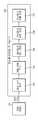
도 1에 나타낸 바와 같이, 차량(1)은 엔진(10)과, 변속기(20)와, 제동 장치(30)와, 조향 장치(40)를 포함한다. 엔진(10)은 실린더와 피스톤을 포함하녀, 차량(1)이 주행하기 위한 동력을 생성할 수 있다. 변속기(20)는 복수의 기어들을 포함하며, 엔진(10)에 의하여 생성된 동력을 차륜까지 전달할 수 있다. 제동 장치(30)는 차륜과의 마찰을 통하여 차량(1)을 감속시키거나 차량(1)을 정지시킬 수 있다. 조향 장치(40)는 차량(1)의 주행 방향을 변경시킬 수 있다.As shown in FIG. 1 , a
차량(1)은 복수의 전장 부품들을 포함할 수 있다. 예를 들어, 차량(1)은 엔진 관리 시스템(Engine Management System, EMS) (11)과, 변속기 제어 유닛(Transmission Control Unit, TCU) (21)과, 전자식 제동 제어 모듈(Electronic Brake Control Module) (31)과, 전자식 조향 장치(Electronic Power Steering, EPS) (41)과, 바디 컨트롤 모듈(Body Control Module, BCM)과, 운전자 보조 시스템(운전자 보조 장치)(Driver Assistance System, DAS)을 더 포함한다.The
엔진 관리 시스템(11)은 가속 페달을 통한 운전자의 가속 의지 또는 운전자 보조 시스템(100)의 요청에 응답하여 엔진(10)을 제어할 수 있다. 예를 들어, 엔진 관리 시스템(11)은 엔진(10)의 토크를 제어할 수 있다.The
변속기 제어 유닛(21)은 변속 레버를 통한 운전자의 변속 명령 및/또는 차량(1)의 주행 속도에 응답하여 변속기(20)를 제어할 수 있다. 예를 들어, 변속기 제어 유닛(21)은 엔진(10)으로부터 차륜까지의 변속 비율을 조절할 수 있다.The
전자식 제동 제어 모듈(31)은 제동 페달을 통한 운전자의 제동 의지 및/또는 차륜들의 슬립(slip)에 응답하여 제동 장치(30)를 제어할 수 있다. 예를 들어, 전자식 제동 제어 모듈(31)은 차량(1)의 제동 시에 감지되는 차륜의 슬립에 응답하여 차륜의 제동을 일시적으로 해제할 수 있다(Anti-lock Braking Systems, ABS). 전자식 제동 제어 모듈(31)은 차량(1)의 조향 시에 감지되는 오버스티어링(oversteering) 및/또는 언더스티어링(understeering)에 응답하여 차륜의 제동을 선택적으로 해제할 수 있다(Electronic stability control, ESC). 또한, 전자식 제동 제어 모듈(31)은 차량(1)의 구동 시에 감지되는 차륜의 슬립에 응답하여 차륜을 일시적으로 제동할 수 있다(Traction Control System, TCS).The electronic
전자식 조향 장치(41)는 스티어링 휠을 통한 운전자의 조향 의지에 응답하여 운전자가 쉽게 스티어링 휠을 조작할 수 있도록 조향 장치(40)의 동작을 보조할 수 있다. 예를 들어, 전자식 조향 장치(41)는 저속 주행 또는 주차 시에는 조향력을 감소시키고 고속 주행 시에는 조향력을 증가시키도록 조향 장치(40)의 동작을 보조할 수 있다.The
바디 컨트롤 모듈(51)은 운전자에게 편의를 제공하거나 운전자의 안전을 보장하는 전장 부품들의 동작을 제어할 수 있다. 예를 들어, 바디 컨트롤 모듈(51)은 헤드 램프, 와이퍼, 클러스터, 다기능 스위치 및 방향 지시 램프 등을 제어할 수 있다.The
운전자 보조 시스템(100)은 운전자가 차량(1)을 조작(구동, 제동, 조향)하는 것을 보조할 수 있다. 예를 들어, 운전자 보조 시스템(100)은 차량(1) 주변의 환경(예를 들어, 다른 차량, 보행자, 사이클리스트(cyclist), 차선, 도로 표지판 등)을 감지하고, 감지된 환경에 응답하여 차량(1)의 구동 및/또는 제동 및/또는 조향을 제어할 수 있다.The
운전자 보조 시스템(100)은 운전자에게 다양한 기능을 제공할 수 있다. 예를 들어, 운전자 보조 시스템(100)은 차선 이탈 경고(Lane Departure Warning, LDW)와, 차선 유지 보조(Lane Keeping Assist, LKA)와, 상향등 보조(High Beam Assist, HBA)와, 자동 긴급 제동(Autonomous Emergency Braking, AEB)과, 교통 표지판 인식(Traffic Sign Recognition, TSR)과, 스마트 크루즈 컨트롤(Smart Cruise Control, SCC)과, 사각지대 감지(Blind Spot Detection, BSD) 등을 제공할 수 있다.The
운전자 보조 시스템(100)은 차량(1) 주변의 영상 데이터를 획득하는 카메라 모듈(101)과, 차량(1) 주변의 객체 데이터를 획득하는 레이더 모듈(102)을 포함한다. 카메라 모듈(101)은 카메라(101a)와 제어기(Electronic Control Unit, ECU) (101b)를 포함하며, 차량(1)의 전방을 촬영하고 다른 차량, 보행자, 사이클리스트, 차선, 도로 표지판 등을 인식할 수 있다. 레이더 모듈(102)은 레이더(102a)와 제어기(102b)를 포함하며, 차량(1) 주변의 객체(예를 들어, 다른 차량, 보행자, 사이클리스트 등)의 상대 위치, 상대 속도 등을 획득할 수 있다.The
운전자 보조 시스템(100)은 도 1에 도시된 바에 한정되지 아니하며, 차량(1) 주변을 스캔하며 객체를 감지하는 라이다(LiDAR)를 더 포함할 수 있다.The
이상의 전자 부품들은 차량용 통신 네트워크(NT)를 통하여 서로 통신할 수 있다. 예를 들어, 전장 부품들은 이더넷(Ethernet), 모스트(Media Oriented Systems Transport, MOST), 플렉스레이(Flexray), 캔(CAN, Controller Area Network), 린(LIN, Local Interconnect Network) 등을 통하여 데이터를 주고 받을 수 있다. 예를 들어, 운전자 보조 시스템(100)은 엔진 관리 시스템(11), 전자식 제동 제어 모듈(31) 및 전자식 조향 장치(41)에 각각 차량용 통신 네트워크(NT)를 통하여 구동 제어 신호, 제동 신호 및 조향 신호를 전송할 수 있다.The above electronic components may communicate with each other through the vehicle communication network NT. For example, electronic components transmit data through Ethernet, Media Oriented Systems Transport (MOST), Flexray, CAN (Controller Area Network), and LIN (Local Interconnect Network). can give and receive For example, the
도 2는 본 발명의 실시 예에 따른 차량의 운전자 보조 시스템의 구성을 나타낸 도면이다. 도 3은 본 발명의 실시 예에 따른 차량의 운전자 보조 시스템에 포함된 카메라 및 레이더의 동작을 나타낸 도면이다.2 is a diagram illustrating a configuration of a driver assistance system for a vehicle according to an embodiment of the present invention. 3 is a diagram illustrating operations of a camera and a radar included in a driver assistance system of a vehicle according to an embodiment of the present invention.
먼저, 도 2에 나타낸 바와 같이, 차량(1)은 제동 시스템(32)과, 조향 시스템(42)과, 운전자 보조 시스템(100)을 포함할 수 있다.First, as shown in FIG. 2 , a
제동 시스템(32)은 도 1의 설명에서 언급된 전자식 제동 제어 모듈(31, 도 1 참조)과 제동 장치(30, 도 1 참조)를 포함하며, 조향 시스템(42)은 전자식 조향 장치(41, 도 1 참조)와 조향 장치(40, 도 1 참조)를 포함할 수 있다.The
운전자 보조 시스템(100)은 전방 카메라(110)와, 전방 레이더(120)와, 복수의 코너 레이더들(130)을 포함할 수 있다.The
전방 카메라(110)는 도 3에 도시된 바와 같이 차량(1)의 전방을 향하는 시야(field of view) (110a)를 가질 수 있다. 전방 카메라(110)는 예를 들어 차량(1)의 프론트 윈드 쉴드에 설치될 수 있다.The
전방 카메라(110)는 차량(1)의 전방을 촬영하고, 차량(1) 전방의 영상 데이터를 획득할 수 있다. 차량(1) 전방의 영상 데이터는 차량(1) 전방에 위치하는 다른 차량 또는 보행자 또는 사이클리스트 또는 차선에 관한 위치를 포함할 수 있다.The
전방 카메라(110)는 복수의 렌즈들 및 이미지 센서를 포함할 수 있다. 이미지 센서는 광을 전기 신호로 변환하는 복수의 포토 다이오드들을 포함할 수 있으며, 복수의 포토 다이오드들이 2차원 매트릭스로 배치될 수 있다.The
전방 카메라(110)는 제어부(140)와 전기적으로 연결될 수 있다. 예를 들어, 전방 카메라(110)는 차량용 통신 네트워크(NT)를 통하여 제어부(140)와 연결되거나, 하드 와이어(hard wire)를 통하여 제어부(140)와 연결되거나, 인쇄 회로 기판(Printed Circuit Board, PCB)을 통하여 제어부(140)와 연결될 수 있다.The
전방 카메라(110)는 차량(1) 전방의 영상 데이터를 제어부(140)로 전달할 수 있다.The
전방 레이더(120)는 도 3에 도시된 바와 같이 차량(1)의 전방을 향하는 감지 시야(field of sensing) (120a)을 가질 수 있다. 전방 레이더(120)는 예를 들어 차량(1)의 그릴(grille) 또는 범퍼(bumper)에 설치될 수 있다.The
전방 레이더(120)는 차량(1)의 전방을 향하여 송신 전파를 방사하는 송신 안테나(또는 송신 안테나 어레이)와, 객체에 반사된 반사 전파를 수신하는 수신 안테나(또는 수신 안테나 어레이)를 포함할 수 있다. 전방 레이더(120)는 송신 안테나에 의한 송신된 송신 전파와 수신 안테나에 의하여 수신된 반사 전파로부터 전방 레이더 데이터를 획득할 수 있다. 전방 레이더 데이터는 차량(1) 전방에 위치하는 다른 차량 또는 보행자 또는 사이클리스트에 관한 거리 정보 및 속도 정도를 포함할 수 있다. 전방 레이더(120)는 송신 전파와 반사 전파 사이의 위상 차이(또는 시간 차이)에 기초하여 객체까지의 상태 거리를 산출하고, 송신 전파와 반사 전파 사이의 주파수 차이에 기초하여 객체의 상대 속도를 산출할 수 있다.The
전방 레이더(120)는 예를 들어 차량용 통신 네트워크(NT) 또는 하드 와이어 또는 인쇄 회로 기판을 통하여 제어부(140)와 연결될 수 있다. 전방 레이더(120)는 전방 레이더 데이터를 제어부(140)로 전달할 수 있다.The
복수의 코너 레이더들(130)은 차량(1)의 전방 우측에 설치되는 제 1 코너 레이더(131)와, 차량(1)의 전방 좌측에 설치되는 제 2 코너 레이더(132)와, 차량(1)의 후방 우측에 설치되는 제 3 코너 레이더(133)와, 차량(1)의 후방 좌측에 설치되는 제 4 코너 레이더(134)를 포함한다.The plurality of
제 1 코너 레이더(131)는 도 3에 도시된 바와 같이 차량(1)의 전방 우측을 향하는 감지 시야(131a)를 가질 수 있다. 전방 레이더(120)는 예를 들어 차량(1)의 전방 범퍼의 우측에 설치될 수 있다. 제 2 코너 레이더(132)는 차량(1)의 전방 좌측을 향하는 감지 시야(132a)를 가질 수 있으며, 예를 들어 차량(1)의 전방 범퍼의 좌측에 설치될 수 있다. 제 3 코너 레이더(133)는 차량(1)의 후방 우측을 향하는 감지 시야(133a)를 가질 수 있으며, 예를 들어 차량(1)의 후방 범퍼의 우측에 설치될 수 있다. 제 4 코너 레이더(134)는 차량(1)의 후방 좌측을 향하는 감지 시야(134a)를 가질 수 있으며, 예를 들어 차량(1)의 후방 범퍼의 좌측에 설치될 수 있다.The
제 1, 제 2, 제 3 및 제 4 코너 레이더들(131, 132, 133, 134) 각각은 송신 안테나와 수신 안테나를 포함할 수 있다. 제 1, 제 2, 제 3 및 제 4 코너 레이더들(131, 132, 133, 134)은 각각 제 1 코너 레이더 데이터와 제 2 코너 레이더 데이터와 제 3 코너 레이더 데이터와 제 4 코너 레이더 데이터를 획득할 수 있다. 제 1 코너 레이더 데이터는 차량(1) 전방 우측에 위치하는 다른 차량 또는 보행자 또는 사이클리스트(이하 "객체"라 한다)에 관한 거리 정보 및 속도 정도를 포함할 수 있다. 제 2 코너 레이더 데이터는 차량(1) 전방 좌측에 위치하는 객체의 거리 정보 및 속도 정도를 포함할 수 있다. 제 3 및 제 4 코너 레이더 데이터는 차량(1) 후방 우측 및 차량(1) 후방 좌측에 위치하는 객체의 거리 정보 및 상대 속도를 포함할 수 있다.Each of the first, second, third, and
제 1, 제 2, 제 3 및 제 4 코너 레이더들(131, 132, 133, 134) 각각은 예를 들어 차량용 통신 네트워크(NT) 또는 하드 와이어 또는 인쇄 회로 기판을 통하여 제어부(140)와 연결될 수 있다. 제 1, 제 2, 제 3 및 제 4 코너 레이더들(131, 132, 133, 134)은 각각 제 1, 제 2, 제 3 및 제 4 코너 레이더 데이터를 제어부(140)로 전달할 수 있다.Each of the first, second, third and
제어부(140)는 카메라 모듈(101, 도 1 참조)의 제어기(101b, 도 1 참조) 및/또는 레이더 모듈(102, 도 1 참조)의 제어기(102b, 도 1 참조) 및/또는 별도의 통합 제어기를 포함할 수 있다.The
제어부(140)는 프로세서(141)와 메모리(142)를 포함한다.The
프로세서(141)는 전방 카메라(110)의 전방 영상 데이터와 전방 레이더(120)의 전방 레이더 데이터와 복수의 코너 레이더들(130)의 코너 레이더 데이터를 처리하고, 제동 시스템(32) 및 조향 시스템(42)을 제어하기 위한 제동 신호 및 조향 신호를 생성할 수 있다. 예를 들어, 프로세서(141)는 전방 카메라(110)의 전방 영상 데이터를 처리하는 이미지 프로세서 및/또는 레이더들(120, 130)의 레이더 데이터를 처리하는 디지털 시그널 프로세서 및/또는 제동 신호와 조향 신호를 생성하는 마이크로 컨트롤 유닛(Micro Control Unit, MCU)를 포함할 수 있다.The
프로세서(141)는 전방 카메라(110)의 전방 영상 데이터와 전방 레이더(120)의 전방 레이더 데이터에 기초하여 차량(1) 전방의 객체들(예를 들어, 다른 차량, 보행자, 사이클리스트 등)을 감지할 수 있다.The
구체적으로, 프로세서(141)는 전방 레이더(120)의 전방 레이더 데이터에 기초하여 차량(1) 전방의 객체들의 위치(거리 및 방향) 및 상대 속도를 획득할 수 있다. 프로세서(141)는 전방 카메라(110)의 전방 영상 데이터에 기초하여 차량(1) 전방의 객체들의 위치(방향) 및 유형 정보(예를 들어, 객체가 다른 차량인지, 또는 보행자인지, 또는 사이클리스트인지 등)를 획득할 수 있다. 또한, 프로세서(141)는 전방 영상 데이터에 의하여 감지된 객체들을 전방 레이더 데이터에 의한 감지된 객체에 매칭하고, 매칭 결과에 기초하여 차량(1)의 전방 객체들의 유형 정보와 위치와 상대 속도를 획득할 수 있다.Specifically, the
프로세서(141)는 전방 객체들의 유형 정보와 위치와 상대 속도에 기초하여 제동 신호와 조향 신호를 생성할 수 있다.The
예를 들어, 프로세서(141)는 전방 객체들의 위치(거리)와 상대 속도에 기초하여 차량(1)과 전방 객체 사이의 충돌까지의 시간(Time to Collision, TTC)를 산출하고, 충돌까지의 시간(TTC)과 미리 정해진 기준 시간 사이의 비교에 기초하여 운전자에게 충돌을 경고하거나 제동 신호를 제동 시스템(32)으로 전송할 수 있다. 미리 정해진 제 1 기준 시간보다 작은 충돌까지의 시간에 응답하여, 프로세서(141)는 오디오 및/또는 디스플레이를 통한 경고를 출력하도록 할 수 있다. 미리 정해진 제 2 기준 시간보다 작은 충돌까지의 시간에 응답하여, 프로세서(141)는 사전 제동 신호를 제동 시스템(32)으로 전송할 수 있다. 미리 정해진 제 3 기준 시간보다 작은 충돌까지의 시간에 응답하여, 프로세서(141)는 긴급 제동 신호를 제동 시스템(32)으로 전송할 수 있다. 이때, 제 2 기준 시간은 제 1 기준 시간보다 작고, 제 3 기준 시간은 제 2 기준 시간보다 작다.For example, the
다른 예로, 프로세서(141)는 전방 객체들의 상대 속도에 기초하여 충돌까지의 거리(Distance to Collision, DTC)를 산출하고, 충돌까지의 거리와 전방 객체들까지의 거리 사이의 비교에 기초하여 운전자에게 충돌을 경고하거나 제동 신호를 제동 시스템(32)으로 전송할 수 있다.As another example, the
프로세서(141)는 복수의 코너 레이더들(130)의 코너 레이더 데이터에 기초하여 차량(1)의 측방(전방 우측, 전방 좌측, 후방 우측, 후방 좌측) 객체들의 위치(거리 및 방향) 및 상대 속도를 획득할 수 있다.The
프로세서(141)는 차량(1)의 측방 객체들의 위치(거리 및 방향) 및 상대 속도에 기초하여 조향 신호를 조향 시스템(42)으로 전송할 수 있다.The
예를 들어, 충돌까지의 시간 또는 충돌까지의 거리에 기초하여 전방 객체와의 충돌이 판단되면, 프로세서(141)는 전방 객체와의 충돌을 회피하기 위하여 조향 신호를 조향 시스템(42)으로 전송할 수 있다.For example, if the collision with the front object is determined based on the time until the collision or the distance to the collision, the
프로세서(141)는 차량(1)의 측방 객체들의 위치(거리 및 방향) 및 상대 속도에 기초하여 차량(1)의 주행 방향을 변경함으로써 전방 객체와의 충돌을 회피할지 여부를 판단할 수 있다. 예를 들어, 차량(1)의 측방에 위치하는 객체가 없으면, 프로세서(141)는 전방 객체와의 충돌을 회피하기 위하여 조향 신호를 조향 시스템(42)으로 전송할 수 있다. 측방 객체들의 위치(거리 및 방향) 및 상대 속도에 기초하여 차량(1)의 조향 이후 측방 객체와의 충돌이 예측되지 않으면, 프로세서(141)는 전방 객체와의 충돌을 회피하기 위하여 조향 신호를 조향 시스템(42)으로 전송할 수 있다. 측방 객체들의 위치(거리 및 방향) 및 상대 속도에 기초하여 차량(1)의 조향 이후 측방 객체와의 충돌이 예측되면, 프로세서(141)는 조향 신호를 조향 시스템(42)으로 전송하지 아니할 수 있다.The
메모리(142)는 프로세서(141)가 영상 데이터를 처리하기 위한 프로그램 및/또는 데이터와, 레이더 데이터를 처리하기 위한 프로그램 및/또는 데이터와, 프로세서(141)가 제동 신호 및/또는 조향 신호를 생성하기 위한 프로그램 및/또는 데이터를 저장할 수 있다.In the
메모리(142)는 전방 카메라(110)로부터 수신된 영상 데이터 및/또는 레이더들(120, 130)로부터 수신된 레이더 데이터를 임시로 기억하고, 프로세서(141)의 영상 데이터 및/또는 레이더 데이터의 처리 결과를 임시로 기억할 수 있다.The
메모리(142)는 S램(S-RAM), D램(D-RAM) 등의 휘발성 메모리뿐만 아니라 플래시 메모리, 롬(Read Only Memory, ROM), 이피롬(Erasable Programmable Read Only Memory: EPROM) 등의 비휘발성 메모리를 포함할 수 있다.The
운전자 보조 시스템(100)은 도 2에 도시된 바에 한정되지 아니하며, 차량(1) 주변을 스캔하며 객체를 감지하는 라이다(LiDAR)를 더 포함할 수 있다.The
이처럼, 제어부(140)는 전방 객체와의 충돌이 예측되는지 여부에 기초하여 제동 신호를 제동 시스템(32)으로 전송할 수 있다. 측방 객체가 존재하지 아니하거나 측방 객체와의 충돌이 예측되지 않으면 제어부(140)는 전방 객체와의 충돌을 회피하기 위하여 조향 신호를 조향 시스템(42)으로 전송할 수 있다. 조향 이후 측방 객체와의 충돌이 예측되면 제어부(140)는 조향 신호를 조향 시스템(42)으로 전송하지 아니할 수 있다.In this way, the
이하의 설명에서 언급될 '차로'와 '차선', '주행 차로', '인접 차로', '인접 차량'은 각각 다음과 같이 정의될 수 있다. '차로'는 보행자가 통행하는 인도와 구분하여 차량이 주행하는 도로의 일부분을 의미한다. '차로'는 차량이 한 줄로 정해진 부분을 통행하도록 차선으로 구분한 도로의 일부분이다. '차선'은 차량이 주행하는 도로에 주행 방향을 따라 일정한 간격으로 그려놓은 선(line)을 의미한다. 하나의 하나의 '차로'는 좌측 차선과 우측 차선의 한 쌍으로 차선에 의해 인접한 다른 차로와 구분될 수 있다. '주행 차로'는 본 발명이 적용된 자 차량(1)이 주행 중인 차로를 의미한다. '인접 차로'는 주행 차로의 좌측 또는 우측에 위치한 다른 차로를 의미한다. '인접 차량'은 인접 차로를 주행 중인 타 차량(도 6 내지 도 8의 602 참조)을 의미한다.'Lane', 'lane', 'driving lane', 'adjacent lane', and 'adjacent vehicle' to be mentioned in the following description may be defined as follows, respectively. The term 'lane' refers to the part of the road on which vehicles travel, as distinguished from the sidewalk for pedestrians. A 'lane' is a portion of a road that is divided into lanes so that vehicles can pass through a section defined by a single line. A 'lane' refers to a line drawn at regular intervals along a driving direction on a road on which a vehicle travels. One 'lane' is a pair of a left lane and a right lane, and may be distinguished from other adjacent lanes by the lane. The 'driving lane' means a lane in which the
도 4는 본 발명의 실시 예에 따른 차량(1)의 운전자 보조 시스템(100)의 제어부(140)에 마련되는 프로세서(141)의 끼어들기 차량 선정 과정을 나타낸 도면이다.4 is a diagram illustrating a process of selecting a cut-in vehicle by the
도 4에 나타낸 바와 같이, 본 발명의 실시 예에 따른 차량의 끼어들기 차량 선정 과정은, '영상 신호 처리'와 '인접 차량 분류', '끼어들기 판단', '끼어들기 최종 판단', '끼어들기 차량 선정'을 포함할 수 있다.As shown in FIG. 4 , the process of selecting a vehicle for interruption of a vehicle according to an exemplary embodiment of the present invention includes 'image signal processing', 'adjacent vehicle classification', 'cutting judgment', 'cutting final judgment', 'cutting in' It may include 'selection of vehicles to be lifted'.
'영상 신호 처리' 과정에서는 전방 카메라(110)를 통해 자 차량(1)의 전방을 촬영한 영상의 신호를 전방 카메라(110)로부터 전송 받아 디지털 신호 처리를 수행한다.In the 'image signal processing' process, a digital signal processing is performed by receiving a signal of an image photographed in front of the
'인접 차량 분류' 과정에서는, 전방 영상의 분석을 통해 자 차량(1)의 좌전방 또는 우전방에 위치한 인접 차량(타 차량)을 분류한다. 끼어들기 차량의 판단 및 선정은 인접 차로에서 주행 차로(자 차량(1)이 주행 중인 차로)로 끼어들기 하는 타 차량을 판단 및 선정하기 위한 것이므로, 인접 차로의 타 차량 즉 인접 차량을 식별 및 분류할 필요가 있다.In the 'adjacent vehicle classification' process, an adjacent vehicle (other vehicle) located in the left front or right front of the
'끼어들기 의도 판단' 과정에서는 본 발명의 실시 예에 따른 차량(1)의 미리 마련된 판단 기준을 적용하여 인접 차로를 주행 중인 타 차량들의 끼어들기 의도를 판단한다.In the 'interference intention determination' process, the intention of other vehicles traveling in an adjacent lane is determined by applying a pre-prepared determination criterion of the
'끼어들기 최종 판단' 과정에서는 본 발명의 실시 예에 따른 차량(1)의 미리 마련된 또 다른 판단 기준을 적용하여 끼어들기 의도 차량으로 분류된 타 차량들의 실제 끼어들기 여부를 판단한다.In the 'interference final determination' process, another
'끼어들기 차량 선정' 과정에서는 '끼어들기 최종 판단'을 통해 판단한 실제 끼어들기 차량을 주의(회피) 대상 차량으로 선정한다.In the 'interference vehicle selection' process, the actual intervening vehicle judged through the 'interference final judgment' is selected as the target vehicle for attention (avoidance).
이와 같은 본 발명의 실시 예에 따른 차량(1)의 끼어들기 차량 선정 과정에 대해서는 후술하는 도 5 내지 도 8을 통해 더욱 자세히 설명하고자 한다.The process of selecting a cut-in vehicle of the
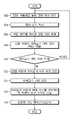
도 5는 본 발명의 실시 예에 따른 차량의 제어 방법을 나타낸 도면이다. 도 5의 차량 제어 방법에서는 인접 차량의 끼어들기 여부를 신속하고 정확하게 판단하여 회피 기동을 수행하는 과정을 나타내었다.5 is a diagram illustrating a vehicle control method according to an embodiment of the present invention. In the vehicle control method of FIG. 5 , a process of performing an evasive maneuver by quickly and accurately determining whether an adjacent vehicle is intervening is illustrated.
도 5에 나타낸 바와 같이, 본 발명의 실시 예에 따른 차량(1)의 운전자 보조 시스템(100)의 제어부(140)는 전방 카메라(110)를 통해 자 차량(1)의 전방을 촬영하여 전방 영상을 획득한다(502). 이 전방 영상은 자 차량(1)의 정면뿐만 아니라 좌전방의 영상 및 우전방의 영상을 포함한다. 차량(1)의 정면을 촬영한 영상의 획득은 차량(1)이 주행 중인 주행 차로의 차선 및 선행 차량을 식별하기 위함이고, 차량(1)의 좌전방 영상 및 우전방 영상의 획득은 인접 차량을 식별하기 위함이다.As shown in FIG. 5 , the
제어부(140)의 프로세서(141)는 전방 카메라(110)를 통해 자 차량(1)의 전방을 촬영한 영상의 신호를 전방 카메라(110)로부터 전송 받아 필터링 및 디지털 변환 등의 신호 처리를 수행한다(504).The
제어부(140)의 프로세서(141)는 측면 차로에 위치한 인접 차량을 분류한다(506). 즉, 전방 영상의 분석을 통해 자 차량(1)의 좌전방 또는 우전방에 위치한 인접 차량(타 차량)을 분류한다. 끼어들기 차량의 판단 및 선정은 인접 차로에서 주행 차로로 끼어들기 하는(cut-in) 타 차량을 판단 및 선정하기 위한 것이므로, 끼어들기 차량의 판단을 위해 먼저 인접 차로를 주행 중인 타 차량 즉 인접 차량을 식별 및 분류할 필요가 있다.The
인접 차량의 식별 및 분류가 완료되면, 제어부(140)의 프로세서(141)는 식별된 인접 차량의 끼어들기 의도를 판단한다(508). 즉, 본 발명의 실시 예에 따른 차량(1)의 미리 마련된 판단 기준을 적용하여 인접 차로를 주행 중인 타 차량들의 끼어들기 의도를 판단한다. 본 발명의 실시 예에 따른 차량(1)에서, 인접 차량의 끼어들기 의도의 판단은 전방 카메라(120)를 통해 촬영한 전방 영상 속의 차선 정보를 기초로 이루어질 수 있다.When the identification and classification of the adjacent vehicle is completed, the
도 6은, 끼어들기 의도 차량이 없을 때, 본 발명의 실시 예에 따른 차량(1)의 전방 카메라(120)를 통해 획득한 전방 영상에 포함되는 차선 정보를 나타낸 도면이다. 도 6에 나타낸 바와 같이, 끼어들기를 시도하는 차량이 없고 인접 차량(602)과 선행 차량(604)이 각자의 차로를 주행하는 동안 자 차량(1)의 전방 카메라(120)에 의해 촬영되는 전방 영상 속의 좌측 차선(606)과 우측 차선(608)의 길이는 도 6에 나타낸 것처럼 서로 동일하다.6 is a diagram illustrating lane information included in a front image acquired through the
도 7은, 끼어들기 의도 차량이 있을 때, 본 발명의 실시 예에 따른 차량(1)의 전방 카메라(120)를 통해 획득한 전방 영상에 포함되는 차선 정보를 나타낸 도면이다. 도 7에 나타낸 바와 같이, 끼어들기를 시도하는 차량이 있을 때 자 차량(1)의 전방 카메라(120)에 의해 촬영되는 전방 영상 속의 좌측 차선(606)과 우측 차선(608)의 길이는 도 7에 나타낸 것처럼 서로 다르게 나타난다. 즉, 끼어들기 의도 차량(602)이 좌측의 인접 차로에서 주행 차로로 끼어들기를 시도하는 경우, 전방 영상 속의 좌측 차선(606)은 끼어들기 의도 차량(602)에 의해 가려져서 온전한 우측 차선(608)보다 상대적으로 짧다. 도 7에 나타낸 것처럼, 전방 영상 속의 좌측 차선(606)의 길이가 우측 차선(608)의 길이보다 짧을 때, 제어부(140)의 프로세서(141)는 좌측 인접 차로에서 인접 차량(602)의 끼어들기 의도가 있는 것으로 판단할 수 있다. 만약 전방 영상 속의 우측 차선(608)의 길이가 좌측 차선(606)의 길이보다 짧으면, 제어부(140)의 프로세서(141)는 우측 인접 차로에서 인접 차량의 끼어들기 의도가 있는 것으로 판단할 수 있다.7 is a diagram illustrating lane information included in a front image acquired through the
만약 끼어들기 의도 차량이 존재하면(510의 '예'), 제어부(140)의 프로세서(141)는 인접 차량의 끼어들기 여부를 최종 판단한다(512). 즉, 제어부(140)의 프로세서(141)는 본 발명의 실시 예에 따른 차량(1)의 미리 마련된 또 다른 판단 기준을 적용하여 끼어들기 의도 차량으로 분류된 타 차량들의 실제 끼어들기 여부를 최종적으로 판단한다.If there is a vehicle intended to intervene (YES in 510), the
끼어들기 여부의 최종 판단을 위한 기준으로는, 인접 차량(602)의 차선과의 거리와 횡방향 속도를 예로 들 수 있다. 즉, 인접 차량(602)이 주행 차로를 침입한 정도를 차선과의 거리를 통해 확인하고, 또 인접 차량(602)이 횡방향으로 얼마나 빠르게 주행 차로를 침입하는지를 확인하여, 이 확인 결과를 통해 인접 차량(602)의 끼어들기 여부를 최종적으로 판단할 수 있다. 만약 선행 단계에서 끼어들기 의도가 있는 것으로 판단한 인접 차량(602)들 가운데 주행 차로를 침입하는 정도와 횡방향 속도가 미리 설정된 기준에 미치지 않으면 해당 인접 차량을 끼어들기 차량으로 확정하지는 않는다.As a criterion for the final determination of whether to cut in, the distance from the lane of the
만약 끼어들기 차량으로 최종 판단된 차량이 복수일 때, 그 중 가장 우선하여 주의(회피)해야 할 끼어들기 차량을 선정할 수 있다(514).If there are a plurality of vehicles that are finally determined to be a cut-in vehicle, a cut-in vehicle that should be given the highest priority may be selected ( 514 ).
가장 우선하여 주의(회피)해야 할 끼어들기 차량(예를 들면 도 6의 602)이 선정되면, 선정된 끼어들기 차량(602)과 자 차량(1)의 상대 속도에 기초하여 자 차량(1)의 요구 가속도를 산출한다(516). 자 차량(1)의 요구 가속도 산출은, 끼어들기 차량(602)이 자 차량(1)의 전방 주행 차로로 안전하게 진입할 수 있도록 자 차량(1)의 전방에 공간을 확보하기 위한 가속도(- 가속도)를 산출하는 것일 수 있다. 반대로, 자 차량(1)의 요구 가속도 산출은, 자 차량(1)이 끼어들기 차량(602)을 추월함으로써 끼어들기 차량(602)이 자 차량(1)의 후방 주행 차로로 안전하게 진입할 수 있도록 자 차량(1)의 후방에 공간을 확보하기 위한 가속도(+ 가속도)를 산출하는 것일 수 있다.When a cutting-in vehicle (for example, 602 in FIG. 6) that should be given priority attention (avoidance) is selected, the
이와 같이, 끼어들기 차량(602)을 고려한 자 차량(1)의 요구 가속도의 산출이 완료되면, 산출된 요구 가속도에 기초하여 자 차량(1)의 가속 제어 또는 감속 제어를 실시한다(518).In this way, when the calculation of the required acceleration of the
도 8은 본 발명의 또 다른 실시 예에 따른 차량의 끼어들기 의도 차량 식별 개념을 나타낸 도면이다.8 is a diagram illustrating a concept of identifying a vehicle intended to cut in a vehicle according to another embodiment of the present invention.
도 8에서, 좌측 인접 차로에서 끼어들기 의도 차량(802)이 주행 차로로 진입하는 경우, 자 차량(1)의 전방 카메라(120)의 영상에는 주행 차로의 좌측 차선이 끼어들기 의도 차량(802)에 의해 단절되어 두 부분(806a)(806b)으로 나타나게 된다. 이처럼, 주행 차로의 좌측 차선(806)과 우측 차선(808) 가운데 적어도 어느 하나의 차선의 중간 부분이 단절되어 도 8에 나타낸 것과 같은 두 개의 차선(806a)(806b)으로 분리되어 촬영되는 경우, 해당 차선 방향에서 주행 차로로 끼어들기를 시도하는 타 차량(602)이 존재하는 것으로 판단할 수 있다.In FIG. 8 , when a
위의 설명은 기술적 사상을 예시적으로 설명한 것에 불과한 것으로서, 본 발명의 기술 분야에서 통상의 지식을 가진 자라면 본질적인 특성에서 벗어나지 않는 범위 내에서 다양한 수정, 변경 및 치환이 가능할 것이다. 따라서 위에 개시된 실시 예 및 첨부된 도면들은 기술적 사상을 한정하기 위한 것이 아니라 설명하기 위한 것이고, 이러한 실시 예 및 첨부된 도면에 의하여 기술적 사상의 범위가 한정되는 것은 아니다. 그 보호 범위는 아래의 청구 범위에 의하여 해석되어야 하며, 그와 동등한 범위 내에 있는 모든 기술적 사상은 권리 범위에 포함되는 것으로 해석되어야 할 것이다.The above description is merely illustrative of the technical idea, and various modifications, changes, and substitutions will be possible within the scope without departing from the essential characteristics by those skilled in the art of the present invention. Therefore, the embodiments disclosed above and the accompanying drawings are for explanation rather than limiting the technical idea, and the scope of the technical idea is not limited by these embodiments and the accompanying drawings. The scope of protection should be construed by the following claims, and all technical ideas within the scope equivalent thereto should be construed as being included in the scope of rights.
1 : 차량(자 차량)
2 : 타 차량
100 : 운전자 보조 시스템
110 : 전방 카메라
120 : 전방 레이더
130 : 복수의 코너 레이더들
131-134 : 제 1-4 코너 레이더
140 : 제어부1: vehicle (own vehicle)
2: other vehicle
100: driver assistance system
110: front camera
120: forward radar
130: multiple corner radars
131-134: 1-4 corner radar
140: control unit
Claims (14)
Translated fromKorean상기 전방 영상으로부터 상기 차량이 주행하는 주행 차로의 좌우 차선을 식별하는 단계와;
상기 전방 영상 내에서 상기 주행 차로의 좌측 차선과 우측 차선의 길이가 서로 다를 때 인접 차로에서 상기 주행 차로로 끼어들기 차량이 존재하는 것으로 판단하는 단계를 포함하는 차량 제어 방법.acquiring a front image by photographing the front of the vehicle;
identifying left and right lanes of a driving lane in which the vehicle travels from the front image;
and determining that a vehicle cutting into the driving lane from an adjacent lane exists when lengths of a left lane and a right lane of the driving lane are different from each other in the front image.
상기 전방 영상으로부터 상기 차량 주변을 주행하는 인접 차량을 식별하는 단계를 더 포함하고;
상기 인접 차량이 존재하는 상태에서 상기 전방 영상 내에서 상기 주행 차로의 상기 좌측 차선과 상기 우측 차선의 길이가 서로 다를 때 상기 끼어들기 차량이 존재하는 것으로 판단하는 차량 제어 방법.The method of claim 1,
further comprising: identifying a neighboring vehicle traveling around the vehicle from the front image;
When the length of the left lane and the right lane of the driving lane are different from each other in the front image in a state in which the adjacent vehicle is present, it is determined that the intervening vehicle is present.
상기 주행 차로의 상기 좌측 차선과 상기 우측 차선 가운데 상기 전면 영상 내에서의 상기 차선의 길이가 상대적으로 더 짧은 쪽에 상기 끼어들기 차량이 존재하는 것으로 판단하는 차량 제어 방법.3. The method of claim 2,
A vehicle control method for determining that the cutting-in vehicle exists on a side of the left lane and the right lane of the driving lane having a shorter length in the front image.
상기 주행 차로의 상기 좌측 차선과 상기 우측 차선 가운데 상기 전면 영상 내에서 중간 부분이 단절된 쪽에 상기 끼어들기 차량이 존재하는 것으로 판단하는 차량 제어 방법.3. The method of claim 2,
A vehicle control method for determining that the cutting-in vehicle is present on a side in which a middle part is cut off in the front image among the left and right lanes of the driving lane.
상기 전방 영상 내에서 상기 주행 차로의 상기 좌측 차선과 상기 우측 차선의 길이로부터 상기 인접 차량의 끼어들기 의도를 판단하고;
상기 인접 차량의 차선과의 거리와 횡방향 속도로부터 상기 인접 차량을 상기 끼어들기 차량으로 확정하는 차량 제어 방법.The method of claim 1,
determining an intention to cut in the adjacent vehicle from lengths of the left and right lanes of the driving lane in the front image;
A vehicle control method for determining the adjacent vehicle as the cutting-in vehicle from a distance from a lane of the adjacent vehicle and a lateral speed.
상기 끼어들기 차량이 존재하는 것으로 판단되면, 상기 끼어들기 차량의 상대 속도와 상대 거리에 따라 상기 차량의 속도를 조절하여 상기 끼어들기 차량의 진입 공간이 확보되도록 하는 단계를 더 포함하는 차량 제어 방법.The method of claim 1,
If it is determined that the interrupting vehicle exists, adjusting the speed of the vehicle according to the relative speed and the relative distance of the interrupting vehicle to secure an entry space for the interrupting vehicle.
상기 전방 영상으로부터 상기 차량이 주행하는 주행 차로의 좌우 차선을 식별하고, 상기 전방 영상 내에서 상기 주행 차로의 좌측 차선과 우측 차선의 길이가 서로 다를 때 인접 차로에서 상기 주행 차로로 끼어들기 차량이 존재하는 것으로 판단하는 제어부를 포함하는 차량.a front camera for obtaining a front image by photographing the front of the vehicle;
The left and right lanes of the driving lane in which the vehicle travels are identified from the front image, and when the lengths of the left and right lanes of the driving lane are different from each other in the forward image, a vehicle that cuts into the driving lane from an adjacent lane exists A vehicle including a control unit that determines that the
상기 전방 영상으로부터 상기 차량 주변을 주행하는 인접 차량을 식별하고;
상기 인접 차량이 존재하는 상태에서 상기 전방 영상 내에서 상기 주행 차로의 상기 좌측 차선과 상기 우측 차선의 길이가 서로 다를 때 상기 끼어들기 차량이 존재하는 것으로 판단하는 차량.The method of claim 7, wherein the control unit,
identify an adjacent vehicle driving around the vehicle from the front image;
When the length of the left lane and the right lane of the driving lane are different from each other in the front image in a state in which the adjacent vehicle exists, it is determined that the intervening vehicle exists.
상기 주행 차로의 상기 좌측 차선과 상기 우측 차선 가운데 상기 전면 영상 내에서의 상기 차선의 길이가 상대적으로 더 짧은 쪽에 상기 끼어들기 차량이 존재하는 것으로 판단하는 차량.The method of claim 8, wherein the control unit,
a vehicle in which the cutting-in vehicle is determined to exist on a side of the driving lane having a shorter length in the front image among the left and right lanes of the driving lane.
상기 주행 차로의 상기 좌측 차선과 상기 우측 차선 가운데 상기 전면 영상 내에서 중간 부분이 단절된 쪽에 상기 끼어들기 차량이 존재하는 것으로 판단하는 차량.The method of claim 8, wherein the control unit,
a vehicle in which the cutting-in vehicle is determined to exist on a side in which a middle part is cut off in the front image among the left and right lanes of the driving lane.
상기 전방 영상 내에서 상기 주행 차로의 상기 좌측 차선과 상기 우측 차선의 길이로부터 상기 인접 차량의 끼어들기 의도를 판단하고;
상기 인접 차량의 차선과의 거리와 횡방향 속도로부터 상기 인접 차량을 상기 끼어들기 차량으로 확정하는 차량.The method of claim 7, wherein the control unit,
determining an intention to cut in the adjacent vehicle from lengths of the left and right lanes of the driving lane in the front image;
A vehicle for determining the adjacent vehicle as the cutting-in vehicle from a distance from a lane of the adjacent vehicle and a lateral speed.
상기 끼어들기 차량이 존재하는 것으로 판단되면, 상기 끼어들기 차량의 상대 속도와 상대 거리에 따라 상기 차량의 속도를 조절하여 상기 끼어들기 차량의 진입 공간이 확보되도록 하는 것을 더 포함하는 차량.The method of claim 7, wherein the control unit,
If it is determined that the interrupting vehicle exists, adjusting the speed of the vehicle according to the relative speed and the relative distance of the interrupting vehicle to secure an entry space for the interrupting vehicle.
상기 전방 영상으로부터 상기 차량 주변을 주행하는 인접 차량을 식별하는 단계와;
상기 전방 영상으로부터 상기 차량이 주행하는 주행 차로의 좌우 차선을 식별하는 단계와;
상기 인접 차량이 존재하는 상태에서 상기 전방 영상 내에서 상기 주행 차로의 좌측 차선과 우측 차선의 길이가 서로 다를 때 인접 차로에서 상기 주행 차로로 끼어들기 차량이 존재하는 것으로 판단하되, 상기 전면 영상 내에서의 상기 차선의 길이가 상대적으로 더 짧은 쪽 또는 상기 전면 영상 내에서 중간 부분이 단절된 쪽에 상기 끼어들기 차량이 존재하는 것으로 판단하는 단계를 포함하는 차량 제어 방법.acquiring a front image by photographing the front of the vehicle;
identifying an adjacent vehicle traveling around the vehicle from the front image;
identifying left and right lanes of a driving lane in which the vehicle travels from the front image;
When the lengths of the left and right lanes of the driving lane are different from each other in the front image in a state in which the adjacent vehicle is present, it is determined that a vehicle intervening into the driving lane from the adjacent lane exists, but within the front image and judging that the cutting-in vehicle exists on the side where the length of the lane is relatively shorter or the side where the middle part is cut off in the front image.
상기 전방 영상으로부터 상기 차량 주변을 주행하는 인접 차량을 식별하고, 상기 전방 영상으로부터 상기 차량이 주행하는 주행 차로의 좌우 차선을 식별하며, 상기 인접 차량이 존재하는 상태에서 상기 전방 영상 내에서 상기 주행 차로의 좌측 차선과 우측 차선의 길이가 서로 다를 때 인접 차로에서 상기 주행 차로로 끼어들기 차량이 존재하는 것으로 판단하되, 상기 전면 영상 내에서의 상기 차선의 길이가 상대적으로 더 짧은 쪽 또는 상기 전면 영상 내에서 중간 부분이 단절된 쪽에 상기 끼어들기 차량이 존재하는 것으로 판단하는 제어부를 포함하는 차량.
a front camera for obtaining a front image by photographing the front of the vehicle;
Identifies an adjacent vehicle traveling around the vehicle from the front image, identifies left and right lanes of a driving lane on which the vehicle travels from the front image, and identifies the driving lane within the front image when the adjacent vehicle exists When the lengths of the left and right lanes of , it is determined that there is a vehicle cutting into the driving lane from an adjacent lane, the lane having a shorter length in the front image or in the front image A vehicle including a control unit for determining that the cut-in vehicle is present on the side where the middle part is cut off.
Priority Applications (2)
| Application Number | Priority Date | Filing Date | Title |
|---|---|---|---|
| KR1020190172222AKR102758772B1 (en) | 2019-12-20 | 2019-12-20 | Vehicle and control method thereof |
| US17/120,736US11605299B2 (en) | 2019-12-20 | 2020-12-14 | Vehicle and control method thereof |
Applications Claiming Priority (1)
| Application Number | Priority Date | Filing Date | Title |
|---|---|---|---|
| KR1020190172222AKR102758772B1 (en) | 2019-12-20 | 2019-12-20 | Vehicle and control method thereof |
Publications (2)
| Publication Number | Publication Date |
|---|---|
| KR20210079946Atrue KR20210079946A (en) | 2021-06-30 |
| KR102758772B1 KR102758772B1 (en) | 2025-01-22 |
Family
ID=76438270
Family Applications (1)
| Application Number | Title | Priority Date | Filing Date |
|---|---|---|---|
| KR1020190172222AActiveKR102758772B1 (en) | 2019-12-20 | 2019-12-20 | Vehicle and control method thereof |
Country Status (2)
| Country | Link |
|---|---|
| US (1) | US11605299B2 (en) |
| KR (1) | KR102758772B1 (en) |
Cited By (1)
| Publication number | Priority date | Publication date | Assignee | Title |
|---|---|---|---|---|
| CN113643534A (en)* | 2021-07-29 | 2021-11-12 | 北京万集科技股份有限公司 | Traffic control method and equipment |
Families Citing this family (6)
| Publication number | Priority date | Publication date | Assignee | Title |
|---|---|---|---|---|
| KR20210114689A (en)* | 2020-03-11 | 2021-09-24 | 주식회사 만도 | Vehicle and method of controlling the same |
| KR20210150926A (en)* | 2020-06-03 | 2021-12-13 | 현대자동차주식회사 | Apparatus for controlling automotive driving detecting low speed cut in vehicle in crowed road, system having the same and method thereof |
| US12157467B2 (en)* | 2020-08-28 | 2024-12-03 | Nissan Motor Co., Ltd. | Driving assist method and driving assist device for detecting cut-in vehicle when host vehicle is stopped |
| JP7716655B2 (en)* | 2022-01-18 | 2025-08-01 | スズキ株式会社 | Vehicle interruption prediction system |
| CN116279450B (en)* | 2023-05-18 | 2023-09-19 | 智道网联科技(北京)有限公司 | Vehicle control method and device, electronic equipment and storage medium |
| CN119261930A (en)* | 2024-10-25 | 2025-01-07 | 江铃汽车股份有限公司 | Method, system, storage medium and vehicle for predicting cutting-in intention of high-speed vehicle |
Citations (5)
| Publication number | Priority date | Publication date | Assignee | Title |
|---|---|---|---|---|
| KR20140128836A (en)* | 2013-04-29 | 2014-11-06 | 팅크웨어(주) | Image-processing Apparatus for Car and Method of Providing Information Using The Same |
| KR101480430B1 (en)* | 2013-08-20 | 2015-01-08 | 현대오트론 주식회사 | Apparatus and method for lane detection support |
| JP2017128178A (en)* | 2016-01-19 | 2017-07-27 | トヨタ自動車株式会社 | Vehicular travel control device |
| KR20190066953A (en)* | 2017-12-06 | 2019-06-14 | 현대자동차주식회사 | Autonomous driving control apparatus and method for changing target thereof |
| KR20190075225A (en)* | 2017-12-21 | 2019-07-01 | 현대자동차주식회사 | Apparatus for controlling driving of vehicle and method thereof |
Family Cites Families (11)
| Publication number | Priority date | Publication date | Assignee | Title |
|---|---|---|---|---|
| JP4539415B2 (en)* | 2005-04-15 | 2010-09-08 | 株式会社デンソー | Image processing device |
| JP5090126B2 (en)* | 2007-10-23 | 2012-12-05 | アルパイン株式会社 | In-vehicle imaging device |
| WO2009072507A1 (en)* | 2007-12-05 | 2009-06-11 | Nec Corporation | Pavement marker recognition device, pavement marker recognition method and pavement marker recognition program |
| WO2014083821A1 (en)* | 2012-11-27 | 2014-06-05 | 日産自動車株式会社 | Driving assistance device |
| JP6303428B2 (en)* | 2013-11-19 | 2018-04-04 | 日本精機株式会社 | Vehicle information projection system |
| KR101807386B1 (en)* | 2016-01-26 | 2018-01-10 | 주식회사 만도 | Cooperative driving method and cooperative driving apparatus |
| KR102572707B1 (en) | 2016-06-14 | 2023-08-30 | 주식회사 에이치엘클레무브 | Vehicle control apparatus and vehicle control method |
| JP6586930B2 (en)* | 2016-08-04 | 2019-10-09 | トヨタ自動車株式会社 | Vehicle travel control device |
| KR101896790B1 (en)* | 2016-11-08 | 2018-10-18 | 현대자동차주식회사 | Apparatus for determining concentration of driver, system having the same and method thereof |
| JP6638701B2 (en)* | 2017-06-08 | 2020-01-29 | トヨタ自動車株式会社 | Driving awareness estimation device |
| KR102054926B1 (en) | 2018-02-27 | 2019-12-12 | 주식회사 만도 | System and method for detecting close cut-in vehicle based on free space signal |
- 2019
- 2019-12-20KRKR1020190172222Apatent/KR102758772B1/enactiveActive
- 2020
- 2020-12-14USUS17/120,736patent/US11605299B2/enactiveActive
Patent Citations (5)
| Publication number | Priority date | Publication date | Assignee | Title |
|---|---|---|---|---|
| KR20140128836A (en)* | 2013-04-29 | 2014-11-06 | 팅크웨어(주) | Image-processing Apparatus for Car and Method of Providing Information Using The Same |
| KR101480430B1 (en)* | 2013-08-20 | 2015-01-08 | 현대오트론 주식회사 | Apparatus and method for lane detection support |
| JP2017128178A (en)* | 2016-01-19 | 2017-07-27 | トヨタ自動車株式会社 | Vehicular travel control device |
| KR20190066953A (en)* | 2017-12-06 | 2019-06-14 | 현대자동차주식회사 | Autonomous driving control apparatus and method for changing target thereof |
| KR20190075225A (en)* | 2017-12-21 | 2019-07-01 | 현대자동차주식회사 | Apparatus for controlling driving of vehicle and method thereof |
Cited By (1)
| Publication number | Priority date | Publication date | Assignee | Title |
|---|---|---|---|---|
| CN113643534A (en)* | 2021-07-29 | 2021-11-12 | 北京万集科技股份有限公司 | Traffic control method and equipment |
Also Published As
| Publication number | Publication date |
|---|---|
| US11605299B2 (en) | 2023-03-14 |
| KR102758772B1 (en) | 2025-01-22 |
| US20210192955A1 (en) | 2021-06-24 |
Similar Documents
| Publication | Publication Date | Title |
|---|---|---|
| KR102715606B1 (en) | Advanced Driver Assistance System, Vehicle having the same and method for controlling the vehicle | |
| KR102187378B1 (en) | Collision Avoidance device, Vehicle having the same and method for controlling the same | |
| KR102673147B1 (en) | Driver assistance system and controlling method thereof | |
| KR102061140B1 (en) | Lane keeping Assistance apparatus, Vehicle having the same and method for controlling the same | |
| KR102758772B1 (en) | Vehicle and control method thereof | |
| KR102440255B1 (en) | Driver assistance system and its control method | |
| KR102356612B1 (en) | Collision Avoidance device, Vehicle having the same and method for controlling the same | |
| KR20210083459A (en) | Advanced Driver Assistance System, Vehicle having the same and method for controlling the vehicle | |
| US11840220B2 (en) | Driver assistance system and control method thereof | |
| KR20210130297A (en) | Driver assistance apparatus | |
| KR20220106875A (en) | Driver assistance system and method therof | |
| US11577730B2 (en) | Vehicle and control method thereof | |
| US12344236B2 (en) | Driver assistance apparatus and driver assisting method | |
| KR20220166119A (en) | Driver assistance system and method thereof | |
| KR20210080720A (en) | Driver assistance apparatus and driver assisting method | |
| KR102440265B1 (en) | driver assistance system | |
| KR102618041B1 (en) | Driver assistance system and method therof | |
| KR102700168B1 (en) | Driver assistance apparatus | |
| KR20210133330A (en) | driver assistance system and driver assistance method | |
| KR20200094629A (en) | Driver assistance system, and control method for the same | |
| KR20220111764A (en) | driver assistance System and control method for the same | |
| KR20210130302A (en) | Driver assistance system and the conrol method of the same | |
| KR102413484B1 (en) | driver assistance apparatus and method thereof | |
| KR20220111851A (en) | Driver assistance system and driver assistance method | |
| KR20210090772A (en) | Driver assistance apparatus |
Legal Events
| Date | Code | Title | Description |
|---|---|---|---|
| PA0109 | Patent application | Patent event code:PA01091R01D Comment text:Patent Application Patent event date:20191220 | |
| PG1501 | Laying open of application | ||
| PN2301 | Change of applicant | Patent event date:20211001 Comment text:Notification of Change of Applicant Patent event code:PN23011R01D | |
| PN2301 | Change of applicant | Patent event date:20220406 Comment text:Notification of Change of Applicant Patent event code:PN23011R01D | |
| PA0201 | Request for examination | Patent event code:PA02012R01D Patent event date:20220426 Comment text:Request for Examination of Application Patent event code:PA02011R01I Patent event date:20191220 Comment text:Patent Application | |
| E902 | Notification of reason for refusal | ||
| PE0902 | Notice of grounds for rejection | Comment text:Notification of reason for refusal Patent event date:20240215 Patent event code:PE09021S01D | |
| E601 | Decision to refuse application | ||
| PE0601 | Decision on rejection of patent | Patent event date:20241017 Comment text:Decision to Refuse Application Patent event code:PE06012S01D | |
| PX0701 | Decision of registration after re-examination | Patent event date:20250114 Comment text:Decision to Grant Registration Patent event code:PX07013S01D | |
| X701 | Decision to grant (after re-examination) | ||
| PG1601 | Publication of registration |