KR20210076199A - Virtual and augmented reality systems and methods - Google Patents
Virtual and augmented reality systems and methodsDownload PDFInfo
- Publication number
- KR20210076199A KR20210076199AKR1020217018584AKR20217018584AKR20210076199AKR 20210076199 AKR20210076199 AKR 20210076199AKR 1020217018584 AKR1020217018584 AKR 1020217018584AKR 20217018584 AKR20217018584 AKR 20217018584AKR 20210076199 AKR20210076199 AKR 20210076199A
- Authority
- KR
- South Korea
- Prior art keywords
- light
- user
- waveguide
- lens
- eye
- Prior art date
- Legal status (The legal status is an assumption and is not a legal conclusion. Google has not performed a legal analysis and makes no representation as to the accuracy of the status listed.)
- Granted
Links
Images


Classifications
- G—PHYSICS
- G02—OPTICS
- G02B—OPTICAL ELEMENTS, SYSTEMS OR APPARATUS
- G02B27/00—Optical systems or apparatus not provided for by any of the groups G02B1/00 - G02B26/00, G02B30/00
- G02B27/01—Head-up displays
- G02B27/017—Head mounted
- G02B27/0172—Head mounted characterised by optical features
- G—PHYSICS
- G02—OPTICS
- G02B—OPTICAL ELEMENTS, SYSTEMS OR APPARATUS
- G02B27/00—Optical systems or apparatus not provided for by any of the groups G02B1/00 - G02B26/00, G02B30/00
- G02B27/42—Diffraction optics, i.e. systems including a diffractive element being designed for providing a diffractive effect
- G02B27/4205—Diffraction optics, i.e. systems including a diffractive element being designed for providing a diffractive effect having a diffractive optical element [DOE] contributing to image formation, e.g. whereby modulation transfer function MTF or optical aberrations are relevant
- G—PHYSICS
- G02—OPTICS
- G02B—OPTICAL ELEMENTS, SYSTEMS OR APPARATUS
- G02B17/00—Systems with reflecting surfaces, with or without refracting elements
- G02B17/08—Catadioptric systems
- G—PHYSICS
- G02—OPTICS
- G02B—OPTICAL ELEMENTS, SYSTEMS OR APPARATUS
- G02B26/00—Optical devices or arrangements for the control of light using movable or deformable optical elements
- G02B26/08—Optical devices or arrangements for the control of light using movable or deformable optical elements for controlling the direction of light
- G02B26/0808—Optical devices or arrangements for the control of light using movable or deformable optical elements for controlling the direction of light by means of one or more diffracting elements
- G—PHYSICS
- G02—OPTICS
- G02B—OPTICAL ELEMENTS, SYSTEMS OR APPARATUS
- G02B27/00—Optical systems or apparatus not provided for by any of the groups G02B1/00 - G02B26/00, G02B30/00
- G02B27/0087—Phased arrays
- G—PHYSICS
- G02—OPTICS
- G02B—OPTICAL ELEMENTS, SYSTEMS OR APPARATUS
- G02B27/00—Optical systems or apparatus not provided for by any of the groups G02B1/00 - G02B26/00, G02B30/00
- G02B27/0093—Optical systems or apparatus not provided for by any of the groups G02B1/00 - G02B26/00, G02B30/00 with means for monitoring data relating to the user, e.g. head-tracking, eye-tracking
- G—PHYSICS
- G02—OPTICS
- G02B—OPTICAL ELEMENTS, SYSTEMS OR APPARATUS
- G02B27/00—Optical systems or apparatus not provided for by any of the groups G02B1/00 - G02B26/00, G02B30/00
- G02B27/01—Head-up displays
- G—PHYSICS
- G02—OPTICS
- G02B—OPTICAL ELEMENTS, SYSTEMS OR APPARATUS
- G02B27/00—Optical systems or apparatus not provided for by any of the groups G02B1/00 - G02B26/00, G02B30/00
- G02B27/01—Head-up displays
- G02B27/017—Head mounted
- G—PHYSICS
- G02—OPTICS
- G02B—OPTICAL ELEMENTS, SYSTEMS OR APPARATUS
- G02B27/00—Optical systems or apparatus not provided for by any of the groups G02B1/00 - G02B26/00, G02B30/00
- G02B27/01—Head-up displays
- G02B27/017—Head mounted
- G02B27/0176—Head mounted characterised by mechanical features
- G—PHYSICS
- G02—OPTICS
- G02B—OPTICAL ELEMENTS, SYSTEMS OR APPARATUS
- G02B3/00—Simple or compound lenses
- G02B3/0006—Arrays
- G—PHYSICS
- G02—OPTICS
- G02B—OPTICAL ELEMENTS, SYSTEMS OR APPARATUS
- G02B3/00—Simple or compound lenses
- G02B3/0006—Arrays
- G02B3/0037—Arrays characterized by the distribution or form of lenses
- G—PHYSICS
- G02—OPTICS
- G02B—OPTICAL ELEMENTS, SYSTEMS OR APPARATUS
- G02B30/00—Optical systems or apparatus for producing three-dimensional [3D] effects, e.g. stereoscopic images
- G02B30/20—Optical systems or apparatus for producing three-dimensional [3D] effects, e.g. stereoscopic images by providing first and second parallax images to an observer's left and right eyes
- G02B30/22—Optical systems or apparatus for producing three-dimensional [3D] effects, e.g. stereoscopic images by providing first and second parallax images to an observer's left and right eyes of the stereoscopic type
- G02B30/24—Optical systems or apparatus for producing three-dimensional [3D] effects, e.g. stereoscopic images by providing first and second parallax images to an observer's left and right eyes of the stereoscopic type involving temporal multiplexing, e.g. using sequentially activated left and right shutters
- G—PHYSICS
- G02—OPTICS
- G02B—OPTICAL ELEMENTS, SYSTEMS OR APPARATUS
- G02B30/00—Optical systems or apparatus for producing three-dimensional [3D] effects, e.g. stereoscopic images
- G02B30/20—Optical systems or apparatus for producing three-dimensional [3D] effects, e.g. stereoscopic images by providing first and second parallax images to an observer's left and right eyes
- G02B30/34—Stereoscopes providing a stereoscopic pair of separated images corresponding to parallactically displaced views of the same object, e.g. 3D slide viewers
- G—PHYSICS
- G02—OPTICS
- G02B—OPTICAL ELEMENTS, SYSTEMS OR APPARATUS
- G02B5/00—Optical elements other than lenses
- G02B5/005—Diaphragms
- G—PHYSICS
- G02—OPTICS
- G02B—OPTICAL ELEMENTS, SYSTEMS OR APPARATUS
- G02B5/00—Optical elements other than lenses
- G02B5/18—Diffraction gratings
- G02B5/1814—Diffraction gratings structurally combined with one or more further optical elements, e.g. lenses, mirrors, prisms or other diffraction gratings
- G—PHYSICS
- G02—OPTICS
- G02B—OPTICAL ELEMENTS, SYSTEMS OR APPARATUS
- G02B5/00—Optical elements other than lenses
- G02B5/18—Diffraction gratings
- G02B5/1828—Diffraction gratings having means for producing variable diffraction
- G—PHYSICS
- G02—OPTICS
- G02B—OPTICAL ELEMENTS, SYSTEMS OR APPARATUS
- G02B5/00—Optical elements other than lenses
- G02B5/20—Filters
- G—PHYSICS
- G02—OPTICS
- G02B—OPTICAL ELEMENTS, SYSTEMS OR APPARATUS
- G02B6/00—Light guides; Structural details of arrangements comprising light guides and other optical elements, e.g. couplings
- G—PHYSICS
- G02—OPTICS
- G02B—OPTICAL ELEMENTS, SYSTEMS OR APPARATUS
- G02B6/00—Light guides; Structural details of arrangements comprising light guides and other optical elements, e.g. couplings
- G02B6/02—Optical fibres with cladding with or without a coating
- G02B6/02042—Multicore optical fibres
- G—PHYSICS
- G02—OPTICS
- G02B—OPTICAL ELEMENTS, SYSTEMS OR APPARATUS
- G02B6/00—Light guides; Structural details of arrangements comprising light guides and other optical elements, e.g. couplings
- G02B6/04—Light guides; Structural details of arrangements comprising light guides and other optical elements, e.g. couplings formed by bundles of fibres
- G02B6/06—Light guides; Structural details of arrangements comprising light guides and other optical elements, e.g. couplings formed by bundles of fibres the relative position of the fibres being the same at both ends, e.g. for transporting images
- G—PHYSICS
- G02—OPTICS
- G02B—OPTICAL ELEMENTS, SYSTEMS OR APPARATUS
- G02B6/00—Light guides; Structural details of arrangements comprising light guides and other optical elements, e.g. couplings
- G02B6/24—Coupling light guides
- G02B6/26—Optical coupling means
- G02B6/32—Optical coupling means having lens focusing means positioned between opposed fibre ends
- G—PHYSICS
- G02—OPTICS
- G02B—OPTICAL ELEMENTS, SYSTEMS OR APPARATUS
- G02B6/00—Light guides; Structural details of arrangements comprising light guides and other optical elements, e.g. couplings
- G02B6/24—Coupling light guides
- G02B6/26—Optical coupling means
- G02B6/34—Optical coupling means utilising prism or grating
- G—PHYSICS
- G02—OPTICS
- G02B—OPTICAL ELEMENTS, SYSTEMS OR APPARATUS
- G02B6/00—Light guides; Structural details of arrangements comprising light guides and other optical elements, e.g. couplings
- G02B6/24—Coupling light guides
- G02B6/36—Mechanical coupling means
- G02B6/40—Mechanical coupling means having fibre bundle mating means
- G—PHYSICS
- G02—OPTICS
- G02C—SPECTACLES; SUNGLASSES OR GOGGLES INSOFAR AS THEY HAVE THE SAME FEATURES AS SPECTACLES; CONTACT LENSES
- G02C7/00—Optical parts
- G02C7/02—Lenses; Lens systems ; Methods of designing lenses
- G02C7/04—Contact lenses for the eyes
- G02C7/049—Contact lenses having special fitting or structural features achieved by special materials or material structures
- G—PHYSICS
- G02—OPTICS
- G02C—SPECTACLES; SUNGLASSES OR GOGGLES INSOFAR AS THEY HAVE THE SAME FEATURES AS SPECTACLES; CONTACT LENSES
- G02C7/00—Optical parts
- G02C7/10—Filters, e.g. for facilitating adaptation of the eyes to the dark; Sunglasses
- G02C7/104—Filters, e.g. for facilitating adaptation of the eyes to the dark; Sunglasses having spectral characteristics for purposes other than sun-protection
- G—PHYSICS
- G02—OPTICS
- G02F—OPTICAL DEVICES OR ARRANGEMENTS FOR THE CONTROL OF LIGHT BY MODIFICATION OF THE OPTICAL PROPERTIES OF THE MEDIA OF THE ELEMENTS INVOLVED THEREIN; NON-LINEAR OPTICS; FREQUENCY-CHANGING OF LIGHT; OPTICAL LOGIC ELEMENTS; OPTICAL ANALOGUE/DIGITAL CONVERTERS
- G02F1/00—Devices or arrangements for the control of the intensity, colour, phase, polarisation or direction of light arriving from an independent light source, e.g. switching, gating or modulating; Non-linear optics
- G02F1/01—Devices or arrangements for the control of the intensity, colour, phase, polarisation or direction of light arriving from an independent light source, e.g. switching, gating or modulating; Non-linear optics for the control of the intensity, phase, polarisation or colour
- G02F1/0102—Constructional details, not otherwise provided for in this subclass
- G02F1/0105—Illuminating devices
- G—PHYSICS
- G02—OPTICS
- G02F—OPTICAL DEVICES OR ARRANGEMENTS FOR THE CONTROL OF LIGHT BY MODIFICATION OF THE OPTICAL PROPERTIES OF THE MEDIA OF THE ELEMENTS INVOLVED THEREIN; NON-LINEAR OPTICS; FREQUENCY-CHANGING OF LIGHT; OPTICAL LOGIC ELEMENTS; OPTICAL ANALOGUE/DIGITAL CONVERTERS
- G02F1/00—Devices or arrangements for the control of the intensity, colour, phase, polarisation or direction of light arriving from an independent light source, e.g. switching, gating or modulating; Non-linear optics
- G02F1/01—Devices or arrangements for the control of the intensity, colour, phase, polarisation or direction of light arriving from an independent light source, e.g. switching, gating or modulating; Non-linear optics for the control of the intensity, phase, polarisation or colour
- G02F1/13—Devices or arrangements for the control of the intensity, colour, phase, polarisation or direction of light arriving from an independent light source, e.g. switching, gating or modulating; Non-linear optics for the control of the intensity, phase, polarisation or colour based on liquid crystals, e.g. single liquid crystal display cells
- G02F1/133—Constructional arrangements; Operation of liquid crystal cells; Circuit arrangements
- G02F1/1333—Constructional arrangements; Manufacturing methods
- G02F1/1334—Constructional arrangements; Manufacturing methods based on polymer dispersed liquid crystals, e.g. microencapsulated liquid crystals
- G—PHYSICS
- G02—OPTICS
- G02F—OPTICAL DEVICES OR ARRANGEMENTS FOR THE CONTROL OF LIGHT BY MODIFICATION OF THE OPTICAL PROPERTIES OF THE MEDIA OF THE ELEMENTS INVOLVED THEREIN; NON-LINEAR OPTICS; FREQUENCY-CHANGING OF LIGHT; OPTICAL LOGIC ELEMENTS; OPTICAL ANALOGUE/DIGITAL CONVERTERS
- G02F1/00—Devices or arrangements for the control of the intensity, colour, phase, polarisation or direction of light arriving from an independent light source, e.g. switching, gating or modulating; Non-linear optics
- G02F1/01—Devices or arrangements for the control of the intensity, colour, phase, polarisation or direction of light arriving from an independent light source, e.g. switching, gating or modulating; Non-linear optics for the control of the intensity, phase, polarisation or colour
- G02F1/17—Devices or arrangements for the control of the intensity, colour, phase, polarisation or direction of light arriving from an independent light source, e.g. switching, gating or modulating; Non-linear optics for the control of the intensity, phase, polarisation or colour based on variable-absorption elements not provided for in groups G02F1/015 - G02F1/169
- G—PHYSICS
- G02—OPTICS
- G02F—OPTICAL DEVICES OR ARRANGEMENTS FOR THE CONTROL OF LIGHT BY MODIFICATION OF THE OPTICAL PROPERTIES OF THE MEDIA OF THE ELEMENTS INVOLVED THEREIN; NON-LINEAR OPTICS; FREQUENCY-CHANGING OF LIGHT; OPTICAL LOGIC ELEMENTS; OPTICAL ANALOGUE/DIGITAL CONVERTERS
- G02F1/00—Devices or arrangements for the control of the intensity, colour, phase, polarisation or direction of light arriving from an independent light source, e.g. switching, gating or modulating; Non-linear optics
- G02F1/29—Devices or arrangements for the control of the intensity, colour, phase, polarisation or direction of light arriving from an independent light source, e.g. switching, gating or modulating; Non-linear optics for the control of the position or the direction of light beams, i.e. deflection
- G02F1/292—Devices or arrangements for the control of the intensity, colour, phase, polarisation or direction of light arriving from an independent light source, e.g. switching, gating or modulating; Non-linear optics for the control of the position or the direction of light beams, i.e. deflection by controlled diffraction or phased-array beam steering
- G—PHYSICS
- G02—OPTICS
- G02F—OPTICAL DEVICES OR ARRANGEMENTS FOR THE CONTROL OF LIGHT BY MODIFICATION OF THE OPTICAL PROPERTIES OF THE MEDIA OF THE ELEMENTS INVOLVED THEREIN; NON-LINEAR OPTICS; FREQUENCY-CHANGING OF LIGHT; OPTICAL LOGIC ELEMENTS; OPTICAL ANALOGUE/DIGITAL CONVERTERS
- G02F1/00—Devices or arrangements for the control of the intensity, colour, phase, polarisation or direction of light arriving from an independent light source, e.g. switching, gating or modulating; Non-linear optics
- G02F1/29—Devices or arrangements for the control of the intensity, colour, phase, polarisation or direction of light arriving from an independent light source, e.g. switching, gating or modulating; Non-linear optics for the control of the position or the direction of light beams, i.e. deflection
- G02F1/294—Variable focal length devices
- G—PHYSICS
- G02—OPTICS
- G02F—OPTICAL DEVICES OR ARRANGEMENTS FOR THE CONTROL OF LIGHT BY MODIFICATION OF THE OPTICAL PROPERTIES OF THE MEDIA OF THE ELEMENTS INVOLVED THEREIN; NON-LINEAR OPTICS; FREQUENCY-CHANGING OF LIGHT; OPTICAL LOGIC ELEMENTS; OPTICAL ANALOGUE/DIGITAL CONVERTERS
- G02F1/00—Devices or arrangements for the control of the intensity, colour, phase, polarisation or direction of light arriving from an independent light source, e.g. switching, gating or modulating; Non-linear optics
- G02F1/29—Devices or arrangements for the control of the intensity, colour, phase, polarisation or direction of light arriving from an independent light source, e.g. switching, gating or modulating; Non-linear optics for the control of the position or the direction of light beams, i.e. deflection
- G02F1/31—Digital deflection, i.e. optical switching
- G—PHYSICS
- G06—COMPUTING OR CALCULATING; COUNTING
- G06F—ELECTRIC DIGITAL DATA PROCESSING
- G06F3/00—Input arrangements for transferring data to be processed into a form capable of being handled by the computer; Output arrangements for transferring data from processing unit to output unit, e.g. interface arrangements
- G06F3/01—Input arrangements or combined input and output arrangements for interaction between user and computer
- G06F3/011—Arrangements for interaction with the human body, e.g. for user immersion in virtual reality
- G06F3/012—Head tracking input arrangements
- G—PHYSICS
- G06—COMPUTING OR CALCULATING; COUNTING
- G06F—ELECTRIC DIGITAL DATA PROCESSING
- G06F3/00—Input arrangements for transferring data to be processed into a form capable of being handled by the computer; Output arrangements for transferring data from processing unit to output unit, e.g. interface arrangements
- G06F3/01—Input arrangements or combined input and output arrangements for interaction between user and computer
- G06F3/011—Arrangements for interaction with the human body, e.g. for user immersion in virtual reality
- G06F3/013—Eye tracking input arrangements
- G—PHYSICS
- G06—COMPUTING OR CALCULATING; COUNTING
- G06F—ELECTRIC DIGITAL DATA PROCESSING
- G06F3/00—Input arrangements for transferring data to be processed into a form capable of being handled by the computer; Output arrangements for transferring data from processing unit to output unit, e.g. interface arrangements
- G06F3/01—Input arrangements or combined input and output arrangements for interaction between user and computer
- G06F3/017—Gesture based interaction, e.g. based on a set of recognized hand gestures
- G—PHYSICS
- G06—COMPUTING OR CALCULATING; COUNTING
- G06F—ELECTRIC DIGITAL DATA PROCESSING
- G06F3/00—Input arrangements for transferring data to be processed into a form capable of being handled by the computer; Output arrangements for transferring data from processing unit to output unit, e.g. interface arrangements
- G06F3/14—Digital output to display device ; Cooperation and interconnection of the display device with other functional units
- G06F3/1423—Digital output to display device ; Cooperation and interconnection of the display device with other functional units controlling a plurality of local displays, e.g. CRT and flat panel display
- G—PHYSICS
- G06—COMPUTING OR CALCULATING; COUNTING
- G06T—IMAGE DATA PROCESSING OR GENERATION, IN GENERAL
- G06T13/00—Animation
- G06T13/20—3D [Three Dimensional] animation
- G06T13/40—3D [Three Dimensional] animation of characters, e.g. humans, animals or virtual beings
- G—PHYSICS
- G06—COMPUTING OR CALCULATING; COUNTING
- G06T—IMAGE DATA PROCESSING OR GENERATION, IN GENERAL
- G06T15/00—3D [Three Dimensional] image rendering
- G—PHYSICS
- G06—COMPUTING OR CALCULATING; COUNTING
- G06T—IMAGE DATA PROCESSING OR GENERATION, IN GENERAL
- G06T15/00—3D [Three Dimensional] image rendering
- G06T15/10—Geometric effects
- G—PHYSICS
- G06—COMPUTING OR CALCULATING; COUNTING
- G06T—IMAGE DATA PROCESSING OR GENERATION, IN GENERAL
- G06T15/00—3D [Three Dimensional] image rendering
- G06T15/50—Lighting effects
- G06T15/506—Illumination models
- G—PHYSICS
- G06—COMPUTING OR CALCULATING; COUNTING
- G06T—IMAGE DATA PROCESSING OR GENERATION, IN GENERAL
- G06T17/00—Three dimensional [3D] modelling, e.g. data description of 3D objects
- G06T17/10—Constructive solid geometry [CSG] using solid primitives, e.g. cylinders, cubes
- G—PHYSICS
- G06—COMPUTING OR CALCULATING; COUNTING
- G06T—IMAGE DATA PROCESSING OR GENERATION, IN GENERAL
- G06T19/00—Manipulating 3D models or images for computer graphics
- G06T19/003—Navigation within 3D models or images
- G—PHYSICS
- G06—COMPUTING OR CALCULATING; COUNTING
- G06T—IMAGE DATA PROCESSING OR GENERATION, IN GENERAL
- G06T19/00—Manipulating 3D models or images for computer graphics
- G06T19/006—Mixed reality
- G—PHYSICS
- G06—COMPUTING OR CALCULATING; COUNTING
- G06T—IMAGE DATA PROCESSING OR GENERATION, IN GENERAL
- G06T19/00—Manipulating 3D models or images for computer graphics
- G06T19/20—Editing of 3D images, e.g. changing shapes or colours, aligning objects or positioning parts
- G—PHYSICS
- G06—COMPUTING OR CALCULATING; COUNTING
- G06T—IMAGE DATA PROCESSING OR GENERATION, IN GENERAL
- G06T5/00—Image enhancement or restoration
- G06T5/50—Image enhancement or restoration using two or more images, e.g. averaging or subtraction
- G—PHYSICS
- G06—COMPUTING OR CALCULATING; COUNTING
- G06T—IMAGE DATA PROCESSING OR GENERATION, IN GENERAL
- G06T5/00—Image enhancement or restoration
- G06T5/70—Denoising; Smoothing
- G—PHYSICS
- G06—COMPUTING OR CALCULATING; COUNTING
- G06T—IMAGE DATA PROCESSING OR GENERATION, IN GENERAL
- G06T5/00—Image enhancement or restoration
- G06T5/73—Deblurring; Sharpening
- G—PHYSICS
- G06—COMPUTING OR CALCULATING; COUNTING
- G06T—IMAGE DATA PROCESSING OR GENERATION, IN GENERAL
- G06T7/00—Image analysis
- G06T7/50—Depth or shape recovery
- G—PHYSICS
- G06—COMPUTING OR CALCULATING; COUNTING
- G06T—IMAGE DATA PROCESSING OR GENERATION, IN GENERAL
- G06T7/00—Image analysis
- G06T7/70—Determining position or orientation of objects or cameras
- G06T7/73—Determining position or orientation of objects or cameras using feature-based methods
- G—PHYSICS
- G06—COMPUTING OR CALCULATING; COUNTING
- G06V—IMAGE OR VIDEO RECOGNITION OR UNDERSTANDING
- G06V40/00—Recognition of biometric, human-related or animal-related patterns in image or video data
- G06V40/10—Human or animal bodies, e.g. vehicle occupants or pedestrians; Body parts, e.g. hands
- G06V40/18—Eye characteristics, e.g. of the iris
- G06V40/193—Preprocessing; Feature extraction
- G—PHYSICS
- G09—EDUCATION; CRYPTOGRAPHY; DISPLAY; ADVERTISING; SEALS
- G09G—ARRANGEMENTS OR CIRCUITS FOR CONTROL OF INDICATING DEVICES USING STATIC MEANS TO PRESENT VARIABLE INFORMATION
- G09G5/00—Control arrangements or circuits for visual indicators common to cathode-ray tube indicators and other visual indicators
- G09G5/003—Details of a display terminal, the details relating to the control arrangement of the display terminal and to the interfaces thereto
- G—PHYSICS
- G09—EDUCATION; CRYPTOGRAPHY; DISPLAY; ADVERTISING; SEALS
- G09G—ARRANGEMENTS OR CIRCUITS FOR CONTROL OF INDICATING DEVICES USING STATIC MEANS TO PRESENT VARIABLE INFORMATION
- G09G5/00—Control arrangements or circuits for visual indicators common to cathode-ray tube indicators and other visual indicators
- G09G5/02—Control arrangements or circuits for visual indicators common to cathode-ray tube indicators and other visual indicators characterised by the way in which colour is displayed
- G—PHYSICS
- G09—EDUCATION; CRYPTOGRAPHY; DISPLAY; ADVERTISING; SEALS
- G09G—ARRANGEMENTS OR CIRCUITS FOR CONTROL OF INDICATING DEVICES USING STATIC MEANS TO PRESENT VARIABLE INFORMATION
- G09G5/00—Control arrangements or circuits for visual indicators common to cathode-ray tube indicators and other visual indicators
- G09G5/10—Intensity circuits
- G—PHYSICS
- G09—EDUCATION; CRYPTOGRAPHY; DISPLAY; ADVERTISING; SEALS
- G09G—ARRANGEMENTS OR CIRCUITS FOR CONTROL OF INDICATING DEVICES USING STATIC MEANS TO PRESENT VARIABLE INFORMATION
- G09G5/00—Control arrangements or circuits for visual indicators common to cathode-ray tube indicators and other visual indicators
- G09G5/18—Timing circuits for raster scan displays
- H—ELECTRICITY
- H04—ELECTRIC COMMUNICATION TECHNIQUE
- H04N—PICTORIAL COMMUNICATION, e.g. TELEVISION
- H04N13/00—Stereoscopic video systems; Multi-view video systems; Details thereof
- H04N13/10—Processing, recording or transmission of stereoscopic or multi-view image signals
- H04N13/106—Processing image signals
- H04N13/111—Transformation of image signals corresponding to virtual viewpoints, e.g. spatial image interpolation
- H04N13/117—Transformation of image signals corresponding to virtual viewpoints, e.g. spatial image interpolation the virtual viewpoint locations being selected by the viewers or determined by viewer tracking
- H—ELECTRICITY
- H04—ELECTRIC COMMUNICATION TECHNIQUE
- H04N—PICTORIAL COMMUNICATION, e.g. TELEVISION
- H04N13/00—Stereoscopic video systems; Multi-view video systems; Details thereof
- H04N13/20—Image signal generators
- H04N13/204—Image signal generators using stereoscopic image cameras
- H04N13/239—Image signal generators using stereoscopic image cameras using two 2D image sensors having a relative position equal to or related to the interocular distance
- H—ELECTRICITY
- H04—ELECTRIC COMMUNICATION TECHNIQUE
- H04N—PICTORIAL COMMUNICATION, e.g. TELEVISION
- H04N13/00—Stereoscopic video systems; Multi-view video systems; Details thereof
- H04N13/20—Image signal generators
- H04N13/286—Image signal generators having separate monoscopic and stereoscopic modes
- H—ELECTRICITY
- H04—ELECTRIC COMMUNICATION TECHNIQUE
- H04N—PICTORIAL COMMUNICATION, e.g. TELEVISION
- H04N13/00—Stereoscopic video systems; Multi-view video systems; Details thereof
- H04N13/30—Image reproducers
- H04N13/327—Calibration thereof
- H—ELECTRICITY
- H04—ELECTRIC COMMUNICATION TECHNIQUE
- H04N—PICTORIAL COMMUNICATION, e.g. TELEVISION
- H04N13/00—Stereoscopic video systems; Multi-view video systems; Details thereof
- H04N13/30—Image reproducers
- H04N13/332—Displays for viewing with the aid of special glasses or head-mounted displays [HMD]
- H04N13/341—Displays for viewing with the aid of special glasses or head-mounted displays [HMD] using temporal multiplexing
- H—ELECTRICITY
- H04—ELECTRIC COMMUNICATION TECHNIQUE
- H04N—PICTORIAL COMMUNICATION, e.g. TELEVISION
- H04N13/00—Stereoscopic video systems; Multi-view video systems; Details thereof
- H04N13/30—Image reproducers
- H04N13/332—Displays for viewing with the aid of special glasses or head-mounted displays [HMD]
- H04N13/344—Displays for viewing with the aid of special glasses or head-mounted displays [HMD] with head-mounted left-right displays
- H—ELECTRICITY
- H04—ELECTRIC COMMUNICATION TECHNIQUE
- H04N—PICTORIAL COMMUNICATION, e.g. TELEVISION
- H04N13/00—Stereoscopic video systems; Multi-view video systems; Details thereof
- H04N13/30—Image reproducers
- H04N13/361—Reproducing mixed stereoscopic images; Reproducing mixed monoscopic and stereoscopic images, e.g. a stereoscopic image overlay window on a monoscopic image background
- H—ELECTRICITY
- H04—ELECTRIC COMMUNICATION TECHNIQUE
- H04N—PICTORIAL COMMUNICATION, e.g. TELEVISION
- H04N13/00—Stereoscopic video systems; Multi-view video systems; Details thereof
- H04N13/30—Image reproducers
- H04N13/363—Image reproducers using image projection screens
- H—ELECTRICITY
- H04—ELECTRIC COMMUNICATION TECHNIQUE
- H04N—PICTORIAL COMMUNICATION, e.g. TELEVISION
- H04N13/00—Stereoscopic video systems; Multi-view video systems; Details thereof
- H04N13/30—Image reproducers
- H04N13/366—Image reproducers using viewer tracking
- H—ELECTRICITY
- H04—ELECTRIC COMMUNICATION TECHNIQUE
- H04N—PICTORIAL COMMUNICATION, e.g. TELEVISION
- H04N13/00—Stereoscopic video systems; Multi-view video systems; Details thereof
- H04N13/30—Image reproducers
- H04N13/366—Image reproducers using viewer tracking
- H04N13/383—Image reproducers using viewer tracking for tracking with gaze detection, i.e. detecting the lines of sight of the viewer's eyes
- H—ELECTRICITY
- H04—ELECTRIC COMMUNICATION TECHNIQUE
- H04N—PICTORIAL COMMUNICATION, e.g. TELEVISION
- H04N23/00—Cameras or camera modules comprising electronic image sensors; Control thereof
- H—ELECTRICITY
- H04—ELECTRIC COMMUNICATION TECHNIQUE
- H04N—PICTORIAL COMMUNICATION, e.g. TELEVISION
- H04N5/00—Details of television systems
- H04N5/14—Picture signal circuitry for video frequency region
- H04N5/21—Circuitry for suppressing or minimising disturbance, e.g. moiré or halo
- H—ELECTRICITY
- H04—ELECTRIC COMMUNICATION TECHNIQUE
- H04N—PICTORIAL COMMUNICATION, e.g. TELEVISION
- H04N5/00—Details of television systems
- H04N5/74—Projection arrangements for image reproduction, e.g. using eidophor
- G—PHYSICS
- G02—OPTICS
- G02B—OPTICAL ELEMENTS, SYSTEMS OR APPARATUS
- G02B6/00—Light guides; Structural details of arrangements comprising light guides and other optical elements, e.g. couplings
- G02B2006/0098—Light guides; Structural details of arrangements comprising light guides and other optical elements, e.g. couplings for scanning
- G—PHYSICS
- G02—OPTICS
- G02B—OPTICAL ELEMENTS, SYSTEMS OR APPARATUS
- G02B27/00—Optical systems or apparatus not provided for by any of the groups G02B1/00 - G02B26/00, G02B30/00
- G02B27/01—Head-up displays
- G02B27/0101—Head-up displays characterised by optical features
- G02B2027/0118—Head-up displays characterised by optical features comprising devices for improving the contrast of the display / brillance control visibility
- G—PHYSICS
- G02—OPTICS
- G02B—OPTICAL ELEMENTS, SYSTEMS OR APPARATUS
- G02B27/00—Optical systems or apparatus not provided for by any of the groups G02B1/00 - G02B26/00, G02B30/00
- G02B27/01—Head-up displays
- G02B27/0101—Head-up displays characterised by optical features
- G02B2027/0123—Head-up displays characterised by optical features comprising devices increasing the field of view
- G02B2027/0125—Field-of-view increase by wavefront division
- G—PHYSICS
- G02—OPTICS
- G02B—OPTICAL ELEMENTS, SYSTEMS OR APPARATUS
- G02B27/00—Optical systems or apparatus not provided for by any of the groups G02B1/00 - G02B26/00, G02B30/00
- G02B27/01—Head-up displays
- G02B27/0101—Head-up displays characterised by optical features
- G02B2027/0132—Head-up displays characterised by optical features comprising binocular systems
- G02B2027/0134—Head-up displays characterised by optical features comprising binocular systems of stereoscopic type
- G—PHYSICS
- G02—OPTICS
- G02B—OPTICAL ELEMENTS, SYSTEMS OR APPARATUS
- G02B27/00—Optical systems or apparatus not provided for by any of the groups G02B1/00 - G02B26/00, G02B30/00
- G02B27/01—Head-up displays
- G02B27/0101—Head-up displays characterised by optical features
- G02B2027/0138—Head-up displays characterised by optical features comprising image capture systems, e.g. camera
- G—PHYSICS
- G02—OPTICS
- G02B—OPTICAL ELEMENTS, SYSTEMS OR APPARATUS
- G02B27/00—Optical systems or apparatus not provided for by any of the groups G02B1/00 - G02B26/00, G02B30/00
- G02B27/01—Head-up displays
- G02B27/0101—Head-up displays characterised by optical features
- G02B2027/014—Head-up displays characterised by optical features comprising information/image processing systems
- G—PHYSICS
- G02—OPTICS
- G02B—OPTICAL ELEMENTS, SYSTEMS OR APPARATUS
- G02B27/00—Optical systems or apparatus not provided for by any of the groups G02B1/00 - G02B26/00, G02B30/00
- G02B27/01—Head-up displays
- G02B27/0149—Head-up displays characterised by mechanical features
- G02B2027/0161—Head-up displays characterised by mechanical features characterised by the relative positioning of the constitutive elements
- G02B2027/0163—Electric or electronic control thereof
- G—PHYSICS
- G02—OPTICS
- G02B—OPTICAL ELEMENTS, SYSTEMS OR APPARATUS
- G02B27/00—Optical systems or apparatus not provided for by any of the groups G02B1/00 - G02B26/00, G02B30/00
- G02B27/01—Head-up displays
- G02B27/017—Head mounted
- G02B2027/0178—Eyeglass type
- G—PHYSICS
- G02—OPTICS
- G02B—OPTICAL ELEMENTS, SYSTEMS OR APPARATUS
- G02B27/00—Optical systems or apparatus not provided for by any of the groups G02B1/00 - G02B26/00, G02B30/00
- G02B27/01—Head-up displays
- G02B27/0179—Display position adjusting means not related to the information to be displayed
- G02B2027/0187—Display position adjusting means not related to the information to be displayed slaved to motion of at least a part of the body of the user, e.g. head, eye
- G—PHYSICS
- G02—OPTICS
- G02C—SPECTACLES; SUNGLASSES OR GOGGLES INSOFAR AS THEY HAVE THE SAME FEATURES AS SPECTACLES; CONTACT LENSES
- G02C2202/00—Generic optical aspects applicable to one or more of the subgroups of G02C7/00
- G02C2202/16—Laminated or compound lenses
- G—PHYSICS
- G06—COMPUTING OR CALCULATING; COUNTING
- G06T—IMAGE DATA PROCESSING OR GENERATION, IN GENERAL
- G06T2207/00—Indexing scheme for image analysis or image enhancement
- G06T2207/10—Image acquisition modality
- G06T2207/10016—Video; Image sequence
- G06T2207/10021—Stereoscopic video; Stereoscopic image sequence
- G—PHYSICS
- G06—COMPUTING OR CALCULATING; COUNTING
- G06T—IMAGE DATA PROCESSING OR GENERATION, IN GENERAL
- G06T2207/00—Indexing scheme for image analysis or image enhancement
- G06T2207/30—Subject of image; Context of image processing
- G06T2207/30196—Human being; Person
- G06T2207/30201—Face
- G—PHYSICS
- G06—COMPUTING OR CALCULATING; COUNTING
- G06T—IMAGE DATA PROCESSING OR GENERATION, IN GENERAL
- G06T2213/00—Indexing scheme for animation
- G06T2213/08—Animation software package
- H—ELECTRICITY
- H04—ELECTRIC COMMUNICATION TECHNIQUE
- H04N—PICTORIAL COMMUNICATION, e.g. TELEVISION
- H04N13/00—Stereoscopic video systems; Multi-view video systems; Details thereof
- H04N2013/0074—Stereoscopic image analysis
- H04N2013/0085—Motion estimation from stereoscopic image signals
Landscapes
- Physics & Mathematics (AREA)
- Engineering & Computer Science (AREA)
- General Physics & Mathematics (AREA)
- Optics & Photonics (AREA)
- Theoretical Computer Science (AREA)
- Multimedia (AREA)
- Signal Processing (AREA)
- Nonlinear Science (AREA)
- General Engineering & Computer Science (AREA)
- Computer Hardware Design (AREA)
- Computer Graphics (AREA)
- Human Computer Interaction (AREA)
- Software Systems (AREA)
- Health & Medical Sciences (AREA)
- Ophthalmology & Optometry (AREA)
- Computer Vision & Pattern Recognition (AREA)
- Geometry (AREA)
- General Health & Medical Sciences (AREA)
- Chemical & Material Sciences (AREA)
- Architecture (AREA)
- Crystallography & Structural Chemistry (AREA)
- Mathematical Physics (AREA)
- Dispersion Chemistry (AREA)
- Radar, Positioning & Navigation (AREA)
- Remote Sensing (AREA)
- Spectroscopy & Molecular Physics (AREA)
- Testing, Inspecting, Measuring Of Stereoscopic Televisions And Televisions (AREA)
- Mechanical Optical Scanning Systems (AREA)
- Liquid Crystal (AREA)
- Eyeglasses (AREA)
- Lenses (AREA)
- User Interface Of Digital Computer (AREA)
- Mechanical Light Control Or Optical Switches (AREA)
- Optical Elements Other Than Lenses (AREA)
- Devices For Indicating Variable Information By Combining Individual Elements (AREA)
- Light Guides In General And Applications Therefor (AREA)
- Processing Or Creating Images (AREA)
- Optical Modulation, Optical Deflection, Nonlinear Optics, Optical Demodulation, Optical Logic Elements (AREA)
- Stereoscopic And Panoramic Photography (AREA)
- Controls And Circuits For Display Device (AREA)
Abstract
Translated fromKoreanDescription
Translated fromKorean[0001]본 개시내용은 가상 현실 및 증강 현실 이미징 및 시각화 시스템들에 관한 것이다.[0001]The present disclosure relates to virtual reality and augmented reality imaging and visualization systems.
[0002]현대 컴퓨팅 및 디스플레이 기술들은 소위 "가상 현실" 또는 "증강 현실" 경험들을 위한 시스템의 개발을 가능하게 하고, 여기서 디지털적으로 재생된 이미지들 또는 부분들은, 이들이 실제인 것 같거나, 또는 실제로서 인식될 수 있는 방식으로 사용자에게 제공된다. 가상 현실, 또는 "VR" 시나리오는 통상적으로 다른 실제 실세계 시각 입력에 대한 투명성(transparency) 없이 디지털 또는 가상 이미지 정보의 제공을 수반하고; 증강 현실, 또는 "AR" 시나리오는 통상적으로 사용자 주변 실세계의 시각화에 대한 증강으로서 디지털 또는 가상 이미지 정보의 제공을 수반한다. 예컨대, 도 1을 참조하여, 증강 현실 장면(4)이 묘사되고 여기서 AR 기술의 사용자는 배경 내 사람들, 나무들, 빌딩들, 및 콘크리트 플랫폼(concrete platform)(1120)을 특징으로 하는 실세계 공원 같은 장소(6)를 본다. 이들 아이템들에 더하여, AR 기술의 사용자는 또한, 그가 실세계 플랫폼(1120) 상에 서 있는 로봇 동상(1110) 및 호박 벌의 의인화된 것 같이 보이는 날고 있는 카툰-형 아바타 캐릭터(2)를 "보는" 것을 인식하지만, 이들 엘리먼트들(2, 1110)은 실 세계에 존재하지 않는다. 알다시피, 인간 시각 인지 시스템은 매우 복잡하고, 다른 가상 또는 실세계 이미지너리 엘리먼트들 사이에서 가상 이미지 엘리먼트들의 편안하고, 자연스러운 느낌, 풍부한 표현(presentation)을 가능하게 하는 VR 또는 AR 기술을 생성하는 것은 난제이다.[0002]Modern computing and display technologies enable the development of systems for so-called "virtual reality" or "augmented reality" experiences, where digitally reproduced images or parts are perceived as real or perceived as real. provided to the user in a possible manner. Virtual reality, or “VR” scenarios, typically involve the provision of digital or virtual image information without transparency to other real-world visual inputs; Augmented reality, or “AR” scenarios, typically involve the provision of digital or virtual image information as an augmentation to a visualization of the real world around the user. For example, with reference to FIG. 1 , an
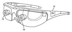
[0003]도 2a를 참조하여, 입체 착용가능 안경(8) 타입 구성들은, 3-차원 시각이 인간 시각 시스템에 의해 인지되도록, 약간 상이한 엘리먼트 표현을 가진 이미지들을 디스플레이하도록 구성되는 일반적으로 2개의 디스플레이들(10, 12)들을 특징화하게 개발되었다. 그런 구성들은 3-차원들에서 이미지들을 인지하기 위하여 극복하여야 하는 수렴(vergence)과 원근조절(accommodation) 사이의 미스 매칭으로 인해 많은 사용자들에게 불편하다는 것이 발견되었고; 정말로, 몇몇 사용자들은 입체 구성들을 견딜 수 없다. 도 2b는 입체 디스플레이들을 통하여 사용자에게 증강 현실 표현을 위해 이미지들을 캡쳐하도록 구성된 2개의 전방-배향 카메라들(16, 18)을 특징으로 하는 다른 입체 착용가능 안경(14) 타입 구성을 도시한다. 카메라들(16, 18) 및 디스플레이들의 포지션은 일반적으로, 안경(14)이 사용자의 머리에 장착될 때 사용자의 자연스러운 시야(field of view)를 차단한다.[0003]With reference to FIG. 2A , stereo
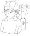
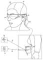
[0004]도 2c를 참조하여, 증강 현실 구성(20)은 또한 도시되고 종래의 안경 렌즈들(22)을 홀딩하는 안경 프레임(24)에 결합된 시각화 모듈(26)을 특징으로 한다. 사용자는 그런 시스템으로 실세계의 적어도 부분적으로 방해받지 않은 뷰를 볼 수 있고, 디지털 이미지너리가 하나의 눈(단안 AR 표현을 위하여)에 AR 구성으로 제공될 수 있는 작은 디스플레이(28)를 가진다. 도 2d는 시각화 모듈(32)이 모자 또는 헬멧(30)에 결합되고 단안 증강 디지털 이미지너리를 작은 디스플레이(34)를 통해 사용자에게 제공하도록 구성될 수 있는 구성을 특징으로 한다. 도 2e는, 시각화 모듈(38)이 이미지들을 캡쳐하고 그리고 또한 작은 디스플레이(40)를 통하여 단안 증강 디지털 이미지너리를 사용자에게 제공하기 위해 활용될 수 있도록, 프레임(36)이 안경 결합과 유사한 방식으로 사용자의 머리에 결합이능한 다른 유사한 구성을 예시한다. 그런 구성은 예컨대 GoogleGlass(RTM)라는 상표명으로 캘리포니아주 Mountain view의 Google, Inc.로부터 입수가능하다. 이들 구성들 중 어느 것도 사용자에게 편안하고 최대로 이용 가능할 방식으로 풍부하고, 양안이며, 3-차원 증강 현실 경험을 제공하기에 최적으로 적당하지 않은데, 그 이유는 부분적으로 종래 시스템들이 사용자에게 시각화의 인지를 생성하기 위하여 망막의 광수용체(photoreceptor)들과 뇌와의 이들의 연동을 포함하여, 인간 인지 시스템의 기본 양상들 중 몇몇을 처리하지 못하기 때문이다.[0004]Referring to FIG. 2C , an
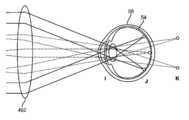
[0005]도 3을 참조하여, 인간 눈의 간략화된 단면도가 묘사되고, 각막(cornea)(42), 홍채(iris)(44), 수정체(lens) - 또는 "안구 수정체"(46), 공막(sclera)(48), 맥락막(choroid) 층(50), 황반(macula)(52), 망막(retina)(54), 및 뇌에 대한 시신경 통로(56)를 특징으로 한다. 황반은 망막의 중심이고, 황반은 적당한 상세(detail)를 보기 위하여 활용되고; 황반의 중심에는, 극상의 상세들을 위해 활용되고, 그리고 망막의 임의의 다른 부분보다 많은 광수용체(시각 각도당 대략 120개의 추상체(cones))를 포함하는 "중심와(fovea)"로서 지칭되는 망막의 일부가 있다. 인간 시각 시스템은 수동 센서 타입의 시스템이 아니고; 환경을 활성적으로 스캔하도록 구성된다. 이미지를 캡쳐하기 위하여 평상형(flatbed) 스캐너의 사용, 또는 종이로부터 점자(Braille)를 판독하기 위하여 손가락의 사용과 다소 유사한 방식으로, 눈의 광수용체들은, 일정한 상태의 자극에 일정하게 반응하기 보다 자극의 변화들에 응답하여 동작한다. 따라서 움직임(motion)은 광수용체 정보를 뇌에 제공하기 위하여(평상형 스캐너로 종이 한 장을 가로지르는 선형 스캐너 어레이의 움직임, 또는 종이에 각인(imprint)된 점자 단어를 가로지르는 손가락의 움직임인 바와 같이) 요구된다. 정말로, 눈의 근육들을 마비시키기 위하여 활용된 코브라 독 같은 물질들을 사용한 실험들은, 인간 피험자가 그의 눈들이 떠져 있는 상태로 포지셔닝되면 눈들의 독-유도 마비로 정적인 장면을 보는 실명을 경험할 것이라는 것을 보여줬다. 다른 말로, 자극의 변화들 없이, 광수용체들은 뇌에 입력을 제공하지 않고 실명이 경험된다. 정상 인간 눈들이 "미소안운동(microsaccades)이라 불리는 왔다갔다, 또는 디더(dither), 좌우 움직임으로 이동하는 것으로 관찰될 수 있다는 것은 이것이 적어도 하나의 이유라는 것이 믿어진다.[0005]Referring to FIG. 3 , a simplified cross-sectional view of the human eye is depicted, with the
[0006]상기 주의된 바와 같이, 망막의 중심와는 더 큰 밀도의 광수용체들을 포함하고, 그리고 인간들은 그들의 시야를 통해 높은 해상도 시각화 능력들을 가진다는 인지를 그들이 통상적으로 가지는 반면, 인간들은 일반적으로 실제로, 그들이 중심와로 최근에 캡쳐된 고해상도 정보의 지속성 메모리와 함께, 일구획 둘레를 기계적으로 스위핑하는 작은 고해상도 센터(center)만을 가진다. 다소 유사한 방식으로, 눈의 초점 거리 제어 메커니즘(모양체(ciliary) 이완에 의해 긴장된 모양체 연결 섬유들이 더 먼 초점 길이들을 위하여 수정체를 차츰 평평하게 하는 방식으로 모양 체근들(ciliary muscles)이 수정체에 동작 가능하게 결합되고; 모양체 수축은 모양체 연결 섬유들을 느슨하게 하고, 이는 수정체가 더 가까운 촛점 길이들에 대해 더 둥근 기하구조를 띠게 함)은 목표화된 촛점 길이의 근접 사이드 및 먼 사이드 둘 다에 대해 "광학 블러(dioptric blur)"라 불리는 작은 양을 주기적으로 유도하도록 대략 1/4 내지 1/2 디옵터(diopter)까지 왔다갔다 디더링하고; 이는 계속 코스를 수정하고 응시된 물체의 망막 이미지를 대략 초점에 맞춰 유지하는 것을 돕는 주기적 네거티브 피드백으로서 뇌의 원근조절 제어 회로들에 의해 활용된다.[0006]As noted above, the fovea of the retina contains a greater density of photoreceptors, and while they usually have the perception that humans have high resolution visualization capabilities through their field of view, humans generally actually, with only a small high-resolution center that mechanically sweeps around a compartment, with a persistent memory of high-resolution information recently captured with In a somewhat similar manner, the ciliary muscles can act on the lens in such a way that the eye's focal length control mechanism (ciliary connecting fibers tensed by ciliary relaxation gradually flatten the lens for greater focal lengths). (ciliary contraction loosens the ciliary connecting fibers, which gives the lens a more rounded geometry for closer focal lengths) is "optical" for both the proximal and far sides of the targeted focal length. dither back and forth by approximately 1/4 to 1/2 diopter to periodically induce a small amount called "dioptric blur"; This is utilized by the brain's accommodation control circuits as periodic negative feedback that continually modifies the course and helps keep the retinal image of the gazed object approximately in focus.
[0007]뇌의 시각화 센터는 또한 양쪽 눈들 및 서로에 관한 양쪽 눈들의 컴포넌트들의 움직임으로부터 가치있는 인지 정보를 얻는다. 서로에 관하여 두 눈들의 수렴 움직임들(즉, 물체를 응시하기 위하여 눈들의 시선들을 수렴하도록 서로를 향해 또는 서로로부터 멀리 동공들의 롤링(rolling) 움직임들)은 눈들의 수정체의 포커싱(또는 "원근조절")과 밀접하게 연관된다. 정상 조건들 하에서, 상이한 거리에 있는 물체를 포커싱하기 위해 눈들의 수정체의 초점 변화, 또는 눈들의 원근조절은 "원근조절-수렴 반사"로서 알려진 관계 하에서, 동일한 거리로의 수렴으로 매칭 변화를 자동으로 유발할 것이다. 마찬가지로, 수렴의 변화는 정상 조건들 하에서, 원근조절의 매칭 변화를 트리거할 것이다. 대부분의 종래의 입체 AR 또는 VR 구성들을 행하는 바와 같은 이런 반사에 대한 작업은 사용자들의 눈 피로, 두통들, 또는 다른 형태의 불편함을 생성하는 것으로 알려져 있다.[0007]The brain's visualization center also obtains valuable cognitive information from the movement of both eyes and the components of both eyes with respect to each other. Converging movements of the two eyes with respect to each other (ie, rolling movements of the pupils towards or away from each other to converge the gazes of the eyes to gaze at an object) are the focusing (or "accommodation") of the lens of the eyes. ") is closely related to Under normal conditions, a change in focus of the lens of the eyes to focus an object at a different distance, or accommodation of the eyes, automatically causes a matching change to converge to the same distance, under a relationship known as "accommodation-converging reflex". will cause Likewise, a change in convergence will trigger a matching change in accommodation, under normal conditions. Working with such reflections, as do most conventional stereoscopic AR or VR configurations, is known to create eye fatigue, headaches, or other forms of discomfort for users.
[0008]눈들을 하우징하는 머리의 움직임은 또한 물체들의 시각화에 핵심 영향을 가진다. 인간들은 그들 둘레의 세계를 시각화하기 위하여 그들의 머리들을 움직이고; 그들은 종종 관심 물체에 관련하여 머리를 재포지셔닝 및 재배향하는 상당히 변함없는 상태에 있는다. 추가로, 대부분의 사람들은, 그들의 눈 시선이 특정 물체에 포커싱하기 위하여 중심에서 약 20도 보다 많이 벗어나게 움직일 필요가 있을 때 그들의 머리들을 움직이는 것을 선호한다(즉, 사람들은 통상적으로 "눈의 코너"에서 물건들을 보는 것을 좋아한다). 인간들은 또한 통상적으로, 오디오 신호 캡쳐를 개선하고 머리에 관하여 귀들의 기하구조를 활용하기 위하여 소리들에 관련하여 그들의 머리들을 스캔하거나 움직인다. 인간 시각 시스템은 머리 움직임 및 눈 수렴 거리의 함수로서 상이한 거리들에 있는 물체들의 상대적 움직임에 관련된 "머리 움직임 시차(parallax)"라 불리는 것으로부터 강력한 깊이 단서를 얻는다(즉, 사람이 그의 머리를 좌우로 움직이고 물체에 고착을 유지하면, 물체로부터 더 멀리 있는 아이템들은 머리와 동일한 방향으로 움직이고; 그 물체의 전면 아이템들은 머리 움직임의 반대로 움직일 것이고; 이들은 물건들이 사람에 관련하여 공간적 환경에 있다는 매우 핵심적 단서들이다 - 아마도 입체시와 같이 강력함). 머리 움직임은 또한 물론, 물체들을 둘러 보기 위하여 활용된다.[0008]The movement of the head housing the eyes also has a key effect on the visualization of objects. Humans move their heads to visualize the world around them; They are often in a fairly constant state of repositioning and reorienting the head in relation to the object of interest. Additionally, most people prefer to move their heads when their eye gaze needs to move more than about 20 degrees off center to focus on a particular object (i.e., people typically refer to the "corner of the eye"). likes to see things in Humans also typically scan or move their heads in relation to sounds to improve audio signal capture and exploit the geometry of the ears in relation to the head. The human visual system derives powerful depth cues from what is called "head movement parallax", which relates to the relative movement of objects at different distances as a function of head movement and eye convergence distance (i.e., a person moves his or her head left and right). moving with and remaining anchored to the object, items further away from the object will move in the same direction as the head; items in front of that object will move in the opposite direction of head movement; these are very key clues that objects are in the spatial environment with respect to the person. are - perhaps as powerful as stereopsis). Head movements are also utilized, of course, to look around objects.
[0009]추가로, 머리 및 눈 움직임은 머리 회전들 동안 망막에 관하여 이미지 정보를 안정화하는 "전정안근반사(vestibulo-ocular reflex)"라 불리는 무언가와 협력되고, 따라서 물체 이미지 정보는 망막 상에 대략 중심을 가지게 유지된다. 머리 회전에 응답하여, 눈들은 물체에 대한 안정된 고착을 유지하기 위하여 반대 방향으로 반사적으로 그리고 비례적으로 회전된다. 이런 보상 관계의 결과로서, 많은 인간들은 그들의 머리를 왔다갔다 흔들면서 책을 읽을 수 있다(응미롭게, 책이 대략적으로 정적인 머리와 동일한 속도로 왔다갔다 보여지면, 동일한 것은 일반적으로 사실이 아니다 - 사람은 움직이는 책을 읽을 수 없을 것고; 전정안근반사는 일반적으로 손 움직임에 대해 개발된 것이 아니라 머리 및 눈 움직임 조정 중 하나이다). 이런 패러다임은 증강 현실 시스템들에 대해 중요할 수 있는데, 그 이유는 사용자의 머리 움직임들이 비교적 직접적으로 눈 움직임들과 연관될 수 있고, 시스템이 바람직하게 이런 관계로 작업할 준비될 것이기 때문이다.[0009]Additionally, head and eye movements cooperate with something called the "vestibulo-ocular reflex" that stabilizes image information with respect to the retina during head rotations, so that the object image information is roughly centered on the retina. maintain. In response to head rotation, the eyes are reflexively and proportionally rotated in opposite directions to maintain a stable fixation to the object. As a result of this reward relationship, many humans can read a book by shaking their head back and forth (and, consequently, if a book is moved to and fro at roughly the same rate as a static head, the same is generally not true - A person will not be able to read a moving book; the vestibular muscle reflex is one of the coordination of head and eye movements, not normally developed for hand movements). This paradigm may be important for augmented reality systems, since the user's head movements can be relatively directly related to eye movements, and the system will preferably be prepared to work with this relationship.
[0010]정말로, 디지털 컨텐츠(예컨대, 3-D 컨텐츠 이를테면 방의 실세계 뷰를 증가하기 위하여 제공된 가상 상들리에 물체; 또는 2-D 컨텐츠 이를테면 방의 실세계 뷰를 증강하기 위하여 제공된 평면/편평한 가상 유화 물체)를 배치할 때, 이들 다양한 관계들이 주어지면, 설계 선택들은 물체들의 거동을 제어하기 위하여 이루어질 수 있다. 예컨대, 2-D 유화 물체는 머리-중심일 수 있고, 상기 경우 물체는 사용자의 머리를 따라 둘레를 움직이고(예컨대, GoogleGlass 접근법); 또는 물체는 세계-중심일 수 있고, 상기 경우 물체는 마치 실 세계 좌표 시스템의 일부인 것처럼 제공될 수 있어서, 사용자는 실세계에 관련하여 물체의 포지션을 이동시킴이 없이 그의 머리 또는 눈들을 움직일 수 있다.[0010]Indeed, to place digital content (eg 3-D content such as a virtual sandelier object provided to augment a real-world view of a room; or 2-D content such as a flat/flat virtual oil painting object provided to augment a real-world view of a room) When given these various relationships, design choices can be made to control the behavior of objects. For example, a 2-D oil painting object may be head-centered, in which case the object moves around along the user's head (eg, GoogleGlass approach); Alternatively, the object may be world-centric, in which case the object may be presented as if it were part of a real world coordinate system, so that the user can move his head or eyes without moving the position of the object relative to the real world.
[0011]따라서 증강 현실 시스템으로 제공된 증강 현실 세계에 가상 컨텐츠를 배치할 때, 물체가 세계 중심(사용자가 실 세계 물체 둘레에 관하여 그의 포지션을 변경함이 없이 그 둘레에서 그의 몸, 머리, 눈들을 이동시킬 수 있도록 가상 물체가 실 세계의 포지션에 있음)으로서 제공되어야 하고; 몸, 또는 몸통, 중심, 상기 경우 가상 엘리먼트는 사용자의 몸통에 관련하여 고정될 수 있어서, 사용자는 물체를 움직이지 않고 그의 머리 또는 눈들을 이동시킬 수 있지만, 몸통 움직임들에 종속되지 않고; 머리 중심, 상기 경우 디스플레이된 물체(및/또는 디스플레이 자체)는 GoogleGlass를 참조하여 상기 설명된 바와 같이, 머리 움직임들에 따라 이동될 수 있거나; 또는 하기 설명된 바와 같이 "포비티드(foveated) 디스플레이" 구성에서 처럼 눈 중심으로서 제공되어야 한하고, 여기서 컨텐츠는 눈 포지션이 무엇인지의 함수로서 휙돈다.[0011]Thus, when placing virtual content in the augmented reality world provided by the augmented reality system, the object is the center of the world (the user can move his body, head and eyes around the real world object without changing his position relative to it) the virtual object is in a real-world position); The body, or torso, center, in this case the virtual element, may be fixed relative to the user's torso, so that the user can move his head or eyes without moving the object, but without subject to torso movements; The head center, in this case the displayed object (and/or the display itself), may be moved in accordance with head movements, as described above with reference to GoogleGlass; Or it should be presented as the eye center, as in a “foveated display” configuration, as described below, where the content swivels as a function of what the eye position is.
[0012]세계-중심 구성들에 의해, 정확한 머리 포즈(pose) 측정, 정확한 표현 및/또는 실세계 물체들의 측정 및 사용자 둘레 기하구조들, 머리 포즈의 함수로서 증강 현실 디스플레에서 동적 렌더링하는 낮은-레이턴시, 및 일반적으로 낮은-레이턴시 디스플레이 같은 입력들을 가지는 것이 바람직할 수 있다.[0012]With world-centric configurations, accurate head pose measurements, accurate representation and/or measurements of real-world objects and user perimeter geometries, low-latency rendering dynamically in augmented reality displays as a function of head pose, and general It may be desirable to have inputs such as low-latency displays.
[0013]본원에 설명된 시스템들 및 기술들은 이들 난제들을 처리하기 위하여 통상적인 인간의 시각 구성으로 작동하도록 구성된다.[0013]The systems and techniques described herein are configured to operate with conventional human visual constructs to address these challenges.
[0014]본 발명의 실시예들은 하나 또는 그 초과의 사용자들에 대한 가상 현실 및/또는 증강 현실 상호작용을 가능하게 하기 위한 디바이스들, 시스템들 및 방법들에 관한 것이다. 일 양상에서, 가상 컨텐츠를 디스플레이하기 위한 시스템이 개시된다.[0014]Embodiments of the present invention relate to devices, systems and methods for enabling virtual reality and/or augmented reality interaction for one or more users. In one aspect, a system for displaying virtual content is disclosed.
[0015]하나 또는 그 초과의 실시예들에서, 시스템은 이미지 데이터의 하나 또는 그 초과의 프레임들과 연관된 하나 또는 그 초과의 광 패턴들을 시간-순차적 방식으로 멀티플렉싱하기 위한 광 소스; 및 상기 하나 또는 그 초과의 광 패턴들을 수신하고, 광을 사출 동공 쪽으로 가변적으로 수렴시키기 위한 반사기들의 어레이를 포함한다.[0015]In one or more embodiments, a system includes a light source for multiplexing one or more light patterns associated with one or more frames of image data in a time-sequential manner; and an array of reflectors for receiving the one or more light patterns and variably converging light toward an exit pupil.
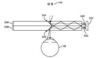
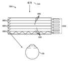
[0016]하나 또는 그 초과의 실시예에서, 시스템은 이미지 데이터의 하나 또는 그 초과의 프레임들을 시간-순차적 방식으로 제공하기 위한 이미지-생성 소스, 상기 이미지 데이터의 하나 또는 그 초과의 프레임들과 연관된 광을 송신하도록 구성되는 광 변조기, 이미지 정보를 사용자 눈으로 지향시키기 위한 기판 ― 상기 기판은 복수의 반사기들을 하우징함 ―, 이미지 데이터의 제 1 프레임과 연관되는 광을 제 1 각도로 상기 사용자 눈으로 반사하기 위한 상기 복수의 반사기들 중 제 1 반사기, 및 상기 이미지 데이터의 제 2 프레임과 연관되는 광을 제 2 각도로 상기 사용자 눈으로 반사하기 위한 복수의 반사기들 중 제 2 반사기를 포함한다.[0016]In one or more embodiments, the system transmits an image-generating source for providing one or more frames of image data in a time-sequential manner, light associated with the one or more frames of image data. a light modulator configured to: a substrate for directing image information to a user's eye, the substrate housing a plurality of reflectors, for reflecting light associated with a first frame of image data to the user's eye at a first angle a first reflector of the plurality of reflectors; and a second reflector of the plurality of reflectors for reflecting light associated with a second frame of image data to the user's eye at a second angle.
[0017]상기 복수의 반사기들의 반사 각도는 하나 또는 그 초과의 실시예들에서 가변적이다. 상기 반사기들은 하나 또는 그 초과의 실시예들에서 스위칭가능하다. 상기 복수의 반사기들은 하나 또는 그 초과의 실시예들에서 전자-광학적으로 활성일 수 있다. 상기 복수의 반사기들의 굴절률은 하나 또는 그 초과의 실시예들에서 상기 기판의 굴절률에 매칭하도록 변경될 수 있다. 선택적 실시예에서, 시스템은 또한 상기 기판과 상기 사용자 눈 사이에 배치되도록 구성가능한 고-주파수 게이팅 층을 포함할 수 있고, 고-주파수 게이팅 층은 제어 가능하게 이동 가능한 애퍼처를 가진다. 상기 고-주파수 게이팅 층의 상기 애퍼처는, 이미지 데이터가 하나 또는 그 초과의 실시예들에서 상기 애퍼처를 통해 반사되는 광을 통해서만 선택적으로 송신되게 하는 방식으로 이동된다. 송신 빔스플리터 기판의 하나 또는 그 초과의 반사기들은 고-주파수 게이팅 층에 의해 차단될 수 있다. 애퍼처는 하나 또는 그 초과의 실시예들에서 LCD 애퍼처일 수 있다. 애퍼처는 하나 또는 그 초과의 실시예들에서 MEMs 어레이일 수 있다. 제 1 각도는 하나 또는 그 초과의 실시예들에서 제 2 각도와 동일할 수 있다. 상기 제 1 각도는 하나 또는 그 초과의 실시예들에서 상기 제 2 각도와 상이할 수 있다.[0017]The reflection angle of the plurality of reflectors is variable in one or more embodiments. The reflectors are switchable in one or more embodiments. The plurality of reflectors may be electro-optically active in one or more embodiments. The refractive index of the plurality of reflectors may be changed to match the refractive index of the substrate in one or more embodiments. In an alternative embodiment, the system may also include a high-frequency gating layer configurable to be disposed between the substrate and the user's eye, the high-frequency gating layer having a controllably moveable aperture. The aperture of the high-frequency gating layer is moved in such a way that image data is selectively transmitted only through light reflected through the aperture in one or more embodiments. One or more reflectors of the transmit beamsplitter substrate may be blocked by a high-frequency gating layer. The aperture may be an LCD aperture in one or more embodiments. The aperture may be an array of MEMs in one or more embodiments. The first angle may be the same as the second angle in one or more embodiments. The first angle may be different from the second angle in one or more embodiments.
[0018]하나 또는 그 초과의 실시예들에서, 시스템은 광선들의 세트를 노달 포인트(nodal point)를 통해 상기 사용자 눈으로 조종하기 위해 제 1 렌즈를 더 포함할 수 있다. 상기 제 1 렌즈는, 하나 또는 그 초과의 실시예들에서 제 1 반사기를 나가는 상기 광선들의 세트가 상기 사용자 눈에 도달하기 이전에 상기 제 1 렌즈를 통과하도록 하기 위해서, 상기 기판 상에 그리고 상기 제 1 반사기 앞에 배치되도록 구성가능할 수 있다.[0018]In one or more embodiments, the system can further include a first lens to steer a set of rays through a nodal point to the user's eye. The first lens, in one or more embodiments, is disposed on the substrate and on the substrate to cause the set of rays exiting the first reflector to pass through the first lens before reaching the user's eye. 1 may be configurable to be placed in front of a reflector.
[0019]시스템은 상기 제 1 렌즈를 보상하기 위해 제 2 렌즈를 더 포함할 수 있고, 상기 제 2 렌즈는 하나 또는 그 초과의 실시예들에서 상기 기판 상에 그리고 상기 제 1 렌즈가 배치되는 사이드의 대향하는 사이드 상에 배치되도록 구성가능하고, 그로 인해서 제로 배율을 유도한다.[0019]The system may further include a second lens to compensate for the first lens, wherein the second lens is in one or more embodiments opposite to the side on which the first lens is disposed and on the substrate. Configurable to be placed on the side, thereby leading to zero magnification.
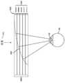
[0020]상기 복수의 반사기들 중 상기 제 1 반사기는 하나 또는 그 초과의 실시예들에서 상기 이미지 데이터와 연관된 광선들의 세트를 상기 사용자 눈에 전달되기 이전에 단일 출력 포인트로 모으기 위해 곡선형 반사 표면일 수 있다. 곡선형 반사기는 하나 또는 그 초과의 실시예들에서 포물선형 반사기일 수 있다. 곡선형 반사기는 하나 또는 그 초과의 실시예들에서 타원형 반사기일 수 있다.[0020]The first of the plurality of reflectors may in one or more embodiments be a curved reflective surface to collect a set of rays associated with the image data to a single output point prior to delivery to the user's eye. . The curved reflector may be a parabolic reflector in one or more embodiments. The curved reflector may be an elliptical reflector in one or more embodiments.
[0021]다른 실시예에서, 가상 컨텐츠를 디스플레이하기 위한 방법은 이미지 데이터의 하나 또는 그 초과의 프레임들과 연관된 하나 또는 그 초과의 광 패턴들을 시간-순차적 방식으로 제공하는 단계 및 상기 이미지 데이터의 하나 또는 그 초과의 프레임들과 연관된 상기 하나 또는 그 초과의 광 패턴들을 투과성 빔스플리터를 통해 사출 동공으로 반사하는 단계를 포함하고, 상기 투과성 빔스플리터는 광을 상기 사출 동공 쪽으로 가변적으로 수렴시키기 위한 복수의 반사기들을 갖는다.[0021]In another embodiment, a method for displaying virtual content includes providing one or more light patterns associated with one or more frames of image data in a time-sequential manner and one or more of the image data reflecting the one or more light patterns associated with the frames of a transmissive beamsplitter through a transmissive beamsplitter to an exit pupil, the transmissive beamsplitter having a plurality of reflectors for variably converging light toward the exit pupil .
[0022]상기 복수의 반사기들의 반사 각도는 하나 또는 그 초과의 실시예들에서 가변적일 수 있다. 상기 반사기들은 하나 또는 그 초과의 실시예들에서 스위칭가능할 수 있다. 상기 복수의 반사기들은 하나 또는 그 초과의 실시예들에서 전자-광학적으로 활성일 수 있다. 상기 복수의 반사기들의 굴절률은 하나 또는 그 초과의 실시예들에서 기판의 굴절률에 매칭하도록 변경될 수 있다. 선택적 실시예에서, 시스템은 또한 기판과 사용자 눈 사이에 배치되도록 구성된 고-주파수 게이팅 층을 포함할 수 있고, 상기 고-주파수 게이팅 층은 제어가능하게 이동가능한 애퍼처를 가진다. 상기 고-주파수 게이팅 층의 상기 애퍼처는, 하나 또는 그 초과의 실시예들에서 이미지 데이터가 상기 애퍼처를 통해 반사되는 광을 통해서만 선택적으로 송신되게 하는 방식으로 이동될 수 있다. 투과성 빔스플리터 기판의 하나 또는 그 초과의 반사기들은 상기 고-주파수 게이팅 층에 의해 차단될 수 있다. 상기 애퍼처는 하나 또는 그 초과의 실시예들에서 LCD 애퍼처일 수 있다. 상기 애퍼처는 하나 또는 그 초과의 실시예들에서 MEMs 어레이일 수 있다. 제 1 각도는 하나 또는 그 초과의 실시예들에서 제 2 각도와 동일할 수 있다. 제 1 각도는 하나 또는 그 초과의 실시예들에서 제 2 각도와 상이할 수 있다.[0022]The reflection angle of the plurality of reflectors may be variable in one or more embodiments. The reflectors may be switchable in one or more embodiments. The plurality of reflectors may be electro-optically active in one or more embodiments. The refractive index of the plurality of reflectors may be varied to match the refractive index of the substrate in one or more embodiments. In an alternative embodiment, the system may also include a high-frequency gating layer configured to be disposed between the substrate and a user's eye, the high-frequency gating layer having a controllably movable aperture. The aperture of the high-frequency gating layer may be moved in one or more embodiments in a manner such that image data is selectively transmitted only via light reflected through the aperture. One or more reflectors of the transmissive beamsplitter substrate may be blocked by the high-frequency gating layer. The aperture may be an LCD aperture in one or more embodiments. The aperture may be an array of MEMs in one or more embodiments. The first angle may be the same as the second angle in one or more embodiments. The first angle may be different from the second angle in one or more embodiments.
[0023]하나 또는 그 초과의 실시예들에서, 시스템은 광선들의 세트를 노달 포인트를 통해 사용자 눈으로 조종하기 위한 제 1 렌즈를 더 포함할 수 있다. 제 1 렌즈는, 하나 또는 그 초과의 실시예들에서 반사기를 나가는 상기 광선들의 세트가 상기 사용자 눈에 도달하기 이전에 상기 제 1 렌즈를 통과하도록 하기 위해서, 상기 기판 상에 그리고 상기 제 1 반사기 앞에 배치되도록 구성가능할 수 있다.[0023]In one or more embodiments, the system can further include a first lens for steering the set of rays through the nodal point to the user's eye. A first lens, in one or more embodiments, is disposed on the substrate and in front of the first reflector to allow the set of rays exiting the reflector to pass through the first lens before reaching the user's eye. It may be configurable to be placed.
[0024]시스템은 상기 제 1 렌즈를 보상하기 위해 제 2 렌즈를 더 포함할 수 있고, 상기 제 2 렌즈는 하나 또는 그 초과의 실시예들에서 상기 기판 상에 그리고 상기 제 1 렌즈가 배치되는 사이드의 대향하는 사이드 상에 배치되도록 구성가능하고, 그로 인해서 제로 배율을 유도한다.[0024]The system may further include a second lens to compensate for the first lens, wherein the second lens is in one or more embodiments opposite to the side on which the first lens is disposed and on the substrate. Configurable to be placed on the side, thereby leading to zero magnification.
[0025]상기 복수의 반사기들 중 상기 제 1 반사기는 하나 또는 그 초과의 실시예들에서 상기 이미지 데이터와 연관된 광선들의 세트를 상기 사용자 눈에 전달되기 이전에 단일 출력 포인트로 모으기 위해 곡선형 반사 표면일 수 있다. 곡선형 반사기는 하나 또는 그 초과의 실시예들에서 포물선형 반사기일 수 있다. 곡선형 반사기는 하나 또는 그 초과의 실시예들에서 타원형 반사기일 수 있다.[0025]The first of the plurality of reflectors may in one or more embodiments be a curved reflective surface to collect a set of rays associated with the image data to a single output point prior to delivery to the user's eye. . The curved reflector may be a parabolic reflector in one or more embodiments. The curved reflector may be an elliptical reflector in one or more embodiments.
[0026]하나 또는 그 초과의 실시예들에서, 파면은 시준(collimated)될 수 있다. 하나 또는 그 초과의 실시예들에서, 상기 파면은 곡선형일 수 있다. 시준된 파면은 몇몇 실시예들에서 무한 깊이 평면으로서 인지될 수 있다. 곡선형 파면은 몇몇 실시예들에서 광학 무한성보다 가까운 깊이 평면으로서 인지될 수 있다.[0026]In one or more embodiments, the wavefront may be collimated. In one or more embodiments, the wavefront may be curved. A collimated wavefront may be perceived as an infinite depth plane in some embodiments. A curved wavefront may be perceived as a depth plane closer to optical infinity in some embodiments.
[0027]다른 실시예에서, 가상 컨텐츠를 사용자에게 디스플레이하기 위한 시스템은 이미지 데이터의 하나 또는 그 초과의 프레임들과 연관된 하나 또는 그 초과의 광 패턴들을 시간-순차적 방식으로 멀티플렉싱하기 위한 광 소스, 상기 하나 또는 그 초과의 광 패턴들을 수신하기 위한 반사기들의 어레이 ― 상기 반사기들의 어레이는 특정 각도로 배향됨 ―, 및 상기 광 패턴들을 사출 동공 쪽으로 가변적으로 수렴시키기 위해 상기 반사기들의 어레이에 결합되는 복수의 광학 엘리먼트들을 포함한다.[0027]In another embodiment, a system for displaying virtual content to a user comprises a light source for multiplexing one or more light patterns associated with one or more frames of image data in a time-sequential manner, the one or more an array of reflectors for receiving excess light patterns, the array of reflectors oriented at a particular angle, and a plurality of optical elements coupled to the array of reflectors to variably converge the light patterns toward an exit pupil. do.
[0028]하나 또는 그 초과의 실시예들에서, 상기 반사기들의 어레이는 하나 또는 그 초과의 실시예들에서 상기 광학 엘리먼트들로부터 분리될 수 있다. 상기 반사기들의 어레이는 하나 또는 그 초과의 실시예들에서, 평면 거울들을 포함할 수 있다. 상기 광학 엘리먼트들은 하나 또는 그 초과의 실시예들에서, 상기 반사기들의 어레이에 결합되는 렌즈릿들(lenslets)일 수 있다. 상기 반사기들의 어레이의 하나 또는 그 초과의 반사기들은 하나 또는 그 초과의 실시예들에서 곡선형일 수 있다. 상기 광학 엘리먼트들은 상기 반사기들의 어레이에 통합될 수 있다. 상기 복수의 광학 엘리먼트들은 하나 또는 그 초과의 실시예들에서 사출 동공을 확장시킬 수 있다.[0028]In one or more embodiments, the array of reflectors may be separate from the optical elements in one or more embodiments. The array of reflectors may, in one or more embodiments, include planar mirrors. The optical elements may, in one or more embodiments, be lenslets coupled to the array of reflectors. One or more reflectors of the array of reflectors may be curved in one or more embodiments. The optical elements may be integrated into the array of reflectors. The plurality of optical elements may dilate the exit pupil in one or more embodiments.
[0029]시스템은 노달 포인트를 통해 사용자 눈으로의 광선들의 세트를 조종하기 위한 제 1 렌즈를 더 포함할 수 있고, 상기 제 1 렌즈는, 하나 또는 그 초과의 실시예들에서 반사기를 나가는 상기 광선들의 세트가 상기 사용자 눈에 도달하기 이전에 상기 제 1 렌즈를 통과하도록 하기 위해서, 기판 상에 그리고 상기 제 1 반사기의 전면 상에 배치되도록 구성가능할 수 있다.[0029]The system may further include a first lens for steering a set of rays through a nodal point to a user's eye, wherein the first lens, in one or more embodiments, comprises a set of rays exiting a reflector. It may be configurable to be disposed on a substrate and on a front surface of the first reflector to allow it to pass through the first lens before reaching the user's eye.
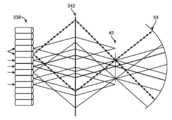
[0030]시스템은 상기 제 1 렌즈를 보상하기 위해 제 2 렌즈를 더 포함할 수 있고, 상기 제 2 렌즈는 하나 또는 그 초과의 실시예들에서 상기 기판 상에 그리고 상기 제 1 렌즈가 배치되는 사이드의 대향하는 사이드 상에 배치되도록 구성가능하고, 그로 인해서 제로 배율을 유도한다. 상기 복수의 반사기들은 하나 또는 그 초과의 실시예들에서 파장-선택 반사기들을 포함할 수 있다. 상기 복수의 반사기들은 하나 또는 그 초과의 실시예들에서 반도금 거울들을 포함할 수 있다. 상기 복수의 광학 엘리먼트들은 굴절 렌즈들을 포함할 수 있다. 상기 복수의 광학 엘리먼트들은 하나 또는 그 초과의 실시예들에서 회절 렌즈를 포함할 수 있다. 곡선형 반사기들은 하나 또는 그 초과의 실시예들에서 파장-길이 선택 노치 필터들을 포함할 수 있다.[0030]The system may further include a second lens to compensate for the first lens, wherein the second lens is in one or more embodiments opposite to the side on which the first lens is disposed and on the substrate. Configurable to be placed on the side, thereby leading to zero magnification. The plurality of reflectors may include wavelength-selective reflectors in one or more embodiments. The plurality of reflectors may include semi-plated mirrors in one or more embodiments. The plurality of optical elements may include refractive lenses. The plurality of optical elements may include a diffractive lens in one or more embodiments. Curved reflectors may include wavelength-length selective notch filters in one or more embodiments.
[0031]다른 실시예에서, 가상 컨텐츠를 사용자에게 디스플레이하기 위한 방법은, 이미지 데이터의 하나 또는 그 초과의 프레임들과 연관된 하나 또는 그 초과의 광 패턴들을 시간-순차적 방식으로 제공하는 단계, 상기 이미지 데이터의 하나 또는 그 초과의 프레임들과 연관된 상기 하나 또는 그 초과의 광 패턴들을 투과성 빔스플리터를 통해 사출 동공으로 반사하는 단계 ― 상기 투과성 빔스플리터는 광을 상기 사출 동공 쪽으로 가변적으로 수렴시키기 위해 복수의 반사기들을 가짐 ―, 및 상기 투과성 빔스플리터의 상기 복수의 반사기들에 결합된 복수의 광학 엘리먼트들을 통해 사출 동공을 확장하는 단계를 포함한다.[0031]In another embodiment, a method for displaying virtual content to a user includes providing one or more light patterns associated with one or more frames of image data in a time-sequential manner, the one of the image data or reflecting the one or more light patterns associated with one or more frames through a transmissive beamsplitter to an exit pupil, the transmissive beamsplitter having a plurality of reflectors to variably converge light toward the exit pupil. - and expanding the exit pupil via a plurality of optical elements coupled to the plurality of reflectors of the transmissive beamsplitter.
[0032]하나 또는 그 초과의 실시예들에서, 반사기들의 어레이는 상기 광학 엘리먼트들로부터 분리될 수 있다. 하나 또는 그 초과의 실시예들에서 반사기들의 어레이는 평면 거울들을 포함한다. 상기 광학 엘리먼트들은 하나 또는 그 초과의 실시예들에서 상기 반사기들의 어레이에 결합되는 렌즈릿들(lenslets)일 수 있다.[0032]In one or more embodiments, the array of reflectors may be separate from the optical elements. In one or more embodiments the array of reflectors includes planar mirrors. The optical elements may be lenslets coupled to the array of reflectors in one or more embodiments.
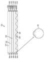
[0033]다른 실시예에서, 가상 컨텐츠를 사용자에게 디스플레이하기 위한 시스템은 이미지 데이터의 하나 또는 그 초과의 프레임들과 연관된 하나 또는 그 초과의 광 패턴들을 시간-순차적 방식으로 멀티플렉싱하기 위한 광 소스, 및 상기 하나 또는 그 초과의 광 패턴들을 수신하고 상기 광 패턴들을 제 1 초점 레벨로 수렴하기 위한 도파관, 및 상기 광 패턴들의 적어도 일부를 제 2 초점 레벨로 수렴하기 위해 상기 도파관에 결합되는 가변 초점 엘리먼트(VFE)를 포함한다.[0033]In another embodiment, a system for displaying virtual content to a user includes a light source for multiplexing one or more light patterns associated with one or more frames of image data in a time-sequential manner, and the one or a waveguide for receiving more light patterns and converging the light patterns to a first focal level, and a variable focus element (VFE) coupled to the waveguide for converging at least a portion of the light patterns to a second focal level. include
[0034]하나 또는 그 초과의 실시예들에서, 상기 VFE는 하나 또는 그 초과의 실시예들에서 텔리센트릭(telecentric)이다. VFE는 하나 또는 그 초과의 실시예들에서 비-텔리센트릭이다. 시스템은 하나 또는 그 초과의 실시예들에서, 외부 세계의 사용자의 뷰가 왜곡되지 않게 하기 위해서 보상 렌즈를 더 포함한다. 복수의 프레임들은 상기 사용자가 프레임들을 단일 코히런트 장면(single coherent scene)의 일부로서 인지하게 하기 위해서 고-주파수로 상기 사용자에게 제공되고, 상기 VFE는 하나 또는 그 초과의 실시예들에서 초점을 제 1 프레임으로부터 제 2 프레임으로 변경한다. 상기 광 소스는 스캐닝 광 디스플레이이고, 상기 VFE는 하나 또는 그 초과의 실시예들에서, 라인 단위 방식으로 초점을 변경한다. 상기 광 소스는 스캐닝 광 디스플레이이고, 상기 VFE는 하나 또는 그 초과의 실시예들에서 픽셀 단위 방식으로 초점을 변경한다.[0034]In one or more embodiments, the VFE is telecentric in one or more embodiments. The VFE is non-telecentric in one or more embodiments. The system, in one or more embodiments, further includes a compensating lens to prevent the user's view of the outside world from being distorted. A plurality of frames is presented to the user at a high-frequency to cause the user to perceive the frames as part of a single coherent scene, wherein the VFE defocuses in one or more embodiments. It changes from the 1st frame to the 2nd frame. The light source is a scanning light display and the VFE, in one or more embodiments, changes focus in a line-by-line manner. The light source is a scanning light display, and the VFE changes focus in a pixel-by-pixel manner in one or more embodiments.
[0035]상기 VFE는 하나 또는 그 초과의 실시예들에서 회절 렌즈이다. VFE는 하나 또는 그 초과의 실시예들에서 굴절 렌즈이다. 상기 VFE는 하나 또는 그 초과의 실시예들에서 반사 거울이다. 반사 거울은 하나 또는 그 초과의 실시예들에서 불투명하다. 반사 거울은 하나 또는 그 초과의 실시예들에서 부분적으로 반사성이다. 시스템은 사용자 눈들의 원근조절(accommodation)을 추적하기 위한 원근조절 모듈을 더 포함하고, 상기 VFE는 하나 또는 그 초과의 실시예들에서 상기 사용자 눈들의 원근조절에 적어도 부분적으로 기초하여 광 패턴들의 초점을 변경한다.[0035]The VFE is a diffractive lens in one or more embodiments. A VFE is a refractive lens in one or more embodiments. The VFE is a reflective mirror in one or more embodiments. The reflective mirror is opaque in one or more embodiments. The reflective mirror is partially reflective in one or more embodiments. The system further comprises an accommodation module for tracking accommodation of the user's eyes, wherein the VFE is in one or more embodiments to focus the light patterns based at least in part on the accommodation of the user's eyes. change the
[0036]또 다른 실시예에서, 가상 컨텐츠를 사용자에게 디스플레이하기 위한 시스템은, 이미지 데이터의 하나 또는 그 초과의 프레임들과 연관된 하나 또는 그 초과의 광 패턴들을 시간-순차적 방식으로 멀티플렉싱하기 위한 광 소스; 하나 또는 그 초과의 광 패턴들을 수신하고, 광 패턴들을 제 1 초점로 수렴하기 위한 도파관; 및 광 패턴들의 적어도 일부를 제 2 초점로 수렴시키기 위해 도파관에 결합되는 가변 초점 엘리먼트(VFE)를 포함하고, VFE는 도파관에 통합된다.[0036]In yet another embodiment, a system for displaying virtual content to a user comprises: a light source for multiplexing one or more light patterns associated with one or more frames of image data in a time-sequential manner; a waveguide for receiving the one or more light patterns and for converging the light patterns to a first focal point; and a variable focus element (VFE) coupled to the waveguide to converge at least a portion of the light patterns to a second focal point, the VFE being integrated into the waveguide.
[0037]다른 실시예에서, 가상 컨텐츠를 사용자에게 디스플레이하기 위한 시스템은, 이미지 데이터의 하나 또는 그 초과의 프레임들과 연관된 하나 또는 그 초과의 광 패턴들을 시간-순차적 방식으로 멀티플렉싱하기 위한 광 소스; 하나 또는 그 초과의 광 패턴들을 수신하고, 광 패턴들을 제 1 초점로 수렴시키기 위한 도파관; 및 광 패턴들의 적어도 일부를 제 2 초점로 수렴시키기 위해 도파관에 결합되는 가변 초점 엘리먼트(VFE)를 포함하고, VFE는 도파관으로부터 분리된다.[0037]In another embodiment, a system for displaying virtual content to a user comprises: a light source for multiplexing one or more light patterns associated with one or more frames of image data in a time-sequential manner; a waveguide for receiving the one or more light patterns and for converging the light patterns to a first focal point; and a variable focus element (VFE) coupled to the waveguide to converge at least a portion of the light patterns to a second focal point, the VFE being separated from the waveguide.
[0038]다른 양상에서, 가상 컨텐츠를 사용자에게 디스플레이하기 위한 방법은, 이미지 데이터의 하나 또는 그 초과의 프레임들과 연관된 하나 또는 그 초과의 광 패턴들을 제공하는 단계; 이미지 데이터의 하나 또는 그 초과의 프레임들과 연관된 하나 또는 그 초과의 광 패턴들을 도파관을 통해 제 1 초점로 수렴시키는 단계; 및 제 2 초점의 파면을 생성하기 위해 광의 제 1 초점을 가변 초점 엘리먼트(VFE)를 통해 수정하는 단계를 포함한다.[0038]In another aspect, a method for displaying virtual content to a user includes providing one or more light patterns associated with one or more frames of image data; converging one or more light patterns associated with the one or more frames of image data through the waveguide to a first focus; and modifying the first focus of the light via the variable focus element (VFE) to produce a wavefront of the second focus.
[0039]하나 또는 그 초과의 실시예들에서, VFE는 도파관으로부터 분리된다. 하나 또는 그 초과의 실시예들에서, VFE는 도파관에 통합된다. 하나 또는 그 초과의 실시예들에서, 이미지 데이터의 하나 또는 그 초과의 프레임들은 시간-순차적 방식으로 제공된다. 하나 또는 그 초과의 실시예들에서, VFE는 이미지 데이터의 하나 또는 그 초과의 프레임들의 초점을 프레임 단위 기반으로 수정한다. 하나 또는 그 초과의 실시예들에서, VFE는 이미지 데이터의 하나 또는 그 초과의 프레임들의 초점을 픽셀 단위 기반으로 수정한다. 하나 또는 그 초과의 실시예들에서, VFE는 제 3 초점로 파면을 생성하기 위해 제 1 초점을 수정하고, 제 2 초점은 제 3 초점와 상이하다. 하나 또는 그 초과의 실시예들에서, 제 2 초점의 파면은 특정 깊이 평면으로부터 오는 것으로 사용자에 의해 인지된다.[0039]In one or more embodiments, the VFE is separate from the waveguide. In one or more embodiments, the VFE is integrated into the waveguide. In one or more embodiments, the one or more frames of image data are provided in a time-sequential manner. In one or more embodiments, the VFE corrects the focus of one or more frames of image data on a frame-by-frame basis. In one or more embodiments, the VFE corrects the focus of one or more frames of image data on a per-pixel basis. In one or more embodiments, the VFE modifies the first focus to create a wavefront with a third focus, and the second focus is different from the third focus. In one or more embodiments, the wavefront of the second focus is perceived by the user as coming from a particular depth plane.
[0040]일부 실시예들에서, 사용자가 복수의 프레임들을 단일 코히런트 장면의 일부로서 인지하게 하기 위해서 복수의 프레임들은 고-주파수로 사용자에게 제공되고, VFE는 초점을 제 1 프레임으로부터 제 2 프레임으로 변경한다. 광 소스는 스캐닝 광 디스플레이이고, 그리고 하나 또는 그 초과의 실시예들에서, VFE는 라인 단위 방식으로 초점을 변경한다.[0040]In some embodiments, the plurality of frames is presented to the user at a high-frequency to cause the user to perceive the plurality of frames as part of a single coherent scene, and the VFE changes focus from the first frame to the second frame . The light source is a scanning light display, and in one or more embodiments, the VFE changes focus in a line-by-line manner.
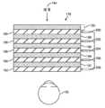
[0041]다른 실시예에서, 가상 컨텐츠를 사용자에게 디스플레이하기 위한 시스템은, 이미지 데이터와 연관된 광선들을 수신하고, 광선들을 사용자 눈들 쪽으로 송신하기 위한 복수의 도파관들 ― 복수의 도파관들은 사용자 눈에 면하는 방향으로 스택됨(stacked) ―; 제 1 도파관으로부터 송신되는 광선들을 수정하기 위해 복수의 도파관들 중 제 1 도파관에 결합됨으로써, 제 1 파면 곡률을 갖는 광선들을 전달하는 제 1 렌즈; 및 제 2 도파관으로부터 송신되는 광선들을 수정하기 위해 복수의 도파관들 중 제 2 도파관에 결합됨으로써, 제 2 파면 곡률을 갖는 광선들을 전달하는 제 2 렌즈를 포함하고, 제 1 도파관에 결합된 제 1 렌즈 및 제 2 도파관에 결합된 제 2 렌즈는 사용자 눈에 면하는 방향에 수평으로 스택된다.[0041]In another embodiment, a system for displaying virtual content to a user comprises: a plurality of waveguides for receiving light rays associated with image data and transmitting the rays towards the user's eyes, the plurality of waveguides stacked in a direction facing the user's eyes stacked -; a first lens coupled to a first one of the plurality of waveguides to modify light rays transmitted from the first waveguide, thereby transmitting light rays having a first wavefront curvature; and a second lens coupled to a second one of the plurality of waveguides to modify light rays transmitted from the second waveguide, thereby transmitting light rays having a second wavefront curvature, a first lens coupled to the first waveguide and a second lens coupled to the second waveguide is stacked horizontally in a direction facing the user's eye.
[0042]하나 또는 그 초과의 실시예들에서, 제 1 파면 곡률은 제 2 파면 곡률과 상이하다. 하나 또는 그 초과의 실시예들에서, 시스템은, 사용자가 이미지 데이터를 광학 무한성 평면으로부터 오는 것으로 인지하게 하기 위해서 시준된 광을 사용자 눈에 전달하기 위해 복수의 도파관들 중 제 3 도파관을 더 포함한다. 하나 또는 그 초과의 실시예들에서, 도파관은 시준된 광을 렌즈들에 송신하도록 구성된다.[0042]In one or more embodiments, the first wavefront curvature is different from the second wavefront curvature. In one or more embodiments, the system further comprises a third of the plurality of waveguides to deliver collimated light to the user's eye to cause the user to perceive the image data as coming from the optical infinity plane. do. In one or more embodiments, the waveguide is configured to transmit collimated light to the lenses.
[0043]하나 또는 그 초과의 실시예들에서, 시스템은, 사용자 눈들에 면하는 방향으로 스택되는 렌즈들의 어그리게이트 파워를 보상하기 위해 보상 렌즈 층을 더 포함하고, 보상 렌즈 층은 사용자 눈으로부터 가장 멀리 스택된다. 하나 또는 그 초과의 실시예들에서, 도파관은 도파관에 주입되는 광선들을 사용자 눈 쪽으로 반사하도록 구성가능한 복수의 반사기들을 포함한다.[0043]In one or more embodiments, the system further comprises a compensating lens layer to compensate for aggregate power of lenses stacked in a direction facing the user's eyes, the compensating lens layer stacked furthest from the user's eyes do. In one or more embodiments, the waveguide includes a plurality of reflectors configurable to reflect light rays injected into the waveguide toward a user's eye.
[0044]하나 또는 그 초과의 실시예들에서, 도파관은 전기-활성이다. 하나 또는 그 초과의 실시예들에서, 도파관은 스위칭가능하다. 하나 또는 그 초과의 실시예들에서, 제 1 파면 곡률을 갖는 광선들 및 제 2 파면 곡률을 갖는 광선들이 동시적으로 전달된다. 하나 또는 그 초과의 실시예들에서, 제 1 파면 곡률을 갖는 광선들 및 제 2 파면 곡률을 갖는 광선들이 순차적으로 전달된다. 하나 또는 그 초과의 실시예들에서, 제 2 파면 곡률이 제 1 파면 곡률의 마진(margin)에 대응함으로써, 사용자가 원근조절할 수 있는 초점 범위(focal range)를 제공한다. 하나 또는 그 초과의 실시예들에서, 시스템은, 사용자 눈들의 원근조절을 추적하기 위한 원근조절 모듈을 더 포함하고, VFE가 사용자 눈들의 원근조절에 적어도 부분적으로 기초하여 광 패턴들의 초점을 변경한다.[0044]In one or more embodiments, the waveguide is electro-active. In one or more embodiments, the waveguide is switchable. In one or more embodiments, the rays of the first wavefront curvature and the rays of the second wavefront curvature are transmitted simultaneously. In one or more embodiments, the rays of the first wavefront curvature and the rays of the second wavefront curvature are delivered sequentially. In one or more embodiments, the second wavefront curvature corresponds to a margin of the first wavefront curvature, thereby providing a focal range that the user can adjust. In one or more embodiments, the system further comprises an accommodation module for tracking accommodation of the user's eyes, wherein the VFE changes focus of the light patterns based at least in part on the accommodation of the user's eyes. .
[0045]또 다른 실시예들에서, 가상 컨텐츠를 사용자에게 디스플레이하기 위한 시스템은, 이미지 데이터의 하나 또는 그 초과의 프레임들과 연관된 하나 또는 그 초과의 광 패턴들을 시간-순차적 방식으로 멀티플렉싱하기 위한 광 소스; 하나 또는 그 초과의 광 패턴들을 수신하고, 광을 사출 동공으로 수렴시키기 위한 복수의 도파관들 ― 복수의 도파관들은 z-축을 따라서 그리고 사용자의 시선으로부터 멀어지게 스택됨 ―; 및 복수의 도파관들에 의해 송신되는 광의 초점을 수정하기 위해, 스택된 도파관들에 결합되는 적어도 하나의 광학 엘리먼트를 포함한다.[0045]In still other embodiments, a system for displaying virtual content to a user comprises: a light source for multiplexing one or more light patterns associated with one or more frames of image data in a time-sequential manner; a plurality of waveguides for receiving the one or more light patterns and for converging the light into the exit pupil, the plurality of waveguides stacked along the z-axis and away from the user's line of sight; and at least one optical element coupled to the stacked waveguides to modify a focus of light transmitted by the plurality of waveguides.
[0046]하나 또는 그 초과의 실시예들에서, 복수의 도파관들 중 일 도파관은 프로젝팅된 광을 자신의 길이에 걸쳐 분산시키기 위한 도파관, 및 파면 곡률이 생성되게 하는 방식으로 광을 수정하기 위한 렌즈를 포함할 수 있고, 생성되는 파면 곡률은 사용자에 의해 보여질 때 초점면에 대응한다.[0046]In one or more embodiments, one of the plurality of waveguides comprises a waveguide for dispersing the projected light over its length, and a lens for modifying the light in such a way that a wavefront curvature is produced. and the resulting wavefront curvature corresponds to the focal plane as viewed by the user.
[0047]하나 또는 그 초과의 실시예들에서, 복수의 도파관들 중 일 도파관은 DOE(diffractive optical element)를 포함한다. 하나 또는 그 초과의 실시예들에서, DOE는 온 및 오프 상태들 사이에서 스위칭가능하다. 하나 또는 그 초과의 실시예들에서, 복수의 도파관들 중 일 도파관은 굴절 렌즈를 포함한다. 하나 또는 그 초과의 실시예들에서, 복수의 도파관들 중 일 도파관은 프레넬 존 플레이트(Fresnel zone plate)를 포함한다. 하나 또는 그 초과의 실시예들에서, 복수의 도파관들 중 일 도파관은 SGO(substrate guided optics) 엘리먼트를 포함한다. 하나 또는 그 초과의 실시예들에서, 도파관은 온 및 오프 상태 사이에서 스위칭가능하다. 하나 또는 그 초과의 실시예들에서, 도파관은 정적이다. 하나 또는 그 초과의 실시예들에서, 이미지 데이터의 제 1 프레임 및 이미지 데이터의 제 2 프레임이 사용자 눈에 동시적으로 전달된다. 하나 또는 그 초과의 실시예들에서, 이미지 데이터의 제 1 프레임 및 이미지 데이터의 제 2 프레임이 사용자 눈에 순차적으로 전달된다.[0047]In one or more embodiments, one of the plurality of waveguides includes a diffractive optical element (DOE). In one or more embodiments, the DOE is switchable between on and off states. In one or more embodiments, one of the plurality of waveguides includes a refractive lens. In one or more embodiments, one of the plurality of waveguides includes a Fresnel zone plate. In one or more embodiments, one of the plurality of waveguides includes a substrate guided optics (SGO) element. In one or more embodiments, the waveguide is switchable between an on and off state. In one or more embodiments, the waveguide is static. In one or more embodiments, the first frame of image data and the second frame of image data are simultaneously delivered to the user's eye. In one or more embodiments, a first frame of image data and a second frame of image data are sequentially delivered to the user's eye.
[0048]하나 또는 그 초과의 실시예들에서, 시스템은, 광을 사용자 눈에 전달하기 위한 복수의 각도를 이룬 반사기들을 더 포함하고, 제 1 도파관 컴포넌트 및 제 2 도파관 컴포넌트가 광을 하나 또는 그 초과의 각도를 이룬 반사기들로 지향시킨다. 하나 또는 그 초과의 실시예들에서, 시스템은, 빔 분산 광 도파관을 더 포함하고, 빔 분산 광 도파관은 도파관 어셈블리에 결합되고, 빔 분산 광 도파관이 프로젝팅된 광을 도파관 어셈블리에 걸쳐 확산시키도록 구성가능함으로써, 빔 분산 광 도파관에 주입되는 광선은 복제되어 도파관 어셈블리의 도파관 컴포넌트들에 주입된다.[0048]In one or more embodiments, the system further comprises a plurality of angled reflectors for directing light to a user's eye, wherein the first waveguide component and the second waveguide component direct the light at the one or more angles. is directed to the reflectors. In one or more embodiments, the system further comprises a beam scattering optical waveguide, the beam scattering optical waveguide coupled to the waveguide assembly, the beam scattering optical waveguide to spread the projected light across the waveguide assembly Being configurable, a ray injected into the beam scattering optical waveguide is replicated and injected into the waveguide components of the waveguide assembly.
[0049]다른 실시예에서, 가상 컨텐츠를 사용자에게 디스플레이하기 위한 시스템은, 이미지 데이터의 하나 또는 그 초과의 프레임들을 시간-순차적 방식으로 제공하기 위한 이미지-생성 소스; 이미지 데이터의 하나 또는 그 초과의 프레임들과 연관된 광을 프로젝팅하기 위한 광 변조기; 및 프로젝팅된 광을 수신하고, 광을 사용자 눈 쪽으로 전달하기 위한 도파관 어셈블리를 포함하고, 도파관 어셈블리는, 적어도, 이미지 데이터의 제 1 프레임과 연관된 광이 제 1 초점면으로부터 오는 것으로 인지되게 하기 위해서 광을 수정하도록 구성가능한 제 1 도파관 컴포넌트, 및 이미지 데이터의 제 2 프레임과 연관된 광이 제 2 초점면으로부터 오는 것으로 인지되게 하기 위해서 광을 수정하도록 구성가능한 제 2 도파관 컴포넌트를 포함하고, 제 1 도파관 컴포넌트 및 제 2 도파관 컴포넌트는 사용자 눈 앞에서 z-축을 따라 스택된다.[0049]In another embodiment, a system for displaying virtual content to a user comprises: an image-generating source for providing one or more frames of image data in a time-sequential manner; a light modulator for projecting light associated with one or more frames of image data; and a waveguide assembly for receiving the projected light and directing the light toward a user's eye, wherein the waveguide assembly is configured to at least cause light associated with the first frame of image data to be perceived as coming from the first focal plane. a first waveguide component configurable to modify light; and a second waveguide component configurable to modify light to cause light associated with a second frame of image data to be perceived as coming from a second focal plane; The component and the second waveguide component are stacked along the z-axis in front of the user's eyes.
[0050]일부 실시예들에서, 도파관 어셈블리의 도파관 컴포넌트는 프로젝팅된 광을 자신의 길이에 걸쳐 분산시키기 위한 도파관, 및 파면 곡률이 생성되게 하는 방식으로 광을 수정하기 위한 렌즈를 포함하고, 생성되는 파면 곡률은 사용자에 의해 보여질 때 초점면에 대응한다. 하나 또는 그 초과의 실시예들에서, 도파관 어셈블리의 도파관 컴포넌트는 DOE(diffractive optical element)를 포함한다.[0050]In some embodiments, the waveguide component of the waveguide assembly comprises a waveguide for dispersing the projected light over its length, and a lens for modifying the light in such a way that a wavefront curvature is produced, the resulting wavefront curvature corresponds to the focal plane as viewed by the user. In one or more embodiments, the waveguide component of the waveguide assembly includes a diffractive optical element (DOE).
[0051]하나 또는 그 초과의 실시예들에서, DOE는 온 및 오프 상태들 사이에서 스위칭가능하다. 하나 또는 그 초과의 실시예들에서, 도파관 어셈블리의 도파관 컴포넌트는 굴절 렌즈를 포함한다. 하나 또는 그 초과의 실시예들에서, 도파관 어셈블리의 도파관 컴포넌트는 프레넬 존 플레이트(Fresnel zone plate)를 포함한다. 하나 또는 그 초과의 실시예들에서, 이미지 데이터의 제 1 프레임 및 이미지 데이터의 제 2 프레임이 사용자 눈에 동시적으로 전달된다. 하나 또는 그 초과의 실시예들에서, 이미지 데이터의 제 1 프레임 및 이미지 데이터의 제 2 프레임이 사용자 눈에 순차적으로 전달된다.[0051]In one or more embodiments, the DOE is switchable between on and off states. In one or more embodiments, the waveguide component of the waveguide assembly includes a refractive lens. In one or more embodiments, the waveguide component of the waveguide assembly includes a Fresnel zone plate. In one or more embodiments, the first frame of image data and the second frame of image data are simultaneously delivered to the user's eye. In one or more embodiments, a first frame of image data and a second frame of image data are sequentially delivered to the user's eye.
[0052]하나 또는 그 초과의 실시예들에서, 시스템은, 광을 사용자 눈에 전달하기 위한 복수의 각도를 이룬 반사기들을 더 포함하고, 제 1 도파관 컴포넌트 및 제 2 도파관 컴포넌트가 광을 하나 또는 그 초과의 각도를 이룬 반사기들로 지향시킨다. 하나 또는 그 초과의 실시예들에서, 시스템은, 빔 분산 광 도파관을 더 포함하고, 빔 분산 광 도파관은 도파관 어셈블리에 결합되고, 빔 분산 광 도파관이 프로젝팅된 광을 도파관 어셈블리에 걸쳐 확산시키도록 구성가능함으로써, 빔 분산 광 도파관에 주입되는 광선은 복제되어 도파관 어셈블리의 도파관 컴포넌트들에 주입된다.[0052]In one or more embodiments, the system further comprises a plurality of angled reflectors for directing light to a user's eye, wherein the first waveguide component and the second waveguide component direct the light at the one or more angles. is directed to the reflectors. In one or more embodiments, the system further comprises a beam scattering optical waveguide, the beam scattering optical waveguide coupled to the waveguide assembly, the beam scattering optical waveguide to spread the projected light across the waveguide assembly Being configurable, a ray injected into the beam scattering optical waveguide is replicated and injected into the waveguide components of the waveguide assembly.
[0053]도파관 어셈블리의 도파관 컴포넌트는 프로젝팅된 광을 사용자 눈 쪽으로 원하는 각도로 반사하도록 구성가능한 반사기를 포함한다. 하나 또는 그 초과의 실시예들에서, 제 1 도파관 컴포넌트는 프로젝팅된 광을 제 1 각도로 반사하도록 구성된 제 1 반사기를 포함하고, 제 2 도파관 컴포넌트는 프로젝팅된 광을 제 2 각도로 반사하기 위한 제 2 반사기를 포함한다. 하나 또는 그 초과의 실시예들에서, 제 1 반사기는 제 2 반사기와 관련하여 스태거링되고(staggered), 그럼으로써 사용자에 의해 보여질 때 이미지의 시야를 확장시킨다.[0053]The waveguide component of the waveguide assembly includes a reflector configurable to reflect the projected light at a desired angle towards the user's eye. In one or more embodiments, the first waveguide component comprises a first reflector configured to reflect the projected light at a first angle, and the second waveguide component is configured to reflect the projected light at a second angle a second reflector for In one or more embodiments, the first reflector is staggered in relation to the second reflector, thereby expanding the field of view of the image when viewed by a user.
[0054]하나 또는 그 초과의 실시예들에서, 도파관 컴포넌트들의 반사기들은 도파관 어셈블리에 걸쳐 연속적 곡선형 반사 표면을 형성하기 위한 방식으로 포지셔닝된다. 하나 또는 그 초과의 실시예들에서, 연속적 곡선형 반사 표면은 포물선형 곡선을 포함한다. 하나 또는 그 초과의 실시예들에서, 연속적 곡선형 반사 표면은 타원형 곡선을 포함한다.[0054]In one or more embodiments, the reflectors of the waveguide components are positioned in a manner to form a continuous curved reflective surface across the waveguide assembly. In one or more embodiments, the continuously curved reflective surface comprises a parabolic curve. In one or more embodiments, the continuously curved reflective surface comprises an elliptical curve.
[0055]또 다른 실시예에서, 가상 컨텐츠를 사용자에게 디스플레이하기 위한 방법은, 이미지 데이터의 제 1 프레임과 연관된 광선들을 제 1 도파관을 통해 사용자에게 전달하는 단계 ― 광선들은 제 1 파면 곡률을 가짐 ―; 및 이미지 데이터의 제 2 프레임과 연관된 광선들을 제 2 도파관을 통해 사용자에게 전달하는 단계 ― 광선들은 제 2 파면 곡률을 가짐 ― 를 포함하고, 제 1 도파관 및 제 2 도파관은 사용자 눈들에 면하는 z-축을 따라 스택된다.[0055]In yet another embodiment, a method for displaying virtual content to a user includes: delivering rays associated with a first frame of image data to a user through a first waveguide, the rays having a first wavefront curvature; and passing the rays associated with the second frame of image data to the user through the second waveguide, the rays having a second wavefront curvature, wherein the first waveguide and the second waveguide are z-facing the user's eyes. stacked along the axis.
[0056]하나 또는 그 초과의 실시예들에서, 제 1 파면 곡률 및 제 2 파면 곡률은 동시적으로 전달된다. 하나 또는 그 초과의 실시예들에서, 제 1 파면 곡률 및 제 2 파면 곡률은 순차적으로 전달된다. 하나 또는 그 초과의 실시예들에서, 제 1 및 제 2 파면 곡률들은 사용자에 의해 제 1 및 제 2 깊이 평면으로서 인지된다. 하나 또는 그 초과의 실시예들에서, 제 1 및 제 2 도파관들은 하나 또는 그 초과의 광학 엘리먼트들에 결합된다. 하나 또는 그 초과의 실시예들에서, 방법은, 하나 또는 그 초과의 광학 엘리먼트들의 효과를 보상 렌즈를 통해 보상하는 단계를 더 포함할 수 있다.[0056]In one or more embodiments, the first wavefront curvature and the second wavefront curvature are communicated simultaneously. In one or more embodiments, the first wavefront curvature and the second wavefront curvature are transferred sequentially. In one or more embodiments, the first and second wavefront curvatures are perceived by the user as the first and second depth planes. In one or more embodiments, the first and second waveguides are coupled to the one or more optical elements. In one or more embodiments, the method may further include compensating for an effect of the one or more optical elements via a compensating lens.
[0057]하나 또는 그 초과의 실시예들에서, 방법은, 사용자 눈들의 원근조절을 결정하는 단계; 및 결정되는 원근조절에 적어도 부분적으로 기초하여 제 1 및 제 2 도파관들 중 적어도 하나를 통해 광선들을 전달하는 단계를 더 포함한다.[0057]In one or more embodiments, a method includes determining accommodation of user eyes; and passing the rays through at least one of the first and second waveguides based at least in part on the determined accommodation.
[0058]다른 실시예에서, 가상 컨텐츠를 사용자에게 디스플레이하기 위한 방법은, 사용자 눈들의 원근조절을 결정하는 단계; 결정된 원근조절에 적어도 부분적으로 기초하여 제 1 파면 곡률을 갖는 광선들을 도파관들의 스택의 제 1 도파관을 통해 전달하는 단계 ― 제 1 파면 곡률은 결정된 원근조절의 초점 거리에 대응함 ―; 및 제 2 파면 곡률을 갖는 광선들을 도파관들의 스택의 제 2 도파관을 통해 전달하는 단계를 포함하고, 제 2 파면 곡률은 결정된 원근조절의 초점 거리의 미리 결정된 마진과 연관된다.[0058]In another embodiment, a method for displaying virtual content to a user includes determining accommodation of the user's eyes; delivering light rays having a first wavefront curvature through a first waveguide of the stack of waveguides based at least in part on the determined accommodation, the first wavefront curvature corresponding to a focal length of the determined accommodation; and passing the rays having a second wavefront curvature through a second waveguide of the stack of waveguides, wherein the second wavefront curvature is associated with a predetermined margin of the determined focal length of accommodation.
[0059]하나 또는 그 초과의 실시예들에서, 마진은 포지티브 마진(positive margin)이다. 하나 또는 그 초과의 실시예들에서, 마진은 부정 마진(negative margin)이다. 하나 또는 그 초과의 실시예들에서, 제 2 도파관은 사용자가 원근조절할 수 있는 초점 범위를 증가시킨다. 하나 또는 그 초과의 실시예들에서, 제 1 도파관은 VFE(variable focus element)에 결합되고, VFE는 도파관이 광선들을 포커싱하는 초점을 변경한다. 하나 또는 그 초과의 실시예들에서, 초점은 사용자 눈들의 결정된 원근조절에 적어도 부분적으로 기초하여 변경된다. 하나 또는 그 초과의 실시예들에서, 제 1 파면 곡률 및 제 2 파면 곡률은 동시적으로 전달된다.[0059]In one or more embodiments, the margin is a positive margin. In one or more embodiments, the margin is a negative margin. In one or more embodiments, the second waveguide increases the focal range that the user can accommodate. In one or more embodiments, the first waveguide is coupled to a variable focus element (VFE), the VFE changing the focus at which the waveguide focuses the rays. In one or more embodiments, the focus is altered based at least in part on the determined accommodation of the user's eyes. In one or more embodiments, the first wavefront curvature and the second wavefront curvature are communicated simultaneously.
[0060]하나 또는 그 초과의 실시예들에서, 제 1 및 제 2 파면 곡률들은 사용자에 의해 제 1 및 제 2 깊이 평면으로 인지된다. 하나 또는 그 초과의 실시예들에서, 도파관은 DOE(diffractive optical element)이다. 하나 또는 그 초과의 실시예들에서, 도파관은 SGO(substrate guided optic)이다. 하나 또는 그 초과의 실시예들에서, 제 1 및 제 2 도파관들은 스위칭가능하다. 하나 또는 그 초과의 실시예들에서, 도파관은 하나 또는 그 초과의 스위칭가능 엘리먼트들을 포함한다.[0060]In one or more embodiments, the first and second wavefront curvatures are perceived by the user as a first and second depth plane. In one or more embodiments, the waveguide is a diffractive optical element (DOE). In one or more embodiments, the waveguide is a substrate guided optic (SGO). In one or more embodiments, the first and second waveguides are switchable. In one or more embodiments, the waveguide includes one or more switchable elements.
[0061]또 다른 실시예에서, 가상 컨텐츠를 사용자에게 디스플레이하기 위한 시스템은, 이미지 데이터의 하나 또는 그 초과의 프레임들을 시간-순차적 방식으로 제공하기 위한 이미지-생성 소스; 이미지 데이터의 하나 또는 그 초과의 프레임들과 연관된 광선들을 프로젝팅하기 위한 디스플레이 어셈블리 ― 디스플레이 어셈블리는 제 1 프레임-레이트 및 제 1 비트 깊이에 대응하는 제 1 디스플레이 엘리먼트, 및 제 2 프레임-레이트 및 제 2 비트 깊이에 대응하는 제 2 디스플레이 엘리먼트를 포함함 ―; 및 프로젝팅된 광의 초점을 변경하고 광을 사용자 눈으로 송신하도록 구성가능한 VFE(variable focus element)를 포함한다.[0061]In yet another embodiment, a system for displaying virtual content to a user comprises: an image-generating source for providing one or more frames of image data in a time-sequential manner; a display assembly for projecting rays associated with one or more frames of image data, the display assembly comprising a first display element corresponding to a first frame-rate and a first bit depth, and a second frame-rate and a second comprising a second display element corresponding to a two-bit depth; and a variable focus element (VFE) configurable to change the focus of the projected light and transmit the light to the user's eye.
[0062]하나 또는 그 초과의 실시예들에서, 제 1 프레임-레이트는 제 2 프레임-레이트보다 높고, 제 1 비트 깊이는 제 2 비트 깊이보다 낮다. 하나 또는 그 초과의 실시예들에서, 제 1 디스플레이 엘리먼트는 DLP 프로젝션 시스템이다. 하나 또는 그 초과의 실시예들에서, 제 2 디스플레이 엘리먼트는 LCD(liquid crystal display)이다. 하나 또는 그 초과의 실시예들에서, 제 1 디스플레이 엘리먼트는 LCD의 주변이 일정한 조명을 갖도록 하기 위해서 광을 제 2 디스플레이 엘리먼트의 서브세트에 프로젝팅한다. 하나 또는 그 초과의 실시예들에서, 제 1 디스플레이 엘리먼트로부터 송신되는 광만이 VFE를 통해 포커싱된다.[0062]In one or more embodiments, the first frame-rate is higher than the second frame-rate and the first bit depth is lower than the second bit depth. In one or more embodiments, the first display element is a DLP projection system. In one or more embodiments, the second display element is a liquid crystal display (LCD). In one or more embodiments, the first display element projects light onto a subset of the second display element to cause the perimeter of the LCD to have constant illumination. In one or more embodiments, only light transmitted from the first display element is focused through the VFE.
[0063]하나 또는 그 초과의 실시예들에서, VFE는 프로젝팅된 광의 초점이 이미지 데이터의 배율에 영향을 주지 않으면서 변경되도록 하기 위해 사출 동공에 광학적으로 켤레(conjugate)된다. 하나 또는 그 초과의 실시예들에서, 제 1 디스플레이 엘리먼트는 DLP이고, 제 2 디스플레이 엘리먼트는 LCD이고, DLP는 저 해상도를 가지며, LCD는 고 해상도를 갖는다. 하나 또는 그 초과의 실시예들에서, 백라이트(backlight)의 강도가 제 1 디스플레이 엘리먼트에 의해 프로젝팅되는 서브-이미지들의 밝기에 대등하도록 시간에 걸쳐 변경되고, 그로 인해서 제 1 디스플레이 엘리먼트의 프레임 레이트를 증가시킨다.[0063]In one or more embodiments, the VFE is optically conjugated to the exit pupil to allow the focus of the projected light to be changed without affecting the magnification of the image data. In one or more embodiments, the first display element is a DLP, the second display element is an LCD, the DLP has a low resolution, and the LCD has a high resolution. In one or more embodiments, the intensity of the backlight changes over time to match the brightness of the sub-images projected by the first display element, thereby changing the frame rate of the first display element. increase
[0064]하나 또는 그 초과의 실시예들에서, VFE는 프로젝팅된 광의 초점을 프레임 단위 기반으로 변경하도록 구성가능하다. 하나 또는 그 초과의 실시예들에서, 시스템은, VFE의 동작과 연관된 광학 배율을 보상하기 위한 소프트웨어를 더 포함한다. 하나 또는 그 초과의 실시예들에서, 이미지-생성 소스는, 함께 또는 순차적으로 프로젝팅될 때 오브젝트의 3-차원 볼륨을 생성하는 특정 이미지의 슬라이스들(slices)을 생성한다. 하나 또는 그 초과의 실시예들에서, DLP는 바이너리 모드에서 동작된다. 하나 또는 그 초과의 실시예들에서, DLP는 그레이스케일 모드에서 동작된다.[0064]In one or more embodiments, the VFE is configurable to change the focus of the projected light on a frame-by-frame basis. In one or more embodiments, the system further comprises software for compensating for optical magnification associated with operation of the VFE. In one or more embodiments, the image-generating source generates slices of a particular image that, when projected together or sequentially, create a three-dimensional volume of the object. In one or more embodiments, the DLP is operated in binary mode. In one or more embodiments, the DLP is operated in grayscale mode.
[0065]하나 또는 그 초과의 실시예들에서, VFE는, 제 1 프레임이 제 1 초점면으로부터 오는 것으로 인지되고 제 2 프레임이 제 2 초점면으로부터 오는 것으로 인지되도록 하기 위해서, 프로젝팅된 광을 변경하고, 제 1 초점면은 제 2 초점면과 상이하다. 하나 또는 그 초과의 실시예들에서, 초점면과 연관된 초점 거리는 고정된다. 하나 또는 그 초과의 실시예들에서, 초점면과 연관된 초점 거리는 가변적이다.[0065]In one or more embodiments, the VFE modifies the projected light so that the first frame is perceived as coming from the first focal plane and the second frame is perceived as coming from the second focal plane; The first focal plane is different from the second focal plane. In one or more embodiments, the focal length associated with the focal plane is fixed. In one or more embodiments, the focal length associated with the focal plane is variable.
[0066]다른 실시예에서, 가상 컨텐츠를 사용자에게 디스플레이하기 위한 방법은, 하나 또는 그 초과의 이미지 슬라이스들을 제공하는 단계 ― 하나 또는 그 초과의 이미지 슬라이스들 중 제 1 이미지 슬라이스 및 제 2 이미지 슬라이스는 3-차원 볼륨을 나타냄 ―; 제 1 이미지 슬라이스와 연관된 광을 공간 광 변조기를 통해 프로젝팅하는 단계; VFE(variable focus element)를 통해 제 1 이미지의 슬라이스를 제 1 초점에 포커싱하는 단계; 제 1 초점을 갖는 제 1 이미지 슬라이스를 사용자에게 전달하는 단계; 제 2 이미지 슬라이스와 연관된 광을 제공하는 단계; VFE를 통해 제 2 이미지 슬라이스를 제 2 초점에 포커싱하는 단계 ― 제 1 초점은 제 2 초점와 상이함 ―; 및 제 2 초점을 갖는 제 2 이미지 슬라이스를 사용자에게 전달하는 단계를 포함한다.[0066]In another embodiment, a method for displaying virtual content to a user includes providing one or more image slices, wherein a first image slice and a second image slice of the one or more image slices are three-dimensional. Indicates volume ―; projecting light associated with the first image slice through a spatial light modulator; focusing the slice of the first image to a first focus through a variable focus element (VFE); delivering a first image slice having a first focus to a user; providing light associated with the second image slice; focusing the second image slice to a second focus via the VFE, wherein the first focus is different from the second focus; and communicating a second image slice having a second focus to the user.
[0067]하나 또는 그 초과의 실시예들에서, 방법은, 사용자 눈들의 원근조절을 결정하는 단계를 더 포함할 수 있고, VFE는 프로젝팅된 광을 결정된 원근조절에 적어도 부분적으로 기초하여 포커싱한다. 하나 또는 그 초과의 실시예들에서, 이미지 슬라이스들은 프레임-순차적 형태로 제공된다. 하나 또는 그 초과의 실시예들에서, 제 1 이미지 슬라이스 및 제 2 이미지 슬라이스는 동시적으로 전달된다. 하나 또는 그 초과의 실시예들에서, 제 1 이미지 슬라이스 및 제 2 이미지 슬라이스는 순차적으로 전달된다.[0067]In one or more embodiments, the method may further comprise determining accommodation of the user's eyes, wherein the VFE focuses the projected light based at least in part on the determined accommodation. In one or more embodiments, the image slices are provided in frame-sequential form. In one or more embodiments, the first image slice and the second image slice are delivered concurrently. In one or more embodiments, the first image slice and the second image slice are delivered sequentially.
[0068]또 다른 실시예에서, 가상 컨텐츠를 사용자에게 디스플레이하기 위한 방법은, 제 1 디스플레이 엘리먼트를 제 2 디스플레이 엘리먼트와 결합하는 단계 ― 제 1 디스플레이 엘리먼트는 고 프레임 레이트 및 저 비트 깊이에 대응하고, 제 2 디스플레이 엘리먼트는 저 프레임 레이트 및 고 비트 깊이에 대응하고, 그로 인해서 결합된 디스플레이 엘리먼트들은 고 프레임 레이트 및 고 비트 깊이에 대응함 ―; 이미지 데이터의 하나 또는 그 초과의 프레임들과 연관된 광을 결합된 디스플레이 엘리먼트들을 통해 프로젝팅하는 단계; 및 제 1 이미지 슬라이스는 제 1 초점로 프로젝팅되고 제 2 이미지 슬라이스는 제 2 초점로 프로젝팅되게 하기 위해서, 프레임 단위 기반으로 VFE(variable focus element)를 통해 프로젝팅된 광의 초점을 스위칭하는 단계를 포함한다.[0068]In another embodiment, a method for displaying virtual content to a user comprises: combining a first display element with a second display element, the first display element corresponding to a high frame rate and a low bit depth, wherein the second display element corresponds to a low frame rate and a high bit depth, whereby the combined display elements correspond to a high frame rate and a high bit depth; projecting light associated with one or more frames of image data through the coupled display elements; and switching the focus of the projected light through a variable focus element (VFE) on a frame-by-frame basis so that the first image slice is projected at the first focus and the second image slice is projected at the second focus. include
[0069]다른 실시예에서, 가상 컨텐츠를 사용자에게 디스플레이하기 위한 시스템은, 이미지 데이터의 하나 또는 그 초과의 프레임들과 연관된 코히런트 광을 수신하고 어그리게이트 파면을 생성하기 위한 복수의 광가이드들; 복수의 광가이드들 중 하나 또는 그 초과의 광가이드들에 의해 프로젝팅되는 광에서 위상 지연을 유도하기 위해 하나 또는 그 초과의 광가이드들에 결합되는 위상 변조기; 및 복수의 광가이드들에 의해 생성되는 어그리게이트 파면이 변경되게 하는 방식으로 위상 변조기를 제어하기 위한 프로세서를 포함한다.[0069]In another embodiment, a system for displaying virtual content to a user includes: a plurality of lightguides for receiving coherent light associated with one or more frames of image data and generating an aggregate wavefront; a phase modulator coupled to the one or more lightguides to induce a phase retardation in light projected by the one or more lightguides of the plurality of lightguides; and a processor for controlling the phase modulator in such a way that the aggregate wavefront generated by the plurality of lightguides is changed.
[0070]하나 또는 그 초과의 실시예들에서, 복수의 광가이드들 중 일 광가이드에 의해 생성된 파면은 구형(spherical) 파면이다. 하나 또는 그 초과의 실시예들에서, 적어도 두 개의 광가이드들에 의해 생성된 구형 파면들은 서로 간에 파괴적으로 간섭한다. 하나 또는 그 초과의 실시예들에서, 적어도 두 개의 광가이드들에 의해 생성되는 구형 파면들은 서로 간에 파괴적으로 간섭한다. 하나 또는 그 초과의 실시예들에서, 어그리게이트 파면은 거의 평판 파면이다.[0070]In one or more embodiments, the wavefront generated by one of the plurality of lightguides is a spherical wavefront. In one or more embodiments, the spherical wavefronts generated by the at least two lightguides destructively interfere with each other. In one or more embodiments, the spherical wavefronts generated by the at least two lightguides destructively interfere with each other. In one or more embodiments, the aggregate wavefront is a substantially planar wavefront.
[0071]평판 파면은 광학 무한성 깊이 평면에 대응한다. 하나 또는 그 초과의 실시예들에서, 어그리게이트 파면은 구형이다. 하나 또는 그 초과의 실시예들에서, 구형 파면은 광학 무한성보다 더 가까운 깊이 평면에 대응한다. 하나 또는 그 초과의 실시예들에서, 원하는 빔의 역 푸리에 변환이 다중코어 섬유들에 주입되고, 그로 인해서 원하는 어그리게이트 파면이 생성된다.[0071]The planar wavefront corresponds to the optical infinity depth plane. In one or more embodiments, the aggregate wavefront is spherical. In one or more embodiments, the spherical wavefront corresponds to a depth plane closer to optical infinity. In one or more embodiments, an inverse Fourier transform of the desired beam is injected into the multicore fibers, thereby generating the desired aggregate wavefront.
[0072]다른 양상에서, 가상 컨텐츠를 사용자에게 디스플레이하기 위한 시스템은, 이미지 데이터의 하나 또는 그 초과의 프레임들을 제공하기 위한 이미지-생성 소스; 이미지 데이터의 하나 또는 그 초과의 프레임들과 연관된 광을 프로젝팅하기 위해 복수의 다중코어 섬유들을 포함하는 다중코어 어셈블리 ― 복수의 다중코어 섬유들 중 일 다중코어 섬유가 파면에서 광을 방출하고, 그로 인해서 다중코어 어셈블리는 프로젝팅된 광의 어그리게이트 파면을 생성함 ―; 및 다중코어 어셈블리에 의해 방출된 어그리게이트 파면이 변경되고 그로 인해서 사용자가 이미지 데이터의 하나 또는 그 초과의 프레임들을 인지하는 초점 거리를 변경하는 방식으로 다중코어 섬유들 사이에서 위상 지연들을 유도하기 위한 위상 변조기를 포함한다.[0072]In another aspect, a system for displaying virtual content to a user includes: an image-generating source for providing one or more frames of image data; a multicore assembly including a plurality of multicore fibers for projecting light associated with one or more frames of image data, wherein a multicore fiber of the plurality of multicore fibers emits light at a wavefront, Due to this, the multicore assembly creates an aggregate wavefront of projected light; and to induce phase delays between the multicore fibers in such a way that the aggregate wavefront emitted by the multicore assembly changes, thereby changing the focal length at which the user perceives one or more frames of image data. It includes a phase modulator.
[0073]또 다른 양상에서, 가상 컨텐츠를 사용자에게 디스플레이하기 위한 방법은, 다중코어 섬유를 통해 광을 방출하는 단계 ― 다중코어 섬유는 복수의 단일코어 섬유들을 포함하고, 단일코어 섬유들은 구형 파면을 방출함 ―; 복수의 단일코어 섬유들로부터 방출되는 광으로부터 어그리게이트 파면을 제공하는 단계; 및 다중코어 섬유에 의해 생성된 어그리게이트 파면이 유도된 위상 지연에 적어도 부분적으로 기초하여 변경되게 하기 위해서 다중코어 섬유의 단일코어 섬유들 사이에서 위상 지연을 유도하는 단계를 포함한다.[0073]In another aspect, a method for displaying virtual content to a user includes emitting light through a multicore fiber, the multicore fiber comprising a plurality of single core fibers, the single core fibers emitting a spherical wavefront. ; providing an aggregate wavefront from light emitted from the plurality of single core fibers; and inducing a phase delay between the single core fibers of the multicore fiber to cause the aggregate wavefront generated by the multicore fiber to change based at least in part on the induced phase delay.
[0074]하나 또는 그 초과의 실시예들에서, 어그리게이트 파면은 평판 파면이다. 하나 또는 그 초과의 실시예들에서, 평판 파면은 광학 무한성에 대응한다. 하나 또는 그 초과의 실시예들에서, 어그리게이트 파면은 구형이다. 하나 또는 그 초과의 실시예들에서, 구형 파면은 광학 무한성보다 더 가까운 깊이 평면에 대응한다. 하나 또는 그 초과의 실시예들에서, 방법은, 어그리게이트 파면이 원하는 파면에 대응하게 하기 위해서 다중코어 섬유에 원하는 파면의 역 푸리에 변환을 주입하는 단계를 더 포함한다.[0074]In one or more embodiments, the aggregate wavefront is a planar wavefront. In one or more embodiments, the planar wavefront corresponds to optical infinity. In one or more embodiments, the aggregate wavefront is spherical. In one or more embodiments, the spherical wavefront corresponds to a depth plane closer to optical infinity. In one or more embodiments, the method further comprises injecting an inverse Fourier transform of the desired wavefront into the multicore fiber to cause the aggregate wavefront to correspond to the desired wavefront.
[0075]또 다른 실시예에서, 가상 컨텐츠를 사용자에게 디스플레이하기 위한 시스템은, 이미지 데이터의 하나 또는 그 초과의 프레임들을 제공하기 위한 이미지-생성 소스; 이미지 데이터의 하나 또는 그 초과의 프레임들과 연관된 광을 프로젝팅하기 위해서 복수의 다중코어 섬유들을 포함하는 다중코어 어셈블리; 및 다중코어 어셈블리에 이미지들을 입력하기 위한 이미지 주입기를 포함하고, 입력 주입기는 다중코어 어셈블리에 원하는 파면의 역 푸리에 변환을 입력하도록 추가로 구성가능하고, 그로 인해서 다중코어 어셈블리가 원하는 파면에서 이미지 데이터와 연관된 광을 생성함으로써 푸리에 변환을 출력하여, 사용자가 원하는 초점 거리에서 이미지 데이터를 인지하게 허용한다.[0075]In yet another embodiment, a system for displaying virtual content to a user comprises: an image-generating source for providing one or more frames of image data; a multicore assembly including a plurality of multicore fibers for projecting light associated with one or more frames of image data; and an image injector for inputting images to the multicore assembly, wherein the input injector is further configurable to input an inverse Fourier transform of a desired wavefront to the multicore assembly, whereby the multicore assembly combines image data and image data at the desired wavefront into the multicore assembly. Outputs a Fourier transform by generating an associated light, allowing the user to perceive image data at a desired focal length.
[0076]하나 또는 그 초과의 실시예들에서, 원하는 파면은 홀로그램과 연관된다. 하나 또는 그 초과의 실시예들에서, 역 푸리에 변환은 하나 또는 그 초과의 광 빔들의 초점을 변조하기 위해 입력된다. 하나 또는 그 초과의 실시예들에서, 복수의 다중코어 섬유들 중 일 다중코어 섬유는 다중-모드 섬유이다. 하나 또는 그 초과의 실시예들에서, 복수의 다중코어 섬유들 중 일 다중코어 섬유는 일 다중코어 섬유를 따른 복수의 경로들을 따라 광을 전파하도록 구성된다. 하나 또는 그 초과의 실시예들에서, 다중코어 섬유는 단일코어 섬유이다. 하나 또는 그 초과의 실시예들에서, 다중코어 섬유는 동심 코어 섬유이다.[0076]In one or more embodiments, the desired wavefront is associated with the hologram. In one or more embodiments, an inverse Fourier transform is input to modulate the focus of the one or more light beams. In one or more embodiments, a multicore fiber of the plurality of multicore fibers is a multi-mode fiber. In one or more embodiments, a multicore fiber of the plurality of multicore fibers is configured to propagate light along a plurality of paths along the multicore fiber. In one or more embodiments, the multicore fiber is a single core fiber. In one or more embodiments, the multicore fiber is a concentric core fiber.
[0077]하나 또는 그 초과의 실시예들에서, 이미지 주입기는 다중코어 어셈블리에 웨이브릿 패턴을 입력하도록 구성된다. 하나 또는 그 초과의 실시예들에서, 이미지 주입기는 다중코어 어셈블리에 제르니케 계수(Zernike coefficient)를 입력하도록 구성된다. 하나 또는 그 초과의 실시예들에서, 시스템은, 사용자 눈들의 원근조절을 결정하기 위한 원근조절 추적 모듈을 더 포함하고, 이미지 주입기는 사용자 눈들의 결정된 원근조절에 대응하는 파면의 역 푸리에 변환을 입력하도록 구성된다.[0077]In one or more embodiments, the image injector is configured to input a wavelet pattern to the multicore assembly. In one or more embodiments, the image injector is configured to input a Zernike coefficient to the multicore assembly. In one or more embodiments, the system further comprises an accommodation tracking module for determining accommodation of the user's eyes, wherein the image injector inputs an inverse Fourier transform of the wavefront corresponding to the determined accommodation of the user's eyes. configured to do
[0078]또 다른 실시예에서, 가상 컨텐츠를 사용자에게 디스플레이하기 위한 방법은, 사용자 눈들의 원근조절을 결정하는 단계 ― 결정된 원근조절은 사용자의 현재 초점 상태에 대응하는 초점 거리와 연관됨 ―; 이미지 데이터의 하나 또는 그 초과의 프레임들과 연관된 광을 도파관을 통해 프로젝팅하는 단계; 프로젝팅된 광의 초점을 결정된 원근조절에 적어도 부분적으로 기초하여 변경하는 단계; 및 광이 사용자의 현재 초점 상태에 대응하는 초점 거리로부터 오는 것으로 사용자에 의해 인지되게 하기 위해서, 프로젝팅된 광을 사용자 눈들에 전달하는 단계를 포함한다.[0078]In yet another embodiment, a method for displaying virtual content to a user comprises: determining accommodation of the user's eyes, the determined accommodation being associated with a focal length corresponding to a current focus state of the user; projecting light associated with one or more frames of image data through the waveguide; changing a focus of the projected light based at least in part on the determined accommodation; and delivering the projected light to the user's eyes so that the light is perceived by the user as coming from a focal distance corresponding to the user's current focus state.
[0079]하나 또는 그 초과의 실시예들에서, 원근조절은 직접적으로 측정된다. 하나 또는 그 초과의 실시예들에서, 원근조절은 간접적으로 측정된다. 원근조절은 적외선 자기굴절매체(infrared autorefractor)를 통해 측정된다. 하나 또는 그 초과의 실시예들에서, 원근조절은 편심 광굴절(eccentric photorefraction)을 통해 측정된다. 하나 또는 그 초과의 실시예들에서, 방법은, 원근조절을 추정하기 위해 사용자의 두 눈들의 수렴 레벨을 측정하는 단계를 더 포함한다. 하나 또는 그 초과의 실시예들에서, 방법은, 결정된 원근조절에 적어도 부분적으로 기초하여 이미지 데이터의 하나 또는 그 초과의 프레임들의 하나 또는 그 초과의 부분들을 흐려지게 하는 단계를 더 포함한다. 하나 또는 그 초과의 실시예들에서, 초점은 고정된 깊이 평면들 사이에서 변경된다. 하나 또는 그 초과의 실시예들에서, 방법은 도파관의 광학 효과를 보상하기 위한 보상 렌즈를 더 포함한다.[0079]In one or more embodiments, accommodation is measured directly. In one or more embodiments, accommodation is measured indirectly. Accommodation is measured through an infrared autorefractor. In one or more embodiments, accommodation is measured via eccentric photorefraction. In one or more embodiments, the method further comprises measuring a level of convergence of both eyes of the user to estimate accommodation. In one or more embodiments, the method further comprises blurring the one or more portions of the one or more frames of the image data based at least in part on the determined accommodation. In one or more embodiments, the focus is changed between fixed depth planes. In one or more embodiments, the method further comprises a compensating lens for compensating for an optical effect of the waveguide.
[0080]하나 또는 그 초과의 실시예들에서, 가상 컨텐츠를 사용자에게 디스플레이하는 방법은 사용자 눈들의 원근조절을 결정하는 단계 ― 결정된 원근조절은 사용자의 현재 초점 상태에 대응하는 초점 거리와 연관됨 ―, 이미지 데이터의 하나 또는 그 초과의 프레임들과 연관된 광을 DOE(diffractive optics element)를 통해 프로젝팅하는 단계, 프로젝팅된 광의 초점을 결정된 원근조절에 적어도 부분적으로 기초하여 변경하는 단계, 및 프로젝팅된 광이 사용자의 현재 초점 상태에 대응하는 초점 거리로부터 오는 것으로 사용자에 의해 인지되게 하도록, 프로젝팅된 광을 사용자 눈들에 전달하는 단계를 포함한다.[0080]In one or more embodiments, a method of displaying virtual content to a user includes determining accommodation of the user's eyes, the determined accommodation being associated with a focal length corresponding to a current focus state of the user, image data projecting light associated with one or more frames of the DOE through a diffractive optics element (DOE), changing the focus of the projected light based at least in part on the determined accommodation, and the projected light delivering the projected light to the user's eyes to be perceived by the user as coming from a focal distance corresponding to the user's current focus state.
[0081]다른 실시예에서, 가상 컨텐츠를 사용자에게 디스플레이하는 방법은 사용자 눈들의 원근조절을 결정하는 단계 ― 결정된 원근조절은 사용자의 현재 초점 상태에 대응하는 초점 거리와 연관됨 ―, 이미지 데이터의 하나 또는 그 초과의 프레임들과 연관된 광을 자유형 광학을 통해 프로젝팅하는 단계, 프로젝팅된 광의 초점을 결정된 원근조절에 적어도 부분적으로 기초하여 변경하는 단계, 및 프로젝팅된 광이 사용자의 현재 초점 상태에 대응하는 초점 거리로부터 오는 것으로 사용자에 의해 인지되게 하도록, 프로젝팅된 광을 사용자 눈들에 전달하는 단계를 포함한다.[0081]In another embodiment, a method of displaying virtual content to a user includes determining accommodation of the user's eyes, the determined accommodation being associated with a focal length corresponding to a current focus state of the user, one or more of the image data. projecting light associated with frames of , through freeform optics, changing a focus of the projected light based at least in part on the determined accommodation, and a focus at which the projected light corresponds to a current focus state of the user. and delivering the projected light to the user's eyes to be perceived by the user as coming from a distance.
[0082]다른 양상에서, 가상 컨텐츠를 사용자에게 디스플레이하는 방법은 사용자 눈들의 원근조절을 결정하는 단계 ― 결정된 원근조절은 사용자의 현재 초점 상태에 대응하는 초점 거리와 연관됨 ―, 이미지 데이터의 하나 또는 그 초과의 프레임들과 연관된 광을 프로젝팅하는 단계, 프로젝팅된 광의 초점을 결정된 원근조절에 적어도 부분적으로 기초하여 변경하는 단계, 및 프로젝팅된 광이 사용자의 현재 초점 상태에 대응하는 초점 거리로부터 오는 것으로 사용자에 의해 인지되게 하도록, 프로젝팅된 광을 사용자 눈들에 전달하는 단계를 포함한다.[0082]In another aspect, a method of displaying virtual content to a user includes determining accommodation of the user's eyes, the determined accommodation being associated with a focal length corresponding to a current focus state of the user, one or more of the image data Projecting light associated with the frames, changing the focus of the projected light based at least in part on the determined accommodation, and determining that the projected light comes from a focal length corresponding to the user's current focus state. delivering the projected light to the user's eyes to be perceived by
[0083]하나 또는 그 초과의 실시예들에서, 광은 기판 유도 광학 어셈블리를 통해 사용자에게 전달된다. 하나 또는 그 초과의 실시예들에서, 광은 자유형 광학 엘리먼트를 통해 사용자에게 전달된다. 하나 또는 그 초과의 실시예들에서, 광은 DOE(diffractive optical element)를 통해 사용자에게 전달된다. 하나 또는 그 초과의 실시예들에서, 광은 도파관들의 스택을 통해 프로젝팅되고, 도파관들의 스택의 제 1 도파관은 특정 파면으로 광을 출력하도록 구성되고, 제 2 도파관은 상기 특정 파면에 관련하여 포지티브 마진 파면을 출력하도록 구성되며, 제 3 도파관은 상기 특정 파면에 관련하여 네거티브 마진 파면을 출력하도록 구성된다. 하나 또는 그 초과의 실시예들에서, 방법은 프로젝팅된 광이 사용자 눈들에 전달될 때 이미지 데이터의 하나 또는 그 초과의 프레임들의 부분이 초점에서 벗어나게 하는 방식으로 그 부분을 흐려지게 하는 단계를 더 포함한다.[0083]In one or more embodiments, the light is delivered to the user via the substrate guided optical assembly. In one or more embodiments, the light is delivered to the user via the freeform optical element. In one or more embodiments, the light is delivered to the user via a diffractive optical element (DOE). In one or more embodiments, light is projected through the stack of waveguides, wherein a first waveguide of the stack of waveguides is configured to output light with a particular wavefront, and wherein the second waveguide is positive with respect to the particular wavefront. and output a margin wavefront, and the third waveguide is configured to output a negative margin wavefront in relation to the particular wavefront. In one or more embodiments, the method further comprises blurring a portion of the one or more frames of image data in a manner that defocuses the portion when the projected light is delivered to the user's eyes. include
[0084]또 다른 실시예에서, 가상 컨텐츠를 사용자에게 디스플레이하기 위한 시스템은 이미지 데이터의 하나 또는 그 초과의 프레임들을 시간-순차적 방식으로 제공하기 위한 이미지-생성 소스, 이미지 데이터의 하나 또는 그 초과의 프레임들과 연관된 광을 제공하기 위한 광 생성기, 사용자 눈의 원근조절을 추적하기 위한 원근조절 추적 모듈, 및 이미지 데이터의 하나 또는 그 초과의 프레임들과 연관된 광의 초점을 변경하기 위한 도파관 어셈블리를 포함하고, 이미지 데이터의 상이한 프레임들은 추적된 원근조절에 적어도 부분적으로 기초하여 상이하게 포커싱된다.[0084]In yet another embodiment, a system for displaying virtual content to a user comprises an image-generating source for providing one or more frames of image data in a time-sequential manner, one or more frames of image data; a light generator for providing an associated light, an accommodation tracking module for tracking accommodation of a user's eye, and a waveguide assembly for changing a focus of light associated with one or more frames of image data; The different frames of ? are focused differently based, at least in part, on the tracked accommodation.
[0085]다른 양상에서, 가상 컨텐츠를 사용자에게 디스플레이하기 위한 시스템은 사용자 눈들의 원근조절을 결정하기 위한 원근조절 추적 모듈, 이미지 데이터의 하나 또는 그 초과의 프레임들을 시간-순차적 방식으로 제공하기 위한 이미지-생성 소스, 이미지 데이터의 하나 또는 그 초과의 프레임들과 연관된 광을 프로젝팅하기 위한 광 생성기, 이미지 데이터와 연관된 광선들을 수신하고 광선들을 사용자 눈들 쪽으로 송신하기 위한 복수의 도파관들 ― 복수의 도파관들은 사용자 눈에 면하는 방향으로 스택됨 ―, 및 송신되는 광의 초점을 사용자 눈들의 결정된 원근조절에 적어도 부분적으로 기초하여 변경하기 위한 VFE(variable focus element)를 포함한다.[0085]In another aspect, a system for displaying virtual content to a user includes an accommodation tracking module for determining accommodation of user eyes, an image-generating source for providing one or more frames of image data in a time-sequential manner. , a light generator for projecting light associated with one or more frames of image data, a plurality of waveguides for receiving rays associated with the image data and for transmitting the rays toward the user's eyes, the plurality of waveguides being directed to the user's eye. stacked in a facing direction, and a variable focus element (VFE) for changing the focus of the transmitted light based at least in part on the determined accommodation of the user's eyes.
[0086]하나 또는 그 초과의 실시예들에서, 복수의 도파관들 중 일 도파관은 도파관 엘리먼트이고, 복수의 도파관들 중 제 1 도파관으로부터 송신되는 이미지 데이터의 제 1 프레임의 초점은 복수의 도파관들 중 제 2 도파관으로부터 송신되는 이미지 데이터의 제 2 프레임의 초점와 상이하다. 하나 또는 그 초과의 실시예들에서, 제 1 프레임은 3D 장면의 제 1 층이고, 제 2 프레임은 3D 장면의 제 2 층이다. 하나 또는 그 초과의 실시예들에서, 시스템은 이미지 데이터의 하나 또는 그 초과의 프레임들의 부분이 사용자에 의해 보여질 때 초점에서 벗어나게 하는 방식으로 그 부분을 흐려지게 하기 위한 블러 모듈을 더 포함한다.[0086]In one or more embodiments, a waveguide of the plurality of waveguides is a waveguide element, and a focus of a first frame of image data transmitted from a first waveguide of the plurality of waveguides is a second waveguide of the plurality of waveguides different from the focus of the second frame of image data transmitted from In one or more embodiments, the first frame is a first layer of the 3D scene, and the second frame is a second layer of the 3D scene. In one or more embodiments, the system further comprises a blur module for blurring the portion of the one or more frames of image data in a manner that causes the portion of the image data to be out of focus when viewed by the user.
[0087]하나 또는 그 초과의 실시예들에서, VFE는 복수의 도파관들에 공통적이다. 하나 또는 그 초과의 실시예들에서, VFE는 복수의 도파관들 중 일 도파관과 연관된다. 하나 또는 그 초과의 실시예들에서, VFE가 복수의 도파관들 중 두 개의 도파관들 사이에서 인터리빙되게 하도록, VFE가 복수의 도파관들 중 일 도파관에 결합된다. 하나 또는 그 초과의 실시예들에서, VFE는 복수의 도파관들 중 일 도파관에 임베딩된다. 하나 또는 그 초과의 실시예들에서, VFE는 회절 광학 엘리먼트이다. 하나 또는 그 초과의 실시예들에서, VFE는 굴절 엘리먼트이다.[0087]In one or more embodiments, the VFE is common to the plurality of waveguides. In one or more embodiments, the VFE is associated with a waveguide of the plurality of waveguides. In one or more embodiments, the VFE is coupled to one of the plurality of waveguides such that the VFE is interleaved between two of the plurality of waveguides. In one or more embodiments, the VFE is embedded in one of the plurality of waveguides. In one or more embodiments, the VFE is a diffractive optical element. In one or more embodiments, the VFE is a refractive element.
[0088] 하나 또는 그 초과의 실시예들에서, 도파관은 전기-활성이다. 하나 또는 그 초과의 실시예들에서, 복수의 도파관들 중 하나 또는 그 초과의 도파관들은 스위칭 오프된다. 하나 또는 그 초과의 실시예들에서, 복수의 도파관들 중 일 도파관은 고정된 초점면에 대응한다. 하나 또는 그 초과의 실시예들에서, 시스템은 사출 동공을 더 포함하고, 사출 동공의 직경은 0.5 mm보다 크지 않다. 광 생성기는 스캐닝 섬유 디스플레이이다. 하나 또는 그 초과의 실시예들에서, 제 302 항의 시스템은 사출 동공들의 어레이를 더 포함한다.[0088] In one or more embodiments, the waveguide is electro-active. In one or more embodiments, one or more of the plurality of waveguides is switched off. In one or more embodiments, one of the plurality of waveguides corresponds to a fixed focal plane. In one or more embodiments, the system further comprises an exit pupil, wherein the diameter of the exit pupil is no greater than 0.5 mm. The light generator is a scanning fiber display. In one or more embodiments, the system of
[0089]하나 또는 그 초과의 실시예들에서, 시스템은 복수의 광 생성기들을 더 포함하고, 광 생성기는 사출 동공에 결합된다. 하나 또는 그 초과의 실시예들에서, 시스템은 사출 동공 확장기를 더 포함한다. 하나 또는 그 초과의 실시예들에서, 사출 동공은 사용자 눈들의 결정된 원근조절에 적어도 부분적으로 기초하여 스위칭가능하다.[0089]In one or more embodiments, the system further comprises a plurality of light generators coupled to the exit pupil. In one or more embodiments, the system further comprises an exit pupil dilator. In one or more embodiments, the exit pupil is switchable based at least in part on the determined accommodation of the user's eyes.
[0090]다른 양상에서, 시스템은 사용자 눈들의 원근조절을 결정하기 위한 원근조절 추적 모듈, 이미지 데이터의 하나 또는 그 초과의 프레임들과 연관된 복수의 광 빔들을 스캐닝하기 위한 섬유 스캐닝 디스플레이 ― 복수의 광 빔들 중 일 광 빔은 이동가능함 ―, 및 사용자 눈들의 결정된 원근조절에 적어도 부분적으로 기초하여 이미지 데이터의 하나 또는 그 초과의 프레임들에서 시뮬레이팅된 광학 블러를 렌더링하기 위한 블러 소프트웨어를 포함한다.[0090]In another aspect, a system includes an accommodation tracking module for determining accommodation of user eyes, a fiber scanning display for scanning a plurality of light beams associated with one or more frames of image data, one of the plurality of light beams. the light beam is movable, and blur software for rendering a simulated optical blur in one or more frames of image data based at least in part on the determined accommodation of the user's eyes.
[0091]하나 또는 그 초과의 실시예들에서, 광 빔들의 직경은 2 mm보다 크지 않다. 하나 또는 그 초과의 실시예들에서, 광 빔들의 직경은 0.5 mm보다 크지 않다. 하나 또는 그 초과의 실시예들에서, 스캐닝된 광 빔이 복수의 사출 동공들을 생성하기 위해서 복제된다. 하나 또는 그 초과의 실시예들에서, 스캐닝된 광 빔이 더 큰 눈 박스를 생성하기 위해서 복제된다. 하나 또는 그 초과의 실시예들에서, 사출 동공들은 스위칭가능하다.[0091]In one or more embodiments, the diameter of the light beams is no greater than 2 mm. In one or more embodiments, the diameter of the light beams is no greater than 0.5 mm. In one or more embodiments, the scanned light beam is replicated to create a plurality of exit pupils. In one or more embodiments, the scanned light beam is replicated to create a larger eye box. In one or more embodiments, the exit pupils are switchable.
[0092]다른 실시예에서, 가상 컨텐츠를 디스플레이하기 위한 방법은 사용자 눈들의 원근조절을 결정하는 단계, 이미지 데이터의 하나 또는 그 초과의 프레임들과 연관된 복수의 광 빔들을 섬유 스캐닝 디스플레이를 통해 스캐닝하는 단계 ― 이미지 데이터의 프레임들이 사용자에 의해 보여질 때 초점에 맞춰 나타나도록 광 빔의 직경은 0.5 mm보다 크지 않음 ―, 및 상기 사용자 눈들의 결정된 원근조절에 적어도 부분적으로 기초하여 프레임의 하나 또는 그 초과의 부분들을 블러 소프트웨어를 사용하여 흐리게 하는 단계를 포함한다.[0092]In another embodiment, a method for displaying virtual content includes determining accommodation of user eyes, scanning a plurality of light beams associated with one or more frames of image data through a fiber scanning display, an image the diameter of the light beam is not greater than 0.5 mm such that the frames of data appear in focus when viewed by the user, and one or more portions of the frame based at least in part on the determined accommodation of the user's eyes. Blur using blur software.
[0093]하나 또는 그 초과의 실시예들에서, 복수의 사출 동공들이 생성된다. 하나 또는 그 초과의 실시예들에서, 광 빔은 단일코어 섬유에 의해 생성된다. 하나 또는 그 초과의 실시예들에서, 광 빔은 복수의 사출 동공들을 생성하기 위해 복제된다. 하나 또는 그 초과의 실시예들에서, 사출 동공들은 스위칭가능하다.[0093]In one or more embodiments, a plurality of exit pupils are created. In one or more embodiments, the light beam is generated by a single core fiber. In one or more embodiments, the light beam is replicated to create a plurality of exit pupils. In one or more embodiments, the exit pupils are switchable.
[0094] 다른 실시예에서, 가상 컨텐츠를 사용자에게 디스플레이하기 위한 방법은 광 프로젝터들의 번들에 관련해 사용자의 동공의 포지션을 결정하는 단계 ― 상기 광 프로젝터들의 번들은 사용자에게 제공될 이미지의 서브-이미지에 대응함 ―, 및 사용자의 동공의 결정된 포지션에 기초하여, 서브-이미지에 대응하는 광을 사용자의 동공의 부분으로 드라이빙하는 단계를 포함한다.[0094] In another embodiment, a method for displaying virtual content to a user includes determining a position of a user's pupil relative to a bundle of light projectors, the bundle of light projectors corresponding to a sub-image of an image to be presented to a user; and based on the determined position of the user's pupil, driving the light corresponding to the sub-image to the portion of the user's pupil.
[0095]하나 또는 그 초과의 실시예들에서, 방법은 광 프로젝터들의 다른 번들을 통해 사용자의 동공의 다른 부분에 제공되도록 이미지의 다른 서브-이미지에 대응하는 광을 드라이빙하는 단계를 더 포함한다. 하나 또는 그 초과의 실시예들에서, 방법은 섬유 스캐닝 디스플레이의 하나 또는 그 초과의 번들들의 광 프로젝터들을 사용자의 동공의 하나 또는 그 초과의 부분들과 맵핑하는 단계를 더 포함한다. 하나 또는 그 초과의 실시예들에서, 맵핑은 1:1 맵핑이다.[0095]In one or more embodiments, the method further comprises driving the light corresponding to the other sub-image of the image to be provided to the other portion of the user's pupil via the other bundle of light projectors. In one or more embodiments, the method further comprises mapping the light projectors of the one or more bundles of the fiber scanning display with the one or more portions of the user's pupil. In one or more embodiments, the mapping is a 1:1 mapping.
[0096]하나 또는 그 초과의 실시예들에서, 광의 직경은 0.5 mm보다 크지 않다. 하나 또는 그 초과의 실시예들에서, 번들의 광 프로젝터들은 어그리게이트 파면을 생성한다. 하나 또는 그 초과의 실시예들에서, 광 프로젝터들에 의해 생성되는 빔릿들은 이산적인 어그리게이트 파면을 형성한다. 하나 또는 그 초과의 실시예들에서, 빔릿들이 사용자 눈에 동시에 접근할 때, 눈은 망막 상의 동일 스폿에 수렴하도록 빔릿들을 편향시킨다. 하나 또는 그 초과의 실시예들에서, 사용자 눈은 빔릿들의 슈퍼세트를 수신하고, 빔릿들은 이들이 동공에 관계하는 복수의 각도들에 대응한다.[0096]In one or more embodiments, the diameter of the light is no greater than 0.5 mm. In one or more embodiments, the light projectors of the bundle generate an aggregate wavefront. In one or more embodiments, the beamlets generated by the light projectors form a discrete aggregate wavefront. In one or more embodiments, when the beamlets simultaneously approach the user's eye, the eye deflects the beamlets to converge to the same spot on the retina. In one or more embodiments, the user's eye receives a superset of beamlets, the beamlets corresponding to a plurality of angles at which they relate to the pupil.
[0097]다른 실시예에서, 가상 컨텐츠를 사용자에게 디스플레이하기 위한 시스템은 이미지 데이터의 하나 또는 그 초과의 프레임들과 연관된 광을 제공하기 위한 광 소스, 및 이미지 데이터의 하나 또는 그 초과의 프레임들과 연관된 광을 수신하기 위한 광 디스플레이 어셈블리를 포함하고, 광 디스플레이 어셈블리는 서로 이격되어 있는 다수의 사출 동공들에 대응하고, 다수의 사출 동공들은 사용자의 동공으로 광을 송신한다.[0097]In another embodiment, a system for displaying virtual content to a user comprises a light source for providing light associated with one or more frames of image data, and a light associated with one or more frames of image data. an optical display assembly for receiving, the optical display assembly corresponding to a plurality of exit pupils spaced apart from each other, the plurality of exit pupils transmitting light to a pupil of the user.
[0098]하나 또는 그 초과의 실시예들에서, 다수의 사출 동공들은 육방형 격자로 배열된다. 하나 또는 그 초과의 실시예들에서, 다수의 사출 동공들은 정방형 격자로 배열된다. 하나 또는 그 초과의 실시예들에서, 다수의 사출 동공들은 2-차원 어레이로 배열된다. 하나 또는 그 초과의 실시예들에서, 다수의 사출 동공들은 3-차원 어레이로 배열된다. 하나 또는 그 초과의 실시예들에서, 다수의 사출 동공들은 시간-가변 어레이로 배열된다.[0098]In one or more embodiments, the plurality of exit pupils are arranged in a hexagonal grid. In one or more embodiments, the plurality of exit pupils are arranged in a square grid. In one or more embodiments, the plurality of exit pupils are arranged in a two-dimensional array. In one or more embodiments, the plurality of exit pupils are arranged in a three-dimensional array. In one or more embodiments, the plurality of exit pupils are arranged in a time-varying array.
[0099]하나 또는 그 초과의 실시예들에서, 가상 컨텐츠를 사용자에게 디스플레이하기 위한 방법은 사출 동공을 형성하기 위해 복수의 광 프로젝터들을 그룹화하는 단계, 제 1 광 패턴을 제 1 사출 동공을 통해서 사용자의 동공의 제 1 부분으로 드라이빙하는 단계, 및 제 2 광 패턴을 제 2 사출 동공을 통해서 사용자의 동공의 제 2 부분으로 드라이빙하는 단계를 포함하고, 제 1 광 패턴 및 제 2 광 패턴은 사용자에게 제공될 이미지의 서브-이미지에 대응하고, 제 1 광 패턴은 제 2 광 패턴과 상이하다. 하나 또는 그 초과의 실시예들에서, 방법은 이산적인 어그리게이트 파면을 생성하는 단계를 더 포함한다.[0099]In one or more embodiments, a method for displaying virtual content to a user comprises: grouping a plurality of light projectors to form an exit pupil; driving into the first portion, and driving the second light pattern through the second exit pupil to a second portion of the user's pupil, wherein the first light pattern and the second light pattern are images to be presented to the user. and the first light pattern is different from the second light pattern. In one or more embodiments, the method further comprises generating a discrete aggregate wavefront.
[00100]또 다른 실시예에서, 가상 컨텐츠를 사용자에게 디스플레이하기 위한 방법은 광 디스플레이 어셈블리에 관련해서 사용자의 동공의 위치를 결정하는 단계, 및 동공의 결정된 위치 주위의 제한된 눈 박스에 적어도 부분적으로 기초하여 광을 동공으로 수렴시키기 위한 초점을 계산하는 단계를 포함한다.[00100]In yet another embodiment, a method for displaying virtual content to a user includes determining a location of a user's pupil relative to an optical display assembly, and directing light based at least in part on a confined eye box around the determined location of the pupil. and calculating a focal point for convergence to the pupil.
[00101]하나 또는 그 초과의 실시예들에서, 광의 직경은 0.5 mm보다 크지 않다. 하나 또는 그 초과의 실시예들에서, 방법은 이산적인 어그리게이트 파면을 생성하는 단계를 더 포함한다. 하나 또는 그 초과의 실시예들에서, 방법은 원하는 어그리게이트 파면의 곡률 반경의 중심에 적어도 부분적으로 기초하여 복수의 이산적인 이웃하는 시준된 광 빔들을 어그리게이팅하는 단계를 더 포함한다. 하나 또는 그 초과의 실시예들에서, 방법은 사용자 눈들의 원근조절을 결정하는 단계를 더 포함하고, 초점은 결정된 원근조절에 적어도 부분적으로 기초하여 계산된다.[00101]In one or more embodiments, the diameter of the light is no greater than 0.5 mm. In one or more embodiments, the method further comprises generating a discrete aggregate wavefront. In one or more embodiments, the method further comprises aggregating the plurality of discrete neighboring collimated light beams based at least in part on a center of a radius of curvature of the desired aggregate wavefront. In one or more embodiments, the method further comprises determining accommodation of the user's eyes, wherein a focus is calculated based at least in part on the determined accommodation.
[00102]하나 또는 그 초과의 실시예들에서, 방법은 초점에서 벗어난 광 빔을 생성하도록 복수의 빔릿들의 광의 각도 궤적을 선택하는 단계를 더 포함한다. 하나 또는 그 초과의 실시예들에서, 복수의 빔릿들이 사용자에게 제공될 이미지 데이터의 픽셀을 나타낸다. 하나 또는 그 초과의 실시예들에서, 빔릿들은 복수의 입사 각도로 눈에 도달한다.[00102]In one or more embodiments, the method further comprises selecting an angular trajectory of light of the plurality of beamlets to produce an out of focus light beam. In one or more embodiments, a plurality of beamlets represent a pixel of image data to be provided to a user. In one or more embodiments, the beamlets reach the eye at multiple angles of incidence.
[00103]또 다른 실시예에서, 가상 컨텐츠를 사용자에게 디스플레이하기 위한 시스템은 사용자에게 제공될 이미지의 하나 또는 그 초과의 부분들을 제공하기 위한 이미지 생성 소스, 및 이미지의 하나 또는 그 초과의 부분들과 연관된 광을 프로젝팅하기 위한 복수의 마이크로프로젝터들을 포함하고, 마이크로프로젝터들은 사용자의 동공에 면하는 방식으로 포지셔닝되고, 복수의 마이크로프로젝터들 중 일 마이크로프로젝터는 서브-이미지의 부분을 나타내는 광선들의 세트를 프로젝팅하도록 구성되며, 광선들의 세트는 사용자의 동공의 부분으로 프로젝팅된다.[00103]In yet another embodiment, a system for displaying virtual content to a user comprises an image generating source for providing one or more portions of an image to be presented to a user, and light associated with the one or more portions of the image. a plurality of microprojectors for projecting, the microprojectors positioned in such a way as to face a user's pupil, one of the plurality of microprojectors projecting a set of rays representing a portion of the sub-image; constructed, and a set of rays is projected into a portion of the user's pupil.
[00104]하나 또는 그 초과의 실시예들에서, 사용자의 동공의 제 1 부분은 복수의 마이크로프로젝터들로부터 광선들을 수신한다. 하나 또는 그 초과의 실시예들에서, 시스템은 복수의 마이크로프로젝터들로부터의 광을 사용자의 동공의 하나 또는 그 초과의 부분들로 반사시키기 위한 반사 표면을 더 포함한다. 하나 또는 그 초과의 실시예들에서, 반사 표면은 사용자가 반사 표면을 통해 실세계를 볼 수 있게 하는 방식으로 포지셔닝된다. 하나 또는 그 초과의 실시예들에서, 광의 직경은 0.5 mm보다 크지 않다. 하나 또는 그 초과의 실시예들에서, 시스템은 이산적인 어그리게이트 파면을 더 포함한다.[00104]In one or more embodiments, the first portion of the user's pupil receives light rays from the plurality of microprojectors. In one or more embodiments, the system further comprises a reflective surface for reflecting light from the plurality of microprojectors to one or more portions of the user's pupil. In one or more embodiments, the reflective surface is positioned in a manner that allows a user to view the real world through the reflective surface. In one or more embodiments, the diameter of the light is no greater than 0.5 mm. In one or more embodiments, the system further comprises a discrete aggregate wavefront.
[00105]다른 실시예에서, 시스템은 사용자의 동공의 위치를 결정하기 위한 프로세서, 및 이미지 데이터의 하나 또는 그 초과의 프레임들과 연관된 광을 프로젝팅하기 위한 SLM들(spatial light modulators)의 어레이를 포함하고, SLM들의 어레이는 사용자의 동공의 결정된 위치에 적어도 부분적으로 기초하여 포지셔닝되며, SLM들의 어레이는 사용자에 의해 보여질 때 명시야를 생성한다.[00105]In another embodiment, a system comprises a processor for determining a location of a user's pupil, and an array of spatial light modulators (SLMs) for projecting light associated with one or more frames of image data, The array of SLMs is positioned based at least in part on the determined location of the user's pupil, and the array of SLMs creates a brightfield when viewed by the user.
[00106]다른 양상에서, 가상 컨텐츠를 사용자에게 디스플레이하기 위한 시스템은 이미지 데이터의 하나 또는 그 초과의 프레임들을 제공하기 위한 이미지 생성 소스, 이미지 데이터의 하나 또는 그 초과의 프레임들과 연관된 광선들을 선택적으로 송신하도록 구성된 제 1 SLM(spatial light modulator), 제 1 SLM과 관련하여 포지셔닝된 제 2 SLM ― 제 2 SLM은 이미지 데이터의 하나 또는 그 초과의 프레임들과 연관된 광선들을 선택적으로 송신하도록 또한 구성됨 ―, 및 송신된 광선들이 사용자에 의해 보여질 때 명시야가 생성되게 하는 방식으로 제 1 및 제 2 SLM들을 제어하기 위한 프로세서를 포함한다.[00106]In another aspect, a system for displaying virtual content to a user is an image generating source for providing one or more frames of image data, configured to selectively transmit rays associated with the one or more frames of image data. a first spatial light modulator (SLM), a second SLM positioned in relation to the first SLM, the second SLM also configured to selectively transmit rays associated with one or more frames of image data, and the transmitted and a processor for controlling the first and second SLMs in such a way that a brightfield is created when the rays are viewed by a user.
[00107]하나 또는 그 초과의 실시예들에서, 시스템은 사용자 눈들의 원근조절을 결정하기 위한 원근조절 추적 모듈을 더 포함한다. 하나 또는 그 초과의 실시예들에서, SLM은 LCD이다. 하나 또는 그 초과의 실시예들에서, LCD는 약화된다. 하나 또는 그 초과의 실시예들에서, LCD는 송신된 광의 편광을 회전시킨다. 하나 또는 그 초과의 실시예들에서, SLM은 DMD이다. 하나 또는 그 초과의 실시예들에서, DMD는 하나 또는 그 초과의 렌즈들에 결합된다. 하나 또는 그 초과의 실시예들에서, SLM은 MEMs 어레이이다. 하나 또는 그 초과의 실시예들에서, MEMs 어레이는 슬라이딩 MEMs 셔터들의 어레이를 포함한다. 하나 또는 그 초과의 실시예들에서, MEMs 어레이는 Pixtronics® MEMs array이다.[00107]In one or more embodiments, the system further comprises an accommodation tracking module for determining accommodation of the user's eyes. In one or more embodiments, the SLM is an LCD. In one or more embodiments, the LCD is weakened. In one or more embodiments, the LCD rotates the polarization of the transmitted light. In one or more embodiments, the SLM is a DMD. In one or more embodiments, the DMD is coupled to one or more lenses. In one or more embodiments, the SLM is an array of MEMs. In one or more embodiments, the MEMs array comprises an array of sliding MEMs shutters. In one or more embodiments, the MEMs array is a Pixtronics® MEMs array.
[00108]다른 실시예에서, 가상 컨텐츠를 사용자에게 디스플레이하기 위한 시스템은 사용자에게 제공될 이미지 데이터의 하나 또는 그 초과의 프레임들과 연관된 광을 프로젝팅하기 위한 복수의 광학 섬유들을 포함하고, 복수의 광학 섬유들 중 일 광학 섬유는 렌즈에 결합되고, 렌즈는 스캐닝 섬유에 의해 프로젝팅되는 광 빔의 직경을 변경하도록 구성되고, 렌즈는 그레디언트 굴절률을 포함한다.[00108]In another embodiment, a system for displaying virtual content to a user includes a plurality of optical fibers for projecting light associated with one or more frames of image data to be provided to a user, the plurality of optical fibers comprising: One of the optical fibers is coupled to the lens, the lens is configured to change a diameter of a light beam projected by the scanning fiber, and the lens includes a gradient index of refraction.
[00109]하나 또는 그 초과의 실시예들에서, 렌즈는 GRIN 렌즈이다. 하나 또는 그 초과의 실시예들에서, 렌즈는 광 빔들을 시준한다. 하나 또는 그 초과의 실시예들에서, 시스템은 섬유를 스캐닝하기 위해서 복수의 광학 섬유들 중 일 광학 섬유에 결합되는 액츄에이터를 더 포함한다. 하나 또는 그 초과의 실시예들에서, 액츄에이터는 압전 액츄에이터이다. 하나 또는 그 초과의 실시예들에서, 광학 섬유의 단부는 렌징 효과를 생성하기 위해서 각도를 이루어 폴리싱된다. 하나 또는 그 초과의 실시예들에서, 광학 섬유의 단부는 렌징 효과를 생성하기 위해서 용해된다.[00109]In one or more embodiments, the lens is a GRIN lens. In one or more embodiments, the lens collimates the light beams. In one or more embodiments, the system further comprises an actuator coupled to an optical fiber of the plurality of optical fibers for scanning the fiber. In one or more embodiments, the actuator is a piezoelectric actuator. In one or more embodiments, the end of the optical fiber is angled polished to create a lensing effect. In one or more embodiments, the end of the optical fiber is melted to create a lensing effect.
[00110]하나 또는 그 초과의 실시예들에서, 가상 컨텐츠를 사용자에게 디스플레이하기 위한 방법은 이미지 데이터의 하나 또는 그 초과의 프레임들과 연관된 광을 프로젝팅하는 단계 ― 광은 복수의 광학 섬유들을 통해 프로젝팅됨 ―, 복수의 광학 섬유들을 통해 프로젝팅되는 광을 렌즈를 통해 수정하는 단계 ― 렌즈는 복수의 광학 섬유들의 팁에 결합됨 ―, 및 수정된 광을 사용자에게 전달하는 단계를 포함한다.[00110]In one or more embodiments, a method for displaying virtual content to a user comprises projecting light associated with one or more frames of image data, wherein the light is projected through the plurality of optical fibers. , modifying light projected through the plurality of optical fibers through the lens, the lens coupled to a tip of the plurality of optical fibers, and delivering the modified light to a user.
[00111]하나 또는 그 초과의 실시예들에서, 가상 컨텐츠를 디스플레이하기 위한 시스템은 이미지 데이터의 하나 또는 그 초과의 프레임들과 연관된 광을 멀티플렉싱하기 위해서 복수의 섬유들을 포함하는 다중코어 어셈블리, 및 광 패턴들을 수신하고, 제 1 뷰잉 존이 단지 이미지의 제 1 부분과 연관된 광만을 수신하고 제 2 뷰잉 존이 단지 이미지의 제 2 부분과 연관된 광만을 수신하도록 광 패턴들을 송신하기 위한 도파관을 포함하고, 제 1 및 제 2 뷰잉 존들은 0.5 mm보다 크지 않다. 하나 또는 그 초과의 실시예들에서, 시스템은 이미지 데이터의 프레임들의 하나 또는 그 초과의 부분들을 흐리게 하기 위한 블러 소프트웨어를 더 포함한다. 하나 또는 그 초과의 실시예들에서, 시스템은 사용자 눈들의 원근조절을 결정하기 위한 원근조절 모듈을 더 포함한다. 하나 또는 그 초과의 실시예들에서, 도파관은 중간 뷰잉 광학이 없이 직접 사용자 눈에 광을 프로젝팅한다.[00111]In one or more embodiments, a system for displaying virtual content receives a multicore assembly comprising a plurality of fibers to multiplex light associated with one or more frames of image data, and light patterns. and a waveguide for transmitting light patterns such that the first viewing zone only receives light associated with the first portion of the image and the second viewing zone only receives light associated with the second portion of the image; The second viewing zones are not larger than 0.5 mm. In one or more embodiments, the system further comprises blur software for blurring one or more portions of frames of image data. In one or more embodiments, the system further comprises an accommodation module for determining accommodation of the user's eyes. In one or more embodiments, the waveguide projects light directly into the user's eye without intermediate viewing optics.
[00112] 하나 또는 그 초과의 실시예들에서, 시스템은 이미지 데이터의 하나 또는 그 초과의 프레임들과 연관된 광을 멀티플렉싱하기 위해서 복수의 섬유들을 포함하는 다중코어 어셈블리, 광 패턴들을 수신하고, 제 1 뷰잉 존이 단지 이미지의 제 1 부분과 연관된 광만을 수신하고 제 2 뷰잉 존이 단지 이미지의 제 2 부분과 연관된 광만을 수신하도록 광 패턴들을 송신하기 위한 도파관 ― 제 1 및 제 2 뷰잉 존들은 0.5 mm보다 크지 않음 ―, 및 제 1 및 제 2 뷰잉 존들로의 송신되는 광 빔들을 수정하기 위해서 도파관에 결합되는 광학 어셈블리를 포함한다.[00112] In one or more embodiments, the system receives a multicore assembly comprising a plurality of fibers, light patterns, to multiplex light associated with one or more frames of image data, wherein the first viewing zone comprises: a waveguide for transmitting light patterns to receive only light associated with the first portion of the image and the second viewing zone to receive only light associated with the second portion of the image, the first and second viewing zones being no greater than 0.5 mm - and an optical assembly coupled to the waveguide for modifying transmitted light beams to the first and second viewing zones.
[00113]복수의 섬유들은 광을 단일 도파관 어레이로 프로젝팅한다. 하나 또는 그 초과의 실시예들에서, 다중코어 어셈블리는 스캐닝된다. 하나 또는 그 초과의 실시예들에서, 시간-가변 광 필드가 생성된다. 광학 어셈블리는 DOE 엘리먼트이다. 하나 또는 그 초과의 실시예들에서, 광학 어셈블리는 LC 층이다.[00113]A plurality of fibers projects light into a single waveguide array. In one or more embodiments, the multicore assembly is scanned. In one or more embodiments, a time-varying light field is generated. The optical assembly is a DOE element. In one or more embodiments, the optical assembly is an LC layer.
[00114]하나 또는 그 초과의 실시예들에서, 방법은 이미지 데이터의 하나 또는 그 초과의 프레임들과 연관된 광을 다중코어 어셈블리를 통해 프로젝팅하는 단계 ― 다중코어 어셈블리는 복수의 광학 섬유들을 포함함 ―, 및 사용자의 동공의 제 1 부분이 이미지의 제 1 부분과 연관된 광을 수신하고 사용자의 동공의 제 2 부분이 이미지의 제 2 부분과 연관된 광을 수신하도록, 프로젝팅된 광을 도파관을 통해 전달하는 단계를 포함한다.[00114]In one or more embodiments, the method includes projecting light associated with one or more frames of image data through the multicore assembly, the multicore assembly comprising a plurality of optical fibers, and passing the projected light through the waveguide such that a first portion of the user's pupil receives light associated with a first portion of the image and a second portion of the user's pupil receives light associated with a second portion of the image; includes
[00115]하나 또는 그 초과의 실시예들에서, 제 1 및 제 2 부분들의 직경은 0.5 mm보다 크지 않다. 하나 또는 그 초과의 실시예들에서, 복수의 광학 섬유들은 단일 도파관 어레이로 광을 프로젝팅한다. 하나 또는 그 초과의 실시예들에서, 다중코어 어셈블리는 스캐닝된다. 하나 또는 그 초과의 실시예들에서, 도파관은 복수의 반사기들을 포함한다. 하나 또는 그 초과의 실시예들에서, 반사기들의 각도는 가변적이다. 하나 또는 그 초과의 실시예들에서, 광학들의 세트가 제 1 및 제 2 뷰잉 존들에 전달되는 광을 수정한다. 광학들의 세트는 DOE 엘리먼트이다. 광학들의 세트는 자유형 광학이다. 하나 또는 그 초과의 실시예들에서, 광학들의 세트는 LC 층이다.[00115]In one or more embodiments, the diameter of the first and second portions is no greater than 0.5 mm. In one or more embodiments, the plurality of optical fibers projects light into a single waveguide array. In one or more embodiments, the multicore assembly is scanned. In one or more embodiments, the waveguide includes a plurality of reflectors. In one or more embodiments, the angle of the reflectors is variable. In one or more embodiments, the set of optics modifies the light transmitted to the first and second viewing zones. The set of optics is a DOE element. The set of optics is a freeform optic. In one or more embodiments, the set of optics is an LC layer.
[00116]한 양상에서는, 하나 또는 그 초과의 실시예들에서, 시스템은 사용자에게 제공될 이미지 데이터의 하나 또는 그 초과의 프레임들과 연관된 광을 프로젝팅하기 위한 마이크로프로젝터들의 어레이를 포함하고, 마이크로프로젝터들의 어레이는 사용자의 동공의 위치에 관련해서 포지셔닝되고, 광이 사용자의 동공으로 프로젝팅된다. 하나 또는 그 초과의 실시예들에서는, 제 407 항의 섬유 스캐닝 디스플레이에서, 제 1 및 제 2 광 빔들이 겹친다. 하나 또는 그 초과의 실시예들에서는, 제 407 항의 섬유 스캐닝 디스플레이에서, 제 1 및 제 2 광 빔들이 폴리싱되는 번들링된 섬유의 임계 각도에 적어도 부분적으로 기초하여 편향된다. 하나 또는 그 초과의 실시예들에서는, 제 407 항의 섬유 스캐닝 디스플레이에서, 폴리싱되는 번들링된 섬유들은 디스플레이의 해상도를 증가시키기 위해서 사용된다. 하나 또는 그 초과의 실시예들에서, 폴리싱되는 번들링된 섬유들은 명시야를 생성하기 위해서 사용된다.[00116]In an aspect, in one or more embodiments, a system includes an array of microprojectors for projecting light associated with one or more frames of image data to be provided to a user, the array of microprojectors comprising: is positioned relative to the location of the user's pupil, and light is projected into the user's pupil. In one or more embodiments, in the fiber scanning display of claim 407, the first and second light beams overlap. In one or more embodiments, in the fiber scanning display of claim 407, the first and second light beams are deflected based at least in part on a threshold angle of the bundled fiber being polished. In one or more embodiments, in the fiber scanning display of claim 407, bundled fibers that are polished are used to increase the resolution of the display. In one or more embodiments, polished bundled fibers are used to create a brightfield.
[00117]다른 실시예에서, 시스템은 사용자에게 제공될 이미지 데이터의 하나 또는 그 초과의 프레임들과 연관된 광을 프로젝팅하기 위한 마이크로프로젝터들의 어레이 ― 마이크로프로젝터들의 어레이는 사용자의 동공의 위치에 관련해서 포지셔닝되고, 광이 사용자의 동공으로 프로젝팅됨 ―, 및 사용자의 동공으로 프로젝팅되는 광을 수정하기 위해서 마이크로프로젝터들의 어레이에 결합되는 광학 엘리먼트를 포함한다.[00117]In another embodiment, the system comprises an array of microprojectors for projecting light associated with one or more frames of image data to be provided to a user, the array of microprojectors positioned with respect to a location of the user's pupil, light is projected into the user's pupil, and an optical element coupled to the array of microprojectors to modify the light projected into the user's pupil.
[00118]또 다른 실시예에서, 시스템은 광 빔들을 송신하기 위한 복수의 다중코어 섬유들 ― 복수의 빔들은 함께 결합됨 ―, 및 복수의 다중코어 섬유들을 함께 번들링하기 위한 결합 엘리먼트를 포함하고, 다중코어 섬유들의 번들은, 번들링된 섬유들의 제 1 섬유로부터 송신된 제 1 광 빔이 제 1 경로 길이를 갖고 번들링된 섬유들의 제 2 섬유로부터 송신된 제 2 광 빔이 제 2 경로 길이를 갖도록 섬유의 종축에 관련해서 임계 각도로 폴리싱되고, 제 1 경로 길이는 제 1 광 빔이 제 2 광 빔에 관련해서 이위상되게 제 2 경로 길이와 상이하다.[00118]In another embodiment, a system includes a plurality of multicore fibers for transmitting optical beams, the plurality of beams being coupled together, and a coupling element for bundling the plurality of multicore fibers together, the multicore fiber comprising: The bundle of bundles is positioned along the longitudinal axis of the fiber such that a first light beam transmitted from a first fiber of bundled fibers has a first path length and a second light beam transmitted from a second fiber of bundled fibers has a second path length. polished at a relative critical angle, wherein the first path length is different from the second path length such that the first light beam is out of phase with respect to the second light beam.
[00119]하나 또는 그 초과의 실시예들에서, 제 1 및 제 2 광 빔들은 겹친다. 하나 또는 그 초과의 실시예들에서, 제 1 및 제 2 광 빔은 폴리싱되는 번들링된 섬유의 임계 각도에 적어도 부분적으로 기초하여 편향된다. 하나 또는 그 초과의 실시예들에서, 폴리싱되는 번들링된 섬유들은 디스플레이의 해상도를 증가시키기 위해서 사용된다. 하나 또는 그 초과의 실시예들에서, 폴리싱되는 번들링된 섬유들은 명시야를 생성하기 위해서 사용된다.[00119]In one or more embodiments, the first and second light beams overlap. In one or more embodiments, the first and second light beams are deflected based at least in part on a critical angle of the bundled fiber being polished. In one or more embodiments, polished bundled fibers are used to increase the resolution of the display. In one or more embodiments, polished bundled fibers are used to create a brightfield.
[00120]다른 실시예에서, 가상 컨텐츠를 사용자에게 디스플레이하기 위한 시스템은 이미지 데이터의 하나 또는 그 초과의 프레임들을 제공하기 위한 이미지-생성 소스, 이미지 데이터의 하나 또는 그 초과의 프레임들과 연관된 광 빔들을 송신하기 위한 복수의 광학 섬유들, 및 광학 섬유들로부터 시준된 광을 수신하고 광 빔들을 사용자 눈에 전달하기 위해서 복수의 광학 섬유들에 결합되는 광학 엘리먼트를 포함하고, 광 빔들은, 제 1 광 빔이 제 1 각도로 사용자 눈의 부분에 전달되고 제 2 광 빔이 제 2 각도로 사용자 눈의 동일 부분에 전달되도록, 사용자 눈에 복수의 각도들로 전달되며, 제 1 각도는 제 2 각도와 상이하다. 하나 또는 그 초과의 실시예들에서, 광학 엘리먼트는 도파관이다. 하나 또는 그 초과의 실시예들에서, 시스템은 광학 섬유들을 통한 광의 송신을 변조하기 위한 위상 변조기를 더 포함한다.[00120]In another embodiment, a system for displaying virtual content to a user is an image-generating source for providing one or more frames of image data, transmitting light beams associated with the one or more frames of image data. and an optical element coupled to the plurality of optical fibers to receive collimated light from the optical fibers and deliver the light beams to a user's eye, the light beams comprising: delivered at a plurality of angles to the user's eye, such that the first angle is directed to the portion of the user's eye and the second light beam is transmitted to the same portion of the user's eye at a second angle, the first angle being different from the second angle . In one or more embodiments, the optical element is a waveguide. In one or more embodiments, the system further comprises a phase modulator for modulating transmission of light through the optical fibers.
[00121]또 다른 실시예에서, 방법은 이미지 데이터의 하나 또는 그 초과의 프레임들을 제공하는 단계, 이미지 데이터의 하나 또는 그 초과의 프레임들과 연관된 광 빔들을 복수의 광학 섬유들을 통해 송신하는 단계, 및 광 빔들을 복수의 각도들로 사용자 눈들에 전달하는 단계를 포함한다.[00121]In another embodiment, a method includes providing one or more frames of image data, transmitting light beams associated with the one or more frames of image data through a plurality of optical fibers, and and delivering them to the user's eyes at a plurality of angles.
[00122]하나 또는 그 초과의 실시예들에서, 방법은 복수의 광학 섬유들의 위상 지연을 변조하는 단계를 더 포함한다. 하나 또는 그 초과의 실시예들에서, 방법은 복수의 광학 섬유들에 광학 엘리먼트를 결합하는 단계를 더 포함한다. 하나 또는 그 초과의 실시예들에서, 광학 엘리먼트는 도파관이다. 광학 엘리먼트는 자유형 광학이다. 하나 또는 그 초과의 실시예들에서, 광학 엘리먼트는 DOE이다. 하나 또는 그 초과의 실시예들에서, 광학 엘리먼트는 도파관이다.[00122]In one or more embodiments, the method further comprises modulating a phase delay of the plurality of optical fibers. In one or more embodiments, the method further comprises coupling the optical element to the plurality of optical fibers. In one or more embodiments, the optical element is a waveguide. The optical element is a freeform optic. In one or more embodiments, the optical element is a DOE. In one or more embodiments, the optical element is a waveguide.
[00123]하나 또는 그 초과의 실시예들에서, 가상 현실 디스플레이 시스템은 사용자에게 제공될 하나 또는 그 초과의 이미지들과 연관된 광 빔들을 생성하기 위한 복수의 광학 섬유들, 및 광 빔들을 변조하기 위해서 복수의 광학 섬유들에 결합되는 복수의 위상 변조기들을 포함하고, 복수의 위상 변조기들은 복수의 광 빔들의 결과로서 생성되는 파면에 영향을 주는 방식으로 광을 변조한다.[00123]In one or more embodiments, the virtual reality display system comprises a plurality of optical fibers to generate light beams associated with the one or more images to be provided to a user, and a plurality of optical fibers to modulate the light beams. a plurality of phase modulators coupled to the fibers, the plurality of phase modulators modulating light in a manner that affects a wavefront generated as a result of the plurality of light beams.
[00124]하나 또는 그 초과의 실시예들에서, 하나 또는 그 초과의 광학 섬유들은 하나 또는 그 초과의 각도들로 편향된다. 하나 또는 그 초과의 실시예들에서, 복수의 광학 섬유들 중 일 광학 섬유는 GRIN 렌즈에 결합된다. 하나 또는 그 초과의 실시예들에서, 복수의 광학 섬유들은 광학 섬유들을 스캐닝하도록 물리적으로 작동된다.[00124]In one or more embodiments, the one or more optical fibers are deflected at one or more angles. In one or more embodiments, an optical fiber of the plurality of optical fibers is coupled to the GRIN lens. In one or more embodiments, the plurality of optical fibers is physically actuated to scan the optical fibers.
[00125]또 다른 양상에서, 방법은 사용자에게 제공될 이미지 데이터의 하나 또는 그 초과의 프레임들을 제공하는 단계, 이미지 데이터의 하나 또는 그 초과의 프레임들과 연관된 광을 복수의 광학 섬유들을 통해 프로젝팅하는 단계, 및 복수의 광학 섬유들에 의해 생성되는 어그리게이트 파면에 영향을 주는 방식으로 복수의 광학 섬유들에 의해 프로젝팅되는 광을 복수의 위상 변조기들을 통해 변조하는 단계를 포함한다.[00125]In another aspect, a method includes providing one or more frames of image data to be provided to a user, projecting light associated with the one or more frames of image data through a plurality of optical fibers; and modulating light projected by the plurality of optical fibers through the plurality of phase modulators in a manner that affects an aggregate wavefront generated by the plurality of optical fibers.
[00126]하나 또는 그 초과의 실시예들에서, 하나 또는 그 초과의 광학 섬유들에 의해 프로젝팅되는 광이 하나 또는 그 초과의 각도들로 편향된다. 하나 또는 그 초과의 실시예들에서, 하나 또는 그 초과의 광학 섬유들이 GRIN 렌즈에 결합된다. 하나 또는 그 초과의 실시예들에서, 방법은 광학 광 빔들을 스캐닝하는 단계를 더 포함하고, 복수의 광학 섬유들은 광학 섬유들을 스캐닝하도록 물리적으로 작동된다.[00126]In one or more embodiments, light projected by the one or more optical fibers is deflected at one or more angles. In one or more embodiments, one or more optical fibers are coupled to a GRIN lens. In one or more embodiments, the method further comprises scanning the optical light beams, wherein the plurality of optical fibers are physically actuated to scan the optical fibers.
[00127]다른 양상에서, 가상 컨텐츠를 디스플레이하기 위한 시스템은, 사용자에게 제공될 이미지와 연관된 광 빔들을 송신하기 위한 광학 섬유들의 어레이, 및 단일 노달 포인트를 통해서 광학 섬유들의 어레이에 의해 출력되는 복수의 광 빔들을 편향시키기 위해 광학 섬유들의 어레이에 결합되는 렌즈를 포함하고, 렌즈는 광학 섬유의 이동이 렌즈로 하여금 이동하게 하기 위해서 광학 섬유들에 물리적으로 부착되고, 단일 노달 포인트는 스캐닝된다.[00127]In another aspect, a system for displaying virtual content includes an array of optical fibers for transmitting light beams associated with an image to be presented to a user, and a plurality of light beams output by the array of optical fibers through a single nodal point. a lens coupled to the array of optical fibers to deflect, the lens physically attached to the optical fibers such that movement of the optical fiber causes the lens to move, and a single nodal point is scanned.
[00128]하나 또는 그 초과의 실시예들에서, 광학 섬유들의 어레이에 의해 출력되는 광 빔들은 사용자에게 제공될 이미지의 픽셀을 나타낸다. 하나 또는 그 초과의 실시예들에서, 렌즈는 GRIN 렌즈이다. 하나 또는 그 초과의 실시예들에서, 광학 섬유들의 어레이는 명시야를 디스플레이하기 위해서 사용된다. 하나 또는 그 초과의 실시예들에서, 광학 섬유들의 다른 어레이에 의해 출력되는 광 빔들의 다른 세트는 사용자에게 제공될 이미지의 다른 픽셀을 나타낸다. 하나 또는 그 초과의 실시예들에서, 광학 섬유들의 다수의 어레이들은 사용자에게 제공될 이미지의 픽셀을 나타내도록 결합된다. 하나 또는 그 초과의 실시예들에서, 광학 섬유들의 어레이는 사용자의 동공의 미리 결정된 부분에 광 빔들을 전달하도록 구성된다. 하나 또는 그 초과의 실시예들에서, 출력되는 광 빔들은 발산하고 있다. 하나 또는 그 초과의 실시예들에서, 출력되는 광 빔들은 수렴하고 있다.[00128]In one or more embodiments, the light beams output by the array of optical fibers represent a pixel of an image to be presented to a user. In one or more embodiments, the lens is a GRIN lens. In one or more embodiments, an array of optical fibers is used to display a brightfield. In one or more embodiments, the different set of light beams output by the different array of optical fibers represent different pixels of the image to be presented to the user. In one or more embodiments, multiple arrays of optical fibers are combined to represent a pixel of an image to be presented to a user. In one or more embodiments, the array of optical fibers is configured to deliver beams of light to a predetermined portion of the user's pupil. In one or more embodiments, the output light beams are diverging. In one or more embodiments, the output light beams are converging.
[00129]하나 또는 그 초과의 실시예들에서, 출력되는 광 빔들의 애퍼처 수는 개별 광학 섬유들에 의해 송신되는 광 빔들과 관련해서 증가된다. 하나 또는 그 초과의 실시예들에서, 증가되는 애퍼처 수는 더 높은 해상도를 허용한다. 하나 또는 그 초과의 실시예들에서, 광학 섬유들의 어레이는, 제 1 광학 섬유를 통해 이동하는 제 1 광 빔의 경로 길이가 제 2 광학 섬유를 통해 이동하는 제 2 광 빔의 경로 길이와 상이함으로써 사용자 눈에 전달되는 광 빔들의 복수의 초점 길이들을 허용하게 하는 방식으로, 베벨링된다.[00129]In one or more embodiments, the aperture number of the output light beams is increased with respect to the light beams transmitted by the individual optical fibers. In one or more embodiments, the increased aperture number allows for higher resolution. In one or more embodiments, the array of optical fibers is configured such that the path length of a first light beam traveling through the first optical fiber is different from the path length of a second light beam traveling through the second optical fiber. Beveled in such a way as to allow multiple focal lengths of the light beams delivered to the user's eye.
[00130]다른 양상에서, 가상 컨텐츠를 사용자에게 디스플레이하기 위한 시스템은, 이미지 데이터의 하나 또는 그 초과의 프레임들과 연관된 광을 프로젝팅하기 위한 마이크로프로젝터들의 어레이 ― 마이크로프로젝터들의 어레이의 하나 또는 그 초과의 마이크로프로젝터들은 프로젝팅된 광이 편향되게 하는 각도로 폴리싱되고, 폴리싱된 각도는 광학 엘리먼트와 관련해서 마이크로프로젝터들의 어레이의 제 1 및 제 2 마이크로프로젝터들 사이에 경로 길이 차이들을 야기함 ―, 및 편향된 광 빔들을 수신하고 편향된 광 빔들을 적어도 하나의 축으로 스캐닝하기 위한 광 스캐너를 포함한다.[00130]In another aspect, a system for displaying virtual content to a user comprises an array of microprojectors for projecting light associated with one or more frames of image data, the one or more microprojectors of the array of microprojectors are polished to an angle such that the projected light is deflected, the polished angle causing path length differences between the first and second microprojectors of the array of microprojectors with respect to the optical element, and the deflected light beam and an optical scanner for receiving the beams and scanning the deflected light beams in at least one axis.
[00131]또 다른 양상에서, 사용자에게 가상 또는 증강 현실 경험 중 적어도 하나를 제공하기 위한 시스템은, 프레임, 프레임에 의해서 운반되며, 프레임이 사용자에 의해 착용될 때 사용자의 적어도 하나의 눈 앞에 포지셔닝가능한 마이크로프로젝터들의 어레이, 및 마이크로프로젝터들에 이미지 정보를 제공하기 위해서 마이크로프로젝터들의 어레이에 통신가능하게 결합되는 로컬 제어기를 포함하고, 로컬 제어기는 적어도 하나의 프로세서, 및 적어도 하나의 프로세서에 통신가능하게 결합된 적어도 하나의 비일시적 프로세서 판독가능 매체들을 포함하고, 적어도 하나의 비일시적 프로세서 판독가능 매체들은, 적어도 하나의 프로세서에 의해 실행될 때, 적어도 하나의 프로세서로 하여금 데이터를 프로세싱, 캐싱 및 저장하는 것 중 적어도 하나를 행하고 그리고 사용자에 대한 가상 또는 증강 현실 가시적 경험 중 적어도 하나를 생성하기 위해 이미지 정보를 마이크로프로젝터들에 제공하게 하는 프로세서-실행가능 명령들 또는 데이터 중 적어도 하나를 저장한다.[00131]In yet another aspect, a system for providing at least one of a virtual or augmented reality experience to a user comprises a frame, of microprojectors carried by the frame, positionable in front of at least one eye of a user when the frame is worn by the user. an array and a local controller communicatively coupled to the array of microprojectors to provide image information to the microprojectors, the local controller comprising at least one processor and at least one communicatively coupled to the at least one processor non-transitory processor-readable media, wherein the at least one non-transitory processor-readable media, when executed by the at least one processor, cause the at least one processor to at least one of processing, caching, and storing data. and store at least one of processor-executable instructions or data to cause the microprojectors to provide image information to the microprojectors to create at least one of a virtual or augmented reality visual experience for the user.
[00132]하나 또는 그 초과의 실시예들에서, 시스템은, 프레임에 의해 지지되고, 프레임이 사용자에 의해 착용될 때 광을 마이크로프로젝터들로부터 사용자의 적어도 하나의 눈 쪽으로 지향시키도록 배향되는 적어도 하나의 반사기를 더 포함한다. 하나 또는 그 초과의 실시예들에서, 마이크로프로젝터들은 복수의 스캐닝 섬유 디스플레이들의 개별 스캐닝 섬유 디스플레이를 포함한다. 하나 또는 그 초과의 실시예들에서, 스캐닝 섬유 디스플레이들 각각은 자신의 원위 팁에 개별 시준 렌즈를 갖는다. 하나 또는 그 초과의 실시예들에서, 개별 시준 렌즈는 그레디언트 굴절률(GRIN) 렌즈이다.[00132]In one or more embodiments, the system comprises at least one reflector supported by the frame and oriented to direct light from the microprojectors towards at least one eye of the user when the frame is worn by the user. include more In one or more embodiments, the microprojectors include a respective scanning fiber display of a plurality of scanning fiber displays. In one or more embodiments, each of the scanning fiber displays has a separate collimating lens at its distal tip. In one or more embodiments, the individual collimating lens is a gradient refractive index (GRIN) lens.
[00133]하나 또는 그 초과의 실시예들에서, 개별 시준 렌즈는 곡선형 렌즈이다. 하나 또는 그 초과의 실시예들에서, 개별 시준 렌즈는 개별 스캐닝 섬유 디스플레이의 원위 팁에 융합된다. 하나 또는 그 초과의 실시예들에서, 스캐닝 섬유 디스플레이들은 자신의 원위 팁에서 개별 회절 렌즈를 갖는다. 하나 또는 그 초과의 실시예들에서, 스캐닝 섬유 디스플레이들 각각은 자신의 원위 팁에 개별 분산기를 갖는다.[00133]In one or more embodiments, the individual collimating lens is a curved lens. In one or more embodiments, a separate collimating lens is fused to a distal tip of a separate scanning fiber display. In one or more embodiments, the scanning fiber displays have a separate diffractive lens at their distal tip. In one or more embodiments, each of the scanning fiber displays has a separate disperser at its distal tip.
[00134]하나 또는 그 초과의 실시예들에서, 분산기는 개별 원위 팁으로 에칭된다. 하나 또는 그 초과의 실시예들에서, 스캐닝 섬유 디스플레이들 각각은 자신의 원위 팁에 개별 렌즈를 갖고, 렌즈는 자극에 대한 응답으로 자유롭게 진동하도록 충분한 거리만큼 원위 팁으로부터 연장한다. 하나 또는 그 초과의 실시예들에서, 스캐닝 섬유 디스플레이들 각각은 자신의 원위 팁에 개별 반사기를 갖고, 반사기는 자극에 대한 응답으로 자유롭게 진동하도록 충분한 거리만큼 원위 팁으로부터 연장한다. 하나 또는 그 초과의 실시예들에서, 스캐닝 섬유 디스플레이들 각각은 개별 단일 모드 광학 섬유를 포함한다.[00134]In one or more embodiments, the disperser is etched with a separate distal tip. In one or more embodiments, each of the scanning fiber displays has a respective lens at its distal tip, the lens extending from the distal tip a sufficient distance to vibrate freely in response to a stimulus. In one or more embodiments, each of the scanning fiber displays has a respective reflector at its distal tip, the reflector extending from the distal tip a sufficient distance to vibrate freely in response to a stimulus. In one or more embodiments, each of the scanning fiber displays includes a respective single mode optical fiber.
[00135]하나 또는 그 초과의 실시예들에서, 스캐닝 섬유 디스플레이들 각각은 적어도 단일 모드 광학 섬유의 원위 팁을 이동시키도록 결합되는 개별 기계 트랜스듀서를 포함한다. 하나 또는 그 초과의 실시예들에서, 개별 기계 트랜스듀서들은 각각의 압전 액츄에이터들이다. 하나 또는 그 초과의 실시예들에서, 단일 모드 광학 섬유들 각각은 원위 팁을 갖고, 원위 팁들은 반구형 렌즈 형상을 갖는다. 하나 또는 그 초과의 실시예들에서, 단일 모드 광학 섬유들 각각은 원위 팁을 갖고, 원위 팁들은 자신들에 부착된 굴절 렌즈를 갖는다.[00135]In one or more embodiments, each of the scanning fiber displays includes a respective mechanical transducer coupled to move the distal tip of at least the single mode optical fiber. In one or more embodiments, the individual mechanical transducers are respective piezoelectric actuators. In one or more embodiments, each of the single mode optical fibers has a distal tip, the distal tips having a hemispherical lens shape. In one or more embodiments, each of the single mode optical fibers has a distal tip, the distal tips having a refractive lens attached to them.
[00136]하나 또는 그 초과의 실시예들에서, 시스템은, 복수의 단일 모드 광학 섬유들을 함께 유지하는 투명 홀더 기판을 더 포함한다. 하나 또는 그 초과의 실시예들에서, 투명 홀더 기판은 단일 모드 광학 섬유들의 클래딩의 굴절률에 적어도 대략 매칭하는 굴절률을 갖는다. 하나 또는 그 초과의 실시예들에서, 투명 홀더 기판은 공통 스폿 쪽으로 각각 각도를 이루는 복수의 단일 모드 광학 섬유들을 유지한다.[00136]In one or more embodiments, the system further comprises a transparent holder substrate holding the plurality of single mode optical fibers together. In one or more embodiments, the transparent holder substrate has a refractive index that at least approximately matches that of the cladding of single mode optical fibers. In one or more embodiments, the transparent holder substrate holds a plurality of single mode optical fibers each angled towards a common spot.
[00137]하나 또는 그 초과의 실시예들에서, 시스템은, 복수의 단일 모드 광학 섬유들을 일제히 이동시키도록 결합되는 적어도 하나의 기계 트랜스듀서를 더 포함한다. 하나 또는 그 초과의 실시예들에서, 적어도 하나의 기계 트랜스듀서는 복수의 단일 모드 광학 섬유들의 기계 공진 주파수에서 복수의 단일 모드 광학 섬유들을 진동시키고, 복수의 단일 모드 광학 섬유들의 부분들은 투명 홀더 기판으로부터 캔틸레버된다. 하나 또는 그 초과의 실시예들에서, 마크로프로젝터들은 복수의 평판 도파관들의 개별 도파관을 포함하고, 평판 도파관들 각각의 부분은 홀더 기판으로부터 캔틸레버되어 연장한다. 하나 또는 그 초과의 실시예들에서, 시스템은, 복수의 평판 도파관들을 일제히 이동시키기 위해 결합된 적어도 하나의 기계 트랜스듀서를 더 포함한다.[00137]In one or more embodiments, the system further comprises at least one mechanical transducer coupled to move the plurality of single mode optical fibers in unison. In one or more embodiments, the at least one mechanical transducer vibrates the plurality of single mode optical fibers at a mechanical resonant frequency of the plurality of single mode optical fibers, wherein portions of the plurality of single mode optical fibers are configured to include the transparent holder substrate. cantilevered from In one or more embodiments, the macroprojectors include a separate waveguide of a plurality of planar waveguides, each portion of the planar waveguides extending cantilevered from the holder substrate. In one or more embodiments, the system further comprises at least one mechanical transducer coupled to move the plurality of planar waveguides in unison.
[00138]하나 또는 그 초과의 실시예들에서, 적어도 하나의 기계 트랜스듀서는 평판 도파관들의 기계 공진 주파수에서 홀더 기판을 진동시킨다. 하나 또는 그 초과의 실시예들에서, 마이크로프로젝터들은 홀더 기판에 대해서 평판 도파관들의 개별 도파관을 이동시키도록 결합되는 복수의 압전 액츄에이터들의 압전 액츄에이터들을 포함한다. 하나 또는 그 초과의 실시예들에서, 평판 도파관들 각각은 평판 도파관의 개별 길이를 따라 내부 전반사 경로를 정의하고, 평판 도파관들은 개별 내부 전반사 경로 외부로 광을 전파하도록 동작가능한 복수의 전자적으로 스위칭가능한 DOE들(diffractive optical elements)의 개별 DOE들을 포함한다. 하나 또는 그 초과의 실시예들에서, 마이크로프로젝터들의 어레이는 광학 섬유들의 어레이를 포함하고, 광학 섬유들 각각은 원위 팁 및 적어도 하나의 베벨 에지를 갖는다. 하나 또는 그 초과의 실시예들에서, 적어도 하나의 베벨 에지는 원위 팁에 있고, 원위 팁은 폴리싱된 원위 팁이다.[00138]In one or more embodiments, the at least one mechanical transducer vibrates the holder substrate at a mechanical resonant frequency of the planar waveguides. In one or more embodiments, the microprojectors include piezoelectric actuators of a plurality of piezoelectric actuators coupled to move an individual waveguide of the planar waveguides relative to the holder substrate. In one or more embodiments, each of the planar waveguides defines a total internal reflection path along a respective length of the planar waveguide, the planar waveguides operable to propagate light out of the respective total internal reflection path; Includes individual DOEs of diffractive optical elements (DOEs). In one or more embodiments, the array of microprojectors includes an array of optical fibers, each of which has a distal tip and at least one bevel edge. In one or more embodiments, the at least one bevel edge is at the distal tip, the distal tip being a polished distal tip.
[00139]하나 또는 그 초과의 실시예들에서, 광학 섬유들 각각은 자신의 개별 원위 팁에 반사 표면을 갖는다. 하나 또는 그 초과의 실시예들에서, 원위 팁은 개별 광학 섬유의 종축에 대해 정의된 임계 각도로 원위 팁에 있는 출력 에지를 갖는다. 하나 또는 그 초과의 실시예들에서, 정의된 임계 각도는 개별 광학 섬유의 종축에 대해 대략 사십오(45)°이다. 하나 또는 그 초과의 실시예들에서, 시스템은, 광학 섬유들의 원위 단부들을 나가는 광의 광학 경로에서 광의 복수의 빔들을 수신하기 위한 포커싱 렌즈를 더 포함하고, 빔들은 서로 이위상이다. 하나 또는 그 초과의 실시예들에서, 시스템은, X-Z 데카르트 좌표계에서 적어도 하나의 광학 섬유에 의해 방출되는 광을 이동시키기 위해서, X-Y 데카르트 좌표계에서 광학 섬유들 중 적어도 하나를 이동시키도록 결합되는 적어도 하나의 트랜스듀서를 더 포함한다. 하나 또는 그 초과의 실시예들에서, 적어도 하나의 트랜스듀서는 캔틸레버되는 부분들이 연장하는 방향에 직교하는 방향으로 광학 섬유들의 캔틸레버된 부분을 공진시키는 제 1 압전 액츄에이터이다.[00139]In one or more embodiments, each of the optical fibers has a reflective surface at its respective distal tip. In one or more embodiments, the distal tip has an output edge at the distal tip at a defined critical angle with respect to the longitudinal axis of the respective optical fiber. In one or more embodiments, the defined critical angle is approximately forty-five (45) degrees with respect to the longitudinal axis of the individual optical fiber. In one or more embodiments, the system further comprises a focusing lens for receiving the plurality of beams of light in an optical path of light exiting the distal ends of the optical fibers, wherein the beams are out of phase with each other. In one or more embodiments, the system comprises at least one coupled to move at least one of the optical fibers in an XY Cartesian coordinate system to move light emitted by the at least one optical fiber in an XZ Cartesian coordinate system. of the transducer is further included. In one or more embodiments, the at least one transducer is a first piezoelectric actuator that resonates the cantilevered portion of the optical fibers in a direction orthogonal to the direction in which the cantilevered portions extend.
[00140]하나 또는 그 초과의 실시예들에서, 광학 섬유들은 광학 섬유들의 얇은 리본을 포함한다. 하나 또는 그 초과의 실시예들에서, 적어도 하나의 트랜스듀서는 캔틸레버되는 부분들이 연장하는 방향에 종적인 방향으로 적어도 광학 섬유들의 캔틸레버된 부분을 이동시키는 제 2 압전 액츄에이터이다. 하나 또는 그 초과의 실시예들에서, 마이크로프로젝터들은 광학 섬유들 중 적어도 하나의 종축을 따라 느린 스캔을 제공하도록 동작가능한 적어도 하나의 단일 축 거울을 포함한다. 하나 또는 그 초과의 실시예들에서, 광학 섬유들의 어레이는 다중코어 섬유를 포함한다. 하나 또는 그 초과의 실시예들에서, 다중코어 섬유는 단일 도관 내에 복수의 ― 대략 7 개의 ― 성기게 위치된 클러스터들을 포함하고, 각각의 클러스터는 3개의 광학 섬유들을 포함하고, 각각의 광학 섬유는 광의 3개의 상이한 컬러들의 개별 컬러를 운반하기 위한 것이다.[00140]In one or more embodiments, the optical fibers comprise a thin ribbon of optical fibers. In one or more embodiments, the at least one transducer is a second piezoelectric actuator that moves at least the cantilevered portion of the optical fibers in a direction longitudinal to the direction in which the cantilevered portions extend. In one or more embodiments, the microprojectors include at least one single axis mirror operable to provide a slow scan along the longitudinal axis of at least one of the optical fibers. In one or more embodiments, the array of optical fibers comprises a multicore fiber. In one or more embodiments, the multicore fiber comprises a plurality of - approximately seven - sparsely located clusters within a single conduit, each cluster comprising three optical fibers, each optical fiber comprising: for carrying individual colors of three different colors of light.
[00141]하나 또는 그 초과의 실시예들에서, 다중코어 섬유는 단일 도관 내에 복수의 ― 대략 19 개의 ― 성기게 위치된 클러스터들을 포함하고, 각각의 클러스터는 3개의 광학 섬유들을 포함하고, 각각의 광학 섬유는 3 개의 상이한 컬러들의 겹친 스폿들의 트리아드(triad)를 생성하기 위해서 광의 3개의 상이한 컬러들의 개별 컬러를 운반하기 위한 것이다. 하나 또는 그 초과의 실시예들에서, 다중코어 섬유는 단일 도관 내에 적어도 하나의 클러스터를 포함하고, 클러스터는 적어도 3 개의 광학 섬유들을 포함하며, 광학 섬유들 각각은 광의 적어도 두 개의 상이한 컬러들을 운반하기 위한 것이다.[00141]In one or more embodiments, the multicore fiber comprises a plurality of - approximately 19 - sparsely located clusters within a single conduit, each cluster comprising three optical fibers, each optical fiber comprising: It is for carrying individual colors of three different colors of light to create a triad of overlapping spots of three different colors. In one or more embodiments, the multicore fiber comprises at least one cluster in a single conduit, wherein the cluster comprises at least three optical fibers, each of the optical fibers carrying at least two different colors of light. it is for
[00142]하나 또는 그 초과의 실시예들에서, 다중코어 섬유는 단일 도관 내에 적어도 하나의 클러스터를 포함하고, 적어도 하나의 클러스터는 4 개의 광학 섬유들을 포함하며, 각각의 광학 섬유는 광의 4 개의 상이한 컬러들의 개별 컬러를 운반하기 위한 것이며, 4 개의 컬러들 중 하나의 컬러는 적외선이거나 또는 거의 적외선이다. 하나 또는 그 초과의 실시예들에서, 다중코어 섬유는 엄격한 번들의 복수의 코어들을 포함하고, 성긴 나선형 패턴으로 코어들을 이동시키도록 결합되는 적어도 하나의 트랜스듀서를 더 포함한다. 하나 또는 그 초과의 실시예들에서, 적어도 하나의 베벨 에지는 원위 팁으로부터 내부 쪽으로 이격된다. 하나 또는 그 초과의 실시예들에서, 적어도 하나의 베벨 에지는 폴리싱된다.[00142]In one or more embodiments, the multicore fiber comprises at least one cluster within a single conduit, wherein the at least one cluster comprises four optical fibers, each optical fiber comprising a respective one of four different colors of light. To convey color, one of the four colors is infrared or nearly infrared. In one or more embodiments, the multicore fiber includes a plurality of cores in a rigid bundle and further includes at least one transducer coupled to move the cores in a loose helical pattern. In one or more embodiments, the at least one beveled edge is spaced inwardly from the distal tip. In one or more embodiments, at least one beveled edge is polished.
[00143]하나 또는 그 초과의 실시예들에서, 시스템은, X-Z 데카르트 좌표계에서 적어도 하나의 광학 섬유에 의해 방출되는 광을 이동시키기 위해서, X-Y 데카르트 좌표계에서 광학 섬유들 중 적어도 하나를 이동시키도록 결합되는 적어도 하나의 트랜스듀서를 더 포함한다.[00143]In one or more embodiments, the system comprises at least one coupled to move at least one of the optical fibers in an XY Cartesian coordinate system to move light emitted by the at least one optical fiber in an XZ Cartesian coordinate system. of the transducer is further included.
[00144]하나 또는 그 초과의 실시예들에서, 시스템은, 광학 섬유들의 베벨 에지들을 나가는 광의 광학 경로에서 광의 복수의 빔들을 수신하기 위한 포커싱 렌즈를 더 포함하고, 빔들은 서로 이위상이다. 하나 또는 그 초과의 실시예들에서, 시스템은, 레이저, 및 상호 코히런스를 획득하기 위해서 다중코어 섬유의 다수의 코어들에 레이저의 출력을 광학적으로 결합하는 적어도 하나의 위상 변조기를 더 포함한다.[00144]In one or more embodiments, the system further comprises a focusing lens for receiving the plurality of beams of light in an optical path of light exiting bevel edges of the optical fibers, wherein the beams are out of phase with each other. In one or more embodiments, the system further comprises a laser and at least one phase modulator that optically couples an output of the laser to multiple cores of the multicore fiber to obtain mutual coherence.
[00145]하나 또는 그 초과의 실시예들에서, 시스템은, 다중코어 섬유의 다수의 코어들의 개개의 코어들의 입력 단부의 업스트림에 광학적으로 결합되는 렌즈릿 어레이, 및 렌즈릿 어레이로부터의 광을 다중코어 섬유의 코어들로 편향시키기 위해서 다중코어 섬유의 코어들의 입력 단부와 복수의 시준 렌즈들 사이에 광학적으로 결합되는 프리즘 어레이를 더 포함한다.[00145]In one or more embodiments, the system comprises a lenslet array optically coupled to an input end of individual cores of a multicore fiber of a multicore fiber, and light from the lenslet array of the multicore fiber. and an array of prisms optically coupled between the input end of the cores of the multicore fiber and the plurality of collimating lenses for deflection to the cores.
[00146]하나 또는 그 초과의 실시예들에서, 시스템은, 다중코어 섬유의 다수의 코어들의 개개의 코어들의 입력 단부의 업스트림에 광학적으로 결합되는 렌즈릿 어레이, 및 렌즈릿 어레이로부터의 광을 다중코어 섬유의 코어들로 편향시키기 위해서 다중코어 섬유의 코어들의 입력 단부와 렌즈릿 어레이 사이에 광학적으로 결합되는 공유된 포커싱 렌즈를 더 포함한다.[00146]In one or more embodiments, the system comprises a lenslet array optically coupled to an input end of individual cores of a multicore fiber of a multicore fiber, and light from the lenslet array of the multicore fiber. and a shared focusing lens optically coupled between the input end of the cores of the multicore fiber and the lenslet array for deflection to the cores.
[00147]하나 또는 그 초과의 실시예들에서, 마이크로프로젝터들의 어레이는 적어도 하나의 반사기를 더 포함하고, 적어도 하나의 반사기는 스캔 패턴을 생성하도록 동작가능하고, 광학 섬유들의 어레이에 광학적으로 결합된다. 하나 또는 그 초과의 실시예들에서, 적어도 하나의 반사기는 래스터(raster) 스캔 패턴, 리사주(Lissajous) 스캔 패턴, 또는 다중초점 빔의 나선형 스캔 패턴 중 적어도 하나를 생성하도록 동작가능하다. 하나 또는 그 초과의 실시예들에서, 다중코어 섬유의 각각의 코어는 겹침이 없이 이미지 평면의 개별 부분을 어드레싱한다. 하나 또는 그 초과의 실시예들에서, 다중코어 섬유의 각각의 코어는 실질적인 겹침이 없이 이미지 평면의 개별 부분을 어드레싱한다.[00147]In one or more embodiments, the array of microprojectors further comprises at least one reflector, the at least one reflector operable to generate a scan pattern, and optically coupled to the array of optical fibers. In one or more embodiments, the at least one reflector is operable to generate at least one of a raster scan pattern, a Lissajous scan pattern, or a helical scan pattern of a multifocal beam. In one or more embodiments, each core of the multicore fiber addresses a separate portion of the image plane without overlap. In one or more embodiments, each core of the multicore fiber addresses a separate portion of the image plane without substantial overlap.
[00148]다른 실시예에서, 가상 컨텐츠를 디스플레이하기 위한 시스템은, 사용자에게 제공될 이미지 데이터의 하나 또는 그 초과의 프레임들을 제공하기 위한 이미지-소스, 광 스캐닝 디스플레이 ― 광 스캐닝 디스플레이는 이미지 데이터의 하나 또는 그 초과의 프레임들과 연관된 광을 프로젝팅하기 위한 복수의 섬유들을 포함하고, 복수의 섬유들은 액츄에이터를 사용하여 스캐닝됨 ―, 및 명시야가 사용자에게 제공되게 하는 방식으로 섬유 스캐닝 디스플레이를 제어하기 위한 프로세서를 포함한다.[00148]In another embodiment, a system for displaying virtual content comprises an image-source for providing one or more frames of image data to be provided to a user, an optical scanning display, wherein the optical scanning display comprises one or more frames of image data to be provided to a user. comprising a plurality of fibers for projecting light associated with frames of the plurality of fibers being scanned using an actuator, and a processor for controlling the fiber scanning display in a manner such that a brightfield is provided to the user. include
[00149]하나 또는 그 초과의 실시예들에서, 액츄에이터는 섬유 스캐닝 디스플레이의 모든 섬유들 사이에 공유된다. 하나 또는 그 초과의 실시예들에서, 각각의 섬유는 자신의 개별 액츄에이터를 갖는다. 하나 또는 그 초과의 실시예들에서, 복수의 섬유들은 복수의 섬유들이 함께 이동하게 하기 위해서 격자에 의해 기계적으로 결합된다. 하나 또는 그 초과의 실시예들에서, 격자는 그래핀(graphene) 평면이다. 하나 또는 그 초과의 실시예들에서, 격자는 경량 버팀대이다.[00149]In one or more embodiments, the actuator is shared among all fibers of the fiber scanning display. In one or more embodiments, each fiber has its own individual actuator. In one or more embodiments, the plurality of fibers are mechanically coupled by a grating to cause the plurality of fibers to move together. In one or more embodiments, the lattice is a graphene plane. In one or more embodiments, the grating is a lightweight brace.
[00150]다른 실시예에서, 사용자에게 가상 또는 증강 현실 경험 중 적어도 하나를 제공하기 위한 시스템은, 프레임, 프레임에 의해서 운반되며, 프레임이 사용자에 의해 착용될 때 사용자의 적어도 하나의 눈 앞에 포지셔닝가능한 디스플레이 시스템, 및 디스플레이 시스템에 이미지 정보를 제공하기 위해서 디스플레이 시스템에 통신가능하게 결합되는 로컬 제어기를 포함하고, 로컬 제어기는 적어도 하나의 프로세서, 및 적어도 하나의 프로세서에 통신가능하게 결합된 적어도 하나의 비일시적 프로세서 판독가능 매체들을 포함하고, 적어도 하나의 비일시적 프로세서 판독가능 매체들은, 적어도 하나의 프로세서에 의해 실행될 때, 적어도 하나의 프로세서로 하여금 데이터를 프로세싱, 캐싱 및 저장하는 것 중 적어도 하나를 행하고 그리고 사용자에 대한 가상 또는 증강 현실 가시적 경험 중 적어도 하나를 생성하기 위해 이미지 정보를 디스플레이에 제공하게 하는 프로세서-실행가능 명령들 또는 데이터 중 적어도 하나를 저장한다.[00150]In another embodiment, a system for providing at least one of a virtual or augmented reality experience to a user comprises: a frame, a display system carried by the frame, the display system positionable in front of at least one eye of a user when the frame is worn by the user; and a local controller communicatively coupled to the display system to provide image information to the display system, wherein the local controller reads at least one processor and at least one non-transitory processor communicatively coupled to the at least one processor. capable media, wherein the at least one non-transitory processor-readable media, when executed by the at least one processor, cause the at least one processor to perform at least one of processing, caching, and storing data and providing information to a user. store at least one of processor-executable instructions or data to cause providing image information to a display to create at least one of a virtual or augmented reality visual experience.
[00151]하나 또는 그 초과의 실시예들에서, 디스플레이는 적어도 하나의 웨지(wedge)-형상 도파관을 포함하고, 웨지-형상 도파관은 제 1 웨지-형상 도파관의 두께에 걸쳐 서로 대향되는 적어도 두 개의 평면 표면들 및 길이를 갖고, 웨지-형상 도파관의 입구 부분을 통해 정의된 각도들로 웨지-형상 도파관에 길이를 따라 들어오는 광은 내부 전반사를 통해 전파하고, 웨지-형상 도파관의 두께는 웨지-형상 도파관의 길이를 따라 선형적으로 변한다. 하나 또는 그 초과의 실시예들에서, 웨지-형상 도파관은 바이모달 내부 전반사를 제공한다.[00151]In one or more embodiments, the display includes at least one wedge-shaped waveguide, wherein the wedge-shaped waveguide has at least two opposing planar surfaces across a thickness of the first wedge-shaped waveguide and a length, wherein light entering the wedge-shaped waveguide at angles defined through the entrance portion of the wedge-shaped waveguide along the length propagates through total internal reflection, and wherein the thickness of the wedge-shaped waveguide is the length of the wedge-shaped waveguide. changes linearly along In one or more embodiments, the wedge-shaped waveguide provides bimodal total internal reflection.
[00152]하나 또는 그 초과의 실시예들에서, 시스템은, 웨지-형상 도파관의 입구 부분을 따라 개별 상이한 위치들에서 웨지-형상 도파관에 광학적으로 결합되는 적어도 두 개의 프로젝터들을 더 포함한다. 하나 또는 그 초과의 실시예들에서, 시스템은, 웨지-형상 도파관의 입구 부분을 따라 개별 상이한 위치들에서 웨지-형상 도파관에 광학적으로 결합되는 복수의 프로젝터들의 제 1 선형 어레이를 더 포함한다.[00152]In one or more embodiments, the system further comprises at least two projectors optically coupled to the wedge-shaped waveguide at respective different locations along the entrance portion of the wedge-shaped waveguide. In one or more embodiments, the system further comprises a first linear array of a plurality of projectors optically coupled to the wedge-shaped waveguide at respective different locations along the inlet portion of the wedge-shaped waveguide.
[00153]하나 또는 그 초과의 실시예들에서, 복수의 프로젝터들의 제 1 선형 어레이의 프로젝터들은 스캐닝 섬유 디스플레이들이다. 하나 또는 그 초과의 실시예들에서, 시스템은, 웨지-형상 도파관의 입구 부분을 따라 웨지-형상 도파관에 광학적으로 결합되는 복수의 공간 광 변조기들의 스택을 더 포함한다. 하나 또는 그 초과의 실시예들에서, 시스템은, 웨지-형상 도파관의 입구 부분을 따라 하나 또는 그 초과의 위치들에서 웨지-형상 도파관에 광학적으로 결합되는 다중코어 광학 섬유를 더 포함한다.[00153]In one or more embodiments, the projectors of the first linear array of the plurality of projectors are scanning fiber displays. In one or more embodiments, the system further comprises a stack of a plurality of spatial light modulators optically coupled to the wedge-shaped waveguide along an inlet portion of the wedge-shaped waveguide. In one or more embodiments, the system further comprises a multicore optical fiber optically coupled to the wedge-shaped waveguide at one or more locations along the inlet portion of the wedge-shaped waveguide.
[00154]하나 또는 그 초과의 실시예들에서, 프로젝터들의 제 1 선형 어레이의 프로젝터들은 제 1 각도로 웨지-형상 도파관에 광을 주입하기 위해서 웨지-형상 도파관에 광학적으로 결합되고, 시스템은 웨지-형상 도파관의 입구 부분을 따라 개별 상이한 위치들에서 웨지-형상 도파관에 광학적으로 결합되는 복수의 프로젝터들의 제 2 선형 어레이를 더 포함하고, 프로젝터들의 제 2 선형 어레이의 프로젝터들은 제 2 각도로 웨지-형상 도파관에 광을 주입하기 위해서 웨지-형상 도파관에 광학적으로 결합되고, 제 2 각도는 제 1 각도와 상이하다.[00154]In one or more embodiments, the projectors of the first linear array of projectors are optically coupled to the wedge-shaped waveguide to inject light into the wedge-shaped waveguide at a first angle, the system comprising: and a second linear array of a plurality of projectors optically coupled to the wedge-shaped waveguide at respective different locations along the entrance portion, wherein the projectors of the second linear array of projectors light the wedge-shaped waveguide at a second angle. optically coupled to the wedge-shaped waveguide to inject the , the second angle being different from the first angle.
[00155]하나 또는 그 초과의 실시예들에서, 입구 부분은 웨지-형상 도파관의 종방향 단부이다. 하나 또는 그 초과의 실시예들에서, 입구 부분은 웨지-형상 도파관의 측방향 에지이다. 하나 또는 그 초과의 실시예들에서, 입구 부분은 웨지-형상 도파관의 평면 표면들 중 하나이다. 하나 또는 그 초과의 실시예들에서, 시스템은, 프로젝터에 광학적으로 결합되는 적어도 하나의 광학 컴포넌트를 더 포함하고, 적어도 하나의 광학 컴포넌트는 웨지-형상 도파관 내에서 광의 내부 전반사를 획득하는 각도들로 웨지-형상 도파관에 광을 광학적으로 결합하기 위해서 프로젝터로부터 수신되는 광의 각도를 변경한다.[00155]In one or more embodiments, the inlet portion is a longitudinal end of the wedge-shaped waveguide. In one or more embodiments, the inlet portion is a lateral edge of the wedge-shaped waveguide. In one or more embodiments, the inlet portion is one of the planar surfaces of the wedge-shaped waveguide. In one or more embodiments, the system further comprises at least one optical component optically coupled to the projector, wherein the at least one optical component is at angles to obtain total internal reflection of light within the wedge-shaped waveguide. The angle of light received from the projector is changed to optically couple the light to the wedge-shaped waveguide.
[00156]다른 양상에서, 가상 컨텐츠를 사용자에게 디스플레이하기 위한 시스템은, 사용자에게 제공될 이미지 데이터의 하나 또는 그 초과의 프레임들과 연관된 광 빔들을 프로젝팅하기 위한 마이크로프로젝터들의 어레이 ― 마이크로프로젝터는 마이크로프로젝터들의 어레이의 하나 또는 그 초과의 마이크로프로젝터에 관련해서 이동가능하도록 구성가능함 ―, 마이크로프로젝터들의 어레이를 하우징하기 위한 프레임, 하나 또는 그 초과의 프로젝터들로부터 송신되는 하나 또는 그 초과의 광 빔들이 마이크로프로젝터들의 어레이에 관련해서 하나 또는 그 초과의 마이크로프로젝터들의 포지션의 함수로서 변조됨으로써 사용자에게 명시야를 전달하는 것을 가능하게 하는 방식으로, 하나 또는 그 초과의 광 빔들을 제어하기 위해서 마이크로프로젝터들의 어레이의 하나 또는 그 초과의 마이크로프로젝터들에 동작가능하게 결합되는 프로세서를 포함한다.[00156]In another aspect, a system for displaying virtual content to a user comprises an array of microprojectors for projecting light beams associated with one or more frames of image data to be provided to a user, the microprojector being an array of microprojectors configurable to be movable relative to one or more microprojectors of a frame for housing an array of microprojectors, wherein one or more light beams transmitted from the one or more projectors are configured to be movable in relation to the array of microprojectors one or more of the array of microprojectors to control the one or more light beams in a manner that makes it possible to deliver a brightfield to a user by being modulated as a function of the position of the one or more microprojectors in relation to and a processor operatively coupled to more than one microprojector.
[00157]하나 또는 그 초과의 실시예들에서, 마이크로프로젝터들의 어레이의 일 마이크로프로젝터는 렌즈에 결합된다. 하나 또는 그 초과의 실시예들에서, 마이크로프로젝터들의 어레이는 사용자에게 제공될 이미지의 원하는 해상도에 기초하는 방식으로 배열된다. 하나 또는 그 초과의 실시예들에서, 마이크로프로젝터들의 어레이는 원하는 시야에 기초하여 배열된다. 하나 또는 그 초과의 실시예들에서, 복수의 마이크로프로젝터들의 광 빔들은 겹친다. 하나 또는 그 초과의 실시예들에서, 시스템은, 액츄에이터를 더 포함하고, 액츄에이터는 하나 또는 그 초과의 마이크로프로젝터들에 결합되며, 액츄에이터는 하나 또는 그 초과의 마이크로프로젝터들을 이동시키도록 동작가능하다.[00157]In one or more embodiments, a microprojector of the array of microprojectors is coupled to a lens. In one or more embodiments, the array of microprojectors is arranged in a manner based on a desired resolution of the image to be presented to the user. In one or more embodiments, the array of microprojectors is arranged based on a desired field of view. In one or more embodiments, the light beams of the plurality of microprojectors overlap. In one or more embodiments, the system further comprises an actuator, the actuator coupled to the one or more microprojectors, the actuator operable to move the one or more microprojectors.
[00158] 하나 또는 그 초과의 실시예들에서, 액츄에이터는 복수의 마이크로프로젝터들에 결합된다. 하나 또는 그 초과의 실시예들에서, 액츄에이터는 단일 마이크로프로젝터에 결합된다. 하나 또는 그 초과의 실시예들에서, 마이크로프로젝터들의 어레이의 일 마이크로프로젝터는 격자에 기계적으로 결합된다.[00158] In one or more embodiments, the actuator is coupled to the plurality of microprojectors. In one or more embodiments, the actuator is coupled to a single microprojector. In one or more embodiments, a microprojector of the array of microprojectors is mechanically coupled to the grating.
[00159]하나 또는 그 초과의 실시예들에서, 가상 또는 증강 현실 디스플레이의 사용자 눈의 각막과 인터페이싱하기 위한 콘택트 렌즈는, 부분 반구형 기판 및 선택성 필터를 포함한다. 하나 또는 그 초과의 실시예들에서, 선택성 필터는 사용자 눈으로의 광 빔들을 선택적으로 통과시키도록 구성된다. 하나 또는 그 초과의 실시예들에서, 선택성 필터는 노치 필터이다. 하나 또는 그 초과의 실시예들에서, 노치 필터는 대략 450 nm의 파장들(최고로 청색)은 실질적으로 차단하고, 전자기 스펙트럼의 가시 부분의 다른 파장들은 실질적으로 통과시킨다. 하나 또는 그 초과의 실시예들에서, 노치 필터는 대략 530 nm의 파장들(녹색)은 실질적으로 차단하고, 전자기 스펙트럼의 가시 부분의 다른 파장들은 실질적으로 통과시킨다. 하나 또는 그 초과의 실시예들에서, 노치 필터는 대략 650 nm의 파장들은 실질적으로 차단하고, 전자기 스펙트럼의 가시 부분의 다른 파장들은 실질적으로 통과시킨다.[00159]In one or more embodiments, a contact lens for interfacing with the cornea of a user's eye of a virtual or augmented reality display includes a partially hemispherical substrate and a selective filter. In one or more embodiments, the selective filter is configured to selectively pass light beams to the user's eye. In one or more embodiments, the selectivity filter is a notch filter. In one or more embodiments, the notch filter substantially blocks wavelengths (highest blue) of approximately 450 nm and substantially passes other wavelengths of the visible portion of the electromagnetic spectrum. In one or more embodiments, the notch filter substantially blocks wavelengths of approximately 530 nm (green) and substantially passes other wavelengths of the visible portion of the electromagnetic spectrum. In one or more embodiments, the notch filter substantially blocks wavelengths of approximately 650 nm and substantially passes other wavelengths of the visible portion of the electromagnetic spectrum.
[00160]하나 또는 그 초과의 실시예들에서, 노치 필터는 기판에 의해 운반되는 유전체 물질의 복수의 층들을 포함한다. 하나 또는 그 초과의 실시예들에서, 필터는 1.5 mm 미만의 직경의 핀홀 개구부를 갖는다. 하나 또는 그 초과의 실시예들에서, 핀홀 개구부는 복수의 파장들의 광 빔들이 통과하도록 허용한다. 하나 또는 그 초과의 실시예들에서, 핀홀의 크기는 디스플레이의 초점의 원하는 깊이에 적어도 부분적으로 기초하여 변경된다. 하나 또는 그 초과의 실시예들에서, 콘택트 렌즈는, 복수의 동작 모드들을 더 포함한다. 하나 또는 그 초과의 실시예들에서, 콘택트 렌즈는, 가상 컨텐츠의 다중-깊이의 초점 디스플레이 구성을 더 포함한다.[00160]In one or more embodiments, the notch filter includes a plurality of layers of dielectric material carried by the substrate. In one or more embodiments, the filter has a pinhole opening of less than 1.5 mm in diameter. In one or more embodiments, the pinhole opening allows light beams of a plurality of wavelengths to pass therethrough. In one or more embodiments, the size of the pinhole is changed based at least in part on a desired depth of focus of the display. In one or more embodiments, the contact lens further comprises a plurality of modes of operation. In one or more embodiments, the contact lens further comprises a multi-depth focus display configuration of virtual content.
[00161]하나 또는 그 초과의 실시예들에서, 콘택트 렌즈는, 사용자 눈의 원근조절을 결정하기 위해서 원근조절 추적 모듈을 더 포함한다. 하나 또는 그 초과의 실시예들에서, 특정 디스플레이 오브젝트의 초점 깊이가 결정된 원근조절에 적어도 부분적으로 기초하여 변경된다. 하나 또는 그 초과의 실시예들에서, 이미지가 도파관을 통해 중계되고, 중계되는 이미지는 특정 깊이의 초점와 연관된다.[00161]In one or more embodiments, the contact lens further comprises an accommodation tracking module to determine accommodation of the user's eye. In one or more embodiments, the depth of focus of the particular display object is changed based, at least in part, on the determined accommodation. In one or more embodiments, an image is relayed through the waveguide, and the relayed image is associated with a particular depth of focus.
[00162]다른 실시예에서, 가상 컨텐츠를 사용자에게 디스플레이하기 위한 방법은, 사용자에게 제공될 이미지 데이터의 하나 또는 그 초과의 프레임들을 제공하는 단계, 이미지 데이터의 하나 또는 그 초과의 프레임들과 연관된 광을 프로젝팅하는 단계, 및 프로젝팅된 광을 사용자의 동공에 결합된 부분 반구형 기판을 통해서 수신하고, 사용자의 동공으로의 광 빔들을 선택적으로 필터링 아웃하는 단계를 포함한다.[00162]In another embodiment, a method for displaying virtual content to a user includes providing one or more frames of image data to be provided to a user, projecting light associated with the one or more frames of image data and receiving the projected light through a partially hemispherical substrate coupled to the user's pupil, and selectively filtering out the light beams to the user's pupil.
[00163]다른 실시예에서, 가상 컨텐츠를 사용자에게 디스플레이하기 위한 시스템은, 이미지 데이터의 하나 또는 그 초과의 프레임들과 연관된 광을 사용자 눈들에 프로젝팅하기 위한 광 프로젝션 시스템 ― 광 프로젝션 시스템은 이미지 데이터와 연관된 복수의 픽셀들에 대응하는 광을 프로젝팅하도록 구성됨 ―, 및 사용자에게 디스플레이되는 복수의 픽셀들의 초점 깊이를 변조하기 위한 프로세서를 포함한다.[00163]In another embodiment, a system for displaying virtual content to a user comprises a light projection system for projecting light associated with one or more frames of image data into user eyes, the light projection system comprising a plurality of images associated with the image data. configured to project light corresponding to pixels of , and a processor for modulating a depth of focus of the plurality of pixels displayed to a user.
[00164]하나 또는 그 초과의 실시예들에서, 초점 깊이는 공간적으로 변조된다. 하나 또는 그 초과의 실시예들에서, 초점 깊이는 시간에 걸쳐 변조된다. 하나 또는 그 초과의 실시예들에서, 시스템은, 이미지 데이터의 하나 또는 그 초과의 프레임들을 시간-순차적 방식으로 제공하기 위한 이미지-생성 소스를 더 포함한다. 하나 또는 그 초과의 실시예들에서, 초점 깊이는 프레임 단위 기반으로 변조된다. 하나 또는 그 초과의 실시예들에서, 광 프로젝션 시스템은 복수의 광학 섬유들을 포함하고, 초점 깊이는, 복수의 광학 섬유들의 부분이 제 1 초점 깊이와 연관되고 복수의 광학 섬유들의 다른 부분이 제 2 초점 깊이와 연관되게 하기 위해서, 복수의 광학 섬유들에 걸쳐 변조되고, 제 1 초점 깊이는 제 2 초점 깊이와 상이하다.[00164]In one or more embodiments, the depth of focus is spatially modulated. In one or more embodiments, the depth of focus is modulated over time. In one or more embodiments, the system further comprises an image-generating source for providing the one or more frames of image data in a time-sequential manner. In one or more embodiments, the depth of focus is modulated on a frame-by-frame basis. In one or more embodiments, the light projection system includes a plurality of optical fibers, wherein a depth of focus is such that a portion of the plurality of optical fibers is associated with a first depth of focus and another portion of the plurality of optical fibers is a second To be associated with a depth of focus, modulated over a plurality of optical fibers, wherein the first depth of focus is different from the second depth of focus.
[00165]하나 또는 그 초과의 실시예들에서, 특정 프레임의 제 1 디스플레이 오브젝트는 제 1 초점 깊이를 통해 디스플레이되고, 특정 프레임의 제 2 디스플레이 오브젝트는 제 2 초점 깊이를 통해 디스플레이되며, 제 1 초점 깊이는 제 2 초점 깊이와 상이하다. 하나 또는 그 초과의 실시예들에서, 특정 프레임의 제 1 픽셀은 제 1 초점 깊이와 연관되고, 특정 프레임의 제 2 픽셀은 제 2 초점 깊이와 연관되며, 제 1 초점 깊이는 제 2 초점 깊이와 상이하다. 하나 또는 그 초과의 실시예들에서, 시스템은, 사용자 눈들의 원근조절을 결정하기 위한 원근조절 추적 모듈을 더 포함하고, 초점 깊이는 결정된 원근조절에 적어도 부분적으로 기초하여 변조된다.[00165]In one or more embodiments, a first display object of a particular frame is displayed through a first depth of focus, a second display object of a particular frame is displayed through a second depth of focus, and wherein the first depth of focus is displayed through a second depth of focus. 2 is different from the depth of focus. In one or more embodiments, the first pixel of the particular frame is associated with a first depth of focus, the second pixel of the particular frame is associated with a second depth of focus, and wherein the first depth of focus is associated with a second depth of focus. different In one or more embodiments, the system further comprises an accommodation tracking module for determining accommodation of the user's eyes, wherein the depth of focus is modulated based at least in part on the determined accommodation.
[00166]하나 또는 그 초과의 실시예들에서, 광 생성 시스템과 연관된 광 생성의 패턴이 결정된 원근조절에 동적으로 종속된다. 하나 또는 그 초과의 실시예들에서, 패턴은 복수의 광학 섬유들의 스캐닝 패턴이다. 하나 또는 그 초과의 실시예들에서, 시스템은, 이미지 데이터의 하나 또는 그 초과의 부분들을 흐리게 하기 위한 블러 모듈을 더 포함하고, 블러는 제 1 스캔 패턴과 제 2 스캔 패턴 사이에서의 전환 또는 제 1 해상도 스캔 피치로부터 제 2 해상도 스캔 피치로의 전환을 원활하게 하도록 생성된다.[00166]In one or more embodiments, a pattern of light generation associated with the light generation system is dynamically subject to the determined accommodation. In one or more embodiments, the pattern is a scanning pattern of a plurality of optical fibers. In one or more embodiments, the system further comprises a blur module for blurring the one or more portions of the image data, wherein the blur is a transition or second scan pattern between the first scan pattern and the second scan pattern. It is created to facilitate the transition from one resolution scan pitch to a second resolution scan pitch.
[00167]다른 실시예에서, 가상 컨텐츠를 사용자에게 디스플레이하기 위한 시스템은, 이미지 데이터의 하나 또는 그 초과의 프레임들과 연관된 광을 사용자 눈들에 프로젝팅하기 위한 광 프로젝션 시스템 ― 광 프로젝션 시스템은 이미지 데이터와 연관된 복수의 픽셀들에 대응하는 광을 프로젝팅하도록 구성됨 ―, 및 사용자에게 디스플레이되는 복수의 픽셀들의 크기를 변조하기 위한 프로세서를 포함한다.[00167]In another embodiment, a system for displaying virtual content to a user comprises a light projection system for projecting light associated with one or more frames of image data into user eyes, the light projection system comprising a plurality of images associated with the image data. configured to project light corresponding to pixels of , and a processor for modulating sizes of the plurality of pixels displayed to a user.
[00168]하나 또는 그 초과의 실시예들에서, 광 프로젝션 시스템은 섬유 스캐닝 디스플레이이다. 하나 또는 그 초과의 실시예들에서, 프로젝팅된 광은 스캐닝 패턴을 통해 디스플레이된다. 하나 또는 그 초과의 실시예들에서, 프로세서는 스캐닝 패턴의 타입에 적어도 부분적으로 기초하여 특정 픽셀의 크기를 변조한다. 하나 또는 그 초과의 실시예들에서, 하나 또는 그 초과의 픽셀들의 크기는 스캐닝 패턴의 스캔 라인들 사이의 거리에 적어도 부분적으로 기초하여 변조될 수 있다. 하나 또는 그 초과의 실시예들에서, 제 1 픽셀의 크기는 동일 프레임의 제 2 픽셀의 크기와 상이하다.[00168]In one or more embodiments, the light projection system is a fiber scanning display. In one or more embodiments, the projected light is displayed through a scanning pattern. In one or more embodiments, the processor modulates the size of the particular pixel based at least in part on the type of scanning pattern. In one or more embodiments, the size of the one or more pixels may be modulated based at least in part on a distance between scan lines of the scanning pattern. In one or more embodiments, the size of the first pixel is different from the size of the second pixel of the same frame.
[00169]다른 양상에서, 가상 컨텐츠를 사용자에게 디스플레이하기 위한 방법은, 하나 또는 그 초과의 실시예들에서, 이미지 데이터의 하나 또는 그 초과의 프레임들과 연관된 광을 프로젝팅하는 단계 ― 프로젝팅된 광의 하나 또는 그 초과의 광 빔들은 하나 또는 그 초과의 픽셀들에 대응하고, 광은 섬유 스캐닝 디스플레이를 통해 프로젝팅됨 ―, 및 사용자에게 디스플레이되는 하나 또는 그 초과의 픽셀들의 크기를 변조하는 단계를 포함한다.[00169]In another aspect, a method for displaying virtual content to a user includes, in one or more embodiments, projecting light associated with one or more frames of image data, one of the projected light or the one or more light beams correspond to the one or more pixels, and the light is projected through the fiber scanning display, and modulating the size of the one or more pixels displayed to the user.
[00170]특정 픽셀의 크기는, 하나 또는 그 초과의 실시예들에서, 섬유 스캐닝 디스플레이의 스캐닝 패턴에 적어도 부분적으로 기초하여 변경된다. 하나 또는 그 초과의 픽셀들의 크기는, 하나 또는 그 초과의 실시예들에서, 스캐닝 패턴의 스캔 라인들 사이의 거리에 적어도 부분적으로 기초하여 변조된다. 하나 또는 그 초과의 픽셀들의 크기는, 하나 또는 그 초과의 실시예들에서, 가변적이다.[00170]The size of a particular pixel, in one or more embodiments, is changed based at least in part on a scanning pattern of the fiber scanning display. The size of the one or more pixels, in one or more embodiments, is modulated based at least in part on a distance between scan lines of the scanning pattern. The size of the one or more pixels is variable, in one or more embodiments.
[00171]또 다른 실시예에서, 가상 컨텐츠를 사용자에게 디스플레이하기 위한 시스템은, 하나 또는 그 초과의 실시예들에서, 이미지 데이터의 하나 또는 그 초과의 프레임들과 연관된 광을 전달하는 디스플레이 시스템 ― 디스플레이 시스템은 복수의 픽셀들을 포함하고, 디스플레이 시스템은 가변적인 라인 피치를 갖는 광을 스캔함 ―, 하나 또는 그 초과의 픽셀들의 크기를 수정하기 위해서 복수의 픽셀들 중 하나 또는 그 초과의 픽셀들을 가변적으로 흐리게 하기 위한 블러 모듈, 및 픽셀 크기가 디스플레이 시스템의 라인 피치에 적어도 부분적으로 기초하여 변경되게 하는 방식으로 블러 모듈을 제어하기 위한 프로세서를 포함한다. 디스플레이 시스템은, 하나 또는 그 초과의 실시예들에서, 섬유 스캐닝 시스템이다. 픽셀 크기는, 하나 또는 그 초과의 실시예들에서, 증대된다. 픽셀 크기는, 하나 또는 그 초과의 실시예들에서, 감소된다. 피치 라인은, 하나 또는 그 초과의 실시예들에서, 성기다(sparse). 피치 라인은, 하나 또는 그 초과의 실시예들에서, 조밀하다.[00171]In yet another embodiment, a system for displaying virtual content to a user comprises, in one or more embodiments, a display system that conveys light associated with one or more frames of image data, the display system comprising a plurality of wherein the display system scans light having a variable line pitch, for variably dimming one or more of the plurality of pixels to modify a size of the one or more pixels. a blur module, and a processor for controlling the blur module in such a way that a pixel size is changed based at least in part on a line pitch of the display system. The display system, in one or more embodiments, is a fiber scanning system. The pixel size, in one or more embodiments, is increased. The pixel size, in one or more embodiments, is reduced. The pitch line, in one or more embodiments, is sparse. The pitch line, in one or more embodiments, is dense.
[00172]다른 양상에서, 가상 컨텐츠를 사용자에게 디스플레이하기 위한 방법으로서, 방법은 사용자에게 제공될 이미지 데이터의 하나 또는 그 초과의 프레임들과 연관된 광을 프로젝팅하는 단계, 및 이미지 데이터의 특성에 적어도 부분적으로 기초하여 프로젝팅된 광 빔들의 적어도 일부를 선택적으로 감쇠시키는 단계, 및 감쇠된 광 빔들을 사용자 눈들로 전달하는 단계를 포함한다.[00172]In another aspect, a method for displaying virtual content to a user, the method comprising: projecting light associated with one or more frames of image data to be provided to a user based at least in part on a characteristic of the image data; selectively attenuating at least a portion of the projected light beams by using the method, and delivering the attenuated light beams to the user's eyes.
[00173]광 빔은, 하나 또는 그 초과의 실시예들에서, 광 빔의 입사 각도에 적어도 부분적으로 기초하여 선택적으로 감쇠된다. 프레임의 상이한 부분들이, 하나 또는 그 초과의 실시예들에서, 상이한 양들까지 감쇠된다. 감쇠된 광 빔들의 초점 깊이가, 하나 또는 그 초과의 실시예들에서, 변경된다.[00173]The light beam, in one or more embodiments, is selectively attenuated based at least in part on an angle of incidence of the light beam. Different portions of the frame, in one or more embodiments, are attenuated by different amounts. The depth of focus of the attenuated light beams, in one or more embodiments, is changed.
[00174]하나 또는 그 초과의 실시예들에서, 가상 컨텐츠를 사용자에게 디스플레이하기 위한 시스템은 이미지 데이터의 하나 또는 그 초과의 프레임들을 제공하기 위한 이미지 생성 소스, 두 개 이상의 SLM들(spatial light modulators)의 스택 ― 스택은 스택이 이미지 데이터의 하나 또는 그 초과의 프레임들과 연관된 광을 사용자에게 전달하게 하도록 포지셔닝되고, SLM은 외부 환경으로부터의 광을 공간적으로 감쇠시킴 ―, 및 광 빔들이 SLM의 하나 또는 그 초과의 셀들을 통과하는 각도가 변조되게 하는 방식으로 SLM들의 스택을 제어하기 위한 프로세서를 포함한다.[00174]In one or more embodiments, a system for displaying virtual content to a user comprises an image generating source for providing one or more frames of image data, a stack of two or more spatial light modulators (SLMs); the stack is positioned to cause the stack to deliver light associated with one or more frames of image data to a user, the SLM spatially attenuating light from the external environment, and the light beams are positioned to cause the light to pass through the one or more frames of the SLM. and a processor for controlling the stack of SLMs in such a way that the angle passing through the cells of
[00175]상기 시스템은 디스플레이 광학들의 세트를 더 포함하고, 디스플레이 광학들의 세트는, 하나 또는 그 초과의 실시예들에서, 사용자 눈과 외부 환경 사이에 포지셔닝된다. SLM들의 스택의 SLM들은 콜레스테릭(cholesteric) LCD들이다. SLM들 중 적어도 하나는, 하나 또는 그 초과의 실시예들에서, 콜레스테릭 LCD이다. SLM들의 스택은 사용자가 SLM들의 스택을 통해 외부 세계를 보게 하기 위해서 포지셔닝되고, SLM들은, 하나 또는 그 초과의 실시예들에서, 적어도 반투명하다.[00175]The system further includes a set of display optics, wherein the set of display optics, in one or more embodiments, is positioned between the user's eye and the external environment. The SLMs of the stack of SLMs are cholesteric LCDs. At least one of the SLMs, in one or more embodiments, is a cholesteric LCD. The stack of SLMs is positioned to allow a user to see the outside world through the stack of SLMs, which, in one or more embodiments, are at least translucent.
[00176]공간 광 변조기 어레이들은, 하나 또는 그 초과의 실시예들에서, 다수의 액정 어레이들, 디지털 광 프로세싱 시스템들의 다수의 디지털 거울 디바이스 엘리먼트들, 다수의 MEMS(micro-electro-mechanical system) 어레이들 또는 다수의 MEMS 셔터들 중 적어도 하나를 포함한다. 상기 시스템은 적어도 하나의 광학 컴포넌트를 포함하는 가리개를 더 포함하고, 프로세서는, 하나 또는 그 초과의 실시예들에서, 어두운 가상 오브젝트의 암시야(dark field) 표현을 생성하기 위해서 가리개의 적어도 하나의 광학 컴포넌트를 제어한다.[00176]Spatial light modulator arrays, in one or more embodiments, include multiple liquid crystal arrays, multiple digital mirror device elements of digital light processing systems, multiple micro-electro-mechanical system (MEMS) arrays, or multiple at least one of the MEMS shutters. The system further comprises a shade comprising at least one optical component, wherein the processor, in one or more embodiments, is configured to: generate a dark field representation of the dark virtual object at least one of the shades. Controls the optical component.
[00177]다른 양상에서, 가상 컨텐츠를 디스플레이하기 위한 시스템으로서, 상기 시스템은 공간 광 변조기들의 어레이 ― 공간 광 변조기들의 어레이는 광 패턴들을 생성하도록 구성되고, 공간 광 변조기들의 어레이는 적어도 두 개의 변조기들을 포함함 ―, 및 적어도 두 개의 공간 변조기들이 무아레(Moire) 패턴을 형성하게 하는 방식으로 공간 변조기들의 어레이를 제어하기 위한 프로세서를 포함하고, 무아레 패턴은 적어도 두 개의 공간 광 변조기들을 통한 광 패턴들 형성들의 주기와는 상이한 주기로 광을 감쇠시키는 주기적 공간 패턴이다.[00177]In another aspect, a system for displaying virtual content, the system comprising an array of spatial light modulators, the array of spatial light modulators configured to generate light patterns, the array of spatial light modulators comprising at least two modulators; , and a processor for controlling the array of spatial modulators in a manner that causes the at least two spatial modulators to form a Moire pattern, the moire pattern comprising a period of formation of light patterns through the at least two spatial light modulators; is a periodic spatial pattern that attenuates light with different periods.
[00178]공간 광 변조기 어레이들은, 하나 또는 그 초과의 실시예들에서, 서로 광학적으로 결합되는 적어도 두 개의 공간 광 변조기 어레이들을 포함하고, 무아레 효과를 통해 광의 통과를 제어한다. 적어도 두 개의 공간 광 변조기 어레이들 각각은, 하나 또는 그 초과의 실시예들에서, 개별 감쇠 패턴을 산출한다. 적어도 두 개의 공간 광 변조기 어레이들 각각은, 하나 또는 그 초과의 실시예들에서, 그 위에 또는 그 내부에 프린팅되거나 에칭되거나 다른 방식으로 새겨지는 개별 최적-피치 사인파 패턴을 산출한다. 적어도 두 개의 공간 광 변조기 어레이들은, 하나 또는 그 초과의 실시예들에서, 서로 정합 상태에 있다. 적어도 두 개의 공간 광 변조기 어레이들 각각은, 하나 또는 그 초과의 실시예들에서, 개별 감쇠 패턴을 산출한다.[00178]The spatial light modulator arrays, in one or more embodiments, include at least two spatial light modulator arrays optically coupled to each other and control passage of light through a moire effect. Each of the at least two spatial light modulator arrays, in one or more embodiments, yields a respective attenuation pattern. Each of the at least two spatial light modulator arrays, in one or more embodiments, yields a respective best-pitch sine wave pattern printed, etched or otherwise engraved thereon or into it. The at least two spatial light modulator arrays, in one or more embodiments, are mated to each other. Each of the at least two spatial light modulator arrays, in one or more embodiments, yields a respective attenuation pattern.
[00179]또 다른 실시예에서, 가상 컨텐츠를 사용자에게 디스플레이하기 위한 시스템은 이미지 데이터의 하나 또는 그 초과의 프레임들과 연관된 광을 제공하기 위한 광 생성 소스 ― 광 생성 소스는 공간 광 변조기임 ―, 및 핀홀 어레이의 핀홀이 공간 광 변조기의 복수의 셀들로부터 광을 수신하게 하는 방식으로 공간 광 변조기에 관련해서 포지셔닝되는 핀홀 어레이를 포함하고, 핀홀을 통과하는 제 1 광 빔은 핀홀을 통과하는 제 2 광 빔과 상이한 각도에 대응하고, 공간 광 변조기의 셀은 광을 선택적으로 감쇠시킨다.[00179]In yet another embodiment, a system for displaying virtual content to a user comprises a light generating source for providing light associated with one or more frames of image data, the light generating source being a spatial light modulator, and a pinhole array an array of pinholes positioned relative to the spatial light modulator in such a way that the pinhole of the spatial light modulator receives light from a plurality of cells of the spatial light modulator, wherein a first light beam passing through the pinhole comprises a second light beam passing through the pinhole and Corresponding to different angles, the cells of the spatial light modulator selectively attenuate the light.
[00180]외부 환경이 핀홀 어레이 및 SLM들을 통해 보여지고, 광 빔들이, 하나 또는 그 초과의 실시예들에서, 광 빔들의 입사 각도에 적어도 부분적으로 기초하여 선택적으로 감쇠된다. 시야의 상이한 부분들로부터의 광이, 하나 또는 그 초과의 실시예들에서, 선택적으로 감쇠된다. 상기 시스템은 자신을 통과하는 광의 송신을 감쇠시키도록 선택적으로 동작가능한 선택성 감쇠 층을 더 포함하고, 선택성 감쇠 층은, 하나 또는 그 초과의 실시예들에서, 핀홀 층과 광학적으로 직렬이다.[00180]An external environment is viewed through the pinhole array and SLMs, and the light beams are selectively attenuated based at least in part on an angle of incidence of the light beams, in one or more embodiments. Light from different portions of the field of view is selectively attenuated, in one or more embodiments. The system further comprises a selective attenuation layer selectively operable to attenuate transmission of light passing therethrough, the selective attenuation layer, in one or more embodiments, optically in series with the pinhole layer.
[00181]선택성 감쇠 층은, 하나 또는 그 초과의 실시예들에서, 액정 어레이, 디지털 광 프로젝터 시스템, 또는 개별 감쇠 패턴들을 산출하는 공간 광 변조기 어레이들을 포함한다. 핀홀 어레이는 사용자 눈의 각막으로부터 대략 30 mm의 거리에 배치되고, 선택성 감쇠 패널이, 하나 또는 그 초과의 실시예들에서, 눈으로부터 핀홀 어레이에 대향하여 로케이팅된다. 핀홀 어레이는 복수의 핀홀들을 포함하고, 프로세서는, 하나 또는 그 초과의 실시예들에서, 광 빔들이 복수의 핀홀들을 통과하는 각도들의 함수로서 광이 감쇠됨으로써 어그리게이트 명시야를 생성하게 하는 방식으로 SLM들을 제어한다. 어그리게이트 명시야는, 하나 또는 그 초과의 실시예들에서, 원하는 초점 거리에서 가림(occlusion)을 야기한다.[00181]The selective attenuation layer, in one or more embodiments, includes a liquid crystal array, a digital light projector system, or spatial light modulator arrays that yield discrete attenuation patterns. The pinhole array is disposed at a distance of approximately 30 mm from the cornea of the user's eye, and the selective attenuation panel is located opposite the pinhole array from the eye, in one or more embodiments. The pinhole array includes a plurality of pinholes, and the processor, in one or more embodiments, causes light to be attenuated as a function of angles at which light beams pass through the plurality of pinholes to create an aggregate brightfield. to control the SLMs. The aggregate brightfield, in one or more embodiments, causes occlusion at the desired focal length.
[00182]다른 실시예에서, 시스템은 이미지 데이터의 하나 또는 그 초과의 프레임들과 연관된 광을 제공하기 위한 광 생성 소스 ― 광 생성 소스는 공간 광 변조기임 ―, 및 렌즈 어레이의 렌즈가 공간 광 변조기의 복수의 셀들로부터 광을 수신하게 하는 방식으로 공간 광 변조기에 관련해서 포지셔닝되는 렌즈 어레이를 포함하고, 렌즈에 수신되는 제 1 광 빔은 렌즈에 수신되는 제 2 광 빔과 상이한 각도에 대응하고, 공간 광 변조기의 셀들은, 하나 또는 그 초과의 실시예들에서, 광을 선택적으로 감쇠시킨다.[00182]In another embodiment, the system comprises a light generating source for providing light associated with one or more frames of image data, wherein the light generating source is a spatial light modulator, and a lens of the lens array comprising a plurality of the spatial light modulators. a lens array positioned relative to the spatial light modulator in such a way as to receive light from the cells, wherein a first light beam received at the lens corresponds to a different angle than a second light beam received at the lens; The cells of , in one or more embodiments, selectively attenuate light.
[00183]외부 환경이 렌즈 어레이 및 SLM들을 통해 보여지고, 광 빔들이, 하나 또는 그 초과의 실시예들에서, 광 빔들의 입사 각도에 적어도 부분적으로 기초하여 선택적으로 감쇠된다. 시야의 상이한 부분들로부터의 광이, 하나 또는 그 초과의 실시예들에서, 선택적으로 감쇠된다. 렌즈 어레이는 복수의 렌즈들을 포함하고, 프로세서는, 하나 또는 그 초과의 실시예들에서, 광 빔들이 복수의 렌즈들에 수신되는 각도들의 함수로서 광이 감쇠됨으로써 어그리게이트 명시야를 생성하게 하는 방식으로 SLM들을 제어한다. 어그리게이트 명시야는, 하나 또는 그 초과의 실시예들에서, 원하는 초점 거리에서 가림을 야기한다.[00183]An external environment is viewed through the lens array and the SLMs, and the light beams, in one or more embodiments, are selectively attenuated based at least in part on an angle of incidence of the light beams. Light from different portions of the field of view is selectively attenuated, in one or more embodiments. The lens array includes a plurality of lenses, and the processor, in one or more embodiments, causes light to be attenuated as a function of angles at which light beams are received at the plurality of lenses, thereby creating an aggregate brightfield. way to control SLMs. The aggregate brightfield, in one or more embodiments, causes occlusion at the desired focal length.
[00184]다른 실시예에서, 가상 컨텐츠를 사용자에게 디스플레이하기 위한 시스템은, 이미지 데이터의 하나 또는 그 초과의 프레임들과 연관된 광을 프로젝팅하기 위한 광 프로젝터, 광을 수신하고 광의 편광을 회전시키기 위한 적어도 하나의 편광 감응 층, 및 편광 감응 층의 편광을 변조하기 위한 편광 변조기들의 어레이를 포함하고, 어레이의 셀의 상태는 얼마나 많은 광이 편광 감응 층을 통과하는지를 결정한다. 상기 시스템은, 하나 또는 그 초과의 실시예들에서, 눈-근방 구성으로 배치된다. 편광 변조기는, 하나 또는 그 초과의 실시예들에서, 액정 어레이이다.[00184]In another embodiment, a system for displaying virtual content to a user includes a light projector for projecting light associated with one or more frames of image data, at least one for receiving the light and rotating a polarization of the light. a polarization-sensitive layer, and an array of polarization modulators for modulating the polarization of the polarization-sensitive layer, wherein the state of a cell in the array determines how much light passes through the polarization-sensitive layer. The system, in one or more embodiments, is disposed in a near-eye configuration. The polarization modulator, in one or more embodiments, is a liquid crystal array.
[00185]상기 시스템은, 하나 또는 그 초과의 실시예들에서, 상이한 사출 동공들이 편광기를 통해 상이한 경로들을 갖게 하기 위해서 편광기를 오프셋하기 위한 시차 베리어를 더 포함한다. 편광기는, 하나 또는 그 초과의 실시예들에서, xpol 편광기이다. 편광기는, 하나 또는 그 초과의 실시예들에서, multiPol 편광기이다. 편광기는, 하나 또는 그 초과의 실시예들에서, 패터닝된 편광기이다. 광은, 하나 또는 그 초과의 실시예들에서, 하나 또는 그 초과의 MEMs 어레이들과 상호작용한다.[00185]The system, in one or more embodiments, further comprises a parallax barrier to offset the polarizer to cause different exit pupils to have different paths through the polarizer. The polarizer, in one or more embodiments, is an xpol polarizer. The polarizer, in one or more embodiments, is a multiPol polarizer. The polarizer, in one or more embodiments, is a patterned polarizer. The light, in one or more embodiments, interacts with the one or more arrays of MEMs.
[00186]상기 시스템은 광을 프로젝팅하기 위한 SLM들을 더 포함하고, SLM들은 하나 또는 그 초과의 광학 엘리먼트들 사이에 포지셔닝되며, 광학 엘리먼트들은, 하나 또는 그 초과의 실시예들에서, 제로 배율 텔레스코프에 대응한다. 사용자는, 하나 또는 그 초과의 실시예들에서, 제로 배율 텔레스코프를 통해 외부 환경을 본다. 적어도 하나의 SLM이, 하나 또는 그 초과의 실시예들에서, 제로 배율 텔레스코프 내의 이미지 평면에 포지셔닝된다. 상기 시스템은 DMD를 더 포함하고, DMD는, 하나 또는 그 초과의 실시예들에서, 투명 기판에 대응한다.[00186]The system further comprises SLMs for projecting light, the SLMs positioned between the one or more optical elements, the optical elements corresponding, in one or more embodiments, to a zero magnification telescope do. The user, in one or more embodiments, views the external environment through a zero magnification telescope. At least one SLM, in one or more embodiments, is positioned at the image plane within the zero magnification telescope. The system further includes a DMD, which, in one or more embodiments, corresponds to a transparent substrate.
[00187]상기 시스템은 적어도 하나의 광학 컴포넌트를 포함하는 가리개를 더 포함하고, 프로세서가, 하나 또는 그 초과의 실시예들에서, 어두운 가상 오브젝트의 암시야 표현을 생성하기 위해서 가리개의 적어도 하나의 광학 컴포넌트를 제어한다. 상기 시스템은 하나 또는 그 초과의 LCD들을 더 포함하고, 하나 또는 그 초과의 LCD들은, 하나 또는 그 초과의 실시예들에서, 광 빔들을 선택적으로 감쇠시킨다. 상기 시스템은 하나 또는 그 초과의 LCD들을 더 포함하고, 하나 또는 그 초과의 LCD들은, 하나 또는 그 초과의 실시예들에서, 편광 회전기들로서 기능한다. 가리개는, 하나 또는 그 초과의 실시예들에서, 루버(louver) MEMs 디바이스이다.[00187]The system further comprises a shade comprising at least one optical component, wherein the processor, in one or more embodiments, controls the at least one optical component of the shade to generate a dark field representation of the dark virtual object. do. The system further includes one or more LCDs, which, in one or more embodiments, selectively attenuate light beams. The system further includes one or more LCDs, which, in one or more embodiments, function as polarization rotators. The shade, in one or more embodiments, is a louver MEMs device.
[00188]루버 MEMs 디바이스는 불투명하고, 루버 MEMs 디바이스는, 하나 또는 그 초과의 실시예들에서, 픽셀 단위 기반으로 입사 각도를 변경한다. 가리개는 슬라이딩 패널 MEMs 디바이스이고, 슬라이딩 패널 MEMs 디바이스는, 하나 또는 그 초과의 실시예들에서, 가림 범위를 수정하기 위해 앞뒤로 슬라이딩한다.[00188]The louvered MEMs device is opaque, and the louvered MEMs device, in one or more embodiments, changes the angle of incidence on a per-pixel basis. The shade is a sliding panel MEMs device, wherein the sliding panel MEMs device, in one or more embodiments, slides back and forth to modify the coverage area.
[00189]다른 실시예에서, 가상 컨텐츠를 디스플레이하기 위한 방법으로서, 상기 방법은 이미지 데이터의 하나 또는 그 초과의 프레임들과 연관된 광을 프로젝팅하는 단계, 프로젝팅된 광을 수신하는 기판에서 편광 감응 층을 통해 광의 편광을 회전시키는 단계, 및 편광 층을 통과하는 광을 선택적으로 감쇠시키기 위해서 광의 편광을 변조하는 단계를 포함한다.[00189]In another embodiment, a method for displaying virtual content, the method comprising: projecting light associated with one or more frames of image data through a polarization sensitive layer in a substrate that receives the projected light rotating the polarization of the light, and modulating the polarization of the light to selectively attenuate light passing through the polarization layer.
[00190]편광 변조기는, 하나 또는 그 초과의 실시예들에서, 액정 어레이이다. 상기 방법은, 하나 또는 그 초과의 실시예들에서, 상이한 사출 동공들이 편광기를 통해 상이한 경로들을 갖게 하기 위해서 편광기를 오프셋하기 위한 시차 베리어를 생성하는 단계를 더 포함한다. 편광기는, 하나 또는 그 초과의 실시예들에서, xpol 편광기이다. 편광기는, 하나 또는 그 초과의 실시예들에서, multiPol 편광기이다. 편광기는, 하나 또는 그 초과의 실시예들에서, 패터닝된 편광기이다.[00190]The polarization modulator, in one or more embodiments, is a liquid crystal array. The method, in one or more embodiments, further comprises creating a parallax barrier to offset the polarizer to cause different exit pupils to have different paths through the polarizer. The polarizer, in one or more embodiments, is an xpol polarizer. The polarizer, in one or more embodiments, is a multiPol polarizer. The polarizer, in one or more embodiments, is a patterned polarizer.
[00191]다른 실시예에서, 가상 컨텐츠를 디스플레이하기 위한 시스템은 이미지 데이터의 하나 또는 그 초과의 프레임들과 연관된 광을 제공하기 위한 광 생성 소스 ― 광 생성 소스는 공간 광 변조기임 ―, 및 MEMs(micro-electro-mechanical) 루버들의 어레이를 포함하고, MEMs 루버들은 실질적으로 투명한 기판에 하우징되고, MEMs 루버들은 광이 픽셀에 전달되는 각도를 변경하도록 구성가능하며, 사용자에게 전달되는 제 1 픽셀의 각도는 사용자에게 전달되는 제 2 픽셀과 상이하다.[00191]In another embodiment, a system for displaying virtual content comprises a light generating source for providing light associated with one or more frames of image data, the light generating source being a spatial light modulator, and micro-electron (MEMs) -mechanical) an array of louvers, wherein the MEMs louvers are housed in a substantially transparent substrate, the MEMs louvers are configurable to change an angle at which light is transmitted to the pixel, and wherein the angle of the first pixel transmitted to the user is determined by the user. It is different from the second pixel being transferred.
[00192]적어도 하나의 광학 컴포넌트가, 하나 또는 그 초과의 실시예들에서, MEMS(micro-electro-mechanical system) 루버들의 제 1 어레이를 포함한다. MEMS 루버들의 어레이는, 하나 또는 그 초과의 실시예들에서, 광학적으로 투명한 기판에 의해 운반되는 복수의 실질적으로 불투명한 루버들을 포함한다. MEMS(micro-electro-mechanical system) 루버들의 어레이는, 하나 또는 그 초과의 실시예들에서, 픽셀 단위 기반으로 광을 선택가능하게 가리기에 충분하게 최적인 루버 피치를 갖는다. 상기 시스템은 가리개의 적어도 하나의 광학 컴포넌트를 더 포함하고, 광학 컴포넌트는 MEMS 루버들의 제 2 어레이를 포함하고, MEMS 루버들의 제 2 어레이는, 하나 또는 그 초과의 실시예들에서, MEMS 루버들의 제 1 어레이와 스택 구성으로 있다.[00192]The at least one optical component, in one or more embodiments, includes a first array of micro-electro-mechanical system (MEMS) louvers. The array of MEMS louvers, in one or more embodiments, includes a plurality of substantially opaque louvers carried by an optically transparent substrate. An array of micro-electro-mechanical system (MEMS) louvers, in one or more embodiments, has a louver pitch that is sufficiently optimal to selectively obscure light on a per-pixel basis. The system further comprises at least one optical component of the shade, the optical component comprising a second array of MEMS louvers, wherein the second array of MEMS louvers, in one or more embodiments, comprises a second array of MEMS louvers. There are 1 array and stack configurations.
[00193]MEMS 루버들의 어레이는, 하나 또는 그 초과의 실시예들에서, 광학적으로 투명한 기판에 의해 운반되는 복수의 편광 루버들을 포함하고, 루버들 각각의 개별 편광 상태는 선택적으로 제어가능하다. MEMS 패널들의 제 1 및 제 2 어레이들의 루버들은, 하나 또는 그 초과의 실시예들에서, 편광기들이다. 가리개의 적어도 하나의 광학 컴포넌트는, 하나 또는 그 초과의 실시예들에서, 프레임에서의 이동을 위해 장착되는 MEMS(micro-electro-mechanical system) 패널들의 제 1 어레이를 포함한다.[00193]The array of MEMS louvers, in one or more embodiments, includes a plurality of polarizing louvers carried by an optically transparent substrate, wherein an individual polarization state of each of the louvers is selectively controllable. The louvers of the first and second arrays of MEMS panels are, in one or more embodiments, polarizers. The at least one optical component of the shade comprises, in one or more embodiments, a first array of micro-electro-mechanical system (MEMS) panels mounted for movement in the frame.
[00194]MEMS 패널들의 제 1 어레이의 패널들은, 하나 또는 그 초과의 실시예들에서, 프레임에서의 이동을 위해 슬라이딩가능하게 장착된다. MEMS 패널들의 제 1 어레이의 패널들은, 하나 또는 그 초과의 실시예들에서, 프레임에서의 이동을 위해 피봇가능하게 장착된다. MEMS 패널들의 제 1 어레이의 패널들은, 하나 또는 그 초과의 실시예들에서, 프레임에서의 이동을 위해 병진적으로 그리고 피봇가능하게 장착된다. 패널들은, 하나 또는 그 초과의 실시예들에서, 무아레 패턴을 생성하기 위해 이동가능하다. 가리개의 적어도 하나의 광학 컴포넌트는 프레임에서의 이동을 위해 장착되는 MEMS 패널들의 제 2 어레이를 더 포함하고, 제 2 어레이는, 하나 또는 그 초과의 실시예들에서, 제 1 어레이와 스택 구성으로 있다. MEMS 패널들의 제 1 및 제 2 어레이들의 패널들은 편광기들이다. 가리개의 적어도 하나의 광학 컴포넌트는, 하나 또는 그 초과의 실시예들에서, 반사기 어레이를 포함한다.[00194]The panels of the first array of MEMS panels, in one or more embodiments, are slidably mounted for movement in the frame. The panels of the first array of MEMS panels, in one or more embodiments, are pivotally mounted for movement in the frame. The panels of the first array of MEMS panels, in one or more embodiments, are mounted translationally and pivotally for movement in the frame. The panels, in one or more embodiments, are movable to create a moire pattern. The at least one optical component of the shade further comprises a second array of MEMS panels mounted for movement in the frame, the second array, in one or more embodiments, in a stacked configuration with the first array . The panels of the first and second arrays of MEMS panels are polarizers. The at least one optical component of the shade, in one or more embodiments, includes a reflector array.
[00195]다른 실시예에서, 시스템은 외부 환경으로부터 광을 수신하고 광을 하나 또는 그 초과의 공간 광 변조기들에 지향시키기 위한 적어도 하나의 도파관을 포함하고, 하나 또는 그 초과의 공간 광 변조기들은 사용자의 시야의 상이한 부분들에서 수신된 광을 선택적으로 감쇠시킨다. 적어도 하나의 도파관은 제 1 및 제 2 도파관들을 포함하고, 제 2 도파관은, 하나 또는 그 초과의 실시예들에서, SLM들을 나가는 광을 사용자 눈에 전달하도록 구성된다.[00195]In another embodiment, the system includes at least one waveguide for receiving light from an external environment and directing the light to one or more spatial light modulators, the one or more spatial light modulators being in the field of view of a user. Selectively attenuates light received in different portions. The at least one waveguide includes first and second waveguides, the second waveguide configured, in one or more embodiments, to deliver light exiting the SLMs to a user's eye.
[00196]다른 실시예에서, 방법은 외부 환경으로부터 광을 수신하는 단계, 광을 선택성 감쇠기에 지향시키는 단계, 및 사용자의 시야의 상이한 부분들에서 수신된 광을 선택성 감쇠기를 통해 선택적으로 감쇠시키는 단계를 포함한다.[00196]In another embodiment, a method includes receiving light from an external environment, directing the light to a selective attenuator, and selectively attenuating the received light in different portions of a user's field of view through the selective attenuator. .
[00197]적어도 하나의 도파관은 제 1 및 제 2 도파관들을 포함하고, 제 2 도파관은, 하나 또는 그 초과의 실시예들에서, SLM들을 나가는 광을 사용자 눈에 전달하도록 구성된다. 선택성 감쇠기는, 하나 또는 그 초과의 실시예들에서, 공간 광 변조기이다. 공간 광 변조기는, 하나 또는 그 초과의 실시예들에서, DMD 어레이이다. 광이, 하나 또는 그 초과의 실시예들에서, 하나 또는 그 초과의 도파관들을 통해 하나 또는 그 초과의 공간 광 변조기들에 지향된다. 상기 방법은, 하나 또는 그 초과의 실시예들에서, 광을 도파관에 다시 재결합함으로써 광으로 하여금 사용자 눈 쪽으로 부분적으로 나가게 하는 단계를 더 포함한다. 도파관이, 하나 또는 그 초과의 실시예들에서, 선택성 감쇠기에 실질적으로 직교하게 배향된다.[00197]The at least one waveguide includes first and second waveguides, the second waveguide configured, in one or more embodiments, to deliver light exiting the SLMs to a user's eye. The selective attenuator, in one or more embodiments, is a spatial light modulator. The spatial light modulator, in one or more embodiments, is a DMD array. Light, in one or more embodiments, is directed through the one or more waveguides to the one or more spatial light modulators. The method, in one or more embodiments, further comprises causing the light to partially exit toward the user's eye by recombination of the light back into the waveguide. The waveguide, in one or more embodiments, is oriented substantially orthogonal to the selective attenuator.
[00198]다른 실시예에서, 가상 컨텐츠를 사용자에게 디스플레이하기 위한 시스템은 이미지 데이터의 하나 또는 그 초과의 프레임들과 연관된 광을 제공하기 위한 광 생성 소스 ― 광 생성 소스는 복수의 마이크로프로젝터들을 포함함 ―, 및 복수의 마이크로프로젝터들로부터 광을 수신하고 광을 사용자 눈에 송신하도록 구성된 도파관을 포함한다.[00198]In another embodiment, a system for displaying virtual content to a user comprises a light generating source for providing light associated with one or more frames of image data, the light generating source comprising a plurality of microprojectors, and and a waveguide configured to receive light from the plurality of microprojectors and transmit the light to a user's eye.
[00199]마이크로프로젝터들은, 하나 또는 그 초과의 실시예들에서, 선형 어레이로 배치된다. 마이크로프로젝터들은, 하나 또는 그 초과의 실시예들에서, 도파관의 한 에지에 배치된다. 마이크로프로젝터들은 도파관의 다수의 에지들에 배치된다. 마이크로프로젝터들은, 하나 또는 그 초과의 실시예들에서, 2-차원 어레이로 배치된다. 마이크로프로젝터들은, 하나 또는 그 초과의 실시예들에서, 3-차원 어레이로 배치된다. 마이크로프로젝터들은, 하나 또는 그 초과의 실시예들에서, 기판의 다수의 에지들에 배치된다. 마이크로프로젝터들은, 하나 또는 그 초과의 실시예들에서, 다수의 각도들로 배치된다.[00199]The microprojectors, in one or more embodiments, are arranged in a linear array. Microprojectors, in one or more embodiments, are disposed at an edge of the waveguide. Microprojectors are disposed at multiple edges of the waveguide. The microprojectors, in one or more embodiments, are arranged in a two-dimensional array. The microprojectors, in one or more embodiments, are arranged in a three-dimensional array. Microprojectors, in one or more embodiments, are disposed at multiple edges of the substrate. Microprojectors, in one or more embodiments, are positioned at multiple angles.
[00200]다른 실시예에서, 가상 컨텐츠를 디스플레이하기 위한 시스템은 이미지 데이터의 하나 또는 그 초과의 프레임들을 제공하기 위한 이미지 생성 소스 ― 이미지 데이터는 사용자에게 제공될 하나 또는 그 초과의 가상 오브젝트들을 포함함 ―, 및 헤일로(halo)가 하나 또는 그 초과의 가상 오브젝트들 주변에서 사용자에 의해 인지되게 하는 방식으로 하나 또는 그 초과의 가상 오브젝트들을 렌더링하기 위한 렌더링 엔진을 포함한다.[00200]In another embodiment, a system for displaying virtual content includes an image generating source for providing one or more frames of image data, the image data comprising one or more virtual objects to be provided to a user, and and a rendering engine for rendering the one or more virtual objects in a manner such that a halo is perceived by the user in the vicinity of the one or more virtual objects.
[00201]상기 시스템은 광 감쇠기를 더 포함하고, 광 감쇠기는, 하나 또는 그 초과의 실시예들에서, 사용자의 시야에 걸쳐 헤일로의 광 강도를 밸런싱한다.[00201]The system further includes a light attenuator, which, in one or more embodiments, balances the light intensity of the halo across the user's field of view.
[00202]다른 실시예에서, 가상 컨텐츠를 디스플레이하기 위한 방법은 이미지 데이터의 하나 또는 그 초과의 프레임들을 제공하는 단계 ― 이미지 데이터는 사용자에게 제공될 하나 또는 그 초과의 가상 오브젝트들을 포함함 ―, 및 헤일로(halo)가 하나 또는 그 초과의 가상 오브젝트들 주변에서 사용자에 의해 인지됨으로써 사용자가 가상 오브젝트를 더 보기 쉽게 하는 방식으로 하나 또는 그 초과의 가상 오브젝트들을 렌더링하는 단계를 포함하고, 가상 오브젝트는 어두운 가상 오브젝트이다.[00202]In another embodiment, a method for displaying virtual content includes providing one or more frames of image data, the image data comprising one or more virtual objects to be presented to a user, and a halo ) rendering the one or more virtual objects in a manner that makes the virtual object easier to see by the user as perceived by the user around the one or more virtual objects, wherein the virtual object is a dark virtual object .
[00203]상기 방법은 외부 환경으로부터 수신하는 광을 광 감쇠기를 통해 선택적으로 감쇠시키는 단계를 더 포함하고, 광 감쇠기는, 하나 또는 그 초과의 실시예들에서, 사용자의 시야에 걸쳐 헤일로의 광 강도를 밸런싱한다.[00203]The method further comprises selectively attenuating light receiving from the external environment through a light attenuator, wherein the light attenuator, in one or more embodiments, balances the light intensity of the halo across the field of view of the user. .
[00204]다른 실시예에서, 가상 컨텐츠를 디스플레이하기 위한 시스템은, 하나 또는 그 초과의 실시예들에서, 실세계의 뷰를 캡쳐하기 위한 카메라 시스템, 실세계의 뷰 위에 겹치는 하나 또는 그 초과의 가상 오브젝트들을 디스플레이하는 광학 시-스루 시스템 ― 캡쳐된 뷰는 사용자에게 제공되는 하나 또는 그 초과의 가상 오브젝트들을 렌더링하기 위해 사용됨 ―, 및 하나 또는 그 초과의 실제 오브젝트들과 하나 또는 그 초과의 가상 오브젝트들 간의 상관성에 적어도 부분적으로 기초하여 실세계의 뷰의 광 강도를 변조함으로써, 어두운 가상 오브젝트가 하나 또는 그 초과의 실제 오브젝트들과 대조적으로 가시적이게 하기 위한 광 강도 모듈을 포함한다.[00204]In another embodiment, a system for displaying virtual content includes, in one or more embodiments, a camera system for capturing a view of the real world, an optics for displaying one or more virtual objects overlapping the view of the real world a see-through system, wherein the captured view is used to render the one or more virtual objects presented to the user, and at least in part to a correlation between the one or more real objects and the one or more virtual objects. and a light intensity module for making the dark virtual object visible in contrast to the one or more real objects by modulating the light intensity of the view of the real world based on .
[00205]캡쳐된 뷰는 하나 또는 그 초과의 가상 오브젝트들 주변에 헤일로를 생성하기 위해 사용되고, 하나 또는 그 초과의 실시예들에서, 헤일로는 공간에 걸쳐 희미해진다. 상기 시스템은 광 감쇠기를 더 포함하고, 광 감쇠기는, 하나 또는 그 초과의 실시예들에서, 사용자의 시야에 걸쳐 헤일로의 광 강도를 밸런싱한다.[00205]The captured view is used to create a halo around one or more virtual objects, and in one or more embodiments, the halo is blurred over space. The system further includes a light attenuator, which, in one or more embodiments, balances the light intensity of the halo across the user's field of view.
[00206]또 다른 실시예에서, 증강 현실 디스플레이 시스템을 드라이빙하는 방법은 사용자의 시야 상의 위치에서 제 1 가상 오브젝트를 렌더링하는 단계, 및 제 1 가상 오브젝트의 렌더링과 실질적으로 동시에, 사용자의 시야의 렌더링된 제 1 가상 오브젝트에 적어도 공간적으로 근접해서 가시적 강조를 렌더링하는 단계를 포함한다.[00206]In yet another embodiment, a method of driving an augmented reality display system includes rendering a first virtual object at a location on the user's field of view, and substantially concurrently with the rendering of the first virtual object, the rendered first view of the user's field of view. and rendering the visual emphasis at least spatially proximate to the virtual object.
[00207]가시적 강조를 렌더링하는 단계는, 하나 또는 그 초과의 실시예들에서, 강도 그레디언트를 갖는 가시적 강조를 렌더링하는 단계를 포함한다. 가시적 강조를 렌더링하는 단계는, 하나 또는 그 초과의 실시예들에서, 가시적 강조의 둘레에 근접해서는 흐리게 하여 가시적 강조를 렌더링하는 단계를 포함한다.[00207]Rendering the visible emphasis includes, in one or more embodiments, rendering the visible emphasis having an intensity gradient. Rendering the visible emphasis includes, in one or more embodiments, rendering the visible emphasis with blurring proximate to the perimeter of the visible emphasis.
[00208]렌더링된 제 1 가상 오브젝트에 적어도 공간적으로 근접해서 가시적 강조를 렌더링하는 단계는, 하나 또는 그 초과의 실시예들에서, 렌더링된 제 1 가상 오브젝트에 공간적으로 근접해서 헤일로 가시적 효과를 렌더링하는 단계를 포함한다. 렌더링된 제 1 가상 오브젝트에 적어도 공간적으로 근접해서 헤일로 가시적 효과를 렌더링하는 단계는, 하나 또는 그 초과의 실시예들에서, 렌더링된 제 1 가상 오브젝트보다 더 밝게 되도록 헤일로 가시적 효과를 렌더링하는 단계를 포함한다.[00208]Rendering the visual emphasis at least spatially proximate to the rendered first virtual object includes, in one or more embodiments, rendering the halo visible effect at least spatially proximate to the rendered first virtual object do. Rendering the halo visible effect at least spatially proximate to the rendered first virtual object includes, in one or more embodiments, rendering the halo visible effect to be brighter than the rendered first virtual object. do.
[00209]렌더링된 제 1 가상 오브젝트보다 더 밝게 되도록 헤일로 가시적 효과를 렌더링하는 단계는, 하나 또는 그 초과의 실시예들에서, 렌더링된 제 1 가상 오브젝트가 어둠의 임계값보다 더 어둡다는 결정에 대한 응답으로 이루어진다. 헤일로 가시적 효과를 렌더링하는 단계는, 하나 또는 그 초과의 실시예들에서, 인지되는 3-차원 공간에서 렌더링된 제 1 가상 오브젝트와 별도의 초점면에서 헤일로 가시적 효과를 렌더링하는 단계를 포함한다. 헤일로 가시적 효과를 렌더링하는 단계는, 하나 또는 그 초과의 실시예들에서, 강도 그레디언트를 갖는 헤일로 가시적 효과를 렌더링하는 단계를 포함한다. 헤일로 가시적 효과를 렌더링하는 단계는, 하나 또는 그 초과의 실시예들에서, 가림의 암시야 효과를 보상하기 위해서 제 1 가상 오브젝트의 렌더링에 적용되는 가림으로부터 발생하는 어두운 헤일로에 매칭하는 강도 그레디언트를 갖는 헤일로 가시적 효과를 렌더링하는 단계를 포함[00209]Rendering the halo visible effect to be brighter than the rendered first virtual object is, in one or more embodiments, in response to determining that the rendered first virtual object is darker than the darkness threshold . Rendering the halo visible effect includes, in one or more embodiments, rendering the halo visible effect in a focal plane separate from the rendered first virtual object in a perceived three-dimensional space. Rendering the halo visible effect includes, in one or more embodiments, rendering the halo visible effect having an intensity gradient. Rendering the halo visible effect may include, in one or more embodiments, having an intensity gradient matching the dark halo resulting from the occlusion applied to the rendering of the first virtual object to compensate for the darkfield effect of the occlusion. Includes rendering the halo visible effect
[00210]헤일로 가시적 효과를 렌더링하는 단계는, 하나 또는 그 초과의 실시예들에서, 헤일로 가시적 효과의 둘레에 근접해서는 흐리게 하여 헤일로 가시적 효과를 렌더링하는 단계를 포함한다. 렌더링된 제 1 가시적 오브젝트는 비-원형 둘레를 갖고, 하나 또는 그 초과의 실시예들에서, 렌더링된 헤일로 가시적 효과는 비-원형 둘레를 따른다. 렌더링된 제 1 가상 오브젝트에 적어도 공간적으로 근접해서 가시적 강조를 렌더링하는 단계는, 하나 또는 그 초과의 실시예들에서, 인지되는 3-차원 공간에서 렌더링된 제 1 가상 오브젝트와 별도의 초점면에서 가시적 효과를 렌더링하는 단계를 포함한다. 인지되는 3-차원 공간에서 렌더링된 제 1 가상 오브젝트와 별도의 초점면에서 가시적 효과를 렌더링하는 단계는, 하나 또는 그 초과의 실시예들에서, 렌더링된 제 1 가상 오브젝트가 렌더링되는 초점면에 대해서 사용자로부터 비교적 멀리 이격된 초점면에서 가시적 효과를 렌더링하는 단계를 포함한다.[00210]Rendering the halo visible effect includes, in one or more embodiments, rendering the halo visible effect with blurring proximate to a perimeter of the halo visible effect. The rendered first visible object has a non-circular perimeter, and in one or more embodiments, the rendered halo visible effect follows the non-circular perimeter. Rendering the visible emphasis at least spatially proximate to the rendered first virtual object may include, in one or more embodiments, being visible at a separate focal plane from the rendered first virtual object in a perceived three-dimensional space. rendering the effect. In one or more embodiments, rendering the visible effect at a focal plane separate from the rendered first virtual object in a perceived three-dimensional space may include, in one or more embodiments, with respect to a focal plane in which the rendered first virtual object is rendered. and rendering the visible effect at a focal plane relatively distant from the user.
[00211]다른 실시예에서, 가상 컨텐츠를 디스플레이하기 위한 시스템은 사용자에게 제공될 이미지 데이터의 하나 또는 그 초과의 프레임들을 제공하기 위한 이미지 생성 소스 ― 이미지 데이터의 하나 또는 그 초과의 프레임들은 적어도 하나의 어두운 가상 오브젝트를 포함함 ―, 이미지 데이터의 하나 또는 그 초과의 프레임들을 렌더링하기 위한 렌더링 이미지를 포함하고, 렌더링 엔진은 어두운 가상 오브젝트가 사용자에게 가시적이게 하기 위해서 어두운 가상 오브젝트를 청색 가상 오브젝트로서 렌더링한다.[00211]In another embodiment, a system for displaying virtual content is an image generating source for providing one or more frames of image data to be provided to a user, wherein the one or more frames of image data are at least one dark virtual object. comprising - a rendering image for rendering one or more frames of image data, wherein the rendering engine renders the dark virtual object as a blue virtual object to make the dark virtual object visible to the user.
[00212]사용자의 시야 상의 위치에서 제 1 가상 오브젝트를 렌더링하는 것은, 하나 이상의 실시예들에서, 제 1 가상 오브젝트의 임의의 어두운 인토네이션들(intonations)을 어두운 청색 컬러로 먼저 변경하는 것을 포함한다.[00212]Rendering the first virtual object at a location in the user's field of view includes, in one or more embodiments, first changing any dark intonations of the first virtual object to a dark blue color.
[00213]또 다른 실시예에서, 가상 컨텐츠의 디스플레이를 위해 광 빔들을 송신하기 위한 시스템은 적어도 하나의 도파관 ― 적어도 하나의 도파관은 제 1 단부 및 적어도 하나의 도파관의 길이에 걸쳐 제 1 단부로부터 이격되는 제 2 단부를 갖고, 길이를 따라 광이 내부 전반사를 통해 정의된 각도 전파들로 개별 도파관에 진입함 ―, 적어도 하나의 도파관의 제 1 단부에 광을 광학적으로 반사적으로 다시 결합하기 위해서 적어도 하나의 도파관의 제 1 단부에 적어도 근접해서 포지셔닝된 적어도 하나의 에지 반사기, 및 적어도 하나의 도파관의 제 2 단부에 광을 광학적으로 반사적으로 다시 결합하기 위해서 적어도 하나의 도파관의 제 2 단부에 적어도 근접해서 포지셔닝되는 적어도 하나의 에지 반사기를 포함한다.[00213]In yet another embodiment, a system for transmitting light beams for display of virtual content comprises at least one waveguide, the at least one waveguide having a first end and a second spaced apart from the first end over a length of the at least one waveguide having an end, along a length of which light enters a separate waveguide at defined angular propagations via total internal reflection of the at least one waveguide to optically and reflectively recouple the light to a first end of the at least one waveguide at least one edge reflector positioned at least proximate the first end, and at least positioned at least proximate to the second end of the at least one waveguide to optically and reflectively recouple light to the second end of the at least one waveguide Includes one edge reflector.
[00214]적어도 하나의 도파관은, 하나 또는 그 초과의 실시예들에서, 광의 적어도 일부를 도파관의 외부에 횡으로 재지향시키는 도파관 내부의 다수의 횡 반사 및/또는 회절 표면들을 갖는다. 횡 반사 및/또는 회절 표면들은, 하나 또는 그 초과의 실시예들에서, 저 회절 효율 회절 광학 엘리먼트들(DOE들)이다. 적어도 하나의 도파관의 제 1 단부에 적어도 근접해서 포지셔닝된 적어도 하나의 에지 반사기는, 하나 또는 그 초과의 실시예들에서, 적어도 하나의 도파관의 제 1 단부에 적어도 근접해서 포지셔닝된 복수의 반사기들을 포함한다.[00214]The at least one waveguide, in one or more embodiments, has a plurality of transverse reflective and/or diffractive surfaces inside the waveguide that redirect at least a portion of the light laterally to the exterior of the waveguide. The transversely reflective and/or diffractive surfaces, in one or more embodiments, are low diffractive efficiency diffractive optical elements (DOEs). The at least one edge reflector positioned at least proximate a first end of the at least one waveguide comprises, in one or more embodiments, a plurality of reflectors positioned at least proximate the first end of the at least one waveguide do.
[00215]적어도 하나의 도파관의 제 2 단부에 적어도 근접해서 포지셔닝된 적어도 하나의 에지 반사기는, 하나 또는 그 초과의 실시예들에서, 적어도 하나의 도파관의 제 2 단부에 적어도 근접해서 포지셔닝된 복수의 반사기들을 포함한다. 적어도 하나의 도파관은, 하나 또는 그 초과의 실시예들에서, 단일 도파관이다.[00215]The at least one edge reflector positioned at least proximate a second end of the at least one waveguide comprises, in one or more embodiments, a plurality of reflectors positioned at least proximate the second end of the at least one waveguide do. The at least one waveguide, in one or more embodiments, is a single waveguide.
[00216]또 다른 실시예에서, 가상 컨텐츠의 디스플레이를 위해 광 빔들을 송신하기 위한 시스템은 복수의 평판 도파관들을 포함하는 도파관 어셈블리를 포함하고, 평판 도파관들 각각은 평판 도파관의 두께에 걸쳐 서로 대향되는 적어도 두 개의 평면 평행 주 면들, 제 1 단부, 및 도파관의 길이에 걸쳐 제 1 단부에 대향되는 제 2 단부를 각각 갖고, 길이를 따라 광이 내부 전반사를 통해 정의된 각도들 전파들로 개별 도파관에 진입하고, 두 개의 평면 주 에지들이 도파관의 폭에 걸쳐 서로 대향되며, 평판 도파관들의 3-차원 어레이를 형성하기 위해서 복수의 평판 도파관들이 평판 도파관들의 두께들 방향과 평행한 제 1 축을 따라 그리고 평판 도파관들의 폭들과 평행한 제 2 축을 따라 스택된 구성으로 된다.[00216]In yet another embodiment, a system for transmitting light beams for display of virtual content comprises a waveguide assembly comprising a plurality of planar waveguides, each of the planar waveguides comprising at least two opposing one another over a thickness of the planar waveguide. each having planar parallel major faces, a first end, and a second end opposite the first end over the length of the waveguide, along the length light enters the respective waveguide at defined angles propagating through total internal reflection; Two planar main edges are opposed to each other over the width of the waveguide, and to form a three-dimensional array of planar waveguides a plurality of planar waveguides are arranged along a first axis parallel to the direction of the thicknesses of the planar waveguides and with the widths of the planar waveguides It is in a stacked configuration along a second parallel axis.
[00217]하나 또는 그 초과의 실시예들에서 제 1 축의 방향으로 스택되는 적어도 세 개의 평판 도파관들이 존재한다. 하나 또는 그 초과의 실시예들에서 제 2 축의 방향으로 스택되는 적어도 세 개의 평판 도파관들이 존재한다. 하나 또는 그 초과의 실시예들에서 제 2 축의 방향으로 스택되는 적어도 세 개의 평판 도파관들이 존재한다. 하나 또는 그 초과의 실시예들에서 제 1 축을 따른 스택의 연속적인 평판 도파관들은 서로 바로 인접하고, 제 2 축을 따른 스택의 연속적인 평판 도파관들은 서로 바로 인접하다. 도파관 어셈블리는 하나 또는 그 초과의 실시예들에서 평판 도파관들 중 적어도 하나 도파관의 적어도 하나의 표면 상에 운반되는 복수의 반사 층들을 더 포함한다.[00217]In one or more embodiments there are at least three planar waveguides stacked in the direction of the first axis. In one or more embodiments there are at least three planar waveguides stacked in the direction of the second axis. In one or more embodiments there are at least three planar waveguides stacked in the direction of the second axis. In one or more embodiments successive planar waveguides of a stack along a first axis are immediately adjacent to one another and successive planar waveguides of a stack along a second axis are immediately adjacent to one another. The waveguide assembly further comprises a plurality of reflective layers carried on at least one surface of at least one of the planar waveguides in one or more embodiments.
[00218]반사 층들은 완전히 반사성인 금속화 코팅을 포함한다. 반사 층들은 하나 또는 그 초과의 실시예들에서 파장 특정 반사기를 포함한다. 반사 층들은 하나 또는 그 초과의 실시예들에서 제 1 또는 제 2 축들 중 적어도 하나를 따른 평판 도파관들의 각각의 연속적인 쌍의 평판 도파관들을 분리한다. 반사 층들은 하나 또는 그 초과의 실시예들에서 제 1 및 제 2 축들 모두를 따른 평판 도파관들의 각각의 연속적인 쌍의 평판 도파관들을 분리한다.[00218]The reflective layers include a fully reflective metallization coating. The reflective layers include a wavelength specific reflector in one or more embodiments. The reflective layers separate each successive pair of planar waveguides along at least one of the first or second axes in one or more embodiments. The reflective layers separate each successive pair of planar waveguides along both the first and second axes in one or more embodiments.
[00219]다수의 평판 도파관들 각각은 하나 또는 그 초과의 실시예들에서 개별 평판 도파관에 의해 수신되는 광의 적어도 일부를 평판 도파관의 외부에 횡으로 재지향시키는 다수의 횡 반사 및/또는 회절 표면들을 포함한다. 횡 반사 및/또는 회절 표면들은 하나 또는 그 초과의 실시예들에서 개별 평판 도파관의 주 면들 사이에서 개별 평판 도파관들에 샌드위치된 회절 광학 엘리먼트들을 포함한다. 하나 또는 그 초과의 실시예들에서, 회절 광학 엘리먼트들은 초점 거리를 변경하도록 선택적으로 동작가능하다.[00219]Each of the plurality of planar waveguides includes in one or more embodiments a plurality of transverse reflective and/or diffractive surfaces that laterally redirect at least a portion of light received by the respective planar waveguide to the exterior of the planar waveguide. The transverse reflective and/or diffractive surfaces in one or more embodiments include diffractive optical elements sandwiched in the respective planar waveguides between major faces of the respective planar waveguide. In one or more embodiments, the diffractive optical elements are selectively operable to change a focal length.
[00220]하나 또는 그 초과의 실시예들에서, 제 1 축은 곡선형 축이고, 도파관 어셈블리의 적어도 하나의 세트의 평판 도파관들 각각의 주 에지들 중 적어도 하나는 단일 라인에 초점하도록 배향되고, 단일 라인은 평판 도파관들의 길이들에 평행하다.[00220]In one or more embodiments, the first axis is a curved axis, wherein at least one of the major edges of each of the planar waveguides of the at least one set of the waveguide assembly is oriented to focus on a single line, the single line being the planar waveguide parallel to their lengths.
[00221]하나 또는 그 초과의 실시예들에서, 가상 컨텐츠를 사용자에게 디스플레이하기 위한 시스템은 하나 또는 그 초과의 실시예들에서, 이미지 데이터의 하나 또는 그 초과의 프레임들과 연관된 광을 프로젝팅하기 위한 광 프로젝터 ― 광 프로젝터는 섬유 스캐닝 디스플레이임 ―; 및 광을 사용자 눈으로 가변적으로 편향시키기 위한 도파관 어셈블리를 포함하고, 도파관은 눈 쪽으로 오목하게 곡선형이다.[00221]In one or more embodiments, a system for displaying virtual content to a user is, in one or more embodiments, a light projector for projecting light associated with one or more frames of image data. — the light projector is a fiber scanning display; and a waveguide assembly for variably deflecting light to a user's eye, wherein the waveguide is concavely curved toward the eye.
[00222]하나 또는 그 초과의 실시예들에서, 곡선형 도파관이 시야를 확장시킨다. 하나 또는 그 초과의 실시예들에서, 곡선형 도파관이 효율적으로 광을 사용자 눈으로 지향시킨다. 하나 또는 그 초과의 실시예들에서, 곡선형 도파관이 시간-가변적 그레이팅을 포함함으로써, 섬유 스캐닝 디스플레이에 대한 광을 스캐닝하기 위한 축을 생성한다.[00222]In one or more embodiments, the curved waveguide expands the field of view. In one or more embodiments, the curved waveguide efficiently directs light to a user's eye. In one or more embodiments, the curved waveguide includes a time-varying grating, thereby creating an axis for scanning light for a fiber scanning display.
[00223]다른 실시예에서 가상 컨텐츠를 사용자에게 디스플레이하기 위한 시스템은 하나 또는 그 초과의 실시예들에서, 광을 수신하기 위한 입구, 및 입구에서 수신되는 광의 적어도 일부를 사용자 눈 쪽으로의 투과성 빔 스플리터 기판 외부에 횡으로 재지향시키기 위해서 입구에 대해 각도를 이루는 다수의 내부 반사 또는 회절 표면들을 갖는 투과성 빔 스플리터 기판 ― 다수의 반사 또는 회절 표면들은 투과성 빔 스플리터 기판의 종축을 따라 이격된 복수의 횡 반사 및/또는 회절 표면들을 포함하고, 횡 반사 및/도는 회절 표면들 각각은 입구에서 수신된 광의 적어도 일부를 사용자 눈 쪽으로의 광학 경로를 따라 투과성 빔 스플리터 기판 외부에 횡으로 재지향시키기 위해서 입구에 대해 각도를 이루거나 각도를 이루는 것이 가능함 ―; 투과성 빔 스플리터에 광을 송신하기 위한 광 생성 시스템; 및 이미지 정보를 디스플레이 시스템에 제공하기 위해서 디스플레이 시스템에 통신가능하게 결합되는 로컬 제어기를 포함하고, 로컬 제어기는 적어도 하나의 프로세서, 및 적어도 하나의 프로세서에 통신가능하게 결합된 적어도 하나의 비일시적 프로세서 판독가능 매체들을 포함하고, 적어도 하나의 비일시적 프로세서 판독가능 매체들은, 적어도 하나의 프로세서에 의해 실행될 때, 적어도 하나의 프로세서로 하여금 데이터를 프로세싱, 캐싱 및 저장하는 것 중 적어도 하나를 행하고 그리고 사용자에 대한 가상 또는 증강 현실 가시적 경험 중 적어도 하나를 생성하기 위해 이미지 정보를 디스플레이에 제공하게 하는 프로세서-실행가능 명령들 또는 데이터 중 적어도 하나를 저장한다.[00223]In another embodiment a system for displaying virtual content to a user may, in one or more embodiments, provide an entrance for receiving light and at least a portion of the light received at the entrance external to the transmissive beam splitter substrate towards the user's eye. a transmissive beam splitter substrate having a plurality of internal reflective or diffractive surfaces angled relative to the entrance for transverse redirection, the plurality of reflective or diffractive surfaces comprising a plurality of transverse reflective and/or diffractive surfaces spaced apart along a longitudinal axis of the transmissive beam splitter substrate wherein each of the transverse reflective and/or diffractive surfaces is angled or angled relative to the entrance to laterally redirect at least a portion of the light received at the entrance out of the transmissive beam splitter substrate along an optical path toward the user's eye. It is possible to achieve ―; a light generating system for transmitting light to the transmissive beam splitter; and a local controller communicatively coupled to the display system to provide image information to the display system, wherein the local controller reads at least one processor and at least one non-transitory processor communicatively coupled to the at least one processor. capable media, wherein the at least one non-transitory processor readable media, when executed by the at least one processor, cause the at least one processor to perform at least one of processing, caching, and storing data and providing information to a user. store at least one of processor-executable instructions or data to cause providing image information to a display to create at least one of a virtual or augmented reality visual experience.
[00224]하나 또는 그 초과의 실시예들에서, 횡 반사 및/또는 회절 표면들은 적어도 하나의 DOE(diffractive optical element)를 포함하고, 다수의 정의된 각도들로 빔 스플리터에 진입하는 시준된 빔은 빔 스플리터의 길이를 따라 내부 전반사되고, 하나 또는 그 초과의 위치들에서 DOE와 교차한다. 적어도 하나의 DOE(diffractive optical element)는 하나 또는 그 초과의 실시예들에서 제 1 그레이팅을 포함한다. 제 1 그레이팅은 하나 또는 그 초과의 실시예들에서 제 1 브래그(Bragg) 그레이팅이다.[00224]In one or more embodiments, the transverse reflective and/or diffractive surfaces comprise at least one diffractive optical element (DOE), and wherein a collimated beam entering the beam splitter at a plurality of defined angles is the beam splitter's It is totally internally reflected along its length and intersects the DOE at one or more locations. The at least one diffractive optical element (DOE) includes a first grating in one or more embodiments. The first grating is a first Bragg grating in one or more embodiments.
[00225]하나 또는 그 초과의 실시예들에서, DOE는 제 2 그레이팅을 포함하고, 제 1 그레이팅은 제 1 평면 상에 있고, 제 2 그레이팅은 제 2 평면 상에 있으며, 제 2 평면은 제 1 및 제 2 그레이팅들이 모아레 비트(beat) 패턴을 생성하기 위해 상호작용하게 하기 위해서 제 1 평면으로부터 이격된다. 하나 또는 그 초과의 실시예들에서, 제 1 그레이팅은 제 1 피치를 갖고, 제 2 그레이팅은 제 2 피치를 갖고, 제 1 피치는 제 2 피치와 동일하다. 하나 또는 그 초과의 실시예들에서, 제 1 그레이팅은 제 1 피치를 갖고, 제 2 그레이팅은 제 2 피치를 갖고, 제 1 피치는 제 2 피치와 상이하다. 하나 또는 그 초과의 실시예들에서, 제 1 그레이팅 피치는 시간에 걸쳐 제 1 그레이팅 피치를 변경하도록 제어가능하다. 하나 또는 그 초과의 실시예들에서, 제 1 그레이팅은 탄성 물질을 포함하고, 기계적 변형이 이루어진다.[00225]In one or more embodiments, the DOE includes a second grating, the first grating is on a first plane, the second grating is on a second plane, and the second plane is on a first and a second plane. It is spaced apart from the first plane to allow the gratings to interact to create a moiré beat pattern. In one or more embodiments, the first grating has a first pitch, the second grating has a second pitch, and the first pitch is equal to the second pitch. In one or more embodiments, the first grating has a first pitch, the second grating has a second pitch, and the first pitch is different from the second pitch. In one or more embodiments, the first grating pitch is controllable to change the first grating pitch over time. In one or more embodiments, the first grating comprises an elastic material and is subjected to a mechanical strain.
[00226]제 1 그레이팅은 하나 또는 그 초과의 실시예들에서, 기계적 변형이 이루어지는 탄성 물질에 의해 운반된다. 제 1 그레이팅 피치는 하나 또는 그 초과의 실시예들에서, 시간에 걸쳐 제 1 그레이팅 피치를 변경하도록 제어가능하다. 제 2 그레이팅 피치는 하나 또는 그 초과의 실시예들에서, 시간에 걸쳐 제 2 그레이팅 피치를 변경하도록 제어가능하다. 하나 또는 그 초과의 실시예들에서, 제 1 그레이팅은 적어도 하나의 ON 상태 및 OFF 상태를 갖는 전기-활성 그레이팅이다. 하나 또는 그 초과의 실시예들에서, 제 1 그레이팅은 폴리머 분산 액정을 포함하고, 폴리머 분산 액정의 복수의 액정 드롭릿들(droplets)이 제 1 그레이팅의 굴절률을 변경하도록 제어가능하게 활성화된다.[00226]The first grating, in one or more embodiments, is carried by an elastic material to which a mechanical deformation is made. The first grating pitch is controllable to change the first grating pitch over time, in one or more embodiments. The second grating pitch is controllable to change the second grating pitch over time, in one or more embodiments. In one or more embodiments, the first grating is an electro-active grating having at least one ON state and an OFF state. In one or more embodiments, the first grating comprises a polymer dispersed liquid crystal, and a plurality of liquid crystal droplets of the polymer dispersed liquid crystal are controllably activated to alter the refractive index of the first grating.
[00227]하나 또는 그 초과의 실시예들에서, 제 1 그레이팅은 시간-가변적 그레이팅이고, 제 1 그레이팅은 시간-가변적 그레이팅이고, 로컬 제어기는 디스플레이의 시야를 확장하기 위해서 적어도 제 1 그레이팅을 제어한다. 하나 또는 그 초과의 실시예들에서, 제 1 그레이팅은 시간-가변적 그레이팅이고, 로컬 제어기는 색수차(chromatic aberration)를 정정하기 위해 적어도 제 1 그레이팅의 시간-가변적 제어를 이용한다. 하나 또는 그 초과의 실시예들에서, 로컬 제어기는 이미지의 대응하는 픽셀의 청색 또는 녹색 서브-픽셀 중 적어도 하나에 대해서 이미지의 픽셀의 적색 서브-픽셀의 배치를 변경하기 위해 적어도 제 1 그레이팅을 드라이빙한다. 로컬 제어기는 하나 또는 그 초과의 실시예들에서, 아웃바운드 이미지 패턴에서 갭을 채우기 위해서 사출 패턴을 측방향으로 시프트하기 위해 적어도 제 1 그레이팅을 드라이빙한다.[00227]In one or more embodiments, the first grating is a time-varying grating, the first grating is a time-varying grating, and the local controller controls at least the first grating to expand a field of view of the display. In one or more embodiments, the first grating is a time-varying grating, and the local controller uses time-varying control of at least the first grating to correct for chromatic aberration. In one or more embodiments, the local controller drives at least the first grating to change the placement of a red sub-pixel of a pixel of the image relative to at least one of a blue or green sub-pixel of a corresponding pixel of the image. do. The local controller drives at least the first grating to laterally shift the exit pattern to fill a gap in the outbound image pattern, in one or more embodiments.
[00228]적어도 하나의 DOE 엘리먼트는 하나 또는 그 초과의 실시예들에서, 제 1 원형-대칭 항(term)을 갖는다. 하나 또는 그 초과의 실시예들에서, 적어도 하나의 DOE 엘리먼트는 제 1 선형 항을 갖고, 제 1 선형 항은 제 1 원형-대칭 항과 합산된다. 원형-대칭 항은 하나 또는 그 초과의 실시예들에서 제어가능하다. 적어도 하나의 DOE 엘리먼트는 하나 또는 그 초과의 실시예들에서 제 2의 제 1 원형-대칭 항을 갖는다. 적어도 하나의 DOE(diffractive optical) 엘리먼트는 하나 또는 그 초과의 실시예들에서 제 1 DOE를 포함한다. 제 1 DOE는 하나 또는 그 초과의 실시예들에서 원형 DOE이다.[00228]The at least one DOE element, in one or more embodiments, has a first circular-symmetry term. In one or more embodiments, the at least one DOE element has a first linear term, and the first linear term is summed with the first circular-symmetric term. The circular-symmetry term is controllable in one or more embodiments. The at least one DOE element has a second first circular-symmetry term in one or more embodiments. The at least one diffractive optical (DOE) element comprises a first DOE in one or more embodiments. The first DOE is a prototype DOE in one or more embodiments.
[00229]원형 DOE는 하나 또는 그 초과의 실시예들에서 시간-가변적 DOE이다. 원형 DOE는 하나 또는 그 초과의 실시예들에서 초점 변조를 위해 도파관에 관련해서 계층화된다. 원형 DOE의 회절 패턴은 하나 또는 그 초과의 실시예들에서 정적이다. 원형 DOE의 회절 패턴은 하나 또는 그 초과의 실시예들에서 동적이다. 하나 또는 그 초과의 실시예들에서, 시스템은 추가적인 원형 DOE들을 포함하고, 추가적인 원형 DOE들은 많은 초점 레벨들이 적은 수의 스위칭가능 DOE들을 통해 달성되게 하기 위해서 원형 DOE에 관련해서 포지셔닝된다.[00229]The prototype DOE is a time-varying DOE in one or more embodiments. The circular DOE is layered relative to the waveguide for focus modulation in one or more embodiments. The diffraction pattern of the circular DOE is static in one or more embodiments. The diffraction pattern of the circular DOE is dynamic in one or more embodiments. In one or more embodiments, the system includes additional prototype DOEs, which are positioned relative to the prototype DOE to allow many focus levels to be achieved through a small number of switchable DOEs.
[00230]시스템은 하나 또는 그 초과의 실시예들에서 스위칭가능 DOE 엘리먼트들의 행렬을 더 포함한다. 행렬은 하나 또는 그 초과의 실시예들에서 시야를 확장하기 위해 활용된다. 행렬은 하나 또는 그 초과의 실시예들에서 사출 동공의 크기를 확장하기 위해서 활용된다.[00230]The system further comprises a matrix of switchable DOE elements in one or more embodiments. The matrix is utilized to expand the field of view in one or more embodiments. The matrix is utilized to expand the size of the exit pupil in one or more embodiments.
[00231]하나 또는 그 초과의 실시예들에서, 가상 컨텐츠를 사용자에게 디스플레이하기 위한 시스템은 하나 또는 그 초과의 실시예들에서, 이미지 데이터의 하나 또는 그 초과의 프레임들과 연관된 광 빔들을 프로젝팅하기 위한 광 프로젝팅 시스템; 및 프로젝팅된 광 빔들을 수신하고 광 빔들을 원하는 초점로 전달하기 위한 DOE(diffractive optical element)를 포함하고, DOE는 원형 DOE이다.[00231]In one or more embodiments, a system for displaying virtual content to a user is, in one or more embodiments, light for projecting light beams associated with one or more frames of image data. projecting system; and a diffractive optical element (DOE) for receiving the projected light beams and directing the light beams to a desired focus, wherein the DOE is a circular DOE.
[00232]DOE는 하나 또는 그 초과의 실시예들에서 선형 DOE 항의 각도를 조정하기 위해서 단일 축을 따라 스트레칭가능하다. DOE는 하나 또는 그 초과의 실시예들에서 멤브레인, 및 시간에 걸친 Z-축 제어 및 초점의 변경을 제공하기 위해 Z-축에서의 진동 운동을 통해 멤브레인을 선택적으로 진동시키도록 동작가능한 적어도 하나의 트랜스듀서를 포함한다. 하나 또는 그 초과의 실시예들에서, DOE의 피치가 스트레칭가능 매체를 물리적으로 스트레칭함으로써 조정될 수 있게 하기 위해서, DOE는 스트레칭가능 매체에 임베딩된다. 하나 또는 그 초과의 실시예들에서, DOE는 두 개의 축으로 스트레칭되고, DOE의 스트레칭은 DOE의 초점 길이에 영향을 준다. 시스템은 하나 또는 그 초과의 실시예들에서 복수의 원형 DOE들을 더 포함하고, DOE들은 Z-축을 따라 스택된다. 원형 DOE가 포커서 변조를 위해 도파관 앞에 계층화된다. DOE는 하나 또는 그 초과의 실시예들에서 정적이다.[00232]The DOE is stretchable along a single axis to adjust the angle of the linear DOE term in one or more embodiments. The DOE in one or more embodiments comprises at least one membrane and at least one operable to selectively vibrate the membrane via oscillatory motion in the Z-axis to provide Z-axis control and change of focus over time. including transducers. In one or more embodiments, the DOE is embedded in the stretchable medium so that the pitch of the DOE can be adjusted by physically stretching the stretchable medium. In one or more embodiments, the DOE is stretched in two axes, and the stretching of the DOE affects the focal length of the DOE. The system further includes a plurality of circular DOEs in one or more embodiments, wherein the DOEs are stacked along the Z-axis. A circular DOE is layered in front of the waveguide for focuser modulation. The DOE is static in one or more embodiments.
[00233]하나 또는 그 초과의 실시예들에서, 가상 컨텐츠를 사용자에게 디스플레이하기 위한 시스템은 하나 또는 그 초과의 실시예들에서, 이미지 데이터의 하나 또는 그 초과의 프레임들과 연관된 광 빔들을 프로젝팅하기 위한 광 프로젝팅 시스템; 임의의 DOE들(diffractive optical elements)이 없는 제 1 도파관 ― 제 1 도파관은 다수의 정의된 각도들로 제 1 도파관에 의해 수신된 광을 내부 전반사를 통해 제 1 도파관의 길이의 적어도 일부를 따라 전파하고, 제 1 도파관으로부터 광을 시준된 광으로서 외부적으로 제공함 ―; 적어도 제 1 원형-대칭 DOE(diffractive optical element)를 갖는 제 2 도파관 ― 제 2 도파관은 제 1 도파관으로부터 시준된 광을 수신하도록 광학적으로 결합됨 ―; 및 DOE의 그레이팅들을 제어하기 위한 프로세서를 포함한다.[00233]In one or more embodiments, a system for displaying virtual content to a user is, in one or more embodiments, light for projecting light beams associated with one or more frames of image data. projecting system; first waveguide free of any diffractive optical elements (DOEs), wherein the first waveguide propagates light received by the first waveguide at a plurality of defined angles along at least a portion of the length of the first waveguide via total internal reflection and externally providing light from the first waveguide as collimated light; a second waveguide having at least a first circularly-symmetric diffractive optical element (DOE), the second waveguide being optically coupled to receive collimated light from the first waveguide; and a processor for controlling the gratings of the DOE.
[00234]제 1 DOE는 하나 또는 그 초과의 실시예들에서 선택적으로 제어가능하다. 하나 또는 그 초과의 실시예들에서, 디스플레이는 제 1 DOE에 부가하여 복수의 추가적인 DOE들을 포함하고, DOE들은 스택 구성으로 배열된다. 복수의 추가적인 DOE들의 DOE들 각각은 하나 또는 그 초과의 실시예들에서 선택적으로 제어가능하다. 로컬 제어기는 하나 또는 그 초과의 실시예들에서 디스플레이를 통과하는 광의 초점을 동적으로 변조하기 위해서 제 1 DOE 및 복수의 추가적인 DOE들을 제어한다. 하나 또는 그 초과의 실시예들에서, 프로세서는 다수의 초점 레벨들을 실현하기 위해서 제 1 DOE 및 복수의 추가적인 DOE들을 선택적으로 각각 스위칭하고, 실현가능 초점 레벨들의 수는 스택에 있는 DOE들의 총 수보다 크다.[00234]The first DOE is selectively controllable in one or more embodiments. In one or more embodiments, the display includes a plurality of additional DOEs in addition to the first DOE, the DOEs being arranged in a stack configuration. Each of the DOEs of the plurality of additional DOEs is selectively controllable in one or more embodiments. The local controller controls the first DOE and the plurality of additional DOEs to dynamically modulate the focus of light passing through the display in one or more embodiments. In one or more embodiments, the processor selectively switches each of the first DOE and the plurality of additional DOEs to realize the plurality of focus levels, wherein the number of feasible focus levels is greater than the total number of DOEs in the stack. Big.
[00235]하나 또는 그 초과의 실시예들에서, 스택에 있는 DOE들 각각은 개별 광학 파워를 갖고, 스택에 있는 DOE들의 광학 파워는 서로에 대해 추가적으로 정적으로 제어가능하다. 하나 또는 그 초과의 실시예들에서, 스택에 있는 DOE들 중 적어도 하나의 개별 광학 파워는 스택에 있는 DOE들의 적어도 다른 하나의 개별 광학 파워의 두 배이다. 하나 또는 그 초과의 실시예들에서, 프로세서는 시간에 걸쳐 DOE들의 개별 선형 및 방사상 항들을 변조하기 위해서 제 1 DOE 및 복수의 추가적인 DOE들을 선택적으로 각각 스위칭한다. 하나 또는 그 초과의 실시예들에서, 프로세서는 프레임 순차적 기반으로 제 1 DOE 및 복수의 추가적인 DOE들을 선택적으로 각각 스위칭한다.[00235]In one or more embodiments, each of the DOEs in the stack has a respective optical power, the optical power of the DOEs in the stack being additionally statically controllable with respect to each other. In one or more embodiments, the individual optical power of at least one of the DOEs in the stack is twice the individual optical power of at least another of the DOEs in the stack. In one or more embodiments, the processor selectively switches each of the first DOE and the plurality of additional DOEs to modulate respective linear and radial terms of the DOEs over time. In one or more embodiments, the processor selectively switches each of the first DOE and the plurality of additional DOEs on a frame sequential basis.
[00236]DOE들의 스택은 폴리머 분산 액정 엘리먼트들의 스택을 포함한다. 하나 또는 그 초과의 실시예들에서, 인가되는 전압의 부재 시에, 호스트 매체 굴절률은 폴리머 분산 액정 엘리먼트들의 분산된 분자들의 세트의 굴절률과 매칭한다. 하나 또는 그 초과의 실시예들에서, 폴리머 분산 액정 엘리먼트들은 호스트 매체의 어느 한 사이드 상의 다수의 투명 인듐 주석 산화물 층 전극 및 리튬 니오베이트(lithium niobate)의 분자들을 포함하고, 리튬 니오베이트의 분산된 분자들은 호스트 매체 내에서 굴절률을 제어가능하게 변경하고 회절 패턴을 기능적으로 형성한다.[00236]The stack of DOEs includes a stack of polymer dispersed liquid crystal elements. In one or more embodiments, in the absence of an applied voltage, the host medium refractive index matches the refractive index of the set of dispersed molecules of the polymer dispersed liquid crystal elements. In one or more embodiments, the polymer dispersed liquid crystal elements comprise a plurality of transparent indium tin oxide layer electrodes on either side of a host medium and molecules of lithium niobate, wherein the dispersed liquid crystal elements of lithium niobate are The molecules controllably alter the refractive index and functionally shape the diffraction pattern in the host medium.
[00237]다른 실시예에서, 가상 컨텐츠를 디스플레이하기 위한 방법은 하나 또는 그 초과의 실시예들에서, 이미지 데이터의 하나 또는 그 초과의 프레임들과 연관된 광을 사용자에게 프로젝팅하는 단계; 광을 제 1 도파관에서 수신하고 ― 제 1 도파관은 어떤 회절 광학 엘리먼트들도 없음 ―, 광을 내부 반사를 통해 전파하는 단계; 및 적어도 제 1 원형-대칭 DOE(diffractive optical element)를 갖는 제 2 도파관에서 시준된 광을 수신하는 단계를 포함하고, 제 2 도파관은 제 1 도파관으로부터 시준된 광을 수신하기 위해 광학적으로 결합되고, 원형 대칭 DOE의 그레이팅이 변경되며, 제 1 도파관 및 제 2 도파관은 DOE들의 스택에 어셈블링된다.[00237]In another embodiment, a method for displaying virtual content includes, in one or more embodiments, projecting to a user light associated with one or more frames of image data; receiving light in a first waveguide, wherein the first waveguide is free of any diffractive optical elements, and propagating the light through internal reflection; and receiving collimated light in a second waveguide having at least a first circularly-symmetric diffractive optical element (DOE), wherein the second waveguide is optically coupled to receive collimated light from the first waveguide, The grating of the circularly symmetric DOE is changed, and the first waveguide and the second waveguide are assembled into a stack of DOEs.
[00238]하나 또는 그 초과의 실시예들에서, 가상 컨텐츠를 사용자에게 디스플레이하기 위한 광학 엘리먼트는 하나 또는 그 초과의 실시예들에서, 광을 수신하도록 포지셔닝된 적어도 하나의 DOE(diffractive optical element)를 포함하고, 적어도 하나의 DOE는 별도로 어드레싱가능한 서브섹션들 각각을 위한 적어도 하나의 전극을 갖는 복수의 별도로 어드레싱가능한 섹션들의 제 1 어레이를 포함하고, 별도로 어드레싱가능한 서브섹션들 각각은 적어도 제 1 상태와 제 2 상태 사이에서 선택적으로 스위칭하도록 적어도 하나의 개별 전극을 통해 수신되는 적어도 하나의 개별 신호에 반응하며, 제 2 상태는 제 1 상태와 상이하다.[00238]In one or more embodiments, the optical element for displaying virtual content to a user comprises, in one or more embodiments, at least one diffractive optical element (DOE) positioned to receive light, The at least one DOE includes a first array of a plurality of separately addressable sections having at least one electrode for each of the separately addressable subsections, each of the separately addressable subsections having at least a first state and a second state responsive to at least one discrete signal received via the at least one discrete electrode to selectively switch between the second state and the first state.
[00239]하나 또는 그 초과의 실시예들에서, 인접하게 어드레싱가능한 서브섹션들을 멀티플렉싱함으로써 시야가 확장된다. 하나 또는 그 초과의 실시예들에서, 제 1 상태는 ON 상태이고, 제 2 상태는 OFF 상태이다. 하나 또는 그 초과의 실시예들에서, 별도로 어드레싱가능한 서브섹션들 각각은 적어도 두 개의 인듐 주석 산화물 전극들의 개별 세트를 갖는다. 하나 또는 그 초과의 실시예들에서, 적어도 하나의 DOE의 복수의 별도로 어드레싱가능한 섹션들의 제 1 어레이는 1-차원 어레이이다. 하나 또는 그 초과의 실시예들에서, 적어도 하나의 DOE의 복수의 별도로 어드레싱가능한 섹션들의 제 1 어레이는 2-차원 어레이이다. 하나 또는 그 초과의 실시예들에서, 별도로 어드레싱가능한 섹션들의 제 1 어레이는 제 1 평판 층 상에 상주하는 제 1 DOE의 섹션들이다.[00239]In one or more embodiments, the field of view is expanded by multiplexing contiguously addressable subsections. In one or more embodiments, the first state is an ON state and the second state is an OFF state. In one or more embodiments, each of the separately addressable subsections has a respective set of at least two indium tin oxide electrodes. In one or more embodiments, the first array of the plurality of separately addressable sections of the at least one DOE is a one-dimensional array. In one or more embodiments, the first array of the plurality of separately addressable sections of the at least one DOE is a two-dimensional array. In one or more embodiments, the first array of separately addressable sections are sections of the first DOE residing on the first planar layer.
[00240]하나 또는 그 초과의 실시예들에서, 적어도 하나의 DOE는 적어도 제 2 DOE를 포함하고, 제 2 DOE는 별도로 어드레싱가능한 서브섹션 각각에 대한 적어도 하나의 전극을 갖는 복수의 별도로 어드레싱가능한 섹션들의 제 2 어레이를 포함하고, 별도로 어드레싱가능한 서브섹션들 각각은 적어도 제 1 상태와 제 2 상태 사이에서 선택적으로 스위칭하도록 적어도 하나의 개별 전극을 통해 수신되는 적어도 하나의 개별 신호에 반응하고, 제 2 상태는 제 1 상태와 상이하고, DOE들의 제 2 어레이는 제 2 평판 층 상에 상주하며, 제 2 평판 층은 제 1 평판 층과 스택 구성으로 있다.[00240]In one or more embodiments, the at least one DOE comprises at least a second DOE, wherein the second DOE is a second of the plurality of separately addressable sections having at least one electrode for each separately addressable subsection. an array, wherein each of the separately addressable subsections is responsive to at least one discrete signal received via at least one discrete electrode to selectively switch between at least a first state and a second state, the second state being Different from
[00241]하나 또는 그 초과의 실시예들에서, 적어도 하나의 DOE는 적어도 제 3 DOE를 포함하고, 제 3 DOE는 별도로 어드레싱가능한 서브섹션 각각에 대한 적어도 하나의 전극을 갖는 복수의 별도로 어드레싱가능한 섹션들의 제 3 어레이를 포함하고, 별도로 어드레싱가능한 서브섹션들 각각은 적어도 제 1 상태와 제 2 상태 사이에서 선택적으로 스위칭하도록 적어도 하나의 개별 전극을 통해 수신되는 적어도 하나의 개별 신호에 반응하고, 제 2 상태는 제 1 상태와 상이하고, DOE들의 제 3 어레이는 제 3 평판 층 상에 상주하며, 제 3 평판 층은 제 1 및 제 2 평판 층들과 스택 구성으로 있다.[00241]In one or more embodiments, the at least one DOE comprises at least a third DOE, wherein the third DOE is a third of the plurality of separately addressable sections having at least one electrode for each separately addressable subsection. an array, wherein each of the separately addressable subsections is responsive to at least one discrete signal received via at least one discrete electrode to selectively switch between at least a first state and a second state, the second state being Different from
[00242]하나 또는 그 초과의 실시예들에서, 별도로 어드레싱가능한 서브섹션들의 제 1 어레이는 단일 평판 도파관에 임베딩된다. 하나 또는 그 초과의 실시예들에서, 로컬 제어부는 선택적으로 제 1 시간에는 평판 도파관으로부터 시준된 광을 방출하고 제 2 시간에는 평판 도파관으로부터 발산 광을 방출하도록 별도로 어드레싱가능한 서브섹션들을 제어하고, 제 2 시간은 제 1 시간과 상이하다. 하나 또는 그 초과의 실시예들에서, 로컬 제어부는 선택적으로 제 1 시간에는 평판 도파관으로부터 제 1 방향으로 방출하고 제 2 시간에는 평판 도파관으로부터 제 2 방향으로 광을 방출하도록 별도로 어드레싱가능한 서브섹션들을 제어하고, 제 2 방향은 제 1 방향과 상이하다.[00242]In one or more embodiments, the first array of separately addressable subsections is embedded in a single planar waveguide. In one or more embodiments, the local control optionally controls the separately addressable subsections to emit collimated light from the planar waveguide at a first time and to emit divergent light from the planar waveguide at a second time, The second hour is different from the first hour. In one or more embodiments, the local control optionally controls the separately addressable subsections to emit light from the planar waveguide in a first direction at a first time and light from the planar waveguide in a second direction at a second time. and the second direction is different from the first direction.
[00243]하나 또는 그 초과의 실시예들에서, 로컬 제어부는 시간에 걸쳐 일 방향으로 광을 선택적으로 스캔하도록 별도로 어드레싱가능한 서브섹션들을 제어한다. 하나 또는 그 초과의 실시예들에서, 로컬 제어부는 시간에 걸쳐 광을 선택적으로 초점하도록 별도로 어드레싱가능한 서브섹션들을 제어한다. 하나 또는 그 초과의 실시예들에서, 로컬 제어부는 시간에 걸쳐 사출 동공의 시야를 선택적으로 변경하도록 별도로 어드레싱가능한 서브섹션들을 제어한다.[00243]In one or more embodiments, the local control controls the separately addressable subsections to selectively scan light in one direction over time. In one or more embodiments, the local control controls the separately addressable subsections to selectively focus light over time. In one or more embodiments, the local control controls the separately addressable subsections to selectively change the field of view of the exit pupil over time.
[00244]하나 또는 그 초과의 실시예들에서, 시스템은 하나 또는 그 초과의 실시예들에서, 광학 파라미터들의 정의된 세트에 대한 시야의 크기를 증가시키기 위한 제 1 자유형 반사 및 렌즈 광학 컴포넌트를 포함하고, 제 1 자유형 반사 및 렌즈 광학 컴포넌트는 제 1 곡선형 표면, 제 2 곡선형 표면 및 제 3 곡선형 표면을 포함하고, 제 1 곡선형 표면은 적어도 부분적으로는 광학적으로 투과성이고 굴절성이며, 제 1 곡선형 표면을 통해 제 1 자유형 반사 및 렌즈 광학 컴포넌트에 의해 수신되는 광에 대한 초점 변경을 부여하고, 제 2 곡선형 표면은 제 1 곡선형 표면으로부터 제 2 곡선형 표면에 의해 수신되는 광을 제 3 곡선형 표면 쪽으로 적어도 부분적으로 반사하고, 제 3 곡선형 표면으로부터 제 2 곡선형 표면에 의해 수신된 광을 통과시키며, 제 3 곡선형 표면은 제 2 곡선형 표면을 통해 제 1 자유형 반사 및 렌즈 광학 컴포넌트 밖으로 광을 적어도 부분적으로 반사한다.[00244]In one or more embodiments, the system includes, in one or more embodiments, a first freeform reflective and lens optical component for increasing a size of a field of view for a defined set of optical parameters; 1 freeform reflective and lens optical component comprising a first curved surface, a second curved surface and a third curved surface, the first curved surface being at least partially optically transmissive and refractive, the first curved surface being at least partially optically transmissive and refractive; imparts a first freeform reflection through the shaped surface and refocusing for light received by the lens optical component, the second curved surface directing light received by the second curved surface from the first curved surface to a third at least partially reflecting toward the curved surface and passing light received by the second curved surface from the third curved surface, the third curved surface passing through the second curved surface the first freeform reflection and lens optics At least partially reflects light out of the component.
[00245]하나 또는 그 초과의 실시예들에서, 제 1 자유형 반사 및 렌즈 광학 컴포넌트의 제 1 곡선형 표면은 개별 자유형 곡선형 표면이다. 하나 또는 그 초과의 실시예들에서, 제 1 자유형 반사 및 렌즈 광학 컴포넌트의 제 1 곡선형 표면은 무비점수차(stigmatism)를 광에 부가한다. 하나 또는 그 초과의 실시예들에서, 제 1 자유형 반사 및 렌즈 광학 컴포넌트의 제 3 곡선형 표면은 제 1 자유형 반사 및 렌즈 광학 컴포넌트의 제 1 곡선형 표면에 의해 부가되는 무비점수차를 취소하기 위해서 정반대 무비점수차를 부가한다. 하나 또는 그 초과의 실시예들에서, 제 1 자유형 반사 및 렌즈 광학 컴포넌트의 제 2 곡선형 표면은 개별 자유형 곡선형 표면이다. 하나 또는 그 초과의 실시예들에서, 제 1 자유형 반사 및 렌즈 광학 컴포넌트의 제 2 곡선형 표면은 제 3 곡선형 표면 쪽으로 내부 전반사에 의해 반사될 광의 정의된 각도들로 반사한다.[00245]In one or more embodiments, the first curved surface of the first freeform reflective and lens optical component is a separate freeform curved surface. In one or more embodiments, the first curved surface of the first freeform reflective and lens optical component adds stigmatism to the light. In one or more embodiments, the first freeform reflective and third curved surface of the lens optical component is diametrically opposite to cancel the astigmatism added by the first freeform reflection and the first curved surface of the lens optical component. Add zero point difference. In one or more embodiments, the second curved surface of the first freeform reflective and lens optical component is a separate freeform curved surface. In one or more embodiments, the second curved surface of the first freeform reflective and lens optical component reflects at defined angles of light to be reflected by total internal reflection towards the third curved surface.
[00246]하나 또는 그 초과의 실시예들에서, 시스템은 하나 또는 그 초과의 실시예들에서 이미지 데이터의 하나 또는 그 초과의 프레임들과 연관된 광을 프로젝팅하기 위한 섬유 스캐닝 디스플레이 ― 섬유 스캐닝 디스플레이는 제 1 자유형 광학 엘리먼트에 광을 전달하도록 구성됨 ―; 및 광학 파라미터들의 정의된 세트에 대한 시야의 크기를 증가시키기 위한 제 1 자유형 반사 및 렌즈 광학 컴포넌트를 포함하고, 제 1 자유형 반사 및 렌즈 광학 컴포넌트는 제 1 곡선형 표면, 제 2 곡선형 표면 및 제 3 곡선형 표면을 포함하고, 제 1 곡선형 표면은 적어도 부분적으로는 광학적으로 투과성이고 굴절성이며, 제 1 곡선형 표면을 통해 제 1 자유형 반사 및 렌즈 광학 컴포넌트에 의해 수신되는 광에 대한 초점 변경을 부여하고, 제 2 곡선형 표면은 제 1 곡선형 표면으로부터 제 2 곡선형 표면에 의해 수신되는 광을 제 3 곡선형 표면 쪽으로 적어도 부분적으로 반사하고, 제 3 곡선형 표면으로부터 제 2 곡선형 표면에 의해 수신된 광을 통과시키며, 제 3 곡선형 표면은 제 2 곡선형 표면을 통해 제 1 자유형 반사 및 렌즈 광학 컴포넌트 밖으로 광을 적어도 부분적으로 반사한다.[00246]In one or more embodiments, the system may in one or more embodiments a fiber scanning display for projecting light associated with one or more frames of image data, wherein the fiber scanning display comprises a first freeform configured to transmit light to the optical element; and a first freeform reflective and lens optical component for increasing a size of a field of view for a defined set of optical parameters, wherein the first freeform reflective and lens optical component comprises a first curved surface, a second curved surface and a second curved surface. 3 curved surfaces, the first curved surface being at least partially optically transmissive and refractive, a first freeform reflection through the first curved surface and refocusing for light received by the lens optical component wherein the second curved surface at least partially reflects light received by the second curved surface from the first curved surface toward the third curved surface, the second curved surface from the third curved surface to the second curved surface and the third curved surface at least partially reflects light through the second curved surface and out of the first freeform reflection and lens optical component.
[00247] 하나 또는 그 초과의 실시예들에서, 자유형 광학은 TIR 자유형 광학이다. 하나 또는 그 초과의 실시예들에서, 자유형 광학은 비-균일한 두께를 갖는다. 하나 또는 그 초과의 실시예들에서, 자유형 광학은 웨지 광학이다. 하나 또는 그 초과의 실시예들에서, 자유형 광학은 원뿔이다. 하나 또는 그 초과의 실시예들에서, 자유형 광학은 임의적인 곡선들에 대응한다.[00247] In one or more embodiments, the freeform optic is a TIR freeform optic. In one or more embodiments, the freeform optic has a non-uniform thickness. In one or more embodiments, the freeform optic is a wedge optic. In one or more embodiments, the freeform optic is conical. In one or more embodiments, the freeform optics correspond to arbitrary curves.
[00248]하나 또는 그 초과의 실시예들에서, 시스템은 하나 또는 그 초과의 실시예들에서 사용자에게 제공될 이미지 데이터의 하나 또는 그 초과의 프레임들을 제공하기 위한 이미지 생성 소스; 이미지 데이터의 하나 또는 그 초과의 프레임들과 연관된 광을 제공하기 위한 디스플레이 시스템; 및 제공된 광을 수정하고 광을 사용자에게 전달하기 위한 자유형 광학 엘리먼트를 포함하고, 자유형 광학 엘리먼트는 반사 코팅부를 포함하고, 디스플레이 시스템은 광의 파장이 반사 코팅부의 대응하는 파장과 매칭하게 하기 위해서 자유형 광학 엘리먼트를 조명하도록 구성된다.[00248]In one or more embodiments, the system includes an image generation source for providing one or more frames of image data to be provided to a user in one or more embodiments; a display system for providing light associated with one or more frames of image data; and a freeform optical element for modifying the provided light and directing the light to a user, the freeform optical element comprising a reflective coating, the display system comprising a freeform optical element to cause a wavelength of the light to match a corresponding wavelength of the reflective coating is configured to illuminate.
[00249]하나 또는 그 초과의 자유형 광학 엘리먼트들이 서로에 관련해 타일링된다(tiled). 하나 또는 그 초과의 실시예들에서, 하나 또는 그 초과의 자유형 광학 엘리먼트들이 z 축을 따라 타일링된다.[00249]One or more freeform optical elements are tiled with respect to each other. In one or more embodiments, the one or more freeform optical elements are tiled along the z axis.
[00250]하나 또는 그 초과의 실시예들에서, 시스템은 하나 또는 그 초과의 실시예들에서 사용자에게 제공될 이미지 데이터의 하나 또는 그 초과의 프레임들을 제공하기 위한 이미지 생성 소스; 이미지 데이터의 하나 또는 그 초과의 프레임들과 연관된 광을 제공하기 위한 디스플레이 시스템 ― 디스플레이 시스템은 복수의 마이크로디스플레이들을 포함함 ―; 및 제공된 광을 수정하고 광을 사용자에게 전달하기 위한 자유형 광학 엘리먼트를 포함한다.[00250]In one or more embodiments, the system includes an image generation source for providing one or more frames of image data to be provided to a user in one or more embodiments; a display system for providing light associated with one or more frames of image data, the display system comprising a plurality of microdisplays; and a freeform optical element for modifying the provided light and delivering the light to the user.
[00251]하나 또는 그 초과의 자유형 광학이 서로에 관련해 타일링된다. 하나 또는 그 초과의 실시예들에서, 복수의 마이크로디스플레이들에 의해 프로젝팅되는 광은 시야를 증가시킨다. 하나 또는 그 초과의 실시예들에서, 자유형 광학 엘리먼트들은 단지 하나의 컬러만이 특정 자유형 광학 엘리먼트에 의해 전달되게 하도록 구성된다. 하나 또는 그 초과의 실시예들에서, 타일링된 자유형은 별 형상이다. 하나 또는 그 초과의 실시예들에서, 타일링된 자유형 광학 엘리먼트들은 사출 동공의 크기를 증가시킨다. 하나 또는 그 초과의 실시예들에서, 시스템은 다른 자유형 광학 엘리먼트를 더 포함하고, 자유형 광학 엘리먼트는 균일한 물질 두께를 생성하는 방식으로 함께 스택된다. 하나 또는 그 초과의 실시예들에서, 시스템은 다른 자유형 광학 엘리먼트를 더 포함하고, 다른 자유형 광학 엘리먼트는 외부 환경에 대응하는 광을 캡쳐하도록 구성된다.[00251]One or more freeform optics are tiled relative to each other. In one or more embodiments, light projected by the plurality of microdisplays increases the field of view. In one or more embodiments, the freeform optical elements are configured such that only one color is transmitted by a particular freeform optical element. In one or more embodiments, the tiled freeform is star-shaped. In one or more embodiments, the tiled freeform optical elements increase the size of the exit pupil. In one or more embodiments, the system further comprises another freeform optical element, the freeform optical element stacked together in a manner that creates a uniform material thickness. In one or more embodiments, the system further comprises another freeform optical element, wherein the other freeform optical element is configured to capture light corresponding to an external environment.
[00252]하나 또는 그 초과의 실시예들에서, 시스템은 DMD를 더 포함하고, DMD는 하나 또는 그 초과의 픽셀들을 가리도록 구성된다. 시스템은 하나 또는 그 초과의 LCD들을 더 포함한다. 하나 또는 그 초과의 실시예들에서 시스템은 콘택트 렌즈 기판을 더 포함하고, 자유형 광학이 콘택트 렌즈 기판에 결합된다. 하나 또는 그 초과의 실시예들에서, 복수의 마이크로디스플레이들은 큰 사출 동공과 동일한 기능을 집합적으로 형성하는 작은 사출 동공들의 어레이를 제공한다.[00252]In one or more embodiments, the system further comprises a DMD, wherein the DMD is configured to obscure the one or more pixels. The system further includes one or more LCDs. In one or more embodiments the system further comprises a contact lens substrate, wherein the freeform optic is coupled to the contact lens substrate. In one or more embodiments, the plurality of microdisplays provides an array of small exit pupils that collectively form the same function as a large exit pupil.
[00253]하나 또는 그 초과의 실시예들에서, 적어도 하나의 이미지 소스는 제 1 컬러의 광을 제공하는 적어도 제 1 단색 이미지 소스, 제 2 컬러의 광을 제공하는 적어도 제 2 단색 이미지 소스 ― 제 2 컬러는 제 1 컬러와 상이함 ―, 및 제 3 컬러의 광을 제공하는 적어도 제 3 단색 이미지 소스를 포함하고, 제 3 컬러는 제 1 및 제 2 컬러들과 상이하다. 하나 또는 그 초과의 실시예들에서, 적어도 제 1 단색 이미지 소스는 스캐닝 섬유들의 제 1 서브그룹을 포함하고, 적어도 제 2 단색 이미지 소스는 스캐닝 섬유들의 제 2 서브그룹을 포함하며, 적어도 제 3 단색 이미지 소스는 스캐닝 섬유들의 제 3 서브그룹을 포함한다.[00253]In one or more embodiments, the at least one image source comprises at least a first monochromatic image source providing light of a first color, at least a second monochromatic image source providing light of a second color, wherein the second color comprises: different from the first color, and at least a third monochromatic image source providing light of a third color, wherein the third color is different from the first and second colors. In one or more embodiments, at least a first monochromatic image source comprises a first subgroup of scanning fibers, and at least a second monochromatic image source comprises a second subgroup of scanning fibers, wherein at least a third monochromatic image source comprises a second subgroup of scanning fibers. The image source includes a third subgroup of scanning fibers.
[00254]시스템은 제 1 자유형 반사 및 렌즈 광학 컴포넌트와 적어도 하나의 반사기 사이의 광학 경로에 포지셔닝되는 가리개를 더 포함하고, 가리개는 픽셀 단위 기반으로 광을 선택적으로 가리도록 동작가능하다. 제 1 자유형 반사 및 렌즈 광학 컴포넌트는 콘택트 렌즈의 적어도 일부를 형성한다. 하나 또는 그 초과의 실시예들에서, 시스템은 제 1 자유형 반사 및 렌즈 광학 컴포넌트의 일부에 광학적으로 결합되는 보상기 렌즈를 더 포함한다.[00254]The system further includes a shade positioned in the optical path between the first freeform reflective and lens optical component and the at least one reflector, the shade being operable to selectively shade light on a pixel-by-pixel basis. The first freeform reflective and lens optical component forms at least a portion of the contact lens. In one or more embodiments, the system further comprises a compensator lens optically coupled to a portion of the first freeform reflection and lens optical component.
[00255]하나 또는 그 초과의 실시예들에서, 시스템은, 하나 또는 그 초과의 실시예들에서 광학 파라미터들의 정의된 세트에 대한 시야의 크기를 증가시키기 위한 제 1 자유형 반사 및 렌즈 광학 컴포넌트 ― 제 1 자유형 반사 및 렌즈 광학 컴포넌트는 제 1 표면, 제 2 표면 및 제 3 표면을 포함하고, 제 1 표면은 제 1 표면을 통해 제 1 자유형 반사 및 렌즈 광학 컴포넌트에 의해 수신되는 광에 대해서 적어도 부분적으로는 광학적으로 투과성이고, 제 2 표면은 곡선형이고, 제 1 표면으로부터 제 2 표면에 의해 수신되는 광을 제 3 표면 쪽으로 적어도 부분적으로 반사하고, 제 3 표면으로부터 제 2 표면에 의해 수신된 광을 통과시키며, 제 3 표면은 곡선형이고, 제 2 표면을 통해 제 1 자유형 반사 및 렌즈 광학 컴포넌트 밖으로 광을 적어도 부분적으로 반사함 ―; 및 제 2 자유형 반사 및 렌즈 광학 컴포넌트 ― 제 2 자유형 반사 및 렌즈 광학 컴포넌트는 제 1 표면, 제 2 표면 및 제 3 표면을 포함하고, 제 2 자유형 반사 및 렌즈 광학 컴포넌트의 제 1 표면은 제 1 표면을 통해 제 2 자유형 반사 및 렌즈 광학 컴포넌트에 의해 수신되는 광에 대해서 적어도 부분적으로는 광학적으로 투과성이고, 제 2 자유형 반사 및 렌즈 광학 컴포넌트의 제 2 표면은 곡선형이고, 제 2 자유형 반사 및 렌즈 광학 컴포넌트의 제 1 표면으로부터 제 2 표면에 의해 수신되는 광을 제 2 자유형 반사 및 렌즈 광학 컴포넌트의 제 3 표면 쪽으로 적어도 부분적으로 반사하고, 제 2 자유형 반사 및 렌즈 광학 컴포넌트의 제 3 표면으로부터 제 2 표면에 의해 수신된 광을 통과시키며, 제 2 자유형 반사 및 렌즈 광학 컴포넌트의 제 3 표면은 곡선형이고, 제 2 표면을 통해 제 2 자유형 반사 및 렌즈 광학 컴포넌트 밖으로 광을 적어도 부분적으로 반사함 ― 를 포함하고, 제 1 및 제 2 자유형 반사 및 렌즈 광학 컴포넌트들은 Z-축을 따라서 대향 배향되는 스택된 구성으로 있다.[00255]In one or more embodiments, the system comprises, in one or more embodiments, a first freeform reflection and a lens optical component for increasing a size of a field of view for a defined set of optical parameters - a first freeform reflection and the lens optical component includes a first surface, a second surface and a third surface, the first surface being at least partially optically optical with respect to light received by the lens optical component and the first freeform reflection through the first surface transmissive, the second surface being curved, at least partially reflecting light received by the second surface from the first surface toward the third surface, and passing light received by the second surface from the third surface; the third surface is curved and at least partially reflects light through the second surface and out of the first freeform reflection and lens optical component; and a second freeform reflective and lens optical component, wherein the second freeform reflective and lens optical component comprises a first surface, a second surface and a third surface, wherein the first surface of the second freeform reflective and lens optical component comprises a first surface at least partially optically transmissive to light received by the second freeform reflection and lens optics component through the second freeform reflection and lens optics component, wherein a second surface of the second freeform reflection and lens optics component is curved; at least partially reflects light received by the second surface from the first surface of the component toward a third surface of the second freeform reflective and lens optical component, the second surface from the third surface of the second freeform reflective and lens optical component passing the light received by the second freeform reflection and a third surface of the lens optical component is curved, and at least partially reflecting the light through the second surface and out of the second freeform reflection and lens optical component; and the first and second freeform reflective and lens optical components are in a stacked configuration oriented oppositely along the Z-axis.
[00256]하나 또는 그 초과의 실시예들에서, 제 2 자유형 반사 및 렌즈 광학 컴포넌트의 제 2 표면은 제 1 자유형 반사 및 렌즈 광학 컴포넌트의 제 3 표면에 인접한다. 하나 또는 그 초과의 실시예들에서, 제 2 자유형 반사 및 렌즈 광학 컴포넌트의 제 2 표면은 오목하고, 제 1 자유형 반사 및 렌즈 광학 컴포넌트의 제 3 표면은 볼록하고, 제 1 자유형 반사 및 렌즈 광학 컴포넌트의 제 3 표면은 제 2 자유형 반사 및 렌즈 광학 컴포넌트의 제 2 표면을 근접하게 수용한다. 하나 또는 그 초과의 실시예들에서, 제 1 자유형 반사 및 렌즈 광학 컴포넌트의 제 1 표면은 평면이고, 제 2 자유형 반사 및 렌즈 광학 컴포넌트의 제 1 표면은 평면이며, 시스템은, 제 1 자유형 반사 및 렌즈 광학 컴포넌트의 제 1 표면을 통해 제 1 자유형 반사 및 렌즈 광학 컴포넌트에 광학적으로 결합되는 적어도 제 1 프로젝터; 및 제 2 자유형 반사 및 렌즈 광학 컴포넌트의 제 1 표면을 통해 제 2 자유형 반사 및 렌즈 광학 컴포넌트에 광학적으로 결합되는 적어도 제 2 프로젝터를 더 포함한다.[00256]In one or more embodiments, a second surface of the second freeform reflective and lens optical component is adjacent a third surface of the first freeform reflective and lens optical component. In one or more embodiments, a second surface of the second freeform reflective and lens optical component is concave, and a third surface of the first freeform reflective and lens optical component is convex, and wherein the first freeform reflective and lens optical component is convex. and a third surface of the , proximally receiving a second surface of the second freeform reflective and lens optical component. In one or more embodiments, the first surface of the first freeform reflective and lens optical component is planar, and the first surface of the second freeform reflective and lens optical component is planar, and wherein the system comprises: at least a first projector optically coupled to the first freeform reflection and lens optical component through a first surface of the lens optical component; and at least a second projector optically coupled to the second freeform reflection and lens optical component through the first surface of the second freeform reflection and lens optical component.
[00257]시스템은, 하나 또는 그 초과의 실시예들에서, 제 1 또는 제 2 자유형 반사 및 렌즈 광학 컴포넌트들 중 적어도 하나에 의해 운반되는 적어도 하나의 파장 선택성 물질을 더 포함한다. 시스템은, 하나 또는 그 초과의 실시예들에서, 제 1 자유형 반사 및 렌즈 광학 컴포넌트들에 의해 운반되는 적어도 제 1 파장 선택성 물질 및 제 2 자유형 반사 및 렌즈 광학 컴포넌트들에 의해 운반되는 적어도 제 2 파장 선택성 물질을 더 포함하고, 제 1 파장 선택성 물질은 제 1 세트의 파장들을 선택하고, 제 2 파장 선택성 물질은 제 2 세트의 파장들을 선택하며, 제 2 세트의 파장들은 제 1 세트의 파장들과 상이하다.[00257]The system, in one or more embodiments, further comprises at least one wavelength selective material carried by at least one of the first or second freeform reflective and lens optical components. The system, in one or more embodiments, includes at least a first wavelength selective material carried by the first freeform reflective and lens optical components and at least a second wavelength carried by the second freeform reflective and lens optical components. further comprising a selective material, wherein the first wavelength selective material selects a first set of wavelengths, the second wavelength selective material selects a second set of wavelengths, wherein the second set of wavelengths comprises the first set of wavelengths and different
[00258]시스템은, 하나 또는 그 초과의 실시예들에서, 제 1 자유형 반사 및 렌즈 광학 컴포넌트들에 의해 운반되는 적어도 제 1 편광기 및 제 2 자유형 반사 및 렌즈 광학 컴포넌트들에 의해 운반되는 적어도 제 2 편광기를 더 포함하고, 제 1 편광기는 제 2 편광기와 상이한 편광 배향을 갖는다.[00258]The system, in one or more embodiments, further comprises at least a first polarizer carried by the first freeform reflection and lens optical components and at least a second polarizer carried by the second freeform reflection and lens optical components wherein the first polarizer has a different polarization orientation than the second polarizer.
[00259]하나 또는 그 초과의 실시예들에서, 광학 섬유 코어들은 동일한 섬유 클래딩에 있다. 하나 또는 그 초과의 실시예들에서, 광학 섬유 코어들은 별도의 섬유 클래딩들에 있다. 원근조절 모듈은, 하나 또는 그 초과의 실시예들에서, 사용자 눈들의 수렴 또는 시선을 추적함으로써 원근조절을 간접적으로 추적한다. 부분 반사 거울은, 하나 또는 그 초과의 실시예들에서, 광 소스에 의해 제공되는 광의 편광에 대한 비교적 높은 반사율 및 외부 세계에 의해 제공되는 광의 다른 편광 상태들에 대한 비교적 낮은 반사율을 갖는다. 복수의 부분 반사 거울들은, 하나 또는 그 초과의 실시예들에서, 유전체 코팅을 포함한다. 복수의 반사 거울들은, 하나 또는 그 초과의 실시예들에서, 광 소스에 의해 제공되는 광의 파장들에 대해 도파관들에 대한 비교적 높은 반사율 및 외부 세계에 의해 제공되는 광의 다른 도파관들에 대한 비교적 낮은 반사율을 갖는다. VFE는, 하나 또는 그 초과의 실시예들에서, 변형가능 거울이고, 변형가능 거울의 표면 형상은 시간에 걸쳐 변경될 수 있다. 하나 또는 그 초과의 실시예들에서, VFE는 정전기식으로 작동되는 멤브레인 거울이고, 도파관 또는 추가적인 투명 층은 하나 또는 그 초과의 실질적으로 투명한 전극들을 포함하며, 하나 또는 그 초과의 전극들에 인가되는 전압은 멤브레인 거울을 정전기식으로 변형시킨다. 하나 또는 그 초과의 실시예들에서, 광 소스는 스캐닝 광 디스플레이이고, VFE는 라인 세그먼트 기반으로 초점을 변경한다. 하나 또는 그 초과의 실시예들에서, 도파관은 사출 동공 확장 기능을 포함하고, 입력되는 광선은 분할되고, 다수의 위치들에서 도파관을 나가는 다수의 광선들로서 아웃결합된다. 하나 또는 그 초과의 실시예들에서, 광학 이미지 배율이 초점 레벨을 조절하는 동안 실질적으로 고정되게 유지되도록 나타나게 하기 위해서, 도파관이 하나 또는 그 초과의 광 패턴들을 수신하기 이전에, 이미지 데이터는 광학 이미지 배율의 변경에 따라 그리고 변경을 보상하기 위해 프로세서에 의해 스케일링된다.[00259]In one or more embodiments, the optical fiber cores are in the same fiber cladding. In one or more embodiments, the optical fiber cores are in separate fiber claddings. The accommodation module, in one or more embodiments, tracks accommodation indirectly by tracking gaze or convergence of the user's eyes. A partially reflecting mirror, in one or more embodiments, has a relatively high reflectivity for a polarization of light provided by the light source and a relatively low reflectivity for other polarization states of light provided by the outside world. The plurality of partially reflecting mirrors, in one or more embodiments, include a dielectric coating. The plurality of reflective mirrors, in one or more embodiments, have a relatively high reflectivity for waveguides for wavelengths of light provided by the light source and a relatively low reflectivity for other waveguides of light provided by the outside world. has A VFE, in one or more embodiments, is a deformable mirror, wherein the surface shape of the deformable mirror may change over time. In one or more embodiments, the VFE is an electrostatically actuated membrane mirror and the waveguide or additional transparent layer includes one or more substantially transparent electrodes, wherein the VFE is applied to the one or more electrodes. The voltage electrostatically deforms the membrane mirror. In one or more embodiments, the light source is a scanning light display and the VFE changes focus on a line segment basis. In one or more embodiments, the waveguide includes an exit pupil dilation function, and the incoming ray is split and outcoupled as multiple rays exiting the waveguide at multiple locations. In one or more embodiments, prior to the waveguide receiving the one or more light patterns, the image data is configured to display the optical image so that the optical image magnification remains substantially fixed while adjusting the focus level. It is scaled by the processor according to the change in magnification and to compensate for the change.
[00260]다른 실시예에서, 가상 컨텐츠를 사용자에게 디스플레이하기 위한 시스템은, 시간-순차적 방식으로 이미지 데이터의 하나 또는 그 초과의 프레임들을 제공하기 위한 이미지-생성 소스, 이미지 데이터의 하나 또는 그 초과의 프레임들과 연관된 광선들을 프로젝팅하기 위한 디스플레이 어셈블리 ―디스플레이 어셈블리는 제 1 프레임-레이트 및 제 1 비트 깊이에 대응하는 제 1 디스플레이 엘리먼트, 및 제 2 프레임-레이트 및 제 2 비트 깊이에 대응하는 제 2 디스플레이 엘리먼트를 포함함―, 및 프로젝팅된 광의 초점을 변경시키고 광을 사용자 눈으로 송신하도록 구성가능한 VFE(variable focus element)를 포함한다.[00260]In another embodiment, a system for displaying virtual content to a user comprises an image-generating source for providing one or more frames of image data in a time-sequential manner, the one or more frames of image data; a display assembly for projecting associated light rays, the display assembly comprising: a first display element corresponding to a first frame-rate and a first bit depth, and a second display element corresponding to a second frame-rate and a second bit depth; comprising—and a variable focus element (VFE) configurable to change the focus of the projected light and transmit the light to the user's eye.
[00261]또 다른 실시예에서, 가상 콘텐츠를 디스플레이하기 위한 시스템은 사용자에게 제공될 이미지와 연관된 광 빔들을 송신하기 위한 광학 섬유 코어들의 어레이, 및 단일 노달 포인트를 통해서 광학 섬유 코어들의 어레이에 의해 출력되는 복수의 광 빔들을 편향시키기 위해 광학 섬유 코어들의 어레이에 결합되는 렌즈를 포함하고, 렌즈는 광학 섬유 코어의 이동이 렌즈로 하여금 이동하게 하기 위해서 광학 섬유 코어들에 물리적으로 부착되고, 단일 노달 포인트는 스캐닝된다.[00261]In yet another embodiment, a system for displaying virtual content includes an array of optical fiber cores for transmitting light beams associated with an image to be presented to a user, and a plurality of optical fiber cores output by the array of optical fiber cores through a single nodal point. a lens coupled to the array of optical fiber cores to deflect the light beams, wherein the lens is physically attached to the optical fiber cores such that movement of the optical fiber core causes the lens to move, and a single nodal point is scanned .
[00262]다른 실시예에서, 가상 현실 디스플레이 시스템은 사용자에게 제공될 하나 또는 그 초과의 이미지들과 연관된 광 빔들을 생성하기 위한 복수의 광학 섬유 코어들, 및 광 빔들을 변조하기 위해서 복수의 광학 섬유 코어들에 결합되는 복수의 위상 변조기들을 포함하고, 복수의 위상 변조기들은 복수의 광 빔들의 결과로서 생성되는 파면에 영향을 주는 방식으로 광을 변조한다.[00262]In another embodiment, a virtual reality display system includes a plurality of optical fiber cores for generating light beams associated with one or more images to be provided to a user, and a plurality of optical fiber cores for modulating the light beams. a plurality of phase modulators coupled thereto, wherein the plurality of phase modulators modulate light in a manner that affects a wavefront generated as a result of the plurality of light beams.
[00263]일 실시예에서, 가상 컨텐츠를 사용자에게 디스플레이하기 위한 시스템은 이미지 데이터의 하나 또는 그 초과의 프레임들과 연관된 광을 사용자 눈들에 프로젝팅하기 위한 광 프로젝션 시스템 ―광 프로젝션 시스템은 이미지 데이터와 연관된 복수의 픽셀들에 대응하는 광을 프로젝팅하도록 구성됨― 및 사용자에게 디스플레이되는 복수의 픽셀들의 초점 크기를 변조하기 위한 프로세서를 포함한다.[00263]In one embodiment, a system for displaying virtual content to a user comprises a light projection system for projecting light associated with one or more frames of image data into the user's eyes, the light projection system comprising a plurality of images associated with the image data. configured to project light corresponding to the pixels - and a processor for modulating a focal size of the plurality of pixels displayed to a user.
[00264]일 실시예에서, 가상 컨텐츠를 사용자에게 디스플레이하기 위한 시스템은, 이미지 데이터의 하나 또는 그 초과의 프레임들을 제공하기 위한 이미지-생성 소스, 이미지 데이터의 하나 또는 그 초과의 프레임들과 연관된 광을 프로젝팅하기 위해 복수의 다중코어 섬유들을 포함하는 다중코어 어셈블리 ―복수의 다중코어 섬유들 중 일 다중코어 섬유가 파면에서 광을 방출하고, 그로 인해서 다중코어 어셈블리는 프로젝팅된 광의 어그리게이트 파면을 생성함 ―, 및 다중코어 어셈블리에 의해 방출된 어그리게이트 파면이 변경되고 그로 인해서 사용자가 이미지 데이터의 하나 또는 그 초과의 프레임들을 인지하는 초점 거리를 변경하는 방식으로 다중코어 섬유들 사이에서 위상 지연들을 유도하기 위한 위상 변조기를 포함한다.[00264]In one embodiment, a system for displaying virtual content to a user includes an image-generating source for providing one or more frames of image data, projecting light associated with the one or more frames of image data. multicore assembly comprising a plurality of multicore fibers to: one multicore fiber of the plurality of multicore fibers emits light at a wavefront, whereby the multicore assembly creates an aggregate wavefront of projected light , and induces phase delays between the multicore fibers in such a way that the aggregate wavefront emitted by the multicore assembly changes, thereby changing the focal length at which the user perceives one or more frames of image data It includes a phase modulator for
[00265]다른 실시예에서, 가상 컨텐츠를 사용자에게 디스플레이하기 위한 시스템은, 사용자에게 제공될 이미지 데이터의 하나 또는 그 초과의 프레임들과 연관된 광 빔들을 프로젝팅하기 위한 마이크로프로젝터들의 어레이 ― 마이크로프로젝터는 마이크로프로젝터들의 어레이의 하나 또는 그 초과의 마이크로프로젝터에 관련해서 이동가능하도록 구성가능함 ―, 마이크로프로젝터들의 어레이를 하우징하기 위한 프레임, 하나 또는 그 초과의 광 빔들이 마이크로프로젝터들의 어레이에 관련해서 하나 또는 그 초과의 마이크로프로젝터들의 포지션의 함수로서 변조됨으로써 사용자에게 명시야 이미지를 전달하는 것을 가능하게 하는 방식으로, 하나 또는 그 초과의 프로젝터들로부터 송신된 하나 또는 그 초과의 광 빔들을 제어하기 위해서 마이크로프로젝터들의 어레이의 하나 또는 그 초과의 마이크로프로젝터들에 동작가능하게 결합되는 프로세서를 포함한다.[00265]In another embodiment, a system for displaying virtual content to a user comprises an array of microprojectors for projecting light beams associated with one or more frames of image data to be provided to a user, the microprojector comprising: configurable to be movable relative to one or more microprojectors of the array, a frame for housing the array of microprojectors, wherein the one or more light beams are configured to be movable relative to the array of microprojectors one of the array of microprojectors to control the one or more light beams transmitted from the one or more projectors in a manner that makes it possible to deliver a brightfield image to a user by being modulated as a function of the position of the projectors. or a processor operatively coupled to more microprojectors.
[00266]본 발명의 추가적인 오브젝트들, 특징들, 및 이점들 및 다른 오브젝트들, 특징들 및 이점들이 상세한 설명, 도면들 및 청구범위에 설명된다.[00266]Additional objects, features, and advantages of the invention and other objects, features and advantages are set forth in the detailed description, drawings and claims.
[00267]도 1은 일 예시되는 실시예에서, 착용가능한 AR 사용자 디바이스를 통한 증강 현실(AR)의 사용자의 뷰를 도시한다.
[00268]도 2a 내지 도 2e는 착용가능한 AR 디바이스들의 다양한 실시예들을 도시한다.
[00269]도 3은, 일 예시되는 실시예에서, 인간 눈의 단면도를 도시한다.
[00270]도 4a 내지 도 4d는 착용가능한 AR 디바이스의 다양한 내부 프로세싱 컴포넌트들의 하나 또는 그 초과의 실시예들을 도시한다.
[00271]도 5a 내지 도 5h는 투과형 빔스플리터 기판을 통해 사용자에게 집중된 광을 송신하는 실시예들을 도시한다.
[00272]도 6a 및 도 6b는 도 5a 내지 도 5h의 투과형 빔스플리터 기판과 렌즈 엘리먼트를 결합시키는 실시예들을 도시한다.
[00273]도 7a 및 도 7b는 사용자에게 광을 송신하기 위한 하나 또는 그 초과의 도파관들을 이용하는 실시예들을 도시한다.
[00274]도 8a 내지 도 8q는 회절 광학 엘리먼트(DOE)의 실시예들을 도시한다.
[00275]도 9의 a 및 b는 일 예시되는 실시예에 따른, 광 프로젝터로부터 생성된 파면을 도시한다.
[00276]도 10은, 일 예시되는 실시예에 따른, 광학 엘리먼트들과 결합된 다수의 투과형 빔스플리터 기판의 적층형 구성의 실시예를 도시한다.
[00277]도 11a 내지 도 11c는 예시되는 실시예들에 따른, 사용자의 동공으로 프로젝팅되는 빔릿들의 세트를 도시한다.
[00278]도 12a 내지 도 12b는 예시되는 실시예들에 따른, 마이크로프로젝터들의 어레이의 구성들을 도시한다.
[00279]도 13a 내지 도 13m은, 예시되는 실시예들에 따른, 마이크로프로젝터들을 광학 엘리먼트들과 결합시키는 실시예들을 도시한다.
[00280]도 14a 내지 도 14f는 예시되는 실시예들에 따른, 광학 엘리먼트들과 결합된 공간 광 변조기들의 실시예들을 도시한다.
[00281]도 15a 내지 도 15c는 예시되는 실시예들에 따른, 복수의 광원들과 함께 지 타입 도파로들의 사용을 도시한다.
[00282]도 16a 내지 도 16o는, 예시되는 실시예들에 따른, 광학 엘리먼트들을 광학 섬유에 결합시키는 실시예들을 도시한다.
[00283]도 17은, 일 예시되는 실시예들에 따른, 노치 필터를 도시한다.
[00284]도 18은, 일 예시되는 실시예에 따른 섬유 스캐닝 디스플레이의 나선형 패턴을 도시한다.
[00285]도 19a 내지 도 19n은 예시되는 실시예들에 따른, 암시야를 사용자에게 제시함에 있어서의 어클루전 효과들을 도시한다.
[00286]도 20a 내지 도 20o는, 예시되는 실시예들에 따른, 다양한 도파관 어셈블리들의 실시예들을 도시한다.
[00287]도 21a 내지 도 21n은, 예시되는 실시예들에 따른, 다른 광학 엘리먼트들에 결합된 DOE들의 다양한 구성들을 도시한다.
[00288]도 22a 내지 도 22y는, 예시되는 실시예들에 따른, 자유형 광학기기의 다양한 구성들을 도시한다.1 shows a user's view of augmented reality (AR) via a wearable AR user device, in one illustrated embodiment.
2A-2E show various embodiments of wearable AR devices.
3 shows a cross-sectional view of a human eye, in one illustrated embodiment.
4A-4D show one or more embodiments of various internal processing components of a wearable AR device.
5A-5H show embodiments of transmitting focused light to a user through a transmissive beamsplitter substrate.
6A and 6B show embodiments of coupling the transmissive beamsplitter substrate and the lens element of FIGS. 5A-5H.
7A and 7B show embodiments that use one or more waveguides to transmit light to a user.
8A-8Q show embodiments of a diffractive optical element (DOE).
9A and 9B show a wavefront generated from a light projector, according to one illustrated embodiment.
[00276] FIG. 10 shows an embodiment of a stacked configuration of multiple transmissive beamsplitter substrates coupled with optical elements, according to one illustrated embodiment.
11A-11C show a set of beamlets projected into a user's pupil, according to illustrated embodiments.
12A-12B show configurations of an array of microprojectors, in accordance with illustrated embodiments.
13A-13M show embodiments of coupling microprojectors with optical elements, in accordance with illustrated embodiments.
14A-14F show embodiments of spatial light modulators combined with optical elements, according to illustrated embodiments.
15A-15C illustrate the use of Ÿ‡ paper type waveguides with a plurality of light sources, in accordance with illustrated embodiments.
16A-16O show embodiments of coupling optical elements to an optical fiber, in accordance with illustrated embodiments.
[00283] FIG. 17 shows a notch filter, according to one illustrated embodiments.
[00284] FIG. 18 shows a spiral pattern of a fiber scanning display according to one illustrated embodiment.
19A-19N show occlusion effects in presenting a dark field to a user, according to illustrated embodiments.
20A-20O show embodiments of various waveguide assemblies, in accordance with illustrated embodiments.
21A-21N show various configurations of DOEs coupled to other optical elements, in accordance with illustrated embodiments.
22A-22Y show various configurations of freeform optics, in accordance with illustrated embodiments.
[00289]도 4a 내지 도 4d를 참조하면, 몇 가지 일반적인 컴포넌트 옵션들이 도시된다. 도 4a 내지 도 4d의 설명을 따르는 상세한 설명의 부분들에서, 다양한 시스템들, 서브시스템들, 및 컴포넌트들이 인간의 VR 및/또는 AR을 위한 고품질의, 편안하게 인지되는 디스플레이 시스템을 제공하는 목적들을 해결하기 위해 제시된다.[00289]4A-4D , some general component options are shown. In portions of the detailed description following the description of FIGS. 4A-4D , various systems, subsystems, and components serve the purpose of providing a high quality, comfortably perceptible display system for human VR and/or AR. presented to solve.
[00290]도 4a에 도시된 바와 같이, 사용자 눈 앞에 포지셔닝되는 디스플레이 시스템(62)에 결합되는 프레임(64) 구조를 착용하고 있는 AR 시스템 사용자(60)가 도시된다. 스피커(66)가 도시된 구성의 프레임(64)에 결합되고 사용자의 외이도에 인접하게 포지셔닝된다(일 실시예에서, 다른 스피커(미도시)가 스테레오/정형가능한 사운드 제어를 제공하기 위해 사용자의 다른 외이도에 인접하게 포지셔닝된다). 디스플레이(62)는, 이를 테면, 유선 리드(lead) 또는 무선 연결에 의해, 로컬 프로세싱 및 데이터 모듈(70)에 동작가능하게 결합되며(68), 로컬 프로세싱 및 데이터 모듈(70)은, 프레임(64)에 고정식으로 부착되는 것과 같이, 다양한 구성들로 장착될 수 있고, 도 4b의 실시예에 도시된 바와 같이 헬멧 또는 모자(80)에 고정되어 부착되며, 헤드폰들에 임베딩되고, 도 4c의 실시예에 도시된 바와 같이 백팩-스타일 구성으로 사용자(60)의 토르소(torso)(82)에 착탈가능하게 부착되거나, 또는 도 4d의 실시예에 도시된 바와 같이 벨트-결합 스타일 구성으로 사용자(60)의 힙(84)에 착탈가능하게 부착될 수 있다.[00290]As shown in FIG. 4A , an
[00291]로컬 프로세싱 및 데이터 모듈(70)은 파워-효율 프로세서 또는 제어기뿐만 아니라 디지털 메모리, 이를 테면, 플래시 메모리를 포함하며, 이들 중 둘은, a) 이미지 캡쳐 디바이스들(이를 테면, 카메라들), 마이크로폰들, 관성 측정 유닛들, 가속도계들, 콤파스들, GPS 유닛들, 라디오 디바이스들, 및/또는 자이로들과 같이, 프레임(64)에 동작가능하게 결합될 수 있는 센서들로부터 캡쳐되고 b) 이러한 프로세싱 또는 리트리브 이후 디스플레이(62)로의 통과를 가능하게 하는, 원격 프로세싱 모듈(72) 및/또는 원격 데이터 리포지터리(74)를 이용하여 포착되고 그리고/또는 프로세싱되는 데이터의 프로세싱, 캐싱, 및 저장을 보조하기 위해 사용될 수 있다. 로컬 프로세싱 및 데이터 모듈(70)은, 이를 테면, 유선 또는 무선 통신 링크들을 통해 원격 프로세싱 모듈(72) 및 원격 데이터 리포지터리(74)로 동작가능하게 결합될 수 있으므로(76, 78), 이러한 원격 모듈들(72, 74)은 서로 동작가능하게 결합되고 로컬 프로세싱 및 데이터 모듈(70)에 대해 리소스들로서 이용가능하다. 일 실시예에서, 원격 프로세싱 모듈(72)은 데이터 및/또는 이미지 정보를 분석하고 프로세싱하도록 구성되는 하나 또는 그 초과의 상대적으로 강력한 프로세서들 또는 제어기들을 포함할 수 있다. 일 실시 예에서, 원격 데이터 리포지터리(74)는, "클라우드" 리소스 구성으로 인터넷 또는 다른 네트워크 구성을 통해 이용가능할 수 있는 비교적 대형-스케일의 디지털 데이터 저장소 설비를 포함할 수 있다. 일 실시예에서, 모든 데이터가 저장되고 모든 계산이 로컬 프로세싱 및 데이터 모듈에서 수행되어, 임의의 원격 모듈들로부터 전자동 사용을 허용한다.[00291]Local processing and
[00292]도 5a 내지 도 22y를 참조하면, 물리적 현실에 대한 증강들로서 편안하게 인지될 수 있는 광자 기반의 방사 패턴들을 가지며, 고레벨의 이미지 품질 및 3-차원 인지를 가질 뿐만 아니라 2-차원 콘텐츠를 나타낼 수 있는 인간 눈들을 나타내도록 설계되는 다양한 디스플레이 구성들이 제시된다.[00292]5A-22Y, which have photon-based radiation patterns that can be comfortably perceived as augmentations to physical reality, have high levels of image quality and three-dimensional perception, as well as exhibit two-dimensional content. Various display configurations designed to represent human eyes are presented.
[00293]도 5a를 참고하면, 단순화된 예에서, 45-도 반사 표면(102)을 갖는 투과형 빔스플리터 기판(104)은, 렌즈(미도시)로부터, 눈(58)의 동공(45)을 통과하고 망막(54)으로 출력될 수 있는 인입하는 방사선(106)을 지향시킨다. 이러한 시스템에 대한 시야는 빔스플리터(104)의 기하학에 의해 제한된다. 일 실시예에서, 최소한의 하드웨어로 편안한 뷰잉을 갖고자 하는 요구를 수용하기 위해서, 일 실시예에서, 예를 들어, 프레임-순차적 구성을 이용하여 다양한 상이한 반사 및/또는 회절 표면들의 출력들/반사들을 어그리게이트함으로써 큰 시야가 생성될 수 있으며, 눈(58)이, 단일 코히어런트 장면의 인지를 제공하는 고 주파수에서 프레임들의 시퀀스로 나타내어진다. 시간-순차적 방식으로 상이한 반사기들을 통해 상이한 이미지 데이터를 제시하는 것에 대한 대안으로, 또는 그 외에도, 반사기들은, 편광 선택성 또는 파장 선택성과 같은 다른 수단에 의해 콘텐츠를 분리할 수 있다. 2-차원 이미지들을 중계할 수 있는 것 이외에도, 반사기들은, 실제 물리적 오브젝트들의 진정한 3-차원 뷰잉과 연관되는 3-차원 파면들을 중계할 수 있다.[00293]Referring to FIG. 5A , in a simplified example, a
[00294]도 5b를 참조하면, 복수의 각도들(110)에서 복수의 반사기들을 포함하는 기판(108)이 도시되며, 각각의 반사기는 예시의 목적으로 도시되는 구성에서 능동적으로 반사한다. 반사기들은, 시간의 선택을 용이하게 하는 스위칭가능한 엘리먼트들일 수 있다. 일 실시예에서, 반사 표면들은 의도적으로, 프레임-순차적 입력 정보(106)을 이용하여 순차적으로 활성화될 것이며, 각각의 반사 표면은, 복합적인 넓은 시야 이미지를 형성하기 위해서 다른 반사 표면들에 의해 나타내어진 다른 좁은 시야 서브-이미지들과 함께 타일링되는 좁은 시야 서브-이미지를 나타낸다. 예를 들어, 도 5c, 도 5d 및 도 5e를 참고하면, 기판(108)의 가운데를 중심으로 하는 표면(110)은 반사 상태로 "온"으로 스위칭되어, 다른 잠재적인 반사 표면들이 투과 상태에 있는 동안, 그 표면은, 상대적으로 좁은 시야 서브-이미지를 더 큰 시야의 가운데에 나타내도록 인입하는 이미지 정보(106)를 반사한다.[00294]Referring to FIG. 5B , a
[00295]도 5c를 참고하면, (기판(108) 입력 인터페이스(112)에 대하여 인입하는 빔들(106)의 각도에 의해, 그리고 이들이 기판(108)을 빠져나가는 결과적으로 발생되는 각도에 의해 도시되는 바와 같이) 협소한 시야의 서브-이미지의 우측으로부터 인입하는 인입 이미지 정보(106)가 반사 표면(110)으로부터 눈(58)을 향해 반사된다. 도 5d는 동일 반사기(110)의 활성 상태로서, 입력 인터페이스(112)에서의 입력 정보(106)의 각도와 이것이 기판(108)을 빠져나가는 그의 각도에 의해 도시된 바와 같이, 이미지 정보가 좁은 시야 서브-이미지의 가운데로부터 인입하고 있는 것을 도시한다. 도 5e는, 입력 인터페이스(112)에서의 입력 정보(106)의 각도와 기판(108)의 표면에서의 결과적으로 발생되는 사출 각도에 의해 도시된 바와 같이, 시야의 좌측으로부터 인입되는 이미지 정보를 갖는 동일한 반사기(110) 활성 상태를 도시한다. 도 5f는, 이미지 정보(106)가 전체 시야의 먼 우측쪽으로부터 인입하고 있는, 하부 반사기(110)가 활성 상태인 구성을 도시한다. 예를 들어, 도 5c, 5d 및 도 5e는 프레임-순차적 타일 이미지의 중앙을 나타내는 하나의 프레임을 도시하며, 도 5f는 그 타일 이미지의 먼 우측을 나타내는 제 2 프레임을 도시할 수 있다.[00295]Referring to FIG. 5C , (as shown by the angle of the
[00296]일 실시예에서, 이미지 정보(106)를 운반하는 광은, 기판(108)의 표면들로부터 먼저 반사되지 않고, 입력 인터페이스(112)에서 기판(108)에 진입한 직후에 반사 표면(110)을 타격할 수 있다. 일 실시예에서, 이미지 정보(106)를 운반하는 광은, 입력 인터페이스(112)에 입력된 후 그리고 반사 표면(110)을 타격하기 전에 기판(108)의 하나 또는 그 초과의 표면들로부터 반사될 수 있고; 예를 들어, 기판(108)은 내부 전반사에 의해 이미지 정보(106)를 운반하는 광을 전파하는 평탄한 도파관으로서 역할을 할 수 있다. 광은 또한 부분 반사 코팅, 파장-선택 코팅, 각도-선택 코팅, 및/또는 편광-선택 코팅으로부터 기판(108)의 하나 또는 그 초과의 표면들로부터 반사될 수 있다.[00296]In one embodiment, the light carrying
[00297]일 실시예에서, 각을 이루는 반사기들은 전기 활성 재료를 이용하여 구성될 수 있도록, 특정 반사기에 대한 전압 및/또는 전류의 인가 시, 이러한 반사기를 포함하는 재료의 굴절률이 기판(108)의 나머지와 실질적으로 일치되는 인덱스로부터 변경되며, 이러한 경우 반사기는 반사 구성에 대하여 투과형 구성이며, 반사기의 굴절률은 반사 효과가 생성되도록 기판(108)의 굴절률과 불일치한다. 예를 들어, 전기 활성 재료는 리튬니오베이트 및 전기 활성 폴리머들을 포함한다. 복수의 이러한 반사기들을 제어하기 위한 적절한 실질적으로 투명한 전극은, 액정 디스플레이들에서 사용되는 인듐 주석 산화물과 같은 재료들을 포함할 수 있다.[00297]In one embodiment, the refractive index of the material comprising the reflector is equal to that of the rest of the
[00298]일 실시예에서, 전기 활성 반사기들(110)은 유리 또는 플라스틱과 같은 기판(108) 호스트 매체에 임베딩된 액정을 포함할 수 있다. 일부 변형들에서, 인가되는 전기 신호의 함수로서 굴절률을 변경시키는 액정이 선택될 수 있으므로, 더 많은 아날로그 변경들이 바이너리(일 투과 상태로부터 일 반사 상태로)와는 대조적으로 성취될 수 있다. 6개의 서브-이미지들이 초당 60 프레임들의 전체 리프레쉬 레이트로 큰 타일 이미지를 형성하도록 눈(eye) 프레임-순차적으로 나타내어질 일 실시예에서, 약 360 Hz를 유지할 수 있는 전기-활성 반사기 어레이를 이용하여 이러한 주파수의 레이트로 리프레시될 수 있는 입력 디스플레이를 갖는 것이 바람직하다. 일 실시예에서, 리튬 니오베이트는 액정과는 대조적으로 전기 활성 반사 재료로서 사용될 수 있고; 리튬 니오베이트는 고속 스위치들 및 섬유 광학 네트워크들에 대한 포토닉스 산업에서 이용되고 매우 높은 주파수에서 인가되는 전압에 대한 응답으로 굴절률을 스위칭시키는 능력을 가지며; 이 고 주파수는, 특히, 입력 디스플레이가 섬유-스캐닝된 디스플레이 또는 스캐닝 거울-기반 디스플레이와 같은 스캐닝된 광 디스플레이인 경우, 라인-순차적 또는 픽셀-순차적 서브-이미지 정보를 스티어링하는 데에 이용될 수 있다.[00298]In one embodiment, the
[00299]다른 실시예에서, 가변 스위칭가능한 각을 이루는 거울 구성은, MEMS(micro-electro-mechanical system) 디바이스와 같은, 하나 또는 그 초과의 고속 기계식 재배치가능 반사 표면들을 포함할 수 있다. MEMS 디바이스는, "디지털 거울 디바이스" 또는 "DMD"(종종 "디지털 광 프로세싱", 또는 "DLP" 시스템, 이를 테면, 텍사스 인스트루먼트 사로부터 입수가능한 것의 일부임)로 알려진 것을 포함할 수 있다. 다른 전기기계적 실시예에서, 복수의 공기 갭(또는 진공 상태의) 반사 표면들이 고 주파수로 장소 안과 밖으로 기계적으로 이동될 수 있다. 다른 전기기계적 실시예에서, 하나의 반사 표면은 상하로 이동될 수 있고 매우 높은 주파수에서 리피치(re-pitch)될 수 있다.[00299]In another embodiment, the variable switchable angled mirror configuration may include one or more high speed mechanically relocatable reflective surfaces, such as a micro-electro-mechanical system (MEMS) device. MEMS devices may include what are known as "digital mirror devices" or "DMDs" (sometimes part of a "digital light processing", or "DLP" system, such as one available from Texas Instruments, Inc.). In another electromechanical embodiment, a plurality of air gap (or under vacuum) reflective surfaces may be mechanically moved in and out of place at high frequency. In another electromechanical embodiment, one reflective surface can be moved up and down and re-pitched at very high frequencies.
[00300]도 5g를 참조하면, 도 5g의 예시에 도시된 바와 같이, 본원에 설명된 스위칭가능한 가변 각도 반사기 구성들은 시준된 또는 평면 파면 정보를 눈(58)의 망막(54)으로 전달할 수 있을 뿐만 아니라, 곡선 파면(122) 이미지 정보를 전달할 수 있다는 것을 주목할 수 있다. 이는 일반적으로, 다른 도파관-기반 구성들을 갖는 경우에는 그렇지 않으며, 곡선형 파면 정보의 내부 전반사는 바람직하지 않은 부작용들을 야기하고, 따라서, 입력들이 일반적으로 반드시 시준되어야 한다. 곡선형 파면 정보를 전달하는 능력은, (시준된 광이 없는 다른 큐들의 해석이 될) 광학 무한대뿐만이 아니라, 눈(58)으로부터의 다양한 거리들에서 초점이 맞춰진 것으로서 인식되는 입력을 망막(54)에 제공하기 위해 도 5b 내지 도 5h에 도시된 것들과 같은 구성들의 능력을 촉진한다.[00300]Referring to FIG. 5G , as shown in the example of FIG. 5G , the switchable variable angle reflector configurations described herein can communicate collimated or planar wavefront information to the
[00301]도 5h를 참조하면, 다른 실시예에서, 정적 부분 반사 표면들(116)의 어레이(즉, 항상 반사 모드에 있음; 다른 실시예에서, 이들은, 상기와 같이, 전기-활성 상태일 수 있음)는, 제어가능하게 이동가능한 상태인 애퍼처(120)를 통과하는 송신을 단지 허용함으로써 눈(58)으로의 출력들을 제어하는 고주파수 게이팅 층(118)과 함께 기판(114)에 임베딩될 수 있다. 다시 말해서, 애퍼처(120)를 통과하는 송신들을 제외하고 모든 것이 선택적으로 차단될 수 있다. 게이팅 층(118)은, 액정 어레이, 리튬 니오베이트 어레이, MEMS 셔터 엘리먼트들의 어레이, DLP DMD 엘리먼트들의 어레이, 또는 송신 모드로 스위칭될 때 상대적으로 높은 주파수 스위칭과 높은 투과도로 전달 또는 송신하도록 구성되는 다른 MEMS 디바이스들의 어레이를 포함할 수 있다.[00301]5H, in another embodiment, the array of static partially reflective surfaces 116 (ie, always in reflective mode; in another embodiment, they may be electro-active, as above) , can be embedded in the
[00302]도 6a 내지 도 6b를 참고하면, 다른 실시예들이 설명되며, 어레이형 광학 엘리먼트들은 사용자의 가상 또는 증강 현실 경험의 편의를 돕기 위해서 사출 동공 확장 구성들과 결합될 수 있다. 광학 구성에 대한 큰 "사출 동공"을 이용하여, (도 4a 내지 도 4d에서와 같이, 구성의 안경을 분류하여 사용자의 머리에 장착될 수 있는) 디스플레이와 관련하여 포지셔닝된 사람의 눈이 그의 경험을 파괴시킬 가능성이 없다 - 시스템의 더 큰 사출 동공으로 인해, 사용자의 해부학적 동공이 원하는 대로 디스플레이 시스템으로부터 여전히 정보를 수신하도록 배치될 수 있는 더 큰 수용가능한 영역이 존재하기 때문이다. 즉, 더 큰 사출 동공으로, 시스템은 사용자의 해부학 동공과 관련하여 디스플레이의 약간의 오정렬들에 민감할 가능성이 더 적고, 사용자에 대한 더 편안함은 그 또는 그녀의 디스플레이/안경과의 관계에 대해 더 낮은 기하학적 제약을 통해 달성될 수 있다.[00302]6A-6B , other embodiments are described, in which arrayed optical elements may be combined with exit pupil dilation configurations to aid convenience of a user's virtual or augmented reality experience. Using a large "exit pupil" for an optical configuration, a person's eye positioned in relation to a display (which can be mounted on a user's head by sorting the glasses of the configuration, as in FIGS. Because of the system's larger exit pupil, there is a larger acceptable area in which the user's anatomical pupil can still be positioned to receive information from the display system as desired. That is, with a larger exit pupil, the system is less likely to be sensitive to slight misalignments of the display with respect to the user's anatomical pupil, and more comfort for the user is more likely to relate to his or her display/glasses. This can be achieved through low geometrical constraints.
[00303]도 6a에 도시된 바와 같이, 좌측의 디스플레이(140)는 기판(124)에 평행 광선들의 세트를 제공한다. 일 실시예에서, 디스플레이는 각도를 이루어 스캐닝되는(angularly-scanned) 광을 수집하고 이를 평행한 광선들의 번들로 변환하기 위해 이용될 수 있는 렌즈 또는 다른 광학 엘리먼트(142)를 통해 이미지를 프로젝팅하도록 나타내어짐에 따라 비스듬히 협소한 광의 빔을 앞뒤로 스캐닝하는 스캐닝된 섬유 디스플레이일 수 있다. 광선들은, 광이 반사 표면들의 그룹(126, 128, 130, 132, 134, 136)에 걸쳐 대략적으로 동일하게 공유될 수 있도록 인입하는 광을 부분적으로 반사하고 부분적으로 투과시키도록 구성될 수 있는 일련의 반사 표면들(126, 128, 130, 132, 134, 136)로부터 반사될 수 있다. 도파관(124)으로부터 각각의 사출 포인트에 배치된 작은 렌즈(138)에 따라, 사출 동공들의 어레이, 또는 사용자가 디스플레이 시스템을 향해 응시함에 따라 그 또는 그녀에 의해 사용가능한 하나의 큰 사출 동공의 기능적 등가물을 제공하기 위해서 노달 포인트(nodal point)를 통해 조종되고 눈(58)을 향해 스캔 아웃될 수 있다.[00303]As shown in FIG. 6A , the
[00304]실세계(144)로 도파관을 통해 또한 볼 수 있는 것이 바람직한 가상의 실제 구성들의 경우, 렌즈들(139)의 유사한 세트가 렌즈들의 서브세트를 보상하기 위해 도파관(124)의 반대쪽 상에 제공될 수 있고; 따라서, 제로-배율 망원경의 등가물을 생성한다. 반사 표면(126, 128, 130, 132, 134, 136) 각각은 도시된 바와 같이 대략 45도로 정렬될 수 있거나, 또는 예를 들어, 도 5b 내지 도 5h의 구성들과 유사한 상이한 정렬들을 구비하도록 구성될 수 있다. 반사 표면들(126, 128, 130, 132, 134, 136)은 파장 선택성 반사기들, 대역 통과 반사기들, 반도금 거울들, 또는 다른 반사 구성들을 포함할 수 있다. 도시된 렌즈들(138, 139)은 굴절 렌즈들이지만, 회절 렌즈 엘리먼트들도 또한 이용될 수 있다.[00304]For hypothetical real-world configurations where it is desirable to also be able to see through the waveguide into the
[00305]도 6b를 참조하면, 다소 유사한 구성이 도시되며, 여기서, 복수의 곡선형 반사 표면들(148, 150, 152, 154, 156, 158)은, 도 6a의 실시예의 렌즈(도 6a의 엘리먼트(138)) 및 반사기(도 6a의 엘리먼트들(126, 128, 130, 132, 134, 136)) 기능을 효율적으로 결합시키기 위해 이용될 수 있으며, 그에 의해, 렌즈들(도 6a의 엘리먼트(138))의 2개의 그룹들에 대한 필요성을 제거한다. 곡선형 반사 표면들(148, 150, 152, 154, 156, 158)은, 포물선 또는 타원 곡선형 표면들과 같이 각 변화를 반영하고 전달하는 것 둘 모두를 행하도록 선택된 다양한 곡선형 구성들일 수 있다. 포물선 형상에 대해, 인입 광선들의 병행한 세트는 단일 출력 포인트로 수집될 것이고; 타원형 구성에 대해, 기점의 단일 포인트로부터 발산한 광선들의 세트는 단일 출력 포인트로 수집된다. 도 6a의 구성에 대해, 바람직하게 곡선형 반사 표면들(148, 150, 152, 154, 156, 158)은, 도래한 광이 도파관(146)의 길이에 걸쳐 공유되기 위해 부분적으로 반사하고 및 부분적으로 투과하도록 구성된다. 곡선형 반사 표면들(148, 150, 152, 154, 156, 158)은, 파장-선택적인 노치 반사기들, 반도금 미러들, 또는 다른 반사 구성들을 포함할 수 있다. 다른 실시예에서, 곡선형 반사 표면들(148, 150, 152, 154, 156, 158)은 반사 및 또한 편향시키도록 구성된 회절 반사기들로 대체될 수 있다.[00305]Referring to FIG. 6B , a somewhat similar configuration is shown, wherein a plurality of curved
[00306]도 7a를 참조하면, Z축 차이의 인지들(즉, 광학 축을 따라 눈으로부터 일직선으로 나온 거리)은, 가변 초점 광학 엘리먼트 구성과 함께 도파관을 사용함으로써 용이하게 될 수 있다. 도 7a에 도시된 바와 같이, 디스플레이(160)로부터의 이미지 정보는, 예컨대, 도 6a 및 6b를 참조하여 설명된 구성들과 같은 구성들 또는 당업자들에게 알려진 다른 기판-안내 광학 방법들을 사용하여 시준되고 도파관(164)으로 주입되고 큰 사출 동공 방식으로 분배될 수 있으며, 그 후, 가변 초점 광학 엘리먼트 능력은, 도파관으로부터 나오는 광의 파면의 초점을 변경시키고, 도파관(164)으로부터 도래하는 광이 특정한 초점 거리로부터의 것이라는 인지을 눈에 제공하기 위해 이용될 수 있다. 즉, 도래한 광이 내부 전반사 도파관 구성들에서의 문제점들을 회피하기 위해 시준되므로, 그 광은, 원거리 포인트를 망막 상의 초점로 가져오기 위해 그 포인트에 원근조절하도록 뷰어의 눈에게 요구하여 시준 방식으로 나갈 것이며, 일부 다른 개입이 광으로 하여금 리포커싱되게 하고 상이한 뷰잉 거리로부터의 것으로서 인지되게 하지 않으면, 본질적으로 광학 무한성로부터의 것으로서 해석될 것이고, 하나의 적절한 그러한 개입은 가변 초점 렌즈이다.[00306]Referring to FIG. 7A , perceptions of the Z-axis difference (ie, distance straight from the eye along the optical axis) may be facilitated by using a waveguide in conjunction with a variable focus optical element configuration. As shown in FIG. 7A , image information from
[00307]도 7a의 실시예에서, 시준된 이미지 정보는, 그 정보가 내부 전반사하고 인접한 도파관(164)으로 전달되도록 하는 각도로 글래스(162) 또는 다른 재료의 일부로 주입된다. 도파관(164)은, 디스플레이로부터의 시준된 광이 도파관의 길이에 따라 반사기들 또는 회절 피쳐들의 분포에 걸쳐 다소 균일하게 나가도록 분배되기 위해, 도 6a 또는 6b의 도파관들(각각, (124, 146))과 유사하게 구성될 수 있다. 눈(58)을 향해 나갈 시에, 나가는 광이 가변 초점 렌즈 엘리먼트(166)를 통해 전달되는 도시된 구성에서(가변 초점 렌즈 엘리먼트(166)의 제어된 초점에 의존함), 가변 초점 렌즈 엘리먼트(166)를 나가고 눈(58)에 진입하는 광은, 다양한 레벨들의 초점을 가질 것이다(광학 무한성를 표현하기 위한 시준된 평면 파면, 눈(58)에 대해 더 가까운 뷰잉 거리를 표현하기 위한 더욱 더 많은 빔 발산/파면 곡률).[00307]In the embodiment of FIG. 7A , the collimated image information is implanted into a piece of
[00308]눈(58)과 도파관(164) 사이의 가변 초점 렌즈 엘리먼트(166)를 보상하기 위해, 다른 유사한 가변 초점 렌즈 엘리먼트(167)는, 증강 현실을 위해 세상(144)으로부터 도래하는 광에 대한 렌즈들(166)의 광학적 효과들을 소거시키기 위해 도파관(164)의 대향하는 사이드 상에 배치된다(즉, 위에서 설명된 바와 같이, 하나의 렌즈는 다른 렌즈를 보상하며, 제로-배율 텔레스코프과 동일한 기능을 생성함).[00308]To compensate for the variable
[00309]가변 초점 렌즈 엘리먼트(166)는, 액정 렌즈, 전기-활성 렌즈, 이동 엘리먼트들을 갖는 종래의 굴절형 렌즈, (유체-충진된 멤브레인 렌즈들, 또는 사람의 수정체 렌즈와 유사한 렌즈(여기서, 유연한 엘리먼트는 액츄에이터들에 의해 수축 및 이완됨)) 기계적-변형-기반 렌즈들, 전기습윤 렌즈, 또는 상이한 굴절율들을 갖는 복수의 유체들과 같은 굴절형 엘리먼트일 수 있다. 가변 초점 렌즈 엘리먼트(166)는 또한, 스위칭가능한 회절 광학 엘리먼트(폴리머 확산된 액정 접근법을 특성으로 하는 엘리먼트(예컨대, 폴리머 재료와 같은 호스트 매체는 재료 내에 확산된 액정의 미세액적들을 가짐); 전압이 인가되는 경우, 분자들은, 그들의 굴절율들이 더 이상 호스트 매체의 굴절율과 매칭하지 않도록 재적응되며, 그에 의해, 고주파수 스위칭가능한 회절 패턴을 생성함)를 포함할 수 있다.[00309]
[00310]하나의 실시예는 호스트 매체를 포함하며, 그 내의 리튬 니오베이트와 같은 커 효과-기반 전기-활성 재료의 미세액적들은 호스트 매체 내에서 확산되고, 섬유-스캐닝 디스플레이 또는 스캐닝-미러-기반 디스플레이와 같은 스캐닝 광 디스플레이와 결합되는 경우 픽셀마다 또는 라인마다 이미지 정보의 리포커싱을 가능하게 한다. 액정, 리튬 니오베이트, 또는 다른 기술이 패턴을 제시하기 위해 이용되는 가변 초점 렌즈 엘리먼트(166) 구성에서, 패턴 간격은, 줌 렌즈 타입의 기능에 대해, 가변 초점 렌즈 엘리먼트(166)의 초점 파워를 변경시킬 뿐만 아니라 전체 광학 시스템의 초점 파워를 변경시키도록 변조될 수 있다.[00310]One embodiment includes a host medium in which microdroplets of a Kerr effect-based electro-active material, such as lithium niobate, are diffused within the host medium, in combination with a fiber-scanning display or a scanning-mirror-based display. When combined with the same scanning light display, it enables refocusing of image information on a per-pixel or line-by-line basis. In a variable
[00311]일 실시예에서, 렌즈들(166)은, 사진 줌 렌즈가 줌 포지션으로부터 초점을 디결합시키도록 구성될 수 있는 것과 동일한 방식으로, 배율을 일정하게 유지하면서 디스플레이 화상의 초점이 수정될 수 있다는 점에서 텔레센트릭일 수 있다. 다른 실시예에서, 렌즈들(166)은 비-텔레센트릭일 수 있어서, 초점 변화들이 또한 줌 변화들에 종속될 것이다. 그러한 구성에 대해, 그러한 배율 변화들은, 초점 변화들과 싱크하여 그래픽 시스템으로부터의 출력의 동적인 스캐일링을 이용하여 소프트웨어에서 보상될 수 있다.[00311]In one embodiment, the
[00312]프로젝터 또는 다른 비디오 디스플레이 유닛(160) 및 이미지들을 광학 디스플레이 시스템으로 어떻게 공급할지의 이슈를 다시 참조하면, "프레임 순차" 구성에서, 순차적인 2-차원 이미지들의 스택은, 계산된 단층촬영 시스템이 3-차원 구조를 표현하기 위해 스택된 이미지 슬라이스들을 사용하는 방식과 유사한 방식으로 시간에 따라 3-차원 인지을 생성하기 위해 순차적으로 디스플레이에 공급될 수 있다. 일련의 2-차원 이미지 슬라이스들은, 각각 눈에 대한 상이한 초점 거리로 눈에 제시될 수 있으며, 눈/뇌는 코히런트한 3-차원 볼륨의 인지으로 그러한 스택을 통합할 것이다. 디스플레이 타입에 의존하여, 3-차원 뷰잉의 인지을 생성하기 위해 라인 단위 또는 심지어 픽셀 단위 시퀀싱이 수행될 수 있다. 예컨대, (스캐닝 섬유 디스플레이 또는 스캐닝 미러 디스플레이와 같은) 스캐닝된 광 디스플레이에 대해, 그 후, 디스플레이는 순차적인 방식으로 한번에 하나의 라인 또는 하나의 픽셀로 도파관(164)을 제시하고 있다.[00312]Referring back to the issue of how to supply a projector or other
[00313]가변 초점 렌즈 엘리먼트(166)가 고주파수의 픽셀 단위 또는 라인 단위 제시로 유지될 수 있으면, 각각의 라인 또는 픽셀은, 눈(58)으로부터 상이한 초점 거리에서 인지되도록 가변 초점 렌즈 엘리먼트(166)를 통해 제시되고 동적으로 포커싱될 수 있다. 픽셀 단위 초점 변조는 일반적으로, 극도로 신속하고/높은-주파수의 가변 초점 렌즈 엘리먼트(166)를 요구한다. 예컨대, 초당 60 프레임들의 전체 프레임 레이트를 갖는 1080P 해상도 디스플레이는 통상적으로, 대략 초당 1억2천5백만개의 픽셀들을 제시한다. 그러한 구성은 또한, 전기-활성 재료, 예컨대, 리튬 니오베이트 또는 전기-활성 폴리머를 사용하는 렌즈와 같은 고체 상태 스위칭가능한 렌즈를 사용하여 구성될 수 있다. 도 7a에 예시된 시스템과의 그의 호환성에 부가하여, 프레임 순차 다중-초점 디스플레이 구동 접근법은, 본원에 설명된 다수의 디스플레이 시스템 및 광학 실시예들과 함께 사용될 수 있다.[00313]If the variable
[00314]도 7b를 참조하면, 인듐 주석 산화물로 구성될 수 있는 기능적 전극들(170, 174)에 의해 둘러싸인 (액정 또는 리튬 니오베이트를 포함하는 층과 같은) 전기-활성층(172)에 대해, 종래의 투과성 기판(176; 예컨대, 알려진 내부 전반사 특징들, 및 전기-활성층(172)의 온 또는 오프 상태와 매칭하는 굴절율을 갖는 글래스 또는 플라스틱으로부터 구성되는 기판)을 갖는 도파관(168)은, 진입하는 빔들의 경로들이 시변 광필드를 본질적으로 생성하도록 동적으로 수정될 수 있기 위해 제어될 수 있다.[00314]Referring to FIG. 7B , for an electro-active layer 172 (such as a layer comprising liquid crystal or lithium niobate) surrounded by
[00315]도 8a를 참조하면, 스택된 도파관 어셈블리(178)는, 각각의 도파관 레벨에 대해 인지될 초점 거리를 표시하는 그 각각의 도파관 레벨에 대해, 다양한 레벨들의 파면 곡률으로 눈에 이미지 정보를 전송하도록 함께 구성되는 복수의 도파관들(182, 184, 186, 188, 190) 및 복수의 약한 렌즈들(198, 196, 194, 192)을 가짐으로써 눈/뇌에 3-차원 인지을 제공하기 위해 이용될 수 있다. 복수의 디스플레이들(200, 202, 204, 206, 208) 또는 다른 실시예서는 단일 멀티플렉싱된 디스플레이는, 시준된 이미지 정보를 도파관들(182, 184, 186, 188, 190)에 주입하기 위해 이용될 수 있으며, 도파관들 각각은 위에서 설명된 바와 같이, 눈을 향해 아래로 나가기 위해 각각의 도파관의 길이에 걸쳐 실질적으로 동일하게 도래한 광을 분배하도록 구성될 수 있다.[00315]Referring to FIG. 8A , stacked
[00316]눈에 가장 가까운 도파관(182)은, 그러한 도파관(182)으로 주입된 바와 같은 시준된 광을 눈에 전달하도록 구성되며, 이는 광학 무한성의 초점면을 표현할 수 있다. 다음의 위의 도파관(184)은, 시준된 광이 눈(58)에 도달할 수 있기 전에 제 1 약한 렌즈(192; 예컨대, 약한 네거티브 렌즈)를 통해 전달되는 그 시준된 광을 바깥으로 전송하도록 구성되며; 그러한 제 1 약한 렌즈(192)는, 광학 무한성로부터 사람을 향해 내부적으로 더 가까운 제 1 초점면으로부터 도래하는 바와 같이 눈/뇌가 그 다음의 위의 도파관(184)으로부터 도래하는 광을 해석하기 위해 약간 볼록한 파면 곡률을 생성하도록 구성될 수 있다. 유사하게, 제 3의 위의 도파관(186)은, 눈(58)에 도달하기 전에 자신의 출력 광을 제 1(192) 및 제 2(194) 렌즈들 둘 모두를 통해 전달하며, 제 1(192) 및 제 2(194) 렌즈들의 결합된 광학적 파워는, 다음의 위의 도파관(184)으로부터의 광보다는 광학 무한성로부터 사람을 향해 내부적으로 더 가까운 제 2 초점면으로부터 도래하는 바와 같이 눈/뇌가 그 제 3의 위의 도파관(186)으로부터 도래하는 광을 해석하기 위해, 파면 발산의 다른 증분된 양을 생성하도록 구성될 수 있다.[00316]The
[00317]다른 도파관층들(188, 190) 및 약한 렌즈들(196, 198)은, 사람에 가장 가까운 초점면을 표현하는 어그리게이트 초점 파워에 대하여, 가장 높은 도파관과 눈 사이의 약한 렌즈들 모두를 통해 자신의 출력을 전송하는 스택에서 가장 높은 도파관(190)을 이용하여 유사하게 구성된다. 스택된 도파관 어셈블리(178)의 다른 사이드 상에서 세상(144)으로부터 도래하는 광을 뷰잉/해석하는 경우 렌즈들(198, 196, 194, 192)의 스택을 보상하기 위해, 보상 렌즈층(180)은, 아래의 렌즈 스택(198, 196, 194, 192)의 어그리게이트 파워를 보상하기 위해 스택의 상단에 배치된다. 그러한 구성은, 다시, 위에서 설명된 바와 같이 비교적 큰 사출 동공 구성에 대해, 이용가능한 도파관/렌즈 페어링들이 존재하는만큼 많은 인지된 초점면들을 제공한다. 도파관들의 반사형 양상들 및 렌즈들의 포커싱 양상들 둘 모두는 정적일 수 있다(즉, 동적이지 않거나 전기-활성적이지 않음). 대안적인 실시예에서, 그들은, 위에서 설명된 바와 같이 전기-활성 특성들을 사용하여 동적일 수 있으며, 작은 수의 도파관들이 더 많은 수의 유효 초점면들을 생성하기 위해 시간 순차적인 방식으로 멀티플렉싱될 수 있게 한다.[00317]The
[00318]도 8b-8n을 참조하면, 시준된 빔들을 포커싱/재안내하기 위한 회절 구성들의 다양한 양상들이 도시된다. 그러한 목적들을 위한 회절 시스템들의 다른 양상들은, 미국 특허 출원 시리얼 넘버 61/845,907호(미국 특허 출원 제 14/331,218호)에 기재되어 있으며, 그 미국 특허 출원은 그 전체가 인용에 의해 본원에 포함된다. 도 8b를 참조하면, 브래그 그레이팅과 같은 선형 회절 패턴(210)을 통해 시준된 빔을 전달하는 것은, 빔을 편향 또는 "스티어링"시킬 것이다. 방사상 대칭인 회절 패턴(212), 또는 "프레넬 구역 플레이트"를 통해 시준된 빔을 전달하는 것은, 빔의 초점 포인트를 변경시킬 것이다. 도 8c는, 선형 회절 패턴(210)을 통해 시준된 빔을 전달하는 편향 효과를 예시하고; 도 8d는 방사상 대칭인 회절 패턴(212)을 통해 시준된 빔을 전달하는 포커싱 효과를 예시한다.[00318]8B-8N, various aspects of diffraction configurations for focusing/redirecting collimated beams are shown. Other aspects of diffraction systems for such purposes are described in U.S. Patent Application Serial No. 61/845,907 (U.S. Patent Application No. 14/331,218), which is incorporated herein by reference in its entirety. . Referring to FIG. 8B , passing a collimated beam through a
[00319]도 8e 및 8f를 참조하면, 선형 및 방사 엘리먼트들(214) 둘 모두를 갖는 결합 회절 패턴은 시준된 입력 빔의 편향 및 포커싱 둘 모두를 생성한다. 이들 편향 및 포커싱 효과들은 반사 모드 뿐만 아니라 투과 모드로 생성될 수 있다. 이들 원리들은, 예컨대, 도 8g-8n에 도시된 바와 같이 부가적인 광학 시스템 제어를 허용하기 위해 도파관 구성들과 함께 적용될 수 있다. 도 8g-8n에 도시된 바와 같이, 회절 패턴(220) 또는 "회절 광학 엘리먼트"(또는 "DOE")는, 시준된 빔이 평면형 도파관(216)을 따라 내부 전반사되는 경우, 그것이 다수의 위치들에서 굴절 패턴(220)을 횡단하도록 평면형 도파관(216) 내에 인베딩된다.[00319]8E and 8F , a combined diffraction pattern having both linear and radiating
[00320]바람직하게, 도 8h에 도시된 바와 같이, DOE(220)는 비교적 낮은 회절 효율을 가져서, 빔의 광의 일부만이 DOE(220)의 각각의 교차점에 대하여 눈(58)을 향해 떨어져 편향되는 반면, 나머지는 내부 전반사를 통하여 평면형 도파관(216)을 통해 계속 이동하고; 그에 따라, 이미지 정보를 운반하는 광은 다수의 위치들에서 도파관을 나가는 다수의 관련된 광 빔들로 분할되며, 결과는, 평면형 도파관(216) 내의 주변에서 바운싱하는 이러한 특정한 시준된 빔에 대한 눈(58)을 향해 나가는 사출의 공평하게 균일한 패턴이다. 눈(58)을 향해 나가는 빔들은, 이러한 경우, DOE(220)가 선형 회절 패턴만을 갖기 때문에 실질적으로 평행한 것으로서 도 8h에 도시된다. 도 8l, 8m, 및 8n 사이의 비교에 도시된 바와 같이, 이러한 선형 회절 패턴 피치에 대한 변화들은, 퇴장하는 평행한 빔들을 제어가능하게 편향시키기 위해 이용될 수 있으며, 그에 의해, 스캐닝 또는 타일링 기능을 생성한다.[00320]Preferably, as shown in FIG. 8H ,
[00321]다시 도 8i를 참조하면, 임베딩된 DOE(220)의 방사상 대칭인 회절 패턴 컴포넌트에서의 변화들에 대해, 퇴장 빔 패턴은 더욱 더 발산하며, 이는, 퇴장 빔 패턴을 망막 상의 초점로 가져오기 위해 더 가까운 거리에 원근조절하도록 눈에게 요구하고, 광학 무한성보다 눈에 더 가까운 뷰잉 거리로부터의 광으로서 뇌에 의해 해석될 것이다. 도 8j를 참조하면, 빔이 (예컨대, 프로젝터 또는 디스플레이에 의해) 주입될 수 있는 다른 도파관(218)의 부가에 대해, 선형 회절 패턴과 같이 이러한 다른 도파관(218)에 임베딩된 DOE(221)는, 전체의 더 큰 평면형 도파관(216)에 걸쳐 광을 확산시키도록 기능할 수 있으며, 이는, 작동 시의 특정한 DOE 구성들에 따라 더 큰 평면형 도파관(216), 즉 큰 눈 박스로부터 퇴장하는 도래한 광의 매우 큰 도래한 필드를 눈(58)에 제공하도록 기능한다.[00321]Referring again to FIG. 8I , for changes in the radially symmetric diffraction pattern component of the embedded
[00322]DOE들(220, 221)은 연관된 도파관들(216, 218)을 이등분하여 도시되지만, 이것은 그 경우일 필요는 없으며; 그들은 동일한 기능을 갖도록 도파관들(216, 218) 중 어느 하나의 사이드에 더 가깝게 또는 그 위에 배치될 수 있다. 따라서, 도 8k에 도시된 바와 같이, 단일 시준된 빔의 주입에 대해, 복제된 시준된 빔들의 전체 필드는 눈(58)을 향해 안내될 수 있다. 부가적으로, 도 8f(214) 및 8I(220)에 도시된 것과 같은 결합된 선형 회절 패턴/방사상 대칭인 회절 패턴 시나리오에 대해, Z축 포커싱 능력을 갖는 (사출 동공 기능 확장과 같은 기능에 대한(도 8k의 구성과 같은 구성에 대해, 사출 동공은 광학 엘리먼트 그 자체만큼 클 수 있으며, 이는 사용자 편의 및 인체공학상 매우 상당한 이점일 수 있음)) 빔 분포 도파관 광학이 제시되며, 여기서, 복제된 빔들의 발산 각도 및 각각의 빔의 파면 곡률 둘 모두는 광학 무한성보다 더 가까운 포인트로부터 도래하는 광을 표현한다.[00322]DOEs 220 , 221 are shown bisecting associated
[00323]일 실시예에서, 하나 또는 그 초과의 DOE들은, 그들이 활성적으로 회절하는 "온" 상태들과, 그들이 현저하게 회절하지는 않는 "오프" 상태들 사이에서 스위칭가능하다. 예컨대, 스위칭가능한 DOE는 폴리머 분산된 액정의 층을 포함할 수 있으며, 여기서, 미세액적들은 호스트 매체에서 회절 패턴을 포함하고, 미세액적들의 굴절율은 호스트 매체의 굴절율과 실질적으로 매칭하도록 스위칭될 수 있거나(이 경우, 패턴은 입사광을 뚜렷하게 회절시키지 못함), 미세액적은, 호스트 매체의 인덱스와 매칭하지 않는 인덱스로 스위칭될 수 있다(이 경우, 패턴은 활성적으로 입사광을 회절시킴). 추가적으로, 도 8l-8n에서와 같이 선형 회절 피치 항과 같은 회절 항들에 대한 동적 변화들에 대해, 빔 스캐닝 또는 터널링 기능이 달성될 수 있다. 위에서 나타낸 바와 같이, DOE들(220, 221) 각각에서 비교적 작은 회절 그레이팅 효율을 갖는 것이 바람직한데, 이는, 그 효율이 광의 분산을 용이하게 하기 때문이고, 또한, 그것이 크로스하는 DOE(220)의 회절 효율이 낮은 경우, 바람직하게 투과되는 도파관들을 통해 도래하는 광(예컨대, 증강 현실 구성에서 세상(144)으로부터 눈(58)을 향해 도래하는 광)이 덜 영향을 받기 때문이며, 그러므로, 그러한 구성을 통한 실제 세상의 더 양호한 뷰가 달성된다.[00323]In one embodiment, the one or more DOEs are switchable between “on” states in which they actively diffract and “off” states in which they do not significantly diffract. For example, the switchable DOE may comprise a layer of polymer dispersed liquid crystal, wherein the microdroplets comprise a diffraction pattern in the host medium, and the refractive index of the microdroplets is to be switched to substantially match the refractive index of the host medium. (in this case, the pattern does not appreciably diffract the incident light), or the microdroplets may be switched to an index that does not match the index of the host medium (in this case, the pattern actively diffracts the incident light). Additionally, for dynamic changes to diffraction terms, such as a linear diffraction pitch term, as in FIGS. 81-8N, a beam scanning or tunneling function may be achieved. As indicated above, it is desirable to have a relatively small diffraction grating efficiency in each of the
[00324]도 8k에 예시된 구성들과 같은 구성들은 바람직하게, 시간 순차적인 접근법에서의 이미지 정보의 주입을 이용하여 구동되며, 프레임 순차 구동은 구현에 가장 직접적이다. 예컨대, 광학 무한성에서의 하늘의 이미지는 시간 1에 주입될 수 있고, 광의 시준을 유지하는 회절 그레이팅이 이용될 수 있으며; 그 후, 가지의 광 정보가 더 가까운 초점 범위로부터 도래하고 있다는 인지을 눈/뇌에게 제공하기 위해, DOE가 초점 변화, 즉, 1 디옵터 또는 1미터 떨어진 것을 제어가능하게 전달하면서, 더 가까운 나무 가지의 이미지는 시간 2에서 주입될 수 있다. 이러한 종류의 패러다임은, 눈/뇌가 입력을 동일한 이미지의 모든 부분인 것으로 인지하도록 급속 시간 순차적인 방식으로 반복될 수 있다. 이것은 단지 2개의 초점면 예일 뿐이며; 바람직하게 시스템은, 오브젝트들과 그들의 초점 거리들 사이에서 더 평활한 트랜지션을 제공하기 위해 더 많은 초점면들을 갖도록 구성될 것이다. 이러한 종류의 구성은 일반적으로, (즉, 수십 내지 수백 사이클들/초의 범위에서 이미지들을 주입하고 있는 디스플레이의 프레임-레이트와 싱크하여) DOE가 비교적 낮은 속도로 스위칭된다고 가정한다.[00324]Configurations such as those illustrated in FIG. 8K are preferably driven using injection of image information in a time sequential approach, with frame sequential driving being the most direct to implementation. For example, an image of the sky at optical infinity may be injected at
[00325]대향하는 극단은, DOE 엘리먼트들이 수십 내지 수백 MHz 또는 그 이상에서 초점을 시프팅할 수 있는 구성일 수 있으며, 이는, 픽셀들이 스캐닝된 광 디스플레이 타입의 접근법을 사용하여 눈(58)으로 스캐닝되므로, 픽셀 단위로 DOE 엘리먼트들의 초점 상태의 스위칭을 용이하게 한다. 이것은, 그것이 전체 디스플레이 프레임-레이트가 매우 낮게 유지될 수 있고, 즉 "플리커"가 문제가 되지 않는다는 것을 보장하기에 충분히 낮게만 (약 60-120 프레임/초의 범위에서) 유지될 수 있다는 것을 의미하기 때문에 바람직하다.[00325]The opposite extreme could be a configuration in which the DOE elements can shift focus at tens to hundreds of MHz or more, as pixels are scanned into the
[00326]이들 범위들 사이에서, DOE들이 KHz 레이트들로 스위칭될 수 있으면, 라인 단위로 각각의 스캔 라인 상의 초점은 조정될 수 있으며, 이는, 예컨대, 디스플레이에 대한 눈 모션 동안 시간적인 아티팩트들의 관점들에서 시각적인 이점을 사용자에게 부여할 수 있다. 예컨대, 장면 내의 상이한 초점면들은 이러한 방식으로, (본 발명에서 추후에 더 상세히 논의되는 바와 같이) 헤드 모션에 대한 응답으로 시각적인 아티팩트들을 최소화시키도록 인터리빙될 수 있다. 라인 단위 초점 변조기는, 그레이팅 광 밸브 디스플레이와 같은 라인 스캔 디스플레이에 동작가능하게 결합될 수 있으며 - 픽셀들의 선형 어레이는 이미지를 형성하기 위해 스윕됨 -; 섬유-스캐닝 디스플레이될 및 미러-스캐닝 광 디스플레이들과 같은 스캐닝 광 디스플레이들에 동작가능하게 결합될 수 있다.[00326]Between these ranges, if the DOEs can be switched at KHz rates, the focus on each scan line can be adjusted line by line, which can be, for example, visual in terms of temporal artifacts during eye motion relative to the display. Benefits can be given to users. For example, different focal planes within a scene may be interleaved in this way to minimize visual artifacts in response to head motion (as discussed in more detail later herein). The line-by-line focus modulator may be operatively coupled to a line scan display, such as a grating light valve display, wherein a linear array of pixels is swept to form an image; may be operatively coupled to scanning light displays, such as to be fiber-scanning displays and mirror-scanning light displays.
[00327]도 8a의 구성들과 유사한 스택된 구성은, 다중-평면 포커싱을 동시에 제공하기 위해 (도 8a의 실시예의 정적 도파관들 및 렌즈들보다는) 동적 DOE들을 사용할 수 있다. 예컨대, 3개의 동시적인 초점면들에 대해, (예컨대, 측정된 눈 원근조절에 기초한) 1차 초점면은 사용자에게 제시될 수 있으며, + 마진 및 - 마진(즉, 하나의 초점면을 더 가깝게, 하나는 더 멀게)은, 평면들이 업데이트될 필요가 있기 전에 사용자가 원근조절할 수 있는 큰 초점 범위를 제공하기 위해 이용될 수 있다. 이러한 증가된 초점 범위는, (즉, 원근조절 측정에 의해 결정된 바와 같이) 사용자가 더 가까운 초점 또는 더 먼 초점로 스위칭하면 시간적인 이점을 제공할 수 있으며; 그 후, 초점의 새로운 평면은 중간 깊이의 초점이도록 제조될 수 있고, + 및 - 마진들은, 시스템이 따라잡는 동안 다시 어느 하나로의 신속한 스위치오버를 준비한다.[00327]A stacked configuration similar to the configurations of FIG. 8A may use dynamic DOEs (rather than the static waveguides and lenses of the embodiment of FIG. 8A ) to simultaneously provide multi-plane focusing. For example, for three simultaneous focal planes, a primary focal plane (eg, based on measured eye accommodation) can be presented to the user, plus a margin and a − margin (ie, bringing one focal plane closer together). , one further away) can be used to provide a large focal range that the user can adjust before the planes need to be updated. This increased focus range may provide a temporal advantage if the user switches to a closer focus or a farther focus (ie, as determined by the accommodation measure); A new plane of focus can then be made to be a mid-depth focus, and the + and - margins prepare for a quick switchover back to either one while the system catches up.
[00328]도 8o를 참조하면, 평면형 도파관들(244, 246, 248, 250, 252)의 스택(222)이 도시되며, 도파관들 각각은, 말단에 반사기(254, 256, 258, 260, 262)를 갖고, 디스플레이(224, 226, 228, 230, 232)에 의해 일 말단에 주입된 시준된 이미지 정보가 내부 전반사에 의해 반사기 아래로 바운싱하도록 구성되며, 그 포인트에서 광의 일부 또는 전부가 눈 또는 다른 타겟을 향해 반사된다. 반사기들 각각은, 그들 모두가 동공과 같은 공통 목적지를 향해 퇴장 광을 반사시키기 위해 약간 상이한 각도들을 가질 수 있다. 그러한 구성은, 프로젝팅된 광이 타겟팅된 반사기로 이동하고 있는 동안 도 8o의 실시예의 각각의 상이한 각진 반사기가 더 작은 간섭을 위해 그 자신의 도파관을 갖는다는 것을 제외하고, 도 5b의 구성과 다소 유사하다. 렌즈들(234, 236, 238, 240, 242)은, 빔 스티어링 및/또는 포커싱을 위해 디스플레이들과 도파관들 사이에 개재될 수 있다.[00328]Referring to FIG. 8O , a
[00329]도 8p는, 퇴장 빔들이 해부학적인 동공과 같은 오브젝트들과 비교적 용이하게 정렬될 수 있도록, 반사기들(276, 278, 280, 282, 284)이 도파관들(266, 268, 270, 272, 274)에서 스태거링된 길이들로 포지셔닝되는 기하학적으로 스태거링된 버전을 예시한다. 스택(264)이 (눈의 각막과 안경 렌즈 사이의 28mm(통상적으로 편안한 지오메트리)과 같이) 눈으로부터 얼마나 멀리 떨어지는지의 정보를 이용하여, 반사기들(276, 278, 280, 282, 284) 및 도파관들(266, 268, 270, 272, 274)의 지오메트리들은, 퇴장 광으로 눈의 동공(통상적으로 약 8mm 또는 그 미만에 걸침)을 채우도록 셋업될 수 있다. 눈의 동공의 직경보다 더 큰 눈 박스로 광을 안내함으로써, 뷰어는, 디스플레이된 이미지를 관측하기 위한 능력을 유지하면서 눈 이동들을 행할 수 있다. 시야 확장 및 반사기 크기에 대해 도 5a 및 5b에 관련된 논의를 다시 참조하면, 확장된 시야는 또한 도 8p의 구성에 의해 제시되며, 그것은, 도 5b의 실시예의 스위칭가능한 반사 엘리먼트들의 복잡도를 수반하지 않는다.[00329]8P shows that
[00330]도 8q는, 많은 반사기들(298)이 전체 곡선과 정렬하도록 배향된 어그리게이트 또는 이산적인 평판 패시트들에서 비교적 연속하는 곡선형 반사 표면을 형성하는 버전을 예시한다. 곡선은, 포물선형 또는 타원형의 곡선일 수 있으며, 임의의 혼선 이슈들을 최소화시키기 위해 복수의 도파관들(288, 290, 292, 294, 296)에 걸쳐 절단하는 것으로 도시되지만, 그것은 모놀리스 도파관 구성으로 또한 이용될 수 있다.[00330]8Q illustrates a version in which
[00331]일 구현에서, 높은-프레임-레이트 및 더 낮은 잔류성 디스플레이는, 비교적 높은-주파수 프레임 순차적인 볼륨 디스플레이를 포함하기 위해 더 낮은-프레임-레이트 및 더 높은 잔류성 디스플레이 및 가변 초점 엘리먼트와 결합될 수 있다. 일 실시예에서, 높은-프레임-레이트 디스플레이는 더 낮은 비트 깊이를 갖고, 더 낮은-프레임-레이트 디스플레이는 더 높은 비트 깊이를 가지며, 프레임 순차적인 방식으로 이미지 슬라이스들을 제시하는데 매우 적합한 효율적인 높은-프레임-레이트 및 높은 비트 깊이 디스플레이를 포함하도록 결합된다. 그러한 접근법에 대해, 바람직하게 표현되는 3-차원 볼륨은 일련의 2-차원 슬라이스들로 기능적으로 분할된다. 그들 2-차원 슬라이스들 각각은, 프레임 순차적으로 눈에 프로젝팅되며, 이러한 제시와 싱크하여, 가변 초점 엘리먼트의 초점이 변경된다.[00331]In one implementation, a high-frame-rate and lower persistence display can be combined with a lower-frame-rate and higher persistence display and variable focus element to include a relatively high-frequency frame sequential volume display. In one embodiment, a high-frame-rate display has a lower bit depth, and a lower-frame-rate display has a higher bit depth, an efficient high-frame well suited for presenting image slices in a frame sequential manner. - Combined to include rate and high bit depth display. For such an approach, the preferably represented three-dimensional volume is functionally divided into a series of two-dimensional slices. Each of those two-dimensional slices is projected into the eye frame-sequentially, and in sync with this presentation, the focus of the variable focus element is changed.
[00332]일 실시예에서, 그러한 구성을 지원하기에 충분한 프레임 레이트를 획득하기 위해, 2개의 디스플레이 엘리먼트들, 즉 초당 60프레임들로 동작하는 풀-컬러 고-해상도 액정 디스플레이("LCD"; 백라이팅된 강유전성 패털 디스플레이가 또한 다른 실시예에서 이용될 수 있음; 추가적인 실시예에서 스캐닝 섬유 디스플레이가 이용될 수 있음), 및 더 높은-주파수 DLP 시스템의 양상들이 통합될 수 있다. 종래의 방식으로(즉, 풀 크기 형광 램프 또는 LED 어레이를 이용하는) LCD 패털의 후면을 조명하는 것 대신에, 종래의 조명 구성은, LCD의 후면 상에 마스크 패턴을 프로젝팅하기 위해 DLP 프로젝터를 사용하는 것을 수용하도록 제거될 수 있다(일 실시예에서, 마스크 패턴은, DLP가 조명 또는 비-조명 중 어느 하나를 프로젝팅한다는 점에서 바이너리일 수 있고; 아래에 설명되는 다른 실시예에서, DLP는 그레이스캐일 마스크 이미지를 프로젝팅하기 위해 이용될 수 있음).[00332]In one embodiment, in order to obtain a frame rate sufficient to support such a configuration, a full-color high-resolution liquid crystal display (“LCD”; backlit ferroelectric panel) operating at 60 frames per second with two display elements. A display may also be used in another embodiment; a scanning fiber display may be used in a further embodiment), and aspects of a higher-frequency DLP system may be incorporated. Instead of illuminating the back side of the LCD panel in the conventional way (ie using a full-size fluorescent lamp or LED array), a conventional lighting configuration uses a DLP projector to project a mask pattern onto the back side of the LCD. (in one embodiment, the mask pattern may be binary in that the DLP projects either illuminated or non-illuminated; in other embodiments described below, the DLP is can be used to project a grayscale mask image).
[00333]DLP 프로젝션 시스템들은 매우 높은 프레임 레이트들로 동작할 수 있으며; 일 실시예에서, 초당 60프레임들의 6 깊이 평면들에 대해, DLP 프로젝션 시스템은 360프레임/초로 LCD 디스플레이의 후면에 대해 동작된다. 그 후, DLP 프로젝터는, LDC 패널의 뷰잉측과 사용자 눈 사이에 배치된 (변형가능한 멤브레인 미러와 같은) 높은-주파수 가변 초점 엘리먼트와 싱크하여 LCD 패널의 일부들을 선택적으로 조명하는데 이용되며, 가변 초점 엘리먼트는, 360프레임/초로 프레임마다 글로벌 디스플레이 초점을 변경시키는데 사용된다. 일 실시예에서, 가변 초점 엘리먼트는, 이미지 배율 또는 "줌"에 동시에 영향을 주지 않으면서 초점의 조정들을 가능하게 하기 위해, 사출 동공에 광학적으로 켤레이도록 포지셔닝된다. 다른 실시예에서, 가변 초점 엘리먼트는 사출 동공에 대해 켤례가 아니므로, 이미지 배율 변경들은 초점 조정들을 동반하며, 소프트웨어는, 제시될 이미지들을 사전-스캐일링 또는 왜곡시킴으로써 이들 광학적 배율 변경들 및 임의의 왜곡들을 보상하는데 사용된다.[00333]DLP projection systems can operate at very high frame rates; In one embodiment, for 6 depth planes at 60 frames per second, the DLP projection system is operated on the back side of the LCD display at 360 frames per second. The DLP projector is then used to selectively illuminate portions of the LCD panel in synch with a high-frequency variable focus element (such as a deformable membrane mirror) disposed between the user's eye and the viewing side of the LDC panel, The element is used to change the global display focus every frame at 360 frames/second. In one embodiment, the variable focus element is positioned to be optically conjugate to the exit pupil to enable adjustments of focus without simultaneously affecting image magnification or “zoom”. In another embodiment, since the variable focus element is not conjugate with respect to the exit pupil, image magnification changes are accompanied by focus adjustments, and the software can use these optical magnification changes and any Used to compensate for distortions.
[00334]동작 가능하게, 배경에 있는 하늘이 광학 무한성의 뷰잉 거리에 있게 될 것이고, 광학 무한성보다 사용자에게 더 가까운 특정 위치에 위치된 나무에 결합된 가지가 나무 몸통으로부터 사용자를 향한 방향으로 연장되어, 나무 몸통에 접하는 가지의 근위부보다 가지의 끝이 사용자에게 더 가까운 3-차원 장면이 사용자에게 제공될 예를 다시 고려하는 것이 유용하다.[00334]Operably, the sky in the background will be at a viewing distance of optical infinity, with branches attached to the tree located at a particular location closer to the user than optical infinity, extending in a direction from the tree trunk toward the user, It is useful to consider again the example in which the user will be presented with a three-dimensional scene where the tip of the branch is closer to the user than the proximal part of the branch tangent to the trunk.
[00335]일 실시예에서, 제공되는 글로벌 프레임에 대해, 시스템은, 하늘 앞쪽에 나무가지의 풀-컬러의 올 인-초점 이미지를 LCD 상에 제공하도록 구성될 수 있다. 이후, 글로벌 프레임 내의 서브프레임1에서, 나무가지, 그리고 하늘과 동일한 초점 거리에서는 인지되지 않을 다른 엘리먼트들을 표현하는 LCD의 부분을 기능적으로 블랙-마스킹(즉, 조명에 실패)하면서, 흐린 하늘을 표현하는 LCD의 부분만을 조명하기 위해, 바이너리 마스킹 구성(즉, 조명, 또는 조명의 부재)의 DLP 프로젝터가 사용될 수 있고, 그리고 눈이 서브프레임1에 있는 서브-이미지를 무한히 멀리 떨어져 있는 구름들인 것으로서 알도록, 초점면을 광학 무한성에 포지셔닝시키기 위해, 가변 초점 엘리먼트(예컨대, 변형가능 멤브레인 거울)가 활용될 수 있다.[00335]In one embodiment, for a given global frame, the system may be configured to provide on the LCD a full-color, all-in-focus image of a tree branch in front of the sky. Then, in
[00336]이후, 서브프레임2에서, 가변 초점 엘리먼트는 사용자 눈들로부터 약 1 미터(또는 어떤 것이든 요구되는 거리; 여기서, 가지 위치에 대한 1 미터는 예시적 목적들을 위해 사용됨) 떨어져 있는 포인트에 포커싱하도록 스위칭될 수 있고, 시스템이, 하늘, 그리고 나무가지와 동일한 초점 거리에서는 인지되지 않을 다른 엘리먼트들을 표현하는 LCD의 부분을 기능적으로 블랙-마스킹(즉, 조명에 실패)하면서, 나무가지를 표현하는 LCD의 부분만을 조명하도록, DLP로부터의 조명의 패턴이 스위칭될 수 있다. 따라서, 눈은 광학 무한성에 있는 구름의 빠른 플래시, 그 뒤를 이어, 1 미터에 있는 나무의 빠른 플래시를 얻고, 그리고 시퀀스가 눈/뇌에 의해 통합되어, 3-차원 인지가 형성된다. 가지가 뷰어에 관련해 대각선으로 포지셔닝될 수 있어, 이 가지는 뷰잉 거리들의 범위를 통과해 연장되는데, 예컨대, 가지의 끝들이 1 미터의 더 가까운 포지션에 있는 반면에, 이 가지는 약 2 미터의 뷰잉 거리에서 몸통과 접할 수 있다.[00336]Then, in subframe2, the variable focus element will be switched to focus on a point about 1 meter (or any desired distance; where 1 meter for branch position is used for illustrative purposes) away from the user's eyes. The portion of the LCD representing the tree branch, while the system functionally black-masks (ie, fails to illuminate) the portion of the LCD representing the sky, and other elements that would not be perceived at the same focal length as the tree branch. The pattern of illumination from the DLP can be switched to illuminate the bay. Thus, the eye gets a fast flash of a cloud in optical infinity, followed by a fast flash of a tree at 1 meter, and the sequence is integrated by the eye/brain, forming a three-dimensional perception. A branch may be positioned diagonally with respect to the viewer, such that it extends through a range of viewing distances, eg, the branch's tips are at a closer position of 1 meter, whereas the branch is at a viewing distance of about 2 meters It can come into contact with the body.
[00337]이 경우, 디스플레이 시스템은, 1 미터에서의 단일 슬라이스가 아니라, 나무가지의 3-D 체적을 다수의 슬라이스들로 분할할 수 있다. 예컨대, (하나의 초점 슬라이스의 표현 동안에 나무의 모든 영역들을 마스킹하기 위해 DLP를 사용하여) 하늘을 표현하기 위해 이 하나의 초점 슬라이스가 사용될 수 있는 반면에, (제공될 나무가지의 각각의 파트에 대해, 한 부분을 제외한 나무의 모든 부분들 및 하늘을 마스킹하기 위해 DLP를 사용하여) 나무가지가 5개의 초점 슬라이스들에 걸쳐 분할된다. 바람직하게, 깊이 슬라이스들이 눈의 초점 깊이와 동일하거나 또는 그보다 작은 간격으로 포지셔닝되어, 뷰어는 슬라이스들 간의 변환을 알아채지 못할 것이고, 대신에, 초점 범위를 통해 가지의 매끄럽고 연속적인 흐름을 인지할 것이다.[00337]In this case, the display system can divide the 3-D volume of the tree branch into multiple slices, rather than a single slice at 1 meter. For example, this one focal slice could be used to represent the sky (using DLP to mask all areas of the tree during the representation of one focal slice), whereas this one focal slice could be used (for each part of the tree branch to be provided). For example, using DLP to mask the sky and all parts of the tree except one), the branch is split across 5 focal slices. Preferably, the depth slices are positioned at intervals equal to or less than the focal depth of the eye, so that the viewer will not notice the transition between slices, but instead perceive a smooth, continuous flow of branches through the focal range .
[00338]다른 실시예에서, 3-차원 인지를 개선시키기 위해, 바이너리(조명 또는 암시야 전용) 모드의 DLP를 활용하는 대신에, 그레이스케일(예컨대, 256개 셰이드들의 그레이스케일) 마스크를 LCD 패널의 후방으로 프로젝팅하는 것이 활용될 수 있다. 그레이스케일 셰이드들은, 인접한 깊이 또는 초점면들 사이에 무언가가 상주한다는 인지를 눈/뇌에게 전하기 위해 활용될 수 있다. 가지 및 구름들 시나리오로 되돌아가면, 사용자에게 가장 가까운 가지의 리딩 에지가 초점면1에 있을 경우, 서브프레임1에서, LCD 상의 그 부분 가지는, 초점면1에서의 가변 초점 엘리먼트를 이용하여 DLP 시스템으로부터 최대 세기 화이트로 밝혀질 수 있다.[00338]In another embodiment, instead of utilizing DLP in binary (light or darkfield only) mode to improve three-dimensional perception, a grayscale (eg, 256 shades of grayscale) mask is placed behind the LCD panel. Projecting can be utilized. Grayscale shades can be utilized to communicate to the eye/brain perception that something resides between adjacent depth or focal planes. Returning to the branch and clouds scenario, if the leading edge of the branch closest to the user is in
[00339]이후, 서브프레임2에서, 밝혀졌던 파트 바로 뒤의 초점면2에서의 가변 초점 엘리먼트를 이용하여, 어떠한 조명도 존재하지 않을 것이다. 이들은 위의 바이너리 DLP 마스킹 구성과 유사한 단계들이다. 그러나, 초점면1과 초점면1 사이의 포지션에, 예컨대, 중간에 인지될 가지의 부분이 존재하는 경우, 그레이스케일 마스킹이 활용될 수 있다. DLP는 양쪽 서브프레임1 및 서브프레임2 동안에 그 부분에 조명 마스크를 프로젝팅할 수 있지만, 각각의 서브프레임에 대해 절반의 조명(예컨대, 256개 그레이스케일 중 레벨 128)으로 프로젝팅할 수 있다. 이는 초점 층들의 깊이의 블렌딩의 인지를 제공하는데, 인지되는 초점 거리는 서브프레임1과 서브프레임2 사이의 조도 비율에 비례한다. 예컨대, 초점면1과 초점면2 사이의 길의 3/4번째에 놓여야 하는 나무가지의 부분에 대해, 서브프레임1에서 LCD의 그 부분을 조명하기 위해 약 25% 세기 그레이스케일 마스크가 사용될 수 있고, 그리고 서브프레임2에서 LCD의 동일한 부분을 조명하기 위해 약 75% 그레이스케일 마스크가 사용될 수 있다.[00339]Then, in subframe2, there will be no illumination, using the variable focus element in focal plane2 just behind the part that was illuminated. These are steps similar to the binary DLP masking configuration above. However, grayscale masking can be utilized when there is a position between
[00340]일 실시예에서, 고 동적 범위 디스플레이를 생성하기 위해, 저-프레임-레이트 디스플레이 및 고-프레임-레이트 디스플레이 둘 다의 비트 깊이들이 이미지 변조를 위해 결합될 수 있다. 고 동적 범위 다중-초점 3-D 디스플레이를 포함하기 위해, 고 동적 범위 드라이빙은 위에서 설명된 초점면 어드레싱 기능과 동시에 수행될 수 있다.[00340]In one embodiment, the bit depths of both the low-frame-rate display and the high-frame-rate display may be combined for image modulation to create a high dynamic range display. To include a high dynamic range multi-focal 3-D display, high dynamic range driving can be performed concurrently with the focal plane addressing function described above.
[00341]계산 자원들에 대해 더욱 효율적일 수 있는 다른 실시예에서, 디스플레이(즉, LCD) 출력의 특정 부분만이 DMD에 의해 마스크-조명될 수 있고, 그리고 사용자 눈으로 가는 도중에 가변적으로 포커싱될 수 있다. 예컨대, 디스플레이의 중간 부분이 마스크 조명될 수 있는데, 디스플레이의 주변부는 다양한 원근조절 큐들을 사용자에게 제공하지 않는다(즉, 주변부가 DLP DMD에 의해 균일하게 조명될 수 있는 반면에, 중심부는 활성적으로 마스킹되고 그리고 눈으로 가는 도중에 가변적으로 포커싱된다).[00341]In another embodiment, which may be more efficient with respect to computational resources, only a specific portion of the display (ie, LCD) output may be mask-illuminated by the DMD and variably focused on the way to the user's eye. For example, a middle portion of the display may be mask-illuminated, with the perimeter of the display not providing the user with various accommodation cues (ie, the periphery may be uniformly illuminated by the DLP DMD, while the central portion is actively masked and variably focused on the way to the eye).
[00342]위에서 설명된 실시예에서, 약 360 Hz의 재생률은 각각 약 60개 프레임들/초로 6개 깊이 평면들을 허용한다. 다른 실시예에서, DLP의 동작 주파수를 증가시킴으로써, 훨씬 더 높은 재생률들이 달성될 수 있다. 표준 DLP 구성은 MEMS 디바이스, 그리고 광을 디스플레이 또는 사용자를 향해 반사시키는 모드 내지 광을 디스플레이 또는 사용자로부터 멀리, 예컨대, 차광판으로 반사시키는 모드 사이에서 토글링하는 마이크로-거울들의 어레이를 사용한다 ―따라서, 이들은 본질적으로 바이너리이다. DLP들은 통상적으로, 펄스 폭 변조 스키마를 사용하여 그레이스케일 이미지들을 생성하고, 여기서 더 밝은 픽셀, 또는 중간 밝기의 픽셀을 생성하기 위하여, 가변 듀티 사이클에 대한 가변적인 양이 시간 동안에, 거울은 "온" 상태로 남아 있다. 따라서, 그레이스케일 이미지들을 중간의 프레임 레이트로 생성하기 위해, 이들은 훨씬 더 높은 바이너리 레이트로 실행되고 있다.[00342]In the embodiment described above, a refresh rate of about 360 Hz allows for 6 depth planes at about 60 frames/sec each. In another embodiment, by increasing the operating frequency of the DLP, even higher refresh rates may be achieved. A standard DLP configuration uses a MEMS device and an array of micro-mirrors that toggle between a mode of reflecting light towards the display or user, and a mode of reflecting light away from the display or user, e.g., to a shading plate—thus, They are essentially binary. DLPs typically use a pulse width modulation scheme to create grayscale images, where a variable amount of time for a variable duty cycle to produce a brighter pixel, or a pixel of medium brightness, during which time the mirror is "on" “It remains as Thus, to produce grayscale images at intermediate frame rates, they are running at a much higher binary rate.
[00343]위에서 설명된 구성들에서, 이러한 셋업은 그레이스케일 마스킹을 생성하기 위해 잘 작용한다. 그러나, DLP 드라이브 방식이 이 방식이 서브이미지들을 바이너리 패턴으로 플래싱하도록 적응되는 경우, 프레임 레이트는 크게 ―초당 수천 개의 프레임들만큼― 증가될 수 있고, 이는 수백 내지 수천 개의 깊이 평면들이 60개 프레임들/초로 재생되는 것을 허용하며, 이는 위에서 설명된 바와 같은 깊이-면-간 그레이스케일 보간을 제거하는데 활용될 수 있다. Texas Instruments DLP 시스템에 대한 통상적인 펄스 폭 변조 방식은 8-비트 커맨드 신호를 갖고(제 1 비트가 거울의 제 1 롱 펄스이고; 제 2 비트가 제 1 비트의 절반만큼 긴 펄스이고; 제 3 비트가 다시 절반만큼 긴 펄스인 식이다), 따라서 이 구성은 2번째 내지 8번째의 파워 상이한 조명 레벨들을 생성할 수 있다. 일 실시예에서, DLP로부터의 백라이팅은 생성되는 서브이미지들의 밝기를 등화시키기 위해 자신의 세기가 DMD의 상이한 펄스들과 동기화된 채로 변경되게 할 수 있고, 이는, 기존의 DMD 드라이브 전자장치가 크게 더 높은 프레임 레이트들을 초래하게 하기 위한 현실적인 제2의 해결책이다.[00343]In the configurations described above, this setup works well for creating grayscale masking. However, if the DLP drive scheme is adapted such that it flashes subimages in a binary pattern, the frame rate can be greatly increased - by thousands of frames per second - which means that hundreds to thousands of depth planes are 60 frames. Allow playback in /sec, which can be exploited to eliminate inter-depth-plane-grayscale interpolation as described above. A typical pulse width modulation scheme for a Texas Instruments DLP system has an 8-bit command signal (first bit is the first long pulse of the mirror; the second bit is a pulse half as long as the first bit; the third bit is again a half-long pulse, and so on), so this configuration can produce 2nd to 8th power different illumination levels. In one embodiment, the backlighting from the DLP may cause its intensity to change in synchronization with the different pulses of the DMD to equalize the brightness of the subimages created, which makes the existing DMD drive electronics significantly more A practical second solution to causing high frame rates.
[00344]다른 실시예에서, 통상적인 가변 온-타임 구성 대신에, 거울들이 항상 동일한 온-타임을 갖게 하기 위해, DMD 드라이브 전자장치 및 소프트웨어에 대한 직접 제어 변경들이 활용될 수 있고, 이는 더 높은 프레임 레이트들을 가능하게 할 것이다. 다른 실시예에서, DMD 드라이브 전자장치는, 높은 비트 깊이 이미지들의 프레임 레이트를 초과하지만 바이너리 프레임 레이트보다는 더 낮은 프레임 레이트로, 낮은 비트 깊이 이미지들을 제공하도록 구성될 수 있고, 이는 초점면들의 수를 적정하게 증가시키면서, 초점면들 사이의 어떤 그레이스케일 블렌딩을 가능하게 한다.[00344]In another embodiment, instead of the conventional variable on-time configuration, direct control changes to the DMD drive electronics and software can be utilized to ensure that the mirrors always have the same on-time, which allows for higher frame rates. will make it possible In another embodiment, the DMD drive electronics may be configured to provide low bit depth images at a frame rate that exceeds the frame rate of the high bit depth images but is lower than the binary frame rate, which determines the appropriate number of focal planes. , allowing any grayscale blending between focal planes.
[00345]다른 실시예에서, 유한한 수, 예컨대, 위의 예에서 6개의 깊이 평면들로 제한될 때, 사용자에게 제공되고 있는 장면에서 최대로 유용하게 되도록, 이들 6개 깊이 평면들을 기능적으로 이리저리 이동시키는 것이 바람직하다. 예컨대, 사용자가 방 안에 서 있고 가상 몬스터가 사용자의 증강 현실 뷰 안에 배치될 경우(가상 몬스터는 사용자 눈들로부터 직선으로 떨어진 Z 축에서 약 2 피트의 깊이로 있음), 몬스터의 현재 위치의 중심 주위에서 6개 깊이 평면들 전부를 클러스터링하는 것(그리고 몬스터가 사용자에 관련해 움직임에 따라 몬스터와 함께 이들을 동적으로 이동시키는 것)이 타당하고, 따라서 더욱 풍부한 원근조절 큐들이 사용자에게 제공될 수 있는데, 여섯 개의 깊이 평면들 전부는 몬스터의 직접 구역에 있다(예컨대, 몬스터의 중심 앞쪽에 3개, 몬스터의 중심 뒤에 3개). 깊이 평면들의 이러한 할당은 콘텐츠 종속적이다.[00345]In another embodiment, when limited to a finite number, e.g., 6 depth planes in the example above, functionally moving these 6 depth planes around to be most useful in the scene being presented to the user is desirable. For example, if the user is standing in a room and a virtual monster is placed within the user's augmented reality view (the virtual monster is at a depth of about 2 feet in the Z axis, a straight line away from the user's eyes), around the center of the monster's current location. It makes sense to cluster all six depth planes (and move them dynamically with the monster as the monster moves with respect to the user), so richer accommodation cues can be provided to the user. All of the depth planes are in the monster's direct zone (eg 3 in front of the monster's center and 3 behind the monster's center). This allocation of depth planes is content dependent.
[00346]예컨대, 동일한 몬스터가 동일한 방 안에 제공될 것이지만, 가상 윈도우 프레임 엘리먼트가 사용자에게 또한 제시될 것이고, 이후, 가상 윈도우 프레임 밖으로 광학 무한성에 대한 가상 뷰가 제공될 위의 장면에서, 광학 무한성에 대해 적어도 하나의 깊이 평면, 가상 윈도우 프레임을 하우징할 벽의 깊이에 대해 하나의 깊이 평면, 그리고 아마도 방 안의 몬스터에 대해 나머지 네 개의 깊이 평면들을 소비하는 것이 유용할 것이다. 콘텐츠가 가상 윈도우로 하여금 사라지게 하는 경우, 두 개의 깊이 평면들이 몬스터 주위의 구역에 동적으로 재할당되는 식일 수 있다 ―컴퓨팅 및 표현 자원들이 제공된다면, 가장 풍부한 경험을 사용자에게 제공하기 위한 초점면 자원들의 콘텐츠-기반 동적 할당.[00346]For example, the same monster would be presented in the same room, but a virtual window frame element would also be presented to the user, and then, in the above scene, out of the virtual window frame a virtual view to optical infinity would be provided, at least one It would be useful to consume a depth plane of , one depth plane for the depth of the wall that will house the virtual window frame, and possibly the remaining four depth planes for the monsters in the room. If the content causes the virtual window to disappear, the two depth planes may be dynamically reassigned to the area around the monster, etc. - given computing and presentation resources, of the focal plane resources to provide the user with the richest experience possible. Content-Based Dynamic Allocation.
[00347]다른 실시예에서, 가변 초점 광 파면들을 생성하기 위해, 다중코어 섬유 또는 단일-코어 섬유들의 어레이에서의 위상 지연들이 활용될 수 있다. 도 9의 a를 참조하면, 다중코어 섬유(300)는 다수의 개별 섬유들(302)의 어그리게이션을 포함할 수 있고; 도 9의 b는 다중코어 어셈블리의 확대도를 도시하며, 이 다중코어 어셈블리는 각각의 코어로부터의 광을 각각으로부터의 구형 파면(304)의 형태로 방출한다. 코어들이 예컨대 공유 레이저 광원으로부터의 코히런트 광을 송신하고 있는 경우, 이들 작은 구형 파면들은 궁극적으로, 구조상으로 그리고 파괴적으로 서로를 간섭하고, 그리고 이들이 다중코어 섬유로부터 동상으로 방출된 경우, 도시된 바와 같이, 이들은 거의 평판 파면(306)을 어그리게이트에서 발전시킬 것이다. 그러나, (예컨대, 다른 코어들에 관련해 일부 코어들의 경로를 느리게 하기 위해, 리튬 니오브산염을 사용하는 것과 같은 통상적인 위상 변조기를 사용하여) 위상 지연들이 코어들 사이에서 유도되는 경우, 광학 무한성보다 더 가까운 포인트로부터 오는 오브젝트를 눈들/뇌에서 표현하기 위해, 곡선형 또는 구형의 파면이 어그리게이트에서 생성될 수 있고, 이는 위에서 설명된 가변 초점 엘리먼트들 대신에 사용될 수 있는 다른 옵션을 제공한다. 다시 말해, 광원으로부터 다수의 광학 초점 레벨들을 생성하기 위해, 이러한 페이즈드 다중코어 구성 또는 페이즈드 어레이가 활용될 수 있다.[00347]In another embodiment, phase delays in a multicore fiber or an array of single-core fibers may be utilized to create variable focal optical wavefronts. Referring to FIG. 9A , a
[00348]광섬유들의 사용에 관련된 다른 실시예에서, 다중-모드 광섬유 또는 광 가이딩 로드들 또는 파이프들의 알려진 푸리에 변환 양상이, 이러한 섬유로부터 출력되는 파면들의 제어를 위해 활용될 수 있다. 광섬유들은 통상적으로 두 개의 카테고리들: 단일 모드 및 다중-모드에서 이용가능하다. 다중-모드 광섬유는 통상적으로 더 큰 코어 직경들을 갖고, 그리고 단일 모드 광섬유의 단지 하나의 각도 경로가 아니라, 다수의 각도 경로들을 따라서 광이 전파되도록 허용한다. 이미지가 다중-모드 섬유의 일 단부에 주입되는 경우, 이미지가 다중-모드 섬유를 통해 전파될 때 그 이미지에 인코딩되는 각도 차이들이 어느 정도 유지될 것임이 알려져 있고, 그리고 일부 구성들의 경우, 섬유로부터의 출력은, 출력되었던 이미지의 푸리에 변환과 크게 유사할 것이다.[00348]In another embodiment related to the use of optical fibers, a known Fourier transform aspect of a multi-mode optical fiber or light guiding rods or pipes may be utilized for control of wavefronts output from such fiber. Fiber optics are typically available in two categories: single mode and multi-mode. Multi-mode optical fibers typically have larger core diameters and allow light to propagate along multiple angular paths, rather than just the one angular path of single mode optical fibers. It is known that when an image is implanted at one end of a multi-mode fiber, some angular differences encoded in the image will be maintained as the image propagates through the multi-mode fiber, and in some configurations, from the fiber. The output of will be very similar to the Fourier transform of the image that was output.
[00349] 따라서, 일 실시예에서, 푸리에 변환을 광학적으로 전하는 섬유를 통과한 이후에, 출력이 원하는 형상의 또는 포커싱된 파면이 되도록, 파면(예컨대, 광학 무한성보다 사용자에게 더 가까운 초점면을 표현하기 위한 발산 구형 파면)의 역 푸리에 변환이 입력될 수 있다. 예컨대, 이러한 출력 단부는, 스캐닝된 섬유 디스플레이로서 사용되도록 막 스캐닝될 수 있거나, 또는 이미지를 형성하기 위해 스캐닝 거울에 대한 광원으로서 사용될 수 있다. 따라서, 이러한 구성은 또 다른 초점 변조 서브시스템으로서 활용될 수 있다. 다른 종류들의 광 패턴들 및 파면들이 다중-모드 섬유에 주입될 수 있어, 출력 단부 상에서, 특정 공간 패턴이 방출된다. 이는 웨이브렛 패턴의 균등물을 갖는데 활용될 수 있다(광학에서, 광학 시스템은 Zernicke 계수들로 불리는 어떤 것의 측면에서 분석될 수 있고; 이미지들은 유사하게, 더 작은 주 컴포넌트들, 또는 상대적으로 더 단순한 이미지 컴포넌트들의 가중된 결합으로 특성화 및 분해될 수 있다). 따라서, 입력 측 상의 주 컴포넌트들을 사용하여 광이 눈 안으로 스캐닝되는 경우, 더 높은 해상도의 이미지가 다중-모드 섬유의 출력 단부에서 복원될 수 있다.[00349] Thus, in one embodiment, after passing through a fiber that optically imparts a Fourier transform, the output is a desired shaped or focused wavefront, such as a wavefront (e.g., to represent a focal plane closer to the user than optical infinity). The inverse Fourier transform of the divergent spherical wavefront) may be input. For example, this output end may be just scanned for use as a scanned fiber display, or may be used as a light source for a scanning mirror to form an image. Thus, this configuration can be utilized as another focus modulation subsystem. Different kinds of light patterns and wavefronts can be injected into the multi-mode fiber, so that on the output end, a specific spatial pattern is emitted. This can be exploited to have the equivalent of a wavelet pattern (in optics, an optical system can be analyzed in terms of something called Zernicke coefficients; images can similarly have smaller principal components, or relatively simpler can be characterized and decomposed into weighted combinations of image components). Thus, when light is scanned into the eye using the main components on the input side, a higher resolution image can be restored at the output end of the multi-mode fiber.
[00350]다른 실시예에서, 3-차원 초점 변조 및/또는 해상도 개선을 위해 사용될 수 있는 파면을 출력하기 위해, 홀로그램의 푸리에 변환이 다중-모드 섬유의 입력 단부에 주입될 수 있다. 특정 단일 섬유 코어, 다중-코어 섬유들, 또는 동심원 코어 + 클래딩 구성들이 또한, 전술된 역 푸리에 변환 구성들에서 활용될 수 있다.[00350]In another embodiment, a Fourier transform of a hologram may be implanted at the input end of a multi-mode fiber to output a wavefront that may be used for three-dimensional focus modulation and/or resolution enhancement. Certain single fiber core, multi-core fibers, or concentric core + cladding configurations may also be utilized in the inverse Fourier transform configurations described above.
[00351]다른 실시예에서, 사용자의 특정한 원근조절 또는 눈 응시 상태에 관계없이 높은 프레임 레이트로 사용자 눈에 접근하여 파면들을 물리적으로 조작하는 것이 아니라, 시스템은 사용자의 원근조절을 모니터링하도록 구성될 수 있고, 그리고 다수의 상이한 광 파면들의 세트를 제공하는 것이 아니라, 시스템은 눈의 원근조절 상태에 대응하는 시간에 단일 파면을 제공하도록 구성될 수 있다. 원근조절은 직접적으로(예컨대, 적외선 자기굴절매체 또는 편심 광굴절에 의해) 또는 간접적으로(예컨대, 사용자의 두 눈들의 수렴 레벨을 측정함으로써; 위에서 설명된 바와 같이, 수렴 및 원근조절이 신경학상으로 강하게 링크되고, 따라서 원근조절의 추정치가 수렴 기하학적 구조에 기초하여 이루어질 수 있음) 측정될 수 있다. 따라서, 말하자면, 사용자로부터 1 미터의 결정된 원근조절을 이용하여, 이후, 눈에서의 파면 표현들은 위의 가변 초점 구성들 중 임의의 구성을 사용하여 1 미터 초점 거리에 대해 구성될 수 있다. 2 미터에 포커싱하기 위한 원근조절 변경이 검출되는 경우, 눈에서의 파면 표현이 2 미터 초점 거리에 대해 재구성되는 식일 수 있다.[00351]In another embodiment, rather than physically manipulating wavefronts by accessing the user's eye at a high frame rate regardless of the user's particular accommodation or eye gaze state, the system may be configured to monitor the user's accommodation, and Rather than providing a set of multiple different optical wavefronts, the system may be configured to provide a single wavefront at a time corresponding to the accommodation state of the eye. Accommodation can be determined either directly (eg, by an infrared magnetorefractive medium or eccentric optical refraction) or indirectly (eg, by measuring the level of convergence of the user's two eyes; as described above, convergence and accommodation are neurologically strongly linked, so an estimate of accommodation can be made based on the converging geometry) can be measured. Thus, so to speak, with a determined accommodation of 1 meter from the user, then wavefront representations at the eye can be constructed for a 1 meter focal length using any of the above variable focus configurations. If an accommodation change to focus at 2 meters is detected, the wavefront representation in the eye may be reconstructed for a 2 meter focal length, and so on.
[00352]따라서, 원근조절 추적을 통합하는 일 실시예에서, 가변 초점 엘리먼트가 출력 결합기(예컨대, 도파관 또는 빔스플리터)와 사용자 눈 사이의 광학 경로에 배치될 수 있어, 초점은 눈의 원근조절 변경들과 함께(즉, 바람직하게, 눈의 원근조절 변경들과 동일한 레이트로) 변경될 수 있다. 오브젝트가 그 뷰잉 거리에 있었을 경우 망막에서 예상되는 광학 블러를 시뮬레이팅하고 눈들/뇌에 의한 3-차원 인지를 개선시키기 위해서, 초점이 맞지 않는 오브젝트들에 가변적 양들의 블러(예컨대, 가우시안)를 생성하기 위해, 소프트웨어 효과들이 활용될 수 있다.[00352]Thus, in one embodiment that incorporates accommodation tracking, a variable focus element may be placed in the optical path between the output coupler (eg, a waveguide or beamsplitter) and the user's eye so that the focus is aligned with the accommodation changes of the eye. (ie, preferably at the same rate as the accommodation changes of the eye). Creating variable amounts of blur (eg Gaussian) in out-of-focus objects to simulate the optical blur expected in the retina and improve 3-dimensional perception by the eyes/brain if the object was at that viewing distance To do this, software effects may be utilized.
[00353]단순한 실시예는 단일 평면이지만 ―이 단일 평면의 초점 레벨은 뷰어의 원근조절 레벨에 종속됨―, 원근조절 추적 시스템에 대한 성능 요구들은, 심지어 낮은 번호의 다수의 평면들이 사용되는 경우 완화될 수 있다. 도 10을 참조하면, 다른 실시예에서, 파면들의 가치가 있는 세 개의 초점면들을 동시에 생성하기 위해, 약 3개 도파관들(318, 320, 322)의 스택(328)이 활용될 수 있다. 일 실시예에서, 약한 렌즈들(324, 326)이 정적 초점 거리들을 가질 수 있고, 그리고 가변 초점 렌즈(316)가 눈들의 원근조절 추적에 종속될 수 있어, 세 개의 도파관들 중 하나(말하자면, 중간 도파관(320))가 인-초점 파면인 것으로 여겨지는 것을 출력하는 반면에, 다른 두 개의 도파관들(322, 318)은 + 마진 파면 및 - 마진 파면(즉, 검출된 초점 거리보다 약간 더 먼 파면, 검출된 초점 거리보다 약간 더 가까운 파면)을 출력하며, 이는 3-차원 인지를 개선시킬 수 있고 그리고 또한 뇌/눈 원근조절 제어 시스템이 네거티브 피드백으로서 어떤 블러를 감지하기에 충분한 차이를 제공할 수 있으며, 이는 현실 인지를 개선시키고 그리고 초점 레벨들의 물리적 조정이 필요하기 이전에 원근조절의 범위를 허용한다.[00353]Although a simple embodiment is a single plane - the focus level of this single plane is dependent on the viewer's accommodation level - the performance requirements for the accommodation tracking system can be relaxed even if a low number of multiple planes is used. . Referring to FIG. 10 , in another embodiment, a
[00354] 증강 현실 구성에서 실세계(144)에서 오는 광이 스택(328) 및 출력 렌즈(316)의 어셈블리에 의해 리포커싱 또는 확대되지 않음을 보장하기 위해, 가변 초점 보상 렌즈(314)가 또한 도시된다. 렌즈들(316, 314)에서의 가변 초점은, 위에서 논의된 바와 같이, 굴절, 회절, 또는 반사 기술들을 이용하여 달성될 수 있다.[00354] A variable
[00355]다른 실시예에서, 가변 초점 엘리먼트가 도 10의 구성의 스택(328)에서와 같이 중앙집중화될 필요가 없도록, 스택의 도파관들 각각은 (예컨대, 포함된 전자식으로 스위칭가능 DOE를 가짐으로써) 초점을 변경시키기 위한 자신만의 능력을 포함할 수 있다.[00355]In another embodiment, each of the waveguides in the stack is focused (eg, by having an included electronically switchable DOE) such that the variable focus element does not need to be centralized as in the
[00356]다른 실시예에서, 고정된 초점의 약한 렌즈들 더하기 전체-스택-리포커싱 가변 초점 엘리먼트의 결합에 대한 필요를 제거하기 위해, 가변 초점 엘리먼트들은 스택의 도파관들 사이에 인터리빙될 수 있다(즉, 도 10의 실시예에서와 같이 고정된 초점의 약한 렌즈들이 아님).[00356]In another embodiment, the variable focus elements may be interleaved between the waveguides of the stack to eliminate the need for coupling of fixed focus weak lenses plus a full-stack-refocusing variable focus element (i.e., FIG. not fixed focus weak lenses as in the embodiment 10).
[00357]이러한 스택킹 구성들은 본원에 설명되는 원근조절 추적 변형들에서 사용될 수 있고, 그리고 또한 프레임-순차적 다중-초점 디스플레이 접근법에서 사용될 수 있다.[00357]These stacking configurations may be used in the accommodation tracking variants described herein, and may also be used in a frame-sequential multi-focal display approach.
[00358]광이 작은 사출 동공, 예컨대, 1/2 mm 직경 또는 그 미만의 사출 동공을 갖는 동공에 들어가는 구성에서, 당업자는, 빔이 눈들/뇌에 의해 인-초점로서 항상 해석되는 핀홀 렌즈 구성의 균등물, 예컨대, 눈에 이미지들을 스캐닝하기 위해 0.5 mm 직경 빔을 사용하는 스캐닝된 광 디스플레이를 갖는다. 이러한 구성은 Maxwellian 뷰 구성으로서 알려져 있고, 그리고 일 실시예에서, 원근조절 추적으로부터 결정된 초점면 앞쪽에 있거나 또는 그 초점면을 지나서 있는 초점면으로서 인지될 이미지 정보에 소프트웨어를 사용하여 블러를 유도하기 위해, 원근조절 추적 입력이 활용될 수 있다. 다시 말해, 당업자가 Maxwellian 뷰를 제시하는 디스플레이를 이용하여 시작하는 경우, 모든 것은 이론상으로 인 초점될 수 있고, 그리고 풍부하고 자연스러운 3-차원 인지를 제공하기 위해, 시뮬레이팅된 광학 블러가 소프트웨어로 유도될 수 있고, 그리고 원근조절 추적 상태에 종속될 수 있다.[00358]In configurations where light enters a small exit pupil, e.g., a pupil with an exit pupil of 1/2 mm diameter or less, one skilled in the art would appreciate the equivalent of a pinhole lens configuration where the beam is always interpreted as in-focus by the eyes/brain. , for example, has a scanned light display that uses a 0.5 mm diameter beam to scan images into the eye. This configuration is known as the Maxwellian view configuration, and in one embodiment, to induce blur using software in image information to be perceived as a focal plane in front of or beyond the focal plane determined from accommodation tracking. , an accommodation tracking input may be utilized. In other words, if one of ordinary skill in the art starts with a display presenting a Maxwellian view, everything could in theory be in focus, and a simulated optical blur is induced in software to provide a rich and natural three-dimensional perception. can be, and subject to accommodation tracking status.
[00359]일 실시예에서, 스캐닝 섬유 디스플레이가 이러한 구성에 잘 맞는데, 그 이유는 스캐닝 섬유 디스플레이가 Maxwellian 형태의 작은-직경 빔들만을 출력하도록 구성될 수 있기 때문이다. 다른 실시예에서, 단 한 개만이 임의의 제공되는 시간에 사용자의 해부학적 동공을 가격할 것임을 보장하는, 제공되는 사출 동공들의 어레이에서의 피치로, 예컨대, 하나 또는 그 초과의 스캐닝 섬유 디스플레이들에 의해, 또는 도 8k를 참조하여 설명된 것과 같은 DOE 구성에 의해, 시스템의 기능적 눈 박스를 증가시키기 위해(그리고 또한, 눈의 유리질 또는 각막에 상주할 수 있는 광-차단 입자의 영향을 감소시키기 위해), 사출 동공들의 어레이가 생성될 수 있다(예컨대, 평균 해부학적 동공 직경이 4mm일 경우, 일 구성은 대략 4mm의 간격들로 서로 이격된 1/2 mm 사출 동공들을 포함할 수 있다). 이러한 사출 동공들이 또한, 눈 포지션에 대한 응답으로 스위칭 가능할 수 있어, 눈은 항상 한 번에 하나의, 그리고 단 한 개의 활성의 작은 사출 동공만을 받고; 이는 사출 동공들의 더 빽빽한 어레이를 허용한다. 이러한 사용자는, 인지되는 깊이 인지를 개선시키기 위해 소프트웨어-기반 블러 기술들이 부가될 수 있는 큰 초점 깊이를 가질 것이다.[00359]In one embodiment, a scanning fiber display is well suited for this configuration, since the scanning fiber display can be configured to output only small-diameter beams of Maxwellian shape. In another embodiment, at a pitch in an array of exit pupils provided, eg on one or more scanning fiber displays, ensuring that only one will strike the user's anatomical pupil at any given time. to increase the functional eye box of the system (and also to reduce the effect of light-blocking particles that may reside in the vitreous or cornea of the eye, either by or by a DOE configuration as described with reference to FIG. 8K ). ), an array of exit pupils may be created (eg, if the average anatomical pupil diameter is 4 mm, one configuration may include 1/2 mm exit pupils spaced apart from each other at intervals of approximately 4 mm). These exit pupils may also be switchable in response to eye position, such that the eye always receives only one, and only one, active small exit pupil at a time; This allows for a denser array of exit pupils. Such a user will have a large depth of focus to which software-based blur techniques can be added to improve perceived depth perception.
[00360]위에서 논의된 바와 같이, 광학 무한성에 있는 오브젝트가 실질적으로 평판 파면을 생성하고; 예컨대, 눈으로부터 1m 떨어져 있는 더 가까운 오브젝트가 곡선형 파면(약 1m 볼록 반경의 곡률을 가짐)을 생성한다. 광의 인입 광선들이 결국 망막에 포커싱되도록(볼록 파면이 오목하게 턴 되고, 이후, 망막 상의 초점 포인트로 내려감), 눈의 광학 시스템은 광의 인입 광선들을 굽히기에 충분한 광학적 파워를 가질 필요가 있다. 이들은 눈의 기본 기능들이다.[00360]As discussed above, an object at optical infinity creates a substantially planar wavefront; For example, a
[00361]위에서 설명된 실시예들 중 많은 실시예들에서, 눈으로 지향되는 광이 하나의 연속적인 파면의 일부인 것으로서 처리되었고, 이들의 어떤 서브세트가 특정한 눈의 동공을 가격할 것이다. 다른 접근법에서, 눈으로 지향되는 광이 효과적으로 이산화되거나 또는 복수의 빔릿들 또는 개별 광선들로 쪼개질 수 있고, 이들 각각은 약 0.5mm 미만의 직경을 갖고, 그리고 빔릿들 또는 광선들의 어그리게이트로 기능적으로 생성될 수 있는 더 큰 어그리게이팅된 파면의 일부로서 고유한 전파 경로를 갖는다. 예컨대, 복수의 이산적인 이웃하는 시준된 빔들을 어그리게이팅함으로써, 곡선형 파면이 근사화될 수 있고, 이 빔들 각각은 원하는 어그리게이트 파면의 곡률의 반경의 중심에 매칭되는 원점을 표현하기 위해 적절한 각도로 눈에 접근하고 있다.[00361]In many of the embodiments described above, light directed to the eye has been treated as being part of one continuous wavefront, some subset of which will strike the pupil of a particular eye. In another approach, light directed to the eye may be effectively discretized or split into a plurality of beamlets or individual rays, each having a diameter of less than about 0.5 mm, and into an aggregate of beamlets or rays. It has a unique propagation path as part of a larger aggregated wavefront that can be functionally created. For example, by aggregating a plurality of discrete neighboring collimated beams, a curved wavefront can be approximated, each of which is appropriate to represent an origin matching the center of the radius of curvature of the desired aggregate wavefront. Approaching the eye at an angle.
[00362]빔릿들이 약 0.5mm 또는 그 미만의 직경을 가질 때, 그것은 마치 핀홀 렌즈 구성을 통해 오고 있는 것과 같고, 이는, 눈의 원근조절 상태에 관계 없이, 각각의 개별 빔릿이 항상 망막에 상대 초점로 있음을 의미하지만, 각각의 빔릿의 궤도는 원근조절 상태에 의해 영향을 받을 것이다. 예컨대, 빔릿들이 눈에 평행하게 접근하는 경우(이산화된 시준된 어그리게이트 파면을 표현함), 무한대로 정확하게 원근조절되는 눈은 전부 망막 상의 동일한 공유 스폿에 수렴되도록 빔릿들을 편향시킬 것이며, 그리고 인 초점로 나타날 것이다. 눈이 말하자면 1 m로 원근조절되는 경우, 빔들은 망막 앞의 스폿으로 수렴될 것이고, 경로들을 건널 것이며, 그리고 망막 상에 다수의 이웃하는 또는 부분적으로 겹치는 스폿들(블러링된 것으로 나타남)에 떨어질 것이다.[00362]When the beamlets have a diameter of about 0.5 mm or less, it is as if they are coming through a pinhole lens configuration, indicating that each individual beamlet is always in relative focus to the retina, regardless of the accommodation state of the eye. Meaning, the trajectory of each beamlet will be affected by the accommodation state. For example, if the beamlets approach the eye parallel (representing a discrete collimated aggregate wavefront), an eye that is accurately accommodated to infinity will deflect the beamlets so that they all converge to the same shared spot on the retina, and in-focus will appear as When the eye is accommodated to say 1 m, the beams will converge to a spot in front of the retina, cross paths, and fall on a number of neighboring or partially overlapping spots on the retina (shown as blurred). will be.
[00363]뷰어로부터 1 미터의 공유 원점으로, 빔릿들이 발산 구성에서 눈에 접근하는 경우, 1 m의 원근조절은 빔들을 망막 상의 단일 스폿으로 스티어링할 것이고, 그리고 인 초점로 나타날 것이며; 뷰어가 무한대로 원근조절되는 경우, 빔릿들은 망막을 지나서 있는 스폿으로 발산할 것이고, 그리고 다수의 이웃하는 또는 부분적으로 겹치는 스폿들을 망막 상에 생성하며, 이는 블러링된 이미지를 생성한다. 더욱 일반적으로 진술하면, 눈의 원근조절은 망막 상에 스폿들의 겹침 정도를 결정하고, 그리고 제공되는 픽셀은, 스폿들 전부가 망막 상의 동일한 스폿으로 지향될 때 "인 초점"이고 그리고 스폿들이 서로 오프셋될 때 "디포커싱"된다. 0.5mm 직경 또는 그 미만의 빔릿들 전부가 항상 인 초점이고, 그리고 마치 이들이 코히런트 파면들과 실질적으로 동일한 것처럼 눈들/뇌에 의해 인지되도록 이들이 어그리게이팅될 수 있는 이 관념은, 편안한 3-차원 가상 또는 증강 현실 인지를 위한 구성들을 생성할 때 활용될 수 있다.[00363]With a shared origin of 1 meter from the viewer, if the beamlets approach the eye in a divergent configuration, an accommodation of 1 m will steer the beams to a single spot on the retina, and appear in focus; When the viewer is accommodated to infinity, the beamlets will diverge to a spot that is past the retina, and create a number of neighboring or partially overlapping spots on the retina, which creates a blurred image. Stated more generally, the accommodation of the eye determines the degree of overlap of the spots on the retina, and a given pixel is "in focus" when all of the spots are directed to the same spot on the retina and the spots are offset from each other. It becomes "defocused" when This notion that all of the 0.5mm diameter or less beamlets are always in focus, and that they can be aggregated so that they are perceived by the eyes/brain as if they were substantially identical to coherent wavefronts, a comfortable three-dimensional It can be utilized when creating configurations for virtual or augmented reality perception.
[00364]다시 말해, 더 큰 직경의 가변 초점 빔에 어떤 일이 일어나고 있는지를 에뮬레이팅하기 위해 다수의 좁은 빔들의 세트가 사용될 수 있고, 그리고 빔릿 직경들이 최대 약 0.5mm로 유지되는 경우, 이들은 비교적 정적인 초점 레벨을 유지하고, 그리고 원해질 때 아웃-초점의 인지를 생성하기 위해, 빔릿 각도 궤도들은, 더 큰 아웃-초점 빔과 거의 같은 효과를 생성하기 위해 선택될 수 있다(이러한 디포커싱 처리는 더 큰 빔에 대한 가우시안 블러 처리와 동일하지 않을 수 있지만, 가우시안 블러과 유사한 방식으로 해석될 수 있는 다중모달 포인트 확산 함수를 생성할 것이다).[00364]In other words, a set of multiple narrow beams can be used to emulate what is happening to a larger diameter variable focus beam, and when the beamlet diameters are kept at a maximum of about 0.5 mm, they are relatively static focus. To maintain the level, and to produce a perception of out-of-focus when desired, beamlet angular trajectories can be chosen to produce an effect that is more or less the same as a larger out-focused beam (this defocusing process It may not be the same as Gaussian blur treatment for a beam, but it will produce a multimodal point spread function that can be interpreted in a similar way to Gaussian blur).
[00365] 바람직한 실시예에서, 이 어그리게이트 초점 효과를 형성하기 위해 빔릿들이 기계적으로 편향되는 것이 아니라, 눈은, 다수의 입사 각도들 및 빔릿들이 동공과 교차하는 다수의 위치들 둘 다를 포함하는 많은 빔릿들의 슈퍼세트를 수신하고; 특정한 뷰잉 거리로부터 제공되는 픽셀을 표현하기 위해, 적절한 입사 각도들과 동공과의 교차점들을 포함하는 슈퍼세트로부터의 빔릿들의 서브세트는 (마치 이들이 공간에서 동일한 공유 원점으로부터 방출되고 있었던 것처럼) 그 어그리게이트 파면을 표현하기 위해 매칭하는 색 및 세기로 턴 온 되는 반면에, 공유 원점과 일치하지 않는 슈퍼세트 내의 빔릿들은 그 색 및 세기로 턴 온 되지 않는다(그러나, 예컨대, 상이한 픽셀을 표현하기 위해, 이들 중 일부는 어떤 다른 색 및 세기로 턴 온 될 수 있음).[00365] In a preferred embodiment, rather than the beamlets being mechanically deflected to form this aggregate focus effect, the eye can see a number of beamlets that contain both multiple angles of incidence and multiple locations where the beamlets intersect the pupil. receive a superset; To represent a pixel provided from a particular viewing distance, a subset of beamlets from the superset containing the appropriate angles of incidence and intersections with the pupil (as if they were emitting from the same shared origin in space) are While turned on with a matching color and intensity to represent the gate wavefront, beamlets in the superset that do not coincide with the shared origin are not turned on with that color and intensity (e.g., to represent a different pixel, Some of these can be turned on in any other color and intensity).
[00366]도 11a를 참조하면, 다수의 인입 빔릿들(332) 각각은 이산화된 파면 디스플레이 구성으로 눈(58)에 대해 작은 사출 동공(330)을 통과하고 있다. 도 11b를 참조하면, 빔릿들(332)의 그룹의 서브세트(334)는, 마치 이들이 동일한 더 큰 크기의 광선의 일부인 것처럼 인지되도록 매칭하는 색 및 세기 레벨들로 드라이빙될 수 있다(볼드체의 서브그룹(334)이 "어그리게이팅된 빔"으로 여겨질 수 있음). 이 경우, 빔릿들의 서브세트는 서로 평행하고, 이는 광학 무한성으로부터의 시준된 어그리게이트 빔(예컨대, 먼 산으로부터 오는 광)을 표현한다. 눈이 무한대로 원근조절되어, 빔릿들의 서브세트는 눈의 각막 및 렌즈에 의해 편향되어, 전부가 망막의 동일한 위치에 실질적으로 떨어지고 그리고 초점 픽셀에서 단일을 포함하는 것으로 인지된다.[00366]Referring to FIG. 11A , each of a plurality of
[00367]도 11c는 눈(58)이 위의 내용으로부터의 코로나-스타일(coronal-style) 평판 뷰에서 보여지는 경우 사용자 눈(58)의 시야의 우측 사이드로부터 오는 어그리게이팅된 시준 빔(336)을 표현하는 빔릿들의 또 다른 서브세트를 도시한다. 다시, 눈은 무한히 조절되도록 도시되어서, 빔릿들은 망막의 동일한 스폿 상에 떨어지고, 픽셀은 초점이 맞는 것으로 인지된다. 이에 반해, 발산하는 광선들의 팬(diverging fan of rays)으로서 눈에 도달되었던 빔릿들의 상이한 서브세트가 선택되었으면, 그 빔릿들은 눈이 그 광선들의 팬의 기하학적 원점과 매칭하는 근점으로의 원근조절을 시프트하였을 것일 때까지 망막의 동일한 위치 상에 떨어(및 초점이 맞는 것으로 인지)지지 않았을 것이다.[00367]11C represents the aggregated collimating beam 336 coming from the right side of the field of view of the user's
[00368]눈의 해부학적 동공(즉, 사출 동공들의 패턴)을 통한 빔릿들의 교차점들의 패턴들과 관련하여, 이들은 단면적으로 효율적인 육방형-격자(예컨대, 도 12a에 도시됨) 또는 정방형 격자 또는 다른 2-차원 어레이와 같은 구성들에서 조직화될 수 있다. 추가로, 사출 동공들의 3-차원 어레이뿐만 아니라 사출 동공들의 시간-가변적 어레이들이 생성될 수 있다.[00368]With respect to the patterns of intersections of beamlets through the anatomical pupil of the eye (ie the pattern of exit pupils), these are cross-sectionally efficient hexagonal-lattice (eg, shown in FIG. It may be organized in array-like configurations. Additionally, three-dimensional arrays of exit pupils as well as time-varying arrays of exit pupils can be created.
[00369]이산적인 어그리게이트 파면들은 다이렉트 시야 기판(direct field of view substrate)(예컨대, 안경 렌즈들)에 결합된 뷰잉 광학(viewing optics), 마이크로디스플레이 또는 마이크로프로젝터 어레이들의 사출 동공과 광학적으로 켤레되어 배치되는 마이크로디스플레이들 또는 마이크로프로젝터들 또는 마이크로프로젝터들의 어레이와 같은 몇몇 구성들을 사용하여 생성될 수 있고, 그로 인해서 이들은 추가적인 개재 뷰잉 광학, 연속 공간 광 변조 어레이 기법들 또는 도 8k와 관련하여 설명되는 것들과 같은 도파관 기법들 없이 눈에 직접적으로 광을 프로젝팅한다.[00369]The discrete aggregate wavefronts are disposed in optical conjugate with the exit pupil of viewing optics, microdisplay or microprojector arrays coupled to a direct field of view substrate (eg, spectacle lenses). It can be created using several configurations, such as microdisplays or microprojectors or arrays of microprojectors, whereby they can be created using additional intervening viewing optics, continuous spatial light modulation array techniques or such as those described with respect to FIG. 8K . Projecting light directly into the eye without waveguide techniques.
[00370]도 12a를 참조하면, 일 실시예에서, 명시야는 소형 프로젝터들 또는 디스플레이 유닛들(예컨대, 스캐닝되는 섬유 디스플레이들)의 그룹을 번들링함으로써 생성될 수 있다. 도 12a는 예컨대, 서브-이미지(340)를 출력하는 각각의 섬유 디스플레이를 갖는 7mm-직경 육각형 어레이를 생성할 수 있는 육각형 격자 프로젝션 번들(338)을 도시한다. 이러한 어레이가 그 어레이가 눈의 입사 동공과 광학적으로 켤레되어 배치되도록 그것의 전방에 배치되는 렌즈들과 같은 광학 시스템을 가지면, 이것은 도 12b에 도시되는 눈의 동공에서의 어레이의 이미지를 생성할 것이고, 이는 본질적으로 도 11a의 실시예와 동일한 광학 배열을 제공한다.[00370]12A , in one embodiment, a brightfield may be created by bundling a group of miniature projectors or display units (eg, scanned fiber displays). 12A shows, for example, a hexagonal
[00371] 그 구성의 작은 사출 동공들 각각은 그 번들(338) 내의 전용 소형 디스플레이, 예컨대, 스캐닝 섬유 디스플레이에 의해 생성된다. 광학적으로, 그것은 마치 전체 육각형 어레이(338)가 해부학적 동공(45)에 바로 포지셔닝되는 것과 같다. 이러한 실시예들은 눈의 동공과의 다양한 교차점들 및 입사 각도들을 갖는 빔릿들의 슈퍼세트를 포함하는, 눈의 더 큰 해부학적 입사 동공(45) 내의 상이한 작은 사출 동공들로 상이한 서브이미지들을 드라이빙하기 위한 수단이다. 별개의 프로젝터들 또는 디스플레이들 각각은 약간 상이한 이미지를 통해 드라이빙될 수 있고, 그로 인해서 상이한 광 세기들 및 컬러들에서 드라이빙되도록 상이한 세트들의 광선들을 빼내는 서브 이미지들이 생성될 수 있다.[00371] Each of the small exit pupils of its configuration is created by a dedicated miniature display within its
[00372]일 변형예에서, 도 12b의 실시예에서와 같이 엄격한 이미지 켤레가 생성될 수 있으며, 여기서, 동공(45)과의 어레이(338)의 다이렉트 1-대-1 맵핑이 존재한다. 또 다른 변형예에서, 어레이에서의 디스플레이들과 광학 시스템(도 12b에서의 렌즈(342)) 사이의 간격이 변화할 수 있어서, 눈의 동공으로의 어레이의 켤레 맵핑을 얻는 대신에, 눈의 동공은 일부 다른 거리에 있는 어레이로부터의 광선들을 캐치할 수 있다. 이러한 구성에 있어서, 이산적인 어그리게이트 파면 표현이 생성될 수 있게 하는 빔들의 각도 다이버시티가 여전히 획득될 것이지만, 어떤 광선을 그리고 어떤 파워 및 세기로 어떻게 드라이브할 것인지에 관한 수학적 처리가 더 복잡해질 것이다(그러나, 한편, 이러한 구성은 뷰잉 광학 관점에서는 더 단순하게 고려될 수 있음). 명시야 이미지 캡쳐에 의해 수반되는 수학적 처리는 이러한 계산들에 대해 영향을 미칠 수 있다.[00372]In one variation, strict image conjugates can be generated as in the embodiment of FIG. 12B , where there is a direct 1-to-1 mapping of
[00373]도 13a를 참조하면, 또 다른 명시야 생성 실시예가 도시되고, 여기서, 마이크로디스플레이들 또는 마이크로프로젝터들의 어레이(346)가 눈(58)의 전방에 포지셔닝되도록 프레임(344; 예컨대, 안경 프레임)에 결합될 수 있다. 도시되는 구성은 켤레되지 않은 배열이고, 여기서, 그 어레이(346)의 디스플레이들(예컨대, 스캐닝 섬유 디스플레이들)과 눈(58) 사이에 어떠한 큰-스케일 광학 엘리먼트들도 삽입되지 않는다. 한 쌍의 안경이 생각되어질 수 있고, 안경 표면에 직교하도록 포지셔닝되는 복수의 디스플레이들, 예컨대, 스캐닝 섬유 엔진들이 그 안경에 결합되며, 그들이 사용자의 동공을 포인팅하도록 모두 내부 쪽으로 각도를 이룬다. 각각의 디스플레이는 빔릿 슈퍼세트의 상이한 엘리먼트들을 표현하는 광선들의 세트를 생성하도록 구성될 수 있다.[00373]Referring to FIG. 13A , another brightfield generating embodiment is shown, wherein an
[00374]이러한 구성에 있어서, 해부학상 동공(45)에서, 사용자는 도 11a를 참조하여 논의되는 실시예들에서 받는 바와 유사한 결과를 받을 것이고, 여기서, 사용자의 동공에서의 모든 포인트는 상이한 디스플레이들로부터 기여되고 있는 다양한 교차점들 및 입사 각도들을 갖는 광선들을 받고 있다. 도 13b는, 도 13b의 실시예가 눈(58)의 시야로부터 멀어지도록 디스플레이 어레이(346)를 이동시키는 것을 가능하게 하기 위한 반사 표면(348)을 특징으로 하는 한편, 또한 반사 표면(348)을 통해 실세계(144)의 뷰들을 허용하는 것을 제외하고, 도 13a의 것과 유사한 켤레되지 않은 구성을 예시한다.[00374]In this configuration, at the
[00375]따라서, 이산적인 어그리게이트 파면 디스플레이에 필요한 각도 다이버시티를 생성하기 위한 또 다른 구성이 제시된다. 이러한 구성을 최적화하기 위해, 디스플레이들의 크기는 최대한으로 감소될 수 있다. 디스플레이들로서 활용될 수 있는 스캐닝 섬유 디스플레이들은 1mm의 범위 내의 베이스라인 직경들을 가질 수 있지만, 인클로저 및 프로젝션 렌즈 하드웨어의 감소는 이러한 디스플레이들의 직경들을 약 0.5mm 또는 그 미만으로 감소시킬 수 있으며, 이는 사용자에게 덜 성가시게 한다. 또 다른 다운사이징(downsizing) 기하학적 개선이 섬유 스캐닝 디스플레이 어레이의 경우 스캐닝 섬유 자신의 팁에 시준 렌즈(이는, 예컨대, 기울기 굴절률 또는 "GRIN" 렌즈, 종래의 곡선형 렌즈 또는 회절 렌즈를 포함할 수 있음)를 직접적으로 결합시킴으로써 달성될 수 있다. 예컨대, 도 13d를 참조하면, GRIN 렌즈(354)는 단일 모드 광학 섬유의 단부에 융합되는 것으로 도시된다. 액츄에이터(350; 예컨대, 압전 액츄에이터)는 섬유(352)에 결합되며, 섬유 팁을 스캐닝하는데 사용될 수 있다.[00375]Accordingly, another configuration for creating the angular diversity required for discrete aggregate wavefront displays is presented. To optimize this configuration, the size of the displays can be reduced to a maximum. Scanning fiber displays that may be utilized as displays may have baseline diameters in the range of 1 mm, but reduction in enclosure and projection lens hardware may reduce the diameters of such displays to about 0.5 mm or less, which may less annoying Another downsizing geometric improvement is that for fiber scanning display arrays, a collimating lens at the tip of the scanning fiber itself (which may include, for example, a gradient refractive index or "GRIN" lens, a conventional curved lens or a diffractive lens ) can be achieved by directly combining For example, referring to FIG. 13D , a
[00376] 또 다른 실시예에서, 섬유의 단부는 렌즈 효과를 생성하기 위해 광학 섬유의 곡선형 폴리싱 처리를 사용하여 반구 형상으로 형상화될 수 있다. 또 다른 실시예에서, 표준 굴절 렌즈는 접착제를 사용하여 각각의 광학 섬유의 단부에 결합될 수 있다. 또 다른 실시예에서, 렌즈는 소량의 투과성 폴리머 물질 또는 유리, 예컨대, 에폭시로 만들어질 수 있다. 또 다른 실시예에서, 광학 섬유의 단부는 렌즈 효과에 대한 곡선형 표면을 생성하도록 용해될 수 있다.[00376] In another embodiment, the end of the fiber may be shaped into a hemispherical shape using a curved polishing process of the optical fiber to create a lens effect. In another embodiment, standard refractive lenses may be bonded to the ends of each optical fiber using an adhesive. In another embodiment, the lens may be made of a small amount of a transmissive polymeric material or glass, such as an epoxy. In another embodiment, the ends of the optical fibers may be melted to create a curved surface for lensing effect.
[00377]도 13c-1 도 13d에 도시되는 것과 같은 디스플레이 구성들 (즉, 도 13c-1의 클로즈-업 뷰에 도시되는 GRIN 렌즈를 갖는 스캐닝 섬유 디스플레이들)이 섬유들 그 자체가 도시되는 어셈블리에 걸쳐 외부 세계를 보기 위해 매우 가시적이지 않도록(클래딩의 굴절률 매칭이 정확하게 수행되면, 더 큰 클래딩/하우징은 투명해지고, 바람직하게 직경이 약 3미크론인 단지 아주 작은 코어들은 뷰를 방해할 것임) 광학 섬유들(352)의 클래딩과 밀접하게 매칭하는 굴절률을 바람직하게 갖는 단일 투명 기판(356)을 통해 함께 결합될 수 있는 실시예를 도시한다. 일 실시예에서, 디스플레이들의 행렬(358)은 모두 내부 쪽으로 각도를 이룰 수 있어서 이들은 사용자의 해부학적 동공을 향해 지향된다(또 다른 실시예에서, 이들은 서로에 대해 평행하게 유지될 수 있지만, 이러한 구성은 덜 효율적임).[00377]13C-1 Display configurations such as that shown in FIG. 13D (ie, scanning fiber displays with a GRIN lens shown in the close-up view of FIG. 13C-1 ) are external across the assembly in which the fibers themselves are shown. so that it is not very visible to see the world (if the refractive index matching of the cladding is done correctly, the larger cladding/housing will become transparent, and only very small cores, preferably about 3 microns in diameter, will obstruct the view) It shows an embodiment that can be joined together via a single
[00378]도 13e를 참조하면, 또 다른 실시예가 도시되고, 여기서, 순환적으로 이동하기 위한 원형 섬유(circular fiber)들을 사용하는 것보다는, 얇은 일련의 평판 도파관들(358)은 더 큰 기판 구조(356)와 관련하여 캔틸레버되도록 구성된다. 일 변형예에서, 기판(356)은 기판 구조에 관련하여 평판 도파관들의 (즉, 캔틸레버식 부재들(358)의 공진 주파수에서의) 사이클릭 운동을 생성하도록 이동될 수 있다. 또 다른 변형예에서, 캔틸레버식 도파관 부분들(358)은 기판에 관련하여 압전 또는 다른 액츄에이터들을 통해 액츄에이팅될 수 있다. 이미지 조명 정보는, 예컨대, 캔틸레버식 도파관 부분들(358)에 결합될 기판 구조의 우측 사이드(360)로부터 주입될 수 있다. 일 실시예에서, 기판(356)은 그것의 길이를 따라 유입 광(360)을 내부 전반사시키고 그 다음, 그것을 캔틸레버식 도파관 부분들(358)로 재지향하도록(예컨대, 위에서 설명된 바와 같은 통합된 DOE 구성으로) 구성되는 도파관을 포함할 수 있다. 사람이 캔틸레버식 도파관 부분들(358)을 향해 그리고 실세계(144)를 통해 응시하는 것처럼, 평판 도파관들은 그들의 평판 형상 팩터들에 의한 임의의 분산 및/또는 초점 변화들을 최소화하도록 구성된다.[00378]Referring to FIG. 13E , another embodiment is shown, wherein, rather than using circular fibers to move cyclically, a thin series of
[00379]논의하는 이산적인 어그리게이트 파면 디스플레이들의 맥락에서, 눈의 사출 동공에서의 모든 포인트에 대해 일부 각도 다이버시티가 생성되게 배치되는 값이 존재한다. 다시 말해서, 디스플레이되는 이미지에서 각각의 픽셀을 표현하기 위한 다수의 입사 빔들을 갖는 것이 바람직하다. 도 13F-1 및 도 13F-2를 참조하면, 추가 각도 및 공간 다이버시티를 얻기 위한 하나의 방식은, 다중코어 섬유를 사용하고, 사출 빔들이 단일 노달 포인트(366)를 통해 굴절되도록 GRIN 렌즈와 같은 렌즈를 사출 포인트에 배치하는 것이고; 그 노달 포인트는 그 다음, (예컨대, 압전 액츄에이터(368)에 의해) 배열의 스캐닝되는 섬유 타입에서 앞뒤로 스캐닝될 수 있다. 망막 켤레가 GRIN 렌즈의 단부에 정의되는 평면에 배치되면, 위에서 설명된 일반적 경우의 이산적인 어그리게이트 파면 구성과 기능적으로 동등한 디스플레이가 생성될 수 있다.[00379]In the context of the discrete aggregate wavefront displays discussed, there is a value that is arranged such that some angular diversity is created for every point in the exit pupil of the eye. In other words, it is desirable to have multiple incident beams to represent each pixel in the displayed image. 13F-1 and 13F-2, one approach to obtain additional angular and spatial diversity is to use a multicore fiber and GRIN lens such that the exit beams are refracted through a single
[00380]도 13g를 참조하면, 렌즈를 사용하는 것이 아니라 광학 시스템(372)의 정확한 켤레에서 다중코어 시스템의 면을 스캐닝함으로써 유사한 효과가 달성될 수 있으며, 목표는 빔들의 더 높은 각도 및 공간 다이버시티를 생성하는 것이다. 다시 말해서, 위에서 설명된 도 12a의 번들링된 예에서와 같이 다수의 개별적으로 스캐닝되는 섬유 디스플레이들을 갖는 것보다는, 이 필요한 각도 및 공간 다이버시티 중 일부는 도파관에 의해 중계될 수 있는 평면을 생성하기 위해 다수의 코어들의 사용을 통해 생성될 수 있다. 도 13h를 참조하면, 다중코어 섬유(362)는 도파관(370)에 의해 눈(58)으로 중계될 수 있는 다양한 교차점들 및 입사 각도들을 갖는 빔릿들의 세트를 생성하기 위해 (예컨대, 압전 액츄에이터(368)에 의해) 스캐닝될 수 있다. 따라서, 일 실시예에서, 시준된 명시야 이미지는 도파관으로 주입될 수 있고, 임의의 추가 리포커싱 엘리먼트들 없이, 그 명시야 디스플레이는 사람의 눈으로 직접적으로 변환될 수 있다.[00380]Referring to FIG. 13G , a similar effect can be achieved by scanning the face of a multicore system in the correct conjugate of
[00381]도 13i-13l은 직사각형 단면을 갖는 일 변형예(363)뿐만 아니라 평탄한 사출 면들(372) 및 각도를 이루는 사출 면들(374)을 갖는 변형들을 포함하는 (일본의 Mitsubishi Cable Industries, Ltd.와 같은 판매회사로부터의) 특정 상업적으로 이용가능한 다중코어 섬유(362) 구성들을 도시한다.[00381]13I-13L show one
[00382]도 13m을 참조하면, 일부 추가 각도 다이버시티는 스캐닝 섬유 디스플레이들과 같은 디스플레이들의 선형 어레이(378)를 통해 공급되는 도파관(376)을 가짐으로써 생성될 수 있다.[00382]Referring to FIG. 13M , some additional angular diversity can be created by having a
[00383]도 14a-14f를 참조하면, 고정 뷰포인트 명시야 디스플레이를 생성하기 위한 구성들의 또 다른 그룹이 설명된다. 도 11a를 다시 참조하면, 좌측으로부터 오는 아주 작은 빔들 모두를 교차시켰던 ― 각각의 빔릿은 그 평면과의 특정 교차점을 가질 것임 ― 2-차원 평면이 생성되었다. 또 다른 평면이 좌측으로 상이한 거리에서 생성되었으면, 모든 빔릿들은 상이한 위치에서 그 평면을 교차시킬 수 있다. 그 다음, 도 14a로 돌아가서, 2개 또는 그 초과의 평면들 각각 상의 다양한 포지션들이 그것을 통해 지향되는 광 라디에이션을 선택적으로 송신 또는 차단하도록 허용될 수 있다면, 이러한 다중-평판 구성은 개별 빔릿들을 독립적으로 변조함으로써 명시야를 선택적으로 생성하는데 활용될 수 있다.[00383]14A-14F , another group of configurations for creating a fixed viewpoint brightfield display is described. Referring back to FIG. 11A , a two-dimensional plane was created that intersected all of the tiny beams coming from the left—each beamlet would have a specific intersection with that plane. If another plane was created at a different distance to the left, all the beamlets could intersect that plane at a different location. Returning then to FIG. 14A , if various positions on each of the two or more planes can be allowed to selectively transmit or block light radiation directed therethrough, this multi-plate configuration separates the individual beamlets independently. It can be used to selectively create a brightfield by modulating with .
[00384]도 14a의 기본 실시예는 높은 해상도를 기반으로 상이한 광선들을 차단 또는 송신하도록 독립적으로 제어될 수 있는 액정 디스플레이 패널들(380, 382; 다른 실시예들에서, 이들은 MEMS 셔터 디스플레이들 또는 DLP DMD 어레이들일 수 있음)과 같은 2개의 공간 광 변조기들을 도시한다. 예컨대, 도 14a를 참조하면, 제 2 패널(382)이 포인트 "a"(384)에서 광선들의 송신을 차단 또는 감쇠시키면, 모든 도시되는 광선들은 차단될 것이지만, 단지 제 1 패널(380)이 포인트 "b"(386)에서 광선들의 송신을 차단 또는 감쇠시키면, 단지 더 낮은 유입 광선(388)만이 차단/감쇠될 것인 반면, 나머지는 동공(45)을 향해 송신될 것이다. 제어가능한 패널들 또는 평면들 각각은 "공간 광 변조기" 또는 "패트(fatte)"로 간주될 수 있다. 일련의 SLM들을 통과되는 각각의 송신되는 빔의 세기는 다양한 SLM 어레이들에서의 다양한 픽셀들의 투명도의 결합의 함수일 것이다. 따라서, 임의의 종류의 렌즈 엘리먼트들 없이도, 다양한 각도들 및 교차점들(또는 "명시야")을 갖는 빔릿들의 세트가 복수의 스택된 SLM들을 사용하여 생성될 수 있다. 2를 초과하는 SLM들의 추가 수들은 어떤 빔들이 선택적으로 감쇠되는지를 제어하기 위해 더 많은 기회들을 제공한다.[00384]The basic embodiment of Figure 14a is liquid
[00385]위에서 간단하게 기술된 바와 같이, SLM들과 같은 스택된 액정 디스플레이들을 사용하는 것과 더불어, DLP 시스템들로부터의 DMD 디바이스들의 평면들은 SLM들과 같은 함수에 스택될 수 있으며, 더 효율적으로 광을 전달하기 위한 그들의 능력에 기인하여 SLM들과 같은 액정 시스템들 상에서 선호될 수 있다(제 1 상태에서의 거울 엘리먼트에 있어서, 눈으로 가는 도중에 다음 엘리먼트에 대한 반사율은 꽤 효율적일 수 있고; 제 2 상태에서의 거울 엘리먼트에 있어서, 눈으로의 경로로부터 멀어지게 광을 지향하도록 12도와 같은 각도만큼 거울 각도가 이동될 수 있음). 도 14b를 참조하면, 일 DMD 실시예에서, 2개의 DMD들(390, 390)은 실세계(144)로부터 사용자 눈(58)으로의 많은 양의 광 송신을 유지하기 위해 잠망경 타입의 구성에서 한 쌍의 렌즈들(394, 396)과 함께 연속으로 활용될 수 있다. 도 14c의 실시예는 빔 제어를 위해 2개의 렌즈들(398, 400)과 함께, 빔들이 눈(58)으로 라우팅될 때 SLM 기능으로부터 중재할 6개의 상이한 DMD(402, 404, 406, 408, 410, 412) 평면 기회들을 제공한다.[00385]As briefly described above, in addition to using stacked liquid crystal displays such as SLMs, the planes of DMD devices from DLP systems can be stacked in the same function as SLMs, to transmit light more efficiently may be preferred on liquid crystal systems such as SLMs due to their ability to element, the mirror angle may be moved by an angle such as 12 degrees to direct the light away from the path to the eye). Referring to FIG. 14B , in one DMD embodiment, two
[00386]도 14d는 SLM 기능에 대한 최대 4개의 DMD들(422, 424, 426, 428) 및 4개의 렌즈들(414, 420, 416, 418)을 갖는 더 복잡한 잠망경 타입 배열을 예시하고; 이 구성은 이미지가 그것이 통과되어 눈(58)으로 이동하는 것처럼 거꾸로 플립되게 하지 않음을 보장하도록 설계된다. 도 14e는, 디스플레이가 "거울들의 홀(hall of mirrors)"을 통해 보여질 수 있으며 도 14a에 예시되는 것과 실질적으로 유사한 모드에서 동작하는 거울들의 홀 타입의 배열에서, 광이 임의의 개재 렌즈들(위의 설계들에서의 렌즈들은 실세계로부터의 이미지 정보를 통합하기 위한 이러한 구성들에서 유용함) 없이 2개의 상이한 DMD 디바이스들(430, 432) 사이에서 반사될 수 있는 실시예를 예시한다. 도 14f는, 2개의 면하는 DMD 칩들(434, 436)의 넌-디스플레이 부분들이 DMD 칩들의 활성 디스플레이 영역들(438, 440)로 그리고 그로부터 광을 전파시키기 위해 반사층으로 커버될 수 있는 실시예를 도시한다. 다른 실시예들에서, SLM 기능에 대한 DMD들 대신에, 슬라이딩 MEMS 셔터들의 어레이들(예컨대, Qualcomm, Inc.의 자회사 Pixtronics와 같은 판매회사로부터 입수가능한 것들)은 광을 전달 또는 차단하기 위해 활용될 수 있다. 또 다른 실시예에서, 광-송신 애퍼처들을 제시하기 위해 장소 밖으로 이동하는 소형 루버들의 어레이들은 SLM 기능에 대해 유사하게 어그리게이팅될 수 있다.[00386]14D illustrates a more complex periscope type arrangement with up to four
[00387]많은 작은 빔릿들(직경이 약 0.5mm 미만인 것으로 나타냄)의 명시야는 도파관 또는 다른 광학 시스템으로 주입되고 그리고 그를 통해 전파될 수 있다. 예컨대, 종래의 "버드바스(birdbath)" 타입의 광학 시스템은 명시야 입력의 광을 전달하는 것, 아래에서 설명되는 바와 같은 자유형 광학 설계, 또는 많은 도파관 구성들에 대해 적합할 수 있다. 도 15a-15c는, 명시야를 생성하는데 유용한 또 다른 구성과 같이, 복수의 광 소스들과 함께 웨지 타입 도파관(442)의 사용을 예시한다. 도 15a를 참조하면, 광은 2개의 상이한 위치들/디스플레이들(444, 446)로부터의 웨지 형상 도파관(442)으로 주입될 수 있고, 도파관으로의 주입점들에 기초하여 상이한 각도들(448)로 웨지 형상 도파관의 내부 전반사 특성들에 따라 나타날 것이다.[00387]The brightfield of many small beamlets (represented as being less than about 0.5 mm in diameter) can be injected into and propagated through a waveguide or other optical system. For example, a conventional “birdbath” type of optical system may be suitable for carrying light of a brightfield input, a freeform optical design as described below, or many waveguide configurations. 15A-15C illustrate the use of a wedge-
[00388]도 15b를 참조하면, 도시되는 도파관의 단부로 프로젝팅하는 디스플레이들(예컨대, 스캐닝 섬유 디스플레이들)의 선형 어레이(450)가 생성되면, 빔들의 큰 각도 다이버시티(452)는 도 15c에 도시되는 바와 같이, 1차원에서 도파관을 나갈 것이다. 실제로, 약간 상이한 각으로 도파관의 단부로 주입되는 디스플레이들의 또 다른 선형 어레이를 추가하는 것이 고려되면, 직교축에서 도 15c에 도시되는 펼쳐지는 사출 패턴으로 유사하게 나가는 빔들의 각도 다이버시티가 생성될 수 있고; 이와 함께 그들은 도파관의 각각의 위치를 나가는 광선들의 2-차원 팬을 생성하는데 활용될 수 있다. 따라서, 또 다른 구성은 하나 또는 그 초과의 스캐닝 섬유 디스플레이 어레이들을 사용하여(또는 대안적으로, 소형화된 DLP 프로젝션 구성들과 같은 공간 요건들을 충족시킬 것인 다른 디스플레이들을 사용하여) 명시야 디스플레이를 형성하도록 각도 다이버시티를 생성하기 위해 제시된다.[00388]Referring to FIG. 15B , when a
[00389]대안적으로, 본원에서 도시되는 웨지 형상 도파관들로의 입력으로서, SLM 디바이스들의 스택이 활용될 수 있고, 이 경우, 위에서 설명된 바와 같은 SLM 출력의 다이렉트 뷰보다는, SLM 구성으로부터 출력되는 명시야는 도 15c에 도시되는 것과 같은 구성으로의 입력으로서 사용될 수 있다. 여기서의 핵심 개념들 중 하나는 종래의 도파관이 시준된 광의 빔들을 성공적으로 중계하는데 최적으로 적합하지만, 작은-직경의 시준된 빔들의 명시야에 있어서, 종래의 도파관 기술은 빔 크기/시준에 기인하여, 웨지 형상 도파관과 같은 도파관의 사이드로 주입되는 것과 같은 이러한 명시야 시스템의 출력을 추가로 조작하는데 활용될 수 있다.[00389]Alternatively, as input to the wedge-shaped waveguides shown herein, a stack of SLM devices may be utilized, in which case the brightfield output from the SLM configuration, rather than a direct view of the SLM output as described above, is It can be used as an input to a configuration such as that shown in FIG. 15C. One of the key concepts here is that while conventional waveguides are optimally suited to successfully relaying beams of collimated light, in the brightfield of small-diameter collimated beams, conventional waveguide technology is due to beam size/collimation. Thus, it can be utilized to further manipulate the output of such a brightfield system, such as injected into the side of a waveguide, such as a wedge-shaped waveguide.
[00390]또 다른 관련 실시예에서, 다수의 별개의 디스플레이들에 대해 프로젝팅하는 것보다는, 다중코어 섬유는 명시야를 생성하고 그것을 도파관으로 주입하는데 사용될 수 있다. 추가로, 시간-가변적 명시야는, 명시야 밖으로 나오는 빔릿들의 정적 분포를 생성하는 것보다는, 빔들의 세트의 경로를 방법론적으로 변경하는 일부 동적 엘리먼트들이 있을 수 있도록, 입력으로서 활용될 수 있다. 이들은 (예컨대, 도 8b-8n을 참조하여 위에서 설명되는 것들 또는 도 7b를 참조하여 설명되는 바와 같은 액정 레이어들과 같은) 임베디드 DOE들을 갖는 도파관들과 같은 컴포넌트들을 사용하여 이루어질 수 있으며, 여기서, 2개의 광학 경로들(다른 기판 물질의 도파관 바로 아래로의 내부 전반사를 야기하는 다른 기판 물질과의 굴절률 미스매치를 갖도록 액정 레이어가 제 1 전압 상태에 배치되는 하나의 더 작은 내부 전반사 경로; 액정 부분 및 다른 기판 부분 둘다를 포함하는 합성 도파관을 통해 광이 내부 전반사되도록 다른 기판 물질과 매칭되는 굴절률을 갖도록 액정 레이어가 제 2 전압 상태에 배치되는 하나의 더 큰 내부 전반사 광학 경로)이 생성될 수 있다. 유사하게, 웨지 형상 도파관은 바이-모달 내부 전반사 패러다임을 갖도록 구성될 수 있다(예컨대, 일 변형예에서, 웨지 형상 엘리먼트들은 액정 부분이 활성화되는 경우, 간격뿐만 아니라 빔들이 반사되는 각도가 변경되도록 구성될 수 있음)[00390]In another related embodiment, rather than projecting for multiple separate displays, a multicore fiber may be used to create a brightfield and inject it into a waveguide. Additionally, a time-varying brightfield may be utilized as input such that there may be some dynamic elements that methodologically change the path of a set of beams, rather than creating a static distribution of beamlets coming out of the brightfield. These may be done using components such as waveguides with embedded DOEs (eg, those described above with reference to FIGS. 8B-8N or liquid crystal layers as described with reference to FIG. 7B ), where 2 two optical paths (one smaller total internal reflection path with the liquid crystal layer placed in the first voltage state to have a refractive index mismatch with the other substrate material causing total internal reflection of the other substrate material directly below the waveguide; the liquid crystal portion and One larger total internal reflection optical path may be created in which the liquid crystal layer is placed in a second voltage state to have a refractive index matching the other substrate materials for total internal reflection of light through the composite waveguide comprising both different substrate portions. Similarly, a wedge-shaped waveguide can be configured to have a bi-modal total internal reflection paradigm (eg, in one variant, the wedge-shaped elements are configured such that when the liquid crystal portion is activated, the spacing as well as the angle at which the beams are reflected changes. can be)
[00391]스캐닝 광 디스플레이의 일 실시예는 스캐닝되는 섬유의 단부에서 렌즈를 갖는 스캐닝 섬유 디스플레이로서 단순하게 특성화될 수 있다. GRIN 렌즈와 같은 많은 렌즈 변형들이 적합하며, 이는, 스폿 크기와 역으로 상관되는, 애퍼처의 수(또는 "NA") 증가를 생성하고 광학 불변자를 피하는 이점을 제공하는 섬유의 모드 필드 직경보다 더 작은 스폿 아래로 광을 포커싱하거나 또는 광을 시준하는데 사용될 수 있다. 더 작은 스폿 크기는 일반적으로, 디스플레이 관점에서 더 높은 해상도 기회를 가능하게 하며, 이는 일반적으로 선호된다. 일 실시예에서, GRIN 렌즈는 그것이 (즉, 스캐닝되는 섬유 디스플레이를 통한 통상적 원위 섬유 팁 진동보다는) 진동 엘리먼트 ― "스캐닝되는 GRIN 렌즈 디스플레이"로 간주될 수 있는 구성 ― 를 포함할 수 있는 섬유에 비해 충분히 길 수 있다.[00391]One embodiment of a scanning light display can be characterized simply as a scanning fiber display with a lens at the end of the fiber being scanned. Many lens variants are suitable, such as the GRIN lens, which is larger than the modal field diameter of the fiber, which produces an increase in the number of apertures (or "NA"), inversely correlated with the spot size, and provides the advantage of avoiding optical invariants. It can be used to focus the light down a small spot or to collimate the light. Smaller spot sizes generally allow for higher resolution opportunities from a display standpoint, which is generally preferred. In one embodiment, a GRIN lens is compared to a fiber in which it may include a vibrating element (a configuration that may be considered a “scanned GRIN lens display”) (ie, rather than typical distal fiber tip vibration through a scanned fiber display). can be long enough.
[00392] 또 다른 실시예에서, 회절 렌즈는 (즉, 섬유 상으로 패터닝되는) 스캐닝 섬유 디스플레이의 사출 단부에서 활용될 수 있다. 또 다른 실시예에서, 곡선형 거울은 반사 구성에서 동작하는 섬유의 단부 상에 포지셔닝될 수 있다. 본질적으로, 빔을 시준 및 포커싱하는 것으로 알려진 구성들 중 임의의 것은 적합한 스캐닝되는 광 디스플레이를 생성하기 위해 스캐닝 섬유의 단부에서 사용될 수 있다.[00392] In another embodiment, a diffractive lens may be utilized at the exit end of a scanning fiber display (ie, patterned onto a fiber). In another embodiment, a curved mirror may be positioned on the end of the fiber operating in a reflective configuration. In essence, any of the configurations known to collimate and focus the beam can be used at the end of the scanning fiber to create a suitable scanned optical display.
[00393](즉, 결합되지 않은 렌즈가 광이 섬유를 나간 이후 광을 지향하는데 활용될 수 있는 구성들에 비해) 스캐닝되는 섬유의 단부에 결합되거나 또는 그를 포함하는 렌즈를 갖는 2개의 중요한 유틸리티들은: a) 나가는 광이 다른 외부 광학을 사용하여 그렇게 수행하기 위한 필요성을 배제하기 위해 시준될 수 있다는 것; b) 광이 단일-모드 섬유 코어의 단부에 분사되는 원뿔의 각 또는 NA가 증가될 수 있고, 그에 의해, 섬유에 대한 연관된 스폿 크기를 감소시키고 디스플레이에 대한 이용가능한 해상도를 증가시키는 것이다.[00393]Two important utilities are having a lens coupled to or including the end of the fiber being scanned (ie, compared to configurations where an uncoupled lens may be utilized to direct light after it exits the fiber): a) that the outgoing light can be collimated to eliminate the need to do so using other external optics; b) the angle or NA of the cone at which the light is projected at the end of the single-mode fiber core can be increased, thereby reducing the associated spot size for the fiber and increasing the available resolution for the display.
[00394]위에서 설명된 바와 같이, GRIN 렌즈와 같은 렌즈는 광학 섬유의 단부에 융합되거나 아니면 결합되거나, 또는 폴리싱과 같은 기법들을 사용하여 섬유의 단부의 일부분으로부터 형성될 수 있다. 일 실시예에서, 약 0.13 또는 0.14의 NA를 갖는 전형적 광학 섬유는 약 3미크론의 스폿 크기(NA가 주어지는 광학 섬유에 대해 "모드 필드 직경"으로 또한 알려짐)를 가질 수 있다. 이것은 산업 표준 디스플레이 해상도 패러다임들(예컨대, LCD 또는 유기 발광 다이오드 또는 "OLED"와 같은 전형적 마이크로디스플레이 기술은 약 5미크론의 스폿 크기를 가짐)이 주어지는 비교적 높은 해상도 디스플레이 가능성들을 제공한다. 따라서, 전술된 스캐닝 광 디스플레이는 종래의 디스플레이를 통해 이용가능한 최소 픽셀 피치의 3/5를 가질 수 있고; 추가로, 섬유의 단부에서의 렌즈를 사용하여, 전술된 구성은 1-2 미크론의 범위 내의 스폿 크기를 생성할 수 있다.[00394]As described above, a lens, such as a GRIN lens, may be fused or otherwise bonded to the end of an optical fiber, or formed from a portion of an end of the fiber using techniques such as polishing. In one embodiment, a typical optical fiber having a NA of about 0.13 or 0.14 may have a spot size of about 3 microns (also known as “mode field diameter” for an optical fiber given a NA). This provides relatively high resolution display possibilities given industry standard display resolution paradigms (eg, LCD or typical microdisplay technologies such as organic light emitting diodes or "OLEDs" have a spot size of about 5 microns). Thus, the scanning light display described above may have three-fifths the minimum pixel pitch available through conventional displays; Additionally, using lenses at the ends of the fibers, the configuration described above can produce spot sizes in the range of 1-2 microns.
[00395]또 다른 실시예에서, 스캐닝되는 원통형 섬유를 사용하는 것보다는, 도파관의 캔틸레버식 부분(예컨대, 도시된 마이크로섬유 기법들보다는 마스킹 및 에칭과 같은 마이크로제조 프로세스들을 사용하여 생성되는 도파관)은 스캐닝 진동 운동에 배치될 수 있으며, 사출 단부들에서의 렌징에 맞춰질 수 있다.[00395]In another embodiment, rather than using a scanned cylindrical fiber, a cantilevered portion of the waveguide (eg, a waveguide created using microfabrication processes such as masking and etching rather than the microfiber techniques shown) is subjected to a scanning oscillatory motion. can be disposed on the , and can be adapted to the lensing at the exit ends.
[00396]또 다른 실시예에서, 스캐닝될 섬유에 대한 증가되는 애퍼처의 수는 섬유의 사출 단부를 커버하는 분산기(즉, 광을 분산시키고 더 큰 NA를 생성하도록 구성되는 것)를 사용하여 생성될 수 있다. 일 변형예에서, 분산기는 광을 분산시키는 지형의 작은 비트들을 생성하기 위해 섬유의 단부를 에칭시킴으로써 생성될 수 있고; 또 다른 변형예에서, 비드 및 샌드블래스팅 기법 또는 다이렉트 샌딩/스커핑 기법이 분산 지형을 생성하는데 활용될 수 있다. 또 다른 변형예에서, 회절 엘리먼트와 유사한 엔지니어링된 분산기는 바람직한 NA를 갖는 클린 스폿 크기를 유지하도록 생성될 수 있으며, 이는 위에서 기술된 바와 같은 회절 렌즈를 사용하는 개념으로 묶인다.[00396]In another embodiment, an increased number of apertures for a fiber to be scanned can be created using a diffuser (ie, configured to scatter light and create a larger NA) that covers the exit end of the fiber. . In one variation, the diffuser may be created by etching the end of the fiber to create small bits of topography that scatter light; In another variation, bead and sandblasting techniques or direct sanding/scuffing techniques may be utilized to create the distributed terrain. In another variant, an engineered diffuser similar to a diffractive element can be created to maintain a clean spot size with a desired NA, which is tied to the concept of using a diffractive lens as described above.
[00397]도 16a를 참조하면, 광학 섬유들의 어레이(454)는, 각도를 이루는 면들을 나가는 광이 그것이 프리즘을 통과되는 것처럼 나갈 것이며, 폴리싱되는 면들의 표면으로 구부려지고 그에 거의 평행해지게 되도록, 그들의 단부들이 입력 섬유들의 종축들에 대해 임계 각도(458; 예컨대, 대부분 유리에 대해 42도)에서 출력 에지를 갖도록 접지 및 폴리싱될 수 있도록 그들을 함께 평행하게 유지하도록 구성되는 결합기(456)에 결합되는 것으로 도시된다. 그 번들 내의 섬유들(454)을 나가는 빔들은 겹쳐지게 될 것이지만, 상이한 경로 길이들에 기인하여 세로로 이위상될 것이다(도 16b를 참조하면, 예컨대, 상이한 코어들에 대해 각도를 이루는 사출 면으로부터 포커싱 렌즈로의 경로 길이들의 차는 가시적임).[00397]Referring to FIG. 16A , an array of
[00398]각도를 이루는 면들로부터 나가기 전에 그 번들 내의 X 축 타입의 분리이었던 것이 Z 축 분리가 될 것이고, 그 사실은 이러한 구성으로부터의 다중초점 광 소스를 생성하는데 도움이 된다. 또 다른 실시예에서, 번들링된/결합된 복수의 단일 모드 섬유들을 사용하는 것보다는, 일본의 Mitsubishi Cable Industries, Ltd.로부터 입수가능한 것들과 같은 다중코어 섬유가 각도 폴리싱될 수 있다(angle polished).[00398]What was the X-axis type of separation within the bundle before exiting from the angled faces will be the Z-axis separation, the fact that helps create a multifocal light source from this configuration. In another embodiment, rather than using a bundled/bonded plurality of single mode fibers, multicore fibers such as those available from Mitsubishi Cable Industries, Ltd. of Japan may be angle polished.
[00399]일 실시예에서, 45도 각도가 섬유에 폴리싱되고, 그 다음, 거울 코팅과 같은 반사 엘리먼트로 커버되면, 나가는 광은 폴리싱된 표면으로부터 반사될 수 있으며, (일 실시예에서, 평탄-폴리싱된 사출 윈도우가 섬유의 사이드에서 생성된 위치에서) 섬유의 사이드로부터 나타날 수 있고, 그로 인해서 섬유가 보통 X-Y 데카르트 좌표 시스템 축이었을 것에서 스캐닝될 때 그 섬유는 이제 X-Z 스캐닝과 동등하게 기능적으로 수행될 것이고, 거리는 스캐닝의 코스 동안 변경된다. 이러한 구성 역시 디스플레이의 초점을 변경하는데 유익하게 활용될 수 있다.[00399]In one embodiment, when a 45 degree angle is polished to the fiber and then covered with a reflective element, such as a mirror coating, the outgoing light can be reflected from the polished surface (in one embodiment, flat-polished injection A window can appear from the side of the fiber (at a location created on the side of the fiber) so that when the fiber is scanned in what would normally be an XY Cartesian coordinate system axis, the fiber will now perform functionally equivalent to XZ scanning, and the changes during the course of scanning. This configuration may also be advantageously utilized to change the focus of the display.
[00400]다중코어 섬유들은 디스플레이 해상도 강화(즉, 더 높은 해상도)에서 역할을 하도록 구성될 수 있다. 예컨대, 일 실시예에서, 개별적인 픽셀 데이터가 다중코어 섬유에서의 19개의 코어들의 엄격한 번들로 전송되고, 나선의 피치가 다중코어의 직경과 대략 동등한 성긴 나선 패턴으로 그러한 클러스터가 스캐닝되는 경우에, 스위핑은 효과적으로, 단일 코어 섬유가 유사하게 스캐닝되는 것의 해상도의 대략 19배의 디스플레이 해상도를 생성할 것이다. 실제로, 각각 도관(462) 내에 하우징된 3개의 섬유들의 7개의 클러스터들(464; 7개가 예시적인 목적들을 위해 사용되고, 이는, 그것이 효율적인 타일링/헥스 패턴이기 때문이고; 예컨대, 19개의 클러스터와 같이; 다른 패턴들 또는 개수들이 활용될 수 있고; 구성은 스케일링 업 또는 다운 가능하다)을 갖는 도 16c의 구성에서와 같이, 섬유들이 서로에 관하여 더 성기게 포지셔닝되게 하는 것이 더 실용적일 수 있다.[00400]Multicore fibers may be configured to play a role in display resolution enhancement (ie, higher resolution). For example, in one embodiment, if individual pixel data is transmitted in a tight bundle of 19 cores in a multicore fiber, such clusters are scanned in a sparse helix pattern, where the pitch of the helix is approximately equal to the diameter of the multicore. will effectively produce a display resolution of approximately 19 times the resolution of a single core fiber being similarly scanned. In practice, seven
[00401]도 16c에서 도시된 바와 같은 성긴 구성에 대해, 다중코어의 스캐닝은, 코어들이 모두 함께 엄격하게 패킹되고 스캐닝되는 구성(여기에서, 코어들은 스캐닝과 겹치고; 코어들이 서로 너무 근접한 경우에, 코어의 NA는 충분히 크지 않고, 매우 밀접하게 패킹된 코어들은 어느 정도 함께 흐려지게 되고, 디스플레이를 위한 스폿을 구별가능하게 생성하지 않게 된다)과 대조적으로, 코어들 각각의 고유의 로컬 구역을 통해 코어들 각각을 스캐닝한다. 따라서, 해상도 증가들을 위해, 양자 모두가 유효할 것이지만, 고도의 조밀한 타일링보다 성긴 타일링을 갖는 것이 바람직하다.[00401]For a sparse configuration as shown in Figure 16c, the scanning of multicores is a configuration in which the cores are all tightly packed and scanned together (here, the cores overlap the scanning; if the cores are too close together, the NA of the cores) is not large enough, and very closely packed cores will blur together to some extent and do not distinguishably create a spot for display), which drives each of the cores through their own local area. Scanning. Thus, for resolution increases, both will work, but it is preferable to have a sparse tiling rather than a highly dense tiling.
[00402]조밀하게 패킹된 스캐닝된 코어들이 디스플레이에서 블러를 생성할 수 있는 개념은, 각각의 트리아드가 적색, 녹색, 및 청색 광을 피처링하는 겹친 스폿들의 트리아드를 형성하도록, 복수의(예컨대, 적색, 녹색, 및 청색 광을 반송하기 위한 코어들 또는 트리아드) 코어들이 의도적으로 조밀하게 함께 패킹될 수 있는 일 실시예에서 이점으로서 활용될 수 있다. 그러한 구성에 대해, 적색, 녹색, 및 청색를 단일-모드 코어로 결합할 필요 없이 RGB 디스플레이를 가질 수 있고, 이는, 광의 복수(예컨대 3개)의 웨이브릿들을 단일 코어로 결합하기 위한 통상적인 메커니즘들이 광학 에너지에서 상당한 손실들을 겪기 때문에, 이점이 된다. 도 16c를 참조하면, 일 실시예에서, 3개의 섬유 코어들의 각각의 엄격한 클러스터는, 적색 광을 중계하는 하나의 코어, 녹색 광을 중계하는 하나의 코어, 및 청색 광을 중계하는 하나의 코어를 포함하고, 3개의 섬유 코어들은, 이들의 포지션 차이들이 후속 중계 옵틱들에 의해 분해가능하지 않을 정도로 충분히 함께 근접하여, 효과적으로 겹친 RGB 픽셀을 형성하고; 따라서, 7개의 클러스터들의 성긴 타일링이 해상도 강화를 생성하는 한편, 글로시 RGB 섬유 결합기들(예컨대, 파장 분할 멀티플렉싱 또는 에바네센트 결합 기법들을 사용하는 것들)을 활용할 필요 없이, 클러스터들 내의 3개의 코어들의 엄격한 패킹은 심리스 컬러 블렌딩을 용이하게 한다.[00402]The notion that densely packed scanned cores can create blur in a display is a concept in which multiple (eg, red, green) , and cores or triads for carrying blue light) may be utilized as an advantage in one embodiment where the cores may be intentionally packed together densely. For such a configuration, one can have an RGB display without the need to combine red, green, and blue into a single-mode core, where conventional mechanisms for coupling multiple (eg, three) wavelets of light into a single core are This is an advantage, as it suffers from significant losses in optical energy. Referring to FIG. 16C , in one embodiment, each rigid cluster of three fiber cores comprises one core relaying red light, one core relaying green light, and one core relaying blue light. wherein the three fiber cores are sufficiently close together such that their position differences are not resolvable by subsequent relay optics, effectively forming an overlapping RGB pixel; Thus, while sparse tiling of 7 clusters produces resolution enhancement, it is not necessary to utilize glossy RGB fiber combiners (eg, those using wavelength division multiplexing or evanescent combining techniques) of three cores in clusters. Strict packing facilitates seamless color blending.
[00403]도 16d를 참조하면, 다른 더 간단한 변형에서, 예컨대, 적색/녹색/청색(그리고 다른 실시예에서, 눈 추적과 같은 용도들을 위한 적외선에 대해 다른 코어가 부가될 수 있다)에 대해 도관(468)에 하우징된 하나의 클러스터(464)만을 가질 수 있다. 다른 실시예에서, 증가된 컬러 영역을 위한 다중-프라이머리 디스플레이를 구성하기 위하여, 광의 부가적인 파장들을 반송하기 위해, 부가적인 코어들이 엄격한 클러스터에 배치될 수 있다. 도 16e를 참조하면, 다른 실시예에서, 도관(466) 내의 단일 코어들(470)(적색, 녹색, 및 청색이 이들 각각으로 결합된 하나의 변형)의 성긴 어레이가 활용될 수 있고; 그러한 구성은, 해상도 증가를 위해 다소 덜 효율적이기는 하지만 작동가능하고, 그러나, 적색/녹색/청색 결합에 대해 최적은 아니다.[00403]Referring to FIG. 16D , in another simpler variant, for example, a
[00404]다중코어 섬유들은 또한, 명시야 디스플레이들을 생성하기 위해 활용될 수 있다. 실제로, 스캐닝 광 디스플레이를 생성하는 것의 콘텍스트에서 위에서 설명된 바와 같이, 코어들이 디스플레이 패널에서 서로의 로컬 영역 상에서 스캐닝하지 않도록, 코어들을 서로로부터 충분히 분리된 상태로 유지하기 보다는, 명시야 디스플레이를 이용하여, 조밀하게 패킹된 복수의 섬유들을 스캐닝하는 것이 바람직하고, 이는, 생성되는 빔들 각각이 명시야의 특정한 부분을 표현하기 때문이다. 번들링된 섬유 팁들로부터 빠져나가는 광은, 섬유들이 작은 NA를 갖는 경우에, 비교적 좁을 수 있고; 명시야 구성들은 이러한 것의 이점을 취할 수 있고, 해부학적인 동공에서, 어레이로부터 복수의 약간 상이한 빔들이 수용되는 배열을 가질 수 있다. 따라서, 단일 스캐닝 섬유 모듈들의 어레이와 기능적으로 동등한, 다중코어를 스캐닝하는 것에 대한 광학 구성들이 존재하고, 따라서, 단일 모드 섬유들의 그룹을 스캐닝하는 대신에 다중코어를 스캐닝함으로써, 명시야가 생성될 수 있다.[00404]Multicore fibers can also be utilized to create brightfield displays. Indeed, as described above in the context of creating a scanning light display, rather than keeping the cores sufficiently separated from each other so that the cores do not scan on each other's local area in the display panel, a brightfield display is used to , it is desirable to scan a plurality of densely packed fibers, since each of the resulting beams represents a particular portion of the brightfield. Light exiting from bundled fiber tips can be relatively narrow if the fibers have small NA; Brightfield configurations may take advantage of this, and in the anatomical pupil, may have an arrangement in which a plurality of slightly different beams from the array are received. Thus, optical configurations exist for scanning a multicore that are functionally equivalent to an array of single scanning fiber modules, and thus, by scanning a multicore instead of scanning a group of single mode fibers, a brightfield can be created have.
[00405]일 실시예에서, 3-차원 인지를 용이하게 하기 위하여, 큰 사출 동공 가변적 파면 구성을 생성하기 위해, 다중-코어 위상 어레이 접근법이 사용될 수 있다. 위상 변조기들을 갖는 단일 레이저 구성이 위에서 설명된다. 다중코어 실시예에서, 상호 코히런스가 존재하도록, 다중코어 구성의 모든 코어들 내로 단일 레이저의 광이 주입되도록, 다중코어 섬유의 상이한 채널들 내에 위상 지연들이 유발될 수 있다.[00405]In one embodiment, a multi-core phased array approach may be used to create a large exit pupil variable wavefront configuration to facilitate three-dimensional perception. A single laser configuration with phase modulators is described above. In a multicore embodiment, phase delays may be induced in different channels of the multicore fiber, such that light of a single laser is injected into all cores of the multicore configuration so that mutual coherence exists.
[00406]일 실시예에서, 다중-코어 섬유는 GRIN 렌즈와 같은 렌즈와 결합될 수 있다. 그러한 렌즈는, 예컨대, 굴절 렌즈, 회절 렌즈, 또는 렌즈로서 기능하는 폴리싱된 에지일 수 있다. 렌즈는 단일 광학 표면일 수 있거나, 또는 스택된 다수의 광학 표면들을 포함할 수 있다. 실제로, 다중코어의 직경을 확장하는 단일 렌즈를 갖는 것에 부가하여, 예컨대, 다중코어의 코어들로부터의 광의 출구 포인트에서, 더 작은 렌즈릿 어레이가 바람직할 수 있다. 도 16f는, 다중코어 섬유(470)가 GRIN 렌즈와 같은 렌즈(472) 내로 다수의 빔들을 방출하고 있는 실시예를 도시한다. 렌즈는 렌즈 앞의 공간에서의 초점 포인트(474)로 아래로 빔들을 모은다. 다수의 통상적인 구성들에서, 빔들은, 발산하면서, 다중코어 섬유에서 빠져나갈 것이다. GRIN 또는 다른 렌즈는 이들을 단일 포인트로 아래로 지향시키고, 이들을 시준하도록 기능하도록 구성되고, 그에 따라, 시준된 결과는, 예컨대, 명시야 디스플레이를 위해, 스캐닝될 수 있다.[00406]In one embodiment, the multi-core fiber may be combined with a lens, such as a GRIN lens. Such a lens may be, for example, a refractive lens, a diffractive lens, or a polished edge that functions as a lens. A lens may be a single optical surface, or may include multiple optical surfaces stacked. Indeed, in addition to having a single lens that extends the diameter of the multicore, a smaller array of lenslets may be desirable, for example at the point of exit of light from the cores of the multicore. 16F shows an embodiment in which the
[00407]도 16g를 참조하면, 더 작은 렌즈들(478)이 다중코어(476) 구성의 코어들 각각 앞에 배치될 수 있고, 이러한 렌즈들은 시준하기 위해 활용될 수 있고; 그러면, 공유된 렌즈(480)는, 모든 3개의 스폿들에 대해 정렬된 회절 제한된 스폿(482)으로 아래로, 시준된 빔들을 포커싱하도록 구성될 수 있다. 그러한 구성의 최종적인 결과는: 도시된 바와 같이, 좁은 NA에 의한 3개의 시준된 좁은 빔들을 함께 결합함으로써, 예컨대, 사용자로의 광 전달의 체인에서 다음 차례일 수 있는 헤드 마운트 광학 디스플레이 시스템에서의 더 작은 스폿 크기로 해석되는 훨씬 더 큰 방출 각도로, 그 모든 3개를 효과적으로 결합하는 것이다.[00407]16G ,
[00408]도 16h를 참조하면, 일 실시예는, 별개의 코어들에 의해 생성되는 빔들을 공통 포인트로 편향시키는 작은 프리즘 어레이(484)로 광을 공급하는 렌즈릿(478) 어레이를 갖는 다중코어 섬유(476)를 특징으로 한다. 대안적으로, 광이 단일 포인트로 아래로 편향되고 포커싱되도록 코어들에 관하여 시프트되는 작은 렌즈릿 어레이를 가질 수 있다. 그러한 구성은 애퍼처 수를 증가시키기 위해 활용될 수 있다.[00408]Referring to Figure 16H, one embodiment is a
[00409]도 16i를 참조하면, 다중코어 섬유(476)로부터 광을 캡쳐하는 작은 렌즈릿(478) 어레이, 순차적으로 이어서, 단일 포인트(488)로 빔들을 포커싱하기 위한 공유된 렌즈(486)를 갖는 2-단계 구성이 도시된다. 그러한 구성은 애퍼처 수를 증가시키기 위해 활용될 수 있다. 위에서 논의된 바와 같이, 더 큰 NA는 더 작은 픽셀 크기 및 더 높은 가능한 디스플레이 해상도에 대응한다.[00409]Referring to FIG. 16I , two- with an array of
[00410]도 16j를 참조하면, 위에서 설명된 것들과 같은, 결합기(456)에 의해 함께 홀딩될 수 있는 베벨링된 섬유 어레이는 반사 디바이스(494; 예컨대, DLP 시스템의 DMD 모듈)로 스캐닝될 수 있다. 다수의 단일 섬유들(454)이 어레이, 또는 대신에 다중코어 내로 결합되면서, 다중초점 빔을 생성하기 위해, 겹친 광이 하나 또는 그 초과의 포커싱 렌즈들(490, 492)을 통해 지향될 수 있고; 어레이의 앵귤레이션 및 겹침으로 인해, 상이한 소스들이 포커싱 렌즈로부터 상이한 거리들에 있고, 이는, 빔들이 렌즈(492)로부터 벗어나고, 사용자 눈(58)의 망막(54)을 향하여 지향될 때, 빔들에서 상이한 초점 레벨들을 생성한다. 예컨대, 가장 먼 광학 루트/빔은 광학 무한 초점 포지션들을 표현하는 시준된 빔이도록 셋업될 수 있다. 더 가까운 루트들/빔들은 더 가까운 초점 위치들의 발산하는 구면 파면들과 연관될 수 있다.[00410]Referring to FIG. 16J , a beveled fiber array, such as those described above, that may be held together by a
[00411]다중초점 빔은, 일련의 포커싱 렌즈들을 통해 그리고 그 후에 눈의 수정체 및 각막으로 통과될 수 있는 다중초점 빔의 래스터 스캔(또는, 예컨대, 리사주 곡선 스캔 패턴 또는 나선형 스캔 패턴)을 생성하도록 구성될 수 있는 스캐닝 미러 내로 통과될 수 있다. 렌즈들로부터 벗어나는 다양한 빔들은, 겹치는 변화하는 초점 거리들의 상이한 픽셀들 또는 복셀들을 생성한다.[00411]The multifocal beam may be configured to produce a raster scan (or, for example, a Lissajous curve scan pattern or a spiral scan pattern) of the multifocal beam that can pass through a series of focusing lenses and thereafter into the lens and cornea of the eye. can be passed into a scanning mirror that The various beams exiting the lenses create different pixels or voxels of varying focal lengths that overlap.
[00412]일 실시예에서, 프론트 엔드에서 광 변조 채널들 각각에 상이한 데이터를 기록할 수 있고, 그에 의해, 하나 또는 그 초과의 초점 엘리먼트들로 눈에 프로젝팅되는 이미지를 생성할 수 있다. 수정체가 상이한 Z 축 포지션들에 있는 도 16k 및 도 16l에서 도시된 바와 같이, 수정체의 초점 거리를 변화시킴으로써(즉, 원근조절함으로써), 사용자는 상이한 인입 픽셀들을 초점이 맞게 하고 초점에서 벗어나게 할 수 있다. 다른 실시예에서, 섬유 어레이는 압전 액츄에이터에 의해 작동/이동될 수 있다. 다른 실시예에서, 압전 액츄에이터가 활성화되는 경우에, 비교적 얇은 리본 어레이는, 어레이 섬유들의 배열에 직교하는 축을 따라(즉, 리본의 얇은 방향으로), 캔틸레버된 형태로 공진될 수 있다. 일 변형에서, 직교하는 긴 축으로 진동성 스캔을 생성하기 위해, 별도의 압전 액츄에이터가 활용될 수 있다. 다른 실시예에서, 섬유 리본이 공진하여 진동되면서, 긴 축을 따르는 느린 스캔을 위해, 단일 거울 축 스캔이 이용될 수 있다.[00412]In one embodiment, different data may be written to each of the light modulation channels at the front end, thereby creating an image that is projected into the eye with one or more focal elements. By varying the focal length of the lens (i.e., by accommodation), as shown in FIGS. 16K and 16L where the lens is in different Z-axis positions, the user can bring different incoming pixels into focus and out of focus. have. In other embodiments, the fiber array may be actuated/moved by a piezoelectric actuator. In another embodiment, when the piezoelectric actuator is activated, a relatively thin ribbon array may resonate in a cantilevered fashion along an axis orthogonal to the arrangement of array fibers (ie, in the thin direction of the ribbon). In one variant, a separate piezoelectric actuator may be utilized to generate vibratory scans with orthogonal long axes. In another embodiment, a single mirror axis scan may be used for a slow scan along the long axis while the fiber ribbon vibrates in resonance.
[00413]도 16m을 참조하면, 스캐닝 섬유 디스플레이들(498)의 어레이(496)이 효과적인 해상도 증가를 위해 유익하게 번들링/타일링될 수 있고, 개념은, 그러한 구성에 대해, 번들의 각각의 스캐닝 섬유가, 예컨대 도 16N에서 도시된 바와 같은 이미지 평면(500)의 상이한 부분에 기록하도록 구성되는 것이고, 여기에서, 이미지 평면의 각각의 부분은 적어도 하나의 번들로부터의 방출들에 의해 어드레싱된다. 다른 실시예들에서, 디스플레이 평면에 도달하는 육방형 또는 다른 격자 패턴에서 약간의 겹침이 존재하도록, 빔들이 광학 섬유에서 나갈 때 빔들의 약간의 배율을 허용하는 광학 구성들이 활용될 수 있고, 따라서, 더 우수한 필 팩터가 존재하면서, 또한, 이미지 평면에서 적절하게 작은 스폿 크기를 유지하고, 그러한 이미지 평면에서 미세한 배율이 존재한다는 것을 이해한다.[00413]Referring to FIG. 16M , an
[00414]각각의 스캐닝된 섬유 인클로저 하우징의 단부에서 개별 렌즈들을 갖기 보다, 일 실시예에서, 단일체 렌즈릿 어레이가 활용될 수 있고, 그에 따라, 렌즈들이 가능한 근접하게 패킹될 수 있고, 이는, 이미지 평면에서 한층 더 작은 스폿 크기들을 허용하며, 이는, 광학 시스템에서 더 낮은 배율의 양을 사용할 수 있기 때문이다. 따라서, 섬유 스캔 디스플레이들의 어레이들이 디스플레이의 해상도를 증가시키기 위해 사용될 수 있거나, 또는 즉, 이들이 디스플레이의 시야를 증가시키기 위해 사용될 수 있고, 이는, 각각의 엔진이 시야의 상이한 부분을 스캐닝하기 위해 사용되기 때문이다.[00414]Rather than having individual lenses at the end of each scanned fiber enclosure housing, in one embodiment, a monolithic lenslet array may be utilized, such that the lenses may be packed as closely together as possible, one layer in the image plane. It allows for smaller spot sizes, since a lower amount of magnification can be used in the optical system. Thus, arrays of fiber scan displays can be used to increase the resolution of the display, or i.e. they can be used to increase the field of view of the display, where each engine is used to scan a different portion of the field of view. Because.
[00415]명시야 구성에 대해, 방출들은 더 바람직하게, 이미지 평면에서 겹칠 수 있다. 일 실시예에서, 명시야 디스플레이는 공간에서 스캐닝된 복수의 작은 직경 섬유들을 사용하여 생성될 수 있다. 예컨대, 위에서 설명된 바와 같이, 모든 섬유들이 이미지 평면의 상이한 부분을 어드레싱하게 하는 대신에, 더 겹치고 더 많은 섬유들이 내부 쪽 등으로 각도를 이루게 하거나, 또는 렌즈들의 초점 파워를 변화시키고, 그에 따라, 작은 스폿 크기들이 타일링된 이미지 평면 구성과 켤레되지 않도록 한다. 그러한 구성은, 동일한 물리적인 공간에서 인터셉트되는 다수의 더 작은 직경 레이들을 스캐닝하기 위하여, 명시야 디스플레이를 생성하기 위해 사용될 수 있다.[00415]For a brightfield configuration, the emissions may more preferably overlap in the image plane. In one embodiment, a brightfield display may be created using a plurality of small diameter fibers scanned in space. For example, as described above, instead of having all fibers address different parts of the image plane, more overlapping and more fibers angled inward, etc., or changing the focal power of the lenses, accordingly, Ensure that small spot sizes are not conjugated with the tiled image plane configuration. Such a configuration can be used to create a brightfield display to scan multiple smaller diameter rays intercepted in the same physical space.
[00416]도 12b를 다시 참조하면, 명시야 디스플레이를 생성하는 하나의 방법은, 좌측 상의 엘리먼트들의 출력이 좁은 빔들로 시준되게 하고, 그 후에, 프로젝팅 어레이가 우측 상의 눈 동공과 켤레되게 하는 것을 수반한다는 것이 논의되었다.[00416]Referring back to FIG. 12B , one method of creating a brightfield display is that it involves having the output of elements on the left collimated into narrow beams, and then causing the projecting array to conjugate with the eye pupil on the right. was discussed.
[00417]도 16O를 참조하면, 공통 기판 블록(502)과 함께, 단일 액츄에이터가 복수의 섬유들(506)을 일제히 함께 작동시키기 위해 활용될 수 있다. 유사한 구성이 도 13-C-1 및 도 13-C-2에 관하여 위에서 논의된다. 모든 섬유들이 동일한 공진 주파수를 유지하게 하거나, 서로에 대한 바람직한 위상 관계로 진동되게 하거나, 또는 기판 블록으로부터의 캔틸레버링의 동일한 치수들을 갖게 하는 것은 사실상 어려울 수 있다. 이러한 어려움을 해소하기 위해, 섬유들의 팁들은, 매우 얇고, 단단하고, 중량이 가벼운 그래핀 시트와 같은 격자 또는 시트(504)와 기계적으로 결합될 수 있다. 그러한 결합으로 인해, 전체 어레이가 유사하게 진동할 수 있고, 동일한 위상 관계를 가질 수 있다. 다른 실시예에서, 카본 나노튜브들의 행렬이 섬유들을 결합시키기 위해 활용될 수 있거나, 또는 (액정 디스플레이 패널들을 생성하는데 사용되는 종류와 같은) 매우 얇은 평판 글래스의 피스가 섬유 단부들에 결합될 수 있다. 추가로, 모든 연관된 섬유들을 동일한 캔틸레버링된 길이로 커팅하기 위해, 레이저 또는 다른 정밀 커팅 디바이스가 활용될 수 있다.[00417]Referring to FIG. 160 , with a
[00418]도 17을 참조하면, 일 실시예에서, 각막과 직접적으로 인터페이싱되고, 상당히 근접한 (예컨대, 각막과 안경 렌즈 사이의 전형적인 거리) 디스플레이에 대한 눈 포커싱을 용이하게 하도록 구성된 콘택트 렌즈를 갖는 것이 바람직할 수 있다. 콘택트 렌즈로서 광학 렌즈를 배치하기 보다는, 일 변형에서, 렌즈는 선택적인 필터를 포함할 수 있다. 도 17은 "노치 필터"로 간주될 수 있는 플롯(508)을 도시하고, 그것의 설계로 인해, 450nm (최고로 청색), 530nm (녹색), and 650nm과 같은 특정한 파장 대역들만을 차단하고, 다른 파장들을 일반적으로 통과시키거나 또는 투과시킨다. 일 실시예에서, 노치 필터링 기능을 제공하기 위해, 유전체 코팅들의 수개의 층들이 어그리게이팅될 수 있다.[00418]Referring to FIG. 17 , in one embodiment, it may be desirable to have a contact lens that interfaces directly with the cornea and is configured to facilitate eye focusing on a display that is in close proximity (eg, typical distance between the cornea and the spectacle lens). have. Rather than disposing an optical lens as a contact lens, in one variant, the lens may include an optional filter. FIG. 17 shows a
[00419]그러한 필터링 구성은, 적색, 녹색, 및 청색을 위한 매우 좁은 대역 조명을 생성하는 스캐닝 섬유 디스플레이와 결합될 수 있고, 노치 필터링을 갖는 콘택트 렌즈는, 투과성 파장들을 제외하고, (안경 렌즈에 의해 정상적으로 차지되는 포지션에 장착되는 OLED 디스플레이와 같은 미니디스플레이과 같은) 디스플레이로부터 유래하는 모든 광을 차단할 것이다. 좁은 핀홀이 콘택트 렌즈 필터링 층들/막의 중간에 생성될 수 있고, 그에 따라, 작은 애퍼처(즉, 약 1.5mm 직경 미만)가 그렇지 않으면 차단되는 파장들의 통과를 허용한다. 따라서, 미니디스플레이로부터 이미지들을 수용하기 위해, 적색, 녹색, 및 청색에 대해서만 핀홀 방식으로 기능하는 핀홀 렌즈 구성이 생성되는 한편, 일반적으로 광대역 조명인 실세계로부터의 광은, 비교적 방해되지 않으면서 콘택트 렌즈를 통과할 것이다. 따라서, 큰 초점 깊이 가상 디스플레이 구성이 어셈블링되고 동작될 수 있다. 다른 실시예에서, 도파관으로부터 나오는 시준된 이미지는, 핀홀 큰-초점-깊이 구성으로 인해, 망막에서 가시적일 것이다.[00419]Such a filtering configuration can be combined with a scanning fiber display that produces very narrow band illumination for red, green, and blue, where a contact lens with notch filtering, except for transmissive wavelengths (normally occupied by spectacle lenses), It will block all light from the display (such as a mini-display such as an OLED display that is mounted in a position where A narrow pinhole can be created in the middle of the contact lens filtering layers/film, such that a small aperture (ie, less than about 1.5 mm diameter) allows passage of otherwise blocked wavelengths. Thus, in order to receive images from the minidisplay, a pinhole lens configuration is created that functions in a pinhole fashion only for red, green, and blue, while light from the real world, which is usually broadband illumination, is relatively undisturbed by the contact lens. will pass through Accordingly, a large depth of focus virtual display configuration can be assembled and operated. In another embodiment, the collimated image coming from the waveguide will be visible to the retina due to the pinhole large-focal-depth configuration.
[00420]시간에 걸쳐 디스플레이의 초점 깊이를 변화시킬 수 있는 디스플레이를 생성하는 것이 유용할 수 있다. 예컨대, 일 실시예에서, 디스플레이는, 작은 사출 동공 직경과 매우 큰 초점 깊이를 결합시키는 (즉, 항시 모든 것이 초점이 맞게 되도록 하는) 제 1 모드, 및 더 큰 사출 동공 및 더 좁은 초점 깊이를 특징으로 하는 제 2 모드와 같은, 오퍼레이터에 의해 선택될 수 있는 (바람직하게는, 오퍼레이터의 커맨드 시에 둘 사이에서 급속하게 토글링하는) 상이한 디스플레이 모드들을 갖도록 구성될 수 있다. 동작 시에, 사용자가 필드의 다수의 깊이들에서 인지될 오브젝트들을 갖는 3-차원 비디오 게임을 플레이하려는 경우에, 오퍼레이터는 제 1 모드를 선택할 수 있고; 대안적으로, 사용자가 2-차원 워드 프로세싱 디스플레이 구성을 사용하여 긴 에세이로(즉, 비교적 긴 시간 기간 동안) 타이핑하려는 경우에, 더 큰 사출 동공 및 더 선명한 이미지의 편의를 갖기 위해, 제 2 모드로 스위칭하는 것이 더 바람직할 수 있다.[00420]It may be useful to create a display that can change the depth of focus of the display over time. For example, in one embodiment, the display features a first mode that combines a small exit pupil diameter with a very large depth of focus (ie, so that everything is in focus at all times), and a larger exit pupil and a narrower depth of focus. It can be configured to have different display modes that can be selected by the operator (preferably rapidly toggling between the two upon the operator's command), such as a second mode of . In operation, if the user intends to play a three-dimensional video game having objects to be perceived at multiple depths of field, the operator may select the first mode; Alternatively, if the user intends to type in a long essay (ie, for a relatively long period of time) using the two-dimensional word processing display configuration, in order to have the convenience of a larger exit pupil and sharper images, the second mode It may be more preferable to switch to
[00421]다른 실시예에서, 몇몇 서브이미지들이 큰 초점 깊이로 제공되는 한편, 다른 서브이미지들이 작은 초점 깊이로 제공되는 다중-초점 깊이 디스플레이 구성을 갖는 것이 바람직할 수 있다. 예컨대, 하나의 구성은 매우 작은 사출 동공으로 제공되는 적색 파장 및 청색 파장 채널들을 가질 수 있고, 그에 따라, 이들은 항상 초점이 맞게 된다. 그 후에, 녹색 채널만이, 다수의 깊이 평면들을 갖는 큰 사출 동공 구성으로 제공될 수 있다(즉, 이는, 인간 원근조절 시스템이 초점 레벨을 최적화하기 위해 녹색 파장들을 우선적으로 타게팅하는 경향을 갖기 때문이다). 따라서, 적색, 녹색, 및 청색의 풀 깊이 평면들로 나타내기에 너무 많은 엘리먼트들을 갖는 것과 연관된 비용들을 삭감하기 위해, 녹색 파장이 우선순위화될 수 있고, 다양한 상이한 파면 레벨들로 표현될 수 있다. 적색 및 청색은 더한 맥스웰 접근법으로 표현되도록 분류될 수 있다(그리고, 맥스웰 디스플레이들에 관하여 위에서 설명된 바와 같이, 소프트웨어는 블러의 가우시안 레벨들을 유도하기 위해 활용될 수 있다). 그러한 디스플레이는 다수의 초점 깊이들을 동시에 제공할 것이다.[00421]In another embodiment, it may be desirable to have a multi-focal depth display configuration in which some subimages are provided with a large depth of focus, while other subimages are provided with a small depth of focus. For example, one configuration may have red and blue wavelength channels provided with a very small exit pupil, so that they are always in focus. Thereafter, only the green channel can be provided with a large exit pupil configuration with multiple depth planes (ie, since human accommodation systems tend to preferentially target green wavelengths to optimize focus level). to be). Thus, to reduce the costs associated with having too many elements to represent with the full depth planes of red, green, and blue, the green wavelength can be prioritized and represented with a variety of different wavefront levels. Red and blue can be classified to be represented with an additive Maxwellian approach (and, as described above with respect to Maxwellian displays, software can be utilized to derive Gaussian levels of blur). Such a display would provide multiple depths of focus simultaneously.
[00422]위에서 설명된 바와 같이, 광 센서들의 더 높은 밀도를 갖는 망막의 부분들이 존재한다. 중심와 부분은, 예컨대, 일반적으로, 시각도 당 대략 120개의 콘들이 존재한다. 입력으로서 눈 또는 시선 추적을 사용하고, 그 시점에서 사람이 응시하고 있는 곳에 대해서만 매우 높은 해상도 렌더링을 생성하는 한편, 망막의 나머지에 더 낮은 해상도 렌더링이 제공됨으로써, 계산 리소스들을 세이브하는 디스플레이 시스템들이 과거에 생성되었고; 그러한 구성에서, 높은 대 낮은 해상도 부분들의 위치들은 추적되는 시선 위치에 동적으로 종속될 수 있고, 이는, "중심와 디스플레이"라고 지칭될 수 있다.[00422]As explained above, there are portions of the retina that have a higher density of light sensors. The fovea portion, for example, typically has approximately 120 cones per view. Display systems that use eye or gaze tracking as input and produce very high resolution renderings only for where the person is staring at that point of time, while providing lower resolution renderings to the rest of the retina, have been used in the past, saving computational resources. was created in; In such a configuration, the positions of the high versus low resolution portions may be dynamically dependent on the tracked gaze position, which may be referred to as a “foveal display”.
[00423]그러한 구성들에 대한 개선은, 추적되는 눈 시선에 동적으로 종속될 수 있는 패턴 간격을 갖는 스캐닝 섬유 디스플레이를 포함할 수 있다. 예컨대, 도 18(도 18에서의 이미지의 가장 좌측의 부분(510)은 스캐닝된 다중코어 섬유(514)의 나선형 운동 패턴을 예시하고; 도 18에서의 이미지의 가장 우측 부분(512)은 비교를 위해 스캐닝된 단일 섬유(516)의 나선형 운동 패턴을 예시한다)에서 도시된 바와 같은, 나선형 패턴으로 동작하는 전형적인 스캐닝 섬유 디스플레이에 대해, 일정한 패턴 피치가 균일한 디스플레이 해상도를 제공한다.[00423]Improvements to such configurations may include a scanning fiber display with pattern spacing that can be dynamically dependent on the tracked eye line of sight. For example, FIG. 18 (
[00424]중심와 디스플레이 구성에서, 비-균일한 스캐닝 피치가 활용될 수 있고, 더 작은/더 엄격한 피치(그리고 따라서 더 높은 해상도)가 검출되는 시선 위치에 동적으로 종속된다. 예컨대, 사용자의 시선이 디스플레이 스크린의 에지 쪽으로 이동하는 것으로 검출된 경우에, 그러한 위치에서, 나선들은 더 조밀하게 클러스터링될 수 있고, 이는, 높은-해상도 부분들에 대해 토로이드-타입 스캐닝 패턴을 생성할 것이고, 디스플레이의 나머지는 더 낮은-해상도 모드에 있다. 더 낮은-해상도 모드에서 디스플레이의 부분들에 갭들이 생성될 수 있는 구성에서, 높은-해상도로부터 더 낮은-해상도 스캔 피치로의 전환들 사이에서, 뿐만 아니라, 스캔들 사이의 전환들을 원활하게 하기 위해, 블러가 의도적으로 동적으로 생성될 수 있다.[00424]In a fovea display configuration, a non-uniform scanning pitch may be utilized, with a smaller/stricter pitch (and thus higher resolution) dynamically dependent on the gaze position being detected. For example, if the user's gaze is detected moving towards the edge of the display screen, at that location the spirals may be clustered more densely, creating a toroidal-type scanning pattern for high-resolution portions. , and the rest of the display is in lower-resolution mode. To facilitate transitions between scans, as well as between transitions from high-resolution to lower-resolution scan pitch, in a configuration where gaps can be created in portions of the display in lower-resolution mode, Blur may be intentionally created dynamically.
[00425]명시야라는 용어는, 오브젝트로부터 뷰어의 눈으로 이동하는 광의 볼류메트릭 3-D 표현을 설명하기 위해 사용될 수 있다. 그러나, 광학 시-스루 디스플레이는, 광의 부재가 아니라, 단지, 눈으로 광을 반사시킬 수 있고, 실세계로부터의 주변 광이 가상 오브젝트를 나타내는 임의의 광에 부가될 것이다. 즉, 눈에 제공되는 가상 오브젝트가 블랙 또는 매우 어두운 부분을 포함하는 경우에, 실세계로부터의 주변 광이 그러한 어두운 부분을 통과할 수 있고, 어둡도록 의도된 것을 불분명하게 할 수 있다.[00425]The term brightfield may be used to describe a volumetric 3-D representation of light traveling from an object to a viewer's eye. However, an optical see-through display can only reflect light to the eye, not the absence of light, and ambient light from the real world will be added to any light representing the virtual object. That is, if the virtual object presented to the eye contains black or very dark portions, ambient light from the real world may pass through those dark portions, obscuring what is intended to be dark.
[00426]그럼에도, 밝은 실제 배경에 걸쳐 어두운 가상 오브젝트를 제공할 수 있고, 그러한 어두운 가상 오브젝트가 원하는 뷰잉 거리에서 볼륨을 차지하는 것으로 나타나는 것이 바람직하고; 즉, 공간에서의 특정한 포인트에 위치될, 광의 부재가 인지되는 그러한 어두운 가상 오브젝트의 "암시야" 표현을 생성하는 것이 유용하다. 우수하게 라이팅된 실제 환경들에서도, 그 또는 그녀가 가상 오브젝트들의 암시야 애스펙트들을 인지할 수 있도록 하는 사용자 눈으로의 정보의 제공 및 가림 엘리먼트들에 관하여, 전술된 공간적인 광 변조기의 특정한 애스펙트들, 또는 "SLM" 구성들이 적절하다. 위에서 설명된 바와 같이, 눈과 같은 광-감지 시스템에 대해, 암시야의 선택적인 인지를 얻기 위한 하나의 방법은 디스플레이의 그러한 부분들로부터의 광을 선택적으로 감쇠시키는 것이고, 이는, 해당 디스플레이 시스템들이 광의 조작 및 제공에 관한 것이기 때문이고; 즉, 암시야는 특정하게 프로젝팅될 수 없고 - 암시야로서 인지될 수 있는 것은 조명의 부족이고, 따라서, 조명의 선택적인 감쇠를 위한 구성들이 개발되었다.[00426]Nevertheless, it is desirable to be able to present a dark virtual object over a bright real background, and such dark virtual object appear to occupy a volume at a desired viewing distance; That is, it is useful to create a "dark field" representation of such a dark virtual object in which the absence of light is perceived, to be located at a particular point in space. The specific aspects of the spatial light modulator described above with respect to the obscuring elements and providing information to the user's eye that enable him or her to perceive darkfield aspects of virtual objects, even in well-lit real environments Or "SLM" configurations are appropriate. As described above, for light-sensing systems such as the eye, one way to achieve selective perception of darkfield is to selectively attenuate light from those portions of the display, which means that because it relates to the manipulation and provision of light; That is, darkfield cannot be specifically projected - it is the lack of illumination that can be perceived as darkfield, and thus configurations for selective attenuation of illumination have been developed.
[00427]SLM 구성들의 논의를 다시 참조하면, 암시야 인지를 위해 선택적으로 감쇠시키기 위한 하나의 방법은, 하나의 각도로부터 유래하는 모든 광을 차단하는 한편, 다른 각도들로부터의 광이 투과되게 허용하는 것이다. 이는, 위에서 설명된 바와 같이, 액정(투과 상태에 있는 경우의 그것의 비교적 낮은 투명도로 인해 가장 최적이 아닐 수 있음), DLP 시스템들의 DMD 엘리먼트들(그러한 모드에 있는 경우에 상대적인 높은 투과/반사 비율들을 가짐), 및 광 복사를 제어가능하게 셔터 또는 통과시키도록 구성된 MEMS 어레이들 또는 셔터들과 같은 엘리먼트들을 포함하는 복수의 SLM 평면들로 달성될 수 있다.[00427]Referring back to the discussion of SLM configurations, one way to selectively attenuate for darkfield perception is to block all light from one angle while allowing light from other angles to pass through. This is, as explained above, liquid crystal (which may not be most optimal due to its relatively low transparency when in a transmissive state), DMD elements of DLP systems (relatively high transmission/reflection ratio when in such a mode). ), and a plurality of SLM planes comprising elements such as MEMS arrays or shutters configured to controllably shutter or pass light radiation.
[00428]적합한 액정 디스플레이("LCD") 구성들에 관하여, 콜레스테릭 LCD 어레이가 제어되는 가림/차단 어레이를 위해 활용될 수 있다. 편광 상태가 전압에 따라 변화되는 통상적인 LCD 패러다임과 대조적으로, 콜레스테릭 LCD 구성에 대해, 안료가 액정 분자에 구속되고, 그 후에, 인가되는 전압에 응답하여, 분자가 물리적으로 틸팅된다. 그러한 구성은, 투과성 모드에 있는 경우에, 통상적인 LCD보다 더 큰 투명도를 달성하도록 설계될 수 있고, 편광 막들의 스택은, 통상적인 LCD에서와 다르게, 요구되지 않는다.[00428]With respect to suitable liquid crystal display (“LCD”) configurations, a cholesteric LCD array may be utilized for a controlled occlusion/blocking array. In contrast to the conventional LCD paradigm, where the polarization state changes with voltage, for a cholesteric LCD configuration, a pigment is bound to a liquid crystal molecule, and then, in response to an applied voltage, the molecule physically tilts. Such a configuration can be designed to achieve greater transparency than a conventional LCD when in transmissive mode, and a stack of polarizing films is not required, unlike in a conventional LCD.
[00429]다른 실시예에서, 제어가능하게 인터럽트된 패턴들의 복수의 층들이, 무아레 효과들을 사용하여, 광의 선택된 제공을 제어가능하게 차단하기 위해 활용될 수 있다. 예컨대, 일 구성에서, 각각, 예컨대, 글래스 기판과 같은 투명 평판 물질 상에 프린팅되거나 또는 페인팅된 최적-피치 사인파들을 포함할 수 있는 감쇠 패턴들의 2개의 어레이들은, 뷰어가 패턴들 중 어느 하나만을 통해 보는 경우에, 뷰가 본질적으로 투명하지만, 뷰어가 순서대로 정렬된 패턴들 양자 모두를 통해 보는 경우에, 2개의 감쇠 패턴들이 사용자 눈에 비교적 근접하게 순서대로 배치되는 경우에도, 뷰어가 공간적인 비트 주파수 무아레 감쇠 패턴을 보게 될 정도로 충분히 근접한 거리에서, 사용자 눈에 제공될 수 있다.[00429]In another embodiment, multiple layers of controllably interrupted patterns may be utilized to controllably block a selected provision of light, using moire effects. For example, in one configuration, two arrays of attenuation patterns, each of which may include best-pitch sine waves printed or painted on, for example, a transparent flat material such as a glass substrate, allow the viewer to pass through either one of the patterns. When viewing, the view is inherently transparent, but when the viewer sees through both of the ordered patterns, the viewer will see a spatial bit even if the two attenuation patterns are placed in order relatively close to the user's eye. It can be presented to the user's eye, at a distance close enough to see the frequency moire attenuation pattern.
[00430]비트 주파수는 2개의 감쇠 평면들 상의 패턴들의 피치에 의존하고, 따라서, 일 실시예에서, 암시야 인지를 위해 특정한 광 투과를 선택적으로 차단하기 위한 감쇠 패턴이 2개의 순차적인 패턴들을 사용하여 생성될 수 있고, 이들 각각은 그렇지 않으면 사용자에 대해 투명할 것이지만, 이들은 함께 연속적으로, 증강 현실 시스템에서 요구되는 암시야 인지에 따라 감쇠되도록 선택되는 공간적인 비트 주파수 무아레 감쇠 패턴을 생성한다.[00430]The beat frequency depends on the pitch of the patterns on the two attenuation planes, and thus, in one embodiment, an attenuation pattern for selectively blocking certain light transmission for darkfield perception will be generated using the two sequential patterns. and each of these would otherwise be transparent to the user, but together they successively produce a spatial beat frequency moire attenuation pattern that is selected to be attenuated according to the darkfield perception required in the augmented reality system.
[00431]다른 실시예에서, 암시야 효과를 위한 제어되는 가림 패러다임이 다중-뷰 디스플레이 스타일 가리개를 사용하여 생성될 수 있다. 예컨대, 하나의 구성은, LCD, DLP 시스템, 또는 위에서 설명된 것들과 같은 다른 선택적인 감쇠 층 구성을 포함할 수 있는, 연속적인 선택적인 감쇠 층과 함께, 작은 애퍼처들 또는 핀홀들을 제외하고, 완전히 가리는 하나의 핀-홀 층을 포함할 수 있다. 하나의 시나리오에서, 핀홀 어레이가 각막으로부터의 전형적인 안경 렌즈 거리(약 30mm)에 배치되고, 선택적인 감쇠 패널이 눈으로부터 핀홀 어레이 반대편에 위치되면서, 공간에서의 선명한 기계적인 에지 아웃의 인지가 생성될 수 있다. 본질적으로, 구성이 광의 특정한 각도들이 통과되게 허용하고, 다른 각도들이 차단되거나 또는 가려지게 허용할 것인 경우에, 선명한 에지 프로젝션과 같은 매우 선명한 패턴의 인지가 생성될 수 있다. 다른 관련된 실시예에서, 핀홀 어레이 층은, 다소 유사하지만 정적 핀홀 어레이 층보다 더 많은 제어들을 갖는 구성을 제공하기 위해, 제 2 동적 감쇠 층으로 대체될 수 있다(정적 핀홀 층이 시뮬레이팅될 수 있지만, 필수적이지는 않다).[00431]In another embodiment, a controlled occlusion paradigm for darkfield effects may be created using a multi-view display style shading. For example, one configuration, except for small apertures or pinholes, with a continuous optional attenuation layer, which may include an LCD, DLP system, or other optional attenuation layer configuration such as those described above, It may include one pin-hole layer that completely obscures it. In one scenario, with a pinhole array placed at a typical spectacle lens distance from the cornea (about 30 mm) and an optional attenuation panel positioned opposite the pinhole array from the eye, a sharp perception of mechanical edge out in space would be created. can In essence, where the configuration will allow certain angles of light to pass through and other angles to be blocked or obscured, the perception of a very sharp pattern, such as a sharp edge projection, can be created. In another related embodiment, the pinhole array layer may be replaced with a second dynamic damping layer (although a static pinhole layer may be simulated), to provide a configuration that is somewhat similar but has more controls than a static pinhole array layer. , not essential).
[00432]다른 관련된 실시예에서, 핀홀들은 원통형 렌즈들로 대체될 수 있다. 핀홀 어레이 층 구성에서와 동일한 패턴의 가림이 달성될 수 있지만, 원통형 렌즈들을 이용시, 어레이는 매우 작은 핀홀 기하학적 구조들로 제한되지 않는다. 렌즈들을 통해 실세계를 뷰잉할 때 렌즈들로 인해 왜곡들이 눈에 표현되는 것을 방지하기 위해, 제 2 렌즈 어레이가 기본적으로 제로 파워 텔레스코프 구성을 사용하여 뷰-쓰루 조명을 보상 및 제공하기 위해 눈에 가장 가까운 사이드의 대향하는 사이드의 렌즈 어레이 또는 애퍼처의 사이드 상에 추가될 수 있다.[00432]In another related embodiment, the pinholes may be replaced with cylindrical lenses. Although the same pattern of occlusion as in the pinhole array layer configuration can be achieved, with cylindrical lenses, the array is not limited to very small pinhole geometries. To prevent distortions from appearing to the eye due to the lenses when viewing the real world through the lenses, a second lens array essentially uses a zero power telescope configuration to compensate for and provide view-through illumination. It can be added on the side of the aperture or lens array on the opposite side of the nearest side.
[00433]다른 실시예에서, 암시야 인지의 생성 및 가림을 위해 광을 물리적으로 차단하기보다는, 광이 구부러지거나 또는 바운스될 수 있거나, 또는 액정층이 활용되는 경우에는 광의 편광이 변경될 수 있다. 예컨대, 일 변형에서, 각각의 액정층이 편광 회전기의 역할을 할 수 있어서, 패터닝된 편광 재료가 패널의 일 면 상에 포함되는 경우, 실세계로부터 비롯되는 개별 광선들의 편광이 선택적으로 조작될 수 있고, 그러므로, 그들은 패터닝된 편광기의 부분을 캐치한다. 체커보드 패턴들을 갖는 당해 기술분야에 알려진 편광기들이 존재하며, 여기서, "체커 박스들"의 절반은 수직 편광을 갖고, 다른 절반은 수평 편광을 갖는다. 추가하여, 편광이 선택적으로 조작될 수 있는 액정과 같은 재료가 사용되는 경우, 광은 이를 사용하여 선택적으로 감쇠될 수 있다.[00433]In other embodiments, rather than physically blocking the light to create and mask darkfield perception, the light may be bent or bounced, or the polarization of the light may be altered if a liquid crystal layer is utilized. For example, in one variant, each liquid crystal layer can act as a polarization rotator so that when a patterned polarizing material is included on one side of a panel, the polarization of individual rays originating from the real world can be selectively manipulated and , therefore, they catch a portion of the patterned polarizer. There are polarizers known in the art having checkerboard patterns, wherein half of the "checker boxes" have vertical polarization and the other half have horizontal polarization. In addition, when a material such as a liquid crystal in which polarization can be selectively manipulated is used, light can be selectively attenuated using it.
[00434]위에서 설명된 바와 같이, 선택적 반사기들은 LCD보다 더 큰 송신 효율성을 제공할 수 있다. 일 실시예에서, 렌즈 시스템이 실세계로부터 비롯되는 광을 취하여, 실세계로부터의 평면을 이미지 평면 상에 포커싱하도록 렌즈 시스템이 배치되는 경우, 그리고 광을 눈으로 통과시키는 렌즈들의 다른 세트를 향해 "온" 상태에 있을 때 광을 반사하도록 그 이미지 평면에 DMD(즉, DLP 기술)가 배치되고, 그러한 렌즈들이 또한 자신들의 초점 길이에서 DMD를 갖는 경우, 이는 눈에 대해 초점이 맞춰진 감쇠 패턴을 생성할 수 있다. 다시 말해, DMD들은, 암시야 인지를 제어가능하게 가리고 암시야 인지를 생성하는 것을 용이하게 하기 위해, 도 19a에 도시된 바와 같이, 제로 배율 텔레스코프 구성의 선택적 반사기 평면에서 사용될 수 있다.[00434]As described above, selective reflectors can provide greater transmission efficiency than LCDs. In one embodiment, when the lens system is arranged to take light originating from the real world, focus the plane from the real world onto the image plane, and "on" towards another set of lenses that pass the light into the eye. If a DMD (i.e. DLP technology) is placed in its image plane to reflect light when in a state, and such lenses also have a DMD at their focal length, this can create a focused attenuation pattern for the eye. have. In other words, DMDs can be used in the optional reflector plane in a zero magnification telescope configuration, as shown in FIG. 19A , to controllably mask darkfield perception and facilitate generating darkfield perception.
[00435]도 19a에 도시된 바와 같이, 렌즈(518)는 실세계(144)로부터의 광을 취하여 그 광을 아래 이미지 평면(520)에 포커싱하며; DMD(또는 다른 공간 감쇠 디바이스)(522)가 렌즈의 초점 길이에(즉, 이미지 평면(520)에) 배치되는 경우, 렌즈(518)는 광학 무한성으로부터 비롯되는 어떤 광이라도 취하여, 그 광을 이미지 평면(520) 상에 포커싱할 것이다. 그 다음으로, 감쇠될 것들을 선택적으로 차단하기 위해 공간 감쇠기(522)가 활용될 수 있다. 도 19a는 투과 모드의 감쇠기 DMD들을 도시하며, 이들은 디바이스를 가로지르는 것으로 도시된 빔들을 통과시킨다. 그 다음으로, 이미지는 제 2 렌즈(524)의 초점 길이에 배치된다. 바람직하게, 2개의 렌즈들(518, 524)은 동일한 초점 파워를 가지며, 그러므로 그들은 결국 제로-파워 텔레스코프 또는 "릴레이"이며, 이는 실세계(144)에 대한 뷰들을 확대하지 않는다. 이러한 구성은 특정 픽셀들의 선택적 차단/감쇠를 또한 허용하면서 실세계의 확대되지 않은 뷰들을 표현하기 위해 사용될 수 있다.[00435]19A ,
[00436]다른 실시예에서, 도 19b 및 19c에 도시된 바와 같이, 추가의 DMD들이 추가되어서, 광은 눈으로 통과시키기 전에 4개의 DMD들(526, 528, 530, 532) 각각으로부터 반사된다. 도 19b는 제로-파워 텔레스코프 효과를 갖도록 서로 2F 관계(첫 번째의 초점 길이가 두 번째의 초점 길이에 활용됨)로 배치된 동일한 초점 파워(초점 길이 "F")를 바람직하게 갖는 2개의 렌즈들을 가진 실시예를 도시하고; 도 19c는 렌즈들이 없는 실시예를 도시한다. 도 19b 및 19c의 도시된 실시예들에서 4개의 반사 패널들(526, 528, 530, 532)의 배향 각도들은 단순한 예시 목적들을 위해 대략 45도인 것으로 도시되지만, 특정한 상대적 배향이 요구된다(예컨대, 통상의 DMD는 약 12도 각도에서 반사함).[00436]In another embodiment, as shown in FIGS. 19B and 19C , additional DMDs are added so that light is reflected from each of the four
[00437]다른 실시예에서, 패널들은 또한 강유전성일 수 있거나, 또는 임의의 다른 종류의 반사 또는 선택적 감쇠기 패널 또는 어레이일 수 있다. 도 19b 및 19c에 도시된 것들과 유사한 일 실시예에서, 3개의 반사기 어레이들 중 하나는 단순한 거울일 수 있어서, 다른 3개는 선택적 감쇠기들일 수 있고, 따라서, 암시야 인지의 발전에서 인입되는 조명의 부분들을 제어가능하게 가리기 위해 3개의 독립적인 평면들을 계속 제공한다. 다수의 동적 반사 감쇠기들을 직렬로 가짐으로써, 실세계에 대해 상이한 광학 거리들에서 마스크들이 생성될 수 있다.[00437]In other embodiments, the panels may also be ferroelectric, or may be any other kind of reflective or selective attenuator panel or array. In one embodiment similar to those shown in Figures 19b and 19c, one of the three reflector arrays may be a simple mirror, such that the other three may be selective attenuators, thus the incoming illumination in the development of darkfield perception. Continue to provide three independent planes to controllably obscure portions of . By having multiple dynamic reflection attenuators in series, masks can be created at different optical distances relative to the real world.
[00438]대안적으로, 도 19c를 다시 참조하면, 하나 또는 그 초과의 DMD들은 어떠한 렌즈들도 없이 반사 잠망경 구성으로 배치되는 구성을 생성할 수 있다. 이러한 구성은 다른 광선들이 통과되는 동안 특정 광선들을 선택적으로 감쇠시키기 위해 명시야 알고리즘들로 드라이빙될 수 있다.[00438]Alternatively, referring back to FIG. 19C , one or more DMDs may create a configuration that is disposed in a reflex periscope configuration without any lenses. This configuration can be driven with brightfield algorithms to selectively attenuate certain rays while others pass through.
[00439]다른 실시예에서, 가상 현실과 같은 투과성 구성에서 사용하기 위해, 일반적으로 불투명한 기판과 반대로 투명한 기판 상에 제어가능하게 이동가능한 디바이스들의 DMD 또는 유사한 행렬이 생성될 수 있다.[00439]In another embodiment, a DMD or similar matrix of controllably movable devices may be created on a transparent substrate as opposed to a generally opaque substrate for use in a transmissive configuration such as virtual reality.
[00440]다른 실시예에서, 2개의 LCD 패널들이 명시야 가리개들로서 활용될 수 있다. 일 변형에서, 이들은 위에서 설명된 바와 같은 그들의 감쇠 능력으로 인해 감쇠기들로서 생각될 수 있으며; 대안적으로 이들은 공유 편광기 스택을 가진 편광 회전기들로 고려될 수 있다. 적절한 LCD들은 청색 상 액정, 콜레스테릭 액정, 강유전성 액정, 및/또는 트위스티드 네마틱 액정과 같은 컴포넌트들을 포함할 수 있다.[00440]In another embodiment, two LCD panels may be utilized as brightfield shades. In one variant, they can be thought of as attenuators due to their damping ability as described above; Alternatively they can be considered polarization rotators with a shared polarizer stack. Suitable LCDs may include components such as blue phase liquid crystals, cholesteric liquid crystals, ferroelectric liquid crystals, and/or twisted nematic liquid crystals.
[00441]일 실시예는, 회전을 변경시킬 수 있는 루버들의 세트를 특징으로 하는 MEMS 디바이스와 같은 방향-선택적 가림 엘리먼트들의 어레이를 포함할 수 있어서, 그들은 특정 각도로 비롯되는 광의 대부분을 통과시키지만, 상이한 각도로 비롯되는 광에 대해 넓은 면의 많은 부분을 나타낸다(플랜테이션 셔터들이 통상의 휴먼 스케일 윈도우와 함께 활용될 수 있는 방식과 다소 유사함). MEMS/루버 구성은 실질적으로 불투명한 루버들과 함께, 광학적으로 투명한 기판 상에 배치될 수 있다. 이상적으로, 이러한 구성은 픽셀 단위로 광을 선택적으로 가리기에 충분히 미세한 루버 피치를 가질 것이다. 다른 실시예에서, 둘 또는 그 초과의 층들 또는 스택들의 루버들은 더 추가의 제어들을 제공하기 위해 결합될 수 있다. 다른 실시예에서, 광을 선택적으로 차단하기보다는, 루버들은 제어가능하게 변수에 기초하여 광의 편광 상태를 변경하도록 구성된 편광기들일 수 있다.[00441]One embodiment may include an array of direction-selective obscuring elements, such as a MEMS device, that features a set of louvers that can change rotation, so that they pass most of the light originating at a particular angle, but at a different angle. Represents a large portion of the broad facet for the resulting light (somewhat similar to the way plantation shutters can be utilized with normal human scale windows). A MEMS/louver configuration may be disposed on an optically transparent substrate, with substantially opaque louvers. Ideally, such a configuration would have a louver pitch fine enough to selectively obscure light on a pixel-by-pixel basis. In another embodiment, louvers of two or more layers or stacks may be combined to provide further additional controls. In another embodiment, rather than selectively blocking light, the louvers may be polarizers configured to controllably change the polarization state of light based on a variable.
[00442]위에서 설명된 바와 같이, 선택적 가림을 위한 다른 실시예는 MEMS 디바이스에 슬라이딩 패널들의 어레이를 포함할 수 있어서, 슬라이딩 패널들은 작은 프레임 또는 애퍼처를 통해 광을 투과하기 위해 (즉, 제 1 포지션으로부터 제 2 포지션으로 평판 방식으로 슬라이딩함으로써; 또는 제 1 배향으로부터 제 2 배향으로 회전함으로써; 또는 예컨대, 결합된 회전 재배향 및 변위에 의해) 제어가능하게 개방되고, 그리고 프레임 또는 애퍼처를 가려서 송신을 방지하기 위해 제어가능하게 폐쇄될 수 있다. 어레이는 다양한 프레임들 또는 애퍼처들을 개방 또는 가리도록 구성될 수 있어서, 이들은 감쇠될 광선들을 최대로 감쇠시키고, 투과될 광선들을 최소로만 감쇠시킨다.[00442]As described above, another embodiment for selective occlusion may include an array of sliding panels in a MEMS device, such that the sliding panels are configured to transmit light through a small frame or aperture (i.e., first from a first position). Controllably open by sliding platewise to two positions; or by rotating from a first orientation to a second orientation; or by a combined rotational redirection and displacement, for example), and obscuring the frame or aperture to prevent transmission can be controllably closed to The array may be configured to open or obscure the various frames or apertures, such that they maximally attenuate rays to be attenuated and only minimally attenuate rays to be transmitted.
[00443]고정된 수의 슬라이딩 패널들이, 제 1 애퍼처를 가리고 및 제 2 애퍼처를 개방하는 제 1 포지션 또는 제 2 애퍼처를 가리고 제 1 애퍼처를 개방하는 제 2 포지션을 점유할 수 있는 실시예에서, 전체적으로 투과되는 동일한 양의 광이 항상 존재할 것이지만(이러한 구성을 이용시 애퍼처들 중 50%가 가려지고, 다른 50%가 개방되기 때문임), 셔터들 또는 도어들의 로컬 포지션 변경들은 다양한 슬라이딩 패널들의 동적 포지셔닝을 사용하여 암시야 인지를 위해 타겟팅된 무아레 또는 다른 효과들을 생성할 수 있다. 일 실시예에서, 슬라이딩 패널들은 슬라이딩 편광기들을 포함할 수 있고, 정적인 또는 동적인 다른 편광 엘리먼트들과 함께 스택된 구성으로 배치되는 경우, 선택적으로 감쇠시키기 위해 활용될 수 있다.[00443]In an embodiment where a fixed number of sliding panels may occupy a first position obscuring the first aperture and opening a second aperture or a second position obscuring a second aperture and opening the first aperture , there will always be the same amount of light transmitted throughout (since 50% of the apertures are obscured and the other 50% open when using this configuration), but changes in the local positions of the shutters or doors can affect the effects of the various sliding panels. Dynamic positioning can be used to create targeted moire or other effects for darkfield perception. In one embodiment, sliding panels may include sliding polarizers and, when disposed in a stacked configuration with other static or dynamic polarizing elements, may be utilized to selectively attenuate.
[00444]도 19d를 참조하면, 이를테면, DMD 스타일 반사기 어레이(534)를 통해 선택적 반사에 대한 기회를 제공하는 다른 구성이 도시되어서, 한 쌍의 초점 엘리먼트들(540, 542) 및 반사기(534; 이를테면, DMD)와 함께 2개의 도파관들(536, 538)의 스택된 세트는 입구 반사기(544)를 이용하여 인입하는 광의 부분을 캡쳐하기 위해 사용될 수 있다. 광을 DMD 어레이와 같은 반사기(534) 상의 초점로 가져가기 위해, 반사된 광은 제 1 도파관(536)의 길이 아래, 포커싱 엘리먼트(540)로 내부 전반사될 수 있으며, 그 후에, DMD는, 포커싱 렌즈(542; 다시 제 2 도파관으로의 광의 주입을 용이하게 하도록 구성된 렌즈)를 통해, 그리고 광을 도파관으로부터 그리고 눈(58)을 향하여 나가게 하도록 구성된 사출 반사기(546)까지 아래로의 내부 전반사를 위해 제 2 도파관(538)으로 광의 부분을 선택적으로 감쇠 및 반사할 수 있다.[00444]Referring to FIG. 19D , another configuration is shown that provides an opportunity for selective reflection, such as through a DMD
[00445]이러한 구성은 비교적 얇은 형상 팩터를 가질 수 있고, 실세계(144)로부터의 광이 선택적으로 감쇠되도록 허용하게 설계된다. 도파관들이 시준된 광과 함께 가장 완전하게 작용하기 때문에, 이러한 구성이 가상 현실 구성들에 상당히 적합할 수 있으며, 초점 길이들은 광학 무한성의 범위 내에 있다. 더 가까운 초점 길이들의 경우, 명시야 디스플레이는, 광이 다른 초점 거리로부터 비롯되는 다른 큐들을 사용자 눈에 제공하기 위해 전술된 선택적 감쇠/암시야 구성에 의해 생성된 실루엣의 최상부 상에서 층으로서 사용될 수 있다. 가림 마스크는 초점에서 벗어났을 수 있고, 심지어는 원하지 않게 초점에서 벗어났을 수 있고, 그 다음으로, 일 실시예에서, 암시야가 잘못된 초점 거리에 있을 수 있다는 사실을 감추기 위해, 마스킹 층의 최상부 상에서 명시야가 사용될 수 있다.[00445]Such a configuration may have a relatively thin shape factor and is designed to allow light from the
[00446]도 19e를 참조하면, 예시 목적들을 위해 대략 45도로 도시된 2개의 각도를 이룬 반사기들(558, 544; 556, 546)을 각각 갖는 2개의 도파관들(552, 554)을 특징으로 하는 실시예가 도시되며; 실제 구성들에서, 그 각도는 실세계로부터 인입되는 광의 부분을 제 1 도파관의 각각의 사이드 아래로 (또는 최상부 층이 모놀리식이 아닌 경우, 2개의 개별 도파관들 아래로) 지향시키는 반사 표면, 도파관들의 반사/굴절 특성들 등에 따라 상이할 수 있어서, 그것은 각각의 단부의 반사기(548, 550), 이를테면, 선택적 감쇠를 위해 사용될 수 있는 DMD를 히트하고, 그 후에, 반사된 광은 다시 제 2 도파관으로 (또는 바닥부 층이 모놀리식이 아닌 경우, 2개의 개별 도파관들로) 그리고 다시 눈(58)을 향해 나가게 하기 위해 2개의 각도를 이룬 반사기들(다시, 이들은 도시된 바와 같이 45도일 필요가 없음)을 향해 주입될 수 있다.[00446]Referring to FIG. 19E , there is shown an embodiment featuring two
[00447]포커싱 렌즈들이 또한 각각의 단부의 반사기들과 도파관들 사이에 배치될 수 있다. 다른 실시예에서, 각각의 단부의 반사기들(548, 550)은 표준 거울들(이를테면, 알루미늄화 거울들)을 포함할 수 있다. 게다가, 반사기들은 파장 선택적 반사기들, 이를테면, 다이크로익 거울들 또는 필름 간섭 필터들일 수 있다. 게다가, 반사기들은 인입하는 광을 반사하도록 구성된 회절 엘리먼트들일 수 있다.[00447]Focusing lenses may also be disposed between the reflectors and waveguides at each end. In another embodiment, the
[00448]도 19f는, 광을 2개의 도파관들(560, 562)을 통해 지향시키기 위해 피라미드형 구성의 4개의 반사 표면들이 활용되고, 실세계로부터 인입하는 광이 분할되어 4개의 상이한 축들에 반사될 수 있는 구성을 예시한다. 피라미드-형상 반사기(564)는 4개보다 많은 수의 패시트들을 가질 수 있고, 도 19e의 구성의 반사기들 같이 기판 프리즘 내에 상주할 수 있다. 도 19f의 구성은 도 19e의 구성의 확장이다.[00448]19F shows a configuration in which four reflective surfaces in a pyramidal configuration are utilized to direct light through two
[00449]도 19g를 참조하면, 하나 또는 그 초과의 반사 표면들(574, 576, 578, 580, 582)을 사용하여 세계(144)로부터의 광을 캡쳐하고, 그것(570)을 선택적 감쇠기(568; 이를테면, DMD 어레이)에 중계하고, 그리고 그것을 다시 동일한 도파관에 재결합하기 위해 단일 도파관(566)이 활용될 수 있어서, 그것은 전파되고(572), 하나 또는 그 초과의 다른 반사 표면들(584, 586, 588, 590, 592)을 만나며, 그 하나 또는 그 초과의 다른 반사 표면들(584, 586, 588, 590, 592)은 그것이 사용자 눈(58)을 향하는 경로 상에서 도파관을 적어도 부분적으로 나가게(594) 한다. 바람직하게, 도파관은 선택적 반사기들을 포함하여서, 하나의 그룹(574, 576, 578, 580, 582)은 인입하는 광을 캡쳐하여 그것을 아래 선택적 감쇠기로 지향시키기 위해 스위칭 온될 수 있는 한편, 별개의 다른 그룹(584, 586, 588, 590, 592)은 선택적 감쇠기로부터 되돌아오는 광을 눈(58)을 향해 나가게 하기 위해 스위칭 온될 수 있다.[00449]Referring to FIG. 19G , one or more
[00450]간략성을 위해, 도파관에 실질적으로 수직하게 배향된 선택적 감쇠기가 도시되며; 다른 실시예들에서, 도파관에 대해 상이한 그리고 더 컴팩트한 배향으로 선택적 감쇠기를 갖기 위해, 굴절 또는 반사 광학들과 같은 다양한 광학 컴포넌트들이 활용될 수 있다.[00450]For simplicity, a selective attenuator oriented substantially perpendicular to the waveguide is shown; In other embodiments, various optical components, such as refractive or reflective optics, may be utilized to have the selective attenuator in a different and more compact orientation relative to the waveguide.
[00451]도 19h를 참조하면, 도 19d를 참조하여 설명된 구성에 대한 변형이 예시된다. 이러한 구성은 도 5b를 참조하여 위에서 논의된 것과 다소 비슷하며, 반사기들의 스위칭가능한 어레이가 한 쌍의 도파관들(602, 604) 각각 내에 임베딩될 수 있다. 도 19h를 참조하면, 제어기가 반사기들(598, 600)을 순차적으로 턴온 및 턴오프시키도록 구성될 수 있어서, 다수의 반사기들이 프레임 시퀀스에 기초하여 동작할 수 있고; 그 다음으로, DMD 또는 다른 선택적 감쇠기(594)가 또한, 턴온 및 턴오프되는 상이한 거울들과 동기화되어 순차적으로 드라이빙될 수 있다.[00451]Referring to FIG. 19H , a modification to the configuration described with reference to FIG. 19D is illustrated. This configuration is somewhat similar to that discussed above with reference to FIG. 5B , where a switchable array of reflectors may be embedded within each of a pair of
[00452]도 19i를 참조하면, (예컨대, 도 15a-15c를 참조하여) 위에서 설명된 것들과 유사한 한 쌍의 웨지-형상 도파관들이, 각각의 웨지-형상 도파관(610, 612)의 2개의 긴 표면들이 동일-평면 상에 있지 않음을 예시하기 위해, 측면도 또는 단면도로 도시된다. "터닝 필름"(606, 608; 이를테면, 상표명 "TRAF"로 3M 코포레이션으로부터 입수가능한 것, 이는 본질적으로 마이크로리즘 어레이를 포함함)은, 광선들이 내부 전반사에 의해 캡쳐될 각도로 인입하는 광선들을 터닝시키거나 또는 광선들이 눈 또는 다른 타겟을 향해 도파관을 나감에 따라 아웃고잉 광선들을 터닝시키기 위해, 웨지-형상 도파관들의 하나 또는 그 초과의 표면들 상에서 활용될 수 있다. 인입하는 광선들은 아래 제 1 웨지로 그리고 선택적 감쇠기(614), 이를테면, DMD, LCD(이를테면, 강유전성 LCD), 또는 마스크로서 동작하는 LCD 스택을 향해 지향된다.[00452]Referring to FIG. 19I , a pair of wedge-shaped waveguides similar to those described above (eg, with reference to FIGS. 15A-15C ) are provided such that the two elongated surfaces of each wedge-shaped
[00453]선택적 감쇠기(614) 후에, 반사된 광은 다시 제 2 웨지-형상 도파관에 결합되고, 그 다음으로, 제 2 웨지-형상 도파관은 웨지를 따라 내부 전반사에 의해 광을 중계한다. 웨지-형상 도파관의 특성들은 의도적으로, 광의 각각의 바운스가 각도 변화를 야기하고; 내부 전반사를 벗어나기 위해 임계 각도가 되기에 충분하게 각도가 변화되는 포인트가 웨지-형상 도파관으로부터의 사출 포인트가 되는 것이다. 통상적으로, 사출부는 사각(oblique angle)일 것이어서, 터닝 필름의 다른 층이 눈(58)과 같은 타겟팅된 오브젝트를 향해 나가는 광을 "터닝"시키기 위해 사용될 수 있다.[00453]After the
[00454]도 19j를 참조하면, 몇몇 아치형의 렌즈릿 어레이들(616, 620, 622)이 눈에 대해 포지셔닝되고, 공간 감쇠기 어레이(618)가 초점/이미지 평면에 포지셔닝되도록 구성되어서, 그것은 눈(58)과 초점이 맞춰질 수 있다. 제 1 어레이(616) 및 제 2 어레이(620)는, 어그리게이트에서, 실세계로부터 눈으로 통과되는 광이 본질적으로 제로 파워 텔레스코프를 통과되도록 구성된다. 도 19j의 실시예는 개선된 광학 보상을 위해 활용될 수 있는 렌즈릿들의 제 3 어레이(622)를 도시하지만, 일반적인 경우는 이러한 제 3 층을 요구하지 않는다. 위에서 논의된 바와 같이, 뷰잉 광학의 직경인 텔레스코픽 렌즈들을 갖는 것은, 원하지 않게 큰 형태 팩터를 생성할 수 있다(눈들의 정면에서 다수의 작은 세트들의 쌍안경을 갖는 것과 다소 유사함).[00454]Referring to FIG. 19J , several
[00455]전체적인 기하학적 구조를 최적화하는 하나의 방식은, 도 19j에 도시된 바와 같이 렌즈들을 더 작은 렌즈릿들로 분할함으로써 렌즈들의 직경을 감소시키는 것이다(즉, 하나의 단일의 큰 렌즈보다는 렌즈들의 어레이). 동공에 인입하는 빔들이 적절한 렌즈릿들을 통해 정렬됨을 보장하기 위해(그렇지 않으면 시스템은 분산, 에일리어싱, 및/또는 초점의 결여와 같은 광학 문제들을 겪을 수 있음), 눈(58) 둘레를 방사상으로 또는 아치형으로 랩핑하는 렌즈릿 어레이들(616, 620, 622)이 도시된다. 따라서, 렌즈릿들 모두는 "내향 발굽형으로(toed in)" 배향되고 눈(58)의 동공에 포인팅되고, 시스템은, 광선들이 동공으로 가는 도중에 의도하지 않은 세트들의 렌즈들을 통해 전파되는 시나리오들의 회피를 용이하게 한다.[00455]One way to optimize the overall geometry is to reduce the diameter of the lenses by dividing the lenses into smaller lenslets (ie, an array of lenses rather than one single large lens) as shown in FIG. 19J . To ensure that the beams entering the pupil are aligned through appropriate lenslets (otherwise the system may suffer optical problems such as dispersion, aliasing, and/or lack of focus), radially around the
[00456]도 19k-19n을 참조하면, 가상 또는 증강 현실 변위 시나리오에서 암시야의 표현을 돕기 위해 다양한 소프트웨어 접근방식들이 활용될 수 있다. 도 19k를 참조하면, 증강 현실에 대한 통상의 까다로운 시나리오가, 텍스처링된 카페트(624) 및 비-균일 배경 건축학적 피쳐들(626)과 함께 도시되며(632), 그 양쪽 모두는 밝게-컬러링된다. 도시된 흑색 상자(628)는, 3-차원 인지를 위해 하나 또는 그 초과의 증강 현실 피쳐들이 사용자에게 표현될 디스플레이의 영역을 표시하고, 흑색 상자에서, 예컨대, 사용자가 참여하는 증강 현실 게임의 부분일 수 있는 로봇 크리처(630)가 표현된다. 도시된 예에서, 로봇 캐릭터(630)는 어둡게-컬러링되며, 이는, 특히 이러한 예시적 시나리오를 위해 선택된 배경과 함께, 3-차원 인지에서 까다로운 표현을 만든다.[00456]19K-19N , various software approaches may be utilized to aid in the presentation of dark fields in virtual or augmented reality displacement scenarios. Referring to FIG. 19K , a typical tricky scenario for augmented reality is shown 632 with a
[00457]위에서 간략하게 논의된 바와 같이, 암시야 증강 현실 오브젝트를 표현하기 위한 주요한 난제들 중 하나는, 시스템이 일반적으로 "어둠"을 추가하거나 또는 색깔로 두드러지게 나타낼 수 없다는 것이며; 일반적으로 디스플레이는 광을 추가하도록 구성된다. 따라서, 도 19l을 참조하면, 암시야 인지를 향상시키기 위한 임의의 특화된 소프트웨어 처리들 없이, 증강 현실 뷰에서의 로봇 캐릭터의 표현은, 표현에서 본질적으로 평평한 흑색이 될 로봇 캐릭터의 부분들이 가시적이지 않고, 일부 밝은 부분을 가질 로봇 캐릭터의 부분들(이를테면, 로봇 캐릭터의 어깨의 총의 밝게-채색된 커버)만이 겨우 가시적인(634) ― 이들은, 다른 정상 배경 이미지에 대한 거의 유사한 밝은 그레이스케일 혼란을 나타낼 것임 ― 장면을 초래한다.[00457]As briefly discussed above, one of the major challenges for representing darkfield augmented reality objects is that systems generally cannot add "darkness" or make them stand out with color; Generally displays are configured to add light. Thus, with reference to FIG. 19L , without any specialized software processes to enhance darkfield perception, the representation of the robot character in the augmented reality view is such that portions of the robot character that would be essentially flat black in the representation are not visible and , only those portions of the robot character that will have some highlights (such as the brightly-painted cover of the gun of the robot character's shoulders) are only visible 634 - these create an almost similar light grayscale confusion to the other normal background images. Will show - bring about the scene.
[00458]도 19m을 참조하면, 소프트웨어-기반 글로벌 감쇠 처리를 사용하는 것(선글라스 하나를 디지털적으로 착용하는 것과 유사함)은, 로봇 캐릭터에 대한 향상된 가시성을 제공하는데, 그 이유는 현재 더 어두운 것으로 나타나는(640) 공간의 나머지에 비해 거의 흑색인 로봇 캐릭터의 밝기가 효과적으로 증가되기 때문이다. 또한 도 19m에 도시되는 것은, 디지털적으로-추가된 광 헤일로(light halo)(636)이며, 광 헤일로(636)는 배경으로부터 현재-더-가시적인 로봇 캐릭터 형상들(638)을 향상 및 구분하기 위해 추가될 수 있다. 헤일로 처리를 이용시, 평평한 흑색으로 표현될 로봇 캐릭터의 부분들조차도, 로봇 캐릭터 둘레에 표현되는 "아우라(aura)" 또는 백색 헤일로에 대한 대비로 가시적이게 된다.[00458]Referring to FIG. 19M , using software-based global attenuation processing (similar to wearing a pair of sunglasses digitally) provides improved visibility for the robot character, which currently appears to be darker ( 640) because the brightness of the robot character, which is almost black compared to the rest of the space, is effectively increased. Also shown in FIG. 19M is a digitally-added
[00459]바람직하게, 헤일로는, 3-차원 공간에서 로봇 캐릭터의 초점 거리 뒤에 있는, 인지되는 초점 거리로 사용자에게 표현될 수 있다. 암시야를 표현하기 위해, 위에서 설명된 것들과 같은 단일 패널 가림 기법들이 활용되는 구성에서, 광 헤일로는 가림을 동반할 수 있는 어두운 헤일로에 매칭되는 강도 그레디언트로 표현될 수 있어서, 암시야 효과의 가시성도 최소화된다. 게다가, 헤일로는 추가의 구분 효과를 위해, 표현되는 헤일로 조명 뒤의 배경에 대해 흐리게 표현될 수 있다. 비교적 밝은-컬러링된 배경의 컬러 및/또는 밝기를 적어도 부분적으로 매칭시킴으로써, 더 교묘한 아우라 또는 헤일로 효과가 생성될 수 있다.[00459]Preferably, the halo may be presented to the user at a perceived focal length that is behind the focal length of the robot character in three-dimensional space. In configurations where single panel occlusion techniques such as those described above are utilized to represent the dark field, the light halo can be expressed as an intensity gradient matching the dark halo that may accompany the occlusion, so that the visibility of the dark field effect is is also minimized. In addition, the halo may be blurred against the background behind the halo light being rendered, for an additional distinguishing effect. By at least partially matching the color and/or brightness of a relatively bright-colored background, a more subtle aura or halo effect can be created.
[00460]도 19n을 참조하면, 로봇 캐릭터의 어두운 인토네이션 중 일부 또는 모두는, 배경에 대한 추가의 구분 효과 및 로봇의 비교적 우수한 시각화(642)를 제공하기 위해 어둡고 차가운 청색들로 변경될 수 있다.[00460]Referring to FIG. 19N , some or all of the dark intonations of the robot character may be changed to dark, cool blues to provide an additional distinguishing effect on the background and a relatively
[00461]이를테면, 도 15a-15d 및 도 19i를 참조하여, 웨지-형상 도파관들이 위에서 설명되었다. 웨지-형상 도파관을 이용시, 동일-평면 상에 있지 않은 표면들 중 하나로부터 광선이 바운스될 때마다, 그것은 각도 변화를 획득하고, 이는 궁극적으로, 표면들 중 하나에 대한 그것의 접근 각도가 임계 각도를 지나갈 때, 내부 전반사를 나가는 광선을 초래한다. 터닝 필름들은, 플레이에서의 기하학적 또는 인체공학적 이슈들에 따라, 나가는 빔들이 사출 표면에 거의 수직하는 궤적으로 떠나가도록, 나가는 광을 재지향시키기 위해 사용될 수 있다.[00461]For example, with reference to FIGS. 15A-15D and 19I , wedge-shaped waveguides have been described above. With a wedge-shaped waveguide, whenever a ray bounces from one of the non-coplanar surfaces, it acquires an angular change, which ultimately results in its approach angle to one of the surfaces being a critical angle. When passing through it, it causes a beam to exit total internal reflection. Turning films may be used to redirect outgoing light such that, depending on geometric or ergonomic issues in the play, the outgoing beams leave in a trajectory substantially perpendicular to the exit surface.
[00462]예컨대, 도 15c에 도시된 바와 같이, 웨지-형상 도파관에 이미지 정보를 주입하는 디스플레이들의 어레이 또는 시리즈를 이용시, 웨지-형상 도파관은 웨지로부터 나오는 각도-바이어스된 광선들의 미세-피칭된 어레이를 생성하도록 구성될 수 있다. 다소 유사하게, 눈이 포지셔닝되는 어디에나, 디스플레이 패널의 정면에서의 특정한 눈 포지션에 대해 고유한 복수의 상이한 빔릿들 또는 빔들에 의해 눈이 히트되도록, 공간에 단일 픽셀을 표현하기 위해, 명시야 디스플레이, 또는 가변 파면 생성 도파관, 양쪽 모두가 다수의 빔릿들 또는 빔들을 생성할 수 있음이 위에서 논의되었다.[00462]For example, as shown in FIG. 15C , using an array or series of displays that inject image information into a wedge-shaped waveguide, the wedge-shaped waveguide is configured to produce a fine-pitched array of angle-biased rays emanating from the wedge. can be configured. somewhat similarly, wherever the eye is positioned, a brightfield display, to represent a single pixel in space, such that the eye is hit by a plurality of different beamlets or beams that are unique for a particular eye position in front of the display panel; or a tunable wavefront generating waveguide, it has been discussed above that both can produce multiple beamlets or beams.
[00463]명시야 디스플레이들의 맥락에서 위에서 추가로 논의된 바와 같이, 복수의 뷰잉 존들이 주어진 동공 내에 생성될 수 있고, 각각은 상이한 초점 거리에 대해 사용될 수 있고, 어그리게이트는 가변 파면 생성 도파관의 것과 유사한 또는 실제였던 뷰잉되는 오브젝트들의 현실의 실제 광학적 물리학과 유사한 인지를 생성한다. 따라서, 다수의 디스플레이들을 가진 웨지-형상 도파관은 명시야를 생성하기 위해 활용될 수 있다. 이미지 정보를 주입하는 디스플레이들의 선형 어레이를 가진 도 15c의 실시예와 유사한 실시예에서, 나가는 광선들의 팬이 각각의 픽셀에 대해 생성된다. 이러한 개념은, 다수의 선형 어레이들이, 웨지-형상 도파관으로의 모든 주입 이미지 정보에 대해 스택되는 실시예에서 확장될 수 있으며(일 변형에서, 하나의 어레이가 웨지-형상 도파관 면에 대해 하나의 각도로 주입할 수 있는 한편, 제 2 어레이는 웨지-형상 도파관 면에 대해 제 2 각도로 주입할 수 있음), 이러한 경우, 사출 빔들은 웨지로부터 2개의 상이한 축들에서 팬 아웃된다.[00463]As discussed further above in the context of brightfield displays, a plurality of viewing zones may be created within a given pupil, each may be used for a different focal length, an aggregate similar to that of a tunable wavefront generating waveguide or It creates a perception similar to the real optical physics of reality of the viewed objects that were real. Thus, a wedge-shaped waveguide with multiple displays can be utilized to create a brightfield. In an embodiment similar to that of FIG. 15C with a linear array of displays injecting image information, a fan of outgoing rays is created for each pixel. This concept can be extended in embodiments where multiple linear arrays are stacked for all implanted image information into the wedge-shaped waveguide (in one variant, one array at an angle to the wedge-shaped waveguide face) while the second array can inject at a second angle to the wedge-shaped waveguide face), in which case the exit beams are fanned out from the wedge in two different axes.
[00464]따라서, 이러한 구성은 수많은 상이한 각도들에서 분사되는 복수의 빔들을 생성하기 위해 활용될 수 있고, 이러한 구성 하에서 각각의 빔이 개별 디스플레이를 사용하여 드라이빙된다는 사실로 인해, 각각의 빔은 개별적으로 드라이빙될 수 있다. 다른 실시예에서, 하나 또는 그 초과의 어레이들 또는 디스플레이들은, 이를테면, 웨지-형상 도파관에 비해 내부 전반사 구성에 주입된 이미지 정보를 구부리기 위해 회절 광학을 사용함으로써, 도 15c에 도시된 것 이외의 웨지-형상 도파관의 사이드들 또는 면들을 통해 이미지 정보를 웨지-형상 도파관에 주입하도록 구성될 수 있다.[00464]Thus, this configuration can be utilized to create a plurality of beams that are fired at numerous different angles, and due to the fact that each beam is driven using a separate display under this configuration, each beam can be driven individually. can In another embodiment, the one or more arrays or displays may include a wedge other than that shown in FIG. 15C , such as by using diffractive optics to bend image information injected into a total internal reflection configuration relative to a wedge-shaped waveguide. may be configured to inject image information into the wedge-shaped waveguide via sides or faces of the -shaped waveguide.
[00465]다양한 반사기들 또는 반사 표면들은 또한, 웨지-형상 도파관으로부터 광을 아웃결합 및 관리하기 위해 이러한 웨지-형상 도파관 실시예와 협력하여 활용될 수 있다. 일 실시예에서, Z-축 델타가 또한 3-차원 정보를 웨지-형상 도파관에 주입하기 위한 수단으로서 개발될 수 있도록, 상이한 디스플레이들 및 어레이들의 스태거링(기하학적 및/또는 시간적)을 용이하게 하기 위해, 웨지-형상 도파관으로의 입구 애퍼처 또는 도 15c에 도시된 것 이외의 상이한 면을 통한 이미지 정보의 주입이 활용될 수 있다. 3-차원보다 더 큰 어레이 구성의 경우, 다양한 디스플레이들은, 더 고차원의 구성들을 획득하기 위해 스태거링을 이용하여 다수의 스택들의 다수의 에지들에서 웨지-형상 도파관에 진입하도록 구성될 수 있다.[00465]Various reflectors or reflective surfaces may also be utilized in conjunction with this wedge-shaped waveguide embodiment to outcouple and manage light from the wedge-shaped waveguide. In one embodiment, the Z-axis delta also facilitates staggering (geometric and/or temporal) of different displays and arrays, so that it can be developed as a means for implanting three-dimensional information into a wedge-shaped waveguide. To do so, injection of image information through an entrance aperture into the wedge-shaped waveguide or a different face than shown in FIG. 15C may be utilized. For array configurations larger than three-dimensional, various displays can be configured to enter a wedge-shaped waveguide at multiple edges of multiple stacks using staggering to obtain higher order configurations.
[00466]도 20a를 참조하면, 도 8h에 도시된 구성과 유사한 구성이 도시되며, 도파관(646)은 중간에 샌드위치된 회절 광학 엘리먼트(648; 또는 위에서 언급된 바와 같은 "DOE")를 갖는다(대안적으로, 위에서 설명된 바와 같이, 회절 광학 엘리먼트는 도시된 도파관의 전면 또는 후면 상에 상주할 수 있음). 광선은 프로젝터 또는 디스플레이(644)로부터 도파관(646)에 진입할 수 있다. 일단 도파관(646)에서, 광선이 DOE(648)를 가로지를 때마다, 광선의 부분이 도파관(646)으로부터 나간다. 위에서 설명된 바와 같이, DOE는, 도파관(646)의 길이에 걸친 사출 조도가 다소 균일하도록 설계될 수 있다(예컨대, 제 1의 이러한 DOE 교차점은 광의 약 10%가 나가게 하도록 구성될 수 있고; 그 다음으로, 제 2 DOE 교차점은 나머지 광의 약 10%가 나가게 하도록 구성될 수 있어서, 81%가 통과되는 등등이고; 다른 구현에서 DOE는 도파관의 길이에 걸쳐 더 균일한 사출 조도를 준비하기 위해 그것의 길이를 따라 가변 회절 효율, 이를테면, 선형으로-감소되는 회절 효율을 갖도록 설계될 수 있음).[00466]Referring to FIG. 20A, a configuration similar to that shown in FIG. 8H is shown, with a
[00467]단부에 도달하는 나머지 광을 추가로 분산시키기 위해(그리고 일 실시예에서는, 뷰-투-세계 투명도 시각(view-to-the-world transparency perspective)에서 바람직할 비교적 낮은 회절 효율 DOE의 선택을 허용하기 위해), 하나의 또는 양쪽 단부들에 반사 엘리먼트(650)가 포함될 수 있다. 게다가, 도 20b의 실시예를 참조하면, (예컨대, 파장-선택적인 박막 다이크로익 코팅을 포함하는) 도시된 바와 같은 도파관의 길이에 걸쳐 세장형 반사기(652)를 포함함으로써 추가의 분산 및 보존이 달성될 수 있고; 바람직하게 이러한 반사기는 뜻하지 않게 (뷰어에 의해 활용되지 않을 방식으로 나가기 위해 실세계(144)를 향해 다시) 상향으로 반사되는 광을 차단할 것이다. 일부 실시예들에서, 이러한 세장형 반사기는 사용자에 의한 "고스팅(ghosting)" 효과 인지에 기여할 수 있다.[00467]Allowing selection of a relatively low diffraction efficiency DOE that would be desirable from a view-to-the-world transparency perspective to further scatter the remaining light reaching the end (and in one embodiment, a view-to-the-world transparency perspective). For this purpose, a
[00468]일 실시예에서, 이러한 고스팅 효과(ghosting effect)는, 도 20c에 도시된 바와 같이, 광이 눈(58)을 향해 빠져나갈 때까지, 도파관 어셈블리의 길이에 걸쳐 바람직하게 실질적으로 균등하게 분배되는 방식으로 광이 주위를 이동하는 것을 유지하도록 설계된, 반사 구성을 순환시키는 이중-도파관(dual-도파관; 646, 654)을 가짐으로써 제거될 수 있다. 도 20c를 참조하면, 광은 프로젝터 또는 디스플레이(644)를 이용해 주입될 수 있고, 광이 제 1 도파관(654)의 DOE(656)에 걸쳐 이동함에 따라, DOE(656)는, 광의 바람직하게 실질적으로 균일한 패턴을 눈(58)을 향해 배출한다; 제 1 도파관에 남은 광은 제 1 반사기 어셈블리(660)에 의해 제 2 도파관(646) 내로 반사된다. 일 실시예에서, 제 2 도파관(646)은 DOE를 갖지 않도록 구성될 수 있고, 이로써, 제 2 도파관(646)은 단지, 남은 광을 제 2 반사기 어셈블리를 사용하여 다시 제 1 도파관으로 운송하거나 재순환시킨다.[00468]In one embodiment, this ghosting effect is preferably substantially evenly distributed over the length of the waveguide assembly until the light exits towards the
[00469]다른 실시예에서(도 20c에 도시된 바와 같이), 제 2 도파관(646)은 또한, 3-차원적 인식을 위한 초점의 제 2 평면을 제공하기 위해, 이동하는 광의 파편들을 균일하게 배출하도록 구성된 DOE(648)를 가질 수 있다. 도 20a 및 20b의 구성들과 달리, 도 20c의 구성은, 광이 도파관을 한 방향으로 이동하도록 설계되는데, 이는, DOE를 갖는 도파관을 통해 뒤로 광을 통과시키는 것과 관련된 상기 언급된 고스팅 문제를 회피한다. 도 20d를 참조하면, 광을 재순환시키기 위해 도파관의 단부들에서 거울 또는 박스 형태의 반사기 어셈블리(660)를 갖는 것 대신에, 더 작은 역반사기들(662)의 어레이, 또는 역반사 재료가 활용될 수 있다.[00469]In another embodiment (as shown in FIG. 20C ), the
[00470]도 20e를 참조하면, 광이 디스플레이 또는 프로젝터(644)에 의해 주입된 후에, 바닥에 도달하기 전에 광이 도파관(646)을 여러 번 앞뒤로 가로지르도록, 샌드위칭된 DOE(648)를 갖는 도파관(646)을 통해 광이 "스네이킹(snake)"하며 내려가게 하기 위해, 도 20c의 실시예의 광 재순환 구성들 중 일부를 활용하는 실시예가 도시되는데, 바닥 지점에서는, 추가적인 재순환을 위해, 광이 상부 레벨로 다시 위로 재순환될 수 있다. 그러한 구성은 광을 재순환시키고 눈(58)을 향해 광을 빠져나가게 하기 위한 상대적으로 낮은 회절 효율 DOE 엘리먼트들의 사용을 용이하게 할뿐만 아니라, 도 8k에 관하여 설명된 것과 유사한 대형 사출 동공 구성을 제공하기 위해, 광을 분배한다.[00470]Referring to Figure 20E, after the light is injected by the display or
[00471]도 20f를 참조하면, 스캐닝 또는 다른 것인 입력 프로젝션(106)이 프리즘의 범위 내에 유지되기 때문에 ― 이는, 그러한 프리즘의 기하학적 형상이 상당히 제한적이 된다는 것을 의미함 ― 내부 전반사 없이(즉, 프리즘이 도파관으로 여겨지지 않고) 입사 광이 종래의 프리즘 또는 빔 스플리터 기판(104)을 따라 반사기(102)로 주입되는, 도 5a의 구성과 유사한 예시적인 구성이 도시된다. 다른 실시예에서, 도파관은 도 20f의 단순한 프리즘 대신에 활용될 수 있고, 이는, 기하학적인 융통성을 더 제공하기 위해 내부 전반사의 사용을 용이하게 한다.[00471]Referring to FIG. 20F , since the
[00472]상기 설명된 다른 구성들은 유사한 조작들 및 광을 위한 도파관들의 포함으로부터 이익을 얻도록 구성된다. 예컨대, 다시 도 7a를 참조하면, 도 7a에서 예시된 일반적인 개념은, 실제 세계로부터 광을 보는 것을 용이하게 하도록 또한 설계된 구성에서, 도파관 내로 주입된 시준된 이미지는 눈을 향하여 밖으로 전달되기 전에 재포커싱될 수 있다는 것이다. 도 7a에 도시된 굴절 렌즈 대신에, 회절 광학 엘리먼트가 가변 초점 엘리먼트로서 사용될 수 있다.[00472]Other configurations described above are configured to benefit from similar manipulations and inclusion of waveguides for light. For example, referring back to FIG. 7A , the general concept illustrated in FIG. 7A is that, in a configuration also designed to facilitate viewing light from the real world, a collimated image injected into the waveguide is refocused before being transmitted out towards the eye. that it can be Instead of the refractive lens shown in FIG. 7A , a diffractive optical element may be used as the variable focus element.
[00473]다시 도 7b를 참조하면, 더 작은 경로(도파관을 통한 내부 전반사)와 더 큰 경로(본래의 도파관, 및 주 도파관과 보조 도파관 사이에서 굴절률들이 실질적으로 매칭되는 모드로 액정이 스위칭되는 액정 격리 영역을 포함하는 하이브리드 도파관을 통한 내부 전반사) 사이에 제어 가능한 액세스 토글링을 가지고 서로 상에 적층된 다수의 층들을 갖는 상황의 다른 도파관 구성이 예시되고, 이로써, 경로가 취해지는 프레임-바이-프레임 기초 상에서 제어기가 튜닝할 수 있다. 니오브산 리튬과 같은 고속 스위칭 전기-활성 재료들은, 기가헤르츠 레이트에서 그러한 구성을 이용하여 경로 변경들을 용이하게 하고, 이는, 광의 경로를 픽셀-바이-픽셀 기반으로 변경하는 것을 허용한다.[00473]Referring again to Figure 7b, the liquid crystal isolation region in which the liquid crystal is switched into a mode in which the refractive indices are substantially matched between the smaller path (total internal reflection through the waveguide) and the larger path (the original waveguide, and between the primary and secondary waveguides) Another waveguide configuration is illustrated in the context of having multiple layers stacked on top of each other with controllable access toggling between the total internal reflection through a hybrid waveguide comprising The controller can tune it. Fast switching electro-active materials, such as lithium niobate, use such a configuration at gigahertz rates to facilitate path changes, which allows changing the path of light on a pixel-by-pixel basis.
[00474]다시 도 8a를 참조하면, 렌즈 및 도파관 엘리먼트들이 정적일 수 있는 다중초점 구성을 보여주기 위해, 약한 렌즈들과 페어링된 도파관들의 스택이 예시된다. 도파관과 렌즈의 각각의 쌍은 내장된 DOE 엘리먼트(도 8a의 구성와 밀접한 유사성으로, 정적일 수 있거나, 또는 동적일 수 있음)를 갖는, 도 8i를 참조하여 설명된 것과 같은 도파관으로 기능적으로 대체될 수 있다.[00474]Referring again to FIG. 8A , a stack of waveguides paired with weak lenses is illustrated to show a multifocal configuration in which the lens and waveguide elements may be static. Each pair of waveguide and lens may be functionally replaced with a waveguide, such as that described with reference to FIG. can
[00475]도 20g를 참조하면, 렌즈(662) 및 프로젝터 또는 디스플레이(664)와 같은 다른 컴포넌트들로부터 광을 수신하기 위해 잠망경 유형의 구성에서 거울 또는 반사기(102)를 유지하는 데에 투명 프리즘 또는 블록(104; 즉, 도파관이 아님)이 활용되는 경우, 시야는 그러한 반사기(102; 반사기가 더 클수록, 시야가 더 넓음)의 크기에 의해 제한된다. 따라서, 그러한 구성에서 더 큰 시야를 갖기 위해, 더 큰 반사기를 유지하도록 더 두꺼운 기판이 필요할 수 있다; 그렇지 않으면, 도 8o, 8p, 및 8q를 참조하여 설명되는 바와 같이, 기능적인 시야를 증가시키기 위해, 복수의 반사기들 집합체의 기능성이 활용될 수 있다. 도 20h를 참조하면, 각각이 디스플레이 또는 프로젝터(644; 또는 다른 실시예에서는, 단일 디스플레이의 멀티플렉싱)로 공급되고 배출 반사기(668)를 갖는 평판 도파관들(666)의 스택(664)은, 더 큰 단일 반사기의 기능을 향하여 집합하기 위해 활용될 수 있다. 일부 경우들에서 배출 반사기들은 동일한 각도일 수 있거나, 또는 다른 경우들에서는, 동일한 각도가 아닐 수 있으며, 이는 어셈블리에 대한 눈(58)의 포지셔닝에 따른다.[00475]Referring to FIG. 20G , a transparent prism or block 104 for holding the mirror or
[00476]도 20i는 관련된 구성을 예시하고, 여기서, 각각의 평판 도파관들(670, 672, 674, 676, 678)의 반사기들(680, 682, 684, 686, 688)은 서로로부터 오프셋되며, 각각은, 렌즈(690)를 통해 전송될 수 있는, 프로젝터 또는 디스플레이(644)로부터의 광을 흡수하여, 궁극적으로, 각각의 평판 도파관들(670, 672, 674, 676, 678)의 반사기들(680, 682, 684, 686, 688)에 의해 광이 눈(58)의 동공(45)으로 빠져나가는 데에 기여한다. 장면에서 보여질 것으로 예상될 모든 각도들의 총 범위를 생성할 수 있는 경우(즉, 바람직하게 키 시야에서 블라인드 스폿들이 없는 경우), 그러면 유용한 시야가 달성된다. 상기 설명된 바와 같이, 눈(58)은 적어도, 어떤 각도의 광선들이 눈에 들어오는지에 기초하여 기능하고, 이는 시뮬레이팅될 수 있다. 광선들은 동공에서의 공간에서 정확히 동일한 점을 통과할 필요가 없다 ― 대신에, 광선들은 단지, 동공을 통과하여 망막에 의해 감지될 필요가 있다. 도 20k는, 광이 제로 파워 망원경을 통과하는 것처럼, 어셈블리를 통해 실제 세계(144)로부터 광을 기능적으로 통과시키기 위해 광학 어셈블리의 쉐이딩된 부분이 보상 렌즈로서 활용될 수 있는 변형을 예시한다.[00476]20I illustrates a related configuration, wherein the
[00477]도 20j를 참조하면, 상기 언급된 광선들 각각은 또한, 내부 전반사에 의해 적절한 도파관(670, 672)을 통해 반사되는 상대적으로 넓은 빔일 수 있다. 반사기(680, 682) 패시트 크기는, 어떤 것이, 빠져나가는 빔의 폭이 될 수 있는 지를 결정할 것이다.[00477]Referring to FIG. 20J , each of the aforementioned rays may also be a relatively broad beam that is reflected through
[00478]도 20l을 참조하면, 반사기의 추가적인 분할이 도시되고, 여기서, 복수의 작은 직선형 각도 반사기들이, 도파관 또는 그러한 반사기들의 스택(696)을 통해서 모여서, 대략적으로 포물선의 반사 표면(694)을 형성할 수 있다. 렌즈(690)를 통해서와 같이, 디스플레이들(644; 또는, 예컨대, 단일 MUXed 디스플레이)로부터 들어오는 광은, 눈(58)의 동공(45)의 동일한 공유된 초점을 향해 모두 지향된다.[00478]Referring to FIG. 20L , a further division of the reflector is shown, wherein a plurality of small straight angular reflectors may be gathered through a waveguide or stack 696 of such reflectors to form an approximately parabolic
[00479]다시 도 13m을 참조하면, 디스플레이들의 선형 어레이(378)는 광을 공유된 도파관(376) 내로 주입한다. 다른 실시예에서, 도 13m의 실시예와 유사한 기능성을 제공하기 위해 단일 디스플레이는 진입 렌즈들의 시리즈로 멀티플렉싱될 수 있고, 진입 렌즈들은 도파관을 통해 이어지는, 광선들의 평행한 경로들을 생성한다.[00479]Referring again to FIG. 13M , a linear array of
[00480]광 전파를 위해 내부 전반사에 의존하는 종래의 도파관 접근법에서, 시야는 제한되는데, 이는, 오직 특정한 각도 범위의 광선들만이 도파관을 통해 전파되기 때문이다(다른 광선들은 빠져나갈 수 있다). 일 실시예에서, 적색/녹색/청색(or “RGB”) 레이저라인 반사기가 평판 표면들의 한쪽 또는 양쪽 단부들에 위치되는 경우, 오직 특정 파장들에 대해서만 매우 반사적이고 다른 파장들에 대해서는 반사성이 좋지 않은 얇은 필름 간섭 필터와 유사하게, 광 전파의 각도들의 범위를 기능적으로 증가시킬 수 있다. 미리 결정된 위치들에서 광이 빠져나가는 것을 허용하기 위해, (코팅이 없는)윈도우들이 제공될 수 있다. 또한, (반사 엘리먼트와 다소 유사하게, 특정 입사 각도들에 대해서만 매우 반사적인)방향 선택성을 갖기 위해, 코팅이 선택될 수 있다. 그러한 코팅은 도파관의 더 큰 평면들/사이들과 가장 관련될 수 있다.[00480]In conventional waveguide approaches that rely on total internal reflection for light propagation, the field of view is limited because only rays of a certain angular range propagate through the waveguide (other rays can escape). In one embodiment, when a red/green/blue (or “RGB”) laserline reflector is placed at one or both ends of the planar surfaces, it is highly reflective only for certain wavelengths and highly reflective for other wavelengths. Similar to the non-thin film interference filter, it is possible to functionally increase the range of angles of light propagation. Windows (without coating) may be provided to allow light to escape at predetermined locations. Also, the coating can be selected to have directional selectivity (which is highly reflective only for certain angles of incidence, somewhat like a reflective element). Such a coating may most relate to the larger planes/between of the waveguide.
[00481]다시 도 13e를 참조하면, 스캐닝 섬유 디스플레이에 대한 변형이 논의되었는데, 이는 스캐닝 얇은 도파관 구성으로 간주될 수 있고, 이로써, 복수의 매우 얇은 평판 도파관들(358)은, 다양한 주입된 빔들이 내부 전반사에 의해 통과하도록 오실레이팅될 수 있거나 진동될 수 있으며, 구성은, 진동 엘리먼트들(358)의 엣지들 밖으로 빠져나가는 빔들의 선형 어레이를 기능적으로 제공할 것이다. 도시된 구성은, 투명한 호스트 매체 또는 기판(356)에서 대략 5개의 외부로-돌출된 평판 도파관 부분들(358)을 갖지만, 이는, 바람직하게 상이한 굴절률을 갖고, 이로써, 광은 궁극적으로, 외부로-돌출된 평판 도파관 부분들(358)을 피딩하는, 각각의 기판-범위의 더 작은 도파관들 내의 내부 전반사에 머무를 것이다(도시된 실시예에서, 광을 외부를 향해 바운싱하는 데에 평판형, 곡선형, 또는 다른 반사기가 활용될 수 있는 포인트에서 각각의 경로에 90도 턴이 존재한다).[00481]Referring again to FIG. 13E , a modification to the scanning fiber display has been discussed, which can be considered a scanning thin waveguide configuration, such that a plurality of very thin
[00482]외부로-돌출된 평판 도파관 부분들(358)은, 기판(356)의 진동 운동을 따라서 그룹으로, 또는 개별적으로 진동될 수 있다. 그러한 스캐닝 운동은 수평 스캐닝을 제공할 수 있고, 수직 스캐닝의 경우, 어셈블리의 입력(360) 양태(즉, 수직 축으로 스캐닝하는 하나 또는 그 초과의 스캐닝 섬유 디스플레이들)가 활용될 수 있다. 따라서, 스캐닝 섬유 디스플레이의 변형이 제시된다.[00482]The out-protruding
[00483]다시 도 13h를 참조하면, 도파관(370)은 명시야를 생성하는 데에 활용될 수 있다. 인식의 관점에서 광학적 무한대와 연관될 수 있는 시준된 빔들과 함께 도파관들이 최상으로 동작하는 상태에서, 초점에 계속 맞는 모든 빔들은 인식의 불편함을 야기할 수 있다(즉, 눈은, 원근조절에 따라서 굴절식 블러에서 뚜렷한 차이를 만들지 않는다; 다시 말해서, 0.5mm 또는 그 미만과 같은 협소한 직경의 시준된 빔릿들(beamlets)은 눈의 원근조절/수렴 시스템을 개방 루프하여, 불편함을 야기한다).[00483]Referring again to FIG. 13H ,
[00484]일 실시예에서, 콘 빔릿들의 개수가 나오는 단일 빔이 피딩될 수 있지만, 진입하는 빔의 도입 벡터가 변화되는 경우(즉, 도파관에 대해 프로젝터/디스플레이에 대한 빔 주입 위치를 측방향으로 시프팅하는 경우), 빔이 눈을 향하여 지향될 때, 도파관으로부터 빔이 빠져나가는 곳을 제어할 수 있다. 따라서, 협소한 직경의 시준된 빔들의 묶음을 생성하는 것에 의해, 명시야를 생성하는 데에 도파관을 사용할 수 있고, 그러한 구성은 눈에서의 원하는 인식과 연관될 광 파면의 실제 변화에 의존하지 않는다.[00484]In one embodiment, a single beam coming out of the number of cone beamlets may be fed, but if the entry vector of the incoming beam is changed (i.e. laterally shifting the beam injection position relative to the projector/display relative to the waveguide). case), you can control where the beam exits from the waveguide when it is directed towards the eye. Thus, by creating a bundle of narrow diameter collimated beams, one can use the waveguide to create a brightfield, the configuration of which does not depend on the actual change in the optical wavefront to be associated with the desired perception in the eye. .
[00485]각이 지게 그리고 측방향으로 다양한 빔릿들의 세트가 도파관 내로 주입되는 경우(예컨대, 다중 코어 섬유를 사용하고 각각의 코어를 개별적으로 구동하는 것에 의해; 다른 구성은, 상이한 각도들로 나오는 복수의 섬유 스캐너들을 활용할 수 있다; 다른 구성은, 상부에 렌즈릿 어레이를 구비하는 고-해상도 패널 디스플레이를 활용할 수 있다), 다수의 빠져나가는 빔릿들은 상이한 나가는 각도들 및 나가는 위치들로 생성될 수 있다. 도파관이 명시야를 스크램블링할 수 있기 때문에, 디코딩은 바람직하게 미리 결정된다.[00485]When different sets of beamlets are angled and laterally injected into the waveguide (e.g., by using a multi-core fiber and driving each core individually; other configurations are multiple fiber scanners coming out at different angles). (other configurations may utilize a high-resolution panel display with a lenslet array thereon), multiple exiting beamlets may be created with different exit angles and exit locations. Since the waveguide can scramble the brightfield, the decoding is preferably predetermined.
[00486] 도 20m 및 20n을 참조하면, 수직 축으로 또는 수평 축으로 적층된 도파관 컴포넌트들을 포함하는 도파관(646) 어셈블리(696)가 도시된다. 하나의 모놀리식 평판 도파관을 갖기 보다는, 이러한 실시예들에 대한 개념은, 하나의 도파관 내에 도입된 광이 또한, 내부 전반사에 의해 그러한 도파관에서 광을 아래로 전파하는 것(즉, +X,-X에서 내부 전반사에 의해 Z축을 따라 전파하는 것)에 부가하여, 수직 축(+y, -Y)으로도 내부 전반사되도록, 복수의 더 작은 도파관들(646)을 서로 바로 인접하게 적층하는 것이고, 이로써, 광은 다른 지역들 내로 퍼지지 않는다. 다시 말해서, Z축 전파 동안 내부 전반사가 좌측으로부터 우측으로 그리고 다시 돌아가는 경우, 구성은, 상부 또는 바닥 사이드들을 또한 타격하는 임의의 광을 내부 전반사하도록 셋업될 수 있다; 각각의 층은 다른 층들로부터의 간섭 없이 개별적으로 구동될 수 있다. 각각의 도파관은, 내장되고, 상기 설명된 바와 같이, 도파관의 길이를 따라 미리 결정된 분배로 광을, 미리 결정된 초점 거리 구성(도 20m에서 0.5미터 내지 광학적 무한대의 범위로 도시됨)으로 배출하도록 구성된 DOE(648)를 가질 수 있다.[00486] Referring to FIGS. 20M and 20N, a
[00487]다른 변형에서, 내장된 DOE들을 갖는 도파관들의 매우 조밀한 스택이, 눈의 해부학적 동공의 크기에 걸치도록(즉, 도 20n에 예시된 바와 같이, 컴포지트 도파관의 다수의 층들(698)은 사출 동공을 가로지르도록 요구된다), 생성될 수 있다. 그러한 구성에서, 시준된 이미지를 하나의 파장에 대해, 그리고 그런 다음에, 다음 밀리미터 아래에 위치되어, 도파관들을 통한, 그리고 DOE들에 걸친 내부 전반사 및 DOE들의 결과로서 사출 동공은 다수의 상이한 도파관들로부터 온다는 개념으로, 말하자면, 15미터 멀리서, 등의 초점 거리로부터 오는 물체를 나타내는 발산 파면을 생성하는 부분에 대해 피딩할 수 있다. 따라서 하나의 균일한 사출 동공을 생성하기보다는, 그러한 구성은, 합쳐서, 눈/뇌를 이용하여 상이한 초점 깊이들의 인식을 용이하게 하는 복수의 스트라이프들을 생성한다.[00487]In another variation,
[00488]그러한 개념은, 도 8b-8n에 관해 설명된 것과 같은, 스위칭 가능한/제어 가능한(즉, 상이한 초점 거리들에 대해 스위칭 가능한) 내장된 DOE를 구비한 도파관을 포함하는 구성들로 확장될 수 있고, 이는, 각각의 도파관에 걸친 축에서의 더 효율적인 광 트래핑을 허용한다. 다수의 디스플레이들은 층들 각각에 결합될 수 있고, DOE를 구비한 각각의 도파관은 도파관 자신의 길이를 따라서 광선들을 방출할 것이다. 다른 실시예에서, 내부 전반사에 의존하기 보다는, 레이저라인 반사기는 각도 범위를 증가시키는 데에 사용될 수 있다. 컴포지트 도파관의 층들 사이에서, 전반사를 보장하기 위해, 알루미늄과 같은, 완전히 반사적인 금속화된 코팅이 활용될 수 있거나, 대안적으로, 다이크로익 형태 또는 협소한 밴드 반사기들이 활용될 수 있다.[00488]Such a concept can be extended to configurations comprising a waveguide with an embedded DOE that is switchable/controllable (ie switchable for different focal lengths), such as that described with respect to FIGS. 8B-8N , This allows for more efficient light trapping in the axis across each waveguide. Multiple displays may be coupled to each of the layers, and each waveguide with a DOE will emit light rays along its own length. In another embodiment, rather than relying on total internal reflection, a laserline reflector may be used to increase the angular range. Between the layers of the composite waveguide, a fully reflective metallized coating, such as aluminum, may be utilized to ensure total reflection, or alternatively, dichroic type or narrow band reflectors may be utilized.
[00489]도 20o를 참조하면, 전체 컴포지트 도파관 어셈블리(696)는, 개별 도파관들 각각이 동공을 향하여 지향되도록, 눈(58)을 향해 오목하게 곡선형으로 될 수 있다. 다시 말해서, 구성은 더 효율적으로, 동공이 존재할 것 같은 위치를 향해 광을 지향시키도록 설계될 수 있다. 그러한 구성은 또한, 시야를 증가시키는 데에 활용될 수 있다.[00489]Referring to FIG. 20O , the overall
[00490]도 8l, 8m, 및 8n과 관련하여 상기 논의되었던 바와 같이, 변화 가능한 회절 구성은 한 축에서의 스캐닝을 허용하고, 스캐닝 광 디스플레이와 다소 유사하다. 도 21a는, 도시된 바와 같이, 도파관으로부터 빠져나가는 광(702)의 출구 각도를 변경하기 위해 변경될 수 있는 라이너 그레이팅 항(term)을 구비한 내장된(즉, 내부에 샌드위칭된) DOE(700)를 갖는 도파관(698)을 예시한다. 니오브산 리튬과 같은 고-주파수 스위칭 DOE 재료가 활용될 수 있다. 일 실시예에서, 그러한 스캐닝 구성은 하나의 축에서의 스캐닝을 위한 단독 메커니즘으로 사용될 수 있다; 다른 실시예에서, 스캐닝 구성은 다른 스캐닝 축들과 조합될 수 있고, 더 큰 시야를 생성하는 데에 사용될 수 있다(즉, 정상 시야가 40도라면, 그리고, 선형 회절 피치를 변화시키는 것에 의해 다른 40도에 걸쳐 스티어링할 수 있다면, 시스템에 대한 유효한 사용 가능한 시야는 80도이다).[00490]As discussed above with respect to FIGS. 8L, 8M, and 8N, the variable diffractive configuration allows scanning in one axis, somewhat similar to a scanning light display. 21A shows an embedded (i.e., sandwiched within) DOE with a liner grating term that can be changed to change the exit angle of light 702 exiting the waveguide, as shown. A
[00491]도 21b를 참조하면, 종래의 구성에서, 도파관(708)은 LCD 또는 OLED 패널과 같은 패널 디스플레이(704)에 대해 수직으로 위치될 수 있고, 이로써, 빔들은, 텔레비젼 또는 다른 목적들을 위한 가시적인 디스플레이를 제공하기 위해, 스캐닝 구성으로, 도파관(708)으로부터, 렌즈(706)를 통해, 패널(704) 내로 주입될 수 있다. 따라서, 도 21a에 대하여 설명된 구성과 대조적으로, 도파관은 그러한 구성에서 스캐닝 이미지 소스로서 활용될 수 있고, 광의 단일 빔은, 상이한 각도 위치들을 통해 스위핑하기 위해, 스캐닝 섬유 또는 다른 엘리먼트에 의해 조작될 수 있고, 부가적으로, 고-주파 회절 광학 엘리먼트를 사용하여 다른 방향이 스캐닝될 수 있다.[00491]Referring to FIG. 21B , in a conventional configuration, the
[00492]다른 실시예에서, 단축 스캐닝 섬유 디스플레이(말하자면, 스캐닝 섬유는 상대적으로 높은 주파수이기 때문에, 패스트 라인 스캔을 스캐닝함)는 패스트 라인 스캔을 도파관 내에 주입하는 데에 사용될 수 있고, 그리고 그런 다음에, 상대적으로 느린 DOE 스위칭(즉, 100 Hz 범위)이, 이미지를 형성하기 위해 다른 축의 라인들을 스캐닝하는 데에 사용될 수 있다.[00492]In another embodiment, a uniaxial scanning fiber display (that is, scanning a fast line scan because the scanning fiber is of relatively high frequency) may be used to inject the fast line scan into the waveguide, and then Slow DOE switching (ie, 100 Hz range) can be used to scan the lines of the other axis to form an image.
[00493]다른 실시예에서, 고정된 피치의 그레이팅을 갖는 DOE는, (액정과 같은) 동적인 굴절률을 갖는 전기-활성 재료의 인접한 층과 조합될 수 있고, 이로써, 광은 상이한 각도들로 그레이팅 내에 리다이렉팅될 수 있다. 이는, 도 7b와 관련하여 상기 설명된 기본 다중경로 구성의 애플리케이션이고, 여기서, 도파관으로부터 광선이 방출되는 각도를 변화시키기 위해, 액정 또는 니오브산 리튬과 같은 전기-활성 재료를 포함하는 전기-활성 층은 자신의 굴절률을 변화시킬 수 있다. 선형 회절 그레이팅은, 회절 그레이팅이 고정된 피치로 남을 수 있도록, 도 7b의 구성에 부가될 수 있지만(일 실시예에서, 유리 또는 더 큰 낮은 도파관을 포함하는 다른 재료 내에 샌드위칭됨), 광은, 광이 그레이팅을 타격하기 전에 바이어싱된다.[00493]In another embodiment, a DOE with a fixed pitch grating may be combined with an adjacent layer of an electro-active material having a dynamic refractive index (such as liquid crystal), such that light is redirected into the grating at different angles. can be This is an application of the basic multipath configuration described above with respect to FIG. 7b , wherein an electro-active layer comprising an electro-active material such as liquid crystal or lithium niobate to change the angle at which light rays are emitted from the waveguide. can change its refractive index. A linear diffractive grating may be added to the configuration of FIG. 7B (in one embodiment, sandwiched in glass or other material comprising a larger low waveguide), such that the diffractive grating may remain at a fixed pitch, but the light , the light is biased before hitting the grating.
[00494]도 21c는, 2개의 지-형 도파관 엘리먼트들(710, 712)을 특징으로 하는 다른 실시예를 도시하고, 여기서, 2개의 지-형 도파관 엘리먼트들(710, 712) 중 하나 또는 그 초과는 전기-활성이어서, 관련된 굴절류이 변화될 수 있다. 엘리먼트들은, 지들이 매칭 굴절률들을 가질 때, 광이 쌍(모여서, 양쪽의 지들이 매칭되는 평판 도파관과 유사하게 수행함)을 통해 내부 전반사되는 반면에, 지 인터페이스들이 아무런 효과를 갖지 않도록 구성될 수 있다. 그러면, 굴절률들 중 하나가, 미스매치를 생성하도록 변화되는 경우에, 지 인터페이스(714)에서의 빔 편향이 야기되고, 표면으로부터, 다시 연관된 지 내로의 내부 전반사가 존재한다. 그러면, 선형 그레이팅을 구비한 제어 가능한 DOE(716)는, 광이 원하는 출구 각도로 빠져나가 눈에 도달하는 것을 허용하기 위해, 지의 긴 엣지들 중 하나를 따라 결합될 수 있다.[00494]21C shows another embodiment featuring two Ÿ‡ finger-shaped
[00495]다른 실시예에서, Bragg 그레이팅과 같은 DOE는, 피치 대 시간, 예컨대, 그레이팅의 기계적 스트레칭에 의해(예컨대, 그레이팅이 탄성 재료 위에 상주하거나 탄성 재료를 포함하는 경우), 2개의 상이한 평면들 상의 2개의 그레이팅들 사이의 모아레 비트 패턴(그레이팅들은 동일하거나 상이한 피치들일 수 있음), 효과 측면에서 그레이팅의 스트레칭과 기능적으로 유사한 그레이팅의 Z-축 운동(즉, 눈에 더 근접하게, 또는 눈으로부터 더 멀어지게), 또는, 활성 그레이팅이 되기 위해 굴절률을 변화시키도록 액정 드롭릿들이 제어 가능하게 활성화될 수 있는 고분자 분산형 액정 접근법을 사용하여 생성된 것과 같은 온 또는 오프로 스위칭될 수 있는 전기-활성 그레이팅들, 대 전압을 턴 오프하고 호스트 매체의 굴절률과 매칭되는 굴절률로 다시 돌아가는 스위치를 허용하는 것을 변화시키도록 구성될 수 있다.[00495]In another embodiment, a DOE, such as a Bragg grating, is applied in pitch versus time, eg, by mechanical stretching of the grating (eg, when the grating resides on or comprises an elastic material), in two different planes on two different planes. Moiré beat pattern between the gratings (the gratings can be of the same or different pitches), the Z-axis motion of the grating functionally similar in effect to the stretching of the grating (i.e. closer to the eye, or further away from the eye) ), or electro-active gratings that can be switched on or off, such as those created using a polymer dispersed liquid crystal approach in which liquid crystal droplets can be controllably activated to change the refractive index to become an active grating. , can be configured to change the voltage to turn off and allow a switch back to an index of refraction matching the index of refraction of the host medium.
[00496]다른 실시예에서, 시간-가변적 그레이팅은, 틸팅된 디스플레이 구성을 생성하는 것에 의한 시야 확장을 위해 활용될 수 있다. 또한, 시간-가변적 그레이팅은 색수차(모든 컬러들/파장들을 동일한 초점에 포커싱하는 것을 실패)를 처리하는 데에 활용될 수 있다. 회절 그레이팅들의 하나의 특성은, 회절 그레이팅들은 빔의 입사 각도 및 파장에 따라 빔을 편향시킬 것이라는 점이다(즉, DOE는 상이한 파장들을 상이한 각도들만큼 편향시킬 것이다: 단일 프리즘이 빔을 빔의 파장 컴포넌트들로 분할할 방식과 다소 유사함).[00496]In another embodiment, time-varying grating may be utilized for field of view extension by creating a tilted display configuration. Also, time-varying grating can be utilized to address chromatic aberration (failure to focus all colors/wavelengths to the same focus). One property of diffractive gratings is that diffractive gratings will deflect the beam depending on the angle and wavelength of the beam's incidence (ie, the DOE will deflect different wavelengths by different angles: a single prism will deflect the beam depending on the wavelength of the beam). somewhat similar to how you would split it into components).
[00497]시야 확장에 부가하여 색수차를 보상하기 위해, 시간-가변적 그레이팅 제어를 사용할 수 있다. 따라서, 예컨대, 상기 설명된 바와 같은 내장된 DOE 유형을 구비한 도파관에서, 원치않는 색수차를 처리하기 위해, DOE는 적색 파장을 녹색 및 청색과 살짝 상이한 위치로 이끌도록 구성될 수 있다. DOE는, 스위칭 온 및 오프하는(즉, 유사하게 아웃바운드 회절될 적색, 녹색, 및 청색을 얻기 위해) 엘리먼트들의 스택을 가지는 것에 의해 시간-가변적일 수 있다.[00497]To compensate for chromatic aberration in addition to field of view expansion, a time-varying grating control can be used. Thus, for example, in a waveguide with an embedded DOE type as described above, in order to address unwanted chromatic aberration, the DOE can be configured to direct the red wavelengths to slightly different locations than green and blue. The DOE can be time-varying by having a stack of elements that switch on and off (ie, similarly to get red, green, and blue to be diffracted outbound).
[00498]다른 실시예에서, 시간-가변적 그레이팅은 사출 동공 확장을 위해 활용될 수 있다. 예컨대, 도 21d를 참조하면, 내장된 DOE(720)를 구비한 도파관(718)이, 베이스라인 모드에서, 빠져나가는 빔들 중 어느 것도 타겟 동공(45)에 실제로 진입하지 않도록 ― 사용자가 적절한 픽셀을 놓치도록, 타겟 동공에 대해 포지셔닝될 수 있는 것이 가능하다. 시간-가변적 구성은, 5개의 빠져나가는 빔들 각각을, 그러한 빔들 중 하나가 눈의 동공을 타격하는 것을 더 잘 보장하기 위해, 효과적으로 스캔하도록, 출구 패턴을 측방향으로 시프팅하는 것에 의해 아웃바운드 출구 패턴의 갭들을 채우도록 활용될 수 있다(대시 선들/점선들로 도시됨). 다시 말해서, 디스플레이 시스템의 기능적 사출 동공이 확장된다.[00498]In another embodiment, a time-varying grating may be utilized for exit pupil dilation. For example, referring to FIG. 21D , the
[00499]다른 실시예에서, 시간-가변적 그레이팅은, 1, 2, 또는 3축 광 스캐닝을 위해 도파관과 함께 활용될 수 있다. 도 21a와 관련하여 설명된 방식과 유사한 방식에서, 빔을 수직 축으로 스캐닝하는 그레이팅뿐만 아니라 수평 축의 스캐닝인 그레이팅에서의 항을 사용할 수 있다. 또한, 도 8b-8n과 관련하여 상기 논의된 바와 같이, 그레이팅의 방사상 엘리먼트들이 포함되는 경우, Z 축으로의 빔의 스캐닝을 가질 수 있고(즉, 눈을 향하여/눈으로부터 멀리), 이러한 스캐닝 전부는 시간 순차적 스캐닝일 수 있다.[00499]In other embodiments, time-varying gratings may be utilized with waveguides for 1, 2, or 3 axis optical scanning. In a manner similar to the manner described with respect to FIG. 21A , the terms in the grating that are scanning in the horizontal axis as well as the grating that scan the beam in the vertical axis can be used. Also, as discussed above with respect to FIGS. 8B-8N , when radial elements of the grating are included, it is possible to have scanning of the beam in the Z axis (ie, towards/away from the eye), and all such scanning may be time sequential scanning.
[00500]본원에서의 논의들은 전문화된 처리들 및 일반적으로 도파관들과 연결된 DOE들의 사용들과 관련되었음에도 불구하고, DOE의 이러한 사용들 중 많은 것은 DOE가 도파관에 내장되든 내장되지 않든 유용하다. 예컨대, 도파관의 출력은 DOE를 사용하여 개별적으로 조작될 수 있거나; 또는 빔은, 빔이 도파관 내로 주입되기 전에 DOE에 의해 조작될 수 있으며; 또한, 시간-가변적 DOE와 같은 하나 또는 그 초과의 DOE들은, 이하에서 논의되는 바와 같은, 프리폼 광학 구성들에 대한 입력으로서 활용될 수 있다.[00500]Although the discussions herein relate to specialized processes and uses of DOEs coupled with waveguides in general, many of these uses of a DOE are useful whether the DOE is embedded in the waveguide or not. For example, the output of the waveguide may be individually manipulated using a DOE; or the beam may be manipulated by the DOE before the beam is injected into the waveguide; In addition, one or more DOEs, such as a time-varying DOE, may be utilized as input to preform optical configurations, as discussed below.
[00501] 도 8b-8n과 관련하여 상기 논의된 바와 같이, DOE의 엘리먼트는 원형-대칭 항을 가질 수 있고, 이는, 제어되는 출구 패턴을 생성하기 위해, 선형 항을 이용해 합산될 수 있다(즉, 상기 설명된 바와 같이, 광을 아웃결합하는 동일한 DOE는 또한 광을 포커싱할 수 있다). 다른 실시예에서, DOE 회절 그레이팅의 원형 항은, 적절한 픽셀들을 나타내는 빔들의 초점이 모듈레이팅되도록 변화될 수 있다. 부가적으로, 일 구성은, DOE에서 선형 항을 가질 필요를 없애면서, 제 2/개별 원형 DOE를 가질 수 있다.As discussed above with respect to FIGS. 8B-8N , an element of a DOE may have a circular-symmetric term, which may be summed using a linear term to produce a controlled exit pattern (i.e., , as described above, the same DOE that outcouples the light can also focus the light). In another embodiment, the circular term of the DOE diffraction grating may be varied such that the focus of the beams representing the appropriate pixels is modulated. Additionally, one configuration may have a second/individual circular DOE, obviating the need to have a linear term in the DOE.
[00502]도 21e를 참조하면, 내장된 DOE 엘리먼트 없이, 시준된 광을 출력하는 도파관(722), 및 다수의 구성들 간에 스위칭될 수 있는 ― 일 실시예에서, 스위칭 온/오프될 수 있는 그러한 DOE 엘리먼트들의 스택(724)을 갖는 것에 의해 ― 원형-대칭 DOE를 갖는 제 2 도파관을 가질 수 있다(도 21f는 다른 구성을 도시하는데, 여기서, DOE 엘리먼트들의 기능적 스택(728)은, 상기 설명된 바와 같은, 고분자 분산형 액정 엘리먼트들(726)의 스택을 포함할 수 있고, 전압이 인가되지 않으면서, 호스트 매체 굴절률은 액정의 분산형 분자들의 굴절률과 매칭된다; 다른 실시예에서, 니오브산 리튬의 분자들은 더 빠른 반응 시간들을 위해 분산될 수 있다; 전압이 인가되면, 호스트 매체의 어느 한 사이드 상의 투명한 인듐 주석 산화물 층들을 통하는 것과 같이, 분산된 분자들은 굴절률을 변화시키고, 호스트 매체 내에 회절 패턴을 기능적으로 형성한다).[00502]Referring to FIG. 21E , without an embedded DOE element, a
[00503]다른 실시예에서, 원형 DOE는 초점 모듈레이팅을 위해 도파관의 전면에 계층화될 수 있다. 도 21g를 참조하면, 도파관(722)은 시준된 광을 출력하고, 이는, 다르게 수정되지 않는 한, 광학적 무한대의 초점 깊이와 관련된 것으로 인식될 것이다. 도파관으로부터의 시준된 광은, 동적 초점 모듈레이팅을 위해 사용될 수 있는 회절 광학 엘리먼트(730) 내에 입력될 수 있다 (즉, 빠져나가는 광에 다양한 상이한 초점들을 전달하기 위해, 상이한 원형 DOE 패턴들을 스위칭 온 및 오프할 수 있다). 관련된 실시예에서, 정적인 DOE는 도파관으로부터 빠져나가는 시준된 광을, 특정 유저 애플리케이션에 유용할 수 있는 단일 깊이의 초점로 포커싱하는 데에 사용될 수 있다.[00503]In another embodiment, a circular DOE may be layered in front of the waveguide for focus modulation. Referring to FIG. 21G ,
[00504]다른 실시예에서, 다수의 적층된 원형 DOE들은 부가적인 파워 및 많은 초점 레벨들 ― 상대적으로 적은 개수의 스위칭 가능한 DOE 층들로부터 ― 에 대해 사용될 수 있다. 다시 말해서, 3개의 상이한 DOE 층들은 서로에 대해 다양한 조합들로 스위칭될 수 있다; 스위칭 온 되는 DOE들의 광학 파워들이 부가될 수 있다. 최대 4 디옵터의 범위가 요구되는 일 실시예에서, 예컨대, 제 1 DOE는, 요구되는 전체 디옵터 범위의 절반을 제공하도록 구성될 수 있다(이러한 예에서는, 초점에서 2 디옵터의 변화); 제 2 DOE는 초점에서 1 디옵터 변화를 유도하도록 구성될 수 있다; 그러면 제 3 DOE는 초점에서 1/2 디옵터 변화를 유도하도록 구성될 수 있다. 이러한 3개의 DOE들은, 초점에서 ½, 1, 1.5, 2, 2.5, 3, 및 3.5 디옵터의 변화를 제공하도록, 혼합되고 매칭될 수 있다. 따라서, 상대적으로 광범위한 제어를 얻기 위해, 매우 많은 개수의 DOE들이 요구되지는 않을 것이다.[00504]In another embodiment, multiple stacked circular DOEs may be used for additional power and many focus levels - from a relatively small number of switchable DOE layers. In other words, the three different DOE layers can be switched in various combinations with respect to each other; The optical powers of the DOEs that are switched on may be added. In one embodiment where a range of up to 4 diopters is desired, for example, the first DOE may be configured to provide half of the total diopter range required (in this example, a change of 2 diopters in focus); The second DOE may be configured to induce a 1 diopter change in focus; The third DOE may then be configured to induce a 1/2 diopter change in focus. These three DOEs can be mixed and matched to provide a change of ½, 1, 1.5, 2, 2.5, 3, and 3.5 diopters in focus. Thus, a very large number of DOEs will not be required to obtain a relatively wide range of control.
[00505]일 실시예에서, 스위칭 가능한 DOE 엘리먼트들의 행렬은 스캐닝, 시야의 확장, 및/또는 사출 동공 확장을 위해 활용될 수 있다. 일반적으로 DOE들의 상기 논의들에서, 전형적인 DOE는 모두 온되거나 모두 오프되는 것으로 가정했다. 일 변형에서, DOE(732)는 복수의 기능적인 서브섹션들로 재분할될 수 있고(도 21h에서 엘리먼트(734)로 레이블링된 것과 같이), 그러한 서브섹션들 각각은 바람직하게, 온 또는 오프되도록 독자적으로 제어 가능하다(예컨대, 도 21h를 참조하면, 각각의 서브섹션은 인듐 주석 산화물의 그 자신의 세트에 의해, 또는 다른 제어 리드 재료, 다시 중앙 제어기로의 전압 애플리케이션 리드들(736)에 의해 작동될 수 있다). DOE 패러다임에 대한 제어의 이러한 레벨을 고려하면, 부가적인 구성들이 용이해진다.[00505]In one embodiment, a matrix of switchable DOE elements may be utilized for scanning, dilation of field of view, and/or dilation of exit pupil. In the above discussions of DOEs in general, it has been assumed that a typical DOE is either all on or all off. In one variation,
[00506]도 21i를 참조하면, 내장된 DOE(740)를 구비한 도파관(738)은, 도파관의 전면에 포지셔닝된 사용자 눈을 이용하여, 상부에서 아래로 보일 수 있다. 주어진 픽셀은 도파관 내로 들어오는 빔으로서 나타내질 수 있고, 빔들의 세트로서 도파관으로부터 나오는 회전 패턴에 의해 빔이 빠져나올 때까지 내부 전반사된다. 회절 구성에 따라서, 빔들은 평행하게/시준되어 나올 수 있거나(편의상, 도 21i에 도시된 바와 같이), 초점 거리를 광학적 무한대보다 가깝게 나타낼 경우, 발산 팬 구성으로 나올 수 있다.[00506]Referring to FIG. 21I , a
[00507]도시된 평행한 나가는 빔들의 세트는, 예컨대, 도파관을 통해 관측되는 바와 같은, 실세계에서 사용자가 보고 있는 것의 가장 먼 좌측 픽셀을 표현할 수 있으며, 최우측 극단으로 벗어나는 광은 평행한 나가는 빔들의 상이한 그룹일 것이다. 실제로, 위에 설명된 바와 같은 DOE 서브섹션들의 모듈식 제어에 대해, 사용자의 동공을 능동적으로 어드레싱할 가능성이 있는 빔들의 작은 서브세트를 생성 및 조작하는데 더 많은 컴퓨팅 리소스 또는 시간을 소비할 수 있다(즉, 다른 빔들은 결코 사용자 눈에 도달하지 않고, 사실상 낭비되기 때문임). 따라서, 도 21j를 참조하면, 도파관(738) 구성이 도시되며, 여기서, 사용자의 동공(45)을 어드레싱할 가능성이 있는 것으로 간주되는 DOE(744)의 2개의 서브섹션들(740, 742)만이 활성화된다. 바람직하게는, 하나의 서브섹션은, 다른 서브섹션이 일 방향으로 광을 지향시키고 있는 경우, 동시에 다른 방향으로 광을 지향시키도록 구성될 수 있다.[00507]The set of parallel outgoing beams shown may represent the farthest left pixel of what the user is looking at in the real world, eg, as observed through a waveguide, and the light exiting to the rightmost extreme is a different group of parallel outgoing beams. would. Indeed, for the modular control of DOE subsections as described above, more computing resources or time may be expended creating and manipulating a small subset of beams that are likely to actively address the user's pupil. i.e. other beams never reach the user's eye, and are effectively wasted). Thus, referring to FIG. 21J , a
[00508]도 21k는, DOE(732)의 2개의 독립적으로 제어된 서브섹션들(734, 746)의 직교 뷰를 도시한다. 도 21l의 상단 뷰를 참조하면, 그러한 독립적 제어는 광을 스캐닝 또는 포커싱하기 위해 사용될 수 있다. 도 21k에 도시된 구성에서, 스캐닝하고, 시야를 증가시키고, 그리고/또는 사출 동공 영역을 증가시키기 위해, 3개의 독립적으로 제어된 DOE/도파관 서브섹션들(750, 752, 754)의 어셈블리(748)가 사용될 수 있다. 그러한 기능은, 그러한 독립적인 제어가능한 DOE 서브섹션들을 갖는 단일 도파관 또는 부가적인 복잡도를 위한 그들의 수직 스택으로부터 발생할 수 있다.[00508]21K shows an orthogonal view of two independently controlled
[00509]일 실시예에서, 원형 DOE가 방사상으로-대칭적이도록 제어가능하게 스트레칭될 수 있으면, 회절 피치는 변조될 수 있고, DOE는, 아날로그 타입의 제어를 갖는 튜닝가능한 렌즈로서 이용될 수 있다. 다른 실시예에서, 스트레치의 단일 축(예컨대, 선형 DOE 항의 각을 조정하기 위한 것임)이 DOE 제어에 대해 이용될 수 있다. 추가로, 다른 실시예에서, 드럼 헤드와 유사한 멤브레인은, 시간에 걸쳐 Z-축 제어 및 초점 변경을 제공하는 Z-축에서의 (즉, 눈 쪽으로의/눈으로부터 멀어지는) 진동 운동을 통해 진동될 수 있다.[00509]In one embodiment, if the circular DOE can be controllably stretched to be radially-symmetrical, the diffraction pitch can be modulated and the DOE can be used as a tunable lens with analog type of control. In another embodiment, a single axis of stretch (eg, to adjust the angle of the linear DOE term) may be used for DOE control. Additionally, in another embodiment, a drum head-like membrane is to be vibrated via oscillating motion in the Z-axis (ie, towards/out of the eye) that provides Z-axis control and refocusing over time. can
[00510]도 21m을 참조하면, 도파관(722)으로부터 시준된 광을 수신하고 그것을 활성화된 DOE들의 부가적인 파워들에 기초하여 재포커싱하는 몇몇 DOE들(756)의 스택이 도시된다. DOE들의 선형 및/또는 방사상 항들은, 도파관으로부터 비롯되는 그리고 바람직하게는 사용자 눈 쪽으로 나가는 광에 대해 (타일형 디스플레이 구성들 또는 확장된 시야와 같은) 다양한 처리들을 제공하기 위해, 프레임 순차적 기반과 같이 시간에 걸쳐 변조될 수 있다. 위에 설명된 바와 같이, DOE 또는 DOE들이 도파관 내에 임베딩되는 구성들에서는, 실세계로부터 통과되는 광에 대한 투과도를 최대화하기 위해 낮은 회절 효율성이 요구되고, DOE 또는 DOE들이 임베딩되지 않는 구성들에서는, 높은 회절 효율성이 요구될 수 있다. 일 실시예에서, 선형 및 방사상 DOE 항들 둘 모두가 도파관 외부에서 결합될 수 있고, 그러한 경우에서, 높은 회절 효율성이 요구될 것이다.[00510]Referring to FIG. 21M , a stack of
[00511]도 21n을 참조하면, 도 8q에서 위에 논의된 것들과 같은 세그먼트화된 또는 포물선형 반사기가 도시된다. 복수의 더 작은 반사기들을 결합시킴으로써 세그먼트화된 반사기를 달성하기 보다는, 일 실시예에서, 서브섹션에 의해 제어가능하도록 자신의 각각의 섹션에 대해 상이한 위상 프로파일들을 갖는 DOE를 갖춘 단일 도파관으로부터 동일한 기능이 초래할 수 있다. 다시 말해서, 전체 세그먼트화된 반사기 기능은 함께 턴 온 또는 턴 오프될 수 있지만, 일반적으로, DOE는 공간 내의 동일한 영역(즉, 사용자의 동공) 쪽으로 광을 지향시키도록 구성될 수 있다.[00511]Referring to FIG. 21N , a segmented or parabolic reflector such as those discussed above in FIG. 8Q is shown. Rather than achieving a segmented reflector by combining a plurality of smaller reflectors, in one embodiment, the same function is achieved from a single waveguide with a DOE having different phase profiles for each of its sections to be controllable by the subsection. can cause In other words, the entire segmented reflector function may be turned on or off together, but in general, the DOE may be configured to direct light towards the same area in space (ie, the user's pupil).
[00512]도 22a-22z를 참조하면, "자유형 광학"으로서 알려져 있는 광학 구성들이 전술된 문제들 중 특정한 것에 이용될 수 있다. 용어 "자유형"은 일반적으로, 구형, 포물선형, 또는 원통형 곡선 렌즈들이 기하학적 제약들과 같은 설계 복잡도를 충족하지 않는 상황들에서 이용될 수 있는 임의적 곡선형 표면들에 대하여 사용된다. 예컨대, 도 22a를 참조하면, 사용자가 거울을 통해 (그리고 또한 종종 렌즈(760)를 통해) 보는 경우의 디스플레이(762) 구성들에 대한 공통적인 문제들 중 하나는, 시스템의 최종 렌즈(760)에 대하는(subtend) 영역에 의해 시야가 제한된다는 것이다.[00512]22A-22Z , optical configurations known as “freeform optics” may be used for certain of the issues discussed above. The term “freestyle” is generally used for arbitrarily curved surfaces that may be used in situations where spherical, parabolic, or cylindrical curved lenses do not meet design complexity such as geometric constraints. For example, referring to FIG. 22A , one of the common problems with
[00513]도 22b를 참조하면, 더 간단하게 말해서, 몇몇 렌즈 엘리먼트들을 포함할 수 있는 디스플레이(762)를 갖는 경우, 시야가 디스플레이(762)에 대하는 각보다 더 클 수 없게 되는 간단한 관계가 존재한다. 도 22c를 참조하면, 이러한 문제는, 실세계로부터의 광이 또한 광학 시스템을 통과하는 것이 가능한 증강 현실 경험을 가지려 시도하는 경우 악화될 수 있으며, 이는, 그러한 경우에서, 종종 반사기(764)가 존재하기 때문인데, 반사기는 렌즈(760)에 대해, 반사기를 끼워 넣음으로써 눈으로부터 렌즈에 획득되기 위한 전체 광학 경로 길이가 증가되는 것을 유발하고, 이는 각을 더 엄격하게 하고 시야를 감소시킨다.[00513]Referring to FIG. 22B , more simply, if you have a
[00514]이것을 고려해 볼 때, 시야를 증가시키기를 원하면 렌즈의 크기를 증가시켜야 하지만, 그것은, 인체공학적 시각에서 사용자의 이마 쪽으로 물리적 렌즈를 미는 것을 의미할 수 있다. 추가로, 반사기는 더 큰 렌즈로부터의 광 전부를 캐치하지 않을 수 있다. 따라서, 인간 머리의 기하학적 구조에 의해 부과되는 현실적인 제한이 존재하며, 그것은 일반적으로, 종래의 시-스루 디스플레이들 및 렌즈들을 사용하여 40도 초과의 시야를 획득하는 것에 대한 문제이다.[00514]Taking this into account, if you want to increase the field of view you have to increase the size of the lens, but that could mean pushing the physical lens towards the user's forehead from an ergonomic perspective. Additionally, the reflector may not catch all of the light from the larger lens. Thus, there is a practical limitation imposed by the geometry of the human head, which is generally a problem for obtaining a field of view greater than 40 degrees using conventional see-through displays and lenses.
[00515]자유형 렌즈들에 대해, 위에 설명된 바와 같은 표준 평판 반사기를 갖기 보다는, 결합된 반사기 및 렌즈(파워를 가짐)(즉, 곡선형 반사기(766))를 갖는데, 이는, 곡선형 렌즈 기하학적 구조가 시야를 결정한다는 것을 의미한다. 도 22d를 참조하면, 도 22c를 참조하여 위에 설명된 바와 같은 종래의 패러다임의 우회형 경로 길이 없이, 주어진 광학 요건들의 세트에 대해 자유형 어레인지먼트가 상당히 더 큰 시야를 실현하는 것이 가능하다.[00515]For freeform lenses, rather than having a standard planar reflector as described above, it has a combined reflector and lens (with power) (ie, curved reflector 766), where the curved lens geometry is the field of view. means to decide Referring to FIG. 22D , it is possible for a freeform arrangement to realize a significantly larger field of view for a given set of optical requirements, without the bypass path length of the conventional paradigm as described above with reference to FIG. 22C .
[00516]도 22e를 참조하면, 통상적인 자유형 광학은 3개의 활성 표면들을 갖는다. 도 22e를 참조하면, 하나의 통상적인 자유형 광학(770) 구성에서, 광은, 평면 패널 디스플레이(768)와 같은 이미지 평면으로부터 제 1 활성 표면(772)으로 자유형 광학을 향하여 지향될 수 있는데, 제 1 활성 표면은 통상적으로, 송신된 광을 굴절시키고 초점 변경을 부과하는 1차 투과성 자유형 표면이다(예컨대, 부가된 무비점 수차, 제 3 표면으로부터의 최종 바운스가 매칭/반대 무비점 수차를 부가할 것이고, 바람직하게는 이들이 취소되기 때문임). 인입 광은 제 1 표면으로부터 제 2 표면(774)으로 지향될 수 있으며, 여기서, 광으로 하여금 내부 전반사 하에서 제 3 표면(776) 쪽으로 반사되게 하기에 충분히 얕은 각으로 충돌할 수 있다.[00516]Referring to FIG. 22E , a typical freeform optic has three active surfaces. Referring to FIG. 22E , in one typical
[00517]제 3 표면은, 도 22e에 도시된 바와 같이, 제 2 표면을 통해 벗어나는 광을 눈 쪽으로 바운싱하도록 구성되는, 반도금, 임의적-곡선형 표면을 포함할 수 있다. 따라서, 도시된 통상적인 자유형 구성에서, 광은 제 1 표면을 통해 들어오고, 제 2 표면으로부터 바운싱되고, 제 3 표면으로부터 바운싱되며, 그리고 제 2 표면을 통해 밖으로 지향된다. 제 2 표면이 제 1 패스에 대한 필요한 반사 속성들 뿐만 아니라 광이 눈 쪽으로 나가는 경우의 제 2 패스에 대한 굴절 속성들을 갖기 위한 최적화로 인해, 단순한 구형 또는 포물선형보다 더 높은 차수의 형상들을 갖는 다양한 곡선형 표면들이 자유형 광학 내에 형성된다.[00517]The third surface may include a semi-plated, arbitrarily-curved surface configured to bounce light escaping through the second surface toward the eye, as shown in FIG. 22E . Thus, in the typical freeform configuration shown, light enters through a first surface, bounces off a second surface, bounces off a third surface, and is directed out through the second surface. Due to the optimization for the second surface to have the necessary reflective properties for the first pass as well as refractive properties for the second pass when light exits towards the eye, various Curved surfaces are formed in the freeform optics.
[00518]도 22f를 참조하면, 광학 어셈블리의 총 두께가 실질적으로 두께에서 균일하도록 그리고 바람직하게는 증강 현실 구성에서 실세계(144)로부터 인입되는 광에 대한 확대 없이, 보상 렌즈(780)가 자유형 광학(770)에 부가될 수 있다.[00518]22F , the compensating
[00519]도 22g를 참조하면, 자유형 광학(770)은, 특정한 제약들 내에서 캡쳐된 광의 내부 전반사를 가능하게 하도록 구성되는 도파관(778)과 결합될 수 있다. 예컨대, 도 22g에 도시된 바와 같이, 광은, 평면 패널 디스플레이와 같이 이미지 평면으로부터 자유형/도파관 어셈블리로 지향될 수 있으며, 광이 곡선형 자유형 표면에 부딪히고 사용자 눈 쪽으로 벗어날 때까지 도파관 내에서 내부 전반사될 수 있다. 따라서, 광은, 자유형 웨지 부분에 도달할 때까지 내부 전반사로 수 차례 바운싱한다.[00519]Referring to FIG. 22G ,
[00520]그러한 어셈블리에 대한 주요 목적들 중 하나는, 더 큰 시야에 대해 (내부 전반사를 가능하게 하고 그리고 또한 추가적인 보상 없이 어셈블리를 통한 세계를 보는 것을 가능하게 하기 위해) 가급적 균일한 두께를 유지하면서 광학 어셈블리가 길어지게 시도하기 위한 것이다. 도 22h는, 도 22h의 구성이 또한 두께 균일성을 추가로 확장하고 그리고 추가적인 보상 없이 어셈블리를 통해 세계를 보는 것을 돕기 위한 보상 렌즈 부분을 특징으로 한다는 점을 제외하고는 도 22g의 것과 유사한 구성을 도시한다.[00520]One of the main purposes for such an assembly is that, for a larger field of view, the optical assembly remains as uniform in thickness as possible (to enable total internal reflection and also to see the world through the assembly without additional compensation). to try to lengthen it. 22H shows a configuration similar to that of FIG. 22G, except that the configuration of FIG. 22H also features a compensating lens portion to further extend thickness uniformity and help view the world through the assembly without additional compensation. show
[00521]도 22i를 참조하면, 다른 실시예에서, 자유형 광학에 대해 통상적으로 사용되는 것과 상이한 위치에서 이미지 정보의 주입을 가능하게 하도록 구성되는 하부 좌측 코너에서 작은 평면 표면 또는 제 4 면(784)을 갖는 자유형 광학(782)이 도시된다. 입력 디바이스(786)는, 예컨대, 매우 작은 출력 기하학적 구조를 갖도록 설계될 수 있는 스캐닝 섬유 디스플레이를 포함할 수 있다. 제 4 면은, 예컨대 평판 또는 자유형 표면 기하학적 구조들의 사용에 의해, 그 자체로서 다양한 기하학적 구조들을 포함할 수 있고, 자신 고유의 굴절력을 가질 수 있다.[00521]Referring to FIG. 22I , in another embodiment, a freeform having a small planar surface or
[00522]도 22j를 참조하면, 실제로 그러한 구성은 또한, 광을 다시 제 2 표면으로 지향시키기 위한 제 1 표면에 따른 반사 코팅(788)을 특징으로 할 수 있으며, 제 2 표면은 이후 광을 제 3 표면으로 바운싱하고, 제 3 표면은 제 2 표면을 통해 밖으로 그리고 눈(58)으로 광을 지향시킨다. 이미지 정보의 주입을 위한 제 4 작은 표면의 부가는, 더 조밀한 구성을 가능하게 한다. 전형적인 자유형 입력 구성 및 스캐닝 섬유 디스플레이(790)가 이용되는 실시예에서, 몇몇 렌즈들(792, 794)은, 스캐닝 섬유 디스플레이로부터의 출력을 사용하여 이미지 평면(796)을 적절하게 형성하도록 요구될 수 있는데, 이들 하드웨어 컴포넌트들은 바람직하지 않을 수 있는 가외의 벌크(extra bulk)를 부가한다.[00522]Referring to FIG. 22J , in practice such a configuration may also feature a
[00523]도 22k를 참조하면, 스캐닝 섬유 디스플레이(790)로부터의 광이 이미지 평면(796) 쪽으로 입력 광학 어셈블리(792, 794)를 통과하고, 이후 자유형 광학(770)의 제 1 표면을 통해 제 2 표면에서의 내부 전반사 바운스로 지향되고, 이후 제 3 표면으로부터의 다른 내부 전반사가 제 2 표면을 통해 나가서 눈(58)을 향해 지향되는 광을 초래하는 실시예가 도시된다.[00523]22K , light from scanning
[00524]전체 내부 전반사 자유형 도파관은, 어떠한 반사 코팅들도 없도록(즉, 위에 설명된 웨지-형상과 유사한 방식으로 광이 나가는 포인트인, 표면에 대한 임계 입사 각이 충족될 때까지 광의 전파에 대해 내부 전반사에 의존하도록) 생성될 수 있다. 다시 말해서, 2개의 평판 표면들을 갖는 것이 아니라, 포물선들, 구들, 타원들 등과 같은 원뿔형 곡선들의 세트로부터의 하나 또는 그 초과의 서브-표면들을 포함하는 표면을 가질 수 있다.[00524]Total internal reflection freeform waveguide is such that there are no reflective coatings (i.e., in a manner similar to the wedge-shape described above, to total internal reflection for the propagation of light until the critical angle of incidence on the surface, the point at which the light exits, is met. dependent) can be created. In other words, rather than having two planar surfaces, one may have a surface comprising one or more sub-surfaces from a set of conical curves such as parabolas, spheres, ellipses, and the like.
[00525]그러한 구성은, 광학 내의 내부 전반사를 위한 충분히-얕은 각들을 계속 생성할 수 있으며, 그에 따라, 종래의 자유형 광학과 웨지-형상 도파관 사이의 다소 하이브리드인 접근법이 제시된다. 그러한 구성을 갖는 하나의 동기는, 반사 코팅들의 사용으로부터 벗어나기 위한 것이며, 반사 코팅들은 제품 반사를 돕지만, 또한, 실세계(144)를 통해 송신되는 광의 비교적 큰 부분(예컨대, 50%)의 송신을 방지하는 것으로 알려져 있다. 추가로, 그러한 코팅은 또한, 입력 디바이스로부터 자유형 광학으로 들어가는 등가의 양의 광을 차단할 수 있다. 따라서, 반사 코팅들을 갖지 않는 설계들을 개발할 이유들이 존재한다.[00525]Such a configuration can continue to create sufficiently-shallow angles for total internal reflection in the optic, thus presenting a somewhat hybrid approach between conventional freeform optics and wedge-shaped waveguides. One motivation for having such a configuration is to move away from the use of reflective coatings, which aid in product reflection, but also reduce the transmission of a relatively large portion (eg, 50%) of the light transmitted through the
[00526]위에 설명된 바와 같이, 종래의 자유형 광학의 표면들 중 하나는 반도금 반사 표면을 포함할 수 있다. 일반적으로, 그러한 반사 표면은, "중성 밀도(neutral density)"를 가질 것이며, 이는, 반사 표면이 일반적으 모든 파장들을 유사하게 반사할 것임을 의미한다. 스캐닝 섬유 디스플레이가 입력으로서 이용되는 것과 같은 다른 실시예에서, 종래의 반사기 패러다임은 박막 레이저라인 반사기와 같은 파장에 민감한 협대역 반사기로 대체될 수 있다. 따라서, 일 실시예에서, 구성은, 특정한 적/녹/파 파장 범위들을 반사하고 다른 파장들에 대해 수동적으로 유지될 수 있고, 이는 일반적으로 광학의 투과도를 증가시킬 것이며, 따라서, 광학을 통한 실세계(144)로부터의 이미지 정보의 송신이 중요한 증강 현실 구성들에 대해 선호될 것이다.[00526]As described above, one of the surfaces of conventional freeform optics may include a semi-plated reflective surface. In general, such a reflective surface will have a “neutral density,” meaning that the reflective surface will generally reflect all wavelengths similarly. In other embodiments, such as where a scanning fiber display is used as an input, the conventional reflector paradigm may be replaced with a wavelength sensitive narrowband reflector such as a thin film laserline reflector. Thus, in one embodiment, the configuration may reflect certain red/green/wave wavelength ranges and remain passive to other wavelengths, which will generally increase the transmittance of the optics, and thus the real world through optics. Transmission of image information from 144 would be preferred for important augmented reality configurations.
[00527]도 22l을 참조하면, 다수의 자유형 광학(770)이 Z 축에서(즉, 실질적으로 눈의 광학 축과 정렬되는 축을 따라) 스택될 수 있는 실시예가 도시된다. 일 변형에서, 3개의 도시된 자유형 광학 각각이 파장-선택적 코팅(예컨대, 하나는 청색에 대해, 다음 것은 녹색에 대해, 다음 것은 적색에 대해 고도로 선택적임)을 가질 수 있음으로써, 이미지들은, 하나의 표면으로부터 반사되는 청색을, 다른 것으로부터 녹색을, 그리고 제 3 표면으로부터 적색을 갖도록 각각에 주입될 수 있다. 그러한 구성은, 예컨대, 색수차 이슈들을 어드레싱하기 위해, 명시야를 생성하기 위해, 또는 기능적 사출 동공 크기를 증가시키기 위해 이용될 수 있다.[00527]Referring to FIG. 22L , an embodiment is shown in which multiple
[00528]도 22m을 참조하면, 단일 자유형 광학(798)이 다수의 반사 표면들(800, 802, 804)을 갖는 실시예가 도시되며, 표면들 각각은, 그들의 반사 속성들이 개별적으로 제어될 수 있도록 파장 또는 편광 선택적일 수 있다.[00528]22M , an embodiment is shown in which a single
[00529]도 22n을 참조하면, 일 실시예에서, 스캐닝 광 디스플레이들과 같은 다수의 마이크로디스플레이들(786)이 단일 자유형 광학으로 주입되어, (즉, 디스플레이 당 하나의 파장을 반사함으로써) 이미지들을 타일링하거나(그에 의해 증가된 시야를 제공함), 기능적 동공 크기를 증가시키거나, 또는 색수차와 같은 문제들을 어드레싱할 수 있다. 도시된 디스플레이들 각각은, 자유형 광학에 관한 디스플레이들의 상이한 포지셔닝으로 인해 자유형 광학에 걸쳐 상이한 경로를 취할 광을 주입할 것이며, 이는 더 큰 기능적 사출 동공 출력을 제공할 것이다.[00529]22N , in one embodiment,
[00530]일 실시예에서, 스캐닝 섬유 디스플레이들의 패킷 또는 번들은, 스캐닝 섬유 디스플레이를 자유형 광학에 동작가능하게 결합시키는데 있어서의 문제들 중 하나를 극복하기 위한 입력으로서 이용될 수 있다. 스캐닝 섬유 디스플레이 구성에 대한 하나의 그러한 문제는, 개별적인 섬유의 출력이 섬유로부터의 광의 투사각과 마찬가지로 특정 수의 애퍼처 또는 "NA"로 방출된다는 것인데; 궁극적으로 이러한 각은 다양한 광학을 통과하는 빔의 직경을 결정하고, 그리고 궁극적으로 사출 기능적 사출 동공 크기를 결정하며; 따라서, 자유형 광학 구성에 대한 사출 동공 크기를 최대화하기 위해, 예컨대 코어와 클래딩 사이의 최적화된 굴절 관계들을 사용하여 섬유의 NA를 증가시키거나, 또는 위에 설명된 바와 같이, 섬유의 말단에 렌즈(즉, 그레디언트 굴절률 렌즈 또는 "GRIN" 렌즈와 같은 굴절 렌즈)를 배치하거나, 또는 섬유의 말단 내에 그러한 렌즈를 짜 넣을(build into) 수 있거나, 또는 자유형 광학으로 피딩되는 섬유들의 어레이를 생성할 수 있으며, 이러한 경우에서, 번들에서의 그러한 NA들 전부가 작게 유지되고, 사출 동공에서, 큰 사출 동공과 동일한 기능을 집합적으로 형성하는 작은 사출 동공들의 어레이가 생성된다.[00530]In one embodiment, a packet or bundle of scanning fiber displays may be used as input to overcome one of the problems in operatively coupling a scanning fiber display to freeform optics. One such problem with scanning fiber display configurations is that the output of individual fibers is emitted with a certain number of apertures, or “NAs,” as well as the angle of incidence of light from the fiber; Ultimately this angle determines the diameter of the beam passing through the various optics, and ultimately the exit functional exit pupil size; Thus, in order to maximize the exit pupil size for a freeform optical configuration, for example, increase the NA of the fiber using optimized refractive relationships between the core and the cladding, or, as described above, a lens at the end of the fiber (i.e., , gradient index lenses or refractive lenses such as "GRIN" lenses), or build into such lenses within the ends of the fibers, or create an array of fibers fed with freeform optics, In this case, all of those NAs in the bundle are kept small and, in the exit pupil, an array of small exit pupils is created that collectively form the same function as the large exit pupil.
[00531]대안적으로, 다른 실시예에서, 자유형 광학을 통한 가상 이미지의 시야를 기능적으로 증가시키기 위해 스캐닝 섬유 디스플레이들 또는 다른 디스플레이들의 더 성긴 어레이(즉, 패킷과 같이 엄격하게 번들링되지 않음)가 이용될 수 있다. 도 22o를 참조하면, 다른 실시예에서, 복수의 디스플레이들 또는 디스플레이들(786)이 자유형 광학(770)의 상단을 통해서 주입될 수 있을뿐만 아니라 다른 복수의 디스플레이들(786)이 하부 코너를 통해 주입될 수 있으며, 디스플레이 어레이들은 2-차원 또는 3-차원 어레이들일 수 있다. 도 22p를 참조하면, 다른 관련된 실시예에서, 이미지 정보는 또한 자유형 광학(770)의 사이드(806)로부터도 주입될 수 있다.[00531]Alternatively, in another embodiment, a more sparse array of scanning fiber displays or other displays (ie, not strictly bundled like a packet) may be used to functionally increase the field of view of the virtual image through freeform optics. have. Referring to FIG. 22O , in another embodiment, a plurality of displays or displays 786 may be injected through the top of the
[00532]복수의 더 작은 사출 동공들이 기능적으로 더 큰 사출 동공으로 어그리게이팅되는 실시예에서, 스캐닝 섬유들 각각이 단색이도록 선택됨으로써, 주어진 번들 또는 복수의 프로젝터들 또는 디스플레이들 내에 오직 적색 섬유들의 서브그룹, 오직 청색 섬유들의 서브그룹, 및 오직 녹색 섬유들의 서브그룹을 가질 수 있다. 그러한 구성은, 광학 섬유들 내로 광을 가져오기 위한 출력 결합에서의 더 높은 효율성을 가능하게 하는데, 예컨대, 그러한 실시예에서, 적색, 녹색, 및 청색을 동일한 대역 내에 겹칠 필요가 없을 것이다.[00532]In embodiments in which a plurality of smaller exit pupils are aggregated into a functionally larger exit pupil, each of the scanning fibers is selected to be monochromatic, such that a subgroup of only red fibers in a given bundle or plurality of projectors or displays; It can have only a subgroup of blue fibers, and a subgroup of only green fibers. Such a configuration enables higher efficiency in output coupling to bring light into the optical fibers, eg, in such an embodiment there would be no need to overlap red, green, and blue within the same band.
[00533]도 22q-22v를 참조하면, 다양한 자유형 광학 타일링 구성들이 도시된다. 도 22q를 참조하면, 2개의 자유형 광학이 나란히 타일링되고, 스캐닝 광 디스플레이와 같은 각각의 사이드 상의 마이크로디스플레이(786)는 하나의 자유형 광학 웨지가 시야의 각각의 절반을 나타내도록 각각의 사이드로부터의 이미지 정보를 주입하게 구성되는 실시예가 도시된다.[00533]22Q-22V, various freeform optical tiling configurations are shown. Referring to Figure 22Q, two freeform optics are tiled side by side, and a
[00534]도 22r을 참조하면, 광학 어셈블리를 통한 실세계의 뷰들을 용이하게 하기 위해 보상기 렌즈(808)가 포함될 수 있다. 도 22s는, 자유형 광학 웨지들이 나란히 타일링되어 기능적 시야를 증가시키면서 그러한 광학 어셈블리의 두께를 비교적 균일하게 유지하는 구성을 예시한다.[00534]Referring to FIG. 22R , a
[00535]도 22t를 참조하면, 스타-형상 어셈블리는, 더 큰 시야 확장을 제공하면서 또한 비교적 얇은 전체 광학 어셈블리 두께를 유지할 수 있는 구성으로 복수의 자유형 광학 웨지들(또한 이미지 정보를 입력하기 위한 복수의 디스플레이들과 함께 도시됨)을 포함한다.[00535]Referring to FIG. 22T , the star-shaped assembly comprises a plurality of freeform optical wedges (also a plurality of displays for inputting image information) in a configuration capable of maintaining a relatively thin overall optical assembly thickness while providing greater field of view extension. shown with).
[00536]타일링된 자유형 광학 어셈블리에 대해, 광학 엘리먼트들은 더 큰 시야를 생성하도록 어그리게이팅될 수 있으며, 위에 설명된 타일링 구성들은 이러한 개념을 다룬다. 예컨대, 2개의 자유형 도파관들이 도 22r에 도시된 것과 같이 눈에 겨냥되는 구성에서, 시야를 증가시키기 위한 여러 방법들이 존재한다. 하나의 옵션은, 자유형 도파관들을 그들의 출력들이 동공의 공간을 공유하거나 또는 동공의 공간에 겹쳐지도록 "토 인(toe in)"하는 것이다(예컨대, 사용자는 좌측 자유형 도파관을 통해 시야의 좌측 절반을 그리고 우측 자유형 도파관을 통해 시야의 우측 절반을 볼 수 있음).[00536]For a tiled freeform optical assembly, the optical elements can be aggregated to create a larger field of view, and the tiling configurations described above address this concept. For example, in a configuration in which two freeform waveguides are aimed at the eye as shown in FIG. 22R, several methods exist to increase the field of view. One option is to “toe in” the freeform waveguides such that their outputs either share or overlap the pupil space (eg, the user draws the left half of the field of view through the left freeform waveguide and You can see the right half of the field of view through the right freeform waveguide).
[00537]그러한 구성에 대해, 시야는 타일형 자유형 도파관들을 이용하여 증가되지만, 사출 동공은 크기가 증가하지 않는다. 대안적으로, 자유형 도파관들은, 그들이 그 정도로 많이 토 인되지 않도록, 그래서 그들이 눈의 해부학적 동공에 나란히 있는 사출 동공들을 생성하도록 배향될 수 있다. 일 예에서, 해부학적 동공은 너비가 8 mm일 수 있고, 나란한 사출 동공들 각각은 8 mm일 수 있어서, 기능적 사출 동공은 약 2배만큼 확장된다. 따라서, 그러한 구성은, 확대된 사출 동공을 제공하지만, 사출 동공에 의해 정의되는 "눈 박스(eyebox)" 주변으로 눈이 이동하면, 그 눈은 시야의 부분들을 잃을 수 있다(즉, 그러한 구성의 나란한 속성 때문에, 우측 인입 광 부분 또는 좌측 인입 광 부분 중 어느 하나를 잃음).[00537]For such a configuration, the field of view is increased using tiled freeform waveguides, but the exit pupil does not increase in size. Alternatively, freeform waveguides can be oriented so that they are not toe-in that much, so that they create exit pupils that align with the anatomical pupil of the eye. In one example, the anatomical pupil may be 8 mm wide and each of the side-by-side exit pupils may be 8 mm, such that the functional exit pupil dilates by about a factor of two. Thus, while such a configuration provides an enlarged exit pupil, if the eye moves around the “eyebox” defined by the exit pupil, the eye may lose parts of its field of view (ie, of such configuration). because of the side-by-side property, either the right-incoming light portion or the left-incoming light portion is lost).
[00538]자유형 광학을 타일링하기 위해 그러한 접근법을 사용하는 실시예에서, 특히 사용자 눈에 관해 Z-축에서, 적색 파장들이 하나의 자유형 광학을 통해 드라이빙될 수 있고, 다른 자유형 광학을 통해 녹색이 그리고 다른 자유형 광학을 통해 청색이 드라이빙될 수 있으며, 그러한 적/녹/청 색수차는 어드레싱될 수 있다. 스택 업된(stacked up) 그러한 구성에 다수의 자유형 광학이 또한 제공될 수 있으며, 이들 각각은 특정한 파장을 어드레싱하도록 구성된다.[00538]In an embodiment that uses such an approach to tile freeform optics, particularly in the Z-axis with respect to the user's eye, red wavelengths may be driven through one freeform optic, green through the other freeform optic and another freeform optic. Blue can be driven through , and such red/green/blue chromatic aberrations can be addressed. Multiple freeform optics may also be provided in such a configuration stacked up, each configured to address a particular wavelength.
[00539]도 22u를 참조하면, 2개의 반대로-배향된 자유형 광학이 Z-축으로 스택되어 도시된다(즉, 그들은 서로에 관해 뒤집혀 있음). 그러한 구성에 대해, 어셈블리를 통한 세계에 대한 정확한 뷰들을 가능하게 하기 위해 보상 렌즈들이 요구되지 않을 수 있는데, 다시 말해서, 도 22f 또는 도 22r의 실시예에서와 같은 보상 렌즈를 갖는 것이 아니라, 부가적인 자유형 광학이 이용될 수 있으며, 이는 추가로, 광을 눈을로 라우팅하는 것을 도울 수 있다. 도 22v는, 2개의 자유형 광학의 어셈블리가 수직 스택으로서 제시되는 다른 유사한 구성을 도시한다.[00539]Referring to FIG. 22U , two counter-oriented freeform optics are shown stacked in the Z-axis (ie, they are flipped relative to each other). For such a configuration, compensating lenses may not be required to enable accurate views of the world through the assembly, ie not having a compensating lens as in the embodiment of FIG. 22F or 22R, but additional Freeform optics may be used, which may further help route light to the eye. 22V shows another similar configuration in which an assembly of two freeform optics is presented as a vertical stack.
[00540]자유형 광학에서 하나의 표면이 다른 표면에 간섭하지 않는다는 것을 보장하기 위해, 파장 또는 편광 선택적 반사기 표면들을 사용할 수 있다. 예컨대, 도 22v를 참조하면, 650nm, 530nm, 및 450nm의 형태로 적색, 녹색, 및 청색 파장들이 주입될 수 있을 뿐만 아니라, 620nm, 550nm, 및 470nm의 형태로 적색, 녹색, 및 청색 파장들이 주입될 수 있으며, 그들이 서로에 대해 간섭하지 않도록 상이한 선택적 반사기들이 자유형 광학 각각에서 이용될 수 있다. 유사한 목적을 위해 편광 필터링이 사용되는 구성에서, 특정한 축에서 편광되는 광에 대한 반사/투과 선택도는 변할 수 있다(즉, 이미지들은 반사기 선택도를 갖도록 동작하기 위해 그들이 각각의 자유형 도파관에 전송되기 이전에 사전-편광될 수 있음).[00540]To ensure that one surface does not interfere with another in freeform optics, wavelength or polarization selective reflector surfaces can be used. For example, referring to FIG. 22V , red, green, and blue wavelengths may be injected in the form of 650 nm, 530 nm, and 450 nm, as well as red, green, and blue wavelengths in the form of 620 nm, 550 nm, and 470 nm. and different selective reflectors can be used in each of the freeform optics so that they do not interfere with each other. In configurations where polarization filtering is used for a similar purpose, the reflection/transmission selectivity for light that is polarized in a particular axis can be varied (i.e. the images are transmitted to their respective freeform waveguides in order to operate with reflector selectivity). may have previously been pre-polarized).
[00541]도 22w 및 22x를 참조하면, 복수의 자유형 도파관들이 직렬로 함께 이용될 수 있는 구성들이 예시된다. 도 22w를 참조하면, 광은, 실세계로부터 들어와서, 순차적으로, DLP 시스템으로부터의 DMD와 같은 반사기(810)로 광을 중계하도록 구성될 수 있는 선택적 렌즈(812)를 통해, 픽셀 단위 기반으로 필터링되는 광을 반사하도록 구성될 수 있는 제 1 자유형 광학(770)을 통하여(즉, 위에 설명된 바와 같이, 암시야 인지에 대해서와 같은 실세계의 특정한 엘리먼트들을 차단하는데 가림 마스크가 이용될 수 있음; 위에 설명된 바와 같이, DMD들, LCD들, 강유전성 LOCS들, MEMS 셔터 어레이들 등을 포함하는 적절한 공간적 광 변조기들이 사용될 수 있음), 사용자 눈(28)으로 광을 중계하는 다른 자유형 광학(770)으로 지향될 수 있다. 그러한 구성은, 공간적 광 변조에 대해 종래의 렌즈들을 사용하는 것보다 더 조밀할 수 있다.[00541]22W and 22X , configurations are illustrated in which a plurality of freeform waveguides may be used together in series. Referring to FIG. 22W , light is filtered on a per-pixel basis, through an
[00542]도 22x를 참조하면, 전체 두께를 최소화되게 유지하는 것이 매우 중요한 시나리오에서, 다른 조밀하게 포지셔닝된 자유형 광학으로 곧바로 광을 바운싱할 수 있도록 고도로-반사성인 하나의 표면을 갖는 구성이 이용될 수 있다. 일 실시예에서, 2개의 자유형 광학(770) 사이에 선택적 감쇠기(814)가 개재될 수 있다.[00542]Referring to FIG. 22X , in scenarios where it is very important to keep the overall thickness to a minimum, a configuration with one highly reflective surface can be used to bounce light directly to another densely positioned freeform optic. In one embodiment, a
[00543]도 22y를 참조하면, 자유형 광학(770)이 콘택트 렌즈 시스템의 일 양상을 포함할 수 있는 실시예가 도시된다. 도 22f를 참조하여 설명된 것과 유사한, 소형화된 보상기 렌즈 부분(780)을 갖춘 사용자 눈(58)의 각막에 맞물리는 소형화된 자유형 광학이 도시된다. 신호들은, 예컨대, 자유형 광학과 사용자의 누관(tear duct) 영역 사이에 또는 자유형 광학과 다른 헤드-장착형 디스플레이 구성 사이에 결합되는 테더드(tethered) 스캐닝 섬유 디스플레이를 사용하여, 소형화된 자유형 어셈블리에 주입될 수 있다.[00543]Referring to FIG. 22Y , an embodiment is shown in which
[00544]본 발명의 다양한 예시적인 실시예들이 본원에서 설명된다. 이들 예들에 대한 참조는 비-제한적인 의미로 이루어진다. 이들은 본 발명의 더욱 광범위하게 적용가능한 양상들을 예시하기 위해 제공된다. 본 발명의 진정한 사상 및 범위로부터 벗어남이 없이, 설명된 본 발명에 대한 다양한 변경들이 이루어질 수 있고, 동등물들이 대체될 수 있다. 부가하여, 특정 상황, 재료, 물질의 조성, 프로세스, 프로세스 동작(들) 또는 단계(들)를 본 발명의 목적(들), 사상, 또는 범위에 적응시키기 위해 많은 수정들이 이루어질 수 있다. 추가로, 당업자들에 의해 인식될 바와 같이, 본 발명들의 범위 또는 사상으로부터 벗어남이 없이, 본원에서 설명 및 예시된 개별적인 변형들 각각은, 다른 여러 실시예들 중 임의의 실시예의 피쳐들과 용이하게 분리 또는 결합될 수 있는 개별 컴포넌트들 및 피쳐들을 갖는다. 모든 이러한 수정들은, 본 개시내용과 연관된 청구항들의 범위 내에 있도록 의도된다.[00544]Various exemplary embodiments of the invention are described herein. References to these examples are made in a non-limiting sense. They are provided to illustrate more broadly applicable aspects of the invention. Various changes may be made to the invention described and equivalents may be substituted without departing from the true spirit and scope of the invention. In addition, many modifications may be made to adapt a particular situation, material, composition of matter, process, process action(s) or step(s) to the objective(s), spirit, or scope of the present invention. Additionally, as will be appreciated by those of ordinary skill in the art, each of the individual variations described and illustrated herein, without departing from the scope or spirit of the inventions, may readily combine with features of any of several other embodiments. It has individual components and features that can be separated or combined. All such modifications are intended to be within the scope of the claims associated with this disclosure.
[00545]본 발명은 대상 디바이스들을 사용하여 수행될 수 있는 방법들을 포함한다. 방법들은 이러한 적합한 디바이스를 제공하는 동작을 포함할 수 있다. 이러한 제공은 최종 사용자에 의해 수행될 수 있다. 다시 말해, 대상 방법에서 필수 디바이스를 제공하기 위해, "제공하는" 동작은 단지, 최종 사용자가 획득, 액세스, 접근, 위치지정, 셋-업, 활성화, 파워-업하거나 또는 다른 방식으로 동작할 것을 요구한다. 본원에서 열거된 방법들은, 열거된 순서의 이벤트들에서뿐만 아니라, 논리적으로 가능한 임의의 순서의 열거된 이벤트들에서 수행될 수 있다.[00545]The present invention includes methods that can be performed using target devices. Methods may include providing such a suitable device. Such provision may be performed by the end user. In other words, in order to provide the necessary device in the subject method, the act of “providing” merely requires the end user to obtain, access, access, locate, set-up, activate, power-up, or otherwise act upon. demand The methods listed herein can be performed not only on the listed order of events, but also on the listed events in any order that is logically possible.
[00546]재료 선택 및 제조에 관한 세부사항들과 함께, 본 발명의 예시적인 양상들이 위에서 전개되었다. 본 발명의 다른 세부사항들에 대해서와 같이, 이들은 당업자들에 의해 이해되거나 또는 일반적으로 알려져 있을 뿐만 아니라, 위에서-인용된 특허들 및 공보들과 관련하여 인식될 수 있다. 동일한 내용이, 공통으로 또는 논리적으로 사용되는 바와 같은 부가적인 동작들의 관점에서 본 발명의 방법-기반 양상들에 대해 유효할 수 있다.[00546]Exemplary aspects of the invention have been developed above, along with details regarding material selection and manufacture. As with other details of the present invention, they may be recognized in connection with the above-cited patents and publications, as well as commonly known or understood by those skilled in the art. The same may hold true for method-based aspects of the present invention in terms of additional operations as used commonly or logically.
[00547]부가하여, 본 발명이 다양한 피쳐들을 선택적으로 포함하는 여러 예들을 참조하여 설명되었지만, 본 발명은 본 발명의 각각의 변형에 대하여 고려된 바와 같이 설명되거나 또는 표시된 것으로 제한되지 않을 것이다. 본 발명의 진정한 사상 및 범위로부터 벗어남이 없이, 설명된 본 발명에 대한 다양한 변경들이 이루어질 수 있고, 등가물들(본원에서 열거되든 또는 어떤 간결성을 위해 포함되지 않든)이 치환될 수 있다. 부가하여, 값들의 범위가 제공되는 경우, 그러한 범위 및 임의의 다른 명시된 또는 그러한 명시된 범위의 중간 값의 상한치와 하한치 사이의 모든 각각의 중간 값이 본 발명 내에 포함된다는 것이 이해된다.[00547]In addition, although the present invention has been described with reference to several examples, optionally including various features, the present invention is not intended to be limited to what has been described or indicated as contemplated for each variant of the invention. Various changes may be made to the invention described and equivalents (whether recited herein or not included for any brevity) may be substituted without departing from the true spirit and scope of the invention. In addition, where a range of values is provided, it is understood that each intermediate value between the upper and lower limits of that range and any other specified or intermediate value of such specified range is encompassed within the invention.
[00548]또한, 설명된 본 발명의 변형들의 임의의 선택적 피쳐가 본원에서 설명된 피쳐들 중 임의의 하나 또는 둘 이상과 독립적으로 또는 결합하여 전개 및 청구될 수 있다는 것이 고려된다. 단일 아이템에 대한 참조는 복수의 동일한 아이템들이 존재할 가능성을 포함한다. 더욱 구체적으로, 본원에서 그리고 그에 연관된 청구항들에서 사용된 바와 같이, 단수 표현들("하나의","상기", 및 "그")은 구체적으로 달리 명시되지 않는 한, 복수의 지시 대상들을 포함한다. 다시 말해, 관사들의 사용은 상기 설명뿐만 아니라 본 개시내용과 연관된 청구항들에서 대상 아이템 중 "적어도 하나"를 허용한다. 이러한 청구항들이 임의의 선택적 엘리먼트를 배제하도록 드래프트될 수 있음이 추가로 유의된다. 그러므로, 이러한 서술은, 청구항 엘리먼트들의 열거 또는 "네거티브" 제한의 사용과 관련하여 "오로지", "단지" 등으로서 이러한 배타적 용어의 사용을 위해 선행하는 기초로서 기능하도록 의도된다.[00548]It is also contemplated that any optional features of the described variants of the invention may be developed and claimed independently or in combination with any one or more of the features described herein. A reference to a single item includes the possibility that a plurality of identical items exist. More specifically, as used herein and in the claims associated therewith, singular expressions ("a," "the," and "the") include plural referents, unless specifically stated otherwise. do. In other words, use of the articles permits “at least one” of the subject item in the above description as well as claims associated with this disclosure. It is further noted that such claims may be drafted to exclude any optional element. Thus, this statement is intended to serve as an antecedent basis for the use of such exclusive terms as "only", "only", etc. in connection with a recitation of claim elements or use of a "negative" limitation.
[00549]이러한 배타적 용어의 사용 없이, 본 개시내용과 연관된 청구항들에서 용어 "포함하는"은 임의의 부가의 엘리먼트의 포함 ― 주어진 수의 엘리먼트들이 이러한 청구항들에 열거되는지와 무관하게 ― 을 허용하거나, 또는 피쳐의 부가는 이러한 청구항들에서 전개되는 엘리먼트의 특성을 전환하는 것으로서 간주될 수 있다. 본원에서 구체적으로 규정되는 바를 제외하고, 본원에서 사용된 모든 기술적 및 과학적 용어들은, 청구항 타당성을 유지하면서, 가능한 한 넓은, 공통으로 이해되는 의미로서 주어질 것이다.[00549]Without the use of this exclusive term, the term “comprising” in the claims associated with this disclosure permits the inclusion of any additional element, regardless of whether a given number of elements are recited in such claims, or feature The addition of may be considered as diverting the nature of the element set forth in these claims. Except as specifically defined herein, all technical and scientific terms used herein are to be given the broadest possible, commonly understood meaning, while maintaining claim validity.
[00550]본 발명의 범위는 제공된 예들 및/또는 대상 명세서로 제한되는 것이 아니라, 오히려 본 개시내용과 연관된 청구항 언어의 범위에 의해서만 제한된다.[00550]The scope of the present invention is not limited by the examples provided and/or the subject specification, but rather only by the scope of the claim language associated with this disclosure.
Claims (9)
Translated fromKorean상기 사용자에게 제시되는 이미지 데이터의 하나 이상의 프레임들과 연관된 광선을 프로젝팅하기 위한 복수의 광학 섬유들;
상기 복수의 광학 섬유들 중 일 광학 섬유의 출력 단부(exit end)에 결합된 렌즈; 및
상기 렌즈를 스캔하기 위해 상기 렌즈에 결합된 액츄에이터
를 포함하고,
상기 렌즈는 상기 광학 섬유들에 의해 프로젝팅된 광선의 직경을 변경하도록 구성되며, 상기 렌즈는 그래디언트(gradient) 굴절률을 포함하는,
가상 컨텐츠를 사용자에게 디스플레이하기 위한 시스템.A system for displaying virtual content to a user, comprising:
a plurality of optical fibers for projecting a light beam associated with one or more frames of image data presented to the user;
a lens coupled to an exit end of one of the plurality of optical fibers; and
an actuator coupled to the lens for scanning the lens
including,
wherein the lens is configured to change a diameter of a ray projected by the optical fibers, the lens comprising a gradient index of refraction;
A system for displaying virtual content to a user.
상기 렌즈는 GRIN 렌즈를 포함하는,
가상 컨텐츠를 사용자에게 디스플레이하기 위한 시스템.According to claim 1,
The lens comprises a GRIN lens,
A system for displaying virtual content to a user.
상기 렌즈는 상기 광선을 시준(collimate)하도록 구성된,
가상 컨텐츠를 사용자에게 디스플레이하기 위한 시스템.According to claim 1,
wherein the lens is configured to collimate the light beam;
A system for displaying virtual content to a user.
상기 액츄에이터는 압전 액츄에이터인,
가상 컨텐츠를 사용자에게 디스플레이하기 위한 시스템.According to claim 1,
The actuator is a piezoelectric actuator,
A system for displaying virtual content to a user.
상기 이미지 데이터의 하나 이상의 프레임들은 시계열적 방식으로 제시되는,
가상 컨텐츠를 사용자에게 디스플레이하기 위한 시스템.According to claim 1,
wherein one or more frames of image data are presented in a time-series manner;
A system for displaying virtual content to a user.
상기 렌즈는, 이미지 데이터의 프레임의 제1 부분에 대응하는 제1 광선의 직경을 상기 이미지 데이터의 프레임의 제2 부분에 대응하는 제2 광선과는 다르게 변경하도록 구성되는,
가상 컨텐츠를 사용자에게 디스플레이하기 위한 시스템.According to claim 1,
wherein the lens is configured to vary a diameter of a first ray corresponding to a first portion of a frame of image data different from a second ray corresponding to a second portion of the frame of image data;
A system for displaying virtual content to a user.
상기 이미지 데이터의 프레임의 제1 부분의 인식된 초점은 상기 이미지 데이터의 프레임의 제2 부분의 인식된 초점과 상이한,
가상 컨텐츠를 사용자에게 디스플레이하기 위한 시스템.According to claim 1,
the perceived focus of the first portion of the frame of image data is different from the perceived focus of the second portion of the frame of image data;
A system for displaying virtual content to a user.
상기 액츄에이터는 상기 광학 섬유는 스캐닝하지 않고 상기 렌즈를 스캐닝하도록 구성되는,
가상 컨텐츠를 사용자에게 디스플레이하기 위한 시스템.According to claim 1,
wherein the actuator is configured to scan the lens without scanning the optical fiber;
A system for displaying virtual content to a user.
상기 이미지 데이터의 하나 이상의 프레임들 중 제1 프레임과 연관된 송신된 광을 제1 각도로 상기 사용자의 눈으로 반사하기 위한 제1 반사기; 및
상기 이미지 데이터의 하나 이상의 프레임들 중 제2 프레임과 연관된 송신된 광을 제2 각도로 상기 사용자의 눈으로 반사하기 위한 제2 반사기
를 더 포함하며,
각각의 반사기는, 상기 하나 이상의 프레임들이 상기 사용자의 눈에 제시되는 리프레쉬 레이트(refresh rate)뿐만 아니라 상기 제1 프레임 또는 상기 제2 프레임 내의 서브-프레임들의 총 개수에도 부분적으로 또는 전체적으로 기초하여, 아날로그 방식으로 각각의 반사기의 굴절률이 변화되도록 구성되고,
가상 컨텐츠를 사용자에게 디스플레이하기 위한 시스템.
According to claim 1,
a first reflector for reflecting transmitted light associated with a first one of the one or more frames of image data to the user's eye at a first angle; and
a second reflector for reflecting transmitted light associated with a second one of the one or more frames of image data to the user's eye at a second angle
further comprising,
Each reflector, based in part or in whole on the refresh rate at which the one or more frames are presented to the user's eye, as well as the total number of sub-frames in the first frame or the second frame, configured to change the refractive index of each reflector in such a way that
A system for displaying virtual content to a user.
Priority Applications (1)
| Application Number | Priority Date | Filing Date | Title |
|---|---|---|---|
| KR1020227009156AKR102493498B1 (en) | 2013-11-27 | 2014-11-27 | Virtual and augmented reality systems and methods |
Applications Claiming Priority (4)
| Application Number | Priority Date | Filing Date | Title |
|---|---|---|---|
| US201361909774P | 2013-11-27 | 2013-11-27 | |
| US61/909,774 | 2013-11-27 | ||
| KR1020167017170AKR102268462B1 (en) | 2013-11-27 | 2014-11-27 | Virtual and augmented reality systems and methods |
| PCT/US2014/067791WO2015081313A2 (en) | 2013-11-27 | 2014-11-27 | Virtual and augmented reality systems and methods |
Related Parent Applications (1)
| Application Number | Title | Priority Date | Filing Date |
|---|---|---|---|
| KR1020167017170ADivisionKR102268462B1 (en) | 2013-11-27 | 2014-11-27 | Virtual and augmented reality systems and methods |
Related Child Applications (1)
| Application Number | Title | Priority Date | Filing Date |
|---|---|---|---|
| KR1020227009156ADivisionKR102493498B1 (en) | 2013-11-27 | 2014-11-27 | Virtual and augmented reality systems and methods |
Publications (2)
| Publication Number | Publication Date |
|---|---|
| KR20210076199Atrue KR20210076199A (en) | 2021-06-23 |
| KR102378457B1 KR102378457B1 (en) | 2022-03-23 |
Family
ID=53199737
Family Applications (6)
| Application Number | Title | Priority Date | Filing Date |
|---|---|---|---|
| KR1020217018584AActiveKR102378457B1 (en) | 2013-11-27 | 2014-11-27 | Virtual and augmented reality systems and methods |
| KR1020247009378AActiveKR102815325B1 (en) | 2013-11-27 | 2014-11-27 | Virtual and augmented reality systems and methods |
| KR1020237002914AActiveKR102651578B1 (en) | 2013-11-27 | 2014-11-27 | Virtual and augmented reality systems and methods |
| KR1020167017170AActiveKR102268462B1 (en) | 2013-11-27 | 2014-11-27 | Virtual and augmented reality systems and methods |
| KR1020257017231APendingKR20250079066A (en) | 2013-11-27 | 2014-11-27 | Virtual and augmented reality systems and methods |
| KR1020227009156AActiveKR102493498B1 (en) | 2013-11-27 | 2014-11-27 | Virtual and augmented reality systems and methods |
Family Applications After (5)
| Application Number | Title | Priority Date | Filing Date |
|---|---|---|---|
| KR1020247009378AActiveKR102815325B1 (en) | 2013-11-27 | 2014-11-27 | Virtual and augmented reality systems and methods |
| KR1020237002914AActiveKR102651578B1 (en) | 2013-11-27 | 2014-11-27 | Virtual and augmented reality systems and methods |
| KR1020167017170AActiveKR102268462B1 (en) | 2013-11-27 | 2014-11-27 | Virtual and augmented reality systems and methods |
| KR1020257017231APendingKR20250079066A (en) | 2013-11-27 | 2014-11-27 | Virtual and augmented reality systems and methods |
| KR1020227009156AActiveKR102493498B1 (en) | 2013-11-27 | 2014-11-27 | Virtual and augmented reality systems and methods |
Country Status (10)
| Country | Link |
|---|---|
| US (94) | US9791700B2 (en) |
| EP (2) | EP3075090B1 (en) |
| JP (19) | JP2017500605A (en) |
| KR (6) | KR102378457B1 (en) |
| CN (15) | CN109445095B (en) |
| AU (14) | AU2014354673B2 (en) |
| CA (1) | CA2931776A1 (en) |
| IL (12) | IL313875A (en) |
| NZ (2) | NZ755272A (en) |
| WO (1) | WO2015081313A2 (en) |
Families Citing this family (1165)
| Publication number | Priority date | Publication date | Assignee | Title |
|---|---|---|---|---|
| US10073264B2 (en) | 2007-08-03 | 2018-09-11 | Lumus Ltd. | Substrate-guide optical device |
| IL166799A (en) | 2005-02-10 | 2014-09-30 | Lumus Ltd | Substrate-guided optical device utilizing beam splitters |
| US20070081123A1 (en)* | 2005-10-07 | 2007-04-12 | Lewis Scott W | Digital eyewear |
| US10261321B2 (en) | 2005-11-08 | 2019-04-16 | Lumus Ltd. | Polarizing optical system |
| GB0522968D0 (en) | 2005-11-11 | 2005-12-21 | Popovich Milan M | Holographic illumination device |
| GB0718706D0 (en) | 2007-09-25 | 2007-11-07 | Creative Physics Ltd | Method and apparatus for reducing laser speckle |
| US9823737B2 (en)* | 2008-04-07 | 2017-11-21 | Mohammad A Mazed | Augmented reality personal assistant apparatus |
| US9865043B2 (en) | 2008-03-26 | 2018-01-09 | Ricoh Company, Ltd. | Adaptive image acquisition and display using multi-focal display |
| US9866826B2 (en)* | 2014-11-25 | 2018-01-09 | Ricoh Company, Ltd. | Content-adaptive multi-focal display |
| US9715112B2 (en) | 2014-01-21 | 2017-07-25 | Osterhout Group, Inc. | Suppression of stray light in head worn computing |
| US9965681B2 (en) | 2008-12-16 | 2018-05-08 | Osterhout Group, Inc. | Eye imaging in head worn computing |
| US9400390B2 (en) | 2014-01-24 | 2016-07-26 | Osterhout Group, Inc. | Peripheral lighting for head worn computing |
| US9229233B2 (en) | 2014-02-11 | 2016-01-05 | Osterhout Group, Inc. | Micro Doppler presentations in head worn computing |
| US20150205111A1 (en) | 2014-01-21 | 2015-07-23 | Osterhout Group, Inc. | Optical configurations for head worn computing |
| US9298007B2 (en) | 2014-01-21 | 2016-03-29 | Osterhout Group, Inc. | Eye imaging in head worn computing |
| US9952664B2 (en) | 2014-01-21 | 2018-04-24 | Osterhout Group, Inc. | Eye imaging in head worn computing |
| US11726332B2 (en) | 2009-04-27 | 2023-08-15 | Digilens Inc. | Diffractive projection apparatus |
| US9335604B2 (en) | 2013-12-11 | 2016-05-10 | Milan Momcilo Popovich | Holographic waveguide display |
| EP2564259B1 (en) | 2010-04-30 | 2015-01-21 | Beijing Institute Of Technology | Wide angle and high resolution tiled head-mounted display device |
| US10156722B2 (en) | 2010-12-24 | 2018-12-18 | Magic Leap, Inc. | Methods and systems for displaying stereoscopy with a freeform optical system with addressable focus for virtual and augmented reality |
| WO2012136970A1 (en) | 2011-04-07 | 2012-10-11 | Milan Momcilo Popovich | Laser despeckler based on angular diversity |
| WO2016020630A2 (en) | 2014-08-08 | 2016-02-11 | Milan Momcilo Popovich | Waveguide laser illuminator incorporating a despeckler |
| US10670876B2 (en) | 2011-08-24 | 2020-06-02 | Digilens Inc. | Waveguide laser illuminator incorporating a despeckler |
| EP2995986B1 (en) | 2011-08-24 | 2017-04-12 | Rockwell Collins, Inc. | Data display |
| US20150010265A1 (en) | 2012-01-06 | 2015-01-08 | Milan, Momcilo POPOVICH | Contact image sensor using switchable bragg gratings |
| CN106125308B (en) | 2012-04-25 | 2019-10-25 | 罗克韦尔柯林斯公司 | Device and method for displaying images |
| WO2013167864A1 (en) | 2012-05-11 | 2013-11-14 | Milan Momcilo Popovich | Apparatus for eye tracking |
| IL219907A (en) | 2012-05-21 | 2017-08-31 | Lumus Ltd | Head-mounted display eyeball tracker integrated system |
| US9933684B2 (en) | 2012-11-16 | 2018-04-03 | Rockwell Collins, Inc. | Transparent waveguide display providing upper and lower fields of view having a specific light output aperture configuration |
| US20140198034A1 (en) | 2013-01-14 | 2014-07-17 | Thalmic Labs Inc. | Muscle interface device and method for interacting with content displayed on wearable head mounted displays |
| US9858721B2 (en) | 2013-01-15 | 2018-01-02 | The University Of North Carolina At Chapel Hill | Methods, systems, and computer readable media for generating an augmented scene display |
| US9699433B2 (en)* | 2013-01-24 | 2017-07-04 | Yuchen Zhou | Method and apparatus to produce re-focusable vision with detecting re-focusing event from human eye |
| US10602927B2 (en) | 2013-01-25 | 2020-03-31 | Wesley W. O. Krueger | Ocular-performance-based head impact measurement using a faceguard |
| US12383178B2 (en) | 2013-01-25 | 2025-08-12 | Wesley W. O. Krueger | Systems and methods for using eye imaging on a wearable device to assess human health |
| US9788714B2 (en) | 2014-07-08 | 2017-10-17 | Iarmourholdings, Inc. | Systems and methods using virtual reality or augmented reality environments for the measurement and/or improvement of human vestibulo-ocular performance |
| US10716469B2 (en) | 2013-01-25 | 2020-07-21 | Wesley W. O. Krueger | Ocular-performance-based head impact measurement applied to rotationally-centered impact mitigation systems and methods |
| US11490809B2 (en) | 2013-01-25 | 2022-11-08 | Wesley W. O. Krueger | Ocular parameter-based head impact measurement using a face shield |
| US12042294B2 (en) | 2013-01-25 | 2024-07-23 | Wesley W. O. Krueger | Systems and methods to measure ocular parameters and determine neurologic health status |
| US12133567B2 (en) | 2013-01-25 | 2024-11-05 | Wesley W. O. Krueger | Systems and methods for using eye imaging on face protection equipment to assess human health |
| US11389059B2 (en) | 2013-01-25 | 2022-07-19 | Wesley W. O. Krueger | Ocular-performance-based head impact measurement using a faceguard |
| US11504051B2 (en) | 2013-01-25 | 2022-11-22 | Wesley W. O. Krueger | Systems and methods for observing eye and head information to measure ocular parameters and determine human health status |
| US10231614B2 (en) | 2014-07-08 | 2019-03-19 | Wesley W. O. Krueger | Systems and methods for using virtual reality, augmented reality, and/or a synthetic 3-dimensional information for the measurement of human ocular performance |
| US9898081B2 (en) | 2013-03-04 | 2018-02-20 | Tobii Ab | Gaze and saccade based graphical manipulation |
| US10082870B2 (en) | 2013-03-04 | 2018-09-25 | Tobii Ab | Gaze and saccade based graphical manipulation |
| US10895908B2 (en) | 2013-03-04 | 2021-01-19 | Tobii Ab | Targeting saccade landing prediction using visual history |
| US11714487B2 (en) | 2013-03-04 | 2023-08-01 | Tobii Ab | Gaze and smooth pursuit based continuous foveal adjustment |
| US9665171B1 (en) | 2013-03-04 | 2017-05-30 | Tobii Ab | Gaze and saccade based graphical manipulation |
| US10209517B2 (en) | 2013-05-20 | 2019-02-19 | Digilens, Inc. | Holographic waveguide eye tracker |
| US9977256B2 (en)* | 2013-05-30 | 2018-05-22 | Johnson & Johnson Vision Care, Inc. | Methods for manufacturing and programming an energizable ophthalmic lens with a programmable media insert |
| US9874749B2 (en) | 2013-11-27 | 2018-01-23 | Magic Leap, Inc. | Virtual and augmented reality systems and methods |
| US9297945B2 (en)* | 2013-07-26 | 2016-03-29 | Citizen Holdings Co., Ltd. | Light source device and projection device |
| WO2015015138A1 (en) | 2013-07-31 | 2015-02-05 | Milan Momcilo Popovich | Method and apparatus for contact image sensing |
| US11921471B2 (en) | 2013-08-16 | 2024-03-05 | Meta Platforms Technologies, Llc | Systems, articles, and methods for wearable devices having secondary power sources in links of a band for providing secondary power in addition to a primary power source |
| US10042422B2 (en) | 2013-11-12 | 2018-08-07 | Thalmic Labs Inc. | Systems, articles, and methods for capacitive electromyography sensors |
| US20150124566A1 (en) | 2013-10-04 | 2015-05-07 | Thalmic Labs Inc. | Systems, articles and methods for wearable electronic devices employing contact sensors |
| US10188309B2 (en) | 2013-11-27 | 2019-01-29 | North Inc. | Systems, articles, and methods for electromyography sensors |
| US9143880B2 (en) | 2013-08-23 | 2015-09-22 | Tobii Ab | Systems and methods for providing audio to a user based on gaze input |
| US10430150B2 (en) | 2013-08-23 | 2019-10-01 | Tobii Ab | Systems and methods for changing behavior of computer program elements based on gaze input |
| CN113576398A (en)* | 2013-09-03 | 2021-11-02 | 托比股份公司 | Portable eye tracking device |
| US10686972B2 (en) | 2013-09-03 | 2020-06-16 | Tobii Ab | Gaze assisted field of view control |
| US10310597B2 (en) | 2013-09-03 | 2019-06-04 | Tobii Ab | Portable eye tracking device |
| US9857591B2 (en) | 2014-05-30 | 2018-01-02 | Magic Leap, Inc. | Methods and system for creating focal planes in virtual and augmented reality |
| US10677969B2 (en) | 2013-11-27 | 2020-06-09 | Magic Leap, Inc. | Manufacturing for virtual and augmented reality systems and components |
| IL313875A (en) | 2013-11-27 | 2024-08-01 | Magic Leap Inc | Virtual and augmented reality systems and methods |
| US9915826B2 (en) | 2013-11-27 | 2018-03-13 | Magic Leap, Inc. | Virtual and augmented reality systems and methods having improved diffractive grating structures |
| WO2015095737A2 (en) | 2013-12-19 | 2015-06-25 | The University Of North Carolina At Chapel Hill | Optical see-through near-eye display using point light source backlight |
| EP3087312B1 (en)* | 2013-12-23 | 2024-09-11 | Essilor International | Head-mounted display with filter function |
| US9465237B2 (en) | 2013-12-27 | 2016-10-11 | Intel Corporation | Automatic focus prescription lens eyeglasses |
| US20150187115A1 (en)* | 2013-12-27 | 2015-07-02 | Mark A. MacDonald | Dynamically adjustable 3d goggles |
| US9841598B2 (en) | 2013-12-31 | 2017-12-12 | 3M Innovative Properties Company | Lens with embedded multilayer optical film for near-eye display systems |
| US11103122B2 (en) | 2014-07-15 | 2021-08-31 | Mentor Acquisition One, Llc | Content presentation in head worn computing |
| US10649220B2 (en) | 2014-06-09 | 2020-05-12 | Mentor Acquisition One, Llc | Content presentation in head worn computing |
| US10684687B2 (en) | 2014-12-03 | 2020-06-16 | Mentor Acquisition One, Llc | See-through computer display systems |
| US20160019715A1 (en) | 2014-07-15 | 2016-01-21 | Osterhout Group, Inc. | Content presentation in head worn computing |
| US9939934B2 (en) | 2014-01-17 | 2018-04-10 | Osterhout Group, Inc. | External user interface for head worn computing |
| US10191279B2 (en) | 2014-03-17 | 2019-01-29 | Osterhout Group, Inc. | Eye imaging in head worn computing |
| US9746686B2 (en) | 2014-05-19 | 2017-08-29 | Osterhout Group, Inc. | Content position calibration in head worn computing |
| US9529195B2 (en) | 2014-01-21 | 2016-12-27 | Osterhout Group, Inc. | See-through computer display systems |
| US20160048019A1 (en)* | 2014-08-12 | 2016-02-18 | Osterhout Group, Inc. | Content presentation in head worn computing |
| US20150228119A1 (en) | 2014-02-11 | 2015-08-13 | Osterhout Group, Inc. | Spatial location presentation in head worn computing |
| US10254856B2 (en) | 2014-01-17 | 2019-04-09 | Osterhout Group, Inc. | External user interface for head worn computing |
| US9841599B2 (en) | 2014-06-05 | 2017-12-12 | Osterhout Group, Inc. | Optical configurations for head-worn see-through displays |
| US20150277118A1 (en) | 2014-03-28 | 2015-10-01 | Osterhout Group, Inc. | Sensor dependent content position in head worn computing |
| US9594246B2 (en) | 2014-01-21 | 2017-03-14 | Osterhout Group, Inc. | See-through computer display systems |
| US9448409B2 (en) | 2014-11-26 | 2016-09-20 | Osterhout Group, Inc. | See-through computer display systems |
| US9299194B2 (en) | 2014-02-14 | 2016-03-29 | Osterhout Group, Inc. | Secure sharing in head worn computing |
| US9829707B2 (en) | 2014-08-12 | 2017-11-28 | Osterhout Group, Inc. | Measuring content brightness in head worn computing |
| US11227294B2 (en) | 2014-04-03 | 2022-01-18 | Mentor Acquisition One, Llc | Sight information collection in head worn computing |
| US9810906B2 (en) | 2014-06-17 | 2017-11-07 | Osterhout Group, Inc. | External user interface for head worn computing |
| US9575321B2 (en) | 2014-06-09 | 2017-02-21 | Osterhout Group, Inc. | Content presentation in head worn computing |
| US9671613B2 (en) | 2014-09-26 | 2017-06-06 | Osterhout Group, Inc. | See-through computer display systems |
| US11669163B2 (en) | 2014-01-21 | 2023-06-06 | Mentor Acquisition One, Llc | Eye glint imaging in see-through computer display systems |
| US11737666B2 (en) | 2014-01-21 | 2023-08-29 | Mentor Acquisition One, Llc | Eye imaging in head worn computing |
| US9651784B2 (en) | 2014-01-21 | 2017-05-16 | Osterhout Group, Inc. | See-through computer display systems |
| US9494800B2 (en) | 2014-01-21 | 2016-11-15 | Osterhout Group, Inc. | See-through computer display systems |
| US9740280B2 (en) | 2014-01-21 | 2017-08-22 | Osterhout Group, Inc. | Eye imaging in head worn computing |
| US9615742B2 (en) | 2014-01-21 | 2017-04-11 | Osterhout Group, Inc. | Eye imaging in head worn computing |
| US11487110B2 (en) | 2014-01-21 | 2022-11-01 | Mentor Acquisition One, Llc | Eye imaging in head worn computing |
| US12093453B2 (en) | 2014-01-21 | 2024-09-17 | Mentor Acquisition One, Llc | Eye glint imaging in see-through computer display systems |
| US9836122B2 (en) | 2014-01-21 | 2017-12-05 | Osterhout Group, Inc. | Eye glint imaging in see-through computer display systems |
| US20150205135A1 (en) | 2014-01-21 | 2015-07-23 | Osterhout Group, Inc. | See-through computer display systems |
| US9753288B2 (en) | 2014-01-21 | 2017-09-05 | Osterhout Group, Inc. | See-through computer display systems |
| US9651788B2 (en) | 2014-01-21 | 2017-05-16 | Osterhout Group, Inc. | See-through computer display systems |
| US9811152B2 (en) | 2014-01-21 | 2017-11-07 | Osterhout Group, Inc. | Eye imaging in head worn computing |
| US9766463B2 (en) | 2014-01-21 | 2017-09-19 | Osterhout Group, Inc. | See-through computer display systems |
| US11892644B2 (en) | 2014-01-21 | 2024-02-06 | Mentor Acquisition One, Llc | See-through computer display systems |
| US9846308B2 (en) | 2014-01-24 | 2017-12-19 | Osterhout Group, Inc. | Haptic systems for head-worn computers |
| EP4099274B1 (en) | 2014-01-31 | 2024-03-06 | Magic Leap, Inc. | Multi-focal display system and method |
| CN110376743B (en) | 2014-01-31 | 2022-03-04 | 奇跃公司 | Multi-focus display system and method |
| US9401540B2 (en) | 2014-02-11 | 2016-07-26 | Osterhout Group, Inc. | Spatial location presentation in head worn computing |
| US9852545B2 (en) | 2014-02-11 | 2017-12-26 | Osterhout Group, Inc. | Spatial location presentation in head worn computing |
| US12112089B2 (en) | 2014-02-11 | 2024-10-08 | Mentor Acquisition One, Llc | Spatial location presentation in head worn computing |
| US10430985B2 (en) | 2014-03-14 | 2019-10-01 | Magic Leap, Inc. | Augmented reality systems and methods utilizing reflections |
| US11138793B2 (en)* | 2014-03-14 | 2021-10-05 | Magic Leap, Inc. | Multi-depth plane display system with reduced switching between depth planes |
| US10048647B2 (en) | 2014-03-27 | 2018-08-14 | Microsoft Technology Licensing, Llc | Optical waveguide including spatially-varying volume hologram |
| US20160187651A1 (en) | 2014-03-28 | 2016-06-30 | Osterhout Group, Inc. | Safety for a vehicle operator with an hmd |
| EP3129821A1 (en) | 2014-04-09 | 2017-02-15 | 3M Innovative Properties Company | Near-eye display system having a pellicle as a combiner |
| IL232197B (en) | 2014-04-23 | 2018-04-30 | Lumus Ltd | Compact head-mounted display system |
| US10853589B2 (en) | 2014-04-25 | 2020-12-01 | Mentor Acquisition One, Llc | Language translation with head-worn computing |
| US9672210B2 (en) | 2014-04-25 | 2017-06-06 | Osterhout Group, Inc. | Language translation with head-worn computing |
| US9651787B2 (en) | 2014-04-25 | 2017-05-16 | Osterhout Group, Inc. | Speaker assembly for headworn computer |
| AU2015266670B2 (en) | 2014-05-30 | 2019-05-09 | Magic Leap, Inc. | Methods and systems for displaying stereoscopy with a freeform optical system with addressable focus for virtual and augmented reality |
| EP3149528B1 (en) | 2014-05-30 | 2023-06-07 | Magic Leap, Inc. | Methods and system for creating focal planes in virtual and augmented reality |
| US10663740B2 (en) | 2014-06-09 | 2020-05-26 | Mentor Acquisition One, Llc | Content presentation in head worn computing |
| US9880632B2 (en) | 2014-06-19 | 2018-01-30 | Thalmic Labs Inc. | Systems, devices, and methods for gesture identification |
| US9766449B2 (en) | 2014-06-25 | 2017-09-19 | Thalmic Labs Inc. | Systems, devices, and methods for wearable heads-up displays |
| US10204530B1 (en) | 2014-07-11 | 2019-02-12 | Shape Matrix Geometric Instruments, LLC | Shape-matrix geometric instrument |
| US10359736B2 (en) | 2014-08-08 | 2019-07-23 | Digilens Inc. | Method for holographic mastering and replication |
| KR20160029245A (en)* | 2014-09-04 | 2016-03-15 | 삼성디스플레이 주식회사 | Head mounted display apparatus |
| WO2016040836A1 (en)* | 2014-09-12 | 2016-03-17 | Eyelock Llc | Methods and apparatus for directing the gaze of a user in an iris recognition system |
| WO2016042283A1 (en) | 2014-09-19 | 2016-03-24 | Milan Momcilo Popovich | Method and apparatus for generating input images for holographic waveguide displays |
| EP3198192A1 (en) | 2014-09-26 | 2017-08-02 | Milan Momcilo Popovich | Holographic waveguide opticaltracker |
| CN112925100B (en) | 2014-09-29 | 2023-10-31 | 奇跃公司 | Optical system |
| US10548489B2 (en)* | 2014-10-31 | 2020-02-04 | Lake Region Medical, Inc. | Fiber Bragg grating multi-point pressure sensing guidewire with birefringent component |
| IL235642B (en) | 2014-11-11 | 2021-08-31 | Lumus Ltd | Compact head-mounted display system protected by a hyperfine structure |
| TWI688789B (en)* | 2014-11-20 | 2020-03-21 | 美商英特爾股份有限公司 | Virtual image generator and method to project a virtual image |
| US9864205B2 (en)* | 2014-11-25 | 2018-01-09 | Ricoh Company, Ltd. | Multifocal display |
| US9684172B2 (en) | 2014-12-03 | 2017-06-20 | Osterhout Group, Inc. | Head worn computer display systems |
| CN107003734B (en)* | 2014-12-23 | 2019-12-17 | 美达视野股份有限公司 | Device, method and system for coupling visual accommodation and visual convergence to the same plane at any depth of an object of interest |
| EP4231637B1 (en) | 2014-12-29 | 2025-06-04 | Magic Leap, Inc. | Light projector using an acousto-optical control device |
| USD751552S1 (en) | 2014-12-31 | 2016-03-15 | Osterhout Group, Inc. | Computer glasses |
| EP3241055B1 (en)* | 2014-12-31 | 2020-04-15 | Essilor International | Binocular device comprising a monocular display device |
| USD753114S1 (en) | 2015-01-05 | 2016-04-05 | Osterhout Group, Inc. | Air mouse |
| US20180275402A1 (en) | 2015-01-12 | 2018-09-27 | Digilens, Inc. | Holographic waveguide light field displays |
| WO2016113534A1 (en) | 2015-01-12 | 2016-07-21 | Milan Momcilo Popovich | Environmentally isolated waveguide display |
| US9659411B2 (en)* | 2015-01-14 | 2017-05-23 | Oculus Vr, Llc | Passive locators for a virtual reality headset |
| EP3248026B1 (en) | 2015-01-20 | 2019-09-04 | DigiLens Inc. | Holographic waveguide lidar |
| EP3248051B1 (en) | 2015-01-22 | 2020-09-23 | Magic Leap, Inc. | Methods and system for creating focal planes using an alvarez lens |
| US11726241B2 (en) | 2015-01-26 | 2023-08-15 | Magic Leap, Inc. | Manufacturing for virtual and augmented reality systems and components |
| IL310369A (en) | 2015-01-26 | 2024-03-01 | Magic Leap Inc | Virtual and augmented reality systems and methods with improved diffractive lattice structures |
| US9632226B2 (en) | 2015-02-12 | 2017-04-25 | Digilens Inc. | Waveguide grating device |
| US20160239985A1 (en) | 2015-02-17 | 2016-08-18 | Osterhout Group, Inc. | See-through computer display systems |
| US10878775B2 (en) | 2015-02-17 | 2020-12-29 | Mentor Acquisition One, Llc | See-through computer display systems |
| US9989764B2 (en) | 2015-02-17 | 2018-06-05 | Thalmic Labs Inc. | Systems, devices, and methods for eyebox expansion in wearable heads-up displays |
| US11468639B2 (en)* | 2015-02-20 | 2022-10-11 | Microsoft Technology Licensing, Llc | Selective occlusion system for augmented reality devices |
| EP3062142B1 (en) | 2015-02-26 | 2018-10-03 | Nokia Technologies OY | Apparatus for a near-eye display |
| JP6663441B2 (en) | 2015-03-01 | 2020-03-11 | ノバサイト リミテッド | System for measuring eye movement |
| US10180734B2 (en) | 2015-03-05 | 2019-01-15 | Magic Leap, Inc. | Systems and methods for augmented reality |
| US10838207B2 (en) | 2015-03-05 | 2020-11-17 | Magic Leap, Inc. | Systems and methods for augmented reality |
| CN112764536B (en) | 2015-03-05 | 2025-04-01 | 奇跃公司 | Systems and methods for augmented reality |
| NZ773836A (en) | 2015-03-16 | 2022-07-01 | Magic Leap Inc | Methods and systems for diagnosing and treating health ailments |
| WO2016146963A1 (en) | 2015-03-16 | 2016-09-22 | Popovich, Milan, Momcilo | Waveguide device incorporating a light pipe |
| US20160274365A1 (en)* | 2015-03-17 | 2016-09-22 | Thalmic Labs Inc. | Systems, devices, and methods for wearable heads-up displays with heterogeneous display quality |
| JP6528498B2 (en)* | 2015-03-25 | 2019-06-12 | セイコーエプソン株式会社 | Head mounted display |
| WO2016156776A1 (en) | 2015-03-31 | 2016-10-06 | Milan Momcilo Popovich | Method and apparatus for contact image sensing |
| US11061232B2 (en)* | 2015-04-03 | 2021-07-13 | David T. Markus | Method and apparatus for an imaging lens |
| JP2016212177A (en)* | 2015-05-01 | 2016-12-15 | セイコーエプソン株式会社 | Transmission type display device |
| US10133075B2 (en) | 2015-05-04 | 2018-11-20 | Thalmic Labs Inc. | Systems, devices, and methods for angle- and wavelength-multiplexed holographic optical elements |
| US10275902B2 (en) | 2015-05-11 | 2019-04-30 | Magic Leap, Inc. | Devices, methods and systems for biometric user recognition utilizing neural networks |
| US10078219B2 (en) | 2015-05-28 | 2018-09-18 | Thalmic Labs Inc. | Wearable heads-up display with integrated eye tracker and different optical power holograms |
| WO2016199731A1 (en)* | 2015-06-10 | 2016-12-15 | 株式会社ソニー・インタラクティブエンタテインメント | Head-mounted display, display control method, and program |
| EP3308220B1 (en)* | 2015-06-15 | 2020-11-18 | Magic Leap, Inc. | Display system with optical elements for in-coupling multiplexed light streams |
| US10210844B2 (en) | 2015-06-29 | 2019-02-19 | Microsoft Technology Licensing, Llc | Holographic near-eye display |
| WO2017015162A1 (en)* | 2015-07-17 | 2017-01-26 | Magic Leap, Inc. | Virtual/augmented reality system having dynamic region resolution |
| US10254536B2 (en) | 2015-07-20 | 2019-04-09 | Magic Leap, Inc. | Collimating fiber scanner design with inward pointing angles in virtual/augmented reality system |
| US10307246B2 (en) | 2015-07-23 | 2019-06-04 | Elwha Llc | Intraocular lens devices, systems, and related methods |
| US9877824B2 (en)* | 2015-07-23 | 2018-01-30 | Elwha Llc | Intraocular lens systems and related methods |
| US10376357B2 (en)* | 2015-07-23 | 2019-08-13 | Elwha Llc | Intraocular lens systems and related methods |
| US10154897B2 (en) | 2015-07-23 | 2018-12-18 | Elwha Llc | Intraocular lens systems and related methods |
| US10007115B2 (en)* | 2015-08-12 | 2018-06-26 | Daqri, Llc | Placement of a computer generated display with focal plane at finite distance using optical devices and a see-through head-mounted display incorporating the same |
| CN109409251B (en)* | 2015-08-18 | 2023-05-16 | 奇跃公司 | Virtual and augmented reality systems and methods |
| JP6918781B2 (en) | 2015-08-21 | 2021-08-11 | マジック リープ, インコーポレイテッドMagic Leap,Inc. | Eyelid shape estimation using eye pose measurement |
| AU2016310452B2 (en) | 2015-08-21 | 2021-04-22 | Magic Leap, Inc. | Eyelid shape estimation |
| JP6367166B2 (en) | 2015-09-01 | 2018-08-01 | 株式会社東芝 | Electronic apparatus and method |
| KR20180053308A (en)* | 2015-09-02 | 2018-05-21 | 라크테일 피티와이 엘티디 | Foldable stroller |
| KR102069024B1 (en) | 2015-09-03 | 2020-01-22 | 쓰리엠 이노베이티브 프로퍼티즈 컴파니 | Optical system |
| CA2996721A1 (en) | 2015-09-04 | 2017-03-09 | Thalmic Labs Inc. | Systems, articles, and methods for integrating holographic optical elements with eyeglass lenses |
| JP6779984B2 (en)* | 2015-09-05 | 2020-11-04 | レイア、インコーポレイテッドLeia Inc. | Condensing backlight and near-eye display system using it |
| KR102351060B1 (en) | 2015-09-16 | 2022-01-12 | 매직 립, 인코포레이티드 | Mixing Head Pose of Audio Files |
| WO2017049106A1 (en)* | 2015-09-17 | 2017-03-23 | Lumii, Inc. | Multi-view displays and associated systems and methods |
| US9978183B2 (en)* | 2015-09-18 | 2018-05-22 | Fove, Inc. | Video system, video generating method, video distribution method, video generating program, and video distribution program |
| HK1256792A1 (en)* | 2015-09-23 | 2019-10-04 | Magic Leap, Inc. | Eye imaging with an off-axis imager |
| US9867189B2 (en) | 2015-09-29 | 2018-01-09 | Newracom, Inc. | Resource allocation indication for multi-user multiple-input-multiple-output (MU-MIMO) orthogonal frequency division multiple access (OFDMA) communication |
| US20170097753A1 (en) | 2015-10-01 | 2017-04-06 | Thalmic Labs Inc. | Systems, devices, and methods for interacting with content displayed on head-mounted displays |
| CN113759555B (en)* | 2015-10-05 | 2024-09-20 | 迪吉伦斯公司 | Waveguide Display |
| KR20180066166A (en)* | 2015-10-05 | 2018-06-18 | 매직 립, 인코포레이티드 | Microlens collimator for scanning optical fiber in virtual / augmented reality system |
| AU2016336546B2 (en)* | 2015-10-06 | 2021-09-16 | Magic Leap, Inc. | Virtual/augmented reality system having reverse angle diffraction grating |
| US11609427B2 (en)* | 2015-10-16 | 2023-03-21 | Ostendo Technologies, Inc. | Dual-mode augmented/virtual reality (AR/VR) near-eye wearable displays |
| JP6885935B2 (en) | 2015-10-16 | 2021-06-16 | マジック リープ, インコーポレイテッドMagic Leap,Inc. | Eye pose identification using eye features |
| KR102348588B1 (en)* | 2015-10-16 | 2022-01-07 | 레이아 인코포레이티드 | Multibeam diffraction grating-based near-eye display |
| US10088685B1 (en)* | 2015-10-19 | 2018-10-02 | Meta Company | Apparatuses, methods and systems for multiple focal distance display |
| IL293873B2 (en) | 2015-10-20 | 2024-03-01 | Magic Leap Inc | Selection of virtual objects in three-dimensional space |
| US9904051B2 (en) | 2015-10-23 | 2018-02-27 | Thalmic Labs Inc. | Systems, devices, and methods for laser eye tracking |
| US9842868B2 (en)* | 2015-10-26 | 2017-12-12 | Sensors Unlimited, Inc. | Quantum efficiency (QE) restricted infrared focal plane arrays |
| US11106273B2 (en) | 2015-10-30 | 2021-08-31 | Ostendo Technologies, Inc. | System and methods for on-body gestural interfaces and projection displays |
| US10048513B2 (en) | 2015-11-02 | 2018-08-14 | Focure Inc. | Continuous autofocusing eyewear |
| US10281744B2 (en) | 2015-11-02 | 2019-05-07 | Focure Inc. | Continuous autofocusing eyewear using structured light |
| NZ742518A (en) | 2015-11-04 | 2019-08-30 | Magic Leap Inc | Dynamic display calibration based on eye-tracking |
| US11231544B2 (en) | 2015-11-06 | 2022-01-25 | Magic Leap, Inc. | Metasurfaces for redirecting light and methods for fabricating |
| US10204451B2 (en) | 2015-11-30 | 2019-02-12 | Microsoft Technology Licensing, Llc | Multi-optical surface optical design |
| US20180045960A1 (en) | 2015-12-02 | 2018-02-15 | Augmenteum, LLC. | System for and method of projecting augmentation imagery in a head-mounted display |
| CA3006556A1 (en) | 2015-12-02 | 2017-06-08 | Abl Ip Holding Llc | Projection and/or waveguide arrangements for a software configurable lighting device |
| KR20180090355A (en) | 2015-12-04 | 2018-08-10 | 매직 립, 인코포레이티드 | Recirculation systems and methods |
| US10445860B2 (en) | 2015-12-08 | 2019-10-15 | Facebook Technologies, Llc | Autofocus virtual reality headset |
| KR102436809B1 (en)* | 2015-12-15 | 2022-08-29 | 삼성디스플레이 주식회사 | Window display apparatus |
| US10802190B2 (en) | 2015-12-17 | 2020-10-13 | Covestro Llc | Systems, devices, and methods for curved holographic optical elements |
| US10345594B2 (en) | 2015-12-18 | 2019-07-09 | Ostendo Technologies, Inc. | Systems and methods for augmented near-eye wearable displays |
| US10419747B2 (en)* | 2015-12-22 | 2019-09-17 | Google Llc | System and methods for performing electronic display stabilization via retained lightfield rendering |
| WO2017112958A1 (en)* | 2015-12-24 | 2017-06-29 | Meta Company | Optical engine for creating wide-field of view fovea-based display |
| US11030443B2 (en) | 2015-12-28 | 2021-06-08 | Nec Corporation | Information processing apparatus, control method, and program |
| US10578882B2 (en) | 2015-12-28 | 2020-03-03 | Ostendo Technologies, Inc. | Non-telecentric emissive micro-pixel array light modulators and methods of fabrication thereof |
| US20200301150A1 (en)* | 2015-12-28 | 2020-09-24 | Intelligent Technologies International, Inc. | Secure testing device with liquid crystal shutter |
| WO2017115587A1 (en)* | 2015-12-28 | 2017-07-06 | 日本電気株式会社 | Information processing device, control method, and program |
| US10764503B2 (en) | 2015-12-28 | 2020-09-01 | Nec Corporation | Information processing apparatus, control method, and program for outputting a guide for correcting a field of view of a camera |
| US9964925B2 (en)* | 2015-12-29 | 2018-05-08 | Oculus Vr, Llc | Holographic display architecture |
| US11281003B2 (en)* | 2015-12-30 | 2022-03-22 | Dualitas Ltd | Near eye dynamic holography |
| US10026232B2 (en) | 2016-01-04 | 2018-07-17 | Meta Compnay | Apparatuses, methods and systems for application of forces within a 3D virtual environment |
| JP6701559B2 (en)* | 2016-02-17 | 2020-05-27 | 株式会社リコー | Light guide and virtual image display device |
| JP6608065B2 (en)* | 2016-01-06 | 2019-11-20 | ビュージックス コーポレーション | Double-sided imaging light guide with embedded dichroic filter |
| JP6681042B2 (en)* | 2016-02-17 | 2020-04-15 | 株式会社リコー | Light guide and virtual image display device |
| WO2017120552A1 (en) | 2016-01-06 | 2017-07-13 | Meta Company | Apparatuses, methods and systems for pre-warping images for a display system with a distorting optical component |
| NZ743884A (en) | 2016-01-07 | 2019-11-29 | Magic Leap Inc | Virtual and augmented reality systems and methods having unequal numbers of component color images distributed across depth planes |
| AU2017205338B2 (en)* | 2016-01-07 | 2021-10-28 | Magic Leap, Inc. | Dynamic fresnel projector |
| IL260048B2 (en)* | 2016-01-12 | 2023-09-01 | Magic Leap Inc | Beam angle sensor in virtual/augmented reality system |
| US10681328B1 (en) | 2016-01-13 | 2020-06-09 | Apple Inc. | Dynamic focus 3D display |
| US11262580B1 (en) | 2016-01-13 | 2022-03-01 | Apple Inc. | Virtual reality system |
| US10466778B2 (en) | 2016-01-19 | 2019-11-05 | Magic Leap, Inc. | Eye image selection |
| IL260604B2 (en) | 2016-01-19 | 2023-09-01 | Magic Leap Inc | Augmented reality systems and methods utilizing reflections |
| US10303246B2 (en) | 2016-01-20 | 2019-05-28 | North Inc. | Systems, devices, and methods for proximity-based eye tracking |
| CN113406801B (en) | 2016-01-20 | 2023-05-30 | 奇跃公司 | Polarization-Maintaining Optical Fibers in Virtual/Augmented Reality Systems |
| US11284109B2 (en) | 2016-01-29 | 2022-03-22 | Cable Television Laboratories, Inc. | Visual coding for sensitivities to light, color and spatial resolution in human visual system |
| CN114063311B (en) | 2016-01-29 | 2024-11-26 | 奇跃公司 | Display of 3D images |
| US10151926B2 (en) | 2016-01-29 | 2018-12-11 | North Inc. | Systems, devices, and methods for preventing eyebox degradation in a wearable heads-up display |
| US10110935B2 (en)* | 2016-01-29 | 2018-10-23 | Cable Television Laboratories, Inc | Systems and methods for video delivery based upon saccadic eye motion |
| EP3409013B1 (en)* | 2016-01-29 | 2022-01-05 | Hewlett-Packard Development Company, L.P. | Viewing device adjustment based on eye accommodation in relation to a display |
| US20190018186A1 (en) | 2016-01-30 | 2019-01-17 | Leia Inc. | Privacy display and dual-mode privacy display system |
| CN109073889B (en) | 2016-02-04 | 2021-04-27 | 迪吉伦斯公司 | Holographic waveguide optical tracker |
| EP3205512B1 (en) | 2016-02-09 | 2018-06-13 | CSEM Centre Suisse d'Electronique et de Microtechnique SA - Recherche et Développement | Optical security device |
| KR102726904B1 (en) | 2016-02-11 | 2024-11-05 | 매직 립, 인코포레이티드 | Multi-depth plane display system with reduced switching between depth planes |
| JP6908872B2 (en)* | 2016-02-17 | 2021-07-28 | 株式会社リコー | Light guide, virtual image display device and light guide member |
| US10591728B2 (en) | 2016-03-02 | 2020-03-17 | Mentor Acquisition One, Llc | Optical systems for head-worn computers |
| CA3015077A1 (en) | 2016-02-24 | 2017-08-31 | Magic Leap, Inc. | Low profile interconnect for light emitter |
| US11157072B1 (en)* | 2016-02-24 | 2021-10-26 | Apple Inc. | Direct retinal projector |
| JP6898938B2 (en)* | 2016-02-24 | 2021-07-07 | マジック リープ, インコーポレイテッドMagic Leap,Inc. | Polarized beam splitter with low light leakage |
| AU2017224107B2 (en)* | 2016-02-26 | 2021-11-04 | Magic Leap, Inc. | Display system having a plurality of light pipes for a plurality of light emitters |
| WO2017147520A1 (en)* | 2016-02-26 | 2017-08-31 | Magic Leap, Inc. | Light output system with reflector and lens for highly spatially uniform light output |
| US10667981B2 (en) | 2016-02-29 | 2020-06-02 | Mentor Acquisition One, Llc | Reading assistance system for visually impaired |
| AU2017228307B2 (en) | 2016-02-29 | 2021-11-04 | Magic Leap, Inc. | Virtual and augmented reality systems and methods |
| CN118112800A (en) | 2016-03-01 | 2024-05-31 | 奇跃公司 | Reflective switching device for inputting light of different wavelengths into a waveguide |
| CN108779978B (en) | 2016-03-01 | 2020-12-11 | 奇跃公司 | Depth sensing system and method |
| KR102079181B1 (en)* | 2016-03-04 | 2020-02-19 | 주식회사 고영테크놀러지 | Pattern lighting appartus and method thereof |
| AU2017225977C1 (en)* | 2016-03-04 | 2023-08-03 | Magic Leap, Inc. | Current drain reduction in AR/VR display systems |
| EP4451237A3 (en) | 2016-03-07 | 2025-04-30 | Magic Leap, Inc. | Blue light adjustment for biometric security |
| US11106276B2 (en) | 2016-03-11 | 2021-08-31 | Facebook Technologies, Llc | Focus adjusting headset |
| CN115345278A (en) | 2016-03-11 | 2022-11-15 | 奇跃公司 | Structural learning of convolutional neural networks |
| CN111329553B (en)* | 2016-03-12 | 2021-05-04 | P·K·朗 | Devices and methods for surgery |
| US9886742B2 (en)* | 2016-03-17 | 2018-02-06 | Google Llc | Electro-optic beam steering for super-resolution/lightfield imagery |
| CN105589202A (en) | 2016-03-18 | 2016-05-18 | 京东方科技集团股份有限公司 | Display device, display method, and display system |
| CA3017795A1 (en)* | 2016-03-22 | 2017-09-28 | Magic Leap, Inc. | Head mounted display system configured to exchange biometric information |
| WO2017164573A1 (en)* | 2016-03-23 | 2017-09-28 | Samsung Electronics Co., Ltd. | Near-eye display apparatus and near-eye display method |
| EP3223062A1 (en) | 2016-03-24 | 2017-09-27 | Thomson Licensing | Device for forming at least one focused beam in the near zone, from incident electromagnetic waves |
| EP3223063A1 (en) | 2016-03-24 | 2017-09-27 | Thomson Licensing | Device for forming a field intensity pattern in the near zone, from incident electromagnetic waves |
| CN108780224B (en) | 2016-03-24 | 2021-08-03 | 迪吉伦斯公司 | Method and apparatus for providing a polarization selective holographic waveguide device |
| US10698215B2 (en) | 2016-03-25 | 2020-06-30 | Magic Leap, Inc. | Virtual and augmented reality systems and methods |
| KR101788452B1 (en)* | 2016-03-30 | 2017-11-15 | 연세대학교 산학협력단 | Apparatus and method for replaying contents using eye tracking of users |
| US10815145B2 (en)* | 2016-03-31 | 2020-10-27 | Corning Incorporated | High index glass and devices incorporating such |
| IL303608B2 (en)* | 2016-03-31 | 2025-05-01 | Magic Leap Inc | Interactions with 3d virtual objects using poses and multiple-dof controllers |
| US10317679B2 (en) | 2016-04-04 | 2019-06-11 | Akonia Holographics, Llc | Light homogenization |
| US10353203B2 (en) | 2016-04-05 | 2019-07-16 | Ostendo Technologies, Inc. | Augmented/virtual reality near-eye displays with edge imaging lens comprising a plurality of display devices |
| US11067797B2 (en) | 2016-04-07 | 2021-07-20 | Magic Leap, Inc. | Systems and methods for augmented reality |
| US10379356B2 (en) | 2016-04-07 | 2019-08-13 | Facebook Technologies, Llc | Accommodation based optical correction |
| US9897811B2 (en) | 2016-04-07 | 2018-02-20 | Google Llc | Curved eyepiece with color correction for head wearable display |
| JP6923552B2 (en)* | 2016-04-08 | 2021-08-18 | マジック リープ, インコーポレイテッドMagic Leap,Inc. | Augmented reality systems and methods with varifocal lens elements |
| US10890707B2 (en) | 2016-04-11 | 2021-01-12 | Digilens Inc. | Holographic waveguide apparatus for structured light projection |
| US10178378B2 (en)* | 2016-04-12 | 2019-01-08 | Microsoft Technology Licensing, Llc | Binocular image alignment for near-eye display |
| CN109313383A (en) | 2016-04-13 | 2019-02-05 | 赛尔米克实验室公司 | For focusing the system, apparatus and method of laser projecting apparatus |
| JP7118007B2 (en) | 2016-04-21 | 2022-08-15 | マジック リープ, インコーポレイテッド | Visual backlight around the field of view |
| US11009714B1 (en) | 2016-04-22 | 2021-05-18 | Holochip Corporation | Interactive virtual reality display providing accommodation depth cues |
| KR102522502B1 (en) | 2016-04-26 | 2023-04-17 | 매직 립, 인코포레이티드 | Electromagnetic tracking with augmented reality systems |
| CN105759447A (en)* | 2016-04-27 | 2016-07-13 | 江苏卡罗卡国际动漫城有限公司 | Augmented reality glasses |
| US10453431B2 (en) | 2016-04-28 | 2019-10-22 | Ostendo Technologies, Inc. | Integrated near-far light field display systems |
| US20170315347A1 (en)* | 2016-04-29 | 2017-11-02 | Mikko Antton Juhola | Exit Pupil Expander for Laser-Scanner and Waveguide Based Augmented-Reality Displays |
| CN105788390A (en)* | 2016-04-29 | 2016-07-20 | 吉林医药学院 | Medical anatomy auxiliary teaching system based on augmented reality |
| US10522106B2 (en) | 2016-05-05 | 2019-12-31 | Ostendo Technologies, Inc. | Methods and apparatus for active transparency modulation |
| WO2017193012A1 (en) | 2016-05-06 | 2017-11-09 | Magic Leap, Inc. | Metasurfaces with asymetric gratings for redirecting light and methods for fabricating |
| KR102450362B1 (en) | 2016-05-09 | 2022-10-04 | 매직 립, 인코포레이티드 | Augmented Reality Systems and Methods for User Health Analysis |
| CN105898276A (en)* | 2016-05-10 | 2016-08-24 | 北京理工大学 | Near-to-eye three-dimensional display system based on non-periodic holographic microlens array |
| AU2017264780B2 (en) | 2016-05-12 | 2022-05-12 | Magic Leap, Inc. | Distributed light manipulation over imaging waveguide |
| US10215986B2 (en) | 2016-05-16 | 2019-02-26 | Microsoft Technology Licensing, Llc | Wedges for light transformation |
| JP6740366B2 (en) | 2016-05-18 | 2020-08-12 | ルーマス リミテッドLumus Ltd. | Head mount imaging device |
| KR102560558B1 (en) | 2016-05-20 | 2023-07-27 | 매직 립, 인코포레이티드 | Contextual awareness of user interface menus |
| EP3463045B1 (en) | 2016-05-29 | 2022-07-06 | Nova-Sight Ltd. | Display system and method |
| CN109564620B (en) | 2016-06-03 | 2023-06-27 | 奇跃公司 | Augmented Reality Authentication |
| US10429647B2 (en) | 2016-06-10 | 2019-10-01 | Facebook Technologies, Llc | Focus adjusting virtual reality headset |
| JP6978442B2 (en) | 2016-06-10 | 2021-12-08 | マジック リープ, インコーポレイテッドMagic Leap, Inc. | Integral point source for textured projection bulbs |
| US10684479B2 (en)* | 2016-06-15 | 2020-06-16 | Vrvaorigin Vision Technology Corp. Ltd. | Head-mounted personal multimedia systems and visual assistance devices thereof |
| CN107526165B (en)* | 2016-06-15 | 2022-08-26 | 威亚视觉科技股份有限公司 | Head-mounted personal multimedia system, visual auxiliary device and related glasses |
| US10332315B2 (en) | 2016-06-20 | 2019-06-25 | Magic Leap, Inc. | Augmented reality display system for evaluation and modification of neurological conditions, including visual processing and perception conditions |
| US10444509B2 (en)* | 2016-06-27 | 2019-10-15 | Daqri, Llc | Near eye diffractive holographic projection method |
| US10366536B2 (en) | 2016-06-28 | 2019-07-30 | Microsoft Technology Licensing, Llc | Infinite far-field depth perception for near-field objects in virtual environments |
| CN109643373B (en) | 2016-06-30 | 2023-06-27 | 奇跃公司 | Estimating pose in 3D space |
| CN107562181B (en)* | 2016-07-01 | 2020-01-31 | 成都理想境界科技有限公司 | Near-to-eye display system, virtual reality equipment and augmented reality equipment |
| CN107561697B (en)* | 2016-07-01 | 2019-04-30 | 成都理想境界科技有限公司 | Near-eye display system, virtual reality device and augmented reality equipment |
| CN107561698A (en)* | 2016-07-01 | 2018-01-09 | 成都理想境界科技有限公司 | A kind of near-eye display system, virtual reality device and augmented reality equipment |
| CN107561700A (en)* | 2016-07-01 | 2018-01-09 | 成都理想境界科技有限公司 | A kind of near-eye display system, virtual reality device and augmented reality equipment |
| US10649209B2 (en)* | 2016-07-08 | 2020-05-12 | Daqri Llc | Optical combiner apparatus |
| WO2018011285A1 (en)* | 2016-07-13 | 2018-01-18 | Seereal Technologies S.A. | Display device |
| JP6917444B2 (en) | 2016-07-14 | 2021-08-11 | マジック リープ, インコーポレイテッドMagic Leap,Inc. | Iris boundary estimation using corneal curvature |
| US10922393B2 (en) | 2016-07-14 | 2021-02-16 | Magic Leap, Inc. | Deep neural network for iris identification |
| KR20230131497A (en)* | 2016-07-15 | 2023-09-13 | 라이트 필드 랩 인코포레이티드 | Energy Propagation and Transverse Anderson Localization with Two-Dimensional, Light Field and Holographic Relays |
| US10152122B2 (en) | 2016-07-18 | 2018-12-11 | Tobii Ab | Foveated rendering |
| CN106201213A (en)* | 2016-07-19 | 2016-12-07 | 深圳市金立通信设备有限公司 | The control method of a kind of virtual reality focus and terminal |
| KR102669685B1 (en)* | 2016-07-25 | 2024-05-29 | 매직 립, 인코포레이티드 | Light field processor system |
| US10838210B2 (en) | 2016-07-25 | 2020-11-17 | Magic Leap, Inc. | Imaging modification, display and visualization using augmented and virtual reality eyewear |
| US10277874B2 (en) | 2016-07-27 | 2019-04-30 | North Inc. | Systems, devices, and methods for laser projectors |
| US10241244B2 (en) | 2016-07-29 | 2019-03-26 | Lumentum Operations Llc | Thin film total internal reflection diffraction grating for single polarization or dual polarization |
| KR102527854B1 (en) | 2016-07-29 | 2023-04-28 | 매직 립, 인코포레이티드 | Secure exchange of cryptographically signed records |
| KR102197544B1 (en) | 2016-08-01 | 2020-12-31 | 매직 립, 인코포레이티드 | Mixed reality system with spatialized audio |
| KR102626821B1 (en)* | 2016-08-02 | 2024-01-18 | 매직 립, 인코포레이티드 | Fixed-distance virtual and augmented reality systems and methods |
| EP3497676B1 (en) | 2016-08-11 | 2024-07-17 | Magic Leap, Inc. | Automatic placement of a virtual object in a three-dimensional space |
| US10516879B2 (en) | 2016-08-12 | 2019-12-24 | Avegant Corp. | Binocular display with digital light path length modulation |
| WO2018027326A1 (en) | 2016-08-12 | 2018-02-15 | Thalmic Labs Inc. | Systems, devices, and methods for variable luminance in wearable heads-up displays |
| US10401639B2 (en) | 2016-08-12 | 2019-09-03 | Avegant Corp. | Method and apparatus for an optical path length extender |
| US10185153B2 (en) | 2016-08-12 | 2019-01-22 | Avegant Corp. | Orthogonal optical path length extender |
| US10379388B2 (en) | 2016-08-12 | 2019-08-13 | Avegant Corp. | Digital light path length modulation systems |
| US10187634B2 (en) | 2016-08-12 | 2019-01-22 | Avegant Corp. | Near-eye display system including a modulation stack |
| US10809546B2 (en) | 2016-08-12 | 2020-10-20 | Avegant Corp. | Digital light path length modulation |
| JP6814279B2 (en) | 2016-08-12 | 2021-01-13 | マジック リープ, インコーポレイテッドMagic Leap,Inc. | Wordflow annotation |
| US10057488B2 (en) | 2016-08-12 | 2018-08-21 | Avegant Corp. | Image capture with digital light path length modulation |
| CA3034384A1 (en) | 2016-08-22 | 2018-03-01 | Magic Leap, Inc. | Virtual, augmented, and mixed reality systems and methods |
| CN114253400A (en) | 2016-08-22 | 2022-03-29 | 奇跃公司 | Augmented reality display unit with deep learning sensors |
| US10481317B2 (en) | 2016-08-22 | 2019-11-19 | Magic Leap, Inc. | Nanograting method and apparatus |
| US10255714B2 (en) | 2016-08-24 | 2019-04-09 | Disney Enterprises, Inc. | System and method of gaze predictive rendering of a focal area of an animation |
| US20180061084A1 (en)* | 2016-08-24 | 2018-03-01 | Disney Enterprises, Inc. | System and method of bandwidth-sensitive rendering of a focal area of an animation |
| SG11201901756UA (en)* | 2016-08-31 | 2019-03-28 | Univ Singapore Technology & Design | Method and device for determining position of a target |
| KR101894555B1 (en)* | 2016-09-07 | 2018-10-04 | 주식회사 레티널 | Reflecting lens module |
| EP3510321B1 (en) | 2016-09-07 | 2023-10-25 | Magic Leap, Inc. | Virtual reality, augmented reality, and mixed reality systems including thick media and related methods |
| US9958749B2 (en)* | 2016-09-12 | 2018-05-01 | Disney Enterprises, Inc. | Optical assemblies that are both brightly backlit and transparent for use in costumed characters |
| KR102737708B1 (en) | 2016-09-13 | 2024-12-02 | 매직 립, 인코포레이티드 | Sensory eyewear |
| AU2017327387B2 (en) | 2016-09-14 | 2021-12-23 | Magic Leap, Inc. | Virtual reality, augmented reality, and mixed reality systems with spatialized audio |
| CN107835288A (en)* | 2016-09-16 | 2018-03-23 | 天津思博科科技发展有限公司 | The interdynamic recreational apparatus realized using intelligent terminal |
| WO2018057660A2 (en) | 2016-09-20 | 2018-03-29 | Apple Inc. | Augmented reality system |
| CN109863435B (en)* | 2016-09-21 | 2021-03-09 | 奇跃公司 | Systems and methods for optical systems with exit pupil expanders |
| US10671159B2 (en)* | 2016-09-22 | 2020-06-02 | Apple Inc. | Postponing the state change of an information affecting the graphical user interface until during the condition of inattentiveness |
| US10330935B2 (en)* | 2016-09-22 | 2019-06-25 | Apple Inc. | Predictive, foveated virtual reality system |
| KR102650592B1 (en) | 2016-09-22 | 2024-03-22 | 매직 립, 인코포레이티드 | Augmented reality spectroscopy |
| JP2020509790A (en) | 2016-09-23 | 2020-04-02 | ノバサイト リミテッド | Screening device and method |
| GB2554416A (en) | 2016-09-26 | 2018-04-04 | Design Led Ltd | Illuminated eyewear device |
| KR102626257B1 (en) | 2016-09-26 | 2024-01-16 | 매직 립, 인코포레이티드 | Calibration of magnetic and optical sensors in a virtual reality or augmented reality display system |
| US10976549B2 (en) | 2016-09-28 | 2021-04-13 | Magic Leap, Inc. | Face model capture by a wearable device |
| RU2016138608A (en) | 2016-09-29 | 2018-03-30 | Мэджик Лип, Инк. | NEURAL NETWORK FOR SEGMENTING THE EYE IMAGE AND ASSESSING THE QUALITY OF THE IMAGE |
| US10425636B2 (en) | 2016-10-03 | 2019-09-24 | Microsoft Technology Licensing, Llc | Automatic detection and correction of binocular misalignment in a display device |
| AU2017338783B2 (en) | 2016-10-04 | 2022-02-10 | Magic Leap, Inc. | Efficient data layouts for convolutional neural networks |
| IL294635B2 (en) | 2016-10-05 | 2024-02-01 | Magic Leap Inc | Surface modeling systems and methods |
| KR102269065B1 (en) | 2016-10-05 | 2021-06-24 | 매직 립, 인코포레이티드 | Periocular Testing for Mixed Reality Correction |
| US10466479B2 (en) | 2016-10-07 | 2019-11-05 | Coretronic Corporation | Head-mounted display apparatus and optical system |
| WO2018065975A1 (en) | 2016-10-09 | 2018-04-12 | Lumus Ltd | Aperture multiplier using a rectangular waveguide |
| JP6209662B1 (en) | 2016-10-13 | 2017-10-04 | 株式会社Qdレーザ | Image projection device |
| EP3312660A1 (en) | 2016-10-21 | 2018-04-25 | Thomson Licensing | Device for forming at least one tilted focused beam in the near zone, from incident electromagnetic waves |
| EP3312646A1 (en) | 2016-10-21 | 2018-04-25 | Thomson Licensing | Device and method for shielding at least one sub-wavelength-scale object from an incident electromagnetic wave |
| JP7128179B2 (en)* | 2016-10-21 | 2022-08-30 | マジック リープ, インコーポレイテッド | Systems and methods for presenting image content on multiple depth planes by providing multiple intra-pupillary suggestive views |
| KR102805976B1 (en) | 2016-10-28 | 2025-05-09 | 매직 립, 인코포레이티드 | Method and system for large field of view display with scanning reflector |
| CN106371218B (en)* | 2016-10-28 | 2019-05-24 | 苏州苏大维格光电科技股份有限公司 | A kind of wear-type three-dimensional display apparatus |
| CN108024187A (en)* | 2016-10-31 | 2018-05-11 | 苏州乐听电子科技有限公司 | It is a kind of independently to debug the intelligent hearing aid tested and matched somebody with somebody |
| US10254542B2 (en) | 2016-11-01 | 2019-04-09 | Microsoft Technology Licensing, Llc | Holographic projector for a waveguide display |
| CN108007386B (en)* | 2016-11-02 | 2021-04-20 | 光宝电子(广州)有限公司 | Three-dimensional scanning method based on structured light and device and system thereof |
| US10274732B2 (en) | 2016-11-04 | 2019-04-30 | Microsoft Technology Licensing, Llc | Hologram focus accommodation |
| KR20240160657A (en) | 2016-11-08 | 2024-11-11 | 루머스 리미티드 | Light-guide device with optical cutoff edge and corresponding production methods |
| US10345596B2 (en) | 2016-11-10 | 2019-07-09 | North Inc. | Systems, devices, and methods for astigmatism compensation in a wearable heads-up display |
| WO2018089329A1 (en) | 2016-11-10 | 2018-05-17 | Magic Leap, Inc. | Method and system for eye tracking using speckle patterns |
| KR102217797B1 (en) | 2016-11-11 | 2021-02-18 | 매직 립, 인코포레이티드 | Pericular and audio synthesis of entire face images |
| AU2017360746B2 (en)* | 2016-11-15 | 2022-07-28 | Creal Sa | Near-eye sequential light-field projector with correct monocular depth cues |
| IL285121B2 (en) | 2016-11-15 | 2023-04-01 | Magic Leap Inc | Deep learning system for cuboid detection |
| EP3542241B1 (en) | 2016-11-16 | 2021-09-01 | Magic Leap, Inc. | Thermal management systems for wearable components |
| KR102516095B1 (en) | 2016-11-16 | 2023-03-29 | 매직 립, 인코포레이티드 | Multi-resolution display assembly for head-mounted display systems |
| CN106657976B (en)* | 2016-11-17 | 2019-06-11 | 宇龙计算机通信科技(深圳)有限公司 | A visual range extension method, device and virtual reality glasses |
| CN115685626A (en) | 2016-11-18 | 2023-02-03 | 奇跃公司 | Multilayer liquid crystal diffraction grating for redirecting light with a wide range of incident angles |
| US11067860B2 (en) | 2016-11-18 | 2021-07-20 | Magic Leap, Inc. | Liquid crystal diffractive devices with nano-scale pattern and methods of manufacturing the same |
| CN115469458B (en) | 2016-11-18 | 2025-06-03 | 奇跃公司 | Spatially variable liquid crystal diffraction grating |
| EP3542213B1 (en)* | 2016-11-18 | 2025-10-08 | Magic Leap, Inc. | Waveguide light multiplexer using crossed gratings |
| WO2018098436A1 (en) | 2016-11-28 | 2018-05-31 | Spy Eye, Llc | Unobtrusive eye mounted display |
| US10509153B2 (en) | 2016-11-29 | 2019-12-17 | Akonia Holographics Llc | Input coupling |
| US10409057B2 (en) | 2016-11-30 | 2019-09-10 | North Inc. | Systems, devices, and methods for laser eye tracking in wearable heads-up displays |
| EP4152077A1 (en) | 2016-11-30 | 2023-03-22 | Magic Leap, Inc. | Method and system for high resolution digitized display |
| EP3549095B1 (en)* | 2016-11-30 | 2022-02-16 | Novasight Ltd. | Methods and devices for displaying image with changed field of view |
| CN106780297B (en)* | 2016-11-30 | 2019-10-25 | 天津大学 | High-precision image registration method under the condition of scene and illumination changes |
| AU2017367640B2 (en) | 2016-12-01 | 2021-11-04 | Magic Leap, Inc. | Projector with scanning array light engine |
| WO2018102834A2 (en) | 2016-12-02 | 2018-06-07 | Digilens, Inc. | Waveguide device with uniform output illumination |
| CN110249368B (en) | 2016-12-05 | 2023-07-07 | 奇跃公司 | Wearable system and method for providing virtual remote control in mixed reality environment |
| US10531220B2 (en) | 2016-12-05 | 2020-01-07 | Magic Leap, Inc. | Distributed audio capturing techniques for virtual reality (VR), augmented reality (AR), and mixed reality (MR) systems |
| US10310268B2 (en) | 2016-12-06 | 2019-06-04 | Microsoft Technology Licensing, Llc | Waveguides with peripheral side geometries to recycle light |
| CN116107101A (en) | 2016-12-08 | 2023-05-12 | 奇跃公司 | Diffraction device based on cholesteric liquid crystal |
| US9946075B1 (en)* | 2016-12-08 | 2018-04-17 | Darwin Hu | See-through display glasses for virtual reality and augmented reality applications |
| US10353213B2 (en)* | 2016-12-08 | 2019-07-16 | Darwin Hu | See-through display glasses for viewing 3D multimedia |
| WO2018111449A2 (en) | 2016-12-13 | 2018-06-21 | Magic Leap. Inc. | Augmented and virtual reality eyewear, systems, and methods for delivering polarized light and determing glucose levels |
| US10922887B2 (en) | 2016-12-13 | 2021-02-16 | Magic Leap, Inc. | 3D object rendering using detected features |
| KR102170123B1 (en) | 2016-12-14 | 2020-10-26 | 주식회사 엘지화학 | Waveguide having light shielding and manufacturing method for the same |
| US10895784B2 (en) | 2016-12-14 | 2021-01-19 | Magic Leap, Inc. | Patterning of liquid crystals using soft-imprint replication of surface alignment patterns |
| US11209586B2 (en)* | 2016-12-15 | 2021-12-28 | Fusao Ishii | Ghost image elimination of doe using fourier optics method |
| CN110959131A (en)* | 2016-12-15 | 2020-04-03 | 株式会社Ntt都科摩 | Wearable display optics using laser beam scanner |
| US9977248B1 (en) | 2016-12-21 | 2018-05-22 | PhantaField, Inc. | Augmented reality display system |
| EP3559785B1 (en) | 2016-12-21 | 2021-02-03 | PCMS Holdings, Inc. | Systems and methods for selecting spheres of relevance for presenting augmented reality information |
| CN106599893B (en)* | 2016-12-22 | 2020-01-24 | 深圳大学 | Augmented reality-based processing method and device for object deviating from recognition map |
| US11036049B2 (en) | 2016-12-22 | 2021-06-15 | Magic Leap, Inc. | Systems and methods for manipulating light from ambient light sources |
| US10371896B2 (en) | 2016-12-22 | 2019-08-06 | Magic Leap, Inc. | Color separation in planar waveguides using dichroic filters |
| US10365492B2 (en) | 2016-12-23 | 2019-07-30 | North Inc. | Systems, devices, and methods for beam combining in wearable heads-up displays |
| JP6832956B2 (en)* | 2016-12-26 | 2021-02-24 | マクセル株式会社 | Video display device and video display method |
| US10746999B2 (en) | 2016-12-28 | 2020-08-18 | Magic Leap, Inc. | Dual depth exit pupil expander |
| CN108254918B (en)* | 2016-12-28 | 2021-10-26 | 精工爱普生株式会社 | Optical element and display device |
| US10650552B2 (en) | 2016-12-29 | 2020-05-12 | Magic Leap, Inc. | Systems and methods for augmented reality |
| EP3563215A4 (en) | 2016-12-29 | 2020-08-05 | Magic Leap, Inc. | Automatic control of wearable display device based on external conditions |
| CN106713882A (en)* | 2016-12-30 | 2017-05-24 | 中国科学院苏州生物医学工程技术研究所 | Photostimulation visual restoration device and photostimulation visual imaging method |
| US10209520B2 (en)* | 2016-12-30 | 2019-02-19 | Microsoft Technology Licensing, Llc | Near eye display multi-component dimming system |
| EP4300160A3 (en) | 2016-12-30 | 2024-05-29 | Magic Leap, Inc. | Polychromatic light out-coupling apparatus, near-eye displays comprising the same, and method of out-coupling polychromatic light |
| US11022939B2 (en) | 2017-01-03 | 2021-06-01 | Microsoft Technology Licensing, Llc | Reduced bandwidth holographic near-eye display |
| USD864959S1 (en) | 2017-01-04 | 2019-10-29 | Mentor Acquisition One, Llc | Computer glasses |
| US10545346B2 (en) | 2017-01-05 | 2020-01-28 | Digilens Inc. | Wearable heads up displays |
| JP7071374B2 (en) | 2017-01-05 | 2022-05-18 | マジック リープ, インコーポレイテッド | Patterning of high refractive index glass by plasma etching |
| KR101894955B1 (en) | 2017-01-05 | 2018-09-05 | 주식회사 미디어프론트 | Live social media system for using virtual human awareness and real-time synthesis technology, server for augmented synthesis |
| KR102780540B1 (en) | 2017-01-11 | 2025-03-12 | 매직 립, 인코포레이티드 | Medical assistant |
| US10481678B2 (en) | 2017-01-11 | 2019-11-19 | Daqri Llc | Interface-based modeling and design of three dimensional spaces using two dimensional representations |
| CN108303804A (en)* | 2017-01-12 | 2018-07-20 | 北京维信诺光电技术有限公司 | 3d glasses |
| TWI629506B (en)* | 2017-01-16 | 2018-07-11 | 國立台灣大學 | Stereoscopic video see-through augmented reality device with vergence control and gaze stabilization, head-mounted display and method for near-field augmented reality application |
| CN110431470B (en)* | 2017-01-19 | 2022-03-01 | 脸谱科技有限责任公司 | Focal plane display |
| US10409066B2 (en) | 2017-01-19 | 2019-09-10 | Coretronic Corporation | Head-mounted display device with waveguide elements |
| EP4250242A3 (en) | 2017-01-23 | 2023-11-29 | Magic Leap, Inc. | Eyepiece for virtual, augmented, or mixed reality systems |
| US10812936B2 (en) | 2017-01-23 | 2020-10-20 | Magic Leap, Inc. | Localization determination for mixed reality systems |
| US10437074B2 (en) | 2017-01-25 | 2019-10-08 | North Inc. | Systems, devices, and methods for beam combining in laser projectors |
| CN110476090B (en) | 2017-01-27 | 2023-04-25 | 奇跃公司 | Antireflective coating for supersurfaces |
| US10466394B2 (en) | 2017-01-27 | 2019-11-05 | Magic Leap, Inc. | Diffraction gratings formed by metasurfaces having differently oriented nanobeams |
| CN110431467A (en)* | 2017-01-28 | 2019-11-08 | 鲁姆斯有限公司 | Augmented reality imaging system |
| US10303211B2 (en)* | 2017-02-01 | 2019-05-28 | Facebook Technologies, Llc | Two part cone display using flexible substrates |
| US9983412B1 (en) | 2017-02-02 | 2018-05-29 | The University Of North Carolina At Chapel Hill | Wide field of view augmented reality see through head mountable display with distance accommodation |
| US10410566B1 (en)* | 2017-02-06 | 2019-09-10 | Andrew Kerdemelidis | Head mounted virtual reality display system and method |
| US10904514B2 (en)* | 2017-02-09 | 2021-01-26 | Facebook Technologies, Llc | Polarization illumination using acousto-optic structured light in 3D depth sensing |
| WO2018147811A1 (en)* | 2017-02-12 | 2018-08-16 | Lemnis Technologies Pte. Ltd. | Methods, devices and systems for focus adjustment of displays |
| CN110300912B (en) | 2017-02-15 | 2022-09-02 | 奇跃公司 | Projector architecture including artifact mitigation |
| US11347054B2 (en) | 2017-02-16 | 2022-05-31 | Magic Leap, Inc. | Systems and methods for augmented reality |
| US11988827B2 (en)* | 2017-02-17 | 2024-05-21 | Cogni Trax | Method and system for displaying images |
| US10485420B2 (en)* | 2017-02-17 | 2019-11-26 | Analog Devices Global Unlimited Company | Eye gaze tracking |
| CN110268448B (en) | 2017-02-20 | 2023-11-24 | 交互数字Vc控股公司 | Dynamically present augmented reality information to reduce peak cognitive demands |
| JP7027856B2 (en)* | 2017-02-21 | 2022-03-02 | 株式会社リコー | Display devices and equipment |
| CN108738358B (en) | 2017-02-22 | 2021-03-26 | 鲁姆斯有限公司 | Light guide optics |
| IL311431A (en)* | 2017-02-23 | 2024-05-01 | Magic Leap Inc | Display system with variable power reflector |
| CN106980983A (en) | 2017-02-23 | 2017-07-25 | 阿里巴巴集团控股有限公司 | Service authentication method and device based on virtual reality scenario |
| JP6774603B2 (en)* | 2017-03-06 | 2020-10-28 | 株式会社Jvcケンウッド | Laser light irradiation detection device, laser light irradiation detection method, laser light irradiation detection system |
| CN110352370B (en)* | 2017-03-07 | 2021-04-20 | 苹果公司 | Head-mounted display system |
| CN107452031B (en)* | 2017-03-09 | 2020-06-26 | 叠境数字科技(上海)有限公司 | Virtual ray tracking method and light field dynamic refocusing display system |
| JP7182796B2 (en)* | 2017-03-09 | 2022-12-05 | アリゾナ ボード オブ リージェンツ オン ビハーフ オブ ザ ユニバーシティ オブ アリゾナ | Head-mounted Lightfield Display Using Integral Imaging and Waveguide Prisms |
| US12078802B2 (en) | 2017-03-09 | 2024-09-03 | Arizona Board Of Regents On Behalf Of The University Of Arizona | Head-mounted light field display with integral imaging and relay optics |
| CA3053963A1 (en) | 2017-03-14 | 2018-09-20 | Magic Leap, Inc. | Waveguides with light absorbing films and processes for forming the same |
| IL251189A0 (en) | 2017-03-15 | 2017-06-29 | Ophir Yoav | Gradual transitioning between two-dimensional and theree-dimensional augmented reality images |
| CA3053990A1 (en) | 2017-03-15 | 2018-09-20 | Magic Leap, Inc. | Techniques for improving a fiber scanning system |
| JP2020510820A (en)* | 2017-03-16 | 2020-04-09 | トリナミクス ゲゼルシャフト ミット ベシュレンクテル ハフツング | Detector for optically detecting at least one object |
| AU2018234921B2 (en) | 2017-03-17 | 2021-10-07 | Magic Leap, Inc. | Mixed reality system with color virtual content warping and method of generating virtual content using same |
| WO2018170470A1 (en) | 2017-03-17 | 2018-09-20 | Magic Leap, Inc. | Mixed reality system with virtual content warping and method of generating virtual content using same |
| KR102302725B1 (en) | 2017-03-17 | 2021-09-14 | 매직 립, 인코포레이티드 | Room Layout Estimation Methods and Techniques |
| CA3054617A1 (en) | 2017-03-17 | 2018-09-20 | Magic Leap, Inc. | Mixed reality system with multi-source virtual content compositing and method of generating virtual content using same |
| IL269289B2 (en) | 2017-03-21 | 2024-10-01 | Magic Leap Inc | Low-profile beam splitter |
| EP3602175A4 (en) | 2017-03-21 | 2021-04-21 | Magic Leap, Inc. | EYE IMAGING DEVICE USING OPTICAL DIFFRACTION ELEMENTS |
| KR102699560B1 (en) | 2017-03-21 | 2024-08-27 | 매직 립, 인코포레이티드 | Stacked waveguides with different diffraction gratings for combined fields of view |
| JP7077334B2 (en) | 2017-03-21 | 2022-05-30 | マジック リープ, インコーポレイテッド | Display system with spatial light modulator lighting for split pupils |
| CA3056657A1 (en)* | 2017-03-21 | 2018-09-27 | Magic Leap, Inc. | Method and system for tracking eye movement in conjunction with a light scanning projector |
| CA3056787A1 (en) | 2017-03-21 | 2018-09-27 | Magic Leap, Inc. | Method and system for fiber scanning projector |
| US10455153B2 (en) | 2017-03-21 | 2019-10-22 | Magic Leap, Inc. | Depth sensing techniques for virtual, augmented, and mixed reality systems |
| KR102579249B1 (en)* | 2017-03-21 | 2023-09-15 | 매직 립, 인코포레이티드 | Methods, devices, and systems for illuminating spatial light modulators |
| CN109416433B (en)* | 2017-03-22 | 2021-06-01 | 鲁姆斯有限公司 | Overlapping Reflector Construction |
| US10859812B2 (en)* | 2017-03-22 | 2020-12-08 | Magic Leap, Inc. | Dynamic field of view variable focus display system |
| US11644669B2 (en)* | 2017-03-22 | 2023-05-09 | Magic Leap, Inc. | Depth based foveated rendering for display systems |
| US10748333B2 (en) | 2017-03-23 | 2020-08-18 | Nvidia Corporation | Finite aperture omni-directional stereo light transport |
| US10216260B2 (en) | 2017-03-27 | 2019-02-26 | Microsoft Technology Licensing, Llc | Selective rendering of sparse peripheral displays based on element saliency |
| US10277943B2 (en) | 2017-03-27 | 2019-04-30 | Microsoft Technology Licensing, Llc | Selective rendering of sparse peripheral displays based on user movements |
| CN110476139B (en)* | 2017-03-28 | 2024-01-02 | 奇跃公司 | Augmented reality system with spatialized audio associated to virtual objects manipulated by a user |
| CN106959514B (en)* | 2017-03-29 | 2021-09-14 | 联想(北京)有限公司 | Head-mounted equipment |
| US20210026069A1 (en) | 2017-03-31 | 2021-01-28 | Universiteit Gent | Integrated near-eye display |
| CN106933022A (en)* | 2017-04-01 | 2017-07-07 | 深圳优立全息科技有限公司 | A kind of virtual reality Interactive Experience device |
| DE102017107346A1 (en)* | 2017-04-05 | 2018-10-11 | Carl Zeiss Ag | Device for power supply of and / or communication with an eye implant by means of illumination radiation |
| DE102018002772A1 (en)* | 2017-04-06 | 2018-10-11 | Konstantin Roggatz | Minimalistic glasses with fiber-optic high-resolution integral light field for the display of extended virtual realities |
| IL251645B (en) | 2017-04-06 | 2018-08-30 | Lumus Ltd | Light-guide optical element and method of its manufacture |
| EP3385219B1 (en) | 2017-04-07 | 2021-07-14 | InterDigital CE Patent Holdings | Method for manufacturing a device for forming at least one focused beam in a near zone |
| IL269908B (en) | 2017-04-18 | 2022-07-01 | Magic Leap Inc | Glavo with reflective layers created by flowing reflective materials |
| CN110785688B (en) | 2017-04-19 | 2021-08-27 | 奇跃公司 | Multi-modal task execution and text editing for wearable systems |
| CN107123096B (en)* | 2017-04-20 | 2018-11-06 | 腾讯科技(深圳)有限公司 | Method for displaying image and device in VR equipment and VR equipment |
| US11474354B2 (en)* | 2017-04-25 | 2022-10-18 | Ati Technologies Ulc | Display pacing in multi-head mounted display virtual reality configurations |
| KR102472428B1 (en) | 2017-04-27 | 2022-11-30 | 매직 립, 인코포레이티드 | Light-Emitting User Input Device |
| US11099633B2 (en)* | 2017-04-27 | 2021-08-24 | Siemens Aktiengesellschaft | Authoring augmented reality experiences using augmented reality and virtual reality |
| US10854146B1 (en)* | 2017-04-28 | 2020-12-01 | Cloudminds (Shenzhen) Robotics Systems Co., Ltd. | Directional optical waveguide, directional backlight module, and display device |
| US10409074B2 (en) | 2017-05-03 | 2019-09-10 | Microsoft Technology Licensing, Llc | Near-to-eye display with steerable phased arrays |
| US10412378B2 (en) | 2017-05-08 | 2019-09-10 | Microsoft Technology Licensing, Llc | Resonating optical waveguide using multiple diffractive optical elements |
| US10386923B2 (en) | 2017-05-08 | 2019-08-20 | International Business Machines Corporation | Authenticating users and improving virtual reality experiences via ocular scans and pupillometry |
| US20200201038A1 (en)* | 2017-05-15 | 2020-06-25 | Real View Imaging Ltd. | System with multiple displays and methods of use |
| EP3625616B1 (en) | 2017-05-16 | 2025-06-25 | Magic Leap, Inc. | Systems and methods for mixed reality |
| CN108873326A (en) | 2017-05-16 | 2018-11-23 | 中强光电股份有限公司 | Head-mounted display device |
| WO2018213801A1 (en) | 2017-05-19 | 2018-11-22 | Magic Leap, Inc. | Keyboards for virtual, augmented, and mixed reality display systems |
| CN110998413B (en)* | 2017-05-19 | 2022-10-21 | 视瑞尔技术公司 | Display device comprising a light guide |
| CN110678891B (en) | 2017-05-22 | 2023-11-14 | 奇跃公司 | Pairing with companion device |
| US20180343396A1 (en)* | 2017-05-26 | 2018-11-29 | Spectrum Optix, Inc. | Reflective truncated ball imaging system |
| WO2018217252A1 (en)* | 2017-05-26 | 2018-11-29 | Google Llc | Near-eye display with extended accommodation range adjustment |
| KR102270131B1 (en)* | 2017-05-26 | 2021-06-28 | 구글 엘엘씨 | Near-eye display with sparse sampling super-resolution |
| EP3631559A1 (en)* | 2017-05-26 | 2020-04-08 | Google LLC | Near-eye display with sparse sampling super-resolution |
| US10222615B2 (en) | 2017-05-26 | 2019-03-05 | Microsoft Technology Licensing, Llc | Optical waveguide with coherent light source |
| US10869517B1 (en) | 2017-05-28 | 2020-12-22 | Nexus House LLC | Folding hat with integrated display system |
| WO2018222618A1 (en) | 2017-05-30 | 2018-12-06 | Magic Leap, Inc. | Power supply assembly with fan assembly for electronic device |
| WO2018222753A1 (en) | 2017-05-31 | 2018-12-06 | Magic Leap, Inc. | Eye tracking calibration techniques |
| US10613413B1 (en) | 2017-05-31 | 2020-04-07 | Facebook Technologies, Llc | Ultra-wide field-of-view scanning devices for depth sensing |
| CN108984075B (en)* | 2017-05-31 | 2021-09-07 | 华为技术有限公司 | Display mode switching method, device and terminal |
| US11119353B2 (en) | 2017-06-01 | 2021-09-14 | E-Vision Smart Optics, Inc. | Switchable micro-lens array for augmented reality and mixed reality |
| US10634921B2 (en)* | 2017-06-01 | 2020-04-28 | NewSight Reality, Inc. | See-through near eye optical display |
| US10921613B2 (en)* | 2017-06-01 | 2021-02-16 | NewSight Reality, Inc. | Near eye display and related computer-implemented software and firmware |
| CN111033572B (en)* | 2017-06-02 | 2023-09-05 | 苹果公司 | Method and apparatus for detecting planes and/or quadtrees used as virtual substrates |
| WO2018226481A1 (en) | 2017-06-05 | 2018-12-13 | Applied Materials, Inc. | Waveguide fabrication with sacrificial sidewall spacers |
| AU2018284089B2 (en) | 2017-06-12 | 2022-12-15 | Magic Leap, Inc. | Augmented reality display having multi-element adaptive lens for changing depth planes |
| KR102365726B1 (en)* | 2017-06-13 | 2022-02-22 | 한국전자통신연구원 | Method for providing composite image based on optical see-through and apparatus using the same |
| US10712567B2 (en) | 2017-06-15 | 2020-07-14 | Microsoft Technology Licensing, Llc | Holographic display system |
| CN110945365B (en)* | 2017-06-16 | 2025-07-08 | 特克特朗尼克公司 | Test and measurement devices, systems, and methods associated with augmented reality |
| CN107065196B (en)* | 2017-06-16 | 2019-03-15 | 京东方科技集团股份有限公司 | A kind of augmented reality display device and augmented reality display methods |
| CN107121787A (en)* | 2017-06-16 | 2017-09-01 | 北京灵犀微光科技有限公司 | three-dimensional imaging display device and method |
| US10181200B1 (en) | 2017-06-28 | 2019-01-15 | Facebook Technologies, Llc | Circularly polarized illumination and detection for depth sensing |
| KR102314789B1 (en)* | 2017-06-29 | 2021-10-20 | 에스케이텔레콤 주식회사 | Apparatus for displaying augmented reality contents |
| US10859834B2 (en) | 2017-07-03 | 2020-12-08 | Holovisions | Space-efficient optical structures for wide field-of-view augmented reality (AR) eyewear |
| US10338400B2 (en) | 2017-07-03 | 2019-07-02 | Holovisions LLC | Augmented reality eyewear with VAPE or wear technology |
| US10908680B1 (en) | 2017-07-12 | 2021-02-02 | Magic Leap, Inc. | Pose estimation using electromagnetic tracking |
| CN107219629B (en)* | 2017-07-14 | 2021-01-08 | 惠州Tcl移动通信有限公司 | Method, storage medium and device for preventing VR device dispersion by RGB superposition |
| CN107277496B (en)* | 2017-07-17 | 2019-05-10 | 京东方科技集团股份有限公司 | Near-eye light field display system and control circuit |
| RU2698919C2 (en)* | 2017-07-18 | 2019-09-02 | Святослав Иванович АРСЕНИЧ | Stereo display (embodiments), video camera for stereoscopic shooting and method for stereoscopic images computer formation for such stereo display |
| EP4215980A1 (en) | 2017-07-19 | 2023-07-26 | Lumus Ltd. | Lcos illumination via loe |
| US20190025602A1 (en)* | 2017-07-20 | 2019-01-24 | Google Llc | Compact near-eye display optics for augmented reality |
| KR102461253B1 (en)* | 2017-07-24 | 2022-10-31 | 삼성전자주식회사 | Projection display apparatus including eye tracker |
| CN111133294B (en)* | 2017-07-24 | 2024-05-24 | 宽腾矽公司 | Photonic structure for light suppression |
| US10578870B2 (en) | 2017-07-26 | 2020-03-03 | Magic Leap, Inc. | Exit pupil expander |
| IL271929B (en) | 2017-07-26 | 2022-07-01 | Magic Leap Inc | Neural network training with displays of user interface devices |
| CN110998099B (en) | 2017-07-28 | 2025-06-10 | 奇跃公司 | Fan assembly for displaying images |
| US11122256B1 (en) | 2017-08-07 | 2021-09-14 | Apple Inc. | Mixed reality system |
| CA3070691A1 (en) | 2017-08-09 | 2019-02-14 | Lumii, Inc. | Manufacturing light field prints |
| CN107817471B (en)* | 2017-08-11 | 2021-07-20 | 北京圣威特科技有限公司 | Optical tracking method, device and system |
| CN107479705B (en)* | 2017-08-14 | 2020-06-02 | 中国电子科技集团公司第二十八研究所 | Command institute collaborative operation electronic sand table system based on HoloLens |
| CN107390365A (en)* | 2017-08-18 | 2017-11-24 | 联想(北京)有限公司 | A kind of imaging device, augmented reality display device and imaging method |
| JP7231546B2 (en) | 2017-08-23 | 2023-03-01 | ソニーセミコンダクタソリューションズ株式会社 | Imaging element and imaging device |
| CN107644443B (en)* | 2017-09-01 | 2020-07-28 | 北京七鑫易维信息技术有限公司 | Parameter setting method and device in sight tracking equipment |
| US10521661B2 (en) | 2017-09-01 | 2019-12-31 | Magic Leap, Inc. | Detailed eye shape model for robust biometric applications |
| US10574973B2 (en) | 2017-09-06 | 2020-02-25 | Facebook Technologies, Llc | Non-mechanical beam steering for depth sensing |
| AU2018337653A1 (en) | 2017-09-20 | 2020-01-16 | Magic Leap, Inc. | Personalized neural network for eye tracking |
| EP3685215B1 (en) | 2017-09-21 | 2024-01-03 | Magic Leap, Inc. | Augmented reality display with waveguide configured to capture images of eye and/or environment |
| US11857260B2 (en)* | 2017-09-21 | 2024-01-02 | Verily Life Sciences Llc | Retinal cameras having movable optical stops |
| KR102481884B1 (en) | 2017-09-22 | 2022-12-28 | 삼성전자주식회사 | Method and apparatus for displaying a virtual image |
| EP3460561A1 (en) | 2017-09-26 | 2019-03-27 | Thomson Licensing | Device for deviating and focusing light |
| US11467407B2 (en) | 2017-09-26 | 2022-10-11 | Apple Inc. | Displays with volume phase gratings |
| US11231581B2 (en) | 2017-09-27 | 2022-01-25 | Magic Leap, Inc. | Near eye 3D display with separate phase and amplitude modulators |
| US10890767B1 (en) | 2017-09-27 | 2021-01-12 | United Services Automobile Association (Usaa) | System and method for automatic vision correction in near-to-eye displays |
| US10867368B1 (en) | 2017-09-29 | 2020-12-15 | Apple Inc. | Foveated image capture for power efficient video see-through |
| IL255049B (en) | 2017-10-16 | 2022-08-01 | Oorym Optics Ltd | A compact, high-efficiency head-up display system |
| EP3692399B1 (en) | 2017-10-02 | 2023-06-07 | CSEM Centre Suisse d'Electronique et de Microtechnique SA - Recherche et Développement | Resonant waveguide grating and applications thereof |
| US10930709B2 (en) | 2017-10-03 | 2021-02-23 | Lockheed Martin Corporation | Stacked transparent pixel structures for image sensors |
| US10788677B2 (en)* | 2017-10-03 | 2020-09-29 | Facebook Technologies, Llc | Fresnel assembly for light redirection in eye tracking systems |
| CN110651215B (en)* | 2017-10-09 | 2021-01-29 | 华为技术有限公司 | Focus-adjustable optical system and multi-focus display apparatus |
| US11733516B2 (en) | 2017-10-11 | 2023-08-22 | Magic Leap, Inc. | Augmented reality display comprising eyepiece having a transparent emissive display |
| US10551625B2 (en) | 2017-10-16 | 2020-02-04 | Palo Alto Research Center Incorporated | Laser homogenizing and beam shaping illumination optical system and method |
| WO2019079350A2 (en) | 2017-10-16 | 2019-04-25 | Digilens, Inc. | Systems and methods for multiplying the image resolution of a pixelated display |
| WO2019079757A1 (en) | 2017-10-19 | 2019-04-25 | Ctrl-Labs Corporation | Systems and methods for identifying biological structures associated with neuromuscular source signals |
| US20190121135A1 (en) | 2017-10-23 | 2019-04-25 | North Inc. | Free space multiple laser diode modules |
| CN119717285A (en) | 2017-10-26 | 2025-03-28 | 奇跃公司 | Broadband adaptive lens assembly for augmented reality displays |
| WO2019084189A1 (en) | 2017-10-26 | 2019-05-02 | Magic Leap, Inc. | Gradient normalization systems and methods for adaptive loss balancing in deep multitask networks |
| US10890769B2 (en)* | 2017-10-26 | 2021-01-12 | Magic Leap, Inc. | Augmented reality display having liquid crystal variable focus element and roll-to-roll method and apparatus for forming the same |
| TW201917447A (en)* | 2017-10-27 | 2019-05-01 | 廣達電腦股份有限公司 | Head-mounted display devices and methods for increasing color difference |
| IL310847A (en) | 2017-10-27 | 2024-04-01 | Magic Leap Inc | Virtual reticle for augmented reality systems |
| KR102507626B1 (en)* | 2017-10-31 | 2023-03-07 | 엘지디스플레이 주식회사 | Volumetric type 3-dimension display device |
| CN109344677B (en)* | 2017-11-07 | 2021-01-15 | 长城汽车股份有限公司 | Method, device, vehicle and storage medium for recognizing three-dimensional object |
| US10510812B2 (en) | 2017-11-09 | 2019-12-17 | Lockheed Martin Corporation | Display-integrated infrared emitter and sensor structures |
| CN109782441A (en)* | 2017-11-14 | 2019-05-21 | 塔普翊海(上海)智能科技有限公司 | A kind of aobvious optical system of the see-through head of nearly eye |
| CA3080005A1 (en) | 2017-11-14 | 2019-05-23 | Magic Leap, Inc. | Meta-learning for multi-task learning for neural networks |
| US20190146152A1 (en)* | 2017-11-15 | 2019-05-16 | Source Photonics (Chengdu) Company , Ltd. | Waveguide Array Module and Receiver Optical Sub-Assembly |
| KR102451601B1 (en)* | 2017-11-15 | 2022-10-06 | 매직 립, 인코포레이티드 | Systems and methods for external calibration of cameras and diffractive optical elements |
| JP7256184B2 (en) | 2017-11-22 | 2023-04-11 | マジック リープ, インコーポレイテッド | Thermally actuated cantilever beam optical scanner |
| KR102182768B1 (en) | 2017-11-24 | 2020-11-25 | 주식회사 엘지화학 | Waveguide having light shielding and manufacturing method for the same |
| WO2019104046A1 (en)* | 2017-11-27 | 2019-05-31 | University Of Central Florida Research | Optical display system, method, and applications |
| KR102467882B1 (en)* | 2017-11-28 | 2022-11-16 | 엘지디스플레이 주식회사 | Personal immersion display device and driving method thereof |
| CN109839742A (en)* | 2017-11-29 | 2019-06-04 | 深圳市掌网科技股份有限公司 | A kind of augmented reality device based on Eye-controlling focus |
| KR102005508B1 (en) | 2017-12-01 | 2019-07-30 | 김태경 | Image display optical apparatus and image generation method thereof |
| CN108012139B (en)* | 2017-12-01 | 2019-11-29 | 北京理工大学 | The image generating method and device shown applied to the nearly eye of the sense of reality |
| KR102436730B1 (en)* | 2017-12-06 | 2022-08-26 | 삼성전자주식회사 | Method and apparatus for estimating parameter of virtual screen |
| KR102858869B1 (en) | 2017-12-10 | 2025-09-11 | 매직 립, 인코포레이티드 | Anti-reflective coatings on optical waveguides |
| CN111587392B (en)* | 2017-12-11 | 2025-05-23 | 奇跃公司 | Waveguide illuminator |
| US12372793B2 (en) | 2017-12-11 | 2025-07-29 | Magic Leap, Inc. | Illumination layout for compact projection system |
| AU2018383539A1 (en) | 2017-12-14 | 2020-06-18 | Magic Leap, Inc. | Contextual-based rendering of virtual avatars |
| US10852547B2 (en)* | 2017-12-15 | 2020-12-01 | Magic Leap, Inc. | Eyepieces for augmented reality display system |
| IL274976B2 (en) | 2017-12-15 | 2024-05-01 | Magic Leap Inc | Enhanced pose determination for display device |
| DE102017130344A1 (en) | 2017-12-18 | 2019-06-19 | Carl Zeiss Ag | Optical system for transmitting a source image |
| CN111712751B (en) | 2017-12-20 | 2022-11-01 | 奇跃公司 | Insert for augmented reality viewing apparatus |
| US10175490B1 (en) | 2017-12-20 | 2019-01-08 | Aperture In Motion, LLC | Light control devices and methods for regional variation of visual information and sampling |
| US10768431B2 (en) | 2017-12-20 | 2020-09-08 | Aperture In Motion, LLC | Light control devices and methods for regional variation of visual information and sampling |
| CN108072978A (en)* | 2017-12-21 | 2018-05-25 | 成都理想境界科技有限公司 | A kind of augmented reality wears display device |
| CN108267856A (en)* | 2017-12-21 | 2018-07-10 | 成都理想境界科技有限公司 | A kind of augmented reality wears display equipment |
| US10845594B1 (en) | 2017-12-21 | 2020-11-24 | Facebook Technologies, Llc | Prism based light redirection system for eye tracking systems |
| CN108294739B (en)* | 2017-12-27 | 2021-02-09 | 苏州创捷传媒展览股份有限公司 | Method and device for testing user experience |
| US10506220B2 (en) | 2018-01-02 | 2019-12-10 | Lumus Ltd. | Augmented reality displays with active alignment and corresponding methods |
| KR102689506B1 (en)* | 2018-01-04 | 2024-07-29 | 매직 립, 인코포레이티드 | Optical elements based on polymer structures containing inorganic materials |
| US10732569B2 (en) | 2018-01-08 | 2020-08-04 | Digilens Inc. | Systems and methods for high-throughput recording of holographic gratings in waveguide cells |
| WO2019136476A1 (en) | 2018-01-08 | 2019-07-11 | Digilens, Inc. | Waveguide architectures and related methods of manufacturing |
| EP3710894B1 (en) | 2018-01-08 | 2025-07-30 | Digilens Inc. | Methods for fabricating optical waveguides |
| EP3710876A4 (en) | 2018-01-08 | 2022-02-09 | DigiLens Inc. | SYSTEMS AND METHODS OF FABRICATING WAVEGUIDE CELLS |
| AU2019209930B2 (en) | 2018-01-17 | 2023-08-03 | Magic Leap, Inc. | Eye center of rotation determination, depth plane selection, and render camera positioning in display systems |
| IL275824B2 (en) | 2018-01-17 | 2024-08-01 | Magic Leap Inc | Display systems and methods for determining registration between a display and a user's eyes |
| US10477186B2 (en)* | 2018-01-17 | 2019-11-12 | Nextvr Inc. | Methods and apparatus for calibrating and/or adjusting the arrangement of cameras in a camera pair |
| CN115052139B (en) | 2018-01-19 | 2023-09-08 | 交互数字Vc控股公司 | Method for displaying video and display device |
| US10551544B2 (en) | 2018-01-21 | 2020-02-04 | Lumus Ltd. | Light-guide optical element with multiple-axis internal aperture expansion |
| US10739595B2 (en)* | 2018-01-22 | 2020-08-11 | Facebook Technologies, Llc | Application specific integrated circuit for waveguide display |
| US10942355B2 (en) | 2018-01-22 | 2021-03-09 | Facebook Technologies, Llc | Systems, devices, and methods for tiled multi-monochromatic displays |
| US11907423B2 (en) | 2019-11-25 | 2024-02-20 | Meta Platforms Technologies, Llc | Systems and methods for contextualized interactions with an environment |
| US11961494B1 (en) | 2019-03-29 | 2024-04-16 | Meta Platforms Technologies, Llc | Electromagnetic interference reduction in extended reality environments |
| US11567627B2 (en) | 2018-01-30 | 2023-01-31 | Magic Leap, Inc. | Eclipse cursor for virtual content in mixed reality displays |
| US10540941B2 (en) | 2018-01-30 | 2020-01-21 | Magic Leap, Inc. | Eclipse cursor for mixed reality displays |
| JP7100333B2 (en)* | 2018-02-02 | 2022-07-13 | Fairy Devices株式会社 | Optical scanning image display device |
| US10673414B2 (en) | 2018-02-05 | 2020-06-02 | Tectus Corporation | Adaptive tuning of a contact lens |
| EP3750033A4 (en) | 2018-02-06 | 2021-10-13 | Magic Leap, Inc. | Systems and methods for augmented reality |
| CN110115842B (en)* | 2018-02-06 | 2023-01-13 | 日本聚逸株式会社 | Application processing system, application processing method, and application processing program |
| CN108366250B (en)* | 2018-02-06 | 2020-03-17 | 深圳市鹰硕技术有限公司 | Image display system, method and digital glasses |
| US10951883B2 (en) | 2018-02-07 | 2021-03-16 | Lockheed Martin Corporation | Distributed multi-screen array for high density display |
| US10652529B2 (en) | 2018-02-07 | 2020-05-12 | Lockheed Martin Corporation | In-layer Signal processing |
| US10129984B1 (en) | 2018-02-07 | 2018-11-13 | Lockheed Martin Corporation | Three-dimensional electronics distribution by geodesic faceting |
| US10594951B2 (en) | 2018-02-07 | 2020-03-17 | Lockheed Martin Corporation | Distributed multi-aperture camera array |
| US10838250B2 (en) | 2018-02-07 | 2020-11-17 | Lockheed Martin Corporation | Display assemblies with electronically emulated transparency |
| US10690910B2 (en) | 2018-02-07 | 2020-06-23 | Lockheed Martin Corporation | Plenoptic cellular vision correction |
| US11616941B2 (en) | 2018-02-07 | 2023-03-28 | Lockheed Martin Corporation | Direct camera-to-display system |
| US10979699B2 (en) | 2018-02-07 | 2021-04-13 | Lockheed Martin Corporation | Plenoptic cellular imaging system |
| JP6956887B2 (en)* | 2018-02-09 | 2021-11-02 | ビュージックス コーポレーションVuzix Corporation | Image light guide with circularly polarized light |
| US10488666B2 (en) | 2018-02-10 | 2019-11-26 | Daqri, Llc | Optical waveguide devices, methods and systems incorporating same |
| US10735649B2 (en) | 2018-02-22 | 2020-08-04 | Magic Leap, Inc. | Virtual and augmented reality systems and methods using display system control information embedded in image data |
| CN108537111A (en)* | 2018-02-26 | 2018-09-14 | 阿里巴巴集团控股有限公司 | A kind of method, apparatus and equipment of In vivo detection |
| EP3759693A4 (en) | 2018-02-27 | 2021-11-24 | Magic Leap, Inc. | Matching meshes for virtual avatars |
| US10866426B2 (en) | 2018-02-28 | 2020-12-15 | Apple Inc. | Scanning mirror display devices |
| US11275433B2 (en) | 2018-02-28 | 2022-03-15 | Magic Leap, Inc. | Head scan alignment using ocular registration |
| US20210364817A1 (en)* | 2018-03-05 | 2021-11-25 | Carnegie Mellon University | Display system for rendering a scene with multiple focal planes |
| AU2019229957A1 (en) | 2018-03-05 | 2020-08-13 | Magic Leap, Inc. | Display system with low-latency pupil tracker |
| US10802285B2 (en) | 2018-03-05 | 2020-10-13 | Invensas Corporation | Remote optical engine for virtual reality or augmented reality headsets |
| AU2019232746A1 (en) | 2018-03-07 | 2020-08-20 | Magic Leap, Inc. | Adaptive lens assemblies including polarization-selective lens stacks for augmented reality display |
| CA3059064C (en) | 2018-03-07 | 2022-01-04 | Magic Leap, Inc. | Visual tracking of peripheral devices |
| WO2019178060A1 (en) | 2018-03-12 | 2019-09-19 | Magic Leap, Inc. | Tilting array based display |
| KR102486664B1 (en) | 2018-03-14 | 2023-01-10 | 주식회사 엘지화학 | Module of diffractive light guide plate |
| EP4510558A3 (en) | 2018-03-14 | 2025-05-07 | Magic Leap, Inc. | Display systems and methods for clipping content to increase viewing comfort |
| US10755676B2 (en) | 2018-03-15 | 2020-08-25 | Magic Leap, Inc. | Image correction due to deformation of components of a viewing device |
| WO2019177870A1 (en) | 2018-03-15 | 2019-09-19 | Magic Leap, Inc. | Animating virtual avatar facial movements |
| USD878420S1 (en)* | 2018-03-16 | 2020-03-17 | Magic Leap, Inc. | Display panel or portion thereof with a transitional mixed reality graphical user interface |
| JP7235146B2 (en)* | 2018-03-16 | 2023-03-08 | 株式会社リコー | Head-mounted display and display system |
| EP3765943A4 (en) | 2018-03-16 | 2021-12-22 | Magic Leap, Inc. | DEPTH-BASED FOVEA REPRESENTATION FOR DISPLAY SYSTEMS |
| CN112106066A (en) | 2018-03-16 | 2020-12-18 | 奇跃公司 | Facial expression from eye tracking camera |
| US10690851B2 (en) | 2018-03-16 | 2020-06-23 | Digilens Inc. | Holographic waveguides incorporating birefringence control and methods for their fabrication |
| JP7027987B2 (en)* | 2018-03-16 | 2022-03-02 | 株式会社リコー | Head-mounted display device and display system |
| WO2019183399A1 (en) | 2018-03-21 | 2019-09-26 | Magic Leap, Inc. | Augmented reality system and method for spectroscopic analysis |
| CN110297324B (en)* | 2018-03-21 | 2021-08-03 | 京东方科技集团股份有限公司 | Display devices and vehicles |
| WO2019179683A1 (en) | 2018-03-22 | 2019-09-26 | Saint-Gobain Glass France | Projection arrangement for a head-up display (hud), with p-polarized light portions |
| US11477434B2 (en) | 2018-03-23 | 2022-10-18 | Pcms Holdings, Inc. | Multifocal plane based method to produce stereoscopic viewpoints in a DIBR system (MFP-DIBR) |
| EP3777652B1 (en)* | 2018-03-26 | 2025-09-10 | Sony Group Corporation | Information detection device, image projection device, information detection method, and image projection method |
| EP3776058B1 (en) | 2018-03-26 | 2024-01-24 | Adlens Ltd. | Improvements in or relating to augmented reality display units and augmented reality headsets comprising the same |
| CN108810519A (en)* | 2018-03-26 | 2018-11-13 | 成都理想境界科技有限公司 | A kind of 3D rendering display equipment |
| FI128552B (en)* | 2018-03-28 | 2020-07-31 | Dispelix Oy | Waveguide display element with reflector surface |
| US20190045174A1 (en)* | 2018-03-29 | 2019-02-07 | Intel Corporation | Extended depth of focus integral displays |
| CN108398791B (en)* | 2018-03-29 | 2022-11-25 | 陈超平 | Near-to-eye display device based on polarized contact lenses |
| CN111902859B (en)* | 2018-03-29 | 2024-01-12 | 索尼公司 | Information processing device, information processing method, and program |
| EP4550031A3 (en) | 2018-04-02 | 2025-07-16 | Magic Leap, Inc. | Waveguides with integrated optical elements |
| US11886000B2 (en) | 2018-04-02 | 2024-01-30 | Magic Leap, Inc. | Waveguides having integrated spacers, waveguides having edge absorbers, and methods for making the same |
| CN112041716A (en) | 2018-04-02 | 2020-12-04 | 奇跃公司 | Hybrid polymer waveguide and method for manufacturing hybrid polymer waveguide |
| WO2019195390A1 (en) | 2018-04-03 | 2019-10-10 | Magic Leap, Inc. | Waveguide display with cantilevered light scanner |
| CN111989609B (en)* | 2018-04-03 | 2022-06-14 | 华为技术有限公司 | Display device and display method for head-mounted installation |
| US10690922B2 (en) | 2018-04-13 | 2020-06-23 | Facebook Technologies, Llc | Super-resolution scanning display for near-eye displays |
| US11048082B1 (en) | 2018-04-13 | 2021-06-29 | Apple Inc. | Wireless bandwidth reduction with display data interleaving |
| WO2019204164A1 (en) | 2018-04-16 | 2019-10-24 | Magic Leap, Inc. | Systems and methods for cross-application authoring, transfer, and evaluation of rigging control systems for virtual characters |
| FI129306B (en)* | 2018-04-19 | 2021-11-30 | Dispelix Oy | Diffractive exit pupil expander arrangement for display applications |
| US11067805B2 (en) | 2018-04-19 | 2021-07-20 | Magic Leap, Inc. | Systems and methods for operating a display system based on user perceptibility |
| CN108333781B (en)* | 2018-04-20 | 2023-10-27 | 深圳创维新世界科技有限公司 | Near-to-eye display system |
| CN108333780A (en)* | 2018-04-20 | 2018-07-27 | 深圳创维新世界科技有限公司 | Near-eye display system |
| US10505394B2 (en) | 2018-04-21 | 2019-12-10 | Tectus Corporation | Power generation necklaces that mitigate energy absorption in the human body |
| US10318811B1 (en)* | 2018-04-22 | 2019-06-11 | Bubbler International Llc | Methods and systems for detecting objects by non-visible radio frequencies and displaying associated augmented reality effects |
| WO2019209431A1 (en) | 2018-04-23 | 2019-10-31 | Magic Leap, Inc. | Avatar facial expression representation in multidimensional space |
| US10895762B2 (en) | 2018-04-30 | 2021-01-19 | Tectus Corporation | Multi-coil field generation in an electronic contact lens system |
| US10838239B2 (en) | 2018-04-30 | 2020-11-17 | Tectus Corporation | Multi-coil field generation in an electronic contact lens system |
| US11257268B2 (en) | 2018-05-01 | 2022-02-22 | Magic Leap, Inc. | Avatar animation using Markov decision process policies |
| US10295723B1 (en)* | 2018-05-01 | 2019-05-21 | Facebook Technologies, Llc | 2D pupil expander using holographic Bragg grating |
| US11308673B2 (en) | 2018-05-03 | 2022-04-19 | Magic Leap, Inc. | Using three-dimensional scans of a physical subject to determine positions and/or orientations of skeletal joints in the rigging for a virtual character |
| US10783230B2 (en)* | 2018-05-09 | 2020-09-22 | Shape Matrix Geometric Instruments, LLC | Methods and apparatus for encoding passwords or other information |
| SG11202011022VA (en) | 2018-05-10 | 2020-12-30 | Acucela Inc | Method and apparatus for treating refractive error of the eye |
| US10747309B2 (en)* | 2018-05-10 | 2020-08-18 | Microsoft Technology Licensing, Llc | Reconfigurable optics for switching between near-to-eye display modes |
| US20210191036A1 (en)* | 2018-05-14 | 2021-06-24 | The Trustees Of Columbia University In The City Of New York | Micromachined waveguide and methods of making and using |
| KR102752134B1 (en)* | 2018-05-14 | 2025-01-08 | 루머스 리미티드 | Projector configuration with sub-optical aperture for near-eye display and corresponding optical system |
| IL278511B2 (en) | 2018-05-17 | 2025-01-01 | Lumus Ltd | Near-eye display having overlapping projector assemblies |
| US11477419B2 (en) | 2018-05-17 | 2022-10-18 | Nokia Technologies Oy | Apparatus and method for image display |
| CN108508616B (en)* | 2018-05-17 | 2024-04-16 | 成都工业学院 | 3D display system and 3D display device |
| EP3794516A4 (en) | 2018-05-17 | 2022-03-16 | Magic Leap, Inc. | Gradient adversarial training of neural networks |
| JP7079146B2 (en)* | 2018-05-18 | 2022-06-01 | シャープ株式会社 | 3D display device |
| US10790700B2 (en) | 2018-05-18 | 2020-09-29 | Tectus Corporation | Power generation necklaces with field shaping systems |
| WO2019226494A1 (en) | 2018-05-21 | 2019-11-28 | Magic Leap, Inc. | Generating textured polygon strip hair from strand-based hair for a virtual character |
| JP7341166B2 (en) | 2018-05-22 | 2023-09-08 | マジック リープ, インコーポレイテッド | Transmode input fusion for wearable systems |
| IL259518B2 (en) | 2018-05-22 | 2023-04-01 | Lumus Ltd | Optical system and method for improvement of light field uniformity |
| EP3797404A4 (en) | 2018-05-22 | 2022-02-16 | Magic Leap, Inc. | SKELETAL SYSTEMS TO ANIMATE VIRTUAL AVATARS |
| US11210835B2 (en) | 2018-05-22 | 2021-12-28 | Magic Leap, Inc. | Computer generated hair groom transfer tool |
| MX2020012512A (en) | 2018-05-23 | 2021-02-16 | Lumus Ltd | Optical system including light-guide optical element with partially-reflective internal surfaces. |
| US11625864B2 (en) | 2018-05-25 | 2023-04-11 | Magic Leap, Inc. | Compression of dynamic unstructured point clouds |
| US11204491B2 (en) | 2018-05-30 | 2021-12-21 | Magic Leap, Inc. | Compact variable focus configurations |
| KR102558106B1 (en)* | 2018-05-30 | 2023-07-21 | 엘지디스플레이 주식회사 | Display panel, display device and virtual reality/augmented reality device |
| CN110554593B (en)* | 2018-05-31 | 2021-01-26 | 京东方科技集团股份有限公司 | Holographic optical element, manufacturing method thereof, image reconstruction method and augmented reality glasses |
| JP7319303B2 (en) | 2018-05-31 | 2023-08-01 | マジック リープ, インコーポレイテッド | Radar head pose localization |
| WO2019232075A1 (en) | 2018-06-01 | 2019-12-05 | Magic Leap, Inc. | Compression of dynamic unstructured point clouds |
| US10825424B2 (en) | 2018-06-05 | 2020-11-03 | Magic Leap, Inc. | Homography transformation matrices based temperature calibration of a viewing system |
| US11157159B2 (en) | 2018-06-07 | 2021-10-26 | Magic Leap, Inc. | Augmented reality scrollbar |
| US11092812B2 (en) | 2018-06-08 | 2021-08-17 | Magic Leap, Inc. | Augmented reality viewer with automated surface selection placement and content orientation placement |
| JP7360405B2 (en) | 2018-06-15 | 2023-10-12 | マジック リープ, インコーポレイテッド | Method of fabricating liquid crystal optical elements with wide-field polarization switch and pretilt |
| US11531244B2 (en) | 2018-06-15 | 2022-12-20 | Magic Leap, Inc. | Wide field-of-view polarization switches with liquid crystal optical elements with pretilt |
| CN112272789B (en)* | 2018-06-15 | 2022-10-04 | 大陆汽车有限责任公司 | Device for generating virtual images with variable projection distance |
| WO2019246058A1 (en) | 2018-06-18 | 2019-12-26 | Magic Leap, Inc. | Systems and methods for temporarily disabling user control interfaces during attachment of an electronic device |
| WO2019246044A1 (en) | 2018-06-18 | 2019-12-26 | Magic Leap, Inc. | Head-mounted display systems with power saving functionality |
| JP7378431B2 (en) | 2018-06-18 | 2023-11-13 | マジック リープ, インコーポレイテッド | Augmented reality display with frame modulation functionality |
| WO2020005757A1 (en) | 2018-06-26 | 2020-01-02 | Magic Leap, Inc. | Waypoint creation in map detection |
| US11415812B2 (en) | 2018-06-26 | 2022-08-16 | Lumus Ltd. | Compact collimating optical device and system |
| CN108932058B (en) | 2018-06-29 | 2021-05-18 | 联想(北京)有限公司 | Display method and device and electronic equipment |
| US11669726B2 (en) | 2018-07-02 | 2023-06-06 | Magic Leap, Inc. | Methods and systems for interpolation of disparate inputs |
| US12154295B2 (en) | 2018-07-02 | 2024-11-26 | Magic Leap, Inc. | Methods and systems for interpolation of disparate inputs |
| US11579441B2 (en) | 2018-07-02 | 2023-02-14 | Magic Leap, Inc. | Pixel intensity modulation using modifying gain values |
| US11856479B2 (en) | 2018-07-03 | 2023-12-26 | Magic Leap, Inc. | Systems and methods for virtual and augmented reality along a route with markers |
| WO2020010226A1 (en) | 2018-07-03 | 2020-01-09 | Magic Leap, Inc. | Systems and methods for virtual and augmented reality |
| CN118158376A (en) | 2018-07-05 | 2024-06-07 | Pcms控股公司 | Method and system for near-eye focal plane overlay |
| EP3818409B1 (en) | 2018-07-05 | 2024-11-06 | Magic Leap, Inc. | Waveguide-based illumination for head mounted display system |
| CN109001907A (en)* | 2018-07-06 | 2018-12-14 | 成都理想境界科技有限公司 | A kind of high-resolution display module |
| US11302156B1 (en)* | 2018-07-06 | 2022-04-12 | Amazon Technologies, Inc. | User interfaces associated with device applications |
| JP2021529068A (en) | 2018-07-07 | 2021-10-28 | アキュセラ インコーポレイテッド | Device to prevent retinal hypoxia |
| CN112585581B (en) | 2018-07-10 | 2024-10-18 | 奇跃公司 | Thread weaving for cross-ISA procedure calls |
| WO2020014038A2 (en)* | 2018-07-11 | 2020-01-16 | Pure Depth Inc. | Ghost multi-layer and single layer display systems |
| CN117369133A (en) | 2018-07-13 | 2024-01-09 | 奇跃公司 | System and method for displaying binocular deformation compensation |
| US11137622B2 (en) | 2018-07-15 | 2021-10-05 | Tectus Corporation | Eye-mounted displays including embedded conductive coils |
| US11966055B2 (en) | 2018-07-19 | 2024-04-23 | Magic Leap, Inc. | Content interaction driven by eye metrics |
| WO2020023524A1 (en) | 2018-07-23 | 2020-01-30 | Magic Leap, Inc. | Method and system for resolving hemisphere ambiguity using a position vector |
| KR102578653B1 (en)* | 2018-07-23 | 2023-09-15 | 삼성전자 주식회사 | Electronic device capable of providing multi focus to light of display |
| CN115097627B (en) | 2018-07-23 | 2024-11-15 | 奇跃公司 | System and method for map construction |
| EP3827417A4 (en) | 2018-07-23 | 2022-04-27 | Magic Leap, Inc. | RECURRENT NEURAL NETWORK WITH DEPTH PREDICTOR FOR HEADPOST PREDICTION |
| WO2020023303A1 (en) | 2018-07-23 | 2020-01-30 | Magic Leap, Inc. | Coexistence interference avoidance between two different radios operating in the same band |
| JP7413345B2 (en) | 2018-07-23 | 2024-01-15 | マジック リープ, インコーポレイテッド | Intra-field subcode timing in field-sequential displays |
| CN112513712B (en) | 2018-07-23 | 2023-05-09 | 奇跃公司 | Mixed reality system with virtual content warping and method of generating virtual content using the system |
| WO2020023404A1 (en) | 2018-07-24 | 2020-01-30 | Magic Leap, Inc. | Flicker mitigation when toggling eyepiece display illumination in augmented reality systems |
| WO2020023531A1 (en) | 2018-07-24 | 2020-01-30 | Magic Leap, Inc. | Methods and apparatuses for corner detection |
| US11567336B2 (en) | 2018-07-24 | 2023-01-31 | Magic Leap, Inc. | Display systems and methods for determining registration between display and eyes of user |
| WO2020023582A1 (en)* | 2018-07-24 | 2020-01-30 | Magic Leap, Inc. | Methods and apparatuses for determining and/or evaluating localizing maps of image display devices |
| WO2020023543A1 (en) | 2018-07-24 | 2020-01-30 | Magic Leap, Inc. | Viewing device with dust seal integration |
| USD930614S1 (en) | 2018-07-24 | 2021-09-14 | Magic Leap, Inc. | Totem controller having an illumination region |
| USD918176S1 (en) | 2018-07-24 | 2021-05-04 | Magic Leap, Inc. | Totem controller having an illumination region |
| CN119197613A (en) | 2018-07-24 | 2024-12-27 | 奇跃公司 | Temperature-dependent calibration of mobile detection equipment |
| WO2020023546A1 (en) | 2018-07-24 | 2020-01-30 | Magic Leap, Inc. | Diffractive optical elements with mitigation of rebounce-induced light loss and related systems and methods |
| JP7456995B2 (en) | 2018-07-24 | 2024-03-27 | マジック リープ, インコーポレイテッド | Display system and method for determining vertical alignment between left and right displays and a user's eyes |
| USD924204S1 (en) | 2018-07-24 | 2021-07-06 | Magic Leap, Inc. | Totem controller having an illumination region |
| US12099386B2 (en) | 2018-07-24 | 2024-09-24 | Magic Leap, Inc. | Thermal management system for electronic device |
| WO2020023779A1 (en) | 2018-07-25 | 2020-01-30 | Digilens Inc. | Systems and methods for fabricating a multilayer optical structure |
| CN108919492B (en)* | 2018-07-25 | 2021-05-07 | 京东方科技集团股份有限公司 | A near-eye display device, system and display method |
| JP7459050B2 (en) | 2018-07-27 | 2024-04-01 | マジック リープ, インコーポレイテッド | Pose space dimension reduction for pose space deformation of virtual characters |
| AU2019314262B2 (en) | 2018-07-30 | 2025-04-03 | Acucela Inc. | An apparatus to treat myopia of an eye |
| US10712837B1 (en)* | 2018-07-30 | 2020-07-14 | David Douglas | Using geo-registered tools to manipulate three-dimensional medical images |
| CN109116577B (en)* | 2018-07-30 | 2020-10-20 | 杭州光粒科技有限公司 | Holographic contact lens and application thereof |
| US11353767B2 (en) | 2018-07-30 | 2022-06-07 | Facebook Technologies, Llc | Varifocal system using hybrid tunable liquid crystal lenses |
| WO2020028834A1 (en) | 2018-08-02 | 2020-02-06 | Magic Leap, Inc. | A viewing system with interpupillary distance compensation based on head motion |
| CN112805659A (en) | 2018-08-03 | 2021-05-14 | 奇跃公司 | Selecting depth planes for a multi-depth plane display system by user classification |
| CN116820239A (en) | 2018-08-03 | 2023-09-29 | 奇跃公司 | Fusion gesture based drift correction of fusion gestures for totem in a user interaction system |
| US10955677B1 (en) | 2018-08-06 | 2021-03-23 | Apple Inc. | Scene camera |
| CN108965857A (en)* | 2018-08-09 | 2018-12-07 | 张家港康得新光电材料有限公司 | A kind of stereo display method and device, wearable stereoscopic display |
| CN110825280A (en)* | 2018-08-09 | 2020-02-21 | 北京微播视界科技有限公司 | Method, apparatus and computer-readable storage medium for controlling position movement of virtual object |
| US10778963B2 (en) | 2018-08-10 | 2020-09-15 | Valve Corporation | Head-mounted display (HMD) with spatially-varying retarder optics |
| US10996463B2 (en) | 2018-08-10 | 2021-05-04 | Valve Corporation | Head-mounted display (HMD) with spatially-varying retarder optics |
| US11227435B2 (en) | 2018-08-13 | 2022-01-18 | Magic Leap, Inc. | Cross reality system |
| JP7445642B2 (en) | 2018-08-13 | 2024-03-07 | マジック リープ, インコーポレイテッド | cross reality system |
| KR102605397B1 (en)* | 2018-08-20 | 2023-11-24 | 삼성디스플레이 주식회사 | Device for providing augmented reality |
| WO2020041615A1 (en) | 2018-08-22 | 2020-02-27 | Magic Leap, Inc. | Patient viewing system |
| CN112601993A (en)* | 2018-08-26 | 2021-04-02 | 鲁姆斯有限公司 | Reflection suppression in near-eye displays |
| US10699383B2 (en) | 2018-08-27 | 2020-06-30 | Nvidia Corp. | Computational blur for varifocal displays |
| GB2576738B (en)* | 2018-08-29 | 2020-08-19 | Envisics Ltd | Head-up display |
| EP4560444A3 (en) | 2018-08-31 | 2025-07-16 | Magic Leap, Inc. | Spatially-resolved dynamic dimming for augmented reality device |
| US11914148B2 (en)* | 2018-09-07 | 2024-02-27 | Adeia Semiconductor Inc. | Stacked optical waveguides |
| DE102018215272A1 (en)* | 2018-09-07 | 2020-03-12 | Bayerische Motoren Werke Aktiengesellschaft | Method for operating a field of view display device for a motor vehicle |
| CN116184666A (en) | 2018-09-09 | 2023-05-30 | 鲁姆斯有限公司 | Optical system comprising a light-guiding optical element with two-dimensional expansion |
| US11103763B2 (en) | 2018-09-11 | 2021-08-31 | Real Shot Inc. | Basketball shooting game using smart glasses |
| US11141645B2 (en) | 2018-09-11 | 2021-10-12 | Real Shot Inc. | Athletic ball game using smart glasses |
| US10529107B1 (en) | 2018-09-11 | 2020-01-07 | Tectus Corporation | Projector alignment in a contact lens |
| JP2020042212A (en)* | 2018-09-12 | 2020-03-19 | ソニー株式会社 | Display unit, display control method, and recording medium |
| EP4567499A3 (en)* | 2018-09-14 | 2025-08-13 | Magic Leap, Inc. | Systems and methods for external light management |
| USD950567S1 (en) | 2018-09-18 | 2022-05-03 | Magic Leap, Inc. | Mobile computing support system having an illumination region |
| USD934872S1 (en) | 2018-09-18 | 2021-11-02 | Magic Leap, Inc. | Mobile computing support system having an illumination region |
| USD934873S1 (en) | 2018-09-18 | 2021-11-02 | Magic Leap, Inc. | Mobile computing support system having an illumination region |
| USD955396S1 (en) | 2018-09-18 | 2022-06-21 | Magic Leap, Inc. | Mobile computing support system having an illumination region |
| US11520044B2 (en)* | 2018-09-25 | 2022-12-06 | Waymo Llc | Waveguide diffusers for LIDARs |
| TWI857974B (en) | 2018-09-25 | 2024-10-11 | 美商蘋果公司 | Camera, computing device, and lens system |
| CN113168009A (en)* | 2018-09-26 | 2021-07-23 | 奇跃公司 | Diffractive optical element with refractive power |
| WO2020069037A1 (en) | 2018-09-26 | 2020-04-02 | Magic Leap, Inc. | Eyewear with pinhole and slit cameras |
| EP3633437A1 (en) | 2018-10-01 | 2020-04-08 | InterDigital CE Patent Holdings | Device for near-field focusing and beam forming |
| EP3633438A1 (en) | 2018-10-01 | 2020-04-08 | InterDigital CE Patent Holdings | Inhomogeneous microlens device for near-field focusing, beam forming, and high-efficiency far-field device implementation |
| JP7086392B2 (en)* | 2018-10-01 | 2022-06-20 | 株式会社Qdレーザ | Image projection device and image projection method |
| CN113196209A (en) | 2018-10-05 | 2021-07-30 | 奇跃公司 | Rendering location-specific virtual content at any location |
| CN114624807B (en)* | 2018-10-08 | 2024-05-28 | 成都理想境界科技有限公司 | Waveguide module, display module based on waveguide and near-to-eye display equipment |
| CN111077670B (en)* | 2018-10-18 | 2022-02-18 | 中强光电股份有限公司 | Light transmission module and head-mounted display device |
| JP7455121B2 (en) | 2018-10-26 | 2024-03-25 | マジック リープ, インコーポレイテッド | Ambient electromagnetic distortion correction for electromagnetic tracking |
| JP7352295B2 (en)* | 2018-10-30 | 2023-09-28 | 国立大学法人横浜国立大学 | Prism lenses, optical deflection devices and lidar equipment |
| US20200386994A1 (en)* | 2018-11-01 | 2020-12-10 | North Inc. | Optical combiner lens with lightguide and spacers embedded in lens |
| KR102140733B1 (en) | 2018-11-06 | 2020-08-03 | 주식회사 레티널 | Optical device for augmented reality |
| KR102099785B1 (en) | 2018-11-06 | 2020-04-10 | 주식회사 레티널 | Optical device for augmented reality |
| WO2020102030A1 (en)* | 2018-11-12 | 2020-05-22 | Magic Leap, Inc. | Multi-depth exit pupil expander |
| US11893789B2 (en) | 2018-11-15 | 2024-02-06 | Magic Leap, Inc. | Deep neural network pose estimation system |
| DE102018219474A1 (en)* | 2018-11-15 | 2020-05-20 | Robert Bosch Gmbh | Method and arrangement for performing a virtual retinal display |
| CN109348210A (en)* | 2018-11-16 | 2019-02-15 | 成都理想境界科技有限公司 | Image source mould group, near-eye display system, control method and near-eye display device |
| EP3881279A4 (en) | 2018-11-16 | 2022-08-17 | Magic Leap, Inc. | Image size triggered clarification to maintain image sharpness |
| EP3884337A4 (en) | 2018-11-20 | 2022-08-17 | Magic Leap, Inc. | Eyepieces for augmented reality display system |
| US10838232B2 (en) | 2018-11-26 | 2020-11-17 | Tectus Corporation | Eye-mounted displays including embedded solenoids |
| EP3886693A4 (en) | 2018-11-27 | 2022-06-08 | Facebook Technologies, LLC. | Methods and apparatus for autocalibration of a wearable electrode sensor system |
| CN111240145B (en)* | 2018-11-29 | 2022-04-15 | 青岛海信激光显示股份有限公司 | Light valve driving control method and projection equipment |
| JP7502292B2 (en) | 2018-11-30 | 2024-06-18 | マジック リープ, インコーポレイテッド | Multimodal hand location and orientation for avatar locomotion |
| EP3887887B1 (en) | 2018-11-30 | 2025-04-30 | Magic Leap, Inc. | Methods and systems for high efficiency eyepiece in augmented reality devices |
| US10866413B2 (en) | 2018-12-03 | 2020-12-15 | Lockheed Martin Corporation | Eccentric incident luminance pupil tracking |
| CN111527440A (en)* | 2018-12-04 | 2020-08-11 | 京东方科技集团股份有限公司 | Display panel, display device, and display method |
| CN113631986A (en) | 2018-12-10 | 2021-11-09 | 脸谱科技有限责任公司 | Adaptive viewport for an hyper-focal viewport (HVP) display |
| US11125993B2 (en)* | 2018-12-10 | 2021-09-21 | Facebook Technologies, Llc | Optical hyperfocal reflective systems and methods, and augmented reality and/or virtual reality displays incorporating same |
| US11107972B2 (en) | 2018-12-11 | 2021-08-31 | Facebook Technologies, Llc | Nanovoided tunable optics |
| CN113168016B (en)* | 2018-12-11 | 2023-06-09 | 富士胶片株式会社 | Light guide element, image display device and sensor device |
| US11409240B2 (en)* | 2018-12-17 | 2022-08-09 | Meta Platforms Technologies, Llc | Holographic pattern generation for head-mounted display (HMD) eye tracking using a diffractive optical element |
| US10644543B1 (en) | 2018-12-20 | 2020-05-05 | Tectus Corporation | Eye-mounted display system including a head wearable object |
| JP7161934B2 (en)* | 2018-12-21 | 2022-10-27 | 株式会社日立エルジーデータストレージ | Video display device and video display system |
| CN118409394A (en) | 2018-12-21 | 2024-07-30 | 奇跃公司 | Cavitation structures for promoting total internal reflection in waveguides |
| KR102041261B1 (en) | 2018-12-28 | 2019-11-07 | 한국광기술원 | Reactive Multifocal Optical System and Augmented Reality Device Using the Same |
| US11977230B2 (en)* | 2018-12-28 | 2024-05-07 | Magic Leap, Inc. | Virtual and augmented reality display systems with emissive micro-displays |
| US11914150B2 (en) | 2018-12-28 | 2024-02-27 | Magic Leap, Inc. | Augmented and virtual reality display systems with shared display for left and right eyes |
| KR102706916B1 (en)* | 2019-01-02 | 2024-09-20 | 삼성디스플레이 주식회사 | Device for providing augmented reality |
| CN113544573B (en) | 2019-01-09 | 2023-05-30 | 元平台技术有限公司 | Non-uniform sub-pupil reflectors and methods in optical waveguides for AR, HMD and HUD applications |
| CN119902373A (en) | 2019-01-11 | 2025-04-29 | 奇跃公司 | Time-multiplexed display of virtual content at various depths |
| US20200225471A1 (en) | 2019-01-14 | 2020-07-16 | Digilens Inc. | Holographic Waveguide Display with Light Control Layer |
| KR102816729B1 (en) | 2019-01-15 | 2025-06-04 | 루머스 리미티드 | Method for fabricating symmetrical light guide optical elements |
| JP7259341B2 (en)* | 2019-01-18 | 2023-04-18 | セイコーエプソン株式会社 | PROJECTION DEVICE, PROJECTION SYSTEM, AND PROJECTION DEVICE CONTROL METHOD |
| WO2020150753A1 (en)* | 2019-01-19 | 2020-07-23 | Ntt Docomo, Inc. | An image device with a compact homogenizer |
| US11061254B2 (en) | 2019-01-24 | 2021-07-13 | International Business Machines Corporation | Adjusting contact lens prescription while wearing lens |
| US11099406B2 (en)* | 2019-01-24 | 2021-08-24 | International Business Machines Corporation | Delivering augmented reality via embedded contact lens |
| MX2021008808A (en) | 2019-01-24 | 2021-08-24 | Lumus Ltd | Optical systems including loe with three stage expansion. |
| JP7431246B2 (en) | 2019-01-25 | 2024-02-14 | マジック リープ, インコーポレイテッド | Eye tracking using images with different exposure times |
| WO2020157562A1 (en)* | 2019-01-31 | 2020-08-06 | Creal3D Sa | Light-field mixed reality system with correct monocular depth cues to a viewer |
| EP3918781B1 (en) | 2019-02-01 | 2024-07-31 | Magic Leap, Inc. | Display system having 1-dimensional pixel array with scanning mirror |
| JP7672980B2 (en) | 2019-02-01 | 2025-05-08 | マジック リープ, インコーポレイテッド | Series-intercoupled optical elements |
| US20200247017A1 (en) | 2019-02-05 | 2020-08-06 | Digilens Inc. | Methods for Compensating for Optical Surface Nonuniformity |
| WO2020163603A1 (en) | 2019-02-06 | 2020-08-13 | Magic Leap, Inc. | Target intent-based clock speed determination and adjustment to limit total heat generated by multiple processors |
| US11237389B1 (en)* | 2019-02-11 | 2022-02-01 | Facebook Technologies, Llc | Wedge combiner for eye-tracking |
| US20220283377A1 (en) | 2019-02-15 | 2022-09-08 | Digilens Inc. | Wide Angle Waveguide Display |
| KR102866596B1 (en) | 2019-02-15 | 2025-09-29 | 디지렌즈 인코포레이티드. | Method and device for providing a holographic waveguide display using an integral grating |
| KR101982098B1 (en)* | 2019-02-27 | 2019-05-24 | 주식회사 두리번 | Motion Sensor With Optical Fiber And Virtual/Augmented Reality System |
| EP3931625B1 (en) | 2019-02-28 | 2024-09-18 | Magic Leap, Inc. | Display system and method for providing variable accommodation cues using multiple intra-pupil parallax views formed by light emitter arrays |
| WO2020174433A1 (en) | 2019-02-28 | 2020-09-03 | Lumus Ltd. | Compact collimated image projector |
| US11360269B2 (en)* | 2019-03-04 | 2022-06-14 | Lumentum Operations Llc | High-power all fiber telescope |
| US11624906B2 (en)* | 2019-03-04 | 2023-04-11 | Microsoft Technology Licensing, Llc | IR illumination module for MEMS-based eye tracking |
| JP2022523852A (en) | 2019-03-12 | 2022-04-26 | マジック リープ, インコーポレイテッド | Aligning local content between first and second augmented reality viewers |
| WO2020186113A1 (en) | 2019-03-12 | 2020-09-17 | Digilens Inc. | Holographic waveguide backlight and related methods of manufacturing |
| EP3938818B1 (en) | 2019-03-12 | 2024-10-09 | Magic Leap, Inc. | Method of fabricating display device having patterned lithium-based transition metal oxide |
| TWI800657B (en) | 2019-03-12 | 2023-05-01 | 以色列商魯姆斯有限公司 | Image projector |
| WO2020185954A1 (en) | 2019-03-12 | 2020-09-17 | Magic Leap, Inc. | Waveguides with high index materials and methods of fabrication thereof |
| US20200301239A1 (en)* | 2019-03-18 | 2020-09-24 | Microsoft Technology Licensing, Llc | Varifocal display with fixed-focus lens |
| KR101984616B1 (en)* | 2019-03-20 | 2019-06-03 | (주)락앤크리에이티브 | System for providing contents using images |
| WO2020191170A1 (en)* | 2019-03-20 | 2020-09-24 | Magic Leap, Inc. | System for providing illumination of the eye |
| US12055721B2 (en) | 2019-03-20 | 2024-08-06 | Magic Leap, Inc. | System for collecting light |
| US11221487B2 (en)* | 2019-03-26 | 2022-01-11 | Kevin Chew Figueroa | Method and device of field sequential imaging for large field of view augmented/virtual reality |
| CN111751987B (en)* | 2019-03-29 | 2023-04-14 | 托比股份公司 | Holographic eye imaging apparatus |
| US10698201B1 (en) | 2019-04-02 | 2020-06-30 | Lockheed Martin Corporation | Plenoptic cellular axis redirection |
| CN216434536U (en) | 2019-04-04 | 2022-05-03 | 鲁姆斯有限公司 | Near-eye display |
| US10867543B2 (en) | 2019-04-09 | 2020-12-15 | Facebook Technologies, Llc | Resolution reduction of color channels of display devices |
| US10861369B2 (en)* | 2019-04-09 | 2020-12-08 | Facebook Technologies, Llc | Resolution reduction of color channels of display devices |
| JP7592024B2 (en) | 2019-04-15 | 2024-11-29 | マジック リープ, インコーポレイテッド | Sensor fusion for electromagnetic tracking. |
| EP3956604A4 (en) | 2019-04-15 | 2022-06-08 | Lumus Ltd. | PROCESS FOR MANUFACTURING AN OPTICAL LIGHT GUIDE ELEMENT |
| US10659772B1 (en)* | 2019-04-23 | 2020-05-19 | Disney Enterprises, Inc. | Augmented reality system for layering depth on head-mounted displays using external stereo screens |
| CN110069310B (en)* | 2019-04-23 | 2022-04-22 | 北京小米移动软件有限公司 | Method, device and storage medium for switching desktop wallpaper |
| KR102302159B1 (en)* | 2019-04-26 | 2021-09-14 | 주식회사 레티널 | Optical device for augmented reality preventing light leakage |
| WO2020223636A1 (en) | 2019-05-01 | 2020-11-05 | Magic Leap, Inc. | Content provisioning system and method |
| TWI845670B (en) | 2019-05-06 | 2024-06-21 | 以色列商魯姆斯有限公司 | Transparent lightguide for viewing a scene and a near-eye display |
| WO2020231517A1 (en) | 2019-05-10 | 2020-11-19 | Verily Life Sciences Llc | Natural physio-optical user interface for intraocular microdisplay |
| US12178755B2 (en) | 2019-05-10 | 2024-12-31 | Verily Life Sciences Llc | Intraocular micro-display system with intelligent wireless power delivery |
| US11778856B2 (en) | 2019-05-15 | 2023-10-03 | Apple Inc. | Electronic device having emissive display with light recycling |
| CN114127610A (en) | 2019-05-20 | 2022-03-01 | 奇跃公司 | Systems and techniques for estimating eye pose |
| US20200371472A1 (en)* | 2019-05-21 | 2020-11-26 | Light Field Lab, Inc. | Light Field Display System Based Commercial System |
| WO2020236993A1 (en) | 2019-05-21 | 2020-11-26 | Magic Leap, Inc. | Hand pose estimation |
| US11973375B2 (en) | 2019-05-24 | 2024-04-30 | Magic Leap, Inc. | Annular axial flux motors |
| US11624919B2 (en) | 2019-05-24 | 2023-04-11 | Magic Leap, Inc. | Variable focus assemblies |
| CN110187506B (en)* | 2019-05-28 | 2021-12-17 | 京东方科技集团股份有限公司 | Optical Display Systems and Augmented Reality Devices |
| CN114174463A (en) | 2019-05-28 | 2022-03-11 | 奇跃公司 | Thermal management system for portable electronic devices |
| USD962981S1 (en) | 2019-05-29 | 2022-09-06 | Magic Leap, Inc. | Display screen or portion thereof with animated scrollbar graphical user interface |
| US12066630B2 (en)* | 2019-06-03 | 2024-08-20 | Vuereal Inc. | Nonintrusive head-mounted device |
| EP3980825A4 (en) | 2019-06-07 | 2023-05-03 | Digilens Inc. | WAVEGUIDES WITH TRANSMITTING AND REFLECTING GRIDS AND RELATED MANUFACTURING PROCESSES |
| US11650423B2 (en) | 2019-06-20 | 2023-05-16 | Magic Leap, Inc. | Eyepieces for augmented reality display system |
| EP3987393A4 (en) | 2019-06-21 | 2023-07-19 | Magic Leap, Inc. | SECURE AUTHORIZATION VIA MODAL WINDOW |
| CN114008512B (en) | 2019-06-23 | 2024-05-24 | 鲁姆斯有限公司 | Display with foveal optical correction |
| US11049302B2 (en) | 2019-06-24 | 2021-06-29 | Realwear, Inc. | Photo redaction security system and related methods |
| US11726317B2 (en) | 2019-06-24 | 2023-08-15 | Magic Leap, Inc. | Waveguides having integral spacers and related systems and methods |
| GB201909179D0 (en) | 2019-06-26 | 2019-08-07 | Wave Optics Ltd | Pupil relay system |
| TWI690745B (en)* | 2019-06-26 | 2020-04-11 | 點晶科技股份有限公司 | Multifunctional eyeglasses |
| CA3137994A1 (en) | 2019-06-27 | 2020-12-30 | Lumus Ltd | Apparatus and methods for eye tracking based on eye imaging via a light-guide optical element |
| US11151794B1 (en) | 2019-06-28 | 2021-10-19 | Snap Inc. | Messaging system with augmented reality messages |
| AU2020300121B2 (en) | 2019-07-04 | 2024-06-13 | Lumus Ltd. | Image waveguide with symmetric beam multiplication |
| EP3994510A4 (en) | 2019-07-05 | 2023-08-02 | Magic Leap, Inc. | EYE TRACKING LATENCY IMPROVEMENTS |
| US11029805B2 (en) | 2019-07-10 | 2021-06-08 | Magic Leap, Inc. | Real-time preview of connectable objects in a physically-modeled virtual space |
| USD907037S1 (en) | 2019-07-12 | 2021-01-05 | Magic Leap, Inc. | Clip-on accessory |
| CN119045183A (en)* | 2019-07-12 | 2024-11-29 | 奇跃公司 | Method and system for an augmented reality display with dynamic field of view |
| USD980840S1 (en) | 2019-07-12 | 2023-03-14 | Magic Leap, Inc. | Clip-on accessory |
| EP3999940A4 (en) | 2019-07-16 | 2023-07-26 | Magic Leap, Inc. | EYE CENTER OF ROTATION DETERMINATION WITH ONE OR MORE EYE TRACKING CAMERAS |
| KR20220035088A (en) | 2019-07-18 | 2022-03-21 | 루머스 리미티드 | Encapsulated light guide optics |
| CN110349383A (en)* | 2019-07-18 | 2019-10-18 | 浙江师范大学 | A kind of intelligent eyeshield device and method |
| WO2021016028A1 (en) | 2019-07-19 | 2021-01-28 | Magic Leap, Inc. | Method of fabricating diffraction gratings |
| EP3999884A4 (en) | 2019-07-19 | 2023-08-30 | Magic Leap, Inc. | DISPLAY DEVICE WITH DIFFRACTION GRATINGS WITH REDUCED POLARIZATION SENSITIVITY |
| US11907417B2 (en) | 2019-07-25 | 2024-02-20 | Tectus Corporation | Glance and reveal within a virtual environment |
| CN112305776B (en)* | 2019-07-26 | 2022-06-07 | 驻景(广州)科技有限公司 | Light field display system based on light waveguide coupling light exit pupil segmentation-combination control |
| WO2021021670A1 (en) | 2019-07-26 | 2021-02-04 | Magic Leap, Inc. | Systems and methods for augmented reality |
| EP4004646A4 (en) | 2019-07-29 | 2023-09-06 | Digilens Inc. | METHODS AND APPARATUS FOR MULTIPLYING THE IMAGE RESOLUTION AND FIELD OF VIEW OF A PIXELATED DISPLAY SCREEN |
| US12311584B2 (en) | 2019-07-30 | 2025-05-27 | Magic Leap, Inc. | Angularly segmented hot mirror for eye tracking |
| KR102808957B1 (en)* | 2019-07-30 | 2025-05-16 | 삼성디스플레이 주식회사 | Optical device |
| WO2021022193A1 (en) | 2019-07-31 | 2021-02-04 | Acucela Inc. | Device for projecting images on the retina |
| CN110426853B (en) | 2019-07-31 | 2020-10-16 | 华为技术有限公司 | Lens and head-mounted display device |
| JP7599475B2 (en) | 2019-07-31 | 2024-12-13 | マジック リープ, インコーポレイテッド | User Data Management for Augmented Reality Using Distributed Ledgers |
| US10944290B2 (en) | 2019-08-02 | 2021-03-09 | Tectus Corporation | Headgear providing inductive coupling to a contact lens |
| US11579425B1 (en) | 2019-08-05 | 2023-02-14 | Meta Platforms Technologies, Llc | Narrow-band peripheral see-through pancake lens assembly and display device with same |
| US11586024B1 (en) | 2019-08-05 | 2023-02-21 | Meta Platforms Technologies, Llc | Peripheral see-through pancake lens assembly and display device with same |
| US11822083B2 (en) | 2019-08-13 | 2023-11-21 | Apple Inc. | Display system with time interleaving |
| CN112399157A (en)* | 2019-08-15 | 2021-02-23 | 中强光电股份有限公司 | Projector and projection method |
| JP7406622B2 (en) | 2019-08-21 | 2023-12-27 | マジック リープ, インコーポレイテッド | Flat spectrally responsive gratings using high refractive index materials |
| KR102386259B1 (en)* | 2019-08-21 | 2022-04-18 | 주식회사 레티널 | Optical device for augmented reality having visual acuity correction function |
| EP4024120B1 (en)* | 2019-08-26 | 2024-12-04 | BOE Technology Group Co., Ltd. | Optical display system and method, and display device |
| KR102775783B1 (en) | 2019-08-29 | 2025-02-28 | 디지렌즈 인코포레이티드. | Vacuum grid and method for manufacturing the same |
| WO2021040096A1 (en)* | 2019-08-30 | 2021-03-04 | 엘지전자 주식회사 | Head-wearable electronic device |
| US11391948B2 (en) | 2019-09-10 | 2022-07-19 | Facebook Technologies, Llc | Display illumination using a grating |
| US11726336B2 (en) | 2019-09-10 | 2023-08-15 | Meta Platforms Technologies, Llc | Active zonal display illumination using a chopped lightguide |
| US11467332B2 (en) | 2019-09-10 | 2022-10-11 | Meta Platforms Technologies, Llc | Display with switchable retarder array |
| WO2021050924A1 (en) | 2019-09-11 | 2021-03-18 | Magic Leap, Inc. | Display device with diffraction grating having reduced polarization sensitivity |
| US11245880B2 (en)* | 2019-09-12 | 2022-02-08 | Universal City Studios Llc | Techniques for spatial data projection |
| WO2021049740A1 (en)* | 2019-09-12 | 2021-03-18 | Samsung Electronics Co., Ltd. | Eye accommodation distance measuring device and method, and head-mounted display |
| CN114730098A (en) | 2019-09-16 | 2022-07-08 | 奥克塞拉有限公司 | Assembly process for electronic soft contact lens designed to inhibit myopia progression |
| US10989928B2 (en) | 2019-09-17 | 2021-04-27 | Facebook Technologies, Llc | Thin see-through pancake lens assembly and display device including the same |
| JP7357976B2 (en)* | 2019-09-18 | 2023-10-10 | レティノル カンパニー リミテッド | Augmented reality optical device with improved light efficiency |
| US11137608B2 (en)* | 2019-09-25 | 2021-10-05 | Electronics And Telecommunications Research Institute | Slim immersive display device, slim visualization device, and user eye-tracking device |
| US11933949B2 (en) | 2019-09-27 | 2024-03-19 | Apple Inc. | Freeform folded optical system |
| CN114766038A (en) | 2019-09-27 | 2022-07-19 | 奇跃公司 | Individual views in a shared space |
| JP2021056369A (en) | 2019-09-30 | 2021-04-08 | セイコーエプソン株式会社 | Head-mounted display |
| US11175509B2 (en)* | 2019-09-30 | 2021-11-16 | Microsoft Technology Licensing, Llc | Tuned waveguides |
| US11039113B2 (en)* | 2019-09-30 | 2021-06-15 | Snap Inc. | Multi-dimensional rendering |
| US11276246B2 (en) | 2019-10-02 | 2022-03-15 | Magic Leap, Inc. | Color space mapping for intuitive surface normal visualization |
| US11176757B2 (en) | 2019-10-02 | 2021-11-16 | Magic Leap, Inc. | Mission driven virtual character for user interaction |
| EP4038313A4 (en) | 2019-10-03 | 2023-11-22 | RealD Spark, LLC | Illumination apparatus comprising passive optical nanostructures |
| US11568605B2 (en) | 2019-10-15 | 2023-01-31 | Magic Leap, Inc. | Cross reality system with localization service |
| US11257294B2 (en) | 2019-10-15 | 2022-02-22 | Magic Leap, Inc. | Cross reality system supporting multiple device types |
| WO2021076748A1 (en) | 2019-10-15 | 2021-04-22 | Magic Leap, Inc. | Cross reality system with wireless fingerprints |
| JP7660113B2 (en) | 2019-10-17 | 2025-04-10 | マジック リープ, インコーポレイテッド | Attenuation of Light Transmittance Artifacts in Wearable Displays |
| TWI858170B (en) | 2019-10-23 | 2024-10-11 | 以色列商魯姆斯有限公司 | Displays employing astigmatic optics and aberration compensation |
| US11662807B2 (en) | 2020-01-06 | 2023-05-30 | Tectus Corporation | Eye-tracking user interface for virtual tool control |
| US10901505B1 (en) | 2019-10-24 | 2021-01-26 | Tectus Corporation | Eye-based activation and tool selection systems and methods |
| CN110866895B (en)* | 2019-10-25 | 2023-09-08 | 广西电网有限责任公司电力科学研究院 | Method for detecting quality of hot galvanizing layer of power transmission and transformation steel framework |
| EP4052086A4 (en)* | 2019-10-31 | 2023-11-15 | Magic Leap, Inc. | Cross reality system with quality information about persistent coordinate frames |
| EP4042364A4 (en)* | 2019-11-01 | 2023-11-22 | Google LLC | Light field displays incorporating eye trackers and methods for generating views for a light field display using eye tracking information |
| KR102282422B1 (en)* | 2019-11-01 | 2021-07-27 | 주식회사 레티널 | Compact type optical device for augmented reality which can prevent ghost images with wide field of view |
| WO2021085960A1 (en)* | 2019-11-01 | 2021-05-06 | 주식회사 레티널 | Compact augmented reality optical device having ghost image blocking function and wide viewing angle |
| KR102248606B1 (en)* | 2019-12-26 | 2021-05-06 | 주식회사 레티널 | Compact type optical device for augmented reality having reflective means arranged in curved line |
| KR102200144B1 (en)* | 2019-11-01 | 2021-01-08 | 주식회사 레티널 | Compact type optical device for augmented reality which can prevent ghost images with wide field of view |
| CN110727115A (en)* | 2019-11-05 | 2020-01-24 | 华东交通大学 | A near-eye display device with super multi-viewpoint based on diffractive optics |
| JP7582675B2 (en) | 2019-11-06 | 2024-11-13 | ヒーズ アイピー ホールディングス エルエルシー | System and method for displaying objects with depth |
| CN114641713A (en) | 2019-11-08 | 2022-06-17 | 奇跃公司 | Metasurfaces with light redirecting structures comprising multiple materials and methods of making |
| USD982593S1 (en) | 2019-11-08 | 2023-04-04 | Magic Leap, Inc. | Portion of a display screen with animated ray |
| US11493989B2 (en) | 2019-11-08 | 2022-11-08 | Magic Leap, Inc. | Modes of user interaction |
| CN120599183A (en) | 2019-11-12 | 2025-09-05 | 奇跃公司 | Cross-reality system with location services and location-based shared content |
| US11561401B2 (en)* | 2019-11-13 | 2023-01-24 | Magic Leap, Inc. | Ambient light management systems and methods for wearable devices |
| JP7635230B2 (en) | 2019-11-14 | 2025-02-25 | マジック リープ, インコーポレイテッド | Systems and methods for virtual and augmented reality |
| CN114667538A (en) | 2019-11-15 | 2022-06-24 | 奇跃公司 | Viewing system for use in a surgical environment |
| US11423624B2 (en) | 2019-11-18 | 2022-08-23 | Magic Leap, Inc. | Mapping and localization of a passable world |
| US11282288B2 (en) | 2019-11-20 | 2022-03-22 | Shape Matrix Geometric Instruments, LLC | Methods and apparatus for encoding data in notched shapes |
| WO2021102165A1 (en) | 2019-11-22 | 2021-05-27 | Magic Leap, Inc. | Method and system for patterning a liquid crystal layer |
| KR102244445B1 (en)* | 2019-11-22 | 2021-04-26 | 인하대학교 산학협력단 | Apparatus and method for occlusion capable near-eye display for augmented reality using single dmd |
| US12094139B2 (en) | 2019-11-22 | 2024-09-17 | Magic Leap, Inc. | Systems and methods for enhanced depth determination using projection spots |
| EP4066042A4 (en)* | 2019-11-26 | 2023-11-08 | Telefonaktiebolaget LM Ericsson (publ) | PROVIDING MULTI-LAYERED EXTENTED REALITY IMAGES TO A USER |
| JP7467623B2 (en) | 2019-11-26 | 2024-04-15 | マジック リープ, インコーポレイテッド | Improved eye tracking for augmented or virtual reality display systems |
| CN110873971B (en)* | 2019-11-29 | 2021-08-31 | 维沃移动通信有限公司 | Wearable device and filter method thereof |
| GB2589575B (en) | 2019-12-02 | 2022-01-12 | Envisics Ltd | Pupil expander |
| TWI884834B (en) | 2019-12-05 | 2025-05-21 | 以色列商魯姆斯有限公司 | Optical device and method of fabricating optical device |
| EP4070150B1 (en) | 2019-12-06 | 2025-08-06 | Magic Leap, Inc. | Dynamic browser stage |
| EP4070240A1 (en) | 2019-12-06 | 2022-10-12 | Dolby Laboratories Licensing Corp. | User-guided image segmentation methods and products |
| US11941408B2 (en) | 2019-12-06 | 2024-03-26 | Magic Leap, Inc. | Encoding stereo splash screen in static image |
| US11523092B2 (en) | 2019-12-08 | 2022-12-06 | Lumus Ltd. | Optical systems with compact image projector |
| USD940749S1 (en) | 2019-12-09 | 2022-01-11 | Magic Leap, Inc. | Portion of a display screen with transitional graphical user interface for guiding graphics |
| US20210173144A1 (en)* | 2019-12-09 | 2021-06-10 | KDH Design Co., Ltd. | Guiding apparatus for an imaging light path and guiding method thereof |
| JP7676400B2 (en) | 2019-12-09 | 2025-05-14 | マジック リープ, インコーポレイテッド | SYSTEM AND METHOD FOR OPERATING A HEAD MOUNTED DISPLAY SYSTEM BASED ON USER IDENTIFICATION - Patent application |
| USD941353S1 (en) | 2019-12-09 | 2022-01-18 | Magic Leap, Inc. | Portion of a display screen with transitional graphical user interface for guiding graphics |
| WO2021118962A1 (en) | 2019-12-09 | 2021-06-17 | Magic Leap, Inc. | Cross reality system with simplified programming of virtual content |
| USD940748S1 (en) | 2019-12-09 | 2022-01-11 | Magic Leap, Inc. | Portion of a display screen with transitional graphical user interface for guiding graphics |
| USD952673S1 (en) | 2019-12-09 | 2022-05-24 | Magic Leap, Inc. | Portion of a display screen with transitional graphical user interface for guiding graphics |
| US12135446B2 (en)* | 2019-12-09 | 2024-11-05 | KDH Advanced Research Pty Ltd. | Light guiding apparatus and guiding method thereof |
| USD940189S1 (en) | 2019-12-09 | 2022-01-04 | Magic Leap, Inc. | Portion of a display screen with transitional graphical user interface for guiding graphics |
| USD941307S1 (en) | 2019-12-09 | 2022-01-18 | Magic Leap, Inc. | Portion of a display screen with graphical user interface for guiding graphics |
| US11288876B2 (en) | 2019-12-13 | 2022-03-29 | Magic Leap, Inc. | Enhanced techniques for volumetric stage mapping based on calibration object |
| US20240210697A1 (en)* | 2019-12-17 | 2024-06-27 | Intelligent Technologies International, Inc. | Secure Testing Device with Reflective Optical Element |
| CN113007618B (en) | 2019-12-19 | 2023-11-28 | 隆达电子股份有限公司 | Optical components and lighting devices |
| KR20220114076A (en) | 2019-12-20 | 2022-08-17 | 나이앤틱, 인크. | Partitioned storage of geolocation data with predictable query response times |
| CN110989172B (en)* | 2019-12-24 | 2021-08-06 | 平行现实(杭州)科技有限公司 | Waveguide display device with ultra-large field angle |
| KR102310804B1 (en)* | 2019-12-26 | 2021-10-08 | 주식회사 레티널 | Compact type optical device for augmented reality having reflective means arranged in curved line |
| TW202125039A (en)* | 2019-12-30 | 2021-07-01 | 宏碁股份有限公司 | Wearable display device |
| IL294151A (en) | 2019-12-30 | 2022-08-01 | Lumus Ltd | Optical systems including light-guiding optical elements with two-dimensional expansion |
| TWI749894B (en)* | 2020-01-14 | 2021-12-11 | 宏達國際電子股份有限公司 | Head mounted display |
| KR20210091580A (en) | 2020-01-14 | 2021-07-22 | 삼성전자주식회사 | Device and method for 3-dimensional image display |
| CN111175976B (en)* | 2020-01-17 | 2022-02-22 | 歌尔股份有限公司 | Optical waveguide component, display system, augmented reality device and display method |
| CN111221126B (en)* | 2020-01-17 | 2022-01-14 | 歌尔股份有限公司 | Imaging system, imaging method and virtual reality equipment |
| US11360308B2 (en) | 2020-01-22 | 2022-06-14 | Facebook Technologies, Llc | Optical assembly with holographic optics for folded optical path |
| EP4094119A4 (en) | 2020-01-24 | 2024-04-10 | Magic Leap, Inc. | CONTENT MOVEMENT AND INTERACTION USING A SINGLE CONTROL |
| US11340695B2 (en) | 2020-01-24 | 2022-05-24 | Magic Leap, Inc. | Converting a 2D positional input into a 3D point in space |
| USD948562S1 (en) | 2020-01-27 | 2022-04-12 | Magic Leap, Inc. | Portion of a display screen with avatar |
| WO2021154646A1 (en) | 2020-01-27 | 2021-08-05 | Magic Leap, Inc. | Neutral avatars |
| USD936704S1 (en) | 2020-01-27 | 2021-11-23 | Magic Leap, Inc. | Portion of a display screen with avatar |
| US11756509B2 (en) | 2020-01-27 | 2023-09-12 | Magic Leap, Inc. | Enhanced state control for anchor-based cross reality applications |
| USD949200S1 (en) | 2020-01-27 | 2022-04-19 | Magic Leap, Inc. | Portion of a display screen with a set of avatars |
| USD948574S1 (en) | 2020-01-27 | 2022-04-12 | Magic Leap, Inc. | Portion of a display screen with a set of avatars |
| EP4097711A4 (en) | 2020-01-27 | 2024-01-24 | Magic Leap, Inc. | Augmented reality map curation |
| US11226678B2 (en) | 2020-01-27 | 2022-01-18 | Magic Leap, Inc. | Gaze timer based augmentation of functionality of a user input device |
| CN115039012A (en) | 2020-01-31 | 2022-09-09 | 奇跃公司 | Augmented and virtual reality display system for eye assessment |
| US10856253B1 (en) | 2020-01-31 | 2020-12-01 | Dell Products, Lp | System and method for beamsteering acquisition and optimization in an enhanced reality environment |
| WO2021154375A1 (en)* | 2020-01-31 | 2021-08-05 | University Of Virginia Patent Foundation | System and method for visual field rapid assessment |
| JP7455985B2 (en) | 2020-02-10 | 2024-03-26 | マジック リープ, インコーポレイテッド | Body-centered content positioning for 3D containers in mixed reality environments |
| US11709363B1 (en) | 2020-02-10 | 2023-07-25 | Avegant Corp. | Waveguide illumination of a spatial light modulator |
| CN115427758B (en) | 2020-02-13 | 2025-01-17 | 奇跃公司 | Cross-reality system with precisely shared maps |
| JP7684321B2 (en) | 2020-02-13 | 2025-05-27 | マジック リープ, インコーポレイテッド | Cross reality system with prioritization of geolocation information for position determination |
| JP2023514208A (en) | 2020-02-13 | 2023-04-05 | マジック リープ, インコーポレイテッド | Cross-reality system with map processing using multi-resolution frame descriptors |
| EP4104436A4 (en) | 2020-02-14 | 2024-03-13 | Magic Leap, Inc. | Virtual object movement speed curve for virtual and augmented reality display systems |
| EP4107820A4 (en) | 2020-02-21 | 2024-04-17 | Acucela Inc. | CHARGING CASE FOR ELECTRONIC CONTACT LENS |
| EP4111425A4 (en) | 2020-02-26 | 2024-03-13 | Magic Leap, Inc. | CROSS-REALLY SYSTEM WITH FAST LOCALIZATION |
| EP4111133A4 (en) | 2020-02-26 | 2024-11-06 | Magic Leap, Inc. | PROCEDURAL ELECTRON BEAM LITHOGRAPHY |
| US11187858B2 (en)* | 2020-02-28 | 2021-11-30 | International Business Machines Corporation | Electrically-controlled fiber-optic switching system |
| CN115190837A (en) | 2020-02-28 | 2022-10-14 | 奇跃公司 | Method of making molds for forming eyepieces with integral spacers |
| US12153220B2 (en)* | 2020-03-02 | 2024-11-26 | Carl Zeiss Meditec Ag | Head-mounted visualization system |
| WO2021178727A1 (en)* | 2020-03-04 | 2021-09-10 | The Regents Of The University Of California | Evanescent coupler mode converters |
| US11662586B2 (en) | 2020-03-06 | 2023-05-30 | Magic Leap, Inc. | Angularly selective attenuation of light transmission artifacts in wearable displays |
| US11262588B2 (en) | 2020-03-10 | 2022-03-01 | Magic Leap, Inc. | Spectator view of virtual and physical objects |
| CN111476104B (en)* | 2020-03-17 | 2022-07-01 | 重庆邮电大学 | AR-HUD image distortion correction method, device and system under dynamic eye position |
| EP3882714A1 (en)* | 2020-03-19 | 2021-09-22 | Patek Philippe SA Genève | Method for manufacturing a silicon clock component |
| WO2021188926A1 (en) | 2020-03-20 | 2021-09-23 | Magic Leap, Inc. | Systems and methods for retinal imaging and tracking |
| EP4127815A4 (en) | 2020-03-23 | 2023-09-20 | Lumus Ltd. | Optical devices for mitigating ghost images |
| CN115698782A (en) | 2020-03-25 | 2023-02-03 | 奇跃公司 | Optical device with a single-way mirror |
| US11348300B2 (en) | 2020-04-03 | 2022-05-31 | Magic Leap, Inc. | Avatar customization for optimal gaze discrimination |
| JP2023520461A (en) | 2020-04-03 | 2023-05-17 | マジック リープ, インコーポレイテッド | Wearable display system with nanowire LED microdisplay |
| US11900547B2 (en) | 2020-04-29 | 2024-02-13 | Magic Leap, Inc. | Cross reality system for large scale environments |
| CN111474813B (en)* | 2020-04-29 | 2021-09-28 | Oppo广东移动通信有限公司 | Projection optical machine and electronic equipment |
| WO2021220267A1 (en) | 2020-04-30 | 2021-11-04 | Lumus Ltd. | Optical sample characterization |
| CN218848473U (en) | 2020-05-12 | 2023-04-11 | 鲁姆斯有限公司 | Equipment including projection optics and light guides |
| EP4150398A4 (en) | 2020-05-13 | 2024-10-09 | Acucela Inc. | ELECTRICALLY SWITCHABLE GLASSES FOR THE TREATMENT OF MYOPIA |
| US11994687B2 (en)* | 2020-05-13 | 2024-05-28 | President And Fellows Of Harvard College | Meta-optics for virtual reality and augmented reality systems |
| KR102284743B1 (en)* | 2020-05-14 | 2021-08-03 | 한국과학기술연구원 | Extended dof image display apparatus and method for controlling thereof |
| WO2021237115A1 (en) | 2020-05-22 | 2021-11-25 | Magic Leap, Inc. | Augmented and virtual reality display systems with correlated in-coupling and out-coupling optical regions |
| CN115668033A (en) | 2020-05-22 | 2023-01-31 | 奇跃公司 | Method and system for dual-projector waveguide display with wide field of view |
| AU2021279462B2 (en) | 2020-05-24 | 2023-06-08 | Lumus Ltd. | Method of fabrication of compound light-guide optical elements |
| CN115176190B (en) | 2020-05-24 | 2024-07-09 | 鲁姆斯有限公司 | Composite light guide optical element |
| US11514649B2 (en) | 2020-05-29 | 2022-11-29 | Microsoft Technology Licensing, Llc | Camera for augmented reality display |
| US11195490B1 (en) | 2020-05-29 | 2021-12-07 | International Business Machines Corporation | Smart contact lens with adjustable light transmittance |
| US11662810B2 (en) | 2020-06-05 | 2023-05-30 | Magic Leap, Inc. | Enhanced eye tracking techniques based on neural network analysis of images |
| KR20230020510A (en) | 2020-06-08 | 2023-02-10 | 어큐셀라 인코포레이티드 | Asymmetric projection lenses for the treatment of astigmatism |
| KR20230020391A (en) | 2020-06-08 | 2023-02-10 | 어큐셀라 인코포레이티드 | Stick on device using peripheral defocus to treat progressive refractive error |
| CN115916331A (en) | 2020-06-08 | 2023-04-04 | 奥克塞拉有限公司 | Projection of defocused images on the peripheral retina to treat ametropia |
| US11281022B2 (en) | 2020-06-10 | 2022-03-22 | Acucela Inc. | Apparatus and methods for the treatment of refractive error using active stimulation |
| US11852842B2 (en)* | 2020-06-16 | 2023-12-26 | Marsupial Holdings, Inc. | Aiming device with a diffractive optical element and reflective image combiner |
| KR20230024409A (en)* | 2020-06-25 | 2023-02-20 | 매직 립, 인코포레이티드 | Tunable Attenuation of Light Transmission Artifacts in Wearable Displays |
| US20220004148A1 (en)* | 2020-07-06 | 2022-01-06 | Grimaldi, Inc. | Apparatus and method of reproduction of a diffractive pattern |
| KR102489272B1 (en)* | 2020-07-07 | 2023-01-17 | 한국과학기술연구원 | Near eye display apparatus |
| US11512956B2 (en) | 2020-07-09 | 2022-11-29 | Trimble Inc. | Construction layout using augmented reality |
| US11360310B2 (en)* | 2020-07-09 | 2022-06-14 | Trimble Inc. | Augmented reality technology as a controller for a total station |
| US11852817B2 (en)* | 2020-07-14 | 2023-12-26 | Mercury Mission Systems, Llc | Curved waveguide for slim head up displays |
| EP4181762A4 (en) | 2020-07-15 | 2024-07-24 | Magic Leap, Inc. | Eye tracking using aspheric cornea model |
| KR102423857B1 (en)* | 2020-07-17 | 2022-07-21 | 주식회사 레티널 | Compact type optical device for augmented reality using total internal reflection |
| US11662511B2 (en) | 2020-07-22 | 2023-05-30 | Samsung Electronics Co., Ltd. | Beam expander and method of operating the same |
| CN111650745B (en)* | 2020-07-24 | 2022-07-19 | 中国科学院光电技术研究所 | Scanning system based on micro-lens array group and self-adaptive optical fiber collimator |
| US12105299B2 (en) | 2020-07-31 | 2024-10-01 | University Of Utah Research Foundation | Broadband diffractive optical element |
| KR102858097B1 (en) | 2020-08-07 | 2025-09-09 | 매직 립, 인코포레이티드 | Multi-object alignment management for imprinting |
| WO2022032198A1 (en) | 2020-08-07 | 2022-02-10 | Magic Leap, Inc. | Tunable cylindrical lenses and head-mounted display including the same |
| CN112087575B (en)* | 2020-08-24 | 2022-03-08 | 广州启量信息科技有限公司 | Virtual camera control method |
| WO2022045707A1 (en) | 2020-08-25 | 2022-03-03 | Samsung Electronics Co., Ltd. | Augmented reality device based on waveguide with holographic diffractive grating structure and apparatus for recording the holographic diffractive grating structure |
| WO2022051123A1 (en)* | 2020-09-02 | 2022-03-10 | The Board Of Trustees Of The Leland Stanford Junior University | Doubly resonant micromechanical beam scanners |
| KR102436597B1 (en)* | 2020-09-09 | 2022-08-26 | 주식회사 레티널 | Optical device for augmented reality having optical structure arranged in straight line and manufacturing method for optical means |
| WO2022065658A1 (en) | 2020-09-22 | 2022-03-31 | Samsung Electronics Co., Ltd. | Holographic waveguide, method of producing the same, and display device including the holographic waveguide |
| US12073018B2 (en) | 2020-09-22 | 2024-08-27 | Apple Inc. | Multiple gaze dependent illumination sources for retinal eye tracking |
| US11860366B2 (en) | 2020-09-29 | 2024-01-02 | Avegant Corp. | Architecture to illuminate a display panel |
| US12387343B2 (en) | 2020-10-07 | 2025-08-12 | Samsung Electronics Co., Ltd. | Eye position tracking sensor and method |
| JP7481225B2 (en)* | 2020-10-08 | 2024-05-10 | エルジー ディスプレイ カンパニー リミテッド | Head-mounted display |
| KR102425375B1 (en)* | 2020-10-15 | 2022-07-27 | 주식회사 레티널 | Compact type optical device for augmented reality having optical structure arranged in straight line and manufacturing method for optical means |
| WO2022086002A1 (en) | 2020-10-20 | 2022-04-28 | Samsung Electronics Co., Ltd. | Waveguide structure with segmented diffractive optical elements and near-eye display apparatus employing the same |
| US20220128756A1 (en)* | 2020-10-27 | 2022-04-28 | Lightspace Technologies, SIA | Display system for generating three-dimensional image and method therefor |
| US11747621B2 (en)* | 2020-11-07 | 2023-09-05 | Microsoft Technology Licensing, Llc | Dichroic coatings to improve display uniformity and light security in an optical combiner |
| CN114545624A (en)* | 2020-11-25 | 2022-05-27 | 华为技术有限公司 | Near-eye display system and near-eye display method |
| WO2022119396A1 (en) | 2020-12-04 | 2022-06-09 | Samsung Electronics Co., Ltd. | Mid-air image display device and method of operating the same |
| TWI793912B (en)* | 2020-12-14 | 2023-02-21 | 瑞士商艾姆微體電子 馬林公司 | Method for sensing a displacement of a pointing device |
| JP2024502255A (en) | 2020-12-21 | 2024-01-18 | ディジレンズ インコーポレイテッド | Eye glow suppression in waveguide-based displays |
| CN112702537B (en)* | 2020-12-25 | 2022-06-28 | 上海科技大学 | High dynamic range ambient light dynamic acquisition system based on albedo difference |
| CN112817117B (en)* | 2020-12-28 | 2022-10-21 | 西南技术物理研究所 | Parabolic reflector auxiliary device with auto-collimation adjusting function |
| WO2022150841A1 (en) | 2021-01-07 | 2022-07-14 | Digilens Inc. | Grating structures for color waveguides |
| EP4275089A4 (en)* | 2021-01-11 | 2024-09-25 | Magic Leap, Inc. | ACTUATED PUPIL STEERING FOR HEAD-MOUNTED DISPLAY SYSTEMS |
| US11323691B1 (en)* | 2021-01-14 | 2022-05-03 | Lightspace Technologies, SIA | Display system for displaying three-dimensional image and method therefor |
| KR102591589B1 (en)* | 2021-01-30 | 2023-10-20 | 주식회사 피앤씨솔루션 | Wearable computing system of ar glasses using external computing device |
| JP7558842B2 (en)* | 2021-02-25 | 2024-10-01 | 株式会社小糸製作所 | Image Projection Device |
| WO2022181346A1 (en)* | 2021-02-25 | 2022-09-01 | 株式会社小糸製作所 | Image projection device |
| KR20240006707A (en) | 2021-02-25 | 2024-01-15 | 루머스 리미티드 | Optical aperture multipliers having a rectangular waveguide |
| JP7558841B2 (en)* | 2021-02-25 | 2024-10-01 | 株式会社小糸製作所 | Image Projection Device |
| USD962290S1 (en)* | 2021-03-03 | 2022-08-30 | Johnson & Johnson Consumer Inc. | Display screen or portion thereof with icon |
| KR102470650B1 (en)* | 2021-03-04 | 2022-11-25 | 주식회사 레티널 | Compact type optical device for augmented reality having reflective means arranged in curved line |
| US12158612B2 (en) | 2021-03-05 | 2024-12-03 | Digilens Inc. | Evacuated periodic structures and methods of manufacturing |
| JP2024514416A (en) | 2021-03-15 | 2024-04-02 | マジック リープ, インコーポレイテッド | Optical devices and head-mounted displays employing adjustable cylindrical lenses |
| WO2022201822A1 (en)* | 2021-03-22 | 2022-09-29 | ソニーセミコンダクタソリューションズ株式会社 | Light source device and image display device |
| KR20220131720A (en)* | 2021-03-22 | 2022-09-29 | 삼성전자주식회사 | Display device including a combiner having an asymmetric magnification |
| CN115128737B (en)* | 2021-03-24 | 2023-04-18 | 华为技术有限公司 | Diffractive optical waveguide and electronic device |
| JP7093591B1 (en)* | 2021-03-24 | 2022-06-30 | 株式会社Qdレーザ | Image projection device |
| US11209672B1 (en) | 2021-04-06 | 2021-12-28 | Acucela Inc. | Supporting pillars for encapsulating a flexible PCB within a soft hydrogel contact lens |
| US20250076646A1 (en)* | 2021-04-06 | 2025-03-06 | Vuereal Inc. | Ar system with hybrid display |
| US11868531B1 (en) | 2021-04-08 | 2024-01-09 | Meta Platforms Technologies, Llc | Wearable device providing for thumb-to-finger-based input gestures detected based on neuromuscular signals, and systems and methods of use thereof |
| CN112950791B (en)* | 2021-04-08 | 2025-07-22 | 腾讯科技(深圳)有限公司 | Display method and related device |
| US11741863B2 (en) | 2021-04-16 | 2023-08-29 | Tectus Corporation | Eyeglass-integrated display device using multiple embedded projectors and display windows |
| KR20220145668A (en) | 2021-04-22 | 2022-10-31 | 삼성전자주식회사 | Display apparatus including free-formed surface and operating method of the same |
| EP4083680B1 (en) | 2021-04-30 | 2025-08-13 | IMEC vzw | Optical system and corresponding optical method |
| US11366341B1 (en) | 2021-05-04 | 2022-06-21 | Acucela Inc. | Electronic case for electronic spectacles |
| CN114675418B (en)* | 2021-05-08 | 2024-08-20 | 胡大文 | Ultra-light wearable display device and method for the same |
| JP2022178456A (en)* | 2021-05-20 | 2022-12-02 | 株式会社ジャパンディスプレイ | Optical elements and electronic equipment |
| JP2022191873A (en)* | 2021-06-16 | 2022-12-28 | ウシオ電機株式会社 | Combiner and head-mounted display using the same |
| KR102676604B1 (en) | 2021-07-04 | 2024-06-18 | 루머스 리미티드 | Display with stacked light guiding elements providing different parts of the field of view |
| EP4387519A4 (en)* | 2021-08-18 | 2025-08-06 | Advanced Neuromodulation Systems Inc | SYSTEMS AND METHODS FOR PROVIDING DIGITAL HEALTH SERVICES |
| KR20240046489A (en) | 2021-08-23 | 2024-04-09 | 루머스 리미티드 | Method for manufacturing composite light guiding optical elements with embedded coupling-in reflector |
| CN113820862B (en)* | 2021-09-10 | 2023-06-27 | 维沃移动通信有限公司 | Optical lens and optical glasses |
| US12135471B2 (en) | 2021-09-10 | 2024-11-05 | Tectus Corporation | Control of an electronic contact lens using eye gestures |
| US20230084541A1 (en)* | 2021-09-16 | 2023-03-16 | Meta Platforms Technologies, Llc | Compact imaging optics using spatially located, free form optical components for distortion compensation and image clarity enhancement |
| GB2614027B (en)* | 2021-09-21 | 2024-09-04 | Envisics Ltd | Compact head-up display |
| CN113989345A (en)* | 2021-10-25 | 2022-01-28 | 广西师范大学 | Depth image processing method and system and electronic equipment |
| US11592899B1 (en) | 2021-10-28 | 2023-02-28 | Tectus Corporation | Button activation within an eye-controlled user interface |
| US11863730B2 (en) | 2021-12-07 | 2024-01-02 | Snap Inc. | Optical waveguide combiner systems and methods |
| US12429701B2 (en) | 2021-12-13 | 2025-09-30 | Samsung Electronics Co., Ltd. | Augmented reality device based on curved waveguide, method therefor, augmented reality glasses based on said device |
| TWI806293B (en)* | 2021-12-17 | 2023-06-21 | 宏碁股份有限公司 | Augmented reality glasses |
| GB2610251B (en)* | 2021-12-21 | 2023-10-18 | Envisics Ltd | Compact head-up display and waveguide therefor |
| WO2023121290A1 (en)* | 2021-12-24 | 2023-06-29 | 삼성전자 주식회사 | Display device and projector using holographic optical element |
| CN116413910B (en)* | 2021-12-30 | 2025-09-23 | 宏碁股份有限公司 | Augmented reality display devices |
| KR20230103379A (en) | 2021-12-31 | 2023-07-07 | 삼성전자주식회사 | Method and apparatus for processing augmented reality |
| US11619994B1 (en) | 2022-01-14 | 2023-04-04 | Tectus Corporation | Control of an electronic contact lens using pitch-based eye gestures |
| US11876952B2 (en)* | 2022-01-24 | 2024-01-16 | Microsoft Technology Licensing, Llc | Calibration of stereoscopic display using waveguide combiner |
| US20230236415A1 (en)* | 2022-01-26 | 2023-07-27 | Meta Platforms Technologies, Llc | Image generation and delivery in a display system utilizing a two-dimensional (2d) field of view expander |
| US11741861B1 (en) | 2022-02-08 | 2023-08-29 | Lumus Ltd. | Optical system including selectively activatable facets |
| EP4490906A2 (en)* | 2022-03-07 | 2025-01-15 | The UAB Research Foundation | An anti-myopia visual display therapy using simulated myopic blur |
| US11556010B1 (en)* | 2022-04-01 | 2023-01-17 | Wen-Tsun Wu | Mini display device |
| US12164109B2 (en)* | 2022-04-29 | 2024-12-10 | Snap Inc. | AR/VR enabled contact lens |
| US11874961B2 (en) | 2022-05-09 | 2024-01-16 | Tectus Corporation | Managing display of an icon in an eye tracking augmented reality device |
| TWI828150B (en)* | 2022-05-20 | 2024-01-01 | 宇力電通數位整合有限公司 | Stereoscopic vision glasses |
| WO2023239417A1 (en)* | 2022-06-10 | 2023-12-14 | Magic Leap, Inc. | Compensating thickness variations in substrates for optical devices |
| EP4540648A1 (en)* | 2022-06-17 | 2025-04-23 | Magic Leap, Inc. | Method and system for performing eye tracking in augmented reality devices |
| US20240087238A1 (en)* | 2022-06-21 | 2024-03-14 | T-Mobile Innovations Llc | System and method for extended reality processing in a local wireless environment with reduced latency |
| CN115128829B (en)* | 2022-08-25 | 2023-01-31 | 惠科股份有限公司 | Display device |
| EP4336243A1 (en)* | 2022-09-09 | 2024-03-13 | Nokia Technologies Oy | An apparatus for projecting images towards a user |
| KR102474532B1 (en)* | 2022-09-13 | 2022-12-06 | 한국광기술원 | Contact Lens Type Holographic Display Apparatus and System with Optical Waveguide Structure |
| JP7720414B2 (en) | 2022-09-15 | 2025-08-07 | ホヤ レンズ タイランド リミテッド | Eyeglass lenses, eyeglasses, eyeglass lens design method, and eyeglass lens manufacturing method |
| WO2024071692A1 (en)* | 2022-09-29 | 2024-04-04 | 삼성전자 주식회사 | Electronic device and operation method thereof |
| US12249019B2 (en)* | 2022-11-29 | 2025-03-11 | Adeia Guides Inc. | Systems and methods for forming folded focal planes |
| KR20240080686A (en) | 2022-11-30 | 2024-06-07 | (주)라이언로켓 | Apparatus and method for processing pseudonyms of video contents using one-shot face swap |
| KR20240080687A (en) | 2022-11-30 | 2024-06-07 | (주)라이언로켓 | Real-time face special makeup device and method through one-shot face swap |
| EP4628975A1 (en) | 2022-12-02 | 2025-10-08 | Hoya Lens Thailand Ltd. | Eyeglass lens and eyeglasses |
| CN115840295B (en)* | 2023-02-23 | 2023-05-02 | 北京数字光芯集成电路设计有限公司 | Linear array micro LED scans AR equipment |
| WO2024238229A1 (en)* | 2023-05-12 | 2024-11-21 | Google Llc | Selectable combiner placement in an eyewear display |
| WO2025019306A1 (en)* | 2023-07-14 | 2025-01-23 | Applied Materials, Inc. | Global color correction for optical system |
| JP7475751B1 (en) | 2023-10-11 | 2024-04-30 | アルディーテック株式会社 | Collimating contact lenses and XR glasses |
| WO2025136795A1 (en)* | 2023-12-20 | 2025-06-26 | Reald Spark, Llc | Directional display apparatus |
| WO2025160570A1 (en)* | 2024-01-26 | 2025-07-31 | LensGuide Imaging Technology, Inc. | Optical imaging with multimode waveguide and lenses |
| CN118506260B (en)* | 2024-04-23 | 2025-04-01 | 广西惠明电气有限公司 | Intelligent identification system for different target contact scenarios in distribution grid |
| CN120523360B (en)* | 2025-07-24 | 2025-09-16 | 杭州晶硝子玻璃科技有限公司 | A display cabinet glass interactive display method based on touch recognition |
Citations (6)
| Publication number | Priority date | Publication date | Assignee | Title |
|---|---|---|---|---|
| KR20100002085A (en)* | 2008-06-25 | 2010-01-06 | 삼성전자주식회사 | Compact virtual display |
| JP2010008948A (en)* | 2008-06-30 | 2010-01-14 | Shinko Electric Ind Co Ltd | Scanning type optical projector |
| JP2011017969A (en)* | 2009-07-10 | 2011-01-27 | Shimadzu Corp | Display device |
| JP2011090230A (en)* | 2009-10-26 | 2011-05-06 | Shimadzu Corp | Display device |
| JP2012507050A (en)* | 2008-10-27 | 2012-03-22 | ピクストロニクス,インコーポレイテッド | Manufacturing structure and process for compliant mechanisms |
| US20130300635A1 (en)* | 2012-05-09 | 2013-11-14 | Nokia Corporation | Method and apparatus for providing focus correction of displayed information |
Family Cites Families (291)
| Publication number | Priority date | Publication date | Assignee | Title |
|---|---|---|---|---|
| US3466021A (en)* | 1967-09-14 | 1969-09-09 | Falconbridge Nickel Mines Ltd | Thermal treatments in fluidized beds |
| US3566021A (en) | 1968-11-29 | 1971-02-23 | Bell Telephone Labor Inc | Real time three dimensional television system |
| US4173391A (en)* | 1978-04-06 | 1979-11-06 | New York Institute Of Technology | Three dimensional display |
| JPS56153315A (en)* | 1980-04-30 | 1981-11-27 | Nippon Telegr & Teleph Corp <Ntt> | Light beam deflector |
| US5061049A (en) | 1984-08-31 | 1991-10-29 | Texas Instruments Incorporated | Spatial light modulator and method |
| US4786150A (en) | 1985-09-19 | 1988-11-22 | Canon Kabushiki Kaisha | Zoom lens with beam splitter |
| JPS6388529A (en)* | 1986-10-01 | 1988-04-19 | Univ Osaka | Multifunctional optical signal processing system |
| US4848884A (en)* | 1987-02-05 | 1989-07-18 | Ricoh Company, Ltd. | Variable focusing lens barrel |
| JPS63254884A (en)* | 1987-04-10 | 1988-10-21 | Toshio Hiji | Image pickup, transmitting, reproducing device for picture |
| US5003300A (en)* | 1987-07-27 | 1991-03-26 | Reflection Technology, Inc. | Head mounted display for miniature video display system |
| GB8727212D0 (en)* | 1987-11-20 | 1987-12-23 | Secr Defence | Optical beam steering device |
| US4957367A (en)* | 1988-05-31 | 1990-09-18 | Lev Dulman | Inteferometric imaging system |
| EP0365406B1 (en)* | 1988-10-21 | 1993-09-29 | Thomson-Csf | Optical collimating system for a helmet visual |
| US5081615A (en)* | 1988-12-16 | 1992-01-14 | Fuji Photo Film Co., Ltd. | Method of coupling external light into an optical waveguide and a guided wave from an optical waveguide and optical pickup employing an optical waveguide |
| JPH0384516A (en)* | 1989-08-29 | 1991-04-10 | Fujitsu Ltd | 3D display device |
| JP2874208B2 (en) | 1989-09-08 | 1999-03-24 | ブラザー工業株式会社 | Image display device |
| US5381253A (en)* | 1991-11-14 | 1995-01-10 | Board Of Regents Of University Of Colorado | Chiral smectic liquid crystal optical modulators having variable retardation |
| US8730129B2 (en) | 1990-12-07 | 2014-05-20 | Dennis J Solomon | Advanced immersive visual display system |
| US5334333A (en)* | 1990-12-17 | 1994-08-02 | Elf Atochem North America, Inc. | Electroactive compounds, compositions and devices and methods of making the same |
| JPH04336523A (en)* | 1991-05-14 | 1992-11-24 | Sumitomo Electric Ind Ltd | Multicore type optical isolator |
| JP2971626B2 (en)* | 1991-07-10 | 1999-11-08 | 旭化成工業株式会社 | Image fiber |
| JP3438732B2 (en)* | 1991-07-19 | 2003-08-18 | セイコーエプソン株式会社 | Optical device and display device |
| JPH0546161A (en) | 1991-08-12 | 1993-02-26 | Casio Comput Co Ltd | Virtual reality display |
| US5233673A (en) | 1991-10-09 | 1993-08-03 | Hughes Aircraft Company | Output steerable optical phased array |
| US5493426A (en)* | 1991-11-14 | 1996-02-20 | University Of Colorado Foundation, Inc. | Lateral electrode smectic liquid crystal devices |
| US5227898A (en)* | 1991-12-02 | 1993-07-13 | Computer Sciences Corporation | Near real-time holographic display for remote operations |
| US5377287A (en) | 1991-12-19 | 1994-12-27 | Hughes Aircraft Company | Fiber optic corporate power divider/combiner and method |
| US5596339A (en)* | 1992-10-22 | 1997-01-21 | University Of Washington | Virtual retinal display with fiber optic point source |
| US6008781A (en) | 1992-10-22 | 1999-12-28 | Board Of Regents Of The University Of Washington | Virtual retinal display |
| US5285509A (en)* | 1992-12-18 | 1994-02-08 | Hughes Aircraft Company | Coupler for waveguides of differing cross section |
| US5548422A (en)* | 1993-06-28 | 1996-08-20 | In Focus Systems, Inc. | Notch filters with cholesteric polarizers with birefringent film and linear polarizer |
| US5564959A (en)* | 1993-09-08 | 1996-10-15 | Silicon Video Corporation | Use of charged-particle tracks in fabricating gated electron-emitting devices |
| JPH0795622A (en)* | 1993-09-21 | 1995-04-07 | Olympus Optical Co Ltd | Stereo image photographing device, stereoscopic image display device and stereoscopic image recording and/or reproducing |
| JP3341795B2 (en)* | 1994-01-13 | 2002-11-05 | 富士写真フイルム株式会社 | Laser scanning oscillator |
| US5416876A (en)* | 1994-01-28 | 1995-05-16 | Hughes Training, Inc. | Fiber optic ribbon subminiature display for head/helmet mounted display |
| JPH07261112A (en)* | 1994-03-22 | 1995-10-13 | Hitachi Ltd | Head mounted display device |
| JP3335248B2 (en)* | 1994-03-31 | 2002-10-15 | セントラル硝子株式会社 | Holographic display device |
| JP3847799B2 (en)* | 1994-08-05 | 2006-11-22 | キヤノン株式会社 | Display device having gaze detection system |
| JP3298082B2 (en)* | 1994-12-13 | 2002-07-02 | 日本電信電話株式会社 | Head mount display device |
| US5768025A (en) | 1995-08-21 | 1998-06-16 | Olympus Optical Co., Ltd. | Optical system and image display apparatus |
| WO1997009653A1 (en)* | 1995-08-25 | 1997-03-13 | Massachusetts Institute Of Technology | Vlsi visual display |
| JP3556389B2 (en)* | 1996-05-01 | 2004-08-18 | 日本電信電話株式会社 | Head mounted display device |
| JPH09211374A (en)* | 1996-01-31 | 1997-08-15 | Nikon Corp | Head mounted display device |
| JPH09219832A (en) | 1996-02-13 | 1997-08-19 | Olympus Optical Co Ltd | Image display |
| JPH09243955A (en)* | 1996-03-11 | 1997-09-19 | Seiko Epson Corp | Head-mounted liquid crystal display device |
| US5701132A (en) | 1996-03-29 | 1997-12-23 | University Of Washington | Virtual retinal display with expanded exit pupil |
| US6243350B1 (en)* | 1996-05-01 | 2001-06-05 | Terastor Corporation | Optical storage systems with flying optical heads for near-field recording and reading |
| US5885822A (en) | 1996-08-20 | 1999-03-23 | David A. Paslin | Method and system for growing molluscum contagiosum in xenografts to immunocompromised hosts |
| US5886822A (en)* | 1996-10-08 | 1999-03-23 | The Microoptical Corporation | Image combining system for eyeglasses and face masks |
| US6204974B1 (en)* | 1996-10-08 | 2001-03-20 | The Microoptical Corporation | Compact image display system for eyeglasses or other head-borne frames |
| US5797050A (en)* | 1997-02-18 | 1998-08-18 | Smith; James Lynn | Selective glare reduction ocular for scenery with very bright objects |
| JP3787939B2 (en)* | 1997-02-27 | 2006-06-21 | コニカミノルタホールディングス株式会社 | 3D image display device |
| JPH10257411A (en)* | 1997-03-14 | 1998-09-25 | Minolta Co Ltd | Video observation system |
| US6046720A (en)* | 1997-05-07 | 2000-04-04 | University Of Washington | Point source scanning apparatus and method |
| US6415087B1 (en) | 1997-06-04 | 2002-07-02 | Corning Laserton, Inc. | Polished fused optical fiber endface |
| JP3865906B2 (en)* | 1997-06-27 | 2007-01-10 | オリンパス株式会社 | Image display device |
| DE69825251T2 (en)* | 1997-12-16 | 2004-12-30 | Federalnoe Gosudarstvennoe Uni. Predpriyatie "Gosudarstvenny Nauchny Tsentr" Nauchno-Issledovatelsky Inst. Org. Poluprod... | POLARIZER AND LIQUID CRYSTAL DISPLAY ELEMENT |
| US6043799A (en) | 1998-02-20 | 2000-03-28 | University Of Washington | Virtual retinal display with scanner array for generating multiple exit pupils |
| JP3279265B2 (en) | 1998-03-26 | 2002-04-30 | 株式会社エム・アール・システム研究所 | Image display device |
| FR2777359B1 (en)* | 1998-04-09 | 2000-07-07 | Corning Inc | CONNECTION OF OPTICAL FIBER AND OPTICAL WAVEGUIDE BY MERGER |
| JP3583613B2 (en)* | 1998-04-15 | 2004-11-04 | 日本電信電話株式会社 | Stereoscopic display method and apparatus |
| US6100862A (en) | 1998-04-20 | 2000-08-08 | Dimensional Media Associates, Inc. | Multi-planar volumetric display system and method of operation |
| JPH11352325A (en)* | 1998-06-05 | 1999-12-24 | Shimadzu Corp | Optical interference filter and head-up display using optical interference filter |
| JP2000105348A (en)* | 1998-07-27 | 2000-04-11 | Mr System Kenkyusho:Kk | Image observation device |
| US6215532B1 (en) | 1998-07-27 | 2001-04-10 | Mixed Reality Systems Laboratory Inc. | Image observing apparatus for observing outside information superposed with a display image |
| JP4232231B2 (en)* | 1998-09-30 | 2009-03-04 | ソニー株式会社 | Information processing apparatus and method, and recording medium |
| JP2000131640A (en)* | 1998-10-23 | 2000-05-12 | Sony Corp | Picture display device |
| US6281862B1 (en) | 1998-11-09 | 2001-08-28 | University Of Washington | Scanned beam display with adjustable accommodation |
| EP1157537A4 (en)* | 1999-02-05 | 2002-07-17 | Imaging Diagnostic Systems Inc | Ccd array as a multiple-detector in an optical imaging apparatus |
| KR20010111260A (en)* | 1999-02-17 | 2001-12-17 | 엘. 데이예를 카렌. | A halo display system generating a panoramic virtual image surrounding the use |
| JP2000249974A (en)* | 1999-03-02 | 2000-09-14 | Canon Inc | Display device and stereoscopic display device |
| JP2000249969A (en)* | 1999-03-04 | 2000-09-14 | Mr System Kenkyusho:Kk | Image display optical system and image display device using the same |
| US6480337B2 (en) | 1999-03-04 | 2002-11-12 | Mixed Reality Systems Laboratory Inc. | Image display apparatus |
| JP3891723B2 (en)* | 1999-03-04 | 2007-03-14 | 富士フイルム株式会社 | Laser deflection scanning device |
| JP2000295637A (en)* | 1999-04-12 | 2000-10-20 | Mr System Kenkyusho:Kk | 3D image display device |
| JP3453086B2 (en)* | 1999-05-18 | 2003-10-06 | 日本電信電話株式会社 | Three-dimensional display method and head-mounted display device |
| JP4372891B2 (en) | 1999-06-22 | 2009-11-25 | オリンパス株式会社 | Video display device |
| JP2001021831A (en)* | 1999-07-09 | 2001-01-26 | Shimadzu Corp | Head mounted display |
| JP2001066504A (en)* | 1999-08-30 | 2001-03-16 | Canon Inc | Optical element and imaging device using the same |
| JP3854763B2 (en)* | 1999-11-19 | 2006-12-06 | キヤノン株式会社 | Image display device |
| JP4921634B2 (en) | 2000-01-31 | 2012-04-25 | グーグル インコーポレイテッド | Display device |
| JP5059937B2 (en)* | 2000-01-31 | 2012-10-31 | グーグル インコーポレイテッド | Display device |
| US6987911B2 (en) | 2000-03-16 | 2006-01-17 | Lightsmyth Technologies, Inc. | Multimode planar waveguide spectral filter |
| JP2001265314A (en)* | 2000-03-17 | 2001-09-28 | Toshiba Corp | Display system, data display method, shadowed character font generation method, and recording medium |
| JP2001290101A (en) | 2000-04-06 | 2001-10-19 | Tomohiko Hattori | Depth direction viewpoint adjustment intention detection and will drive method and automatic perspective correction glasses |
| ATE473464T1 (en)* | 2000-06-05 | 2010-07-15 | Lumus Ltd | OPTICAL BEAM EXPANDER WITH SUBSTRATE LIGHT WAVE GUIDE |
| WO2001095005A1 (en)* | 2000-06-08 | 2001-12-13 | Interactive Imaging Systems, Inc. | Two stage optical magnification and image correction system |
| US6975898B2 (en) | 2000-06-19 | 2005-12-13 | University Of Washington | Medical imaging, diagnosis, and therapy using a scanning single optical fiber system |
| JP2002296626A (en)* | 2000-10-23 | 2002-10-09 | Sony Corp | Optical switch and display apparatus |
| US6856712B2 (en) | 2000-11-27 | 2005-02-15 | University Of Washington | Micro-fabricated optical waveguide for use in scanning fiber displays and scanned fiber image acquisition |
| TW522256B (en)* | 2000-12-15 | 2003-03-01 | Samsung Electronics Co Ltd | Wearable display system |
| JP2002214545A (en)* | 2001-01-18 | 2002-07-31 | Olympus Optical Co Ltd | Optical device |
| US7405884B2 (en) | 2000-12-21 | 2008-07-29 | Olympus Corporation | Optical apparatus |
| US6542665B2 (en) | 2001-02-17 | 2003-04-01 | Lucent Technologies Inc. | GRIN fiber lenses |
| US6654070B1 (en) | 2001-03-23 | 2003-11-25 | Michael Edward Rofe | Interactive heads up display (IHUD) |
| US6761986B2 (en)* | 2001-04-06 | 2004-07-13 | Rockwell Scientific Licensing, Llc | Thin film infrared transparent conductor |
| GB0108838D0 (en)* | 2001-04-07 | 2001-05-30 | Cambridge 3D Display Ltd | Far field display |
| KR20020083737A (en)* | 2001-04-30 | 2002-11-04 | 삼성전자 주식회사 | Wearable display system |
| US7616986B2 (en)* | 2001-05-07 | 2009-11-10 | University Of Washington | Optical fiber scanner for performing multimodal optical imaging |
| EP1438371A4 (en)* | 2001-10-25 | 2005-03-16 | Samsung Electronics Co Ltd | NEMATIC LIQUID CRYSTAL COMPOUND, AND HIGH-TEMPERATURE, ULTRA-RAPID LIQUID CRYSTAL COMPOSITION COMPRISING THE SAME |
| US6574043B2 (en) | 2001-11-07 | 2003-06-03 | Eastman Kodak Company | Method for enhanced bit depth in an imaging apparatus using a spatial light modulator |
| US7012756B2 (en) | 2001-11-14 | 2006-03-14 | Canon Kabushiki Kaisha | Display optical system, image display apparatus, image taking optical system, and image taking apparatus |
| US20030210378A1 (en)* | 2002-01-17 | 2003-11-13 | Riza Nabeel Agha | Optoelectronic eye examination system |
| EP1469424A4 (en)* | 2002-01-23 | 2005-06-01 | Michihiko Shouji | Image processing system, image processing apparatus, and display apparatus |
| US7497574B2 (en) | 2002-02-20 | 2009-03-03 | Brother Kogyo Kabushiki Kaisha | Retinal image display device |
| JP4107102B2 (en)* | 2002-02-20 | 2008-06-25 | ブラザー工業株式会社 | Image display device |
| US6702442B2 (en)* | 2002-03-08 | 2004-03-09 | Eastman Kodak Company | Monocentric autostereoscopic optical apparatus using resonant fiber-optic image generation |
| WO2003079272A1 (en)* | 2002-03-15 | 2003-09-25 | University Of Washington | Materials and methods for simulating focal shifts in viewers using large depth of focus displays |
| KR20030088218A (en)* | 2002-05-13 | 2003-11-19 | 삼성전자주식회사 | Wearable color-display system |
| JP2005530147A (en) | 2002-06-17 | 2005-10-06 | ザイゴ コーポレーション | Interferometric optical system and method for scanning optical path length and focus simultaneously |
| US7031579B2 (en)* | 2002-06-26 | 2006-04-18 | L-3 Communications Corporation | High resolution display component, system and method |
| JP2004038012A (en)* | 2002-07-05 | 2004-02-05 | Minolta Co Ltd | Image display device |
| US7463783B1 (en) | 2002-09-20 | 2008-12-09 | Lockheed Martin Corporation | Constant magnification imaging method and system |
| GB0222244D0 (en) | 2002-09-25 | 2002-10-30 | Sau Anthony L T | Improved 3D imaging system using reflectors |
| JP2004289108A (en)* | 2002-09-27 | 2004-10-14 | Mitsubishi Electric Corp | Semiconductor optical device |
| US7494233B2 (en) | 2003-01-24 | 2009-02-24 | Montana State University | Off-axis variable focus and aberration control mirrors and method |
| WO2004068218A2 (en)* | 2003-01-24 | 2004-08-12 | University Of Washington | Optical beam scanning system for compact image display or image acquisition |
| CN2611927Y (en)* | 2003-02-09 | 2004-04-14 | 广辉电子股份有限公司 | Optical fiber display |
| CN100416340C (en)* | 2003-04-25 | 2008-09-03 | 微型光学公司 | binocular viewing system |
| US7146084B2 (en)* | 2003-06-16 | 2006-12-05 | Cmc Electronics, Inc. | Fiber optic light source for display devices |
| IL157837A (en)* | 2003-09-10 | 2012-12-31 | Yaakov Amitai | Substrate-guided optical device particularly for three-dimensional displays |
| US20050073471A1 (en)* | 2003-10-03 | 2005-04-07 | Uni-Pixel Displays, Inc. | Z-axis redundant display/multilayer display |
| JP4162606B2 (en)* | 2004-01-26 | 2008-10-08 | 富士フイルム株式会社 | Light modulation element, light modulation element array, and image forming apparatus |
| JP2005227324A (en) | 2004-02-10 | 2005-08-25 | Matsushita Electric Ind Co Ltd | Display element and display device |
| US7077523B2 (en) | 2004-02-13 | 2006-07-18 | Angstorm Inc. | Three-dimensional display using variable focusing lens |
| US7274835B2 (en) | 2004-02-18 | 2007-09-25 | Cornell Research Foundation, Inc. | Optical waveguide displacement sensor |
| US7088743B2 (en) | 2004-03-15 | 2006-08-08 | Northrop Grumman Corp. | Laser source comprising amplifier and adaptive wavefront/polarization driver |
| US7418170B2 (en)* | 2004-03-29 | 2008-08-26 | Sony Corporation | Optical device and virtual image display device |
| JP4138690B2 (en)* | 2004-03-31 | 2008-08-27 | 株式会社東芝 | Display device |
| JP4636808B2 (en) | 2004-03-31 | 2011-02-23 | キヤノン株式会社 | Image display device |
| EP1757974B1 (en) | 2004-05-17 | 2012-08-29 | Olympus Corporation | Head-mounted type image display device |
| JP4609160B2 (en)* | 2004-05-17 | 2011-01-12 | 株式会社ニコン | Optical element, combiner optical system, and information display device |
| JP4766913B2 (en) | 2004-05-17 | 2011-09-07 | オリンパス株式会社 | Head-mounted image display device |
| US7764428B2 (en)* | 2004-06-23 | 2010-07-27 | Nikon Corporation | Optical element, optical system, and waveguide |
| US8248458B2 (en)* | 2004-08-06 | 2012-08-21 | University Of Washington Through Its Center For Commercialization | Variable fixation viewing distance scanned light displays |
| JP4637532B2 (en)* | 2004-08-30 | 2011-02-23 | オリンパス株式会社 | Decentered optical system and optical system using it |
| CN100359362C (en)* | 2004-09-13 | 2008-01-02 | 宋义 | LED optical fiber display |
| US20060055844A1 (en)* | 2004-09-13 | 2006-03-16 | Eastman Kodak Company | Dark state light recycling film and display |
| JP4568731B2 (en)* | 2004-11-18 | 2010-10-27 | パイオニア株式会社 | 3D display device |
| JP2006154041A (en) | 2004-11-26 | 2006-06-15 | Konica Minolta Opto Inc | Projection optical system |
| JP2006154437A (en)* | 2004-11-30 | 2006-06-15 | Konica Minolta Photo Imaging Inc | Video display device |
| US7206107B2 (en)* | 2004-12-13 | 2007-04-17 | Nokia Corporation | Method and system for beam expansion in a display device |
| ATE552524T1 (en)* | 2004-12-13 | 2012-04-15 | Nokia Corp | SYSTEM AND METHOD FOR EXPANSION OF NEAR FOCUS RADIANT IN A DISPLAY DEVICE |
| US7499174B2 (en) | 2005-01-12 | 2009-03-03 | John Farah | Lensless imaging with reduced aperture |
| JP2006195084A (en) | 2005-01-12 | 2006-07-27 | Sharp Corp | Display device |
| EP1861745A2 (en)* | 2005-03-22 | 2007-12-05 | MYVU Corporation | Optical system using total internal reflection images |
| EP2450735B1 (en) | 2005-05-18 | 2018-02-21 | Visual Physics, LLC | Image presentation and micro-optic security system |
| JP4655771B2 (en)* | 2005-06-17 | 2011-03-23 | ソニー株式会社 | Optical device and virtual image display device |
| JP2007010830A (en)* | 2005-06-29 | 2007-01-18 | Nikon Corp | Image display optical system and image display apparatus |
| JP4776285B2 (en) | 2005-07-01 | 2011-09-21 | ソニー株式会社 | Illumination optical device and virtual image display device using the same |
| JP4662256B2 (en) | 2005-08-03 | 2011-03-30 | サミー株式会社 | Display device and display program |
| JP4768367B2 (en)* | 2005-09-02 | 2011-09-07 | 日本放送協会 | Stereoscopic image pickup apparatus and stereoscopic image display apparatus |
| KR100725895B1 (en)* | 2005-09-15 | 2007-06-08 | 주식회사 아이캔텍 | Optical data input device using optical fiber |
| US7324732B2 (en) | 2005-10-21 | 2008-01-29 | Fanasys, Llc | Lithium niobate coated optical fiber apparatus and method |
| EP1952189B1 (en)* | 2005-11-21 | 2016-06-01 | Microvision, Inc. | Display with image-guiding substrate |
| WO2007067163A1 (en) | 2005-11-23 | 2007-06-14 | University Of Washington | Scanning beam with variable sequential framing using interrupted scanning resonance |
| US20080144174A1 (en)* | 2006-03-15 | 2008-06-19 | Zebra Imaging, Inc. | Dynamic autostereoscopic displays |
| DE102006047777A1 (en)* | 2006-03-17 | 2007-09-20 | Daimlerchrysler Ag | Virtual spotlight for marking objects of interest in image data |
| MX2008012157A (en) | 2006-03-22 | 2008-10-03 | Procter & Gamble | Liquid treatment unitized dose composition. |
| CA2649415C (en) | 2006-04-19 | 2018-01-16 | Setred As | High speed display shutter for autostereoscopic display |
| CN101086608A (en)* | 2006-06-05 | 2007-12-12 | 中国科学院物理研究所 | Projection display device |
| KR101258584B1 (en) | 2006-06-21 | 2013-05-02 | 엘지디스플레이 주식회사 | Volumetric type 3-Dimension Image Display Device |
| FR2903786B1 (en)* | 2006-07-11 | 2008-09-05 | Thales Sa | HELMET VISUALIZATION SYSTEM WITH INTERCHANGEABLE OPTICAL MODULES |
| JP2008046253A (en)* | 2006-08-11 | 2008-02-28 | Canon Inc | Image display device |
| WO2008024101A1 (en) | 2006-08-21 | 2008-02-28 | University Of Washington | Optical fiber scope with both non-resonant illumination and resonant collection/imaging for multiple modes of operation |
| JP2008070604A (en) | 2006-09-14 | 2008-03-27 | Canon Inc | Image display device |
| JP5023632B2 (en)* | 2006-09-15 | 2012-09-12 | ブラザー工業株式会社 | Head mounted display |
| JP4893200B2 (en)* | 2006-09-28 | 2012-03-07 | ブラザー工業株式会社 | Optical system for light beam transfer, and retinal scanning display using the same |
| DE102007024237B4 (en)* | 2007-05-21 | 2009-01-29 | Seereal Technologies S.A. | Holographic reconstruction system with optical waveguide tracking |
| JP2008197242A (en)* | 2007-02-09 | 2008-08-28 | Sony Corp | Image reproduction method, image reproduction device, and three-dimensional image display apparatus |
| EP2115519A4 (en)* | 2007-02-23 | 2012-12-05 | Pixeloptics Inc | DYNAMIC OPHTHALMIC OPENING |
| JP2008268846A (en) | 2007-03-22 | 2008-11-06 | Citizen Holdings Co Ltd | Spectacles with electronic image display function |
| JP2008304580A (en) | 2007-06-06 | 2008-12-18 | Sharp Corp | Image display device |
| US7700908B2 (en)* | 2007-06-08 | 2010-04-20 | University Of Washington | Two dimensional optical scanning image system |
| WO2009032813A2 (en)* | 2007-09-06 | 2009-03-12 | 3M Innovative Properties Company | Lightguides having light extraction structures providing regional control of light output |
| EP2187259B1 (en)* | 2007-09-14 | 2014-05-14 | Panasonic Corporation | Projector |
| WO2009040822A2 (en)* | 2007-09-25 | 2009-04-02 | Explay Ltd. | Micro-projector |
| JP4739304B2 (en)* | 2007-09-28 | 2011-08-03 | 株式会社エヌ・ティ・ティ・ドコモ | Light wavefront display device and light wavefront display method |
| JP2009092810A (en)* | 2007-10-05 | 2009-04-30 | Nikon Corp | Head mounted display device |
| CN101414425B (en)* | 2007-10-16 | 2013-07-17 | 宋学锋 | Display device and display method |
| US8269692B2 (en)* | 2007-11-20 | 2012-09-18 | Panasonic Corporation | Image display apparatus, display method thereof, program, integrated circuit, goggle-type head-mounted display, vehicle, binoculars, and desktop display |
| CN101939880B (en) | 2008-02-07 | 2013-07-24 | Imra美国公司 | High Power Parallel Fiber Array |
| US20100149073A1 (en)* | 2008-11-02 | 2010-06-17 | David Chaum | Near to Eye Display System and Appliance |
| US20090295683A1 (en)* | 2008-05-27 | 2009-12-03 | Randall Pugh | Head mounted display with variable focal length lens |
| JP5493144B2 (en)* | 2008-05-30 | 2014-05-14 | 国立大学法人東北大学 | Optical scanning device |
| EP2138886A3 (en) | 2008-06-25 | 2011-10-05 | Samsung Electronics Co., Ltd. | Compact virtual display |
| GB2461294B (en) | 2008-06-26 | 2011-04-06 | Light Blue Optics Ltd | Holographic image display systems |
| JP2010020025A (en)* | 2008-07-09 | 2010-01-28 | Ricoh Co Ltd | Optical scanner and image forming apparatus |
| JP5062432B2 (en)* | 2008-07-22 | 2012-10-31 | 大日本印刷株式会社 | Head mounted display |
| US8809758B2 (en)* | 2008-07-25 | 2014-08-19 | Cornell University | Light field image sensor with an angle-sensitive pixel (ASP) device |
| JP5276170B2 (en)* | 2008-08-08 | 2013-08-28 | トムソン ライセンシング | Method and apparatus for detecting banding artifacts |
| JP4569693B2 (en)* | 2008-09-09 | 2010-10-27 | ソニー株式会社 | Playback device and playback method |
| WO2010062479A1 (en)* | 2008-11-02 | 2010-06-03 | David Chaum | System and apparatus for eyeglass appliance platform |
| US10274660B2 (en) | 2008-11-17 | 2019-04-30 | Luminit, Llc | Holographic substrate-guided wave-based see-through display |
| GB2465786A (en)* | 2008-11-28 | 2010-06-02 | Sharp Kk | An optical system for varying the perceived shape of a display surface |
| JP5491833B2 (en) | 2008-12-05 | 2014-05-14 | 株式会社半導体エネルギー研究所 | Semiconductor device |
| EP2373924B2 (en)* | 2008-12-12 | 2022-01-05 | BAE Systems PLC | Improvements in or relating to waveguides |
| JP4674634B2 (en)* | 2008-12-19 | 2011-04-20 | ソニー株式会社 | Head-mounted display |
| JP5136442B2 (en) | 2009-01-27 | 2013-02-06 | ブラザー工業株式会社 | Head mounted display |
| DE102009000724A1 (en)* | 2009-02-09 | 2010-08-12 | Robert Bosch Gmbh | Device for deflecting light rays |
| JP5133925B2 (en)* | 2009-03-25 | 2013-01-30 | オリンパス株式会社 | Head-mounted image display device |
| WO2010123934A1 (en) | 2009-04-20 | 2010-10-28 | The Arizona Board Of Regents On Behalf Of The University Of Arizona | Optical see-through free-form head-mounted display |
| JP2010271526A (en)* | 2009-05-21 | 2010-12-02 | Konica Minolta Opto Inc | Video display device, head mounted display, and head-up display |
| JP2010271565A (en)* | 2009-05-22 | 2010-12-02 | Seiko Epson Corp | Head-mounted display device |
| JP5104823B2 (en)* | 2009-07-29 | 2012-12-19 | 株式会社島津製作所 | Display device |
| DE102009037835B4 (en)* | 2009-08-18 | 2012-12-06 | Metaio Gmbh | Method for displaying virtual information in a real environment |
| US20110075257A1 (en)* | 2009-09-14 | 2011-03-31 | The Arizona Board Of Regents On Behalf Of The University Of Arizona | 3-Dimensional electro-optical see-through displays |
| CN101661163A (en)* | 2009-09-27 | 2010-03-03 | 合肥工业大学 | Three-dimensional helmet display of augmented reality system |
| US20110083741A1 (en)* | 2009-10-01 | 2011-04-14 | RNY Solar LLC | Multiconverter system comprising spectral separating reflector assembly and methods thereof |
| US9195115B2 (en)* | 2009-10-15 | 2015-11-24 | Nec Corporation | Image projection device, image protection method, distance measuring device and distance measuring method |
| US8885112B2 (en)* | 2009-10-27 | 2014-11-11 | Sbg Labs, Inc. | Compact holographic edge illuminated eyeglass display |
| JP2011145607A (en)* | 2010-01-18 | 2011-07-28 | Sony Corp | Head mount display |
| JP5218438B2 (en) | 2010-01-25 | 2013-06-26 | 株式会社島津製作所 | Display device |
| JP5240214B2 (en) | 2010-02-15 | 2013-07-17 | 株式会社島津製作所 | Display device |
| US20120194553A1 (en)* | 2010-02-28 | 2012-08-02 | Osterhout Group, Inc. | Ar glasses with sensor and user action based control of external devices with feedback |
| US8488246B2 (en)* | 2010-02-28 | 2013-07-16 | Osterhout Group, Inc. | See-through near-eye display glasses including a curved polarizing film in the image source, a partially reflective, partially transmitting optical element and an optically flat film |
| WO2011106797A1 (en)* | 2010-02-28 | 2011-09-01 | Osterhout Group, Inc. | Projection triggering through an external marker in an augmented reality eyepiece |
| US20130278631A1 (en)* | 2010-02-28 | 2013-10-24 | Osterhout Group, Inc. | 3d positioning of augmented reality information |
| US9766381B2 (en)* | 2010-03-12 | 2017-09-19 | Nokia Technologies Oy | Light-guiding structures |
| KR101772153B1 (en)* | 2010-03-17 | 2017-08-29 | 삼성디스플레이 주식회사 | Display device using diffractive lens |
| US8134719B2 (en) | 2010-03-19 | 2012-03-13 | Carestream Health, Inc. | 3-D imaging using telecentric defocus |
| JP5361800B2 (en)* | 2010-05-21 | 2013-12-04 | 三菱電機株式会社 | Optical waveguide type Q switch element and Q switch laser device |
| US8649099B2 (en) | 2010-09-13 | 2014-02-11 | Vuzix Corporation | Prismatic multiple waveguide for near-eye display |
| JP5646263B2 (en)* | 2010-09-27 | 2014-12-24 | 任天堂株式会社 | Image processing program, image processing apparatus, image processing system, and image processing method |
| US9223137B2 (en)* | 2010-10-08 | 2015-12-29 | Seiko Epson Corporation | Virtual image display apparatus |
| US8884984B2 (en)* | 2010-10-15 | 2014-11-11 | Microsoft Corporation | Fusing virtual content into real content |
| CN102033319B (en)* | 2010-10-25 | 2015-07-15 | 北京理工大学 | Oxyopter type display device using holographic elements |
| US8582209B1 (en)* | 2010-11-03 | 2013-11-12 | Google Inc. | Curved near-to-eye display |
| US9292973B2 (en)* | 2010-11-08 | 2016-03-22 | Microsoft Technology Licensing, Llc | Automatic variable virtual focus for augmented reality displays |
| US9304319B2 (en)* | 2010-11-18 | 2016-04-05 | Microsoft Technology Licensing, Llc | Automatic focus improvement for augmented reality displays |
| JP2012119867A (en) | 2010-11-30 | 2012-06-21 | Nintendo Co Ltd | Program, device, system, and method for image processing |
| US8988765B2 (en)* | 2010-12-07 | 2015-03-24 | Laser Light Engines, Inc. | Laser projection system with improved bit depth |
| US8988463B2 (en) | 2010-12-08 | 2015-03-24 | Microsoft Technology Licensing, Llc | Sympathetic optic adaptation for see-through display |
| US9690099B2 (en)* | 2010-12-17 | 2017-06-27 | Microsoft Technology Licensing, Llc | Optimized focal area for augmented reality displays |
| US9291828B2 (en)* | 2010-12-22 | 2016-03-22 | Seereal Technologies S.A. | Combined light modulation device for tracking users |
| WO2012088478A1 (en) | 2010-12-24 | 2012-06-28 | Chunyu Gao | An ergonomic head mounted display device and optical system |
| CN103261944A (en)* | 2010-12-28 | 2013-08-21 | 洛克希德马丁公司 | Head-mounted display devices employing one or more light-reflecting surfaces |
| US8432542B2 (en) | 2011-01-10 | 2013-04-30 | Eric T. Marple | Fiber optic probes utilizing GRIN lenses for spatially precise optical spectroscopy |
| US8564628B2 (en)* | 2011-01-26 | 2013-10-22 | Nokia Corporation | Display apparatus |
| US8939579B2 (en)* | 2011-01-28 | 2015-01-27 | Light Prescriptions Innovators, Llc | Autofocusing eyewear, especially for presbyopia correction |
| JP2012163656A (en)* | 2011-02-04 | 2012-08-30 | Seiko Epson Corp | Virtual image display device |
| US9291830B2 (en) | 2011-02-27 | 2016-03-22 | Dolby Laboratories Licensing Corporation | Multiview projector system |
| TWI465768B (en)* | 2011-03-21 | 2014-12-21 | Nat Univ Tsing Hua | Head-up display (hud) |
| CN202041739U (en)* | 2011-05-14 | 2011-11-16 | 马建栋 | Glasses for treating myopia |
| US20120306850A1 (en) | 2011-06-02 | 2012-12-06 | Microsoft Corporation | Distributed asynchronous localization and mapping for augmented reality |
| JP2013013450A (en)* | 2011-06-30 | 2013-01-24 | Namco Bandai Games Inc | Program, information storage medium, terminal and server |
| CA2750287C (en)* | 2011-08-29 | 2012-07-03 | Microsoft Corporation | Gaze detection in a see-through, near-eye, mixed reality display |
| US9025252B2 (en)* | 2011-08-30 | 2015-05-05 | Microsoft Technology Licensing, Llc | Adjustment of a mixed reality display for inter-pupillary distance alignment |
| US9323325B2 (en) | 2011-08-30 | 2016-04-26 | Microsoft Technology Licensing, Llc | Enhancing an object of interest in a see-through, mixed reality display device |
| US8998414B2 (en)* | 2011-09-26 | 2015-04-07 | Microsoft Technology Licensing, Llc | Integrated eye tracking and display system |
| WO2013051051A1 (en) | 2011-10-03 | 2013-04-11 | 古野電気株式会社 | Touch-panel-equipped device, radar device, plotter device, shipboard network system, information display method, and information display program |
| US20130108229A1 (en)* | 2011-10-28 | 2013-05-02 | Google Inc. | Heads-up display including ambient light control |
| US8752963B2 (en)* | 2011-11-04 | 2014-06-17 | Microsoft Corporation | See-through display brightness control |
| BR112014012615A2 (en) | 2011-11-23 | 2017-06-13 | Magic Leap Inc | three-dimensional augmented reality and virtual reality display system |
| US20130135359A1 (en) | 2011-11-30 | 2013-05-30 | Qualcomm Mems Technologies, Inc. | Display systems including illumination and optical touchscreen |
| CN103135233B (en)* | 2011-12-01 | 2015-10-14 | 财团法人车辆研究测试中心 | Head-up display device |
| US20130147686A1 (en)* | 2011-12-12 | 2013-06-13 | John Clavin | Connecting Head Mounted Displays To External Displays And Other Communication Networks |
| US9223138B2 (en)* | 2011-12-23 | 2015-12-29 | Microsoft Technology Licensing, Llc | Pixel opacity for augmented reality |
| US8917453B2 (en)* | 2011-12-23 | 2014-12-23 | Microsoft Corporation | Reflective array waveguide |
| US20130194304A1 (en)* | 2012-02-01 | 2013-08-01 | Stephen Latta | Coordinate-system sharing for augmented reality |
| JP6111635B2 (en) | 2012-02-24 | 2017-04-12 | セイコーエプソン株式会社 | Virtual image display device |
| KR20130097429A (en) | 2012-02-24 | 2013-09-03 | 삼성전자주식회사 | Focusing apparatus for optical device |
| US9977238B2 (en)* | 2012-02-24 | 2018-05-22 | Seiko Epson Corporation | Virtual image display apparatus |
| JP5919885B2 (en)* | 2012-02-28 | 2016-05-18 | セイコーエプソン株式会社 | Virtual image display device |
| JP2013178639A (en)* | 2012-02-28 | 2013-09-09 | Seiko Epson Corp | Head mounted display device and image display system |
| US20130229712A1 (en)* | 2012-03-02 | 2013-09-05 | Google Inc. | Sandwiched diffractive optical combiner |
| JP5957972B2 (en)* | 2012-03-07 | 2016-07-27 | セイコーエプソン株式会社 | Virtual image display device |
| JP5919899B2 (en)* | 2012-03-08 | 2016-05-18 | セイコーエプソン株式会社 | Virtual image display device and method for adjusting position of virtual image display device |
| JP6035793B2 (en)* | 2012-03-14 | 2016-11-30 | ソニー株式会社 | Image display device and image generation device |
| US9578318B2 (en)* | 2012-03-14 | 2017-02-21 | Microsoft Technology Licensing, Llc | Imaging structure emitter calibration |
| US8985803B2 (en)* | 2012-03-21 | 2015-03-24 | Microsoft Technology Licensing, Llc | Freeform-prism eyepiece with illumination waveguide |
| US8736963B2 (en)* | 2012-03-21 | 2014-05-27 | Microsoft Corporation | Two-dimensional exit-pupil expansion |
| US9274338B2 (en) | 2012-03-21 | 2016-03-01 | Microsoft Technology Licensing, Llc | Increasing field of view of reflective waveguide |
| US9116337B1 (en)* | 2012-03-21 | 2015-08-25 | Google Inc. | Increasing effective eyebox size of an HMD |
| JP2013200474A (en)* | 2012-03-26 | 2013-10-03 | Jvc Kenwood Corp | Image display device and control method for image display device |
| US20130285885A1 (en)* | 2012-04-25 | 2013-10-31 | Andreas G. Nowatzyk | Head-mounted light-field display |
| JP6145966B2 (en)* | 2012-05-09 | 2017-06-14 | ソニー株式会社 | Display device |
| US20130300634A1 (en)* | 2012-05-09 | 2013-11-14 | Nokia Corporation | Method and apparatus for determining representations of displayed information based on focus distance |
| KR102062019B1 (en)* | 2012-05-18 | 2020-01-03 | 리얼디 스파크, 엘엘씨 | Directionally illuminated waveguide arrangement |
| US10502876B2 (en)* | 2012-05-22 | 2019-12-10 | Microsoft Technology Licensing, Llc | Waveguide optics focus elements |
| US9116666B2 (en) | 2012-06-01 | 2015-08-25 | Microsoft Technology Licensing, Llc | Gesture based region identification for holograms |
| US9250445B2 (en) | 2012-08-08 | 2016-02-02 | Carol Ann Tosaya | Multiple-pixel-beam retinal displays |
| US9151887B2 (en) | 2012-09-04 | 2015-10-06 | Corning Incorporated | Multi-core optical fibers with single mode and multimode core elements |
| US20140118360A1 (en)* | 2012-10-30 | 2014-05-01 | Pixtronix, Inc. | Thinfilm stacks for light modulating displays |
| CN202975477U (en)* | 2012-11-28 | 2013-06-05 | 联想(北京)有限公司 | Head-mounted electronic equipment |
| CN102998799A (en)* | 2012-12-04 | 2013-03-27 | 深圳市长江力伟股份有限公司 | Near-to-eye display system for blending virtual with real scenes |
| EP3865921A1 (en)* | 2013-01-15 | 2021-08-18 | Magic Leap, Inc. | Ultra-high resolution scanning fiber display |
| US20160103351A1 (en)* | 2013-05-30 | 2016-04-14 | Kent State University | Fast electrooptic switching devices employing polymer template shaped by blue phase liquid crystal |
| WO2015006784A2 (en) | 2013-07-12 | 2015-01-15 | Magic Leap, Inc. | Planar waveguide apparatus with diffraction element(s) and system employing same |
| TWI541543B (en)* | 2013-10-21 | 2016-07-11 | 財團法人工業技術研究院 | Beam splitting module and projector device using the same |
| IL313875A (en) | 2013-11-27 | 2024-08-01 | Magic Leap Inc | Virtual and augmented reality systems and methods |
- 2014
- 2014-11-27ILIL313875Apatent/IL313875A/enunknown
- 2014-11-27EPEP14866595.3Apatent/EP3075090B1/enactiveActive
- 2014-11-27WOPCT/US2014/067791patent/WO2015081313A2/ennot_activeApplication Discontinuation
- 2014-11-27CNCN201811242425.8Apatent/CN109445095B/enactiveActive
- 2014-11-27CNCN201480074051.7Apatent/CN105934902B/enactiveActive
- 2014-11-27NZNZ755272Apatent/NZ755272A/enunknown
- 2014-11-27CACA2931776Apatent/CA2931776A1/enactivePending
- 2014-11-27CNCN202110760710.4Apatent/CN113433700B/enactiveActive
- 2014-11-27AUAU2014354673Apatent/AU2014354673B2/enactiveActive
- 2014-11-27ILIL291010Apatent/IL291010B2/enunknown
- 2014-11-27NZNZ720610Apatent/NZ720610A/enunknown
- 2014-11-27KRKR1020217018584Apatent/KR102378457B1/enactiveActive
- 2014-11-27KRKR1020247009378Apatent/KR102815325B1/enactiveActive
- 2014-11-27CNCN201710242115.5Apatent/CN107329259B/enactiveActive
- 2014-11-27ILIL305162Apatent/IL305162B2/enunknown
- 2014-11-27KRKR1020237002914Apatent/KR102651578B1/enactiveActive
- 2014-11-27CNCN201910628010.2Apatent/CN110542938B/enactiveActive
- 2014-11-27CNCN201710242150.7Apatent/CN107329260B/enactiveActive
- 2014-11-27CNCN201710242045.3Apatent/CN107193126B/enactiveActive
- 2014-11-27CNCN201710242109.XApatent/CN107272199B/enactiveActive
- 2014-11-27CNCN202110867733.5Apatent/CN113568175B/enactiveActive
- 2014-11-27EPEP23161107.0Apatent/EP4220999B1/enactiveActive
- 2014-11-27USUS14/555,585patent/US9791700B2/enactiveActive
- 2014-11-27CNCN201811242449.3Apatent/CN109597202B/enactiveActive
- 2014-11-27KRKR1020167017170Apatent/KR102268462B1/enactiveActive
- 2014-11-27JPJP2016534677Apatent/JP2017500605A/ennot_activeWithdrawn
- 2014-11-27CNCN201710242141.8Apatent/CN109298526B/enactiveActive
- 2014-11-27CNCN201710242158.3Apatent/CN107315249B/enactiveActive
- 2014-11-27CNCN201710242143.7Apatent/CN107203045B/enactiveActive
- 2014-11-27KRKR1020257017231Apatent/KR20250079066A/enactivePending
- 2014-11-27CNCN201710242095.1Apatent/CN107219628B/enactiveActive
- 2014-11-27KRKR1020227009156Apatent/KR102493498B1/enactiveActive
- 2014-11-27CNCN201710242061.2Apatent/CN107300769B/enactiveActive
- 2015
- 2015-05-04USUS14/703,168patent/US9846967B2/enactiveActive
- 2015-05-05USUS14/704,519patent/US20150235440A1/ennot_activeAbandoned
- 2015-05-05USUS14/704,784patent/US20150235443A1/ennot_activeAbandoned
- 2015-05-05USUS14/704,863patent/US20150235448A1/ennot_activeAbandoned
- 2015-05-05USUS14/704,782patent/US20150235442A1/ennot_activeAbandoned
- 2015-05-05USUS14/704,803patent/US20150235444A1/ennot_activeAbandoned
- 2015-05-05USUS14/704,662patent/US20150234190A1/ennot_activeAbandoned
- 2015-05-05USUS14/704,438patent/US20150235438A1/ennot_activeAbandoned
- 2015-05-05USUS14/704,827patent/US20150235445A1/ennot_activeAbandoned
- 2015-05-05USUS14/704,832patent/US20150235446A1/ennot_activeAbandoned
- 2015-05-05USUS14/704,537patent/US20150234476A1/ennot_activeAbandoned
- 2015-05-05USUS14/704,484patent/US20150235439A1/ennot_activeAbandoned
- 2015-05-05USUS14/704,242patent/US20150235418A1/ennot_activeAbandoned
- 2015-05-05USUS14/704,321patent/US20150235437A1/ennot_activeAbandoned
- 2015-05-05USUS14/704,275patent/US20150235436A1/ennot_activeAbandoned
- 2015-05-05USUS14/704,816patent/US20150234205A1/ennot_activeAbandoned
- 2015-05-06USUS14/705,214patent/US20150235457A1/ennot_activeAbandoned
- 2015-05-06USUS14/705,237patent/US20150235458A1/ennot_activeAbandoned
- 2015-05-06USUS14/705,568patent/US20150235462A1/ennot_activeAbandoned
- 2015-05-06USUS14/705,769patent/US9804397B2/enactiveActive
- 2015-05-06USUS14/705,223patent/US20150235421A1/ennot_activeAbandoned
- 2015-05-06USUS14/705,867patent/US9841601B2/enactiveActive
- 2015-05-06USUS14/705,197patent/US20150235456A1/ennot_activeAbandoned
- 2015-05-06USUS14/705,184patent/US20150235455A1/ennot_activeAbandoned
- 2015-05-06USUS14/705,530patent/US20150234191A1/ennot_activeAbandoned
- 2015-05-06USUS14/705,490patent/US20150234254A1/ennot_activeAbandoned
- 2015-05-06USUS14/704,990patent/US20150243088A1/ennot_activeAbandoned
- 2015-05-06USUS14/705,675patent/US20150235465A1/ennot_activeAbandoned
- 2015-05-06USUS14/704,987patent/US20150235419A1/ennot_activeAbandoned
- 2015-05-06USUS14/705,491patent/US20150235461A1/ennot_activeAbandoned
- 2015-05-06USUS14/705,741patent/US9939643B2/enactiveActive
- 2015-05-06USUS14/705,255patent/US20150235460A1/ennot_activeAbandoned
- 2015-05-06USUS14/704,985patent/US20150235454A1/ennot_activeAbandoned
- 2015-05-06USUS14/705,804patent/US9915824B2/enactiveActive
- 2015-05-06USUS14/705,276patent/US20150248046A1/ennot_activeAbandoned
- 2015-05-06USUS14/705,245patent/US20150235459A1/ennot_activeAbandoned
- 2015-05-06USUS14/705,748patent/US9946071B2/enactiveActive
- 2015-05-06USUS14/704,983patent/US9846306B2/enactiveActive
- 2015-05-06USUS14/705,825patent/US20150235467A1/ennot_activeAbandoned
- 2015-05-06USUS14/705,667patent/US20150235464A1/ennot_activeAbandoned
- 2015-05-06USUS14/705,603patent/US20150235463A1/ennot_activeAbandoned
- 2015-05-06USUS14/705,723patent/US20150235466A1/ennot_activeAbandoned
- 2015-05-06USUS14/704,989patent/US20150235420A1/ennot_activeAbandoned
- 2015-05-06USUS14/705,648patent/US20150243089A1/ennot_activeAbandoned
- 2015-05-07USUS14/706,808patent/US20150241703A1/ennot_activeAbandoned
- 2015-05-07USUS14/706,444patent/US20150243092A1/ennot_activeAbandoned
- 2015-05-07USUS14/706,196patent/US20150243090A1/ennot_activeAbandoned
- 2015-05-07USUS14/706,739patent/US20150243098A1/ennot_activeAbandoned
- 2015-05-07USUS14/706,783patent/US20150241702A1/ennot_activeAbandoned
- 2015-05-07USUS14/706,551patent/US20150243094A1/ennot_activeAbandoned
- 2015-05-07USUS14/706,763patent/US20150241701A1/ennot_activeAbandoned
- 2015-05-07USUS14/706,241patent/US20150235470A1/ennot_activeAbandoned
- 2015-05-07USUS14/706,586patent/US20150243095A1/ennot_activeAbandoned
- 2015-05-07USUS14/706,216patent/US20150235468A1/ennot_activeAbandoned
- 2015-05-07USUS14/706,625patent/US20150241697A1/ennot_activeAbandoned
- 2015-05-07USUS14/706,734patent/US20150243097A1/ennot_activeAbandoned
- 2015-05-07USUS14/706,840patent/US20150319342A1/ennot_activeAbandoned
- 2015-05-07USUS14/706,428patent/US20150243091A1/ennot_activeAbandoned
- 2015-05-07USUS14/706,507patent/US20150243093A1/ennot_activeAbandoned
- 2015-05-07USUS14/706,690patent/US20150241700A1/ennot_activeAbandoned
- 2015-05-07USUS14/706,681patent/US20150241699A1/ennot_activeAbandoned
- 2015-05-07USUS14/706,635patent/US20150241698A1/ennot_activeAbandoned
- 2015-05-07USUS14/706,596patent/US20150241696A1/ennot_activeAbandoned
- 2015-05-07USUS14/706,813patent/US20160109708A1/ennot_activeAbandoned
- 2015-05-07USUS14/706,278patent/US20150235471A1/ennot_activeAbandoned
- 2015-05-07USUS14/706,658patent/US20150243096A1/ennot_activeAbandoned
- 2015-05-07USUS14/706,398patent/US20150235473A1/ennot_activeAbandoned
- 2015-05-07USUS14/706,232patent/US20150235469A1/ennot_activeAbandoned
- 2015-05-07USUS14/706,358patent/US20150235472A1/ennot_activeAbandoned
- 2015-05-07USUS14/706,842patent/US20150243099A1/ennot_activeAbandoned
- 2015-05-08USUS14/707,236patent/US20150248011A1/ennot_activeAbandoned
- 2015-05-08USUS14/707,337patent/US20150248010A1/ennot_activeAbandoned
- 2015-05-08USUS14/707,779patent/US20150309315A1/ennot_activeAbandoned
- 2015-05-08USUS14/707,302patent/US20150248006A1/ennot_activeAbandoned
- 2015-05-08USUS14/707,432patent/US20150241706A1/ennot_activeAbandoned
- 2015-05-08USUS14/707,257patent/US20150241704A1/ennot_activeAbandoned
- 2015-05-08USUS14/707,332patent/US20150248790A1/ennot_activeAbandoned
- 2015-05-08USUS14/707,519patent/US20150248012A1/ennot_activeAbandoned
- 2015-05-08USUS14/707,813patent/US20150241707A1/ennot_activeAbandoned
- 2015-05-08USUS14/707,281patent/US20150248158A1/ennot_activeAbandoned
- 2015-05-08USUS14/707,265patent/US20150243103A1/ennot_activeAbandoned
- 2015-05-08USUS14/707,002patent/US20150243101A1/ennot_activeAbandoned
- 2015-05-08USUS14/707,224patent/US20150248786A1/ennot_activeAbandoned
- 2015-05-08USUS14/707,735patent/US20150243107A1/ennot_activeAbandoned
- 2015-05-08USUS14/707,247patent/US20150243102A1/ennot_activeAbandoned
- 2015-05-08USUS14/707,296patent/US20150243104A1/ennot_activeAbandoned
- 2016
- 2016-05-26ILIL245878Apatent/IL245878B/enactiveIP Right Grant
- 2017
- 2017-10-10USUS15/729,462patent/US10629004B2/enactiveActive
- 2017-10-10USUS15/729,494patent/US10643392B2/enactiveActive
- 2017-10-30AUAU2017254800Apatent/AU2017254800B2/enactiveActive
- 2017-10-30AUAU2017254813Apatent/AU2017254813B2/enactiveActive
- 2017-10-30AUAU2017254807Apatent/AU2017254807B2/enactiveActive
- 2017-10-30AUAU2017254801Apatent/AU2017254801B2/enactiveActive
- 2017-10-30AUAU2017254811Apatent/AU2017254811B2/enactiveActive
- 2017-10-30AUAU2017254798Apatent/AU2017254798B2/enactiveActive
- 2017-10-30AUAU2017254803Apatent/AU2017254803B2/enactiveActive
- 2017-11-24JPJP2017225734Apatent/JP2018060214A/enactivePending
- 2017-11-24JPJP2017225727Apatent/JP6529143B2/enactiveActive
- 2017-11-24JPJP2017225735Apatent/JP6510016B2/enactiveActive
- 2017-11-24JPJP2017225736Apatent/JP6600675B2/enactiveActive
- 2017-11-24JPJP2017225733Apatent/JP6513167B2/enactiveActive
- 2017-11-24JPJP2017225726Apatent/JP6510012B2/enactiveActive
- 2017-11-24JPJP2017225732Apatent/JP6514302B2/enactiveActive
- 2017-11-24JPJP2017225728Apatent/JP6510013B2/enactiveActive
- 2017-11-24JPJP2017225731Apatent/JP6510015B2/enactiveActive
- 2017-11-24JPJP2017225729Apatent/JP6510014B2/enactiveActive
- 2017-11-24JPJP2017225730Apatent/JP2018060212A/ennot_activeWithdrawn
- 2018
- 2018-05-03USUS15/970,552patent/US10529138B2/enactiveActive
- 2018-07-30ILIL260865Apatent/IL260865B/enactiveIP Right Grant
- 2018-07-30ILIL260872Apatent/IL260872B/enunknown
- 2018-07-30ILIL260869Apatent/IL260869B/enactiveIP Right Grant
- 2018-07-30ILIL260870Apatent/IL260870B/enactiveIP Right Grant
- 2018-07-30ILIL26086618Apatent/IL260866B/enactiveIP Right Grant
- 2018-07-30ILIL260867Apatent/IL260867B/enactiveIP Right Grant
- 2018-07-30ILIL260871Apatent/IL260871B/enactiveIP Right Grant
- 2018-10-22AUAU2018250534Apatent/AU2018250534A1/ennot_activeAbandoned
- 2019
- 2019-02-28JPJP2019035288Apatent/JP6720368B2/enactiveActive
- 2019-08-05JPJP2019143520Apatent/JP6971281B2/enactiveActive
- 2019-08-05JPJP2019143519Apatent/JP6763070B2/enactiveActive
- 2019-11-06AUAU2019261725Apatent/AU2019261725B2/enactiveActive
- 2020
- 2020-03-10USUS16/814,975patent/US10935806B2/enactiveActive
- 2020-06-18AUAU2020204085Apatent/AU2020204085B2/enactiveActive
- 2021
- 2021-01-22USUS17/155,412patent/US11237403B2/enactiveActive
- 2021-02-07ILIL280685Apatent/IL280685B/enunknown
- 2021-11-01JPJP2021178713Apatent/JP7179140B2/enactiveActive
- 2021-12-20USUS17/555,640patent/US11714291B2/enactiveActive
- 2022
- 2022-10-05AUAU2022246404Apatent/AU2022246404B2/enactiveActive
- 2022-11-15JPJP2022182285Apatent/JP7432687B2/enactiveActive
- 2023
- 2023-06-06USUS18/329,982patent/US20230324706A1/enactivePending
- 2023-06-21AUAU2023203920Apatent/AU2023203920B2/enactiveActive
- 2024
- 2024-02-05JPJP2024015576Apatent/JP7714064B2/enactiveActive
- 2024-02-23AUAU2024201233Apatent/AU2024201233B2/enactiveActive
- 2025
- 2025-06-09JPJP2025095471Apatent/JP2025131778A/enactivePending
Patent Citations (6)
| Publication number | Priority date | Publication date | Assignee | Title |
|---|---|---|---|---|
| KR20100002085A (en)* | 2008-06-25 | 2010-01-06 | 삼성전자주식회사 | Compact virtual display |
| JP2010008948A (en)* | 2008-06-30 | 2010-01-14 | Shinko Electric Ind Co Ltd | Scanning type optical projector |
| JP2012507050A (en)* | 2008-10-27 | 2012-03-22 | ピクストロニクス,インコーポレイテッド | Manufacturing structure and process for compliant mechanisms |
| JP2011017969A (en)* | 2009-07-10 | 2011-01-27 | Shimadzu Corp | Display device |
| JP2011090230A (en)* | 2009-10-26 | 2011-05-06 | Shimadzu Corp | Display device |
| US20130300635A1 (en)* | 2012-05-09 | 2013-11-14 | Nokia Corporation | Method and apparatus for providing focus correction of displayed information |
Also Published As
Similar Documents
| Publication | Publication Date | Title |
|---|---|---|
| AU2024201233B2 (en) | Virtual and augmented reality systems and methods |
Legal Events
| Date | Code | Title | Description |
|---|---|---|---|
| A107 | Divisional application of patent | ||
| PA0104 | Divisional application for international application | Comment text:Divisional Application for International Patent Patent event code:PA01041R01D Patent event date:20210616 Application number text:1020167017170 Filing date:20160627 | |
| PA0201 | Request for examination | ||
| PG1501 | Laying open of application | ||
| E902 | Notification of reason for refusal | ||
| PE0902 | Notice of grounds for rejection | Comment text:Notification of reason for refusal Patent event date:20210927 Patent event code:PE09021S01D | |
| E701 | Decision to grant or registration of patent right | ||
| PE0701 | Decision of registration | Patent event code:PE07011S01D Comment text:Decision to Grant Registration Patent event date:20211227 | |
| GRNT | Written decision to grant | ||
| PR0701 | Registration of establishment | Comment text:Registration of Establishment Patent event date:20220321 Patent event code:PR07011E01D | |
| PR1002 | Payment of registration fee | Payment date:20220321 End annual number:3 Start annual number:1 | |
| PG1601 | Publication of registration |