KR20210072580A - grille-fan assembly for refrigerator - Google Patents
grille-fan assembly for refrigeratorDownload PDFInfo
- Publication number
- KR20210072580A KR20210072580AKR1020190163015AKR20190163015AKR20210072580AKR 20210072580 AKR20210072580 AKR 20210072580AKR 1020190163015 AKR1020190163015 AKR 1020190163015AKR 20190163015 AKR20190163015 AKR 20190163015AKR 20210072580 AKR20210072580 AKR 20210072580A
- Authority
- KR
- South Korea
- Prior art keywords
- cold air
- air guide
- ice
- guide passage
- fan
- Prior art date
- Legal status (The legal status is an assumption and is not a legal conclusion. Google has not performed a legal analysis and makes no representation as to the accuracy of the status listed.)
- Pending
Links
Images


Classifications
- F—MECHANICAL ENGINEERING; LIGHTING; HEATING; WEAPONS; BLASTING
- F25—REFRIGERATION OR COOLING; COMBINED HEATING AND REFRIGERATION SYSTEMS; HEAT PUMP SYSTEMS; MANUFACTURE OR STORAGE OF ICE; LIQUEFACTION SOLIDIFICATION OF GASES
- F25D—REFRIGERATORS; COLD ROOMS; ICE-BOXES; COOLING OR FREEZING APPARATUS NOT OTHERWISE PROVIDED FOR
- F25D17/00—Arrangements for circulating cooling fluids; Arrangements for circulating gas, e.g. air, within refrigerated spaces
- F25D17/04—Arrangements for circulating cooling fluids; Arrangements for circulating gas, e.g. air, within refrigerated spaces for circulating air, e.g. by convection
- F25D17/06—Arrangements for circulating cooling fluids; Arrangements for circulating gas, e.g. air, within refrigerated spaces for circulating air, e.g. by convection by forced circulation
- F25D17/062—Arrangements for circulating cooling fluids; Arrangements for circulating gas, e.g. air, within refrigerated spaces for circulating air, e.g. by convection by forced circulation in household refrigerators
- F—MECHANICAL ENGINEERING; LIGHTING; HEATING; WEAPONS; BLASTING
- F25—REFRIGERATION OR COOLING; COMBINED HEATING AND REFRIGERATION SYSTEMS; HEAT PUMP SYSTEMS; MANUFACTURE OR STORAGE OF ICE; LIQUEFACTION SOLIDIFICATION OF GASES
- F25D—REFRIGERATORS; COLD ROOMS; ICE-BOXES; COOLING OR FREEZING APPARATUS NOT OTHERWISE PROVIDED FOR
- F25D17/00—Arrangements for circulating cooling fluids; Arrangements for circulating gas, e.g. air, within refrigerated spaces
- F25D17/04—Arrangements for circulating cooling fluids; Arrangements for circulating gas, e.g. air, within refrigerated spaces for circulating air, e.g. by convection
- F25D17/06—Arrangements for circulating cooling fluids; Arrangements for circulating gas, e.g. air, within refrigerated spaces for circulating air, e.g. by convection by forced circulation
- F25D17/08—Arrangements for circulating cooling fluids; Arrangements for circulating gas, e.g. air, within refrigerated spaces for circulating air, e.g. by convection by forced circulation using ducts
- F—MECHANICAL ENGINEERING; LIGHTING; HEATING; WEAPONS; BLASTING
- F25—REFRIGERATION OR COOLING; COMBINED HEATING AND REFRIGERATION SYSTEMS; HEAT PUMP SYSTEMS; MANUFACTURE OR STORAGE OF ICE; LIQUEFACTION SOLIDIFICATION OF GASES
- F25D—REFRIGERATORS; COLD ROOMS; ICE-BOXES; COOLING OR FREEZING APPARATUS NOT OTHERWISE PROVIDED FOR
- F25D2317/00—Details or arrangements for circulating cooling fluids; Details or arrangements for circulating gas, e.g. air, within refrigerated spaces, not provided for in other groups of this subclass
- F25D2317/06—Details or arrangements for circulating cooling fluids; Details or arrangements for circulating gas, e.g. air, within refrigerated spaces, not provided for in other groups of this subclass with forced air circulation
- F25D2317/061—Details or arrangements for circulating cooling fluids; Details or arrangements for circulating gas, e.g. air, within refrigerated spaces, not provided for in other groups of this subclass with forced air circulation through special compartments
- F—MECHANICAL ENGINEERING; LIGHTING; HEATING; WEAPONS; BLASTING
- F25—REFRIGERATION OR COOLING; COMBINED HEATING AND REFRIGERATION SYSTEMS; HEAT PUMP SYSTEMS; MANUFACTURE OR STORAGE OF ICE; LIQUEFACTION SOLIDIFICATION OF GASES
- F25D—REFRIGERATORS; COLD ROOMS; ICE-BOXES; COOLING OR FREEZING APPARATUS NOT OTHERWISE PROVIDED FOR
- F25D2317/00—Details or arrangements for circulating cooling fluids; Details or arrangements for circulating gas, e.g. air, within refrigerated spaces, not provided for in other groups of this subclass
- F25D2317/06—Details or arrangements for circulating cooling fluids; Details or arrangements for circulating gas, e.g. air, within refrigerated spaces, not provided for in other groups of this subclass with forced air circulation
- F25D2317/067—Details or arrangements for circulating cooling fluids; Details or arrangements for circulating gas, e.g. air, within refrigerated spaces, not provided for in other groups of this subclass with forced air circulation characterised by air ducts
- F25D2317/0671—Inlet ducts
- F—MECHANICAL ENGINEERING; LIGHTING; HEATING; WEAPONS; BLASTING
- F25—REFRIGERATION OR COOLING; COMBINED HEATING AND REFRIGERATION SYSTEMS; HEAT PUMP SYSTEMS; MANUFACTURE OR STORAGE OF ICE; LIQUEFACTION SOLIDIFICATION OF GASES
- F25D—REFRIGERATORS; COLD ROOMS; ICE-BOXES; COOLING OR FREEZING APPARATUS NOT OTHERWISE PROVIDED FOR
- F25D2317/00—Details or arrangements for circulating cooling fluids; Details or arrangements for circulating gas, e.g. air, within refrigerated spaces, not provided for in other groups of this subclass
- F25D2317/06—Details or arrangements for circulating cooling fluids; Details or arrangements for circulating gas, e.g. air, within refrigerated spaces, not provided for in other groups of this subclass with forced air circulation
- F25D2317/068—Details or arrangements for circulating cooling fluids; Details or arrangements for circulating gas, e.g. air, within refrigerated spaces, not provided for in other groups of this subclass with forced air circulation characterised by the fans
- F25D2317/0681—Details thereof
Landscapes
- Engineering & Computer Science (AREA)
- Chemical & Material Sciences (AREA)
- Combustion & Propulsion (AREA)
- Physics & Mathematics (AREA)
- Mechanical Engineering (AREA)
- Thermal Sciences (AREA)
- General Engineering & Computer Science (AREA)
- Cold Air Circulating Systems And Constructional Details In Refrigerators (AREA)
Abstract
Translated fromKoreanDescription
Translated fromKorean본 발명은 각각의 저장 공간을 제공하는 냉장실과 냉동실 및 절환실을 가짐과 더불어 냉장실용 도어에는 제빙실이 구비된 냉장고의 그릴팬어셈블리에 관한 것이다.The present invention relates to a grill pan assembly of a refrigerator having a refrigerating compartment, a freezing compartment, and a switching compartment providing each storage space, and an ice-making compartment in a door for the refrigerating compartment.
일반적으로 냉장고는 냉동사이클에 따른 냉매의 순환을 이용하여 생성한 냉기로 다양한 식품을 장시간 보관하도록 제공되는 가전 기기이다.BACKGROUND ART In general, a refrigerator is a home appliance that is provided to store various foods for a long time with cold air generated by using a circulation of a refrigerant according to a freezing cycle.
이와 같은 냉장고는 보관 대상물을 냉동하여 보관하기 위한 하나 혹은, 복수의 저장실이 서로 구획되면서 제공된다. 이때, 상기 저장실은 회전식의 도어로 개폐되는 저장실이 될 수도 있고, 서랍식으로 취출 혹은, 수납이 가능하게 이루어지는 저장실이 될 수도 있다.In such a refrigerator, one or a plurality of storage compartments for freezing and storing storage objects are provided while being partitioned from each other. In this case, the storage chamber may be a storage chamber that is opened and closed by a rotary door, or may be a storage chamber that can be taken out or stored in a drawer type.
상기한 저장실은 보관 대상물의 냉동 보관을 위한 냉동실과, 보관 대상물의 냉장 보관을 위한 냉장실이 포함될 수 있으며, 둘 이상의 냉동실 혹은, 둘 이상의 냉장실이 포함될 수도 있다.The storage compartment may include a freezer compartment for freezing storage of a storage object and a refrigerating compartment for refrigeration storage of an object to be stored, and may include two or more freezing compartments or two or more refrigerating compartments.
최근에는 사용자의 편의성을 향상 시키기 위해 냉장실용 도어에 제빙실(혹은, 냉장실과 구획된 별도의 저장 공간)을 가지는 냉장고가 제공되고 있다.Recently, in order to improve user convenience, refrigerators having an ice-making compartment (or a separate storage space partitioned from the refrigerating compartment) on a door for the refrigerating compartment have been provided.
즉, 냉장실용 도어에 제빙실을 제공하고, 이 제빙실은 냉장실와 구획되면서 냉장실에 보관되는 저장물과는 상이한 보관 온도대의 저장물(예컨대, 얼음)을 저장할 수 있도록 한 것이다.That is, an ice-making chamber is provided on the door for the refrigerating chamber, and the ice-making chamber is partitioned from the refrigerating chamber to store stored material (eg, ice) in a storage temperature range different from that stored in the refrigerating chamber.
또한, 상기 제빙실로는 캐비넷 내의 후면에 설치되는 증발기로부터 열교환된 냉기가 공급되며, 이러한 냉기는 그릴팬어셈블리에서 송풍되는 송풍력에 의해 캐비넷 내의 측벽을 따라 설치되는 냉기덕트를 따라 냉장실용 도어가 위치된 부위로 공급된다.In addition, the ice-making chamber is supplied with heat-exchanged cold air from an evaporator installed on the rear side of the cabinet, and the cold air is blown from the grill fan assembly along the cold air duct installed along the side wall of the cabinet. The door for the refrigerating chamber is located. supplied to the designated area.
상기 그릴팬어셈블리에는 팬모듈이 설치된다. 상기 팬모듈은 하나로 제공되면서 냉동실과 제빙실로 냉기를 선택적(또는, 동시)으로 공급하도록 이루어질 수도 있고, 두 개로 제공되면서 각각 냉동실과 제빙실에 냉기를 선택적(또는, 동시)으로 공급하도록 이루어질 수도 있다.A fan module is installed in the grill fan assembly. The fan module may be provided as one to selectively (or simultaneously) supply cold air to the freezing compartment and the ice-making chamber, or two fan modules may be provided to selectively (or simultaneously) supply cold air to the freezing and ice-making chambers, respectively. .
특히, 최근에는 하나의 그릴팬어셈블리에 두 개의 송풍팬이 동시에 설치되는 구조가 제공되고 있다. 이로써 하나의 증발기로 둘 이상 복수의 저장실(냉동실과 제빙실)에 각각의 냉기 공급이 가능하게 되었다.In particular, recently, a structure in which two blowing fans are installed simultaneously in one grill fan assembly has been provided. This made it possible to supply each of the cold air to two or more storage chambers (freezing chamber and ice-making chamber) with one evaporator.
이에 관련하여는 공개특허공보 제10-2017-0050948호, 등록특허 제10-0621236호, 등록특허 제10-0614315호, 등록특허 제10-0709402호, 등록특허 제10-0776422호, 등록특허 제10-1659622호 등에 제시되고 있는 바와 같다.In this regard, Patent Publication No. 10-2017-0050948, Registered Patent No. 10-0621236, Registered Patent No. 10-0614315, Registered Patent No. 10-0709402, Registered Patent No. 10-0776422, Registered Patent No. 10-1659622, etc. are the same as presented.
한편, 전술된 두 송풍팬을 가지는 냉장고의 경우 냉동실에 냉기를 공급하는 냉동실용 송풍팬(냉동팬)은 냉동실의 설정 온도에 따라 온/오프를 반복하면서 상기 냉동실의 온도를 제어하도록 이루어진다.On the other hand, in the case of a refrigerator having the above-described two blowing fans, a blower fan (freezing fan) for a freezing compartment that supplies cold air to the freezing compartment is configured to control the temperature of the freezing compartment while repeatedly turning on/off according to a set temperature of the freezing compartment.
이와 함께, 제빙실에 냉기를 공급하는 제빙실용 송풍팬(제빙팬)은 특수한 상황(예컨대, 제빙실에 얼음이 가득찬 상태 혹은, 필요에 따른 동작 정지가 이루어진 상황)을 제외하고는 항상 동작되도록 이루어진다.In addition, the blower fan for the ice-making room (ice-making fan) that supplies cold air to the ice-making room is operated at all times except under special circumstances (eg, when the ice-making room is full of ice or when necessary, the operation is stopped). is done
전술된 바와 같이 하나의 그릴팬어셈블리에 두 개의 송풍팬이 동시에 설치되는 구조는 냉동팬이 설치된 부위와 제빙팬이 설치된 부위가 서로 연통되면서 동일한 증발기를 통과한 냉기를 각각 흡입하도록 이루어진다.As described above, in the structure in which two blowing fans are installed in one grill fan assembly at the same time, the part where the refrigeration fan is installed and the part where the ice-making fan is installed communicate with each other so that the cold air that has passed through the same evaporator is respectively sucked.
하지만, 이러한 구조의 그릴팬어셈블리는 냉동팬이 동작되는 반면, 제빙팬은 동작 중단된 상태에서 냉장실 도어가 개방된다면 상기 냉장실 내의 냉기가 상기 제빙팬으로 역류되는 현상이 발생된다.However, in the grill pan assembly having this structure, if the refrigerator fan is operated while the refrigerator door is opened while the ice-making fan is stopped, cold air in the refrigerator compartment flows back to the ice-making fan.
즉, 상기 냉동팬의 동작시에는 냉동실 내부의 압력이 증발기가 위치된 부위에 비해 상대적으로 높아지면서 상기 증발기 측의 냉기를 흡입하게 되는데, 이러한 냉기 흡입력은 단순히 증발기가 위치된 부위에만 영향을 주는 것이 아니라 상기 냉동팬과 나란히 배치된 제빙팬 및 이 제빙팬에 의해 냉기가 송풍되는 냉기덕트(제빙실용 냉기덕트)로도 영향을 주기 때문에 상기 제빙실용 냉기덕트를 통해 냉장실 내의 냉기가 역류되어 제빙팬을 통과한 후 냉동팬으로 흡입되는 현상이 발생된다.That is, when the freezing fan is operated, the pressure inside the freezing chamber is relatively high compared to the portion where the evaporator is located, and cold air from the evaporator is sucked. This cold air suction force simply affects the portion where the evaporator is located. However, since it also affects the ice-making fan arranged side by side with the freezing fan and the cold air duct (cold air duct for the ice-making room) through which cold air is blown by the ice-making fan, the cold air in the refrigerating chamber flows back through the cold air duct for the ice-making chamber and passes through the ice-making fan. After that, it is sucked into the refrigeration fan.
특히, 상기 제빙실용 냉기덕트를 통해 제빙팬으로 역류되는 냉장실의 냉기는 냉동실의 냉기에 비해 상대적으로 높은 온도(통상 3~5℃) 및 높은 습도를 가지고 있으며, 이러한 높은 온도 및 높은 습도의 냉기가 상대적으로 낮은 온도 및 낮은 습도로 유지되고 있는 제빙팬을 통과하는 과정에서 상기 제빙팬이 착상되는 현상이 발생되었다.In particular, the cold air in the refrigerating chamber flowing back to the ice making fan through the cold air duct for the ice making chamber has a relatively high temperature (usually 3 to 5° C.) and high humidity compared to the cold air in the freezing chamber, and such high temperature and high humidity cold air In the process of passing through the ice-making fan maintained at a relatively low temperature and low humidity, a phenomenon in which the ice-making fan is implanted occurred.
이에 따라, 종래에는 상기 제빙팬에 착상이 발생되어 결빙됨을 방지하도록 주기적으로 제상 운전을 수행하거나 혹은, 상기 제빙팬 주위에 히터 등이 구비되어야 하며, 또한 응축수의 배출을 위한 구조로 설계되어야만 하였던 설계상의 어려움이 있었다.Accordingly, in the prior art, a defrosting operation must be performed periodically to prevent frost formation on the ice-making fan, or a heater, etc. must be provided around the ice-making fan, and the design had to be designed as a structure for discharging condensate. There were difficulties with
물론, 상기 냉동팬과 제빙팬이 서로 완전히 구획된 위치에 제공되도록 함으로써 증발기를 통과한 냉기가 상기 냉동팬과 제빙팬 중 어느 한 송풍팬으로만 유동되도록 구성될 수도 있다.Of course, by providing the refrigerating fan and the ice making fan at positions completely separated from each other, the cold air passing through the evaporator may be configured to flow only to one of the refrigerating fan and the ice making fan.
그러나, 이와 같이 냉동팬과 제빙팬이 완전히 구획되도록 구성될 경우에는 그만큼 증발기의 위치로부터 냉동팬 및 제빙팬이 충분히 이격될 수 있어야 하며, 이로써 그릴팬어셈블리의 상하 높이를 증가시키거나 혹은, 증발기 자체의 크기(높이)를 줄일 수밖에 없다.However, when the freezing fan and the ice making fan are configured to be completely partitioned in this way, the freezing fan and the ice making fan must be sufficiently spaced apart from the position of the evaporator, thereby increasing the vertical height of the grill fan assembly or the evaporator itself. to reduce the size (height) of
이를 고려할 때 그릴팬어셈블리의 크기 증가에 따른 저장 공간의 상대적 축소 또는, 증발기의 크기 감소로 인한 증발 효율의 저하가 우려된다.Considering this, there is a concern about a relative reduction in storage space due to an increase in the size of the grill pan assembly or a decrease in evaporation efficiency due to a decrease in the size of the evaporator.
본 발명은 전술된 종래 기술에 따른 각종 문제점을 해결하기 위해 안출된 것으로써, 본 발명의 목적은 냉동팬의 단독 운전시 제빙실용 냉기덕트를 통해 냉장실의 냉기가 제빙팬이 위치된 부위로 역류됨을 방지할 수 있는 새로운 형태에 따른 냉장고용 그릴팬어셈블리를 제공하는데 있다.The present invention has been devised to solve various problems according to the prior art, and an object of the present invention is to provide that the cold air in the refrigerating compartment flows back to the area where the ice making fan is located through the cold air duct for the ice making room when the freezing fan is operated alone. It is to provide a grill pan assembly for a refrigerator according to a new form that can be prevented.
본 발명의 다른 목적은 냉동팬의 단독 운전시 제1냉기안내유로의 냉기가 제2냉기안내유로에 원활히 공급될 수 있도록 하여 제1냉기안내유로와 제2냉기안내유로의 압력 불균형이 빠르게 해소될 수 있도록 한 새로운 형태에 따른 냉장고용 그릴팬어셈블리를 제공하는데 있다.Another object of the present invention is to enable the cold air of the first cold air guide flow path to be smoothly supplied to the second cold air guide flow path during independent operation of the refrigerating fan, so that the pressure imbalance between the first cold air guide flow path and the second cold air guide flow path can be quickly resolved. It is to provide a grill pan assembly for a refrigerator according to a new form that can be used.
본 발명의 다른 목적은 냉동팬과 제빙팬이 동시에 동작될 경우 상기 제빙팬에 의해 송풍되는 냉기의 일부가 상기 냉동실로 공급될 수 있도록 함으로써 냉동실로 냉기가 충분히 공급될 수 있도록 한 새로운 형태에 따른 냉장고용 그릴팬어셈블리를 제공하는데 있다.Another object of the present invention is to provide a refrigerator according to a new form in which cold air can be sufficiently supplied to the freezing chamber by allowing a part of the cold air blown by the ice making fan to be supplied to the freezing chamber when the freezing fan and the ice making fan are simultaneously operated. To provide a grill pan assembly for
상기한 목적을 달성하기 위한 본 발명의 냉장고용 그릴팬어셈블리는 제1냉기안내유로와 제2냉기안내유로를 연통하는 연통유로를 포함하여 구성됨을 제시하며, 이를 통해 냉동팬의 단독 회전 동작시 제1냉기안내유로의 냉기가 제2냉기안내유로에 일부 공급되면서 제1냉기안내유로와 제2냉기안내유로의 압력 차이를 해소할 수 있도록 한 것이다.To achieve the above object, it is proposed that the grill fan assembly for a refrigerator of the present invention is configured to include a communication flow path for communicating the first cold air guide flow path and the second cold air guide flow path. The cold air from the first cold air guide passage is partially supplied to the second cold air guide passage, so that the pressure difference between the first cold air guide passage and the second cold air guide passage can be resolved.
또한, 본 발명의 냉장고용 그릴팬어셈블리는 연통유로가 구획리브에 형성됨을 제시하며, 이를 통해 연통유로가 용이하게 형성될 수 있도록 한다.In addition, the grill pan assembly for a refrigerator of the present invention proposes that the communication passage is formed in the partition rib, so that the communication passage can be easily formed through this.
또한, 본 발명의 냉장고용 그릴팬어셈블리는 연통유로가 둘 이상 복수로 제공됨을 제시하며, 이를 통해 제1냉기안내유로와 제2냉기안내유로의 압력 차이가 더욱 빠르게 해소될 수 있도록 한 것이다.In addition, the grill fan assembly for a refrigerator of the present invention proposes that two or more communication passages are provided in plurality, so that the pressure difference between the first cold air guide passage and the second cold air guide passage can be resolved more quickly.
또한, 본 발명의 냉장고용 그릴팬어셈블리는 제1냉기안내유로 내의 상면측에 메인냉기토출구가 형성됨을 제시하며, 이를 통해 냉동팬모듈의 동작에 의해 송풍되는 냉기가 냉동실 내의 상측 공간으로 원활히 공급될 수 있도록 한 것이다.In addition, the grill fan assembly for a refrigerator of the present invention suggests that the main cold air outlet is formed on the upper surface side of the first cold air guide passage, and through this, the cold air blown by the operation of the freezing fan module can be smoothly supplied to the upper space in the freezing chamber. made it possible
또한, 본 발명의 냉장고용 그릴팬어셈블리는 냉기가 구획리브를 타고 흐르면서 제2냉기안내유로에 공급되도록 함을 제시하며, 이를 통해 제1냉기안내유로를 유동하는 냉기가 제2냉기안내유로에 원활히 공급될 수 있도록 한 것이다.In addition, the grill fan assembly for a refrigerator of the present invention proposes that cold air flows through the partition rib and is supplied to the second cold air guide passage, and through this, the cold air flowing through the first cold air guide passage smoothly flows into the second cold air guide passage. so that it could be supplied.
또한, 본 발명의 냉장고용 그릴팬어셈블리는 구획리브가 둘 이상으로 분할 형성됨을 제시하며, 이를 통해 상기 구획리브 간의 분할 부위에 연통유로가 형성될 수 있도록 한 것이다.In addition, the grill pan assembly for a refrigerator according to the present invention proposes that the partition ribs are divided into two or more, so that a communication passage can be formed in the divided portions between the partition ribs.
또한, 본 발명의 냉장고용 그릴팬어셈블리는 제1연통유로가 라운드지게 형성됨을 제시하며, 이를 통해 제1연통유로를 통해 흐르는 냉기가 제1냉기안내유로 혹은, 제2냉기안내유로를 향해 원활히 흐를 수 있도록 한 것이다.In addition, the grill fan assembly for a refrigerator of the present invention suggests that the first communication passage is formed to be round, and through this, cold air flowing through the first communication passage flows smoothly toward the first cold air guide passage or the second cold air guide passage. made it possible
또한, 본 발명의 냉장고용 그릴팬어셈블리는 제1구획리브와 제2구획리브를 서로 이격되게 위치하여 이 이격 부위가 제1연통유로를 형성하도록 이루어짐을 제시하며, 이를 통해 제1연통유로가 방향성을 가질 수 있도록 한 것이다.In addition, the grill pan assembly for a refrigerator of the present invention proposes that the first compartment rib and the second compartment rib are spaced apart from each other so that the spaced portion forms the first communication passage, through which the first communication passage is directional was made to be able to have
또한, 본 발명의 냉장고용 그릴팬어셈블리는 각 구획리브가 제빙팬모듈의 둘레 및 저면을 각각 부분적으로 감싸도록 라운드지게 형성됨을 제시하며, 이를 통해 각 구획리브에 의한 냉기 유동의 안내가 이루어질 수 있도록 한 것이다.In addition, the grill fan assembly for a refrigerator of the present invention suggests that each compartment rib is formed to be rounded to partially surround the circumference and the bottom of the ice-making fan module, respectively, so that the cold air flow can be guided by each compartment rib. will be.
또한, 본 발명의 냉장고용 그릴팬어셈블리는 제빙팬모듈의 저부에서 제1냉기안내유로에 이르기까지 관통된 제2연통유로가 포함됨을 제시하며, 이를 통해 제2냉기안내유로 내에서 발생된 응축수가 제1냉기안내유로 내로 배출될 수 있도록 한 것이다.In addition, the grill fan assembly for a refrigerator of the present invention suggests that a second communication passage that penetrates from the bottom of the ice-making fan module to the first cold air guide passage is included, and through this, the condensed water generated in the second cold air guide passage It is designed to be discharged into the first cold air guide flow path.
또한, 본 발명의 냉장고용 그릴팬어셈블리는 제2연통유로가 구획리브의 가장 저부에 위치된 부위를 관통하도록 형성됨을 제시하며, 이를 통해 제2냉기안내유로 내에서 발생된 응축수가 원활히 배출될 수 있도록 한 것이다.In addition, the grill fan assembly for a refrigerator of the present invention suggests that the second communication passage is formed to pass through the portion located at the lowest part of the partition rib, and through this, the condensed water generated in the second cold air guide passage can be smoothly discharged. it was made to
또한, 본 발명의 냉장고용 그릴팬어셈블리는 제1냉기안내유로에 보조냉기토출구가 포함됨을 제시하며, 이를 통해 제1냉기안내유로의 저면을 타고 흐르는 냉기가 보조냉기토출구를 통해 냉동실로 공급될 수 있도록 한 것이다.In addition, the grill fan assembly for a refrigerator of the present invention suggests that the first cold air guide passage includes an auxiliary cold air outlet, and through this, cold air flowing along the bottom of the first cold air guide passage can be supplied to the freezer through the auxiliary cold air outlet. it was made to
또한, 본 발명의 냉장고용 그릴팬어셈블리는 제1냉기안내유로 중 제2냉기안내유로에 인접한 측 끝단에 제1보조냉기토출구가 형성됨을 제시하며, 이를 통해 제2연통유로를 통과한 냉기가 상기 제1보조냉기토출구를 통해 냉동실로 원활히 공급될 수 있도록 한 것이다.In addition, the grill fan assembly for a refrigerator of the present invention proposes that a first auxiliary cold air outlet is formed at an end of the first cold air guide passage adjacent to the second cold air guide passage, and through this, the cold air passing through the second communication passage is described above. This is so that it can be smoothly supplied to the freezing chamber through the first auxiliary cooling air outlet.
또한, 본 발명의 냉장고용 그릴팬어셈블리는 제2연통유로가 제1보조냉기토출구의 일측 끝단에 연결됨을 제시하며, 이를 통해 제2연통유로를 통과한 냉기가 제1보조냉기토출구를 경유할 수 있도록 한 것이다.In addition, the grill fan assembly for a refrigerator of the present invention suggests that the second communication passage is connected to one end of the first auxiliary cold air outlet, through which the cold air passing through the second communication passage can pass through the first auxiliary cold air outlet. it was made to
또한, 본 발명의 냉장고용 그릴팬어셈블리는 제2연통유로가 보조냉기토출구로 갈수록 하향 경사 혹은, 라운드지게 형성됨을 제시하며, 이를 통해 제2연통유로를 통과한 냉기가 제1보조냉기토출구를 향해 원활히 공급될 수 있도록 한 것이다.In addition, the grill fan assembly for refrigerator of the present invention suggests that the second communication passage is inclined downward or is rounded toward the auxiliary cold air outlet, and through this, the cold air passing through the second communication passage is directed toward the first auxiliary cold air outlet. This was done to ensure a smooth supply.
또한, 본 발명의 냉장고용 그릴팬어셈블리는 제1보조냉기토출구가 형성된 부위의 저면이 경사 혹은, 라운드지게 형성됨을 제시하며, 이를 통해 제1보조냉기토출구로 흐르는 냉기의 유동이 원하는 방향으로 안내될 수 있도록 한 것이다.In addition, the grill fan assembly for a refrigerator of the present invention suggests that the bottom surface of the portion where the first auxiliary cold air outlet is formed is inclined or rounded, through which the flow of cold air flowing to the first auxiliary cold air outlet is guided in a desired direction. made it possible
또한, 본 발명의 냉장고용 그릴팬어셈블리는 제1보조냉기토출구가 냉기 유동 방향으로 갈수록 점차 개방 면적이 커지게 형성됨을 제시하며, 이를 통해 냉기 공급이 더욱 원활히 이루어질 수 있도록 한 것이다.In addition, the grill fan assembly for a refrigerator of the present invention suggests that the opening area of the first auxiliary cold air outlet gradually increases in the cold air flow direction, so that cold air can be supplied more smoothly.
이상에서와 같이, 본 발명의 냉장고용 그릴팬어셈블리는 제빙팬은 동작되지 않고 냉동팬만 단독으로 운전될 때 제1냉기안내유로의 냉기가 제1연통유로를 통해 제2냉기안내유로에 일부 공급되면서 압력 차이를 해소하도록 구성되기 때문에 냉장실용 도어가 열려 제빙실용 냉기덕트의 냉기 유출측이 개방되더라도 냉장실의 냉기가 제빙실용 냉기덕트를 통해 제빙팬으로 유동되는 현상을 방지할 수 있게 된 효과를 가진다.As described above, in the grill fan assembly for a refrigerator of the present invention, when the ice-making fan is not operated and only the freezing fan is operated alone, the cold air from the first cold air guide passage is partially supplied to the second cold air guide passage through the first communication passage. Since the refrigerator compartment door is opened and the cold air outlet side of the ice-making chamber cold air duct is opened, the cold air from the refrigerator compartment can be prevented from flowing to the ice-making fan through the ice-making chamber cold air duct. .
또한, 본 발명의 냉장고용 그릴팬어셈블리는 제빙팬이 위치된 제2냉기안내유로에 냉장실 냉기가 역류됨이 방지되기 때문에 상기 제빙팬이 결빙되는 현상 및 이로 인해 발생되는 동작 불량 현상이 방지될 수 있게 된 효과를 가진다.In addition, the grill fan assembly for a refrigerator according to the present invention prevents the cold air from the refrigerating chamber from flowing back into the second cold air guide passage in which the ice-making fan is located, so that the freezing of the ice-making fan and malfunctions caused by this can be prevented. have the effect of being
또한, 본 발명의 냉장고용 그릴팬어셈블리는 제2냉기안내유로에 제2연통유로를 더 형성함에 따라 제1냉기안내유로와 제2냉기안내유로가 빠르게 압력 차이를 해소할 수 있도록 함으로써 제빙실용 냉기덕트로 냉장실의 냉기가 흡입됨이 방지될 수 있게 된 효과를 가진다.In addition, the grill fan assembly for refrigerator of the present invention further forms a second communication passage in the second cold air guide passage so that the pressure difference between the first cold air guide passage and the second cold air guide passage can be quickly resolved. It has the effect that the cold air of the refrigerating compartment can be prevented from being sucked by the duct.
이와 함께, 상기 제2연통유로는 제빙팬의 동작시 제2냉기안내유로의 일부 냉기를 제1냉기안내유로에 공급함과 더불어 제2냉기안내유로에 존재하는 응축수 등의 수분이 배출되도록 함으로써 제빙팬의 결빙 및 이로 인한 동작 불량을 미연에 방지할 수 있게 된 효과를 가진다.At the same time, the second communication passage supplies some of the cold air from the second cold air guide passage to the first cold air guide passage and discharges moisture such as condensed water existing in the second cold air guide passage when the ice-making fan operates. It has the effect of being able to prevent in advance the freezing of the ice and the malfunction caused by it.
또한, 본 발명의 냉장고용 그릴팬어셈블리는 냉동팬과 제빙팬이 동시에 동작될 경우 상기 제빙팬에 의해 송풍되는 냉기의 일부가 상기 냉동실로 공급되기 때문에 냉동실로 공급되는 냉기량이 더욱 증가될 수 있게 된다. 특히 절환실로 냉기가 공급될 때에도 상기 제빙팬에 의해 송풍되는 냉기의 일부가 제1냉기안내유로의 냉기와 함께 공급되기 때문에 절환실의 빠른 온도 제어가 가능하게 된 효과를 가진다.In addition, in the grill fan assembly for a refrigerator of the present invention, when the freezing fan and the ice making fan are simultaneously operated, a part of the cold air blown by the ice making fan is supplied to the freezing chamber, so that the amount of cold air supplied to the freezing chamber can be further increased. . In particular, even when cold air is supplied to the change-over chamber, a portion of the cold air blown by the ice-making fan is supplied together with the cold air from the first cold air guide flow path, so that it is possible to quickly control the temperature of the change-over chamber.
또한, 본 발명의 냉장고용 그릴팬어셈블리는 유로개폐모듈의 주기적 동작에 의해 절환실과 제1냉기안내유로가 순간적으로 연통될 때 제빙팬이 동작된다 하더라도 제1냉기안내유로와 제2냉기안내유로의 내부 압력이 대략 동일하기 때문에 상기 절환실로부터 제1냉기안내유로로의 냉기 역류는 방지할 수 있게 된 효과를 가진다.In addition, in the refrigerator grill fan assembly of the present invention, even if the ice-making fan is operated when the switching chamber and the first cold air guide passage are instantaneously communicated with each other due to the periodic operation of the passage opening/closing module, the first cold air guide passage and the second cold air guide passage Since the internal pressure is approximately the same, the reverse flow of cold air from the switching chamber to the first cold air guide passage has an effect that can be prevented.
또한, 본 발명의 냉장고용 그릴팬어셈블리는 냉장팬에 비해 제빙팬이 더욱 높은 회전속도로 동작되도록 구성되기 때문에 냉동팬과 제빙팬이 동시에 동작될 경우 제2냉기안내유로에서 제1냉기안내유로에 냉기가 원활히 공급될 수 있게 된 효과를 가진다.In addition, since the grill fan assembly for a refrigerator of the present invention is configured such that the ice making fan operates at a higher rotational speed than the refrigerating fan, when the freezing fan and the ice making fan are operated at the same time, the second cold air guide passage to the first cold air guide passage It has the effect that cold air can be smoothly supplied.
또한, 본 발명의 냉장고용 그릴팬어셈블리는 제2연통유로를 통해 제2냉기안내유로에서 발생된 응축수가 원활히 배출되기 때문에 제2냉기안내유로에 잔존하는 응축수로 인한 제빙팬의 결빙 현상 및 동략 불량 현상은 방지된다는 효과를 가진다.In addition, in the grill fan assembly for a refrigerator of the present invention, since the condensed water generated in the second cold air guide passage is smoothly discharged through the second communication passage, the ice-making fan freezes due to the condensate remaining in the second cold air guide passage and the movement is poor. The phenomenon has the effect of being prevented.
또한, 본 발명의 냉장고용 그릴팬어셈블리는 제2연통유로가 제빙팬의 단독 운전시 제2냉기안내유로의 일부 냉기가 제1냉기안내유로에 공급되면서 서로 간의 압력을 대략 동일하게 유지시키는 역할을 수행하기 때문에 절환실의 냉기 역류로 인해 제빙팬이 결빙되는 문제가 미연에 방지된다는 효과를 가진다.In addition, in the grill fan assembly for a refrigerator of the present invention, the second communication passage serves to maintain approximately the same pressure between the second communication passages while supplying some cold air from the second cold air guide passage to the first cold air guide passage when the ice-making fan operates alone. This has the effect of preventing the problem of freezing of the ice making fan due to the reverse flow of cold air in the switching room.
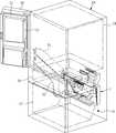
도 1은 본 발명의 실시예에 따른 냉장고용 그릴팬어셈블리가 적용된 냉장고의 외관 구조를 설명하기 위해 나타낸 사시도
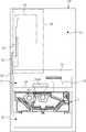
도 2는 본 발명의 실시예에 따른 냉장고용 그릴팬어셈블리가 적용된 냉장고의 내부 구조를 설명하기 위해 개략화하여 나타낸 사시도
도 3은 본 발명의 실시예에 따른 냉장고용 그릴팬어셈블리가 적용된 냉장고의 내부 구조를 설명하기 위해 개략화하여 나타낸 정단면도
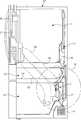
도 4는 본 발명의 실시예에 따른 냉장고용 그릴팬어셈블리가 적용된 냉장고의 내부 구조를 설명하기 위해 개략화하여 나타낸 측단면도
도 5는 도 4의 “A”부 확대도
도 6은 본 발명의 실시예에 따른 냉장고용 그릴팬어셈블리가 적용된 냉장고의 제빙실로 냉기를 공급하거나 회수하는 구조의 적용 상태를 설명하기 위해 나타낸 요부 확대도
도 7은 본 발명의 실시예에 따른 냉장고용 그릴팬어셈블리를 설명하기 위해 나타낸 분해 사시도
도 8은 본 발명의 실시예에 따른 냉장고용 그릴팬어셈블리 중 그릴팬을 설명하기 위해 나타낸 정면도
도 9는 본 발명의 실시예에 따른 냉장고용 그릴팬어셈블리 중 그릴팬을 설명하기 위해 나타낸 배면도
도 10은 본 발명의 실시예에 따른 냉장고용 그릴팬어셈블리 중 쉬라우드를 설명하기 위해 나타낸 정면도
도 11은 본 발명의 실시예에 따른 냉장고용 그릴팬어셈블리 중 쉬라우드를 설명하기 위해 나타낸 배면도
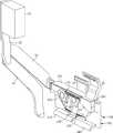
도 12는 본 발명의 실시예에 따른 냉장고용 그릴팬어셈블리와 제빙실 간의 냉기 전달을 위한 관계를 설명하기 위해 나타낸 사시도
도 13은 본 발명의 실시예에 따른 냉장고용 그릴팬어셈블리와 절환실용 냉기덕트 및 절환실용 회수덕트의 연결 상태를 설명하기 위해 나타낸 정면도
도 14는 본 발명의 실시예에 따른 냉장고용 그릴팬어셈블리와 절환실용 냉기덕트 및 절환실용 회수덕트의 연결 상태를 설명하기 위해 나타낸 배면도
도 15는 본 발명의 실시예에 따른 냉장고용 그릴팬어셈블리의 절환댐퍼부의 개방 상태를 설명하기 위해 나타낸 사시도
도 16은 본 발명의 실시예에 따른 냉장고용 그릴팬어셈블리의 절환댐퍼부의 폐쇄 상태를 설명하기 위해 나타낸 사시도
도 17은 본 발명의 실시예에 따른 냉장고용 그릴팬어셈블리의 절환댐퍼부의 개방 상태를 설명하기 위해 정면에서 본 상태를 나타낸 요부 단면도
도 18은 본 발명의 실시예에 따른 냉장고용 그릴팬어셈블리의 절환댐퍼부의 폐쇄 상태를 설명하기 위해 정면에서 본 상태를 나타낸 요부 단면도
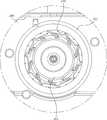
도 19는 본 발명의 실시예에 따른 냉장고용 그릴팬어셈블리의 팬모듈을 설명하기 위해 나타낸 정면도
도 20은 본 발명의 실시예에 따른 냉장고용 그릴팬어셈블리의 팬모듈을 설명하기 위해 나타낸 배면도
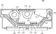
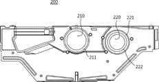
도 21은 본 발명의 실시예에 따른 냉장고용 그릴팬어셈블리의 냉동팬모듈 및 제빙팬모듈이 설치된 그릴팬을 배면에서 본 상태를 나타낸 요부 상태도
도 22는 본 발명의 실시예에 따른 냉장고용 그릴팬어셈블리의 냉동팬모듈 및 제빙팬모듈이 설치된 쉬라우드를 배면에서 본 상태를 나타낸 요부 상태도
도 23은 본 발명의 실시예에 따른 냉장고용 그릴팬어셈블리의 냉동팬모듈이 설치된 상태를 설명하기 위해 쉬라우드의 배면에서 본 상태를 나타낸 요부 상태도
도 24는 본 발명의 실시예에 따른 냉장고용 그릴팬어셈블리의 제빙팬모듈이 설치된 상태를 설명하기 위해 쉬라우드의 배면에서 본 상태를 나타낸 요부 상태도
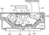
도 25는 본 발명의 실시예에 따른 냉장고용 그릴팬어셈블리의 구획리브를 설명하기 위해 나타낸 요부 확대도
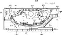
도 26은 본 발명의 실시예에 따른 냉장고용 그릴팬어셈블리가 적용된 냉장고의 냉동실에 대한 냉동 운전시 냉기 흐름을 설명하기 위해 나타낸 측단면도
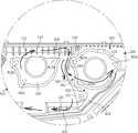
도 27은 본 발명의 실시예에 따른 냉장고용 그릴팬어셈블리가 적용된 냉장고의 냉동실에 대한 냉동 운전시 그릴어셈블리의 그릴팬을 배면에서 본 상태에서의 냉기 흐름을 나타낸 상태도
도 28은 본 발명의 실시예에 따른 냉장고용 그릴팬어셈블리가 적용된 냉장고의 냉동실에 대한 냉동 운전시 각 구획리브에 의한 냉기 흐름을 설명하기 위해 나타낸 요부 확대도
도 29는 본 발명의 실시예에 따른 냉장고용 그릴팬어셈블리가 적용된 냉장고의 냉동실에 대한 냉동 운전시 냉기 유동을 설명하기 위해 나타낸 참고도
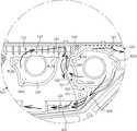
도 30은 본 발명의 실시예에 따른 냉장고용 그릴팬어셈블리가 적용된 냉장고의 냉동 운전과 제빙 운전이 동시에 수행될 때의 각 구획리브에 의한 냉기 흐름을 설명하기 위해 나타낸 요부 확대도
도 31은 본 발명의 실시예에 따른 냉장고용 그릴팬어셈블리가 적용된 냉장고의 냉동 운전과 제빙 운전이 동시에 수행될 때의 냉기 유동을 설명하기 위해 나타낸 참고도
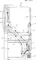
도 32는 본 발명의 실시예에 따른 냉장고용 그릴팬어셈블리가 적용된 냉장고의 절환실에 대한 냉동 운전시 냉기 흐름을 설명하기 위해 나타낸 측단면도
도 33은 도 32의 “B”부 확대도
도 34는 본 발명의 실시예에 따른 냉장고용 그릴팬어셈블리가 적용된 냉장고의 절환실에 대한 냉동 운전시 냉기 흐름을 나타낸 상태도
도 35는 본 발명의 실시예에 따른 냉장고용 그릴팬어셈블리가 적용된 냉장고의 제빙실에 대한 제빙 운전시 냉기 흐름을 나타낸 상태도
도 36은 본 발명의 실시예에 따른 냉장고용 그릴팬어셈블리가 적용된 냉장고의 제빙실에 대한 제빙 운전시 각 구획리브에 의한 냉기 흐름을 설명하기 위해 나타낸 요부 확대도
도 37은 본 발명의 실시예에 따른 냉장고용 그릴팬어셈블리가 적용된 냉장고의 제빙실에 대한 제빙 운전시 냉기 흐름을 설명하기 위해 나타낸 측단면도
도 38은 본 발명의 실시예에 따른 냉장고용 그릴팬어셈블리가 적용된 냉장고의 제빙실에 대한 제빙 운전시 제빙실로의 냉기 공급 및 회수 흐름을 나타낸 상태도1 is a perspective view illustrating an external structure of a refrigerator to which a grill pan assembly for a refrigerator according to an embodiment of the present invention is applied;
2 is a perspective view schematically illustrating an internal structure of a refrigerator to which a grill pan assembly for a refrigerator according to an embodiment of the present invention is applied;
3 is a front cross-sectional view schematically illustrating an internal structure of a refrigerator to which a grill pan assembly for a refrigerator according to an embodiment of the present invention is applied;
4 is a side cross-sectional view schematically illustrating an internal structure of a refrigerator to which a grill pan assembly for a refrigerator according to an embodiment of the present invention is applied;
5 is an enlarged view of part “A” of FIG. 4
6 is an enlarged view showing the main part to explain the application state of a structure for supplying or recovering cold air to an ice-making chamber of a refrigerator to which a grill pan assembly for a refrigerator is applied according to an embodiment of the present invention;
7 is an exploded perspective view illustrating a grill pan assembly for a refrigerator according to an embodiment of the present invention;
8 is a front view illustrating a grill pan in a grill pan assembly for a refrigerator according to an embodiment of the present invention;
9 is a rear view illustrating a grill pan in a grill pan assembly for a refrigerator according to an embodiment of the present invention;
10 is a front view illustrating a shroud of a grill pan assembly for a refrigerator according to an embodiment of the present invention;
11 is a rear view illustrating a shroud of a grill pan assembly for a refrigerator according to an embodiment of the present invention;
12 is a perspective view illustrating a relationship for cold air transfer between a grill pan assembly for a refrigerator and an ice-making chamber according to an embodiment of the present invention;
13 is a front view illustrating a connection state between the grill pan assembly for a refrigerator and a cold air duct for a switching room and a return duct for a switching room according to an embodiment of the present invention;
14 is a rear view illustrating a connection state between the grill pan assembly for a refrigerator and a cold air duct for a switching room and a return duct for a switching room according to an embodiment of the present invention;
15 is a perspective view illustrating an open state of a switching damper of a grill pan assembly for a refrigerator according to an embodiment of the present invention;
16 is a perspective view illustrating a closed state of a switching damper of a grill pan assembly for a refrigerator according to an embodiment of the present invention;
17 is a cross-sectional view showing a main part of the grill pan assembly for a refrigerator in a state in which it is viewed from the front in order to explain an open state of the switching damper according to the embodiment of the present invention;
18 is a cross-sectional view illustrating a main part of a grill pan assembly for a refrigerator in a closed state of a switching damper according to an embodiment of the present invention;
19 is a front view illustrating a fan module of a grill pan assembly for a refrigerator according to an embodiment of the present invention;
20 is a rear view illustrating a fan module of a grill pan assembly for a refrigerator according to an embodiment of the present invention;
21 is a state diagram showing the main part of the grill pan assembly for a refrigerator in accordance with an embodiment of the present invention, showing a state in which the refrigeration fan module and the ice-making fan module are installed, as viewed from the rear;
22 is a state diagram showing the main part of the shroud in which the freezing fan module and the ice making fan module are installed of the grill fan assembly for a refrigerator according to an embodiment of the present invention, as viewed from the rear;
23 is a state diagram of main parts showing a state viewed from the rear of the shroud in order to explain a state in which the refrigeration fan module of the grill fan assembly for a refrigerator is installed according to an embodiment of the present invention;
24 is a state diagram of main parts showing a state viewed from the rear of the shroud in order to explain a state in which the ice-making fan module of the grill fan assembly for a refrigerator according to an embodiment of the present invention is installed;
25 is an enlarged view of a main part shown to explain a partition rib of a grill pan assembly for a refrigerator according to an embodiment of the present invention;
26 is a side cross-sectional view illustrating a flow of cold air during a freezing operation in a freezer compartment of a refrigerator to which a grill pan assembly for a refrigerator according to an embodiment of the present invention is applied;
27 is a state diagram illustrating the flow of cold air when the grill pan of the grill assembly is viewed from the rear during the freezing operation of the freezer compartment of the refrigerator to which the grill pan assembly for the refrigerator according to the embodiment of the present invention is applied;
28 is an enlarged view showing the main part to explain the flow of cold air by each compartment rib during a freezing operation of a freezer compartment of a refrigerator to which a grill pan assembly for a refrigerator according to an embodiment of the present invention is applied;
29 is a reference diagram illustrating a flow of cold air during a freezing operation in a freezer compartment of a refrigerator to which a grill pan assembly for a refrigerator according to an embodiment of the present invention is applied;
30 is an enlarged view illustrating the main part of a refrigerator to which the grill pan assembly for a refrigerator is applied according to an embodiment of the present invention, illustrating the flow of cool air by each compartment rib when the freezing operation and the ice making operation are simultaneously performed;
31 is a reference diagram illustrating a flow of cold air when a freezing operation and an ice-making operation of a refrigerator to which a grill pan assembly for a refrigerator according to an embodiment of the present invention is applied are simultaneously performed;
32 is a side cross-sectional view illustrating a flow of cold air during a refrigeration operation in a switching room of a refrigerator to which a grill pan assembly for a refrigerator according to an embodiment of the present invention is applied;
33 is an enlarged view of part “B” of FIG. 32
34 is a state diagram illustrating a flow of cold air during a refrigeration operation in a switching room of a refrigerator to which a grill pan assembly for a refrigerator according to an embodiment of the present invention is applied;
35 is a state diagram illustrating a flow of cold air during an ice making operation in an ice making chamber of a refrigerator to which a grill pan assembly for a refrigerator according to an embodiment of the present invention is applied;
36 is an enlarged view illustrating the main part of a refrigerator to which the grill pan assembly for a refrigerator is applied in accordance with an embodiment of the present invention;
37 is a side cross-sectional view illustrating a flow of cold air during an ice making operation in an ice making chamber of a refrigerator to which a grill fan assembly for a refrigerator according to an embodiment of the present invention is applied;
38 is a state diagram showing the flow of supply and recovery of cold air to the ice-making chamber during an ice-making operation for the ice-making chamber of the refrigerator to which the grill fan assembly for refrigerator according to the embodiment of the present invention is applied
이하, 본 발명의 바람직한 실시예에 따른 냉장고용 그릴팬어셈블리를 첨부된 도 1 내지 도 38을 참조하여 설명하도록 한다.Hereinafter, a grill pan assembly for a refrigerator according to a preferred embodiment of the present invention will be described with reference to the accompanying FIGS. 1 to 38 .
첨부된 도 1은 본 발명의 실시예에 따른 냉장고용 그릴팬어셈블리가 적용된 냉장고의 외관 구조를 설명하기 위해 나타낸 사시도이고, 도 2는 본 발명의 실시예에 따른 냉장고용 그릴팬어셈블리가 적용된 냉장고의 내부 구조를 설명하기 위해 개략화하여 나타낸 사시도이다. 또한, 첨부된 도 3은 본 발명의 실시예에 따른 냉장고용 그릴팬어셈블리가 적용된 냉장고의 내부 구조를 설명하기 위해 개략화하여 나타낸 정단면도이고, 도 4는 본 발명의 실시예에 따른 냉장고용 그릴팬어셈블리가 적용된 냉장고의 내부 구조를 설명하기 위해 개략화하여 나타낸 측단면도이며, 도 5는 도 4의 “A”부 확대도이다.1 is a perspective view illustrating an external structure of a refrigerator to which a grill pan assembly for a refrigerator is applied according to an embodiment of the present invention, and FIG. 2 is a refrigerator to which a grill pan assembly for a refrigerator according to an embodiment of the present invention is applied. It is a perspective view schematically shown to explain the internal structure. 3 is a front sectional view schematically illustrating the internal structure of a refrigerator to which the grill pan assembly for a refrigerator according to an embodiment of the present invention is applied, and FIG. 4 is a refrigerator grill according to an embodiment of the present invention. It is a sectional side view schematically shown to explain the internal structure of the refrigerator to which the fan assembly is applied, and FIG. 5 is an enlarged view of part “A” of FIG. 4 .
이들 도면에 도시된 바와 같이 본 발명의 실시예에 따른 냉장고용 그릴팬어셈블리(1)는 냉장실(11)과 냉동실(12)과 절환실(13) 및 제빙실(21)을 가지는 냉장고의 냉동실(12)에 적용되는 구조임을 그 예로 한다.As shown in these drawings, the
특히, 본 발명의 실시예에 따른 냉장고용 그릴팬어셈블리(1)는 두 개의 팬모듈(410,420)을 가지면서 어느 한 증발기(32)를 경유하면서 열교환된 냉기를 냉동실(12)과 절환실(13) 및 제빙실(21)에 선택적으로 공급할 수 있도록 구성됨을 특징으로 한다.In particular, the
실시예의 설명에 앞서, 본 발명의 실시예에 따른 냉장고용 그릴팬어셈블리(1)가 적용된 냉장고는 첨부된 도 2 내지 도 4에 도시된 바와 같이 크게 냉장실(11)과 냉동실(12) 및 절환실(13)을 가지는 캐비넷(10)과, 제빙실(21)을 가지는 냉장실용 도어(20)를 포함하여 이루어진다.Prior to the description of the embodiment, the refrigerator to which the
여기서, 상기 냉장실(11) 및 냉동실(12)은 저장물이 저장되는 공간으로써, 냉장실(11)은 저장물을 냉장 보관하도록 제공되는 저장실이고, 상기 냉동실(12)은 저장물을 냉동 보관하도록 제공되는 저장실이다.Here, the refrigerating
상기 절환실(13)은 사용자의 필요에 따라 용도를 변경하여 사용하도록 제공되는 저장실이다. 이때, 상기 절환실(13)의 경우 상기 냉동실(12)과 동일한 증발기(31)를 사용하도록 구성되기 때문에 절환실(13) 내에 저장되는 저장물을 냉장 보관뿐 아니라 냉동 보관의 용도로도 사용할 수가 있다.The
이와 함께, 캐비넷(10) 내의 후벽면 중 냉장실(11)의 후방측에는 제1증발기(31)가 구비되고, 캐비넷(10) 내의 후벽면 중 냉동실(12)의 후방측에는 제2증발기(32)가 구비된다.At the same time, the
상기 제1증발기(31)는 상기 냉장실(11)로 냉기를 공급하기 위해 제공되는 증발기이고, 상기 제2증발기(32)는 상기 냉동실(12)과 절환실(13) 및 제빙실(21)로 냉기를 공급하기 위해 제공되는 증발기이다. 이에 대하여는 도 4 및 도 5에 도시된 바와 같다.The
그리고, 상기 냉장실(11)은 상기 캐비넷(10) 내의 상측에 제공되고, 상기 냉동실(12)은 상기 캐비넷(10) 내의 하측에 제공되며, 상기 절환실(13)은 상기 냉장실(11)과 냉동실(12) 사이인 캐비넷(10) 내의 중층에 제공된다. 이러한 각 저장실(냉장실과 냉동실 및 절환실)(11,12,13)은 캐비넷(10) 내를 상하로 구획하는 복수의 구획벽(14)에 의해 서로 구획되면서 형성된다.In addition, the refrigerating
또한, 상기 냉장실용 도어(20)는 냉장실(11)을 개폐하는 도어로써, 회전식 도어로 이루어진다.In addition, the
특히, 상기 제빙실(21)은 상기 냉장실용 도어(20)의 내측(냉장실용 도어를 닫았을 때 냉장실 내부에 위치되는 측)에 설치된다. 이러한 제빙실(21)은 냉장실용 도어(20)에 얼음의 제빙을 위한 아이스트레이(도시는 생략됨)가 제공되는 저장실이다.In particular, the ice-making
상기 제빙실(21)은 안내덕트(22)를 통해 제빙실용 냉기덕트(51)로부터 냉기를 공급받은 후 제빙실용 회수덕트(52)로 냉기를 배출하도록 이루어진다. 이는 첨부된 도 6에 도시된 바와 같다.The ice-making
또한, 캐비넷(10) 내의 제2증발기(32)의 전방에는 그릴팬어셈블리(1)가 제공되고, 캐비넷(10) 내의 제1증발기(31)의 전방에는 또 다른 그릴팬어셈블리(2)가 제공된다. 상기 제2증발기(32) 전방에 제공되는 그릴팬어셈블리(1)와 제1증발기(31)의 전방에 제공되는 그릴팬어셈블리(2)는 서로 동일한 구조일 수도 있고, 서로 다른 구조일 수도 있다.In addition, a
이때, 캐비넷(10) 내의 후벽면 중 절환실(13)의 후방측에는 상기 그릴팬어셈블리(1)가 제공되지 않고 상기 제2증발기(32) 전방측의 그릴팬어셈블리(1)로부터 냉기를 선택적으로 공급받도록 이루어진다.At this time, the
본 발명의 실시예에 따른 냉장고용 그릴팬어셈블리는 상기 제2증발기(32)의 전방에 위치되는 그릴팬어셈블리(1)임을 그 예로 한다.For example, the grill pan assembly for a refrigerator according to the embodiment of the present invention is the
즉, 상기 냉동실(12) 내의 후방측 공간은 그 저부의 기계실(15)에 따른 영향으로 인해 냉동실(12) 내의 전방측 공간에 비해 상하 높이가 낮게 형성되는데, 이러한 공간 내에 본 발명의 실시예에 따른 냉장고용 그릴팬어셈블리(1)가 제공될 수 있도록 한 것이다. 상기 기계실(15) 내에는 도시되지는 않았으나 냉동사이클을 이루는 압축기 및 응축기가 구비되며, 이로써 제1증발기(31) 및 제2증발기(32)를 이용한 열교환이 가능하게 된다. 물론, 상세히 도시되지는 않았으나 냉장실(11) 후방측 공간에 제공되는 그릴팬어셈블리(2) 역시 상기 그릴팬어셈블리(1)와 동일한 구조로 형성될 수 있다.That is, the rear space in the freezing
첨부된 도 7에 도시된 바와 같이 상기 냉장고용 그릴팬어셈블리(1)는 크게 그릴팬(100)과, 쉬라우드(200)와, 제1냉기안내유로(310) 및 제2냉기안내유로(320)와, 냉동팬모듈(410) 및 제빙팬모듈(420)과, 연통유로(610,620)를 포함하여 구성된다.As shown in the attached FIG. 7 , the
특히, 본 발명의 실시예에 따른 냉장고용 그릴팬어셈블리는 연통유로(610,620)에 의해 냉동팬(411)의 동작시 제1냉기안내유로(310)의 냉기 일부가 제2냉기안내유로(320)로 공급되면서 서로의 압력 차이가 줄어들 수 있도록 함으로써 냉장실(11)의 냉기가 제빙팬(421)으로 역류되면서 상기 제빙팬(421)에 착상이 발생되는 문제점을 방지할 수 있도록 한 것이다.In particular, in the grill fan assembly for a refrigerator according to an embodiment of the present invention, a portion of the cold air of the first cold
이러한 본 발명의 실시예에 따른 냉장고용 그릴팬어셈블리(1)를 각 구성별로 더욱 상세히 설명하면 다음과 같다.The
먼저, 그릴팬(100)에 대하여 첨부된 도 4 및 도 5와 도 7 내지 도 11을 참조하여 설명한다.First, the
상기 그릴팬(100)은 냉장고용 그릴팬어셈블리(1)의 전방측 벽면을 형성하는 부위로써 냉장고용 그릴팬어셈블리(1)의 가장 전방측에 위치된다. 이는 첨부된 도 4 및 도 5에 도시된 바와 같다.The
이러한 그릴팬(100)에는 냉기토출구(110,120,130)가 형성(첨부된 도 7 내지 도 9 참조)된다.
상기 냉기토출구(110,120,130)는 냉동실(12)로의 냉기 공급을 위해 형성되는 구멍이며, 후술될 제1냉기안내유로(310)에 형성된다.The
상기 냉기토출구(110,120,130)는 상기 그릴팬(100)을 전면(혹은, 후면)에서 봤을 때 그릴팬(100)의 중앙측 상부에 형성되는 메인냉기토출구(110)를 포함한다.The
상기한 메인냉기토출구(110)는 냉동팬모듈(410)의 회전에 의해 강제 송풍되는 냉기가 냉동실(12) 내의 상측 벽면이 위치된 공간으로 토출되도록 제공되는 부위이다.The main
이와 같은 메인냉기토출구(110)는 제1냉기안내유로(310) 내의 각 부위 중 냉동팬모듈(410)의 중심 부위에 비해 더욱 상측에 위치되도록 형성된다. 이로써, 상기 메인냉기토출구(110)로 토출되는 냉기는 상기 냉동실(12) 내의 상측 벽면이 위치된 공간으로 토출될 수 있게 된다.The main cold
또한, 상기 메인냉기토출구(110)는 냉동팬모듈(410)의 상하 높이에 비해서는 짧은 높이로 형성되면서도 냉동팬모듈(410)의 좌우 폭에 비해서는 좌우로 더욱 길게 형성되며, 이로써 상기 냉동팬모듈(410)의 회전에 의해 해당 냉동팬모듈(410)의 원주 방향으로 유동되는 냉기가 상기 메인냉기토출구(110)를 통해 냉동실(12)로 충분히 배출될 수 있도록 한다.In addition, the main
그리고, 상기 메인냉기토출구(110)에는 복수의 그릴리브(111)가 형성된다.In addition, a plurality of
상기 그릴리브(111)는 메인냉기토출구(110)로 토출되는 냉기의 토출 방향을 안내하는 리브이다.The
상기한 그릴리브(111)들은 서로 이격되게 배치됨과 더불어 전방을 향하거나 혹은, 양측을 향하도록 경사지게 형성된다. 이때 상기 그릴리브(111)들 중 중앙측 부위의 그릴리브(111)들은 전방을 향하도록 형성함과 더불어 양측 부위의 그릴리브(111)들은 외측에 외측으로 경사지게 형성한다. 이러한 구조는 냉동실(12) 내의 좌우 폭에 비해 좁은 좌우 폭을 갖는 메인냉기토출구(110)로 냉기가 토출됨에도 불구하고 상기 냉동실(12) 내의 전 부위로 고르게 토출될 수 있도록 한 것이다.The above-described
물론, 상기 그릴리브(111)들은 메인냉기토출구(110)의 외측에 위치될수록 더욱 외측을 향해 경사지게 형성하여 더욱 넓은 공간으로 냉기가 고르게 공급될 수 있도록 할 수도 있다.Of course, the
이와 함께, 상기 메인냉기토출구(110)는 단순한 구멍이 아니라 전방으로 돌출된 관체로 형성될 수 있다. 즉, 상기 메인냉기토출구(110)를 통과하는 냉기에 직진성이 부여될 수 있도록 하고, 이로 인해 상기 메인냉기토출구(110)를 통과하는 냉기는 상하로 퍼지지 않고 곧장 전방으로 토출되면서 냉동실(12) 내의 전방측에 이르기까지 냉기를 공급할 수 있게 된다.In addition, the main
한편, 상기한 메인냉기토출구(110)는 상기 그릴팬(100)의 각 부위 중 가장 상측 부위에 형성됨이 바람직하다. 즉, 상기 메인냉기토출구(110)를 최대한 상측에 위치시킴으로써 냉동실(12) 내의 상측 공간을 향해 냉기가 토출되도록 하고, 또한 제1냉기안내유로(310)가 충분한 크기의 유로를 갖도록 하여 해당 그릴팬(100)의 상하 높이를 최대한 낮출 수 있도록 한 것이다.On the other hand, the main
그리고, 상기 냉기토출구(110,120,130)는 보조냉기토출구(120,130)가 포함된다.In addition, the
상기 보조냉기토출구(120,130)는 냉동실(12) 내의 중간측 공간으로 냉기를 공급하도록 제공되는 구멍이다. 즉, 메인냉기토출구(110)는 냉동실(12) 내의 상면측으로만 냉기를 공급하도록 이루어짐을 고려할 때 중간측 부위로는 상면측에 비해 냉기 공급이 상대적으로 부족할 수 있다. 이로써 상기 보조냉기토출구(120,130)의 추가 제공을 통해 냉동실(12) 내의 중간측 부위로도 냉기가 공급될 수 있도록 한 것이다.The auxiliary
이러한 보조냉기토출구(120,130)는 메인냉기토출구(110)의 저부 양측에 형성될 수 있다.These auxiliary
이와 함께, 상기 보조냉기토출구(120,130)는 제1냉기안내유로(310) 내의 저면측에 형성되면서 상기 제1냉기안내유로(310) 내의 저면을 따라 냉기가 유동되는 도중 그릴팬(100) 전방의 냉동실(12)로 배출될 수 있도록 한다.At the same time, the auxiliary
즉, 상기 보조냉기토출구(120,130)는 상기 메인냉기토출구(110)의 저부에서 냉동실(12) 내로 냉기를 공급함으로써 냉동실(12) 내의 중간측 부위에 대한 냉기 공급이 충분히 이루어질 수 있도록 한 것이다.That is, the auxiliary
이때, 상기 보조냉기토출구(120,130)는 제1냉기안내유로(310) 내의 저면측 부위 중 어느 한 측부(그릴팬을 정면에서 봤을 때 도면상 우측)에 형성되는 제1보조냉기토출구(120) 및 다른 한 측부(그릴팬을 정면에서 봤을 때 도면상 좌측)에 형성되는 제2보조냉기토출구(130)가 포함된다. 즉, 냉기가 제1냉기안내유로(310)를 따라 유동되는 도중 상기 제1보조냉기토출구(120) 및 제2보조냉기토출구(130)를 순차적으로 통과하면서 냉동실(12)로 추가 공급될 수 있도록 한 것이다.At this time, the auxiliary
특히, 상기 제1냉기안내유로(310)의 저면 중 제1보조냉기토출구(130)가 형성된 부위는 제1냉기안내유로(310) 저면의 중앙측으로 갈수록 점차 하향 경사지게 형성된다. 이러한 구조는 상기 제1보조냉기토출구(120)의 어느 한 끝단으로 유동된 냉기가 해당 제1보조냉기토출구(120)를 경유하면서 그 반대측의 제2보조냉기토출구(130)로 원활히 유동될 수 있도록 한 것이다.In particular, a portion of the bottom surface of the first cold
물론, 상기 제1냉기안내유로(310)의 저면은 라운드지게 형성될 수도 있다.Of course, the bottom surface of the first cold
이와 함께, 상기 각 보조냉기토출구는 어느 일측 끝단으로부터 타측 끝단으로 갈수록 점차 개방 면적이 커지게 형성된다.At the same time, each of the auxiliary cold air outlets is formed to have an open area gradually increasing from one end to the other end.
상기한 각 보조냉기토출구의 구조는 냉기가 제1냉기안내유로의 저면을 타고 흐르는 도중 상기 각 보조냉기토출구를 통과하여 냉동실로 원활히 공급될 수 있도록 한 것이다.The structure of each of the auxiliary cold air outlets is such that the cold air passes through each of the auxiliary cold air outlets while flowing along the bottom surface of the first cold air guide passage to be smoothly supplied to the freezing chamber.
또한, 상기 메인냉기토출구(110)는 상기 제1보조냉기토출구(120) 및 제2보조냉기토출구(130)를 합친 크기 보다 더욱 크게 형성됨으로써 냉동팬모듈(410)에 의해 송풍되는 대부분의 냉기가 상기 메인냉기토출구(110)를 통해 냉동실(12) 내로 공급되도록 한다.In addition, the main
이와 함께, 상기한 두 보조냉기토출구(120,130) 내에는 복수의 그릴리브(121,131)가 형성된다.At the same time, a plurality of
이때, 상기 각 그릴리브(121,131)는 해당 보조냉기토출구(120,130)를 통과하여 토출되는 냉기에 방향성을 부여하는 구조이며, 적어도 일부의 그릴리브(121,131)는 해당 부위를 통과하는 냉기가 냉동실(12) 내의 측부를 향하도록 안내할 수 있게 경사지게 형성됨이 바람직하다.At this time, each of the
특히, 상기 두 보조냉기토출구(120,130)는 전방으로 돌출된 관체로 형성될 수 있다.In particular, the two auxiliary
즉, 보조냉기토출구(120,130)를 통과하는 냉기에 직진성이 부여될 수 있도록 하고, 이로 인해 상기 보조냉기토출구(120,130)를 통과하는 냉기는 상하로 퍼지지 않고 곧장 전방으로 토출되면서 냉동실(12) 내의 전방측에 이르기까지 냉기를 공급할 수 있게 된다.That is, the cold air passing through the auxiliary
또한, 상기 그릴팬(100)에는 상기 냉동실(12)을 유동한 냉기의 회수 유동을 안내하는 흡입가이드(140)가 더 구비된다. 이때, 상기 흡입가이드(140)는 상기 그릴팬(100)의 하단에 형성되면서 상기 냉동실(12) 내를 순환한 후 회수되는 냉기가 제2증발기(32)의 하측 끝단으로 유입되도록 이루어진다.In addition, the
특히, 상기 냉동실(12) 내의 후방측(후벽면이 위치된 측) 저부에는 기계실(15)이 위치되기 때문에 상기 냉동실(12)의 저면 중 후단측 부위가 저부로 갈수록 전방으로 경사지게 형성된다. 이를 고려할 때 상기 흡입가이드(140)는 하측 끝단으로 갈수록 상기 냉동실(12)의 저면 중 후단측 부위와 동일(혹은, 유사)한 각도(또는, 라운드)로 경사지게 형성됨이 바람직하다. 즉, 상기 냉동실(12)의 저면을 타고 흐르는 냉기가 상기 경사를 따라 유동되면서 상기 흡입가이드(140)의 안내를 받아 상기 제2증발기(32)의 하측 끝단으로 원활히 유동될 수 있도록 한 것이다.In particular, since the
또한, 상기 그릴팬(100)에는 온도센서(150)가 설치된다.In addition, a
상기 온도센서(150)는 냉동실(120) 내의 온도를 감지하기 위한 센서이며, 상기 그릴팬(100)의 양측 끝단 중 어느 한 측 끝단에 위치되도록 이루어진다.The
또한, 상기 그릴팬(100)의 배면에는 제1안착부(160) 및 제2안착부(170)가 각각 함몰(그릴팬의 전방을 향해 돌출)되게 형성된다.In addition, on the rear surface of the
여기서, 상기 제1안착부(160)는 냉동팬모듈(410)이 안착되는 부위로 제공된다.Here, the
상기 제1안착부(160)는 그릴팬(100)의 표면(배면)으로부터 요입되게 형성된다.The
즉, 상기 제1안착부(160)에 안착되는 냉동팬모듈(410)의 냉동팬(411)이 그릴팬어셈블리(1)의 후방에 위치되는 제2증발기(32)로부터 최대한 이격되도록 한 것이다. 이로써 상기 냉동팬(411)이 상기 제2증발기(32)로부터 받는 영향(표면 온도에 따른 영향)을 최대한 줄일 수 있게 된다.That is, the
이와 함께, 상기 제1안착부(160)는 상기 그릴팬(100)의 높이를 기준으로 볼 때 중심에 비해서는 상단측에 위치됨과 더불어 상기 그릴팬(100)의 좌우 길이를 기준으로 볼 때에는 대략 중앙 부위에 형성된다.In addition, the
이때, 메인냉기토출구(110)는 상기 제1안착부(160)의 상단측 부위를 가로지르도록 형성된다.At this time, the main
이와 함께, 상기 제1안착부(160)의 함몰 깊이는 냉동팬모듈(410)의 냉동팬(411)과 제2증발기(32) 간의 이격 거리를 고려하여 결정된다. 즉, 상기 냉동팬(411)이 제2증발기(32)와 과도하게 가까울 경우 상기 냉동팬(411)에 응축수가 맺히는 현상을 발생될 수 있다는 것을 고려할 때 서로가 적어도 3mm 이상 이격되도록 상기 제1안착부(160)의 함몰 깊이를 결정함이 바람직한 것이다.In addition, the depression depth of the
또한, 상기 제1안착부(160)의 상면은 상부로 개방된 구조로 이루어진다.In addition, the upper surface of the
이로써, 상기 제1안착부(160)가 메인냉기토출구(110)를 가로막지 않도록 함으로써 제1유입공(210)을 통과하여 그릴팬(100)과 쉬라우드(200) 사이로 유입되는 냉기가 상기 메인냉기토출구(110)로 곧장 배출될 수 있도록 한 것이다.Accordingly, the cold air flowing between the
이와 함께, 상기 제2안착부(170)는 상기 제1안착부(160)의 측부에 형성되면서 제빙팬모듈(420)이 안착되는 부위로 제공된다. 즉, 상기 제빙팬모듈(420)이 그릴팬(100)의 표면으로부터 요입되게 설치되도록 함으로써 제2증발기(32)의 영향에 의한 결빙을 방지할 수 있도록 한 것이다.In addition, the
다음은, 쉬라우드(200)에 대하여 첨부된 도 4와 도 5 및 도 7과 도 10 및 도 11을 참조하여 설명한다.Next, the
상기 쉬라우드(200)는 냉장고용 그릴팬어셈블리(1)의 후방측 벽면을 형성하는 부위로써 상기 그릴팬(100)의 후방측에 위치된다. 이는 첨부된 도 4 및 도 5에 도시된 바와 같다.The
이러한 쉬라우드(200)는 상기 그릴팬(100)의 후면에 이격되게 결합되면서 상기 그릴팬(100)과의 사이에 냉기 유동을 위한 유로가 생성될 수 있도록 공간을 제공하는 역할을 한다.The
특히, 상기 쉬라우드(200)에는 제1유입공(210) 및 제2유입공(220)이 관통 형성된다.In particular, the
이때, 상기 제1유입공(210)은 상기 쉬라우드(200)의 중앙측 부위 중 제1냉기안내유로(310) 내의 저면에 비해 상기 쉬라우드(200)의 상면에 더욱 가깝게 위치되도록 형성된다. 상기 제2유입공(220)은 상기 제1유입공(210)의 어느 한 측부에 형성된다.At this time, the
이와 함께, 상기 제1유입공(210)의 둘레로는 제1벨마우스(211)가 형성됨과 더불어 상기 제2유입공(220)의 둘레로는 제2벨마우스(221)가 형성된다. 이때 상기 두 유입공(210,220)은 냉동실(12) 내의 후방에 위치된 제2증발기(32)를 통과하여 열교환된 냉기를 상기 그릴팬(100)과 쉬라우드(200) 사이의 공간으로 유입할 수 있도록 형성된 구멍이다.In addition, a
이와 함께, 상기 제1벨마우스(211)는 냉동팬모듈(410)을 통해 냉동실(12)로 공급되는 냉기의 풍량을 고려하여 설계되고, 상기 제2벨마우스(221)는 제빙팬모듈(420)을 통해 제빙실(13)로 공급되는 냉기의 압력을 고려하여 설계된다.In addition, the
즉, 상기 냉동팬모듈(410)은 그의 전방에 위치된 냉동실(12)로 냉기를 공급하기 때문에 충분한 양의 냉기를 공급하도록 구성되는 반면, 제빙팬모듈(420)의 경우는 냉장실용 도어(20)에 위치된 제빙실(21)로 냉기를 공급하는 구성이기 때문에 먼 거리에까지 충분한 냉기 공급이 이루어질 수 있도록 하여야 한다.That is, the freezing
이를 고려할 때, 상기 제2벨마우스(221)의 경우 그의 내주면에 가림부재(222)가 추가로 형성됨을 제시한다. 즉, 제빙팬모듈(420)을 이루는 제빙팬(421)의 각 임펠러(421a)가 상기 가림부재(222)에 의해 최대한 가려질 수 있도록 함으로써 상기 제2유입공(220)을 통과하여 그릴팬어셈블리(1) 내의 제2냉기안내유로(320)에 유입된 냉기가 다시금 제2유입공(220)을 통해 배출되지 않고 송풍압력을 더욱 높여 더욱 원활히 압송되도록 한 것이다.Considering this, in the case of the
한편, 상기 쉬라우드(200)는 상기 그릴팬(100)의 흡입가이드(140)를 가로막지 않도록 구성된다.Meanwhile, the
즉, 상기 쉬라우드(200)는 상기 그릴팬(100)의 배면 일부만 가로막도록 형성함으로써 그릴팬어셈블리(1)의 컴팩트화가 가능하도록 하면서도 냉기의 유동은 원활히 이루어질 수 있도록 하며, 상기 흡입가이드(140)의 안내에 의해 회수되는 냉기는 제2증발기(32)의 하측 끝단으로 원활히 유동될 수 있도록 한 것이다.That is, the
이때, 상기 쉬라우드(200)는 상기 그릴팬(100)의 메인냉기토출구(110) 및 두 보조냉기토출구(120,130)는 가로막을 수 있을 정도의 크기로 형성된다.At this time, the
특히, 상기 그릴팬(100) 및 쉬라우드(200)는 상면(101)(201)을 각각 갖도록 형성되고, 상기 상면(101,201) 간은 서로 겹쳐진 상태로 결합되도록 구성된다.In particular, the
다음은, 제1냉기안내유로(310)에 대하여 도 8 및 도 9를 참조하여 설명한다.Next, the first cold air
상기 제1냉기안내유로(310)는 제1유입공(210)을 통과하여 그릴팬(100)과 쉬라우드(200) 사이로 유입된 냉기가 냉동실(12) 및 절환실(13)로 유동되도록 안내하는 유로이다.The first cold
이러한 제1냉기안내유로(310)는 상기 그릴팬(100)과 쉬라우드(200) 간의 대향면 중 적어도 어느 한 면에 형성된다.The first cold air
본 발명의 실시예에서는 상기 제1냉기안내유로(310)가 상기 그릴팬(100)의 배면에 형성됨을 그 예로 한다. 특히 상기 제1냉기안내유로(310)는 상기 그릴팬(100)의 배면으로부터 전방을 향해 돌출되게 형성되면서 그 내부를 따라 냉기가 유동될 수 있도록 이루어진다.In the embodiment of the present invention, it is assumed that the first cold
이때, 상기 제1냉기안내유로(310)의 배면(그릴팬의 후방을 향하는 면)은 개방되게 형성되지만 상기 그릴팬(100)의 배면에 쉬라우드(200)를 밀착시키는 조립에 의해 상기 제1냉기안내유로(310)의 개방된 배면이 폐쇄되면서 외부 환경으로부터 차단된 유로를 제공할 수 있게 된다.At this time, the rear surface of the first cold air guide passage 310 (the surface facing the rear of the grill pan) is formed to be open, but by assembling the
물론, 도시되지는 않았으나 상기 제1냉기안내유로(310)는 상기 쉬라우드(200)의 전면에 형성될 수도 있고, 상기 그릴팬(100)이나 쉬라우드(200)와는 별개로 제조된 후 상기 그릴팬(100)과 쉬라우드(200) 사이에 결합되도록 구성될 수도 있으며, 상기 그릴팬(100)과 쉬라우드(200)에 일부씩 형성될 수도 있다.Of course, although not shown, the first cold air
또한, 상기한 제1냉기안내유로(310)는 제1안착부(160)가 형성된 부위로부터 이 제1안착부(160)의 둘레를 둘러 끝단이 상기 제1안착부(160)의 어느 한 측편(제2안착부가 위치된 측편과는 반대측의 측편) 상부를 향해 라운드지게 형성되도록 이루어진다.In addition, the first cold air
즉, 상기 제1냉기안내유로(310)가 냉동팬(411)의 회전에 의한 냉기의 유동 방향을 따라 라운드진 구조로 형성함으로써 냉기가 제1냉기안내유로(310)를 따라 원활히 유동될 수 있도록 한 것이다.That is, the first cold
특히, 상기 제1냉기안내유로(310)의 끝단은 그릴팬(100)과 쉬라우드(200)의 상면으로 개방되게 형성된다. 즉, 상기 제1냉기안내유로(310)가 그릴팬어셈블리(1)의 상부로 개방되게 함으로써 해당 제1냉기안내유로(310)에 연결되는 관로(예컨대, 절환실용 냉기덕트)와의 연결이 상부를 향하게 되고, 이렇게 연결 부위가 상부를 향하도록 이루어지기 때문에 냉동실(12) 내의 전후 깊이가 짧아지면서 저장 공간이 줄어드는 문제점을 최대한 방지할 수 있게 된다.In particular, the end of the first cold
이때, 상기 제1냉기안내유로(310)의 개방된 끝단에는 냉동실(12)의 상측에 위치되는 절환실(13)로 냉기를 공급하기 위한 절환실용 냉기덕트(41)의 하측 끝단이 연결(첨부된 도 12 내지 도 14 참조)된다. 상기 절환실용 냉기덕트(41)의 상측 끝단은 절환실(13)의 배면에 연결(첨부된 도 5 참조)된다.At this time, the lower end of the
한편, 냉동실(12)로 냉기를 토출하는 두 보조냉기토출구(120,130)는 상기 제1냉기안내유로(310) 내의 저면을 따라 형성된다.Meanwhile, the two auxiliary
즉, 냉기가 제1냉기안내유로(310)를 따라 유동되는 도중 두 보조냉기토출구(120,130)를 통해 순차적으로 냉동실(12)로 토출될 수 있도록 한 것이다.That is, the cold air can be sequentially discharged to the freezing
특히, 상기 두 보조냉기토출구(120,130)는 상기 제1냉기안내유로(310) 내의 저부측 공간 중 양측에 각각 형성된다. 이는, 상기 두 보조냉기토출구(120,130) 사이의 부위는 사실상 냉동실(12) 내의 하측 공간을 향하는 부위이기 때문에 이 부위에 보조냉기토출구(120,130)를 형성한다면 이 보조냉기토출구(120,130)를 통해 토출되는 냉기가 상기 냉동실(12) 내를 순환하고 하측 공간으로 회수되는 냉기 유동과의 부딪힘이 우려될 수 있기 때문이다.In particular, the two auxiliary
또 한편, 첨부된 도 13에 도시된 바와 같이 상기 제1냉기안내유로(310) 내에는 유로개폐모듈(330)이 더 구비된다.On the other hand, as shown in FIG. 13 , a flow path opening/
상기 유로개폐모듈(330)은 제1냉기안내유로(310)를 따라 유동되는 냉기가 상기 제1냉기안내유로(310)의 냉기 유출측 부위로 배출됨을 선택적으로 차단하도록 개폐하는 구성이다.The flow path opening/
즉, 상기 제1냉기안내유로(310)를 따라 절환실(13)로 공급되는 냉기가 필요에 따라 그 공급이 단속될 수 있도록 한 것이다. 이를 통해 절환실(13) 내부는 냉동실(12)과는 상이한 온도 조건으로 저장물을 보관할 수 있게 된다.That is, the cold air supplied to the switching
이러한 유로개폐모듈(330)은 상기 제1냉기안내유로(310)를 가로막도록 설치된다.The flow path opening/
바람직하기로는, 상기 제1냉기안내유로(310) 내에 여타 부위에 비해 확장된 장착단(311)이 형성되고, 상기 장착단(311) 내에는 상기 유로개폐모듈(330)의 단열 및 정확한 장착을 위한 장착커버(350)(첨부된 도 7 참조)가 구비되며, 상기 유로개폐모듈(330)은 상기 장착커버(350) 내에 장착된 상태로 상기 장착단(311) 내로 제공되어 해당 부위를 지나는 냉기의 유동을 차단하도록 구성된다.Preferably, a mounting
이때, 상기 장착단(311)은 그릴팬(100)의 제1냉기안내유로(310)의 일부를 여타 부위에 비해 확장 형성한 부위이다.At this time, the mounting
이러한 장착단(311)은 그릴팬(100)의 일부를 제1냉기안내유로(310)에 비해 더욱 전방으로 돌출함과 더불어 쉬라우드(200)의 일부를 더욱 후방으로 돌출하여 형성된다.The mounting
이와 함께, 상기 장착단(311)은 상기 제1냉기안내유로(310) 중 냉기 유출측에 인접하게 위치되도록 한다.In addition, the mounting
특히, 상기 장착단(311)은 경사지게 형성됨이 바람직하다.In particular, the mounting
물론, 상기 장착단(311)은 수평하게 형성하거나 혹은, 수직하게 형성할 수도 있다. 그러나, 장착단(311)이 좌우로 수평하게 형성될 경우 이에 장착되는 유로개폐모듈(330)이 수평하게 눕혀짐에 따라 응축수의 발생시 이의 제거에 어려움이 있고, 상기 장착단(311)이 상하로 수직하게 형성될 경우 이에 장착되는 유로개폐모듈(330)이 수직하게 세워짐에 따라 유로의 폐쇄가 정확히 이루어지지 않을 우려가 있다.Of course, the mounting
유로개폐모듈(330)은 첨부된 도 15 내지 도 18에 도시된 바와 같이 댐퍼케이스(331)와 개폐댐퍼(332) 및 댐퍼동작부(333)를 포함하여 구성된다.The flow path opening/
여기서, 상기 댐퍼케이스(331)는 상기 장착단(311) 내를 가로막도록 설치됨과 더불어 내측에는 통과공(331a)이 형성된 사각 틀 구조로 형성되고, 상기 개폐댐퍼(332)는 상기 댐퍼케이스(331) 내에 설치되면서 상기 통과공(331a)을 개폐하도록 이루어지며, 상기 댐퍼동작부(333)는 상기 개폐댐퍼(332)를 동작시키도록 이루어진다.Here, the
이때, 상기 댐퍼동작부(333)는 모터가 될 수 있고, 상기 개폐댐퍼(332)는 상기 모터에 축결합되어 회전되면서 상기 통과공(331a)을 가로막거나 혹은, 개방하는 플레이트로 형성될 수 있다.At this time, the
물론, 도시되지는 않았으나 상기 유로개폐모듈(330)은 솔레노이드나 실린더 등에 의해 제1냉기안내유로(310)를 강제적으로 가로막거나 혹은, 개방하도록 구성될 수도 있으며, 그 이외의 다양한 구조로도 구성될 수 있다.Of course, although not shown, the flow path opening/
다음은, 제2냉기안내유로(320)에 대하여 첨부된 도 8 및 도 9를 참조하여 설명한다.Next, the second cold air
상기 제2냉기안내유로(320)는 제2유입공(220)을 통과하여 그릴팬(100)과 쉬라우드(200) 사이로 유입된 냉기가 제빙실(21)로 유동되도록 안내하는 유로이다.The second cold
이러한 제2냉기안내유로(320)는 상기 그릴팬(100)과 쉬라우드(200) 간의 대향면 중 적어도 어느 한 면에 형성된다.The second cold
본 발명의 실시예에서는 상기 제2냉기안내유로(320)가 상기 그릴팬(100)의 배면에 형성되면서 그 내부를 따라 냉기가 유동될 수 있도록 이루어짐을 제시한다.In the embodiment of the present invention, it is suggested that the second cold
이때, 상기 제2냉기안내유로(320)의 배면은 개방되고, 이렇게 개방되는 제2냉기안내유로(320)의 배면은 쉬라우드(200)에 의해 외부 환경으로부터 폐쇄된다.At this time, the rear surface of the second cold
물론, 도시되지는 않았으나 상기 제2냉기안내유로(320)는 상기 쉬라우드(200)에 형성될 수도 있고, 이의 경우 상기 제2냉기안내유로(320)는 그릴팬(100)에 의해 외부 환경으로부터 폐쇄된다.Of course, although not shown, the second cold
도시되지는 않았으나, 상기 제2냉기안내유로(320)는 상기 그릴팬(100)이나 쉬라우드(200)와는 별개로 제조된 후 상기 그릴팬(100)과 쉬라우드(200) 사이에 결합되도록 구성될 수도 있다.Although not shown, the second cold air
이러한 제2냉기안내유로(320)는 제2안착부(170)의 둘레를 둘러 끝단이 그릴팬(100)의 측면에 이르기까지 형성된다.The second cold
이때, 상기 제2냉기안내유로(320)의 끝단은 그릴팬(100)의 측면을 관통하도록 개방되게 형성된다.At this time, the end of the second cold
상기 제2냉기안내유로(320)의 개방된 끝단에는 제빙실(21)로 냉기를 공급하는 제빙실용 냉기덕트(51)의 일측 끝단이 연결된다. 상기 제빙실용 냉기덕트(51)의 타측 끝단은 제빙실(21)로 냉기를 공급하는 안내덕트(22)에 연결된다.One end of the
특히, 상기 제2냉기안내유로(320)는 냉기 유출측으로 갈수록 점차 유로가 협소해지도록 형성된다. 이를 통해 냉기의 유동 압력을 증가시켜 더욱 먼 위치에 이르기까지 냉기가 공급될 수 있도록 한다.In particular, the second cold
이와 함께, 제빙팬모듈(420)이 안착되는 제2안착부(170)는 상기 제2냉기안내유로(320) 내에 형성된다.In addition, the
이때, 상기 제2안착부(170)는 상기 제2냉기안내유로(320)의 내부 중 제2냉기안내유로(320)의 냉기 유출측이 위치되는 일측 끝단과는 반대측의 끝단에 위치된다. 이로써 상기 제2냉기안내유로(320)가 최대한 긴 길이를 갖도록 한다.In this case, the
한편, 상기 그릴팬(100)의 배면과 쉬라우드(200)의 전면에는 상기 제1냉기안내유로(310) 및 제2냉기안내유로(320)를 따라 밀착부(102,202)가 각각 형성될 수 있다.On the other hand, on the rear surface of the
이때, 상기 각 밀착부(102,202)는 서로 대향되게 위치된다. 이와 함께 상기 각 밀착부(102,202)는 서로 맞물리는 요부 및 돌부로 형성된다.At this time, the
이러한 밀착부(102,202)는 그릴팬(100)과 쉬라우드(200) 간의 결합시 서로 밀착되며(혹은, 맞물리며), 이러한 두 밀착부(102,202) 간의 밀착에 의해 제1냉기안내유로(310) 및 제2냉기안내유로(220) 내부가 외부 환경으로부터 밀폐될 수 있도록 한다.These
다음은, 냉동팬모듈(410)에 대하여 첨부된 도 19 내지 도 24를 참조하여 설명한다.Next, the
상기 냉동팬모듈(410)은 제2증발기(32)를 통과한 냉기를 제1냉기안내유로(310)로 송풍하는 구성이다.The
상기 냉동팬모듈(410)은 냉동팬(411)과 제1설치프레임(412)을 포함하여 이루어진다.The
여기서, 상기 냉동팬(411)은 슬림형의 원심팬으로 형성됨으로써 최대한 그릴팬어셈블리(1)의 두께(전후 방향의 폭)를 줄일 수 있도록 한다.Here, the
또한, 상기 제1설치프레임(412)은 상기 냉동팬(411)이 설치되는 부위로써, 상기 냉동팬(411)의 팬모터(413)가 고정 설치되도록 이루어진다.In addition, the first installation frame 412 is a portion where the
상기 제1설치프레임(412)은 복수의 체결리브(412a,412b,412c)를 이용하여 그릴팬(100)에 체결 고정되도록 구성된다. 이때 상기 각 체결리브(412a,412b,412c)는 냉동팬(411)의 크기와 풍향을 고려한 위치에 각각 형성된다.The first installation frame 412 is configured to be fastened to the
다음은, 제빙팬모듈(420)에 대하여 첨부된 도 19와 도 20 내지 도 24를 참조하여 설명한다.Next, the ice making
상기 제빙팬모듈(420)은 제2증발기(32)를 통과한 냉기를 제2냉기안내유로(320)로 송풍하는 구성이다.The ice-making
상기 제빙팬모듈(420)은 제빙팬(421)과 제2설치프레임(422) 및 팬모터(423)을 포함하여 이루어진다.The ice-making
여기서, 상기 제빙팬(421)은 슬림형의 원심팬으로 형성됨으로써 최대한 그릴팬어셈블리(1)의 두께(전후 방향의 폭)를 줄일 수 있도록 한다.Here, the ice-making
특히, 상기 제빙팬(421)은 냉동팬모듈(410)의 냉동팬(411)과 동일한 구조 및 크기의 팬으로 제공된다. 즉, 두 송풍팬(411,421)을 공용으로 사용할 수 있도록 한 것이다.In particular, the
또한, 상기 제2설치프레임(422)은 상기 제빙팬(421)이 설치되는 부위로써, 상기 제빙팬(421)의 팬모터(423)가 고정 설치되도록 이루어진다.In addition, the second installation frame 422 is a portion where the ice-making
상기 제2설치프레임(422)은 복수의 체결리브(422a,422b,422c)를 이용하여 그릴팬(100)에 체결 고정되도록 구성된다. 이때 상기 각 체결리브(422a,422b,422c)는 제빙팬(421)의 크기와 풍향을 고려한 위치에 각각 형성된다.The second installation frame 422 is configured to be fastened to the
특히, 상기 제빙팬모듈(420)은 제2냉기안내유로(320)의 냉기 유출측에 비해 구획리브(510,520)에 더욱 가깝게 위치(첨부된 도 21 참조)되도록 구성된다. 즉, 제빙팬모듈(420)의 제빙팬(421)이 상기 제2냉기안내유로(320)의 냉기 유출측(개방 부위)으로부터 충분한 거리만큼 이격되게 위치될 수 있도록 함으로써 제2냉기안내유로(320)의 냉기 유출측을 통과하는 냉기가 제빙팬(421)의 회전 방향을 따라 회전되는 냉기 유동으로 인한 저항으로 냉기 유출측을 원활히 통과하지 못하고 난류화되는 현상을 방지할 수 있도록 한 것이다. 이때 상기 제빙팬모듈(420)과 냉기 유출측 간의 이격 거리는 적어도 25mm 이상이 되도록 설정함이 바람직하다.In particular, the ice-making
이와 함께, 상기 제빙팬모듈(420)을 이루는 제빙팬(421)은 냉동팬모듈(410)을 이루는 냉동팬(411)에 비해 높은 회전 속도로 회전되도록 구성된다.In addition, the ice-making
즉, 상기 냉동팬(411)의 경우 그 전방의 냉동실(12)로 냉기를 공급하기 때문에 높은 풍량을 제공할 수 있을 정도의 회전 속도로 회전되지만, 제빙실(21)의 경우 냉동실(12)이나 절환실(13)에 비해 상대적으로 먼 곳에 위치되어 있기 때문에 제빙팬(421)은 냉동팬(411)보다 높은 회전 속도로 동작되면서 상기한 제빙실(21)에 이르기까지 공기를 압송할 수 있도록 한 것이다.That is, the freezing
다음은, 상기 구획리브(510,520)에 대하여 도 9 및 도 25를 참조하여 설명한다.Next, the
상기 구획리브(510,520)는 제1냉기안내유로(310)와 제2냉기안내유로(320) 간의 경계를 가로지르도록 형성되면서 상기 두 냉기안내유로(310,320)를 서로 구획하도록 이루어진다.The
이러한 구획리브(510,520)는 상기 그릴팬(100)의 배면으로부터 쉬라우드(200)의 전면을 향해 돌출 형성된다. 그릴팬(100)과 쉬라우드(200)의 결합시 상기 구획리브(510,520)의 배면은 상기 쉬라우드(200)의 전면에 밀착되도록 이루어진다.The
상기 구획리브(510,520)는 둘 이상으로 분할 형성될 수 있다.The
본 발명의 실시예에서는 상기 구획리브가 제1구획리브(510) 및 제2구획리브(520)로 분할 형성됨을 그 예로 한다. 물론, 도시되지는 않았으나, 상기 구획리브는 셋 이상으로 분할 형성될 수도 있다.In the embodiment of the present invention, it is assumed that the partition rib is divided into a
여기서, 상기 제1구획리브(510)는 그릴팬(100)의 상면으로부터 하측을 향하여 연장되도록 형성된다.Here, the
즉, 상기 제1구획리브(510)가 제빙팬모듈(420)과 냉동팬모듈(410) 사이의 중앙측 부위로부터 상측 부위를 가로막도록 한 것이다.That is, the
이러한 제1구획리브(510)의 구조에 의해 냉동팬모듈(410)로부터 제공되는 냉기가 제2냉기안내유로(320)의 냉기 유출측으로 곧장 배출됨이 방지된다.By the structure of the
이와 함께, 상기 제1구획리브(510)는 제2안착부(170)의 상측 둘레(제빙팬모듈의 둘레) 일부를 감싸도록 라운드지게 형성될 수 있다.In addition, the
그리고, 상기 제2구획리브(520)는 그릴팬(100)의 배면 중 제1냉기안내유로(310) 내의 저면으로부터 상측을 향해 연장되게 형성된다.In addition, the
즉, 상기 제2구획리브(520)가 제빙팬모듈(420)과 냉동팬모듈(410) 사이의 중앙측 부위로부터 하측 부위를 가로막도록 한 것이다.That is, the
이러한 제2구획리브(520)의 구조에 의해 제빙팬모듈(420)로부터 제공되는 냉기가 제1냉기안내유로(310) 내의 냉동팬모듈(410)로 향함을 방지하면서 메인냉기토출구(110)를 향해 원활히 유동될 수 있게 된다.By the structure of the
또한, 상기 제2구획리브(520)는 제2안착부(170)의 둘레(제빙팬모듈의 둘레) 일부를 감싸도록 라운드지게 형성된다.In addition, the
즉, 상기 제2구획리브(520)의 라운드 구조를 통해 제빙팬모듈(420)로부터 송풍되는 냉기가 메인냉기배출구(110)의 어느 한 측 끝단 부위(제빙팬모듈이 위치된 측 부위)로 원활히 유동될 수 있도록 한 것이다.That is, the cold air blown from the ice-making
특히, 상기 제2구획리브(520)에는 안내리브(521)가 형성된다.In particular, a
상기 안내리브(521)는 냉동팬(411)의 동작으로 제1냉기안내유로(310) 내를 유동하면서 제1냉기안내유로(310)의 저면을 향해 흐르는 냉기가 상기 제1냉기안내유로(310)의 저면 중에서도 어느 한 측 끝단을 향하도록 안내하는 구성이다.The
이때, 상기 제1냉기안내유로(310)의 저면 중에서도 어느 한 측 끝단에 제1보조냉기토출구(120)가 위치된다.At this time, the first auxiliary
즉, 상기 안내리브(521)는 상기 제1보조냉기토출구(120)를 향해 냉기가 유동되도록 안내하는 역할을 한다.That is, the
이러한 안내리브(521)는 제2구획리브(520)의 하측 끝단으로 갈수록 제1냉기안내유로(310)의 저면 향해 점차 돌출되면서 상기 제1냉기안내유로(310) 내의 저면 중 어느 한 측 끝단으로 냉기가 유동되도록 라운드지게 형성된다.These guide
즉, 상기 제2구획리브(520)의 표면을 타고 아래로 흐르는 냉기는 상기 안내리브(521)의 안내를 받아 상기 제1냉기안내유로(310) 내의 저면 중 어느 한 측편에 위치된 제1보조냉기토출구(110)로 유동될 수 있게 된다.That is, the cold air flowing downward along the surface of the
다음은, 연통유로(610,620)에 대하여 첨부된 도 9 및 도 25를 참조하여 설명한다.Next, the
상기 연통유로(610,620)는 제1냉기안내유로(310) 내의 냉기 중 일부가 제2냉기안내유로(320) 내로 공급되도록 안내하는 구성이다.The
즉, 상기 연통유로(610,620)에 의해 제1냉기안내유로(310)와 제2냉기안내유로(320)가 연통되면서 서로 간의 압력 차이를 해소하게 된다.That is, the first cold
이에 따라, 제1냉기안내유로(310)에서만 냉기 흡입력이 발생된다 하더라도 상기 제1냉기안내유로(310) 내의 냉기 중 일부가 제2냉기안내유로(320)에 공급되기 때문에 제1냉기안내유로(310)와 제2냉기안내유로(320)의 압력 차이가 해소될 수 있고, 이러한 압력 차이의 해소로 인해 제1냉기안내유로(310)에 설치된 냉동팬(411)만 단독으로 회전된다 하더라도 제빙실용 냉기덕트(51)를 통해 냉장실(11)의 냉기가 제2냉기안내유로(320)에 역류됨이 방지된다.Accordingly, even if the cold air suction force is generated only in the first cold
상기 연통유로(610,620)는 구획리브(510,520)에 형성될 수 있다. 즉, 제1냉기안내유로(310)와 제2냉기안내유로(320) 간의 경계 부위에 연통유로(610,620)를 형성함으로써 두 냉기안내유로(310,320)간의 냉기 공유가 원활히 이루어질 수 있도록 한 것이다.The
특히, 본 발명의 실시예에서는 상기 연통유로(6710,620)가 상기 구획리브(510,520) 중 냉동팬모듈(410)과 제빙팬모듈(420) 간의 대향 부위 사이에 형성되는 제1연통유로(610)를 포함한다.In particular, in the embodiment of the present invention, the
즉, 냉동팬모듈(410)과 제빙팬모듈(420) 간의 최단 거리상에 상기 제1연통유로(610)가 구비되며, 냉동팬모듈(410)의 동작에 따라 발생된 냉기 유동이 상기 제1연통유로(610)를 통과하여 상기 제빙팬모듈(420)이 위치된 제2냉기안내유로(320)에 공급될 수 있도록 하여 상기 제2냉기안내유로(320) 내의 압력을 상승시킬 수 있도록 한 것이다.That is, the
상기 제1연통유로(610)는 제1구획리브(510)와 제2구획리브(520)의 끝단 사이에 형성된다.The
즉, 상기 제1구획리브(510)와 제2구획리브(520)의 끝단 간이 서로 이격되게 배치함으로써 냉기가 통과할 수 있는 제1연통유로(610)가 형성되도록 하고, 이러한 제1연통유로(610)는 냉기의 유동을 안내할 수 있는 통로를 이루도록 한 것이다.That is, by arranging the ends of the
또한, 상기한 제1연통유로(610)는 제2구획리브(520)의 표면을 타고 흐르는 방향으로 냉기가 제2냉기안내유로(320)에 공급되도록 형성된다. 즉, 냉동팬(411)의 동작에 의해 제1냉기안내유로(310)를 유동하는 냉기가 상기 제2구획리브(520)의 안내를 받아 흐르면서 제1연통유로(610)에 유입될 수 있도록 하고, 이를 통해 상기 냉기가 제2냉기안내유로(320)에 원활히 공급될 수 있도록 한 것이다.In addition, the
특히, 상기 제1연통유로(610)는 제1냉기안내유로(310)의 냉기를 제2냉기안내유로(320)에 공급하는 역할만 수행하는 것이 아니라 냉동팬(410)과 제빙팬(420)이 동시에 동작될 경우 상기 제2냉기안내유로(320)의 냉기 중 일부를 상기 제1냉기안내유로(310)에 공급하는 역할도 수행하며, 이때 상기 제1연통유로(610)는 상기 냉기가 상기 제1냉기안내유로(310) 내의 메인냉기배출구(110)를 향해 유동되도록 안내하는 구조로 이루어지게 된다.In particular, the
한편, 전술된 제1연통유로(610)는 냉동팬(411)과 제빙팬(421)의 동시 동작시 제2냉기안내유로(320)의 냉기를 제1냉기안내유로(310)에 공급하는 기능을 수행하여야 하기 때문에 냉동팬(411)과 제빙팬(421)의 동시 동작시 제1냉기안내유로(310)에서 제2냉기안내유로(320)에 역으로 흐르는 유동을 방지하도록 구성됨이 바람직하다.On the other hand, the above-described
즉, 냉동팬모듈의 제1설치프레임을 이루는 각 체결리브 중 어느 한 체결리브를 이용하여 상기 제1냉기안내유로(310)로부터 제2냉기안내유로(320)를 향해 역으로 흐르는 유동을 최대한 방지하거나 혹은, 제1안착부의 상측 끝단에 유동안내단(161)을 형성하여 상기 제1연통유로를 향해 냉기가 곧장 유동됨을 방지하도록 이루어짐이 바람직한 것이다.That is, by using any one of the fastening ribs constituting the first installation frame of the refrigeration fan module, the reverse flow from the first cold
그러나, 이러한 구조는 냉동팬의 단독 운전시 제1냉기안내유로의 냉기가 제1연통유로를 통해 제2냉기안내유로에 원활히 공급되지 못하게 되는 우려가 발생될 수 있다.However, such a structure may cause a concern that the cold air of the first cold air guide passage may not be smoothly supplied to the second cold air guide passage through the first communication passage when the refrigeration fan operates alone.
이에 따라, 본 발명의 실시예에서는 제2냉기안내유로(320)의 저면과 제1냉기안내유로(310)의 저면을 서로 연통시키는 제2연통유로(620)가 더 포함됨을 제시한다.Accordingly, in the embodiment of the present invention, it is suggested that the
즉, 상기 제2연통유로(620)를 추가로 형성하여 제1연통유로(610)를 통해 제1냉기안내유로(310)로부터 제2냉기안내유로(320)에 공급되는 냉기가 부족하더라도 제2연통유로(620)를 통해 제1냉기안내유로(310)로부터 제2냉기안내유로(320)에 공급되는 냉기가 보충되어, 제1냉기안내유로(310)와 제2냉기안내유로(320)의 압력 차이가 빠르게 해소될 수 있는 것이다.That is, even if the cold air supplied from the first cold
이러한 제2연통유로(620)는 상기 제2구획리브(520) 중 제빙팬모듈(420)의 저부(특히, 직하방)에 위치된 부위로부터 제1냉기안내유로(310)의 저면에 이르기까지 관통되게 형성된다.The
특히, 상기 제2연통유로(620)는 상기 제2구획리브(520)의 가장 저부에 위치된 부위를 관통하도록 형성된다.In particular, the
이는, 상기 제2냉기안내유로(320) 내에서 응축수가 발생된다 하더라도 이 응축수가 상기 제2연통유로(620)를 통해 제2냉기안내유로(320)에서 배출될 수 있도록 하여 제빙팬(421)의 착상 현상 및 이로 인한 동작 불량 현상을 방지하기 위함이다.This allows the condensed water to be discharged from the second cold
물론, 상기 응축수가 제1냉기안내유로(310)에 공급됨으로써 냉동팬(411)의 착상 현상이 발생될 우려도 있으나, 상기 제2연통유로(620)는 상기 응축수가 제1냉기안내유로(310)의 저면을 향해 흐르도록 유도하기 때문에 상기 냉동팬(411)의 착상 현상은 방지될 수 있다.Of course, since the condensed water is supplied to the first cold
이와 함께, 상기한 제2연통유로(620)는 제1냉기안내유로(310) 내의 제1보조냉기토출구(120)에 연결되도록 형성된다. 즉, 상기 제2연통유로(620)를 타고 제1냉기안내유로(310)의 저면으로 흐르는 응축수 혹은, 냉기가 제1보조냉기토출구(120)를 통해 냉동실(12) 내로 배출되도록 한 것이다.In addition, the
이때, 상기 제2연통유로(620)의 하측 끝단은 상기 제1보조냉기토출구(120) 중 제2냉기안내유로(320)에 인접한 측의 끝단으로 연결된다. 이를 통해 상기 제1보조냉기토출구(120)로 응축수나 냉기가 원활히 배출될 수 있도록 한다.In this case, the lower end of the
특히, 상기 제2연통유로(620)는 상기 제2냉기안내유로(320)로부터 상기 제1보조냉기토출구(120)로 갈수록 점차 하향 경사 혹은, 라운드지게 형성된다. 이 구조는 제빙팬(421)의 회전에 의한 생성되는 냉기의 회전 방향을 향해 제2연통유로(620)가 형성되도록 하여 상기 냉기가 상기 제2연통유로(620)를 통해 제1냉기안내유로(320)에 원활히 공급될 수 있도록 한 구조이다.In particular, the
즉, 제빙팬(421)이 냉동팬(411)과 동시에 동작될 때에는 제2연통유로(620)를 통해 제2냉기안내유로(320) 내의 냉기가 제1냉기안내유로(310)에 일부 공급되도록 하여 냉동실(12)로의 냉기 보충이 이루어질 수 있도록 한 것이다.That is, when the ice-making
한편, 상기 제2냉기안내유로(320)의 냉기 유입측 부위는 상기 제1구획리브(510) 및 제2구획리브(520)와 제빙팬모듈(420) 간의 사이에 공통적으로 위치되는 제1영역(321)과, 제빙팬모듈(420)의 저면과 상기 제2구획리브(520) 간의 사이에 위치되는 제2영역(322)과, 제빙팬모듈(420)의 상면과 상기 제1구획리브(510) 간의 사이에 위치되면서 제2냉기안내유로(320)의 냉기 유출측 부위와 연통되는 제3영역(523)이 각각 제공되고, 상기 제2연통유로(600)는 상기 제2영역(322)에 연통되도록 형성된다.On the other hand, the cold air inlet side portion of the second cold
즉, 제빙팬(421)이 냉동팬과 함께 동작할 때 제2유입공(220)을 통과하여 상기 제2영역(322)으로 토출되는 냉기가 상기 제2연통유로(620)를 통해 제1냉기안내유로(310) 내로 공급될 수 있도록 한 것이다.That is, when the ice-making
상기 제2냉기안내유로(320)의 각 영역(321,322,323)은 제빙팬모듈(420)의 각 체결리브(422a,422b,422c)에 의해 구분된다.Each of the
상기 각 체결리브(422a,422b,422c)는 제1구획리브(510)에 인접하게 위치되는 제1체결리브(422a)와, 제2구획리브(520)에 인접하게 위치되는 제2체결리브(422b)와, 제2냉기안내유로(320)의 냉기 유출측 저면에 인접하게 위치되는 제3체결리브(422c)가 포함될 수 있다.Each of the
특히, 제빙팬모듈(420)의 위치를 기준으로 볼 때, 상기 제1영역(321)은 제빙팬모듈(420)의 둘레측 중 상기 제1체결리브(422a)와 제2체결리브(422b) 사이의 영역이고, 상기 제2영역(322)은 제빙팬모듈(420)의 둘레측 중 제2체결리브(422b)와 제3체결리브(422c) 사이의 영역이며, 상기 제3영역(323)은 제빙팬모듈(420)의 둘레측 중 제1체결리브(422a)와 제3체결리브(422c) 사이의 영역이다. 이에 대하여는 첨부된 도 35에 도시된 바와 같다.In particular, when viewed based on the position of the ice-making
여기서, 상기 제3영역(323)은 상기 제1영역(321)과 제2영역(322)을 합친 크기와 대략 동일한 양의 냉기를 공급하도록 이루어지고, 상기 제2영역(322)은 상기 제1영역(321)에 비해 상대적으로 많은 양의 냉기를 공급하도록 이루어진다. 즉, 제빙팬(421)의 동작에 의해 송풍되는 전체 냉기 중 대략 절반은 제빙실(21)로 공급되고, 나머지 절반은 제1연통유로(610) 및 제2연통유로(620)를 통해 제1냉기안내유로(310)에 공급되며, 특히 상기 제1냉기안내유로(310)에 공급되는 냉기 중 절반 이상은 제2연통유로(620)를 통해 공급되도록 한 것이다.Here, the
이러한 각 부위별 냉기 공급양의 차별화를 통해 제빙실(21)로의 냉기 공급이 이루어지면서도 냉동실(12) 및 절환실(13)로도 충분한 냉기가 공급될 수 있도록 한 것이다.Through this differentiation of the amount of cold air supplied to each part, while the cold air is supplied to the
이때, 상기 제1영역(321)을 통해 제1냉기안내유로(310)에 공급되는 냉기는 메인냉기토출구(110)를 통해 냉동실(12)로 대부분 공급되고, 제2영역(322) 및 제2연통유로(600)를 통해 제1냉기안내유로(310)에 공급되는 냉기는 각 보조냉기토출구(120,130)를 통해 냉동실(12)로 일부 공급됨과 더불어 제1냉기안내유로(310)를 따라 흐르는 냉기와 함께 절환실(13)에 공급된다.At this time, most of the cold air supplied to the first cold
또한, 상기 제2연통유로(600)의 냉기 유출측은 제1냉기안내유로(310)의 저면을 향하도록 형성된다. 즉, 상기 연통유로(600)를 통과하여 제1냉기안내유로(310) 내로 공급된 냉기가 상기 제1냉기안내유로(310) 내의 저면을 타고 흐를 수 있도록 한 것이다.In addition, the cold air outlet side of the second communication passage 600 is formed to face the bottom of the first cold
하기에서는, 전술된 본 발명의 실시예에 따른 냉장고용 그릴팬어셈블리(1)의 동작에 의한 각 저장실(12,13,21)의 온도 제어 과정에 대하여 더욱 상세히 설명하도록 한다.Hereinafter, the temperature control process of each
먼저, 냉동실(12)의 온도 제어를 위한 과정에 대하여 첨부된 도 26 내지 도 28을 참조하여 설명한다.First, a process for controlling the temperature of the freezing
상기 냉동실(12)의 온도 제어는 냉동팬모듈(410) 및 압축기(도시는 생략됨)의 동작에 의해 수행된다. 즉, 냉동팬모듈(410)로의 전원 공급에 의한 냉동팬(411)의 회전 및 압축기의 동작에 의한 제2증발기(32)의 열교환 동작에 의해 냉동실(12)의 온도 제어를 위한 운전이 수행된다.The temperature control of the freezing
이때, 상기한 냉동실(12)의 온도 제어를 위한 운전시 절환실(13)로의 냉기 공급이 필요치 않는다면 유로개폐모듈(330)을 이루는 개폐댐퍼(332)는 댐퍼케이스(331)의 통과공(331a)을 가로막도록 위치되며, 이로써 제1냉기안내유로(310)의 냉기 유출측은 폐쇄된 상태로 유지된다.At this time, if the cold air supply to the switching
그리고, 상기 냉동팬모듈(410)의 냉동팬(411)이 동작되면 냉동실(12) 내의 공기는 상기 냉동팬(411)에 의한 공기 송풍력으로 제2증발기(32)를 지나도록 유동되며, 이렇게 제2증발기(32)를 통과하면서 열교환된다.And, when the freezing
또한, 상기 열교환된 공기(냉기)는 쉬라우드(200)의 제1유입공(210)을 통과하여 제1냉기안내유로(310) 내로 유입된 후 상기 제1냉기안내유로(310) 내를 따라 유동되고, 계속해서 그릴팬(100)에 형성된 메인냉기토출구(110)를 통해 냉동실(12) 내의 상측 공간으로 공급된다.In addition, the heat-exchanged air (cold air) passes through the
이와 함께, 상기 냉동팬(411)에 의한 송풍력으로 유동되는 냉기 중 상기 메인냉기토출구(110)로 미처 배출되지 못한 나머지 냉기들은 제1냉기안내유로(310)를 따라 유동되며, 이렇게 제1냉기안내유로(310)를 따라 유동되는 도중 제1냉기안내유로(310)에 형성된 제1보조냉기토출구(120) 및 제2보조냉기토출구(130)를 순차적으로 통과하면서 냉동실(12) 내의 중간측으로 공급된다.At the same time, the remaining cold air that has not yet been discharged to the main
이때, 상기 제1유입공(210)를 통과한 냉기 중 대략 절반 이상은 상기 메인냉기토출구(110)로 배출되고, 나머지 냉기는 제1보조냉기토출구(120) 및 제2보조냉기토출구(130)로 배출된다.At this time, about half or more of the cold air passing through the
특히, 상기 제1냉기안내유로(310)는 유로개폐모듈(330)에 의해 냉기 유출측이 폐쇄된 상태를 이루게 됨을 고려할 때 상기 제1냉기안내유로(310) 내를 유동하는 냉기는 각 보조냉기토출구(120,130)를 통해 냉동실(12) 내의 중간측 공간으로 대부분 공급되며, 일부는 다시금 상승 유동되면서 메인냉기토출구(110)를 통해 냉동실(12) 내의 상면이 위치된 부위로 공급된다.In particular, considering that the cold air outlet side of the first cold
이와 함께, 상기 냉기가 각 보조냉기토출구(120,130)를 통과하여 냉동실(12)로 공급되는 도중에는 상기 각 보조냉기토출구(120,130)에 형성된 각 그릴리브(121,131)에 토출 방향을 안내받는다. 즉, 상기 냉기는 각 그릴리브(121,131)에 의해 냉동실(12) 내의 전 부위로 고르게 토출될 수 있다.At the same time, while the cold air is supplied to the freezing
그리고, 상기 제1냉기안내유로(310) 내를 유동하는 냉기는 제1냉기안내유로(310) 내의 상면 및 저면뿐 아니라 각 구획리브(510,520)에 의해서도 그 흐름을 안내받게 된다.In addition, the cold air flowing in the first cold
즉, 상기 제1냉기안내유로(310) 내의 상면을 따라 흐르면서 메인냉기토출구(110)를 경유하여 아래로 흐르는 냉기 중 일부는 제1구획리브(510)의 표면을 타고 흐르며, 이 과정에서 상기 제1구획리브(510)의 하측 끝단과 제2구획리브(520)의 상측 끝단 사이에 형성된 제1연통유로(610)를 통해 제2냉기안내유로(320)에 일부 공급된다.That is, some of the cold air flowing down through the main
이로써, 상기 제2냉기안내유로(320)는 제빙팬(421)이 동작되지 않더라도 상기 제1냉기안내유로(310)에서 냉기를 일부 공급받기 때문에 상기 제1냉기안내유로(310)와의 압력 차이가 해소(또는, 최소화)될 수 있다.Accordingly, the second cold
더욱이, 상기 제1냉기안내유로(310) 내를 유동하는 냉기의 일부는 제2연통유로(620)를 통해서도 제2냉기안내유로(320)에 공급되기 때문에 상기 제1냉기안내유로(310)와 제2냉기안내유로(320)의 압력 차이는 더욱 빨리 해소될 수 있게 된다.Furthermore, since a portion of the cold air flowing in the first cold
따라서, 냉동 운전이 수행되는 도중 냉장실 도어(20)가 열려 제빙실용 냉기덕트(51)의 냉기 출구측이 개방되더라도 상기 제빙실용 냉기덕트(51)를 통해 냉장실(11) 내의 냉기가 제2냉기안내유로(320)를 향해 역류되는 현상이 방지된다.Accordingly, even when the refrigerating
이와 함께 상대적으로 온도 및 습도가 높은 냉장실(11)의 냉기가 제2냉기안내유로(320)에 역류됨이 방지되기 때문에 제2냉기안내유로(320) 내의 제빙팬(421)에 착상이 발생되는 문제점은 방지된다.In addition, since the cold air of the refrigerating
또한, 상기 제1냉기안내유로(310) 내의 상면을 따라 흐르면서 메인냉기토출구(110)를 경유하여 아래로 흐르는 냉기 중 다른 일부는 제2구획리브(520)의 표면을 타고 흐르며, 이의 과정에서 상기 제2구획리브(520)의 하측 끝단 부위에 형성된 안내리브(521)의 안내를 받아 제1보조냉기토출구(120)가 형성된 부위로 유동된다.In addition, another part of the cold air flowing down through the main
이에 따라 상기 안내리브(521)의 안내를 받아 흐르는 냉기는 상기 제1보조냉기토출구(120)를 통해 냉동실(12) 내로 공급된다.Accordingly, the cold air flowing under the guidance of the
계속해서, 상기 제1보조냉기토출구(120)로 배출되지 못하고 지나치는 냉기는 제1냉기안내유로(310) 내의 저면을 타고 흐르면서 제2보조냉기토출구(130)로 유동되고, 상기 제2보조냉기토출구(130)를 통해 냉동실(12) 내로 배출된다.Subsequently, the cold air that cannot be discharged through the first auxiliary
특히, 상기 제1냉기안내유로(310) 내의 저면은 라운드지게 형성되기 때문에 상기 제1보조냉기토출구(120)를 경유한 냉기는 상기 제1냉기안내유로(310)의 저면을 따라 흐르는 도중 제2보조냉기토출구(130)로 원활히 유동될 수 있다.In particular, since the bottom surface in the first cold
이러한 냉동실(12)의 냉동 운전시 냉기의 흐름은 첨부된 도 27 및 도 28에 도시된 바와 같다.The flow of cold air during the freezing operation of the freezing
한편, 첨부된 도 29는 냉동 운전시 냉기 유동에 따른 온도 상태를 나타내고 있다.On the other hand, the accompanying FIG. 29 shows the temperature state according to the flow of cold air during the freezing operation.
즉, 냉동팬(411)의 단독 운전시에는 두 구획리브(510,520) 사이의 제1연통유로(G)를 통해 제1냉기안내유로(310)에서 제2냉기안내유로(320)로 일부의 냉기가 공급됨을 알 수 있다.That is, when the
그리고, 상기 제2냉기안내유로(320)에 제1냉기안내유로(310)의 냉기가 일부 공급되기 때문에 상기 제1냉기안내유로(310)와 제2냉기안내유로(320)의 급격한 압력 차이는 방지된다.And, since the cold air of the first cold
또한, 각 냉기토출구(110,120,130)를 통과하여 냉동실(12) 내로 공급된 냉기는 상기 냉동실(12) 내를 유동한 후 그릴팬(100)에 형성된 흡입가이드(140)의 안내를 받아 제2증발기(32)의 공기 유입측으로 회수된다.In addition, the cold air supplied into the freezing
특히, 상기 흡입가이드(140)는 냉동실(12)의 경사(혹은, 라운드)지게 형성됨을 고려할 때 상기 냉동실(12)을 유동한 후 기계실(15)의 경사진 벽면을 타고 흐르는 냉기는 상기 흡입가이드(140)의 안내를 받아 상기 제2증발기(32)의 공기 유입측으로 원활히 유동될 수 있다. 이는 첨부된 도 26에 도시된 바와 같다.In particular, considering that the
그리고, 상기한 냉동실(12)로 냉기를 공급하는 냉동 운전이 수행되는 도중에는 그릴팬(100)에 설치된 온도센서(150)에 의해 냉동실(12) 내의 온도가 지속적으로 확인되고, 이를 통해 냉동실(12) 내의 온도가 설정 온도에 비해 낮아짐으로 확인될 경우(설정 온도 조건을 만족할 경우)에는 상기 냉동팬(411) 및 냉동사이클의 동작이 정지되면서 냉기 공급이 중단되도록 제어된다.And, while the freezing operation of supplying cold air to the freezing
물론, 냉동실(12) 내의 온도가 설정 온도에 비해 높아진다면 다시금 냉동팬(411) 및 냉동사이클이 동작되면서 냉동실(12) 내로 냉기를 공급하게 된다.Of course, if the temperature in the freezing
따라서, 전술된 공기(냉기)의 반복적인 순환 동작에 의해 상기 냉동실(12) 내의 온도가 제어된다.Accordingly, the temperature in the freezing
한편, 전술된 냉동실(12)에 대한 온도 제어가 수행되는 도중에는 제빙팬(421)도 함께 동작될 수 있다.Meanwhile, the
즉, 제빙 운전의 경우 특수 조건(예컨대, 제빙실에 얼음이 만빙 상태인 경우 등) 외에는 항상 수행됨을 고려할 때 냉동 운전이 수행되는 도중에도 제빙 운전이 동시에 수행될 수 있다.That is, considering that the ice-making operation is always performed except under special conditions (eg, when the ice-making chamber is full of ice, etc.), the ice-making operation may be simultaneously performed even while the freezing operation is being performed.
만일, 냉동 운전이 수행되는 도중 제빙 운전이 수행된다면 제빙팬(421)의 동작에 의해 제2유입공(220)과 제2냉기안내유로(320)를 순차적으로 경유하는 냉기의 흐름이 발생된다.If the ice making operation is performed while the freezing operation is being performed, the flow of cold air sequentially passing through the
특히, 상기 제빙팬(421)은 냉동팬(411)에 비해 더욱 높은 회전속도로 회전됨과 더불어 제2벨마우스(221)의 가림부재(222)에 의해 더욱 높은 압력으로 냉기를 압송하기 때문에 상기한 제빙팬(421)의 동작에 의해 발생되는 냉기는 제1연통유로(610) 및 제2연통유로(620)를 통해 일부가 제1냉기안내유로(310)에 공급되고, 나머지는 제2냉기안내유로(320)에 연결된 제빙실용 냉기덕트(51)를 통해 제빙실(21)에 공급된다.In particular, since the
즉, 제2유입공(220)을 통과하여 제2냉기안내유로(320)의 제1영역(321)으로 송풍된 냉기는 제1연통유로(610)를 통과하여 제1냉기안내유로(310)에 공급되고, 제2유입공(220)을 통과하여 제2냉기안내유로(320)의 제2영역(322)으로 송풍된 냉기는 제2연통유로(620)를 통과하여 제1냉기안내유로(310)에 공급되며, 제2유입공(220)을 통과하여 제2냉기안내유로(320)의 제3영역(323)으로 송풍된 냉기는 제빙실용 냉기덕트(51)를 통해 제빙실(21)에 공급된다.That is, the cold air that has passed through the
이로써, 상기 냉동실(12) 내로는 냉동팬(411)의 동작에 의해 송풍되는 냉기뿐 아니라 제빙팬(421)의 동작에 의해 송풍되는 냉기의 일부도 공급되기 때문에 충분한 냉기 공급이 이루어질 수 있게 된다.Accordingly, not only the cold air blown by the operation of the freezing
더욱이, 상기한 제빙팬(421)이 동작되는 도중 냉장실용 도어(20)의 열림 조작이 발생될 경우에는 상기 제빙팬(421)의 동작이 중단된다.Moreover, when an opening operation of the
그러나, 이러한 제빙팬(421)의 동작 중단시에도 상기 냉동팬(411)은 계속 동작되기 때문에 제1냉기안내유로(310)의 냉기가 제1연통유로(610)를 통해 제2냉기안내유로(320)에 제공되며, 이로써 냉장실(11)의 냉기가 제빙실용 냉기덕트(51)를 통해 제빙팬(421)으로 역류되는 현상은 방지된다.However, since the
이러한 냉동 운전과 제빙 운전이 동시에 수행될 때의 냉기 유동에 관련하여는 첨부된 도 30 및 도 31에 도시된 바와 같다.The flow of cold air when the freezing operation and the ice making operation are simultaneously performed is shown in FIGS. 30 and 31 .
특히, 첨부된 도 31의 참고도를 통해 알 수 있듯이, 제빙팬(421)의 동작에 의해 송풍되는 냉기는 제2냉기안내유로(320)의 제1영역(321)과 제2영역(322)을 통해 제1냉기안내유로(310)에 원활히 공급되고, 제3영역(323)을 통해 제빙실용 냉기덕트(51)측으로 원활히 유동됨을 알 수 있다.In particular, as can be seen from the reference diagram of FIG. 31 , the cold air blown by the operation of the ice-making
다음은, 절환실(13)의 온도 제어를 위한 과정에 대하여 첨부된 도 32 내지 도 34를 참조하여 설명한다.Next, a process for controlling the temperature of the switching
상기 절환실(13)의 온도 제어는 냉동팬모듈(410)과 압축기의 동작 및 유로개폐모듈(330)의 동작에 의해 수행된다.The temperature control of the switching
즉, 냉동팬모듈로(410)의 전원 공급에 의한 냉동팬(411)의 회전 및 압축기의 동작에 의한 제2증발기(32)의 열교환 동작에 의해 절환실(13)의 온도 제어를 위한 운전이 수행되고, 이때 상기 유로개폐모듈(330)은 댐퍼동작부(333)의 동작에 의해 개폐댐퍼(332)가 댐퍼케이스(331)의 통과공(331a)을 개방하도록 동작된다.That is, the operation for controlling the temperature of the switching
그리고, 상기 냉동팬(411)이 동작되면 냉동실(12) 내의 후방측에 존재하는 공기는 상기 냉동팬(411)에 의한 공기 송풍력으로 제2증발기(32)를 지나면서 열교환된다.And, when the refrigerating
또한, 상기 열교환된 공기(냉기)는 쉬라우드(200)의 제1유입공(210)을 통과한 후 그릴팬(100)에 형성된 제1냉기안내유로(310) 내로 유입된 후 상기 제1냉기안내유로(310) 내를 따라 유동되고, 계속해서 그릴팬(100)에 형성된 메인냉기토출구(110)를 통해 냉동실(12) 내의 상면측으로 공급된다.In addition, the heat-exchanged air (cold air) passes through the
이와 함께, 상기 냉동팬(411)에 의한 송풍력으로 유동되는 냉기 중 상기 메인냉기토출구(110)로 미처 배출되지 못한 나머지 냉기들은 제1냉기안내유로(310)를 따라 유동되며, 이렇게 제1냉기안내유로(310)를 따라 유동되는 도중 제1냉기안내유로(310) 내에 형성된 제1보조냉기토출구(120) 및 제2보조냉기토출구(130)를 순차적으로 통과하면서 냉동실(12) 내의 중간측으로 공급됨과 더불어 그 나머지 냉기들은 모두 상기 제1냉기안내유로(310)의 장착단(311)에 위치된 댐퍼케이스(331)의 통과공(331a)을 통과한 후 그 냉기 유출측에 연결된 절환실용 냉기덕트(41)를 통해 절환실(13)로 공급된다.At the same time, the remaining cold air that has not yet been discharged to the main
이때, 상기 제1유입공(210)을 통과하여 메인냉기토출구(110)로 배출되는 냉기는 제1냉기안내유로(310)가 폐쇄된 상태에 비해 상대적으로 적은 양만 배출되고, 제1보조냉기토출구(120) 및 제2보조냉기토출구(130)로 배출되는 냉기는 상기 절환실(13)로 공급되는 냉기에 비해 더욱 적은 양만 배출된다. 이로써 상기 절환실(13)로도 냉기가 충분히 공급될 수 있다.At this time, the cold air discharged to the main
그리고, 상기 과정에 의해 절환실(13) 내로 공급된 냉기는 해당 절환실(103) 내를 유동한 후 상기 절환실(13)에 연결된 절환실용 회수덕트(42)의 안내를 받아 제2증발기(32)의 공기 유입측으로 회수된다.Then, the cold air supplied into the change-over
이때, 상기 절환실용 냉기덕트(41)는 절환실(13)의 후방측 벽면 상측에 연결되고 상기 절환실용 회수덕트(42)는 상기 절환실(13)의 후방측 벽면 하측에 연결되기 때문에 상기 절환실(13) 내로 유입되는 공기가 상기 절환실(13) 내를 충분히 유동한 후 상기 절환실용 회수덕트(42)를 통해 배출된다.At this time, the
한편, 상기 절환실(13) 내부에 대한 온도 제어는 절환실용 온도센서(도시는 생략됨)를 이용하여 수행될 수 있다. 이때 상기 절환실용 온도센서는 상기 절환실(13) 내로 노출되게 위치되면서 상기 절환실(13) 내의 온도를 센싱하도록 구성된다.Meanwhile, the temperature control of the inside of the
따라서, 전술된 공기(냉기)의 반복적인 순환 동작에 의해 상기 절환실(13) 내의 온도가 제어된다.Accordingly, the temperature in the switching
물론, 상기 절환실(13)의 온도 제어를 위한 운전이 수행될 때에도 제빙팬(421)이 동작될 수 있으며, 이러한 제빙팬(421)의 동작시에는 제빙팬(421)에 의해 송풍되는 제2냉기안내유로(320)의 냉기 중 일부가 제1연통유로(610) 및 제2연통유로(620)를 통해 제1냉기안내유로(310)에 공급된 후 상기 제1냉기안내유로(310)에 유동되는 냉기에 편승하여 함께 절환실로 공급된다.Of course, the ice-making
이에 따라, 상기 절환실(13)로 공급되는 냉기량이 더욱 증가됨에 따라 해당 절환실(13)에 대한 온도 제어가 더욱 빨리 이루어질 수 있게 된다.Accordingly, as the amount of cold air supplied to the change-over
다음은, 제빙실(21)의 온도 제어를 위한 운전(제빙 운전)에 대하여 첨부된 도 35 내지 도 38을 참조하여 설명한다.Next, an operation (ice-making operation) for temperature control of the ice-making
상기 제빙실(21)의 온도 제어는 제빙팬모듈(420)로의 전원 공급에 의한 제빙팬(421)의 동작에 의해 수행된다. 이때 압축기는 냉동실(12)의 운전 조건에 따라 동작될 수도 있고 혹은, 정지될 수도 있다.The temperature control of the ice-making
상기 제빙팬(421)이 동작되면 냉동실(12) 내에 존재하는 공기는 상기 제빙팬(421)에 의한 공기 송풍력으로 제2증발기(32)를 지난 후 쉬라우드(200)의 제2유입공(220)을 통과하여 제2냉기안내유로(320)의 제1영역(321)과 제2영역(322) 및 제3영역(323)에 각각 유입되며, 계속해서 상기 각 영역(321,322,323)과의 연통 부위를 통해 제2냉기안내유로(320)로부터 토출된다.When the ice-making
이때, 상기 제빙팬(421)의 동작에 의해 제1영역(321)으로 유입된 냉기는 제1연통유로(610)를 통과하여 제1냉기안내유로(310)에 공급되고, 제2영역(322)으로 송풍된 냉기는 제2연통유로(620)를 통과하여 제1냉기안내유로(310)에 공급되며, 제3영역(323)으로 송풍된 냉기는 제빙실용 냉기덕트(51)를 통해 제빙실(21)에 공급된다.At this time, the cold air introduced into the
특히, 상기 제1연통유로(610)를 통과하여 제1냉기안내유로(310)에 공급되는 냉기는 상기 제1냉기안내유로(310) 내의 메인냉기토출구(110)를 향해 송풍되면서 상기 메인냉기토출구(110)를 통해 냉동실(12)로 공급되고, 상기 제2연통유로(620)를 통과하여 제1냉기안내유로(310)에 공급되는 냉기는 제1냉기안내유로(310)의 저면을 타고 흐르면서 제1보조냉기토출구(120) 및 제2보조냉기토출구(130)를 통해 냉동실(12)로 공급된다.In particular, the cold air supplied to the first cold
이에 따라, 상기 냉동실(12) 내부는 상기 제2냉기안내유로(320)로부터 공급되는 냉기에 의해 사실상 제빙실(21)과 유사한 압력을 유지하게 된다. 즉, 냉동실(12)과 제빙실(21)의 압력이 대략 균형을 이루기 때문에 제빙 운전을 위해 제빙팬(421)만 동작된다 하더라도 냉동실(12)의 냉기가 제1냉기안내유로(310) 및 제1유입공(210)을 역으로 통과하여 제2유입공(220) 및 제2냉기안내유로(320)에 유입됨이 방지(또는, 최소화)될 수 있다.Accordingly, the inside of the freezing
또한, 상기 제2연통유로(620)의 냉기 유출측은 제1냉기안내유로(310)의 저면 중 일측 끝단을 향해 분사하도록 구성되기 때문에 상기 제2연통유로(620)를 통과하여 분사되는 냉기는 상기 제1냉기안내유로(310)의 저면을 타고 흐른다. 이의 과정에서 상기 냉기는 상기 제1냉기안내유로(310) 상의 제1보조냉기토출구(120) 및 제2보조냉기토출구(130)를 순차적으로 경유하면서 각 보조냉기토출구(120,130)를 통해 냉동실(12) 내로 공급된다.In addition, since the cold air outlet side of the
한편, 상기 제2냉기안내유로(320)의 제3영역(323)을 통해 제빙실용 냉기덕트(51)로 제공되는 냉기는 상기 제빙실용 냉기덕트(51)를 따라 유동되면서 제빙실(21)로 공급된다.On the other hand, the cold air supplied to the
이에 따라, 상기 제빙실(21) 내의 얼음트레이(도시는 생략됨)에 존재하는 물(혹은, 여타 음료)은 상기 제빙실(21) 내로 공급된 냉기에 의해 얼게 된다.Accordingly, water (or other beverages) existing in the ice tray (not shown) in the ice-making
그리고, 상기 제빙실(21) 내를 유동한 냉기는 제빙실용 회수덕트(52)로 유동되고, 계속해서 상기 제빙실용 회수덕트(52)의 안내를 받아 냉동실(12) 내로 회수된다. 이는 첨부된 도 37 및 도 38에 도시된 바와 같다.Then, the cold air flowing in the ice-making
이후, 상기 냉동실(12)로 회수된 냉기는 상기 냉동실(12) 내를 유동한 후 그릴팬(100)에 형성된 흡입가이드(140)의 안내를 받아 제2증발기(32)의 공기 유입측으로 회수된다.Thereafter, the cold air recovered to the freezing
만일, 상기 제빙실(21) 내의 온도가 설정 온도에 비해 낮을 경우에는 제빙팬(421)의 동작이 정지되면서 상기 제빙실(21)로의 냉기 공급이 중단된다.If the temperature in the ice-making
따라서, 전술된 공기(냉기)의 반복적인 순환 동작에 의해 상기 제빙실(21) 내의 온도가 제어된다.Accordingly, the temperature in the ice-making
물론, 상기 제빙 운전시 제2냉기안내유로(320)의 각 영역에 유입된 냉기는 제빙팬(421)의 동작에 따른 회전 유동에 의해 여타 영역으로 유동될 수 있다.Of course, the cold air introduced into each region of the second cold
그러나, 상기 각 영역(321,322,323)은 제빙팬모듈(420)의 각 체결리브(422a,422b,422c)가 설치되는 부위로 인해 사실상 서로 구획된 상태를 이루기 때문에 각 영역(321,322,323)간 냉기 유동은 극히 미미하게만 이루어질 뿐 다른 영역을 유동하는 냉기의 유동에 큰 영향을 미치지 않는다.However, since the
결국, 본 발명의 냉장고용 그릴팬어셈블리는 냉동팬(421)의 단독 운전시 제1냉기안내유로(310)의 냉기가 제1연통유로(610)를 통해 제2냉기안내유로(330)에 일부 공급되도록 구성되기 때문에 냉장실용 도어(20)가 열려 제빙실용 냉기덕트(51)의 냉기 유출측이 개방됨에도 불구하고 냉장실(11)의 냉기가 제빙실용 냉기덕트(51)를 통해 제빙팬(421)으로 유동되는 현상을 방지할 수 있게 된다.As a result, in the grill fan assembly for a refrigerator of the present invention, when the freezing
이와 함께, 상기 제빙팬(421)에 위치된 제2냉기안내유로(320)에 냉장실(11) 냉기가 역류됨이 방지되기 때문에 상기 제빙팬(421)이 결빙되는 현상 및 이로 인해 발생되는 동작 불량 현상이 방지될 수 있다.At the same time, since the cold air in the refrigerating
또한, 본 발명의 냉장고용 그릴팬어셈블리는 제2냉기안내유로(320)에 제2연통유로(620)를 더 형성함에 따라 제1냉기안내유로(310)를 유동하는 냉기가 제2연통유로(620)를 통해 제2냉기안내유로(320) 내의 저부측 공간에 추가로 공급되면서 제빙실용 냉기덕트(51) 내의 압력을 상승시켜 이 제빙실용 냉기덕트(51)를 통한 냉장실(11) 내의 냉기가 역류됨을 방지할 수 있게 된다.In addition, in the grill fan assembly for a refrigerator of the present invention, as the
이와 함께, 상기 제2연통유로(620)는 제빙팬(421)의 동작시 제2냉기안내유로(320)의 일부 냉기를 제1냉기안내유로(310)에 공급함과 더불어 제2냉기안내유로(320)에 존재하는 응축수 등의 수분이 배출되도록 함으로써 제빙팬(421)의 결빙 및 이로 인한 동작 불량을 미연에 방지할 수 있게 된다.At the same time, the
또한, 본 발명의 냉장고용 그릴팬어셈블리는 제2냉기안내유로(320)에 제2연통유로(620)를 형성하여 제2냉기안내유로(320)에 존재하는 응축수 등의 수분이 원활히 배출될 수 있도록 함으로써 제빙팬(421)의 결빙 및 이로 인한 동작 불량을 미연에 방지할 수 있게 된다.In addition, the grill fan assembly for a refrigerator of the present invention forms a
또한, 본 발명의 냉장고용 그릴팬어셈블리는 냉동팬(411)과 제빙팬(421)이 동시에 동작될 경우 상기 제빙팬(421)에 의해 송풍되는 냉기의 일부가 상기 냉동실(12)로 공급되기 때문에 냉동실(12)로 공급되는 냉기량이 더욱 증가될 수 있게 된다. 특히 절환실(13)로 냉기가 공급될 때에도 상기 제빙팬(421)에 의해 송풍되는 냉기의 일부가 제1냉기안내유로(310)의 냉기와 함께 공급되기 때문에 절환실(13)의 빠른 온도 제어가 가능하게 된다.In addition, in the grill fan assembly for a refrigerator of the present invention, when the freezing
또한, 본 발명의 냉장고용 그릴팬어셈블리는 유로개폐모듈(330)의 주기적 동작에 의해 절환실(13)과 제1냉기안내유로(310)가 순간적으로 연통될 때 제빙팬(421)이 동작된다 하더라도 제1냉기안내유로(310)와 제2냉기안내유로(320)의 내부 압력이 대략 동일하기 때문에 상기 절환실(13)로부터 제1냉기안내유로(310)로의 냉기 역류는 방지할 수 있다.In addition, in the grill fan assembly for refrigerator of the present invention, the
또한, 본 발명의 냉장고용 그릴팬어셈블리는 냉장팬(411)에 비해 제빙팬(421)이 더욱 높은 회전속도로 동작되도록 구성되기 때문에 냉동팬(411)과 제빙팬(421)이 동시에 동작될 경우 제2냉기안내유로(320)에서 제1냉기안내유로(310)에 냉기가 원활히 공급될 수 있게 된다.In addition, since the grill pan assembly for a refrigerator of the present invention is configured such that the ice-making
또한, 본 발명의 냉장고용 그릴팬어셈블리는 제2연통유로(620)를 통해 제2냉기안내유로(320)에서 발생된 응축수가 원활히 배출되기 때문에 제2냉기안내유로(320)에 잔존하는 응축수로 인한 제빙팬(421)의 결빙 현상 및 동략 불량 현상은 방지된다.In addition, in the refrigerator grill fan assembly of the present invention, the condensed water generated in the second cold
또한, 본 발명의 냉장고용 그릴팬어셈블리는 제2연통유로(620)가 제빙팬(421)의 단독 운전시 제2냉기안내유로(320)의 일부 냉기가 제1냉기안내유로(310)에 공급되면서 서로 간의 압력을 대략 동일하게 유지시키는 역할을 수행하기 때문에 절환실(13)의 냉기 역류로 인해 제빙팬(421)이 결빙되는 문제가 방지된다.In addition, in the grill fan assembly for a refrigerator of the present invention, when the
Claims (17)
Translated fromKorean상기 쉬라우드의 전면에 결합되며, 배면에는 상기 제1유입공을 통해 유입된 냉기가 절환실로 유동되도록 안내하는 제1냉기안내유로 및 상기 제2유입공을 통해 유입된 냉기가 냉장실용 도어에 마련된 제빙실로 유동되도록 안내하는 제2냉기안내유로가 형성되고, 상기 제1냉기안내유로에는 냉동실로 냉기를 배출하는 냉기토출구가 형성된 그릴팬;
상기 제1냉기안내유로 내에 설치되며, 상기 제1유입공을 통해 냉기를 흡입한 후 제1냉기안내유로를 따라 유동되도록 송풍하는 냉동팬모듈;
상기 제2냉기안내유로 내에 설치되며, 상기 제2유입공을 통해 냉기를 흡입한 후 제2냉기안내유로를 따라 유동되도록 송풍하는 제빙팬모듈;을 포함하며,
상기 그릴팬의 배면에는 상기 제1냉기안내유로와 제2냉기안내유로를 서로 구획하는 구획리브가 형성되고,
상기 구획리브에는 상기 제1냉기안내유로의 냉기가 제2냉기안내유로에 공급되도록 안내하는 연통유로가 형성됨을 특징으로 하는 냉장고용 그릴팬어셈블리.a shroud positioned in front of an evaporator provided on a rear wall surface of a cabinet having a switching chamber and a freezing chamber, and having a first inlet hole and a second inlet hole formed therethrough, respectively;
It is coupled to the front surface of the shroud, and on the rear surface is a first cold air guide passage for guiding the cold air introduced through the first inlet hole to flow into the switching room, and cold air introduced through the second inlet hole is provided in the door for the refrigerating chamber. a grill fan having a second cold air guide passage guiding it to flow into the ice making chamber, and the first cold air guide passage having a cold air outlet for discharging cold air into the freezing chamber;
a refrigeration fan module installed in the first cold air guide flow path, the cooling fan module sucking the cold air through the first inlet hole and blowing it to flow along the first cold air guide flow path;
and an ice-making fan module installed in the second cold air guide flow path, which sucks cold air through the second inlet hole and blows it to flow along the second cold air guide flow path; and
A partition rib is formed on the rear surface of the grill pan to partition the first cold air guide passage and the second cold air guide passage from each other,
and a communication passage guiding cold air from the first cold air guide passage to be supplied to the second cold air guide passage is formed in the partition rib.
상기 연통유로는 상기 구획리브에 형성됨을 특징으로 하는 냉장고용 그릴팬어셈블리.The method of claim 1,
The grill pan assembly for a refrigerator, characterized in that the communication passage is formed in the partition rib.
상기 연통유로는 상기 구획리브 중 상기 냉동팬모듈과 상기 제빙팬모듈 간의 대향 부위 사이에 형성되는 제1연통유로가 포함됨을 특징으로 하는 냉장고용 그릴팬어셈블리.3. The method of claim 2,
and the communication passage includes a first communication passage formed between an opposing portion between the freezing fan module and the ice-making fan module among the partition ribs.
상기 제1연통유로는 냉기가 상기 구획리브를 타고 흐르면서 제2냉기안내유로에 공급되도록 형성됨을 특징으로 하는 냉장고용 그릴팬어셈블리.4. The method of claim 3,
The grill pan assembly for a refrigerator, characterized in that the first communication passage is formed so that cold air flows along the partition rib and is supplied to the second cold air guide passage.
상기 구획리브는
둘 이상으로 분할 형성됨을 특징으로 하는 냉장고용 그릴팬어셈블리.3. The method of claim 2,
The partition rib is
A grill pan assembly for a refrigerator, characterized in that it is divided into two or more.
상기 구획리브는
제빙팬모듈과 냉동팬모듈 사이의 중앙측 부위로부터 상측 부위를 가로막도록 형성되는 제1구획리브와,
제빙팬모듈과 냉동팬모듈 사이의 중앙측 부위로부터 하측 부위를 가로막도록 형성되는 제2구획리브를 포함하여 구성됨을 특징으로 하는 냉장고용 그릴팬어셈블리.6. The method of claim 5,
The partition rib is
a first partition rib formed to block the upper portion from the central portion between the ice-making fan module and the freezing fan module;
A grill fan assembly for a refrigerator, characterized in that it comprises a second compartment rib formed to block the lower portion from the central portion between the ice-making fan module and the freezing fan module.
상기 제1연통유로는 상기 제1구획리브와 제2구획리브 사이에 형성됨을 특징으로 하는 냉장고용 그릴팬어셈블리.7. The method of claim 6,
The grill pan assembly for a refrigerator, characterized in that the first communication passage is formed between the first partition rib and the second partition rib.
상기 제1구획리브의 하측 끝단과 상기 제2구획리브의 하측 끝단은 서로 이격되게 위치되도록 형성되고,
상기 제1연통유로는 상기 제1구획리브와 제2구획리브 간의 이격 부위에 형성됨을 특징으로 하는 냉장고용 그릴팬어셈블리.7. The method of claim 6,
The lower end of the first compartment rib and the lower end of the second compartment rib are formed to be spaced apart from each other,
The grill pan assembly for a refrigerator, characterized in that the first communication passage is formed in a spaced portion between the first compartment rib and the second compartment rib.
상기 각 구획리브는 상기 제빙팬모듈의 둘레 및 저면을 각각 부분적으로 감싸도록 라운드지게 형성됨을 특징으로 하는 냉장고용 그릴팬어셈블리.7. The method of claim 6,
The grill pan assembly for a refrigerator, characterized in that each of the compartment ribs is rounded so as to partially surround the circumference and the bottom surface of the ice-making fan module, respectively.
상기 연통유로는 상기 구획리브 중 상기 제빙팬모듈의 저부에 위치된 부위로부터 상기 제1냉기안내유로에 이르기까지 관통된 제2연통유로가 포함됨을 특징으로 하는 냉장고용 그릴팬어셈블리.3. The method of claim 2,
and the communication passage includes a second communication passage penetrating from a portion of the partition rib located at the bottom of the ice-making fan module to the first cold air guide passage.
상기 제2연통유로는 상기 구획리브의 가장 저부에 위치된 부위를 관통하도록 형성됨을 특징으로 하는 냉장고용 그릴팬어셈블리.11. The method of claim 10,
The grill pan assembly for a refrigerator, characterized in that the second communication passage is formed to pass through a portion located at the lowest portion of the partition rib.
상기 냉기토출구는
상기 제1냉기안내유로 내의 저면을 따라 흐르는 냉기를 냉동실 내로 토출되도록 안내하는 하는 보조냉기토출구가 포함됨을 특징으로 하는 냉장고용 그릴팬어셈블리.11. The method of claim 10,
The cold air outlet is
and an auxiliary cold air outlet for guiding cold air flowing along a bottom surface of the first cold air guide passage to be discharged into the freezing chamber.
상기 보조냉기토출구는 상기 제1냉기안내유로 중 제2냉기안내유로에 인접한 측 끝단에 형성되는 제1보조냉기토출구가 포함됨을 특징으로 하는 냉장고용 그릴팬어셈블리.13. The method of claim 12,
and the auxiliary cold air outlet includes a first auxiliary cold air outlet formed at an end of the first cold air guide passage adjacent to a second cold air guide passage.
상기 제2연통유로는 상기 제1보조냉기토출구 중 제2냉기안내유로에 인접한 측의 끝단으로 연결되게 형성됨을 특징으로 하는 냉장고용 그릴팬어셈블리.14. The method of claim 13,
and the second communication passage is formed to be connected to an end of the first auxiliary cold air outlet adjacent to the second cold air guide passage.
상기 제2연통유로는 보조냉기토출구로 갈수록 하향 경사 혹은, 라운드지게 형성됨을 특징으로 하는 냉장고용 그릴팬어셈블리.15. The method of claim 14,
The grill fan assembly for a refrigerator, characterized in that the second communication passage is formed to be inclined downward or rounded toward the auxiliary cold air outlet.
상기 제1냉기안내유로의 저면 중 상기 제1보조냉기토출구가 형성된 부위는 상기 제2연통유로가 연결된 일측 끝단으로부터 그 반대측의 타측 끝단으로 갈수록 점차 하향 경사 혹은, 라운드지게 형성됨을 특징으로 하는 냉장고용 그릴팬어셈블리.15. The method of claim 14,
A portion of the bottom surface of the first cold air guide flow path where the first auxiliary cold air outlet is formed is gradually inclined downward or rounded from one end to which the second communication channel is connected to the other end on the opposite side. Grill pan assembly.
상기 제1보조냉기토출구는 상기 제2연통유로가 연결된 일측 끝단으로부터 그 반대측의 타측 끝단으로 갈수록 점차 개방 면적이 커지게 형성됨을 특징으로 하는 냉장고용 그릴팬어셈블리.17. The method of claim 16,
The grill pan assembly for refrigerator, characterized in that the opening area of the first auxiliary cold air outlet gradually increases from one end to which the second communication passage is connected to the other end on the opposite side.
Priority Applications (6)
| Application Number | Priority Date | Filing Date | Title |
|---|---|---|---|
| KR1020190163015AKR20210072580A (en) | 2019-12-09 | 2019-12-09 | grille-fan assembly for refrigerator |
| US17/077,594US11692756B2 (en) | 2019-12-09 | 2020-10-22 | Refrigerator |
| EP20204934.2AEP3835693A1 (en) | 2019-12-09 | 2020-10-30 | Refrigerator |
| AU2020260541AAU2020260541B2 (en) | 2019-12-09 | 2020-10-30 | Refrigerator |
| CN202011291919.2ACN113028709B (en) | 2019-12-09 | 2020-11-18 | Refrigerator with a door |
| US18/203,205US20230296305A1 (en) | 2019-12-09 | 2023-05-30 | Refrigerator |
Applications Claiming Priority (1)
| Application Number | Priority Date | Filing Date | Title |
|---|---|---|---|
| KR1020190163015AKR20210072580A (en) | 2019-12-09 | 2019-12-09 | grille-fan assembly for refrigerator |
Publications (1)
| Publication Number | Publication Date |
|---|---|
| KR20210072580Atrue KR20210072580A (en) | 2021-06-17 |
Family
ID=76603853
Family Applications (1)
| Application Number | Title | Priority Date | Filing Date |
|---|---|---|---|
| KR1020190163015APendingKR20210072580A (en) | 2019-12-09 | 2019-12-09 | grille-fan assembly for refrigerator |
Country Status (1)
| Country | Link |
|---|---|
| KR (1) | KR20210072580A (en) |
Citations (6)
| Publication number | Priority date | Publication date | Assignee | Title |
|---|---|---|---|---|
| KR100614315B1 (en) | 2005-02-02 | 2006-08-21 | 엘지전자 주식회사 | Refrigerator |
| KR100621236B1 (en) | 2004-05-17 | 2006-09-14 | 엘지전자 주식회사 | Grill opening and closing device of refrigerating room door ice room |
| KR100709402B1 (en) | 2005-06-01 | 2007-04-18 | 엘지전자 주식회사 | De-icing system of the ice-making room equipped in the refrigerating chamber door |
| KR100776422B1 (en) | 2005-07-19 | 2007-11-16 | 엘지전자 주식회사 | Refrigerator |
| KR101659622B1 (en) | 2010-02-24 | 2016-09-23 | 엘지전자 주식회사 | Method for controlling of refrigerator |
| KR20170050948A (en) | 2015-11-02 | 2017-05-11 | 엘지전자 주식회사 | Refrigerator |
- 2019
- 2019-12-09KRKR1020190163015Apatent/KR20210072580A/enactivePending
Patent Citations (6)
| Publication number | Priority date | Publication date | Assignee | Title |
|---|---|---|---|---|
| KR100621236B1 (en) | 2004-05-17 | 2006-09-14 | 엘지전자 주식회사 | Grill opening and closing device of refrigerating room door ice room |
| KR100614315B1 (en) | 2005-02-02 | 2006-08-21 | 엘지전자 주식회사 | Refrigerator |
| KR100709402B1 (en) | 2005-06-01 | 2007-04-18 | 엘지전자 주식회사 | De-icing system of the ice-making room equipped in the refrigerating chamber door |
| KR100776422B1 (en) | 2005-07-19 | 2007-11-16 | 엘지전자 주식회사 | Refrigerator |
| KR101659622B1 (en) | 2010-02-24 | 2016-09-23 | 엘지전자 주식회사 | Method for controlling of refrigerator |
| KR20170050948A (en) | 2015-11-02 | 2017-05-11 | 엘지전자 주식회사 | Refrigerator |
Similar Documents
| Publication | Publication Date | Title |
|---|---|---|
| EP2519793B1 (en) | Refrigerator | |
| KR102862104B1 (en) | Refrigerator | |
| KR20100066663A (en) | Refrigerator | |
| US8789387B2 (en) | Refrigerator | |
| KR20190121437A (en) | Refrigerator | |
| KR20220082388A (en) | refrigerator | |
| KR20210072579A (en) | grille-fan assembly for refrigerator | |
| KR20180129472A (en) | Refrigerator | |
| KR102346139B1 (en) | refrigerator | |
| US12270591B2 (en) | Refrigerator | |
| KR20210128207A (en) | refrigerator | |
| US12292223B2 (en) | Refrigerator | |
| KR20210072576A (en) | refrigerator | |
| US12281835B2 (en) | Refrigerator | |
| KR20210072580A (en) | grille-fan assembly for refrigerator | |
| KR102279053B1 (en) | refrigerator | |
| KR102868110B1 (en) | grille-fan assembly for refrigerator | |
| KR20210072669A (en) | refrigerator | |
| KR20110136917A (en) | Refrigerator | |
| KR20100092277A (en) | A refrigerator | |
| KR20210072574A (en) | grille-fan assembly for refrigerator | |
| KR20210072582A (en) | grille-fan assembly for refrigerator | |
| US20230058849A1 (en) | Refrigerator | |
| KR20210072667A (en) | refrigerator | |
| KR20210072581A (en) | grille-fan assembly for refrigerator |
Legal Events
| Date | Code | Title | Description |
|---|---|---|---|
| PA0109 | Patent application | St.27 status event code:A-0-1-A10-A12-nap-PA0109 | |
| PN2301 | Change of applicant | St.27 status event code:A-3-3-R10-R13-asn-PN2301 St.27 status event code:A-3-3-R10-R11-asn-PN2301 | |
| PG1501 | Laying open of application | St.27 status event code:A-1-1-Q10-Q12-nap-PG1501 | |
| A201 | Request for examination | ||
| PA0201 | Request for examination | St.27 status event code:A-1-2-D10-D11-exm-PA0201 | |
| D13-X000 | Search requested | St.27 status event code:A-1-2-D10-D13-srh-X000 |